Embed Size (px)
Citation preview
Ideal for school or home laboratory experiments.this self-charging electrostatic generator can be built
for a total cost of only $27.95.
150,000-VoIt Van de GraaffElectrostatic Generator
Craft Print Project No. 283
By HAROLD P. STRAND
STANDING only 17-1/2 in. high, thisminiature self-charging electrosta-tic generator is a simplified and
small working model of the multi-mil-lion volt electrostatic generator devel-oped by Dr. Robert J. Van de Graaffin 1931. This table-top size generator(Fig. 1), is capable of developing anddischarging over 150,000 volts in theform of an electric arc (Figs. 2, 3, and4). Although the voltage is very high,the current is low (about 5 micro-amperes) so there is no chance of theuser getting a dangerous electric shock.
Lett, Increasing the distance between electrode andsphere to 6 in. reduces the number of discharges toone about every 3 or 4 seconds. Right, If the elec-trode is swung down away from the sphere thecharge will build up in the sphere until suddenly abolt of artificial lightning will jump between thesphere and the metal ring around the base—adistance of about 18 in. if the relative humidity is
low enough.
Several interesting experiments, including thegeneration of ozone can be conducted with thiselectrostatic generator.
How It Works. The initial charge is producedby a rubber belt (Fig. 5) passing over andaround the lower, Lucite pulley covered with
polyethylene tape.This static chargeis due to dissimi-lar materials beingrepeatedly broughttogether and thenseparated. Thefrictional chargestays on the pul-ley, since it ismade of good in-sulating material,and builds up a po-tential sufficient toionize the air atthe ground brush.The pulley is neg-atively charged,thus at t ract ingpositive charges
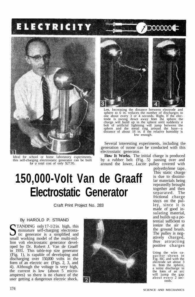
Using the wire ca-pac i to r shown inFig. I6C and with theelectrode set about 3in. from the sphere,a noisy discharge inthe form of an arcwill jump the gapa b o u t e v e r y 2 sec-
onds.
SCIENCE AND MECHANICS174
科技论坛科技论坛:www.tech-domain.com
www.tech-domain.com

FEBRUARY, 1958 175
科技论坛科技论坛:www.tech-domain.com
www.tech-domain.com

Completed inside view of base showing arrangementof parts and wiring.
through the brush, but, since the belt operatesbetween the pulley and brush, these positivecharges are picked up by the belt and carriedup to the high voltage sphere or terminal at thetop of the insulating column. The upper pul-ley, also made of Lucite but covered with alayer of aluminum foil, then becomes positivelycharged. Since unlike charges attract, negativecharges are attracted to the top pulley and arecarried on the downward travel of the belt. Thesum of the charges coming up the belt and thosegoing down the belt represent the total chargingcurrent. A collector brush placed over the toppulley collects positive charges and directs themto the terminal where they build up to a highpotential. This voltage increases to a point wheresparkover or discharges occur at the lower edgeof the sphere where the smallest radius exists.By placing a round metal object like a kitchen
ladle near the sphere (Fig. 1), discharges up toabout 3 in. in length can be obtained.
Relative humidity is also a factor in the oper-ation of all electrostatic machines. When thehumidity is high, leakage occurs along the belt,down the insulating column, and small chargesleak off to the moist atmosphere from the termi-nal, all of which prevent the development ofmaximum voltage. In addition, high humidityprevents the formation of the necessary chargesat the pulleys. Under such conditions, moisturemay be removed by directing warm air from aportable electric hair dryer on the parts underthe base. The generator works best when theroom humidity is about 30% or lower.
Building the Generator. You may purchase thematerials called for in the materials list sep-arately and make the parts or, purchase theparts in kit form made up from this article for$27.95 postage paid.
If you are going to make up the parts your-self, start with the base, which is a Wearever#2702 aluminum baking pan. First lay out thetemplate (Fig. 7A) full size on lightweight card-board and cut it out around the inner and outercircles. Place the template on the outside of thepan bottom, center it and fasten with tape. Witha scratch awl mark the center hole and center-punch the location of the bolt holes. Then cutout the 2-1/4in. dia. center hole with a fly cutterchucked in a drill press or use a fine-toothed,metal cutting blade in a coping saw. Or, use aGreenlee chassis punch, 2-1/4in. When drillingthe small holes, backup the pan bottom witha block of wood. Also drill holes in the side ofthe pan for the switch and cord grommet as inFig. 8.
Next turn the column retaining ring (Fig. 7B)
176 SCIENCE AND MECHANICS
科技论坛科技论坛:www.tech-domain.com
www.tech-domain.com

Locating center of pulley, held in lathe 3-jawChuck, with center drill held in tallstock chuck.
from hardwood (birch, maple or walnut) or birchplywood making the 2-1/4in. dia. hole in the ringa tight press fit on the column. If you use ashank end of a Boye #10 metal crochet needlefor the top pulley shaft as we did (Fig. 7C),drill two holes with a #31 drill diametricallyopposite one another through the top of thecolumn as in Fig. 6. If 1/8-in. drill rod is usedfor the shaft, drill the holes with a 1/8-in. drill.Then, with a hacksaw, cut down to drilled holesto form U-slots in which the shaft will fit freely.Also drill and tap a 4-40 hole 1 in. from theend of the column for the brush bracket. (Fig. 6).
The holes for the shafts in upper and lowerpulleys, which are made from 1-1/2in. lengths of7/8-in. dia. Lucite, must be drilled concentric andin the exact center of the pulleys. Probablythe best way to do this is to chuck it in a latheas in Fig. 9. Start the hole with a center drilland then drill through witha #32 twist drill for apress fit with the shaft.When drilling Lucite, use alathe speed of about 500-600 rpm's and withdrawdrill frequently to removechips. Otherwise, the heatdeveloped may soften theLucite which will cause thedrill to bind, and producea hole having scored sidewalls. Lubricate drill withsoap and water to producea smooth, clean hole. Whendrilling lower pulley (Fig.7D), make a press-fit sizehole with the motor shaft,using two drill sizes if mo-tor shaft is of two-step di-ameter.
Do not hammer pulleyson the shafts. Instead, placepulley and shaft betweenvise jaws or an arbor pressand press shaft through thepulley for a snug fit. Roundoff the ends of the shafts
Fastening base to wooden ring pressed on lowerend of column. Note that motor plate is held with
one sciew driven into wooden ring.
slightly with a file before pressing on the pulley.Now, place the upper pulley with shaft into theslots, which serve as bearings, at the top end ofthe column and center the pulley in the column.Then measure and cut two short lengths of Bake-lite tubing to act as spacers on each side of thepulley as in Fig. 6.
Your next step is to assemble the column tothe base. First press the previously made retain-ing ring over the lower end of the column sothat 3/16 in. of the column projects beyond thering. Then insert this projecting end of thecolumn through the hole in the base and lineup top pulley centerline or slots at the top ofthe column with the pulley centerline marked onthe template. Fasten the column to the base with#5 x 1/2-in. rd wood screws as in Fig. 10. Drillpilot holes for the screws in the retaining ring
to avoid splitting it.After making the motor
base plate and brackets(Figs. 7E and F), press thelower pulley on the motorshaft. Line up the motortogether with its mountingbracket and baseplate withthe holes drilled in thebase. Check to see that thelower pulley centers overinside of column tube (Fig.6) and lines up with toppulley. Wrap face of lowerpulley with polyethylenetape (Fig. 7D).
After bolting the motorin place, wire it to a linecord and SP toggle switchas in Fig. 6.
The rubber belt can bepurchased from ForestProducts or made from al-7/16 x 22in. strip cut froma Davol latex leg bandage.Cut the ends at about a 30deg. angle and lightly sandabout 1/4 in. at each end for
FEBRUARY, 1958 177
科技论坛科技论坛:www.tech-domain.com
www.tech-domain.com

Pinwheel rotates at high speed by unseen force whenheld over the sphere of the electrostatic generator.
lapping. Coat the ends with Pliobond cement,press them together and allow to dry.
The upper pulley must now be covered withheavy-duty, household aluminum foil. Cut a pieceof foil the width of the pulley and long enoughto wrap around it and lap about 1/16 in. Applya coat of Pliobond to both the pulley and one sideof the foil and carefully wrap the foil around thepulley. Press lower half of sphere on column enddown to where its turned-up edge is about 2-1/4in.from top end of column. To install the belt, placeit around the upper pulley, feed it down throughthe column and drop the upper pulley in placein the slot bearings. Then with a piece of wirebent L-shaped, pull the belt through the bottomof the column and around lower pulley. Applya trace of light grease under upper pulley shaftat each bearing.
It is necessary that the belt remain approxi-mately centered on the pulleys while the motoris running. Turn the motor pulley by hand firstand note whether the belt has a tendency to runoff the pulleys. If not, turn on the motor andcheck the belt for proper tracking again. If thebelt runs off to any extent, it indicates that theupper and lower pulley shafts are not parallelto one another. Shifting the motor to right orleft will correct side misalignment and placingthin cardboard or metal shim stock under themotor bracket will correct shaft misalignment.
Make the lower or ground brush bracket (Fig.7G) and fasten a 1/2 x l-1/4-in. piece of bronzewindow screening to it with two 4-40 screws. Thescreen should project 1/8 in. beyond the edge ofthe bracket. Fasten the bracket to the inside ofthe base at the up-going side of the belt withone 8-32 screw (Fig. 6). Then adjust the bracketby bending or moving it along its slot so thatends of the screen brush are fairly close (about1/32 to 1/16in.) to the belt but not touching it
178 SCIENCE AND MECHANICS
科技论坛科技论坛:www.tech-domain.com
www.tech-domain.com

when the lapped joint comes around.Make the bracket for the upper or collector
brush from copper wire as in Fig. 7H. Wrap thebronze screening for the brush around the wireand solder. Fasten bracket and a 2-1/4-in. lengthof #18 copper wire to the column with a 4-40screw in the previously tapped hole. To keep thelower half of the sphere in place on the columnand #18 wire in contact with the sphere, wraptwo turns of #33 plastic tape tightly around thecolumn and turned-up edge of the sphere as inFig. 6. Placing the top half of the sphere on thelower half completes the generator.
Servicing the generator is limited to keeping thesphere and column smooth and clean of dirtwhich cause tiny corona point discharges andprevent the voltage from building up to its maxi-mum. Occasionally, apply a bit of grease to theupper pulley shaft bearings. After considerableuse, remove the belt and wash it with a house-hold detergent. Wipe the surfaces of the pulleysat the same time. Thoroughly dry the belt be-fore assembling. Also check the brush-to-beltclearance and adjust to within 1/32 to 1/16in. gap.If necessary, when starting generator use a hairdryer to dry out working parts.
Using the Generator with Accessories You CanMake. For obtaining electrical discharges youwill need an electrode, and a round-bowl, metalkitchen ladle is ideal for this, Although the ladlecan be simply held by hand to draw off a charge,it's a good idea to ground the handle of the ladleto the generator base with a wire lead to avoida shock. The shock, however, would be quiteharmless. The ladle can also be attached to thegenerator with a clamping ring. Make the ring(Fig. 11B), and a new handle for the ladle asin Fig 11A and clamp it to the column retainingring as in Fig. 1. The length of the spark ordischarge can then be varied by moving theladle toward or away from the aluminum sphere.
The rotation of the pinwheel shown in Fig.12 is due to the "electric wind" effect producedby corona point discharge at the pointed tips ofthe rotor. Make the accessory parts as in Fig. 13.
The electric plume (Fig. 14) is an interestingexperiment because it demonstrates the effectsof repulsion. With the machine running, thestrips become positively charged the same as the
FEBRUARY, 1958 179
科技论坛科技论坛:www.tech-domain.com
www.tech-domain.com

terminal or sphere and,since like charges repel,the free ends of thestrips are thrown out-ward. When the machineis turned off, the stripswill remain in their re-pelled position as longas the terminal retainsits charge. If you holdyour finger over theplume, as in Fig. 15, thestrips will first be at-tracted to your fingersince it has a normalnegative charge. How-ever, upon contact withyour finger, the stripswill receive a negativecharge and be repelledback to the sphere. Whensetting up this experiment, cut thestrips from facial tissue and fastenone end of each strip to the spherewith cellophane tape.
Much heavier discharges can beobtained from this Van de Graaffgenerator by adding a Leyden Jarcapacitor made as shown in Fig. 16A.Connect the bared end of a length ofheavy plastic insulated wire to thesphere with modeling clay and letthe other end of the wire touch thefoil on the inside of the Leyden Jar.Set the spark gap electrode aboutone inch or so from the sphere andturn on the machine. After a chargebuilds up in the Leyden Jar, a heavyspark jumps between sphere andelectrode.
Insulated wire can also be used as a capacitor.Fasten the two bared ends on a length of veryhigh voltage plastic insulated wire to the spherewith modeling clay and wrap the looped endaround the base of the generator as in Fig. 16B.A noisy discharge, 2 in. or more in length willresult. Any breakdown will be to the base as thedielectric fails and little spark will result.
The wire capacitor giving the best results inour experiments was made from a piece of veryhigh voltage wire taken from the core of a co-axial cable found in a surplus store. It has veryhard plastic insulation about 3/16 in. thick arounda stranded conductor of about #14 gage. Thelooped end was placed around the base as in Fig.16C. The bared ends were soldered to a pieceof copper and fastened to the sphere with #33plastic tape covering all bare areas. Then a largelump of modeling clay (Fig. 3) was placed overthe taped ends to minimize corona leakage whichwould have prevented maximum voltage. The6 in. spark. (Fig. 3) and very noisy 3 in. dis-charge (Fig. 2) were obtained with this capacitor.The electrode was then swung down so no arc
Left, Force of repulsion is demonstrated by electric plume experiment. Flexiblepaper strips taped to sphere are repelled as though made of rigid material.Right, When you hold your linger over the plume, the paper strips will first beattracted to your finger since it has a normal negative charge. When you toucha strip with your finger, the strip will receive a negative charge and drop
back on the sphere.
would jump between it and the sphere. After afew seconds a sudden lightning-like bolt jumpedfrom the lower sphere edge to the clamping ring(Fig. 4), a distance of about 10 in.!
Building the generator as described results ina positive terminal. To obtain a negative terminal,apply the plastic tape to the top pulley andthe aluminum foil to the lower pulley.
For a good practical use, the Van de Graaffgenerator can be set up as an ozone generator.Place the unit in a room with stale air causedby tobacco smoke or cooking odors and adjustthe spark gap for about a 2 or 2-1/2-in. spark. Turnon the motor and in a short time you will noticethe clean smell of ozone, much like that causedby lightning after a summer thunderstorm.Ozone combines with odors and destroys them.
180 SCIENCE AND MECHANICS
科技论坛科技论坛:www.tech-domain.com
www.tech-domain.com