Embed Size (px)
Citation preview
___________________
___________________
___________________
___________________
___________________
___________________
___________________
___________________
___________________
___________________
___________________
___________________
___________________
SIMATIC NET
S7-1200 - TeleControl CP 1243-8 IRC
Operating Instructions
02/2018 C79000-G8976-C385-03
Preface
Application and functions 1
LEDs and connectors 2
Installation, connecting up, commissioning
3
Configuration 4
Program blocks 5
Diagnostics and upkeep 6
Technical data 7
Approvals A
Dimension drawings B
Accessories C
STEP 7 V5 configuration of the proxy
D
Documentation references E

Siemens AG Division Process Industries and Drives Postfach 48 48 90026 NÜRNBERG GERMANY
C79000-G8976-C385-03 Ⓟ 02/2018 Subject to change
Copyright © Siemens AG 2015 - 2018. All rights reserved
Legal information Warning notice system
This manual contains notices you have to observe in order to ensure your personal safety, as well as to prevent damage to property. The notices referring to your personal safety are highlighted in the manual by a safety alert symbol, notices referring only to property damage have no safety alert symbol. These notices shown below are graded according to the degree of danger.
DANGER indicates that death or severe personal injury will result if proper precautions are not taken.
WARNING indicates that death or severe personal injury may result if proper precautions are not taken.
CAUTION indicates that minor personal injury can result if proper precautions are not taken.
NOTICE indicates that property damage can result if proper precautions are not taken.
If more than one degree of danger is present, the warning notice representing the highest degree of danger will be used. A notice warning of injury to persons with a safety alert symbol may also include a warning relating to property damage.
Qualified Personnel The product/system described in this documentation may be operated only by personnel qualified for the specific task in accordance with the relevant documentation, in particular its warning notices and safety instructions. Qualified personnel are those who, based on their training and experience, are capable of identifying risks and avoiding potential hazards when working with these products/systems.
Proper use of Siemens products Note the following:
WARNING Siemens products may only be used for the applications described in the catalog and in the relevant technical documentation. If products and components from other manufacturers are used, these must be recommended or approved by Siemens. Proper transport, storage, installation, assembly, commissioning, operation and maintenance are required to ensure that the products operate safely and without any problems. The permissible ambient conditions must be complied with. The information in the relevant documentation must be observed.
Trademarks All names identified by ® are registered trademarks of Siemens AG. The remaining trademarks in this publication may be trademarks whose use by third parties for their own purposes could violate the rights of the owner.
Disclaimer of Liability We have reviewed the contents of this publication to ensure consistency with the hardware and software described. Since variance cannot be precluded entirely, we cannot guarantee full consistency. However, the information in this publication is reviewed regularly and any necessary corrections are included in subsequent editions.

CP 1243-8 IRC Operating Instructions, 02/2018, C79000-G8976-C385-03 3
Preface Validity of this manual
This document contains information on the following product:
● CP 1243-8 IRC Article number 6GK7 243-8RX30-0XE0 Hardware product version 2 Firmware version V3.1
The CP is the communications processor for connection of the SIMATIC S7-1200 via public or private infrastructures to a telecontrol master station. For information on the telecontrol protocols used refer to the section Properties of the CP (Page 11).
With the help of VPN technology and the firewall, the CP allows protected access to the S7-1200.
The CP can also be used as an additional Ethernet interface of the CPU for S7 communication.
Figure 1 CP 1243-8 IRC
Behind the top hinged cover of the module housing, you will see the hardware product version to the right of the article number printed as a placeholder "X". If the printed text is, for example, "X 2 3 4", "X" would be the placeholder for hardware product version 1.
You will find the MAC address under the lower hinged cover of the housing.
Purpose of the manual This manual describes the properties of this module and supports you when installing and commissioning it.
The required configuration steps are described as an overview and there are explanations of the relationship between firmware functions and configuration.

Preface
CP 1243-8 IRC 4 Operating Instructions, 02/2018, C79000-G8976-C385-03
You will also find information about the diagnostics options of the device.
Product names and abbreviations The following short forms are used in this document:
● CP
The short form is used instead of the full product name "CP 1243-8 IRC".
● IRC
Industrial Remote Communication
● STEP 7
Short form for the following versions of the configuration tool STEP 7:
– STEP 7 V5
– STEP 7 Basic
The short form "STEP 7" is only used when the product is self-explanatory in the particular context.
For information on the product versions, refer to the section Requirements for operation (Page 23).
● Proxy
"PROXY CP1243-8 IRC", substitute module for the CP 1243-8 IRC in the catalog of STEP 7 V5 / HW Config.
● ST7
Short form for the telecontrol protocol "SINAUT ST7"
New in this issue Connection to SINEMA Remote Connect of the above firmware version
Replaced manual issue Edition 07/2017
Current manual release on the Internet You will also find the current version of this manual on the Internet pages of Siemens Industry Online Support at the following address:
Link: (https://support.industry.siemens.com/cs/ww/en/ps/21162/man)
Required experience To install, commission and operate the CP, you require experience in the following areas:
● Automation engineering
● Setting up the SIMATIC S7-1200 system
● SIMATIC STEP 7 Basic
Preface
CP 1243-8 IRC Operating Instructions, 02/2018, C79000-G8976-C385-03 5
Requirements for use of the module You will find the requirements for using the module in the section Requirements for operation (Page 23).
Cross references In this manual there are often cross references to other sections.
To be able to return to the initial page after jumping to a cross reference, some PDF readers support the command <Alt>+<left arrow>.
Sources of information and other documentation You will find an overview of further reading and references in the Appendix of this manual.
License conditions
Note Open source software
The product contains open source software. Read the license conditions for open source software carefully before using the product.
You will find the license conditions on the supplied data medium:
● OSS_CP1243-8_99.pdf
Security information Siemens provides products and solutions with industrial security functions that support the secure operation of plants, systems, machines and networks.
In order to protect plants, systems, machines and networks against cyber threats, it is necessary to implement – and continuously maintain – a holistic, state-of-the-art industrial security concept. Siemens’ products and solutions constitute one element of such a concept.
Customers are responsible for preventing unauthorized access to their plants, systems, machines and networks. Such systems, machines and components should only be connected to an enterprise network or the internet if and to the extent such a connection is necessary and only when appropriate security measures (e.g. firewalls and/or network segmentation) are in place.
Additionally, Siemens’ guidance on appropriate security measures should be taken into account. For additional information on industrial security measures that may be implemented, please visit Link: (http://www.siemens.com/industrialsecurity)
Siemens’ products and solutions undergo continuous development to make them more secure. Siemens strongly recommends that product updates are applied as soon as they are available and that the latest product versions are used. Use of product versions that are no longer supported, and failure to apply the latest updates may increase customers’ exposure to cyber threats.
Preface
CP 1243-8 IRC 6 Operating Instructions, 02/2018, C79000-G8976-C385-03
To stay informed about product updates, subscribe to the Siemens Industrial Security RSS Feed under Link: (http://www.siemens.com/industrialsecurity)
For the security functions, see also the following section:
Security functions (Page 20)
Security recommendations (Page 55)
Security (Page 104)
Firmware The firmware is signed and encrypted. This ensures that only firmware created by Siemens can be downloaded to the device.
SIMATIC NET glossary Explanations of many of the specialist terms used in this documentation can be found in the SIMATIC NET glossary.
You will find the SIMATIC NET glossary here:
● SIMATIC NET Manual Collection or product DVD
The DVD ships with certain SIMATIC NET products.
● On the Internet under the following entry ID:
Link: (https://support.industry.siemens.com/cs/ww/en/view/50305045)
Training, Service & Support You will find information on Training, Service & Support in the multi--language document "DC_support_99.pdf" on the data medium supplied with the documentation.
Recycling and disposal The product is low in pollutants, can be recycled and meets the requirements of the WEEE directive 2012/19/EU "Waste Electrical and Electronic Equipment".
Do not dispose of the product at public disposal sites. For environmentally friendly recycling and the disposal of your old device contact a certified disposal company for electronic scrap or your Siemens contact.
Keep to the local regulations.
You will find information on returning the product on the Internet pages of Siemens Industry Online Support: Link: (https://support.industry.siemens.com/cs/ww/en/view/109479891)
CP 1243-8 IRC Operating Instructions, 02/2018, C79000-G8976-C385-03 7
Table of contents
Preface ................................................................................................................................................... 3
1 Application and functions ...................................................................................................................... 11
1.1 PG routing ............................................................................................................................... 11
1.2 Properties of the CP ................................................................................................................ 11
1.3 Communications services ....................................................................................................... 14
1.4 Connection to SINEMA RC ..................................................................................................... 17
1.5 Other services and properties ................................................................................................. 19
1.6 Security functions .................................................................................................................... 20
1.7 Performance data and configuration limits ............................................................................. 22
1.8 Requirements for operation .................................................................................................... 23
1.9 Configuration examples .......................................................................................................... 25 1.9.1 Configurations with the ST7 protocol ...................................................................................... 25 1.9.2 Configurations with the DNP3 / IEC protocols ........................................................................ 31 1.9.3 Remote maintenance with SINEMA RC ................................................................................. 34
1.10 Expansion of SINAUT projects ............................................................................................... 35 1.10.1 Modules for new SINAUT projects and those to be expanded ............................................... 35 1.10.2 Requirements for the expansion ............................................................................................. 37
2 LEDs and connectors ............................................................................................................................ 39
2.1 Opening the covers of the housing ......................................................................................... 39
2.2 LEDs ....................................................................................................................................... 40
2.3 Electrical connectors ............................................................................................................... 45 2.3.1 Power supply .......................................................................................................................... 45 2.3.2 Ethernet interface X1P1 .......................................................................................................... 46 2.3.3 Serial connection for TS module ............................................................................................. 46
3 Installation, connecting up, commissioning ............................................................................................ 47
3.1 Important notes on using the device ....................................................................................... 47 3.1.1 Notices about use in hazardous areas ................................................................................... 47 3.1.2 Notices about use in hazardous areas according to ATEX .................................................... 48 3.1.3 Notices about use in hazardous areas according to UL HazLoc ............................................ 49
3.2 Installing, connecting up and commissioning ......................................................................... 49
3.3 Note on operation ................................................................................................................... 54
4 Configuration ........................................................................................................................................ 55
4.1 Security recommendations ..................................................................................................... 55
4.2 Required STEP 7 products ..................................................................................................... 58
4.3 Overview: Connection to LAN / WAN ..................................................................................... 59
Table of contents
CP 1243-8 IRC 8 Operating Instructions, 02/2018, C79000-G8976-C385-03
4.4 Basic communication mechanisms ........................................................................................ 61 4.4.1 Addressing, authentication, connections (single / redundant) ............................................... 61 4.4.1.1 ST7 ......................................................................................................................................... 61 4.4.1.2 DNP3 / IEC ............................................................................................................................. 63 4.4.2 Connection establishment ...................................................................................................... 64 4.4.3 Acknowledgment .................................................................................................................... 65
4.5 Configuration in STEP 7 Basic ............................................................................................... 66
4.6 Communication types ............................................................................................................ 67
4.7 Telecontrol via SINEMA RC ................................................................................................... 68
4.8 Ethernet interface ................................................................................................................... 70 4.8.1 WAN settings ......................................................................................................................... 70 4.8.2 CP identification ..................................................................................................................... 71 4.8.3 Time-of-day synchronization .................................................................................................. 72 4.8.4 Ethernet addresses ................................................................................................................ 72 4.8.5 Advanced options .................................................................................................................. 72 4.8.5.1 MSC protocol settings ............................................................................................................ 72 4.8.5.2 TCP connection monitoring .................................................................................................... 74 4.8.5.3 Transmission settings - ST7 .................................................................................................. 75 4.8.5.4 Transmission settings – DNP3 ............................................................................................... 75 4.8.5.5 Transmission settings - IEC ................................................................................................... 77 4.8.6 Access to the Web server ...................................................................................................... 79
4.9 Serial interface ....................................................................................................................... 79 4.9.1 Configuration of the serial interface ....................................................................................... 79 4.9.2 Configuring a TS module ....................................................................................................... 80 4.9.3 WAN settings ......................................................................................................................... 81 4.9.4 WAN parameters (networking the CP)................................................................................... 82 4.9.5 Advanced options .................................................................................................................. 84 4.9.5.1 Dedicated line ........................................................................................................................ 84 4.9.5.2 Dialup network ....................................................................................................................... 86
4.10 Partner stations ...................................................................................................................... 90 4.10.1 Importing configuration data (ST7) ........................................................................................ 90 4.10.2 Partners (DNP3 / IEC) ........................................................................................................... 91
4.11 Communication with the CPU ................................................................................................ 95 4.11.1 Communication with the CPU ................................................................................................ 95 4.11.2 CP diagnostics ....................................................................................................................... 96 4.11.3 Partner status / path status .................................................................................................... 97
4.12 Time-of-day synchronization ................................................................................................ 100
4.13 SMSC ................................................................................................................................... 103
4.14 Subscriber numbers ............................................................................................................. 103
4.15 SNMP ................................................................................................................................... 104
4.16 Security ................................................................................................................................ 104 4.16.1 Security user ........................................................................................................................ 105 4.16.2 MSC authentication .............................................................................................................. 105 4.16.3 DNP3 security options ......................................................................................................... 106 4.16.4 Firewall ................................................................................................................................. 108 4.16.4.1 Pre-check of messages by the MAC firewall. ...................................................................... 108
Table of contents
CP 1243-8 IRC Operating Instructions, 02/2018, C79000-G8976-C385-03 9
4.16.4.2 Firewall settings for configured connection connections via a VPN tunnel .......................... 108 4.16.4.3 Settings for online security diagnostics and downloading to station with the firewall
activated ................................................................................................................................ 109 4.16.4.4 Notation for the source IP address (advanced firewall mode) .............................................. 109 4.16.5 Time-of-day synchronization ................................................................................................. 109 4.16.6 E-mail configuration .............................................................................................................. 110 4.16.7 Log settings - Filtering of the system events ........................................................................ 111 4.16.8 VPN ....................................................................................................................................... 111 4.16.8.1 VPN (Virtual Private Network) .............................................................................................. 111 4.16.8.2 Addressing the CP when using VPN .................................................................................... 112 4.16.8.3 Creating a VPN tunnel for S7 communication between stations .......................................... 113 4.16.8.4 VPN communication with SOFTNET Security Client (PC / engineering station).................. 115 4.16.8.5 CP as passive subscriber of VPN connections .................................................................... 115 4.16.8.6 SYSLOG ............................................................................................................................... 116 4.16.8.7 SINEMA Remote Connect .................................................................................................... 116 4.16.9 SNMP .................................................................................................................................... 118 4.16.10 Certificate manager ............................................................................................................... 120 4.16.11 Handling certificates .............................................................................................................. 120
4.17 Creating telecontrol connections for the ST7 communication .............................................. 122
4.18 Data points ............................................................................................................................ 128 4.18.1 Data point configuration ........................................................................................................ 128 4.18.2 Syntax of the data point names ............................................................................................ 135 4.18.3 Datapoint types ..................................................................................................................... 135 4.18.4 Status IDs of the data points ................................................................................................. 141 4.18.5 "General" tab ......................................................................................................................... 143 4.18.6 Configuration of the data point index .................................................................................... 144 4.18.7 Process image, type of transmission, event classes ............................................................ 144 4.18.8 Read cycle ............................................................................................................................ 147 4.18.9 "Trigger“ tab .......................................................................................................................... 148 4.18.10 Threshold value trigger ......................................................................................................... 150 4.18.11 Analog value preprocessing ................................................................................................. 152 4.18.12 Command output .................................................................................................................. 158 4.18.13 Partner stations ..................................................................................................................... 163 4.18.13.1 Partner configuration for ST7 data points ............................................................................. 163 4.18.13.2 Partner configuration for DNP3 and IEC data points ............................................................ 163
4.19 Messages .............................................................................................................................. 163 4.19.1 Message configuration .......................................................................................................... 163 4.19.2 Character set for messages .................................................................................................. 166
5 Program blocks ................................................................................................................................... 167
5.1 Program blocks for OUC ....................................................................................................... 167
5.2 Changing the IP address during runtime .............................................................................. 169
6 Diagnostics and upkeep ...................................................................................................................... 171
6.1 Diagnostics options ............................................................................................................... 171
6.2 Online security diagnostics via port 8448 ............................................................................. 174
6.3 Online functions and TeleService ......................................................................................... 174
6.4 SNMP .................................................................................................................................... 175
Table of contents
CP 1243-8 IRC 10 Operating Instructions, 02/2018, C79000-G8976-C385-03
6.5 Processing status of messages ........................................................................................... 177
6.6 Downloading firmware ......................................................................................................... 179
6.7 Module replacement ............................................................................................................ 182
7 Technical data ..................................................................................................................................... 183
7.1 Technical specifications of the CP ....................................................................................... 183
7.2 Pin assignment of the socket for the external power supply ............................................... 184
7.3 Pinout of the Ethernet interface ........................................................................................... 185
A Approvals ............................................................................................................................................ 187
B Dimension drawings ............................................................................................................................. 191
C Accessories ......................................................................................................................................... 193
C.1 TS modules .......................................................................................................................... 193 C.1.1 The TS modules ................................................................................................................... 193 C.1.2 TS Module Modem ............................................................................................................... 195 C.1.3 TS Module ISDN .................................................................................................................. 197 C.1.4 TS Module RS232 ................................................................................................................ 198 C.1.5 TS Module GSM................................................................................................................... 200
C.2 Modems and routers ............................................................................................................ 202 C.2.1 Dedicated line and dialup network modems ........................................................................ 202 C.2.2 MODEM MD720 ................................................................................................................... 203 C.2.3 Router SCALANCE M .......................................................................................................... 207
C.3 Antennas .............................................................................................................................. 208
C.4 Connecting cables ............................................................................................................... 210 C.4.1 Connecting cables for connecting the CP to Ethernet ......................................................... 210 C.4.2 Connecting cables for connecting the modem of the TS Module RS232 ............................ 210 C.4.3 Connecting cables of the MDx modem ................................................................................ 213
D STEP 7 V5 configuration of the proxy ................................................................................................... 215
D.1 Configuration in STEP 7 V5 ................................................................................................. 215
D.2 Special features of the PROXY CP1243-8 IRC ................................................................... 216
D.3 SINAUT configuration .......................................................................................................... 220
D.4 Exporting configuration data ................................................................................................ 221
E Documentation references ................................................................................................................... 225
Index ................................................................................................................................................... 229
CP 1243-8 IRC Operating Instructions, 02/2018, C79000-G8976-C385-03 11
Application and functions 1 1.1 PG routing
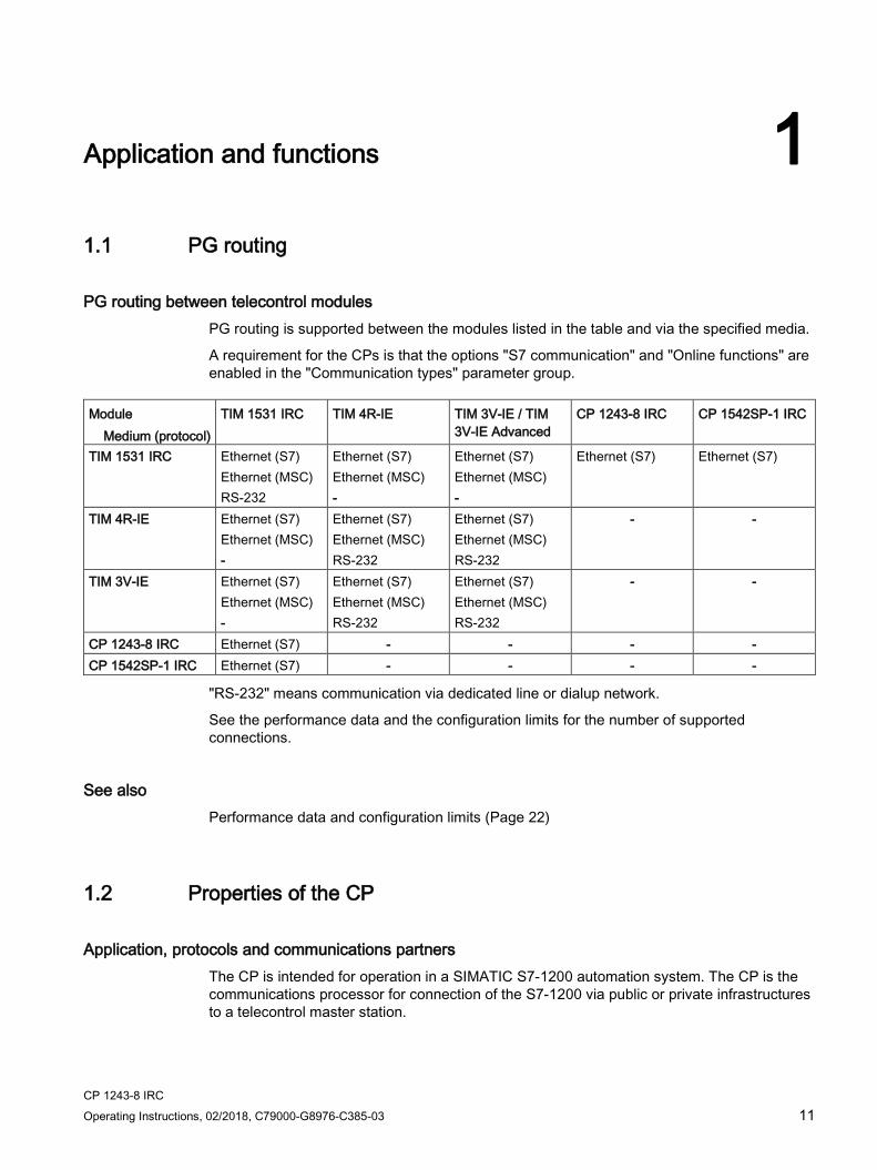
PG routing between telecontrol modules PG routing is supported between the modules listed in the table and via the specified media.
A requirement for the CPs is that the options "S7 communication" and "Online functions" are enabled in the "Communication types" parameter group.
Module
Medium (protocol) TIM 1531 IRC TIM 4R-IE TIM 3V-IE / TIM
3V-IE Advanced CP 1243-8 IRC CP 1542SP-1 IRC
TIM 1531 IRC Ethernet (S7) Ethernet (MSC) RS-232
Ethernet (S7) Ethernet (MSC) -
Ethernet (S7) Ethernet (MSC) -
Ethernet (S7) Ethernet (S7)
TIM 4R-IE Ethernet (S7) Ethernet (MSC) -
Ethernet (S7) Ethernet (MSC) RS-232
Ethernet (S7) Ethernet (MSC) RS-232
- -
TIM 3V-IE Ethernet (S7) Ethernet (MSC) -
Ethernet (S7) Ethernet (MSC) RS-232
Ethernet (S7) Ethernet (MSC) RS-232
- -
CP 1243-8 IRC Ethernet (S7) - - - - CP 1542SP-1 IRC Ethernet (S7) - - - -
"RS-232" means communication via dedicated line or dialup network.
See the performance data and the configuration limits for the number of supported connections.
See also Performance data and configuration limits (Page 22)
1.2 Properties of the CP
Application, protocols and communications partners The CP is intended for operation in a SIMATIC S7-1200 automation system. The CP is the communications processor for connection of the S7-1200 via public or private infrastructures to a telecontrol master station.
Application and functions 1.2 Properties of the CP
CP 1243-8 IRC 12 Operating Instructions, 02/2018, C79000-G8976-C385-03
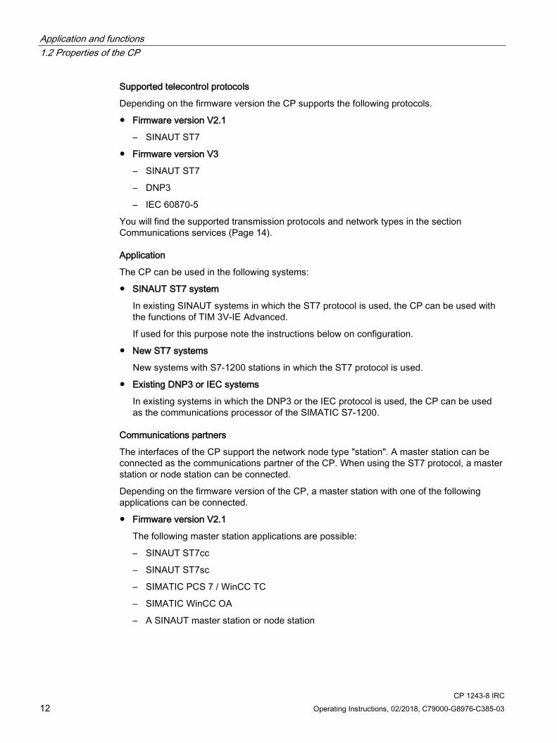
Supported telecontrol protocols
Depending on the firmware version the CP supports the following protocols.
● Firmware version V2.1
– SINAUT ST7
● Firmware version V3
– SINAUT ST7
– DNP3
– IEC 60870-5
You will find the supported transmission protocols and network types in the section Communications services (Page 14).
Application
The CP can be used in the following systems:
● SINAUT ST7 system
In existing SINAUT systems in which the ST7 protocol is used, the CP can be used with the functions of TIM 3V-IE Advanced.
If used for this purpose note the instructions below on configuration.
● New ST7 systems
New systems with S7-1200 stations in which the ST7 protocol is used.
● Existing DNP3 or IEC systems
In existing systems in which the DNP3 or the IEC protocol is used, the CP can be used as the communications processor of the SIMATIC S7-1200.
Communications partners
The interfaces of the CP support the network node type "station". A master station can be connected as the communications partner of the CP. When using the ST7 protocol, a master station or node station can be connected.
Depending on the firmware version of the CP, a master station with one of the following applications can be connected.
● Firmware version V2.1
The following master station applications are possible:
– SINAUT ST7cc
– SINAUT ST7sc
– SIMATIC PCS 7 / WinCC TC
– SIMATIC WinCC OA
– A SINAUT master station or node station

Application and functions 1.3 Communications services
CP 1243-8 IRC Operating Instructions, 02/2018, C79000-G8976-C385-03 13
● Firmware version V3
When using the "DNP3" protocol:
– DNP3 master
When using the "IEC 60870-5" protocol
– IEC master
When using the "ST7" protocol:
– SINAUT ST7cc
– SINAUT ST7sc
– SIMATIC PCS 7 / WinCC TC
– SIMATIC WinCC OA
– A SINAUT master station or node station
Configuration of the CP ● New ST7 systems, DNP3 systems, IEC systems
To configure the CP in new systems with one of the telecontrol protocols named above use STEP 7 Basic.
In these systems use a CP with firmware version V3.
● Existing ST7 systems
In existing SINAUT systems with SIMATIC stations of the families S7-300/400 and the TIM modules for remote transfer, the CP can be used for expansions by S7-1200 stations.
In these systems that were configured with STEP 7 V5, use a CP with firmware version V2.1.
To configure the CP, you require the two following STEP 7 products:
– STEP 7 V5
and
– STEP 7 Basic
For information on the required STEP 7 versions, see section Requirements for operation (Page 23).

Application and functions 1.3 Communications services
CP 1243-8 IRC 14 Operating Instructions, 02/2018, C79000-G8976-C385-03
1.3 Communications services The following communications services are supported:
Telecontrol communication The CP is the communications processor for connection of the SIMATIC S7-1200 via public or private infrastructures to a telecontrol master station. You will find the possible application of the telecontrol master station in the section Properties of the CP (Page 11).
The telecontrol protocol "ST7"
For telecontrol communication, the CP uses the ST7 protocol on the application layer (OSI layer 7) for communication via different telecontrol networks.
Functions and services of the telecontrol protocol
● Communication with the control center
An S7-1200 station with a CP 1243-8 IRC communicates via LAN/WAN with the master station.
● SMS / E-mail
Event-driven, the CP can send SMS messages to mobile telephones and e-mails to PCs with an Internet connection.
– SMS messages can be sent if the CP is connected to a mobile wireless network via the RS-232 interface.
– If the CP is connected, e-mails can be sent via the Ethernet interface.
Both types of messages are configured in telecontrol communication in STEP 7 Basic. The use of program blocks is not necessary here. For information on the configuration, see section Message configuration (Page 163).
● Inter-station communication
In dedicated line networks and with communication via the mobile wireless network and the Internet (GSM/MSC), the CP supports inter-station communication between S7-1200 stations via the master station.
With inter-station communication, the CP establishes a connection to the master station. The master station forwards the frames to the destination station.
The partners for inter-station communication must already have been created in the STEP 7 V5 project.
● Direct communication
In dial-up networks and Ethernet networks, there is direct communication between the subscribers.
Application and functions 1.3 Communications services
CP 1243-8 IRC Operating Instructions, 02/2018, C79000-G8976-C385-03 15
Security protocols
Simple communication via the mobile wireless network (GSM) and the Internet can be achieved with the MSC transmission protocol. If the security requirements are higher, the transmission protocols (OSI layer 3) listed below can be used.
● MSC
Can be used with S7 communication
Simple Internet communication via the Internet (DSL)
The MSC protocol supports authentication of the communications partners and simple encryption of data. A user name and a password are included in the encryption. An MSC tunnel is established between the MSC station and MSC master station.
● MSCsec
Can be used with S7 communication
Secure Internet communication using:
– Internet (DSL)
or
– Mobile wireless network (GSM) + Internet (DSL)
MSCsec supports authentication of the communications partners and data encryption with a user name and password. In addition to this, the shared automatically generated key is renewed between the communications partners at configurable intervals.
● IPsec (VPN)
Highly secure communication via mobile wireless and the Internet (DSL).
Communication via a mobile wireless network combined with the Internet is made possible by the router SCALANCE M. The SCALANCE M product series provides various VPN routers with IPsec and encryption software and their own firewall.
For a description of the configurable Security functions, refer to the section Security (Page 104).
You will find an overview of the possible transmission options in the section Overview: Connection to LAN / WAN (Page 59).
DNP3
Communication is based on the DNP3 SPECIFICATION Version 2.x (2007/2009).
The CP is a communications processor of the SIMATIC S7-1200 for system connection to control centers using the DNP3 protocol for telecontrol applications.
An S7-1200 with a CP functions as a DNP3 station (Outstation).
The CP supports implementation level 1 - 4 (DNP3 Application Layer protocol Level). You will find a description of the other functions in the section Partners (DNP3 / IEC) (Page 91).
IEC 60870-5
The communication is based on the specification IEC 60870-5 Part 1 - 5 (1990 - 1995) and Part 104 (2000).

Application and functions 1.3 Communications services
CP 1243-8 IRC 16 Operating Instructions, 02/2018, C79000-G8976-C385-03
The CP is a communications processor of the SIMATIC S7-1200 for system connection to control centers using the IEC 60870-5 protocol for telecontrol applications.
An S7-1200 with a CP functions as a substation (slave).
Communication via SINEMA Remote Connect Supported as of firmware version V3.1. See section Connection to SINEMA RC (Page 17).
Networks and network nodes
Network types
The CP makes telecontrol communication possible via the following network types:
● Industrial Ethernet
● Dedicated line / wireless network
● Analog dial-up network, ISDN network
● Mobile wireless networks
– GSM/GPRS (2G)
With 2.5G router SCALANCE M874-2
– UMTS (3G)
With 3G router SCALANCE M874-3
– LTE
With router SCALANCE M876-4
● IP-based wireless networks
For information on connecting the CP to various network types, refer to the section Overview: Connection to LAN / WAN (Page 59).
Network node types
The CP with the firmware version described here (see Preface) and configured in STEP 7 V14.0 SP1 supports the following network node types:
● Station
● Node station
Depending on the transmission protocol being used, one of the following transmission modes can be configured in STEP 7 V5:
● GPRS station
● MSC station
● Neutral
Application and functions 1.4 Connection to SINEMA RC
CP 1243-8 IRC Operating Instructions, 02/2018, C79000-G8976-C385-03 17
S7 communication and PG/OP communication Reading / writing data from / to a CPU via the mobile wireless network is possible if S7 communication is enabled in the configuration of the CP.
The CP supports the following functions:
● PUT/GET
The CP supports the function as client (program blocks) and server for data exchange with remote stations (S7-300/400/1200/1500).
● S7 routing
Communication between stations via S7 connections
● PG functions
● Operator control and monitoring functions (HMI)
You will find details on the program blocks in the information system of STEP 7 Basic.
For S7 communication, the CP requires a fixed IP address.
Communication via Open User Communication (OUC) Via the Ethernet interface of the CP and the program blocks of the Open User Communication on the CPU the CP has the following communication options:
● Communication with SIMATIC stations via S7 connections
● Sending e-mails
In contrast to the corresponding service of telecontrol communication (see above), to transfer e-mails via OUC, the TMAIL_C program block needs to be used, see section Program blocks (Page 167).
1.4 Connection to SINEMA RC
Communication via SINEMA Remote Connect (SINEMA RC) The "SINEMA RC Server" application provides end-to-end connection management of distributed networks via the Internet. This also includes secure remote access to lower-level stations. Communication between SINEMA RC Server and the remote devices takes place via a VPN tunnel with consideration of the stored access rights.
SINEMA RC uses OpenVPN for encryption of the data. The center of the communication is SINEMA RC Server via which communication runs between the subscribers and that manages the configuration of the communications system.
SCALANCE M routers, which you can use for the connection, also support OpenVPN and connection to SINEMA Remote Connect.
For the CP firmware version required for communication via SINEMA RC see section Communications services (Page 14).
The CP can also handle telecontrol communication via the SINEMA RC server.

Application and functions 1.4 Connection to SINEMA RC
CP 1243-8 IRC 18 Operating Instructions, 02/2018, C79000-G8976-C385-03
Parameter groups You configure communication via SINEMA RC and telecontrol communication via SINEMA RC in two parameter groups:
● Communication via SINEMA RC:
> "Security > VPN"
● Telecontrol communication via SINEMA RC:
> "Communication types"
For information on the supported protocols and configuration, see section Telecontrol via SINEMA RC (Page 68).
Applications The following application options of the CP result from the combination of the parameters for telecontrol communication and SINEMA RC:
● (1) No telecontrol and no SINEMA RC (CP for network separation only)
● (2) CP only for remote maintenance via SINEMA RC
● (3) CP for telecontrol communication only
● (4) CP uses telecontrol communication, but SINEMA RC only for remote maintenance.
● (5) CP uses SINEMA RC for telecontrol communication and remote maintenance.
The table provides an overview of the applications with the respective parameter settings.
● "On" means that the parameter is activated.
● "Off" means that the parameter is deactivated.
Table 1- 1 Use cases and parameters to be activated
Use case
Parameter settings (Parameters abbreviated) *
SRC TC TC-SRC (1) Off Off Off (2) On Off Off (3) Off On Off (4) On On Off (5) On On On
* Explanation of the parameter abbreviations: SRC - Security > VPN (activated) > "VPN connection type":
"Automatic OpenVPN configuration via SINEMA Remote Connect Server" TC - Communication types > Telecontrol communication enabled TC-SRC - Communication types >
"Activate telecontrol communication via SINEMA Remote Connect"

Application and functions 1.5 Other services and properties
CP 1243-8 IRC Operating Instructions, 02/2018, C79000-G8976-C385-03 19
1.5 Other services and properties
Other services and properties ● Data point configuration
Due to the data point configuration in STEP 7 Basic, programming program blocks in order to transfer the process data is unnecessary. The process data is configured as individual data points and transferred one-to-1 to the master station.
● IP configuration
Characteristics of the IP configuration of the Ethernet interface of the CP:
– The CP supports IP addresses according to IPv4.
– Address assignment:
The IP address, the subnet mask and the address of a gateway can be set manually in the configuration.
As an alternative, the IP address can be obtained from a DHCP server or by other means outside the configuration.
● Time-of-day synchronization
For information on the method and configuration, refer to the section Time-of-day synchronization (Page 100).
For information on the format of the time stamp of the frames, refer to the section Datapoint types (Page 135).
● Access to the Web server of the CPU
With the aid of the Web server of the CPU, you can read out module data from the station.
● Send buffer
The CP saves the values of data points configured as an event in the send buffer.
The data is not saved retentively. It is lost in case of a power outage.
● Event-driven transfer of process data
The CP transmits the data from the send buffer individually or bundled to the communication partner. The transfer can be triggered by various triggers.
● Analog value processing
Analog values can be preprocessed on the CP according to various methods.
Application and functions 1.6 Security functions
CP 1243-8 IRC 20 Operating Instructions, 02/2018, C79000-G8976-C385-03
● Online functions
From an engineering station (ES) on which STEP 7 is installed, you can use the online functions of STEP 7 via the Ethernet interface of the CP to access the S7-1200 CPU if the station is located in the same IP subnet.
The following online functions are available:
– Downloading project or program data from the STEP 7 project to the station
– Querying diagnostics data on the station
– Downloading firmware files to the CP
For a remote station located in a different IP subnet or that can be reached via the Internet, these functions can only be used if the ES (with CP 1628 or via SCALANCE S) is connected to the station via a VPN tunnel.
● SNMP
As an SNMP agent, the CP supports data queries using SNMP (Simple Network Management Protocol).
For more detailed information, refer to section SNMP (Page 175).
1.6 Security functions With Industrial Ethernet Security, individual devices, automation cells or network segments of an Ethernet network can be protected.
Read the information in the section Security recommendations (Page 55) for planning and configuring your networks.
Security functions of the telecontrol and transmission protocols For the telecontrol communication, the following Security functions can be activated:
● ST7
The transmission protocols that can be used by the CP for telecontrol communication via the ST7 protocol support the following Security functions:
– MSC
The MSC protocol supports authentication of the communications partners and simple encryption of data. A user name and a password are included in the encryption. An MSC tunnel is established between the MSC station and MSC master station.
– MSCsec
MSCsec supports authentication of the communications partners and data encryption with a user name and password. In addition to this, the shared automatically generated key is renewed between the communications partners at configurable intervals.
● DNP3
The security functions specific to DNP3 can be used.
Application and functions 1.6 Security functions
CP 1243-8 IRC Operating Instructions, 02/2018, C79000-G8976-C385-03 21
Further configurable security functions of the CP The following security functions can be used independently of telecontrol communication. Due to the activation of the security functions of the CP in the configuration, the following functions are accessible to the S7-1200 station on the interface to the external network:
● Firewall
– IP firewall with stateful packet inspection (layer 3 and 4)
– Firewall also for "non-IP" Ethernet frames according to IEEE 802.3 (layer 2)
– Limitation of the transmission speed to restrict flooding and DoS attacks ("Define IP packet filter rules")
– Global firewall rule sets
The protection provided by the firewall can cover individual devices, several devices or even entire network segments.
● VPN
The following alternatives can be used:
– Secured communication via IPsec tunnels
VPN communication allows the establishment of secure IPsec tunnels for communication with one or more security modules. The CP can be grouped together with other modules to form VPN groups during configuration. IPsec tunnels are created between all security modules of a VPN group.
– Remote maintenance via SINEMA Remote Connect
It is not necessary and not possible to create a VPN group for communication via a SINEMA RC server. The SINEMA RC Server manages the communication between the devices and the security mechanisms (OpenVPN).
● Logging
To allow monitoring, events can be stored in log files that can be read out using the configuration tool or can be sent automatically to a Syslog server.
● NTP (secure)
For secure transfer during time-of-day synchronization (with telecontrol communication disabled)
● STARTTLS / SMTPS
For secure sending of e-mails
● HTTPS
For secure access to the Web server of the CPU
● SNMPv3
Foe secure transfer of network diagnostic information
For the range of performance of the security functions refer to the section Performance data and configuration limits (Page 22).
For a description of the configuration, refer to the section Security (Page 104).
Application and functions 1.7 Performance data and configuration limits
CP 1243-8 IRC 22 Operating Instructions, 02/2018, C79000-G8976-C385-03
You will find further information on the functionality and configuration of the security functions in the information system of STEP 7 and in the manual /11/ (Page 227).
1.7 Performance data and configuration limits
Number of CMs/CPs per station In each S7-1200 station, up to three CMs/CPs can be plugged in and configured, of which a maximum of one CP 1243-8 IRC.
Connection resources ● Telecontrol connections
The CP can establish connections to up to 4 communications partners.
The partners can be linked redundantly.
When using the ST7 protocol, in addition to this, inter-station communication with up to 4 S7 stations can be operated via the master station.
● TCP connections
The CP can establish connections to up to 4 communications partners (S7 stations).
● Online functions
1 connection resource is reserved for online functions.
● S7 connections
8 connection resources for S7 connections (BSEND/BRCV)
These connections are used for SINAUT ST7 communication.
● S7 routing
Max. 4 connections at the same time
● PG/OP connections
– 2 connection resources for PG connections
– 1 connection resource for OP connections
Number of data points for the data point configuration The maximum number of configurable data points is 200.
Frame memory (send buffer) The CP has a frame memory (send buffer) for the values of data points configured as an event.
Application and functions 1.8 Requirements for operation
CP 1243-8 IRC Operating Instructions, 02/2018, C79000-G8976-C385-03 23
The send buffer has a maximum size of 16000 frames. The size of the frame memory is divided equally among all configured communications partners. It can be set in STEP 7 Basic, refer to the section Communication with the CPU (Page 95).
You will find details of how the send buffer works (storing and sending events) as well as the options for transferring data in the section Process image, type of transmission, event classes (Page 144).
Messages: E-mail / SMS Up to 10 messages can be configured in STEP 7 and sent as e-mails or SMS messages.
● Maximum number of characters that can be transferred per SMS message: 160 ASCII characters including any value sent at the same time
● Maximum number of characters that can be transferred per e-mail: 256 ASCII characters including any value sent at the same time
IPsec tunnel (VPN) Up to 8 IPsec terminals can be established for secure communication with other security modules.
Firewall rules The maximum number of firewall rules in advanced firewall mode is limited to 256.
The firewall rules are divided up as follows:
● Maximum 226 rules with individual addresses
● Maximum 30 rules with address ranges or network addresses (e.g. 140.90.120.1 - 140.90.120.20 or 140.90.120.0/16)
● Maximum 128 rules with limitation of the transmission speed ("Bandwidth limitation")
1.8 Requirements for operation
Hardware Apart from the CP, in the remote S7-1200, the following hardware is also required:
● A CPU with firmware version as of V4.1
● For communication via WAN networks (dedicated line, dial-up / GSM / wireless network): A TS module
You will find the TS modules in the telecontrol accessories program, refer to the appendix TS modules (Page 193).
A TS basic device (TS Adapter) is not required.

Application and functions 1.8 Requirements for operation
CP 1243-8 IRC 24 Operating Instructions, 02/2018, C79000-G8976-C385-03
● When using the TS Module RS232: The suitable modem
For information on modems, refer also to the appendix Modems and routers (Page 202).
● When using the TS Module GSM: An external antenna for the CP
Only use antennas from the telecontrol accessories program, refer to the appendix Antennas (Page 208).
Configuration software To configure the CP completely, you require the following products as configuration tools:
● STEP 7 Basic V15
In addition when using the CP to expand SINAUT projects that were configured in STEP 7 V5:
● STEP 7 V5.5
● SINAUT Engineering Software V5.5
The use of the two STEP 7 products is described in the section Configuration (Page 55).
Program blocks for Open User Communication and S7 communication For Open User Communication and S7 communication, program blocks are required, see section Program blocks (Page 167).
Requirements for using mobile wireless services ● A contract with a suitable mobile wireless network provider
The contract must allow the transfer of data.
● IP address:
For communication with the master station, a private (fixed) or public (dynamic) IP address assigned by the mobile wireless network provider can be used.
● The SIM card and PIN belonging to the mobile wireless contract
The SIM card is inserted in the TS module GSM.
With mobile wireless contracts in which the network provider does not assign a PIN, no PIN is configured for the CP in STEP 7 V5.
● Local availability of a mobile wireless network in the range of the station.

Application and functions 1.9 Configuration examples
CP 1243-8 IRC Operating Instructions, 02/2018, C79000-G8976-C385-03 25
1.9 Configuration examples
1.9.1 Configurations with the ST7 protocol Below, you will find configuration examples for stations with a CP 1243-8 IRC.
Telecontrol communication - MSC In telecontrol communication the station communicates via the CP with a master station. Communication can take place via various interfaces of the CP and via various network types.
In the sample configuration shown, stations communicate with a master station TIM that in turn is connected to a master station of the type SINAUT ST7sc:
● An S7-300 that only communicates via the Internet.
● An S7-300 that communicates via the mobile wireless network and the Internet.
● An S7-1200 with CP 1243-8 IRC that communicates via the mobile wireless network and the Internet.
All three stations use the transport protocol MSC (or MSCsec).
Figure 1-1 Communication with the MSC protocol via mobile wireless and Internet

Application and functions 1.9 Configuration examples
CP 1243-8 IRC 26 Operating Instructions, 02/2018, C79000-G8976-C385-03
Inter-station communication between stations
Inter-station communication is possible for stations connected to the same master station.
For the inter-station communication between stations, the master station forwards the messages of the sending station to the receiving station.
Telecontrol communication - Ethernet In the sample configuration shown, an S7-300 and two S7-1200 stations communicate with a master station SINAUT ST7cc/ST7sc.
The CPs are connected via their Ethernet interface.
The connection to the Ethernet network, in this example a fiber-optic cable, is implemented using SCALANCE X switches. Copper cable is also possible as the medium.
Figure 1-2 Communication via an Ethernet network (optical medium)

Application and functions 1.9 Configuration examples
CP 1243-8 IRC Operating Instructions, 02/2018, C79000-G8976-C385-03 27
Telecontrol communication - Internet In the sample configuration shown, an S7-300 and two S7-1200 stations communicate with a master station SINAUT ST7cc/ST7sc via the Internet.
The CPs are connected via their Ethernet interface.
VPN tunnels are established via the ADSL router SCALANCE M812.
Figure 1-3 Communication via the Internet with VPN tunnels
Application and functions 1.9 Configuration examples
CP 1243-8 IRC 28 Operating Instructions, 02/2018, C79000-G8976-C385-03
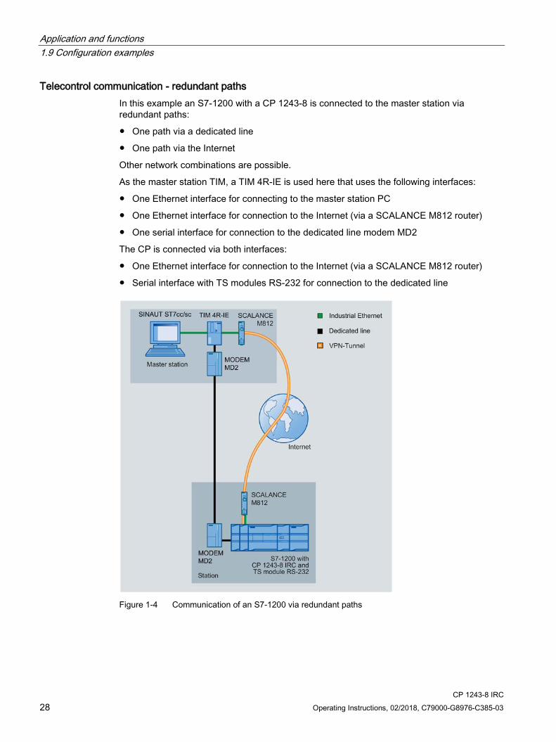
Telecontrol communication - redundant paths In this example an S7-1200 with a CP 1243-8 is connected to the master station via redundant paths:
● One path via a dedicated line
● One path via the Internet
Other network combinations are possible.
As the master station TIM, a TIM 4R-IE is used here that uses the following interfaces:
● One Ethernet interface for connecting to the master station PC
● One Ethernet interface for connection to the Internet (via a SCALANCE M812 router)
● One serial interface for connection to the dedicated line modem MD2
The CP is connected via both interfaces:
● One Ethernet interface for connection to the Internet (via a SCALANCE M812 router)
● Serial interface with TS modules RS-232 for connection to the dedicated line
Figure 1-4 Communication of an S7-1200 via redundant paths
Application and functions 1.9 Configuration examples
CP 1243-8 IRC Operating Instructions, 02/2018, C79000-G8976-C385-03 29
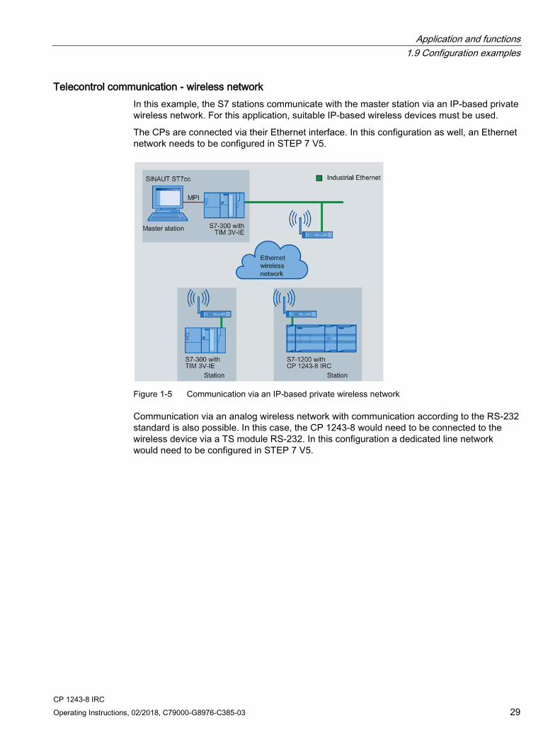
Telecontrol communication - wireless network In this example, the S7 stations communicate with the master station via an IP-based private wireless network. For this application, suitable IP-based wireless devices must be used.
The CPs are connected via their Ethernet interface. In this configuration as well, an Ethernet network needs to be configured in STEP 7 V5.
Figure 1-5 Communication via an IP-based private wireless network
Communication via an analog wireless network with communication according to the RS-232 standard is also possible. In this case, the CP 1243-8 would need to be connected to the wireless device via a TS module RS-232. In this configuration a dedicated line network would need to be configured in STEP 7 V5.

Application and functions 1.9 Configuration examples
CP 1243-8 IRC 30 Operating Instructions, 02/2018, C79000-G8976-C385-03
SMS messages and e-mails
Figure 1-6 Sending messages by SMS from an S7-1200 station
SMS
The CP can send SMS messages to a mobile phone. SMS messages are generated and sent due to events. You will find the description of the configuration in the following sections:
Data point configuration (Page 128)
Message configuration (Page 163)
E-mails
The CP can send e-mails to a PC with an Internet connection or a mobile phone. The mechanisms for this are as follows:
● E-mails that are generated by the telecontrol application.
E-mails are generated and sent due to events. You will find the description of the configuration in the following sections:
Data point configuration (Page 128)
Message configuration (Page 163)
TheE-mail configuration (Page 110)
● E-mails sent as a result of calling the program block TMAIL_C.
You will find information on the blocks in the section Program blocks (Page 167). You will find the description of the programming in the STEP 7 information system.

Application and functions 1.9 Configuration examples
CP 1243-8 IRC Operating Instructions, 02/2018, C79000-G8976-C385-03 31
1.9.2 Configurations with the DNP3 / IEC protocols
Configuration example with a non-redundant control center The following example describes a configuration with a non-redundant control center in which all nodes are located in 1 IP subnet.
In this example, the DNP3 protocol is used; in other words, the stations are equipped with a CP capable of DNP3.
A configuration in which the IEC protocol is used would have the same setup.
Figure 1-7 Configuration example with a non-redundant control center and stations in one IP subnet
The S7-1200 stations are connected to the Internet via the CP and connected to the control center.
When using the DNP3 protocol, for example, SIMATIC PCS 7 TeleControl or the system of a third-party provider can be used as the control center. If you use SIMATIC PCS 7 TeleControl as the DPN3 master in the control center, you require the necessary DPN3 driver.

Application and functions 1.9 Configuration examples
CP 1243-8 IRC 32 Operating Instructions, 02/2018, C79000-G8976-C385-03
Configuration example with connections over the Internet The following example contains a configuration with a non-redundant control center.
In this example, the DNP3 protocol is used. A configuration in which the IEC protocol is used would have the same setup.
The S7-1200 stations are connected to the Internet via the CP and connected to the control center.
When using the DNP3 protocol, for example, SIMATIC PCS 7 TeleControl or the system of a third-party provider can be used as the control center. If you use SIMATIC PCS 7 TeleControl as the DPN3 master in the control center, you require the necessary DPN3 driver.
Figure 1-8 Configuration example with connections over the Internet
As an alternative to the router SCALANCE 812, you can also use a standard DSL modem and establish the VPN connection with a security module SCALANCE S.
Addressing
Refer to the information in the section DNP3 / IEC (Page 63).

Application and functions 1.9 Configuration examples
CP 1243-8 IRC Operating Instructions, 02/2018, C79000-G8976-C385-03 33
Configuration example with a redundant control center The following example contains a configuration with a redundant control center and connections via the Internet.
In this example, the DNP3 protocol is used.
Even configurations with a redundant IEC master station are supported by the CP.
Figure 1-9 Configuration example with a redundant DNP3 master station
Addressing of the redundant master
The two devices of the redundant master in the control center are addressed by the CP using an identical station address but two different IP addresses.
See also section DNP3 / IEC (Page 63).

Application and functions 1.9 Configuration examples
CP 1243-8 IRC 34 Operating Instructions, 02/2018, C79000-G8976-C385-03
1.9.3 Remote maintenance with SINEMA RC
Remote maintenance with SINEMA RC The following figure shows the connection of different stations with Security CP to an engineering station via SINEMA Remote Connect - Server.
Figure 1-10 Connection of stations to engineering station via SINEMA RC

Application and functions 1.10 Expansion of SINAUT projects
CP 1243-8 IRC Operating Instructions, 02/2018, C79000-G8976-C385-03 35
1.10 Expansion of SINAUT projects
1.10.1 Modules for new SINAUT projects and those to be expanded
New SINAUT projects in the TIA Portal For new SINAUT projects, the following modules can be configured in STEP 7 Basic / Professional V15 (TIA Portal) without pre-configuration in STEP 7 V5.
Table 1- 2 Configuring modules in STEP 7 Basic / Professional
Module name (firmware version)
Usable modules in STEP 7 Basic / Professional as of V15 Catalog module STEP 7 version
TIM 3V-IE (V2.6) TIM 3V-IE STEP 7 Profession-al
TIM 3V-IE Advanced (V2.6) TIM 3V-IE Advanced STEP 7 Profession-al
TIM 4R-IE (V2.6) • TIM 4R-IE • TIM 4R-IE Stand-alone
STEP 7 Profession-al
CP 1243-8 IRC (V3.0) CP 1243-8 IRC STEP 7 Basic TIM 1531 IRC (V1.0) TIM 1531 IRC STEP 7 Profession-
al CP 1542SP-1 IRC (V2.0) CP 1542SP-1 IRC STEP 7 Profession-
al
Extension of existing SINAUT projects in the TIA Portal SINAUT projects with TIM modules for the SIMATIC S7-300 and S7-400 series, which were configured in STEP 7 V5, can be extended with communication modules of the S7-1200/1500 series which are configured in STEP 7 Basic or STEP 7 Professional in the TIA Portal.
The following modules are available as communication modules for expanding existing SINAUT systems:
● CP 1243-8 IRC
As of STEP 7 Basic V13.0 SP1
● TIM 1531 IRC
As of STEP 7 Professional V15
To avoid having to create, configure and program the entire STEP 7 V5 project in STEP 7 Professional, the STEP 7 V5 project can be expanded by S7-1200/1500 stations with compatible communication modules.

Application and functions 1.10 Expansion of SINAUT projects
CP 1243-8 IRC 36 Operating Instructions, 02/2018, C79000-G8976-C385-03
The procedure for configuration of a communication module for the expansion is as follows:
1. Configuration of a placeholder (proxy) for an S7-1200/1500 module in the STEP 7 V5 project
The proxy receives the SINAUT-specific communication, connection and address parameters.
2. Export the configuration data (SDBs) of the proxy from STEP 7 V5 as a text file.
3. Import the configuration data of the proxy into a compatible module in STEP 7 Basic / Professional.
The new module adopts the SINAUT-specific communication, connection and address parameters from STEP 7 V5.
4. Complete the configuration of the new module in STEP 7 Basic / Professional.
This procedure is supported by the following modules:
Table 1- 3 Module migration from STEP 7 V5 to STEP 7 Basic / Professional (TIA Portal)
Module function for STEP 7 V5 project ex-pansion
S7-1200/1500 module in STEP 7 Basic / Professional
TIM (function) for expansion
Proxy to be used in the catalog
Compatible module Required STEP 7 version
TIM 3V-IE Advanced PROXY CP1243-8 IRC
⇒ CP 1243-8 IRC STEP 7 Basic
TIM 4R-IE PROXY TIM 1531 IRC
⇒ TIM 1531 IRC STEP 7 Professional
TIM 4R-IE Stand-alone
PROXY TIM 1531 IRC
⇒ TIM 1531 IRC STEP 7 Professional
Note TIM 4R-IE Stand-alone for S7-400 becomes TIM 1531 IRC
A TIM 4R-IE Stand-alone required in STEP 7 V5 that is assigned to a CPU-400 must be replaced by a TIM 1531 IRC for the expansion of classic SINAUT projects in STEP 7 Professional.
A TIM 4R-IE Stand-alone can only be created in new projects that are configured exclusively in STEP 7 Professional.
You can find details on configuration in the section STEP 7 V5 configuration of the proxy (Page 215).
Application and functions 1.10 Expansion of SINAUT projects
CP 1243-8 IRC Operating Instructions, 02/2018, C79000-G8976-C385-03 37
1.10.2 Requirements for the expansion Furthermore, the following requirements apply to importing configuration data from STEP 7 V5 to STEP 7 Basic / Professional.
Additional modules that are not listed here are available for new projects in STEP 7 Basic / Professional.
Requirements: Software versions The above-mentioned configuration tools are required in the specified versions for expansion of SINAUT projects.
● STEP 7 V5 project
A configuration file of the communication module from a consistent STEP 7 V5 project is required.
Requirements: Firmware versions/module update ● Firmware of the communication module
The following firmware versions of the communication modules used are required:
– TIM 1531 IRC - V1.1
A TIM 1531 IRC V1.0 can be exchanged for a TIM 1531 IRC V1.1 but not the other way round.
The mode of the "Telecontrol configuration" ("Basic settings") is set to "Configure". The existing data is adopted.
– CP 1243-8 IRC - V2.1
Adoption of the data from STEP 7 V5 without the option of making changes
A physical V2.1 CP can be exchanged for a V3.1 CP but not the other way round. The CP used must have hardware product version 2. The existing data is adopted.
– CP 1243-8 IRC - V3
Adoption of the STEP 7 V5 data from the predecessor module with option to change some configuration data
A CP V3.0 can be replaced by a CP V3.1 but not the other way round.

Application and functions 1.10 Expansion of SINAUT projects
CP 1243-8 IRC 38 Operating Instructions, 02/2018, C79000-G8976-C385-03

CP 1243-8 IRC Operating Instructions, 02/2018, C79000-G8976-C385-03 39
LEDs and connectors 2 2.1 Opening the covers of the housing
Location of the display elements and the electrical connectors The LEDs for the detailed display of the module statuses are located behind the upper cover of the module housing.
The Ethernet connector is located behind the lower hinged cover of the module.
Opening the covers of the housing Open the upper or lower cover of the housing by pulling it down or up as shown by the arrows in the illustration. The covers extend beyond the housing to give you a grip.
Figure 2-1 Opening the covers of the housing

LEDs and connectors 2.2 LEDs
CP 1243-8 IRC 40 Operating Instructions, 02/2018, C79000-G8976-C385-03
2.2 LEDs
LEDs of the module The module has various LEDs for displaying the status:
● LED on the front panel
The "DIAG" LED that is always visible shows the basic statuses of the module.
● LEDs below the upper cover of the housing
The LEDs below the upper cover provide more detailed information on the module status.
Table 2- 1 LED on the front panel
LED / colors Name Meaning
(red / green)
DIAG Basic status of the module
Table 2- 2 LEDs below the upper cover of the housing
LED (color) Name Meaning
(red / green)
LINK • Status of the connection to Industrial Ethernet • Status of the CPU
(green)
CONNECT ETH Status of the connections to the partner via Ethernet
(green)
VPN Status of the VPN or SINEMA Remote Connect configuration
(green)
CONNECT RS232 Status of the connections to the partner via the serial interface
LED colors and illustration of the LED statuses The LED symbols in the following tables have the following significance:
Table 2- 3 Meaning of the LED symbols
Symbol
-
LED status OFF ON (steady light) Flashing Not relevant
LEDs and connectors 2.2 LEDs
CP 1243-8 IRC Operating Instructions, 02/2018, C79000-G8976-C385-03 41
Note LED colors when the module starts up
When the module starts up, all its LEDs are lit for a short time. Multicolored LEDs display a color mixture. At this point in time, the color of the LEDs is not clear.
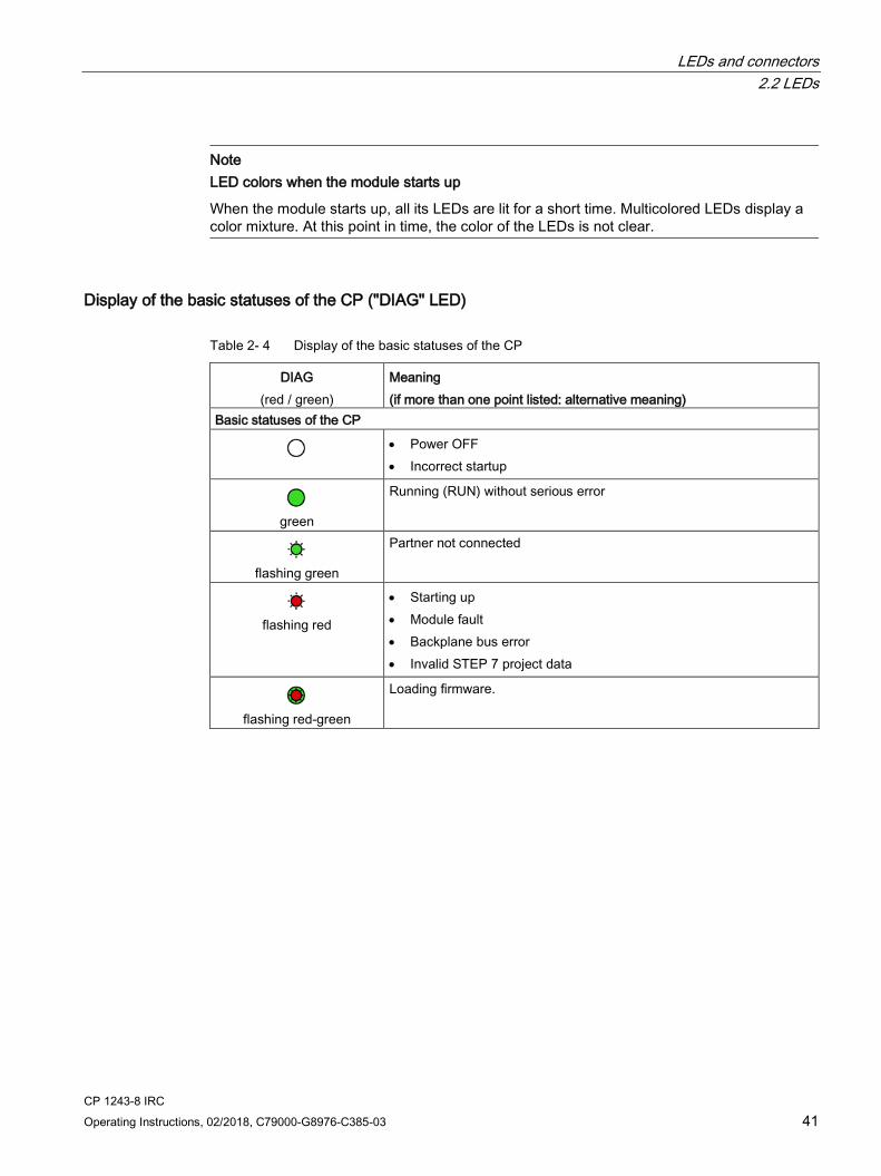
Display of the basic statuses of the CP ("DIAG" LED)
Table 2- 4 Display of the basic statuses of the CP
DIAG (red / green)
Meaning (if more than one point listed: alternative meaning)
Basic statuses of the CP
• Power OFF • Incorrect startup
green
Running (RUN) without serious error
flashing green
Partner not connected
flashing red
• Starting up • Module fault • Backplane bus error • Invalid STEP 7 project data
flashing red-green
Loading firmware.

LEDs and connectors 2.2 LEDs
CP 1243-8 IRC 42 Operating Instructions, 02/2018, C79000-G8976-C385-03
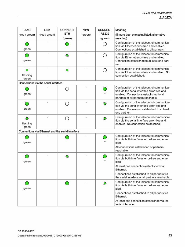
Display of the operating and communications statuses The LEDs indicate the operating and communications status of the module according to the following scheme:
Table 2- 5 Display of the operating and communications statuses
DIAG (red / green)
LINK (red / green)
CONNECT ETH
(green)
VPN (green)
CONNECT RS232 (green)
Meaning (if more than one point listed: alternative meaning)
Module startup (STOP → RUN) or error statuses
Power OFF
red
green
Startup - phase 1
flashing red
-
Startup - phase 2
green
- - - - Running (RUN) without serious error
red
-
- - Invalid STEP 7 project data
flashing red
- - - - Missing STEP 7 project data
flashing red
-
-
Backplane bus error with configured Ether-net connections
flashing red
-
-
Backplane bus error with configured connec-tions via the serial interface
flashing red
-
-
Backplane bus error with configured connec-tions via the Ethernet and the serial interface
Connection to Industrial Ethernet, status of the CPU -
green
- - - Connection to Industrial Ethernet exists CPU in RUN.
-
flashing green
- - - Connection to Industrial Ethernet exists CPU in STOP
-
- - - No connection to Industrial Ethernet
-
flashing red
- - - Duplicate IP address detected in the Ether-net network
Connections via Ethernet
LEDs and connectors 2.2 LEDs
CP 1243-8 IRC Operating Instructions, 02/2018, C79000-G8976-C385-03 43
DIAG (red / green)
LINK (red / green)
CONNECT ETH
(green)
VPN (green)
CONNECT RS232 (green)
Meaning (if more than one point listed: alternative meaning)
green
-
-
Configuration of the telecontrol communica-tion via Ethernet error-free and enabled. Connections established to all partners.
green
-
-
Configuration of the telecontrol communica-tion via Ethernet error-free and enabled. Connection established to at least one part-ner.
flashing green
-
-
Configuration of the telecontrol communica-tion via Ethernet error-free and enabled. No connection established.
Connections via the serial interface
green
-
-
*
Configuration of the telecontrol communica-tion via the serial interface error-free and enabled. Connections established to all partners or all partners reachable .
green
-
-
Configuration of the telecontrol communica-tion via the serial interface error-free and enabled. Connection established to at least one partner.
flashing green
-
-
Configuration of the telecontrol communica-tion via the serial interface error-free and enabled. No connection established.
Connections via Ethernet and the serial interface
green
-
-
*
Configuration of the telecontrol communica-tion via both interfaces error-free and ena-bled. All connections established or partners reachable.
green
-
-
*
Configuration of the telecontrol communica-tion via both interfaces error-free and ena-bled. At least one connection established via Ethernet. Connections established to all partners via the serial interface or all partners reachable.
green
-
-
Configuration of the telecontrol communica-tion via both interfaces error-free and ena-bled. Connections established to all partners via Ethernet. At least one connection established via the serial interface.

LEDs and connectors 2.2 LEDs
CP 1243-8 IRC 44 Operating Instructions, 02/2018, C79000-G8976-C385-03
DIAG (red / green)
LINK (red / green)
CONNECT ETH
(green)
VPN (green)
CONNECT RS232 (green)
Meaning (if more than one point listed: alternative meaning)
green
-
-
Configuration of the telecontrol communica-tion via both interfaces error-free and ena-bled. At least one connection established on eve-ry interface but not all.
flashing green
-
-
Configuration of the telecontrol communica-tion via both interfaces error-free and ena-bled. No connection established.
flashing green
-
-
Configuration of the telecontrol communica-tion via both interfaces error-free and ena-bled. Connection established via Ethernet to at least one partner. No connection established via the serial interface.
flashing green
-
-
Configuration of the telecontrol communica-tion via both interfaces error-free and ena-bled. Connection established via the serial inter-face to at least one partner. No connection established via Ethernet.
VPN/SINEMA Remote Connect connection - - -
- VPN/SINEMA Remote Connect connection
established - - -
- Attempting to establish a configured
VPN/SINEMA Remote Connect connection - - -
- VPN/SINEMA Remote Connect connection
not configured or currently not established on the CP
Loading firmware
flashing green
Loading firmware. The "DIAG" LED flashes alternately red and green.
flashing
green (2x)
flashing green
Firmware was successfully loaded. Die LED "DIAG" flashes green twice.
flashing red
flashing green
Error loading the firmware. Remedy: Power OFF → ON
* With configured dial-up network connections, a connection is shown as being established or the partner as being reacha-ble if the connection has been established and least once and then not aborted.

LEDs and connectors 2.3 Electrical connectors
CP 1243-8 IRC Operating Instructions, 02/2018, C79000-G8976-C385-03 45
2.3 Electrical connectors
2.3.1 Power supply
Power supply The 3-pin socket for the external 24 V DC power supply is located on the top of the module. The matching plug ships with the product.
You will find the pin assignment of the socket in section Pin assignment of the socket for the external power supply (Page 184).
Figure 2-2 Socket for the 24 V DC power supply
Note
You only need to connect the external power supply if you use a TS module on the CP.
LEDs and connectors 2.3 Electrical connectors
CP 1243-8 IRC 46 Operating Instructions, 02/2018, C79000-G8976-C385-03
2.3.2 Ethernet interface X1P1
Ethernet interface The Ethernet connector is located behind the lower hinged cover of the module. The interface is an RJ-45 jack according to IEEE 802.3.
The pin assignment and other data relating to the Ethernet interface can be found in the section Technical data (Page 183).
2.3.3 Serial connection for TS module
Connector for TS module The connector for a TS module is located on the left-hand side of the CP under the cover. See also section Installing, connecting up and commissioning (Page 49).

CP 1243-8 IRC Operating Instructions, 02/2018, C79000-G8976-C385-03 47
Installation, connecting up, commissioning 3 3.1 Important notes on using the device
Safety notices on the use of the device Note the following safety notices when setting up and operating the device and during all associated work such as installation, connecting up or replacing the device.
Overvoltage protection
NOTICE
Protection of the external power supply
If power is supplied to the module or station over longer power cables or networks, the coupling in of strong electromagnetic pulses onto the power supply cables is possible. This can be caused, for example by lightning strikes or switching of higher loads.
The connector of the external power supply is not protected from strong electromagnetic pulses. To protect it, an external overvoltage protection module is necessary. The requirements of EN61000-4-5, surge immunity tests on power supply lines, are met only when a suitable protective element is used. A suitable device is, for example, the Dehn Blitzductor BVT AVD 24, article number 918 422 or a comparable protective element.
Manufacturer: DEHN+SOEHNE GmbH+Co.KG Hans Dehn Str.1 Postfach 1640 D-92306 Neumarkt, Germany
3.1.1 Notices about use in hazardous areas
WARNING
EXPLOSION HAZARD
DO NOT OPEN WHEN ENERGIZED.
WARNING
The device may only be operated in an environment with pollution degree 1 or 2 (see IEC 60664-1).
Installation, connecting up, commissioning 3.1 Important notes on using the device
CP 1243-8 IRC 48 Operating Instructions, 02/2018, C79000-G8976-C385-03
WARNING
The equipment is designed for operation with Safety Extra-Low Voltage (SELV) by a Limited Power Source (LPS).
This means that only SELV / LPS complying with IEC 60950-1 / EN 60950-1 / VDE 0805-1 must be connected to the power supply terminals. The power supply unit for the equipment power supply must comply with NEC Class 2, as described by the National Electrical Code (r) (ANSI / NFPA 70).
If the equipment is connected to a redundant power supply (two separate power supplies), both must meet these requirements.
WARNING
EXPLOSION HAZARD
DO NOT CONNECT OR DISCONNECT EQUIPMENT WHEN A FLAMMABLE OR COMBUSTIBLE ATMOSPHERE IS PRESENT.
WARNING
EXPLOSION HAZARD
SUBSTITUTION OF COMPONENTS MAY IMPAIR SUITABILITY FOR CLASS I, DIVISION 2 OR ZONE 2.
WARNING
When used in hazardous environments corresponding to Class I, Division 2 or Class I, Zone 2, the device must be installed in a cabinet or a suitable enclosure.
3.1.2 Notices about use in hazardous areas according to ATEX
WARNING
Requirements for the cabinet/enclosure
To comply with EU Directive 94/9 (ATEX95), the enclosure or cabinet must meet the requirements of at least IP54 in compliance with EN 60529.

Installation, connecting up, commissioning 3.2 Installing, connecting up and commissioning
CP 1243-8 IRC Operating Instructions, 02/2018, C79000-G8976-C385-03 49
WARNING
If the cable or conduit entry point exceeds 70 °C or the branching point of conductors exceeds 80 °C, special precautions must be taken. If the equipment is operated in an air ambient in excess of 50 °C, only use cables with admitted maximum operating temperature of at least 80 °C.
WARNING
Take measures to prevent transient voltage surges of more than 40% of the rated voltage. This is the case if you only operate devices with SELV (safety extra-low voltage).
3.1.3 Notices about use in hazardous areas according to UL HazLoc
WARNING
EXPLOSION HAZARD
DO NOT DISCONNECT WHILE CIRCUIT IS LIVE UNLESS AREA IS KNOWN TO BE NON-HAZARDOUS.
This equipment is suitable for use in Class I, Division 2, Groups A, B, C and D or non-hazardous locations only.
This equipment is suitable for use in Class I, Zone 2, Group IIC or non-hazardous locations only.
3.2 Installing, connecting up and commissioning
Prior to installation and commissioning
CAUTION
Read the system manual "S7-1200 Programmable Controller"
Prior to installation, connecting up and commissioning, read the relevant sections in the system manual "S7-1200 Programmable Controller", refer to the documentation in the Appendix.
When installing and connecting up, keep to the procedures described in the system manual "S7-1200 Programmable Controller".

Installation, connecting up, commissioning 3.2 Installing, connecting up and commissioning
CP 1243-8 IRC 50 Operating Instructions, 02/2018, C79000-G8976-C385-03
Pulling/plugging the module
NOTICE
Turning off the station when plugging/pulling the module
Before pulling or plugging the module, always turn off the power supply to the station.
Dimensions for installation
Figure 3-1 Dimensions for installation of the S7-1200
Table 3- 1 Dimensions for installation (mm)
S7-1200 devices Width A Width B * CPU (examples) CPU 1211C, CPU 1212C 90 mm 45 mm
CPU 1214C 110 mm 55 mm Communications inter-faces (examples)
CM 1241, CM 1243-5, CM 1242-5 30 mm 15 mm CP 1242-7, CP 1243-1, CP 1243-7, CP 1243-8 IRC 30 mm 15 mm
* Width B: The distance between the edge of the housing and the center of the hole in the DIN rail mounting clip
You will find detailed dimensions of the module in the section Dimension drawings (Page 191).
DIN rail clamps, control panel installation All CPUs, SMs, CMs and CPs can be installed on the 35 mm DIN rail in the cabinet. Use the pull-out DIN rail mounting clips to secure the device to the rail. These mounting clips also lock into place when they are extended to allow the device to be installed in a switching panel. The inner dimension of the hole for the DIN rail mounting clips is 4.3 mm.
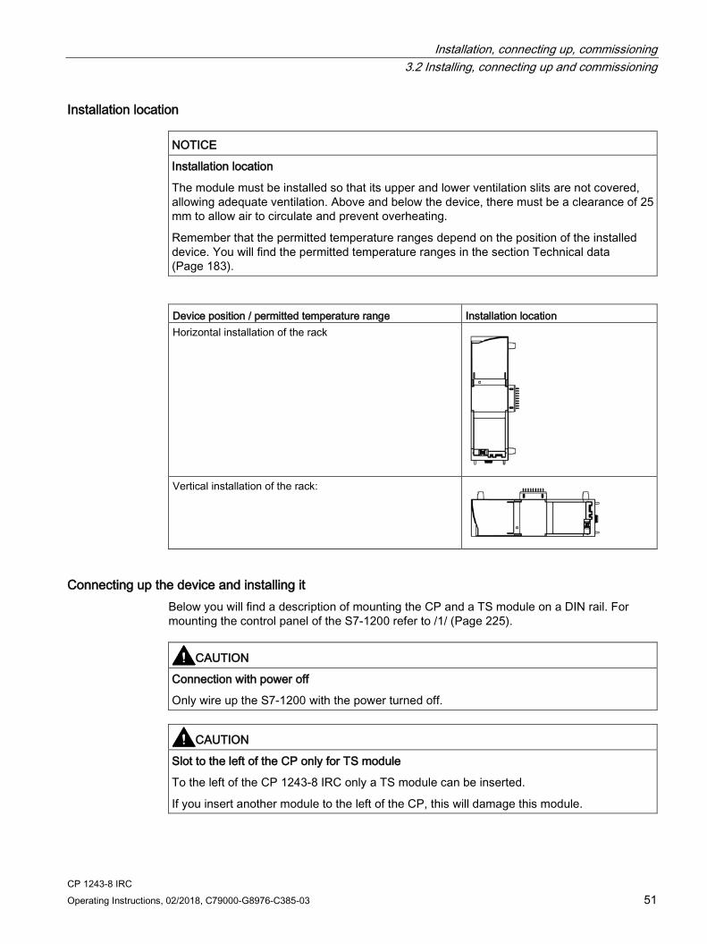
Installation, connecting up, commissioning 3.2 Installing, connecting up and commissioning
CP 1243-8 IRC Operating Instructions, 02/2018, C79000-G8976-C385-03 51
Installation location
NOTICE
Installation location
The module must be installed so that its upper and lower ventilation slits are not covered, allowing adequate ventilation. Above and below the device, there must be a clearance of 25 mm to allow air to circulate and prevent overheating.
Remember that the permitted temperature ranges depend on the position of the installed device. You will find the permitted temperature ranges in the section Technical data (Page 183).
Device position / permitted temperature range Installation location Horizontal installation of the rack
Vertical installation of the rack:
Connecting up the device and installing it Below you will find a description of mounting the CP and a TS module on a DIN rail. For mounting the control panel of the S7-1200 refer to /1/ (Page 225).
CAUTION
Connection with power off
Only wire up the S7-1200 with the power turned off.
CAUTION
Slot to the left of the CP only for TS module
To the left of the CP 1243-8 IRC only a TS module can be inserted.
If you insert another module to the left of the CP, this will damage this module.

Installation, connecting up, commissioning 3.2 Installing, connecting up and commissioning
CP 1243-8 IRC 52 Operating Instructions, 02/2018, C79000-G8976-C385-03
CAUTION
Ground the connecting cable of a TS module separately
Connect the connecting cable of a TS module to the periphery (e.g. modem) separately to functional ground.
Note Prior to mounting a TS module
For information on mounting a TS module, also read the appropriate sections in the device manual, see /4/ (Page 226).
Note Power supply from the power outputs of the CPU
The external power supply of the CP must be supplied via the power outputs of the CPU for the sensor supply.
Keep within the maximum load of the power output of the CPU, see /1/ (Page 225).
You will find data relating to the current consumption and power loss of the CP in the section Technical data (Page 183).
Note Turning off the station when plugging/pulling the CP
Do not only turn off the power supply to the CP. Always turn off the power supply for the entire station.

Installation, connecting up, commissioning 3.2 Installing, connecting up and commissioning
CP 1243-8 IRC Operating Instructions, 02/2018, C79000-G8976-C385-03 53
Table 3- 2 Procedure for installation and connecting up
Step What to do Notes and explanations 1 Secure the DIN rail. 2 Remove the cover on the left-hand side of the
CPU. 1. Insert the tip of a slotted screwdriver in the
gap above the cover. 2. Lever the cover carefully from its holder.
Recommendation: Store the covers in a safe place for possible later use.
When using a TS module: Remove the cover on the left-hand side of the CP as described above.
3 Connect the CPU and CP and - if used - the TS module. Push to modules carefully together until the side contacts are completely closed between the two modules.
Permitted slots: • CPU: Right: • CP: In the middle (to the left of the CPU)
For the CP only one slot to the left beside the CPU is per-mitted. Only one CP 1243-8 can be inserted.
• TS module: Left (to the left of the CP)
To the left of the CP 1243-8 IRC only a TS module can be inserted.
4 Connecting the power supply • Secure the power supply wires to the
power output of the CPU. • Secure the wires of the power supply to
the plug supplied with the CP and insert the plug in the socket on the top of the CP.
The pinning of the power output of the CPU is printed on the terminal on the top of the housing of the CPU, see /1/ (Page 225). The pinning of the power input of the CP is printed on the top of the housing of the CP beside the socket. You will also find this in the section Pin assignment of the socket for the external power supply (Page 184).
5 Connect the data cable to the CP: • The Ethernet-cable when using Ethernet-
based communication. • The relevant cable when using a TS mod-
ule.
You will find the pinout of the interface in the section Pinout of the Ethernet interface (Page 185).
6 Close the front covers of the modules. 7 If the DIN rail clamps on the rear of the mod-
ules have been pulled out, push in all the DIN rail clamps so that they are locked in place.
8 Place the connected modules on the DIN rail. Use a 35 mm DIN rail. 9 Press the connected modules onto the DIN
rail until the lower DIN rail clamps have locked in place.
Note If you install devices vertically in an environment with vibration or if you use a TS module GSM, mount end retainers (8WA1 808) on the rail to ensure that the devices remain con-nected together.
10 Turn on the power supply.

Installation, connecting up, commissioning 3.3 Note on operation
CP 1243-8 IRC 54 Operating Instructions, 02/2018, C79000-G8976-C385-03
Commissioning the module The remaining steps in commissioning involve downloading the STEP 7 project data. One requirement for the full commissioning of the module is the completeness of the STEP 7 project data, see Configuration (Page 55).
The STEP 7 project data of the CP is transferred when you load to the station. To load the station, connect the engineering station on which the project data is located to the Ethernet interface of the CPU.
You will find more detailed information on loading in the following sections of the STEP 7 information system:
● “Loading project data"
● “Using online and diagnostics functions"
Dismantling
WARNING
Keep to the order when dismantling
Remove the plugs of the data cable from the TS module and from the CP before you remove the power plug from the CP and therefore disconnect the ground connection of the devices.
1. Pull down the two lower DIN rail clamps on the rear of the devices with a slotted screwdriver.
This releases the locking mechanism.
2. Swing the devices out of the DIN rail profile to the front.
Note Time synchronization for telecontrol via SINEMA RC
When using SINEMA Remote Connect for telecontrol communication, set the CPU time manually during commissioning; see note in section Telecontrol via SINEMA RC (Page 68).
3.3 Note on operation
NOTICE
Closing the front panels
To ensure interference-free operation, keep the front panels of the module closed during operation.

CP 1243-8 IRC Operating Instructions, 02/2018, C79000-G8976-C385-03 55
Configuration 4 4.1 Security recommendations
Observe the following security recommendations to prevent unauthorized access to the system.
General ● You should make regular checks to make sure that the device meets these
recommendations and other internal security guidelines if applicable.
● Evaluate your plant as a whole in terms of security. Use a cell protection concept with suitable products.
● Do not connect the device directly to the Internet. Operate the device within a protected network area.
● Keep the firmware up to date. Check regularly for security updates of the firmware and use them.
● Check regularly for new features on the Siemens Internet pages.
– You can find information on Industrial Security here: Link: (http://www.siemens.com/industrialsecurity)
– You can find information on security in industrial communication here: Link: (http://w3.siemens.com/mcms/industrial-communication/en/ie/industrial-ethernet-security/Seiten/industrial-security.aspx)
– You can find a publication on the topic of network security (6ZB5530-1AP02-0BA5) here: Link: (http://w3app.siemens.com/mcms/infocenter/content/en/Pages/order_form.aspx?nodeKey=key_518693&infotype=brochures) Enter the following filter: 6ZB5530
Physical access Restrict physical access to the device to qualified personnel.
Network attachment Do not connect the PC directly to the Internet. If a connection of the CP to the Internet is required, use the security variants of the telecontol protocols or use protection mechanisms in front of the CP. Protection mechanisms are for example a SCALANCE M router or a SCALANCE S security module with firewall.
Configuration 4.1 Security recommendations
CP 1243-8 IRC 56 Operating Instructions, 02/2018, C79000-G8976-C385-03
Security functions of the product Use the options for security settings in the configuration of the product. These includes among others:
● Protection levels
Configure a protection level of the CPU.
You will find information on this in the information system of STEP 7.
● Security function of the communication
– Using the security functions of the telecontrol protocols.
– Use the secure protocol variants for example NTP (secure) or SNMPv3.
– Leave access to the Web server deactivated.
Passwords ● Define rules for the use of devices and assignment of passwords.
● Regularly update the passwords to increase security.
● Only use passwords with a high password strength. Avoid weak passwords for example "password1", "123456789" or similar.
● Make sure that all passwords are protected and inaccessible to unauthorized personnel.
See also the preceding section for information on this.
● Do not use one password for different users and systems.
Protocols
Secure and non-secure protocols
● Only activate protocols that you require to use the system.
● Use secure protocols when access to the device is not prevented by physical protection measures.
The NTP protocol provides a secure alternative with NTP (secure).
The HTTP protocol provides a secure alternative with HTTPS when accessing the Web server.
Table: Meaning of the column titles and entries
The following table provides you with an overview of the open ports on this device.
● Protocol / function
Protocols that the device supports.
● Port number (protocol)
Port number assigned to the protocol.
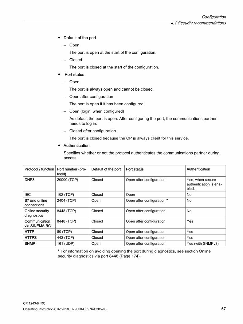
Configuration 4.1 Security recommendations
CP 1243-8 IRC Operating Instructions, 02/2018, C79000-G8976-C385-03 57
● Default of the port
– Open
The port is open at the start of the configuration.
– Closed
The port is closed at the start of the configuration.
● Port status
– Open
The port is always open and cannot be closed.
– Open after configuration
The port is open if it has been configured.
– Open (login, when configured)
As default the port is open. After configuring the port, the communications partner needs to log in.
– Closed after configuration
The port is closed because the CP is always client for this service.
● Authentication
Specifies whether or not the protocol authenticates the communications partner during access.
Protocol / function Port number (pro-
tocol) Default of the port Port status Authentication
DNP3 20000 (TCP) Closed Open after configuration Yes, when secure authentication is ena-bled.
IEC 102 (TCP) Closed Open No S7 and online connections
2404 (TCP) Open Open after configuration * No
Online security diagnostics
8448 (TCP) Closed Open after configuration No
Communication via SINEMA RC
8448 (TCP) Closed Open after configuration Yes
HTTP 80 (TCP) Closed Open after configuration Yes HTTPS 443 (TCP) Closed Open after configuration Yes SNMP 161 (UDP) Open Open after configuration Yes (with SNMPv3)
* For information on avoiding opening the port during diagnostics, see section Online security diagnostics via port 8448 (Page 174).
Configuration 4.2 Required STEP 7 products
CP 1243-8 IRC 58 Operating Instructions, 02/2018, C79000-G8976-C385-03
Ports of communications partners and routers Make sure that you enable the required client ports in the corresponding firewall on the communications partners and in intermediary routers.
These can be:
● MSC / 26382 (TCP) - configurable with a central interface: 1024 .. 65535
● NTP / 123 (UDP)
● DNS / 53 (UDP)
● SINEMA RC and OpenVPN / 1194 (UDP) - can be set
● SINEMA RC autoconfiguration / 443 (TCP) - can be set in SINEMA RC
4.2 Required STEP 7 products
Configuration in STEP 7 You will find the required STEP 7 products and versions in the section Requirements for operation (Page 23).
CP for new systems
You require the following for the configuration:
STEP 7 Basic
You perform the entire configuration in STEP 7 Basic or STEP 7 Professional.
You will find the description of the procedure as of the section Configuration in STEP 7 Basic (Page 66).
CP as replacement TIM 3V-IE Advanced
You configure the CP in the following configuration tools one after the other.
You require the following for the configuration:
● STEP 7 V5
– Configuration of a proxy for the CP (PROXY CP1243-8 IRC) in an S7-300 station
– Configuration of the connected WAN networks and connections in the SINAUT engineering software
Note
Configuration of connections
Remember to create the connections to be used by the CP in the STEP 7 V5 project.
– Exporting the configuration data
You will find the description of the procedure in the section STEP 7 V5 configuration of the proxy (Page 215).
Configuration 4.3 Overview: Connection to LAN / WAN
CP 1243-8 IRC Operating Instructions, 02/2018, C79000-G8976-C385-03 59
● STEP 7 Basic
– Importing the configuration data from STEP 7 V5
– Configuration of further parameters of the CP, its data points and messages to be sent
– Downloading the project data from the engineering station to the S7 station
You will find the description of the procedure as of the section Configuration in STEP 7 Basic (Page 66).
4.3 Overview: Connection to LAN / WAN
Supported network types The CP makes telecontrol communication possible for the various telecontrol protocols via the network types listed below.
Connection via the Ethernet interface of the CP:
● IP-based communication via the Ethernet interface
Supported protocols: ST7, DNP3, IEC
– Industrial Ethernet
Communication in the LAN (copper / fiber-optic cable)
– Internet
Communication via the Internet
– IP-based wireless network
Communication via IP-based wireless networks
● Classic WAN communication via the serial interface
Supported protocols: ST7
With communication via the network types listed below, in addition to the CP a TS module, modem or router must be used.
– Dedicated line (incl. analog wireless network)
Communication via dedicated lines or analog wireless networks
– Analog dial-up network
Communication via the analog dial-up network
– ISDN network
Communication via the ISDN network
– Mobile wireless network
IP-based communication via mobile wireless networks (GSM/GPRS, UMTS, LTE)
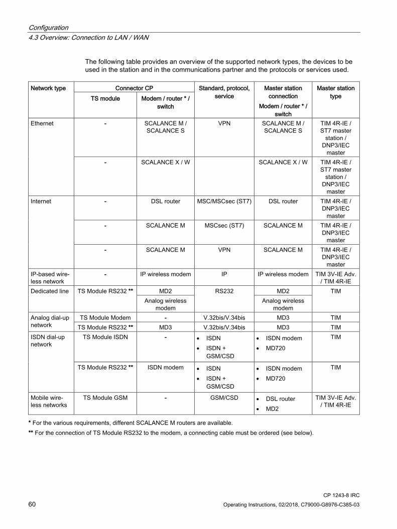
Configuration 4.3 Overview: Connection to LAN / WAN
CP 1243-8 IRC 60 Operating Instructions, 02/2018, C79000-G8976-C385-03
The following table provides an overview of the supported network types, the devices to be used in the station and in the communications partner and the protocols or services used.
Network type Connector CP Standard, protocol,
service Master station
connection Modem / router * /
switch
Master station type TS module Modem / router * /
switch
Ethernet - SCALANCE M / SCALANCE S
VPN SCALANCE M / SCALANCE S
TIM 4R-IE / ST7 master
station / DNP3/IEC
master - SCALANCE X / W SCALANCE X / W TIM 4R-IE /
ST7 master station /
DNP3/IEC master
Internet - DSL router MSC/MSCsec (ST7) DSL router TIM 4R-IE / DNP3/IEC
master - SCALANCE M MSCsec (ST7) SCALANCE M TIM 4R-IE /
DNP3/IEC master
- SCALANCE M VPN SCALANCE M TIM 4R-IE / DNP3/IEC
master IP-based wire-less network
- IP wireless modem IP IP wireless modem TIM 3V-IE Adv. / TIM 4R-IE
Dedicated line TS Module RS232 ** MD2 RS232 MD2 TIM Analog wireless
modem Analog wireless
modem Analog dial-up network
TS Module Modem - V.32bis/V.34bis MD3 TIM TS Module RS232 ** MD3 V.32bis/V.34bis MD3 TIM
ISDN dial-up network
TS Module ISDN - • ISDN • ISDN +
GSM/CSD
• ISDN modem • MD720
TIM
TS Module RS232 ** ISDN modem • ISDN • ISDN +
GSM/CSD
• ISDN modem • MD720
TIM
Mobile wire-less networks
TS Module GSM - GSM/CSD • DSL router • MD2
TIM 3V-IE Adv. / TIM 4R-IE
* For the various requirements, different SCALANCE M routers are available. ** For the connection of TS Module RS232 to the modem, a connecting cable must be ordered (see below).

Configuration 4.4 Basic communication mechanisms
CP 1243-8 IRC Operating Instructions, 02/2018, C79000-G8976-C385-03 61
You will find information on the accessories in the following sections or literature sections:
● TS modules: TS modules (Page 193), /4/ (Page 226)
● Modems and routers: Modems and routers (Page 202)
– Modems: /5/ (Page 226), /6/ (Page 226), /7/ (Page 227), /8/ (Page 227)
– SCALANCE M812/M816: /9/ (Page 227)
– SCALANCE M874/M876: /10/ (Page 227)
● SCALANCE S: /12/ (Page 228)
● Connecting cables between TS Module RS232 and modems: Connecting cables for connecting the modem of the TS Module RS232 (Page 210)
4.4 Basic communication mechanisms
4.4.1 Addressing, authentication, connections (single / redundant)
4.4.1.1 ST7
The ST7 protocol
Network types
ST7 is a protocol for telecontrol communication via WANs (Wide Area Network).
With ST7 it is possible to communicate via the following network types:
● Classic WAN networks
● IP-based WAN networks
Subscriber types
The following subscriber types that support the ST7 protocol are possible communications partners:
● SIMATIC stations with TIM modules or a CP capable of ST7
● Control center applications capable of ST7
Connections
Communication with the ST7 protocol runs via configurable connections. You make the required settings in the STEP 7 configuration.

Configuration 4.4 Basic communication mechanisms
CP 1243-8 IRC 62 Operating Instructions, 02/2018, C79000-G8976-C385-03
Communication via single or redundant telecontrol connections The ST7 communication between two subscribers runs via configurable paths. To do this, telecontrol connections are created in the "Network data" editor in the "Telecontrol" tab, see section Creating telecontrol connections for the ST7 communication (Page 122).
When different networks between two subscribers have been created in the network configuration, you can create redundant telecontrol connections. In the configuration these are displayed in the "Network data" editor. There the main and the substitute path are specified.
To check the reachability of a communications partner of the module, you can write the connection status to "PLC tags for partner status / path status", see section Partner status / path status (Page 97).
For redundant telecontrol connections, the behavior is as follows:
● Main path
If the connection between the two subscribers is undisturbed, the main path is always used.
The status of the main path is rechecked each time there is communication and saved in the PLC tag.
● Substitute path
If the connection via the main path is disturbed, communication is switched to the substitute path.
The status of the substitute path, on the other hand, is only registered when communication is established.
If you configure a dialup network connection as the substitute path via which generally a connection is seldom established, you can test the reachability via this path for example by synchronizing the time of day once daily via this path. To do this a connection must be established once daily via the dialup network. The reachability is then updated once daily in the PLC tag.
Addressing communications partners and network nodes Since the communication between two ST7 subscribers can run via different paths and subnets, precise addressing of the individual subscribers in the ST7 network is necessary. The following two parameters serve this purpose:
● Subscriber number
The subscriber number is unique for every subscriber in a STEP 7 project. The following subscribers require a subscriber number:
– TIM
Communication module for the ST7 protocol
– CP 1243-8 IRC, CP 1542SP-1 IRC
Communication module for the ST7 protocol

Configuration 4.4 Basic communication mechanisms
CP 1243-8 IRC Operating Instructions, 02/2018, C79000-G8976-C385-03 63
– CPU
The local CPU that is assigned to the communication module receives a subscriber number as the end point of an ST7 connection.
With a CP and a classic TIM in the S7-300 rack, the CPU is assigned automatically to the communication module via the rack.
With the TIM 1531 IRC and a TIM 4R-IE Stand-alone, you must assign the local CPU manually.
– Application of the master station PC
The application that you configure in the PC station of the master station.
For the TIM and the assigned CPU, the subscriber number is configured in the "Subscriber numbers" parameter group of the TIM.
For the application of the master station PC, the subscriber number is configured in the telecontrol connection: "Network data" editor > "Telecontrol" tab
● WAN address
For every networked serial interface in a classic ST7 network a WAN address is assigned. It is unique in the respective WAN network.
Since telecontrol connections can run via several network nodes and node stations, unique addressing of the interfaces involved is necessary.
The WAN address is configured in the parameter group "WAN parameters" of the serial interface.
Authentication in ST7 The addressing data "Subscriber number" and "WAN address" are transferred encrypted by the security functions during communication.
The MSC protocols support authentication of the communications partners with user name and password. The data is also transferred encrypted.
4.4.1.2 DNP3 / IEC To configure and commission the CP, the following information is required:
Address information of the master The following information of the master is required for the configuration of the CP:
● Station address of the master
– (DNP3: ASDU address)
– (IEC: Address of the information object)

Configuration 4.4 Basic communication mechanisms
CP 1243-8 IRC 64 Operating Instructions, 02/2018, C79000-G8976-C385-03
● Address of the master
– IP address
or
– Name that can be resolved with DNS
If you use DNS, there must be a DNS server (see below) and this must be reachable for the CP.
● Port number of the listener port of the master
● DNS server address(es)
You require the DNS server address if you address the master using a name that can be resolved by DNS.
Redundant DNP3 or IEC master The two devices of a redundant master have an identical station address with both protocols.
They only require different IP addresses or host names.
Configurations with connections over the Internet: VPN connections For connections running via the Internet, dynamic IP addresses can be used.
To allow communication in both directions and to ensure that the data is protected during transfer, a connection with a VPN tunnel is necessary. For this the security modules of the SCALANCE S or SCALANCE M series are available.
Remember the following points when configuring:
● You configure the master IP address as normal.
● When configuring the CP interface, configure the IP address of the router.
● You create the VPN configuration with SCALANCE S/M both for the station end and for the control center end in STEP 7.
4.4.2 Connection establishment
Connection establishment with telecontrol communication With telecontrol communication the CP always establishes a connection.
DNP3 / IEC
With the DNP3 and IEC protocols, connection establishment by the CP is instigated by the master (polling).
With the DNP3 protocol by configuring the Transmission mode "Spontaneous" in the parameter group "Transmission settings" of the Ethernet interface the unsolicited transfer of data by the CP can be released.
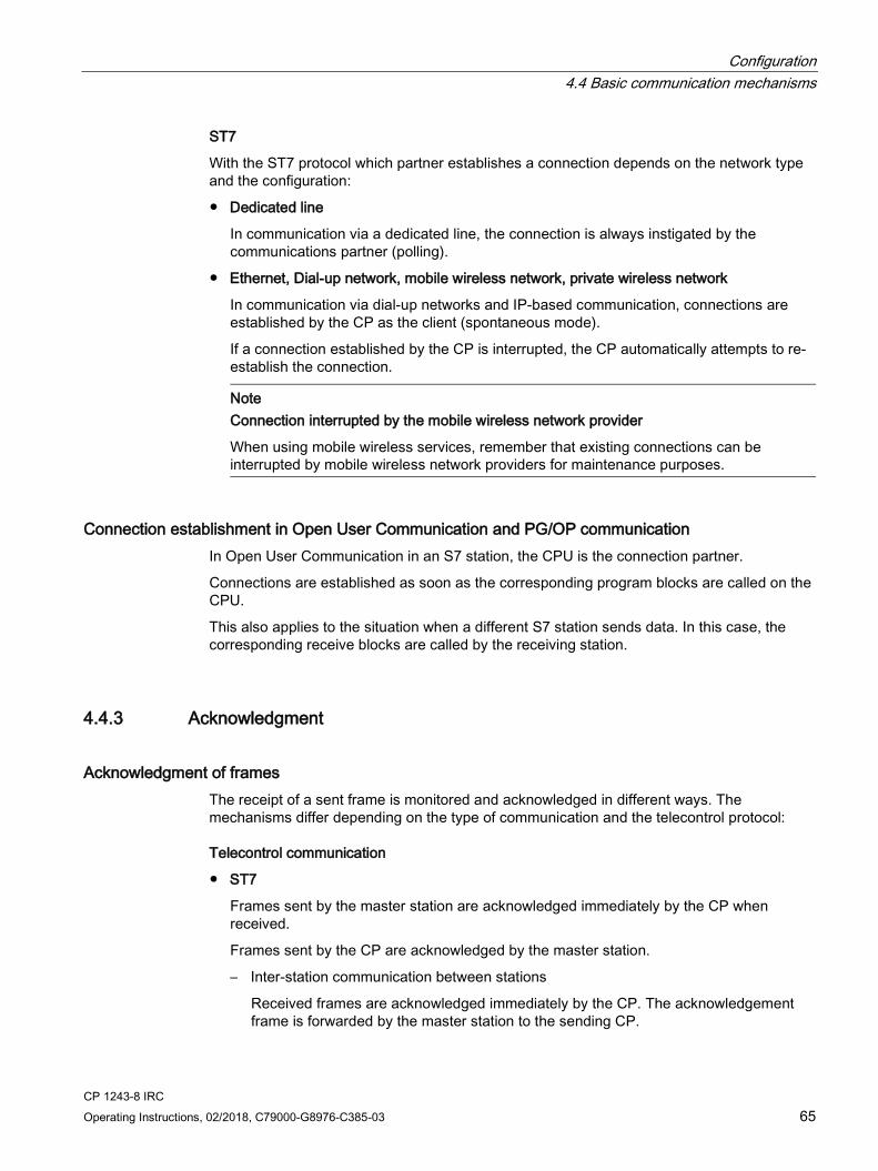
Configuration 4.4 Basic communication mechanisms
CP 1243-8 IRC Operating Instructions, 02/2018, C79000-G8976-C385-03 65
ST7
With the ST7 protocol which partner establishes a connection depends on the network type and the configuration:
● Dedicated line
In communication via a dedicated line, the connection is always instigated by the communications partner (polling).
● Ethernet, Dial-up network, mobile wireless network, private wireless network
In communication via dial-up networks and IP-based communication, connections are established by the CP as the client (spontaneous mode).
If a connection established by the CP is interrupted, the CP automatically attempts to re-establish the connection.
Note
Connection interrupted by the mobile wireless network provider
When using mobile wireless services, remember that existing connections can be interrupted by mobile wireless network providers for maintenance purposes.
Connection establishment in Open User Communication and PG/OP communication In Open User Communication in an S7 station, the CPU is the connection partner.
Connections are established as soon as the corresponding program blocks are called on the CPU.
This also applies to the situation when a different S7 station sends data. In this case, the corresponding receive blocks are called by the receiving station.
4.4.3 Acknowledgment
Acknowledgment of frames The receipt of a sent frame is monitored and acknowledged in different ways. The mechanisms differ depending on the type of communication and the telecontrol protocol:
Telecontrol communication
● ST7
Frames sent by the master station are acknowledged immediately by the CP when received.
Frames sent by the CP are acknowledged by the master station.
– Inter-station communication between stations
Received frames are acknowledged immediately by the CP. The acknowledgement frame is forwarded by the master station to the sending CP.

Configuration 4.5 Configuration in STEP 7 Basic
CP 1243-8 IRC 66 Operating Instructions, 02/2018, C79000-G8976-C385-03
● DNP3
The CP acknowledges a request of the master with its reply frames.
The acknowledgment of frames that the CP sends to the master is configured with the parameters "Connection confirmation" and "Monitoring time for unsolicited frames", see section Transmission settings – DNP3 (Page 75).
● IEC
The CP acknowledges a request of the master with its reply frames.
The acknowledgment of frames that the CP sends to the master is configured with the parameters "Send sequence number" and "Receive sequence number", see section Transmission settings - IEC (Page 77).
Open User Communication
The successful sending and receipt of frames is indicated by status displays of the program blocks.
With TCP segments, the protocol-specific acknowledgement mechanisms are used.
4.5 Configuration in STEP 7 Basic
Requirement The complete configuration of the CP in STEP 7 Basic is only possible after configuring in STEP 7 V5 (see above).
Overview of configuration in STEP 7 Basic Follow the steps below when configuring:
1. Create a STEP 7 project.
2. Insert the S7-1200 CPU for the SIMATIC station.
3. Create the PLC tags required for the data points in the CPU, see also point 7.
4. Select the CP 1243-8 in the catalog and set the firmware version of the CP in the catalog using the "Version" drop-down list.
– To use the CP with the functions of a TIM 3V-IE Advanced in a SINAUT ST7 system, select version V2.1.
– In all other cases, select a version with V3.0 or higher.
5. Insert the CP selected in the catalog into the stations.
6. Importing configuration data from STEP 7 V5:
The function is supported only for the CP with firmware version V2.1. If you are using the CP with firmware version V3, continue at step 7.
If you are using the CP with the functions of a TIM 3V-IE Advanced for a SINAUT ST7 system, in the parameter group "Partners" import the configuration data of the TIM from

Configuration 4.6 Communication types
CP 1243-8 IRC Operating Instructions, 02/2018, C79000-G8976-C385-03 67
the STEP 7 V5 project. You will find the import described in section Importing configuration data (ST7) (Page 90).
After importing from STEP 7 V5, the configuration of the WAN interface is neither possible nor necessary.
7. Create and Ethernet network, connect the network to the CP and its connection partner and configure the interface and network parameters.
For the CP with firmware V2.1 further configuration of the Ethernet interface is not necessary.
8. To use the serial interface of the CP with firmware version V3, insert a TS module.
Without a configured TS module, the serial interface will not be displayed. For information on this, refer to section Configuring a TS module (Page 80).
For the CP with firmware V2.1 configuration of a TS module is neither possible nor necessary.
9. Configure the further parameters of the CP, the required telecontrol connections for ST7 communication and the data points of the CP.
– You will find information on the security functions in the section Security (Page 104) and in /11/ (Page 227).
– For information on the telecontrol connections, refer to the section Creating telecontrol connections for the ST7 communication (Page 122).
For the CP with firmware V2.1 configuration of telecontrol connections is neither possible nor necessary.
– You will find information on the data points in the section Data point configuration (Page 128).
10.Download the project data to the station.
When you load the station, the project data of the station including the configuration data of the CP is stored on the CPU.
You will find further information on configuration and downloading in the STEP 7 information system.
4.6 Communication types
"Communication types" parameter group In this parameter group, you enable the communication type of the CP.
To minimize the risk of unauthorized access to the station, you need to enable the communications services that the CP will execute individually. You can enable all options but at least one option should be enabled.

Configuration 4.7 Telecontrol via SINEMA RC
CP 1243-8 IRC 68 Operating Instructions, 02/2018, C79000-G8976-C385-03
● Enable telecontrol communication
Enables telecontrol communication on the CP.
– ST7
– DNP3
– IEC 60870-5
Note: To use the ST7 protocol the Security functions must also be enabled.
For telecontrol communication via SINEMA Remote Connect see the section Telecontrol via SINEMA RC (Page 68).
● Activate online functions
Enables access to the CPU for the online functions via the CP (diagnostics, loading project data etc.). If the function is enabled, the engineering station can access the CPU via the CP.
If the option is disabled, you have no access to the CPU via the CP with the online functions. Online diagnostics of the CPU with a direct connection to the interface of the CPU however remains possible.
● Enabling S7 communication
Enables the functions of S7 communication with a SIMATIC S7 on the CP.
If you configure S7 connections to the relevant station, and these run via the CP, you will need to enable this option on the CP.
Open User Communication
Open User Communication does not need to be enabled since you then need to create the relevant program blocks. Unintended access to the CP is therefore not possible.
4.7 Telecontrol via SINEMA RC For information on possible applications of communication via SINEMA Remote Connect, see section Connection to SINEMA RC (Page 17).
Requirements Configure the SINEMA Remote Connect - Server before configuring the CP (not in STEP 7). The CP and the communication partner of the CP must be configured in the SINEMA RC Server.
Supported telecontrol protocols The following protocols support communication via SINEMA Remote Connect:
● TeleControl Basic
● DNP3
● IEC 60870-5-104

Configuration 4.7 Telecontrol via SINEMA RC
CP 1243-8 IRC Operating Instructions, 02/2018, C79000-G8976-C385-03 69
Configuration of the telecontrol communication via SINEMA Remote Connect Follow the steps below when configuring the CP for use of telecontrol communication via SINEMA RC:
1. In the "Communication types" parameter group activate telecontrol communication and select the protocol.
The option for communication via SINEMA RC is not yet visible.
2. Change to the "Security" parameter group and enable the security functions.
(In the "Communication types" parameter group the SINEMA RC option appears disabled and grayed out)
3. Open the "Security > VPN" parameter group and enable VPN.
4. For the parameter "VPN connection type" select the option "Automatic OpenVPN configuration via SINEMA Remote Connect Server" if this is not preset.
(In the "Communication types" parameter group the SINEMA RC option becomes usable.)
5. Change to the "Communication types" parameter group and enable the option "Telecontrol communication via SINEMA Remote Connect".
6. Create the remaining configuration of the SINEMA RC connection of the CP under "Security > VPN".
For information on the configuration, see section SINEMA Remote Connect (Page 116).
Manual setting the time of day during commissioning
Note Time synchronization for telecontrol via SINEMA RC
When using SINEMA Remote Connect for telecontrol communication, the communication module needs the current time for authentication on the SINEMA RC Server. The module receives the time from the CPU or from an NTP server before the connection is established for the first time. Recommendation:
During commissioning, set the time of the CPU manually at least once using the STEP 7 online functions. This is necessary especially if you have configured the "Time from partner" option for the time synchronization. In this way, you ensure that the CPU has a valid time of day when the station starts up and that the CP can exchange the required certificates with the SINEMA RC Server.
Configuration 4.8 Ethernet interface
CP 1243-8 IRC 70 Operating Instructions, 02/2018, C79000-G8976-C385-03
4.8 Ethernet interface
4.8.1 WAN settings
WAN parameters The parameter group is available only when ST7 communication is enabled.
In this parameter group of the interfaces you will find parameters that decide the properties of the connected WAN network:
You will also find the parameter group with the serial interface, see section Serial interface (Page 79).
● WAN type
Selection of the WAN type of the interface:
– IP-based
Default setting of the Ethernet interface
– Classic WAN
Default setting of the serial interface
To use MSC via GPRS, the serial interface can be changed to "IP-based".
● Network type
For classic WAN:
– Dedicated line
– Dialup network
For IP-based WAN:
– Neutral
– Mobile wireless with VPN
– MSC
● Network node type
Network node type of the interface:
– Master station
Not relevant for the CP
– Node station
Note on modules whose interfaces function as a node station: Both interfaces - in the direction of the master station and in the direction of the underlying subnet - must be configured as "Node station".
– Station

Configuration 4.8 Ethernet interface
CP 1243-8 IRC Operating Instructions, 02/2018, C79000-G8976-C385-03 71
With the classic network types dedicated line and dialup network, a modem needs to be connected to the serial interface. You select the suitable modem type using the following parameters (serial interface only):
● Modem type
– MD2
Dedicated line modem (network type "Dedicated line")
– MD3
Modem for analog dialup networks (network type "Dialup network")
– MD4
ISDN modem (network type "Dialup network")
– MD720
Siemens-GSM modem MD720 (network type "Dialup network")
– Third party modem
Any compatible modem for the network types "Dedicated line" or "Dialup network" (analog / ISDN)
If you configure "Dialup network" and want to transmit via mobile wireless, you need to select "MD720" as the modem type.
4.8.2 CP identification The parameter group is available only when DNP3 or IEC communication is enabled.
CP addressing The parameter group is used for addressing and identification of the CP in the network.
● DNP3
The station address is the ASDU address.
Entry of the station address (digits only). Permitted range of values: 1...65519.
● IEC
The station address is the "common address of the ASDU" or the address of the information object.
Entry of the station address (digits only). Permitted range of values: 1...65534.
Configuration 4.8 Ethernet interface
CP 1243-8 IRC 72 Operating Instructions, 02/2018, C79000-G8976-C385-03
4.8.3 Time-of-day synchronization
Time-of-day synchronization For the configuration of the time-of-day synchronization read the section Time-of-day synchronization (Page 100).
4.8.4 Ethernet addresses
Ethernet addresses In the following parameter groups you network the Ethernet interface and configure the IP address parameters.
The networking of the serial interface is described in the following section: WAN parameters (networking the CP) (Page 82)
You will find information on configuration in the STEP 7 information system.
Advanced options > Port [Xn P1] You will find information on configuration in the STEP 7 information system.
4.8.5 Advanced options
4.8.5.1 MSC protocol settings The parameter group is available only when using the ST7 protocol and when MSC communication is enabled.
You configure the user name and password for the authentication with the MSC protocol in the security functions.
MSC master station The description applies to the parameter group of an Ethernet interface with the Network node type "Master station". The parameter group is disabled for the CP.
Access to the MSC master station
First set whether the MSC master station or the router should be reachable with DNS via a fixed or a dynamic IP address.
The MSC master station is connected to the Internet via a router.

Configuration 4.8 Ethernet interface
CP 1243-8 IRC Operating Instructions, 02/2018, C79000-G8976-C385-03 73
If the router can be reached via a dynamic IP address, there must be at least a reachable DNS server in the network.
● MSC port of the router
The port number is preset. If necessary, you can change the port number. Note that the port number of both partners must be identical. The port number cannot be configured for the station.
Default setting: 26382. Permitted range: 1024...65535
● Host name
If the router should be reachable using the host name enter it here.
● IP address DNS server
Here, enter the addresses of the DNS servers in the subnet.
MSC monitoring settings The description applies to the parameter group of an Ethernet interface with the Network node type "Master station". The parameter group is disabled for the CP.
● MSC monitoring time
Monitoring time (minutes) for the MSC connection
– Behavior of the master station:
If there is no data traffic between the MSC master and station within the monitoring time, the MSC master sends a sign of life frame to the station.
– Behavior of the master station:
If no sign of life message comes from the MSC master within the monitoring time, the station sets all subscribers reachable via MSC as disrupted.
Default setting: 10. Permitted range: 0...65535
If you enter 0 (zero), the function is disabled.
● Collect data volume
If the option is enabled, the MSC master passes the monthly transferred data volume of the stations to online diagnostics.
MSCsec protocol The parameter group is only active when the setting of the Network node type of the interface is "Station" or "Node station".
● Activate security protocol MSCsec
If the option is enabled, the secure version of the MSC protocol "MSCsec" is used.
● Key exchange interval
Time (h) after which the secret key is renewed between the MSC station and master station.
Default setting: 0. Permitted range: 0...255

Configuration 4.8 Ethernet interface
CP 1243-8 IRC 74 Operating Instructions, 02/2018, C79000-G8976-C385-03
4.8.5.2 TCP connection monitoring
TCP connection monitoring The settings made here apply globally to all configured TCP connections of the CP.
With DNP3: Note the option of overwriting the values configured here for individual communications partners, refer to the section Partners (DNP3 / IEC) (Page 91).
● TCP connection monitoring time
Function: If there is no data traffic within the TCP connection monitoring time, the CP sends a keepalive frame to the communications partner.
Default setting: 180 s. Permitted range: 1...65535 s.
– The parameter below the Ethernet interface
The monitoring time is configured for the Ethernet interface globally for all TCP connections. The parameter is preset to 180 seconds as default.
– The parameter below "Partner stations"
The parameter "TCP connection monitoring time" occurs again with the individual partners in the parameter group "Connection to partner". This parameter applies only to the individual partner. The value of 180 seconds preset on the Ethernet interface is adopted for the individual partners.
If for any reason you want to change the value of the TCP connection monitoring time for individual partners, you can adapt the value for every partner individually in "Partner stations". If. for example, you want to check the connection at shorter intervals, reduce the value.
● TCP keepalive monitoring time
After sending a keepalive frame, the CP expects a reply from the communications partner within the keepalive monitoring time. If the CP does not receive a reply within the configured time, it terminates the connection.
Default setting: 10 s. Permitted range: 1...65535 s.
– The parameter below the Ethernet interface
The monitoring time is configured for the Ethernet interface as a global setting for all TCP connections.
– The parameter below "Partner stations"
As with the TCP connection monitoring time, the value of "Partner stations" can be adapted for each partner individually.

Configuration 4.8 Ethernet interface
CP 1243-8 IRC Operating Instructions, 02/2018, C79000-G8976-C385-03 75
4.8.5.3 Transmission settings - ST7
Transmission settings ● Send conditional spontaneous frames as blocks
Indicates the form of transfer of data frames with the transmission mode "Conditional spontaneous".
– Option enabled
Several items of data are collected and only sent when a frame has reached maximum capacity.
– Option disabled
The data is sent spontaneously as individual frames.
The transfer mode (Spontaneous / Conditional spontaneous) of a frame is set in the "Trigger" tab of the data point.
● Max. allowed disruption time
Tolerance time (s) for a detected connection disruption.
If there is still a disruption on the connection when the set time has elapsed, the disruption is signaled to all accessible connection partners of the disrupted station.
Default setting: 0. Permitted range: 0...255. If you enter 0 (zero), the function is disabled.
4.8.5.4 Transmission settings – DNP3
Transmission settings – DNP3 ● Disturbance bit
The disturbance bit can be used as bit 1.6 (IIN1.6) of the "Internal Indication Bytes" to indicate to the master when the CPU is in STOP mode.
● Max. time between Select and Operate
Max. duration (seconds) between Select and Operate. For a Select command to be transferred to the CPU and to take effect, no other frame may be sent to the station between Select and Operate.
Permitted range: 1..65535
Default setting: 1
● Frame repetitions
Number of frame repetitions at the Data Link Layer if no acknowledgement is received from the master.
Permitted range: 0 ... 255
Default setting: 0
If you enter 0 (zero), the function is disabled.
Configuration 4.8 Ethernet interface
CP 1243-8 IRC 76 Operating Instructions, 02/2018, C79000-G8976-C385-03
● Connection confirmation
Condition for the CP to request a connection confirmation from the master (never, always, only with segmented frames).
● Connection monitoring time
Time (in seconds) within which an acknowledgement is expected from the master.
Permitted range: 0...65535
Default setting: 2
If you enter 0 (zero), the function is disabled.
● Transfer mode "Unsolicited"
Transfer mode for events
– Spontaneous
Event frames are transferred immediately.
– Conditional spontaneous
Event messages are only sent when spontaneous frames are sent or the partner establishes the connection.
● Max. number of unsolicited frames
Maximum number of repetitions of unsolicited frames if no acknowledgement is received from the communications partner .
Permitted range: 0...255
Default setting: 3
● Monitoring time for unsolicited frames
Time (in seconds) within which an acknowledgement of unsolicited frames is expected from the master.
Permitted range: 1...65535
Default setting: 5
● Buffer for class 1 / 2 / 3 events
Here, for each of the three event classes you specify the number of events after which the stored events are sent to the communications partner.
Permitted range: 1 ... 255.
● Delay time class 1 / 2 / 3 events
Here, for each of the three event classes you specify the maximum time in seconds the events can be stored in the send buffer before they are sent to the communications partner.
Permitted range: 0 ... 65535
If you enter 0 (zero), the function is disabled.
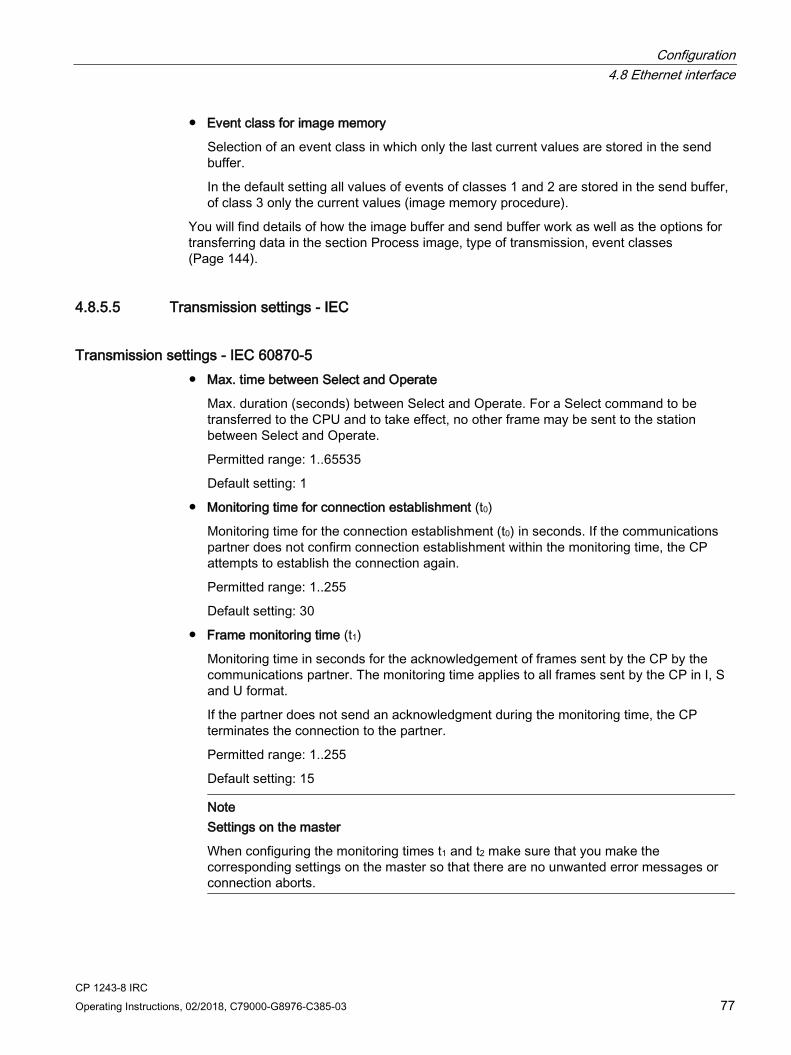
Configuration 4.8 Ethernet interface
CP 1243-8 IRC Operating Instructions, 02/2018, C79000-G8976-C385-03 77
● Event class for image memory
Selection of an event class in which only the last current values are stored in the send buffer.
In the default setting all values of events of classes 1 and 2 are stored in the send buffer, of class 3 only the current values (image memory procedure).
You will find details of how the image buffer and send buffer work as well as the options for transferring data in the section Process image, type of transmission, event classes (Page 144).
4.8.5.5 Transmission settings - IEC
Transmission settings - IEC 60870-5 ● Max. time between Select and Operate
Max. duration (seconds) between Select and Operate. For a Select command to be transferred to the CPU and to take effect, no other frame may be sent to the station between Select and Operate.
Permitted range: 1..65535
Default setting: 1
● Monitoring time for connection establishment (t0)
Monitoring time for the connection establishment (t0) in seconds. If the communications partner does not confirm connection establishment within the monitoring time, the CP attempts to establish the connection again.
Permitted range: 1..255
Default setting: 30
● Frame monitoring time (t1)
Monitoring time in seconds for the acknowledgement of frames sent by the CP by the communications partner. The monitoring time applies to all frames sent by the CP in I, S and U format.
If the partner does not send an acknowledgment during the monitoring time, the CP terminates the connection to the partner.
Permitted range: 1..255
Default setting: 15
Note Settings on the master
When configuring the monitoring times t1 and t2 make sure that you make the corresponding settings on the master so that there are no unwanted error messages or connection aborts.

Configuration 4.8 Ethernet interface
CP 1243-8 IRC 78 Operating Instructions, 02/2018, C79000-G8976-C385-03
● Monitoring time for S and U frames (t2)
Monitoring time in seconds for the acknowledgment of data frames of the master by the CP.
After receiving data from the master, the CP acknowledges the received data as follows:
– If the CP sends data to the master itself within t2, it acknowledges the data frames received from the master during t2 at the same time along with the sent data frame (I format).
– The CP sends an acknowledgment frame (S format) to the master of the latest when t2 elapses.
Permitted range: 1 ... 255
Default setting: 10
The value of t2 should be less than that of t1.
● Idle time for test frames (t3)
Monitoring time in seconds during which the CP has not received any frames from the master.
When t3 elapses, the CP sends a test/control frame (U format) to the master.
This parameter is intended for situations in which longer idle periods occur; in other words, times when there is no data traffic.
Permitted range: 1 ... 255
Default setting: 30
● Difference between send sequence number N(S) and receive sequence number N(R) (k)
The difference between the send sequence number and receive sequence number of a frame.
The master returns the send sequence number of a frame from the CP that the sending CP then saves as the receive sequence number. Frames whose send sequence number is lower than the receive sequence number after the difference configured here is added are evaluated as having been successfully transferred and are deleted from the send buffer of the CP.
Permitted range: 1 ... 64
Default setting: 12
● Max. number of unacknowledged data frames (w)
w: Maximum number of received data frames (I-APDUs), after which the oldest frame received from the master must be acknowledged.
Permitted range: 1..8
Default setting: 8
The value must be less than the value of "Difference between send and receive sequence number" (k).
Configuration 4.9 Serial interface
CP 1243-8 IRC Operating Instructions, 02/2018, C79000-G8976-C385-03 79
Acknowledgment mechanism for the IEC protocol With each sent data frame, the CP sends a continuous send sequence number. The data frame remains initially stored in the send buffer.
When it receives the data frame, the master sends the send sequence number from this or (if several frames are received) the last frame as an acknowledgement to the CP. The CP saves the send sequence number returned by the master as a receive sequence number and uses it as an acknowledgement.
Frames whose send sequence number is equal to or lower than the current receive sequence number are evaluated as having been successfully transferred and are deleted from the send buffer of the CP.
Recommendations of the specification:
● w should not be higher than 2/3 of k.
● Recommended value for k: 12
● Recommended value for w: 8
4.8.6 Access to the Web server
Access to the Web server of the CPU The Web server of the S7-1200 station is located in the CPU. Via the CP, you have access to the Web server of the CPU.
From a PC you can access the Web server of the station if the PC is connected to the system network via LAN.
You will find information on the Web server in the manual /1/ (Page 225).
4.9 Serial interface
4.9.1 Configuration of the serial interface The serial interface can only be used for communication using the ST7 protocol.
The physical connector for the serial interface is located on the left-hand side of the CP, see section Serial connection for TS module (Page 46).
For connection to the network you require a suitable TS module, refer to the appendix TS modules (Page 193).

Configuration 4.9 Serial interface
CP 1243-8 IRC 80 Operating Instructions, 02/2018, C79000-G8976-C385-03
Configuration of the serial interface You configure depending on the application or the firmware version of the CP.
● CP as replacement for TIM 3V-IE Advanced
Use a CP with firmware V2.1.
– You have exported the configuration data of the substitute for the CP (PROXY CP1243-8 IRC) from STEP 7 V5 as a text file with the SDB content.
– You import this text file in STEP 7 Basic in the parameter group Partner stations (Page 90).
● CP for new systems
Use a CP with firmware V3.
You configure the serial interface only in STEP 7 Basic, refer to the section below.
SMS If the CP is intended to use the sending of SMS messages, you need to activate the function:
● CP with firmware V2.1
Enable or disable the sending of SMS messages at this point and assign the number of the SMSC (Short Message Service Center).
● CP with firmware V3
You enable SMS and configure the SMSC in the parameter group SMSC (Page 103).
4.9.2 Configuring a TS module Configuration of the serial interface is only possible and necessary for the CP with a firmware version as of V3.
To be able to configure the serial interface, you must first insert the suitable TS module in STEP 7. Without a configured TS module, the serial interface is not displayed and the CP is only displayed with the green symbol for the Ethernet interface.
Inserting a TS module for the serial interface To insert a TS module in STEP 7, follow the steps outlined below:
1. Open the device view of the CP.
When the network view is open: Open the device view by double-clicking on the CP or by clicking on the work area "Device view".
2. Select the CP in the device view.
The CP is displayed with a blue frame.

Configuration 4.9 Serial interface
CP 1243-8 IRC Operating Instructions, 02/2018, C79000-G8976-C385-03 81
3. In the catalog open the following directory:
"Communications modules > Industrial Remote Communication > TS modules"
For information on selecting the suitable TS module, refer to the appendix The TS modules (Page 193).
4. Expand the directory of the required TS module and select the TS module.
A vertical blue line appears on the symbol of the CP.
5. Drag the TS module precisely onto the blue line of the CP.
The TS module is inserted beside the CP on the same slot.
In the network view the CP is now displayed with the blue symbol for the serial WAN interface.
You can configure the serial WAN interface in the device or in the network view.
4.9.3 WAN settings For descriptions of the parameters, refer to the section WAN settings (Page 70).

Configuration 4.9 Serial interface
CP 1243-8 IRC 82 Operating Instructions, 02/2018, C79000-G8976-C385-03
4.9.4 WAN parameters (networking the CP)
Interfaces of the CP The following figure shows both interfaces of the CP in the STEP 7 device icon (network view):
X1 X2
Ethernet interface Serial interface
Figure 4-1 Device icon of the CP with interface numbers
Networking interfaces To network an interface depending on the initial situation you have different options:
● Creating a subnet
● Connecting two target devices via a new subnet
● Connecting devices to an existing subnet
● Selecting an existing subnet from the "Subnet" list
You will find the description of the individual methods in the STEP 7 information system.
Networking the serial interface You will find the supported transmission options of the CP depending on the interface in the section Overview: Connection to LAN / WAN (Page 59).
Recommendation networking:
To network the interfaces with a WAN network, the following procedure is recommended:
1. Network the WAN networks in the network view of STEP 7.
In the graphic network view, you have an overview of the subnets of the entire system in the project.
2. First configure the interface parameters described in the section WAN settings (Page 70):
– WAN type
– Network type
– Network node type
– Modem type

Configuration 4.9 Serial interface
CP 1243-8 IRC Operating Instructions, 02/2018, C79000-G8976-C385-03 83
3. Select the interface to create a new WAN network. Alternatively:
In the parameter group "Network interface with" of the interface:
– Using the "Add new subnet" button
On the interface in the device icon of the CP
– Using the shortcut menu "Create subnet"
– Graphically by dragging (holding the mouse pointer pressed) to the interface symbol of the communications partner
A new WAN network is created that adopts the network type from the connected interface.
Network representation of a classic WAN
A classic WAN network is displayed in blue.
Figure 4-2 Serial interface of a TIM and a CP 1243-8 IRC connected via classic WAN.
Networking the Ethernet interface You network the Ethernet interface in the same was as the serial interface.
The following example shows two modules with one MSC connection via Ethernet.
Figure 4-3 MSC connection between a TIM and a CP
WAN address Here you assign the WAN address of the CP. For the meaning, refer to ST7 (Page 61).
● WAN address
For every networked interface in a classic ST7 network a WAN address is assigned. This is unique throughout the network.
Since telecontrol connections can run via several network nodes and node stations, unique addressing of the interfaces involved is necessary.
The WAN address is configured in the parameter group "WAN parameters" of the serial interface.
You configure the subscriber numbers in the parameter group "Station address" see section Subscriber numbers (Page 103).

Configuration 4.9 Serial interface
CP 1243-8 IRC 84 Operating Instructions, 02/2018, C79000-G8976-C385-03
4.9.5 Advanced options
4.9.5.1 Dedicated line
Settings dedicated line Only the configurable parameters are explained.
Settings serial interface
● Interface standard
Standard of the serial interface: RS-232 / RS-485
Select the following value:
– RS-232
When a modem with an RS-232 interface is connected to the interface of the CP
– RS-485
When a modem with an RS-485 interface is connected
With parallel connection of several modems to the interface (star-shaped network). Not relevant for the CP with the Network node type "Station".
● RS-485 termination
Enable the option when connecting a terminating resistor for the RS-485 bus when a star-shaped network is connected.
Number of spontaneous frames
● Number of spontaneous frames
Only for interfaces with the Network node type "Station" / "Node station".
The parameter decides after how many frames the master station has the opportunity of transferring its pending frames to the station. As maximum, the configured number of spontaneous frames that are pending at the time of the first call frame are transferred.
Default setting: 200. Permitted range: 0...255
If 0 (zero) is set, all spontaneous frames are sent at the call.
Connection
● Extra transmission time
Time offset (s) with slow networks to prevent premature stopping of connection establishment.
Default setting: 10. Permitted range: 0...65535. If 0 (zero) is set, the function is disabled.
Usually in dedicated line networks the value is 0:

Configuration 4.9 Serial interface
CP 1243-8 IRC Operating Instructions, 02/2018, C79000-G8976-C385-03 85
Time options
● RTS/CTS delay time
The RTS/CTS delay (ms) can be required when a modem is connected via an RS-485 interface.
Default setting: 0. Permitted range: 0...65535
– Value 0
After setting the RTS signal, (turn transmitter on) transmission only starts when the CTS signal (Clear To Send) was set by the modem.
– Value > 0
Transmission is not delayed until the CTS signal of the modem.
After the RTS signal has been set, transmission is delayed for the configured time and then started immediately.
● Send delay time
The send delay time (ms) is used only when the clear to send (CTS signal) comes from the modem (RTS/CTS delay time = 0).
As soon as the CTS signal comes from the modem, the send delay time is started. Sending starts after the time has elapsed.
Default setting: 0. Permitted range: 0...65535
● Polling monitoring time
Only for interfaces with the Network node type "Station" / "Node station".
The latest time (s) after which a CP expects to be polled. When this time has expired, the CP sends a message to its local CPU indicating that the master station is disrupted.
Default setting: 0. Permitted range: 0...65535.
– Parameters configured:
After the configured time elapses, the CP sends a message to the local CPU.
– Parameter not configured at a transmission speed of 9600 bps:
After 4 seconds without frame traffic, the CP outputs a message.
– Parameter not configured at a transmission speed of 1200 bps:
After 32 seconds without frame traffic, the CP outputs a message.
● Max. allowed disruption time
Tolerance time (s) for a detected connection disruption.
If there is still a disruption on the connection when the set time has elapsed, the disruption is signaled to all connection partners of the disrupted station.
Default setting: 0. Permitted range: 0...255. If 0 (zero) is set, the function is disabled.

Configuration 4.9 Serial interface
CP 1243-8 IRC 86 Operating Instructions, 02/2018, C79000-G8976-C385-03
Polling parameters
● Ratio "Polling / Spontaneous"
Max. number of spontaneous frames that can be sent by a master station between two polls.
Only for interfaces with the Network node type "Master station".
Default setting: 0. Permitted range: 0...255. If 0 (zero) is set, the function is disabled.
Event transmission
● Type of transmission
Specifies the form in which data frames are sent.
– As single frames
– Several frames as a block
4.9.5.2 Dialup network
Settings dialup network Only the configurable parameters are explained.
Settings serial interface
Number of spontaneous frames
● Number of spontaneous frames
Only for interfaces with the Network node type "Station" / "Node station".
The parameter decides after how many frames the master station has the opportunity of transferring its pending frames to the station. As maximum, the configured number of spontaneous frames that are pending at the time of the first call frame are transferred.
Default setting: 200. Permitted range: 0...255
If 0 (zero) is set, all spontaneous frames are sent at the call.
● Limit for locked frames
Only for interfaces with the Network node type "Station" / "Node station".
Frames are marked as locked when due to communications problems they cannot be transferred to the communications partner.
The parameter specifies the maximum quota of locked frames in the send buffer. If the value is exceeded, the image procedure is used for new frames to prevent the send buffer from overflowing.
Default setting: 50. Permitted range: 0...90
If 0 (zero) is set, all spontaneous frames are sent at the call.

Configuration 4.9 Serial interface
CP 1243-8 IRC Operating Instructions, 02/2018, C79000-G8976-C385-03 87
Connection
● Extra transmission time
Time offset (s) with slow networks to prevent premature stopping of connection establishment.
Default setting: 10. Permitted range: 0...65535. If 0 (zero) is set, the function is disabled.
The following values are usual:
– Mobile wireless networks: 10
– Wireless or satellite transmission: 0 .. 1
Call parameters
● Dialing command
Dialing command for the local modem
Possible values:
– D (AT command)
– DP (AT command, pulse dialing)
– DT (AT command, tone dialing)
When possible use the dialing command "D".
● Dialing prefix
Access number (outside line) for a private branch exchange (typical entry 0 or 9) or for an alternative telephone provider.
Permitted range: Max. 12 digits
With direct connection to the dial-up network and without an alternative telephone provider, this parameter can remain empty.
● Own phone number
Entry of the network node's own telephone number including the area code.
Permitted values:
– Digits 0 ... 9
– Plus character (+) as placeholder for the trunk prefix (usually 00 or 09) before the international area code
Example: +1230123456789

Configuration 4.9 Serial interface
CP 1243-8 IRC 88 Operating Instructions, 02/2018, C79000-G8976-C385-03
AT initialization
● User-defined
If the option is enabled the AT initialization string for the basic settings of the modem can be assigned manually.
If the option is disabled, the AT initialization string is preset for the specific modem:
– MD3 : ATS45=3\N0F0&W
– MD4 : ATS45=83$P1\N0&W
– MD720 : For information on the initialization string, refer to the manual /8/ (Page 227).
● AT string
Input box for the AT initialization string
Transmission setting for conditionally spontaneous frames
● Transmission criterion
Only for interfaces with the Network node type "Station" / "Node station".
The transmission criterion controls connection establishment for the transmission of conditional spontaneous frames. This reduces the number of connection retries.
Range of values:
– Standard conditions
No connection will be established due to the existence of conditional spontaneous frames.
Only in the following cases will a connection be established to send conditional spontaneous frames.
- Threatened overflow of the send buffer
- Connection establishment by the communications partner
– Degree of filling
The CP only establishes a connection when the configured fill level of the send buffer for conditional spontaneous frames is exceeded.
In the input box, enter the fill level (%) of the send buffer at which when exceeded the CP establishes a connection.
– Time
The CP sends conditional spontaneous frames at a time of day, configurable with "Hours" / "Minutes".
– Time scheme
The CP sends the conditional spontaneous frames cyclically at an interval, configurable with "Hours" / "Minutes".
Configuration 4.9 Serial interface
CP 1243-8 IRC Operating Instructions, 02/2018, C79000-G8976-C385-03 89
Time options
● Call acceptance delay
Wait time (s) before accepting an incoming call
The wait time makes it possible for the CP to accept the call when a telephone is connected parallel to the CP on a shared telephone connector.
Default setting: 0. Permitted range: 0...30
● Dial test interval
The test interval (min) is started when no connection could be established by the CP after 3 attempted repetitions. When the test interval elapses, the CP re-establishes the connection.
If the connection establishment fails, on the other hand, the test interval is restarted.
Default setting: 5. Permitted range: 0...255
● Minimum connection duration
Only for interfaces with the Network node type "Master station".
Minimum connection duration (s) for a dial-up connection.
The minimum connection duration may be required in fast dial-up networks to be able to wait for the reply during a general request before the connection is terminated.
Default setting: 5. Permitted range: 0...65535
● Abort delay time
Duration (s) a dial-up connection is retained when the send buffer of the CP is full and the CP can forward no further frames or data to the CPU.
During the abort delay time, received frames are acknowledged negatively and the communications partner repeats sent and negatively acknowledged frames.
When the abort delay time elapses, the connection is terminated.
Default setting: 20. Permitted range: 0...255
Event transmission
● Type of transmission
Specifies the form in which data frames are sent.
– As single frames
– Several frames as a block
Mobile wireless settings
● PIN
PIN of the SIM card of the modem MD720
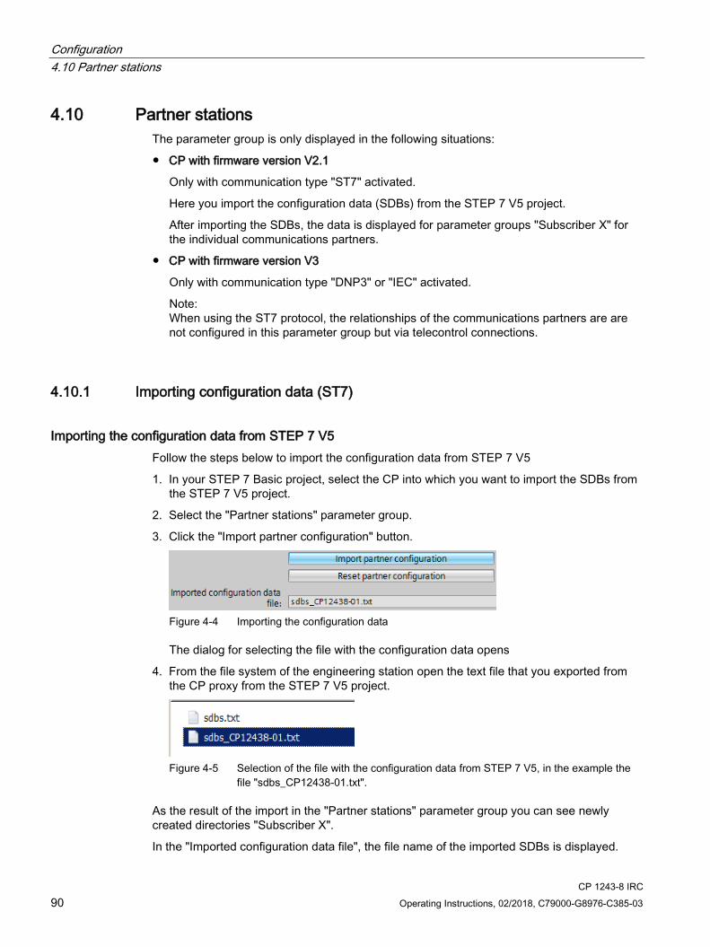
Configuration 4.10 Partner stations
CP 1243-8 IRC 90 Operating Instructions, 02/2018, C79000-G8976-C385-03
4.10 Partner stations The parameter group is only displayed in the following situations:
● CP with firmware version V2.1
Only with communication type "ST7" activated.
Here you import the configuration data (SDBs) from the STEP 7 V5 project.
After importing the SDBs, the data is displayed for parameter groups "Subscriber X" for the individual communications partners.
● CP with firmware version V3
Only with communication type "DNP3" or "IEC" activated.
Note: When using the ST7 protocol, the relationships of the communications partners are are not configured in this parameter group but via telecontrol connections.
4.10.1 Importing configuration data (ST7)
Importing the configuration data from STEP 7 V5 Follow the steps below to import the configuration data from STEP 7 V5
1. In your STEP 7 Basic project, select the CP into which you want to import the SDBs from the STEP 7 V5 project.
2. Select the "Partner stations" parameter group.
3. Click the "Import partner configuration" button.
Figure 4-4 Importing the configuration data
The dialog for selecting the file with the configuration data opens
4. From the file system of the engineering station open the text file that you exported from the CP proxy from the STEP 7 V5 project.
Figure 4-5 Selection of the file with the configuration data from STEP 7 V5, in the example the
file "sdbs_CP12438-01.txt".
As the result of the import in the "Partner stations" parameter group you can see newly created directories "Subscriber X".
In the "Imported configuration data file", the file name of the imported SDBs is displayed.

Configuration 4.10 Partner stations
CP 1243-8 IRC Operating Instructions, 02/2018, C79000-G8976-C385-03 91
With the "Reset partner configuration" button you can delete the imported data again. The partner-specific configuration data of the CP will then be deleted again.
Parameter groups after importing The imported data is displayed in the "Subscriber X" directories. Apart from the "Parameter status" parameter described below, the imported parameters cannot be configured any further.
For the meaning of the parameters, see section Advanced options (Page 84). You will find further information on the parameters in the STEP 7 information system.
Report partner status (connection to partner) With individual partners, the reporting of the partner status can be enabled.
If the "Report partner status" function is enabled, the CP signals the status of the communication to the remote partner.
● Bit 0 of "PLC tag for partner status" (data type WORD) is set to 1 if the partner can be reached.
● Bit 1 is set to 1 if all the paths to the remote partner are OK (useful with redundant paths).
● Bits 2-3 indicate the status of the send buffer (frame memory). The following values are possible:
– 0: Send buffer OK
– 1: Send buffer threatening to overflow (more than 80 % full).
– 3: Send buffer has overflowed (fill level 100 % reached).
As soon as the fill level drops below 50 %, bits 2 and 3 are reset to 0.
Bits 4 to 15 of the PLC tags are not used and do not need to be evaluated in the program.
4.10.2 Partners (DNP3 / IEC)
Listener port Here the listener port of the module, port for connection requests of the communications partner are displayed.
● Default for the DNP3 protocol: 20000
● Default for the IEC protocol: 2404
You can change the port number for the module. Keep in mind the settings on the communications partner (master).
Permitted range: 1024...65535
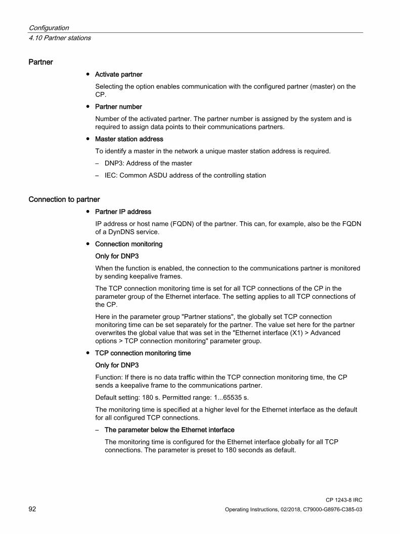
Configuration 4.10 Partner stations
CP 1243-8 IRC 92 Operating Instructions, 02/2018, C79000-G8976-C385-03
Partner ● Activate partner
Selecting the option enables communication with the configured partner (master) on the CP.
● Partner number
Number of the activated partner. The partner number is assigned by the system and is required to assign data points to their communications partners.
● Master station address
To identify a master in the network a unique master station address is required.
– DNP3: Address of the master
– IEC: Common ASDU address of the controlling station
Connection to partner ● Partner IP address
IP address or host name (FQDN) of the partner. This can, for example, also be the FQDN of a DynDNS service.
● Connection monitoring
Only for DNP3
When the function is enabled, the connection to the communications partner is monitored by sending keepalive frames.
The TCP connection monitoring time is set for all TCP connections of the CP in the parameter group of the Ethernet interface. The setting applies to all TCP connections of the CP.
Here in the parameter group "Partner stations", the globally set TCP connection monitoring time can be set separately for the partner. The value set here for the partner overwrites the global value that was set in the "Ethernet interface (X1) > Advanced options > TCP connection monitoring" parameter group.
● TCP connection monitoring time
Only for DNP3
Function: If there is no data traffic within the TCP connection monitoring time, the CP sends a keepalive frame to the communications partner.
Default setting: 180 s. Permitted range: 1...65535 s.
The monitoring time is specified at a higher level for the Ethernet interface as the default for all configured TCP connections.
– The parameter below the Ethernet interface
The monitoring time is configured for the Ethernet interface globally for all TCP connections. The parameter is preset to 180 seconds as default.

Configuration 4.10 Partner stations
CP 1243-8 IRC Operating Instructions, 02/2018, C79000-G8976-C385-03 93
– The parameter below "Partner stations"
The parameter "TCP connection monitoring time" occurs again with the individual partners in the parameter group "Connection to partner". This parameter applies only to the individual partner. The value of 180 seconds preset on the Ethernet interface is adopted for the individual partners.
If for any reason you want to change the value of the TCP connection monitoring time for individual partners, you can adapt the value for every partner individually in "Partner stations". If. for example, you want to check the connection at shorter intervals, reduce the value.
● TCP keepalive monitoring time
Only for DNP3
If the value configured here differs from the value configured in the Ethernet interface parameter group, the monitoring time of the "Partner stations" parameter group is used.
After sending a keepalive frame, the CP expects a reply from the communications partner within the keepalive monitoring time. If the CP does not receive a reply within the configured time, it terminates the connection.
Default setting: 10 s. Permitted range: 1...65535 s.
– The parameter below the Ethernet interface
The monitoring time is configured for the Ethernet interface as a global setting for all TCP connections.
– The parameter below "Partner stations"
As with the TCP connection monitoring time, the value of "Partner stations" can be adapted for each partner individually.
● Connection mode
In the "Permanent" connection mode, there is a permanent connection to the communications partner.
The CP only supports this connection mode.
● Connection establishment
Specifies the communications partner that establishes the connection (always the CP).
● Protocol type
Only for DNP3
Selection of the protocol type on the transport layer: TCP / UDP

Configuration 4.10 Partner stations
CP 1243-8 IRC 94 Operating Instructions, 02/2018, C79000-G8976-C385-03
Advanced settings ● Partner monitoring time
If the CP does not receive a sign of life from the communications partner within the configured time, the CP interprets this as a fault/error on the partner. The CP aborts the connection and attempts to re-establish it.
If you enter 0, the function is deactivated.
● DNP3 conformity level
Only for DNP3
Indicates the DNP3 implementation level supported by the CP
In the DNP3 specification, various levels of protocol conformity are and they describe the supported range of functions (subset) of a master or a station. These DNP3 implementation levels (implementation levels) are referred to as "DNP3 Application Layer protocol Level" and abbreviated with DNP3-L1 to DNP3-L4.
For the communication between the CP and the master, the DNP3 level supported by the master must be known.
The selection of the level used by the DNP3 CP which must correspond to that of the connected master is set separately in STEP 7 for each individual communications partner (DNP3 master).
The CP supports the following DNP3 implementation levels:
– Level 1
– Level 2
– Level 3
– Level 4
– Level 4+
The DNP3 implementation level known here as Level 4+ that is not specified in the standard contains the range of functions of Level 4 and in addition support of the following DNP3 data types / variations:
– 64-bit analog value as floating-point number without time of day
– 64-bit analog value as floating-point number with time of day
– Counter event with time of day in 16-bit format
– Counter event with time of day in 32-bit format
● Event transmission mode
Only for DNP3
Mode with which DNP events are transferred to this communications partner:
– Chronological transfer of individual frames
or
– Transfer of collected frames per data point as a block.
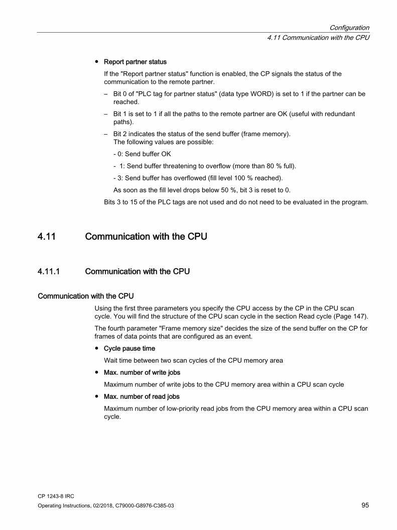
Configuration 4.11 Communication with the CPU
CP 1243-8 IRC Operating Instructions, 02/2018, C79000-G8976-C385-03 95
● Report partner status
If the "Report partner status" function is enabled, the CP signals the status of the communication to the remote partner.
– Bit 0 of "PLC tag for partner status" (data type WORD) is set to 1 if the partner can be reached.
– Bit 1 is set to 1 if all the paths to the remote partner are OK (useful with redundant paths).
– Bit 2 indicates the status of the send buffer (frame memory). The following values are possible:
- 0: Send buffer OK
- 1: Send buffer threatening to overflow (more than 80 % full).
- 3: Send buffer has overflowed (fill level 100 % reached).
As soon as the fill level drops below 50 %, bit 3 is reset to 0.
Bits 3 to 15 of the PLC tags are not used and do not need to be evaluated in the program.
4.11 Communication with the CPU
4.11.1 Communication with the CPU
Communication with the CPU Using the first three parameters you specify the CPU access by the CP in the CPU scan cycle. You will find the structure of the CPU scan cycle in the section Read cycle (Page 147).
The fourth parameter "Frame memory size" decides the size of the send buffer on the CP for frames of data points that are configured as an event.
● Cycle pause time
Wait time between two scan cycles of the CPU memory area
● Max. number of write jobs
Maximum number of write jobs to the CPU memory area within a CPU scan cycle
● Max. number of read jobs
Maximum number of low-priority read jobs from the CPU memory area within a CPU scan cycle.
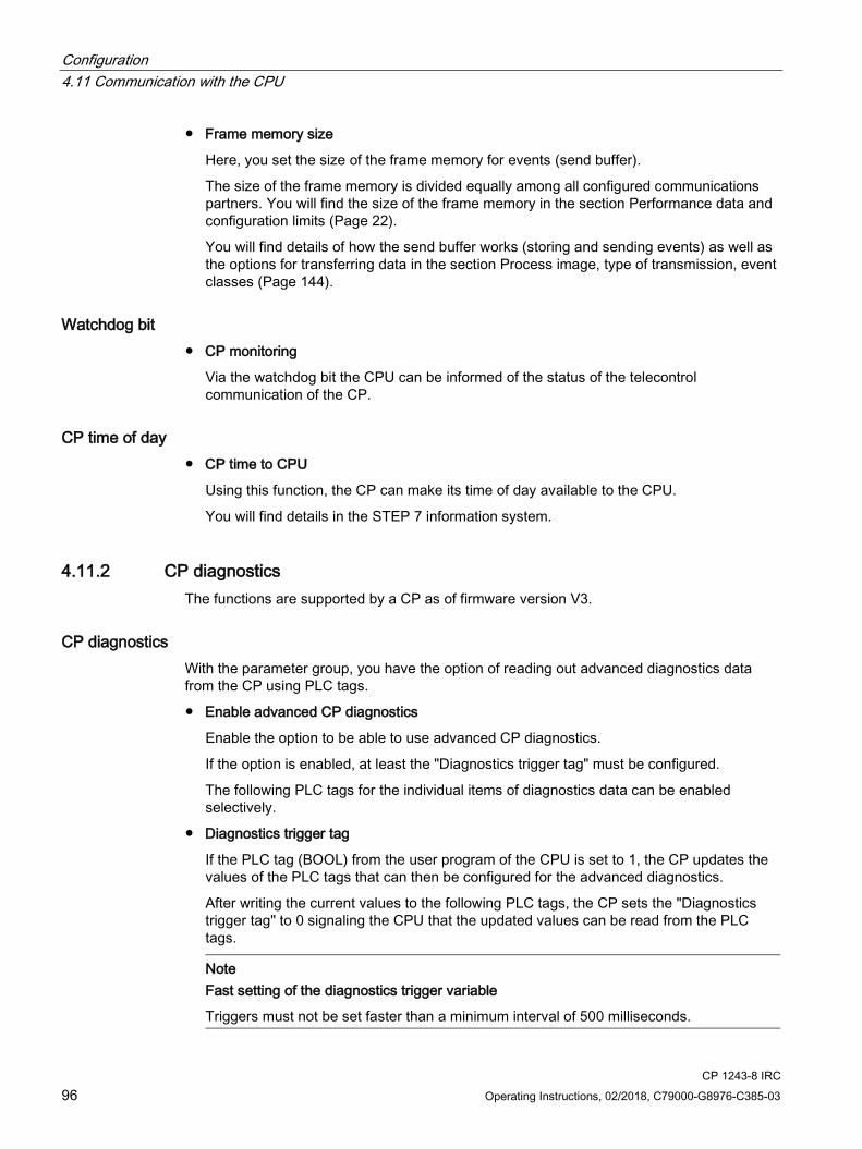
Configuration 4.11 Communication with the CPU
CP 1243-8 IRC 96 Operating Instructions, 02/2018, C79000-G8976-C385-03
● Frame memory size
Here, you set the size of the frame memory for events (send buffer).
The size of the frame memory is divided equally among all configured communications partners. You will find the size of the frame memory in the section Performance data and configuration limits (Page 22).
You will find details of how the send buffer works (storing and sending events) as well as the options for transferring data in the section Process image, type of transmission, event classes (Page 144).
Watchdog bit ● CP monitoring
Via the watchdog bit the CPU can be informed of the status of the telecontrol communication of the CP.
CP time of day ● CP time to CPU
Using this function, the CP can make its time of day available to the CPU.
You will find details in the STEP 7 information system.
4.11.2 CP diagnostics The functions are supported by a CP as of firmware version V3.
CP diagnostics With the parameter group, you have the option of reading out advanced diagnostics data from the CP using PLC tags.
● Enable advanced CP diagnostics
Enable the option to be able to use advanced CP diagnostics.
If the option is enabled, at least the "Diagnostics trigger tag" must be configured.
The following PLC tags for the individual items of diagnostics data can be enabled selectively.
● Diagnostics trigger tag
If the PLC tag (BOOL) from the user program of the CPU is set to 1, the CP updates the values of the PLC tags that can then be configured for the advanced diagnostics.
After writing the current values to the following PLC tags, the CP sets the "Diagnostics trigger tag" to 0 signaling the CPU that the updated values can be read from the PLC tags.
Note
Fast setting of the diagnostics trigger variable
Triggers must not be set faster than a minimum interval of 500 milliseconds.
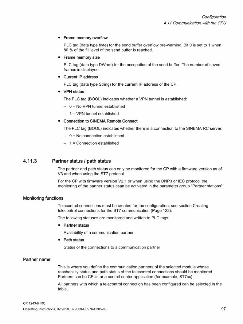
Configuration 4.11 Communication with the CPU
CP 1243-8 IRC Operating Instructions, 02/2018, C79000-G8976-C385-03 97
● Frame memory overflow
PLC tag (data type byte) for the send buffer overflow pre-warning. Bit 0 is set to 1 when 80 % of the fill level of the send buffer is reached.
● Frame memory size
PLC tag (data type DWord) for the occupation of the send buffer. The number of saved frames is displayed.
● Current IP address
PLC tag (data type String) for the current IP address of the CP.
● VPN status
The PLC tag (BOOL) indicates whether a VPN tunnel is established:
– 0 = No VPN tunnel established
– 1 = VPN tunnel established
● Connection to SINEMA Remote Connect
The PLC tag (BOOL) indicates whether there is a connection to the SINEMA RC server:
– 0 = No connection established
– 1 = Connection established
4.11.3 Partner status / path status The partner and path status can only be monitored for the CP with a firmware version as of V3 and when using the ST7 protocol.
For the CP with firmware version V2.1 or when using the DNP3 or IEC protocol the monitoring of the partner status csan be activated in the parameter group "Partner stations".
Monitoring functions Telecontrol connections must be created for the configuration, see section Creating telecontrol connections for the ST7 communication (Page 122).
The following statuses are monitored and written to PLC tags:
● Partner status
Availability of a communication partner
● Path status
Status of the connections to a communication partner
Partner name This is where you define the communication partners of the selected module whose reachability status and path status of the telecontrol connections should be monitored. Partners can be CPUs or a control center application (for example, ST7cc).
All partners with which a telecontrol connection has been configured can be selected in the table.

Configuration 4.11 Communication with the CPU
CP 1243-8 IRC 98 Operating Instructions, 02/2018, C79000-G8976-C385-03
PLC tag for partner status / path status The two statuses are stored in a common PLC tag of Word or UInt type (DB, bit memory, output).
The two statuses occupy one byte of the PLC tag. The coding is written separately for byte 0 (partner status) and byte 1 (path status).
Partner status Byte 0 of the common PLC tag for partner status / path status codes information on the availability of the communications partner, on the existing connections and connection paths and on the status of the send buffer of the CP.
Bit 7 Bit 6 Bit 5 Bit 4 Bit 3 Bit 2 Bit 1 Bit 0 Path redun-
dancy Connection
mode Temporary connection **
(Re-served)
Frame memory * Path status Partner status
0: No re-dundancy 1: Redun-dancy exists
0: Perma-nent 1: Tempo-rary
0: Partner not reacha-ble 1: Partner reachable *
- 0: Send buffer OK 1: Memory alloca-tion > 90 % 3: overflow (memory alloca-tion 100 %)
0: Not all paths reachable 1: All paths reachable
0: Partner not reacha-ble 1: Partner reachable
* Partners that support temporary connections are set to 'reachable' if the partner itself terminates the connection.
** For the behavior of the frame memory, refer to the section "Send buffer" in the section Process image, type of transmission, event classes (Page 144).
Path status Byte 1 shows the status of the connection path (configured connection) to the partner from the point of view of the CP.
A maximum of 2 paths (main and substitute path) to a partner can be configured, see section Creating telecontrol connections for the ST7 communication (Page 122).
Both connection paths must start or end at the CP.
The PLC tag shows the following:
● The paths via which the partner can be reached.
● The path currently being used
● The interface via which the main path was configured.
● The interface via which the substitute path was configured.
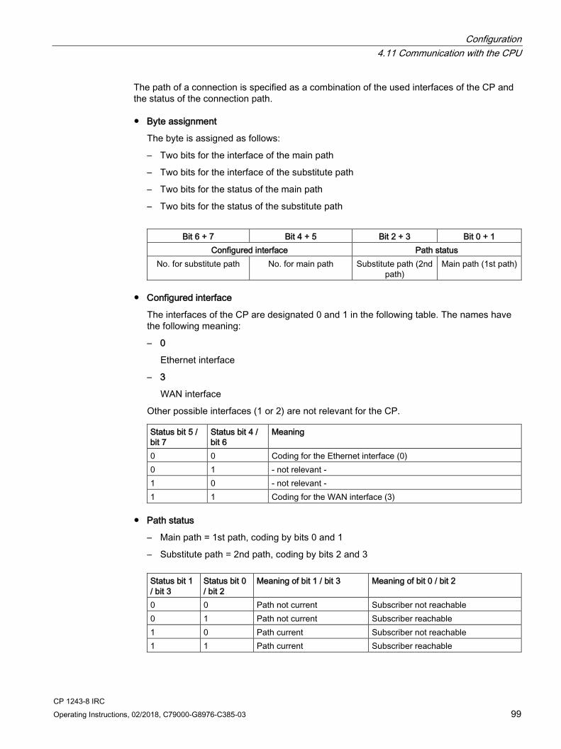
Configuration 4.11 Communication with the CPU
CP 1243-8 IRC Operating Instructions, 02/2018, C79000-G8976-C385-03 99
The path of a connection is specified as a combination of the used interfaces of the CP and the status of the connection path.
● Byte assignment
The byte is assigned as follows:
– Two bits for the interface of the main path
– Two bits for the interface of the substitute path
– Two bits for the status of the main path
– Two bits for the status of the substitute path
Bit 6 + 7 Bit 4 + 5 Bit 2 + 3 Bit 0 + 1 Configured interface Path status
No. for substitute path No. for main path Substitute path (2nd path)
Main path (1st path)
● Configured interface
The interfaces of the CP are designated 0 and 1 in the following table. The names have the following meaning:
– 0
Ethernet interface
– 3
WAN interface
Other possible interfaces (1 or 2) are not relevant for the CP.
Status bit 5 / bit 7
Status bit 4 / bit 6
Meaning
0 0 Coding for the Ethernet interface (0) 0 1 - not relevant - 1 0 - not relevant - 1 1 Coding for the WAN interface (3)
● Path status
– Main path = 1st path, coding by bits 0 and 1
– Substitute path = 2nd path, coding by bits 2 and 3
Status bit 1 / bit 3
Status bit 0 / bit 2
Meaning of bit 1 / bit 3 Meaning of bit 0 / bit 2
0 0 Path not current Subscriber not reachable 0 1 Path not current Subscriber reachable 1 0 Path current Subscriber not reachable 1 1 Path current Subscriber reachable
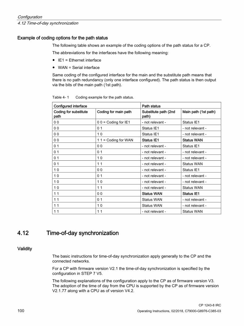
Configuration 4.12 Time-of-day synchronization
CP 1243-8 IRC 100 Operating Instructions, 02/2018, C79000-G8976-C385-03
Example of coding options for the path status The following table shows an example of the coding options of the path status for a CP.
The abbreviations for the interfaces have the following meaning:
● IE1 = Ethernet interface
● WAN = Serial interface
Same coding of the configured interface for the main and the substitute path means that there is no path redundancy (only one interface configured). The path status is then output via the bits of the main path (1st path).
Table 4- 1 Coding example for the path status.
Configured interface Path status Coding for substitute path
Coding for main path Substitute path (2nd path)
Main path (1st path)
0 0 0 0 = Coding for IE1 - not relevant - Status IE1 0 0 0 1 Status IE1 - not relevant - 0 0 1 0 Status IE1 - not relevant - 0 0 1 1 = Coding for WAN Status IE1 Status WAN 0 1 0 0 - not relevant - Status IE1 0 1 0 1 - not relevant - - not relevant - 0 1 1 0 - not relevant - - not relevant - 0 1 1 1 - not relevant - Status WAN 1 0 0 0 - not relevant - Status IE1 1 0 0 1 - not relevant - - not relevant - 1 0 1 0 - not relevant - - not relevant - 1 0 1 1 - not relevant - Status WAN 1 1 0 0 Status WAN Status IE1 1 1 0 1 Status WAN - not relevant - 1 1 1 0 Status WAN - not relevant - 1 1 1 1 - not relevant - Status WAN
4.12 Time-of-day synchronization
Validity The basic instructions for time-of-day synchronization apply generally to the CP and the connected networks.
For a CP with firmware version V2.1 the time-of-day synchronization is specified by the configuration in STEP 7 V5.
The following explanations of the configuration apply to the CP as of firmware version V3. The adoption of the time of day from the CPU is supported by the CP as of firmware version V2.1.77 along with a CPU as of version V4.2.
Configuration 4.12 Time-of-day synchronization
CP 1243-8 IRC Operating Instructions, 02/2018, C79000-G8976-C385-03 101
Basics of time-of-day synchronization With telecontrol applications that require time-of-day synchronization, you need to synchronize the time of day of the CP regularly. If you do not synchronize the time of day, there may be deviations of several seconds per day in the time information of the stations.
If security functions are activated, the module also requires the current time.
The CP can obtain the time of day from an external source, for the method see below. When using an external time source, the connected S7 station can obtain the current time of day both via the CPU as well as via a CP.
Note Recommendation: Time-of-day synchronization only by 1 module
Only have the time of day of the station from an external time source synchronized by a single module so that a consistent time of day is maintained within the station.
When the CPU takes the time from a CP, disable time-of-day synchronization of the CPU.
If you have the time synchronized on the CP and the CPU via NTP, when possible use the same NTP server to maintain a consistent time of day within the station.
Time-of-day concept Before configuring time-of-day synchronization specify the following:
● Specify the time source in the network.
● Specify the time master in the network.
● Specify the network or networks via which the time of day will be forwarded by the time master to the time slaves.
Synchronization method The CP supports the following methods of time-of-day synchronization:
● NTP / NTP (secure)
Network Time Protocol
Time-of-day synchronization only via Ethernet
The function is available only when telecontrol communication is disabled.
The secure method NTP (secure) can be used if the security functions are enabled. It uses authentication with symmetrical keys according to the hash algorithms MD5 or SHA-1. In the global security settings, you can create and manage NTP servers of the type NTP (secure).
Recommendation with NTP: Synchronization with an external clock at intervals of approximately 10 seconds is recommended. This achieves as small a deviation as possible between the internal time and the absolute time.
Configuration 4.12 Time-of-day synchronization
CP 1243-8 IRC 102 Operating Instructions, 02/2018, C79000-G8976-C385-03
● Time from another subscriber
In this case the CP adopts the time of day from a subscriber in the connected network. Time-of-day masters can for example be:
– A synchronized CPU
– A subscriber with a time receiver
– A master station PC (e.g. ST7cc/ST7sc) connected to the network
General information on configuration
Parameter groups for time-of-day synchronization
For configuring the time-of-day synchronization the following parameter groups are available:
● Parameter group of the CP
– Receive time
Here you specify via which of the connected networks or via which subscriber the CP will receive the time of day.
Here, you also configure the NTP servers if the CP will be synchronized directly via NTP.
● Classic WAN network
Time-of-day synchronization via classic WAN networks is only relevant when using the ST7 protocol.
Enable time-of-day synchronization via classic networks directly on the network using the parameter group there. You also specify the synchronization cycle.
The settings for synchronization are then adopted by all communications modules connected to this network.
The send direction of the time-of-day frames is derived automatically from the node type of the connected interfaces: Master station ⇒ Node station ⇒ Station
The settings for the network are not possible with time-of-day synchronization via Ethernet.
Configuring time-of-day synchronization The procedure describes the configuration with telecontrol communication activated.
The CP can only be a time slave.
1. Network an interface of the CP with a network to which a module is connected that can forward the time or that is time master.
Receiving the time is supported for the Ethernet interface with the MSC protocol and for the serial interface, not for Ethernet interface with the setting "Network type" = "Neutral".

Configuration 4.13 SMSC
CP 1243-8 IRC Operating Instructions, 02/2018, C79000-G8976-C385-03 103
2. Enable the receipt of the time from the required time transmitter.
– From NTP server
(only when telecontrol communication is disabled)
– From local station
(adoption of the time from the local CPU)
– Receive time from WAN
If the CP is connected to a classic WAN network and time-of-day synchronization is enabled in the network, the CP automatically takes the time from the WAN network with the settings made there. The parameter is then activated on the CP and the parameter group is grayed out.
4.13 SMSC
SMSC If the CP (firmware V3) is intended to use the sending of SMS messages, you need to activate the option here. Configure the number of the SMSC being used (Short Message Service Center).
For configuring the parameters for the CP with firmware V2.1 refer to the section Configuration of the serial interface (Page 79).
4.14 Subscriber numbers
Subscriber numbers Here you assign the subscriber numbers of the CPU and the CP.
● Subscriber number
The subscriber number is unique for every subscriber in an ST7 network.
For the meaning of the subscriber numbers, see section ST7 (Page 61).
– CPU subscriber number
Subscriber number of the local CPU of the station
– CP subscriber number
Subscriber number of the CP
For the application of the master station PC, the subscriber number is configured in the telecontrol connection: Editor "Network data" > "Telecontrol" tab
You configure WAN address of the CP in the parameter group "WAN parameters", see section WAN parameters (networking the CP) (Page 82).
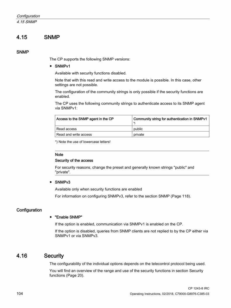
Configuration 4.15 SNMP
CP 1243-8 IRC 104 Operating Instructions, 02/2018, C79000-G8976-C385-03
4.15 SNMP
SNMP The CP supports the following SNMP versions:
● SNMPv1
Available with security functions disabled.
Note that with this read and write access to the module is possible. In this case, other settings are not possible.
The configuration of the community strings is only possible if the security functions are enabled.
The CP uses the following community strings to authenticate access to its SNMP agent via SNMPv1:
Access to the SNMP agent in the CP Community string for authentication in SNMPv1 *)
Read access public Read and write access private *) Note the use of lowercase letters!
Note
Security of the access
For security reasons, change the preset and generally known strings "public" and "private".
● SNMPv3
Available only when security functions are enabled
For information on configuring SNMPv3, refer to the section SNMP (Page 118).
Configuration ● "Enable SNMP"
If the option is enabled, communication via SNMPv1 is enabled on the CP.
If the option is disabled, queries from SNMP clients are not replied to by the CP either via SNMPv1 or via SNMPv3.
4.16 Security The configurability of the individual options depends on the telecontrol protocol being used.
You will find an overview of the range and use of the security functions in section Security functions (Page 20).
Configuration 4.16 Security
CP 1243-8 IRC Operating Instructions, 02/2018, C79000-G8976-C385-03 105
For the configuration limits of the security functions refer to the section Performance data and configuration limits (Page 22).
To be able to configure the security functions, you need to create a security user; see section Security user (Page 105).
4.16.1 Security user
Creating a security user You need the relevant configuration rights to be able to configure security functions. For this purpose, you need to create at least one security user with the corresponding rights.
Navigate to the global security settings > "User and roles" > "Users" tab.
1. Create a user with the associated parameters such as authentication mode, session duration, etc.
2. Assign this user the role "NET Standard" or "NET Administrator" in the area below "Assigned roles".
After logging on, this user can make the necessary settings in the STEP 7 project.
In the future, continue to log on as this user when working on security parameters.
4.16.2 MSC authentication
MSC authentication on the different interfaces When using the secure MSC protocol (MSC / MSCsec) for the CP as MSC station the authentication data for the interface involved must be configured.
Parameter groups
● MSC authentication - Ethernet interface
Relevant when using MSC on the Ethernet interface
● MSC authentication - MD720
Relevant on the serial interface when using MSC via mobile wireless
Parameter
● User name
User name for communication using MSC
● Password
Password for communication using MSC
The user name and password must be different for every MSC station in the network.

Configuration 4.16 Security
CP 1243-8 IRC 106 Operating Instructions, 02/2018, C79000-G8976-C385-03
4.16.3 DNP3 security options
Partner'X'
Preliminary remarks: Authentication and key exchange
If the security function is enabled, the DNP3 master and CP authenticate themselves with a secret key, the pre-shared key.
With the help of the common pre-shared key, after the first connection establishment between master and CP session keys are agreed that are then renewed cyclically. Renewal of the session keys is normally initiated by the master. The criteria for renewing the key are specified in the following parameters.
● Key exchange interval
● Authentication requests before key exchange
As soon as one of these conditions is met, the session key is renewed.
Parameters
● Enable DNP3 security options
Enable the option if you want to use the security mechanisms.
● IKE mode
Selection of the mode for key exchange. Range of values:
– Aggressive Mode
The Aggressive Mode is somewhat faster but transfers the identity unencrypted.
– Main Mode
The Main Mode is the standard mode.
Default setting: Aggressive Mode
● Security statistics
Specifies whether the statistics of security events are sent to the master. Security events are authentication requests to the CP. If the option is enabled, all authentication requests with date, time and result are saved on the CP and sent to the master for further evaluation.
Range of values:
– Do not send security statistics
– Send security statistics
Default setting: Do not send security statistics

Configuration 4.16 Security
CP 1243-8 IRC Operating Instructions, 02/2018, C79000-G8976-C385-03 107
● SHA-1 interlock
Setting to select whether the CP may use the secure hash algorithm SHA-1 if "SHA-256" was configured as the Secure hash algorithm and the master does not support SHA-256.
Range of values:
– SHA-1 mode not allowed
The CP may not use SHA-1. If the master does not support SHA-256, no connection will be established.
– SHA-1 mode allowed
The CP can use SHA-1 if the master does not support SHA-256.
Default setting: SHA-1 mode not allowed
● Secure hash algorithm (SHA)
Selection of the Secure Hash Algorithm (SHA)
Range of values:
– SHA-1
– SHA-256
Default setting: 256
● Key wrap algorithm
Selection of the Advanced Encryption Standard (AES)
Range of values:
– AES-128
– AES-256
Default setting: AES-128
● Key length
Specifies the length of the pre-shared key in bytes.
The following lengths are used depending on the key wrap algorithm.
– For AES-128: 16 bytes
– For AES-256: 32 bytes
● Max. number of statistics queries
If the configured number of statistics queries of the master is exceeded within the key exchange interval, the CP enters a message in the diagnostics buffer of the CPU.
Range of values: 2...255 Default setting: 5
● Authentication requests before key exchange
Maximum number of authentication requests of the CP with the master. When this number is reached, the session key is renewed.
Range of values: 1...10000 Default setting: 1000
Recommendation: Set the number for the CP twice as high as for the master.

Configuration 4.16 Security
CP 1243-8 IRC 108 Operating Instructions, 02/2018, C79000-G8976-C385-03
● Key exchange interval
Period after which the key is exchanged again between the CP and the master. The interval must be matched up on both communications partners.
Range of values: 0...65535 min. at 0 (zero), the key is never changed (function disabled). Default setting: 15 min.
Recommendation: Set the key exchange interval for the CP twice as high as for the master.
● Authentication timeout
Maximum waiting time for the response from the master to an authentication request of the CP.
Exceeding the wait time is evaluated as an error by the CP. In this case, the CP generates a security event and sends this to the master.
Range of values: 1... 65535 s Default setting: 5
● Pre-shared key
The pre-shared key can be configured in two ways:
– Manual configuration
Enter the pre-shared key in STEP 7 manually as a hexadecimal value.
– Import as file
Import the pre-shared key from the file system of the engineering station if the pre-shared key was generated by the master or another system.
The pre-shared key of the CP must be identical to the pre-shared key of the master.
4.16.4 Firewall
4.16.4.1 Pre-check of messages by the MAC firewall. Each incoming or outgoing frame initially runs through the MAC firewall (layer 2). If the frame is discarded at this level, it will not be checked by the IP firewall (layer 3). This means that with suitable MAC firewall rules, IP communication can be restricted or blocked.
4.16.4.2 Firewall settings for configured connection connections via a VPN tunnel
IP rules in advanced firewall mode If you set up configured connection connections with a VPN tunnel between the CP and a communications partner, you will need to adapt the local firewall settings of the CP:
In advanced firewall mode ("Security > Firewall > IP rules") select the action "Allow*" for both communications directions of the VPN tunnel.
See section Settings for online security diagnostics and downloading to station with the firewall activated (Page 109) for information on this.
Configuration 4.16 Security
CP 1243-8 IRC Operating Instructions, 02/2018, C79000-G8976-C385-03 109
4.16.4.3 Settings for online security diagnostics and downloading to station with the firewall activated
Setting the firewall for online functions With the security functions enabled, follow the steps outlined below:
1. In the global security settings (see project tree), select the entry "Firewall > Services > Define services for IP rules".
2. Select the "ICMP" tab.
3. Insert a new entry of the type "Echo Reply" and another of the type "Echo Request".
4. Now select the CP in the S7 station.
5. Enable the advanced firewall mode in the local security settings of the CP in the "Security > Firewall" parameter group.
6. Open the "IP rules" parameter group.
7. In the table, insert a new IP rule for the previously created global services as follows:
– Action: Allow; "From external -> To station " with the globally created "Echo request" service
– Action: Allow; "From station -> to external" with the globally created "Echo reply" service
8. For the IP rule for the Echo Request, enter the IP address of the engineering station in "Source IP address". This ensures that only ICMP frames (ping) from your engineering station can pass through the firewall.
4.16.4.4 Notation for the source IP address (advanced firewall mode) If you specify an address range for the source IP address in the advanced firewall settings of the CP, make sure that the notation is correct:
● Separate the two IP addresses only using a hyphen.
Correct: 192.168.10.0-192.168.10.255
● Do not enter any other characters between the two IP addresses.
Incorrect: 192.168.10.0 - 192.168.10.255
If you enter the range incorrectly, the firewall rule will not be used.
4.16.5 Time-of-day synchronization
Time-of-day synchronization For the configuration of the time-of-day synchronization read the section Time-of-day synchronization (Page 100).
Configuration 4.16 Security
CP 1243-8 IRC 110 Operating Instructions, 02/2018, C79000-G8976-C385-03
4.16.6 E-mail configuration
Configuring e-mails in STEP 7 With special events, e.g. CPU STOP, the CP can send e-mails. It does not depend on whether telecontrol communication is used.
When using telecontrol communication, additionally configured events in the process image of the CPU can trigger the sending of e-mails. Along with the e-mail process data can also be sent.
You configure the individual e-mails in the message editor (entry "Messages"), see section Message configuration (Page 163)
Requirements
The following requirements must be met in the configuration for sending e-mails:
● The security functions are enabled.
● The time of the CP is synchronized.
● In the "E-mail configuration" entry, the protocol to be used and the data for access to the e-mail server are configured.
E-mail configuration With the default setting of the SMTP port 25, the module transfers unencrypted e-mails.
If your e-mail service provider only supports encrypted transfer, use one of the following options:
● Port no. 587
By using STARTTLS, the module sends encrypted e-mails to the SMTP server of your e-mail service provider.
Recommendation: If your e-mail provider offers both options (STARTTLS / SSL/TLS), you should use STARTTLS with port 587.
● Port no. 465
By using SSL/TLS (SMTPS), the module sends encrypted e-mails to the SMTP server of your e-mail service provider.
Ask your e.mail service provider which option is supported.
Importing the certificate with encrypted transfer To be able to use encrypted transfer, you need to load the certificate of your e-mail account in the certificate manager of STEP 7. You obtain the certificate from your e-mail service provider.
Configuration 4.16 Security
CP 1243-8 IRC Operating Instructions, 02/2018, C79000-G8976-C385-03 111
Use the certificate by taking the following steps:
1. Save the certificate of your e-mail service provider in the file system of the engineering station.
2. Import the certificate into your STEP 7 project with "Global security settings > Certificate manager".
3. Use the imported certificate with every module that uses encrypted e-mails via the "Certificate manager" table in the local "Security“ parameter group.
For the procedure, refer to the section Certificate manager (Page 120).
4.16.7 Log settings - Filtering of the system events
Communications problems if the value for system events is set too high If the value for filtering the system events is set too high, you may not be able to achieve the maximum performance for the communication. The high number of output error messages can delay or prevent the processing of the communications connections.
In "Security > Log settings > Configure system events", set the "Level:" parameter to the value "3 (Error)" to ensure the reliable establishment of the communications connections.
4.16.8 VPN
4.16.8.1 VPN (Virtual Private Network)
VPN tunnel Virtual Private Network (VPN) is a technology for secure transportation of confidential data in public IP networks, for example the Internet. With VPN, a secure connection (tunnel) is set up and operated between two secure IT systems or networks via a non-secure network.
One of the main features of the VPN tunnel is that it forwards all frames even from protocols of higher layers (HTTP, FTP telecontrol protocols of the application layer etc.).
The data traffic between two network components is handled unrestricted through a physical network. This allows networks to be connected together via an intermediate network.
VPN tunnels ensure integrity and confidentiality during data transmission.
Configuration 4.16 Security
CP 1243-8 IRC 112 Operating Instructions, 02/2018, C79000-G8976-C385-03
Properties ● VPN forms a logical network that is embedded in a physical network. VPN uses the usual
addressing mechanisms of the physical network, however it transports only the frames of the VPN subscribers and therefore operates independent of the rest of the physical network.
● VPN allows communication of the subscribers in the VPN network with the physical network.
● VPN is based on tunnel technology and can be configured for individual subscribers.
● Communication between the VPN partners is protected from eavesdropping or manipulation by using passwords, public keys or a digital certificate (authentication).
Areas of application ● Local area networks can be connected together securely via the Internet ("site-to-site"
connection).
● Secure access to a company network ("end-to-site" connection)
● Secure access to a server ("end-to-end" connection)
● Communication between two servers without being accessible to third parties (end-to-end or host-to-host connection)
● Protection of computers and their communication within and automation network
● Secure remote access from a PC/PG to automation devices or networks protected by security modules via public networks.
4.16.8.2 Addressing the CP when using VPN
IP addresses and VPN ports In normal mobile wireless networks it is not possible to reach a dynamic IP address assigned to the CP by the mobile wireless network provider from the Internet. For this reason, for incoming connections make sure that the CP is assigned a fixed public IP address by the mobile wireless network provider.
You must also make sure that apart from this IP address, the ports required for VPN are reachable from the Internet.
Configuration 4.16 Security
CP 1243-8 IRC Operating Instructions, 02/2018, C79000-G8976-C385-03 113
4.16.8.3 Creating a VPN tunnel for S7 communication between stations
Requirements To allow a VPN tunnel to be created for S7 communication between two S7 stations or between an S7 station and an engineering station or an ST7cc/sc PC with a security CP (for example CP 1628), the following requirements must be met:
● The two stations have been configured.
● The CPs in both stations must support the security functions.
● The Ethernet interfaces of the two stations are located in the same subnet.
● All receiving stations require a fixed IP address to be reachable via the public networks.
Note Communication also possible via an IP router
Communication between the two stations is also possible via an IP router. To use this communications path, however, you need to make further settings.
Procedure To create a VPN tunnel, you need to work through the following steps:
1. Creating a security user
If the security user has already been created: Log on as this user.
2. Enable the "Activate security features" option
3. Creating the VPN group and assigning security modules
4. Configure the properties of the VPN group
5. Configure local VPN properties of the two CPs
You will find a detailed description of the individual steps in the following paragraphs of this section.
Select "Activate security features" After logging on, you need to select the "Activate security features" check box in the local security settings of both CPs.
You now have the security functions available for both CPs.
Creating the VPN group and assigning security modules 1. In the global security settings, select the entry "VPN groups" > "Add new VPN group".
2. Double-click on the entry "Add new VPN group", to create a VPN group.
Result: A new VPN group is displayed below the selected entry.

Configuration 4.16 Security
CP 1243-8 IRC 114 Operating Instructions, 02/2018, C79000-G8976-C385-03
3. In the global security settings, double-click on the entry "VPN groups" > "Assign module to a VPN group".
4. Assign the security modules between which VPN tunnels will be established to the VPN group.
Note Current date and current time on the CP for VPN connections
Normally, to establish a VPN connection and the associated recognition of the certificates to be exchanged, the current date and the current time are required on both stations.
The establishment of a VPN connection to an engineering station or an ST7cc/sc PC runs as follows along with the time of day synchronization of the CP:
On the engineering station or the ST7cc/sc PC, you want the CP to establish a VPN connection. The VPN connection is established even if the CP does not yet have the current time. Otherwise the certificates used are evaluated as valid and the secure communication will work.
Following connection establishment, the CP synchronizes its time of day with the PC because the ST7cc/sc PC is the time master if telecontrol communication is enabled.
Configure the properties of the VPN group 1. Double-click on the newly created VPN group.
Result: The properties of the VPN group are displayed in the "Properties" > "General" tab of the Inspector window under "Authentication".
2. You configure the pre-shared key or the certificate under the properties of the VPN group.
These properties define the default settings of the VPN group that you can change at any time.
Note Specifying the VPN properties of the CPs
You specify the VPN properties of the CPs in the "Security" > "Firewall" > "VPN" parameter group of the relevant module.
Result You have created a VPN tunnel. The firewalls of the CPs are activated automatically.
The "Activate firewall" check box is selected automatically when you assign the security module to a VPN group. You cannot deselect the check box.
Download the configuration to all modules that belong to the VPN group.
Configuration 4.16 Security
CP 1243-8 IRC Operating Instructions, 02/2018, C79000-G8976-C385-03 115
4.16.8.4 VPN communication with SOFTNET Security Client (PC / engineering station) Setting up VPN tunnel communication between the SOFTNET Security Client and CP has essentially same requirements and procedure as described in the section Creating a VPN tunnel for S7 communication between stations (Page 113).
VPN tunnel communication works only if the internal node is disabled Under certain circumstances the establishment of VPN tunnel communication between SOFTNET Security Client and the CP fails.
In addition to the CP, SOFTNET Security Client also attempts to establish VPN tunnel communication to a lower-level internal subscriber. This communication establishment to a non-existing node prevents the required communication being established to the CP.
To establish successful VPN tunnel communication to the CP, you need to disable the internal subscriber of the CP as follows.
Follow the steps below in the SOFTNET Security Client tunnel overview:
1. Deactivate the option “Learn internal nodes" under "settings" > "SOFTNET Security client-settings".
The lower-level node initially disappears from the tunnel list.
2. In the tunnel overview , select the required connection to the CP.
3. With the right mouse button, select “Activate connection to the internal subscribers" in the shortcut menu.
The lower level node appears temporarily in the tunnel overview.
4. Select the lower-level node in the tunnel overview.
5. Select "Delete Entry" in the shortcut menu.
Result: The lower-level node is now fully disabled. VPN tunnel communication to the CP can be established.
4.16.8.5 CP as passive subscriber of VPN connections
Setting permission for VPN connection establishment with passive subscribers If the CP is connected to another VPN subscriber via a gateway, you need to set the permission for VPN connection establishment to "Responder".
This is the case in the following typical configuration:
VPN subscriber (active) ⇔ gateway (dyn. IP address) ⇔ Internet ⇔ gateway (fixed IP address) ⇔ CP (passive)
Configure the permission for VPN connection establishment for the CP as a passive subscriber as follows:
1. In STEP 7, go to the devices and network view.
2. Select the CP.

Configuration 4.16 Security
CP 1243-8 IRC 116 Operating Instructions, 02/2018, C79000-G8976-C385-03
3. Open the parameter group "VPN“ in the local security settings.
4. For each VPN connection with the CP as a passive VPN subscriber, change the default setting "Initiator/Responder" to the setting "Responder".
4.16.8.6 SYSLOG
Use of SYSLOG only with 1 VPN connection If you want to use SYSLOG with level 7 (debug) via Vpn connections, this is only possible with a single established VPN connection.
4.16.8.7 SINEMA Remote Connect
Remote maintenance with SINEMA Remote Connect (SINEMA RC) The application "SINEMA Remote Connect" (SINEMA RC) is available for remote maintenance purposes.
SINEMA RC uses OpenVPN for encryption of the data. The center of the communication is SINEMA RC Server via which communication runs between the subscribers and that manages the configuration of the communications system.
Preparatory steps Execute the following steps before start configuring the SINEMA RC connection of the module in STEP 7. They are the prerequisite for a consistent STEP 7 project.
● Configuration of SINEMA Remote Connect - Server
Configure SINEMA RC - Server as necessary (not in STEP 7). The communication module and its communication partners must be configured in the SINEMA RC Server.
● Exporting the CA certificate (optional)
If you want to use the server certificate as authentication method of the communication module during connection establishment, export the CA certificate from SINEMA RC - Server. Then import the CA certificate from SINEMA RC - Server to the engineering station.
Alternatively, you can use the fingerprint of the server certificate as authentication method of the communication module.
Note Recommended authentication method:
The recommended authentication method is the one using the CA certificate. The certificate is valid for 10 years.
The fingerprint, on the other hand, is derived from the server certificate. Its validity may be significantly shorter.

Configuration 4.16 Security
CP 1243-8 IRC Operating Instructions, 02/2018, C79000-G8976-C385-03 117
Configuration of SINEMA Remote Connect
Importing your own certificate
1. Navigate to the parameter group "Security > Certificate manager".
2. Open the certificate selection with a double-click on the first free table row of the local certificate manager.
3. Select the CA certificate of SINEMA RC - Server.
Then navigate to the parameter group "Security > VPN".
VPN > General
1. Activate VPN
2. For the parameter "VPN connection type", select the option "Automatic OpenVPN configuration via SINEMA Remote Connect Server" if you wish to use communication via SINEMA Remote Connect.
If you select "Internet Key Exchange (IKE) ...", you can use communication via IPsec tunnels.
SINEMA Remote Connect Server
Enter the address and port number of the server.
Server Verification
Here you select the authentication method of the communication module during connection establishment.
● CA Certificate
Under "CA certificate" select the CA certificate from SINEMA RC - Server that was previously imported and activated in the local certificate manager.
The module generally checks the CA certificate of the server and its validity period. The two options cannot be changed.
● Fingerprint
When you select this authentication method, you enter the fingerprint of the server certificate of SINEMA RC - Server.
Authentication
● Device ID
Enter the device ID generated for the module in SINEMA RC.
● Device password
Enter the device password of the module configured in SINEMA RC.
Max. number of characters: 127
Configuration 4.16 Security
CP 1243-8 IRC 118 Operating Instructions, 02/2018, C79000-G8976-C385-03
Optional settings
The connection establishment is configured in the "Security > VPN > Optional settings" parameter group with the parameter "Connection type".
● Update interval
With this parameter you set the interval at which the CP queries the configuration on the SINEMA RC Server.
Note that with the setting 0 (zero) changes to the configuration of the SINEMA RC Server may result in the CP no longer being capable of establishing a connection to the SINEMA RC Server.
● "Connection type"
The two options of the parameter have the following effect on the connection establishment:
– Auto
The module establishes a connection to the SINEMA RCServer. The OpenVPN connection is retained until the connection parameters are changed by the SINEMA Remote Connect Server. If the connection is interrupted, the CP automatically re-establishes the connection.
If the connection parameters are changed by the SINEMA Remote Connect Server, the CP requests the new connection data after the update interval configured above has elapsed.
– PLC trigger
The option is intended for sporadic communication of the module via the SINEMA RC Server.
You can use this option when you want to establish temporary connections between the module and a PC. The temporary connections are established via a PLC tag and can be used in servicing situations, for example.
● PLC tag for connection establishment
If the option "PLC trigger" is selected, the module establishes a connection when the PLC tag (Bool) changes to the value 1. During operation the PLC tag can be set when necessary, for example using an HMI panel.
When the PLC tag is reset to 0, the connection is terminated again.
4.16.9 SNMP
SNMP You will find the range of functions of the device for SNMP in the section SNMP (Page 175).
If the security functions are enabled, you have the following selection and setting options.

Configuration 4.16 Security
CP 1243-8 IRC Operating Instructions, 02/2018, C79000-G8976-C385-03 119
SNMP
● "Enable SNMP"
If the option is enabled, communication via SNMP is released on the device. As default, SNMPv1 is enabled.
If the option is disabled, queries from SNMP clients are not replied to either via SNMPv1 or via SNMPv3.
● "Use SNMPv1"
Enables the use of SNMPv1 for the device. For information on the configuration of the required community strings see below (SNMPv1).
● "Use SNMPv3"
Enables the use of SNMPv3 for the device. For information on the configuration of the required algorithms see below (SNMPv3).
SNMPv1
The community strings need to be sent along with queries to the device via SNMPv1.
Note the use of lowercase letters with the preset community strings!
● "Reading community string"
The string is required for read access.
Leave the preset string "public" or configure a string.
● "Allow write access"
If the option is enabled write access to the device is released and the corresponding community string can be edited.
● "Writing community string"
The string is required for write access and can also be used for read access.
Leave the preset string "private" or configure a string.
Note Security of the access
For security reasons, change the preset and generally known strings "public" and "private".
SNMPv3
The algorithms need to be configured for encrypted access to the device via SNMPv3.
● "Authentication algorithm"
Select the authentication method to be used from the drop-down list.
● "Encryption algorithm"
Select the encryption method to be used from the drop-down list.
Configuration 4.16 Security
CP 1243-8 IRC 120 Operating Instructions, 02/2018, C79000-G8976-C385-03
User management
In the user management that you will find in the global security settings, assign the various users their role.
Below the properties of the roles you can see the rights list of the particular role, for example the various types of access using SNMP. For new roles, you can freely configure individual rights.
You will find information on users, roles and the password policy in the information system of STEP 7.
4.16.10 Certificate manager
Assignment of certificates If you use communication with authentication for the module, for example SSL/TLS for secure transfer of e-mails, certificates are required. You need to import certificates of non-Siemens communications partners into the STEP 7 project and download them to the module with the configuration data:
1. Import the certificates of the communications partners using the certificate manager in the global security settings.
2. Then assign the imported certificates to the module in the table below the local security settings of the module.
For a description of the procedure, refer to the section Handling certificates (Page 120).
You will find further information in the STEP 7 information system.
4.16.11 Handling certificates
Certificate for authentication If you have configured secure communication with authentication for the CP, own certificates and certificates of the communications partner will be required for communication to take place.
All nodes of a STEP 7 project with enabled security functions are supplied with certificates. The STEP 7 project is the certification authority.
Note No certificate with security functions disabled.
If the security functions of the CP are disabled in the STEP 7 project, no certificate will be generated for the CP.
For the secure transfer of e-mails via SSL/TLS and SSL certificate is created for the CP. It is visible in STEP 7 in "Global security settings > Certificate manager > Device certificates".

Configuration 4.16 Security
CP 1243-8 IRC Operating Instructions, 02/2018, C79000-G8976-C385-03 121
The table "Device certificates" shows the issuer, validity, use of a certificate (service/application) and the use of a key. You can call up further information about a certificate by selecting the certificate in the table and selecting the shortcut menu "Show". The table also shows all other certificates generated by STEP 7 and all imported certificates.
So that the CP can communicate with non-Siemens partners when the security functions are enabled, the relevant certificates of the partners must be exchanged during communication. To supply the CP with third-party certificates, follow the steps below:
1. Importing third-party certificates from communications partners
⇒ Global security settings of the project (certificate manager)
2. Assigning certificates locally
⇒ Local security settings of the CP ("Certificate manager" table)
These two steps are described in the next two sections.
Importing third-party certificates from communications partners Import the certificates of the communications partners of third-party vendors using the certificate manager in the global security settings. Follow the steps outlined below:
1. Save the third-party certificate in the file system of the PC of the connected engineering station.
2. In the STEP 7 project open the global certificate manager:
Global security settings > Certificate manager
3. Open the "Trusted certificates and root certification authorities" tab.
4. Click in a row of the table can select the shortcut menu "Import".
5. In the dialog that opens, import the certificate from the file system of the engineering station into the STEP 7 project.
Assigning certificates locally To be able to use an imported certificate for the CP, you need to specify it in the "Security" parameter group of the CP. Follow the steps outlined below:
1. In the STEP 7 project select the CP.
2. Navigate to the parameter group "Security > Certificate manager".
3. In the table, double-click on the cell with the entry "<Add new>".
The "Certificate manager" table of the Global security settings is displayed.
4. In the table. select the required third-party certificate and to adopt it click the green check mark below the table.
The selected certificate is displayed in the local table of the CP.
Only now will the third-party certificate be used for the CP.
Configuration 4.17 Creating telecontrol connections for the ST7 communication
CP 1243-8 IRC 122 Operating Instructions, 02/2018, C79000-G8976-C385-03
Exporting certificates for applications of third-party vendors (e.g. logging server) For communication with applications of third-party vendors, the third-party application generally also requires the certificate of the CP.
You export the certificate of the CP for communications partners from third-party vendors in much the same way as when importing (see above). Follow the steps outlined below:
1. In the STEP 7 project open the global certificate manager:
Global security settings > Certificate manager
2. Open the "Device certificates" tab.
3. In the table select the row with the required certificate and select the shortcut menu "Export".
4. Save the certificate in the file system of the PC of the connected engineering station.
Now you can transfer the exported certificate of the CP to the system of the third-party vendor.
Certificate for logging server
If you use a logging server in your system, export the SSL certificate for the authentication of the CP on the server.
Change certificate: Subject Alternative Name STEP 7 adopts the properties "DNS name", "IP address", and "URI" from the parameter "Subject Alternative Name" (Windows: "Alternative applicant name") from the STEP 7 configuration data.
You can change this parameter of a certificate inn the certificate manager of the global security settings. To do this, select the a certificate in the table of device certificates and call the shortcut menu "Renew". Properties of the parameter "Alternative name of the certificate owner" changed in STEP 7 are not adopted by the STEP 7 project.
4.17 Creating telecontrol connections for the ST7 communication
Single and redundant connections For ST7 communication of a communication module, you need to create at least one telecontrol connection in the "Network data" editor.
If two subscribers can be reached via different networks, to establish path redundancy for modules with multiple ST7 capable interfaces you create a maximum of two connections between the two subscribers. You specify redundant connections in the "Connection path" table (see below).
Not all communication modules have serial interfaces or only one Ethernet port with ST7 capability. These modules cannot use redundant paths.

Configuration 4.17 Creating telecontrol connections for the ST7 communication
CP 1243-8 IRC Operating Instructions, 02/2018, C79000-G8976-C385-03 123
Opening the editor "Network data" > "Telecontrol" tab To open the editor, follow the steps below:
1. Open the network view of the project.
On the right you will find the collapsed "Network data" editor.
2. Open the "Network data" editor using the arrow symbol.
The editor is displayed with several tabs, on the left the "Network overview" tab.
3. Expand the editor until the "Telecontrol" tab appears.
In this tab you configure the telecontrol connections.
Creating telecontrol connections for the ST7 communication of the module For communication between two ST7 subscribers, you require a telecontrol connection. To create the connection, follow the steps below:
1. In the "Starting point" box, click on a free row in the "Telecontrol" tab.
The drop-down list shows the configurable starting points that can use the ST7 protocol:
– S7 stations: Assigned CPU
– PC stations: Application (e.g. ST7cc / ST7sc)
For connections between an application on the master station PC and an S7 station, always select the application as the starting point because it can only be selected in the list of starting points.
2. Select the starting point of the connection by double-clicking.
The connection will then be included in the list of telecontrol connections.
The name of the connection is preset, but you can change it.
3. Now in the "Endpoint" box select the connection partner from the drop-down list.
Boxes with a missing or bad configuration are shown on a red background, in the example the representation "TC_Connection_3".
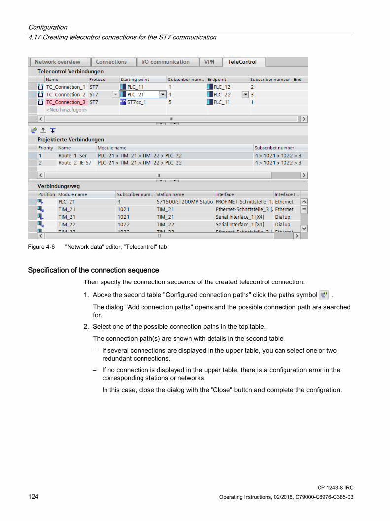
Configuration 4.17 Creating telecontrol connections for the ST7 communication
CP 1243-8 IRC 124 Operating Instructions, 02/2018, C79000-G8976-C385-03
Figure 4-6 "Network data" editor, "Telecontrol" tab
Specification of the connection sequence Then specify the connection sequence of the created telecontrol connection.
1. Above the second table "Configured connection paths" click the paths symbol .
The dialog "Add connection paths" opens and the possible connection path are searched for.
2. Select one of the possible connection paths in the top table.
The connection path(s) are shown with details in the second table.
– If several connections are displayed in the upper table, you can select one or two redundant connections.
– If no connection is displayed in the upper table, there is a configuration error in the corresponding stations or networks.
In this case, close the dialog with the "Close" button and complete the configration.
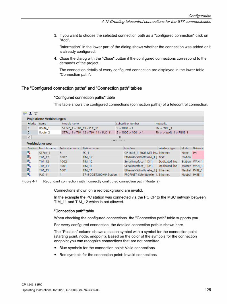
Configuration 4.17 Creating telecontrol connections for the ST7 communication
CP 1243-8 IRC Operating Instructions, 02/2018, C79000-G8976-C385-03 125
3. If you want to choose the selected connection path as a "configured connection" click on "Add".
"Information" in the lower part of the dialog shows whether the connection was added or it is already configured.
4. Close the dialog with the "Close" button if the configured connections correspond to the demands of the project.
The connection details of every configured connection are displayed in the lower table "Connection path".
The "Configured connection paths" and "Connection path" tables
"Configured connection paths" table
This table shows the configured connections (connection paths) of a telecontrol connection.
Figure 4-7 Redundant connection with incorrectly configured connection path (Route_2)
Connections shown on a red background are invalid.
In the example the PC station was connected via the PC CP to the MSC network between TIM_11 and TIM_12 which is not allowed.
"Connection path" table
When checking the configured connections. the "Connection path" table supports you.
For every configured connection, the detailed connection path is shown here.
The "Position" column shows a station symbol with a symbol for the connection point (starting point, node, endpoint). Based on the color of the symbols for the connection endpoint you can recognize connections that are not permitted.
● Blue symbols for the connection point: Valid connections
● Red symbols for the connection point: Invalid connections

Configuration 4.17 Creating telecontrol connections for the ST7 communication
CP 1243-8 IRC 126 Operating Instructions, 02/2018, C79000-G8976-C385-03
Bad connections
In the example the connection path "Route_2" was originally created from the application "ST7cc_1" (PC_1) via the MSC network to TIM_12. This continued via the dedicated line network from TIM_12 to TIM_11.
A connection path from the application via an MSC network or via modules with ST7 capability is not permitted.
The connection of the PC station to the MSC network was deleted in the meantime, so that the connection points "ST7cc_1" and "TIM_12" are invalid and their symbols are red.
Redundant telecontrol connections
When different networks between two subscribers have been created in the network configuration the different connection paths are shown in the "Add connection paths" table.
If you only want to use one connection, select only this connection in the table and click "Add".
If you only want to establish a redundant connection, select two connection paths in the table and click "Add". You specify the main and substitute paths between the subscribers after closing the dialog using the "Configured connections" table.
Main and substitute path of a redundant connection
When you have created two connection paths for a telecontrol connection, the first of the two is the main path and the second the substitute path. This is displayed in the "Priority" column of the "Configured connections" table.
You can change the priority of the two connection paths later, i.e. the specification of the main and substitute path. The arrow keys serve this purpose:
Delete invalid or redundant connections If you have non-permitted or unwanted redundant connections you need to delete one connection. Follow the steps outlined below:
1. To delete a connection in the table "Configured connections", select the connection you do not need.
2. Delete the connection using the shortcut menu "Delete".
Rules for connection configuration Note the following rules for connection configuration:
● A connection via an inconsistent network is invalid. Examples:
– Subscriber with incompatible modems
– Incompatible settings of two modems in a connection
– Incompatible settings between modem and network parameters
– Connections via nodes that are not configured as node stations.
● Two connections to one partner (endpoint) via the same interface of a module (start point) are not permitted.
Configuration 4.17 Creating telecontrol connections for the ST7 communication
CP 1243-8 IRC Operating Instructions, 02/2018, C79000-G8976-C385-03 127
● An MSC connection can only run via the first Ethernet interface [X1] of a TIM or via the serial interface of a module with the setting "IP-based".
● Connections between a PC application and a module can only be of the Network type "Neutral" (S7 connections).
● For connections between a redundant PC application and a module, you need to create two connections.
For a redundant ST7cc control center, in STEP 7 create two PC stations each with an ST7cc application (see below).
Only in this way can you configure a connection from each application.
● A connection via a network in which two MD3 modems communicate with each other and that are configured with 1200 bps / half duplex / AT mode is invalid.
Connections to redundant control centers and other properties If you select a connection in the table "Telecontrol connections" at the top in the "Network data" editor, three parameter groups are displayed in the "Properties" tab of the Inspector window. Here you can check and, if necessary, correct the connection configuration and configure the following properties:
● General
Here, you will find the basic properties of a telecontrol connection.
You can change the subscriber number of the connection starting point and endpoint. This affects the configuration data of the subscriber.
● Redundant ST7cc/sc
If you use a redundant control center in your project (e.g. ST7cc or ST7sc), you must first create two PC stations with CP and application and connect these to the communication module via Ethernet.
Then you create a telecontrol connection from the application of a PC station (start point) and the communication module (end point).
Only afterwards do you create the connection to the second application in the redundancy group in this telecontrol connection.
– Add redundant ST7cc/cc partner
Activate the option for the selected telecontrol connection between application and module.
– Redundant application
Select the second application from the "Redundant application" drop-down list.

Configuration 4.18 Data points
CP 1243-8 IRC 128 Operating Instructions, 02/2018, C79000-G8976-C385-03
● Destination subscriber properties
The parameter group relates to the destination subscriber that was configured as the endpoint of the connection.
– General request supervision time
This is the maximum time that may be required by a destination subscriber (communication module capable of ST7) to respond fully to a general request (GR).
If the GR response has not arrived completely at the requesting partner when the supervision time has expired, a message is entered in the diagnostics buffer of the module.
The general request supervision time is 900 seconds.
– Frames to destination subscriber with time stamp
Regardless of the configuration all frames are sent to the destination subscriber with a time stamp.
4.18 Data points
4.18.1 Data point configuration
Data point-related communication with the CPU No program blocks need to be programmed for telecontrol modules with data point configuration to transfer user data between the station and communications partner.
The data areas in the memory of the CPU intended for communication with the communications partner are configured data point-related on the module. Each data point is linked to a PLC tag or the tag of a data block.
Requirement: Created PLC tags and/or data blocks (DBs) PLC tags or DBs must first be created on the CPU to allow configuration of the data points.
The PLC tags for data point configuration can be created in the standard tag table or in a user-defined tag table. All PLC tags intended to be used for data point configuration must have the attribute "Visible in HMI".
Address areas of the PLC tags are input, output or bit memory areas on the CPU.
Note Number of PLC tags
Remember the maximum possible number of PLC tags the can be used for data point configuration in the section Performance data and configuration limits (Page 22).
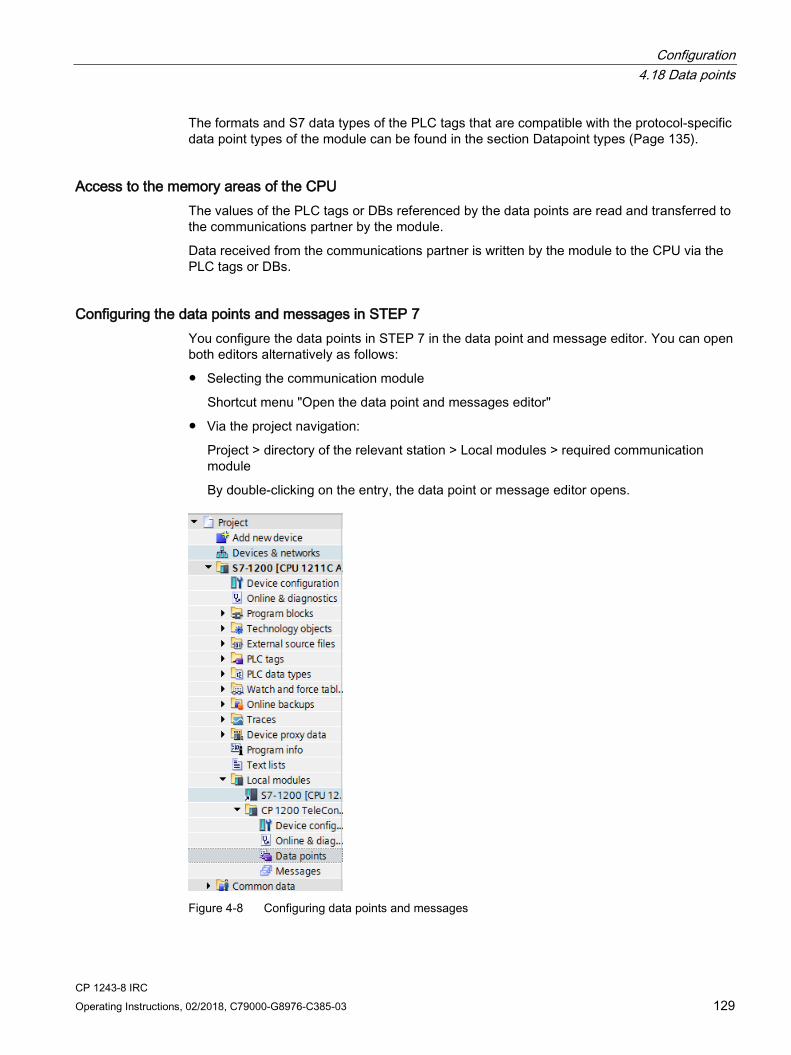
Configuration 4.18 Data points
CP 1243-8 IRC Operating Instructions, 02/2018, C79000-G8976-C385-03 129
The formats and S7 data types of the PLC tags that are compatible with the protocol-specific data point types of the module can be found in the section Datapoint types (Page 135).
Access to the memory areas of the CPU The values of the PLC tags or DBs referenced by the data points are read and transferred to the communications partner by the module.
Data received from the communications partner is written by the module to the CPU via the PLC tags or DBs.
Configuring the data points and messages in STEP 7 You configure the data points in STEP 7 in the data point and message editor. You can open both editors alternatively as follows:
● Selecting the communication module
Shortcut menu "Open the data point and messages editor"
● Via the project navigation:
Project > directory of the relevant station > Local modules > required communication module
By double-clicking on the entry, the data point or message editor opens.
Figure 4-8 Configuring data points and messages
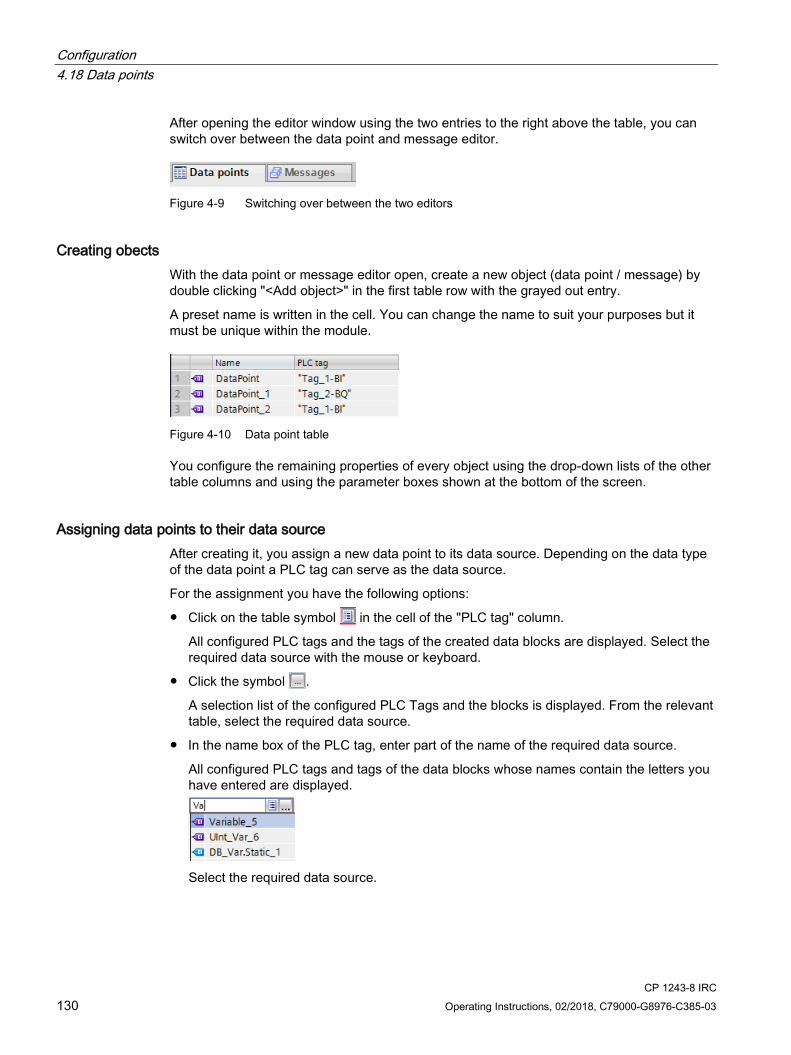
Configuration 4.18 Data points
CP 1243-8 IRC 130 Operating Instructions, 02/2018, C79000-G8976-C385-03
After opening the editor window using the two entries to the right above the table, you can switch over between the data point and message editor.
Figure 4-9 Switching over between the two editors
Creating obects With the data point or message editor open, create a new object (data point / message) by double clicking "<Add object>" in the first table row with the grayed out entry.
A preset name is written in the cell. You can change the name to suit your purposes but it must be unique within the module.
Figure 4-10 Data point table
You configure the remaining properties of every object using the drop-down lists of the other table columns and using the parameter boxes shown at the bottom of the screen.
Assigning data points to their data source After creating it, you assign a new data point to its data source. Depending on the data type of the data point a PLC tag can serve as the data source.
For the assignment you have the following options:
● Click on the table symbol in the cell of the "PLC tag" column.
All configured PLC tags and the tags of the created data blocks are displayed. Select the required data source with the mouse or keyboard.
● Click the symbol .
A selection list of the configured PLC Tags and the blocks is displayed. From the relevant table, select the required data source.
● In the name box of the PLC tag, enter part of the name of the required data source.
All configured PLC tags and tags of the data blocks whose names contain the letters you have entered are displayed.
Select the required data source.

Configuration 4.18 Data points
CP 1243-8 IRC Operating Instructions, 02/2018, C79000-G8976-C385-03 131
Note Assignment of parameter values to PLC tags
The mechanisms described here also apply when you need to assign the value of a parameter to a PLC tag. The input boxes fro the PLC tag (e.g.: PLC tag for partner status support the functions described here for selecting the PLC tag.
Arranging and copying objects As with many other programs in the data point or message editor you can also arrange the columns, sort the table according to your requirements and copy and insert objects.
● Arrange columns
If you click on a column header with the left mouse button pressed, you can move the column.
● Sorting objects
If you click briefly with the left mouse button on a column header, you can sort the objects of the table in ascending or descending order according to the entries in this column. The sorting is indicated by an arrow in the column header.
After sorting in descending order of a column the sorting can be turned off by clicking on the column header again.
● Adapting the column width
You can reach this function with the following actions:
– Using the shortcut menu that opens when you click on a column header with the right mouse key.
"Optimize width", "Optimize width of all columns"
– If you move the cursor close to the limit of a column header, the following symbol appears:
When it does, click immediately on the column header. The column width adapts itself to the broadest entry in this column.
● Showing / hiding columns
You call this function using the shortcut menu that opens when you click on a column header with the right mouse key.
● Copying, pasting, cutting and deleting objects
If you click in a parameter box of an object in the table with the right mouse key, you can use the functions named with the shortcut menu (copy, paste, cut, delete).
You can paste cut or copied objects within the table or in the first free row below the table.

Configuration 4.18 Data points
CP 1243-8 IRC 132 Operating Instructions, 02/2018, C79000-G8976-C385-03
Exporting and importing data points To simplify the engineering of larger plants, you can export the data points of a configured module and import them into other modules in the project. This is an advantage particularly in projects with many identical or similar stations or data point modules.
The export / import function is available when you select the module for example in the network or device view and select the relevant shortcut menu.
Figure 4-11 Shortcut menu of the module
When it is exported the data point information of a module is written to a CSV file.
Export When you call the export function, the export dialog opens. Here, you select the module or modules of the project whose data point information needs to be exported. When necessary, you can export the data points of all modules of the project together.
In the export dialog, you can select the storage location in the file directory. When you export the data of a module you can also change the preset file name.
When you export from several modules, the files are formed with preset names made up of the station name and module name.
The file itself contains the following information in addition to the data point information:
● Module name
● Module type
● CPU name
● CPU type
Editing the export files You can edit the data point information in an exported CSV file. This allows you to use this file as a configuration template for many other stations.
If you have a project with many stations of the same type, you can copy the CSV file with the data points of a fully configured module for other as yet unconfigured stations and adapt individual parameters to the particular station. This saves you having to configure the data points for every module in STEP 7. Instead, you simply import the copied and adapted CSV file to the other modules of the same type. When you import this file into another module, the changed parameter values of the CSV file are adopted in the data point configuration of this module.

Configuration 4.18 Data points
CP 1243-8 IRC Operating Instructions, 02/2018, C79000-G8976-C385-03 133
The lines of the CSV file have the following content:
● Line 1: ,Name,Type,
This line must not be changed.
● Line 2: PLC,<CPU name>, <CPU type>,
Meaning: PLC (designation of the station class), CPU name, CPU type
Only the elements <CPU name> and <CPU type> may be changed.
The CPU type must correspond exactly to the name of the CPU in the catalog.
● Line 3: Module,<module name>,<module type>,
Meaning: Module (Designation of the module class), module type, module name
Only the elements <module name> and <module type> may be changed.
Be careful when changing the module names if you want to import data points into several modules (see below).
The module type must correspond exactly to the name of the module in the catalog.
● Line 4: Parameter names (English) of the data points
This line must not be changed.
● Lines 5..n: Values of the parameters according to line 4 of the individual data points
You can change the parameter values for the particular station.
Importing into a module Before importing the data points make sure that the PLC tags required for the data points have been created.
Note that when you import a CSV file all the data points existing on the module will be deleted and replaced by the imported data points.
Select a module and select the import function from the shortcut menu of the module. The import dialog opens in which you select the required CSV file in the file directory.
If the information on the assignment of the individual data points to the relevant PLC tags matches the assignment in the original module, the data points will be assigned to the corresponding PLC tags.
When you import data points into a module, but some required PLC tags have not yet been created in the CPU, the corresponding data point information cannot be assigned. In this case, you can subsequently create missing PLC tags and them assign them the imported data point information. The "Assignment repair" function is available for this (see below).
If the names of the PLC tags in the module into which the import is made have different names than in the module that exported, the corresponding data points cannot be assigned to your PLC tags.
Importing into several modules You can import the data points from several modules into the modules of a different project. To do this in the import dialog select all the required CSV files with the control key.
Configuration 4.18 Data points
CP 1243-8 IRC 134 Operating Instructions, 02/2018, C79000-G8976-C385-03
Before importing the data points, make sure that the respective stations have been created with CPUs of the same name, modules of the same name and PLC tags of the same name.
When you import the corresponding stations of the project are searched for based on the module names in the CSV files. If a target station does not exist in the project or the module has a different name, the import of the particular CSV file will be ignored.
Restrictions for the import of data points In the following situations the import of data points will be aborted:
● An attribute required by the module is missing in the CSV file to be imported.
Example: If a data point to be imported uses a time trigger, the import will be aborted if no time-of-day synchronization was configured for the module.
● The telecontrol protocol used by the module differs from that of the original module.
Only when importing into several modules:
● The import is aborted when a module or CPU name is different from the data in the CSV file.
Note: Modules with the same telecontrol protocol are compatible with each other:
● TeleControl Basic
All SIMATIC NET modules with the TeleControl Basic protocol:
CP 1243-1, CP 1242-7 GPRS V2, CP 1243-7 LTE, CP 1542SP-1 IRC
● ST7
CP 1243-8 IRC, CP 1542SP-1 IRC, ST7 TIM
● DNP3
CP 1243-1, CP 1243-8 IRC, TIM modules capable of DNP3
● IEC
CP 1243-1, CP 1243-8 IRC
Data points can be imported and exported between compatible modules.
Assignment repair If you have named the PLC tags in a station into which you want to import differently from the station from which the CSV file was exported, the assignment between data point and PLC tag is lost when you import.
You then have the option to either rename the existing PLC tags appropriately or add missing PLC tags. You can then repair the assignment between unassigned data points and PLC tags. This function is available either via the shortcut menu of the module (see above) or with the following icon to the upper left in the data point editor:
If a PLC tag with a matching name is found for a data point by the repair function, the assignment is restored. However the data type of the tag is not checked.
After the assignment repair make sure that you check whether the newly assigned PLC tags are correct.

Configuration 4.18 Data points
CP 1243-8 IRC Operating Instructions, 02/2018, C79000-G8976-C385-03 135
4.18.2 Syntax of the data point names
Character set for data point names When you create a data point, a preset name "DataPoint_n" is adopted. In the data point table and in the "General" tab of the data point you can change the name of the data point.
When assigning names only ASCII characters from the band 0x20 ... 0x7e (no. 32-126) may be used with the exceptions listed below.
Forbidden characters:
● . ' [ ] / \ | period, apostrophe, square brackets, slash, back slash, vertical line (pipe)
4.18.3 Datapoint types Configure the user data to be transferred from the CP that is referenced via PLC tags of the CPU on the CP as data points.
The data point types supported by the CP along with the compatible S7 data types are listed below for the various telecontrol protocols.
Note Effect of the change of arrays for data points
If an array is modified later, the data point must be recreated.
Data point types of the "ST7" protocol The direction of the data transfer is specified in the "Data point type" column:
● Monitoring direction
The objects (right column) for the monitoring direction have the abbreviation "_S".
● Control direction
The objects (right column) for the control direction have the abbreviation "_R".
Table 4- 2 Supported data point types and compatible S7 data types
Format (memory requirements)
Data point type S7 data type Operand area Number of data points per object
Object
Bit Digital input Bool I, Q, M, DB 8 Bin08X_S Digital output Bool Q, M, DB 8 Bin08X_R
Byte Digital input Byte, USInt I, Q, M, DB 4 Bin04B_S Digital output Byte, USInt Q, M, DB 4 Bin04B_R Command output Byte, USInt Q, M, DB 1 Cmd01B_R Command input 1) Byte, USInt I, Q, M, DB 1 Cmd01B_S 1)

Configuration 4.18 Data points
CP 1243-8 IRC 136 Operating Instructions, 02/2018, C79000-G8976-C385-03
Format (memory requirements)
Data point type S7 data type Operand area Number of data points per object
Object
Integer with sign (16 bits)
Analog input Int I, M, DB 4 Ana04W_S Mean value input Int I, M, DB 4 Mean04W_S Analog output Int Q, M, DB 4 Ana04W_R Mean value output Int Q, M, DB 4 Mean04W_R Setpoint output 2) Int Q, M, DB 1 Set01W_R Setpoint input 1) Int I, Q, M, DB 1 Set01W_S 1)
Counter (16 bits) Counter input UInt, Word I, Q, M, DB 1 Cnt01D_S Counter input UInt, Word I, Q, M, DB 4 Cnt04D_S Counter output 1) UDInt, DWord Q, M, DB 1 Cnt01D_R 1) Counter output 1) UDInt, DWord Q, M, DB 4 Cnt04D_R 1)
Floating-point number (32 bits)
Analog input Real M, DB 4 Ana04R_S Analog output Real Q, M, DB 4 Ana04R_R
Block of data (4 .. 48 bytes)
Data input ARRAY [1...12] of DInt / UDInt / DWord / Real 3)
DB 12 Dat12D_S Data output DB 12 Dat12D_R Parameter output 2) DB 12 Par12D_R Parameter input 1) DB 12 Par12D_S 1)
1) Only ST7-TIM as master station or node station 2) See below, section "1: Mirroring back" 3) See below, section "2: Block of data"
Mirroring back
The mirroring back function using the "Value monitoring" parameter can be configured for the following data point types:
● Setpoint output
● Parameter output
The local values of the data points of this type can be monitored for changes and the changes transferred to the master with the "Value monitoring" function.
A change to a local value can be caused by, for example, manual operator input on site.
To allow the value resulting from local events or interventions to be transferred to the master station, a mirroring back channel is generated for the relevant data point with the "Value monitoring" function via which the locally changed value is mirrored back.
Remember that to use the mirror back function, you need to interconnect the local values in the controller with the relevant PLC tag of the data point.
Block of data
With the ARRAY data type, blocks of data from contiguous memory areas up to a size of 4 .. 48 bytes can be transferred.
Compatible components of ARRAY are DInt, UDint, DWord or Real. The components within an array must be of the same type.
Format of the time stamp
For information on the format of the time stamp, see below .

Configuration 4.18 Data points
CP 1243-8 IRC Operating Instructions, 02/2018, C79000-G8976-C385-03 137
Data point types of the "DNP3" protocol The "Direction" column shows the transmission direction:
● "in / input": Monitoring direction
● "out / output": Control direction
Table 4- 3 Supported data point types, DNP3 object groups, variants and compatible S7 data types
Format (memory require-ments)
Data point type CP [Data point type TIM]
DNP3 object group
[variations]
Direction S7 data types Operand area
Bit Binary Input 1 [1, 2] in Bool I, Q, M, DB Binary Input Event 2 [1, 2] in Bool I, Q, M, DB Binary Output 1) 10 [2] out Bool Q, M, DB Binary Output Event 1) 11 [1, 2] out Bool Q, M, DB Binary Command 12 [1] out Bool Q, M, DB
Integer (16 bits) Counter Static 20 [2] in UInt, Word I, Q, M, DB Frozen Counter 2) 21 [2, 6] in UInt, Word I, Q, M, DB Counter Event 22 [2, 6] in UInt, Word I, Q, M, DB Frozen Counter Event 3)
23 [2, 6] in UInt, Word I, Q, M, DB
Analog Input 30 [2] in Int I, Q, M, DB Analog Input Event 32 [2] in Int I, Q, M, DB Analog Output Sta-tus 4)
40 [2] out Int Q, M, DB
Analog Output 41 [2] out Int Q, M, DB Analog Output Event 4)
42 [2, 4] out Int Q, M, DB
Integer (32 bits) Counter Static 20 [1] in DWord I, Q, M, DB Frozen Counter 2) 21 [1, 5] in DWord I, Q, M, DB Counter Event 22 [1, 5] in DWord I, Q, M, DB Frozen Counter Event 3)
23 [1, 5] in DWord I, Q, M, DB
Analog Input 30 [1] in DInt Q, M, DB Analog Input Event 32 [1] in DInt Q, M, DB Analog Output Sta-tus 4)
40 [1, 3] out DInt Q, M, DB
Analog Output 41 [1] out DInt Q, M, DB Analog Output Event 4)
42 [1] out DInt Q, M, DB
Floating-point number (32 bits)
Analog Input 30 [5] in Real Q, M, DB Analog Input Event 32 [5, 7] in Real Q, M, DB Analog Output Sta-tus 4)
40 [3] out Real Q, M, DB
Analog Output 41 [3] out Real Q, M, DB Analog Output Event 4)
42 [5, 7] out Real Q, M, DB
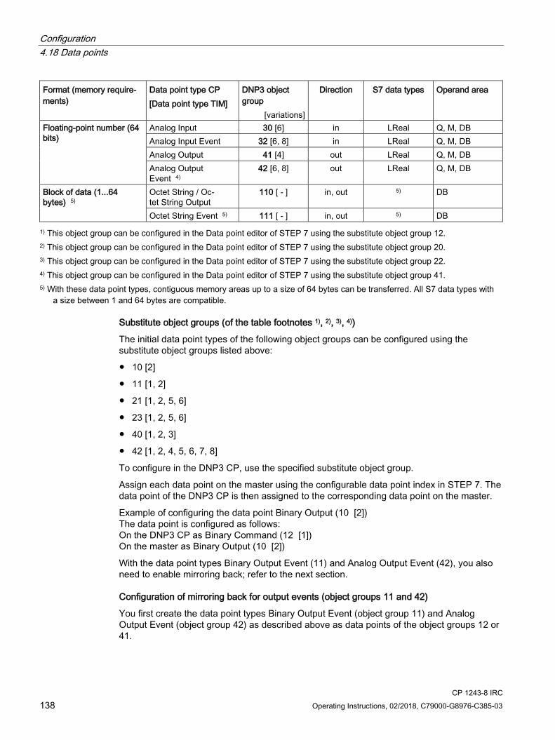
Configuration 4.18 Data points
CP 1243-8 IRC 138 Operating Instructions, 02/2018, C79000-G8976-C385-03
Format (memory require-ments)
Data point type CP [Data point type TIM]
DNP3 object group
[variations]
Direction S7 data types Operand area
Floating-point number (64 bits)
Analog Input 30 [6] in LReal Q, M, DB Analog Input Event 32 [6, 8] in LReal Q, M, DB Analog Output 41 [4] out LReal Q, M, DB Analog Output Event 4)
42 [6, 8] out LReal Q, M, DB
Block of data (1...64 bytes) 5)
Octet String / Oc-tet String Output
110 [ - ] in, out 5) DB
Octet String Event 5) 111 [ - ] in, out 5) DB 1) This object group can be configured in the Data point editor of STEP 7 using the substitute object group 12.
2) This object group can be configured in the Data point editor of STEP 7 using the substitute object group 20. 3) This object group can be configured in the Data point editor of STEP 7 using the substitute object group 22. 4) This object group can be configured in the Data point editor of STEP 7 using the substitute object group 41. 5) With these data point types, contiguous memory areas up to a size of 64 bytes can be transferred. All S7 data types with
a size between 1 and 64 bytes are compatible.
Substitute object groups (of the table footnotes 1), 2), 3), 4))
The initial data point types of the following object groups can be configured using the substitute object groups listed above:
● 10 [2]
● 11 [1, 2]
● 21 [1, 2, 5, 6]
● 23 [1, 2, 5, 6]
● 40 [1, 2, 3]
● 42 [1, 2, 4, 5, 6, 7, 8]
To configure in the DNP3 CP, use the specified substitute object group.
Assign each data point on the master using the configurable data point index in STEP 7. The data point of the DNP3 CP is then assigned to the corresponding data point on the master.
Example of configuring the data point Binary Output (10 [2]) The data point is configured as follows: On the DNP3 CP as Binary Command (12 [1]) On the master as Binary Output (10 [2])
With the data point types Binary Output Event (11) and Analog Output Event (42), you also need to enable mirroring back; refer to the next section.
Configuration of mirroring back for output events (object groups 11 and 42)
You first create the data point types Binary Output Event (object group 11) and Analog Output Event (object group 42) as described above as data points of the object groups 12 or 41.

Configuration 4.18 Data points
CP 1243-8 IRC Operating Instructions, 02/2018, C79000-G8976-C385-03 139
The local values of these two object groups can be monitored for changes and the changes transferred to the master. A change to a local value can be caused by, for example, manual operator input on site.
To allow the value resulting from local events or interventions to be transferred to the master, the data point in question requires a channel for mirroring back. You configure this mirroring back function using the "Value monitoring" option in data point configuration, "General" tab.
Remember that to use the mirror back function, you need to interconnect the local values in the controller with the relevant PLC tag of the data point.
Format of the time stamp
Time stamps are transferred in UTC format (48 bits) and contain milliseconds.
Data point types of the "IEC" protocol The "Direction" column shows the transmission direction:
● "in / input": Monitoring direction
● "out / output": Control direction
Table 4- 4 Supported data point types, IEC types and compatible S7 data types
Format (memory requirements)
Data point type IEC type Direction S7 data types Operand area
Bit Single-point information <1> in Bool I, Q, M, DB Single-point information with time tag CP56Time2a 1)
<30> in Bool I, Q, M, DB
Single command <45> out Bool Q, M, DB Single command with time tag CP56Time2a 1)
<58> out Bool Q, M, DB
Byte Step position information <5> in Byte, USInt I, Q, M, DB Step position information with time tag CP56Time2a 1)
<32> in Byte, USInt I, Q, M, DB
Integer (16 bits) Measured value, normalized value <9> in Int I, Q, M, DB Measured value, normalized value with time tag CP56Time2a 1)
<34> in Int I, Q, M, DB
Measured value, scaled value <11> in Int I, Q, M, DB Measured value, scaled value with time tag CP56Time2a 1)
<35> in Int I, Q, M, DB
Set point command, normalised value
<48> out Int Q, M, DB
Set point command, scaled value <49> out Int Q, M, DB Set point command, normalised value with time tag CP56Time2a 1)
<61> out Int Q, M, DB
Set point command, scaled value with time tag CP56Time2a 1)
<62> out Int Q, M, DB

Configuration 4.18 Data points
CP 1243-8 IRC 140 Operating Instructions, 02/2018, C79000-G8976-C385-03
Format (memory requirements)
Data point type IEC type Direction S7 data types Operand area
Integer (32 bits) Bitstring of 32 bits <7> in UDInt, DWord I, Q, M, DB Bitstring of 32 bits with time tag CP56Time2a 1)
<33> in UDInt, DWord I, Q, M, DB
Integrated totals <15> in UDInt, DWord I, Q, M, DB Integrated totals with time tag CP56Time2a 1)
<37> in UDInt, DWord I, Q, M, DB
Bitstring of 32 bits <51> out UDInt, DWord Q, M, DB Bitstring of 32 bits with time tag CP56Time2a - control direction 1)
<64> out UDInt, DWord Q, M, DB
Floating-point number (32 bits)
Measured value, short floating point number
<13> in Real Q, M, DB
Measured value, short floating point number with time tag CP56Time2a 1)
<36> in Real Q, M, DB
Set point command, short floating point number
<50> out Real Q, M, DB
Set point command, short floating point with time tag CP56Time2a 1)
<63> out Real Q, M, DB
Block of data (1...2 Bit) 2)
Double-point information <3> in 2) DB Double-point information with time tag CP56Time2a 1)
<31> in 2) DB
Double command <46> out 2) DB Regulating step command <47> out 2) DB Double command with time tag CP56Time2a 1) 2)
<59> out 2) DB
Regulating step command with time tag CP56Time2a 1) 2)
<60> out 2) DB
Block of data (1...32 Bit) 3)
Bitstring of 32 bits 3) <7> in 3) DB Bitstring of 32 bits with time tag CP56Time2a 1) 3)
<33> in 3) DB
Bitstring of 32 bits 3) <51> out 3) DB Bitstring of 32 bits with time tag CP56Time2a - control direction 1) 3)
<64> out 3) DB
1) For the format of the time stamp, see the following section. 2) For these data point types, create a data block with an array of precisely 2 bool. 3) With these data point types, contiguous memory areas up to a size of 32 bits can be transferred. Only the S7 Bool data
type is compatible.
Format of the time stamp
Time stamps are transferred according to the IEC specification in the "CP56Time2a" format. Note that in the frames only the first 3 bytes for milliseconds and minutes are transferred.

Configuration 4.18 Data points
CP 1243-8 IRC Operating Instructions, 02/2018, C79000-G8976-C385-03 141
Time stamp of the ST7 frames The values of the data points are transferred by the communications moduel with a time stamp, see also section Creating telecontrol connections for the ST7 communication (Page 122), subsection "Connections to redundant control centers and other properties".
Format of the time stamp The ST7 time stamp is coded in BCD format. The exception is the half byte (nibble) with the time status.
The structure of 8 bytes is assigned as follows:
Table 4- 5 Assignment of the structure of the time stamp
Byte no. Content High nibble Low nibble
0 Year * 10 Year * 1 1 Month * 10 Month * 1 2 Day * 10 Day * 1 3 Hour * 10 Hour * 1 4 Minute * 10 Minute * 1 5 Second * 10 Second * 1 6 Millisecond * 100 Millisecond * 10 7 Millisecond * 1 Time status
Table 4- 6 The assignment of the half byte "time status" (low nibble of byte 7)
Bit No. Value Meaning 0 0 Time is invalid
1 Time is valid 1 0 Standard time
1 Daylight saving time 2 Not used 3 Not used
4.18.4 Status IDs of the data points
Status identifier (DNP3, IEC) With the DNP3 and IEC protocols status identifiers of the values are output. The status identifiers of the data points listed in the following tables are transferred along with the value in each frame to the communications partner. They can be evaluated by the communications partner.
The entries in the table row "Significance" relate to the entry in the table row "Bit status".
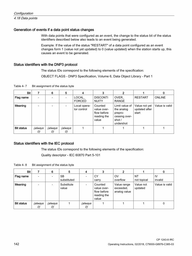
Configuration 4.18 Data points
CP 1243-8 IRC 142 Operating Instructions, 02/2018, C79000-G8976-C385-03
Generation of events if a data point status changes With data points that were configured as an event, the change to the status bit of the status identifiers described below also leads to an event being generated.
Example: If the value of the status "RESTART" of a data point configured as an event changes form 1 (value not yet updated) to 0 (value updated) when the station starts up, this causes an event to be generated.
Status identifiers with the DNP3 protocol The status IDs correspond to the following elements of the specification:
OBJECT FLAGS - DNP3 Specification, Volume 6, Data Object Library - Part 1
Table 4- 7 Bit assignment of the status byte
Bit 7 6 5 4 3 2 1 0 Flag name - - - LOCAL_
FORCED DISCONTI NUITY
OVER_ RANGE
RESTART ONLINE
Meaning - - - Local opera-tor control
Counted value over-flow before reading the value
Limit value of the analog prepro-cessing over-shot / undershot
Value not yet updated after start
Value is valid
Bit status (always 0)
(always 0)
(always 0)
1 1 1 1 1
Status identifiers with the IEC protocol The status IDs correspond to the following elements of the specification:
Quality descriptor - IEC 60870 Part 5-101
Table 4- 8 Bit assignment of the status byte
Bit 7 6 5 4 3 2 1 0 Flag name - - SB
substituted - CY
carry OV overflow
NT not topical
IV invalid
Meaning - - Substitute value
- Counted value over-flow before reading the value
Value range exceeded, analog value
Value not updated
Value is valid
Bit status (always 0)
(always 0)
1 (always 0)
1 1 1 0

Configuration 4.18 Data points
CP 1243-8 IRC Operating Instructions, 02/2018, C79000-G8976-C385-03 143
4.18.5 "General" tab
"General" tab
Data point index
With the DNP3 and IEC protocols the index is an addressing parameter for a data point. Below you will find the rules for configuring in the section Configuration of the data point index (Page 144).
In ST7 a data point is addressed by the object number and the channel (see below).
Type of transmission
For the CP the following transmission types are available: Triggering assigns the data point an event class.
● Transfer after call
The current value of the data point is entered in the image memory of the CP.
● Every value triggered
Each value change is entered in the send buffer in chronological order.
● Current value triggered
Only the current value is entered in the send buffer.
See section Process image, type of transmission, event classes (Page 144) for information on this.
Read cycle
Prioritizes the reading or writing of the data point value in the scan cycle of the CPU.
See section Read cycle (Page 147) for information on this.
Object number (ST7)
The object number must be unique and the maximum permitted number of data points per SINAUT object must not be exceeded. Refer to the column “Number of data points per SINAUT object” in the section Datapoint types (Page 135).
Object channel (ST7)
The object channel is the channel of the corresponding SINAUT object.
Partner object number (ST7)
Per object number, you need to specify a unique object number of the communications partner.
This must result in unique pairs of "Object number" and "Partner object number".
Configuration 4.18 Data points
CP 1243-8 IRC 144 Operating Instructions, 02/2018, C79000-G8976-C385-03
4.18.6 Configuration of the data point index
Configuration of the data point index Below you will find the rules for configuring the data point index for the various protocols.
ST7 The data point indexes must be unique in a module.
Data point indexes assigned twice are indicated as errors in the consistency check and prevent the project being compiled.
DNP3 On a module, data point indexes must be unique within each of the following object groups:
● Binary Input / Binary Input Event
● Binary Output / Binary Command
● Counter / Counter Event
● Analog Input / Analog Input Event
● Analog Output
● Octet String / Octet String Event
Indexes of two data points in different object groups can be identical.
IEC The data point indexes must be unique in a module.
Data point indexes assigned twice are indicated as errors in the consistency check and prevent the project being compiled.
4.18.7 Process image, type of transmission, event classes
Saving the data point values The values of data points are generally stored in the image memory of the CP.
Events are also stored in the send buffer and can be transferred unsolicited.
Data points are configured as a static value or as an event using the "Type of transmission" parameter (see below).
Configuration 4.18 Data points
CP 1243-8 IRC Operating Instructions, 02/2018, C79000-G8976-C385-03 145
The image memory, the process image of the CP The image memory is the process image of the communications module. All the current values of the configured data points are stored in the image memory. New values of a data point overwrite the last stored value in the image memory.
The values are only transferred under the following conditions:
● After a query by the communications partner; see "Transfer after call" in the "Types of transmission" section below.
● Along with a data frame from the send buffer that needs to be transferred immediately.
The send buffer The send buffer of the CP is the memory for the individual values of data points that are configured as an event. The maximum number is divided equally among all configured and enabled communications partners. You configure the size of the send buffer with the parameter "Frame memory size", see the section Communication with the CPU (Page 95).
If the connection to a communications partner is interrupted, the individual values of the events are retained in the buffer. When the connection returns, the buffered values are sent. The frame memory operates chronologically; in other words, the oldest data is sent first (FIFO principle).
If a data frame was transferred to the communications partner, the transferred data is deleted from the send buffer.
If data cannot be transferred for a longer period of time and the send buffer is threatening to overflow, the protocol-dependent response is as follows:
● Telecontrol Basic, ST7
The forced image mode
If the send buffer reaches a certain fill level, the module changes to the forced image mode. The fill level for changing to the forced image mode is:
– Telecontrol Basic: 80 % occupation of the send buffer
– ST7: 90 % occupation of the send buffer
New values of data points configured as an event are no longer added to the send buffer in forced image mode. Rather, they overwrite older existing values in the image memory.
When the connection to the communications partner returns, the module changes back to the send buffer mode as soon as the fill level of the send buffer has fallen below 50 %.
● DNP3 / IEC
If the fill level of the send buffer reaches 100 %, no more values are saved until the fill level falls below 100 % again.
Configuration 4.18 Data points
CP 1243-8 IRC 146 Operating Instructions, 02/2018, C79000-G8976-C385-03
Static values and events The following relationship exists between the memory areas of the CP and the "Type of transmission":
● Static value (no event)
Static values are entered in the image memory (process image of the CP).
With DNP3 and IEC, static values correspond to the following classes:
– DNP3: Class 0
– IEC: Class 2
● Event
The values of data points configured as an event are also entered in the image memory.
The values of events are entered in the send buffer of the communications module in addition.
With DNP3 and IEC, events correspond to the following classes:
– DNP3: Class 1 / 2 / 3
– IEC: Class 1
A data point is configured as a static value or as an event using the "Type of transmission" parameter (see below).
Type of transmission The following types of transmission are possible:
● Transfer after call (class 0)
The current value of the data point is entered as static value in the image memory of the CP. New values of a data point overwrite the last stored value in the image memory.
After being called by the communications partner, the current value at the time is transferred.
● Triggered (events)
The values of data points configured as an event are entered in the image memory and also in the send buffer of the CP.
The values of events are saved in the following situations:
– The configured trigger conditions are fulfilled (data point configuration > "Trigger" tab, see below)
– The value of a status bit of the status identifiers of the data point changes; see also the section Status IDs of the data points (Page 141).
Example: When the value of a data point configured as an event is updated during startup of the station by reading the CPU data for the first time, the status "RESTART" of this data point changes (bit status change 1 → 0). This leads to the generation of an event.
Events can be transmitted spontaneously; see below (Time of transmission).
Configuration 4.18 Data points
CP 1243-8 IRC Operating Instructions, 02/2018, C79000-G8976-C385-03 147
Event classes with the "Triggered" type of transmission Depending on the protocol used the following event classes are available:
● TeleControl Basic / ST7
– Every value triggered
Each value change is entered in the send buffer in chronological order.
– Current value triggered
Only the last, current value is entered in the send buffer. It overwrites the value stored there previously.
● DNP3
The evaluation of the following classification must be handled by the master.
– Event class 1
Class according to DNP3 protocol: Class 1
Each value change is entered in the send buffer in chronological order.
– Event class 2
Class according to DNP3 protocol: Class 2
Each value change is entered in the send buffer in chronological order.
– Event class 3
Class according to DNP3 protocol: Class 3
Only the current value at the time the trigger condition is met is entered in the send buffer and overwrites the last value stored there.
● IEC
Both of the following event classes correspond to the user data class 1 of the IEC protocol
– Every value triggered
Each value change is entered in the send buffer in chronological order.
– Current value triggered
Only the current value at the time the trigger condition is met is entered in the send buffer and overwrites the last value stored there.
For the possible trigger types, see section "Trigger“ tab (Page 148).
4.18.8 Read cycle
Priority of the data points The cyclic reading of the values of input data points from their assigned PLC tags on the CPU can be prioritized.

Configuration 4.18 Data points
CP 1243-8 IRC 148 Operating Instructions, 02/2018, C79000-G8976-C385-03
Less important input data points do not need to be read in every CPU scan cycle. Important input data points, on the other hand, can be prioritized for updating in every CPU scan cycle.
You can prioritize the data points in STEP 7 in the data point configuration in the "General" tab with the "Read cycle" parameter. There you will find the two following options for input data points:
● Fast cycle
● Normal cycle
The data points are read according to the method described below.
Structure of the CPU scan cycle The cycle (including the pause) with which the CP scans the memory area of the CPU is made up of the following phases:
● High-priority read jobs
The values of input data points with the scan priority "High-priority" are read in every scan cycle.
● Low priority read jobs
Some of the values of input data points with the scan priority "Low-priority" are read in every scan cycle.
The number of values read per cycle is specified for the CP in the "Communication with the CPU" parameter group with the "Max. number of read jobs" parameter. The values that exceed this value and can therefore not be read in one cycle are then read in the next or one of the following cycles.
● Write jobs
In every cycle, the values of a certain number of unsolicited write jobs are written to the CPU. The number of values written per cycle is specified for the CP in the "Communication with the CPU" parameter group with the "Max. number of write jobs" parameter. The values whose number exceeds this value are then written in the next or one of the following cycles.
● Cycle pause time
This is the waiting time between two scan cycles. It is used to reserve adequate time for other processes that access the CPU via the backplane bus of the station.
4.18.9 "Trigger“ tab
Trigger Data points are configured as a static value or as an event using the "Type of transmission" parameter:

Configuration 4.18 Data points
CP 1243-8 IRC Operating Instructions, 02/2018, C79000-G8976-C385-03 149
Saving the value of a data point configured as an event
Saving the value of a data point configured as an event in the send buffer (frame memory) can be triggered by various trigger types:
● Threshold value trigger
The value of the data point is saved when this reaches a certain threshold. The threshold is calculated as the difference compared with the last stored value, refer to the section Threshold value trigger (Page 150).
● Time trigger
The value of the data point is saved at configurable intervals or at a specific time of day.
● Event trigger (Trigger tag)
The value of the data point is saved when a configurable trigger signal is fired. For the trigger signal, the edge change (0 → 1) of a trigger tag is evaluated that is set by the user program. When necessary, a separate trigger tag can be configured for each data point.
Resetting the trigger tag in the bit memory area / DB:
If the memory area of a trigger tag is in the bit memory or in a data block, the CP resets the trigger variable itself to 0 (zero) as soon as the value of the data point has been transferred. This can take up to 500 milliseconds.
Note Fast setting of triggers
Triggers must not be set faster than a minimum interval of 500 milliseconds. This also applies to hardware triggers (input area).
Note Hardware trigger
You need to reset hardware triggers via the user program.
Time of transmission of a triggered data point (event) With the DNP3 and IEC protocols, the spontaneous transmission of events depends on whether spontaneous sending or asymmetric communication is possible in the network.
With the ST7 protocol, you define the time using the "Transmission mode" parameter.
Configuration 4.18 Data points
CP 1243-8 IRC 150 Operating Instructions, 02/2018, C79000-G8976-C385-03
Transmission mode You determine whether ST7 values are sent immediately or following a delay with the transmission mode of a data point:
● Spontaneous (unsolicited - direct transfer)
The value is transferred immediately.
● Conditional spontaneous (buffered transfer)
The value is transferred only when one of the following conditions is fulfilled:
– The communications partner queries the station.
– The value of another event with the transmission mode "Spontaneous" is transferred.
– The fill level of the send buffer has reached 80 % (TeleControl Basic) or 90 % (ST7) of its maximum capacity.
4.18.10 Threshold value trigger
Note Threshold value trigger: Calculation only after "Analog value preprocessing"
Note that the analog value preprocessing is performed before the check for a configured threshold value and before calculating the threshold value.
This affects the value that is configured for the threshold value trigger.
Note No Threshold value trigger if Mean value generation is configured
If mean value generation is configured, no threshold value trigger can be configured for the analog value event involved.
For the time sequence of the analog value preprocessing refer to the section Analog value preprocessing (Page 152).
Threshold value trigger
Function
If the process value deviates by the amount of the threshold value, the process value is saved.
Two methods are used to calculate the threshold value deviation:

Configuration 4.18 Data points
CP 1243-8 IRC Operating Instructions, 02/2018, C79000-G8976-C385-03 151
● Absolute method
With binary and counter values as well as with analog values with configured mean value generation, the absolute method is used to calculate the threshold value deviation.
● Integrative method
With analog values without configured mean value generation, the integrating method is used to calculate the threshold value deviation.
In the integration threshold value calculation, it is not the absolute value of the deviation of the process value from the last stored value that is evaluated but rather the integrated deviation.
Absolute method
For each binary value a check is made to determine whether the current (possibly smoothed) value is outside the threshold value band. The current threshold value band results from the last saved value and the amount of the configured threshold value:
● Upper limit of the threshold value band: Last saved value + threshold value
● Lower limit of the threshold value band: Last saved value - threshold value
As soon as the process value reaches the upper or lower limit of the threshold value band, the value is saved. The newly saved value serves as the basis for calculating the new threshold value band.
Integrative method
The integration threshold value calculation works with a cyclic comparison of the integrated current value with the last stored value. The calculation cycle in which the two values are compared is 500 milliseconds. (Note: The calculation cycle must not be confused with the scan cycle of the CPU memory areas).
The deviations of the current process value are totaled in each calculation cycle. The trigger is set only when the totaled value reaches the configured value of the threshold value trigger and a new process value is entered in the send buffer.
The method is explained based on the following example in which a threshold value of 2.0 is configured.
Table 4- 9 Example of the integration calculation of a threshold value configured with 2.0
Time [s] (calculation cycle)
Process value stored in the send buffer
Current process value
Absolute deviation from the stored
value
Integrated devia-tion
0 20.0 20.0 0 0 0.5 20.3 +0.3 0.3 1.0 19.8 -0.2 0.1 1.5 20.2 +0.2 0.3 2.0 20.5 +0.5 0.8 2.5 20.3 +0.3 1.1 3.0 20.4 +0.4 1.5 3.5 20.5 20.5 +0.5 2.0

Configuration 4.18 Data points
CP 1243-8 IRC 152 Operating Instructions, 02/2018, C79000-G8976-C385-03
Time [s] (calculation cycle)
Process value stored in the send buffer
Current process value
Absolute deviation from the stored
value
Integrated devia-tion
4.0 20.4 -0.1 -0.1 4.5 20.1 -0.4 -0.5 5.0 19.9 -0.6 -1.1 5.5 20.1 -0.4 -1.5 6.0 19.9 19.9 -0.6 -2.1
With the changes in the process value shown in the example, the threshold value trigger configured with 2.0 fires twice:
● At the time 3.5 s: The value of the integrated deviation is at 2.0. The new process value stored in the send buffer is 20.5.
● At the time 6.0 s: The value of the integrated deviation is at 2.1. The new process value stored in the send buffer is 19.9.
In this example, if a deviation of the process value of approximately 0.5 should fire the trigger, then with the behavior of the process value shown here a threshold value of approximately 1.5 ... 2.5 would need to be configured.
4.18.11 Analog value preprocessing CPs with data point configuration support analog value preprocessing. For analog value data points, some or all of the functions described below can be configured.
Requirements and restrictions
You will find the requirements for the configuration of the preprocessing options and restrictions in the section relating to the particular function.
Note Restrictions due to configured triggers
The analog value preprocessing options "Error suppression time", "Limit value calculation" and "Smoothing" are not performed if no threshold value trigger is configured for the relevant data point. In these cases, the read process value of the data point is entered in the image memory of the CP before the preprocessing cycle of the threshold value calculation (500 ms) elapses.

Configuration 4.18 Data points
CP 1243-8 IRC Operating Instructions, 02/2018, C79000-G8976-C385-03 153
Sequence of the analog value preprocessing options The values of analog inputs configured as an event are processed on the CPU according to the following scheme:
Figure 4-12 Sequence of the analog value preprocessing

Configuration 4.18 Data points
CP 1243-8 IRC 154 Operating Instructions, 02/2018, C79000-G8976-C385-03
The 500 millisecond cycle is started by the integrative threshold value calculation. In this cycle, the values are saved even when the following preprocessing options are enabled:
● Unipolar transfer
● Fault suppression time
● Limit value calculation
● Smoothing
Mean value generation
Note Restricted preprocessing options if mean value generation is configured
If you configure mean value generation for an analog value event, the following preprocessing options are not available: • Unipolar transfer • Fault suppression time • Smoothing
Function
With this parameter, acquired analog values are transferred as mean values.
If mean value generation is active, it makes sense to configure a time trigger..
The current values of an analog data point are read in a 100 millisecond cycle and totaled. The number of read values per time unit depends on the read cycle of the CPU and the CPU scan cycle of the CP.
The mean value is calculated from the accumulated values as soon as the transfer is triggered by a trigger. Following this, the accumulation starts again so that the next mean value can be calculated.
The mean value can also be calculated if the transmission of the analog value message is triggered by a request from the communications partner. The duration of the mean value calculation period is then the time from the last transmission (for example triggered by the trigger) to the time of the request. Once again, the accumulation restarts so that the next mean value can be calculated.
Input modules: Overflow range / underflow range
As soon as a value is acquired in the overflow or underflow range, mean value generation is stopped. The value 32767 / 7FFFh or -32768 / 8000h is saved as an invalid mean value for the current mean value calculation period and sent with the next message.

Configuration 4.18 Data points
CP 1243-8 IRC Operating Instructions, 02/2018, C79000-G8976-C385-03 155
The calculation of a new mean value is then started. If the analog value remains in the overflow or underflow range, one of the two values named is again saved as an invalid mean value and sent when the next message is triggered.
Note Fault suppression time > 0 configured
If you have configured an error suppression time and then enable mean value generation, the value of the error suppression time is grayed out but no longer used. If mean value generation is enabled, the error suppression time is set to 0 (zero) internally.
Unipolar transfer
Restrictions
Unipolar transfer cannot be configured at the same time as mean value generation. Enabling unipolar transfer has no effect when mean value generation is activated.
Function
With unipolar transfer, negative values are corrected to zero. This can be desirable if values from the underrange should not be transferred as real measured values.
Exception: With process data from input modules, the value -32768 / 8000h for wire break of a live zero input is transferred.
With a software input, on the other hand, all values lower than zero are corrected to zero.
Fault suppression time
Requirements for the function
Configuration of the threshold trigger for this data point
Restrictions
The fault suppression time cannot be configured at the same time as mean value generation. A configured value has no effect when mean value generation is activated.
Function
A typical use case for this parameter is the suppression of peak current values when starting up powerful motors that would otherwise be signaled to the control center as a disruption.
The transmission of an analog value in the overflow (7FFFh) or underflow range (8000h) is suppressed for the specified time. The value 7FFFH or 8000H is only sent after the fault suppression time has elapsed, if it is still pending.
If the value returns to the measuring range before the fault suppression time elapses, the current value is transferred.
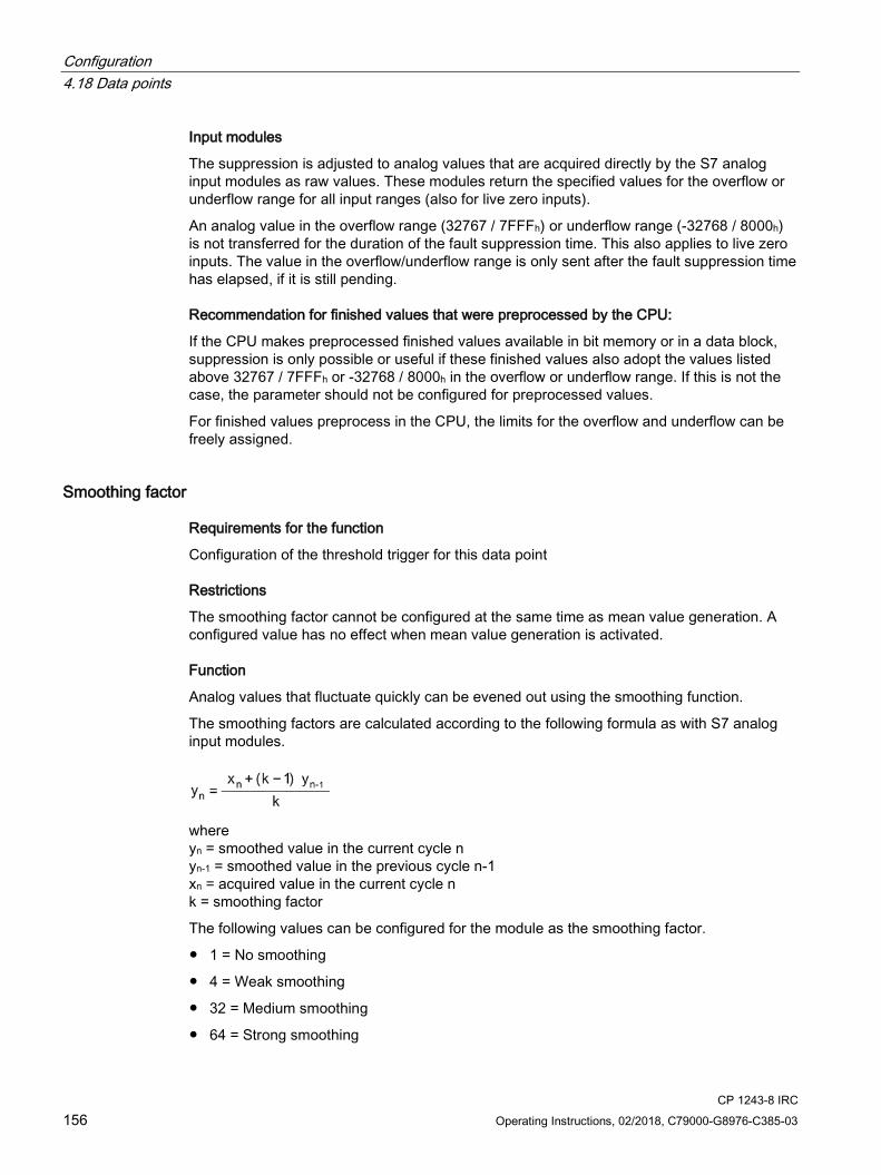
Configuration 4.18 Data points
CP 1243-8 IRC 156 Operating Instructions, 02/2018, C79000-G8976-C385-03
Input modules
The suppression is adjusted to analog values that are acquired directly by the S7 analog input modules as raw values. These modules return the specified values for the overflow or underflow range for all input ranges (also for live zero inputs).
An analog value in the overflow range (32767 / 7FFFh) or underflow range (-32768 / 8000h) is not transferred for the duration of the fault suppression time. This also applies to live zero inputs. The value in the overflow/underflow range is only sent after the fault suppression time has elapsed, if it is still pending.
Recommendation for finished values that were preprocessed by the CPU:
If the CPU makes preprocessed finished values available in bit memory or in a data block, suppression is only possible or useful if these finished values also adopt the values listed above 32767 / 7FFFh or -32768 / 8000h in the overflow or underflow range. If this is not the case, the parameter should not be configured for preprocessed values.
For finished values preprocess in the CPU, the limits for the overflow and underflow can be freely assigned.
Smoothing factor
Requirements for the function
Configuration of the threshold trigger for this data point
Restrictions
The smoothing factor cannot be configured at the same time as mean value generation. A configured value has no effect when mean value generation is activated.
Function
Analog values that fluctuate quickly can be evened out using the smoothing function.
The smoothing factors are calculated according to the following formula as with S7 analog input modules.
where yn = smoothed value in the current cycle n yn-1 = smoothed value in the previous cycle n-1 xn = acquired value in the current cycle n k = smoothing factor
The following values can be configured for the module as the smoothing factor.
● 1 = No smoothing
● 4 = Weak smoothing
● 32 = Medium smoothing
● 64 = Strong smoothing
Configuration 4.18 Data points
CP 1243-8 IRC Operating Instructions, 02/2018, C79000-G8976-C385-03 157
Set limit value 'low' / Set limit value 'high'
Requirements for the function
● Configuration of the threshold trigger for this data point
● PLC tag in the bit memory operand area or data area
The analog value data point must be linked to a PLC tag in the bit memory or data area (data block). For PLC tags of hardware modules (input operand area) limit value configuration is not possible.
The configuration of limit values is pointless for measured values that have already been preprocessed on the CPU.
Function
In these two input boxes, you can set a limit value in the direction of the start of the measuring range or in the direction of the end of the measuring range. You can also evaluate the limit values, for example as the start or end of the measuring range.
Status identifier "OVER_RANGE" / "overflow"
With protocols that support status identifiers, if the limit value is overshot or undershot, the status identifier of the data point is set for measured range violation known below as the identifier "OV". This status identifiers are described in the section Status IDs of the data points (Page 141).
The "OV" bit of the status identifier of the data point is set as follows when the relevant analog value is transferred:
● Limit value 'high':
– If the limit value is exceeded: OV = 1
– If the value then falls below the limit value: OV = 0
● Limit value 'low':
– If the value falls below the limit value: OV = 1
– If the value then exceeds the limit value: OV = 0
Configuration of the limit value
The limit value is configured as a whole decimal number. The range of values is based on the range of values of the raw value of analog input modules.
Entry as a decimal number according to the range of values of the assigned PLC tag from the bit memory or data area.
The entry of the value 0 (zero) is interpreted as a deactivated limit value.

Configuration 4.18 Data points
CP 1243-8 IRC 158 Operating Instructions, 02/2018, C79000-G8976-C385-03
Range Raw value (16 bits) of the PLC tag Module output [mA] Measuring
range [%] Decimal Hexadecimal 0 .. 20 (unipolar)
-20 .. +20 (bipolar)
4 .. 20 (life zero)
Overflow 32767 7FFF > 23.515 > 23.515 > 22.810 > 117.593 Overrange 32511
... 27649
7EFF ...
6C01
23.515 ...
20.001
23.515 ...
20.001
22.810 ...
20.001
117.593 ...
100.004 Nominal range (unipolar / life zero)
27648 ... 0
6C00 ...
0000
20 ... 0
20 ... 4
100 ... 0
Nominal range (bipolar) 27648 ... 0 ...
-27648
6C00 ...
0000 ...
9400
20 ... 0 ...
-20
100 ... 0 ...
-100 Underrange (unipolar / life zero)
-1 ...
-4864
FFFF ...
ED00
-0.001 ...
-3.518
3.999 ...
1.185
-0.004 ...
-17.59 Underrange (bipolar) -27649
... -32512
93FF ...
8100
-20.001 ...
-23.516
-100.004 ...
-117.593 Undershoot / wire break -32768 8000 < -3.518 < 1.185 < -17.593
Note Evaluation of the value even when the option is disabled
If you enable one or both options and configure a value and then disable the option later, the grayed out value is nevertheless evaluated.
To disable the two options, delete the previously configured values limit values from the input boxes and then disable the relevant option.
Recommendation for quickly fluctuating analog values:
If the analog value fluctuates quickly, it may be useful to smooth the analog value first if limit values are configured.
4.18.12 Command output
Processing options of command outputs Parameter
Special output options can be enabled for command outputs in stations which process commands from a central station or a master. The two output options can be enabled alternatively:

Configuration 4.18 Data points
CP 1243-8 IRC Operating Instructions, 02/2018, C79000-G8976-C385-03 159
● LATCH_ON/OFF
The function permanently latches a command output to the value 0 or 1.
Note: The latched value is only canceled by a new command. Alternatively, the command can be reset by the user program.
● PULSE_ON/OFF
The function evaluates the number and length of the signals (pulses) of commands from a master station.
Data point types
The output options can be configured dependent on the protocol for the following data point types:
● ST7
Command output (Cmd01B_R)
● IEC
Single command
● DNP3
Binary Command Output
Reference to specifications
The output options correspond to the following parts of the specification:
● IEC
Qualifier of command - IEC 60870-5-101, Part 1
● DNP3
Control Code, Operation Type field (OP Type) - Volume 6, Part 2, Objects
Protocol-dependent processing ST7
● LATCH_ON/OFF
The function latches the value of a command as described above.
● PULSE_ON/OFF
The function evaluates the "command output time" for a single pulse (see below).
IEC
● LATCH_ON/OFF
The function latches the value of a command as described above.
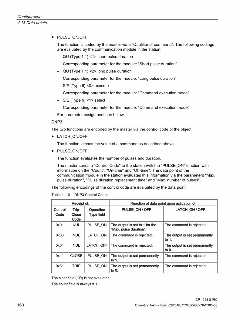
Configuration 4.18 Data points
CP 1243-8 IRC 160 Operating Instructions, 02/2018, C79000-G8976-C385-03
● PULSE_ON/OFF
The function is coded by the master via a "Qualifier of command". The following codings are evaluated by the communication module in the station:
– QU (Type 1.1) <1> short pulse duration
Corresponding parameter for the module: "Short pulse duration"
– QU (Type 1.1) <2> long pulse duration
Corresponding parameter for the module: "Long pulse duration"
– S/E (Type 6) <0> execute
Corresponding parameter for the module: "Command execution mode"
– S/E (Type 6) <1> select
Corresponding parameter for the module: "Command execution mode"
For parameter assignment see below.
DNP3
The two functions are encoded by the master via the control code of the object.
● LATCH_ON/OFF
The function latches the value of a command as described above.
● PULSE_ON/OFF
The function evaluates the number of pulses and duration.
The master sends a "Control Code" to the station with the "PULSE_ON" function with information on the "Count", "On-time" and "Off-time". The data point of the communication module in the station evaluates this information via the parameters "Max. pulse duration", "Pulse duration replacement time" and "Max. number of pulses".
The following encodings of the control code are evaluated by the data point:
Table 4- 10 DNP3 Control Codes
Receipt of: Reaction of data point upon activation of: Control Code
Trip-Close Code
Operation Type field
PULSE_ON / OFF LATCH_ON / OFF
0x01 NUL PULSE_ON The output is set to 1 for the "Max. pulse duration".
The command is rejected.
0x03 NUL LATCH_ON The command is rejected. The output is set permanently to 1.
0x04 NUL LATCH_OFF The command is rejected. The output is set permanently to 0.
0x41 CLOSE PULSE_ON The output is set permanently to 1.
The command is rejected.
0x81 TRIP PULSE_ON The output is set permanently to 0.
The command is rejected.
The clear field (CR) is not evaluated. The count field is always = 1.
Configuration 4.18 Data points
CP 1243-8 IRC Operating Instructions, 02/2018, C79000-G8976-C385-03 161
Parameters Name: Max. number of pulses Range of val-ues:
• DNP3: 0 ... 255 • ST7 and IEC: Fixed assignment with "1"
Default: 1 Explanation: Monitors the number of pulses sent by the master (Count). If the number of
pulses received from the master exceeds the value configured here, the command is discarded. If 0 (zero) is set, the monitoring is disabled.
Name: Max. pulse duration (s)
(DNP3 only) Range of val-ues:
0 ... 65535
Default: 0 Explanation: Monitors the pulse duration transmitted by the master with the command
(On-time). If the pulse duration sent by the master exceeds the value configured here, the command is discarded by the communication module if no "Pulse dura-tion replacement time" has been configured. When the "Max. pulse duration" is exceeded and "Pulse duration replace-ment time" is configured, the pulse duration sent by the master is checked for the "Pulse duration replacement time". If the value is 0 (zero), no "Max. pulse duration" is checked.
Name: Pulse duration replacement time (s)
(DNP3 only) Range of val-ues:
0 ... 65535
Default: 0 Explanation: Replacement value for the pulse duration If the pulse duration received from
the master exceeds the value configured in “Max pulse duration“. If the value is 0 (zero), no replacement value is used. If the ""Max. pulse duration" and "Pulse duration replacement time" are both configured with zero, each command is discarded.
Name: Short pulse duration (s)
(IEC only) Range of val-ues:
0 ... 65535
Default: 0
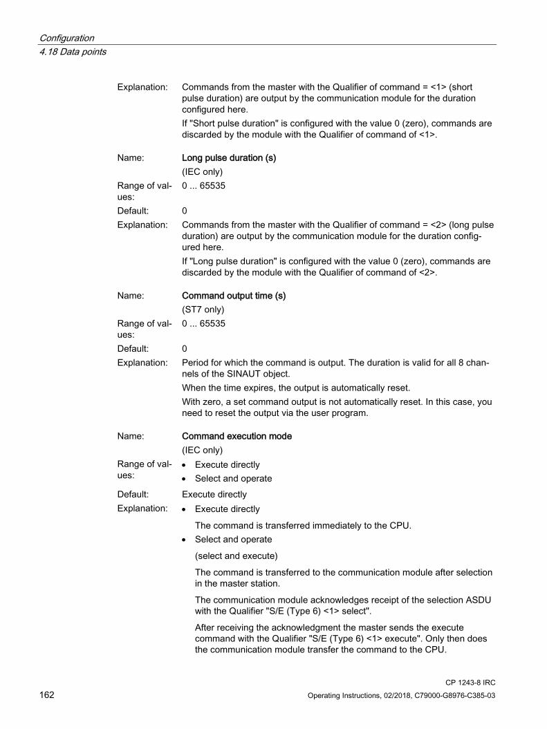
Configuration 4.18 Data points
CP 1243-8 IRC 162 Operating Instructions, 02/2018, C79000-G8976-C385-03
Explanation: Commands from the master with the Qualifier of command = <1> (short pulse duration) are output by the communication module for the duration configured here. If "Short pulse duration" is configured with the value 0 (zero), commands are discarded by the module with the Qualifier of command of <1>.
Name: Long pulse duration (s)
(IEC only) Range of val-ues:
0 ... 65535
Default: 0 Explanation: Commands from the master with the Qualifier of command = <2> (long pulse
duration) are output by the communication module for the duration config-ured here. If "Long pulse duration" is configured with the value 0 (zero), commands are discarded by the module with the Qualifier of command of <2>.
Name: Command output time (s)
(ST7 only) Range of val-ues:
0 ... 65535
Default: 0 Explanation: Period for which the command is output. The duration is valid for all 8 chan-
nels of the SINAUT object. When the time expires, the output is automatically reset. With zero, a set command output is not automatically reset. In this case, you need to reset the output via the user program.
Name: Command execution mode
(IEC only) Range of val-ues:
• Execute directly • Select and operate
Default: Execute directly Explanation: • Execute directly
The command is transferred immediately to the CPU. • Select and operate
(select and execute)
The command is transferred to the communication module after selection in the master station.
The communication module acknowledges receipt of the selection ASDU with the Qualifier "S/E (Type 6) <1> select".
After receiving the acknowledgment the master sends the execute command with the Qualifier "S/E (Type 6) <1> execute". Only then does the communication module transfer the command to the CPU.

Configuration 4.19 Messages
CP 1243-8 IRC Operating Instructions, 02/2018, C79000-G8976-C385-03 163
4.18.13 Partner stations
4.18.13.1 Partner configuration for ST7 data points
Enabling the partner for the ST7 data point Enable all partners to which a telecontrol connection was configured and with which the selected data point will exchange data. To do this select the relevant " " check box.
You can configure or change the partners in the overview table or in the "Partner stations" tab of the module. The data will be adopted at the other point.
4.18.13.2 Partner configuration for DNP3 and IEC data points
Enabling the partners for data points - DNP3 / IEC Enable all configured partners with which the selected data point will exchange data. You specify the communications partners of the CP in the "Partner stations" parameter group.
● Partner 1 enabled
In the overview table of the data points, as default Partner 1 is set as the partner of a data point.
In the "Partner stations" tab, in this case Partner 1 is enabled, the option grayed out.
● Partner n enabled
If you enable a different partner or more partners for this data point in the overview table, these will be enabled in the "Partner stations" tab and all 4 partners can be selected or deselected.
4.19 Messages
4.19.1 Message configuration
SMS If important events occur, the CP can send SMS messages to a mobile phone.
You configure the SMS message in STEP 7 in the data point and message configuration. You can find this using the project tree:
Project > directory of the relevant station > Local modules > CP
For the view in STEP 7, refer to the section Data point configuration (Page 128).
Configuration 4.19 Messages
CP 1243-8 IRC 164 Operating Instructions, 02/2018, C79000-G8976-C385-03
You will find the character set supported for the text of the SMS message in the section Character set for messages (Page 166).
For the configuration of the SMSC, refer to the section SMSC (Page 103).
E-mails If important events occur, the CP can send e-mails. The recipient can be a PC with an Internet connection or an S7-1200.
You configure the e-mails in STEP 7 in the data point and message configuration. You can find this using the project tree:
Project > directory of the relevant station > Local modules > CP
For the view in STEP 7, refer to the section Data point configuration (Page 128).
Triggering sending of messages The sending of the message is triggered by an event that is configured in the "Trigger" tab (see below).
Requirements and necessary information Remember the following requirements in the CP configuration for the transfer of SMS messages and e-mails:
● Enabling telecontrol communication ("Communication types") parameter group
● Activating security functions
Only for SMS:
● An ST7 connection is configured via the serial interface of the CP and a message is configured in the data point and message editor of STEP 7 Basic.
● An SMSC is configured in STEP 7 Basic
● A GSM module is connected to the RS-232 interface.
Only for e-mails.
● Configuring the "E-mail configuration" parameter group
To do this, you require the following information:
– Access data of the SMTP server: Address, port number, user name, password
– E-mail address of the recipient
– When using STARTTLS or SSL/TLS: Certificate of the e-mail service provider
"Message parameter" Here you configure the recipient, the subject and the text of the message.
Configuration 4.19 Messages
CP 1243-8 IRC Operating Instructions, 02/2018, C79000-G8976-C385-03 165
"Trigger" In the "Trigger" parameter group you configure triggering for sending the message and other parameters.
● E-mail trigger / SMS trigger
Specifies the event for which the sending of the message is triggered:
– Use PLC tag
For the trigger signal to send the message, the edge change (0 → 1) of the trigger bit "PLC tag for trigger" that is set by the user program is evaluated. When necessary, a separate trigger bit can be configured for each e-mail. For information on the trigger bit, see below.
– CPU changes to STOP
– CPU changes to RUN
– Connection to a partner interrupted
Triggers the sending of the message when the connection to a partner is interrupted.
– Connection to a partner established
Triggers the sending of the message when the connection returns.
– Weak mobile wireless network
Only with SMS
Triggers the sending of an SMS message when the network is weak and possibly no dialup connection can be established via mobile wireless.
● PLC tag for trigger
PLC tag for the message trigger "Use PLC tag"
If the memory area of the trigger bit is in the bit memory or in a data block, the trigger bit is reset to zero when the message is sent.
● Enable identifier for processing status
If the option is enabled, every attempt to send returns a status with information about the processing status of the sent message.
The status is written to the "PLC tag for processing status". If there are problems delivering messages, you can determine the status via the Web server (diagnostics status) or read it out from the PLC tag.
For the significance of the status output in hexadecimal, refer to the section Processing status of messages (Page 177).
● PLC tag for processing status
PLC tag of the type DWORD for the processing status
Configuration 4.19 Messages
CP 1243-8 IRC 166 Operating Instructions, 02/2018, C79000-G8976-C385-03
● Include value
If you enable the option, the CP sends a value for the placeholder $$ from the memory area of the CPU in the message. To do this enter "$$" as a placeholder for the value to be sent in the message text.
Select a PLC tag whose value will be integrated in the message. The value is entered in the message text instead of the placeholder $$.
$$ can be a placeholder for data point types with a simple data type up to a size of 32 bits.
Note that with the value the number of characters increases. For the maximum number of characters, refer to the section Performance data and configuration limits (Page 22).
● PLC tag for value
PLC tag in which the value to be sent is written.
4.19.2 Character set for messages
Character set for message texts The CP supports the following ASCII character set (hexadecimal value and character name) for the texts:
● 0x0A
LF (line feed)
● 0x0D
CR (carriage return)
● 0x20
Space
● 0x21 ... 0x5A
! " # $ % & ' ( ) * + , - . / 0 1 2 3 4 5 6 7 8 9 : ; < = > ? @ A B C D E F G H I J K L M N O P Q R S T U V W X Y Z
● 0x5F
£
● 0x61 ... 0x7A
a b c d e f g h i j k l m n o p q r s t u v w x y z

CP 1243-8 IRC Operating Instructions, 02/2018, C79000-G8976-C385-03 167
Program blocks 5 5.1 Program blocks for OUC
Using the program blocks for Open User Communication (OUC) You can use the instructions (program blocks) listed below for direct communication between S7 stations.
In contrast to other communication types, Open User Communication does not need to be enabled in the configuration of the CP because corresponding program blocks need to be created for this. You will find details on the program blocks in the information system of STEP 7.
Note Different program block versions
Note that in STEP 7 you cannot use different versions of a program block in a station.
Supported program blocks for OUC The following instructions in the specified minimum version are available for programming Open User Communication:
● TSEND_C V3.0 / TRCV_C V3.0
Compact blocks for:
– Connection establishment / termination and sending data
– Connection establishment / termination and reception of data
Use as an alternative:
● TCON V4.0 / TDISCON V2.1
Connection establishment / connection termination
● TUSEND V4.0 / TURCV V4.0
Sending and receiving data via UDP
● TSEND V4.0 / TRCV V4.0
Sending and receiving data via TCP or ISOonTCP
● TMAIL_C V4.0
Sending e-mails
To transfer encrypted e-mails with this block, the precise time of day is required on the CP. Configure the time-of-day synchronization.

Program blocks 5.1 Program blocks for OUC
CP 1243-8 IRC 168 Operating Instructions, 02/2018, C79000-G8976-C385-03
For changing configuration data of the CP during runtime:
● T_CONFIG V1.0
Program-controlled configuration of the IP parameters
Refer to the information on T_CONFIG and on the SDTs "IF_CONF_..." in the section Changing the IP address during runtime (Page 169).
You can find the program blocks in STEP 7 in the "Instructions > Communication > Open User Communication" task card.
Connection descriptions in system data types (SDTs) The blocks listed above use the CONNECT parameter for the relevant connection description. TMAIL_C uses the parameter MAIL_ADDR_PARAM.
The connection description is stored in a data block whose structure is specified by the system data type (SDT).
Creating an SDT for the data blocks
Create the SDT required for every connection description as a data block (global DB).
The SDT type is generated by entering the name in the declaration table of the block manually not by selecting an entry from the "Data type" drop-down list but by entering it in the "Data type" box for example "TCON_IP_V4". The corresponding SDT is then created with its parameters.
Using the SDT
● TCON_IP_V4
For transferring frames via TCP or UDP
● TADDR_Param
For transferring frames via UDP
● TCON_IP_RFC
For transferring frames via ISO-on-TCP (direct communication between two S7-1200 stations)
● TMail_V4
For transferring e-mails addressing the e-mail server using an IPv4 address
● TMail_V6
For transferring e-mails addressing the e-mail server using an IPv6 address
● TMail_FQDN
For transferring e-mails addressing the e-mail server using its name (FQDN)
● TMail_V4_SEC
For secure transfer of e-mails addressing the e-mail server using an IPv4 address
Program blocks 5.2 Changing the IP address during runtime
CP 1243-8 IRC Operating Instructions, 02/2018, C79000-G8976-C385-03 169
● TMail_V6_SEC
For secure transfer of e-mails addressing the e-mail server using an IPv6 address
● TMail_QDN_SEC
For secure transfer of e-mails addressing the e-mail server using the host name
You will find the description of the SDTs with their parameters in the STEP 7 information system under the relevant name.
Connection establishment and termination Connections are established using the program block TCON. Note that a separate program block TCON must be called for each connection.
A separate connection must be established for each communications partner even if identical blocks of data are being sent.
After a successful transfer of the data, a connection can be terminated. A connection is also terminated by calling TDISCON.
Note Connection abort
If an existing connection is aborted by the communications partner or due to disturbances on the network, the connection must also be terminated by calling TDISCON. Make sure that you take this into account in your programming.
5.2 Changing the IP address during runtime
Changing the IP address during runtime You can change the following address parameters of the CP at runtime controlled by the program:
● IP address
● Subnet mask
● Router address
Note Changing the IP parameters with a dynamic IP address
Note the effects of program-controlled changes to the IP parameters if the CP obtains a dynamic IP address from the Internet service provider: In this case, the CP can no longer be reached by communications partners.

Program blocks 5.2 Changing the IP address during runtime
CP 1243-8 IRC 170 Operating Instructions, 02/2018, C79000-G8976-C385-03
Requirements - firmware version
Requirements for program-controlled changing of the IP parameters are as follows:
● CP firmware ≥ V2.1.7x
and
● CPU firmware ≥ V4.2
Requirements - program blocks / STEP 7 versions
Program-controlled changing of the IP parameters is supported by program blocks. The program blocks access address data stored in a suitable system data type (SDT).
Apart from the address parameters of the CP, with T_CONFIG the address parameters of DNS servers (IF_CONF_DNS) and NTP servers (IF_CONF_NTP) can also be changed program controlled.
Depending on the STEP 7 version, the following program blocks and system data types can be used:
● STEP 7 Basic ≥ V14
T_CONFIG
Along with:
– IF_CONF_V4
– IF_CONF_NTP
– IF_CONF_V6
– IF_CONF_DNS
The address parameters can only be configured with temporary validity in the CP. In the respective "IF_CONF_..." SDT, the "Mode" = 2 parameter must be set.
Note
No feedback from the CP
"T_CONFIG" does not support feedback from the CP to the CPU. Errors in the block call or in setting the address parameter are not reported. The block outputs "BUSY" or "DONE" regardless of whether the address parameter was set.
● STEP 7 Basic ≤ V14
TC_CONFIG
Along with:
– IF_CONF_V4
You will find detailed information on programming the blocks in the STEP 7 information system.
Requirements - CP programming
To be able to change the IP parameters program controlled the option "IP address is set directly at the device" must be enabled in the configuration of the IP address of the Ethernet interface of the CP.
CP 1243-8 IRC Operating Instructions, 02/2018, C79000-G8976-C385-03 171
Diagnostics and upkeep 6 6.1 Diagnostics options
The following diagnostics options are available:
LEDs of the module For information on the LED displays, refer to the section LEDs (Page 40).
If there are connection problems between the master station and station, you can, for example see whether or not the transmission path is disturbed or whether the CPU is in STOP status by checking the LEDs.
Diagnostics SMS / e-mail If configurable events such as the lack of reachability of a partner or if the CPU changes to STOP, the CP can send a diagnostics SMS message or e-mail.
The configuration is described in section Message configuration (Page 163).
STEP 7 Basic: The "Diagnostics" tab in the Inspector window If you access the CP via Ethernet, you obtain the following information about the selected module:
● Entries in the diagnostics buffer of the CPU
● Information on the online status of the module
Access via WAN networks does not provide any information.
STEP 7 Basic: Diagnostics functions via the "Online > Online and diagnostics" menu Using the online functions, you can read diagnostics information from the CP from an engineering station on which the project with the CP is stored.
If you want to operate online diagnostics with the station via the CP, you need to select the type of communication "Enable online functions"; see section Communication types (Page 67).
Diagnostics and upkeep 6.1 Diagnostics options
CP 1243-8 IRC 172 Operating Instructions, 02/2018, C79000-G8976-C385-03
"Diagnostics" group
The diagnostics pages are divided into the following groups:
● General
This group displays general information on the module.
● Diagnostic status
This group displays status information of the module from the view of the CPU.
– Device-specific events
Information on internal module events is displayed here.
● Ethernet interface
Address and statistical information
● Industrial Remote Communication
The group has the following diagnostics pages:
– Partner
Information about the address settings of the partner, connection statistics, configuration data of the partner and other diagnostics information.
– Data point list
Various information on the data points such as configuration data, value, connection status etc.
– Protocol diagnostics
With the button "Enable protocol trace", the frames received and sent by the module are logged for several seconds.
With the function "Disable protocol trace", the logging is stopped and the data is written to a log file.
With the function "Save", you can save the log file on the engineering station and then analyze it.
● Time of day
Information on the time on the device
● Security
The group has the following diagnostics pages:
– Status
This diagnostics page displays the most important security settings, the time of day, and data relating to the configuration.
– System log
You can start logging system entries on this diagnostics page if a connection to a SCALANCE S module is established. You can save the entries.
Diagnostics and upkeep 6.1 Diagnostics options
CP 1243-8 IRC Operating Instructions, 02/2018, C79000-G8976-C385-03 173
– Audit log
You can start logging the log data of the module on this diagnostics page. You can save the entries.
– Communication status
This diagnostics page shows the states of the known security modules of the VPN groups, their endpoints and the tunnel properties.
– SINEMA RC - automatic VPN configuration
This diagnostics page shows the status of the automatic OpenVPN configuration and the OpenVPN connections.
"Functions" group
● Firmware update
For a description, see section Downloading firmware (Page 179).
● Assign IP address
● Assign PROFINET device name
● Save service data
The function is used for logging of internal module processes in situations in which you cannot eliminate unexpected or unwanted behavior of the module yourself.
The log file is created with the "Save service data" button. The data is saved in a file with the format "*.dmp" that can be evaluated by the Siemens hotline.
STEP 7 Basic: The partner status The CP can signal the status of the connection to the remote communications partner.
For information on the configuration, see section Communication with the CPU (Page 95).
STEP 7 V5 Here, the known diagnostics tools are available to you.
When accessing via WAN networks, you can use the functions of PG routing. You will find details in the SINAUT system manual volume 2; see /3/ (Page 226).
Diagnostics options via the Web server of the CPU You will find details on the diagnostics options of the Web server in the S7-1200 system manual, see /1/ (Page 225).

Diagnostics and upkeep 6.2 Online security diagnostics via port 8448
CP 1243-8 IRC 174 Operating Instructions, 02/2018, C79000-G8976-C385-03
6.2 Online security diagnostics via port 8448
Security diagnostics without opening port 102 If you want to perform security diagnostics without opening port 102, follow the steps below:
1. Select the CP in STEP 7.
2. Open the "Online & diagnostics" shortcut menu.
3. In the parameter group "Security" click the "Connect online" button.
In this way you perform the security diagnostics via port 8448.
6.3 Online functions and TeleService
Online functions and TeleService Along with STEP 7 on the engineering station (ES) the CP provides various diagnostics and maintenance functions under the following terms:
● Online functions
Access from the ES to the station via LAN
Requirement: The ES and the CP are located in the same subnet.
● TeleService
Access from the ES to the station via WAN (Internet)
Requirement: The CP is connected to the ES and can be reached via this path Note section Access to the Web server (Page 79) for more information.
For a remote station located in a different IP subnet or that can be reached via the Internet, these functions can only be used if the ES (with CP 1628 or via SCALANCE S) is connected to the station via a VPN tunnel.
Connections between a CP and telecontrol server for transferring user data are not interrupted by a TeleService-connection.
The functions and the connection establishment are largely the same with the online functions and TeleService.
Note Transmission time with TeleService
Note that transferring larger amounts of data via WAN (Internet) can take a very long time.
If there are disruptions or interruptions of the transmission path this can lead to the data transmission being aborted.

Diagnostics and upkeep 6.4 SNMP
CP 1243-8 IRC Operating Instructions, 02/2018, C79000-G8976-C385-03 175
Connection establishment to use the online functions via Ethernet
Procedure:
1. Connect the ES to the network.
2. Open the relevant STEP 7 project on the ES.
3. Select the CP or the CPU of the station whose CP you want to update with new firmware.
4. Enable the online functions using the "Connect online" icon.
5. In the "Connect online" dialog, go to the Choose the entry "TeleService via telecontrol" in the "Type of PG/PC interface" drop-down list.
6. In the "PG/PC interface" drop-down list select the entry "TeleService board".
7. In the table select the CP if it is not already selected.
The path both via the CP or the CPU is possible.
8. Click on the icon next to the "PG/PC interface" drop-down list.
The "Establish remote connection via telecontrol" dialog box opens.
9. Make the necessary entries in this dialog (see below) and click on "Connect".
Terminate online connection
On completion of the online session, terminate the online connection again using the "Disconnect" button.
6.4 SNMP
SNMP (Simple Network Management Protocol) SNMP is a protocol for management and diagnostics of networks and nodes in the network. To transmit data, SNMP uses the connectionless UDP protocol.
The information on the properties of SNMP-compliant devices is stored in MIB files (MIB = Management Information Base).
Range of performance of the CP as an SNMP agent The CP supports data queries in the following SNMP versions:
● SNMPv1 (standard)
● SNMPv3 (security)
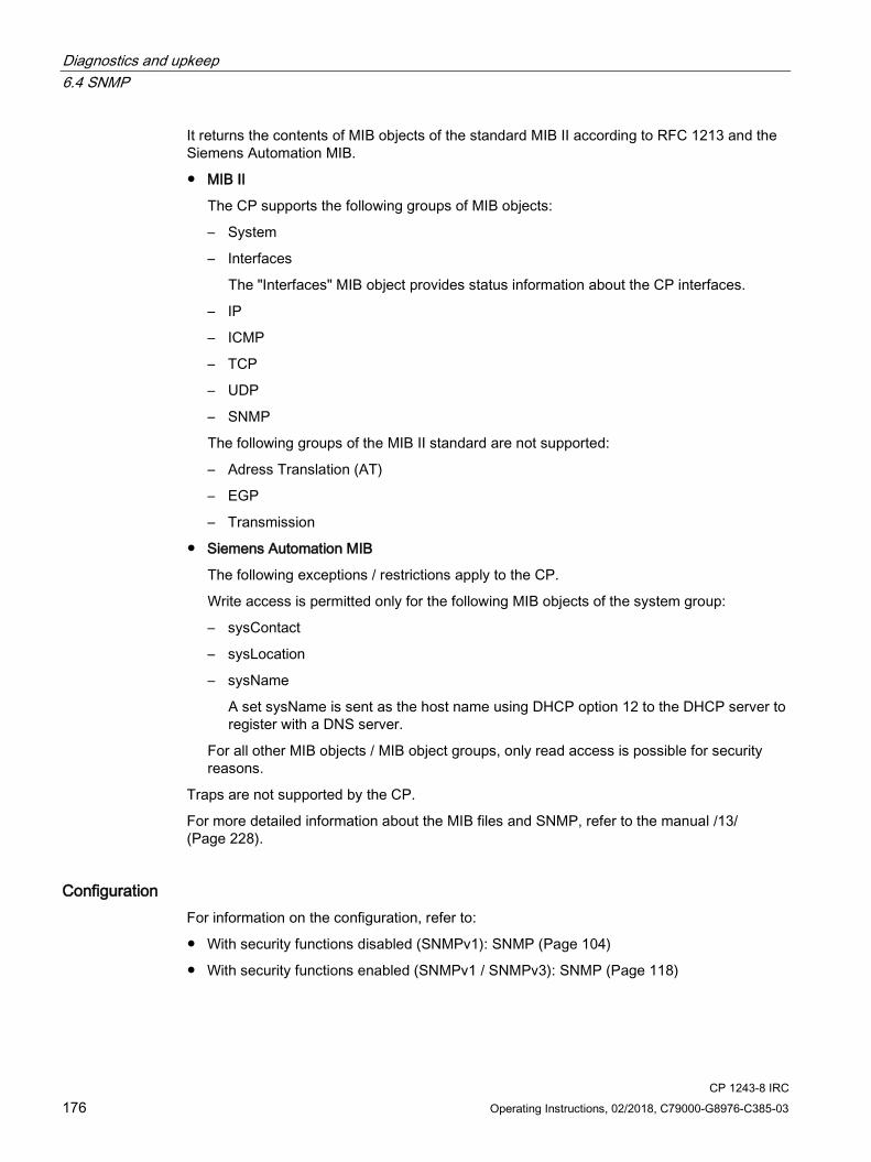
Diagnostics and upkeep 6.4 SNMP
CP 1243-8 IRC 176 Operating Instructions, 02/2018, C79000-G8976-C385-03
It returns the contents of MIB objects of the standard MIB II according to RFC 1213 and the Siemens Automation MIB.
● MIB II
The CP supports the following groups of MIB objects:
– System
– Interfaces
The "Interfaces" MIB object provides status information about the CP interfaces.
– IP
– ICMP
– TCP
– UDP
– SNMP
The following groups of the MIB II standard are not supported:
– Adress Translation (AT)
– EGP
– Transmission
● Siemens Automation MIB
The following exceptions / restrictions apply to the CP.
Write access is permitted only for the following MIB objects of the system group:
– sysContact
– sysLocation
– sysName
A set sysName is sent as the host name using DHCP option 12 to the DHCP server to register with a DNS server.
For all other MIB objects / MIB object groups, only read access is possible for security reasons.
Traps are not supported by the CP.
For more detailed information about the MIB files and SNMP, refer to the manual /13/ (Page 228).
Configuration For information on the configuration, refer to:
● With security functions disabled (SNMPv1): SNMP (Page 104)
● With security functions enabled (SNMPv1 / SNMPv3): SNMP (Page 118)

Diagnostics and upkeep 6.5 Processing status of messages
CP 1243-8 IRC Operating Instructions, 02/2018, C79000-G8976-C385-03 177
6.5 Processing status of messages
Processing status If the option "Enable identifier for processing status" is enabled in the message editor for a message, a status is output on the CP that provides information about the processing status of the sent message. The status is written to a PLC tag of the type DWORD. Select this tag via the "PLC tag for processing status" box.
The meaning of the statuses is as follows:
Table 6- 1 SMS: Meaning of the status ID output in hexadecimal format
Status Meaning 0000 Transfer completed free of errors 0001 Error in the transfer, possible causes:
• SIM card invalid • No network • Wrong destination phone number (number not reachable)
Table 6- 2 E-mails: Meaning of the status ID output in hexadecimal format
Status Meaning 0000 Transfer completed free of errors 82xx Other error message from the e-mail server
Apart from the leading "8", the status corresponds to the three-digit error number of the SMTP protocol.
8401 No channel available Possible cause: There is already an e-mail connection via the CP. A second connection cannot be set up at the same time.
8403 No TCP/IP connection could be established to the SMTP server. 8405 The SMTP server has denied the login request. 8406 An internal SSL error or a problem with the structure of the certificate was detected by the
SMTP client. 8407 Request to use SSL was denied. 8408 The client could not obtain a socket for creating a TCP/IP connection to the mail server. 8409 It is not possible to write via the connection. Possible cause: The communications partner
reset the connection or the connection aborted. 8410 It is not possible to read via the connection. Possible cause: The communications partner
terminated the connection or the connection was aborted. 8411 Sending the e-mail failed. Cause: There was not enough memory space for sending. 8412 The configured DNS server could not resolve specified domain name. 8413 Due to an internal error in the DNS subsystem, the domain name could not be resolved. 8414 An empty character string was specified as the domain name. 8415 An internal error occurred in the cURL module. Execution was aborted.
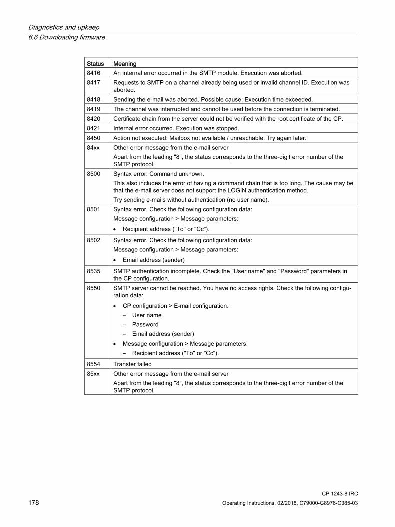
Diagnostics and upkeep 6.6 Downloading firmware
CP 1243-8 IRC 178 Operating Instructions, 02/2018, C79000-G8976-C385-03
Status Meaning 8416 An internal error occurred in the SMTP module. Execution was aborted. 8417 Requests to SMTP on a channel already being used or invalid channel ID. Execution was
aborted. 8418 Sending the e-mail was aborted. Possible cause: Execution time exceeded. 8419 The channel was interrupted and cannot be used before the connection is terminated. 8420 Certificate chain from the server could not be verified with the root certificate of the CP. 8421 Internal error occurred. Execution was stopped. 8450 Action not executed: Mailbox not available / unreachable. Try again later. 84xx Other error message from the e-mail server
Apart from the leading "8", the status corresponds to the three-digit error number of the SMTP protocol.
8500 Syntax error: Command unknown. This also includes the error of having a command chain that is too long. The cause may be that the e-mail server does not support the LOGIN authentication method. Try sending e-mails without authentication (no user name).
8501 Syntax error. Check the following configuration data: Message configuration > Message parameters: • Recipient address ("To" or "Cc").
8502 Syntax error. Check the following configuration data: Message configuration > Message parameters: • Email address (sender)
8535 SMTP authentication incomplete. Check the "User name" and "Password" parameters in the CP configuration.
8550 SMTP server cannot be reached. You have no access rights. Check the following configu-ration data: • CP configuration > E-mail configuration:
– User name – Password – Email address (sender)
• Message configuration > Message parameters: – Recipient address ("To" or "Cc").
8554 Transfer failed 85xx Other error message from the e-mail server
Apart from the leading "8", the status corresponds to the three-digit error number of the SMTP protocol.

Diagnostics and upkeep 6.6 Downloading firmware
CP 1243-8 IRC Operating Instructions, 02/2018, C79000-G8976-C385-03 179
6.6 Downloading firmware
New firmware versions of the CP If a new firmware version is available for the module, you will find this on the following Internet page of Siemens Industry Online Support:
Link: (https://support.industry.siemens.com/cs/ww/en/ps/21162/dl)
Note that firmware versions as of V3 cannot be loaded on CPs with hardware product version 1.
When you have saved the new firmware file on your engineering station (ES), the following methods are available to you for loading the firmware file:
● Saving the firmware file on the memory card of the CPU (recommended method)
You will find a description of the procedure in the S7-1200 system manual.
● Loading the firmware with the online functions of STEP 7 via Ethernet
You will find a description of connecting the ES to the station in the section Online functions and TeleService (Page 174).
● Downloading the firmware via the Web server of the CPU (as of CPU firmware version V4.0)
This method is described below.
Note Effects on the retentive memory of the CPU • If you use a SIMATIC memory card to install the firmware file, the retentive memory is
retained. • If you use the Web server or the online functions to install the firmware file, retentive
memory is lost.
Downloading the firmware via the Web server of the CPU Follow the steps below to connect to the Web server of the CPU from the ES and to download the CP's new firmware file to the station.
Requirements in the network configuration
The CP is connected to the engineering station and can be reached via this path
Requirements in the CPU configuration
1. Open the corresponding project on the ES.
2. Select the CPU of the station involved in STEP 7.
3. Select the "Web server" entry.

Diagnostics and upkeep 6.6 Downloading firmware
CP 1243-8 IRC 180 Operating Instructions, 02/2018, C79000-G8976-C385-03
4. In the parameter group "General", select the "Enable Web server for this interface" option.
5. With a CPU version V4.0 or higher, create a user in the user administration with the required rights.
You need to assign the right to perform firmware updates in the access level.
The procedure for establishing a connection to the Web server depends on whether you have enabled or disabled the "Allow access only using HTTPS" option in the "General" parameter group:
● Connection establishment with HTTP
Procedure if the "Allow access only using HTTPS" option is disabled
● Connection establishment with HTTPS
Procedure if the "Allow access only using HTTPS" option is enabled
These two variants are described in the following sections.
Requirement: The new firmware file is stored on your engineering station.
You will find the requirements for access to the Web server of the CPU (permitted Web browser) and the description of the procedure in the STEP 7 information system under the keyword "Information about the Web server".
Connection establishment with HTTP
1. Connect the PC on which the new firmware file is located to the CPU via the Ethernet interface.
2. Enter the address of the CPU in the address box of your Web browser: http://<IP address>
3. Press the Enter key.
The start page of the Web server opens.
4. Click on the "Download certificate" entry at the top right of the window.
The "Certificate" dialog opens.
5. Download the certificate to your PC by clicking the "Install certificate ..." button.
The certificate is loaded on your PC.
You will find information on downloading a certificate in the help of your Web browser and in the STEP 7 information system under the key words "HTTPS" or "Access for HTTPS (S7-1200)".
6. When the connection has changed to the secure mode HTTPS ("https://<IP address>/..." in the address box of the Web server), you can continue as described in the next section "Downloading firmware".
If you terminate the connection to the Web server, the next time you can log in with the Web server without downloading the certificate using HTTP.

Diagnostics and upkeep 6.6 Downloading firmware
CP 1243-8 IRC Operating Instructions, 02/2018, C79000-G8976-C385-03 181
Connection establishment with HTTPS
1. Connect the PC on which the new firmware file is located to the CPU via the Ethernet interface.
2. Enter the address of the CPU in the address box of your Web browser: https://<IP address>
3. Press the Enter key.
The start page of the Web server opens.
4. Continue as described in the following section "Downloading firmware".
Loading firmware
1. Log in on the start page of the Web server as a user with the necessary rights.
Use the user data configured in the user administration of the Web server of the CPU.
2. After logging in, select the entry "Module status" in the navigation panel of the Web server.
3. Select the CP in the module list.
4. Select the "Firmware" tab lower down in the window.
5. Browse for the firmware file on your PC using the "Browse..." button and download the file to the station using the "Run update" button.
Note Closing the Web server
If you close the Web server during the firmware update, you cannot change the operating status of the CPU to RUN. In this case you need to turn the CPU off and on again to change the CPU to the operating status RUN.

Diagnostics and upkeep 6.7 Module replacement
CP 1243-8 IRC 182 Operating Instructions, 02/2018, C79000-G8976-C385-03
6.7 Module replacement
Module replacement
CAUTION
Read the system manual "S7-1200 Programmable Controller"
Prior to installation, connecting up and commissioning, read the relevant sections in the system manual "S7-1200 Programmable Controller" (refer to the documentation in the Appendix).
When installing and connecting up, keep to the procedures described in the system manual "S7-1200 Programmable Controller".
Make sure that the power supply is turned off when installing/uninstalling the devices.
The STEP -7 project data of the CP is stored on the local CPU. If there is a fault on the device, this allows simple replacement of the CP without needing to download the project data to the station again.
When the station starts up again, the new CP reads the project data from the CPU.

CP 1243-8 IRC Operating Instructions, 02/2018, C79000-G8976-C385-03 183
Technical data 7 7.1 Technical specifications of the CP
Table 7- 1 Technical specifications of the CP 1243-8 IRC
Technical specifications Article number 6GK7 243-8RX30-0XE0 Attachment to Industrial Ethernet Quantity 1 Design RJ-45 jack Properties 100BASE-TX, IEEE 802.3-2005, half duplex/full duplex, autocrossover, autonego-
tiation, galvanically isolated Transmission speed 10/100 Mbps Permitted cable lengths (Ethernet) (Alternative combinations per length range) * 0 ... 55 m • Max. 55 m IE TP Torsion Cable with IE FC RJ45 Plug 180
• Max. 45 m IE TP Torsion Cable with IE FC RJ45 + 10 m TP Cord via IE FC RJ45 Outlet
0 ... 85 m • Max. 85 m IE FC TP Marine/Trailing/Flexible/FRNC/Festoon/Food Cable with IE FC RJ45 Plug 180
• Max. 75 m IE FC TP Marine/Trailing/Flexible/FRNC/Festoon/Food Cable + 10 m TP Cord via IE FC RJ45 Outlet
0 ... 100 m • Max. 100 m IE FC TP Standard Cable with IE FC RJ45 Plug 180 • Max. 90 m IE FC TP Standard Cable + 10 m TP Cord via IE FC RJ45 Outlet
Electrical data External power supply Power supply 24 VDC
Permitted range 19.2 ... 28.8 V Design Terminal block with plug, 3 terminals Cable cross-section • Minimum • Maximum
• 0.14 mm2 (25 AWG) • 1.5 mm2 (15 AWG)
Max- tightening torque of the screw terminals
0.45 Nm (4 lb-in)
Electrical isolation: Power supply unit to internal circuit
710 VDC for 1 minute
Current consumption (typical) From 24 VDC (external) 100 mA From the S7-1200 backplane bus 250 mA
Effective power loss (typical) From 24 VDC (external) 2.4 W From the S7-1200 backplane bus 1.25 W
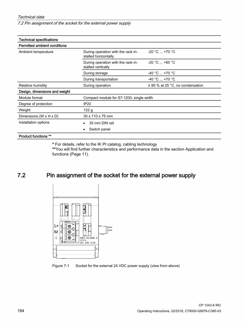
Technical data 7.2 Pin assignment of the socket for the external power supply
CP 1243-8 IRC 184 Operating Instructions, 02/2018, C79000-G8976-C385-03
Technical specifications Permitted ambient conditions Ambient temperature During operation with the rack in-
stalled horizontally -20 °C ... +70 °C
During operation with the rack in-stalled vertically
-20 °C ... +60 °C
During storage -40 °C ... +70 °C During transportation -40 °C ... +70 °C
Relative humidity During operation ≤ 95 % at 25 °C, no condensation Design, dimensions and weight Module format Compact module for S7-1200, single width Degree of protection IP20 Weight 122 g Dimensions (W x H x D) 30 x 110 x 75 mm Installation options • 35 mm DIN rail
• Switch panel
Product functions **
* For details, refer to the IK PI catalog, cabling technology **You will find further characteristics and performance data in the section Application and functions (Page 11).
7.2 Pin assignment of the socket for the external power supply
Figure 7-1 Socket for the external 24 VDC power supply (view from above)
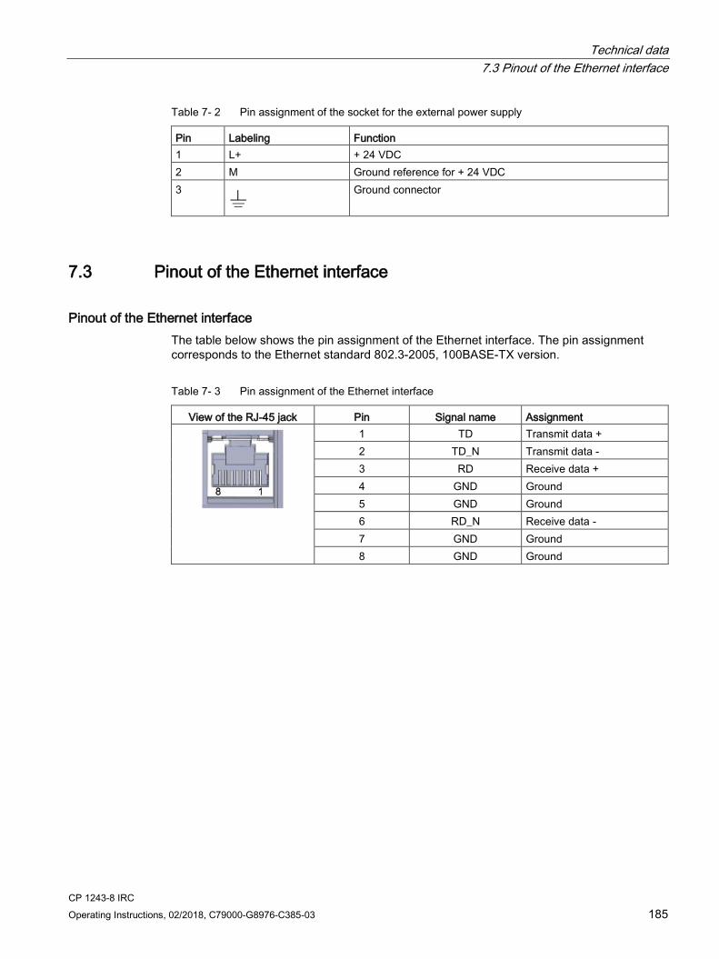
Technical data 7.3 Pinout of the Ethernet interface
CP 1243-8 IRC Operating Instructions, 02/2018, C79000-G8976-C385-03 185
Table 7- 2 Pin assignment of the socket for the external power supply
Pin Labeling Function 1 L+ + 24 VDC 2 M Ground reference for + 24 VDC 3
Ground connector
7.3 Pinout of the Ethernet interface
Pinout of the Ethernet interface The table below shows the pin assignment of the Ethernet interface. The pin assignment corresponds to the Ethernet standard 802.3-2005, 100BASE-TX version.
Table 7- 3 Pin assignment of the Ethernet interface
View of the RJ-45 jack Pin Signal name Assignment
1 TD Transmit data + 2 TD_N Transmit data - 3 RD Receive data + 4 GND Ground 5 GND Ground 6 RD_N Receive data - 7 GND Ground 8 GND Ground

Technical data 7.3 Pinout of the Ethernet interface
CP 1243-8 IRC 186 Operating Instructions, 02/2018, C79000-G8976-C385-03

CP 1243-8 IRC Operating Instructions, 02/2018, C79000-G8976-C385-03 187
Approvals A
Approvals issued
Note Issued approvals on the type plate of the device
The specified approvals apply only when the corresponding mark is printed on the product. You can check which of the following approvals have been granted for your product by the markings on the type plate.
EC declaration of conformity The CP meets the requirements and safety objectives of the following EU directives and it complies with the harmonized European standards (EN) for programmable logic controllers which are published in the official documentation of the European Union.
● 94/9/EC (ATEX explosion protection directive)
Directive of the European Parliament and the Council of 23 March 1994 on the approximation of the laws of the Member States concerning equipment and protective systems intended for use in potentially explosive atmospheres
● 2011/65/EU (RoHS)
Directive of the European Parliament and of the Council of 8 June 2011 on the restriction of the use of certain hazardous substances in electrical and electronic equipment
The EC Declaration of Conformity is available for all responsible authorities at:
Siemens Aktiengesellschaft Process Industries and Drives Process Automation DE-76181 Karlsruhe Germany
You will find the EC Declaration of Conformity for this product on the Internet at the following address:
Link: (https://support.industry.siemens.com/cs/ww/en/ps/21162/cert) Filter settings: Entry type: "Certificates" Certificate Type: “EU Declaration of Conformity"
Approvals
CP 1243-8 IRC 188 Operating Instructions, 02/2018, C79000-G8976-C385-03
IECEx The product meets the requirements of explosion protection according to IECEx.
IECEx classification: Ex nA IIC T4 Gc
The product meets the requirements of the following standards:
● EN 60079-0
Hazardous areas - Part 0: Equipment - General requirements
● EN 60079-15
Explosive atmospheres - Part 15: Equipment protection by type of protection 'n'
ATEX The CP meets the requirements of the EC directive 94/9/EC "Equipment and Protective Devices for Use in Potentially Explosive Atmospheres".
Applied standards:
● EN 60079-0
Hazardous areas - Part 0: Equipment - General requirements
● EN 60079-15
Explosive atmospheres - Part 15: Equipment protection by type of protection 'n'
ATEX approval: II 3 G Ex nA II T4
Test number: KEMA 10 ATEX 0166X
Over and above this, the following conditions must be met for the safe deployment of the CP; see section Notices about use in hazardous areas according to ATEX (Page 48).
You should also note the information in the document "Use of subassemblies/modules in a Zone 2 Hazardous Area" that you will find on the supplied data medium with the documentation.
For information on the EU declaration of conformity see above.
RoHS The CP meets the requirements of the EU directive 2011/65/EC on the restriction of the use of certain hazardous substances in electrical and electronic equipment.
Applied standard:
● EN 50581:2012
cULus Underwriters Laboratories Inc. meets
● Underwriters Laboratories, Inc.: UL 508 Listed (industrial control devices)
● Canadian Standards Association: CSA C22.2 No. 142 (process control equipment)

Approvals
CP 1243-8 IRC Operating Instructions, 02/2018, C79000-G8976-C385-03 189
cULus HAZ.LOC. Underwriters Laboratories Inc. meets
● UL 1604 (Hazardous Location)
● CSA C22.2 No. 213 (Hazardous Location)
APPROVED for Use in:
● Cl. 1, Div. 2, GP. A, B, C, D T4A; Ta = -20 °C...60 °C
● Cl. 1, Zone 2, GP. IIC T4; Ta = -20 °C...60 °C
FM Factory Mutual Research (FM) Approval Standard Class number 3600 and 3611 Approved for use in: Class I, Division 2, Group A, B, C, D, Temperature Class T4A, Ta = 60 °C Class I, Zone 2, Group IIC, Temperature Class T4, Ta = 60 °C
C-Tick The CP meets the requirements of the AS/NZS 2064 standards (Class A).
Current approvals SIMATIC NET products are regularly submitted to the relevant authorities and approval centers for approvals relating to specific markets and applications.
If you require a list of the current approvals for individual devices, consult your Siemens contact or check the Internet pages of Siemens Industry Online Support:
Link: (https://support.industry.siemens.com/cs/ww/en/ps/21162/cert)
Overview of the approvals for SIMATIC NET products You will find an overview of the approvals for SIMATIC NET products including approvals for shipbuilding on the Internet pages of Siemens Industry Online Support under the following address:
Link: (https://support.industry.siemens.com/cs/attachments/57337426/CertificationOverview.pdf)

Approvals
CP 1243-8 IRC 190 Operating Instructions, 02/2018, C79000-G8976-C385-03

CP 1243-8 IRC Operating Instructions, 02/2018, C79000-G8976-C385-03 191
Dimension drawings B
All dimensions in the drawings are in millimeters
Figure B-1 Front view and side view left

Dimension drawings
CP 1243-8 IRC 192 Operating Instructions, 02/2018, C79000-G8976-C385-03
Figure B-2 Top view and view from below

CP 1243-8 IRC Operating Instructions, 02/2018, C79000-G8976-C385-03 193
Accessories C C.1 TS modules
C.1.1 The TS modules
Structure of a TS module The TS modules have the module format of a compact module S7-1200, single width.
You can see the structure of a TS module in the figure.
① TS module, here: TS Module Modem ② Plug-in connection between TS module and CP ③ Interface to the WAN (under the front panel)
Figure C-1 TS module
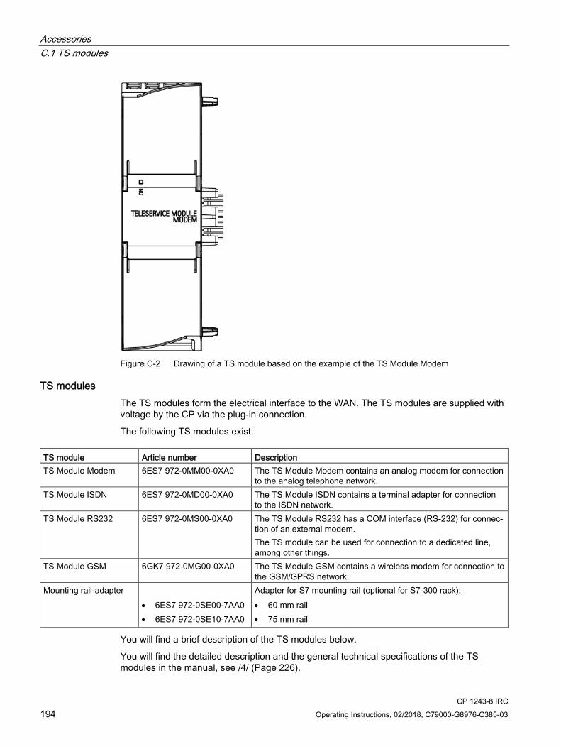
Accessories C.1 TS modules
CP 1243-8 IRC 194 Operating Instructions, 02/2018, C79000-G8976-C385-03
Figure C-2 Drawing of a TS module based on the example of the TS Module Modem
TS modules The TS modules form the electrical interface to the WAN. The TS modules are supplied with voltage by the CP via the plug-in connection.
The following TS modules exist: TS module Article number Description TS Module Modem 6ES7 972-0MM00-0XA0 The TS Module Modem contains an analog modem for connection
to the analog telephone network. TS Module ISDN 6ES7 972-0MD00-0XA0 The TS Module ISDN contains a terminal adapter for connection
to the ISDN network. TS Module RS232 6ES7 972-0MS00-0XA0 The TS Module RS232 has a COM interface (RS-232) for connec-
tion of an external modem. The TS module can be used for connection to a dedicated line, among other things.
TS Module GSM 6GK7 972-0MG00-0XA0 The TS Module GSM contains a wireless modem for connection to the GSM/GPRS network.
Mounting rail-adapter • 6ES7 972-0SE00-7AA0 • 6ES7 972-0SE10-7AA0
Adapter for S7 mounting rail (optional for S7-300 rack): • 60 mm rail • 75 mm rail
You will find a brief description of the TS modules below.
You will find the detailed description and the general technical specifications of the TS modules in the manual, see /4/ (Page 226).

Accessories C.1 TS modules
CP 1243-8 IRC Operating Instructions, 02/2018, C79000-G8976-C385-03 195
C.1.2 TS Module Modem
Product package Designation Article number TS Module Modem 6ES7 972-0MM00-0XA0 Analog telephone cable with two RJ-11 connectors Length 3 m
A5E00243688
TAE connector A5E00243701
Properties The TS Module Modem has an internal analog modem.
The analog modem port is the 6-pin RJ11 socket behind the lower front panel.
Pin assignment and signal description of analog modem port Figure Pin no. Signal name Signal direction Comments
1 - 2 - 3 b1 Bi-directional Incoming wire pair 4 a1 5 - 6 -
Analog phone cable Using the supplied analog phone cable, you connect the RJ11-socket to a phone socket.

Accessories C.1 TS modules
CP 1243-8 IRC 196 Operating Instructions, 02/2018, C79000-G8976-C385-03
Note
Use the supplied cable with ferrite to comply with EMC values and make sure that the ferrite is on the module side.
To use the TS Module Modem outside Germany, you can fit a country-specific TAE connector onto the RJ11 connector of the phone cable. For Germany, a TAE6N connector is supplied. In some countries, telephone jacks with RJ-11 sockets are available, so that the telephone cable can be used without TAE connectors.
Specifications ● Dimensions (WHD): 30 x 100 x 75 mm
● Weight: 98 g
● ITU transmission standards:
V.21, V.22, V.22bis, V.23, V.32, V.32bis, V.34, V.34x, K56flex, V.90, V.92
● Error correction and data compression
● a/b port
● Hayes command set (AT)
● All data formats
● Dialing mode: Multifrequency signaling (DTMF), pulse dialing
National approvals The TS Module Modem is designed so that worldwide use is possible. When installing and operating the TS Module Modem, keep to the country-specific laws and special features.
The TS module has a telecommunications approval in the following countries: • Australia • Iceland • Poland
• Belgium • Italy • Portugal
• Bulgaria • Canada • Romania
• Denmark • Latvia • Sweden
• Germany • Lithuania • Switzerland
• Estonia • Luxembourg • Slovakia
• Finland • Malta • Slovenia
• France • New Zealand • Spain
• Greece • Netherlands • Czech Republic
• Great Britain • Norway • Hungary
• Ireland • Austria • USA • Cyprus
For information on approval in other countries, please contact Technical Support.

Accessories C.1 TS modules
CP 1243-8 IRC Operating Instructions, 02/2018, C79000-G8976-C385-03 197
C.1.3 TS Module ISDN
Product package Designation Article number TS Module ISDN 6ES7 972-0MD00-0XA0 ISDN phone cable with 2 RJ45 connectors length 3 m
A5E00243651
Properties The TS Module ISDN has a terminal adapter with an S0 interface.
The S0 interface is the 8-pin RJ-45 jack behind the lower front panel.
Connector pin assignment and description of the signals of the S0 interface/ISDN interface Figure Pin number Signal name
1 - 2 - 3 TX+ 4 RX+ 5 RX– 6 TX– 7 - 8 -
ISDN phone cable Using the supplied ISDN telephone cable, you connect the RJ-45 socket with an ISDN S0 socket.

Accessories C.1 TS modules
CP 1243-8 IRC 198 Operating Instructions, 02/2018, C79000-G8976-C385-03
Specifications ● Dimensions (WHD): 30 x 100 x 75 mm
● Weight: 92 g
● D channel protocols:
– DSS1 (Euro ISDN) with multiple subscriber numbers (MSN)
– 1 TR 6
● Supported B channel protocols:
– V.110 (9600, 19200, 38400 bps)
– V.120 (64 kpbs)
– X.75 (64 kpbs)
● AT command interpreter
National approvals When installing and operating the TS Module ISDN, keep to the country-specific laws and special features.
The TS module has a telecommunications approval in the following countries: • Belgium • Italy • Romania
• Bulgaria • Latvia • Sweden
• Denmark • Lithuania • Switzerland
• Germany • Luxembourg • Slovakia
• Estonia • Malta • Slovenia
• Finland • Netherlands • Spain
• France • Norway • Czech Republic
• Greece • Austria • Turkey
• Great Britain • Poland • Hungary
• Ireland • Portugal • Cyprus
For information on approval in other countries, please contact Technical Support.
C.1.4 TS Module RS232
Product package Designation Article number TS Module RS232 6ES7 972-0MS00-0XA0
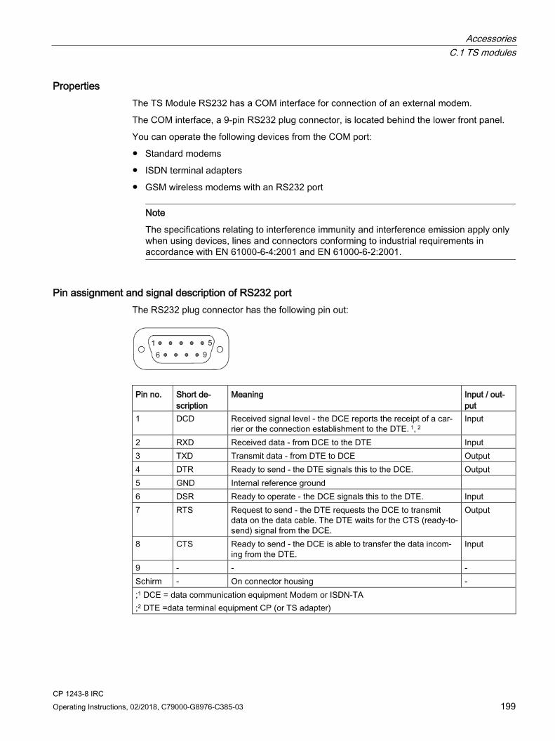
Accessories C.1 TS modules
CP 1243-8 IRC Operating Instructions, 02/2018, C79000-G8976-C385-03 199
Properties The TS Module RS232 has a COM interface for connection of an external modem.
The COM interface, a 9-pin RS232 plug connector, is located behind the lower front panel.
You can operate the following devices from the COM port:
● Standard modems
● ISDN terminal adapters
● GSM wireless modems with an RS232 port
Note
The specifications relating to interference immunity and interference emission apply only when using devices, lines and connectors conforming to industrial requirements in accordance with EN 61000-6-4:2001 and EN 61000-6-2:2001.
Pin assignment and signal description of RS232 port The RS232 plug connector has the following pin out:
Pin no. Short de-
scription Meaning Input / out-
put 1 DCD Received signal level - the DCE reports the receipt of a car-
rier or the connection establishment to the DTE. 1, 2 Input
2 RXD Received data - from DCE to the DTE Input 3 TXD Transmit data - from DTE to DCE Output 4 DTR Ready to send - the DTE signals this to the DCE. Output 5 GND Internal reference ground 6 DSR Ready to operate - the DCE signals this to the DTE. Input 7 RTS Request to send - the DTE requests the DCE to transmit
data on the data cable. The DTE waits for the CTS (ready-to-send) signal from the DCE.
Output
8 CTS Ready to send - the DCE is able to transfer the data incom-ing from the DTE.
Input
9 - - - Schirm - On connector housing - ;1 DCE = data communication equipment Modem or ISDN-TA ;2 DTE =data terminal equipment CP (or TS adapter)

Accessories C.1 TS modules
CP 1243-8 IRC 200 Operating Instructions, 02/2018, C79000-G8976-C385-03
Specifications ● Dimensions (WHD): 30 x 100 x 75 mm
● Weight: 100 g
● Type of traffic: Full duplex
● Transmission mode: Asynchronous
● Signals: TXD, RXD, DSR, CTS, RTS, DTR, DCD
● Transmission speed: 2400...115200 bps
● Frame format: 8 data bits (LSB first), no parity bit, 1 stop bit
● Standard: RS-232
● D-sub male connector: 9-pin, male (PC COMx)
C.1.5 TS Module GSM
Note
The device is designed for industrial use.
Product package Designation Article number TS Module GSM 6GK7 972-0MG00-0XA0
Properties The TS Module GSM has an interface for the connection of a GSM/GPRS antenna and a tray for a SIM card.
The antenna connection and the slot for the SIM card are located behind the lower front panel.
Accessories For the antenna, refer to the section Antennas (Page 208).
CSD data connection (Circuit Switched Data) For outgoing calls, the TS Module GSM supports GPRS and CSD data connections.
For incoming calls, only CSD data connections are accepted.
Accessories C.1 TS modules
CP 1243-8 IRC Operating Instructions, 02/2018, C79000-G8976-C385-03 201
To allow incoming calls, the SIM card inserted in the TS Module GSM must enable CSD data connections. You can apply to your network provider to have a CSD data connection enabled.
Often the network provider assigns a separate call number for the CSD data connection.
Specifications ● Dimensions (WHD): 30 x 100 x 75 mm
● Weight: 118 g
● Interfaces
– SIM interface: 3 V / 1.8 V
– Antenna connector: 1 x SMA socket (50 ohms)
● Multislot class: 10
● Transmission speed (GPRS):
– Up to 2 uplinks: 13.4 ... 27 kbps upload gross
– Up to 4 downlinks: 40 ... 54 kbps download gross
● Frequency ranges: 850, 900, 1800, 1900 MHz
● Transmit output power:
– 2 W at 850 / 900 MHz
– 1 W at 1800 / 1900 MHz
National approvals When installing and operating the TS Module GSM, keep to the country-specific laws and special features.
The TS module has a telecommunications approval in the following countries: • EEA (European Economic Area) • Israel
• Canada • Croatia
• China • Mexico
• USA • Nicaragua
• Russia • Peru
• Argentina • Philippines
• Bosnia • Serbia
• Brazil • Taiwan
• Chile • Ukraine
• Ecuador • UAE (United Arab Emirates)
• India
Accessories C.2 Modems and routers
CP 1243-8 IRC 202 Operating Instructions, 02/2018, C79000-G8976-C385-03
The approvals specified on the TS Module GSM apply.
For information on approval in other countries, please contact Technical Support.
You will find the current list of countries online at:
Link: (www.siemens.com/simatic-net/ik-info)
C.2 Modems and routers
C.2.1 Dedicated line and dialup network modems
Modems for dedicated line and dialup networks
Note Discontinuation of modules
The following products have the product status "type discontinued" but if they exist can be operated with the communications moduel: • Modem MD2
Dedicated line modems Product notification on the Internet: Link: (https://support.industry.siemens.com/cs/ww/en/view/109740149)
• Modem MD3 Modems for analog dialup networks Product notification on the Internet: Link: (https://support.industry.siemens.com/cs/ww/en/view/109740148)
• Modem MD4 Modems for ISDN networks Product notification on the Internet: Link: (https://support.industry.siemens.com/cs/ww/en/view/67637816)
When using the serial interface for dedicated line and dialup networks, use suitable products of other vendors.

Accessories C.2 Modems and routers
CP 1243-8 IRC Operating Instructions, 02/2018, C79000-G8976-C385-03 203
C.2.2 MODEM MD720
MODEM MD720 Article number: 6NH9720-3AA01-0XX0
Figure C-3 MODEM MD720
Use of the MD720 The MD720 is a GPRS/GSM modem for industrial applications.
It is intended for use in SIMATIC S7 stations that are part of a telecontrol or remote maintenance system and for communication with other stations in the network or an OPC server in the master station. Depending on the configuration, the control center can be either TeleControl Server Basic, SINAUT ST7cc, SINAUT ST7sc or SINAUT MICRO SC.
The MD720 supports the following types of communication:
● IP-based communication with the control center using GPRS and the MSC protocol or the MSCsec secure protocol
● SMS messages from or to a mobile telephone
● CSD communication for maintenance and for data connections
Current manual version and further information on the Internet You will find the current version of the manual and further information (e.g. FAQs) on the following Internet page of Siemens Industry Online Support:
Link: (https://support.industry.siemens.com/cs/ww/en/ps/21820/man)
Accessories For the antenna, refer to the section Antennas (Page 208).

Accessories C.2 Modems and routers
CP 1243-8 IRC 204 Operating Instructions, 02/2018, C79000-G8976-C385-03
Communications functions The MD720 supports the following functions:
● Modes
The MD720 is set to one of the following two modes depending on the type of communication required:
– OPC mode
– Terminal mode
● OPC mode
In OPC mode, there is productive data exchange with the control center using GPRS.
● Terminal mode
In terminal mode, the MD720 uses CSD communication for the following functions:
– Sending and receiving SMS messages
– Diagnostics and maintenance functions
– Transfer of configuration data
● Communication with a control center
In OPC mode, an MD720 connected to an S7 station communicates with a control center via a TCP connection. For the data transfer, the GSM network is used with the GPRS service. Either the MSC protocol or the MSCsec protocol is used (see below).
● Sending and receiving SMS messages
The locally connected application (SIMATIC) can transfer data for an SMS message to the MD720 using AT commands. The MD720 sends the SMS message to a subscriber in the GSM network (mobile wireless telephone) or when using a gateway, to a remote fax machine.
SMS messages received by the MD720 can be queried by the local application using AT commands.
● CSD communication
Service data calls via remote connections in CSD format are used for the following purposes:
– Remote configuration of the MD720
– Diagnostics and maintenance functions using AT commands
– Process data connections between stations with TIM module or CP 1243-8 IRC
The partner for the remote connection can be an analog modem, an ISDN modem or a GSM modem.
● Controlling the MD720 using AT commands
You can control the MD720 from a locally connected application or manually with a terminal program connected locally.
Accessories C.2 Modems and routers
CP 1243-8 IRC Operating Instructions, 02/2018, C79000-G8976-C385-03 205
● MSC protocol
Proprietary protocol used for productive communication via TCP connections in OPC mode. The protocol allows authentication of the communications partner and simple encryption. The MSC protocol is supported by the following control center applications:
– TeleControl Server Basic (TCSB)
– SINAUT MICRO SC
● MSCsec protocol
Proprietary protocol used for productive communication via TCP connections in OPC mode. In addition to the MSC protocol, it also allows authentication of the messages using an HMAC with the help of a symmetrical encryption method (with pre-shared key). The MSCsec protocol is supported by the following control center applications:
– TeleControl Server Basic (TCSB)
SIMATIC S7 systems that can be connected locally The following SIMATIC S7 systems can be connected to the GSM network via the MD720:
● SIMATIC S7- 200 via SINAUT PPI modem cable (6NH9701-0AD)
● SIMATIC S7-1200 via CP 1243-8 IRC / TS Module RS232
● SIMATIC S7- 300 via Ethernet TIM module (using GPRS)
● SIMATIC S7- 400 via TIM 4R IE (using GPRS)
● SIMATIC S7-300/400 via classic or Ethernet TIM module (only using CSD)
For project-specific solutions for connecting a SIMATIC S7-300 to the GSM network, please contact Siemens Industry Online Support. You will find an examples of applications with the corresponding documentation on the following Internet page:
Link: (https://support.industry.siemens.com/cs/ww/en/ps/21820/ae)
Possible partners of the MD720 The MD720 can communicate with the following partners.
● Communications partners of the MD720 installed in an S7-200:
– PC with TeleControl Server Basic (TCSB)
– PC with SINAUT MICRO SC
– S7-200 with MD720 (inter-station communication)
The frames are forwarded by TCSB or SINAUT MICRO SC in the master station.
The MD720 operates in OPC mode.
● Communications partners of the MD720 installed in an S7-300/400:
– Station with Ethernet TIM (e.g. central CPU or control system SINAUT ST7cc/ST7sc)
The MD720 operates in OPC mode.

Accessories C.2 Modems and routers
CP 1243-8 IRC 206 Operating Instructions, 02/2018, C79000-G8976-C385-03
● Communications partners of the MD720 for SMS messages:
– Mobile phone
– Fax machine (when using a gateway)
The MD720 operates in terminal mode.
● Communications partners of the MD720 installed in an S7-200:
– Engineering station with STEP 7-Micro/WIN
(via GSM network, ISDN network, analog dial-up network)
The MD720 operates in terminal mode.
● Communications partners of the MD720 installed in an S7-300/400 with TIM:
– SIMATIC S7-300/400 with TIM module (including classic)
(via GSM network, ISDN network, analog dial-up network)
The MD720 operates in terminal mode.
Connection resources ● Active connections at runtime
At runtime, the MD720 can connect to 1 communications partner.
The connection partner is configured in the program blocks.
Technical specifications (excerpt) Connection to Industrial Ethernet X1 interface Number: 1
Implementation: D-sub 9-pin, female Characteristics: RS-232
Control using AT commands Transmission speed: 19200 bps
Permitted range: 300 ... 57600 bps Wireless interface Antenna connector Number: 1
Implementation: SMA socket Impedance: 50 Ω nominal
Frequency bands GPRS / CSD: Quad band: 850, 900, 1800, 1900 MHz GPRS Characteristics: Maximum of 5 time slots at the same time,
of which: • Up to 2 uplinks • Up to 4 downlinks

Accessories C.2 Modems and routers
CP 1243-8 IRC Operating Instructions, 02/2018, C79000-G8976-C385-03 207
Transmission speed • Uplink (modem → Internet) • Downlink (Internet → modem)
Gross values: • Max. 42 kbps • Max. 54 kbps The net values (user data) are approxi-mately 30 % lower.
CSD Characteristics: MTC (Mobile Terminated Call) Transmission speed: 9600 bps
SMS (TX) Characteristics: Text mode
C.2.3 Router SCALANCE M
Routers for IP-based communication To connect a communications module to IP-based infrastructure networks, the following routers are available:
● SCALANCE M812
ADSL router for wired IP communication via the Internet, VPN, firewall, NAT, 1 RJ-45 Ethernet interface,1 digital input, 1 digital output, ADSL2T or ADSL2+
– ADSL2T (analog phone connection - Annex A) Article number: 6GK5812-1AA00-2AA2
– ADSL2+ (ISDN connection - Annex B) Article number: 6GK5812-1BA00-2AA2
● SCALANCE M816
ADSL router for wired IP communication via the Internet, VPN, firewall, NAT, 1 RJ-45 Ethernet interface with 4-port switch,1 digital input, 1 digital output, ADSL2T or ADSL2+
– ADSL2T (analog phone connection - Annex A) Article number: 6GK5816-1AA00-2AA2
– ADSL2+ (ISDN connection - Annex B) Article number: 6GK5816-1BA00-2AA2
● SCALANCE M826-2
SHDSL router for IP communication via 2- and 4-wire cables, ITU-T standard G.991.2 / SHDSL.biz, SHDSL topology: Point-to point, bonding, line bridge mode; routing mode with VPN, firewall, NAT, 1 Ethernet interface with 4-port switch, 1 digital input, 1 digital output Article number 6GK5826-2AB00-2AB2
● SCALANCE M874-2
2.5G router for wireless IP communication via 2.5G mobile phone, VPN, firewall, NAT, 1 RJ45 Ethernet interface with 2-port switch, SMA antenna connector, 1 digital input, 1 digital output Article number: 6GK5874-2AA00-2AA2

Accessories C.3 Antennas
CP 1243-8 IRC 208 Operating Instructions, 02/2018, C79000-G8976-C385-03
● SCALANCE M874-3
3G router for wireless IP communication via 3G mobile phone HSPA+, VPN, firewall, NAT, 1 RJ45 Ethernet interface with 2-port switch, SMA antenna connector, 1 digital input, 1 digital output Article number: 6GK5874-3AA00-2AA2
● SCALANCE M876-3
3G router for wireless IP communication via 3G mobile phone HSPA+/EV-DO, VPN, firewall, NAT, 1 RJ45 Ethernet interface with 4-port switch, SMA antenna connector, antenna diversity,1 digital input, 1 digital output Note network provider approvals!
– International version Article number: 6GK5876-3AA02-2BA2
– Version for Korea Article number: 6GK5876-3AA02-2EA2
● SCALANCE M876-4
4G router for wireless IP communication via LTE mobile phone, VPN, firewall, NAT, 1 RJ45 Ethernet interface with 4-port switch, 2 SMA antenna connectors, MIMO technology, 1 digital input, 1 digital output
– Version for Europe Article number: 6GK5876-4AA00-2BA2
– Version for North America Article number: 6GK5876-4AA00-2DA2
Information on the devices can be found on the Internet pages of Siemens Industry Online Support: Link: (https://support.industry.siemens.com/cs/ww/en/ps/15982)
C.3 Antennas The following antennas are available for use in mobile wireless networks and can be installed both indoors and outdoors. The antennas must be ordered separately.

Accessories C.3 Antennas
CP 1243-8 IRC Operating Instructions, 02/2018, C79000-G8976-C385-03 209
Antenna ANT794-4MR
Figure C-4 Antenna ANT794-4MR
Short name Order no. Explanation ANT794-4MR 6NH9 860-1AA00 Omnidirectional antenna for LTE networks (4G),
GSM networks (2G) and UMTS networks (3G); weatherproof for indoor and outdoor areas; 5 m connecting cable connected permanently to the antenna, SMA connector, including installation bracket, screws, wall plugs.
You will find detailed information in the documentation of the device. You will find this on the Internet on the pages of Siemens Industrial Automation Customer Support under the following entry ID:
Link: (https://support.industry.siemens.com/cs/ww/en/view/23119005)
Flat antenna ANT794-3M
Figure C-5 Flat antenna ANT794-3M
Short name Order no. Explanation ANT794-3M 6NH9 870-1AA00 Flat antenna for GSM networks (2G), for tri-band 900
/ 1800 / 1900 MHz; weatherproof for indoor and outdoor areas; 1.2 m connecting cable connected permanently to the antenna; SMA connector, includ-ing adhesive mounting tape.
You will find detailed information in the documentation of the device. You will find this on the Internet on the pages of Siemens Industrial Automation Customer Support under the following entry ID:
Link: (https://support.industry.siemens.com/cs/ww/en/view/48729835)

Accessories C.4 Connecting cables
CP 1243-8 IRC 210 Operating Instructions, 02/2018, C79000-G8976-C385-03
C.4 Connecting cables
C.4.1 Connecting cables for connecting the CP to Ethernet
Connecting cables for connecting to Ethernet For the Ethernet attachment of the TIM 4RIE DNP3, you can use a standard Ethernet connecting cable (for example IE TP Cord) from the SIMATIC NET product range (catalog IK PI).
The cable must be suitable for the 10Base-TX or 100Base-TX Ethernet specification.
If the CP is connected to a switch or router, it is advisable to use fully shielded straight-through patch cables with RJ-45 connectors at both ends and 1:1 pin assignment. The cable must be suitable for the 10Base-TX or 100Base-TX specification.
You can also use a crossover patch cable with RJ-45 connectors at both ends and the following pin assignment:
Figure C-6 Pinout of a crossover Ethernet RJ-45 cable
C.4.2 Connecting cables for connecting the modem of the TS Module RS232
Connecting cables for connecting the TS Module RS232 to a modem A modem or other transmission device can be connected to the 9-pin D-sub connector of the of the RS-232 interface of the TS module.
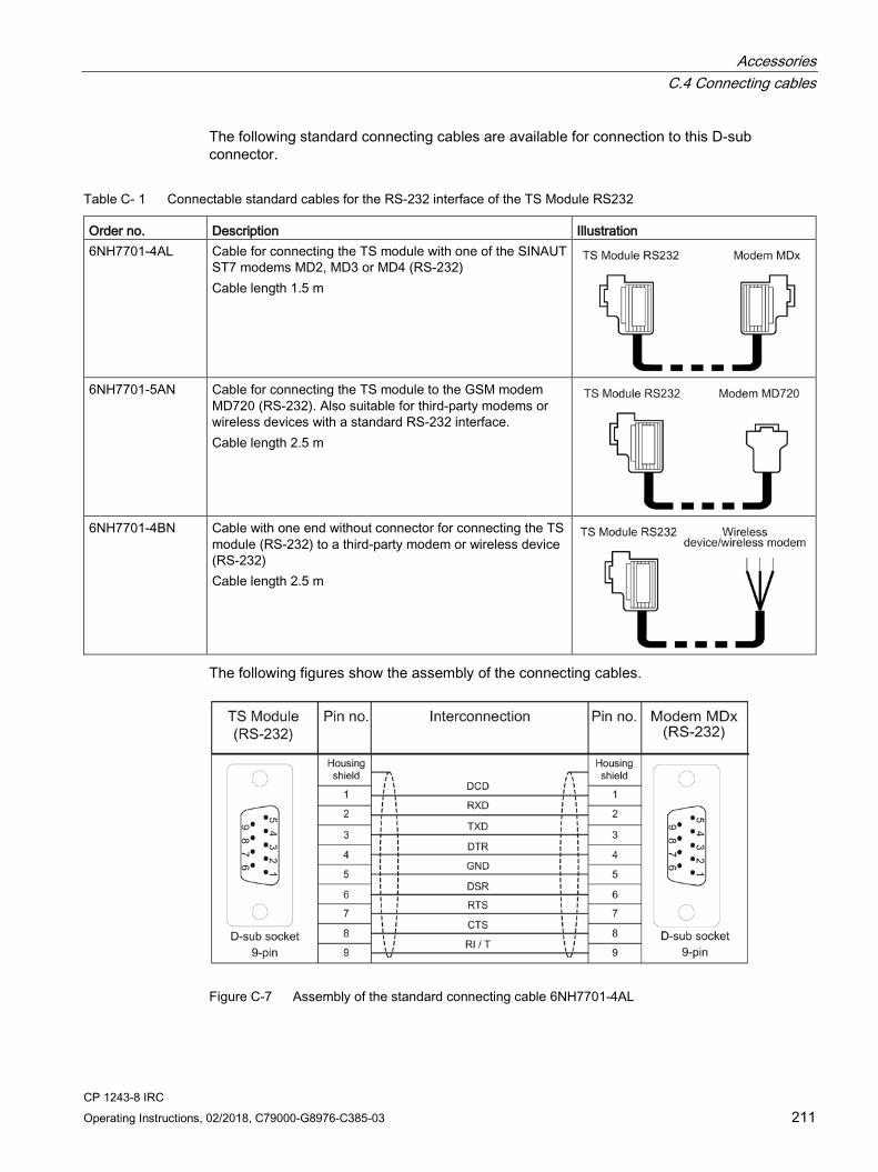
Accessories C.4 Connecting cables
CP 1243-8 IRC Operating Instructions, 02/2018, C79000-G8976-C385-03 211
The following standard connecting cables are available for connection to this D-sub connector.
Table C- 1 Connectable standard cables for the RS-232 interface of the TS Module RS232
Order no. Description Illustration 6NH7701-4AL Cable for connecting the TS module with one of the SINAUT
ST7 modems MD2, MD3 or MD4 (RS-232) Cable length 1.5 m
6NH7701-5AN Cable for connecting the TS module to the GSM modem
MD720 (RS-232). Also suitable for third-party modems or wireless devices with a standard RS-232 interface. Cable length 2.5 m
6NH7701-4BN Cable with one end without connector for connecting the TS
module (RS-232) to a third-party modem or wireless device (RS-232) Cable length 2.5 m
The following figures show the assembly of the connecting cables.
Figure C-7 Assembly of the standard connecting cable 6NH7701-4AL
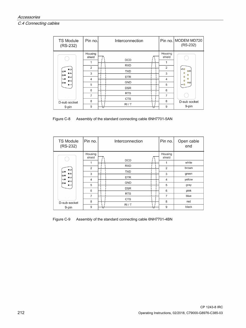
Accessories C.4 Connecting cables
CP 1243-8 IRC 212 Operating Instructions, 02/2018, C79000-G8976-C385-03
Figure C-8 Assembly of the standard connecting cable 6NH7701-5AN
Figure C-9 Assembly of the standard connecting cable 6NH7701-4BN

Accessories C.4 Connecting cables
CP 1243-8 IRC Operating Instructions, 02/2018, C79000-G8976-C385-03 213
C.4.3 Connecting cables of the MDx modem With every MDx modem, a 6NH7700-xxx connecting cable was supplied for connecting the modem to the WAN network.
Table C- 2 Cables for the WAN connection of the modems
Order no. Description Illustration 6NH7700-2AR60 Connecting cable with 2 x RJ-12 plugs for connection to an MD2
modem (RJ-12) with an LTOP overvoltage protection module (RJ-12). Cable length 6 m The adapter cable is no longer available as separate spare part.
6NH7700-3BR60 Connecting cable with 2 x RJ-12 Western plug and snap-on TAE6N plug to connect an MD3 modem (RJ-12) to a telephone jack (TAE6N) or an LTOP overvoltage protection module (RJ-12) if the MD3 modem is being operated as a dedicated line modem. Cable length 6 m The adapter cable is no longer available as separate spare part.
6NH7700-4AR60 Connecting cable with RJ-12 and RJ-45 plug to connect an MD4
modem (RJ-12) with an ISDN-S0 jack (RJ-45). Cable length 6 m The adapter cable is no longer available as separate spare part.

Accessories C.4 Connecting cables
CP 1243-8 IRC 214 Operating Instructions, 02/2018, C79000-G8976-C385-03
CP 1243-8 IRC Operating Instructions, 02/2018, C79000-G8976-C385-03 215
STEP 7 V5 configuration of the proxy D
Note Using the CP
The information on configuration in STEP 7 V5 applies only in the situation when you want to use the CP as a communication module with the functions of a TIM 3V-IE Advanced in existing SINAUT ST7 systems.
See also Expansion of SINAUT projects (Page 35)
D.1 Configuration in STEP 7 V5
Configuration of a proxy in STEP 7 V5 1. Open the STEP 7 V5 project that you wish to expand with S7-1200/1500 modules.
2. Create an S7-300 station with CPU and the new necessary networks, if applicable.
The CPU only serves as placeholder to receive the SINAUT subscriber number.
3. Insert the "proxy" in the station.
4. Perform the configuration in STEP 7.
Deviations from the normal configuration are described below.
5. Perform the configuration in the connection configuration of the SINAUT engineering software.
6. Export the configuration data of the proxy via the SINAUT diagnostics and service tool.
For information on this, refer to section Exporting configuration data (Page 221).
The data exported from STEP 7 V5 is adopted later in the STEP 7 Basic project for the S7-1200/1500 communication module.
PROXY modules in HW Config You can find the proxy modules as representatives of S7-1200/1500 communication modules in the HW Config catalog under:
SIMATIC 300 > SINAUT ST7 > TIM IE

STEP 7 V5 configuration of the proxy D.2 Special features of the PROXY CP1243-8 IRC
CP 1243-8 IRC 216 Operating Instructions, 02/2018, C79000-G8976-C385-03
They have the following names:
● PROXY CP1243-8 IRC
● PROXY TIM 1531 IRC
Figure D-1 PROXY modules in the catalog
D.2 Special features of the PROXY CP1243-8 IRC
Properties of the CP or proxy "PROXY CP1243-8" Like a TIM 3V-IE Advanced the proxy supports parallel connection to two WAN networks via the serial and the Ethernet interface. Both interfaces of the proxy can be configured.
Compared with the TIM 3V-IE Advanced, the proxy or CP has the following differences:
● Station
The interfaces of the proxy can only be configured as station. Use as a node station or master station is not possible. This is expressed in the STEP 7 properties dialog:
● "Time" tab
The proxy can only be configured as a time slave. The function of time master is not supported.
STEP 7 V5 configuration of the proxy D.2 Special features of the PROXY CP1243-8 IRC
CP 1243-8 IRC Operating Instructions, 02/2018, C79000-G8976-C385-03 217
● "Interfaces" tab
– Modem type
TS modules are added here due to the different connection of WAN transmission devices to the CP 1243-8 IRC.
– Connection mode
When the CP 1243-8 IRC is used as successor module with imported configuration data, it can only be used as station. This changes the selection of the connection modes; see below.
● AT strings for TS modules
AT strings were added for the TS modules, see below.
● "Special " tab
The tab no longer exists.
● "Options" tab
The tab no longer exists.
● No loading of firmware
The loading of firmware files on a CP 1243-8 IRC is not supported.
"Interfaces" > "Connection mode" tab Options of the "Connection mode" parameter for both interfaces:
● Ethernet interface
– MSC station
The communication is handled using the MSC protocol. The proxy is configured to connect to the Internet as an MSC station via a DSL router.
– GPRS station
The proxy is configured to connect to the Internet as a GPRS station via an MD720.
– Neutral
On the Ethernet interface, there is normal TCP/IP communication with the ST7 protocol. The proxy is not connected via GPRS and the MSC protocol is not activated.
● Serial WAN interface
– MSC station
The serial interface is configured as an Ethernet interface. The communication is handled using the MSC protocol. The proxy is configured to connect to the Internet as an MSC station via a DSL router.
– Neutral
The serial WAN interface of the proxy is set to the connection mode "Neutral“ if communication is handled via a dial-up network or dedicated line.

STEP 7 V5 configuration of the proxy D.2 Special features of the PROXY CP1243-8 IRC
CP 1243-8 IRC 218 Operating Instructions, 02/2018, C79000-G8976-C385-03
TS modules in the "Interfaces" tab TS modules are used to connect the serial interface of the CP to dial-up networks that are also configured in STEP 7 V5 in the "Interfaces" tab of the Properties dialog of the proxy.
Figure D-2 Properties dialog, "Interfaces" tab. WAN interface connected to dialup network.
The following figure shows drop-down list for selecting the modem type.
Figure D-3 Selectable modem types of a WAN interface with a connection to a dial-up network
The following entries are available for the TS modules:
● TS Module GSM
Connection to a GSM network
● TS Module ISDN
Connection to an ISDN network

STEP 7 V5 configuration of the proxy D.2 Special features of the PROXY CP1243-8 IRC
CP 1243-8 IRC Operating Instructions, 02/2018, C79000-G8976-C385-03 219
● TS Module Modem
Connection to an analog dial-up network
● Third-party modem
Select the "3rd party modem" entry in the following cases:
– Connection to a dedicated line network
For the connection to a dedicated line network via a dedicated line or analog wireless modem, a TS module RS-232 is connected to the CP.
– Connection to a dial-up network
For the connection to a dial-up network via a third-party modem, a TS module RS232 is connected to the CP.
The TS module RS-232 cannot be configured in STEP 7 V5.
AT strings for TS modules If the CP is connected to a dial-up network via a TS module, the suitable AT string must be configured in the properties dialog of the network node in STEP 7 V5 for the network node of the proxy.
Figure D-4 Properties dialog of a dial-up network node, "AT initialization" tab

STEP 7 V5 configuration of the proxy D.3 SINAUT configuration
CP 1243-8 IRC 220 Operating Instructions, 02/2018, C79000-G8976-C385-03
For dial-up network connections via TS modules, AT strings are configured in the "AT Initialization" tab of the Properties dialog of the dial-up network node. Depending on the TS module being used, the following AT strings are preassigned:
● CP with TS Module GSM
ATE0S0=1&D2+CBST=7,0,1;+CRC=1;&W+IPR=115200
● CP with TS Module Modem
AT&FE0&M0&Q6S0=1x3&w0
● CP with TS Module ISDN - partner (master station) with GSM connection:
AT string of the TS Module ISDN in the station:
AT&FE0\N1
Only when transferring via an ISDN network with the following configuration do the AT strings need to be adapted manually in the "Initialization string" input box.
● CP with TS Module ISDN - partner (master station) with Modem MD4:
– AT string for the TS Module ISDN in the station:
AT&FE0\N2
– AT string for the Modem MD4 in the master station:
ATS45=85$P5\N0&W$M=1
D.3 SINAUT configuration
Connection configuration with SINAUT Engineering Software Configure the connection of a proxy in the SINAUT configuration tool in the same way as for a TIM.
In the subscriber administration of the configuration tool, a proxy appears as follows:
Figure D-5 View of a proxy in the SINAUT subscriber administration
If you double-click on the selected subscriber (proxy) in the subscriber list, you will find the corresponding entry for the expanded type in the properties dialog of the subscriber:
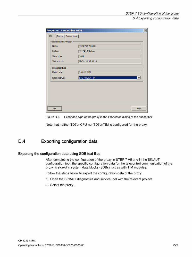
STEP 7 V5 configuration of the proxy D.4 Exporting configuration data
CP 1243-8 IRC Operating Instructions, 02/2018, C79000-G8976-C385-03 221
Figure D-6 Expanded type of the proxy in the Properties dialog of the subscriber
Note that neither TD7onCPU nor TD7onTIM is configured for the proxy.
D.4 Exporting configuration data
Exporting the configuration data using SDB text files After completing the configuration of the proxy in STEP 7 V5 and in the SINAUT configuration tool, the specific configuration data for the telecontrol communication of the proxy is stored in system data blocks (SDBs) just as with TIM modules.
Follow the steps below to export the configuration data of the proxy:
1. Open the SINAUT diagnostics and service tool with the relevant project.
2. Select the proxy.
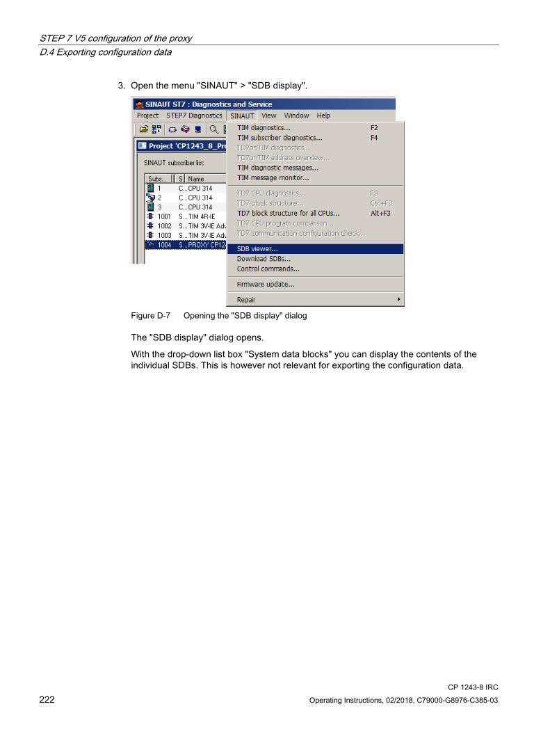
STEP 7 V5 configuration of the proxy D.4 Exporting configuration data
CP 1243-8 IRC 222 Operating Instructions, 02/2018, C79000-G8976-C385-03
3. Open the menu "SINAUT" > "SDB display".
Figure D-7 Opening the "SDB display" dialog
The "SDB display" dialog opens.
With the drop-down list box "System data blocks" you can display the contents of the individual SDBs. This is however not relevant for exporting the configuration data.
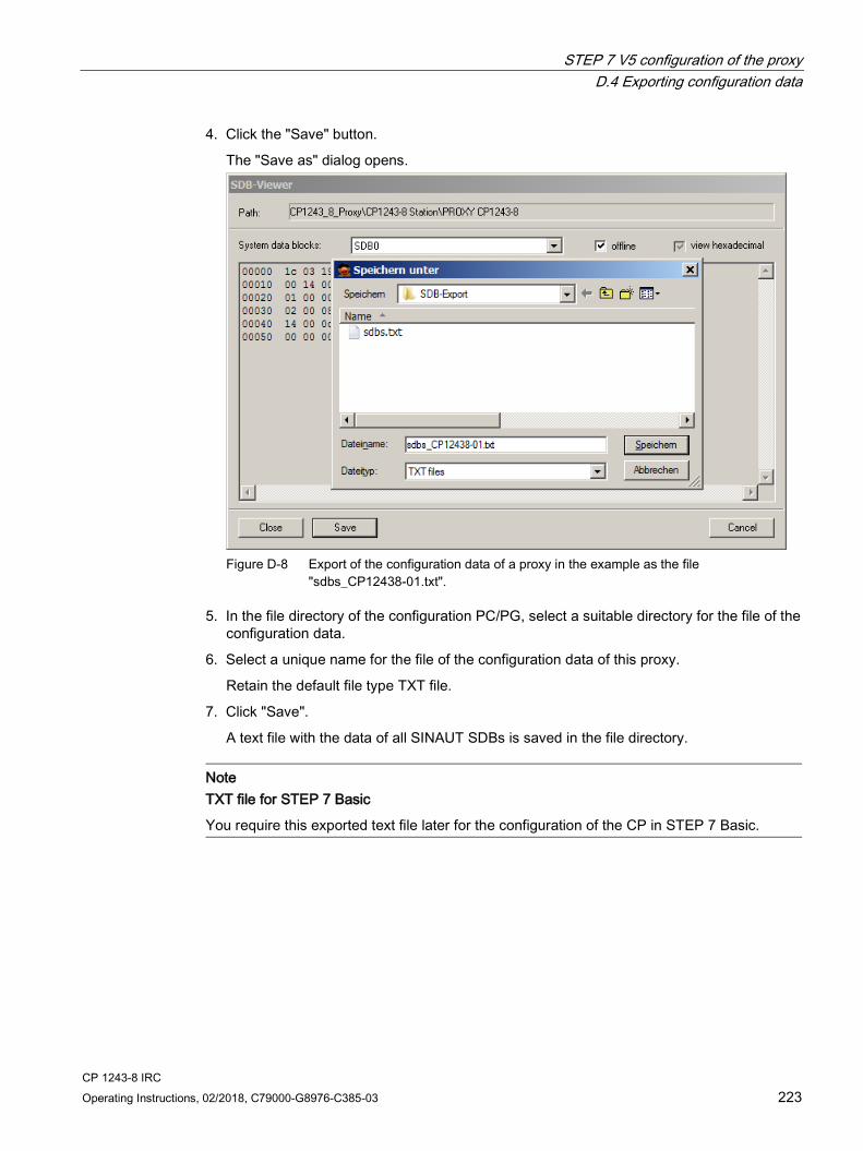
STEP 7 V5 configuration of the proxy D.4 Exporting configuration data
CP 1243-8 IRC Operating Instructions, 02/2018, C79000-G8976-C385-03 223
4. Click the "Save" button.
The "Save as" dialog opens.
Figure D-8 Export of the configuration data of a proxy in the example as the file
"sdbs_CP12438-01.txt".
5. In the file directory of the configuration PC/PG, select a suitable directory for the file of the configuration data.
6. Select a unique name for the file of the configuration data of this proxy.
Retain the default file type TXT file.
7. Click "Save".
A text file with the data of all SINAUT SDBs is saved in the file directory.
Note TXT file for STEP 7 Basic
You require this exported text file later for the configuration of the CP in STEP 7 Basic.

STEP 7 V5 configuration of the proxy D.4 Exporting configuration data
CP 1243-8 IRC 224 Operating Instructions, 02/2018, C79000-G8976-C385-03
CP 1243-8 IRC Operating Instructions, 02/2018, C79000-G8976-C385-03 225
Documentation references E
Where to find Siemens documentation ● Article numbers
You will find the article numbers for the Siemens products of relevance here in the following catalogs:
– SIMATIC NET - Industrial Communication / Industrial Identification, catalog IK PI
– SIMATIC - Products for Totally Integrated Automation and Micro Automation, catalog ST 70
You can request the catalogs and additional information from your Siemens representative. You will also find the product information in the Siemens Industry Mall at the following address:
Link: (https://mall.industry.siemens.com)
● Manuals on the Internet
You will find SIMATIC NET manuals on the Internet pages of Siemens Industry Online Support:
Link: (https://support.industry.siemens.com/cs/ww/en/ps/15247/man)
Go to the required product in the product tree and make the following settings:
Entry type “Manuals”
● Manuals on the data medium
You will find manuals of SIMATIC NET products on the data medium that ships with many of the SIMATIC NET products.
/1/ SIMATIC S7-1200 Automation System system manual Siemens AG Link: (http://support.automation.siemens.com/WW/view/en/34612486)

Documentation references /2/
CP 1243-8 IRC 226 Operating Instructions, 02/2018, C79000-G8976-C385-03
/2/ SIMATIC NET CP 1243-8 Operating Instructions Siemens AG Link: (https://support.industry.siemens.com/cs/ww/en/ps/21162/man)
/3/ SIMATIC NET SINAUT ST7 System Manual - Volume 1: Station control system - Band 2: Software (STEP 7 V5) - Volume 3: Software (STEP 7 Professional) Siemens AG Link: (https://support.industry.siemens.com/cs/ww/en/ps/21771/man)
/4/ SIMATIC TS Adapter modular Device Manual Siemens AG Link: (https://support.industry.siemens.com/cs/ww/en/ps/16006)
/5/ SIMATIC NET MODEM MD2 Operating Instructions Siemens AG Link: (http://support.automation.siemens.com/WW/view/en/17163799)
/6/ SIMATIC NET MODEM MD3 Operating Instructions Siemens AG Link: (http://support.automation.siemens.com/WW/view/en/17164329)

Documentation references /7/
CP 1243-8 IRC Operating Instructions, 02/2018, C79000-G8976-C385-03 227
/7/ SIMATIC NET MODEM MD4 Operating Instructions Siemens AG Link: (http://support.automation.siemens.com/WW/view/en/17165032)
/8/ SIMATIC NET MODEM MD720 Operating Instructions Siemens AG Link: (https://support.industry.siemens.com/cs/ww/en/ps/15923/man)
/9/ SIMATIC NET SCALANCE M812, M816 Operating Instructions Siemens AG Link: (https://support.industry.siemens.com/cs/ww/en/ps/15984)
/10/ SIMATIC NET SCALANCE M874/M876 Operating Instructions Siemens AG Link: (https://support.industry.siemens.com/cs/ww/en/ps/15987/man)
/11/ SIMATIC NET Industrial Ethernet Security Security basics and applications Configuration manual Siemens AG Link: (http://support.automation.siemens.com/WW/view/en/18701555)

Documentation references /12/
CP 1243-8 IRC 228 Operating Instructions, 02/2018, C79000-G8976-C385-03
/12/ SIMATIC NET Industrial Ethernet Security SCALANCE S Commissioning and Installation Manual Siemens AG Link: (https://support.industry.siemens.com/cs/ww/en/ps/15327/man)
/13/ SIMATIC NET Diagnostics and configuration with SNMP Diagnostics manual Siemens AG Link: (https://support.industry.siemens.com/cs/ww/en/ps/15392/man)
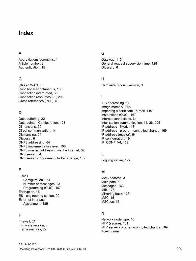
CP 1243-8 IRC Operating Instructions, 02/2018, C79000-G8976-C385-03 229
Index
A Abbreviations/acronyms, 4 Article number, 3 Authentication, 15
C Classic WAN, 83 Conditional spontaneous, 150 Connection interrupted, 65 Connection resources, 22, 206 Cross references (PDF), 5
D Data buffering, 22 Data points - Configuration, 128 Dimensions, 50 Direct communication, 14 Dismantling, 54 Disposal, 6 DNP3 addressing, 64 DNP3 implementation level, 106 DNP3 master, addressing via the Internet, 32 DNS server, 64 DNS server - program-controlled change, 169
E E-mail
Configuration, 164 Number of messages, 23 Programming (OUC), 167
Encryption, 15 ES - engineering station, 20 Ethernet interface
Assignment, 185
F Firewall, 21 Firmware version, 3 Frame memory, 22
G Gateway, 115 General request supervision time, 128 Glossary, 6
H Hardware product version, 3
I IEC addressing, 64 Image memory, 145 Importing a certificate - e-mail, 110 Instructions (OUC), 167 Internet connections, 64 Inter-station communication, 14, 26, 205 IP address - fixed, 113 IP address - program-controlled change, 169 IP address (master), 64 IP configuration, 19 IP_CONF_V4, 169
L Logging server, 122
M MAC address, 3 Main path, 62 Messages, 163 MIB, 175 Mirroring back, 136 MSC, 15 MSCsec, 15
N Network node type, 16 NTP (secure), 101 NTP server - program-controlled change, 169 IPsec tunnel,

Index
CP 1243-8 IRC 230 Operating Instructions, 02/2018, C79000-G8976-C385-03
O Online diagnostics, 172 Online functions, 20, 68, 173 Operating statuses (LED displays), 42 OUC (Open User Communication), 167
P Passive VPN connection establishment, 115 Path redundancy, 62 PG/OP connections, 22 Port 8448, 174 Program blocks, 17
R Recycling, 6 Redundant master, addressing, 33 Redundant telecontrol connection, 62 Redundant telecontrol connections, 126 Replacing a module, 182
S S7 connections
Enable, 67 Resources, 22
S7 systems, connectable, 205 Safety notices, 47 SDBs, 221 Security, 21 Security diagnostics without port 102, 174 Send buffer, 22, 145 Service & Support, 6 SIMATIC NET glossary, 6 SIMATIC PCS 7, 12, 13 SINAUT ST7cc, 12, 13 SINAUT system, 11 SMS, 103
Configuration (telecontrol communication), 163 Number of messages, 23 Programming (OUC), 167
SMSC, 103 SMTPS, 110 SNMP, 20, 104, 175 SNMPv3, 21, 118 Spontaneous, 150 SSL/TLS, 110 ST7sc, 12, 13 STARTTLS, 110
Station address, 83 STEP 7
Version, 24 STEP 7 V5, 13 Subscriber number, 62, 103 Substitute path, 62 SYSLOG, 116 System data blocks, 221
T T_CONFIG, 169 TC_CONFIG, 169 TIM 3V-IE Advanced, 11 Time stamp, 128, 141 Time-of-day synchronization, 19 Training, 6 Transmission mode, 150 Trigger tag - resetting, 148, 164 TS module
configuring, 80
V VPN, 23, 64, 111
W WAN - creating a network, 82 WAN address, 62, 83 Web server, 79
Diagnostics data, 173 WinCC TC, 12, 13