Embed Size (px)
Citation preview

ETSI TR 101 542 V1.2.1 (2013-07)
Satellite Earth Stations and Systems (SES); Comparison of candidate radio interfaces performances
in MSS context
Technical Report
ETSI
ETSI TR 101 542 V1.2.1 (2013-07) 2
Reference RTR/SES-00350
Keywords interface, mobile, radio, satellite
ETSI
650 Route des Lucioles F-06921 Sophia Antipolis Cedex - FRANCE
Tel.: +33 4 92 94 42 00 Fax: +33 4 93 65 47 16
Siret N° 348 623 562 00017 - NAF 742 C
Association à but non lucratif enregistrée à la Sous-Préfecture de Grasse (06) N° 7803/88
Important notice
Individual copies of the present document can be downloaded from: http://www.etsi.org
The present document may be made available in more than one electronic version or in print. In any case of existing or perceived difference in contents between such versions, the reference version is the Portable Document Format (PDF).
In case of dispute, the reference shall be the printing on ETSI printers of the PDF version kept on a specific network drive within ETSI Secretariat.
Users of the present document should be aware that the document may be subject to revision or change of status. Information on the current status of this and other ETSI documents is available at
http://portal.etsi.org/tb/status/status.asp
If you find errors in the present document, please send your comment to one of the following services: http://portal.etsi.org/chaircor/ETSI_support.asp
Copyright Notification
No part may be reproduced except as authorized by written permission. The copyright and the foregoing restriction extend to reproduction in all media.
© European Telecommunications Standards Institute 2013.
All rights reserved.
DECTTM, PLUGTESTSTM, UMTSTM and the ETSI logo are Trade Marks of ETSI registered for the benefit of its Members. 3GPPTM and LTE™ are Trade Marks of ETSI registered for the benefit of its Members and
of the 3GPP Organizational Partners. GSM® and the GSM logo are Trade Marks registered and owned by the GSM Association.
ETSI
ETSI TR 101 542 V1.2.1 (2013-07) 3
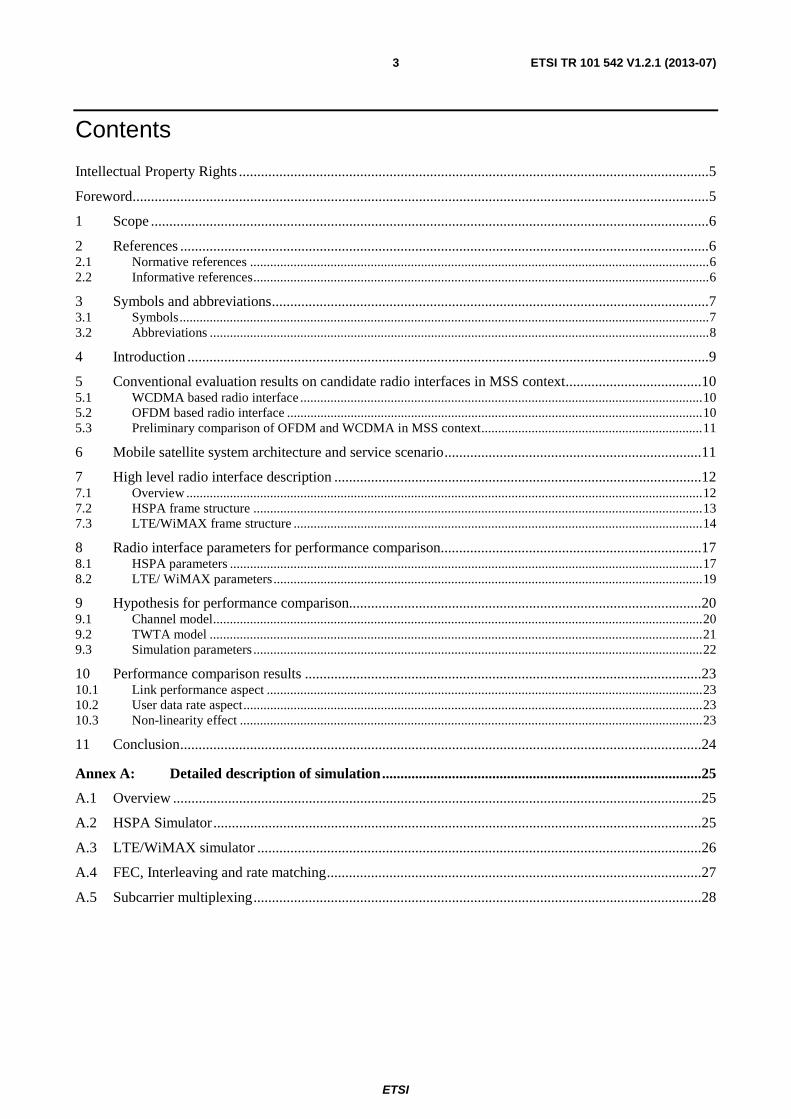
Contents
Intellectual Property Rights ................................................................................................................................ 5
Foreword ............................................................................................................................................................. 5
1 Scope ........................................................................................................................................................ 6
2 References ................................................................................................................................................ 6
2.1 Normative references ......................................................................................................................................... 6
2.2 Informative references ........................................................................................................................................ 6
3 Symbols and abbreviations ....................................................................................................................... 7
3.1 Symbols .............................................................................................................................................................. 7
3.2 Abbreviations ..................................................................................................................................................... 8
4 Introduction .............................................................................................................................................. 9
5 Conventional evaluation results on candidate radio interfaces in MSS context ..................................... 10
5.1 WCDMA based radio interface ........................................................................................................................ 10
5.2 OFDM based radio interface ............................................................................................................................ 10
5.3 Preliminary comparison of OFDM and WCDMA in MSS context .................................................................. 11
6 Mobile satellite system architecture and service scenario ...................................................................... 11
7 High level radio interface description .................................................................................................... 12
7.1 Overview .......................................................................................................................................................... 12
7.2 HSPA frame structure ...................................................................................................................................... 13
7.3 LTE/WiMAX frame structure .......................................................................................................................... 14
8 Radio interface parameters for performance comparison....................................................................... 17
8.1 HSPA parameters ............................................................................................................................................. 17
8.2 LTE/ WiMAX parameters ................................................................................................................................ 19
9 Hypothesis for performance comparison................................................................................................ 20
9.1 Channel model .................................................................................................................................................. 20
9.2 TWTA model ................................................................................................................................................... 21
9.3 Simulation parameters ...................................................................................................................................... 22
10 Performance comparison results ............................................................................................................ 23
10.1 Link performance aspect .................................................................................................................................. 23
10.2 User data rate aspect ......................................................................................................................................... 23
10.3 Non-linearity effect .......................................................................................................................................... 23
11 Conclusion .............................................................................................................................................. 24
Annex A: Detailed description of simulation ....................................................................................... 25
A.1 Overview ................................................................................................................................................ 25
A.2 HSPA Simulator ..................................................................................................................................... 25
A.3 LTE/WiMAX simulator ......................................................................................................................... 26
A.4 FEC, Interleaving and rate matching ...................................................................................................... 27
A.5 Subcarrier multiplexing .......................................................................................................................... 28

ETSI
ETSI TR 101 542 V1.2.1 (2013-07) 4
Annex B: Detailed link-level results ..................................................................................................... 31
B.1 Overview ................................................................................................................................................ 31
B.2 Downlink performance comparison ....................................................................................................... 31
B.3 Uplink performance comparison ............................................................................................................ 35
History .............................................................................................................................................................. 37
ETSI
ETSI TR 101 542 V1.2.1 (2013-07) 5
Intellectual Property Rights IPRs essential or potentially essential to the present document may have been declared to ETSI. The information pertaining to these essential IPRs, if any, is publicly available for ETSI members and non-members, and can be found in ETSI SR 000 314: "Intellectual Property Rights (IPRs); Essential, or potentially Essential, IPRs notified to ETSI in respect of ETSI standards", which is available from the ETSI Secretariat. Latest updates are available on the ETSI Web server (http://ipr.etsi.org).
Pursuant to the ETSI IPR Policy, no investigation, including IPR searches, has been carried out by ETSI. No guarantee can be given as to the existence of other IPRs not referenced in ETSI SR 000 314 (or the updates on the ETSI Web server) which are, or may be, or may become, essential to the present document.
Foreword This Technical Report (TR) has been produced by ETSI Technical Committee Satellite Earth Stations and Systems (SES).
ETSI
ETSI TR 101 542 V1.2.1 (2013-07) 6
1 Scope The present document aims to compare the link level performances of several radio interfaces (HSPA, LTE and mobile WiMAX) in geostationary based mobile satellite systems operating in S band or L band.
The present document provides a high level description of the radio interfaces to be compared. It then identifies their key characteristics and defines the propagation channel used for the comparison.
Link level performances are compared in terms of required signal to noise ratio (ob NE ) for a given block error rate
(BLER) and data rate.
The present document concludes on the respective qualitative benefits and drawbacks of the considered radio interfaces.
2 References References are either specific (identified by date of publication and/or edition number or version number) or non-specific. For specific references, only the cited version applies. For non-specific references, the latest version of the reference document (including any amendments) applies.
Referenced documents which are not found to be publicly available in the expected location might be found at http://docbox.etsi.org/Reference.
NOTE: While any hyperlinks included in this clause were valid at the time of publication, ETSI cannot guarantee their long term validity.
2.1 Normative references The following referenced documents are necessary for the application of the present document.
Not applicable.
2.2 Informative references The following referenced documents are not necessary for the application of the present document but they assist the user with regard to a particular subject area.
[i.1] H. Holma and A. Toskala, "WCDMA for UMTS, Radio Access for Third Generation Mobile Communications", 2nd Edition, John Wiley & Sons, Ltd., 2002.
[i.2] ETSI TS 125 201 (V3.4.0): "Universal Mobile Telecommunications System (UMTS); Physical layer - general description (3GPP TS 25.201 version 3.4.0 Release 1999)".
[i.3] H. Holma and A. Toskala, "HSDPA/HSUPA for UMTS, High Speed Radio Access for Mobile Communications", John Wiley & Sons, Ltd., 2006.
[i.4] ETSI TS 125 201 (V5.3.0): "Universal Mobile Telecommunications System (UMTS); Physical layer - general description (3GPP TS 25.201 version 5.3.0 Release 5)".
[i.5] ETSI TS 125 201 (V6.2.0): "Universal Mobile Telecommunications System (UMTS); Physical layer - general description (3GPP TS 25.201 version 6.2.0 Release 6)".
[i.6] ETSI TS 125 211 (V6.9.0): "Universal Mobile Telecommunications System (UMTS); Physical channels and mapping of transport channels onto physical channels (FDD) (3GPP TS 25.211 version 6.9.0 Release 6)".
[i.7] ETSI TS 136 201 (V8.2.0): "LTE; Evolved Universal Terrestrial Radio Access (E-UTRA); Long Term Evolution (LTE) physical layer; General description (3GPP TS 36.201 version 8.2.0 Release 8)".

ETSI
ETSI TR 101 542 V1.2.1 (2013-07) 7
[i.8] ETSI TS 136 211 (V8.5.0): "LTE; Evolved Universal Terrestrial Radio Access (E-UTRA); Physical channels and modulation (3GPP TS 36.211 version 8.5.0 Release 8)".
[i.9] ETSI TS 136 212 (V8.5.0): "LTE; Evolved Universal Terrestrial Radio Access (E-UTRA); Multiplexing and channel coding (3GPP TS 36.212 version 8.5.0 Release 8)".
[i.10] IEEE 802.16-2009: "IEEE Standard for Local and Metropolitan Area Networks - Part 16: Air Interface for Broadband Wireless Access Systems".
[i.11] ETSI TR 102 443 (V1.1.1): "Satellite Earth Stations and Systems (SES); Satellite Component of UMTS/IMT-2000; Evaluation of the OFDM as a Satellite Radio Interface".
[i.12] R. van Nee and R. Prasad, "OFDM for Wireless Multimedia Communications", Artech House, 2000.
[i.13] WiMAX Forum, "Mobile WiMAX - Part I: A Technical Overview and Performance Evaluation", 2006.
[i.14] WiMAX Forum, Mobile WiMAX - Part II: "A Comparative Analysis", 2006.
[i.15] S. Sesia, I. Toufik and M. Baker,"LTE, the UMTS Long Term Evolution: from Theory to Practice", John Wiley and Sons, 2009.
[i.16] Void.
[i.17] C. Gessner, "UMTS Long Term Evolution (LTE) Technology Introduction", Application Note 1MA111, Rohde and Schwarz, www2.rohde-schwarz.com/file/1MA111-2E.pdf, Sep. 2008.
[i.18] M. Maqbool, M. Coupechoux and P. Godlewski, "Subcarrier permutation types in IEEE 802.16e", www.telecom-paristech.fr/-data/files/docs/id-792-1208254315-271.pdf, Apr. 2008.
[i.19] ETSI TR 102 662 (V1.1.1): "Satellite Earth Stations and Systems (SES); Advanced satellite based scenarios and architectures for beyond 3G systems", March 2010.
[i.20] 3GPP TR 25.896 (V6.0.0): "Feasibility Study for Enhanced Uplink for UTRA FDD".
[i.21] J. Laiho, A. Wacker and T. Novosad, "Radio Network Planning and Optimization for UMTS", John Wiley & Sons, Ltd., 2002.
[i.22] ETSI TR 102 058: "Satellite Earth Stations and Systems (SES); Satellite Component of UMTS/IMT-2000; Evaluation of the W-CDMA UTRA FDD as a Satellite Radio Interface".
[i.23] ETSI TS 136 104 (V8.2.0): "LTE; Technical Specification Group Radio Access Network; Evolved Universal Terrestrial Radio Access (E-UTRA); Base Station (BS) radio transmission and reception (3GPP TS 36.104 version 8.2.0 Release 8)".
3 Symbols and abbreviations
3.1 Symbols For the purposes of the present document, the following symbols apply:
α Code orthogonality factor
ob NE Energy per bit to noise spectral density ratio
orc IE Energy per chip to same cell interference density ratio
G Geometry factor, which is the same cell interference to other cell interference ratio ocor II
-inf Negative infinite
RW Processing gain, which is the chip rate/bit rate
TB The useful OFDM symbol duration FΔ Carrier spacing

ETSI
ETSI TR 101 542 V1.2.1 (2013-07) 8
3.2 Abbreviations For the purpose of the present document, the following abbreviations apply:
3G/ 4G 3rd/ 4th Generation (mobile systems) 3GPP 3rd Generation Partnership Project AMC Adaptive Modulation and Coding AWGN Additive White Gaussian Noise BER Bit Error Rate BLER Block Error Rate BPSK Binary Phase Shift Keying CDMA Code Division Multiple Access CGC Complementary Ground Components CP Cyclic Prefix CPICH Common Pilot Channel CRC Cyclic Redundancy Check CTC Convolutional Turbo Code (Duo-Binary Turbo) DCH Dedicated Channel DFT Discrete Fourier Transform DL Downlink DL+UL Downlink + Uplink DPCCH Dedicated Physical Control Channel DPDCH Dedicated Physical Data Channel DS-CDMA Direct Sequence Code Division Multiple Access E-DCH Enhanced DCH E-DPCCH Enhanced DPCCH E-DPDCH Enhanced DPDCH E-UTRA Evolved Universal Terrestrial Radio Access FDD Frequency Division Duplex FEC Forward Error Control Coding FFSS Frequency band in the spectrum allocated to FSS FFT Fast Fourier Transform FMSS Frequency band in the spectrum allocated to MSS FSS Fixed Satellite Service FUSC Full Usage of the Sub-channels HARQ Hybrid Automatic Repeat Request HD High-speed Downlink HSDPA High Speed Downlink Packet Access HS-DSCH High Speed Downlink Shared Channel HSPA High Speed Packet Access HS-PDSCH High Speed Physical Downlink Shared Channel HS-SCCH High Speed Shared Control Channel HSUPA High Speed Uplink Packet Access IBO Input Back-Off IEEE Institute of Electrical and Electronics Engineers IFFT Inverse Fast Fourier Transform IR Incremental Redundancy LOS Line Of Sight LTE Long Term Evolution (of 3GPP UMTS) MAESTRO Mobile Applications and sErvices based on Satellite and Terrestrial inteRwOrking MIMO Multiple Input Multiple Output MSS Mobile Satellite Services NFFT Number of FFT samples NLOS Non Line of Sight OBO Output Back-Off OFDM Orthogonal Frequency Division Multiplexing OFDMA Orthogonal Frequency Division Multiple Access OVSF Orthogonal Variable Spreading Factor PAPR Peak to Average Power Ratio PCCC Parallel Concatenated Convolutional Code (Binary Turbo) PDSCH Physical Downlink Shared Channel
ETSI
ETSI TR 101 542 V1.2.1 (2013-07) 9
PhyL Physical Layer PRB Physical Resource Block PUSC Partial Usage of Subcarriers PUSCH Physical Uplink Shared Channel QAM Quadrature Amplitude Modulation QPSK Quadrature Phase Shift Keying RB Resource Block RNC Radio Network Control RV Redundancy Version SC-FDMA Single Carrier Frequency Division Multiple Access SES Satellite Earth Stations and Systems SF Spreading Factor SSPA Solid State Power Amplifier STBC Space Time Block Code Tb Symbol Time (OFDM, without cyclic extension) TDD Time Division Duplex Tg Guard Time or CP duration Ts Symbol Time (OFDM, with cyclic extension) TTI Transmit Time Interval TWTA Travelling Wave Tube Amplifier UE User Equipment UL Uplink UMTS Universal Mobile Telecommunications System UTRA Universal Terrestrial Radio Access VRB Virtual Resource Block WCDMA Wideband Code Division Multiple Access WiMAX Worldwide interoperability for Microwave Access
4 Introduction WCDMA [i.1] to [i.6] is the air-interface for the universal mobile telecommunications system (UMTS) which is a 3G mobile standard specified by the 3GPP. It is based on direct sequence code division multiple access (DS-CDMA) due to its robustness in wideband channels and support for asymmetric data rate applications. Release 4 WCDMA has been enhanced to Release 5 and 6 versions for higher data rate applications. These enhancements, referred to as high speed packet access (HSPA), incorporate advanced features such as higher order modulation, fast link adaption, HARQ and spatial diversity. However, prominent candidates for 4G mobile communications include the 3GPP LTE standard [i.7] to [i.9] and the IEEE mobile WiMAX standard [i.10], both of which are based on orthogonal frequency division multiple access (OFDMA) air-interface, due to its robustness against frequency-selective fading and flexibility of subcarrier allocations. LTE is specified as the long term evolution of UMTS while HSPA can be regarded as its short term evolution.
It is observed that all the standards share similarities in the advanced features introduced in HSPA. However, there are fundamental differences in the air-interfaces, frame structures and system/link parameters. Moreover, these standards and their advanced features were specified for terrestrial communications and it would be useful to establish their performance under realistic satellite links (which involve satellite wideband fading channels and power amplifier non-linearity). Therefore, in this study, we compare the link-level performance of HSPA with that of LTE and mobile WiMAX, over satellite links.
Figure 1 describes the evolution of the three baseline terrestrial technologies. For performance comparison in the present document, HSPA Release 6, LTE Release 8 and mobile WiMAX Release 1.0 versions are used.

ETSI
ETSI TR 101 542 V1.2.1 (2013-07) 10
Figure 1: Evolution of HSPA, LTE and Mobile WiMAX
5 Conventional evaluation results on candidate radio interfaces in MSS context
In this clause, we recall outcomes of prior feasibility studies on the use of WCDMA and OFDM based radio interface in the context of mobile satellite systems.
5.1 WCDMA based radio interface The feasibility study on WCDMA UTRA FDD as a satellite radio interface has been done in TR 102 058 [i.22]. Main study results are summarized as:
• MSS systems using WCDMA can complement UMTS network with additional capacity.
• Allows technology synergy and interoperability with terrestrial UMTS network.
• Enables full frequency reuse in all beams and satellites.
• Allows to support broadcast/multicast services over large areas.
• Suitable to complement terrestrial UMTS network coverage and services in areas where:
- terrestrial systems have not been deployed for business attractiveness reasons; or
- terrestrial system requires coverage and/or capacity complement; or
- terrestrial system has suffered environmental damages (crisis conditions).
In the present document, we will only consider HSPA operation of WCDMA.
5.2 OFDM based radio interface A feasibility study on the use of OFDM as a satellite radio interface has been carried out and reported in TR 102 443 [i.11]. Main results are summarized as:
• It appears that, notwithstanding the large PAPR, it is possible to efficiently transmit OFDM signals through non-linear satellite links with very small IBO and OBO values.
• This surprising result is the fruit of virtuous cross-fertilization between careful predistortion design and powerful forward error correction coding application.

ETSI
ETSI TR 101 542 V1.2.1 (2013-07) 11
• In frequency flat correlated Rice fading channels and perfect channel estimation, OFDM produces small losses with respect to the HSDPA interface due to only the guard-time insertion.
• The link budget study shows that proper service reception can be attained in satellite LOS conditions. In satellite NLOS propagation conditions, proper service reception could not be achieved with this radio interface when considering a handheld terminal, due to a negative link margin. Nevertheless, the use of CGCs can be a viable solution to restore proper service reception in areas where satellite reception is critical.
In the present document, we will only consider LTE and Mobile WiMAX version of OFDM.
5.3 Preliminary comparison of OFDM and WCDMA in MSS context
Some preliminary comparisons were carried out in TR 102 443 [i.11]:
• In multi-path channel conditions (satellite and CGC links), OFDM shows its robustness and, for the considered channel profiles and with ideal channel estimation, OFDM outperforms the radio interfaces based on WCDMA and HSPA. Notably, this is achieved considering the same spectrum occupancy specifications.
• Computing the corresponding link budgets for the HSPA case results in low margin for all those cases where the required Rx C/N is higher than for the OFDM case and this is especially true in the NLOS case and when CGCs are considered.
6 Mobile satellite system architecture and service scenario
Physical layer performance comparison is achieved in mobile satellite system architecture as below.
CGC’s Feeder link
Feeder link
Access Network
3GPP core
network
FMSSFFSS
FMSS or F F SS
F MSS
CGC
(optional) UE Gateway
User link from
satellite
User link from
CGC
Figure 2: Mobile satellite system architecture
The system may provide either single satellite or multiple satellite constellations and each satellite may provide either single or multi-spot beam coverage. A location area may be either a single spot beam or a group of spot beams for roaming users.
UEs are connected to the network via one or several satellites which redirect the radio signal to/from gateways. The system allows for either a centralized gateway or a group of geographically distributed gateways, depending on the operators requirements. The gateway connects the signal to the access network, e.g. Node Bs and RNC.

ETSI
ETSI TR 101 542 V1.2.1 (2013-07) 12
In a satellite environment, signal transmission suffers from path blocking due to buildings, mountains, etc. In order to ensure coverage continuity in highly shadowed areas, the system can be possibly completed with Complementary Ground Components (CGCs) whose role is to repeat the signal from the satellite to terrestrial coverage in the MSS frequency band and from terrestrial coverage to satellite. CGCs's feeder link is either in MSS or a Fixed Satellite Service (FSS) band.
From the system point of view, satellite and CGCs have the same functionality, which is signal repetition.
When CGCs are deployed, UEs are subject to communicate with the network:
• via the satellite only (areas where CGCs are not deployed or situation with no signal view from CGCs);
• via CGCs only (situation where there is no view of the satellite signal);
• simultaneously via satellite and CGCs.
In this performance comparison, two application scenarios based on the 5 MHz bandwidth are investigated, which are the outdoor rural and outdoor urban environment respectively, with a major difference being the use of repeaters in the urban area to boost the weak satellite signal. A carrier frequency of 2,5 GHz (S-Band) has been used in modelling the Doppler characteristics of the channel. It should be noted that higher-order modulation, AMC, HARQ, STBC/MIMO and power control are not included in this link-level analysis due to the inefficiencies of these techniques in fast-fading satellite links.
7 High level radio interface description
7.1 Overview The 3GPP UMTS Release 4 standard is based on wideband code division multiple access (WCDMA) air-interface wherein each user channel is defined by signal spreading with channelization codes or signatures. WCDMA is based on QPSK modulation, 5 MHz carrier bandwidth and FDD duplexing and can support data rates up to 2 Mbps [i.1] and [i.2]. However, it has been enhanced to support higher data rate services with better power/bandwidth efficiencies by using advanced link-level techniques in the subsequent releases (Release 5 and Release 6) of the 3GPP UMTS standard. These enhanced versions are known as the high speed packet access (HSPA) which consists of the high speed downlink packet access (HSDPA) and the high speed uplink packet access (HSUPA) standards respectively [i.3] to [i.6].
The high speed-downlink shared channel (HS-DSCH) is introduced in HSDPA in order to support bursty, asymmetric and high data rate packet applications in user terminals. It supports QPSK/16QAM modulations and uses a basic rate 1/3 parallel concatenated convolutional turbo code (PCCC), with rate-matching to higher or lower code rates via puncturing or repetition. Furthermore, it incorporates important features such as fast link adaptation, HARQ, fixed spreading factor, fast scheduling, multi-code transmission, short TTI of 2 ms, spatial diversity and efficient power utilisation but does not support power control or soft handover. Similarly, an enhanced dedicated channel (E-DCH) is introduced in HSUPA in order to support higher uplink data rates. It makes use of BPSK modulation, orthogonal variable spreading factor (OVSF) codes and a TTI of 10 ms. However, the use of a shorter TTI of 2 ms is (optionally) provided, for better utilization of the short term channel capacity. HSUPA also incorporates features such as link adaptation, HARQ, multi-code transmission and MIMO. In general, it is noted that the more efficient scheduling mechanism in HSPA allows better use of the available spectrum and power budget.
On the other hand, the LTE and WiMAX standards [i.7] to [i.11] are based on orthogonal frequency division multiplexing (OFDM) air-interface [i.12], wherein each user resource is defined by time-frequency subcarrier allocations. Both standards support scalable bandwidths (e.g. 1,25 MHz, 5 MHz and above), FDD/TDD duplexing and are designed to provide high data rate services with improved power/bandwidth efficiencies. Similar to the HSPA standards, they also incorporate advanced link-level techniques such as AMC, HARQ, short TTI, and MIMO. It should be noted that LTE is a 3GPP standard which is structured as the long term evolution of UMTS while HSPA can be considered as its short-term evolution. Similar to HSPA, the LTE standard uses a basic rate 1/3 parallel concatenated convolutional turbo code (PCCC) with rate-matching whereas WiMAX specifies a variety of FEC codes, including the duo-binary convolutional turbo code (CTC). The LTE and WiMAX standards share a lot of similarities due to their common use of OFDMA. However, there are differences in frame structure, system parameters and subcarrier multiplexing. Furthermore, LTE uses a DFT-spread OFDMA in its uplink in contrast to WiMAX which uses direct OFDMA in both uplink and downlink.

ETSI
ETSI TR 101 542 V1.2.1 (2013-07) 13
7.2 HSPA frame structure HSDPA has a 10 ms radio frame which is consistent with the Release 4 WCDMA standard, wherein each radio frame consists of 15 slots and each slot is made up of 2 560 chips, resulting in a chip rate of 3,84 MChips/s. However, as shown in figure 3, it uses a shorter TTI equivalent to one subframe of 2 ms duration (i.e. 3 slots) in contrast to the longer TTIs (10 ms, 20 ms, etc.) supported in Release 4 WCDMA. This enables it to achieve fast link adaptation, fast scheduling and low latency. HSDPA uses a fixed spreading factor of 16 and the number of coded bits per TTI is only dependent on the modulation used. For QPSK, this is equal to 960 bits per channelization code while the number of coded bits becomes doubled for 16-QAM as shown in table 1. The transport channel for HSDPA is the High Speed Downlink Shared Channel (HS-DSCH) which is carried on the High Speed Physical Downlink Shared Channel (HS-PDSCH). An HS-PDSCH corresponds to one channelization code and multi-code transmission is supported, which translates to one user equipment (UE) being assigned multiple channelization codes in the same TTI, depending on its capability. The High Speed Shared Control Channel (HS-SCCH) carries relevant downlink control information associated with the HS-DSCH.
Table 1: HS-PDSCH slot formats [i.6]
Slot format #i Channel Bit Rate (kbps)
Channel Symbol Rate (ksps) SF Bits/ HS-DSCH
subframe Bits/ Slot Ndata
0(QPSK) 480 240 16 960 320 320 1(16QAM) 960 240 16 1 920 640 640
Slot #0 Slot#1 Slot #2
T slot = 2560 chips, M*10*2 k bits (k=4)
Data N data 1 bits
1 subframe: T f = 2 ms
Figure 3: HSDPA Frame Structure [i.6]
Data, Ndata bits
Slot #1 Slot #14 Slot #2 Slot #i Slot #0
Tslot = 2560 chips, Ndata = 10*2k bits (k=0…7)
Tslot = 2560 chips
1 subframe = 2 ms
1 radio frame, Tf = 10 ms
E-DPDCH E-DPDCH
E-DPCCH 10 bits
Figure 4: HSUPA Frame Structure [i.6]
ETSI
ETSI TR 101 542 V1.2.1 (2013-07) 14
HSUPA also has a radio frame structure similar to that of HSDPA and Release 4 WCDMA, wherein each radio frame consists of 15 slots and each slot is made up of 2 560 chips as shown in figure 2. However, it uses a TTI of 10 ms duration with an optional support for 2 ms [i.3] and [i.6]. HSUPA uses BPSK modulation and OVSF channelization codes (with spreading factor ranging from 256 down to 2). Consequently, the number of coded bits per TTI varies with the spreading factor as shown in table 2. The transport channel for HSUPA is the Enhanced Dedicated Channel (E-DCH) which is carried on the Enhanced Dedicated Physical Data Channel (E-DPDCH). This channel co-exists with the Release 99 DCH and there may be zero, one, or several E-DPDCH on each radio link. The Enhanced Dedicated Physical Control Channel (E-DPCCH) is used to transmit control information associated with the E-DCH. There is only one E-DPCCH on each radio link, transmitted simultaneously with the E-DPDCH and always accompanied by the Release 99 DPCCH (which is used for channel estimation).
Table 2: E-DPDCH slot formats [i.6]
Slot Format #i Channel Bit Rate (kbps) SF Bits/
Frame Bits/
Subframe Bits/Slot
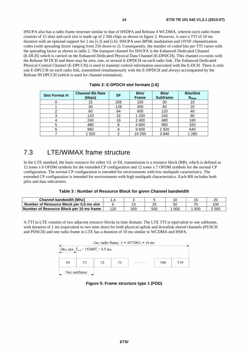
Ndata 0 15 256 150 30 10 1 30 128 300 60 20 2 60 64 600 120 40 3 120 32 1 200 240 80 4 240 16 2 400 480 160 5 480 8 4 800 960 320 6 960 4 9 600 1 920 640 7 1 920 2 19 200 3 840 1 280
7.3 LTE/WiMAX frame structure In the LTE standard, the basic resource for either UL or DL transmission is a resource block (RB), which is defined as 12 tones x 6 OFDM symbols for the extended CP configuration and 12 tones x 7 OFDM symbols for the normal CP configuration. The normal CP configuration is intended for environments with low multipath caracteristics. The extended CP configuration is intended for environments with high multipath characteristics. Each RB includes both pilot and data subcarriers.
Table 3 : Number of Resource Block for given Channel bandwidth
Channel bandwidth [Mhz] 1,4 3 5 10 15 20 Number of Resource Block per 0,5 ms slot 6 15 25 50 75 100
Number of Resource Block per 10 ms frame 120 300 500 1 000 1 500 2 000
A TTI in LTE consists of two adjacent resource blocks in time domain. The LTE TTI is equivalent to one subframe, with duration of 1 ms (equivalent to two time slots) for both physical uplink and downlink shared channels (PUSCH and PDSCH) and one radio frame in LTE has a duration of 10 ms similar to WCDMA and HSPA.
Figure 5: Frame structure type 1 (FDD)

ETSI
ETSI TR 101 542 V1.2.1 (2013-07) 15
Figure 6: LTE downlink Resource Block (extended CP); 0,5 ms duration – 180 Khz
Figure 7: LTE uplink Resource Block (extended CP); 0,5 ms duration – 180 Khz
WiMax supports TDD and FDD mode. The frame duration is variable (2/2,5/4/5/8/10/12,5/20 ms). The number of subcarriers depends on the size of the FFT (128, 512, 1 024, 2 048). Figure 8 shows an example of TDD frame, with the different burst in time and frequency.

ETSI
ETSI TR 101 542 V1.2.1 (2013-07) 16
Figure 8: WiMAX frame structure example (TDD)
Figure 9 shows an example of FDD frame. The frame is split in two groups, each terminal is affected to one of these groups:
Figure 9: WiMAX frame structure example (FDD)
The basic resource in WiMAX is a subchannel of 48 data subcarriers.
There are two modes for the DL:
• FUSC (Fully Used Subcarriers): a subchannel is composed of 48 data subcarriers over one symbol time.
• PUSC (Partially Used Subcarriers): a subchannel is composed of 2 clusters over two symbol time. Each cluster is composed of 12 data carriers and 2 pilot carriers.
In the UL there is only the PUSC mode: the subchannel is composed of six tiles. Each tile is composed of 4 carriers over three symbol time. A tile contains 4 pilots and 8 data carriers.

ETSI
ETSI TR 101 542 V1.2.1 (2013-07) 17
Although a TTI is not explicitly specified in the present document, the WiMAX forum [i.13], [i.14] has configured a radio frame structure of 5 ms duration for the TDD mode but has yet to specify one for the FDD mode. Therefore, in keeping with the generic structure of the basic resource for both uplink and downlink, we envisage a TTI consisting of 6 OFDM symbols or its multiples. For the purpose of consistency with LTE, we choose a TTI of 12 OFDM symbols for WiMAX FDD, which is equivalent to 6 clusters in downlink PUSC and 4 tiles in uplink PUSC, as shown in figures 5 and 6. This results in an WiMAX TTI duration of 1,37 ms for the 25 % CP configuration.
2 4 6 8 10 12
2
4
6
8
10
12
14
OFDM Symbols
Sub
carr
iers
NOTE: Blue: pilot subcarriers. White: data subcarriers.
Figure 10: WiMAX downlink-PUSC TTI (6 clusters, 25 % CP); 1,37 ms duration
NOTE: Blue: pilot subcarriers. White: data subcarriers.
Figure 11: WiMAX uplink-PUSC TTI (4 tiles, 25 % CP); 1,37 ms duration
8 Radio interface parameters for performance comparison
8.1 HSPA parameters The HSPA system design can be very complicated due to several factors that affect its link-level performance. This is as a result of the fact that the whole bandwidth is accessed at all times by all users, wherein multiple access is achieved through the use of channelization codes which spread each user's signal into chips using a unique signature. Therefore, users are separated in the code domain and a uniform number of chips are transmitted per user. In HSPA, 38 400 chips are transmitted in each 10 ms radio frame, 7 680 chips per 2 ms subframe and 2 560 chips per slot, resulting in a chip rate of 3,84 Mchips/s. Table 4 shows important parameters that determine the link performance in HSPA.

ETSI
ETSI TR 101 542 V1.2.1 (2013-07) 18
Table 4: HSPA system/link parameters
Info. Bits Total (Payload) 320 3 200 3 200 4 800 4 800 No. of Ch. Codes 1 10 10 15 15
Info. Bits / Ch. Code 320 320 320 320 320 FEC Rate 0,333 0,333 0,333 0,333 0,333
FEC Coded Bits / Ch. Code 960 960 960 960 960 FEC Coded Bits Total 960 9 600 9 600 14 400 14 400
Modulation Index 2 2 2 2 2 TTI Duration, [s] 0,002 0,002 0,002 0,002 0,002
No. of Chips / TTI 7 680 7 680 7 680 7 680 7 680 Spreading Factor 16 16 16 16 16
Max. Tx. Symbols / TTI 480 480 480 480 480 Chip Rate, [Chips/s] 3 840 000 3 840 000 3 840 000 3 840 000 3 840 000
Data Rate / Ch. Code, [Bits/s] 160 000 160 000 160 000 160 000 160 000 Data Rate Total, [Bits/s] 160 000 1 600 000 1 600 000 2 400 000 2 400 000
Processing Gain 24 2,4 2,4 1,6 1,6 Orthogonality Factor 1 1 0,5 1 0,5
Ec/Ior, [dB] -1 -1 -1 -1 -1 Ior/Ioc, [dB] 0 10 20 10 20 Eb/N0, [dB] 12,80 12,80 5,73 11,04 3,.97 Load Factor 0,44 0,09 0,31 0,09 0,31
Noise Rise, [dB] 2,54 0,40 1,62 0,40 1,62
In HSPA, the 0NEb
value is determined by parameters such as the processing gain, orc IE , geometry factor and
code orthogonality factor, as shown as below [i.3]. WCDMA uses orthogonal codes in the downlink to separate simultaneously transmitted user signals. However, delay spread in a wideband channel causes the mobile receiver to see part of the transmitted signal as multiple access interference. Consequently, the code orthogonality factor has a value of 1 for a single-tap downlink channel, whereas it varies between 0,4 and 0,9 for a wideband downlink channel [i.3].
( )( )( ) ( )G
IERW
N
E orc
o
b
11 +−=
α
where,
0NEb : Energy-per-bit to noise-interference-density
RW : Processing gain, which is the chip rate/bit rate
orc IE : Energy-per-chip to same-cell-interference-density
α : Code orthogonality factor
G : Geometry factor, which is the same-cell-interference to other cells-interference
ratio ocor II .
Table 1 shows that multi-code transmission increases the data rate while reducing the processing gain and achievable
0NEb . Also, increasing orc IE and/or G has a positive effect on the achievable 0NEb . However, the effect of
a good geometry factor is dampened by loss of orthogonality in the multipath downlink channel as it results in a non-linear increase in interference. Another factor to note is that the noise rise over thermal (which relates to the interference margin in HSPA link budgets and is directly determined from the load factor) is most strongly affected by the geometry factor as explained in [i.3].
It can be easily deduced from the discussions above that the capacity and coverage of the HSPA link is interference limited. However, a frequency re-use of 1, interference control mechanisms and user demand for asymmetric data rates provide great flexibilities in HSPA to achieve higher capacities, wherein compromise can be made between capacity and coverage per user.

ETSI
ETSI TR 101 542 V1.2.1 (2013-07) 19
8.2 LTE/ WiMAX parameters As discussed earlier, the LTE and WiMAX standards are based on OFDM/OFDMA multiplexing which is efficiently implemented in digital receivers using the Fast Fourier Transform (FFT) algorithm. Both use fixed subcarrier spacing for their OFDM signals and therefore support different FFT sizes for different bandwidths. In addition to the OFDM signal design requirements, the subcarrier spacing in LTE was carefully chosen by the 3GPP as FΔ = 15 KHz, in order to ensure a signal sampling rate which is an integer multiple of the WCDMA chip rate [i.15]. Consequently, an FFT size of 512 (corresponding to the 5 MHz bandwidth) results in an OFDM signal sampling rate of 7,68 MHz which is double the WCDMA chip rate. Table 5 summarizes the OFDM parameters applicable to the extended CP configuration of LTE and the 25 % CP configuration in WiMAX, wherein TB is the useful OFDM symbol duration ( FTB Δ= 1 ), TG is the
guard interval or CP duration and TS is total OFDM symbol duration.
Table 5: LTE/WiMAX OFDM parameters
Standard ∆F [KHz] TB [μs] TG [μs] TS [μs] TTI [symbols] TTI [ms] LTE extended
CP 15 66,67 16,67 83,33 12 (including 2 pilots in uplink) 1,00
LTE normal CP 15 66,67 5,21 (first)
4,69 (other) 71,88 (first)
71,36 (other) 14 (including 2 pilots in uplink) 1,00
WiMAX 10,94 91,41 22,85 114,26 12 1,37
The time-frequency parameters shown in tables 6 and 7 for downlink and uplink configurations respectively show that LTE is able to achieve higher data rates than WiMAX for a fixed bandwidth and the gap widens in the uplink. This is due to the higher density of pilots used in the WiMAX standard in contrast to LTE. However a higher density of pilots should enhance channel estimation accuracy, thereby compensating capacity loss with improved link performance. Table 7 shows important parameters for OFDM link analysis, where it is shown that the achievable data rate is dependent on the TTI data resource (i.e. excluding pilot tones), modulation, FEC code rate and TTI duration. In contrast to HSPA, the energy-per-bit in OFDM is directly determined since users are multiplexed in the time-frequency domain and not in the interference-limited code domain.
Table 6: 5 MHz DL time-frequency parameters
Standard NFFT Nused CP Length Basic Data Resource
TTI Data Resource
Max. QPSK Data Rate [Mbits/s]
LTE extended
CP 512 300 512
(see note 1) 68 (sub carriers
per RB) 3 400 6,80
LTE normal CP 512 300
160 (first) (Note 1)
144 (rest) (see note 1)
80 (sub-carriers per
RB) (see note 2) 4 000 8,00
WiMAX 512 420 128 48 4 320 6,31 NOTE 1: For LTE, the CP duration is expressed as a multiple of a fixed sampling time Ts=1/(15000*2048). Thus
512 Ts = 16,67µs, 160 Ts = 5,2 µs, 144 Ts = 4,69 µs NOTE 2: For LTE downlink, a Resource Block contains 6 OFDM data symbols (extended CP mode ) or 7 OFDM
data symbols (normal CP mode). Each of these OFDM data symbols is composed of 12 sub-carriers which are modulated in QPSK mode (resp. BPSK, 16QAM, 64 QAM). In each Resource Block, 4 sub-carriers are reserved for physical layer procedures. A TTI is one ms (2 slots)

ETSI
ETSI TR 101 542 V1.2.1 (2013-07) 20
Table 7: 5 MHz UL time-frequency parameters
Standard NFFT Nused CP Length Basic Data Resource
TTI Data Resource
Max. QPSK Raw Data Rate [Mbits/s]
LTE extended
CP 512 300 512
(see note 1)
60 (QPSK symbols per RB)
(see note 2) 3 000 (QPSK
symbols per TTI) 6,00
LTE normal CP 512 300
160 (first) (see note 1) 144 (rest)
(see note 1)
72 (QPSK symbols per RB)
(see note 2) 3 600 (QPSK
symbols per TTI) 7,20 WiMAX 512 408 128 48 3 264 4,76
NOTE 1: For LTE, the CP duration is expressed as a multiple of a fixed sampling time Ts=1/(15 000*2 048). Thus 512 Ts = 16,67µS, 160 Ts = 5,2 µs, 144 Ts = 4,69 µS.
NOTE 2: For LTE uplink, a Resource Block contains 5 SC-FDMA data symbols (extended CP mode ) or 6 SC-FDMA data symbols (normal CP mode). Each of these SC-FDMA data symbols is composed of 12 QPSK (resp. BPSK, 16QAM, 64QAM) modulated symbols.
Table 8: LTE/WiMAX system/link parameters
Standard LTE DL extended CP
LTE DL normal CP WiMAX DL LTE UL
extended CP LTE UL
normal CP WiMAX UL
Info. Bits (Payload) 2 304 2 688 2 880 2 016 2 432 1 920 FEC Rate 0,338 0,336 0,333 0,336 0,338 0,333
FEC Coded Bits Total 6 800 8 000 8 640 6 000 7 200 5 760 Mod. Index 2 2 2 2 2 2
Modulated Symbols 3 400 4 000 4 320 3 000 3 600 2 880 TTI duration, [s] 0,001 0,001 0,00137 0,001 0,001 0,00137
TTI Data Resource 3 400 4 000 4 320 3 000 3 600 3 264 Sampling Rate, Sample [s/s] 7 680 000 7 680 000 5 601 280 7 680 000 7 680 000 5 601 280
Data Rate Total, [Bits/s] 2 304 000 2 688 000 2 102 .190 2 016 000 2 432 000 1 401 460
9 Hypothesis for performance comparison
9.1 Channel model The wideband fading channel models used in this link-level analysis are based on the MAESTRO project measurements [i.19]. In particular, we select two power-delay profiles which provide a close match to the outdoor rural and outdoor urban scenarios. These are the MAESTRO channel 1 and 5 power-delay profiles which are shown in tables 9 and 10 respectively. The multipath fading channel is implemented based on the Jake's model and each channel tap undergoes independent time-variant fading (Rician or Rayleigh) according to the specified K-factor and mobile speed.
Table 9: MAESTRO channel 1: Satellite line-of-sight with many rays (outdoor rural)
Power [dBm] -91,9 -106,3 -110,1 -112,5 -110,2 -112,5 -112,5 Delay [ns] 0 195,3 260,4 846,3 1 171,9 1 953,1 2 734,3
K-factor [dB] 10 -inf -inf -inf -inf -inf -inf
Table 10: MAESTRO channel 5: Satellite + 3 Intermediate Module Repeaters (outdoor urban)
Power [dBm]
-91,8 -67,8 -80,7 -67,5 -72,8 -69,6 -73,1 -74,8 -78,4 -81,6
Delay [ns] 0 1 692,7 1 757,8 2 278,6 2 343,7 2 408,8 3 190,0 8 203,0 8 268,1 8 788,9 K-factor
[dB] 7 -inf -inf -inf -inf -inf -inf -inf -inf -inf

ETSI
ETSI TR 101 542 V1.2.1 (2013-07) 21
9.2 TWTA model
−40 −35 −30 −25 −20 −15 −10 −5 0 5 10−35
−30
−25
−20
−15
−10
−5
0
Input Back−Off (dB)
Out
put B
ack−
Off
(dB
)
Figure 12: TWTA amplitude-to-amplitude response
−40 −35 −30 −25 −20 −15 −10 −5 0 5 100
0.1
0.2
0.3
0.4
0.5
0.6
0.7
0.8
0.9
Input Back−Off (dB)
Pha
se O
ffset
(ra
dian
s)
Figure 13: TWTA amplitude-to-phase response
The TWTA model implemented in the simulators is based on typical S-Band power amplifier specifications which are defined in terms of input back-off, output back-off and phase offset. Its amplitude-to-amplitude response is illustrated in figure 12, wherein an input back-off of 0 dB indicates the saturation point. As is expected, the amplifier becomes increasingly non-linear when it is operated close to saturation and it can be seen that the output power reduces when it is operated beyond the saturation point. However, satellite applications are usually power constrained and therefore designed to make the most use of power available from the TWTA. Figure 13 shows the amplitude-to-phase response of the TWTA wherein it can be seen that an increasing phase offset is introduced into the amplified signal as the TWTA approaches saturation. The power amplifier non-linearity takes on an increased relevance in LTE/WiMAX and HSPA due to the inherently high PAPR of OFDM and multi-code CDMA transmission respectively.

ETSI
ETSI TR 101 542 V1.2.1 (2013-07) 22
9.3 Simulation parameters It should be noted that higher-order modulation, AMC, HARQ, STBC/MIMO and power control are not included in this link-level analysis due to the inefficiencies of these techniques in fast-fading satellite links. Rate 1/3 FEC coding is chosen as default in this performance comparisons, except otherwise stated. The CP duration for LTE/WiMAX is set as 25 % of the useful symbol duration, in order to ensure that it accommodates the delay spread of the selected MAESTRO channels. It is assumed that the link degradation caused by the satellite TWTA is much more significant than that of the user terminal SSPA. Consequently, only the satellite TWTA is taken into account for the link-level analysis. Simulations are performed for two modes of satellite TWTA operation in order to investigate in a linear region with IBO = 30 dB whilst in the second mode, the TWTA is operated in the saturation region with IBO = 0 dB.
For the downlink comparison, block sizes are chosen for each standard such as to achieve comparable data rates (approaching the maximum possible) for rate 1/3 coding subject to the constraints of block sizes allowed by the code interleavers, data subcarriers available and the practical number of channelization codes. This approach is important as the standards under consideration have different system parameters, including TTI duration as discussed in clause 7. Therefore, we compare link performance within the context of user data rate. The uplink comparison takes on a similar approach but some flexibility is introduced due to wide gap in TTI duration between HSPA and LTE/WiMAX. The HSPA simulator implements only the 10 ms TTI (the 2 ms TTI is optional) and thus will benefit more from channel interleaving as compared to the shorter TTIs of LTE and WiMAX. Therefore, in one set of uplink simulations, the LTE and WiMAX standards are modified to ~10 ms TTI (as shown in brackets in table 12) in order to achieve similar interleaving gain, wherein HSPA is investigated using the practical evaluation scenario of one channelization code with a spreading factor of 4 [i.20],[i.3]. In this scenario of a larger TTI, the block size of LTE is matched with that of HSPA (as shown in brackets in table 11) while that of WiMAX is maintained due to the constraint of block sizes allowed. Another set of uplink simulations compares the unmodified LTE and WiMAX standards for data rates approaching the maximum possible for the code rate 1/3. Tables 10 and 11 summarise key parameters used in the computer simulations.
Table 11: Downlink simulation parameters
Standard HSPA LTE WiMAX Bandwidth [MHz] 5 5 5
TTI [ms] 2 1 1,37 Block Size 4 800 (3 200) 2 304 2 880
Data Rate [Mbps] 2,4 (1,6) 2,3 2,1 FEC Turbo (PCCC) Turbo (PCCC) Turbo (CTC)
FEC Rate 0,333 0,333 0,333 Modulation QPSK QPSK QPSK
Channel Profile MAESTRO MAESTRO MAESTRO Channel Type Ch. 1, Ch. 5 Ch. 1, Ch. 5 Ch. 1, Ch. 5
Mobile Speed [km/h] 120 120 120 NOTE: An additional block size as shown in brackets in investigated for HSPA due
to the ob NE saturation experienced by the default choice.
Table 12: Uplink simulation parameters
Standard HSPA LTE WiMAX Bandwidth [MHz] 5 5 5
TTI [ms] 10 (10), 1 (9,59), 1,.37 Block Size 2 560 (2 560), 1 920 1 920
Data Rate [Mbps] 0,256 (0,256), 1,92 (0,2), 1,4 FEC Turbo (PCCC) Turbo (PCCC) Turbo (CTC)
FEC Rate 0,267 0,333 0,333 Modulation BPSK QPSK QPSK
Channel Profile MAESTRO MAESTRO MAESTRO Channel Type Ch. 1 Ch. 1 Ch. 1
Mobile Speed [km/h] 120 120 120

ETSI
ETSI TR 101 542 V1.2.1 (2013-07) 23
10 Performance comparison results HSPA link performance has been compared with LTE and WiMAX based on the 5 MHz carrier bandwidth, in satellite wideband fading channels and in the presence of power amplifier non-linearity. Extensive computer simulations were run for high data rate transmissions (with FEC code rate 1/3) and results presented in terms of block error rate (BLER). In the downlink, '2,4 Mbps and 1,6 Mbps' were tested for HSPA, 2,3 Mbps for LTE and 2,1 Mbps for WiMAX. For uplink transmissions, 0,256 Mbps is tested for HSPA, '0,256 Mbps and 1,92 Mbps' for LTE and '0,2 Mbps and 1,4 Mbps' for WiMAX.
10.1 Link performance aspect Simulation results show that for a target BLER, HSPA requires an
ob NE comparable to that of LTE/WiMAX in
satellite-only wideband fading channels (such as the MAESTRO channel 1 representing the outdoor rural profile) due to their moderate delay spread. However, HSDPA (HSPA downlink) requires a significantly lower
ob NE than
LTE/WiMAX in satellite channels which incorporate the use of terrestrial repeaters to boost the weak satellite signal (such as the MAESTRO channel 5 representing the outdoor urban profile). This is due to a combination of multipath diversity gain (achieved via Rake reception of many channel taps) and multiple access interference resulting from the low code orthogonality factor of such channels which have a large delay spread. Nevertheless, it is noted that a significantly higher geometry factor is needed to achieve the required
ob NE in these channels, which translates into
reduced coverage. Furthermore, implementing a large number of Rake fingers is not practical in consumer-grade terminals.
10.2 User data rate aspect The significant loss of code orthogonality in wideband channels with large delay spread (such as MAESTRO channel 5) constitutes a severely limiting factor for very high data rate transmissions in HSDPA as the required
ob NE for good
link quality cannot be achieved despite increasing the geometry factor to very high values. This is reflected in the 2,4 Mbps HSDPA transmission as
ob NE saturation occurs at ~4,5 dB such that a BLER = 10-3 is never achieved.
A frequency re-use of 1 means that good link quality cannot be achieved for high data rate transmissions at edge of cell areas due to increased interference. This is reflected in the high geometry factors required to achieve good link quality for both MAESTRO channel 1 and 5. On the other hand, LTE and WiMAX achieve a robust link-level performance in terms of insensitivity to the afore-mentioned limiting factors of HSPA. Also, by making use of fractional frequency re-use (which is enabled by the flexibility of subcarrier allocation in OFDMA), it is expected that interference will be a less significant issue with LTE/WiMAX, thereby helping to achieve wider coverage for high data rate applications.
10.3 Non-linearity effect All the standards experience comparable degradation in link performance due to the amplifier non-linearity. In HSDPA, this results from the PAPR arising from multi-code transmission while it is due to the PAPR arsing from OFDM IFFT processing in LTE/WiMAX. LTE shows less sensitivity to amplifier non-linearity in the uplink due to its use of SC-FDMA (DFT-spread-OFDM) in contrast to direct OFDMA used in WiMAX UL PUSC. In comparison, a single-code single-user transmission in HSUPA means that the amplifier non-linearity has very little impact on link performance. However, the use of multi-code transmission in HSUPA will increase the PAPR and degrade performance in similar fashion to HSDPA. It has been shown in previous work [i.15], [i.18] that the effects of TWTA non-linearity can be mitigated through a combined used of back-off and digital pre-distortion.
Based on the link-level results, it can be concluded that LTE and WiMAX achieve a more robust link performance than HSPA over satellite links. However, a key issue in the link performance of all the standards is the absence of significant time diversity within one TTI duration. This leads to a potential performance loss of ~5 dB or more as reflected in the uplink results, due to the absence of time interleaving gain. Terrestrial systems can compensate for this problem by using techniques such as HARQ but this will be more challenging in satellite links which have a longer round trip time. Since satellite systems tend to be power-limited and the advantage of a low-latency TTI is prevented by the satellite link delay, there is need to develop robust satellite-specific link layer mechanisms to solve this issue in order to enable the deployment of LTE/WiMAX over satellite links with maximum commonality.

ETSI
ETSI TR 101 542 V1.2.1 (2013-07) 24
11 Conclusion Link-level performance comparison between HSPA, LTE and WiMAX over satellite links is summarized as follows:
• HSDPA (HSPA downlink) requires an Eb/No comparable to that of LTE/WiMAX in satellite-only wideband fading channels (such as the MAESTRO channel 1) due to their moderate delay spread.
• HSDPA requires a significantly lower Eb/No than LTE/WiMAX in satellite channels which incorporate the use of terrestrial repeaters to boost the weak satellite signal (such as the MAESTRO channel 5) due to a combination of multipath diversity gain (Rake reception) and multiple access interference (low code orthogonality factor of channels with large delay spread).
- Nevertheless, a significantly higher geometry factor is needed to achieve the required Eb/No in these channels, which translates into reduced coverage. Furthermore, implementing a large number of Rake fingers is not practical in consumer-grade terminals.
• The significant loss of code orthogonality in wideband channels with large delay spread (such as MAESTRO channel 5) constitutes a severely limiting factor for very high data rate transmissions in HSDPA.
• All the radio interfaces experience comparable degradation in link performance due to the amplifier non-linearity.
- HSPA: Due to PAPR arising from multi-code transmission.
- LTE/WiMAX: Due to the PAPR arsing from OFDM IFFT processing.
- LTE shows less sensitivity to amplifier non-linearity in the uplink due to its use of SC-FDMA (DFT-spread-OFDM) in contrast to direct OFDMA used in WiMAX UL.
Based on the link-level results, it can be concluded that LTE and WiMAX achieve a more robust link performance than HSPA over satellite links. However, a key issue in the link performance of all the radio interfaces is the absence of significant time diversity within one TTI duration. This leads to a potential performance loss of ~5 dB as reflected in the uplink results, due to the absence of time interleaving gain. Finally, table 13 highlights the benefits of each terrestrial radio interface respect to link-level performance. The following scale of characteristics is defined for use in table 13:
1) For the link performance, 'robust' means that the Eb/No needed for a target BER can be achieved while 'limited' means that the link experiences Eb/No saturation due to air interface constraints.
2) For the receiver complexity, 'high' means that a large number of receiver taps are needed for optimum channel equalization while 'low' means that only single tap equalization is required for optimum performance.
3) For the user data rate, 'limited' means that the achievable link data rate is below the maximum possible due to air interface constraints while 'robust' means that the maximum possible data rate is not constrained by the air interface.
4) For the link degradation due to amplifier non-linearity, 'high' means that the link experiences more than 1,5 dB degradation while 'low' means that the link experiences lower than 1,5 dB degradation.
Table 13: Summary of performance comparison
Air interface HSPA LTE WiMAX Link performance
in satellite-only channel Robust Robust Robust
Link performance in satellite+CGC channel Limited Robust Robust
Receiver complexity in satellite+CGC channel High Low Low
User data rate in satellite+CGC channel Limited Robust Robust
Link degradation due to amplifier non-linearity High (DL+UL) High (DL), Low (UL) High (DL+UL)

ETSI
ETSI TR 101 542 V1.2.1 (2013-07) 25
Annex A: Detailed description of simulation
A.1 Overview The link-level performance comparison between HSPA and LTE/WiMAX air interfaces is based on existing simulators developed at the University of Surrey. The HSPA simulator is a C++ link-level simulator of 3GPP UMTS Release 99 with enhanced functionality for Release 5 and 6 (HSDPA and HSUPA) [i.1] to [i.6]. It is extended to include satellite wideband fading channels and TWTA non-linearity. The HSPA simulator has been validated in comparison with results obtained from the telecommunications industry [i.15]. On the other hand, the more recently developed LTE/WiMAX simulators are based on the Matlab/C platform and implement the physical layer specifications of LTE [i.7] to [i.9] and WiMAX [i.10] and [i.11]. The performances of these simulators were validated.
A.2 HSPA Simulator The HSPA simulator architectures are shown in figures A.1 and A.2 for HSDPA and HSUPA respectively.
RedundancyVersion (RV)
Setting
ACK/NACK
CQI
MuxChain
HS-DSCHHS-SCCH
CPICHOCNS
DeMuxChain
RxTx Payload Channel
CRC Check
Block DeSegmt
Ch DeCoding
PhyL HARQ
PhyCh DeSegmt
HS-DSCHDeInterleaving
PhyCh De Mapping
Cod
e #1
Cod
e #2
Cod
e #N
CRC Attach
Block Segmt
Ch Coding
PhyL HARQ
PhyCh Segmt
HS-DSCHInterleaving
PhyCh Mapping
Cod
e #1
Cod
e #2
Cod
e #N
MoD
Spreading
Scrambling Cha
nnel
Est
Rak
e F
n
Soft DeMoD
DeSpreading
DeScrambling
Combining
Bit
S
epar
atio
n
1stR
ate
Mat
chin
g
IR
Buf
fer
2ndR
ate
Mat
chin
g
Bit
Com
bining
1stD
eRate
Matching
ReT
x C
ombining
2nd
DeR
ateM
atching
HSDPA Simulation Model
Tim
e D
elay
RedundancyVersion (RV)
Setting
ACK/NACK
CQI
MuxChain
HS-DSCHHS-SCCH
CPICHOCNS
DeMuxChain
RxTx Payload Channel
CRC Check
Block DeSegmt
Ch DeCoding
PhyL HARQ
PhyCh DeSegmt
HS-DSCHDeInterleaving
PhyCh De Mapping
Cod
e #1
Cod
e #2
Cod
e #N
CRC Attach
Block Segmt
Ch Coding
PhyL HARQ
PhyCh Segmt
HS-DSCHInterleaving
PhyCh Mapping
Cod
e #1
Cod
e #2
Cod
e #N
MoD
Spreading
Scrambling Cha
nnel
Est
Rak
e F
n
Soft DeMoD
DeSpreading
DeScrambling
Combining
Bit
S
epar
atio
n
1stR
ate
Mat
chin
g
IR
Buf
fer
2ndR
ate
Mat
chin
g
Bit
Com
bining
1stD
eRate
Matching
ReT
x C
ombining
2nd
DeR
ateM
atching
HSDPA Simulation Model
Tim
e D
elayACK/NACK
CQI
MuxChain
HS-DSCHHS-SCCH
CPICHOCNS
DeMuxChain
RxTx Payload Channel
CRC Check
Block DeSegmt
Ch DeCoding
PhyL HARQ
PhyCh DeSegmt
HS-DSCHDeInterleaving
PhyCh De Mapping
Cod
e #1
Cod
e #2
Cod
e #N
CRC Attach
Block Segmt
Ch Coding
PhyL HARQ
PhyCh Segmt
HS-DSCHInterleaving
PhyCh Mapping
Cod
e #1
Cod
e #2
Cod
e #N
MoD
Spreading
Scrambling
MoD
Spreading
Scrambling Cha
nnel
Est
Rak
e F
n
Cha
nnel
Est
Rak
e F
n
Soft DeMoD
DeSpreading
DeScrambling
Combining
Bit
S
epar
atio
n
1stR
ate
Mat
chin
g
IR
Buf
fer
2ndR
ate
Mat
chin
g
Bit
Com
bining
1stD
eRate
Matching
ReT
x C
ombining
2nd
DeR
ateM
atching
HSDPA Simulation Model
Tim
e D
elay
Tim
e D
elay
Figure A.1: HSDPA Simulation Model

ETSI
ETSI TR 101 542 V1.2.1 (2013-07) 26
Figure A.2: HSUPA Simulation Model
These include modules such as the multiplexing chain (CRC attachment, transport block segmentation/concatenation, channel coding, physical layer HARQ, physical channel segmentation, interleaving, physical channel mapping), modulation mapping, spreading and scrambling operations at the transmitter side. The signal then passes through the radio channel and the reverse operations are performed at the receiver in the presence of interference as well as background noise (both modelled as additive white Gaussian noise). The receiver implements channel estimation (Ideal or through CPICH/DPCCH), Rake reception (with the option of combining 'm' best out of 'n' paths where n > m), diversity combining and turbo decoding with max-log map algorithm. The PhyL HARQ functionality consists of two rate matching stages and a virtual buffer. It is controlled by redundancy version (RV) parameters which determine whether incremental redundancy (IR), chase combining or combination of both modes is active in a certain period of time.
A.3 LTE/WiMAX simulator The block diagrams of figure A.3 and A.4 show the modules incorporated into the link-level simulators for LTE and WiMAX respectively. In general, the transmitted signal consists of a block of random information bits which are generated according to the block sizes specified by each standard. These bits undergo FEC encoding to produces a block of coded bits which are interleaved and punctured to achieve the desired coding rate. These are then mapped to a QPSK or 16QAM symbol constellation. The data symbols produced are then allocated to OFDM subcarriers as specified by the OFDMA multiplexing scheme of each standard, after which IFFT processing is applied to convert the signal to time-domain. Direct OFDMA is implemented for LTE downlink and WiMAX uplink/downlink. However, DFT-spread OFDMA (also called SC-FDMA) is implemented for LTE uplink as specified in the standards. The received signal in the time-domain, having experienced TWTA non-linearity, multipath channel distortion and additive white Gaussian noise, undergoes FFT processing to recover the data symbols allocated to the OFDM subcarriers. The channel response is estimated and compensated for in these subcarriers (Ideal estimation implemented in the current version), after which the signal is demultiplexed, de-mapped, de-interleaved and decoded to recover the block of bits. These bits are then compared with the original transmitted bits in order to establish the bit-error-rate (BER) and/or block-error-rate (BLER).

ETSI
ETSI TR 101 542 V1.2.1 (2013-07) 27
Figure A.3: Block diagram of the LTE link-level simulator
Figure A.4: Block diagram of the WiMAX link-level simulator
A.4 FEC, Interleaving and rate matching The binary turbo encoder in the LTE simulator implements a parallel concatenated convolutional code (PCCC) which is similar to HSPA. It consists of two 8-state constituent encoders which are connected to the single information bit input, wherein the second constituent encoder processes an interleaved version of the input. The LTE turbo code internal interleaver implements a quadratic permutation designed to accept a restricted set of block sizes ranging from K = 40 to K = 6 144 and these K values are 188 in total, as specified in [i.9], thereby defining the possible block sizes in LTE. Both LTE and HSPA specify a rate matching algorithm for implementation with the PCCC binary turbo code. This is defined per coded block and consists of three stages: sub-block interleaving, bit collection and bit selection/pruning. The parallel outputs from the rate 1/3 binary turbo encoder undergoes sub-block interleaving, after which the bits are collected as a serial interleaved and interlaced bit stream. They are then passed through a virtual circular buffer for two purposes: bit selection (for the optional HARQ) and bit pruning (puncturing/repetition). The bit selection is achieved by specifying a redundancy version (RV) number which indicates the starting point at which the bits are read out from the buffer. The bit reading process wraps around if the end of the buffer is reached such that reading continues at the beginning of the buffer. Puncturing and/or repetition are achieved by specifying the number of coded bits to be transmitted from the buffer.
Block Bit Generator
Duo-Binary Turbo Encoder
Interleave &
Puncture
Signal Mapper
WiMAX Subchan/ TTI MUX
Channel TWTA OFDM Modulation
AWGN OFDM Demodulation
Signal Demapper
Depuncture &
DeInterleave
Duo-Binary Turbo Decoder
BER/
BLER
Channel Estimation
WiMAX Subchan/ TTI DEMUX
Block Bit Generator
Binary Turbo Encoder
Rate Matching
Signal Mapper
LTE RB/TTI
MUX
Channel TWTA OFDM Modulation
AWGN OFDM Demodulation
LTE RB/TTI
DEMUX
Signal Demapper
De-Rate Matching
Binary Turbo Decoder
BER/
BLER
Channel Estimation

ETSI
ETSI TR 101 542 V1.2.1 (2013-07) 28
On the other hand, the WiMAX FEC encoder is a tail-biting duo-binary convolutional turbo code (CTC), also referred to as a double binary circular recursive systematic convolutional code. It consists of two constituent encoders, each being connected to the two information bit inputs. Each constituent encoder consists of three circulation states and the output is a rate 1/3 mother code, which undergoes sub-block interleaving and puncturing to the higher code rates specified in [i.1]. The WiMAX CTC sub-block interleavers support only 17 block bit sizes, ranging from 48 to 4 800. Sub-block interleaving and bit collection mechanisms help to support the optional HARQ. Puncturing is performed in accordance with specified number of coded bits per encoded block size such that the desired code rate is achieved. After puncturing, all encoded data bits are interleaved by a block channel interleaver, which is defined according to block size and consists of a two-step permutation [i.10].
A.5 Subcarrier multiplexing LTE specifies two categories of subcarrier mappings by using virtual resource blocks (VRB) which are mapped to physical resource blocks (PRB) according to predefined permutations. A virtual resource block has the same size as a physical resource block and VRB allocations are either of localized or distributed type [i.8],[i.17]. For either type, a single VRB number is used to allocate a pair of virtual resource blocks over two slots in a subframe. In the localized VRB, virtual resource blocks are mapped directly to physical resource blocks in a contiguous manner. On the other hand, the distributed subcarrier allocation maps each VRB to its corresponding PRB using some predefined permutations in order to achieve frequency diversity. The localized and distributed subcarrier multiplexing for two resource blocks in LTE uplink and downlink are illustrated in figures A.5 and A.6 respectively.
Subcarrier allocation in WiMAX depends according to the selected mode. The PUSC mode implements a frequency diversity scheme which is specified separately for both uplink and downlink configurations. WiMAX PUSC makes use of logical tiles/clusters to implement an outer permutation for frequency diversity [i.18]. In addition, an inner permutation which consists of intra-subchannel interleaving (over the relevant logical tiles) is performed in the uplink, while the downlink makes use of intra-group interleaving, wherein each group consists of a large number of clusters which are mapped over many subchannels. The outer and inner permutations combine with the smaller time duration of WiMAX PUSC tiles/clusters to achieve robust frequency diversity. Figures A.7 and A.8 illustrate the diversity subcarrier multiplexing of WiMAX for three subchanels in uplink and downlink PUSC respectively.
2 4 6 8 1012
5
10
15
20
25
30
35
40
45
OFDM Symbols
Sub
carr
iers
Figure A.5: Localized VRB multiplexing in LTE UL

ETSI
ETSI TR 101 542 V1.2.1 (2013-07) 29
2 4 6 8 1012
5
10
15
20
25
30
35
40
45
OFDM Symbols
Sub
carr
iers
Figure A.6: Distributed VRB multiplexing in LTE DL
2 4 6 8 1012
5
10
15
20
25
30
35
40
45
OFDM Symbols 1 to 12
Sub
carr
iers
105
to 1
52
Figure A.7: Diversity multiplexing in WiMAX UL PUSC

ETSI
ETSI TR 101 542 V1.2.1 (2013-07) 30
2 4 6 8 1012
5
10
15
20
25
30
35
40
45
Sub
carr
iers
49
to 9
6
OFDM Symbols 1 to 12
Figure A.8: Diversity multiplexing in WiMAX DL PUSC

ETSI
ETSI TR 101 542 V1.2.1 (2013-07) 31
Annex B: Detailed link-level results
B.1 Overview In this clause, link-level simulation results are presented for HSPA in comparison with LTE and WiMAX based on the simulation parameters specified in the previous clause. Eight iterations are implemented in the turbo decoders and a target BLER = 10-3 is selected as it represents a good measure of the desirable link quality for data services [i.3]. For the OFDM-based standards, it is assumed that no extra power is lost due to transmission of the CP, which will be the case if an empty guard interval is used. However, it should be noted that the use of a CP results in a wastage of transmit power by the ratio
SG TT . Consequently, an 0,97 dB increase in required ob NE (corresponding to 25 % CP) will apply to the
LTE/WiMAX results. The HSPA Rake receiver is configured to track all the received channel paths and combine them optimally.
The code orthogonality factor (α ) for downlink HSPA transmission varies in wideband channels and typically lies between 0,4 and 0,9 [i.3]. Therefore, in terms of setting the
ob NE values for HSDPA, the input parameters to the
simulator are the orc IE and
ocor II . Consequently, α should be determined in order to accurately set the
ob NE using (2.1). In order to determine α for a particular multipath channel, we test out different combinations of
orc IE and ocor II (within the acceptable range of a specific link) that achieve the same BLER. This technique is
further described in [i.21]. Based on these repeated trials, it was determined that (at 120 km/h) α = 0,89 for MAESTRO channel 1 and α = 0,56 for channel 5. The greater loss of orthogonality in channel 5 can be explained by the fact that it has a high number of channel taps with wide delay spread and its only Rician tap has a very little proportion of the total channel power.
Pilots are included in the transmission but ideal synchronization and perfect channel estimation are implemented so that performance can be compared independent of estimation algorithms. 10 % of the power in HSDPA is allocated to the CPICH which is transmitted alongside the HS-DSCH. For HSUPA, 20 % of the power is allocated to the DPCCH as specified in [i.21]. On the other hand, all used subcarriers (pilot and data) in the current LTE/WiMAX simulators share power equally, meaning that 5,6 % power is allocated to the pilots in LTE DL, 16,7 % for LTE UL, 14,3 % in WiMAX UL and 33,3 % in WiMAX DL. Results pertaining to HSDPA are denoted as 'HD', HSUPA as 'HU', LTE as 'L' and WiMAX as 'W'.
B.2 Downlink performance comparison Figures B.1 to B.5 shows BLER results for HSDPA in comparison with LTE DL and WiMAX DL, all based on the 5 MHz bandwidth configuration. In figure B.1, it can be seen that 2,4 Mbps HSDPA achieves a target BLER = 10-3 with
ob NE less than 7 dB for MAESTRO channel 1 in contrast to 2,3 Mbps LTE and 2,1 Mbps WiMAX which achieve
this target at ~8 dB. This can be attributed to the fact that HSDPA makes use of a larger block size and larger TTI duration to achieve a similar data rate with LTE/WiMAX. Therefore it benefits from increased coding and interleaving gains respectively but at the expense of increased latency. The performance trend is retained for channel 5 profile but it can be noticed that the
ob NE gap between HSDPA and LTE/WiMAX increases. This is due to a combination of
multipath diversity gain (achieved via Rake reception of many channel taps) and multiple access interference resulting from the low code orthogonality factor of channel 5. However, having a high number of Rake fingers is not usually practical for a user terminal. It can be noticed that at ~4,5 dB,
ob NE saturation occurs for 2,4 Mbps HSDPA due to its
low processing gain and the low orthogonality factor of channel 5, such that the target BLER = 10-3 is never achieved despite increasing the geometry factor to very high values. In contrast, LTE and WiMAX achieve the target BLER at ~8 dB similar to their performance in channel 1. The frequency diversity gain of channel 5 is better than that of channel 1 (due to its larger delay spread) and this takes on greater significance in link performance of LTE/WiMAX as additive noise reduces.

ETSI
ETSI TR 101 542 V1.2.1 (2013-07) 32
0 2 4 6 8 1010
−4
10−3
10−2
10−1
100
Eb/N
0 (dB)
BLE
R
HD−4800−Ch.1HD−4800−Ch.5L−2304−Ch.1L−2304−Ch.5W−2880−Ch.1W−2880−Ch.5
Figure B.1: DL performance comparison (TWTA linear)
0 2 4 6 8 1010
−3
10−2
10−1
100
Eb/N
0 (dB)
BLE
R
HD−3200−Linear−Ch.1HD−3200−IBO=0−Ch.1HD−3200−Linear−Ch.5HD−3200−IBO=0−Ch.5
Figure B.2: HSDPA performance; N = 3 200
Eb/N0 saturation

ETSI
ETSI TR 101 542 V1.2.1 (2013-07) 33
0 2 4 6 8 1010
−3
10−2
10−1
100
Eb/N
0 (dB)
BLE
R
HD−4800−Linear−Ch.1HD−4800−IBO=0−Ch.1HD−4800−Linear−Ch.5HD−4800−IBO=0−Ch.5
Figure B.3: HSDPA performance; N = 4 800
2 4 6 8 10 1210
−4
10−3
10−2
10−1
100
Eb/N
0 (dB)
BLE
R
L−2304−Linear−Ch.1L−2304−IBO=0−Ch.1L−2304−Linear−Ch.5L−2304−IBO=0−Ch.5
Figure B.4: LTE DL performance
Eb/N0 saturation
Eb/N0 saturation

ETSI
ETSI TR 101 542 V1.2.1 (2013-07) 34
1 2 3 4 5 6 7 8 9 10 1110
−4
10−3
10−2
10−1
100
Eb/N
0 (dB)
BLE
R
W−2880−Linear−Ch.1W−2880−IBO=0−Ch.1W−2880−Linear−Ch.5W−2880−IBO=0−Ch.5
Figure B.5: WiMAX DL performance
Figure B.2 shows the 1,6 Mbps HSDPA performance wherein a block size of N = 3 200 is used in contrast to N = 4 800 used for 2,4 Mbps HSDPA. Comparing the TWTA linear region with figure B.1, it can be seen that both transmissions achieve a similar link performance for channel 1, with the 2,4 Mbps having little superiority due to increased coding gain. However, the 1,6 Mbps transmission is able to achieve the target BLER at
ob NE less than 5 dB for channel 5 in
contrast to the 2,4 Mbps transmission, thanks to its increased processing gain. The effect of a TWTA operating at saturation point (0 dB) is also shown in figure B.2 wherein ~2 dB degradation in performance is noticed. This is due to the fact that 1,6 Mbps HSDPA uses multi-code transmission (10 channelization codes) to achieve the given data rate and these parallel codes introduce a high PAPR in the forward link signal. In comparison, the 2,4 Mbps transmission suffers from a higher degradation of ~3 dB in the presence of TWTA non-linearity as shown in figure B.3. This is due to the increased multi-code transmission (15 channelization codes) which increases the PAPR of the signal. It is also noticed that the channel 5 BLER for 2,4 Mbps is very poor in the presence of amplifier non-linearity due to
ob NE
saturation at ~4,5 dB as explained earlier.
LTE and WiMAX also experience degradation in the downlink due to the high PAPR of OFDM transmissions as shown in figures B.4 and B.5, with an increase of ~2 dB in the required
ob NE for 2,4 Mbps LTE and 2,1 Mbps WiMAX
services. Therefore, amplifier non-linearity is an issue for all the standards and this effect can be mitigated by using signal power back-off in the amplifier and/or digital pre-distortion [i.15].
Table B.1 gives more insight into the performance of HSDPA for high data rate transmission in wideband channels. Although the 1,6 Mbps transmission (N = 3 200) in channel 5 is able to achieve BLER < 10-3 at
ob NE less than 5 dB
(in contrast to the 7 dB needed for channel 1), it actually demands more link resources. For a fixed orc IE = -1 dB,
channel 5 requires a geometry factor of 20 dB to achieve the target BLER in contrast to 7,17 dB required by channel 1. This is due to the greater loss of code orthogonality in the channel and means that the 1,6 Mbps service cannot be provided with wide coverage (as this will generate unacceptable interference to neighbouring cells).
Table B.1: HSDPA simulator input and output
Profile ocor II (dB) orc IE (dB) α ob NE (dB) BLER
HD-4 800-Linear-Ch.1 13,02 -1 0,89 7 0,000 HD-4 800-Linear-Ch.5 20 -1 0,56 4,5 0,200 HD-3 200-Linear-Ch.1 7,17 -1 0,89 7 0,000 HD-3 200-Linear-Ch.5 20 -1 0,56 5 0,000

ETSI
ETSI TR 101 542 V1.2.1 (2013-07) 35
B.3 Uplink performance comparison Figures B.6 to B.8 show BLER results for HSUPA in comparison with LTE UL and WiMAX UL, all based on the 5 MHz bandwidth configuration. In figure B.6, it can be seen that similar to the downlink performance, 1,92 Mps LTE and 1,4 Mbps WiMAX achieve a target BLER = 10-3 with
ob NE = ~8 dB for high user data rate transmission in
MAESTRO channel 1. However, in the presence of amplifier non-linearity, LTE experiences a degradation of ~1 dB whereas WiMAX experiences ~2 dB degradation. This is due to the fact that LTE uses SC-FDMA (DFT-spread OFDMA) in its uplink in contrast to the direct OFDMA used in WiMAX and SC-FDMA has a lower PAPR than direct OFDMA.
0 2 4 6 8 10 1210
−4
10−3
10−2
10−1
100
Eb/N
0 (dB)
BLE
R
L−1920−Linear−Ch.1L−1920−IBO=0−Ch.1W−1920−Linear−Ch.1W−1920−IBO=0−Ch.1
Figure B.6: LTE and WiMAX UL performance (short TTI)
In order to make a good comparison in figures B.7 and B.8, the LTE and WiMAX uplinks are modified to have a longer TTI of ~10 ms in order to achieve a similar interleaving gain with the HSUPA simulator (which has the 10 ms TTI implemented). By matching the interleaving gains, it is expected that the results achieved will reflect a parallel comparison for the optional 2 ms TTI in HSUPA. A longer TTI will always benefit the link performance in terms of interleaving gain but at the expense of link latency. Figure B.7 shows that 0,256 Mbps HSUPA and 0,256 Mbps LTE achieve a comparable link performance for MAESTRO channel 1. However, the performance of 0,2 Mbps WiMAX is significantly better due to its higher frequency diversity gain, achieved by diversity subcarrier multiplexing (as shown in figure B.7) in contrast to the localized subcarrier multiplexing of LTE UL (as shown in figure B.5). It is noted that localized multiplexing in LTE UL is needed to achieve the full benefits of SC-FDMA in the presence of amplifier non-linearity. In figure B.8, HSUPA is shown to maintain its link performance in the presence of amplifier non-linearity whereas LTE and WiMAX experience degradation. This is due to a single-user, single-code transmission used in HSUPA (which implies a PAPR = ~1). Despite the higher frequency diversity gain of WiMAX, LTE achieves a better performance under amplifier saturation due to the lower PAPR of SC-FDMA in comparison to the direct OFDMA of WiMAX. As was shown in the downlink results, multi-code transmission in WCDMA leads to increased PAPR of the transmitted signal, thereby resulting in greater degradation under amplifier non-linearity.

ETSI
ETSI TR 101 542 V1.2.1 (2013-07) 36
0 1 2 3 4 510
−4
10−3
10−2
10−1
100
Eb/N
0 (dB)
BLE
R
HU−2560−Linear−Ch.1L−2560−Linear−Ch.1W−1920−Linear−Ch.1
Figure B.7: Uplink performance comparison, linear TWTA (long TTI)
0 1 2 3 4 5 6 710
−4
10−3
10−2
10−1
100
Eb/N
0 (dB)
BLE
R
HU−2560−IBO=0−Ch.1L−2560−IBO=0−Ch.1W−1920−IBO=0−Ch.1
Figure B.8: Uplink performance comparison, saturated TWTA (long TTI)

ETSI
ETSI TR 101 542 V1.2.1 (2013-07) 37
History
Document history
V1.1.1 May 2012 Publication
V1.2.1 July 2013 Publication