Embed Size (px)
Citation preview
1
2

After this training, we hope that you will:
- be able to understand and generally explain the computation procedures in HEC-RAS for water surface profiles and bridge hydraulics.
- Know how to put in decks, piers, bridges, and abutments to correctly model a bridge.
- and know when to adjust the bridge modeling approaches to correctly reflect the hydraulic condition.
3

We will cover a lot of concepts in 2 hours, please always feel free to ask questions if something is not clear.
4

All of this material is used from public agencies. I put together much of this material while at FHWA and it’s important to provide credit to the organizations that publish and develop great hydraulic research and publications.
Interested in more material? Visit FHWA’s web site for hydraulics: http://www.fhwa.dot.gov/engineering/hydraulics/
Like training? 3-4 Day HEC-RAS Courses that cover these concepts in much greater detail are provided by the National Highway Institute (NHI) (www.nhi.fhwa.dot.gov)
5

6
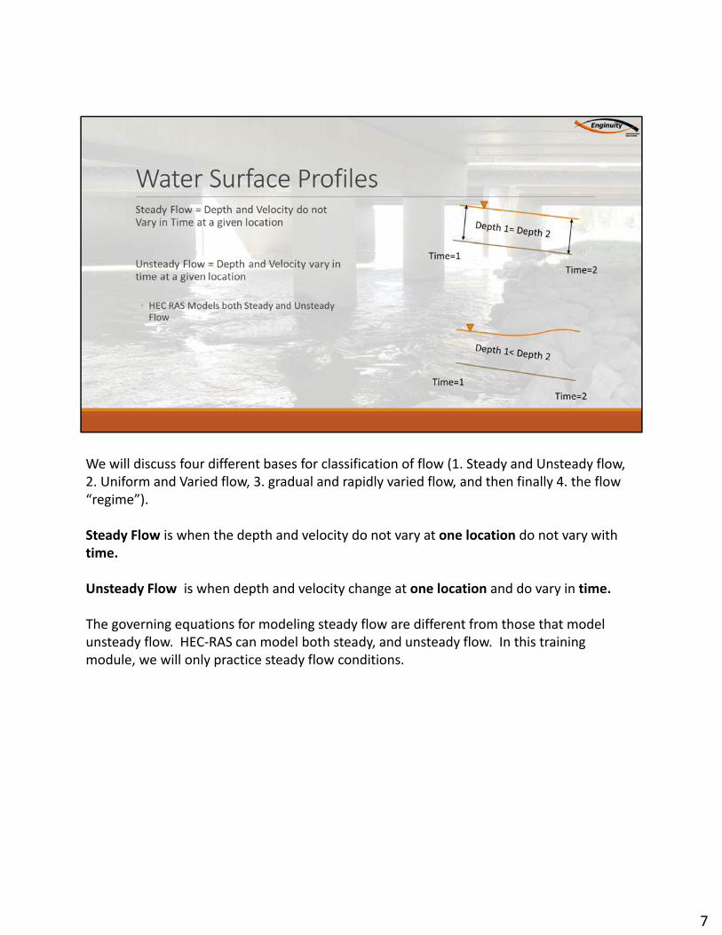
We will discuss four different bases for classification of flow (1. Steady and Unsteady flow, 2. Uniform and Varied flow, 3. gradual and rapidly varied flow, and then finally 4. the flow “regime”).
Steady Flow is when the depth and velocity do not vary at one location do not vary with time.
Unsteady Flow is when depth and velocity change at one location and do vary in time.
The governing equations for modeling steady flow are different from those that model unsteady flow. HEC-RAS can model both steady, and unsteady flow. In this training module, we will only practice steady flow conditions.
7
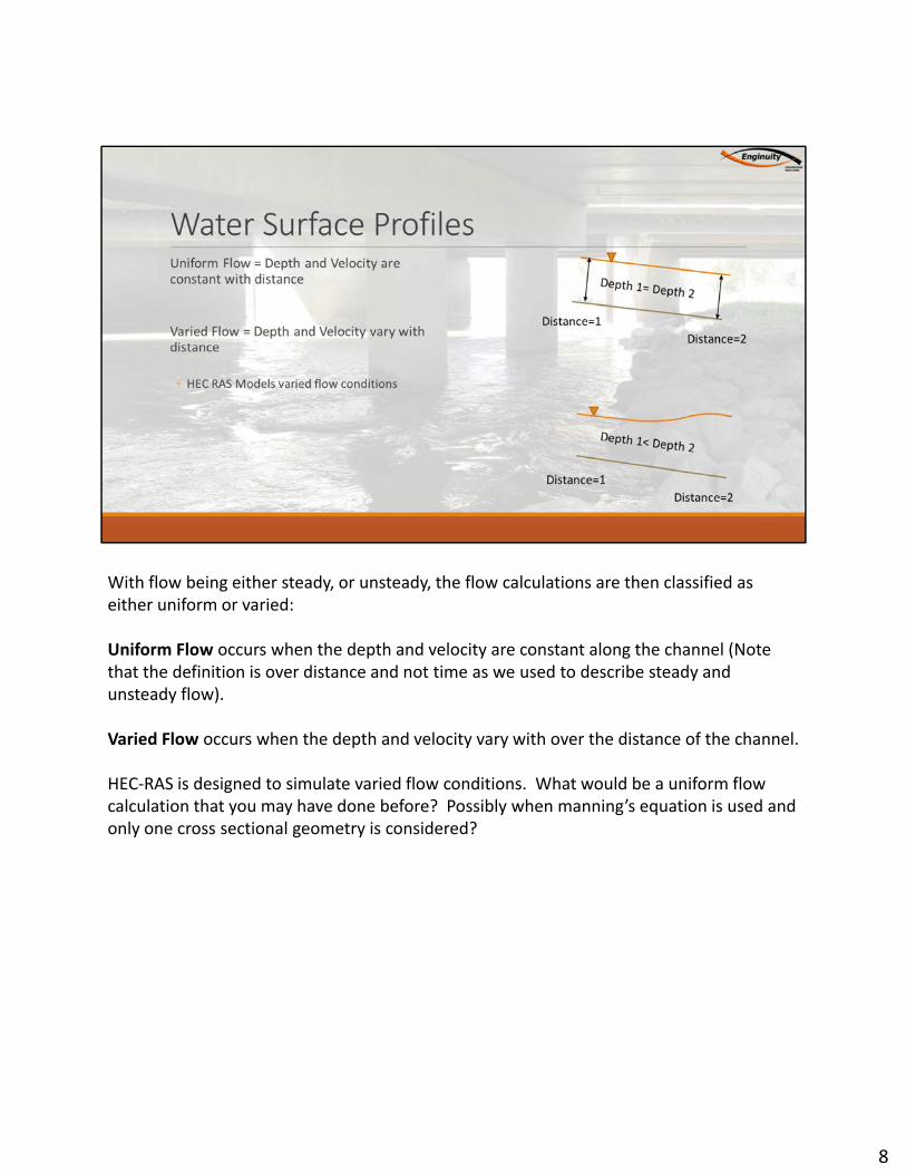
With flow being either steady, or unsteady, the flow calculations are then classified as either uniform or varied:
Uniform Flow occurs when the depth and velocity are constant along the channel (Note that the definition is over distance and not time as we used to describe steady and unsteady flow).
Varied Flow occurs when the depth and velocity vary with over the distance of the channel.
HEC-RAS is designed to simulate varied flow conditions. What would be a uniform flow calculation that you may have done before? Possibly when manning’s equation is used and only one cross sectional geometry is considered?
8
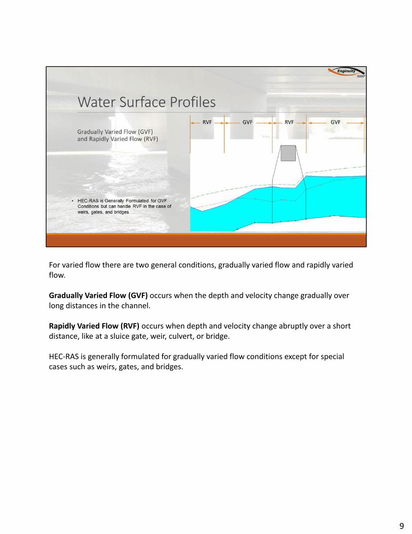
For varied flow there are two general conditions, gradually varied flow and rapidly varied flow.
Gradually Varied Flow (GVF) occurs when the depth and velocity change gradually over long distances in the channel.
Rapidly Varied Flow (RVF) occurs when depth and velocity change abruptly over a short distance, like at a sluice gate, weir, culvert, or bridge.
HEC-RAS is generally formulated for gradually varied flow conditions except for special cases such as weirs, gates, and bridges.
9
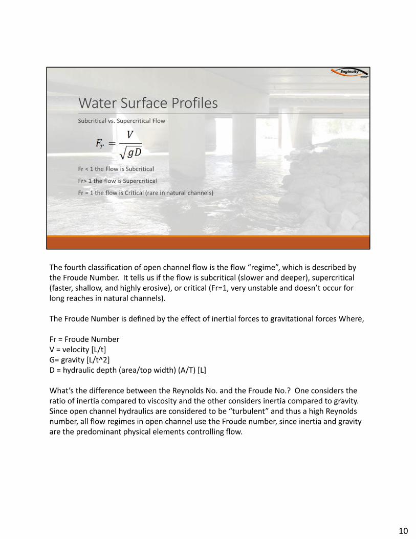
The fourth classification of open channel flow is the flow “regime”, which is described by the Froude Number. It tells us if the flow is subcritical (slower and deeper), supercritical (faster, shallow, and highly erosive), or critical (Fr=1, very unstable and doesn’t occur for long reaches in natural channels).
The Froude Number is defined by the effect of inertial forces to gravitational forces Where,
Fr = Froude NumberV = velocity [L/t]G= gravity [L/t^2]D = hydraulic depth (area/top width) (A/T) [L]
What’s the difference between the Reynolds No. and the Froude No.? One considers the ratio of inertia compared to viscosity and the other considers inertia compared to gravity. Since open channel hydraulics are considered to be “turbulent” and thus a high Reynolds number, all flow regimes in open channel use the Froude number, since inertia and gravity are the predominant physical elements controlling flow.
10

A specific energy curve is a common way of describing potential water surface depths and total energy. When the Froude number is equal to 1, the flow is at it’s minimum specific energy. This is a very unstable state and usually does not occur for long periods of time in natural channels.
Notice there are two depth possibilities for any given energy value, except at critical depth. When we design weirs, we want the flow to be at critical depth, so when we take a depth measurement, there is only one possible solution for flow
11

The computational procedure used to compute water surface profiles is:1.) Assume a water surface elevation at the downstream section (Y2)2.) Determine the conveyance and velocity head at the upstream section (V1)3.) Using the values in the previous step, compute the friction slope between the two section.4.) solve the energy equation for the upstream water surface elevation (Y1)5.) Compare the computed water surface with the assumed. If the difference is less than 0.01 feet, than it is balanced and the computational procedure moves to the next section
12
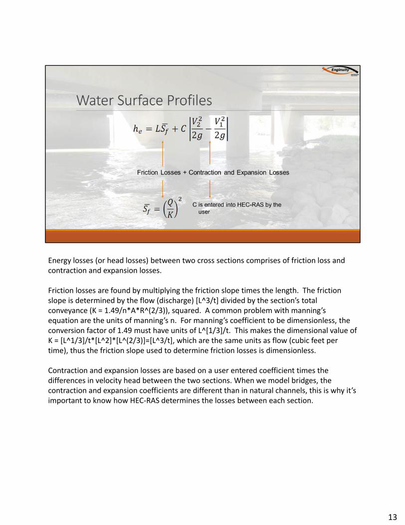
Energy losses (or head losses) between two cross sections comprises of friction loss and contraction and expansion losses.
Friction losses are found by multiplying the friction slope times the length. The friction slope is determined by the flow (discharge) [L^3/t] divided by the section’s total conveyance (K = 1.49/n*A*R^(2/3)), squared. A common problem with manning’s equation are the units of manning’s n. For manning’s coefficient to be dimensionless, the conversion factor of 1.49 must have units of L^[1/3]/t. This makes the dimensional value of K = [L^1/3]/t*[L^2]*[L^(2/3)]=[L^3/t], which are the same units as flow (cubic feet per time), thus the friction slope used to determine friction losses is dimensionless.
Contraction and expansion losses are based on a user entered coefficient times the differences in velocity head between the two sections. When we model bridges, the contraction and expansion coefficients are different than in natural channels, this is why it’s important to know how HEC-RAS determines the losses between each section.
13

14

15
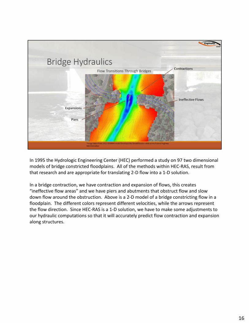
In 1995 the Hydrologic Engineering Center (HEC) performed a study on 97 two dimensional models of bridge constricted floodplains. All of the methods within HEC-RAS, result from that research and are appropriate for translating 2-D flow into a 1-D solution.
In a bridge contraction, we have contraction and expansion of flows, this creates “ineffective flow areas” and we have piers and abutments that obstruct flow and slow down flow around the obstruction. Above is a 2-D model of a bridge constricting flow in a floodplain. The different colors represent different velocities, while the arrows represent the flow direction. Since HEC-RAS is a 1-D solution, we have to make some adjustments to our hydraulic computations so that it will accurately predict flow contraction and expansion along structures.
16
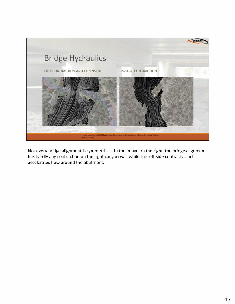
Not every bridge alignment is symmetrical. In the image on the right, the bridge alignment has hardly any contraction on the right canyon wall while the left side contracts and accelerates flow around the abutment.
17

There are a minimum of 4 cross sections required to model a bridge. In between each section, we have to represent ineffective flow and approximate the expansion and contraction of flow. HEC-RAS adds two sections (Bridge Upstream and Bridge Downstream) that are located directly at the bridge face. Notice that the user is required to input the expansion and contraction coefficient values (C) that we discussed earlier. Also notice that the use must determine the expansion and contraction ratios to properly locate the upstream and downstream cross sections.
18
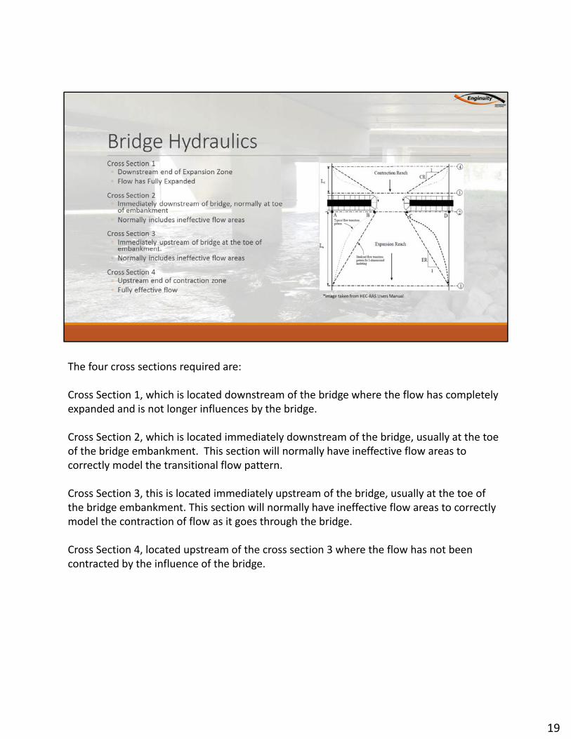
The four cross sections required are:
Cross Section 1, which is located downstream of the bridge where the flow has completely expanded and is not longer influences by the bridge.
Cross Section 2, which is located immediately downstream of the bridge, usually at the toe of the bridge embankment. This section will normally have ineffective flow areas to correctly model the transitional flow pattern.
Cross Section 3, this is located immediately upstream of the bridge, usually at the toe of the bridge embankment. This section will normally have ineffective flow areas to correctly model the contraction of flow as it goes through the bridge.
Cross Section 4, located upstream of the cross section 3 where the flow has not been contracted by the influence of the bridge.
19
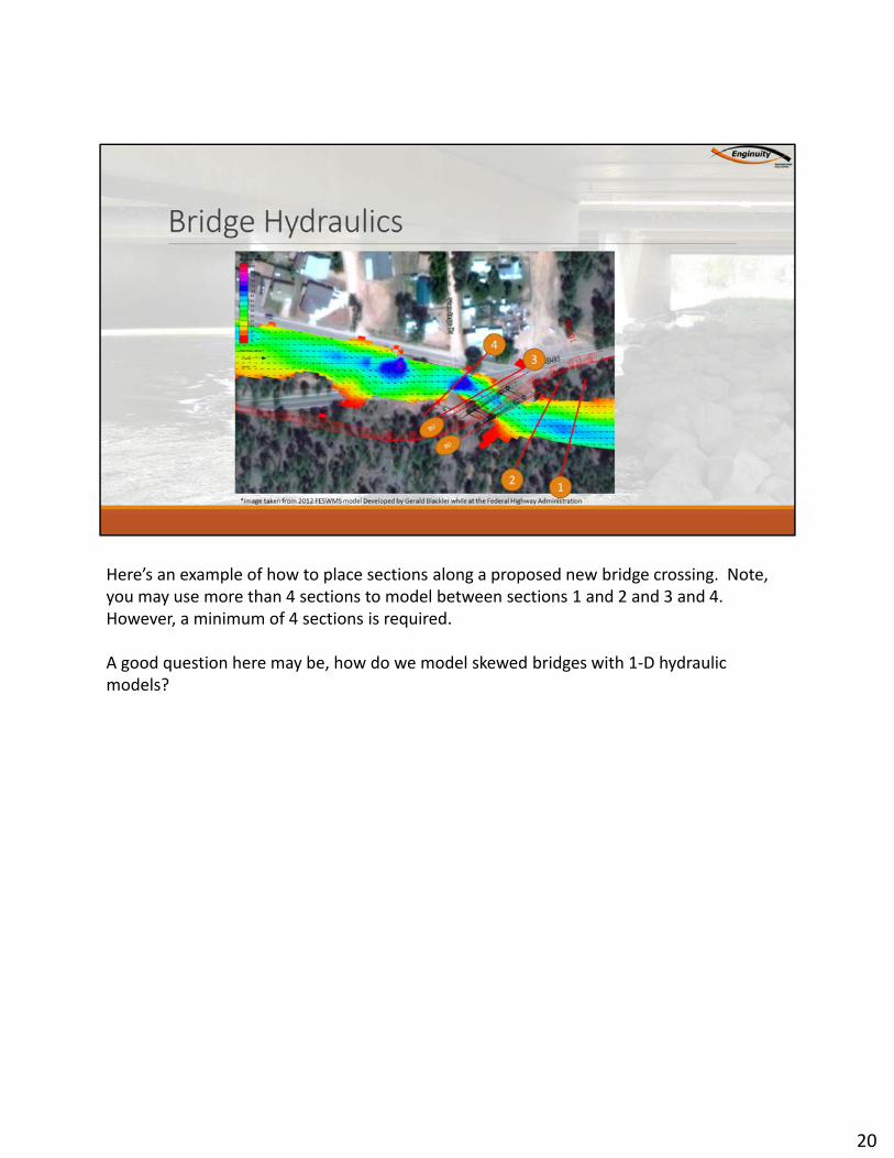
Here’s an example of how to place sections along a proposed new bridge crossing. Note, you may use more than 4 sections to model between sections 1 and 2 and 3 and 4. However, a minimum of 4 sections is required.
A good question here may be, how do we model skewed bridges with 1-D hydraulic models?
20
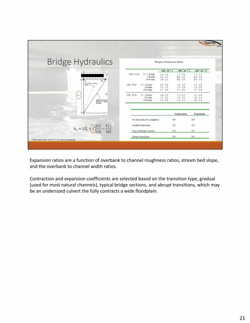
Expansion ratios are a function of overbank to channel roughness ratios, stream bed slope, and the overbank to channel width ratios.
Contraction and expansion coefficients are selected based on the transition type, gradual (used for most natural channels), typical bridge sections, and abrupt transitions, which may be an undersized culvert the fully contracts a wide floodplain.
21

Flow characteristics through bridges can be generally described by four flow regimes,
1.) Low Flow occurs when all the flow is well below the bridge’s deck and low chord and only the contractions and expansions around the bridge abutments are effecting the flow profile.
2.) Weir flow occurs when the flow overtops the bridge deck and the bridge behaves like a broad crested weir.
3.) pressure flow occurs when the flow near or at the bridge deck and the bridge behaves like a sluice gate or orifice.
4.) Highly submerged flow occurs when the depth of water to bridge height ratio is so high that it has surpassed weir flow and the flow behaves similar to a natural channel (not common).
22
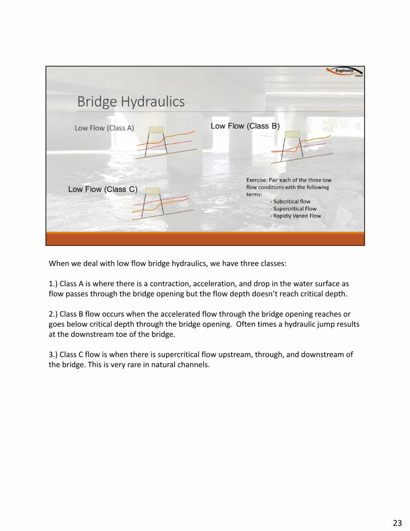
When we deal with low flow bridge hydraulics, we have three classes:
1.) Class A is where there is a contraction, acceleration, and drop in the water surface as flow passes through the bridge opening but the flow depth doesn’t reach critical depth.
2.) Class B flow occurs when the accelerated flow through the bridge opening reaches or goes below critical depth through the bridge opening. Often times a hydraulic jump results at the downstream toe of the bridge.
3.) Class C flow is when there is supercritical flow upstream, through, and downstream of the bridge. This is very rare in natural channels.
23

The same method used to compute water surface profiles in natural channels can be applied to bridge crossings if the flow is Class A flow, there are no piers in the flow field, and there’s no chance of submerged or pressure flow.
24
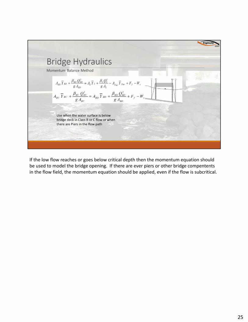
If the low flow reaches or goes below critical depth then the momentum equation should be used to model the bridge opening. If there are ever piers or other bridge compententsin the flow field, the momentum equation should be applied, even if the flow is subcritical.
25
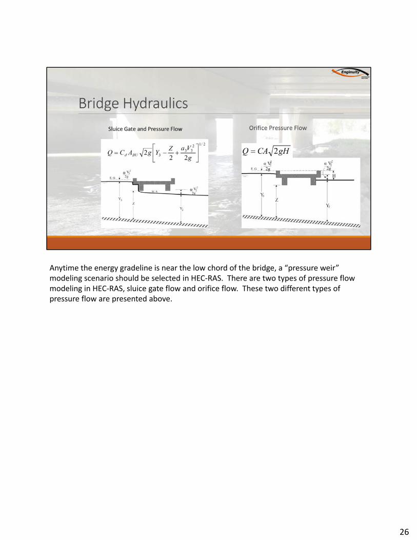
Anytime the energy gradeline is near the low chord of the bridge, a “pressure weir” modeling scenario should be selected in HEC-RAS. There are two types of pressure flow modeling in HEC-RAS, sluice gate flow and orifice flow. These two different types of pressure flow are presented above.
26

27
28