Embed Size (px)
Citation preview

MTX.COM
ENCLOSURE MANUAL
MTX.COM
SP
ECIF
ICA
TIO
NS
INTRODUCTIONThank you for choosing MTX to help you reach your ultimate goal with your vehicle. The MTX JackHammer enclosure has a true 22" subwoofer with power and performance beyond anything ever attempted in the mobile audio world. This behemoth, is capable of handling 6,000 watts of RMS power. Designed for those who want to show off the biggest woofer ever made no matter the price, the JackHammer will fi t into most full-sized SUVs and some shorter models, like Escalades, with the third seat removed.
There are two versions of the JackHammer built for different applications. The SPL model (T9922-22) is perfect for excessive bass and competition use, while the SQL model (T9922-44) offers increased sound quality for “real life” listening. Both of these kits will work in the same motor for easy installation of either unit. You can order either of these models or just a re-cone replacement kit for the other and switch between the two without reinstalling the entire woofer. For more information, see the Piston Change (Re-cone Kit) section in this manual or call 1-800-CALL-MTX.
The most enormous subwoofer to date, the JackHammer is just the newest example of how MTX is the biggest, baddest, boldest car audio...ever!
BEFORE STARTINGIt is very important that you have your JackHammer enclosure installed by an authorized MTX Elite Status retailer, preferably MECP certifi ed. Before installation, make sure you have read the instructions carefully and have the following equipment:
• Fork Lift (or another means of lifting approximately 525 lbs.)• 5⁄32", 3⁄8" hex keys • 3mm hex wrench (if re-coning)
ELECTRICAL UPGRADEA factory electrical system will not be able to handle the power requirements of the amplifi ers that are needed to drive the JackHammer. You will need to upgrade your vehicle’s electrical system with both additional batteries and alternators. MTX Audio recommends West Co. SVR80 or SVR100 because they are a sealed battery that can be mounted in any confi guration and supply the power needed and high-output alternators from either Ohio Generator or PowerMaster. Also, it is recommended to use anywhere from 3 to 6 StreetWires capacitors to help control the fl ow of power, call 877.STREET1 for more information. The diagram below shows the wiring needs of your entire vehicle. Please see the Strapping Thunder Amplifi ers section for further information.
1F 1F1F
1F 1F1F
StreetWiresDistribution
Blocks
StreetWiresCapacitors
StreetWires1/0 AWG Wire
200 AmpMinimum
StreetWires1/0 AWG Wire
StreetWires1/0 AWG Wire
StreetWires4 AWG Wire
StreetWires4 AWG Wire
Isolatoror Relay
Model JackHammer-44 JackHammer-22
Impedance Dual 4 Ohm Dual 2 Ohm
Frequency Response 20Hz-150Hz 20Hz-150Hz
Power Handling (RMS) 6000 Watts 6000 Watts
Recommended RMS Amplifi er Power 3000-6000 Watts 3000-6000 Watts
Dimensions 25 1⁄4"H x 44 3⁄8"W x 24 3⁄4"D 25 1⁄4"H x 44 3⁄8"W x 24 3⁄4"D
Vented Enclosure Net Volume 8.7 ft3 TBD
Port Dimensions (Slot Port) 241⁄8”H x 33⁄16”W x 10”L
Speaker Displacement 1.8 ft3 1.8 ft3
Port Displacement .5 ft3 TBD
Tune Frequency 32Hz TBD
MTX.COM
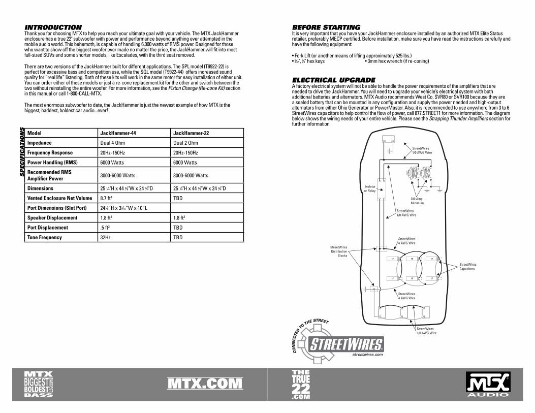
Parallel Confi gurationT9922-44 – Wiring the voice coils in a parallel confi guration will have a total fi nal load of 2 Ohm. Connect each of the dual voice coil’s positive terminals together so that they share the same source (amplifi er). Do the same for the negative terminals. This can be done with the included shorting bars. This connection is ideal when using two Thunder TA92001 amplifi ers.
T9922-22 – Wiring the voice coils in a parallel confi guration will have a total fi nal load of 1 Ohm. Connect each of the dual voice coil’s positive terminals together so that they share the same source (amplifi er). Do the same for the negative terminals.
Note: The wiring of the dual voice coils will affect impedance for the amplifi er system. Care must be takento assure that the resulting impedance does not exceed the amplifi er’s requirements.
WIRING OPTIONSOften overlooked, the installation components used to connect the entire system need to match the maximum capability of the system or you will lose performance. MTX Audio recommends using StreetWires 4 AWG cable as the speaker wire.
Dual Voice Coil WiringJackHammer Superwoofers are available in a dual 2 Ohm (T9922-22) or dual 4 Ohm (T9922-44) voice coil confi guration for either SPL or SQL uses. The voice coils are labeled VC1 and VC2.
Note: Both voice coils should always be connected. See the section on Strapping Thunder Amplifi ersfor amplifi er connections.
Independent Voice Coil Connection Confi gurationThis connection is ideal when using two Thunder TA81001 amplifi ers per voice coil (4 amplifi ers total).You will need to remove the terminal shorting bars for this confi guration. See the section on Strapping Thunder Amplifi ers for amplifi er connections.

MTX.COM
PHASE0 180
180
0
PHASE0 180
CAP+ +BATT REM -GND CAP-
1/0 AWG
1/0 AWG16 AWG
4 AWG
4 AWGAmplifier driving JackHammer’s negativeterminal of 2nd Voice Coil
Amplifier driving JackHammer’s positiveterminal of 1st Voice Coil
Amplifier’s mainpower terminals
Woofer Terminal Connection(2 ohm connection)
Minimum 8awgSpeaker wire
8 AWG
8 AWG
Figure 1
Figure 2Table 1: RMS Power Output for Strapped Thunder Amplifi ers
Two TA92001 Two TA81001
14.4Vdc @ 4Ω 4000 Watts 2000 Watts14.4Vdc @ 2Ω 6000 Watts 3000 Watts
(wattage is combined power from all amps)
STRAPPING THUNDER AMPLIFIERSStrapping amplifi ers brings two mono-block amps together and unleashes the power of both into a single channel confi guration. Think of it like a bridged 2-channel amp which takes a left channel and a right channel and combines them into one output. Strapping is essentially the same process. One of the mono-block amps serves as “one channel” and the other mono-block amp as the “second channel.” The primary difference is that the two mono-block amps are not in the same heatsink like the channels of a 2-channel amp.
Strapping requires that the two mono-block amps function as one, so they must be setup to work together. Both amps need to receive the same exact signal, same exact level of signal, same exact voltage, etc... Just follow this guide to build the Biggest, Baddest, Boldest system...ever.
It has never been easier to strap two MTX Thunder TA92001s, or even two Thunder TA81001s, together to get maximum power from these super amplifi ers. When strapped, expect power output to exceed 6,000 watts RMS for two TA92001 amps with a current draw around 600 amps. Or, for two TA81001 amps, over 3,000 watts of RMS power with a current draw of around 300 amps (Table 1).
ELECTRICAL SYSTEM UPGRADESWhen strapping Thunder Amplifi ers, it is important to remember that to get the desired power from them, you need to supply them with the power they require. You must upgrade the stock battery and add additional batteries to the system. We recommend a minimum of three batteries with a cold cranking amp (CCA) rating of 725 or more. Please remember to install a minimum of 1/0 AWG StreetWires power and ground cable for each alternator. Two 200 amp or greater alternators are strongly recommend for this system because these amplifi ers are capable of pulling more than 600 amps. After your bank of minimum three batteries, you will need to run 1/0 wire to each amplifi er. Just adding extra batteries will not solve the need for power. It will actually put more of a load on the alternator, in turn yielding less power to the audio system.
MTX Audio recommends West Co. SVR80 or SVR100 because they are a sealed battery that can be mounted in any confi guration and supply the power needed, and high-output alternators from either Ohio Generator or PowerMaster.
STRAPPING TWO TA92001 AMPLIFIERSTo successfully strap two TA92001 amplifi ers, follow the process outlined here carefully. It details how to confi gure each amp so one becomes the “positive” (Push) amplifi er and the other becomes the “negative” (Pull) amplifi er.
1. Connect the amplifi ers’ power, ground, and remote but do not supply the 12 volts from the batteries to the amplifi ers until later in the process.
2. Label the fi rst amplifi er as the Positive amp. Set the phase switch on this amp to 0˚. Label the second amplifi er as the Negative amp and set the phase switch on this amp to 180˚ (Figure 1).
3. Using a “Y” adapter, split the “Left” side of the RCA output from the source to the “Left” RCA input receptacles on each amp. Using another “Y” adapter, split the “Right” side of the RCA output from the source to the “Right” RCA input receptacles on each amp (Figure 1).
Note: Only the positive speaker terminals on each amplifi er will be used.
4. Connect the positive side of the speaker wire to the “positive” speaker terminal of the amplifi er labeled Positive. Connect the negative side of the speaker wire to the “positive” speaker terminal of the amp labeled Negative (Figure 2).
Note: The voice coils on the JackHammer must be paralleled (Figure 2). Be sure that the impedance of the subwoofer is no lower than a 2 ohm load to avoid possible damage to the amplifi er.
MTX.COM
8 AWG
CAP+ +BATT REM -GND CAP-
1/0 AWG
1/0 AWG16 AWG
4 AWG
4 AWGAmplifiers mainpower terminals
Amplifier driving JackHammer’s negativeterminal of 1st Voice Coil
Minimum 8awgSpeaker wire
Minimum 8awgSpeaker wire
Amplifier driving JackHammer’s positiveterminal of 1st Voice Coil
Amplifier driving JackHammer’s positiveAmplifier driving JackHammer’s positiveterminal of 2nd Voice Coilterminal of 2nd Voice CoilAmplifier driving JackHammer’s positiveterminal of 2nd Voice Coil
8 AWG
8 AWG
8 AWG
Amplifier driving JackHammer’s negativeAmplifier driving JackHammer’s negativeterminal of 2nd Voice Coilterminal of 2nd Voice CoilAmplifier driving JackHammer’s negativeterminal of 2nd Voice Coil
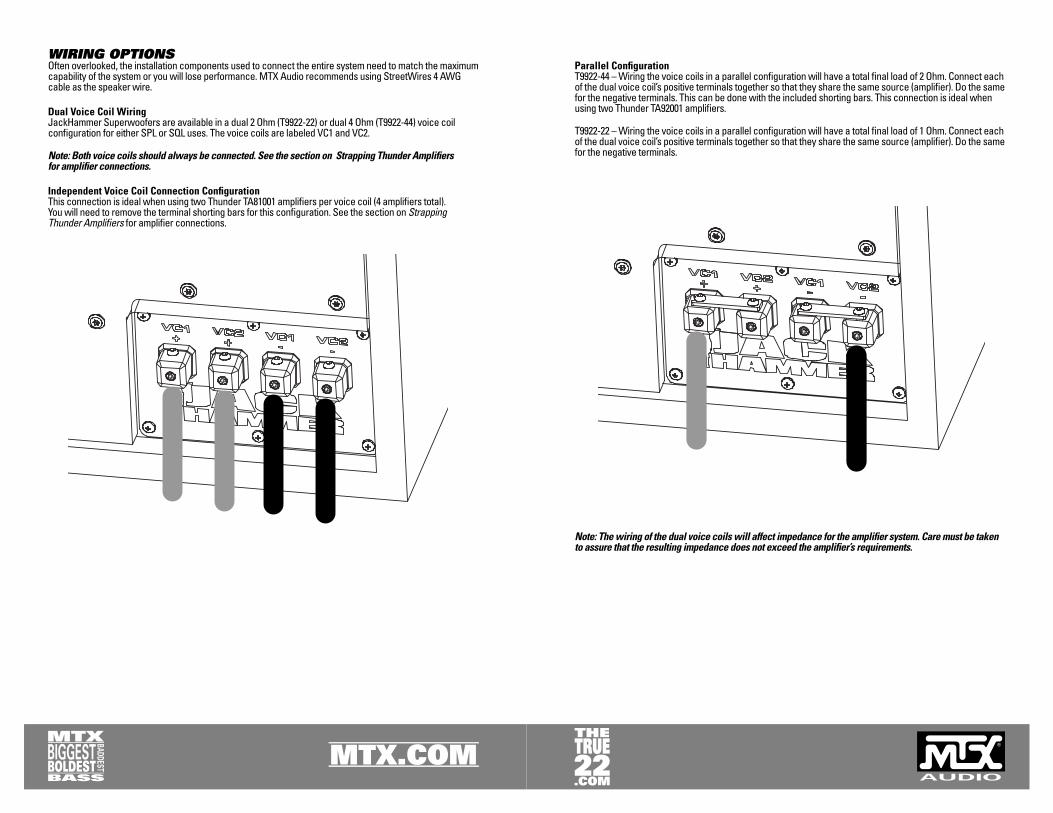
Figure 3
5. Check to be sure all connections are made and the impedance is within range. Once everything is setup correctly, supply the amplifi ers with the 12 volts of power from the batteries.
STRAPPING TWO TA81001 AMPLIFIERS PER VOICE COILIt is also possible to connect four TA81001 amplifi ers by strapping two TA81001s per voice coil. To do this, follow the steps when strapping two TA92001. Those procedures are outlined earlier in this manual. The only exception is that you will now be using two amplifi ers for each voice coil. See Figure 3.
Gain setting is done the same as the two TA92001 setup.
Note: Using two TA81001 amps strapped per voice coil produces a total of over 4,000 watts of RMS power with a current draw of around 400 amps.
SETTINGS AND TUNINGStrapped amplifi ers require “gain matching.” This is the process of adjusting each amplifi er’s gain, frequency, and EQ to be sure both amplifi ers are sending the same AC voltage to the woofer. This will require a volt ohm/multi meter and test tones.
1. Disconnect the speaker wires from each of the amplifi er’s output terminals. It is important to measure the amplifi er’s output with no load (i.e. no speakers connected to the output terminals of the amplifi er).
2. Set the volume of the head unit to max output (before clipping occurs), play a fl at tone (60-80Hz) through the source unit, and hit repeat. Use this same frequency and volume throughout this process.
3. Set the gains on each amplifi er to the most sensitive setting within their proper range. Make sure the input sensitivity is set to the x1 setting for a low level RCA input. (See the amplifi er’s quick install sheet for gain adjustments).
4. Set the multi meter to AC voltage and connect it to the Positive amplifi er’s positive and negative output terminals to measure that amplifi er’s output voltage. Switch the multi meter between the amps and measure each of them to determine which one has the lowest output.
Note: Even the difference of 1 volt can signifi cantly alter the performance of your system.
5. Match the other amplifi er’s gain to the one with the lowest output. Use the fl at tones to gauge what are necessary adjustments.
6. Now that you have matched your amps you will need to set the crossover. It is recommended to have a crossover setting of 60-80Hz and the subsonic fi lter turned off.
7. The parametric EQ can be used to adjust ±12dB from 30-80Hz with a variable “Q” of 0.5 to 4. Using the boost in the 60-80Hz region with a “Q” of 1 or 2 is suggested. The “Q” adjusts the bandwidth of frequencies that are boosted or cut. For more information, read the owner’s manual for the amplifi er.
MTX.COM
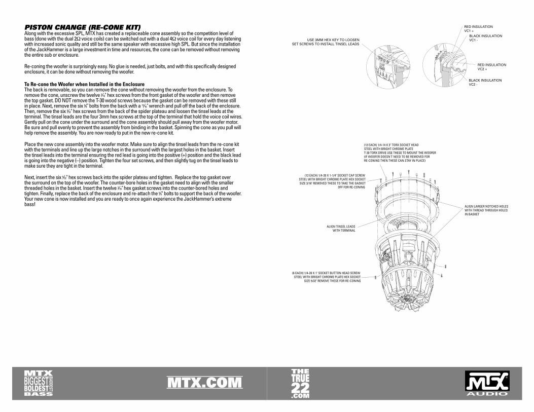
PISTON CHANGE (RE-CONE KIT)Along with the excessive SPL, MTX has created a replaceable cone assembly so the competition level of bass (done with the dual 2Ω voice coils) can be switched out with a dual 4Ω voice coil for every day listening with increased sonic quality and still be the same speaker with excessive high SPL. But since the installation of the JackHammer is a large investment in time and resources, the cone can be removed without removing the entire sub or enclosure.
Re-coning the woofer is surprisingly easy. No glue is needed, just bolts, and with this specifi cally designed enclosure, it can be done without removing the woofer.
To Re-cone the Woofer when Installed in the EnclosureThe back is removable, so you can remove the cone without removing the woofer from the enclosure. To remove the cone, unscrew the twelve 3⁄16" hex screws from the front gasket of the woofer and then remove the top gasket. DO NOT remove the T-30 wood screws because the gasket can be removed with these still in place. Next, remove the six 5⁄8" bolts from the back with a 15⁄16" wrench and pull off the back of the enclosure. Then, remove the six 5⁄32" hex screws from the back of the spider plateau and loosen the tinsel leads at the terminal. The tinsel leads are the four 3mm hex screws at the top of the terminal that hold the voice coil wires. Gently pull on the cone under the surround and the cone assembly should pull away from the woofer motor. Be sure and pull evenly to prevent the assembly from binding in the basket. Spinning the cone as you pull will help remove the assembly. You are now ready to put in the new re-cone kit.
Place the new cone assembly into the woofer motor. Make sure to align the tinsel leads from the re-cone kit with the terminals and line up the large notches in the surround with the largest holes in the basket. Insert the tinsel leads into the terminal ensuring the red lead is going into the positive (+) position and the black lead is going into the negative (–) position. Tighten the four set screws, and then slightly tug on the tinsel leads to make sure they are tight in the terminal.
Next, insert the six 5⁄32" hex screws back into the spider plateau and tighten. Replace the top gasket over the surround on the top of the woofer. The counter-bore holes in the gasket need to align with the smaller threaded holes in the basket. Insert the twelve 3⁄16" hex gasket screws into the counter-bored holes and tighten. Finally, replace the back of the enclosure and re-attach the 5⁄8" bolts to support the back of the woofer. Your new cone is now installed and you are ready to once again experience the JackHammer’s extreme bass!

© 2005 MTX. All rights reserved. MTX, Thunder, JackHammer, and StreetWires are trademarks of Mitek. Designed and Engineered in the U.S.A.
Due to continual product development, all specifi cations are subject to change without notice.
MTX Audio, 1 Mitek Plaza, Winslow, IL 61089 U.S.A.
MTX002239 RevA 10/05 21A8387
MTX.COM