Embed Size (px)
Citation preview

4M200
w w w . r m s p l . c o m . a u
w w w . rm s p l . c o m . a u
4 M 2 0 0 | F | 1 8 / 0 5 / 2 0 1 6
Test Block System
4M200-01 Test Block
> Colour coded finger safe test sockets > 14 independent test groups > Compatible with industry standard 14 circuit
test blocks and test plugs > Optional auxiliary supply isolation circuit > Identification of CT circuits on front panel > Flush panel or rack mounting > IEC 60255 Compliant > Optional test plug to block polarizing system > Made in Australia > http://rmspl.com.au/product/4m200

Functional Description 4M200
2
3
w w w . r m s p l . c o m . a u
w w w . rm s p l . c o m . a u
System Components
> 14 circuit Test Block
> Test Plug
4M200-06 Test Block 4M220-00 Test Plug
Description
The 4M200 Test Block system is an evolution of the 14 test
circuit versions widely employed in the power utility sector.
The primary difference is the incorporation of ‘finger safe’ test
sockets which allow the use of shrouded 4mm banana plugs.
A number of 4M200 Test Block configurations are available to
suit specific protection and control applications as depicted in
the wiring diagram examples.
The 4M200 Test Block has 14 pairs of spring loaded contacts
which are linked to a terminal block positioned at the rear of
the enclosure.
Insertion of the 4M220 Test Plug into the Test Block first
connects & then open circuits each pair of contacts which
connected to the rear terminals.
The 4M220 test plug locates securely into the test block & can
be retained by two knurled screws.
The 28 ‘finger safe’ test sockets on the 4M220 are divided into
two groups of 14:
> 14 even numbered equipment side BLACK test sockets
> 14 odd numbered live side YELLOW test sockets
Each of these 28 test sockets accepts a 4mm shrouded or
standard type test plug.
Features
> 14 independent test groups > ‘Finger safe’ test sockets suit standard or
shrouded type 4mm banana plugs for direct access to the protection or measurement scheme
> Auto CT shorting test plugs available > Clear and concise front panel circuit
identification > Side label instructions on test plug for
changing from normal service to the test condition
> High current / voltage rating > Made in Australia
Application
Test blocks enable test technicians to quickly and safely isolate
protection relays so that test signals may be injected and
system performance verified.
There are a number of advantages in performing injection tests
at the protection relay panel:
> Reduction in down time of the equipment under test
> Testing does not cause disturbance to wiring, terminals
or equipment settings
> Existing auxiliary supply to the equipment under test
may be isolated
The 4M200 Test Block is designed as a general-purpose
isolation and test signal injection point. ‘Finger safe’ sockets
are employed to improve operator safety and suit 4mm
shrouded ‘finger safe’ type banana plugs.
Equipment under test need only be removed for servicing if
problems are detected or for routine maintenance.

Safety Features 4M200 / 4M220
3
3
w w w . r m s p l . c o m . a u
w w w . rm s p l . c o m . a u
Test Plug Insertion
Before use the insulation of the flying leads should be visibly
checked for damage.
Flexible banana test leads with shrouded plugs are
recommended for operator safety. 2.5mm2 multi-strand wire
with PVC insulation is recommended for adequate current
rating and flexibility.
To avoid high voltage shock hazard external CT circuits must
NOT be open circuited. Shorting links must be in position
BEFORE test plug insertion.
Figure 2: Rear view of the 4M220 showing connection fingers
that interface with the 4M200 test block.
The ‘hook’ shape of the odd side connection fingers ensures
‘make before break’ functionality when inserting into the
test block. This function is provided to ensure the continuity
of CT circuits is maintained during insertion of the test plug.
Insertion of the 4M220 connects the live side circuits to the
YELLOW test sockets on the front panel. The equipment side
circuits are connected to the BLACK test sockets on the front
panel. Each test socket is identified by a number, which
corresponds to the numbered terminal on the rear of the
case when the Test Plug is inserted.
Finger Safe Test Sockets
Note the black - even numbered - equipment side sockets.
Note the yellow - odd numbered - live side sockets.
Figure 1: Close up view of the ‘finger safe’ test plug sockets
that accept standard 4mm shrouded test plugs.
CT Shorting – Manual (External)
It is essential that the sockets of the 4M220 Multi-Finger Test
Plug which correspond to the current transformer (CT),
secondary windings are linked prior to the test plug being
inserted into the test block.
This may be achieved using external shorting link lead to ensure
that CT secondary windings are short circuited before they are
disconnected from the protection relay or scheme, thereby
avoiding dangerously high voltages.
The continuity of the shorting plug / wire links & their state of
insulation should be checked prior to into the 4M200 test block.
The 4M220-00 Test Plug is for use with the 4M200-01 to -09
non-polarized Test Block versions
CT Shorting – Automatic (Internal Links)
The 4M220 may be ordered with internal CT shorting links fitted
to pre-designated positions as follows:
4M220-P7 Can only be used with 4M200-P7 test blocks
Internal shorting links between contacts:
21-23-25-27
4M220-P8 Can only be used with 4M200-P8 test blocks
Internal shorting links between contacts:
1-3, 5-7, 9-11, 15-17
4M220-P9 Can only be used with 4M200-P9 test blocks
Internal shorting links between contacts:
1-3-5-7, 9-11, 17-19, 21-23-25-27
Where these 4M220 test plug versions are employed it is
essential that the CT circuits are wired to the 2RMLG test block
in the matching positions.
To Reiterate: The 4M220-00 requires the USER to ensure
that the necessary shorting links are in the correct positions
BEFORE plugging into the test block.

Wiring Diagrams 4M200
4
3
w w w . r m s p l . c o m . a u
w w w . rm s p l . c o m . a u
Figure 3: Test Block Application wiring example for a three phase overcurrent and EF protection scheme
Test Block DC
Isolation
Fixed CT Positions **
Designation on Test Block Facia Polarized Test Plug Comment
4M200-01
YES
NO NO 4M220-00
Operator must manually fit CT shorting
links to the Test Plug in correct positions. 4M200-06
YES 4M200-P6 YES 4M220-P7
Test Plug has fixed shorting positions to
terminal 21-23-25-27
4M 20 0-01
Te st B lo c k
(R E AR VIE W)
4M 20 0- 06 **
4M 20 0-P6 **
C B
Pro tect ion s chem e
4M 22 0- 00 Tes t P lug
( FR O N T V IE W )
T yp ic al ap pli ca tio n for a th ree ph as e o ve rcu rren t & E F p rotec t ion s ch em e
* DC I so la t ion F unct ion Em p lo ye d
4 M2 00 -01
4 M2 00 -06
4M 200-P6
1
- Tr ip
+ Trip
Ca se ea rt h
C ase te r mi na l n um be rs
V aux *
27
2
65
43
87
109
121 1
1413
1615
1817
2019
2 22 1
2423 **
2 625
2 8
A B C
I a
I b
Ic
E /F
DC
au xi l ia ry
Tr ip
Tr ip

Wiring Diagrams 4M200
5
3
w w w . r m s p l . c o m . a u
w w w . rm s p l . c o m . a u
Figure 4: Test Block Application wiring example for a three phase overcurrent and EF protection scheme
Test Block DC
Isolation
Fixed CT Positions **
Designation on Test Block Facia Polarized Test Plug Comment
4M200-02
NO
NO NO 4M220-00
Operator must manually fit CT shorting
links to the Test Plug in correct positions. 4M200-07
YES 4M200-P7 YES 4M220-P7
Test Plug has fixed shorting positions to
terminals 21-23-25-27
4M 200-02
Test B loc k
(R EA R V IE W)
C B
Pro tect ion sc he me
4M 220- 00 Tes t P lug
( FR O N T V IE W)
Typ ica l app licat ion for a th ree phase ove rcu rren t & E F p ro tec t ion schem e 4 M200 -02
4 M200 -07
4M 200-P7
1
- Tr i p
+ Trip
Ca se ea rth
Ca se te rm i na l n um be rs
V au x
27
2
65
43
87
1 09
1 211
1 413
1 615
1 817
2 019
2 22 1
2 423
2 625
2 8
A B C
I a
I b
Ic
E /F
DC
a uxi l iar y
Trip
Trip
4M 20 0- 07 * *
4 M 20 0-P7 **
**

Wiring Diagrams 4M200
6
3
w w w . r m s p l . c o m . a u
w w w . rm s p l . c o m . a u
Figure 5: Typical application for a three phase directional overcurrent & E/F or distance protection scheme
Test Block DC
Isolation
Fixed CT Positions **
Designation on Test Block Facia Polarized Test Plug Comment
4M200-02
NO
NO NO 4M220-00
Operator must manually fit CT shorting
links to the Test Plug in correct positions. 4M200-07
YES 4M200-P7 YES 4M220-P7
Test Plug has fixed shorting positions to
terminals 21-23-25-27
Typ i cal ap pli cat ion fo r a thre e phas e dire ct io na l o ve rc urre nt & E/F o r di stance p rote ct io n s chem e
C B
- Tr ip
+ Trip
T rip
O utput
Input
Va
V b
V c
4M 20 0-02
Te st B lo c k
(R E AR VIE W)
Pro tect ion s chem e
4M 22 0- 00 Tes t P lug
( FR O N T V IE W )
4 M2 00 -02
4 M2 00 -07
4M 200-P7
1
Ca se ea rt h
C ase te r mi na l n um be rs
27
2
65
43
87
109
121 1
1413
1615
1817
2019
2 22 1
2423
2 625
2 8
A B C
I a
I b
Ic
E /F
4M 20 0- 07 **
4M 20 0-P7 **
**

Wiring Diagrams 4M200
7
3
w w w . r m s p l . c o m . a u
w w w . rm s p l . c o m . a u
Figure 6: Typical application for 3 Ph CT’s and core balance E/F CT
Test Block DC
Isolation
Fixed CT Positions **
Designation on Test Block Facia Polarized Test Plug Comment
4M200-08
NO YES
NO 4M220-00 Operator must manually fit CT shorting links
to the Test Plug in the designated positions.
4M200-P8 YES 4M220-P8 Test Plug has fixed shorting positions to
terminals 1-3, 5-7, 9-11, 15-17
A B C
E
I
I
I
( 3Io)
b
a
c
Typical application for 3 Ph CT’s and core balance E/F CT
Test Block
(REAR VIEW)
Protection s cheme
4M220-00 Test Plug
(FRONT VIEW)
4M200-08
4M200-P8
1
Case earth
Case term inal numbers
27
2
65
43
87
109
1211
1413
1615
1817
2019
2221
2423
2625
28
4M200-08 **
4M200-P8 **
**
**
**
**

Wiring Diagrams 4M200
8
3
w w w . r m s p l . c o m . a u
w w w . rm s p l . c o m . a u
Figure 7: Typical application for differential protection of transformers
Test Block DC
Isolation
Fixed CT Positions **
Designation on Test Block Facia Polarized Test Plug Comment
4M200-09
NO YES
NO 4M220-00 Operator must manually fit CT shorting links
to the Test Plug in the designated positions.
4M200-P9 YES 4M220-P9 Test Plug has fixed shorting positions to
terminals 1-3-5-7, 9-11, 17-19, 21-23-25-27
Typ ica l app l icat i on for dif fere nti al pro tec ti on of t ran sform ers
AA
BB
CC
I a
I a
N
N
E /F
E /F
I b
I b
I c
I c
Te st B lo c k
(R E AR VIE W)
Pro tect ion s chem e
4M 22 0- 00 Tes t P lug
( FR O N T V IE W )
4 M2 00 -09
4M 200-P9
1
Ca se ea rt h
C ase te r mi na l n um be rs
27
2
65
43
87
109
121 1
1413
1615
1817
2019
2 22 1
2423
2 625
2 8
4M 20 0- 09 **
4M 20 0-P9 **
**
**
**
**

Test Block Case Details 4M200
9
3
w w w . r m s p l . c o m . a u
w w w . rm s p l . c o m . a u
Rear View
Side View Panel Cut-out
Front View
P/N 263-635-008
Screw lug 4mm (O/D 8.0mm MAX)Wire 2.5mm MAX2
1 2
27 28
2 holes of 3.7
4M 200 Test B lock
Draw ing un its: m m
Suits flush panel m oun ting &
4U high 19 inch rack fram e
27 217
157
25
177
51

Test Block Technical Data 4M200
10
3
w w w . r m s p l . c o m . a u
w w w . rm s p l . c o m . a u
ELECTRICAL ENVIRONMENT
Voltage Rating Standard IEC 60255-27,
Test Identification Test specification
Pollution degree 2
Overvoltage category III
Rated insulation voltage 300 V rms or d.c.
System auxiliary voltage 40 V DC minimum
Current Rating Standard IEC 60947-7-1
Test Identification Test specification
Rated Wire Cross-section 2.5 mm2
Current withstand Continuous withstand: 20 A
Short-time withstand: 400 A for 1 s
Clearances and Creepage Distances Standard IEC 60255-27, #10.6.3, Table C.6
Test Identification Test specification
Creepage distance 3.0 mm
Clearance 3.0 mm
Clearances and Creepage Compliance
CAD drawings assessment
Safety-related Electrical Tests Standard IEC 60255-27, #10.6.4
Test Identification Test specification
Between any contact pair & either adjacent contact pair
5 kV 1.2/50 µs 0.5 J 3 impulses of each polarity
2.2 kV ac rms for 1 minute
Between any terminal and the case earth
5.0 kV ac rms for 1 minute
Between any alternate contact pair, provided that the intermediate pair is not used
5.0 kV ac rms for 1 minute
Across Open Contacts of Auxiliary Power Supply Circuit (No Shorting pin)
1 kV ac rms for 1 minute
4M200 with 4M220 Fitted Standard IEC 60255-27, #10.6.4
Test Identification Test specification
Between any contact pair & either adjacent contact pair
5 kV 1.2/50 µs 0.5 J 3 impulses of each polarity
2.2 kV ac rms for 1 minute
Between Incoming & Outgoing contacts
2.2 kV ac rms for 1 minute
Between any terminal and the case earth
5.0 kV ac rms for 1 minute
Electrical Environment and Flammability Standard IEC 60255-27, #10.6.5
Test Identification Test specification
Single-fault condition Assessment for CT input circuits
Maximum temperature of accessible parts at ambient temperature +40°C
Metal parts: < 70°C
Non-metallic parts: < 80°C
Flammability of insulating materials, components and fire enclosures
Assessment
Performance Requirements Standard IEC 60947-7-1, #7.2.
Test Identification Test specification
Temperature Rise < 45 K
Voltage Drop at 2.4 A DC < 1.6 mV per tier on each individual clamping

Test Block Technical Data 4M200
11
3
w w w . r m s p l . c o m . a u
w w w . rm s p l . c o m . a u
ATMOSPHERIC ENVIRONMENT
Temperature Standard IEC 60068-2-1, IEC 60068-2-2
Test Identification Test specification Auxiliary power Supply voltage
Operating Range -10 to +55°C Min and Max
Storage Range -25 to +70°C Non-energized
Test duration 16 hours at top and bottom temperatures
Damp Heat (Humidity) Standard IEC 680068-2-78
Test Identification Test specification
Operating Range 40°C and 93% RH non condensing
Test duration 16 hours
IP Rating Standard IEC 60529
Test Identification Test specification
Installed IP5x
Performance Standard
Low-voltage switchgear and control gear
Part 7.1: Ancillary equipment – Terminal blocks for copper
conductors
Standard IEC 60947-7-1
MECHANICAL ENVIRONMENT
Vibration - Sinusoidal Standard IEC 60255-21-1 Class 1
Test Identification Test specification Variation
Vibration Response in each of 3 axes
0.035 mm/0.5 gn peak 1 sweep cycle 10-150 Hz
≤5%
Vibration Endurance in each of 3 axes
1.0 gn peak 20 sweep cycles 10-150 Hz
Non- energized
Shock and Bump Standard IEC 60255-21-2 Class 1
Test Identification Test specification Variation
Shock Response in each of 3 axes
5 gn, 11 ms, 3 pulses in each direction
≤5%
Shock Withstand in each of 3 axes
15 gn, 11 ms, 3 pulses in each direction
Non- energized
Bump Test in each of 3 axes
10 gn, 16 ms, 1000 bumps in each direction
Non- energized
Seismic Standard IEC 60255-21-3 Class 1
Test Identification Test specification Variation
Seismic Response Horizontal, on each axis
3.5 mm/1.0 gn, 1 sweep cycle 1-35Hz
≤5%
Seismic Response Vertical
1.5 mm/0.5 gn, 1 sweep cycle 1-35Hz
≤5%
Mechanical Classification Durability 103 insertions of the Test Plug

Test Plug Dimensions 4M220
12
3
w w w . r m s p l . c o m . a u
w w w . rm s p l . c o m . a u
4M220 Multi Finger Test Plug
28 test sockets suitable for 4mm shrouded banana plugs.
Securing screws are integrated to retain the Test Plug during
testing operations.
4M220 Test Leads
13
3
w w w . r m s p l . c o m . a u
w w w . rm s p l . c o m . a u
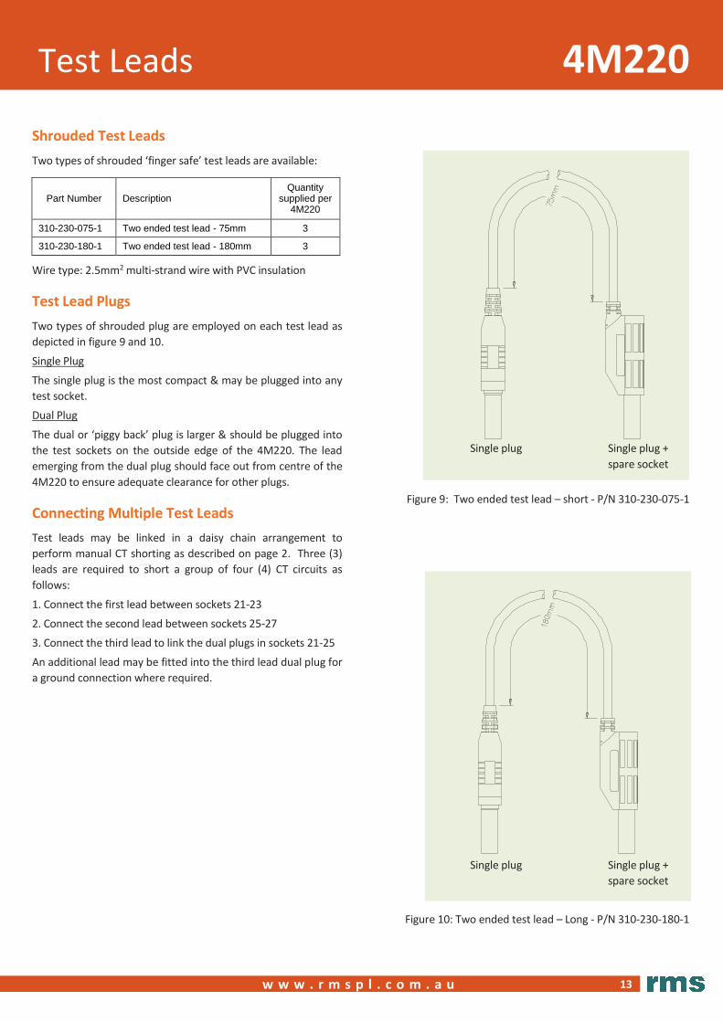
Shrouded Test Leads
Two types of shrouded ‘finger safe’ test leads are available:
Part Number Description Quantity
supplied per 4M220
310-230-075-1 Two ended test lead - 75mm 3
310-230-180-1 Two ended test lead - 180mm 3
Wire type: 2.5mm2 multi-strand wire with PVC insulation
Test Lead Plugs
Two types of shrouded plug are employed on each test lead as
depicted in figure 9 and 10.
Single Plug
The single plug is the most compact & may be plugged into any
test socket.
Dual Plug
The dual or ‘piggy back’ plug is larger & should be plugged into
the test sockets on the outside edge of the 4M220. The lead
emerging from the dual plug should face out from centre of the
4M220 to ensure adequate clearance for other plugs.
Connecting Multiple Test Leads
Test leads may be linked in a daisy chain arrangement to
perform manual CT shorting as described on page 2. Three (3)
leads are required to short a group of four (4) CT circuits as
follows:
1. Connect the first lead between sockets 21-23
2. Connect the second lead between sockets 25-27
3. Connect the third lead to link the dual plugs in sockets 21-25
An additional lead may be fitted into the third lead dual plug for
a ground connection where required.
Figure 2: Alpha XR5-00-1 - Normal system condition
Single plug Single plug +
spare socket
Figure 9: Two ended test lead – short - P/N 310-230-075-1
Single plug Single plug +
spare socket
Figure 10: Two ended test lead – Long - P/N 310-230-180-1

4M200 / 4M220 Order Codes
14
3
w w w . r m s p l . c o m . a u
w w w . rm s p l . c o m . a u
4M200 -
01 Vx isolation 13-14
02 Vx isolation not required
06 Vx isolation 13-14, CT's 21-23-25-27, non-polarized
07 No Vx isolation, CT's 21-23-25-27, non-polarized
08 CT's 1-3, 5-7, 9-11, 15-17, non-polarized
09 CT's 1-3-5-7, 9-11, 17-19, 21-23-25-27, non-polarized
P6 Vx isolation 13-14, CT's 21-23-25-27, polarized
P7 No Vx isolation, CT's 21-23-25-27, polarized
P8 CT's 1-3, 5-7, 9-11, 15-17, polarized
P9 CT's 1-3-5-7, 9-11, 17-19, 21-23-25-27, polarized
4M200 Test Block Order Code
Generate the required ordering code as follows: e.g. 4M200-02
4M220 -
CT Shorting Links 00 External links to be fitted by operator – Must be Fitted Manually by Tester
P7 Internal links fitted between contacts 21-23-25-27, polarized
P8 Internal links fitted between contacts 1-3, 5-7, 9-11, 15-17, polarized
P9 Internal links fitted between contacts 1-3-5-7, 9-11, 17-19, 21-23-25-27, polarized
4M220 Test Plug Order Code
Generate the required ordering code as follows: e.g. 4M220-00
> Polarized Test Blocks
RMS Codes
- 2RMLG-07 4M200-P7
- 2RMLG-08 4M200-P8
- 2RMLG-09 4M200-P9
> Polarized Test Plugs
RMS Codes
MMLB-07 2RMLB-S7 4M220-P7
- 2RMLB-S8 4M220-P8
- 2RMLB-S9 4M220-P9
Cross Reference Charts
> Non-polarized Test Blocks
RMS Codes
MMLG-01 2RMLG-01 4M200-01
MMLG-02 2RMLG-02 4M200-02
- - 4M200-06
- - 4M200-07
- - 4M200-08
- - 4M200-09
> Non-polarized Test Plugs
RMS Code
MMLB-01 2RMLB-S1 4M220-00

®
6 Anzed Court
Mulgrave, Victoria 3170
AUSTRALIA
Ph: +61 3 8544 1200
Fax +61 3 8544 1201
Sales: [email protected]
www.rmspl.com.au www.relays.com.au
ISO9001 Quality Accreditation RMS holds BSI (British Standards Institution) registration number FS
604860 for the certification of a quality system to AS/NZS ISO9001:2008.
Due to RMS continuous product improvement policy the information
contained in this document is subject to change without prior notice.
© 2016 Relay Monitoring Systems Pty Ltd ABN 76 052 484 483
Re l ay Mo n itor i ng Sys te m s Pt y L t d d es ig n, man ufa ct ur e an d ma rk et a w id e ra n ge o f e l ect r ic a l prot ec t io n an d con tro l pro d uct s for a p pl ica t io n o n h i g h vo lta g e powe r sy st em s. T h e com pa ny' s de p th o f man ufa ct ur i ng a n d e ng i n ee r i n g e xpe rt i se i s back e d u p b y m an y ye ars o f e xp er ie nc e s i nc e t he fo rma t io n o f i t s p re d ece s sor , Rel ays Pt y L t d (RPL) , i n 195 5. T hi s exp er i enc e comb i ne d wi t h a broa d b as e o f f ie l d prov e n p ro duc t t yp es e na bl e s RM S to se rv ice s p ec i f ic cu sto mer ne e ds b y pro d uc i n g re lay s on d ema n d an d wi th typ ica l l y sho rt l ea d t im e s.
www.rmspl.com.au