Embed Size (px)
Citation preview

CHAPTER: 2
LITERATUREREVIEW
8
CHAPTER: 2 LITERATURE REVIEW
Narrow gap welding is an effective process for joining thick plates (2” to 12”) of carbon steel, low alloys steel and high strength low alloy steels. But it requires some development in torch design, wire feeding mechanism and welding procedure for preventing all sorts of weld defects before practical application. Narrow gap welding technology is associated with various conventional arc welding technology like GMAW, GTAW, SAW, FCAW & SMAW. Several fabricators world over, especially in Japan have developed their own equipment working on different principal [15]
2.1 Narrow Gap Welding Processes
2.1.1 Narrow Gap Gas Tungsten Arc Welding (NG-GTAW)
Principal of NG-GTAW
It involves use of insulated water cooled contact tube having non consumable tungsten electrode. GTAW process require separate addition of filler metal to provide adequate weld metal to fill the joint gap. Filler metal can be added either manually but mostly through automatic means. Automatic filler wire feeding may be used either as cold wire or hot wire. Process is more suitable for special metals rather than for routine metals. Figure 2.1 shows the working principal of NG-GTAW [8].
Figure 2.1: Working principal of NG-GTAW [8]
NG-GTAW welding head comprises three mutually perpendicular slides (the vertical and transverse to weld slides being motorised and controlled from a joystick), a wire feed system (wire diameter 1.6mm), an arc voltage controller (AVC), and the welding torch. The AVC consist of a voltage sensor and a motorised vertical slides. The arc voltage is measured and the torch vertical position adjusted automatically to maintain the present voltage. [16]
9

Process features are
i) Capability of producing high joint integrity in all welding positionii) Low heat inputiii) No spatteriv) High arc stabilityv) No slag formationvi) Excellent quality of weld metalvii) High strength and fracture toughness inherent to the GTAW process.
NG-GTAW torches
NG-GTAW torches are similar to those for conventional GTAW. However, the contact tube for the tungsten electrode and the guide for filler wire are extended to reach the bottom of the deep narrow groove. In a hot wire, the wire contact tip is insulated from the electrical ground and is the last point of physical contact to the wire before the latter enters the weld pool.
For material up to 40mm thickness, a conventional TIG machine torch can be used with the gas shielding nozzles above the top surface of the joint. For greater thickness a narrow gap GTAW torch is used with a secondary surface gas box to ensure adequate shielding [16]. The primary nozzles provides the central flow of the gas around the tungsten electrode, while the secondary nozzle provides side flow in front and rear areas with regards to the direction of welding. However such arrangement adequately protects the tungsten electrode, the wire and the weld pool only in the confinement of the groove, while the top passes require an additional protection in the form of a shielding box (triple shielding system) located above the work piece [6]. Sidewall penetration control can be obtained by oscillation of the tungsten electrode mechanically or by magnetic filed. [8] Figure 2.2 show NG-GTAW torch.
Gas diffuser
Figure 2.2 NG-GTAW torch [8] Figure 2.3 : Narrow-gap GTAW torch [16]
10
Torches specifically designed for NG-GTAW are usually elongated as shown in Figure 2.3. The shielding gas is delivered to rectangular slots either side of the electrode and in addition gas may be supplied through holes in the side of the blade.In NG GTAW, not only torch linear movement has to be controlled accurately but arc length has to be maintained within limits so to control the heat input.
NG-GTAW wire feeding system
NG-GTAW wire feeding systems both for cold and hot wire techniques are similar to those for conventional GTAW. However, the requirement of defect free performance is higher which reflect concern for difficulties in repair in NGW. A hot wire feeding system should able to provide a wider wire speed range than that for a cold wire system. Useful speed range for a hot wire system is 2.1-211.6 mm/sec. NG-GTAW with cold wire filler addition has been shown to be capable of narrow gap welding; its limited deposition rate capability has not made this a competitive alternative. NG-GTAW with hot wire offers an attractive alternative that combines high deposition rate capability [17].
Applications
i) Automatic high accuracy NG-GTAW process was developed for joining 50mm thick, ultra-high strength steel plates for pressure hull of deep submersibles.
ii) Literature show that NG-GTAW is most often applied to high strength low alloy, ultra high strength and stainless steels and for titanium and its alloys.
iii) Out of position welding can be achieved using pulsed arc current in pipeline engineering and construction, particularly in orbital welding of thick walled pipes.[8]
iv) Mitsubishi heavy industries ltd, Japan had developed NG-GTAW with rotary electrode for fabrication of the heat exchanger from Hastelloy (50-90mm). [18]
v) NG-GTAW process application have been reported for nuclear power pressure vessel, nuclear fusion equipment, piping of nuclear power plant, boiler header, generator rotor and steam turbine rotor. [219]
Problems of NG-GTAW
i) Draughts
Stability of arc is effected by draughts, draughts is more severe in the open production areas. TTiis problem can be solved by enclosing the welding station with plastic tent [16].
11

ii) Referencing
Whenever the arc length is controlled automatically, problem is encountered with NG- GTAW torch when plasma track will established between the side of the tungsten and sidewall of the groove. This causes false voltage reading (low) and causes the arc voltage controller (AVC) to lift the tungsten, which will brake the path and finally the tungsten returned to its correct position. This phenomenon will results in vertical oscillation of the tungsten electrode, which sometime become so severe that tungsten plunged into weld pool. Even when the effect is less severe, the bead tends to be convex causing lack of sidewail fusion.This problem may eliminated by introducing a third gas flow parallel to the joint walls, which may eliminate a ‘dead area’ of gas at the side of the tungsten (considered to be the source of plasma)
\
Hi) Melting of tungsten
On number of occasions, tungsten has been observed to melt and gradually deposits into the weld metal. Tungsten would develop small ‘feathery’ annular growth at the point from which the plasma formed, which would be followed by the tungsten melting, causing point to become truncated. The melting rate increase with the welding current. The improvement in gas shielding described in referencing will eliminate this problem.
iv)Magnetic arc blow
Fundamental problem of, hot wire NG-GTAW, is magnetic arc blow due to electric current supply to the wire which has discouraged the popular use of it. To overcome this problem Babcock Hitachi K.K group of Japan had developed new process called Hot Wire Switching TIG welding process (HST) in which the arc blow is substantially reduced. The alternating switching of arc current and wire heating current is done so that the wire current become zero when high arc current is activated but arc current keeps such a low value, enough to maintain arc, when wire current is activated. [12,19]
Drawbacks
i) The main drawback of the process compared to other arc welding processes is the relatively low joint filling rate. However, low joint filling rate can be justified only under following conditions
For critical structures where safety is major concern rather than economy, such as deep submersiblesFor critical structures which require guaranteed joint performance, because of difficulties in repair. Such critical structures are nuclear reactor components, offshore oil and gas pipe lines. [6]In order to increase the deposition rate, a special independent power supply is used to heat the filler metal wire, known as hot wire NG-GTAW process.
ii) The necessity for high accuracy power supply characteristics, close tolerance requirement for the tungsten electrode to work distance.
12
2.1.2 Narrow Gap Submerged Are Welding (NG-SAW)
Principal of NG-SAW
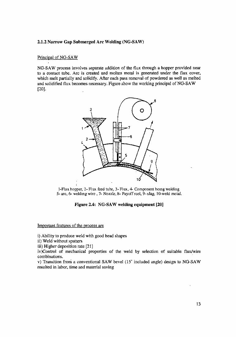
NG-SAW process involves separate addition of the flux through a hopper provided near to a contact tube. Arc is created and molten metal is generated under the flux cover, which melt partially and solidify. After each pass removal of powdered as well as melted and solidified flux becomes necessary. Figure show the working principal of NG-SAW
1-Flux hopper, 2- Flux feed tube, 3- Flux, 4- Component being welding 5- arc, 6- welding wire, 7- Nozzle, 8- Payoff reel, 9- slag, 10-weld metal.
Figure 2.4; NG-SAW welding equipment [20]
Important features of the process are
i) Ability to produce weld with good bead shapesii) Weld without spattersiii) Higher deposition rate [21]iv) Control of mechanical properties of the weld by selection of suitable flux/wire combinations.v) Transition from a conventional SAW bevel (15° included angle) design to NG-SAW resulted in labor, time and material saving
[20].
13
NG-SAW torches
NG-SAW torches are specially designed. However, they are much simpler than those for NG-GMAW, since they are not subjected to heat radiation and spatter and do not required complicated gas shielding systems. In order to extend the range of plate thickness to be welded, one or more torch extensions are attached to the contact tube. Utilisation of thick wire leads to extensive wear of the contact tip which may impair current transfer. To avoid this, wire is pressed to the contact tip by spring tension. Generally service life of the tips depends on welding wire type and wire surface quality. Minimum service life of a tip at feeding by means of smooth roller is 50 and 100 hours for small nozzles and massive tip respectively [22], A flux nozzle is also inserted into the groove to supply flux. The nozzle is usually a long, flat tube attached to the contact tube in front of the latter.
Characteristics of the NG-SAW torch
P.Radic and et al [22,23] had designed different types of NG-SAW torches for welding of material from 150 mm to 450 mm in thickness. They have also suggested chief features of NG-SAW torch.
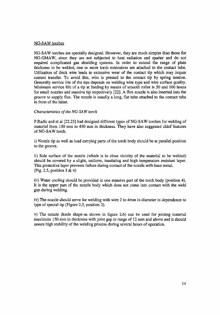
i) Nozzle tip as well as load carrying parts of the torch body should be at parallel position to the groove.
ii) Side surface of the nozzle (which is in close vicinity of the material to be welded) should be covered by a slight, uniform, insulating and high temperature resistant layer. This protective layer prevents failure during contact of the nozzle with base metal.(Fig. 2.5, position 3 & 4)
iii) Water cooling should be provided in one massive part of the torch body (position 4). It is the upper part of the nozzle body which does not come into contact with the weld gap during welding.
iv) The nozzle should serve for welding with wire 2 to 4mm in diameter in dependence to type of special tip (Figure 2.5, position 2).
v) The nozzle (knife shape-as shown in figure 2.6) can be used for joining material maximum 150 mm in thickness with joint gap in range of 12 mm and above and it should assure high stability of the welding process during several hours of operation.
14
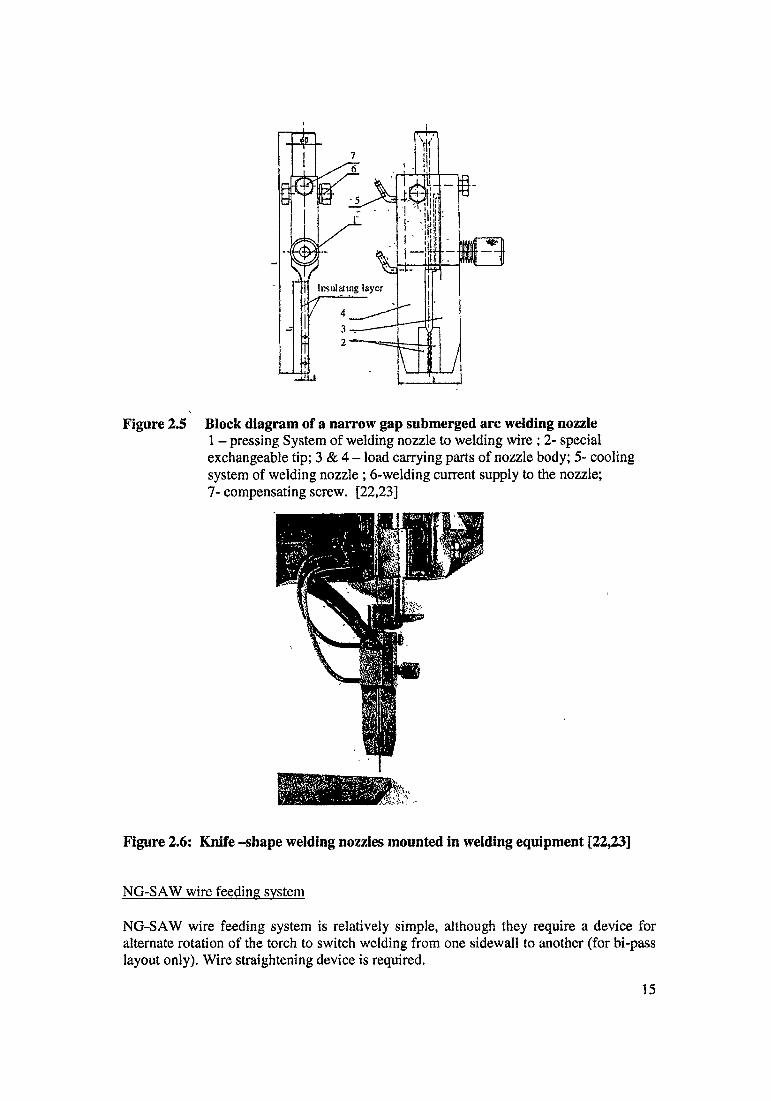
Figure 2.5 Block diagram of a narrow gap submerged arc welding nozzle1 - pressing System of welding nozzle to welding wire; 2- special exchangeable tip; 3 & 4 - load carrying parts of nozzle body; 5- cooling system of welding nozzle ; 6-welding current supply to the nozzle;7- compensating screw. [22,23]
Figure 2.6: Knife -shape welding nozzles mounted in welding equipment [22,23]
NG-SAW wire feeding system
NG-SAW wire feeding system is relatively simple, although they require a device for alternate rotation of the torch to switch welding from one sidewall to another (for bi-pass layout only). Wire straightening device is required.
15
Problems of NG-SAW
E.Derworth [24] had reported that following problems are encountered during application of NG-SAW process.
i) Distortion
Transverse shrinkage occurred and as a result welding nozzles, which had thickness of 15 mm, get chock up. The solution is simple: a slight angle or preset is found necessary in conjunction with ‘strong backs’.
ii) Lack of sidewall fusion
Occurred, basically as a result of poor set up with the welding bead not being in true alignment with the welding groove.
Hi) Shrinkage cracks
Lack of preheat appeared to result in shrinkage cracks. The problem can be eliminated when all subsequent welds preheated using two air-fuel gas burners, one on each side of the joint for 2.5 hours prior to welding. The previous weld seemed to have been absorbing all of the quenching and shrinkage which had occurred in the joint.
ivj Consumable selection
Selection of flux and wire combination to ensure weld metal deposits should compatible with the parent material.
Drawback
i) Absence of visual observation of the arcii) Difficulties in removing slag in the narrow groove after each pass (for single layer single pass), a special instrument was developed to remove slag after each pass and to clean the weld. [25]iii) Weld bead is likely to be convex in most cases, therefore welding condition is selected so that the top face of each pass of the deposited weld metal will be concave to avoid lack of fusion and to facilitate slag removal [16].iv) Overheating of the weld nozzles.v) Accidental arc strike between the contact nozzles and the sidewall. [20]
Process variants
NG-SAW has two major variants: i) Single layer single pass ii) Multi pass per layer
i) Single layer single pass
Cross section area of the groove is 1/3 as compared to conventional process. It gives greatincrease in productivity. Electrode wire must be in the centre of the groove to achieve
equally balanced sidewall penetration. Changing welding parameters is the only option
16
for compensation of variation in gap width and resultant variation in the sidewall penetration; same cannot be achieved by moving wire off centre.
Slag removal is the major problem with this bead configuration. At low arc voltage convex bead will be produced and at high arc voltage undercut may occurs. In both cases slag removal becomes more difficult and to eliminate other defect such as lack of fusion. Slag detachability is a function of groove angle and root gap for a given flux. The optimum root gap of 12mm and groove.angle 3°, at the same time joint filling rate decreases with increase of gap. Under the constant welding condition (600Amp, 32V and 200mm/min), excellent bead configurations and sidewall fusion could be obtained over a wide range of root gap from 12-21 mm. Above this gap, lack of fusion occurs [21]. It was recommended that for gap exceeding 20mm a single layer double pass technique should used.
The weld bead produced in single layer single pass is also encourages solidification cracking, especially in root runs. Low current is advisable to keep low bead depth/width ration particular with small root gap. The use of low carbon backing plate or iron powder addition to reduce dilution in the first pass has been suggested to prevent hot cracking. Drying of consumable, control of preheat, inter pass and post heat treatment temperature are necessary for avoiding hydrogen cracking during the welding of thick section of carbon and low alloys steels.
ii) Multi passes per layer
Multi pass per layers techniques uses single layer double passes or single layer three passes. Welding time for two passes per layer is about 50 % greater than for single layer single pass. Possibility to move off the welding wire from centerline is possible, process is flexible.
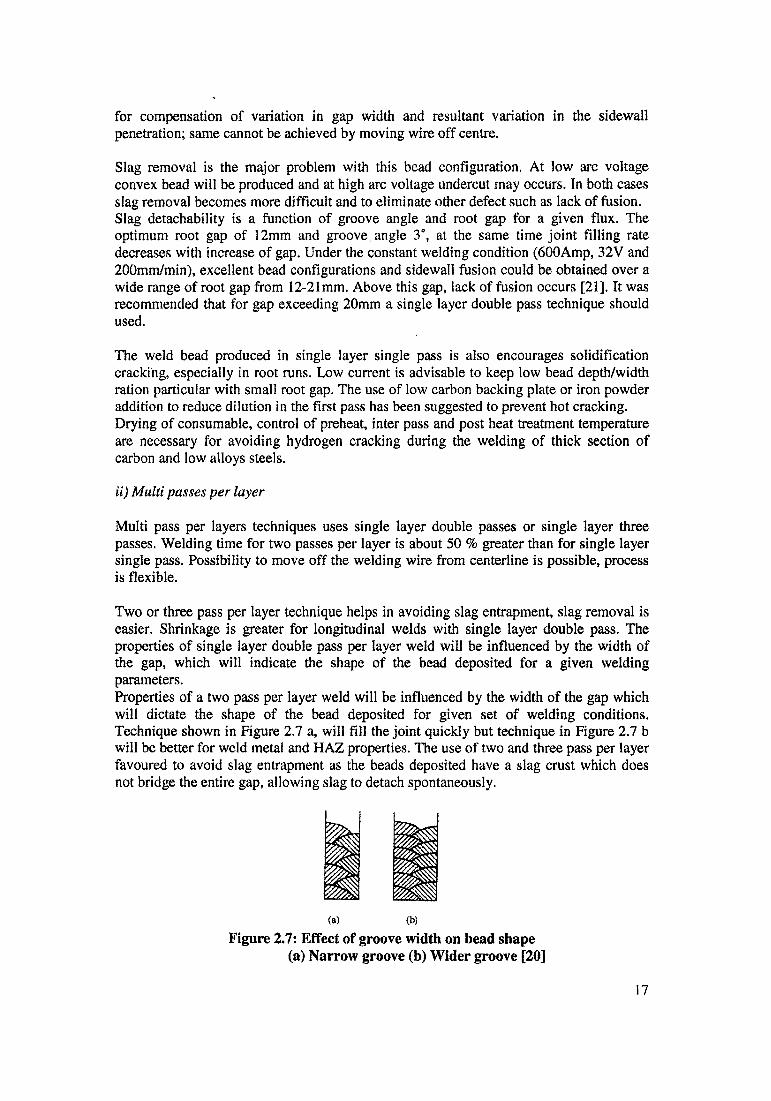
Two or three pass per layer technique helps in avoiding slag entrapment, slag removal is easier. Shrinkage is greater for longitudinal welds with single layer double pass. The properties of single layer double pass per layer weld will be influenced by the width of the gap, which will indicate the shape of the bead deposited for a given welding parameters.Properties of a two pass per layer weld will be influenced by the width of the gap which will dictate the shape of the bead deposited for given set of welding conditions. Technique shown in Figure 2.7 a, will fill the joint quickly but technique in Figure 2.7 b will be better for weld metal and HAZ properties. The use of two and three pass per layer favoured to avoid slag entrapment as the beads deposited have a slag crust which does not bridge the entire gap, allowing slag to detach spontaneously.
(a) (b)
Figure 2.7: Effect of groove width on bead shape (a) Narrow groove (b) Wider groove [20]
17
Welding two pass per layer appears to be less sensitive to deviation in parameters and wire position than single layer single pass and therefore more suitable for production. Three pass per layer welding has limited application, usually in area where the quality of the weld and its properties are of paramount importance. [21]
Filler wire diameter
Electrode diameter in the range of 3-4mm have been recommended in several studies [21]. Large diameter cause excessive wear on the contact tip. Wire diameter less than 2mm, cause arc wandering, so that varied weld bead profile will produced.
Fluxes
Removal of slag is the major problem in NG-SAW. Flux should have following chief characteristicsi) Allows formation of beads with smooth surface and free from notchesii) It should provide arc stabilityiii) It is important that solidified slag is fragile and allowed to breakdown easilyiv) It should remove from the gap easily even at high preheat temperaturev) Flux should also generate small amount of gas because of the small space in narrowgap '
Three major factors will control slag detachabilityi) The expansion/contraction behaviour of the slag-metal systemii) The formation of common oxides between the weld metal and slagiii) Tendency of the transverse joint shrinkage which pinches the slag layers.
In case of Si02-Al203-Mg0-Mn0-Ca0-CaF2, flux system, SiC>2 improves slag detachability, because of the strength of the slag crust decreases and the difference in thermal expansion between metal and slag increases. At the same time, as SiC>2 content increases, weld metal silicon content will also increase and weld metal oxygen content increase with increasing weld metal silicon content.
Oxygen content in the weld metal (300-800 ppm) decreases impact toughness, because of increase of inclusions in the weld metal. Therefore it is necessary to control silicon content to the flux. [20].
NG-SAW at L& T. Hazira
There have been continuous developments in the field of manufacturing technology at L & T.
i) NG-SAW for longitudinal and circumferential welding
300mm thick plate with only 1° included angle has been successfully welded with in house developed NG-SAW using bi axial seam trackers. Single wire (4mm electrode diameter) as well as tandem SAW techniques are being used extensively for pressure vessel and nuclear reactors.NG-SAW with 5mm electrode diameter, recently implemented. 25% increasing productivity by 25% has been reported [26].
18

ii) Hemispherical head welding by NG-SAW.
Petal to petal and crown to petal weld of hemispherical heads are being welded by NG- SAW, Earlier days, these joints used to be done with manual process i.e. SMAW. Improvement in terms of quality and productivity has been reported. The head is mounted on heavy duty manipulator and welding is carried out from outside sequentially on various petals for controlling distortion.
NG-SAW at BHEL. WRI. Trichv T271
The important features of welding head designed at WRIi) Torch is suitable for 18mm joint gap with an included angle 2-4° and it can weld 200mm thick plateii) Provision for self alignment of torch with sidewallsiii) After initial setting, the torch can tolerate a variation of (+/ -) 2.5 mm in the electrode to side wall distance.iv) Wire feeder incorporated with wire straightening devices along with welding head.
Comparison between conventional SAW and NG-SAW has been studied by WRI research workers.155mm of SA 299 material was successfully welded using NG-SAW. 55% reduction in weld metal and 51 % in saving in flux has reported.
Tensile strength of welds by conventional SAW is higher than (59.1 to 62.5 kgf/mm2) than NG-SAW (57.2 to 59 kgf/mm2). The % reduction in area of the all weld tensile specimen is near 10 % higher for narrow gap weld specimen, which indicants ductile weld. At the same time the impact strength of narrow gap weld were nearly double than of conventional welding.
New development in NG-SAW
B.S.Kasatkin, et al., had developed new two arc narrow gap submerged arc welding [28]. Author had highlighted disadvantages of single NG-SAW, such as relatively low productivity and high labor content as a result of the fact that it is often necessary to use preheating and accompanying heating of welded components to 250-300°C. The two-arc NG-SAW is highly promising in this respect. However, considerably difficulties in the removal of the slag skin from a narrow deep gap were observed.
In this process joint gap is in range of 24 to 28 mm and process is applicable for single layer double pass, as shown in figure 2.8. In two arcs NG-SAW, first arc is used to preheat the bas metal whereas the second arc brings in an additional amount of heat and reheat the weld thus reducing the total cooling rate of the welded joint. The thermal cycle of two arcs NG-SAW is strongly affected by the distance between the arcs and the pre heat temperature.
For reliable slag removal of the slag skin from the deep gap, authors had developed special slag-cutting device which is part of welding equipment; the device consists of disc blade l and the mechanism 2 pressing the blade to the slag skin under specific pressure P, as shown in figure 2.9. The distance L of the blade from the second arc was determined by experiments in such a manner as to ensure that the disc blade cuts the unsolidified slag skin into two halves in the longitudinal direction. This accompanied by
19

the formation of force N, as shown in figure 2.10, which causes the separation of the cut parts of the skin from the edges of the metal. After cooling the cut slag skin can be removed relatively easily. The selection of the optimum pressure of the blade on the slag skin is important parameter. Excessive pressure may affect the formation of the weld pool and cause the appearance of a groove on its surface and slag can be trapped inside the groove.In comparison with single arc NG-SAW, two arc NG-SAW reduces the preheat temperature from 300 to 150 °C and the productivity of the welding process increased 1.7times.
Figure 2.8: Diagram of distribution of electrodes in two -arc narrow gap submerged arc welding [28]a) along the length of the gap; b) in the gap; 1 is distance between the arcs, K] & K2 are the distance from the ends of the electrode to edges and Vw is the welding speed.
Figure 2.9 Diagram showing the position of the Figure 2.10 Operating principal of the slag-cutting device. [28] slag-cutting device [28]
Table 1 Known users of NG-SAW [21]
Country Start up time Type of production Type of Material Thickness (mm)Canada 1983 Vessels for chemical & 2.25 Cr- IMo
petrochemical industry225
USA 1983 Reactor pressure vessels for navy 2 Mg- IMo& boilers
120
Japan 1986 Pressure vessels for boiler, construcuon, Carbon steel bridges Industrial machines Low alloy steel
250100
India 19832.1.3 Narrow Gap Flux
Vessels for boiler industry, water turbines. Not availableCore Arc Welding (NG-FCAW)
200
20

FCAW finds very limited applications for NGW, in comparison with other NGW techniques. The FCAW process combines certain features of both GMAW and SAW process and therefore inherits advantages and disadvantages of both. [6] NG-FCAW was developed by Nippon Steel Corporation of Japan [12]. Process is working on following principal
Principal of NG-FCAW
The welding current and arc voltage (D.C) are alternately changed between high and low in narrow groove having an angle of 15-20°. Good penetration is ensured in the condition of high current and low arc voltage. The surface of the bead made flat and smooth in the condition of low current and high arc voltage. These conditions prevent slag inclusion and lack of fusion defects.[6]
Disadvantages
i) Presence of flux in the core lead to problems like slag removal and risk of elevated hydrogen content in the weld metal
ii) Inability of the NG-FCAW process to allow electrode manipulation in the groove has led to the situation that all NG-FCAW techniques utilize NGW-II (Straight fix electrode) feeding technique.
Problem
Arc blow
To avoid arc blow problem which typical for high deposition NG-FCAW technique, Sumitomo Metal Industries, Japan has developed a new NG-FCAW process which utilize alternating current.
Selection of wire
V.Malin [6] cautions against careless selection of wire without proper considerations gives to ease of slag removal, gas shielding, resistance to defect (porosity, incomplete - sidewall fusion, slag entrapment and solidification cracks), metallurgical and mechanical properties
Process features are
i) Smoother metal transfer than obtained with solid wire and better arc stabilityii) Improved bead configuration and higher deposition rateiii) Simplicity of equipment and higher tolerance to electrode guiding accuracy.iv) Capability of eliminating gas shielding is another attractive feature of NG-FCAW.v) The ease changing flux composition in the filler wire, especially during theexperimental stages [29] 1
Application21
NG-FCAW has been also used in Canada by the Canadian General Electric Company back in 1975 [8], A special flux core wire, developed by Canadian Rockwell Ltd., core contains Iron powder, Ferro-manganese, Deoxidants and Euxing agents. The addition of flux during welding, in comparison with the solid wire process, results in improved bead surfaces through control of surface tension, high notch toughness of weld joint. Deslaging is still necessary on every second or third pass [29]
2.1.4 Narrow Gap Shielded Metal Arc Welding (NG-SMAW)
Research work was carried out at Leningrad shipbuilding institute has revealed the conditions under which good quality of welds can be made with narrow gap shielded metal arc welding.[30] Welding current was decided for each diameter in accordance with the instructions effective in the industry and for welding in the flat position in particular the relationship is effective represented by the equation
Iw = 50 de - 30 Iw : Welding Currentde : Diameter of coated electrode
When welds are made in the vertical position it is recommended that the current should be reduced by 10 % for each electrode diameter.
The research has established that welding with NG-SMAW, in flat position or in the vertical position, has lot of advantages over the normal methods of welding like [30]
i) Heat input to the metal joined is greatly reduced and it reduces deformationii) There is no need for any complicated shielding device for molten metaliii) No need of insulation to prevent short circuit.
NG-SMAW is being applied for joining rails on the site [12]. This process is manual arc welding process to be executed down-hand using a low hydrogen coated electrode. In this process, with 10-14mm I groove is taken between rail ends and with a copper backing set at the bottom and end tabs set along the sides, preheating is done and then multi-layer weld is laid while removing the slag from the bottom. Next is, with a 2-4mm clearance maintained from the top and web of the rail. Copper shoes are installed and the arc is started from the bottom to melt the groove face and fill the gap gradually with fused metal. Overflowing slag formed near the molten pool is allowed to escape through the gap at the copper backing. Thus no slag removal is needed until the welding is finished. Even after continuous welding, the weld metal is least liable to contain slag as impurities. The reason is supposed to be because the slag produced in this process possess low viscosity at high temperature and low specific density and accordingly they easily separate from the molten metal just the way oil floats on the water surface.Welding is followed by annealing for stress relief and the work is completed with removal of reinforcement by grinding the whole joint.
22
Features of process
i) Technological features of welding using thick coated electrodes, with narrow groove, deep (>20mm)gap include the difficulty in removing the slag crust from the bead during successive passes, in flat position. This makes, plate with more than 20mm thick impossible to weld with NG-SMAW.
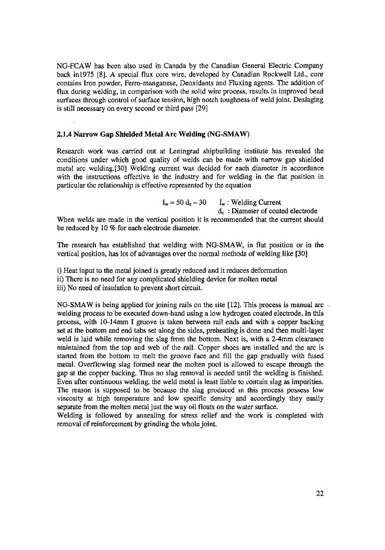
ii) However, if the gap filled vertically up the entire height of the weld edges (Fig. 2.11) metal up to 60mm thick plate can be joined with an unlimited length of weld and there is no need to remove the slag crust from narrow gap.
iii) Since the extended of the bead in the gap is small (it is equal to the thickness of the metal welded). Electrode is moved back and forth inside the gap, the slag is remain in a heated condition and is repeatedly melted.
iv) The amount of slag in the gap may steadily increase because it is free to flow out of the gap the amount of slag is virtually constant and is sufficient for effective shielding of molten pool.iv) To remove excess slag from the gap, it is recommended that work should be inclined at 10-15° from the vertical towards the welder (Figure 2.11)
AdvantagesFigure 2.11 NG-SMAW In vertical position [6]
K. Deyakumaran and his co workers had reported welding of 25 mm thick HSLA steel plate using NG-SMAW (13mm gap) and compared its mechanical and metallurgical properties with conventional V groove. Following investigation were reported
i) Tensile strength of narrow groove joint show relative higher strengthii) Impact toughness of the narrow groove weldment relatively higher than base metal and conventional V groove weldment.iii) Transverse shrinkage of narrow groove is also less compared to V groove.iv) Microstructure of narrow groove welds having finer structure than conventional V groove.
23
2.1.5 Summary and Implications
The use of narrower joint gaps and reduced preparation angles can results in significant improvement in productivity. The use of processes which involve the use of a narrow gap (EBW, Laser, Plasma, Friction) automatically exploit these advantages, whilst systems have been developed to allow narrow gap to be used with GMAW,GTAW, SMAW and SAW processes. The minimum economic thickness for narrow gap technology varies with the process and operating mode. Optimisation of welding parameters and in process control is essential to avoid defects in narrow gap application; the restricted access of the gap make progressive repair difficult, but good procedure control should obviate these problems.
The basis for comparison of various NGW processes will be
i) Joint filling rate
ii) Complexities of the equipments/process
iii) Ease of operation, ease of selection of welding parameters.
iv) Material to be welded.
v) Relative freedom from welding defects including, sidewall fusion / Consistent weld quality.
One of the major constraints governing the use of these three major narrow gap processes is deposition rate, although with narrow gap welding a more useful measure is groove filling rate (both NG-TIG and NG-MIG have advantage over NG-SAW in that they utilise a narrower groove, 9mm rather than 20mm).
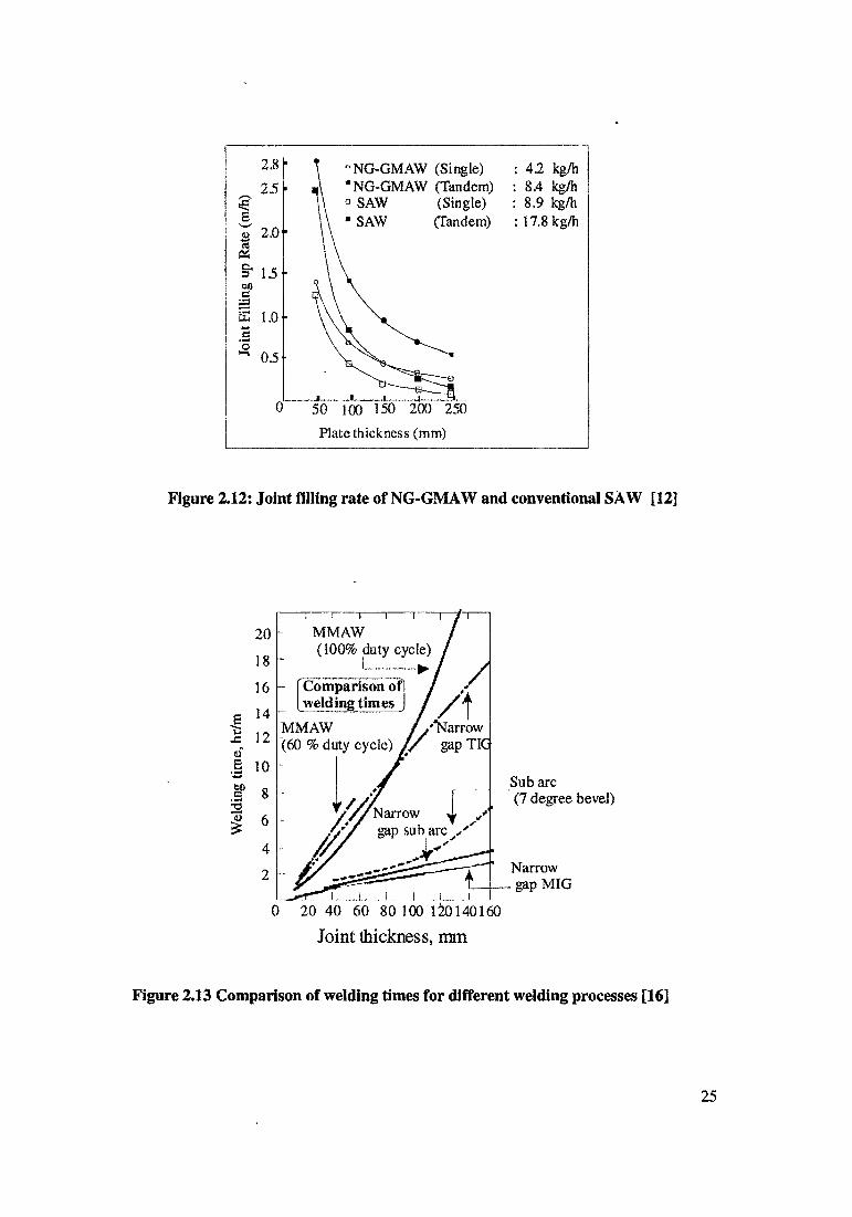
Typical groove filling rates are shown in figure 2.12. Figure compares a single and tandem electrode NG-GMAW process with two similar conventional SAW process. Which show that, in spite of much lower deposition rate, NG-GMAW fills the groove faster than high deposition conventional SAW.[12]
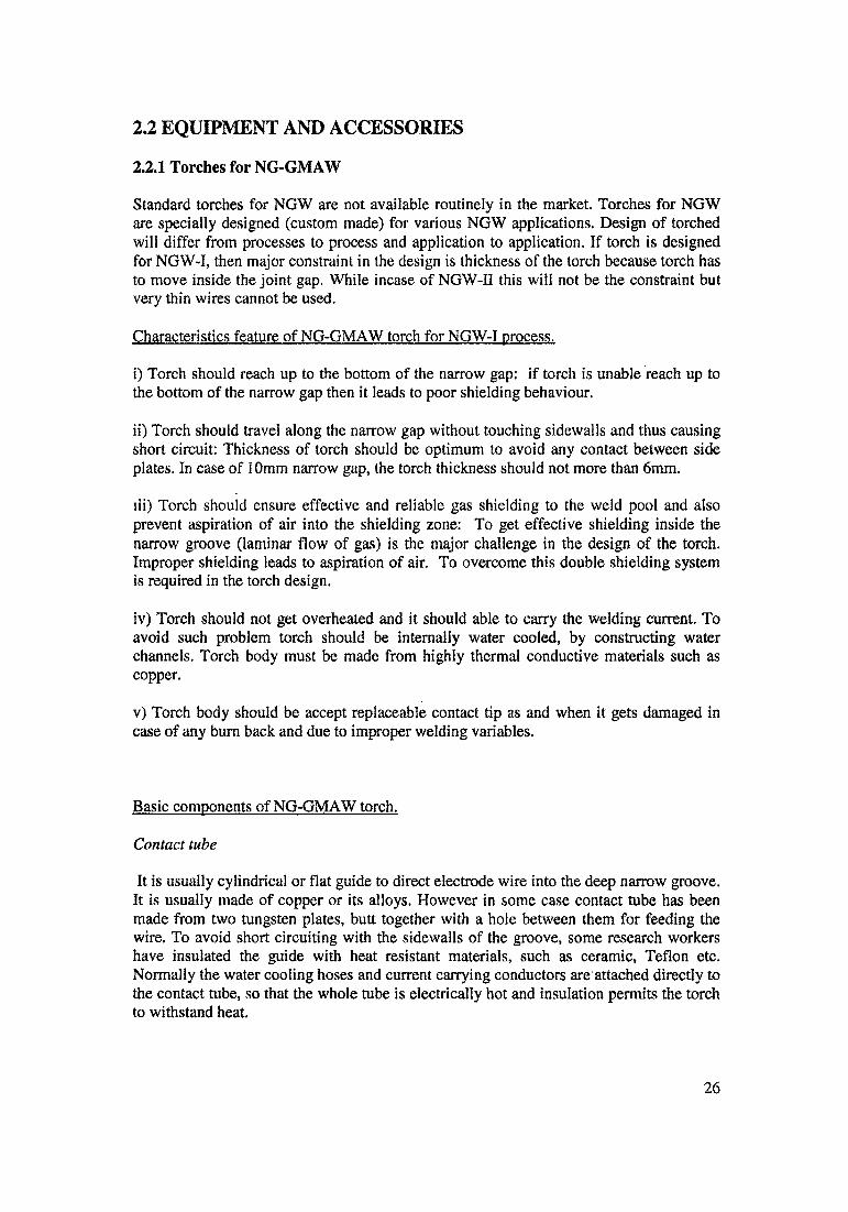
Figure 2.13 illustrate why NG TIG cannot be considered as a serious rival to NG MIG or NG SAW for large volume welds because of its relative low deposition rate. [16]
Complexity of the process is in the following order; complexity is decreases from top tobottomNG-GTAWNG-GMAWNG-SAW.
24
Joint thickness, mm
Figure 2.13 Comparison of welding times for different welding processes [16]
42 kg/h 8.4 kg/h 8.9 kg/h 17.8 kg/h
Figure 2.12: Joint filling rate of NG-GMAW and conventional SAW [12]
Wel
ding
tim
e, h
r/m
25
2.2 EQUIPMENT AND ACCESSORIES
2.2.1 Torches for NG-GMAW
Standard torches for NGW are not available routinely in the market. Torches for NGW are specially designed (custom made) for various NGW applications. Design of torched will differ from processes to process and application to application. If torch is designed for NGW-I, then major constraint in the design is thickness of the torch because torch has to move inside the joint gap. While incase of NGW-II this will not be the constraint but very thin wires cannot be used.
Characteristics feature of NG-GMAW torch for NGW-I process.
i) Torch should reach up to the bottom of the narrow gap: if torch is unable reach up to the bottom of the narrow gap then it leads to poor shielding behaviour.
ii) Torch should travel along the narrow gap without touching sidewalls and thus causing short circuit: Thickness of torch should be optimum to avoid any contact between side plates. In case of 10mm narrow gap, the torch thickness should not more than 6mm.
lii) Torch should ensure effective and reliable gas shielding to the weld pool and also prevent aspiration of air into the shielding zone: To get effective shielding inside the narrow groove (laminar flow of gas) is the major challenge in the design of the torch. Improper shielding leads to aspiration of air. To overcome this double shielding system is required in the torch design.
iv) Torch should not get overheated and it should able to carry the welding current. To avoid such problem torch should be internally water cooled, by constructing water channels. Torch body must be made from highly thermal conductive materials such as copper.
v) Torch body should be accept replaceable contact tip as and when it gets damaged in case of any bum back and due to improper welding variables.
Basic components of NG-GMAW torch.
Contact tube
It is usually cylindrical or flat guide to direct electrode wire into the deep narrow groove. It is usually made of copper or its alloys. However in some case contact tube has been made from two tungsten plates, butt together with a hole between them for feeding the wire. To avoid short circuiting with the sidewalls of the groove, some research workers have insulated the guide with heat resistant materials, such as ceramic, Teflon etc. Normally the water cooling hoses and current carrying conductors are attached directly to the contact tube, so that the whole tube is electrically hot and insulation permits the torch to withstand heat.
26
Contact tip
It is separate part of the contact tube. It is replaceable as and when it get damaged or worn out. It may be electrically insulated by ceramic. Ceramic shield may also used to preserve the water jacket of contact tube if melt back occurs. Melt back is the phenomenon wherein an arc climbs up the sidewalls and start burning between the sidewall and the hot contact tube. Contact tube may also destroy latter due to the close distance between them.
Shielding gas nozzles
Nozzles are used to supply gas into the narrow groove, to provide reliable shielding for the molten weld pool. There are two type of shielding systems a) Single shielding system b) Double shielding system.
In case of single shielding system, there is a long copper tube attached to contact tube from both sides of the latter, this is called single shielding gas system. It may not work properly in a deep groove because of intense air sucking. This leads to formation of porosity in weld bead or poor weld bead quality, to overcome this problem double shielding system is preferred.
In case of double shielding system, secondary nozzle is added to supply secondary gas stream from both sides of the contact tube. Rimary gas stream pressure can be used to improve the surface of the bead along the groove sidewalls.
Water cooling system
NG-GMAW torch which is designed for the NGW-I technique, it must have water cooling system for following reasons.
a) Water cooling is used to dissipate the heat generated near and around the torch, without it, torch become hot and it may damage conduit of the torchb) Water cooling permits the torch to carry higher welding current.
Comparison between torches designed by different research workers.
Literature is available on NG-GMAW processes, but it is very difficult to get the detail about the design and fabrication aspects of NG-GMAW torch. Most of the authors has not discussed or highlighted the detail of NG-GMAW torches. Mailn [201] has reported and discussed about NG-GMAW torches. In order to get proper design aspects of NG- GMAW torches, patent filed in the area of NG-GMAW torches all over the world have been referred.
Comparison has bee made between few patents on important aspects of torch design.
27
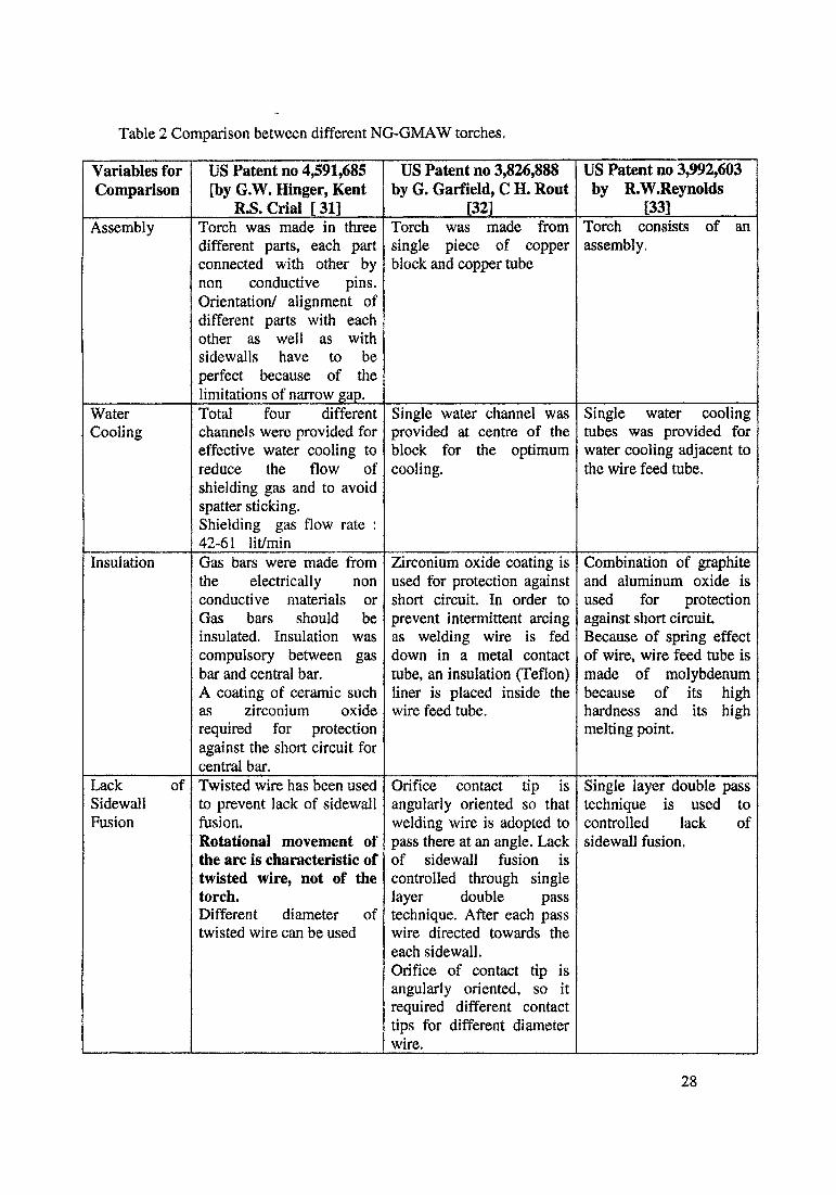
Table 2 Comparison between different NG-GMAW torches.
Variables for Comparison
US Patent no 4,591,685 [by G.W. Hinger, Kent
R.S. Crial [ 31]
US Patent no 3,826,888 by G. Garfield, C H. Rout
[32]
US Patent no 3,992,603 by R.W.Reynolds
[33]Assembly Torch was made in three
different parts, each part connected with other by non conductive pins. Orientation/ alignment of different parts with each other as well as with sidewalls have to be perfect because of the limitations of narrow gap.
Torch was made from single piece of copper block and copper tube
Torch consists of an assembly.
WaterCooling
Total four differentchannels were provided for effective water cooling to reduce the flow of shielding gas and to avoid spatter sticking.Shielding gas flow rate ; 42-61 lit/min
Single water channel was provided at centre of the block for the optimum cooling.
Single water cooling tubes was provided for water cooling adjacent to the wire feed tube.
Insulation Gas bars were made from the electrically nonconductive materials or Gas bars should be insulated. Insulation was compulsory between gas bar and central bar.A coating of ceramic such as zirconium oxiderequired for protection against the short circuit for central bar.
Zirconium oxide coating is used for protection against short circuit. In order to prevent intermittent arcing as welding wire is fed down in a metal contact tube, an insulation (Teflon) liner is placed inside the wire feed tube.
Combination of graphite and aluminum oxide is used for protection against short circuit. Because of spring effect of wire, wire feed tube is made of molybdenum because of its high hardness and its high melting point.
Lack ofSidewallFusion
Twisted wire has been used to prevent lack of sidewall fusion.Rotational movement of the arc is characteristic of twisted wire, not of the torch.Different diameter of twisted wire can be used
Orifice contact tip is angularly oriented so that welding wire is adopted to pass there at an angle. Lack of sidewall fusion is controlled through single layer double passtechnique. After each pass wire directed towards the each sidewall.Orifice of contact tip is angularly oriented, so it required different contact tips for different diameter wire.
Single layer double pass technique is used to controlled lack ofsidewall fusion.
28

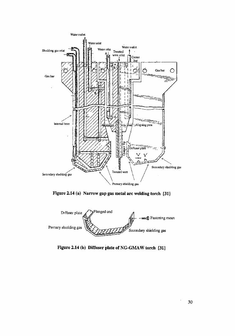
Design Two plugs provided for water circulation in one gas bar. Two gas bars required four plugs. Increased number of plugs increases complexity in design of the torch and fabrication by drilling. Figure 2.14(a) Shows design of Torch
Design was simple.
Figure2.15(a) shows design of TorchFigure 2.15(b) plan view of torchFigure 2.15(c) Torch inside the joint gap
Separate supply has given for shielding gas bar. Design wascomparatively simplethan US Patent no 4,591,685.Figure 2.16 (a) Shows design of Torch
Shielding Gas bars were equipped with a removable diffuser plate. The diffuser plate has flanged end which incorporates with a notch in the gas bars to hold the diffuser plate in position. A mean of fastening such as screw is used to attach the diffuser, as shown in figure 2.14(b)
Front and rear end of body for purpose to the mounting a front shield and inert shielding gas. Both shield have porous sintered bronze diffuser, which pass the inert gas to the weld area.
Flat tubing was provided in the assembly adjacent to wire feed tube,through which inert gas directed to the weld area so as to reducedoxidation of weld metal. Figure 2.16(b) Sectional view of torchFigure 2.16 (c) view of torch inside the joint gap.
Shielding Gas Device
Gas handling equipment, those adjacent to the welding arc, may still be susceptible to damage from the spattering of metal as well as heat and requires periodical replacement.
Gas handling equipment (porous sintered bronze diffusers) were adjacent to the welding arc. There was no mention about susceptibility of damage from the spatter, heat and about periodical replacement shielding device.
Gas handling equipments were adjacent to the welding arc. There is no mention aboutsusceptibility of damage from the spatter, heat and about periodicalreplacement shielding device.
MountingBlock
Special mounting barpreferably from anelectrically non conductive materials so that two gas bar and central barelectrically insulate fromeach other. Matching connections are required for passing supply line in mounting block.
Entire torch was made from single piece. There was no mention about the mounting block.
Mounting holes were provided to allowfastening of the torch to a weld carriage assembly for automaticallypropelling the torch along the gap between the plates to be welded.
Thickness of Torch andJoint Gap
Thickness of torch in the range of 8.95-11.25 mm. No information about gap.
No Information Torch thickness 4.7 mm and joint gap 6.35 mm
Comments Twisted wire is notavailable commercially. Thickness of torch is high. In fact the challenge and novelty of the torch design lies in reducing thethickness of the torch
Torch design is suitable for single layer double pass, as shown in figure 2.15 (d)
Complex insulationprovided to the torch body.Torch design is suitable for single layer double pass..
29
Water outlet
Shielding gas inlet
Gas bar
Internal bore
Water outlet TWistec! | '
1 Center
Secondary shielding gas
Secondary shielding gas
Primary shielding gas
Figure 2.14 (a) Narrow gap gas metal are welding torch [31]
Diffuser plate /^Flanged end
Primary shielding gas
-asEff} Fastening mean
Secondary shielding gas
Figure 2.14 (b) Diffuser plate of NG-GMAW torch [31]
30

Figure 2.15a : NG-GMAW Torch
Figure 2.15c : NG-GMAW torch inside the joint gap.
Water WaterGas tube outlet miet Wire feed tube.
Figure 215d: Sectional view of NG-GMAW joint. (Herringbone pattern)
Figure 2.15 Narrow gap gas metal arc welding torch (a,b,c,d) [32]
31
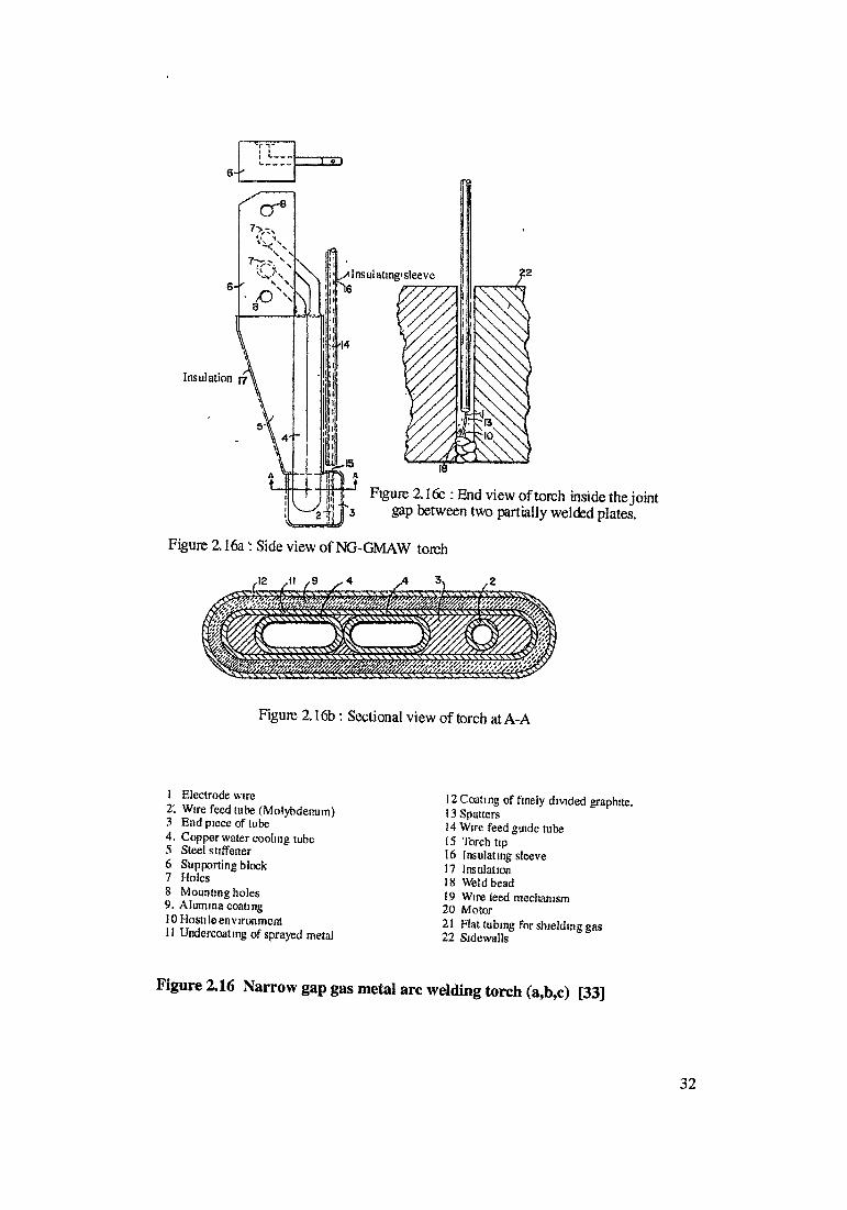
I Electrode wire2'. Wire feed tube (Molybdenum) 3 End piece of tube 4. Copper water cooling tube5 Steel stiffener6 Supporting block7 Holes8 Mounting holes 9. Alumina coating10 Hosti le en v iron mentII Undercoating of sprayed metal
12 Coating of finely divided graphite.13 Spatters14 Wire feed guide tube15 Torch tip16 Insulating sleeve17 Insulation18 Weld bead19 Wire feed mechanism20 Motor21 Flat tubing for shielding gas22 Sidewalls
Figure 2.16 Narrow gap gas metal arc welding torch (a,b,c) [33]
32
2.2.2 Electrode Wire - Feeding Systems for NG-GMAW
Most of wire feeders are now designed for use with constant voltage power sources. The welding current is adjusted by increasing or decreasing electrode speed for a given setting of the power source. With constant current power sources, a voltage-sensing circuit is used to maintain the desired are length by varying the electrode speed.
The wire feed motor is usually a dc type, and it provides the power for driving the electrode wire through the gun to the work. The wire feed is held constant for the majority of GMAW applications. Therefore, most feed motors are shunt wound or permanent magnet types. Occasionally, a variable speed motor will be necessary if a constant current type of power source is used. This type of motor can be series wound or one of the above types. Its speed will vary as the control unit increases or decrease the wire feed speed to maintain constant arc length (voltage).
Welding control unit may be a separate package for remote operation or it may be integrated with the wire feed drive unit is to regulate the speed of wire feed motor. Motor speed regulation is usually accomplished with an electronic governor in the control unit. Electrode feed speed is manually set by the operator to obtain the desired welding current from a constant voltage power source. If a constant current power source is used, the control unit varies the electrode feed rate so that a preset arc voltage is maintained.
Several arc starting system may also be included in the control circuitry. One type is a slow speed start in which the electrode advances slowly towards the work until the arc starts. Then the electrode speeds up. Another type is retract start in which the electrode is touched to the work and then retracted to draw an arc. With constant voltage power source, the arc can be started by just feeding the electrode to the work.
NGW process requires more sophisticated methods to supply electrode wire because'of the limited access inside the deep narrow groove. For this reason, the wire feeding systems for NGW consumables are specially designed to meet specific requirements of various NGW techniques. Various level of sophistication required depending on the NGW technique used.
In case of NGW-1: is characterized by feeding of a small diameter electrode (0.8mm to 1.2mm). Electrode wire generally wound on convenient size spools or coils. Because of less wire diameter, will be less rigid and it has tendency to bend toward the one sidewall. The uniformity of winding and freedom from kinks or bends are important considerations for proper feeding of the electrode in deep narrow groove. Important characteristics for winding operation are the cast and helix of the electrode.
Cast refers to the diameter of one loop of wire, when enough wire is cut from the spool to form a loop and it laid unrestrained on a flat surface. The larger the cast, the more uniform the wire feeding and reduction in frictional force as the wire exits the contact tube. Small cast can cause the tip of the electrode to wonder.
Helix is measure of the amount of rise of the end of the wire above the flat surface. A large helix can cause the tip of the electrode to spiral or flip suddenly as it exits the contact tip.
33
Either of these conditions lead to erratic weld bead contour and inconsistent penetration, especially in groove welds and weld made with automatic equipment [34]. Cast and helix constantly changes as electrode gets consumed from the spool.
In most cases, these techniques require serious modifications of standard wire feeders, which may include a wire straightener, a cast control device, a push-pull type feeder, a wire-bending device, torch rotating and oscillating devices. [6]
NGW-II group of techniques is characterized by feeding of a relatively large diameter straight electrode. For these techniques, standard heavy-duty wire feeders for conventional GMAW can be used. One modification is needed, the addition of a wire straightening device.
Number of innovations are described in the literature to ensure proper fusion between the groove face and weld metal. These innovations are Tandem electrode, Oscillation electrode, Weaving electrode, Waved electrode, Twisted electrode. [5,8]
Tandem electrode
The feed wire, prior to its entry into the contact tube because of spring action of the curve portion under strain, the arc is directed towards one groove face only, results in lack of fusion for other sidewall. In order to overcome this, as shown in figure 2.17(a), two wire with controlled cast and two contact tip can be used in tandem. The arcs are directed towards each sidewalls, producing series of overlapping fillet welds. Weld bead configuration is single layer double pass. For tandem type of welding equipment, a pair of bending rollers is used to produce the wavy electrode shape. These bending rollers installed just before the feed rollers, move from side to side across the feed path of the electrode. This type of mechanism is more compact and this more convenient for installation.
Oscillating electrode
Effect which was achieved in tandem electrode, same can be achieved with one wire by means of weaving techniques, which involves oscillating the arc across the groove in the course of welding. This oscillation can be created mechanically by moving the contact tip across the groove, as shown in figure 2.17(b). Weld bead configuration is single layer single pass. T.ito used four bar link mechanism, which controlled oscillation speed; stopping position and dwell time at both ends are individually adjustable even during welding operations. Deviation of groove width plus or minus 2 will be allowable without change of the oscillation amplitude [35]
Weaving electrode
In this system, contact tip is bent to an angle of about 15 degree as shown in figure 2.17 (c). Along with a forward motion during welding, the contact tip makes an oscillation rotation to the right and left, which gives the arc a weaving motion.
34
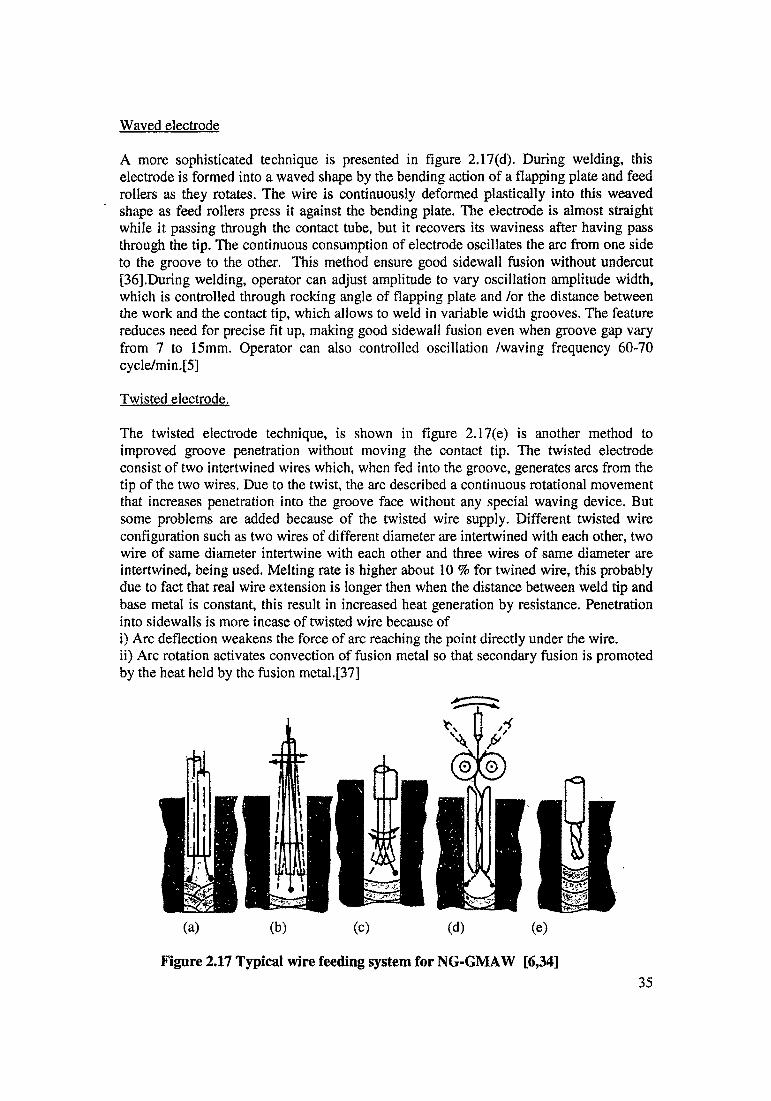
Waved electrode
A more sophisticated technique is presented in figure 2.17(d). During welding, this electrode is formed into a waved shape by the bending action of a flapping plate and feed rollers as they rotates. The wire is continuously deformed plastically into this weaved shape as feed rollers press it against the bending plate. The electrode is almost straight while it passing through the contact tube, but it recovers its waviness after having pass through the tip. The continuous consumption of electrode oscillates the arc from one side to the groove to the other. This method ensure good sidewall fusion without undercut [36].During welding, operator can adjust amplitude to vary oscillation amplitude width, which is controlled through rocking angle of flapping plate and /or the distance between the work and the contact tip, which allows to weld in variable width grooves. The feature reduces need for precise fit up, making good sidewall fusion even when groove gap vary from 7 to 15mm. Operator can also controlled oscillation /waving frequency 60-70 cycle/min.[5]
Twisted electrode.
The twisted electrode technique, is shown in figure 2.17(e) is another method to improved groove penetration without moving the contact tip. The twisted electrode consist of two intertwined wires which, when fed into the groove, generates arcs from the tip of the two wires. Due to the twist, the arc described a continuous rotational movement that increases penetration into the groove face without any special waving device. But some problems are added because of the twisted wire supply. Different twisted wire configuration such as two wires of different diameter are intertwined with each other, two wire of same diameter intertwine with each other and three wires of same diameter are intertwined, being used. Melting rate is higher about 10 % for twined wire, this probably due to fact that real wire extension is longer then when the distance between weld tip and base metal is constant, this result in increased heat generation by resistance. Penetration into sidewalls is more incase of twisted wire because ofi) Arc deflection weakens the force of arc reaching the point directly under the wire.ii) Arc rotation activates convection of fusion metal so that secondary fusion is promoted by the heat held by the fusion metal.[37]
Figure 2.17 Typical wire feeding system for NG-GMAW [6,34]35
2.2.3 Gas Feeding Techniques
Another important task for NG-GMAW is to supply gas into the very narrow deep groove to provide a reliable shield for the molten weld pool without sucking air into it. The principal purpose is to provide primary gas for functioning of the arc and protection of the molten weld metal. Long flat electrically insulated gas nozzles are attached to the contact tube from both sides and inserted into the grooves.
However this single shielded type of gas shielding system does not work properly in a deep groove because gas discharged from the torch at a higher velocity sucks in the surrounding atmosphere; including air by the aspiration effect of the jet.
Thus double -shielded systems are usually used in which addition to the nozzle described above, another nozzle large enough to cover the area adjacent to the welding is included. This nozzle also feeds the gas, but is placed above the work places at a definite distance from their surfaces and is held constant during the welding.
To carry out multipass NGW successfully and to avoid weld defects incomplete fusion (lack of fusion) which occurred at the junction of the side walls and the proceeding bead; it is very important to pay attention to the bead surface. For this there is a way of improving the surface shape of the molten metal along the groove sidewalls by using the stream pressure of the primary shielding gas.
Gas directed towards the rear of the molten pool contributes to the formation of a remarkably concave bead shape. However molten metal pushed ahead, along the welding direction, tends to cause incomplete fusion into the sidewalls. Consequently, another gas stream that is directed towards the front of the molten pool pushing back molten metal is required at the same time. NG-GMAW torch designed by S.Sawada and his co workers at Babcock Hitachi K.K had used such gas feeding system [5], as shown in fig 2.42
It has been reported that balancing the stream gas pressure resulted in a good stable bead shape with an ideal contact angle between the weld and groove sidewalls.
It has been reported in one of study on narrow gap MIG welding by S. Minehisa that the flat type of nozzles/torch when used in narrow grooves except near the plate surface proved good performance. Near the plate surface, air contamination will increase and another type of shielding nozzle shall be applied at the plate surface. [38]
When welding very thick plate, the standard system of gas shielding was found unsatisfactory under such condition, it is usual to mount a gas box over the joint. Gas box is flexible skirt, to which seal the top edges and to direct side jets into the joint to prevent aspiration of air. into the gas shield. Researcher have used either side flow technique to weld thick sections, which will replace at top of joint with gas box or combination of side flow jet as well as gas box to shield welding area.[4]
36

•Shielding gas
Cooling wateri
Figure 2.18 Schema of shielding box [39]
Gas flow
Superior shielding can be obtained with laminar flow of the gas stream. Laminar flow is defined as the particles of a fluid flow in a straight line, it should be parallel to the axis of a pipe and without any radial components on the fluid flow can called streamlined, straight line [40], When the fluid components which can produce vortexes or swirling movements, it is called turbulent flow. Coherent stream should maintain once it leave nozzle. Gas enters the nozzles in a generally turbulent conditioned. As the gas passes through the conduit, the combined effect of the conduit wall and gas viscosity eventually creates a laminar boundary next to the wall. Once lamina leave the torch nozzle, this lamina is no longer supported by its parent walls and start to degrade. There will be shear stress developed between the moving gas stream and the atmosphere to produce swirling motion down. These swirl is called vortex sheets, grow in size to erode the gas lamina until it reach and expose the turbulent inner core of gas. At this point, there will be rapid mixing of the entire gas stream with air begins.
In conventional torches with relatively short nozzles, the protective sheath is so thin that it barely gets outside the nozzle before it is destroyed. Thus area of completed air exclusion is greatly depend upon nozzles elevation and nozzles diameter. Devices which are use to get coherent streaming are mesh screens, porous materials and fibrous packing.
T.Innui, H. Nakajima had designed special shielding gas box to ensure and to make high quality joint even when' an extremely heavy plate was used. [39] Special shielding gas box was made of copper, and it has four holes for the shielding gas. Two holes at the ends were provided with protective tubes, and used to prevent incoming air through the groove. The holes at the centre were used to hold the shielding atmosphere in the box. Figure 2.18 shows schema of shielding gas box.
-'-A
'rn-r
rp
37
Fine mesh screen
The principal function of device that introduces gas into the nozzles is to reduce the level of irregularities in the gas flow [41]. The degree of control impose on the gas is related to finesses and close spacing of the pores rather than thickness of the barrier. In general, the smaller the pore size the greater is the control over the gas going through it. For example a 60 mesh screen exerts less control over the gas pass through it, whereas 200 mesh screen having high degree of control. Screen with large openings can be used if they are stacked in multiple layers, preferable spaced at least a short distance apart. For example three layer of 60 mesh screen spaced 1/16 inch apart give result essentially equivalent to that obtained from a single layer of 200 mesh screen.
Ardentov V.V has also suggested that best properties in respect of gas shielded torches are exhibited by smallest mesh size as well as two or three meshes put together provided distance between the mesh is not less than 15 diameter of mesh wire. [41]
Porous material and fibrous packing
A comparison between the performance of fine mesh screen, fibrous packing and porous material has been studied by E.F.Gorman.[42].Fine mesh screen give uniform distribution of gas velocity because of the uniformity of size and spacing of the pores. The fibrous packing and porous compact frequently produced irregular distribution unless particular care was taken during their construction to ensure uniform gas permeability. These porous walls act on the gas to focus its into a beam much as a glass lens acts in shaping a beam of light.
38
2.2.4 Power Source
The GMAW process uses power sources similar to those used with other continuous electrode feed welding processes, such as flux cored and submerged arc welding. The process requires a source of direct current, which may be supplied by a transformer- rectifier or a motor-generator power source. The power source rating depends on the amperage range required for the applications. Some applications may require anywhere from 15 to 1200 A. Power source ratings are based on either a 60 percent or 100 percent- duty cycle. [43]
Power source characteristics
Constant voltage power supply
The arc voltage is established by setting the output voltage on the power supply. The power source will supply the necessary amperage to melt the welding electrode at the rate required to maintain the preset voltage (or relative arc length). The speed of the electrode drive is used to control the average welding current. This characteristic is generally preferred for the welding of ail metals. The use of this type of power supply in conjunction with constant wire electrode feed results in a self-correcting arc length system. [44]
Constant current power supply
With this type, the welding current is established by the appropriate setting on the power supply. Arc length (voltage) is controlled by the automatic adjustment of the electrode feed rate. This type of welding is best suited to large diameter electrodes and machine or automatic welding, where very rapid change of electrode feed rate is not required. Most constant current power sources have a drooping volt - ampere output characteristic. However, true constant current machines are available.Constant current power sources are not normally selected for GMAW because of the greater control needed for electrode feed speed. The systems are not self - regulating. [44]
Pulsed direct current power supply
This type of power source, pulses the dc output from a low background value to a high peak value, because the average power is lower, pulsed welding current can be used to weld thinner sections than those that are practical with steady dc spray transfer.
NG-GMAW power sources require direct current (dc) to provide energy for melting electrode wire and the base metal. Alternating current (ac) did not find any application for this NGW technique. Typical power source for NG-GMAW is a standard “constant” voltage transformer-rectifier generating steady or pulsed current. However, a “flat” volt- ampere (V-A) characteristic of a conventional power source is not adequate for some of the NG-GMAW techniques. Pulsed current is preferred in NG-GMAW since it allows an arc to operate in a spray transfer mode at a relatively low voltage. This is important for avoiding meltback in the deep narrow groove when the arc tends to climb up the sidewall. Reverse polarity (electrode positive) is preferred to straight polarity (electrode negative) since the latter is characterized by unstable erratic large globule metal transfer. [6]
39
2.2.5 Classification of Automation System
History of Modem welding is not very old. Traditional welding has been operator dependent. For quality welds, welder has to be approved as per certain codes. Stringent inspection procedures ensure sound weld. On the other hand, welder’s job is unsafe. He is exposed to welding fumes and arc glare and is liable to electric shocks. Nature of work is physically very demanding and many a time monotonous.
Welding has evolved gradually from traditional to modern. On one hand there was a need to provide welds which are not open to human error. On the other hand there was a need to protect welder from human drudgery and provide him with safe working conditions. Through mechanization and automation, the face of welding has changed. Not only safety and work environment is improved but quality of weld and productivity has also improved.
In traditional welding electrode/torch carrying arc need to move along the welding line. Mechanization permits welding head or job to move with the help of machines. Even very dangerous locations can be managed in relative safety. All movements has to be precise. Mechanization does not stop here and can be automated.
Now most to the work can be carried out with intelligent machine where all decision can be taken for a specific job. In case of repetitive jobs, monotony of the work can be eliminated. This automation has been possible through the use of system based on various electronic, microprocessor and programmable controls. Significant part of welding abroad is done by mechanized and automated system. The system could be used for other applications also.
In case of NGW-I, torch has to move inside the narrow groove, in order to avoid short circuiting between welding torch and side plates, automation is required. Slight misalignment between job and torch leads to short circuiting. Improper welding condition leads to generation of spatters, spatters will stick with side plates as well as at welding torch. This may decrease the accessibility of torch inside the narrow groove and short circuiting may occur.There are two types of system, Automatic system and Mechanical system [6j.
Mechanical system:
A system which is capable of performing physical functions of an operator is mechanization system. Physical function includes consumable handling and torch travel.
When in addition to the physical function one or both intelligent function are transferred to machine, the ‘man-machine’ system and the group of operations served by this system may be called an automatic welding system [45]. The process or the replacement of the operations associated with welder’s intelligent effort by that based on the intelligent action of a machine is called welding automation.
40
Automatic system
A system which is capable of performing intelligent (Programming and control) function of an operator is called automatic system.
Programming function includes; welding parameter programming, torch motion parameter programming.
Control function includes; Stabilization and adaptive control operations.
Welding parameter programming includes: welding variables setting like current, voltage, welding speed and gas flow rate.
Torch motion parameter programming includes: Torch position along, across and above the joint and torch orientation relative to the joint.
Stabilization and adaptive control should monitor variation in joint geometry, welding setting, position of the welding head are controlled by comparing the measured values with those instructed by the programme and to correct unacceptable deviation from the instructed values [45].
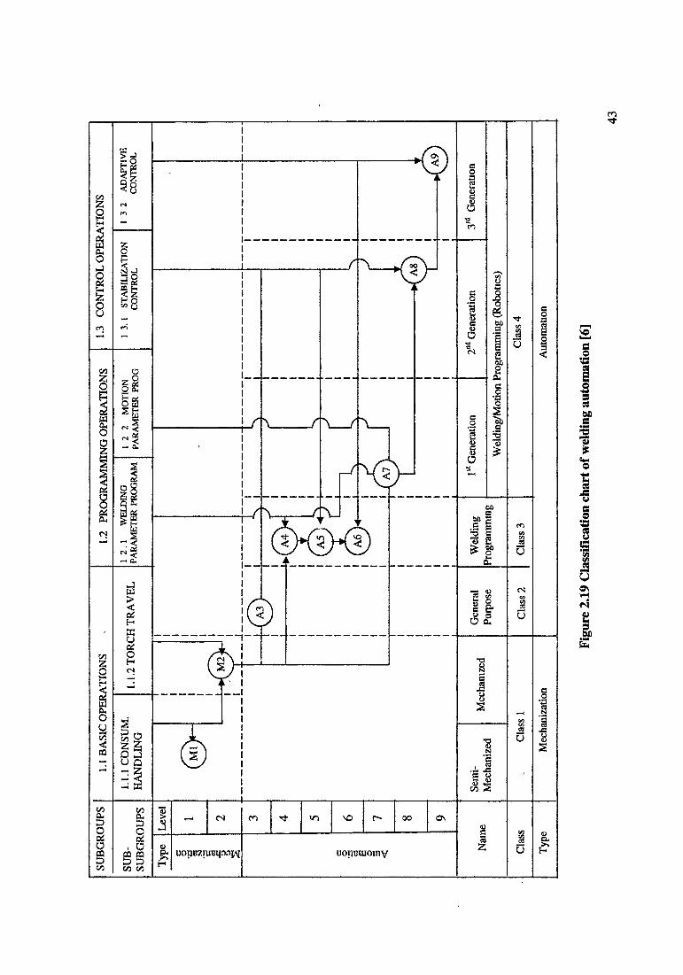
The welding automation is classified in the four different classes. Class 1, 2, 3 & 4 by level of sophistication and performance capabilities of system.
Class 1: Welding mechanization
Level 1 (Ml): A welding system which is capable to perform welding consumable handling, fall into the first level of mechanization. It is called semi mechanisation welding system. Such system is used for their productivity in comparison with manual welding.
Level 2 (M2): A welding system which is capable to perform all basic welding operations of subgroup 1.1, includes consumable handling and torch travel. Level 2 mechanized are widely used in industry for NG-GMAW. They are capable of performing all basic operations.
Class 2: General purpose welding automation
Level 3 (A3): An M2 system turn into an automatic welding system when it is capable to perform stabilization control operation ( sub subgroup 1.3.1). An A3 system equipped with a device which stabilizing torch lateral movement (joint tracking device) is the most popular type of welding automation used in general.
Level 3 systems are used less often than level 2 because additional stabilization control makes system uneconomical.
Class 3: Welding,programming automation
Welding automation is attained when M2 system is capable to perform welding parameter programming operation (sub subgroup 1.2.1). System will store and execute a
41
welding parameter, sequence and time of operations. Class 3 automation cannot be used for general purpose application; it may more effective for special purpose applications.
Level 4 (A4) : An M2 system is able to perform the welding parameter programming (sub subgroup 1.2.1) operation, fall into the forth level of welding automation.
Level 5 (A5): When A4 automation, is capable of performing stabilization control operation (sub subgroup 1.3.1), especially torch lateral and height stabilization control.
Level 6 (A6); When A5 automation is capable of performing adaptive control operations (sub subgroup 1.3.2)
Level 6 automatic systems are the most sophisticated in class 3. Such system is capable to perform a programming welding parameter, stabilization and adaptive control of operations.
Class 4: Welding/Motion programming automation (Robotics)
A robot is a reprogrammable, multi functional manipulator designed to move materials, parts, tools or specilialized device through variable programmed motion for the performance of a variety of tasks.
t
Level 7 (A7): When the automatic system has the capability to perform both welding and torch travel parameter programming operations. Some time it is also called robotic of system of first generation.
Level 8 (A8): When this A7 robotic automation is able to perform stabilization control operations (sub-subgroup 1.3.1) is sometimes called robotic of second generation Stabilization control includes - torch guiding system based on “through the arc’, visual imaging, magnetic and other method of sensing to offset deviation in fit up condition.
Level (A9): A9 welding robotics automation which is able to perform the adaptive control operations (sub-subgroup 1.3.2). This type of automation is the automation of the future or robotics of the third generation, because it will have the capability to change its own program, in order to optimize both the welding and torch motion parameters according to fluctuations in operation conditions. Figure 2.19 shows the classification chart of welding automation.
42
o£H
uopBZiireqoaj^i uopmuojnv
M A
9
A-#►
{ A8
r\ r > f
J
<£>
l^0j
j
Leve
l
43
Aut
omat
ion
Mec
hani
zatio
nTy
pe
Cla
ss 4
Cla
ss 3
Cla
ss 2
Clas
s 1C
lass
Wel
ding
/Mot
ion
Prog
ram
min
g (R
obot
ics)
3 Gener
atio
n2a
i Gen
erat
ion
1 Gene
ratio
nW
eldi
ngiP
rogr
amm
ing
Gen
eral
Purp
ose
Mec
hani
zed
Sem
i-M
echa
nize
dN
ame
3 2 ADA
PTIV
E C
ON
TRO
L1 3
.1 STA
BIL
IZA
TIO
N
CO
NTR
OL
l 2 2 MO
TIO
N
PAR
AM
ETER
PRO
G12
.1 WELD
ING
PA
RA
MET
ER PR
OG
RA
M1.
1.2
TOR
CH
TR
AV
EL1.
1.1 C
ON
SUM
. H
AN
DLI
NG
SUB
SU
BG
RO
UPS
1.3 CO
NTR
OL
OPE
RA
TIO
NS
1.2 PR
OG
RA
MM
ING
OPE
RA
TIO
NS
1.1 B
ASI
C O
PER
ATI
ON
SSU
BG
RO
UPS
Figu
re 2
.19
Cla
ssifi
catio
n ch
art o
f wel
ding
aut
omat
ion
[6]
Seam trackers for narrow gap welding
The application of mechanised welding system is on the increase in developing countries in spite of cheap labour force for reasons for better quality of welds for critical components and for improved productivity. The problem in mechanised arc welding is the proper alignment of weld seam. These problems are very significant for heavy fabrication industries engaged in the manufacture of welded pressure vessels, pipes and large structural members like beams and girders. Hence there is need for automatic weld seam trackers.When a weld seam is not properly aligned, the major result is the misplaced weld bead itself. The weld bead, if it is not laid in the proper location will lead to various defects like lack of sidewall fusion/penetration, Under cuts, Burn through and Bad geometry of bead. These defects have to be repaired immediately otherwise the entire job may be rejected for lack of quality during inspection. Although good selection of process parameters and procedure play a vital role in deciding the quality of a weld joint. Seam tracking systems are very relevant in NG-GMAW.
Any type of seam tracking should have a means of measuring the torch position relative to the weld seam and the mean for correcting the position of the torch. Basically two subsystems are required as give below.Position sensing system (Relative position)Position correction system (Motorised slides)
Depending on the type of application and weld joint the seam tracker may have thefollowing correction possibilitiesSingle axis-vertical correction-heightTwo linear axes- Vertical and lateral correctionThree dimensional including torch orientation
Single axis correction type can be generally employed for very long plate butt or fillet welds such as ship deck plate construction. However, the single axis type seam tracker for one axis only is not generally used since mostly long joints should have correction for both vertical and lateral axes. Therefore the two axes type seam tracker is commonly and commercially available. Three dimension correction type seam trackers are required for critical jobs like full throat welding of nozzles to pressure vessels, [46]
Product research and development laboratories of Nippon Steel Corporation, Japan developed seam tracking system for narrow gap welding [47]. Welding was conducted with an oscillation arc using a 5mm thick nozzle located at mid groove. The thickness of each layer was about 4mm. Therefore, 100mm thick plates are welded in about 25 layers. Author had suggested critical points in selection of seam tracking system for the narrow groove welding are given below
i) As fine wire (1.0 -1.2mm) is used to secure perfect penetration at comers, high accuracy of the seam tracking is required.ii) Since an erroneous operation in the seam tracking system not only causes welding defects but also leads to arcing from the nozzle or the mechanical damage, the highly reliable tracking is required to obtained sound welds.
44
iii) In the multi layer welding, the travel length become long and the groove wall or the upper comer of the groove become irregular under the influence of the preceding bead and the spattering,iv) In the multi layer welding, the welding nozzle reciprocates along the same track.
Sensors for narrow gap welding
Sensors play an important role in automated system. In considering the use of the narrow gap technique, greater attention should be paid to machining, so as to achieve closer fit- up. In addition, there is greater need for sensors to track the electrode along the centre of the joint, as slight deviations from the centerline can result in lack of fusion defects, because the arc and weld pool arc attracted to the sidewall. Sensors that able to relate the position of the weld bead to the sidewall position are preferred because using the positional information; the welding torch may be ‘weaved’ within the narrow gap. This motion will insure full sidewall penetration.
Two types of sensors have been used with narrow gap TIG and MIG processes; these have utilized arc-based and vision-based techniques. The former has attracted more interest to date, because of low cost and simplicity of the approach. In arc base sensors, the information provided is based on inference from measurement of arc based characteristics. Thus, any factors (natural arc noise, arc blow, gas composition and flow rate) which affect the stability of the arc also affect the measurements made by the sensor. [48]
45
2.3 Edge Preparation and Backing Techniques for NGW
For NG-GMAW, normally gap between parts to be welded is kept 10-12 mm. For the purpose of keeping the gap within this range, there are two ways
a) Provide initial bevel angel of 0.6 to 1.5 degree [5]b) Presetting of the job, this is required to compensate distortion during welding.
Some of the common backing techniques used for NG-GMAW.
2.3.1 Backing techniques
Figure 2.20 a: Backing is tack welded with the part being welded. Width of strip will be higher than groove gap and length will also higher than job length allowing run on and run off.
Figure 2.20 b: In some cases rigid ceramic strip may also used as a backing strip. It is faster as there is no necessity for tack welding.
Figure 2.20 c: For circular geometry, flexible heat resistant tape will be more suitable. Strip is in the form of sticker, it will stick with the job.
Figure 2.20d: Incase of copper insert, welding of root is carried out using non consumable electrode. When the arc will throw over copper insert the weld metal gets contaminated with copper. To avoid this, great care has to be taken to ensure that the arc moved along the weld edges [49].
Figure 2.20 e: There is no requirement of any backing materials; edges of jobs are prepared in such a way that these edge it self acts as a backing strip.
Figure 2.20 f: Depending on the length of seam, beads will be deposited on the edge of face by manual or automatic welding.
2.3.2 Typical edge preparations used for pressure vessels fabrication shown in Figure 2.21 \6]
Figure 2.21 a: In this case, the sidewalls are prepared by oxygen cutting and subsequent grinding. This type of groove is used with a backing bar for longitudinal joints.
Figure 2.21 b ; This type of edge preparation will be suitable for both sides welding. The edges can be prepared by machining. In case of circumferential joints for cylindrical shells. The bottom part of the groove is a double -U type. Non symmetric groove are employed in order to eliminate back chipping. Back chipping could otherwise occur before performing back welds from the opposite sides by conventional GMAW and SAW, for complete joint penetration.
Figure 2.21 c: This type of preparation will used for circumferential welding of pipes, when diameter of the pipe does not exceed lm. The root pass for this groove is usually accomplished by GTAW. Root face of type c groove is less than that of type b.
46

2.3.3 Typical edge preparations used for building construction in shown in Figure 2.21(d,e,f) 161
The techniques utilized a cover welding rod, solid backing flux and steel or copper backing case.
The coated rod, laid in the butt groove of the parent metal is melted by the welding arc of for a weld metal of good properties and welding slag.
Backing flux or solid backing material, serves to produce excellent reverse sides bead [51]. These types of edge preparation are widely used for column-bead joint and column- column joints.
All dimensions in mm
Figure 2.20 NGW backing technique (a,b,c,d,e,f,) [6]
47
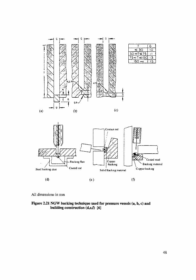
T GOK)VI to
30«=T5=7S 1175<=Tsl50 13
150 «= 15
(d) (e) (0
All dimensions in mm
Figure 2.21 NGW backing technique used for pressure vessels (a, b, c) and building construction (d,e,f) [6]
48
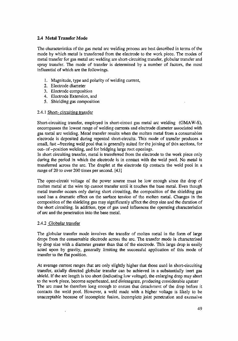
2.4 Metal Transfer Mode
The characteristics of the gas metal arc welding process are best described in terms of the mode by which metal is transferred from the electrode to the work piece. The modes of metal transfer for gas metal arc welding are short-circuiting transfer, globular transfer and spray transfer. The mode of transfer is determined by a number of factors, the most influential of which are the followings.
1. Magnitude, type and polarity of welding current,2. Electrode diameter3. Electrode composition4. Electrode Extension, and5. Shielding gas composition
2.4.1 Short- circuiting transfer
Short-circuiting transfer, employed in short-circuit gas metal arc welding (GMAW-S), encompasses the lowest range of welding currents and electrode diameter associated with gas metal arc welding. Metal transfer results when the molten metal from a consumables electrode is deposited during repeated short-circuits. This mode of transfer produces a small, fast -freezing weld pool that is generally suited for the joining of thin sections, for out- of-position welding, and for bridging large root openings.In short circuiting transfer, metal is transferred from the electrode to the work piece only during the period in which the electrode is in contact with the weld pool. No metal is transferred across the arc. The droplet at the electrode tip contacts the weld pool in a range of 20 to over 200 times per second. [43]
The open-circuit voltage of the power source must be low enough since the drop of molten metal at the wire tip cannot transfer until it touches the base metal. Even though metal transfer occurs only during short circuiting, the composition of the shielding gas used has a dramatic effect on the surface tension of the molten metal. Changes in the composition of the shielding gas may significantly affect the drop size and the duration of the short circuiting. In addition, type of gas used influences the operating characteristics of arc and the penetration into the base metal.
2.4.2 Globular transfer
The globular transfer mode involves the transfer of molten metal in the form of large drops from the consumable electrode across the arc. The transfer mode is characterised by drop size with a diameter greater than that of the electrode. This large drop is easily acted upon by gravity, generally limiting the successful application of this mode of transfer to the flat position.
At average current ranges that are only slightly higher that those used in short-circuiting transfer, axially directed globular transfer can be achieved in a substantially inert gas shield. If the arc length is too short (indicating low voltage), the enlarging drop may short to the work piece, become superheated, and disintegrate, producing considerable spatter The arc must be therefore long enough to ensure that detachment of the drop before it contacts the weld pool. However, a weld made with a higher voltage is likely to be unacceptable because of incomplete fusion, incomplete joint penetration and excessive
49

weld reinforcement. This characteristic greatly limits the use of the globular transfer mode in production application.
Carbon dioxide shielding results in nonaxiallly directed globular transfer when the welding current and voltage are significantly above the range required for short-circuiting transfer. The departure from axial transfer is governed by electromagnetic forces that are generated by the welding current acting upon the molten tip.
The most important of these are(i) The electromagnetic pinch force (P), that results in the momentary necking of the drop from that electrode because of the electromagnetic effects of the current, and(ii) The anode reaction force (R).
The magnitude of the pinch force, which is a direct function of welding current and wire diameter (i.e., current density), is usually responsible for drop detachment. With carbon dioxide shielding, the welding current is conducted through the molten drop, and the arc plasma does not envelop the electrode tip. High speed photography has revealed that the arc moves over the surface of the molten drop and the work piece because the anode reaction force, R, tends to support the drop.
2.4.3 Sprav transfer
The spray transfer mode occurs when the molten metal from a consumable electrode is propelled axially across the arc in the form of minute droplets. With argon rich (at lest 80 %) gas shielding, it is possible to produce a very stable, spatter free axial spray transfer mode.
Spray type transfer has a typical fine arc column and pointed wire tip associated with it. Molten filler metal transfer across the arc as fine droplets. The droplet diameter is equal to or less than the electrode diameter. The metal spray is axially directed. The reduction in droplet size is also accompanied by an increase in the rate of droplet detachment. Metal transfer rate may range from less than 100 to several hundred droplets per seconds as the electrode feed rate is increases from approximately 42 to 340 mm/s.The mechanisms of axial spray transfer appear to be chiefly influence by both the electromagnetic forces on the molten electrode tip and the arc plasma. The action of the latter is at the electrode tip.
V.N.Buchinskll had showed that in pulsing with 60 % Ar and 40 %CC>2 the forces opposing the breaking away of a droplet are considerable. With this mixture, the behaviour of a droplet at an electrode tip is similar to the equivalent behaviour during welding in pure CO2 [52]
Table 3 Current ranges for wire diameters for different metal transfer mode [43]
Wire diameter (mm/ in ) 0.8 / 0.032 0.9 / 0.036 1.2/0.048 1.6/0.064
Current for dip transfer Min / Max
40/ 170 50/190 60/200 100/210
Current for sprayMin / Max
- / 225 - / 260 125/400 220/450
50
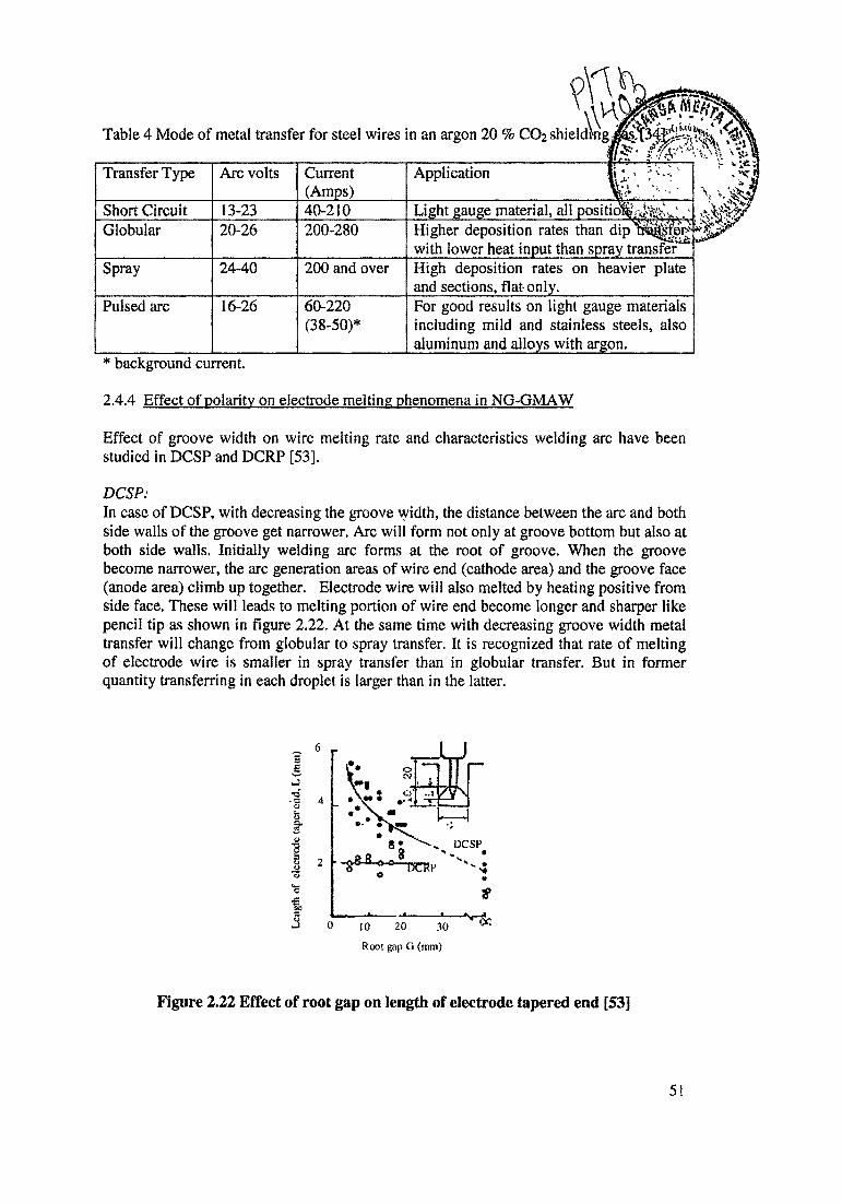
Root gap O (mm)
Figure 2.22 Effect of root gap on length of electrode tapered end [53]
Table 4 Mode of metal transfer for steel wires in an argon 20 % C02 shieldmg«^f34ft^fe^'jJTjte'* ^//I- v.V
Transfer Type Arc volts Current(Amps)
Application It *, • "--v r *
Short Circuit 13-23 40-210 Light gauge material, all positio^VJ%^^'Globular 20-26 200-280 Higher deposition rates than dip
with lower heat input than spray transferSpray 24-40 200 and over High deposition rates on heavier plate
and sections, flat only.Pulsed arc 16-26 60-220
(38-50)*For good results on light gauge materials including mild and stainless steels, also aluminum and alloys with argon.
* background current.
2.4.4 Effect of polarity on electrode melting phenomena in NG-GMAW
Effect of groove width on wire melting rate and characteristics welding arc have been studied in DCSP and DCRP [53].
DCSP:In case of DCSP, with decreasing the groove width, the distance between the arc and both side walls of the groove get narrower. Arc will form not only at groove bottom but also at both side walls. Initially welding arc forms at the root of groove. When the groove become narrower, the arc generation areas of wire end (cathode area) and the groove face (anode area) climb up together. Electrode wire will also melted by heating positive from side face. These will leads to melting portion of wire end become longer and sharper like pencil tip as shown in figure 2.22. At the same time with decreasing groove width metal transfer will change from globular to spray transfer. It is recognized that rate of melting of electrode wire is smaller in spray transfer than in globular transfer. But in former quantity transferring in each droplet is larger than in the latter.
Leng
th o
f ele
ctro
de ta
per e
nd, L
(mm
)
51
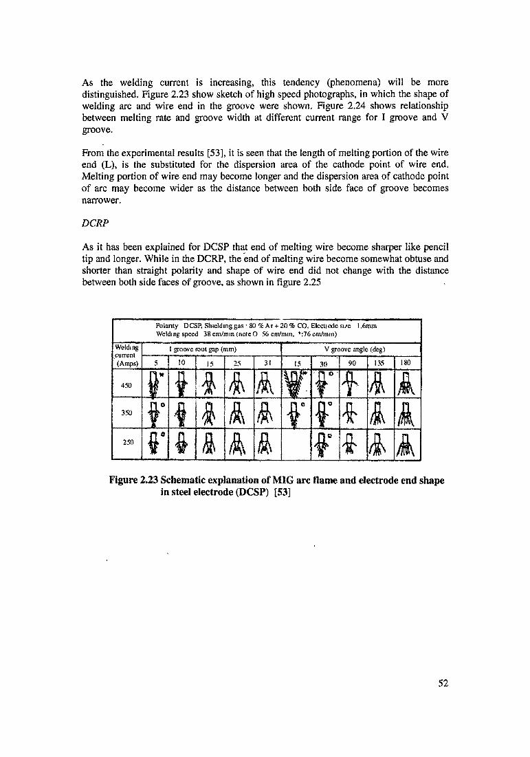
As the welding current is increasing, this tendency (phenomena) will be more distinguished. Figure 2.23 show sketch of high speed photographs, in which the shape of welding arc and wire end in the groove were shown. Figure 2.24 shows relationship between melting rate and groove width at different current range for I groove and V groove.
From the experimental results [53], it is seen that the length of melting portion of the wire end (L), is the substituted for the dispersion area of the cathode point of wire end. Melting portion of wire end may become longer and the dispersion area of cathode point of arc may become wider as the distance between both side face of groove becomes narrower.
DCRP
As it has been explained for DCSP that end of melting wire become sharper like pencil tip and longer. While in the DCRP, the end of melting wire become somewhat obtuse and shorter than straight polarity and shape of wire end did not change with the distance between both side faces of groove, as shown in figure 2.25
Polarity DCSP. Shielding gas • 80 %Ar-t- 20% CO, Eleetiode si/e 1.6mmWelding speed 38 cm/mm (note 0 56 cm/min, 1,:76cm/min)
Weldingcurrent(Amps)
I groove root gap (mm) V groove angle (deg)
5 I0 15 25 3l 15 30 90 135 ISO
450 ! A A A fA A A350 i A A A f A A A250 n°f 4 & A A f A A A
Figure 2.23 Schematic explanation of MIG arc flame and electrode end shape in steel electrode (DCSP) [53]
52
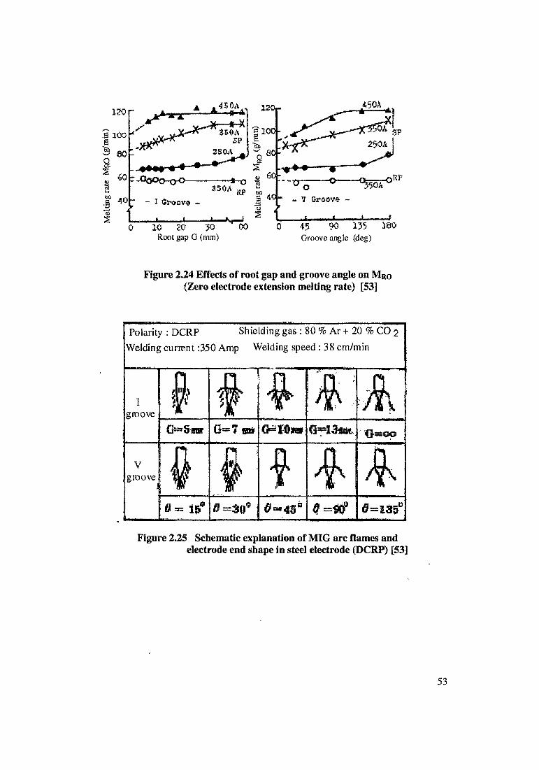
Mel
ting
rate
Mr<0
(g/m
in)
120,-120j-
f 100- §
Ta>V1*s2
I■"s— 0 °mk°w
~ V Groove -
' « 1------------ ?45 $0 135 180Groove angle (deg)
Figure 2.24 Effects of root gap and groove angle on MR0 (Zero electrode extension melting rate) [53]
Polarity : DCRP Shielding gas : 80 % Ar + 20 % CO pWelding current :350 Amp Welding speed : 38 cm/min
Igroove
/lull
lr AO^Sflrar G=7 w* Q*Wm
Vgroove
J $ f ' A A6 = tq? 0=30° 0=135°
Figure 2.25 Schematic explanation of MIG arc flames and electrode end shape in steel electrode (DCRP) [53]
2.5 Features of Pulse Gas Metal Arc Welding.
Available literature shows the importance of pulse current to control metal transfer in welding, [54, 55, 56]In conventional GMAW, the minimum current needed to produce spray transfer is relatively high; causing such a penetrating arc that process cannot be used for joining thin sections. In case of steel, the minimum deposition rate is so great that the metal in the weld pool cannot be retained in the vertical and overhead position; this restricted the use of the process to making horizontal fillet welds or flat position butt welds in steel. The short circuiting method was developed for welding steel sheet and also to weld plate in all position. It has limitation i.e. acceptable weld are possible only when CO2 is present in shielding gas. For this reason, the short circuiting method is used to weld only those metals and alloys which are tolerant of the O2 and carbon. For example, short circuiting welds in stainless steel absorbed Carbon and Chromium and impairing the corrosion resistance of multi pass welds. Welds of plate above !4 inch, were associated with inadequate fusion until special gas mixture containing He, Ar + CO2 were used.[21]
Pulse GMAW process developed principally to resolved the following problems. Situations in which pulse GMAW used
i) To reduce and control the excessive penetration and high deposition rate which had prevented the MIG process from being used to weld sheet or in joint position other than flat.ii) Magnetic Arc blow; Arc blow is particularly troublesome in low alloy plate, some users appears to have adopted this process solely on the basis of this improvement.iii) Spray transfer at lower transition current.
Essential feature of the pulse technique is to produce synthetically “Spray Transfer” at low wire feed rate (which is otherwise cause globular transfer).Standard pulse is associated with the detachment of the given droplet from wire tip, if pulse is repeated at a frequency which is directly related to the wire feed rate, the droplet size remain constant. In other word, if the unit pulse is generated once for every incremental for forward of the wire by a set distance example 1mm, the same drop size is detached by each pulse irrespective of the actual feed speed. In the event the combined relation of all the relevant pulse parameters (frequency, amplitude, background current) to the wire feed rate led to a unique system called synergic pulsing. Where the wire feed speed can be freely altered over wide ranges without requiring any external adjustment to the power supply. [57]
2.5.1 Function of pulse spray
Most important fact is the minute, discreet drops can develop and transfer from the wire tip at very high rates, if the current level is sufficiently high. If the current is below transition, drops can take as long as a second to form at the wire tip. But when the current is raised above the critical level, minute drops of metal can transfer from a molten wire tip in less than on hundredth of a second. The abruptness of these effects has been exploited by varying the output current from a power supply periodically; alternately keeping it below the transition current for a short time (less than required to form a massive drop at the electrode tip) and raising it above the transition current for a time only sufficient to transfer the molten tip as one or more small drops, typical of spray transfer. As a result of pulsing the current, such as show in figure 2.26, controlled spatter
54

free and directional spray transfer is obtained at relatively low average current. The average current level can be varied by adjusting the background current and the duration, frequency and amplitude of superimposed pulse current.[57] M. min and P.V.C.Watkins had studied effect pulse variables on bead on plate with 1,2mm diameter mild steel wire. [58]
Region of Transition Pulse current (Ip)
Time —'■■■imfr
Figure 2.26 Representation of square wave pulses to show intervals of spray transfer above the transition current and the low average current achieved by pulsing [57]
2.5.2 Pulsing in narrow gap welding:
Only limited experimental work was carried out on effect of pulsing in NG-GMAW. The research work was undertaken by the N.S.Barabokhin has shown the use of pulse arc welding with consumable electrode in inert gases was promising for thick plate of aluminum alloys using narrow gap welding.[59] Author discussed the advantages of the pulse are over conventional burning arc.
i) Use of this pulse method, despite the large number of passes, give considerable reduction of the linear heat input. In the welding of aluminum alloys, a reduction of the linear heat input usually leads to an increase in the quality of the welded joints.
ii) Powerful pulsed discharge are accompanied by a sharp rise of plasma temperature at the moments of accumulation a subsequent shock wave, which naturally causes vibrations of molten metal of the weld pool with frequency of 50 pulse per second and refinements of the structure during crystallization.
iii) Because of the spatial stability of pulsed discharge, and the strong pinch constriction of the arc column, the use of pulse arc welding process for narrow gap joints has made it possible to avoid the unfavorable phenomenon of wandering of the cathode spot over the walls of the gap, as observed in ordinarily arc welding with consumable electrode. This ensures uniform fusion of beads to the walls of the gap and the preceding layer; it also simplifies the actual welding process considerably.
iv) Microstructure of welded joints produced by pulse arc welding was more homogenous at the transition from the base metal to seam as compared with joints produced by a 3- phase arc.
v) In pulse arc welding, because of the reduction of linear heat input and because of reduction of the time of contact of the liquid and solid phases in the fusion zone and the relatively high welding speed, a much smaller quantity of brittle segregates were observed at the boundaries of the partially fused grains, this was one of the main reason for the improvement of joint performance.
Curre
nt ....
..
55
2.6 Challenges in NG-GMAW
The main difference between-narrow gap GMAW and conventional welding methods is the technique used to feed an electrode wire and shielding gas into the joint gap. In conventional GMAW, wire reaches to the bottom of the V or double -V groove, do not require special technique or special device. However, this a real problem for NG-GMAW to feed the electrode and supply the shielding gas into the very narrow very deep (12”) square groove without observation of the arc. Accidental arcing contact between torch and sidewall is the problem. Sucking of air into the groove also considered as important problem.
NG-GMAW is the more sensitive to welding conditions as compared to conventional welding methods, slight variations in welding variables and arc may effect the weld bead quality leading to defects. Most common defects encountered during welding NG- GMAW are
i) Porosityii) Residual Stress and Distortioniii) Magnetic Arc Blowiv) Lack of Sidewall Fusion
2.6.1 Porosity
Porosity most commonly occurs on the cover pass, because of infectiveness of shielding. Other associated cause of porosity are power supply, torch design, shielding gas composition, lack of inter pass cleaning and arc blow.
In case of tandem electrode, one operator behind the other, front torch laying a bead along the one side of the joint gap and rear one along the other opposite side. Use of one torch is better than two because the weld bead could be cleaned of oxide before laying another bead. With two torches, the second bead would be laid down over the first as it cooled. There is no scope for cleaning the first bead; oxides remained to cause porosity and lack of interlayer fusion.
Literature report that arc blow observed near the end of the plate and arc disturbance produced local porosity. The problem was overcome by always welding away from the ground connection. Each pass is normally run in opposite direction to the previous pass, so ground connection is attached to both end of the test plate and knife-switch used to change from one ground to the other.
2.6.2 Residual stresses and distortion
Residual stresses and distortion in NG-GMAW is much lower in comparison with conventional welding process, due to relative smaller volume of the weld metal and lower heat input. Comparison was made of welding distortion for NG-GMAW against conventional welding, horizontal, semiautomatic C02 GMAW (35° angle single V groove) [60,61]
56
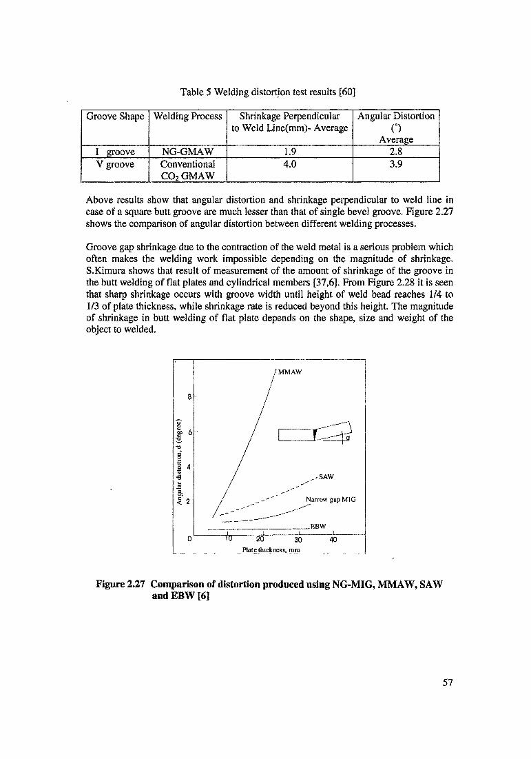
,-SAW
Narrow gap MIG
_EBW
TO ~ 20 30Plate thickness, mm
40
Figure 2.27 Comparison of distortion produced using NG-MIG, MMAW, SAW and EBW [6]
Table 5 Welding distortion test results [60]
Groove Shape Welding Process Shrinkage Perpendicular to Weld Line(mm)- Average
Angular DistortionO
AverageI groove NG-GMAW 1.9 2.8V groove Conventional
C02 GMAW4.0 3.9
Above results show that angular distortion and shrinkage perpendicular to weld line in case of a square butt groove are much lesser than that of single bevel groove. Figure 2.27 shows the comparison of angular distortion between different welding processes.
Groove gap shrinkage due to the contraction of the weld metal is a serious problem which often makes the welding work impossible depending on the magnitude of shrinkage. S.Kimura shows that result of measurement of the amount of shrinkage of the groove in the butt welding of flat plates and cylindrical members [37,6]. From Figure 2.28 it is seen that sharp shrinkage occurs with groove width until height of weld bead reaches 1/4 to 1/3 of plate thickness, while shrinkage rate is reduced beyond this height. The magnitude of shrinkage in butt welding of flat plate depends on the shape, size and weight of the object to welded.
j MMAW
8 - /
Ang
ular
dist
ortio
n, d
(deg
ree)
o
M o-
57
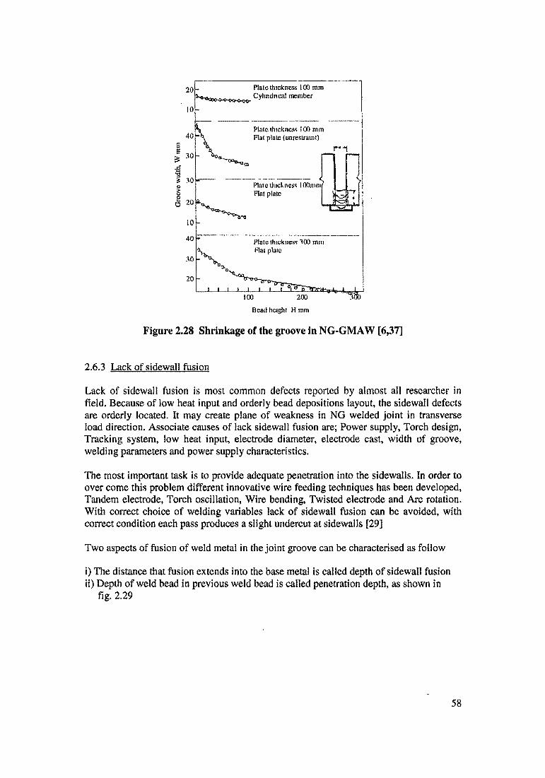
30
20
■ ~ ■^sab
Figure 2.28 Shrinkage of the groove in NG-GMAW [6,37]
100 200
Bead heighl H mm
2.6.3 Lack of sidewall fusion
Lack of sidewall fusion is most common defects reported by almost all researcher in field. Because of low heat input and orderly bead depositions layout, the sidewall defects are orderly located. It may create plane of weakness in NG welded joint in transverse load direction. Associate causes of lack sidewall fusion are; Power supply, Torch design, Tracking system, low heat input, electrode diameter, electrode cast, width of groove, welding parameters and power supply characteristics.
The most important task is to provide adequate penetration into the sidewalls. In order to over come this problem different innovative wire feeding techniques has been developed, Tandem electrode, Torch oscillation, Wire bending, Twisted electrode and Arc rotation. With correct choice of welding variables lack of sidewall fusion can be avoided, with correct condition each pass produces a slight undercut at sidewalls [29]
Two aspects of fusion of weld metal in the joint groove can be characterised as follow
i) The distance that fusion extends into the base metal is called depth of sidewall fusionii) Depth of weld bead in previous weld bead is called penetration depth, as shown in
fig. 2.29
Gro
ove w
idth
, W m
m
58

G
Figure 2.29 Characterisation of sidewall fusion and depth of penetration [6]
Wl-G : Bead to Bead Penetration W2-G : Side Wall Fusion
d : Penetration depth
Measurement
In order to measure the depth of sidewall fusion and penetration depth of weld bead, transverse cross section of weldment is required. Cross section need to prepare for macro observation through metallographic procedure. Toolmaker microscope can be used for measurement of sidewall fusion and penetration depth. Yu. N. Kutenov had used tool maker’s micro scope for measurement of depth of penetration for his investigation. He had also developed mathematical equation of penetration depth. [62]. Least count of tool maker’s micro scope in the order of 0.01 mm.
2.6.4 Magnetic arc blow
Arc-blow is generally assumed to results from alternation of arc behavior. A welding arc can become unstable and distorted out shape by utilisation of contaminated shielding gas, aspiration of air into the shielding cone adjacent to the arc, turbulence of heated gases it, and to “magnetic disturbances surrounding the welding arc”.[60] The last cause is attributed to
i) The change in direction of current flow as it enters the work and is conducted away toward the ground connection, andii) The asymmetric arrangement of magnetic material around the arc, a condition that normally exists when welding is done on ferrous materials.
59

2.7 Effect of Variables on Sidewall fusion
Production of the sound narrow gap joint depends on the weld bead shape. Weld bead shape is defined as ratio of bead width to depth. To achieve sufficient sidewall fusion weld bead shape must be concave and ratio of weld bead width to depth to be held within the range of 1.5 to 2.0. Arc voltage, welding current, travel speed, shielding gas, wire diameter, joint gap, all these variable have influence on sidewall fusion [4], NG-GMAW is much more sensitive to change in welding parameters as compared to conventional GMAW because the fact is, arc in NGW is operating in the close confines of a narrow gap, which restricted arc atmosphere [6].
2.7.1 Arc voltage
Arc voltage is a key factor for adequate depth of penetration inside the sidewalls. Weld bead width will increase with increase in voltage. In normal welding the metal melted in one direction only (beneath the welding arc), where as in NG-GMAW it is necessary to provide penetration not only in one direction, but also into three directions (Preceding pass and each sidewall) [63]. The walls of gap are melted by conduction from the active spot of the arc, by radiation and through convection by means of metal vapor and heated gas.
Increasing voltage tends to widen the fused zone but in extreme case, results in undercutting at sidewalls. Sometime slag flows into undercut and may cause defects. Generally arc is operating in the spray transfer mode, which is characterised by high arc stability and low spattering. This may leads to arc scramble up the groove sidewall like melt back, which may also damaged the contact tip and welding become almost impractical.
At low voltage value there will be lesser heating of the wall and it also increases bead height. At very low voltage value arc will operate in the short circuit transfer, it may cause lack of fusion. There will be intensive spattering which adheres to groove side walls and contact tube. For these reasons, the consumable electrode must be positioned with great accuracy in the centre of the gap in order to achieve reliable sidewall fusion on both sides. Figure 2.30 summaries effect of voltage on arc performance in NG-GMAW [6]
It is advisable to reduce the arc voltage for the final two or three passes because the heat transfer into the parent metal decreases at the upper comer of the edges. This may also cause undercutting at the top of the edges of the final bead.
Figure 2.30 Summaries effect of voltage on arc performance in NG-GMAW [6]
60

2.7.2 Welding current
In NG-GMAW there is no need for a great degree of penetration and it is necessary to establish the optimum current because welding output and heat input into parent metal depend on this [63].
Deposition rate, arc stability and bead geometry will effect by welding current. Weld bead depth will increase with increasing welding current. Current is basically direct function of the wire feed rate. Deposition rate will increase with increasing the wire feed rate. Increasing current results into deep penetration into the bottom of the joint much faster than into sidewalls and there will be unfavorable bead configuration. To over come this problem the current is kept proportional to travel speed.
If current exceeds beyond definite limit, which depend on voltage, travel speed, wire diameter and other welding condition, it can leads to deterioration of arc stability and excessive spattering.
2.7.3 Welding speed
Welding speed in NG-GMAW must be such that it form concave bead and metal is melted on all three directions [63].
Welding speed is set accordance with other welding parameters (namely welding current, welding voltage). Weld bead width is proportional to travel speed. At low travel speed, a large molten pool may be created, which will flow under the arc. It may cause incomplete fusion into the sidewalls and between layers of deposited metal.
At high welding speed, heat input will be minimum and it will leads to incomplete fusion to the sidewalls.
2.7.4 Shielding gas
Shielding gas is of great importance for NG-GMAW because choice of the shielding gas affects many aspects of welding process. Selection of the shielding gas is usually made on the basis of
i) Arc stabilityii) Shape of weld beadiii) Properties of welded joint.
Argon (Ar), Carbon Dioxide (CO2), Helium (He) and Oxygen (O2) have been considered the most important in providing shielding in deep narrow groove [201].
The primary function of the shielding gas is to protect the molten metal from contamination and damage by surrounding atmosphere. Several other factors which effect the choice of a shielding gas like
- Arc and metal transfer characteristics during welding.- Penetration, width of fusion and shape of reinforcement
61

The selection of one or the other or mixture of the two gases in various combinations can be made so that the desirable metal transfer, penetration, bead geometry and other weld characteristics can be obtained.Pure inert gases protect the weld metal from reaction with air; these are not suitable for all welding applications. By mixing controlled quantities of reactive gases, stable arc with substantially spatter free metal transfer obtained simultaneously. [15]
Pure argon
Conventional dc reverse polarity GMAW using pure argon has very rare application in industrial steel fabrication. The major drawback of pure argon shielding is some what erratic and spattering transfer leading to poor mushroom type shape of the bead and this is not acceptable for multipass welding. NGW, where concave shape of the bead is great important for sidewall fusion. Pure argon leads to formation of the unsatisfactory weld shape, intensive radiation of arc and the fact that the weld metal is very susceptible to the formation of pores. Addition of small amount of Carbon dioxide to pure argon can eliminate this draw back to considerable extent [6,64]. Argon and Carbon dioxide mixture is the most popular gas mixture for NG-GMAW for fabrication of various grades of steels.
Arc stability and transfer mode greatly effects by CO2 addition. Table 6 highlights different transfer mode with change in percentage of CO2.
When using 100 % CO2 alone, it gives a deep bowl shape penetration. This shape of penetration is preferred over narrow finger penetration characteristies of argon shieldinggas.CO2 have higher thermal conductivity than argon. For a given welding current and arc voltage, the heat input is higher for more thermally conductive gas, which results into deeper penetration and higher deposition rates. The greater penetration of CO2 usually allow§ the use of higher welding speed. Thus, higher welding speed and higher deposition rate provides higher productivity in welding.
Table 6 Effect of CO2 in the Ar + CO2 mixture on arc stability and transfer mode [6]
CO2 Content Effect
Small (5 -7%) 1. Globule transfer2. Small spherical globules3. Relative stable arc4. Minimum spatter
Optimum 10-20 % Optimum Characteristics
High above 40% 1. Globules transfer2. Large globules3. Erratic arc4. Intensive spattering
62
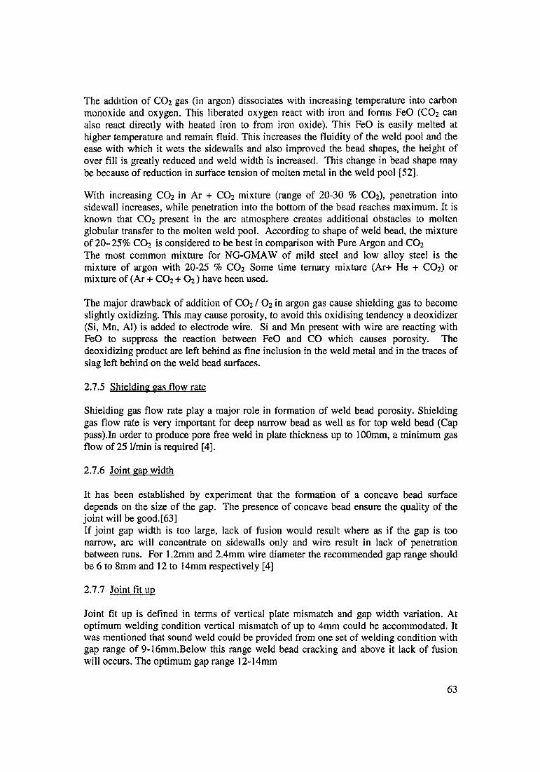
The addition of CO2 gas (in argon) dissociates with increasing temperature into carbon monoxide and oxygen. This liberated oxygen react with iron and forms FeO (CO2 can also react directly with heated iron to from iron oxide). This FeO is easily melted at higher temperature and remain fluid. This increases the fluidity of the weld pool and the ease with which it wets the sidewalls and also improved the bead shapes, the height of over fill is greatly reduced and weld width is increased. This change in bead shape may be because of reduction in surface tension of molten metal in the weld pool [52].
With increasing CO2 in Ar + CO2 mixture (range of 20-30 % CO2), penetration into sidewall increases, while penetration into the bottom of the bead reaches maximum. It is known that CO2 present in the arc atmosphere creates additional obstacles to molten globular transfer to the molten weld pool. According to shape of weld bead, the mixture of 20-’25% C02 is considered to be best in comparison with Pure Argon and CO2
The most common mixture for NG-GMAW of mild steel and low alloy steel is the mixture of argon with 20-25 % C02 Some time ternary mixture (Ar+ He + C02) or mixture of (Ar + C02 + 02) have been used.
The major drawback of addition of C02 / 02 in argon gas cause shielding gas to become slightly oxidizing. This may cause porosity, to avoid this oxidising tendency a deoxidizer (Si, Mn, Al) is added to electrode wire. Si and Mn present with wire are reacting with FeO to suppress the reaction between FeO and CO which causes porosity. The deoxidizing product are left behind as fine inclusion in the weld metal and in the traces of slag left behind on the weld bead surfaces.
2.7.5 Shielding gas flow rate
Shielding gas flow rate play a major role in formation of weld bead porosity. Shielding gas flow rate is very important for deep narrow bead as well as for top weld bead (Cap pass).In order to produce pore free weld in plate thickness up to 100mm, a minimum gas flow of 25 1/min is required [4],
2.7.6 Joint gap width
It has been established by experiment that the formation of a concave bead surface depends on the size of the gap. The presence of concave bead ensure the quality of the joint will be good.[63]If joint gap width is too large, lack of fusion would result where as if the gap is too narrow, arc will concentrate on sidewalls only and wire result in lack of penetration between runs. For 1.2mm and 2.4mm wire diameter the recommended gap range should be 6 to 8mm and 12 to 14mm respectively [4]
2.7.7 Joint fit up
Joint fit up is defined in terms of vertical plate mismatch and gap width variation. At optimum welding condition vertical mismatch of up to 4mm could be accommodated. It was mentioned that sound weld could be provided from one set of welding condition with gap range of 9-16mm.Below this range weld bead cracking and above it lack of fusion will occurs. The optimum gap range 12-14mm
63

2.7.8 Wire diameter
Electrode diameter will affect the weld bead deposition. Increasing wire diameter increases the depth of fusion and the weld bead become more convex. In order to compensate this effect, it was recommended to use slightly higher arc voltage. Large wire diameter will improve wire rigidity and wire could be consistently centralised in the joint. It was recommended to use finer wire (< 3mm diameter) for plate less than 50mm thick [4]. It is advisable to use fine wires so as to maintain control of weld pool, when doing position welding. In normal practice to use a flat characteristic power source for welding up to approximately 3mm diameter. A drooping characteristic power source is used with voltage control for thick wires (> 3mm)
2.7.9 Stand off distance
The long stand off distance leads to more spatters and unstable arc. Weld bead become rough. At long stand off, arc pressure is less and weld bead become flat. At short stand off distance, arc conditions produce concave weld bead shape. If stand off distance is very short the higher current produce harsh arc and arc will agitate the weld pool violently. The optimum stand off distance is 17-19mm [15].
2.7.10 Effect of variation in gap width
For taper groove specimen, welding will be carried at out at different speeds. Bead shape will change as the gap width increased. Initially bead will have concave shape then flat weld bead and finally it will be convex patterns. Welding speed will also change with gap variation. The combine effect of gap variation and speed, reduced the height of weld bead. At slow welding speeds, the variation in gap width is very well compensated; it will reduce with increasing speeds.Wide variation in gap width leads to variation in the thickness of deposited metal along the weld length. For very thick plate, it would be difficult in achieving uniform bead width and build up. There will be variation in sidewall penetration and penetration depth.
2.7.11 Preheating and inter run temperatures
Preheating temperature depends on material thickness being welded. Preheating is required for removal of moisture from backing strip and gap it self. In general preheating at 60- 100 °C is recommended for moisture removal and preheating up to 200 °C can enhance notch impact and fracture toughness [65].Inter pass temperature is not normally necessary due to its chief characteristics of heat input and the large heat sink because of the heavy sections. Intermittent cleaning of the weld runs is necessary to remove oxides and silicates which could act to disturb the arc. Stop and starts arc potential defect sites, it is recommended to have minimum number of interruptions to welding.
64
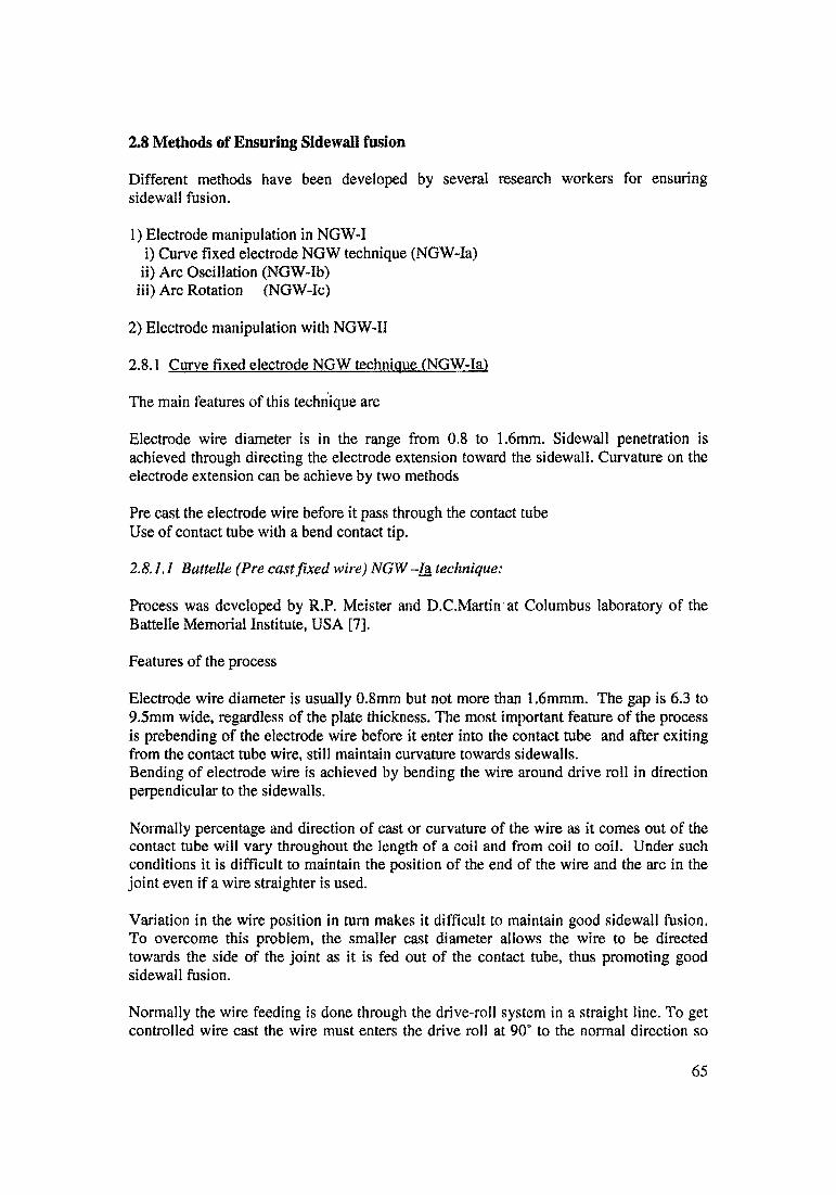
2.8 Methods of Ensuring Sidewall fusion
Different methods have been developed by several research workers for ensuring sidewall fusion.
1) Electrode manipulation in NGW-Ii) Curve fixed electrode NGW technique (NGW-Ia)
ii) Arc Oscillation (NGW-Ib)iii) Arc Rotation (NGW-Ic)
2) Electrode manipulation with NGW-II
2.8.1 Curve fixed electrode NGW technique (NGW-Ia)
The main features of this technique are
Electrode wire diameter is in the range from 0.8 to 1.6mm. Sidewall penetration is achieved through directing the electrode extension toward the sidewall. Curvature on the electrode extension can be achieve by two methods
Pre cast the electrode wire before it pass through the contact tube Use of contact tube with a bend contact tip.
2.8.1.1 Battelle (Pre cast fixed wire) NGW -la technique:
Process was developed by R.P. Meister and D.C.Martin at Columbus laboratory of the Battelle Memorial Institute, USA [7].
Features of the process
Electrode wire diameter is usually 0.8mm but not more than 1.6mmm. The gap is 6.3 to 9.5mm wide, regardless of the plate thickness. The most important feature of the process is prebending of the electrode wire before it enter into the contact tube and after exiting from the contact tube wire, still maintain curvature towards sidewalls.Bending of electrode wire is achieved by bending the wire around drive roll in direction perpendicular to the sidewalls.
Normally percentage and direction of cast or curvature of the wire as it comes out of the contact tube will vary throughout the length of a coil and from coil to coil. Under such conditions it is difficult to maintain the position of the end of the wire and the arc in the joint even if a wire straighter is used.
Variation in the wire position in turn makes it difficult to maintain good sidewall fusion. To overcome this problem, the smaller cast diameter allows the wire to be directed towards the side of the joint as it is fed out of the contact tube, thus promoting good sidewall fusion.
Normally the wire feeding is done through the drive-roll system in a straight line. To get controlled wire cast the wire must enters the drive roll at 90' to the normal direction so
65

the so that wire can be formed around one of the drive rolls. This give uniform cast in the wire. Figure 2.31 shows uniform cast obtained by the technique.Spilling of water into the weld is a significant problem of this technique. To avoid this it is necessary to insulate the contact tube to prolong its service life [6].
Use of thin wire and very narrow spacing between the plates, allows the use of low heat input and requires the deposition of much less filler metal, so that the technique meet the requirement of out of position welding.
Due to low heat input and small molten metal; lack of sidewall fusion into a sidewall is most frequent defect of Battelle NG-GMAW process. To improve weld quality and increase productivity, two wire and contact tube is used in tandem. It will increase the penetration capability of the arcs and provide bi-pass bead layout. The maximum thickness weld by this technique is reported 8 inch.
Figure 2.31 Principle of the battelle (precast fixed wire) NG-GMAW (la) technique [7]
2.8.1.2 Sciaky SA (bend fixed torch) NGW-Ia technique:
Process was developed by Sciaky SA, France [66]. Curvature in the electrode wire is achieved by special designed contact tube with an angle tip (20°), which ensuring very good sidewall fusion.
Bending of the wire is achieved near the impact point of arc, thus improves reproducibility of wire curvature, which was problem of battelle technique [6]. The gap of 14-20mm, in order to use two sturdier torches directed at the opposite sidewalls. However, much more filler metal and time required filling wide groove.To over come this three torches work simultaneously, one at right side another at left side and third at the middle, third straight electrode is added in the centre of the groove to bridge two fillet weld performed by the other two torches. It should be noted that, when
66
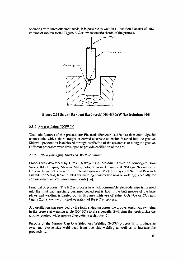
operating with three different heads, it is possible to weld in all position because of small volume of molten metal. Figure 2.32 show schematic sketch of the process.
Figure 2.32 Sciaky SA (bent fixed torch) NG-GMAW (ia) technique [66]
2.8.2 Arc oscillation (NGW-Ib)
The main features of this process are; Electrode diameter used is less than 2mm. Special contact tube with a short straight or curved electrode extension inserted into the groove. Sidewall penetration is achieved through oscillation of the arc across or along the groove. Different processes were developed to provide oscillation of the arc.
2.8.2,1 NOW (Swinging Torch) NGW- lb technique
Process was developed by Hiroshi Nakayama & Masami Kamata of Tomoegumi Iron Works ltd of Japan, Masami Matsumoto, Kosaku Futamura & Takaya Nakamura of Nozawa Industrial Research Institute of Japan and Michio Inoyaki of National Research Institute for Metal, Japan in 1974 for building construction (onsite welding), specially for column-beam and column-column joints [14].
Principal of process : The NOW process in which consumable electrode wire is inserted into the joint gap, specially designed coated rod is laid in the butt groove of the base plates and welding is carried out in this area with use of either CO2 -O2 or CO2 gas. Figure 2.33 show the principal operation of the NOW process.
Arc oscillation was provided by the torch swinging across the groove, torch was swinging in the groove at weaving angle (30°-60°) to the sidewalls. Swinging the torch inside the groove required wider groove than battel le technique [6].
Purpose of the Narrow Gap One Sided Arc Welding (NOW) process is to produce an excellent reverse side weld bead from one side welding as well as to increase the productivity.
67
W. Weaving width, V : Travel speed (cm/min), G Root gap (mm) a . Weaving angle (') C : Weaving cycle (cycle/ min)
Figure 2.33 Principle of “NOW” (swinging torch) NG-GMAW (lb) technique [14]
2.8.22 Nippon steel (Swiveling Torch ) NGW-Ib technique
Process was developed by T. Ito, Y.Yabukai, Y. Hagiward, A. Yamaka and K. Ono of Nippon Steel Welding Product & Engineering Company ltd., Japan. [35]
In order to get sufficient depth of fusion; it is necessary to bring the arc point as near as possible to the groove walls. The angle between electrode wire with respect to the groove wall is term as approach angel (0). The approach angle must be as large as possible. As shown in figure 2.34 a maximum approach angle is obtained when the axis of electrode is brought into the groove. If approach angle is small the electrode wire is nearly parallel to the groove wall. It was found from experimentally the approach angle should large than 6 degree (°).A special mechanism has been developed so that electrode will oscillate around a point inside the groove. Figure 2.35 shows schematic drawing of mechanism. This mechanism is termed as four bar link mechanism. Oscillation speed, amplitude and dwell time at both end are individually adjustable even during welding operation.
This device which has been designed can weld maximum plate thickness of about 80 mm. In order to maintain approach angle to minimum specific value, the groove width must be slightly higher for thick plates.
Weaving is fairly effective although its amplitude would be as small as half the groove width, but it is desirable to be as wide as possible. This because the groove wall should
68
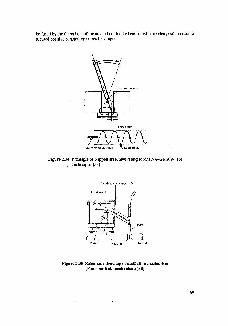
be fused by the direct heat of the arc and not by the heat stored in molten pool in order to secured positive penetration at low heat input.
Figure 2.34 Principle of Nippon steel (swiveling torch) NG-GMAW (lb) technique [35]
Amplitude adjusting knob
Figure 2.35 Schematic drawing of oscillation mechanism (Four bar link mechanism) [35]
69
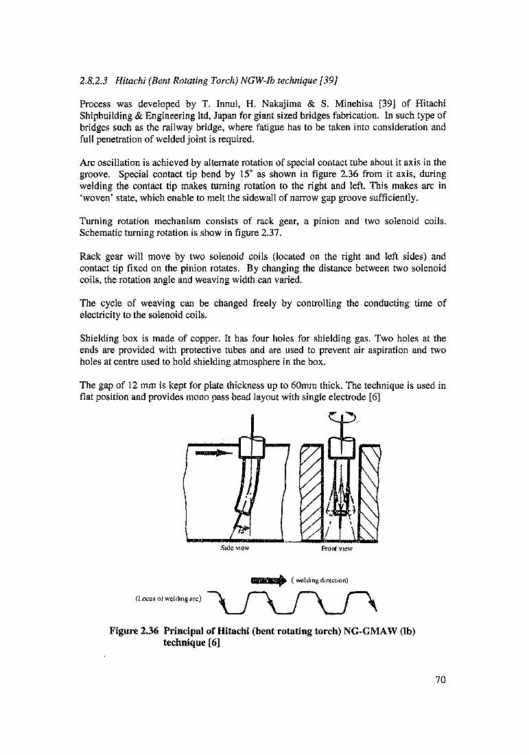
2.8.2.3 Hitachi (Bent Rotating Torch) NGW-Ib technique [39]
Process was developed by T, Innul, H, Nakajima & S. Minehisa [39] of Hitachi Shipbuilding & Engineering ltd, Japan for giant sized bridges fabrication. In such type of bridges such as the railway bridge, where fatigue has to be taken into consideration and full penetration of welded joint is required.
Arc oscillation is achieved by alternate rotation of special contact tube about it axis in the groove. Special contact tip bend by 15° as shown in figure 2.36 from it axis, during welding the contact tip makes turning rotation to the right and left. This makes arc in ‘woven’ state, which enable to melt the sidewall of narrow gap groove sufficiently.
Turning rotation mechanism consists of rack gear, a pinion and two solenoid coils. Schematic turning rotation is show in figure 2.37.
Rack gear will move by two solenoid coils (located on the right and left sides) and contact tip fixed on the pinion rotates. By changing the distance between two solenoid coils, the rotation angle and weaving width can varied.
The cycle of weaving can be changed freely by controlling the conducting time of electricity to the solenoid coils.
Shielding box is made of copper. It has four holes for shielding gas. Two holes at the ends are provided with protective tubes and are used to prevent air aspiration and two holes at centre used to hold shielding atmosphere in the box.
The gap of 12 mm is kept for plate thickness up to 60mm thick. The technique is used in flat position and provides mono pass bead layout with single electrode [6]
Side view Front view
( welding direction)
(Locus ot welding arc)
Figure 2.36 Principal of Hitachi (bent rotating torch) NG-GMAW (lb) technique [6]
70
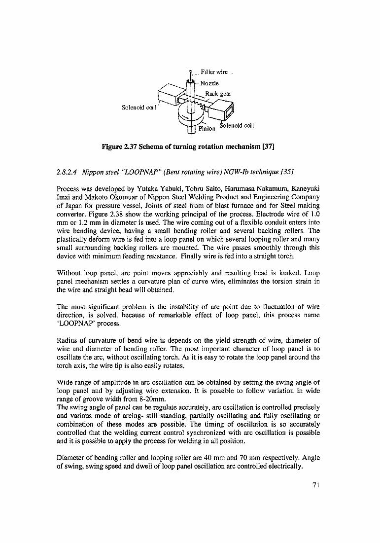
Filler wire .
Nozzle
Rack gear
Solenoid eoi 1
olenoid coil
Figure 2.37 Schema of turning rotation mechanism [37]
2.82.4 Nippon steel “LOOPNAP” (Bent rotating wire) NGW-lb technique [35]
Process was developed by Yutaka Yabuki, Tobru Saito, Harumasa Nakamura, Kaneyuki Imai and Makoto Okomuar of Nippon Steel Welding Product and Engineering Company of Japan for pressure vessel, Joints of steel from of blast furnace and for Steel making converter. Figure 2.38 show the working principal of the process. Electrode wire of 1.0 mm or 1.2 mm in diameter is used. The wire coming out of a flexible conduit enters into wire bending device, having a small bending roller and several backing rollers. The plastically deform wire is fed into a loop panel on which several looping roller and many small surrounding backing rollers are mounted. The wire passes smoothly through this device with minimum feeding resistance. Finally wire is fed into a straight torch.
Without loop panel, arc point moves appreciably and resulting bead is kinked. Loop panel mechanism settles a curvature plan of curve wire, eliminates the torsion strain in the wire and straight bead will obtained.
The most significant problem is the instability of arc point due to fluctuation of wire ' direction, is solved, because of remarkable effect of loop panel, this process name ‘LOOPNAP’ process.
Radius of curvature of bend wire is depends on the yield strength of wire, diameter of wire and diameter of bending roller. The most important character of loop panel is to oscillate the arc, without oscillating torch. As it is easy to rotate the loop panel around the torch axis, the wire tip is also easily rotates.
Wide range of amplitude in arc oscillation can be obtained by setting the swing angle of loop panel and by adjusting wire extension. It is possible to follow variation in wide range of groove width from 8-20mm.The swing angle of panel can be regulate accurately, arc oscillation is controlled precisely and various mode of arcing- still standing, partially oscillating and fully oscillating or combination of these modes are possible. The timing of oscillation is so accurately controlled that the welding current control synchronized with arc oscillation is possible and it is possible to apply the process for welding in all position.
Diameter of bending roller and looping roller are 40 mm and 70 mm respectively. Angle of swing, swing speed and dwell of loop panel oscillation arc controlled electrically.
71
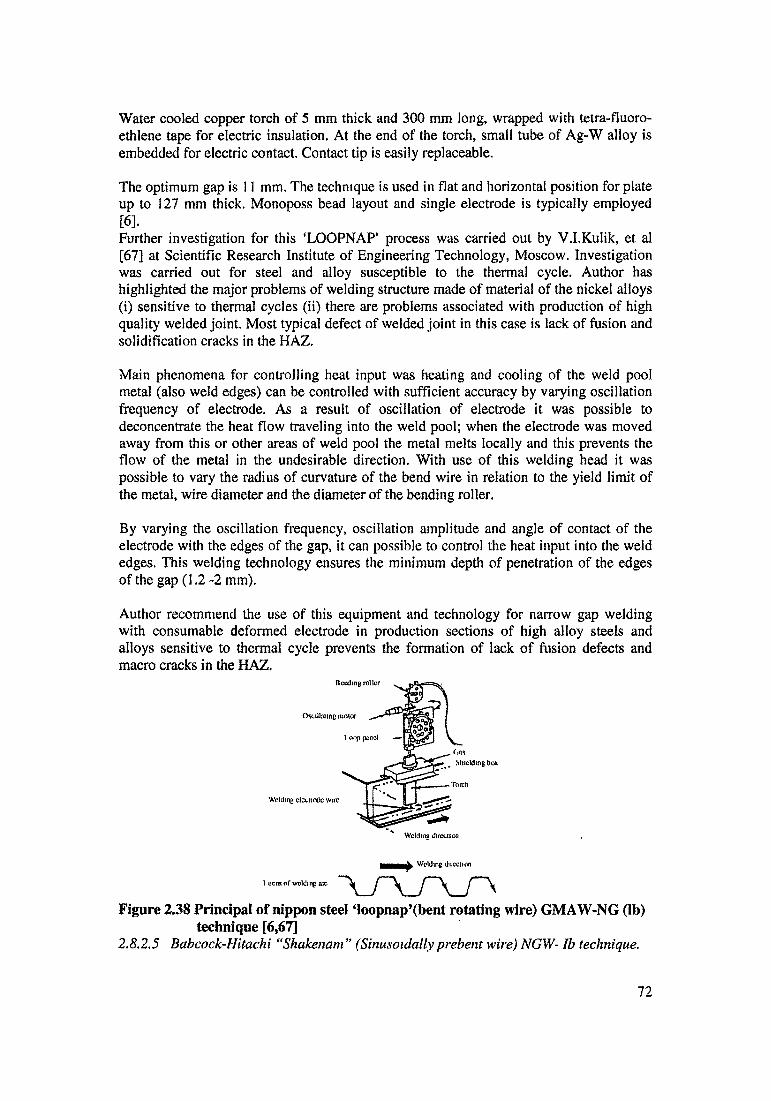
Water cooled copper torch of 5 mm thick and 300 mm long, wrapped with tetra-fluoro- ethlene tape for electric insulation. At the end of the torch, small tube of Ag-W alloy is embedded for electric contact. Contact tip is easily replaceable.
The optimum gap is 11 mm. The technique is used in flat and horizontal position for plate up to 127 mm thick. Monoposs bead layout and single electrode is typically employed [6].Further investigation for this ‘LOOPNAP’ process was carried out by V.I.Kulik, et al [67] at Scientific Research Institute of Engineering Technology, Moscow. Investigation was carried out for steel and alloy susceptible to the thermal cycle. Author has highlighted the major problems of welding structure made of material of the nickel alloys (i) sensitive to thermal cycles (ii) there are problems associated with production of high quality welded joint. Most typical defect of welded joint in this case is lack of fusion and solidification cracks in the HAZ.
Main phenomena for controlling heat input was heating and cooling of the weld pool metal (also weld edges) can be controlled with sufficient accuracy by varying oscillation frequency of electrode. As a result of oscillation of electrode it was possible to deconcentrate the heat flow traveling into the weld pool; when the electrode was moved away from this or other areas of weld pool the metal melts locally and this prevents the flow of the metal in the undesirable direction. With use of this welding head it was possible to vary the radius of curvature of the bend wire in relation to the yield limit of the metal, wire diameter and the diameter of the bending roller.
By varying the oscillation frequency, oscillation amplitude and angle of contact of the electrode with the edges of the gap, it can possible to control the heat input into the weld edges. This welding technology ensures the minimum depth of penetration of the edges of the gap (1.2-2 mm).
Author recommend the use of this equipment and technology for narrow gap welding with consumable deformed electrode in production sections of high alloy steels and alloys sensitive to thermal cycle prevents the formation of lack of fusion defects and macro cracks in the HAZ.
Figure 2.38 Principal of nippon steel ‘loopnap’fbent rotating wire) GMAW-NG (lb) technique [6,67]
2.8.2.S Babcock-Hitachi “Shakenam ” (Sinusoidally prebent wire) NGW- lb technique.
72
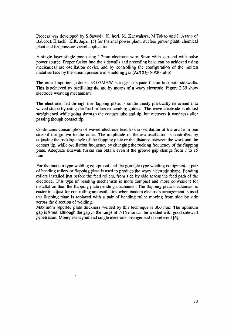
Process was developed by S.Sawada, K. hori, M. Kanwahara, M.Takao and I. Asano of Babcock Hitachi K.K, Japan [5] for thermal power plant, nuclear power plant, chemical plant and for pressure vessel application.
A single layer single pass using 1.2mm electrode wire, 9mm wide gap and with pulse power source. Proper fusion into the sidewalls and preceding bead can be achieved using mechanical arc oscillation device and by controlling the configuration of the molten metal surface by the stream pressure of shielding gas (Ar/CC>2- 80/20 ratio)
The most important point in NG-GMAW is to get adequate fusion into both sidewalls. This is achieved by oscillating the arc by means of a wavy electrode. Figure 2.39 show electrode weaving mechanism.
The electrode, fed through the flapping plate, is continuously plastically deformed into waved shape by using the feed rollers as bending guides. The wave electrode is almost straightened while going through the contact tube and tip, but recovers it waviness after passing though contact tip.
Continuous consumption of waved electrode lead to the oscillation of the arc from one side of the groove to the other. The amplitude of the arc oscillation is controlled by adjusting the rocking angle of the flapping plate or the distance between the work and the contact tip, while oscillation frequency by changing the rocking frequency of the flapping plate. Adequate sidewall fusion can obtain even if the groove gap change from 7 to 15 mm.
For the tandem type welding equipment and the portable type welding equipment, a pair of bending rollers or flapping plate is used to produce the wavy electrode shape. Bending rollers installed just before the feed rollers, from side by side across the feed path of the electrode. This type of bending mechanism is more compact and more convenient for installation than the flapping plate bending mechanism The flapping plate mechanism is easier to adjust for controlling arc oscillation when tandem electrode arrangement is used the flapping plate is replaced with a pair of bending roller moving from side by side across the direction of welding.Maximum reported plate thickness welded by this technique is 300 mm. The optimum gap is 9mm, although the gap in the range of 7-15 mm can be welded with good sidewall penetration. Monopass layout and single electrode arrangement is preferred [6].
73
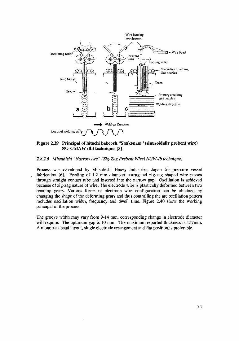
Wire bending mechanism
Locusot welding
Figure 239 Principal of Hitachi babcock “Shakenam” (sinusoidally prebent wire) NG-GMAW (lb) technique [5]
2.8.2.6 Mitsubishi “Narrow Arc” (Zig-Zag Prebent Wire) NGW-Ib technique;
Process was developed by Mitsubishi Heavy Industries, Japan for pressure vessel fabrication [6]. Feeding of 1.2 mm diameter corrugated zig-zag shaped wire passes through straight contact tube and inserted into the narrow gap. Oscillation is achieved because of zig-zag nature of wire. The electrode wire is plastically deformed between two bending gears. Various forms of electrode wire configuration can be obtained by changing the shape of the deforming gears and thus controlling the arc oscillation pattern includes oscillation width, frequency and dwell time. Figure 2.40 show the working principal of the process.
The groove width may vary from 9-14 mm, corresponding change in electrode diameter will require. The optimum gap is 10 mm. The maximum reported thickness is 157mm. A monopass bead layout, single electrode arrangement and flat position, is preferable.
74
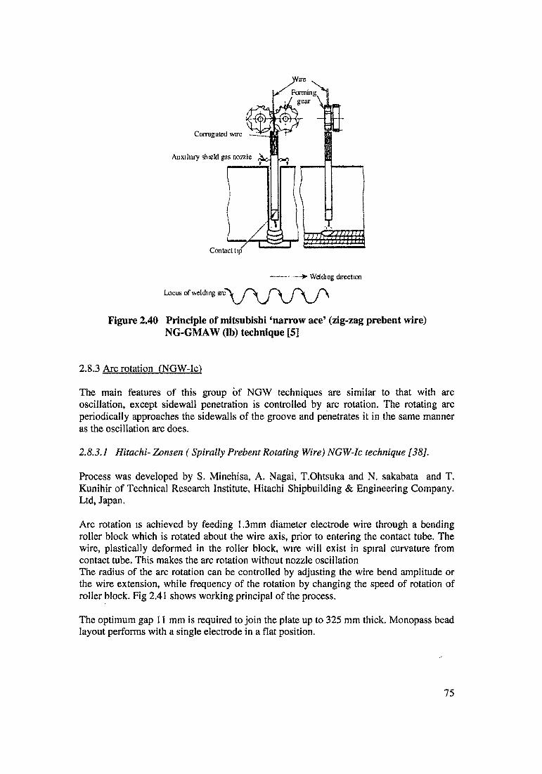
Figure 2.40 Principle of mitsubishi ‘narrow ace’ (zig-zag prebent wire) NG-GMAW (lb) technique [5]
2.8.3 Arc rotation fNGW-Ic)
The main features of this group of NGW techniques are similar to that with arc oscillation, except sidewall penetration is controlled by arc rotation. The rotating arc periodically approaches the sidewalls of the groove and penetrates it in the same manner as the oscillation arc does.
2.8.3. / Hitachi- Zonsen (Spirally Prebent Rotating Wire) NGW-Ic technique [38],
Process was developed by S. Minehisa, A. Nagai, T.Ohtsuka and N. sakabata and T. Kunihir of Technical Research Institute, Hitachi Shipbuilding & Engineering Company. Ltd, Japan.
Arc rotation is achieved by feeding 1.3mm diameter electrode wire through a bending roller block which is rotated about the wire axis, prior to entering the contact tube. The wire, plastically deformed in the roller block, wire will exist in spiral curvature from contact tube. This makes the arc rotation without nozzle oscillation The radius of the arc rotation can be controlled by adjusting the wire bend amplitude or the wire extension, while frequency of the rotation by changing the speed of rotation of roller block. Fig 2.41 shows working principal of the process.
The optimum gap 11 mm is required to join the plate up to 325 mm thick. Monopass bead layout performs with a single electrode in a flat position.
75
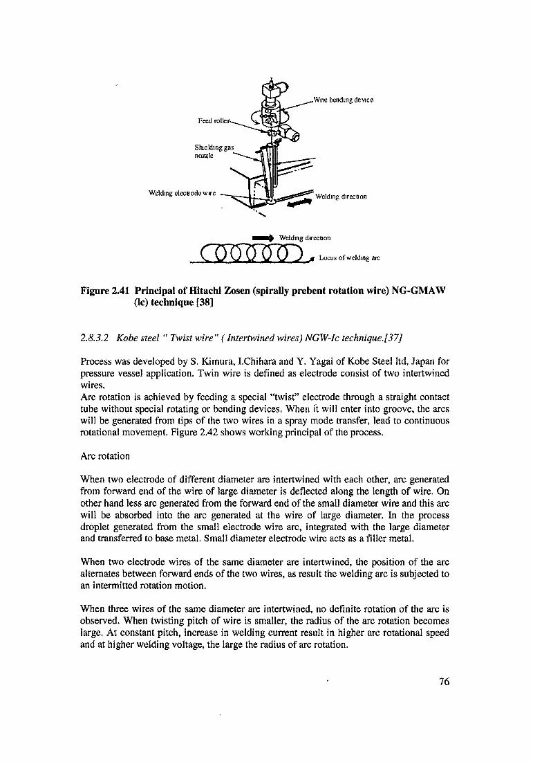
Weldmg electrode wire
Shieldingnozzle
Feed ro
•Wire bending device
Weldmg direction
Locus of welding an;
Figure 2.41 Principal of Hitachi Zosen (spirally prebent rotation wire) NG-GMAW
2.83,2 Kobe steel “ Twist wire" (Intertwined wires) NGW-Ic technique.[37]
Process was developed by S. Kimura, I.Chihara and Y. Yagai of Kobe Steel ltd, Japan for pressure vessel application. Twin wire is defined as electrode consist of two intertwined wires.Arc rotation is achieved by feeding a special “twist” electrode through a straight contact tube without special rotating or bending devices. When ft will enter into groove, the arcs will be generated from tips of the two wires in a spray mode transfer, lead to continuous rotational movement. Figure 2.42 shows working principal of the process.
Arc rotation
When two electrode of different diameter are intertwined with each other, arc generated from forward end of the wire of large diameter is deflected along the length of wire. On other hand less arc generated from the forward end of the small diameter wire and this arc will be absorbed into the arc generated at the wire of large diameter. In the process droplet generated from the small electrode wire arc, integrated with the large diameter and transferred to base metal. Small diameter electrode wire acts as a filler metal.
When two electrode wires of the same diameter are intertwined, the position of the arc alternates between forward ends of the two wires, as result the welding arc is subjected to an intermitted rotation motion.
When three wires of the same diameter are intertwined, no definite rotation of the arc is observed. When twisting pitch of wire is smaller, the radius of the arc rotation becomes large. At constant pitch, increase in welding current result in higher arc rotational speed and at higher welding voltage, the large the radius of arc rotation.
(lc) technique [38]
76
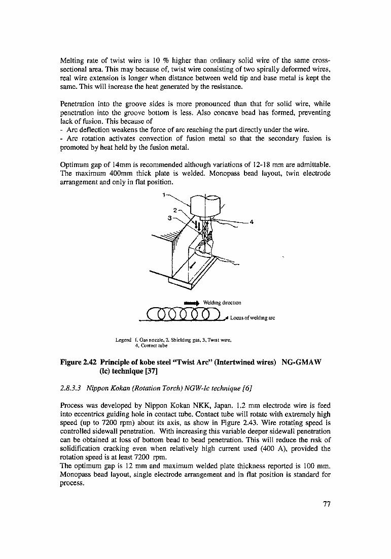
Melting rate of twist wire is 10 % higher than ordinary solid wire of the same cross- sectional area. This may because of, twist wire consisting of two spirally deformed wires, real wire extension is longer when distance between weld tip and base metal is kept the same. This will increase the heat generated by the resistance.
Penetration into the groove sides is more pronounced than that for solid wire, while penetration into the groove bottom is less. Also concave bead has formed, preventing lack of fusion. This because of- Arc deflection weakens the force of arc reaching the part directly under the wire.- Arc rotation activates convection of fusion metal so that the secondary fusion is promoted by heat held by the fusion metal.
Optimum gap of 14mm is recommended although variations of 12-18 mm are admittable. The maximum 400mm thick plate is welded. Monopass bead layout, twin electrode arrangement and only in flat position.
j* Locus of welding arc
Legend I. Gas nozzle. 2, Shielding gas, 3, Twist wire,4, Contact tube
Figure 2.42 Principle of kobe steel “Twist Arc” (Intertwined wires) NG-GMAW (Ic) technique [37]
2.8.3.3 Nippon Kokan (Rotation Torch) NGW-Ic technique [6]
Process was developed by Nippon Kokan NKK, Japan. 1.2 mm electrode wire is feed into eccentrics guiding hole in contact tube. Contact tube will rotate with extremely high speed (up to 7200 rpm) about its axis, as show in Figure 2.43. Wire rotating speed is controlled sidewall penetration. With increasing this variable deeper sidewall penetration can be obtained at loss of bottom bead to bead penetration. This will reduce the risk of solidification cracking even when relatively high current used (400 A), provided the rotation speed is at least 7200 rpm.The optimum gap is 12 mm and maximum welded plate thickness reported is 100 mm. Monopass bead layout, single electrode arrangement and in flat position is standard for process.
77

Figure 2.43 Principle of nippon kokan (rotating torch) NG-GMAW (1c) technique [6]
2.8,4 Electrode manipulation with NGW-III
The main features of this group of NGW technique are following
Relative thick electrode wire (1.6mm to 5mm).Long straight electrode extension in the centre of the groove. Higher heat input, provides much higher deposition rate. Large volume of molten metal restricts the welding in flat position. In general, standard welding equipment with slight modification can be successfully used, most attractive feature of the process.The major difference between the techniques of this group related to the method of controlling sidewall penetration. This will be possible with manipulation of welding parameters in order to widen the arc across the groove rather than manipulation of the electrode wire and welding torch.
2.8.4.1 Linde NGW-II technique [68].
Process was developed by J.E.Jackson and H.B.Sargent of union carbide corporation of USA for boiler, pressure vessels and structural members.
Basic technique involves plates to be joined in a square butt configuration with 12.7 mm gap with suitable backing technique. A large diameter (2 to 3,4 mm) electrode is feed into the groove with straight polarity and arc will initiate. The controlled arc behavior results in a weld bead trying together both sidewalls of the groove and simultaneously depositing metal on top of a preceding pass.
78

The electrode wire is feed directly without need for sophisticated contact tube with water cooling and electric insulation. While standard heavy duty filler metal feeder is used, which is an important modification required for welding head.
Simple shielding device. The torch remains above the work piece, so there is no danger of accidental arcing between them and sidewalls. Since the torch (contact tube) remains above the work piece, the electrode extension is slightly longer than plate thickness. For 3 in thick plate the filler metal extension beyond the contact tube is usually 3.5 in. Extension will decreases as the groove fills. Then it will maintain at this length by raising the welding head, one bead thickness for each pass.
At higher electrode extension, the current tends to oscillate during first few seconds, before the temperature distribution along the filler metal has settled down to steady state. This may leads to fusion defect in the first weld. The oscillation can be reduced by starting at reduced filler metal feed rate and increasing the rate gradually to normal.
A “Steady rest” is added to the torch or electrode holder as shown in figure 2.44. This is narrow finger of steel extended below the contact tube, this will electrically insulate and it will bear light of filler metal. Its purpose is to prevent vibration of filler metal and avoid erratic arc action that tends to developed under the strong arc blow conditions.
The maximum plate thickness welded is 150 mm, it seems there is no theoretical limit for the plate thickness weldable. The filler metal is fed into groove at inclined 15 degree to the vertical, the tip lagging. Sound weld has been made with filler metal in vertical position.
Figure 2.44 Principle of linde (straight fixed wire) GMAW-NG (II) technique [68]
79
2.8.42 Mitsubishi M.N.NNGW-II technique [69]
Process was developed by T Kurokawa, M. Nakajima, Yoshikuma & A. Urayama of Nagasaki technical institute of Mitsubishi heavy industries, Japan for pressure vessel fabrication in 1966.
Process differs from the Linde NGW-II technique in following aspects
Process involving a pulse arc with reverse polarity DC. Pulse arc improves erratic large globular metal transfer, typical for the straight polarity Linde technique, turning into spray transfer. Electrode wire (3.2mm) is associated with a relatively high heat input, which widen the arc to provide adequate sidewall penetration.
The maximum plate thickness welded was 130mm. The optimum gap is 16mm. A monpass bead layout in combination with single electrode and in flat position was used.[6]
80
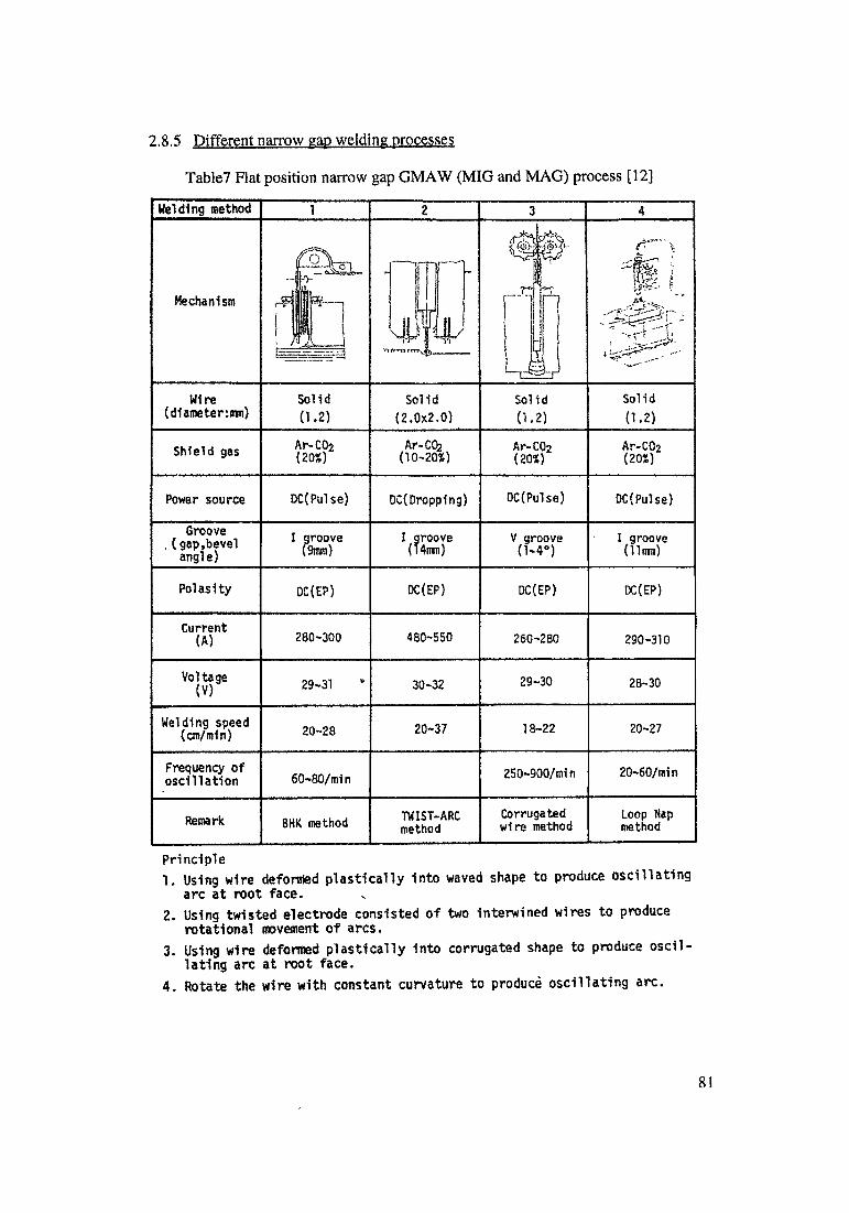
2.8,5 Different narrow gap welding processes
Table7 Flat position narrow gap GMAW (MIG and MAG) process [12]
1. Using wire deformed plastically into waved shape to produce oscillating arc at root face.
2. Using twisted electrode consisted of two interwined wires to produce rotational movement of arcs.
3. Using wire deformed plastically into corrugated shape to produce oscillating arc at root face.
4. Rotate the wire with constant curvature to produce oscillating arc.
81
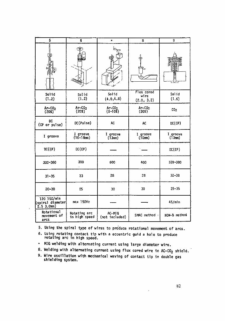
* MIG welding with alternating current using large diameter wire.8. Welding with alternating current using flux cored wire 1n AC-C&j shield.9. Wire oscillation with mechanical waving of contact tip in double gas
shielding system.
82
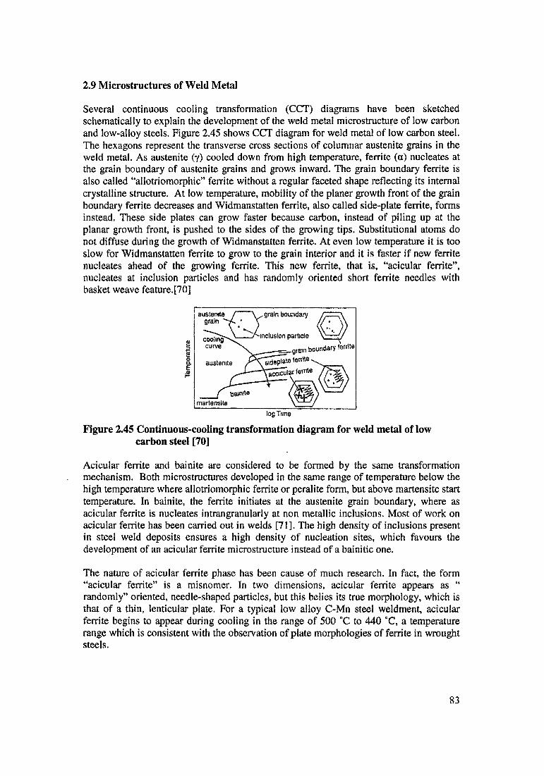
2.9 Microstructures of Weld Metal
log Time
Figure 2.45 Continuous-cooling transformation diagram for weld metal of low carbon steel [70]
Acicuiar ferrite and bainite are considered to be formed by the same transformation mechanism. Both microstructures developed in the same range of temperature below the high temperature where allotriomorphic ferrite or peralite form, but above martensite start temperature. In bainite, the ferrite initiates at the austenite grain boundary, where as acicuiar ferrite is nucleates intrangranularly at non metallic inclusions. Most of work on acicuiar ferrite has been carried out in welds [71]. The high density of inclusions present in steel weld deposits ensures a high density of nucleation sites, which favours the development of an acicuiar ferrite microstructure instead of a bainitic one.
The nature of acicuiar ferrite phase has been cause of much research. In fact, the form “acicuiar ferrite” is a misnomer. In two dimensions, acicuiar ferrite appears as “ randomly” oriented, needle-shaped particles, but this belies its true morphology, which is that of a thin, lenticular plate. For a typical low alloy C-Mn steel weldment, acicuiar ferrite begins to appear during cooling in the range of 500 °C to 440 °C, a temperature range which is consistent with the observation of plate morphologies of ferrite in wrought steels.
Several continuous cooling transformation (CCT) diagrams have been sketched schematically to explain the development of the weld metal microstructure of low carbon and low-alloy steels. Figure 2.45 shows CCT diagram for weld metal of low carbon steel. The hexagons represent the transverse cross sections of columnar austenite grains in the weld metal. As austenite (y) cooled down from high temperature, ferrite (a) nucleates at the grain boundary of austenite grains and grows inward. The grain boundary ferrite is also called “allotriomorphic” ferrite without a regular faceted shape reflecting its internal crystalline structure. At low temperature, mobility of the planer growth front of the grain boundary ferrite decreases and Widmanstatten ferrite, also called side-plate ferrite, forms instead. These side plates can grow faster because carbon, instead of piling up at the planar growth front, is pushed to the sides of the growing tips. Substitutional atoms do not diffuse during the growth of Widmanstatten ferrite. At even low temperature it is too slow for Widmanstatten ferrite to grow to the grain interior and it is faster if new ferrite nucleates ahead of the growing ferrite. This new ferrite, that is, “acicuiar ferrite”, nucleates at inclusion particles and has randomly oriented short ferrite needles with basket weave feature.[70]
Tem
pera
ture
83

It is well established that acicular ferrite nucleates at nonmetallic inclusions which occurs frequently in arc welds. With respect of the carbon concentration of acicular ferrite during transformation, experiments and thermodymic theory demonstrated that the growth of acicular ferrite is diffusionless, the ferrite inheriting the chemical composition of the parent austenite. However, Immediately after transformation, the excess carbon In the acicular ferrite is rejected into residual austenite. Latter process can oeours in a matter of seconds. [72]
Mechanism of transition from bainite to acicular ferrite has been studied by S.S.Babu and H.K.D.H Bhadeshia [73], Some of the experimental results which confirm that acicular ferrite is nothing but intragranularly nucleated bainite are summarized schematically in figure 2.46. The transformation temperatures are identical for all the cases illustrated, the differences being that
Figure 2.46 A : Inclusion density changed for the same austenite grain size- the sample with the smaller inclusion density transforms to bainite since the relative number density of austenite grain boundary nucleation sites is large.
Figure 2.46 B: An increase in the austenite grain size at constant inclusion density stimulates a transition from a predominately bainitic to an acicular ferrite microstructure.
Figure 2.46 C: the growth layer of inert allotriomorphic ferrite at the austenite grain surface causes a transition from bainite to acicular ferrite.
Figure 2.46 Schematic illustration of transition from bainite to acicular ferrite [73]
(Q No grain hnundaiy .ilkunnmorphic femic
(O Poljvrystalline layer of allotnomorpfncfcrnic
84
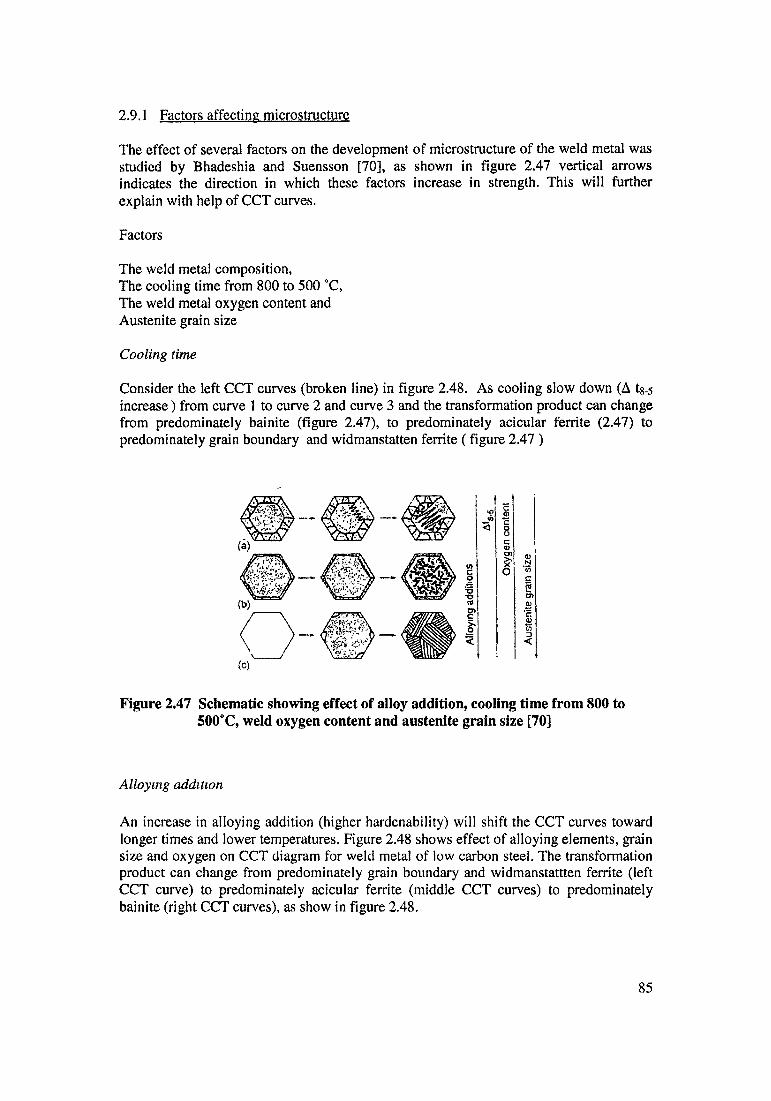
2.9.1 Factors affecting microstructure
The effect of several factors on the development of microstructure of the weld metal was studied by Bhadeshia and Suensson [70], as shown in figure 2.47 vertical arrows indicates the direction in which these factors increase in strength. This will further explain with help of CCT curves.
Factors
The weld metal composition,The cooling time from 800 to 500 °C,The weld metal oxygen content and Austenite grain size
Cooling time
Consider the left CCT curves (broken line) in figure 2.48. As cooling slow down (A tg-s increase) from curve 1 to curve 2 and curve 3 and the transformation product can change from predominately bainite (figure 2.47), to predominately acicular ferrite (2.47) to predominately grain boundary and Widmanstatten ferrite (figure 2.47 )
(C)
Figure 2.47 Schematic showing effect of alloy addition, cooling time from 800 to 500°C, weld oxygen content and austenite grain size [70]
Alloying addition
An increase in alloying addition (higher hardenability) will shift the CCT curves toward longer times and lower temperatures. Figure 2.48 shows effect of alloying elements, grain size and oxygen on CCT diagram for weld metal of low carbon steel. The transformation product can change from predominately grain boundary and widmanstattten ferrite (left CCT curve) to predominately acicular ferrite (middle CCT curves) to predominately bainite (right CCT curves), as show in figure 2.48.
Aus
teni
te g
ram
size
Oxy
gen
cont
entS*8
At
85
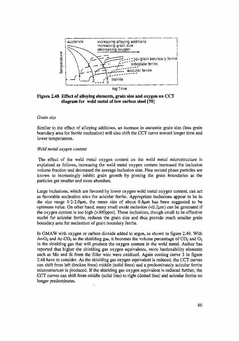
log Time
Figure 2.48 Effect of alloying elements, grain size and oxygen on CCT diagram for weld metal of low carbon steel [70]
Grain size
Similar to the effect of alloying additions, an increase in austenite grain size (less grain boundary area for ferrite nucleation) will also shift the CCT curve toward longer time and lower temperatures.
Weld metal oxygen content
The effect of the weld metal oxygen content on the weld metal microstructure is explained as follows, increasing the weld metal oxygen content increased the inclusion volume fraction and decreased the average inclusion size. Fine second phase particles are known to increasingly inhibit grain growth by pinning the grain boundaries as the particles get smaller and more abundant.
Large inclusions, which are favored by lower oxygen weld metal oxygen content, can act as favorable nucleation sites for acicular ferrite. Appropriate inclusions appear to be in the size range 0.2-2.Opm, the mean size of about 0.4pm has been suggested to be optimum value. On other hand, many small oxide inclusion (<0.2pm) can be generated if the oxygen content is too high (>300ppm). These inclusions, though small to be effective nuclei for acicular ferrite, reduces the grain size and thus provide much smaller grain boundary area for nucleation of grain boundary ferrite.
In GMAW with oxygen or carbon dioxide added to argon, as shown in figure 2.49. With Ar-02 and Ar-C02 as the shielding gas, it becomes the volume percentage of C02 and 02 in the shielding gas that will produce the oxygen content in the weld metal. Author has reported that higher the shielding gas oxygen equivalents, more hardenability elements such as Mn and Si from the filler wire were oxidized. Again cooling curve 3 in figure 2.48 have to consider. As the shielding gas oxygen equivalent is reduced, the CCT curves can shift from left (broken lines) middle (solid lines) and a predominately acicular ferrite microstructure is produced. If the shielding gas oxygen equivalent is reduced further, the CCT curves can shift from middle (solid line) to right (dotted line) and acicular ferrite no longer predominates.
Tem
pera
ture
86
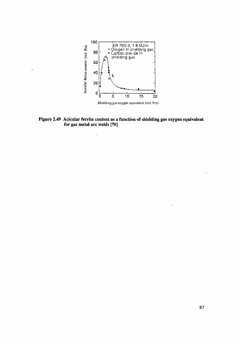
Shielding gas oxygen equivalent (vol. Pet)
Figure 2.49 Acicular ferrite content as a function of shielding gas oxygen equivalent for gas metal arc welds [70]
Aci
cula
r fer
rite
cont
ent (v
ol Pe
t)
87
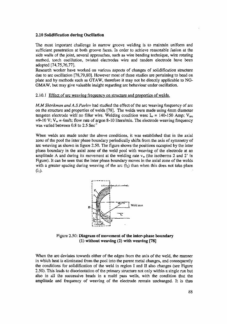
2.10 Solidification during Oscillation
The most important challenge in narrow groove welding is to maintain uniform and sufficient penetration at both groove faces. In order to achieve reasonable fusion at the side walls of the joint, several approaches, such as wire bending technique, wire rotating method, torch oscillation, twisted electrodes wire and tandem electrode have been adopted [74,75,76,77].Research worker have worked on various aspects of changes of solidification structure due to arc oscillation [78,79,80]. However most of these studies are pertaining to bead on plate and by methods such as GTAW, therefore it may not be directly applicable to NG- GMAW, but may give valuable insight regarding arc behaviour under oscillation.
2.10.1 Effect of arc weaving frequency on structure and properties of welds.
M.M Shtrikman and A.S. Pavlov had studied the effect of the arc weaving frequency of arc on the structure and properties of welds [78], The welds were made using 4mm diameter tungsten electrode with5 no filler wire. Welding condition were Iw = 140-150 Amp; Varc =9-10 V; Vw = 4m/h; flow rate of argon 8-10 liters/min. The electrode weaving frequency was varied between 0.8 to 2.5 Sec"1
When welds are made under the above conditions, it was established that in the axial zone of the pool the inter phase boundary periodically shifts from the axis of symmetry of arc weaving as shown in figure 2.50. The figure shows the positions occupied by the inter phase boundary in the axial zone of the weld pool with weaving of the electrode at an amplitude A and during its movement at the welding rate vw (the isotherms 2 and 2’ in Figure). It can be seen that the inter phase boundary moves in the axial zone of the welds with a greater spacing during weaving of the arc (I2) than when this does not take place
When the arc deviates towards either of the edges from the axis of the weld, the manner in which heat is eliminated from the pool into the parent metal changes, and consequently the conditions for solidification of the weld in region I and II also changes (see Figure 2.50). This leads to disorientation of the primary structure not only within a single run but also in all the successive beads in a multi pass wells, with the condition that the amplitude and frequency of weaving of the electrode remain unchanged. It is thus
di).
r .. i-----dJmi r I----- <—1.
Figure 2.50: Diagram of movement of the inter-phase boundary (1) without weaving (2) with weaving [78]
88
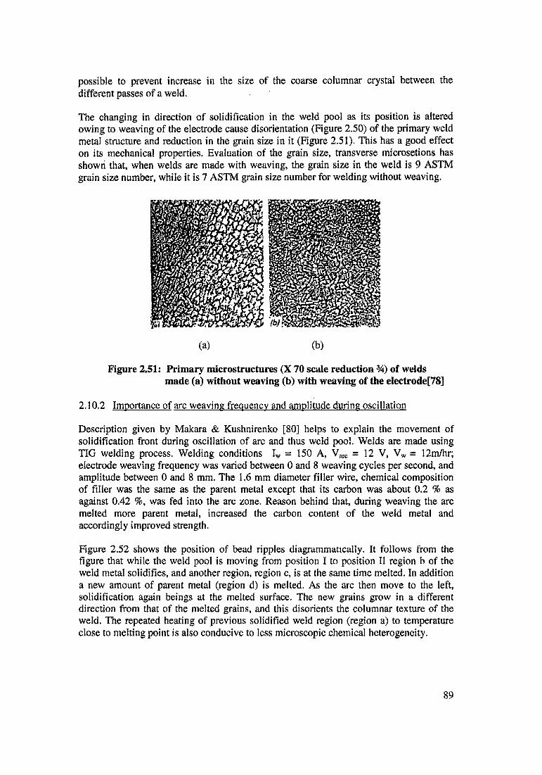
possible to prevent increase in the size of the coarse columnar crystal between the different passes of a weld.
The changing in direction of solidification in the weld pool as its position is altered owing to weaving of the electrode cause disorientation (Figure 2.50) of the primary weld metal structure and reduction in the grain size in it (Figure 2.51). This has a good effect on its mechanical properties. Evaluation of the grain size, transverse microsetions has shown that, when welds are made with weaving, the grain size in the weld is 9 ASTM grain size number, while it is 7 ASTM grain size number for welding without weaving.
Figure 2.51: Primary microstructures (X 70 scale reduction %) of weldsmade (a) without weaving (b) with weaving of the electrode[78]
2.10.2 Importance of arc weaving frequency and amplitude during oscillation
Description given by Makara & Kushnirenko [80] helps to explain the movement of solidification front during oscillation of arc and thus weld pool. Welds are made using TIG welding process. Welding conditions Iw = 150 A, Varc = 12 V, Vw = 12m/hr; electrode weaving frequency was varied between 0 and 8 weaving cycles per second, and amplitude between 0 and 8 mm. The 1.6 mm diameter filler wire, chemical composition of filler was the same as the parent metal except that its carbon was about 0.2 % as against 0.42 %, was fed into the arc zone. Reason behind that, during weaving the arc melted more parent metal, increased the carbon content of the weld metal and accordingly improved strength.
Figure 2.52 shows the position of bead ripples diagrammatically. It follows from the figure that while the weld pool is moving from position I to position II region b of the weld metal solidifies, and another region, region c, is at the same time melted. In addition a new amount of parent metal (region d) is melted. As the arc then move to the left, solidification again beings at the melted surface. The new grains grow in a different direction from that of the melted grains, and this disorients the columnar texture of the weld. The repeated heating of previous solidified weld region (region a) to temperature close to melting point is also conducive to less microscopic chemical heterogeneity.
89
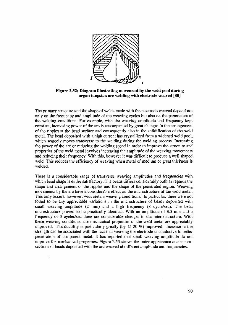
argon tungsten arc welding with electrode weaved [80]
The primary structure and the shape of welds made with the electrode weaved depend not only on the frequency and amplitude of the weaving cycles but also on the parameters of the welding conditions. For example, with the weaving amplitude and frequency kept constant, increasing power of the arc is accompanied by great changes in the arrangement of the ripples at the bead surface and consequently also in the solidification of the weld metal. The bead deposited with a high current has crystallized from a widened weld pool, which scarcely moves transverse to the welding during the welding process. Increasing the power of the arc or reducing the welding speed in order to improve the structure and properties of the weld metal involves increasing the amplitude of the weaving movements and reducing their frequency. With this, however it was difficult to produce a well shaped weld. This reduces the efficiency of weaving when metal of medium or great thickness is welded.
There is a considerable range of transverse weaving amplitudes and frequencies with which bead shape is entire satisfactory. The beads differs considerably both as regards the shape and arrangement of the ripples and the shape of the penetrated region. Weaving movements by the arc have a considerable effect on the microstructure of the weld metal. This only occurs, however, with certain weaving conditions. In particular, there were not found to be any appreciable variations in the microstructure of beads deposited with small weaving amplitude (2 mm) and a high frequency (8 cycle/sec). The bead microstructure proved to be practically identical. With an amplitude of 3.5 mm and a frequency of 3 cycles/sec there are considerable changes in the micro structure. With these weaving conditions, the mechanical properties of the weld metal are appreciably improved. The ductility is particularly greatly (by 15-20 %) improved. Increase in the strength can be associated with the fact that weaving the electrode is conducive to better penetration of the parent metal. It has reported that small weaving amplitude do not improve the mechanical properties. Figure 2.53 shows the outer appearance and macrosections of beads deposited with the arc weaved at different amplitude and frequencies.
90
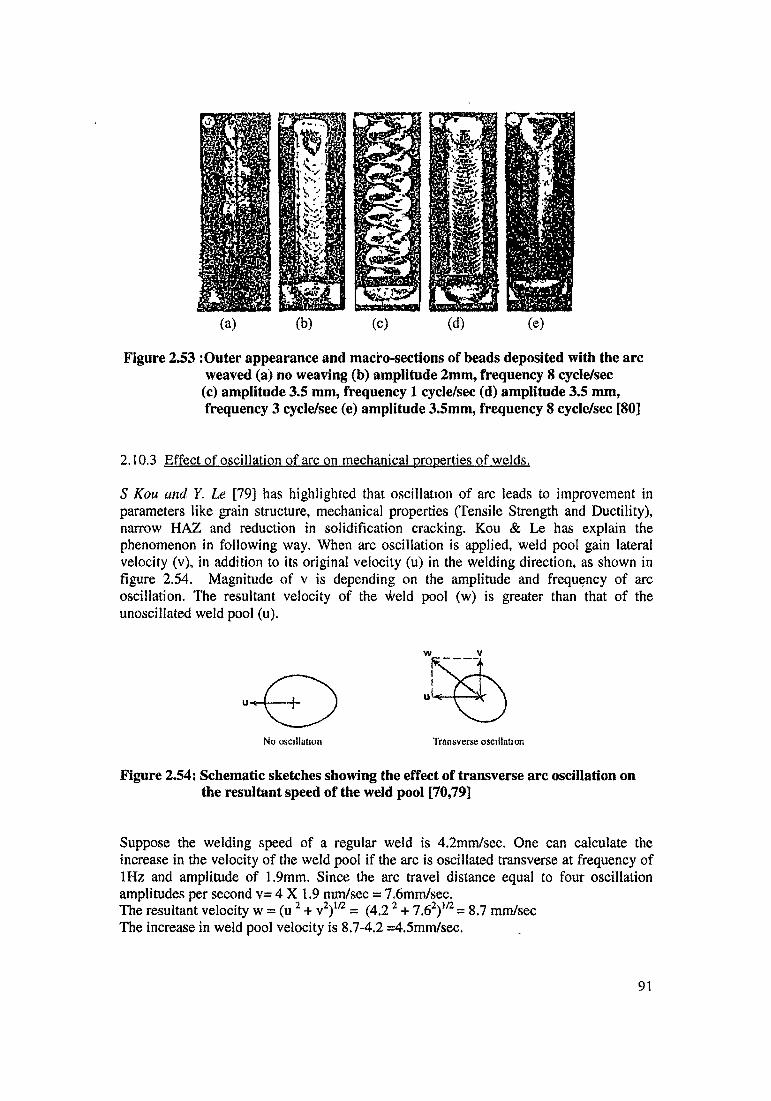
Figure 2.53 : Outer appearance and macro-sections of beads deposited with the arc weaved (a) no weaving (b) amplitude 2mm, frequency 8 cycle/sec
(c) amplitude 3.5 nun, frequency 1 cycle/sec (d) amplitude 3.5 mm, frequency 3 cycle/sec (e) amplitude 3.5mm, frequency 8 cycle/sec [80]
2.10.3 Effect of oscillation of arc on mechanical properties of welds.
S Kou and Y. Le [79] has highlighted that oscillation of arc leads to improvement in parameters like grain structure, mechanical properties (Tensile Strength and Ductility), narrow HAZ and reduction in solidification cracking, Kou & Le has explain the phenomenon in following way. When arc oscillation is applied, weld pool gain lateral velocity (v), in addition to its original velocity (u) in the welding direction, as shown in figure 2.54. Magnitude of v is depending on the amplitude and frequency of arc oscillation. The resultant velocity of the weld pool (w) is greater than that of the unoscillated weld pool (u).
Figure 2.54: Schematic sketches showing the effect of transverse arc oscillation on the resultant speed of the weld pool [70,79]
Suppose the welding speed of a regular weld is 4.2mm/sec. One can calculate the increase in the velocity of the weld pool if the arc is oscillated transverse at frequency of 1Hz and amplitude of 1.9mm. Since the arc travel distance equal to four oscillation amplitudes per second v= 4 X 1.9 mm/sec = 7.6mm/sec.The resultant velocity w = (u 2 + v2)m = (4.2 2 + 7.62)1/2 = 8.7 mm/sec The increase in weld pool velocity is 8.7-4.2 =4.5mm/sec.
91
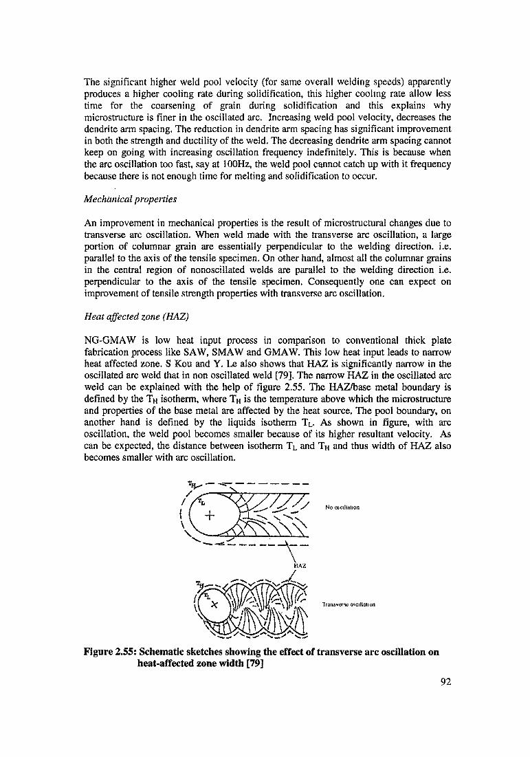
The significant higher weld pool velocity (for same overall welding speeds) apparently produces a higher cooling rate during solidification, this higher cooling rate allow less time for the coarsening of grain during solidification and this explains why microstructure is finer in the oscillated arc. Increasing weld pool velocity, decreases the dendrite arm spacing. The reduction in dendrite arm spacing has significant improvement in both the strength and ductility of the weld. The decreasing dendrite arm spacing cannot keep on going with increasing oscillation frequency indefinitely. This is because when the arc oscillation too fast, say at 100Hz, the weld pool cannot catch up with it frequency because there is not enough time for melting and solidification to occur.
MechUnical properties
An improvement in mechanical properties is the result of microstructural changes due to transverse arc oscillation. When weld made with the transverse arc oscillation, a large portion of columnar grain are essentially perpendicular to the welding direction, i.e. parallel to the axis of the tensile specimen. On other hand, almost all the columnar grains in the central region of nonoseillated welds are parallel to the welding direction i.e. perpendicular to the axis of the tensile specimen. Consequently one can expect on improvement of tensile strength properties with transverse arc oscillation.
Heat affected zone (HAZ)
NG-GMAW is low heat input process in comparison to conventional thick plate fabrication process like SAW, SMAW and GMAW. This low heat input leads to narrow heat affected zone. S Kou and Y. Le also shows that HAZ is significantly narrow in the oscillated arc weld that in non oscillated weld [79]. The narrow HAZ in the oscillated arc weld can be explained with the help of figure 2.55. The HAZ/base metal boundary is defined by the Th isotherm, where Th is the temperature above which the microstructure and properties of the base metal are affected by the heat source. The pool boundary, on another hand is defined by the liquids isotherm TL. As shown in figure, with arc oscillation, the weld pool becomes smaller because of its higher resultant velocity. As can be expected, the distance between isotherm Tl and Th and thus width of HAZ also becomes smaller with arc oscillation.
Figure 2.55: Schematic sketches showing the effect of transverse arc oscillation on heat-affected zone width [79]
92

Solidification cracking
Solidification cracking is also one of the problem, affected due to oscillation of arc. Solidification cracking get reduced dramatically in the oscillated arc weld. The mechanism that reduces solidification cracking because of alternating grain orientation, is effective because of solidification cracking is intergranular and columnar grains which reverse their orientation at regular interval force the crack to change its direction periodically, thus discouraging crack propagation. Figure 2.56 show crack path in a weld made with transverse arc oscillation. It expected that, when the amplitude of arc oscillation was reduced, the effect of arc oscillation on cracking is decreased.
Curved columnar grains} Straight crack path
Alternating columnar grains Winding crack path
Figure 2.56: The effect of grain structure on crack path and resistance to crackpropagation during welding arc oscillation on solidification cracking, the center of the arc is indicated by “+” and the welding direction is from right to left [79]
Importance of frequency range
Transverse arc oscillation at high frequencies was ineffective. This findings matches with that of Makara & Kushnirenko [80]. Grain structure at high frequency indicates there was no evidence of alternating columnar grains or fine equiaxed grains.
Solidification cracking is also related to frequency of oscillation. Minimum solidification cracking existed in a rather narrow range of frequency near 0.9 Hz. This solidification cracking is because of significant reduction in solidification cracking in this frequency range was due to mechanism of alternating grain orientation.
As the oscillation frequency approach zero, solidification cracking increases again. Apparently, alternating columnar grain can no longer exist in weld, if the frequency of oscillation is too low.
Neither alternating grain orientation nor reduction in solidification cracking was observed when welding was carried out with circular or longitudinal arc oscillation.
93
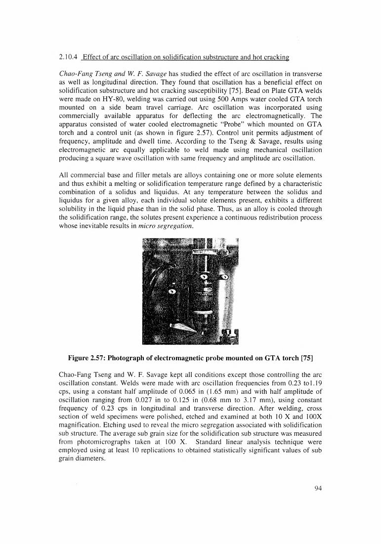
2.10.4 Effect of arc oscillation on solidification substructure and hot cracking
Chao-Fang Tseng and W. F. Savage has studied the effect of arc oscillation in transverse as well as longitudinal direction. They found that oscillation has a beneficial effect on solidification substructure and hot cracking susceptibility [75], Bead on Plate GTA welds were made on HY-80, welding was carried out using 500 Amps water cooled GTA torch mounted on a side beam travel carriage. Arc oscillation was incorporated using commercially available apparatus for deflecting the arc electromagnetically. The apparatus consisted of water cooled electromagnetic “Probe” which mounted on GTA torch and a control unit (as shown in figure 2.57). Control unit permits adjustment of frequency, amplitude and dwell time. According to the Tseng & Savage, results using electromagnetic arc equally applicable to weld made using mechanical oscillation producing a square wave oscillation with same frequency and amplitude arc oscillation.
All commercial base and filler metals are alloys containing one or more solute elements and thus exhibit a melting or solidification temperature range defined by a characteristic combination of a solidus and liquidus. At any temperature between the solidus and liquidus for a given alloy, each individual solute elements present, exhibits a different solubility in the liquid phase than in the solid phase. Thus, as an alloy is cooled through the solidification range, the solutes present experience a continuous redistribution process whose inevitable results in micro segregation.
Figure 2.57: Photograph of electromagnetic probe mounted on GTA torch [75]
Chao-Fang Tseng and W. F. Savage kept all conditions except those controlling the arc oscillation constant. Welds were made with arc oscillation frequencies from 0.23 to 1.19 cps, using a constant half amplitude of 0.065 in (1.65 mm) and with half amplitude of oscillation ranging from 0.027 in to 0.125 in (0.68 mm to 3.17 mm), using constant frequency of 0.23 cps in longitudinal and transverse direction. After welding, cross section of weld specimens were polished, etched and examined at both 10 X and 100X magnification. Etching used to reveal the micro segregation associated with solidification sub structure. The average sub grain size for the solidification sub structure was measured from photomicrographs taken at 100 X. Standard linear analysis technique were employed using at least 10 replications to obtained statistically significant values of sub grain diameters.
94
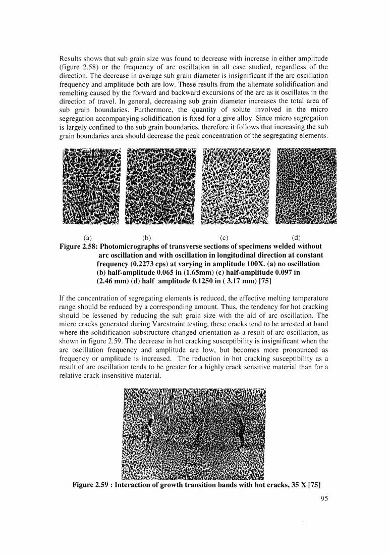
Results shows that sub grain size was found to decrease with increase in either amplitude (figure 2.58) or the frequency of arc oscillation in all case studied, regardless of the direction. The decrease in average sub grain diameter is insignificant if the arc oscillation frequency and amplitude both are low. These results from the alternate solidification and remelting caused by the forward and backward excursions of the arc as it oscillates in the direction of travel. In general, decreasing sub grain diameter increases the total area of sub grain boundaries. Furthermore, the quantity of solute involved in the micro segregation accompanying solidification is fixed for a give alloy. Since micro segregation is largely confined to the sub grain boundaries, therefore it follows that increasing the sub grain boundaries area should decrease the peak concentration of the segregating elements.
(a) (b) (c) (d)Figure 2,58: Photomicrographs of transverse sections of specimens welded without
arc oscillation and with oscillation in longitudinal direction at constant frequency (0.2273 cps) at varying in amplitude 100X. (a) no oscillation (b) half-amplitude 0.065 in (1.65mm) (c) half-amplitude 0.097 in (2.46 mm) (d) half amplitude 0.1250 in ( 3.17 mm) [75]
If the concentration of segregating elements is reduced, the effective melting temperature range should be reduced by a corresponding amount. Thus, the tendency for hot cracking should be lessened by reducing the sub grain size with the aid of arc oscillation. The micro cracks generated during Varestraint testing, these cracks tend to be arrested at band where the solidification substructure changed orientation as a result of arc oscillation, as shown in figure 2.59. The decrease in hot cracking susceptibility is insignificant when the arc oscillation frequency and amplitude are low, but becomes more pronounced as frequency or amplitude is increased. The reduction in hot cracking susceptibility as a result of arc oscillation tends to be greater for a highly crack sensitive material than for a relative crack insensitive material.
Figure 2.59 : Interaction of growth transition bands with hot cracks, 35 X [75]
95

2.10.5 Effect of arc oscillation on the formation lack of interlayer fusion in NG-GTAW.
A.S.Pavlov M.M Shtrikman and VI Zakharovl had studied effect of narrow gap GTAW welding conditions on the formation of lack of fusion defects. [76]According authors in multi pass welding, the type of defect appeared called interlayer lack fusion. Reason behind the formation of this defects i) Penetration depth of the previous layer of weld ii) The thickness of the liquid interlayer below the arc column is the main parameter for determining the stability of the penetration depth.
Welding condition
In this work, investigation of the effect of the main welding parameters on the penetration depth of previous layer of the weld at a different width of the slit gap. The experiment were carried out in mechnised argon -arc TIG welding, pipe of 30KhGSA steel with an external diameter of 140mm and wall thickness of 15mm by the ‘forward tilt’ technique. The welding conditions were varied over the following ranges: Iw = 150- 160A, Vw = 4- 15 m/hr, Wire feed rate (Vf) = 4-40 m/hr (Sv-18KhMA filler wire, diameter 1.6mm), width of the gap (slit) bs = 4-12mm, frequency (f) and amplitude (a) of all electrode oscillations were respectively 0.5 -2 Sec'! and 0-90°
The quality of formation of the weld layer was evaluated on transverse macro sections. The penetration depth of the weld layer (hp) was measured by the method shown in figure 2.60 (a). The thickness of the liquid interlayer 5| was measured using an electric resistance senor, its probe was periodically immersed in the molten pool using a signal (in the form of voltage) taken from its probe. The probe was in the form of tungsten wire 0.5 mm in diameter, placed in a quarts tube 1.3 mm in diameter. The rate of immersion of the probe Vp =0.5 m/sec, the immersion frequency 3 min'1. Measurement was taken when the distance of the arc from the weld axis was 01-0.15 bs. One of the conditions (Iw, Vw, Vf and f) was varied in welding a joint. Depending upon the task, the frequency of immersion varied over wide range.
(a)0 4 8 12 16 Vw, m/hr
(b)
Figure:2.60 Dependence of penetration depth hp of previous layer of the weld [76](a) on current Iw at Vw - 6 m/hr (b) On welding speed Vw at Iw =250 A
Investigation show figure 2.60 (a) and (b) that, width reduction of the width of the gap (to 6 mm), the penetration depth decreased as a result of more extensive melting of the edges and an increase of the thickness of the liquid interlayer below the arc column. This may lead to lack of fusion even at high arc power. To avoid the formation of molten pool with a large volume, author recommended to reduce wire feed rate from 40 to 20-30 m/hr, so that penetration depth was slightly stabilised.
96
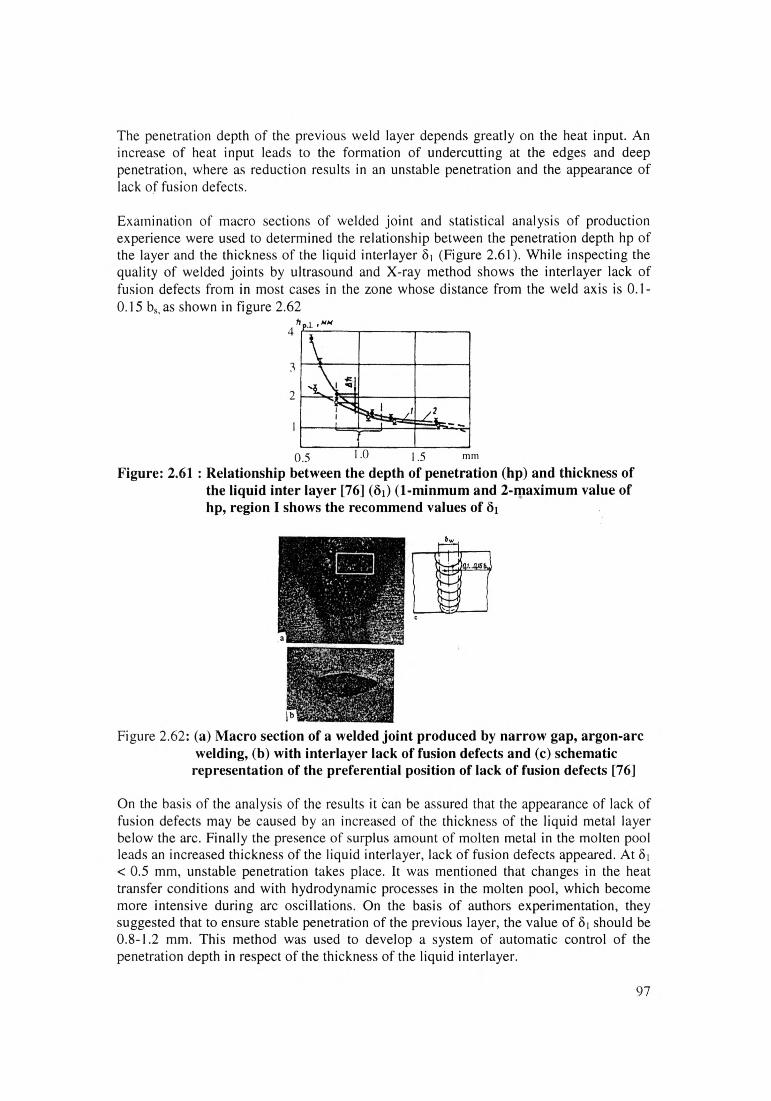
The penetration depth of the previous weld layer depends greatly on the heat input. An increase of heat input leads to the formation of undercutting at the edges and deep penetration, where as reduction results in an unstable penetration and the appearance of lack of fusion defects.
Examination of macro sections of welded joint and statistical analysis of production experience were used to determined the relationship between the penetration depth hp of the layer and the thickness of the liquid interlayer 81 (Figure 2.61). While inspecting the quality of welded joints by ultrasound and X-ray method shows the interlayer lack of fusion defects from in most cases in the zone whose distance from the weld axis is 0.1- 0.15 bs, as shown in figure 2.62
4
3
2
0.5 1 0 1.5 mm
Figure: 2.61 : Relationship between the depth of penetration (hp) and thickness of the liquid inter layer [76] (8i) (1-minmum and 2-maximum value of hp, region I shows the recommend values of 8i
Figure 2.62: (a) Macro section of a welded joint produced by narrow gap, argon-arc welding, (b) with interlayer lack of fusion defects and (c) schematic representation of the preferential position of lack of fusion defects [76]
On the basis of the analysis of the results it can be assured that the appearance of lack of fusion defects may be caused by an increased of the thickness of the liquid metal layer below the arc. Finally the presence of surplus amount of molten metal in the molten pool leads an increased thickness of the liquid interlayer, lack of fusion defects appeared. At 8| < 0.5 mm, unstable penetration takes place. It was mentioned that changes in the heat transfer conditions and with hydrodynamic processes in the molten pool, which become more intensive during arc oscillations. On the basis of authors experimentation, they suggested that to ensure stable penetration of the previous layer, the value of 8i should be 0.8-1.2 mm. This method was used to develop a system of automatic control of the penetration depth in respect of the thickness of the liquid interlayer.
97

2.10.6 Effect of arc oscillation and additional gas iet on structure and chemical heterogeneity of the weld in NG-GTAW
A.S.Pavlov MM Shtrikman and VI Zakharovl had carried out investigation of the effect of low frequency oscillation of the arc and the effect of an additional gas jet in automatic narrow gap argon TIG welding on the structure and chemical heterogeneity of the weld.[77]Most of previous case studies highlighted the importance of low frequency oscillation of the weld pool, an efficient means of improving their structure and properties of welded joints in welding thin-walled [80] and thick walled [78] components of high strength steels. In previous case study it was highlighted (case study 5) that periodic displacement of the flow of liquid metal along each of the edges and also by the flow of metal below the arc. This increase the thickness of the liquid interlayer and leads to the formation of lack of fusion defects [76,77].
Welding condition
The welding was earned out in argon with a non consumable electrode in a gap 8 mm wide. Annular joints in pipes 250mm X 25mm in diameter of 39 KhGSNM2A steel were welded under condition : Iw = 150-250 A, Vw = 2-10 m/h ; tungsten electrode diameter was 4mm, bending angle of the working tip of electrode 10°, oscillation frequency of the working tips of the electrode f = 0.5-2.5'1,oscillation amplitude 2.5mm, argon flow rate 151/min.The temperature gradients of the liquid metal in the tail part of the weld pool were determined in accordance with method descried in ref [78]. The investigation shows that temperature gradient and values of the criteria of concentrational super cooling (AVc/ AT ration) was decreased with increased of linear energy and electrode weaving frequency,
Av^iT, miiiVCs
Figure 2.63 : Dependence of variation of the temperature gradient (a) and the criterion of concentrational supper cooling (b) in the tail part of the weld pool on electrode oscillation frequency 1) q/v =4 KJ/cm 2) q/v = lOKJ/cm 3) q/v = 35 KJ/cm. [77]
98

It was confirmed for NG-GTAW that variation of the position of the weld pool under the effect of electrode weaving leads to disorientation and refining of the primary structure of weld. Grain size structure of the weld was evaluated on the basis of GOST 5639-65 on macro sections showed that the maximum effect was obtained in welding with the minimum linear energy as shown In figure 2.64 and 2.6S.
Figure 2.64 : Effect of electrode oscillation frequency (f) on grain size dm
Figure 2.65 : Dependence of weld structure on weld oscillation frequency [77](q/v =4KJ/cm) a) f =0 sec'1 b) 1.0 sec'1 c) 2.0 sec'1
To vary the solidification direction of remelted region, a method was developed of welding with periodic supply of gas from two additional nozzles against the flow of molten metal, as shown in figure 2.66. Welding was carried out under the condition described previously. An additional gas flow (flow rate 3 I/min) was supplied through pipes (nozzles diameter 2mm) its end were situated at a height of 5 mm from the surface of the weld pool. The gas flow was directed into the tail part of the weld pool directly to the zone of displacement of the interphase boundary, at a certain distance 1 from the axis of the gap. Movement of interphase boundary of the weld pool was examined by high speed filming as suggested in ref [78].
Metallographic analysis of the welded joints showed that in welding with transverse electrode weaving an additional supply of gas into gap it was possible to guarantee refining and disorientation of the primary structure of the weld metal the highest refining effect and smallest grain size were obtained at I = 0.2 b. Result also shows that efficiency
99
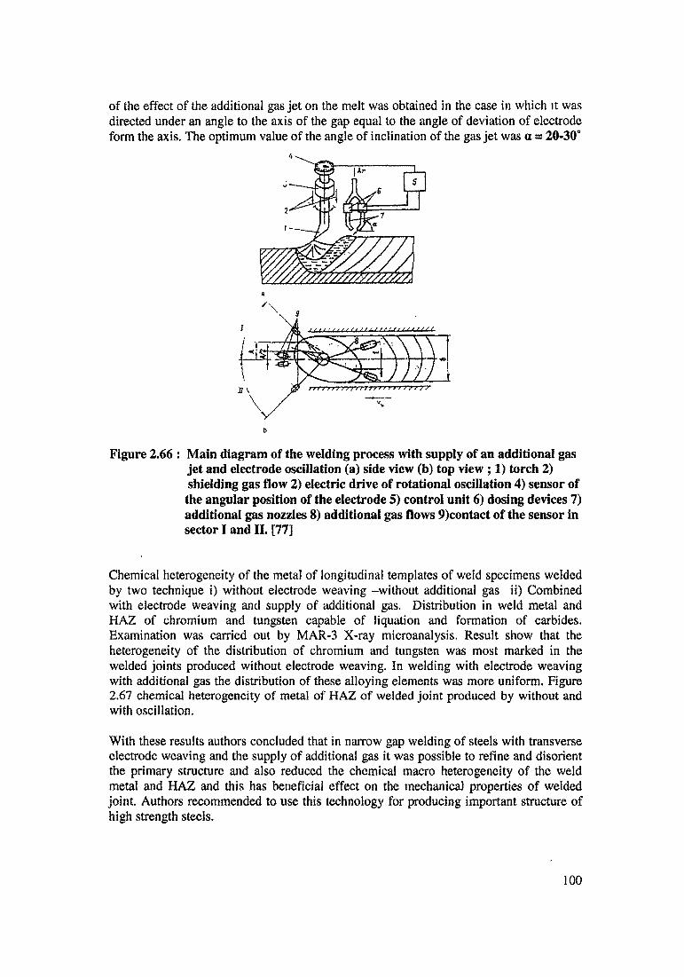
of the effect of the additional gas jet on the melt was obtained in the case in which it was directed under an angle to the axis of the gap equal to the angle of deviation of electrode form the axis. The optimum value of the angle of inclination of the gas jet was a = 20-30°
Figure 2.66 : Main diagram of the welding process with supply of an additional gas jet and electrode oscillation (a) side view (b) top view ; 1) torch 2) shielding gas flow 2) electric drive of rotational oscillation 4) sensor of the angular position of the electrode 5) control unit 6) dosing devices 7) additional gas nozzles 8) additional gas flows 9)contact of the sensor in sector I and II. [77]
Chemical heterogeneity of the metal of longitudinal templates of weld specimens welded by two technique i) without electrode weaving -without additional gas ii) Combined with electrode weaving and supply of additional gas. Distribution in weld metal and HAZ of chromium and tungsten capable of liquation and formation of carbides. Examination was carried out by MAR-3 X-ray microanalysis. Result show that the heterogeneity of the distribution of chromium and tungsten was most marked in the welded joints produced without electrode weaving. In welding with electrode weaving with additional gas the distribution of these alloying elements was more uniform. Figure 2.67 chemical heterogeneity of metal of HAZ of welded joint produced by without and with oscillation.
With these results authors concluded that in narrow gap welding of steels with transverse electrode weaving and the supply of additional gas it was possible to refine and disorient the primary structure and also reduced the chemical macro heterogeneity of the weld metal and HAZ and this has beneficial effect on the mechanical properties of welded joint. Authors recommended to use this technology for producing important structure of high strength steels.
100

Weld Fusionzone Parent metal
Figure 2.67: Chemical heterogeneity of metal of the HAZ of a welded joint inmaterial welded(a) without weaving and without additional gas (b) with electrode oscillation and additional gas supply [77]
101

2.11 Magnetic Arc Blow in NG-GMAW
Drozdov, Pak & Rubtrov [81] have done extensive work on the effect of magnetic field on weld quality during welding. They felt ,that, magnetic arc blow impedes arc striking, increases spatter of electrode metal and impair weld formation. Strong magnetic field usually contains a large amount of defects. Magnetic field influences jointly the welding arc and weld pool, this effect cause change in electrical parameter of arc (Variation in Voltage, Current) and in the nature of metal transfer and also change in geometrical dimensions and formation condition of the joint.
A welding arc is like a cylindrical conductor carrying current and therefore it carries a magnetic field around it as shown in figure 2.68. This magnetic field magnetises the mild steel work piece and also tends to deflect arc from its vertical line in the joint gap which leads to loss of arc stability. Magnetic field around the arc exerts a force on the electrons and ions, which cause the arc to be deflect away from the normal arc path, this is called Arc Blow' [82], Arc instability produces spatters, lack of sidewall fusion and porosity [83]. In conventional welding magnetic field is known to cause arc blow and literature is available on role of magnetism in welding [1,9,65]. However very little information is available about the role of magnetic field and residual magnetism in NG-GMAW [84,85]. Mention has been made in literature that magnetic effects will be more pronounced in case of NG-GMAW. This is indeed the case and is logical too considering the fact that sidewalls are closer to arc. However there is no systematic study of residual magnetism on sidewall fusion in NGW.
lectrode
) <—Magnetic Field
7\Arc
Figure 2.68 Magnetic fields around the electrode and inside the joint
Since the joint gap in which arc moves is narrow, the magnetic field of the arc passes through the work piece and magnetises it. When the arc comes out of the joint gap, residual magnetism is left in the work piece of the mild steel. It is expected that two opposite pieces of the job will have opposite poles. Also that residual magnetism will be building up with each traverse of the torch. Residual magnetism will tend to deflect arc to one side of the joint gap and may prevent melting and fusion on one of the two joint faces.
The arc blow is most likely to occur in the fillet welds, deep weld edge preparation in thick metal piece welded with d.c arc. An a.c arc is less sensitive to arc blow but did not find application for NG-GMAW [6]. The use of a.c current markedly reduced the like hood of arc blow. The rapid reversal of the a.c current induces eddy current in the base metal, and the field created by the eddy current greatly reduces the strength of the magnetic field that cause arc blow [83].
102
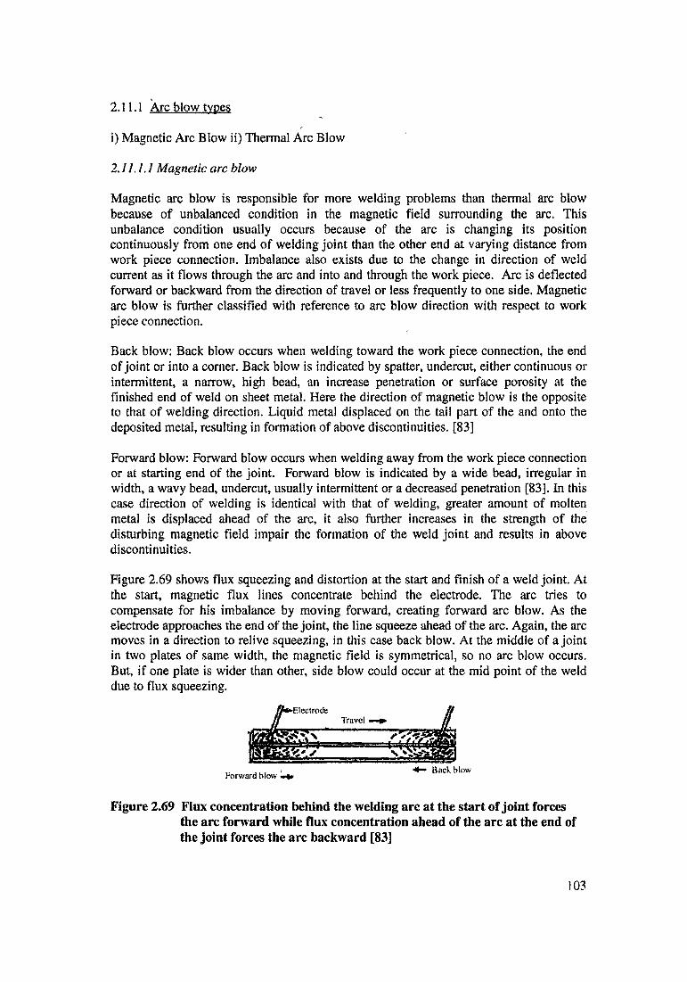
2.11.1 Arc blow types
i) Magnetic Arc Blow ii) Thermal Arc Blow
2.11.1.1 Magnetic arc blow
Magnetic arc blow is responsible for more welding problems than thermal arc blow because of unbalanced condition in the magnetic field surrounding the arc. This unbalance condition usually occurs because of the arc is changing its position continuously from one end of welding joint than the other end at varying distance from work piece connection. Imbalance also exists due to the change in direction of weld current as it flows through the arc and into and through the work piece. Arc is deflected forward or backward from the direction of travel or less frequently to one side. Magnetic arc blow is further classified with reference to arc blow direction with respect to work piece connection.
Back blow: Back blow occurs when welding toward the work piece connection, the end of joint or into a corner. Back blow is indicated by spatter, undercut, either continuous or intermittent, a narrow, high bead, an increase penetration or surface porosity at the finished end of weld on sheet metal. Here the direction of magnetic blow is the opposite to that of welding direction. Liquid metal displaced on the tail part of the and onto the deposited metal, resulting in formation of above discontinuities. [83]
Forward blow: Forward blow occurs when welding away from the work piece connection or at starting end of the joint. Forward blow is indicated by a wide bead, irregular in width, a wavy bead, undercut, usually intermittent or a decreased penetration [83]. In this case direction of welding is identical with that of welding, greater amount of molten metal is displaced ahead of the arc, it also further increases in the strength of the disturbing magnetic field impair the formation of the weld joint and results in above discontinuities.
Figure 2.69 shows flux squeezing and distortion at the start and finish of a weld joint. At the start, magnetic flux lines concentrate behind the electrode. The arc tries to compensate for his imbalance by moving forward, creating forward arc blow. As the electrode approaches the end of the joint, the line squeeze ahead of the arc. Again, the arc moves in a direction to relive squeezing, in this case back blow. At the middle of a joint in two plates of same width, the magnetic field is symmetrical, so no arc blow occurs. But, if one plate is wider than other, side blow could occur at the mid point of the weld due to flux squeezing.
Figure 2.69 Flux concentration behind the welding arc at the start of joint forces the arc forward while flux concentration ahead of the arc at the end of the joint forces the arc backward [83]
103

Another possibility of magnetic flux squeezing may be from the welding current returning back toward the work piece connection within the work piece, which will cause arc blow away from the work piece connection.
2.11.1.2 Thermal arc blow
Thermal arc blow occurs because an electric arc requires hot zones on the electrode and work piece/plate to maintain continuous flow of current in the arc stream. As the electrode advance along the work, the arc tends to lag behind, caused by reluctance of arc to move to the colder plate. The ionized space between end of the electrode and hot surface of molten crater creates a more conductive path than from the electrode to the colder plate. Thermal arc blow sometimes may combine with magnetic back blow, leading to quality problems.
2.11.2 Role of fixtures in arc blow
i) Steel fixture may effect the magnetic field around the arc, and may become magnetised over time, it recommended that fixtures are fabricated from low carbon steel to prevent build up of permanent magnetism in the fixture.ii) Copper strip inserted in a steel bar for a backing should not be used, this will increase arc blowiii) Continuous or close clamping of parts to be seam welded should be provided. Wide, intermittent clamping may cause seams to gap between clamping points, causing arc blow over the gaps.iv) Fixture should not build up from the large masses of steel on side of the seam, it should counter balance with similar mass on the opposite side of the fixture.v) It should recommend to connect the work connection directly to work piece.
2.11.3 Prevention of magnetic arc blow
Literature highlights the different methods to control degree of magnetism in welding. Effect of magnetic blow on the welding process in not always detrimental. At specific values of the magnetic field, the parameters of the welding process are optimised and quality of welding improves.
i) The arc blow induced by passing current can be controlled to some degree by number of measures such reducing oscillation width, reduce electrode extension, reduce travel speed, reduce arc voltage or shorten the arc length or connecting the ground cables to both ends of the joint.[36]
ii) Natural corollary of this reasoning was that if direction of welding is reversed, it will lead to decrease in the magnitude of residual magnetism in work piece. Decreased magnetism will lead to more centrally located and balance arc. If all this is true it must lead to balanced and equal fusion on both sidewalls with control of residual magnetism. No literature is available on this aspect. With the use of different combination of welding directions, residual magnetism can controlled, without altering the welding variables as sighted above. Literature highlights that use of back step welding sequence reduce the arc blow.[83]
However, it is more difficult to cope with residual magnetism induced in the work piece by preceding operations. Tack welding of work piece into an assembly may increases the
104
magnitude of magnetised induction in the gap as much as 5-10 times [86]. This may sometime render NG-GMAW impractical unless a special costly demagnetising procedure is applied. A more than 5 gauss of residual magnetism calls for demagnetization [36],
1) Hllii fli] ipaii ui'ie M eiUtdlliifig liii m M\ is io titransverse magnetic filed to it and such field can be produced in work piece of unlimited thickness. When external longitudinal magnetic field is applied, the arc runs more stably when relatively thin metal is welded by mechanised method. For NGW, this method is not suitable. However, practically no actual methods, device and approved practical recommendation for NGW welding of magnetised product.
In this method, external transverse magnetic field is applied to the arc. The direction of this field is perpendicular to the longitudinal axis of the joint. External transverse magnetic fields is created by applying winding to the work piece or winding on the core move together with arc, were used to create the transverse magnetic field. The magnetic field strength was varied by adjusting the current, the direction of magnetic blow out by altering the direction of the current in the windings.
2.11.3.1 Fix position magnetising circuit
Fix position magnetising circuit were used for stabilizing the arc by means of an external magnetic field. The winding in this circuit has 8-10 turns. The current in winding was varied between 100-350 Amp, as shown in figure 2.70
Figure 2.71 (a) shows the circuit used for controlling the current in the magnetising circuit creating external transverse magnetic field in the work piece.Fix position magnetising circuit works as follow; when arc become unstable an independent d.c source is cut in the voltage is fed to the terminal 1 and 2. At the same time the coil K1 at the switch for the polarity of the independent current is connected to this source by two position tumbler switch T. The cuirent in the turns of the magnetsing circuit is then regulated by ballast rheostat (BR). This creates on external magnetic field by which instability of the arc is eliminated. If the arc is not stable, the coil K2 is cut in by the tumbler switch T. This switches the polarity of the independent current source. This arc is given the required stability, as in first case, by regulating the current in the turns of the magnetising circuit. The principal of failing of the magnetic circuit shown in figure 2.71 (a) are that the turns are wound on actual work pieces and the magnetising currents in the circuit are high. It is therefore interesting to consider circuit whose turns are wound on separate cores figure 2.72 (b).
2.11.3.2 Moving magnetising circuit
Moving magnetising circuit used for stabilizing the arc with transverse field/ Circuit contained two 60 mm xl2 mm cross section core on which were wound the windings with 800 turns of wire with cross section of 2mm2. The length of the closed region of the magnetic circuit did not exceed 800 mm. The current in the winding varied between 0.3-5 Amp.
105

Figure 2.71 b shows the circuit used for controlling the current in the magnetising circuit creating external transverse magnetic field in the work piece.
Moving magnetising circuit works as follow : A moving magnetising circuit is used to reduce the working current of the independent current source. The close magnetic circuit provides lower magnetic flux dissipation. In some cases an open magnetic circuit can be used. In this case dissipation of the magnetic flux is increased.
The principal components of the circuit are the autotransformer (ATr) and rectifier (Rec). When the arc becomes unstable the rely Rel. 1 is cut in by the two position tubler switch T2. A d.c. voltage then reaches the terminal 1 and 2. The arc is made stable by increasing or reducing the current in the magnetizing circuit windings. If the arc cannot be made to run stable, the relay Rel 2 is cut in by the tumbler switch T2. This changes the direction of welding current (plus at terminal 1) in the windings, and consequently the direction of the magnetic flux in the work piece. As in the first case the arc is made stable by regulating the current in the windings of the magnetising circuit.
Above fix and moving magnetising circuit acceptable for welding of magnetised work piece without demagnetizing. As result of interaction of the outside magnetic field with the arc magnetic field, the arc landed at controlled angle in the vertical plane of the weld axis rather than in the lateral direction. It is recommended to stabilize an arc when magnetised products are welded, to use a magnetic circuit which move together with the arc, and in which the work piece are part of the closed magnetic circuit [87], as shown in figure 2.70 d. A magnetising circuit of this design is small and current in the winding can be reduced.
»
Figure 2.70 Magetising circuit diagram ; (a) with the winding on the workpieces; (b)with the work pieces on a stationary magnetic circuit; (c) with the windings moved ; (d) the same, with a closed magnetic circuit; 1- work pieces; 2-backing piece; 3-winding;4-core ; 5-plate closing the magnetic circuit; B- magnetic flux ;VCb- direction of welding [6,86 ]
106

m ftnc.
Figure 2.71 Electrical circuit diagrams for controlling the high (a) and low (b) current in the welding of the magnetising circuit [6,86]
107
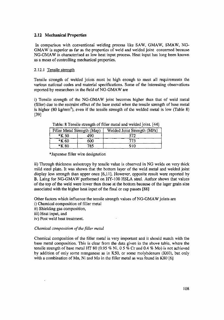
2.12 Mechanical Properties
In comparison with conventional welding process like SAW, GMAW, SMAW, NG- GMAW is superior as far as the properties of weld and welded joint concerned because NG-GMAW is characterised as low heat input process. Heat input has long been known as a mean of controlling mechanical properties.
2.12.1 Tensile strength
Tensile strength of welded joints must be high enough to meet all requirements the various national codes and material specifications. Some of the interesting observations reported by researchers in the field of NG-GMAW are
i) Tensile strength of the NG-GMAW joint becomes higher than that of weld metal (filler) due to the restraint effect of the base metal when the tensile strength of base metal is higher (80 kg/mm2), even if the tensile strength of the welded metal is low (Table 8) [39]
Table: 8 Tensile strength of filler metal and welded joint. [44]Filler Metal Strength (Map) Welded Joint Strength (MPa)
*K 50 490 572*K60 600 773*K 80 785 910
^Japanese filler wire designation
ii) Through thickness anisotropy by tensile value is observed in NG welds on very thick mild steel plate. It was shown that the bottom layer of the weld metal and welded joint display less strength than upper once [6,11]. However, opposite result were reported by B. Laing for NG-GMAW performed on HY-100 HSLA steel. Author shows that values of the top of the weld were lower than those at the bottom because of the lager grain size associated with the higher heat input of the final or cap passes [88]
Other factors which influence the tensile strength values of NG-GMAW joints arei) Chemical composition of filler metalii) Shielding gas composition,iii) Heat input, andiv) Post weld heat treatment.
Chemical composition of the filler metal
Chemical composition of the filler metal is very important and it should match with the base metal composition. This is clear from the data given in the above table, where the tensile strength of base metal HT 80 (0.95 % Ni, 0 5 % Cr and 0.4 % Mo) is not achieved by addition of only some manganese as in K50, or some molybdenum (K60), but only with a combination of Mn, Ni and Mo in the filler metal as was found in K80 [6]
108

Shielding gas composition
Presence of argon and helium in the shielding gas mixture with carbon dioxide has a favorable influence on the tensile properties of the weld metal. On the other hand tensile and yield strength of the weld are lower if oxygen is used, instead of carbon dioxide in combination with argon. Comparison was made between base metal close to ASTM SA 516 Gr.70 steel welded with 80 % Ar + 20 % 02 and 80 % Ar + 20 C02 gas mixtures, results show that 28 % lowers yield strength was reported for the first case. [6,8,68,]
Heat input
An increase of heat input from 8 kj/in to 50 kj/in in NG-GMAW of HY-80 HSLA steel results in reduction in yield strength and tensile strength by 30 % and 22% respectively. However, at the same time it results in increase in ductility, due to the lower cooling rates.
Post weld heat treatment (PWHT)
PWHT used as stress relief operation, PWHT lower the tensile strength and increase the ductility. Author S.Kimura [14] show that, the stress relief treatment of weld mad by NG- GAMW at 620°C for 12 hr resulted in reduction in yield strength and tensile strength by 28 % and 14 % respectively, while elongation increased by 20 %.[6]
2.12.2 Fracture toughness:
Fracture toughness described as the resistance of a metal to crack propagation or brittle fracture. Fracture toughness is one of the most vital property of a welded joint. Majority of research has been done to consider NG-GMAW to have higher fracture toughness than other conventional welding methods (SAW), specially for HSLA Steels.
Author S. Sawada report that fracture toughness of SA 533 Gr B Cl. 1 steel (for nuclear pressure vessels) joints welded by conventional SAW and NG-GMAW shows that the absorbed energy at -40°C of a welded joint performed by NG-GMAW is more than three times higher for weld metal and almost twice as high as the HAZ of SAW joint (Table 9) [88]
Table 9 Charpay V- notch impact test [29]
Process Absorbed Energy (-40°C) in Joule -Fracture toughness in ft-lbWeld Metal HAZ
NG-GMAW 104.9 -77.4 112.7 - 83.1SAW 29.4 -21.7 58.8 - 43.3
Base Metal 5 8.8Superiorfracture toughness of the HAZ which makes NG-GMAW the most attractive process for joining HSLA steels. However, it is impossible to achieve good HAZ properties by simple reduction of gap between the plates and reduction of the heat input (to generate narrow HAZ). Combining these measures with the reheating effect of subsequent overlaying passes in the deep square groove, which is inherent* of NG-GMAW, make it possible to improve the fracture toughness of the weld metal and HAZ.[11]
109

Metallurgical factors responsible for the superior fracture toughness of NG-GMAW over SAW are
i) The width of HAZ is narrower, due to much lower heat input and more uniform due to a constant depth of penetration into sidewalls, is typical for the NG-GMAW bead deposition layout.
ii) The chemical composition of the NG-GMAW weld metal is more uniform, since due to constant depth of penetration, the penetration depth into sidewalls is 0.5-1.Omm for NG-GMAW. It is diluted uniformly with the base metal (15-20 %), while in case of SAW dilution varies from 50 % at the root up to almost zero at the top of the joint were it is almost the same as the filler metal [5].
iii) The grain size in coarse region of the HAZ of NG-GMAW is smaller due to low heat input. In case of butt welding of thick plate by SAW, the heat input is 102- to 107 kj/in. on the other hand, the heat input of NG-GAMW welding is 53 kj/in, only half as much as that of SAW. This may be one of the reason for the width of HAZ in NG-GMAW is about half of that in a SAW [5]
iv) Arc oscillation was also found to substantially reduce the grain size [79], The reason for this a periodical shift of the solid liquid metal interface relative to the weld axis which leads to increase in solidification rate. Higher solidification rate allows less time for grain coarsening and result into fine grain structure.[78]
v) Due to orderly oriented bead layout, reheating effect of subsequent overlaying passes is inherent to NG-GMAW. In general, which result in same areas of HAZ to be tempered several times, reducing the size of coarse grained region.
With combination all the described above effect and make it possible to improve the fracture toughness of the weld and HAZ.
Other factors which influence the fracture toughness values of NG-GMAW joints are shielding gas, post weld heat treatment and thickness anisotropy.
Shielding gas composition
Shielding gas composition has great influence on the charpy V notch toughness of the welded joint. The lowest absorbed energy were obtained for the pure carbon dioxide shielding gas. Addition of 50 % helium to the mixture seemed to improve the situation but the highest result was reached using He +Ar + CO2, composition of with the CO2 content less than 20 % [156], The same trend was observed upon lowering the C02 content in a mixture with argon. In this case charpy V notch increased by 130-140 % at 15-20% CO2 level in the mixture. Replacement of CO2 by O2 in the mixture with argon may reduce the charpy V notch toughness considerable [6,11 ]
PWHT
The absorbed energy of the samples cut from any location of a thick wall joint is increased after stress relief operation at 621°C for 12 hr, in comparison with as welded sample. This is most pronounced for the lower test temperature.
110
Heat input
If heat input extremely low (less than 10 kj/in), can to a certain degree decrease the notch toughness. When comparing Battelle NGW-I technique, extremely low heat input of 8 kj/in, with Navel Research Laboratory technique of 50 kj/In, the investigators reported a 28 % increased in the charpy V-notch absorbed energy (65.6 ft lb vs. 50.9 ft lb) [11]
Through thickness anisotropy
Literature show that [11,37] the bottom layer of the weld show less desirable notch properties than upper layers and the layers in the centre, specially at R.T. Charpy V notch test, which is reported as the most popular method of characterizing the fracture toughness of welded joints, which is reported in majority of the publication surveyed [6]. These are, however, opinion [11] which states that this method is inadequate and lead to incorrect conclusion regarding fracture mode propagation feature of the metal. C.N.Freed and P.P.Puzak [89] have developed the dynamic tear (DT) test which provides reliable measurement of fracture toughness, where charpy V-notch test is inadequate and leads to incorrect conclusions reading fracture mode propagation feature in metal. According to the authors investigation of fracture toughness of A 543 steel plate welded by NG- GMAW, using dynamic tear test samples, disclosed unique plastic zone side characteristics of narrow gap welds. The uniquely limited width of the NG weld enhances the fracture toughness of the weldment in the transition temperature and on the upper shelf when the crack tip plastic zone size exceeded the weld zone and enters the plate. This increases the resistance of fracture propagation, through involvement of the tough plate metal. [11]
Resistance to temper embrittlement (TE) ofNG-GMAWjoints:
Resistance to TE is an important fracture toughness characteristic of low alloy steel and welded joints. It refers to the loss of notch toughness experienced by low alloy steel that are slowly cooled through or heated in the temperature range of 399-593 °C, due to segregation of impure elements, such as P, As, Sb and Sn in the grain boundary region. Resistance to TE is usually assessed by the shift of ductile - brittle transition temperature after and before special extended PWHT called “step cooling”, which is designed to simulated high-temperature service embrittlement. It has been reported that lower heat input and higher temperature of PWHT favorable affects the resistance to TE.
Resistance to delayed cracking ofNG-GMAW joints:
It is known that high hydrogen level in the weld metal may result in a reduced resistance of the welded joints to delayed cracking. In this respect, hydrogen content in NG-GMAW is less than that of conventional SAW because of fewer beads, absence of flux and better quality of gas shielding in the deep square groove.
2.12,3 Ductility
A bend test is a generalize ductility indictor which in frequently reported by many of research workers [1,6,14,16,39,44,150], Face, root and side bend tests were applied to specimen cut from a welded joint made by NG-GMA. Comparison has been made between the bending characteristic of mild steel plate welded by NG-GMAW and conventional double -V groove CO2 GMAW, only 5% of 95 samples cut from NG- GMAW joints failed, while 13% of 68 conventional welded joint samples failed. [6]
Presence of defects specially lack of sidewall fusion and porosity decreased the ductility. Improper sidewall fusions at any of sidewalls of joint act as a crack initiation site during bend testing which leads to poor bending characteristics.
Even after getting proper sidewall fusion with the special wire/torch oscillation techniques, presence of minutes porosity inside the weld metal due poor shielding or air aspiration, welded sample may fail from the porosities present in the weld metal.
112