Embed Size (px)
Citation preview

Central Marketing Office: Tel. : Fax:email : [email protected], [email protected]
+91-11- , +91-11-2684 8241, 2684 73423088 7520-29
Corporate Office :Tel. : +91-11-3088 7520 - 29, Fax: +91-11-2684 7154, 2682 9063
222, Okhla Industrial Estate, New Delhi - 110 020
International Business Division: Tel. : Fax:email : [email protected]
+91-11-4161 3503, 3088 7520-29, +91-11-2683 8291, 2684 7342
C&S Electric Ltd.
Power Capacitor
IS: 8828
We touch your electricity everyday!
We touch your everyday! electricity
www.cselectric.co.in
Capacitor
State of the art Manufacturing Facilities
Haridwar, Noida Ph-I& Noida Ph-II Plant
117SGR/C
AP/062013
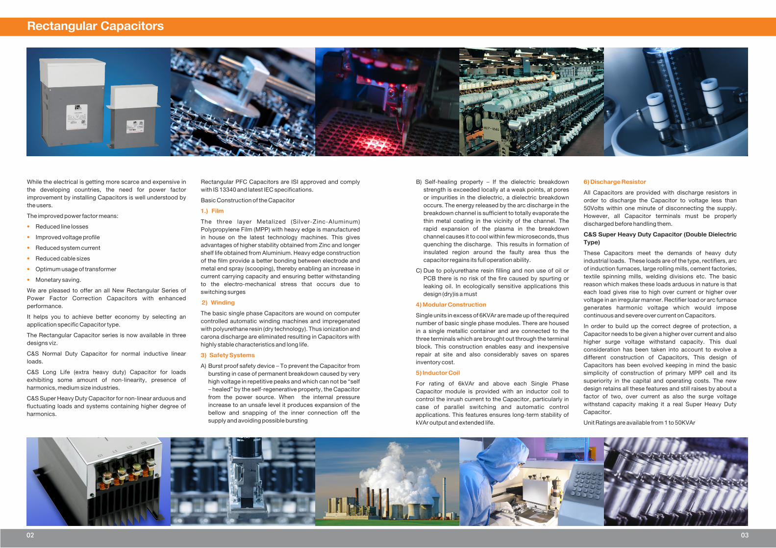
Rectangular Capacitors
While the electrical is getting more scarce and expensive in Rectangular PFC Capacitors are ISI approved and comply
the developing countries, the need for power factor with IS 13340 and latest IEC specifications.
improvement by installing Capacitors is well understood by Basic Construction of the Capacitorthe users.
The improved power factor means:The three layer Metalized (Silver-Zinc-Aluminum)
Reduced line losses Polypropylene Film (MPP) with heavy edge is manufactured
Improved voltage profile in house on the latest technology machines. This gives
advantages of higher stability obtained from Zinc and longer Reduced system currentshelf life obtained from Aluminium. Heavy edge construction
Reduced cable sizes of the film provide a better bonding between electrode and
metal end spray (scooping), thereby enabling an increase in Optimum usage of transformercurrent carrying capacity and ensuring better withstanding
Monetary saving.to the electro-mechanical stress that occurs due to
We are pleased to offer an all New Rectangular Series of switching surgesPower Factor Correction Capacitors with enhanced
performance.
The basic single phase Capacitors are wound on computer It helps you to achieve better economy by selecting an
controlled automatic winding machines and impregenated application specific Capacitor type.
with polyurethane resin (dry technology). Thus ionization and The Rectangular Capacitor series is now available in three carona discharge are eliminated resulting in Capacitors with designs viz. highly stable characteristics and long life.
C&S Normal Duty Capacitor for normal inductive linear
loads.A) Burst proof safety device – To prevent the Capacitor from
C&S Long Life (extra heavy duty) Capacitor for loads bursting in case of permanent breakdown caused by very exhibiting some amount of non-linearity, presence of high voltage in repetitive peaks and which can not be “self harmonics, medium size industries. – healed” by the self-regenerative property, the Capacitor
from the power source. When the internal pressure C&S Super Heavy Duty Capacitor for non-linear arduous and increase to an unsafe level it produces expansion of the fluctuating loads and systems containing higher degree of bellow and snapping of the inner connection off the harmonics.supply and avoiding possible bursting
1.) Film
•
•
•
•
•
•
2) Winding
3) Safety Systems
B) Self-healing property – If the dielectric breakdown
strength is exceeded locally at a weak points, at pores All Capacitors are provided with discharge resistors in or impurities in the dielectric, a dielectric breakdown order to discharge the Capacitor to voltage less than occurs. The energy released by the arc discharge in the 50Volts within one minute of disconnecting the supply. breakdown channel is sufficient to totally evaporate the However, all Capacitor terminals must be properly thin metal coating in the vicinity of the channel. The discharged before handling them.rapid expansion of the plasma in the breakdown
C&S Super Heavy Duty Capacitor (Double Dielectric channel causes it to cool within few microseconds, thus Type)quenching the discharge. This results in formation of
insulated region around the faulty area thus the These Capacitors meet the demands of heavy duty capacitor regains its full operation ability. industrial loads. These loads are of the type, rectifiers, arc
of induction furnaces, large rolling mills, cement factories, C) Due to polyurethane resin filling and non use of oil or textile spinning mills, welding divisions etc. The basic PCB there is no risk of the fire caused by spurting or reason which makes these loads arduous in nature is that leaking oil. In ecologically sensitive applications this each load gives rise to high over current or higher over design (dry)is a mustvoltage in an irregular manner. Rectifier load or arc furnace
generates harmonic voltage which would impose
Single units in excess of 6KVAr are made up of the required continuous and severe over current on Capacitors.
number of basic single phase modules. There are housed In order to build up the correct degree of protection, a
in a single metallic container and are connected to the Capacitor needs to be given a higher over current and also three terminals which are brought out through the terminal
higher surge voltage withstand capacity. This dual block. This construction enables easy and inexpensive consideration has been taken into account to evolve a repair at site and also considerably saves on spares
different construction of Capacitors, This design of inventory cost. Capacitors has been evolved keeping in mind the basic
simplicity of construction of primary MPP cell and its
superiority in the capital and operating costs. The new For rating of 6kVAr and above each Single Phase design retains all these features and still raises by about a Capacitor module is provided with an inductor coil to factor of two, over current as also the surge voltage control the inrush current to the Capacitor, particularly in withstand capacity making it a real Super Heavy Duty case of parallel switching and automatic control Capacitor.applications. This features ensures long-term stability of
kVAr output and extended life. Unit Ratings are available from 1 to 50KVAr
6) Discharge Resistor
4) Modular Construction
5) Inductor Coil
02 03

04 05
Rectangular Capacitors
CSSND0001440 1 3*5.5 1.31 170 125 45
CSSND0002440 2 3*11 2.62 170 125 45
CSSND0003440 3 3*16.5 3.94 240 185 60
CSSND0004440 4 3*22 5.25 240 185 60
CSSND0005440 5 3*27.5 6.56 240 185 60
CSSND0075440 7.5 3*41.5 9.84 325 210 70
440 CSSND0010440 10 3*55 13.12 325 240 80
CSSND0125440 12.5 3*69 16.40 325 240 80
CSSND0015440 15 3*83 19.68 325 240 80
CSSND0020440 20 6*55 26.24 325 240 160
CSSND0025440 25 6*69 32.80 325 240 160
CSSND0050440 50 12*69 65.60 375 240 320
H W D
RatedCurrent
(A)
Volts Reference KVArDimension (mm)
Technical data and specifications
CSSHD0001440 1 3*5.5 1.3 270 185 60
CSSHD0002440 2 3*11.0 2.6 270 185 60
CSSHD0003440 3 3*16.5 3.9 300 240 80
CSSHD0004440 4 3*22.0 5.3 300 240 80
CSSHD0005440 5 3*27.5 6.6 300 240 80
440 CSSHD0075440 7.5 3*41.5 9.8 405 240 80
CSSHD0010440 10 3*55.0 13.1 405 240 80
CSSHD0125440 12 3*69.0 16.4 405 240 80
CSSHD0015440 15 6*41.5 19.7 400 240 160
CSSHD0020440 20 6*55.0 26.2 400 240 160
CSSHD0025440 25 6*69.0 32.8 400 240 160
CSSHD0050440 50 12*69.0 65.6 450 240 320
H W D
RatedCurrent
(A)
Volts KVArDimension (mm)
Selection Table - Rectangular Normal Duty Capacitor Rated Voltage 440V, Delta Connection
Selection Table - Rectangular Super Heavy Duty Capacitor Rated Voltage 440V, Delta Connection
CharacteristicsSuper
Heavy Duty
* Other voltages available on request
Extra
Heavy Duty Normal Duty
CSEHD0001440 1 3*5.5 1.31 170 125 45
CSEHD0002440 2 3*11 2.62 170 125 45
CSEHD0003440 3 3*16.5 3.94 240 185 60
CSEHD0004440 4 3*22 5.25 240 185 60
CSEHD0005440 5 3*27.5 6.56 240 185 60
CSEHD0075440 7.5 3*41.5 9.84 325 210 70
440 CSEHD0010440 10 3*55 13.12 325 240 80
CSEHD0125440 12.5 3*69 16.40 325 240 80
CSEHD0015440 15 3*83 19.68 325 240 80
CSEHD0020440 20 6*55 26.24 325 240 160
CSEHD0025440 25 6*69 32.80 325 240 160
CSEHD0050440 50 12*69 65.60 375 240 320
H W D
RatedCurrent
(A)
Volts KVArDimension (mm)
Selection Table - Rectangular Extra Heavy Duty Capacitor Rated Voltage 440V, Delta Connection
Tolerance -0/+10% 0/+10%
Rated Voltage-Vac 415, 440V* 415, 440V* 415, 440V*
Rated frequency fr 50/60Hz 50/60Hz 50Hz
Dielectric Losses < 0.2 W/kvar 0.2 W/kvar < 0.2 W/kvar
Losses (Single Phase cell) < 0.5 W/kvar < 0.5 W/kvar < 0.5 W/kvar
Maximum ratings
Maximum Permissible Voltage 1.1 Un 1.2 Un (VR+10%VR) VAC, (VR+30%VR) VAC
Maximum Permissible Current 1.3 In (A) 1.3 In (A) 1.6 · IR (A)
Transient peak Current max 100In (A) 250In (A) 350 · IR (A)
Permissible
Climatic category
Tmin -25ºC -10ºC -10ºC
Tmax +50ºC +55ºC +55ºC
Rel humidity Av < 95% Av < 95% Max 95%
Maximum altitude 4000 m 4000 m 4000 m above sea level
Mean life expectancy
TLD Upto100,000 Hrs Upto125,000 Hrs Upto 150,000 Hrs
Design data
Impregnation Non-PCB, PU Resin, Biodegradable soft Resin
Dielectric Polypropylene Film
Terminals Stud terminals with ceramic bushing
Mounting and Grounding Vertical position. Threaded bottom stud for grounding
Connection D (Delta)
Cooling Naturally air cooled or (forced cooling)
Case Shape/Finish Rectangular / Powder coated Siemens gray colour / Square cap
Casing of Capacitor Cell Cylindrical
Enclosure MS sheet metal
Safety
Safety Over pressure disconnector.
Max short circuit current AFC: 10 kA
Discharge resistor Included
Discharge resistor time <1 min (50 V)
-0/+10%
<
Reference
Reference
Construction
n
n
n
n
Features
n
n
n
n
Typical applications
n
Dielectric: Polypropylene film
Semi dry; high viscosity PU
resin; non-PCB
Container type / finish: MS
sheet metal/powder coated
gray colour
Built-in inductor coil
Three phase
Self-healing technology
Naturally air cooled (or forced
air cooling)
Explosion proof
For power factor correction

06 07
Cylindrical Capacitors
Cylindrical Capacitors: Dual safety system
Cylindrical Capacitor selection
•
•
•Features•Compact design -low weight and small volume
•
•
Cylindrical Capacitors are a tried and tested series of MPP Self-healing: The Capacitor repairs itself after overload (to
(Metalized Polypropylene) Capacitors from C&S. The IEC60831). Self-healing Capability prevents permanent
power range varies from 1.0 to 30.0 kvar. The Cylindrical dielectric breakdown in case of sporadic voltage surges,
Capacitor is especially intended for power factor overcurrent or over temperature (to IEC60831).
correction in industrial and semi-industrial applications.
The Capacitors are manufactured using metalized To specify and select Capacitors for PFC, several factors polypropylene film as the dielectric and housed in a affecting the performance and the expected useful life of the Cylindrical Aluminum case.Capacitors must be considered.
The Cylindrical Capacitors are self-healing, metalized Voltagepolypropylene film Capacitor. The current-carrying AIZn
metal layer is vapor-deposited onto one side of the film. Harmonics
Temperature
Total RMS current
Inrush current / switchingThe entire three-phase Capacitor is composed of three
single-phase element stacks. The electrodes are Operations
connected by metal spraying on the face ends of the Permanent overvoltage shortens the useful life of a Capacitor. winding elements.The winding elements are encapsulated The Capacitor's rated voltage must be equal or higher than the in a Cylindrical Aluminum case and hermetically sealed operating voltage of the circuit to which it is connected.either by a press-rolled metal lid or plastic disk with fast-on
Harmonics produce overvoltage and overcurrent on the terminals.Capacitors themselves. If the total harmonics distortion level
for voltage (THO-V) e.g. exceeds 5%, serious damage to the series-inductance (e.g. detuned harmonic filter) will avoid
installation may be caused by the resonance of the circuit. excessive transient currents.
In such cases usage of series reactors (detuning) is
recommended. Operation of the Capacitors above the upper After a long drying phase to eliminate moisture from the category temperature level will accelerate degradation of the active element, the Capacitor is impregnated.The case is dielectric and shorten the Capacitor's useful life.filled with biodegradable soft resin. This production process
By keeping min. 20 mm spacing and Cylindrical Capacitors helps to avoid oxidation and partial discharges( corona
mounted in upright position, better thermal conditions will effect), promoting Capacitance stability over a long period
ensure best performance and a longer useful life. Residual an essential in detuned PFC.
voltage should not exceed 10% of rated voltage for re-
switching Capacitors.
Capacitors used for power factor correction undergo a lot of During the charging period of the Capacitors the current is switching operations The high inrush currents that go along very high - if they are connected in automatic Capacitor with this must be handled without degrading useful life.banks, it is very likely that discharged Capacitors are
connected to charged ones already connected to the grid. In The pulse strength of this technology comes in particular such cases the maximum permissible current peak reaches from the enlarged, sensitive contact area (improved metal values up to 150 . IR.spraying). Cylindrical Capacitors can handle inrush currents
of upto 200 times rated current (max.5000 switching During the switching process thermal and electrodynamic operations. according to IEC 60831standard).stresses are developed caused by transient overcurrents of
high amplitude and frequency and may damage the system.
Capacitor contactors with inrush current limiting resistors or
Life expectancy of up to 100000 operating hours
High inrush current withstand .. capability is crucial

08 09
Cylindrical Capacitors
Characteristics ND HD
Rated capacitance CR As per table
Tolerance -5 / +10% 0 / +10%
Connection D (Delta) (Delta)
Rated Voltage As per table As per table
Rated frequency fR 50 Hz /60 Hz 50 Hz /60 Hz
Output As per table As per table
Rated current IR As per table As per table
Dielectric losses ≤ 0.2 W / kVAr W / kVAr
Maximum ratings
Vmax (up to 8 h daily) VR+10%VR V AC VR+10%VR V AC
Vmax (up to 1 min) VR+30%VR V AC VR+30%VR V AC
Imax 1.3 · IR (A) 1.5 · IR (A)
IS 200 · IR (A) 200 · IR (A)
Test data
VTT 1.75*VR V AC / 50 Hz 1.75*VR V AC / 50 Hz
during 2 s during 2 s
VTC 3,000 V AC / 50 Hz during 10s 3,000 V AC / 50 Hz during 10 s
Total losses ≤ 0.45 W / kVAr W / kVAr
Climatic category / -25/D
Tmin –25 ºC –25 ºC
Tmax +55 ºC +55 ºC
Rel. humidity av. < 95% av. < 95%
Maximum altitude 4,000m 4,000m
Mean life expectancy
tLD up to 100,000 hours up to 100,000 hours
Max. 5,000 switchings per year to IEC 60831
Design data
Dimensions (Φ×h) As per table As per table
Impregnation Biodegradable soft resin Biodegradable soft resin
Fixing Threaded bolt M12 Threaded bolt M12
Mounting position Vertical position. See Vertical position. See“Maintenance and “Maintenance andInstallation Manual” for Installation Manual” forfurther details. further details.
Terminals
Degree of protection Isolated terminals, IP20 Isolated terminals, IP20
Max. torque 1.2 Nm 1.2 Nm for terminal for 16sq
mm cable & 2.0 Nm for
terminal for 25sq mm cable
Creepage distance (min.) 12.7 mm 12.7 mm
Clearance (min.) 9.6 mm 9.6 mm
Safety
Mechanical safety Overpressure disconnector Overpressure disconnector
Max. short circuit current AFC: 10 kA AFC: 10 kA
Discharge resistor time ≤ 1 min (50 V) ≤ 1 min (50 V)
Reference Standards
IEC 60831-1/2, IS: 13340/41
As per table
D
≤ 0.2
≤ 0.5
Technical data and specifications
6.0 7.9 7.2 9.4 11.17 3 * 33 78.4 * 195 CSPND0006440
7.0 9.2 8.4 11.8 13.05 3 * 38.5 78.4 * 195 CSPND0007440
7.5 9.8 9.0 11.8 13.85 3 * 41 78.4 * 195 CSPND0075440
8.3 10.9 10.0 13.07 15.41 3 * 45.5 78.4 * 195 CSPND0083440
9.0 11.8 10.8 14.4 16.68 3 * 49.5 78.4 * 195 CSPND0009440
10.0 13.1 12.0 15.7 18.52 3 * 55 88.4 * 195 CSPND0010440
12.5 16.4 15.0 19.7 23.18 3 * 68.5 88.4 * 270 CSPND0125440
15.0 19.7 18.0 23.6 27.85 3 * 82.5 88.4 * 270 CSPND0015440
16.7 21.9 20.0 26.3 30.96 3 * 91.5 88.4 * 345 CSPND0167440
19.0 24.9 23.0 29.9 35.20 3 * 104.5 88.4 * 345 CSPND0019440
20.0 27.3 24.0 32.8 38.60 3 * 110 88.4 * 345 CSPND0020440
20.8 27.3 25.0 32.8 38.60 3 * 114 88.4 * 345 CSPND0208440
25.0 32.8 30.0 39.4 46.37 3 * 137.5 93.5 * 345 CSPND0025440
28.0 36.7 – 44.0 51.89 3*157.5 93.5 * 345 CSPND0028440
30.0 39.4 36.0 47.3 55.71 3*164.5 93.5 * 345 CSPND0030440
50 Hz
Kvar
60 Hz
Kvar In (A)In (A)
Imax,RMS
A
Cn dxh
μF mmOrdering code
Construction
n
n
n
n
Features
n
n
n
n
Typical applications
n
Dielectric: Polypropylene film
Three phase, delta connected
Semi dry; high viscosity PU resin;
non-PCB
Extruded round aluminum can
with stud
Self-healing technology
Naturally air cooled (or forced air
cooling)
Indoor mounting
Dual safety system
For power factor correction
Kvar Current
50 Hz50 Hz 60 Hz60 Hz
CapacitanceOrdering code
440 3 3.6 3.9 4.7 3 x 16.5 78.4 x 195 CSPHD0003440
440 4 4.8 5.2 6.3 3 x 22 78.4 x 195 CSPHD0004440
440 5 6 6.6 7.9 3 x 27.5 78.4 x 195 CSPHD0005440
440 6 7.2 7.8 9.4 3 x 33 88.4 x 195 CSPHD0006440
440 7.5 9 9.8 11.8 3 x 41.5 88.4 x 270 CSPHD0075440
440 8 9.6 10.5 12.6 3 x 44 88.4 x 270 CSPHD0008440
440 9 10.8 11.8 14.2 3 x 49.5 88.4 x 270 CSPHD0009440
440 10 12 13.1 15.7 3 x 55 88.4 x 270 CSPHD0010440
440 12.5 15 16.4 19.7 3 x 68.5 93.5 X 270 CSPHD0125440
440 15 18 19.7 23.6 3 x 82.5 105.5 X 280 CSPHD0015440
440 20.8 25.0 27.3 32.8 3 x 114 121.5 x 280 CSPHD0208440
440 25 30.0 32.8 39.4 3 x 137 121.5 x 325 CSPHD0025440
Voltage
Selection Table - Cylindrical Normal Duty Capacitor Rated Voltage 440V, Delta Connection
Selection Table - Cylindrical Heavy Duty Capacitor Rated Voltage 440V, Delta Connection
μF
dxh
mm

Power Capacitors
10 11
Rated Current
415V 440V
1 1.4 1.3 16 4 0.75 1.5
2 2.8 2.6 16 4 0.75 1.5
3 4.2 3.9 16 16 1.5 1.5
4 5.6 5.2 16 16 1.5 1.5
5 7 6.5 16 16 2.5 4
6 8.4 7.8 32 16 2.5 4
7 9.8 9.1 32 16 2.5 4
8 11.2 10.4 32 25 2.5 4
9 12.5 11.7 32 25 4 6
10 14 13 32 25 4 6
12.5 17.5 16.3 32 35 6 10
15 21 19.5 63 35 6 10
20 28 26 63 50 10 16
25 35 32.5 63 63 16 25
30 42 39 100 80 25 35
40 56 52 125 100 35 70
45 63 58.5 125 125 35 70
50 70 65 160 125 50 95
60 84 78 200/250 160 50 95
75 105 97.5 200/250 160 70 185
100 140 130 300 200 120 240
Output
Qn KVAr
Switch
rating (A)
HRC Fuse
rating (A)Cu cable
2mm
AI cable2mm
Recommended size/rating for accessories (cable, fuses and switchgear)
for use with 415/440V AC, 50 cycles, three-phase delta - connected PFC capacitors
achievable
(TARGET)Cos j
Current
(ACTUAL)
Tan j
0.80 0.82 0.85 0.88 0.90 0.92 0.94 0.96 0.98 1.00
3.18 0.30 2.43 2.48 2.56 2.64 2.70 2.75 2.82 2.89 2.98 3.18
2.96 0.32 2.21 2.26 2.34 2.42 2.48 2.53 2.60 2.67 2.76 2.96
2.77 0.34 2.02 2.07 2.15 2.23 2.28 2.34 2.41 2.48 2.56 2.77
2.59 0.36 1.84 1.89 1.97 2.05 2.10 2.17 2.23 2.30 2.39 2.59
2.43 0.38 1.68 1.73 1.81 1.89 1.95 2.01 2.07 2.14 2.23 2.43
2.29 0.40 1.54 1.59 1.67 1.75 1.81 1.87 1.93 2.00 2.09 2.29
2.16 0.42 1.41 1.46 1.54 1.62 1.68 1.73 1.80 1.87 1.96 2.16
2.04 0.44 1.29 1.34 1.42 1.50 1.56 1.61 1.68 1.75 1.84 2.04
1.93 0.46 1.18 1.23 1.31 1.39 1.45 1.50 1.57 1.64 1.73 1.93
1.83 0.48 1.08 1.13 1.21 1.29 1.34 1.40 1.47 1.54 1.62 1.83
1.73 0.50 0.98 1.03 1.11 1.19 1.25 1.31 1.37 1.45 1.63 1.73
1.64 0.52 0.89 0.94 1.02 1.10 1.16 1.22 1.28 1.35 1.44 1.64
1.56 0.54 0.81 0.86 0.94 1.02 1.07 1.13 1.20 1.27 1.36 1.56
1.48 0.56 0.73 0.78 0.86 0.94 1.00 1.05 1.12 1.19 1.28 1.48
1.40 0.58 0.65 0.70 0.78 0.86 0.92 0.98 1.04 1.11 1.20 1.40
1.33 0.60 0.58 0.63 0.71 0.79 0.85 0.91 0.97 1.04 1.13 1.33
1.30 0.61 0.55 0.60 0.68 0.76 0.81 0.87 0.94 1.01 1.10 1.30
1.27 0.62 0.52 0.57 0.65 0.73 0.78 0.84 0.91 0.99 1.06 1.27
1.23 0.63 0.48 0.53 0.61 0.69 0.75 0.81 0.87 0.94 1.03 1.23
1.2 0.64 0.45 0.50 0.58 0.66 0.72 0.77 0.84 0.91 1.00 1.20
1.17 0.65 0.42 0.47 0.55 0.63 0.68 0.74 0.81 0.88 0.97 1.17
1.14 0.66 0.39 0.44 0.52 0.60 0.65 0.71 0.78 0.85 0.94 1.14
1.11 0.67 0.36 0.41 0.49 0.57 0.63 0.68 0.75 0.82 0.90 1.11
1.08 0.68 0.33 0.38 0.46 0.54 0.59 0.65 0.72 0.79 0.88 1.08
1.05 0.69 0.30 0.35 0.43 0.51 0.56 0.62 0.69 0.76 0.85 1.05
1.02 0.70 0.27 0.32 0.40 0.48 0.54 0.59 0.66 0.73 0.82 1.02
0.99 0.71 0.24 0.29 0.37 0.45 0.51 0.57 0.63 0.70 0.79 0.99
0.96 0.72 0.21 0.26 0.34 0.42 0.48 0.54 0.60 0.67 0.76 0.96
0.94 0.73 0.19 0.24 0.32 0.40 0.45 0.51 0.58 0.65 0.73 0.94
0.91 0.74 0.16 0.21 0.29 0.37 0.42 0.48 0.55 0.62 0.71 0.91
0.88 0.75 0.13 0.18 0.26 0.34 0.40 0.46 0.52 0.59 0.68 0.88
0.86 0.76 0.11 0.16 0.24 0.32 0.37 0.43 0.50 0.57 0.65 0.86
0.83 0.77 0.08 0.13 0.21 0.29 0.34 0.40 0.47 0.54 0.63 0.83
0.8 0.78 0.05 0.10 0.18 0.26 0.32 0.38 0.44 0.51 0.60 0.80
0.78 0.79 0.03 0.08 0.16 0.24 0.29 0.35 0.42 0.49 0.57 0.78
0.75 0.80 0.05 0.13 0.21 0.27 0.32 0.39 0.46 0.55 0.75
0.72 0.81 0.10 0.18 0.24 0.30 0.36 0.43 0.52 0.72
0.7 0.82 0.08 0.16 0.21 0.27 0.34 0.41 0.49 0.70
0.67 0.83 0.05 0.13 0.19 0.25 0.31 0.38 0.47 0.67
0.65 0.84 0.03 0.11 0.16 0.22 0.29 0.36 0.44 0.65
0.62 0.85 0.08 0.14 0.19 0.26 0.33 0.42 0.62
0.59 0.86 0.05 0.11 0.17 0.23 0.30 0.39 0.59
0.57 0.87 0.08 0.14 0.21 0.28 0.36 0.57
0.54 0.88 0.06 0.11 0.18 0.25 0.34 0.54
0.51 0.89 0.03 0.09 0.15 0.22 0.31 0.51
0.48 0.90 0.06 0.12 0.19 0.28 0.48
0.46 0.91 0.03 0.10 0.17 0.25 0.46
0.43 0.92 0.07 0.14 0.22 0.43
0.40 0.93 0.04 0.11 0.19 0.40
0.36 0.94 0.07 0.16 0.36
0.33 0.95 0.13 0.33
Cos j
Factor F
TARGET
Cos j = 0.96Cos j <1
Qc=Pmot x F(0.96)=...(KVAr)
100 x 1.01=101.0 KVAr
Capacitor (KVAr) selection chart
Qc
Q


![TECHNICAL NOTE - NASA · 222 MC L_ MULTIPLIER3 TIME5 ] ... determined by quality overload tests with the FMFB receiver (Refer-ence 1), ... !USH-PULL AFC 70 MC FM .SAMPLE OSC](https://img.dokumen.tips/doc/110x75/5b5b24027f8b9a885b8d6a36/technical-note-nasa-222-mc-l-multiplier3-time5-determined-by-quality.jpg)