Embed Size (px)
Citation preview

ARCHLine.XP 2020
Windows
ARCHITECTURAL
TUTORIAL

Architectural Tutorial
Information in this document is subject to change without notice and does not represent a commitment on the part of CadLine. The software, which includes the information contained in any databases, described in this document is furnished under a license agreement or nondisclosure agreement. The software may be used or copied only in accordance with the terms of the agreement. It is against the law to copy the software on any medium except as specifically allowed in the license or nondisclosure agreement. The licensee (purchaser) may make one copy of the software for the purpose of creating a -backup copy. No part of this tutorial may be reproduced, transmitted, transcribed, or translated into any language in any form or by any means, without the express written permission of CadLine.
2020 CadLine. All rights reserved. In no event shall CadLine be liable for special, indirect or consequential damages in connection with or arising from the use of this document or any programs contained herein. Microsoft, MS, and MS-DOS are registered trademarks and Windows is a trademark of Microsoft Corporation. ARCHLine.XP® is a trademark of CadLine. This tutorial was produced using Microsoft Word and ARCHLine.XP®.

Contents 3
Contents
1. Part: Building design 7
1.1. Getting started ............................................................................................................................. 7
1.1.1. Creating a new project ............................................................................................................... 7
1.1.2. How do I correct any mistake during work? ............................................................................ 7
1.1.3. Interface and navigation fundamentals .................................................................................... 7
1.2. Working with external files ......................................................................................................... 8
1.2.1. Importing the DWG drawing of the situation plan .................................................................. 9
1.2.2. Importing the floor plan DWG drawing................................................................................... 11
1.3. Walls ........................................................................................................................................... 14
1.3.1. Setting up the wall properties .................................................................................................. 14
1.3.2. Drawing walls on DWG floor plan ........................................................................................... 16
1.3.3. Line thickness scale .................................................................................................................. 19
1.3.4. Slab tool - Creating the flooring .............................................................................................. 20
1.3.5. Slab tool - Creating a terrace .................................................................................................. 21
1.3.6. Creating a ramp ......................................................................................................................... 22
1.4. Tags ............................................................................................................................................ 26
1.4.1. Place one tag ............................................................................................................................. 27
1.4.2. Creating new tags ..................................................................................................................... 30
1.5. Openings: Doors and windows ............................................................................................... 33
1.5.1. Doors ........................................................................................................................................... 33
1.5.2. Windows ..................................................................................................................................... 35
1.5.3. Place two windows as corner window ................................................................................... 38
1.6. Stairs ........................................................................................................................................... 39
1.6.1. Placing stairs.............................................................................................................................. 39
1.6.2. Modifying properties of the previously placed staircase ..................................................... 40
1.7. Working on an additional floor ................................................................................................ 46
1.7.1. Importing content of the 1st floor ............................................................................................. 46
1.7.2. Copy content from one floor to the other ............................................................................... 46
1.7.3. Customizing the content of the 1. floor .................................................................................. 48
1.8. Railing ......................................................................................................................................... 53
1.9. Roof ............................................................................................................................................. 54
1.9.1. Creating the loft floor ................................................................................................................ 54
1.9.2. Designing the roof ..................................................................................................................... 56
1.9.3. Changing the roof contour ....................................................................................................... 57
1.9.4. Designing the fire-wall .............................................................................................................. 58
1.9.5. Designing the roof gutter .......................................................................................................... 61
1.10. Solar panels ............................................................................................................................... 63
1.11. Columns ..................................................................................................................................... 65
1.11.1. Create railing with the column tool ......................................................................................... 65
1.11.2. Place structural columns outside ............................................................................................ 66
1.11.3. Column cutout, recess, attachment ........................................................................................ 68
2. Part: Documentation 73
2.1. Section, elevation and views ................................................................................................... 73
2.1.1. Sections ...................................................................................................................................... 73
2.1.2. Hatch patterns on sections ...................................................................................................... 75
2.1.3. Elevations ................................................................................................................................... 76
2.1.4. Hatch patterns on elevations ................................................................................................... 77

4 Contents
Architectural Tutorial
2.2. Documentation ........................................................................................................................... 77
2.2.1. Location, North direction, Geolocation ................................................................................... 77
2.2.2. Building volumes ....................................................................................................................... 78
2.2.3. Shadow simulation .................................................................................................................... 79
2.2.4. Dimensioning ............................................................................................................................. 80
2.2.5. Room and area .......................................................................................................................... 82
2.2.6. Elevation on floor plan .............................................................................................................. 85
2.2.7. Symbols ...................................................................................................................................... 85
2.2.8. Placing a text.............................................................................................................................. 88
2.2.9. Creating unlinked drawings ..................................................................................................... 89
2.2.10. Lengths dimensioning ............................................................................................................... 89
2.2.11. Elevation on section .................................................................................................................. 91
2.2.12. Schedules ................................................................................................................................... 92
2.2.13. Quantity take-off ........................................................................................................................ 92
2.2.14. Plot layout ................................................................................................................................... 93
2.3. Printing ...................................................................................................................................... 101
2.3.1. PDF printing / Publishing a PDF file ..................................................................................... 102
2.3.2. Print queue ............................................................................................................................... 102
2.3.3. Printing the 3D image window ............................................................................................... 103
3. Part: Visual design 105
3.1. Preparing the model................................................................................................................ 105
3.1.1. Creating a simple sketch of the neighbouring building ...................................................... 105
3.1.2. Adding the fences.................................................................................................................... 107
3.1.3. Modelling the paths and roads .............................................................................................. 108
3.1.4. Creating the terrace at the backyard .................................................................................... 109
3.1.5. Drilling a hole into the terrace for the pool ........................................................................... 109
3.1.6. Creating the pool water using the slab tool ......................................................................... 110
3.1.7. Populate the backyard with objects ...................................................................................... 110
3.1.8. 3D representation types ......................................................................................................... 112
3.1.9. Working with standard views ................................................................................................. 112
3.1.10. Perspective views.................................................................................................................... 112
3.1.11. Setting up a walk-through animation .................................................................................... 113
3.1.12. Working with materials ........................................................................................................... 115
3.1.13. Coloring materials and textures ............................................................................................ 115
3.1.14. Render styles ........................................................................................................................... 117
3.1.15. Real-time render ...................................................................................................................... 117
3.1.16. Sun light .................................................................................................................................... 118
3.1.17. Working with Color cards ....................................................................................................... 120
3.1.18. Creating a new material ......................................................................................................... 124
3.1.19. Working with lamps ................................................................................................................. 125
3.2. Visualization ............................................................................................................................. 126
3.2.1. Architectural render settings .................................................................................................. 126
3.2.2. Creating the final renders ....................................................................................................... 128
3.2.3. Render list ................................................................................................................................ 129
5
What is ARCHLine.XP®?
ARCHLine.XP is a large-scale 3D BIM software for architecture, rendering, site design, interior design and decoration projects. ARCHLine.XP is an architectural design software equipped with a fully integrated Open BIM interface, providing the tools to create coordinated and computable building models. Every component, such as floor plans, sections, and elevations are in one comprehensive model. Your BIM projects are fully coordinated and they don't require any manual updates to keep them synchronized. Working with ARCHLine.XP architectural design software you can create: floor plan views, section views, elevation views, perspective views, construction details, printing layouts, schedules, Excel reports, renderings, photo inserts, and even animations. ARCHLine.XP is specifically designed for residential and commercial design professionals. It allows you to easily and efficiently produce 3D models and construction documents.
Description
The aim of this tutorial is to guide you through the planning of a residential building, step by step. This tutorial consists of 3 main parts:
1. Building design 2. Documentation 3. Visual design
During this tutorial we look through how we can import a situation plan and an architectural floor plan into ARCHLine.XP, then create a 3D architectural model on that basis. To get the most out of this tutorial it is best to run ARCHLine.XP® and YouTube with the appropriate video, so that you can get experiment with the concepts that are mentioned in the tutorial.

Part 1: Building design 7
1. Part: Building design
1.1. Getting started
Open the YouTube video: https://youtu.be/OQ9BMwhRKpQ
1.1.1. Creating a new project
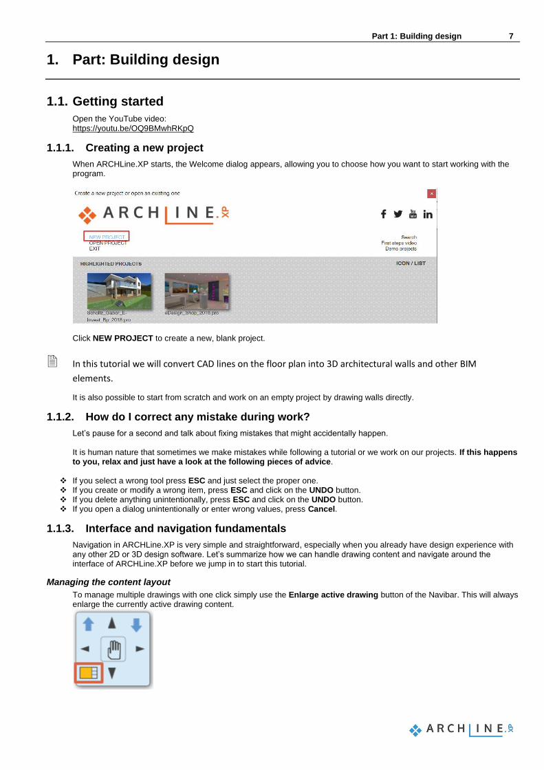
When ARCHLine.XP starts, the Welcome dialog appears, allowing you to choose how you want to start working with the program.
Click NEW PROJECT to create a new, blank project.
In this tutorial we will convert CAD lines on the floor plan into 3D architectural walls and other BIM
elements.
It is also possible to start from scratch and work on an empty project by drawing walls directly.
1.1.2. How do I correct any mistake during work?
Let’s pause for a second and talk about fixing mistakes that might accidentally happen. It is human nature that sometimes we make mistakes while following a tutorial or we work on our projects. If this happens to you, relax and just have a look at the following pieces of advice.
❖ If you select a wrong tool press ESC and just select the proper one. ❖ If you create or modify a wrong item, press ESC and click on the UNDO button. ❖ If you delete anything unintentionally, press ESC and click on the UNDO button. ❖ If you open a dialog unintentionally or enter wrong values, press Cancel.
1.1.3. Interface and navigation fundamentals
Navigation in ARCHLine.XP is very simple and straightforward, especially when you already have design experience with any other 2D or 3D design software. Let’s summarize how we can handle drawing content and navigate around the interface of ARCHLine.XP before we jump in to start this tutorial.
Managing the content layout
To manage multiple drawings with one click simply use the Enlarge active drawing button of the Navibar. This will always enlarge the currently active drawing content.

8 Part 1: Building design
Architectural Tutorial
Zoom
Scroll up or down to zoom in and out on a 2D content and in a 3D view.
Pan
Hold down the mouse wheel and move the mouse at the same time. This moves the current content to the desired direction. Release the mouse wheel to stop panning.
Orbit
To orbit around the model keep holding the mouse wheel + SHIFT key and move the mouse. To finish orbiting around the model simply release the mouse wheel and the SHIFT key.
Look around
When you already have a perspective view (this topic is covered later by the tutorial) you can hold the right mouse button and move the mouse around to look around in the model.
Selecting one item
When you would like to select an item, you should simply click on the item and it gets selected. You will see that the item gets recolored with the selection color and the selected item’s properties appear on the left-hand side. To deselect an item simply hit ESC on your keyboard or click on another item.
Selecting multiple items
If you would like to select multiple items you can either: ❖ add a new item to the selection by holding down the Ctrl key on the keyboard while clicking on another item
or ❖ you can click and drag the mouse over the drawing to draw a selection rectangle and click again in the end to select
items under the selection rectangle. When you draw a selection rectangle from left to right all items that are completely under the selection rectangle will be selected. When you draw a selection rectangle from right to left, all items that are completely under and also those that are only “touching” the selection rectangle, will be selected.
Selection list
When you click on an item and see the selection list, that means there are multiple items which can be selected at the same click-point. You can use the left and right arrows on it to navigate to the previous or the following selection. To cycle through the possible items, you can also use the TAB key on your keyboard. You can also use the selection jump-list by clicking on the arrow pointing down and selecting the desired item.
User interface
To make sure you work with the default software interface – which this tutorial is based on – use the Ribbon bar / View / User interface / Reset interface to factory default command. These are the most fundamental things about the interface and the navigation tools. All the rest of the interface, the location and management of tools and the commands will be taught as you progress through this tutorial.
1.2. Working with external files
If you are using ARCHLine.XP you can import or export CAD files, in DWG or DXF file formats.
Before you import a file containing the floor plan, it's helpful to know which formats are supported:
❖ raster images in JPG and PNG format ❖ PDF files as raster images ❖ PDF files as vector drawings ❖ DWG/DXF drawing ❖ IFC model

Part 1: Building design 9
Importing a DWG drawing means a geometry import, so as a result, we get a drawing with precise units of measure. It may contain points, lines, polylines, arcs, circles, ellipses, notes, hatches, dimensions, raster images. Let’s start working!
1.2.1. Importing the DWG drawing of the situation plan
• Choose the File menu / Import / DWG command.
• Browse to the …\Documents\ARCHlineXP DRAW\2019\Architectural_Tutorial folder with the following file: elata_nova_START-2D.dwg
The “Keep original layers” checkbox, which is selected by default, creates the items with their original layers. All items can
be placed on one single layer when this option is disabled.
• Click on the “Open” button and the following dialog appears:
• The unit is automatically recognized, and you can also select another unit of measurement from the drop-down list. Selecting the correct unit ensures that your imported drawing is accurately measured. Make sure “mm” is selected.
• Import the file by pressing “OK”.
• In the appearing dialog window just click “OK”. As the “Place with new drawing origin” option is disabled, the drawing is imported to the same location where it was drawn in the original application.

10 Part 1: Building design
Architectural Tutorial
• Check if geometry is imported at the correct scale.
• To do this, choose the Ribbon bar / Dimension / Measure / Distance command.
• Click on a horizontal line and measure it.
The scale unit is correct.
If you accidentally selected a wrong unit and the drawing is having a wrong scaling don’t worry. You can either undo the
import and repeat it with the correct scaling or actually there is a Scale command in the Ribbon bar at the Edit menu / Move / Scale.
Importing a DWG drawing you get a good quality situation plan or floor plan. Imported CAD items can be selected and
edited just like any 2D items that were created in ARCHLine.XP. When importing a DWG file, the program automatically recognizes the dimensions and notes. These can also be easily adjusted or removed from the floor plan.
Part 1: Building design 11
1.2.2. Importing the floor plan DWG drawing
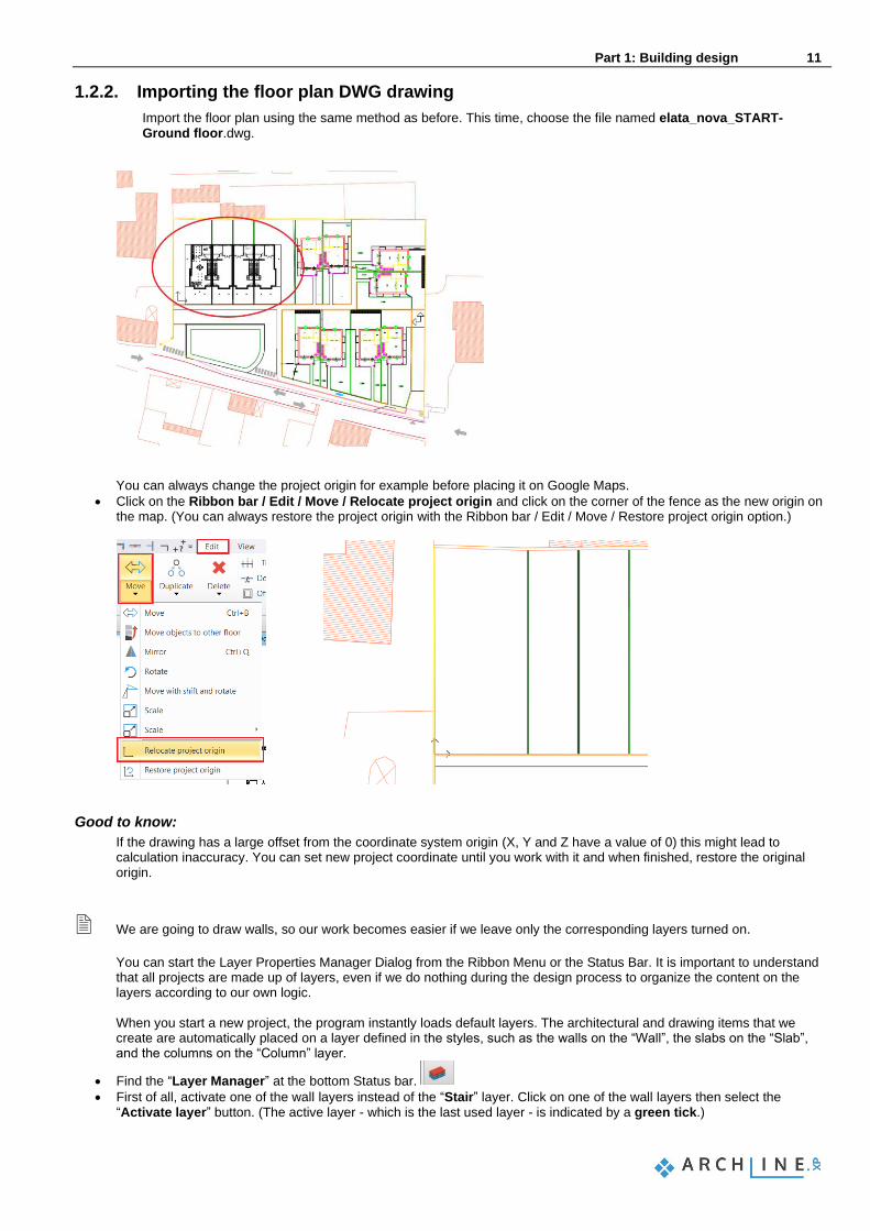
Import the floor plan using the same method as before. This time, choose the file named elata_nova_START-Ground floor.dwg.
You can always change the project origin for example before placing it on Google Maps.
• Click on the Ribbon bar / Edit / Move / Relocate project origin and click on the corner of the fence as the new origin on the map. (You can always restore the project origin with the Ribbon bar / Edit / Move / Restore project origin option.)
Good to know:
If the drawing has a large offset from the coordinate system origin (X, Y and Z have a value of 0) this might lead to calculation inaccuracy. You can set new project coordinate until you work with it and when finished, restore the original origin.
We are going to draw walls, so our work becomes easier if we leave only the corresponding layers turned on.
You can start the Layer Properties Manager Dialog from the Ribbon Menu or the Status Bar. It is important to understand that all projects are made up of layers, even if we do nothing during the design process to organize the content on the layers according to our own logic. When you start a new project, the program instantly loads default layers. The architectural and drawing items that we create are automatically placed on a layer defined in the styles, such as the walls on the “Wall”, the slabs on the “Slab”, and the columns on the “Column” layer.
• Find the “Layer Manager” at the bottom Status bar.
• First of all, activate one of the wall layers instead of the “Stair” layer. Click on one of the wall layers then select the “Activate layer” button. (The active layer - which is the last used layer - is indicated by a green tick.)

12 Part 1: Building design
Architectural Tutorial
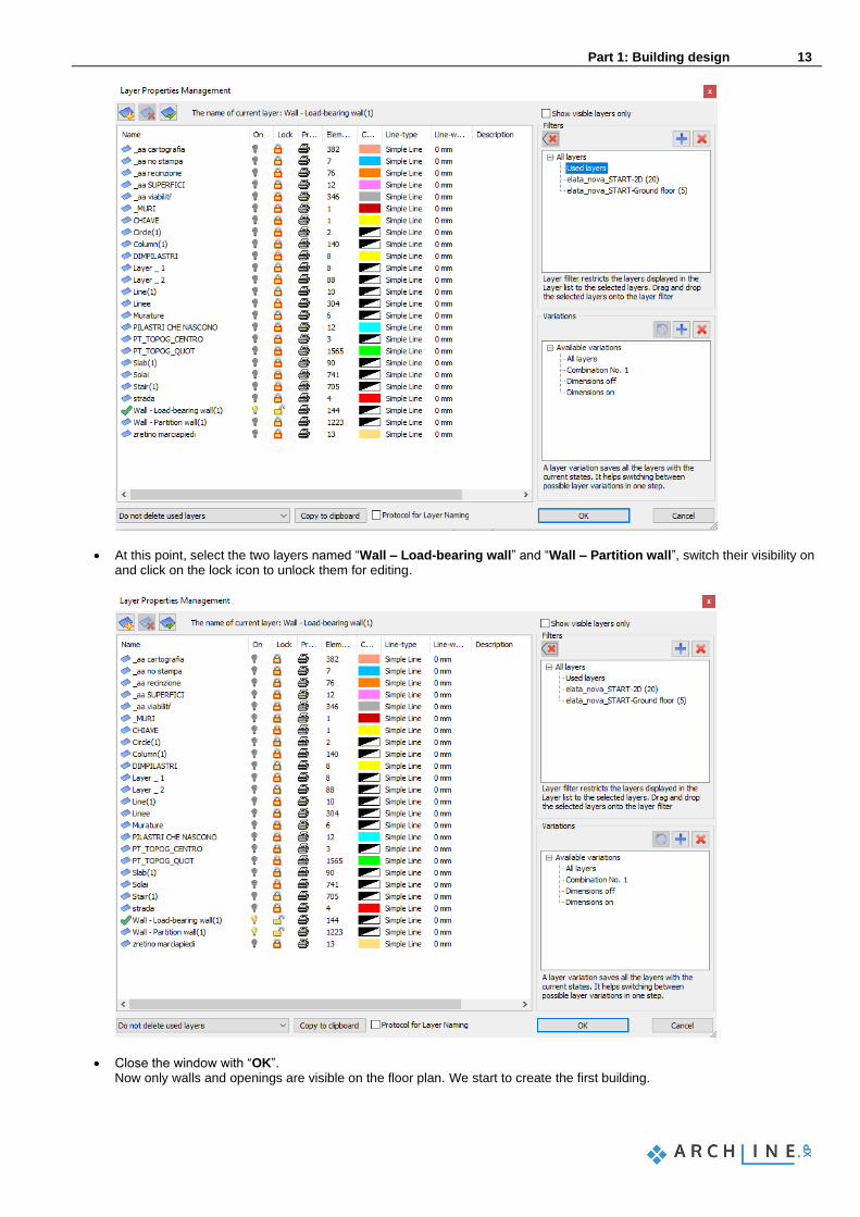
• Click on the “Used layers” filter, then select all layers within by selecting one and pressing CTRL + A. Switch off all with one click on the yellow bulb icon.
Part 1: Building design 13
• At this point, select the two layers named “Wall – Load-bearing wall” and “Wall – Partition wall”, switch their visibility on and click on the lock icon to unlock them for editing.
• Close the window with “OK”. Now only walls and openings are visible on the floor plan. We start to create the first building.

14 Part 1: Building design
Architectural Tutorial
1.3. Walls
In this part, we create a residential building based on the imported drawing. ARCHLine.XP generates the 3D BIM model parallel as you work on the floor plan.
1.3.1. Setting up the wall properties
First, we will create the walls on the Ground floor and then we will place the other architectural elements, such as doors, windows, slabs, columns, a stair and a roof.
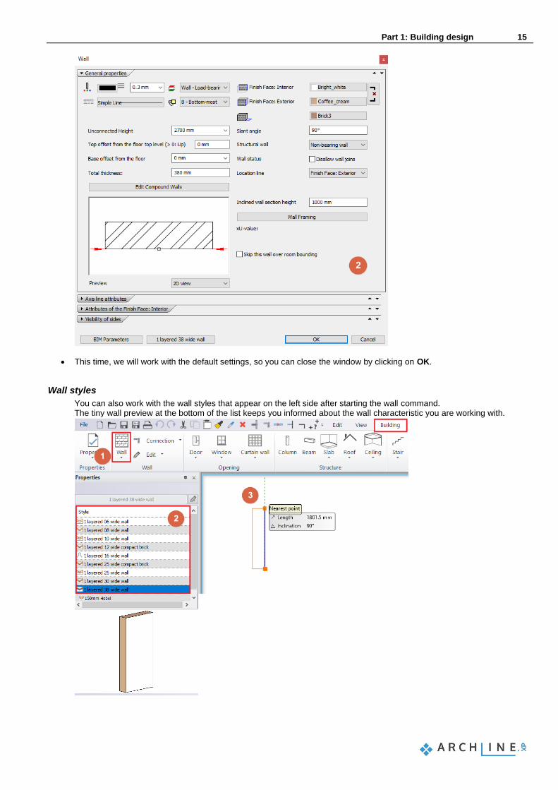
• Click on the Wall properties in the Building - Properties menu to have a look at the wall settings. Here you can enter values for the wall’s unconnected height, thickness and additional properties.
Part 1: Building design 15
• This time, we will work with the default settings, so you can close the window by clicking on OK.
Wall styles
You can also work with the wall styles that appear on the left side after starting the wall command. The tiny wall preview at the bottom of the list keeps you informed about the wall characteristic you are working with.

16 Part 1: Building design
Architectural Tutorial
When you start an element creating command (e.g.: walls, door, window etc.) the Properties panel on the left side displays all the styles of that element. Styles can be classified as:
❖ Factory (built-in) styles ❖ Styles in project only ❖ My styles ❖ Company styles
Factory (built-in) styles: Factory (built-in) styles come with the installation of the software. These styles are read-only so you cannot change them. These built-in styles are represented by an orange-tinted envelope icon. Styles in Project only: Styles created and saved in a project only are included in this category. Please note that these styles are not available in other projects. These styles are represented by a blue upside-down envelope icon. My styles: You can store your favourite styles here in order to make those available in every project. These styles are represented by a human shape icon. Company styles: You can deploy styles within your organization if you define the organizational style package with name and shared network location (Path). Styles relocated to company package are accessible to all users on shared network. Implementing organizational standards and rules allow users to become more proficient. Company styles are represented by a folder shape icon. In this tutorial we do not work with Company styles.
1.3.2. Drawing walls on DWG floor plan
Walls can be created many ways either from scratch or based on an existing drawing content. When working from scratch you can draw walls with the following tools: ❖ straight wall ❖ curved wall ❖ rectangle wall ❖ spline wall This time we will use the DWG file to turn its 2D shapes into real BIM walls. The Walls on DWG drawing command can be used to convert CAD lines on the floor plan into 3D architectural walls.
• Select Building / Wall / Walls on DWG drawing tool.
• Click near to the wall starting (1) and end point (2), then on the opposite side of the wall (3). The wall appears in the 3D view.
• Use this method to draw all the main walls.
• Then continue with the partition walls.
Part 1: Building design 17
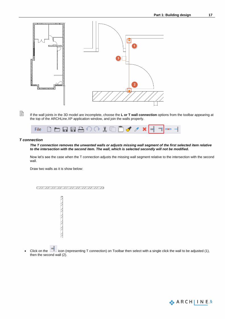
If the wall joints in the 3D model are incomplete, choose the L or T wall connection options from the toolbar appearing at the top of the ARCHLine.XP application window, and join the walls properly.
T connection
The T connection removes the unwanted walls or adjusts missing wall segment of the first selected item relative to the intersection with the second item. The wall, which is selected secondly will not be modified. Now let’s see the case when the T connection adjusts the missing wall segment relative to the intersection with the second wall.
Draw two walls as it is show below:
• Click on the icon (representing T connection) on Toolbar then select with a single click the wall to be adjusted (1), then the second wall (2).
18 Part 1: Building design
Architectural Tutorial
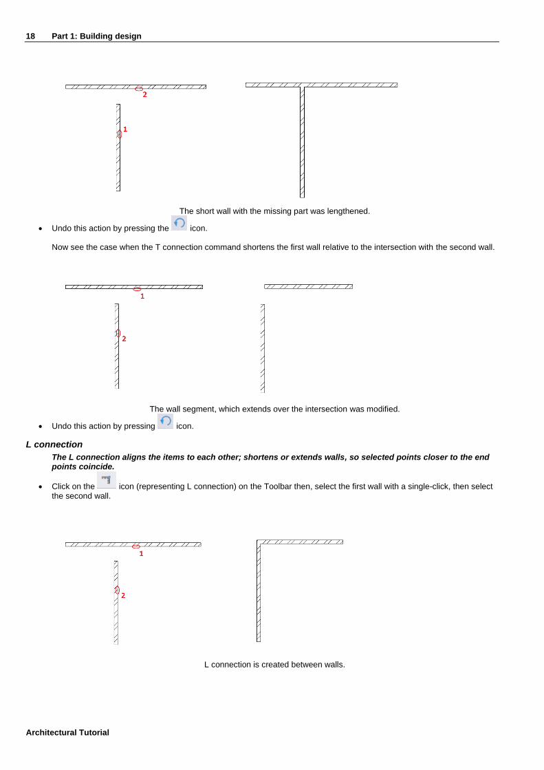
The short wall with the missing part was lengthened.
• Undo this action by pressing the icon.
Now see the case when the T connection command shortens the first wall relative to the intersection with the second wall.
The wall segment, which extends over the intersection was modified.
• Undo this action by pressing icon.
L connection
The L connection aligns the items to each other; shortens or extends walls, so selected points closer to the end points coincide.
• Click on the icon (representing L connection) on the Toolbar then, select the first wall with a single-click, then select the second wall.
L connection is created between walls.
Part 1: Building design 19
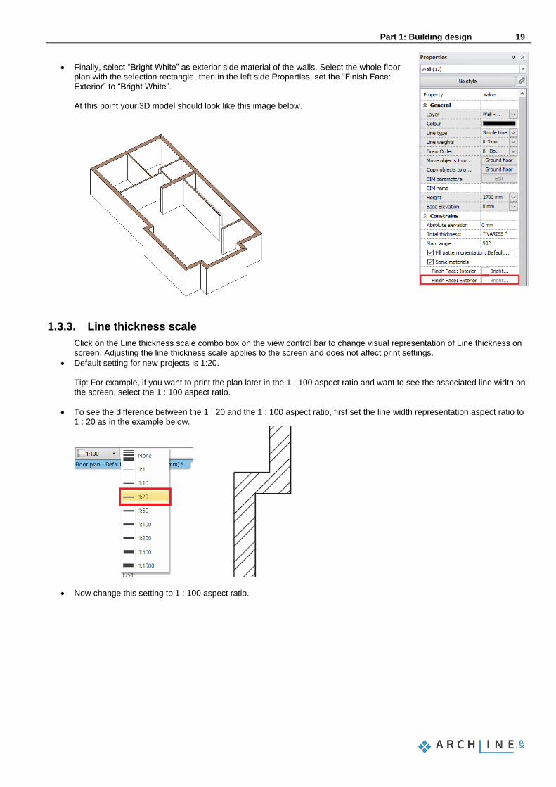
• Finally, select “Bright White” as exterior side material of the walls. Select the whole floor plan with the selection rectangle, then in the left side Properties, set the “Finish Face: Exterior” to “Bright White”.
At this point your 3D model should look like this image below.
1.3.3. Line thickness scale
Click on the Line thickness scale combo box on the view control bar to change visual representation of Line thickness on screen. Adjusting the line thickness scale applies to the screen and does not affect print settings.
• Default setting for new projects is 1:20. Tip: For example, if you want to print the plan later in the 1 : 100 aspect ratio and want to see the associated line width on the screen, select the 1 : 100 aspect ratio.
• To see the difference between the 1 : 20 and the 1 : 100 aspect ratio, first set the line width representation aspect ratio to 1 : 20 as in the example below.
• Now change this setting to 1 : 100 aspect ratio.

20 Part 1: Building design
Architectural Tutorial
• Slab and ramps
1.3.4. Slab tool - Creating the flooring
When we have finished drawing walls, let’s continue the work with placing a slab. First, we need to set up the settings we will work with.
• Before we create the slab, go to the Ribbon Bar / Building / Properties / Structure / Slab tool, and here we can find all the settings of the slab.
• We need to modify the material of the slab. Choose a new material as the top material of the slab by clicking on the first material button.
• In the appearing dialog, you can see the material library with the current project materials (used in this project until now) and you can also access all the materials on this computer. Click on the Home button and find the “Parquet / Strips” material category. Find a material, for example “parquet_rovere_03”, click on it and click OK to select it.
• The second material button is defining the side material of the slab. Click on it to change.
• Click on the Home button in the material library and type “bright” in the search field and hit Enter.
• Select the “Bright_white” material and click OK.
• Close the slab properties dialog window also with OK. Now that the settings are okay, we can start creating the slab.
• Activate the floor plan window.
• Select the Ribbon Bar / Building / Slab / Slab by walls command.
• Select the floor plan with the selection rectangle.
• Press Enter and the slab is ready.

Part 1: Building design 21
1.3.5. Slab tool - Creating a terrace
In the next step we will create a terrace with the slab tool.
• First of all, enter the Layer manager dialog window and activate the “Slab(1)” layer. Now we see the line of the terrace on the left side (1) and the ramp in front of the entrance (2).
• Draw a slab on the left side with the Ribbon bar / Building / Slab / Slab in Sketch mode command.
• Choose the created slab by clicking on it.
• Find the Properties at the left side and select “Prefab concrete” as the new top and side material of the slab and “White ceiling” as the bottom material.

22 Part 1: Building design
Architectural Tutorial
1.3.6. Creating a ramp
We create a ramp in front of the entrance by using the dedicated Ramp tool.
• Using the Ramp command from the Ribbon bar / Building / Ramp command list, then choose “Straight run” from the Straight category.

Part 1: Building design 23
• Place the ramp by specifying the bottom (1) and top (2) points.
• Click on the ramp, then choose the marker in the middle near to the Move marker. The Elevation value window is
appearing.
• We know the top and the bottom values: the top value is 0 mm, this is the ground floor and the bottom value is -300 mm. First set the 2nd option: “Base level is fixed, inclination angle or top level is editable” option (1), then add the top values (2):
• Next set the 3rd option: “Top level is fixed, inclination angle or top level is editable” option (3), then add the bottom values (4):
• Close the dialog window with OK. Now modify the width of the ramp.
• Click on the ramp in the floor plan window and select the Offset command to place it to the right place.

24 Part 1: Building design
Architectural Tutorial
Insert four additional nodes into the top contour of the ramp and snap them to the corners of the bay window.
• Click on the top edge of the selected ramp and select the Insert node command.
• Snap the new node to an external corner point of the bay window.
• Repeat the same method on the other side. Click on the edge and select Insert node, then snap it to the following corner point.
• Add the 3rd node.

Part 1: Building design 25
• Repeat this method on the other side too, in order to add the 4th node.
Finally, modify the material of the ramp from the material library.
• Click on the ramp, and choose the pencil icon from the appearing menu.
• In the Properties dialog window modify the “Waist slab material” to “Concrete3”.
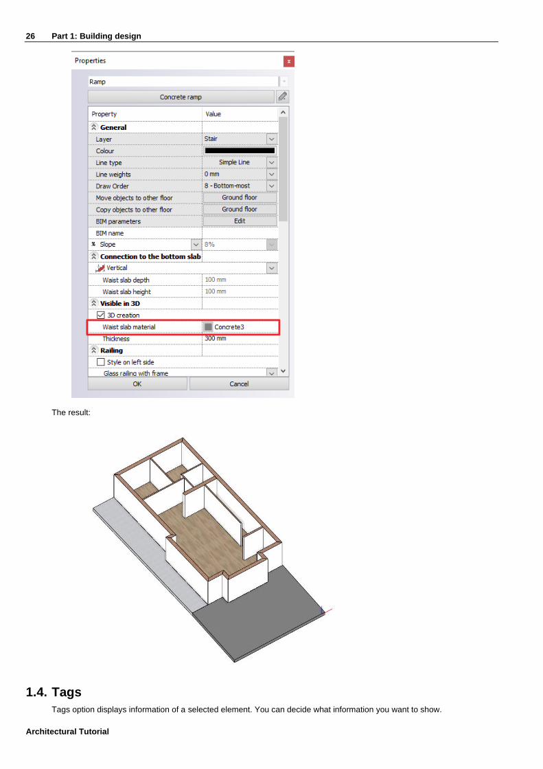
26 Part 1: Building design
Architectural Tutorial
The result:
1.4. Tags
Tags option displays information of a selected element. You can decide what information you want to show.

Part 1: Building design 27
1.4.1. Place one tag
In this section you can see how to use the basic tags in ARCHLine.XP. Tags automatically update the displayed data if you change the properties of the elements or you can change the properties of the elements directly from the tags.
• Now select Ribbon bar / Documentation / Tags / Place one tag command.
• In the pop up window select on the left side the “Slab” menu and check the parameters you want to display on the right side.
• Close the dialog window with “OK”.
• Select the slab by clicking on it then press enter.
28 Part 1: Building design
Architectural Tutorial
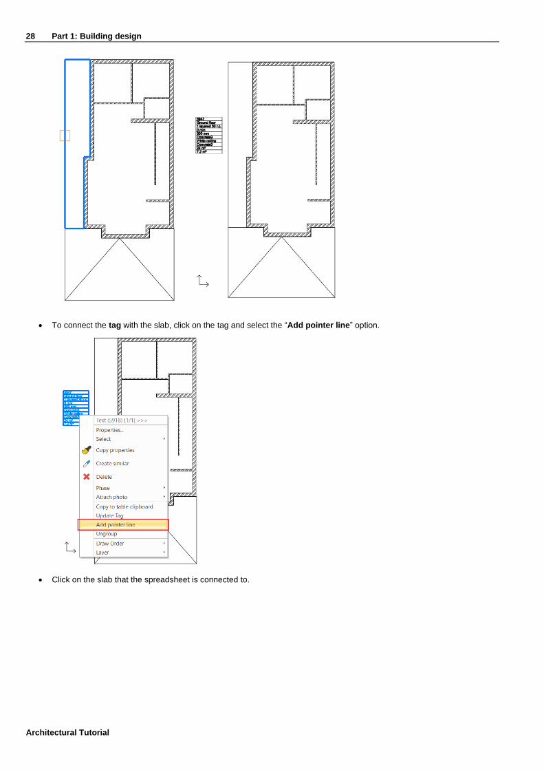
• To connect the tag with the slab, click on the tag and select the “Add pointer line” option.
• Click on the slab that the spreadsheet is connected to.

Part 1: Building design 29
• Now let’s change the top and side materials to “Concrete3”.
• Select the tag.
• In the line of the materials on the right side click on the paint bucket.
• Change both of the Prefab concrete materials to “Concrete3”.
• In the pop up window select the “Concrete3” material.
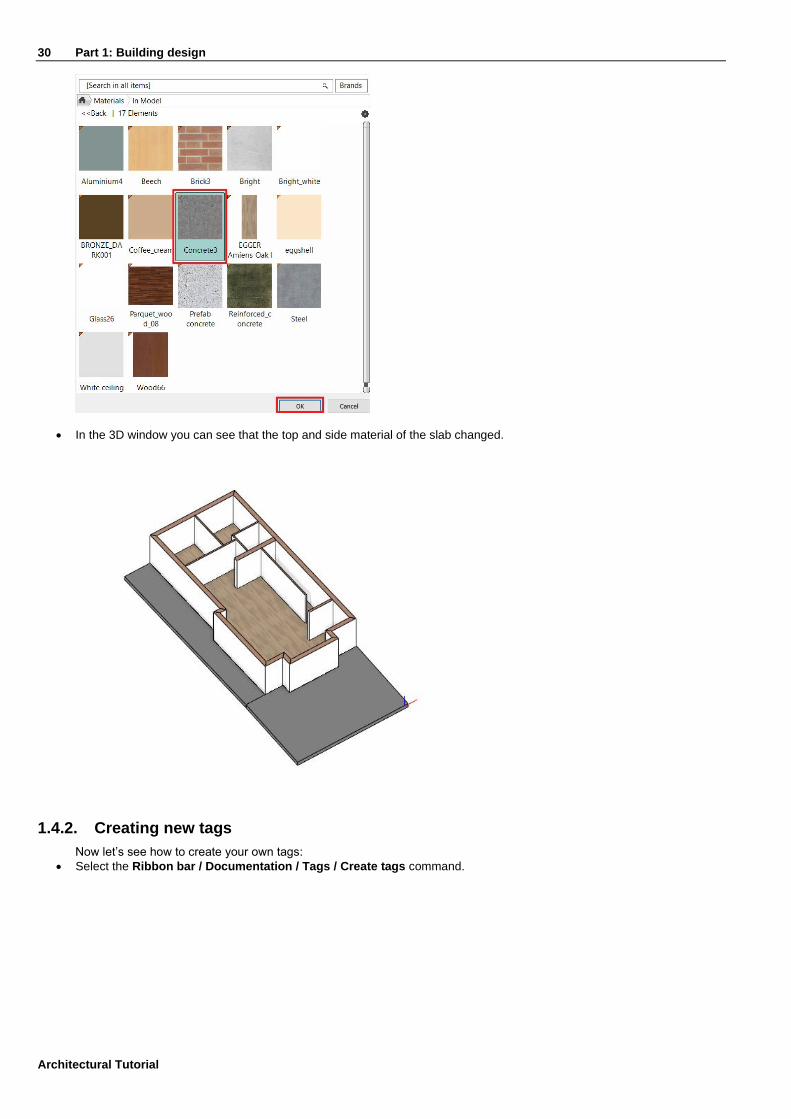
30 Part 1: Building design
Architectural Tutorial
• In the 3D window you can see that the top and side material of the slab changed.
1.4.2. Creating new tags
Now let’s see how to create your own tags:
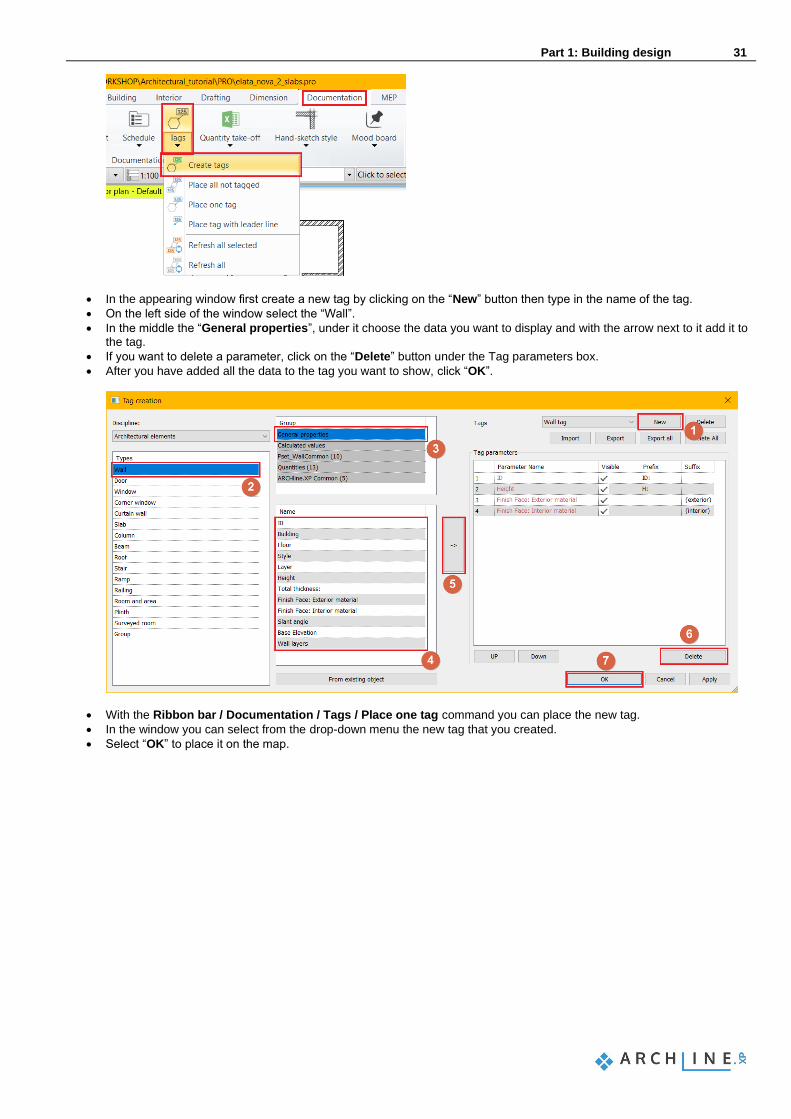
• Select the Ribbon bar / Documentation / Tags / Create tags command.
Part 1: Building design 31
• In the appearing window first create a new tag by clicking on the “New” button then type in the name of the tag.
• On the left side of the window select the “Wall”.
• In the middle the “General properties”, under it choose the data you want to display and with the arrow next to it add it to the tag.
• If you want to delete a parameter, click on the “Delete” button under the Tag parameters box.
• After you have added all the data to the tag you want to show, click “OK”.
• With the Ribbon bar / Documentation / Tags / Place one tag command you can place the new tag.
• In the window you can select from the drop-down menu the new tag that you created.
• Select “OK” to place it on the map.
32 Part 1: Building design
Architectural Tutorial
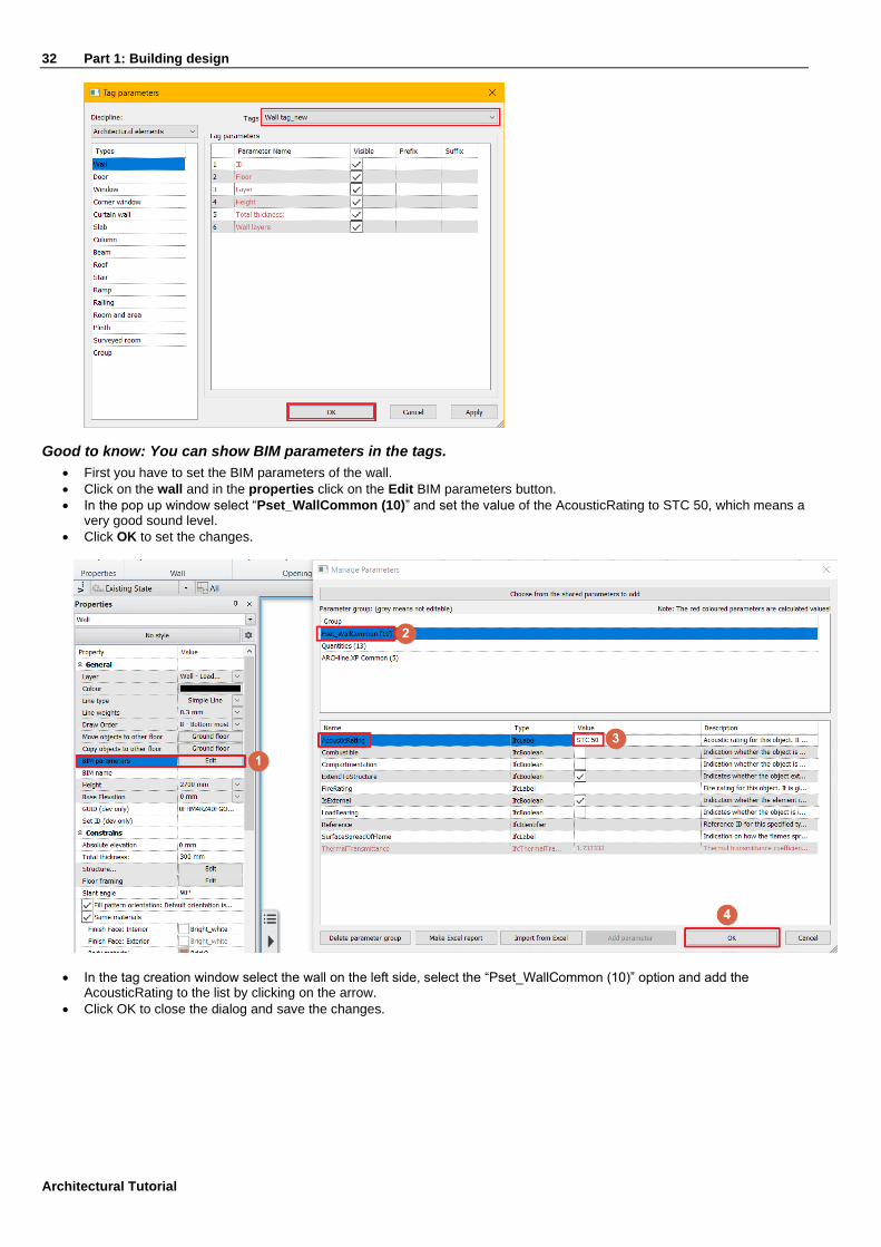
Good to know: You can show BIM parameters in the tags.
• First you have to set the BIM parameters of the wall.
• Click on the wall and in the properties click on the Edit BIM parameters button.
• In the pop up window select “Pset_WallCommon (10)” and set the value of the AcousticRating to STC 50, which means a very good sound level.
• Click OK to set the changes.
• In the tag creation window select the wall on the left side, select the “Pset_WallCommon (10)” option and add the AcousticRating to the list by clicking on the arrow.
• Click OK to close the dialog and save the changes.

Part 1: Building design 33
• Now place the tag on a wall.
• You can see that the Acoustic rating of the wall now appears in the tag.
1.5. Openings: Doors and windows
This section covers the essentials to place doors / windows into the walls created so far. The creation method of openings is the same for doors, windows, voids or recesses. There is a strong connection between wall and openings. An opening (with a few exceptions) is always hosted in a wall: if you move a wall its openings move together with the wall.
1.5.1. Doors
Place doors according to the DWG drawing, so the door width will be defined by the DWG drawing. The doors are all 2100 mm high, except the front door which is 2400 mm high. You can set the door properties by selecting its properties on the Ribbon bar or using pre-defined doors from the styles that appear on the left after the command has been started.
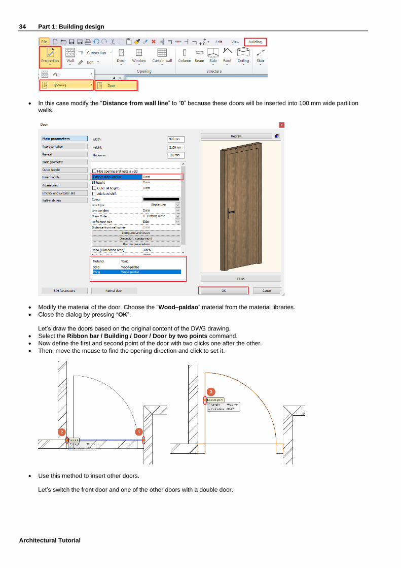
• Now select Ribbon bar / Building / Properties / Opening / Door command.
34 Part 1: Building design
Architectural Tutorial
• In this case modify the “Distance from wall line” to “0” because these doors will be inserted into 100 mm wide partition walls.
• Modify the material of the door. Choose the “Wood–paldao” material from the material libraries.
• Close the dialog by pressing “OK”. Let’s draw the doors based on the original content of the DWG drawing.
• Select the Ribbon bar / Building / Door / Door by two points command.
• Now define the first and second point of the door with two clicks one after the other.
• Then, move the mouse to find the opening direction and click to set it.
• Use this method to insert other doors.
Let’s switch the front door and one of the other doors with a double door.
Part 1: Building design 35
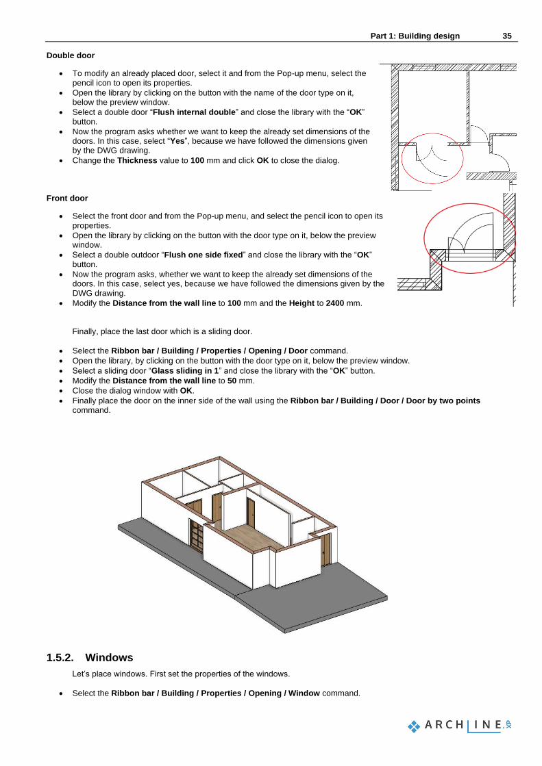
Double door
• To modify an already placed door, select it and from the Pop-up menu, select the pencil icon to open its properties.
• Open the library by clicking on the button with the name of the door type on it, below the preview window.
• Select a double door “Flush internal double” and close the library with the “OK” button.
• Now the program asks whether we want to keep the already set dimensions of the doors. In this case, select “Yes”, because we have followed the dimensions given by the DWG drawing.
• Change the Thickness value to 100 mm and click OK to close the dialog.
Front door
• Select the front door and from the Pop-up menu, and select the pencil icon to open its properties.
• Open the library by clicking on the button with the door type on it, below the preview window.
• Select a double outdoor “Flush one side fixed” and close the library with the “OK” button.
• Now the program asks, whether we want to keep the already set dimensions of the doors. In this case, select yes, because we have followed the dimensions given by the DWG drawing.
• Modify the Distance from the wall line to 100 mm and the Height to 2400 mm.
Finally, place the last door which is a sliding door.
• Select the Ribbon bar / Building / Properties / Opening / Door command.
• Open the library, by clicking on the button with the door type on it, below the preview window.
• Select a sliding door “Glass sliding in 1” and close the library with the “OK” button.
• Modify the Distance from the wall line to 50 mm.
• Close the dialog window with OK.
• Finally place the door on the inner side of the wall using the Ribbon bar / Building / Door / Door by two points command.
1.5.2. Windows
Let’s place windows. First set the properties of the windows.
• Select the Ribbon bar / Building / Properties / Opening / Window command.
36 Part 1: Building design
Architectural Tutorial
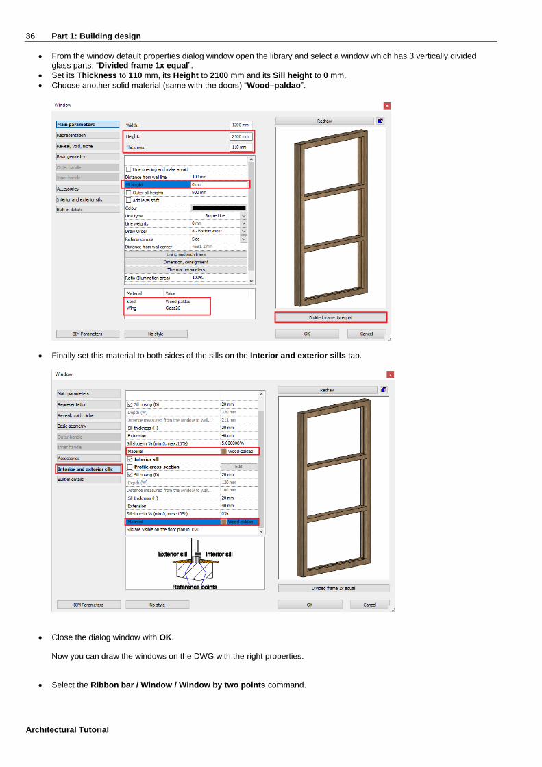
• From the window default properties dialog window open the library and select a window which has 3 vertically divided glass parts: “Divided frame 1x equal”.
• Set its Thickness to 110 mm, its Height to 2100 mm and its Sill height to 0 mm.
• Choose another solid material (same with the doors) “Wood–paldao”.
• Finally set this material to both sides of the sills on the Interior and exterior sills tab.
• Close the dialog window with OK. Now you can draw the windows on the DWG with the right properties.
• Select the Ribbon bar / Window / Window by two points command.

Part 1: Building design 37
• Select two corner points of the window by clicking on the inner side of the wall.
• Place all other windows following these steps.
Good to know: You can change the interior and exterior material of the window separately.
• Select any window in the house.
• You can now change the material settings in the Window settings / Main parameters / Material option.
• Select the “Wood-walnutciaro” material as Internal frame material.
• You can immediately see the changes on the 3D model on the right side.

38 Part 1: Building design
Architectural Tutorial
1.5.3. Place two windows as corner window
Any combination of standard windows can be joined in a corner window. To create a corner window place two windows on each side of a corner where two walls form a corner. Using the Join two openings on wall corner command from the Ribbon bar / Building / Window / Windows on wall corner menu then select the first and second window with one click.
ARCHLine.XP automatically creates the corner post between two windows.
• Change its material “Wood-paldao”: Go to the properties, Built-in details tab and modify the Body material. Finally, modify the width of the two joining corner windows to match the original drawing.
• Select one of the windows.
• Click on the blue dot corner marker and select the Change size command.
• Adjust size and snap it to the original drawing content.

Part 1: Building design 39
• Repeat these with the other window.
The result looks like this when all the openings are completed:
1.6. Stairs
1.6.1. Placing stairs
• Activate the floor plan window, and make sure that the Ground floor is active. We will design a staircase on this floor:
• Open the Ribbon bar / Building / Stair command list. Here you can find tools for creating and editing stairs.
• Start the Building / Stair / L form + Landing command.
When you start the command, the Properties panel on the left displays all the previously saved styles. You can use these styles too.

40 Part 1: Building design
Architectural Tutorial
• Before placing the stair, choose the “Right side” option from the appearing option list on the right-hand side to place the stair with a reference line on the right side.
• Place the staircase with 3 corner points.
1.6.2. Modifying properties of the previously placed staircase
When you have placed the staircase, modify its properties. To do this, click on any points of it, and select the pencil icon from the floating menu.
• Now the Stair dialog window will appear. Set the following values on the Stair Calculator tab:
• And set the following values on the Support tab:

Part 1: Building design 41
• Floor height (1): Activate the Take the floor height option and this value will be automatically overwritten as per the project to 3000 mm.
Ergonomic settings (2)
These values are not to be changed now - they are automatically calculated based on the height and the number of steps of the staircase. The staircase is considered ergonomic when these values are falling within the right side, indicated minimum and maximum standard values. If a value exceeds the limits, the software indicates that with a red highlight. However, even in case of a non-ergonomic stair the software allows the placement and leaves the decision to the designer whether it is to be changed or not.
Number of the steps (3)
The number of steps are calculated based on the values of n1 and n 2.
• n1, n2 (4): In case of a winded stair, the values of n1, n2 define the number of non-winded steps on the straight side. n1 is 3 and n2 is 13.
• Width (5): use 1200 mm.
Side parameters (6)
These two values show the length on each sides of the staircase.
Rounding radius (7)
This can be found at the bottom. We do not change it this time and it results in a sharp corner with no rounding.
Walking line
Now it is 50%, which is in the middle of the staircase.
• Select the Support tab and modify the Cut the walls option to “Own floor”. This way the stair will cut the wall below it.

42 Part 1: Building design
Architectural Tutorial
• Finally, scroll down in the support tab to modify the material of the Tread. Choose the same material that you used for the door: “Wood–paldao”.
• When you finished the settings, close the dialog window by pressing OK. Now the program creates the staircase with the modified parameters.
• Change to the 3D window, right click on the wall next to the stairs and choose the Isolate / Hide this object option. Repeat this step with the door too.
Part 1: Building design 43
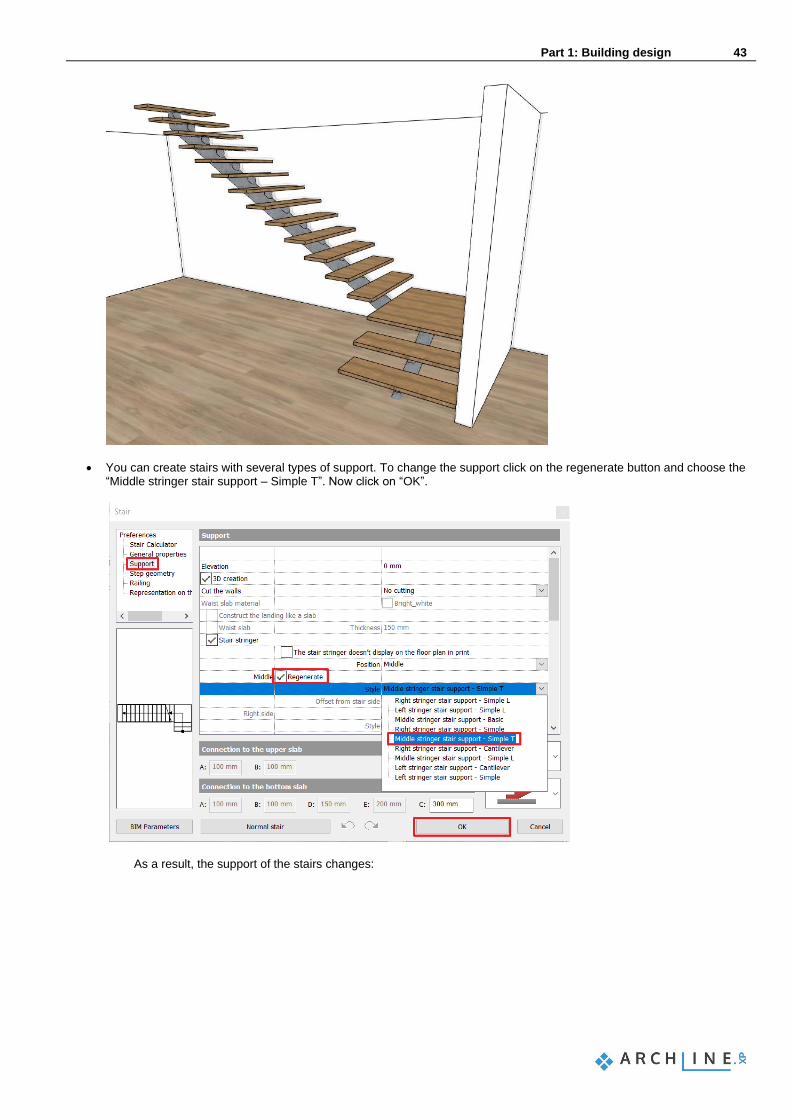
• You can create stairs with several types of support. To change the support click on the regenerate button and choose the “Middle stringer stair support – Simple T”. Now click on “OK”.
As a result, the support of the stairs changes:

44 Part 1: Building design
Architectural Tutorial
• Now select the following options in the support tab:

Part 1: Building design 45
• Click on the “Quick 3D model” hammer to update the wall-stair connection.
• Now select the support tab again and select the Cut the walls / Own floor option and click on the hammer sign again.
Good to know: You can change the tilt of the riser board.
• In the stairs settings select the support tab and activate the riser board option.
• Change the Angle of riser board from the vertical degree to the desired value.

46 Part 1: Building design
Architectural Tutorial
1.7. Working on an additional floor
ARCHLine.XP automatically creates several floors when the project is first created. You can create or import content on any of these floors. These floors are ready-made for you to use and of course you can fully customize, rename or erase them and you can add as many floors as necessary to create your building structure. In our project we need to draw another floorplan, too. We will follow these 2 tasks to create the 1st floor’s content:
❖ Import the DWG drawing of the 1st floor ❖ Copy content from the Ground floor to the 1st floor. ❖ Customize the architectural items of the 1st floor to match the DWG content.
1.7.1. Importing content of the 1st floor
Let’s import the DWG drawing of the 1st floor:
• Use the floor navigator buttons at the bottom of the screen to navigate to the “1. floor”. (Alternatively, you can use the Page Up and Page Down keys too.)
• Import the floor plan of the 1st floor following the same method as in case of the Ground floor.
1.7.2. Copy content from one floor to the other
To speed up your work, it is very useful to know that you can easily copy or move things onto other floors.
• Use the floor navigator buttons at the bottom of the screen to navigate to the “Ground floor”. (Alternatively, you can use the Page Up and Page Down keys too.).

Part 1: Building design 47
• Find the “Layer Manager” at the bottom Status bar.
• Click on the “elata_nova_START-Ground floor” filter, then select all layers within by selecting one and pressing CTRL + A. Switch off all with one click on the yellow bulb icon.
• Close the Layer manager with the OK button.
• Select the entire floor plan in the Ground floor then open the Edit levels dialog window by with clicking on the Ground floor button at the bottom of the screen.
In the list there are 4 floors now. The currently active floor is the Ground floor. These floors are automatically created by the software by default, every time you start a new project.
• Click on “Copy objects to other floor” icon.
• In the appearing dialog window, select the First floor. Press the OK to copy the selected items.

48 Part 1: Building design
Architectural Tutorial
In the 3D window you can see that the full content of the ground floor is copied to the upper floor as well.
1.7.3. Customizing the content of the 1. floor
Now we will customize the content of the 1. floor by removing unnecessary partition walls and openings and create new ones.
• Select and erase the partition walls inside the First floor’s content.
• Select and delete one window from the corner windows on this floor to have 1+1 one window instead of the original 2+1 layout.
• Delete the entrance door from the main wall of the First floor.
• Draw the partition walls using the Walls on DWG drawing tool. Make “L” and “T” connections where necessary.
• Place all the openings matching the original DWG drawing.
Setting up the correct display of the staircase In order to show the staircase properly on both the floor plan and on the 3D, we have to switch off the display of the staircase in 3D, and also, we’ll need to modify the 2D symbol, too. This is how we do it:
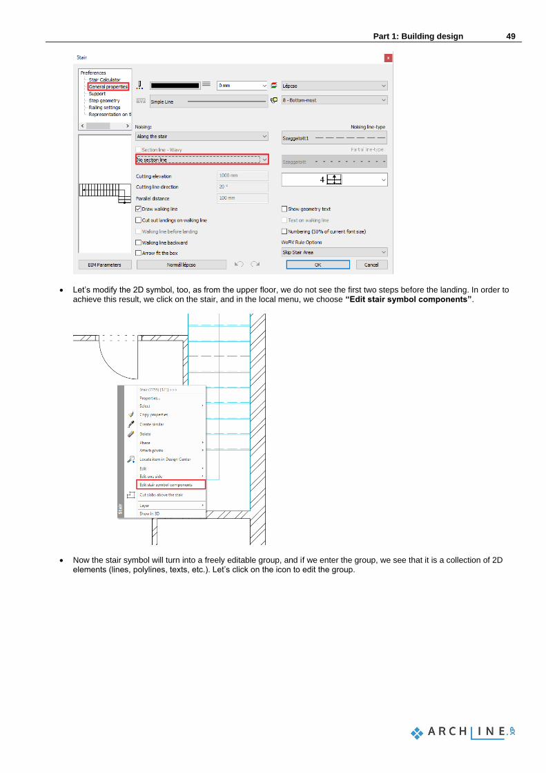
• Open up the stair properties, and on the Support tab, we should turn off the 3D creation option, furthermore, we switch the Cut the walls option to “No cutting”. In the General properties tab, we have to choose to have “No section line”, so that the 2D display of the stair will be proper.
Part 1: Building design 49
• Let’s modify the 2D symbol, too, as from the upper floor, we do not see the first two steps before the landing. In order to achieve this result, we click on the stair, and in the local menu, we choose “Edit stair symbol components”.
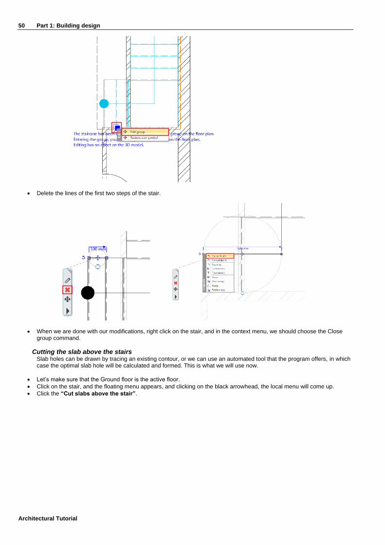
• Now the stair symbol will turn into a freely editable group, and if we enter the group, we see that it is a collection of 2D elements (lines, polylines, texts, etc.). Let’s click on the icon to edit the group.
50 Part 1: Building design
Architectural Tutorial
• Delete the lines of the first two steps of the stair.
• When we are done with our modifications, right click on the stair, and in the context menu, we should choose the Close group command.
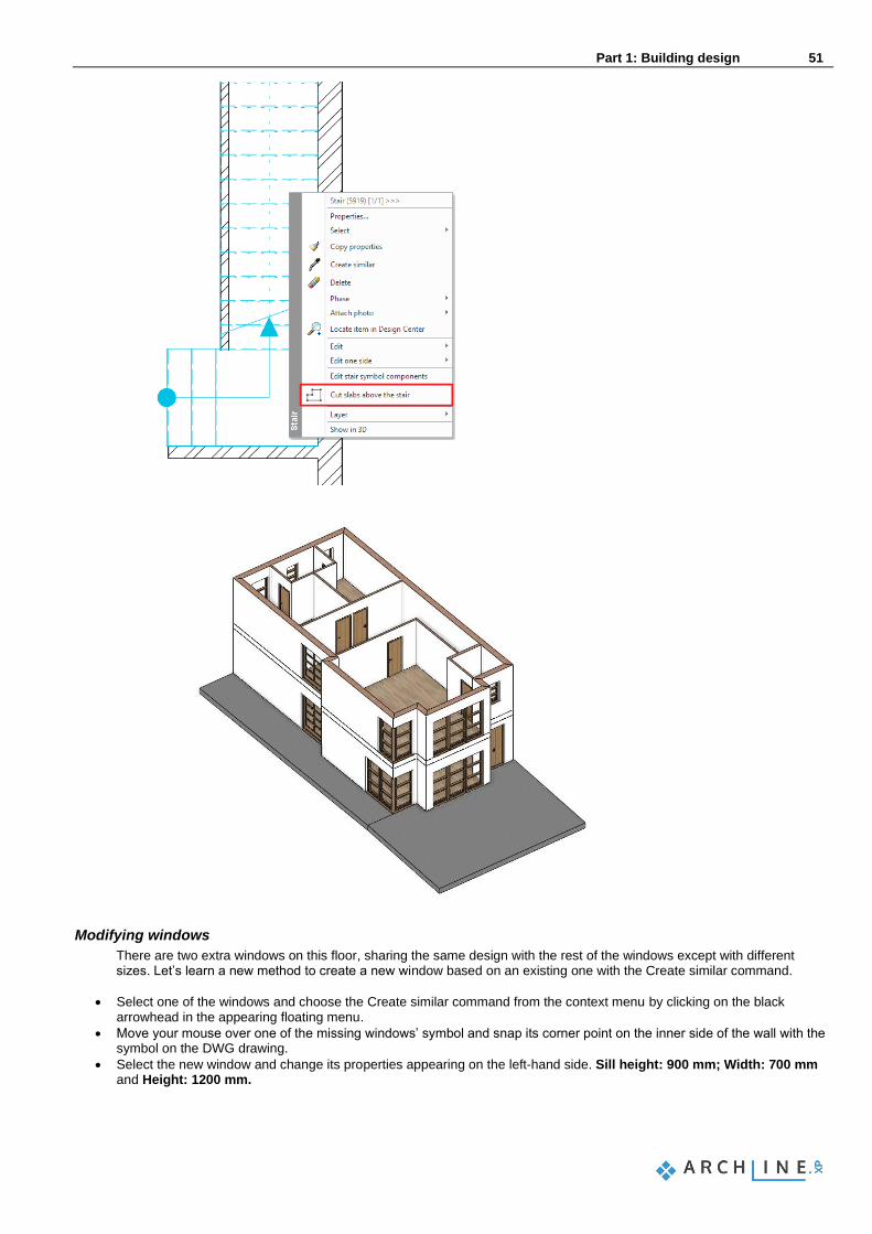
Cutting the slab above the stairs Slab holes can be drawn by tracing an existing contour, or we can use an automated tool that the program offers, in which case the optimal slab hole will be calculated and formed. This is what we will use now.
• Let’s make sure that the Ground floor is the active floor.
• Click on the stair, and the floating menu appears, and clicking on the black arrowhead, the local menu will come up.
• Click the “Cut slabs above the stair”.
Part 1: Building design 51
Modifying windows
There are two extra windows on this floor, sharing the same design with the rest of the windows except with different sizes. Let’s learn a new method to create a new window based on an existing one with the Create similar command.
• Select one of the windows and choose the Create similar command from the context menu by clicking on the black arrowhead in the appearing floating menu.
• Move your mouse over one of the missing windows’ symbol and snap its corner point on the inner side of the wall with the symbol on the DWG drawing.
• Select the new window and change its properties appearing on the left-hand side. Sill height: 900 mm; Width: 700 mm and Height: 1200 mm.

52 Part 1: Building design
Architectural Tutorial
Balcony and flat roof
Let’s create a balcony with the Slab in Sketch mode command.
• After starting the command, draw the contour of the left balcony using Slab in Sketch mode command. Follow the inner contour of the terrace line of the DWG drawing.
• After the terrace is completed, select it and change its properties appearing on the left-hand side.
• Select “Bright_White” as the top and side material of the slab and “White ceiling” as the bottom material.
• Close the dialog window with OK.
Let’s create the flat roof above the driveway.
• Start the Slab in Sketch mode command and draw the contour of the inner flat roof.
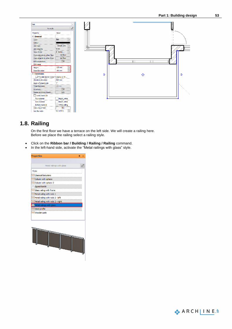
• In the Property grid on the left-hand side, modify its Base Elevation to -300 mm and its Height to -100 mm.
• Select “Concrete3” as the bottom and side material of the slab.
• After that draw, the contour of the outer flat roof too.
• Set its Base Elevation to -200 mm and its Height to +100 mm.
• Select “Bright_White” as the top and side material of the slab and “White ceiling” as the bottom material.
Part 1: Building design 53
1.8. Railing
On the first floor we have a terrace on the left side. We will create a railing here. Before we place the railing select a railing style.
• Click on the Ribbon bar / Building / Railing / Railing command.
• In the left-hand side, activate the “Metal railings with glass” style.

54 Part 1: Building design
Architectural Tutorial
• Trace the 2nd line parallel with the terrace contour.
• When you are done, press the Enter key on the keyboard twice.
• Activate the 3D window.
• Click on the railing and lower its position by 100 mm: Click on the blue arrowhead, select the Move command and move the content downwards and type 100 and hit the Enter key on the keyboard.
Finally, modify the glass material on the railing – this time we are learning a new method.
• Make sure nothing is selected on the drawing and click on the “Materials” catalogue in the Design center on the left-hand side. This is where you can quickly find all the materials.
• Click on the GLASS, MIRROR / Glass category. Select a glass material (for example “Blue glass 02” and click and drag it into the model.
• Release the mouse button and choose the “Replacing one material with another on this object” command.
• Click on the glass surface of the railing to change it to “Blue glass 02”.
• Hit ESC to close the material replacement command.
The railing is done.
1.9. Roof
The ARCHLine.XP Roof toolset offers powerful solutions to design roof structures on a professional level should it be a simple conceptual or a highly detailed plan. The type of structure is not limited as you can design archaic, modern wooden or even steel structure. Everything you design is parametric and flexible, allowing designers to shape these complex items all through the design process just as the current status of project demands. In this paragraph, we will create a simple conceptual roof. Through this example you will learn and understand the following concepts:
❖ Designing a roof ❖ Reshape an existing roof ❖ Working with roof planes and editing roof pitch ❖ Setting up roof materials and simple details ❖ Making connections to other architectural items
1.9.1. Creating the loft floor
Before we actually create the roof structure itself, let’s create a closing slab structure above the 1st Floor. There are many ways to create slabs; this time we will copy and change an existing one.
• Activate the floor named “1. floor”.
• Select the floor slab following the outer contour of the floor plan.
• Click on the “1. floor” button of the “Copy objects to other floor” row in the Properties panel.
• Select “2. floor” in the appearing floor list and click OK.
• Click on the hole contour of the newly created slab on the 2nd floor and select the “Hole / Delete hole” command in the context menu.

Part 1: Building design 55
• Select the slab and change the Height to -100 mm and the Base Elevation to -300 mm.
Now that the closing slab structure is set up and done, we also need to change its contour to get the final shape.
• Select the slab.
• Click on the short horizontal contour line at the bottom of the slab drawing and select the “Offset” command in the appearing marker menu.
• Move it 750 mm downwards to snap to the lowest horizontal edge.
• Use the same solution to move the right side short horizontal edge to perfectly snap to the lowest horizontal edge.
• Use the marker menu to erase the remaining 2 corner points on the newly created horizontal slab edge.
• Click on the vertical edge of the slab on the right side and use the “Offset“ command to move it 300 mm to the left.

56 Part 1: Building design
Architectural Tutorial
1.9.2. Designing the roof
ARCHLine.XP provides tools to create a roof structure either by selecting walls of an existing building to recognize its outer contour or you can also draw this contour by yourself. Either way, the roof can be reshaped, changed and redesigned completely at any time to add more details. This time we are creating a conceptual roof following the contour of the existing slab with only a few settings changed to understand the basics of the roof design process.
• Start the Ribbon bar / Building / Roof / Roof in sketch mode tool.
• Select the “Simple roof” style appearing on the left-hand side.
• By default, this tool is waiting for walls to be selected to recognize their outer contour. Now click on the Polygon option on the right-hand side to switch to the manual contour design mode.
• Draw a polygon contour by clicking into each corner points of the slab. When you are finished drawing the closed contour, the roof property dialog appears. Let’s make changes.
• Change both the bottom plane and side plane materials from Natural_pine to Bright_white.
• Change the Value “C” in the Reference point for roof elevation list to -300 mm.
• Go to the “Pitch and shape” page of the roof properties dialog window and enable the “Apply for all planes” option, then modify the pitch value from 42 degrees to 25 degrees. Click on the “Update” button on the right side above the 3D preview to see the changes.
• Click on the roof plane marked nr.1. on the following image and change its pitch to 35 degrees and the click “Update” to see the changes.

Part 1: Building design 57
• Use the same method to change the pitch of the plane marked nr.2 to 35 degrees.
• Click on plane marked nr.3. and tick the Gable end radio button to turn it into a gable end then the click “Update” to see the changes.
• Go to the “Roof tiles” page and under the “Basic” tiling page click on the paint bucket icon to change the current roof material from “Roof brown” to “Roof_Blind_Coal”. If you cannot see this material in the list, just click on the button with the blue cross on it to get access to the Design center with all the materials.
• Click on the “Ridge” and “Valley” tiling pages too and change the current material from “Roof brown” to “Roof_Blind_Coal”.
• Click OK to close the properties dialog and see the roof on the 2D layout and in the 3D view.
1.9.3. Changing the roof contour
All roof shapes created with the Automatic roof tool can be changed in shape and details when needed. This time we will move 2 edges to make space for a fire-wall separating our building from the rest of the building block.
• Select the roof in the 2D view.
• Click on the right-side edge and select the Offset command from the appearing marker menu.
• Move the edge to the left to perfectly snap to the slab contour.
• Do the same with the 2nd vertical edge of the roof on the right side.
• Hit ESC to deselect the roof. Let’s align the contour of the slab to the roof to finish the roof-slab connection.

58 Part 1: Building design
Architectural Tutorial
• Select the slab.
• Click on an edge and select the “Offset“ command in the appearing marker menu.
• Move the edge to snap to the roof edge.
• Repeat this all the slab edges not aligned with the roof outer contour.
1.9.4. Designing the fire-wall
Let’s create the wall separating the two buildings. For this we will now copy an existing wall and change its properties and then we will redesign its shape to match the roof.
• Switch to the floor named “1. floor”.
• Select the right-side wall of our building.
• Click on the “1. floor” button of the “Copy objects to other floor” row in the Properties panel.
• Select “2. floor” in the appearing floor list and click OK.
• Select the new wall on the 2nd floor and change its Height to 4500 mm and its Base elevation to -300 mm.
• Change the Body material to Bright_white.
• Click on the endpoint marker of the wall and select the “Change length” command to snap it to the closest corner point of the roof.
• Repeat this with the other end of the wall. The fire-wall is now just a regular wall with a straight horizontal top. Let’s redesign its shape (the so-called frontal profile) to have a wall top that’s following the pitch of the roof. First, we will take the current shape of the wall in context with the roof to use it as a basis to the design.
• Activate the 3D window.
• Click on the header of the 3D content window and select the Side views / Right option.
• Click on the 3D window header again and select the Image <-> Vector drawing switch. This command turns the original easy to rotate 3D content into a line drawing.
Part 1: Building design 59
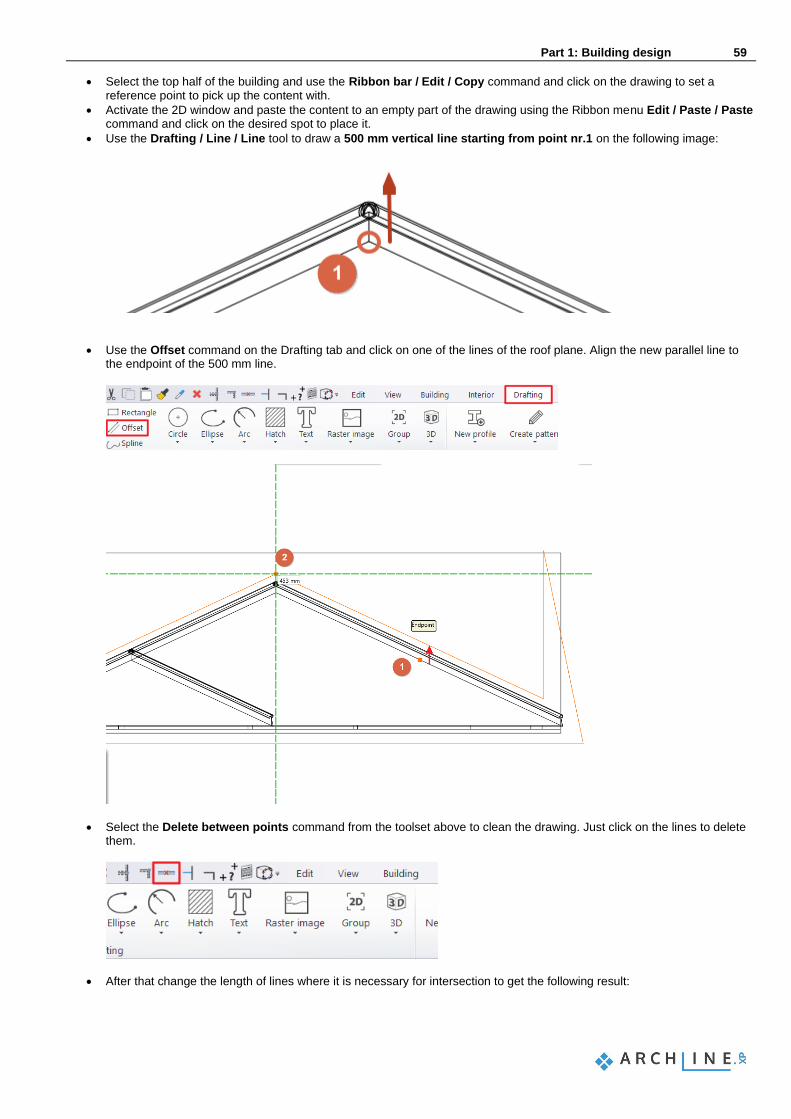
• Select the top half of the building and use the Ribbon bar / Edit / Copy command and click on the drawing to set a reference point to pick up the content with.
• Activate the 2D window and paste the content to an empty part of the drawing using the Ribbon menu Edit / Paste / Paste command and click on the desired spot to place it.
• Use the Drafting / Line / Line tool to draw a 500 mm vertical line starting from point nr.1 on the following image:
• Use the Offset command on the Drafting tab and click on one of the lines of the roof plane. Align the new parallel line to the endpoint of the 500 mm line.
• Select the Delete between points command from the toolset above to clean the drawing. Just click on the lines to delete them.
• After that change the length of lines where it is necessary for intersection to get the following result:

60 Part 1: Building design
Architectural Tutorial
• Now select the newly created lines along with the wall contour and by clicking on the Move marker, move a copy above it
to use as trace reference.
• Now select the originally pasted complex layout and delete it, keeping only the simple line drawing copy.
The above-mentioned short example is just one way to approach a complex design process like this. Feel free to use other creative approaches to design layouts in your future projects based on this example. We can actually use the previously drafted contour to change the 3D wall shape.
• Click on the right side of the wall and select the context menu Profile / Add whole front profile command.
• Snap the top left corner of the rectangular layout to the top left corner of the previously designed shape and click to place it.
• Select the Closed loop option at the profile definition list appearing at the Ribbon menu and click inside the shape.
Part 1: Building design 61
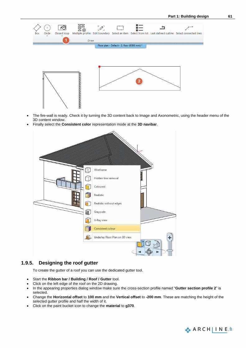
• The fire-wall is ready. Check it by turning the 3D content back to Image and Axonometric, using the header menu of the 3D content window.
• Finally select the Consistent color representation mode at the 3D navibar.
1.9.5. Designing the roof gutter
To create the gutter of a roof you can use the dedicated gutter tool.
• Start the Ribbon bar / Building / Roof / Gutter tool.
• Click on the left edge of the roof on the 2D drawing.
• In the appearing properties dialog window make sure the cross-section profile named “Gutter section profile 2” is selected.
• Change the Horizontal offset to 100 mm and the Vertical offset to -200 mm. These are matching the height of the selected gutter profile and half the width of it.
• Click on the paint bucket icon to change the material to g370.

62 Part 1: Building design
Architectural Tutorial
• Select the 2nd page named Downspout.
• Change Length to 5900 mm.
• Change the Position value appearing on the right side of the position slider to 5580 mm.
• Click on the Green tick to add the downspout.
• Add a 2nd downspout using the Green plus icon, this time using 7800 mm measured from the left side.
• Click OK to create.
Part 1: Building design 63
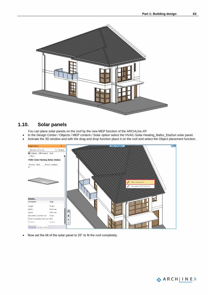
1.10. Solar panels
You can place solar panels on the roof by the new MEP function of the ARCHLine.XP.
• In the Design Center / Objects / MEP content / Solar option select the HVAC-Solar-Heating_Baltur_EtaSun solar panel.
• Activate the 3D window and with the drag and drop function place it on the roof and select the Object placement function.
• Now set the tilt of the solar panel to 25° to fit the roof completely.
64 Part 1: Building design
Architectural Tutorial
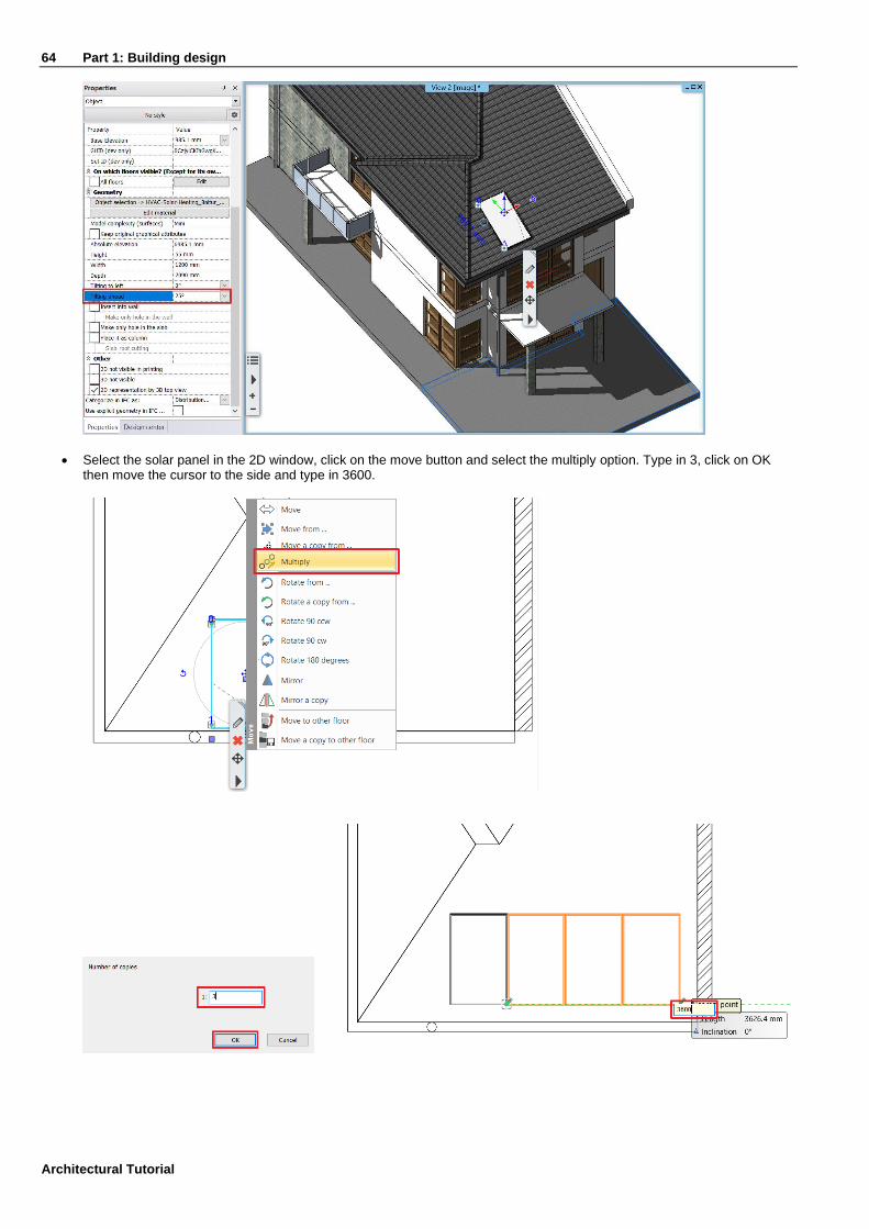
• Select the solar panel in the 2D window, click on the move button and select the multiply option. Type in 3, click on OK then move the cursor to the side and type in 3600.

Part 1: Building design 65
1.11. Columns
In this project, columns are used for two different reasons. You can use columns to design the railing built from wooden columns next to the stairs, and you can also use this method for structural columns too.
1.11.1. Create railing with the column tool
First, let's look at creating a railing near the stairs. This is an alternative solution to using the railing tool. Set the properties of the columns required for the railing.
• Click on the Ribbon bar / Building / Properties / Structure / Column command. Next, we will set the following values:
• Specify the value of the section profile, by choosing a section profile. Click on the Profile from Library button and then the Select Profile button.
• Look for the Rectangle Simple profile. After selecting it, disable the “Uniform 3D scaling operation” option, then change the Height to 100 mm and the width to 50 mm.
• Next, change the material of the columns. Both the solid material and the surface material should be “Wood-oakwhiteqtrd”.
• The Base offset from the floor should be 675 mm.
• Height should be: 7500 mm.
• Lastly disable the “Slab-roof cutting” option.
• Close the Column dialog window with OK.

66 Part 1: Building design
Architectural Tutorial
• Place columns on each step in the predefined location on the DWG content of the Ground floor. The railing done with the column tool is ready.
1.11.2. Place structural columns outside
First of all, activate the column layers. Our exterior columns are made up of two parts. Before you place the columns, go to the Ribbon Bar / Building / Properties / Structure / Column tool, and here you can find the all settings of the column.
• Select a profile from the library named Rectangle Simple.

Part 1: Building design 67
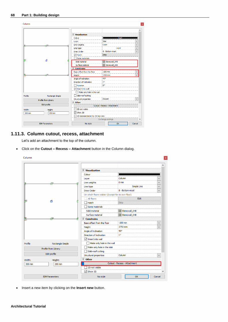
• Disable the “Uniform 3D scaling operation” option and set Width to 300 mm and Height to 200 mm.
• Set the Height of the column to 2700 mm and its Base offset from floor to -200 mm.
• Select Stonewall_048 as the material of the column.
68 Part 1: Building design
Architectural Tutorial
1.11.3. Column cutout, recess, attachment
Let’s add an attachment to the top of the column.
• Click on the Cutout – Recess – Attachment button in the Column dialog.
• Insert a new item by clicking on the Insert new button.

Part 1: Building design 69
• Select Rectangle Simple from the profile library and select the middle bottom reference point of the profile.
• Modify the type to Attachment.
• Set the start of the attachment from the reference plane to -150 mm and its thickness to 100 mm.
• Select “Concrete3” as the material of the attachment.
• Finally select Top for the position in the vertical direction to be measured from.

70 Part 1: Building design
Architectural Tutorial
• Close the dialogs.
• Activate the “Column(1)” layer then place three columns as seen on the DWG drawing.
Activate the 1st floor as an inactive floor the following way:
• On the bottom bar click on the arrow next to the “Ground floor” title and click on the lightbulb next to the “1st floor” title. Now you enabled the inactive floor view for the 1st floor.
Part 1: Building design 71
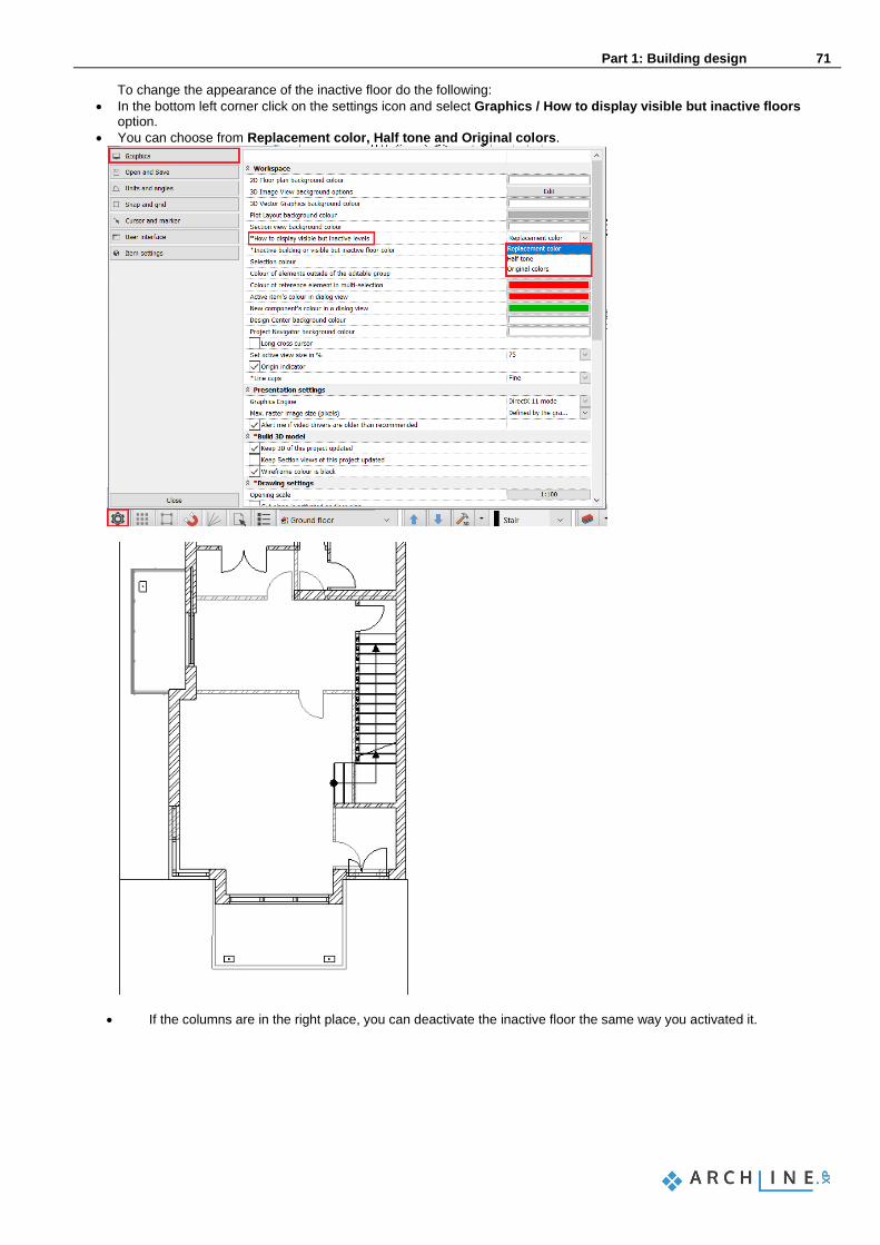
To change the appearance of the inactive floor do the following:
• In the bottom left corner click on the settings icon and select Graphics / How to display visible but inactive floors option.
• You can choose from Replacement color, Half tone and Original colors.
• If the columns are in the right place, you can deactivate the inactive floor the same way you activated it.


Part 2: Documentation 73
2. Part: Documentation
Open the YouTube video: https://youtu.be/xxkirYUd3LI
2.1. Section, elevation and views
Sections and elevations are all fundamental dynamic drawings. A dynamic drawing is linked to the building; thus it is able to respond to changes in your design. All the floorplans are dynamic drawings too, actually.
2.1.1. Sections
To define a section, start the Ribbon bar / Documentation / Section / Define section command. A dialog appears in which you can specify the properties of the representation of the section in 2D and in 3D and the properties of the marker.
• First, enable the option that makes the arrow and the letter of the section visible on the right side as well.
• Then enable the “Hatch on the section” option. You can turn on and off the display of objects here as well. Keep the “Hide all the objects” option enabled.

74 Part 2: Documentation
Architectural Tutorial
• Finally, enable the partial section option, in order to have the section created only between the two endpoints of the section lines.
• Close the dialog with the OK button and draw the section line on the floor plan with one click at the starting point and one another at the endpoint.
• Move your mouse and set the view direction arrow to point to the right and click to accept.
• Hit OK in the appearing dialog and the section will be created in a separate window from vectors and lines.
Part 2: Documentation 75
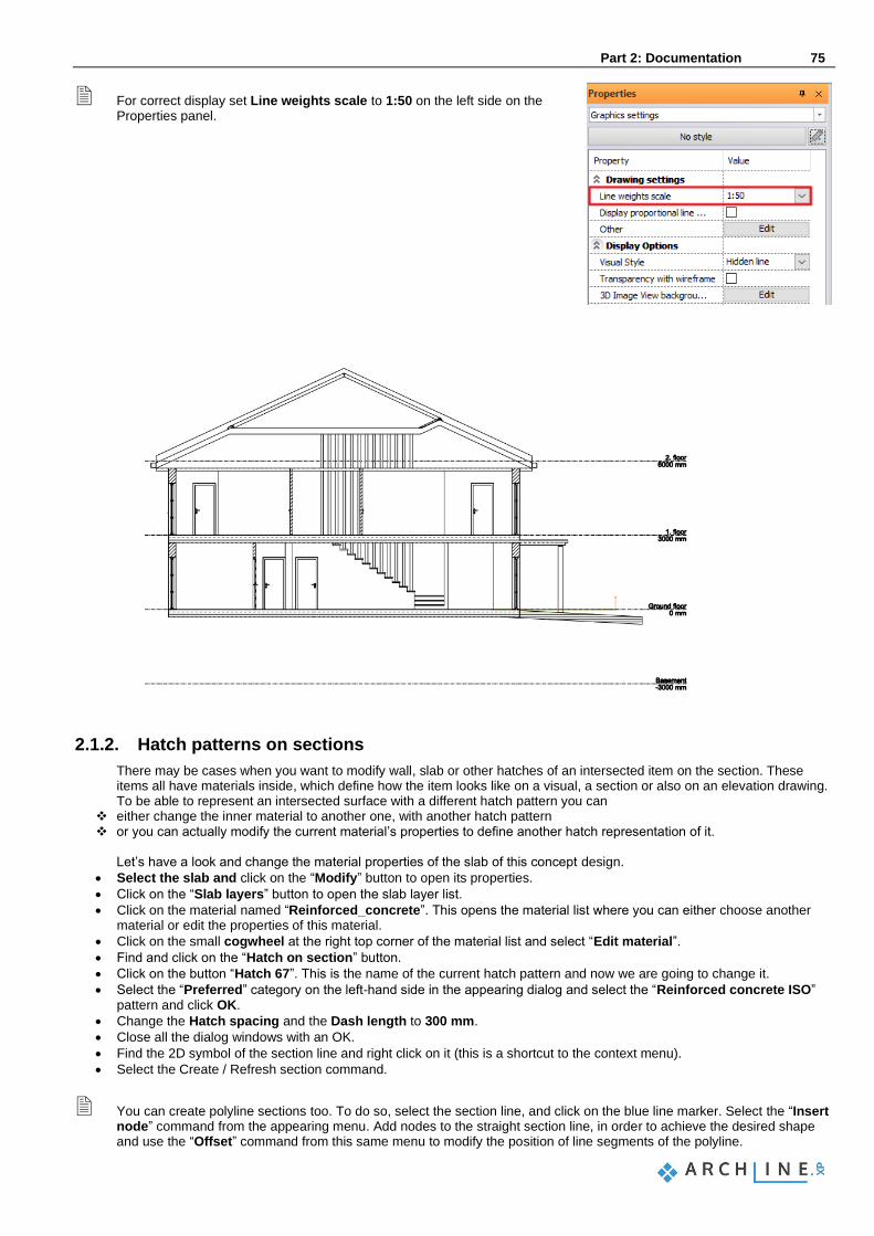
For correct display set Line weights scale to 1:50 on the left side on the Properties panel.
2.1.2. Hatch patterns on sections
There may be cases when you want to modify wall, slab or other hatches of an intersected item on the section. These items all have materials inside, which define how the item looks like on a visual, a section or also on an elevation drawing. To be able to represent an intersected surface with a different hatch pattern you can
❖ either change the inner material to another one, with another hatch pattern ❖ or you can actually modify the current material’s properties to define another hatch representation of it.
Let’s have a look and change the material properties of the slab of this concept design.
• Select the slab and click on the “Modify” button to open its properties.
• Click on the “Slab layers” button to open the slab layer list.
• Click on the material named “Reinforced_concrete”. This opens the material list where you can either choose another material or edit the properties of this material.
• Click on the small cogwheel at the right top corner of the material list and select “Edit material”.
• Find and click on the “Hatch on section” button.
• Click on the button “Hatch 67”. This is the name of the current hatch pattern and now we are going to change it.
• Select the “Preferred” category on the left-hand side in the appearing dialog and select the “Reinforced concrete ISO” pattern and click OK.
• Change the Hatch spacing and the Dash length to 300 mm.
• Close all the dialog windows with an OK.
• Find the 2D symbol of the section line and right click on it (this is a shortcut to the context menu).
• Select the Create / Refresh section command.
You can create polyline sections too. To do so, select the section line, and click on the blue line marker. Select the “Insert node” command from the appearing menu. Add nodes to the straight section line, in order to achieve the desired shape and use the “Offset” command from this same menu to modify the position of line segments of the polyline.

76 Part 2: Documentation
Architectural Tutorial
2.1.3. Elevations
To create elevations, look for them in the Project Navigator on the right-hand side.
• Click on one of the elevations – for example: West elevation. In the appearing dialog click Yes and the elevation will be created in a separate window.
•
• In order to display hatches and technical shadow on the elevation, go to the Ribbon Bar / View / Shadow group and start the Elevation shadow command.
• In the appearing dialog set the shadow representation to Shadow with contour lines + hatches, the shading to Shaded with texture and the light direction to Elevation shadow.
• Make sure that the “Shadow on selected surfaces only” option is disabled.
• Now click OK and wait until the elevation will be regenerated with the new settings.
Part 2: Documentation 77
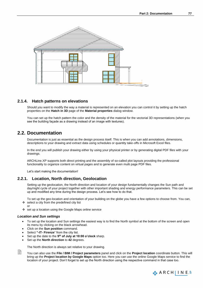
2.1.4. Hatch patterns on elevations
Should you want to modify the way a material is represented on an elevation you can control it by setting up the hatch properties on the Hatch in 3D page of the Material properties dialog window. You can set up the hatch pattern the color and the density of the material for the vectorial 3D representations (when you see the building façade as a drawing instead of an image with textures).
2.2. Documentation
Documentation is just as essential as the design process itself. This is when you can add annotations, dimensions, descriptions to your drawing and extract data using schedules or quantity take-offs in Microsoft Excel files. In the end you will publish your drawing either by using your physical printer or by generating digital PDF files with your drawings. ARCHLine.XP supports both direct printing and the assembly of so-called plot layouts providing the professional functionality to organize content on virtual pages and to generate even multi page PDF files. Let’s start making the documentation!
2.2.1. Location, North direction, Geolocation
Setting up the geolocation, the North direction and location of your design fundamentally changes the Sun path and day/night cycle of your project together with other important shading and energy performance parameters. This can be set up and modified any time during the design process. Let’s see how to do that. To set up the geo-location and orientation of your building on the globe you have a few options to choose from. You can,
❖ select a city from the predefined city list or
❖ set up a location using the Google Maps online service
Location and Sun settings
• To set up the location and Sun settings the easiest way is to find the North symbol at the bottom of the screen and open its menu by clicking on the black arrowhead.
• Click on the Sun position command.
• Select “-IT- Firenze” from the city list.
• Set up the date to the 9th of July at 10:00 o’clock sharp.
• Set up the North direction to 42 degrees. The North direction is always set relative to your drawing.
You can also use the File / BIM / Project parameters panel and click on the Project location coordinate button. This will bring up the Project location by Google Maps option too. Here you can use the online Google Maps service to find the location of your project. Don’t forget to set up the North direction using the respective command in that case too.

78 Part 2: Documentation
Architectural Tutorial
2.2.2. Building volumes
Let’s create a schematic representation of the neighbouring buildings in order to see the plan with its environment and to be able to create a shadow analysis of the area.
• Turn on the layers on the situation plan in the Layer manager.
• Go to the Ribbon Bar / Building / Terrain group and start the Building volumes command.
• Trace the contour of one of the neighbouring buildings.
• Hit Enter when you are done.
• In the appearing dialog you can set the 3D shape of the building volume. Set its full height to 9000 mm. The roof will start from 6000 mm and its elevation angle is 45 degree for all sides.
• Create a few more building volumes based on the situation plan.
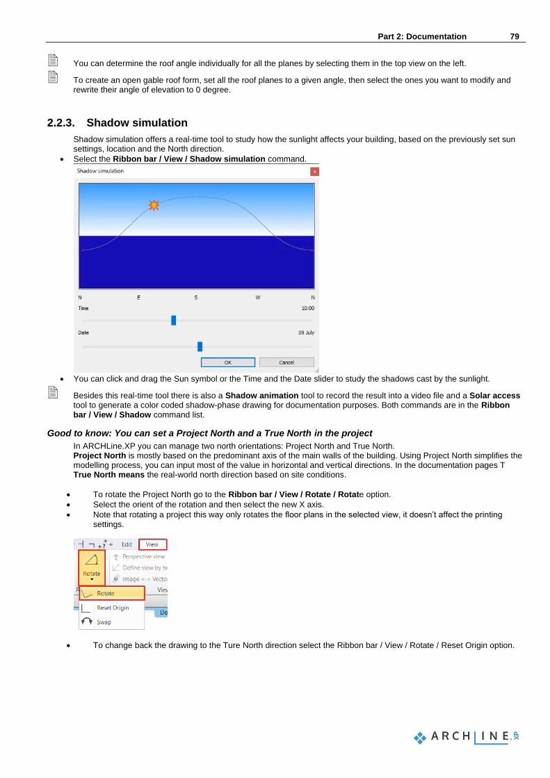
Part 2: Documentation 79
You can determine the roof angle individually for all the planes by selecting them in the top view on the left.
To create an open gable roof form, set all the roof planes to a given angle, then select the ones you want to modify and rewrite their angle of elevation to 0 degree.
2.2.3. Shadow simulation
Shadow simulation offers a real-time tool to study how the sunlight affects your building, based on the previously set sun settings, location and the North direction.
• Select the Ribbon bar / View / Shadow simulation command.
• You can click and drag the Sun symbol or the Time and the Date slider to study the shadows cast by the sunlight.
Besides this real-time tool there is also a Shadow animation tool to record the result into a video file and a Solar access tool to generate a color coded shadow-phase drawing for documentation purposes. Both commands are in the Ribbon bar / View / Shadow command list.
Good to know: You can set a Project North and a True North in the project
In ARCHLine.XP you can manage two north orientations: Project North and True North. Project North is mostly based on the predominant axis of the main walls of the building. Using Project North simplifies the modelling process, you can input most of the value in horizontal and vertical directions. In the documentation pages T True North means the real-world north direction based on site conditions.
• To rotate the Project North go to the Ribbon bar / View / Rotate / Rotate option.
• Select the orient of the rotation and then select the new X axis.
• Note that rotating a project this way only rotates the floor plans in the selected view, it doesn’t affect the printing settings.
• To change back the drawing to the Ture North direction select the Ribbon bar / View / Rotate / Reset Origin option.

80 Part 2: Documentation
Architectural Tutorial
2.2.4. Dimensioning
Let’s add wall and opening dimensions around the whole plan.
• Select the Ribbon bar / Dimension / Building / All walls command.
• Select the one from the Dimension options and add the desired dimensions to assemble a list as shown on the picture.
• Then click on the OK button to confirm.
• After closing the window, you can select the floorplan by drawing a rectangle from the right bottom corner to the top left corner – selecting the whole drawing.
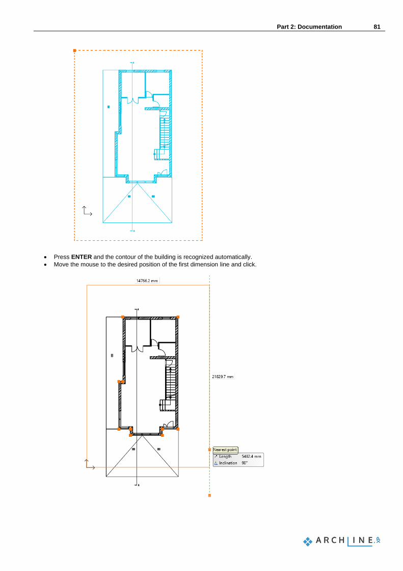
Part 2: Documentation 81
• Press ENTER and the contour of the building is recognized automatically.
• Move the mouse to the desired position of the first dimension line and click.
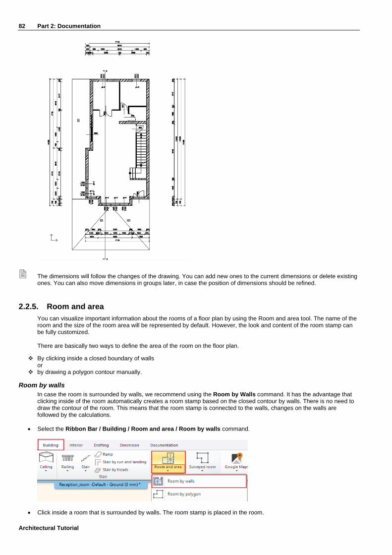
82 Part 2: Documentation
Architectural Tutorial
The dimensions will follow the changes of the drawing. You can add new ones to the current dimensions or delete existing ones. You can also move dimensions in groups later, in case the position of dimensions should be refined.
2.2.5. Room and area
You can visualize important information about the rooms of a floor plan by using the Room and area tool. The name of the room and the size of the room area will be represented by default. However, the look and content of the room stamp can be fully customized.
There are basically two ways to define the area of the room on the floor plan.
❖ By clicking inside a closed boundary of walls or
❖ by drawing a polygon contour manually.
Room by walls
In case the room is surrounded by walls, we recommend using the Room by Walls command. It has the advantage that clicking inside of the room automatically creates a room stamp based on the closed contour by walls. There is no need to draw the contour of the room. This means that the room stamp is connected to the walls, changes on the walls are followed by the calculations.
• Select the Ribbon Bar / Building / Room and area / Room by walls command.
• Click inside a room that is surrounded by walls. The room stamp is placed in the room.

Part 2: Documentation 83
You can change the appearing content on the room stamp within its properties.
• Click on the already placed text in order to select it and then choose the pencil icon to open its properties. Click on the Calculated values tab.
In our example, there are 3 basic data. You can modify them as follows:
• Room Name: It can be renamed to the name that you want to display (e.g. Living - room).
• Gross area: indicates the area of the room.
• Floor finish: Choose one from the list of floor finishes or type in a new text (e.g. Parquet).
• When the changes are completed, press the OK button and they will be visible on the floor plan.
Room by polygon
This function is used when a physical space is divided into more than one functions (e.g., a living-dining room) or when we would like to measure areas not surrounded by walls (for example: terraces, balconies, gardens).
• Select the Ribbon Bar / Building / Room and area / Room by polygon command.
• Draw the shape of the room by following the inner side.

84 Part 2: Documentation
Architectural Tutorial
• Type the wall / ceiling height in the dialog box that appears.
• The room stamp is ready, you can modify it afterwards as described above.

Part 2: Documentation 85
2.2.6. Elevation on floor plan
You can place a dimension symbol of an elevation on the floor plan. Select the Ribbon bar / Dimension / Elevation on floor plan command.
• First you need to select an element. Select one of the external walls. Then click on the inner line of it. This is where you will measure the elevation.
• In the top right corner of the screen you need to choose the proper keyword to set elevation point to measure. Now choose the “Bottom” option.
• A dialog box appears with the starting height which can be changed if it is needed. Set this value to 0 mm.
• Click OK to continue.
• In the appearing dialog window, you can change the desired symbol. Let’s keep it for now.
• Place the symbol on the floor plan with one click.
2.2.7. Symbols
There are other symbols that may be needed on a floor plan during design, such as the symbol that marks the entrance or the North direction symbol. Most symbols can be found under the Design center / Building / Groups / Signs category. To position them on the floor plan just drag and drop them onto the drawing.
North direction sign
• Find the Design center / Building / Group / Signs / North - English category and select a north sign that suits you and simply click and drag it onto the floor plan and release the mouse button. Click once to place it.

86 Part 2: Documentation
Architectural Tutorial
• In case you want to change/modify the position of the previously placed symbol, select it. The rotation and move commands become accessible. Other properties will be editable in the Property grid on the left-hand side.
The North symbol will be automatically aligned with the previously set North direction of the project.
Entrance symbol
• Select an arrow in the Design center / Group / Signs / Arrows category and place it in front of the entrance.
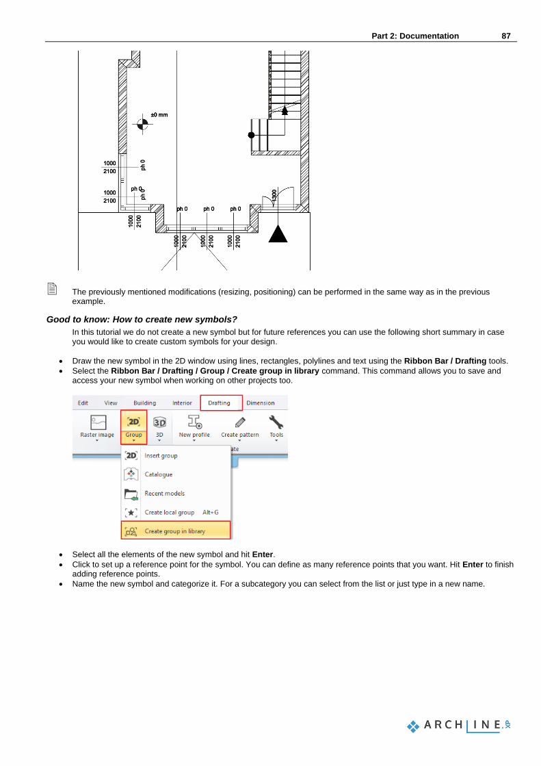
Part 2: Documentation 87
The previously mentioned modifications (resizing, positioning) can be performed in the same way as in the previous example.
Good to know: How to create new symbols?
In this tutorial we do not create a new symbol but for future references you can use the following short summary in case you would like to create custom symbols for your design.
• Draw the new symbol in the 2D window using lines, rectangles, polylines and text using the Ribbon Bar / Drafting tools.
• Select the Ribbon Bar / Drafting / Group / Create group in library command. This command allows you to save and access your new symbol when working on other projects too.
• Select all the elements of the new symbol and hit Enter.
• Click to set up a reference point for the symbol. You can define as many reference points that you want. Hit Enter to finish adding reference points.
• Name the new symbol and categorize it. For a subcategory you can select from the list or just type in a new name.

88 Part 2: Documentation
Architectural Tutorial
2.2.8. Placing a text
• Place text on the architectural floor plan by using the Ribbon bar / Drafting / Text / Place it command.
• In the appearing "Text actuals" dialog window, type the text to place (for example, “Ground floor"), and then click OK.
• The orange contour of the text appears, one of the corners is grabbed by the cursor. With this corner point, you can place the text on the drawing sheet anywhere you like.
• Now the text is placed, the text input window re-appears. Close the window by clicking on the Cancel button. The default text height is 200 mm, which is ideal for displaying designs at a 1:50 or 1:100 scale compared to drawing content.
The height of the selected text can be edited by clicking on the height and typing a new value.
Good to know: You can also connect the text to elements on the plan.
• Create a text “Ground floor” and place it next to the west side of the building as shown in the picture.
• Right click on the text, then choose “Add pointer line” and select the object you want to connect it to.

Part 2: Documentation 89
2.2.9. Creating unlinked drawings
Let’s create a new 2D unlinked version of the section. With this method the designer can make changes on a separate copy of the original dynamic section or elevation.
• Select the Ribbon bar / View / Add 2D Drawing command.
• Add a new name for this drawing: “2D Sections”.
• Next activate the Section window, and select the whole content.
• Use the CTRL + C shortcut and click on a point of the selected content to copy it. This is the reference point of the copy and will be used when pasting.
• Activate the previously created drawing called “2D Sections”.
• Finally paste the content using the CTRL+ V keyboard shortcut and click to place the pasted content with the previously defined reference point.
• Hit ESC to stop pasting other copies.
2.2.10. Lengths dimensioning
Let’s add dimensions to the previously created 2D unlinked copy of the section.
Lengths dimensioning
• Select the Ribbon bar / Dimension / Length / Continuous dimensions command.
• In the appearing dialog window, you can adjust the dimensioning properties, for example: the orientation.

90 Part 2: Documentation
Architectural Tutorial
• Set the dimension line to Horizontal, and the dimension type to Serial and then click OK.
• Click on the first point on the 2D section drawing to start the dimensioning (1).
• Click on the second point to get its distance from the first point (2).
• The horizontal projection of the distance appears with a dotted line which can be placed at any distance from the wall elevation view (3). Click to place the dimension under the section.
• Due to the “serial“ setting of the dimension, the second point of the previous distance and the first point of the following
distance are the same, therefore we only have to define the following points continuously, one-by-one.
• Click to define additional points, one-by-one. The horizontal distance between the previous two points appears on a new dimension line alongside with the previous ones.
• When the dimensions are all set, please press ENTER.

Part 2: Documentation 91
2.2.11. Elevation on section
The Elevation on section command is located in the Ribbon bar / Dimension. The dimensioning process is the following:
• Open the command from the above-mentioned path, then mark the starting height on the wall elevation view by clicking on the connection between the slab and wall. This will be the origin of measurement.
• To measure the value 0, click again at the same point or at the same height, then determine the position of the dimensioning next to the wall elevation view. Click on the preferred position, so the first height value of 0.00 will appear next to the wall elevation view at the desired location.
• Additional points should be determined with just one click and the height value for that distance will be displayed immediately next to the wall elevation view.
• When the dimensions are all placed, please press ENTER.

92 Part 2: Documentation
Architectural Tutorial
2.2.12. Schedules
Schedules are dynamic lists of building parts, generated based on the project content. Schedules are in bi-directional connection with the drawing, which means that changes of the projects are reflected in the schedules and changing values of the schedule tables will have an effect on the corresponding items of the drawing, too. Let’s see how that works.
• Click on the Documentation / Schedule / Placing schedule command in the Ribbon bar.
• Select the “Door” schedule in the left-hand side list of the appearing dialog window, then press OK.
• Let’s keep the default setting in the “Formatting schedule” window and click OK.
• Place the schedule next to the drawing on the Ground floor with one click.
Finding and changing items of a schedule
Items of a schedule can be easily found on the drawing, by selecting the content.
• Select the previously placed schedule and find one of the Flush doors of the Ground floor in the list.
• Click on the small “Finder” magnifying glass icon at the left side and the software will draw an arrow pointing to the item on the drawing.
• Find the width value in the schedule for this very door and click on the blue value.
• Type a slightly smaller or larger value (for example 1000 mm or 850 mm) and hit Enter. The software changes the width of the door on the drawing.
2.2.13. Quantity take-off
Quantity take-off is a great set of commands that you can use when you would like to extract data from your design into Microsoft Excel files to use them for calculations. Let’s extract a Building calculation and a Room summary list. Building calculation list:
• Use the Ribbon bar / Documentation / Quantity take off / Excel list command.
• Select the Building calculation option.
• Leave all options enabled and turn off “Export BIM parameters” and click OK.
• Set up the file name “Building_calculation.xlsx” and click Save to save the file.
• Microsoft Excel automatically opens the file if you have it installed on your computer.

Part 2: Documentation 93
Room summary list:
• Use the Ribbon bar / Documentation / Quantity take off / Excel list command.
• Select the Rooms option.
• Click on “Yes” to update all rooms and areas in your project to reflect the latest status.
• Set up the file name “Room_summary.xlsx” and click “Save” to save the file.
• Microsoft Excel automatically opens the file if you have it installed on your computer.
2.2.14. Plot layout
In order to record differently scaled plans to the corresponding project it is beneficial to create plot layouts. It is also recommended to use them as they provide neat, precise look.
• The Prepare plot layout command is available under the Ribbon bar / Documentation / Plot layout group.
• First, you need to set the paper size and orientation in the appearing dialog window, then press OK to open the empty page.

94 Part 2: Documentation
Architectural Tutorial
From the Project Navigator on the right-hand side select the Floor plan / Ground floor drawing.
• “Drag and drop” the Ground floor plan onto the page and select the 1:100 scale factor.
• Place the content to an empty area of the plot layout. This way it is possible to place different drawings on a plot layout with different scaling.
• Repeat these steps and find and place the previously created 2D section next to the Ground floor plan with 1:100 scaling.

Part 2: Documentation 95
If you just want to copy a detail, e.g. from the floor plan do the following:
• Activate the window from you want to copy the content (in this example, this is the floor plan window).
• Choose Ribbon bar / Documentation / Plot layout / Copy part to plot layout command.
• Select the part you want to copy (by drawing a closed polygonal shape around the content).
• Determine a reference point with which you want to grab the selected part.
• Activate the plot layout.

96 Part 2: Documentation
Architectural Tutorial
• Select Paste to plot layout command from the Ribbon bar / Documentation / Plot layout group and specify the scale to which you want to place the drawing on the page.
• Place the drawing.
Good to know: How to create plot stamps?
Documentation can be formally unified with the use of the plot stamp, which provides a suitable framework for the presented plans. It is possible to create a plot stamp that can be saved later on the plot layout. It is desirable to draw a plot stamp in different sizes (A3, A4), as well as in portrait and landscape positions, which you can use afterwards.
• Create a new plot layout following as described above.
• Create the plot stamp frame. The simplest way is to draw a border line along the print range (blue dotted line) by using the Ribbon bar / Drafting / Polyline / General rectangle command.
• After placement, select Offset All command from the Local menu and move by 2 mm towards the center of the plot layout.
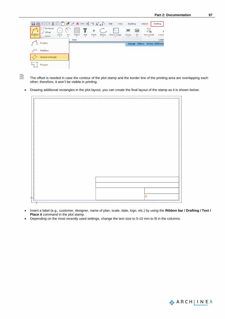
Part 2: Documentation 97
The offset is needed in case the contour of the plot stamp and the border line of the printing area are overlapping each other; therefore, it won’t be visible in printing.
• Drawing additional rectangles in the plot layout, you can create the final layout of the stamp as it is shown below:
• Insert a label (e.g., customer, designer, name of plan, scale, date, logo, etc.) by using the Ribbon bar / Drafting / Text / Place it command in the plot stamp.
• Depending on the most recently used settings, change the text size to 5-10 mm to fit in the columns.
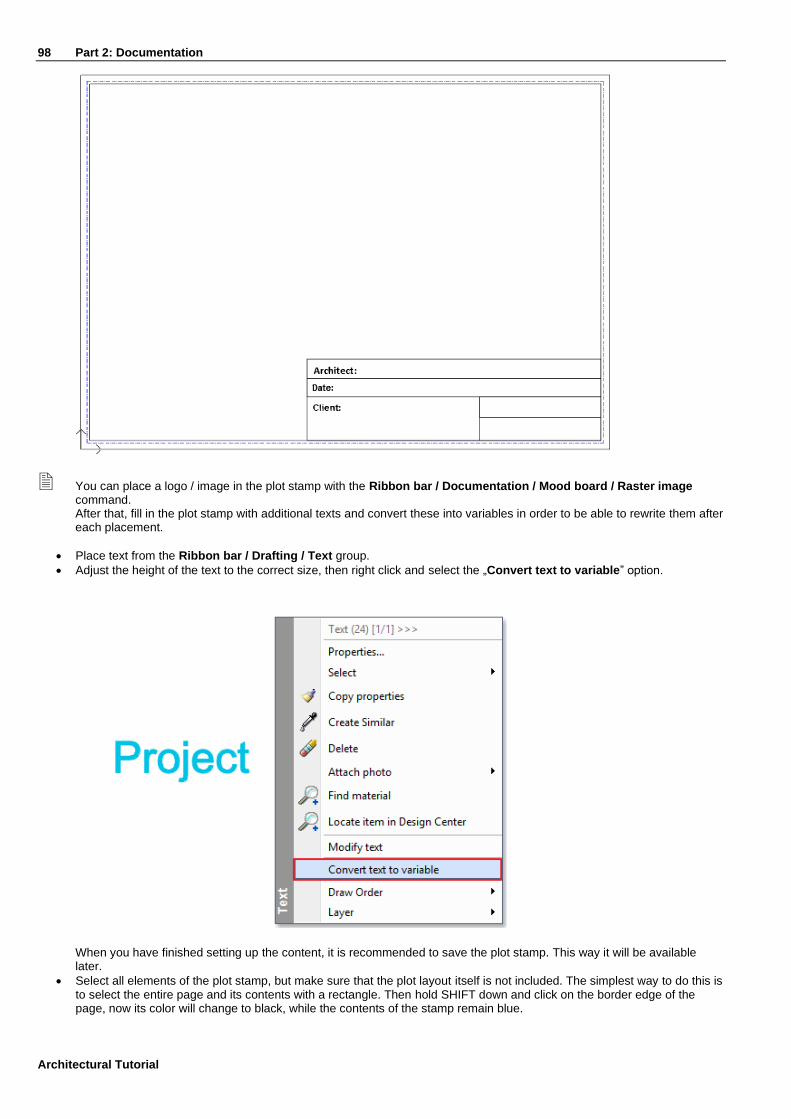
98 Part 2: Documentation
Architectural Tutorial
You can place a logo / image in the plot stamp with the Ribbon bar / Documentation / Mood board / Raster image command. After that, fill in the plot stamp with additional texts and convert these into variables in order to be able to rewrite them after each placement.
• Place text from the Ribbon bar / Drafting / Text group.
• Adjust the height of the text to the correct size, then right click and select the „Convert text to variable” option.
When you have finished setting up the content, it is recommended to save the plot stamp. This way it will be available later.
• Select all elements of the plot stamp, but make sure that the plot layout itself is not included. The simplest way to do this is to select the entire page and its contents with a rectangle. Then hold SHIFT down and click on the border edge of the page, now its color will change to black, while the contents of the stamp remain blue.

Part 2: Documentation 99
• Select the Ribbon bar / Drafting / Group / Create group in library command.
• Specify the reference points of the plot stamp; these will be used for placing it later.
As a reference point, it is useful to select the corners of the printing area. This way when you place it later, the plot stamp will always be within the print range.
• Press ENTER and the "Create new item in the library" window appears.
• Type the name of the library element (e.g. A3_landscape).
• Define the category and subcategory of the item (e.g. PRINTING / English), and then click OK.

100 Part 2: Documentation
Architectural Tutorial
After saving, the plot stamp will be available to be placed from the Design center.
• Simply find the Groups in the Design center and use the “drag and drop” method to place it on an empty plot layout in the bottom left corner, for example.
• To fill the plot stamp, right-click on the edge of the plot stamp, then select the „Edit text in group” command or left click with your mouse button to change directly the data in the plot stamp. Other parts of the previously placed plot stamp can also be modified after placing it:
• Select the plot stamp and choose Edit group from the Local menu, the contents of the plot layout turn grey.
• Then you can modify the elements of group (text, lines).
• After making the changes, make sure to close the group by using the Close group command in the Local menu.

Part 2: Documentation 101
2.3. Printing
It is essential to be able to publish your previously created drawings in a project. You can either: ❖ print the current single drawing or
❖ print the current plot layout assembled from many other drawings.
The result can be a hard copy or a PDF file, depending on what you need to provide for your clients. Make sure you have the plot layout activated and start the Ribbon bar / Documentation / Print command. Let’s see a quick guide to the Print dialog, before we start:
Printer/Plotter
All available PDF options and printers are in this list. You can choose any of the available options at your preference.
Paper size (1)
Here you can set the paper size, orientation, and the number of copies. Based on these settings, the paper and printable size information will be automatically set in Print dialog.

102 Part 2: Documentation
Architectural Tutorial
Orientation (2)
Specifies the drawing orientation. You can select Default or Rotated drawing option.
Don’t confuse the Orientation with paper orientation. The former refers to the drawing and the latter to the paper sheet.
Content to print (3)
Specifies the area of the drawing to be printed.
Scale factor (4)
You can choose a predefined scale factor: e.g.: 1:100 The Scale to Fit calculates the best scale to fit the current paper size.
You need to set the scale 1:1 in case of publishing a plot layout, because the layout is a real-world size virtual paper and does not need to be further scaled.
Center the plot (5)
It moves the drawing center point into the paper center point.
Printing (6)
The Print button starts printing the content based on the settings of the Print dialog. The result can be a hard copy or a PDF file based on the selected Printer.
2.3.1. PDF printing / Publishing a PDF file
This time we will publish a PDF file out of the previously assembled Plot layout.
• Make sure you have the plot layout activated and start the Ribbon bar / Documentation / PDF print command.
• Click on the file path button in the appearing dialog and browse for a file location and type a filename and click on the “Save” button.
• Set up the paper size to A3 landscape.
• Set the scale factor to 1:1 – remember the plot layout is a virtual paper in real-world size.
• Make sure that the “Entire drawing” option is enabled and click on the “Center the plot” option to align the content.
• Start publishing the PDF file by clicking on the Print button. The PDF file is created in the predefined folder under the specified name.
2.3.2. Print queue
A print queue is a print/publish job-list that you can assemble and save with the project. It is extremely helpful when you need to publish your drawings over and over again, because it stores all the publishing settings for each and every content added to the print queue. This feature might not be available in all versions of the software, so please double check the availability of the command before you proceed. Putting together the Printing Queue is simple:
• Start the File menu / Print queue command.
• Click on the green plus, and select view/drawing/layout to be added to the Printing Queue from the Project Navigator.
• Set up the printing properties in the appearing dialog and the close it with the “Apply” button.
• Keep adding as many tasks to the list as you need. You can add, modify and cancel documents before starting to print. You can print the documents into one PDF file with multiple pages if you use the same file name or you can print the content directly to the selected printer.

Part 2: Documentation 103
2.3.3. Printing the 3D image window
You can either print a vector drawing of the 3D content or print the 3D image window content as it is with textures. To publish the 3D image window content into a JPG file, just follow these steps:
• Activate the 3D image window. (In the header of the 3D window content you can see the word “Image” appearing)
• Select the File menu – Print command.
• Set up the properties. The settings are similar to the general printing dialog, but a bit simpler.
It is possible to place the content of the 3D Image window on the plot layout. The resolution of the image will be the same as the resolution of the screen. Before printing, it is suggested to apply the Plot Layout menu – Refresh layout command, so the resolution of the image will change to the best available settings.

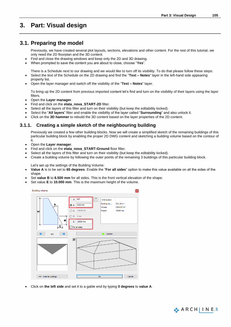
Part 3: Visual Design 105
3. Part: Visual design
3.1. Preparing the model
Previously, we have created several plot layouts, sections, elevations and other content. For the rest of this tutorial, we only need the 2D floorplan and the 3D content.
• Find and close the drawing windows and keep only the 2D and 3D drawing.
• When prompted to save the content you are about to close, choose “Yes”. There is a Schedule next to our drawing and we would like to turn off its visibility. To do that please follow these steps:
• Select the text of the Schedule on the 2D drawing and find the “Text – Notes” layer in the left-hand side appearing property list.
• Open the layer manager and switch off the visibility of the “Text – Notes” layer. To bring up the 2D content from previous imported content let’s find and turn on the visibility of their layers using the layer filters.
• Open the Layer manager.
• Find and click on the elata_nova_START-2D filter.
• Select all the layers of this filter and turn on their visibility (but keep the editability locked).
• Select the “All layers” filter and enable the visibility of the layer called “Surrounding” and also unlock it.
• Click on the 3D hammer to rebuild the 3D content based on the layer properties of the 2D content.
3.1.1. Creating a simple sketch of the neighbouring building
Previously we created a few other building blocks. Now we will create a simplified sketch of the remaining buildings of this particular building block by enabling the proper 2D DWG content and sketching a building volume based on the contour of it.
• Open the Layer manager.
• Find and click on the elata_nova_START-Ground floor filter.
• Select all the layers of this filter and turn on their visibility (but keep the editability locked).
• Create a building volume by following the outer points of the remaining 3 buildings of this particular building block. Let’s set up the settings of the Building Volume:
• Value A is to be set to 65 degrees. Enable the “For all sides” option to make this value available on all the sides of the shape.
• Set value B to 6.500 mm for all sides. This is the front vertical elevation of the shape.
• Set value E to 10.000 mm. This is the maximum height of the volume.
• Click on the left side and set it to a gable end by typing 0 degrees to value A.

106 Part 3: Visual Design
Architectural Tutorial
• Click on the right side and set it to 55 degrees changing value A.
• Close the window by clicking on OK. This creates the building volume at the default height and with a default material. Let’s customize that.
• Select the appearing 3D building volume and find its material on the left-hand side. Change it to “Grey” on this object.
• Find the Base elevation value on the left-hand side and change it to -300 mm.
Now that we are done with the sketch of the neighbouring building, we do not need the originally imported Ground floor content.
• Open the Layer manager.
• Find and click on the elata_nova_START-Ground floor filter.
• Select all the layers of this filter and turn off their visibility.
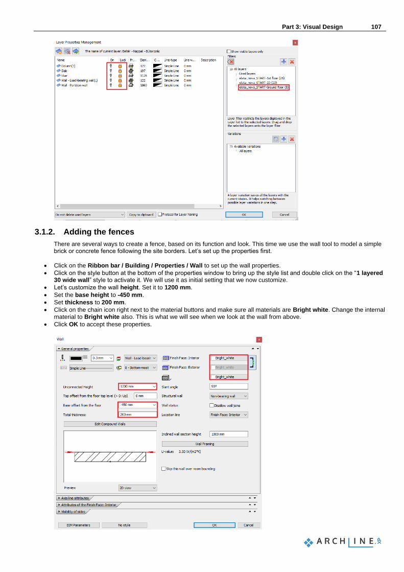
Part 3: Visual Design 107
3.1.2. Adding the fences
There are several ways to create a fence, based on its function and look. This time we use the wall tool to model a simple brick or concrete fence following the site borders. Let’s set up the properties first.
• Click on the Ribbon bar / Building / Properties / Wall to set up the wall properties.
• Click on the style button at the bottom of the properties window to bring up the style list and double click on the “1 layered 30 wide wall” style to activate it. We will use it as initial setting that we now customize.
• Let’s customize the wall height. Set it to 1200 mm.
• Set the base height to -450 mm.
• Set thickness to 200 mm.
• Click on the chain icon right next to the material buttons and make sure all materials are Bright white. Change the internal material to Bright white also. This is what we will see when we look at the wall from above.
• Click OK to accept these properties.

108 Part 3: Visual Design
Architectural Tutorial
Now that the properties are set, we are good to go and trace the lines of the original DWG drawing with the wall tool.
• Start the wall tool and follow the lines of the original DWG file and create the fence around.
• Use the “Right”, “Left” or “Center” keywords when necessary.
• There is a short piece of fence to the left, connecting the west side fence and the corner of the front ramp, draw that too.
• Finally create the short piece of fence separating the current building site from the rest of the buildings at the street side
• Change its height to 1500 mm and base elevation to -300 mm. Now you can take your time and model extra fence pieces using the same tool to add more detail to your work.
3.1.3. Modelling the paths and roads
Roads can be modelled many ways using a dedicated terrain and road toolset. This time, the sidewalks and the asphalt road is only for visual representation so we use simple slabs and the foundation tool to create them in front of our building.
• Click on the Ribbon bar / Building / Slab / Open foundation command. The offset distance will create a slab piece with a certain width based on the current settings.
• Type 1670 mm to define the width of the walkway.
• Follow the edge of the 2D in an L shape starting from the meeting point of the two fences in front of the house and turning to the right to keep it simple for now.
• Hit Enter to finish drawing. The slab is created with the current default properties. Let’s customize its properties to make look like a concrete sidewalk.
• Select the slab and click on the Modify properties command (Pencil icon) to open the slab properties window.
• Change base offset to -300 mm and thickness to 150 mm.
• Change all materials to Concrete3. An asphalt road can be created following the same method. The original asphalt road on the site drawing has various widths around the drawing so we will set up a generic width and then customize it wherever it will be necessary.
• Click on the Ribbon bar / Building / Slab / Open foundation command.
• Type 4660 to define the width of the street.
• Follow the contour of the original site drawing by following the upside-down U shape in front of the building.
• Use the keyword Inverse to switch reference line during drafting just as we did in case of the walls.
• Hit Enter to finish drawing. Now the basic street shape is modelled and we are about to adjust its edges all around where the generic width was not matching the original situation.
• Select the slab and click on an edge that you wish to adjust.
• Select the “Offset” command to change width and snap it to the original drawing line.
• Follow these steps to adjust the edges all around where necessary. The slab is created with the current default properties. Let’s customize its properties to make it look like an asphalt road.
• Select the slab and click on the Modify properties command (Pencil icon) to open the slab properties window.

Part 3: Visual Design 109
• Change base offset to -300 mm and thickness to 50 mm.
• Change all materials to Asphalt_.
3.1.4. Creating the terrace at the backyard
As the terrace is more of a visual item and not a detailed part of the documentation, we will create a very simple representation of the terrace by using the slab tool.
• Start the Ribbon bar / Building / Slab / Slab in Sketch mode tool.
• Trace the contours of the fence and the back of the building to create the four-sided shape of the backyard terrace. When the slab is created with the basic settings change its materials.
• Select the terrace slab and click on the Modify properties command (Pencil icon) to open the slab properties window.
• Find the “Top material” and change it to a parquet_rovere_02 for now.
• Find the “Side material” and change it to Bright white.
3.1.5. Drilling a hole into the terrace for the pool
Previously disabled layers might automatically re-appear during work. This happens mostly when the selected tool uses a layer that was disabled. In this case the software automatically enables the layer to be able to draft the item. Use the Layerwalk or the Layer manager to disable these layers any time again. Before we start creating the actual hole in the slab let’s design its shape using classic Drafting tools.
• Select the Ribbon bar / Drafting / Polyline / General rectangle tool.
• Place the first point of the rectangle with a click and move your mouse to the right. Type 5500 mm and hit Enter. This will be the width of the rectangle.
• Move your mouse up, type 3500 mm and hit Enter. This will be the height of the rectangle.
• Select the rectangle and click on the blue dot marker, representing its corner point.
• Select the “Fillet all” command and move your mouse to find the best visual result and click to round off the corners.
Creating a 2D draft of a 3D shape has a few advantages. It can be repositioned, modified and used for visual thinking before creating the real result, and it can also be re-used later at any time. Now let’s create a real cut through the actual terrace slab based on the previously designed pool shape.
• Click on the slab contour and use the context menu to find the Hole / Create a hole command.
• Find the “Closed loop” keyword at the top of the screen and click on it.
• Click into the previously drafted rectangle shape to make its shape recognized by the software.

110 Part 3: Visual Design
Architectural Tutorial
3.1.6. Creating the pool water using the slab tool
Now there is a hole in the slab and we need to fill it up with water.
• Start the Slab in Sketch mode command and follow the contour of the previously created hole.
• Use the “Arc” keyword when necessary to match the round-off shape.
• When the contour gets closed the slab is created.
• Select the new slab and change its materials to Water_1
• Modify the “Base offset“ to -100 mm and thickness to -200 mm.
3.1.7. Populate the backyard with objects
ARCHLine.XP comes with a built-in library of objects which you can use at any time, but its biggest power is in the many other tools and file formats you can use and import to find the latest possible products. These products you can find online either as free or commercial models. Let’s start with a built-in parametric object: a parasol.
• Find and start the Ribbon bar / Interior / Soft Furnishing / Parasol tool.
• Place it on the drawing with a click and refine its position if necessary. Many built-in objects are parametric in ARCHLine.XP. This means that not only their materials and size can be changed, but also other parameters of them can be modified. In case of a parasol you can change how many sides the parasol has, for example. There are popular platforms that you can get access to right from within the software. Let’s see what we can do using the free 3D Warehouse platform, provided by Trimble®.
• Start the Ribbon bar / Interior / Warehouse tool.
• Search for deck chairs. Use the keyword “liegestuhl” to find the one we used in this tutorial.
• Click on its thumbnail to enlarge the image and download the model into the design.
• Place it on the drawing in 2 copies and rotate and move the copies to create an arrangement on the terrace. The pool also needs a ladder. Let’s use the 3D Warehouse again.
• Open Warehouse and find the “Swimming Pool Ladder” object.
• Click on it and download.
• Place it on the drawing and rotate if necessary. The top view helps properly matching the swimming pool ladder object to the side of the pool.
• Use the Move from… command and click on the 2D symbol of the ladder object to define the reference point.
• Move your mouse and snap it to the side of the pool and click to place it.

Part 3: Visual Design 111
• Select it on the 3D and click on the vertical blue arrowhead.
• Choose “Move” and move it vertically until you find the proper position and click to place it there.
If during the creation of the previous content any layer turned on, it is because the tools you have used had a setting referencing an invisible layer. In such cases the software automatically turns on the visibility of such layers and unlocks them for editing. To make any of these layers invisible again, please simply turn their visibility off.
• Open the Layer manager.
• Find and click on the elata_nova_START-Ground floor filter.
• Select all the layers of this filter and turn off their visibility.

112 Part 3: Visual Design
Architectural Tutorial
3.1.8. 3D representation types
The Navibar is a place where you can change representation types quickly at any time. It appears on the right bottom corner of the drawing area by default and its content changes based on the content you are working on (2D or 3D).
• Click on the 3D preview mode icon of the Navibar. A menu opens where you can set how to display the model.
• Try each of the different representations and see how the model will change. Finally select the Consistent color display mode.
3.1.9. Working with standard views
There are various 3D views that help you display your model.
• Activate the 3D window and from the Navibar you can select the standard views.
• First, select the “Front view”. This represents the model in style similar to the frontal elevation view.
• Now select the “Left view”. From this direction the view is blocked by other 3D building volumes we sketched earlier. There is a quick tool to hide unnecessary parts of the 3D model, by defining the representation boundaries on the floor plan. Let’s try that for now.
• Make sure the 2D is the active content.
• At the bottom of the screen you can find the “Quick 3D model” button with a tiny arrow on the right side of it. Click on that arrow an select the “Create cut-away 3D view” tool from the appearing menu.
• Draw a rectangle around the building by defining its 2 corners on the drawing. You can see the 3D content updated containing only the model within the previously drawn rectangle area. The cut-away view’s rectangle will remain on the floor plan, which will help when you are willing to refine its position or switch between the fully model view (generated by using the “Quick 3D model” button) and the cut-away view within the boundaries of the rectangle (generated by clicking on any of the appearing icons after selecting the rectangle on the drawing).
3.1.10. Perspective views
One of the essential parts of the project organization is setting the views properly for a well-ordered project. If you consistently follow the same logic, to set perspectives in the 3D window and name them appropriately, it will be easier to navigate through them.
In case of multilevel buildings, it can be useful to use numbering before the name of the perspective views. This way we can easily distinguish views of the first level from the view of ground floor for example. On the ground floor you can use “0_bathroom_ view_01” and on the first floor “1_bathroom_view_01”. Let’s try this in practice.

Part 3: Visual Design 113
• Please activate a 3D window now.
• Select the right bottom “Perspective dialog” icon of the Navibar.
• Set up a perspective view: you need to click and drag the blue marker to find the location for the viewer or camera. Drag it to the left bottom corner of your drawing outside the building.
• You also need to set up the target viewpoint. Click and drag the grey dot marker and move it above the center of the building.
• To add a view, you need to click on the green cross.
• You can name your view by double clicking on it.
• Repeat these steps to add a few more views and finally close the dialog window with the OK button.
The program is automatically sorting all views in an alphabetical order. This is also why it is good practice to put a number before the name of the consecutive perspective views to control their order.
When in a 3D view, you can use either the up and down buttons at the status bar of ARCHLine.XP to navigate from one view to another. Alternatively, you can also use the Page Up and Page Down keys on your keyboard to do the same.
Defining a perspective directly on the floor plan
There is a special blue perspective symbol on the 2D drawing which you can use to see the current perspective view’s position over the plan and to set up a different perspective or to navigate in the 3D model. You can:
❖ click and drag the center of the symbol to move it around, ❖ or click and drag the tiny arrow to refine the view direction and pull the camera like a cart.
3.1.11. Setting up a walk-through animation
Walk-through animations are very effective to demonstrate the size and context of your model. All you need is to set up a camera path and timing for the animation and you are good to go to create and share a video file. Let’s create a walk-through animation.
• Activate the 2D drawing.
• Use the Ribbon bar / View / Animation / Path / Define path command.

114 Part 3: Visual Design
Architectural Tutorial
• Set up 3 points now to define the current curve of the walkthrough in front of the building.
• Set all viewpoints to the center of the building from each and every points of the curve.
• Hit OK to close the appearing dialog.
• Click on the Play button to play the preview. The walk-through animation might be a bit fast by default. This is how you can customize it:
• Click on the Setting button.
• Change the speed from 2 seconds to 5.
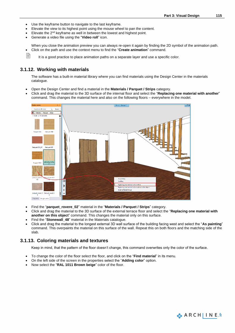
Part 3: Visual Design 115
• Use the keyframe button to navigate to the last keyframe.
• Elevate the view to its highest point using the mouse wheel to pan the content.
• Elevate the 2nd keyframe as well in between the lowest and highest point.
• Generate a video file using the “Video roll” icon. When you close the animation preview you can always re-open it again by finding the 2D symbol of the animation path.
• Click on the path and use the context menu to find the “Create animation” command.
It is a good practice to place animation paths on a separate layer and use a specific color.
3.1.12. Working with materials
The software has a built-in material library where you can find materials using the Design Center in the materials catalogue.
• Open the Design Center and find a material in the Materials / Parquet / Strips category.
• Click and drag the material to the 3D surface of the internal floor and select the “Replacing one material with another” command. This changes the material here and also on the following floors – everywhere in the model.
• Find the “parquet_rovere_02” material in the “Materials / Parquet / Strips” category.
• Click and drag the material to the 3D surface of the external terrace floor and select the “Replacing one material with another on this object” command. This changes the material only on this surface.
• Find the “Stonewall_48” material in the Materials catalogue.
• Click and drag the material to the longest external 3D wall surface of the building facing west and select the “As painting” command. This overpaints the material on this surface of the wall. Repeat this on both floors and the matching side of the slab.
3.1.13. Coloring materials and textures
Keep in mind, that the pattern of the floor doesn’t change, this command overwrites only the color of the surface.
• To change the color of the floor select the floor, and click on the “Find material” in its menu.
• On the left side of the screen in the properties select the “Adding color” option.
• Now select the “RAL 1011 Brown beige” color of the floor.

116 Part 3: Visual Design
Architectural Tutorial

Part 3: Visual Design 117
3.1.14. Render styles
Render styles are quick settings to help you set up the most commonly used material types in your model. A render style defines the main characteristic of a material from transparency through brightness till bump mapping, automatically. It is a very good starting point when setting up materials. These settings can be later fully customized.
• Find and click on the “Render styles” option in the Design Center.
• Click and drag the “Wall” render style to the bright white wall surface and click on it. This makes the bright white material a wall material all around the project wherever it was already used.
• Do the same with the rest of the model to define wooden surfaces, metal surfaces, glass surfaces and so on.
• To check whether there is anything left use the “Color coded” switch.
This visualizes the model re-colored by the color-codes of the material render styles applied to their surfaces. You can easily find all glass or metal surfaces for example and if a surface has a different color code than the tiny color swatch at the left top corner of a render style you can click and drag the proper one onto that surface to change it.
3.1.15. Real-time render
Real-time render helps adjusting lights and material settings to find the best setting prior the final renders. Real-time rendered images are created very quickly based on the settings.

118 Part 3: Visual Design
Architectural Tutorial
• Set up a small wide screen resolution for rendering. Click on the “Ribbon menu / View / Rendering / Standalone rendering – realtime draft” command. Close the appearing explanation and find the Resolution option to change it to “854x480” resolution.
• Click on the “Rendered frame on / off” button at the bottom of the dialog. This will set up the visibility of the borders of the final render in the model view. You might need to stretch the width of the 3D Image window to be able to see the borders represented with dashed lines.
This function is useful to set the perspectives precisely, because you can define exactly what will be visible in the final render.
• Now start the “Standalone rendering – realtime draft” command again and start rendering by clicking on the “Start rendering” button. Realtime rendering appears soon in a new window and as soon as you make changes in the model or modify the view for example, you will see those changes automatically updated to the realtime rendered image too.
• Make sure you add a parquet material from the Design Center to the terrace surface,
• and do not forget to add “Water” style to the pool water in the backyard.
• Add a “Translucent glass” render style to the glass surfaces of the balcony.
• Once you finished you can go back to the normal model view, by clicking on the “Restore” option next to the “Color coded” option in the Design Center.
Realtime render is performance demanding and you can close it at any time you need. To open it again, you only need to start the “Standalone rendering – realtime draft” command.
3.1.16. Sun light
After setting the materials right, the other key to realistic rendering is the sunlight settings. In the following we will see a few examples of displaying and setting lights. It is important in both interior design and architectural plans how the sunlight illuminates the interior and exterior surfaces of the model. We can set the direction of sunlight two ways:
❖ Heliodon based artistic lighting and ❖ Geo-location based realistic lighting.
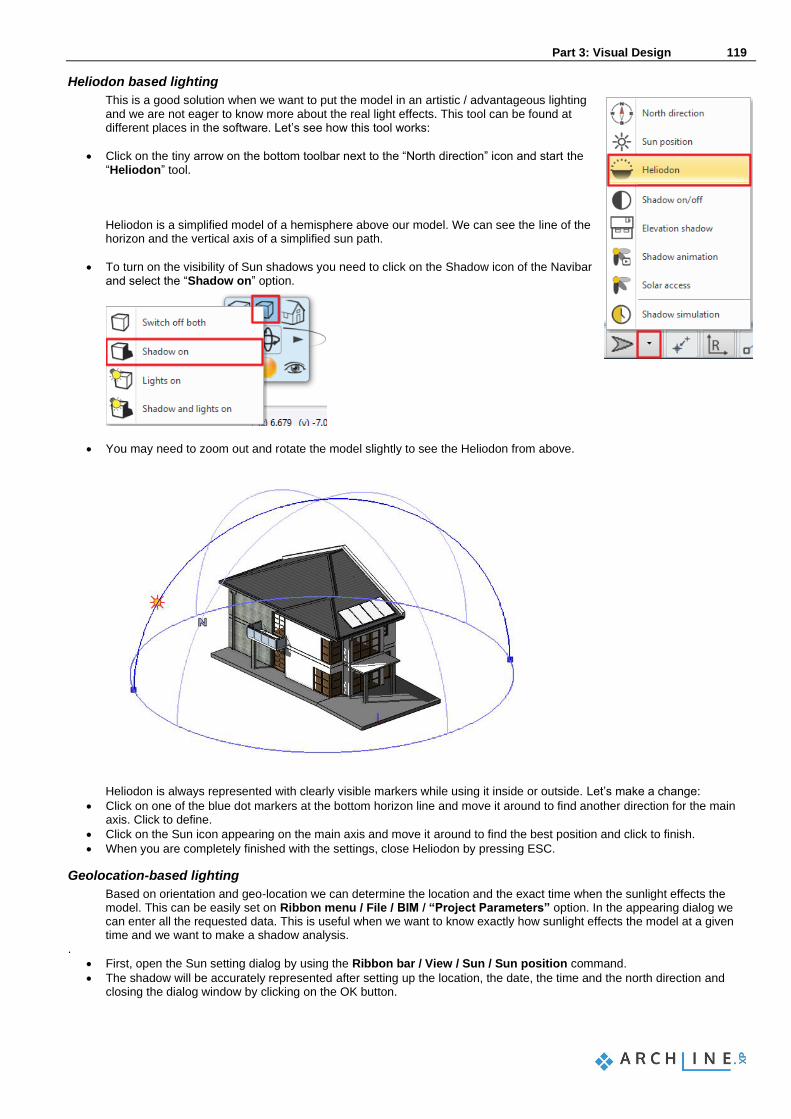
Part 3: Visual Design 119
Heliodon based lighting
This is a good solution when we want to put the model in an artistic / advantageous lighting and we are not eager to know more about the real light effects. This tool can be found at different places in the software. Let’s see how this tool works:
• Click on the tiny arrow on the bottom toolbar next to the “North direction” icon and start the “Heliodon” tool.
Heliodon is a simplified model of a hemisphere above our model. We can see the line of the horizon and the vertical axis of a simplified sun path.
• To turn on the visibility of Sun shadows you need to click on the Shadow icon of the Navibar and select the “Shadow on” option.
• You may need to zoom out and rotate the model slightly to see the Heliodon from above.
Heliodon is always represented with clearly visible markers while using it inside or outside. Let’s make a change:
• Click on one of the blue dot markers at the bottom horizon line and move it around to find another direction for the main axis. Click to define.
• Click on the Sun icon appearing on the main axis and move it around to find the best position and click to finish.
• When you are completely finished with the settings, close Heliodon by pressing ESC.
Geolocation-based lighting
Based on orientation and geo-location we can determine the location and the exact time when the sunlight effects the model. This can be easily set on Ribbon menu / File / BIM / “Project Parameters” option. In the appearing dialog we can enter all the requested data. This is useful when we want to know exactly how sunlight effects the model at a given time and we want to make a shadow analysis.
.
• First, open the Sun setting dialog by using the Ribbon bar / View / Sun / Sun position command.
• The shadow will be accurately represented after setting up the location, the date, the time and the north direction and closing the dialog window by clicking on the OK button.
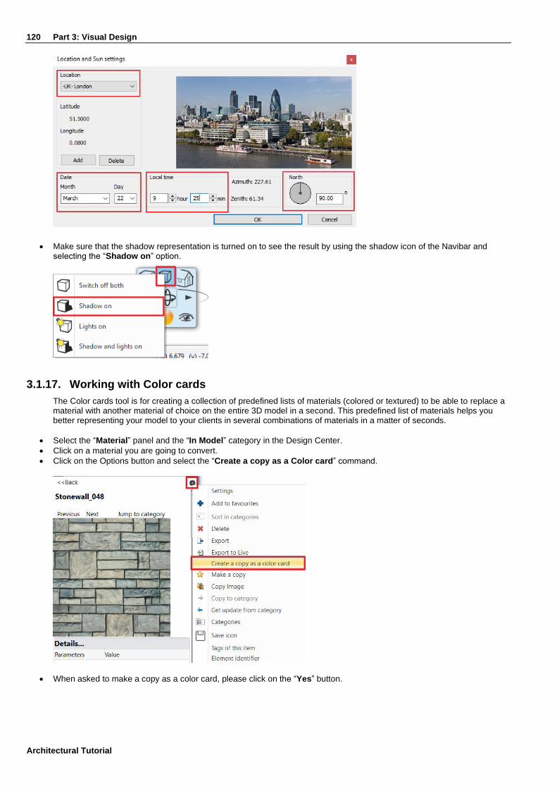
120 Part 3: Visual Design
Architectural Tutorial
• Make sure that the shadow representation is turned on to see the result by using the shadow icon of the Navibar and
selecting the “Shadow on” option.
3.1.17. Working with Color cards
The Color cards tool is for creating a collection of predefined lists of materials (colored or textured) to be able to replace a material with another material of choice on the entire 3D model in a second. This predefined list of materials helps you better representing your model to your clients in several combinations of materials in a matter of seconds.
• Select the “Material” panel and the “In Model” category in the Design Center.
• Click on a material you are going to convert.
• Click on the Options button and select the “Create a copy as a Color card” command.
• When asked to make a copy as a color card, please click on the “Yes” button.

Part 3: Visual Design 121
In the appearing dialog you can collect new materials and add them to the color card.
You can also remove one from the collection or change which material is the current one. When you close the dialog with OK, the program replaces the original material with the previously selected “Current” material.
• Click on the “Add new” button (represented with a green plus symbol) and select a new replacement material to the collection.
• Keep adding a few more to have at least 5-6 alternative representations for the material.
• Click “OK” to close the dialog window.

122 Part 3: Visual Design
Architectural Tutorial
Keep in mind that the color card does not change its name when another material is selected to be the “Current” one. If you want to find the color card during work even easier, you can change its name (originated from the name of the first material converted) to a more descriptive name like “Elevation color card”. You can change the current material at any time.
• Find and click on the color card in the Design Center and click on the “Color card” icon at the left top corner of the image.
• Select a new “Current” material in the appearing dialog.
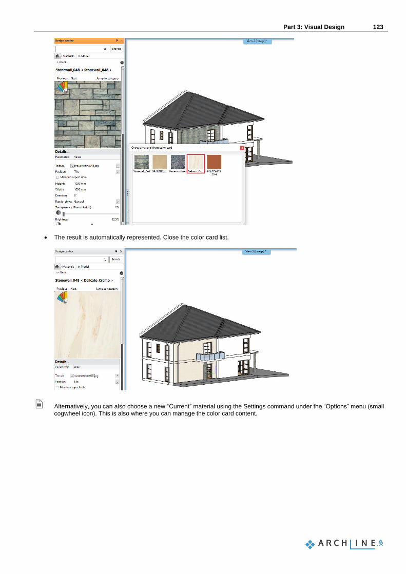
Part 3: Visual Design 123
• The result is automatically represented. Close the color card list.
Alternatively, you can also choose a new “Current” material using the Settings command under the “Options” menu (small cogwheel icon). This is also where you can manage the color card content.

124 Part 3: Visual Design
Architectural Tutorial
3.1.18. Creating a new material
ARCHLine.XP is shipped with a built-in material library. We have used them previously in this project, but it is essential to be able to create new materials for your projects either based on colors or textures of surface patterns. Let’s see how to create a material based on an image search, using your web browser.
• Open your web browser and find a seamless image online. Use the following keywords for example: “grey brick seamless texture”.
• Right click on the image in your browser and select “Copy image”.
Note that based on which specific browser you are using this command might be simply “Copy” or “Copy to clipboard”. The important thing here is that we do not want to save the image file on our computer now, we only want to copy it and later paste it into ARCHLine.XP.
• Go back to ARCHLine.XP, find the Design Center and open the “Material” catalogue.
• Use the “Create new material” command by clicking on the “Options” menu at the right top corner.
• Select the “Building” category and the “Brick” sub-category.
• Click on the “Paste” button to insert the previously copied image. This will be the texture of the new material.
• Make sure that the “Physical properties” page is activated and set width and height to 1000 mm x 1000 mm. (Based on the result you found online you can use other values too.)
• Find the “Appearance” page and change the render style to “Wall”.
• Click in the name field at the left top corner and change its name to “Bright grey brick 001”.
• Close the dialog with the “OK” button.

Part 3: Visual Design 125
Now you can use the new material on any surface you want. It will be available for all of your projects on this computer. Let’s see how it looks like on a surface of this building.
• Change the material on any surface to see the result.
• Undo the change to the original material.
3.1.19. Working with lamps
ARCHLine.XP has a built-in library of lamps and you can also create your lamps for interior or exterior models. A lamp is basically a composite of an object and at least one light source. You can turn lamps on or off and you can also change the color or intensity of their light sources. These topics are not covered in this tutorial, but feel free to find our detailed tutorials and learn more about lamps when you need. Let’s see how to find and place a lamp.
• Open the Design Center and find the “Objects / Lighting / Ceiling lights” category.
• Click and drag the “Ceiling lamp 3” into the 3D surface under the porch ceiling of the entrance.
• To change the light settings of a lamp select it and switch to the “Light sources” component of it at the left top of the properties list, by clicking on “Object” and selecting “Light sources”.
• Here you can turn it on or off and manage the Dimming level of the light.
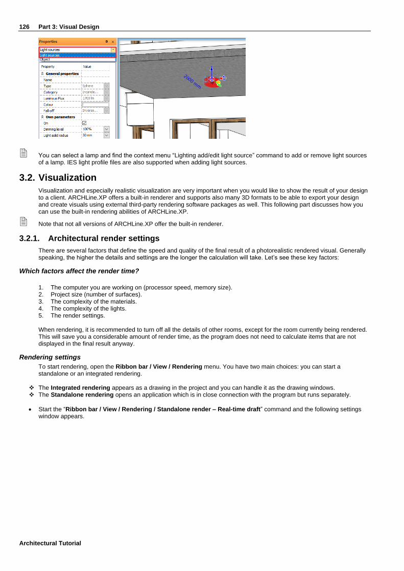
126 Part 3: Visual Design
Architectural Tutorial
You can select a lamp and find the context menu “Lighting add/edit light source” command to add or remove light sources of a lamp. IES light profile files are also supported when adding light sources.
3.2. Visualization
Visualization and especially realistic visualization are very important when you would like to show the result of your design to a client. ARCHLine.XP offers a built-in renderer and supports also many 3D formats to be able to export your design and create visuals using external third-party rendering software packages as well. This following part discusses how you can use the built-in rendering abilities of ARCHLine.XP.
Note that not all versions of ARCHLine.XP offer the built-in renderer.
3.2.1. Architectural render settings
There are several factors that define the speed and quality of the final result of a photorealistic rendered visual. Generally speaking, the higher the details and settings are the longer the calculation will take. Let’s see these key factors:
Which factors affect the render time?
1. The computer you are working on (processor speed, memory size). 2. Project size (number of surfaces). 3. The complexity of the materials. 4. The complexity of the lights. 5. The render settings. When rendering, it is recommended to turn off all the details of other rooms, except for the room currently being rendered. This will save you a considerable amount of render time, as the program does not need to calculate items that are not displayed in the final result anyway.
Rendering settings
To start rendering, open the Ribbon bar / View / Rendering menu. You have two main choices: you can start a standalone or an integrated rendering.
❖ The Integrated rendering appears as a drawing in the project and you can handle it as the drawing windows. ❖ The Standalone rendering opens an application which is in close connection with the program but runs separately.
• Start the “Ribbon bar / View / Rendering / Standalone render – Real-time draft” command and the following settings window appears.

Part 3: Visual Design 127
• Let’s set up the “Resolution” (1) first. Select 854x480 for now. This is a low-resolution for work and the reason we choose this is that lower resolutions render faster. Later, you can choose higher resolutions for the final renders for the client.
• The next setting is the “Render quality” (2). Let’s keep it at “Real-time draft”. This mode will give a quick but not final result. It is good enough to determine what to fine-tune. Later we will change this to a higher quality. You have the following options to create final visuals for the client:
❖ Exterior – Quick render: For exteriors and well-lit interiors. ❖ Interior – Quick render: For images that are not clear enough using the “Exterior – Quick render” quality setting. (Most
probably when there is not enough direct light). ❖ High detail render: More details are displayed; the result will be clearer and noiseless but it will take more time.
Note that simply always going with the highest possible rendering quality might result in a good final render, but often the time you would invest into rendering like this will not lead to a considerable quality increase. Lower quality rendering settings may end up quite similar in many cases. The “Exterior – Quick render” for example can perform very well in well-lit interiors, too. In such cases increasing the quality to “Interior – Quick render” will take longer and sometimes will have no clearly visible difference. Test your scene with a lower quality setting first and if the result is not grainy you are good to go and use it for the final renders too.
• Leave the “Visualize the light sources” (3) option turned off. Using this option, you can turn on a simulation which
visualize the light sources of the project as light bulbs. Usually this option is disabled because the source of the light is very well visible without it too.
• Enable the “Enable artificial light” (4) option. This option toggles the lights of the lamps in the project.
• Keep the “Enable sunlight” (5) option enabled. This toggles the direct sunlight. Note that turning off the sunlight does not mean that we will have a night time render. If this option is turned off, the result will resemble to a cloudy day outside.
• Keep “Bump mapping” (6) enabled. Materials have a bump map effect based on the selected render style or the custom settings made by the user. Bump map can increase realism and it is not too costly regarding rendering time, so it should be kept enabled.
• Select “Panorama” and the “Just outside the town” background for the render (7). Panoramic backgrounds completely surround the model. You can also choose a color or color gradient or an image as background. Feel free to select backgrounds from the pre-defined ones or browse for custom background images.
• We are not changing the “Specify a folder to save render images” (8) for now. This is basically a back-up location, where the program creates a back-up of the latest state of each image.

128 Part 3: Visual Design
Architectural Tutorial
• Leave the “Background brightness” (9) option on default. The brightness of backgrounds from different sources are not the same. You can adjust it here if necessary. In case of rendering exterior scenes the background brightness value should be set higher to better match the outdoor lighting conditions.
• Click on the “Start Rendering” button. Once the rendering process is started you will see an image appearing in a matter of seconds, however, depending on your computer’s speed it can take a while. In the appearing dialog window, you will see the rendering “Effects” on the left-hand side.
• Set up the Exposure first. Try to find a good balance between lit and shaded areas, not allowing the image to become too bright washed out or too dark. Exposure for exteriors is usually kept on default or even lowered a bit.
You can use the real-time draft render to find materials that need further attention. Pay extra attention to the wall surfaces, metals, wooden frames, glass surfaces and the roads too. Make sure you use the proper “Render styles” we discussed in an earlier paragraph of this tutorial.
When you have enough artificial lights inside and outside your model, you can also create night time renders. For this, you simply need to
❖ use the “Shadow simulation” command to find a time at night ❖ disable the “Enable sunlight” option and ❖ make sure the lamps are turned on and the “Enable artificial light” option is enabled.
3.2.2. Creating the final renders
If you want to create a final image from a rendering started as a real-time draft, you have to do the following:
• Activate the render window.
• Go to the Details tab. Here you can find the settings with which you have originally started the work.
• Select the “Exterior – Quick render” quality from the options and the program automatically changes to normal render. In this case it will take a bit longer to complete the render.
• The rendering can be stopped anytime with the Stop button seen at the bottom of the rendering dialog window. Later it can be re-started again using the start rendering button.
• To modify the resolution, click on the Stop button. Modify the resolution in the top right corner, then restart the render.
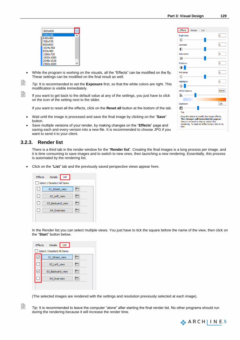
Part 3: Visual Design 129
• While the program is working on the visuals, all the “Effects” can be modified on the fly. These settings can be modified on the final result as well.
Tip: It is recommended to set the Exposure first, so that the white colors are right. This modification is visible immediately.
If you want to get back to the default value at any of the settings, you just have to click on the icon of the setting next to the slider. If you want to reset all the effects, click on the Reset all button at the bottom of the tab.
• Wait until the image is processed and save the final image by clicking on the “Save” button.
• Save multiple versions of your render, by making changes on the “Effects” page and saving each and every version into a new file. It is recommended to choose JPG if you want to send it to your client.
3.2.3. Render list
There is a third tab in the render window for the “Render list”. Creating the final images is a long process per image, and it is time consuming to save images and to switch to new ones, then launching a new rendering. Essentially, this process is automated by the rendering list.
• Click on the “List” tab and the previously saved perspective views appear here.
In the Render list you can select multiple views. You just have to tick the square before the name of the view, then click on the “Start” button below.
(The selected images are rendered with the settings and resolution previously selected at each image).
Tip: It is recommended to leave the computer “alone” after starting the final render list. No other programs should run during the rendering because it will increase the render time.

130 Part 3: Visual Design
Architectural Tutorial
Congratulations!
You have done an excellent job by meeting a serious and very useful milestone, you have completed the architectural tutorial of ARCHLine.XP! With the help of this tutorial material you made yourself familiar with the methods of the accurate and precise architectural design. With the knowledge you have acquired so far, you will be able to process complex floor plans, sections and elevations, all in one comprehensive model.


![[MS-WSP]: Windows Search ProtocolMS-WSP].… · 1 / 243 [MS-WSP] - v20200304 Windows Search Protocol Copyright © 2020 Microsoft Corporation Release: March 4, 2020 [MS-WSP]: Windows](https://img.dokumen.tips/doc/110x75/5f1017a27e708231d447683e/ms-wsp-windows-search-protocol-ms-wsp-1-243-ms-wsp-v20200304-windows.jpg)