Embed Size (px)
Citation preview

DEVELOPMENT OF A HIGHLY MOBILE ROBOT FOR REMOTE INSPECTION
By
TIMOTHY MICHAEL WILLIAMS
A THESIS PRESENTED TO THE GRADUATE SCHOOL OF THE UNIVERSITY OF FLORIDA IN PARTIAL FULFILLMENT
OF THE REQUIREMENTS FOR THE DEGREE OF MASTER OF SCIENCE
UNIVERSITY OF FLORIDA
2019

© 2019 Timothy Michael Williams

To the memory of my mom’s vegetable garden

4
ACKNOWLEDGMENTS
I would like to thank my advisor, Dr. Crane, for allowing me to work in CIMAR
from my junior year through graduate school, and for the guidance and opportunities he
has given me. Shannon Ridgeway has been a great source of engineering knowledge,
and has helped me overcome many engineering obstacles. I would also like to thank Dr.
Schueller for serving on my committee and always being willing to answer my
questions. Thanks are also due to the graduate students who mentored me when I was
a new member of CIMAR, especially Jackson Graham, Bob Kidd and Dan Frank.
This project would not have been possible without the help of my peers who
assisted, especially Max Anderton, Matt Banks and Max Stein. My parents and sister
have been an invaluable support system through college. Lastly, I would like to thank
my friends in Graduate Christian Fellowship for their friendships, support and
encouragement that have helped me through graduate school.

5
TABLE OF CONTENTS page
ACKNOWLEDGMENTS .................................................................................................. 4
LIST OF TABLES ............................................................................................................ 7
LIST OF FIGURES .......................................................................................................... 8
LIST OF ABBREVIATIONS ........................................................................................... 11
ABSTRACT ................................................................................................................... 12
CHAPTER
1 INTRODUCTION .................................................................................................... 13
2 PROBLEM ANALYSIS ............................................................................................ 20
Given Design Requirements ................................................................................... 20 Development of Conceptual Design ....................................................................... 21
Conceptual Design Iterations ........................................................................... 22 Final Conceptual Design .................................................................................. 26
Establishment of Design Parameters ...................................................................... 28
Actuation Torques Characterization ................................................................. 29 Flipper actuation torque ............................................................................. 29
Wheel actuation torque .............................................................................. 31 Steering angle actuation torque ................................................................. 33
Secondary Design Parameters ......................................................................... 36 High Level Design Decisions .................................................................................. 37
3 PROTOTYPE DESIGN ........................................................................................... 42
Drivetrain Design .................................................................................................... 43 Drive System Detail Design .............................................................................. 45 Actuation Paths ................................................................................................ 52
Electrical System Design ........................................................................................ 55 Power System Design ...................................................................................... 55 Computer System Design ................................................................................. 56
Body Assembly ....................................................................................................... 57 Drive Assembly ....................................................................................................... 65 Flipper Assembly .................................................................................................... 73
4 CONCLUSIONS AND FUTURE WORK ................................................................. 80
LIST OF REFERENCES ............................................................................................... 83

6
BIOGRAPHICAL SKETCH ............................................................................................ 85

7
LIST OF TABLES
Table page 1-1 Status of robot inspection missions in H Canyon [10] ......................................... 19
3-1 Design matrix for the Allied Motion QB2302 and QB3402 motors ...................... 44
3-2 Design matrix for the ElectroCraft RP23-54 and RP14-36 motors...................... 44
3-3 Baseline torques and target speeds for each degree of freedom. ...................... 45
3-4 Output torques and speeds at the three operating points ................................... 48
3-5 Critical key lengths for the peak torque operating points and actual key lengths ................................................................................................................ 51
3-6 Operation scenarios and their power requirements. ........................................... 55
8
LIST OF FIGURES
Figure page 1-1 Chaos robot outfitted with rotating flippers. ....................................................... 14
1-2 Inspection robot at the Fukushima Daiichi plant performing a practice run up a staircase. ......................................................................................................... 15
2-1 Hybrid robotic vehicle design and conceptual design with very high mobility. ... 22
2-2 Simplified conceptual design. ............................................................................ 24
2-3 A representation of the conceptual design with an actuation system and its track and flipper drive system design ................................................................. 25
2-4 Robot with redesigned drive system. ................................................................. 25
2-5 Redesigned robot with wheels instead of tracks. ............................................... 26
2-6 The final conceptual design, shown with a manipulator arm on top. .................. 27
2-7 Assemblies and degrees of freedom of the mobile platform. ............................. 27
2-8 Free body diagram showing the forces and torques involved in actuating the flipper and steering angle degrees of freedom. .................................................. 30
2-9 The mock robot in the mud pit that was used to determine baseline torque requirements. ...................................................................................................... 32
2-10 Mock flipper used to derive experimental steering angle torques. ..................... 34
2-11 Top-down view of a flipper showing a free body diagram of the forces and torques involved in actuating the steering angle.. ............................................... 35
3-1 The top half of the actuation system for the rear-left corner of the mobile platform. ............................................................................................................. 53
3-2 Exploded view showing the flipper motor that mates to a planetary gearbox, which drives a spur gear pinion. ......................................................................... 53
3-3 Section view of the drivetrain of the rear-left corner of the robot. ...................... 54
3-4 Aluminum skeleton with sheet metal shell and lid, and rubber sealing strip inside the lip of the lid. The lid is transparent to show the internal skeleton. ...... 57
3-5 Section view of the body showing the mounting block for the manipulator arm. .................................................................................................................... 58

9
3-6 View of the robot body with lid removed. ........................................................... 59
3-7 View of one of the corners of the body assembly. ............................................. 60
3-8 Exploded view of one of the corners of the body assembly. .............................. 61
3-9 Exploded view of the motor mounts and motor saddles showing the screws and pins that secure the motor mounts and motor saddles to the body skeleton. ............................................................................................................. 62
3-10 Exploded view of the wheel motor assembly.. ................................................... 63
3-11 Exploded view showing how the steering angle motor attaches to the motor mount and the motor saddle. .............................................................................. 64
3-12 View of the motors in the rear of the body, showing the offset between the steering angle motors in the middle. ................................................................... 65
3-13 Isometric view of the drive assembly. ................................................................ 66
3-14 Front view of the drive assembly with a section view showing the concentric shaft drive system. .............................................................................................. 66
3-15 Top view of the drive assembly with the steering angle shaft capture exploded. ............................................................................................................ 67
3-16 Exploded view of the top of the drive assembly. ................................................ 69
3-17 The structure of the redirection box with an exploded view showing how the individual components fit together. ..................................................................... 70
3-18 Exploded view of the bottom of the drive assembly. .......................................... 71
3-19 Alternate exploded view of the drive assembly. ................................................. 72
3-20 Close-up section view of the redirection box. .................................................... 73
3-21 Two views of the flipper subassembly. .............................................................. 74
3-22 Exploded view of the distal end of the flipper assembly. ................................... 76
3-23 View of the internal components of the flipper. .................................................. 76
3-24 Exploded view of the tensioner subassembly. ................................................... 78
3-25 Exploded view of the flipper assembly. .............................................................. 79
4-1 Top-down view of the mobile platform deploying into the H-Canyon exhaust tunnel with a manipulator arm mounted to the top of the platform. ..................... 81

10
4-2 Normal view of the mobile platform deploying down the tunnel. ........................ 82
4-3 Rendered isometric view of the mobile platform. ............................................... 82

11
LIST OF ABBREVIATIONS
ANSI American National Standards Institute
BLDC Brushless Direct Current
CAD Computer-Aided Design
CPR Count Per Revolution
CPU Central Processing Unit
DC Direct Current
DOE Department of Energy
GB Gigabyte
IRP Individual Research Project
kW Kilowatt
LIDAR Light Detection And Ranging
PV Pressure-Velocity
RAM Random Access Memory
ROS Robot Operating System
RPM Rotations Per Minute
RTV Room Temperature Vulcanizing
SwRI Southwest Research Institute
SRS Savannah River Site
TB Terabyte
TEPCO Tokyo Electric Power Company
UHMWPE Ultra-High Molecular Weight Polyethylene
VAC Volts Alternating Current
VDC Volts Direct Current

12
Abstract of Thesis Presented to the Graduate School of the University of Florida in Partial Fulfillment of the Requirements for the Degree of Master of Science
DEVELOPMENT OF A HIGHLY MOBILE ROBOT FOR REMOTE INSPECTION
By
Timothy Michael Williams
May 2019
Chair: Carl Crane III Major: Mechanical Engineering
Remote inspection robots are useful for providing surveillance of areas that are
too hazardous for human entry, such as radioactive areas in nuclear complexes. The
Savannah River Site, a U.S. Department of Energy nuclear complex, depends on
remote inspection robots to inspect critical infrastructure to ensure the ability to continue
operations. The extremely challenging operating environment where these robots work
has made it challenging for inspectors to gather the information they need. Previous
inspections have been limited by a lack of sufficient robot mobility, and a lack of
adequate sensors. This paper describes the design of a mobile platform that possesses
adequate mobility to robustly maneuver in the operating environment, and to support a
variety of sensors.
A design for a twelve degree of freedom mobile platform is presented. This
platform has the ability to drive on wheels, paddle flippers through viscous debris,
elevate itself, and strafe from side to side. The platform also has sufficient mobility to
minimize its cross sectional area to facilitate deployment through small access ports. A
detailed design for a functional prototype to serve as a proof of concept is also
presented.

13
CHAPTER 1 INTRODUCTION
Increasingly, robots are being used to perform remote inspections in
environments that are inaccessible to humans. Inspection robots are particularly useful
for surveilling hazardous environments, such as nuclear sites. The International Atomic
Energy Agency formally recommends the use of robots in nuclear environments to
assist in operations and reduce downtime [1]. Inspection robots are deployed in the
nuclear industry in cases ranging from routine equipment inspections to recovery from
catastrophic events such as the Fukushima Daiichi disaster [2].
The Tokyo Electric Power Company (TEPCO) has commissioned a number of
remote inspection robots to perform reconnaissance of the Fukushima Daiichi plant in
order to attempt to categorize the current state of the plant and inventory where the
nuclear material is so that cleanup and decontamination efforts can begin. The areas of
interest have such a strong radioactive field that human entry is not viable. Instead,
inspection robots are deployed to assess the situation. One example is a joint effort by
TEPCO and the Southwest Research Institute (SwRI) to deploy drones into one of the
contaminated areas to attempt to locate the leftover fuel from one of the reactors. The
number and size of obstacles on the ground made ground-based robots difficult due to
the navigation challenges that all of the debris caused. TEPCO and SwRI instead
decided to use drones. The radiation levels in this area are so high that the drones were
only expected to last for seconds to minutes until they became nonfunctional. Cheap, off
the shelf drones were outfitted with light and basic navigation and radiation detection
sensors, and given a preplanned route to fly around known obstacles and towards
where the fuel was expected to be. These drones allowed TEPCO to locate the fuel and

14
classify the amount of radiation it emitted, which will allow them to develop plans to
contain the fuel and ultimately decontaminate the area. [3].
This scenario is one example of where a highly mobile ground-based inspection
robot might have offered a better solution. A robot that had enough maneuverability
might have been able to navigate through all of the obstacles, and would have been
able to carry a heavier payload, including heavier radiation shielding and more sensors,
providing the users with more data. One example of such a highly mobile robot is the
Chaos platform developed by Autonomous Solutions [4]. Chaos is a platform that can
support various configurations of running gear; its default setup is four flippers that
feature tracks. The tracks on each flipper actuate, and each flipper can also rotate about
axis 1 in Figure 1-1. [4, 5]. These multiple types of actuation allow the robot to drive in a
wide variety of conditions. The ability of the flippers to rotate allows the robot to propel
itself in situations where the track actuation is insufficient, such as up and down stairs,
or in deep snow.
Figure 1-1. Chaos robot outfitted with rotating flippers. Source: “Chaos High Mobility Robot.” Autonomous Solutions, Inc., Petersoboro, Utah. Reprinted with permission from Unmanned Systems Technology, https://www.unmannedsystemstechnology.com (March 1, 2019).

15
While the Chaos platform is highly maneuverable, it lacks the resistance to
hazards commonly found in nuclear environments, such as radiation and various
chemicals. Additionally, its relatively small size would cause it to have difficulty in
maneuvering through significant obstacles such as deep mud or over large obstacles.
In addition to the drones used by SwRI, ground based robots similar to the
Chaos robot are being used for reconnaissance of the Fukushima Daiichi plant to
categorize the damage and identify where nuclear materials are located in the various
damaged facilities. These robots have to perform what are already challenging
maneuvering tasks such as climbing stairs and opening doors, but with the added
challenge that much of the physical infrastructure has been partially or completely
destroyed [6].
Figure 1-2. Inspection robot at the Fukushima Daiichi plant performing a practice run up a staircase. Source: “Fukushima Robot Operator Writes Tell-All Blog,” IEEE Spectrum. Reprinted with permission from IEEE Spectrum, https://www.spectrum.ieee.org (March 7, 2019).

16
Radiation levels are so high and traversability so challenging in some of the
facilities that many of the early robots deployed at the site were rendered ineffective.
Successful inspection missions have required the development of specialized robots
specific to the complex maneuverability and radiation problems at the site [2]. The
Fukushima Daiichi site serves as an example of the need for highly mobile and robust
inspection robots that are specially built to perform in hazardous environments such as
nuclear sites. This paper presents the design of a mobile platform to be used as a
remote inspection unit at a federal nuclear complex in the United States.
The Savannah River Site (SRS) is a United States Department of Energy (DOE)
complex located in Aiken, South Carolina that processes nuclear materials and waste.
The SRS was built in the 1950’s to support the U.S. nuclear weapons program during
the Cold War. One of the Site’s main focuses now is environmental cleanup and
management of the nuclear waste produced during the Cold War buildup [7].
One of the core facilities at the Savannah River Site is the H Canyon facility,
which is the only operational nuclear chemical separations facility in the county. H
Canyon came online in the 1950’s and was used to produce radioactive material for use
in nuclear weapons; it is now used to downblend uranium into a “low enriched” material
that cannot be used for weapons, but is usable as fuel in nuclear power plants [8].
The areas in H Canyon where the nuclear material is processed are kept at
negative pressure in order to contain the radioactive material involved in the process.
The air in the processing areas is pulled into an underground exhaust tunnel by four
fans, where it is filtered through sand filters before being vented to the atmosphere. This
exhaust tunnel is approximately 700 feet long, and has an average cross section of 9

17
feet by 12 feet. The walls, roof and ceiling are concrete. The constant air flow through
the exhaust tunnel of 30+ mph, combined with the residual debris and acidic vapors
from the upstream processes that are carried by the wind, have eroded the walls over
the last six decades of continuous operation. The actual thickness of the walls is
unknown, but is expected to be between 15-18 inches thick, according to the design
plans. The walls are each estimated to have lost approximately 2 inches of thickness
due to erosion. In response to this degradation, periodic inspections of the exhaust
tunnel are carried out to verify the structural integrity of the tunnel so that H Canyon can
continue operating. Due to the hazardous nature of the tunnel environment, along with
the physical difficulty of accessing the tunnel, inspection by human personnel is not an
option. Instead, remotely controlled inspection robots are used to perform inspections of
the tunnel walls and ceiling.
The H Canyon exhaust tunnel is a particularly difficult operating environment for
robots. The concrete aggregate that has eroded from the walls has gathered on the
floor of the tunnel, forming a mud that has the consistency of oily peanut butter. The
depth of the mud is not consistent; the condition of the floor in the middle of the
passageway can range from bare concrete to approximately 6 inches of mud, while the
corners of the tunnel can have mud as deep as 12 inches. Water intrusion from the
ground above has led to the formation of small ponds of standing water that feature
unknown chemical formations at the surface. Two air ducts run through the length of the
tunnel, and fallen duct supports pose dangers as sharp object embedded in the mud.
The floor is not consistently smooth underneath the mud and water; expansion joints
and other construction features form bumps up to three inches tall that must be traveled

18
over. There are vertical supports in the tunnel that must be maneuvered around, and
instrumented observing poles hanging from the roof form overhead obstacles. While the
majority of the tunnel is straight, there are turns that cables can get caught on.
Additionally, access to the tunnel is restricted to a 30 inch diameter access port in the
ceiling at one end of the tunnel. Inspection robots are lowered through the access port
into the tunnel using a crane.
The SRS performs inspections of the H Canyon exhaust tunnel using a remote
controlled robot instrumented with a video camera in order to characterize how much
the walls of the exhaust tunnel have eroded. Over the years, various robot designs have
been used. All of these robots have been fully remote controlled with power and signal
provided over a tether. Inspection personnel have only been able maneuver a robot
through the entire exhaust tunnel in recent inspections; earlier inspections were not able
to inspect the entire tunnel due to difficulties in navigating through the tunnel. There are
still areas of the walls (specifically behind the air ducts) that have still not been able to
be inspected. None of the robots that have been deployed have been instrumented with
inspection sensors other than cameras, and previous inspection robots have faced
significant challenges navigating through the tunnel. During inspections, it is common
for significant time to be spent deciding on a strategy to navigate past various obstacles
in the tunnel. The robot for the 2014 inspection became stuck in the tunnel during its
inspection, and an attempt to recover it with another robot in 2015 was unsuccessful, so
it was abandoned in place in the exhaust tunnel [9].
As part of an effort to obtain inspection robots that are more capable and can
support a wider variety of sensors, the SRS has funded Individual Research Projects

19
(IRP) to develop new inspection units. This paper presents the design of the mobile
platform for such an IRP, which will be combined with sensors and a manipulator arm
from the University of Texas at Austin, along with a Miniature Inspection Unit developed
by Florida International University, to form a highly mobile inspection unit that can
provide large amounts of useful data to SRS engineers to verify the structural integrity
of the H Canyon exhaust tunnel.
Table 1-1. Status of robot inspection missions in H Canyon [10]
Deployment Year Mission Notes Recovery Status
2003 First inspection in 50 years Abandoned in place 2009 Video quality poorer than desired Abandoned in place 2011 Successfully inspected some walls Recovered 2014 Inspected 300 feet of wall before failing in
place Abandoned in place
2015 Successful inspection except behind air duct, could not recover 2014 robot, experienced mobility challenges
Recovered
2017 Successful inspection except behind air duct, experienced mobility challenges
Recovered

20
CHAPTER 2 PROBLEM ANALYSIS
SRS personnel need a robot that has robust maneuverability so that it can
function well in the H Canyon exhaust tunnel or in other areas as needed. The robot
must be able to reliably maneuver through the entire exhaust tunnel while pulling a
tether, and needs to be able to support lights, cameras, and other sensors that can be
used to determine the health of the tunnel walls. The robot must also support a
manipulator arm that can perform various inspection tasks, as well as a miniature
inspection unit. SRS engineers are especially interested in surveying the areas of the
walls directly behind the air ducts, as these areas have never been inspected due to the
difficulty of accessing the area with a robot. These areas will be inspected with the
miniature inspection unit that will interface with the mobile platform. In order to be able
to deploy the miniature inspection unit onto the ducts, the robot must be able to drive to
and accurately position itself under the ducts.
Given Design Requirements
The following design requirements for the mobile platform were given by SRS
personnel [11]:
• Remotely gain access to and maneuver within a high-hazard, physically challenged, confined, and unstructured space or area within a nuclear facility
• Capable of performing during and after total immersion in acidic water
• All joints must be protected from dirt and water intrusion
• Maximum dimension of 27 inches to fit through manway
• Have self-righting capability should it tip over in the tunnel
• Must be capable of maneuvering through 6 to 12 inches of moist floor debris that has a consistency of a dense, wet, slippery, cohesive powder (such as oily peanut butter)

21
In addition, several other design requirements were created to ensure that the
robot could operate in the exhaust tunnel environment:
• Must be able to withstand 30+ mph air flow
• Must be able to withstand acidic vapors from nitric acid in air
• Must be able to withstand alpha, beta and gamma radiation
• Must be able to navigate through 12 inches of standing water, over obstacles and debris, over a submerged 3 inch ledge, and under overhead obstacles
• Must be able to travel 700 feet into tunnel
• Must be tethered
• Must be able to support manipulator arm, sensors, and miniature inspection unit mounting on top
• Must have mounting points for a crane attachment
• Must be easy to work with in hazardous material suit
Development of Conceptual Design
A platform design of a highly mobile robotic vehicle from previous work, seen in
Figure 2-1 A, was used as the inspiration for the conceptual design [12]. This
conceptual design, seen in Figure 2-1 B, was modified slightly from the original design
by moving the pivot joint on the outer flipper from the center of the flipper to the end to
reduce the size of the flipper. This robot has a degree of freedom around axis 1, about
which the entire flipper and wheel appendage can rotate. The wheel and the silver
flipper can both rotate about axis 3. The white flipper can rotate about axis 2, and the
treads on the white flipper actuate as well. These degrees of freedom are replicated at
each corner of the robot.

22
A B
Figure 2-1. Hybrid robotic vehicle design from [12] (A). Conceptual design based on [12] with very high mobility (B). Photos courtesy of author.
Conceptual Design Iterations
This design was selected as a starting point because it has a high degree of
mobility that would be advantageous in moving through the exhaust tunnel. Additionally,
the robot has enough mobility that it would have the capability to right itself if it were to
tip over during operation. However, outfitting this design with the required number of
motors and gearboxes would likely make it larger than the 30 inch diameter access port.
The required actuation system and the specialized materials that would be necessary to
fabricate the system would make the system prohibitively complicated and expensive to
fabricate. After consulting with team members and SRS personnel, the decision was
made to pursue a modified version of this design with fewer degrees of freedom that
would still be capable of navigating through the tunnel, but be easier and cheaper to
build. SRS engineers also removed the self-righting capability requirement as they felt
that this requirement was making the design of the platform unnecessarily complicated
and difficult to realize. The engineers advised that if the robot had enough mobility to
successfully navigate through the tunnel, the self-righting capability was not a priority.

23
A simplified conceptual design that is based on the original proposed design
were created. This platform has 3 unique degrees of freedom, seen in Figure 2-2. The
tracks can articulate around axis 2, and the flipper can also rotate about the same axis.
The flippers can also articulate around axis 1 as a unit, a degree of freedom named the
“steering angle”. This design was chosen because having these three distinct degrees
of freedom ensures that it can successfully navigate through the exhaust tunnel or other
operating environments with challenging terrain. The primary degree of freedom is the
treads, which act as the primary method of propulsion. The secondary degree of
freedom, the flipper rotation, serves as an auxiliary degree of freedom to provide more
mobility than the primary method can, and also as both a backup method of propulsion
if the robot encounters a situation where the primary degree of freedom cannot propel
the robot (e.g. deep mud). The flippers can rotate to paddle the robot through mud in
the event that the tracks slip, can rotate to lift the robot over obstacles larger than the
wheels or tracks can drive over, and can elevate the robot to avoid obstacles. The
tertiary degree of freedom, the steering angle, allows the robot to perform fine
navigational movements when operating in tight environments, deploy the flippers in a
position that provides the robot with extra stability when needed, and can be used to
tuck the flippers underneath the body to reduce the cross sectional profile of the robot
for deployment through the access port.
An actuation system developed for this concept is seen in Figure 2-3. This
actuation system uses Brushless Direct Current (BLDC) motors. The motors in the body
have worm gears mounted to their output shafts (Figure 2-3 A), which actuate the
steering angle by rotating the boxes and flippers underneath the body.

24
Figure 2-2. Simplified conceptual design. Photo courtesy of author.
The tracks and flippers are actated by a motor and gearing combination shown in Figure
2-3 B that are housed inside the boxes underneath the body. Both of these motors are
mated to plantetary gearboxes. The gearbox on motor A drives a spur gear that mates
with the ring gear of a planetary gear system. The gearbox mated with motor B drives a
harmonic drive, which in turn drives the sun gear of the planetary gear system. The
wheel drive shaft is connected to the sun gear of the planetary gear system, and the
flipper drive shaft is bolted to the carrier. If motor A drives the ring gear and motor B
holds the sun gear static, the flipper is driven. If motor B actuates the sun gear and
motor A rotates the ring gear with the opposite angular velocity, the wheel output shaft
is actuated while the flipper drive shaft remains static. This configuration allows for
independent control of each degree of freedom at each corner of the robot.
This actuation system was deemed impractical to implement on the robot. The
harmonic drive is prohibitively large and heavy, and the ring gear would be difficult to
fabricate. The motors used in this concept are also very expensive and have low torque
25
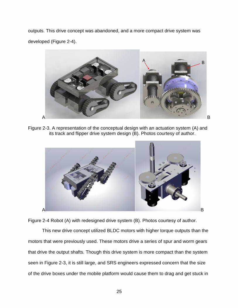
outputs. This drive concept was abandoned, and a more compact drive system was
developed (Figure 2-4).
A B
Figure 2-3. A representation of the conceptual design with an actuation system (A) and its track and flipper drive system design (B). Photos courtesy of author.
A B
Figure 2-4 Robot (A) with redesigned drive system (B). Photos courtesy of author.
This new drive concept utilized BLDC motors with higher torque outputs than the
motors that were previously used. These motors drive a series of spur and worm gears
that drive the output shafts. Though this drive system is more compact than the system
seen in Figure 2-3, it is still large, and SRS engineers expressed concern that the size
of the drive boxes under the mobile platform would cause them to drag and get stuck in

26
the mud. SRS engineers were also concerned with the power draws of the motors and
the challenges that providing that much power down the tether would entail.
They shared anecdotal evidence that counterintuitively, wheels performed better in the
tunnel environment than tracks did. The robot design was subsequently modified to use
motors with lower power consumption that would be placed in the main body.
Additionally, the tracks were replaced with a set of 3 wheels (Figure 2-5). Using 3
wheels on each flipper allows the robot to drive at any flipper angle, and to be able to
navigate over obstacles such as stairs.
Figure 2-5. Redesigned robot with wheels instead of tracks. Photo courtesy of author.
Final Conceptual Design
The twelve-wheeled design in Figure 2-5 would be 5 feet long when the flippers
were oriented outward. Having such long flippers would cause the robot to be
excessively large, heavy, and difficult to actuate. The design was modified to use two
wheels on each flipper to reduce the overall length and weight of the robot to make it
easier to deploy into the tunnel and actuate while still retaining the ability to drive at any
flipper angle. The loss of ability to traverse over obstacles that would require a flipper
with more wheels is an intentional tradeoff in order to make the platform more feasible
27
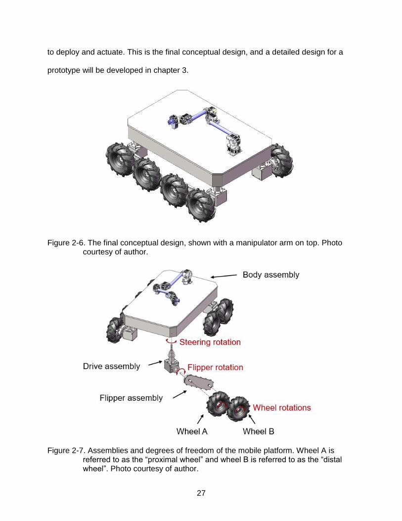
to deploy and actuate. This is the final conceptual design, and a detailed design for a
prototype will be developed in chapter 3.
Figure 2-6. The final conceptual design, shown with a manipulator arm on top. Photo courtesy of author.
Figure 2-7. Assemblies and degrees of freedom of the mobile platform. Wheel A is
referred to as the “proximal wheel” and wheel B is referred to as the “distal wheel”. Photo courtesy of author.

28
The finalized mobile platform concept consists of a body to house all of the major
components, a drive assembly to redirect motion to the outputs, and flippers with two
wheels each. The degrees of freedom are shown in Figure 2-7. Both wheels are driven,
and the flipper can be rotated about the same axis as wheel A. The steering angle
allows for the flipper and wheels to be rotated as a unit. A manipulator arm (shown),
sensors and inspection tools can be mounted on top of the robot.
Establishment of Design Parameters
From the design requirements, design parameters such as actuation speeds and
torques, weight, size, cost, and design life must be established. Some of these
parameters are driven directly by the design requirements, while others are less critical.
In order to design a platform that can perform correctly and robustly for the duration of
an inspection mission, parameters such as size and actuation torques and speeds are
critical. Inspection missions typically lasts no more than 4 days, so the design life for the
robot can be relatively short, and the cost of the platform is a secondary concern to its
robust performance. Because of this, size and robustness, rather than factors such as
cost and design life, will drive many of the design decisions for the platform.
The most important design parameter for the robot is the size constraint. If the
robot can not physically fit through the access port into the tunnel, the inspection cannot
be performed. Therefore, it is critical that the cross section of the robot fit within a 30-
inch diameter envelope. A target cross sectional envelope of 27 inches was given by
Savannah River to provide a buffer and allow for ease of deployment through the
access port.
A secondary size constraint is that the maximum distance between the access
port and the hook on the crane used to deploy the inspection robots is 58 inches. This

29
size constraint means that the robot must be designed in such a way that it can be
deployed through the access port with this maximum hook height. This is does not
necessarily translate to a strict limit on the length of the robot; the attachment point for
the hook can be closer to the midpoint of the robot than the extreme end, and the robot
can be inserted into the access port diagonally, as has been done in previous
inspections.
Actuation Torques Characterization
The robot’s maneuverability is central to its ability to perform a successful
inspection mission, so torque and speed parameters are very important. Torque and
speed are closely related, and must be designed in tandem. For this robot, speed is a
secondary concern to torque. During exhaust tunnel inspections, the robot is driven very
slowly, and the ability to successfully navigate through the tunnel is much more
important than the speed at which the robot can do so [13]. The amount of torque
available to actuate each degree of freedom directly affects the robot’s ability to
successfully maneuver through the tunnel – without enough actuation torque to navigate
through the tunnel, that degree of freedom is useless. Therefore, it is important to
characterize how much torque is needed to actuate each degree of freedom. Once the
baseline torque requirements are established, the actual torques and speeds of the
robot can be designed as the motors, gearing and other components for the drive
system are specified.
Flipper actuation torque
The minimum torque required to actuate the flippers was determined with a
quasistatic equilibrium analysis, where the torque required to support the robot in a
worst-case scenario was calculated. It was assumed that there will always be a

30
minimum of three wheels on the robot in contact with the ground at any time, as three
points generate a plane. The highest load on the flippers will occur when the flippers are
extended just past 90 degrees from vertical so that only the distal wheel of the flipper is
in contact with the ground. The required torque per flipper in a worst-case scenario,
𝑇𝑓𝑙𝑖𝑝𝑝𝑒𝑟, is then one third of the weight of the robot times the moment arm it acts over,
which is the center distance between the wheels on the flipper, 𝐿 (Equation 2-1).
Dynamic loading was considered negligible, as the flippers will be moving very slowly.
𝑇𝑓𝑙𝑖𝑝𝑝𝑒𝑟 =𝑊
3𝐿
(2-1)
Figure 2-8. Free body diagram showing the forces and torques involved in actuating the flipper and steering angle degrees of freedom. 𝑊 is the weight of the robot, 𝑅 is the reaction force at each wheel that makes contact with the ground, and 𝐿 is the center distance between the wheels. 𝑇𝑓𝑙𝑖𝑝𝑝𝑒𝑟 is the flipper actuation
torque applied at point A, and 𝑇𝑠𝑡𝑒𝑒𝑟𝑖𝑛𝑔 is the steering angle actuation torque
applied around axis 1. Photo courtesy of author.

31
Wheel actuation torque
Calculating the torque required to drive the robot through the mud with its wheels
is a challenging problem. In addition to overcoming rolling friction, the wheels will have
to displace mud in front of them, and will have to overcome suction as they move,
because the mud viscously couples to the wheels. The physical properties of the mud,
such as its viscosity, are unknown, making the required actuation torque difficult to
solve for mathematically. Rather than attempt to mathematically model the forces
involved, baseline torques were determined experimentally. A small mobile platform
was built and tested in a mud pit to measure the forces required to drive through the
mud and rotate the flippers in the mud in order to obtain approximate torque
requirements for the wheels and the steering angle degrees of freedom.
A three-wheeled mock robot that could be loaded with various weights was
constructed out of plywood. 10 inch wheels were used to match the size of the wheels
that would be used on the actual robot. Ball bearings were used to support the wheel
shafts to approximate the bearing friction that the wheels on the actual robot would
experience. Three wheels were used for simplicity, and also to model the worst-case
scenario with respect to loading on the wheels. Two wheels were used on one side of
the model, with one wheel on the other side. This allowed the rear of the two wheels to
ride in the path of the lead wheel, which is what would happen on the actual robot.
To model the mud in the tunnel, an area of dirt approximately 3 feet by 15 feet
was lined with plastic sheeting, and filled with soil, pulverized concrete aggregate, and
water until the mixture appeared to have the same consistency of the mud in the tunnel
as compared to pictures from previous inspections. The depth of the mud was

32
approximately 2-4 inches deep. This depth serves as an average of the various
conditions that the mobile platform will encounter in the tunnel.
Figure 2-9. The mock robot in the mud pit that was used to determine baseline torque requirements. Photo courtesy of author.
The test platform was loaded with a known amount of weight and placed at one
end of the mud pit, and the force required to pull the it through the mud pit was
recorded. In order to characterize both static and kinetic frictional behavior, both the
highest starting force and the average steady state force once the platform was moving
were recorded. This test was repeated several times with two different amounts of
weight to determine how the pulling force scaled with the weight of the platform.
It was assumed that all of the unknown parameters that affect the force required
to move the mock robot through the mud, such as rolling friction, mud displacement,
and suction, could be lumped into one constant parameter 𝑐𝑤ℎ𝑒𝑒𝑙 that could be related
to the actuation force required to move the robot, 𝐹𝐴, and the normal force of the robot,
𝐹𝑁, in the same manner as static, kinetic, and rolling friction are related to normal force,
seen in Equation 2-2:

33
𝐹𝐴 = 𝑐𝑤ℎ𝑒𝑒𝑙𝐹𝑁 (2-2)
In this case, the normal force is simply the weight of the robot, 𝑊. It was assumed that
the relationship developed in testing was linear, i.e. that the values of c for starting
motion and continual motion each remain approximately constant as 𝐹𝐴 and 𝑊 are
scaled to their respective values for the full size platform. Both the starting and steady
state values of 𝑐𝑤ℎ𝑒𝑒𝑙 were found to be constant between the different platform weights,
validating the assumption that 𝑐𝑤ℎ𝑒𝑒𝑙 remains constant as the forces are scaled, at least
in the range of the weights tested. The total torque that must be produced by the wheels
is equal to the actuation force multiplied by the radius of the wheel. If only three wheels
are in contact with the ground, the equivalent actuation torque required to drive each
wheel, 𝑇𝑤ℎ𝑒𝑒𝑙, can be calculated as
𝑇𝑤ℎ𝑒𝑒𝑙 =𝑐𝑤ℎ𝑒𝑒𝑙𝑊
3𝑟
(2-3)
where 𝑟 is the wheel radius, and 𝑐 = 0.35 for starting motion and 𝑐 = 0.32 for continuous
motion.
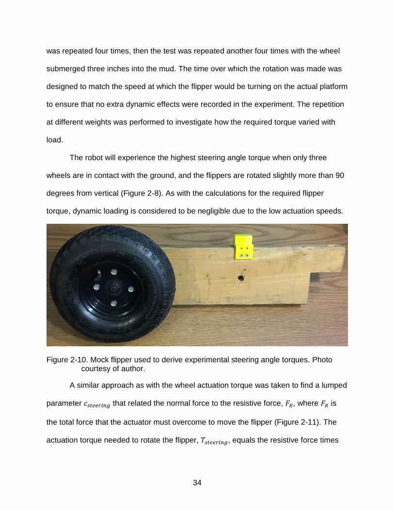
Steering angle actuation torque
The mud pit was also used to calculate the baseline torques for actuating the
steering angle. A wooden mockup of a flipper was created with one of the 10 inch
testing wheels mounted at the end (Figure 2-10). A 3D printed hexagon was screwed to
the flipper at the appropriate distance to generate the moment arm that would be
experienced by the robot. A known amount of weights were stacked on top of the mock
flipper near its center of mass. The wheel was then submerged two inches in the mud.
A torque wrench was affixed to the hexagon with a socket, and the average torque
required to make a 45 degree turn over approximately 5 seconds was recorded. This
34
was repeated four times, then the test was repeated another four times with the wheel
submerged three inches into the mud. The time over which the rotation was made was
designed to match the speed at which the flipper would be turning on the actual platform
to ensure that no extra dynamic effects were recorded in the experiment. The repetition
at different weights was performed to investigate how the required torque varied with
load.
The robot will experience the highest steering angle torque when only three
wheels are in contact with the ground, and the flippers are rotated slightly more than 90
degrees from vertical (Figure 2-8). As with the calculations for the required flipper
torque, dynamic loading is considered to be negligible due to the low actuation speeds.
Figure 2-10. Mock flipper used to derive experimental steering angle torques. Photo courtesy of author.
A similar approach as with the wheel actuation torque was taken to find a lumped
parameter 𝑐𝑠𝑡𝑒𝑒𝑟𝑖𝑛𝑔 that related the normal force to the resistive force, 𝐹𝑅, where 𝐹𝑅 is
the total force that the actuator must overcome to move the flipper (Figure 2-11). The
actuation torque needed to rotate the flipper, 𝑇𝑠𝑡𝑒𝑒𝑟𝑖𝑛𝑔, equals the resistive force times

35
the moment arm 𝐿, and the resistive force is the normal force times the lumped
parameter 𝑐𝑠𝑡𝑒𝑒𝑟𝑖𝑛𝑔,
𝐹𝑅 = 𝑐𝑠𝑡𝑒𝑒𝑟𝑖𝑛𝑔𝐹𝑁 (2-4)
where the normal force is equal to one third of the robot’s weight. In this case, 𝑐𝑠𝑡𝑒𝑒𝑟𝑖𝑛𝑔
increased as the submersion depth of the wheel increased. This is likely due to the fact
that the cross section of the tire that is displacing mud increases as the submersion
depth increases. The required steering angle torque, 𝑇𝑠𝑡𝑒𝑒𝑟𝑖𝑛𝑔, can be found by
𝑇𝑠𝑡𝑒𝑒𝑟𝑖𝑛𝑔 =𝑐𝑠𝑡𝑒𝑒𝑟𝑖𝑛𝑔𝑊
3𝐿
(2-5)
where 𝑊 is the weight of the platform and 𝐿 is the moment arm, which is the center
distance between the wheels on the flipper. At a submersion depth of 2 inches
𝑐𝑠𝑡𝑒𝑒𝑟𝑖𝑛𝑔 = 2.53, and at a submersion depth of 3 inches, 𝑐𝑠𝑡𝑒𝑒𝑟𝑖𝑛𝑔 = 3.19.
Figure 2-11. Top-down view of a flipper showing a free body diagram of the forces and torques involved in actuating the steering angle. 𝐹𝑅 is the resistive force, and 𝐿 is the center distance between the wheels. 𝑇𝑠𝑡𝑒𝑒𝑟𝑖𝑛𝑔 is the steering angle
actuation torque, which is applied at point B. Photo courtesy of author.
36
The high values of 𝑐𝑠𝑡𝑒𝑒𝑟𝑖𝑛𝑔 mean that the torques required to actuate the
steering angle are significantly higher than the torques required to actuate the other two
degrees of freedom. Additionally, the relationship between the 𝑐𝑠𝑡𝑒𝑒𝑟𝑖𝑛𝑔 values for the
different submersion tests suggests that the required torque will increase as the
submersion depth increases. Given the size requirement of the robot, it is impractical to
specify a motor and gearing system and a power system large enough to actuate the
steering angle when the wheels are submerged in mud. Instead, the steering angle will
be designed for use with both wheels down only when the robot is on concrete. When
the steering degree of freedom is required at times when the wheels are submerged in
mud, the operator can actuate the flippers to raise the distal wheel out of the mud
before actuating the steering degree of freedom.
Calculating the required actuation torque for the steering angle becomes much
simpler when friction is the only resistive force considered. When rotating on wet
concrete, the friction force experienced by the steering angle is simply the normal force
multiplied by the coefficient of static friction between rubber and wet concrete (𝜇 = 0.6).
The required actuation torque is then the force of friction multiplied by the moment arm
𝐿, seen in Equation 2-6:
𝑇𝑠𝑡𝑒𝑒𝑟𝑖𝑛𝑔 =𝜇𝑊
3𝐿
(2-6)
Secondary Design Parameters
The weight of the mobile platform is not a critical parameter, and SRS gave no
weight requirements. As the weight of the platform increases, so do the actuation torque
and power requirements, so an optimal design will be as light as possible. Previous

37
inspection robots deployed into H Canyon have weighed approximately 200 pounds.
This weight of 200 pounds will be used as a goal for the weight of this platform.
As part of the IRP project budget, $70,000 was budgeted for the fabrication of the
mobile platform. Accordingly, the equipment and manufacturing cost requirement was
set at $70,000.
Previous inspection robots at H Canyon have had exceptionally low design lives.
Early inspection robots were intentionally abandoned in place after the inspection was
performed [14]. Exhaust tunnel inspections currently last 3-4 days, during which the
robot is left in the tunnel for the duration of the inspection. Robots have only been
reused in the most recent inspection, where the 2015 robot was deployed again in
2017. This robot was not used between inspections [10]. Current practice for H Canyon
inspection robots is to treat environmentally sensitive components on the robot, such as
rubber tires, as consumable and to replace them for every inspection. This mobile
platform will be designed to operate for a 7 day inspection at a time for 3 inspections.
Rubber components such as the tires and shaft seals will have to be replaced for every
deployment.
High Level Design Decisions
Several different options were considered for the type of prime mover that would
actuate every degree of freedom, including brushed DC motors, brushless DC motors,
hydraulic actuators and pneumatic actuators. The primary considerations that drove the
selection of the prime mover were space, torque delivery capabilities, power
consumption, and robustness. Hydraulic and pneumatic actuators were eliminated for
space reasons, as they would require fluid or air to be stored on board the robot.
Brushless DC motors have a higher torque per unit weight than brushed DC motors,

38
and are more robust, as they do not have brushes that can wear out. Although
brushless motors cost more and require more complicated control schemes and motor
drivers, the benefits that they offer as far as torque density and robustness are weighted
higher for this application.
Brushless DC motors generally come in voltages ranging from 12 volts to
upwards of 90 volts. Higher voltage motors generate more torque per amp, but higher
voltages require more expensive electronics, and can be more dangerous to work with.
A motor voltage of 24 volts was selected in order to minimize current draw while still
retaining the benefits of a lower-voltage system.
Electric motors characteristically have high speed, low torque outputs. In order to
multiply the torque output of the motors, each motor was mounted to a high-reduction
gearbox to exchange the motor’s speed for torque. After the gearbox, spur and bevel
gearing were used to further multiply the torque and redirect the motion from the motors
to the output locations. Spur and straight bevel gears were selected because they are
the simplest and cheapest type of gear to design torque reductions for parallel shafts
and 90 degree offset shafts, respectively, and have high efficiencies compared to other
types of gearing [15]. Worm gears were also considered as a method for achieving high
torque multiplication ratios while redirecting the axis of rotation by 90 degrees, but were
not used because the calculated efficiency was extremely low at the operating points
that were required.
In locations where a bearing surface was needed to facilitate relative motion
between parts, bushings were generally used instead of bearings. For the vast majority
of parts, the loads and speeds are low enough that ball or roller bearings are not

39
required, and bushings offer a smaller form factor than bearings. With so many moving
parts and such a limited size constraint, the space that using bushings saved was
significant. Bushing material was chosen to be Oilite, a sintered bronze impregnated
with oil. Pressure on the bushing caused by relative motion between parts expels the oil
from the pores in the bronze, lubricating the parts. Oilite bushings have higher load
capacity than other common bushing material such as plastics, but have a similar low
cost. For continuity, every bushing used in the design was made from Oilite material.
The choice of materials for the external parts of the robot has significant effects
on radiation shielding and resistance to corrosion by chemicals in the tunnel, namely
nitric acid. Leads and steels are typical favored metals for radiation shielding. Stainless
steels are the most corrosion resistant of common metals, and the 304 alloy is the most
resistant to nitric acid of all of the common stainless steels. For welded parts, such as
the sheet metal shell that protect the body assembly, 304L, a version of 304 with a
lower carbon content, is used because it is more resistant to localized corrosion [16].
The stainless steel shell will also serve as a shield for radiation.
Internal components of the platform were designed from 6061 aluminum to
minimize weight. The 6061 alloy was selected for its high machinability and low price.
Internal shafts are designed from 4140 steel to avoid shaft windup that would manifest
in aluminum shafts due to aluminum’s lower modulus of elasticity. Steel also has the
advantage of having an infinite fatigue life at low loads. 4140 steel was selected for its
strength, price and availability in various sizes.
Rubber components that are used on the robot, such as shaft seals and o-rings,
are fluoroelastomer rubber that is resistant to nitric acid [17]. The major exception to this

40
are the wheels, for availability reasons. Pneumatic wheels are not readily available in
fluoroelastomer rubber. Instead, wheels with natural rubber were selected and planned
to be disposed of after each deployment, which is the procedure for the wheeled robots
that SRS currently uses.
All of the motors and electronics are housed in the main body. This allows for
shorter wiring and eliminates the need for wiring to run between parts that move relative
to each other. Additionally, the main body provides a safe location for the electronics
and motors that is elevated over mud and water. In the event that the robot has to drive
through a deep puddle of water, the flippers can lift the main body high enough that the
water-sensitive components are held above the water. With this design, only hardware,
which is less sensitive to water, is housed in the subassemblies that will be in the
closest contact with the mud and water, namely the flipper and drive subassemblies.
This means that water intrusion into one of these subassemblies will be significantly
less catastrophic.
A system of three vertical nested concentric shafts is used to transmit the motion
from the motors to the output location. At the bottom of this assembly, a pair of nested
miter gears redirects the wheel and flipper actuation to the wheels and flipper.
A 700 foot tether will be used to send power and command signals to the robot.
A computer on board the robot will arbitrate the command signals and issue motor
commands to the motor drivers using an Arduino to convert between digital and analog
signals. The power will be sent down the tether at a high DC voltage (~300 volts) in
order to reduce the current in the tether, therefore reducing the required cross sectional
area of the conductors in the tether and allowing for a smaller tether. Buck converters

41
on board the robot will convert the high voltage to the lower operating voltages required
by the components on the robot.

42
CHAPTER 3 PROTOTYPE DESIGN
A functional prototype will be built as a proof of concept to demonstrate the
mobility capabilities of this platform. While the cost of the actual mobile platform is not a
significant factor, the prototype will be made with a stricter budget. This prototype will
not be expected to be deployed into the exhaust tunnel, and significant cost savings can
be achieved by reducing the environmental hardiness of the prototype. The external
components of the actual mobile platform will be made from 304 stainless steel,
however, stainless steel is more expensive than other common metals, such as
aluminum. Manufacturing stainless steels, and 304 stainless steel in particular, is
difficult and expensive due to strain hardening that occurs during cutting. Aluminum
alloys are significantly easier, and therefore cheaper, to machine. Aluminum’s lower
density relative to steel also reduces the weight of the robot, and therefore the actuation
efforts and electric power needed to move the robot. Due to all of these factors,
aluminum was chosen as the main material for the metal components of the prototype.
All aluminum parts are 6061-T6 aluminum, except for the steering angle shaft and the
flipper drive shaft, which are 7075-T6 aluminum because a higher strength was needed.
All of the shafts in the design aside from these are designed from steel to avoid shaft
windup that would manifest in aluminum shafts due to aluminum’s lower modulus of
elasticity, and to take advantage of both the ability to machine finer finishes on the
running surfaces and the infinite fatigue life of steel. 4140 steel was selected for its
strength, price and availability in various sizes. The steering angle shaft and flipper drive
shaft were designed out of aluminum and not steel because the large size and
significant amount of material removal would cause manufacturing to be expensive if

43
the material was steel. These shafts have a large enough moment of inertia that shaft
windup is not a problem, and 7075 aluminum can be machined to a high surface finish
quality.
Adjustments can also be made to the tether to reduce the cost of the prototype.
For testing purposes, a 50 foot tether will be used. The prototype will only need to
supply power for the mobile platform, manipulator arm and sensor tree. The shorter
tether will also have less of a voltage drop than the 700 foot tether. These factors both
lower the amount of power that must be delivered through the tether. Because the
prototype will not be operating in the tunnel, control commands can be sent over wifi
and received by a wireless access point on the robot, thus eliminating the need for
signal cables in the tether. For the prototype, the tether can be reduced to an extension
cord that can plug into a wall outlet.
Drivetrain Design
Several different brushless DC motors were considered to actuate the various
degrees of freedom. The size, the current, the torque and speed at operating points,
hardware integrability, availability of drivers specific to the motor, and price were all
considered. The different degrees of freedom have torque and speed requirements that
are different enough that it is not feasible to control all three degrees of freedom with
identical motors. Some vendors offer “families” of motors that are copies of each other
except for their stack length, which gives them different speed and torque (and resultant
power consumption) figures. The benefit of using motors from the same family is that
motor mounting and control is identical for all the motors. Four different families of
BLDC motors form two different vendors were identified and the median motor of each
family was compared in a design matrix to select the best motor family to use in the

44
mobile platform. Table 3-1 shows the design matrix comparing the median motors from
the Allied Motion QB23 and QB34 motor families. Table 3-2 shows the design matrix
comparing the median motors from the ElectroCraft RP23 and RP17 motor families.
Both tables have the same design objectives weighted equally. A high peak current is
not desirable because it requires more expensive power components and a thicker
tether, and also generates more heat. The continuous stall torque is used as a
benchmark of the amount of torque the motor can produce. The body length, weight and
cost should all be minimized. Of these, the body length is especially important due to
the limited space in the robot body assembly for mounting the motors.
Table 3-1. Design matrix for the Allied Motion QB2302 and QB3402 motors
QB2302 QB3402 Objective Weighing
Factor Mag. Score Value Mag. Score Value
Peak Current (A)
0.15 98 0 0 98 0 0
Cts Stall Torque (in-lbs)
0.45 8.14 3.3 1.49 20 10 4.5
Body Length (in)
0.3 4.3 3.5 1.05 5.07 0 0
Weight (lbs) 0.05 2.7 7.69 0.39 6.8 0 0 Cost ($) 0.05 850 0.65 0.03 875 0 0
Sum 2.95 4.5
Table 3-2. Design matrix for the ElectroCraft RP23-54 and RP14-36 motors
RP23-54 RP17-36 Objective Weighing
Factor Mag. Score Value Mag. Score Value
Peak Current (A)
0.15 18.5 9.1 1.37 10.4 10 1.5
Cts Stall Torque (in-lbs)
0.45 2.92 0.35 0.16 2.21 0 0
Body Length (in)
0.3 3 10 3.00 3.1 9.5 2.85
Weight (lbs) 0.05 1.94 9.22 0.46 1.47 10 0.5 Cost ($) 0.05 383 8.6 0.43 300 10 0.5
Sum 5.41 5.35

45
The ElectroCraft RP23-54 had the best rating in the design matrix, so the RP23
family of motors was selected. To decide which motor would actuate each degree of
freedom, the torque and speed abilities of each motor and the area in the motor’s
speed-torque curve that it would have to operate were considered. The RP23-26 model
was selected to actuate the steering angle, the RP23-54 model was selected to actuate
the wheels, and the RP23-73 model was selected to actuate the flippers. Each motor is
fitted with a 500 count per revolution (CPR) encoder.
Drive System Detail Design
In order to begin the detailed design of the drive system, target torques and
speeds were selected as preliminary operating points. The baseline actuation torque
formulas from equations 2-1, 2-3 and 2-6 with an estimated robot weight of 200 pounds
were used as a starting point and appear in Table 3-3 below. Target speeds of 2
rotations per minute (RPM) were arbitrarily chosen as a starting point for the flipper and
steering angle degrees of freedom, and a target speed of 50 RPM was arbitrarily
chosen for the wheel degree of freedom. A generalized gearing system was designed
where straight bevel gears were used to mate shafts offset by 90 degrees that needed
to transmit torque. For degrees of freedom that required another torque multiplication
step in order to reach the target torques, a spur gear pair was inserted into the path
after the gearbox.
Table 3-3. Baseline torques and target speeds for each degree of freedom.
Degree of Freedom Baseline Torque (in-lbs) Target Speed (RPM)
Flipper 733.28 2 Steering Angle 449.97 2 Wheels 107.01 50

46
Given the wide range of conditions that the robot may need to maneuver through,
as well as the lack of knowledge of the exact torques needed to actuate each degree of
freedom to adequately maneuver through the operating environment, it is unrealistic to
design each degree of freedom to actuate at one single operation point for the duration
of the inspection. Instead, it is expected that the robot will operate in a range of torques
and speeds within a certain window. The drivetrain of each degree of freedom was
designed to provide operation windows that allow the robot to move quickly while under
an average load, but to also have extra torque available at lower speeds in order to be
able to maneuver through difficult conditions. Operation points at the boundaries of
these windows were chosen as design points. Each degree of freedom is designed with
a maximum speed operating point, a low speed/high torque operating point, and a peak
torque operating point.
The maximum speed operating points represent the fastest speed that each
degree of freedom can move. This operating point is designed to be used in average
conditions, so torques will be similar to the baseline torques in Table 3-3. This operating
point was designed to be within the continuous operation region of the motors. Because
this operating point is expected to be the average speed and torque that is required,
keeping this point in the continuous operation region allows the robot to drive in these
conditions indefinitely.
If the robot experiences conditions that require more torque than is provided at
the maximum speed operating point, more torque can be supplied at lower speeds by
the motor. The high torque operating point denotes a point in the continuous operation
region of the motor’s speed-torque curve where the speed is low, but the torque is high.

47
It should be noted that there is a continuous range of speeds and torques in the
continuous operation region for the motor that can be achieved in the window between
the maximum speed and high torque operating points.
For high starting and stopping torques, or in an emergency situation where even
more torque is needed than is available at the high torque operating point, the
drivetrains are built to be able to withstand a peak torque operating point. This peak
torque occurs at near zero speed, and can only be achieved for a short time before the
motor is harmed, as this point is outside the continuous operation region of the motor’s
speed/torque curve.
Final design of the drivetrain was performed through recursive iterations to
optimize the output torques and speeds, gear sizes, and motor performances. Each
actuation path was mathematically modeled, and the torque and speed outputs were
calculated for each step, with efficiency losses included. The drivetrain design was
adjusted until torques that larger than the baseline torques by a factor ranging from 1.15
to 1.25 were achieved for the maximum speed actuation point. Having actuation torques
at the maximum speed operating point that are greater than the baseline torques
ensures that the platform will be able to operate at the expected average conditions at
speeds that will not be so low as to impede the tunnel inspection. Acceptable speeds for
the maximum speed operating point were determined by comparing the designed
speeds to the speed of the most recent inspection robot to be deployed. That robot had
a top wheel actuation speed of 3 miles per hour, but the top speed was rarely used, and
was only employed to get the robot unstuck [13]. To achieve a wheel actuation torque
that is larger than the baseline wheel torque by a factor of 1.15, the wheel speed for the

48
mobile platform is 55 RPM, or 1.6 miles per hour. This is less than the top speed of the
previous robot, but comes with significantly more torque, which helps prevent the
platform from getting stuck in the first place.
Speeds for the other two degrees of freedom can not be directly compared to
previous inspection robots, because no previous inspection robot has had these types
of motion. Speeds for the flipper and steering angle actuation were chosen based on
the speed in the 1.15 to 1.25 torque multiplication range that seemed most reasonable
in relation to a wheel speed of 55 RPM.
Table 3-4. Output torques and speeds at the three operating points
Maximum Speed Operating Point
High Torque Operating Point
Peak Torque Operating Point
Degree of Freedom
Torque (in-lbs)
Speed (RPM)
Torque (in-lbs)
Speed (RPM)
Torque (in-lbs)
Speed (RPM)
Flipper 917.24 11.42 1592.04 0.22 2124.94 1.0 Steering angle 535.43 6.31 840.03 1.26 2100.08 1.26 Wheels 124.01 55.56 204.89 0.1 377.42 1.11
The gearbox that the wheel motor drives is a harmonic drive gearbox with a 45:1
reduction ratio. A harmonic drive was chosen because it provides a high reduction in a
small form factor with no backlash, and is difficult to back drive. The bearings in the
harmonic drive are also rated to withstand high levels of both axial and radial force. The
pinion gear on the output shaft of the harmonic drive gearbox is a bevel gear, which will
generate high axial and radial forces due to the amount of torque it transfers. The
gearboxes mated with the flipper and the steering angle motors are planetary
gearboxes with a 50:1 reduction ratio. These have a larger form factor than the
harmonic drive, but have a higher reduction ratio at a higher efficiency. These
gearboxes also have lower bearing ratings for axial and radial forces, but the pinion

49
gears on the output shafts of the gearboxes are spur gears, which do not generate axial
forces. The radial forces generated by these pinion gears will sometimes be larger than
the rated radial force of the gearbox, but this is an intentional tradeoff with design life.
The gearbox is rated for 20,000 hours at the rated forces. Larger forces with reduce the
life of the gearbox, but this is acceptable, as the design life for the robot is significantly
less than 20,000 hours. These planetary gearboxes were chosen because in addition to
their higher reduction ratio and efficiency, they are 30% of the cost of the harmonic drive
gearboxes.
The design requirements for the open gearing in the drivetrains was so specific
that commercial off the shelf solutions were not a feasible option. Instead, the open
gearing was custom built from hardened 4140 steel. The gears were designed so that
the bending stress of the teeth on the gear did not exceed ½ of the yield stress of the
gear. Bending stress for the spur gears was calculated using the Lewis equation
𝜎𝑠𝑝𝑢𝑟 =𝑊𝑡𝑃𝑑
𝐹𝑌
(3-1)
where 𝑊𝑡 is transmitted load, 𝑃𝑑 is the diametral pitch, 𝐹 is the face width, and 𝑌 is the
Lewis Form Factor [18]. Dynamic effects and fatigue life were neglected for the spur
gears for simplicity due to the low design life of the robot. Bending stress for the bevel
gears was calculated using
𝜎𝑏𝑒𝑣𝑒𝑙 =𝑊𝑡
𝐹𝑃𝑑𝐾𝑜𝐾𝑣
𝐾𝑠𝐾𝑚
𝐾𝑥𝐽
(3-2)
where 𝑊𝑡 is the transmitted load, 𝐹 is the face width, 𝑃𝑑 is the diametral pitch, 𝐾𝑜 is the
overload factor, 𝐾𝑣 is the dynamic factor, 𝐾𝑠 is the size factor, 𝐾𝑚 is the load distribution
factor, 𝐾𝑥 is the lengthwise curvature factor, and 𝐽 is the geometry factor [18].

50
Diametral pitches were chosen to minimize the pitch diameter of the gears while
still keeping the bending stress below ½ of the yield point. Diametral pitches between
mating gears were kept the same to ensure that the gears would mate successfully. The
pressure angle on all of the gears is a standard 20 degrees. The minimum number of
teeth on a gear was kept to 13 in order to avoid undercutting (and resultant weakening)
of gear teeth. Every gear has a set screw, and every gear except for the pinions on the
planetary gearbox shafts has a keyway. The planetary gearbox shafts have a flat
ground on them for set screws, but do not have keyways. However, the torque is low
enough on these gears that a keyway is not needed in addition to the set screw.
Setscrew sizes and keyway dimensions were used from [19]. All keyways are standard
square keyways except for the keyways on the miter gears for the flipper, which are
rectangular to avoid wall thickness issues between the outer diameter of the hub and
the keyway. Some set screw sizes deviate slightly from [19] in order to reduce the
number of types of set screws used on the robot.
The critical key length, or minimum key length required to avoid key failure, was
calculated for each gear [20]. Both shear and compressive key failure modes were
considered, and the longest length at which a failure mode was calculated to occur was
taken as the critical key length. Hub lengths were designed so that the key length for
each gear is at least twice as long as the critical key length for that gear.
𝑙𝑐𝑟𝑖𝑡,𝑠ℎ𝑒𝑎𝑟 =2𝑇𝑚𝑎𝑥
𝑑𝑤𝜏𝑑𝑒𝑠𝑖𝑔𝑛
(3-3)
𝑙𝑐𝑟𝑖𝑡,𝑐𝑜𝑚𝑝𝑟𝑒𝑠𝑠𝑖𝑜𝑛 =4𝑇𝑚𝑎𝑥
𝑑ℎ𝜎𝑑𝑒𝑠𝑖𝑔𝑛
(3-4)
51
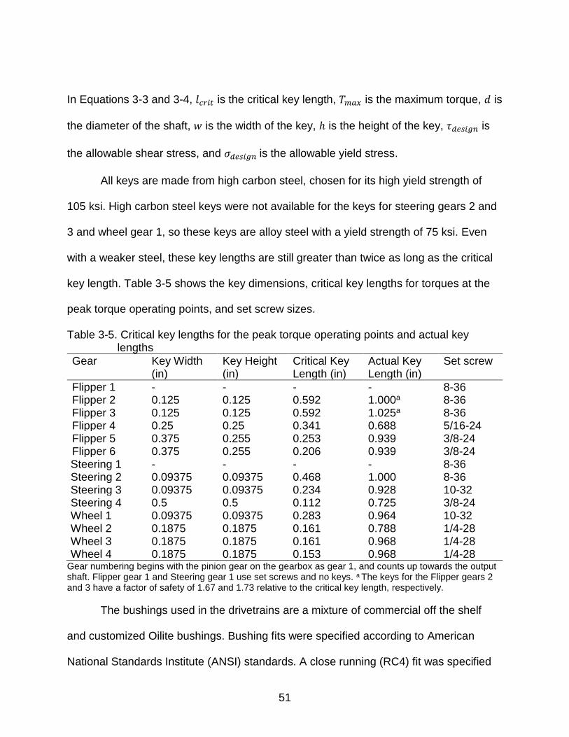
In Equations 3-3 and 3-4, 𝑙𝑐𝑟𝑖𝑡 is the critical key length, 𝑇𝑚𝑎𝑥 is the maximum torque, 𝑑 is
the diameter of the shaft, 𝑤 is the width of the key, ℎ is the height of the key, 𝜏𝑑𝑒𝑠𝑖𝑔𝑛 is
the allowable shear stress, and 𝜎𝑑𝑒𝑠𝑖𝑔𝑛 is the allowable yield stress.
All keys are made from high carbon steel, chosen for its high yield strength of
105 ksi. High carbon steel keys were not available for the keys for steering gears 2 and
3 and wheel gear 1, so these keys are alloy steel with a yield strength of 75 ksi. Even
with a weaker steel, these key lengths are still greater than twice as long as the critical
key length. Table 3-5 shows the key dimensions, critical key lengths for torques at the
peak torque operating points, and set screw sizes.
Table 3-5. Critical key lengths for the peak torque operating points and actual key lengths
Gear Key Width (in)
Key Height (in)
Critical Key Length (in)
Actual Key Length (in)
Set screw
Flipper 1 - - - - 8-36 Flipper 2 0.125 0.125 0.592 1.000a 8-36 Flipper 3 0.125 0.125 0.592 1.025a 8-36 Flipper 4 0.25 0.25 0.341 0.688 5/16-24 Flipper 5 0.375 0.255 0.253 0.939 3/8-24 Flipper 6 0.375 0.255 0.206 0.939 3/8-24 Steering 1 - - - - 8-36 Steering 2 0.09375 0.09375 0.468 1.000 8-36 Steering 3 0.09375 0.09375 0.234 0.928 10-32 Steering 4 0.5 0.5 0.112 0.725 3/8-24 Wheel 1 0.09375 0.09375 0.283 0.964 10-32 Wheel 2 0.1875 0.1875 0.161 0.788 1/4-28 Wheel 3 0.1875 0.1875 0.161 0.968 1/4-28 Wheel 4 0.1875 0.1875 0.153 0.968 1/4-28
Gear numbering begins with the pinion gear on the gearbox as gear 1, and counts up towards the output shaft. Flipper gear 1 and Steering gear 1 use set screws and no keys. a The keys for the Flipper gears 2 and 3 have a factor of safety of 1.67 and 1.73 relative to the critical key length, respectively.
The bushings used in the drivetrains are a mixture of commercial off the shelf
and customized Oilite bushings. Bushing fits were specified according to American
National Standards Institute (ANSI) standards. A close running (RC4) fit was specified

52
for the inner diameter of the bushing and the shaft that rotated in the bushing. A light
interference fit (FN1) was specified for the outer diameter of the bushing and the hole
that it fits into. Many of the off the shelf bushings were supplied with dimensions that
were outside of the tolerances listed by the ANSI fits. In these cases, the limits of
clearance or interference were used to specify a shaft or hole that would mate with the
bushing in order to get a fit as close to an RC4 or FN1 fit as possible. For off the shelf
bushings that were used without modification, load ratings provided from the vendor
were used to ensure that bushings were not loaded over their capacity. For off the shelf
bushings that were modified, or for custom bushings, pressure-velocity (PV) values
supplied by the Oilite manufacturer were used.
Motor drivers were procured from the same company as the motors because
they were guaranteed to interface with each other. Drivers were specified based on the
peak current that each motor could demand. The drivers that were selected have
analog control inputs. Drivers with digital control inputs were available, but were four
times the price, and were deemed too expensive.
Actuation Paths
The actuation path for each degree of freedom begins with a motor that drives a
gearbox, which in turn has a pinion gear mounted on its output shaft. When necessary,
a spur gear pair after the gearbox provides a torque multiplication step, and then a
bevel pinion drives a bevel gear that is mated to the respective vertical shaft in the drive
assembly (Figure 3-1).
The flipper motor drives a planetary gearbox with a 50:1 reduction (Figure 3-2). A spur
gear pinion mounted on the output shaft of the planetary gearbox mates with another
spur gear for a 2.9:1 reduction. This second spur gear shares a shaft with a bevel

53
pinion, which mates with a bevel gear on the vertical flipper shaft with a 3:1 reduction.
At the bottom of the flipper vertical shaft, the outer pair of nested miter gears redirect
the motion to the flipper output shaft, which is bolted to the flipper, so that rotation of the
flipper output shaft rotates the flipper (Figure 3-3).
Figure 3-1. The top half of the actuation system for the rear-left corner of the mobile platform. This design is replicated at each corner of the body. Photo courtesy of author.
Figure 3-2. Exploded view showing the flipper motor that mates to a planetary gearbox, which drives a spur gear pinion. Photo courtesy of author.
The wheel motor drives a harmonic drive gearbox with a 45:1 reduction. A bevel
pinion mounted on the output shaft of the harmonic drive gearbox mates with a bevel

54
gear on top of the vertical wheel shaft with a 2:1 reduction. At the bottom of the vertical
wheel shaft, there is a miter gear pair that redirects the motion from the vertical wheel
shaft to the wheel output shaft. This miter pair forms the inner pair of the nested miter
gears in the redirection box (Figure 3-3).
The steering angle motor drive a planetary gearbox with a 50:1 reduction, and
the torque is then multiplied by a 2.9:1 spur gear reduction in the same manner as the
flipper actuation path. The large spur gear shares a shaft with a bevel pinion that mates
with a bevel gear on the steering angle shaft with a 5.4:1 reduction. This large gear is
keyed to the vertical steering angle shaft, which rotates the redirection box and flipper
assembly to adjust the steering angle (Figure 3-3).
Figure 3-3. Section view of the drivetrain of the rear-left corner of the robot. Wheel actuation components are shown in blue, flipper actuation components in red, and steering actuation components in green. Photo courtesy of author.

55
Electrical System Design
Power requirements were calculated by analyzing different scenarios that the
platform would have to supply power for. The number of components on the robot that
will need to provide power to simultaneously depends on how the robot is moving. The
current draw of the different components also varies according to the load placed on
them. By evaluating which components would be utilized in different operational
scenarios and what the approximate current draw would be on each component in each
scenario, a power budget can be established.
Power System Design
The four scenarios considered include two inspection modes, where the
propulsion motors, manipulator arm motors, computer, and sensor tree are operating. In
the first mode, “drive and inspect”, the wheels are driving the robot. In “elevate and
inspect”, the flippers elevating the robot body in the air. In both of these cases, the
motors are considered to be operating at their high speed operating points. Two
scenarios where the motors are at their peak operating points are also considered. The
“peak wheels” scenario considers all four wheel motors at their peak torque operating
point while the computer and sensor tree are operating. The “peak flippers” scenario
considers all four flipper motors operating at their peak operating point while the
computer and sensor tree are operating.
Based on these calculations, the overall power for the prototype was determined
to be 1.24 kW. For the testing purposes with the prototype, the tether will be an
extension cord that can plug into a wall outlet and deliver 120 VAC to the mobile
platform. A rectifier on board the platform will convert the power to 12 VDC and 24 VDC

56
rails that components on the mobile platform, manipulator arm and sensor tree can be
powered from.
Table 3-6. Operation scenarios and their power requirements.
Drive and Inspect Elevate and Inspect Peak Wheels Peak Flippers Component Power (kW) Power (kW) Power (kW) Power (kW)
Wheels 0.36 0 1.08 0 Flippers 0 0.45 0 1.05 Arm 0.22 0.22 0 0 Lights 0.048 0.048 0.048 0.048 LIDAR 0.012 0.012 0.012 0.012 Servo 0.03 0.03 0.03 0.03 Computer 0.063 0.063 0.063 0.063
Total 0.73 0.83 1.24 1.20 “Arm” refers to the manipulator arm. “Lights”, “LIDAR” and “Servo” are components of the sensor unit that will be mounted on top of the platform. “Computer” refers to the onboard computer in the body.
Computer System Design
Components for the computer were specified based on requirements of the
mobile platform, manipulator arm and sensor tree. An Intel I7 CPU was chosen for its
high clock speeds to handle the large amount of sensor data. A motherboard with two
ethernet ports was selected so that LIDAR data could be read into the computer with
one port and output in real time to a user with the other port. 16 GB of DDR4 RAM was
specified to provide adequate memory for mobile platform, manipulator arm and sensor
tree operations. A 1 TB solid state drive was specified to host the operating system for
higher speeds, and a 5 TB spinning hard drive was included for storing large amounts of
sensor data. The computer will run Ubuntu 16 and use Robot Operating System (ROS)
version Kinetic to control the mobile platform motors, manipulator arm, and interface
with the sensors.
To control the mobile platform, user commands will be input into the computer
and then relayed to an Arduino Mega. The Arduino will convert between digital and

57
analog signals to interface between the computer and motor drivers. The motor drivers
have differential analog inputs. Differential inputs were selected instead of single ended
inputs to reduce the effect of noise caused by a long tether or interference from gamma
radiation.
Body Assembly
The body assembly is the central part of the robot, and is where the motors and
all of the electronics are held. A welded skeleton made from ¼ inch aluminum plate
provides the main structure. The main body is wrapped in a 12 gage aluminum sheet
metal shell for sealing. ¼-20 flat head sealing screws on the front, back and sides
attach the shell to the skeleton. A sheet metal lid fits on top, and is affixed to the
skeleton with ¼-20 hex head sealing screws. A rubber seal inside the lip of the lid
provides sealing at the interface between the body and the lid. Any screws that puncture
the shell are sealing screws. The body assembly has flats on the corners to provide
clearance for the flippers to rotate.
Figure 3-4. Aluminum skeleton with sheet metal shell and lid, and rubber sealing strip inside the lip of the lid. The lid is transparent to show the internal skeleton. Photo courtesy of author.

58
Figure 3-5. Section view of the body showing the mounting block for the manipulator arm. Photo courtesy of author.
Aluminum plates that run horizontally provide support and mounting locations for
all of the electronics and the motors. The computer, Arduinos and power converters are
located in the middle of the body so that they are equidistant from all of the motor
drivers. Motor drivers are located near the motors at each corner of the body. An
aluminum mounting subassembly at the front of the body provides a mounting location
for the manipulator arm developed by the University of Texas at Austin (Figure 3-5).
Four ¼-20 hex head sealing screws pass through clearance holes on a mounting plate
on the arm and through clearance holes in the lid, and thread into the mounting block.
The mounting block is attached to the front plate of the skeleton with two 10-24 flat head
screws. The mounting block is reinforced by a triangular support that is attached to the
mounting block and the front plate with 10-24 flat head screws.
The high thermal conductivity of the aluminum skeleton allows it to also act as a
heat sink for the electronics. Because the body has to be sealed, fans cannot be used

59
to cool the body assembly. Instead, the platform will dissipate heat through conduction
onto the skeleton and convection into the environment. The electronics that generate
the most heat, that is, the computer, power converters, and motor drivers, are mounted
with large contact areas touching the skeleton to allow for heat transfer from the
electronics to the body, and then out to the environment. The computer processor is
adhered to the skeleton with thermal paste to allow for optimal heat transfer. Due to
space limitations, not all of the motor drivers could be mounted with their largest areas
in contact with the aluminum skeleton. The motor drivers that are expected to be used
Figure 3-6. View of the robot body with lid removed. Photo courtesy of author.

60
the most, and therefore generate the most heat, are the flipper and wheel motor
drivers. These were mounted with maximum area in contact with the aluminum, while
the steering angle motor drivers were mounted vertically.
Figure 3-7. View of one of the corners of the body assembly. Photo courtesy of author.
The actuation system is replicated at each corner of the robot. The motors and
gearboxes are held in place with motor mounts made from ½ inch aluminum plate. At
the top of each corner, a ½ inch aluminum plate called the “top capture” provides a
structure to pin and screw the motor mounts to. This plate also provides a base for
bushing support that holds a bushing which captures the output shaft from the harmonic
drive. This plate also holds a tapered roller bearing which the vertical wheel shaft fits
into that supports the vertical and radial forces from the drive assembly.
All of the gearboxes are screwed to M5 tapped holes in the motor mounts. The
flipper and steering angle actuation paths use an extra spur gear reduction to create

61
additional torque. These motor mounting plates have attachment points for the gearbox
as well as the shaft that supports the second spur gear and the bevel pinion. The rear of
this shaft is stepped to prevent rearward axial shaft motion caused by the normal force
of the bevel gear mesh. A retaining ring on the rear of the shaft prevents forward axial
shaft motion. Thrust and flanged bushings take the radial and axial forces applied to the
shaft. Set screws in the gears prevent axial motion of the gears relative to the shafts.
These shafts are fabricated from 4140 steel because the increased stiffness as
compared to aluminum helps to prevent deflection that would affect the bevel gear
meshes.
Figure 3-8. Exploded view of one of the corners of the body assembly. Photo courtesy of author.
Strategies to minimize assembly tolerances were implemented in order to help
facilitate successful mates between the gears, as meshing gears require very close
tolerances (on the order of ±0.001 inches). The motor mounts for the flipper and
steering angle motors both use one part to support the gearbox and the shaft shared by

62
the spur and bevel gears, thus reducing assembly tolerances between the two shafts
and helping the spur gears to mesh accurately. Distances between spur gear shafts
were determined by the pitch radii of the spur gears. Distances between the bevel gear
meshes were determined by the mounting distances of each bevel gear. To accurately
place the motor mounts relative to the bevel gears in the drive assembly, 3/16 inch
dowel pins are used to locate the motor mounts. Number 10 flat head screws are then
used to secure the mounts to the motor mounting plate and top capture, and number 6
flat head screws are used to secure the motor saddles and the wheel pinion gear
support to the motor mounting plate and the top capture, respectively. The use of flat
head screws allows for the sheet metal shell to fit flush on the skeleton. For
organizational reasons, the body assembly is the only assembly to use flat head
screws.
Figure 3-9. Exploded view of the motor mounts and motor saddles showing the screws and pins that secure the motor mounts and motor saddles to the body skeleton. Photo courtesy of author.

63
The mesh between the wheel pinion gear and the wheel bevel gear has high
normal and radial forces. The length of the shaft on the wheel gearbox is long enough
that deflection resulting from the radial force of the bevel gear mesh is a concern. To
counteract this, the output shaft of the gearbox was made thicker after the step to
increase the moment of inertia, and a bushing was added around the hub of the bevel
pinion to help take some of the radial load from the mesh. A bushing holder that is
screwed to the top capture provides a rigid mount for the bushing. The step in the shaft
prevents the gear from slipping backwards due to the normal force from the mesh.
Figure 3-10. Exploded view of the wheel motor assembly showing the gearbox output shaft with a step to react against the normal load and a thick section to minimize bending due to the radial force generated by the gear mesh. Photo courtesy of author.
The length and weight of the motors creates a bending moment that can force
the pinion gear on the output shaft of the gearbox to become misaligned with its mating
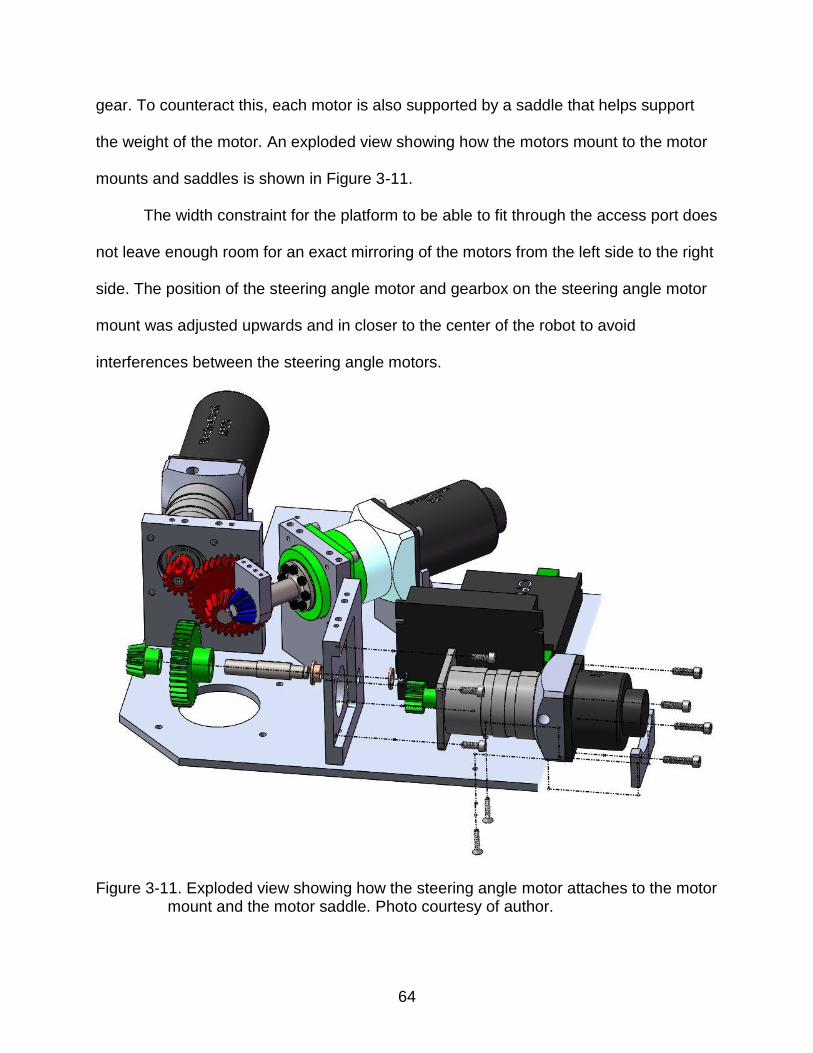
64
gear. To counteract this, each motor is also supported by a saddle that helps support
the weight of the motor. An exploded view showing how the motors mount to the motor
mounts and saddles is shown in Figure 3-11.
The width constraint for the platform to be able to fit through the access port does
not leave enough room for an exact mirroring of the motors from the left side to the right
side. The position of the steering angle motor and gearbox on the steering angle motor
mount was adjusted upwards and in closer to the center of the robot to avoid
interferences between the steering angle motors.
Figure 3-11. Exploded view showing how the steering angle motor attaches to the motor mount and the motor saddle. Photo courtesy of author.

65
Figure 3-12. View of the motors in the rear of the body, showing the offset between the steering angle motors in the middle. Photo courtesy of author.
Drive Assembly
The drive assembly redirects the actuation motion from the body to the outputs. It
consists of three concentric shafts. The innermost shaft actuates the wheels, and is
named the “vertical wheel shaft”. The middle shaft actuates the flipper, and is named
the “vertical flipper shaft”. The outer shaft actuates the steering angle, and is named the
“steering angle shaft”. Motion is input into this assembly through the bevel gears at the
top. A key for each gear ensures positive mechanical engagement between each gear
and the shaft that it rotates. Flanged bushings allow for relative motion between the
shafts, and provide a surface for the bevel gears to sit on. At the bottom of the
assembly, the redirection box houses a pair of nested miter gears that redirect motion
for the flipper and wheels out to the flipper drive shaft and the long wheel shaft,
respectively. The steering angle vertical shaft bolts to the top of the redirection box,
allowing it to rotate the redirection box and flipper to adjust the steering angle.
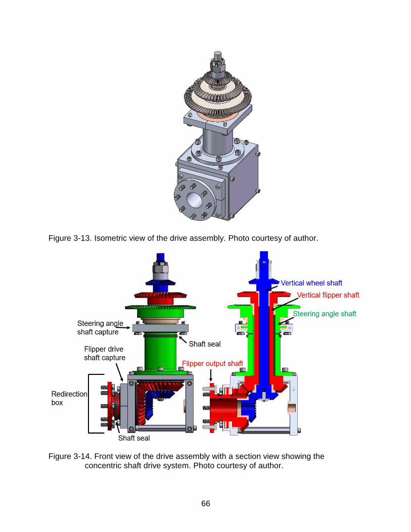
66
Figure 3-13. Isometric view of the drive assembly. Photo courtesy of author.
Figure 3-14. Front view of the drive assembly with a section view showing the concentric shaft drive system. Photo courtesy of author.

67
The steering angle shaft is held in place axially by a flange on the shaft. Two
“steering angle shaft capture” parts wrap around the flange and are secured to the main
body with hex head sealing screws. Thrust bushings are placed above and below the
flange inside the shaft captures to provide running surfaces for the shaft. To install the
thrust bushing below the flange on the shaft, two thrust bushing halves are joined
together. This captures the flange between the body and the shaft captures, preventing
the steering angle shaft from moving axially. A shaft seal on the steering angle vertical
shaft prevents liquid and contaminants from entering the body assembly at the interface
between the shaft and the shaft captures. RTV silicone is applied between the shaft
captures and the body to prevent water intrusion through the mating surfaces into the
body.
Figure 3-15. Top view of the drive assembly with the steering angle shaft capture exploded. Photo courtesy of author.

68
The top of the vertical wheel shaft has a shoulder that sits against a tapered
roller bearing. The bearing takes the vertical load and the moment load of the vertical
wheel shaft. In order to prevent the bevel gear at the top of the vertical wheel shaft from
moving upward, a castle nut, which is kept from loosening by a pin through the shaft,
applies a downward force on plastic spacer, which applies a downward force on the
bevel gear. This gear sits on the flange of a bushing, which allows it to rotate relative to
the vertical flipper shaft, and takes the axial load from the gear. This bushing flange also
prevents the vertical flipper shaft from moving upwards relative to the vertical wheel
shaft.
The bevel gear at the top of the vertical flipper shaft sits on the flange of a
bushing that in turn sits on the top of the steering angle shaft, which prevents this gear
from moving axially downwards. The gear has a set screw that bites into the vertical
flipper shaft. Because the vertical flipper shaft can not move upward, this gear is also
secured from moving upward. The gear then prevents the vertical flipper shaft from
moving downwards. The bevel gear at the top of the steering angle sits on the flange of
a bushing, which in turn rests on the motor mounting plate in the body assembly.
The structure of the box at the bottom of the assembly is from three aluminum
parts that form a U. To strengthen the box, two hexagonal shafts reinforce the bottom of
the U. The shafts thread into the outer plate, and have a tapped hole on the other side
so that a screw can join the inner plate and the hexagonal shaft. Hexagonal shafts were
chosen so that a wrench could be used to hold them and apply a twist during
installation. Blind tapped holes are used on the outer plate to aid with sealing.

69
Figure 3-16. Exploded view of the top of the drive assembly. Photo courtesy of author.
In order to allow for precise alignment between miter gear pairs, 3/16 inch dowel
pins are used to align the side plates relative to the top plate. The top plate has blind pin
holes so that the sealed cavity is not punctured again. A plastic shield fits over the open
sides of the box in order to seal it. The shield is screwed onto the side plates with 10-24
socket head sealing cap screws, and RTV silicone is applied to seal all of the interfaces
where there is contact between the plates or the shield or the steering angle shaft. All of
the screws used on the drive assembly are sealing screws to prevent liquid from
entering the assembly. Hex head screws would be more resistant to being filled with

70
mud, and are used on the flipper assembly for this reason. In order to differentiate the
number 8 screws used in the flipper assembly from the number 10 screws used in the
drive assembly, all the flipper screws are number 8 stainless steel hex head screws,
and all of the number 10 screws on the drive assembly are stainless steel socket head
cap screws. The hex heads were used on the flipper assembly because it will be in
closer contact with the mud than the drive assembly will be. The ¼-20 screws on the
drive assembly, that is, the screws that attach the steering angle shaft captures to the
body, and that attach the flipper drive shaft to the flipper, are stainless steel hex head
sealing screws.
Figure 3-17. The structure of the redirection box with an exploded view showing how the individual components fit together. Photo courtesy of author.
The top plate of the redirection box has a bolt circle that secures the bottom
flange of the steering angle shaft to the redirection box. The top plate also houses a
sleeve bushing to allow the larger miter gear to rotate relative to the plate. The inside
plate holds a flanged bushing that captures the axial and radial forces of the long wheel

71
shaft. The outer plate holds a sleeve bushing that allows the output miter gear to rotate
relative to the plate and drive the flipper drive shaft. A clearance hole in the outer plate
allows the flipper drive shaft to rotate freely. Similarly to the steering angle shaft, a
flange on the flipper drive shaft is captured by two flipper drive shaft captures to prevent
axial motion of the flipper drive shaft. A shaft seal on the flipper drive shaft prevents
liquid or contaminants from entering the box at the interface between the shaft and the
shaft captures.
Figure 3-18. Exploded view of the bottom of the drive assembly. Photo courtesy of author.
The axial force of the outer miter gears is supported by needle roller bearings.
These bearings are sandwiched between hardened steel washers to provide a hard
surface for the bearings to run on. Shims are built into the design underneath the

72
washers so that adjustments can be made to account for assembly tolerances. The
inner pair of miter gears sit in flanged bushings that take the radial and axial loads.
Shims are incorporated between the gear and the bushing flange. A circular pocket on
the outer plate provides a recess for the needle bearing, washers and shims to sit so
that the output miter gears can be located at the appropriate mounting distance.
Axial motion of the vertical miter gears is prevented by a screw that threads into
a tapped hole in the bottom of the vertical wheel shaft. This screw clamps a plastic
spacer that captures the wheel miter gear and compresses it against the flanged
bushing, which in turn compresses the flipper miter gear against the roller bearing.
Figure 3-19. Alternate exploded view of the drive assembly. Photo courtesy of author.

73
Figure 3-20. Close-up section view of the redirection box. Photo courtesy of author.
The steering angle shaft and the flipper drive shaft both experience high
stress on their flange that is used to rotate the redirection box and the flipper,
respectively. The stress at each clearance hole on the flange of both shafts is expected
to be 35 ksi. 6061-T6 aluminum has a yield strength of 40 ksi. In order to have a higher
factor of safety relative to the yield strength, 7075-T6 aluminum, which has a yield
strength of 60 ksi, was used for these parts.
Flipper Assembly
The flipper assembly acts as an appendage that allows the robot to elevate its
body, and to paddle through the mud. It also houses the end of the wheel actuation
system. The main component of the flipper is the flipper shell, which provides the

74
structural strength for the assembly, and houses a chain drive system to drive the distal
wheel. A lid fits on the outside of the flipper shell to protect all of the internal
components. Both the flipper shell and lid are made from 6061-T6 aluminum. Two steel
shafts drive the wheels. These shafts are press fit and welded to hubs that are bolted to
the wheels with stainless steel 5/16th inch bolts and nuts. The shafts and hubs are both
fabricated from 4140 steel. The wheels are 10 inches in diameter, and have an
aggressive tread to help the robot navigate through the mud. This wheel diameter was
chosen because it was the largest size that would still allow the robot to fit through the
access port. A center distance of 11.25 inches between the wheel shafts was chosen to
allow space between the wheels so that a rock or other object would not get caught
between the wheels, because the experimental torque testing in the mud pit showed
that the wheels tend to pick up mud.
Figure 3-21. Two views of the flipper subassembly. Photo courtesy of author.

75
The width of the flipper assembly is especially important, because the ability of
the robot to reduce its cross section area to fit through the access port is dependent on
the flipper assemblies being thin enough to rotate 180 degrees inward without
interfering with each other. Due to this constraint, one of the main design parameters
that drove the design of the flipper assembly was minimizing its width. Additionally, the
flipper needs to be sealed. Because the flipper is the closest assembly of the robot to
the ground, it will be exposed to liquid more frequency, and has a higher chance of
being submerged. Shaft seals on the wheel shafts keep water and contaminants from
entering the assembly at the interface between the shaft and the lid, and an o-ring in the
flipper shell prevents liquid intrusion at the interface between the flipper shell and the lid.
The flippers are put under a large amount of stress when supporting the robot, so
bending strength is critical. In order to make a stronger part and reduce the surfaces
that need to be sealed, the flipper shell is made from one monolithic part. A bolt circle of
eight ¼-20 sealing screws attaches the flipper shell to the flipper drive shaft, which is
the outer of the two output shafts on the drive assembly. At the center of this bolt circle
in the flipper shell is a hole through which the long wheel shaft fits into the redirection
box of the drive assembly, where it is driven by the inner pair of nested bevel gears. The
distal wheel shaft is named the “short wheel shaft”, and has a step that seats in a
flanged bushing which fits into a blind hole in the flipper shell (Figure 3-22).
A pattern of 8-32 tapped holes around the perimeter of the flipper shell allows for
the lid to be attached with screws and put consistent, adequate pressure on the o-ring.
The screws used to secure the lid to the flipper shell are number 8 hex head stainless
steel screws. Hex head bolts were chosen because this assembly is exposed the most

76
to the mud, and hex head bolts will not fill up with mud like socket head cap screws
would. This assembly exclusively uses hex head screws, while the drive assembly
primarily uses socket head cap screws.
Figure 3-22. Exploded view of the distal end of the flipper assembly. Photo courtesy of author.
Figure 3-23. View of the internal components of the flipper. Photo courtesy of author.
The lid is also one monolithic aluminum part, with a boss that houses the
bushings for the wheel shafts. Bushings for both wheel shafts are press fit into the lid.
The boss pattern on the lid acts to stiffen it and prevent bending, so that the wheel

77
shafts remain horizontal, and the pressure on the o-ring is consistent around the
perimeter of the o-ring.
Both wheels are driven so that the robot can be articulated with the wheels at any
flipper angle. This is accomplished through a chain drive. A roller chain drive was
chosen instead of a belt drive due to its higher load carrying capacity and smaller width.
The chain is ANSI trade size 35, and was chosen as a compromise between size and
working load rating. The working load of the chain is given as 190 lbs by the
manufacturer [21]. At the maximum speed operating point, the working load is 86.58
pounds. At the peak torque operating point, the working load is 263 pounds, which
technically exceeds the chain’s specified working load. A size 40 chain, the next largest
chain size, has a working load higher than any of these points, but is significantly larger
than a size 35 chain, and the flipper size required to accommodate a size 40 chain
would result in interferences when the flippers rotated 180 degrees. Size 35 chain has a
tensile strength of 2,100 pounds [22], so having momentary working loads up to 263
pounds is acceptable, as it still leaves a large factor of safety relative to failure.
In order to attenuate chain stretch, a tensioner was added to keep the chain tight
on the sprockets, and minimize backlash when reversing direction. The tensioner is
made from ultra-high molecular weight polyethylene (UHMWPE), selected for its low
friction and high toughness, which will allow it to stand up to wear well. The tensioner
has walls on each side to prevent the chain from slipping out, and a gentle hump in the
middle to minimize friction. As the robot will be deployed in locations where it cannot be
serviced, the tensioner is held in place with a spring so that it is self-adjusting. One side
of the spring is held at the midpoint of the flipper shell with a round head screw, while
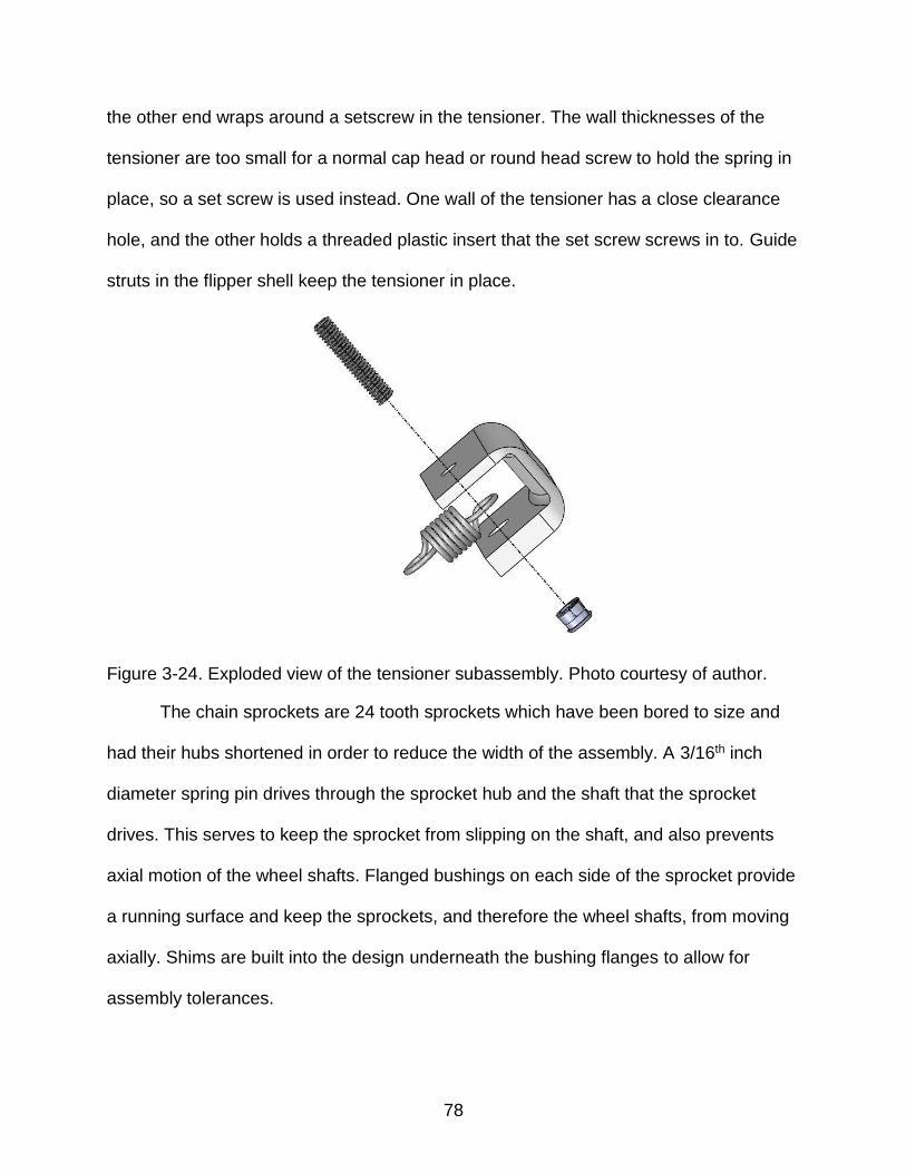
78
the other end wraps around a setscrew in the tensioner. The wall thicknesses of the
tensioner are too small for a normal cap head or round head screw to hold the spring in
place, so a set screw is used instead. One wall of the tensioner has a close clearance
hole, and the other holds a threaded plastic insert that the set screw screws in to. Guide
struts in the flipper shell keep the tensioner in place.
Figure 3-24. Exploded view of the tensioner subassembly. Photo courtesy of author.
The chain sprockets are 24 tooth sprockets which have been bored to size and
had their hubs shortened in order to reduce the width of the assembly. A 3/16th inch
diameter spring pin drives through the sprocket hub and the shaft that the sprocket
drives. This serves to keep the sprocket from slipping on the shaft, and also prevents
axial motion of the wheel shafts. Flanged bushings on each side of the sprocket provide
a running surface and keep the sprockets, and therefore the wheel shafts, from moving
axially. Shims are built into the design underneath the bushing flanges to allow for
assembly tolerances.

79
Figure 3-25. Exploded view of the flipper assembly. Photo courtesy of author.

80
CHAPTER 4 CONCLUSIONS AND FUTURE WORK
This paper outlines the design of a mobile platform that can be deployed as a
remote inspection robot in a variety of situations, including for inspections of the H
Canyon exhaust tunnel at the Savannah River Site. The mobile platform is designed to
withstand an operating environment like the exhaust tunnel that has 30 mile per hour
winds, radiation, and nitric acid present. The platform is specifically built to have a very
high degree of mobility so that it can traverse very difficult terrain, including the mud and
standing water present in the exhaust tunnel. The mobility of this platform allows it to
move through small spaces, including the 30 inch diameter access port into the exhaust
tunnel (Figure 4-1). The length of the body is 40 inches, which is short enough for the
crane to lift above the access port for deployment into the tunnel. The aluminum
skeleton in the body assembly provides a strong structure that a mounting point for the
crane can be attached to, and also provides a base that a manipulator arm and sensors
can be mounted to. The mobile platform also met weight and cost goals. According to
the CAD model, the platform will weigh 180 pounds. Equipment and manufacturing
costs for the prototype are expected to be $40,000.
Future work will include building the system at full scale and integrating it with
sensors and a manipulator arm developed at the University of Texas at Austin, as well
as a miniature inspection unit developed at Florida International University. The system
will be tested in a mockup of the exhaust tunnel that has been developed at the
University of Texas at Austin. The system will then be demonstrated to H Canyon
personnel for evaluation and integration into upcoming inspections.

81
Figure 4-1. Top-down view of the mobile platform deploying into the H-Canyon exhaust tunnel with a manipulator arm mounted to the top of the platform. Photo courtesy of author.
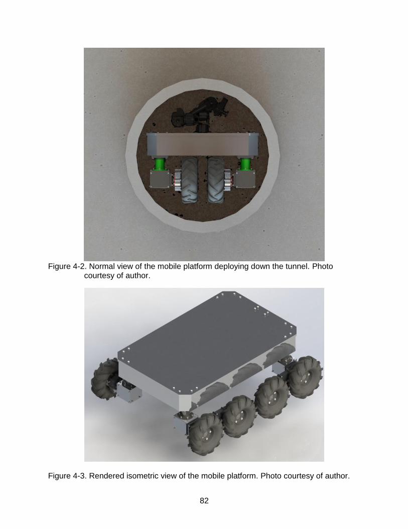
82
Figure 4-2. Normal view of the mobile platform deploying down the tunnel. Photo
courtesy of author.
Figure 4-3. Rendered isometric view of the mobile platform. Photo courtesy of author.

83
LIST OF REFERENCES
[1] “Nuclear Power Plant Optimization Strategy.” International Atomic Energy Agency, Vienna, Austria, 2002.
[2] R. Cheng, “The Fukushima meltdown is way too hot for humans,” CNET, 07-Mar-2019. [Online]. Available: https://www.cnet.com/news/at-fukushimas-nuclear-disaster-robots-are-just-now-attacking-the-radiation-problem/. [Accessed: 07-Mar-2019].
[3] D. P. Speaker and N. B. Hall, “Advancing the Survivability of Unmanned Systems in High Radiation Environments,” in American Nuclear Society Winter Meeting 2018, 2018, pp. 1343–1346.
[4] P. J. Lewis, N. Flann, M. R. Torrie, E. A. Poulson, T. Petroff, and G. Witus, “Chaos, an intelligent ultra-mobile SUGV: combining the mobility of wheels, tracks, and legs,” Unmanned Ground Vehicle Technology VII, 2005.
[5] “Chaos High Mobility Robot.” Autonomous Solutions, Inc., Petersboro, Utah.
[6] E. Guizzo, “Fukushima Robot Operator Writes Tell-All Blog,” IEEE Spectrum: Technology, Engineering, and Science News, 23-Aug-2011. [Online]. Available: https://spectrum.ieee.org/automaton/robotics/industrial-robots/fukushima-robot-operator-diaries. [Accessed: 07-Mar-2019].
[7] “Facts From the Savannah River Site: Savannah River Site,” Savannah River Site.
[8] “Facts From the Savannah River Site: H Canyon,” Savannah River Site.
[9] “H-Canyon Recovery Crawler,” OSTI. Office of Scientific and Technical Information, Aug-2015.
[10] B. Giddings, J. Carter, E. Kriikku, S. Carey, and J. Ray, “H-Canyon Ventilation System Exhaust Tunnel Inspection at the Savannah River Site,” in Waste Management 2018 Conference.
[11] E. Kriikku, “H-Canyon Exhaust Tunnel Requirements.” 11-Sep-2015.
[12] C. D. Crane III and D. S. Haukoos, “Hybrid Robotic Vehicle,” 18-Dec-1990.
[13] B. Giddings, “H-Canyon tunnel inspection robot speeds,” H-Canyon tunnel inspection robot speeds.
[14] “Going Where No Man Can Go,” OSTI. Office of Scientific and Technical Information, 2003.
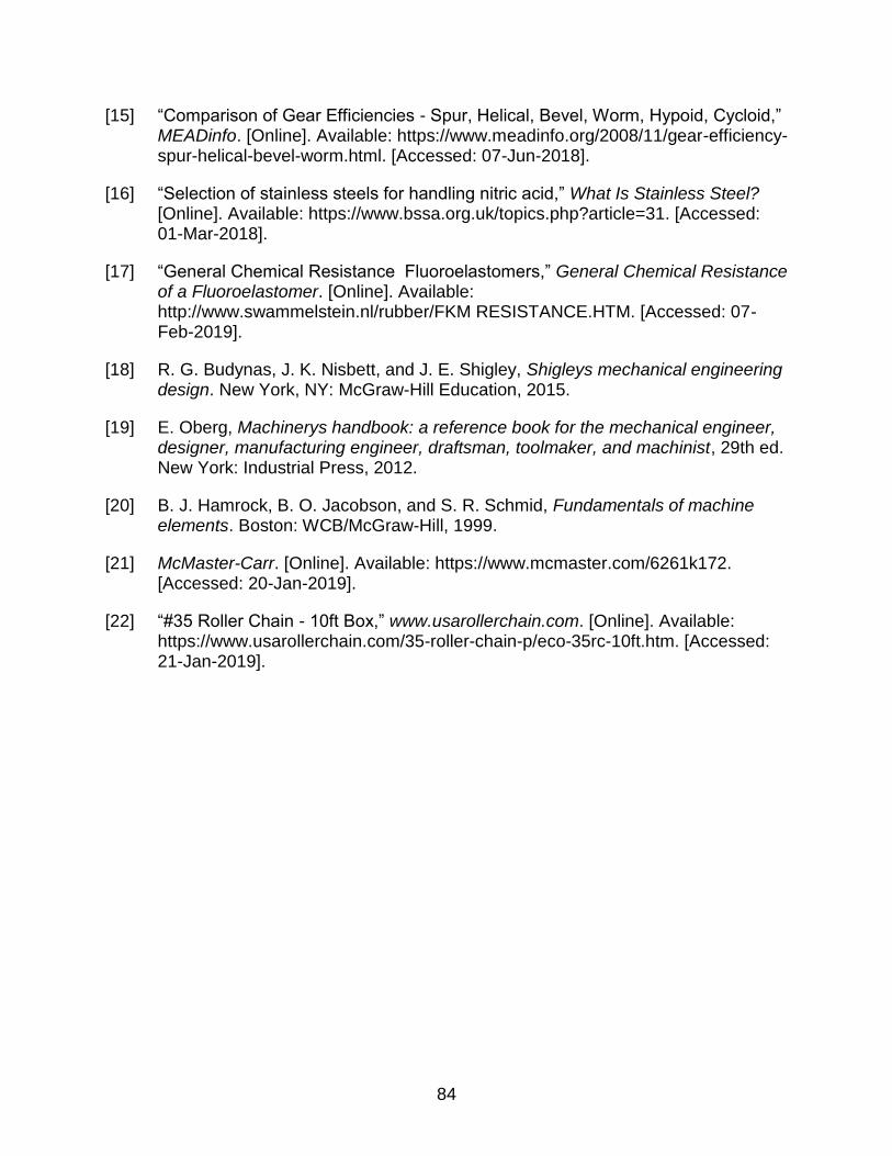
84
[15] “Comparison of Gear Efficiencies - Spur, Helical, Bevel, Worm, Hypoid, Cycloid,” MEADinfo. [Online]. Available: https://www.meadinfo.org/2008/11/gear-efficiency-spur-helical-bevel-worm.html. [Accessed: 07-Jun-2018].
[16] “Selection of stainless steels for handling nitric acid,” What Is Stainless Steel? [Online]. Available: https://www.bssa.org.uk/topics.php?article=31. [Accessed: 01-Mar-2018].
[17] “General Chemical Resistance Fluoroelastomers,” General Chemical Resistance of a Fluoroelastomer. [Online]. Available: http://www.swammelstein.nl/rubber/FKM RESISTANCE.HTM. [Accessed: 07-Feb-2019].
[18] R. G. Budynas, J. K. Nisbett, and J. E. Shigley, Shigleys mechanical engineering design. New York, NY: McGraw-Hill Education, 2015.
[19] E. Oberg, Machinerys handbook: a reference book for the mechanical engineer, designer, manufacturing engineer, draftsman, toolmaker, and machinist, 29th ed. New York: Industrial Press, 2012.
[20] B. J. Hamrock, B. O. Jacobson, and S. R. Schmid, Fundamentals of machine elements. Boston: WCB/McGraw-Hill, 1999.
[21] McMaster-Carr. [Online]. Available: https://www.mcmaster.com/6261k172. [Accessed: 20-Jan-2019].
[22] “#35 Roller Chain - 10ft Box,” www.usarollerchain.com. [Online]. Available: https://www.usarollerchain.com/35-roller-chain-p/eco-35rc-10ft.htm. [Accessed: 21-Jan-2019].

85
BIOGRAPHICAL SKETCH
Tim Williams received his Bachelor of Science in mechanical engineering and his
Bachelor of Music from the University of Florida in 2017. He worked in the Center for
Intelligent Machines and Robotics laboratory in the Department of Mechanical and
Aerospace Engineering at the University of Florida from 2014 to 2019, where he
managed the Rapid Prototyping Facility for the department and served as a member of
the Navigator Autonomous Boat team, which won first place in international competition.
He received his Master of Science in mechanical engineering from UF in 2019.