Embed Size (px)
Citation preview

2005 Pearson Education South Asia Pte Ltd
1. Stress
1.5 AVERAGE SHEAR STRESS
• Shear stress is the stress component that act in the plane of the sectioned area.
• Consider a force F acting to the bar• For rigid supports, and F is large enough,
bar will deform and fail along the planes identified by AB and CD
• Free-body diagram indicates that shear force, V = F/2 be applied at both sections to ensure equilibrium
2005 Pearson Education South Asia Pte Ltd
1. Stress
1.5 AVERAGE SHEAR STRESS
Average shear stress over each section is:
τavg = average shear stress at section, assumed to be same at each pt on the section
V = internal resultant shear force at section determined from equations of equilibrium
A = area of section
PA
τavg =
2005 Pearson Education South Asia Pte Ltd
1. Stress
1.5 AVERAGE SHEAR STRESS
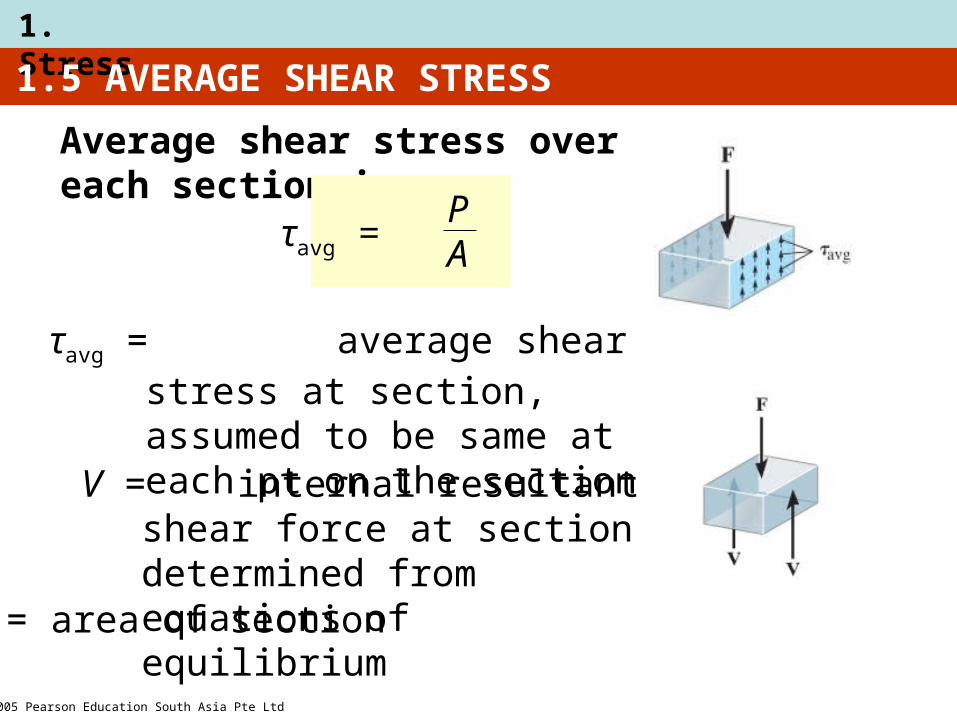
• Case discussed above is example of simple or direct shear
• Caused by the direct action of applied load F• Occurs in various types of simple connections,
e.g., bolts, pins, welded material
2005 Pearson Education South Asia Pte Ltd
1. Stress
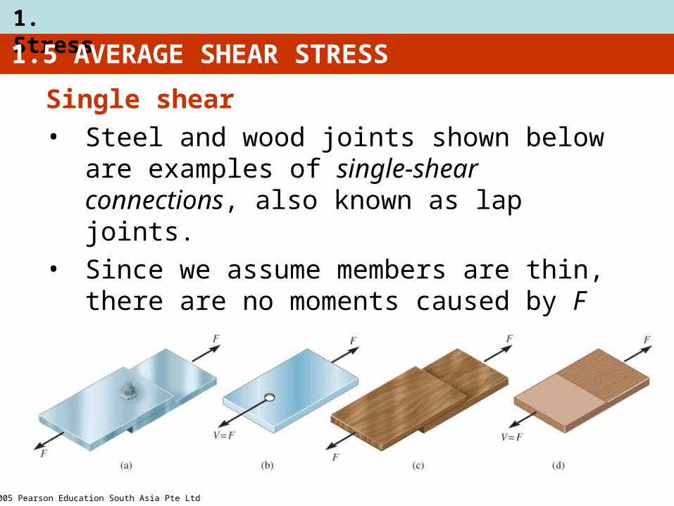
Single shear• Steel and wood joints shown below are
examples of single-shear connections, also known as lap joints.
• Since we assume members are thin, there are no moments caused by F
1.5 AVERAGE SHEAR STRESS
2005 Pearson Education South Asia Pte Ltd
1. Stress
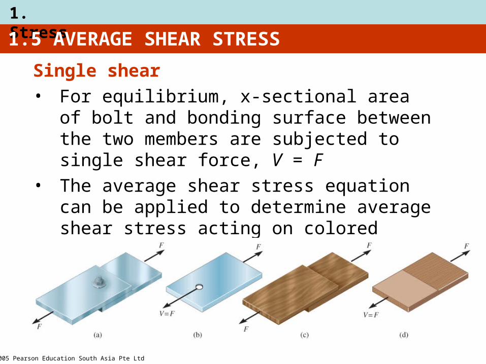
Single shear• For equilibrium, x-sectional area of bolt and
bonding surface between the two members are subjected to single shear force, V = F
• The average shear stress equation can be applied to determine average shear stress acting on colored section in (d).
1.5 AVERAGE SHEAR STRESS

2005 Pearson Education South Asia Pte Ltd
1. Stress
1.5 AVERAGE SHEAR STRESS
Double shear • The joints shown below are examples of
double-shear connections, often called double lap joints.
• For equilibrium, x-sectional area of bolt and bonding surface between two members subjected to double shear force, V = F/2
• Apply average shear stress equation to determine average shear stress acting on colored section in (d).
2005 Pearson Education South Asia Pte Ltd
1. Stress
1.5 AVERAGE SHEAR STRESS
Procedure for analysis
Internal shear
1. Section member at the pt where the τavg is to be determined
2. Draw free-body diagram
3. Calculate the internal shear force V
Average shear stress
1. Determine sectioned area A
2. Compute average shear stress τavg = V/A

2005 Pearson Education South Asia Pte Ltd
1. Stress
EXAMPLE 1.10
Depth and thickness = 40 mm
Determine average normal stress and average shear stress acting along (a) section planes a-a, and (b) section plane b-b.
2005 Pearson Education South Asia Pte Ltd
1. Stress
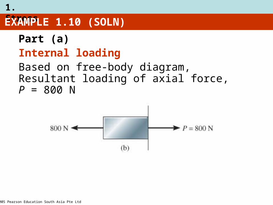
EXAMPLE 1.10 (SOLN)
Part (a)Internal loadingBased on free-body diagram, Resultant loading of axial force, P = 800 N

2005 Pearson Education South Asia Pte Ltd
1. Stress
EXAMPLE 1.10 (SOLN)
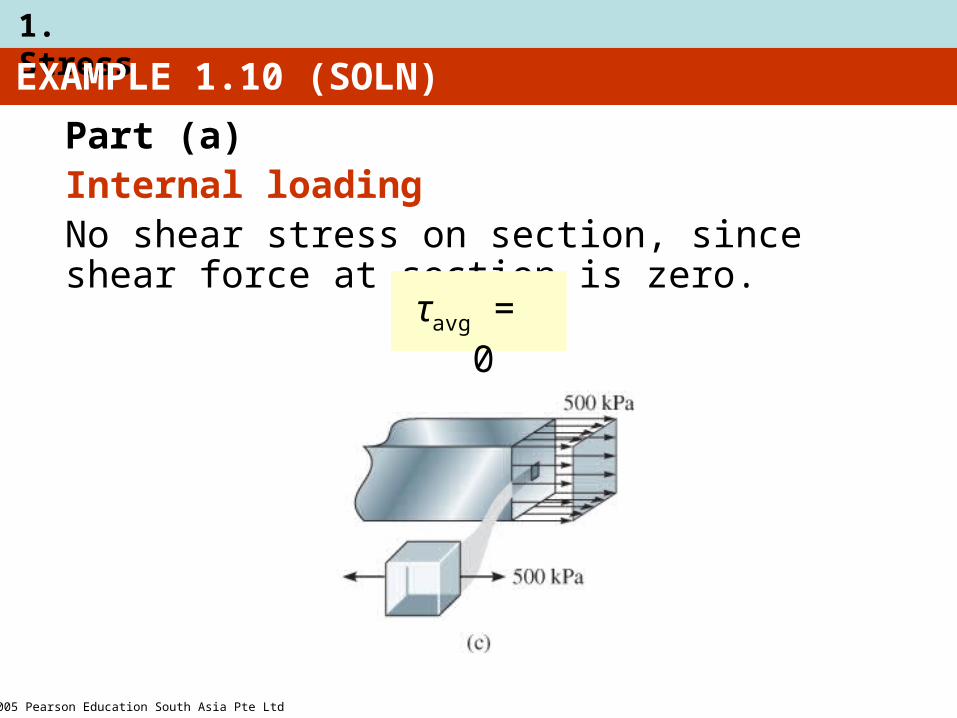
Part (a)Average stress
Average normal stress, σ
σ = P
A
800 N
(0.04 m)(0.04 m)= 500 kPa =
2005 Pearson Education South Asia Pte Ltd
1. Stress
EXAMPLE 1.10 (SOLN)
Part (a)Internal loadingNo shear stress on section, since shear force at section is zero.
τavg = 0
2005 Pearson Education South Asia Pte Ltd
1. Stress
EXAMPLE 1.10 (SOLN)
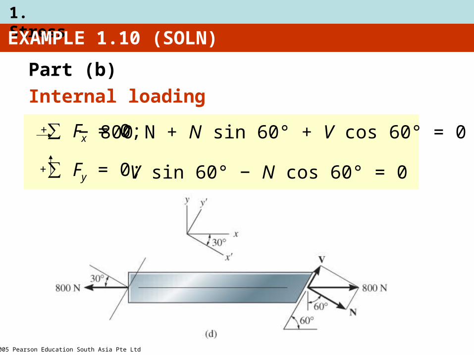
Part (b)
Internal loading
+
∑ Fx = 0; − 800 N + N sin 60° + V cos 60° = 0+
∑ Fy = 0; V sin 60° − N cos 60° = 0
2005 Pearson Education South Asia Pte Ltd
1. Stress
EXAMPLE 1.10 (SOLN)
Part (b)
Internal loading
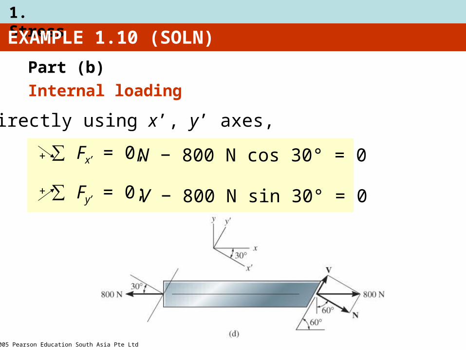
Or directly using x’, y’ axes,
∑ Fx’ = 0;
∑ Fy’ = 0;
+
+
N − 800 N cos 30° = 0
V − 800 N sin 30° = 0

2005 Pearson Education South Asia Pte Ltd
1. Stress
EXAMPLE 1.10 (SOLN)
Part (b)
Average normal stress
σ = N
A 692.8 N
(0.04 m)(0.04 m/sin 60°) = 375 kPa =
2005 Pearson Education South Asia Pte Ltd
1. Stress
EXAMPLE 1.10 (SOLN)
Part (b)
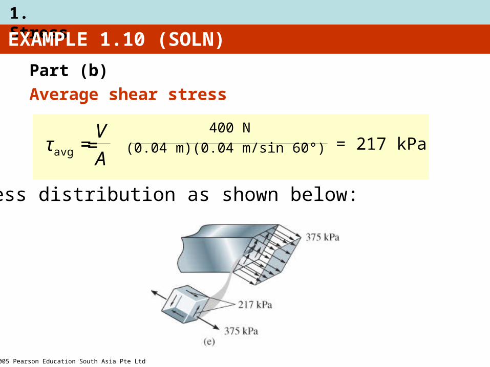
Average shear stress
τavg = V
A
400 N
(0.04 m)(0.04 m/sin 60°) = 217 kPa =
Stress distribution as shown below:
2005 Pearson Education South Asia Pte Ltd
1. Stress
1.6 ALLOWABLE STRESS
• When designing a structural member or mechanical element, the stress in it must be restricted to safe level
• Choose an allowable load that is less than the load the member can fully support
• One method used is the factor of safety (F.S.)
F.S. = Ffail
Fallow
2005 Pearson Education South Asia Pte Ltd
1. Stress
1.6 ALLOWABLE STRESS
• If load applied is linearly related to stress developed within member, then F.S. can also be expressed as:
F.S. = σfail
σallow
F.S. = τfail
τallow
• In all the equations, F.S. is chosen to be greater than 1, to avoid potential for failure
• Specific values will depend on types of material used and its intended purpose
2005 Pearson Education South Asia Pte Ltd
1. Stress
1.7 DESIGN OF SIMPLE CONNECTIONS
• To determine area of section subjected to a normal force, use
A = P
σallow
A = V
τallow
• To determine area of section subjected to a shear force, use

2005 Pearson Education South Asia Pte Ltd
1. Stress
1.7 DESIGN OF SIMPLE CONNECTIONS
Cross-sectional area of a tension member
Condition:
The force has a line of action that passes through the centroid of the x-section.

2005 Pearson Education South Asia Pte Ltd
1. Stress
1.7 DESIGN OF SIMPLE CONNECTIONS
Cross-sectional area of a connecter subjected to shear
Assumption:
If bolt is loose or clamping force of bolt is unknown, assume frictional force between plates to be negligible.

2005 Pearson Education South Asia Pte Ltd
1. Stress
Assumptions:
1. (σb)allow of concrete < (σb)allow of base plate
2. Bearing stress is uniformly distributed between plate and concrete
1.7 DESIGN OF SIMPLE CONNECTIONS
Required area to resist bearing• Bearing stress is normal stress produced by
the compression of one surface against another.
2005 Pearson Education South Asia Pte Ltd
1. Stress
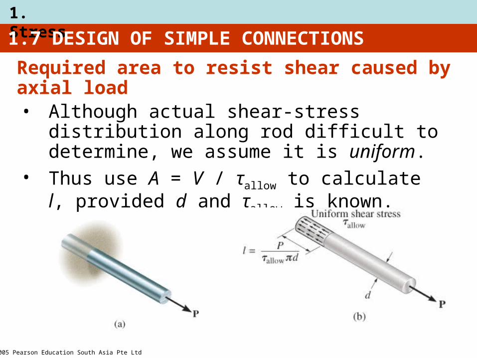
1.7 DESIGN OF SIMPLE CONNECTIONS
• Although actual shear-stress distribution along rod difficult to determine, we assume it is uniform.
• Thus use A = V / τallow to calculate l, provided d and τallow is known.
Required area to resist shear caused by axial load

2005 Pearson Education South Asia Pte Ltd
1. Stress
1.7 DESIGN OF SIMPLE CONNECTIONS
Procedure for analysis
When using average normal stress and shear stress equations, consider first the section over which the critical stress is acting
Internal loading
1. Section member through x-sectional area
2. Draw a free-body diagram of segment of member
3. Use equations of equilibrium to determine internal resultant force

2005 Pearson Education South Asia Pte Ltd
1. Stress
1.7 DESIGN OF SIMPLE CONNECTIONS
Procedure for analysis
Required area• Based on known allowable stress, calculate
required area needed to sustain load from A = P/τallow or A = V/τallow
2005 Pearson Education South Asia Pte Ltd
1. Stress
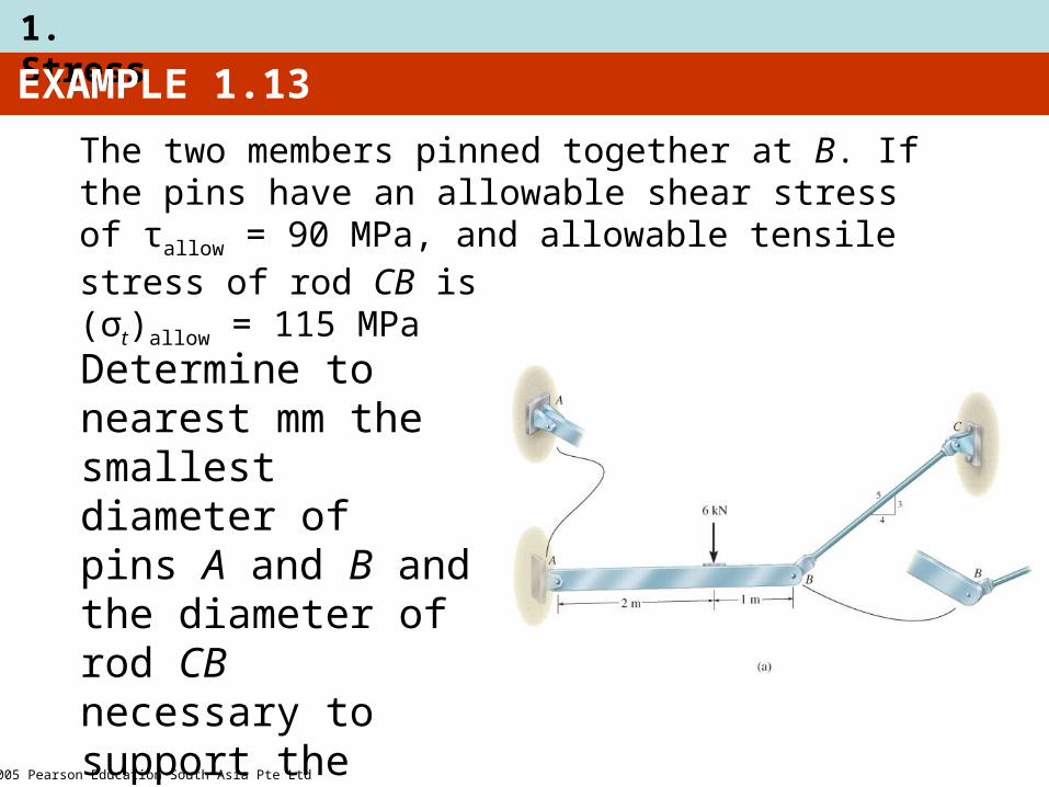
EXAMPLE 1.13
The two members pinned together at B. If the pins have an allowable shear stress of τallow = 90 MPa, and allowable tensile stress of rod CB is (σt)allow = 115 MPa
Determine to nearest mm the smallest diameter of pins A and B and the diameter of rod CB necessary to support the load.
2005 Pearson Education South Asia Pte Ltd
1. Stress
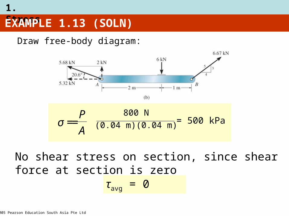
EXAMPLE 1.13 (SOLN)
Draw free-body diagram:
σ = P
A
800 N
(0.04 m)(0.04 m) = 500 kPa =
No shear stress on section, since shear force at section is zero
τavg = 0
2005 Pearson Education South Asia Pte Ltd
1. Stress
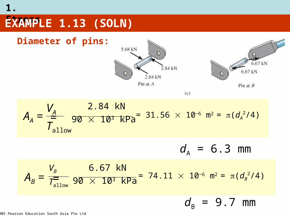
EXAMPLE 1.13 (SOLN)
Diameter of pins:
dA = 6.3 mm
AA =VA
Tallow
2.84 kN
90 103 kPa = = 31.56 10−6 m2 = (dA2/4)
dB = 9.7 mm
AB =VB
Tallow
6.67 kN
90 103 kPa = = 74.11 10−6 m2 = (dB2/4)
2005 Pearson Education South Asia Pte Ltd
1. Stress
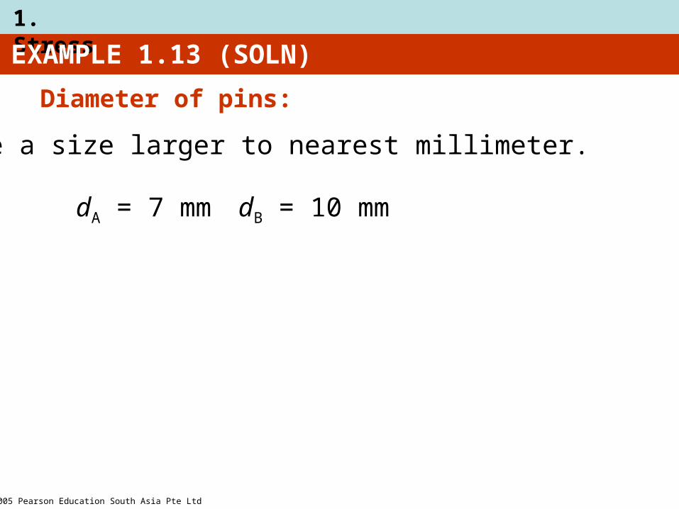
EXAMPLE 1.13 (SOLN)
Diameter of pins:
dA = 7 mm dB = 10 mm
Choose a size larger to nearest millimeter.
2005 Pearson Education South Asia Pte Ltd
1. Stress
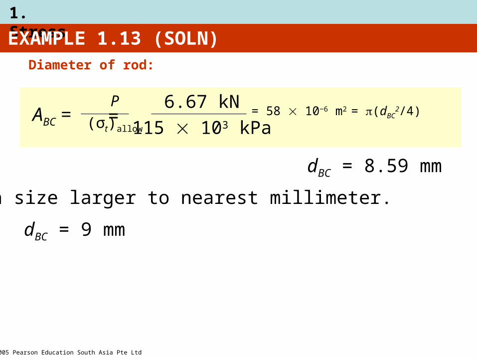
EXAMPLE 1.13 (SOLN)Diameter of rod:
dBC = 8.59 mm
ABC = P
(σt)allow
6.67 kN
115 103 kPa = = 58 10−6 m2 = (dBC
2/4)
dBC = 9 mm
Choose a size larger to nearest millimeter.
2005 Pearson Education South Asia Pte Ltd
1. Stress
CHAPTER REVIEW
• Internal loadings consist of
1. Normal force, N
2. Shear force, V
3. Bending moments, M
4. Torsional moments, T• Get the resultants using
1. method of sections
2. Equations of equilibrium
2005 Pearson Education South Asia Pte Ltd
1. Stress
CHAPTER REVIEW
• Assumptions for a uniform normal stress distribution over x-section of member (σ = P/A)
1. Member made from homogeneous isotropic material
2. Subjected to a series of external axial loads that,
3. The loads must pass through centroid of x-section

2005 Pearson Education South Asia Pte Ltd
1. Stress
CHAPTER REVIEW
• Determine average shear stress by using τ = V/A equation
– V is the resultant shear force on x-sectional area A
– Formula is used mostly to find average shear stress in fasteners or in parts for connections

2005 Pearson Education South Asia Pte Ltd
1. Stress
CHAPTER REVIEW
• Design of any simple connection requires that
– Average stress along any x-section not exceed a factor of safety (F.S.) or
– Allowable value of σallow or τallow
– These values are reported in codes or standards and are deemed safe on basis of experiments or through experience


![Shear stress-induced pathological changes in endothelial ... · 1/7/2020 · Fluid shear stress induced [Ca2 +]i overload is force and time dependent . Shear stress is a physiological](https://img.dokumen.tips/doc/110x75/606ea5e1c71f9c48290448a9/shear-stress-induced-pathological-changes-in-endothelial-172020-fluid-shear.jpg)