Embed Size (px)
Citation preview
© 2005 ANSYS, Inc.28 November 2005
ANSYS, Inc. ProprietaryL1-1
CFX-10 IntroductionCFX-10 Introduction
Lecture 1
© 2005 ANSYS, Inc. L1-2
28 November 2005
ANSYS, Inc. Proprietary
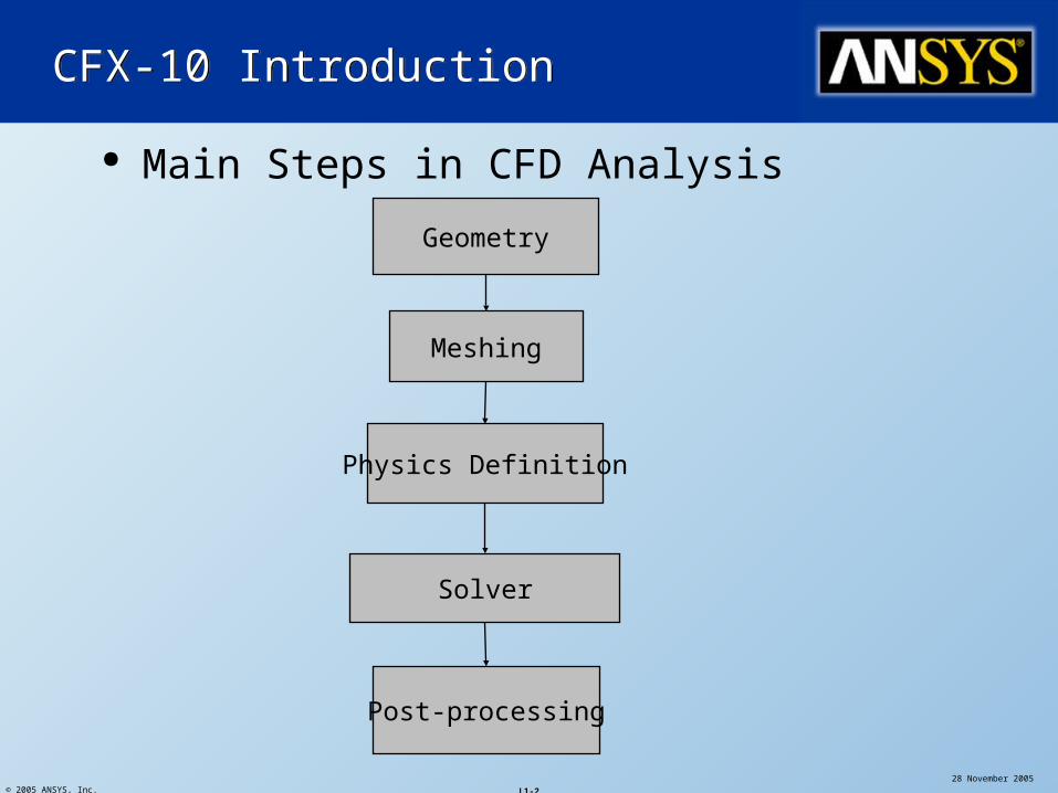
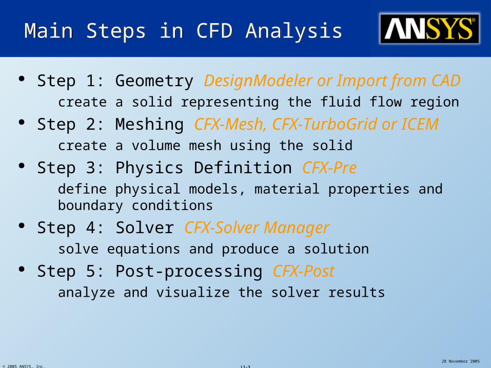
Main Steps in CFD Analysis
Geometry
Physics Definition
Solver
Post-processing
CFX-10 IntroductionCFX-10 Introduction
Meshing
© 2005 ANSYS, Inc. L1-3
28 November 2005
ANSYS, Inc. Proprietary
Step 1: Geometry DesignModeler or Import from CAD create a solid representing the fluid flow region
Step 2: Meshing CFX-Mesh, CFX-TurboGrid or ICEM create a volume mesh using the solid
Step 3: Physics Definition CFX-Pre define physical models, material properties and boundary conditions
Step 4: Solver CFX-Solver Manager solve equations and produce a solution
Step 5: Post-processing CFX-Post analyze and visualize the solver results
Main Steps in CFD AnalysisMain Steps in CFD Analysis
© 2005 ANSYS, Inc.28 November 2005
ANSYS, Inc. ProprietaryL1-4
Step 1: GeometryStep 1: Geometry
DesignModeler or CAD
© 2005 ANSYS, Inc. L1-5
28 November 2005
ANSYS, Inc. Proprietary
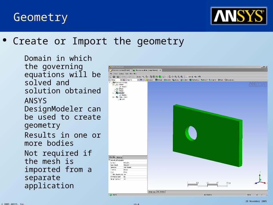
Create or Import the geometry
GeometryGeometry
Domain in which the governing equations will be solved and solution obtained
ANSYS DesignModeler can be used to create geometry
Results in one or more bodies
Not required if the mesh is imported from a separate application
© 2005 ANSYS, Inc.28 November 2005
ANSYS, Inc. ProprietaryL1-6
Step 2: MeshingStep 2: Meshing
CFX-Mesh, ICEM or CFX-TurboGrid
© 2005 ANSYS, Inc. L1-7
28 November 2005
ANSYS, Inc. Proprietary
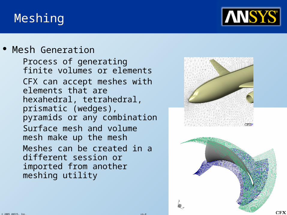
Mesh Generation Process of generating finite
volumes or elements CFX can accept meshes with
elements that are hexahedral, tetrahedral, prismatic (wedges), pyramids or any combination
Surface mesh and volume mesh make up the mesh
Meshes can be created in a different session or imported from another meshing utility
MeshingMeshing

© 2005 ANSYS, Inc.28 November 2005
ANSYS, Inc. ProprietaryL1-8
Step 3: Physics DefinitionStep 3: Physics Definition
CFX-Pre
© 2005 ANSYS, Inc. L1-9
28 November 2005
ANSYS, Inc. Proprietary
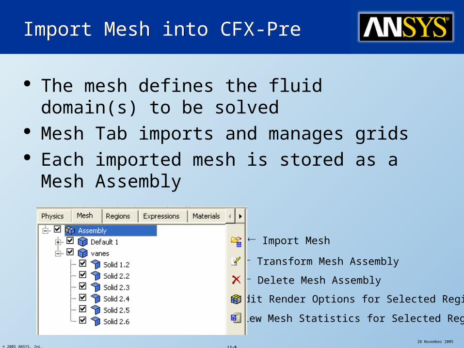
The mesh defines the fluid domain(s) to be solved
Mesh Tab imports and manages grids Each imported mesh is stored as a Mesh
Assembly
Import Mesh into CFX-PreImport Mesh into CFX-Pre
Import Mesh
View Mesh Statistics for Selected Regions
Transform Mesh Assembly
Delete Mesh Assembly
Edit Render Options for Selected Regions
© 2005 ANSYS, Inc. L1-10
28 November 2005
ANSYS, Inc. Proprietary
Create ToolbarCreate Toolbar
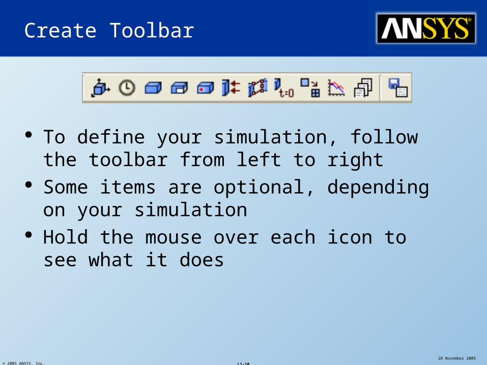
To define your simulation, follow the toolbar from left to right
Some items are optional, depending on your simulation
Hold the mouse over each icon to see what it does
© 2005 ANSYS, Inc. L1-11
28 November 2005
ANSYS, Inc. Proprietary
Create ToolbarCreate Toolbar
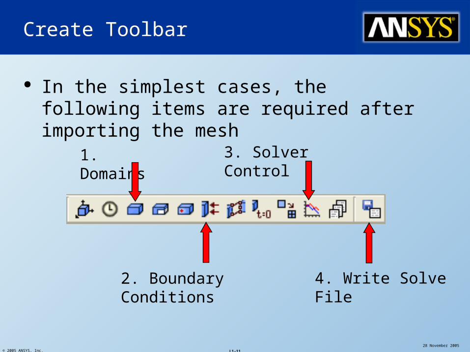
In the simplest cases, the following items are required after importing the mesh
1. Domains
2. Boundary Conditions
3. Solver Control
4. Write Solve File
© 2005 ANSYS, Inc. L1-12
28 November 2005
ANSYS, Inc. Proprietary
Create ToolbarCreate Toolbar
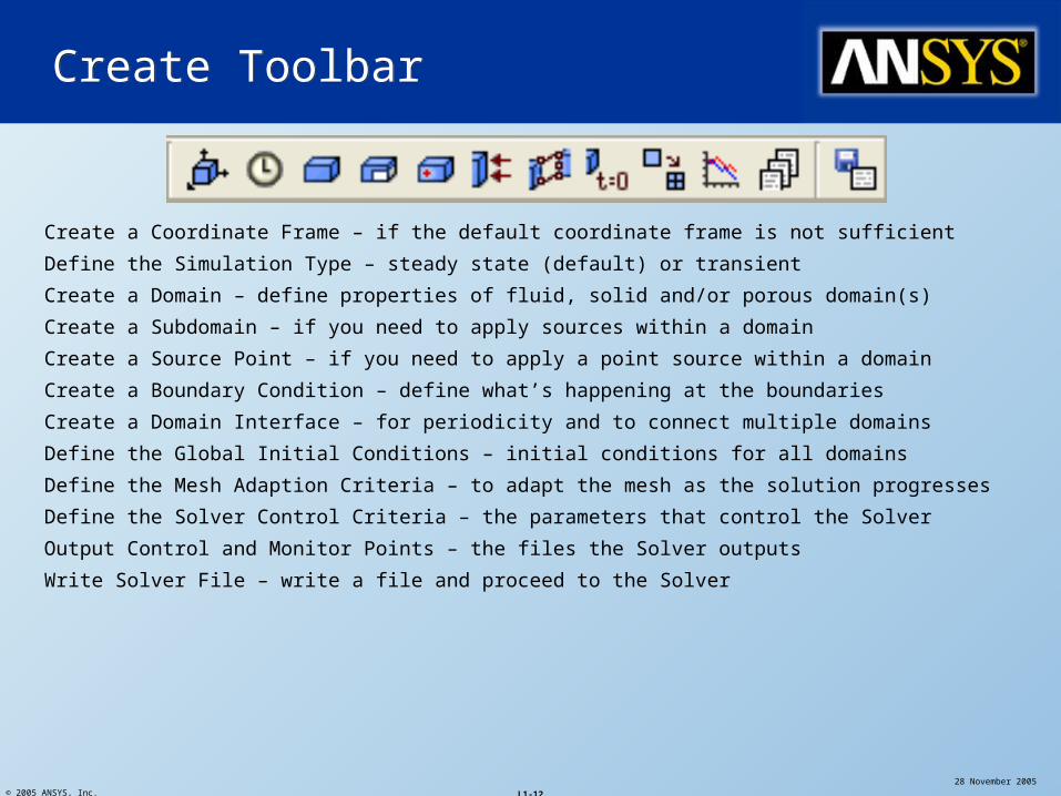
Create a Coordinate Frame – if the default coordinate frame is not sufficient
Define the Simulation Type – steady state (default) or transient
Create a Domain – define properties of fluid, solid and/or porous domain(s)
Create a Subdomain – if you need to apply sources within a domain
Create a Source Point – if you need to apply a point source within a domain
Create a Boundary Condition – define what’s happening at the boundaries
Create a Domain Interface – for periodicity and to connect multiple domains
Define the Global Initial Conditions – initial conditions for all domains
Define the Mesh Adaption Criteria – to adapt the mesh as the solution progresses
Define the Solver Control Criteria – the parameters that control the Solver
Output Control and Monitor Points – the files the Solver outputs
Write Solver File – write a file and proceed to the Solver
© 2005 ANSYS, Inc. L1-13
28 November 2005
ANSYS, Inc. Proprietary
DomainsDomains
Define the regions in which the equations are solved
Fluid, solid and porous regions Pick the fluid(s) or solid materials Select the physical models:
Turbulence and Heat Transfer model Buoyancy Multiphase models Combustion and Radiation models Particle Tracking ……
© 2005 ANSYS, Inc. L1-14
28 November 2005
ANSYS, Inc. Proprietary
Boundary Conditions are needed to completely specify (or close) the problem
Required on all external surfaces of geometry Boundary values can be constants or CEL
expressions A Default Boundary Condition is applied to external
surfaces which have not been explicitly defined created automatically for each domain
All mesh regions are available in CFX-Post, not just Boundary Conditions
Boundary ConditionsBoundary Conditions
© 2005 ANSYS, Inc. L1-15
28 November 2005
ANSYS, Inc. Proprietary
There are 5 general types of boundary conditions INLET: allow flow into the domain only OUTLET: allow flow out of the domain only OPENING: allow flow in and out of the domain WALL: no flow, normal velocity is zero SYMMETRY: flat surface specifying plane of
symmetry
Boundary ConditionsBoundary Conditions
© 2005 ANSYS, Inc. L1-16
28 November 2005
ANSYS, Inc. Proprietary
Control of the CFX-5 Solver is undertaken by the use of Solver Parameters, set on the Solver Control form Convergence Control
> maximum number of iterations> timescale selection
Advection Scheme Convergence criteria
> MAX or RMS residual> conservation target
Solver ControlSolver Control
© 2005 ANSYS, Inc. L1-17
28 November 2005
ANSYS, Inc. Proprietary
CFX-Pre writes out a “Definition” (.def) file to run in the Solver Contains everything needed (mesh and physics)
to run the simulation. CFX-Pre stores mesh data in the “Geometry,
Topology and Mesh” (.gtm) file and physics in the .cfx file Keep these files to re-open simulations in CFX-
Pre
Write Solver FileWrite Solver File
© 2005 ANSYS, Inc.28 November 2005
ANSYS, Inc. ProprietaryL1-18
Step 4: SolverStep 4: Solver
CFX-Solver Manager
© 2005 ANSYS, Inc. L1-19
28 November 2005
ANSYS, Inc. Proprietary
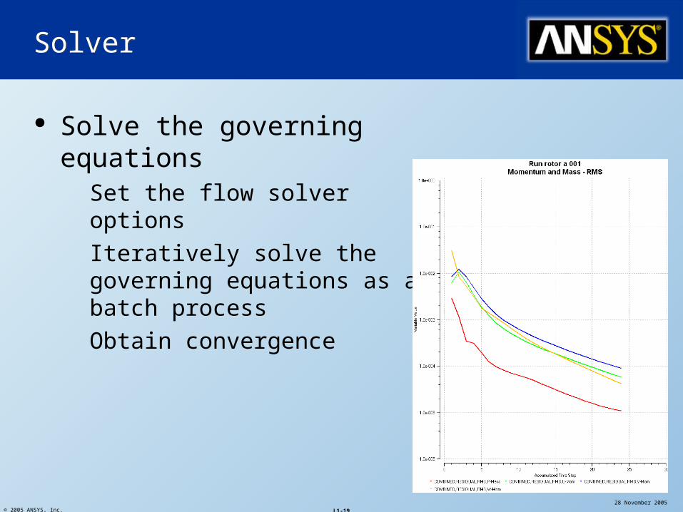
SolverSolver
Solve the governing equations Set the flow solver options Iteratively solve the governing
equations as a batch process Obtain convergence
© 2005 ANSYS, Inc. L1-20
28 November 2005
ANSYS, Inc. Proprietary
The Solver Manager is primarily used to: start a new calculation, or set up multiple runs restart a calculation from an earlier solution examine the problem information set up parallel runs monitor residuals, global balances, monitor
points, expressions, etc.
Solver ManagerSolver Manager
© 2005 ANSYS, Inc.28 November 2005
ANSYS, Inc. ProprietaryL1-21
Step 5: Post-processingStep 5: Post-processing
CFX-Post
© 2005 ANSYS, Inc. L1-22
28 November 2005
ANSYS, Inc. Proprietary
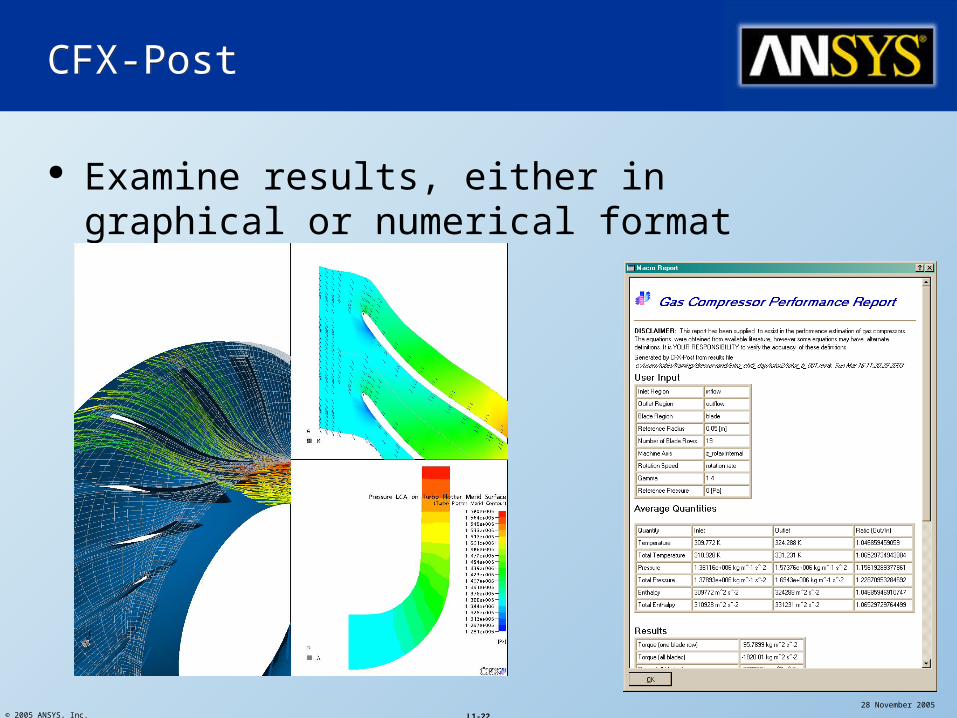
CFX-PostCFX-Post
Examine results, either in graphical or numerical format
© 2005 ANSYS, Inc. L1-23
28 November 2005
ANSYS, Inc. Proprietary
Provides capability to quantify and visualize results
Typical Post functionality involves creating Locator Objects (Points, Lines, Slice
Planes, etc.) plotting Visualization Objects (Contours, Vectors,
etc.) on locators evaluating expressions on locators exporting data for further external analysis
CFX-Post also includes turbomachinery specific post-processing tools
CFX-PostCFX-Post
© 2005 ANSYS, Inc. L1-24
28 November 2005
ANSYS, Inc. Proprietary
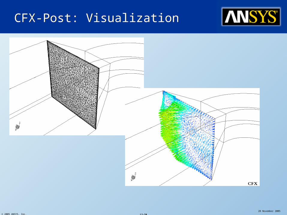
CFX-Post: VisualizationCFX-Post: Visualization
© 2005 ANSYS, Inc. L1-25
28 November 2005
ANSYS, Inc. Proprietary
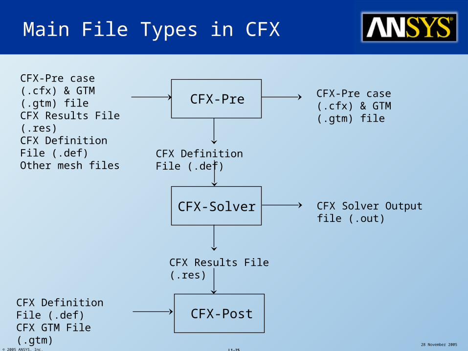
Main File Types in CFXMain File Types in CFX
CFX-Pre
CFX-Solver
CFX-Post
CFX-Pre case (.cfx) & GTM (.gtm) fileCFX Results File (.res)CFX Definition File (.def)Other mesh files
CFX Definition File (.def)
CFX Results File (.res)
CFX-Pre case (.cfx) & GTM (.gtm) file
CFX Definition File (.def)CFX GTM File (.gtm)
CFX Solver Output file (.out)
© 2005 ANSYS, Inc. L1-26
28 November 2005
ANSYS, Inc. Proprietary
Practical SessionsPractical Sessions
Practical 1: Duct Bend A simple example to take you through the
stages of setting up and running a model and then visualising the results
Practical 2: Duct Bend With Vanes Include heat transfer and turning vanes (thin
surfaces) in the above example.