Embed Size (px)
Citation preview

© 2003 HART Communication Foundation

Copyright © 2003 HART Communication Foundation. All rights reserved.
HART® is a registered trademark of the HART Communication Foundation. Any use of the word “HART” hereafter in this document implies the registered trademark. All other trademarks used in this document are acknowledged to be trademarks of their respective companies.
For additional information contact:HART Communication Foundation9390 Research BoulevardSuite I-350Austin, Texas 78759 USATel: 512-794-0369Fax: 512-794-3904

Table of Contents
HART APPLICATION GUIDE
© 2003 HART Communication Foundation Page iii
Preface............................................................................................................................................................. 1Theory of Operation........................................................................................................................................ 2Communication Modes ................................................................................................................................... 3Frequency Shift Keying .................................................................................................................................. 4HART Networks .............................................................................................................................................. 5HART Commands........................................................................................................................................... 7Benefits of HART Communications .............................................................................................................. 9Improved Plant Operations........................................................................................................................... 10Operational Flexibility.................................................................................................................................. 13Instrumentation Investment Protection ....................................................................................................... 14Digital Communication ................................................................................................................................ 15Getting the Most out of HART Systems ....................................................................................................... 16Wiring and Installation................................................................................................................................. 17Intrinsic Safety .............................................................................................................................................. 18HART Multidrop Networks .......................................................................................................................... 22Control System Interfaces............................................................................................................................. 24Multiplexers................................................................................................................................................... 26Reading HART Data into NonHART Systems ............................................................................................ 28Universal Handheld Communicator ............................................................................................................ 30PC Configuration Software .......................................................................................................................... 31Commissioning HART Networks ................................................................................................................. 32Device Status and Diagnostics...................................................................................................................... 33Connecting a PC to a HART Device or Network......................................................................................... 34PC Application Development Tools.............................................................................................................. 35Control in Field Devices ............................................................................................................................... 36Use the Power of HART ............................................................................................................................... 38Call for Information ..................................................................................................................................... 40Hidden In HART........................................................................................................................................... 48Leverage Your Assets .................................................................................................................................... 58Unleash the Power of HART........................................................................................................................ 63Powerful Connections................................................................................................................................... 66Put It To Work .............................................................................................................................................. 70HART Plant of the Year ............................................................................................................................... 82Get Started ..................................................................................................................................................... 86Industry Applications................................................................................................................................... 89Inventory-Management Applications...........................................................................................................90Cost-Saving Applications..............................................................................................................................93Remote-Operation Applications ...................................................................................................................98Open-Architecture Applications................................................................................................................. 100Where To Get More Information ............................................................................................................... 103Appendix A: HART Checklist .................................................................................................................... 104Appendix B: HART Revision 5................................................................................................................... 107Appendix C: HART Revisions 2, 3, and 4.................................................................................................. 109Appendix D: Common Practice Commands .............................................................................................. 111Appendix E: Response Codes ..................................................................................................................... 116

Table of Contents
HART APPLICATION GUIDE
Page iv © 2003 HART Communication Foundation
Appendix F: HART Field Control.............................................................................................................. 118Appendix G: Technical Information.......................................................................................................... 120Glossary ....................................................................................................................................................... 121

© 2003 HART Communication Foundation Page 1
PrefaceIn today’s competitive environment, all companies seek to reduce operation costs, deliver products rapidly, and improve product quality. The HART® (highway addressable remote transducer) protocol directly contributes to these business goals by providing cost savings in:
Commissioning and installationPlant operations and improved qualityMaintenance
The HART Application Guide has been created by the HART Communication Foundation (HCF) to provide users of HART products with the information necessary to obtain the full benefits of HART digital instrumentation. The HART communication protocol is an open standard owned by the more than 100 member companies in the HCF. Products that use the HART protocol to provide both analog 4–20 mA and digital signals provide flexibility not available with any other communication technology.
The following four sections provide you with an understanding of how the HART technology works, insight on how to apply various features of the technology, and specific examples of applications implemented by HART protocol users around the world:
Theory of Operation3Benefits of HART CommunicationsGetting the Most out of HART SystemsIndustry Applications
HART APPLICATION GUIDE

Page 2 © 2003 HART Communication Foundation
Theory of OperationThe following sections explain the basic principles behind the operation of HART instruments and networks:
Communication ModesFrequency Shift KeyingHART NetworksHART Commands
THEORY OF OPERATION

© 2003 HART Communication Foundation Page 3
Communication ModesMASTER-SLAVE MODE
HART is a master-slave communication protocol, which means that during normal operation, each slave (field device) communication is initiated by a master communication device. Two masters can connect to each HART loop. The primary master is generally a distributed control system (DCS), programmable logic controller (PLC), or a personal computer (PC). The secondary master can be a handheld terminal or another PC. Slave devices include transmitters, actuators, and controllers that respond to commands from the primary or secondary master.
BURST MODE Some HART devices support the optional burst communication mode. Burst mode enables faster communication (3–4 data updates per second). In burst mode, the master instructs the slave device to continuously broadcast a standard HART reply message (e.g., the value of the process variable). The master receives the message at the higher rate until it instructs the slave to stop bursting.
Use burst mode to enable more than one passive HART device to listen to communications on the HART loop.
THEORY OF OPERATION
Page 4 © 2003 HART Communication Foundation
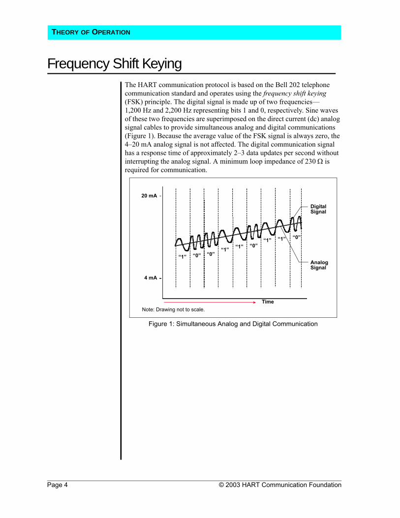
Frequency Shift KeyingThe HART communication protocol is based on the Bell 202 telephone communication standard and operates using the frequency shift keying (FSK) principle. The digital signal is made up of two frequencies—1,200 Hz and 2,200 Hz representing bits 1 and 0, respectively. Sine waves of these two frequencies are superimposed on the direct current (dc) analog signal cables to provide simultaneous analog and digital communications (Figure 1). Because the average value of the FSK signal is always zero, the 4–20 mA analog signal is not affected. The digital communication signal has a response time of approximately 2–3 data updates per second without interrupting the analog signal. A minimum loop impedance of 230 Ω is required for communication.
Figure 1: Simultaneous Analog and Digital Communication
“1” “0”“1” “1”
“1” “1”
“0”“0”
“0”
Time
20 mA
4 mA
Digital Signal
Analog Signal
Note: Drawing not to scale.
THEORY OF OPERATION

© 2003 HART Communication Foundation Page 5
HART NetworksHART devices can operate in one of two network configurations—point to point or multidrop.
POINT-TO-POINT In point-to-point mode, the traditional 4–20 mA signal is used to communicate one process variable, while additional process variables, configuration parameters, and other device data are transferred digitally using the HART protocol (Figure 2). The 4–20 mA analog signal is not affected by the HART signal and can be used for control in the normal way. The HART communication digital signal gives access to secondary variables and other data that can be used for operations, commissioning, maintenance, and diagnostic purposes.
Figure 2: Point-to-Point Mode of Operation
Control System or Other Host Application
Multiplexer
Barrier
Handheld Terminal
Field Device
Note: Instrument power is provided by an interface or external power source that is not shown.
THEORY OF OPERATION

Page 6 © 2003 HART Communication Foundation
HART NetworksMULTIDROP The multidrop mode of operation requires only a single pair of wires and, if
applicable, safety barriers and an auxiliary power supply for up to 15 field devices (Figure 3). All process values are transmitted digitally. In multidrop mode, all field device polling addresses are >0, and the current through each device is fixed to a minimum value (typically 4 mA).
Figure 3: Multidrop Mode of Operation
Use multidrop connection for supervisory control installations that are widely spaced, such as
pipelines, custody transfer stations, and tank farms.
Input/Output (I/O) System
Handheld Terminal
Field Devices
Control System or Other Host Application
Note: Instrument power is provided by an interface or external power source that is not shown.
THEORY OF OPERATION

© 2003 HART Communication Foundation Page 7
HART CommandsThe HART command set provides uniform and consistent communication for all field devices. The command set includes three classes: universal, common practice, and device specific (Table 1). Host applications may implement any of the necessary commands for a particular application.
UNIVERSAL All devices using the HART protocol must recognize and support the universal commands. Universal commands provide access to information useful in normal operations (e.g., read primary variable and units).
COMMON PRACTICE
Common practice commands provide functions implemented by many, but not necessarily all, HART communication devices.
DEVICE SPECIFIC Device-specific commands represent functions that are unique to each field device. These commands access setup and calibration information, as well as information about the construction of the device. Information on device-specific commands is available from device manufacturers.
SUMMARY TABLE
Note: Table 1 is a partial list of HART commands. See Appendices B, C, and D for more detailed information.
Universal Commands Common Practice Commands Device-Specific Commands
• Read manufacturer and device type
• Read primary variable (PV) and units
• Read current output and percent of range
• Read up to four predefined dynamic variables
• Read or write eight-character tag, 16-character descriptor, date
• Read or write 32-character message
• Read device range values, units, and damping time constant
• Read or write final assembly number
• Write polling address
• Read selection of up to four dynamic variables
• Write damping time constant• Write device range values• Calibrate (set zero, set span)• Set fixed output current• Perform self-test• Perform master reset• Trim PV zero• Write PV unit• Trim DAC zero and gain• Write transfer function (square
root/linear)• Write sensor serial number• Read or write dynamic variable
assignments
• Read or write low-flow cut-off• Start, stop, or clear totalizer• Read or write density calibration
factor• Choose PV (mass, flow, or
density)• Read or write materials or
construction information• Trim sensor calibration• PID enable• Write PID setpoint• Valve characterization• Valve setpoint• Travel limits• User units• Local display information
Table 1: HART Commands
THEORY OF OPERATION

Page 8 © 2003 HART Communication Foundation
HART CommandsESTABLISHING COMMUNICATION WITH A HART DEVICE
Each HART device has a 38-bit address that consists of the manufacturer ID code, device type code, and device-unique identifier. A unique address is encoded in each device at the time of manufacture. A HART master must know the address of a field device in order to communicate successfully with it. A master can learn the address of a slave device by issuing one of two commands that cause the slave device to respond with its address:
Command 0, Read Unique Identifier—Command 0 is the preferred method for initiating communication with a slave device because it enables a master to learn the address of each slave device without user interaction. Each polling address (0–15) is probed to learn the unique address for each device.Command 11, Read Unique Identifier by Tag - Command 11 is useful if there are more than 15 devices in the network or if the network devices were not configured with unique polling addresses. (Multidropping more than 15 devices is possible when the devices are individually powered and isolated.) Command 11 requires the user to specify the tag numbers to be polled.
DEVICE DESCRIPTION
Some HART host applications use device descriptions (DD) to obtain information about the variables and functions contained in a HART field device. The DD includes all of the information needed by a host application to fully communicate with the field device. HART Device Description Language (DDL) is used to write the DD, that combines all of the information needed by the host application into a single structured file. The DD identifies which common practice commands are supported as well as the format and structure of all device-specific commands.
A DD for a HART field device is roughly equivalent to a printer driver for a computer. DDs eliminate the need for host suppliers to develop and support custom interfaces and drivers. A DD provides a picture of all parameters and functions of a device in a standardized language. HART suppliers have the option of supplying a DD for their HART field product. If they choose to supply one, the DD will provide information for a DD-enabled host application to read and write data according to each device’s procedures.
DD source files for HART devices resemble files written in the C programming language. DD files are submitted to the HCF for registration in the HCF DD Library. Quality checks are performed on each DD submitted to ensure specification compliance, to verify that there are no conflicts with DDs already registered, and to verify operation with standard HART hosts. The HCF DD Library is the central location for management and distribution of all HART DDs to facilitate use in host applications such as PCs and handheld terminals.
Additional information, not provided by the DD, may be required by some host applications for screen formatting and other uses.
THEORY OF OPERATION

© 2003 HART Communication Foundation Page 9
Benefits of HART CommunicationsThe HART protocol is a powerful communication technology used to exploit the full potential of digital field devices. Preserving the traditional 4–20 mA signal, the HART protocol extends system capabilities for two-way digital communication with smart field instruments.
The HART protocol offers the best solution for smart field device communications and has the widest base of support of any field device protocol worldwide. More instruments are available with the HART protocol than any other digital communications technology. Almost any process application can be addressed by one of the products offered by HART instrument suppliers.
Unlike other digital communication technologies, the HART protocol provides a unique communication solution that is backward compatible with the installed base of instrumentation in use today. This backward compatibility ensures that investments in existing cabling and current control strategies will remain secure well into the future.
Benefits outlined in this section include:Improved plant operationsOperational flexibilityInstrumentation investment protectionDigital communication
BENEFITS OF HART COMMUNICATIONS

Page 10 © 2003 HART Communication Foundation
Improved Plant OperationsThe HART protocol improves plant performance and increases efficiencies in :
Commissioning and installationPlant operations Maintenance
COST SAVINGS IN COMMISSIONING
HART-based field devices can be installed and commissioned in a fraction of the time required for a traditional analog-only system. Operators who use HART digital communications can easily identify a field device by its tag and verify that operational parameters are correct. Configurations of similar devices can be copied to streamline the commissioning process. A loop integrity check is readily accomplished by commanding the field transmitter to set the analog output to a preset value.
COST SAVINGS IN INSTALLATION
The HART protocol supports the networking of several devices on a single twisted wire pair. This configuration can provide significant savings in wiring, especially for applications such as tank monitoring.
Multivariable devices reduce the number of instruments, wiring, spare parts, and terminations required. Some HART field instruments embed PID control, which eliminates the need for a separate controller, and results in significant wiring and equipment cost savings.
Use HART multidrop mode to connect multiple instruments to a single cable and reduce installation costs.
BENEFITS OF HART COMMUNICATIONS

Improved Plant Operations
© 2003 HART Communication Foundation Page 11
IMPROVED MEASUREMENT QUALITY
HART-communicating devices provide accurate information that helps improve the efficiency of plant operations. During normal operation, device operational values can be easily monitored or modified remotely. If uploaded to a software application, these data can be used to automate record keeping for regulatory compliance (e.g., environmental, validation, ISO9000, and safety standards).
Numerous device parameters are available from HART-compatible instruments that can be communicated to the control room and used for control, maintenance, and record keeping (Figure 4).
Figure 4: Examples of Device Parameters Sent to Control Room
Some HART devices perform complex calculations, such as PID control algorithms or compensated flow rate. Multivariable HART-capable instruments take measurements and perform calculations at the source, which eliminates time bias and results in more accurate calculations than are possible when performed in a centralized host.
Some HART field devices store historical information in the form of trend logs and summary data. These logs and statistical calculations (e.g., high and low values and averages) can be uploaded into a software application for further processing or record keeping.
The HART protocol provides access to all information in multivariable devices. In addition to the analog output
(primary variable), the HART protocol provides access to all measurement data that can be used for verification or
calculation of plant mass and energy balances.
Control RoomFieldDevice
BENEFITS OF HART COMMUNICATIONS

Page 12 © 2003 HART Communication Foundation
Improved Plant OperationsCOST SAVINGS IN MAINTENANCE
The diagnostic capabilities of HART-communicating field devices can eliminate substantial costs by reducing downtime. The HART protocol communicates diagnostic information to the control room, which minimizes the time required to identify the source of any problem and take corrective action. Trips into the field or hazardous areas are eliminated or reduced.
When a replacement device is put into service, HART communication allows the correct operational parameters and settings to be quickly and accurately uploaded into the device from a central database. Efficient and rapid uploading reduces the time that the device is out of service. Some software applications provide a historical record of configuration and operational status for each instrument. This information can be used for predictive, preventive, and proactive maintenance.
BENEFITS OF HART COMMUNICATIONS

© 2003 HART Communication Foundation Page 13
Operational Flexibility The HART protocol allows two masters (primary and secondary) to communicate with slave devices and provide additional operational flexibility. A permanently connected host system can be used simultaneously, while a handheld terminal or PC controller is communicating with a field device (Figure 5).
Figure 5: Multimaster System
The HART protocol ensures interoperablility among devices through universal commands that enable hosts to easily access and communicate the most common parameters used in field devices. The HART DDL extends interoperability to include information that may be specific to a particular device. DDL enables a single handheld configurator or PC host application to configure and maintain HART-communicating devices from any manufacturer. The use of common tools for products of different vendors minimizes the amount of equipment and training needed to maintain a plant.
HART extends the capability of field devices beyond the single-variable limitations of 4–20 mA in hosts with HART capability.
TransmitterSecondary Master
Primary Master: Control System or Other Host Application
Analog
Digital Data(2–3 updates per second)
HART Interface
Power Supply
BENEFITS OF HART COMMUNICATIONS

Page 14 © 2003 HART Communication Foundation
Instrumentation Investment ProtectionExisting plants and processes have considerable investments in wiring, analog controllers, junction boxes, barriers, marshalling panels, and analog or smart instrumentation. The people, procedures, and equipment already exist for the support and maintenance of the installed equipment. HART field instruments protect this investment by providing compatible products with enhanced digital capabilities. These enhanced capabilities can be used incrementally.
At the basic level, HART devices communicate with a handheld terminal for setup and maintenance. As needs grow, more sophisticated, on-line, PC-based systems can provide continuous monitoring of device status and configuration parameters. Advanced installations can also use control systems with HART I/O capability. The status information can be used directly by control schemes to trigger remedial actions and allow on-line reranging based on operating conditions and direct reading of multivariable instrument data.
COMPATIBILITY OF HART REVISIONS
As HART field devices are upgraded, new functions may be added. A basic premise of the HART Protocol is that new HART instruments must behave in precisely the same manner as older versions when interfaced with an earlier revision host system.
The HART communication protocol enables you to retain your previous investments in existing hardware and personnel.
BENEFITS OF HART COMMUNICATIONS

© 2003 HART Communication Foundation Page 15
Digital CommunicationA digital instrument that uses a microprocessor provides many benefits. These benefits are found in all smart devices regardless of the type of communication used. A digital device provides advantages such as improved accuracy and stability. The HART protocol enhances the capabilities of digital instruments by providing communication access and networking (Table 2).
Table 2: Digital Instruments Versus HART Instruments
Benefits HART Instruments Digital InstrumentsAccuracy and stabilityReliabilityMultivariableComputationsDiagnosticsMultiple sensor inputsEase of commissioningTag IDRemote configurationLoop checksAdjustable operational parametersAccess to historical dataMultidrop networkingAccess by multiple host devicesExtended communication distancesField-based controlInteroperability
BENEFITS OF HART COMMUNICATIONS

Page 16 © 2003 HART Communication Foundation
Getting the Most out of HART SystemsTo take full advantage of the benefits offered by the HART communication protocol, it is important that you install and implement the system correctly. The following sections contain information that can help you to get the most from your HART system:
Wiring and InstallationIntrinsic safetyHART multidrop networksControl system interfacesMultiplexersReading HART data into nonHART systemsUniversal handheld communicatorPC configuration softwareCommissioning HART networksDevice status and diagnosticsConnecting a PC to a HART device or networkPC application development toolsControl in field devices
GETTING THE MOST OUT OF HART SYSTEMS

© 2003 HART Communication Foundation Page 17
Wiring and InstallationIn general, the installation practice for HART communicating devices is the same as conventional 4-20mA instrumentation. Individually shielded twisted pair cable, either in single-pair or multi-pair varieties, is the recommended wiring practice. Unshielded cables may be used for short distances if ambient noise and cross-talk will not affect communication. The minimum conductor size is 0.51 mm diameter (#24 AWG) for cable runs less than 1,524 m (5,000 ft) and 0.81 mm diameter (#20 AWG) for longer distances.
CABLE LENGTH Most installations are well within the 3,000 meter (10,000 ft) theoretical limit for HART communication. However, the electrical characteristics of the cable (mostly capacitance) and the combination of connected devices can affect the maximum allowable cable length of a HART network. Table 3 shows the affect of cable capacitance and the number of network devices on cable length. The table is based on typical installations of HART devices in non-IS environments, i.e. no miscellaneous series impedance. Detailed information for determining the maximum cable length for any HART network configuration can be found in the HART Physical Layer Specifications.
Cable Capacitance – pf/ft (pf/m)Cable Length – feet (meters)
No. Network Devices
20 pf/ft(65 pf/m)
30 pf/ft(95 pf/m)
50 pf/ft(160 pf/m)
70 pf/ft(225 pf/m)
1 9,000 ft(2,769 m)
6,500 ft(2,000 m)
4,200 ft(1,292 m)
3,200 ft(985 m)
5 8,000 ft(2,462 m)
5,900 ft(1,815 m)
3,700 ft(1,138 m)
2,900 ft(892 m)
10 7,000 ft(2,154 m)
5,200 ft(1,600 m)
3,300 ft(1,015 m)
2,500 ft(769 m)
15 6,000 ft(1,846 m)
4,600 ft(1,415 m)
2,900 ft(892 m)
2,300 ft(708 m)
Table 3: Allowable cable lengths for 1.02 mm (#18 AWG) shield twisted pair
GETTING THE MOST OUT OF HART SYSTEMS

Page 18 © 2003 HART Communication Foundation
Intrinsic SafetyIntrinsic safety (IS) is a method of providing safe operation of electronic process-control instrumentation in hazardous areas. IS systems keep the available electrical energy in the system low enough that ignition of the hazardous atmosphere cannot occur. No single field device or wiring is intrinsically safe by itself (except for battery-operated, self-contained devices), but is intrinsically safe only when employed in a properly designed IS system.
INTRINSIC SAFETY DEVICES
HART-communicating devices work well in applications that require IS operation. IS devices (e.g., barriers) are often used with traditional two-wire 4–20 mA instruments to ensure an IS system in hazardous areas. With traditional analog instrumentation, energy to the field can be limited with or without a ground connection by installing one of the following IS devices:
Shunt-diode (zener) barriers that use a high-quality safety ground connection to bypass excess energy (Figure 6)Isolators, which do not require a ground connection, that repeat the analog measurement signal across an isolated interface in the safe-side load circuit (Figure 7 on page 19)
Both zener barriers and isolators can be used to ensure an IS system with HART-communicating devices, but some additional issues must be considered when engineering the HART loop.
Figure 6: 4–20 mA Loop with a Zener Barrier
Power Supply
250 Ω Load Resistor
Transmitter
Zener Barrier
HAZARDOUS SIDE SAFE SIDE
1–5 V Output Signal
GETTING THE MOST OUT OF HART SYSTEMS

Intrinsic Safety
© 2003 HART Communication Foundation Page 19
Figure 7: 4–20 mA Loop with Isolator
DESIGNING AN IS SYSTEM USING SHUNT-DIODE BARRIERS
Designing an IS direct-current loop simply requires ensuring that a field device has sufficient voltage to operate, taking into account zener barrier resistance, the load resistor, and any cable resistance.
When designing an IS loop using shunt-diode barriers, two additional requirements must be considered:
The power supply must be reduced by an additional 0.7 V to allow headroom for the HART communication signal and yet not approach the zener barrier conduction voltage.The load resistor must be at least 230 Ω (typically 250 Ω).
Depending on the lift-off voltage of the transmitter (typically 10–12 V), these two requirements can be difficult to achieve. The loop must be designed to work up to 22 mA (not just 20 mA) to communicate with a field device that is reporting failure by an upscale, over-range current. The series resistance for the same zener barrier may be as high as 340 Ω. To calculate the available voltage needed to power a transmitter, use the following equation:
Power Supply Voltage – (Zener Barrier Resistance + Sense Resistance) × Operating Current (mA) = Available Voltage
Example: 26.0 V – (340 Ω + 250 Ω) × 22 mA = 13.0 V
Any cable resistance can be added as a series resistance and will reduce the voltage even further. In addition, the power supply to the zener barrier must also be set lower than the zener barrier conduction voltage. For example, a 28 V, 300 Ω zener barrier would typically be used with a 26 V power supply.
Power Supply
SAFE SIDEHAZARDOUS SIDE
4–20 mATransmitter
250 Ω Load Resistor
Isolator
1–5 V Output Signal
GETTING THE MOST OUT OF HART SYSTEMS
Page 20 © 2003 HART Communication Foundation
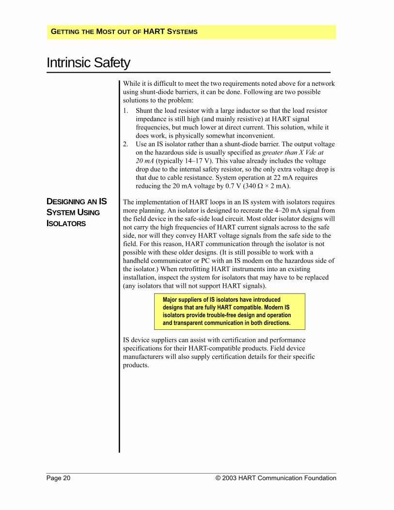
Intrinsic SafetyWhile it is difficult to meet the two requirements noted above for a network using shunt-diode barriers, it can be done. Following are two possible solutions to the problem:1. Shunt the load resistor with a large inductor so that the load resistor
impedance is still high (and mainly resistive) at HART signal frequencies, but much lower at direct current. This solution, while it does work, is physically somewhat inconvenient.
2. Use an IS isolator rather than a shunt-diode barrier. The output voltage on the hazardous side is usually specified as greater than X Vdc at 20 mA (typically 14–17 V). This value already includes the voltage drop due to the internal safety resistor, so the only extra voltage drop is that due to cable resistance. System operation at 22 mA requires reducing the 20 mA voltage by 0.7 V (340 Ω × 2 mA).
DESIGNING AN IS SYSTEM USING ISOLATORS
The implementation of HART loops in an IS system with isolators requires more planning. An isolator is designed to recreate the 4–20 mA signal from the field device in the safe-side load circuit. Most older isolator designs will not carry the high frequencies of HART current signals across to the safe side, nor will they convey HART voltage signals from the safe side to the field. For this reason, HART communication through the isolator is not possible with these older designs. (It is still possible to work with a handheld communicator or PC with an IS modem on the hazardous side of the isolator.) When retrofitting HART instruments into an existing installation, inspect the system for isolators that may have to be replaced (any isolators that will not support HART signals).
IS device suppliers can assist with certification and performance specifications for their HART-compatible products. Field device manufacturers will also supply certification details for their specific products.
Major suppliers of IS isolators have introduced designs that are fully HART compatible. Modern IS isolators provide trouble-free design and operation and transparent communication in both directions.
GETTING THE MOST OUT OF HART SYSTEMS

Intrinsic Safety
© 2003 HART Communication Foundation Page 21
MULTIDROP IS NETWORKS
HART multidrop networks are particularly suitable for intrinsically safe installations. With a multidrop configuration, fewer barriers or isolators are required. In addition, because each field device takes only 4 mA (for a total of 16 mA in a four-device loop), plain zener barriers can be used. With a 250 Ω load, 25 V – (340 + 250 Ω) × 16 mA = 15.5 V, which is well above the transmitter lift-off voltage and leaves a margin for cable resistance.
IS OUTPUT LOOPS For output devices such as valve positioners, direct-current voltage considerations will vary depending on the drive requirements of the device. Zener barriers may be possible. If not, modern HART-compatible output isolators are appropriate.
IS CERTIFICATION CONSIDERATIONS
If the HART loop contains an IS-approved handheld communicator or modem, slight changes may be needed to meet IS installation certification rules. Handheld communicators and modems add the HART signal voltage to the voltage level coming from the zener barrier or isolator. For example, a handheld communicator typically adds a maximum of 2 V to the loop. Therefore, when used with a 28 V zener barrier, a total of 30 V may theoretically be present in the loop. The allowable capacitance must be reduced by about 15% to account for this increase in voltage.
IS NETWORK CABLE LENGTH CALCULATIONS
The cable length calculation must include the resistance of both the zener barrier and the load resistor.
GETTING THE MOST OUT OF HART SYSTEMS

Page 22 © 2003 HART Communication Foundation
HART Multidrop NetworksThe HART communication protocol enables several instruments to be connected on the same pair of wires in a multidrop network configuration (Figure 8). The current through each field device is fixed at a minimum value (typically 4 mA) sufficient for device operation. The analog loop current does not change in relation to the process and thus does not reflect the primary variable. Communications in multidrop mode are entirely digital.
Figure 8: Multidrop Configuration
Standard HART commands are used to communicate with field instruments to determine process variables or device parameter information (see HART Commands on page 7). The typical cycle time needed to read information on a single variable from a HART device is approximately 500 milliseconds (ms). For a network of 15 devices, a total of approximately 7.5 seconds is needed to scan and read the primary variables from all devices. Reading information from multivariable instruments may take longer, as the data field will typically contain values for four variables rather than just one.
The typical multidrop network enables two-wire measurement devices to be connected in parallel. Two-wire loop-powered and four-wire active-source devices can be connected in the same network. If both two- and four-wire devices are used in the same network, three wires must be used to properly connect the devices (see Water Treatment Facility Upgrade on page 45).
Transmitters
Master Device
Modem
Auxiliary Power Supply
GETTING THE MOST OUT OF HART SYSTEMS

HART Multidrop Networks
© 2003 HART Communication Foundation Page 23
MULTIDROP WITH HART FIELD CONTROLLERS
HART field controllers can also be wired in a multidrop network (Figure 9). Each analog output signal from the transmitter/controllers is isolated from every other output signal, which provides a cost-effective HART network configuration. In this case, the analog signals are not fixed and are used for the output signal to the controlled device.
Figure 9: HART Controllers with Multidrop
APPLICATION CONSIDERATIONS
Connecting HART field devices in a multidrop network can provide significant installation savings. The total cable length in a multidrop network is typically less than the maximum cable length in point-to-point connections because the capacitance of the additional devices reduces the distance that the HART signal can be carried (see Wiring and Installation on page 17).
CONFIGURING DEVICES FOR MULTIDROP OPERATION
Using the polling address structure of the HART protocol, up to 15 devices can be connected in a multidrop network. The analog current of a HART device can be fixed by setting its polling address to a number other than zero. With the HART protocol, each field instrument should be configured with different polling addresses or tag numbers before being connected to a multidrop network—otherwise, the master will not be able to establish communication with the slave devices.
HandheldTerminal Computer or
DCSPower Supply HART Interface
HARTTransmitter
Control Valve
4–20 mA
+ –+ – + – + – + – + –
Power Supply Impedance
To save on installation costs, use HART multidrop networks for remote monitoring stations, tank farms, pipeline distribution systems, and other monitoring
applications in which fast update rates are not required.
GETTING THE MOST OUT OF HART SYSTEMS
Page 24 © 2003 HART Communication Foundation
Control System InterfacesWhen you change your existing control system by adding a HART interface, it is important to understand the complete functionality offered by the HART interface. While several control-system suppliers offer HART interfaces, not all interfaces provide the same functionality.
Control systems such as a DCS, PLC, or SCADA/RTU (remote terminal unit) implement only the functionality required for a given application. For example, a flow-control system may only read the primary variable of a device and provide no additional support for viewing or changing configuration information. Other control-system interfaces provide comprehensive HART support, maintaining complete configuration records for all connected devices.
Contact your system supplier for specific details on their HART interface(s). Use the form in Appendix A to obtain information from control-system suppliers to identify specific characteristics of their products.
HART I/O SUBSYSTEMS
Many HART-compatible I/O subsystems have multiple analog channels on each I/O card. Suppliers choose whether to provide one HART interface per channel or to share one HART interface among several channels. The number of shared channels per HART interface impacts the frequency of data updates from a HART field device and the HART functionality that is supported.
HART I/O FOR MULTIDROP SUPPORT
For the best performance and flexibility, one HART interface should be dedicated to each I/O channel. Systems that share only one HART interface among several I/O channels may not support multidrop networks. The effective update rate of a multiplexed interface is slow enough that the performance of multiplexed multidrop networks would not be practical. Some suppliers enable multidrop support by fixing the HART interface to one specific I/O channel. However, the other channels on that card may then not be available for HART communications.
HART I/O FOR BURST MODE SUPPORT
Burst mode is an optional implementation in a field device. Receiving burst mode messages is optional in a host as well. To take full advantage of burst mode, the I/O system should have one HART interface for each channel. If the HART interface is shared by more than one channel, messages sent by the field device may not be detected by the control system. If the system does not have the ability to configure burst mode in the field device, a handheld terminal or other configuration tool is required.
GETTING THE MOST OUT OF HART SYSTEMS

Control System Interfaces
© 2003 HART Communication Foundation Page 25
DATA HANDLING All HART-compatible control systems can read the digital primary variable from a slave device. However, some system architectures may not be able to accommodate textual data (e.g., tag and descriptor fields). In these cases, the controller is able to read the process variable, but may not have direct access to all other data in the HART device.
PASSTHROUGH FEATURE
Some control systems are integrated with a configuration or instrument- management application. In these systems, the control system passes a HART command, issued by the management application, to the field device via its I/O interface. When the control system receives the reply from the field device, it sends the reply to the management application. This function is referred to as a passthrough feature of the control system.
GATEWAYS Gateways can be used to bring HART digital data into control systems that do not support HART-capable I/O. Some systems support HART gateways with communication protocols such as Modbus, PROFIBUS DP, or TCP/IP Ethernet. The typical HART gateway supports all universal commands and a subset of the common practice commands. Support varies depending on the gateway supplier. Some gateways support access to device-specific information.
SCADA/RTU SYSTEMS
RTUs used in SCADA systems use a special telemetry to communicate with the control system. RTUs have the same considerations regarding multidrop and burst mode support as other systems. However, implementation is made more complex because RTUs often communicate to an upper-level host using a communication protocol other than HART (e.g., Modbus). While there are many benefits to implementing HART in an RTU (support of multidrop, burst mode, and multivariable instruments), HART data are only available to the central host system if the telemetry protocol supports the transfer of HART commands or specific HART data (see Multidrop for Tank Farm Monitoring on page 40).
GETTING THE MOST OUT OF HART SYSTEMS

Page 26 © 2003 HART Communication Foundation
MultiplexersHART-compatible multiplexers are ideal for users who want to interface with a large number of HART devices. Multiplexers can be modular and are capable of supporting both point-to-point and all-digital (multidrop) HART communication modes. Communication between a multiplexer and a host application depends on the multiplexer capabilities (e.g., RS232C, RS485, Modbus, and TCP/IP Ethernet).
When installing HART multiplexer systems, the following capabilities should be considered:
Number of HART channels supportedNumber of HART channels that share a HART modemBurst mode supportMultidrop supportMethod of communication with the host computer or control system
MULTIPLEXER AS THE PRIMARY I/O SYSTEM
HART multiplexers can be used as the primary I/O front end for a HART-based control or monitoring system (Figure 10). Typically, a PC acts as the host, providing the human-machine interface and performing other high-level functions. The multiplexer continuously monitors the field devices, reports the current readings and instrument status to the host, and passes HART commands from the host computer to the field devices.
Figure 10: HART Multiplexer as the Primary I/O System
PARALLEL MONITORING WITH A MULTIPLEXER
When a traditional 4–20 mA control system is using the analog signals for measurement and control outputs, a HART multiplexer can be added to the network to gain access to the digital HART signal. Using a multiplexer enables a supervisory computer to monitor diagnostics and device status, access configuration information, and read any additional process inputs or calculations not provided by the 4–20 mA signal.
Multiplexer
FieldDevices
Field Device
SCADA
GETTING THE MOST OUT OF HART SYSTEMS

Multiplexers
© 2003 HART Communication Foundation Page 27
Two types of multiplexers are used in conjunction with a control system. A multiplexer wired in parallel with the field wiring is commonly used when the control system wiring is already in place (Figure 11).
Figure 11: HART Multiplexer with Existing I/O
A multiplexer can also be an integral part of the control system as a third-party I/O (Figure 12). As an I/O system, the multiplexer can include IS barriers and other filtering capabilities and provide services to the field device, such as galvanic isolation or power. For this type of installation, no additional terminations or space are required. The multiplexer can also act as a gateway to convert the HART messages to another protocol such as Modbus, PROFIBUS, or Ethernet..
Figure 12: HART Multiplexer Integrated with I/O
Use a HART multiplexer to gain access to the digital HART signal.
Automation and Display System Supervisory
ComputerControllers
I/O
Transmitter
Control Valves
Multiplexer
Controller
I/O
Supervisory Computer
Automation and Display System
Transmitter Control Valve
GETTING THE MOST OUT OF HART SYSTEMS

Page 28 © 2003 HART Communication Foundation
Reading HART Data into NonHART SystemsMany HART products are able to perform more than one measurement or output function (e.g., make multiple process measurements, calculate process information, and provide positioner feedback information). All of this information can be easily accessed digitally. However, existing controllers or interface equipment may not have the ability to read digital HART data. Products are available that can read HART digital signals and convert them to analog or contact information, which enables any traditional analog/digital I/O to take full advantage of the benefits of HART-communicating devices. The Rosemount Inc. Tri-Loop module and the Moore Industries Site Programmable Alarm (SPA) are two such products.
HART DATA-CONVERSION PRODUCTS
The Tri-Loop module monitors a HART loop for a bursting message and converts three of the four possible variables in HART command number three to analog outputs (Figure 13). The conversion enables the field device to provide a total of four analog signals over a single pair of wires run from the field..
Figure 13: Tri-Loop Module
Channel 1Channel 2
Channel 3
Control SystemRail-Mounted Tri-Loop Module
Field Terminals
4–20 mA Signals for Secondary Variables
GETTING THE MOST OUT OF HART SYSTEMS

Reading HART Data into NonHART Systems
© 2003 HART Communication Foundation Page 29
The SPA module continuously communicates with any HART-capable device and provides contact closure outputs (alarm trips) based on the information received (Figure 14). For example, the SPA can be configured to monitor the device-status information inherent in the HART communication protocol and trigger events such as local on/off applications or alarms. The SPA can also initiate emergency shutdown action if problems are detected with a field device in critical loop applications.
Figure 14: SPA Module
Both HART Tri-Loop and SPA provide multivariable product support on a loop-by-loop basis.
4–20 mA and HART Digital
SignalsHART
TransmitterHART Communicator
Process and
Diagnostic Data
HART Master
Annunciator
Event Recorder
Control System
Shutdown Controls
GETTING THE MOST OUT OF HART SYSTEMS

Page 30 © 2003 HART Communication Foundation
Universal Handheld CommunicatorThe 275 Universal HART Communicator is available from major instrumentation suppliers around the globe and is supported by all member companies in the HCF. Using HART DDL, the communicator can fully communicate with and configure any HART device for which it has a DD installed. If the communicator does not have the DD for a particular network device installed, it can still communicate with that device using the universal and common practice commands (see HART Commands on page 7). The HCF provides centralized control and registration for all DDs that can be loaded into the communicator. An index of registered DDs can be found on the world wide web at <http://www.hartcomm.org>.
Figure 15: 275 Universal Handheld Communicator
Use the 275 Universal HART Communicator to communicate with and configure any
HART-communicating device.
GETTING THE MOST OUT OF HART SYSTEMS

© 2003 HART Communication Foundation Page 31
PC Configuration SoftwareMany instrument manufacturers, as well as some independent software developers, offer HART communication software for PCs with capabilities similar to and beyond those offered by a HART handheld communicator.
The software packages listed in Table 4 are used for configuration management, parameter tuning, and data acquisition with a HART device. The list is not comprehensive, and all software applications are not functionally equivalent. A number of product-specific software applications are also available for diagnostics. An RS232 HART interface or other interface device connects the PC running the HART application software to the field devices.
SUMMARY TABLE OF HART SOFTWARE
Table 4: HART Software
Use special software applications to continuously monitor the status of connected field devices and log
status changes as they occur, which may help reduce the costs of regulatory compliance.
Software Application Manufacturer
Asset Management Solutions (AMS)
Configuration and calibration management Fisher-Rosemount
CONF301 HART Configurator Configuration management Smar International
CONFIG Configuration management Krohne
Cornerstone Base Station
Configuration and calibration management
Applied System Technologies
Cornerstone Configurator Instrument configuration Applied System
Technologies
H-View Configuration management and data acquisition Arcom Control Systems
IBIS Configuration management EB Hartmann & Braun
IBIS Configuration management Samson
K-S Series Configuration management ABB
Mobrey H-View Configuration management KDG Mobrey
Pacemaker Configuration management UTSI International Corporation
SIMATIC PDM Configuration management Siemens
Smart Vision Configuration management EB Hartmann & Braun/Bailey Fischer & Porter
XTC Configuration Software Configuration management Moore Products Co.
GETTING THE MOST OUT OF HART SYSTEMS

Page 32 © 2003 HART Communication Foundation
Commissioning HART NetworksHART-based instruments have several features that significantly reduce the time required to fully commission a HART network (loop). When less time is required for commissioning, substantial cost savings are achieved.
DEVICE VERIFICATION
Before installation, manufacturers usually enter device tags and other identification and configuration data into each field instrument. After installation, the instrument identification (tag and descriptor) can be verified in the control room using a configurator (handheld terminal or PC). Some field devices provide information on their physical configuration (e.g., wetted materials)—these and other configuration data can also be verified in the control room. The verification process can be important in conforming to governmental regulations and ISO quality requirements.
The commissioning process can be further streamlined by connecting a PC configurator to each HART loop online, either by integration with the control system or by using one of the many available HART multiplexing I/O systems (see Multiplexers on page 26). With this centralized approach, there is no need to move the configuration device from one termination point to the next while commissioning all devices on the network.
LOOP INTEGRITY CHECK
Once a field instrument has been identified and its configuration data confirmed, the analog loop integrity can be checked using the loop test feature, which is supported by many HART devices. The loop test feature enables the analog signal from a HART transmitter to be fixed at a specific value to verify loop integrity and ensure proper connection to support devices such as indicators, recorders, and DCS displays.
AS-INSTALLED RECORD KEEPING
A HART configurator also facilitates record keeping. As-installed device configuration data can be stored in memory or on a disk for later archiving or printing.
Use the HART protocol loop test feature to check analog loop integrity and ensure a proper physical
connection among all network devices.
GETTING THE MOST OUT OF HART SYSTEMS

© 2003 HART Communication Foundation Page 33
Device Status and DiagnosticsMost HART field instruments provide both status information and diagnostic information. The HART protocol defines basic status information as information that is included with every message from a field device. Basic status information enables the host application to immediately identify warning or error conditions detected by the field device. Status messages also enable the user to differentiate between measurements that are outside sensor or range limits and actual hardware malfunctions. Examples of status messages are:
Field device malfunctionConfiguration changedCold startMore status availableAnalog output current fixedAnalog output saturatedNonprimary variable out of limitsPrimary variable out of limits
HART instruments can implement extensive, device-specific diagnostics. The amount and type of diagnostic information is determined by the manufacturer and varies with product and application. Diagnostic information can be accessed using the HART communication protocol. Host applications using DD files can interpret and display diagnostic information. Applications not using DD technology may require product- specific software modules to interpret diagnostic information.
Many manufacturers offer special software applications for their own products. Some modules allow you to customize for specific products. Manufacturers of valve actuators have made extensive use of this capability to provide preventative and predictive diagnostic information that greatly enhances the value of their products as compared to conventional actuators.
Several software applications are available that provide continuous communication with field devices using a HART-compatible multiplexer and HART I/O (see Multiplexers on page 26). These applications provide real-time monitoring of status and diagnostic information.
APPENDICESAPPENDICESAPPENDICES
GETTING THE MOST OUT OF HART SYSTEMS
Page 34 © 2003 HART Communication Foundation
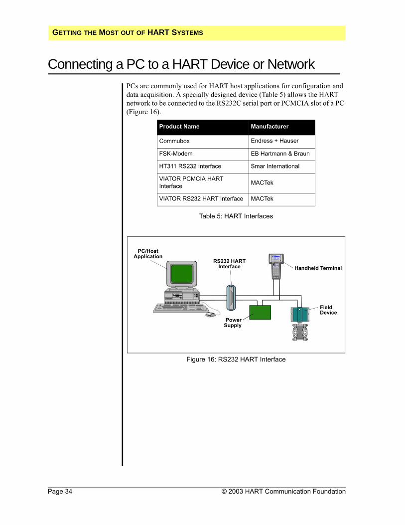
Connecting a PC to a HART Device or NetworkPCs are commonly used for HART host applications for configuration and data acquisition. A specially designed device (Table 5) allows the HART network to be connected to the RS232C serial port or PCMCIA slot of a PC (Figure 16).
Table 5: HART Interfaces
Figure 16: RS232 HART Interface
Product Name Manufacturer
Commubox Endress + Hauser
FSK-Modem EB Hartmann & Braun
HT311 RS232 Interface Smar International
VIATOR PCMCIA HART Interface MACTek
VIATOR RS232 HART Interface MACTek
Field Device
RS232 HART Interface Handheld Terminal
PC/Host Application
PowerSupply
GETTING THE MOST OUT OF HART SYSTEMS

© 2003 HART Communication Foundation Page 35
PC Application Development ToolsSoftware drivers are available to assist in the development and integration of PC applications with HART networks. Table 6 shows a partial list of products available.
Table 6: PC Development Tools
Product Name Description Manufacturer
Hview Provides DDE server Arcom Control Systems
HRT VBX 16-bit Visual Basic driver Borst Automation
HRT OCX 32-bit ActiveX Control Borst Automation
HART OPC Server OPC Server HCF (via member
companies)
HL-LinkPro HART driver for LabVIEW Cardiac Systems Solutions
GETTING THE MOST OUT OF HART SYSTEMS
Page 36 © 2003 HART Communication Foundation
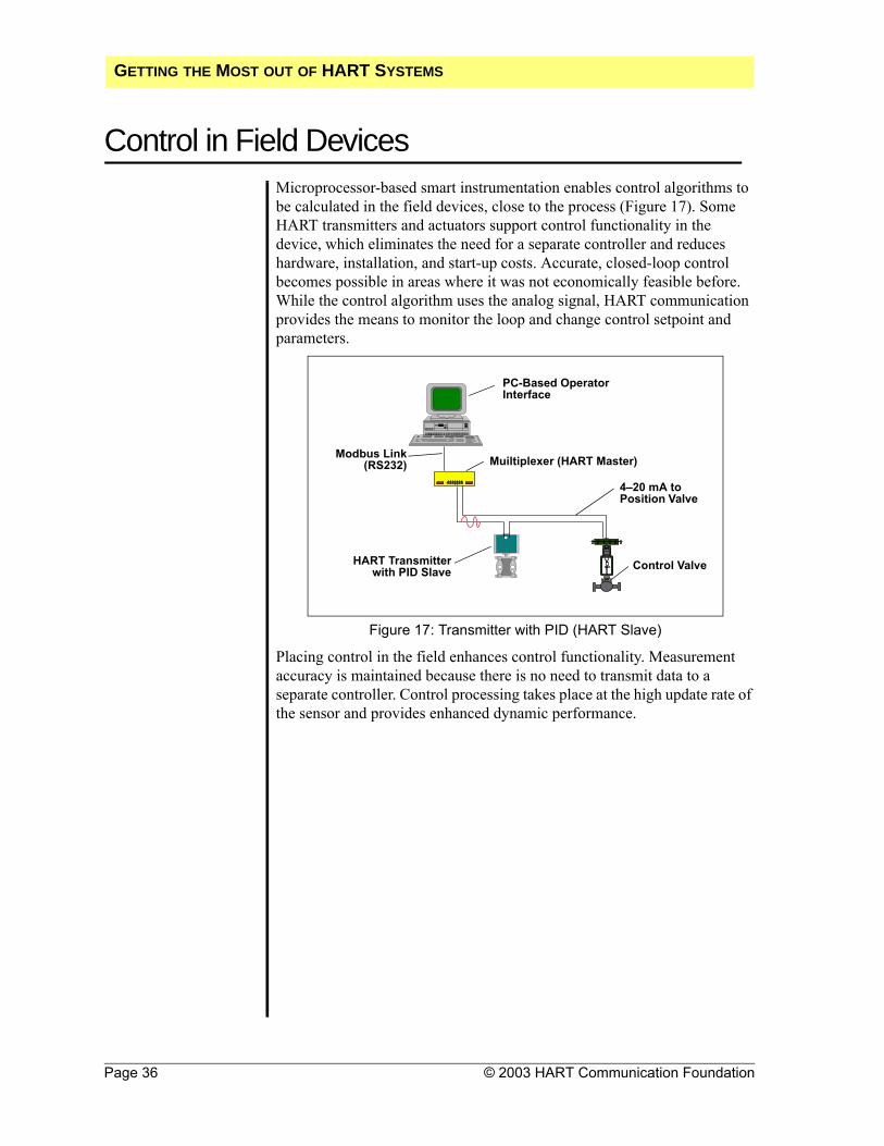
Control in Field DevicesMicroprocessor-based smart instrumentation enables control algorithms to be calculated in the field devices, close to the process (Figure 17). Some HART transmitters and actuators support control functionality in the device, which eliminates the need for a separate controller and reduces hardware, installation, and start-up costs. Accurate, closed-loop control becomes possible in areas where it was not economically feasible before. While the control algorithm uses the analog signal, HART communication provides the means to monitor the loop and change control setpoint and parameters.
Figure 17: Transmitter with PID (HART Slave)
Placing control in the field enhances control functionality. Measurement accuracy is maintained because there is no need to transmit data to a separate controller. Control processing takes place at the high update rate of the sensor and provides enhanced dynamic performance.
PC-Based Operator Interface
Muiltiplexer (HART Master)
4–20 mA to Position Valve
Control ValveHART Transmitterwith PID Slave
Modbus Link(RS232)
GETTING THE MOST OUT OF HART SYSTEMS

Control in Field Devices
© 2003 HART Communication Foundation Page 37
HART FIELD CONTROLLER IMPLEMENTATION
A HART field controller takes advantage of the HART protocol’s simultaneous analog and digital signaling by converting the transmitter’s traditional analog measurement output into a control output. The analog signal from the smart transmitter (controller) is used to manipulate the field device (Figure 18). The analog output signal also carries the HART digital signal, which is used for monitoring the process measurement, making setpoint changes, and tuning the controller.
Figure 18: Smart Transmitter with PID
The communication rate of the HART protocol (2–3 updates per second) is generally perceived as too slow to support closed-loop control in the central host. With control in the field, the control function no longer depends on the HART protocol’s communication rate. Instead, the control signal is an analog output that is updated at a rate that is much faster than can typically be processed in a conventional control system. Processing rates vary from 2–20 updates per second, depending on the product. The HART digital communication rate remains sufficient for monitoring the control variable and changing setpoint values.
+Power Supply
Smart Transmitter
ControlValve
Bypass Capacitor
Resistor
GETTING THE MOST OUT OF HART SYSTEMS

THE POWER OF HART
Use the Power of HART Look under your nose. Though rarely in the news, HART has the
largest installed base of all digital field communications protocols in the process industries. A significant percentage of the field devices in your plant are probably HART-enabled, and you almost certainly are or will soon be under pressure to bring more information from those devices to your control, asset management, and enterprise systems. But many end users haven’t made the connection. HART can do much more than serve as an occasional information bridge for device configuration and troubleshooting. In many applications it can serve as the primary means of two-way communications for system integration. Using the power of HART communication is like letting the genie out of the bottle.
Resources Are Rising When HART technology was introduced in the early 1990s, control
engineers realized information from intelligent devices was valuable, but at the time there was no easy or clean way to integrate this data into control systems. For years, valuable information in these devices has languished in parts of subsystems, in limited applications such as maintenance and loop checkout tools, or ignored altogether. Meanwhile, the business situation in the process industries has changed dramatically, creating the need to maximize any and all investments and assets. Reduced manpower, budget cuts, higher profit requirements, and increased global competition have users looking at all possible S-6 means of capturing information that can improve the operation and financial results of their plants. Highly visible discussions have promoted fieldbus capabilities and the value of additional information from remote communications. But access to information is one thing¡ª the ability to get it full-time and without pain is another. Over the past 10 years, companies of all sizes have created HART-capable devices that operate in a hybrid fashion. These devices offer a powerful bridge between the analog and digital worlds by using the 4-20 mA signal to feed the control system as initially designed, and simultaneously carry digital HART information¡ª which in most cases is free - with additional process variables, enhanced alarms and diagnostics information. HART Communication Foundation (HCF) members around the globe have created a cadre of instrumentation that collectively provides all the pieces of the puzzle needed to address the many needs of process control. And the HART protocol continues to
Page 38 © 2003 HART Communication Foundation

THE POWER OF HART
© 2003 HART Communication Foundation Page 39
evolve as a global standard. Members recently approved new HART 6 specifications that expands communications capabilities and is compatible with existing instrumentation. In addition, the HCF has initiated a significant program to educate both users and suppliers/members on the value of full-time HART communication. The HCF web site, www.hartcomm.org, has been redesigned to make it more user-friendly as well as to provide more user-application and user-oriented information. .
What to Do Take another look at HART as it applies to your company’s needs.
Review your installed base of instrumentation and your current buying requirements as they are likely to show you have a significant investment in and potential to harness HART. Talk with your suppliers about how their products support the full power of HART. If they don’t, ask why. Discuss your current installation with your suppliers to ascertain the degree of HART compatibility of your system. Then map out a plan to use your assets to the fullest. There is a growing need to use intelligent data from the field to address enterprise improvements such as performance, quality, safety, reliability, profitability, maintenance, and management. No one bus or communication technology is perfect for all applications, but HART may be the simple, cost-effective, low-risk, high-value solution you need for improved process control and odds are you’ve already got it.

THE POWER OF HART
Call for Information Most users were attracted to HART for instrument calibration and
maintenance, but many don’t realize the protocol has the power to be the main digital communication bus for applications such as SCADA, ERP, and asset management. HART provides a wealth of the type of data required by these high level applications. Corporations have spent billions of dollars over the past few years installing ERP and asset management systems. A tremendous amount of pressure is now being applied to process plant managers and engineers to provide data to these systems. SCADA systems must also be upgraded to improve performance and reduce costs. Existing HART instruments can accomplish these tasks in a cost-effective and low-risk manner
SCADA Can Do More With
The market for SCADA applications continues to grow. According to Russ Novak, director of consulting for the ARC Advisory Group, Dedham, Mass., “The worldwide SCADA systems market for the oil & gas and water &wastewater industries exceeded $650 million in 2000. This market will reach almost $780 million by the end of 2005,growing at an annual rate of 3.5%.” HART devices can be expected to play a significant role in this growth. Periodic instrument adjustment is a necessity in process plants, but continuous monitoring can be a requirement for certain applications. One of these applications is a SCADA natural gas metering system designed by Arcom Control Systems, Kansas City, Mo., for the Tejas Calumet gas plant in Louisiana (Tejas is an affiliate of Royal Dutch Shell). The Calumet gas plant receives raw natural gas from offshore pipelines and separates out liquids such as propane, ethane, and methane. The plant consumes natural gas in the process and is charged for the energy usage by its suppliers. “Our firm designed a gas flow measurement system for Calumet to internally verify the amount of energy used in various parts of the process. Calumet needed to provide check metering for gas usage,” says Jon Tandy, a project engineer for Arcom. The gas flow measurement system uses a combination of protocols to gather and process data. “Our SCADA system acquires gas composition data from Applied Automation gas chromatographs and calculates compressibility constants using AGA8 calculations. This information is downloaded to the HART-compatible Rosemount 3095FT flow transmitters via the HtNode every three hours. Production data is also acquired from Daniels 2500 flow computers and RTUs,” adds Tandy. The HtNode is a protocol translator that allows HART devices to communicate via Modbus.
Page 40 © 2003 HART Communication Foundation
THE POWER OF HART
The 3095FT flow transmitter was chosen by Calumet because it provides high accuracy, is physically smaller than most flow computers, and has a competitive price. It provides differential pressure, absolute pressure, and temperature inputs on the same transmitter. The HART protocol is used for communication of process variables and for the acquisition of device-specific historical and configuration data.
Accurate measurement of gas flow with the flow transmitters is
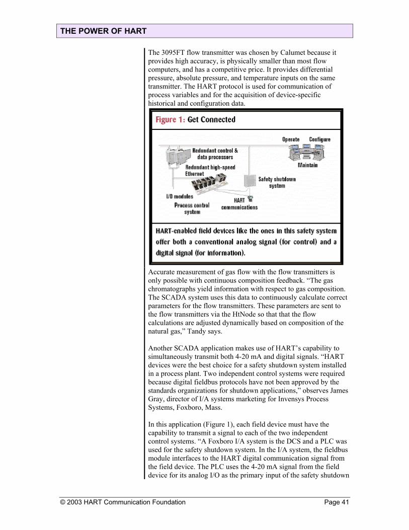
only possible with continuous composition feedback. “The gas chromatographs yield information with respect to gas composition. The SCADA system uses this data to continuously calculate correct parameters for the flow transmitters. These parameters are sent to the flow transmitters via the HtNode so that that the flow calculations are adjusted dynamically based on composition of the natural gas,” Tandy says. Another SCADA application makes use of HART’s capability to simultaneously transmit both 4-20 mA and digital signals. “HART devices were the best choice for a safety shutdown system installed in a process plant. Two independent control systems were required because digital fieldbus protocols have not been approved by the standards organizations for shutdown applications,” observes James Gray, director of I/A systems marketing for Invensys Process Systems, Foxboro, Mass. In this application (Figure 1), each field device must have the capability to transmit a signal to each of the two independent control systems. “A Foxboro I/A system is the DCS and a PLC was used for the safety shutdown system. In the I/A system, the fieldbus module interfaces to the HART digital communication signal from the field device. The PLC uses the 4-20 mA signal from the field device for its analog I/O as the primary input of the safety shutdown
© 2003 HART Communication Foundation Page 41

THE POWER OF HART
system,” continues Gray. The DCS analyzes the HART signal information and distributes this information throughout the control system. “The HART protocol is used for diagnostic information from the field device. This information can provide an active status word to the system and alert the operator of a device fault before it impacts the performance of the process. The status word is integrated into the analog input block of the control system and propagated throughout the control strategy if an error or device fault is detected,” adds Gray. If an error is found, the DCS can interact with an operator to correct the problem. “Once an error in the field devices is detected, the operator or technician can interrogate the field device from the console. Using the tools of the I/A system’s Technician’s Workbench, a poll command is sent from the operator console to the field device to read or perform a series of diagnostics,” Gray says. “These tests validate the condition of the field device and often eliminate unnecessary trips to the field.” HART capabilities can also be extended to wireless SCADA applications. A major Midwest gas pipeline company planned to replace paper chart recorders on its natural gas pipeline with an automated meter reading (AMR) system. The AMR system would have to be capable of acquiring data from devices within a radius of up to 80 miles, publishing this field data from locations throughout the Midwest to a central host in Tulsa, and integrating the data with an existing measurement system. The system architecture diagram (Figure 2) illustrates the design of the wireless SCADA system. Multivariable flow transmitters provide flow measurement and data logging capabilities. These transmitters communicate via HART over a wireless radio link to a network gateway/ multiplexer from Arcom. “Our Director gateway satisfied all the requirements for the project,” says Tandy. “The Director uses HART to acquire real-time and historical information. Data is then published to a central host via satellite.” The AMR system uses spread-spectrum radio and satellite communication to extend the HART network beyond the traditional 10,000-ft. distance limitation. Spread-spectrum radios from Freewave Technologies provide the wireless link between the gateway and the HART instruments. “The radios allow great flexibility in network architecture through multipoint and repeater configurations, as well as providing reliable data transmission of the HART messages,” Tandy adds. “With the use of repeaters, HART units can be brought into a single multiplexer from a radius of 80 miles or more.” By implementing the HART-based AMR system, the pipeline company was able to realize cost savings in several ways. The
Page 42 © 2003 HART Communication Foundation

THE POWER OF HART
paper chart recorders previously had to be collected and tabulated manually for each monthly billing. This is now done automatically with ongoing savings estimated at $1.25 million per year. Because the HART signal is transferred over the radio link, there is no need for a separate remote terminal unit (RTU) or multiplexer at each meter site. One multiplexer serves as a master to 32 HART meters and allows data consolidation.
Wireless communication avoids costly cable runs to each HART
meter. The multivariable flow transmitters effectively combine a traditional flowmeter and three discrete instruments into a single instrument, yielding hardware cost savings of almost 30% per site. TCP/IP communications allow remote diagnostics and configuration, reducing the need for on-site technical support. HART provides the communication tool to create an extended meter-reading network via spread-spectrum radio and satellite communication
ERP Needs HART ERP and e-business systems from vendors such as SAP, Baan, and Oracle cannot perform as designed without extensive information from plant-floor control systems. This information is often available through existing HART devices. Plant engineers can extract data from these existing devices and provide it to ERP systems. The expenses of purchasing and installing new devices often can be avoided.
© 2003 HART Communication Foundation Page 43
THE POWER OF HART
Many food and pharmaceutical processes require extensive record keeping with respect to batch parameters. These parameters can include process variables such as pressure, temperature, and level. The multivariable capabilities of HART devices can be exploited to extract these secondary variables from existing devices. Batch records should also indicate if each field device is operating properly. The status and diagnostic information available from each HART device can be used to automatically verify proper operation. The only alternative in most cases is to have a field technician check and verify device operation
HART Helps Manage Assets
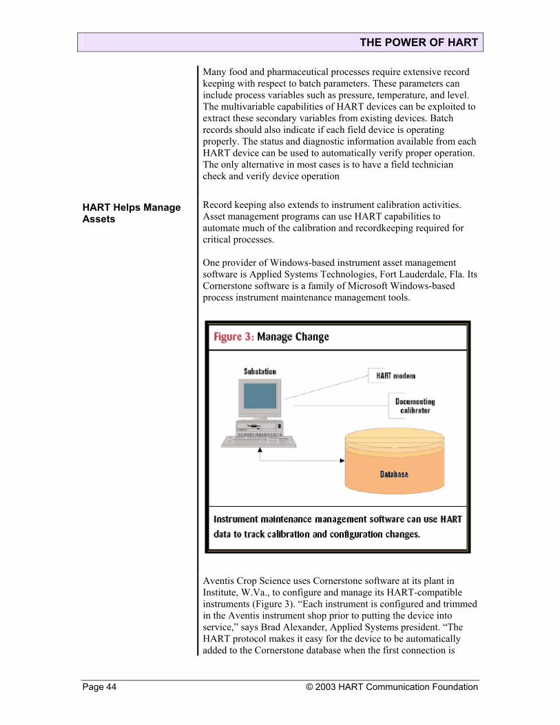
Record keeping also extends to instrument calibration activities. Asset management programs can use HART capabilities to automate much of the calibration and recordkeeping required for critical processes. One provider of Windows-based instrument asset management software is Applied Systems Technologies, Fort Lauderdale, Fla. Its Cornerstone software is a family of Microsoft Windows-based process instrument maintenance management tools.
Aventis Crop Science uses Cornerstone software at its plant in Institute, W.Va., to configure and manage its HART-compatible instruments (Figure 3). “Each instrument is configured and trimmed in the Aventis instrument shop prior to putting the device into service,” says Brad Alexander, Applied Systems president. “The HART protocol makes it easy for the device to be automatically added to the Cornerstone database when the first connection is
Page 44 © 2003 HART Communication Foundation
THE POWER OF HART
accomplished.” Three of the instrument shops at the site use Cornerstone, and Aventis plans to convert the rest of the shops in the near future. “We use the HART interface with Cornerstone to configure the instruments for our use and to track any changes that are made to these instruments,” says Denny Humphreys, an instrument/electrical technician with the equipment reliability group at Aventis. “These changes might be made in the field through a documenting calibrator, in the field though a field communicator, or through Cornerstone itself.” Initial device configuration establishes a baseline for each instrument that can be compared to later readings to create a history for the instrument. The baseline includes not only calibration information, but also device information such as a user-designated tag number, a user-defined descriptor, and manufacturer’s information. “One specific issue in calibration management that is addressed by the HART protocol is the ability to positively confirm the identity of the device being calibrated. Prior to smart devices, there was no inherent method available to confirm the unique device identification, which is obviously required to validate the calibration history,” observes Alexander. This observation is seconded by Aventis. “Using Cornerstone with the HART interface has helped us tremendously in getting new instruments configured and calibrated quickly,” adds Humphreys. “Cornerstone also has a database that is password protected and that automatically documents every change that takes place at our site.” Aventis uses the software in conjunction with HART instruments to provide complete management of instrument calibration and maintenance. Alexander says, “The Cornerstone HART maintenance station makes it possible to confirm existing configurations, to automatically detect any configuration changes introduced in the field, to prepare configuration edits for download to an instrument upon next connection, and to reconcile any variances between the instrument database records and the devices.” The software can also be used to provide remote diagnostics by periodically polling each instrument to access device status. This information can then be used to alert the instrument shop and generate repair orders. “We use the Cornerstone monitor feature with our HART Instrument. This allows us to quickly spot any problems with an instrument including signal spiking, ground loops, or a problem with the primary element,” continues Humphreys. The HART protocol and maintenance management software allow Aventis to use instruments from many different vendors. “ The HART interface is not proprietary so we are not tied to one
© 2003 HART Communication Foundation Page 45

THE POWER OF HART
instrument vendor or one type of documenting calibrator. Cornerstone is also able to handle many vendors through the use of model libraries and calibrator libraries that can be used anywhere on the LAN,” Humphreys says. “I have been completely sold on the HART interface for years, but it was not until I discovered Cornerstone that the benefits became so very apparent.”
Application Optimizes HART
Condition and diagnostic information generated by field instruments can be captured from control networks by online applications and integrated with an enterprise asset management (EAM) or computerized maintenance management system (CMMS). One such online application is Asset Management Solutions (AMS) software from Emerson Process Management, Austin, Texas. AMS provides the interface between fieldbus devices and maintenance management systems (Figure 4). This allows automatic generation of work orders based on actual device conditions.
The online asset management software gathers data from HART instruments and stores it in a device-oriented database. The data is then processed, organized, and presented in graphic displays. The information can be used to speed unit startups, streamline routine maintenance, and provide early warning alerts of component failure.
Page 46 © 2003 HART Communication Foundation

THE POWER OF HART
© 2003 HART Communication Foundation Page 47
Overall maintenance costs can be further reduced and delivering field-based data directly to an EAM can increase process uptime. When AMS is integrated with an EAM system, early predictive maintenance warnings can be provided about potential equipment problems. Trial-and-error preventive maintenance can be replaced by prioritized work orders based on actual evidence that a repair or replacement is required. Rather than scheduling field devices for maintenance based on the calendar, the EAM system receives notification from AMS that service is necessary and a work order to that effect is generated. Integration of an online AMS with an EAM system lowers overall maintenance costs and increases process uptime by providing advanced warning about potential equipment failures. By combining these important maintenance tools, companies can establish a predictive maintenance environment to keep plants running at higher efficiency with less technician involvement. Potential problems can be corrected before serious damage occurs, and the cost of maintenance can be significantly reduced. Syncrude Canada, Calgary, Alberta, is using HART and the AMS system at its oil refinery in Fort McMurray, Alberta. “During the design of our most recent process unit, a 305,000 barrel-per-day vacuum distillation unit, we decided to install all HART smart instruments and hook them up to the AMS through a Honeywell DCS,” says Gil Hurtubise, process automation specialist with Syncrude in Calgary. The AMS system works with HART devices to improve plant efficiency. “The largest economic payback is the maintenance efficiency gained by being able to access the equipment diagnostics in order to make our maintenance more predictive,” adds Hurtubise. “Equipment diagnostics also allow us to keep a history of control valve signatures. This becomes a very valuable tool as the equipment ages and also assists in planning which equipment must come out for maintenance during a planned process unit outage. It is important, however, that this tool [AMS] be set up as a working system initially and later supported on a dedicated basis through organizational structure.” Another benefit of HART was realized during plant startup. “Using the HART component of the signal allows you to be much more efficient during final construction checks, commissioning loop checks, and startup,” adds Hurtubise. “It allows you to forgo many of the point-to-point wiring checks that you would normally make with analog instruments, by making use of the digital network to prove the integrity of the wiring instantly for the entire loop.”

THE POWER OF HART
Hidden In HART Most users know HART provides for communication of multiple
data items between field devices and a host controller or computer. Many also know that integrating additional field device data into control or maintenance strategies can improve system performance. What most HART users don’t know is there is an incredible amount of data that can be communicated between their existing HART devices and control systems. Typical user estimates of available data items range from three to 10 values in addition to the process variable. The actual number is 35 to 40 values depending on the type of HART device (see sidebar, “Data Items Available for Communication Between HART Devices and a Host”). There is tremendous value in the data available from HART devices. “Many users have little or no idea of the measurement and process improvements that can be implemented through HART devices,” says Warren Meyer, principal marketing specialist with The Foxboro Co., Foxboro, Mass. “These improvements typically require minimal engineering and can be implemented quickly and at very low cost. These HART devices are like icebergs—we only see about 20% of the functionality and 80% is hidden from view.” The most important data items available from HART devices are the process variables. The primary process variable is continuously transmitted in two formats: 4-20 mA analog and digital as part of the HART protocol. The primary process variable is also transmitted as a percent of range. Finally, the loop current in milliamps can also be accessed. The loop current reading can be used to validate the signal being received by the controller. The primary process variable digital value is expressed as an IEEE floating-point number with up to 32-bit precision. This far exceeds the standard 12-bit precision offered with most PLC and DCS analog input modules. High precision can be especially useful in weighing and scaling applications. Twelve-bit resolution yields very limited accuracy for storage tank weighing systems. These systems often measure weights up to 200,000 lbs. and require high precision to resolve the total weight to an acceptable level. Many existing and most new HART devices have multivariable measurement capabilities. This is true of many pressure and
Page 48 © 2003 HART Communication Foundation

THE POWER OF HART
temperature devices; most flow, level, and analytical devices; and all valve positioners and valve controllers. Table I lists common types of multivariable devices and typical outputs available from these devices. Up to three secondary process variables in addition to the primary process variable (total of four) can be simultaneously transmitted from a HART device to a host in a single message. This multivariable capability can be exploited in a number of ways
Multivariables Provide Multi-Benefits
Multivariable transmitters with a digital HART interface offer tremendous functionality and application diversity compared to instruments with only a 4-20 mA output. Unfortunately, the average user of HART devices only scratches the surface in terms of using the information available from them. One of the best ways to improve plant profitability is to use the on-board temperature sensor located in virtually all HART devices. This sensor measures the internal temperature inside the field device, not the ambient or process temperature. The manufacturer uses internal device temperature to characterize the output during wide temperature fluctuations, thereby eliminating most of the temperature-related error of the device. A user can also digitally transmit the on-board device temperature to the control system using the HART protocol. “Our clients often use the on-board temperature sensor for freeze protection alarming,” says Meyer. “During the winter months in cold climates, every process plant has some type of freeze protection on various production lines. The protection can be electric heaters, steam, or just insulation to keep the process fluid from freezing.” The conventional solution is to purchase and install a temperature sensor
© 2003 HART Communication Foundation Page 49

THE POWER OF HART
inside the freeze-protection housing. This can be very expensive and may not be cost-effective for many applications. “When our clients use the internal temperature measurement already available over the HART interface, all that is required is a software change to set alarm points,” adds Meyer. “One client in northern Canada with approximately 2,000 microprocessor-based transmitters estimates they have saved over $300,000 each year since 1989 using the ‘free temperature measurement’ for alarming as compared to the previous installation with 4-20 mA transmitters.” Another use of the internal instrument temperature is for ambient temperature error compensation on a dual-seal level transmitter. The ambient temperature error of the differential pressure transmitter is virtually eliminated with factory compensation using the internal temperature sensors. The problem is that the compensation is done before the dual seals are installed on a vessel, and this installation can introduce temperature errors. The temperature errors of the dual seals tend to offset each other because the error on one side is canceled by a similar error on the other side. But there still is one error that is not compensated: a shift in the output caused by a temperature-driven change in the density of the fluid inside the capillary between the two seals. As the ambient capillary temperature changes, the change in the fluid density creates an error. The low-cost solution is to take the on-board temperature inside the basic differential pressure transmitter as a good approximation of the seal fill fluid temperature. A user can then program a software compensation block with a table of the fill fluid density vs. temperature. A few basic math calculations using the distance between the seals, the span of the level measurement, and the density vs. temperature chart greatly enhance level measurement accuracy. A hydrostatic tank gauging system can be configured using pressure transmitters with a temperature secondary variable. “We multi-drop two or three pressure transmitters, each with secondary temperature variables, to create a tank level measurement system. This system is marketed as our Hydrostatic Interface Unit,” says Jim Cobb, marketing manager for Austin, Texas-based Emerson Process Management, formerly Fisher-Rosemount. Multivariable instruments often can use multiple variables to calculate process information. A differential pressure flowmeter, for example, uses pressure taps upstream and downstream of an orifice plate, and the square root of the differential pressure is proportional to the flow. A multivariable transmitter could transmit the flow value, the upstream pressure, and the downstream pressure. Calculations performed at the instrument level can provide better accuracy and can off-load central controllers from these math-intensive tasks.
Page 50 © 2003 HART Communication Foundation

THE POWER OF HART Valves Vie for Attention
The multivariable features of HART are used extensively for valve control. “The management of final control elements through digital communication offers significant advantages,” says James Gray, director of I/A systems marketing, Invensys Process Systems, Foxboro, Mass. “Intelligent valve positioners provide real-time feedback of valve position, measurement of pneumatic supply pressure, and measurement of the positioner’s output signal to the actuator.” Operators can use the secondary variable information to perform remote diagnostics on valves.
HART valve positioners can monitor actuator pressure (Figure 1). “Excess friction in a control valve often leads to surging conditions that can result in dangerous process upsets,” says Bud Adler, director of professional development for Moore Industries, North Hills, Calif. “Our HART loop monitor can be configured to alarm on loss of actuator pressure (a secondary variable) that often results from a clogged air filter or a torn diaphragm.” Emergency shutdown valves can use the multivariable capabilities of a HART valve positioner. “Potentially catastrophic results can occur when an emergency shutdown valve does not close when triggered by a dangerous process upset,” Adler says. “These critical valves often go for months or even years without being stroked to assure proper operation.” Users do not stroke these valves because partial valve actuation without position monitoring can be hazardous. “A prudent strategy is to upgrade
© 2003 HART Communication Foundation Page 51
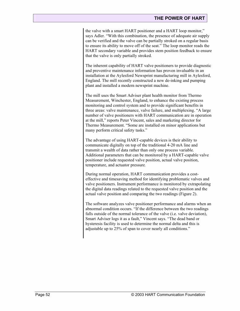
THE POWER OF HART
the valve with a smart HART positioner and a HART loop monitor,” says Adler. “With this combination, the presence of adequate air supply can be verified and the valve can be partially stroked on a regular basis to ensure its ability to move off of the seat.” The loop monitor reads the HART secondary variable and provides stem position feedback to ensure that the valve is only partially stroked. The inherent capability of HART valve positioners to provide diagnostic and preventive maintenance information has proven invaluable in an installation at the Aylesford Newsprint manufacturing mill in Aylesford, England. The mill recently constructed a new de-inking and pumping plant and installed a modern newsprint machine. The mill uses the Smart Adviser plant health monitor from Thermo Measurement, Winchester, England, to enhance the existing process monitoring and control system and to provide significant benefits in three areas: valve maintenance, valve failure, and multiplexing. “A large number of valve positioners with HART communication are in operation at the mill,” reports Peter Vincent, sales and marketing director for Thermo Measurement. “Some are installed on minor applications but many perform critical safety tasks.” The advantage of using HART-capable devices is their ability to communicate digitally on top of the traditional 4-20 mA line and transmit a wealth of data rather than only one process variable. Additional parameters that can be monitored by a HART-capable valve positioner include requested valve position, actual valve position, temperature, and actuator pressure. During normal operation, HART communication provides a cost-effective and timesaving method for identifying problematic valves and valve positioners. Instrument performance is monitored by extrapolating the digital data readings related to the requested valve position and the actual valve position and comparing the two readings (Figure 2). The software analyzes valve positioner performance and alarms when an abnormal condition occurs. “If the difference between the two readings falls outside of the normal tolerance of the valve (i.e. valve deviation), Smart Adviser logs it as a fault,” Vincent says. “The dead band or hysteresis facility is used to determine the normal delta and this is adjustable up to 25% of span to cover nearly all conditions.”
Page 52 © 2003 HART Communication Foundation

THE POWER OF HART
In addition, should the valve deviation exceed the programmed alarm point, the critical alarm mode provides instantaneous indication of valve failure. When the maintenance schedule is drawn up, the log is studied to see which valves are frequently working outside of normal tolerances. Smart Adviser can also function as a multiplexer, collecting up to 24 channels of field data from smart valve positioners and sending it to the control system
© 2003 HART Communication Foundation Page 53

THE POWER OF HART
Page 54 © 2003 HART Communication Foundation

THE POWER OF HART Available: Advanced Diagnostics
HART devices provide eight diagnostic status bits (16 bits with the new HART 6 enhancement). These status bits can be used to provide early warning of device problems. Handheld communicators can access this information when connected to the instrument loop, but most applications would benefit from continuous monitoring of these status bits. This monitoring function is provided with some DCS and HMI software packages, but not all control and monitoring systems have this functionality. “Moore Industries provides loop monitors that are typically panel-mounted and connected just like a handheld calibrator. When a HART status bit changes, the loop monitor provides both LED indication and a relay output,” says Adler. The relay output can be connected to an existing control and monitoring system, and the loop monitor can also provide a 4-20 mA signal based on one of the HART process variables. This allows a HART instrument to be interfaced to a control system simply and quickly. The performance of temperature transmitters can be improved by using the status and diagnostic information provided by HART devices. “Most temperature transmitters incorporate sensor diagnostics to drive the 4-20 mA output either upscale or downscale upon sensor failure. In a safety-critical application, this high or low action would often trigger an expensive and perhaps unnecessary process shutdown,” says Adler. HART compatible temperature transmitters can be used to avoid a process shutdown. “A HART loop monitor can be configured to use the status bits to provide a relay output indicating sensor failure,” Adler adds. “This strategy provides differentiation between a sensor problem and potentially dangerous process condition. For more safety-critical applications, a dual nonvoting scheme or a two-out-of-three scheme provides even more reliability.” A transmitter can lock at a fixed output value if it is placed in a manual mode for tests and not returned to automatic operation. HART’s Primary Variable Analog Output Fixed status bit can be used to detect this condition and alert an operator. Distributed control systems such as Foxboro’s I/A can automatically detect and use HART diagnostic information. “HART status and diagnostic signals can be transmitted in digital format and used by the control strategy and operator displays,” says Gray. “In addition, there are more than 30 diagnostic parameters available to maintenance to determine the health of a valve. These are available through our Technician’s Workbench I/A system module.”
Configuration Is Easy With a PC
Most HART users are aware that HART instruments can be configured remotely from any point on the HART data highway. This can be performed with handheld calibrators or through a host computer.
© 2003 HART Communication Foundation Page 55
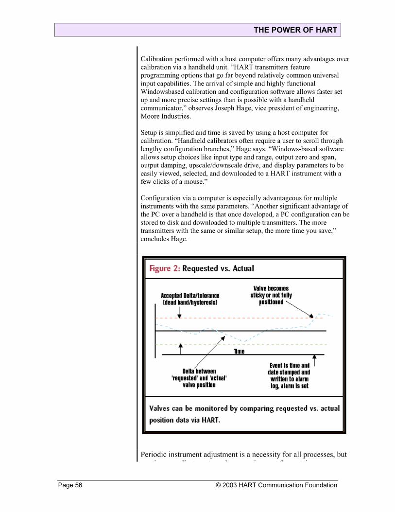
THE POWER OF HART
Calibration performed with a host computer offers many advantages over calibration via a handheld unit. “HART transmitters feature programming options that go far beyond relatively common universal input capabilities. The arrival of simple and highly functional Windowsbased calibration and configuration software allows faster set up and more precise settings than is possible with a handheld communicator,” observes Joseph Hage, vice president of engineering, Moore Industries. Setup is simplified and time is saved by using a host computer for calibration. “Handheld calibrators often require a user to scroll through lengthy configuration branches,” Hage says. “Windows-based software allows setup choices like input type and range, output zero and span, output damping, upscale/downscale drive, and display parameters to be easily viewed, selected, and downloaded to a HART instrument with a few clicks of a mouse.” Configuration via a computer is especially advantageous for multiple instruments with the same parameters. “Another significant advantage of the PC over a handheld is that once developed, a PC configuration can be stored to disk and downloaded to multiple transmitters. The more transmitters with the same or similar setup, the more time you save,” concludes Hage.
Periodic instrument adjustment is a necessity for all processes, but ti dj t t b i t f t i
Page 56 © 2003 HART Communication Foundation

THE POWER OF HART
© 2003 HART Communication Foundation Page 57
continuous adjustment can be a requirement for certain applications. These applications virtually necessitate a digital data interface to a smart instrument. If the composition of the fluid or gas that is being measured changes continuously and if this change in composition affects setup parameters, then continuous reconfiguration is required to maintain the accuracy of process measurements. Smart instruments equipped with HART capability can enable continuous adjustment by receiving data from instruments with respect to fluid or gas composition, using these data to automatically calculate settings, and downloading these settings to the affected instruments. Asset management software programs make extensive use of the device identification information available through HART. This information is read by the asset management program and stored in a database, allowing the program to automatically populate the database with pertinent information related to each instrument’s tag number, manufacturer, device type, final assembly number, and serial number.

THE POWER OF HART
Leverage Your Assets HART Communication: It's Not Just for Configuration Anymore
Want to run your plant more efficiently? Would you like to set up a better,more automated maintenance management program? Are you trying to obtain asset management information from your plant instrumentation? Maybe you'd like to avoid process disruptions. Or keep your plant from catching fire and blowing up. A level transmitter at a Midwest refinery was short-circuited by condensation and created an erroneous 4-20mA signal. The operator was suspicious,but no one could find a problem until the tank overfilled and shut the entire plant down. The process disruption cost $300,000. If the system and level transmitter had been HART-enabled, the erroneous signal could have been detected and the operator would have been alerted to the problem before it shut down the plant. You can create those kinds of capabilities in your plant. You may already have much of what you need to get started, particularly if you purchased new smart field instrumentation in the past 10 years. That's because just about every smart field instrument built these days is capable of HART Communication. And if you have devices with HART Communication, you also have a good start on what you need to run your plant more efficiently. You're ready to begin an asset management program, obtain early alarms on process upsets, and increase the reliability of your processes. What's more, it won't be a major investment to obtain the information you need, because it's already there, ready to be accessed via HART Communication
More Than Maintenance
Maintenance technicians appreciate HART because it makes their jobs easier. Techs can interrogate devices directly from the control room, eliminating many unnecessary trips out into the plant. What you may not realize is that simplifying maintenance and calibration tasks is just the tip of the iceberg. Your HART devices also have the power to push your existing plant instrumentation and control systems into the 21st Century. You can use HART technology to get started in asset management, for example. HART devices have all the information you need to determine device status, health, and the need for field maintenance. HART devices can also determine the health of other process equipment, such as control and safety shutdown valves. The Gainesville Regional Utility,Gainesville, Fla., uses HART Communication to diagnose instrumentation problems and reduce unnecessary trips to the field. The data is fed to asset management Operators at its John R. Kelley Generating Station (photo above) can check many process problems by examining asset management data from a PC.
Page 58 © 2003 HART Communication Foundation

THE POWER OF HART
For example, if an operator suspects a transmitter is not zeroing out, he can check the asset management system historical data. If there's a difference of 5% or more between the process signal and the HART data, the operator knows a problem exists, and someone must physically check the transmitter and associated equipment. More often than not, the utility will report the problem is a leaking valve, found long before the consequences serious and cause a system breakdown. "After nearly a year of working with the HART-capable instrumentation installed as part of a re-powered 110MW combined-cycle generating plant, our reliance on the unit's asset management software package continues to grow," says Terry Gordon, instrumentation supervisor. "It enables us to do a lot more things a lot quicker, with fewer personnel than we could by following conventional instrument maintenance procedures." One of the finalists for this year's HART Plant of the Year Award, a Solutia plant in Chocolate Bayou,Texas, that started up in 2000, has lots of HART-enabled instrumentation. All the HART data is logged to an Aspen Tech data historian and to an asset management system. "Our design decision was to use as much smart instrumentation as possible,” says John Forbis, Engineering Fellow at Solutia's Integrated Nylon Div., St. Louis.” Ninety-nine percent of all instruments are HART-enabled. The only non-HART instruments are on OEM systems, such as chillers and air compressors. We tried another communication technology, and it just did not work for us." A British Petroleum ethylene plant in Cologne, Germany, has about 2,000 HART-enabled instruments and about 800 HART-enabled control valves
© 2003 HART Communication Foundation Page 59
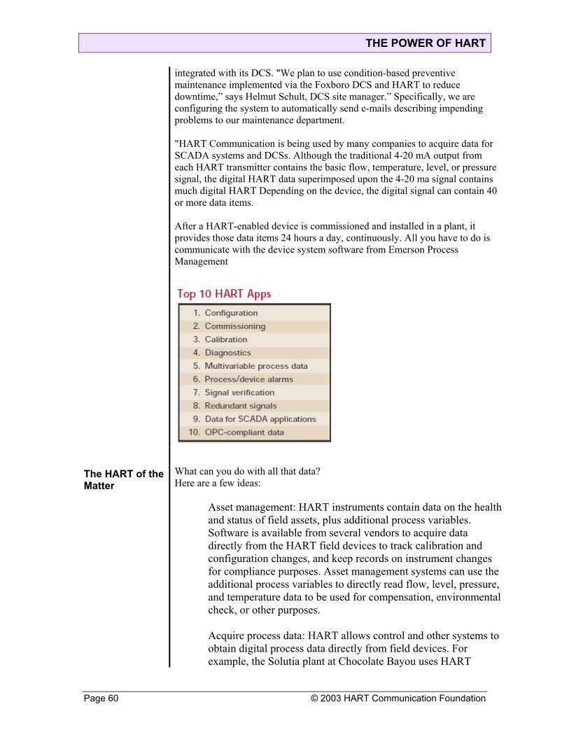
THE POWER OF HART
integrated with its DCS. "We plan to use condition-based preventive maintenance implemented via the Foxboro DCS and HART to reduce downtime,” says Helmut Schult, DCS site manager.” Specifically, we are configuring the system to automatically send e-mails describing impending problems to our maintenance department. "HART Communication is being used by many companies to acquire data for SCADA systems and DCSs. Although the traditional 4-20 mA output from each HART transmitter contains the basic flow, temperature, level, or pressure signal, the digital HART data superimposed upon the 4-20 ma signal contains much digital HART Depending on the device, the digital signal can contain 40 or more data items. After a HART-enabled device is commissioned and installed in a plant, it provides those data items 24 hours a day, continuously. All you have to do is communicate with the device system software from Emerson Process Management
The HART of the Matter
What can you do with all that data? Here are a few ideas:
Asset management: HART instruments contain data on the health and status of field assets, plus additional process variables. Software is available from several vendors to acquire data directly from the HART field devices to track calibration and configuration changes, and keep records on instrument changes for compliance purposes. Asset management systems can use the additional process variables to directly read flow, level, pressure, and temperature data to be used for compensation, environmental check, or other purposes.
Acquire process data: HART allows control and other systems to obtain digital process data directly from field devices. For example, the Solutia plant at Chocolate Bayou uses HART
Page 60 © 2003 HART Communication Foundation

THE POWER OF HART
technology to acquire analog inputs for a Triconex triple-modular redundant system used for safety and emergency shutdowns. “When the same signal needs to go to our control system and the Triconex safety system, we use a signal splitter/isolator from Moore Industries,” says Bart Propst, process control engineer.” The Moore device receives a 4-20 ma signal from a HART instrument and sends 4-20Ma outputs to the control system and another 4-20 ma signal created from the HART data to the safety system.” This lets them use the same 4-20 ma sensor for control, safety, and shutdown, and still maintain signal isolation. Improve product quality: HART data can be used to improve process dynamics and product quality. The Solutia plant in Chocolate Bayou acquires process data from multivariable HART transmitters. Forbis says they use Valvelink software to do advanced testing and trim key valves to improve process performance. Manage maintenance: At the Air Products and Chemicals plant in Baytown, Texas, the asset management system keeps track of 1,000 transmitters and 150 valves using HART data. “Plant personnel use asset management for routine trouble shooting of process issues, recalibration, and verifying valve operation relative to the original valve signatures,” says Mark Lusignia, instrument engineer. Real-time diagnostics: When problems arise with a field instrument, the array of diagnostic information available in HART devices makes it possible to diagnose many problems from a PC screen. In some plants, half of the times an instrument tech is asked to go out into the plant to check an instrument, the result is “no problem found.” Being able to diagnose instrument problems remotely saves time and improves worker safety. For example, the Gainesville Regional Utility uses HART communication to verify the condition and operational status of instruments on top of a seven-story heat-recovery generator and other in accessible points.” It would take a technician up to an hour to go out into the plant and check a single instrument,” says Gordon. Diagnostic alarms: When a control system depends on a 4-20 ma signal alone, an operator has no way to check the accuracy or validity of data when a problem is suspected. With HART-enabled systems, software can be set up to automatically look for a device status problem or a performance problem and sound
© 2003 HART Communication Foundation Page 61

THE POWER OF HART
Page 62 © 2003 HART Communication Foundation
alarms long before a problem can be detected in the 4-20 ma loop current. Minimize scheduled downtime: GSK Pharmaceuticals in Irvine, Scotland, also a HART Plant of the Year finalist, wanted to reduce the frequency of calibration for 122 critical devices from once every three months to something less often. It takes four hours to calibrate each device, and four times per year seemed to be too frequent, but they had no way of knowing how often calibrations were really necessary. The plant used HART data to collect device information and run online diagnostics. “After a year and-a-half evaluation period, HART data showed that the calibration cycle could be at least doubled to every six months,” says Ian Allen, instrument engineer. “We also got more accurate information as to when a device actually did fail, as opposed to waiting for the next calibration, so it could be repaired or replaced immediately
Where Do You Go From Here? Finding Problems
HART communication enables intelligent I/O systems to identify and diagnose process problems such as:
Loop fault: With a standard 4-20 ma signal, I/O systems can detect a problem only if the signal is outside the 4-20 ma range, and only if it is constant; they can easily miss intermittent problems. A HART system can periodically check the 4-20 ma signal to ensure its agreement with the field I/O device. It detects intermittent problems and performs loop tests whenever needed. Device failure: With ordinary transmitters, I/O can detect catastrophic device failure only if the 4-20 ma signal is outside the normal operating range. With HART, internal diagnostics can communicate the status of field devices in real time, provide early notification of problems, and help you take action to prevent a process disruption. Incorrect reading: When the accuracy of the 4-20 ma signal is impaired by, for example, a bad connection or deteriorating sensor, the host system can detect the incongruities between the 4-20 ma signal and the additional process variables communicated by the HART protocol. Early detection and analysis of these incongruities can focus maintenance operations and prevent shutdowns

THE POWER OF HART
Unleash the Power of HART
Critical Facts About HART
• Traditional 4-20 mA analog signal is used for control and/or monitoring.
• Digital signal carries additional information on the same wiring.
• All HART smart devices continuously provide process data for plant operation—24/7.
• HART provides access to all device data while the 4-20 mA analog signal is being used for control.
• Information about the status (health) of the field device and quality of the 4-20 mA signal is in every message.
• The Process or Primary Variable (PV) is transmitted as a 4-20 mA signal and also as a digital value.
• Many devices have measured or calculated process variables in addition to the PV.
• The more you communicate with HART devices, the more value you receive from your investment.
HART Device Data Every HART device, regardless of the supplier, comes standard
with the ability to communicate 35-40 data items you can use to improve your operations. These data items include:
• Process Variable Values Primary, secondary, and other values Loop current value in milliamps
© 2003 HART Communication Foundation Page 63
THE POWER OF HART
• Device Status & Diagnostic Alerts Device malfunction Configuration change Variable out of limits Primary variable output fixed or saturated
• Device Identification Instrument tag, device type, etc.
• Calibration Information Date of last calibration Upper & lower range value PV damping Loop current transfer function & alarm action Write protect status
A Choice of Migration Strategies
There are many ways to benefit from the power of HART communication and leverage the intelligence in your smart field devices. The figures show several simple and cost-effective migration strategies to get more from currently installed HART equipment Point-to-Point Strategy: This is the most common way HART is used. The communication capability of HART-enabled devices allows them to be configured and set-up for specific applications, reducing spares inventory and saving time and money in commissioning and maintenance. Connecting to the 4-20 mA wires, you can interrogate a device from remote locations for diagnostic information HART-to-Analog Strategy: Signal extractors communicate with HART devices in real time to convert the intelligent information in these devices into 4-20 mA signals for input into an existing analog control system. Add this capability one device at a time to get more of the power of HART. HART-Plus-Analog Strategy: New HART multiplexer packaging solu- tions make it easy to communicate with HART devices by replacing your existing I/O termination panels. Your analog control signal continues on to the control system but the HART data is sent to a device management system providing valuable diagnostics information 24/7. Although the control system is not aware of the HART data, this solution provides access to device diagnostics for asset management and process improvements. Full HART Integration Strategy: Upgrading your field or remote I/O system provides an integrated path to continuously put HART data directly into your control system. Continuous communication between the field device and control system allows automatic detection of problems so corrective action can be taken before there is negative impact to the process operation.
Page 64 © 2003 HART Communication Foundation

THE POWER OF HART
© 2003 HART Communication Foundation Page 65
HART-to-Plant-Network Strategy: HART OPC server software tools provide a simple, cost-effective means of passing HART data onto your plant Ethernet network to OPC compliant applications anywhere in the plant.
Serve HART to Plant Networks
The HART Communication Foundation has developed the HART Server Tool to facilitate serving HART data to plant networks and other high-level OPC-compliant applications. The tool provides easy access to HART device data anywhere on a plant network.
• Allows several applications to simultaneously access data in a HART device.
• Enables popular HMI and trending packages to access HART data.
• Connect to one or a thousand devices using common HART I/O systems and interfaces. • Cost-effective and easy to set-up and use.
• Can put HART data on your desk top, PDA, e-mail system, etc.
• Created and supported by the HART Communication Foundation.
What to Do? HART communication technology is simple, easy to use, low-risk, and cost effective. As with any journey, taking the first step is important. Here’s how to get started:
• Visualize one or more of the many ways HART communications could improve operations in your plant.
• Identify your installed HART devices to confirm that key measurements are included. If not, map out a plan to make all devices HART-capable.
• Provide HART technology training to your staff. • Explore HART solutions with your suppliers to determine
your best migration strategy. • Contact the HART Communication Foundation or visit the
Foundation web site, www.hartcomm.org, for more information and for specific cost-effective solutions you can use to Unleash the Power of HART.

THE POWER OF HART
Powerful Connections New Products Seamlessly Connect HART Field Devices to Any Control System In essence, HART’s value proposition is moving more data from
the process into the control system with an infrastructure you already own, then leveraging that information to increase plant efficiency. A range of connection options make it relatively easy. If your plant has a DCS connected to a large number of HART-enabled instruments and field devices, the HART signal superimposed on the 4-20 mA wiring is readily available and contains a wealth of useful process and device diagnostics information.
Control Systems Get HART
Most of the major DCS and control system vendors already have HART Communication capability in their newer systems, and many have upgrade paths for older systems. For example, in May the Foxboro division of Invensys announced new I/A Series HART modules. Each module can accept up to eight 4-20 mA inputs and fully integrates HART Communication. The Foxboro upgrade has already been used to implement asset management and preventive maintenance at a British Petroleum ethylene plant in Cologne, Germany. The plant has about 2,000 HART-enabled instruments and about 800 HART-enabled control valves. “We purchased new input and output modules and installed the newest version of the Foxboro I/A software,” says Helmut Schult, BP’s DCS site manager at the Cologne plant. “We then installed the modules, and configured the I/A system to recognize the modules.” There was no need to change field devices since they were already HART-capable. This kind of system offers full-time, real-time HART data integration with the control system and higher-level systems. While the several-second latencies of other approaches are usually quite acceptable in process applications, control systems optimized for HART Communication can reduce latency times to about 0.4 sec. per point, depending on the network configuration. Honeywell’s Experion PKS control system offers eight-channel HART analog- input and analog-output modules. Both modules scan the standard 4-20 mA analog signal and the HART digital signal. The HART digital data is made available to the control system over ControlNet. “HART device information is scanned from each device and made available for display, logic, control, or trending,” says Joe Serafin, Experion PKS product manager for Honeywell Industry Solutions. ABB supports the HART protocol through its Industrial IT
Page 66 © 2003 HART Communication Foundation

THE POWER OF HART
controllers. “HART instruments are connected to the Industrial IT I/O system,” explains Martina Walzer, marketing manager of fieldbus technologies for ABB. “HART information is then tunneled to the controller via Profibus.” HART Communications is also available on ABB’s legacy control systems including Advant, Symphony, and Freelance 2000..
HART devices can communicate with Siemens’ systems through its
compatible remote I/O, HART modem, HART interface, or HART multiplexer products, and a HART I/O module is offered as part of the APACS+ control system. Emerson Process Management delivers its DeltaV automation systems with HART as a standard. “We feel so strongly that HART is a good protocol for those not considering Foundation fieldbus that the DeltaV automation system analog I/O is only sold with HART capability,” says Ron Eddie, vice president of technology for Fisher- Rosemount Systems. HART functionality is also available on Westinghouse Ovation systems and on Provox and RS3 systems. On older generations of Provox it is only necessary to upgrade the I/O terminal strip and the analog I/O card. For the older generations of RS3 systems, it is necessary only to upgrade the I/O electronics
Clever Devices Fill Gaps
If your existing DCS is not HART enabled, and if immediate plans do not call for a new DCS or an upgrade to your DCS to make it HART-capable, there are many other options. Signal extractors can access portions of HART data from a device and send it to your plant control system via 4-20 mA signals and/or discrete outputs.
© 2003 HART Communication Foundation Page 67

THE POWER OF HART
The 2002 HART Plant of the Year (page S-21) makes extensive use of Moore Industries’ SPA loop monitor and alarm. Signal extractors like the SPA extract the HART data superimposed on a 4-20 mA signal and retransmit virtually any combination of the process variable values, the status and diagnostic alerts, and the device identification information contained in the HART data. Many control systems already have the capability to communicate via a digital fieldbus or an OPC interface. A low-cost way to connect HART instruments and control valves to these control systems is through a communications gateway. Multiplexers, RS- 232 interfaces, and gateways that connect HART to Ethernet, Modbus, and Profibus are widely available. The Viator HART PC modem from MACTek, for example, attaches to a PC serial port and allows the PC to communicate with HART devices. The modem is a good interface for Siemens’ Simatic PDM and other asset management software. Pepperl+Fuchs has a choice of HART multiplexers that convert HART data to RS-485. This serial data can be recognized by a number of PC based software programs including AMS from Emerson, Cornerstone from Applied Systems Technologies, and Pepperl+Fuchs’ PACTware. A typical connection scheme combining master and slave multiplexers (Figure 1) can connect as many as 7,905 HART field devices to a PC.
OPC Serves It Up A more versatile and powerful method of connecting HART instruments and control valves to existing control systems is through the OPC-compatible HART Server Tool (Figure 2). Inexpensive and simple to implement, all that is required is a PC, OPC server software from the HART Communication Foundation, and a multiplexer or serial modem.
Page 68 © 2003 HART Communication Foundation
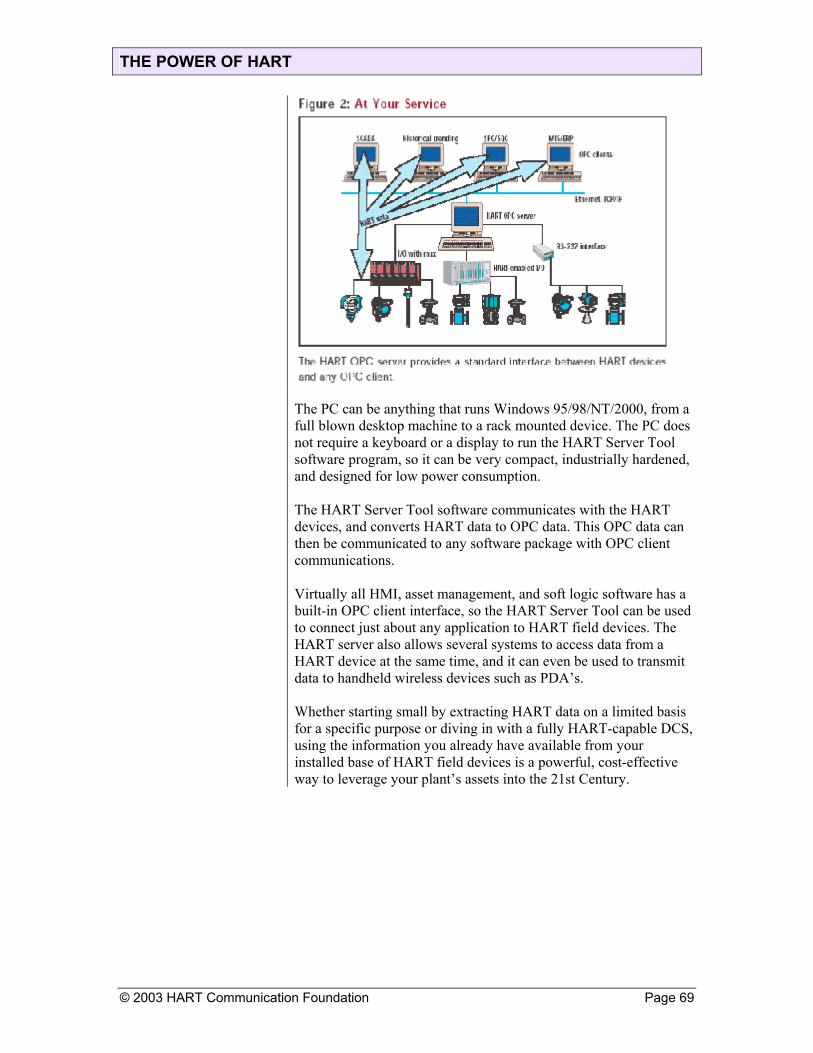
THE POWER OF HART
© 2003 HART Communication Foundation Page 69
The PC can be anything that runs Windows 95/98/NT/2000, from a full blown desktop machine to a rack mounted device. The PC does not require a keyboard or a display to run the HART Server Tool software program, so it can be very compact, industrially hardened, and designed for low power consumption. The HART Server Tool software communicates with the HART devices, and converts HART data to OPC data. This OPC data can then be communicated to any software package with OPC client communications. Virtually all HMI, asset management, and soft logic software has a built-in OPC client interface, so the HART Server Tool can be used to connect just about any application to HART field devices. The HART server also allows several systems to access data from a HART device at the same time, and it can even be used to transmit data to handheld wireless devices such as PDA’s. Whether starting small by extracting HART data on a limited basis for a specific purpose or diving in with a fully HART-capable DCS, using the information you already have available from your installed base of HART field devices is a powerful, cost-effective way to leverage your plant’s assets into the 21st Century.

THE POWER OF HART
Put It To Work Take Advantage of HART Communications by Connecting Instruments to Control Systems, Laptop PCs, or Wireless Networks
You will be happy to learn that not only is instrument information readily available; it is downright easy to get. What’s more, you don’t have to be a programmer. We’ll walk you through the various options available, starting with handheld terminals and working up to the most complex networking systems.
Calibrating Field Devices Virtually everyone who owns HART instrumentation knows how to
connect a handheld terminal to calibrate or diagnose a field device. Essentially, you find any convenient location along the 4-20 mA signal line—between the instrument and its termination in the control room or remote data acquisition system—and clamp on an adapter. The adapter is able to read the analog and embedded digital signal without affecting the signal in any way. Many of the handheld terminals are based on Emerson Process Management’s 275 HART device, which it supplies to many HART vendors as a house brand. It was designed years ago, but it still works just fine. Newer handhelds from companies such as Smar are becoming available with Palm user interfaces. According to Jonas Berge, manager of Smar Asia-Pacific Operations in Singapore, the Palm-based devices have a Windows-like user interface. “This comes in handy, as newer-generation HART devices have more diagnostics information than ever before,” says Berge. “Some information is better visualized graphically on a large screen than on just a textbased screen like the older units.” About 80% of all process controller and field instruments have a HART interface these days, and practically every maintenance technician, operator, instrument engineer and control engineer knows how to use a handheld HART terminal to change the zero and span, or check status. In probably 99% of the process installations, this was why HART devices were bought in the first place. That was most definitely true 15 years ago, when HART-based smart instruments first appeared on the scene. Back then, being able to work with a handheld terminal to remotely change, calibrate, and diagnose a field instrument was all the rage. Today, engineers and technicians still use this capability out in the field, but now they don’t have to. Instead of getting wet or huddling in an instrument shed, engineers and operators can interrogate and change parameters from the comfort of the plant’s control room, using software loaded on any Windowscompatible PC. All they have to do is connect the PC to the HART device network, and install a simple software package that emulates a handheld terminal.
Page 70 © 2003 HART Communication Foundation

THE POWER OF HART
Siemens and Emerson Process Management both offer software packages—Simatic PDM and AMS respectively —that run on a PC. Both can connect directly via RS-232 to a HART multiplexer (see below), and provide all the configuration, setup, calibration, and diagnostic functions of handheld terminals. At this point, Device Descriptions (DDs) enter the picture. While a handheld terminal or PC software package has the ability to configure any HART device, DDs make the procedure much simpler, because they provide the necessary parameter locations. Every vendor that makes a HART instrument also writes a DD that can be loaded into a handheld terminal. Typically, an end user loads handheld terminals with DDs for all the field instrumentation in the plant so engineers and technicians can work with anything. Owners of the 275 HART terminals often send the unit off to the manufacturer to have the necessary DDs loaded. This is much easier for some plants than loading DDs locally. Fortunately, the latest handheld terminals and PC software packages are able to load from CD-ROMs, disks, or Internet sources, simplifying the update process. At present, there are more than 250 unique HART instruments from 70 vendors, all with individual DDs.
Getting Connected For a simple connection, a HART modem interface from MACTek will connect your PC’s RS-232 port to a HART field device. The modem connects to the 4-20 mA signal line just like the handheld communicators, and provides an RS-232 signal containing all the digital HART information. If more than a few HART devices are involved, then RS-485 multiplexers from companies such as Arcom, Elcon, MTL, Pepperl+Fuchs, Stahl, or Thermo Measurement can be used (Figure 1). Up to 31 multiplexers can be connected, each with 32 loops, for a maximum of 992 devices. Some multiplexers support a multi-tier architecture that allows you to connect thousands of field devices into a single virtual network. The point is, no matter how many HART devices you want to connect—from one to thousands—the connection to your PC is simple and straightforward. All you need is a modem and a cable. And a server, of course. The HART Communication Foundation (HCF) recently announced the availability of the HART to Enterprise OPC server, or HART Server. Load this software into your PC, hook up to HART devices with a modem, and you gain real-time access to all the process-related information available in HART devices. With HART Server software and a $350 RS-232 link or a $2,000 multiplexer, you may have all the connective functionality you’ll ever need.
© 2003 HART Communication Foundation Page 71

THE POWER OF HART
The HART Server is OLE for Process Control (OPC)- compliant, so it can obtain information from HART devices and pass it along to any OPC client applications, such as SCADA/HMI software, an Internet web browser, an Excel spreadsheet, SQC and SPC software, and ERP systems. For example, real-time flow transfer data obtained from a HART device can be delivered to an Excel spreadsheet. No special skill or customized software is needed. Using simple drop-down screens (Figure 2), fill-in-the blanks functions, and tag names, the HART Server can be configured to automatically collect real-time information from any number of HART devices and deliver it to any OPC client application. Once configured, the HART Server starts working immediately. Users can start gathering HART data in a matter of minutes, rather than several hours or days. The HART Server is a plug-and-play device; that is, once it is connected to the HART network via a modem, it automatically recognizes and communicates with all HART devices it can find on the network. This includes HART devices directly connected via RS-232 as well as devices connected through various control networks, multiplexers, and I/O systems. Once it establishes communication, the HART Server automatically retrieves device information. Each OPC client that connects to the HART Server can request information at any rate desired. The client can specify update frequency, dead band, and so on. The HART Server will update information as requested and send it to the client. To see how easy it is to use, download a free evaluation version of the HART Server. Just go to www.hartcomm. org, select the End User Info box, then click on HART Server. From there, you can
Page 72 © 2003 HART Communication Foundation

THE POWER OF HART
request a demo evaluation kit that allows you to download server and related software modules on your PC and simulate the complete server functionality, free of charge for 30 days. This kit includes:
HART Server software Xmtr-mv instrument simulation software (Windows NT only) GnHost diagnostic software
To use these modules, simply load the software into a Windows NT, 98, or 2000 environment, associate and jumper the correct COMM ports on your PC (for example, COMM 1 for the server, COMM 2 for Xmtr-mv) and follow the instructions in the kit. You may also use your own instruments in the simulation by connecting a HART modem to the serial port.
Hooking Up a HART Multiplexer
If you have more than one HART device, connecting them to your control system can be done in one of two ways. The first is to run the HART signals to a HART I/O board in your control system. The second way to obtain HART data is to use a HART multiplexer. This is ideal for end users with control systems that do not yet support HART digital data for control and monitoring purposes. Users with legacy control systems also are in this situation. David Hohenstein, manager of the hardware marketing group at Pepperl+Fuchs, Twinsburg, Ohio, explains that hooking up a HART multiplexer is easy. “Just run the 4-20 mA signals from HART field devices into a HART multiplexer,” explains Hohenstein. “The multiplexer strips off the digital HART data, then sends the 4-20 mA signal on its way.” The original 4-20 mA signal is unaffected, so it can connect to a normal analog input board at a control systemMeanwhile, the multiplexer sends the digital HART data to the control system via a serial link, typically RS-232 or RS-485. The only trick to using a HART multiplexer is that it must be compatible with the control system, says Hohenstein. “The connection to all HART instruments is standard, but every control system is different. You have to purchase a HART multiplexer with an I/O interface that works with your particular control system.” Pepperl+ Fuchs has 40 different HART multiplexers, with models ranging from 32 to 255 channels. Once connected to the control system, the multiplexer becomes a passive device, serving merely as a conduit of information. When asset management or HART Server software in the control system wants data from a HART instrument, it sends the device a HART command. The command signal goes to the HART multiplexer which embeds the digital signal into the 4-20 mA loop. The
© 2003 HART Communication Foundation Page 73
THE POWER OF HART
command arrives at the HART device where it is acted upon. The HART device embeds the requested information into the 4-20 mA signal, and the multiplexer strips out the digital data and sends it on to the control system. Issues to be considered with HART multiplexers primarily involve speed. A multiplexer with 255 channels and a single modem operates much slower (on a channelby- channel basis) than does a 32-channel multiplexer with one modem. If a control system needs faster access to data, it can use smaller, eight or 16-channel multiplexers, or you can purchase multiplexers with multiple modems
Getting More Complex So far, we’ve only looked at HART networks that connect to a single PC. Much more capability is available for a serious user. It’s possible to connect your HART instruments into most major networks, the Internet, and even into wireless systems. Arcom, for example, sells a series of multiplexers that plug into Modbus networks. At Shell’s Tejas Calumet gas plant in Louisiana, data from Rosemount HART flowmeters is stored in Modbus registers in an Arcom HtNode multiplexer, allowing any Modbus host to access the information. A SCADA system in a PC accesses the flow data every five minutes by interrogating the HtNode device over Modbus. HART multiplexers are available that support Ethernet TCP/IP connections. Such a system could easily connect into the Internet, a plant intranet, OPC systems, or other plant network schemes based on Ethernet. In such a case, a PC or workstation equipped with HART Server software can access HART instruments anywhere on the network. With a HART Server in your PC, you can make instrument information available to any OPC client device (Figure 3). This includes web browsers, SCADA systems, ERP systems, and software that drives cell phones, handheld computers, personal digital assistants (PDAs), and wireless equipment. A control system designed and installed by SysInc Engineering to support multiple plants, process areas, and loading facilities makes extensive use of HART devices. A Windows 2000 HART OPC Server at each plant is connected directly to an Arcom 32-channel HART multiplexer via an RS-485 serial port.
Page 74 © 2003 HART Communication Foundation

THE POWER OF HART
Approximately 70 two-wire and four-wire HART devices per plant are connected to the multiplexer. These devices include SAAB and Krohne radar level gauges, Inor and Smar temperature transmitters, Micro Motion mass flowmeters, and Endress+Hauser volumetric flowmeters. Most of the HART devices are wired in a multi-drop configuration and connected to the HART OPC Server. Other HART devices feed into four-channel ProLinx HART/Modbus gateways that in turn feed into the Modbus OPC server. The OPC server provides a clean interface to custom as well as off-the-shelf SQL and web-based applications. Most of the devices are set up on multi-drop networks and do not use the 4-20 mA signal available from each device. The faster update time of a 4-20 mA signal took a back seat to the accuracy of the HART digital signal for this application. According to the system integrator, the client plans to take advantage of many HART features. “Our client will use the multivariable, status and diagnostics, and remote calibration capabilities of the HART devices. The most critical capabilities for this application are multivariable and device status,” says Curtis Butt, electrical engineer, SysInc. “The long-term manageability of the system required us to provide not only remote access to basic variables, but also remote diagnostics and configuration.”
© 2003 HART Communication Foundation Page 75

THE POWER OF HART
The client and SysInc expect to see a significant improvement in the reliability of the data coming from the devices. “The old system had only local displays at each instrument,” says Butt. “Operators did not trust the system and would often revert to manual operation. Part of this was due to devices being in remote locations, which led to difficulties in calibration and verification of proper operation.” Operators will now be able to remotely access devices and receive accurate information. “The new system will provide complete access to all devices including status, calibration, and configuration information,” Butt concludes. “Use of the HART protocol will help us achieve better repeatability and higher accuracy, both in the process area and in the bulk storage/inventory area.” You may never need such complex communication schemes, but it is comforting to know that HART instruments fit right in.
Connecting to Controls HART devices can connect directly to control systems and devices, allowing users to make use of instrument data for monitoring, alarming and control purposes. Allen-Bradley, Wickliffe, Ohio, provides a HART interface module for its PLC 5 and SLC programmable controllers that allows a PLC to see HART data. Installed as a remote I/O device, the module acquires data from a HART instrument, strips out the HART signals, and puts the data into a format that can be addressed by ladder logic programming. Pat Moyer, product manager at A-B, explains that the system is
Page 76 © 2003 HART Communication Foundation

THE POWER OF HART
supplied with preconfigured instructions that support HART commands. “We provide several basic HART commands, but a user is free to write additional commands in ladder logic to perform whatever functions are needed, such as data logging, alarm checking, or monitoring device status.” Moyer says the HART module is a big hit among certain A-B customers. “We have users in the food and oil and gas industries that use the module extensively,” she says. Yokogawa Corp. of America, Newnan, Ga., offers hardware and software that acquire HART data and make it available to its Centum control systems. Bruce Jensen, manager of systems marketing, explains that a Centum can acquire data from a standard HART multiplexer or from its own FIO 4-20 mA input modules. “The FIO devices have a HART module that extracts the digital HART data from the 4-20 mA signal and provides both analog and digital data.” FIO devices are available in eight or 16-channel versions. Yokogawa’s Plant Resource Management software formats the HART data and makes it available to the HMI and controls software, where it can be monitored, trended, logged, and displayed. Jensen says most customers use the capability to automate instrument maintenance functions because the software supports all the standard configuration and calibration functions from an HMI screen. “We have several users, mostly in the pharmaceutical industry, who are starting to take advantage of HART data for more sophisticated purposes,” says Jensen, “but most of our users are not familiar with all the capability available within HART.” Virtually all major process control companies support HART, so it should be relatively easy to connect your control system to your own HART devices. Dave Sheppard, vice president of I/A Systems at Foxboro/Invensys, Foxboro, Mass., says Foxboro has supported HART for maintenance purposes for years. “We support the connection of HART multiplexers from several suppliers,” he explains, “and we bring the HART data into a dedicated PC where third-party software can obtain data for maintenance calibration and equipment configuration functions.” At ISA/2001 in Houston, Foxboro will unveil a new eight-channel analog I/O board with a HART module that splits out the digital signal and feeds it into standard equipment control block (ECB) modules. “The HART data will be made available to Foxboro’s HMI and process control software like any other process variable, so it can be used for control, data logging, monitoring and so on,” says Sheppard. “We are taking orders now for delivery in the second quarter of 2002.” Honeywell, Phoenix, is on a similar track
© 2003 HART Communication Foundation Page 77

THE POWER OF HART
“We offer standard HART multiplexers from Pepperl+Fuchs or MTL,” says Joe Serafin, product manager for Plantscape I/O. “The MUX connects to the serial port of a PC, which runs Cornerstone or some other third-party HART software for maintenance and instrument calibration.” Honeywell’s customers have been asking for additional HART capabilities, so Honeywell has a HART I/O card in the works, scheduled for introduction in the near future. “The new card will strip off the HART digital data from the 4-20 mA signal and make it available to the control environment,” says Serafin. Meanwhile, if you don’t want to wait for products to become available, you can take matters into your own hands and implement a system using the HART Server.
By the Numbers Here’s a step-by-step procedure for getting started with the HART Server. This should get you up and running in a matter of just a few minutes:
1. Load and install the HART Server software on your PC. You can download it from the Internet or load it from a CD-ROM. 2. Configure your PC’s COM port to communicate with the HART network. You need to tell the PC port if it will be seeing RS-232, RS-485, or RS-485 with an Ethernet adapter. The HART Server configuration screens help you do this. 3. Configure the HART Server to set up links between the data sources and the data users (what programs want to see what data?). Again, the HART Server configuration screens ask the right questions. 4. Verify and test the HART Server using the GnHost diagnostic software tool, supplied by the HART Foundation.
Most of the configuration menu screens are similar to Windows Explorer. With a series of mouse clicks, you should be able to complete the configuration quickly. The HART Server will automatically detect and learn the HART devices connected to the port. At the end of the configuration process, two-way communication between the HART Server and the HART instruments will be fully established. The HART Server pass-through software lets OPC client applications send HART commands to HART instruments. Therefore, any software such as configuration or valve analysis packages that run on handheld terminals can run on a PC equipped with HART Server. Likewise, HMI and SCADA software can access data using standard OPC functions. The OPC client browses the data items available from the server and subscribes to the data items of interest. This is a standard OPC function that is supported by all software packages that claim to be OPC clients or servers, such as HMI/SCADA systems. When you get the HART system connected to the HART Server, simply go to the part of your HMI or SCADA system that defines I/O points. You will be adding the HART instruments the same way you configured your plant when you first installed the HMI/SCADA system: that is, you’ll probably use a menu-based configuration screen to define the path, device, tag name, and so on, and your HMI/SCADA system will lead you through the process. .
Page 78 © 2003 HART Communication Foundation

THE POWER OF HART
You will also be able to define how often you want each parameter or groups of parameters updated, or “turned on.” When a group is turned on, the HART Server will publish the data items (i.e., update, acquire, and send the group to the client). This allows processing packages from loop controllers to process historians to obtain instrument information from the field as often as necessary, simply by making the appropriate definitions in an OPC software package
Using Specialty Devices
Several HART instrument vendors have developed specialty processors and loop monitors that perform unique diagnostic and analysis functions. In many cases, this allows you to take advantage of the information contained in your HART instruments without making a network connection or using PC software. In other words, you can solve local problems without involving the plant’s main control system. An annoying problem in many plants involves sticking valves and worn-out positioners. Such problems are usually difficult to detect for most control engineers, maintenance technicians, and even the best process control and SCADA systems. Most all these entities are usually at a loss to explain a valve’s bad behavior when it starts hunting, sticking, and performing poorly. The answer in most plants is to pull the valve out of the line for maintenance.
A HART-based smart valve positioner has all the information you need to analyze valve performance. HART data can tell how many times the valve opens and closes, how much the stem has traveled, if actuator pressure has changed, and a host of other variables that are available through HART, but are never monitored in most plants. The positioner itself can perform its own analyses. For
© 2003 HART Communication Foundation Page 79

THE POWER OF HART
example, the Smar FY301 performs diagnostics, collects operational statistics, and stores information pertinent to the management of the valve and actuator. But how do you get to this data, and what do you do with it? You can install a HART loop monitor to monitor any of these variables, and to sound an alarm if it sees a condition that could result in dangerous process upsets. For example, excess friction in a valve can lead to surging conditions. Loss of actuator pressure from a clogged air filter or torn diaphragm can cause a dangerous or costly control offset. A loop monitor can be set to alarm on any of these conditions. Aylesford Newsprint in Aylesford, England, has many HART-based smart valve positioners and it uses Smart Adviser from Thermo Measurement to check for faults and problems. The module accepts data from up to 24 valve positioners, performs a variety of calculations to compare the requested position to the actual position, compares it against a deadband, monitors pressure to the pneumatic actuator, and sounds an alarm if it detects a fault. The module can also act as a HART multiplexer; that is, it can collect data from the valve positioners and send it to a PC via an RS-232 link. Control systems that are not fitted with a HART modem and HART Server cannot obtain any data other than the 4-20 mA signal from HART instruments. Here, loop monitors can serve as an intermediary. For example, Moore Industries’ SPA monitor can read all the data from a HART device, extract digital data, and produce additional signals (Figure 4). It provides up to four independent relay outputs that can be used as alarms when process conditions fall outside of user-selected high or low limits. It can also pick off any of the four dynamic (analog) variables from the HART data and transmit it to the control system as a 4-20 mA signal. For example, it could take the density value from a Coriolis flowmeter, the stem position for a valve, or it can calculate an analog variable as a function of two or more other variables. Rosemount’s Tri-Loop monitor, for example, can extract the remaining three process measurements and create three additional 4-20 mA analog signals from a single HART message. The HART 4-20 mA signal goes to a control system flanked by three additional 4-20 mA signals. This makes it possible to extract gross flow, net flow, mass flow, and process temperature from a Brooks Instruments TRi-20 flowmeter; or valve position, actuator pressure, controller process variable, and controller setpoint from Fisher, Masoneilan, Neles, Samson, Flowserve, and other valve actuators. Multivariable devices such as these are becoming available to solve specific problems and help maintenance and operations engineers obtain the most information possible from their HART devices.
Page 80 © 2003 HART Communication Foundation

THE POWER OF HART
© 2003 HART Communication Foundation Page 81
The best part is that all this diagnostic, status, and operations information has been available all this time, so it requires no additional investment by end users. All they have to do is go get it with handheld devices, multivariable loop monitors, or PCs and HART Servers.
HART Marches On Although HART has been available for 15 years, like Ethernet it is showing no signs of getting old. The current version is HART 5, but HART 6 has recently been approved by the foundation’s members. “HART 6 is an augmentation of the existing standard that allows the installed base to continue while incorporating new features,” says Ben Cianfrone, engineering development manager, Fluke Corp., Everett, Wash. “We will be able to use this for at least 10 or 15 more years, or even longer.” The upgrade was necessary because HART instruments are getting smarter all the time, incorporating more self-diagnostics, saving more operational history data, and reporting on the quality of the data they obtain. Someday, HART devices may even have other HART devices embedded within, such as flow computers and multi-channel temperature monitors. HART 6 makes all this possible, without making any previous HART instruments obsolete. Some of the new functions include Extended Device Status, which alerts users to situations such as, “device needs maintenance;” Device Variable Status, which allows field devices to self-validate and provide quality indicators on process data (good, poor, bad, fixed); Long Tags, which allows international characters and longer tag names; Configuration Change Counter, which determines if a field device configuration has been changed; and Block Data Transfer, which moves large blocks of data between masters and field devices. The new spec should be available for all to review at the ISA Show in September.

THE POWER OF HART
HART Plant of the Year For its recognized success with HART-enabled instrumentation, as
well as its commitment to future system enhancements using HART technology, the DuPont chloride- processing facility in DeLisle, Miss., has been selected the 2002 HART Plant of the Year. The HART Communication Foundation asked CONTROL readers and its members to tell us about plants that are leading the way in using the power of HART technology. Many worthy nominations were received. A panel of Foundation officials and CONTROL editors reviewed the submissions, interviewed the candidates, and selected the HART Plant of the Year. Three main factors led the judges to select this DuPont application as this year’s winner. First, the plant uses the power of HART even though it does not have a HART-enabled control system. Second, HART Communication is used full-time in daily operations. Finally, the plant is migrating to using HART information for additional cost-effective solutions that deliver significant benefits to the enterprise today and into the future. The DeLisle plant produces DuPont’s proprietary R-104 Ti-Pure titanium dioxide (TiO2). TiO2 is a white pigment used in paint, plastics, and products where color retention is desired. TiO2 absorbs ultra-violet light energy and it also possesses light-scattering properties that enhance whiteness, brightness, and opacity. TiO2 production requires a sophisticated manufacturing process that includes chemical reduction, purification, precipitation, washing, and calcination of titanium, iron, and other metal sulfates. “DuPont determined that the best way to control and monitor these processes was with HART-enabled instrumentation,” says Joe Moffet, project manager with DuPont. “Virtually all of the plant instrumentation is HART enabled, and this includes instruments used to monitor and control temperature, pressure, level, and flow.” The DeLisle plant control and instrumentation system uses the HART communications protocol in a variety of ways. HART data is used as an input to the safety interlock system and as an input to the control system. Like most other users, DeLisle personnel use handheld HART communicators for configuration, calibration, and troubleshooting. And as we’ll see, future plans call for HART data as a key input to an asset management system. Normal plant operations are controlled by a Honeywell TDC-3000 distributed control system (DCS), and the DCS is also used with a hard-wired relay system to control safety shutdown systems. Although future generations of Honeywell DCSs will be able to directly receive and transmit HART data, the present DCS does not have HART communications capability.
Page 82 © 2003 HART Communication Foundation
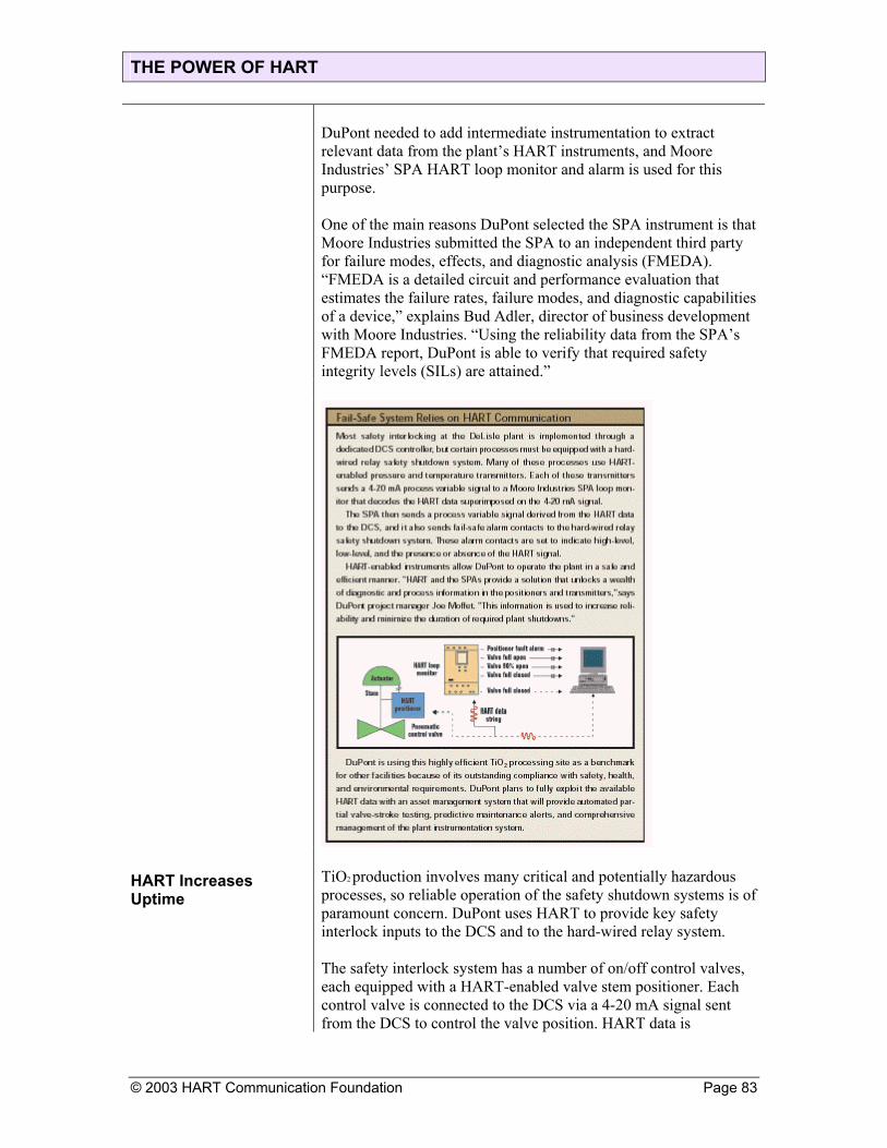
THE POWER OF HART
DuPont needed to add intermediate instrumentation to extract relevant data from the plant’s HART instruments, and Moore Industries’ SPA HART loop monitor and alarm is used for this purpose. One of the main reasons DuPont selected the SPA instrument is that Moore Industries submitted the SPA to an independent third party for failure modes, effects, and diagnostic analysis (FMEDA). “FMEDA is a detailed circuit and performance evaluation that estimates the failure rates, failure modes, and diagnostic capabilities of a device,” explains Bud Adler, director of business development with Moore Industries. “Using the reliability data from the SPA’s FMEDA report, DuPont is able to verify that required safety integrity levels (SILs) are attained.”
HART Increases Uptime
TiO2 production involves many critical and potentially hazardous processes, so reliable operation of the safety shutdown systems is of paramount concern. DuPont uses HART to provide key safety interlock inputs to the DCS and to the hard-wired relay system. The safety interlock system has a number of on/off control valves, each equipped with a HART-enabled valve stem positioner. Each control valve is connected to the DCS via a 4-20 mA signal sent from the DCS to control the valve position. HART data is
© 2003 HART Communication Foundation Page 83

THE POWER OF HART
superimposed on the 4-20 mA connection, and the SPA loop monitor and alarm extracts the valve-stem position from the HART data. The SPA then sends the actual valve-stem position data to the DCS via an additional 4-20 mA connection. The DCS compares the valve control output signal to the HART valve-stem position data to ensure proper positioning. This data is used to verify correct functioning of the valve in normal operations, and to test the valve when DuPont performs periodically required plant shutdowns to verify operation of the safety shutdown system. The HART data allows DuPont to test valve safety interlock operation from the control room. Control room operators place the appropriate DCS output in manual mode and adjust the 4-20 mA control valve output signal to open and close the valve. The SPA sends a 4-20 mA signal derived from the HART data back to the DCS to verify valve position. Consider the alternative: If the valvestem position data was not available at the DCS through HART and the SPA, DuPont would have to station an instrument technician at each valve to observe valve operation. The technician would have to observe valve travel, and communicate this information to control room personnel. “There are over 100 control valves equipped with Moore SPA loop monitors, so valve safety interlock testing would be a labor-intensive and cumbersome operation without HART Communication,” observes Moffet
Online Tests Reduce Outages
DuPont has plans to take valve testing to another level—a level that will reduce the number and lengths of outages required for safety interlock testing. Certain valve testing requirements for safety interlock systems can be met with partial valve-stroke testing of emergency shutdown valves during normal operations. Performing those tests during normal operations means fewer shutdowns are required, and the required tests take less time so the shutdowns can be shorter. Partial valve-stroke testing during normal operations is a procedure, either manual or automated, used to stroke a valve over a small percentage of the valve’s total travel range. For example, a safety interlock valve might be fully closed during normal operations. Partial valve-stroke testing could be used to move the valve to a slightly open position. This would verify valve operation without
Page 84 © 2003 HART Communication Foundation

THE POWER OF HART
© 2003 HART Communication Foundation Page 85
affecting normal operations. The present system could be used to undertake manual partial valve-stroke testing, or an upgraded system could be used to implement automated partial valve-stroke testing. “We are currently evaluating device management system that would be able to directly accept data from all of our HART instruments,” Moffet says, “and the system could be used to implement automated partial valve-stroke testing.” Other plans call for using additional SPA capabilities to monitor the diagnostic status of the valve-stem positioners, to provide alarm on low valve-operating air pressure, and to provide relay contacts for open and closed valve position. For more critical applications, one-out of- two (1oo2) and two-out-of-three (2oo3) configurations can be used to increase availability and reliability.

THE POWER OF HART
Get Started The preceding articles have shown how HART is much more than
just a way to calibrate flowmeters. It provides an enormous amount of plant-floor information not obtainable through any other means, and you don’t need a complicated fieldbus system to get to that data. In fact, since most of your instruments, valves, and controllers already have a HART interface, obtaining real-time process information is not only easy, it is very inexpensive. All you need to do is learn how to use it. When it comes to calibration and diagnostics with handheld terminals, HART technology is so easy to learn that vendors often teach their customers over the telephone. Bud Adler, director of professional development at Moore Industries, North Hills, Calif., says he often walks people through a quick course. “It is fairly easy to lead someone through a procedure over the phone,” says Adler. “The technology is simple and the procedures are straightforward. We do it all the time.” Jon Tandy, sales engineer at Arcom Control Systems, Kansas City, Mo., agrees. “I’m the one who usually deals with HART customers from sales through tech support, and I generally educate them over the phone,” he explains. “Often, they have some basic understanding of HART already.” When you need to go beyond handheld terminals, it gets a bit more difficult. Moore Industries’ Adler travels around the country giving HART seminars at trade shows and “Lunch-and-Learn” sessions, where employees from a chemical or process plant get a sandwich and a seminar on HART. “We get everyone from instrument engineers to maintenance technicians,” says Adler, “and most are amazed to find out what the instruments already installed in their plant are capable of providing.” Some companies conduct on-site training during installation. Thermo Measurement’s signal conditioning product manager, for example, trained people at Aylesford Newsprint on-site. All this vendor activity is useful and helpful, but what the industry really needs is a better and more consistent way to teach end users about HART.
Page 86 © 2003 HART Communication Foundation

THE POWER OF HART
Regarding Users in a New Light
The HART Communication Foundation (HCF) has been strictly a vendor group since its founding in 1993. During that time, HCF left all the end user promotion to the marketplace while it concentrated on helping the vendors design and develop new instruments, software, interfaces, calibrators, and similar devices. All of HCF’s educational efforts and training classes have been designed for vendors, and all of its efforts toward standardization have been aimed at solidifying and enhancing HART products. It’s accomplished that, in spades. Today, HCF has more than 130 vendor members all over the world that offer a large number and variety of HART-compliant products (Figure 1). Virtually every process instrument built today has a HART interface. In spite of all the publicity garnered by the various fieldbuses, the fact remains that HART has the largest installed base in the industry, and it is growing every day. This is in part because many fieldbus-compatible instruments and devices also have a HART interface. Fieldbus users may discover they actually have two plant networks built into their devices: fieldbus and HART. The HCF realizes its future lies in educating, enlightening, and engaging users, so it has launched an End User Program. This program will teach users about the benefits of HART, establish a training curriculum, bring end users into the HCF, and involve them in the HART interface for everyone’s benefit.
Educational Support Learning more about networking and HART Servers is a little bit beyond a five-minute phone call from the rep. You need training and non-vendor technical literature. HCF understands. Here’s what they have in store for you: The Complete HART Guide on CD-ROM: This is an excellent way to learn how HART works, in a format that is easy to pass on to fellow workers and bosses. The CD-ROM was recently completely revised to include new topics such as HART 6, asset management, and the HART Server. The new CD-ROM is
© 2003 HART Communication Foundation Page 87
THE POWER OF HART
Page 88 © 2003 HART Communication Foundation
available for free from HCF, and you should be able to get a copy at the HART Foundation booth at the ISA or Interkama shows this year. To obtain a free copy via the Internet, go to the HCF web site (see next bullet). You can also call the HCF office in Austin, Texas. Web site: The HCF web site at www.hartcomm.org has been completely updated to include a new end user focus on applications, education, downloads, Q/A forums, and a newsletter. An end user can pick up a large amount of technical, product, and application information by simply browsing through the web site and following the links. End user training: The HCF plans to offer a comprehensive two-day HART technology education class, starting in 2002. Two pilot classes will be held in 2001. The classes will be taught by HCF staff and will cover the technology, using DDs, applications, device configurations, communications, and using the HART Server. To find out more about specific dates and times, contact HCF or visit the web site. After HCF runs the pilot classes, it plans to finalize the training materials so that users will be able to conduct classes themselves. This will put training out in the field, closer to end users.
Coming on Board The HCF also realizes that end users will determine the future of HART. Already, many experienced users are asking for additional capability and functions. Although HART has been available for 10 years for field communications, it is just now entering the early adopter step in its lifecycle as a networking system. At this point in HART development, user input is critical. The HART Foundation is considering forming an end user core group to provide it with input on key issues such as HCF activities, technology issues, applications, product needs, and other ideas. If you are interested in participating, contact HCF. While fieldbus efforts are struggling to deal with a large number of unrelated and incompatible networks, HART offers an excellent alternative. The HCF and its vendor members have built a technology that works, but end users are needed now to make sure that HART continues to meet all the information and network needs of the process industry.
Page 89 © 2003 HART Communication Foundation
Industry ApplicationsMany companies in a wide variety of industries have already realized the advantages of using the HART communication protocol. This section describes some applications in detail and outlines the tangible benefits that result. The applications have been grouped into the following sections:
Inventory-management applicationsCost-saving applicationsRemote-operation applicationsOpen-architecture applications
INDUSTRY APPLICATIONS
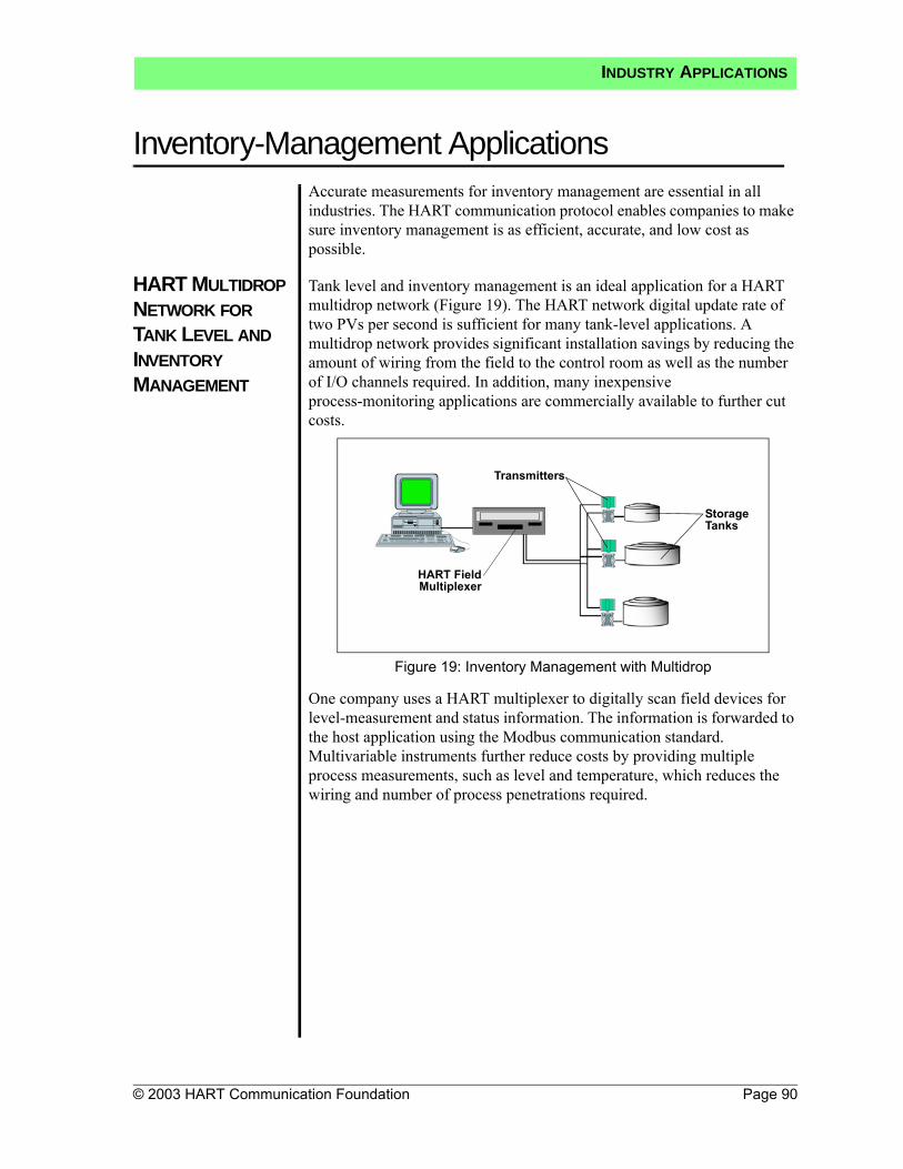
© 2003 HART Communication Foundation Page 90
Inventory-Management ApplicationsAccurate measurements for inventory management are essential in all industries. The HART communication protocol enables companies to make sure inventory management is as efficient, accurate, and low cost as possible.
HART MULTIDROP NETWORK FOR TANK LEVEL AND INVENTORY MANAGEMENT
Tank level and inventory management is an ideal application for a HART multidrop network (Figure 19). The HART network digital update rate of two PVs per second is sufficient for many tank-level applications. A multidrop network provides significant installation savings by reducing the amount of wiring from the field to the control room as well as the number of I/O channels required. In addition, many inexpensive process-monitoring applications are commercially available to further cut costs.
Figure 19: Inventory Management with Multidrop
One company uses a HART multiplexer to digitally scan field devices for level-measurement and status information. The information is forwarded to the host application using the Modbus communication standard. Multivariable instruments further reduce costs by providing multiple process measurements, such as level and temperature, which reduces the wiring and number of process penetrations required.
HART FieldMultiplexer
Transmitters
Storage Tanks
INDUSTRY APPLICATIONS

Page 91 © 2003 HART Communication Foundation
Inventory-Management ApplicationsMULTIDROP FOR TANK FARM MONITORING
In one tank farm application, 84 settlement tanks and filter beds on a very large site (over 300,000 m2) are monitored using HART multidrop networks and HART RTUs (see SCADA/RTU Systems on page 25). The HART architecture required just eight cable runs for 84 tanks, with 10–11 devices per run (Figure 20). Over 70 individual runs of over 500 m each were eliminated. Cable savings were estimated at over $40,000 when compared to a conventional installation. RTU I/O was also reduced, which resulted in additional hardware and installation savings. The total installed cost was approximately 50% of a traditional 4–20 mA installation.
Figure 20: Tank Farm Monitoring with Multidrop
HART Multiplexer
Storage Tanks
Control Room
StorageTanks
INDUSTRY APPLICATIONS

Inventory-Management Applications
© 2003 HART Communication Foundation Page 92
UNDERGROUND PETROLEUM STORAGE WITH HART COMMUNICATION FOR ACCURACY
Underground salt caverns are frequently used for crude oil storage. One customer pumps oil from barges into the storage caverns. An ultrasonic flowmeter records the total flow. To get the oil out of the caverns, a brine solution is pumped into the cavern through a magnetic flowmeter. Brine and crude oil flowing in both directions are measured and reported to the DCS using the HART communication protocol for accuracy. The DCS tracks flow rate and total quantity to maintain a certain pressure inside the caverns (Figure 21).
Figure 21: Underground Petroleum Storage
HART Transmitter Interface
Field InstrumentsOil Caverns
HART TransmitterInterface
Note: Digital accuracy for flow accuracy and flow totals
INDUSTRY APPLICATIONS

Page 93 © 2003 HART Communication Foundation
Cost-Saving Applications
WASTEWATER TREATMENT PLANT UPGRADE
A Texas wastewater treatment plant replaced stand-alone flowmeters and chart recorder outstations that required daily visits for totalization with a HART system. HART-based magnetic flowmeters were multidropped into HART RTUs to create a cost-effective SCADA network. The use of HART technology reduced system and cable costs, enhanced measurement accuracy, and eliminated time-consuming analog calibration procedures.
A system of 11 HART multidrop networks was used to connect 45 magnetic flowmeters from different plant areas. Each flowmeter communicated flow rate and a totalized value over the HART network. Multidrop networks eliminated the need for additional hardware and PLC programming while providing a more accurate totalized value. Complex and costly system integration issues were also avoided—for example, there was no need for synchronization of totals between the host and field PLCs.
Multidrop networking further reduced the installation cost by reducing the required number of input cards from the traditional 45 (for point-to-point installations) to 11. Maintenance was simplified because of access to instrument diagnostic and status data.
Use HART multidrop networking to reduce installation and maintenance costs.
INDUSTRY APPLICATIONS

Cost-Saving Applications
© 2003 HART Communication Foundation Page 94
APPLIANCE MANUFACTURING WITH MULTIDROP
A consumer appliance manufacturer used the networking capability of the HART protocol to measure level, flow, and pressure. HART multidrop provided substantial wiring and installation savings as well as digital accuracy with the elimination of the analog to digital (A/D) and digital to analog (D/A) conversions of the instrument and PLC I/O. Figure 22 shows pressure transmitters connected to a PLC via smart transmitter interface multiplexers.
Figure 22: Multidrop Network Example
Storage Tanks
CommunicationModule
Smart TransmitterInterface
Highway
TerminalBlock Module
PLC
INDUSTRY APPLICATIONS

Page 95 © 2003 HART Communication Foundation
Cost-Saving ApplicationsREMOTE REZEROING IN A BREWERY
The benefits of remote monitoring and rezeroing of smart transmitters using the HART protocol are dramatically illustrated in this example of two smart transmitters that control the fluid level in lauter tubs in a brewhouse application. Similar benefits would be realized in any application involving a closed vessel.
Two smart transmitters are installed on each lauter tub—one on the bottom of the tank and the other about nine inches from the bottom. The bottom transmitter is ranged ±40 inH2O; the upper transmitter is ranged0–30 inH2O. As the lauter tub is filled, the bottom transmitter senses level based on pressure. When the level reaches the upper transmitter, that point is marked as the new zero-level point, and the upper transmitter becomes the primary sensing instrument for the lauter-tub level. The nine-inch zero-level offset from the bottom of the tank is necessary to accommodate loose grain that settles in the bottom of the tank.
Transmitters that are coordinated and working together control fluid level in each lauter tub to within a few barrels. However, the upper transmitter requires periodic maintenance or replacement and rezeroing. An undetected false upper-transmitter level reading can cause a tank level error of up to 40 gallons.
The usual procedure for transmitter rezeroing takes about 95 minutes and has been required as frequently as twice a day. Rezeroing a transmitter using configuration software and PLC interface modules eliminates the need to locate and identify the problem at the site as well as the need for verification by control-room personnel and greatly reduces the chance for inadvertent errors. Estimated total time to rezero each transmitter is reduced to 15 minutes.
Through the configuration software’s instrument-status and diagnostic capabilities, a false level indication can be automatically detected while a lauter tub fill is in progress. The affected transmitter can then be automatically rezeroed by programming logic in the programmable controller to issue the appropriate command to the instrument.
INDUSTRY APPLICATIONS

Cost-Saving Applications
© 2003 HART Communication Foundation Page 96
WATER TREATMENT FACILITY UPGRADE
HART transmitters and a control system with HART capability were chosen to upgrade a water treatment facility. The completed installation reduced capital, engineering, and installation costs. The process dynamics of the water treatment facility allowed the HART instruments to be used in all-digital mode without compromising plant performance.
The water treatment plant is divided into two areas, each with 14 filters. Each area is controlled by a separate control system for complete autonomy. A HART network monitors each filter for filter level, filter bed differential, and filter outlet flow. The multidrop installation used a three-wire system in order to accommodate both the two-wire and the four-wire devices (magnetic flowmeters) in use (Figure 23) (see Multidrop on page 6).
Figure 23: Multidrop Networks with 2-Wire and 4-Wire Devices
Because the water treatment facility had a modular design, the use of HART instruments allowed the configuration from the one filter network to be copied to the others, which reduced the implementation time. Engineering, system configuration, drafting, commissioning, maintenance, and documentation were simplified. A reduced I/O card count also saved money.
Main Power
4 mA
12 mA
4 mA
Pressure Transmitters
Magnetic Flowmeter
INDUSTRY APPLICATIONS

Page 97 © 2003 HART Communication Foundation
Cost-Saving ApplicationsIMPROVED DIAGNOSTICS
A cleaning materials supplier required periodic checkup of the instrument condition and configuration information as compared to the initial installation. The field transmitters provided a historical record of status changes along with current configuration information. Periodic download of this information was made possible using PLC ladder logic developed for HART instruments.
INDUSTRY APPLICATIONS

© 2003 HART Communication Foundation Page 98
Remote-Operation ApplicationsUNMANNED OFFSHORE GAS PRODUCTION WITH HART NETWORKS
Choosing the HART communication protocol for all-digital communication in a wide-area network enabled one company to have real-time monitoring and control, access to diagnostics, and maintenance capabilities—all from a remote location.
Over half of the 500 transmitters on 15 platforms could be multidropped with update rates of three seconds (six devices), which resulted in substantial savings in wiring, I/O, and installation. The remaining devices (flowmeters) required a faster response and were wired point to point using digital HART communications to transmit the process data. The flowmeters used the optional burst mode, which provided an update rate of 3.7 times per second. All-digital communications provided maximum accuracy and eliminated potential errors from input scaling, conversion, and drift (see Multidrop on page 6).
Figure 24: RTU Application
Each platform’s RTU provided a link to approximately 50 temperature, pressure, and flow transmitters (Figure 24). The RTU used the multimaster capability of the HART protocol to enable the second RTU to act as a hot standby, which monitored activity and was able to take over if a failure occurred. The RTUs provided links with the emergency and safety systems and a local interface for maintenance personnel. The Modbus protocol was used for communication to the central SCADA system.
Standby RTUPrimaryRTU
Modbus Link
HARTMultiplexers
Transmitters
Transmitters
Radio Antennae
INDUSTRY APPLICATIONS

Page 99 © 2003 HART Communication Foundation
Remote-Operation ApplicationsVENEZUELA GAS-LIFT PROJECT
In a Venezuela gas-lift project, HART multidrop technology was used for remote operation of offshore gas-lift production wells at considerable savings (Figure 25):
30% decrease in installation costs16:1 reduction of input modulesReduced cost of I/O cards in the RTURemote rerangingRemote access to the transmitter status for improved process uptime
Figure 25: Offshore Gas-Lift Project
Microwave TowersRadio Antennae
Electric Valve
Configuration and
Maintenance Tools
HART Transmitters
Control Room
INDUSTRY APPLICATIONS

© 2003 HART Communication Foundation Page 100
Open-Architecture ApplicationsOIL REFINERY EXPANSION
The best way to judge the openness of a communication protocol is by the number of products supported. By this standard, the HART protocol is perhaps the most open of any field-communication protocol available today.
In a major refinery expansion, an oil company weighed the advantages of using either a proprietary system or a HART-based system. The results indicated that the company could use HART digital instruments in 92% of their applications, compared to only 33% with the proprietary system. Choosing HART products resulted in an incremental $23,000 in savings due to commissioning efficiencies and ongoing maintenance and diagnostic capabilities.
The oil company used a traditional control system with analog I/O and supplemented the control capability with an online maintenance and monitoring system. All of the HART field devices were monitored from a central location (Figure 26).
Figure 26: Online Implementation
Fisher Fisher
Ethernet LinkControlDisplaySystem
Maintenance Station
Controller
I/O I/OHARTMultiplexer
HARTTransmitter Control Valve
INDUSTRY APPLICATIONS

Page 101 © 2003 HART Communication Foundation
Open-Architecture ApplicationsHART WITHIN A PROFIBUS NETWORK
HART field devices can be seamlessly integrated with PROFIBUS DP networks using the HART/DP Link, which enables the connection of four HART devices and facilitates the passthrough of HART commands to host applications on the DP network (Figure 27). The HART/DP Link supports IS installations.
Figure 27: HART Within a PROFIBUS Network
PCs with HART Applications
PLC
DP/PA Link
HART Instruments
Remote I/O
HART/DPLink
Profibus PA
DP/ASI Link
PROFIBUSDP
INDUSTRY APPLICATIONS

Open-Architecture Applications
© 2003 HART Communication Foundation Page 102
HART/DDE SERVER
Cost-effective level- and temperature-monitoring systems can be designed using HART multidrop networks and commercially available HART/DDE interface software. HART/DDE interface software allows any compliant application (e.g., spreadsheet) to directly read the process data and status information available in HART field devices. A HART interface module connected to the PC’s serial port is needed for this HART monitoring application (Figure 28).
Figure 28: Multidrop Network
Transmitter
Spreadsheet Data Logging
RS232 HART Interface
Power Supply
INDUSTRY APPLICATIONS
Page 103 © 2003 HART Communication Foundation
Where To Get More InformationWHAT INFORMATION IS AVAILABLE?
To serve the growing interest in HART-related products, the HCF publishes a library of additional documents, articles, and overviews. The following information is currently available:
HART specificationsTechnical overviewApplication notesTechnical assistanceTraining classes
WHERE TO FIND INFORMATION
By Mail
HART Communication Foundation9390 Research Blvd, Suite I-350Austin, TX 78759 USA
By Phone
Call 512-794-0369.
By Fax
Send correspondence to 512-794-3904.
By E-mail
Send correspondence to <[email protected]>.
Online
Visit the HCF website at <http://www.hartcomm.org>.
WHERE TO GET MORE INFORMATION

© 2003 HART Communication Foundation Page 104
Appendix A: HART ChecklistHART HOST SYSTEM CAPABILITIES CHECKLIST
Date:_________________Manufacturer:
Model number/name:
Revision or version:
Product application (configurator, DCS, RTU, etc.):
Function Commands/Notes Support Provided
How many HART I/O channels per card?
Can the system power the devices with an internal power supply? Yes No
Which HART revisions are supported? Rev 3 Rev 4 Rev 5
Is burst mode supported on all channels? Yes No
Is multidrop networking supported on all channels?If yes, how many devices can be placed on a single network?
Yes No# of devices: _____________
How are device-specific functions and features supported?
Hard coded HART DDL binary files HART DDL source files Application resource files Other: ________________ Device-specific features are not
supported.
Indicate the parameters that are accessed in ANY HART device.
Manufacturer’s identification 0 Read Display text Display code
Device identification (device type code) 0 Read Display text Display code
Device identification (unique ID) 0 Read Display text
Device serial number 0 Read Display text
Revision levels 0 Read Display text
TAG 13, 18 Read Write
DESCRIPTOR 13, 18 Read Write
MESSAGE 12, 17 Read Write
DATE 13, 18 Read Write
Upper-range value 15, 35 Read Write
APPENDICES

Page 105 © 2003 HART Communication Foundation
Appendix A: HART ChecklistManufacturer:
Model number/name:
Revision or version:
Lower-range value 15, 35 Read Write
Sensor limits 14 Read
Alarm selection 15 Read
Write-protect status 15 Read
Analog reading 1, 2, 3 Read
Primary variable 1, 3 Read
Secondary variable 3 Read
Tertiary variable 3 Read
Fourth variable 3 Read
Change engineering units 44 Read Write
Damping value 15, 34 Read Write
Read device variablesHow many? (up to 250) 33 Read
Materials of construction Device specific Read Write
HART status information (change flag, malfunction, etc.) Standard status bits Read Display text Display code
Device-specific status information 48 Read Display text Display code
Use of status bits in control logic? Std & 48 Yes No
Use of status bits in alarm handling? Std & 48 Yes No
Setpoint (PID and output devices)Which devices? Device specific Read Write
Support of device-specific commands/functions: (a) for your own company’s field devices (b) for other vendors’ field devices
Yes No Yes No
Rezero 43 Yes No
Loop test (fix the analog current at specified value) 40 Yes No
Support calibration procedures? Which products?
Yes No
Calibrate the D/A converter 45, 46 Yes No
APPENDICES
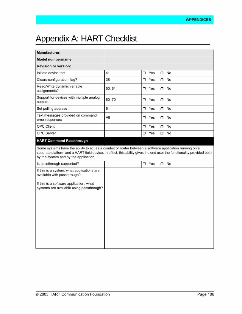
Appendix A: HART Checklist
© 2003 HART Communication Foundation Page 106
Manufacturer:
Model number/name:
Revision or version:
Initiate device test 41 Yes No
Clears configuration flag? 38 Yes No
Read/Write dynamic variable assignments? 50, 51 Yes No
Support for devices with multiple analog outputs 60–70 Yes No
Set polling address 6 Yes No
Text messages provided on command error responses All Yes No
OPC Client Yes No
OPC Server Yes No
HART Command Passthrough
Some systems have the ability to act as a conduit or router between a software application running on a separate platform and a HART field device. In effect, this ability gives the end user the functionality provided both by the system and by the application.
Is passthrough supported? Yes No
If this is a system, what applications are available with passthrough?
If this is a software application, what systems are available using passthrough?
APPENDICES

Page 107 © 2003 HART Communication Foundation
Appendix B: HART Revision 5UNIVERSAL COMMANDS IN HART REVISION 5
Command Data in Command Data in Reply
# Function Byte Data Type Byte Data Type
0 Read unique identifier None
0123456789–11
"254" (expansion)Manufacturer identification codeManufacturer device type codeNumber of preambles requiredUniversal command revisionDevice-specific command revisionSoftware revisionHardware revisionDevice function flags*Device ID number
(H)(B)
* Bit 0 = multisensor device; Bit 1 = EEPROM control required;Bit 2 = protocol bridge device
1 Read primary variable None 01–4
PV units codePrimary variable (F)
2 Read current and percent of range None 0–3
4–7Current (mA)Percent of range
(F)(F)
3 Read current and four (predefined) dynamic variables None
0–345–8910–131415–181920–23
Current (mA)PV units codePrimary variableSV units codeSecondary variableTV units codeThird variableFV units codeFourth variable
(F)
(F)
(F)
(F)
(F)
(truncated after last supported variable)
6 Write polling address0
Polling address As in command
11 Read unique identifier associated with tag 0–5 Tag (A) 0–11 As Command 0
12 Read message None 0–23 Message (32 characters) (A)
13 Read tag, descriptor, date None0–56–1718–20
Tag (8 characters)Descriptor (16 characters)Date
(A)(A)(D)
14 Read PV sensor information None
0–23
4–78–1112–15
Sensor serial numberUnits code for sensor limits and
minimum spanUpper sensor limitLower sensor limitMinimum span
(F)(F)(F)
APPENDICES

Appendix B: HART Revision 5
© 2003 HART Communication Foundation Page 108
Command Data in Command Data in Reply
# Function Byte Data Type Byte Data Type
15 Read output information None
0123–67–1011–141516
Alarm select codeTransfer function codePV/range units codeUpper-range valueLower-range valueDamping value (seconds)Write-protect codePrivate-label distributor code
(F)(F)(F)
16 Read final assembly number None 0–2 Final assembly number
17 Write message 0–23 Message (32 characters) (A) As in command
18 Write tag, descriptor, date
0–5
6–17
18–20
Tag (8 characters)Descriptor (16 characters)Date
(A)
(A)
(D)
As in command
19 Write final assembly number0–2 Final assembly
number As in command
APPENDICES

Page 109 © 2003 HART Communication Foundation
Appendix C: HART Revisions 2, 3, and 4UNIVERSAL COMMANDS IN HART REVISIONS 2, 3, AND 4 (DIFFERENCES FROM REVISION 5)
Command Data in Command Data in Reply
# Function Byte Data Type Byte Data Type
0 Read unique identifier None
0123
4567–9
Transmitter type code*Number of preamblesUniversal command revisionDevice-specific command revisionSoftware revisionHardware revisionDevice function flagsFinal assembly number
(H)(B)
* Revision 4 introduced the expanded device type as an option (see Rev. 5, Table 4-4), with the remaining bytes moved up by two positions.
4 Read common static data (block 0): Read message 0 Block number ("0") 0
1–24Block number ("0")Message (A)
4 Read common static data (block 1): Read tag, descriptor, date
0 Block number ("1")
01–67–1819–2122–24
Block number ("1")TagDescriptorDate"250"
(A)(A)(D)
4 Read common static data (block 2): Read sensor information
0 Block number ("2")
01–34
5–89–1213–1617–24
Block number ("2")Sensor serial numberUnits code for sensor limits and
minimum spanUpper-sensor limitLower-sensor limitMinimum span"250"
(F)(F)(F)
4 Read common static data (block 3): Read output information
0 Block number ("3")
01234–78–1112–1516
1718–24
Block number ("3")Alarm select codeTransfer function codePV/range units codeUpper-range valueLower-range valueDamping value (seconds)Write-protect code ("1" = protected)*Private-label distributor code**"250"
(F)(F)
(F)
* “250” or “251” in Revisions 2 and 3** "250" in Revisions 2 and 3
5 Write common static data (block 0): Write message
01–24
Block number ("0")Message (A) As in command
APPENDICES

Appendix C: HART Revisions 2, 3, and 4
© 2003 HART Communication Foundation Page 110
Command Data In Command Data in Reply
# Function Byte Data Type Byte Data Type
5 Write common static data (block 1): Write tag, descriptor, date
01–67–1819–2122–24
Block number ("1")TagDescriptorDate"250"
(A)(A)(D)
As in command
5 Write common static data (block 4): Write final assembly number
01–3
4–24
Block number ("4")Final assembly number"250"
As in command
11–19 These commands did not exist before Revision 5.0.
APPENDICES

Page 111 © 2003 HART Communication Foundation
Appendix D: Common Practice CommandsCOMMON PRACTICE COMMANDS
Command Data In Command Data in Reply
# Function Byte Data Type Byte Data Type
33 Read transmitter variables
0
1
2
3
Transmitter variable code for slot 0
Transmitter variable code for slot 1
Transmitter variable code for slot 2
Transmitter variable code for slot 3
012–5678–11121314–17181920–23
Transmitter variable code for slot 0Units code for slot 0Variable for slot 0Transmitter variable code for slot 1Units code for slot 1Variable for slot 1Transmitter variable code for slot 2Units code for slot 2Variable for slot 2Transmitter variable code for slot 3Units code for slot 3Variable for slot 3
(F)
(F)
(F)
(F)
(truncated after last requested code) (truncated after last requested variable)
34 Write damping value0–3 Damping value
(seconds) (F) As in command
35 Write range values01–45–8
Range units codeUpper-range valueLower-range value
(F)(F)
As in command
36 Set upper-range value (= push SPAN button) None None
37 Set lower-range value (= push ZERO button) None None
38 Reset "configuration changed" flag None None
39 EEPROM control 0 EEPROM control code* As in command
*0 = burn EEPROM; 1 = copy EEPROM to RAM
40 Enter/exit fixed current mode 0–3 Current (mA)* (F) As in command
*0 = exit fixed current mode
41 Perform device self-test None None
42 Perform master reset None None
43 Set (trim) PV zero None None
44 Write PV units 0 PV units code As in command
44 Write PV units 0 PV units code As in command
45 Trim DAC zero 0–3 Measured current (mA) (F) As in command
APPENDICES
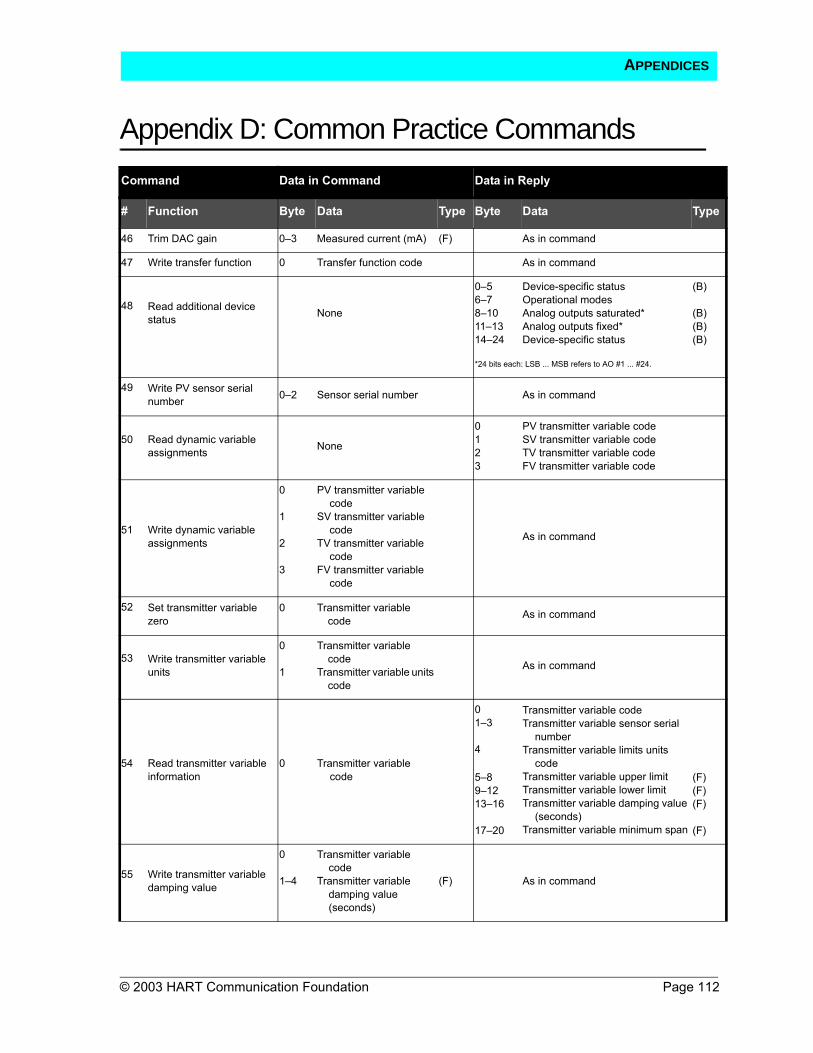
Appendix D: Common Practice Commands
© 2003 HART Communication Foundation Page 112
Command Data in Command Data in Reply
# Function Byte Data Type Byte Data Type
46 Trim DAC gain 0–3 Measured current (mA) (F) As in command
47 Write transfer function 0 Transfer function code As in command
48 Read additional device status None
0–56–78–1011–1314–24
Device-specific statusOperational modesAnalog outputs saturated* Analog outputs fixed* Device-specific status
(B)
(B)(B)(B)
*24 bits each: LSB ... MSB refers to AO #1 ... #24.
49 Write PV sensor serial number 0–2 Sensor serial number As in command
50 Read dynamic variable assignments None
0123
PV transmitter variable codeSV transmitter variable codeTV transmitter variable codeFV transmitter variable code
51 Write dynamic variable assignments
0
1
2
3
PV transmitter variable code
SV transmitter variable code
TV transmitter variable code
FV transmitter variable code
As in command
52 Set transmitter variable zero
0 Transmitter variable code As in command
53 Write transmitter variable units
0
1
Transmitter variable code
Transmitter variable units code
As in command
54 Read transmitter variable information
0 Transmitter variable code
01–3
4
5–89–1213–16
17–20
Transmitter variable codeTransmitter variable sensor serial
numberTransmitter variable limits units
codeTransmitter variable upper limitTransmitter variable lower limitTransmitter variable damping value
(seconds)Transmitter variable minimum span
(F)(F)(F)
(F)
55 Write transmitter variable damping value
0
1–4
Transmitter variable code
Transmitter variable damping value (seconds)
(F) As in command
APPENDICES

Page 113 © 2003 HART Communication Foundation
Appendix D: Common Practice Commands
Command Data in Command Data in Reply
# Function Byte Data Type Byte Data Type
56 Write transmitter variable sensor serial number
0
1–3
Transmitter variable code
Transmitter variable sensor serial number
As in command
57 Read unit tag, descriptor, date None
0–56–1718–20
Unit tag (8 characters)Unit descriptor (16 characters)Unit date
(A)(A)(D)
58 Write unit tag, descriptor, date
0–56–17
18–20
Unit tag (8 characters)Unit descriptor
(16 characters)Unit date
(A)(A)
(D)
As in command
59 Write number of response preambles
0 Number of response preambles As in command
60 Read analog output and percent of range
0 Analog output number code
012–56–9
Analog output number codeAnalog output units codeAnalog output levelAnalog output percent of range
(F)(F)
61 Read dynamic variables and PV analog output None
01–456–91011–141516–192021–24
PV analog output units codePV analog output levelPV units codePrimary variableSV units codeSecondary variableTV units codeTertiary variableFV units codeFourth variable
(F)
(F)
(F)
(F)
(F)
62 Read analog outputs
0
1
2
3
Analog output number; code for slot 0
Analog output number; code for slot 1
Analog output number; code for slot 2
Analog output number; code for slot 3
012–5678–11121314–17181920–23
Slot 0 analog output number codeSlot 0 units codeSlot 0 levelSlot 1 analog output number codeSlot 1 units codeSlot 1 levelSlot 2 analog output number codeSlot 2 units codeSlot 2 levelSlot 3 analog output number codeSlot 3 units codeSlot 3 level
(F)
(F)
(F)
(F)
(truncated after last requested code) (truncated after last requested level)
APPENDICES

Appendix D: Common Practice Commands
© 2003 HART Communication Foundation Page 114
Command Data in Command Data in Reply
# Function Byte Data Type Byte Data Type
63 Read analog output information
0 Analog output number code
012
34–78–1112–15
Analog output number codeAnalog output alarm select codeAnalog output transfer function
codeAnalog output range units codeAnalog output upper-range valueAnalog output lower-range valueAnalog output additional damping
value (sec)
(F)(F)(F)
64 Write analog output additional damping value
0
1–4
Analog output number code
Analog output additional damping value (sec)
(F) As in command
65 Write analog output range value
0
1
2–5
6–9
Analog output number code
Analog output range units code
Analog output upper- range value
Analog output lower- range value
(F)
(F)
As in command
66 Enter/exit fixed analog output mode
0
12–5
Analog output number code
Analog output units codeAnalog output level* (F)
As in command
* "not a number" exits fixed output mode
67 Trim analog output zero
0
12–5
Analog output number code
Analog output units codeExternally measured
analog output level (F)
As in command
68 Trim analog output gain
0
12–5
Analog output number code
Analog output units codeExternally measured analog output level (F)
As in command
69 Write analog output transfer function
0
1
Analog output number code
Analog output transfer function code
As in command
APPENDICES
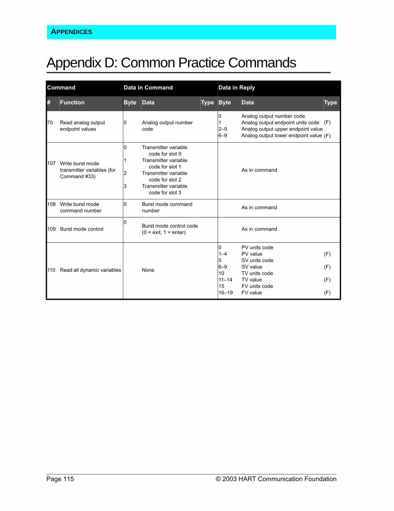
Page 115 © 2003 HART Communication Foundation
Appendix D: Common Practice Commands
Command Data in Command Data in Reply
# Function Byte Data Type Byte Data Type
70 Read analog output endpoint values
0 Analog output number code
012–56–9
Analog output number codeAnalog output endpoint units codeAnalog output upper endpoint valueAnalog output lower endpoint value
(F)
(F)
107 Write burst mode transmitter variables (for Command #33)
0
1
2
3
Transmitter variable code for slot 0
Transmitter variable code for slot 1
Transmitter variable code for slot 2
Transmitter variable code for slot 3
As in command
108 Write burst mode command number
0 Burst mode command number As in command
109 Burst mode control 0
Burst mode control code(0 = exit, 1 = enter) As in command
110 Read all dynamic variables None
01–456–91011–141516–19
PV units codePV valueSV units codeSV valueTV units codeTV valueFV units codeFV value
(F)
(F)
(F)
(F)
APPENDICES

© 2003 HART Communication Foundation Page 116
Appendix E: Response CodesSTATUS Two bytes of status, also called the response code, are included in every
reply message from a field or slave device. These two bytes convey three types of information:
Communication errorsCommand response problemsField device status
If an error is detected in the outgoing communication, the most significant bit (bit 7) of the first byte is set to 1 and the details of the error are reported in the rest of that byte. The second byte is then all zeros.
If no error is detected in the outgoing communication, bit 7 of the first byte is 0 and the remainder of the byte contains the command response, which indicates any problem with the received command. The second byte contains status information pertaining to the operational state of the field or slave device.
Communication errors are typically those that would be detected by a UART (i.e., parity overrun and framing errors). The field device also reports overflow of its receive buffer and any discrepancy between the message content and the checksum received.
RESPONSE CODES
First Byte
Bit 7 = 1: Communication Error Bit 7 = 0: Command response
OR Bits 6 to 0 (decoded as an integer, not bit-mapped):
Bit 6Bit 5Bit 4Bit 3Bit 2Bit 1Bit 0
hex C0hex A0hex 90hex 88hex 84hex 82hex 81
Parity errorOverrun errorFraming errorChecksum error0 (reserved)Rx buffer overflowOverflow (undefined)
012345678–15
1628
3264
No command-specific error(Undefined)Invalid selectionPassed parameter too largePassed parameter too smallToo few data bytes receivedDevice-specific command error (rarely used)In write-protect modeMultiple meanings (see Table 4-9 in A
Technical Overview)Access restrictedMultiple meanings (see Table 4-9 in A
Technical Overview)Device is busyCommand not implemented
APPENDICES

Page 117 © 2003 HART Communication Foundation
Appendix E: Response CodesSecond Byte
Note: Hexadecimal equivalents are quoted assuming only a single bit is set. In reality, several bits may be set simultaneously, and the hex digits can be or’ed together.
(Not Used) Field Device Status
Bit 7Bit 6Bit 5Bit 4Bit 3Bit 2Bit 1Bit 0
All bits 0(when a communication error is reported in the first byte)
OR
Bit 7Bit 6Bit 5Bit 4Bit 3Bit 2Bit 1Bit 0
(hex 80)(hex 40)(hex 20)(hex 10)(hex 08)(hex 04)(hex 02)(hex 01)
Field device malfunctionConfiguration changedCold startMore status availableAnalog output current fixedAnalog output saturatedNonprimary variable out of limitsPrimary variable out of limits
APPENDICES

© 2003 HART Communication Foundation Page 118
Appendix F: HART Field ControlHART FIELD CONTROLLER INSTALLATION
The field controller (Figure 29) is wired in series with the field device (valve positioner or other actuator). In some cases, a bypass capacitor may be required across the terminals of the valve positioner to keep the positioner’s series impedance below the 100 Ω level required by HART specifications. Communication with the field controller requires the communicating device (handheld terminal or PC) to be connected across a loop impedance of at least 230 Ω. Communication is not possible across the terminals of the valve positioner because of its low impedance (100 Ω). Instead, the communicating device must be connected across the transmitter or the current sense resistor.
Figure 29: HART Field Controller Wired in Series
+
F1 F2 F3 F4
HART Communicator
DVC:FCV101BFisher Dig Vlv Ctrl
2 Analog In 12.13 mA 3 Travel 50.36 % 4 Drive Sgl 31.54 % 5 Instrument Status
7 8 9
4 5 6
3 2 1
0 . -
A B C D E F G H I
J K L M N O P Q R
S T U V W X Y Z /
# % & < > * : +
1 Main
F1 F2 F3 F4
HART Communicator
DVC:FCV101BFisher Dig Vlv Ctrl
2 Analog In 12.13 mA 3 Travel 50.36 % 4 Drive Sgl 31.54 % 5 Instrument Status
7 8 9
4 5 6
3 2 1
0 . -
A B C D E F G H I
J K L M N O P Q R
S T U V W X Y Z /
# % & < > * : +
1 Main
Smart Transmitter with PID
Power Supply Handheld
Terminal
4-20 mA Valve
Positioner
ResistorOptional Bypass
Capacitor
APPENDICES

Page 119 © 2003 HART Communication Foundation
Appendix F: HART Field ControlIt is also possible to use both a smart transmitter and a smart valve positioner in the loop. The control function can be in either device. The HART protocol allows one low-impedance device on the network, which is typically the current sense resistor. In Figure 26, the smart valve positioner is the low-impedance device, which eliminates the need for a current sense resistor. Communication is possible by connection across the terminal of either the transmitter or the positioner.
Figure 30: Field Control in Transmitter or Positioner
Fisher
+
F1 F2 F3 F4
HART Communicator
DVC:FCV101BFisher Dig Vlv Ctrl
2 Analog In 12.13 mA 3 Travel 50.36 % 4 Drive Sgl 31.54 % 5 Instrument Status
7 8 9
4 5 6
3 2 1
0 . -
A B C D E F G H I
J K L M N O P Q R
S T U V W X Y Z /
# % & < > * : +
1 Main
F1 F2 F3 F4
HART Communicator
DVC:FCV101BFisher Dig Vlv Ctrl
2 Analog In 12.13 mA 3 Travel 50.36 % 4 Drive Sgl 31.54 % 5 Instrument Status
7 8 9
4 5 6
3 2 1
0 . -
A B C D E F G H I
J K L M N O P Q R
S T U V W X Y Z /
# % & < > * : +
1 Main
Power Supply
Handheld Terminal or PC Interface
Smart Valve PositionerSmart Transmitter
InvalidConnection
APPENDICES
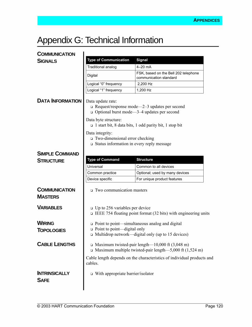
© 2003 HART Communication Foundation Page 120
Appendix G: Technical InformationCOMMUNICATION SIGNALS
DATA INFORMATION Data update rate:Request/response mode—2–3 updates per secondOptional burst mode—3–4 updates per second
Data byte structure:1 start bit, 8 data bits, 1 odd parity bit, 1 stop bit
Data integrity:Two-dimensional error checkingStatus information in every reply message
SIMPLE COMMAND STRUCTURE
COMMUNICATION MASTERS
Two communication masters
VARIABLES Up to 256 variables per deviceIEEE 754 floating point format (32 bits) with engineering units
WIRING TOPOLOGIES
Point to point—simultaneous analog and digitalPoint to point—digital onlyMultidrop network—digital only (up to 15 devices)
CABLE LENGTHS Maximum twisted-pair length—10,000 ft (3,048 m)Maximum multiple twisted-pair length—5,000 ft (1,524 m)
Cable length depends on the characteristics of individual products and cables.
INTRINSICALLY SAFE
With appropriate barrier/isolator
Type of Communication Signal
Traditional analog 4–20 mA
Digital FSK, based on the Bell 202 telephone communication standard
Logical “0” frequency 2,200 HzLogical “1” frequency 1,200 Hz
Type of Command Structure
Universal Common to all devicesCommon practice Optional; used by many devicesDevice specific For unique product features
APPENDICES

© 2003 HART Communication Foundation Page 121
Glossary275 HART Communicator
A handheld master device that uses the HART communication protocol and DDL to configure or communicate with any HART smart device
Bell 202 A U.S. telephone standard that uses 1,200 Hz and 2,200 Hz as 1 and 0, respectively, at 1,200 baud; a full duplex communication standard using a different pair of frequencies for its reverse channel; HART uses Bell 202 signals but is a half-duplex system, so the reverse channel frequencies are not used
Burst (Broadcast) Mode A HART communication mode in which a master device instructs a slave device to continuously broadcast a standard HART reply message (e.g., value of a process variable) until the master instructs it to stop bursting
Cable Capacitance Per Unit of Length
The capacitance from one conductor to all other conductors (including the shield if present) in the network; measured in feet or meters
Cable Resistance Per Unit of Length
The resistance for a single wire; meausred in feet or meters
Closed-Loop Control A system in which no operator intervention is necessary for process control
Communication Rate The rate at which data are sent from a slave device to a master device; usually expressed in data updates per second
DCS See Distributed Control System.
DD See Device Description.
DDL See Device Description Language.
Device Description A program file written in the HART Device Description Language (DDL) that contains an electronic description of all of a device’s parameters and functions needed by a host application to communicate with the device
Device Description Language
A standardized programming language used to write DDs for HART-compatible field devices
Distributed Control System
Instrumentation (input/output devices, control devices, and operator interface devices) that permits transmission of control, measurement, and operating information to and from user-specified locations, connected by a communication link
GLOSSARY

Page 122 © 2003HART Communication Foundation
GlossaryField The area of a process plant outside the control room where measurements
are made, and to and from which communication is provided; a part of a message devoted to a particular function (e.g., the address field or the command field)
Field Device A device generally not found in the control room; field devices may generate or receive an analog signal in addition to the HART digital communication signal
Frequency Shift Keying Method of modulating digital information for transmission over paths with poor propagation characteristics; can be transmitted successfully over telephone systems
FSK See Frequency Shift Keying.
Gateway A network device that enables other devices on the network to communicate with a second network using a different protocol
HART Command Set A series of commands that provide uniform and consistent communication for all master and slave devices; includes universal, common practice, and device-specific commands
HART Communication Protocol
Highway Addressable Remote Transducer communication protocol; the industry standard protocol for digitally enhanced 4–20 mA communication with smart field devices
HART Loop A communication network in which the master and slave devices are HART smart or HART compatible
Host Application A software program used by the control center to translate information received from field devices into a format that can be used by the operator
Interoperability The ability to operate multiple devices, independent of manufacturer in the same system, without loss of functionality
Intrinsic Safety A certification method for use of electrical equipment in hazardous (e.g., flammable) environments; a type of protection in which a portion of an electrical system contains only intrinsically safe equipment that is incapable of causing ignition in the surrounding environment
Intrinsic Safety Barrier A network or device designed to limit the amount of energy available to the protected circuit in a hazardous location
IS See Intrinsic Safety.
GLOSSARY

Glossary
© 2003 HART Communication Foundation Page 123
Master Device A device in a master-slave system that initiates all transactions and commands (e.g., central controller)
Master-Slave Protocol Communication system in which all transactions are initiated by a master device and are received and responded to by a slave device
Miscellaneous Series Impedance
The summation of the maximum impedance (500 Hz–10 kHz) of all devices connected in series between two communicating devices; a typical nonintrinsically safe loop will have no miscellaneous series impedance
Modem Modulator/demodulator used to convert HART signals to RS232 signals
Multidrop Network HART communication system that allows more than two devices to be connected together on a single cable; usually refers to a network with more than one slave device
Multimaster Multimaster refers to a communication system that has more than one master device. The HART protocol is a simple multimaster system allowing two masters; after receiving a message from a slave device, the master waits for a short time before beginning another transmission, which gives the second master time to initiate a message
Multiplexer A device that connects to several HART loops and allows communication to and from a host application
Multivariable Instrument A field device that can measure or calculate more than one process parameter (e.g., flow and temperature)
Network A series of field and control devices connected together through a communication medium
Parallel Device Capacitance
The summation of the capacitance values of all connected devices in a network
Parallel Device Resistance
The parallel combination of the resistance values of all connected devices in the network; typically, there is only one low-impedance device in the network, which dominates the parallel device-resistance value
Passthrough A feature of some systems that allows HART protocol send-and-receive messages to be communicated through the system interface
PID Proportional-integral-derivative
PID Control Proportional-plus-integral-plus-derivative control; used in processes where the controlled variable is affected by long lag times
GLOSSARY

Page 124 © 2003 HART Communication Foundation
GlossaryPoint to Point A HART protocol communication mode that uses the conventional
4–20 mA signal for analog transmission, while measurement, adjustment, and equipment data are transferred digitally; only two communicating devices are connected together
Polling A method of sequentially observing each field device on a network to determine if the device is ready to send data
Polling Address Every HART device has a polling address; address 0 is used for point-to-point networks; addresses 1–15 are used in multidrop networks
Process Variable A process parameter that is being measured or controlled (e.g., level, flow, temperature, mass, density, etc.)
Protocol A set of rules to be used in generating or receiving a message
PV See Process Variable.
Remote Terminal Unit A self-contained control unit that is part of a SCADA system
RTU See Remote Terminal Unit.
SCADA See Supervisory Control and Data Acquisition.
Slave Device A device (e.g., transmitter or valve) in a master-slave system that receives commands from a master device; a slave device cannot initiate a transaction
Smart Instrumentation Microprocessor-based instrumentation that can be programmed, has memory, is capable of performing calculations and self-diagnostics and reporting faults, and can be communicated with from a remote location
Supervisory Control and Data Acquisition
A control system using communications such as phone lines, microwaves, radios, or satellites to link RTUs with a central control system
Zener Type of shunt-diode barrier that uses a high-quality safety ground connection to bypass excess energy
GLOSSARY


![sensors OPEN ACCESS · 2007, the HART (Highway Addressable Remote Transducer) Communication Foundation [1] developed WirelessHART, the first open, international standard to fulfill](https://img.dokumen.tips/doc/110x75/5f39fb247080821f5731ba8a/sensors-open-access-2007-the-hart-highway-addressable-remote-transducer-communication.jpg)