Embed Size (px)
Citation preview

© 2001, Cisco Systems, Inc.
Troubleshooting the Top Issues on the CSS
Troubleshooting the Top Issues on the CSS

© 2001, Cisco Systems, Inc. www.cisco.com Module 1 Rev 0101
Top Issues Broken DownTop Issues Broken Down
•ACLs•Groups•One Armed Configs•Asymmetric Flows•Keepalives•Redundancy•Persistence•Garbage Collection•Troubleshooting Tips

© 2001, Cisco Systems, Inc. www.cisco.com Module 1 Rev 0101
ACLsACLs
When enabling ACLs globally, every Circuit VLAN is required to have an ACL applied to it.
Can Cause Network Outage if proper clauses are not in place.
Make sure each Circuit VLAN has the proper clauses in place before enabling ACLs globally

© 2001, Cisco Systems, Inc. www.cisco.com Module 1 Rev 0101
ACLs (cont)ACLs (cont)
!**************************GLOBAL**************************
acl enable
!************************** CIRCUIT **************************
circuit VLAN1
redundancy
ip address 172.17.63.216 255.255.255.192
circuit VLAN20
redundancy
ip address 20.0.0.1 255.0.0.0
circuit VLAN10
ip address 10.1.1.1 255.0.0.0
redundancy-protocol
acl 1
clause 10 permit any any destination any
apply circuit-(VLAN20)
apply circuit-(VLAN1)
apply circuit-(VLAN10)

© 2001, Cisco Systems, Inc. www.cisco.com Module 1 Rev 0101
GroupsGroups
Groups can be used to NAT servers OR clients.
Caveats:
Inside communication between servers forced through the CSS may be NATted by the group.
© 2001, Cisco Systems, Inc. www.cisco.com Module 1 Rev 0101
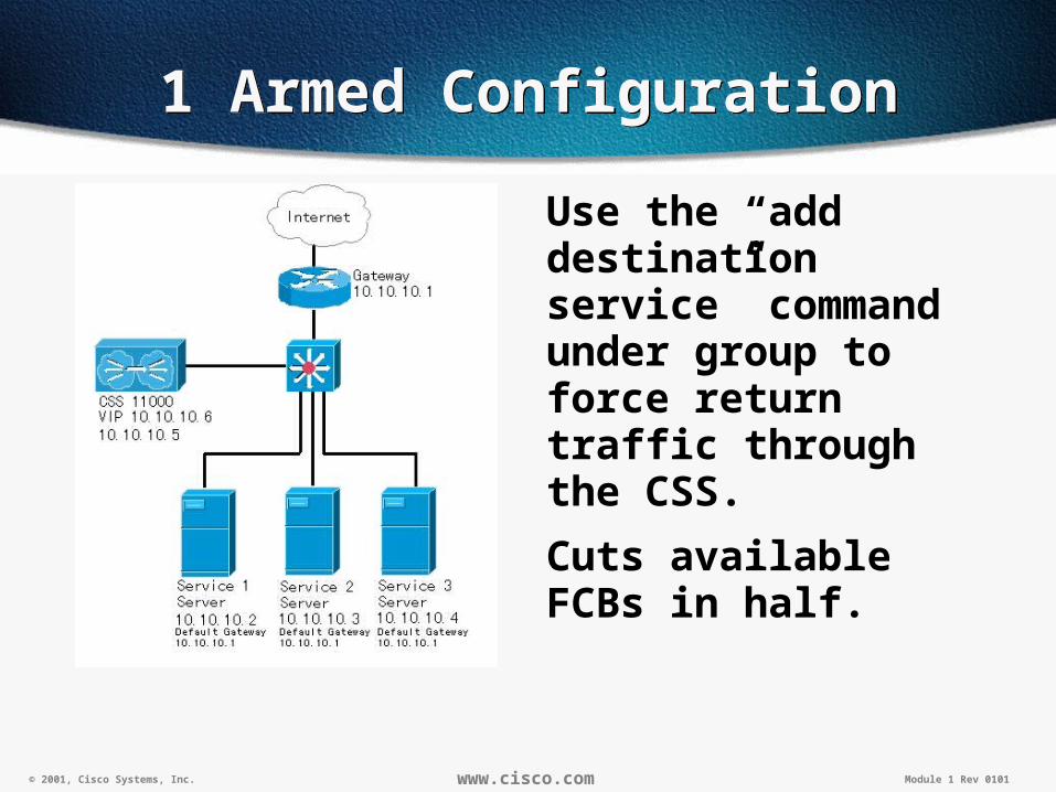
1 Armed Configuration1 Armed Configuration
Use the “add destination service” command under group to force return traffic through the CSS.
Cuts available FCBs in half.

© 2001, Cisco Systems, Inc. www.cisco.com Module 1 Rev 0101
One armed config exampleOne armed config example
To accomplish client NAT use “add destination service”. This will insure that the flow will pass back through the CSS.
Example:
group 1armed
vip address 192.168.1.1
add destination service cisco1
add destination service cisco2
add destination service cisco3
active

© 2001, Cisco Systems, Inc. www.cisco.com Module 1 Rev 0101
Asymmetric FlowsAsymmetric Flows

© 2001, Cisco Systems, Inc. www.cisco.com Module 1 Rev 0101
Asymmetric FlowsAsymmetric Flows
Responses are routed around the CSS.
Problems:
NAT never occurs on the reply from the server. Connection will be rejected by the client.
© 2001, Cisco Systems, Inc. www.cisco.com Module 1 Rev 0101
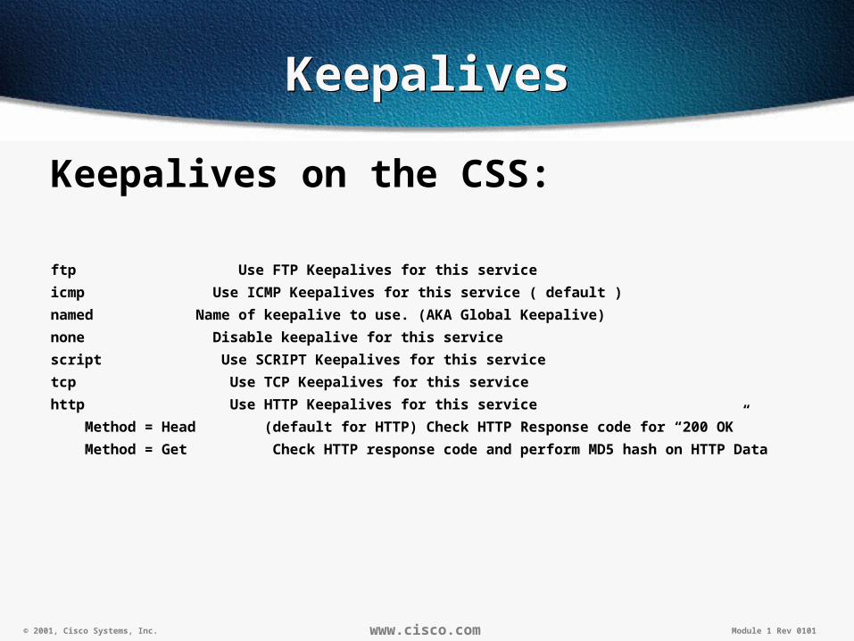
KeepalivesKeepalives
Keepalives on the CSS:
ftp Use FTP Keepalives for this service
icmp Use ICMP Keepalives for this service ( default )
named Name of keepalive to use. (AKA Global Keepalive)
none Disable keepalive for this service
script Use SCRIPT Keepalives for this service
tcp Use TCP Keepalives for this service
http Use HTTP Keepalives for this service
Method = Head (default for HTTP) Check HTTP Response code for “200 OK”
Method = Get Check HTTP response code and perform MD5 hash on HTTP Data

© 2001, Cisco Systems, Inc. www.cisco.com Module 1 Rev 0101
Redundancy on the CSSRedundancy on the CSS
• Box to Box Redundancy
• VIP and Interface Redundancy
• Fate Sharing/Critical Services
• Active/Active with VIP redundancy

© 2001, Cisco Systems, Inc. www.cisco.com Module 1 Rev 0101
Box to Box Redundancy
Active/Standby
Very simple
Supports configuration synchronization
Can utilize health checks to determine when to alternate mastership

© 2001, Cisco Systems, Inc. www.cisco.com Module 1 Rev 0101
Box to Box RedundancyAddressing
Box to Box RedundancyAddressing
VLAN2192.1.1.1
VLAN110.1.1.1
VIP192.1.1.100
VLAN2192.1.1.1
VLAN110.1.1.1
VIP192.1.1.100
VLAN311.1.1.254
VLAN311.1.1.253
CSS’s are configured identically with the exception of the dedicated Redundancy Link IP addresses.
Redundancy Link
Internet
Server110.1.10.1
Server210.1.10.2
© 2001, Cisco Systems, Inc. www.cisco.com Module 1 Rev 0101
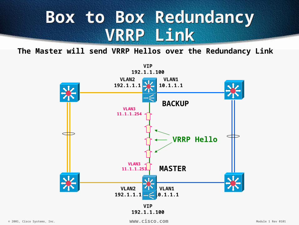
Box to Box RedundancyVRRP Link
Box to Box RedundancyVRRP Link
VLAN2192.1.1.1
VLAN110.1.1.1
VIP192.1.1.100
VLAN2192.1.1.1
VLAN110.1.1.1
VIP192.1.1.100
VLAN311.1.1.254
VLAN311.1.1.253 MASTER
BACKUP
VRRP Hello
The Master will send VRRP Hellos over the Redundancy Link

© 2001, Cisco Systems, Inc. www.cisco.com Module 1 Rev 0101
Box to Box RedundancyRedundant Ports
Box to Box RedundancyRedundant Ports
VLAN2192.1.1.1
VLAN110.1.1.1
VIP192.1.1.100
VLAN2192.1.1.1
VLAN110.1.1.1
VIP192.1.1.100
VLAN311.1.1.254
VLAN311.1.1.253 MASTER
BACKUP
VRRP Hello
All Circuits specified as redundant will be blocked on the Backup
X X

© 2001, Cisco Systems, Inc. www.cisco.com Module 1 Rev 0101
Box to Box RedundancyLink Commands
Box to Box RedundancyLink Commands
VRRP Link•The redundancy link runs over an isolated VLAN.
•It is enabled in the circuit's IP address using the command "redundancy-protocol".
Redundant Links•The remaining VLANs are configured to not pass traffic when in standby mode.
•Redundancy is enabled in the circuit's definition with the command "redundancy".
circuit VLAN1 redundancy ip address 10.1.1.1 255.255.255.0circuit VLAN2 redundancy ip address 192.1.1.1 255.255.255.0circuit VLAN3 ip address 11.1.1.253 255.255.255.0 redundancy-protocol
Redundancy at the circuit level enables/disables passing traffic for all the ports on the VLAN.
Redundancy-Protocol within the circuit's ip address is the IP interface running VRRP.
© 2001, Cisco Systems, Inc. www.cisco.com Module 1 Rev 0101
Box to Box RedundancyLink Details
Box to Box RedundancyLink Details
The VRRP Link is the redundancy management link.
A crossover cable links the two switches. The VRRP Link must use its own VLAN.
The host portion of the IP address will be unique between the CSS's.
The Out of Band Management Port cannot be used for the redundancy link.

© 2001, Cisco Systems, Inc. www.cisco.com Module 1 Rev 0101
Box to Box RedundancyConvergence
Box to Box RedundancyConvergence
Flow states are not carried over.
The VIP convergence is about 12-17 seconds.
Because ports are blocked on the backup, they must transition to forwarding state first, then verify services before accepting requests.
A web client will need to hit the "Refresh" or "Reload" button on their browser.

© 2001, Cisco Systems, Inc. www.cisco.com Module 1 Rev 0101
Box to Box RedundancyHealth Checks
Box to Box RedundancyHealth Checks
Redundancy Uplink or Redundant-PHYs must be configured, or else only a box outage will trigger a mastership change.
Multiple redundancy uplinks can be health checked.
A switch fail over occurs when there are no longer any live uplink services.
© 2001, Cisco Systems, Inc. www.cisco.com Module 1 Rev 0101
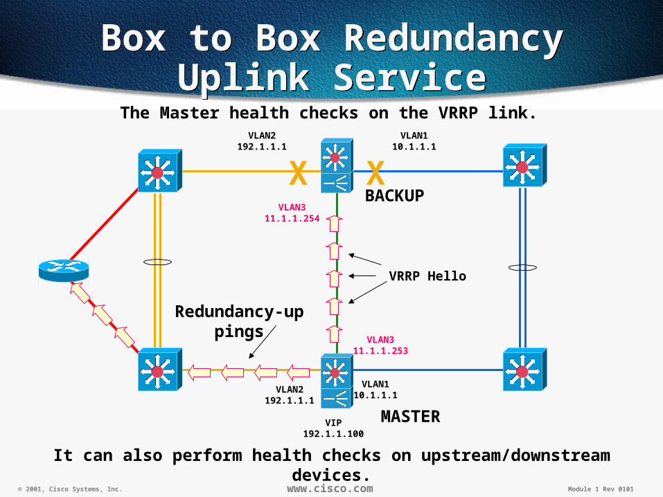
Box to Box RedundancyUplink Service
Box to Box RedundancyUplink Service
VLAN2192.1.1.1
VLAN110.1.1.1
VIP192.1.1.100
VLAN2192.1.1.1
VLAN110.1.1.1
VLAN311.1.1.254
VLAN311.1.1.253
MASTER
BACKUP
VRRP Hello
X X
The Master health checks on the VRRP link.
Redundancy-uppings
It can also perform health checks on upstream/downstream devices.

© 2001, Cisco Systems, Inc. www.cisco.com Module 1 Rev 0101
Box to Box RedundancyUplink Configuration
Box to Box RedundancyUplink Configuration
When configuring services, use the type "redundancy-up" command to designate a router, typically, as an uplink service.
The service type enables the active CSS to ping the upstream device using the default keepalive ICMP.
If the Master CSS fails or it detects that the uplink service has died, the Backup CSS becomes Master.
With ip redundancy-master the backup has all it’s ports blocked, so it cannot run it’s redundancy-up services.
service UpstreamRouter ip address 192.168.1.1 type redundancy-up active

© 2001, Cisco Systems, Inc. www.cisco.com Module 1 Rev 0101
Box to Box RedundancyMonitoring Physical LinkBox to Box RedundancyMonitoring Physical Link
Link status is not monitored by default.
Hello’s only run on the dedicated redundancy link.
© 2001, Cisco Systems, Inc. www.cisco.com Module 1 Rev 0101
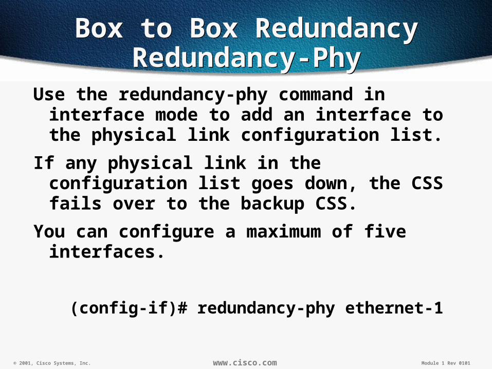
Box to Box RedundancyRedundancy-Phy
Box to Box RedundancyRedundancy-Phy
Use the redundancy-phy command in interface mode to add an interface to the physical link configuration list.
If any physical link in the configuration list goes down, the CSS fails over to the backup CSS.
You can configure a maximum of five interfaces.
(config-if)# redundancy-phy ethernet-1
© 2001, Cisco Systems, Inc. www.cisco.com Module 1 Rev 0101
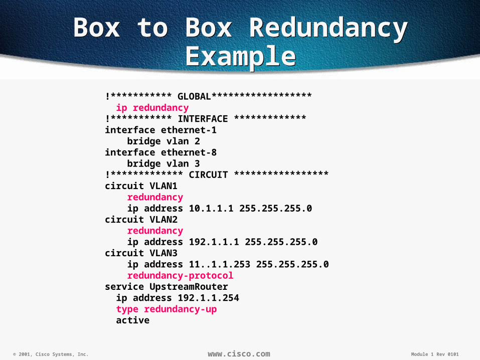
Box to Box RedundancyExample
Box to Box RedundancyExample
!*********** GLOBAL****************** ip redundancy!*********** INTERFACE *************interface ethernet-1 bridge vlan 2interface ethernet-8 bridge vlan 3!************* CIRCUIT *****************circuit VLAN1 redundancy ip address 10.1.1.1 255.255.255.0circuit VLAN2 redundancy ip address 192.1.1.1 255.255.255.0circuit VLAN3 ip address 11..1.1.253 255.255.255.0 redundancy-protocolservice UpstreamRouter ip address 192.1.1.254 type redundancy-up active

© 2001, Cisco Systems, Inc. www.cisco.com Module 1 Rev 0101
Box to Box RedundancyTroubleshooting
Box to Box RedundancyTroubleshooting
Type "show redundancy" in the CLI to see whether the CSS is Master or Backup.
You can also check the reason for the last fail over.
Redundancy: Enabled Redundancy Protocol: Running
Redundancy State: Master MasterMode: No
Number of times redundancy state changed to Master: 1
to Backup: 1
Redundancy interface: 192.168.1.2
Current State Duration: 0 days 14:10:02
Last Fail Reason: No Fail
VRID: 128 Priority: 100
Physical Link Failure Monitor on:
Interface: State
ethernet-3 Up
ethernet-2 Up
Uplink Enabled: 4 Number Alive 4
Service Name: Service State:
------------- --------------
SERV_1 Up
SERV_2 Up

© 2001, Cisco Systems, Inc. www.cisco.com Module 1 Rev 0101
Box to Box RedundancyTroubleshooting
Box to Box RedundancyTroubleshooting
The configuration command "logging subsystem redundancy level warning-4" can be used to monitor mastership transitions.
The "logging subsystem redundancy level debug-7" configure command will show details of the redundancy protocol in action.
(Note- Issue "no logging subsystem all" after debugging an issue.)

© 2001, Cisco Systems, Inc.
CSS RedundancyCSS Redundancy
Configuration Synchronization
Configuration Synchronization
28

© 2001, Cisco Systems, Inc. www.cisco.com Module 1 Rev 0101
Configuration SynchronizationConfiguration Synchronization
Automated process to configure a Backup CSS identically to a Master CSS
Saves time for administrator •Administrators only need to make modifications to the master and then issue an update for the backup(s).
Only works with Box-to-Box Redundancy.

© 2001, Cisco Systems, Inc. www.cisco.com Module 1 Rev 0101
Configuration SyncConfiguration Sync
VLAN2192.1.1.1
VLAN110.1.1.1
VIP192.1.1.100
VLAN2192.1.1.1
VLAN110.1.1.1
VIP192.1.1.100
VLAN311.1.1.254
VLAN311.1.1.253 MASTER
BACKUP
CAPP Session
A CAPP session needs to be setup between the CSS’s on the redundancy VLAN for Config Sync.
X X
© 2001, Cisco Systems, Inc. www.cisco.com Module 1 Rev 0101
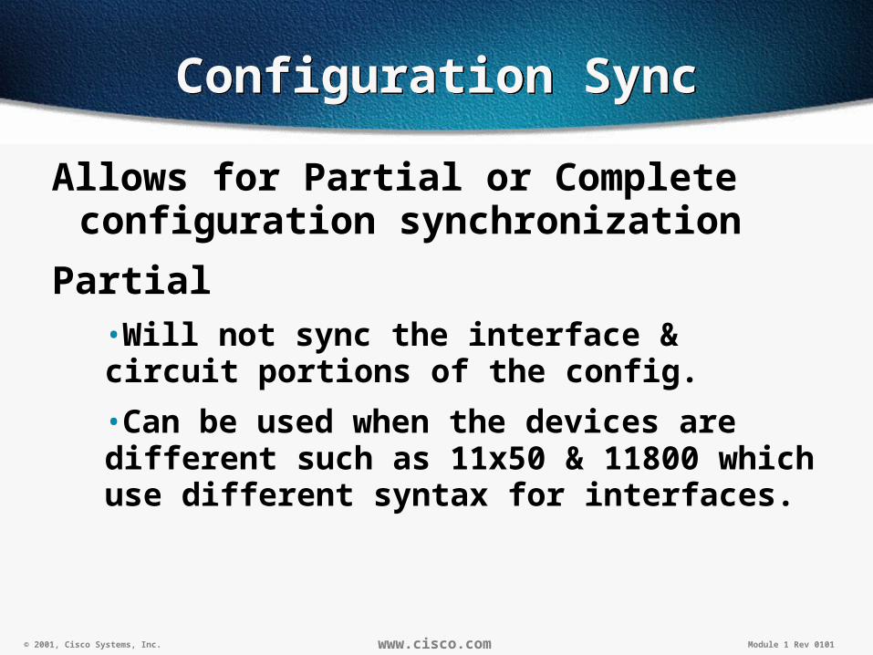
Configuration SyncConfiguration Sync
Allows for Partial or Complete configuration synchronization
Partial•Will not sync the interface & circuit portions of the config.
•Can be used when the devices are different such as 11x50 & 11800 which use different syntax for interfaces.
© 2001, Cisco Systems, Inc. www.cisco.com Module 1 Rev 0101
Configuration SyncConfiguration Sync
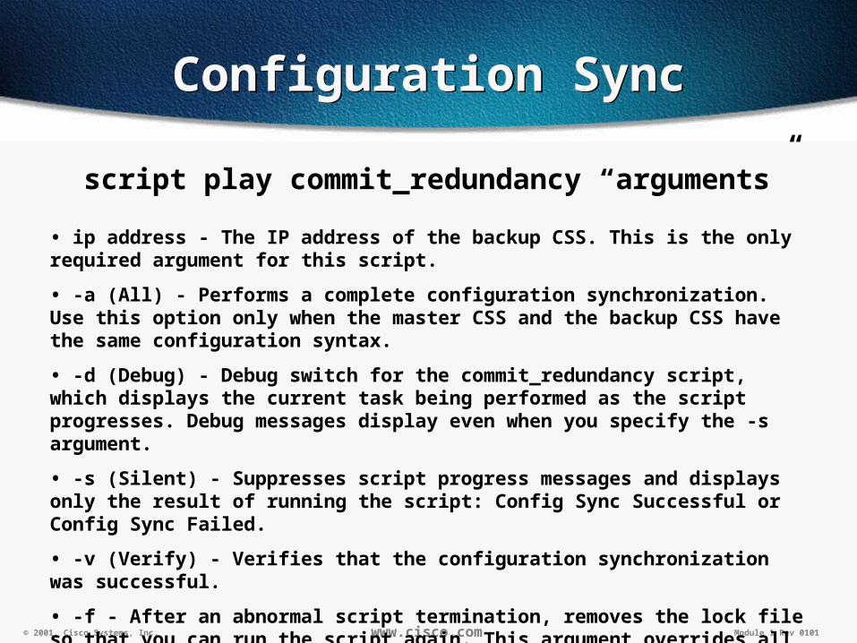
script play commit_redundancy “arguments”
• ip address - The IP address of the backup CSS. This is the only required argument for this script.
• -a (All) - Performs a complete configuration synchronization. Use this option only when the master CSS and the backup CSS have the same configuration syntax.
• -d (Debug) - Debug switch for the commit_redundancy script, which displays the current task being performed as the script progresses. Debug messages display even when you specify the -s argument.
• -s (Silent) - Suppresses script progress messages and displays only the result of running the script: Config Sync Successful or Config Sync Failed.
• -v (Verify) - Verifies that the configuration synchronization was successful.
• -f - After an abnormal script termination, removes the lock file so that you can run the script again. This argument overrides all other specified arguments and the script exits immediately after removing the lock file.

© 2001, Cisco Systems, Inc.
CSS RedundancyCSS Redundancy
VIP & Interface Redundancy
using VRRP
VIP & Interface Redundancy
using VRRP33
© 2001, Cisco Systems, Inc. www.cisco.com Module 1 Rev 0101
VIP & Interface RedundancyVIP & Interface Redundancy
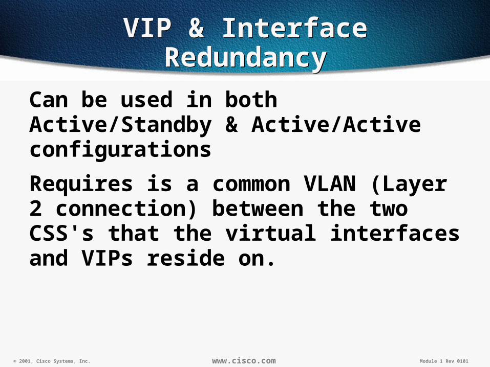
Can be used in both Active/Standby & Active/Active configurations
Requires is a common VLAN (Layer 2 connection) between the two CSS's that the virtual interfaces and VIPs reside on.

© 2001, Cisco Systems, Inc. www.cisco.com Module 1 Rev 0101
Internet
VIP Redundancy Active/Backup
VIP Redundancy Active/Backup
VLAN2192.1.1.2
VLAN110.1.1.2
VIP Active192.1.1.100
VLAN2192.1.1.1
VLAN110.1.1.1
Redundant Interface10.1.1.254
ACTIVE
BACKUP
All servers gateways should point to the Redundant Interface10.1.1.254

© 2001, Cisco Systems, Inc. www.cisco.com Module 1 Rev 0101
VRRPCommands
VRRPCommands
The "show redundant-interfaces" and "show redundant-vips commands can be used to show the current state of the interface, when it last transitioned, and how many times.
CSS-Example# show redundant-interfaces
Redundant-Interfaces:
Interface Address: 10.100.100.7 VRID: 1
Redundant Address: 10.100.100.100 Range: 1
State: Backup Master IP: 10.100.100.8
State Changes: 3 Last Change: 11/07/2000 10:42:41

© 2001, Cisco Systems, Inc. www.cisco.com Module 1 Rev 0101
VRRPTroubleshooting
VRRPTroubleshooting
The configuration command "logging subsystem vrrp level warning-4" can be used to monitor mastership transitions.
The "logging subsystem vrrp level debug-7" configure command will show details of the redundancy protocol in action.
(Note- Issue "no logging subsystem all" after debugging an issue.)

© 2001, Cisco Systems, Inc. www.cisco.com Module 1 Rev 0101
Fate SharingOverview
Fate SharingOverview
The CSS minimally runs a virtual interface on the public and private side.
If either interface fails, and the other continues to forward traffic, asymmetry can occur.
Fate sharing ensures that if either interface fails, the other interface will share the same fate.

© 2001, Cisco Systems, Inc. www.cisco.com Module 1 Rev 0101
Fate SharingExample
Fate SharingExample
VLAN2192.1.1.2
VLAN110.1.1.2
VIP Active192.1.1.100
VLAN110.1.1.1
Redundant Interface10.1.1.254
ACTIVE BACKUP
Without Fate Sharing asymmetric flows could happen
ACTIVEBACKUP
VLAN2192.1.1.1
011001

© 2001, Cisco Systems, Inc. www.cisco.com Module 1 Rev 0101
Fate Sharing UsingCritical Services
Fate Sharing UsingCritical Services
Define a service with the IP address of an upstream device (i.e. HSRP address on routers)
Add a keepalive type of script ap-kal-pinglist with ip addresses of an upstream & downstream networking device.
Add this service as a critical service to each Virtual Router. The same critical service should be used for the Redundant VIP & the Redundant Interface.
service VRRP-KAL ip address 192.1.1.254 keepalive type script ap-kal-pinglist “192.1.1.254 10.100.100.1” active circuit VLAN1 ip address 10.1.1.1 255.255.255.0 ip virtual-router 1 priority 200 preempt ip redundant-interface 1 10.1.1.254 ip critical service 1 VRRP-KAL
Circuit VLAN2ip address 192.1.1.1 255.255.255.0 ip virtual-router 2 priority 200 preempt ip redundant-vip 2 192.1.1.100 ip critical service 2 VRRP-KAL
Using the same Critical Service for both Virtual Routers provides Fate Sharing
© 2001, Cisco Systems, Inc. www.cisco.com Module 1 Rev 0101
Fate SharingCritical Service
Fate SharingCritical Service
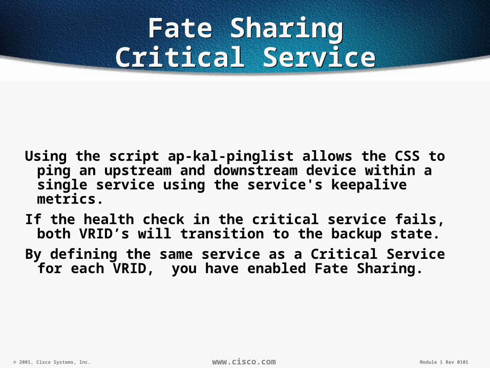
Using the script ap-kal-pinglist allows the CSS to ping an upstream and downstream device within a single service using the service's keepalive metrics.
If the health check in the critical service fails, both VRID’s will transition to the backup state.
By defining the same service as a Critical Service for each VRID, you have enabled Fate Sharing.

© 2001, Cisco Systems, Inc. www.cisco.com Module 1 Rev 0101
Fate SharingCritical Service Monitoring
Fate SharingCritical Service Monitoring
The "show service summary" command can be used to monitor how many times the critical service has failed.
© 2001, Cisco Systems, Inc. www.cisco.com Module 1 Rev 0101
Critical ServicesTips
Critical ServicesTips
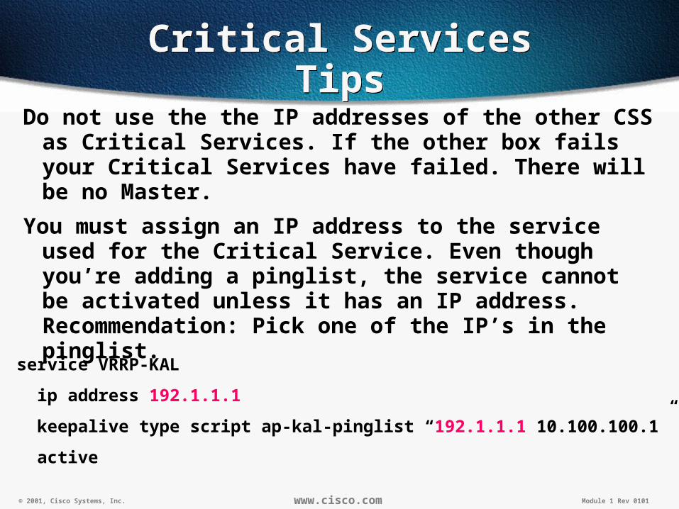
Do not use the the IP addresses of the other CSS as Critical Services. If the other box fails your Critical Services have failed. There will be no Master.
You must assign an IP address to the service used for the Critical Service. Even though you’re adding a pinglist, the service cannot be activated unless it has an IP address. Recommendation: Pick one of the IP’s in the pinglist.
service VRRP-KAL
ip address 192.1.1.1
keepalive type script ap-kal-pinglist “192.1.1.1 10.100.100.1”
active

© 2001, Cisco Systems, Inc.
CSS RedundancyCSS Redundancy
Non-Shared VIP Redundancy Using
VRRP
Non-Shared VIP Redundancy Using
VRRP44

© 2001, Cisco Systems, Inc. www.cisco.com Module 1 Rev 0101
Active/Active VIP RedundancyActive/Active VIP Redundancy
There are two different modes of Active/Active VIP Redundancy• Non-shared
• Shared
Non-shared allows both CSSs to be active at the same time. Each will be active for a unique set of VIPs.
Shared allows both CSSs to be active for the same VIP.

© 2001, Cisco Systems, Inc. www.cisco.com Module 1 Rev 0101
Active/Active VIP Redundancy Non-Shared
Active/Active VIP Redundancy Non-Shared
Requires multiple VIPs
Use Preempt mode to force Mastership to different CSSs.
Requires a unique Redundant-Interface on the backend for each VIP. The VIP & corresponding Redundant-Interface should be tied together with the same Critical Service.
Servers are segmented into groups, each group using a unique default gateway.
A server should only be associated with one active switch at any given time.

© 2001, Cisco Systems, Inc. www.cisco.com Module 1 Rev 0101
Active/Active VIP Redundancy Non-Shared
Active/Active VIP Redundancy Non-Shared
VLAN2192.1.1.2
VLAN110.1.1.2
VIP Active192.1.1.100
VLAN2192.1.1.1
VLAN110.1.1.1
Redundant Interface10.1.1.254
ACTIVE
VIP 192.1.1.100 is Master on the bottom CSS and Backup on the top CSSVIP 192.1.1.101 is Master on the top CSS and Backup on the bottom CSS
ACTIVE
ACTIVE
VIP Active192.1.1.101
Redundant Interface10.1.1.253
ACTIVE Default Gateway10.1.1.253
Default Gateway 10.1.1.254
Use Preempt to define which VIPs are active on each CSS.

© 2001, Cisco Systems, Inc. www.cisco.com Module 1 Rev 0101
Active/Active VIP Redundancy Non-Shared
Active/Active VIP Redundancy Non-Shared
circuit VLAN1
ip address 10.1.1.1 255.255.255.0
ip virtual-router 1 priority 101 preempt
ip virtual-router 2
ip-redundant-interface 1 10.1.1.253
ip-redundant-interface 2 10.1.1.254
ip critical-service 1 VRRP-KAL
ip critical-service 2 VRRP-KAL
Circuit VLAN2
ip address 192.1.1.1 255.255.255.0
ip virtual-router 3 priority 101 preempt
ip virtual-router 4
ip redundant-vip 3 192.1.1.101
ip redundant-vip 4 192.1.1.100
ip critical service 3 VRRP-KAL
ip critical-service 4 VRRP-KAL
circuit VLAN1
ip address 10.1.1.2 255.255.255.0
ip virtual-router 1
ip virtual-router 2 priority 101 preempt
ip-redundant-interface 1 10.1.1.253
ip-redundant-interface 2 10.1.1.254
ip critical-service 1 VRRP-KAL
ip critical-service 2 VRRP-KAL
Circuit VLAN2
ip address 192.1.1.2 255.255.255.0
ip virtual-router 3
ip virtual-router 4 priority 101 preempt
ip redundant-vip 3 192.1.1.101
ip redundant-vip 4 192.1.1.100
ip critical service 3 VRRP-KAL
ip critical-service 4 VRRP-KAL
Top CSS Bottom CSS

© 2001, Cisco Systems, Inc.
CSS RedundancyCSS Redundancy
Shared VIP Redundancy
Using VRRP
Shared VIP Redundancy
Using VRRP49
© 2001, Cisco Systems, Inc. www.cisco.com Module 1 Rev 0101
Active/Active VIP Redundancy Shared
Active/Active VIP Redundancy Shared
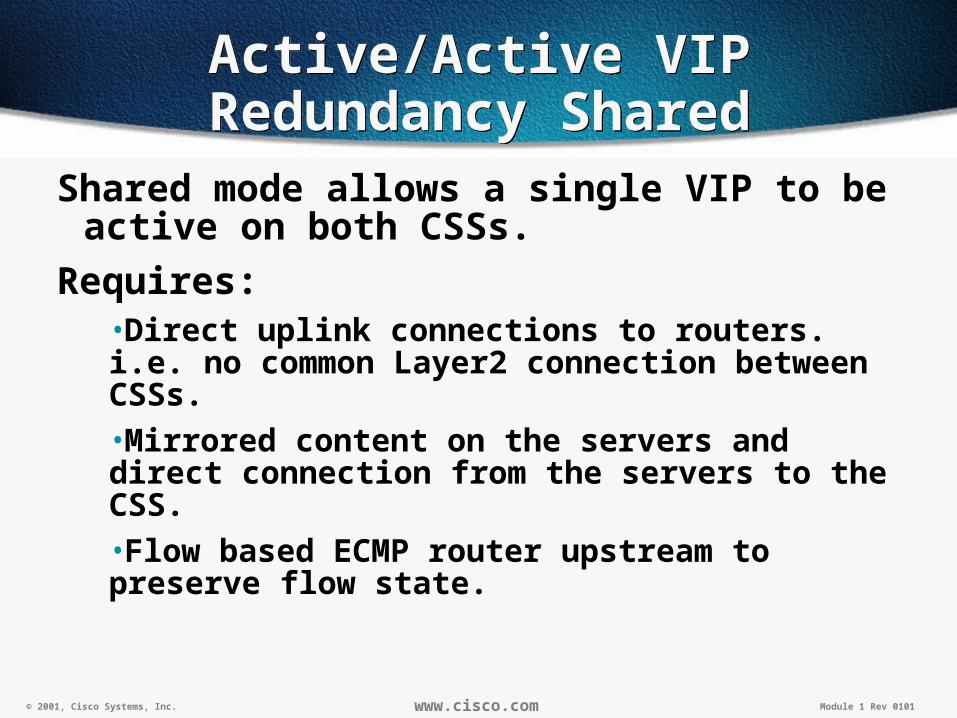
Shared mode allows a single VIP to be active on both CSSs.
Requires:•Direct uplink connections to routers. i.e. no common Layer2 connection between CSSs.•Mirrored content on the servers and direct connection from the servers to the CSS.•Flow based ECMP router upstream to preserve flow state.

© 2001, Cisco Systems, Inc. www.cisco.com Module 1 Rev 0101
Active/Active VIP Redundancy Shared
Active/Active VIP Redundancy Shared
VLAN2192.1.1.2
VLAN110.1.1.2
VIP Active192.1.1.100
VLAN2192.1.1.1
VLAN110.1.1.1
MASTER
Servers must be directly connected to preserve flows
BACKUP
Mirrored Content
192.1.2.1
192.1.3.1
Equal Cost Routesip route 192.1.1.0 255.255.255.0 192.1.2.1 1ip route 192.1.1.0 255.255.255.0 192.1.3.1 1
Only the Master will respond to ARPs for the VIPBoth the Master & Backup will process flows for the same VIP
ARP VIP
ARP VIP

© 2001, Cisco Systems, Inc.
CSS RedundancyCSS Redundancy
Dual Homed ServersDual Homed Servers
52

© 2001, Cisco Systems, Inc. www.cisco.com Module 1 Rev 0101
Dual Homed ServersL2 Attach
Dual Homed ServersL2 Attach
VLAN2192.1.1.2
VLAN110.1.1.2
VIP Active192.1.1.100
VLAN2192.1.1.1
VLAN110.1.1.1
Redundant Interface10.1.1.254
ACTIVE
BACKUP
The preferred (easiest) configuration for dual homed servers is to connectthem directly to Layer 2 switches behind the CSS’s.

© 2001, Cisco Systems, Inc. www.cisco.com Module 1 Rev 0101
Dual Homed Servers Direct Attach
Dual Homed Servers Direct Attach
VLAN2192.1.1.2
VLAN110.1.1.2
VIP Active192.1.1.100
VLAN2192.1.1.1
VLAN110.1.1.1
ACTIVE
BACKUP
Attempting to directly attach the servers to the CSS requires a lot of thought and testing (each NIC/Failover implementation is different)
Option # 1 – Use Active/Active VIP Redundancy & have servers listento Router Discovery Protocol for gateway info.

© 2001, Cisco Systems, Inc. www.cisco.com Module 1 Rev 0101
Dual Homed Servers Direct Attach – Different
Subnets
Dual Homed Servers Direct Attach – Different
Subnets
VLAN2192.1.1.2 VLAN1
10.1.2.1
VIP Active192.1.1.100
VLAN2192.1.1.1
VLAN110.1.1.1
ACTIVE
ACTIVE
Each CSS will source NAT all packets forwarded to the servers to an address on the backend subnet.
Benefit- No default routes are needed on the servers.
Source NAT all packets To 10.1.1.254
Source NAT all packets To 10.1.2.254

© 2001, Cisco Systems, Inc.
CSS RedundancyCSS Redundancy
Lab TopologyLab Topology
56

© 2001, Cisco Systems, Inc. www.cisco.com Module 1 Rev 0101
CACHEA
PDB-1
RTR-SP1 RTR-SP2
INET-CORP ToINET-SAT
High Availability - Flat Corporate
High Availability - Flat Corporate
OUT-L OUT-R
FarmB1-4FarmA1-4FarmDB1-4
CSS-DB
FW-RFW-L
IN-L IN-R
CSS-R VIPs192.168.51.100192.168.50.100
CSS-L VIPs192.168.50.100192.168.51.100

58© 2000, Cisco Systems, Inc.

© 2001, Cisco Systems, Inc. www.cisco.com Module 1 Rev 0101
Persistence in this context refers to a specific connection being initially load balanced to a server and maintaining a “persistent” connection on the same server for subsequent requests in the same session.
Persistence (Sticky) on the CSS
Persistence (Sticky) on the CSS
© 2001, Cisco Systems, Inc. www.cisco.com Module 1 Rev 0101
Persistence (Sticky) on the CSS (cont.)
Persistence (Sticky) on the CSS (cont.)
Types of Persistence on the CSS:
Source IP Sticky
Cookie Sticky
SSL Sticky
HTTP Redirection

© 2001, Cisco Systems, Inc. www.cisco.com Module 1 Rev 0101
Source IP StickySource IP Sticky
The CSS uses client’s Source IP address to map connection to server.
Possible Problems:
1) The “Mega Proxy Issue”
2) Client NAT

© 2001, Cisco Systems, Inc. www.cisco.com Module 1 Rev 0101
Sticky IPSticky IP
advanced-balance sticky-srcip
• Content Services Switch “sticks” a client to a server based on the client’s source IP address
• Available layer 3, 4, and 5 content rules• Referred to as layer 3 sticky
advanced-balance sticky-srcip dstport • Content Services Switch “sticks” a client to a
server based on the client’s source IP address and destination port
• Available layer 4, and 5 content rules• Referred to as layer 4 sticky

© 2001, Cisco Systems, Inc. www.cisco.com Module 1 Rev 0101
Sticky MaskSticky Mask
The CSS uses a set mask and groups connections accordingly to servers.
Problems:
1) Mega Proxy Issue
2) Could throw off accuracy of load balance metric.
© 2001, Cisco Systems, Inc. www.cisco.com Module 1 Rev 0101
Sticky-MaskSticky-Mask
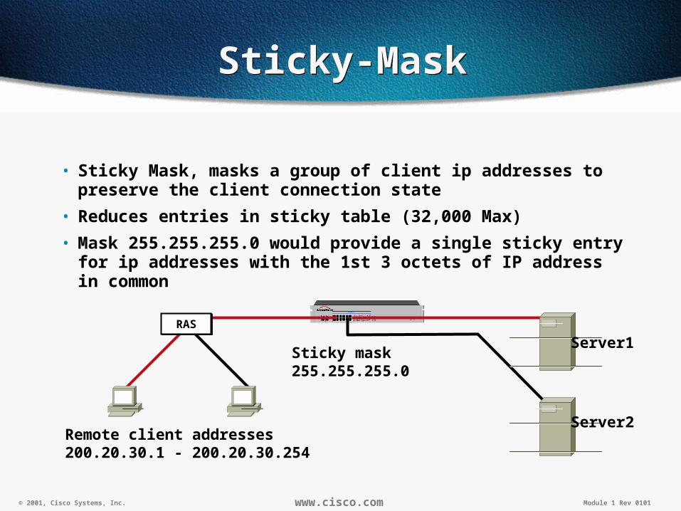
• Sticky Mask, masks a group of client ip addresses to preserve the client connection state
• Reduces entries in sticky table (32,000 Max)
• Mask 255.255.255.0 would provide a single sticky entry for ip addresses with the 1st 3 octets of IP address in common
Remote client addresses200.20.30.1 - 200.20.30.254
Sticky mask255.255.255.0
RASRAS
Server2
Server1

© 2001, Cisco Systems, Inc. www.cisco.com Module 1 Rev 0101
Cookie StickyCookie Sticky
The CSS uses either a cookie it creates or a cookie set by the server to map client connections to servers,
Caveat:
1) Doesn’t work with SSL or other non-HTTP traffic.

© 2001, Cisco Systems, Inc. www.cisco.com Module 1 Rev 0101
Sticky CookieSticky Cookie
• advanced-balance cookie
• Content Services Switch “sticks” the client to a server based on the cookie
• Optional string tools can be used to limit the amount of processing required by the CSS
• Cookie configured for server
• Does not use a sticky table
Server1
HTTP get
HTTP response cookie: server1;
HTTP get cookie: server1;
service server1• ip address 10.0.3.221• string server1• active
10.0.3.221
content sticky-cookie• vip address 192.10.10.1• url “/*”• advanced-balance cookie• add service server1• active
vip 192.10.10.1
RASRAS
© 2001, Cisco Systems, Inc. www.cisco.com Module 1 Rev 0101
Example Sticky-cookie Example Sticky-cookie
10.0.3.221
10.0.3.222
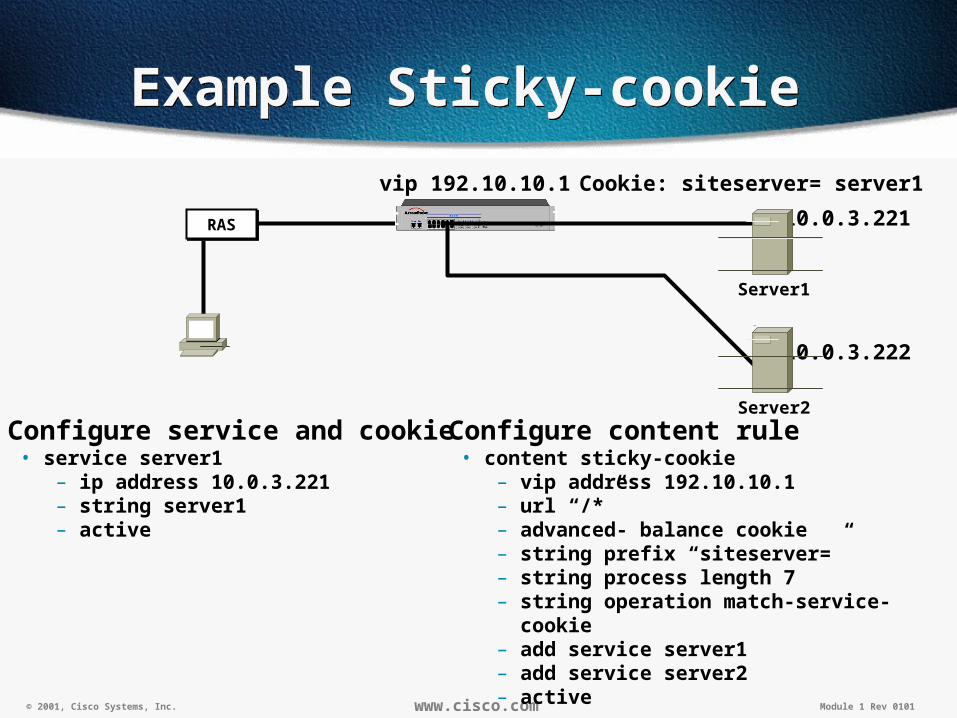
Cookie: siteserver= server1
Configure service and cookie• service server1
– ip address 10.0.3.221– string server1– active
Configure content rule• content sticky-cookie
– vip address 192.10.10.1– url “/*”– advanced- balance cookie– string prefix “siteserver=”– string process length 7– string operation match-service-cookie– add service server1– add service server2– active
Server1
RASRAS
vip 192.10.10.1
Server2

© 2001, Cisco Systems, Inc. www.cisco.com Module 1 Rev 0101
SSL StickySSL Sticky
CSS Uses the SSL session ID to map connections to servers.
Caveats:
1) Doesn’t work with HTTP or other non-SSL traffic
2) Doesn’t work with clients and servers that reset/change SSL Session ID mid-session.
© 2001, Cisco Systems, Inc. www.cisco.com Module 1 Rev 0101
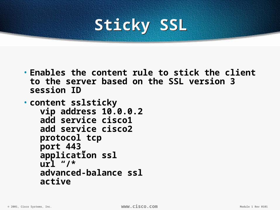
Sticky SSLSticky SSL
• Enables the content rule to stick the client to the server based on the SSL version 3 session ID
• content sslsticky vip address 10.0.0.2 add service cisco1 add service cisco2 protocol tcp port 443 application ssl url “/*” advanced-balance ssl active

© 2001, Cisco Systems, Inc. www.cisco.com Module 1 Rev 0101
HTTP RedirectionHTTP Redirection
CSS config is setup to use redirection (HTTP 302 redirects) to map a 1-1 connection from client to server.
Caveats:
1) Requires n+1 Public IPs
2) Requires extra DNS configuration
3) Requires unique SSL Certificate for every server.
© 2001, Cisco Systems, Inc. www.cisco.com Module 1 Rev 0101
Garbage Collection on the CSS
Garbage Collection on the CSS
Flows that become idle and have not been closed via valid means (TCP FIN, RST, etc) are subject to be removed via the garbage collection process.
Garbage collection can, in some cases, terminate long lived idle sessions due to inactivity. (Example: SSH, Telnet, etc)

© 2001, Cisco Systems, Inc. www.cisco.com Module 1 Rev 0101
Garbage Collection (cont)Garbage Collection (cont)
Flow permanent can prevent garbage collection from cleaning up certain traffic.
CSS150-3(config)# flow permanent port<1-10> <port>
Pros: Keeps flow active forever or until properly closed. No “Garbage collection”
Cons: Keeps flow active forever or until properly closed. No “Garbage collection” ;-)- Can use up all available Flow Control Blocks (FCBs) and cause
severely impact the CPU.
© 2001, Cisco Systems, Inc. www.cisco.com Module 1 Rev 0101
Troubleshooting TipsTroubleshooting Tips
•Useful commands

© 2001, Cisco Systems, Inc. www.cisco.com Module 1 Rev 0101
The most useful troubleshooting commands
The most useful troubleshooting commands
• Show flow
# Show flow <source ip> <destination ip>
CSS150-3# show flow 0.0.0.0 0.0.0.0
Src Address SPort Dst Address DPort NAT Dst Address Prt InPort OutPor
t
--------------- ----- --------------- ----- --------------- --- --------- ------
---
172.17.63.230 1095 171.68.122.99 53 0.0.0.0 UDP e14 e13
172.17.63.230 1095 171.70.24.186 53 0.0.0.0 UDP e14 e13
CSS150-3#
© 2001, Cisco Systems, Inc. www.cisco.com Module 1 Rev 0101
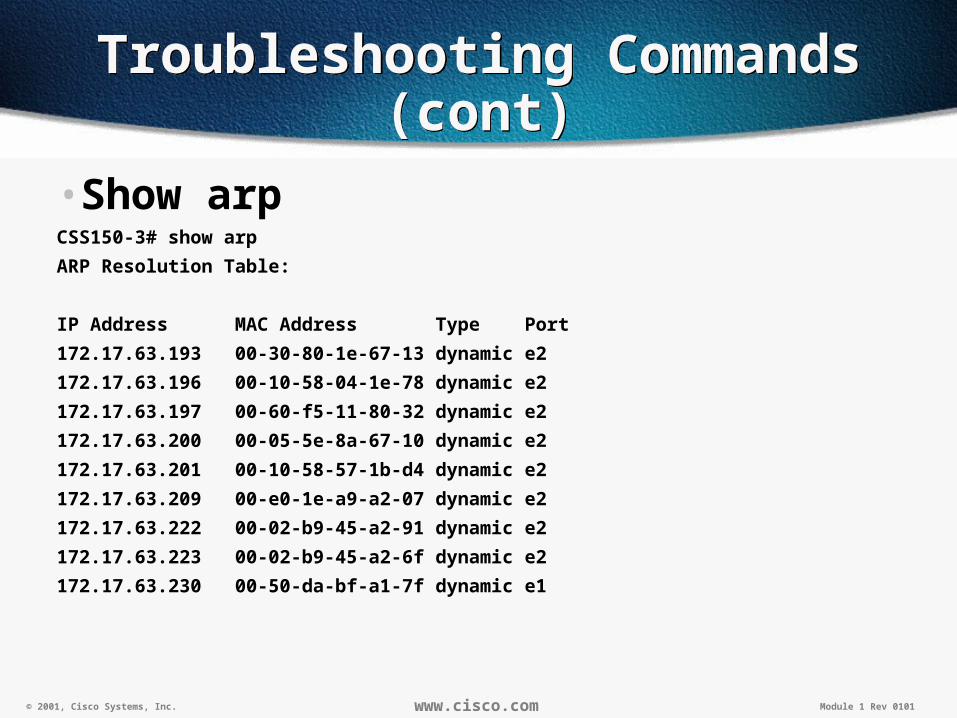
Troubleshooting Commands (cont)
Troubleshooting Commands (cont)
•Show arpCSS150-3# show arp
ARP Resolution Table:
IP Address MAC Address Type Port
172.17.63.193 00-30-80-1e-67-13 dynamic e2
172.17.63.196 00-10-58-04-1e-78 dynamic e2
172.17.63.197 00-60-f5-11-80-32 dynamic e2
172.17.63.200 00-05-5e-8a-67-10 dynamic e2
172.17.63.201 00-10-58-57-1b-d4 dynamic e2
172.17.63.209 00-e0-1e-a9-a2-07 dynamic e2
172.17.63.222 00-02-b9-45-a2-91 dynamic e2
172.17.63.223 00-02-b9-45-a2-6f dynamic e2
172.17.63.230 00-50-da-bf-a1-7f dynamic e1
© 2001, Cisco Systems, Inc. www.cisco.com Module 1 Rev 0101
Logging FeaturesLogging Features
The CSS provides logging capabilities for debug and system monitoring by generating the following log files:• Boot.log - Records the results of the boot process. Each time you
reboot the CSS, the boot.log is overwritten with the new boot information. The default location is to the Disk and Console.
• Sys.log - Records log information for a user defined subsystem or logs CLI commands. The default location is to disk but alternate locations are the console, syslogd, or VTYs.
The CSS has boot logging and system logging enabled and writes to disk by default.
The maximum size of a log file is 50 MB and is recorded in ASCII text.

© 2001, Cisco Systems, Inc. www.cisco.com Module 1 Rev 0101
Enabling Subsystem LoggingEnabling Subsystem Logging
• Use the logging subsystem command to enable logging on a CSS subsystem and the level of info to log:
• The level you specify instructs the CSS to log subsystem activity that occurs at that level and all numbered values less than that level.
• Levels include:
– Fatal=0, Alert=1, Critical=2, Error=3, Warning=4, Notice=5, Info=6, Debug=7
• The following example enables logging for the chassis subsystem with a critical-2, alert-1, and fatal-0 error level.
– (config)# logging subsystem chassis level critical-2

© 2001, Cisco Systems, Inc. www.cisco.com Module 1 Rev 0101
Sending Log Messages to an Email Address
Sending Log Messages to an Email Address
To send the log activity of a subsystem to an email address, use the logging sendmail command.
The syntax for this global command is:• (config)# logging sendmail email_address host_address level
• The variables are:
– email_address = The email address for the recipient
– host_address = The IP address for the SMTP host
– level = The type of information to log. Enter one of these levels:
• fatal, alert, critical, error or warning
To turn off logging to an email address, enter:• (config)# no logging sendmail email_address
© 2001, Cisco Systems, Inc. www.cisco.com Module 1 Rev 0101
Misc. Logging CommandsMisc. Logging Commands
Use the show log command to display the contents in a log or trap log file. The options are:• show log - Send the log activity to your current session. Press any key
to stop displaying log activity.
• show log logfilename - Display the contents in a log file.
• show log logfilename tail <x> - Display the last X lines in a log file.
• show log traplog - Display all traps that have occurred. A trap log file is an ASCII file in the log directory containing generic and enterprise traps.
• show log ? - Display a list of valid log files.
When you want to keep track of all CLI commands: •(config)# logging commands enable
– Logs all CLI commands to the sys.log file
•(config)# no logging commands
– Disable logging CLI commands to the sys.log file.