Embed Size (px)
Citation preview

VOLUME 1 ISSUES8&9FIRST AND SECOND
QUARTER 2002DOUBLE ISSUE
ROLLS-ROYCE SILVER CLOUD. II. III. AND PHANTOM V
BENTLEY S, S2 AND S3
- 1959 SILVER CLOUD I RADFORD, SMH177 TIM MYRICK AND SCOTT JORDAN, OWNERS
SHE'S NOT JUST ANOTHER PRETTY COVER GIRL, MEET "SMOKEY"

From the Editor's Desk...
Hopefully this issue of the Post "55" finds you and yours well and staying busy.
First, let me begin by apologizing for getting this out a
2002 Society Officers and Directors
President- Larry Durocher398 Old Shcrman Hill Road Woodbury, CT 06798
203-263-3720 ladiiroch@ earthlink.net
Secretary- Dale Clark4114 Flint Creek Kingwood, TX 77339 281-361-4715 [email protected]
Treasurer- Hal Lambert7621 K ingsbury Road A lexandria, V A 22315
703-971-1097 hallam bert@ crols.com
Editor- Debbie Habacker3136 H am pshire Ct. Frisco, TX 75034 972-385-8888 dhabacker@ aol.com fax
469-384-0063
J im F a c in e lli
24 W est M ain Street, Box V
Elizabethvillc, PA 17023
717-362-3477 fax 717-362-4571
restore® cpix.net
Jim Klein Frank Russell655 Greenwood Ave. 1157 Bcnnet Street
Glencoe, IL 60022-1549 P.O. 60x1117
[email protected] Parkslcy, VA 23421
Russelsformal@ icqmail.com
little later than anticipated, lam still trying to get the Post "55" on some semblance of a regular schedule, but time has been flying by for me (no pun intended), and I'm a little farther behind than I wanted to be. Does anyone know what has happened to the first half of this year?
With that in mind, those of you who are regular readers might notice that this issue is a little larger than usual. I've decided to make this a "double issue" if you will to catch up. Thank you to those of you who have been sending in articles and requesting information. Keep them coming. I plan to use each and every item that comes across my desk. Please do not be alarmed if you've sent something in and it hasn't been printed yet. I will get it published.
Also, I am still looking for cover articles with photos of your cars as well as technical articles or useful tips that may be of interest to other members. You all know something about these cars whether you want to admit it or not and you just might have information than someone else does not have. Please use this as a forum to exchange ideas and experiences. That is what the Post "55" is for. Don't be shy.
Please note that there is a scheduled meeting of the Silver Cloud and Bentley "S" Society at the National Meet at The Homestead in Virginia. If you are planning on attending the National Meet, please plan to attend the Silver Cloud and Bentley "S" meeting as well. We will have some business/organizational things to discuss, but we plan on having a technical meeting at that time. So bring your technical questions and I promise someone qualified will be there to answer them for you and trust it will not be me.
Until Next time...
Debbie
VOLUME 1
issues 8 & 9
D irectors –Francis Bourgeois P.O. Box 1702 Conroe, TX 77305 409-445-1485 [email protected]
Rolls-Royce Silver Cloud, II, III, and Phantom V Bentley S, 52 and S3 Society
Diamond in the Rough
I feel certain that many of you are scratching your heads and wondering about my choice for the cover of this special double issue of the "post 55." You are probably thinking "even my car looks better than that one."
Obviously the car in question would not beconsidered by most to be the most beautiful cover girl in her current condition, but her story is definitely worth telling.
I hope that as we chronicle her refurbishing process and her return to glory, some of you will be become motivated and inspired.
Call me crazy, but I usually root for the underdog. Not everyone would take on such an endeavor and I think we would all agree that it does take a special devotion and love to refurbish from the ground up.
As you read about "Smokey" and how she came out of hiding to be lovingly restored, don't forget to read the Sunday paper, you never know what you might find and you just might find a diamond in the rough.
Many ThanksTo
Tim Myrick and Scott JordanFor Bringing Us Smokey's StoryAnd for allowing us to follow her
Cinderella Story of Rags to Riches
Society Car Badges are Still Available:
For More Information Contact:
LARRY DUROCHER (IN THE U.S.)398 Old Sherman Hill RoadWoodbury, CT 06798203-263-3720 [email protected]
RALPH CURZON (IN CANADA)130Mayfield DriveOakville, ONT Canada L6H 1K7905-670-3656 [email protected]
HELPFUL TIPS & NEWS YOU CAN USE
New Headquarters/Foundation Museum
Matt Syscik, President of the Rolls-Royce Owners' Club, Inc. and on behalf of the RROC Board of Directors has signed the land purchase agreement for the new headquarters/foundation museum and offices. The land purchase agreement is for the purchase of 20 acres of land located at Mechanicsburg and was signed on March 18, 2002. The club has posted the required $25,000 earnest money and now the fun begins as the foundation and the club work towards gathering the remaining money to purchase the land as well as the necessary funding to complete the project as envisioned.
2004 World Tour Information
To plan ahead and see what exciting events are planned for the 2004 world tour please visit:
www.rroc.org/worldtour
If this is not possible, contact Peter Lind at Fax # 707-967-0626, E-mail bonpete@earthlink or write to 1031 White Lane, St Helena, CA, 94574
Indiana Region
The Indiana Region is once again up and running! The meeting held on March 23, 2002 was attended by approximately 25 members. By all accounts, the meeting was considered to be quite a success. Those of you who are Society Members and in the Indiana area should make sure that you are once again involved with the newly reorganized Indiana Region. Glad to have you back on track and best of luck to all in the Indiana Region.
Post "55" is a periodical of the Silver Cloud & Bentley "S" Society published four (4) times per year. Every effort has been made to publish accurate information, but the Society and its Directors assume no liability for loss or for damage arising from any information contained herein. Statements attributed to individuals do not necessarily reflect the official policy of the Society.

Rolls-Royce Silver Cloud. H. in, and Phantom V Bentley S. 52 and S3 Society
On our 1958 Cloud I, the intake air scoops for the heater/demister have long departed. It is possible to use the heater/demister without the air scoops. However, the amount of air that can be "rammed" through the system, as one proceeds at a brisk rate without the benefit of the fan, is minimal. The system, obviously, works better with air scoops.
You don't have to hock your Rolex to buy new ones. (If they are still available). You can make them. Instructions are as follows:
1. Secure a sheet of aluminum thin enough to bend easily. At least 26" by 8"
2. Replicate the attached drawing on the aluminum. I found that a Sharpie Ultra Fine Point Permanent Marker Pen writes well on metal.
3. Using your tin snip. Cut out the pattern.
Note: Use great care. Cut aluminum is very sharp and you should keep Band Aids at the ready.
The cut lines are plain. ——————The bend lines are squiggly. AAAAAAA
Note: At flaps A, B, C & D 2" cut from rear towards the front. To make sharp bends I would suggest that you place a stout metal straight edge on the fold lines and clamp it to a table top.
How to assemble a LEFT side air scoop:
1. Bend flaps B, C and D up90* (* = degrees)2. Bend flap A up 90*3. Bend flap E up 90*4. At flap F bend up the 7' side 90* and arrange it so that flap C ends up in front of flap D.5. At flap F bend up the 8" side 90* and arrange it so that flap B is in front of flap C.
You now have yourself a box with one end half open and one end fully open.Pop rivet it together.At least two (2) rivets to hold flaps A and E together.One rivet to hold flaps B, C and D together.Another rivet to hold B and D together.
To install:
1. Jack up left front.2. Remove left wheel.3. Slip new intake air scoop over air vent.
Note: Since the bottom of the air scoop is one inch longer than the top, the air scoop will tilt upwards. This is good.
4. Affix air scoop to air vent. Use at least two sheet metal screws through the top of the air scoop.
(Continued on page 5)
INTAKE AIR SCOOPBY
CORKY MORRISON
Rolls-Royce Silver Cloud. II, HI. and Phantom V Bentley S, S2 and S3 Society
(Continued from page 4}
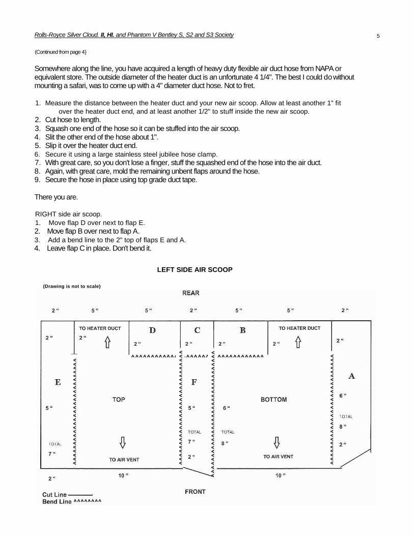
Somewhere along the line, you have acquired a length of heavy duty flexible air duct hose from NAPA or equivalent store. The outside diameter of the heater duct is an unfortunate 4 1/4". The best I could do without mounting a safari, was to come up with a 4" diameter duct hose. Not to fret.
1. Measure the distance between the heater duct and your new air scoop. Allow at least another 1" fitover the heater duct end, and at least another 1/2" to stuff inside the new air scoop.
2. Cut hose to length.3. Squash one end of the hose so it can be stuffed into the air scoop.4. Slit the other end of the hose about 1".5. Slip it over the heater duct end.6. Secure it using a large stainless steel jubilee hose clamp.7. With great care, so you don't lose a finger, stuff the squashed end of the hose into the air duct.8. Again, with great care, mold the remaining unbent flaps around the hose.9. Secure the hose in place using top grade duct tape.
There you are.
RIGHT side air scoop.1. Move flap D over next to flap E.2. Move flap B over next to flap A.3. Add a bend line to the 2" top of flaps E and A.4. Leave flap C in place. Don't bend it.
LEFT SIDE AIR SCOOP
(Drawing is not to scale)
5

Rolls-Royce Silver Cloud, II, III, and Phantom V Bentley $, 52 and S3 Society
The Thrilling Tale of "Smokey" 1959 Rolls Royce Silver Cloud (SMH177) by Harold Radford
Owned by Tim Myrick and Scott Jordan
Every Sunday morning, Scott and I enjoy reviewing the automobile classifieds in our local papers to look for undiscovered treasures. As most club members know, it has been a long time since a rare Silver Ghost was discovered languishing with assorted livestock and haystacks in a bam. We still enjoy looking.
Several months ago, we were intrigued by the following classified ad: "1959 Rolls Royce Silver Cloud 22,000 original miles—NEEDS WORK."
Knowing that the "needs work" claim has a wide variety of connotations from surface cosmetic to deep mechanical issues, our interest was peaked, and we were compelled to investigate. After contacting the owner, we were directed to an unfamiliar part of Dallas to view the car.
While we didn't find a forgotten Silver Ghost in a bam, we did find a Radford Silver Cloud I lodged under a big blue tarp among years of overgrowth and adjacent to the shabby ruins of a large home that appeared to be damaged by fire. The owner told us that up until several years ago, the car had always been carefully parked in the home's garage. When the home caught fire, the garage was engulfed in heat, and the fire fighters used the garage (with car still in it) as the main point of entry to the burning house.
Though the car itself never caught fire, it suffered from the affects of extreme heat and a deluge of water. The once stunning shell gray and midnight blue body was reduced to a murky brown and red body sitting on four cracked and melted tires. In fact, some of the leading had liquefied and appeared to be dripping down the front fender. The windshield was blackened, cracked and warped. The driver's window was completely shattered from heat. Likewise, all lenses had melted and were dripping down the body. While the interior of the car was unharmed by heat, it was severely damaged by an excessive amount of water.
This Cloud I was customized by Harold Radford with a full webesto roof. The roof did not survive the heat of the fire, so water from the firelighters hoses followed by years of being outdoors under a tarp sullied the once pristine interior. Despite the indication of excessive water inside the car, there was no evidence of rust.
Even as Scott and I were wary of the severity of damage that the car had experienced, we were also thrilled to find such a worthy project. This was a low-mileage, beautiful, and unusual car that deserved to be restored—not end up at a junkyard. The car seemed to call out to us quietly: "Please save me, and bring me back to my former glory. I have stories to tell."
After our inspection of the car, the owner said, "this car hasn't run since the fire, and that was over five years ago."
He invited us to make an offer, and being wary of how we would even get the car from it current perch to our garage, we replied with a very conservative bid. Much to our surprise (or possible horror) he
accepted.
With the help of a weed eater and a heavy-duty flatbed tow truck, the car was in our driveway the next day. Needlessto say, our neighbors were delighted with our newest addition.
(Continued on pages 19 & 20)

Rolls-Royce Silver Cloud, II, in. and Phantom V Bentley S. 52 and S3 Society
Removing/Disassembling the Trunk Handle By Larry Durocher (LSCX671)
Trunk handles may need to be removed for re-plating, lock or push button problems, etc. This note outlines the procedure I employed on my Silver Cloud III. The trunk handle is secured to the boot lid with two bolts and two stud/nut combinations. To gain access to the mounting bolts and nuts, you must remove a small rectangular access panel (about 12" x 7"). The access panel is secured to the boot lid with 9 upholstery clips, identical to those used on the door panels. There are three clips on the top, two on each side, two in the middle, and none on the bottom. Use an upholstery clip remover to gently pry the clips out of the boot lid.
With the panel removed, the trunk handle bolts and the interior portion of the trunk push button mechanism, are exposed (see Figure i). Figure i shows the two inner bolts, the outer portions of the handle have studs that pass through the boot lid and secured by nuts on the interior of the lid.
When the owner pushes the trunk handle pushbutton, the center rod (has a small nut at the end) in the center moves inward and the attached flat plate with two ears pushes on the two levers (one on each side) which pivot and pull the links towards the center.
When you lock the trunk by turning the key clockwise (as viewed from the exterior), you are rotating the center rod, and hence the attached plate with two ears, counter-clockwise (as viewed from the interior) about 45 degrees. At that angle, when you depress the pushbutton, the rod moves inward but the flat plate ears do not contact the levers and hence the trunk latches do not release.
The trunk release mechanism will become loose when the handle is unbolted. To make it easier to reposition the mechanism in the original position, use a scriber to lightly outline the position of the trunk release mechanism plate. Remove the two center bolts and the two outer nuts using a 7/16" socket. Gently pull/tap and rotate the handle to clear the inner mechanism and lift it out of the boot lid. There should be flat rubber seals/gaskets on the two "ears" of the handle and an "O-ring" type of rubber gasket/ seal around the center section of the handle. Figure 2 shows the trunk handle after removal.
Figure 2
DO NOT CLOSE THE TRUNK AFTER THE HANDLE IS REMOVED! I didn't trust myself so I put a bulky towel on each side of the trunk opening to ensure that I could not close the trunk.
Remove the small center nut with a 9/32" socket, remove the two small center screws, and remove the flat plate, bracket, and spring. Note the orientation of the plate (the top and bottom are different) and that the hole in the plate has flats which engage the flats on the center rod.
(Continued on page 12)
Figure l

Rolls-Royce Silver Cloud, II. Ill and Phantom V Bentley S. 52 and S3 Society
NOVEMBER 2001 TECHNICAL E-MAIL
Checking the Starting System
This e-mail addresses the basic procedure to diagnose a cranking problem - the starter does not turn over the engine or the cranking is very slow.
1. See if the battery will provide power to other devices such as the lights and horn (turn ignition on). If the lights work, and the horn and lights are "strong", then the battery should have sufficient charge to at least turn the motor over slowly.
If the lights, horn, and other accessories do not work, make sure the battery cutout (if installed) is turned to the proper position. Check the battery terminal connections for tightness and corrosion and check the battery ground (negative terminal) to the chassis. If everything seems OK, charge the battery or remove the battery and have it tested.
2. With the battery and connections eliminated as the source of the problem, we now move on to the starter solenoid switch which is located on the left-hand side of the chassis for V8 cars, adjacent to the starter. On 6-cylinder cars the solenoid can be to the left or right of the starter but is always adjacent to the starter. Make sure the transmission lever is positioned in neutral and touch a grounded probe light to the end of the heavy cable that runs from the battery (+ terminal) to the switch. If the probe illuminates, have someone turn and hold the ignition key to the starting position and use the probe to check if you have power at the other end of the switch, where the other heavy cable runs from the switch to the starter.
If you do not have power at the other end, then the switch has failed or the ignition switch is not supplying power to the solenoid switch. With the ignition switch turned and held to the starting position, see if you have power at the small 2 B.A. screw terminal on the solenoid switch. If you have power here, then the ignition switch is working properly. If you do not have power, then check the micro-switches at the base of the steering column. One of the switches ensures that no power goes to the starter unless the transmission gear selector lever is in neutral. If that is not the culprit, use the probe to find the problem in the wiring between the solenoid switch, the micro-switch, and the ignition switch.
3. With power available at the solenoid switch output, check to make sure that when the ignition switch is turned and held to the start position, you have power at the starter end of the heavy cable that runs from the solenoid switch to the starter.
On the V8 cars, the starter consists of two distinct pieces, a solenoid (small cylindrical canister) and the starter motor. The heavy wire from the solenoid switch connects to the large terminal on the solenoid and a much lighter (jumper wire) runs from the large terminal to a small terminal clip on the solenoid on V8 cars. Again, with the ignition at the start position, use the probe to ensure that the jumper is supplying power to the small terminal clip on the solenoid. The solenoid will not engage, nor will the starter motor turn, if this jumper is broken or disconnected.
4. If you have power at the starter and the starter is not turning then the starter must be removed. If all the connections are tight and clean (and the battery is fully charged) and the motor still turns slowly, the starter should be removed. Further diagnostics are described in section M4 of the workshop manual.
To remove the starter:
. disconnect the negative lead from the battery
. remove the under shield (aluminum pan) beneath the starter motor
. Use a 1/2" wrench to remove the securing nut and then the heavy cable (power input) from the starter
. remove/loosen the three 3/8" bolts that hold the starter to the engine block on V8s or the four 1/4"bolts on 6-cylinder cars . remove the starter by lowering it between the
frame and the engine block
5. At this point you can obtain the necessary parts and rebuild the starter (see section M4) or send the starter out to be rebuilt. If you send it out, a typical cost for the rebuild is in the range of $325- $425.

Rolls-Royce Silver Cloud. II, III, and Phantom V Bentley S. S2 and S3 Society
MARCH 2002 TECHNICAL E-MAIL
Simple Troubleshooting of the Charging System
This technical e-mail addresses simple trouble-shooting of the charging system; the e-mail assumes that the charging system is the standard generator/voltage regulator system rather than a non-standard (alternator) system. Section M of the Workshop Manual gives a much more complete description and detailed troubleshooting of the voltage regulator (control box). Before proceeding with the current procedure, check the following:
• Battery condition• Battery cables (clean and tight)• All wires leading to the generator and
voltage regulator• Generator belt tension
If no problems exist in this list, then we should check the output of the generator. The voltage regulator is mounted on the right-side firewall and has a black cover with the stamping Lucas Current Voltage Regulator and three (3) sets of terminals (marked D, F, and B) on the bottom. Before removing any wires, put tags on each wire so that you will know how to reconnect the wires. Remove the two (2) wires from the generator that go to the D and F terminals. The heavy wire on the D terminal should be the generator wire; if there is any doubt use a continuity tester to verify the connection to the generator D terminal. Connect both of these wires (disconnected from the F and D terminals of the regulator) to the positive lead of a voltmeter and ground the negative lead of the voltmeter. Start the car and observe the voltage as the car speed is increased slightly (up to about 1000 RPM). The voltage should increase as the speed is increased and the value should rise above 12 volts, 14-16 volts is typical.
If the voltage builds up to a normal value, the voltage regulator is at fault. You can diagnose the exact problem and get it fixed or simply buy a replacement voltage regulator. If the voltage is not normal, the generator can usually be rebuilt; a prior Post "55" article by Ralph Curzon covered the rebuilding of a generator. You can also send the unit out for rebuilding at a cost that seems to be in the range of $300 - $400.
Removing, Installing Flap Actuators on a Cloud III By Larry Durocher (LSCX671)
I recently decided to re-plate the hardware associated with the flap actuators on my Silver Cloud III. The upper (evaporator) and lower (heater) flap actuators are located on the right hand valance, adjacent to the rear brake fluid reservoir, see Figure 1. The upper actuator controls the airflow to the upper evaporator and the lower actuator controls airflow to the heater, The positions of both flaps for various combinations of the two rotary switches (marked UPPER and LOWER) on the dashboard are given on page C2(S) of the Workshop Manual Supplement. The switch/flap correspondence for earlier models is given on page C8 of the Workshop Manual. Please note, although the dash switches are marked UPPER and LOWER, the lower and upper actuators are both influenced by the position of a given dash switch. In other words, the UPPER and LOWER switches on the dash are not separate controls for the corresponding upper and lower actuators.
Figure 1
Before dismantling any hardware, have someone sit in the car and put the switches through the various positions and make sure that both actuators are working. In many cases, one or both switches have failed. These units can be rebuilt and are available on an exchange basis; I got a unit from Hyphen Repairs for approximately $160.
If you are going to replace an actuator, please mark the wire connections carefully before removing any wires. Each actuator motor has four connectors, marked 1 through 4, with 1 always being at the lowest position on the valence, see Figure 2.
Figure 2
When I am working under the hood, I always start with a few simple preparations:
• Disconnect the battery (hopefully through a cut-out switch)• Put a towel under the
work area to catch anything (wrench, screw, washer) that might drop and end up inaccessible or in the under trays.
(Continued on page 18}

Rolls-Royce Silver Cloud, II, III, and Phantom V Bentley S. 52 and S3 Society 10
MAY 2002 TECHNICAL EMAIL
Diagnosing Horn Problems
In this brief note we cover the basics of locating a horn problem. Most horn problems fall into one of two categories: . no - horn sound - incorrect horn sound
We start with the easier problem, incorrect horn sound.
Incorrect Horn Sound
Our cars were supplied with either Lucas Windtone horns or a matched pair of high frequency horns. USA, Canada and "Home" cars were typically equipped with two (2) Windtone horns, a low-note horn (UD 5582) and a high note horn (UD 5583). The Windtone horns do not have a pitch adjustment. The horns are located on the front of the chassis frame.
The first step is to determine if both horns are actually producing some sound. Get under the car and "fairly close" to the horns and have someone press the horn button. You can tell by sound which horn is or is not working. If not, put your hand on the horn case and you can tell by vibration.
After locating the problem horn (s), flip your battery disconnect switch to shut off the electrical power to the car, tin-mount the horn, remove the center screw in the hemispherical cover, and remove (mark the connections before removing the wires) the two (2) push-in wires that supply power and the ground.
To ensure that the power and/or ground wires to the particular horn are not the source of the problem, use a 12 volt source (4-6 amps) to supply power and ground to the horn that has been removed. If the horn works out of the car, then the problem is either the power or the ground.
If the horn is not working, you can clean the contact points and adjust the contacts, see page M43 in the workshop manual. If the cleaning/adjustments do not solve the problem, you need to buy a new or used horn. Before searching for a replacement, look at the horn to determine whether it is the low note (L in the trumpet section) or high note (H in the trumpet section). Also look at the other horn to ensure that your car has both types of horns. An earlier horn problem may have caused someone to use an incorrect replacement since they did not realize that two types were used or could not get the correct replacement I have looked at 4-5 pairs of new and used horns and have found that the trumpet size and orientation was somewhat different among the pairs. I actually bought a set of new, "replacement (not RR)" horns and found that the trumpet section was so large, I could not mount the new horns. Luckily, I was able to take the new horn "guts" and put them in the old horn cases and then readjust the contacts.
No Horn Sound
The horns are operated by the push button on the steering wheel through a relay mounted on the left hand bulkhead (firewall). A separate fuse box is used for the horn circuit and the fuse box (with two fuses) is mounted adjacent to the main fuse box on the right hand firewall.
Assuming that the horns are OK, we must determine if power is being distributed to the horns. The ignition key must be turned on to check the power throughout the horn circuit. We start at the fuse box on the right hand firewall. Use a power probe to check the power before and after the fuses. If power is passing through the fuse box, we move onto the horn relay on the left hand firewall (below the windshield wiper motor). The relay has three connectors, marked W1, C1, and C2 in the wiring diagram. The connections are, as viewed from the top:
. C1 is the top connector and connects the horn relay to the left valance connector group and then to the horns .
. C2 is the middle connector (power input) which has two wires:
. one to the horn fuse box
. one to a condenser on the firewall
. W1 is the lowest connector and connects the horn relay to the horn button switch in the steering wheel
Again, we start by checking the power to the relay. Use a power probe to see if we have power at the middle (C2) connector. If not, we have a broken wire between the fuse box and the relay.
(Continued on page 11)

Rolls-Royce Silver Cloud, II, III, and Phantom V Bentley S, 52 and S3 Society
(Continued from page 10)
If we have power at C2, then have someone press and hold the horn button and use the power probe to see if we have power at Ci. If we have power at C1, then the horn button is working correctly and the relay is working correctly and therefore the problem is one of the following:
. the wiring between the relay and horns . the horn ground wires . the horns
If we have power at C2 but do not have power at C1 when the horn button is pressed, we can try one or more of the following:
.bypass the horn button by removing the wire from W1i, then use a jumper wire from W1 to ground, every time you touch the wire to ground the horns should blow. If so, the problem is in the wire from the relay to the horn button or in the horn button switch.
. bypass the horn button and relay switch, by removing the power input from C2 and the horn wire from C1 and then connecting the two wires with a jumper wire. Every time we connect a jumper from the power input (€2) wire to the horn (Ci) wire, the horns should blow.
Rolls-Royce Silver Cloud III
By Kay Buie-Nelson
The third and final series of the Cloud was well received in 1962. Horsepower was up 7% because of a boost to 9:1compression and larger carburetors. Interior changes increased room and front seats were individually adjustable. Production ceased in 1965. Maximum speed was 115 mph. 0-6 time was 10.8 seconds. Power assistance was increased to make steering lighter. Air conditioning was now very reliable and these cars continued to perform to the highest standards.
The Cloud III series has an enviable service record and is the most trouble free Rolls-Royce ever built. All components were well seasoned and long production has eliminated virtually all problems both major and minor.
There are some noteworthy coach built bodies on the III series and the last chance the coachbuilders had to work with a separate chassis. In late 1964 and 1965 a few Silver Cloud Ill's appeared with special chassis numbers and coachwork by H.J. Mulliner-Park Ward. These are the rarest examples of this series. Long wheel base saloons on the SIII are rare. Only 253 were produced between 1962-1965, with only 25 by H.J. Mulliner-Park Ward.
Silver Cloud Ill's have found increasing favor especially as the variety of coachwork still available gave collectors a last chance at some individuality.
Reliability of these cars is well known. It is very possible that the III series may be the favorite of the 1955-1965 production. They are highly esteemed by
collectors. It is readily identifiable by the public as a "Rolls".
Silver Cloud III, LWB with the rear quarter division window coachwork brings a premium price compared to the standard steel saloon. It has more elaborate wood paneling, some with the radio inset and speaker inset. The division fits neatly and closes flush to the headliner.
Other special features of the Silver Cloud III, LWB include special driving mirror with altimeter, combined parking and blinking light above each door pillar, folding mirrors behind each picnic table in the rear on the H.J. Mulliner Park Ward, companion rear center armrest, special remote control button for special radio, lambskin rugs and petrol pump testing switch.
Total Cars Made On Silver Cloud/Bentley S Series
SS LWB
SC I 2,238 121S 1 3,072 35SC II 2,417 299S 2 1,865 57SC III 2,044 153S 3 1,286 32
SC I, II, III 6,699 673S 1, 2, 3 6,223 124
Total Cars Made
13,719 797
11
Rolls-Royce Silver Cloud, II, III, and Phantom V Bentley S, 52 and S3 Society
(continued from page 7)
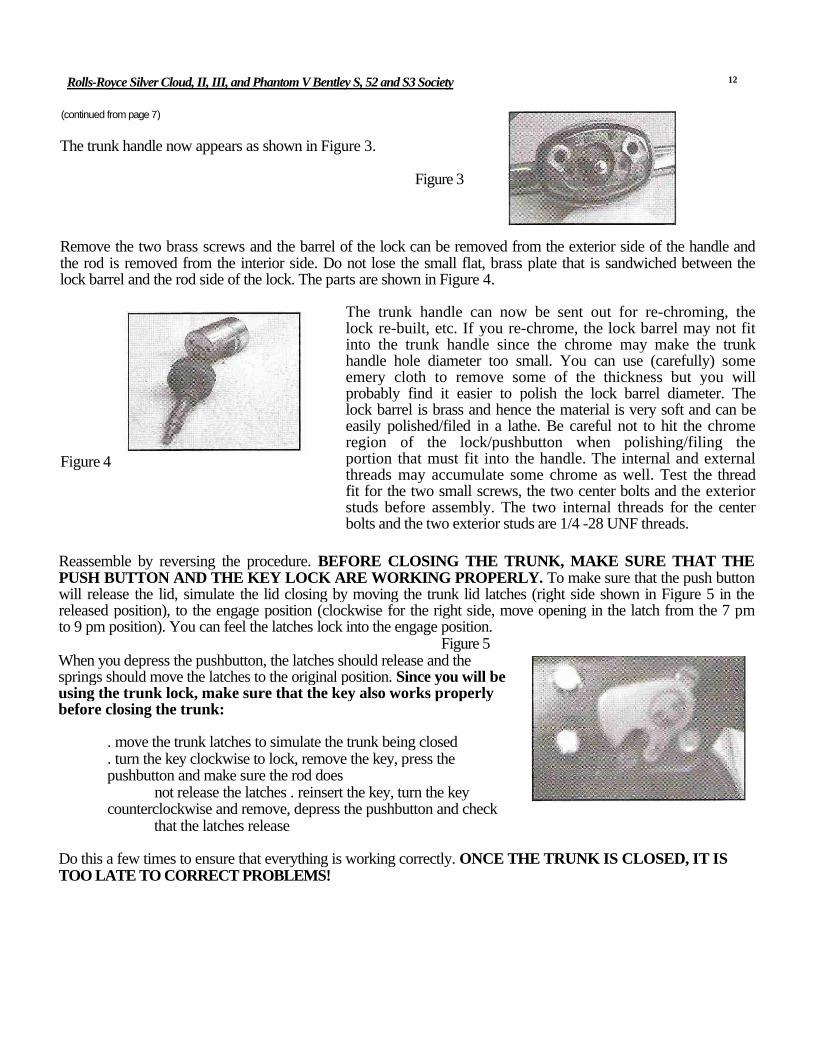
The trunk handle now appears as shown in Figure 3.
Figure 3
Remove the two brass screws and the barrel of the lock can be removed from the exterior side of the handle and the rod is removed from the interior side. Do not lose the small flat, brass plate that is sandwiched between the lock barrel and the rod side of the lock. The parts are shown in Figure 4.
The trunk handle can now be sent out for re-chroming, the lock re-built, etc. If you re-chrome, the lock barrel may not fit into the trunk handle since the chrome may make the trunk handle hole diameter too small. You can use (carefully) some emery cloth to remove some of the thickness but you will probably find it easier to polish the lock barrel diameter. The lock barrel is brass and hence the material is very soft and can be easily polished/filed in a lathe. Be careful not to hit the chrome region of the lock/pushbutton when polishing/filing the portion that must fit into the handle. The internal and external threads may accumulate some chrome as well. Test the thread fit for the two small screws, the two center bolts and the exterior studs before assembly. The two internal threads for the center bolts and the two exterior studs are 1/4 -28 UNF threads.
Reassemble by reversing the procedure. BEFORE CLOSING THE TRUNK, MAKE SURE THAT THE PUSH BUTTON AND THE KEY LOCK ARE WORKING PROPERLY. To make sure that the push button will release the lid, simulate the lid closing by moving the trunk lid latches (right side shown in Figure 5 in the released position), to the engage position (clockwise for the right side, move opening in the latch from the 7 pm to 9 pm position). You can feel the latches lock into the engage position.
Figure 5When you depress the pushbutton, the latches should release and the springs should move the latches to the original position. Since you will be using the trunk lock, make sure that the key also works properly before closing the trunk:
. move the trunk latches to simulate the trunk being closed
. turn the key clockwise to lock, remove the key, press the pushbutton and make sure the rod does
not release the latches . reinsert the key, turn the key counterclockwise and remove, depress the pushbutton and check
that the latches release
Do this a few times to ensure that everything is working correctly. ONCE THE TRUNK IS CLOSED, IT IS TOO LATE TO CORRECT PROBLEMS!
12
Figure 4

Rolls-Royce Silver Cloud, II, III, and Phantom V Bentley S, 52 and S3 Society
TECHNICAL TIPS - SHOCK ABSORBER
1] THE SHOCK REMOVED FROM THE CAR. 2] REMOVE THE ARMS FROM THE SHOCK SHAFT.
3] REMOVE THE SHOCK ABSORBER TOP.
4] REMOVE THE NUTS THAT HOLD ON THE BRACKET AND VALVE BODY.
5] REMOVE THE VALVE BODY. 6] REMOVE THE SPLIT PIN FROM THE PINCH BOLT.
7] REMOVE THE NUT AND BOLT. 8] REMOVE THE TWO SEAL HOUSINGS. 9] REMOVE THE SHAFT AND THE TWO SPACER WASHERS.
10] REMOVE THE PISTON LEVER. 11] REMOVE THE PISTON AND CHECK THE BORE AND THE PISTON FOR WEAR.
12] REMOVE THE PLATE FROM THE VALVE BODY.
13
(Continued on pages 14, 15, 16)

Rolls-Royce Silver Cloud. II. Ill, and Phantom V Bentley S, 52 and S3 Society
DO NOT REMOVE THE BOLT FROM THE END OF THIS HOUSING, AS THE SET-UP SHOCK WILL BE CHANGED .
13] REMOVE THE COVER PLATE AND BOLT TO REMOVE THE PLUNGER VALVE AND SPRING. THIS IS THE TIME TO WASH ALL THE PARTS.
14] AFTER ALL THE PARTS ARE WASHED, REMOVE THE TWO VALVES FROM THE MAIN BODY AND BLOW OUT THE ORIFICES.
16] INSTALL THE PISTON LEVER INTO THE PISTON, IT WILL TAKE AN AMOUNT OF EFFORT TO OVER-COME THE SPRING PRESSURE.
17] INSTALL THE SHAFT IN THE BODY AND THROUGH THE PISTON LEVER.
18] FIT THE SPACER WASHERS.
19] FIT THE PINCH BOLT. 20] FIT THE NUT AND THE SPLIT PIN. 21] WITH A SCREWDRIVER REMOVE THE OLD GLAND.
22] WITH A THIN PIN PUNCH CAREFULLY KNOCK OUT THE BRASS GLAND RETAINER AND CHECK THE BUSHINGS FOR WEAR.
23] FIT THE SEAL HOUSINGS TO THE SHOCK ABSORBER BODY.
24] FIT THE SPECIAL TOOL OVER THE END OF SHOCK SHAFT.
(Continued on pages 15&16)
14
15] FIT THE PISTON TO THE MAIN BODY.

Rolls-Royce Silver Cloud, II, III, and Phantom V Bentley S, 52 and S3 Society
25] WHEN THE GLAND RETAINER IS REMOVED FROM THE BUSHING HOUSING
26] PUSH THE NEW GLAND INTO THE RETAINER.
27] PUSH THE GLAND RETAINER OVER THE TOOL.
28] USING A "C" CLAMP CONTINUE TO PUSH IT ALL THE WAY HOME INTO THE HOUSING. DO THIS TO BOTH ENDS OF THE SHAFT.
29] SELECT THE GASKET WITH THE SMALL HOLE IN THE CENTER.
30] COAT THE VALVE BODY SURFACE WITH GASKET SEALER AND FIT THE GASKET AND THE METAL PLATE.
31] COAT THE EDGE OF THE PLATE WITH GASKET SEALER.
32] FIT THE GASKET WITH THE LARGE HOLE TO THE VALVE BODY.
33] FIT THE VALVE BODY TO THE SHOCK BODY.
34] FIT THE BRACKET AND TIGHTEN UP THE NUTS.
35] THIS IS THE VALVE ARRANGEMENT. THE BOLT SUPPORTS THE SPRING THEN THE VALVE AND THEN THE SQUARE ROD.
36] FIT THE BOLT WITH THE SPRING INTO THE VALVE BODY AND PUSH THE VALVE IN FROM THE TOP AND THEN THE SQUARE ROD.
15
(Continued on page 16}
Rolls-Royce Silver Cloud, II, III, and Phantom V Bentley S. 52 and S3 Society
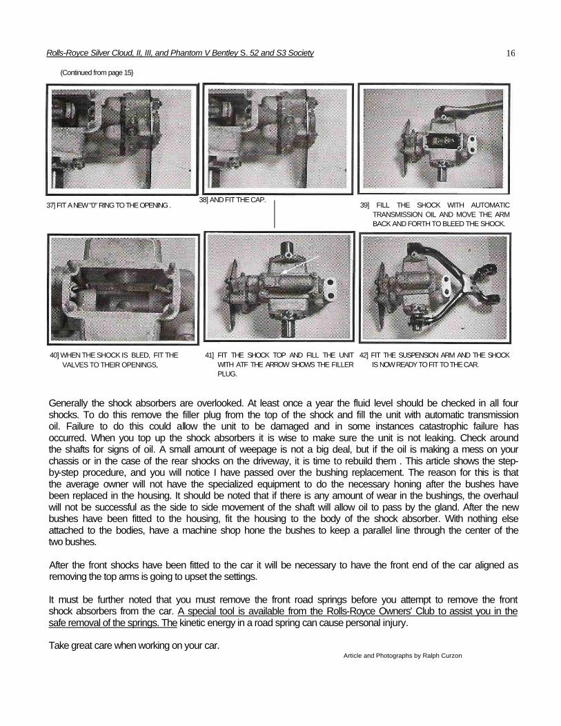
(Continued from page 15}
37] FIT A NEW "0" RING TO THE OPENING . 39] FILL THE SHOCK WITH AUTOMATIC TRANSMISSION OIL AND MOVE THE ARM BACK AND FORTH TO BLEED THE SHOCK.
40] WHEN THE SHOCK IS BLED, FIT THE VALVES TO THEIR OPENINGS,
41] FIT THE SHOCK TOP AND FILL THE UNIT WITH ATF THE ARROW SHOWS THE FILLER PLUG.
42] FIT THE SUSPENSION ARM AND THE SHOCK IS NOW READY TO FIT TO THE CAR.
Generally the shock absorbers are overlooked. At least once a year the fluid level should be checked in all four shocks. To do this remove the filler plug from the top of the shock and fill the unit with automatic transmission oil. Failure to do this could allow the unit to be damaged and in some instances catastrophic failure has occurred. When you top up the shock absorbers it is wise to make sure the unit is not leaking. Check around the shafts for signs of oil. A small amount of weepage is not a big deal, but if the oil is making a mess on your chassis or in the case of the rear shocks on the driveway, it is time to rebuild them . This article shows the step-by-step procedure, and you will notice I have passed over the bushing replacement. The reason for this is that the average owner will not have the specialized equipment to do the necessary honing after the bushes have been replaced in the housing. It should be noted that if there is any amount of wear in the bushings, the overhaul will not be successful as the side to side movement of the shaft will allow oil to pass by the gland. After the new bushes have been fitted to the housing, fit the housing to the body of the shock absorber. With nothing else attached to the bodies, have a machine shop hone the bushes to keep a parallel line through the center of the two bushes.
After the front shocks have been fitted to the car it will be necessary to have the front end of the car aligned as removing the top arms is going to upset the settings.
It must be further noted that you must remove the front road springs before you attempt to remove the front shock absorbers from the car. A special tool is available from the Rolls-Royce Owners' Club to assist you in the safe removal of the springs. The kinetic energy in a road spring can cause personal injury.
Take great care when working on your car.Article and Photographs by Ralph Curzon
16
38] AND FIT THE CAP.
Rolls-Royce Silver Cloud, II, III, and Phantom V Bentley S, 52 and S3 Society
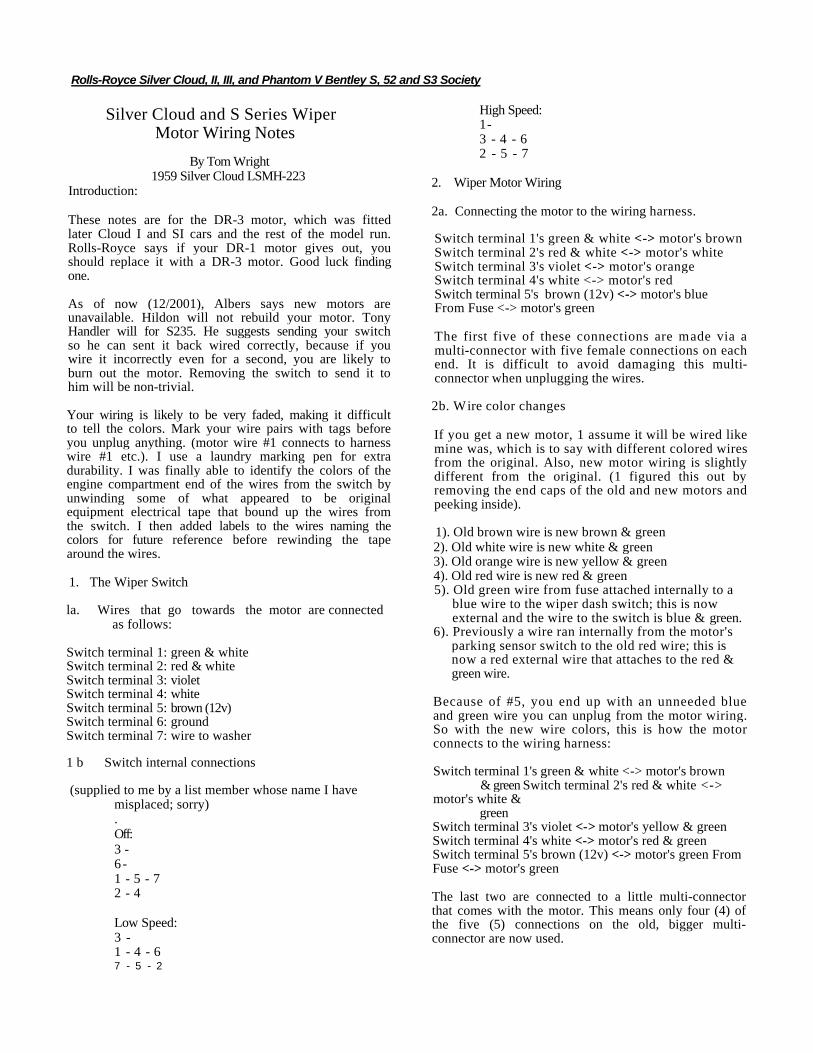
Silver Cloud and S Series Wiper Motor Wiring Notes
By Tom Wright1959 Silver Cloud LSMH-223
Introduction:
These notes are for the DR-3 motor, which was fitted later Cloud I and SI cars and the rest of the model run. Rolls-Royce says if your DR-1 motor gives out, you should replace it with a DR-3 motor. Good luck finding one.
As of now (12/2001), Albers says new motors are unavailable. Hildon will not rebuild your motor. Tony Handler will for S235. He suggests sending your switch so he can sent it back wired correctly, because if you wire it incorrectly even for a second, you are likely to burn out the motor. Removing the switch to send it to him will be non-trivial.
Your wiring is likely to be very faded, making it difficult to tell the colors. Mark your wire pairs with tags before you unplug anything. (motor wire #1 connects to harness wire #1 etc.). I use a laundry marking pen for extra durability. I was finally able to identify the colors of the engine compartment end of the wires from the switch by unwinding some of what appeared to be original equipment electrical tape that bound up the wires from the switch. I then added labels to the wires naming the colors for future reference before rewinding the tape around the wires.
1. The Wiper Switch
la. Wires that go towards the motor are connected as follows:
Switch terminal 1: green & whiteSwitch terminal 2: red & whiteSwitch terminal 3: violetSwitch terminal 4: whiteSwitch terminal 5: brown (12v)Switch terminal 6: groundSwitch terminal 7: wire to washer
1 b Switch internal connections
(supplied to me by a list member whose name I have misplaced; sorry).Off: 3 -6 -1 - 5 - 72 - 4
Low Speed:3 -1 - 4 - 67 - 5 - 2
High Speed: 1 -3 - 4 - 6 2 - 5 - 7
2. Wiper Motor Wiring
2a. Connecting the motor to the wiring harness.
Switch terminal 1's green & white <-> motor's brown Switch terminal 2's red & white <-> motor's white Switch terminal 3's violet <-> motor's orange Switch terminal 4's white <-> motor's red Switch terminal 5's brown (12v) <-> motor's blue From Fuse <-> motor's green
The first five of these connections are made via a multi-connector with five female connections on each end. It is difficult to avoid damaging this multi-connector when unplugging the wires.
2b. Wire color changes
If you get a new motor, 1 assume it will be wired like mine was, which is to say with different colored wires from the original. Also, new motor wiring is slightly different from the original. (1 figured this out by removing the end caps of the old and new motors and peeking inside).
1). Old brown wire is new brown & green2). Old white wire is new white & green3). Old orange wire is new yellow & green4). Old red wire is new red & green5). Old green wire from fuse attached internally to a
blue wire to the wiper dash switch; this is now external and the wire to the switch is blue & green.
6). Previously a wire ran internally from the motor's parking sensor switch to the old red wire; this is now a red external wire that attaches to the red & green wire.
Because of #5, you end up with an unneeded blue and green wire you can unplug from the motor wiring. So with the new wire colors, this is how the motor connects to the wiring harness:
Switch terminal 1's green & white <-> motor's brown& green Switch terminal 2's red & white <->
motor's white &green
Switch terminal 3's violet <-> motor's yellow & green Switch terminal 4's white <-> motor's red & green Switch terminal 5's brown (12v) <-> motor's green From Fuse <-> motor's green
The last two are connected to a little multi-connector that comes with the motor. This means only four (4) of the five (5) connections on the old, bigger multi-connector are now used.

Rolls-Royce Silver Cloud, II, III and Phantom V Bentley S. 52 and S3 Society
(continued from page 9)
The crank arm on the actuator and the crank arm on the extension spindle are connected by a simple rod (link) with 90 bends at each end and split pins. I found it easier to leave the link in place. Simply remove the clamping bolt/nut combination on each crank arm and gently work the cranks off the shafts. If you are replacing an actuator, mark and disconnect the wires. Then unscrew the three mounting screws that bolt each actuator to the flat mounting plate and gently "wiggle" the actuator to remove. The back of each actuator has a large rubber boss that fits snuggly into a corresponding hole in the mounting plate.
1 also wanted to get freshly plated mounting hardware, spacers, etc so I needed to go a step further. To remove the mounting plate, user a 7/16" socket to remove the three nuts holding the plate to three studs that protrude from the valence. Don't lose the washers; there are three thick washers underneath each nut and three identical washers between the cylindrical spacers (they slide over the mounting studs) and the flat, mounting plate. Two of the spacers (distance pieces) are the same length; the third (longer) spacer goes on the most forward (towards the front on the car) stud.When you remove the mounting plate, the two driving spindles will come out with the plate. The driving spindles have transverse pins at the valence end; see Figure 3 showing the mounting plate and the two drive spindles. These pins go into a slot in the end of tubular, cylindrical pieces (see Figure 4) that pass through holes in the valence and engage the flaps. The other end of the cylindrical piece is also slotted and engages a corresponding set of pins (dogs) on theflap shaft. Once the mounting plate is removed, the slotted pieces are accessible and loose and can be taken out.
Figure 3
When you are reassembling, I found it convenient to use the following steps:• Mount the stud spacers and washers• Put the slotted tubes through the valence and engage the "dogs" of the flaps, see Figure 4• Check the engagement by rotating the slotted tubes; each tube should rotate only 90 degrees. One extremity is fully open; the other is the fully
closed position. . Loosen the setscrews (5/64" hex) on the collars of the drive spindles and make sure that the collars can be easily moved. Prior setscrew
deformation will probably require some mild filing of the drive spindles.• Put the drive spindles through the mounting plate, see Figure 3.. Put the mounting plate on the rearmost studs and put on the washers and nuts but only tighten one turn, see Figure 5.• Push and rotate the drive spindles to insert the drive pins into the slotted ends.• Push the mounting plate onto the third stud and tighten ail three nuts.• Make sure the spindles are fully engaging the slotted cylinder, retract about 1/16" to create some play and tighten the setscrews on the drive spindle
collars.• Again, check the operation of the flaps by rotating the drive spindles by hand; each spindle should only rotate 90 degrees.• Gently push the crank/link assembly onto the actuator shaft and drive (extension) spindle.
The Workshop Supplement (see C5(S), C6(S)) covers the adjustment of the crank levers to achieve the correct operation. The description is quite complete and easy to follow. However, i found the directions to have one significant error, or at least my interpretation of the instructions indicates an error.When you are adjusting the mechanism for either actuator, you must move the drive (extension) spindle so that the flap is fully closed. If you are looking at the actuators from the left hand fender, the fully closed position is achieved as follows: • For the upper flap, turn the spindle clockwise until it stops
For the lower flap, turn the spindle counter-clockwise until it stops
My interpretation of the Supplement text is the instructions say clockwise when it should be counter-clockwise and vice versa.When everything is set up correctly and the dashboard switches are in the OFF position, the cranks positions are approximately (see Figure 1):
• Upper actuatorSpindle crank is at 2 o'clockActuator crank points to connector marked 1, see Figure 2
• Lower actuator Figure 5Spindle crank is at 4 o'clockActuator crank points to connector marked 3, see Figure 2
When the Upper switch (dashboard/facia) is turned one position clockwise, both actuator shafts turn counter-clockwise & both flaps should move to the fully open position. The flap/switch position correspondence is not the same on earlier models.
18
Figure 4

Rolls-Royce Silver Cloud, II, in. and Phantom V Bentley 5. 52 and S3 Society
(continued from page 6)
For obvious reasons, we named her "Smokey." Once we had the car on our own turf, we were able to do a more thorough investigation. We knew it was a Radford Cloud 1. Luckily; we found the Radford nameplate on the body to confirm this. In addition to the full Webesto Roof it was outfitted with a Radford boot, place for shooting sticks, electric aerial, a built in compass, special Radford fine lines, several empty cubby-holes in the trunk for picnic items and fittings for a missing trunk mounted picnic table. We reconfirmed that the car was surprisingly without rust and that everything was present.
The boot held additional bonuses. The factory build sheet stated that the car was shipped with six matched pieces of luggage and special order Avon Wide Whitewall tires, very unusual for a British delivery car. We found the original wide whitewall Avon spare along with the complete tool kit, and some of the tools were still wrapped in the factory paper. While the luggage was no longer with the car, the six-piece luggage set (instead of the usual nine piece set) was ordered so that it could accommodate rear mounted air conditioning. Not only does this air conditioning work, it blew cold the first time 1 turned it on — a must for Texas.
We spent several hours with a shop-vac to remove all debris, and then I made adjustments in the engine compartment consisting of a basic tune up, new plugs, wires and hoses (which were all factory correct). After this basic cleaning out, we tested the electrical system. Surprisingly, everything worked—even the bulbs in the melted turn signals!
Were there really only 22,000 miles on this car? All evidence supports this claim. Being a Silver Cloud I, I knew it was important to replace the brake lines before taking it on the road. Upon inspection, I found all original factory hoses with original factory hose clamps (never before seen by me). These parts had minimal wear and tear. Furthermore, the UK registration for the car shows that it spent the majority of its active life in Guernsey, a British Channel Island. As this island is only 3 miles long by 5 miles wide, the low mileage on the car is certainly plausible.
Within a few weeks, we had drained that gas tank, changed the oil and installed the fuel pump that I had rebuilt. From this point forward, it ran like a champ. I am sure our neighbors questioned my sanity as 1 test-drove the "work in progress" around the block.
Her body has been completely stripped to bare metal. The only piece of metal that was warped by the heat was the hood, so a new hood was located. And with the help of Ralph Curzon and Bill Habacker all outside fittings and window frames have been carefully removed. Through this process, I again confirmed that this is a totally rust free, low mileage, unmolested Radford Silver Cloud I.
Smokey is now at the paint shop awaiting her turn for a new coat of paint and a new lease on life.
I know that she has more stories to tell, and I look forward to sharing them with you.Tim Myrick, Dallas Texas
19

Rolls-Royce Silver Cloud, II. Ill, and Phantom V Bentley S. S2 and S3 Society
Smokey arrives at her new homeready to
begin her refurbishing process and start a new life.
Close up photographs of Smokeyshow the damage she received
from the fire surrounding her .
Most of her damage came from the heatand smoke as well as the water used to
extinguish the fire.
20
Please make sure that you vote for
your SocietyOfficers/ Directorson the enclosedballot & return.
Also note thereprint of theJanuary 2002
technical e-mail isthe separate 6
page insert:Silver Cloud IIIMaintenance
Checklist