Embed Size (px)
Citation preview

| 1 |
Defeating Signed BIOS Enforcement
§ Corey Kallenberg § John Butterworth § Sam Cornwell § Xeno Kovah

| 2 |
BIOS Rootkits
§ Very powerful due to being the first code executed on the platform.
§ Can leverage System Management Mode, which is the most powerful mode of execution on the x86 platform.1
§ Survives OS reinstalls.
§ However, we don’t see many “in the wild” BIOS Rootkits. – Less portable and more difficult to implement than their OS level
counterparts. – Perhaps we will see more in the future as the OS becomes more
locked down.
1 There is a lot of prior work on leveraging SMM for nefarious purposes, I encourage you to look it up…
| 3 |
Recent Noteworthy BIOS Security Results
§ “Hardware Backdooring Is Practical” by J. Brossard – Contrary to previous thinking, BIOS rootkits are not that difficult to
implement thanks to opensource firmware projects. § “A Tale Of One Software Bypass Of Windows 8 Secure Boot” by
Bulygin et al. – If you can get onto the flash chip, you can defeat Secure Boot.
§ “BIOS Chronomancy” by Butterworth et al. – BIOS Rootkits can defeat TPM detection. – BIOS Rootkits can survive BIOS reflashes.

| 4 |
Related Work
§ “Attacking Intel BIOS” by Rafal Wojtczuk and Alexander Tereshkin – Exploited memory corruption vulnerability in parsing of unsigned
custom bootup picture in signed Intel BIOS. – Allowed reflashing BIOS with arbitrary (malicious) image despite
signed enforcement. – Blackhat USA 2009

| 5 |
Protecting your BIOS
§ The previous results are dependent on an attacker being able to get a foothold on the SPI flash chip that contains your platform firmware (BIOS or UEFI).
§ Signed firmware update enforcement protects against malicious writes to the flash chip.
§ Most new systems offer or even require signed firmware update enforcement.1
1 More on this later…

| 6 |
How is this implemented?
§ Intel provides a number of protection mechanisms that can “lock down” the flash chip. – You can read all about these in the ICH documentation for your
chipset. – These protections have remained relatively static recently.
§ It’s then up to the OEM to leverage these flash lock down mechanisms to roll their own signed bios enforcement. – This includes correctly configuring a surprisingly complicated set of
flash lock down controls… – As well as implementing an update routine that doesn’t contain any
bugs…

| 7 |
Follow Along
§ I encourage you to download a tool my colleagues and I have written to read out your flash lock down configuration. – http://www.mitre.org/capabilities/cybersecurity/overview/
cybersecurity-blog/copernicus-question-your-assumptions-about – Direct link to binary: http://www.mitre.org/sites/default/files/
copernicus_pr.zip

| 8 |
Protected Range SPI Flash Protections
§ Protected Range registers can provide write protection to the flash chip.
http://www.intel.com/content/www/us/en/chipsets/6-chipset-c200-chipset-datasheet.html
| 9 |
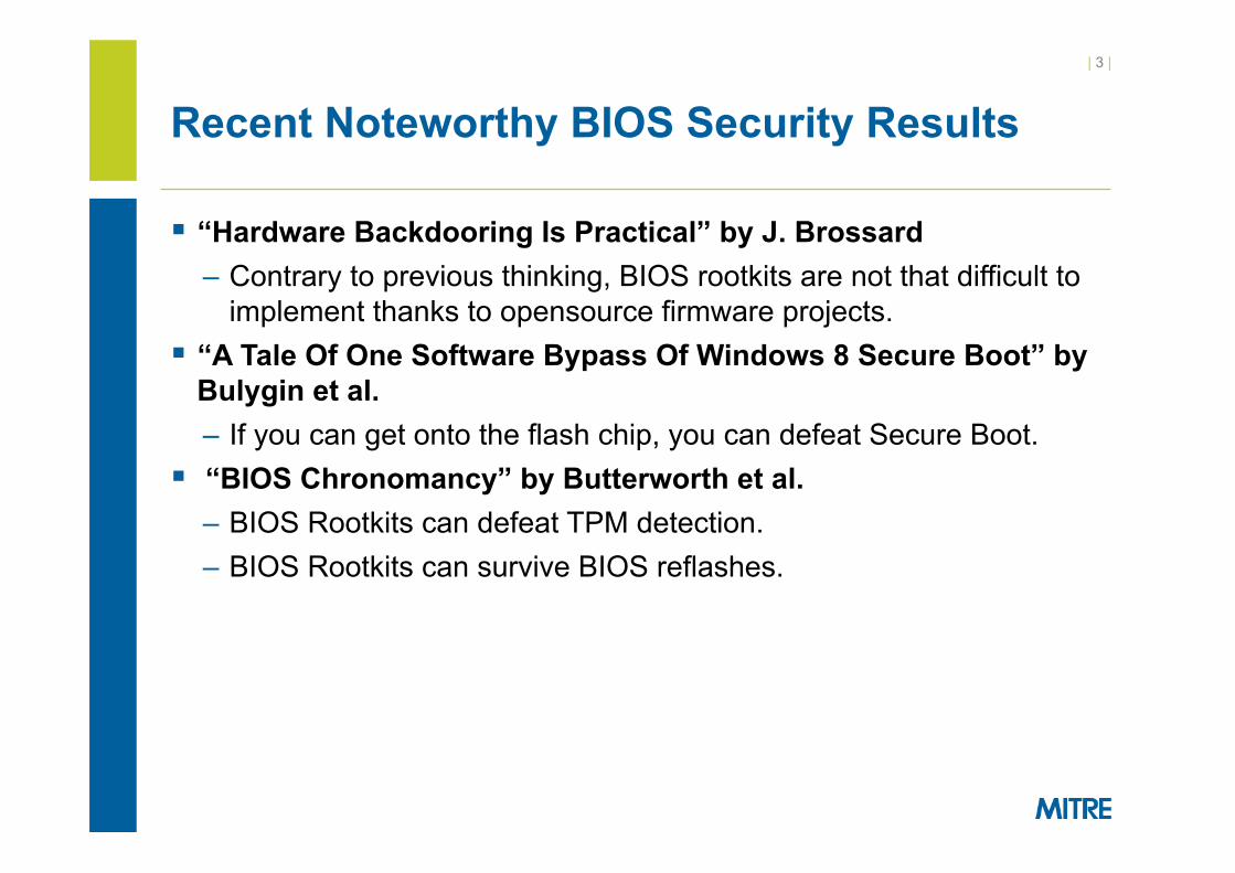
HSFS.FLOCKDN
§ HSFS.FLOCKDN bit prevents changes to the Protected Range registers once set.

| 10 |
BIOS_CNTL
§ The above bits are part of the BIOS_CNTL register on the ICH. § BIOS_CNTL.BIOSWE bit enables write access to the flash chip. § BIOS_CNTL.BLE bit provides an opportunity for the OEM to
implement an SMM routine to protect the BIOSWE bit.

| 11 |
SMM BIOSWE protection (1 of 2)
§ Here the attacker tries to set the BIOS Write Enable bit to 1 to allow him to overwrite the BIOS chip.
Ring0 Code BIOS_CNTL
SMM
BIOS_CNTL.BIOSWE = 1

| 12 |
SMM BIOSWE protection (2 of 2)
§ The write to the BIOSWE bit generates an SMI. § The SMI immediately writes 0 back to the BIOSWE bit. § The end result is that BIOSWE is always 0 when non-SMM code
is running.
Ring0 Code BIOS_CNTL
SMM
BIOS_CNTL.BIOSWE = 1
SMI#
BIOS_CNTL.BIOSWE=0

| 13 |
BIOSWE Protection Demo (1 of 2)
§ Set_bioswe is a simple program that attempts to set the BIOSWE bit in the BIOS_CNTL register.
§ BIOS_CNTL = 0xB implies BIOSWE is set. § BIOS_CNTL = 0xA implies BIOSWE is not set. § Notice that our attempt to set BIOSWE=1 in the above output
has failed as SMM is protecting the BIOSWE value.

| 14 |
BIOSWE Protection Demo (2 of 2)
§ Attempting to write to the BIOS chip using the flashrom open source utility fails because BIOS_CNTL=0xA (BIOSWE=0), implying write access is not allowed to the BIOS chip.1
1 Command: flashrom –p internal:laptop_I_want_a_brick,ich_spi_mode=swseq –w bios.bin

| 15 |
Intel Protections Summary
§ The Protected Range and BIOS_CNTL registers provide duplicative protection of the SPI flash chip that contains the platform firmware.
§ These protections are reset upon platform reset, and must be correctly configured by the platform firmware during power on.

| 16 |
OEM BIOS Update Routines
§ We will use Dell BIOS as a case study in how OEM’s use the Intel flash protection mechanisms to implement signed BIOS enforcement.
§ The following code is from the Dell Latitude E6400 BIOS, but the BIOS update routine in question is shared among 20+ other Dell models.

| 17 |
Dell E6400 BIOS Update
1. Firmware update binary (“HDR”) is copied to kernel memory – Default method is to packetize the HDR file into “rbu packets” – HDR contains more than just the BIOS update (Keyboard
Controller, Management Engine, too) 2. A bit in CMOS byte 0x78 is flipped 3. The system is rebooted 4. BIOS sees CMOS bit is flipped and triggers an SMI to execute
the SMM BIOS Update routine 5. After the BIOS Update routine has occurred, the appropriate
Intel flash protection mechanisms are set so that no more writes to the flash chip can occur.

| 18 |
BIOS Update Routine (1 of 2)
$RPK… Packet=1, size=0x400
Copyright 2011 Dell Inc.. A29
$RPK… Packet=N, size=0x100
EB 39 00 00 00 FF FF FF FF …
$RPK… Packet=2, size=0x1000
00 00 FF FF FF FF FF…
OS Kernel Driver
• The Opera)ng System packe)zes the new BIOS image across the address space. Each packet has a 33 byte rbu_packet header that describes the contents and order of the BIOS image informa)on the packet contains.
• A bit is then flipped in CMOS to indicate to the BIOS upon the next reboot that an update is pending.

| 19 |
BIOS Update Routine (2 of 2)
$RPK… Packet=N, size=0x100
EB 39 00 00 00 FF FF FF FF FF …
$RPK… Packet=N-‐1, size=0x1000
00 00 FF FF FF FF FF… • Upon reboot, the System Management Mode update rou)ne scans for the individual rbu packets and uses them to reconstruct the complete BIOS image.
• SMM then verifies the reconstructed BIOS image is signed by Dell before wri)ng to the flash chip.
System Management Mode RAM SMM Update Rou)ne
Copyright 2011 Dell Inc. A29.. FF FF FF FF FF FF FF FF FF FF
… …
EB 39 00 00 FF FF FF FF FF FF

| 20 |
Attacker Objective and Plan
§ Reflash BIOS chip with arbitrary image despite signed BIOS enforcement.
§ Method: find a memory corruption vulnerability in the parsing of the BIOS update information (RBU packets). This will allow us to seize control of SMM and reflash the BIOS chip at will.
§ The memory corruption vulnerability must occur before the signature on the bios update image is checked.
§ SMM parses the 33 byte rbu_packet header that describes metadata about the BIOS update image. This parsing occurs before the signature check.

| 21 |
Attack Surface
http://linux.dell.com/libsmbios/main/RbuLowLevel_8h-source.html

| 22 |
Packet Parsing
§ SMM first locates the RBU packet by scanning for an ASCII signature upon page aligned boundaries.
§ Once located, members of the RBU packet are stored in an SMM data area for use in later calculations…

| 23 |
Curious GEOR?
§ When reconstructing the BIOS image from the rbu packets, SMM writes an initialization string “GEOR” to the destination memory space where the BIOS image is being reconstructed….
| 24 |
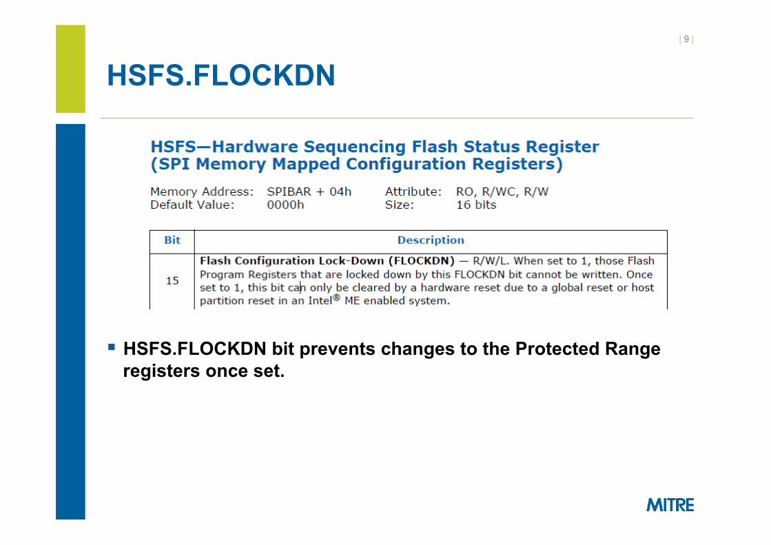
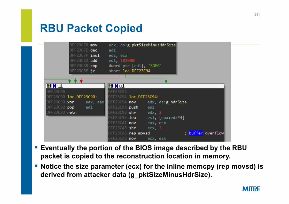
RBU Packet Copied
§ Eventually the portion of the BIOS image described by the RBU packet is copied to the reconstruction location in memory.
§ Notice the size parameter (ecx) for the inline memcpy (rep movsd) is derived from attacker data (g_pktSizeMinusHdrSize).

| 25 |
RBU Packet Parsing Vulnerability
§ In fact, the copy destination and copy source are also both derived from attacker data read in from the current rbu_packet.
§ This is an exploitable buffer overflow.

| 26 |
Lack of Mitigations
§ System Management Mode is missing all of the traditional exploit mitigations you would expect to find in modern applications.
§ No ASLR, NX, stack canaries, and so on…. § This means we can pursue any target with our overwrite, such
as the return address for the rbu packet copying function…

| 27 |
Exploiting the Vulnerability
§ There are actually a number of constraints on the RBU packet data that make exploiting this buffer overflow tricky.

| 28 |
Constraints Overview
§ Our copy destination must point to an area pre-initialized with the “GEOR” string.
§ Copy_dest must be lower in memory than the return address. § We can’t overwrite too much lest we die in the inline memcpy and
never return. § Copy source must be positioned such that attacker controlled
data in the address space ends up overwriting the saved return address.
§ Others….

| 29 |
More Problems
§ The source, destination and size operands are all derived from the same rbu_packet members.
§ Changing one operand, changes the others. § All of the constraints previously mentioned must be satisfied. § Exploitation of this vulnerability can be modeled as a constraints
solving problem.

| 30 |
Constraints Corollary
§ An initialization routine populates the “GEOR” string at the expected copy dest location under “normal” circumstances.
§ In order to pass the totalDataSize sanity check, we set totPkts to 1, forcing totalDataSize to 0.
§ This means the expected “GEOR” string won’t naturally occur in the address space, and we will have to inject it somehow to satisfy the *copy_dest = “GEOR” constraint.

| 31 |
Faux GEOR
§ The vulnerable memcpy will only execute if the copy destination points to a location containing this GEOR string.
§ We use a Windows kernel driver that performs memory mapped i/o to write the GEOR string as high up in memory as possible, to allow us to force copy_dest to be within striking distance of the return address we want to overwrite.
§ Like the BIOS update process, we are abusing the fact RAM remains intact during a soft reboot so the GEOR strings we wrote will remain in the address space.

| 32 |
RBU Packet Solution
§ With all those constraints in mind, we brute force an rbu_packet configuration that allows us to pass the sanity checks and overwrite the return address gracefully.

| 33 |
Malicious BIOS Update
$RPK.. Packet=0x83f9, size=0xfffe Shellcode Shellcode
… Shellcode
• The unusually large packet size and packet sequence number cause the packet reconstruc)on area to overflow into SMRAM.
• This allows us to overwrite a return address inside of SMRAM and gain control of EIP while in the context of the BIOS update rou)ne.
System Management Mode RAM SMM Update Rou)ne
Packet Reconstruc)on Space Shellcode Shellcode Shellcode
….

| 34 |
PoC Demonstration Video http://youtu.be/V_ea21CrOPM

| 35 |
Vulnerability Conclusion
§ The vulnerability allows an attacker to take control of the BIOS update process and reflash the BIOS with an arbitrary image despite the presence of signed bios enforcement.
§ CVE-2013-3582 § We suspect other firmware update routines also contain
vulnerabilities because: – They were probably developed before signed BIOS enforcement
was even a consideration. – It is difficult to locate and reverse engineer the update code due to
the proprietary nature of BIOS images, thus these routines have likely seen little (if any) peer review.
§ Locating and exploiting a vulnerability in the Dell BIOS update routine was quite difficult, perhaps that is an easier way…

| 36 |
Attacking the Intel Protections
§ As a reminder, the BIOS_CNTL and Protected Range/FLOCKDN registers are the primary protections against arbitrary flash writes.
§ Interestingly, it seems as though most OEM’s opt to rely entirely on the BIOS_CNTL register for flash protection. – Of the 5197 systems that implemented signed BIOS enforcement
in our enterprise environment, 4779 relied exclusively on BIOS_CNTL for protection!
– Approximately 92% of the systems we surveyed don’t configure Protected Range registers!
§ This entangles the security of SMRAM with the security of the flash chip in a dangerous way.

| 37 |
An Old Bug Revisited
§ In 2009 Invisible Things Lab and Duflot et al. identified an attack that abused Intel architecture caching features to execute arbitrary code in the context of System Management Mode (SMM)1 2.
§ The ITL/Duflot cache poisoning attack was originally thought to be a temporary attack on System Management RAM (SMRAM); any attacker code injected into SMRAM would be flushed by a platform reset.
§ However, on some systems the cache poisoning attack can lead to an arbitrary reflash of the BIOS chip. – Because the BIOS is responsible for instantiating SMRAM, this
would allow the attacker permanent residence in SMM.
1 “Attacking SMM Memory via Intel Cache Poisoning” by Rafal Wojtczuk and Joanna Rutkowska 2 “Getting into SMRAM: SMM Reloaded” by L. Duflot, O. Levillain, B. Morin and O. Grumelard.

| 38 |
Cache Poisoning Attack Overview (1 of 2)
§ SMRAM is only writeable or readable by the CPU when it is executing in the context of SMM. Any attempt to ready SMRAM outside of SMM will be blocked by the Memory Controller Hub (MCH).
§ The default caching policy for SMRAM is uncacheable; reads and writes happen directly to and from RAM, and are not stored in the cache.

| 39 |
Cache Poisoning Attack Overview (2 of 2)
§ However, It is possible to program the MTRR’s such that SMRAM is “Write Back” cacheable.
§ An attacker can then pollute the cache entries corresponding to SMRAM by writing malicious code to the memory range associated with SMRAM.
§ Although these changes will not actually be reflected in SMRAM, they will be reflected in the cache lines for the SMRAM memory locations.
§ When the CPU next enters into SMM, it will fetch the SMM code from the SMRAM cache entries (instead of SMRAM actual).
§ This results in arbitrary code execution in the context of SMM.

| 40 |
Cache Attack (1 of 2)
§ In this case, SMRAM is based at DFF00000. § First the attacker sets the SMRAM region to WriteBack
cacheable using the MTRRs. § Next the attacker pollutes the cache lines corresponding to
SMRAM by attempting to write to SMRAM locations.
CPU Cache
Location Contents DFF00000 badc0de
C1000 E9 FF 00 F0000 00 00 00
RAM
Location Contents A0000 A1000 …
C1000 …
DFF00000
FF FF FF F1 00 1B
… E9 FF 00
… SMM code
CPU
DFF00000= badc0de
| 41 |
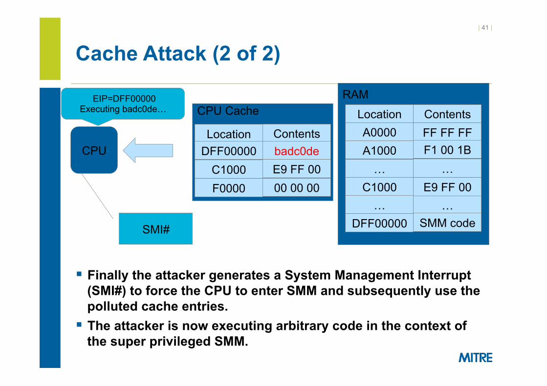
Cache Attack (2 of 2)
§ Finally the attacker generates a System Management Interrupt (SMI#) to force the CPU to enter SMM and subsequently use the polluted cache entries.
§ The attacker is now executing arbitrary code in the context of the super privileged SMM.
CPU Cache
Location Contents DFF00000 badc0de
C1000 E9 FF 00 F0000 00 00 00
RAM
Location Contents A0000 A1000 …
C1000 …
DFF00000
FF FF FF F1 00 1B
… E9 FF 00
… SMM code
CPU
EIP=DFF00000 Executing badc0de…
SMI#

| 42 |
BIOSWE Cache Attack
§ We pollute the SMI entry point with an immediate return from SMM instruction.
§ This will result in SMM failing to protect BIOSWE from being set.
CPU Cache
Location Contents DFF00000 0F AA2
C1000 E9 FF 00 F0000 00 00 00
RAM
Location Contents A0000 A1000 …
C1000 …
DFF00000
FF FF FF F1 00 1B
… E9 FF 00
… SMM code
CPU
DFF00000= RSM1
1 RSM is the return from system management opcode 2 0F AA are the opcodes for the RSM instruction

| 43 |
Disabled BIOSWE protection (1 of 2)
§ Again the attacker tries to set the BIOS Write Enable bit to 1 to allow him to overwrite the BIOS chip.
Ring0 Code BIOS_CNTL
SMM
BIOS_CNTL.BIOSWE = 1

| 44 |
Disabled BIOSWE protection (2 of 2)
§ An SMI is generated on the write as before, but this time SMM just immediately returns instead of resetting the BIOSWE bit to 0.
Ring0 Code BIOS_CNTL
SMM
OK: BIOS_CNTL.BIOSWE = 1

| 45 |
Disabled BIOSWE Protection Demo
§ We are able to set the BIOSWE bit (BIOS_CNTL = 0xB), and subsequently reflash the BIOS chip with an arbitrary image.
§ This bypasses the signed firmware update requirement which is supposed to prevent arbitrary flash overwrites.

| 46 |
Poison Reflash Bug Conclusion
§ Currently reported to CERT as VU#255726. § This bug has been largely fixed on newer systems by the
introduction of “SMM Range Registers” which when programmed correctly prevent the SMM Cache Poisoning Attack.
§ Important takeaway: – Due to many OEM’s sole reliance on BIOS_CNTL protection of the
flash chip, it follows that any vulnerabilities that allow you to modify SMRAM can be leveraged to reflash the BIOS.

| 47 |
Unified Extensible Firmware Interface
§ Does UEFI solve these problems? – No. The underlying Intel flash protection mechanisms are the
same. Many vendors are still relying only on BIOS_CNTL register for protection, and hence are vulnerable to any SMRAM compromises that may occur.
– Vendor’s are still implementing their own custom firmware update routines.
– There are even UEFI systems shipping with completely unlocked flash chips…
§ In some ways, UEFI makes things easier for an attacker…

| 48 |
UEFI Reversing is Easier
§ UEFI Firmware comes in a standard “firmware volume” which you can parse to quickly find relevant code.1
1 EFIPWN: https://github.com/G33KatWork/EFIPWN

| 49 |
Disturbing Trend
§ Lots and lots of code is getting put into SMM. § An exploitable bug in any of this may lead to a firmware reflash
bug.

| 50 |
Unpatched Vulnerability
§ Demo § Reported to CERT § Effects multiple vendors § VU #291102

| 51 |
Conclusion
§ OEM’s should be using the Protected Range registers, but many of them are not.
§ Sole reliance on BIOS_CNTL for flash protection entangles the security of SMM with the security of the flash chip.
§ Vulnerabilities lurking in OEM firmware update routines can allow arbitrary reflashes of the system firmware.
§ These issues are UEFI/BIOS agnostic. § There are still new UEFI systems shipping with unlocked flash
chips!

| 52 |
Acknowledgements
§ Rafal Wojtczuk – Breaking ground in this area – Helpful email discussion on topic
§ Rick Martinez – Dell contact for BIOS related security issues – Great vendor for researchers to work with
§ Bruce Monroe – Intel contact – Strong interest in general BIOS/UEFI/Intel security issues! – Currently coordinating the release of other issues