Embed Size (px)
Citation preview
P O W E R E D B Y S P E C I A L I S T S
ZUCCHINI XCP BUSBARFOR POWER DISTRIBUTION SYSTEMS

2
Global strength
CORPORATE SOCIAL RESPONSIBILITYLegrand’s CSR roadmap is a natural extension to the governance and sustainable development approach in which the company has been engaged for many years. The CSR roadmap firmly asserts Legrand’s ongoing commitment to sustainable development.
built on localknowledge
LEGRAND’S POWER DISTRIBUTION BUSINESS UNIT From Legrand transformers, through high power distribution and rising main busbar to Electrak powertrack, desk modules and lighting control, Legrand’s power distribution business unit provides market leading solutions to the increasing demands of today’s buildings.
Legrand is the global specialist in electrical and digital building infrastructures. Innovation is the driving force behind its development. With an increasing investment in research and development (circa 5% of sales) and more than 4,000 active patents, the Legrand Group is focused on maintaining a high rate of new product launches that present innovative solutions to the market.
Respect human rights and communities Ensure health, safety and well-being
Develop skills Promote equal opportunity and diversity
Provide sustainable solutions Ensure sustainable procurement
Act ethically
Mitigate climate change Innovate for the circular economy Prevent pollution

XCP OVERVIEWSafety, flexibility and simplicity 04 Range features 06 XCP-S and XCP-HP 07 Range composition 09 Product additional features 10 GRP and metal tap-off boxes 11 Order SELECTION GUIDEBusbar selection guide 13 XCP-S - technical information 20 XCP-HP - technical information 28 Design instructions for the creation of a rising mains (BTS*) 36 OPERATING INFORMATIONSuggestions for the design and installation of the busbar 38 Protection classifications 47
3XCPCATALOGUE
CONT
ENTS
LEGRAND ENERGY EFFICIENCY Legrand has long been committed to an initiative to protect the environment. We are dedicated to ensuring that everyone can use electricity in a sustainable way. By working together we can create solutions that deliver less carbon to the environment. Look out for the green leaf which identifies our range of energy efficient busbars.
*BTS = busway trunking system
4
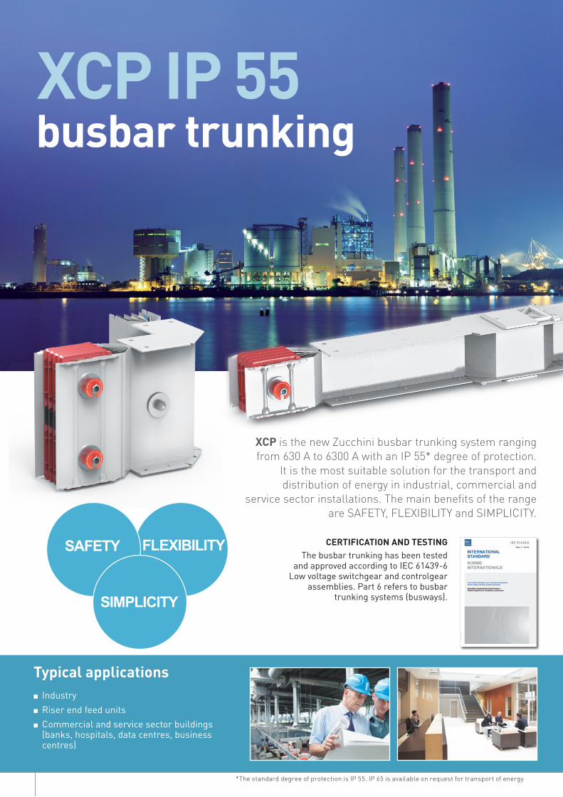
XCP is the new Zucchini busbar trunking system ranging from 630 A to 6300 A with an IP 55* degree of protection.
It is the most suitable solution for the transport and distribution of energy in industrial, commercial and
service sector installations. The main benefits of the range are SAFETY, FLEXIBILITY and SIMPLICITY.
busbar trunking
CERTIFICATION AND TESTINGThe busbar trunking has been tested
and approved according to IEC 61439-6 Low voltage switchgear and controlgear
assemblies. Part 6 refers to busbar trunking systems (busways).
XCP IP 55
Typical applications■ Industry■ Riser end feed units■ Commercial and service sector buildings (banks, hospitals, data centres, business
centres)
*The standard degree of protection is IP 55. IP 65 is available on request for transport of energy
FLEXIBILITYSAFETY
SIMPLICITY
5XCPCATALOGUE
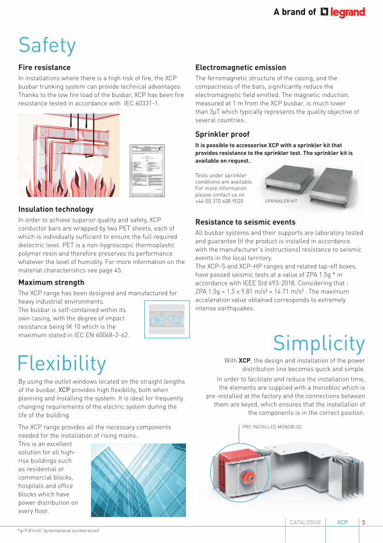
Fire resistanceIn installations where there is a high risk of fire, the XCP busbar trunking system can provide technical advantages. Thanks to the low fire load of the busbar, XCP has been fire resistance tested in accordance with IEC 60331-1.
Maximum strengthThe XCP range has been designed and manufactured for heavy industrial environments. The busbar is self-contained within its own casing, with the degree of impact resistance being IK 10 which is the maximum stated in IEC EN 60068-2-62.
SPRINKLER KIT
Flexibility
Electromagnetic emissionThe ferromagnetic structure of the casing, and the compactness of the bars, significantly reduce the electromagnetic field emitted. The magnetic induction, measured at 1 m from the XCP busbar, is much lower than 3µT which typically represents the quality objective of several countries.
Tests under sprinkler conditions are available. For more information please contact us on +44 (0) 370 608 9020
It is possible to accessorise XCP with a sprinkler kit that provides resistance to the sprinkler test. The sprinkler kit is available on request.
By using the outlet windows located on the straight lengths of the busbar, XCP provides high flexibility, both when planning and installing the system. It is ideal for frequently changing requirements of the electric system during the life of the building.
The XCP range provides all the necessary components needed for the installation of rising mains. This is an excellent solution for all high-rise buildings such as residential or commercial blocks, hospitals and office blocks which have power distribution on every floor.
Safety
Sprinkler proof
Resistance to seismic eventsAll busbar systems and their supports are laboratory tested and guarantee (if the product is installed in accordance with the manufacturer's instructions) resistance to seismic events in the local territory.The XCP-S and XCP-HP ranges and related tap-off boxes, have passed seismic tests at a value of ZPA 1.5g * in accordance with IEEE Std 693-2018. Considering that : ZPA 1.5g = 1.5 x 9.81 m/s² = 14.71 m/s² . The maximum acceleration value obtained corresponds to extremely intense earthquakes.
Simplicity
PRE-INSTALLED MONOBLOC
With XCP, the design and installation of the power distribution line becomes quick and simple.
In order to facilitate and reduce the installation time, the elements are supplied with a monobloc which is
pre-installed at the factory and the connections between them are keyed, which ensures that the installation of
the components is in the correct position.
*g=9·81m/s2 (gravitational acceleration)
Insulation technologyIn order to achieve superior quality and safety, XCP conductor bars are wrapped by two PET sheets, each of which is individually sufficient to ensure the full required dielectric level. PET is a non-hygroscopic thermoplastic polymer resin and therefore preserves its performance whatever the level of humidity. For more information on the material characteristics see page 45.
6
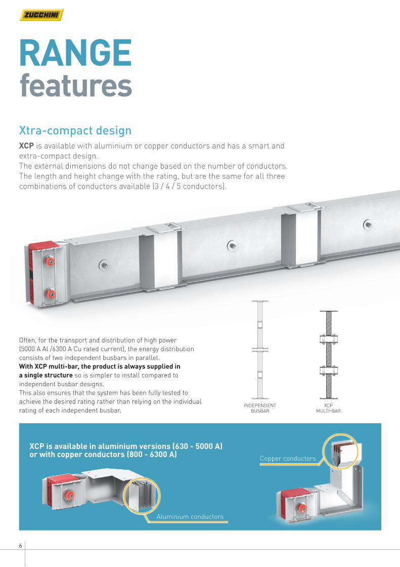
Xtra-compact designXCP is available with aluminium or copper conductors and has a smart and extra-compact design.The external dimensions do not change based on the number of conductors. The length and height change with the rating, but are the same for all three combinations of conductors available (3 / 4 / 5 conductors).
INDEPENDENT BUSBAR
XCP MULTI-BAR
Often, for the transport and distribution of high power (5000 A Al /6300 A Cu rated current), the energy distribution consists of two independent busbars in parallel. With XCP multi-bar, the product is always supplied in a single structure so is simpler to install compared to independent busbar designs. This also ensures that the system has been fully tested to achieve the desired rating rather than relying on the individual rating of each independent busbar.
RANGEfeatures
XCP is available in aluminium versions (630 - 5000 A) or with copper conductors (800 - 6300 A) Copper conductors
Aluminium conductors
7XCPCATALOGUE
XCP-S and XCP-HP
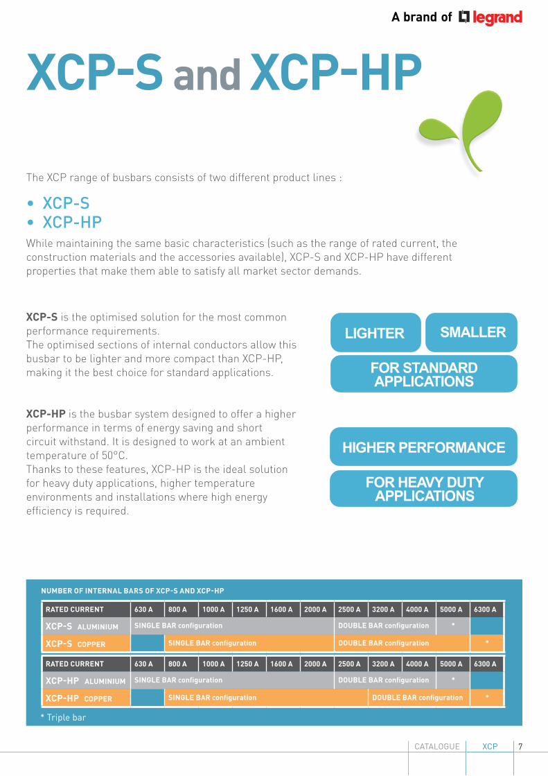
The XCP range of busbars consists of two different product lines :
• XCP-S• XCP-HP While maintaining the same basic characteristics (such as the range of rated current, the construction materials and the accessories available), XCP-S and XCP-HP have different properties that make them able to satisfy all market sector demands.
* Triple bar
RATED CURRENT 630 A 800 A 1000 A 1250 A 1600 A 2000 A 2500 A 3200 A 4000 A 5000 A 6300 A
XCP-HP ALUMINIUM SINGLE BAR configuration DOUBLE BAR configuration *
XCP-HP COPPER SINGLE BAR configuration DOUBLE BAR configuration *
RATED CURRENT 630 A 800 A 1000 A 1250 A 1600 A 2000 A 2500 A 3200 A 4000 A 5000 A 6300 A
XCP-S ALUMINIUM SINGLE BAR configuration DOUBLE BAR configuration *
XCP-S COPPER SINGLE BAR configuration DOUBLE BAR configuration *
XCP-S is the optimised solution for the most common performance requirements.The optimised sections of internal conductors allow this busbar to be lighter and more compact than XCP-HP, making it the best choice for standard applications.
XCP-HP is the busbar system designed to offer a higher performance in terms of energy saving and short circuit withstand. It is designed to work at an ambient temperature of 50°C.Thanks to these features, XCP-HP is the ideal solution for heavy duty applications, higher temperature environments and installations where high energy efficiency is required.
NUMBER OF INTERNAL BARS OF XCP-S AND XCP-HP
SMALLERLIGHTER
FOR STANDARD APPLICATIONS
HIGHER PERFORMANCE
FOR HEAVY DUTY APPLICATIONS
8
XCP-S and XCP-HP
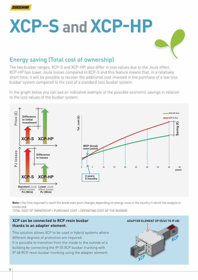
Energy saving (Total cost of ownership)The two busbar ranges, XCP-S and XCP-HP, also differ in loss values due to the Joule effect.XCP-HP has lower Joule losses compared to XCP-S and this feature means that, in a relatively short time, it will be possible to recover the additional cost invested in the purchase of a low loss busbar system compared to the cost of a standard loss busbar system.
In the graph below you can see an indicative example of the possible economic savings in relation to the loss values of the busbar system.
Note : The time required to reach the break even point changes depending on energy costs in the country in which the analysis is conducted.TOTAL COST OF OWNERSHIP = PURCHASE COST + OPERATING COST OF THE BUSBAR
XCP
ADAPTER ELEMENT (IP 55/65 TO IP 68)
RCP
XCP can be connected to RCP resin busbar thanks to an adapter element.
This solution allows XCP to be used in hybrid systems where different degrees of protection are required.It is possible to transition from the inside to the outside of a building by connecting the IP 55 XCP busbar trunking with IP 68 RCP resin busbar trunking using the adapter element.
Difference in initial investment
Difference in losses
Standard Joule effect losses
PJ (W/m)
Lower Joule effect losses
PJ (W/m)
XCP-S
XCP-S
XCP-HP
XCP-HP
Pri
ce (
£)P
J lo
sses
Sav
ing
(£)
Tot.
co
st
(£)
BEP (break even point)
years
2 years6 months
XCP-HP (Cu)
0 5 10 15 20 25 30 35 40 45
XCP-S (Cu)
9XCPCATALOGUE
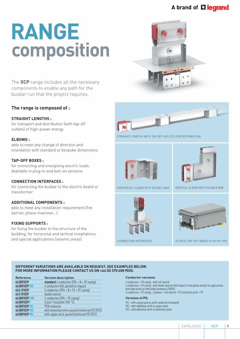
RANGEcompositionThe XCP range includes all the necessary components to enable any path for the busbar run that the project requires.
The range is composed of :
STRAIGHT LENGTHS :for transport and distribution (with tap-off outlets) of high-power energy
ELBOWS :able to meet any change of direction and orientation with standard or bespoke dimensions
TAP-OFF BOXES :for connecting and energising electric loads.Available in plug-in and bolt-on versions
CONNECTION INTERFACES :for connecting the busbar to the electric board or transformer
ADDITIONAL COMPONENTS :able to meet any installation requirement (fire barrier, phase inversion...)
FIXING SUPPORTS :for fixing the busbar to the structure of the building, for horizontal and vertical installations and special applications (seismic areas)
DIFFERENT VARIATIONS ARE AVAILABLE ON REQUEST. SEE EXAMPLES BELOW. FOR MORE INFORMATION PLEASE CONTACT US ON +44 (0) 370 608 9020.
Reference Version description64280102P standard 4 conductors (3Ph + N + PE casing)64280102P-R5 4 conductors RAL painted on request64240102P 5 conductors (3Ph + N + FE + PE casing)64250102P double neutral64280102P-3W 3 conductors (3Ph + PE casing)64280102PF Class F insulation (155 °C)64280102P-RL PEN conductor64280102P-R3 with aluminium extra-ground (reinforced PE) (PE3)64280102P-R4 with copper extra-ground (reinforced PE) (PE2)
HORIZONTAL ELBOW WITH DOUBLE BAR
CONNECTION INTERFACES
VERTICAL ELBOW WITH DOUBLE BAR
STRAIGHT LENGTHS WITH TAP OFF OUTLETS FOR DISTRIBUTION
PLASTIC TAP-OFF BOXES PLUG-IN TYPE
Conductor versions4 conductors + PE casing : with full neutral4 conductors + PE casing : with double neutral with respect to the phase section for applications with high values of third order harmonics (THD%)5 conductors + PE casing : 3 phases + full neutral + FE functional earth + PE
Versions of PE:PE1 : with casing used as earth conductor (standard)PE2 : with additional earth in copper platePE3 : with additional earth in aluminium plate
10
PRODUCTadditional features
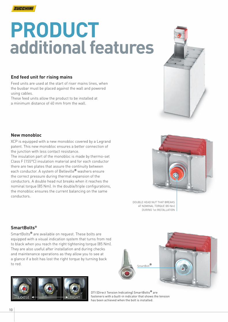
New monoblocXCP is equipped with a new monobloc covered by a Legrand patent. This new monobloc ensures a better connection of the junction with less contact resistance.The insulation part of the monobloc is made by thermo-set Class F (155°C) insulation material and for each conductor there are two plates that assure the continuity between each conductor. A system of Belleville® washers ensure the correct pressure during thermal expansion of the conductors. A double head nut breaks when it reaches the nominal torque (85 Nm). In the double/triple configurations, the monobloc ensures the current balancing on the same conductors.
End feed unit for rising mainsFeed units are used at the start of riser mains lines, when the busbar must be placed against the wall and powered using cables. These feed units allow the product to be installed at a minimum distance of 40 mm from the wall.
SmartBolts®
SmartBolts® are available on request. These bolts are equipped with a visual indication system that turns from red to black when you reach the right tightening torque (85 Nm). They are also useful after installation and during checks and maintenance operations as they allow you to see at a glance if a bolt has lost the right torque by turning back to red.
DOUBLE HEAD NUT THAT BREAKS AT NOMINAL TORQUE (85 Nm)
DURING 1st INSTALLATION
SmartBolt®
DTI (Direct Tension Indicating) SmartBolts® are fasteners with a built-in indicator that shows the tension has been achieved when the bolt is installed.
LOOSE TIGHT

11XCPCATALOGUE
TAP-OFF BOXESGRP* and metalXCP distribution bars are equipped with outlets suitable for the range of dedicated tap-off boxes.The tap-off boxes are available in two different construction materials:• GRP* composite with rating up to 250 A, plug-in type (to be installed on outlets)• painted steel enclosure with rating up to 630 A for plug-in type (to be installed on outlets)
and up to 1250 A for bolt-on type (to be installed on the junction)They are universal and therefore can be used on both (XCP-S and XCP-HP) product lines.
The design of the outlets enables the installation of GRP* tap-off boxes in addition to the painted steel version.The degree of protection of the outlets and the system is IP 2x with the cover open and IP 55 with the cover closed or with tap-off unit installed.
The new tap-off boxes guarantee: Safety Optimised dimensions Reduced maintenance costs Pre-fitted for MCB/MCCB circuit breakers
NEW CONNECTION SYSTEM -SAFE AND QUICK TO ASSEMBLE
SAFETY SYSTEM FOR HANDS
SAFETY SYSTEM (PADLOCK) ON TAP-OFF BOX
* GRP = glass reinforced plastic

12
GRP* version: Range from 32 A to 250 A Optimised installation of Legrand circuit breakers (MCB/MCCB) Optimised for P17 Tempra Pro CEE sockets Ready for data centre applications Empty or with fuse carrier version available Total insulation Plug-in / plug-out under live voltage
Painted steel version: Range from 63 A to 630 A Optimised installation of Legrand circuit breakers (MCCB) Optimised for P17 Tempra Pro CEE sockets Ready for data centre applications Empty or with fuse carrier version available
Equipped with : - anti-manoeuvre security system - anti-accidental closing and opening of the box - guard for open covering - safer vertical installation (the cover remains in an open position)
Plug-in / plug-out under live voltage
Tap-off boxes for XCP are available in two different materials: GRP* and metal, both characterised by a simple installation and fast connection thanks to the new layout of hooks that offer safety and speed of assembly.
Tap-off boxes can be installed and removed when the busbar is energised and it can be assembled with DPX3 moulded case circuit breakers.
Tap-off boxes: accessoriesTap-off boxes are ready to be assembled with Legrand circuit breakers and industrial sockets**
DIN MODULES
P17 SOCKETS
DPX3
PAINTED STEEL VERSION FROM 63 A TO 630 A
** Accessories not supplied. To be purchased separately.
GRP VERSION FROM 32 A TO 250 A
Other devices available on request Contact us on +44 (0) 370 608 9020*GRP = glass reinforced plastic
13XCPCATALOGUE
SELECTION GUIDE
Busbar selection based on the rated transformer data
Temperature impact on the rating of the busbar trunking system
Joule effect losses in busbar
Busbar trunking system selection based on voltage drop
Short circuit withstand
Characterisation of short circuit current
Harmonics
14141516171719
CONTENTS
14
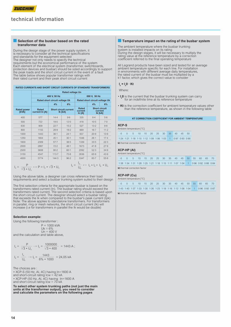
The ambient temperature where the busbar trunking system is installed impacts on its ratingDuring the design stages, it will be necessary to multiply the rating value at the reference temperature by a correction coefficient referred to the final operating temperature
All Legrand products have been sized and tested for an average ambient temperature specific for each line. For installation in environments with different average daily temperatures, the rated current of the busbar must be multiplied by a k1 factor, which gives the correct value to consider
Iz = Iz0 · Kt
Where:
• Iz0 is the current that the busbar trunking system can carry for an indefinite time at its reference temperature
• Kt is the correction coefficient for ambient temperature values other than the reference temperature, as shown in the following table
KT CORRECTION COEFFICIENT FOR AMBIENT TEMPERATURE
XCP-HP (Al)Ambient temperature [°C]
-5 0 5 10 15 20 25 30 35 40 45 50 55 60 65 70
1·38 1·34 1·31 1·28 1·25 1·21 1·18 1·15 1·11 1·07 1·04 1 0·96 0·92 0·88 0·84
kt thermal correction factor
XCP-HP (Cu)Ambient temperature [°C]
-5 0 5 10 15 20 25 30 35 40 45 50 55 60 65 70
1·43 1·40 1·37 1·33 1·30 1·26 1·23 1·19 1·16 1·12 1·08 1·04 1 0·96 0·92 0·87
kt thermal correction factor
■ Temperature impact on the rating of the busbar system■ Selection of the busbar based on the rated transformer data
RATED CURRENTS AND SHORT CIRCUIT CURRENTS OF STANDARD TRANSFORMERS
Rated voltage Un
400 V, 50 Hz 690 V, 50 Hz
Rated short circuit voltage Uk Rated short circuit voltage Uk
4% 6% 4% 6%
Rated power [kVA]
Rated current In [A]
Short circuit current Ik [kA]
Rated current In [A]
Short circuit current Ik [kA]
400 577 14·4 9·6 335 8·4 5·6
500 722 18·0 12·0 418 10·5 7·0
630 909 22·7 15·2 527 13·2 8·8
800 1155 28·9 19·2 669 16·7 11·2
1000 1443 36·1 24·1 837 20·9 13·9
1250 1804 45·1 30·1 1046 26·1 17·4
1600 2309 57·7 38·5 1339 33·5 22·3
2000 2887 72·2 48·1 1673 41·8 27·9
2500 3608 90·2 60·1 2092 52·3 34·9
3150 4547 113·7 75·8 2636 65·9 43·9
4000 5774 144·3 96·2 3347 83·7 55·8
Using the above table, a designer can cross reference their load requirements and select a busbar trunking system suited to their design
The first selection criteria for the appropriate busbar is based on the transformers rated current (In). The busbar rating should exceed the transformers rated current. The second selection criteria is based upon the short circuit current. The designer should select a busbar rating that exceeds the Ik when compared to the busbar's peak current (Ipk) Note: The above applies to standalone transformers. For transformers in parallel, ring or mesh networks, the short circuit current (Ik) will increase (i.e for transformers in parallel the Ik would be double)
Selection example: Using the following transformer : P = 1000 kVA Uk = 6% Un = 400 Vand the calculation and table above,
The choices are :• XCP-S (50 Hz, Al, 4C) having In=1600 A and short-circuit rating Icw = 42 kA• XCP-HP (50 Hz, Al, 4C) having In=1600 A and short circuit rating Icw = 70 kA
technical information
During the design stage of the power supply system, it is necessary to consider all the technical specifications and standards for the equipment selectedThe designer not only needs to specify the technical requirements but the economical performance of the systemEach element of the electrical system (transformer, switchboards, protection devices and busbar) should be sized accordingly to support the peak loads and the short circuit current in the event of a fault The table below shows popular transformer ratings with their rated current and their peak short circuit current
To select other system trunking paths (not just the main units at the transformer output), you need to consider and calculate the parameters on the following pages
In = P = In •P
3 • Un
3 • Un
In =
Ik =
In =
InIk =
= 1443 A ;
= 24,05 kA
P 1000000
1443
3 • Un
Uk
3 • 400
6% • 1000
Ik = In • Ik =In
Uk
Ik • Un
XCP-SAmbient temperature [°C]
-5 0 5 10 15 20 25 30 35 40 45 50
1·24 1·21 1·18 1·15 1·12 1·09 1·06 1·03 1 0·97 0·93 0·90
kt thermal correction factor
15
technical information
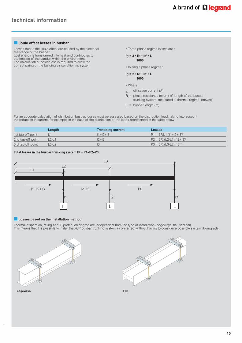
• Three phase regime losses are :
Pj = 3 • Rt • Ib2 • L 1000
• In single phase regime :
Pj = 2 • Rt • Ib2 • L 1000
• Where :
Ib = utilisation current (A)
Rt = phase resistance for unit of length of the busbar trunking system, measured at thermal regime (mΩ/m)
L = busbar length (m)
Losses due to the Joule effect are caused by the electrical resistance of the busbarLost energy is transformed into heat and contributes to the heating of the conduit within the environmentThe calculation of power loss is required to allow the correct sizing of the building air conditioning system
L1L2
L3
L L L
l1 l3l2
I1+I2+I3 I2+I3 I3
Length Transiting current Losses
1st tap-off point L1 I1+I2+I3 P1 = 3RtL1 (I1+I2+I3)2
2nd tap-off point L2-L1 I2+I3 P2 = 3Rt (L2-L1) (I2+I3)2
3rd tap-off point L3-L2 I3 P3 = 3Rt (L3-L2) (I3)2
Total losses in the busbar trunking system Pt = P1+P2+P3
Thermal dispersion, rating and IP protection degree are independent from the type of installation (edgeways, flat, vertical) This means that it is possible to install the XCP busbar trunking system as preferred, without having to consider a possible system downgrade
Edgeways Flat
■ Losses based on the installation method
For an accurate calculation of distribution busbar, losses must be assessed based on the distribution load, taking into account the reduction in current, for example, in the case of the distribution of the loads represented in the table below
■ Joule effect losses in busbar
16
■ Calculation of the voltage drop with loads not evenly distributed (continued)
technical information
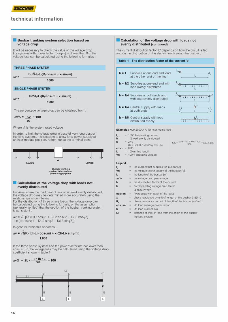
b•2•Ib•L•(Rt•cosϕm + x•sinϕm) ∆∆v = 1000
The percentage voltage drop can be obtained from :
∆v% = ∆v • 100 Vr
Where Vr is the system rated voltage
In order to limit the voltage drop in case of very long busbar trunking systems, it is possible to allow for a power supply at an intermediate position, rather than at the terminal point
LOADS LOADS
Busbar trunking system intermediate power supply point
It will be necessary to check the value of the voltage drop For systems with power factor (cosϕm) no lower than 0·8, the voltage loss can be calculated using the following formulas :
Legend :Ib = the current that supplies the busbar [A]
Vn = the voltage power supply of the busbar [V]
L = the length of the busbar [m]
∆v% = the voltage drop percentage
b = the distribution factor of the current
k = corresponding voltage drop factor
a cosϕ [V/m/A]
cosϕ m = Average power factor of the loads
x = phase reactance by unit of length of the busbar (mΩ/m)
Rt = phase resistance by unit of length of the busbar (mΩ/m)
cosϕ mi = i-th load average power factor
li = i-th load current (A)
Li = distance of the i-th load from the origin of the busbar
trunking system
If the three phase system and the power factor are not lower than cosϕ = 0·7, the voltage loss may be calculated using the voltage drop coefficient shown in table 1
∆v% = k • Ib • L Vn
L1L2
L3
L L L
l1 l3l2
2b • • 100
The current distribution factor 'b' depends on how the circuit is fed and on the distribution of the electric loads along the busbar :
THREE PHASE SYSTEM
SINGLE PHASE SYSTEM
Example : XCP 2000 A Al for riser mains feed
Ib = 1600 A operating currentb = 1/2 load evenly distributedk = 27·3 (XCP 2000 A Al cosϕ = 0·85)cosϕ = 0·85L = 100 m line lengthVn = 400 V operating voltage
b = 1 Supplies at one end and load at the other end of the line
b = 1/2 Supplies at one end and with load evenly distributed
b = 1/4 Supplies at both ends and with load evenly distributed
b = 1/4 Central supply with loads at both ends b = 1/8 Central supply with load distributed evenly
Ib
Ib
L
Ib
Ib
Ib
Ib
L
L
Ib
2Ib
2L
Ib
Table 1 - The distribution factor of the current 'b'
b•√3•Ib•L•(Rt•cosϕm + x•sinϕm) ∆∆v = 1000
■ Busbar trunking system selection based on voltage drop
∆v% = 27·3 • 10-6 • 1600 • 100
400 • 100 = 1·09%
■ Calculation of the voltage drop with loads not evenly distributed
In cases where the load cannot be considered evenly distributed, the voltage drop may be determined more accurately using the relationships shown belowFor the distribution of three phase loads, the voltage drop can be calculated using the following formula, on the assumption (generally verified) that the section of the busbar trunking system is consistent :
∆v = √3 [Rt (I1L1cosϕ1 + I2L2 cosϕ2 + I3L3 cosϕ3) + x (I1L1sinϕ1 + I2L2 sinϕ2 + I3L3 sinϕ3)]
In general terms this becomes :
∆v = √3(Rt•∑Ii•Li• cosϕmi + x•∑Ii•Li• sinϕmi)
1.000
17
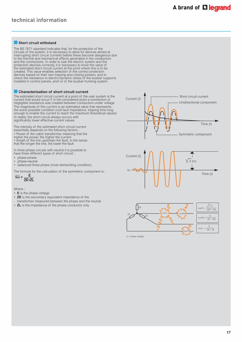
■ Short circuit withstandThe BS 7671 standard indicates that, for the protection of the circuits of the system, it is necessary to allow for devices aimed at interrupting short circuit currents before these become dangerous due to the thermal and mechanical effects generated in the conductors and the connections. In order to size the electric system and the protection devices correctly, it is necessary to know the value of the estimated short circuit current at the point where this is to be created. This value enables selection of the correct protection devices based on their own tripping and closing powers, and to check the resistance to electro-dynamic stress of the busbar supports installed in control panels, and/ or of the busbar trunking system
Where :• E is the phase voltage• ZE is the secondary equivalent impedance of the
transformer measured between the phase and the neutral • ZL is the impedance of the phase conductor only
Icc = EZE+ZL
■ Characterisation of short circuit currentThe estimated short circuit current at a point of the user system is the current that would occur if in the considered point a connection of negligible resistance was created between conductors under voltageThe magnitude of this current is an estimated value that represents the worst possible condition (null fault impedance, tripping time long enough to enable the current to reach the maximum theoretical values)In reality, the short circuit always occurs with significantly lower effective current values
The intensity of the estimated short circuit current essentially depends on the following factors :• Power of the cabin transformer, meaning that the higher the power, the higher the current• length of the line upstream the fault, in the sense that the longer the line, the lower the fault
In three phase circuits with neutral it is possible to have three different types of short circuit :• phase-phase• phase-neutral• balanced three phase (most demanding condition)
The formula for the calculation of the symmetric component is :
Short circuit current
Unidirectional component
Symmetric component
Time (t)
Current (I)
Time (t)
Current (I)
In
2 Icc
ZE
Icc3~ IccFN
IccFF
IccFF =2ZE + 2ZL
3 E
IccFN =ZE + 2ZL
E
Icc3~ = ZE + ZL
E
E = phase voltage
ZEZE
technical information
18
technical information
L (m)
S (mm2)
P (kVA)
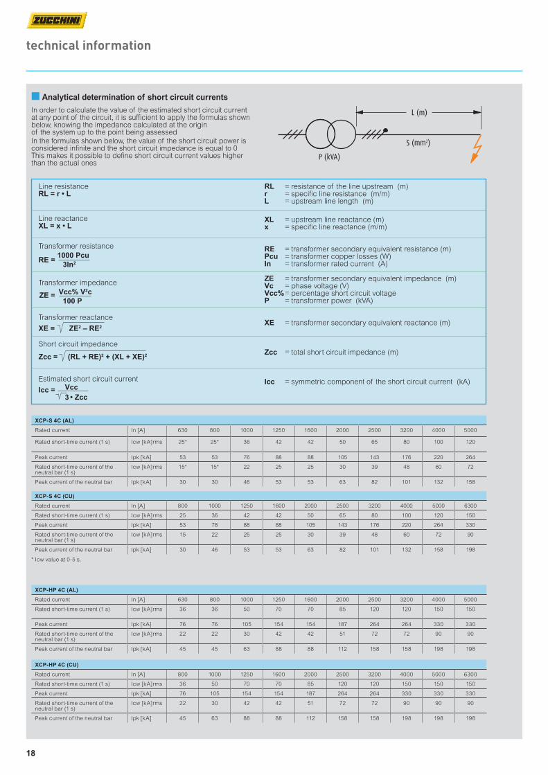
■ Analytical determination of short circuit currents
In order to calculate the value of the estimated short circuit currentat any point of the circuit, it is sufficient to apply the formulas shownbelow, knowing the impedance calculated at the origin of the system up to the point being assessedIn the formulas shown below, the value of the short circuit power is considered infinite and the short circuit impedance is equal to 0 This makes it possible to define short circuit current values higher than the actual ones
RL = resistance of the line upstream (m) r = specific line resistance (m/m) L = upstream line length (m)
XL = upstream line reactance (m) x = specific line reactance (m/m)
RE = transformer secondary equivalent resistance (m) Pcu = transformer copper losses (W) In = transformer rated current (A) ZE = transformer secondary equivalent impedance (m)Vc = phase voltage (V)Vcc% = percentage short circuit voltage P = transformer power (kVA)
XE = transformer secondary equivalent reactance (m)
Zcc = total short circuit impedance (m)
lcc = symmetric component of the short circuit current (kA)
Line resistanceRL = r • L
Line reactanceXL = x • L
Transformer resistance
RE = 1000 Pcu
3In2
Transformer impedance Vcc% V2c 100 P
Transformer reactance
XE = ZE2 – RE2
Short circuit impedance
Zcc = (RL + RE)2 + (XL + XE)2
Estimated short circuit current
Vcc
3
ZE =
• ZccIcc =
XCP-S 4C (AL)
Rated current In [A] 630 800 1000 1250 1600 2000 2500 3200 4000 5000
Rated short-time current (1 s) Icw [kA]rms 25* 25* 36 42 42 50 65 80 100 120
Peak current Ipk [kA] 53 53 76 88 88 105 143 176 220 264
Rated short-time current of the neutral bar (1 s)
Icw [kA]rms 15* 15* 22 25 25 30 39 48 60 72
Peak current of the neutral bar Ipk [kA] 30 30 46 53 53 63 82 101 132 158
XCP-HP 4C (AL)
Rated current In [A] 630 800 1000 1250 1600 2000 2500 3200 4000 5000
Rated short-time current (1 s) Icw [kA]rms 36 36 50 70 70 85 120 120 150 150
Peak current Ipk [kA] 76 76 105 154 154 187 264 264 330 330
Rated short-time current of the neutral bar (1 s)
Icw [kA]rms 22 22 30 42 42 51 72 72 90 90
Peak current of the neutral bar Ipk [kA] 45 45 63 88 88 112 158 158 198 198
XCP-S 4C (CU)
Rated current In [A] 800 1000 1250 1600 2000 2500 3200 4000 5000 6300
Rated short-time current (1 s) Icw [kA]rms 25 36 42 42 50 65 80 100 120 150
Peak current Ipk [kA] 53 78 88 88 105 143 176 220 264 330
Rated short-time current of the neutral bar (1 s)
Icw [kA]rms 15 22 25 25 30 39 48 60 72 90
Peak current of the neutral bar Ipk [kA] 30 46 53 53 63 82 101 132 158 198
XCP-HP 4C (CU)
Rated current In [A] 800 1000 1250 1600 2000 2500 3200 4000 5000 6300
Rated short-time current (1 s) Icw [kA]rms 36 50 70 70 85 120 120 150 150 150
Peak current Ipk [kA] 76 105 154 154 187 264 264 330 330 330
Rated short-time current of the neutral bar (1 s)
Icw [kA]rms 22 30 42 42 51 72 72 90 90 90
Peak current of the neutral bar Ipk [kA] 45 63 88 88 112 158 158 198 198 198
* Icw value at 0·5 s.
19
technical information
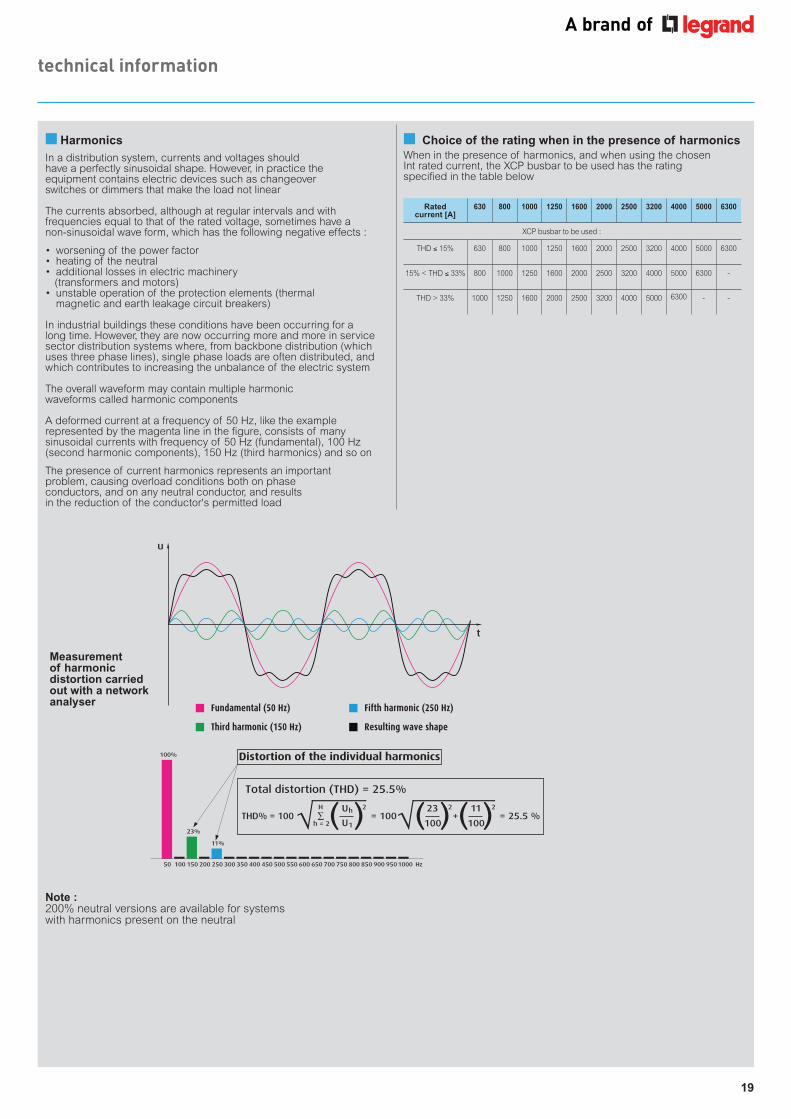
■ Choice of the rating when in the presence of harmonicsWhen in the presence of harmonics, and when using the chosen Int rated current, the XCP busbar to be used has the rating specified in the table below
u
t
Fundamental (50 Hz)
Third harmonic (150 Hz)
Fifth harmonic (250 Hz)
Resulting wave shape
100%
23%
11%
50 100 200 300 350 400 450 500 550 600 650 700 750 800 850 900 9501000250150 Hz
THD% = 100H
h = 2
Uh
U1( )2 23
100( )2
+11
100( )2
= 100 = 25.5 %
Total distortion (THD) = 25.5%
Distortion of the individual harmonics
Rated current [A]
630 800 1000 1250 1600 2000 2500 3200 4000 5000 6300
XCP busbar to be used :
THD ≤ 15% 630 800 1000 1250 1600 2000 2500 3200 4000 5000 6300
15% < THD ≤ 33% 800 1000 1250 1600 2000 2500 3200 4000 5000 6300 -
THD > 33% 1000 1250 1600 2000 2500 3200 4000 5000 6300 - -
Measurement of harmonic distortion carried out with a network analyser
■ HarmonicsIn a distribution system, currents and voltages should have a perfectly sinusoidal shape. However, in practice the equipment contains electric devices such as changeover switches or dimmers that make the load not linear
The currents absorbed, although at regular intervals and with frequencies equal to that of the rated voltage, sometimes have a non-sinusoidal wave form, which has the following negative effects :
• worsening of the power factor• heating of the neutral• additional losses in electric machinery (transformers and motors) • unstable operation of the protection elements (thermal magnetic and earth leakage circuit breakers)
In industrial buildings these conditions have been occurring for a long time. However, they are now occurring more and more in service sector distribution systems where, from backbone distribution (which uses three phase lines), single phase loads are often distributed, and which contributes to increasing the unbalance of the electric system
The overall waveform may contain multiple harmonic waveforms called harmonic components
A deformed current at a frequency of 50 Hz, like the example represented by the magenta line in the figure, consists of many sinusoidal currents with frequency of 50 Hz (fundamental), 100 Hz (second harmonic components), 150 Hz (third harmonics) and so on
The presence of current harmonics represents an important problem, causing overload conditions both on phase conductors, and on any neutral conductor, and results in the reduction of the conductor's permitted load
Note :200% neutral versions are available for systems with harmonics present on the neutral
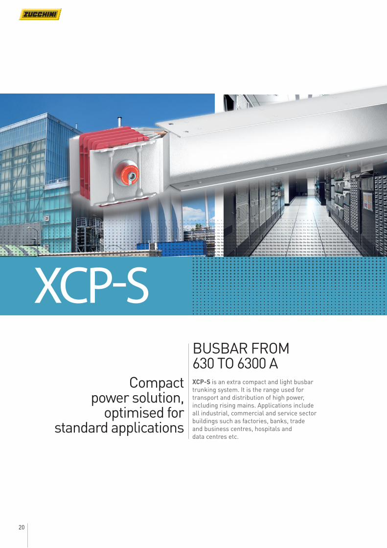
20
BUSBAR FROM 630 TO 6300 AXCP-S is an extra compact and light busbar trunking system. It is the range used for transport and distribution of high power, including rising mains. Applications include all industrial, commercial and service sector buildings such as factories, banks, trade and business centres, hospitals and data centres etc.
Compact power solution,
optimised for standard applications
XCP-S
21
XCP-S
Xtra Compact (XCP-S) technical information
■ General features
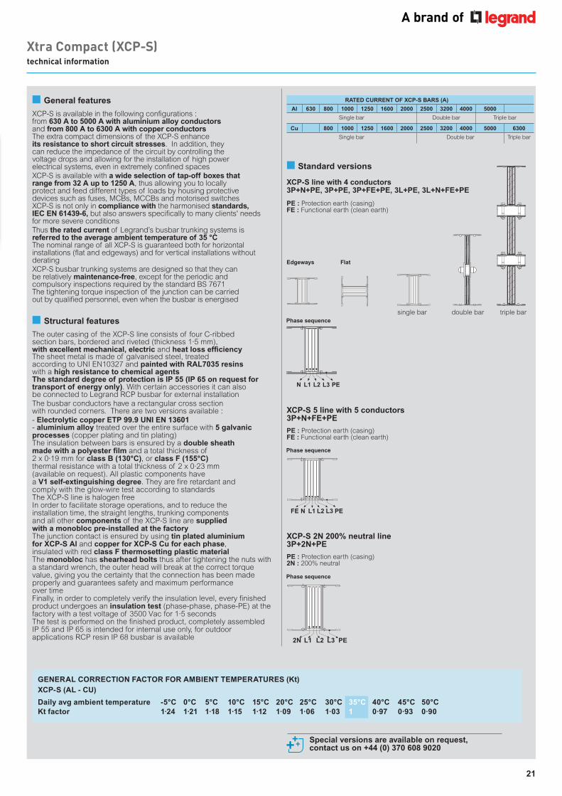
XCP-S is available in the following configurations : from 630 A to 5000 A with aluminium alloy conductors and from 800 A to 6300 A with copper conductors The extra compact dimensions of the XCP-S enhance its resistance to short circuit stresses. In addition, they can reduce the impedance of the circuit by controlling the voltage drops and allowing for the installation of high power electrical systems, even in extremely confined spaces XCP-S is available with a wide selection of tap-off boxes that range from 32 A up to 1250 A, thus allowing you to locally protect and feed different types of loads by housing protective devices such as fuses, MCBs, MCCBs and motorised switches XCP-S is not only in compliance with the harmonised standards, IEC EN 61439-6, but also answers specifically to many clients' needs for more severe conditionsThus the rated current of Legrand’s busbar trunking systems is referred to the average ambient temperature of 35 °C The nominal range of all XCP-S is guaranteed both for horizontal installations (flat and edgeways) and for vertical installations without deratingXCP-S busbar trunking systems are designed so that they can be relatively maintenance-free, except for the periodic and compulsory inspections required by the standard BS 7671The tightening torque inspection of the junction can be carried out by qualified personnel, even when the busbar is energised
■ Structural features
The outer casing of the XCP-S line consists of four C-ribbed section bars, bordered and riveted (thickness 1·5 mm), with excellent mechanical, electric and heat loss efficiencyThe sheet metal is made of galvanised steel, treatedaccording to UNI EN10327 and painted with RAL7035 resins with a high resistance to chemical agentsThe standard degree of protection is IP 55 (IP 65 on request for transport of energy only). With certain accessories it can alsobe connected to Legrand RCP busbar for external installationThe busbar conductors have a rectangular cross sectionwith rounded corners. There are two versions available :- Electrolytic copper ETP 99.9 UNI EN 13601- aluminium alloy treated over the entire surface with 5 galvanic processes (copper plating and tin plating)The insulation between bars is ensured by a double sheathmade with a polyester film and a total thickness of2 x 0·19 mm for class B (130°C), or class F (155°C)thermal resistance with a total thickness of 2 x 0·23 mm(available on request). All plastic components havea V1 self-extinguishing degree. They are fire retardant andcomply with the glow-wire test according to standardsThe XCP-S line is halogen freeIn order to facilitate storage operations, and to reduce theinstallation time, the straight lengths, trunking componentsand all other components of the XCP-S line are suppliedwith a monobloc pre-installed at the factoryThe junction contact is ensured by using tin plated aluminiumfor XCP-S Al and copper for XCP-S Cu for each phase,insulated with red class F thermosetting plastic materialThe monobloc has shearhead bolts thus after tightening the nuts with a standard wrench, the outer head will break at the correct torque value, giving you the certainty that the connection has been made properly and guarantees safety and maximum performanceover timeFinally, in order to completely verify the insulation level, every finished product undergoes an insulation test (phase-phase, phase-PE) at the factory with a test voltage of 3500 Vac for 1·5 secondsThe test is performed on the finished product, completely assembled IP 55 and IP 65 is intended for internal use only, for outdoor applications RCP resin IP 68 busbar is available
Edgeways
Phase sequence
Phase sequence
Flat
RATED CURRENT OF XCP-S BARS (A)
Al 630 800 1000 1250 1600 2000 2500 3200 4000 5000
Single bar Double bar Triple bar
Cu 800 1000 1250 1600 2000 2500 3200 4000 5000 6300
Single bar Double bar Triple bar
■ Standard versions
XCP-S line with 4 conductors 3P+N+PE, 3P+PE, 3P+FE+PE, 3L+PE, 3L+N+FE+PE
XCP-S 5 line with 5 conductors 3P+N+FE+PE
XCP-S 2N 200% neutral line 3P+2N+PE
double bar
PE : Protection earth (casing)FE : Functional earth (clean earth)
PE : Protection earth (casing)FE : Functional earth (clean earth)
PE : Protection earth (casing)2N : 200% neutral
FE PEL2L1N L3
2N PEL2L1 L3
single bar
Special versions are available on request, contact us on +44 (0) 370 608 9020
Phase sequence
N PEL3L2L1
triple bar
GENERAL CORRECTION FACTOR FOR AMBIENT TEMPERATURES (Kt) XCP-S (AL - CU)
Daily avg ambient temperature -5°C 0°C 5°C 10°C 15°C 20°C 25°C 30°C 35°C 40°C 45°C 50°CKt factor 1·24 1·21 1·18 1·15 1·12 1·09 1·06 1·03 1 0·97 0·93 0·90
22
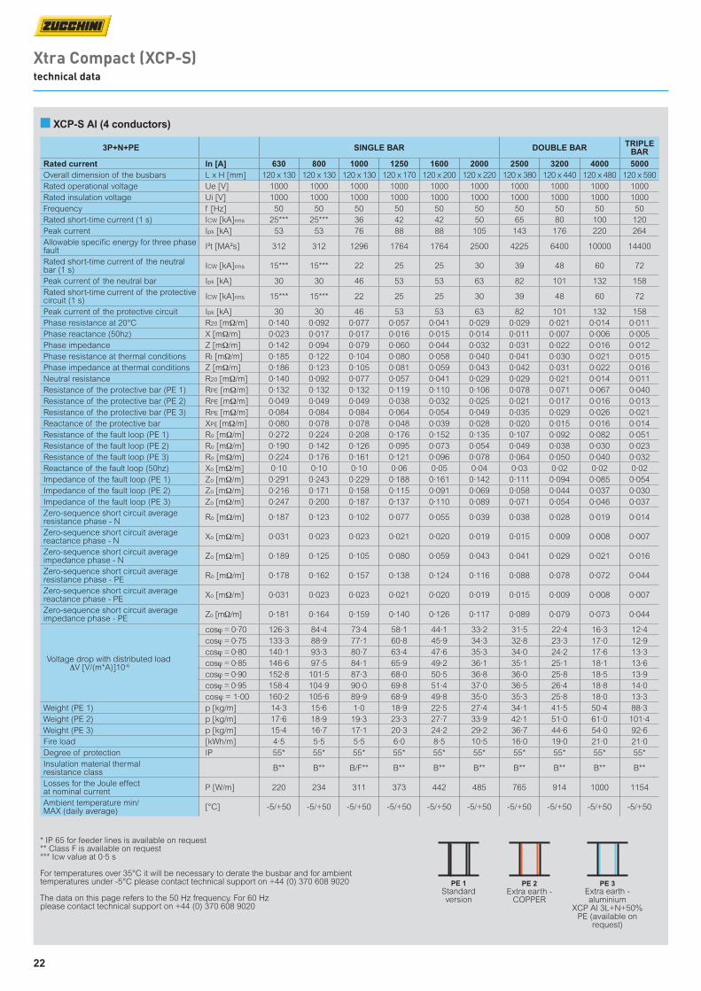
3P+N+PE SINGLE BAR DOUBLE BAR TRIPLE BAR
Rated current In [A] 630 800 1000 1250 1600 2000 2500 3200 4000 5000Overall dimension of the busbars L x H [mm] 120 x 130 120 x 130 120 x 130 120 x 170 120 x 200 120 x 220 120 x 380 120 x 440 120 x 480 120 x 590Rated operational voltage Ue [V] 1000 1000 1000 1000 1000 1000 1000 1000 1000 1000Rated insulation voltage Ui [V] 1000 1000 1000 1000 1000 1000 1000 1000 1000 1000Frequency f [Hz] 50 50 50 50 50 50 50 50 50 50Rated short-time current (1 s) ICW [kA]rms 25*** 25*** 36 42 42 50 65 80 100 120Peak current Ipk [kA] 53 53 76 88 88 105 143 176 220 264Allowable specific energy for three phase fault I²t [MA²s] 312 312 1296 1764 1764 2500 4225 6400 10000 14400
Rated short-time current of the neutral bar (1 s) ICW [kA]rms 15*** 15*** 22 25 25 30 39 48 60 72
Peak current of the neutral bar Ipk [kA] 30 30 46 53 53 63 82 101 132 158Rated short-time current of the protective circuit (1 s) ICW [kA]rms 15*** 15*** 22 25 25 30 39 48 60 72
Peak current of the protective circuit Ipk [kA] 30 30 46 53 53 63 82 101 132 158Phase resistance at 20°C R20 [mΩ/m] 0·140 0·092 0·077 0·057 0·041 0·029 0·029 0·021 0·014 0·011Phase reactance (50hz) X [mΩ/m] 0·023 0·017 0·017 0·016 0·015 0·014 0·011 0·007 0·006 0·005Phase impedance Z [mΩ/m] 0·142 0·094 0·079 0·060 0·044 0·032 0·031 0·022 0·016 0·012Phase resistance at thermal conditions Rt [mΩ/m] 0·185 0·122 0·104 0·080 0·058 0·040 0·041 0·030 0·021 0·015Phase impedance at thermal conditions Z [mΩ/m] 0·186 0·123 0·105 0·081 0·059 0·043 0·042 0·031 0·022 0·016Neutral resistance R20 [mΩ/m] 0·140 0·092 0·077 0·057 0·041 0·029 0·029 0·021 0·014 0·011Resistance of the protective bar (PE 1) RPE [mΩ/m] 0·132 0·132 0·132 0·119 0·110 0·106 0·078 0·071 0·067 0·040Resistance of the protective bar (PE 2) RPE [mΩ/m] 0·049 0·049 0·049 0·038 0·032 0·025 0·021 0·017 0·016 0·013Resistance of the protective bar (PE 3) RPE [mΩ/m] 0·084 0·084 0·084 0·064 0·054 0·049 0·035 0·029 0·026 0·021Reactance of the protective bar XPE [mΩ/m] 0·080 0·078 0·078 0·048 0·039 0·028 0·020 0·015 0·016 0·014Resistance of the fault loop (PE 1) Ro [mΩ/m] 0·272 0·224 0·208 0·176 0·152 0·135 0·107 0·092 0·082 0·051Resistance of the fault loop (PE 2) Ro [mΩ/m] 0·190 0·142 0·126 0·095 0·073 0·054 0·049 0·038 0·030 0·023Resistance of the fault loop (PE 3) Ro [mΩ/m] 0·224 0·176 0·161 0·121 0·096 0·078 0·064 0·050 0·040 0·032Reactance of the fault loop (50hz) Xo [mΩ/m] 0·10 0·10 0·10 0·06 0·05 0·04 0·03 0·02 0·02 0·02Impedance of the fault loop (PE 1) Zo [mΩ/m] 0·291 0·243 0·229 0·188 0·161 0·142 0·111 0·094 0·085 0·054Impedance of the fault loop (PE 2) Zo [mΩ/m] 0·216 0·171 0·158 0·115 0·091 0·069 0·058 0·044 0·037 0·030Impedance of the fault loop (PE 3) Zo [mΩ/m] 0·247 0·200 0·187 0·137 0·110 0·089 0·071 0·054 0·046 0·037Zero-sequence short circuit average resistance phase - N Ro [mΩ/m] 0·187 0·123 0·102 0·077 0·055 0·039 0·038 0·028 0·019 0·014
Zero-sequence short circuit average reactance phase - N Xo [mΩ/m] 0·031 0·023 0·023 0·021 0·020 0·019 0·015 0·009 0·008 0·007
Zero-sequence short circuit average impedance phase - N Zo [mΩ/m] 0·189 0·125 0·105 0·080 0·059 0·043 0·041 0·029 0·021 0·016
Zero-sequence short circuit average resistance phase - PE Ro [mΩ/m] 0·178 0·162 0·157 0·138 0·124 0·116 0·088 0·078 0·072 0·044
Zero-sequence short circuit average reactance phase - PE Xo [mΩ/m] 0·031 0·023 0·023 0·021 0·020 0·019 0·015 0·009 0·008 0·007
Zero-sequence short circuit average impedance phase - PE Zo [mΩ/m] 0·181 0·164 0·159 0·140 0·126 0·117 0·089 0·079 0·073 0·044
Voltage drop with distributed load ∆V [V/(m*A)]10-6
cosϕ = 0·70 126·3 84·4 73·4 58·1 44·1 33·2 31·5 22·4 16·3 12·4cosϕ = 0·75 133·3 88·9 77·1 60·8 45·9 34·3 32·8 23·3 17·0 12·9cosϕ = 0·80 140·1 93·3 80·7 63·4 47·6 35·3 34·0 24·2 17·6 13·3cosϕ = 0·85 146·6 97·5 84·1 65·9 49·2 36·1 35·1 25·1 18·1 13·6cosϕ = 0·90 152·8 101·5 87·3 68·0 50·5 36·8 36·0 25·8 18·5 13·9cosϕ = 0·95 158·4 104·9 90·0 69·8 51·4 37·0 36·5 26·4 18·8 14·0cosϕ = 1·00 160·2 105·6 89·9 68·9 49·8 35·0 35·3 25·8 18·0 13·3
Weight (PE 1) p [kg/m] 14·3 15·6 1·0 18·9 22·5 27·4 34·1 41·5 50·4 88·3Weight (PE 2) p [kg/m] 17·6 18·9 19·3 23·3 27·7 33·9 42·1 51·0 61·0 101·4Weight (PE 3) p [kg/m] 15·4 16·7 17·1 20·3 24·2 29·2 36·7 44·6 54·0 92·6Fire load [kWh/m] 4·5 5·5 5·5 6·0 8·5 10·5 16·0 19·0 21·0 21·0Degree of protection IP 55* 55* 55* 55* 55* 55* 55* 55* 55* 55*Insulation material thermal resistance class B** B** B/F** B** B** B** B** B** B** B**
Losses for the Joule effect at nominal current P [W/m] 220 234 311 373 442 485 765 914 1000 1154
Ambient temperature min/MAX (daily average) [°C] -5/+50 -5/+50 -5/+50 -5/+50 -5/+50 -5/+50 -5/+50 -5/+50 -5/+50 -5/+50
■ XCP-S Al (4 conductors)
* IP 65 for feeder lines is available on request ** Class F is available on request*** Icw value at 0·5 s
For temperatures over 35°C it will be necessary to derate the busbar and for ambient temperatures under -5°C please contact technical support on +44 (0) 370 608 9020
The data on this page refers to the 50 Hz frequency. For 60 Hz please contact technical support on +44 (0) 370 608 9020
Xtra Compact (XCP-S) technical data
PE 1Standard version
PE 2Extra earth -
COPPER
PE 3Extra earth - aluminium
XCP Al 3L+N+50%PE (available on
request)
23
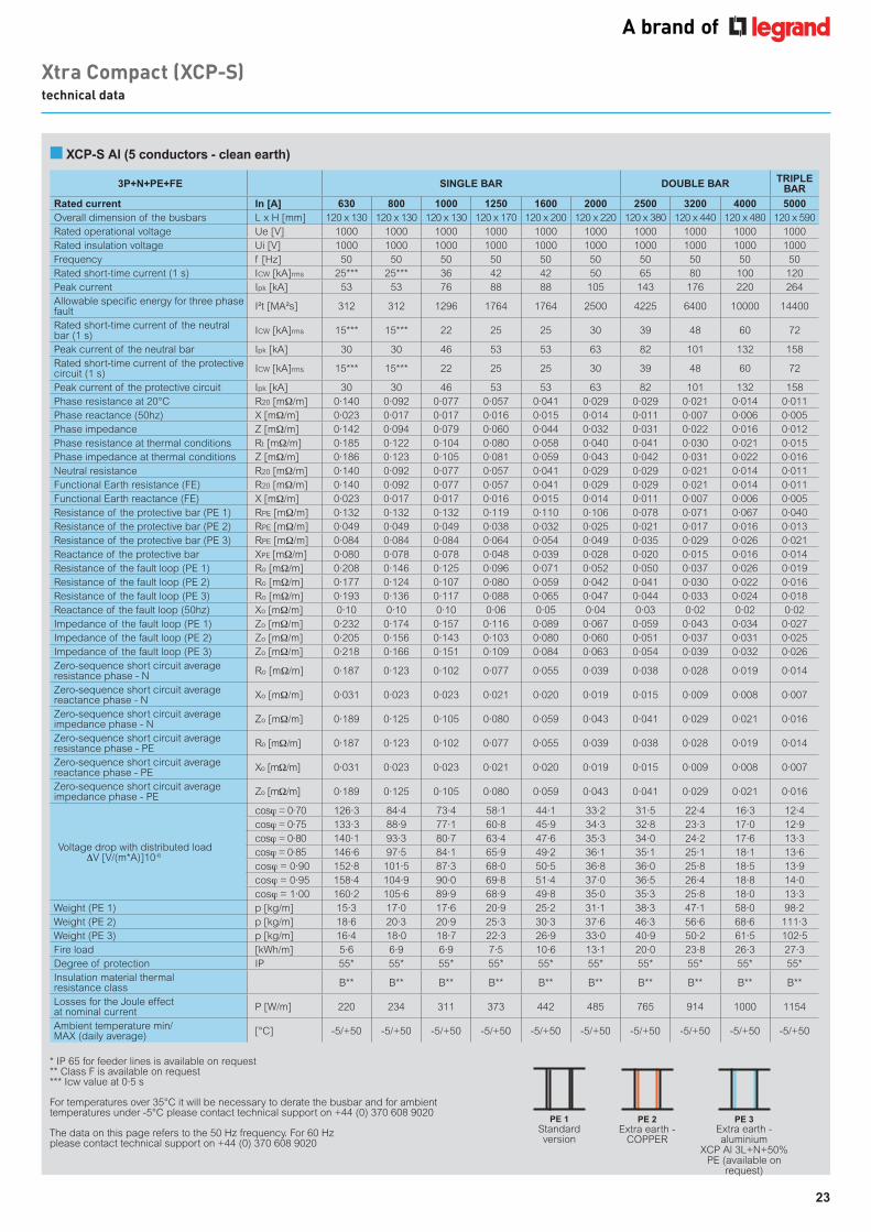
3P+N+PE+FE SINGLE BAR DOUBLE BAR TRIPLE BAR
Rated current In [A] 630 800 1000 1250 1600 2000 2500 3200 4000 5000Overall dimension of the busbars L x H [mm] 120 x 130 120 x 130 120 x 130 120 x 170 120 x 200 120 x 220 120 x 380 120 x 440 120 x 480 120 x 590Rated operational voltage Ue [V] 1000 1000 1000 1000 1000 1000 1000 1000 1000 1000Rated insulation voltage Ui [V] 1000 1000 1000 1000 1000 1000 1000 1000 1000 1000Frequency f [Hz] 50 50 50 50 50 50 50 50 50 50Rated short-time current (1 s) ICW [kA]rms 25*** 25*** 36 42 42 50 65 80 100 120Peak current Ipk [kA] 53 53 76 88 88 105 143 176 220 264Allowable specific energy for three phase fault I²t [MA²s] 312 312 1296 1764 1764 2500 4225 6400 10000 14400
Rated short-time current of the neutral bar (1 s) ICW [kA]rms 15*** 15*** 22 25 25 30 39 48 60 72
Peak current of the neutral bar Ipk [kA] 30 30 46 53 53 63 82 101 132 158Rated short-time current of the protective circuit (1 s) ICW [kA]rms 15*** 15*** 22 25 25 30 39 48 60 72
Peak current of the protective circuit Ipk [kA] 30 30 46 53 53 63 82 101 132 158Phase resistance at 20°C R20 [mΩ/m] 0·140 0·092 0·077 0·057 0·041 0·029 0·029 0·021 0·014 0·011Phase reactance (50hz) X [mΩ/m] 0·023 0·017 0·017 0·016 0·015 0·014 0·011 0·007 0·006 0·005Phase impedance Z [mΩ/m] 0·142 0·094 0·079 0·060 0·044 0·032 0·031 0·022 0·016 0·012Phase resistance at thermal conditions Rt [mΩ/m] 0·185 0·122 0·104 0·080 0·058 0·040 0·041 0·030 0·021 0·015Phase impedance at thermal conditions Z [mΩ/m] 0·186 0·123 0·105 0·081 0·059 0·043 0·042 0·031 0·022 0·016Neutral resistance R20 [mΩ/m] 0·140 0·092 0·077 0·057 0·041 0·029 0·029 0·021 0·014 0·011Functional Earth resistance (FE) R20 [mΩ/m] 0·140 0·092 0·077 0·057 0·041 0·029 0·029 0·021 0·014 0·011Functional Earth reactance (FE) X [mΩ/m] 0·023 0·017 0·017 0·016 0·015 0·014 0·011 0·007 0·006 0·005Resistance of the protective bar (PE 1) RPE [mΩ/m] 0·132 0·132 0·132 0·119 0·110 0·106 0·078 0·071 0·067 0·040Resistance of the protective bar (PE 2) RPE [mΩ/m] 0·049 0·049 0·049 0·038 0·032 0·025 0·021 0·017 0·016 0·013Resistance of the protective bar (PE 3) RPE [mΩ/m] 0·084 0·084 0·084 0·064 0·054 0·049 0·035 0·029 0·026 0·021Reactance of the protective bar XPE [mΩ/m] 0·080 0·078 0·078 0·048 0·039 0·028 0·020 0·015 0·016 0·014Resistance of the fault loop (PE 1) Ro [mΩ/m] 0·208 0·146 0·125 0·096 0·071 0·052 0·050 0·037 0·026 0·019Resistance of the fault loop (PE 2) Ro [mΩ/m] 0·177 0·124 0·107 0·080 0·059 0·042 0·041 0·030 0·022 0·016Resistance of the fault loop (PE 3) Ro [mΩ/m] 0·193 0·136 0·117 0·088 0·065 0·047 0·044 0·033 0·024 0·018Reactance of the fault loop (50hz) Xo [mΩ/m] 0·10 0·10 0·10 0·06 0·05 0·04 0·03 0·02 0·02 0·02Impedance of the fault loop (PE 1) Zo [mΩ/m] 0·232 0·174 0·157 0·116 0·089 0·067 0·059 0·043 0·034 0·027Impedance of the fault loop (PE 2) Zo [mΩ/m] 0·205 0·156 0·143 0·103 0·080 0·060 0·051 0·037 0·031 0·025Impedance of the fault loop (PE 3) Zo [mΩ/m] 0·218 0·166 0·151 0·109 0·084 0·063 0·054 0·039 0·032 0·026Zero-sequence short circuit average resistance phase - N Ro [mΩ/m] 0·187 0·123 0·102 0·077 0·055 0·039 0·038 0·028 0·019 0·014
Zero-sequence short circuit average reactance phase - N Xo [mΩ/m] 0·031 0·023 0·023 0·021 0·020 0·019 0·015 0·009 0·008 0·007
Zero-sequence short circuit average impedance phase - N Zo [mΩ/m] 0·189 0·125 0·105 0·080 0·059 0·043 0·041 0·029 0·021 0·016
Zero-sequence short circuit average resistance phase - PE Ro [mΩ/m] 0·187 0·123 0·102 0·077 0·055 0·039 0·038 0·028 0·019 0·014
Zero-sequence short circuit average reactance phase - PE Xo [mΩ/m] 0·031 0·023 0·023 0·021 0·020 0·019 0·015 0·009 0·008 0·007
Zero-sequence short circuit average impedance phase - PE Zo [mΩ/m] 0·189 0·125 0·105 0·080 0·059 0·043 0·041 0·029 0·021 0·016
Voltage drop with distributed load ∆V [V/(m*A)]10-6
cosϕ = 0·70 126·3 84·4 73·4 58·1 44·1 33·2 31·5 22·4 16·3 12·4cosϕ = 0·75 133·3 88·9 77·1 60·8 45·9 34·3 32·8 23·3 17·0 12·9cosϕ = 0·80 140·1 93·3 80·7 63·4 47·6 35·3 34·0 24·2 17·6 13·3cosϕ = 0·85 146·6 97·5 84·1 65·9 49·2 36·1 35·1 25·1 18·1 13·6cosϕ = 0·90 152·8 101·5 87·3 68·0 50·5 36·8 36·0 25·8 18·5 13·9cosϕ = 0·95 158·4 104·9 90·0 69·8 51·4 37·0 36·5 26·4 18·8 14·0cosϕ = 1·00 160·2 105·6 89·9 68·9 49·8 35·0 35·3 25·8 18·0 13·3
Weight (PE 1) p [kg/m] 15·3 17·0 17·6 20·9 25·2 31·1 38·3 47·1 58·0 98·2Weight (PE 2) p [kg/m] 18·6 20·3 20·9 25·3 30·3 37·6 46·3 56·6 68·6 111·3Weight (PE 3) p [kg/m] 16·4 18·0 18·7 22·3 26·9 33·0 40·9 50·2 61·5 102·5Fire load [kWh/m] 5·6 6·9 6·9 7·5 10·6 13·1 20·0 23·8 26·3 27·3Degree of protection IP 55* 55* 55* 55* 55* 55* 55* 55* 55* 55*Insulation material thermal resistance class B** B** B** B** B** B** B** B** B** B**
Losses for the Joule effect at nominal current P [W/m] 220 234 311 373 442 485 765 914 1000 1154
Ambient temperature min/MAX (daily average) [°C] -5/+50 -5/+50 -5/+50 -5/+50 -5/+50 -5/+50 -5/+50 -5/+50 -5/+50 -5/+50
* IP 65 for feeder lines is available on request ** Class F is available on request*** Icw value at 0·5 s
For temperatures over 35°C it will be necessary to derate the busbar and for ambient temperatures under -5°C please contact technical support on +44 (0) 370 608 9020
The data on this page refers to the 50 Hz frequency. For 60 Hz please contact technical support on +44 (0) 370 608 9020
Xtra Compact (XCP-S) technical data
■ XCP-S Al (5 conductors - clean earth)
PE 1Standard version
PE 2Extra earth -
COPPER
PE 3Extra earth - aluminium
XCP Al 3L+N+50%PE (available on
request)
24
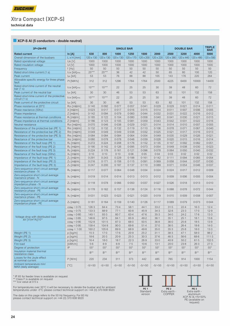
■ XCP-S Al (5 conductors - double neutral)
Xtra Compact (XCP-S) technical data
3P+2N+PE SINGLE BAR DOUBLE BAR TRIPLE BAR
Rated current In [A] 630 800 1000 1250 1600 2000 2500 3200 4000 5000Overall dimension of the busbars L x H [mm] 120 x 130 120 x 130 120 x 130 120 x 170 120 x 200 120 x 220 120 x 380 120 x 440 120 x 480 120 x 590Rated operational voltage Ue [V] 1000 1000 1000 1000 1000 1000 1000 1000 1000 1000Rated insulation voltage Ui [V] 1000 1000 1000 1000 1000 1000 1000 1000 1000 1000Frequency f [Hz] 50 50 50 50 50 50 50 50 50 50Rated short-time current (1 s) ICW [kA]rms 25*** 25*** 36 42 42 50 65 80 100 120Peak current Ipk [kA] 53 53 76 88 88 105 143 176 220 264Allowable specific energy for three phase fault I²t [MA²s] 312 312 1296 1764 1764 2500 4225 6400 10000 14400
Rated short-time current of the neutral bar (1 s) ICW [kA]rms 15*** 15*** 22 25 25 30 39 48 60 72
Peak current of the neutral bar Ipk [kA] 30 30 46 53 53 63 82 101 132 158Rated short-time current of the protective circuit (1 s) ICW [kA]rms 15*** 15*** 22 25 25 30 39 48 60 72
Peak current of the protective circuit Ipk [kA] 30 30 46 53 53 63 82 101 132 158Phase resistance at 20°C R20 [mΩ/m] 0·140 0·092 0·077 0·057 0·041 0·029 0·029 0·021 0·014 0·011Phase reactance (50hz) X [mΩ/m] 0·023 0·017 0·017 0·016 0·015 0·014 0·011 0·007 0·006 0·005Phase impedance Z [mΩ/m] 0·142 0·094 0·079 0·060 0·044 0·032 0·031 0·022 0·016 0·012Phase resistance at thermal conditions Rt [mΩ/m] 0·185 0·122 0·104 0·080 0·058 0·040 0·041 0·030 0·021 0·015Phase impedance at thermal conditions Z [mΩ/m] 0·186 0·123 0·105 0·081 0·059 0·043 0·042 0·031 0·022 0·016Neutral resistance R20 [mΩ/m] 0·070 0·046 0·038 0·029 0·021 0·014 0·014 0·010 0·007 0·005Resistance of the protective bar (PE 1) RPE [mΩ/m] 0·132 0·132 0·132 0·119 0·110 0·106 0·078 0·071 0·067 0·040Resistance of the protective bar (PE 2) RPE [mΩ/m] 0·049 0·049 0·049 0·038 0·032 0·025 0·021 0·017 0·016 0·013Resistance of the protective bar (PE 3) RPE [mΩ/m] 0·084 0·084 0·084 0·064 0·054 0·049 0·035 0·029 0·026 0·021Reactance of the protective bar XPE [mΩ/m] 0·080 0·078 0·078 0·048 0·039 0·028 0·020 0·015 0·016 0·014Resistance of the fault loop (PE 1) Ro [mΩ/m] 0·272 0·224 0·208 0·176 0·152 0·135 0·107 0·092 0·082 0·051Resistance of the fault loop (PE 2) Ro [mΩ/m] 0·190 0·142 0·126 0·095 0·073 0·054 0·049 0·038 0·030 0·023Resistance of the fault loop (PE 3) Ro [mΩ/m] 0·224 0·176 0·161 0·121 0·096 0·078 0·064 0·050 0·040 0·032Reactance of the fault loop (50hz) Xo [mΩ/m] 0·10 0·10 0·10 0·06 0·05 0·04 0·03 0·02 0·02 0·02Impedance of the fault loop (PE 1) Zo [mΩ/m] 0·291 0·243 0·229 0·188 0·161 0·142 0·111 0·094 0·085 0·054Impedance of the fault loop (PE 2) Zo [mΩ/m] 0·216 0·171 0·158 0·115 0·091 0·069 0·058 0·044 0·037 0·030Impedance of the fault loop (PE 3) Zo [mΩ/m] 0·247 0·200 0·187 0·137 0·110 0·089 0·071 0·054 0·046 0·037Zero-sequence short circuit average resistance phase - N Ro [mΩ/m] 0·117 0·077 0·064 0·048 0·034 0·024 0·024 0·017 0·012 0·009
Zero-sequence short circuit average reactance phase - N Xo [mΩ/m] 0·019 0·014 0·014 0·013 0·013 0·012 0·009 0·006 0·005 0·004
Zero-sequence short circuit average impedance phase - N Zo [mΩ/m] 0·118 0·078 0·066 0·050 0·037 0·027 0·026 0·018 0·013 0·010
Zero-sequence short circuit average resistance phase - PE Ro [mΩ/m] 0·178 0·162 0·157 0·138 0·124 0·116 0·088 0·078 0·072 0·044
Zero-sequence short circuit average reactance phase - PE Xo [mΩ/m] 0·031 0·023 0·023 0·021 0·020 0·019 0·015 0·009 0·008 0·007
Zero-sequence short circuit average impedance phase - PE Zo [mΩ/m] 0·181 0·164 0·159 0·140 0·126 0·117 0·089 0·079 0·073 0·044
Voltage drop with distributed load ∆V [V/(m*A)]10-6
cosϕ = 0·70 126·3 84·4 73·4 58·1 44·1 33·2 31·5 22·4 16·3 12·4cosϕ = 0·75 133·3 88·9 77·1 60·8 45·9 34·3 32·8 23·3 17·0 12·9cosϕ = 0·80 140·1 93·3 80·7 63·4 47·6 35·3 34·0 24·2 17·6 13·3cosϕ = 0·85 146·6 97·5 84·1 65·9 49·2 36·1 35·1 25·1 18·1 13·6cosϕ = 0·90 152·8 101·5 87·3 68·0 50·5 36·8 36·0 25·8 18·5 13·9cosϕ = 0·95 158·4 104·9 90·0 69·8 51·4 37·0 36·5 26·4 18·8 14·0cosϕ = 1·00 160·2 105·6 89·9 68·9 49·8 35·0 35·3 25·8 18·0 13·3
Weight (PE 1) p [kg/m] 15·3 17·0 17·6 20·9 25·2 31·1 38·3 47·1 58·0 98·2Weight (PE 2) p [kg/m] 18·6 20·3 20·9 25·3 30·3 37·6 46·3 56·6 68·6 111·3Weight (PE 3) p [kg/m] 16·4 18·0 18·7 22·3 26·9 33·0 40·9 50·2 61·5 102·5Fire load [kWh/m] 5·6 6·9 6·9 7·5 10·6 13·1 20·0 23·8 26·3 27·3Degree of protection IP 55* 55* 55* 55* 55* 55* 55* 55* 55* 55*Insulation material thermal resistance class B** B** B** B** B** B** B** B** B** B**
Losses for the Joule effect at nominal current P [W/m] 220 234 311 373 442 485 765 914 1000 1154
Ambient temperature min/MAX (daily average) [°C] -5/+50 -5/+50 -5/+50 -5/+50 -5/+50 -5/+50 -5/+50 -5/+50 -5/+50 -5/+50
* IP 65 for feeder lines is available on request ** Class F is available on request*** Icw value at 0·5 s
For temperatures over 35°C it will be necessary to derate the busbar and for ambient temperatures under -5°C please contact technical support on +44 (0) 370 608 9020
The data on this page refers to the 50 Hz frequency. For 60 Hz please contact technical support on +44 (0) 370 608 9020
PE 1Standard version
PE 2Extra earth -
COPPER
PE 3Extra earth - aluminium
XCP Al 3L+N+50%PE (available on
request)
25
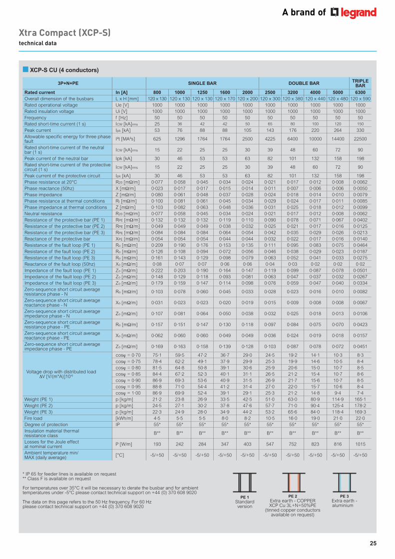
■ XCP-S CU (4 conductors)
Xtra Compact (XCP-S) technical data
3P+N+PE SINGLE BAR DOUBLE BAR TRIPLE BAR
Rated current In [A] 800 1000 1250 1600 2000 2500 3200 4000 5000 6300Overall dimension of the busbars L x H [mm] 120 x 130 120 x 130 120 x 130 120 x 170 120 x 200 120 x 300 120 x 380 120 x 440 120 x 480 120 x 590Rated operational voltage Ue [V] 1000 1000 1000 1000 1000 1000 1000 1000 1000 1000Rated insulation voltage Ui [V] 1000 1000 1000 1000 1000 1000 1000 1000 1000 1000Frequency f [Hz] 50 50 50 50 50 50 50 50 50 50Rated short-time current (1 s) ICW [kA]rms 25 36 42 42 50 65 80 100 120 150
Peak current Ipk [kA] 53 76 88 88 105 143 176 220 264 330Allowable specific energy for three phase fault I²t [MA²s] 625 1296 1764 1764 2500 4225 6400 10000 14400 22500
Rated short-time current of the neutral bar (1 s) ICW [kA]rms 15 22 25 25 30 39 48 60 72 90
Peak current of the neutral bar Ipk [kA] 30 46 53 53 63 82 101 132 158 198Rated short-time current of the protective circuit (1 s) ICW [kA]rms 15 22 25 25 30 39 48 60 72 90
Peak current of the protective circuit Ipk [kA] 30 46 53 53 63 82 101 132 158 198Phase resistance at 20°C R20 [mΩ/m] 0·077 0·058 0·045 0·034 0·024 0·021 0·017 0·012 0·008 0·0062Phase reactance (50hz) X [mΩ/m] 0·023 0·017 0·017 0·015 0·014 0·011 0·007 0·006 0·006 0·0050Phase impedance Z [mΩ/m] 0·080 0·061 0·048 0·037 0·028 0·024 0·018 0·014 0·010 0·0079Phase resistance at thermal conditions Rt [mΩ/m] 0·100 0·081 0·061 0·045 0·034 0·029 0·024 0·017 0·011 0·0085Phase impedance at thermal conditions Z [mΩ/m] 0·103 0·082 0·063 0·048 0·036 0·031 0·025 0·018 0·012 0·0099Neutral resistance R20 [mΩ/m] 0·077 0·058 0·045 0·034 0·024 0·021 0·017 0·012 0·008 0·0062Resistance of the protective bar (PE 1) RPE [mΩ/m] 0·132 0·132 0·132 0·119 0·110 0·090 0·078 0·071 0·067 0·0402Resistance of the protective bar (PE 2) RPE [mΩ/m] 0·049 0·049 0·049 0·038 0·032 0·025 0·021 0·017 0·016 0·0125Resistance of the protective bar (PE 3) RPE [mΩ/m] 0·084 0·084 0·084 0·064 0·054 0·042 0·035 0·029 0·026 0·0213Reactance of the protective bar XPE [mΩ/m] 0·054 0·054 0·054 0·044 0·044 0·032 0·022 0·017 0·016 0·0140Resistance of the fault loop (PE 1) Ro [mΩ/m] 0·209 0·190 0·176 0·153 0·135 0·111 0·095 0·083 0·075 0·0464Resistance of the fault loop (PE 2) Ro [mΩ/m] 0·126 0·108 0·094 0·072 0·056 0·046 0·038 0·029 0·023 0·0187Resistance of the fault loop (PE 3) Ro [mΩ/m] 0·161 0·143 0·129 0·098 0·079 0·063 0·052 0·041 0·033 0·0275Reactance of the fault loop (50hz) Xo [mΩ/m] 0·08 0·07 0·07 0·06 0·06 0·04 0·03 0·02 0·02 0·02Impedance of the fault loop (PE 1) Zo [mΩ/m] 0·222 0·203 0·190 0·164 0·147 0·119 0·099 0·087 0·078 0·0501Impedance of the fault loop (PE 2) Zo [mΩ/m] 0·148 0·129 0·118 0·093 0·081 0·063 0·047 0·037 0·032 0·0267Impedance of the fault loop (PE 3) Zo [mΩ/m] 0·179 0·159 0·147 0·114 0·098 0·076 0·059 0·047 0·040 0·0334Zero-sequence short circuit average resistance phase - N Ro [mΩ/m] 0·103 0·078 0·060 0·045 0·033 0·028 0·023 0·016 0·010 0·0082
Zero-sequence short circuit average reactance phase - N Xo [mΩ/m] 0·031 0·023 0·023 0·020 0·019 0·015 0·009 0·008 0·008 0·0067
Zero-sequence short circuit average impedance phase - N Zo [mΩ/m] 0·107 0·081 0·064 0·050 0·038 0·032 0·025 0·018 0·013 0·0106
Zero-sequence short circuit average resistance phase - PE Ro [mΩ/m] 0·157 0·151 0·147 0·130 0·118 0·097 0·084 0·075 0·070 0·0423
Zero-sequence short circuit average reactance phase - PE Xo [mΩ/m] 0·062 0·060 0·060 0·049 0·049 0·036 0·024 0·019 0·018 0·0157
Zero-sequence short circuit average impedance phase - PE Zo [mΩ/m] 0·169 0·163 0·158 0·139 0·128 0·103 0·087 0·078 0·072 0·0451
Voltage drop with distributed load ∆V [V/(m*A)]10-6
cosϕ = 0·70 75·1 59·5 47·2 36·7 29·0 24·5 19·2 14·1 10·3 8·3cosϕ = 0·75 78·4 62·2 49·1 37·9 29·9 25·3 19·9 14·6 10·5 8·4cosϕ = 0·80 81·5 64·8 50·8 39·1 30·6 25·9 20·6 15·0 10·7 8·5cosϕ = 0·85 84·4 67·2 52·3 40·1 31·1 26·5 21·2 15·4 10·7 8·6cosϕ = 0·90 86·9 69·3 53·6 40·9 31·5 26·9 21·7 15·6 10·7 8·5cosϕ = 0·95 88·8 71·0 54·4 41·2 31·4 27·0 22·0 15·7 10·6 8·4cosϕ = 1·00 86·9 69·9 52·4 39·1 29·1 25·3 21·2 14·8 9·4 7·4
Weight (PE 1) p [kg/m] 21·2 23·8 26·9 33·5 42·5 51·0 63·0 80·9 114·9 165·1Weight (PE 2) p [kg/m] 24·5 27·1 30·2 37·8 47·6 57·7 71·0 90·4 125·4 178·2Weight (PE 3) p [kg/m] 22·3 24·9 28·0 34·9 44·2 53·2 65·6 84·0 118·4 169·3Fire load [kWh/m] 4·5 5·5 5·5 8·0 8·2 10·5 16·0 19·0 21·0 22·0Degree of protection IP 55* 55* 55* 55* 55* 55* 55* 55* 55* 55*Insulation material thermal resistance class B** B** B** B** B** B** B** B** B** B**
Losses for the Joule effect at nominal current P [W/m] 193 242 284 347 403 547 752 823 816 1015
Ambient temperature min/MAX (daily average) [°C] -5/+50 -5/+50 -5/+50 -5/+50 -5/+50 -5/+50 -5/+50 -5/+50 -5/+50 -5/+50
* IP 65 for feeder lines is available on request ** Class F is available on request
For temperatures over 35°C it will be necessary to derate the busbar and for ambient temperatures under -5°C please contact technical support on +44 (0) 370 608 9020
The data on this page refers to the 50 Hz frequency. For 60 Hz please contact technical support on +44 (0) 370 608 9020
PE 1Standard version
PE 2Extra earth - COPPER XCP Cu 3L+N+50%PE
(tinned copper conductors available on request)
PE 3Extra earth - aluminium
26
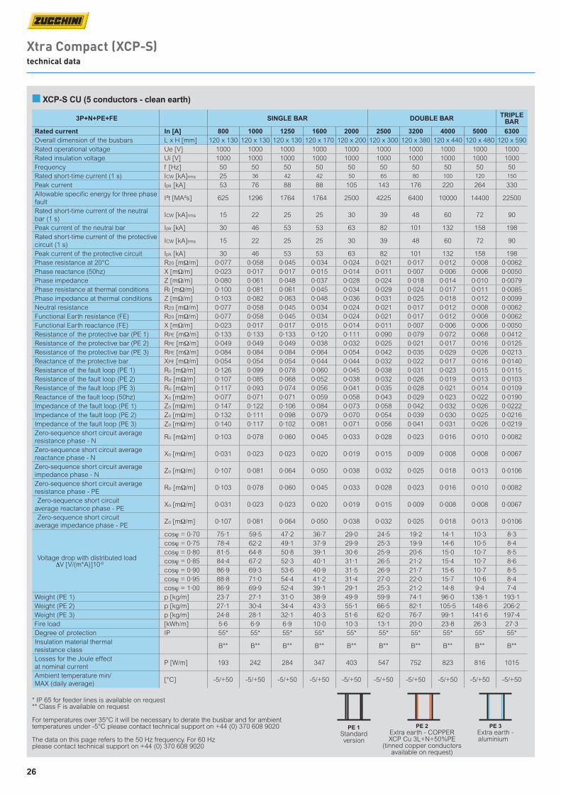
Xtra Compact (XCP-S) technical data
■ XCP-S CU (5 conductors - clean earth)
3P+N+PE+FE SINGLE BAR DOUBLE BAR TRIPLE BAR
Rated current In [A] 800 1000 1250 1600 2000 2500 3200 4000 5000 6300Overall dimension of the busbars L x H [mm] 120 x 130 120 x 130 120 x 130 120 x 170 120 x 200 120 x 300 120 x 380 120 x 440 120 x 480 120 x 590Rated operational voltage Ue [V] 1000 1000 1000 1000 1000 1000 1000 1000 1000 1000Rated insulation voltage Ui [V] 1000 1000 1000 1000 1000 1000 1000 1000 1000 1000Frequency f [Hz] 50 50 50 50 50 50 50 50 50 50Rated short-time current (1 s) ICW [kA]rms 25 36 42 42 50 65 80 100 120 150
Peak current Ipk [kA] 53 76 88 88 105 143 176 220 264 330Allowable specific energy for three phase fault
I²t [MA²s] 625 1296 1764 1764 2500 4225 6400 10000 14400 22500
Rated short-time current of the neutral bar (1 s)
ICW [kA]rms 15 22 25 25 30 39 48 60 72 90
Peak current of the neutral bar Ipk [kA] 30 46 53 53 63 82 101 132 158 198Rated short-time current of the protective circuit (1 s)
ICW [kA]rms 15 22 25 25 30 39 48 60 72 90
Peak current of the protective circuit Ipk [kA] 30 46 53 53 63 82 101 132 158 198Phase resistance at 20°C R20 [mΩ/m] 0·077 0·058 0·045 0·034 0·024 0·021 0·017 0·012 0·008 0·0062Phase reactance (50hz) X [mΩ/m] 0·023 0·017 0·017 0·015 0·014 0·011 0·007 0·006 0·006 0·0050Phase impedance Z [mΩ/m] 0·080 0·061 0·048 0·037 0·028 0·024 0·018 0·014 0·010 0·0079Phase resistance at thermal conditions Rt [mΩ/m] 0·100 0·081 0·061 0·045 0·034 0·029 0·024 0·017 0·011 0·0085Phase impedance at thermal conditions Z [mΩ/m] 0·103 0·082 0·063 0·048 0·036 0·031 0·025 0·018 0·012 0·0099Neutral resistance R20 [mΩ/m] 0·077 0·058 0·045 0·034 0·024 0·021 0·017 0·012 0·008 0·0062Functional Earth resistance (FE) R20 [mΩ/m] 0·077 0·058 0·045 0·034 0·024 0·021 0·017 0·012 0·008 0·0062Functional Earth reactance (FE) X [mΩ/m] 0·023 0·017 0·017 0·015 0·014 0·011 0·007 0·006 0·006 0·0050Resistance of the protective bar (PE 1) RPE [mΩ/m] 0·133 0·133 0·133 0·120 0·111 0·090 0·079 0·072 0·068 0·0412Resistance of the protective bar (PE 2) RPE [mΩ/m] 0·049 0·049 0·049 0·038 0·032 0·025 0·021 0·017 0·016 0·0125Resistance of the protective bar (PE 3) RPE [mΩ/m] 0·084 0·084 0·084 0·064 0·054 0·042 0·035 0·029 0·026 0·0213Reactance of the protective bar XPE [mΩ/m] 0·054 0·054 0·054 0·044 0·044 0·032 0·022 0·017 0·016 0·0140Resistance of the fault loop (PE 1) Ro [mΩ/m] 0·126 0·099 0·078 0·060 0·045 0·038 0·031 0·023 0·015 0·0115Resistance of the fault loop (PE 2) Ro [mΩ/m] 0·107 0·085 0·068 0·052 0·038 0·032 0·026 0·019 0·013 0·0103Resistance of the fault loop (PE 3) Ro [mΩ/m] 0·117 0·093 0·074 0·056 0·041 0·035 0·028 0·021 0·014 0·0109Reactance of the fault loop (50hz) Xo [mΩ/m] 0·077 0·071 0·071 0·059 0·058 0·043 0·029 0·023 0·022 0·0190Impedance of the fault loop (PE 1) Zo [mΩ/m] 0·147 0·122 0·106 0·084 0·073 0·058 0·042 0·032 0·026 0·0222Impedance of the fault loop (PE 2) Zo [mΩ/m] 0·132 0·111 0·098 0·079 0·070 0·054 0·039 0·030 0·025 0·0216Impedance of the fault loop (PE 3) Zo [mΩ/m] 0·140 0·117 0·102 0·081 0·071 0·056 0·041 0·031 0·026 0·0219Zero-sequence short circuit average resistance phase - N
Ro [mΩ/m] 0·103 0·078 0·060 0·045 0·033 0·028 0·023 0·016 0·010 0·0082
Zero-sequence short circuit average reactance phase - N
Xo [mΩ/m] 0·031 0·023 0·023 0·020 0·019 0·015 0·009 0·008 0·008 0·0067
Zero-sequence short circuit average impedance phase - N
Zo [mΩ/m] 0·107 0·081 0·064 0·050 0·038 0·032 0·025 0·018 0·013 0·0106
Zero-sequence short circuit average resistance phase - PE
Ro [mΩ/m] 0·103 0·078 0·060 0·045 0·033 0·028 0·023 0·016 0·010 0·0082
Zero-sequence short circuit average reactance phase - PE
Xo [mΩ/m] 0·031 0·023 0·023 0·020 0·019 0·015 0·009 0·008 0·008 0·0067
Zero-sequence short circuit average impedance phase - PE
Zo [mΩ/m] 0·107 0·081 0·064 0·050 0·038 0·032 0·025 0·018 0·013 0·0106
Voltage drop with distributed load ∆V [V/(m*A)]10-6
cosϕ = 0·70 75·1 59·5 47·2 36·7 29·0 24·5 19·2 14·1 10·3 8·3cosϕ = 0·75 78·4 62·2 49·1 37·9 29·9 25·3 19·9 14·6 10·5 8·4cosϕ = 0·80 81·5 64·8 50·8 39·1 30·6 25·9 20·6 15·0 10·7 8·5cosϕ = 0·85 84·4 67·2 52·3 40·1 31·1 26·5 21·2 15·4 10·7 8·6cosϕ = 0·90 86·9 69·3 53·6 40·9 31·5 26·9 21·7 15·6 10·7 8·5cosϕ = 0·95 88·8 71·0 54·4 41·2 31·4 27·0 22·0 15·7 10·6 8·4cosϕ = 1·00 86·9 69·9 52·4 39·1 29·1 25·3 21·2 14·8 9·4 7·4
Weight (PE 1) p [kg/m] 23·7 27·1 31·0 38·9 49·9 59·9 74·1 96·0 138·1 193·1Weight (PE 2) p [kg/m] 27·1 30·4 34·4 43·3 55·1 66·5 82·1 105·5 148·6 206·2Weight (PE 3) p [kg/m] 24·8 28·1 32·1 40·3 51·6 62·0 76·7 99·1 141·6 197·4Fire load [kWh/m] 5·6 6·9 6·9 10·0 10·3 13·1 20·0 23·8 26·3 27·3Degree of protection IP 55* 55* 55* 55* 55* 55* 55* 55* 55* 55*Insulation material thermal resistance class
B** B** B** B** B** B** B** B** B** B**
Losses for the Joule effect at nominal current
P [W/m] 193 242 284 347 403 547 752 823 816 1015
Ambient temperature min/MAX (daily average)
[°C] -5/+50 -5/+50 -5/+50 -5/+50 -5/+50 -5/+50 -5/+50 -5/+50 -5/+50 -5/+50
* IP 65 for feeder lines is available on request ** Class F is available on request
For temperatures over 35°C it will be necessary to derate the busbar and for ambient temperatures under -5°C please contact technical support on +44 (0) 370 608 9020
The data on this page refers to the 50 Hz frequency. For 60 Hz please contact technical support on +44 (0) 370 608 9020
PE 1Standard version
PE 2Extra earth - COPPER XCP Cu 3L+N+50%PE
(tinned copper conductors available on request)
PE 3Extra earth - aluminium
27
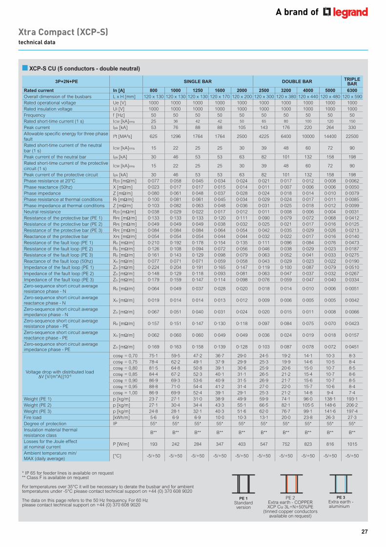
■ XCP-S CU (5 conductors - double neutral)
Xtra Compact (XCP-S) technical data
3P+2N+PE SINGLE BAR DOUBLE BAR TRIPLE BAR
Rated current In [A] 800 1000 1250 1600 2000 2500 3200 4000 5000 6300Overall dimension of the busbars L x H [mm] 120 x 130 120 x 130 120 x 130 120 x 170 120 x 200 120 x 300 120 x 380 120 x 440 120 x 480 120 x 590Rated operational voltage Ue [V] 1000 1000 1000 1000 1000 1000 1000 1000 1000 1000Rated insulation voltage Ui [V] 1000 1000 1000 1000 1000 1000 1000 1000 1000 1000Frequency f [Hz] 50 50 50 50 50 50 50 50 50 50Rated short-time current (1 s) ICW [kA]rms 25 36 42 42 50 65 80 100 120 150
Peak current Ipk [kA] 53 76 88 88 105 143 176 220 264 330Allowable specific energy for three phase fault
I²t [MA²s] 625 1296 1764 1764 2500 4225 6400 10000 14400 22500
Rated short-time current of the neutral bar (1 s)
ICW [kA]rms 15 22 25 25 30 39 48 60 72 90
Peak current of the neutral bar Ipk [kA] 30 46 53 53 63 82 101 132 158 198Rated short-time current of the protective circuit (1 s)
ICW [kA]rms 15 22 25 25 30 39 48 60 72 90
Peak current of the protective circuit Ipk [kA] 30 46 53 53 63 82 101 132 158 198Phase resistance at 20°C R20 [mΩ/m] 0·077 0·058 0·045 0·034 0·024 0·021 0·017 0·012 0·008 0·0062Phase reactance (50hz) X [mΩ/m] 0·023 0·017 0·017 0·015 0·014 0·011 0·007 0·006 0·006 0·0050Phase impedance Z [mΩ/m] 0·080 0·061 0·048 0·037 0·028 0·024 0·018 0·014 0·010 0·0079Phase resistance at thermal conditions Rt [mΩ/m] 0·100 0·081 0·061 0·045 0·034 0·029 0·024 0·017 0·011 0·0085Phase impedance at thermal conditions Z [mΩ/m] 0·103 0·082 0·063 0·048 0·036 0·031 0·025 0·018 0·012 0·0099Neutral resistance R20 [mΩ/m] 0·038 0·029 0·022 0·017 0·012 0·011 0·008 0·006 0·004 0·0031Resistance of the protective bar (PE 1) RPE [mΩ/m] 0·133 0·133 0·133 0·120 0·111 0·090 0·079 0·072 0·068 0·0412Resistance of the protective bar (PE 2) RPE [mΩ/m] 0·049 0·049 0·049 0·038 0·032 0·025 0·021 0·017 0·016 0·0125Resistance of the protective bar (PE 3) RPE [mΩ/m] 0·084 0·084 0·084 0·064 0·054 0·042 0·035 0·029 0·026 0·0213Reactance of the protective bar XPE [mΩ/m] 0·054 0·054 0·054 0·044 0·044 0·032 0·022 0·017 0·016 0·0140Resistance of the fault loop (PE 1) Ro [mΩ/m] 0·210 0·192 0·178 0·154 0·135 0·111 0·096 0·084 0·076 0·0473Resistance of the fault loop (PE 2) Ro [mΩ/m] 0·126 0·108 0·094 0·072 0·056 0·046 0·038 0·029 0·023 0·0187Resistance of the fault loop (PE 3) Ro [mΩ/m] 0·161 0·143 0·129 0·098 0·079 0·063 0·052 0·041 0·033 0·0275Reactance of the fault loop (50hz) Xo [mΩ/m] 0·077 0·071 0·071 0·059 0·058 0·043 0·029 0·023 0·022 0·0190Impedance of the fault loop (PE 1) Zo [mΩ/m] 0·224 0·204 0·191 0·165 0·147 0·119 0·100 0·087 0·079 0·0510Impedance of the fault loop (PE 2) Zo [mΩ/m] 0·148 0·129 0·118 0·093 0·081 0·063 0·047 0·037 0·032 0·0267Impedance of the fault loop (PE 3) Zo [mΩ/m] 0·179 0·159 0·147 0·114 0·098 0·076 0·059 0·047 0·040 0·0334Zero-sequence short circuit average resistance phase - N
Ro [mΩ/m] 0·064 0·049 0·037 0·028 0·020 0·018 0·014 0·010 0·006 0·0051
Zero-sequence short circuit average reactance phase - N
Xo [mΩ/m] 0·019 0·014 0·014 0·013 0·012 0·009 0·006 0·005 0·005 0·0042
Zero-sequence short circuit average impedance phase - N
Zo [mΩ/m] 0·067 0·051 0·040 0·031 0·024 0·020 0·015 0·011 0·008 0·0066
Zero-sequence short circuit average resistance phase - PE
Ro [mΩ/m] 0·157 0·151 0·147 0·130 0·118 0·097 0·084 0·075 0·070 0·0423
Zero-sequence short circuit average reactance phase - PE
Xo [mΩ/m] 0·062 0·060 0·060 0·049 0·049 0·036 0·024 0·019 0·018 0·0157
Zero-sequence short circuit average impedance phase - PE
Zo [mΩ/m] 0·169 0·163 0·158 0·139 0·128 0·103 0·087 0·078 0·072 0·0451
Voltage drop with distributed load ∆V [V/(m*A)]10-6
cosϕ = 0,70 75·1 59·5 47·2 36·7 29·0 24·5 19·2 14·1 10·3 8·3cosϕ = 0,75 78·4 62·2 49·1 37·9 29·9 25·3 19·9 14·6 10·5 8·4cosϕ = 0,80 81·5 64·8 50·8 39·1 30·6 25·9 20·6 15·0 10·7 8·5cosϕ = 0,85 84·4 67·2 52·3 40·1 31·1 26·5 21·2 15·4 10·7 8·6cosϕ = 0,90 86·9 69·3 53·6 40·9 31·5 26·9 21·7 15·6 10·7 8·5cosϕ = 0,95 88·8 71·0 54·4 41·2 31·4 27·0 22·0 15·7 10·6 8·4cosϕ = 1,00 86·9 69·9 52·4 39·1 29·1 25·3 21·2 14·8 9·4 7·4
Weight (PE 1) p [kg/m] 23·7 27·1 31·0 38·9 49·9 59·9 74·1 96·0 138·1 193·1Weight (PE 2) p [kg/m] 27·1 30·4 34·4 43·3 55·1 66·5 82·1 105·5 148·6 206·2Weight (PE 3) p [kg/m] 24·8 28·1 32·1 40·3 51·6 62·0 76·7 99·1 141·6 197·4Fire load [kWh/m] 5·6 6·9 6·9 10·0 10·3 13·1 20·0 23·8 26·3 27·3Degree of protection IP 55* 55* 55* 55* 55* 55* 55* 55* 55* 55*Insulation material thermal resistance class
B** B** B** B** B** B** B** B** B** B**
Losses for the Joule effect at nominal current
P [W/m] 193 242 284 347 403 547 752 823 816 1015
Ambient temperature min/MAX (daily average)
[°C] -5/+50 -5/+50 -5/+50 -5/+50 -5/+50 -5/+50 -5/+50 -5/+50 -5/+50 -5/+50
* IP 65 for feeder lines is available on request ** Class F is available on request
For temperatures over 35°C it will be necessary to derate the busbar and for ambient temperatures under -5°C please contact technical support on +44 (0) 370 608 9020
The data on this page refers to the 50 Hz frequency. For 60 Hz please contact technical support on +44 (0) 370 608 9020
PE 1Standard version
PE 2Extra earth - COPPER XCP Cu 3L+N+50%PE
(tinned copper conductors available on request)
PE 3Extra earth - aluminium

28
BUSBAR FROM 630 TO 6300 AXCP-HP is a busbar trunking system characterised by high performance and low losses due to the Joule effect.Used for transport and distribution of high power, including rising mains. Applications include all industrial, commercial and service sector buildings such as factories, banks, trade and business centres, hospitals and data centres etc.
The high performance power solution for
industrial and service sector applications
XCP-HP
29
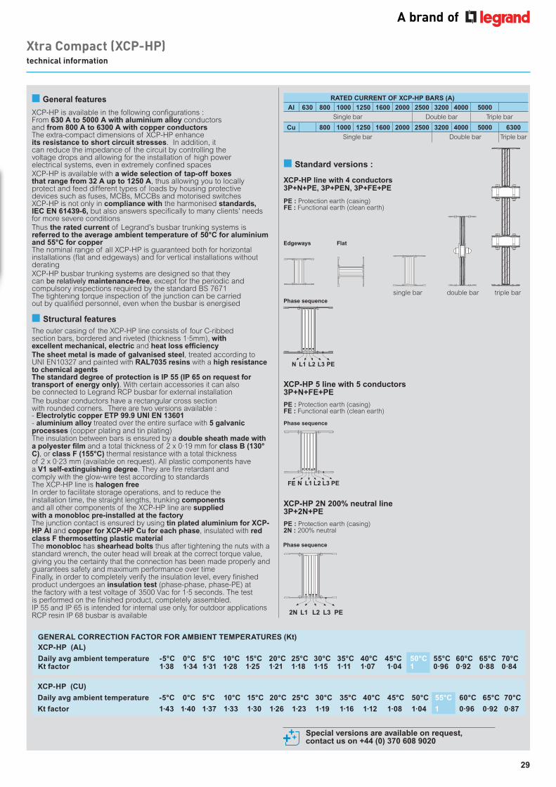
Xtra Compact (XCP-HP) technical information
Edgeways
Phase sequence
Phase sequence
Flat
RATED CURRENT OF XCP-HP BARS (A)
Al 630 800 1000 1250 1600 2000 2500 3200 4000 5000
Single bar Double bar Triple bar
Cu 800 1000 1250 1600 2000 2500 3200 4000 5000 6300
Single bar Double bar Triple bar
■ Standard versions :
XCP-HP line with 4 conductors 3P+N+PE, 3P+PEN, 3P+FE+PE
XCP-HP 5 line with 5 conductors 3P+N+FE+PE
XCP-HP 2N 200% neutral line 3P+2N+PE
double bar
PE : Protection earth (casing)FE : Functional earth (clean earth)
PE : Protection earth (casing)FE : Functional earth (clean earth)
PE : Protection earth (casing)2N : 200% neutral
FE PEL2L1N L3
2N PEL2L1 L3
single bar
Special versions are available on request, contact us on +44 (0) 370 608 9020
Phase sequence
N PEL3L2L1
triple bar
GENERAL CORRECTION FACTOR FOR AMBIENT TEMPERATURES (Kt) XCP-HP (AL)
Daily avg ambient temperature -5°C 0°C 5°C 10°C 15°C 20°C 25°C 30°C 35°C 40°C 45°C 50°C 55°C 60°C 65°C 70°CKt factor 1·38 1·34 1·31 1·28 1·25 1·21 1·18 1·15 1·11 1·07 1·04 1 0·96 0·92 0·88 0·84
XCP-HP (CU)
Daily avg ambient temperature -5°C 0°C 5°C 10°C 15°C 20°C 25°C 30°C 35°C 40°C 45°C 50°C 55°C 60°C 65°C 70°C
Kt factor 1·43 1·40 1·37 1·33 1·30 1·26 1·23 1·19 1·16 1·12 1·08 1·04 1 0·96 0·92 0·87
■ General features
XCP-HP is available in the following configurations : From 630 A to 5000 A with aluminium alloy conductors and from 800 A to 6300 A with copper conductors The extra-compact dimensions of XCP-HP enhance its resistance to short circuit stresses. In addition, it can reduce the impedance of the circuit by controlling the voltage drops and allowing for the installation of high power electrical systems, even in extremely confined spaces XCP-HP is available with a wide selection of tap-off boxes that range from 32 A up to 1250 A, thus allowing you to locally protect and feed different types of loads by housing protective devices such as fuses, MCBs, MCCBs and motorised switches XCP-HP is not only in compliance with the harmonised standards, IEC EN 61439-6, but also answers specifically to many clients' needs for more severe conditionsThus the rated current of Legrand’s busbar trunking systems is referred to the average ambient temperature of 50°C for aluminium and 55°C for copper The nominal range of all XCP-HP is guaranteed both for horizontal installations (flat and edgeways) and for vertical installations without deratingXCP-HP busbar trunking systems are designed so that they can be relatively maintenance-free, except for the periodic and compulsory inspections required by the standard BS 7671The tightening torque inspection of the junction can be carried out by qualified personnel, even when the busbar is energised
■ Structural featuresThe outer casing of the XCP-HP line consists of four C-ribbedsection bars, bordered and riveted (thickness 1·5mm), withexcellent mechanical, electric and heat loss efficiencyThe sheet metal is made of galvanised steel, treated according to UNI EN10327 and painted with RAL7035 resins with a high resistance to chemical agentsThe standard degree of protection is IP 55 (IP 65 on request for transport of energy only). With certain accessories it can alsobe connected to Legrand RCP busbar for external installationThe busbar conductors have a rectangular cross sectionwith rounded corners. There are two versions available :- Electrolytic copper ETP 99.9 UNI EN 13601- aluminium alloy treated over the entire surface with 5 galvanic processes (copper plating and tin plating)The insulation between bars is ensured by a double sheath made with a polyester film and a total thickness of 2 x 0·19 mm for class B (130°C), or class F (155°C) thermal resistance with a total thicknessof 2 x 0·23 mm (available on request). All plastic components havea V1 self-extinguishing degree. They are fire retardant andcomply with the glow-wire test according to standardsThe XCP-HP line is halogen freeIn order to facilitate storage operations, and to reduce theinstallation time, the straight lengths, trunking componentsand all other components of the XCP-HP line are suppliedwith a monobloc pre-installed at the factoryThe junction contact is ensured by using tin plated aluminium for XCP-HP Al and copper for XCP-HP Cu for each phase, insulated with red class F thermosetting plastic materialThe monobloc has shearhead bolts thus after tightening the nuts with a standard wrench, the outer head will break at the correct torque value, giving you the certainty that the connection has been made properly and guarantees safety and maximum performance over timeFinally, in order to completely verify the insulation level, every finished product undergoes an insulation test (phase-phase, phase-PE) atthe factory with a test voltage of 3500 Vac for 1·5 seconds. The testis performed on the finished product, completely assembled.IP 55 and IP 65 is intended for internal use only, for outdoor applications RCP resin IP 68 busbar is available
30
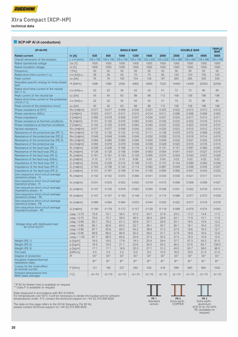
3P+N+PE SINGLE BAR DOUBLE BAR TRIPLE BAR
Rated current In [A] 630 800 1000 1250 1600 2000 2500 3200 4000 5000Overall dimension of the busbars L x H [mm] 125 x 130 125 x 130 125 x 130 125 x 130 125 x 200 125 x 220 125 x 380 125 x 440 125 x 480 125 x 740Rated operational voltage Ue [V] 1000 1000 1000 1000 1000 1000 1000 1000 1000 1000Rated insulation voltage Ui [V] 1000 1000 1000 1000 1000 1000 1000 1000 1000 1000Frequency f [Hz] 50 50 50 50 50 50 50 50 50 50Rated short-time current (1 s) ICW [kA]rms 36 36 50 70 70 85 120 120 150 150Peak current Ipk [kA] 76 76 105 154 154 187 264 264 330 330Allowable specific energy for three phase fault I²t [MA²s] 1296 1296 2500 4900 4900 7225 14400 14400 22500 22500
Rated short-time current of the neutral bar (1 s) ICW [kA]rms 22 22 30 42 42 51 72 72 90 90
Peak current of the neutral bar Ipk [kA] 45 45 63 88 88 112 158 158 198 198Rated short-time current of the protective circuit (1 s) ICW [kA]rms 22 22 30 42 42 51 72 72 90 90
Peak current of the protective circuit Ipk [kA] 45 45 63 88 88 112 158 158 198 198Phase resistance at 20°C R20 [mΩ/m] 0·077 0·077 0·056 0·045 0·031 0·025 0·022 0·015 0·012 0·010Phase reactance (50hz) X [mΩ/m] 0·023 0·017 0·017 0·015 0·014 0·011 0·006 0·006 0·006 0·005Phase impedance Z [mΩ/m] 0·080 0·079 0·059 0·047 0·034 0·027 0·023 0·017 0·014 0·011Phase resistance at thermal conditions Rt [mΩ/m] 0·101 0·102 0·076 0·062 0·043 0·035 0·032 0·022 0·018 0·014Phase impedance at thermal conditions Z [mΩ/m] 0·104 0·103 0·078 0·064 0·045 0·037 0·032 0·023 0·019 0·015Neutral resistance R20 [mΩ/m] 0·077 0·077 0·056 0·045 0·031 0·025 0·022 0·015 0·012 0·010Resistance of the protective bar (PE 1) RPE [mΩ/m] 0·132 0·132 0·132 0·133 0·111 0·106 0·078 0·072 0·068 0·035Resistance of the protective bar (PE 2) RPE [mΩ/m] 0·049 0·049 0·049 0·049 0·032 0·029 0·019 0·016 0·014 0·010Resistance of the protective bar (PE 3) RPE [mΩ/m] 0·084 0·084 0·084 0·084 0·054 0·049 0·032 0·027 0·025 0·016Reactance of the protective bar XPE [mΩ/m] 0·080 0·078 0·078 0·048 0·039 0·028 0·020 0·015 0·016 0·014Resistance of the fault loop (PE 1) Ro [mΩ/m] 0·208 0·208 0·188 0·178 0·142 0·131 0·101 0·087 0·080 0·045Resistance of the fault loop (PE 2) Ro [mΩ/m] 0·126 0·126 0·106 0·094 0·063 0·054 0·041 0·031 0·027 0·019Resistance of the fault loop (PE 3) Ro [mΩ/m] 0·161 0·161 0·140 0·129 0·085 0·074 0·054 0·043 0·037 0·026Reactance of the fault loop (50hz) Xo [mΩ/m] 0·10 0·10 0·10 0·06 0·05 0·04 0·03 0·02 0·02 0·02Impedance of the fault loop (PE 1) Zo [mΩ/m] 0·232 0·229 0·210 0·189 0·151 0·137 0·104 0·089 0·083 0·049Impedance of the fault loop (PE 2) Zo [mΩ/m] 0·163 0·158 0·142 0·114 0·082 0·067 0·049 0·038 0·035 0·027Impedance of the fault loop (PE 3) Zo [mΩ/m] 0·191 0·187 0·169 0·144 0·100 0·084 0·060 0·047 0·043 0·032Zero-sequence short-circuit average resistance phase - N Ro [mΩ/m] 0·102 0·102 0·075 0·060 0·041 0·033 0·030 0·021 0·017 0·013
Zero-sequence short circuit average reactance phase - N Xo [mΩ/m] 0·031 0·023 0·023 0·020 0·019 0·015 0·008 0·008 0·008 0·007
Zero-sequence short circuit average impedance phase - N Zo [mΩ/m] 0·107 0·105 0·078 0·063 0·045 0·036 0·031 0·022 0·018 0·014
Zero-sequence short circuit average resistance phase - PE Ro [mΩ/m] 0·157 0·157 0·150 0·148 0·121 0·115 0·086 0·077 0·072 0·039
Zero-sequence short circuit average reactance phase - PE Xo [mΩ/m] 0·088 0·084 0·084 0·053 0·044 0·032 0·022 0·017 0·018 0·016
Zero-sequence short circuit average impedance phase - PE Zo [mΩ/m] 0·180 0·178 0·172 0·157 0·129 0·119 0·088 0·079 0·074 0·042
Voltage drop with distributed load ∆V [V/(m*A)]10-6
cosϕ = 0·70 75·6 72·1 56·5 47·0 34·7 27·9 23·0 17·2 14·6 11·5cosϕ = 0·75 79·0 75·7 59·0 49·0 36·0 28·9 24·1 17·9 15·1 11·9cosϕ = 0·80 82·1 79·2 61·3 50·9 37·1 29·9 25·1 18·5 15·6 12·2cosϕ = 0·85 85·1 82·6 63·5 52·7 38·1 30·7 26·1 19·1 16·0 12·5cosϕ = 0·90 87·7 85·6 65·5 54·2 38·8 31·3 27·0 19·6 16·3 12·7cosϕ = 0·95 89·6 88·2 66·9 55·3 39·2 31·7 27·8 19·9 16·4 12·8cosϕ = 1·00 87·7 88·0 65·6 53·9 37·3 30·2 27·5 19·3 15·6 12·0
Weight (PE 1) p [kg/m] 16·0 16·0 17·8 19·3 25·4 29·4 37·7 47·3 54·3 91·0Weight (PE 2) p [kg/m] 19·3 19·3 21·1 22·6 30·5 35·0 46·4 57·6 65·7 108·0Weight (PE 3) p [kg/m] 17·1 17·1 18·9 20·3 27·1 31·2 40·5 50·7 58·0 96·5Fire load [kWh/m] 4·5 5·5 5·5 6·0 8·5 10·5 16·0 19·0 21·0 21·0Degree of protection IP 55* 55* 55* 55* 55* 55* 55* 55* 55* 55*Insulation material thermal resistance class B** B** B** B** B** B** B** B** B** B**
Losses for the Joule effect at nominal current P [W/m] 121 195 227 292 330 418 596 683 863 1042
Ambient temperature min/MAX (daily average) [°C] -5/+70 -5/+70 -5/+70 -5/+70 -5/+70 -5/+70 -5/+70 -5/+70 -5/+70 -5/+70
■ XCP-HP Al (4 conductors)
* IP 65 for feeder lines is available on request ** Class F is available on request
Data measured in accordance with IEC 61439-6 For temperatures over 50°C it will be necessary to derate the busbar and for ambient temperatures under -5°C contact the technical support on +44 (0) 370 608 9020
The data on this page refers to the 50 Hz frequency. For 60 Hz, please contact technical support on +44 (0) 370 608 9020
Xtra Compact (XCP-HP) technical data
PE 1Standard version
PE 2Extra earth -
COPPER
PE 3Extra earth - aluminium
XCP Al 3L+N+50%PE (available on
request)

31
3P+N+PE+FE SINGLE BAR DOUBLE BAR TRIPLE BAR
Rated current In [A] 630 800 1000 1250 1600 2000 2500 3200 4000 5000Overall dimension of the busbars L x H [mm] 125 x 130 125 x 130 125 x 130 125 x 130 125 x 200 125 x 220 125 x 380 125 x 440 125 x 480 125 x 740Rated operational voltage Ue [V] 1000 1000 1000 1000 1000 1000 1000 1000 1000 1000Rated insulation voltage Ui [V] 1000 1000 1000 1000 1000 1000 1000 1000 1000 1000Frequency f [Hz] 50 50 50 50 50 50 50 50 50 50Rated short-time current (1 s) ICW [kA]rms 36 36 50 70 70 85 120 120 150 150Peak current Ipk [kA] 76 76 105 154 154 187 264 264 330 330Allowable specific energy for three phase fault I²t [MA²s] 1296 1296 2500 4900 4900 7225 14400 14400 22500 22500
Rated short-time current of the neutral bar (1 s) ICW [kA]rms 22 22 30 42 42 51 72 72 90 90
Peak current of the neutral bar Ipk [kA] 45 45 63 88 88 112 158 158 198 198Rated short-time current of the protective circuit (1 s) ICW [kA]rms 22 22 30 42 42 51 72 72 90 90
Peak current of the protective circuit Ipk [kA] 45 45 63 88 88 112 158 158 198 198Phase resistance at 20°C R20 [mΩ/m] 0·077 0·077 0·056 0·045 0·031 0·025 0·022 0·015 0·012 0·010Phase reactance (50hz) X [mΩ/m] 0·023 0·017 0·017 0·015 0·014 0·011 0·006 0·006 0·006 0·005Phase impedance Z [mΩ/m] 0·080 0·079 0·059 0·047 0·034 0·027 0·023 0·017 0·014 0·011Phase resistance at thermal conditions Rt [mΩ/m] 0·101 0·102 0·076 0·062 0·043 0·035 0·032 0·022 0·018 0·014Phase impedance at thermal conditions Z [mΩ/m] 0·104 0·103 0·078 0·064 0·045 0·037 0·032 0·023 0·019 0·015Neutral resistance R20 [mΩ/m] 0·077 0·077 0·056 0·045 0·031 0·025 0·022 0·015 0·012 0·010Functional Earth resistance (FE) R20 [mΩ/m] 0·077 0·077 0·056 0·045 0·031 0·025 0·022 0·015 0·012 0·010Functional Earth reactance (FE) X [mΩ/m] 0·023 0·017 0·017 0·015 0·014 0·011 0·006 0·006 0·006 0·005Resistance of the protective bar (PE 1) RPE [mΩ/m] 0·133 0·133 0·266 0·266 0·222 0·213 0·156 0·143 0·136 0·035Resistance of the protective bar (PE 2) RPE [mΩ/m] 0·049 0·049 0·049 0·049 0·032 0·029 0·019 0·016 0·014 0·010Resistance of the protective bar (PE 3) RPE [mΩ/m] 0·084 0·084 0·084 0·084 0·054 0·049 0·032 0·027 0·025 0·016Reactance of the protective bar XPE [mΩ/m] 0·080 0·078 0·078 0·048 0·039 0·028 0·020 0·015 0·016 0·014Resistance of the fault loop (PE 1) Ro [mΩ/m] 0·125 0·125 0·102 0·083 0·058 0·047 0·042 0·029 0·024 0·017Resistance of the fault loop (PE 2) Ro [mΩ/m] 0·107 0·107 0·082 0·069 0·047 0·038 0·033 0·023 0·019 0·014Resistance of the fault loop (PE 3) Ro [mΩ/m] 0·117 0·117 0·090 0·074 0·051 0·042 0·036 0·025 0·021 0·016Reactance of the fault loop (50hz) Xo [mΩ/m] 0·10 0·10 0·10 0·06 0·05 0·04 0·03 0·02 0·02 0·02Impedance of the fault loop (PE 1) Zo [mΩ/m] 0·162 0·157 0·140 0·105 0·079 0·061 0·049 0·036 0·032 0·026Impedance of the fault loop (PE 2) Zo [mΩ/m] 0·148 0·143 0·126 0·093 0·071 0·055 0·042 0·031 0·029 0·024Impedance of the fault loop (PE 3) Zo [mΩ/m] 0·156 0·151 0·131 0·097 0·073 0·057 0·044 0·033 0·030 0·025Zero-sequence short circuit average resistance phase - N Ro [mΩ/m] 0·102 0·102 0·075 0·060 0·041 0·033 0·030 0·021 0·017 0·013
Zero-sequence short circuit average reactance phase - N Xo [mΩ/m] 0·031 0·023 0·023 0·020 0·019 0·015 0·008 0·008 0·008 0·007
Zero-sequence short circuit average impedance phase - N Zo [mΩ/m] 0·107 0·105 0·078 0·063 0·045 0·036 0·031 0·022 0·018 0·014
Zero-sequence short circuit average resistance phase - PE Ro [mΩ/m] 0·102 0·102 0·075 0·060 0·041 0·033 0·030 0·021 0·017 0·013
Zero-sequence short circuit average reactance phase - PE Xo [mΩ/m] 0·031 0·023 0·023 0·020 0·019 0·015 0·008 0·008 0·008 0·007
Zero-sequence short circuit average impedance phase - PE Zo [mΩ/m] 0·107 0·105 0·078 0·063 0·045 0·036 0·031 0·022 0·018 0·014
Voltage drop with distributed load ∆V [V/(m*A)]10-6
cosϕ = 0·70 75·6 72·1 56·5 47·0 34·7 27·9 23·0 17·2 14·6 11·5cosϕ = 0·75 79·0 75·7 59·0 49·0 36·0 28·9 24·1 17·9 15·1 11·9cosϕ = 0·80 82·1 79·2 61·3 50·9 37·1 29·9 25·1 18·5 15·6 12·2cosϕ = 0·85 85·1 82·6 63·5 52·7 38·1 30·7 26·1 19·1 16·0 12·5cosϕ = 0·90 87·7 85·6 65·5 54·2 38·8 31·3 27·0 19·6 16·3 12·7cosϕ = 0·95 89·6 88·2 66·9 55·3 39·2 31·7 27·8 19·9 16·4 12·8cosϕ = 1·00 87·7 88·0 65·6 53·9 37·3 30·2 27·5 19·3 15·6 12·0
Weight (PE 1) p [kg/m] 17·5 17·5 19·7 21·7 28·8 33·6 42·8 54·4 62·9 102·2Weight (PE 2) p [kg/m] 20·8 20·8 23·0 25·0 34·0 39·3 51·5 64·7 74·2 119·2Weight (PE 3) p [kg/m] 21·0 18·6 20·8 22·7 30·5 35·5 45·6 57·7 66·6 107·8Fire load [kWh/m] 5·6 6·9 6·9 7·5 10·6 13·1 20·0 23·8 26·3 27·3Degree of protection IP 55* 55* 55* 55* 55* 55* 55* 55* 55* 55*Insulation material thermal resistance class B** B** B** B** B** B** B** B** B** B**
Losses for the Joule effect at nominal current P [W/m] 121 195 227 292 330 418 596 683 863 1042
Ambient temperature min/MAX (daily average) [°C] -5/+70 -5/+70 -5/+70 -5/+70 -5/+70 -5/+70 -5/+70 -5/+70 -5/+70 -5/+70
* IP 65 for feeder lines is available on request ** Class F is available on request
Data measured in accordance with IEC 61439-6 For temperatures over 50°C it will be necessary to derate the busbar and for ambient temperatures under -5°C please contact technical support on +44 (0) 370 608 9020
The data on this page refers to the 50 Hz frequency. For 60 Hz please contact technical support on +44 (0) 370 608 9020
Xtra Compact (XCP-HP) technical data
■ XCP-HP Al (5 conductors - clean earth)
PE 1Standard version
PE 2Extra earth -
COPPER
PE 3Extra earth - aluminium
XCP Al 3L+N+50%PE (available on
request)
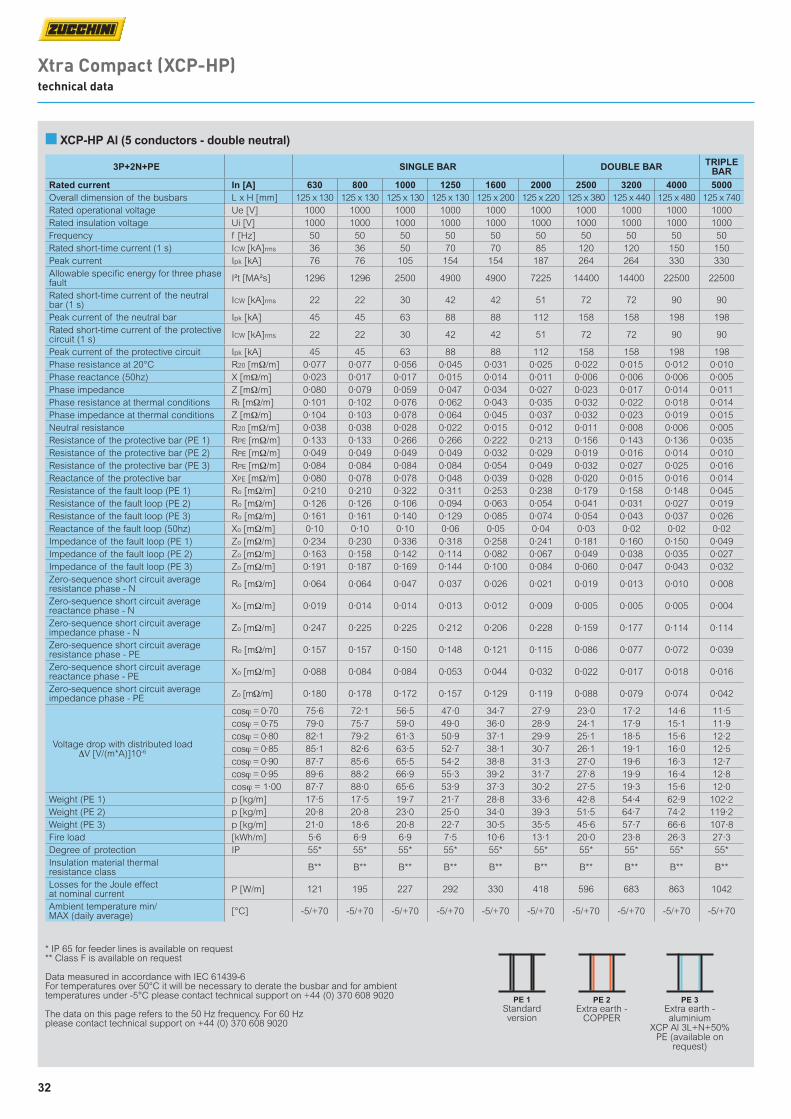
32
■ XCP-HP Al (5 conductors - double neutral)
Xtra Compact (XCP-HP) technical data
3P+2N+PE SINGLE BAR DOUBLE BAR TRIPLE BAR
Rated current In [A] 630 800 1000 1250 1600 2000 2500 3200 4000 5000Overall dimension of the busbars L x H [mm] 125 x 130 125 x 130 125 x 130 125 x 130 125 x 200 125 x 220 125 x 380 125 x 440 125 x 480 125 x 740Rated operational voltage Ue [V] 1000 1000 1000 1000 1000 1000 1000 1000 1000 1000Rated insulation voltage Ui [V] 1000 1000 1000 1000 1000 1000 1000 1000 1000 1000Frequency f [Hz] 50 50 50 50 50 50 50 50 50 50Rated short-time current (1 s) ICW [kA]rms 36 36 50 70 70 85 120 120 150 150Peak current Ipk [kA] 76 76 105 154 154 187 264 264 330 330Allowable specific energy for three phase fault I²t [MA²s] 1296 1296 2500 4900 4900 7225 14400 14400 22500 22500
Rated short-time current of the neutral bar (1 s) ICW [kA]rms 22 22 30 42 42 51 72 72 90 90
Peak current of the neutral bar Ipk [kA] 45 45 63 88 88 112 158 158 198 198Rated short-time current of the protective circuit (1 s) ICW [kA]rms 22 22 30 42 42 51 72 72 90 90
Peak current of the protective circuit Ipk [kA] 45 45 63 88 88 112 158 158 198 198Phase resistance at 20°C R20 [mΩ/m] 0·077 0·077 0·056 0·045 0·031 0·025 0·022 0·015 0·012 0·010Phase reactance (50hz) X [mΩ/m] 0·023 0·017 0·017 0·015 0·014 0·011 0·006 0·006 0·006 0·005Phase impedance Z [mΩ/m] 0·080 0·079 0·059 0·047 0·034 0·027 0·023 0·017 0·014 0·011Phase resistance at thermal conditions Rt [mΩ/m] 0·101 0·102 0·076 0·062 0·043 0·035 0·032 0·022 0·018 0·014Phase impedance at thermal conditions Z [mΩ/m] 0·104 0·103 0·078 0·064 0·045 0·037 0·032 0·023 0·019 0·015Neutral resistance R20 [mΩ/m] 0·038 0·038 0·028 0·022 0·015 0·012 0·011 0·008 0·006 0·005Resistance of the protective bar (PE 1) RPE [mΩ/m] 0·133 0·133 0·266 0·266 0·222 0·213 0·156 0·143 0·136 0·035Resistance of the protective bar (PE 2) RPE [mΩ/m] 0·049 0·049 0·049 0·049 0·032 0·029 0·019 0·016 0·014 0·010Resistance of the protective bar (PE 3) RPE [mΩ/m] 0·084 0·084 0·084 0·084 0·054 0·049 0·032 0·027 0·025 0·016Reactance of the protective bar XPE [mΩ/m] 0·080 0·078 0·078 0·048 0·039 0·028 0·020 0·015 0·016 0·014Resistance of the fault loop (PE 1) Ro [mΩ/m] 0·210 0·210 0·322 0·311 0·253 0·238 0·179 0·158 0·148 0·045Resistance of the fault loop (PE 2) Ro [mΩ/m] 0·126 0·126 0·106 0·094 0·063 0·054 0·041 0·031 0·027 0·019Resistance of the fault loop (PE 3) Ro [mΩ/m] 0·161 0·161 0·140 0·129 0·085 0·074 0·054 0·043 0·037 0·026Reactance of the fault loop (50hz) Xo [mΩ/m] 0·10 0·10 0·10 0·06 0·05 0·04 0·03 0·02 0·02 0·02Impedance of the fault loop (PE 1) Zo [mΩ/m] 0·234 0·230 0·336 0·318 0·258 0·241 0·181 0·160 0·150 0·049Impedance of the fault loop (PE 2) Zo [mΩ/m] 0·163 0·158 0·142 0·114 0·082 0·067 0·049 0·038 0·035 0·027Impedance of the fault loop (PE 3) Zo [mΩ/m] 0·191 0·187 0·169 0·144 0·100 0·084 0·060 0·047 0·043 0·032Zero-sequence short circuit average resistance phase - N Ro [mΩ/m] 0·064 0·064 0·047 0·037 0·026 0·021 0·019 0·013 0·010 0·008
Zero-sequence short circuit average reactance phase - N Xo [mΩ/m] 0·019 0·014 0·014 0·013 0·012 0·009 0·005 0·005 0·005 0·004
Zero-sequence short circuit average impedance phase - N Zo [mΩ/m] 0·247 0·225 0·225 0·212 0·206 0·228 0·159 0·177 0·114 0·114
Zero-sequence short circuit average resistance phase - PE Ro [mΩ/m] 0·157 0·157 0·150 0·148 0·121 0·115 0·086 0·077 0·072 0·039
Zero-sequence short circuit average reactance phase - PE Xo [mΩ/m] 0·088 0·084 0·084 0·053 0·044 0·032 0·022 0·017 0·018 0·016
Zero-sequence short circuit average impedance phase - PE Zo [mΩ/m] 0·180 0·178 0·172 0·157 0·129 0·119 0·088 0·079 0·074 0·042
Voltage drop with distributed load ∆V [V/(m*A)]10-6
cosϕ = 0·70 75·6 72·1 56·5 47·0 34·7 27·9 23·0 17·2 14·6 11·5cosϕ = 0·75 79·0 75·7 59·0 49·0 36·0 28·9 24·1 17·9 15·1 11·9cosϕ = 0·80 82·1 79·2 61·3 50·9 37·1 29·9 25·1 18·5 15·6 12·2cosϕ = 0·85 85·1 82·6 63·5 52·7 38·1 30·7 26·1 19·1 16·0 12·5cosϕ = 0·90 87·7 85·6 65·5 54·2 38·8 31·3 27·0 19·6 16·3 12·7cosϕ = 0·95 89·6 88·2 66·9 55·3 39·2 31·7 27·8 19·9 16·4 12·8cosϕ = 1·00 87·7 88·0 65·6 53·9 37·3 30·2 27·5 19·3 15·6 12·0
Weight (PE 1) p [kg/m] 17·5 17·5 19·7 21·7 28·8 33·6 42·8 54·4 62·9 102·2Weight (PE 2) p [kg/m] 20·8 20·8 23·0 25·0 34·0 39·3 51·5 64·7 74·2 119·2Weight (PE 3) p [kg/m] 21·0 18·6 20·8 22·7 30·5 35·5 45·6 57·7 66·6 107·8Fire load [kWh/m] 5·6 6·9 6·9 7·5 10·6 13·1 20·0 23·8 26·3 27·3Degree of protection IP 55* 55* 55* 55* 55* 55* 55* 55* 55* 55*Insulation material thermal resistance class B** B** B** B** B** B** B** B** B** B**
Losses for the Joule effect at nominal current P [W/m] 121 195 227 292 330 418 596 683 863 1042
Ambient temperature min/MAX (daily average) [°C] -5/+70 -5/+70 -5/+70 -5/+70 -5/+70 -5/+70 -5/+70 -5/+70 -5/+70 -5/+70
* IP 65 for feeder lines is available on request ** Class F is available on request
Data measured in accordance with IEC 61439-6 For temperatures over 50°C it will be necessary to derate the busbar and for ambient temperatures under -5°C please contact technical support on +44 (0) 370 608 9020
The data on this page refers to the 50 Hz frequency. For 60 Hz please contact technical support on +44 (0) 370 608 9020
PE 1Standard version
PE 2Extra earth -
COPPER
PE 3Extra earth - aluminium
XCP Al 3L+N+50%PE (available on
request)
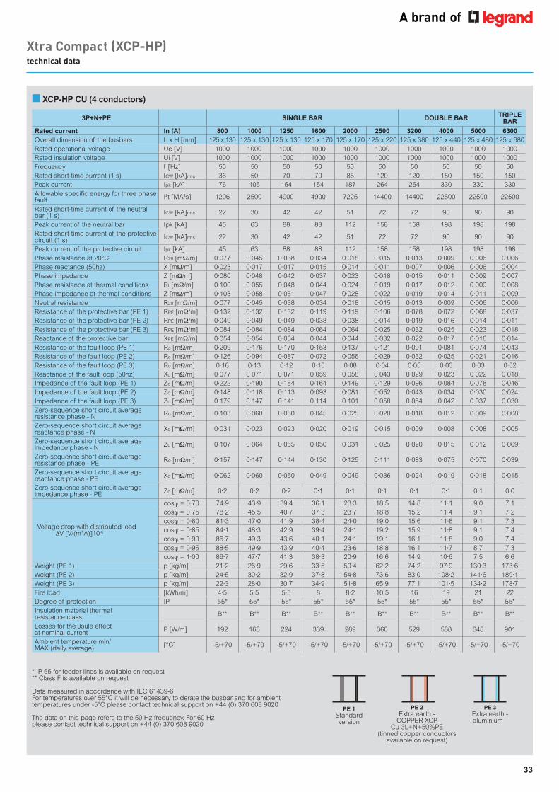
33
■ XCP-HP CU (4 conductors)
Xtra Compact (XCP-HP) technical data
3P+N+PE SINGLE BAR DOUBLE BAR TRIPLE BAR
Rated current In [A] 800 1000 1250 1600 2000 2500 3200 4000 5000 6300Overall dimension of the busbars L x H [mm] 125 x 130 125 x 130 125 x 130 125 x 170 125 x 170 125 x 220 125 x 380 125 x 440 125 x 480 125 x 680Rated operational voltage Ue [V] 1000 1000 1000 1000 1000 1000 1000 1000 1000 1000Rated insulation voltage Ui [V] 1000 1000 1000 1000 1000 1000 1000 1000 1000 1000Frequency f [Hz] 50 50 50 50 50 50 50 50 50 50Rated short-time current (1 s) ICW [kA]rms 36 50 70 70 85 120 120 150 150 150Peak current Ipk [kA] 76 105 154 154 187 264 264 330 330 330Allowable specific energy for three phase fault I²t [MA²s] 1296 2500 4900 4900 7225 14400 14400 22500 22500 22500
Rated short-time current of the neutral bar (1 s) ICW [kA]rms 22 30 42 42 51 72 72 90 90 90
Peak current of the neutral bar Ipk [kA] 45 63 88 88 112 158 158 198 198 198Rated short-time current of the protective circuit (1 s) ICW [kA]rms 22 30 42 42 51 72 72 90 90 90
Peak current of the protective circuit Ipk [kA] 45 63 88 88 112 158 158 198 198 198Phase resistance at 20°C R20 [mΩ/m] 0·077 0·045 0·038 0·034 0·018 0·015 0·013 0·009 0·006 0·006Phase reactance (50hz) X [mΩ/m] 0·023 0·017 0·017 0·015 0·014 0·011 0·007 0·006 0·006 0·004Phase impedance Z [mΩ/m] 0·080 0·048 0·042 0·037 0·023 0·018 0·015 0·011 0·009 0·007Phase resistance at thermal conditions Rt [mΩ/m] 0·100 0·055 0·048 0·044 0·024 0·019 0·017 0·012 0·009 0·008Phase impedance at thermal conditions Z [mΩ/m] 0·103 0·058 0·051 0·047 0·028 0·022 0·019 0·014 0·011 0·009Neutral resistance R20 [mΩ/m] 0·077 0·045 0·038 0·034 0·018 0·015 0·013 0·009 0·006 0·006Resistance of the protective bar (PE 1) RPE [mΩ/m] 0·132 0·132 0·132 0·119 0·119 0·106 0·078 0·072 0·068 0·037Resistance of the protective bar (PE 2) RPE [mΩ/m] 0·049 0·049 0·049 0·038 0·038 0·014 0·019 0·016 0·014 0·011Resistance of the protective bar (PE 3) RPE [mΩ/m] 0·084 0·084 0·084 0·064 0·064 0·025 0·032 0·025 0·023 0·018Reactance of the protective bar XPE [mΩ/m] 0·054 0·054 0·054 0·044 0·044 0·032 0·022 0·017 0·016 0·014Resistance of the fault loop (PE 1) Ro [mΩ/m] 0·209 0·176 0·170 0·153 0·137 0·121 0·091 0·081 0·074 0·043Resistance of the fault loop (PE 2) Ro [mΩ/m] 0·126 0·094 0·087 0·072 0·056 0·029 0·032 0·025 0·021 0·016Resistance of the fault loop (PE 3) Ro [mΩ/m] 0·16 0·13 0·12 0·10 0·08 0·04 0·05 0·03 0·03 0·02Reactance of the fault loop (50hz) Xo [mΩ/m] 0·077 0·071 0·071 0·059 0·058 0·043 0·029 0·023 0·022 0·018Impedance of the fault loop (PE 1) Zo [mΩ/m] 0·222 0·190 0·184 0·164 0·149 0·129 0·096 0·084 0·078 0·046Impedance of the fault loop (PE 2) Zo [mΩ/m] 0·148 0·118 0·113 0·093 0·081 0·052 0·043 0·034 0·030 0·024Impedance of the fault loop (PE 3) Zo [mΩ/m] 0·179 0·147 0·141 0·114 0·101 0·058 0·054 0·042 0·037 0·030Zero-sequence short circuit average resistance phase - N Ro [mΩ/m] 0·103 0·060 0·050 0·045 0·025 0·020 0·018 0·012 0·009 0·008
Zero-sequence short circuit average reactance phase - N Xo [mΩ/m] 0·031 0·023 0·023 0·020 0·019 0·015 0·009 0·008 0·008 0·005
Zero-sequence short circuit average impedance phase - N Zo [mΩ/m] 0·107 0·064 0·055 0·050 0·031 0·025 0·020 0·015 0·012 0·009
Zero-sequence short circuit average resistance phase - PE Ro [mΩ/m] 0·157 0·147 0·144 0·130 0·125 0·111 0·083 0·075 0·070 0·039
Zero-sequence short circuit average reactance phase - PE Xo [mΩ/m] 0·062 0·060 0·060 0·049 0·049 0·036 0·024 0·019 0·018 0·015
Zero-sequence short circuit average impedance phase - PE Zo [mΩ/m] 0·2 0·2 0·2 0·1 0·1 0·1 0·1 0·1 0·1 0·0
Voltage drop with distributed load ∆V [V/(m*A)]10-6
cosϕ = 0·70 74·9 43·9 39·4 36·1 23·3 18·5 14·8 11·1 9·0 7·1cosϕ = 0·75 78·2 45·5 40·7 37·3 23·7 18·8 15·2 11·4 9·1 7·2cosϕ = 0·80 81·3 47·0 41·9 38·4 24·0 19·0 15·6 11·6 9·1 7·3cosϕ = 0·85 84·1 48·3 42·9 39·4 24·1 19·2 15·9 11·8 9·1 7·4cosϕ = 0·90 86·7 49·3 43·6 40·1 24·1 19·1 16·1 11·8 9·0 7·4cosϕ = 0·95 88·5 49·9 43·9 40·4 23·6 18·8 16·1 11·7 8·7 7·3cosϕ = 1·00 86·7 47·7 41·3 38·3 20·9 16·6 14·9 10·6 7·5 6·6
Weight (PE 1) p [kg/m] 21·2 26·9 29·6 33·5 50·4 62·2 74·2 97·9 130·3 173·6Weight (PE 2) p [kg/m] 24·5 30·2 32·9 37·8 54·8 73·6 83·0 108·2 141·6 189·1Weight (PE 3) p [kg/m] 22·3 28·0 30·7 34·9 51·8 65·9 77·1 101·5 134·2 178·7Fire load [kWh/m] 4·5 5·5 5·5 8 8·2 10·5 16 19 21 22Degree of protection IP 55* 55* 55* 55* 55* 55* 55* 55* 55* 55*Insulation material thermal resistance class B** B** B** B** B** B** B** B** B** B**
Losses for the Joule effect at nominal current P [W/m] 192 165 224 339 289 360 529 588 648 901
Ambient temperature min/MAX (daily average) [°C] -5/+70 -5/+70 -5/+70 -5/+70 -5/+70 -5/+70 -5/+70 -5/+70 -5/+70 -5/+70
* IP 65 for feeder lines is available on request ** Class F is available on request
Data measured in accordance with IEC 61439-6 For temperatures over 55°C it will be necessary to derate the busbar and for ambient temperatures under -5°C please contact technical support on +44 (0) 370 608 9020
The data on this page refers to the 50 Hz frequency. For 60 Hz please contact technical support on +44 (0) 370 608 9020
PE 1Standard version
PE 2Extra earth -
COPPER XCP Cu 3L+N+50%PE
(tinned copper conductors available on request)
PE 3Extra earth - aluminium
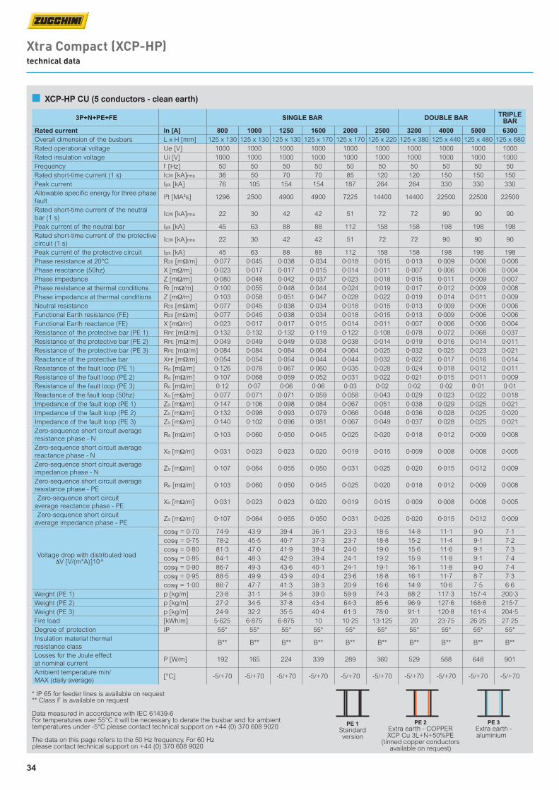
34
Xtra Compact (XCP-HP) technical data
■ XCP-HP CU (5 conductors - clean earth)
3P+N+PE+FE SINGLE BAR DOUBLE BAR TRIPLE BAR
Rated current In [A] 800 1000 1250 1600 2000 2500 3200 4000 5000 6300Overall dimension of the busbars L x H [mm] 125 x 130 125 x 130 125 x 130 125 x 170 125 x 170 125 x 220 125 x 380 125 x 440 125 x 480 125 x 680Rated operational voltage Ue [V] 1000 1000 1000 1000 1000 1000 1000 1000 1000 1000Rated insulation voltage Ui [V] 1000 1000 1000 1000 1000 1000 1000 1000 1000 1000Frequency f [Hz] 50 50 50 50 50 50 50 50 50 50Rated short-time current (1 s) ICW [kA]rms 36 50 70 70 85 120 120 150 150 150Peak current Ipk [kA] 76 105 154 154 187 264 264 330 330 330Allowable specific energy for three phase fault
I²t [MA²s] 1296 2500 4900 4900 7225 14400 14400 22500 22500 22500
Rated short-time current of the neutral bar (1 s)
ICW [kA]rms 22 30 42 42 51 72 72 90 90 90
Peak current of the neutral bar Ipk [kA] 45 63 88 88 112 158 158 198 198 198Rated short-time current of the protective circuit (1 s)
ICW [kA]rms 22 30 42 42 51 72 72 90 90 90
Peak current of the protective circuit Ipk [kA] 45 63 88 88 112 158 158 198 198 198Phase resistance at 20°C R20 [mΩ/m] 0·077 0·045 0·038 0·034 0·018 0·015 0·013 0·009 0·006 0·006Phase reactance (50hz) X [mΩ/m] 0·023 0·017 0·017 0·015 0·014 0·011 0·007 0·006 0·006 0·004Phase impedance Z [mΩ/m] 0·080 0·048 0·042 0·037 0·023 0·018 0·015 0·011 0·009 0·007Phase resistance at thermal conditions Rt [mΩ/m] 0·100 0·055 0·048 0·044 0·024 0·019 0·017 0·012 0·009 0·008Phase impedance at thermal conditions Z [mΩ/m] 0·103 0·058 0·051 0·047 0·028 0·022 0·019 0·014 0·011 0·009Neutral resistance R20 [mΩ/m] 0·077 0·045 0·038 0·034 0·018 0·015 0·013 0·009 0·006 0·006Functional Earth resistance (FE) R20 [mΩ/m] 0·077 0·045 0·038 0·034 0·018 0·015 0·013 0·009 0·006 0·006Functional Earth reactance (FE) X [mΩ/m] 0·023 0·017 0·017 0·015 0·014 0·011 0·007 0·006 0·006 0·004Resistance of the protective bar (PE 1) RPE [mΩ/m] 0·132 0·132 0·132 0·119 0·122 0·108 0·078 0·072 0·068 0·037Resistance of the protective bar (PE 2) RPE [mΩ/m] 0·049 0·049 0·049 0·038 0·038 0·014 0·019 0·016 0·014 0·011Resistance of the protective bar (PE 3) RPE [mΩ/m] 0·084 0·084 0·084 0·064 0·064 0·025 0·032 0·025 0·023 0·021Reactance of the protective bar XPE [mΩ/m] 0·054 0·054 0·054 0·044 0·044 0·032 0·022 0·017 0·016 0·014Resistance of the fault loop (PE 1) Ro [mΩ/m] 0·126 0·078 0·067 0·060 0·035 0·028 0·024 0·018 0·012 0·011Resistance of the fault loop (PE 2) Ro [mΩ/m] 0·107 0·068 0·059 0·052 0·031 0·022 0·021 0·015 0·011 0·009Resistance of the fault loop (PE 3) Ro [mΩ/m] 0·12 0·07 0·06 0·06 0·03 0·02 0·02 0·02 0·01 0·01Reactance of the fault loop (50hz) Xo [mΩ/m] 0·077 0·071 0·071 0·059 0·058 0·043 0·029 0·023 0·022 0·018Impedance of the fault loop (PE 1) Zo [mΩ/m] 0·147 0·106 0·098 0·084 0·067 0·051 0·038 0·029 0·025 0·021Impedance of the fault loop (PE 2) Zo [mΩ/m] 0·132 0·098 0·093 0·079 0·066 0·048 0·036 0·028 0·025 0·020Impedance of the fault loop (PE 3) Zo [mΩ/m] 0·140 0·102 0·096 0·081 0·067 0·049 0·037 0·028 0·025 0·021Zero-sequence short circuit average resistance phase - N
Ro [mΩ/m] 0·103 0·060 0·050 0·045 0·025 0·020 0·018 0·012 0·009 0·008
Zero-sequence short circuit average reactance phase - N
Xo [mΩ/m] 0·031 0·023 0·023 0·020 0·019 0·015 0·009 0·008 0·008 0·005
Zero-sequence short circuit average impedance phase - N
Zo [mΩ/m] 0·107 0·064 0·055 0·050 0·031 0·025 0·020 0·015 0·012 0·009
Zero-sequence short circuit average resistance phase - PE
Ro [mΩ/m] 0·103 0·060 0·050 0·045 0·025 0·020 0·018 0·012 0·009 0·008
Zero-sequence short circuit average reactance phase - PE
Xo [mΩ/m] 0·031 0·023 0·023 0·020 0·019 0·015 0·009 0·008 0·008 0·005
Zero-sequence short circuit average impedance phase - PE
Zo [mΩ/m] 0·107 0·064 0·055 0·050 0·031 0·025 0·020 0·015 0·012 0·009
Voltage drop with distributed load ∆V [V/(m*A)]10-6
cosϕ = 0·70 74·9 43·9 39·4 36·1 23·3 18·5 14·8 11·1 9·0 7·1cosϕ = 0·75 78·2 45·5 40·7 37·3 23·7 18·8 15·2 11·4 9·1 7·2cosϕ = 0·80 81·3 47·0 41·9 38·4 24·0 19·0 15·6 11·6 9·1 7·3cosϕ = 0·85 84·1 48·3 42·9 39·4 24·1 19·2 15·9 11·8 9·1 7·4cosϕ = 0·90 86·7 49·3 43·6 40·1 24·1 19·1 16·1 11·8 9·0 7·4cosϕ = 0·95 88·5 49·9 43·9 40·4 23·6 18·8 16·1 11·7 8·7 7·3cosϕ = 1·00 86·7 47·7 41·3 38·3 20·9 16·6 14·9 10·6 7·5 6·6
Weight (PE 1) p [kg/m] 23·8 31·1 34·5 39·0 59·9 74·3 88·2 117·3 157·4 200·3Weight (PE 2) p [kg/m] 27·2 34·5 37·8 43·4 64·3 85·6 96·9 127·6 168·8 215·7Weight (PE 3) p [kg/m] 24·9 32·2 35·5 40·4 61·3 78·0 91·1 120·8 161·4 204·5Fire load [kWh/m] 5·625 6·875 6·875 10 10·25 13·125 20 23·75 26·25 27·25Degree of protection IP 55* 55* 55* 55* 55* 55* 55* 55* 55* 55*Insulation material thermal resistance class
B** B** B** B** B** B** B** B** B** B**
Losses for the Joule effect at nominal current
P [W/m] 192 165 224 339 289 360 529 588 648 901
Ambient temperature min/MAX (daily average)
[°C] -5/+70 -5/+70 -5/+70 -5/+70 -5/+70 -5/+70 -5/+70 -5/+70 -5/+70 -5/+70
* IP 65 for feeder lines is available on request ** Class F is available on request
Data measured in accordance with IEC 61439-6 For temperatures over 55°C it will be necessary to derate the busbar and for ambient temperatures under -5°C please contact technical support on +44 (0) 370 608 9020
The data on this page refers to the 50 Hz frequency. For 60 Hz please contact technical support on +44 (0) 370 608 9020
PE 1Standard version
PE 2Extra earth - COPPER XCP Cu 3L+N+50%PE
(tinned copper conductors available on request)
PE 3Extra earth - aluminium
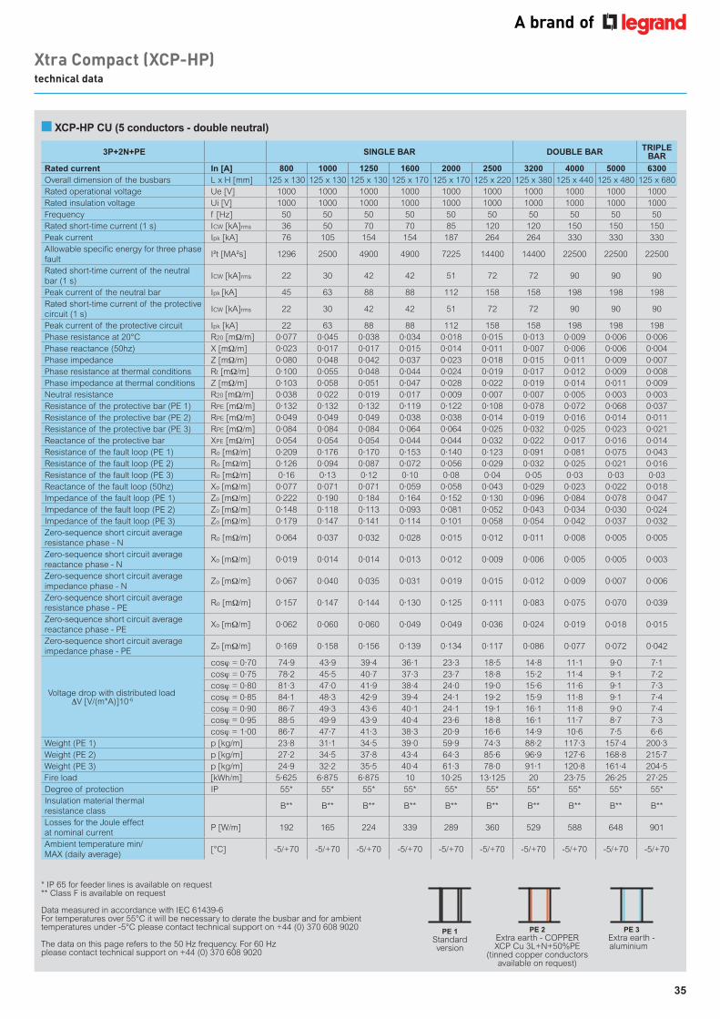
35
■ XCP-HP CU (5 conductors - double neutral)
Xtra Compact (XCP-HP) technical data
3P+2N+PE SINGLE BAR DOUBLE BAR TRIPLE BAR
Rated current In [A] 800 1000 1250 1600 2000 2500 3200 4000 5000 6300Overall dimension of the busbars L x H [mm] 125 x 130 125 x 130 125 x 130 125 x 170 125 x 170 125 x 220 125 x 380 125 x 440 125 x 480 125 x 680Rated operational voltage Ue [V] 1000 1000 1000 1000 1000 1000 1000 1000 1000 1000Rated insulation voltage Ui [V] 1000 1000 1000 1000 1000 1000 1000 1000 1000 1000Frequency f [Hz] 50 50 50 50 50 50 50 50 50 50Rated short-time current (1 s) ICW [kA]rms 36 50 70 70 85 120 120 150 150 150Peak current Ipk [kA] 76 105 154 154 187 264 264 330 330 330Allowable specific energy for three phase fault
I²t [MA²s] 1296 2500 4900 4900 7225 14400 14400 22500 22500 22500
Rated short-time current of the neutral bar (1 s)
ICW [kA]rms 22 30 42 42 51 72 72 90 90 90
Peak current of the neutral bar Ipk [kA] 45 63 88 88 112 158 158 198 198 198Rated short-time current of the protective circuit (1 s)
ICW [kA]rms 22 30 42 42 51 72 72 90 90 90
Peak current of the protective circuit Ipk [kA] 22 63 88 88 112 158 158 198 198 198Phase resistance at 20°C R20 [mΩ/m] 0·077 0·045 0·038 0·034 0·018 0·015 0·013 0·009 0·006 0·006Phase reactance (50hz) X [mΩ/m] 0·023 0·017 0·017 0·015 0·014 0·011 0·007 0·006 0·006 0·004Phase impedance Z [mΩ/m] 0·080 0·048 0·042 0·037 0·023 0·018 0·015 0·011 0·009 0·007Phase resistance at thermal conditions Rt [mΩ/m] 0·100 0·055 0·048 0·044 0·024 0·019 0·017 0·012 0·009 0·008Phase impedance at thermal conditions Z [mΩ/m] 0·103 0·058 0·051 0·047 0·028 0·022 0·019 0·014 0·011 0·009Neutral resistance R20 [mΩ/m] 0·038 0·022 0·019 0·017 0·009 0·007 0·007 0·005 0·003 0·003Resistance of the protective bar (PE 1) RPE [mΩ/m] 0·132 0·132 0·132 0·119 0·122 0·108 0·078 0·072 0·068 0·037Resistance of the protective bar (PE 2) RPE [mΩ/m] 0·049 0·049 0·049 0·038 0·038 0·014 0·019 0·016 0·014 0·011Resistance of the protective bar (PE 3) RPE [mΩ/m] 0·084 0·084 0·084 0·064 0·064 0·025 0·032 0·025 0·023 0·021Reactance of the protective bar XPE [mΩ/m] 0·054 0·054 0·054 0·044 0·044 0·032 0·022 0·017 0·016 0·014Resistance of the fault loop (PE 1) Ro [mΩ/m] 0·209 0·176 0·170 0·153 0·140 0·123 0·091 0·081 0·075 0·043Resistance of the fault loop (PE 2) Ro [mΩ/m] 0·126 0·094 0·087 0·072 0·056 0·029 0·032 0·025 0·021 0·016Resistance of the fault loop (PE 3) Ro [mΩ/m] 0·16 0·13 0·12 0·10 0·08 0·04 0·05 0·03 0·03 0·03Reactance of the fault loop (50hz) Xo [mΩ/m] 0·077 0·071 0·071 0·059 0·058 0·043 0·029 0·023 0·022 0·018Impedance of the fault loop (PE 1) Zo [mΩ/m] 0·222 0·190 0·184 0·164 0·152 0·130 0·096 0·084 0·078 0·047Impedance of the fault loop (PE 2) Zo [mΩ/m] 0·148 0·118 0·113 0·093 0·081 0·052 0·043 0·034 0·030 0·024Impedance of the fault loop (PE 3) Zo [mΩ/m] 0·179 0·147 0·141 0·114 0·101 0·058 0·054 0·042 0·037 0·032Zero-sequence short circuit average resistance phase - N
Ro [mΩ/m] 0·064 0·037 0·032 0·028 0·015 0·012 0·011 0·008 0·005 0·005
Zero-sequence short circuit average reactance phase - N
Xo [mΩ/m] 0·019 0·014 0·014 0·013 0·012 0·009 0·006 0·005 0·005 0·003
Zero-sequence short circuit average impedance phase - N
Zo [mΩ/m] 0·067 0·040 0·035 0·031 0·019 0·015 0·012 0·009 0·007 0·006
Zero-sequence short circuit average resistance phase - PE
Ro [mΩ/m] 0·157 0·147 0·144 0·130 0·125 0·111 0·083 0·075 0·070 0·039
Zero-sequence short circuit average reactance phase - PE
Xo [mΩ/m] 0·062 0·060 0·060 0·049 0·049 0·036 0·024 0·019 0·018 0·015
Zero-sequence short circuit average impedance phase - PE
Zo [mΩ/m] 0·169 0·158 0·156 0·139 0·134 0·117 0·086 0·077 0·072 0·042
Voltage drop with distributed load ∆V [V/(m*A)]10-6
cosϕ = 0·70 74·9 43·9 39·4 36·1 23·3 18·5 14·8 11·1 9·0 7·1cosϕ = 0·75 78·2 45·5 40·7 37·3 23·7 18·8 15·2 11·4 9·1 7·2cosϕ = 0·80 81·3 47·0 41·9 38·4 24·0 19·0 15·6 11·6 9·1 7·3cosϕ = 0·85 84·1 48·3 42·9 39·4 24·1 19·2 15·9 11·8 9·1 7·4cosϕ = 0·90 86·7 49·3 43·6 40·1 24·1 19·1 16·1 11·8 9·0 7·4cosϕ = 0·95 88·5 49·9 43·9 40·4 23·6 18·8 16·1 11·7 8·7 7·3cosϕ = 1·00 86·7 47·7 41·3 38·3 20·9 16·6 14·9 10·6 7·5 6·6
Weight (PE 1) p [kg/m] 23·8 31·1 34·5 39·0 59·9 74·3 88·2 117·3 157·4 200·3Weight (PE 2) p [kg/m] 27·2 34·5 37·8 43·4 64·3 85·6 96·9 127·6 168·8 215·7Weight (PE 3) p [kg/m] 24·9 32·2 35·5 40·4 61·3 78·0 91·1 120·8 161·4 204·5Fire load [kWh/m] 5·625 6·875 6·875 10 10·25 13·125 20 23·75 26·25 27·25Degree of protection IP 55* 55* 55* 55* 55* 55* 55* 55* 55* 55*Insulation material thermal resistance class
B** B** B** B** B** B** B** B** B** B**
Losses for the Joule effect at nominal current
P [W/m] 192 165 224 339 289 360 529 588 648 901
Ambient temperature min/MAX (daily average)
[°C] -5/+70 -5/+70 -5/+70 -5/+70 -5/+70 -5/+70 -5/+70 -5/+70 -5/+70 -5/+70
* IP 65 for feeder lines is available on request ** Class F is available on request
Data measured in accordance with IEC 61439-6 For temperatures over 55°C it will be necessary to derate the busbar and for ambient temperatures under -5°C please contact technical support on +44 (0) 370 608 9020
The data on this page refers to the 50 Hz frequency. For 60 Hz please contact technical support on +44 (0) 370 608 9020
PE 1Standard version
PE 2Extra earth - COPPER XCP Cu 3L+N+50%PE
(tinned copper conductors available on request)
PE 3Extra earth - aluminium
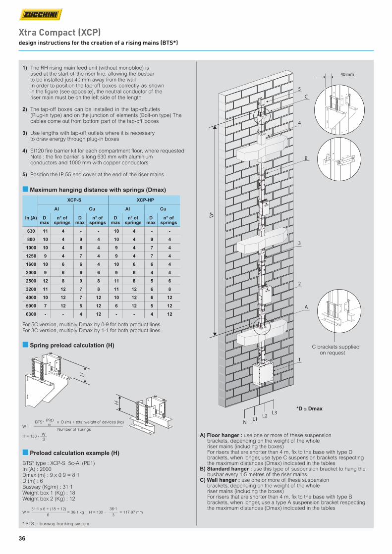
36
A) Floor hanger : use one or more of these suspensionbrackets, depending on the weight of the wholeriser mains (including the boxes)For risers that are shorter than 4 m, fix to the base with type Dbrackets, when longer, use type C suspension brackets respectingthe maximum distances (Dmax) indicated in the tables
B) Standard hanger : use this type of suspension bracket to hang thebusbar every 1·5 metres of the riser mains
C) Wall hanger : use one or more of these suspensionbrackets, depending on the weight of the wholeriser mains (including the boxes)For risers that are shorter than 4 m, fix to the base with type Bbrackets, when longer, use a type A suspension bracket respectingthe maximum distances (Dmax) indicated in the tables
40 mm
5
4
C
B
3
2
1
A
N L1L2
L3
D*
Xtra Compact (XCP) design instructions for the creation of a rising mains (BTS*)
1) The RH rising main feed unit (without monobloc) isused at the start of the riser line, allowing the busbarto be installed just 40 mm away from the wallIn order to position the tap-off boxes correctly as shownin the figure (see opposite), the neutral conductor of theriser main must be on the left side of the length
2) The tap-off boxes can be installed in the tap-off outlets(Plug-in type) and on the junction of elements (Bolt-on type) The cables come out from bottom part of the tap-off boxes
3) Use lengths with tap-off outlets where it is necessaryto draw energy through plug-in boxes
4) EI120 fire barrier kit for each compartment floor, where requested Note : the fire barrier is long 630 mm with aluminiumconductors and 1000 mm with copper conductors
5) Position the IP 55 end cover at the end of the riser mains
BTS* type : XCP-S 5c-Al (PE1)In (A) : 2000Dmax (m) : 9 x 0·9 = 8·1D (m) : 6Busway (Kg/m) : 31·1Weight box 1 (Kg) : 18Weight box 2 (Kg) : 12
■ Maximum hanging distance with springs (Dmax)
■ Spring preload calculation (H)
■ Preload calculation example (H)
For 5C version, multiply Dmax by 0·9 for both product linesFor 3C version, multiply Dmax by 1·1 for both product lines
*D ≤ Dmax
H
H
(Kg)
3
W =
H = 130 -
BTS* x D (m) + total weight of devices (kg)
Number of springsW
m
W = H == 36·1 kg36·1
= 117·97 mm31·1 x 6 + (18 + 12)
1306 3
C brackets supplied on request
XCP-S XCP-HP
Al Cu Al Cu
In (A) D max
n° of springs
D max
n° of springs
D max
n° of springs
D max
n° of springs
630 11 4 - - 10 4 - -
800 10 4 9 4 10 4 9 4
1000 10 4 8 4 9 4 7 4
1250 9 4 7 4 9 4 7 4
1600 10 6 6 4 10 6 6 4
2000 9 6 6 6 9 6 4 4
2500 12 8 9 8 11 8 5 6
3200 11 12 7 8 11 12 6 8
4000 10 12 7 12 10 12 6 12
5000 7 12 5 12 6 12 5 12
6300 - - 4 12 - - 4 12
* BTS = busway trunking system
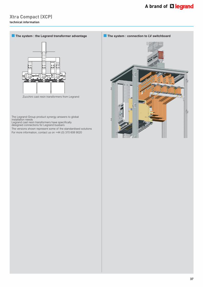
37
Xtra Compact (XCP) technical information
The Legrand Group product synergy answers to global installation needsLegrand cast resin transformers have specifically designed connections for Legrand busbarsThe versions shown represent some of the standardised solutionsFor more information, contact us on +44 (0) 370 608 9020
Zucchini cast resin transformers from Legrand
■ The system : the Legrand transformer advantage ■ The system : connection to LV switchboard

38
Operational information and advice for the correct design and construction of the busbar trunking system
Suggestions for the design and installation
of the busbar
OPERATING INFORMATION
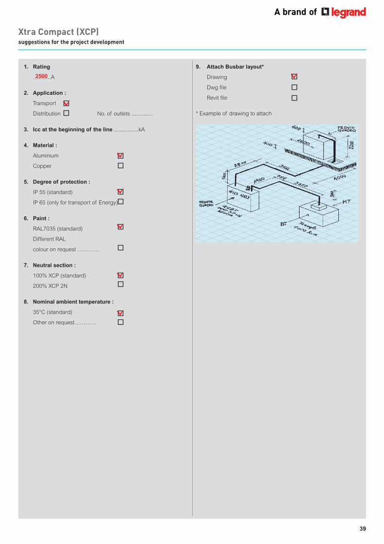
39
OPERATING INFORMATION
Xtra Compact (XCP) suggestions for the project development
1. Rating
……….A
2. Application :
Transport
Distribution No. of outlets ..............
3. Icc at the beginning of the line ................kA
4. Material :
Aluminium
Copper
5. Degree of protection :
IP 55 (standard)
IP 65 (only for transport of Energy)
6. Paint :
RAL7035 (standard)
Different RAL
colour on request …………
7. Neutral section :
100% XCP (standard)
200% XCP 2N
8. Nominal ambient temperature :
35°C (standard)
Other on request…………
2500
9. Attach Busbar layout*
Drawing
Dwg file
Revit file
* Example of drawing to attach
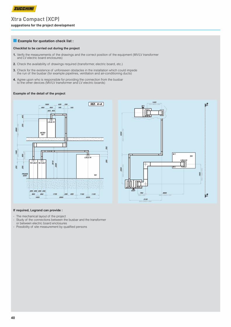
40
Xtra Compact (XCP) suggestions for the project development
■ Example for quotation check list :
Checklist to be carried out during the project
1. Verify the measurements of the drawings and the correct position of the equipment (MV/LV transformer and LV electric board enclosures)
2. Check the availability of drawings required (transformer, electric board, etc.)
3. Check for the existence of unforeseen obstacles in the installation which could impede the run of the busbar (for example pipelines, ventilation and air-conditioning ducts)
4. Agree upon who is responsible for providing the connection from the busbar to the other devices (MV/LV transformer and LV electric boards)
Example of the detail of the project
If required, Legrand can provide :
- The mechanical layout of the project- Study of the connections between the busbar and the transformer
or between electric board enclosures- Possibility of site measurement by qualified persons
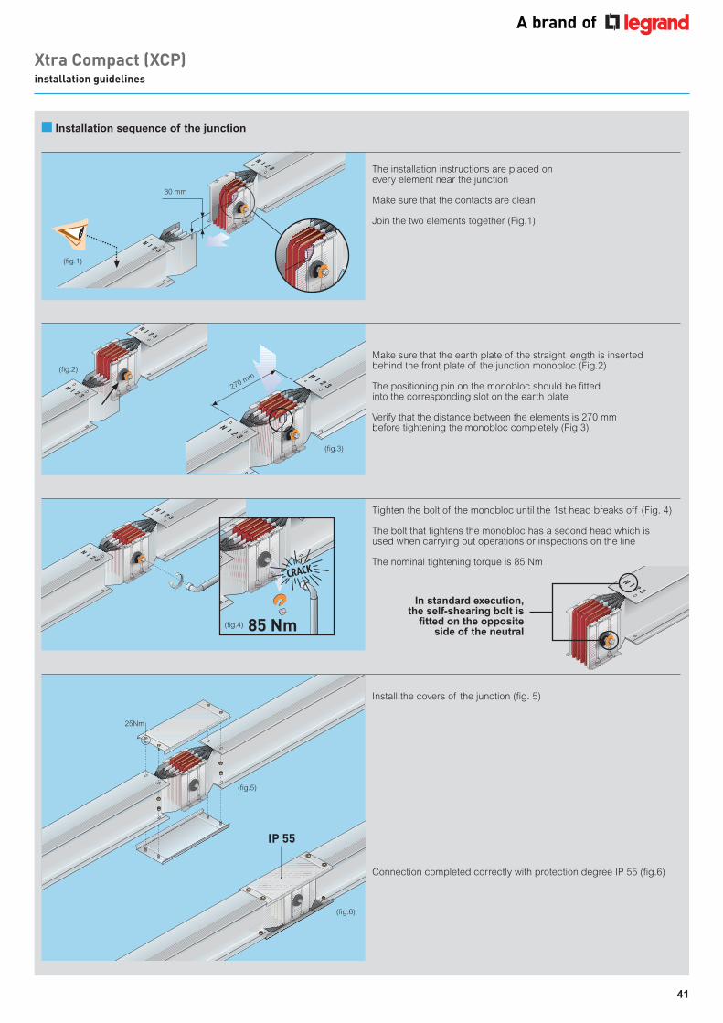
41
Xtra Compact (XCP) installation guidelines
270 mm(fig.2)
(fig.3)
(fig.5)
(fig.6)
30 mm
(fig.1)
(fig.4) 85 Nm
IP 55
■ Installation sequence of the junction
The installation instructions are placed on every element near the junction
Make sure that the contacts are clean
Join the two elements together (Fig.1)
Make sure that the earth plate of the straight length is inserted behind the front plate of the junction monobloc (Fig.2)
The positioning pin on the monobloc should be fitted into the corresponding slot on the earth plate
Verify that the distance between the elements is 270 mm before tightening the monobloc completely (Fig.3)
Tighten the bolt of the monobloc until the 1st head breaks off (Fig. 4)
The bolt that tightens the monobloc has a second head which is used when carrying out operations or inspections on the line
The nominal tightening torque is 85 Nm
Install the covers of the junction (fig. 5)
Connection completed correctly with protection degree IP 55 (fig.6)
In standard execution, the self-shearing bolt is
fitted on the opposite side of the neutral
25Nm
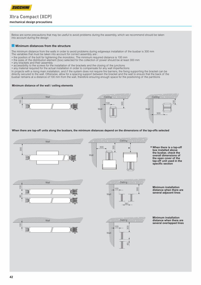
42
Xtra Compact (XCP) mechanical design precautions
■ Minimum distances from the structure
Minimum distance of the wall / ceiling elements
Minimum installation distance when there are several adjacent lines
When there are tap-off units along the busbars, the minimum distances depend on the dimensions of the tap-offs selected
300
300
* *
Wall
Ceiling
100
300
80
Wall
Ceiling
100
300
60
Wall
Ceiling
100
Wall
300
Wall
100
80
Wall
100
300
Wall
Ceiling
300
100
Wall
Ceiling
100
WallMinimum installation distance when there are several overlapped lines
When there is a tap-off box installed above the busbar, check the overall dimensions of the open cover of the tap-off unit used in the specific section
Below are some precautions that may be useful to avoid problems during the assembly, which we recommend should be taken into account during the design
The minimum distance from the walls in order to avoid problems during edgeways installation of the busbar is 300 mmThe variables that must be taken into account for correct assembly are :• the position of the bolt for tightening the monobloc. The minimum required distance is 100 mm• the sizes of the distribution element (box) selected for the collection of power should be at least 300 mm• any brackets and their assembly• accessibility to the screws for the installation of the brackets and the closing of the junctions • any material required for the actual installation in order to compensate for any wall imperfectionsIn projects with a rising main installation, and if the system does not require fire barriers, the fixing supporting the bracket can be directly secured to the wall. Otherwise, allow for a spacing support between the bracket and the wall to ensure that the back of the busbar remains at a distance of 100 mm from the wall, therefore ensuring enough space for the positioning of the partitions
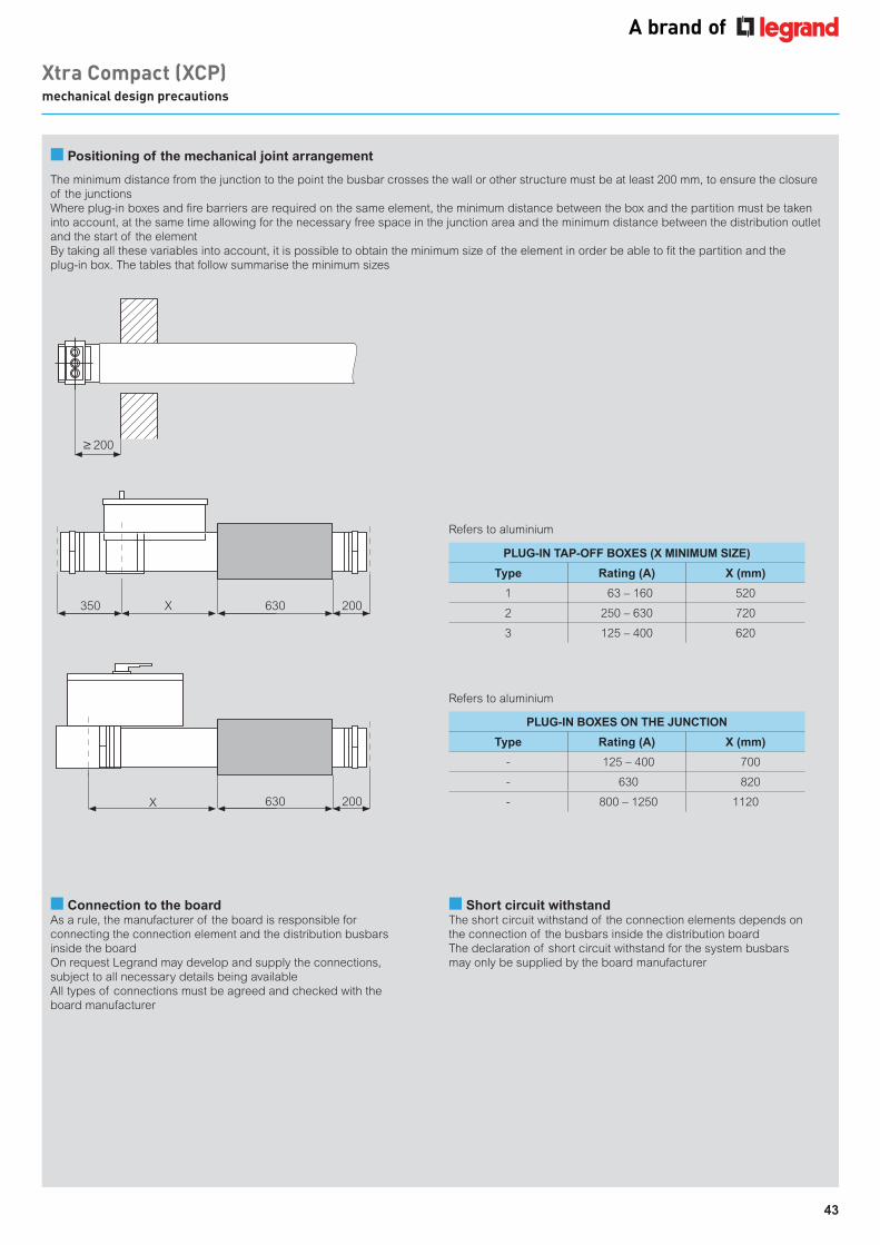
43
200
350 630X 200
630 200X
The minimum distance from the junction to the point the busbar crosses the wall or other structure must be at least 200 mm, to ensure the closure of the junctionsWhere plug-in boxes and fire barriers are required on the same element, the minimum distance between the box and the partition must be taken into account, at the same time allowing for the necessary free space in the junction area and the minimum distance between the distribution outlet and the start of the elementBy taking all these variables into account, it is possible to obtain the minimum size of the element in order be able to fit the partition and the plug-in box. The tables that follow summarise the minimum sizes
PLUG-IN TAP-OFF BOXES (X MINIMUM SIZE)
Type Rating (A) X (mm)
1 63 – 160 520
2 250 – 630 720
3 125 – 400 620
PLUG-IN BOXES ON THE JUNCTION
Type Rating (A) X (mm)
- 125 – 400 700
- 630 820
- 800 – 1250 1120
200
350 630X 200
630 200X
200
350 630X 200
630 200X
■ Connection to the boardAs a rule, the manufacturer of the board is responsible for connecting the connection element and the distribution busbars inside the boardOn request Legrand may develop and supply the connections, subject to all necessary details being availableAll types of connections must be agreed and checked with the board manufacturer
■ Short circuit withstandThe short circuit withstand of the connection elements depends on the connection of the busbars inside the distribution boardThe declaration of short circuit withstand for the system busbars may only be supplied by the board manufacturer
Refers to aluminium
Refers to aluminium
Xtra Compact (XCP) mechanical design precautions
■ Positioning of the mechanical joint arrangement
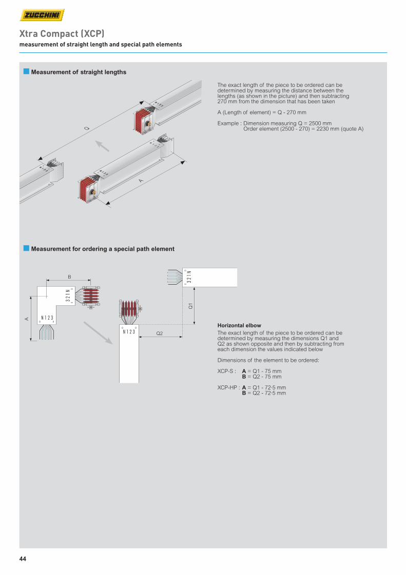
44
Xtra Compact (XCP) measurement of straight length and special path elements
The exact length of the piece to be ordered can be determined by measuring the distance between the lengths (as shown in the picture) and then subtracting 270 mm from the dimension that has been taken
A (Length of element) = Q - 270 mm
Example : Dimension measuring Q = 2500 mm Order element (2500 - 270) = 2230 mm (quote A)
Q2
Q1
B
A
■ Measurement of straight lengths
■ Measurement for ordering a special path element
Horizontal elbowThe exact length of the piece to be ordered can be determined by measuring the dimensions Q1 and Q2 as shown opposite and then by subtracting from each dimension the values indicated below
Dimensions of the element to be ordered:
XCP-S : A = Q1 - 75 mm B = Q2 - 75 mm
XCP-HP : A = Q1 - 72·5 mm B = Q2 - 72·5 mm
Q
N 1 2 3
N 1 2 3
A
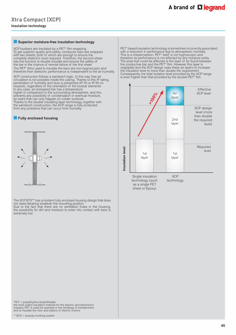
45
■ Superior moisture-free insulation technology
XCP busbars are insulated by a PET* film wrapping To get superior quality and safety, conductor bars are wrapped with two sheets, both of which are enough to ensure the complete dielectric level required. Therefore, the second sheet has the function to double insulate and ensure the safety of the bar in the chance of remote failure of the first sheetThe PET* films used to insulate the bars are non-hygroscopic and therefore their dielectric performance is independent to the air humidity
■ Fully enclosed housing
*PET = polyethylene terephthalatethe most useful insulation material for the electric and electronics industry, PET is used for example in the windings of transformers and to insulate the rotor and stators of electric motors
The XCP BTS** has a modern fully enclosed housing design that does not need derating whatever the mounting positionDue to the fact that there are no ventilation holes in the housing, the possibility for dirt and moisture to enter into contact with bars is extremely low
PET* based insulation technology is sometimes incorrectly associated with a reduction in perfomance due to atmospheric humidity This is a misperception. PET* itself is not hygroscopic and therefore its performance is not affected by any moisture entity The area that could be affected is the layer of air found between the conductive bar and the PET* film. However this layer is negligible and the XCP design uses these air layers to increase the insulation level to more than double the requirement Consequently, the total isolation level provided by the XCP range is even higher than that provided by the double PET* film
Xtra Compact (XCP) Insulation technology
XCP construction follows a sandwich logic. In this way, free air circulation is not possible inside the casing. Thanks to this IP rating, penetration of humidity and dust is prevented (IP 55 or IP 65 on request), regardless of the orientation of the busbar elementsIn any case, an energised bar has a temperaturehigher in comparison to the surrounding atmosphere, and this prevents any possibility of condensation or eventual moisture,an event that can only happen on colder surfacesThanks to the double insulating layer technology, together with the sandwich construction, the XCP range is fully protectedfrom any problems that can occur from humidity
Insu
lati
on
leve
l
Single insulation technology (such as a single PET sheet or Epoxy)
XCP technology
EffectiveXCP level
Required level
XCP design level (more
than double the required
level)
1stlayer
2ndlayer
Airlayer
1stlayer
>100
%
** BTS = busway trunking system

46
From July 2021, regulation 548/2014 (updated by regulation 2019/1783) requires manufacturers to reduce no-load losses of their transformers by 10% compared with the previous requirement.
Legrand's Zucchini Green T.HE (Tier 2) transformers fully comply with the new eco-compatible design rules and guarantee a significant reduction in energy consumption, thus promoting substantial economic savings and the reduction of CO2 emissions into the atmosphere.
With an ingress protection rating of IP 68 and ranging from 630 A to 6300 A, RCP is ideal for the distribution of high power energy in external environments. RCP is manufactured with either aluminium or copper conductors which are completely embedded
in an epoxy resin, that provides mechanical strength and electrical insulation.
RCP resin busbar has good performance in fire conditions and exceeds the requirements stipulated in IEC 60331-1 : 2009 for continuity of service in the event of fire.
RCP resin busbar - suitable for indoor and outdoor installations
quality through to the core
IP 68 RCP RESINbusbar trunking
Green T.HEhigh efficiency transformers
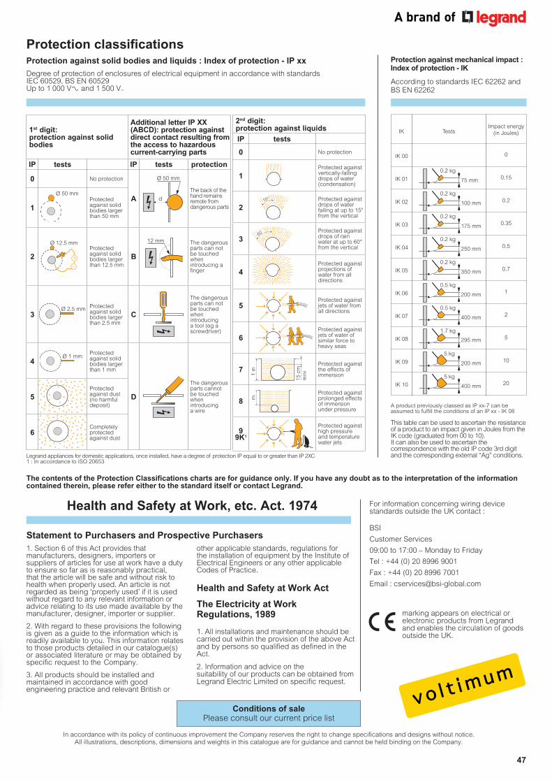
47
quality through to the core
Protection classifications Protection against solid bodies and liquids : Index of protection - IP xx Protection against mechanical impact :
Index of protection - IK
The contents of the Protection Classifications charts are for guidance only. If you have any doubt as to the interpretation of the information contained therein, please refer either to the standard itself or contact Legrand.
Statement to Purchasers and Prospective Purchasers1. Section 6 of this Act provides that manufacturers, designers, importers or suppliers of articles for use at work have a duty to ensure so far as is reasonably practical, that the article will be safe and without risk to health when properly used. An article is not regarded as being ‘properly used’ if it is used without regard to any relevant information or advice relating to its use made available by the manufacturer, designer, importer or supplier.
2. With regard to these provisions the following is given as a guide to the information which is readily available to you. This information relates to those products detailed in our catalogue(s) or associated literature or may be obtained by specific request to the Company.
3. All products should be installed and maintained in accordance with good engineering practice and relevant British or
other applicable standards, regulations for the installation of equipment by the Institute of Electrical Engineers or any other applicable Codes of Practice.
Health and Safety at Work Act
The Electricity at Work Regulations, 1989
1. All installations and maintenance should be carried out within the provision of the above Act and by persons so qualified as defined in the Act.
2. Information and advice on the suitability of our products can be obtained from Legrand Electric Limited on specific request.
According to standards IEC 62262 and BS EN 62262
For information concerning wiring device standards outside the UK contact :
BSI
Customer Services
09:00 to 17:00 – Monday to Friday
Tel : +44 (0) 20 8996 9001
Fax : +44 (0) 20 8996 7001
Email : [email protected]
marking appears on electrical or electronic products from Legrand and enables the circulation of goods outside the UK.
Health and Safety at Work, etc. Act. 1974
In accordance with its policy of continuous improvement the Company reserves the right to change specifications and designs without notice. All illustrations, descriptions, dimensions and weights in this catalogue are for guidance and cannot be held binding on the Company.
A product previously classed as IP xx-7 can be assumed to fulfill the conditions of an IP xx - IK 08
This table can be used to ascertain the resistance of a product to an impact given in Joules from the IK code (graduated from 00 to 10). It can also be used to ascertain the correspondence with the old IP code 3rd digit and the corresponding external “Ag” conditions.
Degree of protection of enclosures of electrical equipment in accordance with standards IEC 60529, BS EN 60529 Up to 1 000 V± and 1 500 V=
CELOGO-001�black
1st digit: protection against solid bodies
Additional letter IP XX (ABCD): protection against direct contact resulting from the access to hazardous current-carrying parts
IP tests IP tests protection
0 No protection
AThe back of the hand remains remote from dangerous parts1
Ø 50 mmProtected against solid bodies larger than 50 mm
2
Ø 12.5 mmProtected against solid bodies larger than 12.5 mm
B
The dangerous parts can not be touched when introducing a finger
3Ø 2.5 mm Protected
against solid bodies larger than 2.5 mm
C
The dangerous parts can not be touched when introducing a tool (eg a screwdriver)
4Ø 1 mm
Protected against solid bodies larger than 1 mm
D
The dangerous parts cannot be touched when introducing a wire
5Protected against dust (no harmful deposit)
6Completely protected against dust
2nd digit: protection against liquids
IP tests
0 No protection
1Protected against vertically-falling drops of water (condensation)
2Protected against drops of water falling at up to 15° from the vertical
360 Protected against
drops of rain water at up to 60° from the vertical
4Protected against projections of water from all directions
5Protected against jets of water from all directions
6Protected against jets of water of similar force to heavy seas
7
15 c
mm
ini
1 m
Protected against the effects of immersion
8 m
Protected against prolonged effects of immersion under pressure
9 9K1
Protected against high pressure and temperature water jets
Ø 50 mm
d
12 mm
0
Impact energy(in Joules)TestsIK
IK 01
IK 02
IK 00
0.15
IK 03
2
1
5
0.7
0.2
10
0.35
0.5
IK 07
20
IK 06
IK 04
IK 05
IK 08
IK 09
IK 10
75 mm
0.2 kg
100 mm
0.2 kg
175 mm
0.2 kg
250 mm
0.2 kg
350 mm
0.2 kg
200 mm
0.5 kg
400 mm
0.5 kg
295 mm
1.7 kg
200 mm
5 kg
5 kg
400 mm
Legrand appliances for domestic applications, once installed, have a degree of protection IP equal to or greater than IP 2XC1 : In accordance to ISO 20653
Conditions of sale Please consult our current price list

9995
47 Z
ucch
ini X
CP
bus
bar
prod
uct g
uide
06/
2021
The Legrand logo is a registered trademark of the Legrand group of companies.This document is printed on sustainably sourced paper. Please recycle.
Head office (UK and Ireland):Legrand Electric LimitedGreat King Street North, Birmingham, B19 2LFTel: +44 (0) 370 608 9000 Fax: +44 (0) 370 608 9004Website: www.legrand.co.uk
In accordance with its policy of continuous improvement, the Company reserves the right to change specifications and designs without notice. All illustrations, descriptions, dimensions and weights in this catalogue are for guidance and cannot be held binding on the Company. All contents and design presentation included in this publication are © Legrand Electric Limited. All rights reserved. 2021
Contact details Quotations and Technical Support: Legrand Electric Ltd. Great King Street North, Birmingham, B19 2LF Tel: +44 (0) 370 608 9020 E-mail: [email protected] Services: Tel: +44 (0) 345 605 4333 E-mail: [email protected]
FOLLOW US AT
www.legrand.co.ukwww.legrand.iewww.youtube.com/legrandtvukwww.voltimum.co.ukwww.voltimum.iewww.twitter.com/legrandukwww.linkedin.com/company/legranduk


