Embed Size (px)
Citation preview
28 BIOCHIMICA ET BIOPHYSICA ACTA
BBA 26581
ZONAL CENTRIFUGATION IN REORIENTING DENSITY GRADIENTS
P H I L L I P S H E E L E R , D E N N I S M. GR OS S AND J O H N R. W E L L S
Department of Biology, San Fernando Valley State College, Northridge, Calif. 91324 (U.S.A.)
(Received Sep t embe r 29th, 197 o)
SUMMARY
i. Zonal rotors which do not require rotating-seal assemblies were tested and employed for quantitative cell fractionations in sucrose density gradients. The design and operation of these rotors represents a departure from other zonal rotors presently in use. These rotors may be either statically or dynamically loaded but are always statically unloaded following deceleration. During deceleration, the density gradient within the rotor undergoes a gradual reorientation from a radial to a vertical distribu- tion. Gradients and separated particles are then pumped from the floor of the rotor.
2. The reorienting gradient rotors were used to fractionate liver homogenates and the resulting distribution of cell particles in the collected gradient examined and identified by a combination of microscopic and biochemical methods. Several interest- ing and unusual features of reorienting gradient zonal rotors are discussed.
INTRODUCTION
In view of their greatly increased sample capacity and idealized internal ge- ometry, A and B series zonal rotors have become increasingly popular instruments for quantitative centrifugal fractionations of animal and plant tissues on density gra- dients 1-1°. These rotors have been employed to isolate and to study cell nuclei 1, chloroplasts 2, mitochondria 3, Golgi bodies 4, lysosomes 3, 5, peroxisomes 5, smooth and rough membranes 6, plasma membranes 7,8, ribosomes 9 and glycogen 1°. Since zonal rotors are loaded and unloaded during rotation through a complex rotating, fluid line seal assembly 1~,12, a number of problems are frequently encountered; these in- clude difficulty in pumping viscous sucrose gradients through the rotating seal, extended gradient loading and unloading times, and continued particle sedimentation during gradient unloading.
We have examined the possibility of effecting similar large-scale tissue and cell fractionations using simpler and less costly seal-less zonal rotors which are statically unloaded following deceleration. During deceleration, the density gradient within these rotors undergoes a gradual reorientation from a radial to a vertical distribution 1'~-''~. Gradient reorientation has been employed previously in an experimental low-speed plastic rotor used for the isolation of cell nuclei ~6 and also in K-series continuous- flow rotors used for large-scale isolations of virus particles by isopycnic bandinglL However, the reorienting gradient rotors described in this paper represent a departure in design and operation from all other zonal rotors presently being used.
Biochim. Biophys. ,4cta, 237 (I97 t) 28 42
REORIENTING GRADIENT CENTRIFUGATION 2 9
MATERIALS AND METHODS
Design of rotors Two zonal rotors were constructed and tested: rotor SZ-2o (2000 ml capacity)
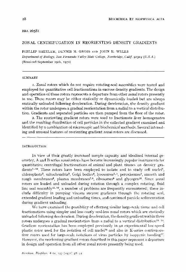
and rotor SZ-I 4 (14oo ml capacity). Both rotors were employed with Sorvall model RC2-B refrigerated centrifuges especially modified to produce slow acceleration and deceleration between o and IOOO rev./min. Centrifuge drive characteristics restricted maximum speeds of the SZ-2o and SZ-I 4 to 15000 rev./min (27000 × g) and 20000 rev./min (42400 × g), respectively. Except for differences in size and capacity, both rotors have similar designs. Components of the SZ-I4 rotor are shown in Fig. IA and the fully-assembled rotor in Fig. IB. The rotor base contains an annular chamber surrounding an axial shaft. The outer wall and axial shaft are tapered at the bot tom to produce an annular V-shaped groove. The groove is asymmetric since the centrifugal surface slopes downward and inward at a shallower angle than the downward and
Fig. r. The SZ-I4 reor ien t ing g rad ien t zonal rotor . A, c o m p o n e n t s of the rotor , inc lud ing ro tor- base, co re / sep ta piece, d i s t r ibu to r wi th r emovab le s t em , and lid. t3, fu l ly -assembled SZ-I 4 rotor.
Biochim. Biophys. Acta, 237 (I97I) 28-42
30 P. SHEELER et al.
outward-sloping centr ipetal surface. A core/septa piece slides over the shaft and divides the annu la r chamber into 6 sector-shaped compar tments . The upper, external surface of the rotor is threaded to accommodate a circular threaded lid which is sealed to the rotor with an O-ring.
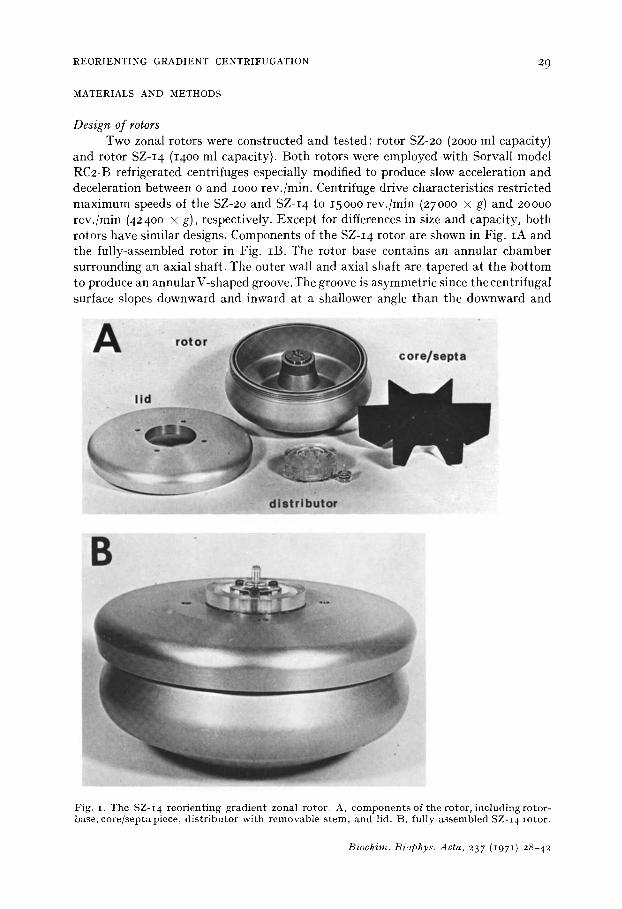
The core/septa piece (Fig. 2) contains 2 sets of 6 tubu la r channels: these are re- ferred to as the septa lines and the core lines. The septa lines descend at an angle through each septum from the core surface and open at the vertex of the annu la r V- shaped groove. The core lines descend a short dis tance vert ical ly through the core and then tu rn radial ly to open on the core surface adjacent (clockwise) to the leading edge of each septum.
openings ....
Fig. 2. Core/septa piece with attached Lucite distributor. The stem is inserted into the axial chamber which communicates via 6 radial channels with the septa lines. When core/septa piece is inserted into the rotor, the septa lines open at the vertex of the annular V-shaped groove. The annular chamber of the distributor communicates via another 6 radial channels with the core lines. Opanings of the core lines at the surface of the core in two sectors are indicated by white arrows.
Secured by bolts to the top of the core is a Lucite d is t r ibutor conta in ing an axial and annu la r chamber (Fig. 2). Six lines pass radially from the axial chamber and communicate with the septa lines, while another 6 lines pass radially from the annu la r chamber and communicate with the core lines; all of these connections are sealed with small O-rings. A hollow Lucite stem may be removably inserted into the axial chamber of the dis t r ibutor (Figs. IA, IB and 2). A small annu la r space exists between the lid opening and the outer edge of the Lucite distr ibutor. This space allows air to escape from and pass into the rotor chamber during the respective loading and unloading operations. Consequently, in their present form these rotors cannot be used under vaccuum.
Biochim. Biophys. Acta, 237 (1971) 2,"I-42
REORIENTING GRADIENT CENTRIFUGATION 31
Operation of rotors Density gradients were prepared using a two-chamber mixing device and deliv-
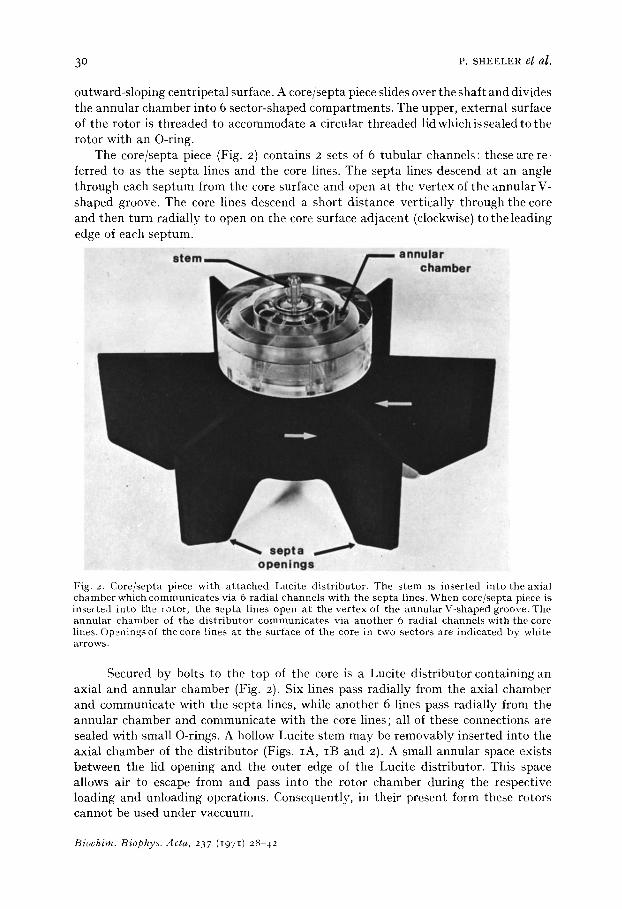
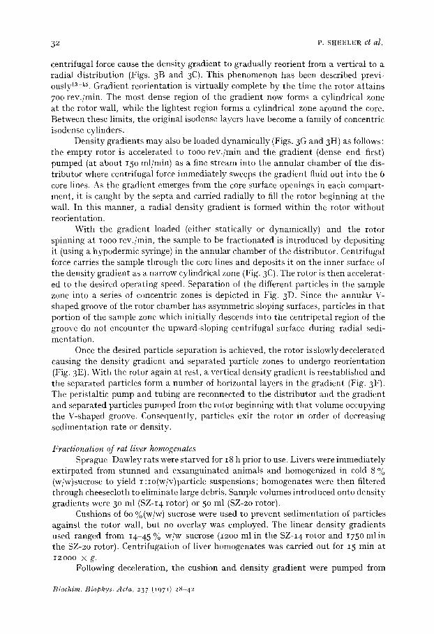
ered to the rotor with a variable speed Masterflex peristaltic pump. Gradients may be loaded into the rotor at rest (i.e. statically) or while rotating (i.e. dynamically) as shown in Fig. 3. For static loading, the density gradient is pumped into the rotor (light end first) through the stem of the distributor and passes through the core/septa piece to the vertex of the V-shaped groove. As it emerges at the vertex, it is displaced upward by the denser fluid flowing immediately behind. In this way, the rotor is filled with a vertical density gradient ; in Fig. 3A, several isodense layers are depicted as horizontal lines within the rotor chamber.
With the peristaltic pump tubing disconnected from the distributor, the rotor is slowly accelerated. During acceleration, the combined influences of gravity and
Static Loading Dynamic Loading JL
C Lmldk~ Sample
Unk~Hdl~
Fig. 3. Operation of the reorienting gradient zonal rotors. Following static loading of the density gradient through the septa lines (A), the vertical gradient is reoriented by acceleration (B) and is transformed into a radial gradient (C) 13-15. Several isodense layers in the gradient are depicted by parallel lines within each compartment. A radial gradient may be produced directly by dynamic loading of the empty rotor through the core lines (G and H). The sample is introduced onto the reoriented gradient through the core lines (C) and following acceleration of the rotor to operating speed, the particles ill the sample sediment radially to form a series of concentric zones(D). These zones, together with the gradient, are reoriented during deceleration (E) and are withdrawn in sequence from the rotor at rest through the septa lines (F).
Biochim. Biophys. dcta, 237 (197.1) 28-42
3 2 P. SHEELER et al.
centrifugal force cause the density gradient to gradually reorient from a vertical to a radial distribution (Figs. 3B and 3C). This phenomenon has been described previ- ously la-15. Gradient reorientation is virtually complete by the time the rotor attains 7oo rev./min. The most dense region of the gradient now forms a cylindrical zone at the rotor wall, while the lightest region forms a cylindrical zone around the core. Between these limits, the original isodense layers have become a family of concentric isodense cylinders.
Density gradients may also be loaded dynamically (Figs. 3G and 3H} as follows : the empty rotor is accelerated to iooo rev./min and the gradient (dense end first) pumped (at about 15o ml/min) as a fine stream into the annular chamber of the dis- tributor where centrifugal force immediately sweeps the gradient fluid out into the 6 core lines. As the gradient emerges from the core surface openings in each compart- ment, it is caught by the septa and carried radially to fill the rotor beginning at the wall. In this manner, a radial density gradient is formed within the rotor without reorientation.
With the gradient loaded (either statically or dynamically) and the rotor spinning at IOOO rev./min, the sample to be fractionated is introduced by depositing it (using a hypodermic syringe) in the annular chamber of the distributor. Centrifugal force carries the sample through the core lines and deposits it on the inner surface of the density gradient as a narrow cylindrical zone (Fig. 3C). The rotor is then accelerat- ed to the desired operating speed. Separation of the different particles in tile sample zone into a series of concentric zones is depicted in Fig. 3 D. Since the annular V- shaped groove of the rotor chamber has asymmetric sloping surfaces, particles in that portion of the sample zone which initially descends into the centripetal region of tile groove do not encounter the upward-sloping centrifugal surface during radial sedi- mentation.
Once the desired particle separation is achieved, the rotor is slowly decelerated causing the density gradient and separated particle zones to undergo reorientation (Fig. 3E). With the rotor again at rest, a vertical density gradient is reestablished and the separated particles form a number of horizontal layers in the gradient (Fig. 3F). The peristaltic pump and tubing are reconnected to the distributor and the gradient and separated particles pumped from the rotor beginning with that volume occupying the V-shaped groove. Consequently, particles exit the rotor in order of decreasing sedimentation rate or density.
Fractionation of rat liver homogenates Sprague-Dawley rats were starved for 18 h prior to use. Livers were immediately
extirpated from stunned and exsanguinated animals and homogenized in cold 8 % (w/w)sucrose to yield I :io(w/v)particle suspensions; homogenates were then filtered through cheesecloth to eliminate large debris. Sample volumes introduced onto density gradients were 3 ° m l (SZ-I 4 rotor) or 5 ° m l (SZ-2o rotor).
Cushions of 60 %(w/w) sucrose were used to prevent sedimentation of particles against the rotor wall, but no overlay was employed. The linear density gradients used ranged from 14-45 % w/w sucrose (12oo ml in the SZ-I4 rotor and 175o ml in the SZ-2o rotor). Centrifugation of liver homogenates was carried out for 15 rain at 12000 × g.
Following deceleration, the cushion and density gradient were pumped from
Biochim. Biophys. Acta, 237 (1971) 28-42
REORIENTING GRADIENT CEIqTRIFUGATION 33
the rotor and the effluent directed in sequence through the flow-cells of an LKB Uvicord-I ultraviolet light (254 m#) monitor and a modified Bausch and Lomb Spectronic 20 visible (575 m/~) light monitor integrated with a 2-pen stripchart re- corder. Fractions were collected by hand in tubes maintained in ice.
The protein content of all collected fractions was determined by the method of LOWRY et al. TM. Sucrose concentrations were determined refractometrically. Frac- tions containing undisrupted liver cells, cell fragments and erythrocytes were identi- fied by light microscopy. For acid phosphatase (orthophosphoric monoester phos- phohydrolase, EC 3.1.3.2) activity determinations, particulate material in aliquots of each collected fraction were concentrated by centrifugation at 105000 × g for 30 min in a Beckman Spinco type 30 rotor. The pellets were twice frozen and thawed and the acid phosphatase content measured using a manual version of the method of SCHUEL et al. 3. In this manner, that region of the density gradient containing lyso- somes could be identified 3, s, 19, 2o. Succinic dehydrogenase (succinate :(acceptor) oxido- reductase, EC 1.3.99.1) was employed as a marker for fractions containing mito- chondria 8, 21, 22 and was assayed using the method of SHELTON AND RICE 2a. The distribu- tion of glucose-6-phosphatase (D-glucose-6-phosphate phosphohydrolase, EC3.I.3.9) in the collected fractions was determined by the method of BAGINSKI et al. 2~ and used as a marker for microsomal membranes 4, 5, 22.
In certain experiments fractions containing cell nuclei, mitochondria and various microsomal elements were also examined by electron microscopy as follows: 15 ml portions of selected fractions were diluted with 5 ml of 8 % (w/w) sucrose and the par- ticulate material pelleted by centrifugation at 105000 × g for 30 min. Pellets were fixed for 15 min at room temperature in 2. 5 % glutaraldehyde buffered in o I M cacodylate (pH 7-4), cut into I mm 3 pieces and then washed in buffer for 3 h at 4 ° (fractions containing nuclei were also post-fixed in buffered 2 % osmium tetroxide). Following dehydration in a graded series of ethanol-water mixtures, pellets were immersed in pure styrene for 3 h, then transferred to a I :i mixture of styrene and Vestopal-W and left overnight. Pellets were embedded in Vestopal-W and poly- merized at 60 ° for 2 days. Sections were prepared using a Reichert OmU-2 ultra- microtome and diamond knife and placed on 2oo-mesh copper grids coated with parlodion. Grids were stained with uranyl acetate and lead citrate and examined with a Zeiss EM 9 A electron microscope.
RESULTS
Rotor performance A number of tests were conducted to examine the stability of density gradients
during loading, unloading and reorientation. The shape of the density gradient enter- ing the rotor was determined by collecting the effluent from the gradient-maker directly as a series of fractions and measuring the sucrose density of each using the refractometer. Following this, identical gradients were dynamically loaded into the rotor and gradient profiles of fractions collected following deceleration, reorientation and unloading were compared with those initially delivered to the rotor. In each instance, gradient shape was unaltered by reorientation.
In another series of rotor tests, Torula RNA was employed as a marker by including it in the sucrose solution serving as the dense limit of the gradient. In this
Biochim. Biophys. Acta, 237 (197 I) 28-42
34 P. SHEELER et al.
manner the shape ot the density gradient entering and/or leaving the rotor could be monitored by directing the gradient through the ultraviolet light absorbance monitor. The continuous absorption tracings obtained when gradients were statically loaded into the rotor, immediately unloaded, and unloaded following acceleration and de- celeration were compared and found to be essentially identical. Finally, a series of sucrose solutions of increasing density were statically loaded in sequence into the rotor producing a discontinuous (stepwise) gradient; in this instance, every other sucrose solution contained the RNA marker. Absorption profiles obtained when the gradient was pumped from the rotor with and without intervening acceleration and deceleration were also identical.
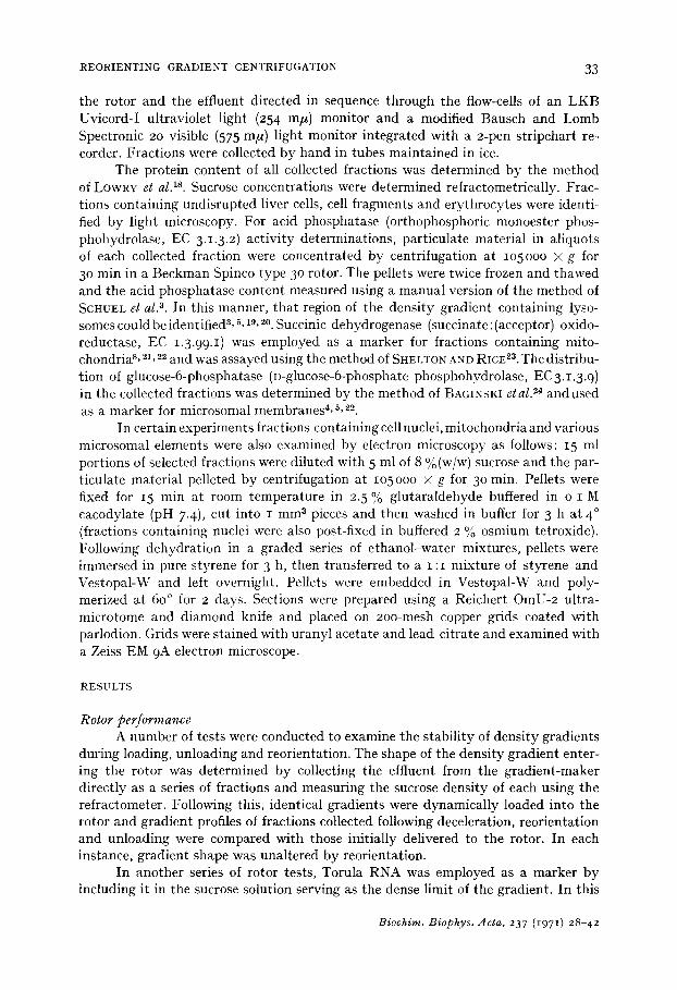
Although these tests showed that density gradients are essentially unaltered during loading, unloading and reorientation, measurements of the stability of an inter- face introduced into a continuous gradient provided an additional index of rotor performance. Accordingly, a sharp interface within a continuous sucrose density gradient was produced by temporarily interrupting the flow from the gradient-maker after the first half of the gradient volume had been produced, adding equal amounts of CoC12 crystals to the two chambers, and resuming production of the second half of the gradient once the crystals were dissolved. (CoCI 2 was used to produce the interface because of its rapid dissolution in sucrose and because its absorbance at 52o m# is linear with concentration.) Absorbance profiles and sucrose densities of gradients collected directly from the gradient-maker using this procedure were compared with those obtained after loading and unloading the rotor with and without intervening acceleration and deceleration. Results of one test with the SZ-I 4 rotor are depicted in Fig. 4. The upper portion of this figure shows that the sucrose gradient delivered to the rotor was not altered during loading, unloading and reorientation. The CoC12 absorbance profile of fractions collected directly from the gradient-maker (closed triangles in lower portion of Fig. 4) was similar to that obtained after loading and un- loading the static rotor (closed circles), and the small difference noted may be accounted for by diffusion ot CoCI 2 within the rotor during the 2o min which elapsed between the introduction of the second half of the gradient and the subsequent collection of the first half. Since the gradient is collected from the rotor dense end first but is delivered light end first, the absorbance and sucrose density values of fractions collect- ed directly from the gradient-maker were necessarily plotted in reverse order. Although the symmetry of the absorbance profile suggests that little if any trailing occurred in the rotor during unloading, it should be noted that the viscosity of the sucrose solution at the dense end of the gradient (6.I 5 centipoises at 2o ° for 4 ° %, w/w, sucrose) is considerably less than that which would be encountered if higher sucrose density limits were employed (e.g. 58.4 centipoises at 6o %, w/w, sucrose).
Reorientation of the density gradient and interface by accelerating and de- celerating the rotor altered the CoC12 absorbance profile of the collected gradient (Fig. 4, open circles). However, the effect was probably due in part to the greater amount of CoC12 diffusion occurring during the additional 3o min required to accele- rate and decelerate the rotor. This notion is supported by the observation that the CoC1,, absorbance profile obtained when the rotor was permit ted to remain at rest for 3 ° min prior to unloading was intermediate to the profiles obtained when the rotor was immediately unloaded and unloaded following reorientation. Evidence that dif- fusion is a major source of solute movement across a sucrose-water interface in the
l~iochim. Biophys. Acta, 237 (i97 I) 28-42
REORIENTING GRADIENT CENTRIFUGATION 35
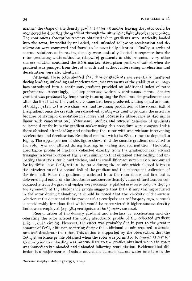
K- I I continuous-flow zonal rotor has recently been provided by PERARDI et al. 25.
Fig. 5 shows the results of tests in which the SZ-I 4 rotor was first loaded with equal volumes of water and 60 %(w/w) sucrose and then immediately unloaded (closed circles), unloaded after standing for 3 h (closed triangles) and unloaded after reorienta- tion (open circles). The results indicate that the decay of the sucrose-water interface during 3 h at rest was about as great as that which occurred by both reorientation and diffusion during the 30 rain rotor acceleration and deceleration period. Similar results were obtained with the SZ-2o rotor. The slight asymmetry of the sucrose density profiles obtained during these tests may have been the result of trailing of the viscous 60 % (w/w)sucrose during unloading. Similar findings have been made by PERARDI et al. 25 with the K- I I rotor.
- -".... I e o ~ 60
~°i . . i I ~ 4a
o ~
O.4 ~ " ' ~ 30
U 0.3 ~
o.1 ~ol~,x x
FRACTION NUMBER FRACTION NUMBER
Fig. 4. Effects of reorientation and unloading on density gradient and CoCI~ interface stability: sucrose densities (top) and CoCI~ absorbance at 520 m/l (bottom) of fractions collected directly from the gradient-maker (~k- -A) , collected immediately following statically loading the rotor ( O - - O ) and following gradient reorientation (C)--C)).
Fig. 5. Effects of reorientation and unloading on the interface between water and 60 ~o (w/w) sucrose: sucrose densities of fractions collected immediately following static loading ( O - - O ) , collected after 3 h at rest ( A - - A ) and following reorientation ( O - - O ) -
Two cores having removable septa were constructed so that gradient and particle zone stability during reorientation could be compared when o, 2, 4, 6, 8 and 12 septa were present. In these studies, rat blood was diluted I :IOO in 8 % (w/w) sucrose and the red cells present in 30 ml sample volume sbanded isopycnically in 35-55 % (w/w) linear sucrose gradients (15 rain at IOOOO × g). Following rotor deceleration, fractions were collected and gradient profiles determined together with gradient volumes containing 9 ° % of the red cells. No improvement of rotor performance was noted when more than 6 septa were present. However, density gradients were less stable when fewer septa were used and the collected gradient volume occupied by the red cells increased. When no septa were present, rotors were unstable.
Biochim. Biophys. Acta, 237 (1971) 28-42
36 P. SHEELER et al.
2 1 I o,..Q,,o e ~ - 60 ~.o "7 . ,, ~ / -s°
.~ 4 "%'°b'°.o c ~ I - i ° ' o . ~ ~ /I I - 4 0 - - ~" t O. 5 ~ e\ "O/o.~ - "-~.S4 mp / / t ~"
3 - • •
2- ~ ~°'° ' -o . 20 tt~ ©,
N
, ...... / o f,0 O - - ( ~ I I I I I J ' ' ' I J L I I I I I I I I " ~ ' ~ 1 I I I I I I J
4 8 12 16 20 24 28 32 36 FRACTION NUMBER
18
t t l N
o112
g ~ 6 0. O
<t Z !,2 u~ 0 | 8
z+=
//slO'3
/1 0.2 r ¢'/ : ' ~ °/°0o+ /
~ o q,/ - - • • 0 u . O • ', •
i +d o d' "%...•// ' o , /o
i "1¥~'1 ,Iv~, 4 8 12 16 20 24 28 32 36
3.1
O-- 0
FRACTION NUMBER
<.+.
o: t~
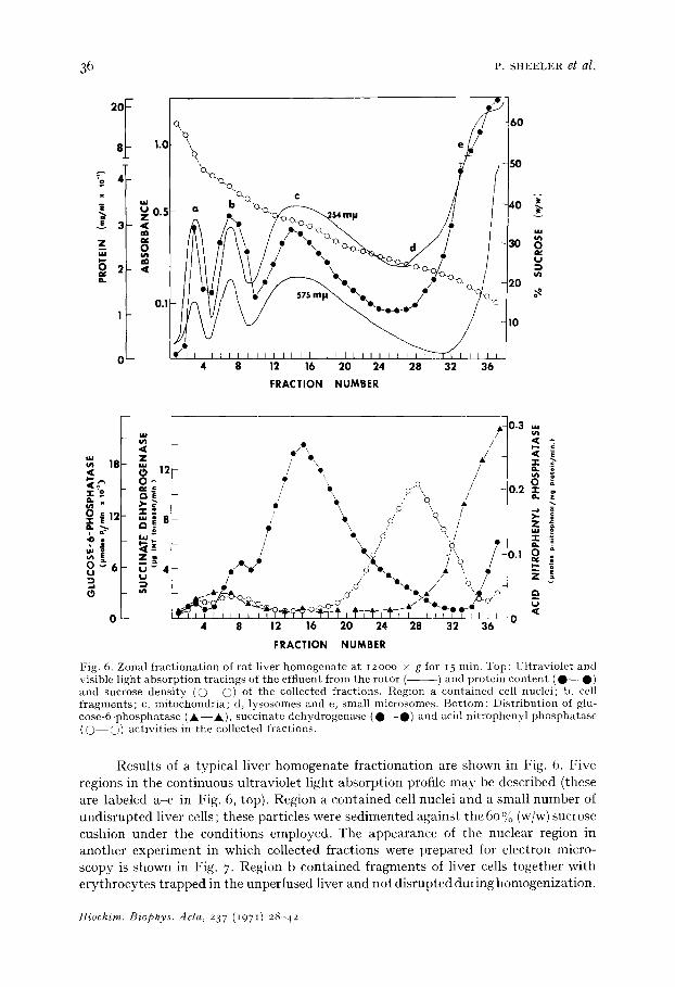
Fig. 6. Zonal f rac t iona t ion of r a t liver h o m o g e n a t e a t 12ooo x g for 15 rain. Top: Ul t ravio le t and visible l ight abso rp t ion t rac ings of the eff luent f rom tile ro tor ( ) and prote in c o n t e n t ( O - - O ) and sucrose dens i ty ( 0 - - @ ) of the collected f ract ions . Region a con ta ined cell nuclei ; b, cell f r a g m e n t s ; c, m i tochondr i a ; d, lysosomes and e, smal l microsomes . B o t t o m : Dis t r ibu t ion of glu- cose -6 -phospha tase ( Jk- - Jk) , succ ina te dehydrogenase ( O - - O ) and acid n i t ropheny l p h o s p h a t a s e ( O - - O ) act iv i t ies in the collected fract ions.
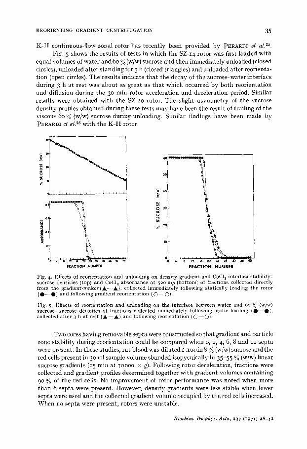
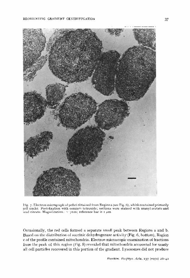
Results of a typical liver homogenate fractionation are shown in Fig. 6. Five regions in the continuous ultraviolet light absorption profile may be described (these are labeled a-e in Fig. 6, top). Region a contained cell nuclei and a small number of undisrupted liver cells ; these particles were sedimented against the 6o % (w/w) sucrose cushion under the conditions employed. The appearance of the nuclear region in another experiment in which collected fractions were prepared for electron micro- scopy is shown in Fig. 7. Region b contained fragments of liver cells together with erythrocytes trapped in the unperfused liver and not disrupted during homogenization.
Biochim. Biophys. Acta, 237 (1971) 28-42
REORIENTING GRADIENT CENTRIFUGATION 37
Fig. 7- Electron micrograph of pellet obtained from Region a (see Fig. 6), which contained primarily cell nuclei. Post-fixation with osmium tetroxide; sections were stained with uranyl acetate and lead citrate. Magnification: x 7o2o; reference bar is I /ml.
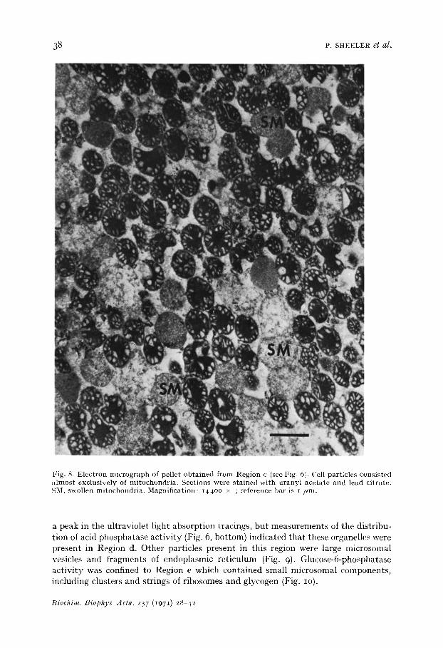
Occasionally, the red cells formed a separa te smal l peak between Regions a and b. Based on the d i s t r ibu t ion of succinic dehydrogenase ac t i v i t y (Fig. 6, bot tom) , Region c of the profile conta ined mi tochondr ia . Elect ron microscopic examina t ion of fract ions from the peak of this region (Fig. 8) revealed t ha t mi tochondr ia accounted for near ly all cell par t ic les recovered in this por t ion of the gradient . Lysosomes d id not produce
Biochim. I3iophys. Acta, 237 (I97 I) 28-42
3 8 P. SHEELER et al.
Fig. 8. Electron micrograph of pellet obtained from Region c (see Fig. 6). Cell particles consisted a lmost exclusively of mitochondria. Sections were stained with uranyl acetate and lead citrate. SM, swollen mitochondria. Magnification: i44oo >( ; reference bar is i /ml.
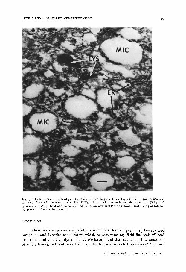
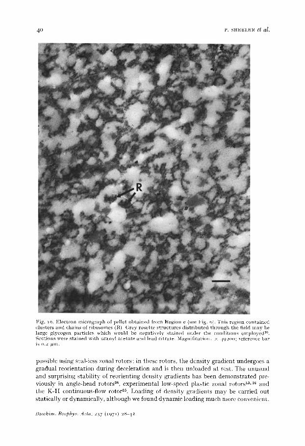
a peak in the ultraviolet light absorption tracings, but measurements of the distribu- tion of acid phosphatase activity (Fig. 6, bottom) indicated that these organelles were present in Region d. Other particles present in this region were large microsomal vesicles and fragments of endoplasmic reticulum (Fig. 9). Glucose-6-phosphatase activity was confined to Region e which contained small microsomal components, including clusters and strings of ribosomes and glycogen (Fig. IO).
Biochim. Biophys. dcla, 237 (I97I) 28 42
REORIENTING GRADIENT CENTRIFUGATION 30
Fig. 9. Electron micrograph of pellet obtained from Region d (see Fig. 6). This region contained large numbers of microsomal vesicles (MIC), ribosome-laden endoplasmic reticulum (ER) and lysosomes (LYS). Sections were stained with uranyl acetate and lead citrate. Magnification: × 456oo; reference bar is 0.2 /~m.
DISCUSSION
Qtlant i ta t ive rate-zonal separat ions of cell particles have previously been carried
out in A- and B-series zonal rotors which possess rotat ing, fluid line seals 1-1° and a re loaded and unloaded dynamical ly . We have found tha t ra te-zonal f ract ionat ions of whole homogenates of l iver tissue similar to those reported previously3,5, 9, 21 are
Biochim. Biophys. dcta, 237 (1971) 28-42
4 ° P. SHEELER el al.
Fig. 1 o. Electron micrograph of pellet obtained from Region e (see Fig. 6). This region contained clusters and chains of ribosomes (R). Grey rosette structures distributed through the field may be large glycogen particles which would be negatively stained under the conditions employed TM. Sections were stained with uranyl acetate and lead citrate. Magnification: × 492oo; reference bar is o.2 l~m.
possible using s~al-less zonal rotors; in these rotors, the densi ty gradient undergoes a gradual reorientat ion during deceleration and is then unloaded at rest. The unusua l and surprising stabi l i ty of reorienting densi ty gradients has been demonst ra ted pre- viously in angle-head rotors 26, experimental low-speed plastic zonal rotors la, a~ and the K-II continuous-flow rotor 2~. Loading of densi ty gradients may be carried out stat ical ly or dynamical ly, al though we found dynamic loading much more convenient .
Biochim. Biophys..4eta, 237 (i971) 28-42
REORIENTING GRADIENT CENTRIFUGATION 41
Notwithstanding small losses in resolution which appear to be associated with re- orientation and static unloading, the simplicity of construction and operation of the reorienting gradient rotors described should make them quite useful in many experi- mental situations in which the use of a large capacity zonal rotor is desirable.
Rotating-seal zonal rotors are unloaded while rotating at 6oo rev./min (rotor A-XII) or 3ooo-5ooo rev./min (B-series rotors), with displacement of the entire gradient requiring 3o 6o min4,< 9, 27, 28. As a result, large paIticles such as whole cells, nuclei, chloroplasts and mitochondria continue to sediment during the unloading operation. This added sedimentation must be accounted for and unloading schedules rigorously controlled. Negligible particle sedimentation occurs during the static un- loading of reorienting gradient zonal rotors.
Density gradients (even those of high limiting viscosity) can be loaded into the reorienting gradient zonal rotors very rapidly (about 15o ml/min), since loading is not dependent on gravity feed and cross-leakage between input and output lines cannot occur when pumps are used. For similar reasons, the sample to be fractionated can be introduced onto the reoriented density gradient in just a few seconds, thereby forming an extremely narrow starting zone. This is particularly important when large particles are to be separated; since particle sedimentation begins immediately upon entry into the rotor, the longer the time interval between introduction of the first and last portions of the sample volume, the broader the starting zone. Overlay solutions are not required to displace samples radially until they clear the core region of the reorienting gradient rotors. Consequently, flotation experiments 29-$1 may be carried out with no danger of the lightest particles encountering the core surface during their centripetal migration.
Liver homogenates were separated by reorienting gradient zonal centrifugation into zones containing cell nuclei, mitochondria, lysosomes and microsomes. Our results are similar to those reported previously by SCHUEL et al2, BROWY s, HINTON et al2 and EL-AASER el al. 21.
The studies reported here demonstrate that certain minimum performance criteria are satisfied by reorienting gradient zonal rotors. In addition to the fractiona- tion of whole liver tissue homogenates, we have successfully employed the SZ-I 4 and SZ-2o rotors for separating different cell populations at low speeds, isolating tetraploid and diploid liver cell nuclei, separating smooth and rough cell membranes and fractionating polydisperse glycogen particles; these studies will be described else- where.
ACKNOWLEDGEMENTS
The authors would like to thank Mr. Patrick J. Dowd, Mr. Wayne Kahn, Mr. George F. Durdle, Mr. Glen A. Shaw and Mr. Edward D. McDonald for their most valuable technical assistance.
R E F E R E N C E S
i I. R. JOHNSTON, A. P. MATHIAS, F. PENNINGTON AND D. RIDGE, Biochem. J., lO9 (1968) 127. 2 C. C. STILL AND C. A. PRICE, Biochim. Biophys. Acta, 141 (1967) 176. 3 H. SCHUEL, a . SCHUEL AND N. J. I~NAKAR, Anal. Biochem., 25 (1968) 146. 4 B. FLEISCHER, S. FLEISCHEE AND H. OZAWA, J. Cell Biol., 43 (1969) 59.
Biochim. Biophys. Aeta, 237 (1971) 28-42
42 P. SHEELER et al.
5 D. H. BROWN, Biochim. Biophys. Acta, 162 (1968) 152. 6 T. LEE, D. C. SWARTZENDRUBER AND F. SNYDER, Biochem. Biophys. Res. Commun., 36 (1969)
748 • 7 R. A. WEAVER AND W. BOYLE, Biochim. Biophys. Acta, 173 (1969) 377. 8 R. H. HINTON, M. DOBROTA, J. T. R. FITZSlMONS AND F.. REID, European J. Biochem., 12
(197 ° ) 349- 9 E. S. KLuc l s AND H. J. GOULD, Science, 152 (1966) 378 .
io A. A. BARBER, \V. \A,T. HARRIS AND lX~. G. ANDERSON, National Cancer Institute Monograph, Vo]. 21, [7. S. G o v e r n m e n t P r i n t i n g Office, W a s h i n g t o n D. C., 1966, p. 285.
i i N. G. ANDERSON, National Cancer Institute Monograph, Vol. 21, U. S. G o v e r n m e n t P r i n t i n g Office, W a s h i n g t o n D. C., 1966, p. 9.
12 N. G. ANDERSON, Quart. Rev. Biophys., I (1968) 217. 13 N. G. ANDERSON, C. A. PRICE, W. D. FISHER, R. E. CANNING AND C. L. BURGER, Anal. BiD-
chem., 7 (1964) i. 14 H. \V. H s u AND N. G. ANDERSON, Biophys. J . , 9 (1969) 173. 15 J. R. WELLS, D. M. GROSS AND P. SHEELER, Lab. Pract., 19 (197 o) 497. 16 L. H. ELROD, L. C. PATRICK AND N. G. ANDERSON, Anal. Biochem., 3 ° (1969) 230. 17 N. G. ANDERSON, D. A. WATERS, C. E. NUNLEY, R. F. GIBSON, R. M. SCHILLING, E. C. DENNY,
G. B. CLINE, E. F. BABELAY AND T. ]~. PERARDI, Anal. Biochem., 32 (1969) 460. IS (). I-[. LOWRY, N. J. ROSEBROUGH, A. L. FARR AND R. J. RANDALL, J. Biol. Chem., 193 (I95 I)
265 • 19 M. BAGGIOLINI, J. G. HIRSCH AND C. DE DUVE, d r. Cell Biol., 4 ° (1969) 529 . 20 P. G. CANONICO AND J. W. C. BIRD, J. Cell Biol., 45 (197 ° ) 321. 21 A. A. E1-AASER, J. T. R. FITZSIMONS, R. H. HINTON, E. REID, E. KLUCIS AND P. ALEXANDER,
Biochim. Biophys. Acta, 127 (1966) 553. 22 L. A. WILSON AND V(. BOYLE, Anal. Biochem., 35 (I97O) 466. 23 E. SHELTON AND M. E. RICE, J. Natl. Cancer Inst., 18 (1957) 117. 24 E. S. BAGINSKI, P. P. FOA AND B. ZAK, Anal. Biochem., 21 (1967) 2Ol. 25 T. E. PERARDI, R. A. LEFFLER AND N. G. ANDERSON, Anal. Biochem., 32 (1969) 495. 26 \V. D. FISHER, G. B. CLINE AND N. G. ANDERSON, Anal. Biochem., 9 (1964) 477- 27 N. G. ANDERSON, Science, 154 (1966) lO 3 . 28 N. G. ANDERSON, D. A. WATERS, \¥ . D. FISHER, G. B. CLINE C. E. NUNLEY, L. H. ]~LROD AND
C. T. RANKIN, Anal. Biochem., 21 (1967) 235. 29 H. G. WILCOX AND M. HEIMBERG, Biochim. Biophys. Acta, 152 (1968) 424 • 3 ° H. G. WILCOX, D. C. DAVIS AND M. HEIMBERG, Biochim. Biophys. Acta, 187 (1969) 147. 31 N. G. ANDERSON, C. E. NUNLEY AND C. T. RANKIN, Anal. Biochem., 31 (I969) 255.
Bioehim. Biophys. Aeta, 237 (1971) 28-42


