Embed Size (px)
Citation preview
Vertical Machining Centers
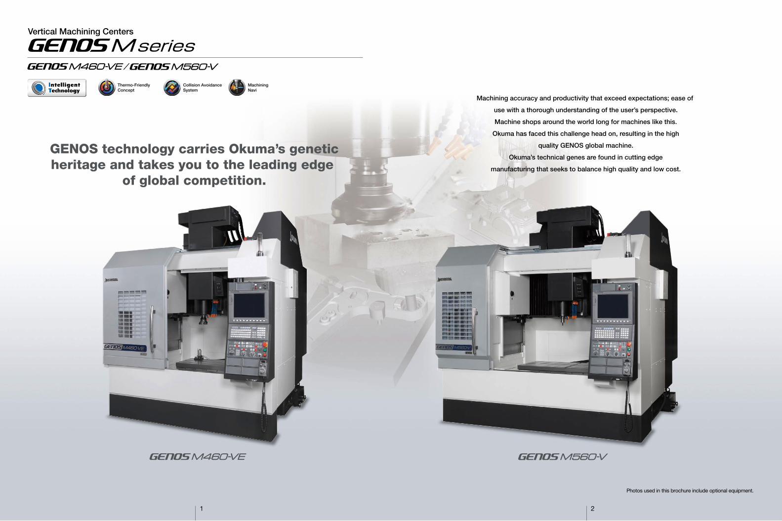
GENOS technology carries Okuma’s geneticheritage and takes you to the leading edge
of global competition.
Vertical Machining Centers
Photos used in this brochure include optional equipment.
1 2
Machining accuracy and productivity that exceed expectations; ease of
use with a thorough understanding of the user’s perspective.
Machine shops around the world long for machines like this.
Okuma has faced this challenge head on, resulting in the high
quality GENOS global machine.
Okuma’s technical genes are found in cutting edge
manufacturing that seeks to balance high quality and low cost.
Thermo-Friendly Concept
Machining Navi
Collision AvoidanceSystem
3 4
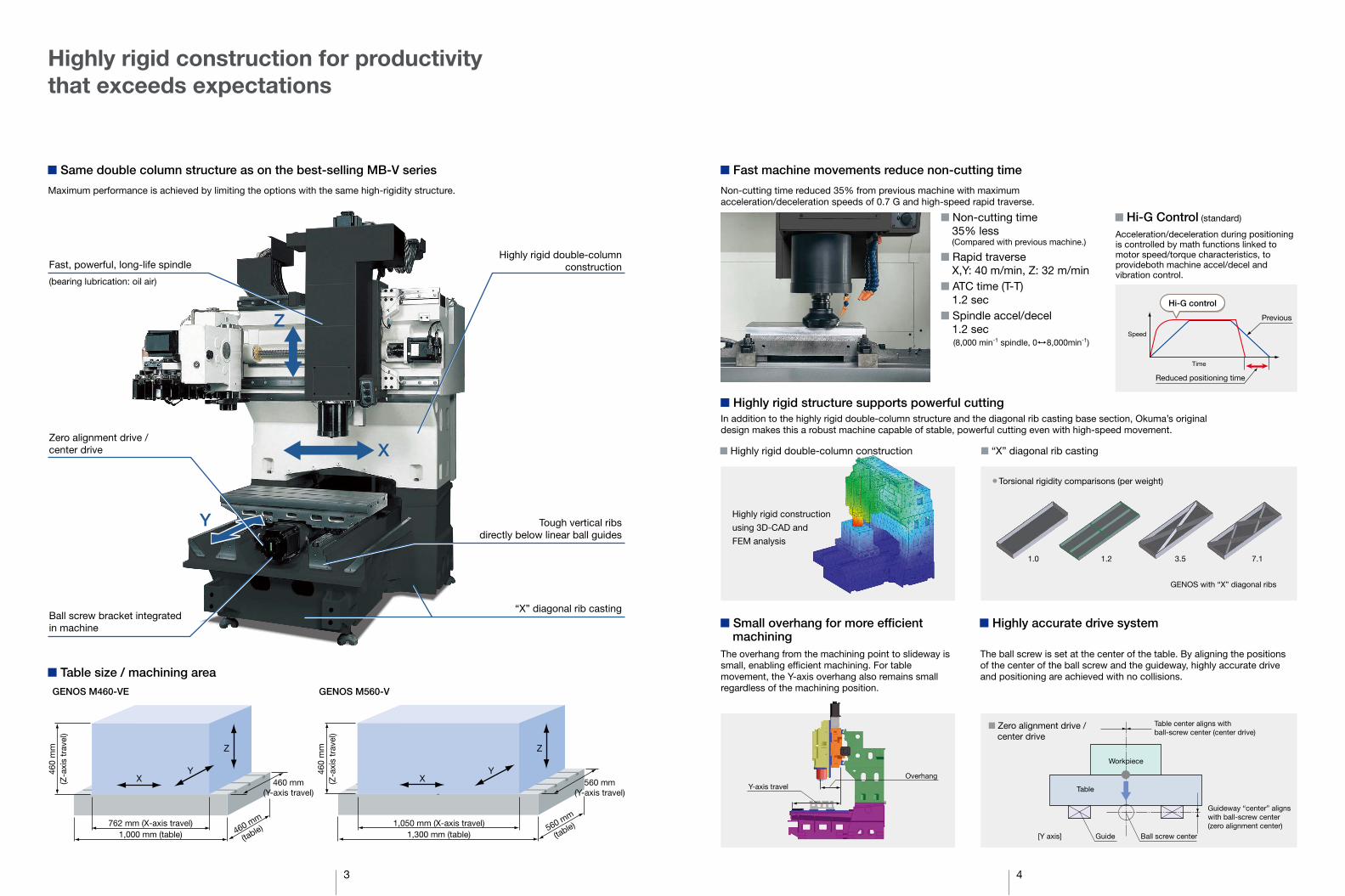
Highly rigid construction for productivity that exceeds expectations
■ Table size / machining area
Non-cutting time reduced 35% from previous machine with maximum acceleration/deceleration speeds of 0.7 G and high-speed rapid traverse.
■ Fast machine movements reduce non-cutting time
Maximum performance is achieved by limiting the options with the same high-rigidity structure.
■ Same double column structure as on the best-selling MB-V series
In addition to the highly rigid double-column structure and the diagonal rib casting base section, Okuma’s original design makes this a robust machine capable of stable, powerful cutting even with high-speed movement.
■ Highly rigid structure supports powerful cutting
The overhang from the machining point to slideway is small, enabling efficient machining. For table movement, the Y-axis overhang also remains small regardless of the machining position.
The ball screw is set at the center of the table. By aligning the positions of the center of the ball screw and the guideway, highly accurate drive and positioning are achieved with no collisions.
■ Small overhang for more efficient machining
■ Highly accurate drive system
X
Z
Y
Fast, powerful, long-life spindle
(bearing lubrication: oil air)
Ball screw bracket integrated in machine
Highly rigid double-column construction
Tough vertical ribs directly below linear ball guides
“X” diagonal rib casting
Zero alignment drive / center drive
Time
Speed
Previous
Reduced positioning time
Hi-G control
Highly rigid construction
using 3D-CAD and
FEM analysis
■ Highly rigid double-column construction ■ “X” diagonal rib casting
● Torsional rigidity comparisons (per weight)
GENOS with “X” diagonal ribs
1.0 1.2 3.5 7.1
Table center aligns with ball-screw center (center drive)
Workpiece
Ball screw center
Guideway “center” aligns with ball-screw center (zero alignment center)
Table
Guide [Y axis]
Overhang
Y-axis travel
GENOS M460-VE GENOS M560-V
■ Hi-G Control (standard)
Acceleration/deceleration during positioning is controlled by math functions linked to motor speed/torque characteristics, to provideboth machine accel/decel and vibration control.
■ Zero alignment drive / center drive
1,300 mm (table) 1,050 mm (X-axis travel)
460
mm
(Z
-axi
s tr
avel
)
560 mm (Y-axis travel)
X
Z
Y
560 mm
(table) 1,000 mm (table)
762 mm (X-axis travel)
460
mm
(Z
-axi
s tr
avel
)
460 mm (Y-axis travel)
X
Z
Y
460 mm
(table)
■ Non-cutting time35% less(Compared with previous machine.)
■ Rapid traverseX,Y: 40 m/min, Z: 32 m/min
■ ATC time (T-T)1.2 sec
■ Spindle accel/decel1.2 sec(8,000 min-1 spindle, 0 8,000min-1)
5
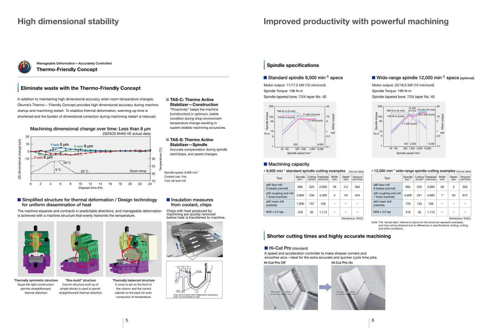
High dimensional stability
■ Simplified structure for thermal deformation / Design technology for uniform dissemination of heat
Manageable Deformation—Accurately Controlled Thermo-Friendly Concept
Eliminate waste with the Thermo-Friendly Concept
In addition to maintaining high dimensional accuracy when room temperature changes,
Okuma’s Thermo— Friendly Concept provides high dimensional accuracy during machine
startup and machining restart. To stabilize thermal deformation, warming-up time is
shortened and the burden of dimensional correction during machining restart is reduced.
■ TAS-C: Thermo Active Stabilizer—Construction“Proactively” keeps the machine [construction] in optimum, stable condition during shop environment temperature change resulting in superb (stable) machining accuracies.
■ TAS-S: Thermo Active Stabilizer—SpindleAccurate compensation during spindle start/stops, and speed changes.
Thermally symmetric structure Equal left-right construction
permits straightforward thermal distortion
“Box-build” structure Column structure built up of
simple blocks is used to permit straightforward thermal distortion
Thermally balanced structure A cover is set on the front of the column and the control
cabinet on the back for even conduction of temperature.
Sloped telescopic cover
Chips with heat produced by machining are quickly removed before heat is transferred to machine.
The machine expands and contracts in predictable directions, and manageable deformation is achieved with a machine structure that evenly transmits the temperature.
■ Insulation measures from coolant, chips
Note: The “actual data” referred to above for this brochure represent examples, and may not be obtained due to differences in speci�cations, tooling, cutting, and other conditions.
■ Hi-Cut Pro (standard)A speed and acceleration controller to make sharper corners and smoother arcs—ideal for the extra accurate and quicker cycle time jobs.
Hi-Cut Pro Off Hi-Cut Pro On
Machining dimensional change over time: Less than 8 μm (GENOS M460-VE actual data)
OD
dim
ensi
onal
cha
nge
(µm
)
Tem
per
atur
e (˚C
) -10
0
10
20
15
20
25
30
Elapsed time (Hr) 0 2 4 6 8 10 12 14 16 18 20 22 24
Room temp 20 ˚C
28 ˚C
8 ˚C
X-axis 8 µm Y-axis 5 µm
Z-axis 6 µm
Spindle speed: 8,000 min-1
Coolant use: Yes Tool: ø6 end mill
(Workpiece: S45C) (Workpiece: S45C)
Bed
Chip coil conveyor with independent suspension (heat not transmitted to bed)
Trough
6
Improved productivity with powerful machining
■ Standard spindle 8,000 min-1 specs
■ Machining capacity● 8,000 min-1 standard spindle cutting examples
Tool
895
3,660
1,000
318
225
230
157
30
2,600
4,300
150
1,113
56
4
2.5
20
364
344
Spindle min-1
Cutting m/min
Feedrate mm/min
Width mm
Depth mm
Amount cm3/min
[Actual data] ● 12,000 min-1 wide-range spindle cutting examples
ø80 face mill 8 blades (cermet)
M30 x 3.5 tap
ø20 roughing end mill 7 ¨utes (carbide)
ø63 insert drill(carbide)
ø80 face mill 8 blades (cermet)
M30 x 3.5 tap
ø20 roughing end mill 7 ¨utes (carbide)
ø50 insert drill(carbide)
Tool
895
4,000
720
318
225
251
142
30
3,000
4,800
108
1,113
56
7
3
20
504
672
Spindle min-1
Cutting m/min
Feedrate mm/min
Width mm
Depth mm
Amount cm3/min
[Actual data]
Shorter cutting times and highly accurate machining
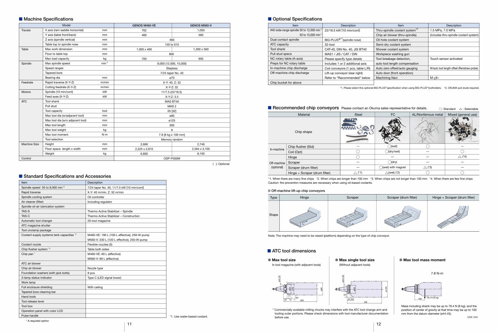
Spindle specifications
Motor output: 11/17.5 kW (10 min/cont)
Spindle Torque: 198 N-m
Spindle tapered bore: 7/24 taper No. 40
■ Wide-range spindle 12,000 min-1 specs (optional)
Motor output: 22/18.5 kW (10 min/cont)
Spindle Torque: 199 N-m
Spindle tapered bore: 7/24 taper No. 40
50 100 500 1,000 4,000 10,000
720 12,000 2,500
5
10
50
100
500
1
1
5
10
50
0.5
0.1
Spindle speed min-1
199 N-m (5 min)
146 N-m (cont)
22 kW (10 min) 15 kW (5 min)
11 kW (cont)
18.5 kW (cont)
Round cornersRound corners Sharp cornersSharp corners
N-m
Sp
ind
le t
orq
ue
kW
Mot
or o
utp
ut
50 100 500 1,000 5,000 10,000
530 8,000
5
10
50
100
500
1
1
5
10
50
0.5
0.1
198 N-m (5 min)
135 N-m (cont) 11 kW (10 min)
7.5 kW (cont)
Spindle speed min-1
N-m
Sp
ind
le t
orq
ue
kW
Mot
or o
utp
ut
7 8
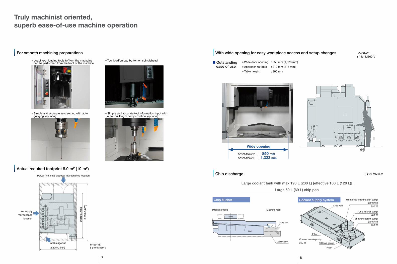
Truly machinist oriented, superb ease-of-use machine operation
For smooth machining preparations With wide opening for easy workpiece access and setup changes
Power line, chip disposal maintenance location
3,58
0 (3
,875
)
2,81
0 (3
,105
)
2,225 (2,564)
■ Outstanding ease of use
● Wide door opening : 850 mm (1,323 mm)
● Approach to table : 210 mm (215 mm)
● Table height : 800 mm
Chip discharge
Wide opening
GENOS M460-VE : 850 mm GENOS M560-V : 1,323 mm
Chip flusher
Large coolant tank with max 190 L (230 L) [effective 100 L (120 L)]
Large 60 L (69 L) chip pan
Coolant supply system
Shower coolant pump (optional)
250 W
Chip Pan
Chip �usher pump
400 W
Filter
Filter
Oil level gauge
Workpiece washing gun pump (optional)
250 W
Coolant nozzle pump
250 W M460-VE ( ) for M560-V
Actual required footprint 8.0 m2 (10 m2)
Air supply maintenance
location
ATC magazine
● Loading/unloading tools to/from the magazine can be performed from the front of the machine
● Tool load/unload button on spindlehead
● Simple and accurate zero setting with auto gauging (optional)
● Simple and accurate tool information input with auto tool length compensation (optional)
M460-VE ( ) for M560-V
( ) for M560-V
Travel Y travel Travel
800
Table
230 (280)
460 (560)
460 (560)
230 (280)
210 (215)
Table
Bed
(Machine front)
Chip pan
Coolant tank
(Machine rear)
Power consumption compared to previous Okuma machine
Power consumption compared toprevious Okumamachine
9 10
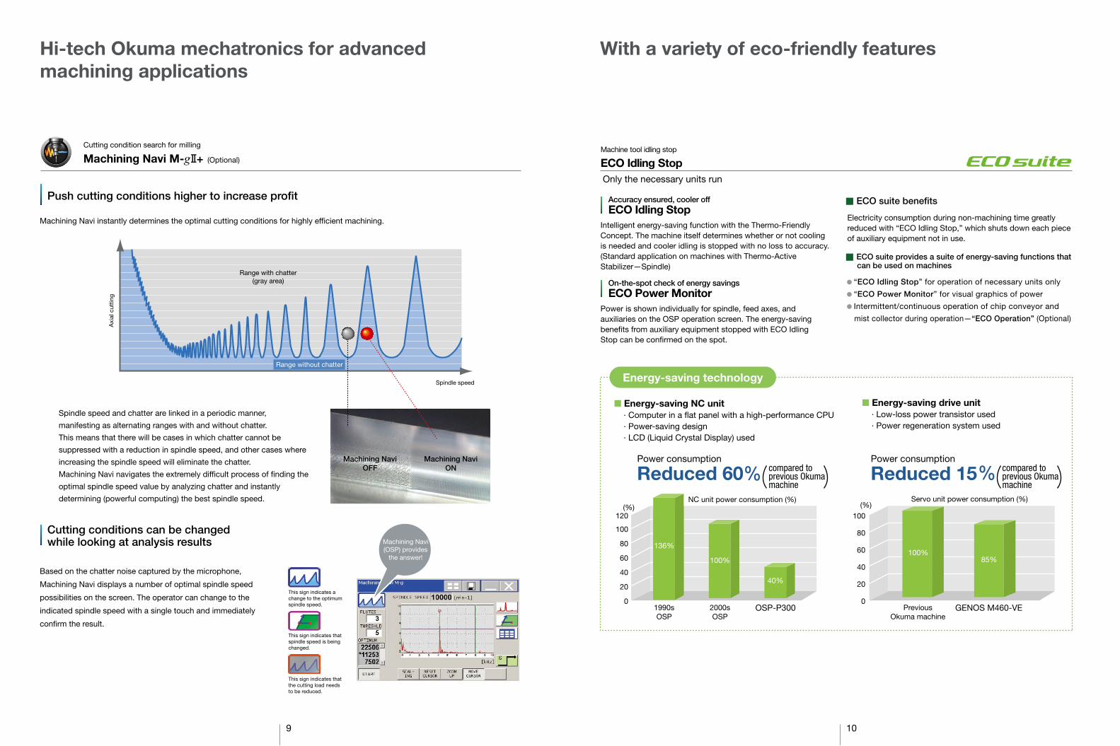
Push cutting conditions higher to increase profit
Machining Navi instantly determines the optimal cutting conditions for highly efficient machining.
Cutting conditions can be changed while looking at analysis results
Based on the chatter noise captured by the microphone,
Machining Navi displays a number of optimal spindle speed
possibilities on the screen. The operator can change to the
indicated spindle speed with a single touch and immediately
confirm the result.
Hi-tech Okuma mechatronics for advanced machining applications
Spindle speed
Axi
al c
uttin
g
Spindle speed and chatter are linked in a periodic manner,
manifesting as alternating ranges with and without chatter.
This means that there will be cases in which chatter cannot be
suppressed with a reduction in spindle speed, and other cases where
increasing the spindle speed will eliminate the chatter.
Machining Navi navigates the extremely dif�cult process of �nding the
optimal spindle speed value by analyzing chatter and instantly
determining (powerful computing) the best spindle speed.
Range without chatter
Range with chatter (gray area)
Machining Navi (OSP) provides
the answer!
Energy-saving technology
■ Energy-saving drive unit· Low-loss power transistor used· Power regeneration system used
NC unit power consumption (%) Servo unit power consumption (%)
0
20
40
60
80
100
120 (%)
0
20
40
60
80
100 (%)
136% 100%
100% 85%
40%
1990s OSP
2000s OSP
OSP-P300 Previous Okuma machine
GENOS M460-VE
■ Energy-saving NC unit· Computer in a �at panel with a high-performance CPU· Power-saving design· LCD (Liquid Crystal Display) used
With a variety of eco-friendly features
Accuracy ensured, cooler off ECO Idling Stop
● “ECO Idling Stop” for operation of necessary units only
● “ECO Power Monitor” for visual graphics of power
● Intermittent/continuous operation of chip conveyor and
mist collector during operation—“ECO Operation” (Optional)
■ ECO suite provides a suite of energy-saving functions thatcan be used on machines
Electricity consumption during non-machining time greatly reduced with “ECO Idling Stop,” which shuts down each piece of auxiliary equipment not in use.
■ ECO suite benefits
ECO Idling Stop Machine tool idling stop
Intelligent energy-saving function with the Thermo-Friendly Concept. The machine itself determines whether or not cooling is needed and cooler idling is stopped with no loss to accuracy. (Standard application on machines with Thermo-Active Stabilizer—Spindle)
On-the-spot check of energy savings ECO Power Monitor
Power is shown individually for spindle, feed axes, and auxiliaries on the OSP operation screen. The energy-saving benefits from auxiliary equipment stopped with ECO Idling Stop can be confirmed on the spot.
Only the necessary units run
Cutting condition search for milling
Machining Navi M-g + (Optional)
This sign indicates a change to the optimum spindle speed.
This sign indicates that spindle speed is being changed.
This sign indicates that the cutting load needs to be reduced.
Machining Navi OFF
Machining NaviON Reduced 60 Reduced 15
460
150 to 610
800
8,000 (12,000, 15,000)
Stepless
7/24 taper No. 40
ø70
X-Y: 40, Z: 32
X-Y-Z: 32
11/7.5 (22/18.5)
X-Y-Z: 3.5
MAS BT40
MAS 2
20 [32]
ø90
ø125
300
8
7.8 [8 kg x 100 mm]
Memory random
OSP-P300M
Travels
Table
Spindle
Feedrate
Motors
ATC
Machine Size
Control
Model Item Description Item Description
( ): Optional
X axis (ram saddle horizontal)
Y axis (table front/back)
Z axis (spindle vertical)
Table top to spindle nose
Max work dimension
Floor to table top
Max load capacity
Max spindle speed
Speed ranges
Tapered bore
Bearing dia
Rapid traverse (X-Y-Z)
Cutting feedrate (X-Y-Z)
Spindle (10 min/cont)
Feed axes (X-Y-Z)
Tool shank
Pull stud
Tool capacity
Max tool dia (w/adjacent tool)
Max tool dia (w/o adjacent tool)
Max tool length
Max tool weight
Max tool moment
Tool selection
Height
Floor space length x width
Weight
mm
mm
mm
mm
mm
mm
kg
min-1
mm
m/min
m/min
kW
kW
tool
mm
mm
mm
kg
N-m
mm
mm
kg
Spindle speed 50 to 8,000 min-1
Rapid traverse
Spindle cooling system
Air cleaner (�lter)
Spindle oil-air lubrication system
TAS-S
TAS-C
Automatic tool changer
ATC magazine shutter
Tool unclamp package
Coolant supply systems tank capacities *1
Coolant nozzle
Chip ¡usher system *1
Chip pan *
ATC air blower
Chip air blower
Foundation washers (with jack bolts)
3-lamp status indicator
Work lamp
Full enclosure shielding
Tapered bore cleaning bar
Hand tools
Tool release lever
Tool box
Operation panel with color LCD
Pulse handle
7/24 taper No. 40, 11/7.5 kW [10 min/cont]
X-Y: 40 m/min, Z: 32 m/min
Oil controller
Including regulator
Thermo Active Stabilizer – Spindle
Thermo Active Stabilizer – Construction
20-tool magazine
M460-VE: 190 L (100 L effective), 250-W pump
M560-V: 230 L (120 L effective), 250-W pump
Flexible nozzles (5)
Table both sides
M460-VE: 60 L (effective)
M560-V: 69 L (effective)
Nozzle type
8 pcs
Type C (LED signal tower)
With ceiling
Item Description
*1. Use water-based coolant. * A required option
#40 wide-range spindle 50 to 12,000 min-1
50 to 15,000 min-1
Dual contact spindle
ATC capacity
Tool shank
Pull stud specs
NC rotary table (A-axis)
Preps for NC rotary table
In-machine chip discharge
Off-machine chip discharge
Chip bucket for above
Thru-spindle coolant system*2
Chip air blower (thru-spindle)
Oil-hole coolant system
Semi-dry coolant system
Shower coolant system
Workpiece washing gun
Tool breakage detection,
auto tool length compensation
Auto zero offset/auto gauging
Auto door (front operation)
Machining Navi
22/18.5 kW [10 min/cont]
BIG-PLUS®*1(spindle nose)
32-tool
CAT-40, DIN No. 40, JIS BT40
MAS1 / JIS / CAT / DIN
Please specify type details
Includes 1 or 2 additional axis
Coil conveyors (1 pcs, table L/R)
Lift-up conveyor (rear right)
Refer to “Recommended” below
1.5 MPa, 7.0 MPa
(includes thru-spindle coolant system)
Touch sensor activated
W/auto tool length offset (Renishaw probe)
M-gII+
Chip shape
In-machine
Off-machine (optional)
Chip ¡usher (Std)
Coil (Opt)
Hinge
Scraper
Scraper (drum �lter)
Hinge + Scraper (drum �lter)
Material Steel FC AL/Nonferrous metal Mixed (general use)
—
—— (*1)
(wet)
(dry/wet)
—(dry)
(wet) with magnet
(wet) (*2)
——— (*3)
—
(*4)
——
Type
Shape
Hinge Scraper Scraper (drum �lter) Hinge + Scraper (drum �lter)
Caution: �re prevention measures are necessary when using oil-based coolants.
Note: The machine may need to be raised (platform) depending on the type of chip conveyor.
*1. When there are many �ne chips *2. When chips are longer than 100 mm *3. When chips are not longer than 100 mm *4. When there are few �ne chips
: Standard : Selectable
762
460
1,000 x 460
700
2,225 x 2,810
6,800
GENOS M460-VE GENOS M560-V
1,050
560
1,300 x 560
900
2,564 x 3,105
8,100
*1. Please select this optional BIG-PLUS speci�cation when using BIG-PLUS toolholders. *2. OKUMA pull studs required.
Mass including shank may be up to 78.4 N (8 kg), and the position of center of gravity at that time may be up to 100 mm from the datum diameter (ø44.45).
* Commercially available milling chucks may interfere with the ATC tool change arm and tooling outer portions. Please check dimensions with tool manufacturer documentation before use.
● Max tool sizeIn tool magazine (with adjacent tools)
● Max single tool size(Without adjacent tools)
● Max tool mass moment
7.8 N-m
ø44.
45
ø63
ø90
32 12 300 30°
ø76
ø4
4.4
5
ø1
25
ø6
3
32 30 300
30°
100 78.4 N (8 kg)
Unit: mm
* *
R R
11 12
2,746 2,666
■ Machine Specifications ■ Optional Specifications
■ Recommended chip conveyors Please contact an Okuma sales representative for details.
■ Standard Specifications and Accessories
■ ATC tool dimensions
■ Off-machine lift-up chip conveyors
■ Dimensional drawing / Installation drawing
1,89
0 (B
ed b
otto
m le
ngth
)
100
3,87
5 29
5 31
0 55
0 1,
340
1,18
4.5
357
10
551
59
135
380 200
130
525
1,230 1,200 100
1,770 (Bed bottom)
Bed bottom line
515 895
2,430 2,564
90 44
505 515 Spindle center
1,030 (Bed bottom)
FL
A TC operation panel
A TC magazine door
1,323 (Doors open) 1,410 1,020
667 743 580
380 3,840 *4,190
200
1,300 T able full length
525 Move
525 Move
1,050 X-axis travel
Tool load/unload button
460
Z
-axi
s tr
avel
146
2,29
5 61
0 70
0 *1
000
61 *3
3 73
0 150
Pulse handle
Signal tower
Operation panel
(in-MC)
2,60
0
70
2,74
6
Coolant tank
T ank r emoval di r ection
280 Move
280 Move
560 Y -axis travel
2,795 310 845 1,950
600
490 75
0
2,15
0
Spindle center 32-tool ATC (Opt)
A TC
1,40
0 (C
NC
cab
inet
hei
ght)
Air unit
Spindlehead cooler
560 T able width
T ransformer (Opt)
1.5 MPa thru-spindle coolant unit (Opt)
600 *800
230 *380
440
Chip bucket (Opt)
Lift-up conveyer (Opt)
500
(Mar
gin)
170
830 *1030
500 (Margin)
3,840 *4,190 500 (Margin)
1,33
0 43
0
Required capacity 500 L/min (ANR) More than 0.5 MPa Supplied air temperature should be within +5˚C
Air inlet height 954, Rc3/8 internal
32-tool ATC
Tank removal direction
500
(Mar
gin)
600
610
89
450
NC cabinet
Power inlet 22 KVA 30 mm2 4C (8,000 min-1 Spindle) 37 KVA 50 mm2 4C (12,000 min-1 /15,000 min-1 Spindle (Opt))
Height from �oor: 750 mm or 2,150 mm
1,200 860 130
450 380 470 200
50 2,175 2,225
885 430 430 430
1,07
6
1,64
0 (B
ed b
otto
m le
ngth
)
Spindle center
(Mar
gin)
50
0 (M
argi
n)
500
3,58
0 2,
810
600
100
100
110
610
240
320
170
551
1,19
0 45
0 35
4 91
0 59
(Margin) 500 3,390 *3,790
730 *1,130 (Margin) 500
430
300
1,33
0
860 (Bed bottom)
1,500 (Bed bottom)
32-tool ATC (Opt)
20-tool ATC
Air inlet height 456, Rc3/8 internal Required capacity 500 L/min (ANR) More than 0.5 MPa Supplied air temperature should be within +5°C
Bed bottom line
1.5 MPa thru-spindle coolant unit (Opt)
Tank removal direction
NC cabinet
Height from �oor: 670 mm or 2,070 mm
Power inlet 22 KVA 30 mm2 4C (8,000 min-1 Spindle) 37 KVA 50 mm2 4C (12,000 min-1 /15,000 min-1 Spindle (Opt))
13 14
GENOS M460-VE
■ Table size
■ Dimensional drawing / Installation drawing
■ Table size■ Working ranges ■ Working ranges
GENOS M560-V
30
150
80
150
80
18H7
30
1,000 Table length
T-slot detail (3 slots)
762 Spindle travel range (X axis)
460
Tab
le t
rave
l (Y
axi
s)
+2 0
12 +2
0
Travel 560
560 Table width
280 280
Trav
el 4
60
Travel 1,050
150
525 525
650
1,300 Table width
650
Z-a
xis
trav
el
(sp
ind
le v
ertic
al)
X-axis travel (spindle vertical)
Z-a
xis
trav
el
(sp
ind
le v
ertic
al)
Y-axis travel (table F/B)
T-slot detail (4 slots)
T-slot Cross groove
30
125
125
125
92.5
92
.5
18H7
30
1,300 Table length
1,050 Spindle travel range (X axis)
560
Tab
le t
rave
l (Y
axi
s)
18H7
7
+2 0
12 +2
0
Cross groove detail
Travel 460
460 Table width
230 230
Trav
el 4
60
Travel 762
150
381 381
500
1,000 Table length
500
Z-a
xis
trav
el
(sp
ind
le v
ertic
al)
Z-a
xis
trav
el
(sp
ind
le v
ertic
al)
X-axis travel (spindle vertical)
+0.
4 0
2,495
1,800 695
460 230 230
730
490
670
315
Spindle center
2,66
6
32-tool ATC (Opt)
1,40
0 (C
NC
cab
inet
hei
ght)
Air unit Coolant tank
1,96
5 (1
2,00
0 m
in-1
sp
ind
le)
1,76
5 (8
,000
min
-1 s
pin
dle
)
Tank removal direction
Move Move Y-axis travel
460 Table width
Spindlehead cooler
20-tool ATC
*H1000 lift-up conveyor specifications *H1000 lift-up conveyor specifications
Lift-up chip conveyor (Opt)
Tool load/unload button (in-MC)
460
Z-ax
is tra
vel
FL
1,23
5
146
2,52
0
280
1,92
2
3,390 *3,790
118 *374
*800
ATC operation panel
ATC magazine door Pulse handle
810 (Doors open)
Chip bucket (Opt)
Signal tower
1,000 Table full length
381 Move
381 Move
762 X-axis travel
Operation panel
860 1,220 380
200
390
470
470
340
880 95 600
*330
*756
130
*1,0
00
*6
700
610
150
56
Y-axis travel(table F/B)
15 16
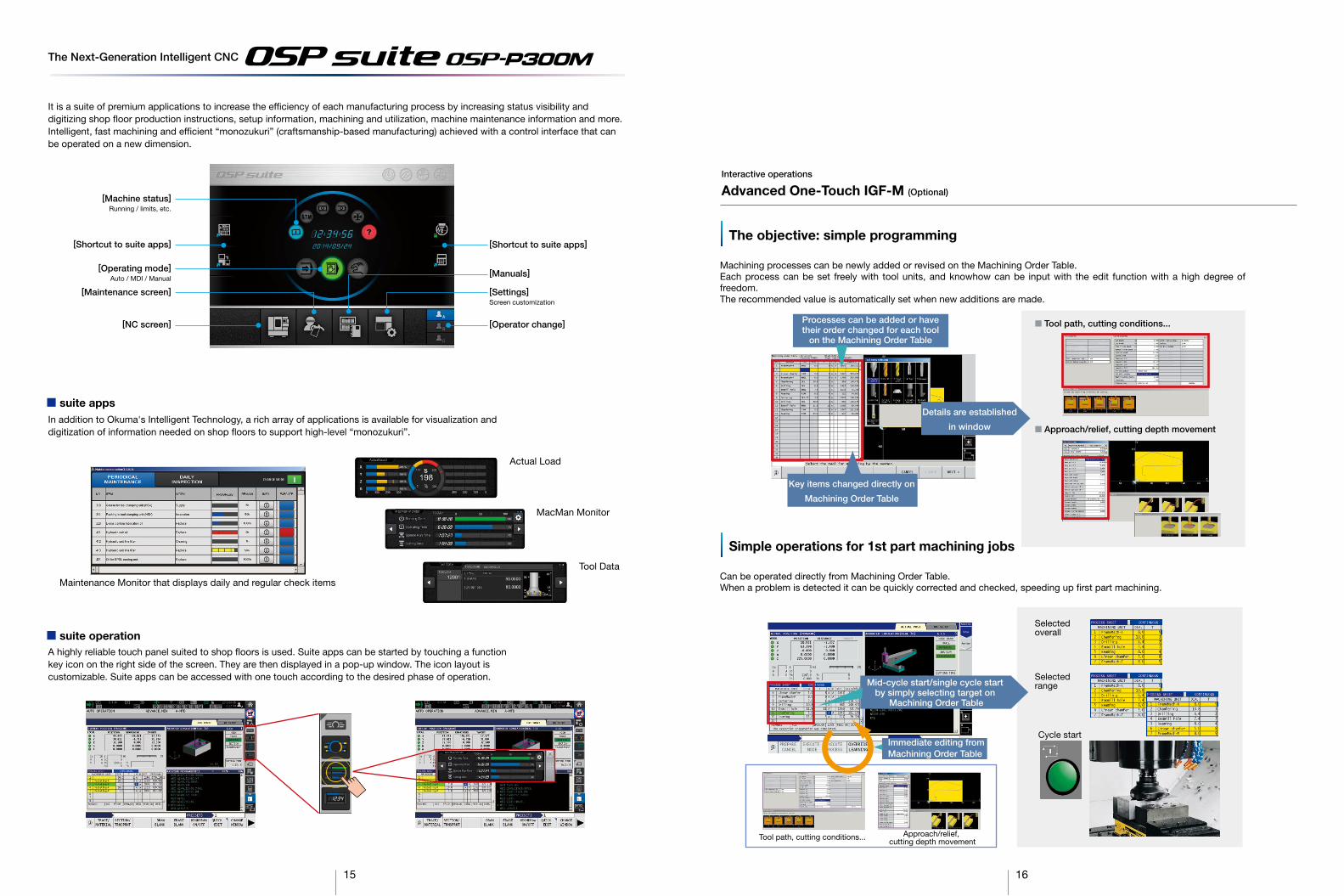
Interactive operations
Advanced One-Touch IGF-M (Optional)
The objective: simple programming
Machining processes can be newly added or revised on the Machining Order Table. Each process can be set freely with tool units, and knowhow can be input with the edit function with a high degree of freedom. The recommended value is automatically set when new additions are made.
Simple operations for 1st part machining jobs
Can be operated directly from Machining Order Table. When a problem is detected it can be quickly corrected and checked, speeding up first part machining.
■ Tool path, cutting conditions...
■ Approach/relief, cutting depth movement
Details are established
in window
Processes can be added or have their order changed for each tool
on the Machining Order Table
Key items changed directly on
Machining Order Table
Tool path, cutting conditions... Approach/relief, cutting depth movement
Selected overall
Selected range
Cycle start
Mid-cycle start/single cycle start by simply selecting target on
Machining Order Table
Immediate editing from Machining Order Table
■ suite apps
Actual Load
MacMan Monitor
Tool Data
Maintenance Monitor that displays daily and regular check items
The Next-Generation Intelligent CNC
■ suite operation
It is a suite of premium applications to increase the ef�ciency of each manufacturing process by increasing status visibility and digitizing shop �oor production instructions, setup information, machining and utilization, machine maintenance information and more. Intelligent, fast machining and ef�cient “monozukuri” (craftsmanship-based manufacturing) achieved with a control interface that can be operated on a new dimension.
[Shortcut to suite apps]
[Operating mode] Auto / MDI / Manual
[Maintenance screen]
[Machine status] Running / limits, etc.
[NC screen]
[Settings] Screen customization
[Operator change]
[Manuals]
[Shortcut to suite apps]
In addition to Okuma's Intelligent Technology, a rich array of applications is available for visualization and digitization of information needed on shop �oors to support high-level “monozukuri”.
A highly reliable touch panel suited to shop �oors is used. Suite apps can be started by touching a function key icon on the right side of the screen. They are then displayed in a pop-up window. The icon layout is customizable. Suite apps can be accessed with one touch according to the desired phase of operation.
17 18
Real 3D simulation included Easy part program editing per guide maps (with drawing calculate) Part program edit during a scheduled run G: 100 sets / M: 20 sets 1000 (standard is 200) ON/OFF external switch (part program) Message displayed on screen by part program 100, 200, 400 sets (Std: 20 sets) Large-diameter screws with angular cutters Fast & accurate rigid tapping (synchronized spindle speed, angle, feed axis position) Easy any-angle chamfering (C, R) Easier to execute Flat-tool free-shaped grooving (XY/spindle) Changeable per G22, G23 commands Offset directions per I-J-K commands Programmable mirror image Enlarge/reduce I/O variables (16 each) Consultations required Real time simulation of all machining modes (auto, MDI, manual) Spindle overload monitor Hour meter, work counter Adaptive control, overload monitor Hour meter, No. of workpieces Touch probe Includes auto gauging Includes auto tool offset File output Touch-sensor, touch-probe required
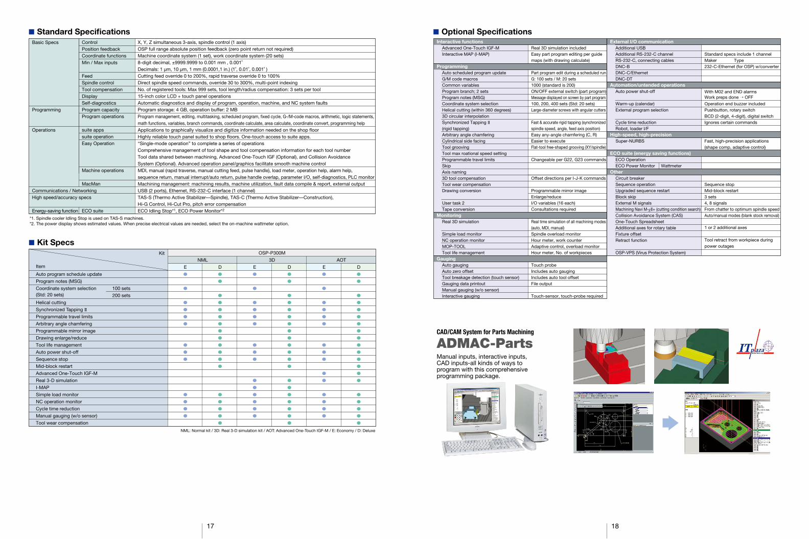
ADMAC-Parts CAD/CAM System for Parts Machining
Manual inputs, interactive inputs, CAD inputs-all kinds of ways to program with this comprehensive programming package.
■ Kit Specs
Auto program schedule update
Program notes (MSG)
Coordinate system selection (Std: 20 sets)
Helical cutting
Synchronized Tapping II Programmable travel limits
Arbitrary angle chamfering
Programmable mirror image
Drawing enlarge/reduce
Tool life management
Auto power shut-off
Sequence stop
Mid-block restart
Advanced One-Touch IGF-M
Real 3-D simulation
I-MAP
Simple load monitor
NC operation monitor
Cycle time reduction
Manual gauging (w/o sensor)
Tool wear compensation
●
●
●
●
●
●
●
●
●
●
●
●
●
E
●
●
●
●
●
●
●
●
●
●
●
●
●
●
●
●
●
●
D
●
●
●
●
●
●
●
●
●
●
●
●
●
●
●
E
●
●
●
●
●
●
●
●
●
●
●
●
●
●
●
●
●
●
●
●
D
●
●
●
●
●
●
●
●
●
●
●
●
●
●
●
E
NML 3D
OSP-P300M
AOT
●
●
●
●
●
●
●
●
●
●
●
●
●
●
●
●
●
●
●
●
DItem
Kit
100 sets
200 sets
NML: Normal kit / 3D: Real 3-D simulation kit / AOT: Advanced One-Touch IGF-M / E: Economy / D: Deluxe
■ Optional SpecificationsExternal I/O communication
Additional USB Additional RS-232-C channel RS-232-C, connecting cables DNC-B DNC-C/Ethernet DNC-DT
Automation/untended operations Auto power shut-off Warm-up (calendar) External program selection Cycle time reduction Robot, loader I/F
High-speed, high-precision Super-NURBS ECO suite (energy saving functions)
ECO Operation ECO Power Monitor Wattmeter
Other Circuit breaker Sequence operation Upgraded sequence restart Block skip External M signals Machining Navi M-gII+ (cutting condition search) Collision Avoidance System (CAS) One-Touch Spreadsheet Additional axes for rotary table Fixture offset Retract function OSP-VPS (Virus Protection System)
Interactive functions Advanced One-Touch IGF-M Interactive MAP (I-MAP)
Programming
Auto scheduled program update G/M code macros Common variables Program branch; 2 sets Program notes (MSG) Coordinate system selection Helical cutting (within 360 degrees) 3D circular interpolation Synchronized Tapping II (rigid tapping) Arbitrary angle chamfering Cylindrical side facing Tool grooving Tool max roational speed setting Programmable travel limits Skip Axis naming 3D tool compensation Tool wear compensation Drawing conversion User task 2 Tape conversion
Monitoring Real 3D simulation Simple load monitor NC operation monitor MOP-TOOL Tool life management
Gauging Auto gauging Auto zero offset Tool breakage detection (touch sensor) Gauging data printout Manual gauging (w/o sensor) Interactive gauging
Standard specs include 1 channelMaker Type232-C-Ethernet (for OSP) w/converter
With M02 and END alarmsWork preps done → OFF
Operation end buzzer includedPushbutton, rotary switchBCD (2-digit, 4-digit), digital switchIgnores certain commands
Fast, high-precision applications(shape comp, adaptive control)
Sequence stopMid-block restart3 sets4, 8 signalsFrom chatter to optimum spindle speedAuto/manual modes (blank stock removal)
1 or 2 additional axes
Tool retract from workpiece duringpower outages
■ Standard Specifications
*1. Spindle cooler Idling Stop is used on TAS-S machines. *2. The power display shows estimated values. When precise electrical values are needed, select the on-machine wattmeter option.
Basic Specs Programming Operations Communications / Networking High speed/accuracy specs Energy-saving function
Control Position feedback Coordinate functions Min / Max inputs Feed Spindle control Tool compensation Display Self-diagnostics Program capacity Program operations suite apps suite operation Easy Operation Machine operations MacMan ECO suite
X, Y, Z simultaneous 3-axis, spindle control (1 axis)OSP full range absolute position feedback (zero point return not required)Machine coordinate system (1 set), work coordinate system (20 sets)8-digit decimal, ±9999.9999 to 0.001 mm , 0.001˚Decimals: 1 µm, 10 µm, 1 mm (0.0001,1 in.) (1˚, 0.01˚, 0.001˚ )Cutting feed override 0 to 200%, rapid traverse override 0 to 100%Direct spindle speed commands, override 30 to 300%, multi-point indexingNo. of registered tools: Max 999 sets, tool length/radius compensation: 3 sets per tool15-inch color LCD + touch panel operationsAutomatic diagnostics and display of program, operation, machine, and NC system faultsProgram storage: 4 GB, operation buffer: 2 MBProgram management, editing, multitasking, scheduled program, «xed cycle, G-/M-code macros, arithmetic, logic statements,math functions, variables, branch commands, coordinate calculate, area calculate, coordinate convert, programming helpApplications to graphically visualize and digitize information needed on the shop ¬oorHighly reliable touch panel suited to shop ¬oors. One-touch access to suite apps. “Single-mode operation” to complete a series of operationsComprehensive management of tool shape and tool compensation information for each tool numberTool data shared between machining, Advanced One-Touch IGF (Optional), and Collision Avoidance System (Optional). Advanced operation panel/graphics facilitate smooth machine controlMDI, manual (rapid traverse, manual cutting feed, pulse handle), load meter, operation help, alarm help,sequence return, manual interrupt/auto return, pulse handle overlap, parameter I/O, self-diagnostics, PLC monitorMachining management: machining results, machine utilization, fault data compile & report, external outputUSB (2 ports), Ethernet, RS-232-C interface (1 channel)TAS-S (Thermo Active Stabilizer––Spindle), TAS-C (Thermo Active Stabilizer––Construction), Hi-G Control, Hi-Cut Pro, pitch error compensationECO Idling Stop*1, ECO Power Monitor*2

Okuma Techno(Thailand) LtdSingapore Branch
Okuma’s Global Support System
Okuma Europe GmbH (Germany)
BYJC-Okuma (Beijing)Machine Tool Co., Ltd
Okuma America Corporation
Okuma Korea Technical Service Center
Oguchi Plant (World Headquarters)
OKUMA Corporation
Kani Plant
Okuma Europe RUS (Russia)
Okuma Technical Centre East (Austria)
Okuma Technology Centre South (Germany)
OkumaTechnical Centre Paris
Okuma Australia Pty Ltd
OkumaNew Zealand Ltd
Partners in THINC
OkumaTech Centerat HEMAQ(Mexico)
Okuma Techno (Thailand) Ltd
Okuma India Pvt Ltd Okuma Machine Tool (Shanghai) Corporation
Tatung-Okuma Co. LtdOkuma Taiwan Technical Center
OkumaTech CenterHouston
Okuma TechCenter at Morris ChicagoMidwest
Okuma LatinoAmericanaOkuma Tech Center Brazil
Okuma VietnamCo., Ltd
PT. OkumaIndonesia
Pub
.No.G
EN
OS
-M-E
-(AP
)-(13a)-300 (Ap
r 2016)
�
dna
stek
ram
tner
effi
d ni
yrav
eru
hcor
b si
ht n
i sn
oitpir
cse
d dn
a ,sn
oitar
tsull
i ,sn
oitac
ifice
ps e
hT.e
citon
tuo
htiw
egna
hc o
t tc
ejbu
s er
asn
oitua
cer
p yt
efas
eht
da
er s
yawl
a ,st
cudo
rp
amu
kO
gnis
u ne
hW
.tcu
dor
p eh
t ot
de
hcat
ta
dna l
auna
m no
itcu
rtsn
i eh
t ni
deno
itne
m
Oguchi-cho, Niwa-gun,Aichi 480-0193, JapanTEL: +81-587-95-7825 FAX: +81-587-95-6074
This product is subject to the Japanese government Foreign Exchange and Foreign Trade Control Act with regard to security controlled items; whereby Okuma Corporation should be notified prior to its shipment to another country.


