Embed Size (px)
Citation preview

IAEA-TECDOC-607
Experience in energy and electricitysupply and demand planning
with emphasis on MAED and WASPamong Member States of Europe,the Middle East and North Africa
Proceedings of a Workshopheld in Nicosia, Cyprus, 11-15 December 1989
INTERNATIONAL ATOMIC ENERGY AGENCY

The IAEA does not normally maintain stocks of reports in this series.However, microfiche copies of these reports can be obtained from
INIS ClearinghouseInternational Atomic Energy AgencyWagramerstrasse 5P.O. Box 100A-1400 Vienna, Austria
Orders should be accompanied by prepayment of Austrian Schillings 100,-in the form of a cheque or in the form of IAEA microfiche service couponswhich may be ordered separately from the INIS Clearinghouse.

EXPERIENCE IN ENERGY AND ELECTRICITY SUPPLY AND DEMAND PLANNINGWITH EMPHASIS ON MAED AND WASP AMONG MEMBER STATES OF EUROPE,
THE MIDDLE EAST AND NORTH AFRICAIAEA, VIENNA, 1991IAEA-TECDOC-607ISSN 1011-4289
Printed by the IAEA in AustriaMay 1991

FOREWORD
In its efforts to assist its developing Member States in allfields of peaceful application of nuclear energy, the Interna-tional Atomic Energy Agency has developed a very comprehensiveprogramme of activities geared towards the transfer of know howon this technology which is still relatively new for manydeveloping countries.
In the particular area of nuclear power, the programme oftechnical assistance and co-operation offered by the IAEA to itsMember States includes also several interrelated activitiescovering from the so-called pre-planning phase, for countrieswhere nuclear power is envisaged as a future option for develop-ing the electricity generation system, up to power reactorsoperation for countries which already have installed this type ofgeneration.
Within the initial phases of considering nuclear power as aviable alternative for electricity generation up to the practicalintroduction of nuclear power in a country, planning plays a veryimportant role in securing that decisions are timely made andactions taken accordingly.
In the specific area of planning for nuclear power the IAEAhas developed several methodologies widely recognized as suitableto undertake the type of analysis needed at this phase. Amongthem the computer models called MAED (Model for Analysis of theEnergy Demand) and WASP (Wien Automatic System Planning Package)constitute the most important ones.
These models have been transferred to interested MemberStates and many national experts responsible for their use in thecountry have been trained in the use of these tools along theyears. Training has been provided either through attendance tointerregional, regional, or national training courses on the sub-ject matter or through the conduct of planning studies in co-operation with requesting Member States. All this have permittedto accumulate sufficient experience in these models among dif-ferent Member States.
In a later development, the IAEA has started to promoteregional co-operation among its developing Member States with theaim that the most experienced countries could help the less ex-perienced ones in the use of IAEA's planning tools.
This regional co-operation effort in the planning fieldreally started within the frame of the IAEA Regional Co-operativeAgreement (RCA) in Asia and the Pacific Region, for which an ex-tensive programme of technical co-operation has been implementedover the years, including activities such as Training Courses,Seminars and Provision of Technical Experts for RegionalProjects, mainly in the fields of agriculture, medicine and basicnuclear science.

The scope of RCA activities was enlarged in 1986 by adding anew project on energy and nuclear power planning which had as abasic aim to promote regional co-operation among RCA countries inthe domain of energy, electricity and nuclear power planning,focusing on experience acquired by these countries in the use ofthe IAEA's planning models: MAED (Model for Analysis of EnergyDemand) and WASP (Wien Automatic System Planning Package). Thisproject was scheduled with a duration of four years and based onthe conduct of several workshops and other activities.
The first workshop was held in Jakarta, Indonesia, during 7-11 December 1987 and dealt basically with the WASP model. Thesecond workshop of this series was held in Kuala Lumpur,Malaysia, 5-9 December 1988 and its scope was extended to coverthe MAED and WASP models. The Proceedings of both Workshops havebeen published by the Agency as a technical document: "Experiencewith WASP Among IAEA Member States Participating in the RegionalCo-operative Agreement (RCA) in Asia and the Pacific Region"IAEA-TECDOC-474, 1988 and "Experience with WASP and MAED AmongIAEA Member States Participating in the Regional Co-operativeAgreement (RCA) in Asia and the Pacific Region" IAEA-TECDOC-528,1989.
Trying to extend the experience gained from the aboveWorkshop, the IAEA organized the present Workshop on "ElectricityDemand and Supply Planning in Europe, Middle East and NorthAfrica Countries". The workshop was attended by a total of 22participants and 8 observers from 16 IAEA Member States of theseregions.
The basic objective of this Workshop was to promote the ex-change of information and experience among the related countriesin the use of these methodologies for energy demand analysis andfor electric system expansion planning, including nuclear powerplanning. A second objective of the meeting was to considerwhether improvements need to be made to the MAED/WASP model forbetter adaptation to the needs of the countries in the region. Athird objective was to discuss energy and electricity planning ingeneral, and the acceptance of the MAED and WASP models on thepart of the decision makers. Future activities to be organized inthe framework of this new energy and nuclear power planningproject were also considered, including holding of a trainingcourse on WASP.
There was clear consensus among the participants that: a)energy/electricity planning and modeling are very important andall activities conducted by the IAEA to facilitate performance ofthese tasks should be supported, encouraged and enhanced; b) theMAED model is an important tool to assist energy planners inselecting appropriate policies to meet future energy demand, buta major problem for the use of this type of methodology concernsdata limitations; c) the WASP model is being widely used in theregion as a tool to assist electric system planners in the selec-tion of appropriate generation expansion plans for their electricsystems; c) regional co-operation activities such as the Workshopare particularly beneficial to energy and electricity planners ofthe region in sharing experience, data and information. Thus, theoverwhelming conclusion was that additional Workshops on Energy

Planning in the countries represented in the present meetingshould be organized on a frequent basis. Several recommendationswere also made by the participants regarding improvements of theMAED/WASP models and related activities.
This report includes the proceedings and papers presentedduring the above referred Workshop. It is hoped that its contentswill serve as a useful guide for the users of the MAED and WASPmodel, as well as electricity planners in general, and that itwill thus, further stimulate co-operation among developingcountries.
The IAEA wishes to acknowledge the contribution from allrepresentatives of the different countries, whose active par-ticipation in the Workshop made it a complete success. Specialacknowledgment is also made to all authors of the differentpapers since their contributions have made this publicationpossible.
Finally, the IAEA wishes to thank the Government of Cyprusand particularly the Electricity Authority of Cyprus for thefacilities made available and the substantial support providedduring the organization and throughout the conduct of theWorkshop. These contributed greatly to the smooth running andsuccess of the Workshop.

EDITORIAL NOTE
In preparing this material for the press, staff of the International Atomic Energy Agency havemounted and paginated the original manuscripts as submitted by the authors and given someattention to the presentation.
The views expressed in the papers, the statements made and the general style adopted are theresponsibility of the named authors. The views do not necessarily reflect those of the governmentsof the Member States or organizations under whose auspices the manuscripts were produced.
The use in this book of particular designations of countries or territories does not imply anyjudgement by the publisher, the IAEA, as to the legal status of such countries or territories, of theirauthorities and institutions or of the delimitation of their boundaries.
The mention of specific companies or of their products or brand names does not imply anyendorsement or recommendation on the pari of the IAEA.
Authors are themselves responsible for obtaining the necessary permission to reproducecopyright material from other sources.
CONTENTS
Conclusions and recommendations ......................................................................... 9
IAEA activities in the area of energy, electricity and nuclear power planning ................... 15P. Molina
Experience of SONELGAZ in using WASP for the Algerian power system planning .......... 31L. Sahoui
Generation expansion planning and long run marginal cost calculationsusing the ENPEP-(WASP) computer package ........................................................ 41C. Charalambous
Czechoslovak nuclear power within the power system development ................................ 79T. Rajci
COST — A probabilistic production cost model using the segmentation technique .............. 915. Vassos
Lont-term planning of the Hungarian power system: experience and problemsusing the WASP model ................................................................................... 115P. Balazs
Development of new investment strategies for the Hungarian power system ..................... 131P. Dörfner
Improvements and use of WASP for special applications ............................................. 143Y. Porat
ENPEP and the decision making process in energy planning problems ............................ 157D. Soloveitchik
Evaluation of wind energy credits ......................................................................... 1635. Pardchelli
Experience with MAED/WASP and other planning methodologies usedby the Jordan Electricity Authority ..................................................................... 173N. Musa
Problems related to energy and electricity demand forecasting and power generationin the Libyan Arab Jamahiriya .......................................................................... 193Ez-Dean Aboughafya
Problems related to energy demand forecasting and energy supply planningin Madagascar .............................................................................................. 207J.E. Raberanohatra
Long term optimal planning of local/regional energy systems in Norway ......................... 215B. Grinden, N. Feilberg
Polish experience in the use of MAED ................................................................... 229J. Dudzik
Generating system reliability and maintenance schedule model (GARFUNQUEL) .............. 239S. Muitoz, M. Brea
Analysis method of the long term evolution of the Swiss electricity supply ...................... 253E. Gnansounou
Experience in the use of WASP at the Société tunisienne de l'électricité et du gaz ............. 259C. Chakroun
List of Participants ............................................................................................ 273

CONCLUSIONS AND RECOMMENDATIONS
GENERAL
The general consensus among the participants was that theWorkshop has achieved all its major objectives and served as anexcellent forum for the exchange of experience in the use of theIAEA planning models, or similar models for energy, electricityand nuclear power planning, thus, promoting the regional co-operation in this field among participating countries.Such an exchange of information and experience, as demonstratedduring the Workshop, should be further fostered on a regionalbasis by organizing similar type of Workshops on a regular basis(e.g., every two years). This does not imply stopping all ex-changes until the next meeting, but on the contrary to keep alivethe contacts already made during the present Workshop, in orderto maintain the exchanges, bilaterally or trilaterally, on a con-tinuous basis.Recognizing that similar type of regional co-operation is beingpromoted by other international organizations, such as the UnitedNations Development Program (UNDP) and the World Bank through theRegional Project on Energy Planning for European and Arab StatesCountries, it would be desirable to co-ordinate efforts among theparticipating countries and international organizations involvedin order to minimize efforts.The Workshop has identified a general need for availability ofenergy-economics and power plants data, extracted from actual ex-perience in the countries, and which could serve as reference toconduct energy and electricity planning studies. Certainly thereis a scope for regional co-operation in this field, all the moreneeded in many countries of the regions involved, where substan-tive changes in the planning procedure are expected in the nearfuture as a consequence of fundamental changes in the economicstructure and overall objectives.Although the establishment of a fully integrated network amongthe participating countries to give them access to informationfrom the Data Banks of the other countries, seems to be impracti-cal and may be not politically wise at this moment, it would bedesirable that such a way of exchange of information could bemade available in the medium term, since in the long-run all par-ticipating countries will benefit from such a network.Considering that some expertise has been accumulated in severalcountries of the region, either from direct application of theplanning tools or through the application within the framework ofthe regional UNDP/World Bank project on energy planning or IAEArelated project, this expertise should be used to provide train-ing and guidance to less experienced countries in the region.This idea has been suggested by several participants of theWorkshop.

The final general recommendation concerns the future channels ofcommunication between the participating countries and interna-tional organizations. Without trying to diminish the sovereigntyof each participating country in designating the proper agency tobe contacted for activities of this nature, it seems logical thatthe full involvement of the national electric utilities will besought for future activities. This suggestion is based on thepractical consideration that, after all, the detailed knowledgeon electricity planning and the characteristics of the power gen-erating system are concentrated in this type of organizations.
PARTICULAR CONCLUSIONS AND RECOMMENDATIONS
While noting that the International Atomic Energy Agency in-tends to embark on a project aiming at producing a revisedversion of WASP to include all improvements to the programcommunicated by some Member States, the participatingcountries on the Workshop suggest the following items to beconsidered in such development.a) the new version of WASP should include the following:
improvement of the treatment of combined-cycle plantsand allowance for consideration that some delay mayexist between the addition of gas turbine and steamturbine components.
- representation of pumped storage plants.better treatment of power plant limitations eitherbecause of fuel availability constraints or becauseof the plant serving for dual purposes (e.g. co-generation) .A more straight-forward treatment of imports andexports of energy rather than the present one need torepresent them by either modification of the loadcurve or adding a pseudo generating plant dependingon the case and the time of the year.
- Treatment of strategic energy conservation by addinga pseudo generating plant or by more sophisticatedmethods.Including in the program (at the level of MERSIM andDYNPRO) the capabilities of branch and bound tech-nique in order to reduce the number of alternativepaths to be considered in the optimization.
To develop a more detailed simulation module account-ing for hydro plants or specific considerations ofthermal power plants (in principle ICARUS can be onesuggestion for highly-dominated thermal power sys-tems, even recognizing its limitation, whileVALORAGUA and VANSIMTAP can be used for highlydominated hydro power systems.)
10
b) Several other modifications in WASP have been expressedas desirable, including:
improvements of calculation of maintenance schedulein MERSIM.Consideration of plant characteristics changing withtime such as maturity and aging effects on forcedoutage rate (FOR), number of start ups, service hoursand O&M costs.
- to include the effect of partial forced outages ofpower plants.the next version of WASP should be more oriented todecision-makers and because of current uncertainties,itshould include multi-criteria optimization proce-dure at the level of DYNPRO.the simulation module should include considerationsabout power plant availability in regards to thedynamics of power systems operations.
- it is desirable to include the treatment of oc-casional power demand (as opposed to firm demand) torepresent the possibility of public utilities to sellpower under special conditions.the retirement of expansion candidates (VARSYS)should be considered.the results of the program should be presented ingraphical form to facilitate its presentation todecision makers.the auxiliary programs distributed with the mainframeversion of WASP III should be made available in aversion adapted for PC (e.g. POLIN, COMBI, DURAT,FRESCO, MASCO, etc.).the financial model developed by the IAEA (FINPLAN)should be distributed among Member States in order tocomplement the purely economic analysis of WASP.air pollution can be treated in WASP for energyproducing sector, and in MAED for other sectors.
c) It would be desirable to involve the participatingcountries in the process of developing the new version ofthe program. Towards this goal, some of the participatingcountries (Greece, Hungary, Israel and Tunisia) haveindicated their willingness to collaborate in suchdevelopment by undertaking some of the code writing andmodification.
11
d) Accepting that the new version of WASP should bring im-provements in the modeling and its utilization by plan-ners, it remains to keep in mind the following problems:
A more comprehensive Data Bank in power plant techni-cal and economic characteristics should be availablefor direct reference.Although the IAEA Guidebook (TRS No. 241) is stillconsidered a good reference for electric system ex-pansion planning, the technical and economic data onthermal/hydro power plants included in its appendicesshould be updated in order to consider more recentdevelopments. At the same time, the data should becomplemented with more information about practicalexperience in utilities, as well as including datafor power plants of smaller sizes which are moreclosely related to the needs of developing MemberStates with smaller power grids. Finally, the datashould include considerations as to maturity andaging effects on FOR, O&M costs, number of days formaintenance per year.Updating of the TRS 241 should also consider thedescription of LRMC calculation techniques followingthe guidelines of the module on this subject that wasincluded in the EMENA Regional Project of UNDP/WorldBank.The Data Bank and updates of TRS 241 should ex-plicitly make references to the sources used and makeaware the reader of the potential deviations of thevalues when applied to other environments andcountries. It seems that sources such as the reportpublished by the IEEE on power plants availabilityand reliability could complement any information ob-tained from references obtained from suppliers.Additional information could be sought from othersources such as UNIPEDE. In each case, a veryprecise definition of the updated parameters would bedesirable, in order to make the reader aware of pos-sible deviations from one source to another.Although it is expected that in some cases a widerange of applicable values for some parameters mayappear from different sources, it would eventuallyallow the WASP user and system planners to envisagepotential sensitivity studies to be conducted or con-sidered in future power expansion studies.Realizing that the micro-computer versions of theprograms have proven to be very adequate for work, itwould bedesirable that all future developments give ahigher priority to its ready adaptation to PCs.Training in the new version should be envisaged alongthe same lines of previous training programmes con-ducted by the IAEA.
12
It is desirable that the documentation of the newversion is made available in other languages (notonly English, but also in French).
2. Regarding the MAED model some recommendations have been sug-gested as follows:a) to consider replacement of the MAED-1 version based in
the MEDEE-2 model by a more recent version of the latter,called MEDEE-S, which is considered to be more flexiblein terms of the decomposition of the consumer sectors andtheir end uses of energy.
b) to make available the MAED computer model to participat-ing countries which do not already possess this model.
c) to find ways of simplifying the analytical processrequired to define the input data to the MAED model andeventually to reduce the scope of the program in order tofacilitate its use by electric utilities not all dealingor directly involved with the overall picture of energyconsumption at all its levels.
d) to complement the MAED analysis with the evaluation ofprimary energy requirements and not to limit it to theevaluation of final energy demand.
e) Some countries expressed their interest in exchanginginformation and experience about the methodological ap-proach for using data already collected on electricityconsumption (meters installed at power stations orfeeders) to represent the pattern of consumption bydifferent sectors and subsectors in order to define theinput data for module 2 of MAED.
13
IAEA ACTIVITIES IN THE AREA OF ENERGY,ELECTRICITY AND NUCLEAR POWER PLANNING
P. MOLINADivision of Nuclear Power,International Atomic Energy Agency,Vienna
AbstractThis paper describes the IAEA's activities in the area ofenergy, electricity and nuclear power planning and inproviding assistance in this area to its Member States.Since this is a very broad area covering many differentsubjects the description which follows mainly concentratesin those activities relevant to the purposes of thepresent workshop. Emphasis is given to the targets alreadyachieved in terms of development of computer and analyti-cal methodologies, providing training in the use of thesemethodologies and their application in the conduct of na-tional planning studies. The prospects for future ac-tivities in this field are also reviewed.
INTRODUCTION
The International Atomic Energy Agency (IAEA) has alwaysplaced great importance on providing assistance to its developingMember States in the multiple uses of nuclear energy, in order toguarantee adequate transfer of know-how in this technology. Withthis objective in mind, the IAEA offers to its Member States avery comprehensive programme of technical co-operation and assis-tance through various types of activities, including regional andinterregional training courses on different subjects and nationalcourses more tailored to the specific needs of a given country.This is complemented by research contracts, planning studies,scientific visits and fellowships, publications, etc.
Owing to the constant interest of Member States in keepingnuclear power as an option for future expansion of their electricpower generating system, an important component of IAEA's assis-tance programme is in the area of energy, electricity and nuclearpower planning. This includes in particular providing assistancein determining the role that nuclear energy could play in meetingthe future requirements for electricity generation within thecontext of the overall future energy needs of the country whichare consistent with the national objectives for socioeconomic andtechnical development. The economic analysis of optimal gener-ation system expansion programes, including nuclear power, arealso accompanied with further analyses on the impacts of theseprogrammes, with special emphasis on the evaluation of environ-mental effects, manpower and financial requirements, needs forinfrastructure development, etc.
Several related and interdependent types of activities in-tegrate this programme, but before describing these activities,let us consider a brief recount of how the Agency got involved inthis programme.
15
HISTORY OF IAEA'S INVOLVEMENT IN ENERGY AND ELECTRICITYPLANNING IN DEVELOPING COUNTRIES
The recognition of the role that nuclear power could make insatisfying the energy and electricity needs of Member States andin particular of developing countries was always present in theIAEA's programme of activities. During the early years, up to1970, the economic comparison of nuclear power against alterna-tive means of electricity generation (primarily oil) was over-simplified by supposing a certain number of hours of annualoperation for both types of plant and simply comparing theresulting generation costs over the plant life.
As power system became more complex and the sizes and typesof candidate for future expansion was enlarged, it was soon real-ized that the economic assessment of nuclear power needed to bemade within the context of integrated system analysis, which inturn imposed the need for searching for appropriate methodologiesto undertake this type of analysis. This led in 1972, to thedevelopment of the computer model WASP (Wien Automatic SystemPlanning Package) in co-operation with the United States ofAmerica [1].
WASP in its original version was used by the IAEA to conductglobal studies aiming at identifying the market for nuclear powerin developing countries [2]. From the experience gained in carry-ing out these studies, a new version of the program (WASP-II) wasdeveloped in the period 1973-1974, and further improved trough1976. During the same period, WASP-II was transferred to manyMember States and other international organizations. The transferto member States was accompanied with the conduct of NuclearPower Planning Studies for the requesting country [3].
In 1979 the UN-Economic Commission for Latin America was in-terested in conducting an interconnection study for the CentralAmerica countries. In cooperation with ECLA a new version of theprogram (WASP-III) was developed. Major improvements introducedwere a better treatment of hydroelectricity and increasing thecompetition among hydro projects.
From the experience gained in conducting several WASPstudies, it was recognized the drawbacks connected with them.Among others and perhaps the most important one was that theelectricity demand forecast that is one of the major inputs toWASP was always provided by the participating country and veryoften these forecasts were the result of extrapolating techniqueswith no regards as to the structural changes of energy andelectricity demand. In trying to improve the forecasts, the IAEAdeveloped a methodology for energy and electricity demandforecast (MAED: Model for Analysis of Energy Demand) in 1981 [4].
In more recent years, owing to the problems related to usingplanning models in mainframe computers, new versions of MAED andWASP have been developed for use in microcomputers. These arediscussed in more detail in other sections of this paper.
16

IAEA'S PROGRAMME OF TECHNICAL ASSISTANCE IN ENERGY, ELECTRICITYAND NUCLEAR POWER PLANNING
In this area, IAEA's assistance! is basically addressed totwo categories of developing Member States: 1) countries whichare in the early stage of nuclear power planning; and 2)countries which are considering or have just taken a decision tolaunch a nuclear power programme. Countries which have a well-established nuclear programme have a good understanding of theirneeds and generally request assistance in specific subject areas.Since the list of developing Member States under category 1)above is more important for the purposes of the following discus-sion, special emphasis is made to the requirements of thesecountries and how the IAEA can help them in undertaking thenecessary planning activities.
The introduction of nuclear power in a country imposesspecific requirements on national infrastructures far beyondthose experienced in general industrial and energy developmentplanning; hence requiring that the decision for introduction ofthis technology be a sound one. After the decision of "going-nuclear" is made, a coordinated programme must be undertaken inorder to guarantee that adequate project financing and projectmanagement is in place during the plant construction, and thatonce the plant is completed, it is operated efficiently under themost stringent safety standards. Recognizing that weakness ininfrastructure in all these areas may become a primary constrainton nuclear power development, the IAEA has developed a systematicapproach to assessment and development of infrastructures.
The overall objective of the assistance programme is to helpstrengthen national capabilities of executing the followingtasks: Analyzing overall energy and electricity demand andsupply projections; Planning the possible role of nuclear powerin electricity supply, through determining the economically op-timal extent and schedule for the introduction of nuclear powerplants; Assessing the available infrastructures and the need,constraints and possibilities for their development; Developingof master schedules, programmes and recommendations for action.
In providing IAEA's technical assistance all available meansare extensively used, as illustrated in a non-exhaustive way inFigure 1. The following paragraphs concentrate on the majortypes of activities of IAEA's assistance in the field of nuclearpower programme planning, with special focus in the area ofenergy, electricity and nuclear power planning. For the purposesof discussion three major types of activities are considered: a)development of computer models and analytical methodologiesadapted to the specific needs of developing countries, b) provid-ing training in the use of these models, and c) execution ofplanning studies in co-operation with the requesting MemberState. Other important categories of assistance are groupedtogether and summarily treated afterwards. Planned activities inthis area are also briefly discussed.
17
Developmentof Planning
Methodologies TrainingCoursesPlanning
Studies
ExpertsMissionsIAEA
Technical AssistanceIn Energy, Electricityand Nuclear Power
Planning ResearchContractsFellowships
and TechnicalVisits
Exchange ofInformation
FIG. 1.
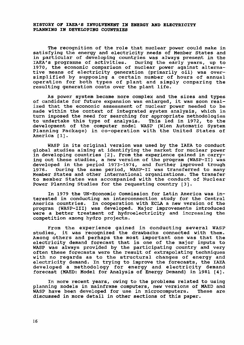
IAEA Planning MethodologiesTwo basic methodologies are available at the IAEA for under-
taking energy, electricity and nuclear power planning as listedin Table 1. These consist of: a model for the analysis of thedemand for energy and electricity called MAED (Model for Analysisof the Energy Demand) and a model for determining economicallyoptimal expansion schedules of electricity generation systemcalled WASP (Wien Automatic System Expansion Planning).
Table l IAEA Computer Programs for Energy, Electricityand Nuclear Power Planning
o Energy Planning: Model for Analysis of Energy Demand (MAED),Energy and Electricity Demand Evaluation (EDE) Model, Tech-nical University of Vienna Model (TUV)
o Electricity Supply Planning: Wien Automatic System PlanningPackage (WASP)
o Integrated: Energy and Power Evaluation Program (ENPEP)o Auxiliary: Hydro/Thermal System Simulation Model
(VALORAGUA) , Economic Evaluation of Bids (BIDEVAL) , Finan-cial Planning Model (FINPLAN), etc.
18
MAED is a simulation model, based on the so-called scenariotechnique, which provides a flexible framework for exploring theinfluence of various socioeconomic and technical factors on thelong-term evolution of energy demand. It is based on a detailedanalysis of energy demand by consumer sector (e.g. manufacturing,agriculture, transport, household, services, etc.), by end-use(thermal uses in manufacturing, cooking in household, electricityfor specific uses, etc.), and by energy form (electricity, fossilfuels, solar, etc.). Scenarios are constructed by giving theevolution of the factors affecting energy demand and MAED is thenused to evaluate the consequence in energy terms of the scenario.Special attention was paid while developing the program in orderto adapt it to the situation of developing countries and tofacilitate its application with the more limited data base whichis typical of these countries. MAED also includes some programsto give special treatment to the forecast of electricity demand,which can be calculated not only in terms of total annual needsas for other forms of energy but also in terms of the hour-by-hour distribution of power demand during the year.
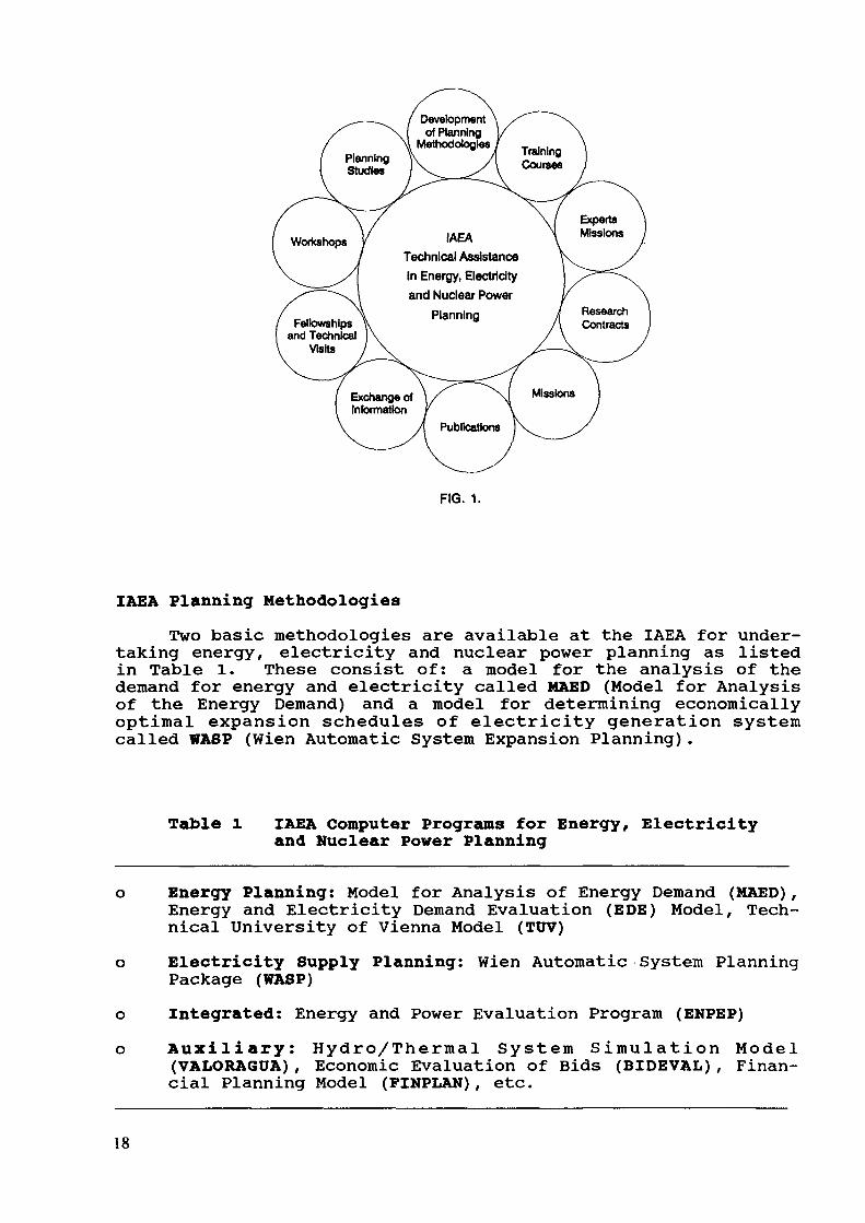
The WASP model is composed of computer programs designed todetermine the economically optimal long-term expansion of anelectric generation system. WASP uses probabilistic simulationfor determining the operating costs and reliability associatedwith different alternative paths for expanding an electric powersystem and dynamic programming techniques for economic optimiza-tion among the different alternative paths. WASP is structured ina flexible, modular system which can treat the following inter-connected parameters in an evaluation: load forecast (electricalenergy forecast, power generation system development); powerplant costs (capital, operating and fuel costs); power planttechnical parameters; power supply reliability criteria; andpower generation system operation practices.
The electric energy forecast is obtained through use of MAEDas described previously (see Figure 2). In addition to the totalannual demand for electricity, MAED provides WASP with some es-
Energy DemandForecast (MAED)
Electricity DemandRequirements
Optimal ExpansionSchedule of
the Generating System
NuclearPower
Programme
FIG. 2.
19

sential details about the estimated time distribution of thedemand, that is a basic input required for the WASP analysis.
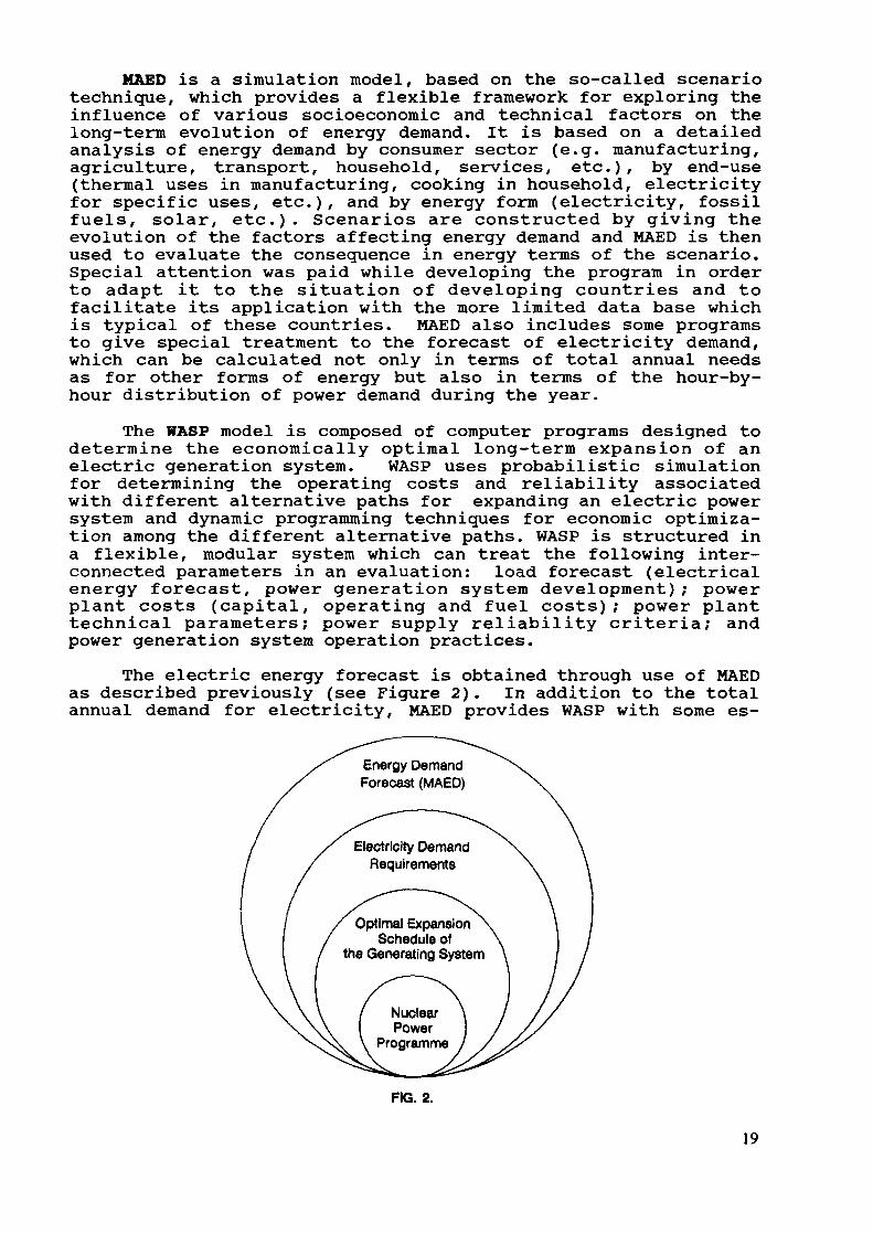
Since the ultimate objective of the IAEA in developing com-puter tools and planning methodologies is to make them availableto its Member States on a cost-free basis, large efforts are madeduring program development for adaptation to the needs ofdeveloping countries. In addition, large efforts are made in dis-seminating these tools and transferring them to interested MemberStates. For example, by end-1989, the IAEA had transferred theMAED model to 12 requesting countries and to 3 international or-ganizations. By the same date, the IAEA had transferred the WASPpackage to 60 countries and to five international organizations.These developments are summarized in Figure 3.Microcomputer-based tools
In the last 15 years, continuous progress in sophisticationand performance of PCs have encouraged their use as an alterna-tive to mainframe computers. This has somehow alleviated theproblems faced in the past by many energy/electricity planners inmany developing countries where the availability of mainframecomputers for planning purposes was given a lower priority withrespect to other applications. A dedicated personal computer (PC)would allow planners to carry out planning analyses without in-terferences from these type of application.
Following these developments, the IAEA has adapted the MAEDand WASP planning models for operation on PCs [5]. These PC ver-sions of the models are available for distribution to interestedMember States. The IAEA is also in possession of other PC-versions of MAED and WASP, which are part of a larger energy andelectricity planning package called ENPEP (ENergy and PowerEvaluation Program). ENPEP [6] is a microcomputer-based set ofprograms, developed by Argonne National Laboratory (ANL) under aproject funded by the United States Department of Energy (USDOE),and intended for overall energy and electricity planning. Apartfrom the MAED and WASP models, ENPEP integrates several otherprograms into technical modules, each one having a specific task:specifying macroeconomic growth parameters that will drive energydemand (MACRO); projections of energy demand (DEMAND); definingcharacteristics of electric power plants (PLANTDATA); determina-tion of energy supply/demand balance (BALANCE); analysis ofelectric load (LOAD); and calculation of environmental impactsand resource requirements associated with energy supply systemoptions (IMPACTS). An additional module (EXECUTIVE) is used tointegrate all technical modules and to coordinate the storage andretrieval of information used in those modules.
It is envisaged that the Agency may increase the effective-ness of its Technical Assistance programme by making available tointerested Member States the new PC versions of MAED and WASP andproviding short training courses to some of these countries.Furthermore, the Agency may be in a position to offer a completesystem including hardware and software to some interested MemberStates which lack the financial capability for acquiring an ap-propriate (large) mainframe or even a PC of the characteristicsrequired. This would obviously enhance the capabilities ofdeveloping Member States for conducting energy and nuclear powerplanning studies, an initial step required in the appraisal of
20
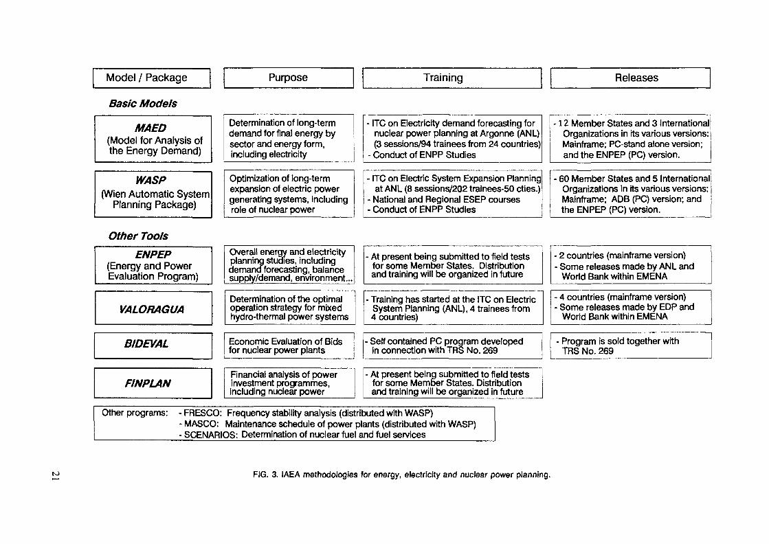
Model / Package Purpose Training Releases
Basic Models
MAED(Model for Analysis ofthe Energy Demand)
WASP(Wien Automatic System
Planning Package)
Determination of long-termdemand for final energy bysector and energy form,including electricity
Optimization of long-termexpansion of electric powergenerating systems, includingrole of nuclear power
ITC on Electricity demand forecasting fornuclear power planning at Argonne (ANL)(3 sessions/94 trainees from 24 countries)
- Conduct of ENPP Studies
ITC on Electric System Expansion Planningat ANL (8 sessions/202 trainees-50 cties.)
• National and Regional ESEP courses• Conduct of ENPP Studies
12 Member States and 3 InternationalOrganizations in its various versions:Mainframe; PC-stand alone version;and the ENPEP (PC) version.
• 60 Member States and 5 InternationalOrganizations in its various versions:Mainframe; ADB (PC) version; andthe ENPEP (PC) version.
Other ToolsENPEP
(Energy and PowerEvaluation Program)
VALORAGUA
BIDEVAL
FINPLAN
Overall energy and electricityplanning studies, includingdemand forecasting, balancesupply/demand, environment...
Determination of the optimaloperation strategy for mixedhydro-thermal power systems
Economic Evaluation of Bidsfor nuclear power plants
Financial analysis of powerinvestment programmes,including nuclear power
At present being submitted to field testsfor some Member States. Distributionand training will be organized in future
• Training has started at the ITC on ElectricSystem Planning (ANL), 4 trainees from4 countries)
Self contained PC program developedin connection with TRS No. 269
- At present being submitted to field testsfor some Member States. Distributionand training will be organized in future
Other programs: - FRESCO: Frequency stability analysis (distributed with WASP)- MASCO: Maintenance schedule of power plants (distributed with WASP)- SCENARIOS: Determination of nuclear fuel and fuel services
2 countries (mainframe version)• Some releases made by ANL and
World Bank within EMENA
• 4 countries (mainframe version)• Some releases made by EDP and
World Bank within EMENA
Program is sold together withTRS No. 269
FIG. 3. IAEA methodologies for energy, electricity and nuclear power planning.

the need and appropriate role of nuclear power in meeting the fu-ture energy requirements of the country.
Additional Computer ProgramsSeveral additional programs are also available at the IAEA
for specific purposes, as listed in Table 1. As an example, twoother computer models for energy demand analysis based on asimilar technique as MAED have been developed for the IAEA, andare used in different types of studies. These are the modelscalled TUV (Technical University of Vienna) and EDE (Energy andElectricity Demand Evaluation Model), which are intended to beused by the Agency mainly to produce quick estimates of energyand electricity demand for a country or region.
Auxiliary computer tools are also available, particularlyfor work related to the application of the WASP model forelectricity and nuclear power planning. Within this category themost important models are the so-called VALORAGUA [7] and FINPLAN[8] computer models.
The VALORAGUA Program, developed by Electricidade de Por-tugal (EDP), is a simulation model to find the optimal operatingstrategy for mixed thermal/hydro power system. The aim ofVALORAGUA is to minimize the operating costs of an electric powersystem, taking into account the physical constraints and randomconditions of the system, including the availability of water forelectricity generation. The results of the VALORAGUA detailedanalysis provide valuable information on the hydro power stationswhich can be used for the WASP optimization analysis. In a secondstage, and once the WASP optimal solution is found, VALORAGUA canbe used to check that the operation of the proposed hydro-plantsystem leads to optimal use of the generating stations. Hence,iterative application of VALORAGUA and WASP will allow to obtainthe economic advantage of hydro/thermal systems with a largehydro component.
The FINPLAN Model was developed by Credit Lyonnais Bank ofFrance in co-operation with the IAEA. FINPLAN is a PC-based modelusing spreadsheet software. One motivation for FINPLAN was thefact that the economically optimal schedule of power plant addi-tions obtained by WASP, may not be 'affordable' by the utilityand country, even if the plan satisfies all the technical andeconomic constraints. FINPLAN allows the user to analyze thefinancial impact of a power expansion programme, based on theyearly evolution of certain "ratios" commonly used by financialinstitutions in order to judge the soundness of an investmentproject or programme given the series of expenditures (costs) as-sociated with the programme and the revenues expected from it.Alternatively, FINPLAN can be used in reverse mode to calculatewhat should be the adequate tariff structure that would meet theconditions for the financial ratios to make the power expansionprogramme a sound programme of investments.
Apart from VALORAGUA and FINPLAN, other auxiliary tools arealso available but they concern specific analysis (BIDEVAL: Foreconomic evaluation of Bids for nuclear power plants; SCENARIOS:for analysis of the nuclear fuel and fuel cycle services; etc.).
22
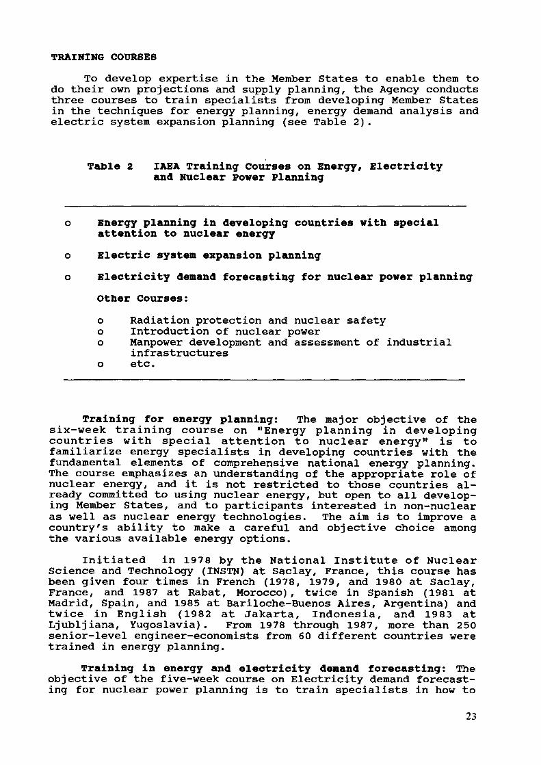
TRAINING COURSES
To develop expertise in the Member States to enable them todo their own projections and supply planning, the Agency conductsthree courses to train specialists from developing Member Statesin the techniques for energy planning, energy demand analysis andelectric system expansion planning (see Table 2).
Table 2 IAEA Training Courses on Energy, Electricityand Nuclear Power Planning
Energy planning in developing countries with specialattention to nuclear energyElectric system expansion planningElectricity demand forecasting for nuclear power planningOther Courses:o Radiation protection and nuclear safetyo Introduction of nuclear powero Manpower development and assessment of industrial
infrastructureso etc.
Training for energy planning: The major objective of thesix-week training course on "Energy planning in developingcountries with special attention to nuclear energy" is tofamiliarize energy specialists in developing countries with thefundamental elements of comprehensive national energy planning.The course emphasizes an understanding of the appropriate role ofnuclear energy, and it is not restricted to those countries al-ready committed to using nuclear energy, but open to all develop-ing Member States, and to participants interested in non-nuclearas well as nuclear energy technologies. The aim is to improve acountry's ability to make a careful and objective choice amongthe various available energy options.
Initiated in 1978 by the National Institute of NuclearScience and Technology (INSTN) at Saclay, France, this course hasbeen given four times in French (1978, 1979, and 1980 at Saclay,France, and 1987 at Rabat, Morocco), twice in Spanish (1981 atMadrid, Spain, and 1985 at Bariloche-Buenos Aires, Argentina) andtwice in English (1982 at Jakarta, Indonesia, and 1983 atLjubljiana, Yugoslavia). From 1978 through 1987, more than 250senior-level engineer-economists from 60 different countries weretrained in energy planning.
Training in energy and electricity demand forecasting: Theobjective of the five-week course on Electricity demand forecast-ing for nuclear power planning is to train specialists in how to
23

project future energy and electricity demand, the first step ofany energy planning study. In particular, participants aretrained in the use of the IAEA energy demand model MAED by con-ducting practical case studies based on their own country.During the course, attention is focussed on the overall problemsinvolved in energy planning, stressing the problems related toenergy and electricity demand forecasting. Other valuable ap-proaches to energy and electricity demand forecasting developedand used in different countries and organizations are alsodescribed to the participants.
Since 1985, three sessions of this course have been or-ganized by the IAEA at Argonne National Laboratory, U.S.A. Duringthese sessions, 94 engineers-economists from 25 countries weretrained in energy and electricity demand forecasting. Thisfigure does not include about 30 more specialists from developingcountries who have been provided with training in the use of MAEDas part of the conduct of Energy and Nuclear Power PlanningStudies for interested Member States.
Training on electric system expansion planning: The 9-weektraining course on "Electric system expansion planning (ESEP)"has the objective to train specialists in planning the expansionof power generation systems. The course emphasizes givingrealistic planning experience, through the conduct of WASP casestudies which the trainees carry out during the course based ontheir own national situation. After completion of this course,the trainee should be fully competent to carry out studies todetermine economically optimal expansion programmes including, inparticular, the economically optimal share of nuclear power.During the period 1978 to 1989, eight sessions of the ESEP coursehave been conducted by the IAEA at ANL, with a next sessionplanned for Fall 1990 also at ANL.
Including those who received training at IAEA Headquartersfrom 1975 to 1977, and the eight sessions of the training courseabove indicated, more than 250 senior engineers and power systemplanners from 60 countries and 3 international organizations weretrained by the IAEA in the use of the various versions of WASP.
Apart from the sessions of the ESEP course organized at ANLon a interregional basis, other sessions of this course have beenorganized on a national basis (China) and on a regional basis(Asia and the Pacific), adding more than 60 trainees to the totalnumber of specialists who have been trained in ESEP techniques.
Carrying out Studies for energy and nuclear power planningThe introduction of nuclear power in a country requires
careful planning of the different activities. Decisions need tobe based on conduct of a logical sequence of interrelated studiesand analyses, each one with a specific objective. At the begin-ning of the process, careful appraisal of the planningcapabilities and preparedness for future decisions is needed. Asthe process continues, several studies will be required, includ-ing those covered under the prefeasibility level (analysis of theviability of the nuclear option), and later for the feasibilityof a nuclear power programme and in particular of the firstnuclear power project.24

The IAEA may help interested Member States in the conduct ofsuch studies, but only under the condition that any such a studybe entirely carried out by national experts, with the role of theIAEA being limited to providing guidance on the study's organiza-tion and expertise throughout the conduct of the study.
Although the scope, organization, and duration of each studywill be highly dependent on the respective subject, the studiesfor energy and nuclear power planning (ENPP) conducted incooperation with some Member States can be used to illustratethese points. Other type of studies for nuclear power programmeplanning are summarized in Table 3.
Table 3 Studies for Nuclear Power Planning
o Energy and Nuclear Power Planning Studies (ENPP)o Energy and Electricity Demand Studies (HAED) Studieso Nuclear Power Planning Studies (WASP) Studieso Other Studies:
o Feasibility Studieso Studies on National Infrstructure Capabilities
for Nuclear Power Programmeso Assessment of Financial Requirements of a Nuclear
Power Programmeo Siting Studies
Carrying out Energy and Nuclear Power Planning StudiesAny country intending to launch a nuclear power programme
must take early decisions, based on careful assessment of futureenergy supply/demand planning, economic and financial implica-tions, and requirements for infrastructure and technology trans-fer. Therefore, when consideration is given to the possible in-troduction of nuclear power in the electricity generating system,the first task to be performed is a nuclear power planning study.Experience has shown that such a study should be carried outtaking into consideration the overall energy requirements of thecountry and the share that may be accorded to each alternativeform of energy (particularly electricity) in satisfying theseneeds. Energy and Nuclear Power Planning (ENPP) studies can beexecuted by the IAEA in co-operation with its developing MemberStates following a standard procedure.
The objective of this co-operation effort is to assist theMember State in detailed economic analysis and planning studiesto determine the need for and the appropriate role of nuclearpower within its national energy and development plan. Forthese purposes, the IAEA models, MAED and WASP are used in thestudy, and are released to the country. Connected with thisrelease, a large component of the effort is dedicated to provid-ing on-the-job training to a team of national specialists who areresponsible for the conduct of the studies.
25

The organization for conducting ENPP studies normally in-cludes integration of a multi-disciplinary team of nationalspecialists who are responsible for the conduct of the study.This team is to be composed by representatives of the principalnational organizations involved in the process of energy andelectricity planning at the country level. The national teamcarries the major tasks involved in the study, from gathering ofdata, execution of analysis, and the preparation of the studyreport. The role of the IAEA experts is to provide guidance andoverall coordination during the execution of the study, as wellas providing training in the use of the MAED/WASP models to thenational experts and assisting them in implementing the models onlocal computers. At the end of the process, the country shouldbe in a position to carry out planning studies working on its ownand based on the application of the transferred methodologies bythe national experts who participated in the study.
Several ENPP studies have been conducted by the IAEA in co-operation with participating Member States, some of them in co-operation with the World Bank. Reports of some of these studieshave been published by the IAEA [9, 10].
Integrated Package Approach to Nuclear Power Programme Planningin Developing Countries
There is an increasing trend to provide more comprehensiveassistance through multi-year programmes, and regional and inter-regional projects instead of through numerous small projects. Inaddition, the IAEA is implementing an integrated assistancepackage to assist developing countries in nuclear power programmeplanning. The integrated approach represents the most effectiveway of unifying IAEA's present individual activities on nuclearpower planning and implementation with developing countries needsin infrastructure and particularly manpower development.
The main objective of the IPA is to provide a clearlydefined sequential approach to nuclear power programme planningactivities from the very beginning of the process up to the ap-proval by the national authorities to implement the first nuclearpower project and the timely decisions to be made by the countryin order to meet the goal of introduction of nuclear power.
The IPA is closely related to the conduct of Nuclear Plan-ning Advisory Team (NUPAT) missions to the interested MemberState, specially constituted for each country according to itscurrent status and needs. NUPAT consists of a team of expertsvisiting the requesting country to review the current status ofnuclear power planning in the country and produce a report advis-ing the country of future and timely steps required to be under-taken for a sound decision on nuclear power.
After a NUPAT comprehensive review of the Member State'splanning and implementation status, the IAEA could propose atailor made and efficient Assistance Programme supporting thecountry in every step of the planning process. An additionalbenefit inherent to the NUPAT effort is that this comprehensivereview allows the country to become aware of what the level ofpreparedness for nuclear power introduction is and the type andextent of the work still needed to be done.
26

The whole NUPAT process may take 12-15 months, counted fromthe moment a request from the country is received by the IAEA upto the presentation of the final report to the nationalauthorities. The major output is the recommendations for futurenational activities and the role that the IAEA may play in help-ing the Member State in meeting the goal for introducing nuclearpower. It is not expected that each NUPAT mission would lead toa a nuclear power programme, but eventually would help inclarifying where the immediate needs are.
The IPA and related NUPAT missions are a new programme beingimplemented by the IAEA. Two such missions may be organized in1990 and the report and descriptive material for the IPA are alsoexpected to be concluded in 1990.
OTHER TYPE OF ASSISTANCE
Apart from the main categories of IAEA's activities innuclear power programme planning, other means are used for en-hancing the assistance provided to member States, as shown inFigure 1. Highlights of those activities directly related toenergy, electricity and nuclear power planning are given in thefollowing paragraphs.
Availability of Information/Data Banks: Important sourcesof information are maintained by the IAEA for internal statisticsand studies, as well as to serve for reference purposes. Theseinclude in particular, the International Nuclear Information Sys-tem (INIS) which contains all index and publications related tonuclear energy; the Energy and Economic Data Bank (EEDB) whichcomprises the most relevant information on country's economic,social, and energy statistics; and finally the Power Reactor In-formation System (PRIS) which compiles the major data on powerreactor status and operating performance.
Publications: Numerous publications related to nuclear powerin general and nuclear power planning and implementation in par-ticular have been made by the IAEA, including: technical reports,guidebooks, nuclear safety guides, training manuals, etc., as il-lustrated in Table 4. They are intended to serve as textbook foruse in the IAEA's training courses [11, 12, 13] and to provideguidance on specific aspects of the nuclear power planningprocess. Some other are used to serve as quick references of thestatus of nuclear power worlwide and of the IAEA estimates onenergy, electricity and nuclear power planning based on the PRISand EEDB data banks.
Regional Workshops: Regional Workshops on energy andelectricity supply and demand planning with emphasis on the MAEDand WASP models are conducted by the IAEA with the aim of foster-ing regional co-operation in these methodologies. The first ofthe workshops were organized under the IAEA/UNDP Regional Co-operative Agreement for Asia and the Pacific (Indonesia, 1987,Malaysia, 1988, China, 1989) with a fourth one planned forRepublic of Korea, 1990. A similar workshop is the present onefor countries in Europe, Middle East and North Africa, and a newone is being organized for North America and Latin America, inCosta Rica, December 1990.
27
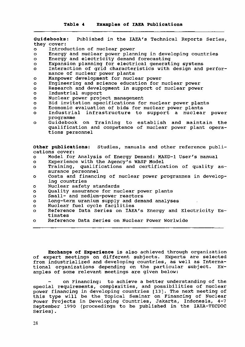
Table 4 Examples of IAEA Publications
Guidebooks: Published in the IAEA's Technical Reports Series,they cover:o Introduction of nuclear powero Energy and nuclear power planning in developing countrieso Energy and electricity demand forecastingo Expansion planning for electrical generating systemso Interaction of grid characteristics with design and perfor-
mance of nuclear power plantso Manpower development for nuclear powero Engineering and science education for nuclear powero Research and development in support of nuclear powero Industrial supporto Nuclear power project managemento Bid invitation specifications for nuclear power plantso Economic evaluation of bids for nuclear power plantso Industrial infrastructure to support a nuclear power
programmeo Guidebook on Training to establish and maintain the
qualification and competence of nuclear power plant opera-tions personnel
Other publications: Studies, manuals and other reference publi-cations cover:o Model for Analysis of Energy Demand: MAED-1 User's manualo Experience with the Agency's WASP Modelo Training, qualifications and certification of quality as-
surance personnelo Costs and financing of nuclear power programmes in develop-
ing countrieso Nuclear safety standardso Quality assurance for nuclear power plantso Small- and medium-power reactorso Long-term uranium supply and demand analyseso Nuclear fuel cycle facilitieso Reference Data Series on IAEA's Energy and Electricity Es-
timateso Reference Data Series on Nuclear Power Worlwide
Exchange of Experience is also achieved through organizationof expert meetings on different subjects. Experts are selectedfrom industrialized and developing countries, as well as Interna-tional organizations depending on the particular subject. Ex-amples of some relevant meetings are given below:
on Financing: to achieve a better understanding of thespecial requirements, complexities, and possibilities of nuclearpower financing in developing countries [13]. The next meeting ofthis type will be the Topical Seminar on Financing of NuclearPower Projects in Developing Countries, Jakarta, Indonesia, 4-7September 1990 (proceedings to be published in the IAEA-TECDOCSeries).
28

on Cost Information: to discuss the most recentdevelopment concerning generation costs of different means ofelectricity generation, including nuclear.
- on recent development of planning methodologies: in-cluding expert meetings on Experience with the MAED and WASPmodels, organized on frequent basis [14, 15]. The most recentmeeting of this series is the Advisory Group Meeting on Ex-perience with using the Agency's Model WASP for Energy andNuclear Power Planning in Developing Countries, Vienna, 21-25 May1990.
- Senior Expert Symposium on Electricity and the Environ-ment, Helsinki, Finland, 13-17 May 1991, with the main objectiveof comparing different means of meeting electricity requirements,considering both demand- and supply options, in light of theircomparative economic, environmental and health-related impacts.
Table 5 Missions and Other Means of Technical Assistance
Missions: Expert and advisory missions extend to areasincluding:o Legal framework and legislationo Nuclear safetyo Implementation of nuclear safety standardso Organizational requirementso Nuclear power planning advisory team (NUPAT)*o Financial aspects (joint missions with World Bank)o Manpower developmento Establishment of nuclear reactor training centreso Quality assuranceo Industrial surveyso Assessment of financial requirements of a nuclear power plantOther means:o Visits to regulatory organizationso Country visitso On-the-job trainingo Seminars for decision makers on the introduction of
nuclear powero Seminars for decision makers on financing schemeso Expert adviceo Market surveys for nuclear power
* This is a new activity to be implemented in 1990.
CONCLUDING REMARKS
The IAEA has the technical background and tools to support acomprehensive programme of assistance in nuclear power assess-ment, planning and implementation. Assistance can be provided onrequest, either as selected components or as a complete package,the approach that would be favoured in future.
29
The IAEA will continue to provide this unique programme ofassistance in order to strengthen the national infrastructuresfor nuclear power programme planning, as no other means areavailable to achieve these goals.
The IAEA's role always will be that of providing expertiseand guidance, and in no case as a substitute to the decision-making within the Member States. However, through the technicalassistance programme, countries will be made aware of the im-plications of their decisions.
REFERENCES
[I] Wien Automatic System Planning Package (WASP) - A Com-puter Code for Power Generating System Expansion Plan-ning, IAEA (1980).
[2] Market Survey for Nuclear Power in Developing Countries,IAEA, Vienna 1973, and Revision, Vienna, 1974.
[3] Nuclear Power Planning Studies for Member Sates (Thisseries included several reports for various countries,e.g. Indonesia, Hong Kong, Republic of Korea, etc.) IAEA,Vienna (1977-1979).
[4] Model for Analysis of Energy Demand (MAED): Users' Manualfor Version MAED-1, IAEA-TECDOC-386 (1986).
[5] Documentation of MAED and WASP-III Development on PCs andUsers' Guide, IAEA (1989).
[6] Energy and Power Evaluation Program (ENPEP): Documenta-tion and User's Manual, Argonne National Laboratory,ANL/EES-TM-317 (1987).
[7] VALORAGUA: A Model for the Optimal Management of a HydroThermal System, Electricidade de Portugal (1987).
[8] FINPLAN - Model for the Financial Analysis of ElectricExpansion Programmes. Documentation and User's Guide,IAEA Report (in preparation).
[9] Energy and Nuclear Power Planning Study for: Algeria(IAEA Technical Report, 1985), Thailand (IAEA-TECDOC-518,1989).
[10] Energy and Electricity Planning Study for Jordan, IAEA-TECDOC-439 (1987)..
[II] Energy Planning and Nuclear Power Planning in DevelopingCountries, IAEA Technical Report Series No. 245 (1985).
[12] Energy and Electricity Demand Forecasting for NuclearPower Planning in Developing Countries, A Reference Book,IAEA-TECDOC-470 (1988).
[13] Expansion Planning for Electrical Generating Systems: AGuidebook, IAEA Technical Report Series No. 241, (1984).
[14] Experience with the Agency's WASP for Nuclear Power Plan-ning in Developing Countries, IAEA-TECDOC-364 (1986).
[15] Improvements to the lAES's WASP-III, IAEA-TECDOC-433(1986).
30
EXPERIENCE OF SONELGAZ IN USING WASPFOR THE ALGERIAN POWER SYSTEM PLANNING
L. SAHOUIDirection de la planification,Société nationale de l'électricité et du gaz (SONELGAZ),Alger, Algeria
Abstract
Algeria is endowed with a vast amount of naturalgas and some hydrocarbons, and this is reflected inthe composition of the power generating system. Inorder to optimize the use of these reserves inelectricity generation leaving sufficient remnantof the annual production for exports (gas is theprincipal earning of foreign currency for thecountry), great efforts have always been made inplanning the power generating system. Differentmodels have been applied in these studies,including the MAED and WASP models. This papersummarizes the main applications and studiesconducted. Some of the principal problems faced inthe use of the MAED and WASP models are alsodiscussed.
I. ALGERIAN ELECTRICAL SYSTEM OVERVIEWa) GeneralitiesSONELGAZ (SOCIETE NATIONALE DE L'ELECTRICITE ET DU GAZ) is a
state owned company which has the responsibility of production,transmission and distribution of electricity and also of thetransportation and distribution of natural gas for domesticconsumption. Some self producers, mainly industrial factoriesoperate for their own needs about ten per cent of total nationalinstalled capacity ( 490 MW ).
The electrical system consists of a main grid called RIN(RESEAU INTERCONNECTE NORD) covering the north part of thecountry (400 000 km2) and several micro-networks which supplyisolated localities and villages of the deep south. These centersare distributed over an area of 2 millions km . Interconnectionlines exist with the neighbouring Tunisian and Moroccan grids in220 kV and 90 kV.
b) Characteristics (as of 1989)The RIN electrical plants operate mainly with natural gas
and have a combined capacity of 4230 MW. Steam turbines represent1816 MW and are located on the sea shore because of the amount ofcooling water they need, while gas turbines are installed insidethe country and represent 2230 MW.
31
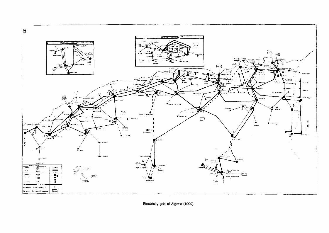
Electricity grid of Algeria (1990).

The regularised hydro generating capacity is limited to184 MW and has almost not changed for the thirty past years. Themicro plants of the south consist of small diesel units,presently less than 2 MW each, feeding small 30 kv grids. Theirtotal generating capacity is 112 MW.
The fuel needs are supplied by refineries from the northwhich pose technical and financial problems that Sonelgaz triesto solve, whenever possible, either by developing interconnectionlines with the RIN (ex: BECHAR and EL GOLEA which are going to belinked by lines of 520 km and 250 km respectively), or putting inoperation local gas fields when available.
c) Planned evolution (for the period 1990 - 2000)Most of the power plant addition program will be based on
steam turbines with the introduction of a new 300 MW level fortwelve units which will raise the RIN installed capacity in year2000 to 8500 MW to serve an estimated peak load of 6400 MW. Inaddition, a big multipurpose pump-storage hydro plant (irrigationand drinkable water supply) capable of 300 MW generation isscheduled for 1996 and also some 100 MW gas turbines.
The length of the transmission grid should reach 19 000 kmin the year 2000, while the actual length is 10 000 km.
II. GENERATING SYSTEM PLANNING BEFORE WASPRight after getting its independence (1962), Algeria faced a
period of disorganization and stagnation of its economic activitywhich resulted in a sudden drop of electricity consumption. Thenext years were devoted to the reorganization of the economy andthe creation of public companies in charge of promotingdevelopment (for example, the 1962 level of low voltageconsumption was not reached again until 1969). Meanwhile, since1967, the launching of special regional development programs andthe national plan induced important electricity consumptiongrowth rates and the necessity for investment planning tools tobe available was felt.
For several years, generating system expansion studies wereperformed with a simulation model called REVMAC (RevisionMachines). This model designed to define a yearly maintenanceprogram with regards to various constraints, also allows carryingout simulation of the operation of the generating system, andcalculates LOLP (expressed in hours), mathematical expectation ofunserved energy, fuel needs and the associated costs.
Input data consists mainly of technical characteristics forthe different units and the load duration curves by steps. Anempirical criterion of 10 h/year for LOLP allowed to judge thecapability of a configuration to satisfy a given demand.
The investment program was determined by simulation ofpossible configurations for different years. Although tiresome,this method allowed to identify, among the considered paths forsystem development, the one which resulted in the least totalcost (investment cost, operating cost, unserved energy cost).
33

As the number of configurations increases rapidly with thenumber of years or alternatives, only some were selected to besimulated. The selection of configurations was made according toa-priori fixed criteria as to the share of steam turbines and gasturbines, reserve margin, type of fuels, etc. However, nothingallowed to judge the optimality of the retained path.
This methodology has been used until 1979, although anoptimization model was available since 1974: DORA.
The DORA model (Développement Optimal du Reseau Algerien) intheory, allowed optimization of the electrical system development(generation & transmission) using linear programming, but it hasnever been concretely used due to difficulties faced to collectand enter data and also to properly read the printed outputs.
From 1980, as studies were performed with the assistance ofconsultants from EOF and IAEA the opportunity was given toSonelgaz to have two new models at its disposal: the MNI (MODELNATIONAL D'INVESTISSEMENT - EOF) and WASP.
Because it is more practical to use (modular structure) andeasier to read its results (MNI does not give the number of unitsof each type to install but a number of MW) the WASP model hasprevailed and is now used for all the generating systemdevelopment studies.
III. The Different uses of WASPOn the occasion of the energy and nuclear power study for
Algeria driven by IAEA experts, a new methodological approachwas used: the MAED-WASP approach.
The objective was to build with the MAED model, coherentforecasts of electricity and final energy demand, to deduce fromit the load curves and the load duration curves to use as inputfor WASP.
In addition to the great methodology improvements itbrought, this study has raised up a great attention and gave theopportunity to present to decision makers coherent developmentscenarii linking energy consumption to economic activity andsocial needs, and allowing to identify the share of the differentenergy forms.
Moreover, it gave the opportunity to sensibilize decisionmakers with new and important problems as:
- How to finance the electrical sector investments sinceSonelgaz appeared to become the first investor in thecountry.How to arbitrate between the satisfaction of natural gasneeds for the domestic market which appeared veryimportant in the long range and the necessity ofexporting gas to ensure the financing of the development;perspectives of exports different from hydrocarbons beingvery limited.
34

From this last question are issued the two following optionsfor electricity generation in the future which are the subjectfor intense debates:
- To build after the year 2000 mixed fired steam plantscapable of operating with gas and imported coal andincrease the investment costs.To base the generating system development on combinedcycle plants in order to improve efficiency and at thesame, reduce investment costs.
The answer, which may seem obvious a-priori, is not easy ifsome important factors associated to each candidate are taken inaccount as national integration possibilities, imported spareparts consumption, plant technical lives and also the reliabilityof combined cycles which have never been either used by anycountry as a base candidate plant nor produced in series.
The experience gained from this study and the availabilityof the MAED model were also used to define a "national energyconsumption model" based on a maximal natural gas penetration,after the substitution possibilities to other energy forms wereidentified.
This was done according to the energy resources structureamong which natural gas represents 70% of the total with 3000billions cubic meters proven reserves.
A national agency for rationalization and promotion of theenergy uses (APRUE) has also been created as a result of thisMAED study. Unfortunately, Sonelgaz has never been able to useagain MAED for the generation system planning in such anefficient way because of the difficulties met in proceeding tothe data collect and in setting collaboration with all concernedutilities.
The WASP model, instead, has been used on several occasionsamong which:
a) common planning study for Algeria and TunisiaThis study has concerned the Algerian and Tunisian power
systems separately and a fictitious set composed of the twocountries. The goal was to evaluate the possibilities of gainoffered by an optimized development for the common systemcompared to the separately optimized ones.
In fact, the gain could come from:- Improvement of load factor and reduction of common peak
load due to time lag and differences in holidaysoccurrences.
- Anticipating bigger plant size unit.Putting together the reserve margins.
The goal aimed through such studies is to identify theactions that could reinforce integration and particularly thedevelopment of new interconnection lines or the construction ofplants in common.
35
A similar study, extended to the whole Maghreb region withpossibilities of interconnection (Morocco - Algeria - Tunisia andLybia) has been recently undertaken.
These studies are obviously only academic cases because ofthe great differences in economic conditions and energy situationwithin each country, but they are a fruitful frame for exchanginginformations on respective data, methodologies and problems facedby each.
b) Generation development study for the micro-networks (RIS)The optimization study of electricity generation development
for some micro-network of the south has been an interestingexperience because it was the occasion to test the adaptation ofthe model to very small systems.
The expansion candidates were as follows :- 2 MW, 4 MW and 10 MW units for Diesel.
10 MW and 20 MW for gas turbines ( fuel fired ).The conclusion was that for small loads ( < 100 MW ) and
when the only fuel available is gas oil, diesel plants are morecompetitive than gas turbines although their capital cost ishigher.
Another very important conclusion was that, within arelatively short time (10 to 15 years) Sonelgaz would have toface an unsolvable problem of fuel supply if alternativesolutions were not developed.
The main problems faced were related first to the non-existence of statistical data which made the load forecast notreliable and second to the lack of a reference level for the LOLPcriterion or the energy not served cost.
c) Long Range Marginal Generation Costs calculationWithin the frame of the regional UNDP-World Bank project
devoted to the energy planning methodologies improvement, amethod of marginal costs calculation using the WASP and ICARUSmodels has been applied with the collaboration of ArgonneNational Laboratory (Illinois, USA).
This work was based on A. McKechnie's (World Bank)theoretical note called: "Application of wasp by World Bank inpreparing electricity pricing and investment strategy".
It resulted in the improvement of knowledges and calculationmethods related with electricity pricing. It should continue in asecond phase by the marginal transmission and distribution costdetermination to finally update the existing tariff system.
d) Medium-Term equipment program adaptationThe WASP model is used each year in the decision process of
Sonelgaz to adapt the generation investment program to the realevolution of electricity demand.
36

By using fixed expansion simulations, the planned sequenceof investments for the ten next years carried out by a previouslong range optimization is tested with updated load forecast todetermine if it is yet adapted or not, specially in concern withthe quality of service criteria (LOLP and ENS) , and if not, theschedule is then modified by postponing or anticipating plants'construction. In this way, carrying out frequent and longoptimization runs as load forecast changes is avoided, whichsaves a lot of computer resources (time and space).
Since one cannot say if the values usually applied for LOLPor ENS cost (1 day/year = 0.274; 5 DA/kwh) are the proper ones,the REVMAC model is still often used to simulate the annualoperation of some configurations to make sure that one does notgo far from the previous criterion (10 hours/year).
IV. Problems faced related to WASPWhen carrying out electricity generation expansion planning,
many problems appear, some of which due to the lack of a reliabletechnical and economic data base, while others are due to thespecial characteristics of the Algerian electrical system forwhich MAED and WASP models are not perfectly adapted.
As for MAED, the problem should be partially solved by theuse of a new version of the energy demand module allowing moreflexible sectorial breakdown capabilities and thus a betteradaptation to the economical characteristics of each country.This new version (MEDEE-S) has not yet been used in Sonelgaz.
As for WASP, the main problems faced are as follows :o Since Algeria does not produce electricity generation
equipment, the technical and economic data for theexpansion candidates are not available locally and dependon manufacturers. This is particularly sensitive for newtype candidates such as nuclear or combined cycle, forwhich several designs exist.The capital cost announced for these candidates may hidestrategies to invest a new market and become afterwardsmuch higher.In addition for the national integration policy SONELGAZintends to develop generation overcosts which aredifficult to estimate.
The Algerian generating system consists of an importantshare of gas turbines, at present or even in all futureoptimal configurations obtained in the different studies.This specificity related to the lack of important hydrocapacities for peak modulation lays out several problems:- The maximal commercial size available today for gasturbines is 100 - 120 MW. The number of 100 MW gasturbines in all long range configurations is very high
37

(almost a hundred) which induces important computingtimes and make it necessary to use a greater sizecandidate (200 MW) to reduce their number.The retirement of expansion candidate is not allowed byWASP which compels, when the study period exceeds 15-20years, to force the reinvestment of same units (GT)after the end of their life. This introduces a bias andmay change the solution, specially when several unitsare added the same year.The gas turbine efficiency is very sensitive to thetemperature and the power drop can reach 30% at 50°C.Algeria being a very hot country, this temperaturefrequently occurs and the power fall can not be takeninto account in the MERSIM module.
The water transfer project associated with a pumpedstorage plant in BENI HAROUN (400 MW pumping and 300 MWgeneration capacity) will set to Sonelgaz a new problemto simulate its operation during the year and introduceit in WASP studies.As pointed out previously, the combined cycle seems avery good expansion candidate for the Algerian generationsystem but besides the problems noticed for gas turbinesit has the inconvenient of complexity when trying to takeit as a candidate. Indeed it is composed of three or evenfour different units and its equivalent characteristicschange according to the way it is operated or built.For instance, the base and peak block capacities, the ef-ficiency, the forced outage rate and even maintenancetime may change. The scheduled outage for maintenance ofa gas turbine do not compel to stop all the plant and thesame is valid for the steam turbine.Another problem is that combined cycle can be built intwo or three phases, i.e. begin with the GT and later on,maybe several years, transform the plant by addition ofthe steam turbine portion.Because of these problems, all the studies achieved untilnow concerning the place combined cycle could take in thegenerating system have not been reliable or convincing.
CONCLUSION
The introduction of MAED and WASP models have constituted adecisive step for improvement of the generation planning andenergy demand study methodologies, but these tools cannot make upfor the lack of data as perfect as they may be. So a great andpermanent effort has to be done to create the necessary databases and to have it updated.
38

Also, although some improvements can be made, no model canbe perfectly adapted to the needs of all users and the "optimal"solution will always be based on explicit or implicit assumptionsand simplifications of the system for modeling purposes. So itseems better for us to invest in training to get good plannerswith a good critical sense than in developing more and moresophisticated models.
In this case, one of the obstacles to develop local trainingof WASP users is simply the lack of french language documentationand this local training is necessary for us to make up for lossesof human resource trained through IAEA's specialized courses.
39
GENERATION EXPANSION PLANNING AND LONG RUNMARGINAL COST CALCULATIONS USING THEENPEP-OVASP) COMPUTER PACKAGE
C. CHARALAMBOUSElectricity Authority of Cyprus,Nicosia, Cyprus
Abstract
The association of the Electricity Authority ofCyprus (EAC) with the IAEA commenced with a trainingcourse on Electric System Expansion Planning and theuse of WASP-III at Argonne National Laboratory, latein 1984. At that time both the Government of Cyprusand EAC relied mostly on external Consultants forconduct of energy and electricity planning studies. Agreat effort was therefore required to establishthis, new for Cyprus, planning methodology. Therelease of ENPEP which is an integrated PC-basedEnergy and Power Evaluation package made the use ofWASP very much easier and accessible to power systemplanners. Through continuous efforts these computersmodels have now been established in the Planning Pro-cedures of EAC and are used extensively to a degreethat it was difficult to imagine five years ago.This paper contains some of the experiences gained inthe use of these models in electric system expansionplanning and the long run marginal cost analysis.
1. INTRODUCTION
The WASP-III Computer model has established itself as oneof the leading computer packages for Generation System ExpansionPlanning. The release of ENPEP, a microcomputer based energyplanning program which includes the WASP III, will make an evengreater impact for the following reasons:
1. It provides planners with a tool which is easilyaccessible without having to rely to inconvenientand expensive main frame computers.
2. Like most PC packages, it is "user-friendly",making its use faster and more efficient. Itprovides a state of the art Energy Analysis andElectric System Expansion Planning capabilities todeveloping countries.
3. Despite certain limitations, these packages areboth useful and usable. Useful because there is nolimit to the analysis that can be carried out andusable since, with the right training, plannershave access to powerful tools and "in house"facilities to carry out complete studies and toinvestigate numerous scenarios as required.
41
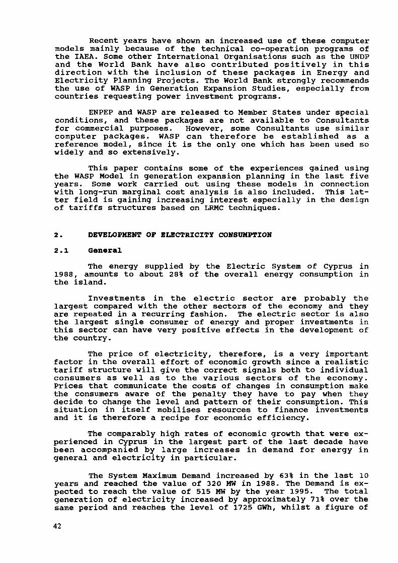
Recent years have shown an increased use of these computermodels mainly because of the technical co-operation programs ofthe IAEA. Some other International Organisations such as the UNDPand the World Bank have also contributed positively in thisdirection with the inclusion of these packages in Energy andElectricity Planning Projects. The World Bank strongly recommendsthe use of WASP in Generation Expansion Studies, especially fromcountries requesting power investment programs.
ENPEP and WASP are released to Member States under specialconditions, and these packages are not available to Consultantsfor commercial purposes. However, some Consultants use similarcomputer packages. WASP can therefore be established as areference model, since it is the only one which has been used sowidely and so extensively.
This paper contains some of the experiences gained usingthe WASP Model in generation expansion planning in the last fiveyears. Some work carried out using these models in connectionwith long-run marginal cost analysis is also included. This lat-ter field is gaining increasing interest especially in the designof tariffs structures based on LRMC techniques.
2. DEVELOPMENT OF ELECTRICITY CONSUMPTION2.1 General
The energy supplied by the Electric System of Cyprus in1988, amounts to about 28% of the overall energy consumption inthe island.
Investments in the electric sector are probably thelargest compared with the other sectors of the economy and theyare repeated in a recurring fashion. The electric sector is alsothe largest single consumer of energy and proper investments inthis sector can have very positive effects in the development ofthe country.
The price of electricity, therefore, is a very importantfactor in the overall effort of economic growth since a realistictariff structure will give the correct signals both to individualconsumers as well as to the various sectors of the economy.Prices that communicate the costs of changes in consumption makethe consumers aware of the penalty they have to pay when theydecide to change the level and pattern of their consumption. Thissituation in itself mobilises resources to finance investmentsand it is therefore a recipe for economic efficiency.
The comparably high rates of economic growth that were ex-perienced in Cyprus in the largest part of the last decade havebeen accompanied by large increases in demand for energy ingeneral and electricity in particular.
The System Maximum Demand increased by 63% in the last 10years and reached the value of 320 MW in 1988. The Demand is ex-pected to reach the value of 515 MW by the year 1995. The totalgeneration of electricity increased by approximately 71% over thesame period and reaches the level of 1725 GWh, whilst a figure of42
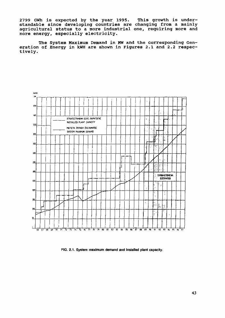
2799 GWh is expected by the year 1995. This growth is under-standable since developing countries are changing from a mainlyagricultural status to a more industrial one, requiring more andmore energy, especially electricity.
The System Maximum Demand in MW and the corresponding Gen-eration of Energy in kWH are shown in Figures 2.1 and 2.2 respec-tively.
600
SM
V»
IS
iOO
J»
KO
»0
KO
tno
so
•^f
\
lx-— —
1
X
ErKAIEITHMENH IDCYE nARUnjTHI~" " INSTALLED RANT CAPACITY
«EdlTH ZHTHEH ntTHfttTOrSYSTEM MAXIMUM DEMAND
rJ-x
.»-" /\
1
1—J
/ "
1
^:=
1
^ -
^
—
/
rij
__ — ^~
i
it
xx7
66 67 ' 68 ' 69 ' 70 71 72 ' 73 ' 7C-' 75 ' 76 ' 77 ' 78 ' 79 80 81 82 83 84 85 ' 86 ' 87 ' 88
»
rii1-
^
>
m«i6ir
y
V
5-
xs?
'/
-
ï- J
'
/
/
i
/
J, nPOBAEnOHENH' EST1HATED
-
•
?
|
'
-;
x
9 90 ' 91 ' 92 93 9t 95 96 97
FIG. 2.1. System maximum demand and installed plant capacity.
43
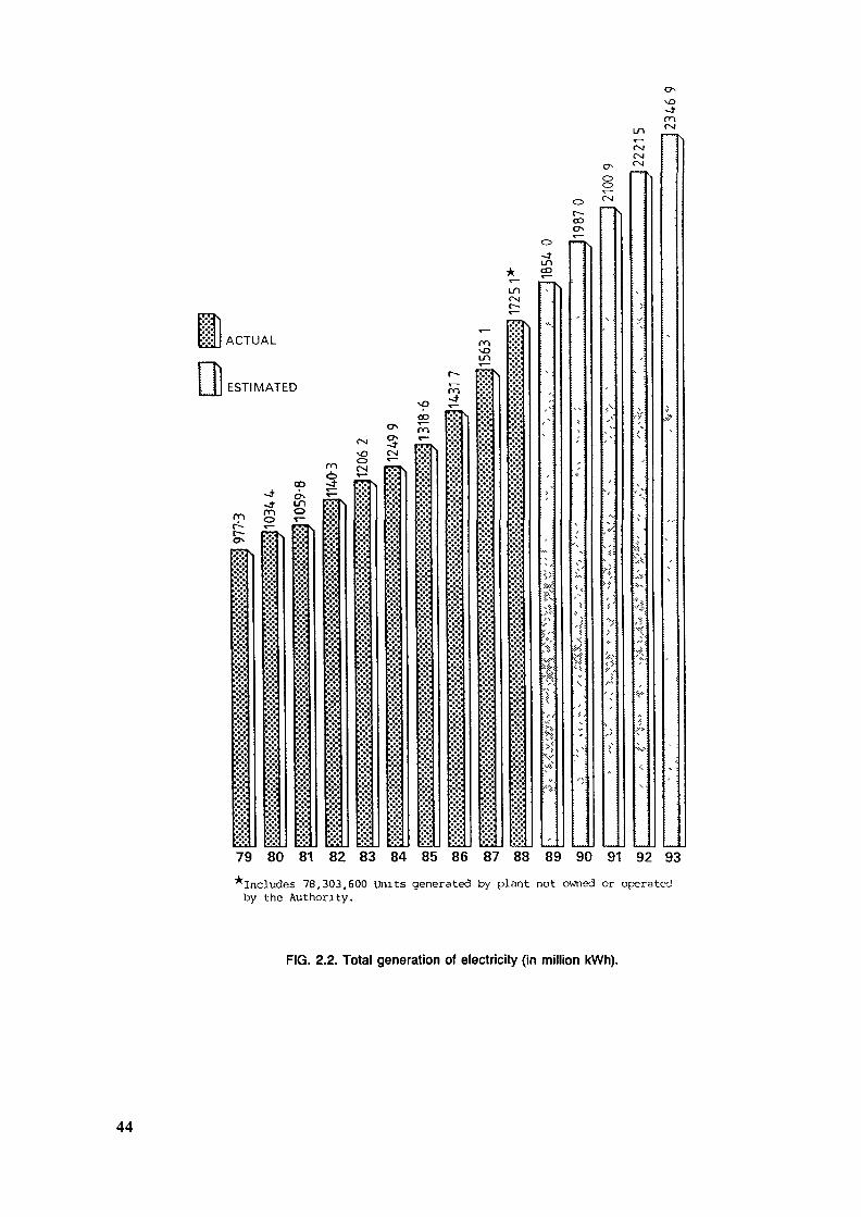
ACTUAL
ESTIMATED
m\oin
mö-d-
rsivOCSJ
5CSI
vJDCOrn
m Oo r-
U1CD
oo
CSICsl
vO<tm
79 80 81 82 83 84 85 86 87 88 89 90 91 92 93^Includes 78,303,600 Units generated by plnnt not owned or operatedby the Authority.
FIG. 2.2. Total generation of electricity (in million kWh).
44
2.2 The Electricity Supply SystemThe Electric Power System of Cyprus consists at the moment
exclusively of oil-fired thermal power plant. The installedcapacity in 1988 was 342 MW.
A number of major projects covering the Generation, Trans-mission and Distribution of electrical energy were implemented inthe last ten years in order to meet the increase in demand and toimprove the security and reliability of supply. The most impor-tant projects were associated with the construction of the newOil Fired Power Station, 'Dhekelia B' which was designed for 6 x60 MW units, and the upgrading of the major Transmission Networkof the Authority to 132 kV, a voltage level which will adequatelymeet the needs of the system in the year 2000.
As part of the above project, two new 60 MW oil firedunits (units 3 & 4 at Dhekelia 'B') bagan commercial operation inthe Spring and summer of 1989, making the total installedCapacity to 462 MW. Expected Maximum Demand in the same year is349 MW.
The Authority's main generation and transmission networkis shown on the attached map of Cyprus (Figure 2.3).
GENERATING STATIONS
® 132/66(11 kV SUBSTATIONS
B 132/11 kV SUBSTATIONS
• ««11 W SUBSTATIONS
—— 132 kV OVERHEAD LINES
—•• 132 KV UNDERGROUND CABLES
—— 132 kV OVERHEAD LINES OPERATEDAT«kVte kV OVERHEAD LINES
FIG. 2.3. Generating and transmission system (1988).
45
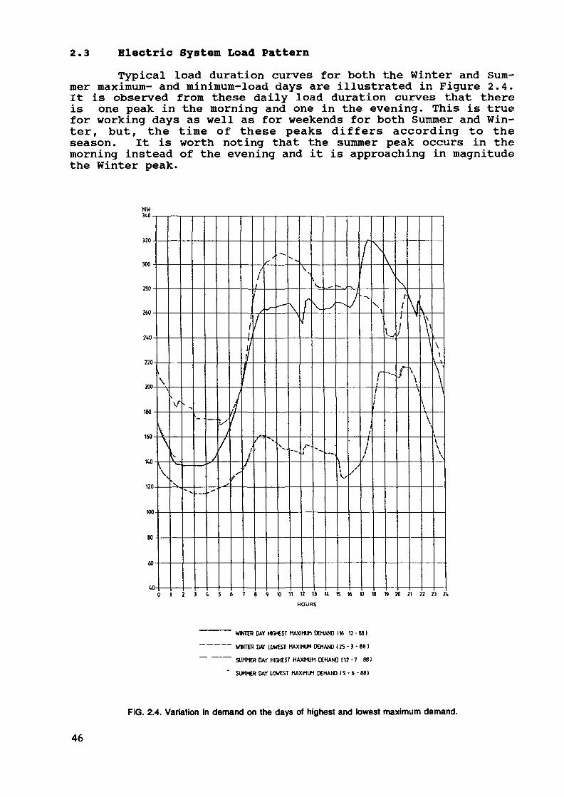
2.3 Electric System Load PatternTypical load duration curves for both the Winter and Sum-
mer maximum- and minimum-load days are illustrated in Figure 2.4.It is observed from these daily load duration curves that thereis one peak in the morning and one in the evening. This is truefor working days as well as for weekends for both Summer and Win-ter, but, the time of these peaks differs according to theseason. It is worth noting that the summer peak occurs in themorning instead of the evening and it is approaching in magnitudethe Winter peak.
MW340
320
3001\
280
f
240
220
200.
180
160
KO
120
»0
80
60
to0 1 2 3 4 5 6 7 8 9 10 11 12 13 It 15 16 n 18 19 20 21 22 23
HOURS
WKTER DAY HEHEST MAXIMUM DEMAND (« 12 - 881
WINTER DAY LOWEST MAXIMUM DEMAND 125 - 3 - 88 ]
SUMMER DAT HIGHEST MAXIMUM CEMAND [12-7 881
SUMMER DAY LOWEST MAXIMUM DEMAND (5-6 -88)
FIG. 2.4. Variation in demand on the days of highest and lowest maximum demand.
46
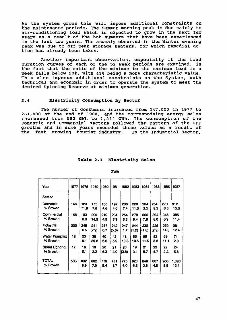
As the system grows this will impose additional constraints onthe maintenance periods. The Summer morning peak is due mainly toair-conditioning load which is expected to grow in the next fewyears as a result-of the hot summers that have been experiencedin the last two years. The anomaly observed in the Winter eveningpeak was due to off-peak storage heaters, for which remedial ac-tion has already been taken.
Another important observation, especially if the loadduration curves of each of the 52 week periods are examined, isthe fact that the ratio of the minimum to the maximum load in aweek falls below 50%, with 43% being a more characteristic value.This also imposes additional constraints on the System, bothtechnical and economic in order to operate the system to meet thedesired Spinning Reserve at minimum generation.
2.4 Electricity Consumption by SectorThe number of consumers increased from 147,000 in 1977 to
261,000 at the end of 1988, and the correspodning energy salesincreased from 582 GWh to 1,214 GWh. The consumption of theDomestic and Commercial sectors followed the pattern of the GDPgrowths and in some years exceeded these values as a result ofthe fast growing tourist industry. In the Industrial Sector,
Table 2.1 Electricity Sales
GWh
Year
Sector
Domestic% Growth
Commercial% Growth
Industrial% Growth
Water Pumping% Growth
Street Lighting% Growth
TOTAL% Growth
1977
146
168
233
18
17
583
1978
16311.9
1838.6
2486.5
209.1
185.1
6328.5
1979
1757.6
20914.5
241(2.9)
3889.6
192.2
6827.9
1980
1834.6
2194.5
2576.7
406.0
206.3
7195.4
1981
1924.6
2346.9
242(5.6)
425.9
214.0
7311.7
1982
2067.4
2548.8
2471.7
4813.8
20(3.8)
7756.0
1983
22811.0
2789.4
244(1.2)
5310.5
193.1
8236.2
1984
2342.5
3007.8
232(4.8)
5911.5
218.7
8462.8
1985
2548.3
3248.0
225(2.9)
625.6
224.7
8874.8
1986
2706.3
3466.9
25914.8
6911.1
222.2.
9668.9
1987
31215.3
38511.4
29112.4
712.0
245.8
1,08312.1
47
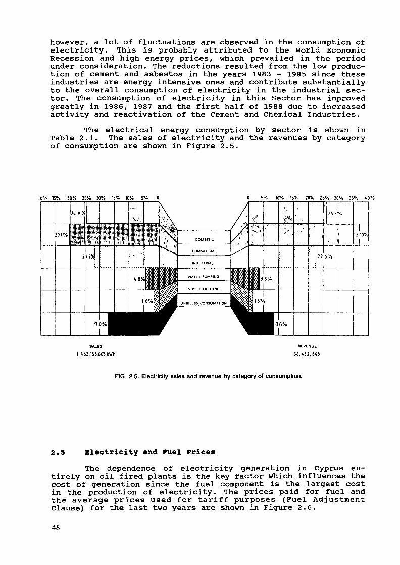
however, a lot of fluctuations are observed in the consumption ofelectricity. This is probably attributed to the World EconomicRecession and high energy prices, which prevailed in the periodunder consideration. The reductions resulted from the low produc-tion of cement and asbestos in the years 1983 - 1985 since theseindustries are energy intensive ones and contribute substantiallyto the overall consumption of electricity in the industrial sec-tor. The consumption of electricity in this Sector has improvedgreatly in 1986, 1987 and the first half of 1988 due to increasedactivity and reactivation of the Cement and Chemical Industries.
The electrical energy consumption by sector is shown inTable 2.1. The sales of electricity and the revenues by categoryof consumption are shown in Figure 2.5.
40% 35% 30% 25% 20% 15% 10% 5% 0 0 5% 10% 15% 20% 25% 30% 35% 40%
SALES
1,463,156.665 kWhREVENUE
56,432,645
FIG. 2.5. Electricity sales and revenue by category of consumption.
2.5 Electricity and Fuel PricesThe dependence of electricity generation in Cyprus en-
tirely on oil fired plants is the key factor which influences thecost of generation since the fuel component is the largest costin the production of electricity. The prices paid for fuel andthe average prices used for tariff purposes (Fuel AdjustmentClause) for the last two years are shown in Figure 2.6.
48
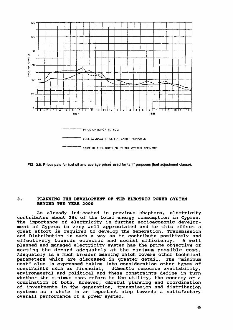
120
100
80
60-
20-
4 I 5 I 10 11 12 10 11 I 121987 1988
PRICE OF IMPORTED FUEL
FUEL AVERAGE PRICE FOR TARIFF PURPOSES
PRICE OF FUEL SUPPLIED BY THE CYPRUS REFINERY
FIG. 2.6. Prices paid for fuel oil and average prices used for tariff purposes (fuel adjustment clause).
3. PLANNING THE DEVELOPMENT OF THE ELECTRIC POWER SYSTEMBEYOND THE YEAR 2000
As already indicaated in previous chapters, electricitycontributes about 28% of the total energy consumption in Cyprus.The importance of electricity in further socioeconomic develop-ment of Cyprus is very well appreciated and to this effect agreat effort is required to develop the Generation, Transmissionand Distribution in such a way as to contribute positively andeffectively towards economic and social efficiency. A wellplanned and managed electricity system has the prime objective ofmeeting the demand adequately at the minimum possible cost.Adequately is a much broader meaning which covers other technicalparameters which are discussed in greater detail. The "minimumcost" also is expressed talcing into consideration other types ofconstraints such as financial, domestic resource availability,environmental and political and these constraints define in turnwhether the minimum cost refers to the utility, the economy or acombination of both. However, careful planning and coordinationof investments in the generation, transmission and distributionsystems as a whole is an important step towards a satisfactoryoverall performance of a power system.
49
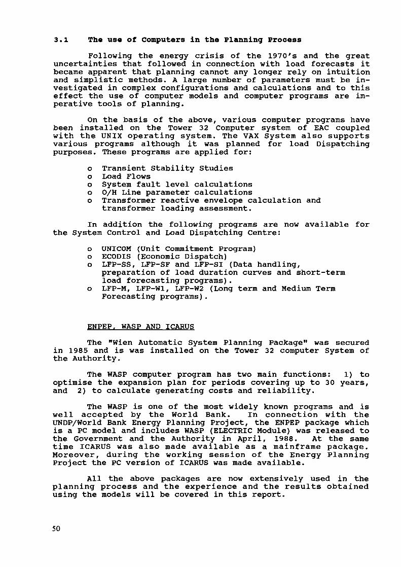
3.1 The use of Computers in the Planning ProcessFollowing the energy crisis of the 1970's and the great
uncertainties that followed in connection with load forecasts itbecame apparent that planning cannot any longer rely on intuitionand simplistic methods. A large number of parameters must be in-vestigated in complex configurations and calculations and to thiseffect the use of computer models and computer programs are im-perative tools of planning.
On the basis of the above, various computer programs havebeen installed on the Tower 32 Computer system of EAC coupledwith the UNIX operating system. The VAX System also supportsvarious programs although it was planned for load Dispatchingpurposes. These programs are applied for:
o Transient Stability Studieso Load Flowso System fault level calculationso O/H Line parameter calculationso Transformer reactive envelope calculation and
transformer loading assessment.In addition the following programs are now available for
the System Control and Load Dispatching Centre:o UNICOM (Unit Commitment Program)o ECODIS (Economic Dispatch)o LFP-SS, LFP-SF and LFP-SI (Data handling,
preparation of load duration curves and short-termload forecasting programs).
o LFP-M, LFP-Wl, LFP-W2 (Long term and Medium TermForecasting programs).
ENPEP. WASP AND ICARUSThe "Wien Automatic System Planning Package" was secured
in 1985 and is was installed on the Tower 32 computer System ofthe Authority.
The WASP computer program has two main functions: 1) tooptimise the expansion plan for periods covering up to 30 years,and 2) to calculate generating costs and reliability.
The WASP is one of the most widely known programs and iswell accepted by the World Bank. In connection with theUNDP/World Bank Energy Planning Project, the ENPEP package whichis a PC model and includes WASP (ELECTRIC Module) was released tothe Government and the Authority in April, 1988. At the sametime ICARUS was also made available as a mainframe package.Moreover, during the working session of the Energy PlanningProject the PC version of ICARUS was made available.
All the above packages are now extensively used in theplanning process and the experience and the results obtainedusing the models will be covered in this report.
50

3.2 Information Technology and SCADA systemsA study has been initiated in order to formulate a
strategy for the introduction, development and operation of anappropriate Information Technology System to enable the Authorityto meet its business objectives in the medium and long-term.
Two aspects will be considered within a single strategy.a) An IT strategy based on a comprehensive study of
the requirements in all main service areas of EAC.b) A supervisory control and data acquisition scheme
(SCADA) for the System Control Centre.The supervisory control and data acquisition scheme will
use an on-line computer system to optimise the monitoring andcontrol of the generation/transmission system. The main purposeof such systems is to improve the quality of decision taken bythe Control Duty Engineers in terms of increased systemreliability reduced operating costs.
3.3 The Transmission networkThe present 10-year development plan of the Authority
covers the period 1987-1996 and the principles underlying thedesign of the Transmission Network are described in brief below:
The design of the transmission network is based oncriteria of satisfactory voltage and loading levels under maximumanticipated energy flow conditions. Taking into consideration thelocation of the power plants in relation to the major loadcentres, the most critical transmission conditions correspond tothe hour of the maximum demand in each year.
The first principle underlying transmission system designis to meet set requirements and provide a sufficient reservecapacity to prevent cascading in case one of its elements failsi.e. the (N-l) criterion. The criterion for the satisfaction forthis principle under current system configuration is to ensureproper system operation when one feeder of the double circuit 132kV lines is lost.
A second principle applied during this development plan isto ensure for certain major areas of the country supply of theirfull load even if all generating capacity from one Power Stationis lost. To this effect the transmission network should be ableto supply the power required from outside the area considered,satisfying the N-l principle mentioned.
Tapped connections of loads on 132 kV transmission linesconnecting power stations through which considerable amounts ofelectric energy flow systematically, are not allowed.
Solid transmission network grounding is provided throughthe neutral nodes of the step-up and step-down transformers andautotransformers.
51

The main protection for overhead transmission lines is ofthe impedance type. Back-up O/C protection is also provided. Im-pedance protection to the 132 kV lines is applied with a transfertripping scheme based on pick-up and direction criteria. All 132kV lines are equipped with distance protection systems with HF(Power Line Carrier) transfer tripping or transfer blocking sig-nals to achieve correct and fast clearing of faults, to limitstability problems. Delayed auto-reclosing is also provided. Tothis effect a comprehensive Transmission Study which will coverthe requirements of the system for the next 15 years is now beencarried out.
3.4 Prospects up to 1997In this period a further development of the 132 kV network
is planned in order to ensure reliable transmission of electricenergy from the power stations to the major consumer centres.
Work has already commenced for the reinforcement of theDhekelia-Sotera- Protaras network with the introduction of a132kV system to cater for the increasing demand due to tourismdevelopment in the Southeast part of the country. This projectalso covers the upgrading of the Larnaca System from 66 kV to 132kV. All this work is expected to be completed by the year 1990.
The three power stations, Dhekelia, Vassilikos and Moniwill be interconnected via strong 132 kV links to the principalconsumer centres, and especially Nicosia, the capital which isthe largest consumer centre.
In order to meet the growing demand in the various loadcentres, it is planned to establish new transmission substations-and to extensively reinforce existing ones, by increasing theirtransformer capacity thus improving the security and reliabilityof supply to these areas. In this respect, new lines will berequired between Athalassa and Strovolos substations, Paphos andPolis substations. New indoor type (SF6) Substations will be es-tablished in Nicosia and Limassol in order to meet the growingdemand of the next decade.
3.5 DistributionThe main distribution system voltage is at 11 kV. The
distribution system extensions and reinforcements for the periodunder review is designed to meet increased demand from existingconsumers and new demand from major industrial and commercialconsumers. It will also cover the establishment of new IndustrialEstates and the extension of existing ones.
Another major feature of this plan is the need to meet theincreasing demand from tourism development along the entire coastfrom Paralimni to Polis.
During this period the studies for the large distributioncentres will be regularly reviewed using the available computerprograms in order to increase the security and reliability ofsupply to the consumers and to improve the system efficiency.
52

The planned distribution system extensions and reinforce-ments will benefit about 110,000 new consumers who are expectedto be connected on the system up to the year 1995. By the end ofyear 1991 the number of consumers connected on to the Authority'sSystem is expected to rise up to 360,000.
4. GENERATION EXPANSION PLANNINGExisting SystemThe existing generating system of EAC is all thermal steam
plant with a total installed capacity in 1989 of 452 MW asfollows:
DHEKELIA POWER STATION 4 X 50 MW (OIL)MONI POWER STATION 6 X 30 MW (OIL)DHEKELIA OLD 3 X 14 MW (OIL)
The estimated maximum demand of the system for year 1989is 349 MW. The problem phasing EAC is to meet the Maximum Demand.This problem is becoming more acute since the Winter and Summerpeak demands are almost identical, making it very difficult forthe Authority to maintain the plant.
Because of high economic activity in the island and therelatively low energy prices of the last few years large in-creases in the consumption of electrical energy and the maximumdemand have been experienced. These increases are in the regionof 9-11% imposing an additional burden to the Authority.
Another factor which has been gaining increasing impor-tance is the environmental impact. Economic factors alone can nolonger define the generation expansion programme of a Utility,environmental issues being as equally important. This is a factorwhich may delay decision making, and Utilities must be preparedto face this kind of situations.
Technical and Economic Parameters for the WASP ModelThe most difficult part of a study to determine generation
expansion programmes is the definition of the technical andeconomic parameters that must be used in the Study.
The effect of uncertainty is of prime importance instrategic planning. Such uncertainties exist with respect to loadgrowth, load shape, unit construction costs, fuel cost and newenergy sources. The environmental impact of general expansionplanning is of paramount importance and these parameters whichare usually exogenous and on which the Utility has very littlecontrol must be seriously considered after the optimum solutionhas been reached.
Some of the most difficult parameters are the constructioncosts of candidate units, especially for those associated withtechnologies which are not already available within a utility,and secondly the cost of fuel. These two costs and especially the
53

cost of fuel over a long time horizon, influence drastically theOptimum Solution and this factor must be tediously tested throughextensive sensitivity studies.
In small isolated systems such as the one of Cyprus, thereserve margin and the Loss of Load Probability (LOLP) must begiven very serious consideration. On the other hand an increasedreserve margin beyond the level required (and thus a more strin-gent LOLP criterion) will impose an additional financial burdento the utility and as a consequence to the consumers.
Consideration of Expansion OptionsCyprus has no resources of its own, and relies entirely on
imported energy. All generating units at the moment use HeavyFuel Oil, (HFO) and they are all steam plant. The Authority hasalready decided to proceed with the installation of a 5th 60 MWOil Unit at Dhekelia which is expected to be commissioned in 1993and two gas turbines (GT) 37 MW each which must be in operationby January, 1992. The GT's will use distillate fuel.
The latest expansion study for EAC, which was completed inthe last few days was aimed at defining a Medium Term ExpansionPlan Within a Long-Term Expansion Planning. The ELECTRIC Module(WASP III) of the ENPEP package was used in the study.
The Options which were considered were the following:- Oil- Coal
Combined Cycle (Using distillate fuel), and- Gas Turbines again using distillate fuel.There is no natural gas available in Cyprus and at present
there is no consideration of importing LNG because of the highcapital expenditure that would be required for this facility.Such a possibility could be ideal because natural gas is a veryclean fuel and the operation of such a station is much simplerthan any other conventional power station.
The System of Cyprus is very small and it can be very ac-curately represented in the WASP model. However, with this laststudy certain requirements and limitations made the analysis muchmore complex and tedious, requiring very careful consideration.Some of these requirements are outlined below.
In the case of a new power station, being oil or coal, thefirst two units carried most of the infrastructure of the stationand subsequent units were considered as extension units. Con-sequently, the construction costs of the first 2 units and theextension units were different.
The new power station is planned to be constructed in theVassilikos Area. So the units were classified as follows:
VSOL (Vassilikos Oil Units 1,2)VSOE (Vassilikos Oil extension, for subsequent units)VSCO (Vassilikos Coal Units 1,2)VSCE (Vassilikos Coal Extension for subsequent units).
54
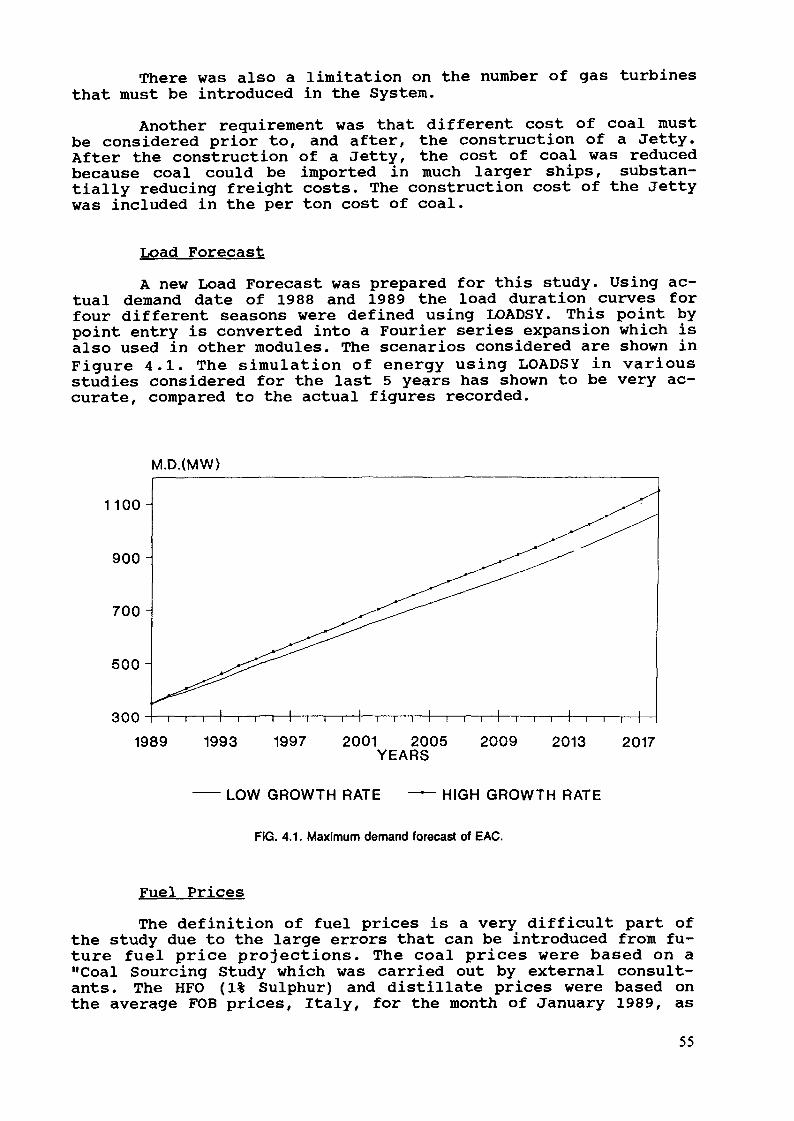
There was also a limitation on the number of gas turbinesthat must be introduced in the System.
Another requirement was that different cost of coal mustbe considered prior to, and after, the construction of a Jetty.After the construction of a Jetty, the cost of coal was reducedbecause coal could be imported in much larger ships, substan-tially reducing freight costs. The construction cost of the Jettywas included in the per ton cost of coal.
Load ForecastA new Load Forecast was prepared for this study. Using ac-
tual demand date of 1988 and 1989 the load duration curves forfour different seasons were defined using LOADSY. This point bypoint entry is converted into a Fourier series expansion which isalso used in other modules. The scenarios considered are shown inFigure 4.1. The simulation of energy using LOADSY in variousstudies considered for the last 5 years has shown to be very ac-curate, compared to the actual figures recorded.
M.D.(MW)
1100-
900-
700 -
500-
3001989 1993 1997 2001 2005 2009 2013 2017
YEARS
LOW GROWTH RATE HIGH GROWTH RATE
FIG. 4.1. Maximum demand forecast of EAC.
Fuel Prices
The definition of fuel prices is a very difficult part ofthe study due to the large errors that can be introduced from fu-ture fuel price projections. The coal prices were based on a"Coal Sourcing Study which was carried out by external consult-ants. The HFO (1% Sulphur) and distillate prices were based onthe average FOB prices, Italy, for the month of January 1989, as
55
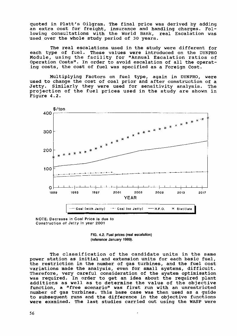
quoted in Platt's Oilgram. The final price was derived by addingan extra cost for freight, insurance and handling charges. Fol-lowing consultations with the World Bank, real Escalation wasused over the whole study period of 30 years.
The real escalations used in the study were different foreach type of fuel. These values were introduced on the DYNPROModule, using the facility for "Annual Escalation ratios ofOperation Costs". In order to avoid escalation of all the operat-ing costs, the cost of fuel was specified as a Foreign Cost.
Multiplying Factors on fuel type, again in DYNPRO, wereused to change the cost of coal prior and after construction of aJetty. Similarly they were used for sensitivity analysis. Theprojection of the fuel prices used in the study are shown inFigure 4.2.
400
300 -
200 -
100
$/ton
1989 1993 1997 2001 2005
YEAR2009 2013 2017
—— Coal (with Je t ty ) - — - C o a l (no Jet ty ) ——H.F.O. * Distillate
NOTE: Decrease in Coal Price is due toConstruction of Jetty in year 2001
FIG. 4.2. Fuel prices (real escalation)(reference January 1989).
The classification of the candidate units in the samepower station as initial and extension units for each basic fuel,the restriction in the number of gas turbines, and the fuel costvariations made the analysis, even for small systems, difficult.Therefore, very careful consideration of the system optimisationwas required. In order to get an idea about the required plantadditions as well as to determine the value of the objectivefunction, a "free scenario" was first run with an unrestrictednumber of gas turbines. This base case was then used as a guideto subsequent runs and the difference in the objective functionswere examined. The last studies carried out using the WASP were
56

somewhat different, because they were aimed at examining theMedium Term Generation Expansion Programme which is available tothe Authority prior to the establishment of a new power station.
The objective was to identify the economic and technicallysound solutions that must be pursued in order to meet the newforecasts of demand, at the same time satisfying the technicalrestrictions and operating criteria for a reliable system in linewith modern trends and expectations.
Some of the outputs obtained using the WASP Model are in-cluded in the report to facilitate the discussion. Table 4.1shows two of the solutions which were investigated as possibleoptions to EAC. Figure 4.3. shows the system maximum demand andreserve margin. The base plant and peaking plant is also shown.
Very important observations can be made from theseresults.
a) Reserve Margin - A minimum reserve margin of 20% wasspecified with a maximum of 40%.In 1991 the 20% margin had to be relaxed since the leadtimes of new plants could not permit making additionsin this year. The first observation is that the intro-duction of the first 2 gas turbines must be acceleratedas much as possible.
b) The reserve margin is satisfied with the introductionin the system of more gas turbines i.e. the role of gasturbines is to provide a low cost source of standbycapacity (to satisfy the Reserve Margin requirements)and at the same time to provide peaking power.
c) It was established that the introduction of additionalgas turbines prior to the construction of a new powerstation was very robust in increases in fuel costs,construction costs and variation in the discount rate.The contribution of gas turbines in the energy produc-tion was then more closely examined using a moredetailed MERSIM output for specific years. Other Modelssuch as ICARUS which can look into greater detail maybe used for further analysis.
d) It was also established that the Medium Term expansionplan was itself a Least Cost Solution since it was partof an overall Least Cost Solution covering a 30 yearperiod.
57
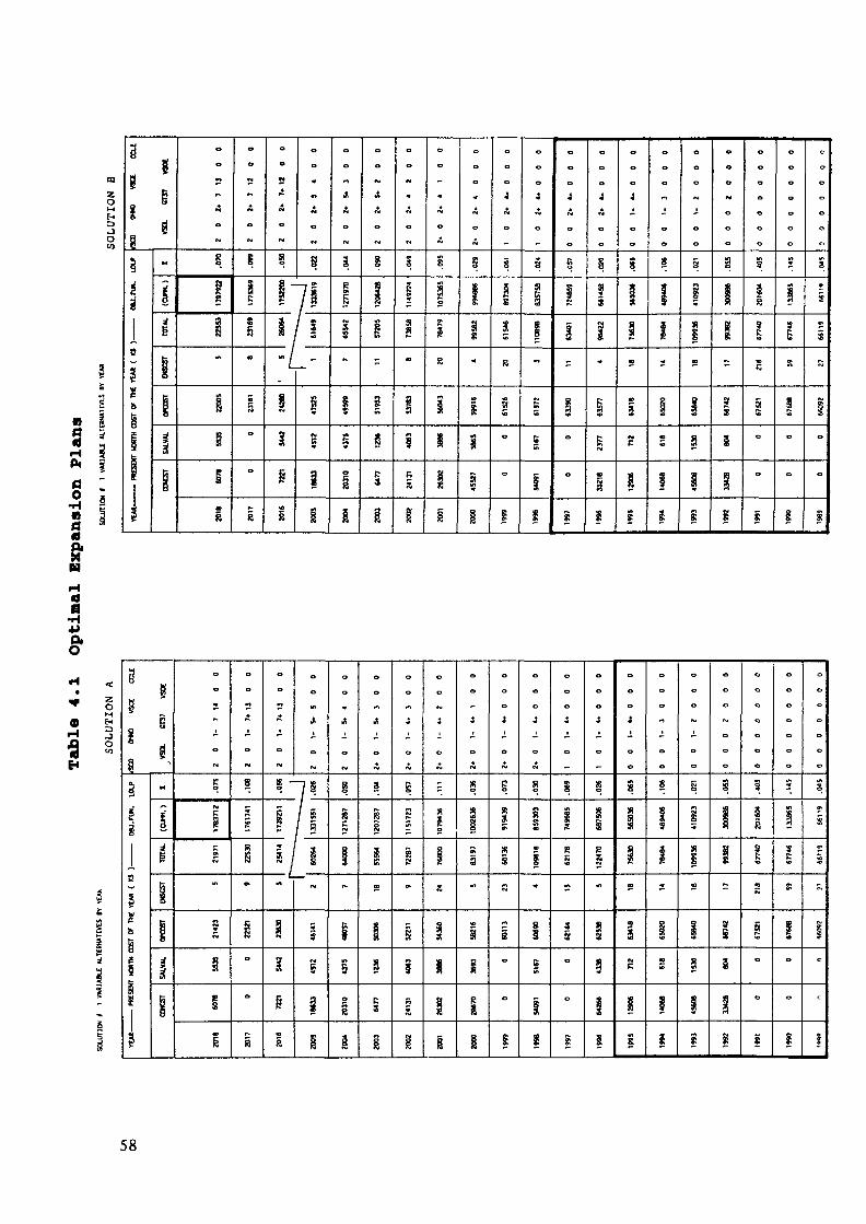
sP«
flO
•HnaaaH
ös
ï
so
3
i;ii1
ü
85g
dS
«
I
i
t
i11
A
i
|
î
iBi
I
i|3S
*
°
O
i
*
8
1"
i.
1i
«R
S
— j S7§
/ !
sIMjj
i§
A
i|
s
1
s
1I
Jt
§1I"g
B
§
|
s
19S
1
iKR
I
A
S
1
î
8
I
i
I
i
§
1s
i
i
|
P
4
i
»UM
S
s
S
0
°
g
4
S
1
1
R0l
S
i
1
4
KO
I!^
10
°
f-.s
4
§
Si
I
»
g
1
i
4
8
S
1
•"
«0
S
|
K
8
1
I
*"
I
VS
1
i
§I
i*~
1B
ii
so
S1•~
yi
«
i
g
§
ig
!s
1o
°
g
5
§
!s
to
°
0
1
3
9-
i
i
1M
(V
°
o
i
a-<d•H4^OiO
tzoMfrH
o
1&ii5i1
4
yH
Ms
1B?
§
lilsg6
gO
i'1
KBr»
FfB
\
M
î
Î1i11
~Mg1s
**
5
B
I
I
Ä
~
8
f*
S
SKl
"
I
0
O
r«
R
A
fW
8 -
f^
' /M
1
?
1
i
&
fM
!*•
1331
551
IVM
«
5Mg
a
i
A
„
g
1271
287
1
-
i
M*
5
o
1
A
&
3
1207
287
3S
n
I
s
i
I
Ä
srlr*
1
Cl
ir»
S
fi«v
1
A
E
1079
43«
1s
1iII
+
«
8S
r*01
i»
igsgg
4
A
E
9194
39
3
a
i•»
°
i
t+
?1»i-
Iw5»
i
i
_
8
iR
R5
S
i»
0
1
:
_
3
6875
0612
2470
w>
1
§
1
i
4i
o
8
1
1f«-
<e
IME
i«
(
o
1
Ii-i•a«S
11
(
O
g
I»im
I
S
1i
0
s
IIt
I1
i1
o
i
3£
§
03
a<o
o
o
1
0
in«
1
I
3
!«•-
i
0
tft5
O>
5
C>
i
K
Ic-
c
o
rH•sH
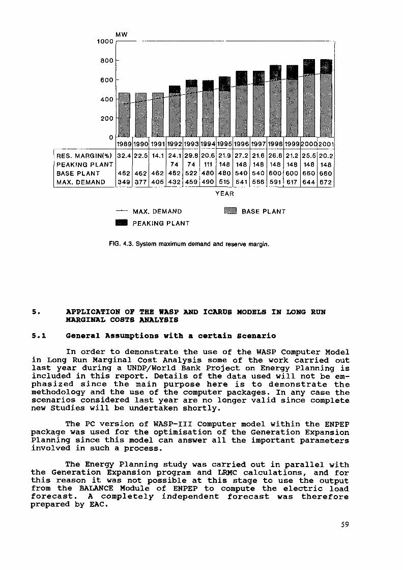
MW1000
800 -
600
400
200
0
RES. MARGIN(%)PEAKING PLANTBASE PLANTMAX. DEMAND
YEAR
MAX. DEMANDPEAKING PLANT
BASE PLANT
FIG. 4.3. System maximum demand and reserve margin.
5. APPLICATION OF THE WASP AND ICARUS MODELS IN LONG RUNMARGINAL COSTS ANALYSIS
5.1 General Assumptions with a certain ScenarioIn order to demonstrate the use of the WASP Computer Model
in Long Run Marginal Cost Analysis some of the work carried outlast year during a UNDP/World Bank Project on Energy Planning isincluded in this report. Details of the data used will not be em-phasized since the main purpose here is to demonstrate themethodology and the use of the computer packages. In any case thescenarios considered last year are no longer valid since completenew Studies will be undertaken shortly.
The PC version of WASP-III Computer model within the ENPEPpackage was used for the optimisation of the Generation ExpansionPlanning since this model can answer all the important parametersinvolved in such a process.
The Energy Planning study was carried out in parallel withthe Generation Expansion program and LRKC calculations, and forthis reason it was not possible at this stage to use the outputfrom the BALANCE Module of ENPEP to compute the electric loadforecast. A completely independent forecast was thereforeprepared by EAC.
59
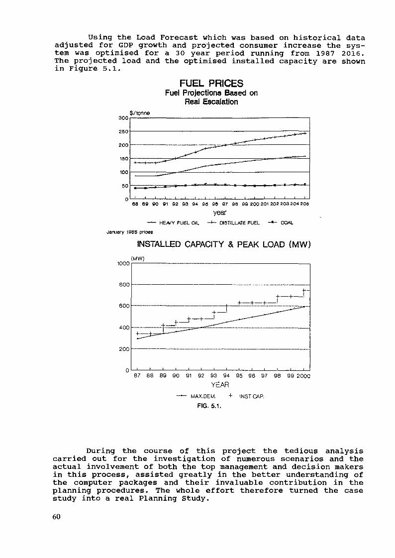
Using the Load Forecast which was based on historical dataadjusted for GDP growth and projected consumer increase the sys-tem was optimised for a 30 year period running from 1987 2016.The projected load and the optimised installed capacity are shownin Figure 5.1.
FUEL PRICESFuel Projection» Based on
Real Escalation
300
260
200
150
100
60
$/tonne
0L_J——I——I——1——l——i——l——l——l——l——i——l——l——l——I——I——I——I88 89 90 91 92 93 94. 90 90 97 98 99 200 201 202 203 20* 200
yearHEA/Y FUEL OIL -*- DISTILLATE FUEL COAL
1B68 prices
INSTALLED CAPACITY & PEAK LOAD (MW)(MW)
1000
800
600 -——
400 -
200 —
87 88 89 90 91 92 93 94 95 96 97 98 99 2000YEAR
MAX.DEM. + INSTCAP.FIG. 5.1.
During the course of this project the tedious analysiscarried out for the investigation of numerous scenarios and theactual involvement of both the top management and decision makersin this process, assisted greatly in the better understanding ofthe computer packages and their invaluable contribution in theplanning procedures. The whole effort therefore turned the casestudy into a real Planning Study.
60
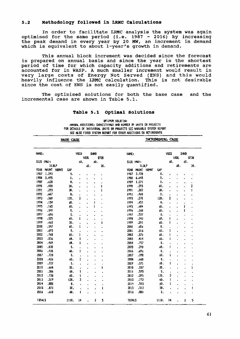
5.2 Methodology followed in LRMC CalculationsIn order to facilitate LRMC analysis the system was again
optimised for the same period (i.e. 1987 - 2016) by increasingthe peak demand in every year by 20 MW, an increment in demandwhich is equivalent to about 1-year's growth in demand.
This annual block increment was decided since the forecastis prepared on annual basis and since the year is the shortestperiod of time for which capacity additions and retirements areaccounted for in WASP. A much smaller increment would result invery large costs of Energy Not Served (ENS) and this wouldheavily influence the LRMC calculation. This is not desirablesince the cost of ENS is not easily quantified.
The optimised solutions for both the base caseincremental case are shown in Table 5.1.
and the
Table 5.1 Optimal SolutionsOPT1HU1 sournw
rt««IAL ADDITIONS: CAPACITY<MU) AND NUMBER OF IMTS OR PROJECTSFOR DETAILS Of INDIVIDUAL WITS OR PROJECTS SEE VARIABLE SYSTEM REPORT
SEE ALSO FIXED SYSTEM REPORT FOR OTHER ADDITIONS OR RET1REHEKTSBASE CASE INCREMENTAL. CASE
(«IE:
SIZE (M
YEAR H1987 11QOO 0
1989199019911992199319941995199419971998199920002001200220032004200520042007200820092010201120122013201420152014
TOTALS
W):XLOLP
A1KT NOM.293
.620
.438
.293.667.349.154.145.349.494.325.442.347.493.768.836.469.830.438
.426
.727
.664
.386
.738.519.880.871.610
1
«T CAP0.0.0.
30.30.0.
120.60.60.0.0.
40.30.40.0.
40.40.40.0.
40.0.
Xft
0.30.40.40.
120.0.
30.611.
1110.
VSCO DWOVSOL 6T30
40, 40.40. 30.
1. 1
2 . . .11
1 . . .1
1 . . .
1 . . .1 . . .1 . . .
1 . . .
1 . . .
11 . . .1 . . .2 . . .
. 11 . . .
14 . 2 5
NAHE:
S12E «1
YEAR (11007 Î
loog A
1989 1199019911992199319941995199419971998199920002001200220032004200520042007Iflflß
onno
2010201120122013201420152016
TOTALS
U):XLOLP
MINT NOMi TXI
I A4Q
.271
.293
.202
.468
.270
.652
.684
.248
.537
.243
.291
.606Ol X
.375
.414
.757
.398
.69639fl
.668
.371
.337
.595
.395
.772
.513.512.881
1
HT CAP0.0.0.
60.30.0.
120.0.
60.60.
60.40.0.
60.60.60.0.
40.0.
60.0.
40.30.0.
120.40.40.30,0.
1110.
VSCD 1VSOL
40.40.
•
2 .
11
111
1
1
1
2 .11
14
)moST30
60.30.
. 21
11
« •
•
•
1
1
2 5
61
Between the years 1987 - 1989 no changes are possible be-cause of long lead times and this increases tremendously the ENSand the LOLP of the System. Since with the Coal Scenario it wasnot possible to bring forward the first coal unit prior to 1993,when it is first available for commissioning, a gas turbine witha shorter lead time was brought forward to 1990 by increasing thedemand. A second gas turbine was brought forward in 1991 for ex-actly the same reasons. This has the effect of distorting theplant mix, but even so at later years the coal units (base loadplant) 4, 5, 6, 7, 8, 9, 10 and 12th are brought forward becausethey generate fuel savings. At the final year of the study (2016)the plant for both cases is identical. The above shows that theincrease in demand may cause complex re-ordering of the invest-ment program although the immediate impact may be the advancementof the introduction of gas turbines.
5.3 LRMC AnalysisThe Long-Run Marginal Cost (LRMC) of generation is defined
as the cost of meeting an increase in electrical consumption,sustained indefinitely into the future, when capacity adjustmentsare possible. LRMC of electricity generation has two components.The marginal cost of capacity which is the cost of expandingcapacity to meet incremental demand and is measured in $/KW/annumand the marginal cost of energy ($/MWh), which is the additionalfuel and variable operating and maintenance cost incurred to meetthe same incremental demand.
The analysis for LRMC calculations covers usually a time-period or a time slice of 10 to 20 years which is the expectedlife of consumer's equipment, if this information will be usedfor tariff design. Longer time periods were also considered inorder to give a measure to EAC of the effect of various scenariosand to investigate the change in LRMC costs as the system movestowards equilibrium.
5.3.1 Marginal Cost of CapacityThe marginal cost of capacity has four components.1. Capital cost of new Capacity2. Fixed operation and maintenance (O & M) cost3. Energy not Served Cost (ENS)4. Fuel Component (Fuel Savings).All the above information is obtained as output from the
WASP Computer package and the steps followed in this analysis aregiven below. It is perhaps important to stress that otherpackages which give a measure of the reliability of the systemand the cost of ENS may also be used for LRMC analysis. However,LOLP and ENS are important parameters of this analysis and cannotin any way be ignored.
62

Capacity Cost ComponentThe marginal capacity cost component is calculated as
follows: The capital expenditure for the base and incrementalloads (optimised as already described) are subtracted to give theyear by year difference in capital expenditure stretching overthe period of the study. This new capital expenditure (CIN-CBA)I/ is then annualised 2/ over the life of the plant to obtain theequivalent annual cost. This means that the effect of extra plantdue to the increment of load is not only in the year that it isintroduced but stretches on an annuity basis over the life of theplant. The total cost in every year of the planning study is thesummation of all the individual annuities. This method alsoevens out the lumpiness in investment costs and is consideredmore appropriate for LRMC calculations.
The sum of the annuities for each year are then expressedin present worth values. The resulting discounted values areadded and then annualized over the time period under considera-tion (usually 10-20 years). The annual cost is divided by theincremental demand (in this case 20 MW) to find the capacity costin $/kW/annum ($/kW/a).
Fixed O&M ComponentThe annual increases in fixed O&M costs for both the base
and incremental cases are first listed. The base case costs arethen subtracted from the incremental case costs and the resultingdifference is expressed in present values. (In a year with no newcapacity or with the same capacity expansion the difference in O& M costs is zero).
The resulting present values are added and then annualizedover the time period of LRMC analysis under consideration (10-20). The Fixed O&M component is derived by dividing this valueby the load increment, in order to express it in cost/kW/a.
Energy Not Served ComponentThis component is first calculated as the difference in
present value of unserved energy cost between the incremental andbase cases. The resulting figures are added and then annualizedover the period of LRMC analysis. This is also divided by the in-cremental load to give the ENS component cost/kW/a.
Fuel SavingsThe fuel savings or fuel component is calculated in a
similar way as for the ENS. The fuel component is first calcu-lated as the per year difference in present value of the fuelcosts between the incremental and base cases. The resulting
I/ C I N = C a p i t a l E x p e n d i t u r e of the i n c r e m e n t a l case in y e a r tCp, = C a p i t a l E x p e n d i t u r e of the base case in year t.
2_/ The a n n u i t y f a c t o r A is the a n n u a l e x p e n d i t u r e over n years, w h i c h hasa present v a l u e of 1 S at a discount rate r:
A = r / CI - (1+r)n
63

figures are then added and annual!zed over the period of LRMCanalysis and is finally divided by the incremental load to givethe fuel component in $/KW/a. The fuel savings were estimatedusing the following procedure.
The WASP was used to optimise the system with the basecase forecast. The system was then re-optimised using the in-cremental load and the difference in fuel costs was used asdescribed above to calculate the LRMC fuel component.
With this first approach the fuel cost component isdirectly linked with the effect of incrementing the demand.
The total marginal capacity cost is derived by adding thecapital component, the fixed 0 & M component, the Unserved EnergyComponent and the Fuel cost component.
Fuel Savings independent of incremental demandThere is another school of thought which dissociates the
fuel costs from the effect of changing demand. The fuel costs aretherefore evaluated with the incremental investment programme butwith the base case demand forecast. This is achieved as follows:
Once the WASP has been used to produce a revised leastcost investment programme to meet an increment in demand, thefuel costs of the advanced programme are re-estimated using theoriginal base case demand forecast.
The fuel savings are then calculated as the difference be-tween the fuel cost of the base case investment programme withbase case demand forecast and the fuel cost of the advanced(incremented) investment programme and base case demand forecast.The remaining procedure is then exactly as before.
The new Marginal Capacity Cost is derived by adding thepreviously calculated Capital, O & M and ENS components to thenew fuel savings component.
Details of the LRMC calculations for different timehorizons are shown in Table 5.2. The time horizons were chosen toreflect the state of the system where in the first years the ENScomponent is high due to plant shortage and in later years it isconsiderably improved as the system approaches equilibrium.
Full details of the LRMC computations are shown in Appen-dix I of this paper. The same results are depicted in graphicalform in the following figures: Figure 5.2 shows the MarginalCapacity Cost components when the fuel is directly associatedwith the incremental load. Figure 5.3 again shown the MarginalCapacity Cost for corresponding periods when the fuel is not as-sociated with the incremental load.
From Table 5.2.A and Figure 5.2, in the LRMC analysis for15 year periods commencing at years 1987, 1989, 1992 and 1996,the fuel cost is the dominating factor although it is reduced asthe more efficient base load plant is introduced in the system.After year 1996 the dominating factor is the capital expenditurewith drastic reductions in fuels.
64
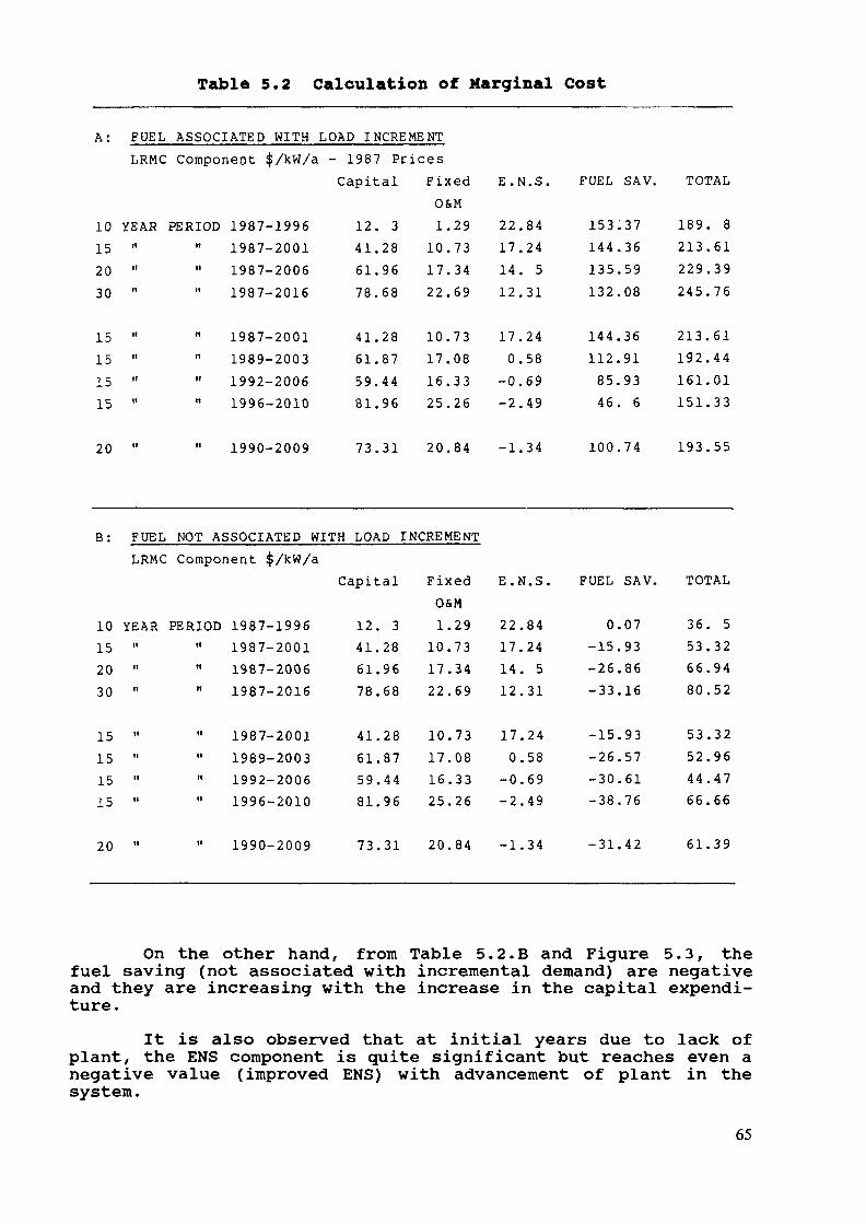
Table 5.2 Calculation of Marginal Cost
A: FUEL ASSOCIATED WITH LOAD ILRMC Component $/kW/a
NCREMENT- 1987 PricesCapital Fixed E.N.S. FUEL SAV. TOTAL
O&M10152030
15151515
20
B:
YEAR PERIOD 1987-19961987-2001
" " 1987-20061987-2016
1987-2001" " 1989-2003
1992-2006" " 1996-2010
1990-2009
12416178
41615981
73
. 3
.28
.96
.68
.28
.87
.44
.96
.31
FUEL NOT ASSOCIATED WITH LOADLRMC Component $/kW/a
Capital
1101722
10171625
20
.29
.73
.34
.69
.73
.08
.33
.26
.84
22171412
170
-0-2
-1
.84
.24
. 5
.31
.24
.58
.69
.49
.34
153.144.135.132.
144.112.85.46.
100.
37365908
3691936
74
189213229245
213192161151
193
. 8
.61
.39
.76
.61
.44
.01
.33
.55
INCREMENT
Fixed E.N.S. FUEL SAV. TOTALO&M
10152030
15151515
20
YEAR PERIOD 1987-1996" " 1987-2001
1987-2006" 1987-2016
" " 1987-20011989-2003
" 1992-2006" 1996-2010
" " 1990-2009
12416178
41615981
73
. 3
.28
.96
.68
.28
.87
.44
.96
.31
1101722
10171625
20
.29
.73
.34
.69
.73
.08
.33
.26
.84
22171412
170
-0-2
-1
.84
.24
. 5
.31
.24
.58
.69
.49
.34
0.-15.-26.-33.
-15.-26.-30.-38.
-31.
07938616
93576176
42
36536680
53524466
61
. 5
.32
.94
.52
.32
.96
.47
.66
.39
On the other hand, from Table 5.2.B and Figure 5.3, thefuel saving (not associated with incremental demand) are negativeand they are increasing with the increase in the capital expendi-ture.
It is also observed that at initial years due to lack ofplant, the ENS component is quite significant but reaches even anegative value (improved ENS) with advancement of plant in thesystem.
65
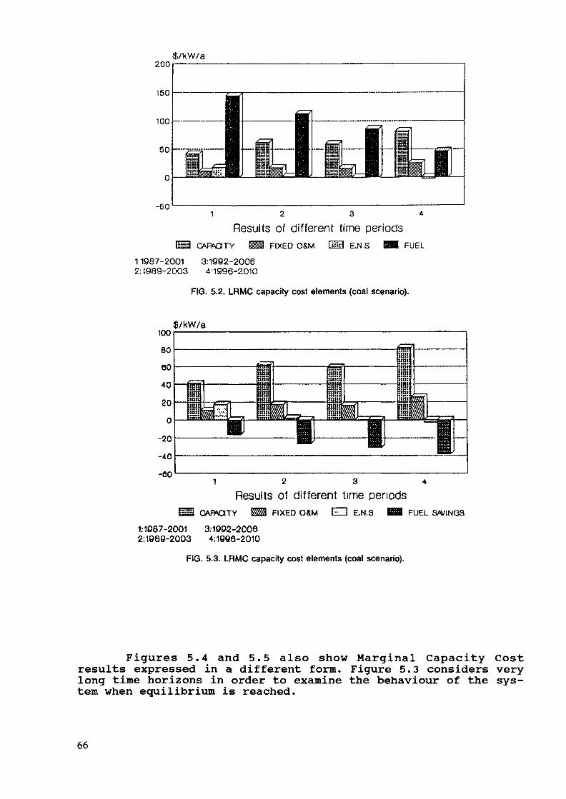
200
150
$/kW/a
-601 2 3 4
Results of different time periodsiffl Ct-PAdTY Ma FIXED OSM CÜI E.N S BB FUEL
11987-2001 3:1992-20082:I989-2003 4'1996-2010
FIG. 5.2. LRMC capacity cost elements (coal scenario).
$/kW/a
-40
-eo
1:1087-20012:1069-2003
2 3 4
Results of different time periodsCABOCITY ESS FIXED O&M El] E.N.S G89 FUEL SWINGS
3:1902-20084:1096-2010
FIG. 5.3. LRMC capacity cost elements (coal scenario).
Figures 5.4 and 5.5 also show Marginal Capacity Costresults expressed in a different form. Figure 5.3 considers verylong time horizons in order to examine the behaviour of the sys-tem when equilibrium is reached.
66
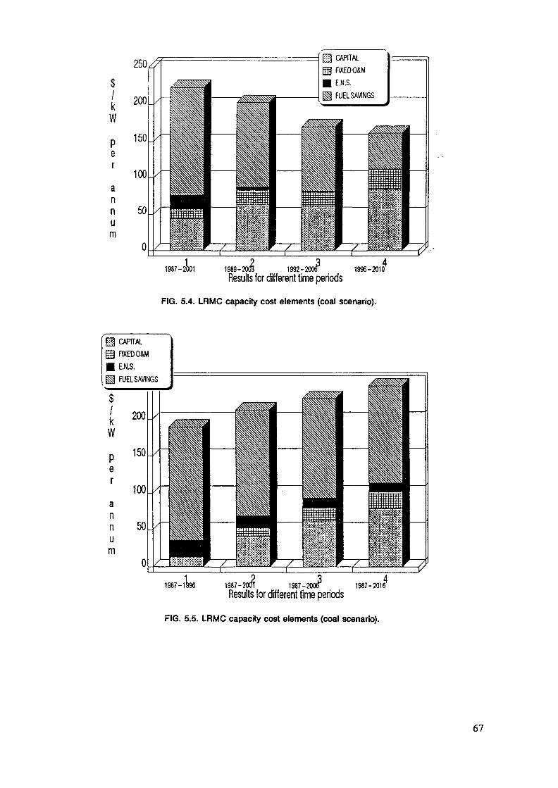
kW
Per
annum
m CAPITALFIXED OiME.N.S.FUEL SAVINGS
1989-2003 1992-20M 1996-2010Results for different time periods
FIG. 5.4. LRMC capacity cost elements (coal scenario).
4
11 CAPITALgä FIXED 0&M| E.N.S.| FUEL SAVINGS
kW
Per
annum
1987-1 1987-200T 1987-2006 1987-2016Results for different time periods
4
FIG. 5.5. LRMC capacity cost elements (coal scenario).
67

5.3.2 Marginal Energy CostsIn order to complete the calculations of LRMC, it is
necessary to estimate the Marginal Energy Cost Component. This isa more straight forward approach and corresponds basically to thecalculation of the marginal fuel cost.
This can be calculated with a very small incrementaldemand and for short periods when no changes are possible in thesystem. This analysis was carried out using the ICARUS model(both the mainframe and the PC versions) . The WASP model is notsuitable or estimating marginal energy costs since an hour byhour simulation is required to give the marginal costs by time ofday needed for tariff design. The model used however, must becapable of calculating probabilistic simulation, since LOLP orENS are used to attribute the marginal capacity cost to eachperiod under consideration.
In more detail the following procedure is followed:a) Using ICARUS, the weekly operation of the system is
simulated for one year in order to determine:1. The plant down for maintenance2. The weekly or monthly ENS which is used to assign
the weekly or monthly marginal capacity cost, i.e.$/kW/month.
The above cost is then easily expressed in $/kW - dayby dividing by the important days in a month or a week.
b) Simulate hour by hour the system operation for typicaldays each month or each season excluding plant down formaintenance. This simulation must also produce the hourby hour LOLP or ENS, essential for transforming themarginal capacity cost to a cost/kWh by time of day,(Hourly Cost).
c) Re-simulate the system operation by increasing the peakdemand by 1 MW. The marginal energy cost is thencalculated as the difference between the variable costsof the base and increased load cases in each hourdivided by the incremental generation.The total hourly LRMC cost is the sum of the marginalfuel cost ($/MWh) and the marginal capacity costexpressed in ($/MWh).
Details about the LOLP and ENS calculations, both weeklyand monthly are shown in Table 5.3. The monthly allocation ofmarginal capacity cost is shown in Table 5.4. Typical marginalenergy cost calculations for a winter day are shown in Table 5.5.Finally, marginal cost calculations by time of day for typicalWinter and Summer days are shown in Tables 5.6. and 5.7.
As seen from the above there is no limit to the analysisthat can be carried out using the techniques and the methodologydescribed above. However for the purpose of this paper, only someexamples will be given in order to demonstrate its use.
68
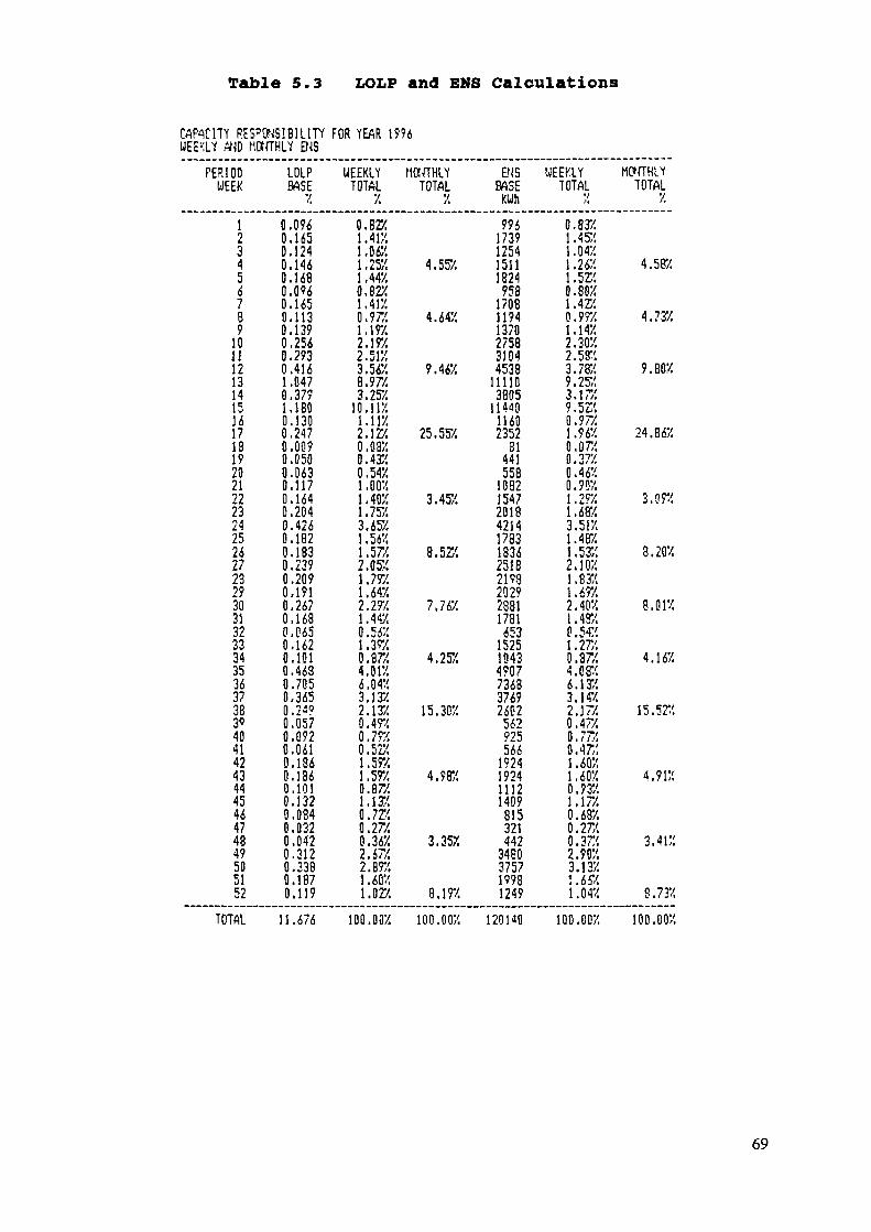
Table 5.3 LOLP and ENS Calculations
CAPACITY RESPONSIBILITYWEEKLY AMD MONTHLY B4S
PERIODWEEK
123456789
10U12131415lé171319202122232425262723293031323334353437383«4041424344454647434?505152
TOTAL
LOLPBASE
X
0.0960.1650.1240.1460.168Q.0<?60.1650.1130.1390.2560.2930.4161.0470.3791.1BO0.1300.247O.Û090.0500.0630.1170.1640.2040.4260.1820.1830.2390.2090.1910.2670.1680.0650.1620.1010,4680.7050.3650.24?0.0570.0920.0610.1860.1360.1010.1320.0840.0320.0420.3120.3380.1870.119
11.676
FOR YEAR 1996
UEEKLYTOTAL
X
0.8221.4 IX.1 .06X.1.2521 ,44X.0.82X1.417.0.977.1.19X.2.197.2. SIX3.5628.9723.252
10. 117.1.11X2.1220.08X0.4320.54X
.002
.40X
.75X3.652
.56X,57/
2. OK1.797.1.647.2.2921.44X0.5421.3920.87X4.017.6.04X3.1322.13X0.49X0.7920.527.1.597.1.597.0.8721.1320.727.0.277.0.36X2.67X2.89X1 ,6021.02X
100. OOX
MONTHLYTOTAL
X
4.55X
4.647.
9.46X
25.557.
3.452
8.527.
7.76X
4.25X
15.302
4.987.
3.352
8.192
100. OOX
EN'SBASE
KUh
9?61739125415111824958
170811941370275831044538
111103805
1144011602352
SI441558
10321547201842141783183625182198202928811781653
152510434?07736337692602
562?25566
1924192411121409815321442
3480375717981249
120 HO
UEEKLYTOTAL
V
0.8321.4521.047.1.26X1.5228.8021.4220.9?X1.14X2.30X2,5323.78X9.257.3.1729. 52'.0.97X1 .9620.0720.37;',0.46X0.907.1.2921.6823.517.1.487.1.5322.1021.8321.697.2.40X1.432P. 5421.27,'.0.3724.0826.1323.1 4X2.17/0.4720.7720.47/.1.6021.607.0.9321.17/0.687.0.27/.0.3722.907.3.137.1.6«1.042
100.007.
MO>ÏÏHLYTOTAL
2
4.587.
4.732
9. BOX
24.86X
3.0 n
8.202
8.012
4.167.
15.5?'.
4.912
3.41;:
8.732
100.002
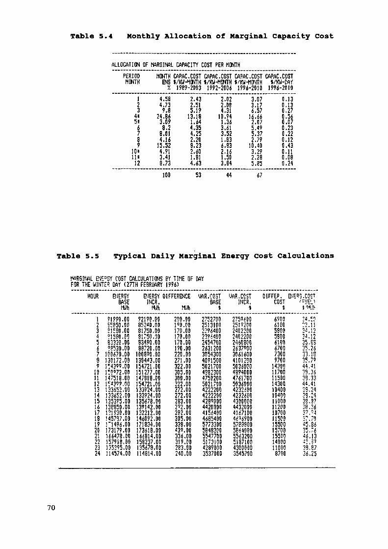
Table 5.4 Monthly Allocation of Marginal Capacity Cost
ALLOCATION OF
PERIODMONTH
123
4»5*
6789
10*11»
12
MARGINAL CAPACITY COST PER MONTH
MONTHENS
'/.
4.584.739.8
24.863.098.2
8.014.16
15.524.913.418.73
CAPAC.COSTJ/KU-MOHTH
1989-2003
2.432.515.19
13.181.644.354.252.208.232.601.814.63
CAPAC.COSTI/KU-MONTH
1992-2006
2.022.084.31
10.941.363.613.521.836.832.161.503.84
CAPAC.COST$.'KW-MONTH
1996-2010
3.073.176.57
16.662.075.495.372.79
10.403.292.285.85
CAPAC.COSTI/KU-DAY
1996-2010
0.130.130.270.560.070.230.220.120.430.110.080.24
100 53 44 67
Table 5.5 Typical Daily Marginal Energy Cost Calculations
DJE=GY COST CALCULATIONS BY TIME OF DAYFOR THE WINTER DAY (27TH FEBRUARY 1996)
HOUR
12345678919111213141516171819202!222324
ENERGYBASEHUh91990.00S505Q.DO21580.00?!580.0033320 .00?8530.00100670.00130172.09IMS". 00ITO'72.00147518,00Ica39?. 00133652.00133652.00135395.00138850.00171930.00545797.00ri496.00173179.00166478.00157918.00135395.00114574.00
ENERSY DIFFERENCEINCR.MUh MUh92190.00852*0.0081750,0981750.0083490 .0088720.00100890,00130443.00154721.00151277.00147818.00154721.00133924.00133924.00135678.09139142.00132212.00146092.09171834.00173618.00166814.00158237.00135678.00114814.00
200.00190.00170.00170.00170.00190.00220.00271.00322.00305.00300.00322.00272.00272.00283.00292.00282.00305.00338.00«39.00336.00319.00283.00240.00
gAR.COSTBASE1275270025131002296400239640024547002631200305430040915005021700438230047502005021700422220042222004289000442080041564004685400577330058483005547700517310042890003537000
YAR.CCSTINCR.$275960025192002402200240220024608002637900306160041012005036000489400047617005836000423260042326004300000443209041671004696900578380058640005563200513710043000003545700
DIFFER. ENE93.COSTCOST '-'JEL>$ $ n,'f>69036100580058006100670073009700143001170011500143001040010^001100011200107001150015500157001550014000110008700
it en:2Ui'iS P34.1235.Ë335.2633.1835.7944.4139.3639.334«. 4133.2429.2433.3738,3637. -427.7045.3635,7646.13i",:?39, Ê736.25
70
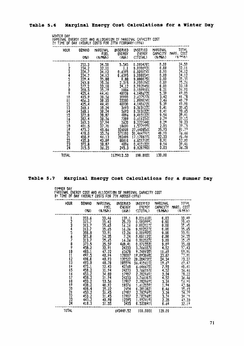
Table 5.6 Marginal Energy Cost Calculations for a Winter DayWINTER DAYIWG1N4L ENERGY COST AND ALLOCATION OF MARGINAL CAPACITY COSTBY TIME OF MY (HOURLY COSTS FOR 27TH FEBRIWRM996)
HOUR
12345&789
101112131415161718192021222324
DEMAND
(VU)
253.3234.2224.7224.7229.4243.8277.2358.5425.4415.9406.3425.4369.1368.1372.8382.4363.3401.5473.2478.0458.9435.0372.8315.5
MARGINALFUEL
<*/Wh)
34.5(132.1134.1234.1235.8835.2633.1835.7?44.4138.3638.3344.4138.2438.2438.8738.3637.9437.7045.8635.7646.1343.8938.8736.25
UNSERVEDENERGY
(KWh)
5.5451.1
0.63950.6395
0.882,31524.12
188648930309902228048930
36933693489672092620
18600326000371100202600
808104896
245.3
UNSERVED fENERGY C
(•/TOTAL)
0.00047020.0000937,0.00805«0.00005«0.00007520.00019620.00204520.1599107.4.148672*2.627577X1.89987«4.14567Z>:0.31312ZÎ0.31 31 2220.415122550.61123«0.22214«1.5770552
27^640856231.46479H17.17802926.85171020.4151227.0.0207982
lAPGltWLOPACITY ME(VMUh)
0.000.000.000.000.000.000.000.215.393.422.445.390.410.410.540.790.292.05
35.9340.9022.33
8.910.540.03
TOTûLm. COST
<1 'nJtO
34.5032. Il34.1234.1235.3325.2$33,183i.OO49.25M. 7840.7949.9038.6533.6539.113?. 1533.233?. 7581.?'76.666S.J652.8039.4136.23
TOTAL 1179413.53 100.0002 130.00
Table 5.7 Marginal Energy Cost Calculations for a Summer Day
SlflER DAYMARGINAL ENERGY COST AND ALLOCATION OF MARGINAL CAPACITY COST8V TIME OF DAY «HOURLY COSTS FOR 7TH AUGUST-1996)
HOUR
123456789
101112131415161718192021222324
DETOND 1
(MM)
353.6323.7313.7313.7308.8303.8313.7373.5458.2483.1497.5498.0493.0473.1458.2453.2459.2453.2438.2408.4453.2453.2443.2418.3
MARSItWLFUEL
<$/Ulh)
33.4635.4235.6535.6533.9134.3535.6535.5?32.9147.2243.9448.9348.7832.4331.9434.8831.9453.5640.9235.2231.4531.4540.9831.55
UNSERUEDENERGY
(kUh)
139.125.7316.2616.2612.26
7.2416.26
460.412423362678
128007130522105594
427682423317907242331790710376
24541790717907125953435
UNSERUED t-ENE°GY (
(2TOTAL)
0.0216187.0.00399^:0.00252720.002527/.0.001905X0.00112K0.002527/.0.07155X'.3.766107/.9.74093K
19.893868X20.284730X14.410*1126.6446757.3.766107/2.7S296?;:3.766107/2. 7829 W1.61255920.38138Z/.2.782965X2.782967X1.9574 1920. 5338« r/.
WIGINALOPACITY Mf<$/MUh)
0.030.000.000.000.000.000.000.094.52
11.6923.8724.3419.6'
7.984.523.344.523.341.940.463.343.342.350.64
TOTuLm. COST
<4/tf!h>
33. «925.J23!.*535.6533.9134.3535. «35. i827.4359.91-i 01
?iU7^Al10.4136. 4i;9.2236.46!6.'0«2. 8635. f324,7'"W.7?43.3332.!'
TOTAL 643449.52 100.0007. 120.00
71
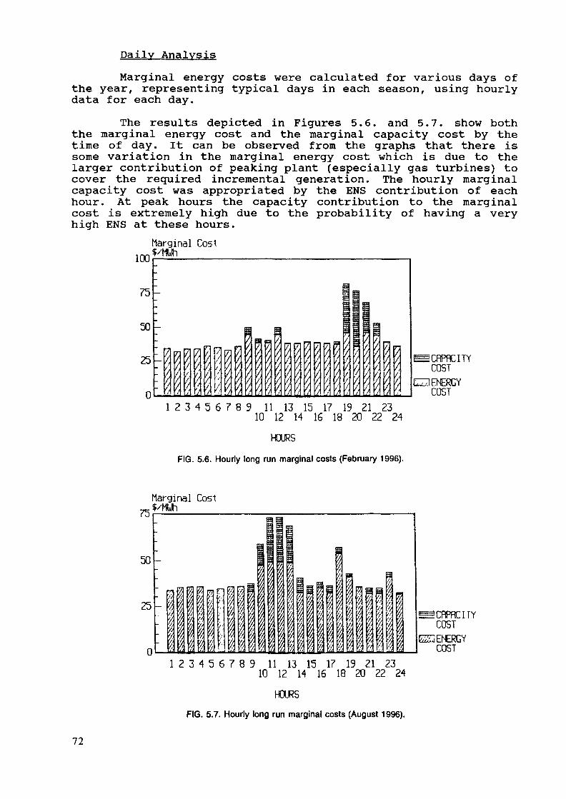
Daily AnalysisMarginal energy costs were calculated for various days of
the year, representing typical days in each season, using hourlydata for each day.
The results depicted in Figures 5.6. and 5.7. show boththe marginal energy cost and the marginal capacity cost by thetime of day. It can be observed from the graphs that there issome variation in the marginal energy cost which is due to thelarger contribution of peaking plant (especially gas turbines) tocover the required incremental generation. The hourly marginalcapacity cost was appropriated by the ENS contribution of eachhour. At peak hours the capacity contribution to the marginalcost is extremely high due to the probability of having a veryhigh ENS at these hours.
Marginal Cost1UU
75
50
25
n
-
—
-
-
-V\/ 1
m|É 7,
i'{
r
'/
nlv..IP/
r; t/ l/ t/ f
g
|
D
^/t
m|
^r
y
7
/
/•I7
/'/
7
'/
sKS0EBïaE
R î/ /
|i
„i;
/
ra57,
/;
-!
!r
£CflPflCITYCOSTCD ENERGYCOST
1 2 3 4 5 6 7 8 9 11 13 15 17 19 21 2310 12 H 16 18 20 22 24
HOURS
FIG. 5.6. Hourly long run marginal costs (February 1996).
Marginal Cost^$/MUh
50
25
n
: I-~a
-
||
p•V
11«!^/
I//
•7
/!
1i
r
;•:
^
1li%l
111^ ! ^
11!
=E
1 Pi
î m
<H,'j /i ///• fi h'/.• /i //1 k ï''t '/t 7:
1i51/> '•
B
j
j1lj
Q
/!
i.vv!
1
m
1l//
'kii
^CRPRCITYCOST
ES3 ENERGYCOST
1 2 3 4 5 6 7 8 9 11 13 15 17 19 21 2310 12 14 16 18 20 22 24
HOURS
FIG. 5.7. Hourly long run marginal costs (August 1996).
72
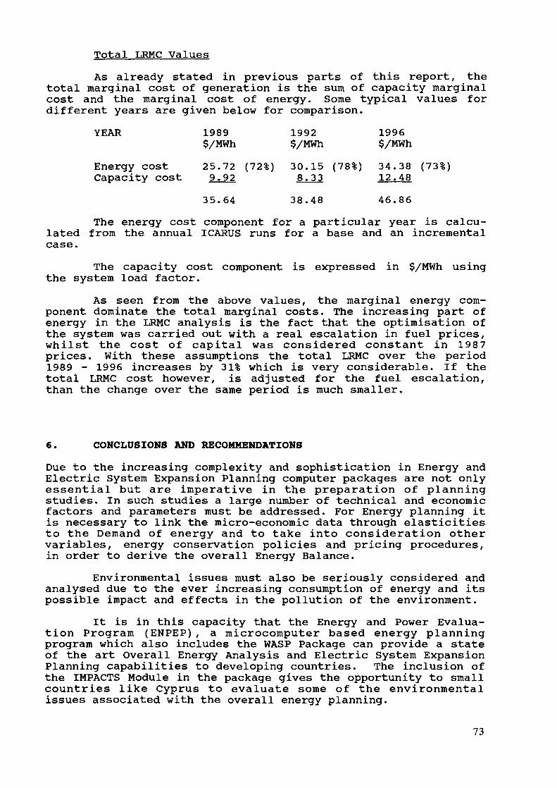
Total LRMC ValuesAs already stated in previous parts of this report, the
total marginal cost of generation is the sum of capacity marginalcost and the marginal cost of energy. Some typical values fordifferent years are given below for comparison.
YEAR 1989 1992 1996$/MWh $/MWh $/MWh
Energy cost 25.72 (72%) 30.15 (78%) 34.38 (73%)Capacity cost 9.92 8.33 12.48
35.64 38.48 46.86
The energy cost component for a particular year is calcu-lated from the annual ICARUS runs for a base and an incrementalcase.
The capacity cost component is expressed in $/MWh usingthe system load factor.
As seen from the above values, the marginal energy com-ponent dominate the total marginal costs. The increasing part ofenergy in the LRMC analysis is the fact that the optimisation ofthe system was carried out with a real escalation in fuel prices,whilst the cost of capital was considered constant in 1987prices. With these assumptions the total LRMC over the period1989 - 1996 increases by 31% which is very considerable. If thetotal LRMC cost however, is adjusted for the fuel escalation,than the change over the same period is much smaller.
6. CONCLUSIONS AND RECOMMENDATIONS
Due to the increasing complexity and sophistication in Energy andElectric System Expansion Planning computer packages are not onlyessential but are imperative in the preparation of planningstudies. In such studies a large number of technical and economicfactors and parameters must be addressed. For Energy planning itis necessary to link the micro-economic data through elasticitiesto the Demand of energy and to take into consideration othervariables, energy conservation policies and pricing procedures,in order to derive the overall Energy Balance.
Environmental issues must also be seriously considered andanalysed due to the ever increasing consumption of energy and itspossible impact and effects in the pollution of the environment.
It is in this capacity that the Energy and Power Evalua-tion Program (ENPEP), a microcomputer based energy planningprogram which also includes the WASP Package can provide a stateof the art Overall Energy Analysis and Electric System ExpansionPlanning capabilities to developing countries. The inclusion ofthe IMPACTS Module in the package gives the opportunity to smallcountries like Cyprus to evaluate some of the environmentalissues associated with the overall energy planning.
73

Through the extensive use of ENPEP and WASP it transpiredthat these packages are both useful and usable. Useful becausethere is no limit to the analysis that can be carried out andusable since with the right training, planners have access topowerful tools and "in house" facilities to carry out completestudies and to investigate numerous scenarios as required.
The LRMC work carried out has shown that WASP is very wellsuited for this analysis since it can address the importantissues of probabilistic simulation.
Because of the great benefits that can be gained from theuse of these Computer Packages and their unlimited use it isrecommended:
a) To continue the training courses on the use of thesepackages.
b) To involve Decision makers in some of the projects andat some stage in the training procedures in order toappreciate the extent and sophistication of thesecourses.
c) To extend the packages to include system analysis in-cluding the Transmission and Distribution of ElectricalEnergy.
A follow up and a systematic assistance from the IAEA,especially in the first stages of the release of new packages andnew versions, is essential in order to improve the skills andresolve possible problems during the use and application of thesemodels.
74
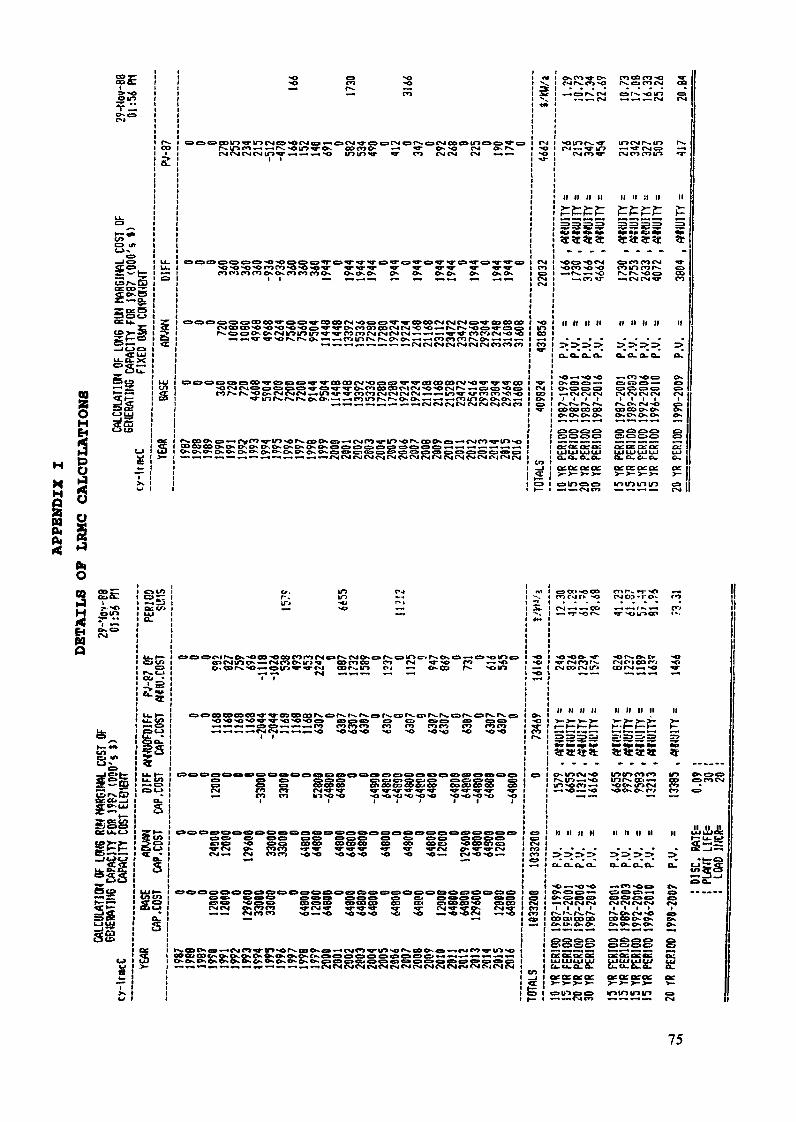
SS
« • £ 3
CO§s:§
U-CJ_X
^.SîTBco
oë
U
Plp«
.ir>rn»-.--.p^>otoJ CM O4 04 m «r «- «-• «^
.r>. o o e»-. o^ CM ir> v> tn v «• ro ro CM CM CM CM »-. *— »^ v ^*- co er»>«r>*rw*» ON «***—«i
icMCMCMCMCMCMCMOsiCO
—•ev*** vu&p"-O>- O . O» O-. O-» ON O^ O>. O-.> *O ^»- CD €K <=»••-• CM f*> •»• U*> X> r^ CO Ov O *-» CM CO «WIO X>• ON o-> Os o» «s» c» d ça o C9 co ça* es» ça c> c» ça c» ça ea c?>
*«-*«^v-*rMCMCMrMCMCMCMOJrMrMCMCMrMCMcVjOICM
ON C*> * O"^ fi OO C*3 O
-i c» r*. CM es. r-*. xa in
(I If II II II II 11 II II
«cîrîïît
Si
II II II II If II II H II
»-.CMCMCM CMCMCMCM CMj i j l i l i i rCO OD CO CO O3COO^O^ ON
gggs gsss gff-^ftf tf* f3ff jy çti {y (y p-
oâOfceoe or ce 0:0: o=
ho
H
£2 se&£§Äa«SS
£
fe{ . . -»-3 aomco co rsit-i 55r-. u-> o» -^
^-**-»«-t*-»C=»C=»-*-i*~*-«C..KP-tw^vrMrM^*^.^*.i t
O C9 C=»C9 «a çaCM ro en»-. co en
NO NO «ONO *<•
tê> cr*oê»cdo<C9 c^(z!>oca oOO OR OC* CO COCK' CO COCO OO OO CD
1 ( » 1 I
5rcM 2CM«-« CM
CO CO COQO OO OO CO OO>— 4<r<Q-^r ^> o o o . _ _ _ . _^cv o»*^*'^rcM-o*-*
» oCO ^ iff^ ço CD Ç" ijp OTi fr CO
^coc^^^^CMCo^^to^of^-oac^c^-'^cMCn^rw^^or^.coo^c»''—»cMco^rir>-*o
S
• --o rMO>-i'Ov
M II II II II II II 1l II
OMOew-o »r>ir»<*>m ir> 0*00r**.\r* *-••*> tr> rs. «i —« oc» c»rocM*-• «O «w «o >O CK €>-. C»/ CO ^»
II II II II II II H II II
f --- r-*. f .co on cocoCrs W- Cr* O.
1 1rx.o^rcooo«ï*S
êSêo §êoê êt_« «**«^.*u< ^ j^
u.tx.b.0. a.ceacoea: 0:0:0:0: ce- - - - >_>_>_>_ >_
minmin ça
UJUI1ULUa. u.a. a.
75
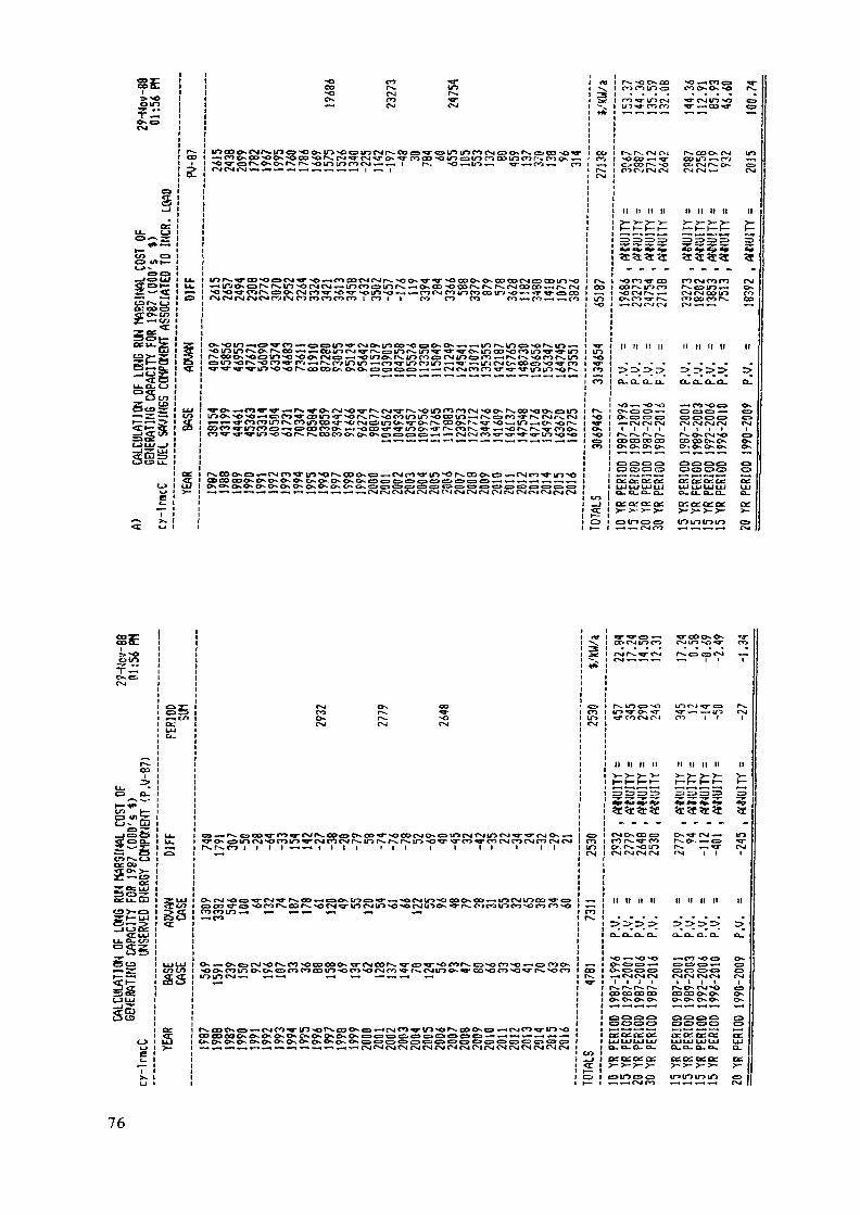
»z:fc=••« I5» !
12
S
<-J >•• 21 •
<=>e> i_«=>U< I U.§S£!£
ZCE« :Sot— i
CS«-^CL. i <:_JUJ£ Itrès iU.CL- CJ I<=>«r iO tn i2T to I£*S5 ! </>5P5! S_-*<r eft irac2 i
cj i So i >-e »
-o enco rs.M3 CMCK CO
.•• co •*-» co
ir> PS. - co *o Œ> c cocMCMrs, *o ON w socoos ON coco CM o ODID -olocnc^uorN.^^osCO'•oco^^l^r^CMOoac^*-^r^cv*vsoioso^^coCMCoincocoirjso««r*»-Œ>eoc o i c o i t co n co eo »-. co >-• — • co
<=»m sors,«o en««' c*t —H rslco ir>in •«—tco^r lôcôun «—» ^j- ira cMo.coer> so^fr>•o-^a-Hr-^-LOMD-or-coooo o-.ON«r>c3Oo—^*-^CMCMCnroTr-«wtrioir>'ors.
CD CO CO OK ON O^OsCKC^C^CKC^CKC=>C3C^e=>C>C3i=iC=»CI»e=i*-.v-.--.-»-.
**.^-.^-,—*--.-^-.—-CMCMCMCMCMCMC'-^CMCMCMr-JrstOJCsjjC-JCMCM
ro-ST 10 CM ^rcMiOso
tK. r , CM 04 FS. CO CK CMso co *-* -o- co u*> —• co -^o CD r^- NO co csjj fN^ o*-O'J C^J CM CM CM CM f-i
II II 11 II II \\ II II II
r OO COCMfoCO
i CM CM CM CMCMCMCM CMI I I 1 t l t I
C3CTtCDCD Ci O O CD
ÔIO
S-5
?
oUPe
S3
CO«srNO
i i i i i i i
sooKCoinosOscacncocoto-oc'j
OsOsCKOsOsOsc>C=>C='C=»OC=«C=>^C3^>C=i^C3C9C=><S>C=»
CO CM ITï CO r l ITS -O CO
CM r- 1 c*i
n n ti n ti n n n n
CMO-.OOC3-
M U II II II II II II II
O.O-O.CL. CU
.-«CO'-O« ON
C3C3OCD
CUOU Ou Ow CU
CdCtZO^CK Cr:
76
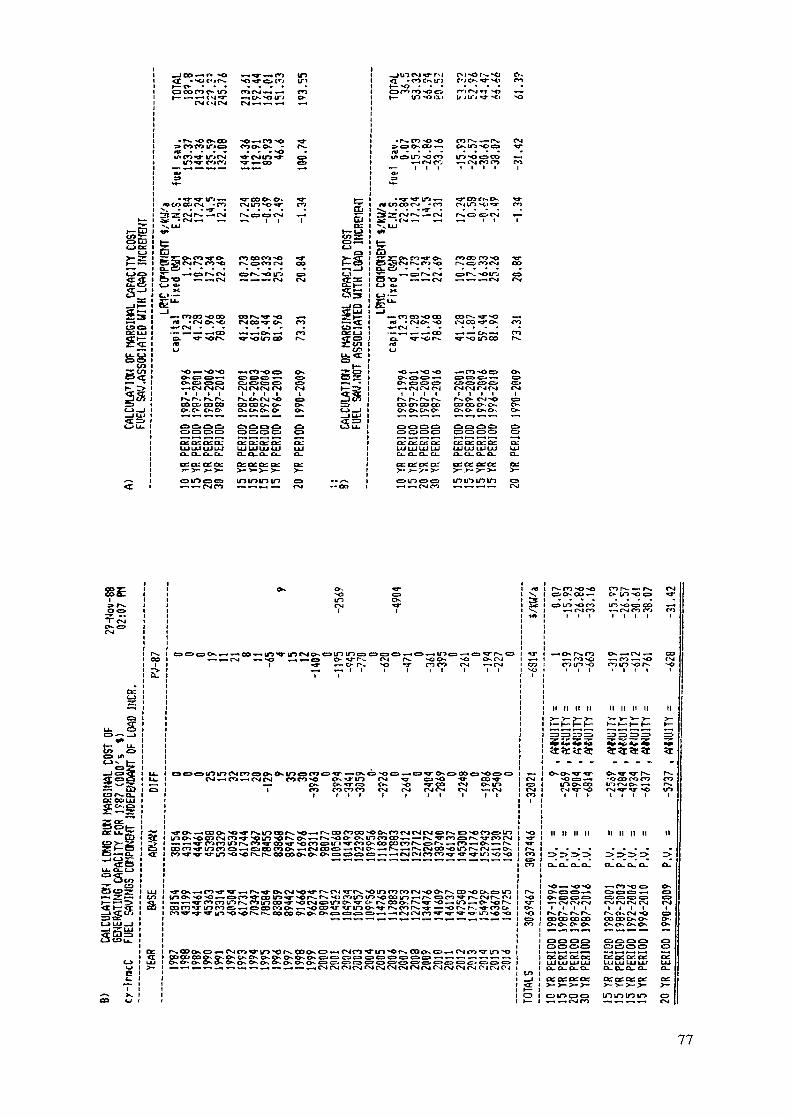
a(Z2o£.£
S3is
CMC +4 CM CM »-»«•»-• —t
Sî z: CM r^. —• CM
•W—- •wi> CM r**, rö ""O rs, ça co CM^^^C^CM" cir^-âiôb •O*"**--—.OM <-.^-.*_CM
f* »CM Os-O^«CM • - .
ex tr *or>-
coco
CVICMfSI~-*CM CM CMl l l l l t l
COC&COOO OOOOOs.
C=*CNI
IX. O- O- Q.
ccce: Ct: tt:
UJo_et:
ö^s
- <r> c»- i*o . -O"<f*>^oIT) ~o
OslO^OCÖ
JA)
^-« csi CM o-j
oc ctccr: ex:UJUJUJUJa. CL. a- a-
orceo^cic ot:
10 ni in ir»
*Jen o^*~> i/iCJk^ l—
esfe_io9*SESSss^ca
is«
S
CXJ*--CO»-^CSICM .c>N-»-to cxjC* - Cr\ l*r C5 C*"*co co co co c\j
t i l i*3* CO CM CK tOc*j c^j CN »-» CNIi t i i t
S5
. -o ^^ ir> — . c»- *
SCDCOO-.O-. O-.OSCKQ-. O-. ON Os. os> cz> CT"J er> CD es ea ^^ er? <2* ^ er» es <^ c^> o er» c^»^«-^v^^^CMCvjOJCvjCMCsjC^C^CMCvjCMrMCNCMCjCMCi
Stîïîtît
*OC3«-» -OCXJCOCO CO1I~J Qs. OO If > CNJ ON f • PN«
1 1 1 t i l l
ON CO C3OT-iOMfsjCM
oooo coco
ai et: ce ce a: a^ ac: ot ce:^ LI 11 J i | J [j j LU LU LU t*J LlJix. a. a_ CL. ex. CL. CL. Ou CL.
ce et: CE: et: or
77
CZECHOSLOVAK NUCLEAR POWER WITHINTHE POWER SYSTEM DEVELOPMENT
T. RAJCIResearch Institute of Fuel and Energy Complex,Bratislava, Czechoslovakia
Abstract
The paper consists of two main parts. In the firstpart an overview of the recent and current energysituation in Czechoslovakia is presented. Recently,electric power system was based primarily on thermalpower plants burning brown coal. Due to the setup ofCzechoslovak industry and its extensive developmentmood, the specific energy consumption has been, andstill is, very high. Now, for about 10 years, anextensive nuclear power development programme is onits way with an expected 50% contribution to the to-tal power demand in year 2000 to be produced innuclear power plants. The role of hydro-power inCzechoslovakia is explained too. The second part ofthe paper is dedicated to the model calculations usedat the author's institute and especially to the codesWASP and MAED. The reason why WASP and MAED are usedonly occasionally and the prerequisites for thewide exploitation of both models are presented.
1. INTRODUCTION
The Czechoslovak power system has a relatively long historythe hundred years anniversary of the first electrical power
plant of the country was celebrated only last month. Fullydeveloped metallurgy, machinery, as well chemistry, electricalengineering, and consumer good industries very soon demandedpower engineering industry development and the construction ofpower plants.
Relatively plentiful natural coal resources are the mainreason for the fact that the power system was based primarily onthermal power plants using brown or black coal. Small hydro-powerplants were thus outnumbered very soon by significant number ofcoal firing electrical power plants.
The development of energy consumption and above all that ofelectricity consumption since the end of World War II was deter-mined by the needs of the national economy, rather than by somehypothetical wish of the power industry to raise output. Therapid development of the national economy kept demanding more andmore power and power plants, without caring for efficient ex-ploitation of the resources. This situation lasted almost untilour days.
79
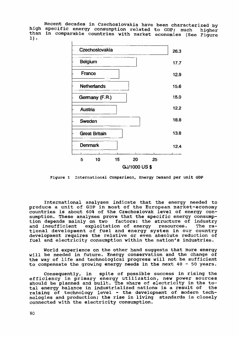
Recent decades in Czechoslovakia have been characterized byhigh specific energy consumption related to GDP; much higherthan in comparable countries with market economies (See Figure
CzechoslovakiaBelgiumFranceNetherlandsGermany (F.R.)AustriaSwedenGreat Britain
Denmark
26.317.7
12.9
15.6
15.0
12.2
18.8
13.8
12.4
5 10 15 20 25GJ/1000US$
Figure 1 International Comparison, Energy Demand per unit GDP
International analyses indicate that the energy needed toproduce a unit of GDP in most of the European market-economycountries is about 60% of the Czechoslovak level of energy con-sumption. These analyses prove that the specific energy consump-tion depends mainly on two factors: the structure of industryand insufficient exploitation of energy resources. The ra-tional development of fuel and energy system in our countrydevelopment requires the relative or even absolute reduction offuel and electricity consumption within the nation's industries.
World experience on the other hand suggests that more energywill be needed in future. Energy conservation and the change ofthe way of life and technological progress will not be sufficientto compensate the growing energy needs in the next 40-50 years.
Consequently, in spite of possible success in rising theefficiency in primary energy utilization, new power sourcesshould be planned and built. The share of electricity in the to-tal energy balance in industrialized nations is a result of theraising of technology level - the development of modern tech-nologies and production; the rise in living standards is closelyconnected with the electricity consumption.
80

These trends must be followed in Czechoslovakia too - theenergy consumption growth must correspond to the rate of economicdevelopment.
2. The current situationThe current state of Czechoslovakia's electrical power sys-
tem can be illustrated by the following data:The total installed capacity is about 22,000 MW, of which
15,000 MW are thermal power plants burning coal, 3,500 MW are in-stalled in nuclear power plants and about the same 3,500 MW inrun-of-river, peaking and pumped storage hydro plants.
Steam condensing power plants and heat delivery power plantsconsist mainly of 100 MW and 200 MW units dispersed at ap-proximately 25 sites, though mainly in the north-western part ofthe country. The biggest there is a 500 MW unit at Melnik powerplant. The largest power plants reach about 1,000 MW of in-stalled capacity.
The Bratislava branch of the Prague Research Institute ofFuel and Energy deals mainly with the development of nuclearpower plants (NPP) and hydro-power plants. Both types of plantsare extensively used in the country, with further development en-visaged during the coming years.
2.1 Nuclear Power PlantsNuclear power development in Czechoslovakia is based on the
Soviet PWR type, known as WWER. The first stage of NPP construc-tion was based on WWER 440 MW units, and the second stage on1,000 MW units.
At the very beginning of the nuclear power programme, acarbon dioxide cooled heavy water moderated reactor with naturaluranium as fuel was built in Slovakia at about 70 km fromBratislava (the capital of Slovakia). Its code name was A-l, andwent into operation in 1972. Its nominal capacity was 150 MW butthe electrical net capacity (into the power system of thecountry) was only 110 MW. Since the time this plant was planned,the situation on the nuclear fuel market as well as the economicconditions changed; thus, after evaluating the technical andeconomical experience it was decided to switch over from thistype into the PWR type reactor. At present, the NPP A-l is beingdecommissioned.
At the same time the first WWER 440 unit went into operationin late 1979 under the code name V-l. At present 4 units of thesame type (the 3rd and 4th with enhanced nuclear safety under thecode name V-2) are in successful operation. Another site with 4WWER 440 units is Dukovany in southern Moravia, about 60 kmsouthwest wards from Brno.
Another 4x440 MW units in advanced stage of construction areat Mochovce in southern Slovakia. We expect them to be in opera-tion soon after 1990 (the last one will be commissioned in 1993).
81

Those 12 units close the first stage of nuclear powerdevelopment in Czechoslovakia. The next phase of nuclear power isbased on PWR's Soviet type WWER 1000. At present, in an advancedstage of construction is the NPP Temelin in southern Bohemia -where 4 units of this type are being built. The first unit willgo into operation in 1992.
The 5th site for NPP lies in eastern Slovakia in thevicinity of the village Kecerovce. The construction of the 2units WWER 1000 is going to start in the very near future, thefirst unit should go into operation around year 2000.
The next locations of NPP are in northern Moravia atBlahutovice in the vicinity of the Czechoslovak huge industrialcenter Ostrava, and in eastern Bohemia at Tetov. It should benoted that this site had to be changed from the originallyplanned and already sanctioned site Opatovice which was abandonedafter the Chernobyl disaster since it is placed between two bigurban areas Hradec Kralove and Pardubice, each having around100000 inhabitants. The final decision about two sites and theorder of construction there has yet to be made, we expect boththese NPP to be in operation before year 2010.
The same goes for the NPP western Bohemia, for which thesite should be chosen later. Meanwhile we must consider the fateof NPPs with 440 units; the decommissioning of the first of themis expected around 2005. As in Czechoslovakia it is planned todeliver heat from NPP for the region where NPP is situated (thefirst 40 MWt of the total 120 MWt from NPP V-l are already beingdelivered now) and as the heat distribution pipelines, pumpingstation, heat exchanger stations are quite expensive and theirtechnical life is longer than the technical life of nuclearunits, there is a problem to be solved regarding heat deliveryafter the first generation of nuclear units is closed. It isbeing considered, either life extension of these units (providedsafety regulations permit it then), building new generation ofnuclear units at the site, or (though not probable) installingnuclear heat delivery plant.
2.2 Hydro Power PlantsAmong the hydro-power plants in operation in the country,
the most complex utilization is at the two of the big riversVltava and Vah, where hydro cascades were built. Pumped storagehydro-power plants are also considered, for instance Cierny Vahhas an installed capacity of 600 MW. At present, constructiongoes on at the biggest river - Danube. This river makes a borderbetween Czechoslovakia and Hungary. The suspected environmentaldisaster (and political considerations probably too) induced Hun-gary to cancel the common project and renounce the contract withCzechoslovakia. The Hungarian part of the common hydro-powerproject at Nagymaros will not therefore enter into operationwhich turns the Czechoslovak part at Gabcikovo into run-of-riverplant whereas originally it was planned for peaking.
Although there is still a relatively large hydro potentialin Czechoslovakia, the majority of the sites correspond to smallhydro-power plants, which indicates the fact that the hydro-
82

power potential in the country is vastly dispersed and couldtherefore be fully utilized only with difficulties and with highspecific capital costs.
The total hydro-power potential of Czechoslovakia is about11 million MWh per year. This potential could be utilized byhydro-power plants of 10 MW capacity and only up to above 8 mil-lion MWh per year. Currently only about 35% of primary hydro-power potential is utilized, big reserves are therefore stillavailable. Big efforts should be therefore made to use thisnatural resource, which is relatively inexpensive, environmen-tally safe and enables maneuverability within the power system.
2.3 Coal burning Power PlantsCurrently thermal power plants burning coal still occupy a
dominant position in Czechoslovakia, delivering around 65% of theelectricity produced in the country. These plants were built inthe period when the quality of coal was significantly higher andthe environmental impact of those power plants was generallyneglected by the authorities and the public as well. Therefore,the power plants (some of them over 25 years old) were notequipped with the necessary equipment to reduce environmental im-pacts. The country' thermal power plants are thus one of the mainair pollutants in Central Europe (not the biggest, though), andas the quality of the coal continues to drop (e.g. calorificvalue drops, sulphur content rise), the situation will be dif-ficult in spite of the reconstructions and installations of sul-phur dioxide separators in some of the power plants.
3. The Future DevelopmentIt is very important for Czechoslovakia to study closely the
future development of power production in the country. Thechoice and structure of the power plants are one of the impor-tant factors influencing the future environmental risks.
Generally, the choice of power sources could be made out ofthe following power plants:
- coal burning condensing power plants,oil burning condensing power plants and gas turbines,
- combined cycle plants,nuclear power plants,hydropower plantsunconventional power sources (solar, wind, biomass).
What prospects are there for these power sources inCzechoslovakia?
3.1 Coal burning Condensing Power PlantsAs disposable coal resources have been rapidly exploited
during the last 30-40 years and the coal quality is falling too,no new power plants of this type are planned. Current plants are
83

either gradually shut down, or equipped with more modern dustcollectors and sulphur-dioxide separators, some are turned overinto heat and power supply plants. Nevertheless, in the long run,these plants are environmentally unacceptable as no technicalmeasures could completely eliminate air pollution caused by them,and nothing could limit the carbon dioxide formation, and thusthe so called "greenhouse effect". Czechoslovakia sees the out-come of coal fired power plants on its dying forests as a resultof a combined effect of domestic production and import of emis-sions from abroad. The future of coal lies first of all in chemi-cal industry and gasification.
3.2 Oil burning Power PlantsCzechoslovakia has no significant oil deposits and not
enough hard currency to purchase oil for burning in steam gener-ators of power plants. Only about 4 units of 100 MW each of thisfuel exist in the country and they are used for less than 500 hr.a year each; the rest of the time they serve as a standby. Theimprovement of environmental impact here is negligible (same sul-phur dioxide output, a lot of natrium oxide).
3.3 Gas burning Power Plants (steam and gas turbines,combined cycle)Here the outlook is much better thanks to the long term con-
tract with the USSR. Environmentally, the situation with naturalgas is also better; only natrium oxide could be of a problem.Compared with coal-fired, gas fired power plants have bettermaneuverability.
For peaking purposes, gas turbines could be used. Morerecently combined cycle (2 x 100 MW gas turbines + 100 MW steamturbine) has been widely discussed in Czechoslovakia, mainly ascompetition to nuclear power - the idea was to disperse the com-bined cycle plant directly into the centers of electricity andheat consumption. Still, the economic comparison based on thespecific price of one kWh of power and one GJ/kW is unfavorableas well as the practical manufacture of equipment in Czechoslovakindustry.
3.4 Nuclear Power PlantsNuclear power in Czechoslovakia has been accepted long ago
as a future cornerstone of the country's energy policy. Thisdecision was based on rapidly diminishing coal reserves and alack of alternative fuel (with the exception of some uraniumore) .
These plans are being endangered recently. Firstly there isthe problem of confidence on the safety and reliability ofnuclear power plants. The Chernobyl disaster provoked discus-sions about the acceptable risk connected with widely use ofnuclear power throughout the world, and also in our country.
84

Various views should be confronted with total risks resultingfrom power plant construction; the need of electrical power isevident to everybody.
Further development of power generation must first of alltake care of the environment. Those who fight against nuclearpower willfully, exaggerating the risks of this technology,either do not realize the environmental disaster caused by burn-ing coal and hydrocarbons, or just do not care. There is a suf-ficiently long experience with nuclear power especially PWR's toenable us to say, that this technology from the safety point ofview is more safe and reliable than any other. The TMI-2 accidentdemonstrated that even the grave failure does not endangerneither the population nor the people at the plant. The Chernobyldisaster spoiled the favorable statistics in a way, but one mustkeep in mind that this was not a PWR type reactor and that peoplearound the plant made a whole chain of extremely improbable gravemistakes. Chernobyl taught us to attach even greater attention tothe design of nuclear power plants and their systems, and to thepreparedness of personnel. The question of rad waste is oftendiscussed; at present it presents no major problem - we mustrealize that however demanding the storage of rad waste couldbe, its volume is relatively small, much smaller than waste fromcoal burning condensing power plant.
Reliable way in nuclear power development leads through theactive approach towards the nuclear safety improvement utilizinghigh level of inherent safety rise of reliability and reductionof failure rate of major NPP components, high qualification anddiscipline of the personnel and reliable high capacity automatedcontrol system.
When these goals are fulfilled, nuclear power will be themost suitable power generating technology, mainly from the en-vironmental point of view.
Very important is the question of economy. Capital costs ofnuclear power plants are high. This argument is correct, butthermal power plants provided with all environmental protectionequipment would be almost equally expensive as NPP. Capital costsof NPP's could be lowered considerably by well organized con-struction activities, introduction of advanced technologies,shortening of the construction time, etc. One must also takeinto account the capital costs connected to the infrastructurerequired by the power plants. For instance, if instead of the NPPTemelin with an installed capacity of 4,000 MW, a brown coalfired thermal power plant would be installed there, 1000 freightcars daily would be needed for delivery of coal, e.g. one coaltrain every 40 minutes - this too should be added to capital andoperation costs. The production cost of electricity is decisive.If we use the information from the utility Data Institute, theproduction costs of various power plants in the USA was asfollows:
coal - 21,64 $/MWhgas - 30,43 $/MWhoil - 33,99 $/MWhnuclear - 19,05 $/MWh
This comparison illustrates well the situation.
85
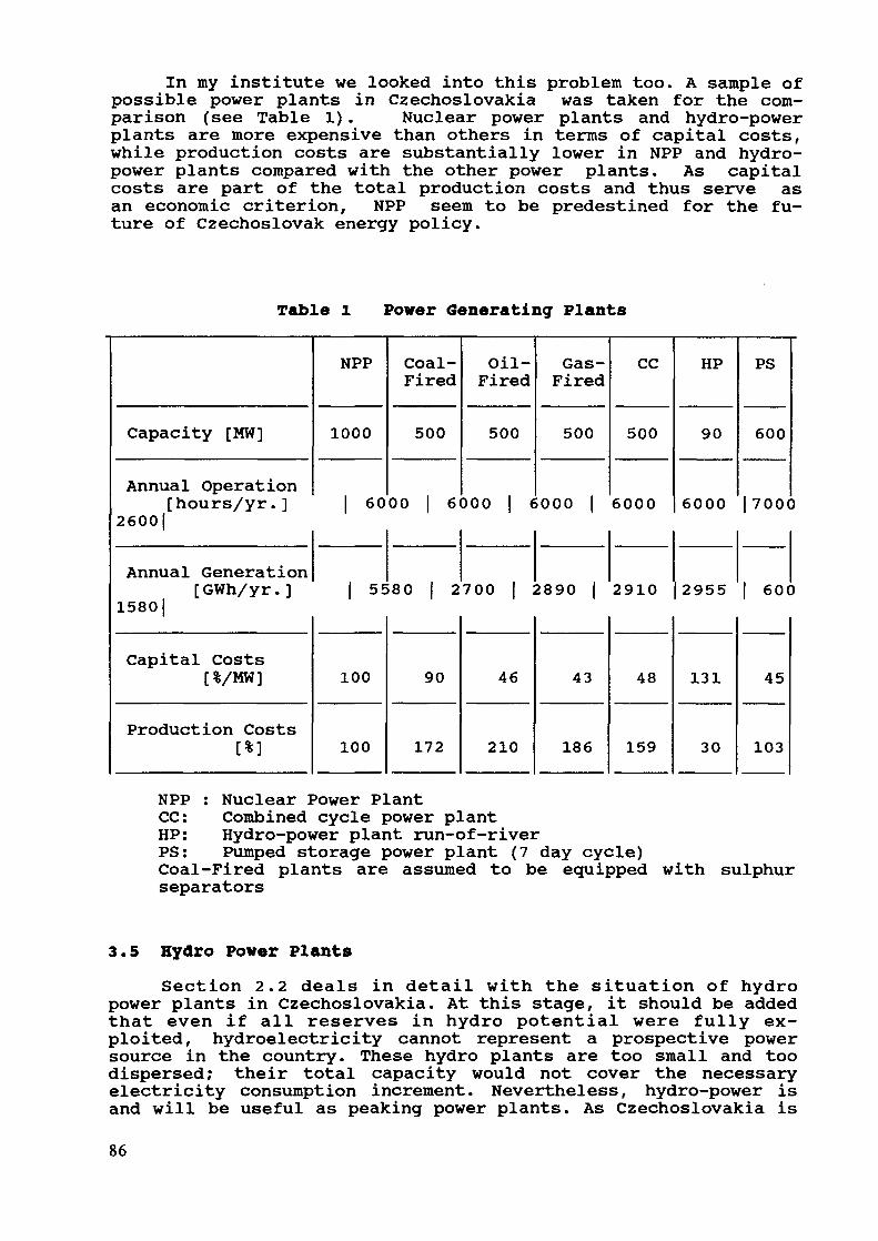
In my institute we looked into this problem too. A sample ofpossible power plants in Czechoslovakia was taken for the com-parison (see Table 1) . Nuclear power plants and hydro-powerplants are more expensive than others in terms of capital costs,while production costs are substantially lower in NPP and hydro-power plants compared with the other power plants. As capitalcosts are part of the total production costs and thus serve asan economic criterion, NPP seem to be predestined for the fu-ture of Czechoslovak energy policy.
Table l Power Generating Plants
Capacity [MW]
Annual Operation[hours/yr. ]
2600|
Annual Generation[GWh/yr.]
1580]
Capital Costs[%/MW]
Production Costs[%]
NPP
1000
| 60
| 5E
100
100
Coal-Fired
500
00 6
80 2
90
172
Oil-Fired
500
300 | €
700 | :
46
210
Gas-Fired
500
000 |
2890 |
43
186
CC
500
6000
2910
48
159
HP
90
6000
2955
131
30
PS
600
| 700C
| 600
45
103
NPP : Nuclear Power PlantCC: Combined cycle power plantHP: Hydro-power plant run-of-riverPS: Pumped storage power plant (7 day cycle)Coal-Fired plants are assumed to be equipped with sulphurseparators
3.5 Hydro Power PlantsSection 2.2 deals in detail with the situation of hydro
power plants in Czechoslovakia. At this stage, it should be addedthat even if all reserves in hydro potential were fully ex-ploited, hydroelectricity cannot represent a prospective powersource in the country. These hydro plants are too small and toodispersed; their total capacity would not cover the necessaryelectricity consumption increment. Nevertheless, hydro-power isand will be useful as peaking power plants. As Czechoslovakia is
86
a mountainous country, there are good possibilities to buildpumped storage hydro-power plants. The total potential of thistype is about 15,000 MW, some sites enable 2,000 MW of installedcapacity. The load curve needs not only daily accumulation butmore capacities in weekly pumped storage hydro-plant are needed.As the changes in the national economy are rather slow, there arestill needs to reduce power even in nuclear power plants in sum-mer.
3.6 Renewable Energy ResourcesDue to geographical conditions and climate in Czechoslovakia
renewable energy resources do not have much chance to help sig-nificantly to the development of the power generation system.
There is still one alternative for the energy developmentradical reduction of specific energy demand in the nationaleconomy and thus reduction of the overall energy consumption.This presumes radical changes in the structure of the economy,mainly its industrial structures. This would ease the demand forcapital investments but on the other hand, it would needavailability of money for the necessary modernization of the in-dustry branches. It might turn out that this alternative wouldnot be less expensive at all, but in the long run it could enableCzechoslovakia to accelerate the transition toward the modernproduction in the country's industry.
4. Model CalculationsSeveral partial models dealing with power system development
from various points of view are used in Czechoslovakia. Since thecountry's power system is quite developed, the selection criteriaare rather limited; thus the following criteria are used:
availability- load curve following
environmental impacts- availability of investment resources- development trendsSpecial models are oriented at the study of the influence of
every viewpoint individually.Table 2 shows the basic alternatives of power plant develop-
ment until year 2000, modified by subjective views. The develop-ment of the two decisive power plant types is in fact given: con-densing power plants are shut down when reaching the end of theirtechnical life, nuclear power plants are being built just asquickly as the capabilities of the national power engineering andbuilding industries allow it. More cannot be built. Therefore,this period is considered as "fixed expansion".
Into the set of models helping in the analysis of thedevelopment of the fuel and energy system of Czechoslovakia wecount too the models from IAEA, namely MAED and WASP.
87
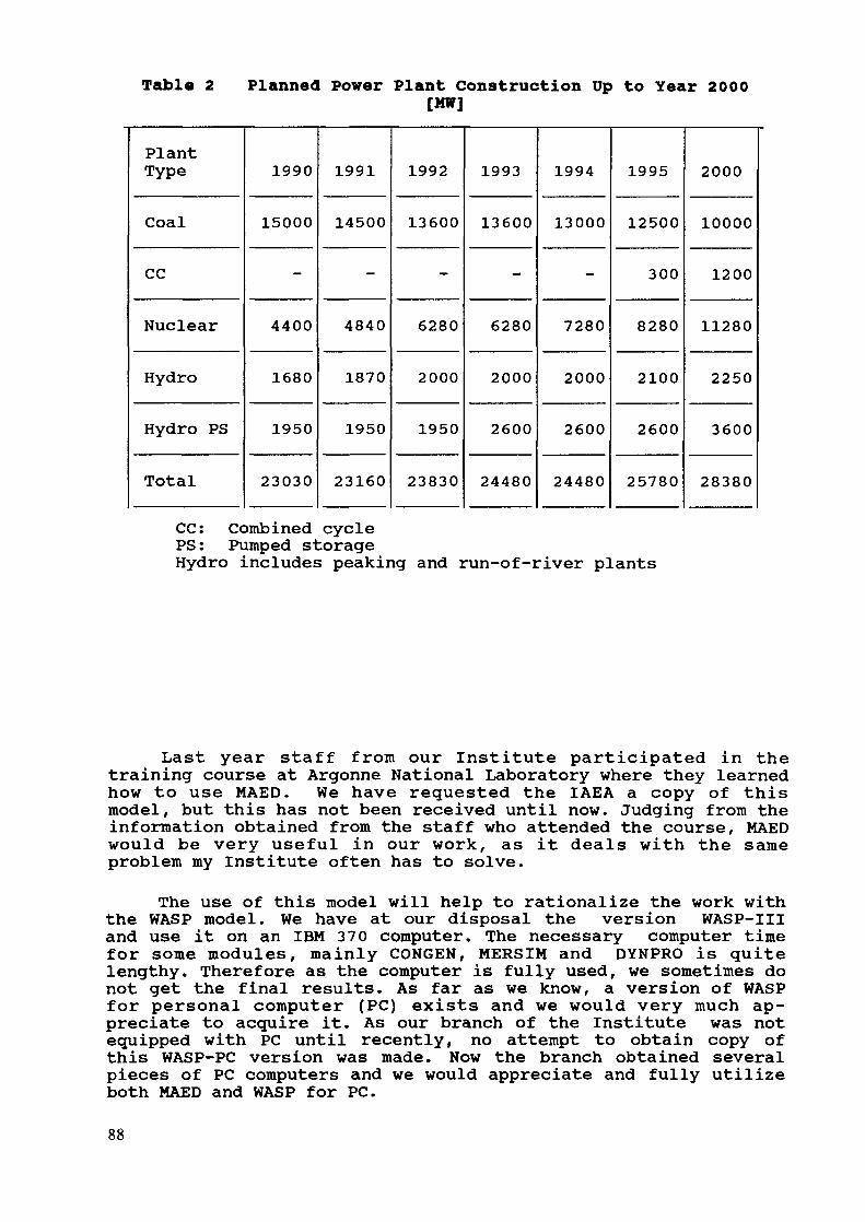
Table 2 Planned Power Plant Construction Up to Year 2000[MW]
PlantType
Coal
CG
Nuclear
Hydro
Hydro PS
Total
1990
15000
-
4400
1680
1950
23030
1991
14500
-
4840
1870
1950
23160
1992
13600
-
6280
2000
1950
23830
1993
13600
-
6280
2000
2600
24480
1994
13000
-
7280
2000
2600
24480
1995
12500
300
8280
2100
2600
25780
2000
10000
1200
11280
2250
3600
28380
CG: Combined cyclePS: Pumped storageHydro includes peaking and run-of-river plants
Last year staff from our Institute participated in thetraining course at Argonne National Laboratory where they learnedhow to use MAED. We have requested the IAEA a copy of thismodel, but this has not been received until now. Judging from theinformation obtained from the staff who attended the course, MAEDwould be very useful in our work, as it deals with the sameproblem my Institute often has to solve.
The use of this model will help to rationalize the work withthe WASP model. We have at our disposal the version WASP-IIIand use it on an IBM 370 computer. The necessary computer timefor some modules, mainly GONGEN, MERSIM and DYNPRO is quitelengthy. Therefore as the computer is fully used, we sometimes donot get the final results. As far as we know, a version of WASPfor personal computer (PC) exists and we would very much ap-preciate to acquire it. As our branch of the Institute was notequipped with PC until recently, no attempt to obtain copy ofthis WASP-PC version was made. Now the branch obtained severalpieces of PC computers and we would appreciate and fully utilizeboth MAED and WASP for PC.
88
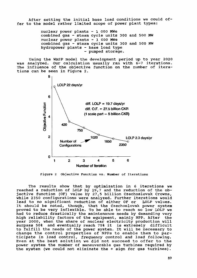
After setting the initial base load conditions we could of-fer to the model rather limited scope of power plant types:
nuclear power plants - 1 000 MWecombined gas - steam cycle units 300 and 500 MWnuclear power plants - 1 000 MWecombined gas - steam cycle units 300 and 500 MWhydropower plants - base load type
- pumped storage.Using the WASP model the development period up to year 2020
was analyzed. Our calculation usually ran with 6-7 iterations.The influence of the objective function on the number of itera-tions can be seen in Figure 2.
8LOLP 22 days/yr
o
.QO
diff. LOLP = 19.7 days/yrdiff. O.P. = 27.5 billion CKR
(1 scale part = 5 billion CKR)
420
Number ofConfigurations
LOLP 2.3 days/yr
2350
1 2 3 4 5 6Number of Iteration
Figure 2 Objective Function vs. Number of Iterations
The results show that by optimization in 6 iterations wereached a reduction of LOLP by 19,7 and the reduction of the ob-jective function (OF) value by 27,5 billion Czechoslovak Crowns,while 2350 configurations were analyzed. Further iterations wouldlead to no significant reduction of either OF or LOLP values.It should be noted, though, that the Czechoslovak power systemproved to be very inflexible. To be able to reach so low LOLP wehad to reduce drastically the maintenance needs by demanding veryhigh reliability factors of the equipment, mainly NPP. After theyear 2000, when the share of nuclear electricity production willsurpass 50% and eventually reach 75% it is extremely difficultto fulfill the needs of the power system. It will be necessary tochange the control properties of NPPs to enable them to par-ticipate in load control, frequency control and load following.Even at the best solution we did not succeed to offer to thepower system the number of maneuverable gas turbines required bythe system (we could not eliminate the + sign for gas turbines).
89

As it was mentioned before, we seldom have utilized the WASPmodel for the task of our power system development in our prog-nostic work, as the computer service proved to be inflexible andtime consuming. Now the situation should change profoundly withnew personal computer equipment that has been installed in theinstitute, provided that the MAED and WASP models on floppy discsfor PC will be obtained.
As previously discussed, the institute has available, anumber of partial models to help us solve some separateproblems. This will give us an excellent opportunity to comparethe results provided by the WASP model with the outcome of thosepartial models. I must say with pleasure, that the results ofboth are in very good agreement.
The staff of the institute in charge of making prognoses of-ten prefer simulation models over optimization models, as theycan usually select an optimum variant taking into account manycriteria. Some of those criteria are of sociopolitical characterwhich could not be transferred into mathematical formulae.
WASP, compared with optimization models with one input andoptimum solution as an output, has a great advantage in its sys-tem, which enables the researcher to take into account some ob-jective factors within individual models, which characterizeboundary conditions.
Irrespective of the fact, that the use of WASP is optimal incountries starting the development of their power system and witha wide variety of power source types and sizes at their disposal,its use in a country with a stabilized trend of development issuitable too. During power system development new methods andtechnologies would be used in power industry, new fuels and com-binations of the two. The progress of thought in energy policy isimportant too. In some countries, such as the USA, where untilrecently power plant development was almost unlimited, now thepolicy of energy conservation is widely accepted.
Concluding this I would like to stress, that in spite ofthe fact that WASP has been until now scarcely used, we plan toutilize it more widely especially in conjunction with the MAEDmodel. A prerequisite of our plans with WASP and MAED is theirapplicability on IBM-compatible PCs. After obtaining that set ofmodels, I shall gladly inform you about our new results, that areneeded for future development of the Czechoslovak fuel and energysystem.
90
COST — A PROBABILISTIC PRODUCTION COST MODELUSING THE SEGMENTATION TECHNIQUE
S. VASSOSGeneration Planning Division,Public Power Corporation,Athens, Greece
Abstract
COST is a simulation model for evaluating the annualproduction cost and reliability of a generating systemfor each year of a planning horizon. The Segmentationprobabilistic technique is utilized in this model forthe evaluation of the expected energy generation of theunits, the loss of load probability and the expected un-served energy. The model was developed in the GenerationPlanning Department of Public Power Corporation ofGreece for capturing the peculiarities of the Greekutility, by applying a computationally efficient andaccurate probabilistic technique. The model is capableto include in the simulation resent advances in theproduction of electric energy and constraints in theproduction imposed by operating the PPC generatingsystem.
INTRODUCTION
Given a generation expansion plan, simulation models areused to predict for each year of the planning horizon severalvariables of interest, including: a) production cost cash flows,b) power reliability, and c) power plant operation.
The production costing simulation models serve a dual pur-pose for the system planner. For a specified generation expansionplan, the simulator will estimate the production cost across theplanning horizon and also, assess the plan's operationalfeasibility. An expansion plan is operationally feasible if alldemand within each operating period can be satisfied while simul-taneously meeting the constraints imposed in the operation of thethermal and hydro units.
In estimating total annual production cost the model shouldaccount for direct production cost, fixed and variable operatingand maintenance cost. Additional information from a productionsimulation model includes fuel consumption and reliability of thesystem in terms of annual Loss of Load Probability (LOLP) and theExpected Unserved Energy (EUE) of each year in the planninghorizon.
The basic methodology for production simulation requires thedispatching of plant production against load. The operating timeis decomposed into monthly or weekly periods with either a Load
91

Duration Curve (LDC) or hourly loads for each period. Economicpriority list for unit commitment and plant dispatch are alsospecified. While insuring that all operating constraints aresatisfied, units are dispatched against load so as to minimizesystem fuel costs. The important differences between productionsimulation methodologies all relate to the trade off between themodeling accuracy and its computational efficiency.
The heart of a production simulation model is the techniquefor estimating the expected generation of the units and thereliability of the system. It has been universally accepted theutilization of probabilistic technique in the simulation ofproduction costing models. A number of different probabilisticmethodologies have been developed since the introduction by Booth[6] of a mathematical technique that considers the random outagesoutages of the unit in the estimation of the expected generation.A more recent technique using the Moments of independent RandomVariables (RV) became very popular because of its computationalefficiency. However, this analytical method fails in consistencyand highly depends on the characteristics (load and generatingunit) of the particular system. The method of Moments orCumulants may offer acceptable results for long term expansionplanning models.
A more recent technique [1], [2] based on the probabilitydensity function (PDF) of demand and the PDF of generating unitoutages reduce considerably the computational requirements for anexact probabilistic technique. The method offers greatflexibility in using multiblock loading of the generating unitsfor improving the accuracy in fuel costs and fuel consumptionrequirements, multistate representation of the units for betterresults in the estimation of system reliability, and incorpora-tion of time dependent technologies (wind, solar, etc.), loadmanagement, and consideration of interconnections.
The segmentation technique has been selected for thedevelopment of the production simulation Model of the GenerationPlanning Department of PPC. The Model is utilized for furtherrefinement of the results obtained from the expansion planningstudies carried by WASP-III particularly for the planning horizon(2-5-10 years) of the Greek utility.
METHODOLOGY
The Segmentation technique is based on the observation thatthe expected energy generation and the Loss of Load Probability(LOLP) of a power generating system can be evaluated from thezeroth and first order moments of the Random Variables (RV) thatdescribe the equivalent load.
Multistate and multiblock loading of the generating unitsare two very strong features of the method. A full descriptionfor applying this capabilities can be found in [1], [2], [12].
The production costing evaluation is carried out for a givenbase time unit (week or month) by considering the maintenanceoutages of the units. When the energy resource available to aparticular plant (lignite, oil, etc.) is a limiting factor in the
92

operation of the plant, the entire economic dispatch of thermalunits forces a change in the loading priority list by placingthat plant higher on the loading order, thus, reducing the fuelrequirements for the operation of the plant.
The annual calculations and the quantities of interest suchas expected generation, fuel costs, operating and maintenancecosts, fuel consumption and reliability of the system are foundby summing up the results from the individual time unit base overthe year.
Multistate generating unit representation of the thermalunits has not been considered in the model mainly due to lack ofthe appropriate data, even though it can be incorporated veryeasily into the model.
A brief description of the Segmentation technique follows,while a full description of the method can be found in [1], [2],[12].
Brute force techniqueThe starting point for this method is the development of the
probability density function (PDF) of load model from the dailychronological load curve for a period. Consequently, the loadmodel is convolved with the generating unit model that is repre-sented by the PDF of each unit in order to obtain the PDF 's ofthe equivalent load.
The technique will be fully described by the simple exampleshown in Figure 1 .
The Expected Unserved Energy (EUE) before loading the firstunit is calculated from the following equation:
where:T = period in hoursL , = hourly load i (MW)
By applying Equation (1) to the example of Figure 1 the fol-lowing result is obtained:
EUE0 =90 MWh
93

A) Convolution of the first unit
0.9. 1. 1. 1.
*
0.1I -t .;i .\t .\t
.1 .1 .1 .]1 1 n15 20 25 30 0 20
Load Unit1
15 20 25 30 35 40 45 50 (MW)Equivalent Load
B) Convolution of the second unit
0.8.9 .9 .9 .9
T T .1 .1 .1 .1I T I I0.2
J15 20 25 30 35 40 45 50 0 20 (MW)
Equivalent Load Unit
.72 .72 .72 .72.26 .26 .26 .26j j -r T .02 .02 .02 .C
1 1 1 1 T T T 115 20 25 30 35 40 45 50 55 60 65 70
Final Equivalent Load(MW)
Figure 1 Convolution of the load and generating units (impulsesof the PDF'8 of the load model to be divided by T*4).
94
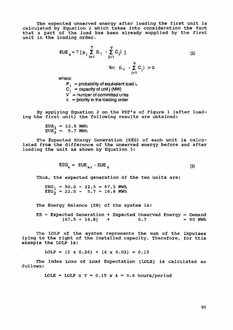
The expected unserved energy after loading the first unit iscalculated by Equation 2 which takes into consideration the factthat a part of the load has been already supplied by the firstunit in the loading order.
EUE k=T[p, I (L, - Z C , ) ] (2)
Vfor: {L, -1C, ) >0
J=1where:
P | = probability of equivalent load LC, - capacity of unit j (MW)V = number of committed unitsk - priority in the loading order
By applying Equation 2 on the PDF's of Figure 1 (after load-ing the first unit) the following results are obtained:
EUE-L = 22.5 MWhEUE2 = 5.7 MWh
The Expected Energy Generation (EEC) of each unit is calcu-lated from the difference of the unserved energy before and afterloading the unit as shown by Equation 3 :
EEGk= EU£k-i-EUE
k (3)
Thus, the expected generation of the two units are:EEG-L = 90.0 - 22.5 = 67.5 MWhEEG2 = 22.5- 5.7 = 16.8 MWh
The Energy Balance (EB) of the system is:EB = Expected Generation + Expected Unserved Energy = Demand
(67.5 + 16.8) + 5.7 = 90 MWh
The LOLP of the system represents the sum of the impulseslying to the right of the installed capacity. Therefore, for thisexample the LOLP is:
LOLP = (2 X 0.26) + (4 X 0.02) = 0.15The index Loss of Load Expectation (LOLE) is calculated as
follows:LOLE = LOLP x T = 0 . 1 5 x 4 = 0 . 6 hours/period
95
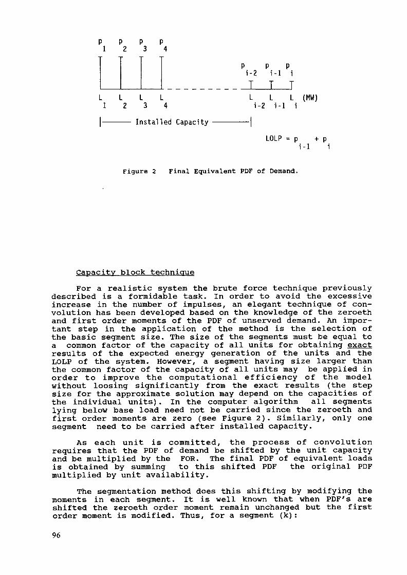
p p p p1 2 3 4
L L L L1 2 3 4
P P Pi-2 i-1 iT T TL L L (MW)i-2 i-1 i
Installed Capacity
LOLP = p + pi-1 i
Figure 2 Final Equivalent PDF of Demand.
Capacity block techniqueFor a realistic system the brute force technique previously
described is a formidable task. In order to avoid the excessiveincrease in the number of impulses, an elegant technique of con-volution has been developed based on the knowledge of the zeroethand first order moments of the PDF of unserved demand. An impor-tant step in the application of the method is the selection ofthe basic segment size. The size of the segments must be equal toa common factor of the capacity of all units for obtaining exactresults of the expected energy generation of the units and theLOLP of the system. However, a segment having size larger thanthe common factor of the capacity of all units may be applied inorder to improve the computational efficiency of the modelwithout loosing significantly from the exact results (the stepsize for the approximate solution may depend on the capacities ofthe individual units). In the computer algorithm all segmentslying below base load need not be carried since the zeroeth andfirst order moments are zero (see Figure 2). Similarly, only onesegment need to be carried after installed capacity.
As each unit is committed, the process of convolutionrequires that the PDF of demand be shifted by the unit capacityand be multiplied by the FOR. The final PDF of equivalent loadsis obtained by summing to this shifted PDF the original PDFmultiplied by unit availability.
The segmentation method does this shifting by modifying themoments in each segment. It is well known that when PDF's areshifted the zeroeth order moment remain unchanged but the firstorder moment is modified. Thus, for a segment (k):
96
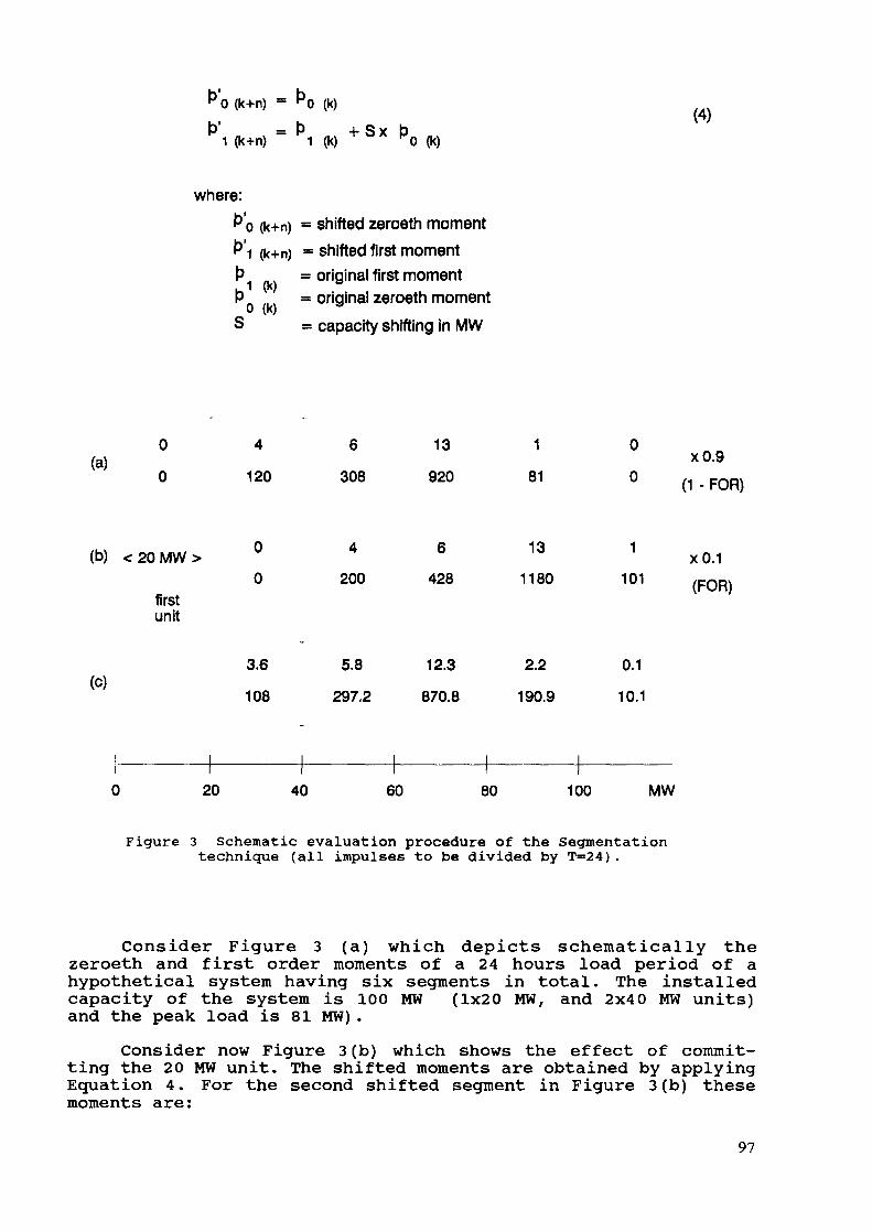
b>0 (k+n) = bo (k)b1 _ b 4. s x b
1 (k+n) 1 (k) K0 (k)
where:b'o (k+n) = shifted zeroeth momentb 1 (k+n) = shifted first momentb = original first momenti • VVo = original zeroeth momentS = capacity shifting in MW
0 4(a)
0 120
(b) <20MW> °0
6
308
4
200
13
920
6
428
1
81
13
1180
0
0
1
101firstunit
(c)3.6
108
5.8
297.2
12.3
870.8
2.2
190.9
0.1
10.1
xO.9(1 - FOR)
(FOR)
20 40 60 80 100 MW
Figure 3 Schematic evaluation procedure of the Segmentationtechnique (all impulses to be divided by T=24).
Consider Figure 3 (a) which depicts schematically thezeroeth and first order moments of a 24 hours load period of ahypothetical system having six segments in total. The installedcapacity of the system is 100 MW (1x20 MW, and 2x40 MW units)and the peak load is 81 MW).
Consider now Figure 3(b) which shows the effect of commit-ting the 20 MW unit. The shifted moments are obtained by applyingEquation 4. For the second shifted segment in Figure 3 (b) thesemoments are:
97
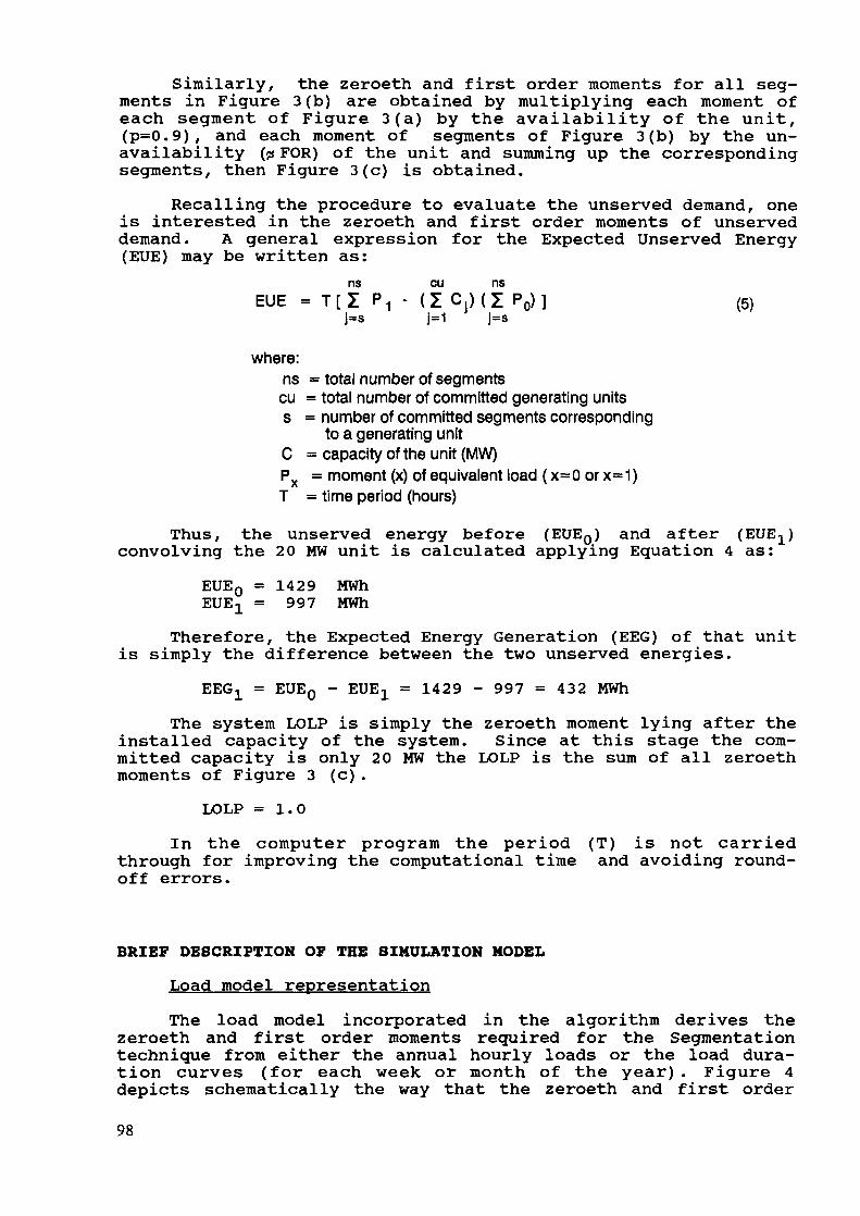
Similarly, the zeroeth and first order moments for all seg-ments in Figure 3 (b) are obtained by multiplying each moment ofeach segment of Figure 3(a) by the availability of the unit,(p=0.9), and each moment of segments of Figure 3(b) by the un-availability (çs FOR) of the unit and summing up the correspondingsegments, then Figure 3(c) is obtained.
Recalling the procedure to evaluate the unserved demand, oneis interested in the zeroeth and first order moments of unserveddemand. A general expression for the Expected Unserved Energy(EUE) may be written as:
ns cu nsEUE = T[Z PI • (Z C,)(Z PQ)] (5)
]»8 J-1 |=S
where:ns = total number of segmentscu = total number of committed generating unitss = number of committed segments corresponding
to a generating unitC = capacity of the unit (MW)Px = moment (x) of equivalent load ( x=0 or x=1)T = time period (hours)
Thus, the unserved energy before (EUEQ) and afterconvolving the 20 MW unit is calculated applying Equation 4 as:EUE0 = 1429 MWhEUEX = 997 MWh
Therefore, the Expected Energy Generation (EEC) of that unitis simply the difference between the two unserved energies.
EEG-L = EUE0 - EUEX = 1429 - 997 = 432 MWhThe system LOLP is simply the zeroeth moment lying after the
installed capacity of the system. Since at this stage the com-mitted capacity is only 20 MW the LOLP is the sum of all zeroethmoments of Figure 3 (c) .
LOLP =1.0In the computer program the period (T) is not carried
through for improving the computational time and avoiding round-off errors.
BRIEF DESCRIPTION OF THE SIMULATION MODELLoad model representationThe load model incorporated in the algorithm derives the
zeroeth and first order moments required for the Segmentationtechnique from either the annual hourly loads or the load dura-tion curves (for each week or month of the year) . Figure 4depicts schematically the way that the zeroeth and first order
98
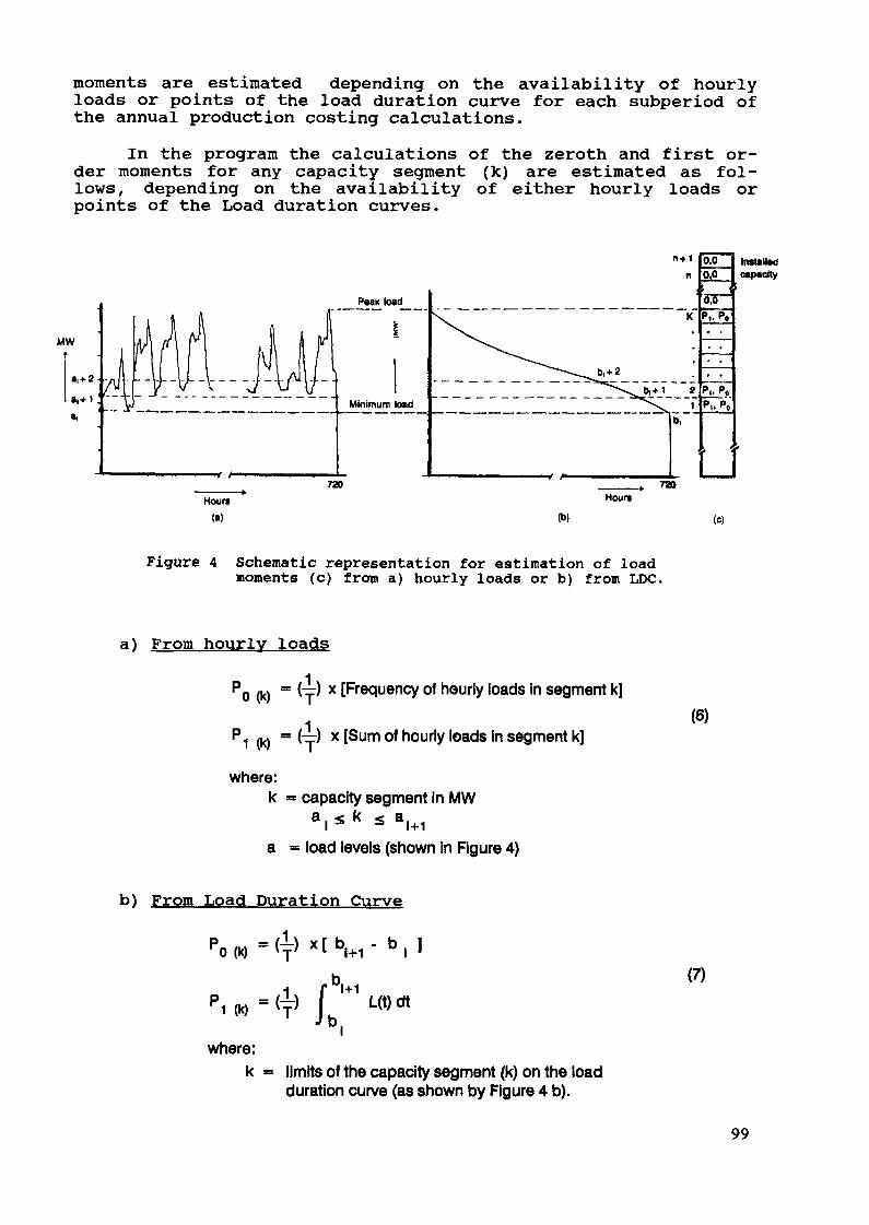
moments are estimated depending on the availability of hourlyloads or points of the load duration curve for each subperiod ofthe annual production costing calculations.
In the program the calculations of the zeroth and first or-der moments for any capacity segment (k) are estimated as fol-lows, depending on the availability of either hourly loads orpoints of the Load duration curves.
MW
Install«!o*p*dty
Figure 4 Schematic representation for estimation of loadmoments (c) from a) hourly loads or b) from LDC.
a) From hourly loads
(k)1
~f) x Frequency of hourly loads in segment k]
(T) x [Sum of hourly loads in segment k]
where:k = capacity segment In MW
a . * k * a,+ia = load levels (shown in Figure 4)
(6)
b) From Load Duration Curve
ri W
where:k
1+1L(t)dt
limits of the capacity segment (k) on the loadduration curve (as shown by Figure 4 b).
(7)
99

Simulation of Thermal unitsThe mathematical algorithm used to estimate the expected
energy generation of the thermal units is the Segmentation multi-block loading technique.
At this stage, during the execution of the model the loaddemand in term of capacity segments (Figure 4 c) and the loadingpriority list of the units based on the incremental cost of eachblock of thermal units have been calculated or they are given.
The load demand and the available capacity of each unit areconsidered to be random variables. Each unit may be representedas consisting of several load blocks (maximum 5 blocks), clearlythe capacity blocks of each unit may occupy non-adjacent posi-tions in the loading order. The basic consideration in thesimulation procedure of multiblock loading is that higher orderblocks cannot be loaded until lower blocks have been committed.To correctly account for this dependency, during the execution,lower order blocks are first deconvolved before the combinedlower and higher blocks are convolved. The deconvolution processis necessary to avoid the convolution of the higher block againstthe outage of the lower block of the same unit (Equations forthe deconvolution process of the Segmentation method are given in[2], [12]). At this point it should be mentioned the superiorityand consistency of the Segmentation technique over other prob-abilistic simulation techniques, exact or approximate, thatdevelop inaccuracies due to instability caused by round-off er-rors introduced from multiple convolution-deconvolution process.
Loading orderThe loading or merit order procedure is the manner by which
the various thermal units are committed for generation in orderto meet the demand and to minimize the system operating costs.The loading procedure determines the number, type and productionlevel of each unit which is committed to generate at any giventime. The loading order is a very important factor for calculat-ing the expected generation and operating cost of the individualunits and the corresponding quantities for the total generatingsystem. The major operating cost component of a power system,excluding start-up, shut-down and transmission losses is the fuelcost. The economic loading procedure which yields the minimumoperating cost for the total system is the one which equates themarginal costs of the units of the power system for any demandlevel [9].
In the program, from the heat rate of each capacity block ofevery unit (multiblock loading), the heating value of fuel, andthe price of fuel, the expected incremental fuel cost is es-timated. By sorting in ascending order the expected incrementalfuel cost of the capacity blocks of the thermal units, the leastcost loading order of the system is obtained.
The basic least cost loading order of thermal units can begiven externally by the user of the Model for capturing existingoperating constraints such as minimum loading requirements, must-run units, etc. or it may calculated internally by the Model. The
100

loading order utilized during the execution of the Model can alsobe modified automatically in the program because of possible fuellimitations of a particular plant or mine.
MaintenanceThe maintenance scheduling problem consists of planning the
annual maintenance outage of the generating units. During themaintenance period of a unit its capacity is not available, thusthe total operating capacity of the system is decreased. Thereduction in operating capacity results in the deterioration ofsystem reliability, followed by increase in operating costs ofthe generating system owing to the greater production by higherincremental cost units. An automated maintenance scheduling al-gorithm is incorporated in the Model for emulating the stoppageprocess, considering planned outages of each unit. Maintenancescheduling calculations take place at the beginning of each yearprior of performing the annual production costing estimations.Generating units are removed from operation for a specific dura-tion (given in days per year) and the algorithm aims at keepingthe amount of reserve capacity almost at the same level in eachsubperiod (week or month) of the year. In the algorithm, specialconsideration is given to constraints imposed by labor orsecurity of system operation, by assigning potential maintenancedates to each unit, and to changes of the installed capacityduring the year due to additions or retirements of generatingunits in pre-specified month of a year of the planning horizon.
Simulation of Hydro unitsTo minimize the fuel cost in the operation of a mixed hydro-
thermal system, the hydro energy production must always be op-timally utilized. For the evaluation of production cost of sucha system it is very important to have this fact represented inthe model as close as possible to realistic operating procedures.
There are two different techniques included in the modelfor simulating the operation of the hydro units: a) the capacitylimiting and b) the energy limiting options. The user selectseither option for the execution of the program.
Capacity limiting; This option of simulating the operationof the hydro units is based on the aggregation of the individualhydro units into a single multistate unit for the purpose ofcomputational efficiency without sacrificing other simulationcapabilities such as random outages, maintenance scheduling ofeach unit. It is well known that the maximum generating energyavailable from conventional hydroelectric units is fixed by cer-tain constraints which are independent of the operation of theremaining units of the system. These constraints include limitingreservoir, seasonal rainfall limitations etc. Since the costsassociated with the hydro energy is essentially zero, it is mostadvantageous to use all of the available energy for the givenperiod. Thus, the energy to be generated by a conventionalhydroelectric plan is fixed.
101
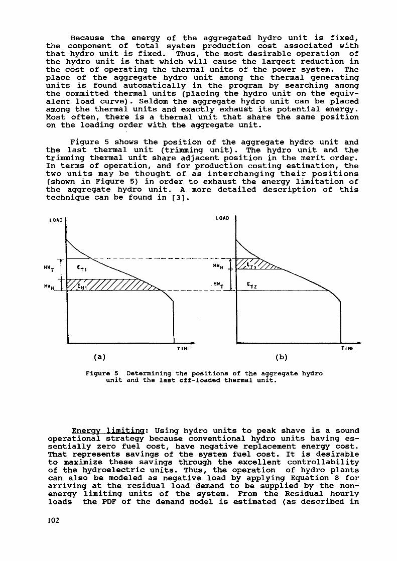
Because the energy of the aggregated hydro unit is fixed,the component of total system production cost associated withthat hydro unit is fixed. Thus, the most desirable operation ofthe hydro unit is that which will cause the largest reduction inthe cost of operating the thermal units of the power system. Theplace of the aggregate hydro unit among the thermal generatingunits is found automatically in the program by searching amongthe committed thermal units (placing the hydro unit on the equiv-alent load curve). Seldom the aggregate hydro unit can be placedamong the thermal units and exactly exhaust its potential energy.Most often, there is a thermal unit that share the same positionon the loading order with the aggregate unit.
Figure 5 shows the position of the aggregate hydro unit andthe last thermal unit (trimming unit) . The hydro unit and thetrimming thermal unit share adjacent position in the merit order.In terms of operation, and for production costing estimation, thetwo units may be thought of as interchanging their positions(shown in Figure 5) in order to exhaust the energy limitation ofthe aggregate hydro unit. A more detailed description of thistechnique can be found in [3].
LOAD
MM
T IMF TIME(a) (b)
Figure 5 Determining the positions of the aggregate hydrounit and the last off-loaded thermal unit.
Energy limiting: Using hydro units to peak shave is a soundoperational strategy because conventional hydro units having es-sentially zero fuel cost, have negative replacement energy cost.That represents savings of the system fuel cost. It is desirableto maximize these savings through the excellent controllabilityof the hydroelectric units. Thus, the operation of hydro plantscan also be modeled as negative load by applying Equation 8 forarriving at the residual load demand to be supplied by the non-energy limiting units of the system. From the Residual hourlyloads the PDF of the demand model is estimated (as described in102
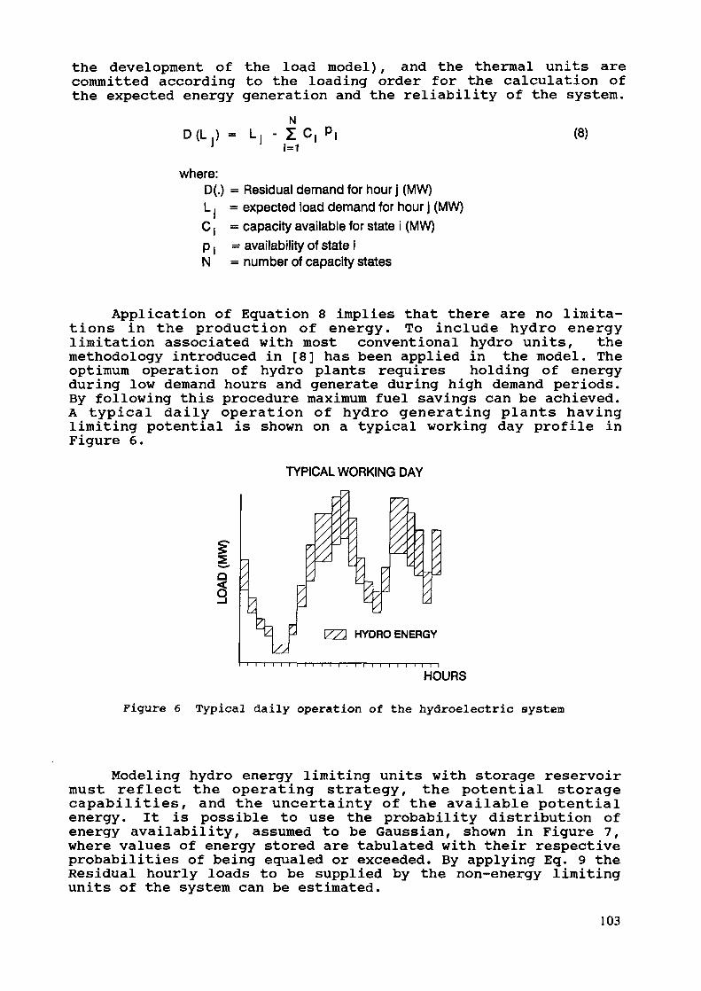
the development of the load model) , and the thermal units arecommitted according to the loading order for the calculation ofthe expected energy generation and the reliability of the system.
• jN- ic,1=1 (8)
where:D(.) = Residual demand for hour j (MW)L : = expected load demand for hour j (MW)C, = capacity available for state i (MW)p | = availability of state iN = number of capacity states
Application of Equation 8 implies that there are no limita-tions in the production of energy. To include hydro energylimitation associated with most conventional hydro units, themethodology introduced in [8] has been applied in the model. Theoptimum operation of hydro plants requires holding of energyduring low demand hours and generate during high demand periods.By following this procedure maximum fuel savings can be achieved.A typical daily operation of hydro generating plants havinglimiting potential is shown on a typical working day profile inFigure 6.
TYPICAL WORKING DAY
|
IZZ3 HYDRO ENERGY
i—i—n—i—n—i—i—i—i—i—i—i—i—i—i—i—n—n
Figure 6 Typical daily operation of the hydroelectric system
Modeling hydro energy limiting units with storage reservoirmust reflect the operating strategy, the potential storagecapabilities, and the uncertainty of the available potentialenergy. It is possible to use the probability distribution ofenergy availability, assumed to be Gaussian, shown in Figure 7,where values of energy stored are tabulated with their respectiveprobabilities of being equaled or exceeded. By applying Eq. 9 theResidual hourly loads to be supplied by the non-energy limitingunits of the system can be estimated.
103
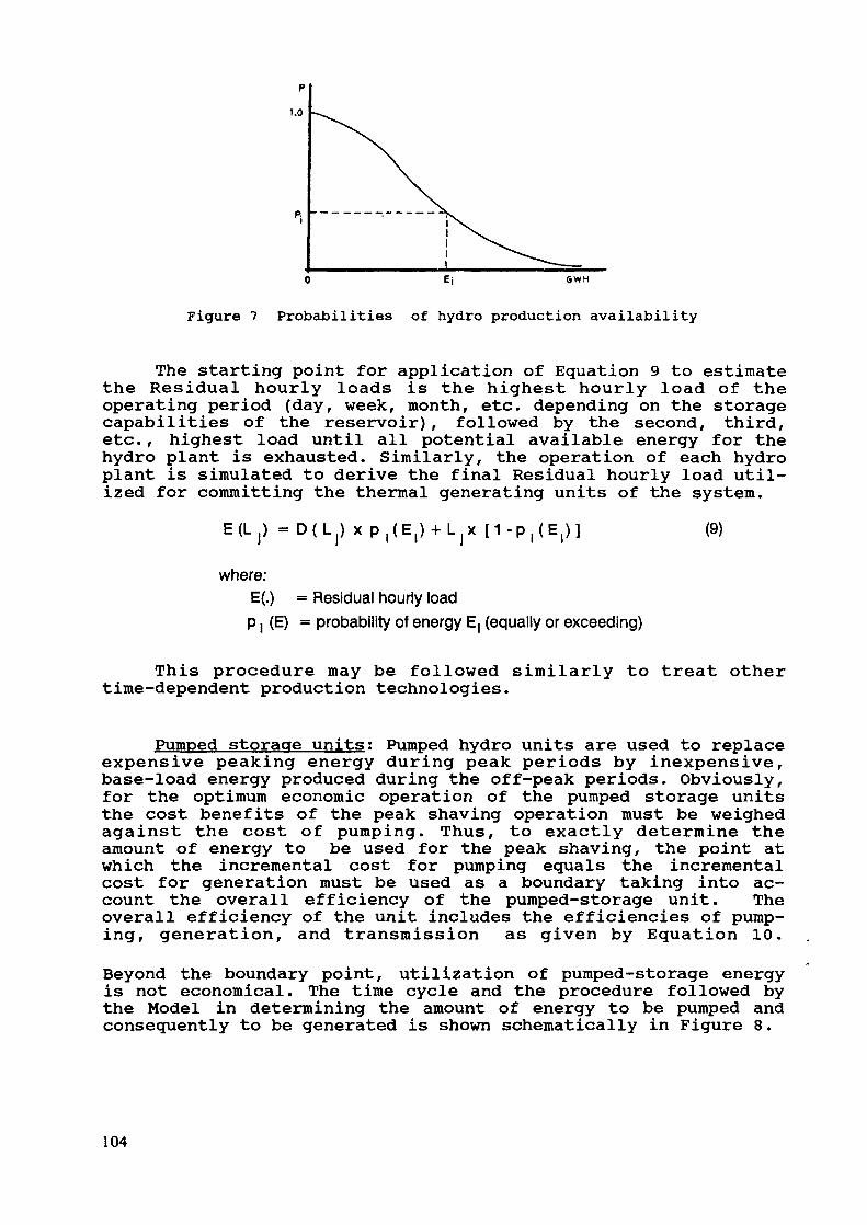
pT.O
6WH
Figure 7 Probabilities of hydro production availability
The starting point for application of Equation 9 to estimatethe Residual hourly loads is the highest hourly load of theoperating period (day, week, month, etc. depending on the storagecapabilities of the reservoir), followed by the second, third,etc., highest load until all potential available energy for thehydro plant is exhausted. Similarly, the operation of each hydroplant is simulated to derive the final Residual hourly load util-ized for committing the thermal generating units of the system.
E(L ) = D(L) x (9)
where:E(.) = Residual hourly loadp i (E) = probability of energy E| (equally or exceeding)
This procedure may be followed similarly to treat othertime-dependent production technologies.
Pumped storage units; Pumped hydro units are used to replaceexpensive peaking energy during peak periods by inexpensive,base-load energy produced during the off-peak periods. Obviously,for the optimum economic operation of the pumped storage unitsthe cost benefits of the peak shaving operation must be weighedagainst the cost of pumping. Thus, to exactly determine theamount of energy to be used for the peak shaving, the point atwhich the incremental cost for pumping equals the incrementalcost for generation must be used as a boundary taking into ac-count the overall efficiency of the pumped-storage unit. Theoverall efficiency of the unit includes the efficiencies of pump-ing, generation, and transmission as given by Equation 10.Beyond the boundary point, utilization of pumped-storage energyis not economical. The time cycle and the procedure followed bythe Model in determining the amount of energy to be pumped andconsequently to be generated is shown schematically in Figure 8.
104
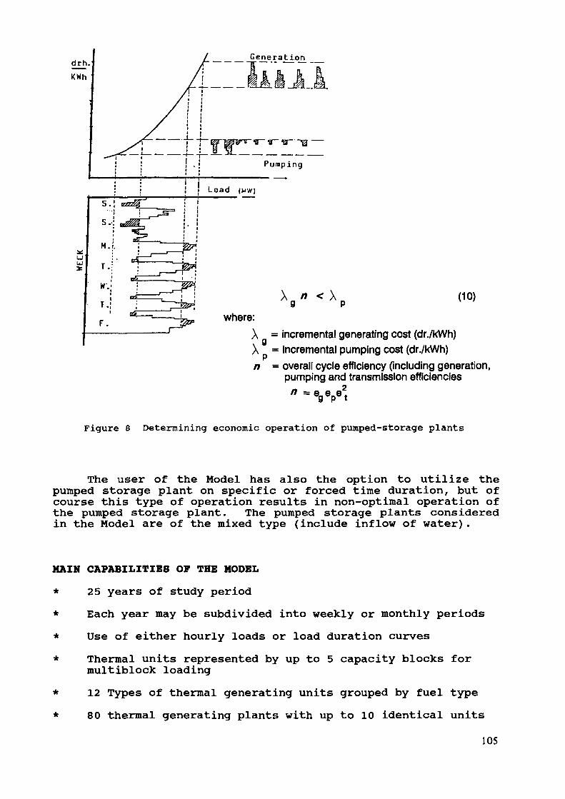
Generation
(10)
X = incremental generating cost (dr./kWh)X = incremental pumping cost (dr./kWh)n = overall cycle efficiency (including generation,
pumping and transmission efficiencies
Figure 8 Determining economic operation of pumped-storage plants
The user of the Model has also the option to utilize thepumped storage plant on specific or forced time duration, but ofcourse this type of operation results in non-optimal operation ofthe pumped storage plant. The pumped storage plants consideredin the Model are of the mixed type (include inflow of water).
MAIN CAPABILITIES OF THE MODEL
* 25 years of study periodEach year may be subdivided into weekly or monthly periodsUse of either hourly loads or load duration curves
**
Thermal units represented by up to 5 capacity blocks formultiblock loading12 Types of thermal generating units grouped by fuel type80 thermal generating plants with up to 10 identical units
105
30 Hydro stations having up to 10 identical units5 hydrological conditionsSimulation on pumped storage units operating on
i) economic baseii) forced utilization on specific hours of the week
Simulation of hydro units using two different techniquesi) operating among the thermal units as a composite
hydro station (capacity limiting option)ii) unit by unit according to the technique described
in [8], (energy limiting option)Maintenance schedule of the generating units by levelingthe reserve margin. The time base unit for maintenance isthe week or 1/4 of the month (4X12 = 48 periods per year)Escalation of fuel prices for each individual fuel (12)type. Generating units are added or retired at beginningof a month of any year of study period.Loading order may be given by the user or may estimatedby the program to be the basic least cost economic order.Fuel availability limitations consideredTime dependent units (wind, solar, etc.) can be treatedLoad management.
APPLICATION
The COST Model has been applied very successfully for thelast two years for production costing calculations of the PowerGenerating system of Greece (PPC).
The PPC system consists of three independent generating sys-tems, the mainland system having presently installed capacity inthe order of 7500 MW with peak load of approximately 5100 MW andenergy demand of 30000 GWh. The second generating system is onthe island of Crete which have an installed capacity of 270 MW,peak load of the order of 210 MW and energy demand of ap-proximately 1000 GWh. The third system supplies the island ofRhodos having installed capacity 110 MW, peak load 70 MW andenergy demand 310 GWh.
The generating system of IEEE-RTS has also been evaluated,and the results for that system as directly obtained as the out-put of the model are shown on Tables A, B, and C (see Appendix).The results obtained from execution of the Model for the PPCmainland power system and the generating systems of Crete areshown on Tables D, E, and F.
106

INPUT-OUTPUT AND COMPUTER REQUIREMENTS
Data on four major categories are required to execute COST:a) system demand, b) thermal generating units, c) hydro units andd) constraints and running options.
The demand must be given in terms of hourly loads (typicalyear with 8760 hours) or points of the load duration curves(weekly or monthly) . Peak loads and energies for the studyhorizon must also be given.
The required data for thermal units include their operatingcharacteristics such as capacity, forced outage rates, heatrates, maintenance requirements, fuel cost and type, and economicdata such as O&M costs, escalation of fuel prices.
The data for hydro units include unit capacity, possiblehydro generation with respective probability (up to 5probabilities), planned maintenance and O&M costs. For pumpingunits the overall efficiency and the potential storage capabilityis also required.
Modeling running options include utilization of hourly loadsor load duration curves during the execution, forced againsteconomic operation of pumped storage unit, utilization oneconomic or user specified loading order, running weekly ormonthly the production simulator and various choices on the out-put tables to be printed by the Model.
The output of the Model is given in terms of tables that in-clude input data, detailed annual production costing results foreach unit, annual maintenance table, detailed annual generationand consumption by fuel type and summary of the annualreliability and production costs for the study horizon. COST isavailable for running on mainframe, mini-computers and personalcomputers (PC).
The mainframe version runs on a BULL-8 computer while themini model is a mini-6 BULL computer. The PC version run underDOS environment with memory storage requirements of less than 0.5MB. Presently the model runs on 80386 and 80286 PC computers at25 MHz and 12 MHz respectively including also mathematicalcoprocessors.
FURTHER DEVELOPMENTS
At this time work is under way for improving the simulationof hydro generating units in terms of the monthly allocation ofhydro energy production. Other improvements include environmentalconsiderations, multistate representation for combined cycleunits, and consideration of interconnections.
107

REFERENCES
1. K.F. Schenk, S. Vassos, "A Novel and Efficient Techniquefor the Exact Evaluation of LOLP and Production Costs inGeneration Planning", Proceeding of the Symposium, NRRI,pp. 311-321, Sept. 1983.
2. K.F. Schenk, R.B. Misra, S. Vassos, W. Wen, "A New Methodfor the Evaluation of Expected Energy Generation and Lossof Load Probability", IEEE Trans., Vol. PAS-103 No 2, pp.294-303, 1984.
3. B. Manhire, R.T. Jenkins, "A New Technique for Simulatingthe Operation of Multiple Assigned-Energy GeneratingUnits Suitable for use in Generation System PlanningModels", IEEE Trans. Vol. PAS-101, No 10, pp. 3861-3869,1982.
4. R. Billinton, P.G. Harrington, "Reliability, Evaluationin Energy Limited Generating Capacity Studies", IEEETransactions, Vol. PAS-97, No 6, pp. 2076-2082, 1978.
5. IEEE Committee Report, "IEEE Reliability Test System",IEEE Transactions, Vol. PAS-98, pp. 2047-2054, 1979.
6. R.R. Booth, "Power System Simulation Model Based onProbability Analysis" IEEE-Transactions, Vol. PAS-91 pp.62-69, 1972.
7. K.F. Schenk, Q. Ahsan, S. Vassos, "The SegmentationMethod Applied to the Evaluation of Production Costs oftwo Inter-connected Systems", International ElectricPower and Energy Systems Journal, vol. 3, 1985.
8. Vassos S., Panagiotarea E., Karydogiannis E.,"Production Costing Evaluation in Energy Limited Units bythe Segmentation Technique", Presented at the MELECON'87, Rome, Italy, March 24-26, 1987.
9. Zahavi I., Vardi J., Avi-Itzhak B., "Operating Cost Cal-culation of an Electric Generating System under In-cremental Loading Procedure", IEEE Transactions, PAS-96pp. 285-292, 1977.
10. Wood A.I., Wollenberg B.F., "POWER GENERATION, OPERATION& CONTROL", John Wiley & Sons Inc., New York, 1984.
11. Sullivan R.L., "POWER SYSTEM PLANNING", Me Graw Hill,Inc., New York, 1978.
12. Technical Reports Series No 241, "EXPANSION PLANNINGFOR ELECTRICAL GENERATING SYSTEM A GUIDEBOOK", Interna-tional Atomic Energy Agency, Vienna, pp. 448-468, 1984.
108
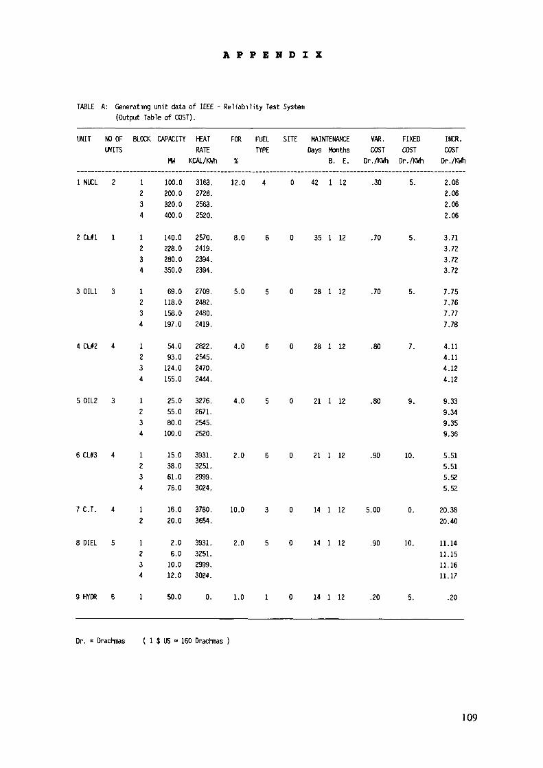
A P P E N D I X
TABLE A: Generating unit data of IEEE - Reliability Test System(Output Table of COST).
UNIT NO OFUNITS
1 NUCL 2
2 CL#1 1
3 OIL1 3
4 CLI2 4
5 OIL2 3
6 CU3 4
7 C.T. 4
8 DIEL 5
9 HYDR B
BLOCK
1234
1234
1234
1234
1234
1234
12
1234
1
CAPACITY
HU
100.0200.0320.0400.0
140.0228.0280.0350.0
69.0118.0158.0197.0
54.093.0
124.0155.0
25.055.080.0
100.0
15.038.061.076.0
16.020.0
2.06.0
10.012.0
50.0
HEAT FOR FUEL SITE MAINTENANCE VAR. FIXEDRATE TYPE Days Months COST COST
KCAL/KWh % B. E. Dr. /KWh Dr. /KWh
3163. 12.0 4 0 42 1 12 .30 5.2728.2563.2520.
2570. 8.0 6 0 35 1 12 .70 5.2419.2394.2394.
2709. 5.0 5 0 28 1 12 .70 5.2482.2480.2419.
2822. 4.0 6 0 28 1 12 .80 7.2545.2470.2444.
3276. 4.0 5 0 21 1 12 .80 9.2671.2545.2520.
3931. 2.0 6 0 21 1 12 .90 10.3251.2999.3024.
3780. 10.0 3 0 14 1 12 5.00 0.3654.
3931. 2.0 5 0 14 1 12 .90 10.3251.2999.3024.
0. 1.0 1 0 14 1 12 .20 5.
INCR.COSTDr. /KWh
2.062.062.062.06
3.713.723.723.72
7.757.767.777.78
4.114.114.124.12
9.339.349.359.36
5.515.515.525.52
20.3820.40
11.1411.1511.1611.17
.20
Dr. = Drachmas ( 1 $ US » 160 Drachmas )
109
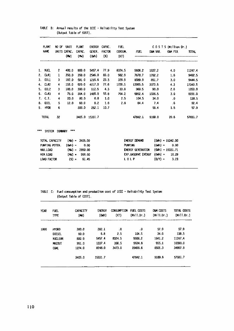
TABLE B: Annual results of the IEEE - Reliability Test Systen(Output Table of COST).
PLANT NO OFNAME UNITS
1. NUCL2. ail3. OIL14. CL#25. OIL26. a#37. C.T.8. DIEL9. HYDR
TOTAL
*** SYSTEM
213434456
32
UNITCAPAC.(MW)
400.0350.0197.0155.0100.076.020.012.0
PLANT ENERGY CAPAC.CAPAC. GENER. FACTOR(MW) (GWh) (%)
800.0 5457.4 77.9350.0 2546.0 83.0591.0 1216.6 23.5620.0 4217.0 77.6300.0 112.5 4.3304.0 1485.0 55.880.0 6.8 1.060.0 8.2 1.6300.0 282.1 10.7
3405.0 15331.7
FUELCONSUM.(KT)
8324.5982.9329.91726.533.8764.22.52.8
FUEL
9606.27678.78589.913965.5960.56852.4104.584.4
47842.1
C O S T S (Million Dr.)08M VAR. OS« FIX TOTAL
1637.21782.2851.73373.6
90.01336.534.07.4
56.4
9169.0
4.01.63.04.32.63.0.0.61.5
20.6
11247.49462.59444.517343.51053.08191.9138.592.457.9
57031.7
SUMMARY ***
TOTAL CAPACITYPUMPING POTEN.MAX. LOADMIN. LOAD
(MW)(GWh)(MW)(MW)
LOAD FACTOR (%)
= 3405.000.00
= 2850.00= 966.00
61.45
ENERGY DEMANDPUMPING
(GWh) =(GWh) =
ENERGY GENERATION (GWh) =EXPL 0
.UNSERVE ENERGY (GWh) =L P (0/Y) =
15342.000.00
15331.7110.293.23
TABLE C: Fuel consuiption and production cost of IEEE - Reliability Test System(Output Table of COST).
YEAR
1990
FUELTYPE
HYDRODIESELNUCLEARMAZOUTCOAL
CAPACITY(Wrf)
300.080.0800.0951.01274.0
ENERGY(GWH)
282.16.8
5457.41337.48248.0
CONSUMPTION(KT)
.02.5
8324.5366.53473.6
FUEL COSTS(Mill. Dr.)
.0104.59606.29634.828496.6
OSW COSTS(Mill. Dr.)
57.934.0
1641.2955.16501.3
TOTAL COSTS(Mill. Dr.)
57.9138.5
11247.410590.034997.9
3405.0 15331.7 47842.1 9189.6 57031.7
110
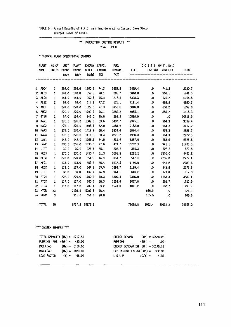
TABLE D : Annual Results of P.P.C. mainland Generating System, Case Study(Output Table of COST).
** PRODUCTION COSTING RESULTSYEAR 1990
**
* THERMAL PLANT OPERATIONAL SUMMARY
PLANTNAME
1 A0042 AL033 AL044 AL125 AM016 AM027 GT568 KAR19 KAR210 KAR311 KAR412 LAV113 LAV214 LIPT15 ME0316 ME0417 ME0118 ME0219 PT0120 PT0421 PT0222 PT0323 HYDR24 PUMP
NO OFUNITS
1112112111111111111111333
UNITCAPAC.(MW)
286.0140.0144.038.0270.0270.057.0276.0276.0276.0276.0142.0285.030.0270.0270.0113.0113.066.0276.0117.0117.0
PLANTCAPAC.(MW)
286.0140.0144.076.0270.0270.0114.0276.0276.0276.0276.0142.0285.030.0270.0270.0113.0113.066.0276.0117.0117.02199.5315.0
ENERGYGENER.(GWh)
1860.6859.8950.6514.11829.51799.2849.01682.61498.11412.21411.91056.31936.5223.51450.4351.9657.4647.9432.71700.2700.3709.15089.8551.6
CAPAC.FACTOR(%)
74.370.175.477.277.376.185.069.662.058.458.484.977.685.161.314.966.465.574.870.368.369.226.420.0
FUELCONSUM.(KT)
3653.5205.7217.5171.13951.63886.2286.53487.73159.62824.42875.2231.6419.7536.53691.9863.71912.51884.7944.13400.41553.41573.0
FUEL
2489.45040.85328.34191.45048.84965.110515.92375.12152.81924.41958.05857.010762.3365.32212.2517.31146.01129.4643.22316.91057.81071.2
C O S T SO&M VAR
.0
.0
.0
.0
.0
.0
.0
.0
.0
.0
.0
.0
.0
.0
.0
.0
.0
.0
.0
.0
.0
.0926.9165.5
(Hill.. 08M
741900926488850850
964964964964468941507225522559439433731563662662
Dr.)FIX.
.3
.5
.2
.8
.2
.2
.0
.3
.3
.3
.3
.9
.1
.5
.0
.0
.8
.8
.8
.3
.7
.7
.0
.0
TOTAL
3230.75941.36254.54680.25899.05815.310515.93339.43117.22888.72922.36325.811703.3872.84467.22772.42089.82073.21017.03880.11720.51733.9926.9165.5
TOTAL 60 6717.5 30175.1 73068.5 1092.4 20192.2 94353.0
SYSTEM SUMMARY
TOTAL CAPACITY (MW) = 6717.50PUMPING POT. (GWh) = 480.00MAX.LOAD (MW) = 5126.00MIN.LOAD (MW) = 1873.00LOAD FACTOR (%) = 68.00
ENERGY DEMAND (GWh) = 30538.02PUMPING (GWh) = .00ENERGY GENERATION (GWh) = 30175.12EXP.UNSERVE ENERGY(GWh) = 362.90L O L P (D/Y) = 4.39
1 1 1
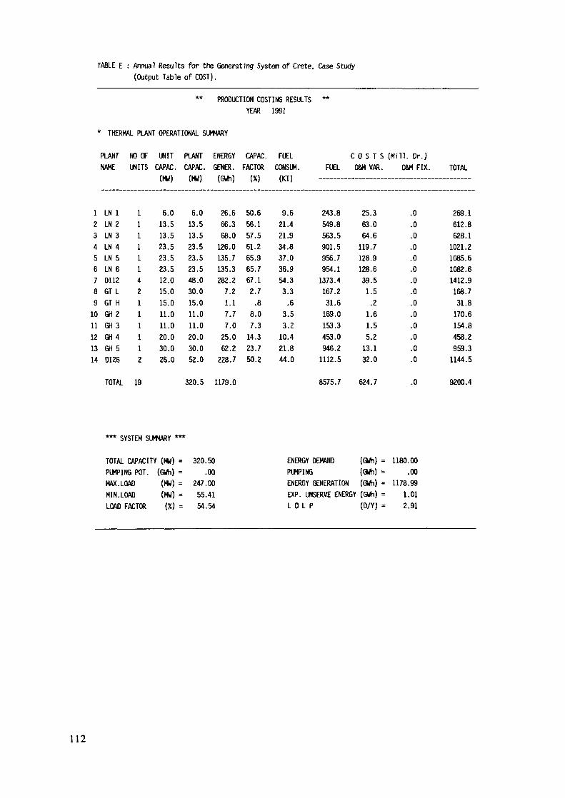
TABLE E : Annual Results for the Generating System of Crete, Case Study(Output Table of COST).
** PRODUCTION COSTING RESULTS **YEAR 1991
* THERMAL PLANT OPERATIONAL SUMMARY
PLANT NO OF UNIT PLANT ENERGY CAPAC. FUELNAME UNITS CAPAC. CAPAC. GENER. FACTOR CONSUM. FUEL
C O S T S (Mill. Dr.)OSM VAR. OEM FIX. TOTAL
123456789
1011121314
LN 1LN 2LN 3LN 4LN 5LN 6DI12GT LGT HGH 2GH 3G H 4GH 5DI26
11111142111112
\rrni
6.013.513.523.523.523.512.015.015.011.011.020.030.026.0
Vn*;
6.0
13.513.523.523.523.548.030.015.011.011.020.030.052.0
lUWIIJ
26.666.368.0
126.0135.7135.3282.2
7.21.17.77.0
25.062.2
228.7
i*y
50.656.157.561.265.965.767.12.7
.88.07.3
14.323.750.2
\*>i
9.621.421.934.837.036.954.33.3
.63.53.2
10.421.844.0
243.8549.8563.5901.5956.7954.1
1373.4167.231.6
169.0153.3453.0946.2
1112.5
25.363.064.6
119.7128.9128.639.51.5.2
1.61.55.2
13.132.0
.0
.0
.0
.0
.0
.0
.0
.0
.0
.0
.0
.0
.0
.0
269.1612.8628.1
1021.21085.61082.61412.9168.731.8
170.6154.8458.2959.3
1144.5
TOTAL 19 320.5 1179.0 8575.7 624.7 9200.4
SYSTEM SUMMARY
TOTAL CAPACITY (MW) = 320.50PUMPING POT. (GWh) = .00MAX.LOAD (MW) = 247.00MIN.LOAD (MW) = 55.41LOAD FACTOR (%) = 54.54
ENERGY DEMAND (GWh) = 1180.00PUMPING (GWh) = .00ENERGY GENERATION (GWh) = 1178.99EXP. UNSERVE ENERGY (GWh) = 1.01L 0 L P (D/Y) = 2.91
112
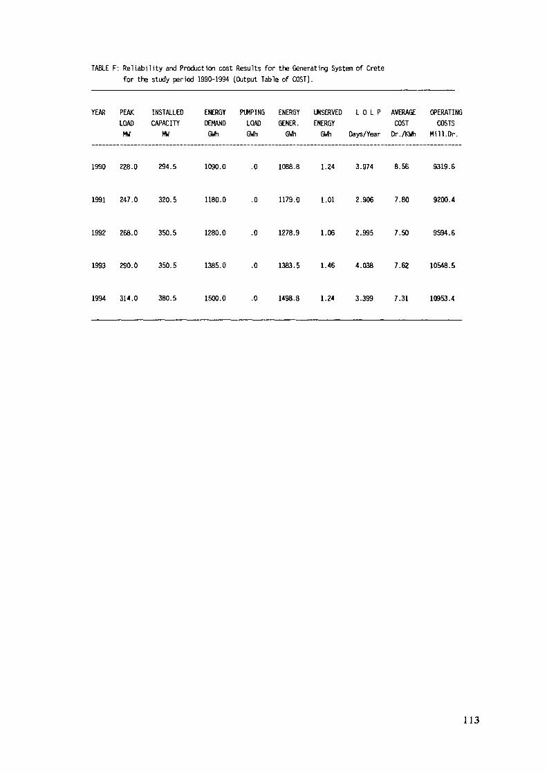
TABLE F: Reliability and Production cost Results for the Generating System of Cretefor the study period 1990-1994 (Output Table of COST).
YEAR PEAK INSTALLED ENERGY PUMPING ENERGY UNSERVED L O L P AVERAGE OPERATINGLOAD CAPACITY DEMAND LOAD GENER. ENERGY COST COSTSMW MW GWh GWh GWh GWh Days/Year Dr./KWh Mi 11.Dr.
1990 228.0 294.5 1090.0 .0 1088.8 1.24 3.974 8.56 9319.6
1991 247.0 320.5 1180.0 .0 1179.0 1.01 2.906 7.80 9200.4
1992 268.0 350.5 1280.0 .0 1278.9 1.06 2.995 7.50 9594.6
1993 290.0 350.5 1385.0 .0 1383.5 1.46 4.038 7.62 10548.5
1994 314.0 380.5 1500.0 .0 1498.8 1.24 3.399 7.31 10953.4
113
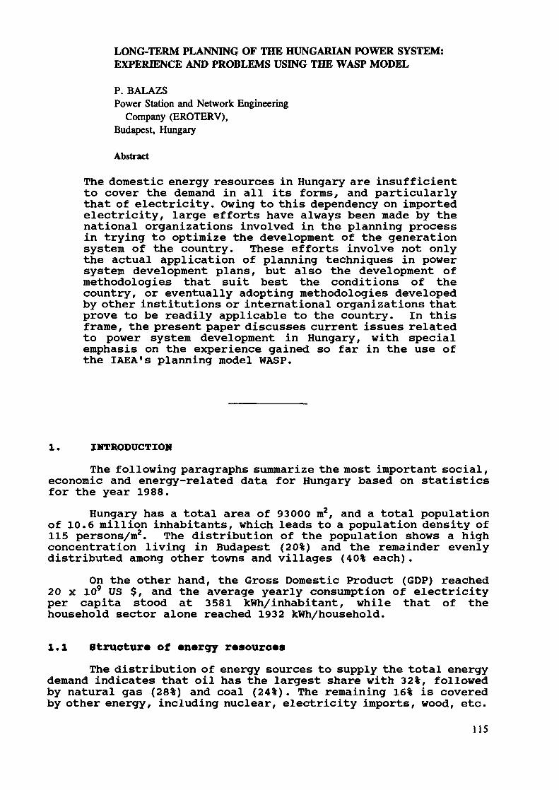
LONG-TERM PLANNING OF THE HUNGARIAN POWER SYSTEM:EXPERIENCE AND PROBLEMS USING THE WASP MODEL
P. BALAZSPower Station and Network Engineering
Company (EROTERV),Budapest, Hungary
Abstract
The domestic energy resources in Hungary are insufficientto cover the demand in all its forms, and particularlythat of electricity. Owing to this dependency on importedelectricity, large efforts have always been made by thenational organizations involved in the planning processin trying to optimize the development of the generationsystem of the country. These efforts involve not onlythe actual application of planning techniques in powersystem development plans, but also the development ofmethodologies that suit best the conditions of thecountry, or eventually adopting methodologies developedby other institutions or international organizations thatprove to be readily applicable to the country. In thisframe, the present paper discusses current issues relatedto power system development in Hungary, with specialemphasis on the experience gained so far in the use ofthe IAEA's planning model WASP.
1. INTRODUCTION
The following paragraphs summarize the most important social,economic and energy-related data for Hungary based on statisticsfor the year 1988.
Hungary has a total area of 93000 m2, and a total populationof 10.6 million inhabitants, which leads to a population density of115 persons/m2. The distribution of the population shows a highconcentration living in Budapest (20%) and the remainder evenlydistributed among other towns and villages (40% each).
On the other hand, the Gross Domestic Product (GDP) reached20 x 109 US $, and the average yearly consumption of electricityper capita stood at 3581 kWh/inhabitant, while that of thehousehold sector alone reached 1932 kWh/household.
l.l Structure of energy resourcesThe distribution of energy sources to supply the total energy
demand indicates that oil has the largest share with 32%, followedby natural gas (28%) and coal (24%). The remaining 16% is coveredby other energy, including nuclear, electricity imports, wood, etc.
115
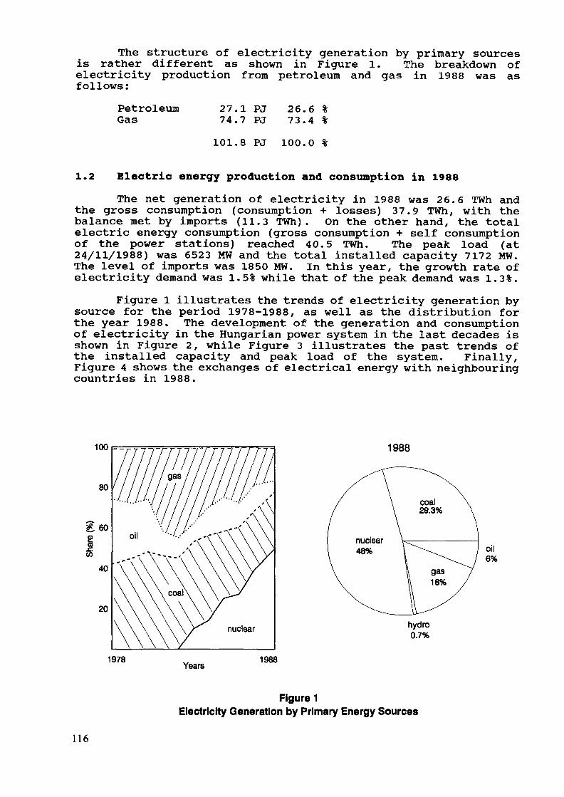
The structure of electricity generation by primary sourcesis rather different as shown in Figure 1. The breakdown ofelectricity production from petroleum and gas in 1988 was asfollows:
PetroleumGas
27.1 PJ74.7 PJ
26.6 %73.4 %
101.8 PJ 100.0 %
1.2 Electric energy production and consumption in 1988The net generation of electricity in 1988 was 26.6 TWh and
the gross consumption (consumption + losses) 37.9 TWh, with thebalance met by imports (11.3 TWh). On the other hand, the totalelectric energy consumption (gross consumption + self consumptionof the power stations) reached 40.5 TWh. The peak load (at24/11/1988) was 6523 MW and the total installed capacity 7172 MW.The level of imports was 1850 MW. In this year, the growth rate ofelectricity demand was 1.5% while that of the peak demand was 1.3%.
Figure 1 illustrates the trends of electricity generation bysource for the period 1978-1988, as well as the distribution forthe year 1988. The development of the generation and consumptionof electricity in the Hungarian power system in the last decades isshown in Figure 2, while Figure 3 illustrates the past trends ofthe installed capacity and peak load of the system. Finally,Figure 4 shows the exchanges of electrical energy with neighbouringcountries in 1988.
100
80
60
40
20
nuclear
1988
hydro0.7%
1978 Years 1988
Figure 1Electricity Generation by Primary Energy Sources
116
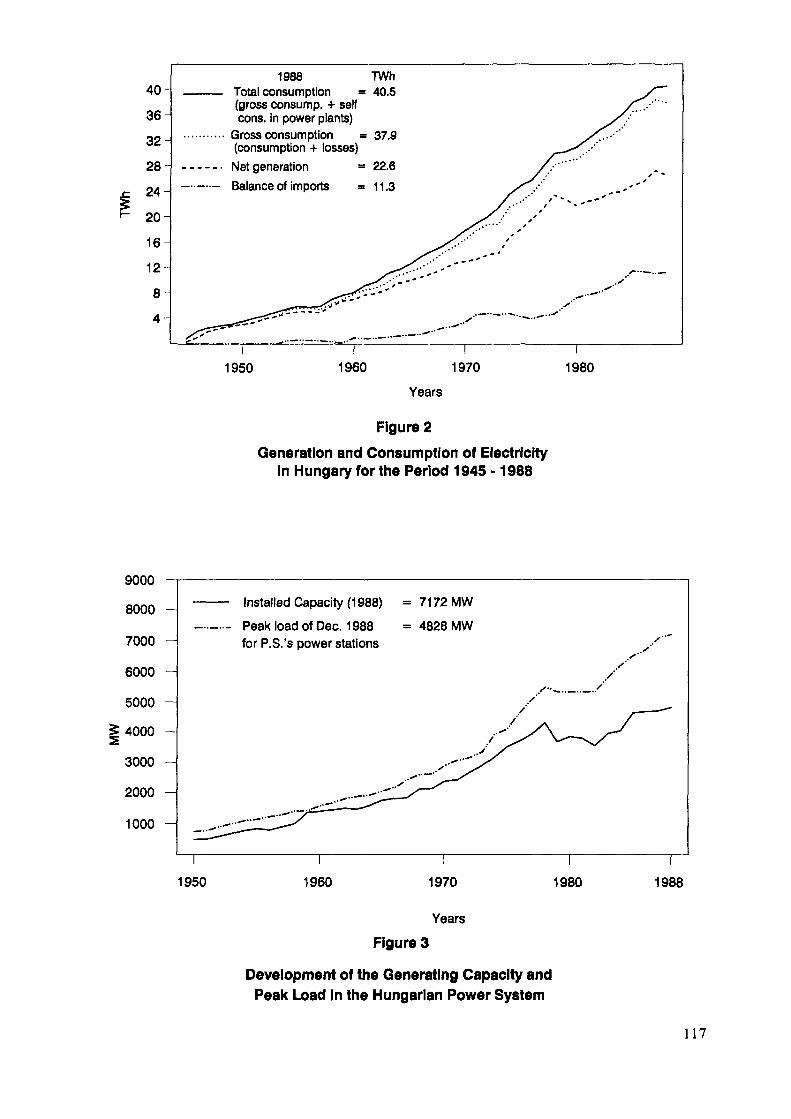
40-
36
32-
28-
24-
20-
16-
12-
8
4
1988 TWhTotal consumption = 40.5(gross consump. + selfcons, in power plants)
Gross consumption = 37.9(consumption + losses)Net generation = 22.6Balance of imports =11.3
9000800070006000 -5000 -4000 -30002000 -1000 -
1950 1960 1970 1980
Years
Figure 2Generation and Consumption of Electricity
in Hungary for the Period 1945 -1988
Installed Capacity (1988) = 7172MW
Peak load of Dec. 1988 = 4828 MWfor P.S.'s power stations
1950 1960 1970
Years
1980 1988
Figure 3
Development of the Generating Capacity andPeak Load in the Hungarian Power System
117
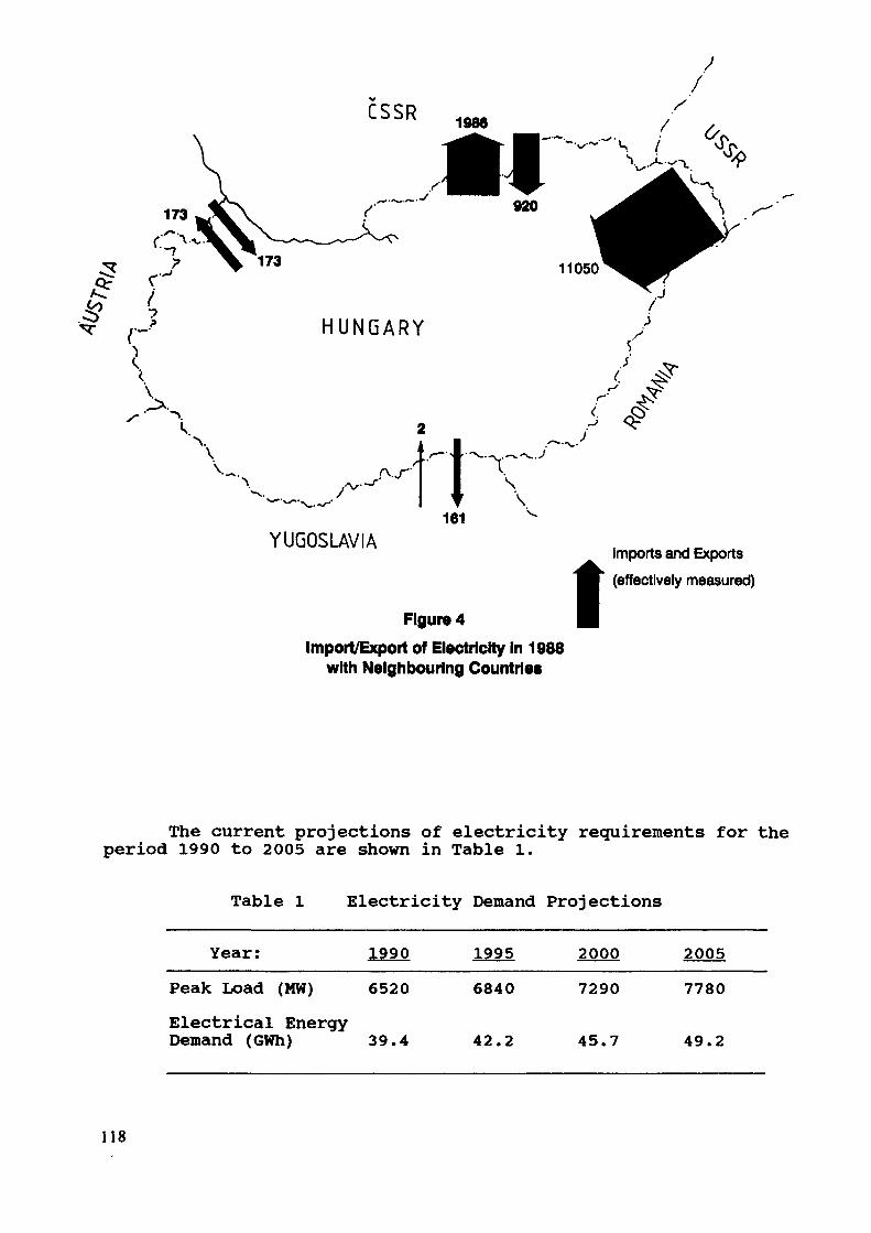
YUGOSLAVIA
Figure 4Import/Export of Electricity In 1988
with Neighbouring Countries
IImports and Exports(effectively measured)
The current projections of electricity requirements for theperiod 1990 to 2005 are shown in Table 1.
Table 1 Electricity Demand Projections
Year: 1990 1995 2000 2005
Peak Load (MW) 6520Electrical EnergyDemand (GWh) 39.4
6840
42.2
7290
45.7
7780
49.2
118

2. POSSIBLE NEW POWER STATION TYPES IN THE NEXT DECADE
To meet the future electricity demand, three versions can beactually taken into consideration:
A. gas turbine heat supplying capacities,B. nuclear power plant,C. 1200 MW Thermal Power Plant of "Bukk" (lignite base)
2.1 Gas turbine heat supplying capacitiesThe advantages provided by the establishment of gas turbine
heat supplying capacities are as follows:- This type of power plant can be developed with smallerstages of capacity;
- Its relatively low investment cost would imply less burdenfor the national economy;
- It has a relatively short investment processing time, soit can be flexibly adapted to changes of the demand andeconomic conditions;
- The most favourable heat utilization (around 80%) can beachieved thermodynamically;
- It would allow utilization of the domestic capacity formanufacturing of machinery, with possible subsequentexports.
On the other hand, certain disadvantages are recognized forthis type of generation as follows:
- The share of hydrocarbons in the total energy supply evencurrently is already rather high (about 50 %), that is whyit would not be reasonable to develop the electric powersystem on hydrocarbon base, procurable only by payments inhard currency (dollar) in the long run. The basicprinciple also in international practice is thediversification of energy source bases.
- The economic efficiency of the gas turbine program can bejustified only up to a marginal cost of 270 Ft/GJ forhydrocarbon, yet there is a considerable risk thatpurchasing it from capitalist market would already mean ahigher price about the year 2000. This means that thetotal capacity to be economically developed may amount toaround 700 MW.
- Gas turbines can also be procured only by payments in hardcurrency.2.2 Nuclear power plant version
Advantages ;- The expansion of the Nuclear Power Plant "Paks" with2x1000 MW is well prepared;
119

- According to experience, this is the safest power planttype and the least harmful to the environment;
- The conditions of domestic and international cooperationare well arranged and favourable for Hungary, which can beprobably kept up only with a certain delay of the originalschedule - not more than 3 years (with the first unitcommissioned in 1988 instead of 1995).
Disadvantages ;- It requires the earliest decision, owing to the lead andconstruction times involved.
- It would bring the highest burden to the investmentresources of national economy, which could only berelieved by involving foreign capital for itsestablishment. (Efforts made to this end have not been metwith success as yet.)
- It means an extremely strong and inflexible determinationof investment, which may restrain the development towardsa structural change in the present state of economy and inthe transient state to be expected in the coming years.
- The new changes of design for safety enhancement,occurring all over the world in nuclear energy, cannot betaken into account as yet.
- The 1000 MW unit performance is too high in the Hungarianenergy system, at a minimum rise of demand (about 150MW/year) this is the most difficult to adapt to varyingconditions.
2.3 "BuMc" Thermal power plantAdvantages;- It can solve the diversification of power basis by
utilizing domestic energy sources.- The envisaged units of 300 MW unit of capacity can well
fit into the system.- Appropriate domestic and foreign offers are available for
its construction. If choosing a domestic one, the capacityof the national construction industry could be bestutilized, also resulting in a reference to promoteexports.
- The domestic lignite resources are explored, measures havealready been taken for the preparation of the new open-pitto be established.
Disadvantages ;- The total investment costs, including the mine, would be
nearly as high as those of the nuclear power plant option,though in a more favourable schedule.
120
- Its preparedness - especially considering theenvironmental effects - contains uncertain elements, thatis why there are still open questions also with regard toits economy.
2.4 Other considerationsThe volume of a power plant construction program that can
currently be proposed, however, is definitely restricted not onlyby the demands, but also by the constraint of an economic policy,according to which for the development of a capital-intensiveelectric power industry in the present state of our economy wecannot follow the principle generally accepted in well-balancedeconomies, i.e. planning by the least-value of the demand-zone.The lack of investment resources makes it impossible to have a newlarge base-load plant - either on nuclear or coal base - put intooperation before 2000.
Examining the above considerations, but above all taking intoaccount the investment-saving environment, we can come to theconclusion that increments from 1988 to 2000 can be most reasonablymet by the progressive construction of combined-cycle units withgas turbines.
The construction of a nuclear power plant and/or alignite-based coal power plant can be subsequently fitted into theprogram. According to the studies carried out, up to 700 MWcapacity the implementation of heat supplying combined-cycle gasturbine units connected with power plant reconstruction seems to bemore economical than a base-load plant. Their involvement in theprogram prior to the base-load plant, therefore, is economicallyjustified by the present data.
The above program contains consciously several risks asfollows:
- The tendency of electric energy demand, considerablydependent on the development of the national economy.
- Measures to improve energy efficiency and reduceperformance can come across in the sphere of enterprise,under the evolving conditions towards a market-basedeconomy. Accordingly, the expected results will berealized on the basis of company decisions and interests.So it cannot be excluded that applying their resources forthe modernization of production and not for energyrationalization or capacity reduction may provide thecompanies with higher profits.
- The combined-cycle units increase the hydrocarbon imports,which in turn increases the import-dependence of theelectric power system. Taking into account the existing1850 MW of electric power import from the Soviet Union.
121
3. EXPERIENCE OF USING WASP FOR POWER SYSTEM PLANNING
3.1 IntroductionLong-range planning of the Hungarian electric power system
carried out by EROTERV (Power Station and Network EngineeringCompany) dates back for over 25 years now. First, each expert groupestablished separate models for the analysis of several particularfields, and then they were integrated into the long-range planningmodel of the electric power system. Over a period of years thismodel has been refined both in its inner construction and in thefield of its external connections. In the course of developing amodel for the long-range planning of the electric power system, theestablishment of a complex energy model performing the nationaldistribution of energy sources marked a great step forward.
These two models connected and incorporated into the planningprocess of the national economy meant a qualitative changeconcerning both the long-range planning of the power generationsystem and the general planning of the national economy. Thefollowing subsections give a brief review of the long-rangeplanning process of the Hungarian electric power system and of itsmain elements.3.2 Interconnection between planning of the national economy and
that of the electric power systemMeeting the electric power demands with an acceptable
reliability is of serious interest to the national economy becauseelectric power shortages set limits to industrial production, andthis shortage may cause a damage (losses, equipment damage) whosevalue is many times higher than the expenses required forproduction of the excess electric power.
On the other hand, however, in the construction of a newpower plant and possibly of an adjoining mine, considerable capitalforces are spent from the national economy, which would constraintthe further development of the industrial production. In addition,the electrical power system has also significant influence on theformation of energy source utilization within the national economy.Therefore, long-range planning of electric power system isconsidered as one of the essential elements of national economyplanning in Hungary.
Figure 5 shows how the long-range planning of the electricpower system is connected to the planning of the national economy.Long-range planning of the electric power system sets out from agiven national economic plan. From its target-figures electricpower demand is needed in the first place. The investment costsnecessary so as to meet these demands are determined by thelong-range planning model of electric power system. From theresults of this electricity plan, the electric power production andfuel requirements are extracted and then introduced into thenational model of energy source distribution. This is required, onthe one hand, because one of the main fuel bases for power stationsis represented by "wastes" issuing from energy conversions:low-grade coal, residual of oil refining, free gas producingcapacity in summer. On the other hand, it is necessary, since over25% of energy source utilization of households is falling to thepower plant fuel consumption.
122
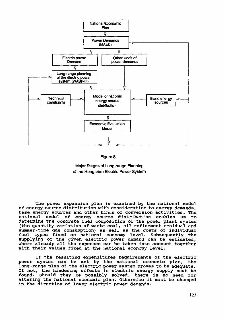
National EconomiePlan
Power Demands(MAED)
Electric powerDemand
Long-range planningof the electric powersystem (WASP-111)
Technicalconstraints
I
Other kinds ofpower demands
Model of nationalenergy source
distribution
IEconomic Evaluation
Model
Basic energysources
Figure 5
Major Stages of Long-range Planningof the Hungarian Electric Power System
The power expansion plan is examined by the national modelof energy source distribution with consideration to energy demands,base energy sources and other kinds of conversion activities. Thenational model of energy source distribution enables us todetermine the concrete fuel composition of the power plant system(the quantity variation of waste coal, oil refinement residual andsummer-time gas consumption) as well as the costs of individualfuel types fixed on national economy level. Subsequently thesupplying of the given electric power demand can be estimated,where already all the expenses can be taken into account togetherwith their values fixed at the national economy level.
If the resulting expenditures requirements of the electricpower system can be met by the national economic plan, thelong-range plan of the electric power system proves to be adequate.If not, the hindering effects in electric energy supply must befound. Should they be possibly solved, there is no need foraltering the national economic plan. Otherwise it must be changedin the direction of lower electric power demands.
123
3.3 Model for long-range planning of the Hungarian electric powersystemThe model incorporates the results obtained in work
throughout several decades. In its preparation, it was always triedto use the international experience, but at the same time withoutany aim at creating a so-called super model, solving at once allproblems connected with the electric power system. The authors haverather developed it in accordance with the Hungarian conditions.
During the development of the model a system of statisticswas set up based upon data on the power plants of the HungarianElectricity Board and also on international power plants. Thisstatistical data system constitutes a basis for the long-rangeplanning of the electrical power system.
The model is essentially a static one. It identifies the timeof putting into service new power plant capacities and the costsinvolved for a particular scheme of power plant construction.Though a dynamic model is much more up-to-date, the Hungarian powerdemands being not very high and the number of alternatives forpower plant construction that can be reasonably taken intoconsideration for supplying these demands, being not very largeeither, so far there has been no need to develop a dynamic program.The restricted number of alternatives for power plant constructionis intended to be thoroughly examined by the model.
The long-range planning model of the Hungarian electric powersystem is made up of the following sub-models:
- sub-model of capacity planning- sub-model of electric power load-distribution and of fuel
demand determination;- sub-model of power plant investment costs.When describing the particular sub-models emphasis shall
primarily be given to their particularities.
3.3.1 Sub-model of capacity planningWe have to be prepared in time for supplying the rising
electric power demands, because investments in power generationhave a long construction time (e.g. with the large condensingplants it is 7-10 years). Preparation means an expansivetechnical-economic activity. Within it a prominent role is playedby capacity planning. Its aim is to determine the new power plantcapacity required for supplying the consumers' demands reliably.The basic problem of this task is to reveal the rate of power plantcapacity to be provided in a certain year so that the resultant ofthe loss arising from consumer's restrictions and of the expensescoming from reserve formation are the minimum.
< CREST. /R/ + KRESE /R/> ======> minimumwhere:
CREST /R/ : the restriction loss for an "R" reserveESE /R/ : *-ne cost of reserve formation for an "R"reservei
124

At the preparation of capacity planning one should not besatisfied with merely having a power station pool adequate tosupply year-end peak demands, it is also necessary to work outplans meeting the demand at constant safety all year round. Theseasonal change of consumers' demands is sufficiently modelled bythe variation of weekly peaks within the year. It is determined onthe basis of earlier statistic data and of the expected tendenciesin the main branches of the national economy and in the consumer'shabits of the population.
The capacity demand of the generation system is determinedby the average of weekly peak values and of the reserve volumeneeded for the optimal supply of the consumers.
The volume of the necessary reserves is determined by theconsumers' demand, the expected and random changes of power plantcapacities, the consumer's restriction loss and the reserve costs.
The commissioning date of new power plants is identified withfull knowledge of the power plant system's capacity demand, of thealready existing and projected power plant investments. Thecommissioning dates are given with monthly accuracy on the basis ofthe model, and a gradual capacity improvement of 3-4 years isassumed till the maximum capacity is obtained.
3.3.2 Sub-model of electric power load-distribution and fuel demanddeterminationDistribution of electric load among the generating units is
performed on the basis of the incremental specific generatingcosts, so that power plants with low specific costs shall be ofhigh load factor, while those with high specific costs of low loadfactor. In the Hungarian electric power system considerable role isplayed by electric power import, co-generating power supply. Also,the amount of electric power produced by hydro-electric powerstations is on the increase. In electric power load-distributionthese capacities should be handled differently from condensingpower plants, since beside their capacity they have a fixedelectric power production. In electric power load-distribution thisshould also be separately considered beyond consumer's demands.
When calculating the fuel consumption of power plant units,their specific heat consumption is taken into account with a lossheat consumption factor, i.e.:
s = «v • n «,where:
q - specific heat consumptionq t - optimum heat consumptioniH 8{ - the product of loss heat consumption factors
125
To determine specific heat consumption the following lossheat consumption factors are applied:
a) Basic loss heat consumption factor. Its rate depends onthe non-coincidence of partial efficiencies and oncontamination.
b) Loss heat consumption factor during the improvementperiod of availability. During the first years ofoperation of reheated large units, specific heatconsumption greatly surpasses the value characteristic ofthe stable running condition. This is due to the factthat in this period the higher number of breakdownsrequires more operating tests, more frequent starting andstopping, operation with partial load.
c) Loss heat consumption factor depending on the way ofutilization time. Its value depends on various moments:if the unit runs at partial loading, if there is afrequent restarting or if it operates at full loading.
3.3.3 Sub-model of power plant investment costsThe sub-model determining the investment costs of the new
power plants always sets out from the investment costs of a powerplant which was last accepted. On this basis it can determine theinvestment costs of different power plants found in practice.
When establishing investment costs the following divergencesfrom the basic case are considered by the sub-model:
- optional power plant and unit size;- optional fuel type;- construction on a new site or extension of an existing
power plant.For the yearly distribution of power plant cost-types
relative index-numbers have been worked out and they are scheduledin compliance with the parallel connection of units. Power plantinvestment costs are broken down by the investment cost sub-modelfor each year as follows:
- civil work;- power plant technology;- other.
3.4 Model of national energy source distributionThis is a general linear distribution model, searching for
the composition of basic energy sources within a possible range onthe basis of externally provided consumer's demands, fuel-dependentefficiency and consumer's costs. The calculations take into accountthe conversion technologies and secondary fuels. The range underexamination is restricted by external possibilities (capacities,supplies, readiness of investments etc.), within it there is apossibility of optimization according to a resultant cost with theconsideration of the obligatory conversion rates and conditions.
126

In the model, energy sources are divided into technologicallycharacteristic consumers' groups, which are subdivided into socalled homogeneous consumers' groups. Those consumers are groupedtogether who, within the accuracy of long-range planning, estimateinterchangeable fuels identically regarding specific heatconsumption and specific costs. The cost effects of exchange volumeare linear.
Within the model the available fuel types are classified intoso called homogeneous fuel categories. Thus the technical andeconomic conditions of consumption become clear-cut at theconsumers.
A significant element of the model is represented by thosetechnologies which are transforming an optional part of a certainfuel into another sort of fuel on a given specific cost.
With the help of the national energy source model it ispossible to optimize the fuel consumption structure of the powerplant system with consideration to the national economic demands,sources and technologies.
3.5 Model performing economic estimationThis model analyzes the results obtained from the long-range
planning of the electric power system and the national model ofenergy source load distribution with a view to the distinctversions of power plant construction.
In the course of the analysis the present values of costdifferentials occurring between the individual versions of powerplant construction are determined by the model. For the calculationthe following cost differentials are reckoned with:
- investment cost;- maintenance cost;- cost of staff;- fuel cost;- loss due to consumer's restriction.In case the electrical power production and heat delivery is
not the same for individual versions, also these differences are tobe appraised.
When performing the economic analysis, it is also examinedhow the uncertainty of basic data available for calculationsaffects the economic merit order of the plant construction options.
This way it can be ascertained with what probability theindividual versions are better or worse compared to each other. Itis needed, because the present values of the expected costdifferentials are so low for these possible versions that sometimesthe difference falls within the error of calculation. In such acase further information is needed for decisions. Here comes inhelp the Monte-Carlo method for examining the uncertainty of basicdata. Beside comparing various options for plan construction, themodel of economic estimation also determines the expenses requiredby the versions for the long-range planning of national economy.
127

3.6 Models not organically attached to the long-range planningof the electrical power system, but complementing itThese are models solving partial problems connected with the
electrical power system. Their results, however, can be made use ofat the long-range planning of the electrical power system. Thesemodels have been elaborated for the solution of the followingproblems :
- establishing of a pumped-storage capacity of optimum size;- the volume of economic reserve in case of interconnected
power plant systems.The integration of these models into the long-range planning
model of the present electric power system is not reasonable, sinceit would only become even more complicated.
3.7 Comparison of the model for the long-range planning of theHungarian electric power system with the model WASP-inThe WASP-III program has been developed by the International
Atomic Energy Agency (IAEA) for the long-range expansion planningof electric power systems. Parallel examinations have been carriedout in 1985-1988 based on the national Hungarian long-rangeplanning model and on WASP-III. As a result, EROTERV came toestablish that both models gave the same evaluation of the order ofindividual versions for power plant construction. The differencebetween the present values of the individual versions essentiallycame from the fact that WASP-III is not prepared to model theelectric power import and co-generation power supply, though thereis a possibility of modelling them as a so called "fictitioushydro-electric power plant" capacity. This, however, is not theproper course, since their electric power production is independentof water level conditions.
Therefore at the end of 1985 EROTERV and IAEA agreed on thefurther development of the WASP-III program. This work wouldpromote the introduction of WASP-III into the long-range planningof the Hungarian electric power system. By the help of WASP-III arapid selection of the reasonable versions of power plantconstruction might become possible, and subsequently the Hungarianlong-range planning model would be used to perform the more refinedexamination of the given versions.
3.8 conclusionThe model for the long-range planning of the Hungarian
electric power system is permanently under development. The aim ofthis work is to provide the possible best modelling of Hungariancircumstances and to render help for the planning of the powerplant system and of the national economy.
128

4. SUMMARIZED RESULTS OF STUDIES CARRIED OUT WITH WASP-III
The first computer runs with the WASP-III program, in whichreal data were used, were performed in December 1986. Then it wasconsidered a primary task to get a better knowledge of WASP-III andthis way make it an integral part of the domestic practice oflong-range electric power system planning. In the course of thiswork we have prepared the strategy of the least-cost electric powersystem extension both by our domestic model for long-range planningand by WASP-III. When comparing the results, we came to theconclusion that the results of the two models were quite different.In the past three years we succeeded in revealing the reasons forthese departures so that today we can already claim that we do knowWASP-III and can use it properly.
For this we had to get acquainted with WASP-III not merelyfrom the description, but also through the program lines. Thus wehad the opportunity to print out also partial results, which is notallowed by the original program. Now I would like to outline theproblems encountered during the application of WASP-III as follows.
We were faced with several difficulties owing to the shareof hydro-electric power plants in domestic electric energy systembeing lower than 5 per cent, while that of other co-generationplants reaching as high as 30 to 35 per cent. By co-generationpower plants we mean power plants for which both capacity andelectric energy production are fixed. These power plants are likehydro-electric power plants, yet, as opposed to them, they alsohave forced outages, as well as fuel consumption and costs. In theHungarian electric energy system such a co-generation plant is thecombined heat- and electric energy generation and the imports ofelectricity. With combined heat and electric energy generation theelectric power output and the volume of electric energy aredetermined by the heat demands, while electric energy import isregulated by a treaty. We broke these power plants into acondensing part and a section of hydro power plants so that thedivisions adequately represent the outage, performance, electricenergy production and fuel consumption of co-generation powerplants. This way we could manage that WASP-III required the samepower plant capacities for the individual years the national model.
With WASP-III the hydro-electric power plants have no forcedoutage, yet the outage of the 30% co-generation plants cannot bedisregarded, because in this case the least-cost constructionversion requires less new power plant capacity than would beactually necessary economically.
The next scope of problems we had to cope with was the fuelcosts of power plants. The Hungarian electric energy systemconverts 50 p.c. of the national base-energy source consumptioninto heat- and electric energy, that is why the fuel consumption ofthe power plant system cannot be handled independently of nationalenergy consumption. The fuel cost of power plant system alsodepends on the fuel amount consumed. Therefore, it was necessary tohave WASP-III print out also the amount of fuel consumption for theindividual power plants.
129

With this printing we have already completed WASP-III. So forthe individual power plant fuels we can apply the shadow price thatalso reveals whether, compared to the source amount available onthe national level, there is a shortage or an overage of the givenfuel.
We have envisaged to define fuel cost as well as fuel typealso for hydro-electric power plants, so the modelling of variableco-generation power plants would be simplified.
We do not schedule the power plant investment costs byWASP-III, since we have got a model of our own, that corresponds tothe Hungarian practice of investment. This model can manage theconventional-, nuclear-, gas turbine and pumped-storage powerplants separately.
At EROTERV, three versions of the WASP-III program arecurrently in use: two versions for personal computers (PC) and onefor large computers (mainframe version). It is with the PCversions that the initial data are prepared, while the mainframeversion is preferred to carry out the optimization studies. For themainframe version, the source code is at our disposal so thatmodifications with this program can be easily introduced. If wecould get a source program also for the PC version, we shouldperform the program modifications in these versions as well.
130
DEVELOPMENT OF NEW INVESTMENT STRATEGIESFOR THE HUNGARIAN POWER SYSTEM
P. DÖRFNERHungarian Electricity Board,Budapest, Hungary
Abstract
The Hungarian Electricity Board (MVMT) is going todevelop its own planning capabilities. After havingtested the IAEA's methodologies, MVMT has started usingthem. This paper describes the available methodologiesat MVMT and their potential role in the planningprocess. The last least-cost investment study and long-run marginal cost (LRMC) calculations performed for thecountry are briefly summarized. These issues, as wellas some comments and proposed enhancements to the WASP-111 model are also discussed in the paper.
A. BackgroundThe Hungarian Electricity Board (MVMT) is the only power
utility in Hungary. It has the responsibility of operating theinterconnected electric energy system in the country, from powerplants to the distribution companies. The share of industrialpower plants is about 2 per cent. However, MVMT is not involvedin the decisions on electric system expansion and finance. Deci-sions on electric system expansion are made by the Ministry ofIndustry, while decisions on financial arrangements are theresponsibility of the Ministry of Finance. The main problems thatresult from this discrepancy are as follows:
- MVMT mainly deals with technical problems. (Thereis not enough interest in economic and financialthinking),
- There is only a weak relation between costs andtariffs,
- There is not enough planning capability at MVMT.For the solution of these problems MVMT should become a
self-financing utility. Some components of the above mentionedprocess are as follows:
- MVMT should have a real picture about its costs.- MVMT should have a least cost - least risk investment
strategy.131

MVMT should use tariffs based on long-run marginalcost (LRMC).
Because of these components MVMT should develop its ownplanning capability.
B. Overview of available planning methodologiesMVMT has two main sources of planning methodologies. Some
domestic methodologies have been developed by Hungarian researchinstitutes. Such institutes are independent from MVMT.
The MAED-1, WASP-III and ENPEP methodologies were providedby the IAEA to Hungarian users. The first goal of MVMT was tocompare the methodologies with those available from domesticsources. Domestic methodologies also serve for energy demandforecasting (modified version of MEDEE-2), power system expansionplanning (simulation model) and modeling of energy and powersupply (national energy balance model). Training courses or-ganized by IAEA have helped MVMT in getting experience in the useof IAEA's methodologies.
B.I Comparison of methodologiesB.I.I Energy demand forecasting
The basic principles are very similar in both, the domesticand MAED-1 methodologies, but the domestic methodology wasadapted to Hungarian constraints instead of the static sectorialstructure of MAED-1. This means that the domestic model fits theHungarian statistical data collection system. It has a regionalbreakdown for environmental impact calculations. However, unlikeMAED-1, the domestic model does not have a module for electricalload forecasting.
MVMT will continue to use the domestic methodology forenergy demand forecast, but we would like to carry out a furtherdevelopment on methodology. MVMT wants to modify the Modules 2and 3 of MAED-1 to adapt them to the Hungarian circumstances.
The creation and maintenance of a consistent data base forenergy demand forecasting is a basic task to ensure the easy andefficient usage of the methodology and efforts in this directionwill be made by MVMT.B.I.2 Power system expansion planning
The domestic methodology is a simulation model without op-timization. It was developed in the sixties, and it is very welladapted to earlier requirements (output tables, representation ofnew commitments in the first years, reliability of energy limitedcapacities etc.). However, WASP-III is more useful in the fieldof sensitivity analysis.
MVMT will use both types of models in expansion strategiesand for sensitivity analysis.WASP-III does not need significantmodification for Hungarian circumstances to achieve the above
132
mentioned goal. A more detailed simulation model (ICARUS) willbe used for the analysis of main strategies (yearly fuel consump-tion, yearly generation, etc.).
MVMT has used different detailed simulation models(domestic model, ICARUS), but we are not fully satisfied with theresults. It is required to develop a new detailed simulationmodel for the Hungarian power system.
The data requirement of simulation models is significant.Hence, MVMT must create a data base and transformation facilitiesfor different models considering that the representation of dif-ferent sources are different from one model to another. The con-sistency of results obtained from different models can be ensuredthrough a central data base and correct transformations.
B.2 Modeling of energy and power supplyIn the process of long-term planning several different
tasks are involved. The development of ENPEP (Energy and PowerEvaluation Program) is a significant step in developing planningcapabilities. ENPEP was developed by Argonne National Laboratory.It permits handling the planning process in an integrated manner.Furthermore, as the package is prepared for working on microcom-puters (PC), its different modules are more user-friendly.
MVMT will use the complete ENPEP package in the planningprocedure. Also, MVMT staff will take part in further develop-ments of the package in order to rewrite the LOAD module and toincorporate the ICARUS model as a new module of ENPEP. MVMT hasmade the first steps in using the different ENPEP modules asfollows:
- PLANDATA, MAED-1, ELECTRIC are used,- MACRO, DEMAND, BALANCE are being tested,- LOAD is being rewritten,
IMPACTS is not used,- ICARUS is being adapted for fitting into ENPEP.
B.3 UNDP-World Bank Project on Energy Planning for European andArab StatesThis is a project for development of planning capabilities
in EMENA region). The first phase of the project started in 1987and it finished this year. The topics of the first phase were asfollows:
Energy and macroeconomic linkages,Long-run marginal cost,
- Pricing impact,- Energy demand,
Hydro-thermal systems,- ENPEP training course.
133
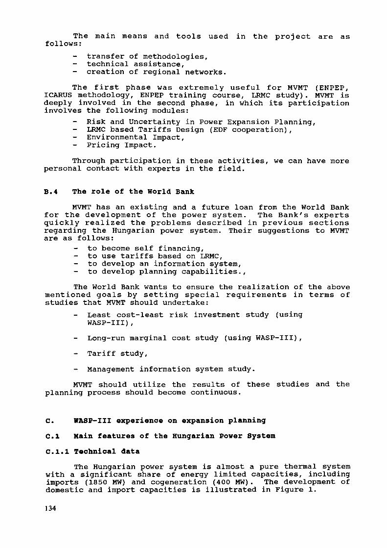
The main means and tools used in the project are asfollows:
transfer of methodologies,technical assistance,
- creation of regional networks.The first phase was extremely useful for MVMT (ENPEP,
ICARUS methodology, ENPEP training course, LRMC study). MVMT isdeeply involved in the second phase, in which its participationinvolves the following modules:
Risk and Uncertainty in Power Expansion Planning,- LRMC based Tariffs Design (EOF cooperation),
Environmental Impact,Pricing Impact.
Through participation in these activities, we can have morepersonal contact with experts in the field.
B.4 The role of the World BankMVMT has an existing and a future loan from the World Bank
for the development of the power system. The Bank's expertsquickly realized the problems described in previous sectionsregarding the Hungarian power system. Their suggestions to MVMTare as follows:
- to become self financing,to use tariffs based on LRMC,to develop an information system,to develop planning capabilities.,
The World Bank wants to ensure the realization of the abovementioned goals by setting special requirements in terms ofstudies that MVMT should undertake:
- Least cost-least risk investment study (usingWASP-III),
- Long-run marginal cost study (using WASP-III),- Tariff study,- Management information system study.MVMT should utilize the results of these studies and the
planning process should become continuous.
C. WASP-III experience on expansion planningC.I Main features of the Hungarian Power SystemC.I.I Technical data
The Hungarian power system is almost a pure thermal systemwith a significant share of energy limited capacities, includingimports (1850 MW) and cogeneration (400 MW) . The development ofdomestic and import capacities is illustrated in Figure 1.
134
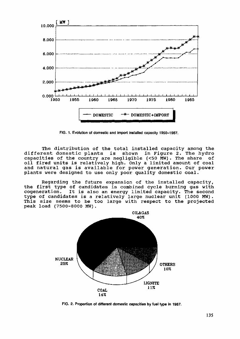
10.000[ M W ]
8.000 -
6.000
4.000 -
2.000 -
0 000 ' i i i i i i i i i i i i i i i i i i i i i i i i i i i i i i i i i i i1950 1955 1960 1965 1970 1975 1980 1985
DOMESTIC DOMESTIC+IMPORT
FIG. 1. Evolution of domestic and import installed capacity 1950-1987.
The distribution of the total installed capacity among thedifferent domestic plants is shown in Figure 2. The hydrocapacities of the country are negligible (<50 MW). The share ofoil fired units is relatively high. Only a limited amount of coaland natural gas is available for power generation. Our powerplants were designed to use only poor quality domestic coal.
Regarding the future expansion of the installed capacity,the first type of candidates is combined cycle burning gas withcogeneration. It is also an energy limited capacity. The secondtype of candidates is a relatively large nuclear unit (1000 MW) .This size seems to be too large with respect to the projectedpeak load (7500-8000 MW).
OIL&GAS40%
NUCLEAR25% OTHERS
10%
COAL14%
LIGNITE11%
FIG. 2. Proportion of different domestic capacities by fuel type in 1987.
135
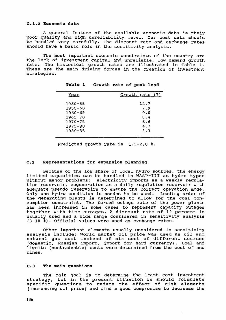
C.I.2 Economic dataA general feature of the available economic data is their
poor quality and high unreliability level. Our cost data shouldbe handled very carefully. The discount rate and exchange ratesshould have a basic role in the sensitivity analysis.
The most important economic constraints of the country arethe lack of investment capital and unreliable, low demand growthrate. The historical growth rates are illustrated in Table 1.These are the main driving forces in the creation of investmentstrategies.
Table l Growth rate of peak loadYear Growth rate (%)1950-551955-601960-651965-701970-751975-801980-85
12.77.99.08.46.64.73.3
Predicted growth rate is 1.5-2.0 %.
C.2 Representations for expansion planningBecause of the low share of local hydro sources, the energy
limited capacities can be handled in WASP-III as hydro typeswithout major problems: electricity imports as a weekly regula-tion reservoir, cogeneration as a daily regulation reservoir withadequate pseudo reservoirs to ensure the correct operation mode.Only one hydro condition is needed to be used. Loading order ofthe generating plants is determined to allow for the coal con-sumption constraint. The forced outage rate of the power plantshas been increased in some cases to represent capacity outagestogether with time outages. A discount rate of 12 percent isusually used and a wide range considered in sensitivity analysis(8-18 %). Official values were used as exchange rates.
Other important elements usually considered in sensitivityanalysis include: World market oil price was used as oil andnatural gas cost instead of mix cost of different sources(domestic, Russian import, import for hard currency). Coal andlignite (nontradeable) costs were determined from the cost of newmines.
C.3 The main questionsThe main goal is to determine the least cost investment
strategy, but in the present situation we should formulatespecific questions to reduce the effect of risk elements(increasing oil price) and find a good compromise to decrease the
136

uncertainty level (demand growth rate, unreliability of capitalcost data, etc.)- The main formulated questions are as follows:
Can MVMT start investing in combined cycle based ongas? (Is it economical?)How can the dependence on possible increase of oilprices be reduced? (What is the reasonable numberof combined cycle plants?)
- When should MVMT start erecting baseload plants(nuclear or lignite)? (When should the decision bemade about baseload plants?)
- What is the influence of the discount and exchangerates on the above mentioned questions?
C.4 The main resultsFor the above questions the same or similar results have
been obtained from different methodologies. The answer is verysimilar and it is composed of three main parts:
- Combined cycle gas turbine program can be started.The planning process should be continued.Decision making about baseload plants can bepostponed until the beginning of the nineties.
The commissioning times of combined cycle plants should bemodified slightly from the optimal solution because of the exist-ence of other technical problems (Combined cycle gas turbineswill replace old boilers instead of their reconstructions).
D. LRMC calculations Capacity element for generation)D.l Definition of the marginal cost
Marginal cost is defined as the cost of incurred to satisfyan infinitesimal increase of demand. If not enough time is avail-able to install new capacity to meet the excess demand, onespeaks about short-run marginal cost (SRMC). The two main com-ponents of SRMC are the operation cost and energy not servedcost. If enough time is available to install new capacity, onespeaks about long-run marginal cost (LRMC). The three componentsof LRMC are capacity cost, operation cost and energy not servedcost. Theoretically, the marginal cost can be calculated from thecost function by derivation. But normally the cost function isnot continuous and convex, so different approaches must be used.
D.2 Methodology for the calculation of LRMC of power capacityThe most crucial problem is the calculation of LRMC of
power capacity. Mr. Alastair McKechnie (World Bank) suggested amethodology based on WASP runs. After the determination of a
137
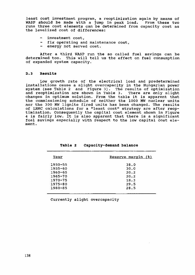
least cost investment program, a reoptimization again by means ofWASP should be made with a jump in peak load. From these tworuns three cost elements can be determined from capacity cost asthe levelized cost of differences:
- investment cost,fix operating and maintenance cost,energy not served cost.
After a third WASP run the so called fuel savings can bedetermined too. This will tell us the effect on fuel consumptionof expanded system capacity.
D.3 ResultsLow growth rate of the electrical load and predetermined
installations cause a slight overcapacity in the Hungarian powersystem (see Table 2 and Figure 3). The results of optimizationand reoptimization are shown in Table 3. There are only slightchanges in optimum solution. From the table it is apparent thatthe commissioning schedule of neither the 1000 MW nuclear unitsnor the 300 MW lignite fired units has been changed. The resultsof LRMC calculations for a "least cost" strategy are after reop-timization. Consequently the capital cost element shown in Figure4 is fairly low. It is also apparent that there is a significantfuel savings especially with respect to the low capital cost ele-ment.
Table 2 Capacity-demand balance
Year Reserve margin (%)1950-55 38.01955-60 30.01960-65 20.21965-70 20.21970-75 18.31975-80 29.51980-85 28.5
Currently slight overcapacity
138
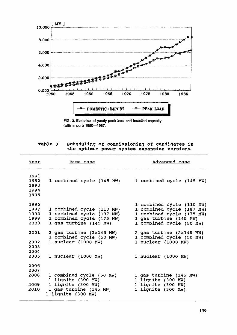
2.000 -
0.0001950 1955 1960 1965 1970 1975 1980 1985
DOMESTIC+IMPORT PEAK LOAD
FIG. 3. Evolution of yearly peak load and installed capacity(with import) 1950—1987.
Table 3 Scheduling of commissioning of candidates inthe optimum power system expansion versions
Base case Advanced case
19911992199319941995
1 combined cycle (145 MW) 1 combined cycle (145 MW)
19961997199819992000
2001
2002200320042005
200620072008
20092010
1 combined cycle (110 MW)1 combined cycle (187 MW)1 combined cycle (175 MW)1 gas turbine (145 MW)2 gas turbine (2x145 MW)1 combined cycle (50 MW)1 nuclear (1000 MW)
1 nuclear (1000 MW)
1 combined cycle (50 MW)1 lignite (300 MW)1 lignite (300 MW)1 gas turbine (145 MW)1 lignite (300 MW)
1 combined cycle (110 MW)1 combined cycle (187 MW)1 combined cycle (175 MW)1 gas turbine (145 MW)1 combined cycle (50 MW)2 gas turbine (2x145 MW)1 combined cycle (50 MW)1 nuclear (1000 MW)
1 nuclear (1000 MW)
1 gas turbine (145 MW)1 lignite (300 MW)1 lignite (300 MW)1 lignite (300 MW)
139

For reducing the oil price dependence a limitation was im-posed on the number of combined cycle gas turbines. For this"least risk" strategy the results of LRMC calculations are alsoillustrated in Figure 4. There are even fewer modifications,after reoptimization, in the schedule of commissioning thevarious blocks, compared to the previous version (because thenuclear blocks are commissioned earlier). However, this will notcause large differences between the two version as far as thecapital cost element is concerned, but because of the limitationin the number of combined cycle gas turbines the fuel savingswill be considerably smaller.
3.000[ Ft/kW.a ]
2.000 -
-1.772
I INVEST FIX O&M I ENS ! FUEL SAV. UlUiil TOTAL
FIG. 4. Long run marginal capacity cost comparison of two expansion versions.
E. SummaryE.I Conclusions
WASP-III is an almost perfect planning tool for the Hun-garian power system.WASP-III is a useful and usable module of ENPEP and is ex-tremely useful for searching the correct representations ofthe power system economics.There are significant risk and uncertainty elements, whichcan be solved using other methodologies.
E.2 RecommendationsProblem: It is not possible to represent the reliability
level of energy limited capacities.Possible solution: Use a reduced maximum capacity with a
certain probability.
140
Problem: It is not possible to represent the capacityoutage (only time outage).
Possible solution: Use a reduced maximum capacity with acertain probability.
Problem: It is not possible to analyze retirement programs.Possible solution: Extend GONGEN to retirement pos-
sibilities.Problem: It is not possible to check overall reliability
level of the power and transmission system.
E.3 RemarksThe cumulant methodology can reduce the calculation time ofthe simulation in WASP, but it causes an inaccuracy in LOLPcalculation.There is a wide range of enhancements for modification anddevelopment of WASP-III. But it is not an efficient way tosolve all of the problems in one version. It would be bet-ter to create more versions on different complexity levels.WASP-III could be the starting point to special develop-ments because of its general features, but the recent ver-sion is also a very useful tool in long-term planning.It would be extremely useful to have some modified versionsof WASP-III.
BIBLIOGRAPHY
[1] Experience with WASP among IAEA Member States par-ticipating in the Regional Co-operative Agreement(RCA) in Asia and the Pacific Region, IAEA,Vienna, 1988.
[2] Expansion Planning for Electrical Generating Sys-tems, A Guidebook, IAEA, Vienna, 1984.
[3] Energy and Power Evaluation Program (ENPEP),Documentation and User's Manual, Argonne NationalLaboratory, 1988.
[4] Documentation for Investigation of Costs andReliability in Utility Systems Model (ICARUS), Ar-gonne National Laboratory, 1988.
[5] Mckechnie, A., Application of WASP by World Bankin Preparing Electricity Pricing and InvestmentStrategy, World Bank, Washington D.C., 1985.
141

[6] Buehring, W. A., VanKuiken, J. C., Assessment ofLong-Run Marginal Cost for Designing ElectricityTariffs Based on Analysis of Electric Power Least-Cost Expansion Programs, Argonne NationalLaboratory, 1987.
[7] Least Cost Investment Study for the World Bank,MVMT, Budapest, 1989.
[8] Long-Run Marginal Cost Study for the World Bank,MVMT, Budapest, 1989.
142
IMPROVEMENTS AND USE OF WASPFOR SPECIAL APPLICATIONS
Y. PORATAnalytical Research Department,Israel Electric Corporation Limited,Haifa, Israel
Abstract
The WASP program is being used in the Israel ElectricCorporation (by the R&D division) since 1978 as a usefultool for decisions concerning the long range developmentof the generation system. Some problems encountered invarious studies performed during the last ten yearsusing the version WASP-II necessitated the introductionof several changes. Some of these changes appeared al-ready in the WASP-III version, therefore they are nottreated in the paper. Other changes, which may be of in-terest to WASP users, are presented in this paper. Inaddition, an improved procedure concerning the loadingorder of generating units is suggested. Examples of theuse of WASP for special applications are also includedencompassing the following subjects: - Break-even costcalculation for a pumped storage plant; - Determinationof a reliability criterion for expansion of the powergenerating system; - Long run hourly marginal generatingcost calculations for time of day pricing; and finally,- Uncertainty considerations, including: a) cost of overversus under expansion, b) nuclear versus coal expansionplans and c) optimal in-service date for power stations.
1.0 Basic Data of the Israeli Electrical SystemThe Israel Electric Corporation - IEC - is generating,
transmitting and distributing electricity in Israel. IEC servesa population of about 4.5 million in an area of approximately21500 sq.km.
The basic utility data for 1989 are as follows:Total generation 19,900 106 kWhAverage consumption per capita 3,800 kWhMaximum demand 3,750 MW
Installed capacity;Coal-fired 1400 MWResidual oil-fired 2150 MWJet-type and Industrial typegas turbines 735 MW
143
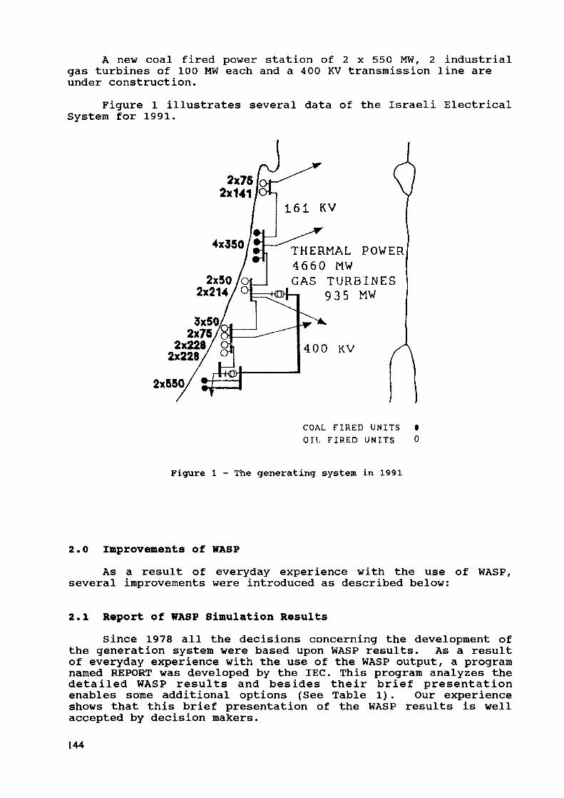
A new coal fired power station of 2 x 550 MW, 2 industrialgas turbines of 100 MW each and a 400 KV transmission line areunder construction.
Figure 1 illustrates several data of the Israeli ElectricalSystem for 1991.
2x752x141
4x350 /J
2x550
2x502x214
2X752x2282x228
161 KV
THERMAL POWER4660 MWGAS TURBINES
935 MW
4.00 KV
COAL FIRED U N I T S •OIL F I R E D U N I T S 0
Figure 1 - The generating system in 1991
2.0 Improvements of WASPAs a result of everyday experience with the use of WASP,
several improvements were introduced as described below:
2.1 Report of WASP Simulation ResultsSince 1978 all the decisions concerning the development of
the generation system were based upon WASP results. As a resultof everyday experience with the use of the WASP output, a programnamed REPORT was developed by the IEC. This program analyzes thedetailed WASP results and besides their brief presentationenables some additional options (See Table 1) . Our experienceshows that this brief presentation of the WASP results is wellaccepted by decision makers.
144
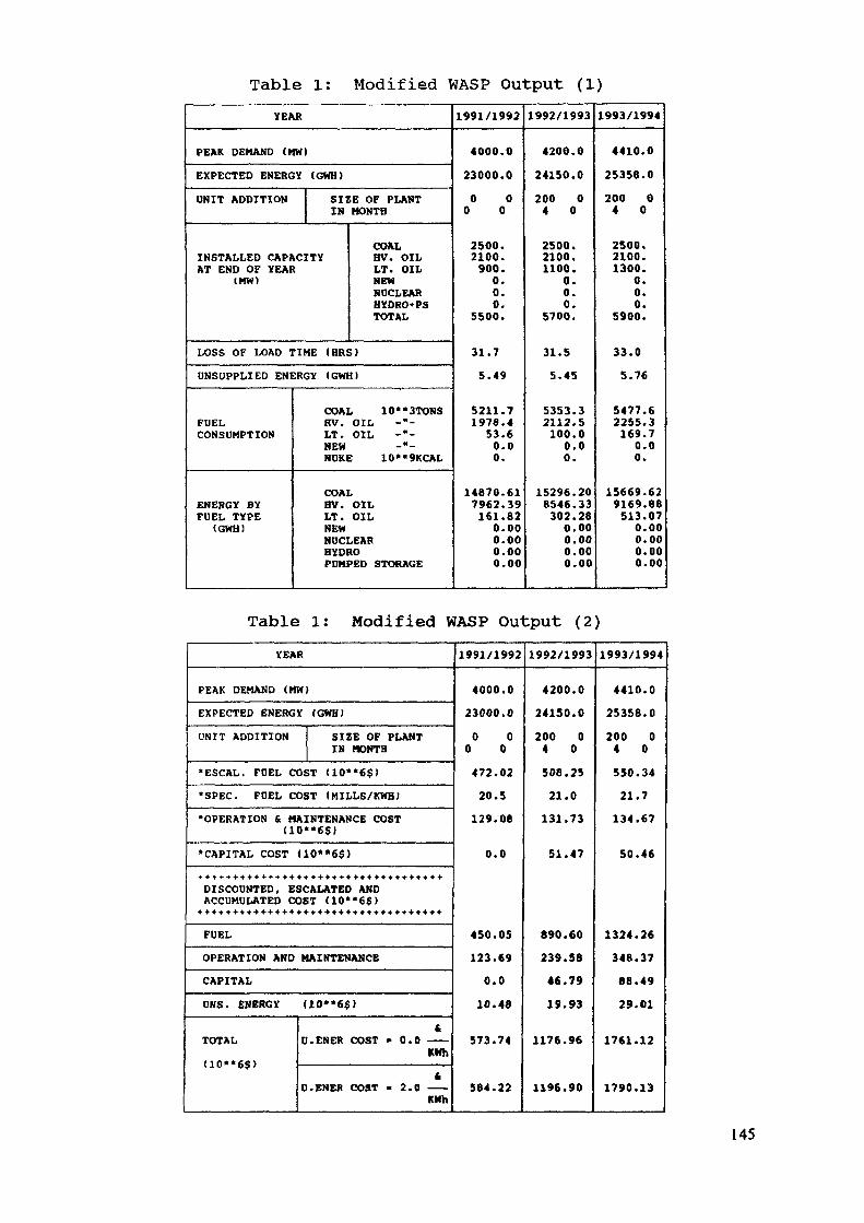
Table 1: Modified WASP Output (1)YEAR
PEAK DEMAND (MM)
EXPECTED ENERGY (GHH)UNIT ADDITION SIZE OF PLANT
IN MONTH
COALINSTALLED CAPACITY HV. OILAT END OF YEAR LT. OIL
(MW) NEWNUCLEARHYDRO+PSTOTAL
LOSS OF LOAD TIME (BRS)UNSUPPLIED ENERGY (GWH)
FUELCONSUMPTION
ENERGY BYFUEL TYPE
(GWH)
COAL 10**3TONSHV. OIL -"-LT. OIL -"-NEW -"-WJKE 10«*9KCAL
COALHV. OILLT. OILNEWNDCLEARHYDROPUMPED STORAGE
1991/1992
4000.023000.00 00 0
2500.2100.900.0.0.0.
5500.
31.75.49
5211.71978.453.60.00.
14670.617962.39161.820.000.000.000.00
1992/1993
4200.024150.0200 04 0
2500.2100.1100.
0.0.0.
5700.
31.55.45
5353.32112.5100.00.00.
15296.208546.33302.280.000.000.000.00
1993/1994
4410.025356.0200 04 0
2500.2100.1300.
0.0.0.
5900.
33.05.76
5477.62255.3169.70.00.
15669.629169.68513.070.000.000.000.00
Table 1: Modified WASP Output (2)YEAR
PEAK DEMAND <MW)EXPECTED ENERGY (GWH)UNIT ADDITION SIZE OF PLANT
IN MONTH«ESCAL. FUEL COST <10«*6$l•SPEC. FUEL COST IMILLS/KWH)•OPERATION & MAINTENANCE COST
(10«*6$)•CAPITAL COST <10*»6$)
DISCOUNTED, ESCALATED ANDACCUMULATED COST (10** 6$)
+ + + + + + + « + + + + + + » + + + + + + + + » + + » + 4-*+ + + + +
FUELOPERATION AND MAINTENANCECAPITALOUS. ENERGY
TOTAL<10«*6$>
U0*'6$)t
D.ENER COST • 0.0 ——KWht
D.ENER COST - 2.0 ——KMh
1991/1992
4000.023000.00 00 0472.0220.5129.08
0.0
450.05123.690.010.48
573.74
564.22
1992/1993
4200.024150.0200 04 0508.2521.0131.73
51.47
890.60239.56«6.7919.93
1176.96
1196.90
1993/1994
4410.025358.0200 04 0550.3421.7134.67
50.46
1324.26348.3788.4929.01
1761.12
1790.13
145

2.2 Extensions to the maintenance algorithmTwo options have been included: one option enables to keep
the maintenance schedule unchanged when relatively small changesin the load pattern are made, or when changes in the in-servicedates of small generating units, such as gas turbines are inves-tigated. In both cases, a change in the maintenance programcould distort the correct assessment of the benefits of loadmanagement or renewables or the economics of advancement of gasturbines.
The second option enables to use an external maintenanceprogram. This option is useful in cases when it is desired tospecify the in-service dates of large generating units at thebeginning of a season (not only at the beginning of the year) .For this purpose, another option was included which enables todefine, externally, a maintenance program.
2.3 Plant loading orderIt was observed that in the case of intensive switch-over
from oil-fired to coal-fired units (due to a large difference be-tween oil and coal prices) some of the oil-fired units wereloaded at very low plant factors (several %) . Such results arein contradiction with the LOLP calculations which assume thatthese units contribute to the system reliability at any time!
In order to achieve a better correlation between the simula-tion results and the actual system behaviour, the followingchange in the loading order was introduced (see Figure 2), thusensuring a minimal plant factor of around 20%.
Gas turbines — -Gas turbines
Upper OilUpper CoalBase Oil *Base Coal
hr
* e.g. 15*20%
Figure 2 - Changes of plant loading order
146
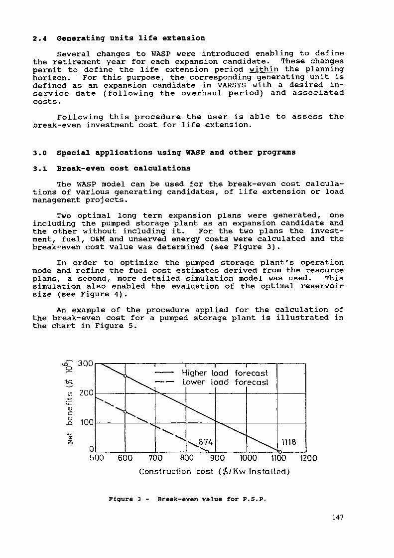
2.4 Generating units life extensionSeveral changes to WASP were introduced enabling to define
the retirement year for each expansion candidate. These changespermit to define the life extension period within the planninghorizon. For this purpose, the corresponding generating unit isdefined as an expansion candidate in VARSYS with a desired in-service date (following the overhaul period) and associatedcosts.
Following this procedure the user is able to assess thebreak-even investment cost for life extension.
3.0 Special applications using WASP and other programs3.1 Break-even cost calculations
The WASP model can be used for the break-even cost calcula-tions of various generating candidates, of life extension or loadmanagement projects.
Two optimal long term expansion plans were generated, oneincluding the pumped storage plant as an expansion candidate andthe other without including it. For the two plans the invest-ment, fuel, O&M and unserved energy costs were calculated and thebreak-even cost value was determined (see Figure 3).
In order to optimize the pumped storage plant's operationmode and refine the fuel cost estimates derived from the resourceplans, a second, more detailed simulation model was used. Thissimulation also enabled the evaluation of the optimal reservoirsize (see Figure 4).
An example of the procedure applied for the calculation ofthe break-even cost for a pumped storage plant is illustrated inthe chart in Figure 5.
i£> OUUo
-«AL
i/i 200
(U
1 100
05
X
*N
i i i i> ——— Higher load forecast^v. ——— Lower load forecast
^X^>s
^
^874 ^\,1118
v*\
00 600 700 800 900 1000 1100 12
Construction cost ($/Kw Installed)
Figure 3 - Break-even value for P.S.P.
147
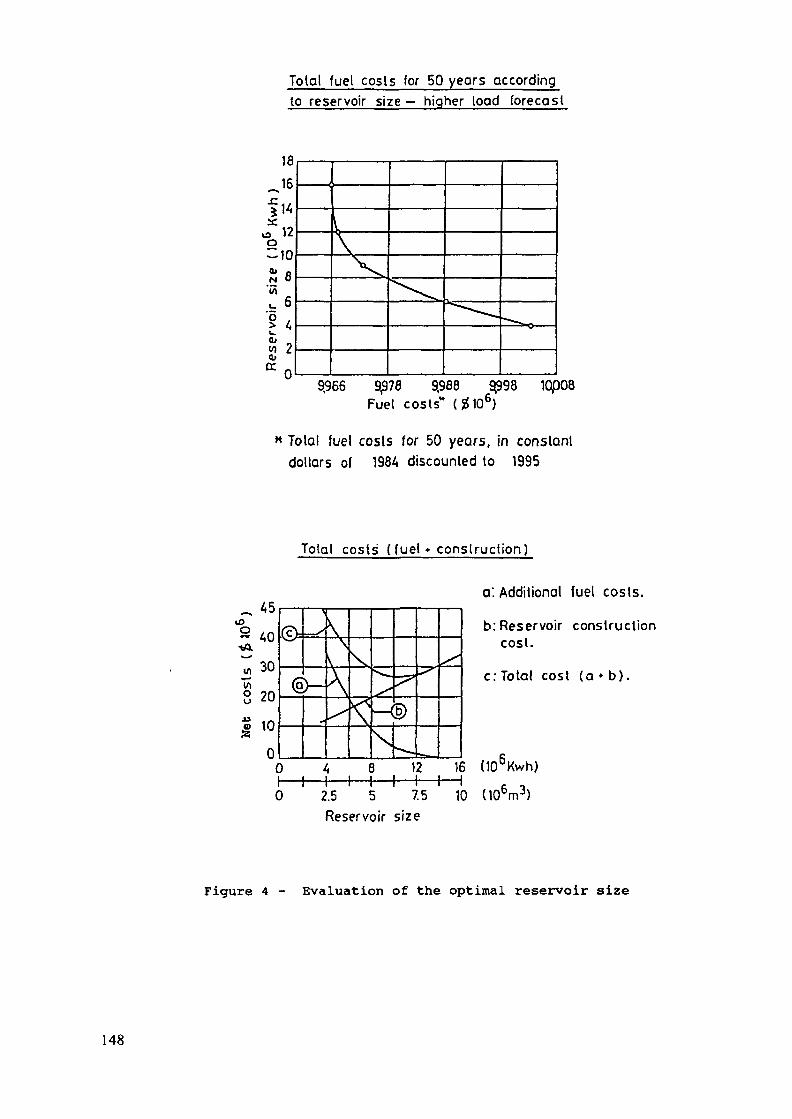
Total fuel costs for 50 years accordingto reservoir size — higher load forecas
18
~16IMX
A 12o310«» pN 0'w^ 6
1«<" ~y 2Ol
* n
\-V\"\
9,966 9,978 9.988 9£98 10p08Fuel costs'* (glO6)
* Tolal fuel costs for 50 years, in constantdollars of 1984 discounted to 1995
Tolal costs ( fuel * construction)
otA
TnutaS»
30
0
®.-&
K-®
a: Additional fuel costs.
b: Reservoir constructioncost.
c: Total cos I (a « b).
12 16 (106Kwh)
0 2.5 5 75 10 (106m3)Reservoir size
Figure 4 - Evaluation of the optimal reservoir size
148
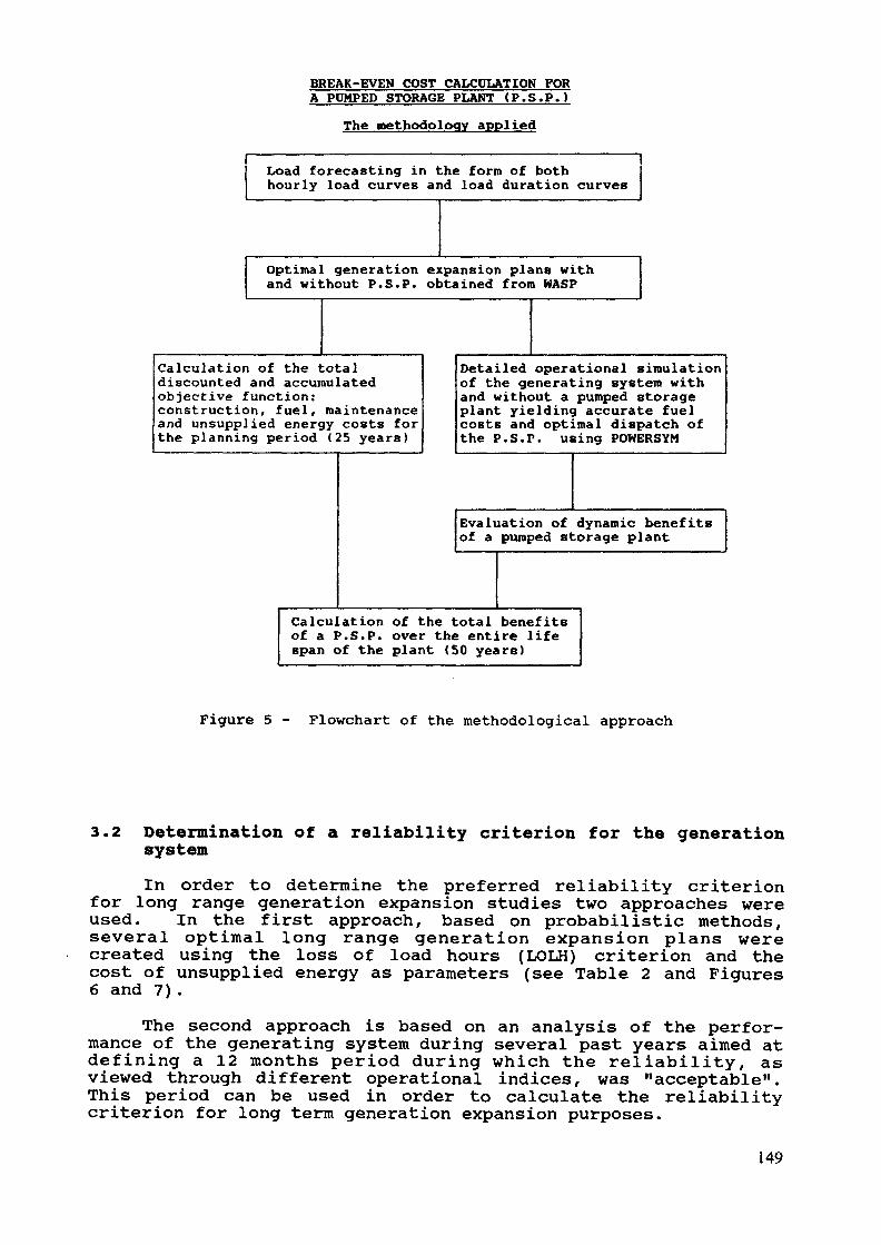
BREAK-EVEN COST CALCULATION FORA PUMPED STORAGE PLANT (P .S .P . )
The methodology applied
I ILoad forecasting in the form of bothhourly load curves and load duration curves
Optimal generation expansion plans withand without P.S .P. obtained from WASP
Calculation of the totaldiscounted and accumulatedobjective function:construction, fuel, maintenanceand unsupplied energy costs forthe planning period (25 years)
Detailed operational simulationof the generating system withand without a pumped storageplant yielding accurate fuelcosts and optimal dispatch ofthe P.S.P. using POWERSYM
Evaluation of dynamic benefitsof a pumped storage plant
Calculation of the total benefitsof a P.S.P. over the entire lifespan of the plant (50 years)
Figure 5 - Flowchart of the methodological approach
3.2 Determination of a reliability criterion for the generationsystem
In order to determine the preferred reliability criterionfor long range generation expansion studies two approaches wereused. In the first approach, based on probabilistic methods,several optimal long range generation expansion plans werecreated using the loss of load hours (LOLH) criterion and thecost of unsupplied energy as parameters (see Table 2 and Figures6 and 7).
The second approach is based on an analysis of the perfor-mance of the generating system during several past years aimed atdefining a 12 months period during which the reliability, asviewed through different operational indices, was "acceptable".This period can be used in order to calculate the reliabilitycriterion for long term generation expansion purposes.
149
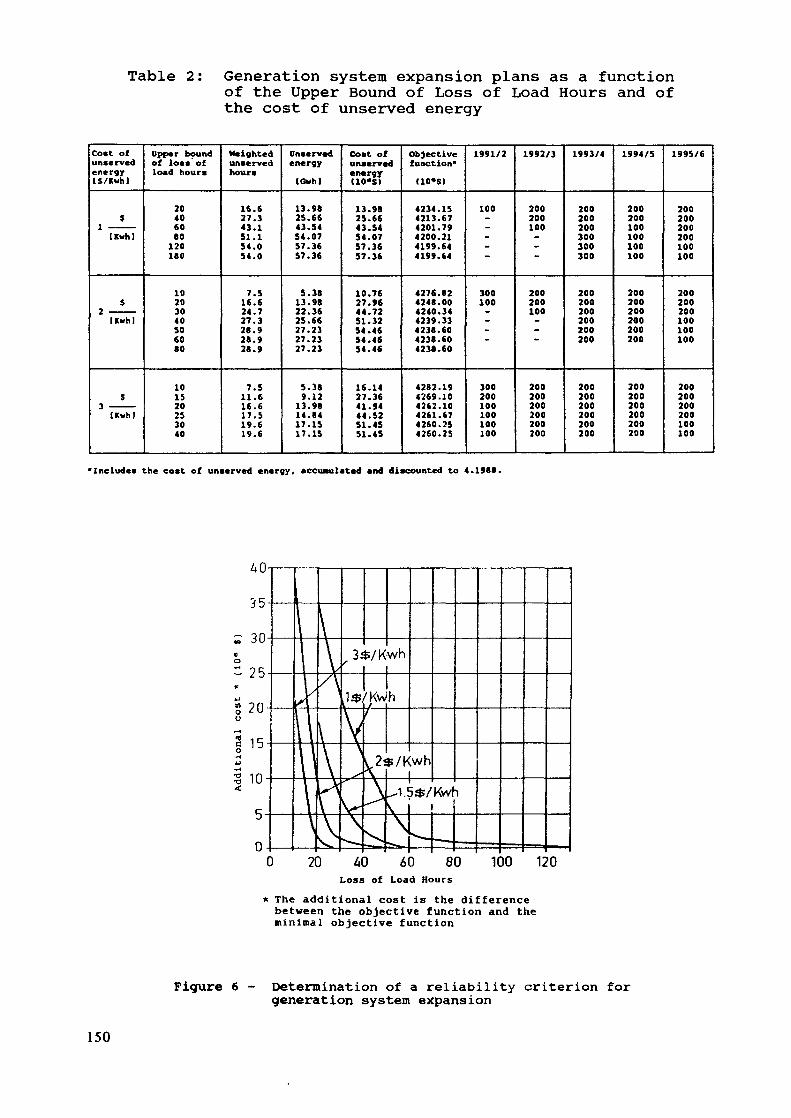
Table 2: Generation system expansion plans as a functionof the Upper Bound of Loss of Load Hours and ofthe cost of unserved energy
Cost ofunservedenergyl$/Kwh]
$J.
iKwh)
$2Uuhl
$3 ————
IKwh)
Upper boundof Ion ofload hour«
204060801201«0
10203040SO6080
101520253040
Weightedunservedhour*
16.627.343.151.154.054.0
7.516.624.727.328.928.928.9
7.511.616.617.519.619.6
Onservedenergy(CMh)
13.9825.6643.5454.0757.3657.36
5.3813.9822.3625.6627.2327.2327.23
5.389.12
13.9814.8417.1517.15
Cost ofunservedenergyC10-S)
13.9825.6643.5454.0757.3657.36
10.7627.9644.7251.3254.4654.4654.46
16.1427.3641.9444.5251.4551.45
Objectivefunction*(10«SI
4234.154213.674201.794200.214199.644199.64
4276.824248.004240.344239.334238.604238.604238.60
4282.194269.104262.104261.674260.254260.25
1991/2
100-„.-~
300100_-_
300200100100100100
1992/3
200200100-~
200200100-_
200200200200200200
1993/4
200200200300300300
200200200200200200
200200200200200200
1994/5
200200100100100100
200200200200200200
200200200200200200
1995/6
200200200200100100
200200200100100100
200200200200100100
•Include! the cost of unserved energy, accumulated and discounted to 4.1988.
20 40 60 80 120Loss of Load Hours
* The additional cost is the differencebetween the objective function and theminimal objective function
Figure 6 - Determination of a reliability criterion forgeneration system expansion
150
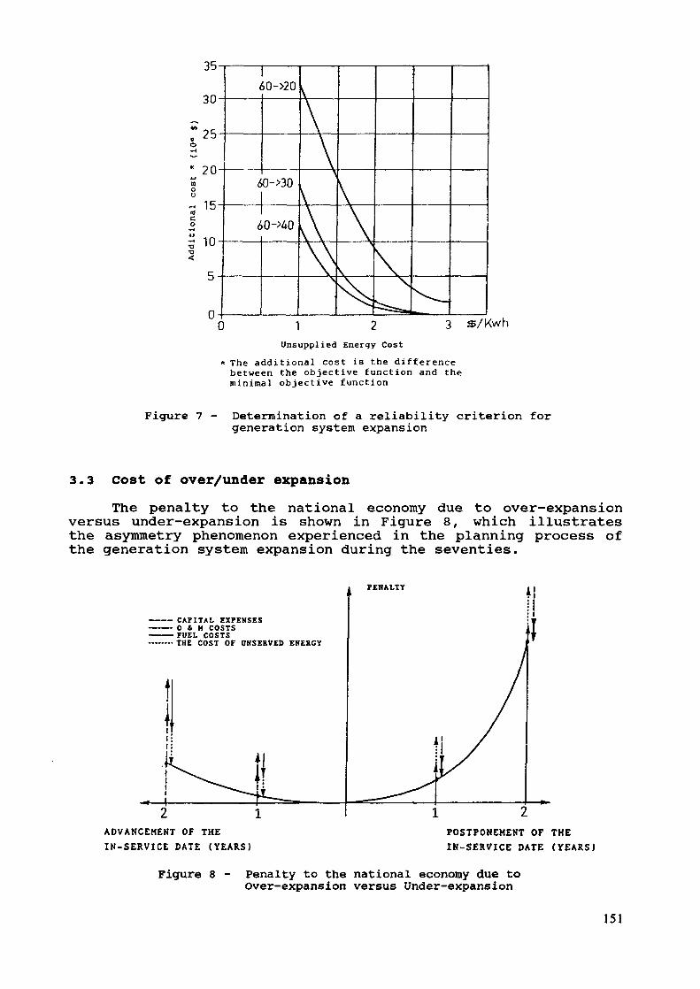
35
30
25
20
15
10
60->20
oO->30
60 -
A
3,/KwhUnsupplied Energy Cost
* The addit ional cost is the d i f fe rencebetween the objective function and theminimal objective funct ion
Figure 7 - Determination of a reliability criterion forgeneration system expansion
3.3 Cost of over/under expansionThe penalty to the national economy due to over-expansion
versus under-expansion is shown in Figure 8, which illustratesthe asymmetry phenomenon experienced in the planning process ofthe generation system expansion during the seventies.
PENALTY
CAPITAL EXPENSES0 4 M COSTS
• FUEL COSTSTHE COST OF OBSERVED ENERGY
2 1ADVANCEMEKT OF THEIN-SERVICE DATE (YEARS)
POSTPONEMENT OF THEIK-SERVICE DATE (YEARS)
Figure 8 - Penalty to the national economy due toOver-expansion versus under-expansion
151
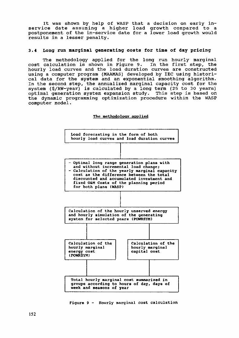
It was shown by help of WASP that a decision on early in-service date assuming a higher load growth compared to apostponement of the in-service date for a lower load growth wouldresults in a lesser penalty.
3.4 Long run marginal generating costs for time of day pricing
The methodology applied for the long run hourly marginalcost calculation is shown in Figure 9. In the first step, thehourly load curves and the load duration curves are constructedusing a computer program (MAAMAS) developed by IEC using histori-cal data for the system and an exponential smoothing algorithm.In the second step, the annualized marginal capacity cost for thesystem ($/kW-year) is calculated by a long term (25 to 30 years)optimal generation system expansion study. This step is based onthe dynamic programming optimization procedure within the WASPcomputer model.
The methodology applied
Load forecasting in the form of bothhourly load curves and load duration curves
- Optimal long range generation plans withand without incremental load change;
- Calculation of the yearly marginal capacitycost as the difference between the totaldiscounted and accumulated investment andfixed O&M Costs of the planning periodfor both plans (WASP)
Calculation of the hourly unserved energyand hourly simulation of the generatingsystem for selected years (POWRSYM)
Calculation of thehourly marginalenergy cost(POWRSYM)
Calculation of thehourly marginalcapital cost
Total hourly marginal cost summarized ingroups according to hours of day, days ofweek and seasons of year
Figure 9 - Hourly marginal cost calculation
152
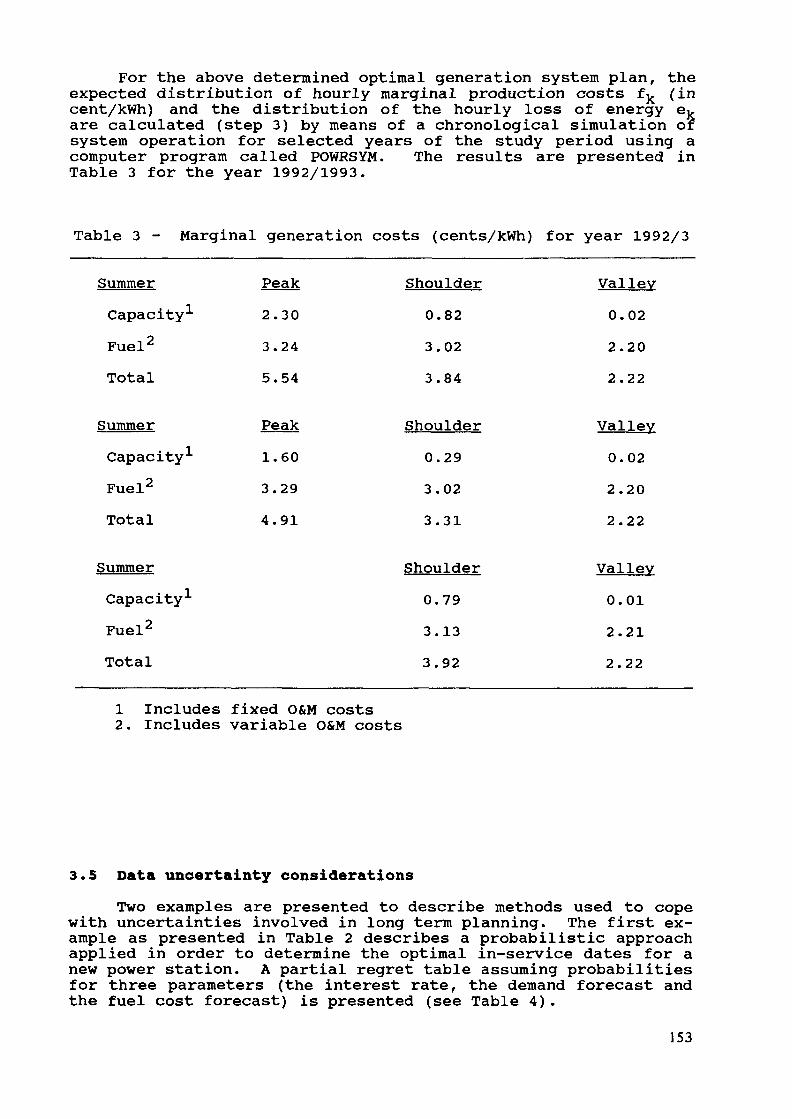
For the above determined optimal generation system plan, theexpected distribution of hourly marginal production costs fk (incent/kWh) and the distribution of the hourly loss of energy ej.are calculated (step 3) by means of a chronological simulation ofsystem operation for selected years of the study period using acomputer program called POWRSYM. The results are presented inTable 3 for the year 1992/1993.
Table 3 - Marginal generation costs (cents/kWh) for year 1992/3
SummerCapacityFuel2
Total
Peak2.303.245.54
Shoulder0.823.023.84
Valley0.022.202.22
SummerCapacity1
Fuel2
Total
Peak1.603.294.91
Shoulder0.293.023.31
Valley0.022.202.22
SummerCapacity1
Fuel2
Total
Shoulder0.793.133.92
Valley0.012.212.22
1 Includes fixed O&M costs2. Includes variable O&M costs
3.5 Data uncertainty considerationsTwo examples are presented to describe methods used to cope
with uncertainties involved in long term planning. The first ex-ample as presented in Table 2 describes a probabilistic approachapplied in order to determine the optimal in-service dates for anew power station. A partial regret table assuming probabilitiesfor three parameters (the interest rate, the demand forecast andthe fuel cost forecast) is presented (see Table 4).
153
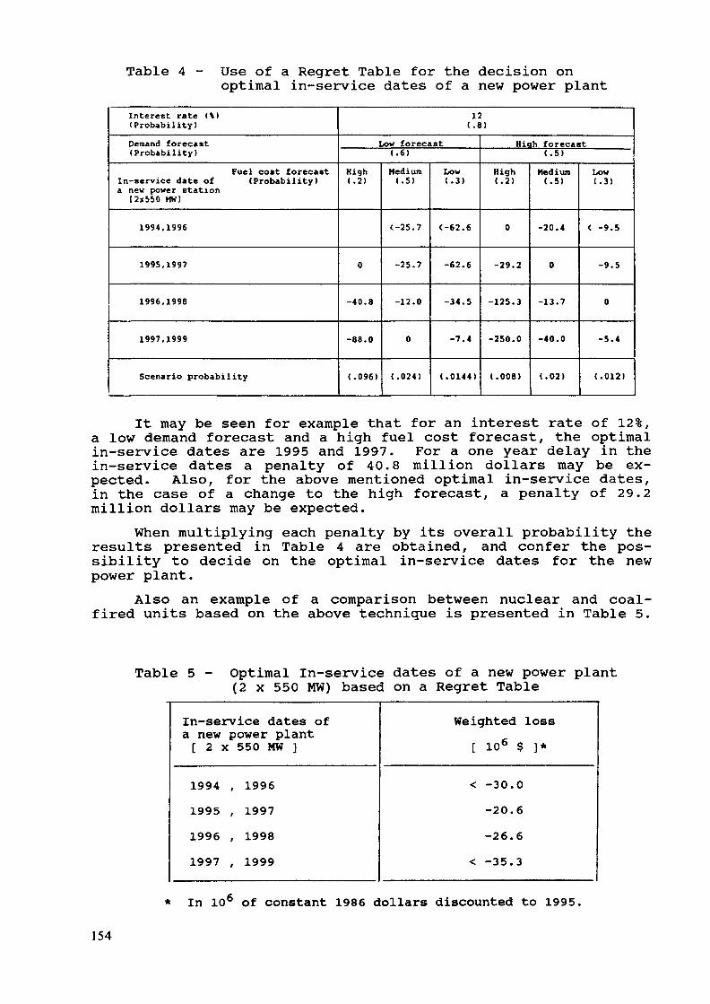
Table 4 - Use of a Regret Table for the decision onoptimal in-service dates of a new power plant
Interest rate (*)(Probability)Demand forecast(Probability)
Fuel cost forecastIn-service date of (Probability Ia new power station
[2x550 MWJ
1994,1996
1995,1997
1996,1998
1997,1999
Scenario probability
12(.8)
Low forecast(.6)
High(.2)
0
-40.8
-88.0
(.096)
Medium(.5)
<-25.7
-25.7
-12.0
0
(.024)
Low(.3)
<-62.€
-62.6
-34.5
-7.4
(.0144)
Hiqh forecast(.5)
High(.2)
0
-29.2
-125.3
-250.0
(.008)
Medium(.5)
-20.4
0
-13.7
-40.0
(.02)
Low(.3)
< -9.5
-9.5
0
-5.4
(.012)
It may be seen for example that for an interest rate of 12%,a low demand forecast and a high fuel cost forecast, the optimalin-service dates are 1995 and 1997. For a one year delay in thein-service dates a penalty of 40.8 million dollars may be ex-pected. Also, for the above mentioned optimal in-service dates,in the case of a change to the high forecast, a penalty of 29.2million dollars may be expected.
When multiplying each penalty by its overall probability theresults presented in Table 4 are obtained, and confer the pos-sibility to decide on the optimal in-service dates for the newpower plant.
Also an example of a comparison between nuclear and coal-fired units based on the above technique is presented in Table 5.
Table 5 - Optimal In-service dates of a new power plant(2 x 550 MW) based on a Regret Table
In-service dates ofa new power plant[ 2 X 550 MW ]
1994 , 19961995 , 19971996 , 19981997 , 1999
Weighted[ 106 $
< -30.0-20.6-26.6
< -35.3
loss]*
* In 106 of constant 1986 dollars discounted to 1995.
154

CONCLUSION
The WASP program has proven a useful tool for planning ofthe expansion of the Israeli power generation system, not onlyfor straight forward application, but also for special studies asdescribed in the previous sections.
In our opinion, besides the current changes which still needto be done in the WASP program and which are undoubtedly very im-portant, the WASP users should create a reliable date base in-spired from the experience of electrical utilities in whichvarious considerations such as the maturity and aging factorsshould be taken into account. Another very important subject isthe development of methodologies enabling decision making, takinginto account the uncertainties involved with most of theparameters used in long range planning.
155

ENPEP AND THE DECISION MAKING PROCESSIN ENERGY PLANNING PROBLEMS
D. SOLOVEITCHIKMinistry of Energy and Infrastructure,Jerusalem, Israel
Abstract
This paper summarizes the principal models for energyand electricity planning available at the Ministry ofEnergy and Infrastructure of Israel. Further, the paperdiscusses the increased need of applying multi-criteriadecision making (MCDM) approach to solve the electricityexpansion problem as the traditional single-criterionapproach of minimization of costs fails to respond toall questions being addressed by the planner as well asthe related uncertainties and risks. An illustration ofthe need for MCDM is given by means of a questionnairedistributed among the participants of the presentWorkshop. The results confirm the idea that the mini-mization of cost is not the only problem at stake.
1. The Planning and Policy Division has developed computerizedmodels which can be used for solving some parts of the energyplanning problems. The following models are used:
CAPEX - (Expanding Electricity Generating Capacity) - adynamic programming model of expansion planning withsingle objective cost minimization algorithm (developedby Tel Aviv University);MPC - (Marginal Cost in the Electricity GeneratingSystem) - calculates the marginal cost of generatingelectricity, at different time of the day and differentseasons. This model is based on the detailed simulationof the electricity generating system (MPC was alsodeveloped by Tel Aviv University);OMER - input/output model which provides a detailedsector-by-sector picture of the economic activity(developed by Technion, Haifa);Compact Macro-economic Model - enables construction ofalternative scenarios for future trends in the nationaleconomic and estimation of future demand for specificenergy products according to these scenarios.
All these models can be run on personal computers - PC-IBM.157

2. The CAPEX model has been used for the long term period ofplanning on the basis of several scenarios of electricity con-sumption [4] . CAPEX has been applied to evaluate the adequacyof adding eight units to the Israeli electricity system. Theplanning period of the study is from 1997 to 2026. The base yearselected is 1996, the discount rate is 10% per year, and theelectricity demand growth rate is 4.0%. The basic characteris-tics of candidate generating units in selection by the algorithmwere considered.
The main objective of the study was to determine the rolethat new generating units play in meeting the demand forelectricity in Israel during the years 1997-2026. In terms ofcapacity additions, up to the year 2026, the expansion of thegeneration system may be covered by coal-fired units (550 MW)with some participation of gas turbine and combined cycle units.
Sensitivity analyses were undertaken using several scenariosof future electricity demand, prices of fuels, cost of energy notsupplied, discount rates for investment and operating costs.
Some efforts to improve the methodology and modeling tech-niques are presently being examined for better representation ofthe Israeli electricity system.
3. It is well known that in energy planning and in expansionplanning, especially, several goals and objectives can be iden-tified. A traditional single-objective based approach to powergeneration expansion planning will be inadequate to model theprocess in a realistic way. The objective functions of the ex-pansion policy for a power generation system are usually in con-flict and noncommensurable and they have multiple decisionmakers. The multi-criteria decision making (MCDM) approach hasbeen applied to several electrical systems [1,2]. This approachhas been adapted for application to power system planning in Is-rael.
It seems to us, that the next step in the improvements of theENPEP package may be developed:
- to consider ENPEP as MCDM approach to optimization stepwithin Generation Expansion Planning.
The Following groups of planning criteria can be determinedas a first step:
a) total system costs;b) environmental impact;c) risk of plant disaster;d) fuel import vulnerability,e) employment;f) political and social factors;g) etc.
158
Specific questionnaire matrices [3] were prepared and writtenanswers of the 15 power engineers participating in the Workshopwere collected. The results obtained can help the decision-makerto distinguish the relative importance of multiple attributesconsidered in the process of energy planning (an example of thequestionnaire matrices checked by the Workshop participants andof the results obtained is included in attachment).
In the questionnaire the participants were asked to rank theobjectives in order of the importance, from the most to the leastimportant. The respondents were given a list of the followingobjectives:
cost,- environmental impact,
fuel import vulnerability,risk of plant disaster.
The results obtained are as follows:- 40% of participants ranked "environmental impact" as the
most important objective,33% of the participants ranked "risk of plant disaster"as the most important objective.20% of participants ranked "cost" as the most importantobjective,7% of participants ranked "fuel import vulnerability" asthe most important objective.
As it follows from the results only 20% of the participantsthought that cost should be considered now as the most importantobjective. In spite of this and other facts, "cost" is thesingle-objective function in the majority of electric power gen-eration expansion planning programs.
It seems to us that it will be very important to collectweights for the relative importance of the objection functions inMCDM Model which includes questionnaire respondents of differentexpertise for finding the best compromise solution.
4. The Energy Planning Package (ENPEP) is an important tool forperforming long-range expansion planning studies.
The direct links between the following modules: Macro-economic Growth; Energy Demand and Supply; Expansion Planning;Environmental Burdens and Resource Requirements for the EnergySupply Systems which are provided in ENPEP, from our point ofview, are a major advantage of this package.
5. Uncertainty as a critical element of utility analysis, plan-ning and decision making also cannot be ignored.
159

6. It will be interesting to check the modification ininput/output methodology for using input/output model in energyplanning problems (multi-criteria approach is also available inthis case).
REFERENCES
(1) H.A. Quaddus and T.N. Goh (1985). "Electric Power Gen-eration Expansion: Planning with Multiple Objectives",Applied Energy, 19, 31 - 319.
(2) H.P. Yang and S.L. Chen (1989). "Incorporating amulti-criteria decision procedure into the combineddynamic programming/production simulation algorithm forgeneration expansion planning", IEEE Transactions, Vol.4. No. 1.
(3) T. Saaty (1980), The Analytic Hierarchy Process, McGrawHill. New York.
(4) "Power Generation Long Term Expansion Planning (1997-2026)" (1990), Report of the Planning and Policy Divi-sion, Ministry of Energy and Infrastructure, Israel,(in Hebrew) (in press).
160
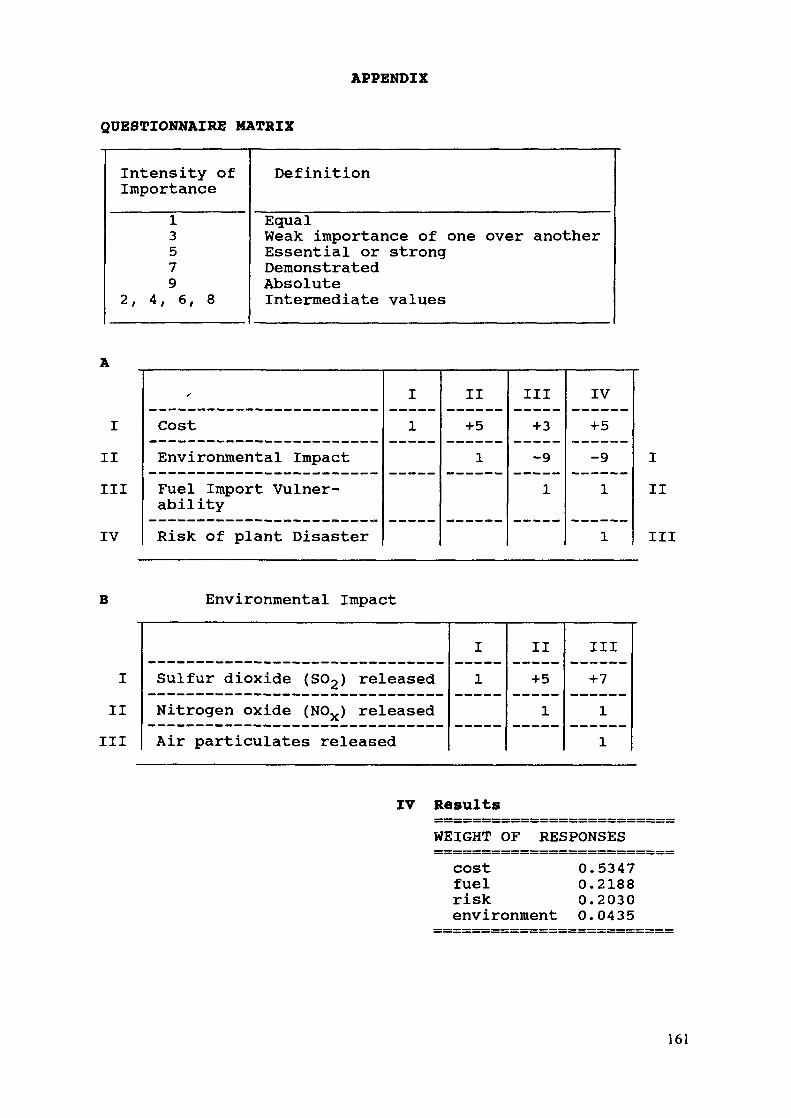
APPENDIX
QUESTIONNAIRE MATRIX
Intensity ofImportance
Definition
13579
2, 4, 6, 8
EqualWeak importance of one over anotherEssential or strongDemonstratedAbsoluteIntermediate values
IIIIII
IV
f
CostEnvironmental ImpactFuel Import Vulner-abilityRisk of plant Disaster
I1
II+51
III+3-91
IV+5-91
1
III
III
B Environmental Impact
Sulfur dioxide (SO2) releasedNitrogen oxide (NOX) releasedAir particulates released
I1
II+51
III4-7
1
1
IIIIII
IV ResultsWEIGHT OF RESPONSEScost 0.5347fuel 0.2188risk 0.2030environment 0.0435
161
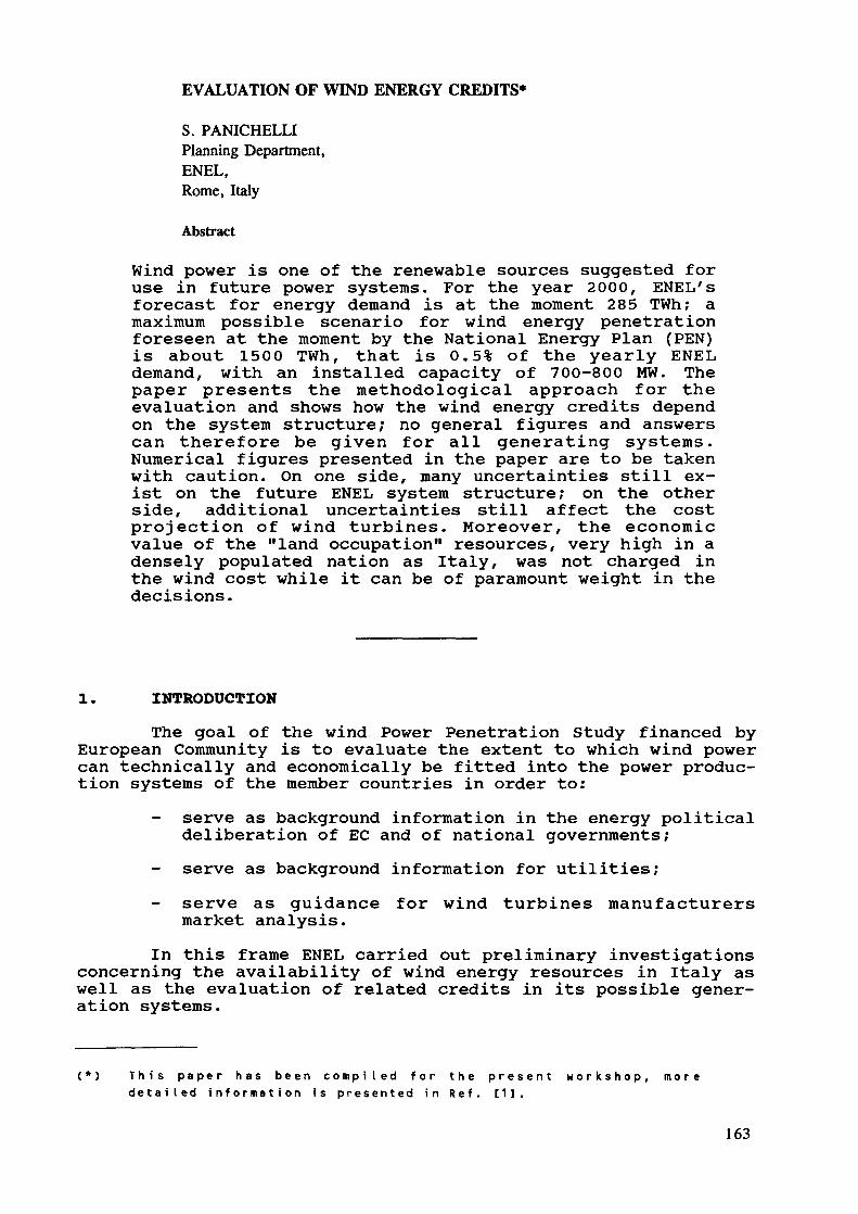
EVALUATION OF WIND ENERGY CREDITS*
S. PANICHELLIPlanning Department,ENEL,Rome, Italy
Abstract
Wind power is one of the renewable sources suggested foruse in future power systems. For the year 2000, ENEL'sforecast for energy demand is at the moment 285 TWh; amaximum possible scenario for wind energy penetrationforeseen at the moment by the National Energy Plan (PEN)is about 1500 TWh, that is 0.5% of the yearly ENELdemand, with an installed capacity of 700-800 MW. Thepaper presents the methodological approach for theevaluation and shows how the wind energy credits dependon the system structure; no general figures and answerscan therefore be given for all generating systems.Numerical figures presented in the paper are to be takenwith caution. On one side, many uncertainties still ex-ist on the future ENEL system structure; on the otherside, additional uncertainties still affect the costprojection of wind turbines. Moreover, the economicvalue of the "land occupation" resources, very high in adensely populated nation as Italy, was not charged inthe wind cost while it can be of paramount weight in thedecisions.
1. INTRODUCTION
The goal of the wind Power Penetration Study financed byEuropean Community is to evaluate the extent to which wind powercan technically and economically be fitted into the power produc-tion systems of the member countries in order to:
serve as background information in the energy politicaldeliberation of EC and of national governments;
- serve as background information for utilities;serve as guidance for wind turbines manufacturersmarket analysis.
In this frame ENEL carried out preliminary investigationsconcerning the availability of wind energy resources in Italy aswell as the evaluation of related credits in its possible gener-ation systems.
( * ) T h i s p a p e r h a s b e e n c o m p i l e d f o r t h e p r e s e n t w o r k s h o p , m o r ed e t a i l e d i n f o r m a t i o n i s p r e s e n t e d i n R e f . [1].
163
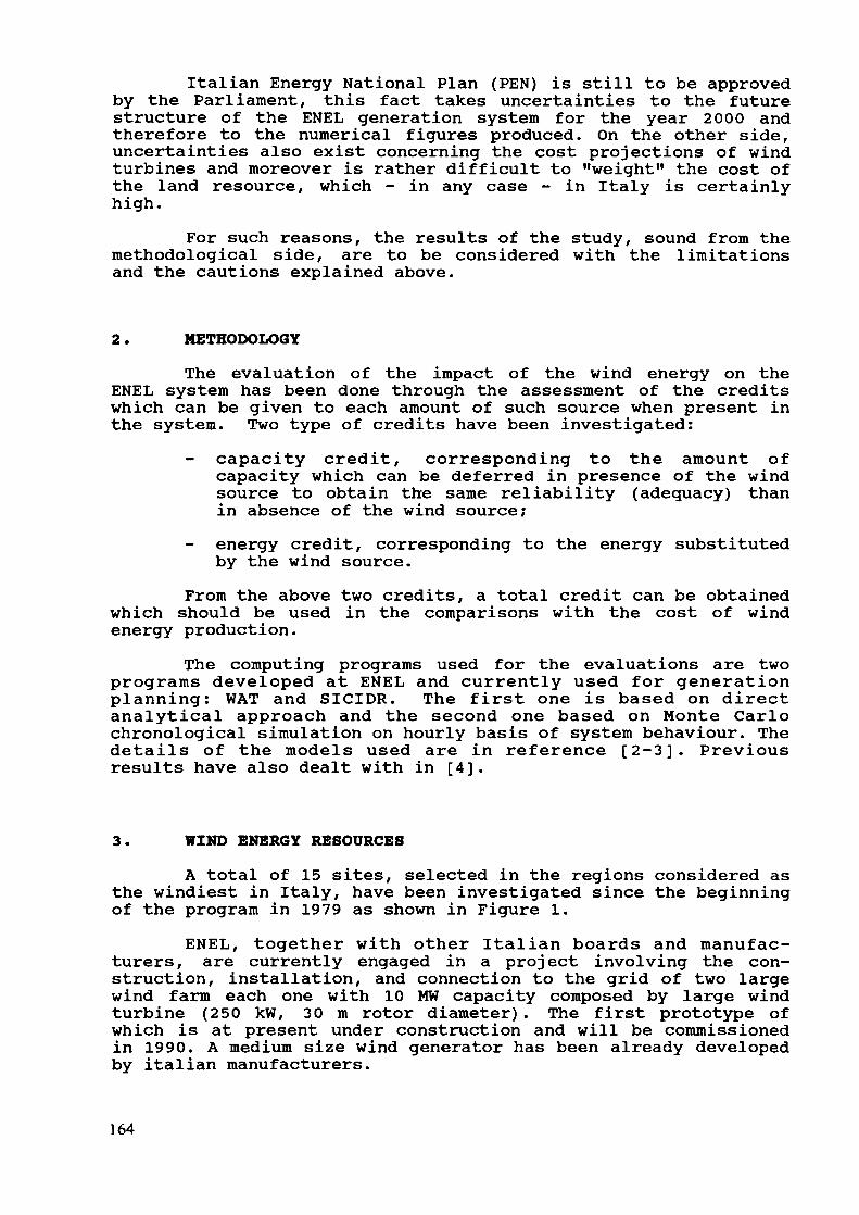
Italian Energy National Plan (PEN) is still to be approvedby the Parliament, this fact takes uncertainties to the futurestructure of the ENEL generation system for the year 2000 andtherefore to the numerical figures produced. On the other side,uncertainties also exist concerning the cost projections of windturbines and moreover is rather difficult to "weight" the cost ofthe land resource, which - in any case - in Italy is certainlyhigh.
For such reasons, the results of the study, sound from themethodological side, are to be considered with the limitationsand the cautions explained above.
2. METHODOLOGY
The evaluation of the impact of the wind energy on theENEL system has been done through the assessment of the creditswhich can be given to each amount of such source when present inthe system. Two type of credits have been investigated:
- capacity credit, corresponding to the amount ofcapacity which can be deferred in presence of the windsource to obtain the same reliability (adequacy) thanin absence of the wind source;
- energy credit, corresponding to the energy substitutedby the wind source.
From the above two credits, a total credit can be obtainedwhich should be used in the comparisons with the cost of windenergy production.
The computing programs used for the evaluations are twoprograms developed at ENEL and currently used for generationplanning: WAT and SICIDR. The first one is based on directanalytical approach and the second one based on Monte Carlochronological simulation on hourly basis of system behaviour. Thedetails of the models used are in reference [2-3]. Previousresults have also dealt with in [4].
3. WIND ENERGY RESOURCES
A total of 15 sites, selected in the regions considered asthe windiest in Italy, have been investigated since the beginningof the program in 1979 as shown in Figure 1.
ENEL, together with other Italian boards and manufac-turers, are currently engaged in a project involving the con-struction, installation, and connection to the grid of two largewind farm each one with 10 MW capacity composed by large windturbine (250 kW, 30 m rotor diameter). The first prototype ofwhich is at present under construction and will be commissionedin 1990. A medium size wind generator has been already developedby italian manufacturers.
164
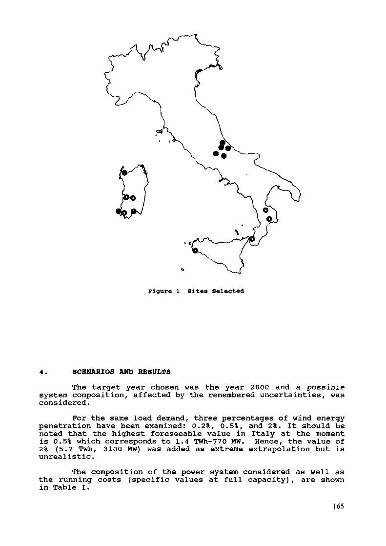
Figure 1 Sites Selected
4. SCENARIOS AND RESULTS
The target year chosen was the year 2000 and a possiblesystem composition, affected by the remembered uncertainties, wasconsidered.
For the same load demand, three percentages of wind energypenetration have been examined: 0.2%, 0.5%, and 2%. It should benoted that the highest foreseeable value in Italy at the momentis 0.5% which corresponds to 1.4 TWh-770 MW. Hence, the value of2% (5.7 TWh, 3100 MW) was added as extreme extrapolation but isunrealistic.
The composition of the power system considered as well asthe running costs (specific values at full capacity), are shownin Table I.
165
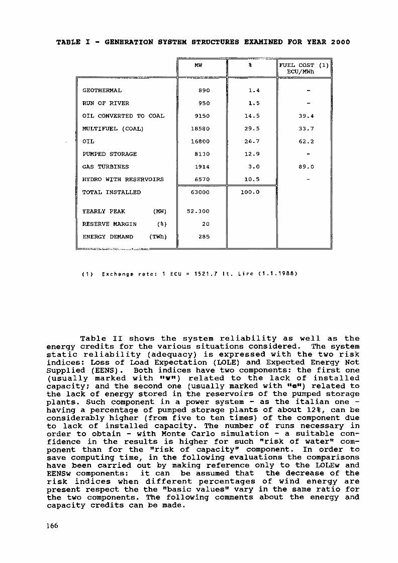
TABLE I - GENERATION SYSTEM STRUCTURES EXAMINED FOR YEAR 2000
GEOTHERMALRUN OF RIVEROIL CONVERTED TO COALMULTIFUEL (COAL)OILPUMPED STORAGEGAS TURBINESHYDRO WITH RESERVOIRSTOTAL INSTALLED
YEARLY PEAK (MW)RESERVE MARGIN (%)ENERGY DEMAND (TWh)
MW H %1
890950
9150185801680081301914657063000
52.30020285
1.41.5
14.529.526.712.93.0
10.5100.0
FUEL COST (1)ECU/MWh
-
-39.433.762.2-
89.0
"
( 1 ) E x c h a n g e r a t e : 1 E C U = 1521 .7 I t . L i r e ( 1 . 1 . 1 9 8 8 )
Table II shows the system reliability as well as theenergy credits for the various situations considered. The systemstatic reliability (adequacy) is expressed with the two riskindices: Loss of Load Expectation (LOLE) and Expected Energy NotSupplied (EENS). Both indices have two components: the first one(usually marked with "w") related to the lack of installedcapacity; and the second one (usually marked with "e") related tothe lack of energy stored in the reservoirs of the pumped storageplants. Such component in a power system - as the italian one -having a percentage of pumped storage plants of about 12%, can beconsiderably higher (from five to ten times) of the component dueto lack of installed capacity. The number of runs necessary inorder to obtain - with Monte Carlo simulation - a suitable con-fidence in the results is higher for such "risk of water" com-ponent than for the "risk of capacity" component. In order tosave computing time, in the following evaluations the comparisonshave been carried out by making reference only to the LOLEw andEENSw components: it can be assumed that the decrease of therisk indices when different percentages of wind energy arepresent respect the the "basic values" vary in the same ratio forthe two components. The following comments about the energy andcapacity credits can be made.
166
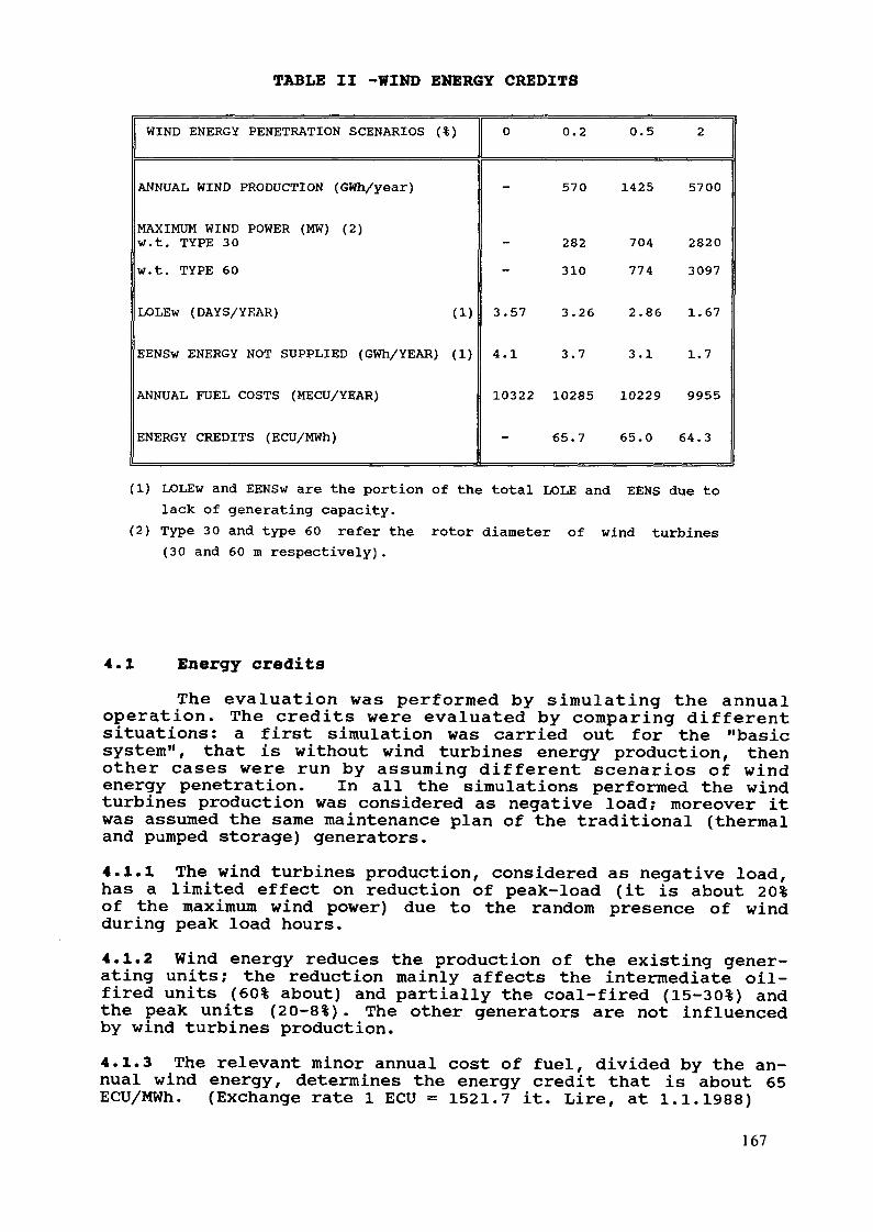
TABLE II -WIND ENERGY CREDITS
WIND ENERGY PENETRATION SCENARIOS (%)
ANNUAL WIND PRODUCTION (GWh/year)
MAXIMUM WIND POWER (MW) (2)W.t. TYPE 30w.t. TYPE 60
LOLEw (DAYS/YEAR) (1)
EENSw ENERGY NOT SUPPLIED (GWh/YEAR) (1)
ANNUAL FUEL COSTS (MECU/YEAR)
ENERGY CREDITS (ECU/MWh)
0 0.2
570
282310
3.57 3.26
4.1 3.7
10322 10285
65.7
0.5
1425
704774
2.86
3.1
10229
65.0
2
5700
28203097
1.67
1.7
9955
64.3
(1) LOLEw and EENSw are the portion of the total LOLE and EENS due tolack of generating capacity.
(2) Type 30 and type 60 refer the rotor diameter of wind turbines(30 and 60 m respectively).
4.1 Energy creditsThe evaluation was performed by simulating the annual
operation. The credits were evaluated by comparing differentsituations: a first simulation was carried out for the "basicsystem", that is without wind turbines energy production, thenother cases were run by assuming different scenarios of windenergy penetration. In all the simulations performed the windturbines production was considered as negative load; moreover itwas assumed the same maintenance plan of the traditional (thermaland pumped storage) generators.4.1.1 The wind turbines production, considered as negative load,has a limited effect on reduction of peak-load (it is about 20%of the maximum wind power) due to the random presence of windduring peak load hours.4.1.2 Wind energy reduces the production of the existing gener-ating units; the reduction mainly affects the intermediate oil-fired units (60% about) and partially the coal-fired (15-30%) andthe peak units (20-8%). The other generators are not influencedby wind turbines production.4.1.3 The relevant minor annual cost of fuel, divided by the an-nual wind energy, determines the energy credit that is about 65ECU/MWh. (Exchange rate 1 ECU = 1521.7 it. Lire, at 1.1.1988)
167
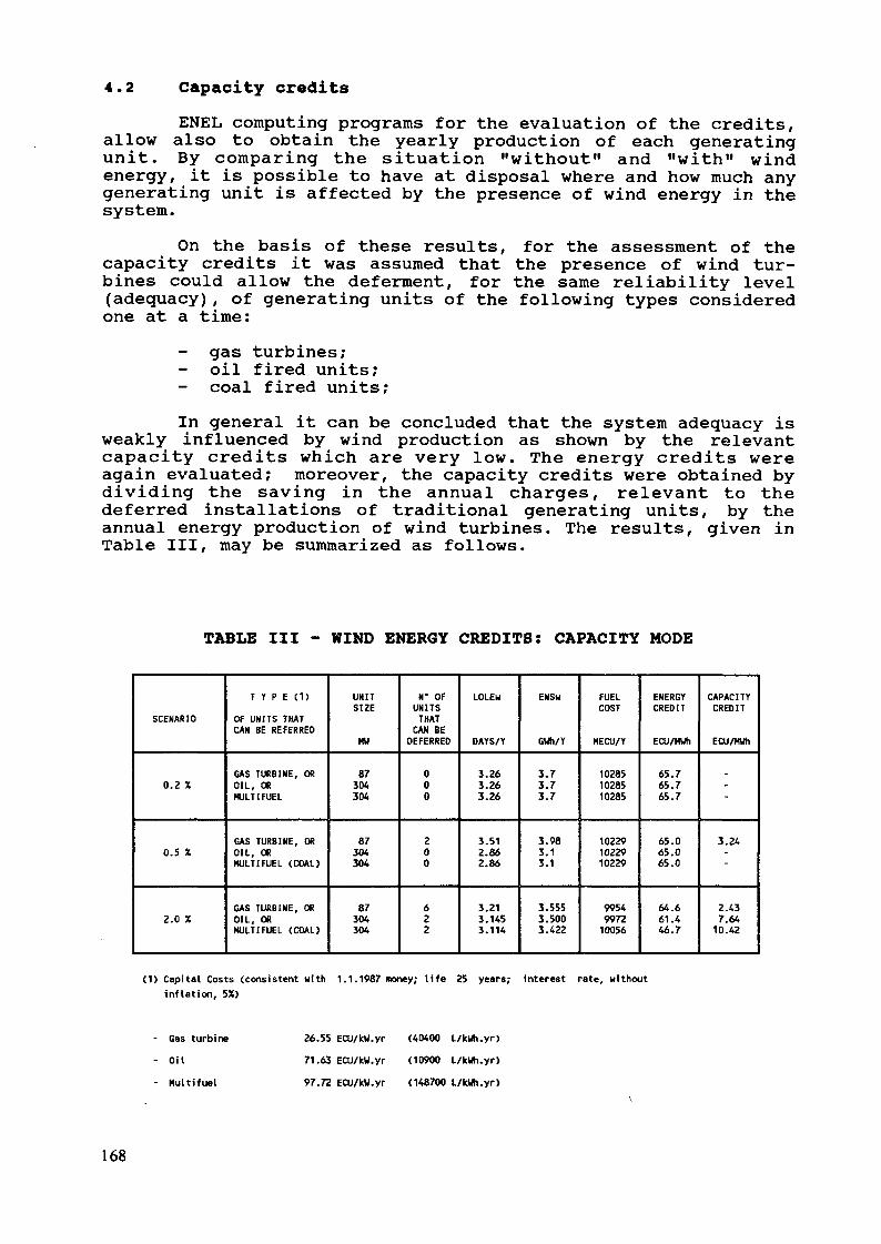
4.2 Capacity creditsENEL computing programs for the evaluation of the credits,
allow also to obtain the yearly production of each generatingunit. By comparing the situation "without" and "with" windenergy, it is possible to have at disposal where and how much anygenerating unit is affected by the presence of wind energy in thesystem.
On the basis of these results, for the assessment of thecapacity credits it was assumed that the presence of wind tur-bines could allow the deferment, for the same reliability level(adequacy), of generating units of the following types consideredone at a time:
gas turbines;oil fired units;
- coal fired units;In general it can be concluded that the system adequacy is
weakly influenced by wind production as shown by the relevantcapacity credits which are very low. The energy credits wereagain evaluated; moreover, the capacity credits were obtained bydividing the saving in the annual charges, relevant to thedeferred installations of traditional generating units, by theannual energy production of wind turbines. The results, given inTable III, may be summarized as follows.
TABLE III - WIND ENERGY CREDITS: CAPACITY MODE
SCENARIO
0.2 X
0.5 X
2.0 X
T Y P E (1)OF UNITS THATCAN BE REFERRED
GAS TURBINE, OROIL, ORMULT I FUEL
GAS TURBINE, OROIL, ORMULT I FUEL (COAL)
GAS TURBINE, OROIL, ORMULT 1 FUEL (COAL)
UNITSIZE
MU
87304304
87304304
87304304
N' OFUNITSTHATCAN BE
DEFERRED
000
200
622
LOLEu
DAYS/Y
3.263.263.26
3.512.862.86
3.213.1453.114
ENS«
GUh/Y
3.73.73.7
3.983.13.1
3.5553.5003.422
FUELCOST
MECU/Y
102851028510285
102291022910229
9954997210056
ENERGYCREDIT
ECU/HUh
65.765.765.7
65.065.065.0
64.661.446.7
CAPACITYCREDIT
ECU/HUh
-
"
3.24-
2.437.6410.42
(1) Capital Costs (consistent with 1.1.1987 money; life 25 years; interest rate, withoutinflation, 5X)
Gas turbineOilHultifuel
26.55 ECU/kU.yr (40400 L/kUh.yr)
71.63 ECU/kU.yr (10900 L/kUh.yr)
97.72 ECU/kU.yr (148700 L/kUh.yr)
168
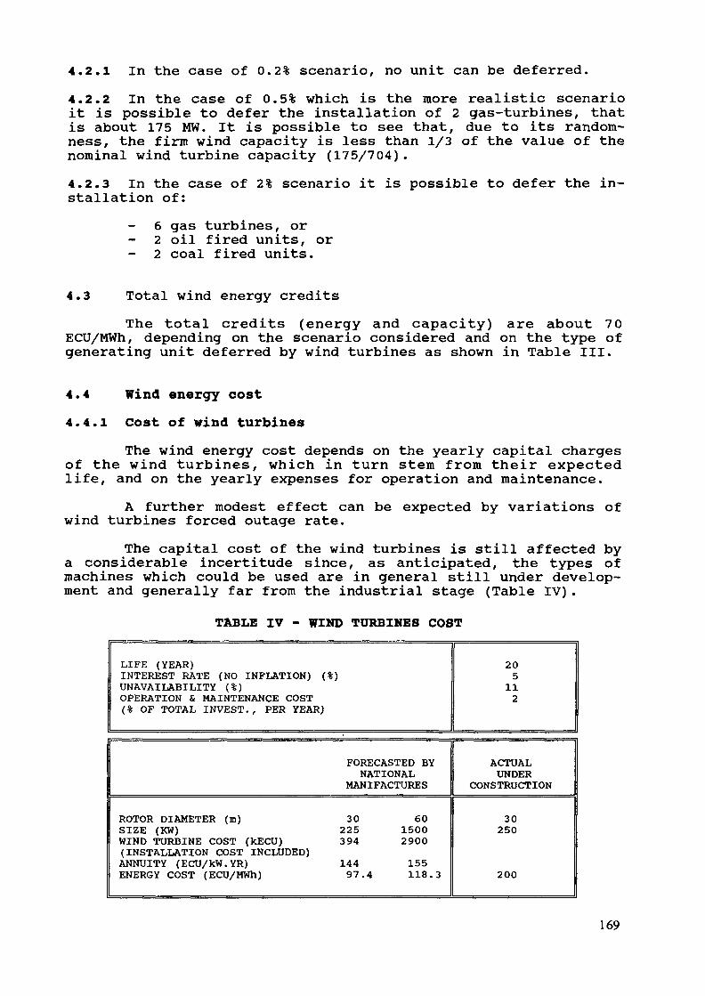
4.2.1 In the case of 0.2% scenario, no unit can be deferred.4.2.2 In the case of 0.5% which is the more realistic scenarioit is possible to defer the installation of 2 gas-turbines, thatis about 175 MW. It is possible to see that, due to its random-ness, the firm wind capacity is less than 1/3 of the value of thenominal wind turbine capacity (175/704).4.2.3 In the case of 2% scenario it is possible to defer the in-stallation of:
6 gas turbines, or2 oil fired units, or
- 2 coal fired units.
4.3 Total wind energy creditsThe total credits (energy and capacity) are about 70
ECU/MWh, depending on the scenario considered and on the type ofgenerating unit deferred by wind turbines as shown in Table III.
4.4 Wind energy cost4.4.1 Cost of wind turbines
The wind energy cost depends on the yearly capital chargesof the wind turbines, which in turn stem from their expectedlife, and on the yearly expenses for operation and maintenance.
A further modest effect can be expected by variations ofwind turbines forced outage rate.
The capital cost of the wind turbines is still affected bya considerable incertitude since, as anticipated, the types ofmachines which could be used are in general still under develop-ment and generally far from the industrial stage (Table IV).
TABLE IV - WIND TURBINES COST
LIFE (YEAR)INTEREST RATE (NO INFLATION) (%)UNAVAILABILITY (%)OPERATION & MAINTENANCE COST(% OF TOTAL INVEST., PER YEAR)
205112
FORECASTED BYNATIONAL
MANIFACTURESACTUALUNDER
CONSTRUCTION
ROTOR DIAMETER (m) 30SIZE (KW) 225WIND TURBINE COST (kECU) 394(INSTALLATION COST INCLUDED)ANNUITY (ECU/kW.YR) 144ENERGY COST (ECU/MWh) 97.4
6015002900155118.3
30250
200
169
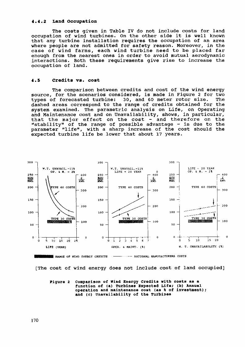
4.4.2 Land OccupationThe costs given in Table IV do not include costs for land
occupation of wind turbines. On the other side it is well knownthat any turbine installation requires the occupation of an areawhere people are not admitted for safety reason. Moreover, in thecase of wind farms, each wind turbine need to be placed farenough from the nearest ones in order to avoid mutual aerodynamicinteractions. Both these requirements give rise to increase theoccupation of land.
4.5 Credits vs. costThe comparison between credits and cost of the wind energy
source, for the scenarios considered, is made in Figure 2 for twotypes of forecasted turbine: 30, and 60 meter rotor size. Thedashed areas correspond to the range of credits obtained for thesystem examined. The parametric analysis on Life, on Operatingand Maintenance cost and on Unavailability, shows, in particular,that the major effect on the cost - and therefore on the"stability" of the range of possible advantage - is due to theparameter "life", with a sharp increase of the cost should theexpected turbine life be lower that about 17 years.
300 —i
250 -ÊSHMWh2OO -
150 —
100 -
50 -
W.T. UNAVAIL.=11%OP. i H. = 2%
60 COSTS
f— 400_£_kWh
- 300
- 200
- 100
300 —i
250 -ECUKWh200 -
150 -
100 -
0
W.T. UNAVAIL.=11%LIFE = 20 YEAR 0
T— 400
TYPE 60 COSTS
kWh
— 300
— 200
— 100
0 5 10 15 20 25LIFE (YEAR)
I I I I l T0 1 2 3 4 5 6 7
300
250ECUMWh200 —
150 —
100 —
0
LIFE = 20 YEAROP. S. M. = 2%
TYPE 60 COSTS
f— 400_£kWh
— 300
— 200
— 100
OPER. 4 MAINT. (%)
RANGE OF WIND ENERGY CREDITS —————————— NATIONAL MANUFACTURERS COSTS
0 5 10 15 20
W. T. UNAVAILABILITY (%)
[The cost of wind energy does not include cost of land occupied]
Figure 2 Comparison of Wind Energy Credits with costs as afunction of (a) Turbines Expected Life; (b) Annualoperation and maintenance cost (as % of investment);and (c) Unavailability of the Turbines
170

REFERENCES
[1] "EC Wind Power Penetration Study - ENEL Perception".G.Botta, A. Invernizzi, S. Panichelli, L. Salvaderi.Euroforum New Energies, Proceedings, Saarbruken, 24-28 October 1988.
[2] "Optimization of the basic characteristics of pumpedstorage plants". L. Paris, L. Salvaderi, IEEE PESWinter Meeting, New York, N.Y., January 27-February1, 1974.
[3] "Planning Thermal and Hydraulic Power System relevantparameters and their relative influence". G. Manzoni,P.L. Noferi, M. Valtorta. International Conferenceon large high tension Electric System - CIGRE Paris,August 24-September 6, 1972
[4] Cogeneration and Renewable Sources: Their Impacton Electric System. G. Manzoni, L. Salvaderi, A.Taschini, M. Valtorta - CIGRE 1980 Session, Paper41.05 Paris, August 1980.
171
EXPERIENCE WITH MAED/WASP AND OTHERPLANNING METHODOLOGIES USED BY THEJORDAN ELECTRICITY AUTHORITY
N. MUS APlanning Department,Jordan Electricity Authority,Amman, Jordan
Abstract
This paper presents the current planning methodologyadopted by Jordan Electricity Authority (JEA), andbriefly describes the methodologies and tools for loadforecasting, generation, transmission, economic andfinancial planning. It also deals with JEA experiencein the use of the MAED and WASP computer models, aswell as the problems faced during their operation.However, the WASP results are mainly used for purposesof checking with results of the available methodology.It should be mentioned that the ENPEP version of theprogram, which made the use of WASP much easier, hasnot been yet utilized by JEA. However, arrangementshave been made to run this program.
1. IntroductionUp to November 1st, 1984, the date when the Ministry of
Energy and Mineral Resources (MEMR) was established, energy plan-ning in Jordan was the responsibility of several entities. Thissituation caused some duplication of efforts. However, this isno more valid after creating the MEMR.
Energy PolicyJordan is totally dependent on imported oil for meeting its
energy needs. However, natural gas was recently discovered inthe country. The Ministry of Energy has adopted a Policy aimedat securing a sufficient supply of energy at the minimum possiblecost to the economy.
Electricity SectorJordan Electricity Authority (JEA) is the power supply
utility responsible for generation, transmission and part of dis-tribution system outside the concession areas of the two Privatedistribution companies, i.e. - Jordan Electric Power Company(JEPCO) and - Irbid District Electricity Company (IDECO), whichare responsible for distributing electricity to the central andnorthern parts of the country and they buy their power needs fromJEA in bulk (see Figure 1).
173
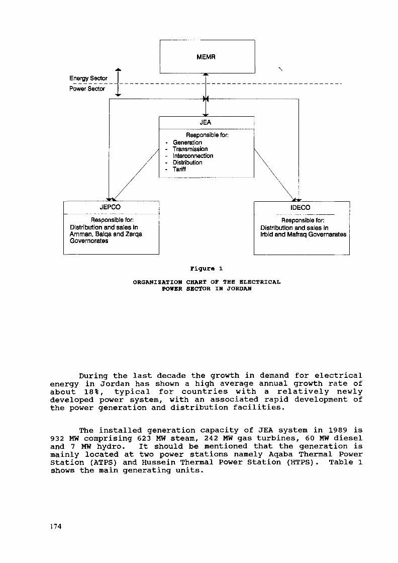
MEMR
Energy Sector\
Power Sector
JEA
Responsible for:GenerationTransmissionInterconnectionDistributionTariff
JEPCO
Responsible for:Distribution and sales InAmman, Balqa and ZarqaGovernorates
IDECO
Responsible for:Distribution and sales inIrbid and Mafraq Governarates
Figure l
ORGANIZATION CHART OF THE ELECTRICALPOWER SECTOR IN JORDAN
During the last decade the growth in demand for electricalenergy in Jordan has shown a high average annual growth rate ofabout 18%, typical for countries with a relatively newlydeveloped power system, with an associated rapid development ofthe power generation and distribution facilities.
The installed generation capacity of JEA system in 1989 is932 MW comprising 623 MW steam, 242 MW gas turbines, 60 MW dieseland 7 MW hydro. It should be mentioned that the generation ismainly located at two power stations namely Aqaba Thermal PowerStation (ATPS) and Hussein Thermal Power Station (HTPS). Table lshows the main generating units.
174
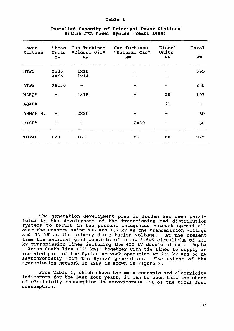
Table 1Installed Capacity of Principal Power Stations
Within JEA Power System (Year: 1989)
PowerStation
HTPS
Steam Gas TurbinesUnits "Diesel Oil"MW MW
Gas Turbines"Natural Gas"
MWDieselUnitsMW
3x334x66
1x181x14
TotalMW
395
ATPS 2X130MARQA - 4x18
AQABA
AMMAN S. - 2x30RISHA
26035 10721
602X30 - 60
TOTAL 623 182 60 60 925
The generation development plan in Jordan has been paral-leled by the development of the transmission and distributionsystems to result in the present integrated network spread allover the country using 400 and 132 kV as the transmission voltageand 33 kV as the primary distribution voltage. At the presenttime the national grid consists of about 2,646 circuit-km of 132kV transmission lines including the 400 kV double circuit Aqaba- Amman South line (325 km), together with tie lines to supply anisolated part of the Syrian network operating at 230 kV and 66 kVasynchronously from the Syrian generation. The extent of thetransmission network in 1989 is shown in Figure 2.
From Table 2, which shows the main economic and electricityindicators for the Last four years, it can be seen that the shareof electricity consumption is aproximately 25% of the total fuelconsumption.
175
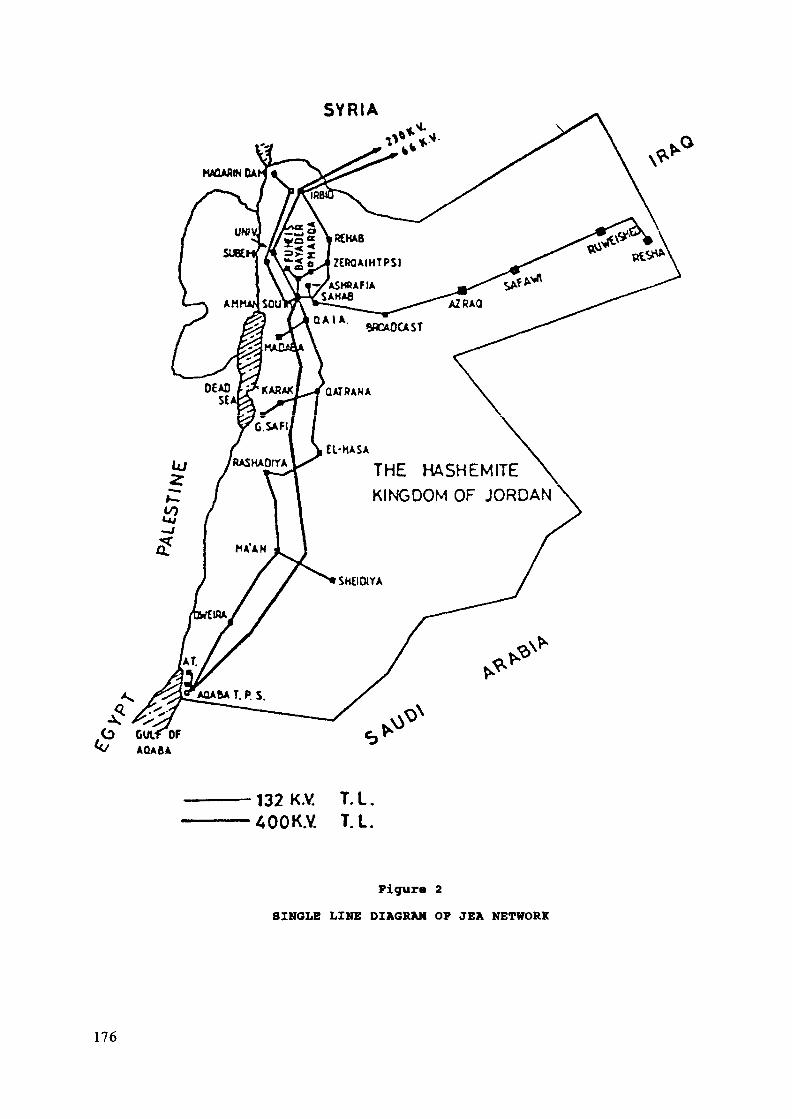
SYRIA
THE HASHEMITEKINGDOM OF JORDAN
132 K.V. T.I.400K.Y. T.I.
Figure 2SINGLE LINE DIAGRAM OF JEA NETWORK
176

Table 2Economie and Electricity Consumption Indicators
Population (thousands)GNP at current price
198526941881
198627961919
198728971867
198830011885(million JD)
Demand of Oil (103toe) 2820 2870 3000 3050Fuel Consumption forElectricity Gen. (103) 689 747 808 850Share of Electricity 24.8 26.0 26.9 27.8in Total Consumpt. (%)Electricity Producedfor Local Cons. (GWh) 2473 2722 3122 3263Value Added of ElectricSector (Million JD) 28.5 35.1 38.0 40.0
2. Power system Planning in JordanIn the first years of its existence (1966-1974), the Jordan
Electricity Authority was largely dependent on foreign consult-ants for conducting the necessary studies and planning for thedevelopment of the electric sector in the country. At that timea planning unit was established within JEA to follow-up and par-ticipate, along with foreign consultants, in planning thedevelopment of the electric sector in the country.
Later, this unit evolved into a planning department respon-sible for carrying out planning activities in cooperation withforeign consultants. Finally, Technical Planning, studies and Re-search, Corporate Planning and Computer and Information Depart-ments in JEA were reorganized into the Technical and CorporatePlanning Division. This change has taken place in order topromote JEA's planning activities into a new more advanced level.
Now, the JEA Planning Division is capable of conductingdifferent kinds of professional technical and corporate planningstudies and research and electronic data processing services,within Jordan and abroad.
2.1 Present Methodology Used by JEA in the Planning ProcessFigure 3 represents the planning process followed by the
Technical Planning Department in JEA. The main activities of theplanning cycle comprises: load forecasting; system expansion,and financial and economic analysis.
177
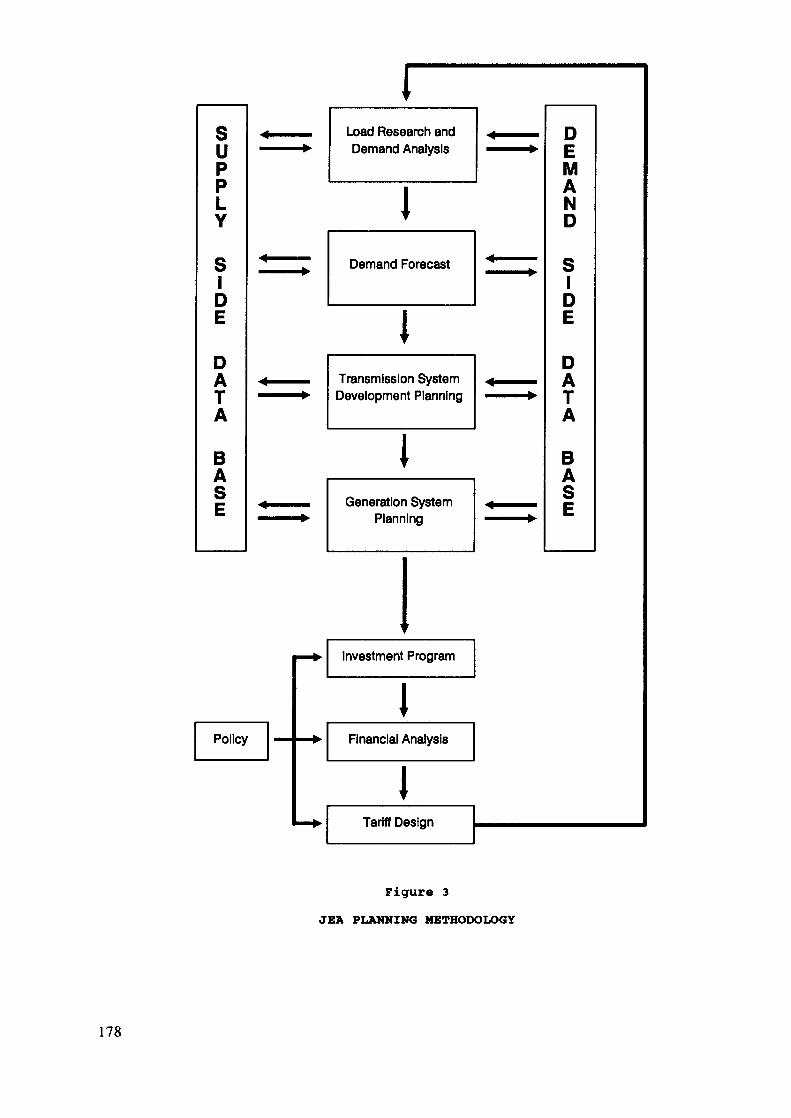
SuppLY
SlDE
DATA
BASE
Load Research andDemand Analysis
Demand Forecast
ITransmission SystemDevelopment Planning
IGeneration System
Planning
DEMAND
SIDE
DATA
BASE
Investment Program
iFinancial Analysis
lTariff Design
Figure 3JEA PLANKING METHODOLOGY
178

2.1.1 Load Forecasting MethodologyThe approach adopted is to forecast and analyse some of the
factors that influence the electricity demand in each sector.The relationship between these factors and electricity demand isdetermined. The sectors are classified into domestic, commer-cial, industrial, water pumping, institutions and others. Thisclassification complies to some extent with the existing tariffstructure.
The approach used to forecast the electricity demand is acombination of the following methods:
Extrapolation (Time series)- Market Survey
Econometric approachFigure 4 shows the load forecasting steps.ExtrapolationThis method reflects the continuation of the past trend of
consumption. it is used to forecast demand of institutions andstreet lighting sectors. Moreover it is used to forecast some ofthe influencing factors affecting the demand of other sectors.
This method is based on predicting the future by theknowledge of the past. Time series and regression analysis tech-niques are used.
Market SurveyThis method is used to forecast the electricity demand of
the bulk supply industries and water pumping facilities. Theindustrial category constitutes the large industries becausetheir operational plans are preprogrammed and in general theydevelop their own future marketing strategy.
This information coupled with actual specific consumptionproduce the electricity demand. However, the forecast has someuncertainties as the development and production of the plant areinfluenced by many external factors such as recession in localand world markets.
Econometric ApproachThe basic idea of this method is to derive mathematical
equations that explain the relationships between electricitydemand and other independent variables which influence thisdemand. These equations are established by means of the regres-sion analysis which is carried out by using the historical dataof the selected independent variables, together with the depen-dent electricity demand variables.
If the relation between these variables is significant thenprojections could be obtained from forecasting of the independentvariables included in these equations.
179
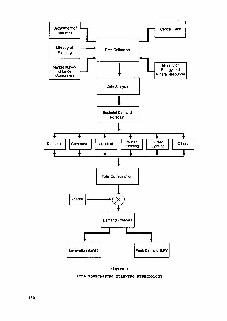
Department ofStatistics
Ministry ofPlanning
1*-
Data Collection
Central Bank
Market Surveyof Large
Consumers IData Analysis
ISectoriel Demand
Forecast
I
Ministry ofEnergy and
Mineral Resources
WaterPumping
Total Consumption
Demand Forecast
Generation (GWh)
StreetLighting
Peak Demand (MW)
Figure 4LOAD FORECASTING PLANNING METHODOLOGY
180
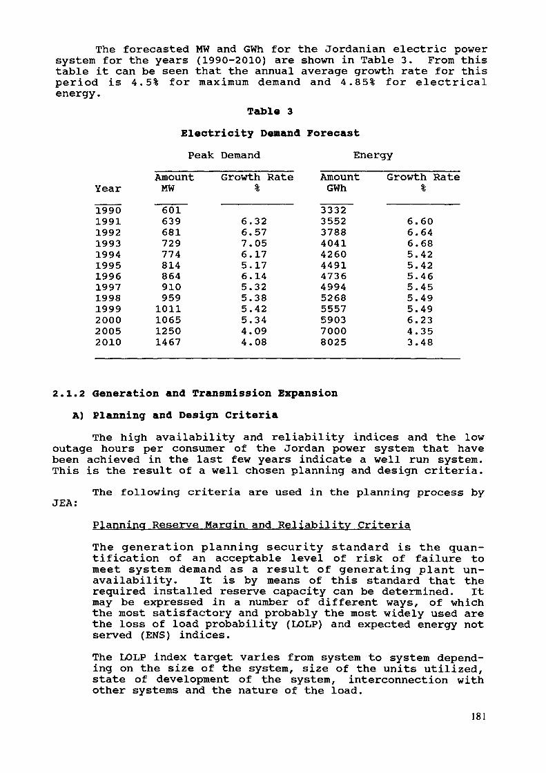
The forecasted MW and GWh for the Jordanian electric powersystem for the years (1990-2010) are shown in Table 3. From thistable it can be seen that the annual average growth rate for thisperiod is 4.5% for maximum demand and 4.85% for electricalenergy.
Table 3Electricity Demand ForecastPeak Demand Energy
Year1990199119921993199419951996199719981999200020052010
AmountMW6016396817297748148649109591011106512501467
Growth Rate%
6.326.577.056.175.176.145.325.385.425.344.094.08
AmountGWh3332355237884041426044914736499452685557590370008025
Growth Rate%
6.606.646.685.425.425.465.455.495.496.234.353.48
2.1.2 Generation and Transmission ExpansionA) Planning and Design Criteria
The high availability and reliability indices and the lowoutage hours per consumer of the Jordan power system that havebeen achieved in the last few years indicate a well run system.This is the result of a well chosen planning and design criteria.
JEA:The following criteria are used in the planning process by
Planning Reserve Margin and Reliability CriteriaThe generation planning security standard is the quan-tification of an acceptable level of risk of failure tomeet system demand as a result of generating plant un-availability. It is by means of this standard that therequired installed reserve capacity can be determined. Itmay be expressed in a number of different ways, of whichthe most satisfactory and probably the most widely used arethe loss of load probability (LOLP) and expected energy notserved (ENS) indices.The LOLP index target varies from system to system depend-ing on the size of the system, size of the units utilized,state of development of the system, interconnection withother systems and the nature of the load.
181
It is worthwhile to mention that the LOLP level improves asnew units are added to the power system. However, any unitaddition's contribution to system capability is measured byeffective load carrying capability (ELCC). \ This measureprovides system planners with knowledge of the relative im-pact of unit addition in meeting system load growth. It isthat part of the capacity of the unit that is available tosupply the increase in demand in order to maintain systemreliability less than or equal to the LOLP target.An LOLP target level of 0.4 day/year which translates intoa planning reserve margin of 30% is adopted in JEA for thenear future. However, this margin will be revised downwardupon the interconnection with neighboring Arab countries.It is anticipated that the interconnections will lead to10-15% reduction in the reserve margin.Other criteria used for planning the system are as follows:- The transmission System is considered secure for single
contingency cases without reducing system load (n-1criterion).In selecting transmission equipment sizes the principleof firm loading is used, i.e. at least two elements,each with a capacity equal to the demand, are selected.There is a tendency now to reduce this criterion.No element in the system should carry load beyond itsdesign rating for the normal condition.
- The voltage regulation on the 132 kV national grid is+6% under normal conditions and ±10% under emergencyconditions.Selection of new generating plant is based on the al-ternative with the lowest capital and O&M costs overthe life of the plant.The lifetime of the different assets is as follows:steam generating plants 30 yearsgas turbines (for peaking purposes) 15 yearsdiesel units 15 yearsT and D equipment 25 yearsT and D Lines 40 years
- Short circuit rupturing capacity ratings (at ambienttemperature = 40 ÖC with 35 °C temperature rise):
- 400 kV : 40 kA- 132 kV : 31.5 kA- 33 kV : 25 kA
182
B) Generation System Expansion MethodologyThe generation system expansion methodology includes the
following steps:1) The investigation of different geographical sites is
based on factors such as proximity to load centres,availability of water and fuel, environmental aspects,accessibility and reliability of the whole generatingsystem after expansion.
2) Study of the different fuel types to be used in thegeneration expansion schemes.
3) Determination of the optimal set size and plant size,commissioning years and the generation expansionprogram. Choice of set size(s) to take into accountreserve, overall reliability of the system, operationaland investment costs.
4) The investigation of alternative cooling systems forthe selected sites (i.e. dry cooling, wet tower coolingor open cycle cooling).
5) Study incorporating water desalination plant in the al-ternative generation plants to be studied.
6) Determining the optimum plant mix (steam, combinedcycle and gas turbines).
7) General conceptual design philosophy of the generatingunits including, operating pressures, temperatures andefficiencies, etc.
8) Investigation of the effect of the existing andproposed interconnections with neighboring Arabcountries on the total generation and transmission sys-tems in Jordan, as regards to technical requirementsand constraints.
Figure 5 shows the generation expansion methodology.The optimal generation plan for the Jordanian electrical
power system up to the year 2010 is shown in Table 4.
C) Transmission System ExpansionAnalysis of different alternative schemes for expanding the
transmission system is associated with the generation expansionschemes. The investigation should concentrate on the transmissionequipment needed for the transfer of power, maintenance of thesystem security and stability and the control of power from theproposed power station site(s) to the national grid under allswitching conditions, enforcing the JEA transmission system tomeet the increased demand.
183
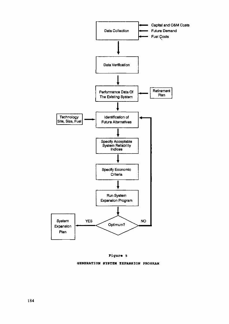
Data Collection
IData Verification
1Performance Data OfThe Existing System
IIdentification of
Future Alternatives
Specify AcceptableSystem Reliability
Indices
Specify EconomicCriteria
IRun System
Expansion Program
Capital and O&M CostsFuture DemandFuel Costs
Figure 5GENERATION SYSTEM EXPANSION PROGRAM
184
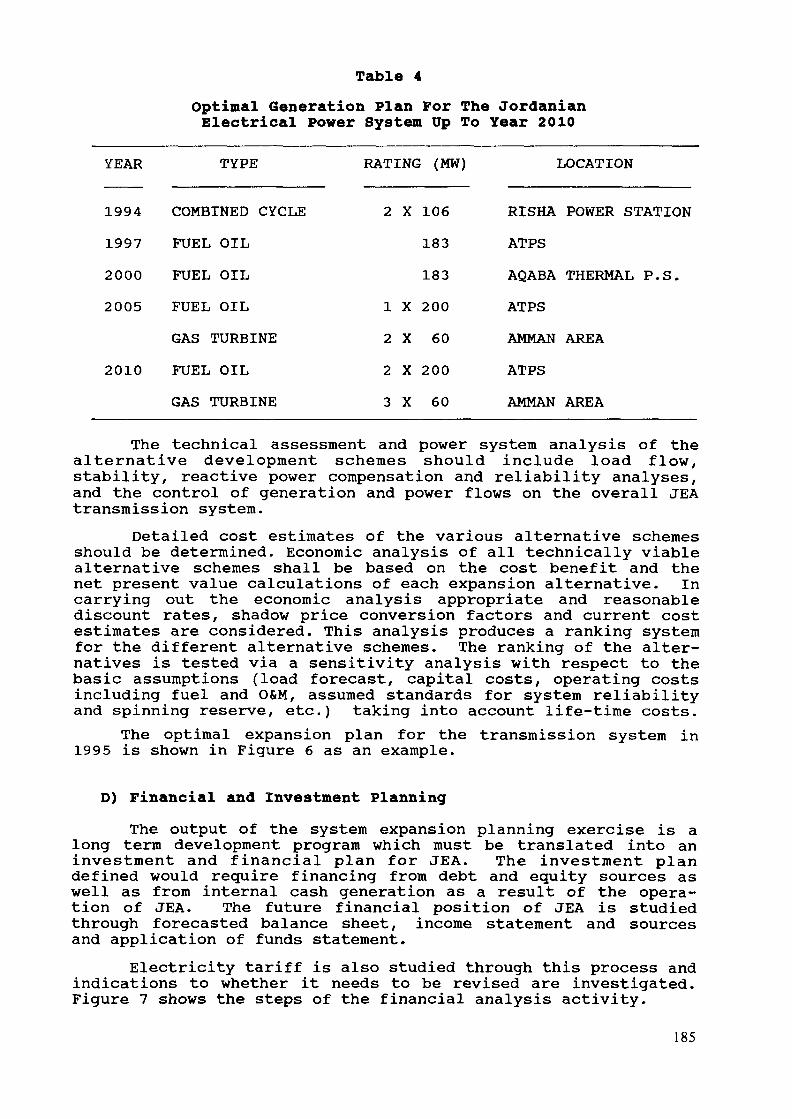
Table 4Optimal Generation Plan For The JordanianElectrical Power System Up To Year 2010
YEAR TYPE RATING (MW) LOCATION
1994199720002005
2010
COMBINED CYCLEFUEL OIL
FUEL OILFUEL OILGAS TURBINE
FUEL OILGAS TURBINE
2 X 106183183
1 X 2002 X 602 X 2003 X 60
RISHA POWER STATIONATPS
AQABA THERMAL P.S.ATPS
AMMAN AREAATPS
AMMAN AREA
The technical assessment and power system analysis of thealternative development schemes should include load flow,stability, reactive power compensation and reliability analyses,and the control of generation and power flows on the overall JEAtransmission system.
Detailed cost estimates of the various alternative schemesshould be determined. Economic analysis of all technically viablealternative schemes shall be based on the cost benefit and thenet present value calculations of each expansion alternative. Incarrying out the economic analysis appropriate and reasonablediscount rates, shadow price conversion factors and current costestimates are considered. This analysis produces a ranking systemfor the different alternative schemes. The ranking of the alter-natives is tested via a sensitivity analysis with respect to thebasic assumptions (load forecast, capital costs, operating costsincluding fuel and O&M, assumed standards for system reliabilityand spinning reserve, etc.) taking into account life-time costs.
The optimal expansion plan for the transmission system in1995 is shown in Figure 6 as an example.
D) Financial and Investment PlanningThe output of the system expansion planning exercise is a
long term development program which must be translated into aninvestment and financial plan for JEA. The investment plandefined would require financing from debt and equity sources aswell as from internal cash generation as a result of the opera-tion of JEA. The future financial position of JEA is studiedthrough forecasted balance sheet, income statement and sourcesand application of funds statement.
Electricity tariff is also studied through this process andindications to whether it needs to be revised are investigated.Figure 7 shows the steps of the financial analysis activity.
185
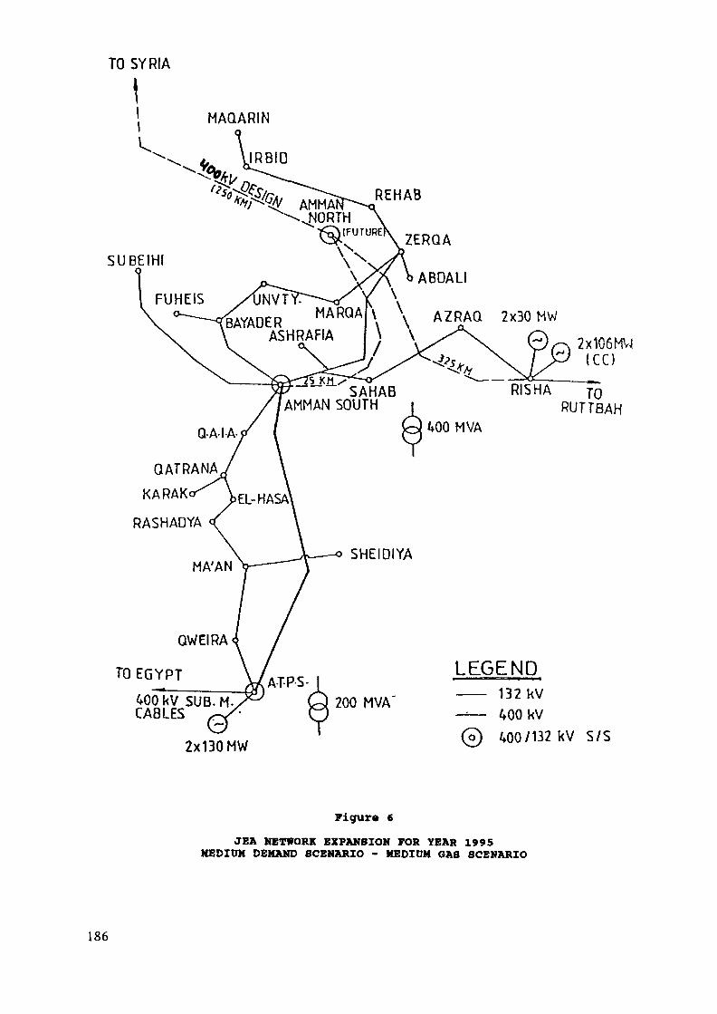
AMMA^ REHAB
.NORTH^UTURE\ ZERQA\\>
\X>\ >>ABOAll\
\ AZRAQ 2x3Q MW\ \
NVTY:BAYADER MARQA
ASHRAFIA
SAHABAMMAN SOUTH
2x10⁶MV|I C C )
RUTTBAH
QWEIRA
TO EGYPT
40(kV SUB.CABLES
2x130 MW
LEGEND200 MVA —— 132 kV
-— WQW0 ^00/132 kV S/S
Figur« 6
JEA NETWORK EXPANSION FOR YEAR 1995MEDIUM DEMAND SCENARIO - MEDIUM GAS SCENARIO
186
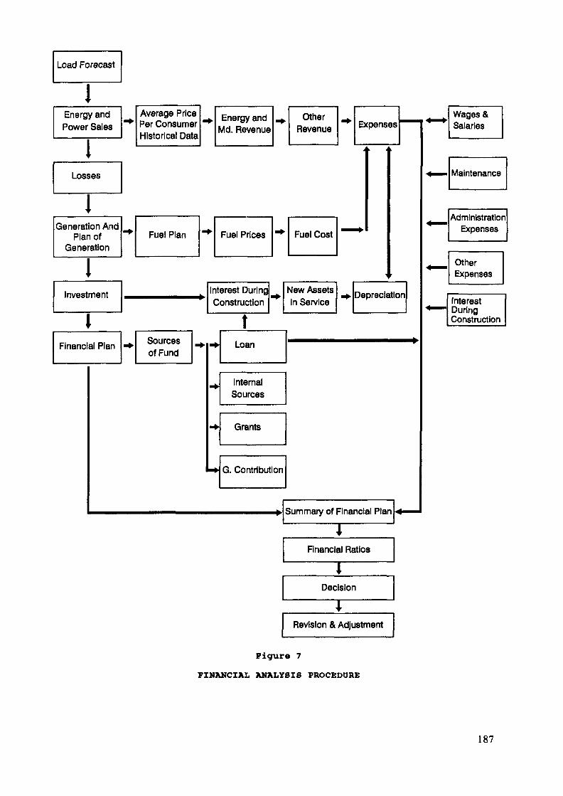
Load Forecast
IEnergy andPower Sales
iLosses
1Generation And
Plan ofGeneration
IInvestment
IFinancial Plan •*•
Summary of Financial Plan
Financial Ratios
TDecision
Revision & Adjustment
Figure 7FINANCIAL ANALYSIS PROCEDURE
187
3. Analytical Tools Available at JEA for Operation Planning:3.1 Software
Model for the Analysis of Energy Demand (MAED)It is an end use model which basically provides demandprojections based on selected scenarios. Although it is avery useful tool, it requires an intensive data base. Theinput data include information regarding all energy formsand the associated driving forces. The variables coversocioeconomic, demographic and technological lifestyle fac-tors.Wien Automatic system planning package (WASP-III)This package permits to determine the optimum expansionplan for a power generating system over a period of up tothirty years, within constraints specified by the planner.The optimum solution is evaluated in terms of minimum dis-counted total cost. WASP uses probabilistic estimation ofproduction costs, amount of energy not served andreliability, and the dynamic optimization method for com-paring the costs of alternative system expansion policies.Production simulation for planning (PSIM)This program is used to compute generation system operationand production costs. It is not used to optimize longterm generation plan but only simulates the operation ofexisting generation units, and could be used to simulatefuture additions.PC/CUM; PC/CUM is a probabilistic utility productioncosting program based on a more refined approach in whichthe Gram-Charlier series are used for the representation ofthe equivalent load duration curve which is the core of theprobabilistic production costing.The marginal cost calculation program (PCCM):The program is an annual simulation model for any electricpower system described by:- a demand given through an annual load curve,- a periodic amount of hydro energy shared in two parts,
one part which is assumed to be used at the optimaltime, and another which is assumed to be used uniformlyon the period.a fixed generation unit's structurea cost for unserved energy.
The PCCM model operates the generating plants in economicmerit order to minimize annual operating and shortagecosts. It runs week by week, using a weekly load durationcurve described by a maximum of ten steps and gives foreach step of each week:- the energy produced by each kind of units.- the average generation and shortage cost,
the marginal costs,the loss of load probability.
188
LDISP: This program is used to compute generation systemoperation and production cost, in addition to monthlysimulation of load dispatch for various years.Power system simulator PSS/E: This program is used forload flow, short circuit and dynamic studies.ERACLES: This model is used for transmission expansion op-timization. It consists of a group of programs (load flow,short circuit & stability) to assess suitability of trans-mission expansion schemes preselected by the planner.Electromagnetic Transient Program (EMTP); This program isused to study the different types of over-voltage in thepower system and the methods for their remedies.Financial Forecast Program (FFP): This Program wasdeveloped in-house by JEA staff for the purpose of carryingout financial analysis, investment planning and tariffstudies for long term planning.
3.2 HardwarePersonal Computers ;
Multitech personal computers with 640 KB, main memory,20 MB auxiliary memory (hard disk).IBM personal computers with 1024 KB Random AccessMemory (RAM) and 70 MB auxiliary memory (hard disk).AT personal computer with, 64 KB Random Access Memory,70 MB auxiliary memory (hard disk) with mathematicalcoprocessor and color monitor.
Mini Computers1 - A VAX MODEL 8530 computer with the following hardware
configuration:Core memory size 32 MBytes, 32 Bits per word, and8 Bits per character.
Virtual memory (4.3 MB)2 - Micro VAX 2000 computer system 6 MB Memory and I/Oport.
189
4. JEA Experience in Using the MAED and WASP ModelsJEA in cooperation with the IAEA conducted the Energy and
Electricity Planning (EEP) study for Jordan using the MAED andWASP computer models. The objectives of this study were asfollows:
1) To provide planning methodologies for long-term energyand electricity demand forecasts by using the MAEDcomputer model.
2) To provide planning criterion for generation expansionplans by using WASP model.
3) To train a local team on the use of the MAED and WASPcomputer models.
4) To provide forecast results for energy and electricitydemands as well as optimal generation expansion plans.
5) To provide a nucleus of information for the energystatistical data base.
The following paragraphs describe the experience gainedfrom the execution of the above study and subsequent use of themodels at JEA.
4.1 MAED Model
A wide variety of activities have been carried by JEA inrelation to the MAED model, including:
Transfer of the MAED program from the WANG computer tothe VAX computer.JEA constituted a team for running the program and up-dating the data annually.Comparison of the results of other load forecastingmethodologies used by JEA with MAED results.Training three of its staff in MAED courses held at Ar-gonne National Laboratory was accomplished.Participation of a Jordanian lecturer (One JEA staff)in training courses held at Argonne.
On the other hand, several problems have been faced inusing the MAED model:
Lack of sufficient and reliable data. Many difficultieshad been faced in gathering data.Similar difficulties were encountered in preparing thegathered data in the format required by the MAED model.Necessity to make external calculations and hypotheses.
190
The analysis of energy demand performed by MAED modelstops at the level of energy supplied to the consumer.No evaluation within the model for the correspondingrequirements of the primary energy.Necessity of constituting a national team for runningthe model due to the type of data needed for it whichinvolves information at the national level.
4.2 WASP ModelThe activities undertaken by JEA in utilizing the WASP
program include the following:Using the WASP program in addition to other programsfor updating the generation expansion plans.
- JEA constituted a team for running this program.Continuous training (local and abroad).Transferring the WASP program from the WANG to the VAXcomputer. The following advantages were achieved:
Operation of REPROBAT program. This program hadnot been run on WANG computer as it needs to openmany working files which could not be accepted byWANG computer.Shortening the time needed for running MERSIM onVAX to around one half hour instead of 10-12 hourswhen running on WANG.Reducing the time needed for running GONGEN toabout 15% of the time needed when running on WANGprogram.
Although less numerous that the ones ecountered for the ap-plication of MAED, certain problems were faced in using the WASPmodel at JEA, including the following:
Method of entering the data is not user friendly, thisresults in wrong entry data.Method of entering the data concerning the unitsretirement in FIXSYS is complex.Increasing the ascertained number of fuel types to morethan 5 types of existing in the program.
4.3 Conclusions and RecommendationsFrom our experience in the use of MAED and WASP programs it
transpired that these packages are powerful tools for energydemand forecast and generation expansion studies.
191

Due to the benefits that can be gained from the use of theabove mentioned programs, it is recommended:
To undertake the necesssary improvements that could beintroduced to the models in order to solve the pre-viously mentioned problems.To provide training on the use of improved versions ofthe programs.
192
PROBLEMS RELATED TO ENERGY AND ELECTRICITYDEMAND FORECASTING AND POWER GENERATIONIN THE LIBYAN ARAB JAMAHIRIYA
Ez-Dean ABOUGHALYAMinistry of Energy,Tripoli, Libyan Arab Jamahiriya
Abstract
This paper corresponds to some extracts of the resultsof a case study conducted jointly between the LibyanEnergy Authority and an International Consultant withthe objective to assess the economic viability of thenuclear power option within the wider framework of theexpansion of the overall energy supply system for thecountry. The learnings of the process are reviewed inthis paper and some of the principal results are il-lustrated at the end in graphical form. Major recom-mendations of the study are also summarized. A reviewof the situation of the supply and demand energy systemof Libya is also discussed.
INTRODUCTION
The adequate and secure supply of energy is one indispensableprecondition to any well-conceived national socioeconomicdevelopment by self-sustaining economic growth. The energy sec-tor, which encompasses all activities concerned with the procure-ment, conversion, transport, end use and storage of energy, thusholds a position of central importance in a nation's economy.Its activities are to be geared towards the goal of attaining andusing as efficiently as possible the necessary resources andcapabilities for satisfying the country's changing energy demandat both the lowest financial, as well as intangible costs andrisks to society.
The supply of energy must never be a handicap to economicdevelopment. To minimize this risk, and because of the generallylong lead times of capacity additions, planning of the timely andtechnically appropriate expansion of the energy sector has thusto anticipate such economic development well in advance. Tocomply with the requirement of cost minimization an optimizationapproach to national energy planning commends itself, which paysattention to the economic and technical link between the choiceof primary energy and conversion technology, and to theconsumer's need for useful energy.
The argument of long lead times applies to nuclear powermore than to any other energy technology. The infrastructurepreconditions that have to be met before its introduction, demandthorough and lenghty preparations, of which the economic assess-ment is one of the most important ones.
193

Late in 1982, the then Secretariate of Atomic Energy (SAE)of Libya contracted this Energy Supply Optimization (ESO) Studyto be carried out by Interatom/KWU, in order to assess, withinthe wider frame of the expansion of the entire national energysupply system, when and to what extent nuclear power could be in-troduced in Libya as an economically viable proposition. Theresults of this study should form the basis for timely and ra-tional arguable decisions on the expansion of the Libyan energysupply system in the near and medium term. In addition, itshould help to identify the problems encountered in performingsuch studies so that remedial action can be taken. A joint work-ing group consisting of Libyan and German experts was set up tothis purpose and started working in the same year.
According to the original concept of the study, the economicdevelopment of Libya's most important geographic regions was tobe forecasted by economic sectors, partly on the basis of theshort-term aims of the Socioeconomic Transformation Plan 1981-85,and partly by estimates on the basis of long-term aims until theyear 2030. From the results, the required development of the end-use energy demand, in particular the demand for electricity, wasto be derived and with the aid of the optimization programme ECOT(Energy Conversion and Transport) the corresponding least costexpansion strategy for the energy supply system determined.Starting year for the optimization was 1985.
In the course of the work, however, it became apparent thatfor various reasons outside the influence of the team membersthis approach could not be successfully implemented. Althougholder statistics and other raw data on the economy and the energysector were generally available, essential data and informationconcerning more recent years was often fragmentary and contradic-tory. Frequently, it was not available when it was needed or inadequate form, or it was not available at all. The resulting in-terruptions as well as the amount of supplementary work that wascarried out in the endeavour to overcome these shortcomings ledto several considerable delays, after which the original database had to be repeatedly updated, thereby running into the samesort of problems again. The accuracy achievable in this way wasalso not sufficient to warrant the effort.
Since under the given circumstances this concept could notlead to the desired results, it was eventually agreed to abandonit in favour of the following more appropriate approach.
Rather than deriving the required production of electricityand refinery products from a forecast of the economic develop-ment, this production was directly forecasted. In both cases therange of developments deemed to be likely is covered by a low, amedium and a high projection.
For electricity this was done on the more general assump-tion, based on empirical evidence, that the development of itsper-capita production may be approximated by a logistic curve.This permits its projection in the future by extrapolation oftime series of the past. To account for regional effects, thecountry was subdivided into the four geographical regions ofTripoli, Banghazi, Sebha and Sarir/Kufrah, which at present(1988) still have separate electric grids.
194
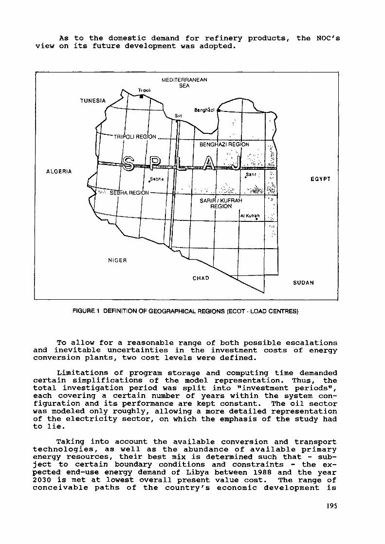
As to the domestic demand for refinery products,view on its future development was adopted.
the NOC's
Tripoli
MEDITERRANEANSEA
TUNESIA
ALGERIA
SARIR / KUFRAHREGION
EGYPT
NIGER
CHAD SUDAN
FIGURE 1 DEFINITION OF GEOGRAPHICAL REGIONS (ECOT - LOAD CENTRES)
To allow for a reasonable range of both possible escalationsand inevitable uncertainties in the investment costs of energyconversion plants, two cost levels were defined.
Limitations of program storage and computing time demandedcertain simplifications of the model representation. Thus, thetotal investigation period was split into "investment periods",each covering a certain number of years within the system con-figuration and its performance are kept constant. The oil sectorwas modeled only roughly, allowing a more detailed representationof the electricity sector, on which the emphasis of the study hadto lie.
Taking into account the available conversion and transporttechnologies, as well as the abundance of available primaryenergy resources, their best mix is determined such that - sub-ject to certain boundary conditions and constraints - the ex-pected end-use energy demand of Libya between 1988 and the year2030 is met at lowest overall present value cost. The range ofconceivable paths of the country's economic development is
195
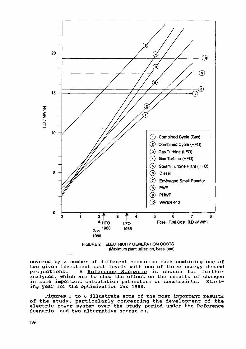
20 -
15 -
10 -
/ / x xx
Combined Cycle (Gas)21 Combined Cycle (HFO)3} Gas Turbine (LFO)
© Gas Turbine (HFO)Steam Turbine Plant (HFO)Diesel
Envisaged Small ReactorPWRPHWRWWER440
5 6 7 8Fossil Fuel Cost [LD /MWth]
FIGURE 2 ELECTRICITY GENERATION COSTS(Maximum plant utilization, base load)
covered by a number of different scenarios each combining one oftwo given investment cost levels with one of three energy demandprojections. A Reference Scenario is chosen for furtheranalyses, which are to show the effect on the results of changesin some important calculation parameters or constraints. Start-ing year for the optimization was 1988.
Figures 3 to 6 illustrate some of the most important resultsof the study, particularly concerning the development of theelectric power system over the study period under the ReferenceScenario and two alternative scenarios.196
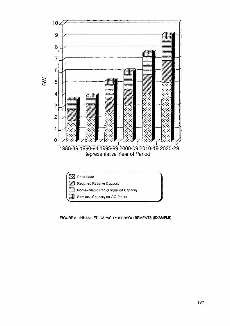
1988-89 1990-94 1995-99 2000-09 2010-'Representative Year of Period
2020-29
Peak Load
Required Reserve Capacity
Non-available Part ol Installed Capacity
Rest met Capacity lor RO-Plants
FIGURE 3 INSTALLED CAPACITY BY REQUIREMENTS (EXAMPLE)
197
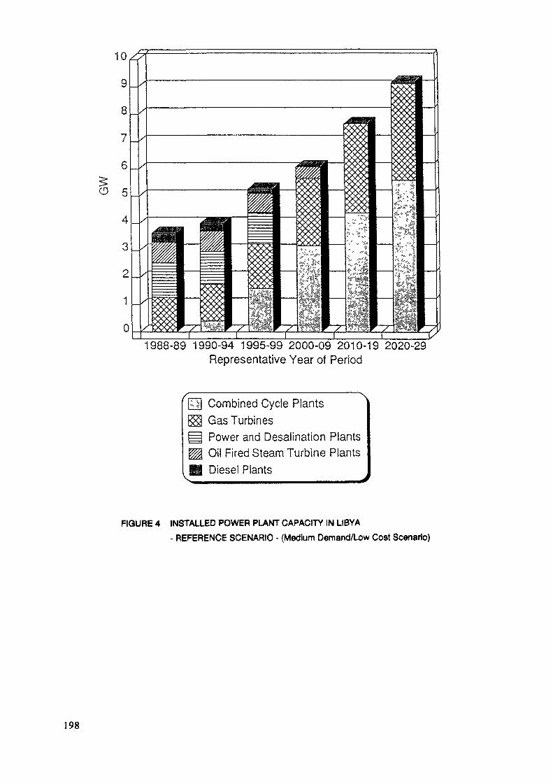
1988-89 1990-94 1995-99 2000-09 2010-19 2020-29Representative Year of Period
Combined Cycle PlantsGas TurbinesPower and Desalination PlantsOil Fired Steam Turbine PlantsDiesel Plants
FIGURE 4 INSTALLED POWER PLANT CAPACITY IN LIBYA- REFERENCE SCENARIO - (Medium Demand/Low Cost Scenario)
198
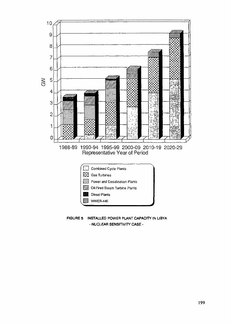
1988-89 1990-94 1995-99 2000-09 2010-19 2020-29Representative Year of Period
Combined Cycle Plants
Gas Turbines
Power and Desalination Plants
Oil Fired Steam Turbine Plants
Diesel PlantsWWER-440
FIGURE 5 INSTALLED POWER PLANT CAPACITY IN LIBYA- NUCLEAR SENSITIVITY CASE -
199
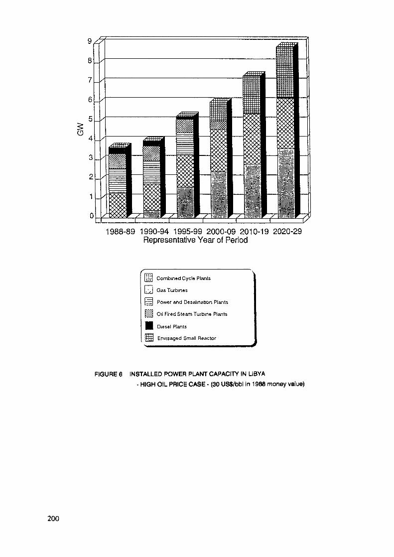
1988-89 1990-94 1995-99 2000-09 2010-19 2020-29Representative Year of Period
iu-] Combined Cycle Plants
', I Gas Turbines
rEJ Power and Desalination Plants
§g] Oil Fired Steam Turbine Plants
Diesel Plants
|îj Envisaged Small Reactor
FIGURE 6 INSTALLED POWER PLANT CAPACITY IN LIBYA- HIGH OIL PRICE CASE - (30 US$/bbl in 1988 money value)
200
Quality and Availability of InformationGenerally, for years further in the past official statistics
and other supplementary information exists on most issues of boththe Libyan energy supply system and the Libyan economy from avariety of international and particularly of extensive nationalsources. By contrast, it is frequently much more difficult andconsequently sometimes quite time consuming to obtain data andinformation on the last two or three years. Usually, thismaterial has to be collected from many different sources, fromsupplementary literature or by personal inquiries.
Although discrepancies occur occasionally also when compar-ing official statistics of past years, reliability problems areunderstandably more concentrated on the newer data material. Themain reasons encountered are
imprecise definitionsfragmentary information, andtranslation mistakes
Imprecise definition of the exact meaning of figures quotedis the most frequent cause of contradictions between differentsources, and sometimes even within the same source, In cases ofcontradictory information the choice was made on the basis ofconsistency checks and, whenever possible, preference was givento Libyan sources.
Sometimes, essential information (the load duration curveswere an example) was not available in the form required. To ob-tain it, the basic data for its preparation had to be collectedand appropriately processed first.
Prior to its use the data material in this report waschecked and discussed among the members of the Joint Workingteam. It was only used, if agreement could be reached that itwas reasonably reliable, or else that no better information couldbe procured.
It must be recognized that such a study gives recommenda-tions which are necessarily based on the assumption of "surprise-free" development, both of the domestic economy and of worldmarkets. Obviously, the probability that this assumption becomesincorrect increases with the length of the investigation period.Moreover, decisions on issues of long lead-times are based onscanty and insufficient information at the time. Even if changesoccurring in the calculation parameters should only be minor, itis conceivable that some of them may lead to widely differentresults. therefore, reasonably reliable conclusions can only bedrawn for the near and medium term.
This emphasizes both the need for updating the study atregular intervals and for keeping Energy Programs flexible withrespect to long term issues. these are decisions, which arerelatively insensitivity to changes of the economic frame andwhich permit adjustments to be made at a later date.
201

Before going into the main parts of the report, a conciseintroduction of the present (1988) situation of Libya's energydemand/supply system shall be given in the following section, in-cluding oil products and desalinated water.
The Libyan Energy Demand/Supply SystemLibya has an area of 1.755 million km2, most of which is
covered by desert. Large oil and gas resources rank the countryamong the world's important exporters of fossil energies. In1985, for instance, its oil production amounted to about 20% ofthe entire African production and nearly 2% of the world produc-tion.
About 93% of Libya's 3.64 million inhabitants (census 1984)live in the comparatively narrow region along the country's fer-tile north coast. The major part, nearly 67% settles in theTripolitania in the East, 26% along the Sirte and in the widerregion around Benghazi and the Jabal Akhdar in the West. Notquite 7% of the population lives in the central region of theFezzan, the rest living scattered over a number of major oases,such as Jaghbub, Kufrah or Ghat, and over small, isolated popula-tion centers.
The population distribution obviously determines the dis-tribution of Libya's end-use energy demand, which is charac-terized by a number of geographically separated demand regions.This is of particular importance for the electricity sector. In1988, a total electricity demand of about 10,200 GWh had to bemet, the regional pattern of which resembles very closely thesettlement pattern, i.e. about 60% arises in the Tripolitania,30% in the region of Benghazi including the Sirte and the JabalAkhdar, and only 10% in the rest of the country, mostly in theFezzan. Thus, together the coastal regions account for nearly90% of the country's electricity demand.
In 1988, the total installed power generation capacity ofthe country amounted to some 3,656 MWe, 70% of which are equallyshared between Combined Power & Desalination Plants and Gas Tur-bine Plants; 20% are steam power plants. Power and desalinationplants and steam power plants are only installed in the Tripoliand the Benghazi regions, whereas gas turbine plants and dieselstations are found everywhere.
At present (1988), electricity is still distributed via fourmajor sub-systems of the national electricity grid, named afterthe main population centers in the regions: Tripoli, Benghazi,Sebha and Sarir/Kufrah. They are still self-contained, but theyare due to be interconnected within the next few years.
Libya's total installed refining capacity of some 380,000bbl/day of crude oil operates at about 305,400 bbl/day (1988).It covers the country's demand for kerosene, light and heavy fueloil, LPG, and about 50% of its gasoline demand. Any surplus leftis available for export.
Petrochemical products such as methanol and ammonia areproduced at Brega at a rate of 660,000 tons/a by a total in-stalled production capacity of the same size.202

Since the largest portion of Libyan natural gas is as-sociated gas rather than dry gas, its production is linked to aconsiderable extent to the oil production and its limitations.So far, about 50% of the gas extracted has been flared, rein-jected or lost. The present net production runs at about 160billion cubic feet per annum, more than 2/3 of which is useddomestically. The remainder is exported as liquefied natural gas(LNG) produced at a plant at Brega, which at present runs at 30%of its design output capacity, i.e. at about 46 billion cubicfeet per annum.
As to crude oil, the country's production over the lastyears amounted mostly to somewhat more than 1,000,000 bbl/dayOnly about 40% (1988) of it is refined domestically, and the restgoes directly into exports.
Oil, and oil products are practically the only source of thecountry's revenues.
Over the years, the rising water demand of households,agriculture and industry has led to an over-exploitation of localwells and thus to a rapid fall of the ground water table. As aconsequence, sea water has been seeping into the coastal aquifersfor some time, causing a deterioration of water quality andsalination of the soil. To curb this development, a considerablenumber of sea desalination plants has been built in the past withmore to come. In 1988 about 2/3 of the installed capacity con-sists of dual purpose power & desalination plants using themulti-stage flash (MSF) process. The remainder consists ofsingle purpose reverse osmosis (RO) plants. Together their totalcapacity amounts to 301,720 m /day, with an estimated annualproduction of 38.7 million m3/a of desalinated water. Thesefigures reveal a very low utilization of the plants of only about35% on average.
Currently the largest project to alleviate the water situa-tion, particularly in agriculture, is the construction of theGreat Man-made River (GMR), which is to bring huge quantities ofhigh quality water from well fields in central Libya to theMediterranean coast.
Despite these enormous investments, today's demand fordesalted water is still greater than the supply, and continuingefforts will be needed to close this gap within the foreseeablefuture. Figure 7 shows the estimates of demand and production ofdesalted water for the country as considered in the study.
203
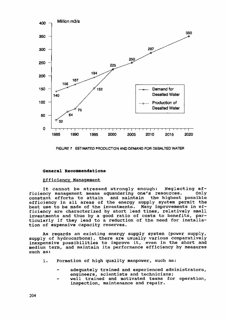
400 Million m3/a
350 -
300
250
200 -
150 -
100
50 H
0
350
287
225
194
156167
140
--•o---
Demand forDesalted Water
Production ofDesalted Water
1985 1990 1995 2000r i r i r i | r r t r j i i \ i |
2005 2010 2015 2020
FIGURE 7 ESTIMATED PRODUCTION AND DEMAND FOR DESALTED WATER
General RecommendationsEfficiency ManagementIt cannot be stressed strongly enough: Neglecting ef-
ficiency management means squandering one's resources. Onlyconstant efforts to attain and maintain the highest possibleefficiency in all areas of the energy supply system permit thebest use to be made of the investments. Many improvements in ef-ficiency are characterized by short lead times, relatively smallinvestments and thus by a good ratio of costs to benefits, par-ticularly if they lead to a reduction of the need for installa-tion of expensive capacity reserves.
As regards an existing energy supply system (power supply,supply of hydrocarbons), there are usually various comparativelyinexpensive possibilities to improve it, even in the short andmedium term, and maintain its performance efficiency by measuressuch as:
1. Formation of high quality manpower, such as:adequately trained and experienced administrators,engineers, scientists and technicians;
- well trained and motivated teams for operation,inspection, maintenance and repair.
204
Long term employment should be given preference, in or-der to allow the continuous building up and passing onof a fund of knowledge and experience by individualstaff members.
2. Standardization of equipment as far as possible, tosimplify replacement and stock-keeping by smaller andbetter utilized teams.
3. Improvement of the system reliability by increasing theavailability of individual plants and facilities (powerplants, refineries, mining facilities, etc.). Thisimplies:
performance analysis of existing plants andfacilities to identify problem areas;rehabilitation of plants and facilities byspecification, testing and implementation ofremedial measures;
- careful planning of maintenance strategies andcontrol of their results.
4. Evaluation of the optimum unit commitment of powerplants (on a daily and yearly basis).
5. Improvement of the reliability of energy transport sys-tems (electric transmission lines and distribution net-works, oil- and gas-pipelines) e.g. by:
adjustment of the capacity of transport systems;- better interconnections ;- introduction of modern ancillary facilities; and
high quality care and maintenance.6. Central control of the supply system by telecommunica-
tion.
Procurement of DataLasting changes in the relative structure of investment
costs, as well as of energy mining costs and export prices ofcrude oil, gas and heavy fuel oil may have a strong impact on theoverall economy of the power supply system. They are thus ofstrategic importance, since they affect the preferences in theuse of conversion technologies, and in the choice of end-energiesas power plant fuel and for exports. Therefore,
1. Continuous reviews of the expansion strategy arestrongly recommended and the corresponding respon-sibilities should be assigned. This entails further-more that
2. Responsibilities should be assigned to a single entityattached to the National Energy Committee for annuallyproviding a data base containing essential information(prices, costs, technical and performance data) fromthe energy and especially the electricity sector,
205

necessary for optimization calculations. regular up-dating of the data contained in the data section ofthis report could be used as a first approach to thistask.Likewise, responsibilities should be assigned to col-lect more detailed information on the actual demand fordesalted water and the structure of this demand withrespect to the economic sectors, and to monitor thesedata also in future. Better information is needed inorder to improve the demand projections, which are ofcentral importance for reliable estimates of the neces-sary investments.
206
PROBLEMS RELATED TO ENERGY DEMAND FORECASTINGAND ENERGY SUPPLY PLANNING IN MADAGASCAR
J.E. RABERANOHATRADirection de l'énergie et de l'eau,Antananarivo, Madagascar
Abstract
Madagascar is endowed with vast natural resources, butmost of them still unexploided. A principal factor forthis situation lies on the uneven distribution ofpopulation among rural and urban areas which makes woodand charcoal the principal sources of energy being usedin the country. This paper reviews the problems re-lated to planning of supply and demand of energy forthe country, with certain emphasis on planning of theelectricity sector.
I. GENERALITIES
Madagascar, an Indian Ocean Island situated at 400 km Eastof Africa, has about 12 million inhabitants distributed on590,000 km2 of surface area.
Urban population, growing at about 4.5% per annum, repre-sents only 19% of the total populations, which in turn has agrowth rate of 3%.
Madagascar has at its disposal an important potential ofenergy resources. Highlights of these resources are as follows:
Non-renewable;- Coal 1000 million tones- Lignite about 11 million tones
Rabble (tourbe) everywhere in the island, butin small scale
Renewable;Hydroelectricity: about 3,650 MW for 350 inventoried
sites:- 295 sites < 5 MW
22 sites 5 MW < > 50 MW33 sites > 50 MW
Wood: Natural forest is estimated at 12,3millions hectares and plantationsat 265,000 ha.
207
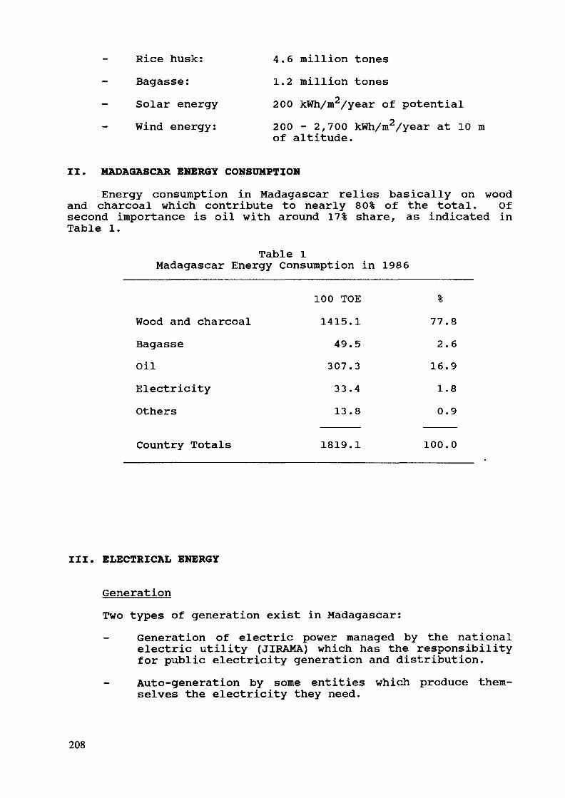
- Rice husk: 4.6 million tonesBagasse: 1.2 million tonesSolar energy 200 kWh/m2/year of potentialWind energy: 200 - 2,700 kWh/m2/year at 10 m
of altitude.
II. MADAGASCAR ENERGY CONSUMPTION
Energy consumption in Madagascar relies basically on woodand charcoal which contribute to nearly 80% of the total. Ofsecond importance is oil with around 17% share, as indicated inTable 1.
Table 1Madagascar Energy Consumption in 1986
Wood and charcoalBagasseOilElectricityOthers
Country Totals
100 TOE1415.1
49.5307.3
33.413.8
1819.1
%77.82.616.91.80.9
100.0
III. ELECTRICAL ENERGY
GenerationTwo types of generation exist in Madagascar:
Generation of electric power managed by the nationalelectric utility (JIRAMA) which has the responsibilityfor public electricity generation and distribution.Auto-generation by some entities which produce them-selves the electricity they need.
208
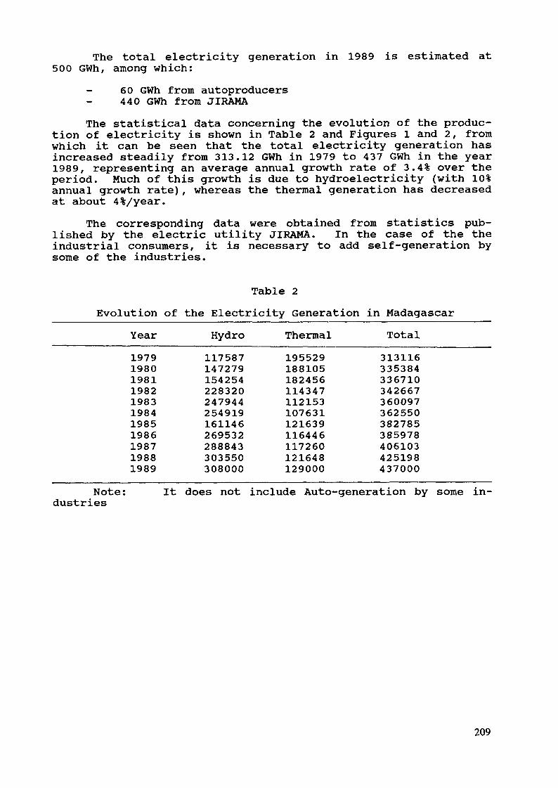
The total electricity generation in 1989 is estimated at500 GWh, among which:
60 GWh from autoproducers440 GWh from JIRAMA
The statistical data concerning the evolution of the produc-tion of electricity is shown in Table 2 and Figures 1 and 2, fromwhich it can be seen that the total electricity generation hasincreased steadily from 313.12 GWh in 1979 to 437 GWh in the year1989, representing an average annual growth rate of 3.4% over theperiod. Much of this growth is due to hydroelectricity (with 10%annual growth rate), whereas the thermal generation has decreasedat about 4%/year.
The corresponding data were obtained from statistics pub-lished by the electric utility JIRAMA. In the case of the theindustrial consumers, it is necessary to add self-generation bysome of the industries.
Table 2Evolution of the Electricity Generation in Madagascar
Year Hydro Thermal Total19791980198119821983198419851986198719881989
117587147279154254228320247944254919161146269532288843303550308000
195529188105182456114347112153107631121639116446117260121648129000
313116335384336710342667360097362550382785385978406103425198437000
Note: It does not include Auto-generation by some in-dustries
209
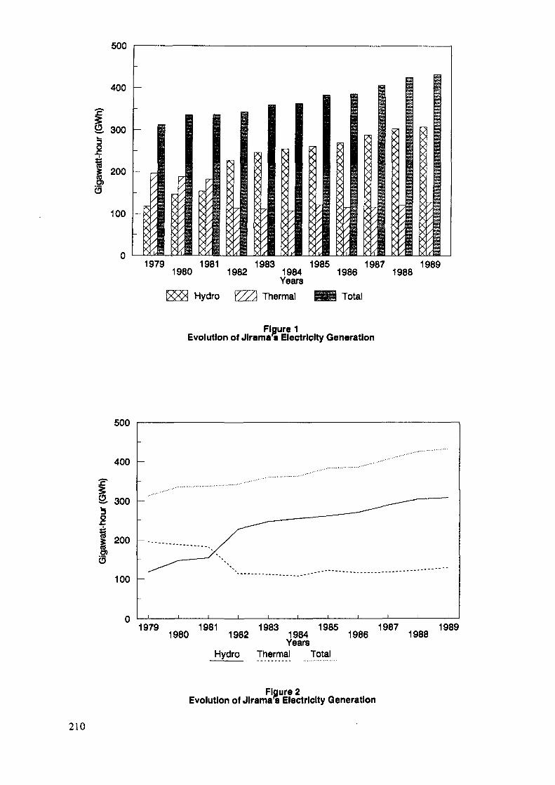
500
1979 1981 1983 1985 1987 19891980 1982 1984 1986 1988YearsHydro Y//\ Thermal Total
Figure 1Evolution of Jlrama's Electricity Generation
500
400
300
200
100
I________l
1979 1981 1983 1985 1987 19891980 1982 1984 1986 1988YearsHydro Thermal Total
Figure 2Evolution of Jlrama^ Electricity Generation
210
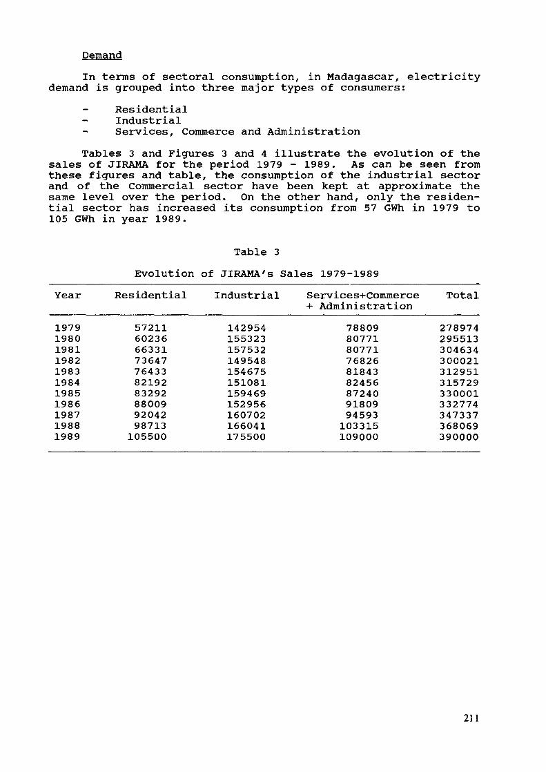
DemandIn terms of sectoral consumption, in Madagascar, electricity
demand is grouped into three major types of consumers:- Residential
Industrial- Services, Commerce and AdministrationTables 3 and Figures 3 and 4 illustrate the evolution of the
sales of JIRAMA for the period 1979 - 1989. As can be seen fromthese figures and table, the consumption of the industrial sectorand of the Commercial sector have been kept at approximate thesame level over the period. On the other hand, only the residen-tial sector has increased its consumption from 57 GWh in 1979 to105 GWh in year 1989.
Table 3Evolution of JIRAMA's Sales 1979-1989
Year Residential Industrial Services+Commerce Total+ Administration
19791980198119821983198419851986198719881989
57211602366633173647764338219283292880099204298713105500
142954155323157532149548154675151081159469152956160702166041175500
788098077180771768268184382456872409180994593103315109000
278974295513304634300021312951315729330001332774347337368069390000
211
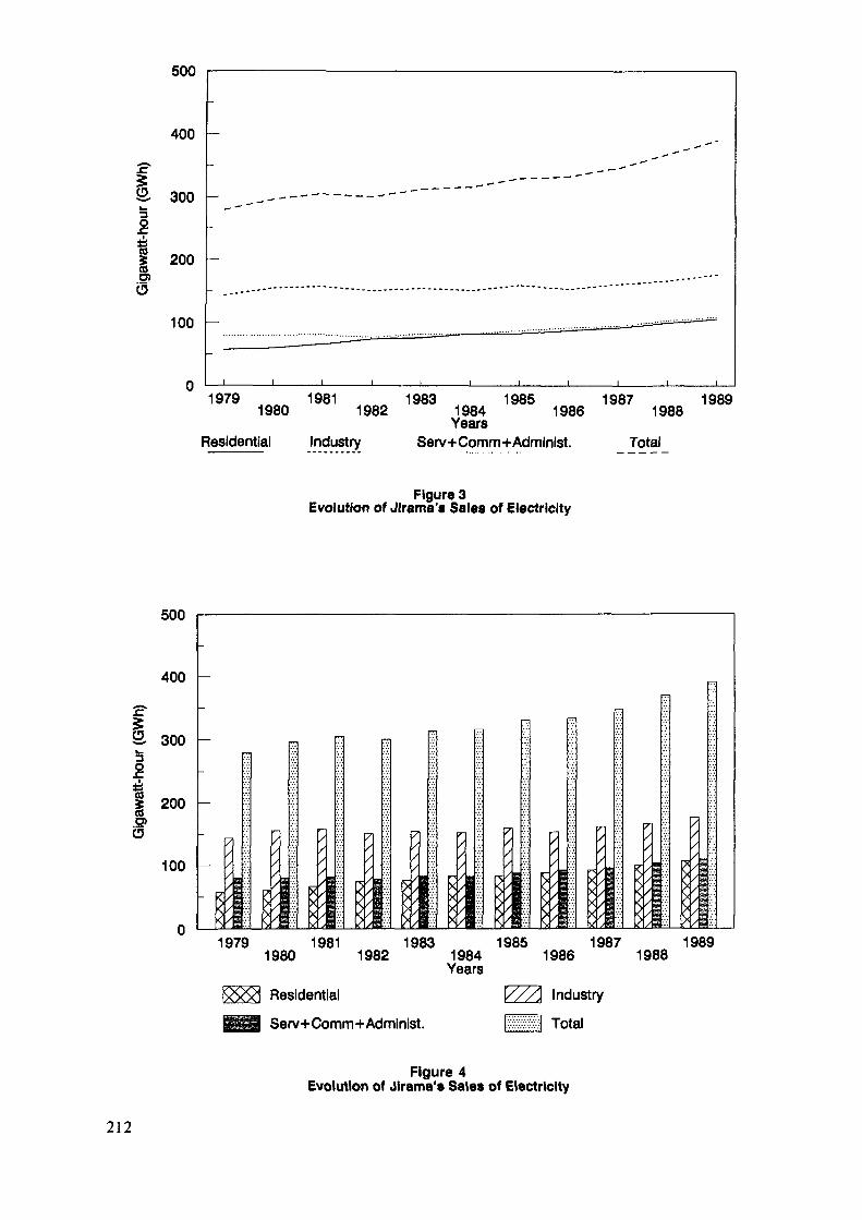
500
400
S 300k-
I
&b200
100
1979 1981 1983 1985 1987 19891980 1982 1984 1986 1988YearsResidential Industry Serv+Comm+Administ. Total
Figure 3Evolution of Jlrama's Sales of Electricity
500
400
ö. 300k_
l£
O)Ö
200
100*•/><xxx
19791980
19811982
19831984Years
19851986
19871988
1989
Residential
Serv+Comm+Administ.
V/A Industry
ilH Total
Figure 4Evolution of Jirama's Sales of Electricity
212
Real problems for planning the electricity sector stem fromthis fact, as electricity is only used in urban centers and thisin a country where rural population represents 80% of the total.
The energy policy of the country is to give priority toelectrical energy in the total consumption. However, ruralpopulation is constituted by small villages which, in general,are situated far from the existing electrical network or the ex-isting power plants.
Concerning the 54 JIRAMA existing exploitations, there aremany factors which also cause some problems:
clients,the electricity utility (JIRAMA) itself,institutional.
Clients: 1) Quality of supply:Continuity of supply is the greatproblem, particularly for thermal powerplants exploitation (lack of spareparts, inadequate maintenance, etc.)
2) Electrification and extensions of thenetwork:This would increase the costs and wouldcause problems due to lack of sufficientequipment and materials.
3) Electricity price:price rising during the last threeyearselectricity tariff includes fourtaxes and value added tax, repre-senting 7-20% of the amount paid bythe consumers.
JIRAMA: 1) Production and Transport:inadequate utilisation of existingequipment (under-utilization ofcertain thermal power plants)No spare parts, lack of funds
2) Projects:New projects to further reduce thethermal power plant utilisation andincrease that of hydroelectricplants (waiting for funds)
213

3) Interconnection:Interconnection of many power sta-tions (cost of equipment and trans-mission lines is relatively toohigh)
INSTITUTIONAL: 1) Demand planning:Because of the absence of previous in-dustries, generation equipment exploita-tion impose economical, financial andtechnical problems.The installation of a big consumer in-dustry always involves an important in-crease of installed capacity.
2) Water utilisation planning:Many institutions use water (energy, ir-rigation, drinking water, etc.) and theutilisation of water must be the objectof a concertation between the differentagencies concerned in order to avoid toinvest vainly.
At the end, I would like to state that our country does nothave any experience with either MAED or WASP and we want to knowif the Agency would agree to help us resolve the problems statedabove.
We would like to have access to both, the MAED and WASPmodels in order to try to resolve ourselves our problems in caseof need.
214
LONG TERM OPTIMAL PLANNING OF LOCAL/REGIONALENERGY SYSTEMS IN NORWAY
B. GRINDEN, N. FEILBERGNorwegian Electric Power Research Institute (EFI),Trondheim, Norway
Abstract
The Norwegian Electric Power Research Institute (EFI)has used WASP-III since 1987. Owing to problems inmodeling the Norwegian energy system, WASP is not incommon use in Norway. The main modeling problems arehydro power simulation, imports and exports of energy,occasional energy and energy conservation. In Norway,WASP-III is mainly used as an instrument in the processof building our own system expansion package called"IMESS". This model is used for long-term energy demandforecasting, long-term production and expansion planning- including the hydro power and its stochastic behaviourand finally the economic and financial consequences forthe utility company. The salient characteristics of theIMESS model are described in this paper. Problems con-cerning the use of WASP for power systems such as theNorway's one are also discussed.
1. EXPERIENCE IN USING WASP-III IN NORWAY1.1 GENERAL
In the summer 1986, EFI made a request to IAEA for theWASP-III program through the Ministry of Foreign Affairs. Theprogram was received on a magnetic tape in a complete form, withoperating system calls and source codes (FORTRAN-77) for the to-tal system. Some corrections had to be made in the source codesas described in the newsletters.
As the system was to be run on a NORD-570 computer, theFORTRAN version had to be adjusted. This adjustments mainly con-cerned the use of peripheral files - and the lengths of computerwords, which were different from the IBM computer in use by theIAEA. This work took some time, but after three months a runningversion was available.
The case study provided as a test sample "CASE-39" wasthoroughly studied, and correct results were obtained in areasonably computer time.
1.2 USE OF WASP-III IN NORWAY
A WASP study for the Norwegian power system based onhydropower data from the Norwegian Power Pool, was carried outmodeling the power system of 1985. The study contained no expan-sion planning, but consisted in a run of the LOADS Y and FIXSYSmodules.
215
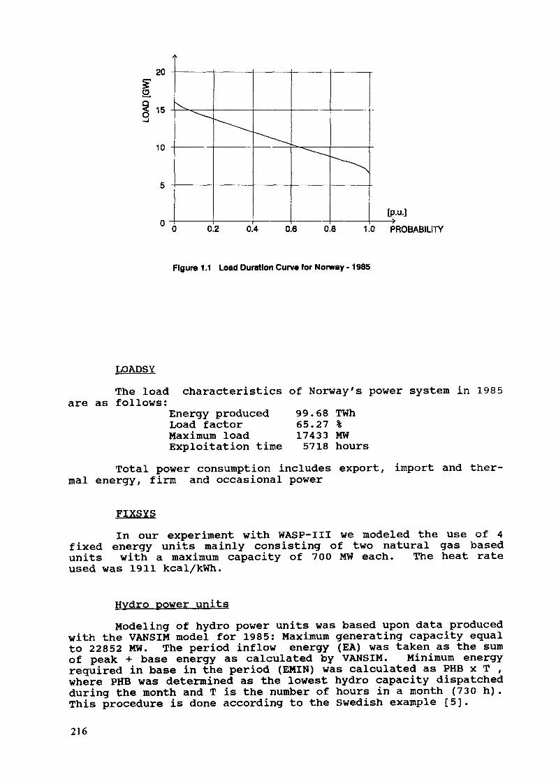
20
15
10
0 0.2 0.4 0.6 0.8 1.0 PROBABILITY
Figure 1.1 Load Duration Curv« for Norway -1985
LOADSYThe load
are as follows:characteristics of Norway's power system in 1985
Energy producedLoad factorMaximum loadExploitation time
99.68 TWh65.27 %17433 MW5718 hours
Total power consumption includes export, import and ther-mal energy, firm and occasional power
FIXSYSIn our experiment with WASP-III we modeled the use of 4
fixed energy units mainly consisting of two natural gas basedunits with a maximum capacity of 700 MW each. The heat rateused was 1911 kcal/kWh.
Hydro power unitsModeling of hydro power units was based upon data produced
with the VANSIM model for 1985: Maximum generating capacity equalto 22852 MW. The period inflow energy (EA) was taken as the sumof peak + base energy as calculated by VANSIM. Minimum energyrequired in base in the period (EMIN) was calculated as PHB x T ,where PHB was determined as the lowest hydro capacity dispatchedduring the month and T is the number of hours in a month (730 h).This procedure is done according to the Swedish example [5].
216

1.3 PROBLEMS IN USING WASP-111 IN NORWAY
WASP-III has a widespread use all over the world, and canbe used without any serious problems in countries that have smallamount of occasional (surplus) power, and negligible exchange ofelectricity with neighboring countries. In Norway there willarise some problems if WASP-III were to be used for expansionplanning. In this chapter these problems are discussed.
1.3.1 Hydro power simulationIn Norway more than 99% of the electricity is produced
with hydro power. The total electricity production in 1987 was104 TWh, out of which only 0.53 TWh was from thermal powerplants. Firm power consumption was 89.6 TWh, occasional powerwas 4.1 TWh. As one can understand it is of vital importance thatthe hydro power is correctly simulated in order to compute thecost of power production.
The large extent of firm power and the variable water in-flow through the year and from one year to another, makes itnecessary to have large reservoirs to be able to store some ofthe water for long periods, up to more than two years.
In 1986, the IAEA started working on a concept where"VALORAGUA" - a Hydro power simulation program - were to be usedtogether with WASP in order to handle the hydro power more satis-factory. We have not yet received this new version in Norway, andwe have not been able to test this in practice.
1.3.2 Import - Export of energy between neighbouring countriesIn 1987 Norway exported 3.3 TWh to, and imported 2.9 TWh
from neighbouring countries. In 1988 the export was 7.4 TWh andthe import 1.7 TWh. These two examples clearly show the impor-tance of handling export/import correctly, in order to simulatethe Norwegian power system.
The import energy could be handled as an energy producingunit, competing in price with other units. The power should besplit into base or peak, depending on the sort of contract to beused for each portion of the energy import. A problem that willarise in simulation of this type of energy is that the "pseudogenerating unit" used to represent the energy import, will dependon the time of year. Each month of the year the import has agiven maximum effect, and a given price. One needs to describeenergy import units that can only be used one month of the year,and this is not possible in WASP-III.
Exports can be considered as a portion of energy that canbe sold when the marginal generation cost of electricity is lowerin Norway than in for example Sweden. This amount of energyshould then be added on top of the load duration curve for Norwayas shown in Figure 1.2. This mechanism is not available in thepresent version of WASP.
217
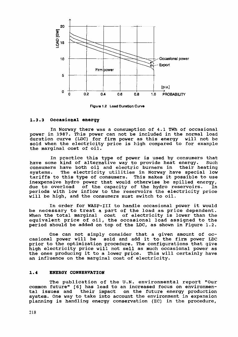
20
Il"
10
Firm power
- Occasional powerExport
0.2 0.4 0.6 0.8 1.0 PROBABILITY
Figure 1.2 Load Duration Curve
1.3.3 Occasional energyIn Norway there was a consumption of 4.1 TWh of occasional
power in 1987. This power can not be included in the normal loadduration curve (LDC) for firm power as this energy will not besold when the electricity price is high compared to for examplethe marginal cost of oil.
In practice this type of power is used by consumers thathave some kind of alternative way to provide heat energy. Suchconsumers have both oil and electric burners in their heatingsystems. The electricity utilities in Norway have special lowtariffs to this type of consumers. This makes it possible to useinexpensive hydro power that would otherwise be spilled energy,due to overload of the capacity of the hydro reservoirs. Inperiods with low inflow to the reservoirs the electricity pricewill be high, and the consumers must switch to oil.
In order for WASP-III to handle occasional power it wouldbe necessary to treat a part of the load as price dependent.When the total marginal cost of electricity is lower than theequivalent price of oil, the occasional load assigned to theperiod should be added on top of the LDC, as shown in Figure 1.2.
One can not simply consider that a given amount of oc-casional power will be sold and add it to the firm power LDCprior to the optimization procedure. The configurations that givehigh electricity price will not sell as much occasional power asthe ones producing it to a lower price. This will certainly havean influence on the marginal cost of electricity.
1.4 ENERGY CONSERVATION
The publication of the U.N. environmental report "Ourcommon future" [6] has lead to an increased focus on environmen-tal issues and their impact on the future energy productionsystem. One way to take into account the environment in expansionplanning is handling energy conservation (EC) in the procedure,218
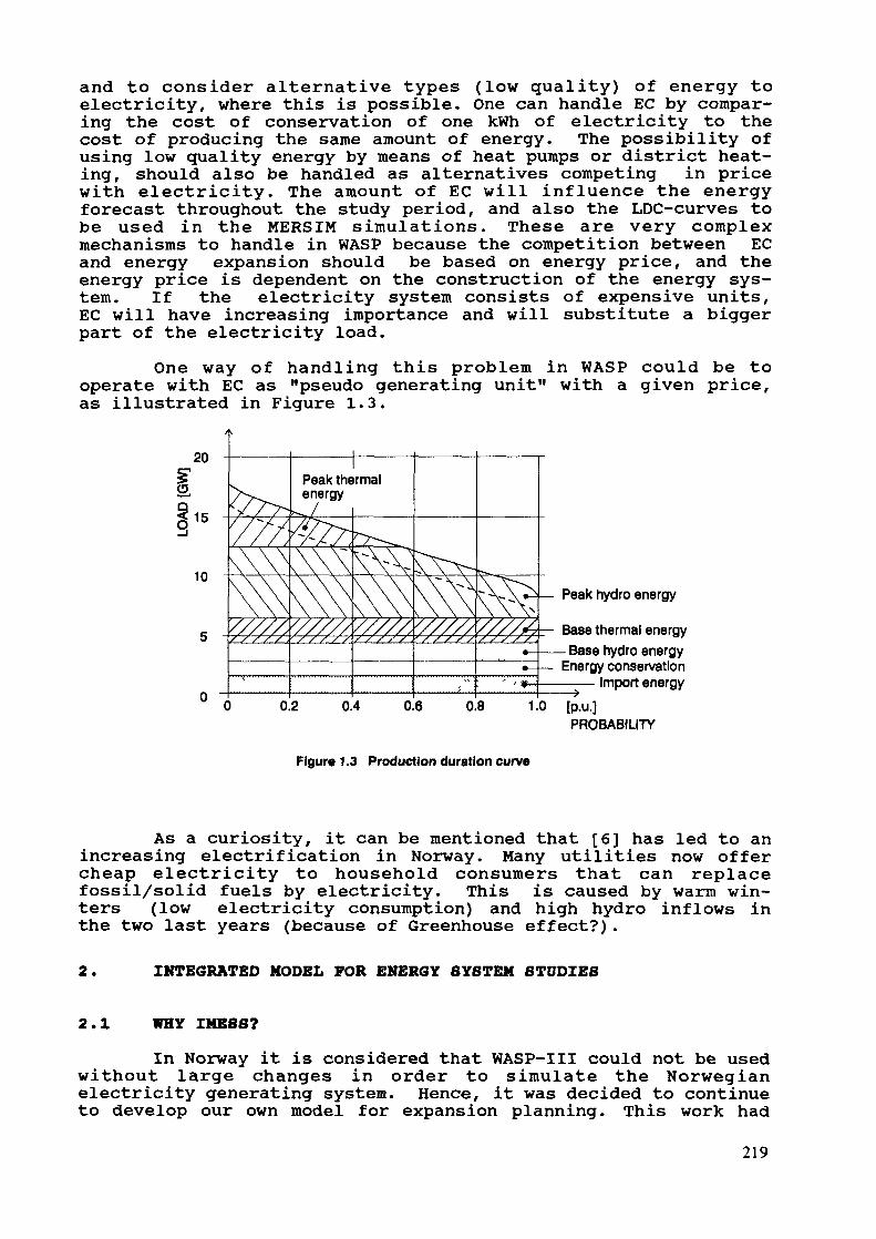
and to consider alternative types (low quality) of energy toelectricity, where this is possible. One can handle EC by compar-ing the cost of conservation of one kWh of electricity to thecost of producing the same amount of energy. The possibility ofusing low quality energy by means of heat pumps or district heat-ing, should also be handled as alternatives competing in pricewith electricity. The amount of EC will influence the energyforecast throughout the study period, and also the LDC-curves tobe used in the MERSIM simulations. These are very complexmechanisms to handle in WASP because the competition between ECand energy expansion should be based on energy price, and theenergy price is dependent on the construction of the energy sys-tem. If the electricity system consists of expensive units,EC will have increasing importance and will substitute a biggerpart of the electricity load.
One way of handling this problem in WASP could be tooperate with EC as "pseudo generating unit" with a given price,as illustrated in Figure 1.3.
20
15
10Peak hydro energy
Base thermal energyBase hydro energy
Energy conservation- Import energy
0.2 0.4 0.6 0.8 1.0PROBABILITY
Figur« 1.3 Production duration curve
As a curiosity, it can be mentioned that [6] has led to anincreasing electrification in Norway. Many utilities now offercheap electricity to household consumers that can replacefossil/solid fuels by electricity. This is caused by warm win-ters (low electricity consumption) and high hydro inflows inthe two last years (because of Greenhouse effect?).
2. INTEGRATED MODEL FOR ENERGY SYSTEM STUDIES
2.1 WHY IMESS?
In Norway it is considered that WASP-III could not be usedwithout large changes in order to simulate the Norwegianelectricity generating system. Hence, it was decided to continueto develop our own model for expansion planning. This work had
219
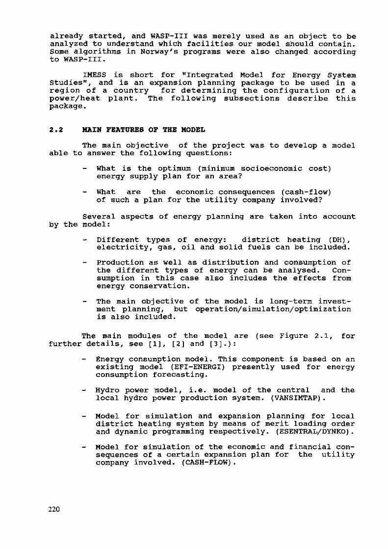
already started, and WASP-III was merely used as an object to beanalyzed to understand which facilities our model should contain.Some algorithms in Norway's programs were also changed accordingto WASP-III.
IMESS is short for "Integrated Model for Energy SystemStudies", and is an expansion planning package to be used in aregion of a country for determining the configuration of apower/heat plant. The following subsections describe thispackage.
2.2 MAIM FEATURES OF THE MODEL
The main objective of the project was to develop a modelable to answer the following questions:
What is the optimum (minimum socioeconomic cost)energy supply plan for an area?What are the economic consequences (cash-flow)of such a plan for the utility company involved?
Several aspects of energy planning are taken into accountby the model:
Different types of energy: district heating (DH) ,electricity, gas, oil and solid fuels can be included.
- Production as well as distribution and consumption ofthe different types of energy can be analysed. Con-sumption in this case also includes the effects fromenergy conservation.The main objective of the model is long-term invest-ment planning, but operation/simulation/optimizationis also included.
The main modules of the model are (see Figure 2.1, forfurther details, see [1], [2] and [3]-):
Energy consumption model. This component is based on anexisting model (EFI-ENERGI) presently used for energyconsumption forecasting.Hydro power model, i.e. model of the central and thelocal hydro power production system. (VANSIMTAP).
- Model for simulation and expansion planning for localdistrict heating system by means of merit loading orderand dynamic programming respectively. (ESENTRAL/DYNKO).
- Model for simulation of the economic and financial con-sequences of a certain expansion plan for the utilitycompany involved. (CASH-FLOW).
220
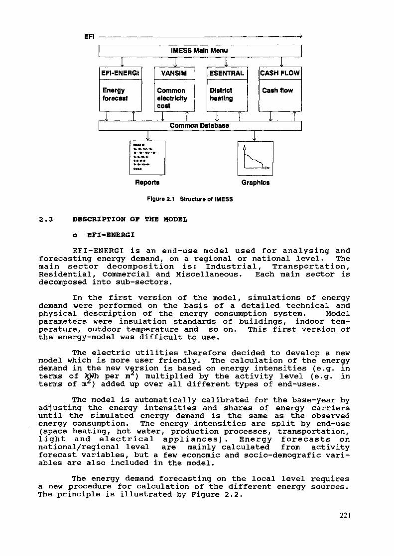
EPI
Reports Graphics
Figure 2.1 Structure of IMESS
2.3 DESCRIPTION OF THE MODELO EFI-ENERGIEFI-ENERGI is an end-use model used for analysing and
forecasting energy demand, on a regional or national level. Themain sector decomposition is: Industrial, Transportation,Residential, Commercial and Miscellaneous. Each main sector isdecomposed into sub-sectors.
In the first version of the model, simulations of energydemand were performed on the basis of a detailed technical andphysical description of the energy consumption system. Modelparameters were insulation standards of buildings, indoor tem-perature, outdoor temperature and so on. This first version ofthe energy-model was difficult to use.
The electric utilities therefore decided to develop a newmodel which is more user friendly. The calculation of the energydemand in the new version is based on energy intensities (e.g. interms of kWh per m2) multiplied by the activity level (e.g. interms of m2) added up over all different types of end-uses.
The model is automatically calibrated for the base-year byadjusting the energy intensities and shares of energy carriersuntil the simulated energy demand is the same as the observedenergy consumption. The energy intensities are split by end-use(space heating, hot water, production processes, transportation,light and electrical appliances). Energy forecasts onnational/regional level are mainly calculated from activityforecast variables, but a few economic and socio-demografic vari-ables are also included in the model.
The energy demand forecasting on the local level requiresa new procedure for calculation of the different energy sources.The principle is illustrated by Figure 2.2.
221
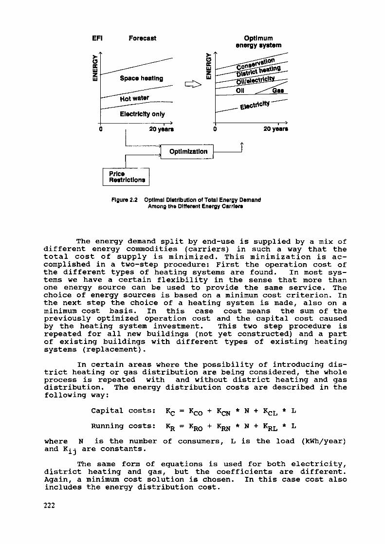
EFI
SocLU
Forecast
Space heating
^-—^Hot water
Electricity only
20 year«
SocLU
Optimization
Price ~~|Restrictions
Optimumenergy system
Gas
20 years
Figure 2.2 Optimal Distribution of Total Energy DemandAmong the Different Energy Carriers
The energy demand split by end-use is supplied by a mix ofdifferent energy commodities (carriers) in such a way that thetotal cost of supply is minimized. This minimization is ac-complished in a two-step procedure: First the operation cost ofthe different types of heating systems are found. In most sys-tems we have a certain flexibility in the sense that more thanone energy source can be used to provide the same service. Thechoice of energy sources is based on a minimum cost criterion. Inthe next step the choice of a heating system is made, also on aminimum cost basis. In this case cost means the sum of thepreviously optimized operation cost and the capital cost causedby the heating system investment. This two step procedure isrepeated for all new buildings (not yet constructed) and a partof existing buildings with different types of existing heatingsystems (replacement).
In certain areas where the possibility of introducing dis-trict heating or gas distribution are being considered/ the wholeprocess is repeated with and without district heating and gasdistribution. The energy distribution costs are described in thefollowing way:
Capital costs: KC = Kco + KCN * N + KCL * LRunning costs: KR KRO KRN * N KRL * L
whereand
N is the number of consumers, L is the load (kWh/year)are constants.The same form of equations is used for both electricity,
district heating and gas, but the coefficients are different.Again, a minimum cost solution is chosen. In this case cost alsoincludes the energy distribution cost.
222
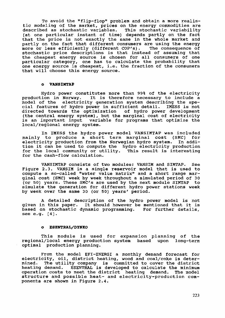
To avoid the "flip-flop" problem and obtain a more realis-tic modeling of the market, prices on the energy commodities aredescribed as stochastic variables. This stochastic variability(at one particular instant of time) depends partly on the factthat the price is not exactly the same in the whole market andpartly on the fact that different consumers are using the energymore or less efficiently (different OOP's). The consequence ofstochastic price descriptions is that instead of assuming thatthe cheapest energy source is chosen for all consumers of oneparticular category, one has to calculate the probability thatone energy source is cheapest, i.e. the fraction of the consumersthat will choose this energy source.
O VANSIMTAP
Hydro power constitutes more than 99% of the electricityproduction in Norway. It is therefore necessary to include amodel of the electricity generation system describing the spe-cial features of hydro power in sufficient detail. IMESS is notdirected towards the optimization of hydro power development(the central energy system), but the marginal cost of electricityis an important input variable for programs that optimize thelocal/regional energy system.
In IMESS the hydro power model VANSIMTAP was includedmainly to produce a short term marginal cost (SMC) forelectricity production from the Norwegian hydro system. In addi-tion it can be used to compute the hydro electricity productionfor the local community or utility. This result is interestingfor the cash-flow calculation.
VANSIMTAP consists of two modules: VANSIM and SIMTAP. SeeFigure 2.3. VANSIM is a single reservoir model that is used tocompute a so-called "water value matrix" and a short range mar-ginal cost (SMC) week by week throughout a simulated period of 30(or 50) years. These SMC's are used by the next module SIMTAP tosimulate the generation for different hydro power stations weekby week over the same 30 (or 50) years' period.
A detailed description of the hydro power model is notgiven in this paper. It should however be mentioned that it isbased on stochastic dynamic programming. For further details,see e.g. [4].
O ESENTRAL/DYNKO
This module is used for expansion planning of theregional/local energy production system based upon long-termoptimal production planning.
From the model EFI-ENERGI a monthly demand forecast forelectricity, oil, district heating, wood and coal/coke is deter-mined. The utility company is committed to cover the districtheating demand. ESENTRAL is developed to calculate the minimumoperation costs to meet the district heating demand. The modelstructure and possible heat- and electricity-production com-ponents are shown in Figure 2.4.
223
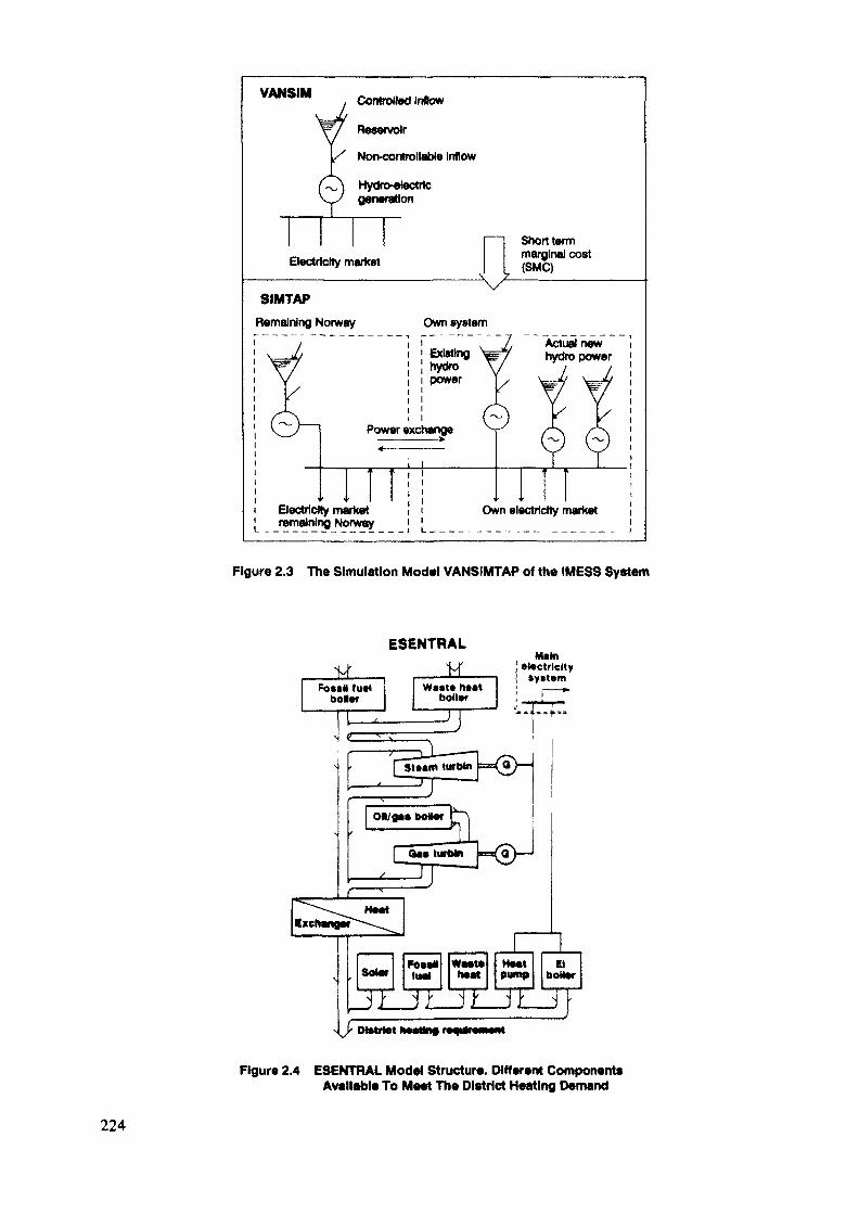
VANSIM
N
(
Electn
, Controlled Inflow=Y^y Reservoir
y Non-controllable Inflow
O Hydroelectric~^y generation
Short term„. . marginal costcity market ^ ^ (SM«j
VSIMTAP
Remaining Norway Own system
1Electric!remalnlr
i _ _ v _ Z Act"»! n**Existing W^ hydro powerhydro \/ / /power Y/ \—Jj \—ù
Power exchange V^ /-K /A.
* T TI I I I 111
ty market i i Own electricity market•g Norway ] '
Figure 2.3 The Simulation Modal VANSIMTAP of the (MESS System
ESENTRALMam
! *l*ctrlcltyt »ytUrn
Figure 2.4 ESENTRAL Model Structure. Different ComponentsAvailable To Meet The District Heating Demand
224

The user may specify possible components, for example fos-sil fuel, available waste heat, heat pumps and electricityboilers, gas turbines. Each of these components is described by:
- Maximum output [MW]Efficiency (the ratio energy output/energy input)Running cost (except fuel costs) [NOK/kWh]Fuel type
- Planned stops for maintenanceIt is also possible to simulate production of electricity
from steam and gas turbines for combined heat and power systems(both electricity and heat are produced). Electricity is onlyproduced if it can reduce (decrease) the running costs. Theshort term marginal cost (SMC), which is an output from thesingle reservoir model VANSIM, makes it possible to run our com-bined heat and power plant in an optimal interplay with thehydropower system.
To optimize the operation of the system (minimum cost) aLP (linear programming) routine was originally used. However, theuse of LP made the system very CPU demanding. (Optimizing 30years with time deviation week gave 1560 periods to optimize.)
Consequently an alternative optimizing method was tried:Merit order loading with some adaptations. The simulation time(CPU-time) was then reduced from 3-4 minutes to one second. Thismade it possible to use the system (ESENTRAL) together with a DP(dynamic programming) model, DYNKO. Now it was possible tospecify a lot of configurations of the combined heat and powersystem and to calculate the operation costs at different stages,without too long simulation time.
The operation costs together with the investment costs areused by DYNKO to produce an optimum plan for meeting the forecastfor district heating demand.
O CASH-FLOW
According to the objective of the project the economicconsequences (cash-flow) for the utility are to be calculatedafter the socioeconomic optimal supply plan is found. To be ableto do this, a new economic model called "CASH-FLOW" has beendeveloped.
This model can be used to calculate the economic con-sequences for a set of good socioeconomic solutions from the DP-model, not only the optimum solution. This can be very usefulif the socioeconomic differences among e.g. the ten best solu-tions are very small.
The results from the economic calculations can bepresented as shown in Figure 2.5. Here we have operating costsand capital development as a function of time for differentenergy supply alternatives.
225
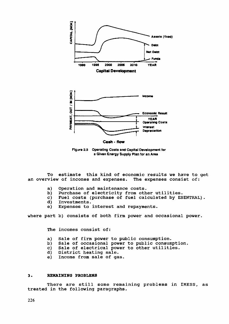
1990 199S 2000 2005 2010Capital Development
Income
Economic Result
YEAROperating Coat«InterestDepreciation
Cash- flowFigure 2.5 Operating Costs and Capital Development for
a Given Energy Supply Plan for an Area
To estimate this kind of economic results we have to getan overview of incomes and expenses. The expenses consist of:
a) Operation and maintenance costs.b) Purchase of electricity from other utilities.c) Fuel costs (purchase of fuel calculated by ESENTRAL).d) Investments.e) Expenses to interest and repayments.
where part b) consists of both firm power and occasional power.
The incomes consist of:a) Sale of firm power to public consumption.b) Sale of occasional power to public consumption.c) Sale of electrical power to other utilities.d) District heating sale.e) Income from sale of gas.
3. REMAINING PROBLEMS
There are still some remaining problems in IMESS, astreated in the following paragraphs.
226
3.1 Size of the local systemThe amount of electricity produced by the local system
must not be a major part of the country's electricity production,as it will then have an influence on the marginal cost of theelectric system. VANSIMTAP calculates the marginal cost ofelectricity. In VANSIMTAP we are only able to describe the localsystem very roughly. If the size of the local system is less thanabout 100 MW electricity, this will not be any problem.
3.2 Stochastic production costingIn WASP-III, probabilistic production costing (PPC) is
used to compute Loss of load probability (LOLP) and Energy notserved (ENS), and also to compute the side effect of forcedoutages. Forced outages will increase the system operating costsince more expensive units have to be used instead of inexpensiveunits that are not available because of forced outage.
In the IMESS model, PPC is not used; instead a Monte Carlo(MC) simulation technique is used to take care of forced outages.In IMESS the simulation is carried out on a weekly basis, insteadof a monthly basis, and also using 30 to 50 hydro conditionsinstead of only up to 5 as in WASP-III. This gives a largeenough stochastic room for using MC technique. This techniquealso should make it possible to compute ENS and LOLP.
3.3 Constant loadThe simulation time steps in IMESS consist of weeks
divided into four parts. The load (heat and electricity) is con-sidered to be constant over the simulation steps. This meansthat Load Duration Curves are not used for the calculation ofproduction cost.
3.4 Minimum output from the energy unitsIMESS does not have mechanisms to handle minimal output
from the energy units. This means that IMESS consider the energyunits to have the same variable cost from zero output up tomaximal output, and this is far from reality. This is consideredto be a serious problem of the IMESS model and work on improve-ments is underway.
4. CONCLUSION
The study of WASP has indirectly been very useful, as ithas given us ideas on improvements in our IMESS package. Wehope that our experience in the IMESS project can be useful in afurther development of the WASP/MAED systems, and that we can ex-change informations in the future.
227
REFERENCES
[1] N. Feilberg, B. Grinden, S. Johansen, O. Rismark, I.Wangensteen "Grovspesifikasjon for IMESS", EFI,Teknisk rapport nr. 3497, 1988. (In Norwegian).
[2] N. Feilberg, O. Rismark, I. Wangensteen: "Simulationand planning of district heating by means of an in-tegrated energy model". International symposium ondistrict heating Reykjavik, 13-16 April 1989.
[3] S. Johansen and I. Wangensteen: "Optimal planning andsimulation of a load/regional system by means of anintegrated energy model". The Tenth European con-ference on operational research, Beograd, 27-30 June1989.
[4] O. Egeland, J. Hegge, E. Kylling: "CIGRE Report32.14". Session 1982.
[5] P. Nordlund, S.O. Larsson, A. Bubenko, B. Jansson:"APPLICATION OF WASP TO THE SWEDISH POWER SYSTEM"Proceedings of the Ninth Power Systems ComputationConference, Cascais 1987, pp. 953-960.
[6] World Commission on environment and development. "Ourcommon future". ISBN 82-10-03078-7. Oxford UniversityPress, 1987.
228
POLISH EXPERIENCE IN THE USE OF MAED
J. DUDZIKPower and Lignite Board,Pruszkow, Poland
Abstract
This paper deals with the experience in the use of theMAED model for electricity demand forecasting in Poland.It includes the results of a study carried out by meansof MAED and a discussion on the case study experience.The usefulness of the model to the planner in Poland isalso mentioned.
l. introductionLong term demographic, economic and energy situation of the
country has a big impact on choosing the optimal method forelectricity demand forecasting. Stable rate of GDP growth andslow changes in its structure favours methods based on historicaltrends. On the other hand, rapid changes in the economy imposethe need for methods based preferably on the scenario approach.Since the usefulness of different methods depends on the actualand anticipated changes in demographic, economic and energychanges, it is necessary to present some basic information inthese areas for Poland.
Demographic situationToday Poland's population is about 37.2 million. The age
structure of Poland's population shows that children, up to 14years of age, account for 24 per cent; nearly half the populationis under 25 years of age. The demographic situation in Poland isrelatively stable and we do not expect any major changes in thenear future. Particularly the age structure will not changesignificantly and the ratio of urban to rural population willonly slightly increase.
Economic situationSince the World War II the economic development in Poland
has been implemented through a series of five-year medium-termplans. These plans are regarded as an indicative framework intowhich individual one-year plans are placed.
During the last three decades, in particular during theyears 1970 to 1978, the Polish economy went through a period ofdynamic development. In this period fast development, especiallyin mining industry, steel industry and machinery construction wasachieved. The rate of GDP growth in the 1948-1980 period was
229

about 7 per cent per year, but the resulting structure of theeconomy was characterized with a high energy consumption (aboutthree times higher than in Western Europe - on per unit of GDP).
In the 70's, the high share of foreign credits played an im-portant role in the development of the Polish economy. At the endof the 70's, as a result of wrong economic policies of the pre-vious years, the Polish economy entered a deep recession.
After 1980 some attempts to reform the economy were under-taken. The main targets of reforms were:
- economy effectiveness improvement,- structural changes in the production sector
and modern industry branch promotion,- closer cooperation with highly industrialized
countries, and open economy.However, up to the year 1989 the effects of these attempts
were not satisfactory. This situation dramatically changed in1989. At the present time serious efforts to build a marketoriented economy are observed.
Energy situationHard coal is one of the most important national resources.
The hard coal output during the recent years was maintained atthe level of 190-192 million tons per year. Brown coal is thesecond primary energy carrier among domestic resources. The out-put of brown coal in 1985 reached 55 million tons. Unfortunately,crude oil and natural gas resources in Poland are very poor. Asa consequence of this, Poland is an important exporter of hardcoal and importer of hydrocarbons.
The installed capacity of the Polish power system reached31.3 GW in 1987 and electricity production in this year amountedto 145 TWh (3900 kWh per capita). About 65 per cent of theelectricity is produced by hard coal power stations and 32 percent by brown coal power stations.
In the future, up to year 2000, some essential changes inthe national primary energy balance are forecasted, namely:
the share of solid fuels in the total primary energysupply will fall from about 80 per cent in 1985 toabout 70 per cent in 2000,the share of hydrocarbon fuels will be maintainedat relatively low level, close to 20 per cent,the role of nuclear energy will grow, covering inyear 2000 about 6% of the total primary energy demandand about 20% of the total electricity production.
230

The information presented above related to the present andfuture situation of the Polish economy indicates that a new ap-proach to the problem of energy demand forecasting is necessary.The main arguments are:
- dramatic changes expected in the economy (fromcentrally planned to market oriented) practicallyexclude possibilities of using historical trends,
- the future structure of production and consumptionis unknown,the role of new technologies is difficult to evaluate.
In this situation the scenario approach for energy andelectricity demand forecasting may be very useful.
2. Application of the MAED modelThe first application of the MAED model to the electricity
demand forecast for Poland took place at the Argonne NationalLaboratory during the IAEA training course on Electricity DemandForecasting for Nuclear Power Planning, end 1988. The resultsobtained were confirmed in Poland and updated.
MethodologyThe MAED model is a simulation model designed for evaluation
of the energy demand in the medium and long term. MAED belongsto the family of MEDEE models which are based on the scenario ap-proach. In this approach a scenario is a consistent descriptionof a possible long-term development pattern of a country. Follow-ing this approach, the planner can make assumptions about thepossible evolution of the social, economic and technologicaldevelopment pattern of a country and use the model to evaluatethe resulting energy requirements.
The energy demand from final consumers is, as far as pos-sible, always evaluated in terms of useful energy. This differen-tiation between energy expressed in useful terms and in finalterms makes it easier to study the interchangeability of variousenergy forms.
The main features of the MAED model could be summarized asfollows:
it is designed to evaluate medium and long term energydemand broken down by sectors and energy forms,
- it is driven by the scenario which is defined bycertain economic, social and technical factors,it is oriented towards developing countries,
- it allows to analyse the substitution of energy forms,it pays special attention to the evaluation ofthe electricity demand,it permits the final results of the calculationsto be presented in different units,
231
- it produces an output file which could be useddirectly for the electricity supply model (WASP).
Scenario specificationThe future economic system is the main uncertainty that
determines the development of the Polish economy. There are twopossible options:
1) the economic system does not change - centralizedplanning persists,
2) the economic system changes towards market economy.In the first case we can expect:
- very low economic growth,- very low price elasticity of energy consumption,- small changes in energy consumption pattern,- small structural changes in the economy,- limited role of new technologies.
In the second case we can expect that the changes in theeconomic system will liberate existing reserves, and:
- encourage foreign capital to invest in Poland,- increase the economic growth rate,- rise the price elasticity of energy consumption,- increase the role of new technologies,- cause the extended structural shift in the economywhich yields substantial energy conservation effects.
There is a set of some basic social meeds which must be metat some minimum level, regardless whether the economic systemchanges or not, in order to avoid explosion of existing socialtensions. It consists of the following items: a) housingconstruction; b) medical service; and c) education system.
In conclusion, two scenarios were considered in the casestudy:
Scenario A: Economic system remains unchanged(centrally planned economy)
Scenario B: Economic system changes towards marketeconomy
Detailed data about both scenarios are not included in thispresentation.
Analysis of resultsComputation of the MAED Module 1 based on the assumptions
characterizing the two scenarios has been done for the period1985-2010. The results concerning total amount of final energydemand and electricity demand are shown in Figures 1, 2, 3, 4.
232
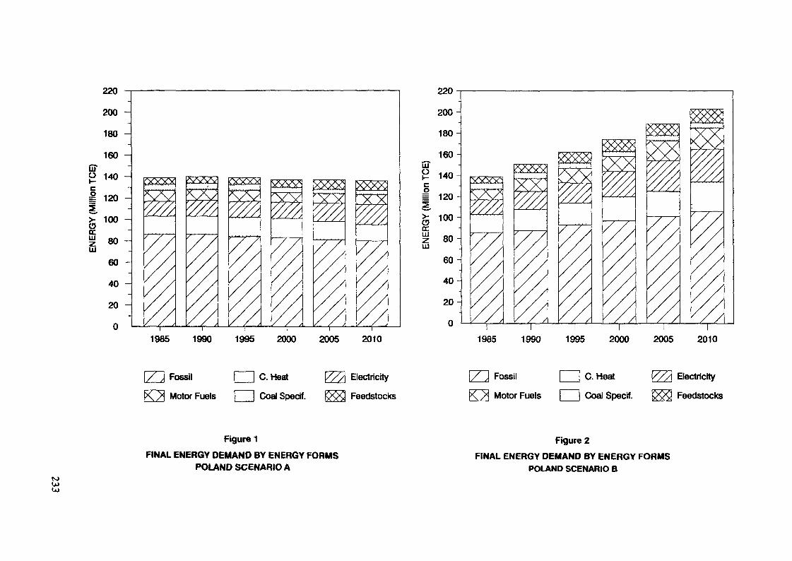
UT
220200 -180 -160 -140 -
l—
I 120 -
£ 1°° ~
| 80LU
60
40 -
20 -
0
w X X
220
200
180
_LU
o= 120
ceLU
LU
100-
80-
60
40
20
0
yyyy* XX
1985 1990 1995 2000 2005 2010l l 1 I
1985 1990 1995 2000 2005 2010
Fossil
Motor Fuels
C. Heat
Coal Specif.
Electricity
Feedstocks
Fossil | I C. Heat
Motor Fuels j I Coal Specif.
Electricity
Feedstocks
N»(JJCO
Figure 1FINAL ENERGY DEMAND BY ENERGY FORMS
POLAND SCENARIO A
Figure 2FINAL ENERGY DEMAND BY ENERGY FORMS
POLAND SCENARIO B
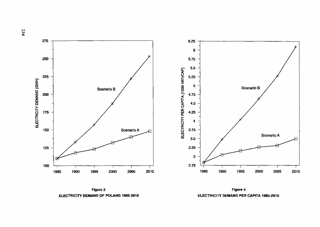
to
.
§
275
250 -
225 -
200 -LUQ
0 175cc§LU
150
125 -
100
Scenario B
6.25
6
5.75
E- 5.5
5.25 -
8o5 -
< 4.50
jjj 4.25
LULu
3.75 -
3.5 -
3.25 -
3 -
2.75
Scenario B
1985 1990 1995 2000 2005 2010 1985 1990 1995 2000 2005 2010
Figure 3ELECTRICITY DEMAND OF POLAND 1985-2010
Figure 4ELECTRICITY DEMAND PER CAPITA 1985-2010
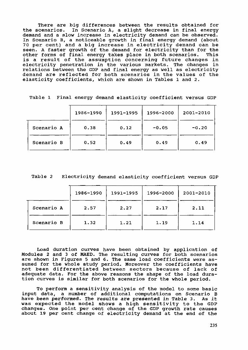
There are big differences between the results obtained forthe scenarios. In Scenario A, a slight decrease in final energydemand and a slow increase in electricity demand can be observed.In Scenario B, a noticeable growth in final energy demand (about70 per cent) and a big increase in electricity demand can beseen. A faster growth of the demand for electricity than for theother forms of final energy takes place in both scenarios. Thisis a result of the assumption concerning future changes inelectricity penetration in the various markets. The changes inrelations between the GDP and final energy as well as electricitydemand are reflected for both scenarios in the values of theelasticity coefficients, which are shown in Tables 1 and 2.
Table 1 Final energy demand elasticity coefficient versus GDP
Scenario A
Scenario B
1986-1990
0.38
0.52
1991-1995
0.12
0.49
1996-2000
-0.05
0.49
2001-2010
-0.20
0.49
Table 2 Electricity demand elasticity coefficient versus GDP
Scenario A
Scenario B
1986-1990
2.57
1.32
1991-1995
2.27
1.21
1996-2000
2.17
1.19
2001-2010
2.11
1.14
Load duration curves have been obtained by application ofModules 2 and 3 of MAED. The resulting curves for both scenariosare shown in Figures 5 and 6. The same load coefficients were as-sumed for the whole study period. Moreover the coefficients havenot been differentiated between sectors because of lack ofadequate data. For the above reasons the shape of the load dura-tion curves is similar for both scenarios for the whole period.
To perform a sensitivity analysis of the model to some basicinput data, a number of additional computations on Scenario Bhave been performed. The results are presented in Table 3. As itwas expected the model shows a high sensitivity to the GDPchanges. One point per cent change of the GDP growth rate causesabout 19 per cent change of electricity demand at the end of the
235
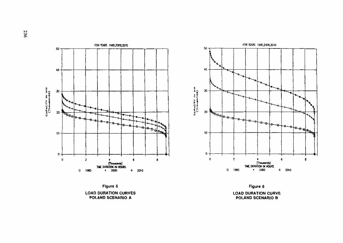
K)W
FOR YEARS t985.2000.2QtU FOR YEARS 1985,2000,2010
E~ 30
t!U 0
(~ 20
10
2 4 «(Dmaonds)
HIE DURATION IN HOURSQ 1965 * 2O» » 2010
EiU 0< £
2 4 6(Thousands)
HUE DURATION IN HOURSa 1985 <• 2000 0 2010
Figure 5LOAD DURATION CURVES
POLAND SCENARIO A
Figure 6
LOAD DURATION CURVEPOLAND SCENARIO B
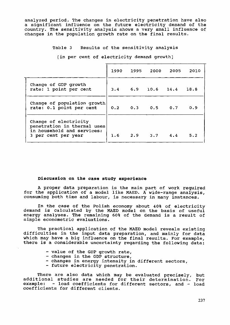
analyzed period. The changes in electricity penetration have alsoa significant influence on the future electricity demand of thecountry. The sensitivity analysis shows a very small influence ofchanges in the population growth rate on the final results.
Table 3 Results of the sensitivity analysis[in per cent of electricity demand growth]
Change of GDP growthrate: 1 point per cent
Change of population growthrate: 0.1 point per cent
Change of electricitypenetration in thermal usesin household and services:3 per cent per year
1990 1995 2000 2005 2010
3.4 6.9 10.6 14.4 18.8
0.2 0.3 0.5 0.7 0.9
1.6 2.9 3.7 4.4 5.2
Discussion on the case study experienceA proper data preparation is the main part of work required
for the application of a model like MAED. A wide-range analysis,consuming both time and labour, is necessary in many instances.
In the case of the Polish economy about 40% of electricitydemand is calculated by the MAED model on the basis of usefulenergy analyses. The remaining 60% of the demand is a result ofsimple econometric evaluations.
The practical application of the MAED model reveals existingdifficulties in the input data preparation, and mainly for datawhich may have a big influence on the final results. For example,there is a considerable uncertainty regarding the following data:
- value of the GDP growth rate,- changes in the GDP structure,- changes in energy intensity in different sectors,- future electricity penetration.
There are also data which may be evaluated precisely, butadditional studies are needed for their determination. Forexample: - load coefficients for different sectors, and - loadcoefficients for different clients.
237

3. Conclusions and recommendations* The MAED model is a useful tool for national organizations
dealing with electricity sector planning, especially incountries where the scenario approach is needed.
* The practical application of the MAED model needs wide andtime absorbing studies both within and outside theelectricity sector.
* To prepare coherent scenarios for a MAED study, a substan-tial difficulty consisting in the quantitative descriptionof the correlation between important input data has to besolved. For example, there is a problem in how to evaluatethe correlation between:- GDP growth rate and changes in the GDP structure,- GDP growth rate and specific energy intensity ofthe different economic sectors,
- GDP growth rate and energy consumption pattern ofthe residential sector.
* Some technical improvements in the model may be suggested:- to equip the model with procedures for graphicpresentation of the results,
- to improve the way of inputting the data to make itless time consuming.
238
GENERATING SYSTEM RELIABILITY AND MAINTENANCESCHEDULE MODEL (GARFUNQUEL)
S. MUNOZ, M. BREAUNESA,Madrid, Spain
Abstract
This report describes a model for computing generatingsystem reliability and selecting an optimum maintenanceprogram, which was developed in UNESA's PlanningDepartment. The model optimizes the distribution ofmaintenance tasks on the basis of two possible options:a) leveling out the annual loss of load probability(LOLP), and b) minimizing the annual LOLP. The inclu-sion of units having predetermined maintenance programsis possible, as is the potential for incompatibilitybetween units as regards maintenance. This model usesthe Baleriaux-Booth algorithm convolution method, in-corporating discrete, step-wise distribution functionsfor each of the 52 weeks. The results of the programare as follows: a) optimum maintenance program, b)weekly LOLP (52 values), c) monthly LOLP, d) annualLOLP, taking into consideration the constraints imposedby incompatibility between the different units. Themodel has been developed for iterative application inparallel with other models that meet electric loaddemand or energy requirements.
1. OBJECTIVESThis paper describes the characteristic of the GARFUNQUEL
model, developed by the UNESA Planning Department to schedulemaintenance and compute system reliability.
2. BACKGROUNDTo date two different types of methods have been used to
calculate generating system reliability: deterministic and prob-abilistic.
Among the different kinds of deterministic methods, probablythe most widely used in the Spanish electric system is the supplyindex for dry years which is similar to reserve margin butweighting capacity by its availability factor. This index offersthe advantage of being highly intuitive, but also has the follow-ing disadvantages:
1. Use of this index leads to situations in which thereliability provided, for example, by a 1,000 MW unithaving an availability factor of 80% is equal to thatprovided by two 500 MW units having the sameavailability.
239

2. The criterion limiting the minimum value of the supplyindex is usually established on the basis of ex-perience, and is difficult to extrapolate into the fu-ture since, as has been seen, it does not depend on thesize of the units in the system and, hence, one samevalue might reflect two different system reliabilitysituations, depending on the units mix.
As regards the probabilistic method used in Spain, specialattention may be given to the GARAN model. We will not attempt toprovide an exhaustive description of the model here; it sufficesto say that one of its outstanding features is that it uses theGalver algorithm, characterizing the capacity provided by each ofthe units to meet peak load.
Distribution of the maintenance schedule is performed deter-ministically, unless firm capacity is used instead of netcapacity. After the calculation of the maintenance schedule, theprogram determines the loss of load probability (LOLP).
This model was built at a time when simplifications of thiskind were necessary, as both the processing speed and memorycapacity of the computers then existing, significantly restrictedthe field of operation of models. The values were acceptablewhen the model was built although, subseguently, and given theincreases in thermal units, it began to show problems in conver-gence, and a tendency to distribute maintenance in such a waythat the maximum loss of load probability occurred during monthsof lower demand.
3. DESCRIPTION OF THE GARFUNQUEL MODEL3.1 Objectives to be covered by the Model
The model optimizes maintenance distribution on the basis oftwo possible options:
1. Leveling out the annual LOLP2. Minimizing the annual LOLPThe first of these options attempts to achieve LOLP values
for all weeks as similar as possible, while the second tends tominimize the annual LOLP. This second option can lead to situa-tions in which the LOLP might be minimum on an annual time scalebut may show very high values for certain specific weeks.
The inclusion of units having predetermined maintenanceprogrammes is possible, as is the potential for incompatibilitybetween units as regards maintenance.
The GARFUNQUEL model uses the Baleriaux-Booth algorithm con-volution method , incorporating discrete step-wise distribu-tion functions for each of the 52 weeks. For the benefit ofreaders not familiar with the Baleriaux-Booth algorithm and theconcepts of convolution and deconvolution, Appendix I gives avery brief description of these concepts, which are necessary tobe able to follow this report.
240

3.2 Characterization of generating stationsThe units to be considered are determined on the basis of
the following parameters:1. Name of the unit2. Type of fuel3. Gross capacity4. On-site consumption used for calculation of unit net
capacity5. Equivalent availability rate6. Number of weeks of maintenance7. Initial week of maintenance if unit maintenance tasks
have been pre-scheduled.8. Unit incompatibility index such that two units having
one same index may not undergo maintenance in the sameweek.
3 . 3 Model operational secfuenceAs can be appreciated in the flow diagram of the program
(see Figure 1), the operational sequence is as follows:1) Determination of joint probability of outage for all
units. This is performed in discrete steps using foreach unit a binary system, such that units may operateunder one of two possible status conditions, i.e.outage or full capacity.
2) For each of the 52 weeks, the corresponding thermalload duration curve (*) is convolved with the overalloutage probability function for the units, and thisgenerates the initial equivalent load duration curves.
3) Units having preset maintenance schedules are then in-serted. These units are deconvolved for the weeksduring which they are to be under maintenance, and anew series of equivalent demand curves is obtained.
4) Attempts continue to place those plants whose main-tenance schedule is not pre-estimated. The order ofthe sequence is 1) priority of fuel, and 2) from higherto lower net power. In order to assure that this com-parison is realistic, the unit is first deconvolved forthe 52 weeks. In this way, the comparison is performedon the basis of the unit being under maintenance, i.e.shut down, in any of these weeks.
(*) Thermal load duration curve is defined as the loadduration curve to be met by the thermal power stationsonce the contribution of hydro to system reliabilityhas been taken into account. The contribution of hydroto system reliability is computed outside the model.
241
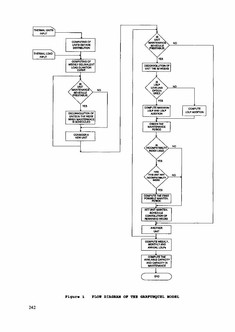
THERMAL UNITSINPUT
THERMAL LOADINPUT
COMPUTING OFUNITS OUTAGEDISTRIBUTION
COMPUTING OFWEEKLY EQUIVALENT
LOAD DURATIONCURVE
ISUNIT
NTENANCSEHEDULE
ABUS.
DECONVOLUnON OFUNITS IN THE WEEK
WHEN MAINTENANCEIS SCHEDULED
CONSIDERANEW UNIT
DECONVOLUnON OFUNIT THE 62 WEEKS
ISLOLP
LEVEUNQOPTIONUSED
COMPUTE MAXIMUM
ISINCOMPA
INDEX USED
HASTHIS UNIT
INCOMPATIBHJTYINDEX
COMPUTE THE FIRSTPOSSIBLE MAINTEN.
PERIOD
SET UNIT MAINTEN.SCHEDULE
CONVOLUTION OFREMAINING WEEKS
COMPUTE WEEKLY,MONTHLY ANDANNUAL LOLPt
COMPUTETHEAVAILABLE CAPACITY
AND CAPACITY INMAINTENANCE
Figur« l PLOW DIAGRAM OF THE OAKFUHQUBL MODEL
242

5) The "maintenance outage period" is defined as the over-all number of consecutive weeks necessary for main-tenance of a unit. For each unit there will be thesame number of maintenance outage periods as there areweeks in the year minus the number of weeks required bythe unit for maintenance. Each outage period will beassociated with a maximum LOLP and a total LOLP value.A given maintenance outage period will be made up of aset of weeks, each having its LOLP. The maximum LOLPof the maintenance outage period will be the one of theweek with the highest LOLP value, and the total LOLPwill be the sum of the different LOLP values for allthe weeks within such outage period.
6) Using option 1 - leveling out of the LOLP - all themaintenance outage periods are ordered depending ontheir maximum LOLP. If several weeks were to have thesame maximum LOLP value, a secondary orderingcriterion, consisting of summing the different LOLP's,will be used. In other words, maintenance outageperiods are ordered from low to high maximum LOLP, andif this value is equal for several outage periods theseare ordered depending on the sum of increasing LOLP7s.Using option 2 - the addition of minimum LOLP's - themaintenance outage periods are ordered depending on thesum of LOLP's and the process is continued as describedin the following point.
7) Following ordering of the maintenance outage periods,the maintenance schedule for a unit is located in thefirst of these outage periods. The equivalent loadduration curves corresponding to the weeks included inthis outage period are modified, the curves correspond-ing to the rest of the weeks being left unaltered asthey existed prior to deconvolution.
8) If at any time during the process the model finds aunit having an incompatibility index equal to that ofany of the units whose maintenance schedule has beensettled, the process would be modified as follows onreaching point 7 :Following the ordering of the outage periods, the modelbegins to search in the first of these for any week inwhich a unit with the same unavailability index hasbeen placed. If such a week is detected, the model goeson to the second outage period and so on until it findsan outage period without incompatibilities, placing theunit in this outage period and continuing the process.
9) On completion of the process, the model will possessinformation on the maintenance of all units, and onweekly, monthly and annual LOLP's.
243

3.4 Results of the modelThe model output begins by offering data on the generating
plants: name, installed power, on-site consumption, availability,incompatibility index, and the initial and final weeks for main-tenance. The model output then moves on to consider a table in-cluding weekly and monthly LOLP's and annual totals in unitvalues. The process then continues with a table identical tothat described above, including values expressed in hours.
The output from the model is a table listing the totalcapacity under maintenance and capacity available per week(available capacity being that corresponding to plants not shutdown due to scheduled unavailability).3.5 Use of the model
The model should be operated as follows:1) The incompatibility index restrictions included should
not be excessive as this limits the optimizationcapability of the model due to the fact that suchrestrictions are a determining factor when locatingmaintenance.
2) It is advisable to use both options - maximum LOLP andsum of LOLP values - as this makes possible to comparethe difference between the annual LOLP according toboth criteria, and the LOLP values for the most criti-cal weeks also for both criteria.
3) The model should be used in parallel with a model op-timizing energy generation. This is mainly for thefollowing two reasons: 1) the available hydroelectricpower is a pre-established value in this model, and 2)the model does not include any economic optimizationbut only optimization of system reliability. Thismodel would in turn supply the optimum maintenanceschedule from the point of view of system reliabilityfor a model that meets load demand on an energy basis.
3.6 Computer system requirementsThe CPU time used with a IBM 4381 Mod 2 computer and a total
number of 80 generating units amounts to some 5 minutes.
244

APPENDIX I (*)
BASIC ALGORITHMS
1. Calculation of available and unavailable power distributionLet us assume an electric system made up of one single plant
having a capacity C and capable of presenting one of twoconditions: in operation with a degree of probability Plf andnot in operation with a probability of q^; in this case, theavailable capacity and associated degree or probability would beas follows:
Available power ProbabilityO q-Lcl Pi
If to this system we add a new plant having a capabilitylevel C2, and degrees of probability p2 and q2, the followingsituation would exist:
Available power ProbabilityO q!.q2cl Pi-92C2 qi-P2
C1+C2 Pl'P2If the two plants included in our hypothetical system were
identical, in other words, if C1=C2, p^=p2 and q1=q2/ then thesituation would be as follows:Available power Probability
0 q2C 2pq2C p2
and so on indefinitely.Let us now consider a system made up of G units. Let the
capacity of these units be Cit C2 ... Cn ..., Cg, and let us alsoconsider that these units may have S states, where pn j is theprobability of any one of these plants having a status'i with apower level of a_ ^. In order to assure greater simplicity, fromhere on it will Be assumed that all units have a similar numberof possible statuses.
(*) This part of the paper is based on the book "ExpansionPlanning for Electrical Generating Systems, A Guidebook".International Atomic Energy Agency, TRS-241, Vienna, 1984.
245
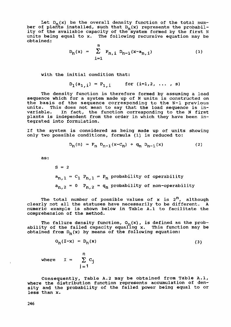
Let Dn(x) be the overall density function of the total num-ber of plants installed, such that Dn(x) represents the probabil-ity of the available capacity of the system formed by the first Nunits being equal to x. The following recursive equation may beobtained:
sDn(x) = 2 Pn,i D x-a ) (l)
with the initial condition that:) = P for (i=l,2, ... , s)
The density function is therefore formed by assuming a loadsequence which for a system made up of N units is constructed onthe basis of the sequence corresponding to the N-l previousunits. This does not mean to say that the load sequence is in-variable. In fact, the function corresponding to the N firstplants is independent from the order in which they have been in-tegrated into formulation.If the system is considered as being made up of units showingonly two possible conditions, formula (1) is reduced to:
Dn(n) = Fn Dn_l(x-Cn) -f qn D x) (2)
as:S = 2an -^ = C-^ Pn -^ = Pn probability of operabilityan 2 = ° pn 2 = ^n Probat>ility of non-operability
The total number of possible values of x is 2n, althoughclearly not all the statuses have necessarily to be different. Anumeric example is shown below in Table A.I to facilitate thecomprehension of the method.
The failure density function, On(x) , is defined as the prob-ability of the failed capacity equaling x. This function may beobtained from Dn(x) by means of the following equation:
On(I-x) = Dn(x)
nwhere I = 2 cj
Consequently, Table A. 2 may be obtained from Table A.I,where the distribution function represents accumulation of den-sity and the probability of the failed power being equal to orless than x.246
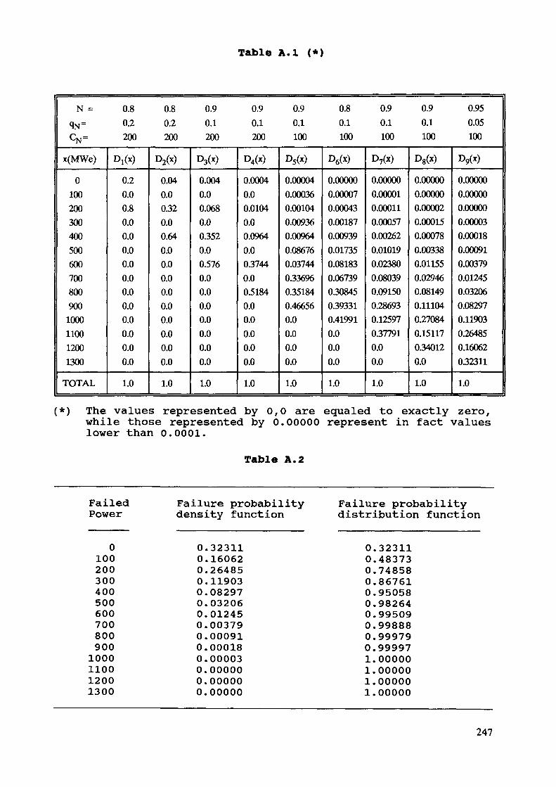
Table A.I (*)
N = 0.8 0.8 0.9 0.9 0.9 0.8 0.9 0.9 0.95qN= 0.2 0.2 0.1 0.1 0.1 0.1 0.1 0.1 0.05CN= 200 200 200 200 100 100 100 100 100x(MWe)01002003004005006007008009001000110012001300TOTAL
DI(X)0.20.00.80.00.00.00.00.00.00.00.00.00.00.01.0
D2(x)0.040.00.320.00.640.00.00.00.00.00.00.00.00.01.0
D3000.0040.00.0680.00.3520.00.5760.00.00.00.00.00.00.01.0
D4(x)0.00040.00.01040.00.09640.00.37440.00.51840.00.00.00.00.01.0
D5(x)0.000040.000360.001040.009360.009640.086760.037440.336960.351840.466560.00.00.00.01.0
D6000.000000.000070.000430.001870.009390.017350.081830.067390.308450.393310.419910.00.00.01.0
D7(x)0.000000.000010.000110.000570.002620.010190.023800.080390.091500.286930.125970.377910.00.01.0
D8(x)0.000000.000000.000020.000150.000780.003380.011550.029460.081490.111040.270840.151170.340120.01.0
D9(x)0.000000.000000.000000.000030.000180.000910.003790.012450.032060.082970.119030.264850.160620.323111.0
(*) The values represented by 0,0 are equaled to exactly zero,while those represented by 0.00000 represent in fact valueslower than 0.0001.
Table A.2
FailedPower
01002003004005006007008009001000110012001300
Failure probabilitydensity function
0.323110.160620.264850.119030.082970.032060.012450.003790.000910.000180.000030.000000.000000.00000
Failure probabilitydistribution function
0.323110.483730.748580.867610.950580.982640.995090.998880.999790.999971.000001.000001.000001.00000
247
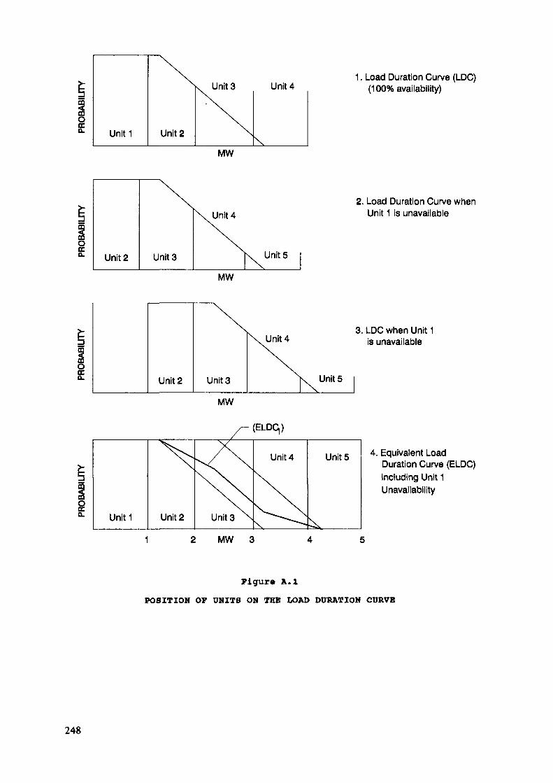
go. Unit1 Unit 2
Units Unit 4
MW
Unit 2 Unit 3
Unit 4
Units
MW
Unit 2 Unit3
Unit 4
MW
(ELDq)
Unitl Unit 2 Units
Unit 4
Units
1. Load Duration Curve (LDC)(100% availability)
2. Load Duration Curve whenUnit 1 is unavailable
3. LDC when Unit 1is unavailable
Units 4. Equivalent LoadDuration Curve (ELDC)including Unit 1Unavailability
MW
Figure A.IPOSITION OF UNITS ON THE LOAD DURATION CURVE
248

2. Baleriaux-Booth Algorithm2.1 Basic concepts
Let us first intuitively consider the load duration curvesand non-scheduled unavailability.
Curve 1 in Figure A.I is a load duration curve representingthe energy generated by each of the units, given an availabilityvalue of 100%.
If Unit 1 were unavailable (curve 2 of Figure A.I), Unit 2and all following units would be moved towards the left in orderto cover the system load. This would be equivalent to the situa-tion indicated in curve 3 of the same figure, in which the loadduration curve is displaced towards the right by a quantity equalto the capacity of Unit 1.
It would appear logical to assume that the "real" load dura-tion curve, as perceived by Unit 2, is in fact a function of theunavailability of Unit 1, and that consequently this coveragewould be an intermediate value between those indicated on curves1 and 3.
The convolution method - which is illustrated in curve 4 -establishes an equivalent curve such that the area covered byUnit 2 on curve 4 is equal to that covered by Unit 2 on curve 1by the operational probability of Unit 1, plus the area coveredon curve 3 by the corresponding probability of unavailability ofUnit 1.
Evidently, only the unavailability of Unit 1 exercise anyinfluence on Unit 2.
Using this same method, the ELDC^ can be convolved withrespect to unavailability of Unit 2, and the coverage provided byUnit 3 could be calculated, and so on.
2.2 Fundamental mathematical principlesAn equivalent load, De, may be defined as the sum of two
random variables: one, the load or consumption, DC, and theother a fictitious load due to unavailability of units, alreadytaken into account, Df.
De = DC + ofThe distribution function of the sum of these two randomvariables is given by:
Ge (d) = ff fc f (Dc,Df) dDc dDf (4)JJ De '
or by changing limitsd-Df
0 0249
rd /«d-DfGe (d) =/ / fc f (Dc,Df) dDc dDf•^ n J n '
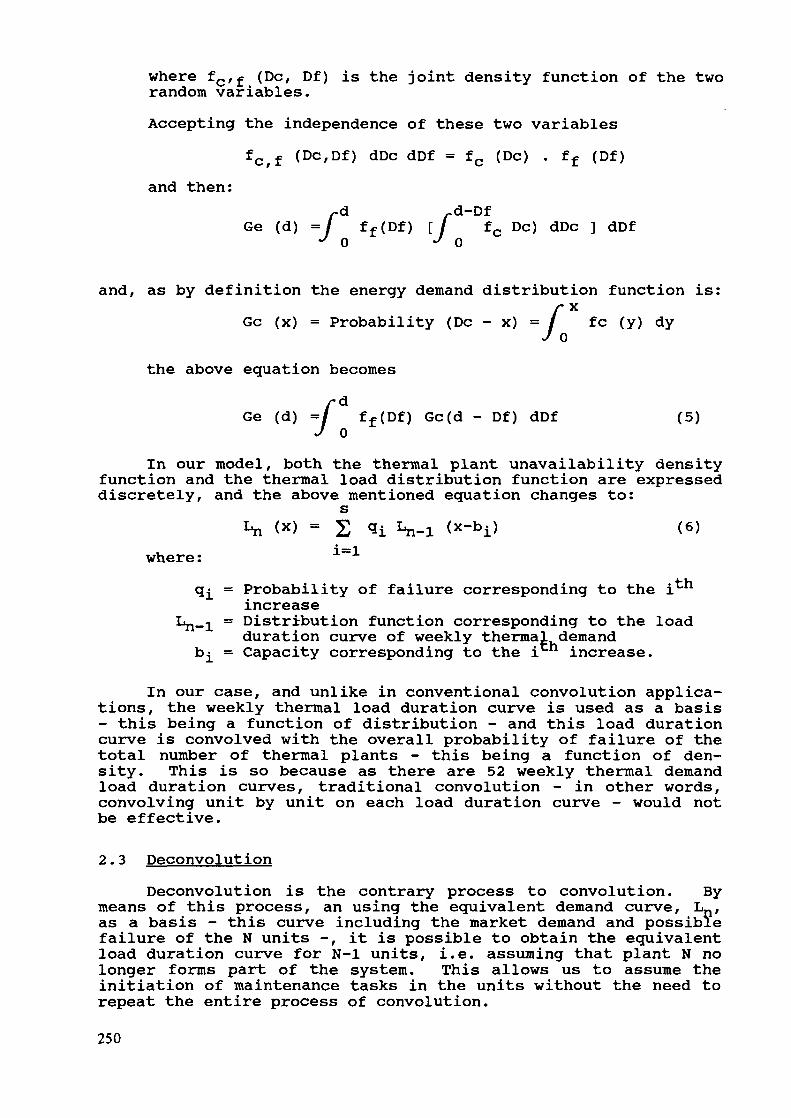
where fc/f (De, Df) is the joint density function of the tworandom variables.Accepting the independence of these two variables
fc>f (Dc,Df) dDc dDf = fc (Dc) . ff (Df)and then:
rd -d-DfGe (d) =/ ff(Df) [/ fc DC) dDc ] dDf
J 0 J 0
and, as by definition the energy demand distribution function is:
/
xfc (y) dy
the above equation becomes» d0
rdGe (d) =/ ff(Df) Gc(d - Df) dDf (5)
J 0In our model, both the thermal plant unavailability density
function and the thermal load distribution function are expresseddiscretely, and the above mentioned equation changes to:s
1^ (x) = q I.- (x-b) (6)where : 1
tnq^ = Probability of failure corresponding to the iincrease
Ln-1 = Distribution function corresponding to the loadduration curve of weekly thermal demand
b^ = Capacity corresponding to the i increase.
In our case, and unlike in conventional convolution applica-tions, the weekly thermal load duration curve is used as a basis- this being a function of distribution - and this load durationcurve is convolved with the overall probability of failure of thetotal number of thermal plants - this being a function of den-sity. This is so because as there are 52 weekly thermal demandload duration curves, traditional convolution - in other words,convolving unit by unit on each load duration curve - would notbe effective.
2.3 DeconvolutionDeconvolution is the contrary process to convolution. By
means of this process, an using the equivalent demand curve, L_,as a basis - this curve including the market demand and possiblefailure of the N units -, it is possible to obtain the equivalentload duration curve for N-l units, i.e. assuming that plant N nolonger forms part of the system. This allows us to assume theinitiation of maintenance tasks in the units without the need torepeat the entire process of convolution.250
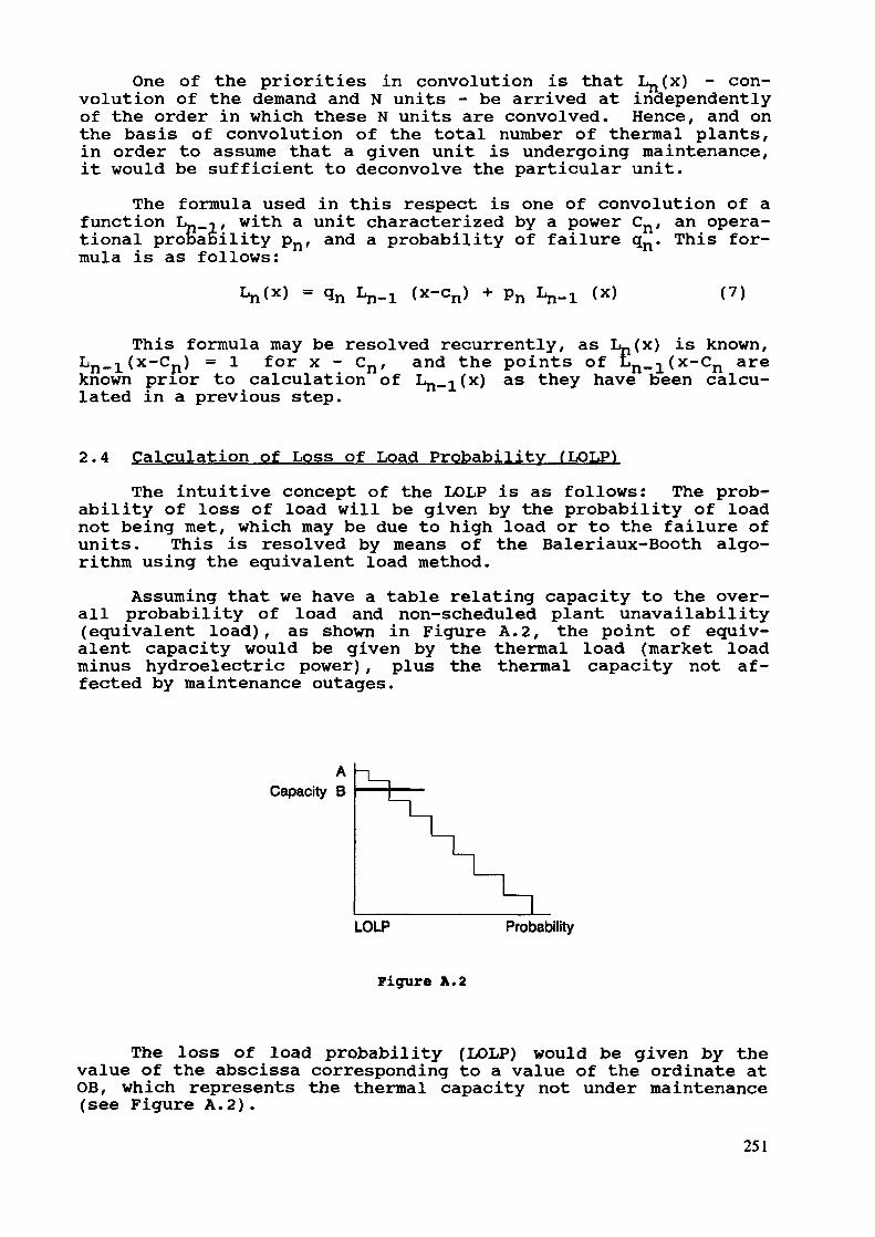
One of the priorities in convolution is that Lj x) - con-volution of the demand and N units - be arrived at independentlyof the order in which these N units are convolved. Hence, and onthe basis of convolution of the total number of thermal plants,in order to assume that a given unit is undergoing maintenance,it would be sufficient to deconvolve the particular unit.
The formula used in this respect is one of convolution of afunction L-i/ with a unit characterized by a power Cn, an opera-tional probaeility pn, and a probability of failure qn. This for-mula is as follows:
n .j. (x-cn) n (x) (7)
This formula may be resolved recurrently, as Ln(x) is known,Ln_1(x-Cn) = 1 for x - Cn, and the points of Ln-i(x~cn areknown prior to calculation of Ln_i(x) as they have been calcu-lated in a previous step.
2.4 Calculation of Loss of Load Probability (LOLP)The intuitive concept of the LOLP is as follows: The prob-
ability of loss of load will be given by the probability of loadnot being met, which may be due to high load or to the failure ofunits. This is resolved by means of the Baleriaux-Booth algo-rithm using the equivalent load method.
Assuming that we have a table relating capacity to the over-all probability of load and non-scheduled plant unavailability(equivalent load), as shown in Figure A.2, the point of equiv-alent capacity would be given by the thermal load (market loadminus hydroelectric power), plus the thermal capacity not af-fected by maintenance outages.
ACapacity B
LOLP Probability
Figure A.2
The loss of load probability (LOLP) would be given by thevalue of the abscissa corresponding to a value of the ordinate atOB, which represents the thermal capacity not under maintenance(see Figure A.2).
251

ANALYSIS METHOD OF THE LONG TERM EVOLUTIONOF THE SWISS ELECTRICITY SUPPLY
E. GNANSOUNOULaboratoire de systèmes énergétiques,Ecole polytechnique fédérale de Lausanne,Lausanne, Switzerland
Abstract
The particularities of Swiss Electrical sector are briefly presented. The difficultiesencountered when using WASP-III to analyze the long range evolution of Electricitysupply of the country are pointed out and the method used at present in Switzerland isexposed. Researches are made in the "Laboratoire de Systèmes Energétiques" in order toimprove this method and the first results are discussed.
1. Electricity sector in Switzerland
1.1 Institutional Environment
Contrary to many countries where one only public utility has the monopoly ofelectricity generation and transmission, there are about 1200 electricity utilities inSwitzerland. Among these firms we have :
. utilities generating and selling electricity to other utilities or customers;utilities generating for themselves
The latter are essentially chemical, aluminium industries and railways.
The former group is divided up in- public- private- and semi-public utilities
As far as their activities are concerned, we have- utilities limited to electricity generating
utilities only distributing electricity- and numerous mixed generating and distributing electricity
The importance of electricity generated or distributed and the size of population servedmay change sharply from one utility to another.
The sixteen biggest utilities produced in 1988 more that the half of electricity generatedin the country.
Generally speaking, local administration are represented in the most importantutilities. Their main goal is to get electricity at sable prices and reliable conditions.However , utilities are conducted independently and it exists even something likecompetition between them. But this competition has rather a complementary natureintending to long, medium and short terms contracts conclusion.
Because of it's association with Union for electricity generating and transmissioncoordination, export and import contracts do exist between Swiss utilities andneighbouring countries utilities.
So, due to the institutional environment of electric sector in Switzerland, each utilityoptimizes its own system expansion and concludes contracts necessary to meet itscustomers demand.
253
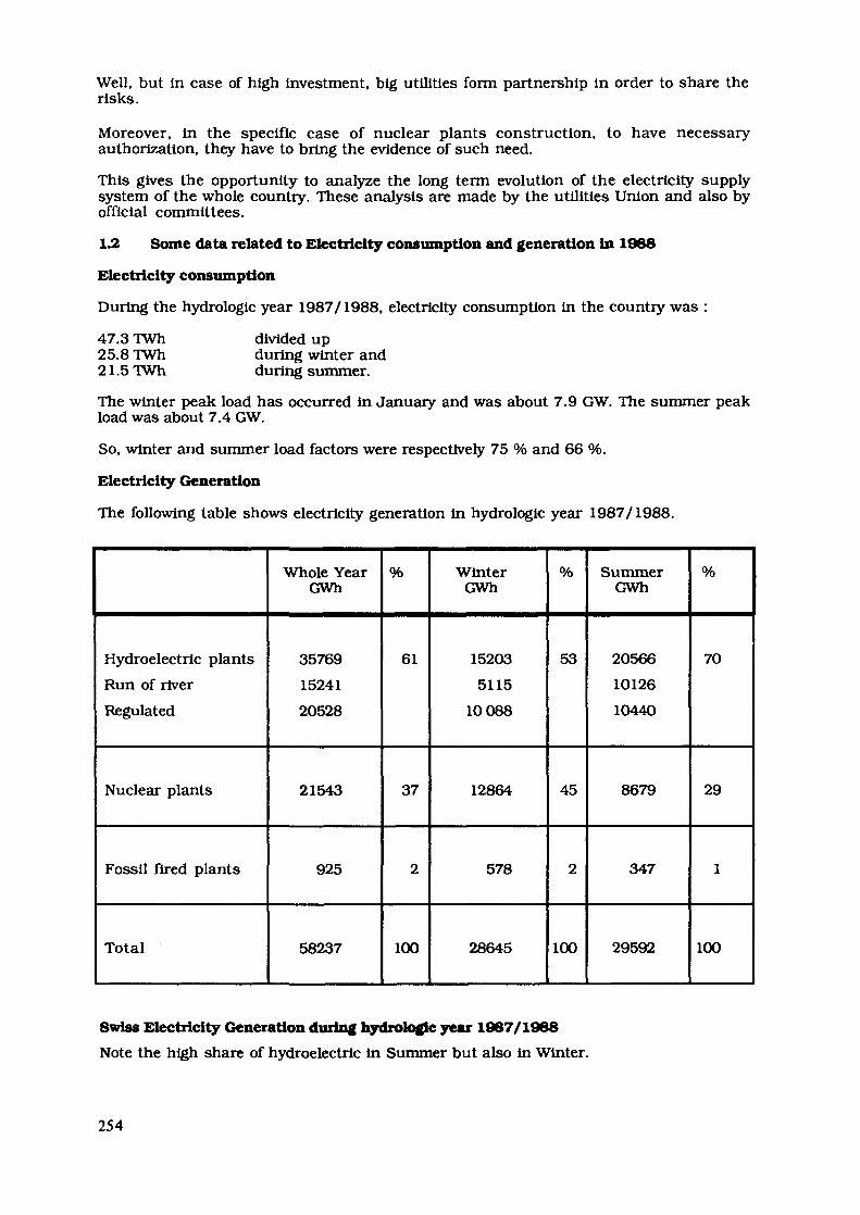
Well, but in case of high investment, big utilities form partnership in order to share therisks.
Moreover, in the specific case of nuclear plants construction, to have necessaryauthorization, they have to bring the evidence of such need.
This gives the opportunity to analyze the long term evolution of the electricity supplysystem of the whole country. These analysis are made by the utilities Union and also byofficial committees.
1.2 Some data related to Electricity consumption and generation in 1988
Electricity consumption
During the hydrologie year 1987/1988, electricity consumption in the country was :
47.3 TWh25.8 TWh21.5 TWh
divided upduring winter andduring summer.
The winter peak load has occurred in January and was about 7.9 GW. The summer peakload was about 7.4 GW.
So, winter and summer load factors were respectively 75 % and 66 %.
Electricity Generation
The following table shows electricity generation in hydrologie year 1987/1988.
Hydroelectric plantsRun of riverRegulated
Nuclear plants
Fossil fired plants
Total
Whole YearGWh
357691524120528
21543
925
58237
%
61
37
2
100
WinterGWh
152035115
10088
12864
578
28645
%
53
45
2
100
SummerGWh
205661012610440
8679
347
29592
%
70
29
1
100
Swiss Electricity Generation during hydrologie year 1967/1988Note the high share of hydroelectric in Summer but also in Winter.
254

At the end of 1988, the installed capacity was :
Hydro: 11515MWNuclear : 2950 MWFossil fired plants : 790 MW
So, Swiss electricity generating system is a hydro dominated and energy limited one.
2. Problems related to WASP utilization
2.1 Facing a short term electricity market
Generally speaking, when making the balance between generation and demand for agiven season, different cases may arise :
a) For each hour, generation meets the demand; this situation is prevailing inSwitzerland in Summer;
b) During hours of peak demand only, generation is not able to meet the demand;
c) During hours of peak demand, generation meet demand, but in off-peak period, thebase plants don't produce energy enough to satisfy the load;
In Switzerland, this situation may prevail during winter. This may be solved byshort term or long term decisions :
- importing during base load period,- generating part of the regulated energy,- construction new base generating plants.
d) The generation isn't sufficient to satisfy the demand in any period.
When using the WASP program to analyze long term generating system of a givencountry, a main assumption is an autarklcal environment and the goal is to be in thecase a) all time during the planning period.
When the country is connected with other countries, the operation goals may change. Soin the case c), when a connection exists, it will be more economic, as a short termdecision, to import during intermediate loads or base load period.
This conceiving may be transformed in an operating rule in the case of short termelectricity market existence.
2^ Other well-known problems
Other well-known problems make WASP-III program not very suitable for Swisselectricity generating expansion analysis.
1) Swiss electricity generating system is an energy limited one; it is well known that inthis case, LOLP is not a good reliability index.
2) When trying to use WASP-III to analyze Swiss case, the LOLP determination is notaccurate due to the fact that the electricity system capacity included the long termimport contracts is often out off the range of accuracy of Fourier series, this arrivesin Summer but also in Winter.
This means that the LOLP is very low. so, for Swiss system, it is necessary to define thereliability of the electricity supply in another way. According to Swiss electricityutilities union, in medium range there will not be a great development of plantsconstruction in Switzerland.
Some small cogeneration plants will be probably built. The import of electricity fromFrance will certainly increase. Investments has already been done by some big Swissutilities in the construction of some french nuclear plants.
255

The problem Is: how much energy to import from France ? It is mostly a problem ofvulnerability of Switzerland 's supply of energy.
3. Method used at present in Switzerland
In Switzerland, because of the structure of electricity supply system, the analysis of theadequacy of supply is based on energy criteria.
The method utilized consists simply in determining the probability density function(p.d.f.) of electrical energy generation during Winter.
And the criteria is :
In long and medium range, the electrical energy generating system and the long termimport contracts must be adjusted in order to meet the demand with a probabilitygreater than 95%.
To determine the p.d.f. of the Winter electrical energy generated, the process is :
1) hydroelectric generation in Winter is considered as uncertain variable due to thehydrological conditions; nuclear energy in Winter is considered as uncertainvariable due to the unplanned outages; fossil fired based generation is considered ina deterministic manner;
2) these variables are assumed to be independent;
3) Using historical operating results of the hydroelectric plants, one determines thep.d.f of the hydro-generation in Winter;
4) Using historical operating results of nuclear plants of the same type existing inindustrialized countries, one determines the p.d.f. of each nuclear plant wintergeneration.
5) The different p.d.f. are convoluted and average fossil fired plants electricitygenerated in winter is added to obtain the aggregated p.d.f. of Winter electricitygenerated.
4. Research in our laboratory
The goal of our research is to contribute to the improvement of the method usednowadays in Switzerland.
In a first step, we attempt to improve the determination of the p.d.f. of electricitygeneration in Winter and especially of hydroelectric generation.
Note that EG = EPR + IW
with
EG : the total hydroelectricity generated in WinterEPR : the total hydroelectricity drawn out in Winter from Summer stored inflowIW : the total natural inflow during Winter
EPR : depends on the aggregate levels of the seasonal reservoir at the Winterbeginning and end. So it depends on the operation of the different seasonalregulated reservoirs.
Since these reservoirs belong to different utilities and that the data abouttheir operations are not available, EPR Is taken into account in adeterministic manner.
IW : is considered as uncertain variable.
256

The determination of p.d.f. of the inflow during Winter is not a trivial question. Indeedthere exist many hydro-plants (more than 450) in Switzerland and they have beencommitted in different dates.
So, the available aggregate inflow data are not homogeneous. We have obtained moredetailed sub -regional data from Swiss Federal Energy Office. We've analyzed each sub-region and for each, we have retained only the period during which the data seem to behomogeneous. Consequently, the sub-regions Inflow series have different sizes.
But the p.d.f. fitted for each sub-region is Gaussian.So, for the aggregate inflow, we fit an exponential family distribution :
p(x) = exp (X.Q + X,jx
where the parameters X0, X^, ^2 were determined by imposing these constraints :
xmax/ p(x) dx = 1
xminxmax
J p(x) dx = x iwxmin
xmax _ g 2J p(x) dx = Xjw + a rw
xmin
where xmm and xmax are assumed to be known and x j^y and CTr\v are determined onthe basis of sub-regional data.
With the data available In the Swiss Federal Energy Office, the solution obtained Is adouble truncated Gaussian p.d.f.
Now, we have collected more detailed data about the inflows to different hydro-plantsduring winter and we are applying this method to these data.
Furthermore, in long term, energy deficit during peak demand period may arise too, sowe also intend to develop an appropriate model taking into account- base and peak loads- existence of a short term electricity market- stochastic nature of inflows.
5. Conclusion
WASP-III program is a sophisticated and efficient tool In electricity supply planning. Butin some cases, the use of this program is not advisable. It is the case of Swiss ElectricitySupply analysis.
In these cases, appropriate methods may be developed taking into account thespecificities of the system to be analyzed.
In our laboratory, we are improving the method used at present by Swiss electricityutilities union and we intend to develop a more Integrated tool suitable for long termevolution of Swiss electricity supply analysis.
257
EXPERIENCE IN THE USE OF WASP AT THE SOCIETETUNISIENNE DE L'ELECTRICITE ET DU GAZ
C. CHAKROUNDirection des études et de la planification,Société tunisienne de l'électricité et du gaz,Tunis, Tunisia
Abstract
This paper presents what has been done at Steg usingWASP. The implementation phase of the WASP and MAEDmodels and the ENPEP Package is first described.Hence, the paper gives a list of the studies conductedby the Planning Department during the 80's, using WASP.The last WASP study, described in more details, dealswith inter-fuel substitution in STEG's power gener-ation, for the next thirty years. Finally, some sug-gestions are proposed for WASP enhancement.
1. INTRODUCTION
The Tunisian company for electricity and gas (STEG) wascreated in 1962 as public utility. Electricity demand has grownfrom 288 GWh in the year 1962 to 3742 GWh in 1988. During thesame period the installed capacity has been multiplied by 16 andis presently 1343 MW, composed of 61% steam turbine, 37% gas tur-bine and 2% hydro. The first gas turbine was installed in 1971to burn El Borma associated gas.
STEG fuel consumption is composed in 1988 of natural gasfrom El Borma and Algeria for 680,000 toe, heavy fuel for 400,000toe and gas oil for 3,000 toe.
2. IMPLEMENTATION OF IAEA'S ENERGY PLANNING PACKAGES
For a long time STEG based its planning activities on handcalculations. The growth of the installed capacity and the in-creasing number of possible new types of plants along with thedevelopment of computer equipment of STEG, led our PlanningDepartment to computerize some of its activities.
Apart from some transmission planning tools, STEG developed,in 1979 and 1980, a FORTRAN program to simulate electric powerplant operation and calculate total present values of a givensystem configuration. At that time STEG had a mainframe IBM 370.Computer Jobs and data were sent through a card reader.
The WASP package was implemented on this computer at the endof 1982. Both versions of WASP (WASP-II and WASP-III) werereleased to STEG, time including subsidiary modules. A team ofthree people attended to the 1983 WASP training course of 1983 atArgonne National Laboratory.
259
In 1983, STEG acquired a new mainframe computer from CIIHonneywell Bull -DPS7/35 model. WASP was then transferred to thenew system during the year 1984 and compiled under FORTRAN IVversion. The use of WASP became then easier since a console wasdedicated to the Planning Department. But priority level given toplanning jobs in computer access and the long calculating timerequested by WASP, made each optimization a long task.
At the beginning of 1987, the MAED model was also imple-mented at STEG in the same context as WASP. The purpose was tocarry out a MAED-WASP study with the assistance of the IAEA, aspart of the nuclear option study for Tunisia.
In September 1987, two IBM XT 286 micro computers were af-fected to the Planning Department.
At the end of 1987, the IAEA sent to STEG a copy of the ADBmicro-computer version of WASP III. Unfortunately some problemsin the installation of the program and the lack of a dedicatedmicrocomputer did not make it possible to complete the installa-tion. ADB-WASP was yet felt to be very useful.
Four months later, in May-June 1988, the UNDP and World Bankpermitted STEG to have a team trained on the ENPEP program at Ar-gonne. At the end of the session, the IAEA released the ENPEPpackage to STEG. In the following months an ESMAP project studywas initiated in Tunisia on energy substitution in Industry.
A new NEC PowerMate 1 (80286) microcomputer equipped with a80387 mathematical coprocessor and a 40 Mbites hard disk, was al-located to this study which used the ELECTRIC module of ENPEP.
3. WASP STUDIES AT STEG
STEG's Planning Department carried out several long term ex-pansion studies for the power generating system between 1983 and1987, using the mainframe version of WASP-III. In that period thepurpose was essentially to evaluate coal and nuclear options.
During the same period STEG was asked to provide a forecastof the fuel consumption for electric generation, as part of theNational Development Plan.
In addition, for a long time, STEG and SONELGAZ, the Al-gerian electric utility, have cooperated in different fields, andfirst of all in electric energy exchange among their intercon-nected networks. This interconnection is one of the oldest Arabnetworks international interconnection. One of the principles ofthis linkage is to share part of the spinning reserve.
So, the idea came to examine the impact of a common powersystem expansion approach. The "Common Planning Study" isdivided in three parts: 1) load forecasting; 2) power generatingsystem expansion; and 3) network development.
The purpose was to compare the optimum expansion plans ofthe two separate electric systems with the optimum expansion ofthe two systems considered as one grid.
260

Common planning of the integrated system permits to take ad-vantage of the differences in peaking hours, to minimize thereserve margin and to allow the early implementation of new(larger) unit size. The power generating system optimizationconsiders classic thermal and combined cycle candidates for 150MW, 300 MW and 600 MW size on one hand, and nuclear 600 MW andgas turbine of 100 MW on the other hand.
As previously indicated, a nuclear option study initiated in1986 by STEG with IAEA assistance is yet on hand. Besides siteand technical studies, this project includes the conduct of aMAED-WASP study. The sizes considered at that time were the sameas for the "Common Tunisian-Algerian Study", but heavy fuel andcoal were introduced.
STEG took advantage of the IAEA expertise in order to revisecandidates characteristics and fuel prices.
The last study conducted by the Planning Department of STEGon power generating system expansion deals with "heavy fuel,natural gas and coal substitution". The objective was toelaborate a fuel strategy for Tunisia for the next twenty years.The study, initiated in August 1988, gave the opportunity to ex-periment the ELECTRIC module of ENPEP and micro computer perfor-mances. For the first time in STEG, fuel prices where introducedas scenarios, represented by fuel price multipliers in DYNPRO.Throughout the duration of the study, many discussions arose onthe characteristics of the combined cycle and particularly on itsthermal efficiency and its availability.
As this study is presently coming to an end, we can statethat microcomputers are much more convenient than mainframes torun WASP.
STEG is now planning to undertake two new WASP studies. Thefirst one is a common Tunisian-Algerian study extended to Libyaand Morocco. Since Morocco has an important hydroelectric in-stalled capacity the study will probably have recourse to theVALORAGUA program. The methodology will be the same as for theprevious one.
The second study to be undertaken in 1990 is on calculationof long run marginal cost, with the assistance of UNDP and WorldBank, in cooperation with other countries from EMENA region.
4. "INTER FUEL SUBSTITUTION STUDY" DATA AND RESULTS
4.1 Context
For the last two decades, Tunisia has been an exporter ofcrude oil, but according to present estimates it is going to be-come, in the middle of the 90's, a net importer of oil productsif no new oil field come into operation.
Natural associated gas reserves are going to be depleted inthe few coming years. Offshore reserves of natural gas have beenidentified but no decision has been made yet about their ex-ploitation. On the other hand, Tunisia has no coal resources.
261

The international Algeria-Italy gas pipeline crosses Tunisiaand provides it with royalties. Tunisia can also buy quantitiesof natural gas from Algeria by contract.
Presently, 54% of the total available electric powercapacity can switch from heavy fuel to natural gas. Another 25%can switch from gas oil to natural gas without new investment.
The problem was to decide what type of new equipments shouldbe installed in the mid- and long-term, i.e., steam turbinesburning either heavy fuel or natural gas, or if they were to burncoal, or eventualy, if they were to be of the combined cycle typeburning exclusively natural gas.
The heavy fuel steam turbines solution gives the maximumflexibility and allow to switch from gas to heavy fuel andviceversa as the relative prices of natural gas and heavy fuelchanges in one way or the other, or when a shortage occurs in oneof these fuels. The coal steam turbine is capital intensive butin the two fuel price scenarios (Figure 1) elaborated for thisstudy, coal price remains low all throughout the planning period.
The combined cycle candidate has a low capital cost, a highefficiency, but a relatively high fuel cost. It relies on asingle fuel and a single supplier.
4.2 DataTwo price scenarios and two electricity demand forecasts
were considered, giving four different situations. Steam coalprices are supposed, for both soft and high scenario, to remainunder an upper limit of 120 US$/toe (80 US$/ton) between 1990 and2020. Heavy fuel price is expected to vary from 89 US$/toe in1990 to 240 in 2020 for the soft scenario and from 105 in 1990 to287 US$/toe in 2020 for the high scenario. For natural gasmarket the net back approach were considered to become a rule.Natural gas price scenarios are equivalent to heavy fuel.
The demand forecasts consdier a 4% growth rate for the lowcase and 5.3 % for the high case.
The "Fixed System" capacity is 1179 MW in 1991 (APPENDIX I),composed as follow :
724 MW for 10 steam turbines,435 MW for 19 gas turbines,64 MW for 6 hydroelectric units
As mentioned previously, candidates are gas turbine, com-bined cycle, heavy fuel steam turbine and coal steam turbine.The sizes considered are 150 MW, 300 MW and 600 MW (APPENDIX II).
262
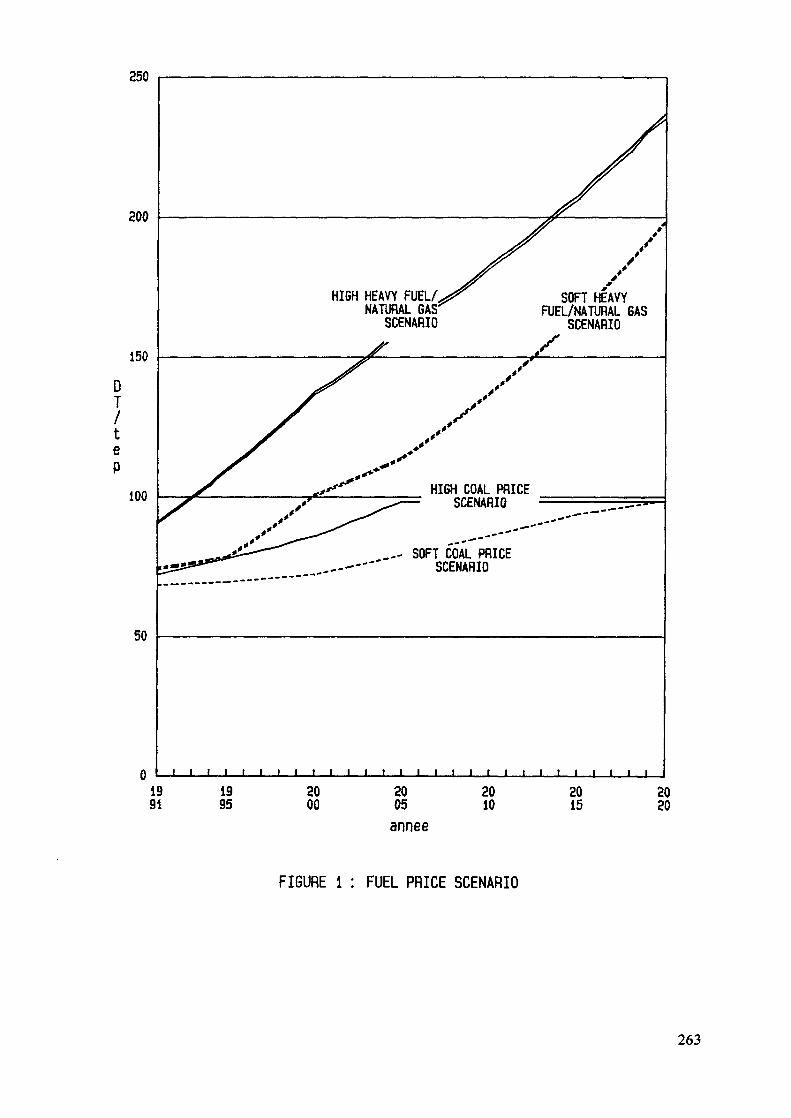
250
200
150DT/teP
100
HIGH HEAVY FUEL/NATURAL GAS:
SCENARIOSOFT HEAVYFUEL/NATURAL GASSCENARIO
HIGH COAL PRICESCENARIO
tl*i£^~*^^ _— SOFT WAL PRICE___--'-""" SCENARIO
50
i i i i i i i i i1991
1995
2000
2005
année
2010 2015
2020
FIGURE 1 : FUEL PRICE SCENARIO
263

4.3 ResultsTo summarize the results of the four optimizations it can be
said that, in every case, two 300 MW combined cycle plants are tobe installed before year 2000. After these two plants, dependingon demand and price scenario, 300 MW combined cycle plants or 300MW coal steam turbines are built (APPENDIX III).
The sensitivity study on investment cost, environmental con-straints, heat rate efficiencies, availability, and discount rategive those conclusions as robust.
5. SUGGESTIONS FOR WASP ENHANCEMENT
Conversion of WASP to microcomputer appear to be the rightsolution. Other modules such as DURAT, POLIN, COMBIN, etc. shouldalso be adapted to PCs.
ELECTRIC should incorporate the improvements brought aboutby the Asian Development Bank version of WASP, such as MERGEBINwhich allow to interrupt and restart MERSIM run, and to realizeparallel processing on different micro computers.
Graphic routines and files should be added in order to en-hance the presentation of reports.
The REPROBAT output should give:the image of the optimum solution in the same manner asin DYNPRO,
- fuel consumption in tons of oil equivalent or any otherunit at user convenience, andhours of operation or load factor for each candidate.
A solution has to be found for combined cycle constructionsequence and operating scheme description in WASP.
A financial module should be of good help to better in-tegrate the results of the power generation expansion studiesconclusions in the decision process.
Besides or before technical data processing problems,electric planners face the problem of data collection, especiallyfor technical and economic parameters either for equipment orfuels. Some arrangement should be made to allow exchange of in-formation on a regular basis.
264
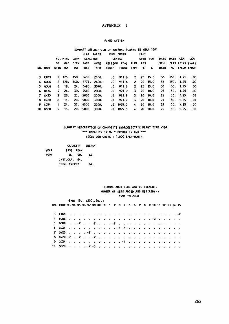
APPENDIX
FIXED SYSTEM
SUMMARY DESCRIPTION OF THERMAL PLANTS IN YEAR 1991HEAT RATES FUEL COSTS FAST
NO. MIN. CAPA KCAL/KWH CENTS/ SPIN FOR DAYS MAIN O&M O&MOF LOAD CITY BASE AVGE MILLION KCAL FUEL RES SCHL CLAS (FIX) (VAR)
NO. NAME SETS MW MU LOAD INCR DMSTC FORGN TYPE X % MAIN MW S/KUH S/MUH
3 RADS 2 125. 150. 2635. 2400.4 SOUS 2 120. 140. 2775. 2400.5 GOUG 66 GN34 47 GN25 28 GN20 69 G034 110 G020 5
18. 24. 3490. 3090.24. 30. 4500. 2000.20. 25. 5000. 2500.15. 20. 5000. 3000.24. 30. 4500. 2000.15. 20. 5000. 3000.
0,0000000
91191191192192192119251925
.6
.6
.6
.9
.9
.9
.0
.0
22233344
2020202020202020
15.15.15.10.10.
00000
10.010.10.00
3636362525252525
150.150.50.50.50.50.50.50.
1.1.1.1.1.
7575752525
1.251.1.2525
.00
.00
.00
.00
.00
.00
.00
.00
SUMMARY DESCRIPTION OF COMPOSITE HYDROELECTRIC PLANT TYPE HYDR*** CAPACITY IN MW * ENERGY IN GUH ***
FIXED O&M COSTS : 4.000 S/KW-HONTH
CAPACITY ENERGYYEAR BASE PEAK1991 0. 50. 64.
INST.CAP. 64.TOTAL ENERGY 64.
THERMAL ADDITIONS AND RETIREMENTSNUMBER OF SETS ADDED AND RETIRED(-)
1991 TO 2020YEAR: 19.. (200./20..)
NO. NAME 93 94 95 96 97 98 99 0 1 2 3 4 5 6 7 8 9 10 11 12 13 14 15
RADSSOUSGOUG
-2-2
-2 -26 GN34 .7 GN25 .8 GN20 -29 G034 .10 G020 .
-1 -3-2
-2 -2-1
-2 -3
265
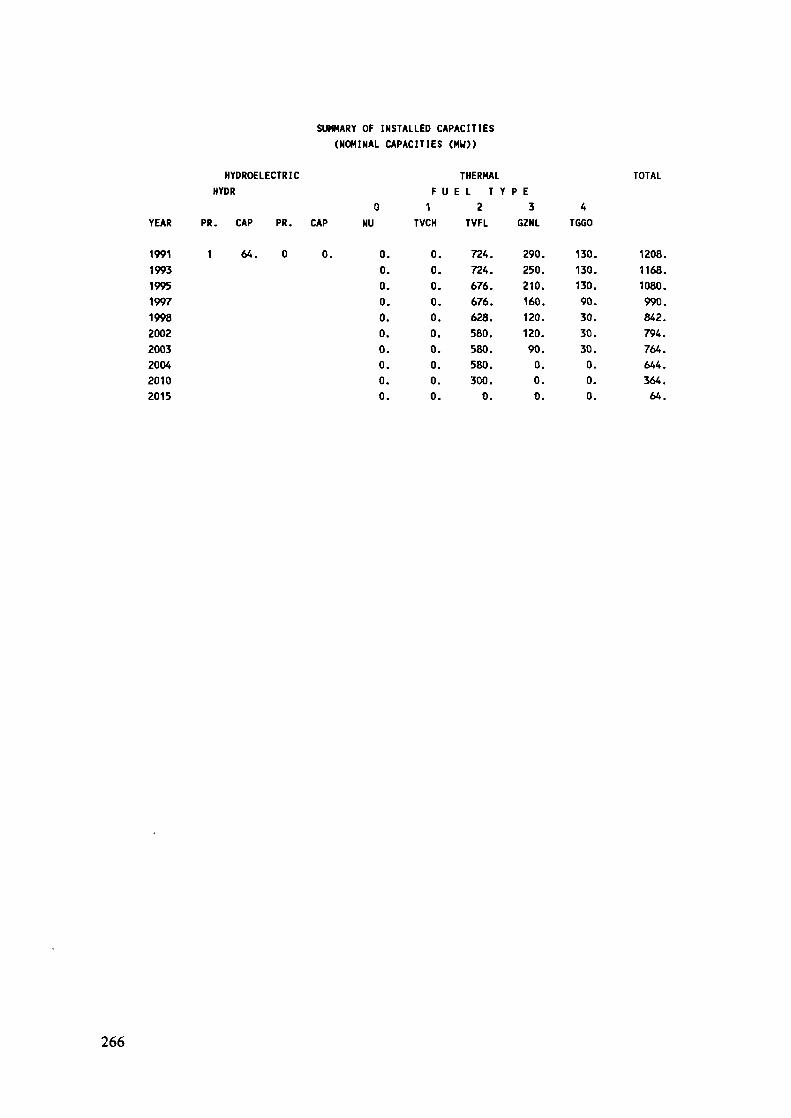
SUMMARY OF INSTALLED CAPACITIES(NOMINAL CAPACITIES (MW)>
HYDROELECTRIC THERMAL TOTALHYDR F U E L T Y P E
0 1 2 3 4YEAR PR. CAP PR. CAP NU TVCH TVFL GZNL TGGO
1991 1 64. 0 0.199319951997199820022003200420102015
0.0.0.0.0.0.0.0.0.0.
0.0.0.0.0.0.0.0.0.0.
724.724.676.676.628.580.580.580.300.0.
290.250.210.160.120.120.90.0.0.0.
130.130.130.90.30.30.30.0.0.0.
1208.1168.1080.990.842.794.764.644.364.64.
266
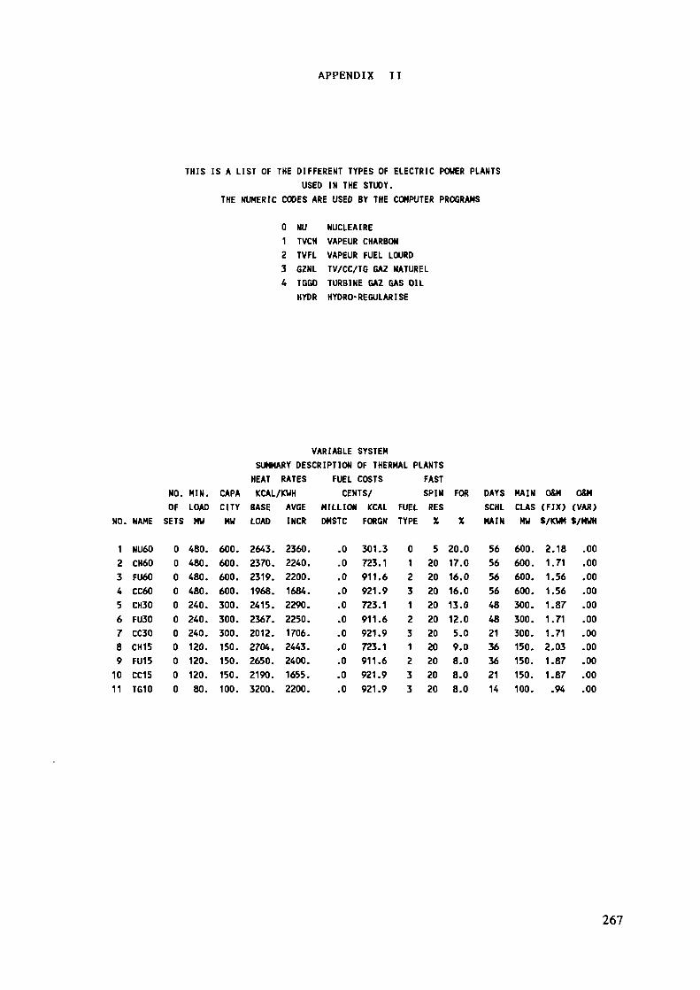
APPENDIX II
THIS IS A LIST OF THE DIFFERENT TYPES OF ELECTRIC POWER PLANTSUSED IN THE STUDY.
THE NUMERIC CODES ARE USED BY THE COMPUTER PROGRAMS
0 NU NUCLEAIRE1 TVCH VAPEUR CHARBON2 TVFL VAPEUR FUEL LOURD3 GZNL TV/CC/TG GAZ NATUREL4 TGGO TURBINE GAZ GAS OIL
HYDR HYDRO-REGULARISE
VARIABLE SYSTEMSUMMARY DESCRIPTION OF THERMAL PLANTSHEAT RATES FUEL COSTS FAST
NO. MIN. CAPA KCAL/KWH CENTS/ SPIN FOROF LOAD CITY BASE AVGE MILLION KCAL FUEL RES
NO. NAME SETS MW MU LOAD INCR DMSTC FORGN TYPE X X
DAYS MAIN O&M O&MSCHL CLAS (FIX) (VAR)MAIN MW S/KUM S/MWH
1234567891011
NU60CH60FU60CC60CH30FU30CC30CH15FU15CC15TG10
00000000000
480.480.480.480.240.240.240.120.120.120.80.
600.600.600.600.300.300.300.150.150.150.100.
2643.2370.2319.1968.2415.2367.2012.2704.2650.2190.3200.
2360.2240.2200.1684.2290.2250.1706.2443.2400.1655.2200.
.0
.0
.0
.0
.0
.0
.0
.0
.0
.0
.0
301.3723.1911.6921.9723.1911.6921.9723.1911.6921.9921.9
01231231233
520202020202020202020
20.017.016.016.013.012.05.09.08.08.08.0
5656565648482136362114
600.600.600.600.300.300.300.150.150.150.100.
2.181.711.561.561.871.711.712.031.871.87.94
.00
.00
.00
.00
.00
.00
.00
.00
.00
.00
.00
267
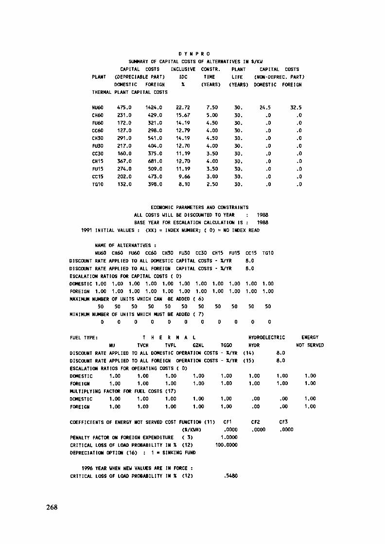
D Y N P R 0SUMMARY OF CAPITAL COSTS OF ALTERNATIVES IN S/KW
CAPITAL COSTS INCLUSIVE CONSTR. PLANT CAPITAL COSTSPLANT (DEPRECIABLE PART) IDC TIME LIFE (NON-DEPREC. PART)
DOMESTIC FOREIGN X (YEARS) (YEARS) DOMESTIC FOREIGNTHERMAL PLANT CAPITAL COSTS
NU60CH60FU60CC60CH30FU30CC30CH15FUI 5CC15TG10
475.0231.0172.0127.0291.0217.0160.0367.0274.0202.0132.0
1424.0429.0321.0298.0541.0404.0375.0681.0509.0473.0398.0
22.7215.6714.1912.7914.1912.7011.1912.7011.199.668.10
7.505.004.504.004.504.003.504.003.503.002.50
30.30.30.30.30.30.30.30.30.30.30.
24.5.0.0.0.0.0.0.0.0.0.0
32.5.0.0.0.0.0.0.0.0.0.0
ECONOMIC PARAMETERS AND CONSTRAINTSALL COSTS WILL BE DISCOUNTED TO YEAR : 1988BASE YEAR FOR ESCALATION CALCULATION IS : 1988
1991 INITIAL VALUES : (XX) = INDEX NUMBER; ( 0) = NO INDEX READ
NAME OF ALTERNATIVES :NU60 CH60 FU60 CC60 CH30 FU30 CC30
DISCOUNT RATE APPLIED TO ALL DOMESTIC CAPITAL COSTS - X/YRDISCOUNT RATE APPLIED TO ALL FOREIGN CAPITAL COSESCALATION RATIOS FOR CAPITAL COSTS ( 0)DOMESTIC 1.00 1.00 1.00 1.00 1.00 1.00 1.00FOREIGN 1.00 1.00 1.00 1.00 1.00 1.00 1.00MAXIMUM NUMBER OF UNITS WHICH CAN BE ADDED ( 6)
50 50 50 50 50 50 50MINIMUM NUMBER OF UNITS WHICH MUST BE ADDED ( 7)
0 0 0 0 0 0 0
FUEL TYPE: T H E R M A LNU TVCH TVFL GZNL
DISCOUNT RATE APPLIED TO ALL DOMESTIC OPERATION COSTS - X/YRDISCOUNT RATE APPLIED TO ALL FOREIGN OPERATION CESCALATION RATIOS FOR OPERATING COSTS ( 0)DOMESTIC 1.00 1.00 1.00 1.00FOREIGN 1.00 1.00 1.00 1.00MULTIPLYING FACTOR FOR FUEL COSTS (17)DOMESTIC 1.00 1.00 1.00 1.00FOREIGN 1.00 1.00 1.00 1.00
COEFFICIENTS OF ENERGY NOT SERVED COST FUNCTION (11) CF1($/KWH)
PENALTY FACTOR ON FOREIGN EXPENDITURE ( 3)CRITICAL LOSS OF LOAD PROBABILITY IN X (12)DEPRECIATION OPTION (16) : 1 * SINKING FUND
CH15 FU15i - X/YRi - X/YR
1.00 1.001.00 1.00
50 50
0 0
TGGOÎTS - X/YRiTS - X/YR
1.001.00
1.001.00
I) CF1.00001.0000
100.0000
CC15 TG108.08.0
1.00 1.001.00 1.00
50 50
0 0
HYDROELECTRICHYDR
(14) 8.0(15) 8.0
1.00 1.001.00 1.00
.00 .00
.00 .00
CF2 CF3.0000 .0000
ENERGYNOT SERVED
1.001.00
1.001.00
1996 YEAR WHEN NEW VALUES ARE IN FORCE :CRITICAL LOSS OF LOAD PROBABILITY IN X (12) .5480
268
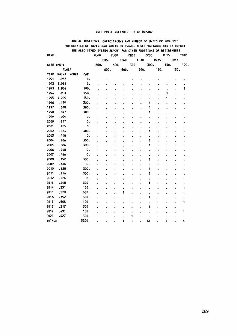
SOFT PRICE SCENARIO - HIGH DEMAND
ANNUAL ADDITIONS: CAPACITY(MU) AND NUMBER OF UNITS OR PROJECTSFOR DETAILS OF INDIVIDUAL UNITS OR PROJECTS SEE VARIABLE SYSTEM REPORT
SEE ALSO FIXED SYSTEM REPORT FOR OTHER ADDITIONS OR RETIREMENTSNAME: NU60 FU6Û CH30 CC30 FU15 TG10
CH60 CC60 FU30 CH15 CC15SIZE (MW): 600. 600. 300. 300. 150. 100.
%LOLP 600. 600. 300. 150. 150.YEAR199119921993199419951996199719981999200020012002200320042005200620072008200920102011201220132014201520162017201820192020TOTALS
MAINT.937
1.9811.934
.9031.209
.179
.070
.047
.099
.217
.485
.163
.440
.286
.086
.208
.466
.152
.336
.520
.216
.524
.248
.351
.529
.352
.508
.317
.495
.427
NOMNT CAP0.0.
100.150.150.300.300.300.
00,0.
300.0.
300.300.
0.0.
300.0.
300.300.
0.300.100.600.300.100.300.100.300.
5200.
1• • • • • • • • 1
111
1
11
. . . . . . . . .
• • • • • • • • •
1. . . . . . . , ,
11
• • • • • . . . •
1» . * . . . . . .
1 . . . . .1
• « « . « . • • .
1• • » • • • • • •
1 . . . .1 1 . 12 . 2
1
. «
. .
. .
„
f f
m m
m »
• *
f f
• *
. ,
. ,
. .
.
. .
1• »
. .
1» .
1. .
4
269
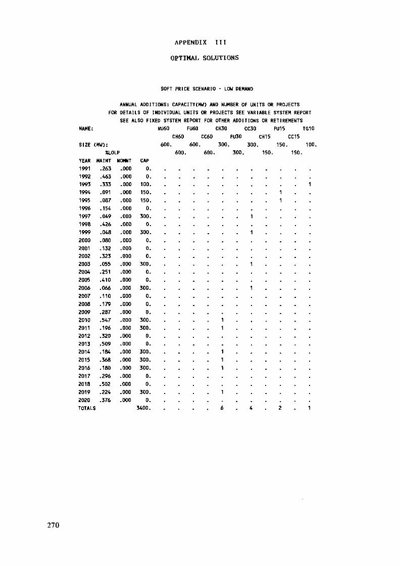
APPENDIX III
OPTIMAL SOLUTIONS
SOFT PRICE SCENARIO - LOW DEMAND
ANNUAL ADDITIONS: CAPACITY(HU) AND NUMBER OF UNITS OR PROJECTSFOR DETAILS OF INDIVIDUAL UNITS OR PROJECTS SEE VARIABLE SYSTEM REPORT
SEE ALSO FIXED SYSTEM REPORT FOR OTHER ADDITIONS OR RETIREMENTSNAME: NU60 FU60 CH30 CC30 FU15 TG10
CH60 CC60 FU30 CH15 CC15SIZE (
YEAR1991199219931994199519961997199819992000200120022003200420052006200720082009201020112012201320 H201520162017201820192020TOTALS
MW):XLOLP
MAINT N.263.463.333.091.087.154.049.426.048.080.132.323.055.251.410.066.110.179.287.547.196.320.509.184.368.180.296.502.224.376
OMNT.000.000.000.000.000.000.000.000.000.000.000.000.000.000.000.000.000.000.000.000.000.000.000.000.000.000.000.000.000.000
CAP0.0
100.150.150.0.
300.0
300.0,00.
300.0.0.
300.0.0.0.
300.300.0.0.
300.300.300.0.0.
300.0.
3400.
600. 600. 300. 300. 150. 10600. 600. 300. 150. 150.
111
1
1
1. . . . . . . . . .
. . . . . . . . . . .
1. . . . . . . . . . .
. . . . . . . . . . .
. . . . . . . . . . .
1 . . . . . .1 . . . . . .
. . . . . . . . .. . . . . . . . . . .
1 . . . . . .1 . . . . . .1 . . . . . .
. . . . . . . . . . .
. . . . . . . . .
1 . . . . . .. . . . . . . . . . .
6 . 4 . 2 . 1
270
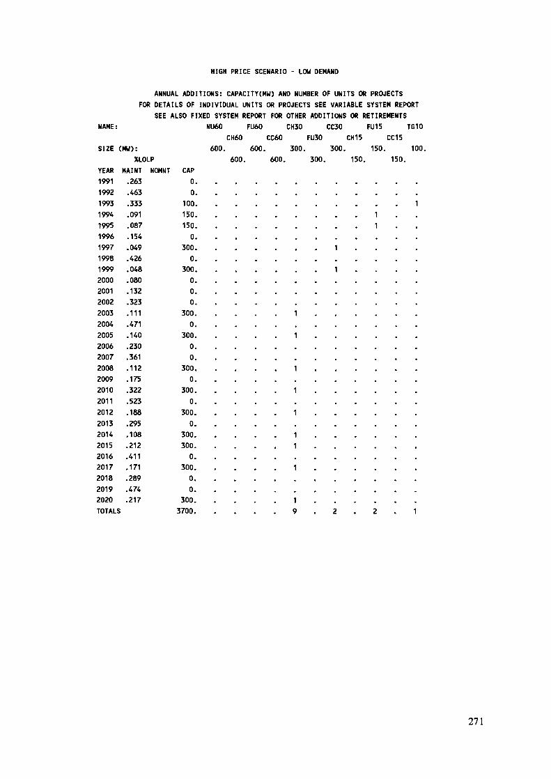
HIGH PRICE SCENARIO - LOW DEMAND
ANNUAL ADDITIONS: CAPACITY(HW) AND NUMBER OF UNITS OR PROJECTSFOR DETAILS OF INDIVIDUAL UNITS OR PROJECTS SEE VARIABLE SYSTEM REPORT
SEE ALSO FIXED SYSTEM REPORT FOR OTHER ADDITIONS OR RETIREMENTSNAME: NU60 FU60 CH30 CC30 FU15 TG10
CH60 CC60 FU30 CH15 CC15SIZE (MW): 600. 600. 300. 300. 150. 100.
%LOLP 600. 600. 300. 150. 150.YEAR1991199219931994199519961997199819992000200120022003200420052006200720082009201020112012201320U201520162017201820192020TOTALS
MAINT.263.463.333.091.087.154.049.426.048.080.132.323.111.471.140.230.361.112.175.322.523.188.295.108.212.411.171.289.474.217
NOMNT CAP0.0
100,150.150.
0.300.
0.300.
0.00.
300.0.
300.00.
300.0.
300.0.
300.0.
300.300.
0.300.
0.0.
300.3700.
• • • •
. . . . .
* • • • •
• • • •
1
1
• • • • •
1. . . .
1• . . . •
1• • • • .
11
. . . . .
1» . . .
• . . . .
19
111
1
1
. . . . . .
• • • • • •
. . . . . .
. . . . . .
. . . . . .
. . . . . .
. . . . . .
. . • • • •
. . . . . .
. . . . . .
. . . . . .
. . . .
. . . . . .
. . . . . .
. . . . . .
. . . . .
2 . 2 . 1
271
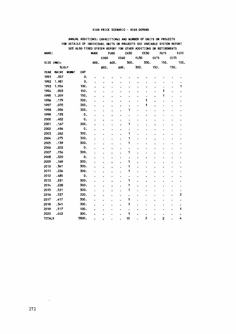
HIGH PRICE SCENARIO - HIGH DEMAND
ANNUAL ADDITIONS: CAPACITY(MW) AND NUMBER OF UNITS OR PROJECTSFOR DETAILS OF INDIVIDUAL UNITS OR PROJECTS SEE VARIABLE SYSTEM REPORT
SEE ALSO FIXED SYSTEM REPORT FOR OTHER ADDITIONS OR RETIREMENTSNAME: NU60 FU60 CH30 CC30 FU15 TG10
CH60 CC60 FU30 CH15 CC15SIZE (MW): 600. 600. 300. 300. 150. 100.
%LOLP 600. 600. 300. 150. 150.YEAR199119921993199419951996199719981999200020012002200320042005200620072008200920102011201220132014201520162017201820192020TOTALS
MAINT.9371.9811.934.9031.209.179.070.096.193.402.167.496.262.275.139.303.156.320.169.361.226.485.331.228.521.537.417.341.517.443
NOMNT CAP00,
100.150.150.300.300.300.00,
300.0.
300.300.300.0
300.0.
300.300.300.0.
300.300.300.200.300.300.100.300.5800.
• . • . •
• " • • •
. . . . .
. . . . .1
11111
.111
• . . . .111
• • • . .11
• . . . .1. 15
111
1 . . . .1 . . . .
. . . . . .
.
. . . . . .
. . » . , .
. . . . . .
. . . . . .
. . . . .
. . . . . .
. . . . . .
. . . . . .
. . . . . .
. . . . . .
. . . .
. . . . . .
2. . . . . .
. . . . . .
1. . . . . .
2 . 2 . 4
272

LIST OF PARTICIPANTS
Mr. Lounès SAHOUIHead, Electricity/Gas Network StudiesSONELGAZ, Direction de la Planification2 Bd. Salah Bouakouir, AlgersAlgeriaMr. Tibor RAJCIDivision HeadResearch Institute of Fuel and Energy ComplexBajkalskà 27, 827 52 BratislavaCzechoslovakiaMr. Spyridon VASSOSGeneration Planning DivisionPublic Power Corporation32 Arachovis Street, AthensGreeceMr. Peter BALAZSDeputy Director, Power Station andNetwork Engineering Co. (EROTERV)Sz/Chenyu rkp. 3, 1054 BudapestHungaryMr. Peter DÖRFNERGroup LeaderHungarian Electricity Board (MVMT)Vàm u. 5-7, H-11011 Budapest IHungaryMr. Yigal PORATIsrael Electric CorporationHead, Analytical Research DepartmentP.O. Box 10, Haifa 31000IsraelMr. David SOLOVEITCHIKMinistry of Energy15/11 A. Rubovich Str.93811 JerusalemIsraelMr. Sandro PANICHELLIENEL, Planning DepartmentVia G.B. Martini 300198 RomaItalyMr. Niazi MUSAPlanning DepartmentJordan Electricity AuthorityP.O. Box 2310, AhmanJordan
273

Mr. Ez-Dean M. ABOUGHALYAConsultant to the Ministry of EnergyP.O. Box 397, TripolisLibyan Arab JamahiriyaMr. J.E. RABERANOHATRAPlanning and Economic Studies DepartmentDirection de l'Energie et de l'EauBP 896 AntananarivoMadagascarMr. Nicolai FEILBERGNorwegian Electric Power ResearchInstitute (EFI)
N-7034 TrondheimNorwayMr. Björn GRINDENNorwegian Electric Power ResearchInstitute (EFI)
N-7034 TrondheimNorwayMr. Jerzy DUDSIKPower and Lignite Board05 800 PruszkowPolandMr. Santiago MUNOZUNESA, C. Francisco Gervâs, 3Madrid 28020SpainMr. Edgard GNANSOUNOUEcole Plytechnique Federale de LausanneLaboratoire de Systèmes EnergétiquesIHE/DGC, 1015 Lausanne (CH)SwitzerlandMr. Khaled HOMSIPublic Establishment of ElectricityP.O. Box 3386, DamascusSyrian Arab RepublicMr. Chedli CHAKROUNSTEG, Assistant HeadPlanning Department38 rue Kemal Ataturk1021 TunisTunisia
274

IAEA Scientific SecretaryPablo E. MOLINADivision of Nuclear PowerPlanning and Economic Studies SectionInternational Atomic Energy AgencyP.O. Box 100, A-1400 ViennaAustria
HOST COUNTRY - CYPRUSPrincipals:Mr. D.A. PapageorgisGeneral ManagerElectricity Authority of Cyprus (EAC)15 Photis Pittas StreetP.O. Box 4506, NicosiaCyprusMr. G. KountourisManager, Transmission and Distribution, EACMr. C. CharalarabousSenior System Development Engineer, EAC
Observers :Dr. T. Drakos, Director, Higher Technical InstituteMr. S. Prodromitis, Assistant, T/D Manager (S.D. & F.P.), EACMr. G. Poullikas, Assistant, T/D Manager (Operations), EACMr. A. Theophanous, System Development Engineer, EACMr. A. Kellas, Generation Engineer, Test and Efficiency, EACMr. I. Chrysis, Ministry of Commerce and IndustryMr. G. Roditis, Ministry of Commerce and IndustryMr. S. Stylianou, Shift Charge Engineer, EAC
275