Embed Size (px)
Citation preview
Wishful Search: Interactive Composition of Data Mashups
Anton V. Riabov, Eric Bouillet, Mark D. Feblowitz, Zhen Liu and Anand RanganathanIBM T. J. Watson Research Center
19 Skyline Drive, Hawthorne, NY 10532, USA riabov, ericbou, mfeb, zhenl, arangana @ us.ibm.com
ABSTRACT
With the emergence of Yahoo Pipes and several similar ser-vices, data mashup tools have started to gain interest ofbusiness users. Making these tools simple and accessible tousers with no or little programming experience has become apressing issue. In this paper we introduce MARIO (MashupAutomation with Runtime Orchestration and Invocation),a new tool that radically simplifies data mashup composi-tion. We have developed an intelligent automatic composi-tion engine in MARIO together with a simple user interfaceusing an intuitive “wishful search” abstraction. It thus al-lows users to explore the space of potentially composabledata mashups and preview composition results as they iter-atively refine their “wishes”, i.e. mashup composition goals.It also lets users discover and make use of system capabil-ities without having to understand the capabilities of indi-vidual components, and instantly reflects changes made tothe components by presenting an aggregate view of changedcapabilities of the entire system. We describe our experi-ence with using MARIO to compose flows of Yahoo Pipescomponents.
Categories and Subject Descriptors
H.4.m [Information Systems]: Miscellaneous
General Terms
Algorithms, Design, Experimentation
Keywords
Composition, Programmable Web, Tag Cloud
1. INTRODUCTIONConfigurable applications for automated processing of syn-
dication feeds (i.e. Atom and RSS) are gaining increasinginterest and attention on the Web. As of writing this pa-per there are over 30,000 customized feed processing flows(referred to as “pipes”) published on Yahoo Pipes [15], themost popular service of this kind. Yahoo Pipes offers hostedfeed processing and provides a rich set of user-configurableprocessing modules, which extends beyond the typical syn-dication tools and includes advanced text analytics such aslanguage translation and keyword extraction. Yahoo Pipes’
Copyright is held by the International World Wide Web Conference Com-mittee (IW3C2). Distribution of these papers is limited to classroom use,and personal use by others.WWW 2008, April 21–25, 2008, Beijing, China.ACM 978-1-60558-085-2/08/04.
Parameter:Search Query
URL Builder:Yahoo News
http://news.search.yahoo.com/news/rss
URL Builder:Yahoo Answers
http://answers.yahoo.com/rss/searchq
Fetch Feed Fetch Feed
Truncate10 Entries
Truncate10 Entries
Union
Sort
Output
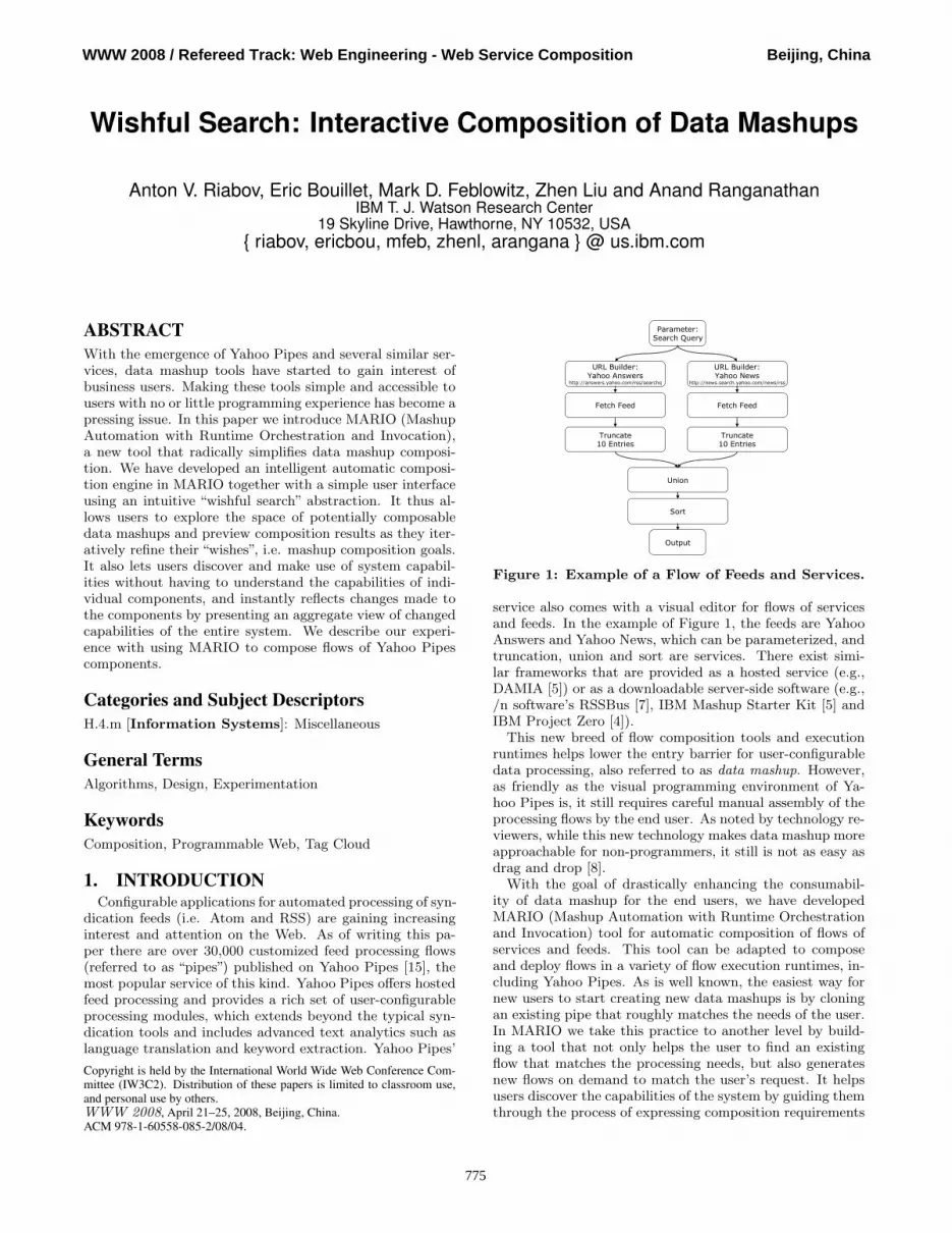
Figure 1: Example of a Flow of Feeds and Services.
service also comes with a visual editor for flows of servicesand feeds. In the example of Figure 1, the feeds are YahooAnswers and Yahoo News, which can be parameterized, andtruncation, union and sort are services. There exist simi-lar frameworks that are provided as a hosted service (e.g.,DAMIA [5]) or as a downloadable server-side software (e.g.,/n software’s RSSBus [7], IBM Mashup Starter Kit [5] andIBM Project Zero [4]).
This new breed of flow composition tools and executionruntimes helps lower the entry barrier for user-configurabledata processing, also referred to as data mashup. However,as friendly as the visual programming environment of Ya-hoo Pipes is, it still requires careful manual assembly of theprocessing flows by the end user. As noted by technology re-viewers, while this new technology makes data mashup moreapproachable for non-programmers, it still is not as easy asdrag and drop [8].
With the goal of drastically enhancing the consumabil-ity of data mashup for the end users, we have developedMARIO (Mashup Automation with Runtime Orchestrationand Invocation) tool for automatic composition of flows ofservices and feeds. This tool can be adapted to composeand deploy flows in a variety of flow execution runtimes, in-cluding Yahoo Pipes. As is well known, the easiest way fornew users to start creating new data mashups is by cloningan existing pipe that roughly matches the needs of the user.In MARIO we take this practice to another level by build-ing a tool that not only helps the user to find an existingflow that matches the processing needs, but also generatesnew flows on demand to match the user’s request. It helpsusers discover the capabilities of the system by guiding themthrough the process of expressing composition requirements
775
WWW 2008 / Refereed Track: Web Engineering - Web Service Composition Beijing, China
MARIO VisualEditor
ExecutionRuntime
FeedsFeedsFeeds FeedsResults
FeedsFlows
FeedsFeedsServices
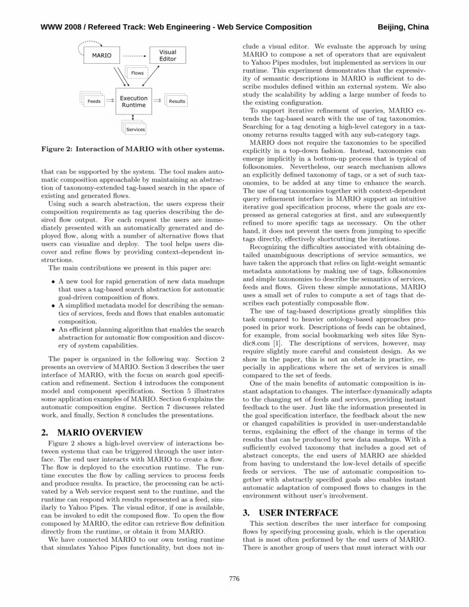
Figure 2: Interaction of MARIO with other systems.
that can be supported by the system. The tool makes auto-matic composition approachable by maintaining an abstrac-tion of taxonomy-extended tag-based search in the space ofexisting and generated flows.
Using such a search abstraction, the users express theircomposition requirements as tag queries describing the de-sired flow output. For each request the users are imme-diately presented with an automatically generated and de-ployed flow, along with a number of alternative flows thatusers can visualize and deploy. The tool helps users dis-cover and refine flows by providing context-dependent in-structions.
The main contributions we present in this paper are:
• A new tool for rapid generation of new data mashupsthat uses a tag-based search abstraction for automaticgoal-driven composition of flows.
• A simplified metadata model for describing the seman-tics of services, feeds and flows that enables automaticcomposition.
• An efficient planning algorithm that enables the searchabstraction for automatic flow composition and discov-ery of system capabilities.
The paper is organized in the following way. Section 2presents an overview of MARIO. Section 3 describes the userinterface of MARIO, with the focus on search goal specifi-cation and refinement. Section 4 introduces the componentmodel and component specification. Section 5 illustratessome application examples of MARIO. Section 6 explains theautomatic composition engine. Section 7 discusses relatedwork, and finally, Section 8 concludes the presentations.
2. MARIO OVERVIEWFigure 2 shows a high-level overview of interactions be-
tween systems that can be triggered through the user inter-face. The end user interacts with MARIO to create a flow.The flow is deployed to the execution runtime. The run-time executes the flow by calling services to process feedsand produce results. In practice, the processing can be acti-vated by a Web service request sent to the runtime, and theruntime can respond with results represented as a feed, sim-ilarly to Yahoo Pipes. The visual editor, if one is available,can be invoked to edit the composed flow. To open the flowcomposed by MARIO, the editor can retrieve flow definitiondirectly from the runtime, or obtain it from MARIO.
We have connected MARIO to our own testing runtimethat simulates Yahoo Pipes functionality, but does not in-
clude a visual editor. We evaluate the approach by usingMARIO to compose a set of operators that are equivalentto Yahoo Pipes modules, but implemented as services in ourruntime. This experiment demonstrates that the expressiv-ity of semantic descriptions in MARIO is sufficient to de-scribe modules defined within an external system. We alsostudy the scalability by adding a large number of feeds tothe existing configuration.
To support iterative refinement of queries, MARIO ex-tends the tag-based search with the use of tag taxonomies.Searching for a tag denoting a high-level category in a tax-onomy returns results tagged with any sub-category tags.
MARIO does not require the taxonomies to be specifiedexplicitly in a top-down fashion. Instead, taxonomies canemerge implicitly in a bottom-up process that is typical offolksonomies. Nevertheless, our search mechanism allowsan explicitly defined taxonomy of tags, or a set of such tax-onomies, to be added at any time to enhance the search.The use of tag taxonomies together with context-dependentquery refinement interface in MARIO support an intuitiveiterative goal specification process, where the goals are ex-pressed as general categories at first, and are subsequentlyrefined to more specific tags as necessary. On the otherhand, it does not prevent the users from jumping to specifictags directly, effectively shortcutting the iterations.
Recognizing the difficulties associated with obtaining de-tailed unambiguous descriptions of service semantics, wehave taken the approach that relies on light-weight semanticmetadata annotations by making use of tags, folksonomiesand simple taxonomies to describe the semantics of services,feeds and flows. Given these simple annotations, MARIOuses a small set of rules to compute a set of tags that de-scribes each potentially composable flow.
The use of tag-based descriptions greatly simplifies thistask compared to heavier ontology-based approaches pro-posed in prior work. Descriptions of feeds can be obtained,for example, from social bookmarking web sites like Syn-dic8.com [1]. The descriptions of services, however, mayrequire slightly more careful and consistent design. As weshow in the paper, this is not an obstacle in practice, es-pecially in applications where the set of services is smallcompared to the set of feeds.
One of the main benefits of automatic composition is in-stant adaptation to changes. The interface dynamically adaptsto the changing set of feeds and services, providing instantfeedback to the user. Just like the information presented inthe goal specification interface, the feedback about the newor changed capabilities is provided in user-understandableterms, explaining the effect of the change in terms of theresults that can be produced by new data mashups. With asufficiently evolved taxonomy that includes a good set ofabstract concepts, the end users of MARIO are shieldedfrom having to understand the low-level details of specificfeeds or services. The use of automatic composition to-gether with abstractly specified goals also enables instantautomatic adaptation of composed flows to changes in theenvironment without user’s involvement.
3. USER INTERFACEThis section describes the user interface for composing
flows by specifying processing goals, which is the operationthat is most often performed by the end users of MARIO.There is another group of users that must interact with our
776
WWW 2008 / Refereed Track: Web Engineering - Web Service Composition Beijing, China

Figure 3: MARIO interface for an empty goal.
system for another purpose, namely to input the tag-baseddescriptions of feeds and services. We have not developedany graphical tools for that group of users, and in our im-plementation the required descriptions are provided simplyvia dynamically loaded configuration files. This will be de-scribed in Section 4.
The user interface described in this section is not specificto automatic composition per se in many respects. It was ourintent to develop an interface that can simplify navigationand search in a large set of tagged and ranked objects. Thoseobjects do not have to be feeds that are generated on the fly– they could also be taken from an external catalog.
It is the efficient planning algorithm that enables the useof this user interface for flow composition. It shields theuser from the associated complexity, and makes dynamiccomposition appear as search over a static catalog. Thedetails of the algorithm will be explained in Section 6.
3.1 Initial Goal SpecificationThe end user interacts with MARIO via a web browser.
The first screen presented to the user contains a single tagcloud (see Figure 3). This tag cloud contains tags that arerelevant to the application domain. The user can select oneor more tags from the tag cloud to describe the desired re-sults. Tags shown using large font sizes generally correspondto high-level categories. For example, the tag Newspaper ap-pears in a larger font than WashingtonTimes. The larger fontsize indicates that the selection will constitute a broad goalthat will likely need to be refined by adding other tags.
Clicking on a tag in the tag cloud adds that tag to thecurrent goal, which is initially empty. The tag cloud showsonly those tags that can be added to the goal such thatthe new goal can be planned, i.e., at least one flow can becomposed to satisfy the goal. In further sections we willdiscuss how this is achieved. Practically it means that thetag cloud reflects the current capabilities of the system.
Due to screen space constraints the tags that would oth-erwise appear in the smallest font may be completely re-moved from the screen. To accommodate advanced userswho want to enter these tags directly, MARIO interface in-cludes a search string where tags can be typed in. The searchstring also lets users add more than one tag to the goal.
3.2 Goal Refinement InterfaceGoal refinement is the main mode of interaction between
MARIO and its users. When one or more tags are specified
as the goal, new control elements appear in the user inter-face, as shown on Figure 4. New elements display the flowthat matches the goal and a preview of the output producedby that flow. The interface also includes a number of otherelements that help user understand current system capabil-ities and refine the goal. All user interface elements shownon Figure 4 appear simultaneously on one screen, and userinput committed to any element changes the contents of allelements.
3.2.1 Current Goal
The “Current Goal” element displays the set of tags thatconstitute the goal. These tags, shown in black font, arereferred to in what follows as the current goal. On Figure 4,the current goal is the set Sorted, Yahoo Answers, Yahoo
News. The user can click on each of these tags to removethat tag from the goal.
Each time the user changes the current goal, the composergenerates and ranks possible alternative flows for that goal,computing sets of tags describing these flows. It also choosesone flow with the best rank among the alternatives and sub-mits it to the execution environment. We will refer to thisflow as the selected flow.
The description of each of the alternatives must includeall tags of the current goal, but may also contain other tags.These additional tags for the selected flow are shown in grayfont in the “Current Goal” element. This gives user an in-dication of how MARIO interpreted the goal. Being ableto see this set of guessed tags is especially helpful when thegoal is ambiguous, for example is based on a general concept.On Figure 4, Sorted was specified as part of the goal, andMARIO selected the flow described by ByTitleAsc (amongother tags) to satisfy the goal.
3.2.2 Parameters
The selected flow can have one or more parameters. Theselected flow on Figure 4 has one parameter, “Destination”.The parameters are automatically initialized with defaultvalues, but the users can change parameter values using theedit controls inside the“Parameters”element. Depending onthe runtime environment, it can be possible to change thevalues of the parameters without redeploying the flow. InYahoo Pipes, for example, the parameters can be specifiedin the URL corresponding to the deployed flow.
3.2.3 Composed Flow
The “Composed Flow” element shows a graphical repre-sentation of the selected flow and its configuration param-eters. This is especially useful for the advanced users whohave a good understanding of individual service modules,and use MARIO to quickly create a flow for their needs.The users who are less familiar with the individual servicesmay be able to get better understanding of the selected flowfunctionality from the guessed tags in the “Current Goal”and the contents of “Flow Output”.
3.2.4 Flow Output
The “Flow Output” element shows the results producedby the selected flow. In our implementation it shows thefeed produced by the selected flow. Note that this is theonly user interface element cannot be populated until theselected flow is deployed and produces results. Dependingon the runtime, in some cases it may take longer than the
777
WWW 2008 / Refereed Track: Web Engineering - Web Service Composition Beijing, China

Add to goalModify goalCurrent goal
AlternativesComposed Flow
Flow OutputParameters
Flow graph
Figure 4: MARIO interface for goal Sorted, YahooAnswers, YahooNews.
user is willing to wait. In those cases the element can displaya preview of the results obtained by other means.
3.2.5 Add to Goal and Modify Goal
The “Add To Goal” element shows a tag cloud similar tothe one shown in Figure 3, but computed in the context ofthe current goal. In other words, the tag cloud in Figure 4only shows the tags that can be combined with the currentgoal, such that there will exist at least one flow satisfyingthe new goal. Both the set of tags in the tag cloud and thesize of the fonts used to display the tags in “Add To Goal”element may change depending on the current goal.
Clicking on a tag in the tag cloud adds the tag to thecurrent goal, which results in composition and deploymentof a new selected flow and changes the contents of all userinterface elements.
The “Modify Goal” element allows specifying a new goalusing a search string. This can be especially useful for expe-rienced users who may find it tedious to click tags in “AddTo Goal” or “Current Goal” elements to add or remove tagsone by one. When the set of tags is large, the tag cloud maynot show all of those tags, and several steps of goal refine-ment may be necessary to add a tag that is initially hidden.On the other hand, it can be the only way for the end userto discover that the tag exists and is supported by the sys-tem. The users who already know about the tag can type itdirectly into“Modify Goal”without intermediate refinementsteps. After clicking on “Go” button, the set of tags enteredin the search string becomes the new goal.
3.2.6 Alternatives
The list of alternative flows, their rankings and tag anno-tations are provided as reference to power users. Selectingand clicking one flow in the list of alternatives replaces theselected flow with the selected flow without changing the
current goal. Some of the alternative flows can be subopti-mal, i.e. there may exist better ranking flows with exactlythe same description. Hence, the preferred way of selectinganother flow is to modify the goal using other user interfaceelements, which guarantees that the selected flow is optimalfor the selected goal.
3.2.7 Commands
The user interface provides access to a set of commandsthat operate on the selected flow (the commands are locatedabove the flow graph in Figure 4). The set of commandsdepends on the functionality supported by the runtime. Forexample, “Edit” command can be used to open the VisualEditor, and “Publish” command can be used to make theflow public, i.e. accessible by others.
4. COMPOSITIONAL SEMANTICSThis section deals with the formal definition of the com-
positional semantics of a flow. We address this issue bydefining a model for deriving the semantic description of aflow based on the descriptions of its individual components.A key characteristic of our model is that it captures notonly the semantics of inputs and outputs, but also the func-tional dependency between the outputs and the inputs. Thismodel can also be expressed using SPPL formalism (StreamProcessing Planning Language, [10]) for describing planningtasks, which allows us to use an efficient planning algorithmfor flows composition.
4.1 Composition Elements
4.1.1 Objects, Tags and Taxonomies
A taxonomy T = t is a set of tags (i.e. keywords) t. Anobject o is described by a set of tags d(o) ⊆ T selected from
778
WWW 2008 / Refereed Track: Web Engineering - Web Service Composition Beijing, China
the taxonomy T . An object can be, for example, a resourcebookmark, as in del.icio.us [12], or a feed, as in Syndic8 [1].
In the simplest case, for example if T is formed as afolksonomy, by people specifying one or more tags to de-scribe certain objects, the tags in T are unrelated and T iscompletely unstructured. Introducing a taxonomy structurein T , however, enhances query expressivity, as we explainbelow, and also helps keep tag-based descriptions succinct.
The structure of the taxonomy is described by specifyingsub-tag relationship between tags. The following definitionis the standard definition of a taxonomy sub-tag relationapplied to tagging.
Definition 1. A tag t1 ∈ T is a sub-tag of t2 ∈ T , denotedt1 :: t2, if all objects described by t1 can also be describedby t2. The sub-tag relation is transitive, i.e. if t1 :: t2 andt2 :: t3 implies t1 :: t3 for ∀t1, t2, t3 ∈ T.
For example, NewYorkTimes :: Newspaper. For notationalconvenience we will further assume that each tag is a sub-tagof itself, i.e.
∀t ∈ T, t :: t.
If two tags t1, t2 ∈ T are such that t1 :: t2 and t2 :: t1,these tags are synonyms, since by definition they describethe same set of objects. We will denote this as t1 ≡ t2.
4.1.2 Queries
Queries are used to describe the desired results producedby a composition (i.e., composition goals), or to specify theinput conditions of an operator.
Definition 2. A tag query q ⊆ T selects a subset Qq(O) ofan object set O = o such that each object in the selectedsubset is described by all tags in q, taking into account sub-tag relationships between tags. Formally,
Qq(O) = o ∈ O|∀t ∈ q ∃t′ ∈ d(o) such that t
′ :: t.
Note that this definition of a query remains equally effec-tive in taxonomies with explicitly stated sub-tag relation-ships, as well as in configurations with implicit taxonomies,where the sub-tag relationships are not explicitly stated, butcan be inferred from joint appearance of tags.
For example, consider a set of objects O1 and a taxonomyT1 where NewYorkTimes :: Newspaper, and some objects inO1 are annotated with NewYorkTimes. Assume that O2 iscreated from O1 by annotating every object in the set o ∈O1|NewYorkTimes ⊆ d(o) with Newspaper tag, and tax-onomy T2 is the same as T1 but with the sub-tag relationshipbetween Newspaper and NewYorkTimes removed (thus defin-ing an implicit taxonomy). As a result, for q =Newspaperthe selected subset will be the same in both sets of objects.
This is a very important property of the proposed ap-proach. It allows mixing implicit taxonomies, typical offolksonomy-like bottom-up modeling approaches, with muchmore structured and elaborate top-down modeling, which istypical of taxonomies and ontologies. By effectively enablingan easy gradual transition from implicitly formed to explic-itly stated sub-tag relationships between tags, as the modelevolves, it greatly reduces the effort required for creating afirst working set of descriptions compared to the top-downontology-based modeling approaches, where the significantcost of defining taxonomies must be paid upfront.
4.1.3 Operators
An operator is a basic unit in the composition. Generally,it creates one or more new objects from a subset of exist-ing objects. An operator can require no inputs. When oneor more inputs are required, an input condition is specifiedfor each input. The input condition is specified as a tagquery, which must be satisfied by the corresponding objectprovided as input. The outputs are described by specifyingtags that are added to and removed from the descriptionof the new objects produced by the output. For example,consider a service that truncates an RSS feed to specifiednumber of items. This service can be modeled by an opera-tor that includes FullFeed in its input condition, and removesit from the output object description, adding ShortFeed.
The descriptions of the new objects functionally dependon descriptions of input objects. There are two methodsof propagating information from the input to the output.The first, explicit, method involves using a typed tag vari-able that can be bound to one of the tags describing theinput object, and then using this variable to describe one ormore of the outputs. The type of the variable is a tag, andthe variable can be bound to any single sub-tag of its type.In certain cases, however, operators must propagate sets oftags unrelated to the operator. For example, the trunca-tion operator needs to propagate any tags describing feedorigin, such as Newspaper. To enable the second method ofpropagation, a special “sticky” tag Ω is defined to serve as alabel for automatically propagating tags. If any sub-tag ofΩ appears in at least one input object description, it will beautomatically added to the description of all output objects.
The following definition captures all of the properties ofan operator explained above.
Let
• p(f) ≥ 0 be the number of operator variables for op-erator f ;
• ~t(f) = tk(f)|tk(f) ∈ Tp(f)k=1 be an array of tags repre-
senting the types of operator variables ~v for operator f ;• n(f) ≥ 0 be the number of inputs of operator f ;
• ~q(f,~v) = qi(f,~v)|qi(f,~v) ⊆ Tn(f)i=1 be an array of tag
queries that define input conditions of operator f ;• m(f) ≥ 1 be the number of outputs of operator f ;
• ~a(f,~v) = aj(f,~v)|aj(f,~v) ⊆ Tm(f)j=1 be an array of
sets of added tags for outputs of operator f ;
• ~r(f,~v) = rj(f,~v)|rj(f,~v) ⊆ Tm(f)j=1 be an array of
sets of removed tags for outputs of operator f .
Given the above parameters of an operator, and
• an object set O;
• an array of tags ~v = vkp(f)k=1 assigned to operator
variables, such that vk ∈ T and vk :: tk(f);• an array of input objects ~o ⊆ O satisfying the input
conditions parameterized with ~v, i.e., such that ~o =
oin(f)i=1 and oi ∈ Qqi(f,~v)(O)
we define the operator as follows.
Definition 3. Operator f = 〈p,~t, n, ~q, m,~a, ~r〉 is a functionon the object set, defined as f(O,~v, ~o) = O ∪ O′, where
O′ = o′j |o 6∈ Om(f)j=1 is the set of new objects produced by
the operator, and where
d(o′j) =
n(f)⋃
i=1
t′ ∈ d(oi)|t′ :: Ω
∪ aj(f,~v) \ rj(f,~v).
779
WWW 2008 / Refereed Track: Web Engineering - Web Service Composition Beijing, China

The definition above provides a formula for computing de-scriptions of new objects produced by the operator: the de-scription of each object is the union of automatically propa-gated tags derived from Ω and operator-output-specific addedtags, minus the set of operator-output-specific removed tags.
4.2 Composition
4.2.1 Composition Semantics
A composition of operators is defined simply as the re-sult of applying one operator to the object set produced byanother operator.
Definition 4. The composition of l operator instances formedby operators f1, f2, . . . fl applied to object subsets ~o1, ~o2, . . . , ~ol
and parameterized with tags ~v1, ~v2, . . . , ~vl correspondingly isthe composite operator f = fj , j = 1..l defined as
f(O) = fl(. . . (f2(f1(O, ~v1, ~o1), ~v2, ~o2)), ~vl, ~ol).
Notice that f(O) = O ∪ O′
1 ∪ O′
2 . . . ∪ O′
l, where O′
i is theset of new objects produced by operator fi. Also note thatinput objects for each subsequent operator can be selectedfrom the object set produced by the preceding operator, i.e.
~o1 ⊆ O0 ≡ O
~o2 ⊆ O1 ≡ O ∪ O′
1
...
~ol ⊆ Ol−1 ≡ O ∪ O′
1 ∪ O′
2 ∪ . . . ∪ O′
l−1
Definition 5. The composition is valid when the inputconditions of each operator instance fj are satisfied by theobject array ~oj , i.e. ∀i, j oji
∈ Qqji(fj , ~vj)(Oj−1).
Subsequent instances of operators may use objects pro-duced by preceding operators as inputs, i.e. there could ex-ist i and j, i < j such that ~oj ∩O′
i 6= ∅. In other words, thereis a data dependency between ~oj and ~oi. Data dependenciesbetween operator instances within a composition can be rep-resented using a data dependency graph where arcs connectoperator outputs to inputs of other operators, similarly tothe flow graph in Figure 1. Note that under this model thedirected data dependence graphs will always be acyclic.
4.2.2 Goal-Driven Composition
The problem of goal-driven composition can now be sim-ply defined as the problem of finding a composition of opera-tors that produces an object satisfying a given query. As anadditional simplifying assumption, we assume that the com-position is applied to an empty object set. This assumptionis not significantly constraining, since the initial objects canalways be produced by operators that do not require anyinput objects. On the other hand, the assumption allowsuniform modeling of both feeds and services as operators.
Given a composition problem P(T,F , g), where:
• T is a tag taxonomy,• F = f is a set of operators,• g is a composition goal specified as a tag query, g ⊆ T ,
the solution set is defined as follows.
Definition 6. The set of solutions S(T,F , g) to the goal-driven composition problem P(T,F , g) is the set of all validcompositions F of operators in F such that
• Qg(F (∅)) 6= ∅;• for all operator instances in F , at least one object pro-
duced by this instance serves as input to another op-erator instance, or satisfies the goal query.
The second condition in the definition above helps eliminatefrom consideration inefficient compositions that have dead-end operator instances producing unused objects.
4.2.3 Composition Ranking
Before the set of compositions S(T,F , g) can be presentedto the user, the compositions must be ranked, with thosemost likely to satisfy user’s intent appearing first in the list.The ranking is based on a heuristic metric reflecting compo-sition quality. Each operator f ∈ F is assigned a fixed costc(f). Cost of an operator instance in a composition is equalto the cost of the corresponding operator.
Definition 7. Rank rank(f) of the composition
f(O) = fn(. . . (f2(f1(O)) . . .)
is the sum of the costs of operator instances, i.e.
rank(f) =n
∑
i=1
c(fi).
By default for all operators c(f) = 1. Hence, the bestcompositions are the shortest ones. During configuration ofthe system, the c(f) can be changed for some operators toreflect feed or service quality.
4.2.4 Goal Refinement Tag Cloud
The refinement tag cloud, as shown in “Add to Goal”area of user interface in Figure 4, provides valuable helpto the user in refining the goal. The tag cloud is simplya popularity-weighted set of tags computed over the de-scriptions of outputs of all compositions in a solution setS(T,F , g). In theory, if the goal g is empty, the tag cloud iscomputed over all valid compositions. Although the set ofall compositions may indeed be very large, the set of com-positions with differently described outputs is much smaller.The planner that we describe later in this paper can computethe tag cloud without constructing all compositions.
Note that the queries in our model behave as though thesuper-tags from the taxonomy are always included in objectdescription with the corresponding sub-tags. The same ap-proach should be used during tag cloud computation. Evenif the super-tags are not included in object description ex-plicitly, they are added to the description automatically forthe purposes of computing the weights in the tag cloud. Thisensures that even if certain tags do not accumulate enoughweight to appear in the visible portion of the tag cloud, theyadd weight to their super-tags, and will still be accessiblethrough those super-tags.
5. APPLICATION EXAMPLEIn this section we describe how the concepts introduced
at an abstract level in the previous section can be applied inpractice, using the set of Yahoo Pipes modules as an exampleof a set of feed processing services.
5.1 Execution RuntimeThe Yahoo Pipes modules for processing feeds are only
available through the visual editor. Therefore, MARIO can
780
WWW 2008 / Refereed Track: Web Engineering - Web Service Composition Beijing, China
<flow><flowInput name="SearchQuery"/><call name="yAnswers" class="com.example.URLBuilder"><input name="prefix"value="http://answers.yahoo.com/rss/searchq"/><input name="suffix" link="SearchQuery"/> </call>
<call name="yNews" class="com.example.URLBuilder"><input name="prefix"value="http://news.search.yahoo.com/news/rss"/><input name="suffix" link="SearchQuery"/> </call>
<call name="fetchNews" class="com.example.FetchFeed"><input name="url" link="yNews"/> </call>
<call name="fetchAnswers" class="com.example.FetchFeed"><input name="url" link="yAnswers"/> </call>
<call name="truncNews" class="com.example.Truncate"><input name="feed" link="fetchNews"/> </call>
<call name="truncAnswers" class="com.example.Truncate"><input name="feed" link="fetchAnswers"/> </call>
<call name="union" class="com.example.Union"><input name="feed1" link="truncAnswers"/><input name="feed2" link="truncNews"/> </call>
<call name="sort" class="com.example.Sort"><input name="feed" link="union"/> </call>
<flowOutput link="sort"/></flow>
Figure 5: Example flow description.
compose a flow of Yahoo Pipes modules, but cannot deployit as a pipe. Deploying a flow is necessary, however, to showthe preview of flow output in MARIO interface (Figure 4).
To overcome this difficulty, as part of our implementationwe have built a simple Java-based runtime that plays thesame role. Each service in this runtime implements interfaceService with a single public method named process thatreceives and returns a hashmap containing input and outputobject values:
interface Service Map<String,Object> process(Map<String,Object> inputs);
The set of hashmap keys used to identify input and out-put objects in the input and output hashmaps is specific toeach service. A separate description is provided to specifythe hashmap keys recognized by the service, as well as tag-based annotations on inputs and outputs. This descriptionis then used to construct a description of an operator. Ser-vice implementation can invoke web services for advancedprocessing, such as language translation, when necessary.
A simple XML format is used to define a flow and deployit in the runtime. Once deployed, the flow can be called withuser-defined values of parameters, and will produce results.Figure 5 presents a sample description corresponding to theflow shown on Figure 1.
Flow definition consists of flow inputs (i.e., external pa-rameters), calls (i.e., operator instances) and a flow output.The call elements instruct runtime about the Java classesto be used to process data, and the input objects to be in-cluded in the input map. The objects can be specified asstring values by specifying value attribute, or linked to out-puts of other calls by specifying a link. In the exampleabove, each output map contains just one element, so spec-ifying the name of the call is sufficient to describe a link.Otherwise, for operators that produce more than one ob-ject, “callName.elementName” notation is used.
5.2 DescriptionsMARIO requires descriptions of services, feeds, parame-
ters, and taxonomies. These descriptions are translated into
tag _URL - _Formattag _Feed - _Formattag _Source - _StickyTagtag FrontPage - _Sourcetag Opinion - _Sourcetag Travel - _Sourcetag News - _Sourcetag Newspaper - Newstag Blog - _Sourcetag NewYorkTimes - Newspapertag NYTFrontPage - NewYorkTimes FrontPagetag Yahoo - _Sourcetag TruncatedFeed - _FeedLengthtag FullFeed - _FeedLengthtag InForeignLanguage -_Languagetag InEnglish - _Languagetag InFrench - InForeignLanguagetag Sorted - _SortOrdertag _NotSorted - _SortOrdertag NaturalOrder - _NotSortedtag Unsorted - _NotSorted
Figure 6: Fragment of a tag taxonomy.
operators and other elements of the model described in Sec-tion 4, which is then used by the planner to generate flows.All descriptions can be specified in one file or broken intomultiple files, which are then automatically combined intoone logical file before processing.
5.2.1 Tag Taxonomies
Taxonomies are described by specifying sub-tag relation-ships between tags. A tag does not need to be explicitly de-clared before it is used, but a tag statement is necessary todeclare parents of a tag, which follow after ’-’, for example:tag NYTFrontPage - NewYorkTimes FrontPage.
Tag names beginning with underscore “ ” are hidden tagsthat are never displayed in user interface, but otherwise be-have as normal tags. Hidden tags can be used to expresscomposition constraints that are internal to the system, forexample, type constraints. The special tag Ω is representedas _StickyTag. Figure 6 shows a fragment of tag taxonomyused in our experiments.
5.2.2 Feed Descriptions
In the example of feed description below the output anno-tation uses tags to describe the content of the feed, as wellas its language.
feed NYTFrontPage output NYTFrontPage InEnglish _URL url http://www.nytimes.com/services/xml/rss/nyt/HomePage.xml
Such descriptions can be generated automatically, for ex-ample using Syndic8 tags and default values for language.The description is translated into an operator that has noinputs, and produces a single output object tagged with alltags used in output annotation. If this operator is includedin a flow composed by the planner, during flow executionthe runtime will bind the corresponding operator instanceto a built-in service that returns the URL string as a singleentry in the hashmap of output objects.
5.2.3 Service DescriptionsEach service can have a number of inputs and outputs.
Service description is directly translated into an operatorthat requires and produces the corresponding number of ob-jects. For example, the following describes a FetchFeed ser-vice.
781
WWW 2008 / Refereed Track: Web Engineering - Web Service Composition Beijing, China

service FetchFeed java com.example.FetchFeedvar ?lang - _Languageinput[url] ?lang _URL output?lang FullFeed NaturalOrder _Feed Text
This description uses a variable ?lang of type _Language,and declares an input and an output. The output list enu-merates tags added by the operator. Tags that are precededwith ~ are interpreted as removed tags.
Note that sub-tags of _Language are not sticky (i.e. arenot derived from the special tag Ω represented as _StickyTag),and therefore must be propagated explicitly from input tooutput using a variable. However, if FetchFeed operator isapplied to the output of the feed operator in the exampleabove, NYTFrontPage tag will be propagated to the outputof FetchFeed as well, since that tag is sticky according tothe taxonomy in Figure 6.
Each input and output in the description can have a portname specified in square brackets. In this example only theinput has a port name “url”. The port name is the nameof the entry in the hashmap that is used to carry the cor-responding input or output object. Since there is only oneoutput port, the runtime does not need to know the name ofthe output object. Finally, java description element speci-fies the name of the Java class that implements the service.
5.2.4 Flow Parameters and ConstantsFlows that take external parameters can also be com-
posed using the same framework. When two or more serviceswithin a flow are parametric, the planner can decide whetherto expose the service parameters as one input parameter ofthe flow, or as several separate parameters. This is achievedby using tags to describe service input parameters (as inputsto services), and representing parameter values similarly tofeeds, i.e. as operators that produce a single object describedby tags. The following is an example of service descriptionthat has an external parameter.param Destination defaultLondonoutput_SearchQuery Travel
service YNewsSearchURL java com.example.URLBuilderinput[prefix]"http://news.search.yahoo.com/news/rss"input[suffix]_SearchQueryoutput_URL YahooNews InEnglish
Service YNewsSearchURL has two inputs, but the corre-sponding operator will have only one input. The constantstring in quotes is used to initialize the prefix parameterto a constant. In the plan suffix parameter will be con-nected to the object produced by the operator correspond-ing to Destination service. Note that including constantsinto the description makes it possible to specify different se-mantic descriptions for different configurations of the sameservice.
5.2.5 More Service Description Examples
The following examples from the sample application fur-ther illustrate different services that can be described in thismodel.
service Truncate10 java com.example.Truncatevar ?lang - _Languagevar ?sort - _SortOrderinput[feed]_Feed ?lang FullFeed ?sortinput[length]"10"output_Feed ?lang ShortFeed ?sort
service TranslateEnFr java com.example.Translatevar ?len - _FeedLengthinput[feed]_Feed InEnglish ?len NaturalOrderinput[fromLanguage]"en"input[toLanguage]"fr"output_Feed InFrench ?len NaturalOrder
service Union2 java com.example.UnionOfTwoFeedsvar ?lang - _Languagevar ?len - _FeedLengthinput[feed1]_Feed ?lang NaturalOrder ?leninput[feed2]_Feed ?lang NaturalOrder ?lenoutput_Feed ?lang ?len Unsorted
These descriptions were used in the application shownin Figure 4. In addition to the goal shown in that figure,the application supports a set of interesting goals, such asNewYorkTimes InFrench, Technology News ByDate, NewYork-
Times Flickr Image, etc. We will continue using this applica-tion for illustration in the next section, where it is used asa benchmark to evaluate planner performance.
6. PLANNING ALGORITHMTo compose flows according to the semantic model de-
scribed in Section 4, we have developed an improved versionof SPPL planner [11] by proceeding with both plannabilityexploration and analysis of related goals. We also addedfunctionality necessary for generating tag clouds. The se-mantic model naturally maps to SPPL formalism, which de-scribes the planning domain as a set of actions that can becomposed by the planner. The set of actions is created basedon the set of operators. Action preconditions, described bypredicates, are created based on operator input conditions.Tags are represented as types in SPPL, and preconditionsare specified using a variable of the corresponding type. Ac-tion effects also are mapped to operator outputs. SPPLpredicate propagation mechanism is used for propagation ofsticky and regular tags.
6.1 Presolve OptimizationsDuring the presolve phase the planner performs action
grounding and obtains results of preliminary problem struc-ture analysis that are later used for optimizing the search.
Intelligent Grounding. Grounding of actions duringpresolve may lead to a combinatorial explosion in the num-ber of actions. To avoid the explosion, the planner performsgrounding intelligently. First, it analyzes the set of groundactions in the first tier, i.e. those actions that can be applieddirectly in the initial state. Next, it creates the set of possi-ble groundings for actions that can be applied to the resultsof the actions in the first tier. This procedure is repeated,until a steady state is reached, and no new ground actionsare created.
Source Grouping. Source actions are actions that donot have inputs. Such actions correspond to operators with-out inputs, and most often correspond to feeds. In certaincases it is possible to combine multiple sources into one ac-tion to reduce the total number of actions considered by theplanner. In particular this is possible when the output de-scription of two sources cannot be distinguished using anyof the input conditions of other actions, i.e. all input con-ditions are either satisfied or not satisfied by both sources.Source grouping procedure is carried out after grounding,
782
WWW 2008 / Refereed Track: Web Engineering - Web Service Composition Beijing, China
and results in significant performance improvements in con-figurations with large number of sources.
Construction of an Action Graph. The planner an-alyzes compatibility of inputs and outputs of ground ac-tions by comparing the effect and precondition predicates.This procedure helps the planner to eliminate connectionsbetween incompatible actions during search. The result ofthis domain preprocessing is an action graph where directededges represent potential connections between an effect ofone ground action and precondition of another ground ac-tion. Action graphs can contain cycles. An important prop-erty of the action graph is that for any connection betweenaction instances in any valid plan there is a directed edge be-tween the corresponding ground actions of the action graph.
In addition to speeding up the search, an action graph canbe used for reachability analysis. If the planning task has asolution there must be a path from all goals in G to at leastone of the initial state object. During presolve, the plannerbuilds shortest path trees from the goals to all nodes of theaction graph. Actions that are not on any of the paths fromgoal to initial state are labeled as disconnected and are notconsidered during plan search. The shortest distances to thegoal in action graph are used to direct plan search.
6.2 Plan SearchThe planner searches for plans using a forward search
strategy. It creates new objects by applying actions thathave satisfied preconditions. At the initialization of the al-gorithm the current set of objects S is empty. A set ofactions L is also created, containing the ground actions forwhich all preconditions can be satisfied by objects containedin S. The planner applies actions from L one by one. Theground action to be applied next is an action from L that hasthe least distance to the goal based on reachability analysis.The action is skipped if the cost of the associated subplan ishigher than the cost bound ~B. When applied, a new actioninstance produces a set of new objects, one object for eacheffect. The predicates on the new objects are computed us-ing predicate propagation rules, and the objects are addedto S. New candidate action instances are determined usingthe action graph and added to L.
Algorithm SPPL Planner(Π)Presolve
1. Action set A← Intelligent Grounding(Π).2. A← Source Grouping(A);3. G(A)← Action Graph(A);
Forward Search4. S ← I; L←
a ∈ A |prec(a) ⊆ S
;5. for each a ∈ L
6. for each a ∈ instances(a, S, G(A))
7. if ~cost(subplan(a)) ≤ ~B and[
∃o ∈ effect(a) : o 6∈ S or6 ∃p ∈ subplans producingS(effect(a)) such that[
p ⊆ subplan(a) and ~cost(subplan(a)) ≥ ~cost(p)]]
8. S ← S ∪ effect(a) ;
9. L← L ∪
a′ ∈ A|prec(a′) ⊆G(A) effect(a)
;
10. if ∃g ∈ G : effect(a) ⊆G(A) g and G ⊆ S
11. add plan candidate((subplan(a)));12. L← L \ a ;
The same object can be produced by many different sub-plans, and each time the same object is produced, a sub-plan (i.e. a set of action instances and their connections)for producing the object is registered. The subplan has an
associated cost vector. Once a subplan is registered, the ac-tion graph is used to create a list of candidate new actionsthat can be applied next. The search algorithm terminateswhen no actions can be applied and no new objects can beproduced.
An important optimization technique used during plansearch is a verification step (line 7) that prevents registra-tion of a new subplan, if the same object can be producedby a subset of that subplan with lower or equal cost. Formany actions the predicates of the output satisfy the inputpreconditions, and without this verification step the searchwould cycle producing new identical instances of the sameobject. Hence, the number of action instances created bythe planner is significantly reduced in those cases. The orig-inal backward search based SPPL planner [10] does not per-form the comparison step, which is difficult to implement inbackward search, and our forward search planner is thereforesignificantly more efficient on this type of planning tasks.
The result of the search is a set of candidate plans thatsatisfy the goals. The candidate plans are then sorted bycost, and only the best plans are returned. Note that thesearch can be terminated early, producing only a subset ofpossible candidate plans. Hence, it is possible to obtain anumber of suboptimal plans before the search finishes, whichcan be important if planning time is limited.
The same algorithm can be enhanced to generate tag cloudswhile searching for plans. The tag weight computation forthe tag cloud uses tag membership statistics that are col-lected from descriptions of outputs of candidate plans.
6.3 Complexity ChallengesAs is shown in [10], SPPL planner performs much bet-
ter in typical flow composition problems than AI planners.Problems that are easily solved by SPPL planner can at thesame time be very difficult for the best general AI planners.By making objects a part of the domain model, SPPL plan-ner avoids unnecessary grounding and symmetries, and thesearch space is reduced by an exponential factor as a result.
However, the problem of finding optimal plans remainsa difficult one. In general, there do not exist optimal orconstant-factor-approximation SPPL planners that can guar-antee termination in polynomial time on all tasks unlessP=NP . In particular, Bylander has shown that STRIPSplanning, which is a special case of general SPPL planning,is PSPACE-complete [3]. Nevertheless, we have shown em-pirically that our planner can find plans for large tasks invery short time [11].
6.4 Performance EvaluationWe have measured the response time of the flow composer
by measuring the time it takes to generate a flow and a tagcloud for a given goal. In MARIO user interface this is ameasure of the delay between user changing the current goalusing one of the controls, and rendering of the next screen.Since the performance of the runtime can be variable, we didnot include the time to deploy the flow, run it and renderresults. The measurements were taken on a PC with a dual-core Intel CPU at 1.86GHz and 1GB RAM.
As a first experiment we have created descriptions of sev-eral feeds and Yahoo services modules (including translation,sorting, truncation, union and keyword extraction) togetherwith descriptions of external input parameters resulting in73 SPPL actions, 24 of which corresponded to feeds. With
783
WWW 2008 / Refereed Track: Web Engineering - Web Service Composition Beijing, China

this set of descriptions, planning any goal reachable throughthe user interface took 5 seconds or less.
To experiment with larger sets of descriptions, we haveimported additional descriptions of feeds from Syndic8.com.Planning times (in seconds) for several sample goals in thissetting are presented in the table below. The columns cor-respond to the number of described feeds.
100 150 200first tag cloud (“any feed” goal) 0.41 0.51 0.61Sorted, Travel, YAnswers, YNews 0.09 0.10 0.11NewYorkTimes, InFrench 0.72 0.91 1.03NewYorkTimes, Image 0.73 0.92 1.05
As these results show, MARIO can provide instantaneousresponse to user requests while analyzing large sets of feedsand creating complex flows and tag clouds, and quickly gen-erate user interface screens, such as Figure 4.
7. RELATED WORKWork has been done on automatic goal-driven composition
in the past, especially within the AI planning and semanticweb communities. Some of this work uses ontologies and as-sociated standards such as OWL-S to describe componentsused in composition [13]. Other work uses process modelsor transition systems [9]. In this work we developed a rad-ically simplified tag-based component description approachto reduce the knowledge engineering work required upfrontin order to start using an automatic composer.
Other differences of our approach are the innovative“wish-ful search”abstraction and the underlying formalism of plan-ning using tag taxonomies and actions that create new ob-jects. In prior work, earlier versions of this formalism calledSPPL were used for stream processing and ontology-basedsemantic web service composition [10, 11, 6]. In the cur-rent work we have significantly extended the SPPL plannerto add support for tag taxonomies, tag-based operator de-scriptions, added tag cloud computation functionality, anddeveloped an innovative user interface based on tag clouds.
A formalism that is similar in expressivity to SPPL, andin certain aspects exceeds it, has been proposed in Seman-tic Streams system [14], which allows users to pose queriesbased on the semantics of sensor data. We believe that SPPLplanners are a better choice MARIO, since they can be ex-tended to compute tag clouds and have been shown to behighly scalable with the number of operators [10, 11].
Interesting results have also been published on intelli-gent and incremental interaction with users, that are in thesame spirit as the interactive goal refinement in MARIO.ACE [2] helps users incrementally formalize text statementsby making formalization suggestions based on ontologies.RIA [16] can interpret multimodal inputs, including typed-in text, and dynamically finds information that is tailoredto user’s interaction context, including interaction history.However, we are not aware of any prior work that pro-posed taxonomy-supported iterative refinement of compo-sition goals and making use of planner output generated forpartial goals.
8. CONCLUSIONSWe have developed MARIO, a tool for automatic data
mashup composition that implements a new“wishful search”pattern of interaction with the user. In a wishful-search-enabled catalog of feeds and services, users state their wishes
by selecting tags that describe a feed that they would like tosubscribe to. The composer then matches their request toan existing feed, as in regular search, or, if such a feed doesnot yet exist, it “grants the wish” by producing a new feedusing an automatically composed flow. It also helps usersunderstand what they can wish for, by providing context-dependent controls for refining the requests. In this paperwe show that all of this can be done very efficiently and inreal time, which opens many application possibilities.
We believe that wishful search is a general user interac-tion pattern that can be implemented in a wide variety ofsystems. To become useful within a system, it only requiresthe system to have documents and components that processdocuments. One important application is Web Service com-position. In that scenario, the pattern also helps addressesthe problem of dynamic web service discovery, by reflect-ing changes to service descriptions in the results of wishfulsearch. Other potential application areas include StreamProcessing and Grid, or any other component-based systemwhere the end users will benefit from interactive goal-drivencomposition provided by wishful search.
9. REFERENCES[1] J. Barr and B. Kearney. http://www.syndic8.com/,
2001.
[2] J. Blythe and Y. Gil. Incremental formalization ofdocument annotations through ontology-basedparaphrasing. In WWW’04, 2004.
[3] T. Bylander. The computational complexity ofpropositional STRIPS planning. Artificial Intelligence,69(1-2):165–204, 1994.
[4] IBM Corp. http://www.projectzero.org/, 2007.
[5] IBM Corp. Damia.http://services.alphaworks.ibm.com/damia/, 2007.
[6] Z. Liu, A. Ranganathan, and A. Riabov. A planningapproach for message-oriented semantic web servicecomposition. In AAAI’08, 2008.
[7] /n software inc. RSSBus. http://www.rssbus.com/,2007.
[8] T. O’Reilly. Pipes and filters for the Internet.http://radar.oreilly.com/archives/2007/02/pipes and filte.html, February 2007.
[9] M. Pistore, P. Traverso, P. Bertoli, and A. Marconi.Automated synthesis of composite BPEL4WS webservice. In ICWS, 2005.
[10] A. Riabov and Z. Liu. Planning for stream processingsystems. In AAAI’05, July 2005.
[11] A. Riabov and Z. Liu. Scalable planning fordistributed stream processing systems. In ICAPS’06,2006.
[12] J. Schachter. http://del.icio.us/, 2003.
[13] E. Sirin and B. Parsia. Planning for Semantic WebServices. In Semantic Web Services Workshop at 3rd
ISWC, 2004.
[14] K. Whitehouse, F. Zhao, and J. Liu. Semanticstreams: A framework for composable semanticinterpretation of sensor data. In EWSN’06, 2006.
[15] Yahoo, Inc. http://pipes.yahoo.com/, 2007.
[16] M. X. Zhou, K. Houck, S. Pan, J. Shaw, V. Aggarwal,and Z. Wen. Enabling context-sensitive informationseeking. In IUI ’06, 2006.
784
WWW 2008 / Refereed Track: Web Engineering - Web Service Composition Beijing, China

![WISHFUL THINKING: HEGEMONY, CLASS, TRUST AND PROFESSIONS [Ford social Learning and Hegemony: Essay 4 -- Wishful Thinking draft December 2014]](https://img.dokumen.tips/doc/110x75/631d07abd5372c006e04b9d8/wishful-thinking-hegemony-class-trust-and-professions-ford-social-learning-and.jpg)


