Embed Size (px)
Citation preview

Sudan University of Science and
Technology
College of Engineering
School of Electrical and Nuclear
Engineering
Wireless Control System of Electrical
Meters
نظام التحكم الالسلكي في العدادات الكهربائيةA Project Submitted in Partial Fulfillment for the Requirements of the
Degree of B.Sc. (Honor) In Electrical Engineering (control)
Prepared by:
1. Abobakr Dafallah Ahmed Dafallah
2. Ashraf Elrasheed MohamedAhmed Mohamed
3. Hamdan Abdelazim Abdellah Hussein
4. Rafat Qurashi Ibrahim Taher
Supervised By:
U. Gaffer Babiker Osman
November 2020

i
ةاآلي
قال تعالى:
بهناا لا ا اكتاسابات را ا ما لايها عا ا كاسابات وا ا ما ا لاها نافسا إله وسعاها ل ف للاه )لا يكا
لتاه عالاى ما ا حا لايناا إصرا كاما ل عا لا تاحم بهناا وا أناا را يناا أاو أاخطا ذناا إن نهس اخ تؤا
بهنا ن قابلناا را ينا م اغفر لاناا الهذ اعف عانها وا ا لا طااقاةا لاناا به وا لناا ما م لا تحا ا وا
) ينا لاى القاوم الكاافر ناا فاانصرناا عا ولا مناا أانتا ما ارحا وا
(286سورة البقرة اآلية )

ii
DEDICATION
To My Mother: A Strong and Gentle Soul Who Taught Me to Trust Allah Believe In Hard Work and the So Much Could Be Done With Little. My Father: For Earning an Honest Living for Us and For Supporting and Encouraging Me to Believe In Myself. My Brothers and Sisters: for their help and Passion. My Friends: a great people whose standing with me when I need support,
Especially to Eng. Omer salama, Eng. Galal Abdalrahman
I Dedicate This Work

iii
ACKNOWLEDGEMENT
All the thanks, praises and glorifying is due to Almighty ALLAH I owe my deepest gratitude to my advisor Ust. Gaffer Babiker First for accepting me as a student, then for the support and help he has given me throughout the project. Many thanks to my colleagues and all the staff at the Department Of Electrical And Nuclear Engineering for the pleasant working atmosphere and your friendship. Finally, I would like to thank all those who helped me
supported me and lots of thanks to my family.
iv
ABSTRACT
In the modern world, intelligent control has become The priority, although
energy-saving services remain It is controlled by traditional methods. traditional
way Expensive, time consuming and human power required To monitor and
collect data that consumers may It also leads to human errors. GSM proposed
system Integrates digital energy meters installed in the consumer unit with
Electricity supply companies for monitoring, configuration and control Energy
flow. in a This two-way communication system, GSM network is used To
determine the flow of energy with the help of SMS to energy Resource and
display it on the power supply screen Using the graphical user interface it is also
possible to communicate with the user via SMS.
Relay circuit and LCD screen are provided for information update Such as
voltage, current, units, and bills .
The main problem with the current meters is that they are recharged by the
human element in their presence in the place of the electric meter itself. The
GSM system allows us to recharge from anywhere via the phone by SMS text
messages.

v
المستخلص
في العالم الحديث , أصبح التحكم الذكي أولوية , علي الرغم من بقاء خدمات توفير الطاقة , و لكن يتم
إلىساليب التقليدية . الطرق التقليدية باهظة الثمن و تستغرق وقتا طويال وتحتاج التحكم فيها من خالل األ
ء بشرية . يدمج نظام االتصال الالسلكي أخطا إلى قبة و جمع البيانات التي قد تؤديقوة بشرية لمرا
لمراقبة تدفق مداد بالكهرباء إلالمثبتة في وحدة المستهلك مع شركات ا المقترح عدادات الطاقة الرقمية
الطاقة وتكوينه والتحكم فيه.
الطاقة رفي نظام االتصال ثنائي االتجاه هذا، يتم تحديد الطاقة بواسطة الرسائل القصيرة لمصد
يضا التواصل مع أوعرضها علي شاشة مصدر الطاقة باستخدام واجهة المستخدم الرسومية ومن الممكن
المستخدم عبر الرسائل القصيرة .
مام العداد أبواسطة العنصر البشري في تواجده دة شحن عدادات الكهرباء اج يتم إعذفي هذا النمو
مكان عن طريق الرسائل القصيرة. عادة الشحن من أي الالسلكي بإ نفسه . يسمح لنا نظام االتصال

vi
TABLE OF CONTENTS
Page No.
i اآلية
DEDICATION ii ACKNOWLEDGMENT iii ABSTRACT iv v مستخلص
TABLE OF CONTENTS vi LIST OF FIGURES viii
CHAPTER ONE INTRODUCTION
1.1 Preface 1 1.2 Problem Statement 1 1.3 Objectives 2 1.4 Methodology 2 1.5 Thesis outlines 3
CHAPTER TWO POWER METERS PRINCIPLES 2.1 Introduction 4 2.2 Types of meters 5
2.3 Payment methods 12
2.4 Electrical Metering Instrument Technology 15
2.5 Embedded system 20 2.6 Wireless Fidelity (Wi-Fi) 20
CHAPTER THREE SYSTEM HAEDWARE AND SOFTWARE CONSIDERATION
3.1 Introduction 22 3.2 ATMEGA16 microcontroller 27 3.3 (4x4) Matrix Membrane Keypad 33 3.4 Liquid Crystal Display 35 3.5 Timers 38
3.6 Relay 46 3.7 Software Part 47
CHAPTER FOUR SYSTEM SIMULATION 4.1 Introduction 50 4.2 Complete System Design 50 4.3 Simulation Case 54

vii
CHAPTER FIVE CONCLUSION AND RECOMMENDATIONS 5.1 Conclusion 60 5.2 Recommendations 60 REFERENCES 61 APPENDIX A 62

viii
LIST OF FIGURES
Figure No. Title Page No.
2.1 Electromechanical meter 6
2.2 Electronic meter 8
2.3 Payment by Coins 12
2.4 Payment by Token or PIN 13
2.5 Payment by Memory cards 14
2.6 Payment by Mobile Phones
14
3.1 GSM module 24
3.2 ATMEGA16 microcontroller pin configuration 28
3.3 Keypad 34
3.4 Matrix Keypad Connections 35
3.5 LCD 36
3.6 555 Timer construction & pin out 39
3.7 Internal Function Diagram of 555 Timers 42
3.8 Stable circuits 45
3.9 Internal circuit of Relay 46
4.1 transceiver circuit block diagram 51
4.2 Meter Circuit Block Diagram 51
4.3 System Design Details 52
4.4 transceiver circuit Design Details 53
4.5 Meter with 17 kw 55
4.6 Meter with 15 kw 56
4.7 Meter with 10 kw 57
4.8 Meter with 0 kw 58
4.9 Meter with 105 kw 59

1
CHAPTER ONE
INTRODUCTIN
1.1 Preface In smart metering system as proposed in research with the ability to
communicate wirelessly, commands are sent to the meter via SMS and the meter
replies with the relevant energy consumption readings again via SMS. In this
way it allows both the power supply companies and the user to have a better
monitoring of the energy consumed by the load. Smart Energy has been an
important conceptual paradigm for future energy use. How to make energy use
more efficient and effective is very critical for future social and economic
developments due to limited availability of non-renewable energy resources and
expensive ways of acquiring renewable energies [1]. Over the last few years,
Smart Energy Meter has been proposed as an innovative solution aimed at
facilitating affordability and reducing the cost of utilities [2]. The existing energy
meter has mechanical construction with various erroneous, tiresome and insecure
meter reading methods. The problem with this system is that it requires man
power, time consuming and causes error. So there is a need of smart energy
meter which will provide bill to consumer both as an SMS along with other
inbuilt features such as tamper proof, fault detection etc. [3] . In addition, the
online approach generates alerts about consumptions of energy as and when
required according to a predefined pricing structure through a call/email/short
text message [4]. Unlike traditional meter, a smart meter is well equipped
digitally to provide better power theft-detection. Smart meters having
capabilities based on different internet protocol to communication reliably for
performing real-time operations like billing, quality assurance, load notifications
[5-6]. They are digital meters that offer two-way communication, unlike the one-
way manual services of traditional meters, allowing for more interactivity
between the consumer and utility [7]. Smart meters are widely used around the
world such as UK, Japan, New Zealand, Canada, USA, Italy and Netherlands. A
lot of research work is being done on this project in countries abroad as well as
in some areas of Pakistan [8-9].
1.2 Problem Statement Every time a customer (end-user of currently used meters) wants to
recharge their energy meter, they would have to go all the way to the utility
company to buy electricity and receive a voucher that is then must be taken back
to the location of the meter and is entered through a keypad. This is a very
2
tiresome process for electricity recharge, especially if the location of the meter is
far from the utility company. Moreover, in case the electricity runs out, the
period of time the facility where the meter is installed stays offline until it is once
more recharged may be critical depending on the facility itself (home, hospital,
mainframe server…etc.)
1.3 Objective The objectives of thesis search are:
To study GSM technology.
To understand Automatic meter reading (AMR).
To analyze, design, simulation and implementation energy
meter.
1.4 Methodology The method used to carry out this thesis is the principle of wireless
communication in collaboration with embedded system. The thesis has an
electric meter which will work with GSM which is the lowest cost
technology used for communication. By using Proteus simulation program
meter and transceiver circuits were built and tested properly. Real meter and
transceiver circuits were designed and worked properly in communion with
microcontroller.

3
1.5 Thesis outlines Chapter one: is the introduction to this thesis. This chapter discusses the
objectives and Methodology. It also provides an outline of the thesis.
Chapter two: introduces necessary background over view of the thesis.
Chapter three: describes the simulation component and Software used to
implement AMR meter.
Chapter four: presents the results and discusses of this study.
Chapter five: conclusion and recommendations of the search and presents
suggestions for future work.
4
CHAPTER TWO
POWER METERS PRINCIPLES
2.1 Introduction
The Electrical metering instrument technology has come a long way
from what it was more than 100 years ago. From the original bulky meters with
heavy magnets and coils, there have been many innovations that have resulted
in size & weight reduction in addition to improvement in features and
specifications. Resolution and accuracy of the meter have seen substantial
improvements over the years. Introduction of the digital meter in the later part
of last century has completely changed the way Electrical parameters are
measured. Starting with Voltmeters & Ammeters, the digital meter has
conquered the entire spectrum of measuring instruments due to their
advantages like ease of reading, better resolution and rugged construction. Of
particular significance is the introduction of the Electronic Energy Meter in the
mid eighties. Now a days, the energy consumption and energy distribution has
became a big subject for discussion because of huge difference in energy
production and consumption. In this regard, energy consumers are facing so
many problems due to the frequent power failures; another important reason
for power cuts is due to the un-limited energy consumption of rich people. In
this aspect, to minimize the power cuts and to distribute the energy equally to
all areas, some restriction should have over the power consumption of
each and every energy consumer, and according to that the Government
should implement a policy, by introducing Autonomous Energy Meters
everywhere in domestic sector. Hence, the need has come to think on this line
and a solution has to be emerged out.
5
2.2 Types of meters Electricity meters operate by continuously measuring the
instantaneous voltage (volts) and current (amperes) to give energy used (in
joules, kilowatt-hours etc.). Meters for smaller services (such as small
residential customers) can be connected directly in-line between source and
customer. For larger loads, more than about 200 ampere of load, current
transformers are used, so that the meter can be located other than in line
with the service conductors. The meters fall into two basic categories,
electromechanical and electronic.
2.2.1 Electromechanical meters The most common type of electricity meter is the electromechanical
induction watt-hour meter. The electromechanical induction meter operates
by counting the revolutions of a non- magnetic, but electrically conductive,
metal disc which is made to rotate at a speed proportional to the power
passing through the meter. The number of revolutions is thus proportional to
the energy usage. The voltage coil consumes a small and relatively constant
amount of power, typically around 2 watts which is not registered on the
meter. The current coil similarly consumes a small amount of power in
proportion to the square of the current flowing through it, typically up to a
couple of watts at full load, which is registered on the meter.
The disc is acted upon by two sets of coils, which form, in effect, a two
phase induction motor. One coil is connected in such a way that it
produces a magnetic flux in proportion to the voltage and the other
produces a magnetic flux in proportion to the current. The field of the
voltage coil is delayed by 90 degrees, due to the coil's inductive nature, and
calibrated using a lag coil. This produces eddy currents in the disc and the
effect is such that a force is exerted on the disc in proportion to the product
6
of the instantaneous current, voltage and phase angle (power factor)
between them. A permanent magnet exerts an opposing force proportional
to the speed of rotation of the disc. The equilibrium between these two
opposing forces results in the disc rotating at a speed proportional to the
power or rate of energy usage. The disc drives a register mechanism which
counts revolutions, much like the odometer in a car, in order to render a
measurement of the total energy used.
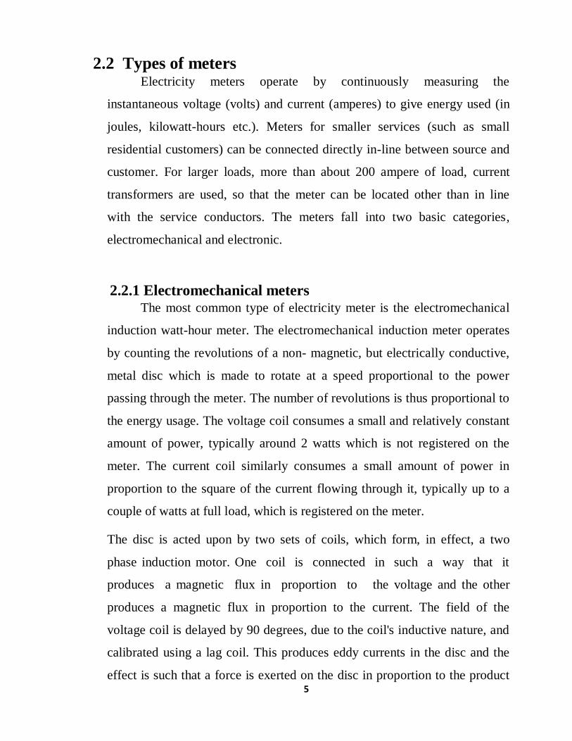
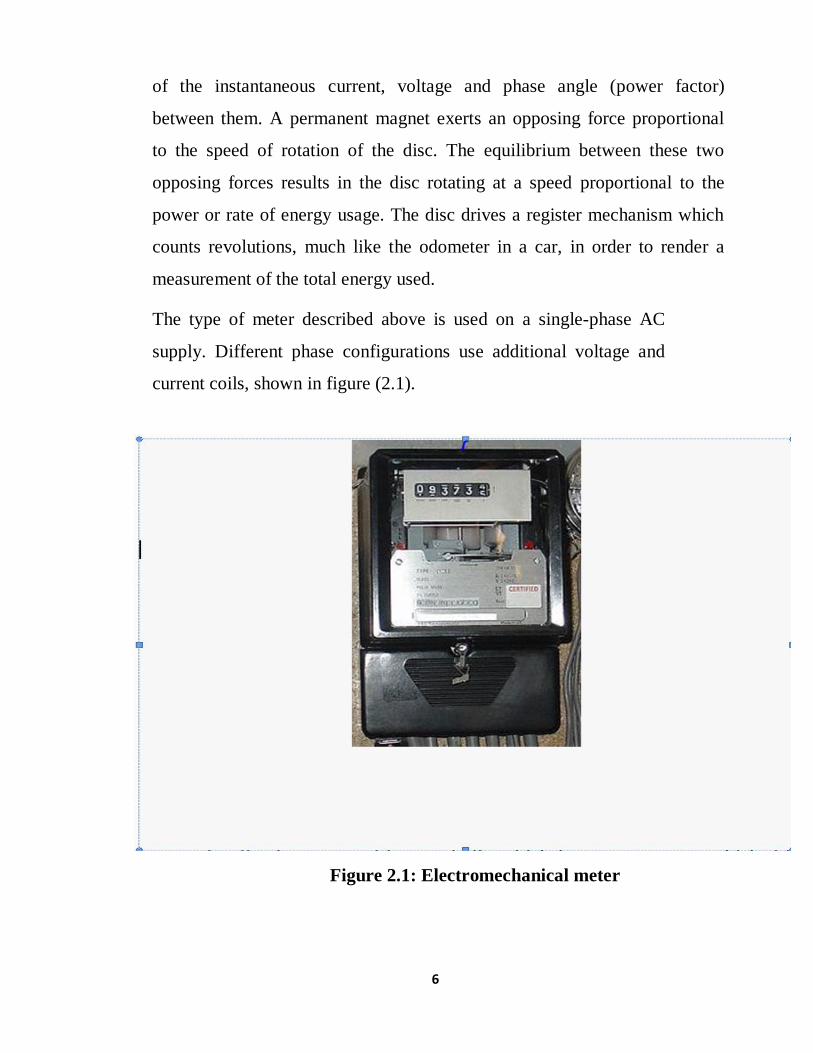
The type of meter described above is used on a single-phase AC
supply. Different phase configurations use additional voltage and
current coils, shown in figure (2.1).
Figure 2.1: Electromechanical meter

7
The disc is supported by a spindle which has a worm gear which drives the
register. The register is a series of dials which record the a mount of energy
used. The dials may be of the cyclometer type, an odometer-like display that is
easy to read where for each dial a single digit is shown through a window in the
face of the meter, or of the pointer type where a pointer indicates each digit.
With the dial pointer type, adjacent pointers generally rotate in opposite
directions due to the gearing mechanism.
The amount of energy represented by one revolution of the disc is denoted by
the symbol Kwh which is given in units of watt-hours per revolution. The
value 7.2 is commonly seen. Using the value of Kwh one can determine their
power consumption at any given time by timing the disc with a stopwatch.
𝑃 =3600 𝑘𝑤ℎ
𝑡… … … … … (2.1)
- Where:
t = time in seconds taken by the disc to
complete one revolution, P = power in watts.
For example, if Kwh = 7.2 as above, and one revolution took place in 14.4
seconds, the power is 1800 watts. This method can be used to determine the
power consumption of household devices by switching them on one by one.
Most domestic electricity meters must be read manually, whether by a
representative of the power company or by the customer. Where the customer
reads the meter, the reading may be supplied to the power company by
telephone, post or over the internet. The electricity company will normally
require a visit by a company representative at least annually in order to verify
customer-supplied readings and to make a basic safety check of the meter.
In an induction type meter, creep is a phenomenon that can adversely affect
accuracy that occurs when the meter disc rotates continuously with potential
applied and the load terminals open circuited. A test for error due to creep is
8
called a creep test.
Two standards govern meter accuracy.
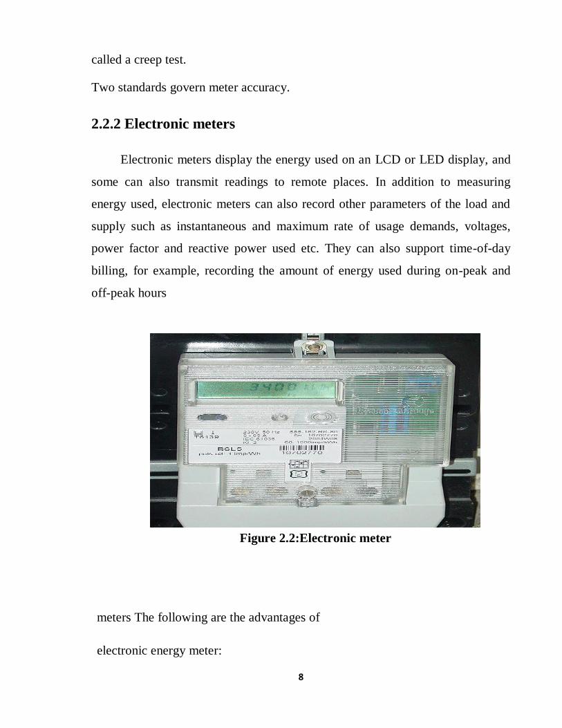
2.2.2 Electronic meters
Electronic meters display the energy used on an LCD or LED display, and
some can also transmit readings to remote places. In addition to measuring
energy used, electronic meters can also record other parameters of the load and
supply such as instantaneous and maximum rate of usage demands, voltages,
power factor and reactive power used etc. They can also support time-of-day
billing, for example, recording the amount of energy used during on-peak and
off-peak hours
Figure 2.2:Electronic meter
meters The following are the advantages of
electronic energy meter:
9
-Accuracy
While electromechanical meters are normally available with Class
2accuracy, Electronic meters of Class 1 accuracy are very common.
-Low Current Performance
Most of the electromechanical meters tend to run slow after a few
years and stop recording at low loads typically below 40% of their basic
current. This is due to increased friction at their bearings. This results in
large losses in revenue since most of the residential consumers will be
running at very low loads for almost 20 hours in a day. Electronic meters
record consistently and accurately even at 5% of their basic current. Also
they are guaranteed to start recording energy at0.4% of their basic current.
-Low Voltage Performance
Most of the mechanical meters become inaccurate at voltages
below75% of rated voltage whereas electronic meters record accurately even
at 50% of rated voltage. This is a major advantage where low voltage
problem is very common.
-Installation
The mechanical meter is very sensitive to the position in which it is
installed. If it is not mounted vertically, it will run slow, resulting in revenue
loss. Electronic meters are not sensitive
-Tamper
The mechanical meters can be tampered very easily even without
disturbing the Wiring either by using an external magnet or by inserting a thin
film into the meter to touch the rotating disc. In addition to these methods, in

10
the case of a single-phase meter, there are more than 20 conditions of external
wiring that can make the meter record less. In the case of three Phase meter,
external wiring can be manipulated in 4 ways to make it slow. Hence, any of
these methods cannot tamper electronic meters. Moreover they can detect the
tampering of meter by using LED.
2.2.3 Electronic meters New Features Electronic meters provide many new features like prepaid metering
and remote Metering that can improve the efficiency of the utility.
11
2.2.4 Prepayment metering
Yet another advantage of the electronic meter is the possibility of
introducing Prepaid metering system. Prepaid metering system is the one in
which the consumer pays money in advance to the utility and then feeds this
information into his meter. The meter then updates the credit available to the
consumer and starts deducting his consumption from available credit. Once the
credit reaches a minimum specified value, meter raises an alarm. If the credit is
completely exhausted, the meter switches off the loads of the consumer.
Main advantage of this system is that the utility can eliminate meter readers.
Another benefit is that they get paid in advance. The consumer benefits due to
elimination of penalty for late payment. Also it enables him to plan his electricity
bill expenses in a better manner. Due to the.
intelligence built in into the electronic meters, introduction of prepaid
metering becomes much easier than in the case of electromechanical meters.
Energy meters, the only direct revenue interface between utilities and the
consumers, have undergone several advancements in the last decade. The
conventional electro-mechanical meters are being replaced with electronic
meters to improve accuracy in meter reading. Asian countries are
currently looking to introduce prepaid electricity meters across their
distribution network, buoyed up by the success of this novel methodology in
South Africa. The existing inherent problems with the post-paid system and
privatization of state held power distribution companies are the major driving
factors for this market in Asia.
Over 40 countries have implemented prepaid meters in their markets In
United Kingdom the system, has been in use for well over 70 years with
about3.5 million consumers. The prepaid program in South Africa was started in
1992 since then they have installed over 6 million meters.

12
Other African counties such as Sudan, Madagascar are following the
South African success. The concept has found ground in Argentina and New
Zealand with few thousands of installations. The prepaid meters in the market
today are coming up with smart cards to hold information on units consumed
or equivalent money value. When the card is inserted, the energy meter reads
it, connects the supply to the consumer loads, and debits the value. The
meters are equipped with light emitting diodes (LED) to inform consumers
when 75 percent of the credit energy has been consumed. The consumer
then recharges the prepaid card from a sales terminal or distribution
point, and during this process any changes in the tariff can also be loaded in
the smart card.
2.3 Payment methods There are different ways to pay for energy consumption, and these
payment solutions are directly linked with the meter’s capabilities. Among
the different payment solutions used globally are:
-Coins
This is the most widely established way to pay via a prepaid meter; coins
offer a simple way to use a mechanical process to reload energy credit (Figure
2.3). The main disadvantage of this system is the vulnerability of the meter itself.
Indeed, there is a risk of theft of the cash, while fraud (with specially designed
coins) is not rare. The other negative impact is on the energy supplier or
subcontractor companies that need to collect the cash on a regular basis.
Figure 2.3: Payment by Coins

13
-Token or PIN
This is one of the two most important payment solutions used in the
metering ecosystem (Figure 2.4). This payment concept is based on simplicity
and flexibility. There are different form factors to store the token or PIN. For
example, the consumer could buy a ticket, including a token
Number, from dedicated shops and supermarkets. Alternatively, some
solutions allow customers to reload a plastic key or a magnetic strip card via
a dedicated vendor machine.
Figure2.4:Payment by Token or PIN
-Memory cards
This is another solution that is in use everywhere in the globe for
water, gas and electricity (Figure 2.5). When customers enter the card into
the meter, the valve opens (for water) and water is made available. The
display allows the consumer to check credit left on the memory card. Such
cards can be recharged by using dedicated software loaded onto a home
computer.

14
Figure 2.5: Payment by Memory Cards
-Mobile phone
With the deployment of mobility, mobile devices could also be used as a prepaid
payment solution (Figure 2.6). Indeed, solutions such as SMS for payment or
even online mobile payment will allow the consumer to receive a credit token to
recharge the meter.
Figure 2.6: Payment by Mobile Phones
All these payment solutions are already available for the prepaid
market. Based on the required level of flexibility, security and reliability.

15
2.4 Electrical Metering Instrument Technology
The Automated Meter Reading (AMR) was first conceived in 1962
by AT&T, but this experiment was not successful. After successful
experiments, AT&T offered to provide phone system-based AMR services
at $2 per meter. The price was four times more than the monthly cost of a
person to read the meter-50 cents. Thus the program was considered
economically unfeasible.
In 1972, Theodore George “Ted” Paraskevakos, while working with Boeing
in Huntsville, Alabama, developed a sensor monitoring system which used
digital transmission for security, fire and medical alarm systems as well as
meter reading capabilities for all utilities. This technology was a spin off of
the automatic telephone line identification system, now known as Caller
ID.
In 1974, Mr. Paraskevakos was awarded a U.S. patent for this
technology.In1977, He launched Metretek, Inc., which developed and
produced the first fully automated, commercially available remote meter
reading and load management system. Since this system was developed pre-
internet, Metretek utilized the IBM series 1 mini-computer. For this
approach, Mr. Paraskevakos and Metretek were awarded multiple patents.
The modern era of AMR began in 1985, when several major full-scale
projects were implemented. Hackensack Water Co. and Equitable Gas Go.
Were the first to commit to full- scale implementation of AMR on water and
gas maters, respectively. In 1986, Minnegasco initiated a 450,000-point
radio-based AMR system. In 1987, Philadelphia Electric Co. faced with a
large number of inaccessible meters, installed thousands of distribution line
carrier AMR units to solve this problem. Thus, AMR is becoming more

16
viable each day. Advances in solid-state electronics, microprocessor
components and low cost surface-mount technology assembly techniques
have been the catalyst to produce reliable cost-effective products capable of
providing the economic and human benefits that justify use of AMR systems
on a large, if not full-scale, basis.
The primary driver for the automation of meter reading is not to reduce
labor costs, but to obtain data that is difficult to obtain. As an example,
many water meters are installed in locations that require the utility to
schedule an appointment with the homeowner in order to obtain access to
the meter. In many areas, consumers have demanded that their monthly
water bill be based on an actual reading, instead of (for example) an
estimated monthly usage based on just one actual meter reading made every
12 months. Early AMR systems often consisted of walk-by and drive- by
AMR for residential customers, and telephone-based AMR for commercial
or industrial customers. What was once a need for monthly data became a
need for daily and even hourly readings of the meters. Consequently, the
sales of drive-by and telephone AMR has declined in the US, while sales of
fixed networks has increased. The US Energy Policy Act of 2005 asksthat
electric utility regulators consider the support for a “…time-based rate
schedule (to) enable the electric consumer to manage energy use
and cost through advanced metering and communications
technology.”
Today the metering instrument technology grown up significantly,
such that the Consumed energy can be calculated mathematically, displayed,
data can be stored, data can be transmitted, etc. Presently the
microcontrollers are playing major role in metering instrument technology.
The present project work is designed to collect the consumed energy data of

17
a particular energy consumer through wireless communication system
(without going to consumer house), the system can be called as automatic
meter reading (AMR) system. The Automatic Meter reading system is
intended to remotely collect the meter readings of a locality using a
communication system, without persons physically going and reading the
meters visually.
18
-Benefits of AMR:-
The automatic meter reading (AMR) technology is very useful in
many applications. By using AMR technology we can accommodate a lot of
benefits. Some benefits of AMR are as follow.
-Electrical Company Benefits:-
Smart automated processes instead of manual work.
Accurate information from the network load to optimize maintenance
and investments.
Customized rates and billing dates.
Streamlined high bill investigations.
Detection of tampering of Meters.
Accurate measurement of transmission losses.
Better network performance and cost efficiency.
Demand and distribution management.
More intelligence to business planning.
Better company credibility.
-Customer Benefits:-
Precise consumption information.
Clear and accurate billing.
Automatic outage information and faster recovery.
Better and faster customer service.
Flag potential high consumption before customer gets a high bill.
-AMR Applications:-
As technology continues to improve in price/performance, the number of
municipal utilities implementing automatic meter reading (AMR) systems

19
continues to grow. Today, most AMR deployments are “walk-by” or “drive-by”
systems. A battery-operated transmitter in each meter sends a radio frequency
(RF) signal that is read by a special receiver either carried by hand or mounted in
a vehicle. These solutions require a much smaller staff of meter readers, who
merely need to walk or drive by the many meters in any neighborhood. Although
this form of AMR is an enormous improvement over manual meter reading,
continued high labor and vehicle costs are driving the industry to an even better
solution.
Among the many advantages are the ability to monitor daily demand,
implement conservation programs, create usage profiles by time of day, and
detect potentially hazardous conditions, such as leaks or outages. But there is
still one drawback with these AMR deployments: the costly network backhaul
required by leased lines or cellular services from a local telephone company, or
Power Line Carrier (PLC) solutions from the local power company.
AMR is the remote collection of consumption data from customers’ utility
meters using telephony, radio frequency, power lines and satellite
communications technologies. AMR provides water, gas and electric utility-
service companies the opportunity to increase operational efficiency, improve
customer service, reduce data-collection costs and quickly gather critical
information that provides insight to company decision-makers.
-Different AMR Technologies:-
There are many different technologies which are used in the AMR.
Using these technologies data can be send from transmitting end to the receiving
end. In our search we are using GSM technology for transmitting the meter
reading from one point to other point

20
2.5 Embedded system
An embedded system is a combination of computing H/W & S/W, and perhaps
additional mechanical or other parts, designed to perform a specific function. An
embedded is a component with in some larger system.
By definition, all embedded system contents a processor and software but what
other feature do they have in common? Certainly, in order to have software,
there must be a placed to store the executable code and temporary storage for run
time data manipulation. This take the form of ROM and RAM, respectively; any
embedded system will have the sum of the both.
If only a small amount of memory is required, it might be contained whit in the
same chip as processor. Otherwise, one or both types of memory will reside in
external memory chip.
All smart meter it can be classified as embedded system here we mention
different technologies developed.
Remote meter reading (or AMR) refers to the system that uses a communication
technique to automatically collect the meter readings and other relevant data
from utilities’ gas meters, without the need to physically visit the gas meters.
The development of AMR technology has catapulted meter data to center stage
of the utility business plan.
2.6 Wireless Fidelity (Wi-Fi) Today many meters are designed to transmit using Wi-Fi even if a Wi-Fi
network is not available, and they are read using a drive-by local Wi-Fi hand
held receiver. Narrow-banded signal has a much greater range than Wi-Fi so the
numbers of receivers required for the project are far fewer the number of Wi-Fi
access points covering the same area. These special receiver stations then take in
the narrow-band signal and report their data via Wi-Fi Most of the automated
utility meters installed in the Corpus Christi area are battery powered. Compared
to narrow-band burst telemetry, Wi-Fi technology uses far too much power for
long-term battery- powered operation. Thus Wi-Fi is the efficient mean of
communication in AMR technologies, which allows communication between the
central data base and the end users, and defines the efficient reliability of the
system. Thus offering a ultimate mean to fulfill the requirement.
21
In general AMR can be implemented using a variety of technologies.
Depending on the scope, available infrastructure and network topologies, many
technologies could be employed to realize AMR systems. Generally however,
these technologies are divided into three groups:
-Legacy Options:
These comprises traditionally available technologies used in communication
systems today, such as POTS (Plain Old Telephone System),
Public Wireless (Paging, GSM, CDMA, GPRS, etc) and Satellite (Low Orbit
Communication Satellites)
- Broadband Options:
Newer technologies used for large bandwidth data communication such as
Broadband over Power lines (BPL) and Wireless Broadband (Wi-Fi, WiMax,
etc).
-Cost-Effective Options:
These are the technologies of choice for low bandwidth; cost sensitive
applications using Private Wireless (licensed &Unlicensed ISM Band) and
Narrowband Power Line Communication (PLC).
22
CHAPTER THREE
WIRELESS SYSTEM COMPONENTS
3.1 Introduction
The Global System for Mobile communications(GSM) is an open, digital
cellular technology used for transmitting mobile voice and data services. GSM
supports voice calls and data transfer speeds of up to 9.6 kbps, together with the
transmission of SMS (Short Message Service).
A GSM modem is a special type of modem that accepts a SIM card and
operates over a subscription to a mobile operator just like as a mobile phone.
GSM modem is a wireless modem which sends and receives data through radio
waves .A GSM modem requires a SIM card from a wireless carrier in order to
operate Just like as a GSM mobile phone. GSM modem support standard AT
commands as well as extended set of AT commands. With the standard AT
commands and extended AT commands, you can do things like:
• Sending SMS message
• Reading, Writing and Deleting SMS massage
• Monitoring the signal strength
• Reading, Writing and Searching phonebook entries
• Real time clock
GSM operates in the 900MHz and 1.8GHz bands in Europe and the 1.9GHz and
850MHz bands in the US. GSM services are also transmitted via 850MHz
spectrum in Australia, Canada and many Latin American countries. The use of
harmonised spectrum across most of the globe, combined with GSM‟s
international roaming capability, allows travellers to access the same mobile
services at home and abroad. GSM enables individuals to be reached via the
same mobile number in up to 219 countries.
Terrestrial GSM networks now cover more than 90% of the world‟s population.
GSM satellite roaming has also extended service access to areas where terrestrial
coverage is not available.
23
-GSM Features
· Quad Band GSM/GPRS: 850 / 900 / 1800 / 1900 MHz
· Built in RS232 to TTL or vice versa Logic Converter (MAX232)
· Configurable Baud Rate
· SMA (Sub Miniature version A) connector with GSM L Type
Antenna
· Built in SIM (Subscriber Identity Module) Card holder
· Built in Network Status LED
Inbuilt Powerful TCP / IP (Transfer Control Protocol /
Internet Protocol) stack for internet data transfer through
GPRS (General Packet Radio Service)
· Audio Interface Connectors (Audio in and Audio out)
· Most Status and controlling pins are available
· Normal Operation Temperature: -20 °C to +55 °C
· Input Voltage: 5V to 12V DC
· LDB9 connector (Serial Port) provided for easy interfacing.
24
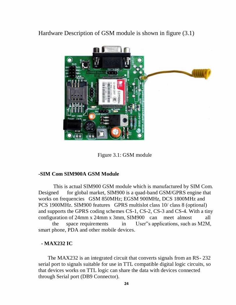
Hardware Description of GSM module is shown in figure (3.1)
Figure 3.1: GSM module
-SIM Com SIM900A GSM Module
This is actual SIM900 GSM module which is manufactured by SIM Com.
Designed for global market, SIM900 is a quad-band GSM/GPRS engine that
works on frequencies GSM 850MHz; EGSM 900MHz, DCS 1800MHz and
PCS 1900MHz. SIM900 features GPRS multislot class 10/ class 8 (optional)
and supports the GPRS coding schemes CS-1, CS-2, CS-3 and CS-4. With a tiny
configuration of 24mm x 24mm x 3mm, SIM900 can meet almost all
the space requirements in User‟s applications, such as M2M,
smart phone, PDA and other mobile devices.
- MAX232 IC
The MAX232 is an integrated circuit that converts signals from an RS- 232
serial port to signals suitable for use in TTL compatible digital logic circuits, so
that devices works on TTL logic can share the data with devices connected
through Serial port (DB9 Connector).

25
-Serial port / DB9 connector
User just needs to attach RS232 cable here so that it can be connected
to devices which have Serial port / DB9 Connector.
-Power Supply Socket
This power supply socket which actually named as AC/DC Socket
provides the functionality to user to connect external power supply from
Transformer, Battery or Adapter through DC jack. User can provide maximum
of 12V AC/DC power supply through AC/DC socket. This is power supply
designed into maximum protection consideration so that it can even prevent
reverse polarity DC power supply as well as DC conversion from AC power
Supply. It also includes LM317 Voltage Regulator which provides an output
voltage adjustable over a1.2V to 37V.
-Power On/Off and GSM On Switch
Power On/Off switch is type of push-on push-offDPDTswitch which is
used for only make power supply on/off provided through AC/DC Socket
indicated by ‘PowerLED‟. GSM On Switch is type of Push on DPST tactile
switch which is used for only to make GSM module „On‟ Indicated by „Module
On/Off LED‟ while initiating with Network indicated by ‘Network Indication
LED‟.
-SIM (Subscriber Identity Module) Card Slot
This on board SIM card slot provides User functionality of insert a SIM
(GSM only) card of any service provider. Process of inserting and locking SIM
card into SIM card slot is given in this manual. While inserting in and removing
out SIM card from SIM card slot, User needs to take precaution that power
supply should be OFF so that after making Power supply ON it wills be easy to
reinitialize with SIM for this module.
- Indicator LEDs
Indicator LEDs just used to indicate status accordingly. These are three
LEDs represents Power On/Off Status, Network Status and Module On/Off
Status respectively. Power LED will keep on until the power supply is enable to

26
this board by using push-on push-offswitch. Network Status LED will show
whether inserted SIM card successfully connected to service provider‟s Network
or not, in short signal strength. Module On/Off indicator LED will show status of
GSM module‟s power on/off.
- RXD, TXD and GND pins (JP2)
These pins are used to connect devices which need to be connected to
GSM module through USART (Universal Synchronous Asynchronous Receiver
and Transmitter) communication. Devices may be like Desktop or Laptop
Computer System, Microcontrollers, etc. RXD (Receive Data) should be
connected to TXD (Transmit Data) of other device and vice versa, whereas GND
(Ground) should be connected to other device‟s GND pin to make ground
common for both systems.
- Audio Connectors
Audio Connectors deals with Audio related operations. These pins already
shown in hardware description diagram. These are eight pins in a group of two
each denoted by SV4. GND (0V Supply) and VCC (+5V Supply) are used to
have source for external device. MIC+ and MIC used to connect Microphone
(abbr. as Mic) through which user can give audio
input while calling. SP- and SP+ used to connect Speaker (can be connected to
amplifier circuit if necessary) through which User can hear audio output. LN-L
and LN-R used to connect Line in to GSM module.
- Debugger (DBG-R and DBG-T) Connectors (J2)
These connectors are 2-wire null modem interface DBG_TXD and
DBG_RXD. These pins can be used for debugging and upgrading firmware.
User generally no needs to deal with these pins.
27
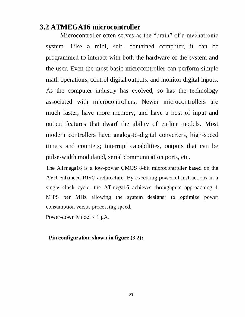
3.2 ATMEGA16 microcontroller
Microcontroller often serves as the “brain” of a mechatronic
system. Like a mini, self- contained computer, it can be
programmed to interact with both the hardware of the system and
the user. Even the most basic microcontroller can perform simple
math operations, control digital outputs, and monitor digital inputs.
As the computer industry has evolved, so has the technology
associated with microcontrollers. Newer microcontrollers are
much faster, have more memory, and have a host of input and
output features that dwarf the ability of earlier models. Most
modern controllers have analog-to-digital converters, high-speed
timers and counters; interrupt capabilities, outputs that can be
pulse-width modulated, serial communication ports, etc.
The ATmega16 is a low-power CMOS 8-bit microcontroller based on the
AVR enhanced RISC architecture. By executing powerful instructions in a
single clock cycle, the ATmega16 achieves throughputs approaching 1
MIPS per MHz allowing the system designer to optimize power
consumption versus processing speed.
Power-down Mode: < 1 μA.
-Pin configuration shown in figure (3.2):
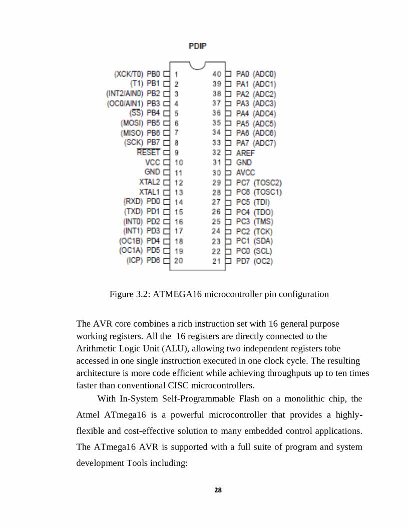
28
Figure 3.2: ATMEGA16 microcontroller pin configuration
The AVR core combines a rich instruction set with 16 general purpose
working registers. All the 16 registers are directly connected to the
Arithmetic Logic Unit (ALU), allowing two independent registers tobe
accessed in one single instruction executed in one clock cycle. The resulting
architecture is more code efficient while achieving throughputs up to ten times
faster than conventional CISC microcontrollers.
With In-System Self-Programmable Flash on a monolithic chip, the
Atmel ATmega16 is a powerful microcontroller that provides a highly-
flexible and cost-effective solution to many embedded control applications.
The ATmega16 AVR is supported with a full suite of program and system
development Tools including:

29
C compilers, macro assemblers, program debugger/simulators, in-circuit
emulators, and evaluation kits.
-Pin Descriptions Details
CC Digital supply voltage.
GND Ground.
Port A (PA7..PA0) Port A serves as the analog inputs to the A/D Converter.
Port A also serves as an 8-bit bi-directional I/O port, if the A/D Converter is
not used. Port pins can provide internal pull-up resistors (selected for each
bit). The Port A output buffers have symmetrical drive characteristics with
both high sink and source capability. When pins PA0 to PA7 are used as
inputs and are externally pulled low, they will source current if the internal
pull-up resistors are activated. The Port A pins are tri-stated when a reset
condition becomes active, even if the clock is not running.
Port B (PB7..PB0) Port B is an 8-bit bi-directional I/O port with internal
pull-up resistors (selected for each bit). The Port B output buffers have
symmetrical drive characteristics with both high sink and source
capability. As inputs, Port B pins that are externally pulled low will source
current if the pull-up resistors are activated. The Port B pins are tri-stated
when a reset condition becomes active, even if the clock is not running.
Port B also serves the functions of various special features of the
ATmega16.
Port C (PC7..PC0) Port C is an 8-bit bi-directional I/O port with
internal pull-up resistors (selected for each bit). The Port C output buffers
have symmetrical drive characteristics with both high sink and source
capability. As inputs, Port C pins that are externally pulled low will source
current if the pull-up resistors are activated. The Port C pins are tri-stated

30
when a reset condition becomes active, even if the clock is not running. If
the JTAG interface is enabled, the pull-up resistors on pins PC5(TDI),
PC3(TMS) and PC2(TCK) will be activated even if a reset occurs. Port C
also serves the functions of the JTAG interface and other special features
of the ATmega16.
Port D (PD7..PD0) Port D is an 8-bit bi-directional I/O port with internal
pull-up resistors (selected for each bit). The Port D output buffers have
symmetrical drive characteristics with both high sink and source capability.
As inputs, Port D pins that are externally pulled low will source current if
the pull-up resistors are activated. The Port D pins are tri-stated when a reset
condition becomes active, even if the clock is not running. Port D also
serves the functions of various special features of the ATmega16.
-RESET
Reset Input. A low level on this pin for longer than the minimum
pulse length will generate a reset, even if the clock is not running. The
minimum pulse length is given in Table (1) on appendix A. Shorter pulses
are not guaranteed to generate a reset.
XTAL1 Input to the inverting Oscillator amplifier and input to the internal
clock operating circuit.
-ATMEGA16 microcontroller Features Features
• High-performance, Low-power AVR® 8-bit Microcontroller Advanced
RISC Architecture
– 131 Powerful Instructions – Most Single-clock Cycle Execution
– 16 x 8 General Purpose Working Registers
– Fully Static Operation
31
– Up to 16 MIPS Throughput at 16 MHz
– On-chip 2-cycle Multiplier
• Nonvolatile Program and Data Memories
– 16K Bytes of In-System Self-Programmable Flash Endurance: 10,000
Write/Erase Cycles
– Optional Boot Code Section with Independent Lock Bits In-System
Programming by On-chip Boot Program True Read-While-Write Operation
– 1024 Bytes EEPROM Endurance: 100,000 Write/Erase Cycles
– 2K Byte Internal SRAM
– Programming Lock for Software Security
• JTAG (IEEE std. 1149.1 Compliant) Interface
– Boundary-scan Capabilities According to the JTAG Standard
– Extensive On-chip Debug Support
– Programming of Flash, EEPROM, Fuses, and Lock Bits through the JTAG
Interface
• Peripheral Features
– Two 8-bit Timer/Counters with Separate Prescalers and Compare Modes
– One 16-bit Timer/Counter with Separate Prescaler, Compare Mode, and
Capture Mode
– Real Time Counter with Separate Oscillator
– Four PWM Channels
32
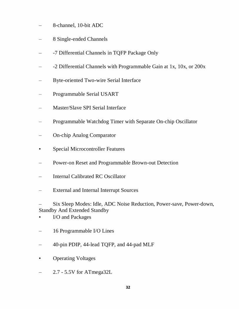
– 8-channel, 10-bit ADC
– 8 Single-ended Channels
– -7 Differential Channels in TQFP Package Only
– -2 Differential Channels with Programmable Gain at 1x, 10x, or 200x
– Byte-oriented Two-wire Serial Interface
– Programmable Serial USART
– Master/Slave SPI Serial Interface
– Programmable Watchdog Timer with Separate On-chip Oscillator
– On-chip Analog Comparator
• Special Microcontroller Features
– Power-on Reset and Programmable Brown-out Detection
– Internal Calibrated RC Oscillator
– External and Internal Interrupt Sources
– Six Sleep Modes: Idle, ADC Noise Reduction, Power-save, Power-down,
Standby And Extended Standby
• I/O and Packages
– 16 Programmable I/O Lines
– 40-pin PDIP, 44-lead TQFP, and 44-pad MLF
• Operating Voltages
– 2.7 - 5.5V for ATmega32L
33
– 4.5 - 5.5V for ATmega32
• Speed Grades
– 0 - 8 MHz for ATmega32L
– 0 - 16 MHz for ATmega32
• Power Consumption at 1 MHz, 3V, 25°C for ATmega32L
– Active: 1.1 am
– Idle Mode: 0.35 am
– Power-down Mode: < 1 μA
3.3 (4x4) Matrix Membrane Keypad This 16-button keypad provides a useful human interface component for
microcontroller projects.
Convenient adhesive backing provides a simple way to mount the keypad in a
variety of applications.
-Features
Ultra-thin design
Adhesive backing
Excellent price/performance ratio
Easy interface to any microcontroller
Example programs provided for the BASIC
Stamp 2 and Propeller P8X32A Microcontrollers
(4x4) Matrix membrane keypad shown in figure (3.3)

34
Figure 3.3: keypad
-Key Specifications
Maximum Rating: 24 VDC, 30 mA
Interface: 8-pin access to 4x4 matrix
Operating temperature: 32 to 122 °F (0 to 50°C)
How it Works Matrix keypads use a combination of four rows and four columns to
provide button states to the host device, typically a microcontroller.
Underneath each key is a pushbutton, with one end connected to one row,
and the other end connected to one column. These connections are shown
in Figure (3.4).

35
Figure 3.4: Matrix Keypad Connections
In order for the microcontroller to determine which button is pressed,
it first needs to pull each of the four columns (pins 1-4) either low or high
one at a time, and then poll the states of the four rows (pins 5-8). Depending
on the states of the columns, the microcontroller can tell which button is
pressed. For example, say your program pulls all four columns low and then
pulls the first row high. It then reads the input states of each column, and
reads pin 1 high. This means that a contact has been made between column
4 and row 1, so button ‘A’ has been pressed.
3.4 Liquid Crystal Display LCD (Liquid Crystal Display) screen is an electronic display module
and find a wide range of applications. A 16x2 LCD display is very basic
module and is very commonly used in various devices and circuits. These
modules are preferred over seven segments and other multi segment LEDs.

36
The reasons being: LCDs are economical; easily programmable; have no
limitation of displaying special & even custom characters (unlike in seven
segments), animations and so on.
A 16x2 LCD means it can display 16 characters per line and there are
2 such lines. In this LCD each character is displayed in 5x7 pixel matrix.
This LCD has two registers, namely, Command and Data.
The command register stores the command instructions given to the
LCD. A command is an instruction given to LCD to do a predefined task
like initializing it, clearing its screen, setting the cursor position, controlling
display etc. The data register stores the data to be displayed on the LCD.
The data is the ASCII value of the character to be displayed on the LCD.
LCD (Liquid Crystal Display) is shown in figure (3.5)
Figure 3.5: LCD
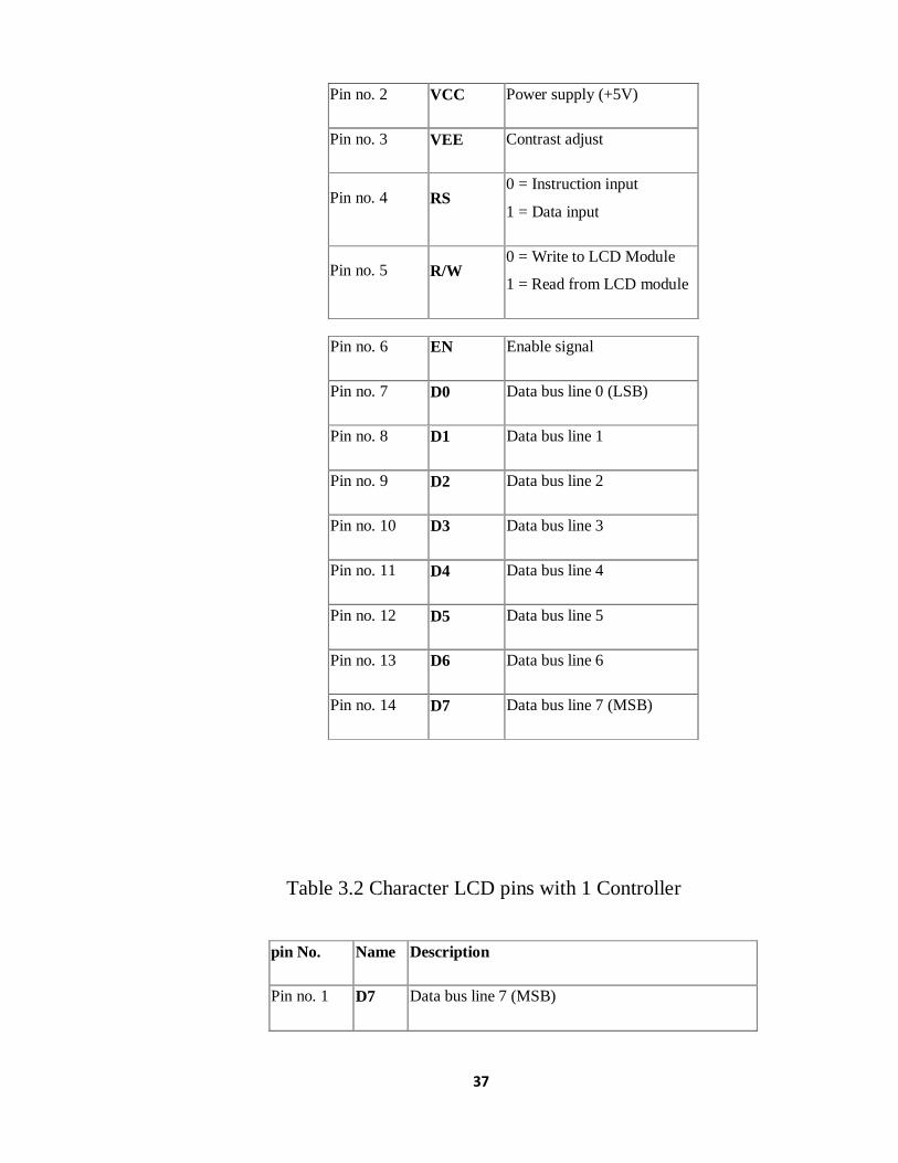
-Pin configuration
Table 3.1 Character LCD type HD44780 Pin diagram
Pin No. Name Description
Pin no. 1 VSS Power supply (GND)
37
Pin no. 2 VCC Power supply (+5V)
Pin no. 3 VEE Contrast adjust
Pin no. 4 RS 0 = Instruction input
1 = Data input
Pin no. 5 R/W 0 = Write to LCD Module
1 = Read from LCD module
Table 3.2 Character LCD pins with 1 Controller
pin No. Name Description
Pin no. 1 D7 Data bus line 7 (MSB)
Pin no. 6 EN Enable signal
Pin no. 7 D0 Data bus line 0 (LSB)
Pin no. 8 D1 Data bus line 1
Pin no. 9 D2 Data bus line 2
Pin no. 10 D3 Data bus line 3
Pin no. 11 D4 Data bus line 4
Pin no. 12 D5 Data bus line 5
Pin no. 13 D6 Data bus line 6
Pin no. 14 D7 Data bus line 7 (MSB)

38
Pin no. 2 D6 Data bus line 6
Pin no. 3 D5 Data bus line 5
Pin no. 4 D4 Data bus line 4
Pin no. 5 D3 Data bus line 3
Pin no. 6 D2 Data bus line 2
Pin no. 7 D1 Data bus line 1
pin No. Name Description
Pin no. 1 D7 Data bus line 7 (MSB)
Pin no. 2 D6 Data bus line 6
Pin no. 3 D5 Data bus line 5
Pin no. 4 D4 Data bus line 4
Pin no. 5 D3 Data bus line 3
Pin no. 6 D2 Data bus line 2
Pin no. 7 D1 Data bus line 1
3.5 Timers Timers are those circuits, which provide periodic signals to a digital
system which change the state of that system. In other words, those circuits,
which work on the base of multivibrator changes or a device, which can be used
as multivibrator is called Timer.

39
-Types of Timers
There are two basic types of 555 Timer with respect to function and
operation.
(i) 555 Timer as Astable Multivibrator
(ii) 555 Timer as Monostable Multivibrator
-(555) Timer
555 Timer is a digital monolithic integrated circuit which may be
used as a clock generator. In other words, 555 Timer is a circuit which may
be connected as a stable or monostable multivibrator.
555 Timer is a versatile and most usable device in the electronics circuits and
designs which work for both stable and monostable states. It may provide time
delay from microseconds up to many hours.
The pin diagram of DIP (Dual inline Package) 555 timer with 8 pins.
shown in figure (3.6).
Figure 3.6: 555 Timer construction & pin out

40
555 timer is a very cheap IC which works for wide range of
potential difference (typically, from 4.5 to 15V DC) and the different
provided input voltages do not affect the timer output.
555 Timer is a linear device and it can be directly connected to the
CMOS or TTL (Transistor – Transistor Logic) digital circuits due to its
compatibility but, interfacing is must to use 555 timer with other digital
circuits.
-(555) Timer Construction
There are lots of manufacturers who manufacture 555 timer which
included the number 555 e.g. NE555, CA555, SE555, MC14 555 etc.
typically, two 555 timers sandwiched inside a single chip which is called
556. Nowadays, chips are available with four 555 timers in it. These devices
are available in circular IC with eight (8), DIP (Dual inline Package) with 8
pins or DIP with 14 pins.
Explanation of the 8 pins of 555 Timer:
-Ground (GND)
It’s the common ground point of the circuit. The ground terminal of
external circuit as well as power supply (Vcc) ground terminal is connected
with this i.e. GND (Ground) terminal of 555 timer.
-Trigger
When Trigger terminal gets one –third (1/3) of the supply voltage i.e. Vcc/3
equal amplitude’s negative trigger pulse, then the circuit output changes form
Low to High.
-Output
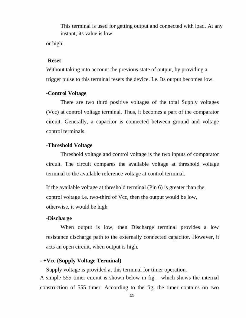
41
This terminal is used for getting output and connected with load. At any
instant, its value is low
or high.
-Reset
Without taking into account the previous state of output, by providing a
trigger pulse to this terminal resets the device. I.e. Its output becomes low.
-Control Voltage
There are two third positive voltages of the total Supply voltages
(Vcc) at control voltage terminal. Thus, it becomes a part of the comparator
circuit. Generally, a capacitor is connected between ground and voltage
control terminals.
-Threshold Voltage
Threshold voltage and control voltage is the two inputs of comparator
circuit. The circuit compares the available voltage at threshold voltage
terminal to the available reference voltage at control terminal.
If the available voltage at threshold terminal (Pin 6) is greater than the
control voltage i.e. two-third of Vcc, then the output would be low,
otherwise, it would be high.
-Discharge
When output is low, then Discharge terminal provides a low
resistance discharge path to the externally connected capacitor. However, it
acts an open circuit, when output is high.
- +Vcc (Supply Voltage Terminal)
Supply voltage is provided at this terminal for timer operation.
A simple 555 timer circuit is shown below in fig _ which shows the internal
construction of 555 timer. According to the fig, the timer contains on two

42
comparators, an RS flip flop, an Output stitch (output buffer) and a Discharge
Transistor Q1.
In addition, there are three 5kΩ resistors are connected in series with 5kΩ
resistor which first end is connected with Vcc (Pin 8 = Supply voltage) and the
other end is connected with ground (GND = Pin 1).
Good to Know: due to the three 5kΩ series connected resistors, this IC timer
chip is called 555 Timer J as shown in figure (3.7).
Figure 3.7: Internal Function Diagram of 555 Timers
43
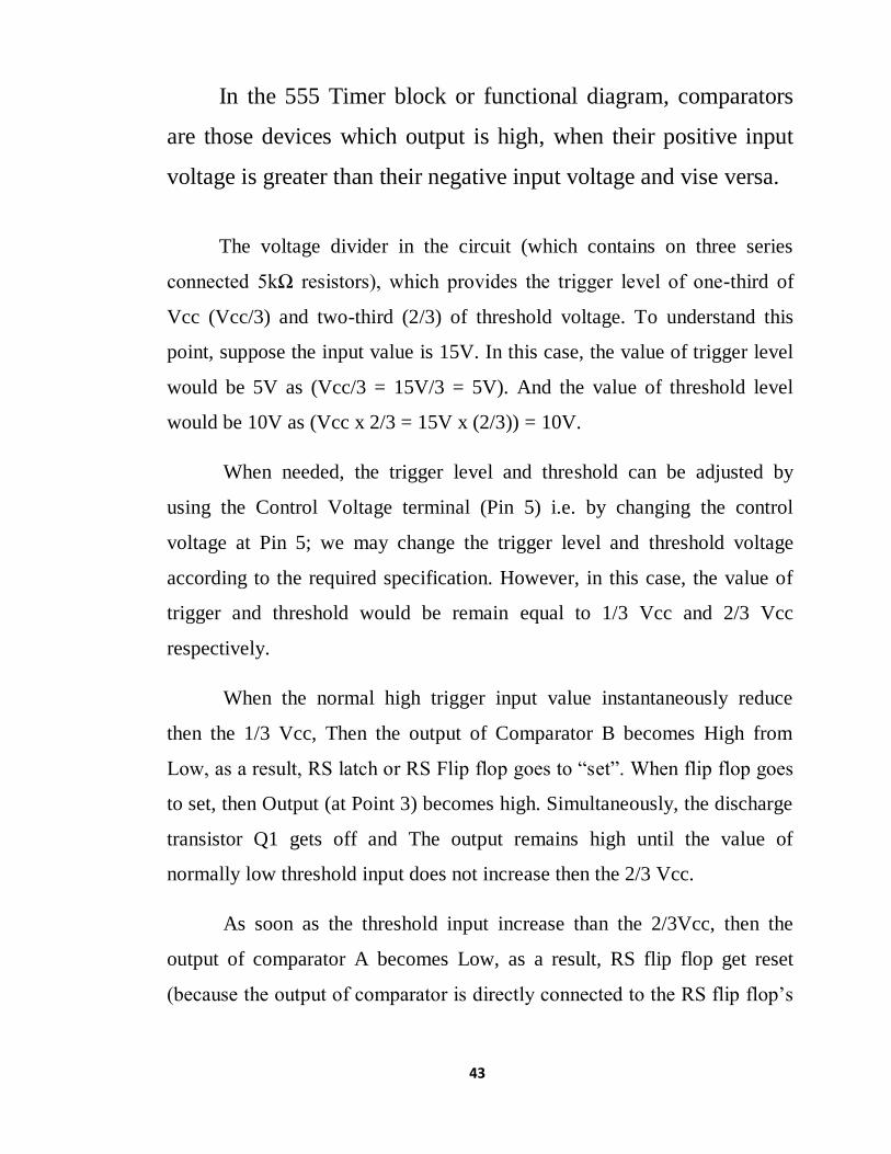
In the 555 Timer block or functional diagram, comparators
are those devices which output is high, when their positive input
voltage is greater than their negative input voltage and vise versa.
The voltage divider in the circuit (which contains on three series
connected 5kΩ resistors), which provides the trigger level of one-third of
Vcc (Vcc/3) and two-third (2/3) of threshold voltage. To understand this
point, suppose the input value is 15V. In this case, the value of trigger level
would be 5V as (Vcc/3 = 15V/3 = 5V). And the value of threshold level
would be 10V as (Vcc x 2/3 = 15V x (2/3)) = 10V.
When needed, the trigger level and threshold can be adjusted by
using the Control Voltage terminal (Pin 5) i.e. by changing the control
voltage at Pin 5; we may change the trigger level and threshold voltage
according to the required specification. However, in this case, the value of
trigger and threshold would be remain equal to 1/3 Vcc and 2/3 Vcc
respectively.
When the normal high trigger input value instantaneously reduce
then the 1/3 Vcc, Then the output of Comparator B becomes High from
Low, as a result, RS latch or RS Flip flop goes to “set”. When flip flop goes
to set, then Output (at Point 3) becomes high. Simultaneously, the discharge
transistor Q1 gets off and The output remains high until the value of
normally low threshold input does not increase then the 2/3 Vcc.
As soon as the threshold input increase than the 2/3Vcc, then the
output of comparator A becomes Low, as a result, RS flip flop get reset
(because the output of comparator is directly connected to the RS flip flop’s

44
input R as shown in the fig). When flip flop gets reset, output becomes low
and discharge transistor Q1 goes to on.
The flip flop can be reset by applying external input reset without threshold
circuit. Note that, the trigger and threshold inputs (Pin 2 and Pin 6) are controlled
by externally components and the 555 timer can be used for stable or monostable
operation by controlling the trigger and threshold inputs with the help of those
external components.
45
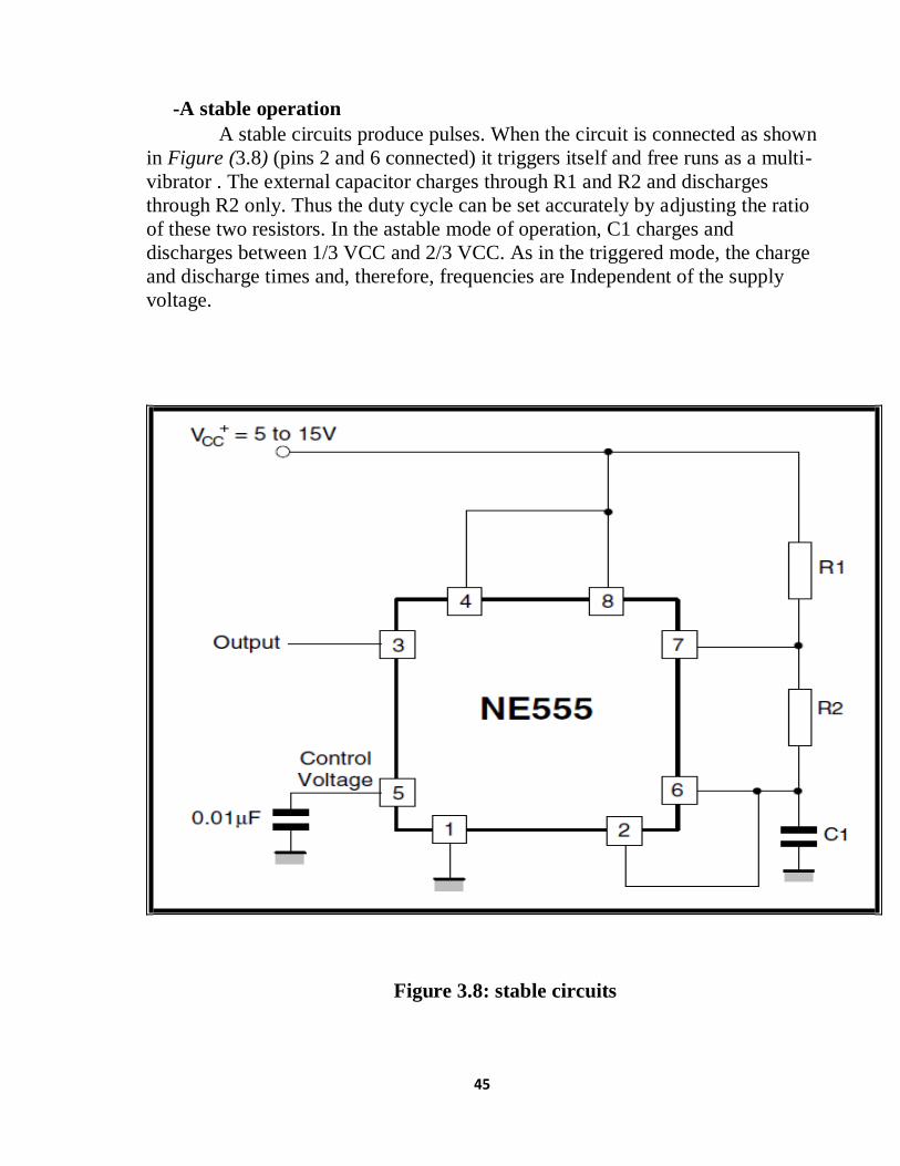
-A stable operation
A stable circuits produce pulses. When the circuit is connected as shown
in Figure (3.8) (pins 2 and 6 connected) it triggers itself and free runs as a multi-
vibrator . The external capacitor charges through R1 and R2 and discharges
through R2 only. Thus the duty cycle can be set accurately by adjusting the ratio
of these two resistors. In the astable mode of operation, C1 charges and
discharges between 1/3 VCC and 2/3 VCC. As in the triggered mode, the charge
and discharge times and, therefore, frequencies are Independent of the supply
voltage.
Figure 3.8: stable circuits

46
3.6 Relay The relay takes advantage of the fact that when electricity
flows through a coil, it becomes an electromagnet. The
electromagnetic coil attracts a steel plate, which is attached to a
switch. So the switch's motion (ON and OFF) is controlled by the
current flowing to the coil, or not, respectively as shown in figure
(3.9).
A very useful feature of a relay is that it can be used to electrically
isolate different parts of a circuit. It will allow a low voltage
circuit (e.g. 5VDC) to switch the power in a high voltage circuit
(e.g. 100 VAC or more).
The relay operates mechanically, so it cannot operate at high speed.
Figure 3.9: internal circuit of Relay

47
3.7 Software Part
-BASCOM-AVR language BASCOM-AVR is the original Windows BASIC COMPILER for the
AVR family. It is designed to run on W95/W98/NT/W2000/XP and Vista
Key Benefits
Structured BASIC with labels.
Structured programming with IF-THEN-ELSE-END IF, DO-LOOP,
WHILE-WEND, SELECT- CASE.
Fast machine code instead of interpreted code.
Variables and labels can be as long as 32 characters.
Bit, Byte, Integer, Word, Long, Single, Double and String variables.
Support for the Double. Not found in any AVR compiler,
BASCOM gives you the advantage to crunch huge numbers with the
Double(8 byte Floating Point)
Large set of Trig Floating point functions.
Date & Time calculation functions.
Compiled programs work with all AVR microprocessors that have
internal memory.
Statements are highly compatible with Microsoft’s VB/QB.
Special commands for LCD-displays, I2C chips and 1WIRE
chips, PC keyboard, matrix keyboard, RC5 reception, software
UART, SPI, graphical LCD, send IR RC5, RC6 or Sony code.
TCP/IP with W3100A chip.
Local variables, user functions, library support.
Integrated terminal emulator with download option..
Integrated simulator for testing.

48
Integrated ISP programmer (application note AVR910.ASM).
Integrated STK200 programmer and STK300 programmer. Also
supported is the low cost Sample Electronics programmer. Can be
built in 10 minutes! Many other programmers supported via the
Universal Interface.
Editor with statement highlighting.
PDF datasheet viewer
Context sensitive help.
Perfectly matches the following boards :
o MAVRIC and the MAVRIC-II from BDMICRO.
o AVR robot controller (ARC 1.1) from L. Barello
o Active Mega8535 Micro Board from Active Robots
DEMO version compiles 4KB of code. Well suited for the ATmega48.
English and German Books available
Special TCP/IP library, AT mouse simulator, AT keyboard
simulator and others are available as add on.
To make a program takes just a few steps:
Write the program in BASIC
Compile it to fast machine binary code
Test the result with the integrated simulator (with additional
hardware you can simulate the hardware too).
Program the chip with one of the
integrated programmers. (hardware
must be purchased separately)
The program can be written in a comfortable MDI color coded editor.
Besides the normal editing features, the editor supports Undo, Redo, Bookmarks
and block indention.
49
-Simulation Design:
Electronic circuit simulation uses mathematical models to replicate the
behavior of an actual electronic device or circuit. Simulation software allows for
modeling of circuit operation and is an invaluable analysis tool. Due to its highly
accurate modeling capability, many colleges and universities use this type of
software for the teaching of electronics technician and electronics engineering
programs. Electronics simulation software engages its users by integrating them
into the learning experience. These kinds of interactions actively engage learners
to analyze, synthesize, organize, and evaluate content and result in learners
constructing their own knowledge.
-Proteus VSM Definition Proteus Virtual System Modeling (VSM) combines mixed mode
SPICE circuit simulation, animated components and microprocessor models
to facilitate co-simulation of complete microcontroller based designs. For
the first time ever, it is possible to develop and test such designs before a
physical prototype is constructed.
This is possible because you can interact with the design using on
screen indicators such as LED and LCD displays and actuators such as switches
and buttons. The simulation takes place in real time (or near enough to it): a
1GMHz Pentium III can simulate a basic 8051 system clocking at over 12MHz.
Proteus VSM also provides extensive debugging facilities including breakpoints,
single stepping and variable display for both assembly code and high level
language source.

50
CHAPTER FOUR
SYSTEM SIMULATION
4.1 Introduction
After design of the meter was completed, the next phase was initiated.
This was the simulation and testing phase. Simulation was done with the use
of software simulating programs, along with BASCOM-AVR language
Compilers for the code written to the MCU. The simulating program used
for this thesis was Proteus 7.1 Professional, and for coding, Code Vision
AVR 2.05. Several separate code blocks were written for different blocks of
the meter in order to simulate and test them separately before integration
and system simulation and testing.
In this embodiment, the system components are represented by the
simulation software used to connect the electric meter with GSM technology
to wirelessly control the meter reading and recharging easier and faster.
4.2 Complete System Design
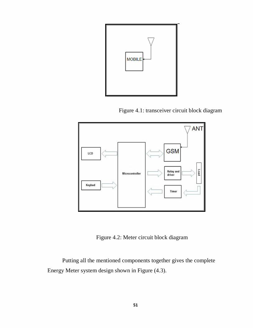
The transceiver of electrical company and meter block
diagrams shown in figure (4.1) & (4.2).
51
Figure 4.1: transceiver circuit block diagram
Figure 4.2: Meter circuit block diagram
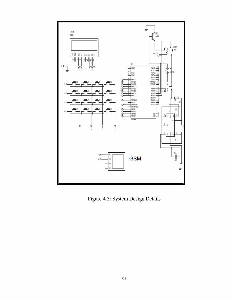
Putting all the mentioned components together gives the complete
Energy Meter system design shown in Figure (4.3).
52
Figure 4.3: System Design Details

53
Figure 4.4: transceiver circuit Design Details

54
4.3 Simulation Case
We show the simulation of the AMR scale that the user can enter the
electricity value in kw, which we set a value for is 50kw using the keyboard and
display the value on the LCD when he presses (m). The microcontroller sends
the electricity value to the management system server through gsm.
Server management system chick meter number and calculates the amount of
electricity and sends the amount of electricity to the meter through a unit; gsm,
and the value of the electricity received by the unit on the side of the meter and
the microcontroller displayed on the LCD screen and send a signal for the relay
to contact the load circuit after that the amount of electrical decrease by the load
until it reaches Zero then a microcontroller sends a relay signal to disconnect the
load circuit and the red led flashing .
55
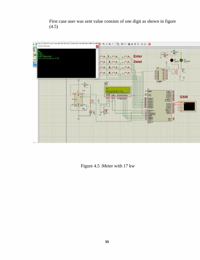
First case user was sent value consists of one digit as shown in figure
(4.5)
Figure 4.5 :Meter with 17 kw

56
In the second case, when the electricity value reaches 15 kw, the gsm
sends a message to the user about the remaining electricity value and
that he must recharge as shown in figure (4.6)
figure 4.6 : Meter with 15 kw
57
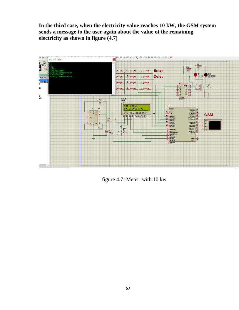
In the third case, when the electricity value reaches 10 kW, the GSM system
sends a message to the user again about the value of the remaining
electricity as shown in figure (4.7)
figure 4.7: Meter with 10 kw
58
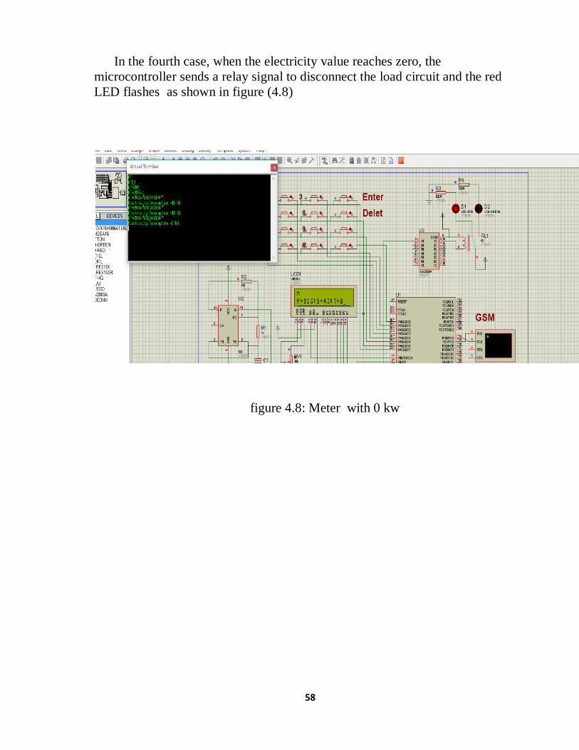
In the fourth case, when the electricity value reaches zero, the
microcontroller sends a relay signal to disconnect the load circuit and the red
LED flashes as shown in figure (4.8)
figure 4.8: Meter with 0 kw
59
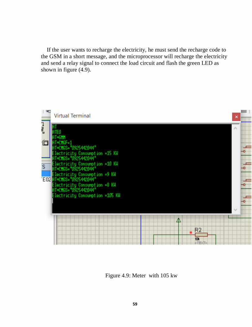
If the user wants to recharge the electricity, he must send the recharge code to
the GSM in a short message, and the microprocessor will recharge the electricity
and send a relay signal to connect the load circuit and flash the green LED as
shown in figure (4.9).
Figure 4.9: Meter with 105 kw
60
Chapter Five
Conclusion And Recommendations
5.1 Conclusion The aim of this research was to bring improvement in the current
power systems of the country by introducing a new smart metering system. For
this purpose, a GUI based smart energy monitoring and controlling system was
proposed. The results discussed, and observations made in this research
concluded that smart metering system with GSM
communication capabilities will make the current power management better and
efficient in many ways.
5.2 Recommendations The most important recommendation is to create a mobile app to make it
easier to monitor consumption and recharge. Alerting when malfunctions occur
at home, alerting when network malfunctions (for the consumer and the service
provider) make statistics and collect information for the service provider to
predict the loads and conduct studies for the construction of new stations in a
thoughtful manner and correct decisions and know the peak times and the
amount of loads, make a consumer use plan Clarify the efficiency of the devices
Accordingly, the data and information used in the home will be sent to the
Energy Efficiency Center to discover the efficiency of the devices and their
specifications, and then send them to the Ministry of Commerce to prevent the
import of low-efficiency devices that do not conform to the specifications and
standards, and to know the highest peak time for the application of what is
known as the hourly tariff.
61
REFERENCES
[1] D. Alahakoon, X. Yu, “Smart Electricity Meter Data Intelligence for
Future Energy Systems: A Survey”, IEEE Transactions on Industrial
Informatics, vol. 12, No. 1, February 2016.
[2] Prabhu. R, Geetha. A, Vadivelan. P, Ilayabharathy. L, “Smart Energy
Meter with GSM Technology and Self Thermal Printing Technology”,
IJETCSE, vol. 12, issue 1, pp. 58-66, December 2014.
[3] J. Jose, L. Mohan, Nijeesh U, T. C. Benny., “Smart Energy Meter”,
IJETT, vol. 22 No. 4, April 2015.
[4] Q. Sun, H Li, Z. Ma, C. Wang, J. Campillo, Q. Zhang, F. Wallin, J. Guo,
“A Comprehensive Review of Smart Energy Meters in Intelligent
Energy Networks”, IEEE Internet of Things Journal, Vol. 3, No. 4,
August 2016.
[5] B. Morvaj, L. Lugaric, S. Krajcar, “Demonstrating Smart Buildings and
Smart Grid features in a Smart Energy City”, IYEC, 3rd International
Youth Confrence, July 2011.
[6] T. Khalifa, K. Naik, A. Nayak, “A survey of communication protocols
for automatic meter reading applications”, Commun. Surveys Tuts, vol.
13, no. 2, pp. 168–182, 2011.
[7] A. Shafik, “Smart metering and home automation solutions for the next
decade”, ETNCC, pp. 200–204, 2011.
[8] M. Gayatri Lakshmi, S.Srivani, “Arduino Based Energy Conservation
using Zigbee and GSM Technology”, ISSN: 2321-8665, Vol. 3, Issue.
6, pp. 811-816,August 2015.
[9] Praveen, Vadda, S. Murthy, Seelam, “Smart Metering for Smart
Electricity Consumption”, 1st ed. BTH, pp. 02-62, Karlskrona, 2013.
[10] S. S. Mohammad, A. A. Dar, P. A. Javaid, P. Ranjan, “Prevention of
Illegal Distribution Line Tappings”, International Conference on
Computing, Communication and Automation, India, 2017.
[11] S. S. S. R. Depuru, L. Wang, V. Devabhaktuni, “Electricity theft:
Overview, issues, prevention and a smart meter based approach to
control theft”, Energy Policy, Vol 39, pp. 1007- 1015, 2011.

62
APPENDIX A
-Bascom code
$regfile = "m16def.dat"
$crystal = 8000000
Config Com1 = 9600 , Synchrone = 0 , Parity = None , Stopbits = 1 , Databits =
8 , Clockpol = 0
Config Lcd = 16 * 2
Config Lcdpin = Pin , Db4 = Portb.4 , Db5 = Portb.5 , Db6 = Portb.6 , Db7 =
Portb.7 , E = Portb.2 , Rs = Portb.0
Cls
Lcd "Smart Counter"
Waitms 500
Cls
Dim Count As Integer
Dim A As Integer
Dim Aa As Byte
Dim X As Byte
Dim Xx As Byte
Dim M As Integer
Dim D As Integer
Dim L As Integer
Dim Ev As Integer
Ev = 20

63
Config Timer1 = Counter , Edge = Rising
'-------
Config Timer0 = Timer , Prescale = 1024
'---------------
'---------------------
'On Ovf1 Pulse_counter
On Ovf0 Displays
'-------------------
'-----------------------
Start Timer0
'------------
Enable Interrupts
Enable Urxc
On Urxc Display1
'Enable Int0 'enable the interrupt
Enable Timer0
Enable Timer1
Start Timer1
On Int0 Label2 'jump to label2 on INT0
Dim Bt As Byte
Dim K As Byte
Dim Key As Byte
Dim S As String * 200

64
Dim Sr As String * 200
Config Portb.3 = Output
Config Pinb.1 = Input
Sr = "AT+CMGS="
Sr = Sr + Chr(&H22)
Sr = Sr + "0925442044"
Sr = Sr + Chr(&H22)
S = ""
Cls
Locate 1 , 1
Lcd "waiting gsm"
Waitms 500
Print "AT"
Waitms 100
Cls
Lcd S
Waitms 100
S = ""
Print "ATE0"
Waitms 100
Cls
Lcd S
Waitms 100
S = ""
Print "AT+GMM"
Waitms 100
65
Cls
Lcd S
Waitms 100
S = ""
Print "AT+CMGF=1"
Waitms 100
Cls
Lcd S
Waitms 100
S = ""
Cls
Locate 1 , 1
Lcd "gsm ready"
Waitms 500
Config Kbd = Porta , Debounce = 10
Do
If Chr(bt) = "5" Then 'endless loop
Ev = Ev + 50
Bt = ""
Cls
Locate 1 , 1
Lcd Ev
Bt = ""
End If
If Chr(bt) = "m" Then 'endless loop
Cls
Locate 1 , 1

66
Lcd S
Waitms 50
Print Sr
Waitms 100
Print "Electricity Consumption =" ; Ev ; " KW"
Waitms 100
Printbin &H1A
Bt = ""
End If
S = ""
Loop
End
Label2:
Incr Count
'Waitms 200
Return
Displays:
Incr A
If A = 30 Then
67
Incr M
Waitms 221
If M = 60 Then
M = 0
Incr M
Timer1 = 0
L = D
End If
D = Timer1
Locate 2 , 1
Lcd "P=" ; D ; ":S=" ; M ; ":T=" ; L
If Ev = 15 Then
Print Sr
Waitms 100
Print "Electricity Consumption =" ; Ev ; " KW"
Waitms 100
Printbin &H1A
End If
If Ev = 10 Then

68
Print Sr
Waitms 100
Print "Electricity Consumption =" ; Ev ; " KW"
Waitms 100
Printbin &H1A
End If
If Ev = 0 Then
Portb.3 = 1
End If
If Ev >= 1 Then
Portb.3 = 0
Decr Ev
End If
Waitms 1000
A = 0
End If
Return
Display1:
Inputbin Bt
If Bt <> &H0A Then
69
If Bt <> &H0D Then
S = S + Chr(bt)
End If
End If
Return
Eee:
Data 15 , 14 , 0 , 13 , 12 , 11 , 10 , 9 , 8 , 7 , 6 , 5 , 4 , 3 , 2 , 1

70


