Embed Size (px)
Citation preview

ArthurArthur Chidiebere oKONGWU
The ability to design electrical system to achieve maximum efficiency while
maintain investment saving in important in electrical engineering
Electric Motor Selection and Control Selection for Pump ApplicationElectric drive system Assignment
arthur.okongwu

ContentsAcquiring Motor and VSD Quotes.............................................................................................2
Contacts and Correspondence with Supplier............................................................................2
Analysing Motor and VSD Quote..............................................................................................3
Electric motor type for the Motor driving the Pump...................................................................3
Transmission system Application to for the Motor driving the Pump.........................................4
Circuit protection application for the Motor driving the Pump....................................................5
Flexible Coupling Application to Shaft Connecting the Motor in the Pump...............................5
Operating condition of pump.....................................................................................................6
Static Head Consideration....................................................................................................6
Annual Length of service Consideration...............................................................................6
Findings Selecting Motor and VSD for Factory Ring Main System from Acquired Quotes.......8
Grundfos................................................................................................................................... 8
Electrical Protection Considerations (GRUNDFOS)..........................................................13
Efficiency Class...................................................................................................................15
Flowserve............................................................................................................................... 16
Graphs.................................................................................................................................... 17
Assignment Specification....................................................................................................17
Flowserve.......................................................................................................................... 18
Farm Energy Innovation Program Energy and Irrigation.....................................................20
VSD SELECTION................................................................................................................... 22
Selection of Control Transducer.............................................................................................23
Electrical Protection Considerations.......................................................................................24
Adequate Cable Rating.......................................................................................................24
Starting and Running Considerations.....................................................................................25
Investment Cost Considerations.............................................................................................27
Saving Achieved.....................................................................................................................28
References............................................................................................................................. 29
APPENDIX.............................................................................................................................. 31
1. Appendix A..................................................................................................................... 31
2. Appendix B......................................................................................................................32
3. Appendix C..................................................................................................................... 32
APENDIX D......................................................................................................................... 33
.......................................................................................................................................... 6
ELECTRIC DRIVE SYSTEMS ARTHUR.OKONGWU
1

Introduction
There is a need to evaluate cost and energy saving that will arise when a quotation is accepted to replace an existing application for a specified factory ring main water process distribution system. To undertake this task real life industry practise was adopted to acquire information from local business to aid the acquisition and as such advise appropriately.
Acquiring Motor and VSD Quotes
Contacts and Correspondence with Supplier Step is initiated to reach out to some businesses most likely to respond to request for a quote for the anticipated replacement. Performer request is develop to aid the reach out process as seen in attached appendix A.
The first response was from, Murray Kerr [1]. Unfortunately the reply was not as expected as seen in Appendix B. Then there was a response from Alan Mathieson [2]. Response from also received from Jim Hunter [5]
ELECTRIC DRIVE SYSTEMS ARTHUR.OKONGWU
2
Analysing Motor and VSD QuoteElectric motor type for the Motor driving the
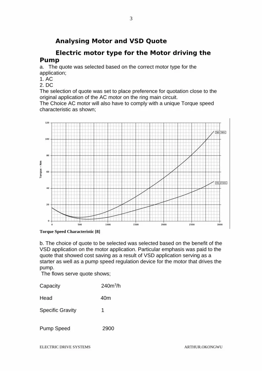
Pumpa. The quote was selected based on the correct motor type for the application;1. AC 2. DCThe selection of quote was set to place preference for quotation close to the original application of the AC motor on the ring main circuit.The Choice AC motor will also have to comply with a unique Torque speed characteristic as shown;
Torque Speed Characteristic [8]
b. The choice of quote to be selected was selected based on the benefit of the VSD application on the motor application. Particular emphasis was paid to the quote that showed cost saving as a result of VSD application serving as a starter as well as a pump speed regulation device for the motor that drives the pump. The flows serve quote shows;
Capacity 240m3/h
Head 40m
Specific Gravity 1
Pump Speed 2900
ELECTRIC DRIVE SYSTEMS ARTHUR.OKONGWU
3

Based on this information the quote from GRUNFOS seems to present a better choice for the application of VSD as there is more cost savings associated looking at the operating parameter;
System pressure 16bar
Flow of 306m3/h (increase capacity of 66m3/h)
Head 50.33m (increase capacity of 10.33m also this quote Show that the pump has capacity for head Up to 74m)
c. The motor type in each quote was assessed based on potential cost saving s or efficiency increase that may be present with the application of a transducer.
Transmission system Application to for the Motor driving the Pump
a. The Quotes were accessed based on the choice of gear application. This involved consideration of the gear ratio variation requirement, torque, moment of inertia, angle of separation of shaft
b. The Quotes were accessed based on validity of belt drive application for the load type and running life of the pump
c. The stalling requirement for the pump and duty cycle.
ELECTRIC DRIVE SYSTEMS ARTHUR.OKONGWU
4

Circuit protection application for the Motor driving the Pump
a. Consideration was made in assessing the quote on the kind of short circuit fault prevalent in the factory installation. This was done in conjunction with the validation of the stipulated detection and break of the circuit for abnormal current. In this application 12 time s grater than the rated current and 4 second interval.
b. The choice of motor application was subject to the form overloads evidence within the ring main application. This would helps identify the type of starter required for the motor necessary for operating as a drive in the pump. This is to ensure that the right protection criteria has been considered in the quote for the motor such that it is capable of detecting current increase up to 10 times the rated current. This would expect to trip off the power to the motor before it heats up to avoid damaging the insulation.
c. The selection of quote was also done to identify the isolation category compliance with the application of the motor in the pump.
d. This included taking consideration of the maximum heating effect of the motor and the impact of altitude on the performance of the motor. This was done taking account of economic and technical practicality of de-rating the chosen quote.
Flexible Coupling Application to Shaft Connecting the Motor in the Pump
ELECTRIC DRIVE SYSTEMS ARTHUR.OKONGWU
5

The quotes received were evaluated taking into consideration the impact of the operation of the pump as a result of the alignment shaft that connects the motor that drives the pump. These considerations included factoring out [4];
a. If the pump was mounted on a base plate. This factor was considered to advice about the need for coupling such as the Oldham coupling which works well to check mate parallel misalignment.
b. If the layout of the motor was such that the base plate on which it relies for support was lying horizontal and that of the pump was not. In this case a rubber bushed pin type of coupling would be expected to be on the motor in the quote. Other wise the expectation would be that any other type of coupling which factored in angular misalignment would have been compatible for the motor pump system.
c. If the ring circuit arrangement was such that the pump would require a long shaft susceptible to heating. In such situation the procedure would be to investigate the quote to ensure that the choice of motor would accommodate a Meta flex coupling or any type of coupling that would avoid a case of sliding splint joint associated with axial misalignments. This would also be applicable where there is a chance that it is impossible for the pump to have a connection the shaft to motor in the correct axial position.
Operating condition of pump
Static Head Consideration
The quotes from the supplier would be investigated to assess if there has been consideration for the amount of static head the ring main system is operating under. This will provide information about the suitability of the quotation bearing in mind that VSD applicable for system with high static head. Taking into account the fact that the motor is for a pump application to a ring main at a pressure of 5 bar, the assessment of the quote will weigh the amount of consideration the supplier has placed on the viability of installing a VSD on a distribution system delivering raw water from the factory main storage tank. As such supplier quote would be expected to provide information about viable VSD for the required static head application for the factory [3].
Annual Length of service Consideration
This assessment will include check on the attention the supplier has placed on the fact that the motor and VSD application would be expected to service the ring main for the 46 week year which the factory operates. The service life
ELECTRIC DRIVE SYSTEMS ARTHUR.OKONGWU
6

of the application is given by;
Pay back bar (Grundfos)
ELECTRIC DRIVE SYSTEMS ARTHUR.OKONGWU
7

Findings Selecting Motor and VSD for Factory Ring Main System from Acquired Quotes
The quotation received was critically evaluated as a way to make technical and informed decision to ensure that the correct application relevant to the particular requirement was chosen.
GrundfosThe presence of an automatic cascade control which improves the efficiency of the motor adopted by the pump offered by Grundfos makes it a viable option. This application also comes with alarm log with display features that makes it a great option since it provided enhance motor circuit protection as a result of the monitoring possibility for the sensors and cables for malfunction.
The fact that this quote provides a potential free change over contact that is useful both during operation and fault makes it a practical choice. This is further enhanced as a result of the presence of a Grundfos bus communication compatible with other communication inter phase such as CIM SCADA OR BMS.
The energy consumption for this VSD Motor Pump application is has been calculated by the supplier to be 943kWh/year. 3
The input power of the pump is calculated as follows:
P = (g * ρ * Q * H) / (1000 * η p * η M)
Where;P = pump input power (kW) g = gravitational Constant = 9.81(m/s2)ρ = density of fluid (kg/m3) = 10000kg/m3 (water)Q = pump flow rate (m3/s)The pump flow total per hour is 240m3
Therefore in m3/s isQ = (240/60*60) = .06m3/sH = Head developed by the pump (m) =50.22mη p = pump efficiency (%) = 75.9%η m = motor efficiency (%) = 89.6%
ELECTRIC DRIVE SYSTEMS ARTHUR.OKONGWU
8

P = (9.81* 10000 *0.06*50.22) / (1000 * 0.759 * 0.896) = 29559.492/680.064 = 43.47kWThis corresponds with the quote from Grundfos as shown in the chart;
Pump power rating (Grundfos) [2]
Taking this power requirement into consideration it is clear that the annual electricity demand for this pump will be;Annual Electricity Use = 43.47kW *8760 h/year = 380.76kWh p.a
Comparatively using the Flowserve quote;
P = (9.81* 10000 *0.06*40) / (1000 * 0.781 * 0.896) = 235440/699.776 = 336.45kW
As such,
Annual Electricity Use = 336.45kW *8760 h/year = 294.73kWh p.a
How ever the client calculation shows that the total yearly energy cost for the hydro MPC E3CRE64-2-1[2] is £123 at the estimated consumption of 943kWh/year.
ELECTRIC DRIVE SYSTEMS ARTHUR.OKONGWU
9

Grundfos specification [9]
ELECTRIC DRIVE SYSTEMS ARTHUR.OKONGWU
10

Control MPC circuitry [8]
ELECTRIC DRIVE SYSTEMS ARTHUR.OKONGWU
11

Flowserve Specification [8]This calculation shows that after 10 years of service the total cost would be £1713. This means that the GRUNDFOS quote presents an energy tariff of
ELECTRIC DRIVE SYSTEMS ARTHUR.OKONGWU
12

£0.13kWh. This is on the assumption that the inflation rate is 6% and that there is no interest charge for acquiring the clients suggested Quote [2].
Quote Summary [2]
Electrical Protection Considerations (GRUNDFOS) The electrical protection application for the quote from Grundfos also contributes to the reason why nit would be the preferred choice for the project. This is because electronic starting implementation would rely on maximizing the variable speed drive as both a control device for the motor and a control device to ensure that the rated current of 102A is not exceeded during the starting of the motor. The use of the enclosure case IEC34-5 of IP54 delivers standard wiring protection. The choice of cable size for the Line, L1, L2, and L3 of 5X 10 mm2 gives enough room for the Rated current of 102 and any current surge that would have posed a risk of fire on the circuit.
Supplier Data [1]
P = (9.81 * 1000 * .06 * 50.22) / (1000 * 75.9* 89.6) =336.45kWThis application is expected to cost £1713 in total over a 10 years life span.
ELECTRIC DRIVE SYSTEMS ARTHUR.OKONGWU
13

Supplier Data 2
ELECTRIC DRIVE SYSTEMS ARTHUR.OKONGWU
14

Pump and motor efficiency Chart (Grundfos)
Efficiency Class Motor at full load 37kW 2-pole (3000rpm)
IE1 efficiency = 91.2% which gives losses of 3.26kWIE1 efficiency = 91.2% which gives losses of 3.26kWIE2 efficiency = 92.5% which gives losses of 2.78kWIf IE1 = £900 and IE2 = £1600 then:
(3.26 –2.78) x £0.13/kWh = 3.69/kWh saved for every hour of running.It would take 700/0.038 = 18421 Hrs of running (~770 days) to make up for the difference in price.The system will not be running at full load and motor efficiency drops as load is decreased.
ELECTRIC DRIVE SYSTEMS ARTHUR.OKONGWU
15

The search for a more efficient motor will be based on the how much benefit this will deliver over the lifetime of the motor.
The energy cost of this application has been calculated to be £0.13/kWh
FlowserveThe Flowserve quotation is unique and desirable as a result of it closed centrifugal pump VSD pressure sensor motor control application. The decision to consider this quotation is also strengthened as a result of the fact that it comes with energy saving mechanism that allow for full speed application at high demand, low speed at low demand and standby at no demand. The set back to this quotation is the fact that it might require that extra cost be incurred to fit an expansion tank on the site.
ELECTRIC DRIVE SYSTEMS ARTHUR.OKONGWU
16

Graphs
Assignment Specification
ELECTRIC DRIVE SYSTEMS ARTHUR.OKONGWU
17

Flowserve
Supplier Data 3
ELECTRIC DRIVE SYSTEMS ARTHUR.OKONGWU
18

Supplier Data 4
ELECTRIC DRIVE SYSTEMS ARTHUR.OKONGWU
19

Farm Energy Innovation Program Energy and Irrigation
Effect of Reducing Drive Speed [4]
Operating point shift with reducing Drive Speed [4]
ELECTRIC DRIVE SYSTEMS ARTHUR.OKONGWU
20

Illustrative Operating point [4]
The input power of the pump is calculated as follows:
P = (g * ρ * Q * H) / (1000 * η p * η M)
Where;P = pump input power (kW) g = gravitational Constant = 9.81(m/s2)ρ = density of fluid (kg/m3) = 10000kg/m3 (water)Q = pump flow rate (m3/s)H = Head developed by the pump (m)η p = pump efficiency (%)η p = motor efficiency (%)
ELECTRIC DRIVE SYSTEMS ARTHUR.OKONGWU
21

VSD SELECTION
VSD Circuitry 1
ELECTRIC DRIVE SYSTEMS ARTHUR.OKONGWU
22

Selection of Control Transducer Transducers are electronic device that convert energy from one form to another. In this project application the transducer required is a pressure sensor.
Transducer Application for Grundfos Quote [8]
In order to get the best out come consideration from the quoted was made to determine the efficiency of the transducer using the formula;
E = Q/P
Where;
E = EfficiencyP = Power inputQ =Power output
However looking at the quotes it was decided that there will be no need for a transducer as the quote from GRUNDFOS product number 98427084 has a pressure booster system as a compact assembly compliant with the DIN
ELECTRIC DRIVE SYSTEMS ARTHUR.OKONGWU
23

standard. This is also because it has an inbuilt pressure gauge and pressure transmitter with analogue output of between 4 to 20 mA
Electrical Protection Considerations In order to ensure the safety to asset and personnel fuses have been included as part of the electrical protection for the control MPC, IP54 and main switch for the Grundfos Pump. Although there are similar protection options for the Flowserve application other protection associated to earth leakage on the Grundfos Pump makes it a preferred option [2]
Control MPC Circuitry [2]
Adequate Cable RatingThe Grundfos quote comes with the correct cable rating that ensures the integrity of the wiring for the motor. As such this makes it a viable choice for the project application.
ELECTRIC DRIVE SYSTEMS ARTHUR.OKONGWU
24

Adequate Cable Rating [8]
The design also has taken into consideration the need to synchronise the booster set selection with the supply where it is applied. This means that the cable rating is feeding the booster set correspondent with the what is on the label of the for the it’s wiring diagram
Starting and Running Considerations
In line with the specification for the project the best quote for starting was chosen based on the following outline on the Grundfos quote.
ELECTRIC DRIVE SYSTEMS ARTHUR.OKONGWU
25

Manufacturer Specification (Grundfos) [2]
ELECTRIC DRIVE SYSTEMS ARTHUR.OKONGWU
26

On the other hand the Flow serve quote involved the use of direct online starting. As shown;
Additional cost with direct online starting with the Flowserve quote [8]
This would be an extra cost for starting compared to the Grundfos quote which had integrated starting.
Investment Cost ConsiderationsThe quote for Grundfos would better suit the application. This can be seen on the investment compares with the power delivery and requirement as shown within the quote.
ELECTRIC DRIVE SYSTEMS ARTHUR.OKONGWU
27

Energy Consumption and Life cycle assess (Grundfos) [2]
Annual Electricity Utilization [4]
Saving Achieved In order to calculate the total energy savings over a production year a table of the Pump flow rate, pump in and Motor out was created as such:
ELECTRIC DRIVE SYSTEMS ARTHUR.OKONGWU
28

Pump Flow Rate m3/h
80 100 170
Pump PIN KW 16 18.5 33Motor PIN KW 17.8 20.6 36.7
Motor efficiency throughout working range was calculated to be 90%.The Energy cost was calculated to be cost £0.13/kWh.Assuming original system loaded pump to full load of 37kW.The calculation of the total energy savings over a production year would be based on the motor efficiency which is throughout working range.Energy cost of £0.13/kWhAssuming original system loaded pump to full load of 37kW.Payback period based [2]Total purchase, installation and commissioning costs divided by annual savings£20302/£2030.2= 10 years
References
1. Hayward Tyler, M. Kerry, [email protected] ,2015-11-08
2. Clyde Associated Engineers Limited, A. Mathieson, [email protected], 76 Beardmore Way ,Clydebank Industrial Estate Glasgow, g81 4ht,2015-11-08
3. Farm Energy Innovation Program Energy and Irrigation, www.nswfarmers.org.au, 2013
4. L. Porter, Electric Motor Drive Systems ,www.edinburghcollege.ac.uk,2015-11-08
5. J. Hunter, Dan fuss, WJ Electrical,15 Almond Road Midfield Falkirk FK29HQ [email protected],2015-11-19
6. l. Porter , Electric Motor drive system A C Induction Motor Starter,2015
ELECTRIC DRIVE SYSTEMS ARTHUR.OKONGWU
29

7. Whalts.com, http://whatis.techtarget.com/definition/transducer,24/11/2015
8. Flows serve, quote, 4/12/2015.9. Q12860 Grundfos data sheet , 412/2015
ELECTRIC DRIVE SYSTEMS ARTHUR.OKONGWU
30

APPENDIX
1. Appendix A
“Hi
I wish to request your assistance in securing a quote for water pump which can serve a factory water ring main. The factory process water distribution system consists of 150mm cast Iron ring main at a pressure of 5 bars. It receives water supply from a water tank through the local water supply company. The preferred specification is as follows;
TEFC squirrel cage motor with cast Iron construction frameEFC2 level efficiencies as per CEMPEP Agreement with EU for energy efficient motorsVoltage variation 400v+/- 10%Frequency Variation 50Hz +/-5%Class of insulation ‘F’Ambient Temperature 45 degree CelsiusTemperature Rise Max 75 Degree CelsiusOverload Capacity capable of withstanding 60%overloadMotor Rating 37KwFull Load REV / MIN 2950Efficiency through working 90%Vibration Level as per Normal class of BS4999Rating duty continuous SICapable of running continuously 7 days a week for 46 weeks
It would be great if you are in a position to give insight and quotes of potential saving opportunity available with the application of a Variable speed drive. I will appreciate it if you are able to also include quotation for inverter with the following operation specifications;
Max peak Voltage Vpeak < or = 1000V (single amplitude-to motor terminals peak-Line to Line Voltage.Minimum inverter rise time t> or = 0.2 micro secondsMaximum Cable Length = 3 meters.
I hope that you will be in a position to give me some quotes.
Kind Regards
Arthur”
ELECTRIC DRIVE SYSTEMS ARTHUR.OKONGWU
31

2. Appendix B
“Arthur,
Further to receiving your enquiry email. We specialise in the design & manufacture of specialised engineered pumps for the nuclear, defence and power industries.
Unfortunately the type of pump required for this enquiry is out with our product range, and we are unable to provide you with a quotation on this occasion. We thank you for your interest in our company.
Best RegardsMurray Kerr”
3. Appendix C
“From: Alan Mathieson [mailto:[email protected]] Sent: 30 October 2015 14:19To: Okongwu, ArthurSubject: Pump Company
Dear Mr Okongwu,
Can I please take two minutes of your time to introduce our company Clyde Associated Engineers, we specialise in fluid handling.
We currently deal with similar clients Greater Glasgow NHS. As such I thought you might be interested in some of our products and services.
I have attached a short presentation that shows some of the services we offer and recent jobs that we have completed.
Established in 1952, Clyde Associated Engineers have built a solid reputation over the years supplying quality pump and mixing equipment to industry and coupled with the acquisition in 2004 of Sutherland Engineers and Fabricators the increased knowledge and experience gained has ensured that the company provides a total technical advice and support service to the customer regarding the right solution for all fluid handling requirements. CAE have been ISO9001 Quality Assured since 1998.
ELECTRIC DRIVE SYSTEMS ARTHUR.OKONGWU
32

If you have any questions relating to the information within the email or attached presentation please do not hesitate to contact me.
Regards Alan Mathieson
Area Sales Engineer
Mobile: 07769677089
Clyde Associated Engineers Limited, 76 Beardmore Way, Clydebank Industrial Estate, Glasgow, G81 4HT, Tel 0141 951 1331
www.clyde-associated-engineers.co.uk “
APENDIX D
“From: Jim Hunter [[email protected]]Sent: 12 November 2015 08:10To: Okongwu, ArthurSubject: Re: Motor and VSD Quote for a ring main pumpAttachments: image001.jpgOK ArthurLook forward to hearing from you.Sent from my Samsung Galaxy smartphone.Best RegardsJim HunterSales EngineerTel: 01324 633203Fax: 01324 631973Mob: 07967109523-------- Original message --------From: "Okongwu, Arthur" <[email protected]> Date: 11/11/2015 23:44 (GMT+00:00) To: Jim Hunter <[email protected]> Subject: RE: Motor and VSD Quote for a ring main pump Hi Jim, I have asked for assistance from Laura to get more information. I can however advise that the pressure is presently regulated mechanically by means of a pressure relief valve. These valves divert excess water back to the storage tank.I can also advise that the main requirement for the quote is to determine the most cost effective means for energy saving using a VSD in combination with a choice of motor. As such any quote that reflect energy cost saving will do irrespective of pump consideration. I will provide more information hopefully tomorrow the 12th of November 2015 as soon as I consult with Laura.Kind Regards
ELECTRIC DRIVE SYSTEMS ARTHUR.OKONGWU
33

Arthur
From: Jim Hunter [mailto:[email protected]] Sent: 11 November 2015 16:20To: Okongwu, ArthurSubject: FW: Motor and VSD Quote for a ring main pump HI ArthurThank you for your enquiry, I will need further information.Do you just require a motor (foot or flange mounted) or a pump and motor combination?How will the pressure be maintained (PID in Inverter or PLC)?Do you require a panel mounted Inverter or a stand- alone one?Is this an existing system?How is the pressure regulated at the moment?Best Regards,Jim HunterSales Engineer.WJ Electrical15, Almond Road.MiddlefieldFalkirkFK2 9HQTel 01324 633203Fax 01324 631973Mob 07967 109523Mailto [email protected] www.wjelectrical.co.uk From: Dave Lawes Sent: 11 November 2015 08:07To: Jim Hunter <[email protected]>Subject: FW: Motor and VSD Quote for a ring main pump From: Brian Sloss Sent: 11 November 2015 08:04To: Dave Lawes
Subject: FW: Motor and VSD Quote for a ring main pumpFrom: Okongwu, Arthur [mailto:[email protected]] Sent: 11 November 2015 05:31To: Brian SlossSubject: Motor and VSD Quote for a ring main pumpI wish to request your assistance in securing a quote for motor and VSD for application for a water pump which can serve a factory water ring main. The factory process water distribution system consists of 150mm cast Iron ring main at a pressure of 5 bars. It receives water supply from a water tank through the local water supply company. The preferred specification is as follows;TEFC squirrel cage motor with cast Iron construction frame
ELECTRIC DRIVE SYSTEMS ARTHUR.OKONGWU
34

EFC2 level efficiencies as per CEMPEP Agreement with EU for energy efficient motorsVoltage variation 400v+/- 10%Frequency Variation 50Hz +/-5%Class of insulation ‘F’Ambient Temperature 45 degree CelsiusTemperature Rise Max 75 Degree CelsiusOverload Capacity capable of withstanding 60%overloadMotor Rating 37KwFull Load REV / MIN 2950Efficiency through working 90%Vibration Level as per Normal class of BS4999Rating duty continuous SICapable of running continuously 7 days a week for 46 weeksIt would be great if you are in a position to give insight and quotes of potential saving opportunity available with the application of a Variable speed drive. I will appreciate it if you are able to also include quotation for inverter with the following operation specifications; Max peak Voltage Vpeak < or = 1000V (single amplitude-to motor terminals peak-Line to Line Voltage.Minimum inverter rise time t> or = 0.2 micro secondsMaximum Cable Length = 3 meters. I hope that you will be in a position to give me some quotes. Kind Regards Arthur”
ELECTRIC DRIVE SYSTEMS ARTHUR.OKONGWU
35


