Embed Size (px)
Citation preview
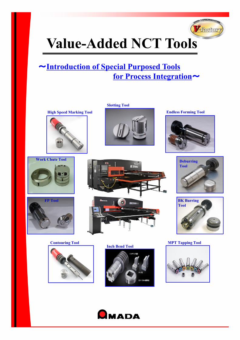
Contouring Tool
FP Tool
Slotting Tool
Deburring Tool
MPT Tapping Tool
Value-Added NCT Tools
Work Chute Tool
High Speed Marking Tool
BK BurringTool
~Introduction of Special Purposed Tools for Process Integration~
Endless Forming Tool
Inch Bend Tool
Deburring Work Reduction by EM machine
・・・ Deburring Tool
Free Forming without Special Tool & Semi-standard Tool
・・・ Contouring Tool
Seamless Slotting Work
・・・ Slotting Tool Ⅲ
Marking Process Integration
・・・ High Speed Marking Tool
High Speed Offset Processing
・・・ Endless Forming Tool
Tapping Integration
・・・ MPT Tapping Tool
Extrusion Quality Improvement
・・・ BK Burring Tool
Parts Location Improvement
・・・ FP Tool
Integration of Bending & Micro-joint Separation
・・・ Inch Bend Tool
Jointless Processing for Small Piece Products
・・・ Work Chute Tool
~ Index ~
Page 3~
Page 7~
Page 11~
Page 15~
Page 19~
Page 23~
Page 28~
Page 32~
Page 36~
Page 40~
1.
2.
3.
4.
5.
6.
7.
8.
9.
10.
2
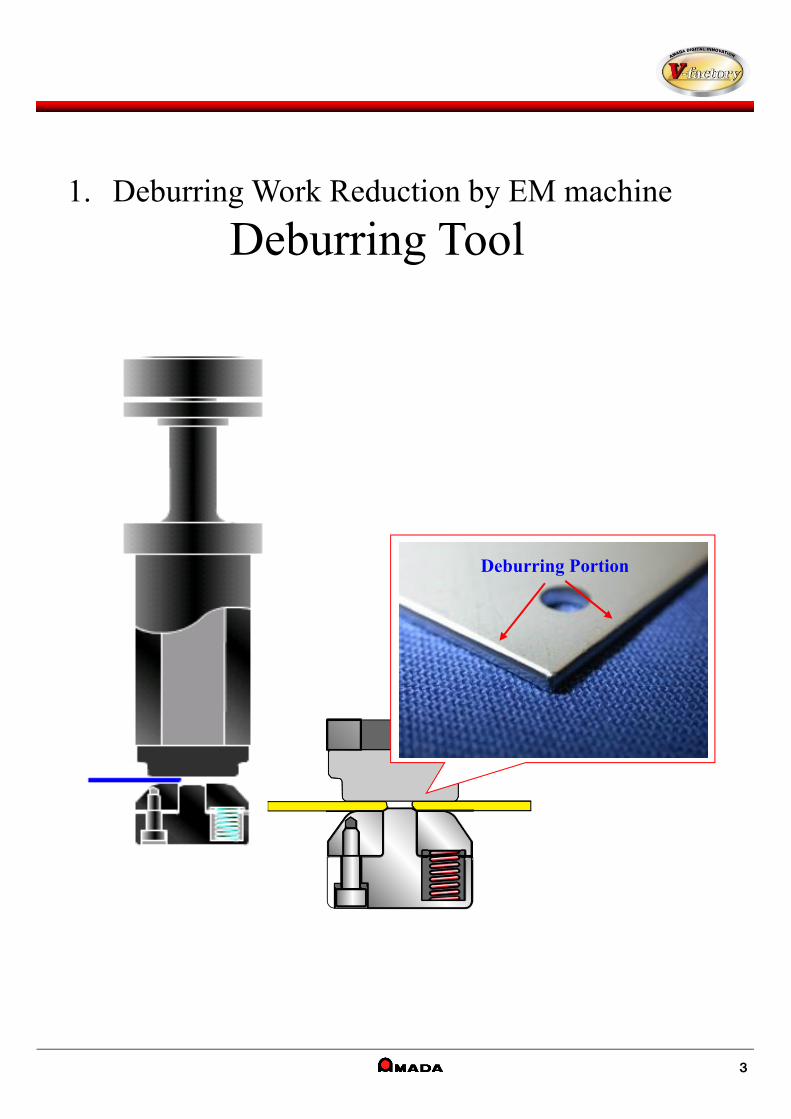
バリ潰し部分
1. Deburring Work Reduction by EM machine
Deburring Tool
3
Deburring Portion
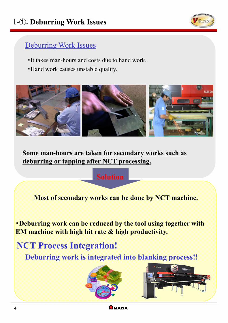
Some man-hours are taken for secondary works such asdeburring or tapping after NCT processing.
Most of secondary works can be done by NCT machine.
NCT Process Integration!Deburring work is integrated into blanking process!!
・Deburring work can be reduced by the tool using together with EM machine with high hit rate & high productivity.
1-①. Deburring Work Issues
Solution
4
Deburring Work Issues
・It takes man-hours and costs due to hand work.
・Hand work causes unstable quality.
1-②. Introduction Effects of Deburring Tool
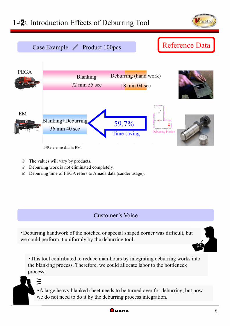
Reference DataCase Example / Product 100pcs
Customer’s Voice
・Deburring handwork of the notched or special shaped corner was difficult, but we could perform it uniformly by the deburring tool! ・Deburring handwork of the notched or special shaped corner was difficult, but we could perform it uniformly by the deburring tool!
・This tool contributed to reduce man-hours by integrating deburring works into the blanking process. Therefore, we could allocate labor to the bottleneck process!
・This tool contributed to reduce man-hours by integrating deburring works into the blanking process. Therefore, we could allocate labor to the bottleneck process!
・A large heavy blanked sheet needs to be turned over for deburring, but now we do not need to do it by the deburring process integration.・A large heavy blanked sheet needs to be turned over for deburring, but now we do not need to do it by the deburring process integration.
5
※ The values will vary by products.※ Deburring work is not eliminated completely.※ Deburring time of PEGA refers to Amada data (sander usage).
※Reference data is EM.
Time-saving
PEGA
EM
Blanking
72 min 55 sec
Deburring (hand work)
18 min 04 sec
Blanking+Deburring
36 min 40 sec59.7%
Deburring Portion
1-③. Features / Specification
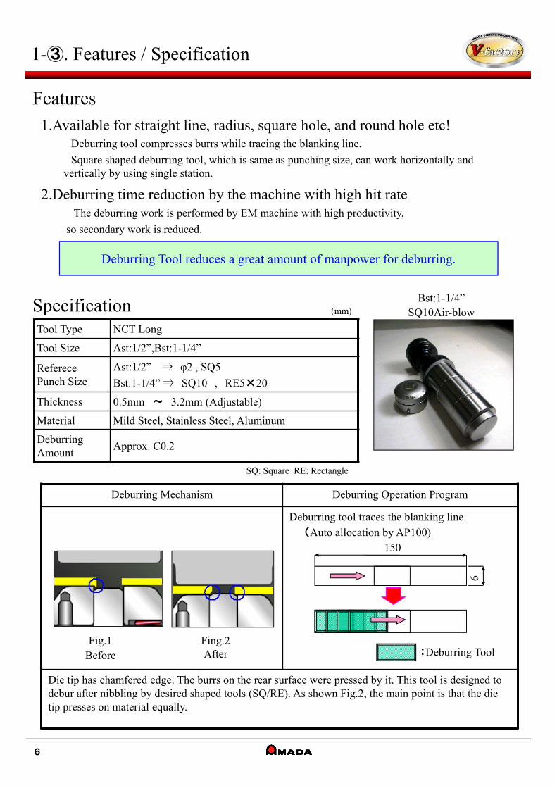
Deburring Mechanism Deburring Operation Program
Deburring tool traces the blanking line.(Auto allocation by AP100)
Die tip has chamfered edge. The burrs on the rear surface were pressed by it. This tool is designed to debur after nibbling by desired shaped tools (SQ/RE). As shown Fig.2, the main point is that the die tip presses on material equally.
1.Available for straight line, radius, square hole, and round hole etc!Deburring tool compresses burrs while tracing the blanking line.
Square shaped deburring tool, which is same as punching size, can work horizontally andvertically by using single station.
2.Deburring time reduction by the machine with high hit rateThe deburring work is performed by EM machine with high productivity,
so secondary work is reduced.
Deburring Tool reduces a great amount of manpower for deburring.
Fig.1Before
Fing.2After :Deburring Tool
6
150
Tool Type NCT Long
Tool Size Ast:1/2”,Bst:1-1/4”
Referece Punch Size
Ast:1/2” ⇒ φ2 , SQ5
Bst:1-1/4” ⇒ SQ10 , RE5×20
Thickness 0.5mm ~ 3.2mm (Adjustable)
Material Mild Steel, Stainless Steel, Aluminum
Deburring Amount
Approx. C0.2
Specification Bst:1-1/4” SQ10Air-blow
6
Features
SQ: Square RE: Rectangle
(mm)
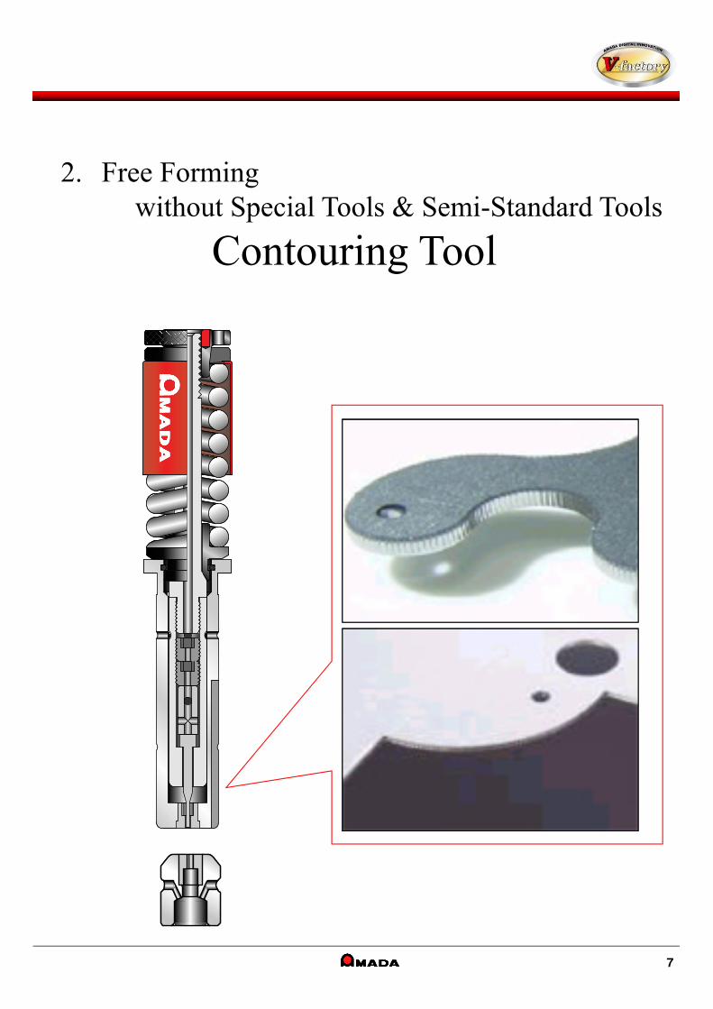
2. Free Forming without Special Tools & Semi-Standard Tools
Contouring Tool
7
2-①. Nibbling Track Removal Work Issues
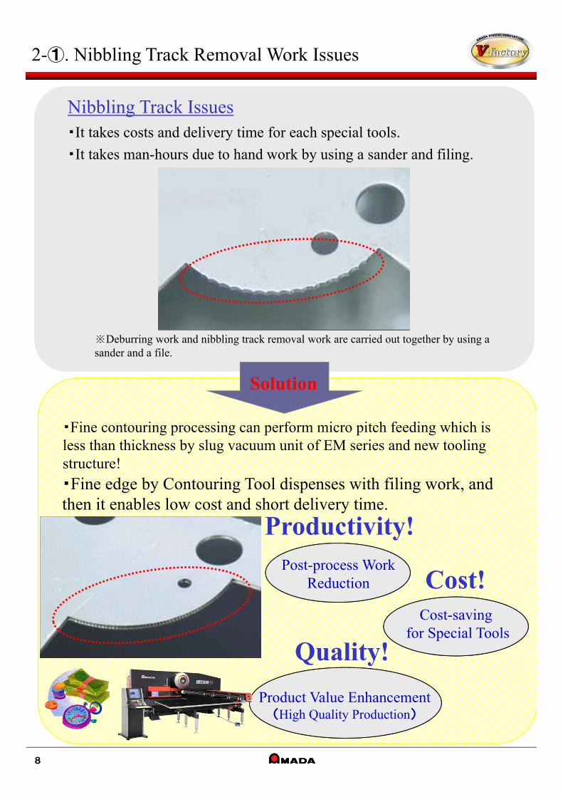
・Fine contouring processing can perform micro pitch feeding which is less than thickness by slug vacuum unit of EM series and new tooling structure!
・Fine edge by Contouring Tool dispenses with filing work, and then it enables low cost and short delivery time.
Post-process WorkReduction
Productivity!
Product Value Enhancement(High Quality Production)
Quality!
Cost!Cost-saving
for Special Tools
8
Nibbling Track Issues・It takes costs and delivery time for each special tools.
・It takes man-hours due to hand work by using a sander and filing.
※Deburring work and nibbling track removal work are carried out together by using a sander and a file.
Solution
0 100 200 300 400 500 600 700 800
EM2510
PEGA357
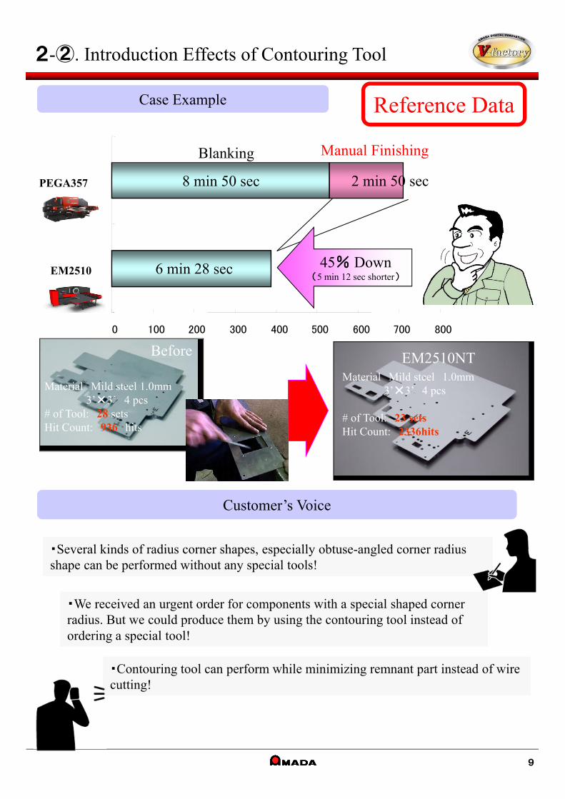
Reference DataCase Example
Customer’s Voice
・Several kinds of radius corner shapes, especially obtuse-angled corner radius shape can be performed without any special tools!・Several kinds of radius corner shapes, especially obtuse-angled corner radius shape can be performed without any special tools!
・We received an urgent order for components with a special shaped corner radius. But we could produce them by using the contouring tool instead of ordering a special tool!
・We received an urgent order for components with a special shaped corner radius. But we could produce them by using the contouring tool instead of ordering a special tool!
・Contouring tool can perform while minimizing remnant part instead of wire cutting!・Contouring tool can perform while minimizing remnant part instead of wire cutting!
2‐②. Introduction Effects of Contouring Tool
6 min 28 sec
8 min 50 sec 2 min 50 sec
Blanking Manual Finishing
Before
Material Mild steel 1.0mm3’×3’ 4 pcs
# of Tool: 28 setsHit Count: 936 hits
Material Mild steel 1.0mm3’×3’ 4 pcs
# of Tool: 23 setsHit Count: 2336hits
EM2510NT
9
45% Down(5 min 12 sec shorter)

2-③. Features / Specification
Caution
Die Clearance Table for Material & Thickness
Punch Tip
Guide Bushing
Button Die
Die Body
0.5mm pitch work available
Power Vacuum Unit
Stainless 1.0mm
10
Specification
Features1.Enables nibbling under the pitch less than material thickness.
2.Enables special shaping without any special tools.
3.High Hit Rate
Thickness (mm)
Material 0.8 1.0 1.2 1.6 2.3
Mild 0.15 0.15 0.15 0.2 0.3
Stainless 0.15 0.15
0.5mm pitch contouring work creates a 0.03mm waved pitch mark. Please verify this is within product tolerance.
金型タイプ NCTロング
金型サイズ Ast:1/2”
パンチチップ径 φ2.0(標準推奨寸法)
適応ダイ パワーバキューム仕様
パンチチップ鋼種 コーティングハイス・超硬
ダイチップ鋼種 SKH・超硬
Tool Type
Tool Size
Punch Tip Size
Applicable Die
Punch Tip Grade
Die Tip Grade
NCT Long
Ast:1/2”
φ2.0 (recommended size)
Power Vacuum
Coating / Carbide
SKH / Carbide
使用パンチチップ鋼種
加工可能材質および最大板厚
コーティングハイス
SPCC 1.6mm、SUS 1.0mmアルミ不可
超硬 SPCC 2.3mm SUSおよびアルミ不可
Punch Tip Grade
Coating
Carbide
Applicable Material & Max. Thickness
Mild Steel: 1.6mm / Stainless:1.0mmAluminum: NA
Mild Steel: 2.3mmStainless/Aluminum: NA
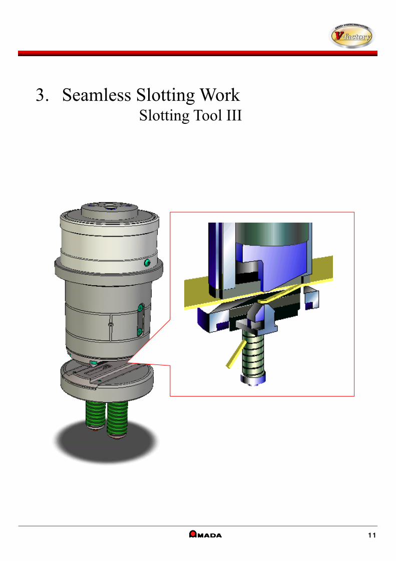
3. Seamless Slotting WorkSlotting Tool III
11
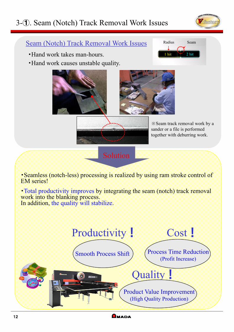
3-①. Seam (Notch) Track Removal Work Issues
Smooth Process Shift
Productivity!
Process Time Reduction(Profit Increase)
Quality!
Product Value Improvement(High Quality Production)
Cost!
12
Seam (Notch) Track Removal Work Issues
・Hand work takes man-hours.・Hand work causes unstable quality.
※Seam track removal work by a sander or a file is performed together with deburring work.
Solution
・Seamless (notch-less) processing is realized by using ram stroke control of EM series!
・Total productivity improves by integrating the seam (notch) track removal work into the blanking process.In addition, the quality will stabilize.
Radius Seam
1 hit 2 hit

Reference DataCase Example
Customer’s Voice
・Laser cutting causes a thermal deformation on long components, and it makes bending accuracy poor and requires the shearing process. But Slotting Tool III could realize the intensive process by NCT work!
・Laser cutting causes a thermal deformation on long components, and it makes bending accuracy poor and requires the shearing process. But Slotting Tool III could realize the intensive process by NCT work!
・Laser cutting is not suited for processing pure aluminum and brass material. But they can be processed with high quality and without seams using Slotting Tool III!
・Laser cutting is not suited for processing pure aluminum and brass material. But they can be processed with high quality and without seams using Slotting Tool III!
・Laser cutting could not provide seamless radius edges indicated in the drawing instruction. But Slotting Tool III can provide seamless radius edges!・Laser cutting could not provide seamless radius edges indicated in the drawing instruction. But Slotting Tool III can provide seamless radius edges!
3-②. Introduction Effects of Slotting Tool III
Flat
13
PEGA
EMNormal
Blanking
Blanking 6 min 14 sec
Blanking+Seam Removal Work 6 min 3 sec
Blanking 3 min 26 sec
EMSlotting
+Seam Removal Work
Sheet Name:B-46# of Parts:3 pcs/sheet
+Seam Removal Work

3-③. Features / Specification
Slotting Image
Specification
Slotting Work by Normal Tool(6×30)
Slotting Tool III(Dst:4-1/2”)
Flat
14
Features
Tool Size Cst:2” Dst:3-1/2” Est:4-1/2”
Punch Type Solid Punch Body Punch Tip - Replacement Style
Die Type Die Plate - Replacement Style
Die Tip Type Die Tip - Replacement Style
Punch Size (A size) 6mm~10mm
Applicable Material
Max. Thickness
Mild Steel※1 1.6mm 2.3mm
Stainless※2 1.5mm 1.5mm(2.00mm※ 3)
Aluminum※2 1.5mm 3.0mm
Proper Clearance t×20%~25% *t: thickness
Machine Specification Limited to the machine with air-blow unit※4
Max. Slotting Pitch (D) 15mm1.6mm<t→20mm
t≦1.6mm→25mm
1.6mm<t→30mm
t≦1.6mm→35mm
Dead Zone
A
クランプ
D
55mm 35mm
A
クランプ
D
※1 In case of hot rolled steel, please be sure to clean the tooling every 3,000 hits. The black coating is peeled off from the surfaceand makes trouble. If not, there is a danger of tooling being damaged.
※2 Slotting Tool III is not allowed if the material has vinyl protection sheet on rear side (die side). It causes slug clogging etc.※3 APH punch tip is optional.※4 Air-blow unit is necessary for Slotting Tool III. Slug rising / clogging etc will occur if they are not used together.
Besides, it makes the tooling life extremely shorter and gives damages on the tooling.
※ Programming software of Slotting Tool III is optional.
1.Yield improvement by sheet-saver
2.Seamless processing until re-clamping
3.Interference avoidance (formed portion / clamps) by double side relief
Cla
mp
Cla
mp

4. Marking Process Integration!
High Speed Marking Tool
15
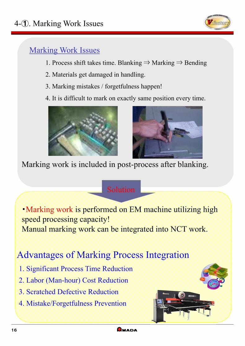
4-①. Marking Work Issues
Marking work is included in post-process after blanking.
1. Process shift takes time. Blanking ⇒ Marking ⇒ Bending
2. Materials get damaged in handling.
3. Marking mistakes / forgetfulness happen!
4. It is difficult to mark on exactly same position every time.
Advantages of Marking Process Integration1. Significant Process Time Reduction
2. Labor (Man-hour) Cost Reduction
3. Scratched Defective Reduction
4. Mistake/Forgetfulness Prevention
・Marking work is performed on EM machine utilizing high speed processing capacity!Manual marking work can be integrated into NCT work.
Solution
16
Marking Work Issues
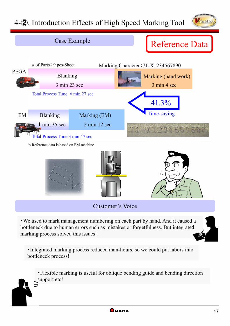
Reference DataCase Example
Customer’s Voice
・We used to mark management numbering on each part by hand. And it caused a bottleneck due to human errors such as mistakes or forgetfulness. But integrated marking process solved this issues!
・We used to mark management numbering on each part by hand. And it caused a bottleneck due to human errors such as mistakes or forgetfulness. But integrated marking process solved this issues!
・Integrated marking process reduced man-hours, so we could put labors into bottleneck process!・Integrated marking process reduced man-hours, so we could put labors into bottleneck process!
・Flexible marking is useful for oblique bending guide and bending direction support etc!・Flexible marking is useful for oblique bending guide and bending direction support etc!
4-②. Introduction Effects of High Speed Marking Tool
# of Parts: 9 pcs/Sheet
Blanking
3 min 23 sec
Marking (EM)
Marking (hand work)
3 min 4 sec
41.3%Time-saving
Total Process Time 6 min 27 sec
Total Process Time 3 min 47 sec
Marking Character:71-X1234567890PEGA
EM Blanking
1 min 35 sec 2 min 12 sec
17
※Reference data is based on EM machine.
4-③. Features / Specification
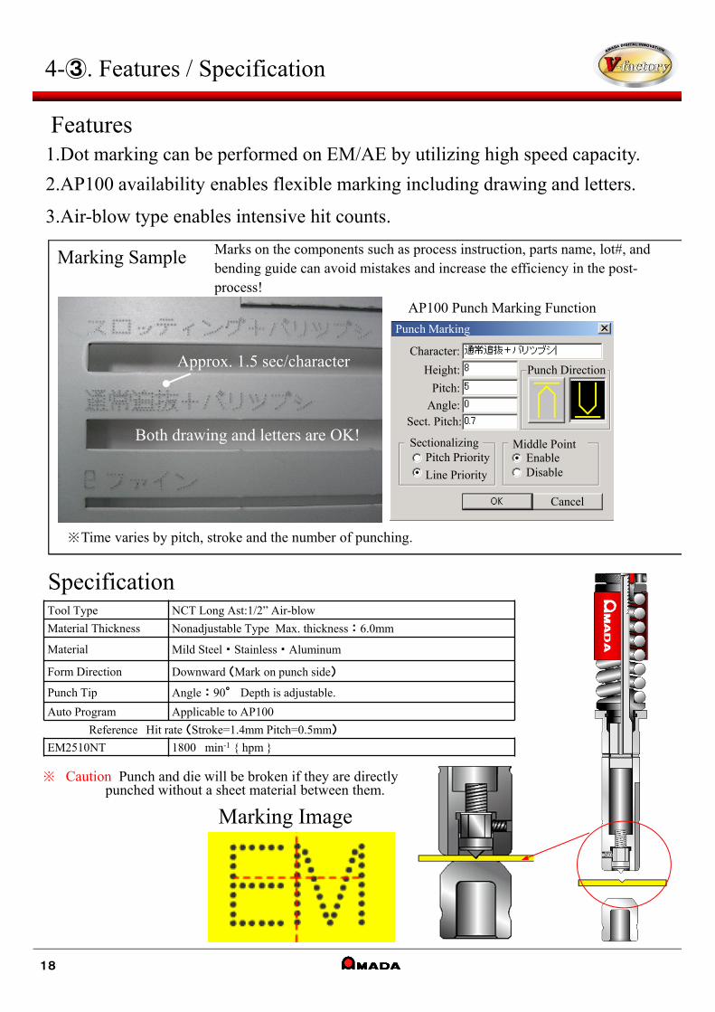
Marking Sample
Both drawing and letters are OK!
Approx. 1.5 sec/character
※Time varies by pitch, stroke and the number of punching.
AP100 Punch Marking Function
Tool Type NCT Long Ast:1/2” Air-blow
Material Thickness Nonadjustable Type Max. thickness : 6.0mm
Material Mild Steel ・ Stainless ・ Aluminum
Form Direction Downward (Mark on punch side)
Punch Tip Angle : 90° Depth is adjustable.
Auto Program Applicable to AP100
Reference Hit rate (Stroke=1.4mm Pitch=0.5mm)
EM2510NT 1800 min-1 { hpm }
Marks on the components such as process instruction, parts name, lot#, and bending guide can avoid mistakes and increase the efficiency in the post-process!
Marking Image
※ Caution Punch and die will be broken if they are directlypunched without a sheet material between them.
18
Specification
Features1.Dot marking can be performed on EM/AE by utilizing high speed capacity.
2.AP100 availability enables flexible marking including drawing and letters.
3.Air-blow type enables intensive hit counts.
Character:
Height:
Pitch:
Angle:Sect. Pitch:
SectionalizingPitch Priority
Line Priority
Middle PointEnableDisable
Punch Direction
Cancel
Punch Marking
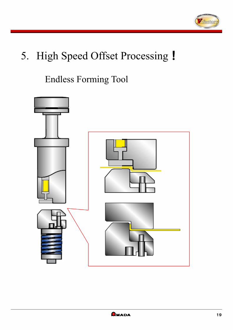
5. High Speed Offset Processing!
Endless Forming Tool
19

5-①. Small Lot, Multi Process Issues
Various forming can be performed by EM series functions including high speed transfer, high accuracy stroke control, high feed clearance and brush float table!
Both straight line and free curve (15mm radius or more) can be formed by using Endless Forming Tool (Offset / Burring)!
※ The tool will be designed exclusively to meet thickness and material.
NCT machine only
Productivity!
Product Value Improvement(Quick Prototype Delivery)
Quality!
Cost!
Cost Reductionfor Special Tools
20
*Material thickness offset
*Flange processing for pipe welding
*Various flange height processing for prototype
・Small lot work needs to use bending machine or press machine, so operation is not efficient. ・It takes costs and delivery time for special tools.
Small Lot, Multi Process Issues
Solution
0 500 1000 1500 2000
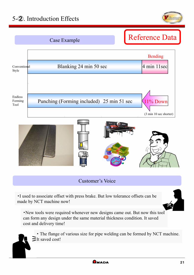
Reference DataCase Example
Customer’s Voice
・I used to associate offset with press brake. But low tolerance offsets can be made by NCT machine now!・I used to associate offset with press brake. But low tolerance offsets can be made by NCT machine now!
・New tools were required whenever new designs came out. But now this tool can form any design under the same material thickness condition. It saved cost and delivery time!
・New tools were required whenever new designs came out. But now this tool can form any design under the same material thickness condition. It saved cost and delivery time!
・ The flange of various size for pipe welding can be formed by NCT machine. It saved cost!・ The flange of various size for pipe welding can be formed by NCT machine. It saved cost!
21
5-②. Introduction Effects
Blanking 24 min 50 sec 4 min 11sec
Bending
Conventional Style
Endless Forming Tool
Punching (Forming included) 25 min 51 sec
(3 min 10 sec shorter)
11% Down
Tool Type
Tool Size
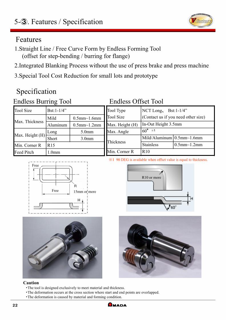
NCT Long、 Bst:1-1/4”
(Contact us if you need other size)
Max. Height (H) In-Out Height 3.5mm
Max. Angle 60°※1
ThicknessMild/Aluminum 0.5mm~1.6mm
Stainless 0.5mm~1.2mm
Min. Corner R R10
Tool Size Bst:1-1/4”
Max. ThicknessMild 0.5mm~1.6mm
Aluminum 0.5mm~1.2mm
Max. Height (H)Long 5.0mm
Short 3.0mm
Min. Corner R R15
Feed Pitch 1.0mm
Caution・The tool is designed exclusively to meet material and thickness.・The deformation occurs at the cross section where start and end points are overlapped.・The deformation is caused by material and forming condition.
22
5-③. Features / Specification
Specification
Features1.Straight Line / Free Curve Form by Endless Forming Tool
(offset for step-bending / burring for flange)
2.Integrated Blanking Process without the use of press brake and press machine
3.Special Tool Cost Reduction for small lots and prototype
Endless Burring Tool Endless Offset Tool
※1 90 DEG is available when offset value is equal to thickness.
Free
Free
15mm or more
R10 or more
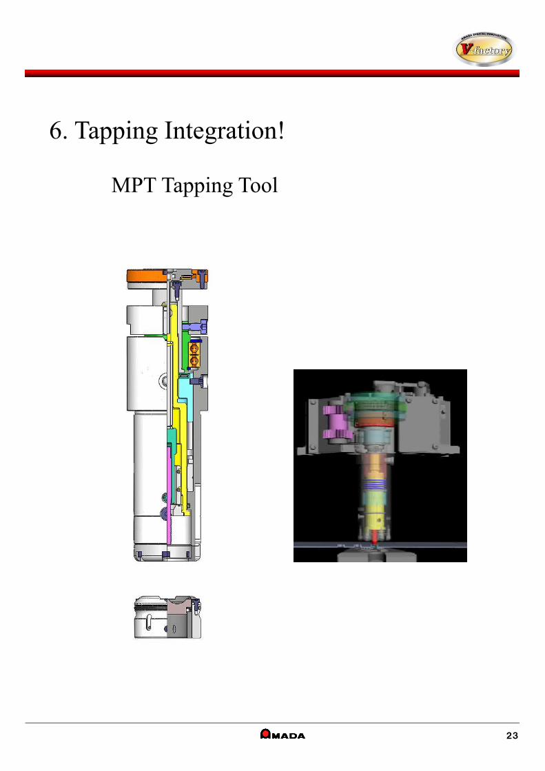
6. Tapping Integration!
MPT Tapping Tool
23
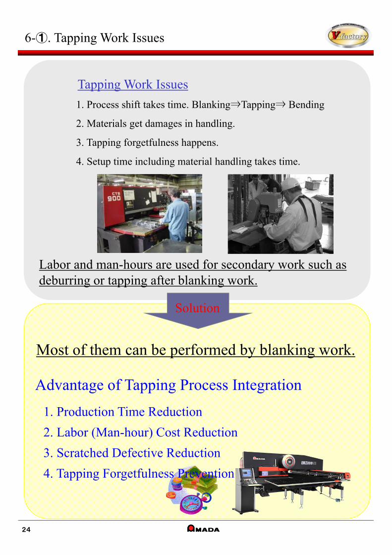
6-①. Tapping Work Issues
Labor and man-hours are used for secondary work such as deburring or tapping after blanking work.
1. Process shift takes time. Blanking⇒Tapping⇒ Bending
2. Materials get damages in handling.
3. Tapping forgetfulness happens.
4. Setup time including material handling takes time.
Advantage of Tapping Process Integration
1. Production Time Reduction
2. Labor (Man-hour) Cost Reduction
3. Scratched Defective Reduction
4. Tapping Forgetfulness Prevention
Solution
24
Tapping Work Issues
Most of them can be performed by blanking work.
Reference DataCase Example
Customer’s Voice
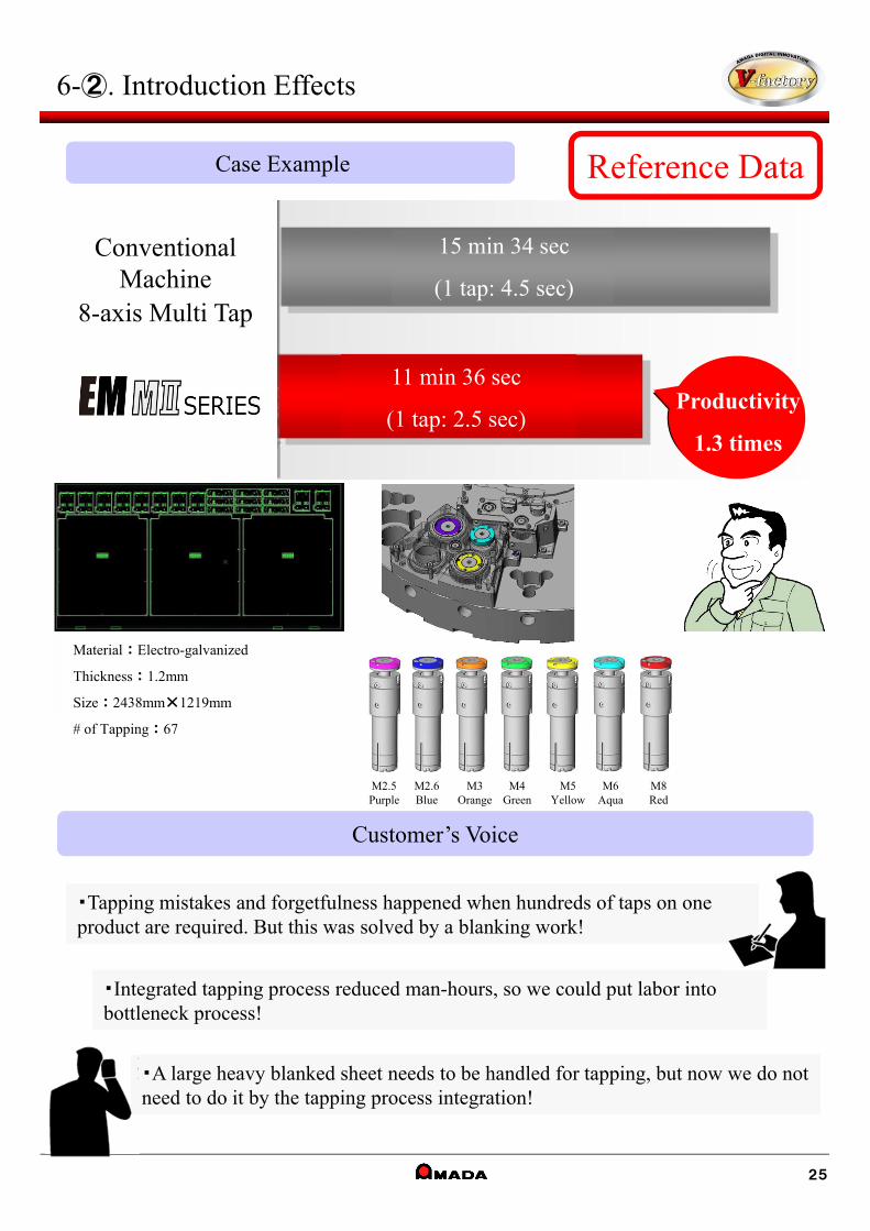
・Tapping mistakes and forgetfulness happened when hundreds of taps on one product are required. But this was solved by a blanking work!・Tapping mistakes and forgetfulness happened when hundreds of taps on one product are required. But this was solved by a blanking work!
・Integrated tapping process reduced man-hours, so we could put labor into bottleneck process!・Integrated tapping process reduced man-hours, so we could put labor into bottleneck process!
・A large heavy blanked sheet needs to be handled for tapping, but now we do not need to do it by the tapping process integration!・A large heavy blanked sheet needs to be handled for tapping, but now we do not need to do it by the tapping process integration!
6-②. Introduction Effects
25
M2.5Purple
M2.6Blue
M3Orange
M4Green
M5Yellow
M6Aqua
M8Red
Conventional Machine
8-axis Multi Tap
11 min 36 sec
(1 tap: 2.5 sec)
15 min 34 sec
(1 tap: 4.5 sec)
Productivity
1.3 times
Material : Electro-galvanized
Thickness : 1.2mm
Size : 2438mm×1219mm
# of Tapping : 67

6-③. Features / Specification
26
Shear-pin※ This shear-pin protects the
master screw by breaking itself when excessive overload was applied to the tapping tool.
Tapping work can be integrated by MPT Tapping Tool.
Station SizeMPT Tap Unit(Bst︓1-1/4") 4 stations
Tap Type Cutting / Forming(Amada spec. tap)
Tap Size M2.5・M2.6・M3・M4・M5・M6・M8
Material Thickness Max. 6.0mm (Forming included)
Material Type Mild steel / Stainless steel / Aluminum
Thread Grade ISO Grade 6H (JIS-Grade 2nd) equiv.
Work TimeApprox. 2 sec / tap(Case : Mild Steel / 6mm or less)
Tip-break Sensor Available
Tapping OilCombination machines︓AML-46
Punching machines︓TANOI SHINCOOL 99X Super
Lubrication Common with Air-blow Unit(Tank 1.0L)
Swarf Control Absorption by Slug Suction and Power-Vacuum Unit
Tap Life
(Guidance)Mild Steel 10,000hitStainless #304 5,000hit
<Specification>MPT Tapping Tool Punch Assembly(Cutting / Forming common)
<Maintenance Kit>
・EMK-MⅡ・LS2612E・C1(C1AJ)・EM-MⅡ
・ACIES・EM‐ZR・EMZ-MⅡ
◇Stripper-free structure reduces processing restriction for tap work and forming.
◇Tap break detecting function reduces defectives.
◇Processing range is same as punching, so change of clamping/coordinates are needless.
◇Both cutting tap and forming tap can be used by changing tap and conditions.
◇Shear-pin reduces risk of tooling damage.
MPT Tapping Tool Die Assembly
Size is common.
(Cutting / Forming common)
<Feature>
Product Name Set Contents
For EMZR/EM-MⅡMPT Tapping Tool Maintenance Kit
Grease Gun、Pistol Pump Oiler、Amada Grease SRL、Tap Holder Assembly Jig、 TANOI SHINCOOL 99X Super
For LCC1 & ACIESMPT Tapping Tool Maintenance Kit
Grease Gun、Pistol Pump Oiler、Amada Grease SRL、Tap Holder Assembly Jig、 AML46
Type-B(ZR-turret / Z-turret)
Type-A(φ1010-turret / King-turret)
Type-A Type-B
High Power Tap Die※1
(Recommended for 4.5mm〜6.0mm*Mild Steel only)
Min.pitch to the next P=30mm
Tap (Cutting / Forming)
* Not available for EM-NT/AE/EML.
※1 Please use a tip-breaker tap for M5 & M6.
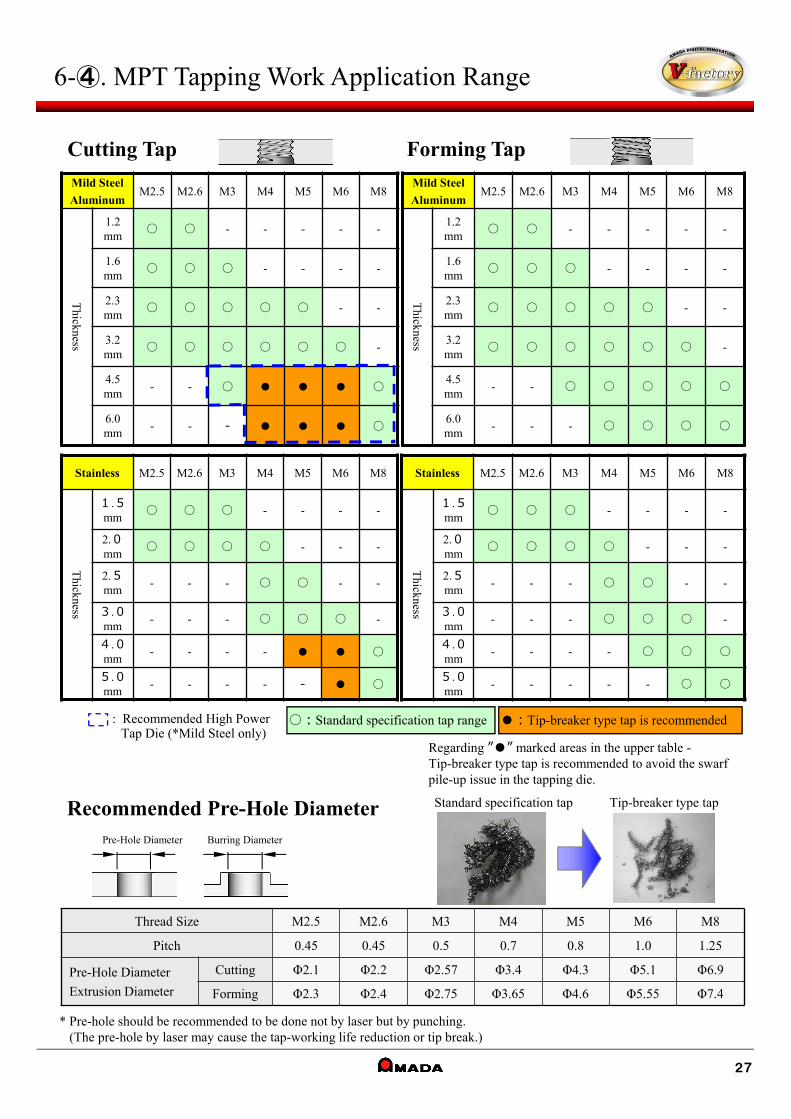
6-④. MPT Tapping Work Application Range
27
Cutting Tap Forming Tap
●︓Tip-breaker type tap is recommended○︓Standard specification tap range
Pre-Hole Diameter Burring Diameter
Recommended Pre-Hole Diameter
Thread Size M2.5 M2.6 M3 M4 M5 M6 M8
Pitch 0.45 0.45 0.5 0.7 0.8 1.0 1.25
Pre-Hole Diameter
Extrusion Diameter
Cutting Φ2.1 Φ2.2 Φ2.57 Φ3.4 Φ4.3 Φ5.1 Φ6.9
Forming Φ2.3 Φ2.4 Φ2.75 Φ3.65 Φ4.6 Φ5.55 Φ7.4
* Pre-hole should be recommended to be done not by laser but by punching. (The pre-hole by laser may cause the tap-working life reduction or tip break.)
Stainless M2.5 M2.6 M3 M4 M5 M6 M8
Thickness
1.5mm
○ ○ ○ - - - -
2.0mm
○ ○ ○ ○ - - -
2.5mm
- - - ○ ○ - -
3.0mm
- - - ○ ○ ○ -
4.0mm
- - - - ● ● ○
5.0mm
- - - - - ● ○
Stainless M2.5 M2.6 M3 M4 M5 M6 M8
Thickness
1.5mm
○ ○ ○ - - - -
2.0mm
○ ○ ○ ○ - - -
2.5mm
- - - ○ ○ - -
3.0mm
- - - ○ ○ ○ -
4.0mm
- - - - ○ ○ ○
5.0mm
- - - - - ○ ○
Mild Steel
AluminumM2.5 M2.6 M3 M4 M5 M6 M8
Thickness
1.2mm
○ ○ - - - - -
1.6mm
○ ○ ○ - - - -
2.3mm
○ ○ ○ ○ ○ - -
3.2mm
○ ○ ○ ○ ○ ○ -
4.5mm
- - ○ ● ● ● ○
6.0mm
- - - ● ● ● ○
Mild Steel
AluminumM2.5 M2.6 M3 M4 M5 M6 M8
Thickness
1.2mm
○ ○ - - - - -
1.6mm
○ ○ ○ - - - -
2.3mm
○ ○ ○ ○ ○ - -
3.2mm
○ ○ ○ ○ ○ ○ -
4.5mm
- - ○ ○ ○ ○ ○
6.0mm
- - - ○ ○ ○ ○
: Recommended High Power Tap Die (*Mild Steel only)
Standard specification tap Tip-breaker type tap
Regarding ”●” marked areas in the upper table -Tip-breaker type tap is recommended to avoid the swarf pile-up issue in the tapping die.
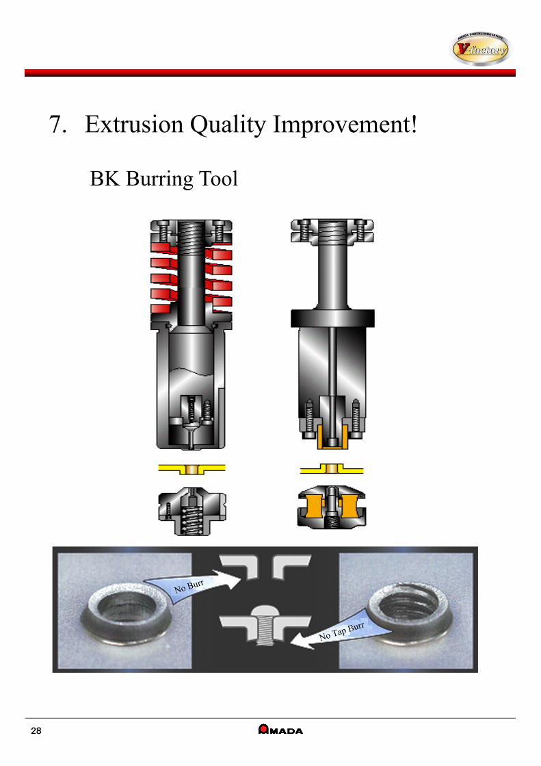
7. Extrusion Quality Improvement!
BK Burring Tool
28
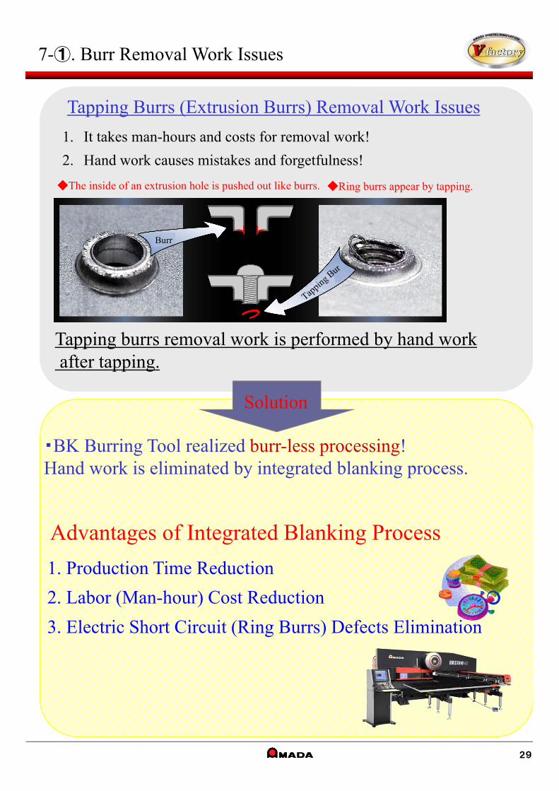
7-①. Burr Removal Work Issues
Tapping burrs removal work is performed by hand workafter tapping.
◆The inside of an extrusion hole is pushed out like burrs. ◆Ring burrs appear by tapping.
Advantages of Integrated Blanking Process
1. Production Time Reduction
2. Labor (Man-hour) Cost Reduction
3. Electric Short Circuit (Ring Burrs) Defects Elimination
・BK Burring Tool realized burr-less processing!Hand work is eliminated by integrated blanking process.
Solution
Tapping Burrs (Extrusion Burrs) Removal Work Issues
1. It takes man-hours and costs for removal work!
2. Hand work causes mistakes and forgetfulness!
Burr
29
Customer’s Voice
・Tapping mistakes and forgetfulness happened when hundreds of taps on one product are required. But those were solved by a blanking work!・Tapping mistakes and forgetfulness happened when hundreds of taps on one product are required. But those were solved by a blanking work!
・Integrated blanking process reduced man-hours, so we could put labor into bottleneck process!・Integrated blanking process reduced man-hours, so we could put labor into bottleneck process!
・A large heavy blanked sheet needed to be handled for removal work, but now we do not need to do it by the blanking process integration!・A large heavy blanked sheet needed to be handled for removal work, but now we do not need to do it by the blanking process integration!
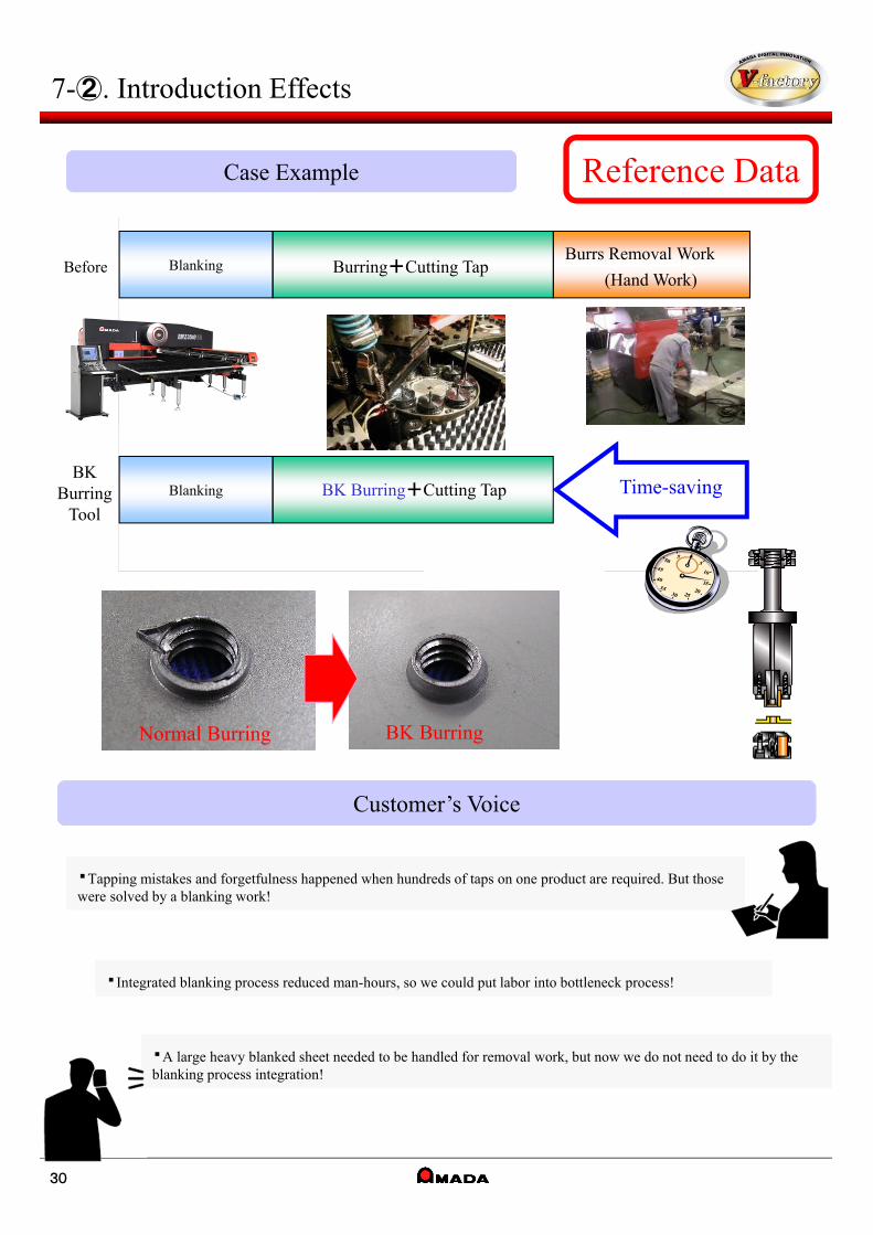
7-②. Introduction Effects
Normal Burring BK Burring
Reference DataCase Example
172172
Time-savingBK
BurringTool
Blanking BK Burring+Cutting Tap
BeforeBurrs Removal Work
(Hand Work)Blanking Burring+Cutting Tap
30
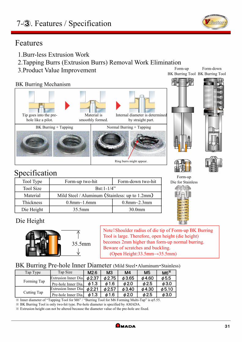
7-③. Features / Specification
BK Burring Mechanism
BK Burring Pre-hole Inner Diameter (Mild Steel・Aluminum・Stainless)
※ Inner diameter of “Tapping Tool for M6” / “Burring Tool for M6 Forming Multi-Tap” is φ5.55.※ BK Burring Tool is only two-hit type. Pre-hole diameter is specified by AMADA.※ Extrusion height can not be altered because the diameter value of the pre-hole are fixed.
35.5mm
Note:Shoulder radius of die tip of Form-up BK Burring Tool is large. Therefore, open height (die height) becomes 2mm higher than form-up normal burring. Beware of scratches and buckling.
(Open Height:33.5mm→35.5mm)
Die Height
Features1.Burr-less Extrusion Work2.Tapping Burrs (Extrusion Burrs) Removal Work Elimination3.Product Value Improvement
Specification
Tip goes into the pre-hole like a pilot.
Material is smoothly formed.
Internal diameter is determined by straight part.
BK Burring + Tapping Normal Burring + Tapping
Ring burrs might appear.
Form-upBK Burring Tool
Form-downBK Burring Tool
Form-upDie for StainlessTool Type Form-up two-hit Form-down two-hit
Tool Size Bst:1-1/4”
Material Mild Steel / Aluminum (Stainless: up to 1.2mm)
Thickness 0.8mm~1.6mm 0.8mm~2.3mm
Die Height 35.5mm 30.0mm
M2.6 M3 M4 M5 M6※
φ2.37 φ2.75 φ3.65 φ4.60 φ5.5
φ1.3 φ1.6 φ2.0 φ2.5 φ3.0
φ2.21 φ2.57 φ3.40 φ4.30 φ5.10
φ1.3 φ1.6 φ2.0 φ2.5 φ3.0切削タップ
タップサイズ
Br内径
下穴径
Br内径
下穴径
タップ種類
転造タップForming Tap
Cutting Tap
Extrusion Inner Dia.
Pre-hole Inner Dia.Extrusion Inner Dia.
Pre-hole Inner Dia.
Tap Type Tap Size
31
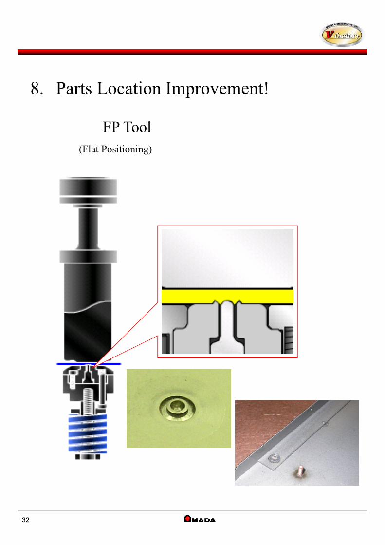
8. Parts Location Improvement!
FP Tool(Flat Positioning)
32
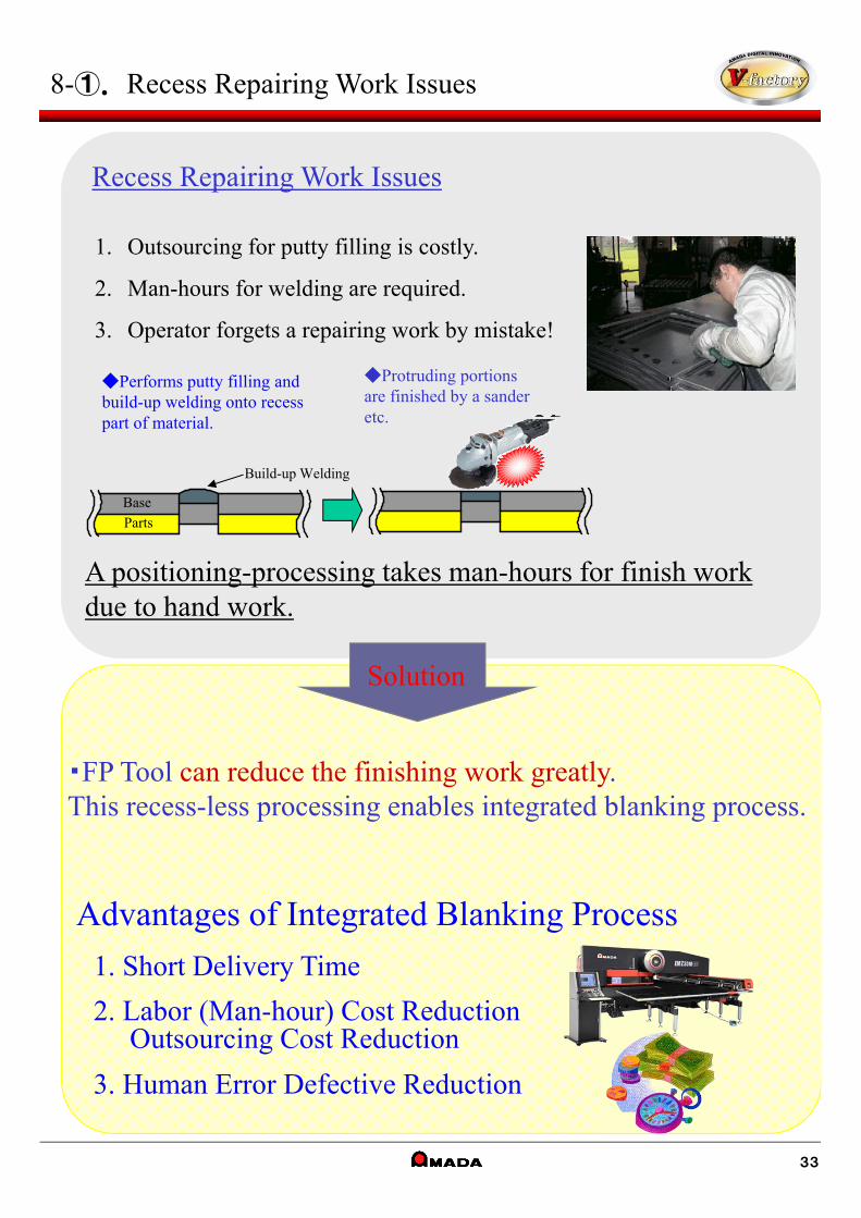
A positioning-processing takes man-hours for finish work due to hand work.
Recess Repairing Work Issues
1. Outsourcing for putty filling is costly.
2. Man-hours for welding are required.
3. Operator forgets a repairing work by mistake!
◆Performs putty filling and build-up welding onto recess part of material.
◆Protruding portions are finished by a sander etc.
Parts
Base
Build-up Welding
Advantages of Integrated Blanking Process
1. Short Delivery Time
2. Labor (Man-hour) Cost ReductionOutsourcing Cost Reduction
3. Human Error Defective Reduction
・FP Tool can reduce the finishing work greatly.This recess-less processing enables integrated blanking process.
Solution
8-①. Recess Repairing Work Issues
33
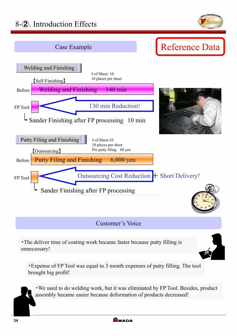
Reference DataCase Example
Customer’s Voice
・The deliver time of coating work became faster because putty filling is unnecessary!・The deliver time of coating work became faster because putty filling is unnecessary!
・Expense of FP Tool was equal to 3 month expenses of putty filling. The tool brought big profit!・Expense of FP Tool was equal to 3 month expenses of putty filling. The tool brought big profit!
・We used to do welding work, but it was eliminated by FP Tool. Besides, product assembly became easier because deformation of products decreased!・We used to do welding work, but it was eliminated by FP Tool. Besides, product assembly became easier because deformation of products decreased!
8-②. Introduction Effects
130 min Reduction!
Before Welding and Finishing 140 min
FP Tool
Welding and Finishing
Sander Finishing after FP processing 10 min
# of Sheet: 10 10 places per sheet
Outsourcing Cost Reduction + Short Delivery!
Before Putty Filing and Finishing 6,000 yen
FP Tool
Putty Filing and Finishing # of Sheet:1010 places per sheetPer putty filing: 60 yen【Outsourcing】
【Self-Finishing】
Sander Finishing after FP processing
34
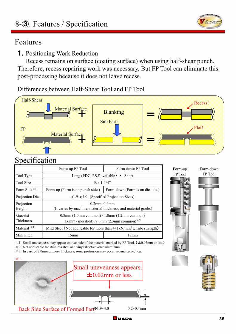
Differences between Half-Shear Tool and FP Tool
+
Half-Shear
Material Surface
Material SurfaceFP
+
=
=
Flat!
Recess!
Blanking
Sub Parts
Form-up FP Tool Form-down FP Tool
Tool Type Long (PDC, P&F available) ・ Short
Tool Size Bst:1-1/4”
Form Side※1 Form-up (Form is on punch side.) Form-down (Form is on die side.)
Projection Dia. φ1.9~φ4.0 (Specified Projection Sizes)
Projection Height
0.2mm~0.4mm(It varies by machine, material thickness, and material grade.)
Material Thickness
0.8mm (1.0mm common) / 1.0mm (1.2mm common)
1.6mm (specified) /2.0mm (2.3mm common)※3
Material ※2 Mild Steel (Not applicable for more than 441kN/mm2 tensile strength)
Min. Pitch 15mm 17mm
Φ1.9~4.0 0.2~0.4mm
Small unevenness appears.±0.02mm or less
※1.
Back Side Surface of Formed Part
8-③. Features / Specification
Features1.Positioning Work Reduction
Recess remains on surface (coating surface) when using half-shear punch. Therefore, recess repairing work was necessary. But FP Tool can eliminate this post-processing because it does not leave recess.
Specification
※1 Small unevenness may appear on rear side of the material marked by FP Tool. (±0.02mm or less)※2 Not applicable for stainless steel and vinyl sheet-covered aluminum.※3 In case of 2.0mm or more thickness, some protrusion may occur around projection.
Form-upFP Tool
Form-downFP Tool
35
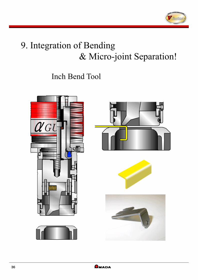
9. Integration of Bending & Micro-joint Separation!
Inch Bend Tool
36
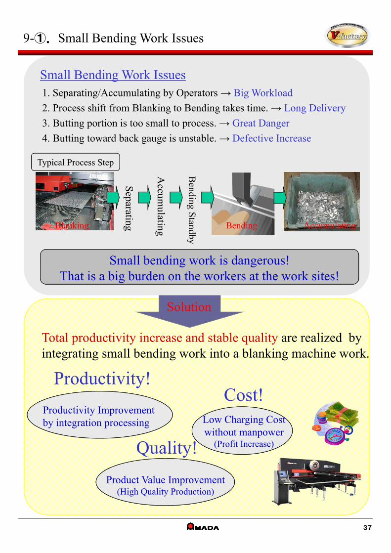
Solution
9-①. Small Bending Work Issues
Total productivity increase and stable quality are realized by integrating small bending work into a blanking machine work.
Productivity Improvementby integration processing
Productivity!
Low Charging Cost without manpower
(Profit Increase)
Cost!
Quality!
Product Value Improvement(High Quality Production)
1. Separating/Accumulating by Operators → Big Workload
2. Process shift from Blanking to Bending takes time. → Long Delivery
3. Butting portion is too small to process. → Great Danger
4. Butting toward back gauge is unstable. → Defective Increase
Small bending work is dangerous!That is a big burden on the workers at the work sites!
Separating
Bending S
tandby
Typical Process Step
BlankingA
ccumulating Bending Accumulating
Small Bending Work Issues
37

Reference DataCase Example
Customer’s Voice
・Bending work by hand was very dangerous work, but bending by this tool is safe!・Bending work by hand was very dangerous work, but bending by this tool is safe!
・Processing is integrated into a blanking machine work, and it brought stable quality with short time!・Processing is integrated into a blanking machine work, and it brought stable quality with short time!
・Unattended operation by a blanking machine enabled operators to do other work!・Unattended operation by a blanking machine enabled operators to do other work!
※Products go into scrap box. Therefore, the box needs to be replaced when it is full.
Bending Times per product 1 hit
Production Time per sheet 5.4 sec
# of Parts 3,000 pcs
4.5
12.0
0.0 2.0 4.0 6.0 8.0 10.0 12.0
提案
現状
Time-saving
7.5 sec shorter!
9-②. Introduction Effects
Before
WorkChuteTool
38

9-③. Features / Specification
Features1.Form-down small flange bending is possible.
2.Post-processing can be eliminated because burr faces inward.
3.6 kinds of thicknesses can be used by changing die direction.
4.Micro flange bending and Continuous feed radius bending are available.
Specification
t = thickness
L Bending コ Bending
Bending Length
In case of Extrusion
Form-down Form-up
39
Tool Size Cst:2”
Bending Direction Downward
Bending Accuracy ±30’
Thickness (Die 4 faces) 0.5 0.8 1.0/1.2 1.5/1.6
Material Mild Steel / Stainless / Aluminum
Max. Bending Length L=30
Punch Tip Size 10/15/20/25/30
Applicable Product Size√(A2+B2+L2) < 52
(In case of コ bending, either longer one of A or C.)
Bending Flange length Min Max
L Bend(A) 2.0 and 3×t 35.0
L Bend(B) 5.0 35.0
コ Bend(A) 2.0 and 3×t12.0(B-2×t>14)
4.0(B-2×t≦14)
コ Bend(B) 3.5 25.0
コ Bend(C) 5.0 35.0※ Please use Cst:2” αGude for Inch Bend Tool.
Inch Bend Tool Process Flow
Bending Separating
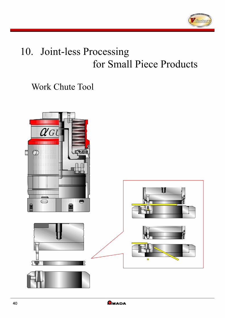
10. Joint-less Processing for Small Piece Products
Work Chute Tool
40
Solution
10-①.Joint Separating Work Issues
NCT Work OnlyNo Hand Work
(Productivity Improvement)
Productivity!
Quality!No Warping
No Hand Work(Defective Rate Reduction)
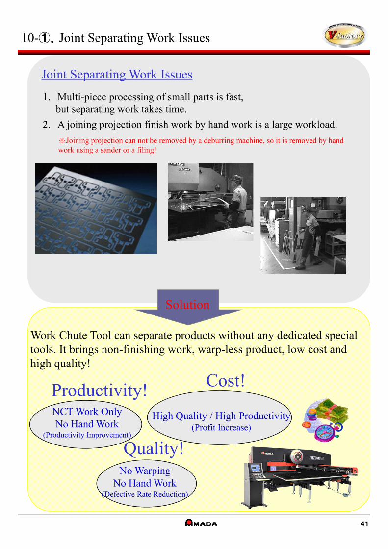
Work Chute Tool can separate products without any dedicated special tools. It brings non-finishing work, warp-less product, low cost and high quality!
Cost!
High Quality / High Productivity(Profit Increase)
※Joining projection can not be removed by a deburring machine, so it is removed by hand work using a sander or a filing!
Joint Separating Work Issues
1. Multi-piece processing of small parts is fast, but separating work takes time.
2. A joining projection finish work by hand work is a large workload.
41
Reference DataCase Example
Customer’s Voice
・Small parts having low manufacturing unit price can be produced by machine without requiring a large cost and labor now!・Small parts having low manufacturing unit price can be produced by machine without requiring a large cost and labor now!
・Small parts could not be picked up by a work chute unit, but this tool solved this issue.・Small parts could not be picked up by a work chute unit, but this tool solved this issue.
・Special tool caused a deformation on products by punching out. But this method reduced deformation and special tool costs!・Special tool caused a deformation on products by punching out. But this method reduced deformation and special tool costs!
10-②. Introduction Effects
抜きカス 製品抜きカス 製品
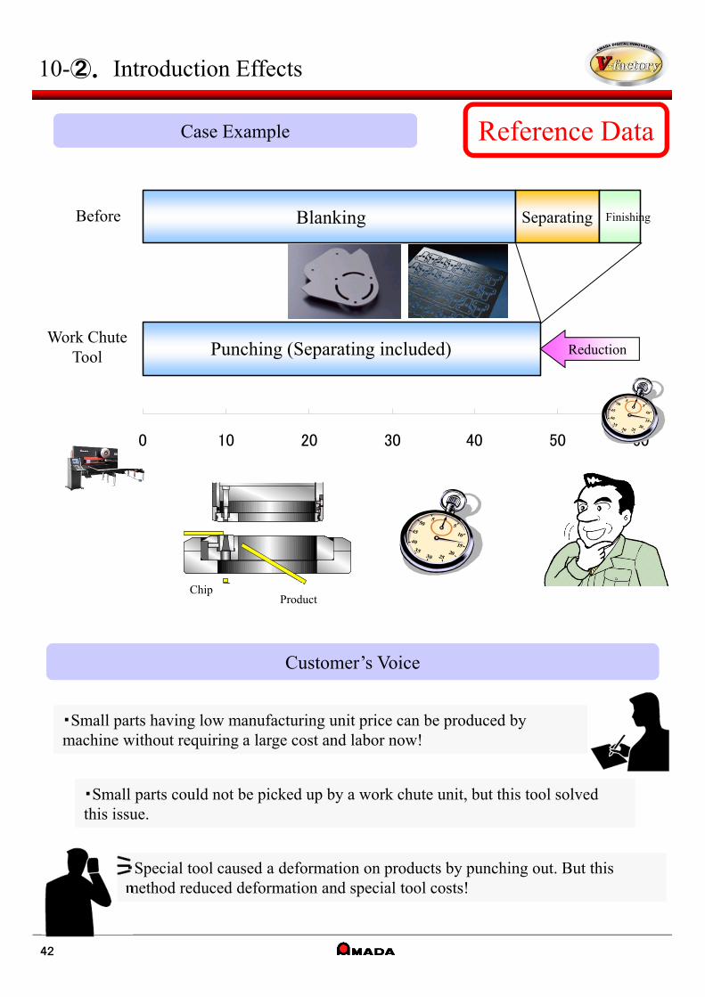
0 10 20 30 40 50 60
Blanking
Punching (Separating included)
Separating FinishingBefore
Work Chute Tool Reduction
ChipProduct
42
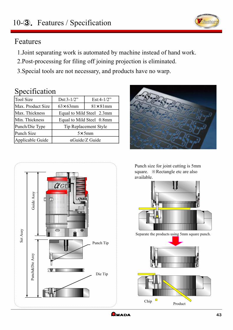
Punch size for joint cutting is 5mm square. ※Rectangle etc are also available.
Separate the products using 5mm square punch.
抜きカス 製品
セッ
トA
ssy
ガイ
ドA
ssy
ダイチップ
パン
チ、
ダイ
Assy
パンチチップセッ
トA
ssy
ガイ
ドA
ssy
ダイチップ
パン
チ、
ダイ
Assy
パンチチップ
10-③. Features / Specification
Features1.Joint separating work is automated by machine instead of hand work.
2.Post-processing for filing off joining projection is eliminated.
3.Special tools are not necessary, and products have no warp.
SpecificationTool Size Dst:3-1/2” Est:4-1/2”
Max. Product Size 63×63mm 81×81mm
Max. Thickness Equal to Mild Steel 2.3mm
Min. Thickness Equal to Mild Steel 0.8mm
Punch/Die Type Tip Replacement Style
Punch Size 5×5mm
Applicable Guide αGuide/Z Guide
Set
Ass
y
Gui
de A
ssy
Pun
ch&
Die
Ass
y
Punch Tip
Die Tip
ChipProduct
43

200, Ishida, Isehara-shi, Kanagawa 259-1196 JapanISO9001:2008/ ISO14001:2004
©AMADA CO.,LTD. ALL Rights Reserved
10201812


