Embed Size (px)
Citation preview

Ultrasonic Inspection of
aluminum componentsConventional to phased array, manual to automatic
Stefan Kierspel
KARL DEUTSCH Prüf- und Messgerätebau GmbH + Co KG
Wuppertal
AMAP-Colloquium January 31st, 2019

Contents
• Introduction to KARL DEUTSCH
• Basics of UT inspection
• Distinctiveness of UT testing on aluminum
• Inspection of welds on thin plates with complex geometries
• Inspection of casted aluminum plates
• Integrated precision measurement of wall thickness
• Inspection of spotwelded aluminum plates
• Different types of automatic testing machines

Introduction to
KARL DEUTSCH

Ing. Karl Deutsch & LEPTOSKOP
Hannover Messe
(1951)
LEPTOSKOP
coating thickness
measurement
since 1948,
founding of company
May 13th 1949

• Founded in 1949, family business in 3rd generation
• Two locations in Wuppertal
• 130 employees in Wuppertal +20 more worldwide
KARL DEUTSCH
Ing. Karl
Deutsch
1900 -
1975
Prof. Dr. Volker
Deutsch
* 1932, KD 1961-
2001
Dr. (USA)
Wolfram
Deutsch
KD 1998 - …

KARL DEUTSCH in Wuppertal
KARL
DEUTSCH

Works 1: Portables, R&D, Administration
1967
1972

Works 2: Testing Systems Production
1978
2004
20061978
2013
2015

SGS NDT –Symposium Hürth, 15.11.2018

KARL DEUTSCH Product Range
• Machines, instruments and equipment for
PT, MT and UT
• UT probes development and manufacturing
• Portable units for coating- and wall-
thickness measurement
• Portable units for measurement of
magnetic fields

Application-Laboratory
• Consulting
• Tests on customer specimens
• Instrument-Training
• Application development
Dr. rer. nat. Helge Rast
(Laboratory head)
Dr.-Ing. Volker Schuster
(QM, Standards)
Stefan Kierspel
(Productmanager PA/UT)
Contakt:
Basics of UT inspection

Principles of UT inspection
1 MHz
12 mm
Steel
2 MHz
12 mm
Steel
2 MHz
12 mm
Perspex
2 MHz
24 mm
Steel

flaw gate
threshold
US-signals
d
Principles of UT inspection

☺☺☺☺
Ultrasonic Reflection from Defects
☺☺☺☺���� ����

ECHOGRAPH Ultrasonic Probes
Criteria of Choice:���� frequency (material,
penetration depth, sensitivity)
���� probe size (intensity)
���� incidence angle (application)
���� width of sound field, focus
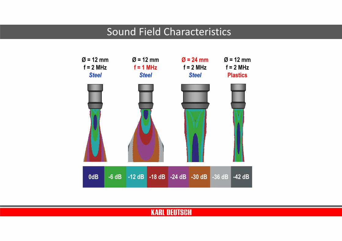
Sound Field Characteristics
Ø = 12 mmf = 2 MHzSteel
Ø = 12 mmf = 1 MHzSteel
Ø = 24 mmf = 2 MHzSteel
Ø = 12 mmf = 2 MHzPlastics
0dB -6 dB -12 dB -18 dB -24 dB -30 dB -36 dB -42 dB

Reflection and Diffraction
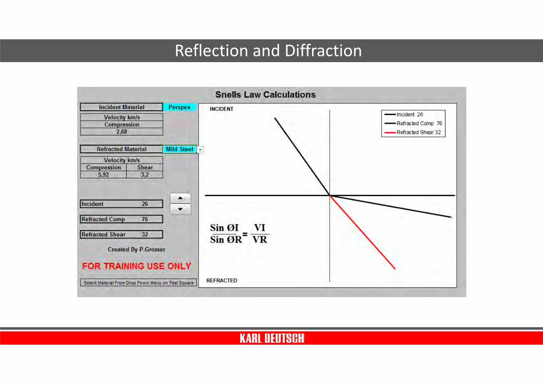
Reflection and Diffraction
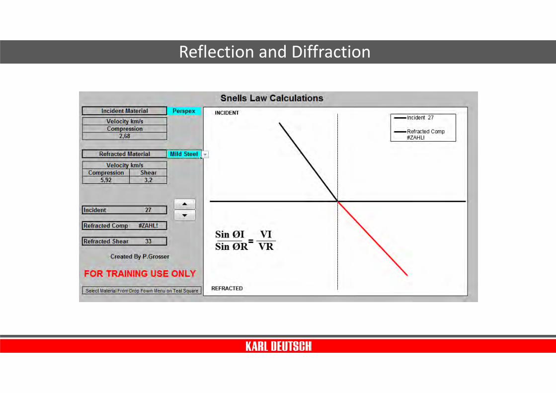
Reflection and Diffraction

Reflection and Diffraction
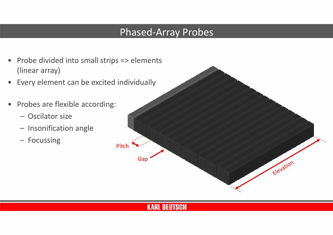
Phased-Array Probes
• Probe divided into small strips => elements
(linear array)
• Every element can be excited individually
• Probes are flexible according:
– Oscilator size
– Insonification angle
– FocussingPitch
Gap

Variation of insonification angle

Standard PA-UT methods
Sector-Scan Linear-Scan

Display of results
Elektronical B-Scans (E-Scan)
B-Scan Side View(E-Scan)
Top view (C-/P-scan)Mechanical Scan
PA Probe
Elektronic Scan
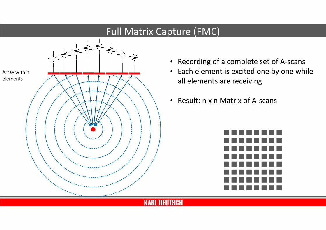
Full Matrix Capture (FMC)
Array with n
elements
• Recording of a complete set of A-scans
• Each element is excited one by one while
all elements are receiving
• Result: n x n Matrix of A-scans

Principle of the Total Focusing Method (TFM)
TFM is a post-processing algorithm for
FMC data.
• Discretion of an inspection area to a
grid
• Creation of an artificial focus at all
points of the grid by summation of the
FMC data
Advantage:
• Inspection area may be wider than the
probe
• Focussation within the complete
inspection zone

Soundfield of a single element
• CIVA simulation of a probe with
10 MHz, 64 elements, 0.3 mm
pitch, 0.05 mm gap
• Wide soundfield
• Probe „looks“ into all directions
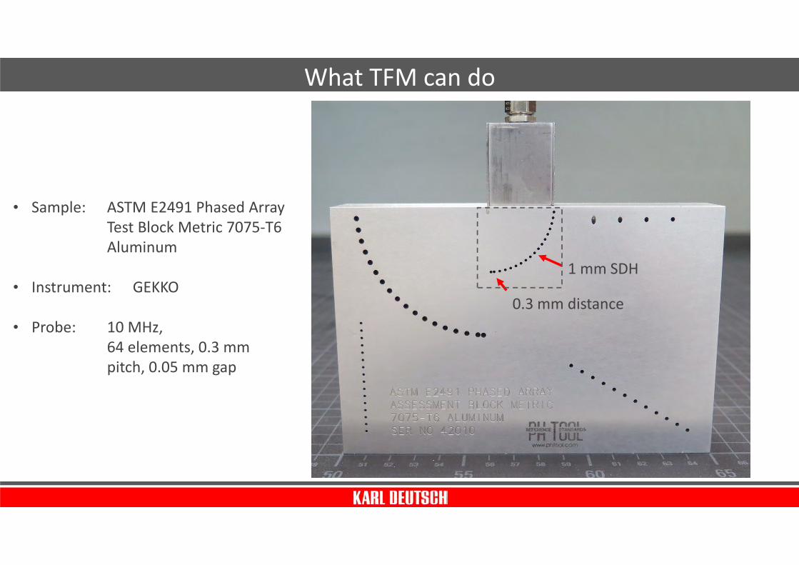
What TFM can do
• Sample: ASTM E2491 Phased Array
Test Block Metric 7075-T6
Aluminum
• Instrument: GEKKO
• Probe: 10 MHz,
64 elements, 0.3 mm
pitch, 0.05 mm gap
1 mm SDH
0.3 mm distance
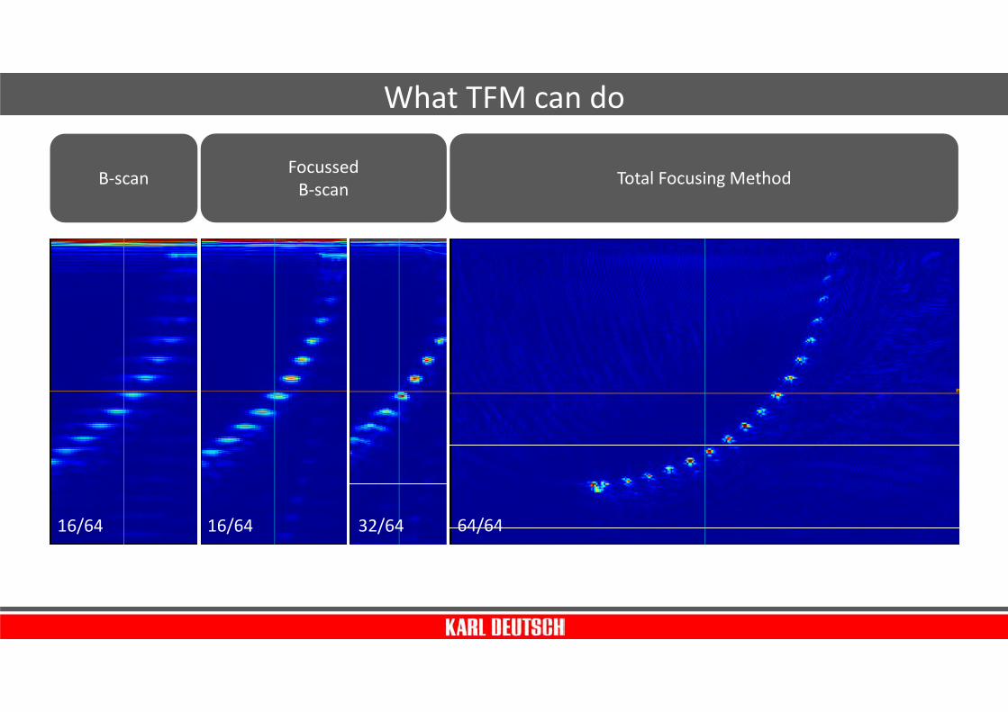
B-scan
16/64
Focussed
B-scan
16/64 32/64
Total Focusing Method
64/64
What TFM can do
Distinctiveness of
UT testing on aluminum

Special characteristics of aluminum in terms of UT inspection are:
• Relatively high sound velocity of L-waves (6.400 m/sec) and
relatively low sound velocity of T-waves (3.100 m/sec)
=> angle inspection with T-waves can go down to 30°
without having an L-wave
• Relatively low sound attenuation => pulser voltage on steel
might be ok but leads to over-saturated signals on aluminum
• Inhomogenious sound velocity on rolled parts
• Grain size influences sound attenuation
Distinctiveness

Inspection of welds on thin
plates with complex geometries
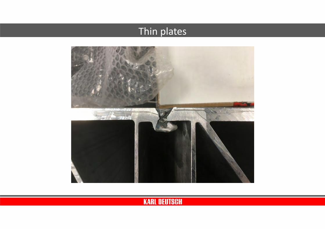
Thin plates
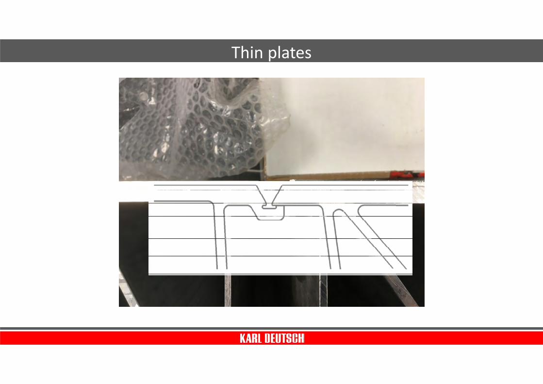
Thin plates

Thin plates
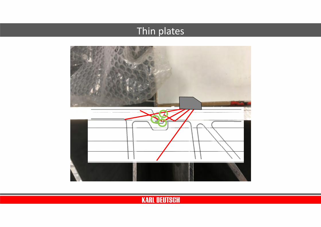
Probe 16 Elements,
10 MHz, 50° wedge
Sector-Scan 40-80 °
Thin plates

Thin plates
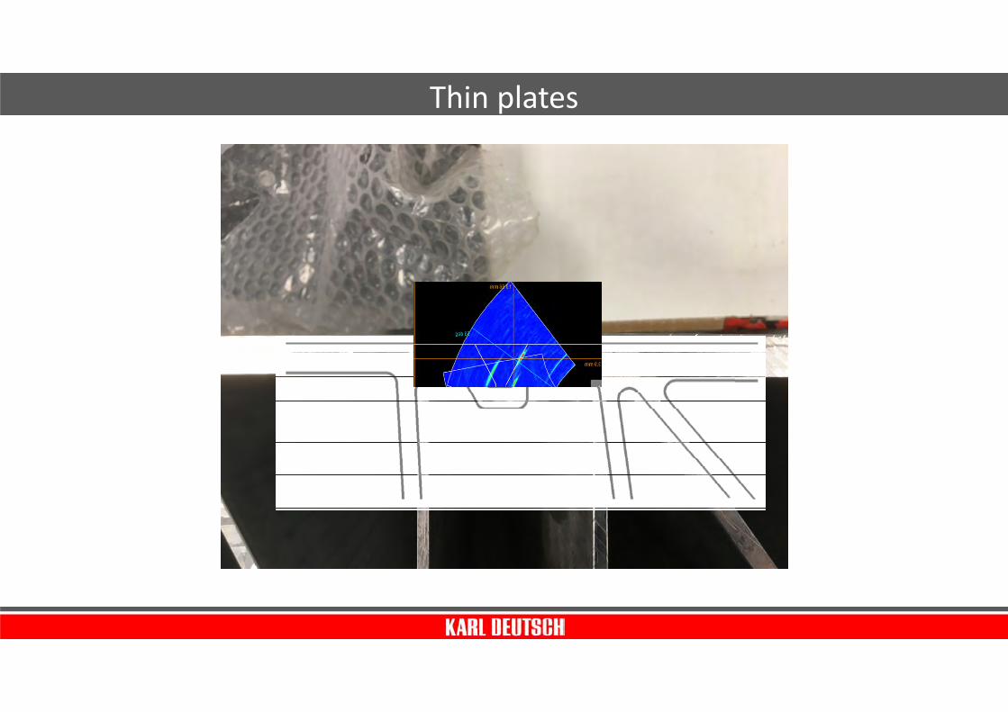
Thin plates
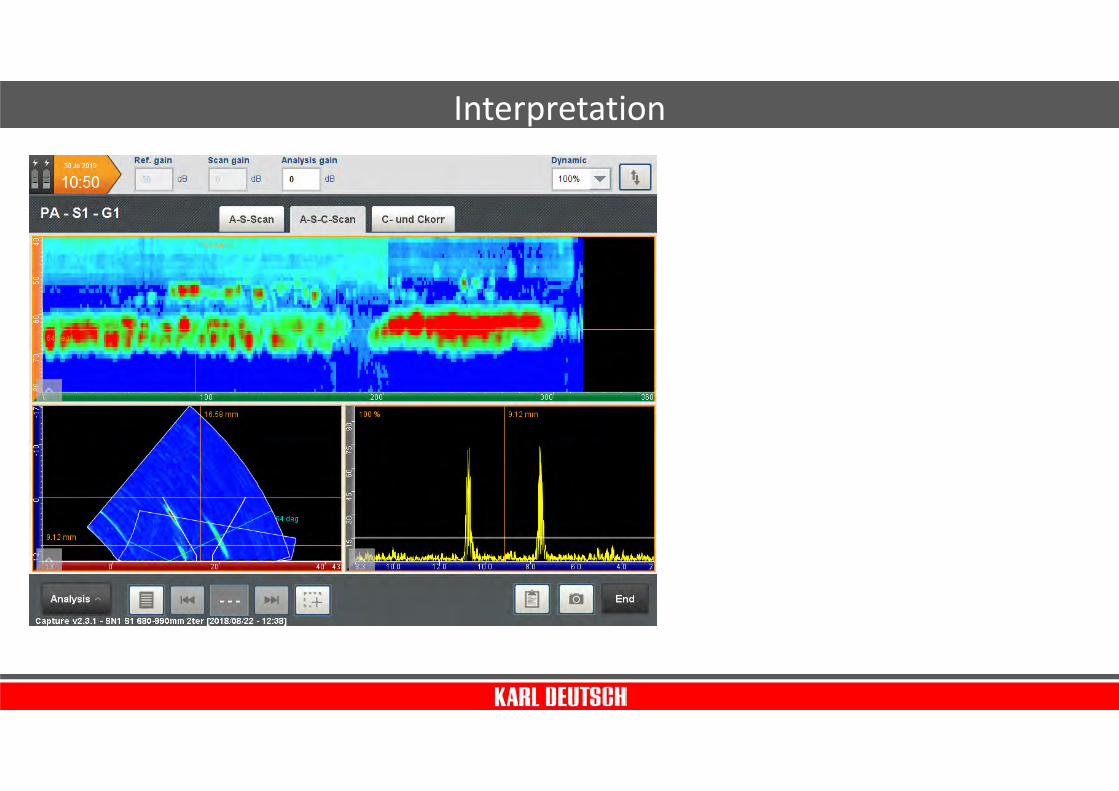
Interpretation

Interpretation

Inspection of casted
aluminum plates

Probe with 5 MHz,
0,85 mm pitch
10 mm elevation
Watergap 1 mm
Inspection setup

Without focussation
FBH 2,5 mm
at 150 mm
unfosussed
Sector Scan
-10° to +10°
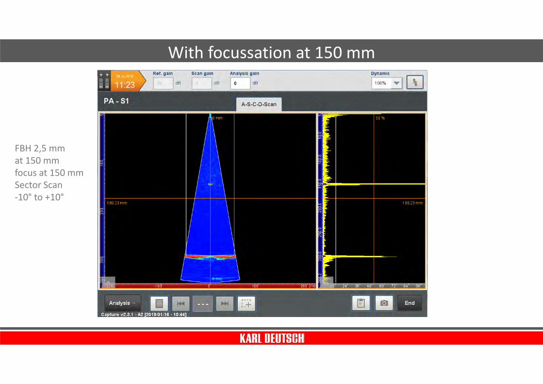
With focussation at 150 mm
FBH 2,5 mm
at 150 mm
focus at 150 mm
Sector Scan
-10° to +10°
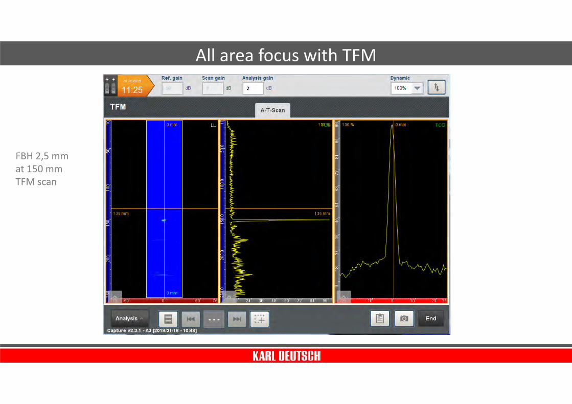
All area focus with TFM
FBH 2,5 mm
at 150 mm
TFM scan

Evaluation of the defect size
FBH 2,5 mm
at 150 mm
TFM scan
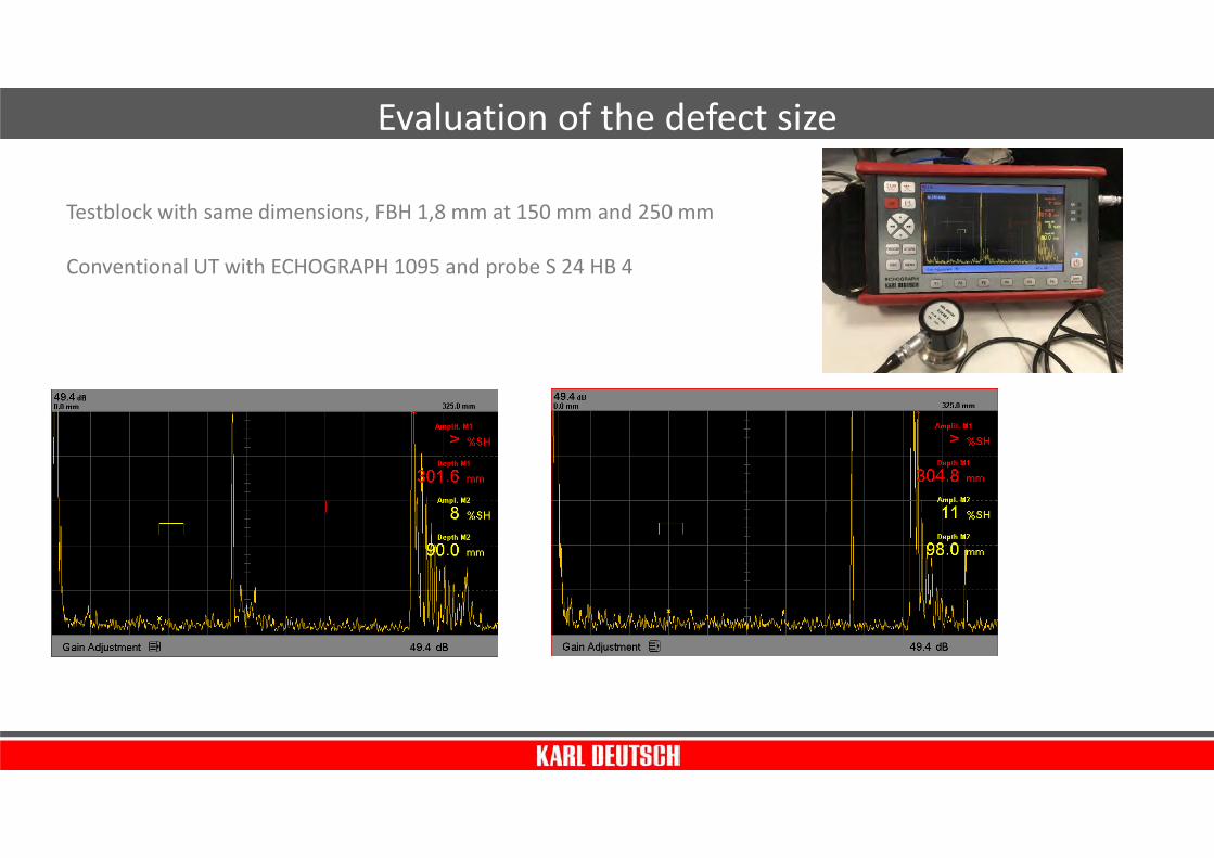
Evaluation of the defect size
Testblock with same dimensions, FBH 1,8 mm at 150 mm and 250 mm
Conventional UT with ECHOGRAPH 1095 and probe S 24 HB 4

Without focussation
FBH 1,8 mm
at 150 mm
unfosussed
Sector Scan
-10° to +10°

With focussation at 150 mm
FBH 1,8 mm
at 150 mm
focus at 150 mm
Sector Scan
-10° to +10°

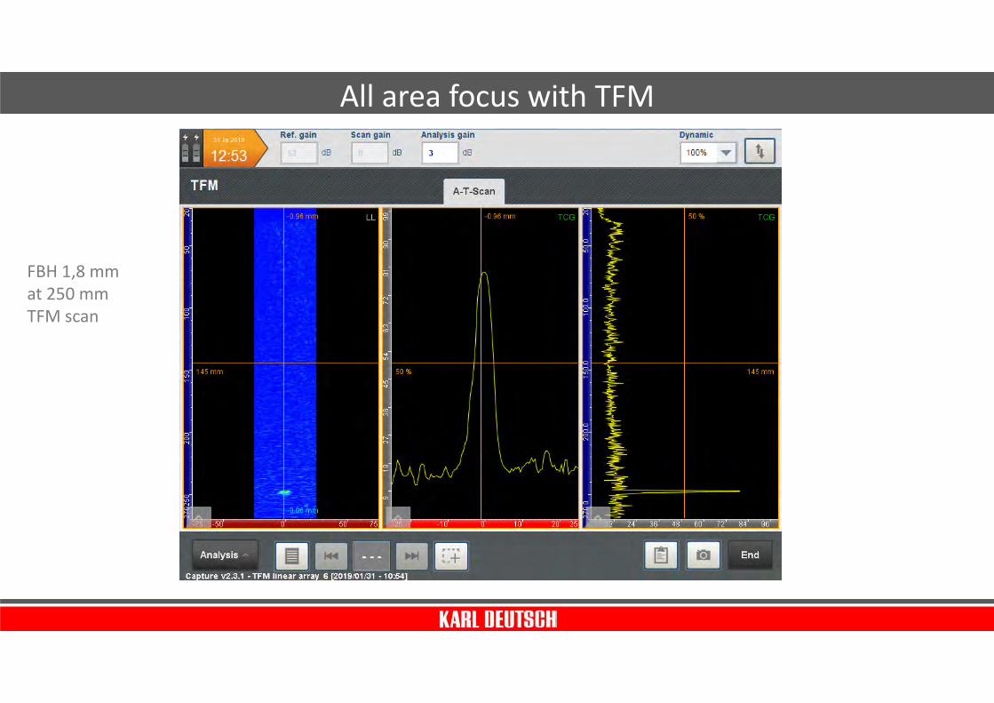
All area focus with TFM
FBH 1,8 mm
at 150 mm
TFM scan

Evaluation of the defect size
FBH 1,8 mm
at 150 mm
TFM scan
FBH 1,8 mm
at 250 mm
TFM scan
All area focus with TFM

Evaluation of the defect size
FBH 1,8 mm
at 250 mm
TFM scan
Integrated precision
measurement of
wall thickness

Sonic Eye by Starrag
Multi-axis grinding
machine for large
vertical parts

Sonic Eye by Starrag
Sonic Eye as a changing tool
Automatic thickness measurement,
measured data directly influence
the grinding process

Inside Sonic Eye
Special Version of
standard precision
wall-thickness gauge
ECHOMETER 1077 with
probe DS 12 PB 1-7

Inspection of spotwelded
aluminum plates
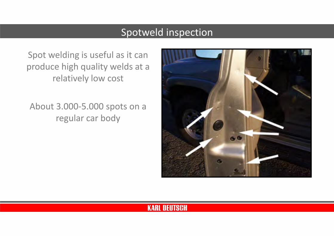
Spot welding is useful as it can
produce high quality welds at a
relatively low cost
About 3.000-5.000 spots on a
regular car body
Spotweld inspection

Welding Process
1. Pressure applies to assure full sheet contact
2. Heat melt the steel to form the nugget weld
3
HoldTime
P
P
Weld
Time
2
P
P
c
c
SqueezeTime
1
P
P

The Result

The challenge
Weld quality is impossible to predict visually from the
outside

• Good
• No Weld (Loose)
• Undersized
Some nugget types
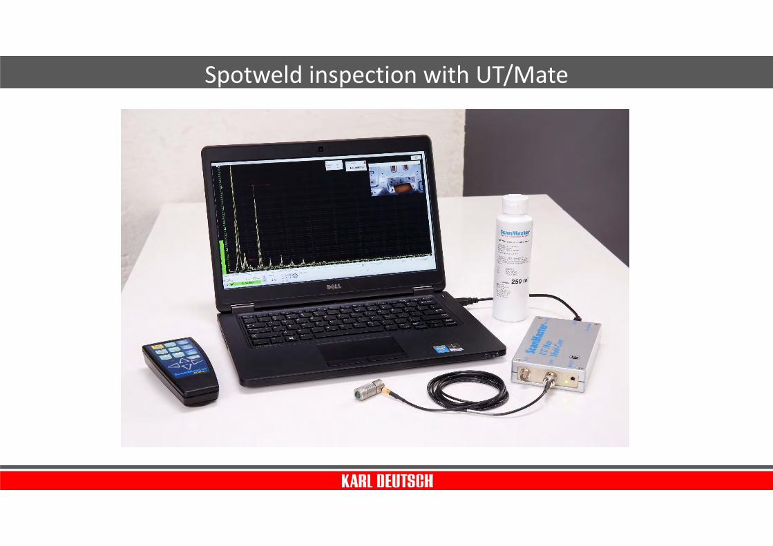
Spotweld inspection with UT/Mate

Spotweld inspection - probes
Probes have to be selected according to the nominal nugget size

OK NOK
Spotweld inspection – basic principle

Spotweld inspection – basic principle
• Good spot
• Spot too small
• Cladding
• No weld
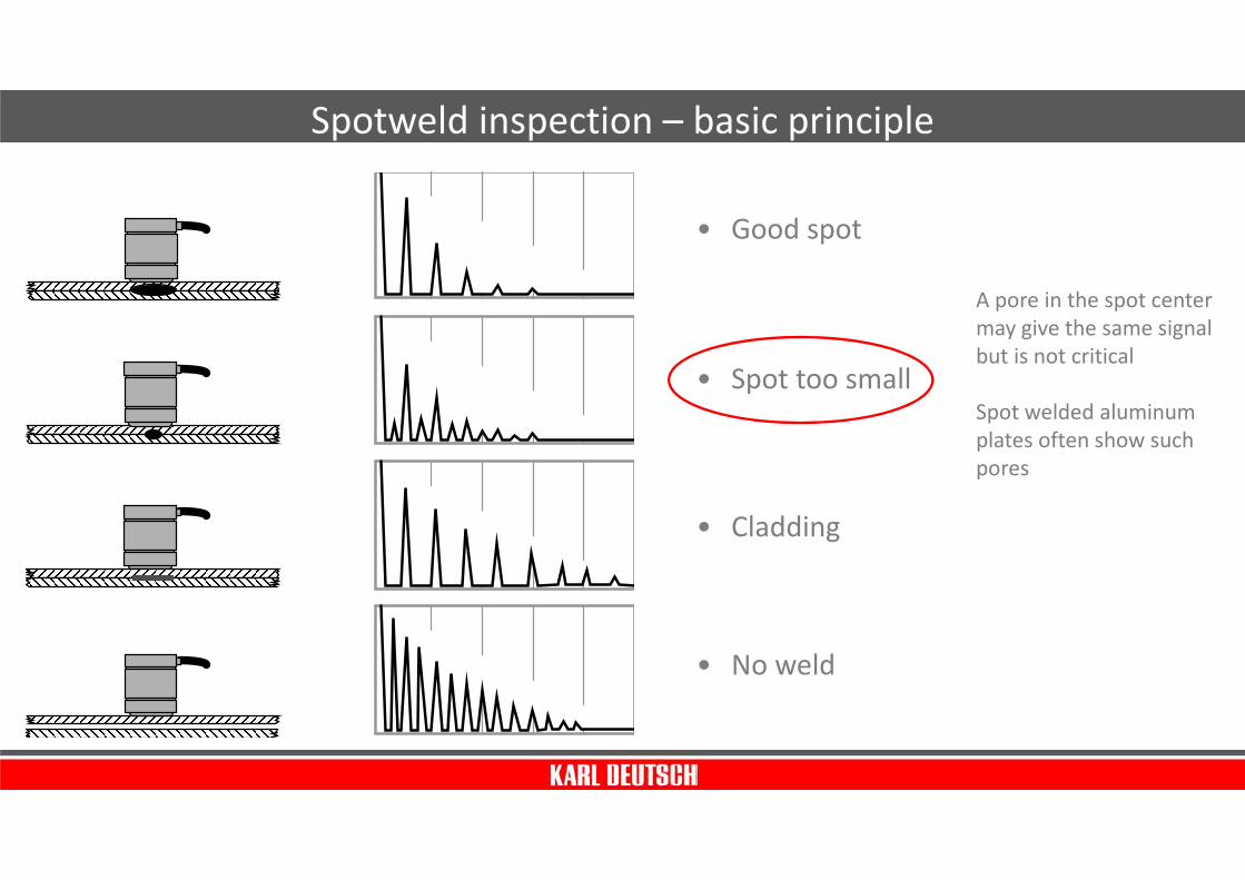
Spotweld inspection – basic principle
• Good spot
• Spot too small
• Cladding
• No weld
A pore in the spot center
may give the same signal
but is not critical
Spot welded aluminum
plates often show such
pores
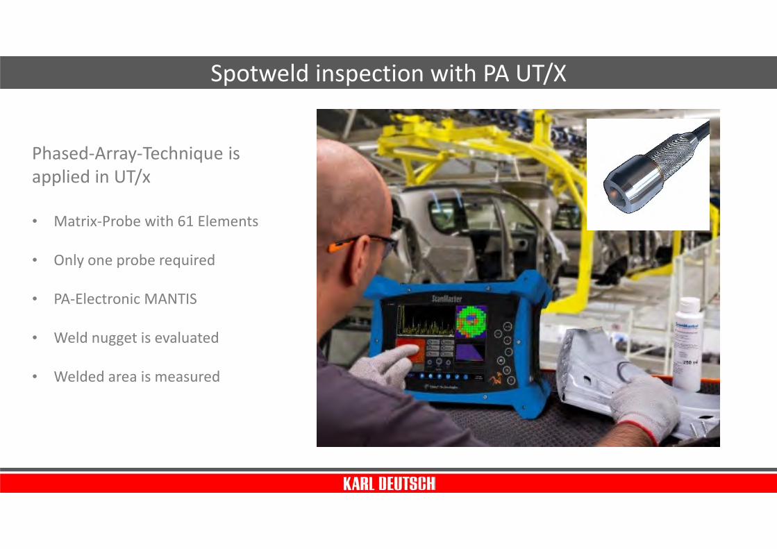
Phased-Array-Technique is
applied in UT/x
• Matrix-Probe with 61 Elements
• Only one probe required
• PA-Electronic MANTIS
• Weld nugget is evaluated
• Welded area is measured
Spotweld inspection with PA UT/X


