Embed Size (px)
Citation preview
Using the HT46R12 in an Induction Cooker
1
Using the HT46R12 in an Induction Cooker
D/N:HA0101E
Introduction
The HT46R12 and HT46R14 are two devices from Holtek’s A/D series of MCUs. These two MCUs each include an integrated PPG (Programmable Pulse Generator) function. By having this on-chip hardware PPG module, the devices are very suitable for induction cooker product applications. In addition to having the PPG function, these two MCU devices also include 2K×14 / 4K×15 of Program Memory, 88×8 / 192×8 of Data Memory, 16/20 bi-directional I/O lines, a 4/8 Channel 9-bit ADC, two comparators and two 8-bit programmable timer/event counters with PFD functions.
In this application note, the HT46R12 MCU will be used as the central component in the control of the induction cooker. The basic operation will be discussed together with the circuit control method.
Basic Operating Theory
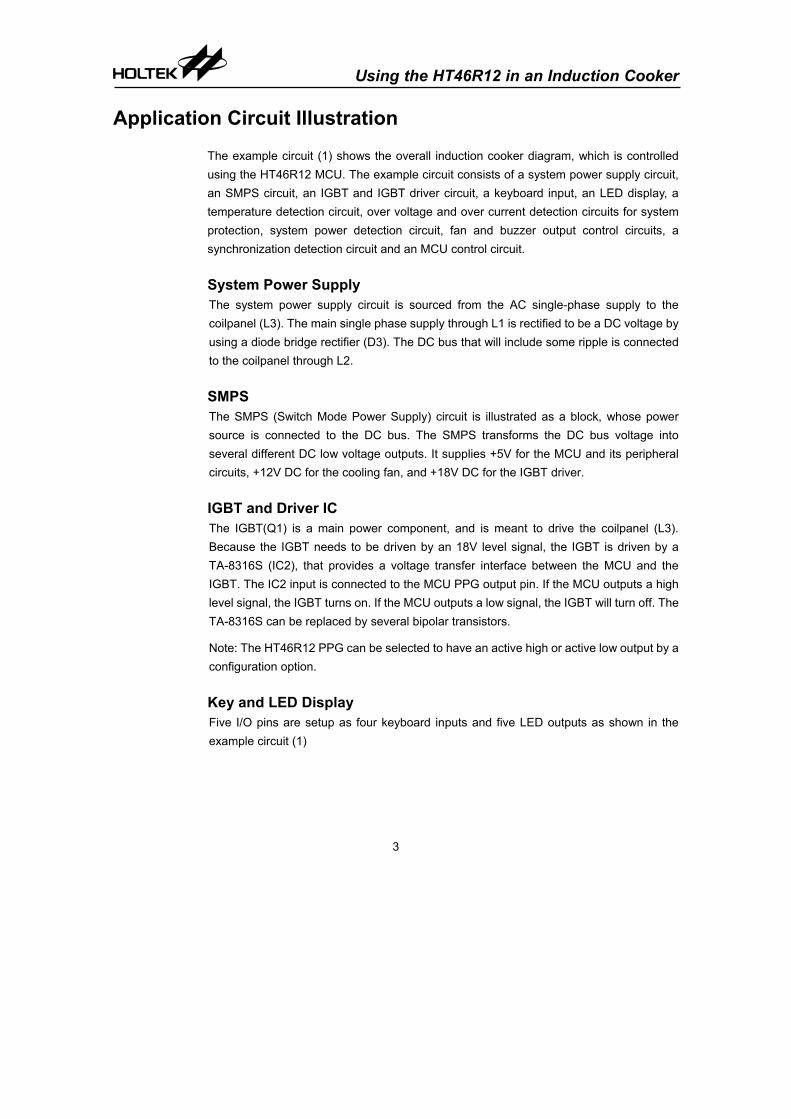
Induction Cooking Operating Theory Explained
Fig.1

Using the HT46R12 in an Induction Cooker
2
The AC power source is rectified to a DC voltage by using a bridge diode rectifier. The DC bus is connected to the Coil Panel. A high frequency current is generated in the coilpanel by a switching power IGBT component. This current generates a high frequency magnetic flux which in turn induces eddy currents in the cookware that is placed above the coilpanel. These eddy currents directly heat the cookware which of course in turn cooks the food.
HT46R12 Based Induction Cooker Block Diagram
Fig.2
Fig.2 shows the overall induction cooker block diagram using the HT46R12 MCU. All the signals, such as over voltage (OV), over current (OC), system voltage, system current, synchronous signal, temperature and keyboard are all processed by the HT46R12. The outputs are also controlled by the HT46R12 MCU. The output power is controlled by the PPG output pulse width.
Using the HT46R12 in an Induction Cooker
3
Application Circuit Illustration
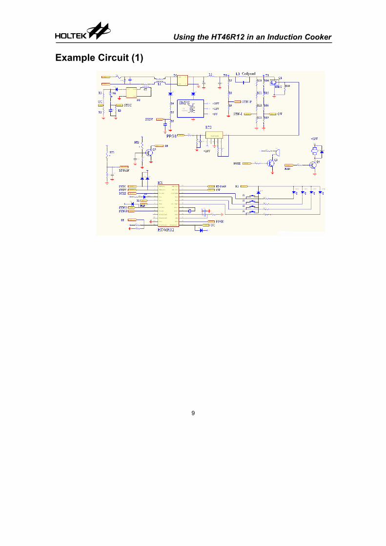
The example circuit (1) shows the overall induction cooker diagram, which is controlled using the HT46R12 MCU. The example circuit consists of a system power supply circuit, an SMPS circuit, an IGBT and IGBT driver circuit, a keyboard input, an LED display, a temperature detection circuit, over voltage and over current detection circuits for system protection, system power detection circuit, fan and buzzer output control circuits, a synchronization detection circuit and an MCU control circuit.
System Power Supply The system power supply circuit is sourced from the AC single-phase supply to the coilpanel (L3). The main single phase supply through L1 is rectified to be a DC voltage by using a diode bridge rectifier (D3). The DC bus that will include some ripple is connected to the coilpanel through L2.
SMPS The SMPS (Switch Mode Power Supply) circuit is illustrated as a block, whose power source is connected to the DC bus. The SMPS transforms the DC bus voltage into several different DC low voltage outputs. It supplies +5V for the MCU and its peripheral circuits, +12V DC for the cooling fan, and +18V DC for the IGBT driver.
IGBT and Driver IC The IGBT(Q1) is a main power component, and is meant to drive the coilpanel (L3). Because the IGBT needs to be driven by an 18V level signal, the IGBT is driven by a TA-8316S (IC2), that provides a voltage transfer interface between the MCU and the IGBT. The IC2 input is connected to the MCU PPG output pin. If the MCU outputs a high level signal, the IGBT turns on. If the MCU outputs a low signal, the IGBT will turn off. The TA-8316S can be replaced by several bipolar transistors.
Note: The HT46R12 PPG can be selected to have an active high or active low output by a configuration option.
Key and LED Display Five I/O pins are setup as four keyboard inputs and five LED outputs as shown in the example circuit (1)
Using the HT46R12 in an Induction Cooker
4
Temperature Detection • RT1 is an NTC resistor, which is used as a temperature sensor. A potentiometer
(RT-PAN) connected to AN2 detects the temperature of the pan. An MCU detects the temperature to regulate the output power.
• RT2 is the same as RT1, a potentiometer (OT) is connected to Q5 transistor’s base. RT2 can be used to detect the PCB, the case temperature or the IGBT body temperature dependent upon the user’s application. If the case inside temperature or IGBT temperature is too high, then Q5 will be turned on to short C0VIN+ to ground. This also causes COMP0 to output a falling edge to stop the PPG output.
Over Voltage and Over Current Detection • Over Voltage (OV): When the induction cooker is running, it may generate an over
voltage or a high level of voltage noise created by the IGBT turning on and off repeatedly, or if the object is moved. This over voltage may damage the IGBT, so “OV” needs to be detected to protect the power component. A potentiometer OV is connected to the AN3 (ADC input), and the MCU detects this voltage to control and regulate the output power.
• Over Current (OC): When current flowing through the IGBT is higher than the expected current, it may damage the IGBT. A CT (current transformer) is inserted in series between the power line and the rectifier. The user can detect a voltage that is transferred from the CT to control and regulate the output power and protect the system. OC is connected to C0VIN- in the circuit. When an over current situation occurs, the C0VIN- voltage will be higher than C0VIN+, which will cause the comparator 0, in the HT46R12 MCU, to output a falling edge and then turn off the PPG output.
System Power Detection The user needs to check whether the power corresponds to the expected value. A potentiometer SYSV connected to AN0 detects the system voltage and a potentiometer SYSC connected to AN1 detects the system circuit. With these two check points, the user can obtain the system power status and regulate the output power. VR1 is used to correct the system power.
Fan and Buzzer Output Control • When the induction cooker is running, Q4, which is the fan driver, needs to be turned
on to distribute the heat inside the case. • Q3 is the buzzer driver, connected to the MCU PFD. The buzzer frequency can be
changed by controlling the timer. The user can program a different tone corresponding to the status of the system.
Using the HT46R12 in an Induction Cooker
5
Synchronization Detect Circuit The Induction cooker is heated by controlling the coilpanel power. To control the coilpanel power, a synchronous signal between the coilpanel (T0,T1) needs to be detected, two potentiometers called SYN-P and SYN-I are connected with the C1VIN- and C1VIN+ respectively. The SYN-P provides a reference voltage that corresponds to the DC bus voltage and SYN-I corresponds to the IGBT collector voltage. When the PPG module is enabled and the SYN-I voltage is lower than the SYN-P voltage, the comparator1 outputs a falling edge to start the PPG. (In this example circuit, the PPG output is programmed as active high)
MCU Control Circuit In the application circuit, the MCU is a control centre, which is used to deal with all the input signals received such as system voltage, system current, over voltage, over current, over temperature, synchronization and keyboard input. It also controls all the outputs, such as those which regulate the power using the PPG, generates the PFD sound signals, controls the fan to regulate the temperature inside the case and controls the LED display.
PPG Function Description
PPG Features The HT46R12 provides an 8-bit PPG (Programmable Pulse Generator) module. The PPG has a programmable period of 256xT, where T can be 1/fSYS, 2/fSYS, 4/fSYS, 8/fSYS, 16/fSYS, 32/fSYS, 64/fSYS, 128/fSYS, for an output pulse width. The PPG output can be set as active low or active high by a configuration option.
• PPG Timer
The PPG0 consists of a PPG0 timer, a PPG mode control and two comparators. The PPG0 timer comprises of a prescaler, one 8-bit up-counter timer, and an 8-bit preload data register. The programmable pulse generator (PPG) starts counting at the value setup in the preload register and ends at “FFH 00H”, Once an overflow occurs, the counter is reloaded from the PPG0 timer counter preload register, and generates a signal to stop the PPG output. The software trigger bit (P0ST) will be cleared when a PPG timer overflow occurs.
There are two registers related to the PPG0, a control register, known as PPG0C, and a timer preload register, known as PPGT0. The PPG0C control register defines the PPG input control mode (trigger source), enables or disables the comparators, defines the PPG0 timer prescaler rate, enables or disables stopping the PPG0 timer using the C0VO trigger input, enables or disables restarting the PPG0 timer using the C1VO
Using the HT46R12 in an Induction Cooker
6
trigger input, and controls the PPG0 software trigger bit to start or stop the PPG0 output. The user can set the prescaler and the PPGT0 register to regulate the PPG output pulse width.
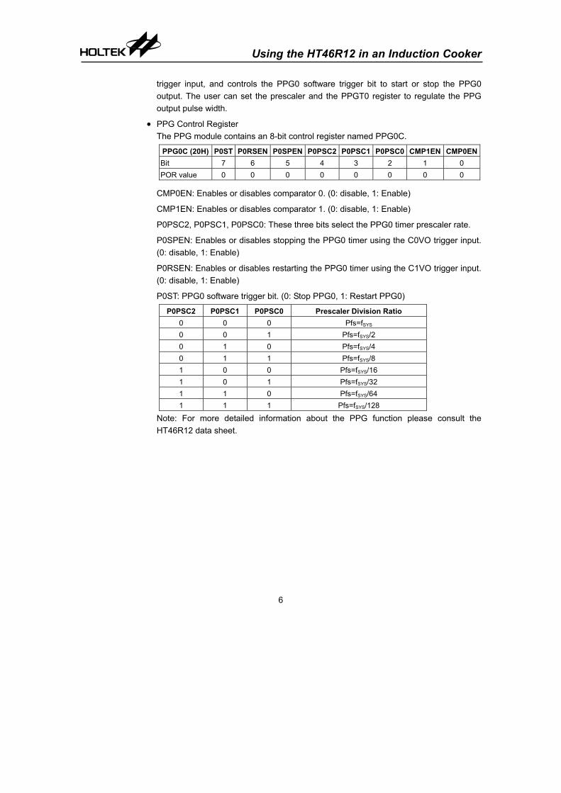
• PPG Control Register The PPG module contains an 8-bit control register named PPG0C.
PPG0C (20H) P0ST P0RSEN P0SPEN P0PSC2 P0PSC1 P0PSC0 CMP1EN CMP0ENBit 7 6 5 4 3 2 1 0 POR value 0 0 0 0 0 0 0 0
CMP0EN: Enables or disables comparator 0. (0: disable, 1: Enable)
CMP1EN: Enables or disables comparator 1. (0: disable, 1: Enable)
P0PSC2, P0PSC1, P0PSC0: These three bits select the PPG0 timer prescaler rate.
P0SPEN: Enables or disables stopping the PPG0 timer using the C0VO trigger input. (0: disable, 1: Enable)
P0RSEN: Enables or disables restarting the PPG0 timer using the C1VO trigger input. (0: disable, 1: Enable)
P0ST: PPG0 software trigger bit. (0: Stop PPG0, 1: Restart PPG0)
P0PSC2 P0PSC1 P0PSC0 Prescaler Division Ratio 0 0 0 Pfs=fSYS 0 0 1 Pfs=fSYS/2 0 1 0 Pfs=fSYS/4 0 1 1 Pfs=fSYS/8 1 0 0 Pfs=fSYS/16 1 0 1 Pfs=fSYS/32 1 1 0 Pfs=fSYS/64 1 1 1 Pfs=fSYS/128
Note: For more detailed information about the PPG function please consult the HT46R12 data sheet.

Using the HT46R12 in an Induction Cooker
7
IGBT Driver
+
-
+
-
PPGControl
START
STOP
COMP1
COMP0
PPGTimer
+
-
+
-
PPG ModuleC1VO
C0VO
P0ST
Overflow
How to Control the PPG
• There are two registers and two Configuration Option bits related to PPG: − PPGT0: PPG0 timer register
− PPG0C: PPG0 control Register
− P0LEV: This is a configuration option bit that defines the PPG output as high active or low active
− PTSYN: This is a configuration option bit that defines if the PPG0 timer is synchronized with the PPG clock or not
• Some required steps when PPG is applied. − Set the PPG output active high or active low (P0LEV; by option).
− Define if the PPG0 timer is synchronized or not with the PPG clock (P0fs) (PTSYN; by option).
− Set the PPG0 timer prescaler value (P0PSC2, P0PSC1, PPSC0) and write a value to the PPGT0 register to define the PPG pulse width
− Enable COMP0 and COMP1 (CMP0EN,CMP1EN)
− Enable the PPG0 input (P0RSEN, P0SPEN)
− Adjust the output power by changing the value of PPGT0
• How to Start or Stop the PPG output. − There are two ways to start the PPG output:
a) Comparator1 outputs a falling edge. b) The P0ST bit is set to “1” by software.
− There are three conditions to stop the PPG output: a) Comparator0 outputs a falling edge. b) The P0ST bit is cleared to “0” by software. c) PPG Timer overflow occurs.
Fig.3

Using the HT46R12 in an Induction Cooker
8
How to Control the Power with PPG • The HT46R12 provides two comparators, called COMP0 and COMP1, whose
operation voltage is the same as the MCU. In this application a +5V operation voltage is suggested.
• COMP0 is used to stop the PPG output. When the P0SPEN bit is enabled (PPGC0; bit.5) and COMP0 outputs a falling edge, then this will stop the PPG output directly. In this example circuit (Fig.4), COMP0 is used to manage the over current. When a load current is higher than the system expected value, the OC voltage will be higher than C0VIN+ and COMP0 will output a falling edge to stop the PPG output.
• COMP1 is applied to start the PPG output. When the P0RSEN bit is enabled (PPGC0; bit.6) and COMP1 outputs a falling edge, this will start the PPG output directly. In this example circuit (Fig.4), COMP1 is used to deal with the synchronous signal. When the T1 voltage drops off from a high voltage to a low voltage until the SYN-I voltage (T1) is lower then SYN-P in the IGBT turn off period, the COMP1 outputs a falling edge to start the PPG timer to turn on the IGBT again.
• The PPG can be started and stopped by a falling edge on COMP1 and COMP0, and can also be controlled by setting the P0ST bit (PPGC0; bit.7)
�
�
�
� � � � � �
� � � � �
� � �
�
�
� �
� � � � � �
� � � �
� � � � �
� � � � � � �
�
� �
� � � �
� � � �
� � � � �
� � � � �
� �
� �
� � �
� � � � �
�
� �� �
� � �
� � � �
� � � � �� � � � �
� � � � � � �
� � � � � �
Fig.4
Using the HT46R12 in an Induction Cooker
9
Example Circuit (1)

Using the HT46R12 in an Induction Cooker
10
Example Circuit (2)
This example circuit is modified from the example circuit (1) and illustrates the following;
• The keys and temperatures are detected by scanning I/Os and all the signals are read through an A/D input. In this way, the user can expand the keyboard’s number easily.
• The MCU pins, I/O-OT and I/O-RT, fan and other I/O pins can also be used for display. The user can also use a 74HC138 or 74HC164 to expand the display.
• The synchronization circuit is modified on the up and right side in this example circuit. One thing that needs to be taken care of is that when a DC bus ripple voltage is in the lowest period, it may cause a PPG trigger failure. This is because the voltage of SYN-I is always higher then SYN-P. The user needs to adjust the voltage of the divider to an accurate value or use software to check if an interrupt has occurred.
• A pressure switch is added in the buzzer circuit, with this switch the user can detect if the fan is running correctly.


