Embed Size (px)
Citation preview

Allen amp Heath 1 XONE43 User Guide
USER GUIDE
Publication AP9968_2
Allen amp Heath 2 XONE43 User Guide
XONE43 User Guide AP9968 Issue 2
Copyright copy 2018 Allen amp Heath Limited All rights reserved
Allen amp Heath Limited
Kernick Industrial Estate Penryn Cornwall TR10 9LU UK
wwwallen-heathcom
Limited One Year Manufacturerrsquos Warranty
Allen amp Heath warrants the Allen amp Heath - branded hardware product and accessories contained in the original packaging (Allen amp Heath Productrdquo) against defects in materials and workmanship when used in accordance with Allen amp Heaths user manuals technical specifications and other Allen amp Heath product published guidelines for a period of ONE (1) YEAR from the date of original purchase by the end-user purchaser (Warranty Period)
This warranty does not apply to any non-Allen amp Heath branded hardware products or any software even if packaged or sold with Allen amp Heath hardware Please refer to the licensing agreement accompanying the software for details of your rights with respect to the use of software (ldquoEULArdquo) Details of the EULA warranty policy and other useful information can be found on the Allen amp Heath website wwwallen-heathcomlegal
Repair or replacement under the terms of the warranty does not provide right to extension or renewal of the warranty period Repair or direct replacement of the product under the terms of this warranty may be fulfilled with functionally equivalent service exchange units
This warranty is not transferable This warranty does not cover fader wear and tear
This warranty will be the purchaserrsquos sole and exclusive remedy and neither Allen amp Heath nor its approved service centres shall be liable for any incidental or consequential damages or breach of any express or implied warranty of this product
Conditions of Warranty The equipment has not been subject to misuse either intended or accidental neglect or alteration other than as described in the User Guide or Service Manual or approved by Allen amp Heath Any necessary adjustment alteration or repair has been carried out by an authorised Allen amp Heath distributor or agent The defective unit is to be returned carriage prepaid to the place of purchase an authorised Allen amp Heath distributor or agent with proof of purchase Please discuss this with the distributor or the agent before shipping If the unit is to be repaired in a different country to that of its purchase the repair may take longer than normal whilst the warranty is confirmed and parts are sourced Units returned should be packed in the original carton to avoid transit damage In certain territories the terms may vary Check with your Allen amp Heath distributor or agent for any additional warranty information which may apply If further assistance is required please contact Allen amp Heath Ltd
DISCLAIMER Allen amp Heath shall not be liable for the loss of any savedstored data in products that are either repaired or replaced
XONE43 complies with the European Electromagnetic Compatibility directives
201430EU and the European Low Voltage directives 201435EU
Any changes or modifications to the equipment not approved by Allen amp Heath could void the compliance of the product and therefore the users authority to operate it
Allen amp Heath 3 XONE43 User Guide
PACKED ITEMS
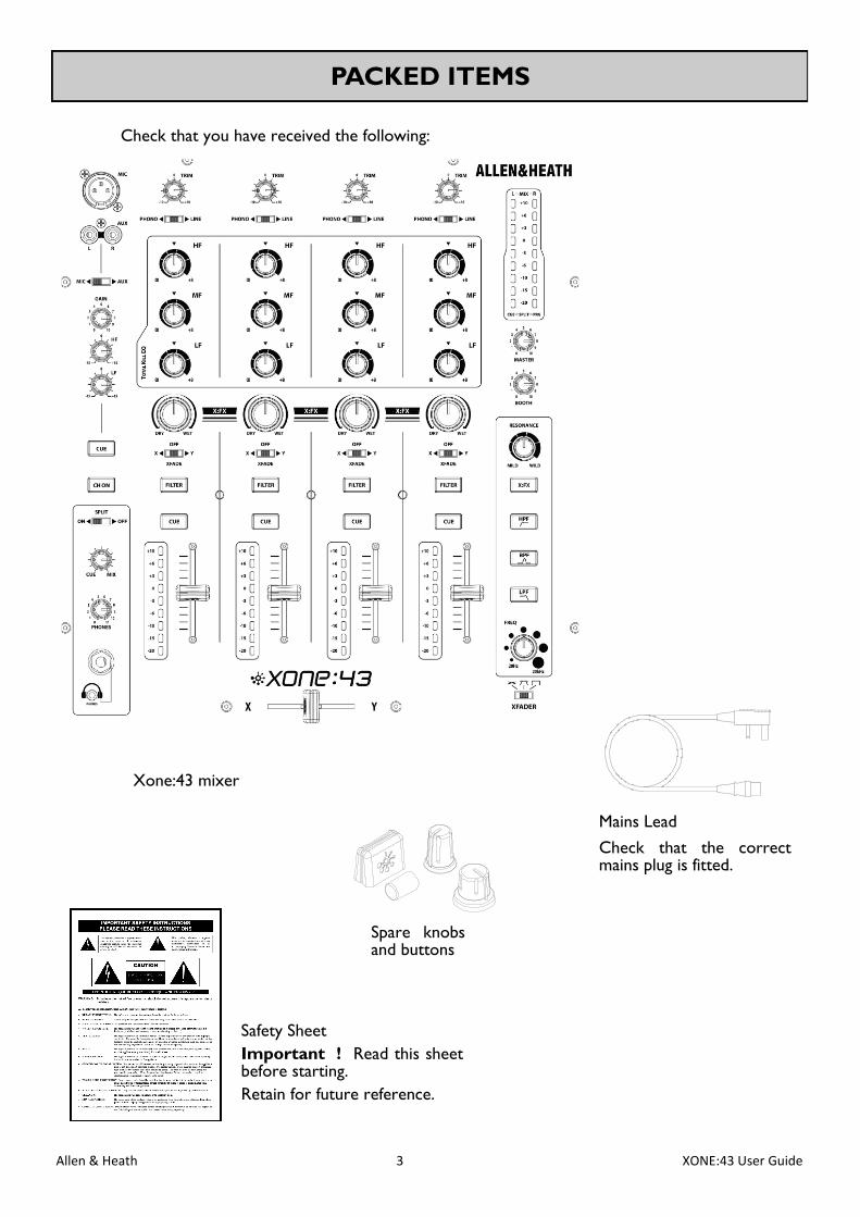
Check that you have received the following
Safety Sheet
Important Read this sheet before starting
Retain for future reference
Mains Lead
Check that the correct mains plug is fitted
Xone43 mixer
Spare knobs and buttons
Allen amp Heath 4 XONE43 User Guide
CONTENTS
Congratulations on purchasing the Allen amp Heath Xone43 DJ mixer
The Xone43 is a DJ mixer featuring four stereo dual input channels a MicAux input channel 45mm
linear VCA channel faders Xone VCF filter and XFX external effects loop for sendreturn functionality
with wetdry control
To ensure that you get the maximum benefit from the unit please spare a few minutes familiarizing yourself with the controls and setup procedures outlined in this user guide For further information please refer to the additional information available on our website or contact our product support team
httpwwwallen-heathcom
Warranty 2
Packed Items 3
Contents 4
Setup Examples 5
Mic Aux Channel Input 6
Phono Line Input Channels 1 to 4 7
Filter Section 9
Headphone Section 10
Master Section 11
Crossfader 12
Rear Connectors 13
Panel Drawings 15
Specifications 16
Block Diagram 17
Filter Reference 18
Operating Levels 19
Earthing 20
Replacing the Crossfader 21
Product Registration 23
Allen amp Heath 5 XONE43 User Guide
SETUP EXAMPLES
Allen amp Heath 6 XONE43 User Guide
MIC AUX INPUT CHANNEL
3
Mic Input
Standard 3-Pin XLR socket wired as Pin 1 = Ground Pin
2 = hot (+) Pin 3 = cold (-)
2
Mic Aux Select Switch
Selects either the XLR microphone input or the alterna-
tive Aux input
4 Channel Gain Control
Adjusts the input sensitivity of the Mic Aux channel to
compensate for different source signal levels
5 Channel Equaliser
The Mic Aux input channel is equipped with a 2 band
EQ stage providing +15dB of boost when fully clockwise
and ndash15dB attenuation when fully anti-clockwise
1
Aux Input
Dual RCA sockets for connecting an external line level
source
7 Channel On Switch
Press the Channel On switch to send the channel audio
to the main mix
6 Cue Switch
Press the Cue switch to listen to the pre-channel on sig-
nal in the headphones and view its level on the main me-
ters Press the switch again to deselect cue
1
2
3
4
5
7
6
Allen amp Heath 7 XONE43 User Guide
PHONO LINE INPUT CHANNELS 1 2 3 and 4
1
Phono Line Select Switch
Selects either the RCA phono input or the alternative
RCA stereo line input
2
Channel Level Control
This control has a range from - 10dB to +10dB Use it
to adjust the signal level of an audio source to give a
nominal 0dB reading on the channel meter with the
peak level at or below 6dB
3 Channel Equalizer Isolator
The Xone43 is equipped with a very powerful 3 band
EQ providing a controlled +6dB of boost when fully
clockwise but dramatic cut of each band when fully anti-
clockwise Centre frequencies are set at
HF = 38kHz (high frequency treble)
MF = 1kHz (mid frequency)
LF = 310Hz (low frequency bass)
4
Filter Select
Press to route the channel signal through the VCF filter
The switch will illuminate to indicate that the channel is
being sent to the filter
5
XFX Dry Wet Send
Use this control to vary the amount of channel signal
that is sent to an external effects device connected to
the XFX send return on the rear panel With this
control set to lsquodryrsquo none of the signal is routed to the
external effects loop With the control in the central
position half of the signal is sent to external effects
while the other half is unaffected or if filter is selected
only the dry part of signal is filtered With the control
set to fully lsquowetrsquo all of the signal is sent to external ef-
fects and the VCF filter is bypassed
XFade Assign Switch
Used to assign the channel to either the X (left) Off
(middle) or Y (right) side of the cross-fader
1
2
3
4
5
6
6
Allen amp Heath 8 XONE43 User Guide
PHONO LINE INPUT CHANNELS 1 2 3 and 4
9 Channel Fader
A high quality smooth travel fader adjusts the channel
signal level from fully off to fully on
8 Channel Meter
Displays the channel signal level It is pre-EQ and pre-
fader allowing the input level to be displayed even if the
EQ is set to off on all bands
The channel level control should be set so that the me-
ter averages around lsquo0rsquo with loudest peaks no higher
than lsquo+6rsquo Turn down the level control if the +10 indica-
tor lights
7 Cue Switch
Press the Cue switch to listen to the channel pre-fade
signal in the headphones and see its level on the main
meters Press the switch to deselect cue
9
8
7
Allen amp Heath 9 XONE43 User Guide
FILTER SECTION
1
2
3
4
5
1
XFX Return to Filter
Pressing this button routes the XFX return to the VCF
filter instead of directly into the main mix buss The
effected channel signal can then be filtered as well allow-
ing extra versatility and creativity to be brought into the
mix
2
Resonance Control
This produces the classic Xone VCF sound by feeding
some of the filter output back to its input The control
ranges from lsquomildrsquo producing a very subtle effect to
lsquowildrsquo producing a dramatic phase effect with feedback
just short of oscillation
3 HPF
Turns on the high pass (bass cut) filter slope
4 BPF
Turns on the band pass (bell shaped) filter slope
5 LPF
Turns on the low pass (treble cut) filter slope
Frequency Sweep Control
This control sets the ndash3dB cut-off frequency of the filter
It ranges from very low frequency (20Hz) to very high
frequency (20kHz)
6
6
Allen amp Heath 10 XONE43 User Guide
HEADPHONE SECTION
1
2
3
4
1
Headphone Outputs
Stereo 14rdquo TRS jack and 35mm mini-jack sockets Plug
in good quality stereo headphones intended for DJ mon-
itoring Use closed-ear headphones that provide maxi-
mum acoustic isolation when cueing your sources
2
Split Cue Switch
Selects the way Cue operates Normally pressing a
channel Cue switch overrides both left and right moni-
tor program signals with the stereo Cue signal With
Split set to On Cue overrides just the left channel leav-
ing the program in the right channel The left monitor
meter displays the Cue signal right displays program
This is very useful when beat mixing using headphones
3
Cue Mix Control
Allows the main mix output to be added to the Cue sig-
nal Turned fully anticlockwise only the active Cue is
heard through the headphones when Cue is active
Gradually turning clockwise introduces the main mix
output to the headphones together with the active Cue
Selecting Split Cue will automatically override this con-
trol
4
Headphones Level Control
Adjusts the level of the signal in the stereo headphones
This does not affect the level of the local booth monitor
Allen amp Heath 11 XONE43 User Guide
MASTER SECTION
1 Mix Monitor Meters
The main meters follow the selected monitor source
The default display is the mix level pre-master level
which is overridden with an input channel level if the
channel cue switch is selected
In split cue mode the left (L) mix meter will display the
cued channel signal level and the right (R) mix meter will
display the mix level The cued mix audio is pre level to
prevent mismatch due to the position of the master lev-
el control
The mixer should be operated with these meters aver-
aging around lsquo0rsquo with loudest peaks no higher than lsquo+6rsquo
2
3
Master Level Control
A rotary master control adjusts the level of the master
mix XLR outputs feeding the house sound system This
does not affect the booth output or the meter reading
Booth Level Control
Adjusts the level of the signal to the stereo booth RCA
output This does not affect the headphones The
booth output could be used for a booth monitor re-
cording or an additional zone feed
1
2
3
Allen amp Heath 12 XONE43 User Guide
Crossfader
This lets you fade between signals routed to either side typically to fade
smoothly into a new music track or to creatively layer sounds when scratch or
cut mixing
The crossfader is a VCA controller which affects the level of signals routed via
the filters Make sure the switches on the channels you wish to fade are set to
X or Y as appropriate
CROSSFADER
2
1
Crossfader Curve Control
This control adjusts the crossfader curve between dipped dipless and fast-cut
better suited for scratch or cut mixing
1
2
Allen amp Heath 13 XONE43 User Guide
REAR CONNECTORS
1
2
3
AC Mains Input
IEC cable with moulded mains plug suitable for your local supply
Important Read the SAFETY INSTRUCTIONS sheet included with the
Xone43 and printed on the rear panel
Check that the correct mains lead with moulded plug has been supplied with your console
The power supply accepts mains voltages within the range 100-240V without changing any
fuses or settings Ensure that the IEC mains plug is pressed fully into the rear panel socket
before switching on
Note It is standard practice to turn connected power amplifiers down or off before
switching the console on or off This prevents any potential damage to speaker systems due
to switch-on transients
CH 1 2 3 and 4 Phono Input
Plug in turntables with magnetic cartridges requiring RIAA equalisation For non-RIAA turn-
tables plug into the LINE input instead Do not plug in line level sources to the phono inputs
as these will overload the preamp and cause severe high level distortion
CH 1 2 3 and 4 Line Input
RCA phono Connect stereo line level music sources such as CD players Do not connect
turntables which require RIAA equalisation Alternatively you can connect to jack sources
using a cable with RCA to jack adapters Avoid using low grade cables such as those often
supplied with domestic equipment as these can quickly prove unreliable in use
1 2
3
1 2
Allen amp Heath 14 XONE43 User Guide
REAR CONNECTORS
5
6
4 Master Output
Balanced XLR This is the main output that feeds the house PA system Plug into the house
processoramplifier system using balanced cables Use balanced cables and equipment
When the main meter LEDs are at ldquo0dBrdquo the output will nominally be at +4dBu Do not
unbalance this output by shorting one phase to groundmdashfor unbalanced operation use pin 2
only
Booth Output
RCA phono 0dBu Provides a line level stereo feed to the DJ local monitor amplifier sys-
tem It is not affected by the master fader or cue system
XFX SendReturn
RCA phono Connect your external effects device and use the XFX dry wet control to
send channel signals to the effects unit The signal returns to the mix bus but can be routed
to the VCF filter by pressing the lsquoXFXrsquo button on the front panel filter section This allows
the filter to be lsquostackedrsquo with an external effects device
Record Output
RCA Phono nominal 0dBu Pre-level mix output for connection to external recording de-
vices
Chassis Earth Terminal
A screw terminal is provided for connecting the earth straps from turntables This connec-
tion earths the metal parts of the turntable to reduce hum buzz or similar audible noise get-
ting into the system
4 5 6 7
7
8
8
Allen amp Heath 15 XONE43 User Guide
PANEL DRAWINGS
Rear Panel
Front Panel
Allen amp Heath 16 XONE43 User Guide
Dimensions and Weights
The console is fitted with rubber feet for desktop operation
Width Height Depth Weight
Mixer 320 mm 110mm 370mm 51 kg
SPECIFICATIONS
Nom max output levels Main Mix +4dBu +27dBu
Booth 0dBu +22dBu
XFX Send 0dBu +20dBu
Record Out 0dBu +20dBu
Internal headroom Channels +20dB
Frequency response +-05dB 20Hz - 20kHz
Distortion lt 005 THD+noise 1kHz
Crosstalk lt -83dB inter-channel
Residual noise Mix 1 -89dBu
Booth -93dBu
XFX -77dBu
Rec -92dBu
Mix noise Mix 1 -82dBu
Booth -84dBu
XFX -77dBu
Rec -87dBu
Channel meters Peak reading 9 LED -20dB to +10dB
Main meters Peak reading 9 LED -20dB to +10dB
Mic EQ 2-Band +-12dB
Channel EQ 3-Band +6dB total kill
Channel fader 45mm stereo VCA lt -85dB shutoff
Crossfader 45mm stereo VCA - replaceable
Filters Stereo VCF analogue
Consumption 30W max
Allen amp Heath 17 XONE43 User Guide
BLOCK DIAGRAM
Allen amp Heath 18 XONE43 User Guide
FILTER REFERENCE
The VCF Filters
A voltage controlled filter is an audio filter where the cut-off frequency is altered by a DC control voltage rather than a variable resistor This produces a much wider operating range and more control over the filter response to create unlimited combinations of tonal effect
Filter Type Select
The filters are lsquostate variablersquo This means that they provide three simultaneous filter types high-pass band-pass and low-pass Three large illuminated switches select which type is active You can press any combination together to create different response types such as lsquonotchrsquo and an interesting lsquoall-passrsquo effect The switches are lsquosoft switchedrsquo for live performance meaning that the audio signal is ramped between filter states to prevent audible clicks
Note that the last selected type is lost when power is removed from the console The LPF is always selected when power is applied
The graphs below show the effect on the audio frequency response for the three filter types The range of sweep from low to high frequency is shown together with the effect of adjusting RESONANCE (one frequency with several resonance settings shown)
The vertical scale shows the amount of cut or boost around the normal 0dB operating level The horizontal scale shows the change in frequency from low (bass) to high (treble)
10k20 1kHz100 20k
0dB
+5
+10
+15
+20
-5
-10
-15
-20
LO-PASS FILTER
LO HI
BAND-PASS FILTER
LO HI
10k20 1kHz100 20k
0dB
+5
+10
+15
+20
-5
-10
-15
-20
10k20 1kHz100 20k
0dB
+5
+10
+15
+20
-5
-10
-15
-20
HI-PASS FILTER
LO HI
10k20 1kHz100 20k
0dB
+5
+10
+15
+20
-5
-10
-15
-20
LO-PASS FILTER
LO HI
BAND-PASS FILTER
LO HI
10k20 1kHz100 20k
0dB
+5
+10
+15
+20
-5
-10
-15
-20
10k20 1kHz100 20k
0dB
+5
+10
+15
+20
-5
-10
-15
-20
HI-PASS FILTER
LO HI
10k20 1kHz100 20k
0dB
+5
+10
+15
+20
-5
-10
-15
-20
LO-PASS FILTER
LO HI
BAND-PASS FILTER
LO HI
10k20 1kHz100 20k
0dB
+5
+10
+15
+20
-5
-10
-15
-20
10k20 1kHz100 20k
0dB
+5
+10
+15
+20
-5
-10
-15
-20
HI-PASS FILTER
LO HI
Allen amp Heath 19 XONE43 User Guide
It is most important that the system level settings are correctly set It is well known that many DJs push the level to maximum with meters peaking hard in the belief that they are getting the best from the system THIS IS NOT THE CASE The best can only be achieved if the system levels are set within the normal operating range and not allowed to peak Peaking simply results in signal distortion not more volume It is the specification of the amplifier speaker system that sets the maximum volume that can be achieved not the console The human ear too can fool the operator into believing that more volume is needed Be careful as this is in fact a warning that hearing damage will result if high listen-ing levels are maintained Remember that it is the QUALITY of the sound that pleases the ear not the VOLUME
OPERATING LEVELS
The diagram below illustrates the operating range of the audio signal
NORMAL OPERATING RANGE For normal music the signal should range between ndash6 and +6 on the meters with average around 0dB This allows enough HEADROOM for unexpected peaks before the signal hits its maximum CLIPPING voltage and distorts
It also achieves the best SIGNAL-TO-NOISE-RATIO by keeping the signal well above the residual NOISE FLOOR (system hiss)
The DYNAMIC RANGE is the maximum signal swing available between the residual noise floor and clipping
An important note hellip
The human ear is a remarkable organ with the ability to com-press or lsquoshut downrsquo when sound levels become too high Do not interpret this natural response as a reason to turn the sys-tem volume up further As the session wears on ear fatigue may set in and the speaker cones may become hot so reducing the effectiveness of the system and listeners to gain any benefit from increased volume
Allen amp Heath 20 XONE43 User Guide
The connection to earth (ground) in an audio system is important for two reasons
SAFETY - To protect the operator from high voltage electric shock and
AUDIO PERFORMANCE - To minimise the effect of earth (ground) loops which result in audible hum and buzz and to shield the audio signals from interference
For safety it is important that all equipment earths are connected to mains earth so that exposed metal parts are prevented from carrying high voltage which can injure or even kill the operator It is recommended that a qualified system engineer check the continuity of the safety earth from all points in the system including microphone bodies turntable chassis equipment cases and so on
The same earth is also used to shield audio cables from external interference such as the hum fields associated with power transformers lighting dimmer buzz and computer radiation Problems arise when the signal sees more than one path to mains earth An lsquoearth looprsquo (ground loop) results causing current to flow between the different earth paths This condition is usually detected as a mains frequency audible hum or buzz
To ensure safe and trouble-free operation we recommend the following
Have your mains system checked by a qualified electrician If the supply earthing is solid to start with you are less likely to experience problems
Do not remove the earth connection from the console mains plug The console chassis is connected to mains earth through the power cable to ensure your safety Audio 0V is connected to the console chassis internally If problems are encountered with earth loops operate the audio lsquoground liftrsquo switches on connected equipment accordingly or disconnect the cable screens at one end usually at the destination
Make sure that turntables are correctly earthed A chassis earth terminal is provided on the console rear panel to connect to turntable earth straps
Use low impedance sources such as microphones and line level equipment rated at 200 ohms or less to reduce susceptibility to interference The console outputs are designed to operate at very low impedance to minimise interference problems
Use balanced connections for microphones and mix output as these provide further immunity by cancelling out interference that may be picked up on long cable runs To connect an unbalanced source to a balanced console input link the cold input (XLR pin 3 or jack ring) to 0V earth (XLR pin 1 or jack sleeve) at the console To connect a balanced XLR output to unbalanced equipment link the cold output to 0V earth at the console
Use good quality cables and connectors and check for correct wiring and reliable solder joints Allow sufficient cable loop to prevent damage through stretching
If you are not sure Contact your service agent or local Allen amp Heath dealer for advice
EARTHING
Allen amp Heath 21 XONE43 User Guide
REPLACING THE CROSSFADER
If the crossfader is subject to a lot of use it will in time wear out and need replacing Intermittent or
noisy operation is an indication that it is becoming worn Using a propriety fader cleaner such as
CaigLube might temporarily restore use but DO NOT use on a new fader as it will wash away the facto-
ry applied grease
The standard fader can be ordered under AampH part number 004-632JIT
The Innofader can be ordered under part number 004-504JIT
Warning Dismantling your mixer could invalidate the warranty if you are unsure of your ability to safely
carry out this work then it is advised that you leave it to a qualified service technician
Tools you will need
bull T8 Torx screwdriver
bull A small container to keep screws in
Have a clean flat work surface ready before starting work
Ensure that the power to the unit has been turned off and disconnected completely from the mains
Step 1
bull Remove and retain 2 screws from front panel
bull Remove and retain 4 screws from rear panel
upper phono sockets
Step 2
bull Remove and retain 4 screws from side panel
of the mixer (2 each side)
bull Turn console over onto its front panel ndash
take care not to scratch the unit
Step 3
bull Remove and retain 6 screws from base panel
bull Note that the 2 nearest the rear connector
remain in place
bull Turn console over to be the correct way up
Allen amp Heath 22 XONE43 User Guide
REPLACING THE CROSSFADER
Step 4
bull Gently slide the two halves of the console
apart until the rear connector PCB is wholly
visible
Step 5
bull With care unplug the grey flat wireform from
the connector PCB
bull The console base and front panel can now be
separated
Step 7
bull With care unplug the white harness from the
connector PCB
bull The cross fader and plate can now be sepa-
rated
Step 8
bull Remove and retain 2 screws from crossfader
plate
bull Note that these 2 screws from the cross fad-
er plate are a different size length do not mix
them up with the other screws
Step 6
bull Remove the crossfader cap
bull Remove and retain 2 screws from crossfader
front panel
Allen amp Heath 23 XONE43 User Guide
REPLACING THE CROSSFADER
Step 9
bull Fit the new replacement crossfader to the
bracket as shown (slot 1)
bull The longer (slot 2) beneath is for mounting
the optional Innofader (not supplied)
The standard crossfader must be fitted to slot
1 and not slot 2
Step 10
bull Screw the crossfader plate back to the con-
sole
bull Replace the crossfader cap
bull Connect the white harness from the connect-
or PCB
Step 11
bull Re-assembly of the console is the reverse of
steps 1-5 When re-assembling the console
take great care to refit the wireform fully into
the socket
1
2
PRODUCT REGISTRATION
Registering your product
Please register your product with AllenampHeath online at
httpwwwallen-heathcomsupportregister-product

Allen amp Heath 2 XONE43 User Guide
XONE43 User Guide AP9968 Issue 2
Copyright copy 2018 Allen amp Heath Limited All rights reserved
Allen amp Heath Limited
Kernick Industrial Estate Penryn Cornwall TR10 9LU UK
wwwallen-heathcom
Limited One Year Manufacturerrsquos Warranty
Allen amp Heath warrants the Allen amp Heath - branded hardware product and accessories contained in the original packaging (Allen amp Heath Productrdquo) against defects in materials and workmanship when used in accordance with Allen amp Heaths user manuals technical specifications and other Allen amp Heath product published guidelines for a period of ONE (1) YEAR from the date of original purchase by the end-user purchaser (Warranty Period)
This warranty does not apply to any non-Allen amp Heath branded hardware products or any software even if packaged or sold with Allen amp Heath hardware Please refer to the licensing agreement accompanying the software for details of your rights with respect to the use of software (ldquoEULArdquo) Details of the EULA warranty policy and other useful information can be found on the Allen amp Heath website wwwallen-heathcomlegal
Repair or replacement under the terms of the warranty does not provide right to extension or renewal of the warranty period Repair or direct replacement of the product under the terms of this warranty may be fulfilled with functionally equivalent service exchange units
This warranty is not transferable This warranty does not cover fader wear and tear
This warranty will be the purchaserrsquos sole and exclusive remedy and neither Allen amp Heath nor its approved service centres shall be liable for any incidental or consequential damages or breach of any express or implied warranty of this product
Conditions of Warranty The equipment has not been subject to misuse either intended or accidental neglect or alteration other than as described in the User Guide or Service Manual or approved by Allen amp Heath Any necessary adjustment alteration or repair has been carried out by an authorised Allen amp Heath distributor or agent The defective unit is to be returned carriage prepaid to the place of purchase an authorised Allen amp Heath distributor or agent with proof of purchase Please discuss this with the distributor or the agent before shipping If the unit is to be repaired in a different country to that of its purchase the repair may take longer than normal whilst the warranty is confirmed and parts are sourced Units returned should be packed in the original carton to avoid transit damage In certain territories the terms may vary Check with your Allen amp Heath distributor or agent for any additional warranty information which may apply If further assistance is required please contact Allen amp Heath Ltd
DISCLAIMER Allen amp Heath shall not be liable for the loss of any savedstored data in products that are either repaired or replaced
XONE43 complies with the European Electromagnetic Compatibility directives
201430EU and the European Low Voltage directives 201435EU
Any changes or modifications to the equipment not approved by Allen amp Heath could void the compliance of the product and therefore the users authority to operate it
Allen amp Heath 3 XONE43 User Guide
PACKED ITEMS
Check that you have received the following
Safety Sheet
Important Read this sheet before starting
Retain for future reference
Mains Lead
Check that the correct mains plug is fitted
Xone43 mixer
Spare knobs and buttons
Allen amp Heath 4 XONE43 User Guide
CONTENTS
Congratulations on purchasing the Allen amp Heath Xone43 DJ mixer
The Xone43 is a DJ mixer featuring four stereo dual input channels a MicAux input channel 45mm
linear VCA channel faders Xone VCF filter and XFX external effects loop for sendreturn functionality
with wetdry control
To ensure that you get the maximum benefit from the unit please spare a few minutes familiarizing yourself with the controls and setup procedures outlined in this user guide For further information please refer to the additional information available on our website or contact our product support team
httpwwwallen-heathcom
Warranty 2
Packed Items 3
Contents 4
Setup Examples 5
Mic Aux Channel Input 6
Phono Line Input Channels 1 to 4 7
Filter Section 9
Headphone Section 10
Master Section 11
Crossfader 12
Rear Connectors 13
Panel Drawings 15
Specifications 16
Block Diagram 17
Filter Reference 18
Operating Levels 19
Earthing 20
Replacing the Crossfader 21
Product Registration 23
Allen amp Heath 5 XONE43 User Guide
SETUP EXAMPLES
Allen amp Heath 6 XONE43 User Guide
MIC AUX INPUT CHANNEL
3
Mic Input
Standard 3-Pin XLR socket wired as Pin 1 = Ground Pin
2 = hot (+) Pin 3 = cold (-)
2
Mic Aux Select Switch
Selects either the XLR microphone input or the alterna-
tive Aux input
4 Channel Gain Control
Adjusts the input sensitivity of the Mic Aux channel to
compensate for different source signal levels
5 Channel Equaliser
The Mic Aux input channel is equipped with a 2 band
EQ stage providing +15dB of boost when fully clockwise
and ndash15dB attenuation when fully anti-clockwise
1
Aux Input
Dual RCA sockets for connecting an external line level
source
7 Channel On Switch
Press the Channel On switch to send the channel audio
to the main mix
6 Cue Switch
Press the Cue switch to listen to the pre-channel on sig-
nal in the headphones and view its level on the main me-
ters Press the switch again to deselect cue
1
2
3
4
5
7
6
Allen amp Heath 7 XONE43 User Guide
PHONO LINE INPUT CHANNELS 1 2 3 and 4
1
Phono Line Select Switch
Selects either the RCA phono input or the alternative
RCA stereo line input
2
Channel Level Control
This control has a range from - 10dB to +10dB Use it
to adjust the signal level of an audio source to give a
nominal 0dB reading on the channel meter with the
peak level at or below 6dB
3 Channel Equalizer Isolator
The Xone43 is equipped with a very powerful 3 band
EQ providing a controlled +6dB of boost when fully
clockwise but dramatic cut of each band when fully anti-
clockwise Centre frequencies are set at
HF = 38kHz (high frequency treble)
MF = 1kHz (mid frequency)
LF = 310Hz (low frequency bass)
4
Filter Select
Press to route the channel signal through the VCF filter
The switch will illuminate to indicate that the channel is
being sent to the filter
5
XFX Dry Wet Send
Use this control to vary the amount of channel signal
that is sent to an external effects device connected to
the XFX send return on the rear panel With this
control set to lsquodryrsquo none of the signal is routed to the
external effects loop With the control in the central
position half of the signal is sent to external effects
while the other half is unaffected or if filter is selected
only the dry part of signal is filtered With the control
set to fully lsquowetrsquo all of the signal is sent to external ef-
fects and the VCF filter is bypassed
XFade Assign Switch
Used to assign the channel to either the X (left) Off
(middle) or Y (right) side of the cross-fader
1
2
3
4
5
6
6
Allen amp Heath 8 XONE43 User Guide
PHONO LINE INPUT CHANNELS 1 2 3 and 4
9 Channel Fader
A high quality smooth travel fader adjusts the channel
signal level from fully off to fully on
8 Channel Meter
Displays the channel signal level It is pre-EQ and pre-
fader allowing the input level to be displayed even if the
EQ is set to off on all bands
The channel level control should be set so that the me-
ter averages around lsquo0rsquo with loudest peaks no higher
than lsquo+6rsquo Turn down the level control if the +10 indica-
tor lights
7 Cue Switch
Press the Cue switch to listen to the channel pre-fade
signal in the headphones and see its level on the main
meters Press the switch to deselect cue
9
8
7
Allen amp Heath 9 XONE43 User Guide
FILTER SECTION
1
2
3
4
5
1
XFX Return to Filter
Pressing this button routes the XFX return to the VCF
filter instead of directly into the main mix buss The
effected channel signal can then be filtered as well allow-
ing extra versatility and creativity to be brought into the
mix
2
Resonance Control
This produces the classic Xone VCF sound by feeding
some of the filter output back to its input The control
ranges from lsquomildrsquo producing a very subtle effect to
lsquowildrsquo producing a dramatic phase effect with feedback
just short of oscillation
3 HPF
Turns on the high pass (bass cut) filter slope
4 BPF
Turns on the band pass (bell shaped) filter slope
5 LPF
Turns on the low pass (treble cut) filter slope
Frequency Sweep Control
This control sets the ndash3dB cut-off frequency of the filter
It ranges from very low frequency (20Hz) to very high
frequency (20kHz)
6
6
Allen amp Heath 10 XONE43 User Guide
HEADPHONE SECTION
1
2
3
4
1
Headphone Outputs
Stereo 14rdquo TRS jack and 35mm mini-jack sockets Plug
in good quality stereo headphones intended for DJ mon-
itoring Use closed-ear headphones that provide maxi-
mum acoustic isolation when cueing your sources
2
Split Cue Switch
Selects the way Cue operates Normally pressing a
channel Cue switch overrides both left and right moni-
tor program signals with the stereo Cue signal With
Split set to On Cue overrides just the left channel leav-
ing the program in the right channel The left monitor
meter displays the Cue signal right displays program
This is very useful when beat mixing using headphones
3
Cue Mix Control
Allows the main mix output to be added to the Cue sig-
nal Turned fully anticlockwise only the active Cue is
heard through the headphones when Cue is active
Gradually turning clockwise introduces the main mix
output to the headphones together with the active Cue
Selecting Split Cue will automatically override this con-
trol
4
Headphones Level Control
Adjusts the level of the signal in the stereo headphones
This does not affect the level of the local booth monitor
Allen amp Heath 11 XONE43 User Guide
MASTER SECTION
1 Mix Monitor Meters
The main meters follow the selected monitor source
The default display is the mix level pre-master level
which is overridden with an input channel level if the
channel cue switch is selected
In split cue mode the left (L) mix meter will display the
cued channel signal level and the right (R) mix meter will
display the mix level The cued mix audio is pre level to
prevent mismatch due to the position of the master lev-
el control
The mixer should be operated with these meters aver-
aging around lsquo0rsquo with loudest peaks no higher than lsquo+6rsquo
2
3
Master Level Control
A rotary master control adjusts the level of the master
mix XLR outputs feeding the house sound system This
does not affect the booth output or the meter reading
Booth Level Control
Adjusts the level of the signal to the stereo booth RCA
output This does not affect the headphones The
booth output could be used for a booth monitor re-
cording or an additional zone feed
1
2
3
Allen amp Heath 12 XONE43 User Guide
Crossfader
This lets you fade between signals routed to either side typically to fade
smoothly into a new music track or to creatively layer sounds when scratch or
cut mixing
The crossfader is a VCA controller which affects the level of signals routed via
the filters Make sure the switches on the channels you wish to fade are set to
X or Y as appropriate
CROSSFADER
2
1
Crossfader Curve Control
This control adjusts the crossfader curve between dipped dipless and fast-cut
better suited for scratch or cut mixing
1
2
Allen amp Heath 13 XONE43 User Guide
REAR CONNECTORS
1
2
3
AC Mains Input
IEC cable with moulded mains plug suitable for your local supply
Important Read the SAFETY INSTRUCTIONS sheet included with the
Xone43 and printed on the rear panel
Check that the correct mains lead with moulded plug has been supplied with your console
The power supply accepts mains voltages within the range 100-240V without changing any
fuses or settings Ensure that the IEC mains plug is pressed fully into the rear panel socket
before switching on
Note It is standard practice to turn connected power amplifiers down or off before
switching the console on or off This prevents any potential damage to speaker systems due
to switch-on transients
CH 1 2 3 and 4 Phono Input
Plug in turntables with magnetic cartridges requiring RIAA equalisation For non-RIAA turn-
tables plug into the LINE input instead Do not plug in line level sources to the phono inputs
as these will overload the preamp and cause severe high level distortion
CH 1 2 3 and 4 Line Input
RCA phono Connect stereo line level music sources such as CD players Do not connect
turntables which require RIAA equalisation Alternatively you can connect to jack sources
using a cable with RCA to jack adapters Avoid using low grade cables such as those often
supplied with domestic equipment as these can quickly prove unreliable in use
1 2
3
1 2
Allen amp Heath 14 XONE43 User Guide
REAR CONNECTORS
5
6
4 Master Output
Balanced XLR This is the main output that feeds the house PA system Plug into the house
processoramplifier system using balanced cables Use balanced cables and equipment
When the main meter LEDs are at ldquo0dBrdquo the output will nominally be at +4dBu Do not
unbalance this output by shorting one phase to groundmdashfor unbalanced operation use pin 2
only
Booth Output
RCA phono 0dBu Provides a line level stereo feed to the DJ local monitor amplifier sys-
tem It is not affected by the master fader or cue system
XFX SendReturn
RCA phono Connect your external effects device and use the XFX dry wet control to
send channel signals to the effects unit The signal returns to the mix bus but can be routed
to the VCF filter by pressing the lsquoXFXrsquo button on the front panel filter section This allows
the filter to be lsquostackedrsquo with an external effects device
Record Output
RCA Phono nominal 0dBu Pre-level mix output for connection to external recording de-
vices
Chassis Earth Terminal
A screw terminal is provided for connecting the earth straps from turntables This connec-
tion earths the metal parts of the turntable to reduce hum buzz or similar audible noise get-
ting into the system
4 5 6 7
7
8
8
Allen amp Heath 15 XONE43 User Guide
PANEL DRAWINGS
Rear Panel
Front Panel
Allen amp Heath 16 XONE43 User Guide
Dimensions and Weights
The console is fitted with rubber feet for desktop operation
Width Height Depth Weight
Mixer 320 mm 110mm 370mm 51 kg
SPECIFICATIONS
Nom max output levels Main Mix +4dBu +27dBu
Booth 0dBu +22dBu
XFX Send 0dBu +20dBu
Record Out 0dBu +20dBu
Internal headroom Channels +20dB
Frequency response +-05dB 20Hz - 20kHz
Distortion lt 005 THD+noise 1kHz
Crosstalk lt -83dB inter-channel
Residual noise Mix 1 -89dBu
Booth -93dBu
XFX -77dBu
Rec -92dBu
Mix noise Mix 1 -82dBu
Booth -84dBu
XFX -77dBu
Rec -87dBu
Channel meters Peak reading 9 LED -20dB to +10dB
Main meters Peak reading 9 LED -20dB to +10dB
Mic EQ 2-Band +-12dB
Channel EQ 3-Band +6dB total kill
Channel fader 45mm stereo VCA lt -85dB shutoff
Crossfader 45mm stereo VCA - replaceable
Filters Stereo VCF analogue
Consumption 30W max
Allen amp Heath 17 XONE43 User Guide
BLOCK DIAGRAM
Allen amp Heath 18 XONE43 User Guide
FILTER REFERENCE
The VCF Filters
A voltage controlled filter is an audio filter where the cut-off frequency is altered by a DC control voltage rather than a variable resistor This produces a much wider operating range and more control over the filter response to create unlimited combinations of tonal effect
Filter Type Select
The filters are lsquostate variablersquo This means that they provide three simultaneous filter types high-pass band-pass and low-pass Three large illuminated switches select which type is active You can press any combination together to create different response types such as lsquonotchrsquo and an interesting lsquoall-passrsquo effect The switches are lsquosoft switchedrsquo for live performance meaning that the audio signal is ramped between filter states to prevent audible clicks
Note that the last selected type is lost when power is removed from the console The LPF is always selected when power is applied
The graphs below show the effect on the audio frequency response for the three filter types The range of sweep from low to high frequency is shown together with the effect of adjusting RESONANCE (one frequency with several resonance settings shown)
The vertical scale shows the amount of cut or boost around the normal 0dB operating level The horizontal scale shows the change in frequency from low (bass) to high (treble)
10k20 1kHz100 20k
0dB
+5
+10
+15
+20
-5
-10
-15
-20
LO-PASS FILTER
LO HI
BAND-PASS FILTER
LO HI
10k20 1kHz100 20k
0dB
+5
+10
+15
+20
-5
-10
-15
-20
10k20 1kHz100 20k
0dB
+5
+10
+15
+20
-5
-10
-15
-20
HI-PASS FILTER
LO HI
10k20 1kHz100 20k
0dB
+5
+10
+15
+20
-5
-10
-15
-20
LO-PASS FILTER
LO HI
BAND-PASS FILTER
LO HI
10k20 1kHz100 20k
0dB
+5
+10
+15
+20
-5
-10
-15
-20
10k20 1kHz100 20k
0dB
+5
+10
+15
+20
-5
-10
-15
-20
HI-PASS FILTER
LO HI
10k20 1kHz100 20k
0dB
+5
+10
+15
+20
-5
-10
-15
-20
LO-PASS FILTER
LO HI
BAND-PASS FILTER
LO HI
10k20 1kHz100 20k
0dB
+5
+10
+15
+20
-5
-10
-15
-20
10k20 1kHz100 20k
0dB
+5
+10
+15
+20
-5
-10
-15
-20
HI-PASS FILTER
LO HI
Allen amp Heath 19 XONE43 User Guide
It is most important that the system level settings are correctly set It is well known that many DJs push the level to maximum with meters peaking hard in the belief that they are getting the best from the system THIS IS NOT THE CASE The best can only be achieved if the system levels are set within the normal operating range and not allowed to peak Peaking simply results in signal distortion not more volume It is the specification of the amplifier speaker system that sets the maximum volume that can be achieved not the console The human ear too can fool the operator into believing that more volume is needed Be careful as this is in fact a warning that hearing damage will result if high listen-ing levels are maintained Remember that it is the QUALITY of the sound that pleases the ear not the VOLUME
OPERATING LEVELS
The diagram below illustrates the operating range of the audio signal
NORMAL OPERATING RANGE For normal music the signal should range between ndash6 and +6 on the meters with average around 0dB This allows enough HEADROOM for unexpected peaks before the signal hits its maximum CLIPPING voltage and distorts
It also achieves the best SIGNAL-TO-NOISE-RATIO by keeping the signal well above the residual NOISE FLOOR (system hiss)
The DYNAMIC RANGE is the maximum signal swing available between the residual noise floor and clipping
An important note hellip
The human ear is a remarkable organ with the ability to com-press or lsquoshut downrsquo when sound levels become too high Do not interpret this natural response as a reason to turn the sys-tem volume up further As the session wears on ear fatigue may set in and the speaker cones may become hot so reducing the effectiveness of the system and listeners to gain any benefit from increased volume
Allen amp Heath 20 XONE43 User Guide
The connection to earth (ground) in an audio system is important for two reasons
SAFETY - To protect the operator from high voltage electric shock and
AUDIO PERFORMANCE - To minimise the effect of earth (ground) loops which result in audible hum and buzz and to shield the audio signals from interference
For safety it is important that all equipment earths are connected to mains earth so that exposed metal parts are prevented from carrying high voltage which can injure or even kill the operator It is recommended that a qualified system engineer check the continuity of the safety earth from all points in the system including microphone bodies turntable chassis equipment cases and so on
The same earth is also used to shield audio cables from external interference such as the hum fields associated with power transformers lighting dimmer buzz and computer radiation Problems arise when the signal sees more than one path to mains earth An lsquoearth looprsquo (ground loop) results causing current to flow between the different earth paths This condition is usually detected as a mains frequency audible hum or buzz
To ensure safe and trouble-free operation we recommend the following
Have your mains system checked by a qualified electrician If the supply earthing is solid to start with you are less likely to experience problems
Do not remove the earth connection from the console mains plug The console chassis is connected to mains earth through the power cable to ensure your safety Audio 0V is connected to the console chassis internally If problems are encountered with earth loops operate the audio lsquoground liftrsquo switches on connected equipment accordingly or disconnect the cable screens at one end usually at the destination
Make sure that turntables are correctly earthed A chassis earth terminal is provided on the console rear panel to connect to turntable earth straps
Use low impedance sources such as microphones and line level equipment rated at 200 ohms or less to reduce susceptibility to interference The console outputs are designed to operate at very low impedance to minimise interference problems
Use balanced connections for microphones and mix output as these provide further immunity by cancelling out interference that may be picked up on long cable runs To connect an unbalanced source to a balanced console input link the cold input (XLR pin 3 or jack ring) to 0V earth (XLR pin 1 or jack sleeve) at the console To connect a balanced XLR output to unbalanced equipment link the cold output to 0V earth at the console
Use good quality cables and connectors and check for correct wiring and reliable solder joints Allow sufficient cable loop to prevent damage through stretching
If you are not sure Contact your service agent or local Allen amp Heath dealer for advice
EARTHING
Allen amp Heath 21 XONE43 User Guide
REPLACING THE CROSSFADER
If the crossfader is subject to a lot of use it will in time wear out and need replacing Intermittent or
noisy operation is an indication that it is becoming worn Using a propriety fader cleaner such as
CaigLube might temporarily restore use but DO NOT use on a new fader as it will wash away the facto-
ry applied grease
The standard fader can be ordered under AampH part number 004-632JIT
The Innofader can be ordered under part number 004-504JIT
Warning Dismantling your mixer could invalidate the warranty if you are unsure of your ability to safely
carry out this work then it is advised that you leave it to a qualified service technician
Tools you will need
bull T8 Torx screwdriver
bull A small container to keep screws in
Have a clean flat work surface ready before starting work
Ensure that the power to the unit has been turned off and disconnected completely from the mains
Step 1
bull Remove and retain 2 screws from front panel
bull Remove and retain 4 screws from rear panel
upper phono sockets
Step 2
bull Remove and retain 4 screws from side panel
of the mixer (2 each side)
bull Turn console over onto its front panel ndash
take care not to scratch the unit
Step 3
bull Remove and retain 6 screws from base panel
bull Note that the 2 nearest the rear connector
remain in place
bull Turn console over to be the correct way up
Allen amp Heath 22 XONE43 User Guide
REPLACING THE CROSSFADER
Step 4
bull Gently slide the two halves of the console
apart until the rear connector PCB is wholly
visible
Step 5
bull With care unplug the grey flat wireform from
the connector PCB
bull The console base and front panel can now be
separated
Step 7
bull With care unplug the white harness from the
connector PCB
bull The cross fader and plate can now be sepa-
rated
Step 8
bull Remove and retain 2 screws from crossfader
plate
bull Note that these 2 screws from the cross fad-
er plate are a different size length do not mix
them up with the other screws
Step 6
bull Remove the crossfader cap
bull Remove and retain 2 screws from crossfader
front panel
Allen amp Heath 23 XONE43 User Guide
REPLACING THE CROSSFADER
Step 9
bull Fit the new replacement crossfader to the
bracket as shown (slot 1)
bull The longer (slot 2) beneath is for mounting
the optional Innofader (not supplied)
The standard crossfader must be fitted to slot
1 and not slot 2
Step 10
bull Screw the crossfader plate back to the con-
sole
bull Replace the crossfader cap
bull Connect the white harness from the connect-
or PCB
Step 11
bull Re-assembly of the console is the reverse of
steps 1-5 When re-assembling the console
take great care to refit the wireform fully into
the socket
1
2
PRODUCT REGISTRATION
Registering your product
Please register your product with AllenampHeath online at
httpwwwallen-heathcomsupportregister-product
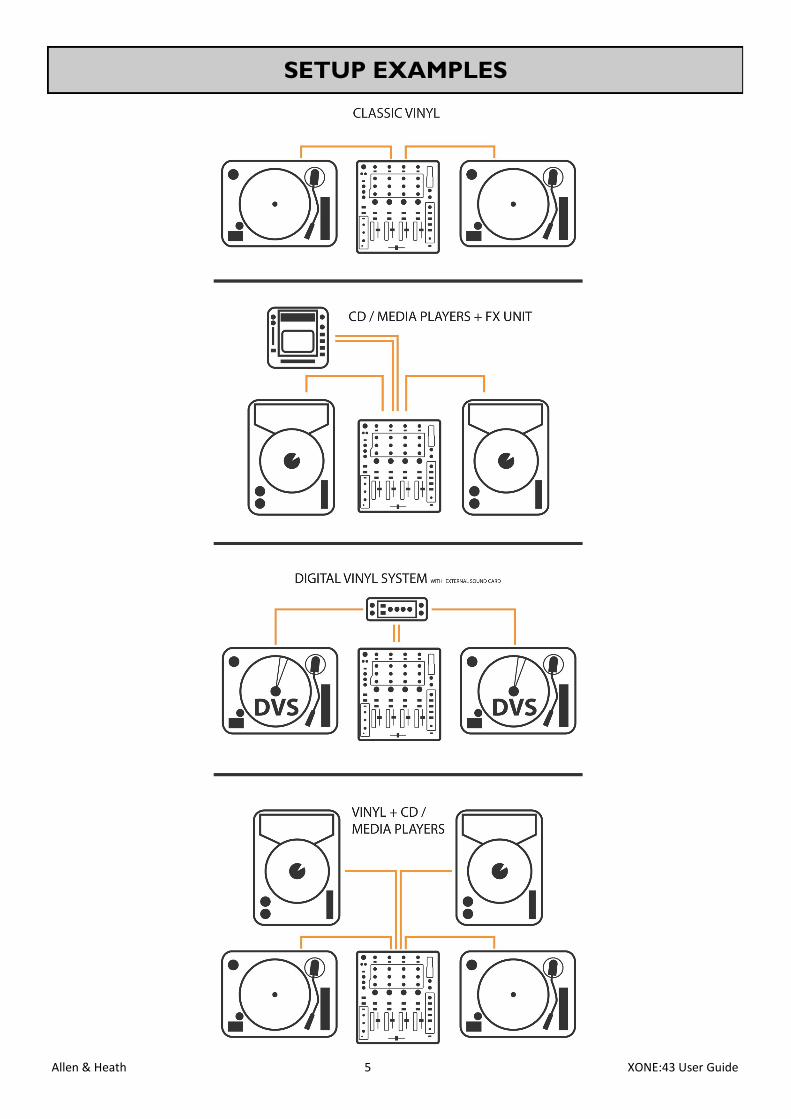
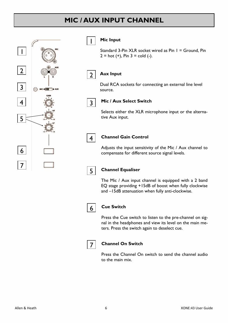
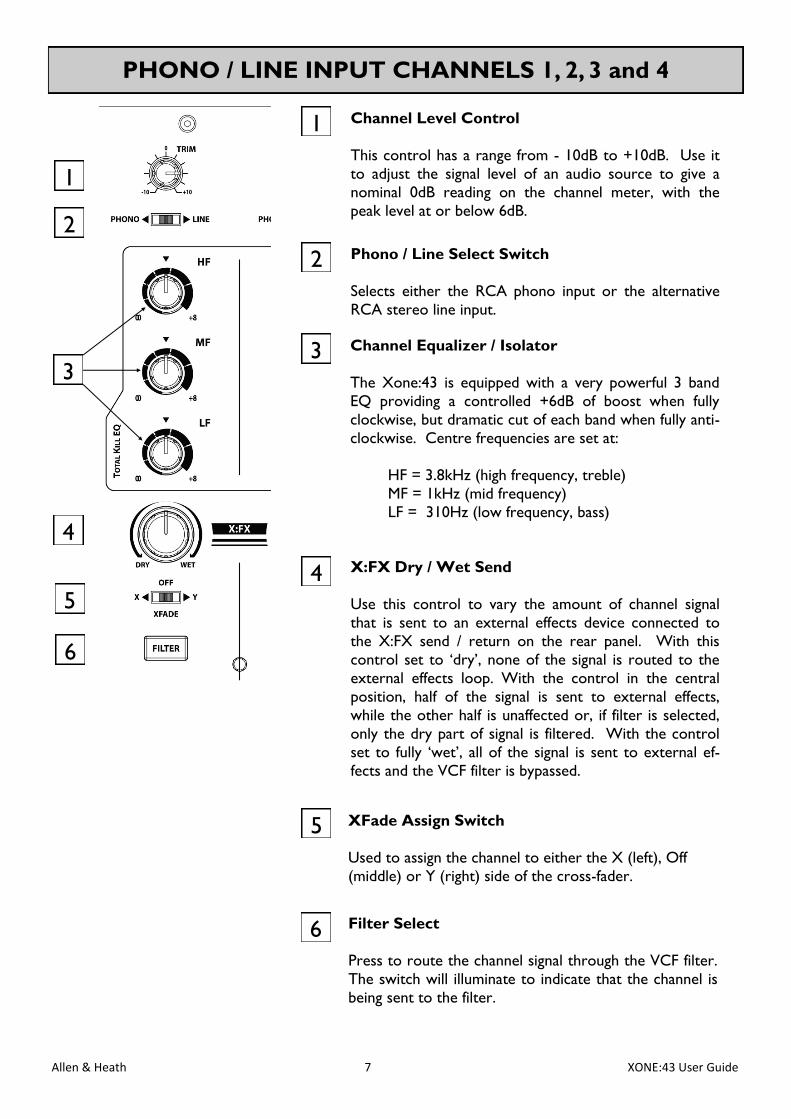
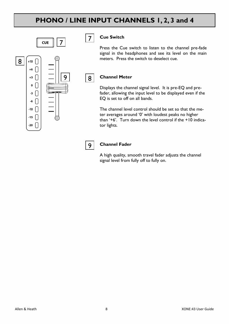
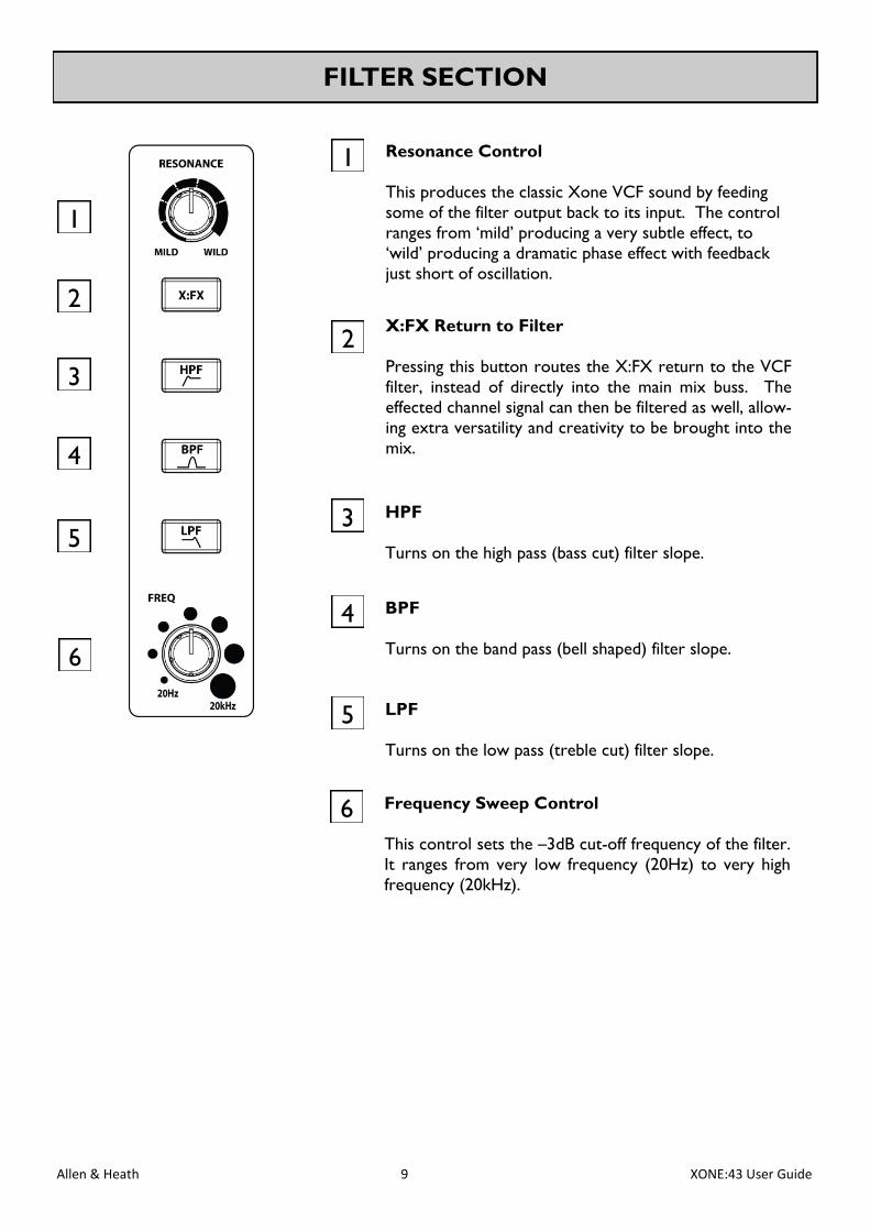
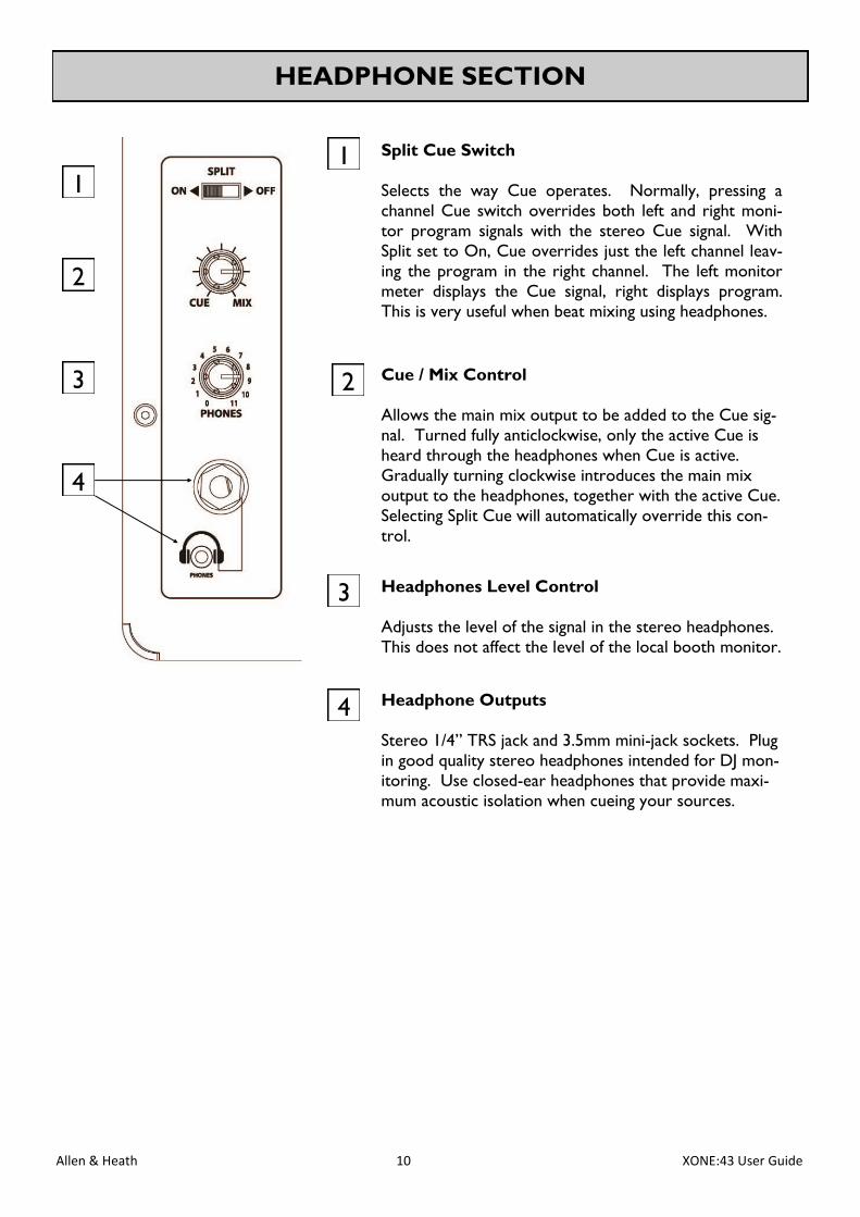
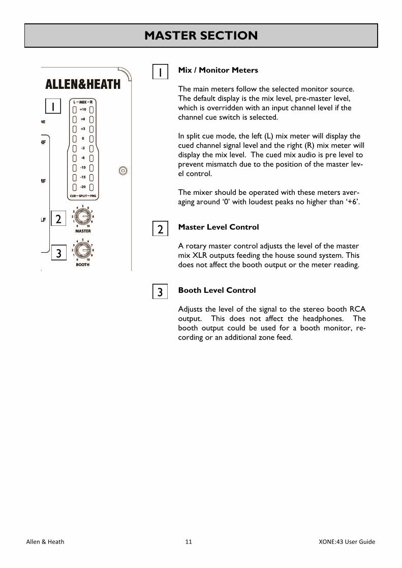
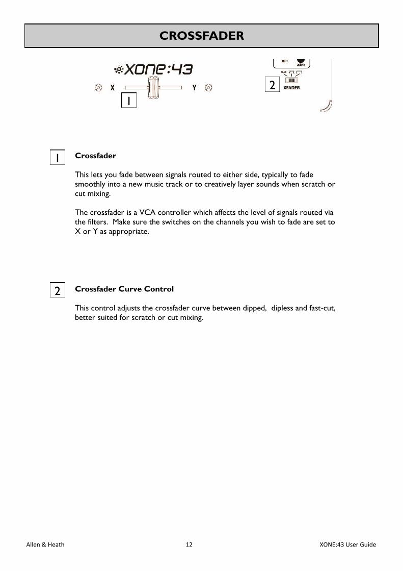
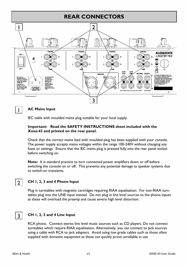
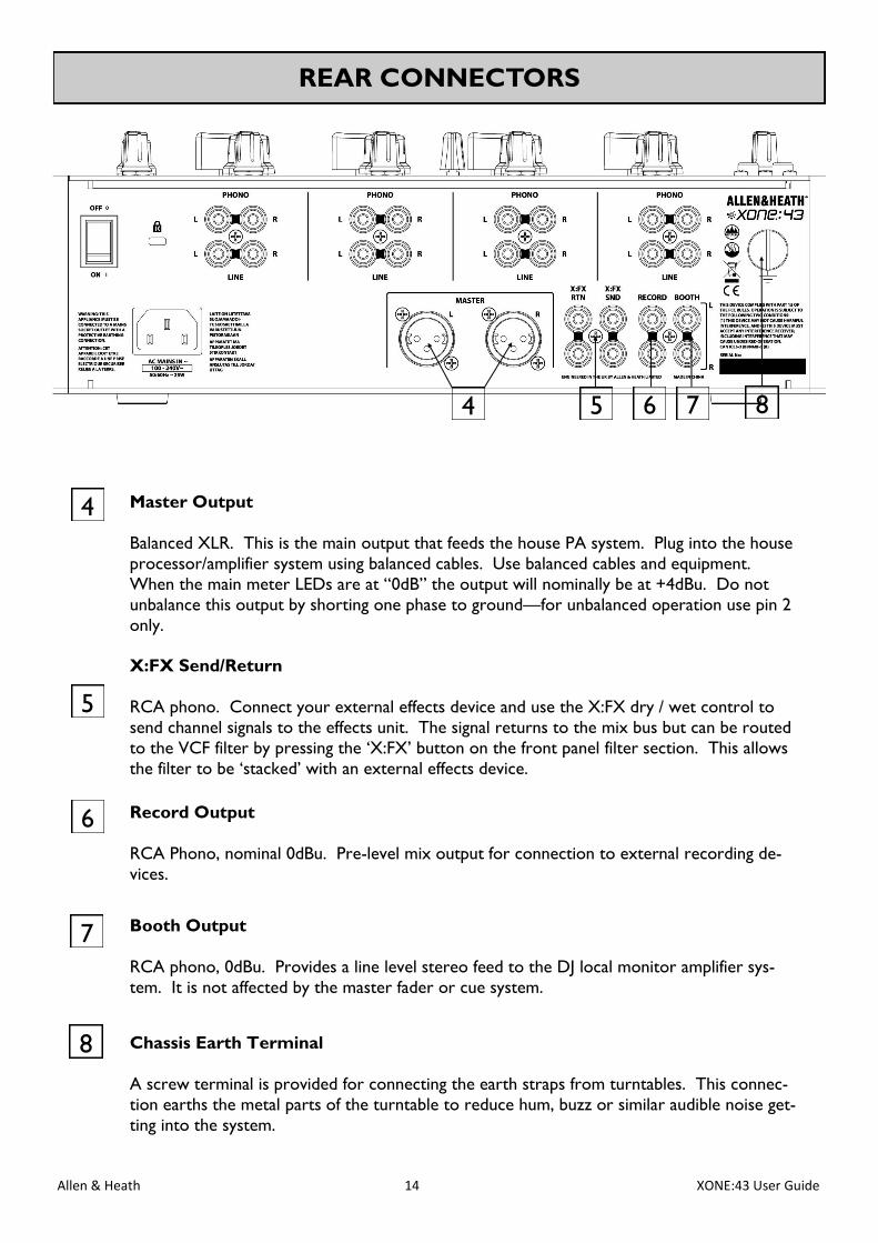
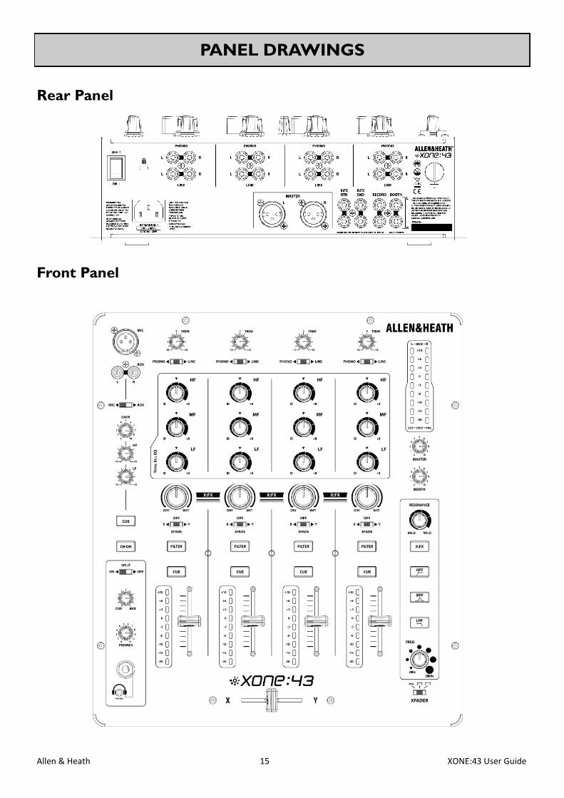
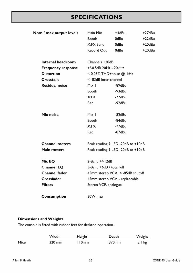
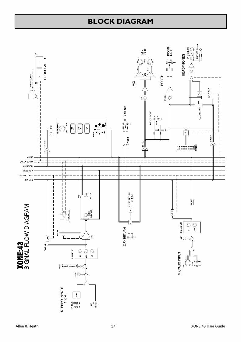
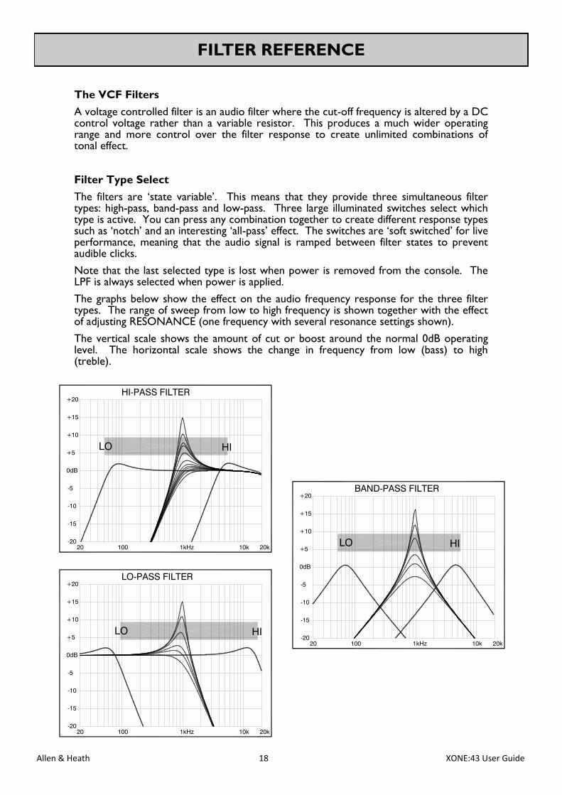
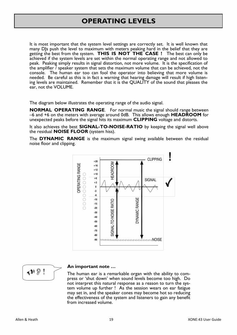
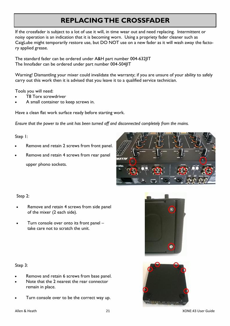
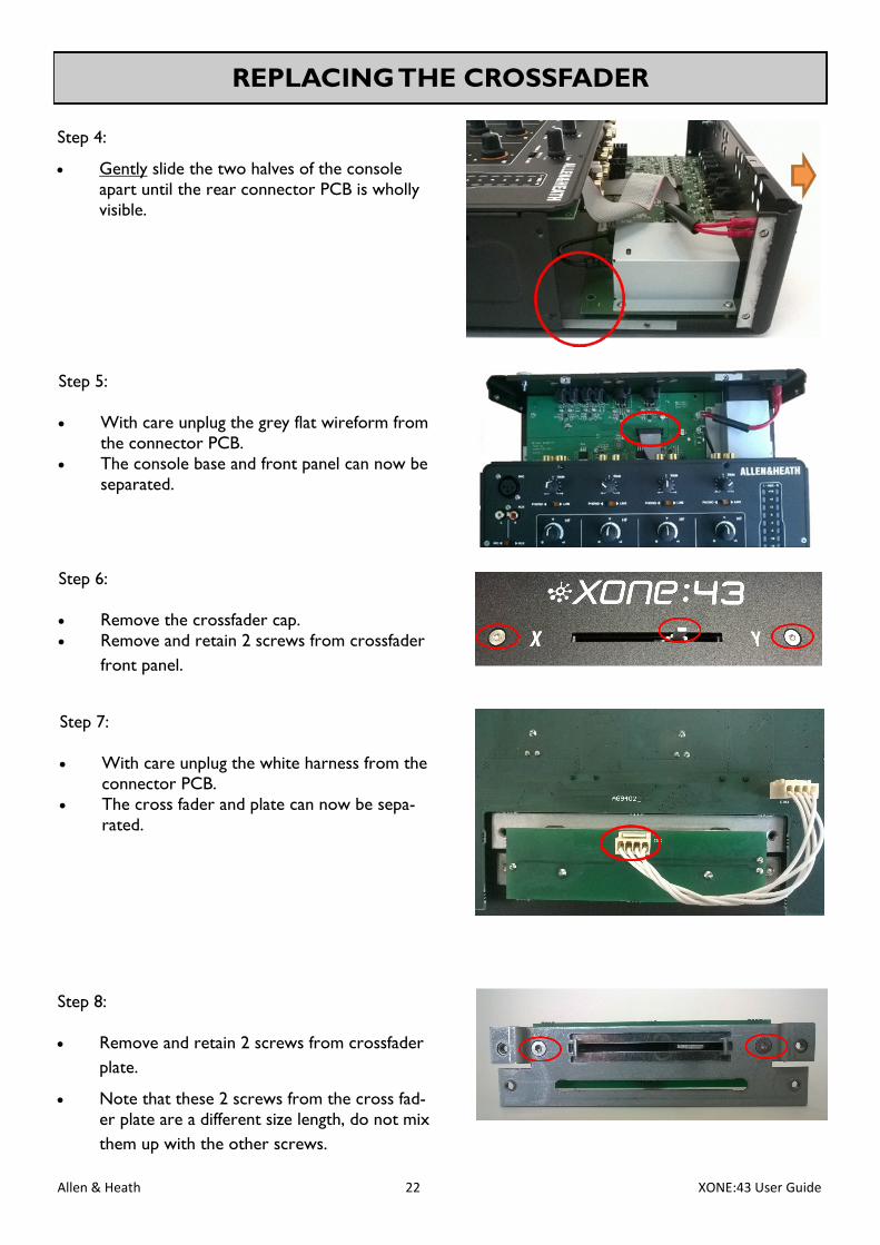
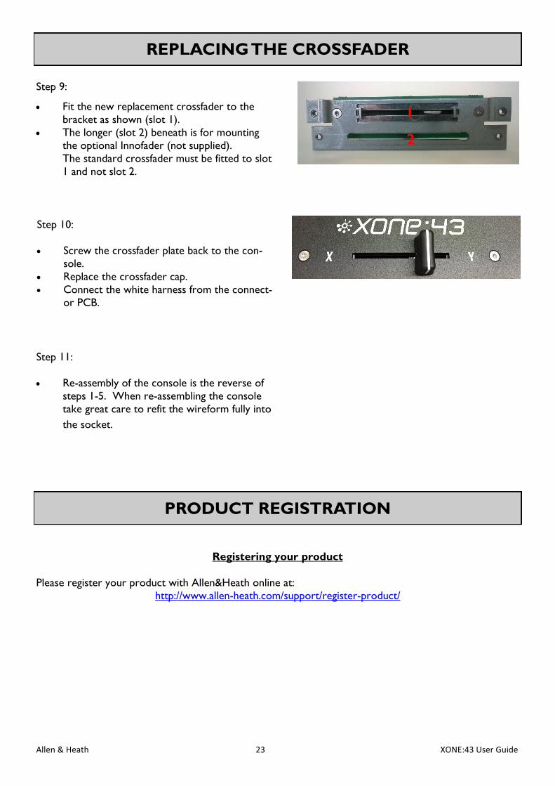


