Embed Size (px)
Citation preview


Published by National Vocational and Technical Training Commission Government of Pakistan Headquarter Plot 38, Kirthar Road, Sector H-9/4, Islamabad, Pakistan www.navttc.org Responsible Director General Skills Standard and Curricula, National Vocational and Technical Training Commission National Deputy Head, TVET Reform Support Programme, Deutsche Gesellschaft für Internationale Zusammenarbeit (GIZ) GmbH Layout & design SAP Communications Photo Credits TVET Reform Support Programme URL links Responsibility for the content of external websites linked in this publication always lies with their respective publishers. TVET Reform Support Programme expressly dissociates itself from such content. This document has been produced with the technical assistance of the TVET Reform Support Programme, which is funded by the European Union, the Embassy of the Kingdom of the Netherlands, the Federal Republic of Germany and the Royal Norwegian Embassy and has been commissioned by the German Federal Ministry for Economic Cooperation and Development (BMZ). The Deutsche Gesellschaft für Internationale Zusammenarbeit (GIZ) GmbH in close collaboration with the National Vocational and Technical Training Commission (NAVTTC) as well as provincial Technical Education and Vocational Training Authorities (TEVTAs), Punjab Vocational Training Council (PVTC), Qualification Awarding Bodies (QABs)s and private sector organizations. Document Version December, 2014 Islamabad, Pakistan


2
Table of Contents
Purpose of this Manual ............................................................................................................... 4
A. Course Introduction ......................................................................................................... 5
A1. Name of course ....................................................................................................... 5
A2. Overall objective of course ...................................................................................... 5
A3. Competencies gained after completion of course .................................................... 5
A4. Introduction of Modules ........................................................................................... 6
A5. Course Duration ...................................................................................................... 6
A6. Timeframe of assessment ....................................................................................... 7
Module-01: Describe basics of biogas generation and installation of biodigesters ............ 8
Introduction ................................................................................................................................ 9
Outline of Learning Units for Module-1 ..................................................................................... 12
Learning Units 1 ....................................................................................................................... 12
Topic-1: Introduction to Biogas Technology .............................................................................. 12
1.1 Biogas Production ................................................................................................. 12
1.2 Biogas Appliances ................................................................................................. 13
Learning Unit 2 ......................................................................................................................... 14
Topic-1: Types of Biogas Plant ................................................................................................. 14
Topic-2: Functioning of a Floating Drum Biodigester ................................................................ 17
Topic-3: Different Components of a Floating Drum Biodigester ................................................ 18
Learning Unit 3 ......................................................................................................................... 24
Topic-1: Benefits of Biodigester Technology ............................................................................. 24
Topic-2: Biogas in Pakistan .................................................................................................... 26
2.1 History of Biodigester Technology in Pakistan ....................................................... 26
2.2 Potential of Biodigesters in Pakistan ..................................................................... 27
Learning Unit 4, 5, 6 and 7 ....................................................................................................... 29
Topic-1: Concept of Drawing .................................................................................................. 29
Topic-2: Drawings of Floating Drum Biodigester .................................................................... 29
Topic-3: Drawing of Water Drain and Mixture ......................................................................... 31
Learning Units 8, 9, 10 and 11 .................................................................................................. 33
Topic-1: Selection of Biodigester Design ................................................................................ 33
Topic-2: Selection of Size of Biodigester ................................................................................ 34
Topic-3: Hydraulic Retention Time and Feeding ..................................................................... 35
Topic-4: Basic Calculation of Quantity and Cost ..................................................................... 36
Learning Units 12, 13, 14 and 15 .............................................................................................. 38
Topic-1: Quality Standards of Construction Materials and Appliances .................................... 38
Topic-2: Selection of Construction Site................................................................................... 39
Topic-3: Construction Steps ................................................................................................... 41
Self-Assessment Questions for Participants – Module-1 .......................................................... 42
Module- 02: Construct civil structural components of a floating drum biodigester .......... 43
Introduction .............................................................................................................................. 44
Outline of Learning Units for Module-2 ..................................................................................... 46
Learning Units 1, 2, 3, 4 and 5 .................................................................................................. 46
Topic-1: Layout and Construction of Digester ........................................................................... 46
1.1 Layout Works ........................................................................................................ 46
1.2 Excavation of Pit ................................................................................................... 47
1.3 Construction of Floor/Foundation of Digester ........................................................ 48
1.4 Construction of Digester Round Wall and Partition Wall ........................................ 48
Topic-2: Fabrication and Installation of Gas Holder (Floating Drum) ......................................... 49
2.1 Construction of Deflector Ledge ............................................................................ 49
2.2 Fabrication and fixing of floating drum ................................................................... 50

3
Topic-3: Construction of Inlet and Outlet Chambers ................................................................. 51
3.1. Construction of Outlet/Displacement Chamber .................................................. 51
3.2. Construction of Inlet/Mixing Tank ....................................................................... 53
Topic-4: Construction of Slurry Collection Pit ............................................................................ 54
Learning Units 6, 7, 8 and 9 ..................................................................................................... 56
Topic-1: Importance of Quality Assurance ................................................................................ 56
1.1. Rational ............................................................................................................. 56
1.2 Quality Control Process ...................................................................................... 57
Topic-2: Role of Biodigester Technicians.................................................................................. 59
Self-Assessment Questions for Participants ............................................................................. 61
Module-03: Install Pipeline, Appliances and Electro-mechanical Components ................. 62
Introduction .............................................................................................................................. 63
Outline of Learning Units for Module-3 ..................................................................................... 65
Learning Units 1, 2, 3, 4, 5 and 6 .............................................................................................. 65
Topic-1: Installation of Pipeline and Electro Mechanical Components ...................................... 65
1.1 Installation of Pipe, Fittings and Appliances ....................................................... 65
1.2. Installation of Gas Storage Tank ........................................................................ 69
1.3. Installation of Biogas Filter Unit .......................................................................... 70
Topic-2: Electric Appliances ..................................................................................................... 72
2.1. Modification of Diesel and Gasoline Engines ..................................................... 72
2.2. Electricity Generation from Biogas ..................................................................... 73
Learning Units 7 and 8 ............................................................................................................. 75
Topic-1: Role and Responsibilities of Biogas Technician .......................................................... 75
Topic-2: Occupational Health and Safety Measure ................................................................... 75
Self-Assessment Questions for Participants ............................................................................. 75
Module-4: Ensure effective operation and timely maintenance of biodigesters ................ 76
Introduction .............................................................................................................................. 77
Learning Units 1, 2 and 3 ......................................................................................................... 79
Topic-1: Operational and Maintenance of Biodigester ............................................................ 79
1.1 Checking of Gas and Water Tightness .................................................................. 79
1.2 Operational and Maintenance Activities ................................................................ 80
Topic-2: Common O & M Problems, Causes and Potential Solutions ..................................... 95
Learning Units 4, 5 and 6 ......................................................................................................... 99
Topic-1: Optimum Utilisation of Biogas and Bioslurry ............................................................. 99
1.1. Use of Biogas .................................................................................................... 99
1.2. Use of Bio-slurry .............................................................................................. 100
Learning Units 8 and 9 ........................................................................................................... 105
Topic-1: Role of Technician for Security and Safety Measures ............................................ 105
Self-Assessment Questions for Participants ........................................................................... 109
Final Assessment of Competencies........................................................................................ 110
Annexes ................................................................................................................................ 111
Annex-1: Monitoring Parameters for fixed-dome Biodigester ....................................... 112
Annex-2: Tools and Equipment ................................................................................... 114
Annex-3: Session Plan - Biogas Technicians – Floating Drum Dome Biodigesters ...... 118
Annex-4: Abbreviation used in the Text ....................................................................... 114

4
Purpose of this Manual
Different governmental and non-governmental organisations have been supporting the promotion
and extension of biodigester technology in Pakistan. More recently, The Government of Punjab has
realized that bigger size biodigesters are required to meet increasing demand in the present context
of energy crisis, especially in private cattle farms to use biogas for running irrigation pumps. The
government envisages to install 20,000 biodigester to operate pumps for irrigation. The task of
capacity building of local artisans and technicians has been given to Punjab Skill Development Fund
(PSDF).
Considering that the standardization of floating drum biodigesters is still lacking in the country, TVET
Reform Support Program envisaged an initiative with a view of standardizing floating drum
biodigesters of various capacities. The first step towards this was the formulation of competency
standards for (i) biogas technicians (ii) biogas technical supervisors and (iii) biodigester trainers,
both on fixed dome and floating drum design of biodigesters. After the approval of competency
standards, curriculum for respective trade were prepared and endorsed by National Vocational and
Technical Training Commission (NAVTTC). It is understood that in the process of building local
technical skills, Punjab Skill Development Fund (PSDF) is targeting a training programme for the
consulting companies that can initiate the process and provide services for the installation of such
technology in the country. In this context, this manual is prepared as a reference document for local
technicians (masons) to construct and operate floating drum design of biodigester efficiently.
The success or failure of any biodigester depends mainly upon the appropriateness of the design,
suitability of site for construction and quality of construction works including quality of construction
materials and workmanship involved during construction, and effectiveness of operation and
maintenance activities. This document highlights basics of biogas generation, the methods for
selecting appropriate size and site for construction; steps of construction works; as well as operation
and maintenance of biodigesters in Pakistan. This manual is prepared to assist concerned company
personal, especially the local technicians, to successfully carry out their anticipated roles in
effectively promoting and disseminating biodigester technology, constructing quality biodigesters and
ensuring effective operation. It is expected that this manual will strength capacity of biodigester
technicians in executing their anticipated tasks. This manual includes learning topics related to the
following competency standards for biodigester technicians to construct, operate and maintain
floating drum biodigesters as approved by National Vocational and Technical Training Commission
(NAVTTC).
a. Standard-1: Recall basic concepts of biogas production and benefits of biodigester technology
b. Standard 2: Read and interpret drawings of floating drum biodigesters
c. Standard 3: Select suitable type and appropriate size of floating-drum biodigester and carry out
basic calculations
d. Standard 4: Select construction materials and construction site
e. Standard 5: Construct structural component of a floating-drum biodigester
f. Standard 6: Install pipeline, appliances and electro-mechanical components
g. Standard 7: Perform routine operation and minor maintenance tasks
h. Standard 8: Practice quality norms and ensure the compliance of quality standards while
construction
This manual should be used in conjunction with the training curricula developed for biodigester
technicians by TVET Reform Support Program and approved by National Vocational and Technical
Training Commission (NAVTTC) for biodigester technicians.

5
A. Course Introduction
A1. Name of course
The title of the course is ‘Training of Biodigester Technicians (Masons) to Construct
Floating Drum Biodigester for Running Pumps’. This curriculum represents plan for the
term, and communicates expectations to the training participants, the local artisans. The course
envisages to fulfil the following competency standards:
a. Standard-1: Recall basic concepts of biogas production and benefits of biodigester
technology
b. Standard 2: Read and interpret drawings of floating drum biodigesters
c. Standard 3: Select suitable type and appropriate size of floating-drum biodigester and carry
out basic calculations
d. Standard 4: Select construction materials and construction site
e. Standard 5: Construct structural component of a floating-drum biodigester
f. Standard 6: Install pipeline, appliances and electro-mechanical components
g. Standard 7: Perform routine operation and minor maintenance tasks
h. Standard 8: Practice quality norms and ensure the compliance of quality standards while
construction
A2. Overall objective of course
The main objective of the course is to enhance the knowledge and develop the skills of local
artisans (i) to construct quality biodigesters, and (ii) to ensure continued operation of the
installed facility, so that the users are benefitted for long run. This is expected to be useful for
local artisans to gain employment as biodigester technician as specified by TEVTA and National
Vocational and Technical Training Commission. The focus of the curriculum is on construction
and after-sale-services of biodigesters to be installed in farms to run tube-well pumps for
irrigation. The following are specific objectives:
To familiarize the participants on Biogas Technology, in general, and Floating Drum
Biodigesters, in particular.
To acquaint the participants on technological aspects of floating drum biodigester, its
components and working principle.
To build skills and enhance knowledge of the participants on construction of structural
components of floating drum biodigester.
To build skills and enhance knowledge of the participants on installing pipelines, biogas-
filtration devices, and end-appliances (pumps, generators, stoves, lamps etc.).
To capacitate the participants in delivering quality services related to operation and
maintenance, quality assurance, diversification of end-use applications, and users’ training.
A3. Competencies gained after completion of course
The learning outcomes describe what participants should know, be able to do, and value by the
end of their educational program. Within this curriculum, four general dimensions of learning
outcomes are commonly identified:
(a) Knowledge outcomes, pertaining to grasp of fundamental cognitive content, core concepts
or questions, basic principles of inquiry, a broad history, and/or varied disciplinary techniques.
(b) Skills outcomes, focussing on capacity for applying basic knowledge, analyzing and
synthesizing information, assessing the value of information, communicating effectively, and

6
collaborating. (c) Attitudes and values outcomes, encompassing affective states,
personal/professional/social values, and ethical principles. (d) Behavioural outcomes, reflecting
a manifestation of knowledge, skills, and attitudes as evidenced by performance, contributions,
etc.
This curriculum envisages to equip the participants with required knowledge and underpinning
skills in all duties and tasks of different modules formulated for local technicians (masons) to
install floating drum biodigester. After the completion of the training course, the participants will
be able to: (a) explain the basics of biogas generation (b) read and interpret drawings of
biodigesters, (c) carry out construction works as per set quality standards, (d) instruct users for
effective operation and timely repair and maintenance, and (e) advice users for optimal
utilization of the products of biodigesters -biogas and bioslurry.
The following are the specific outputs expected from the training:
The participants will acquire detailed knowledge on biogas technology, its importance and
use of biodigester products (biogas and bioslurry)
The participants will have hands-on knowledge and skills on:
o Reading drawings of biodigesters
o Selection of biodigester size, construction sites and construction materials
o Plant lay-out, digging of pits and construction of foundation
o Construction of digester
o Fabrication of MS steel gas holder and fit it in position
o Construction of inlet and outlet chambers
o Laying of pipelines and installation filtration system
o Fitting of end-use-applications (stove, lamps, pumps and generators)
o Construction of slurry pits and importance of composting
o Routine operation and maintenance activities
o Quality standards on biodigester construction, operation and maintenance
The participants will know and realise the roles and responsibilities of local technicians to
install biodigester.
The participants will be able to orient/train users for ensure effective operation and routine
maintenance activities.
A4. Introduction of Modules
Module 1: Describe basics of biogas generation and installation of biodigesters
Module 2: Construct civil structural components of a floating drum biodigester
Module 3: Install pipeline, appliances and electro-mechanical components
Module 4: Ensure effective operation and timely maintenance of biodigesters
A5. Course Duration
The total duration of the training would be 192 hours divided in to:
Theoretical Sessions: 48 hours
Practical Sessions: 148 hours
Total Duration: 192 hours (24 days)

7
Session details have been given in Annex-3.
A6. Timeframe of assessment
The assessment of the trainees/participants need to be carried out during the entire process of
the training sessions and, at the end of the training sessions using appropriate assessment
methods such as oral questions, observation of on-the-job involvement, simulations, and case
studies to collect factual evidences. Methodology for assessments should be designed and
used to make sure that the participants are assessed properly and relevantly. A standard
checklist should be developed to facilitate the assessment process. Collection of evidence is
important to assess the learning outcomes. Evidences should: (a) cover core knowledge and
skills that are developed throughout the program’s curriculum, (b) involve multiple judgments of
student performance, (c) provide information on multiple dimensions of student performance.
Good evidence is also relevant, verifiable, representative or typical, cumulative, actionable, and
reflectively analyzed. The guideline for formative assessment of the learning for each module
has been described in the respective module details.

8
Module-01: Describe basics of biogas generation and installation of biodigesters

9
Introduction
a. Title: Describe basics of biogas generation and installation of biodigesters
b. Aim: The overall objective of this module is to make trainees familiar with the process of
biogas generation, importance of biodigesters and pre-requisites for installation of a floating
drum biodigester.
c. Duration: 24 hours; Theory - 16 hours; Practice - 8 hours
d. Competency Standards
The following four competency standards are covered under the framework of this module:
i. Standard-1: Recall basic concepts of biogas production and benefits of biodigester
technology
ii. Standard 2: Read and interpret drawings of floating drum biodigesters
iii. Standard 3: Select suitable type and appropriate size of floating drum biodigester and
carry out basic calculations
iv. Standard 4: Select construction materials and construction site
e. Learning Outcomes
After completion of this module the trainees will be able to:
1. Explain prerequisites for biogas generation
2. Describe types and functioning/ working of biodigesters
3. Describe benefits of biodigesters and importance of the technology in Pakistan
4. Describe the basic concepts of a drawing of an object
5. Demonstrate ability to read basic drawings
6. Demonstrate ability of interpret drawing of floating drum biodigesters
7. Read and interpret drawings of appliances, pipes and fittings and filter systems
8. Select suitable type of biodigester
9. Select suitable size of biodigester
10. Carry out basic calculations
11. Interpret the relation between HRT, quantity of feeding materials and required size of
biodigester floating drum biodigester
12. Appraise quality standards of construction materials
13. Explain criteria for selection of construction site
14. Explain steps of construction of a floating drum biodigester
f. Formative / sessional assessment at the end of Module-1
The following assessment methods should be used to gather evidence and a means of
collecting evidence for this particular module.
direct observation, for example:
o reading dimension of various components in the drawings
o work activities in a simulated workplace environment for selecting sites and
construction materials
questioning, for example:
o interviews
o self-assessment

10
o verbal questioning
o oral examinations
portfolios, for example:
o collections of work samples compiled by the candidate
o historical evidence
o information about life experience
third party feedback, for example:
o testimonials/reports from employers/supervisors
o evidence of training
o authenticated prior achievements
o interview with employer, supervisor, peer
The following assessment instruments - the documented questions/assessment activities
developed to support the selected assessment method/s used to collect the evidence of
candidate competence could therefore be used:
oral questions
observation/demonstration checklists
candidate self-assessment guides
workplace portfolios
simulation activities
definition of relevant workplace documents
evidence/observation checklists
checklists for the evaluation of work samples
The following table summarises learning units for this module and formative assessment
guidelines:
LEARNING UNIT FORMATIVE ASSESSMENT SCHEDULED
DATES
C1.1: Explain prerequisites for biogas
generation
C1.2: Describe types and functioning/
working of biodigesters
C1.3: Describe benefits of
biodigesters and importance of the
technology in Pakistan
C2.1: Describe the basic concepts of a
drawing of an object
C2.2: Demonstrate ability to read basic
drawings
C2.3: Demonstrate ability of interpret
drawing of floating drum biodigesters
C2.4: Read and interpret drawings of
appliances, pipes and fittings and filter
systems
C3.1: Select suitable type of biodigester
C3.2: Select suitable size of biodigester
a. What is biogas? How is it
generated?
b. Explain major benefits of
biogas technology in
Pakistan.
c. What do you understand by
the terms the terms ‘plan’ and
‘section’ in a drawing?
d. What are the major factors
that need to be considered
while selecting type and size
of biodigester?
e. What are the factors to be
considered while selecting
site for construction of a
biodigester?
f. What are the major
construction materials needed

11
C3.3: Carry out basic calculations
C3.4: Interpret the relation between
HRT, quantity of feeding materials and
required size of biodigester
C4.1: Name different types of
construction materials needed for
constructing a floating drum biodigester
C4.2: Appraise quality standards of
construction materials
C4.3: Explain criteria for selection of
construction site
C4.4: Explain steps of construction of a
floating drum biodigester
to construct floating drum
biodigester?
g. Describe the steps of
construction of a floating drum
biodigesters in sequential
order.

12
Outline of Learning Units for Module-1
Learning Units 1
Unit 1 - C1.1: Explain prerequisites for biogas generation
Topic-1: Introduction to Biogas Technology
1.1 Biogas Production
Biogas is produced by bacteria during digestion or fermentation of organic matter under airless
condition (anaerobic process). The gas consists mainly of methane (CH4) and carbon-di-oxide
(CO2). This mixture of gases is combustible if the methane content is more than 50%. Biogas
from animal dung contains approximately 60% methane.
Biogas Technology includes everything which is needed to produce and utilize the products of
anaerobic digestion which are biogas and bioslurry. Beside energy and fertilizer, other benefits
of biogas technology are improved sanitation and environmental protection. The general
conditions to produce biogas are:
digestable substrate, i.e. organic matter plus water
a vessel where the substrate is not in contact with air
a digestion temperature between 15ºC and 40°C
a retention time longer than 30 days to allow the bacteria to produce the biogas. (The
retention time is considerably reduced in industrial high-tech plants).
If methane producing bacteria are already present in the substrate (e.g. in dung from
ruminants), biogas production begins within a week depending upon the digester temperature.
At the farm site, biogas plants are daily fed and gas production is used for household purposes
such as cooking, lighting and running a small engine.
The gas production potential of a certain substrate is high when organic matter content is high
and the Carbon Nitrogen (C/N) ratio ranges from 20: 1 to 30: 1. The speed of the gas production
depends further on the physical properties of the substrate and the temperature (optimum at
35°C). Dry and fibrous material takes longer to digest than fine-structured and wet substrate.
Favoured total solid (TS) contents of the undigested substrate are between 6% and 10% which
is approximately reached if dung is mixed with an equal volume of water or urine. A healthy
digestion process shows a pH of 7.0 (neutral stage of substrate).
Gas production per unit of feeding material depends upon the Hydraulic Retention Time (HRT),
quality of feeding and the conditions inside the digester. If the daily collectable quantity of
available dung (fresh weight) is known, the gas production per day in a warm climate will
approximately correspond to the following values.
Table-1.1: Gas Production Potential
Manure Gas Production (litres) as per HRT in days Average Dung Production
by an Adult in kg/day 25 days
HRT
30 days
HRT
35 days
HRT
50 days
HRT
Cow 30 34 37 40 10-14
Buffalo 30 34 37 40 15-20
Horse 45 51 56 60 12-15
Chicken 60 65 69 70 0.05-0.07
Human Excreta 50 55 59 65 0.3-0.5

13
1.2 Biogas Appliances
Biogas Appliances are pieces of equipment for utilizing the energy of the gas. Either special
biogas appliances are used or LPG equipment is adapted to operate with biogas. Biogas is
mainly used in stoves for cooking and in gas lamps for lighting. Frequently, refrigerators and
incubators, coffee roasters, baking ovens and water heaters, chicken or piglet heaters, Power
engines for milling or generating electricity are fuelled with biogas.
The quantity of biogas needed for various appliances are given in the table below:
Table-1.2: Gas requirements for some appliances
Appliances Gas Requirement in m3/hour
Gas Burner: 5 cm 10 cm 14 cm
0.226 0.280 0.420
Mantle Lamp: Ordinary 25 watts equivalent 60 watts equivalent
0.071 0.100 0.195
Gas Refrigerator: 100 litre 170 litre 225 litre
0.053 0.067 0.078
Incubator: per m3 capacity 0.600
Gasoline engine: Per kW output Per rated kW
0.569 0.398
Diesel engine: Per kW output Per rated kW
0.700 0.563

14
Learning Unit 2
Unit 2 - C1.2: Describe types and functioning/ working of biodigesters
Topic-1: Types of Biogas Plant
There are different designs of biodigesters being in use these days. The most popular designs
are: (a) floating drum design (ii) fixed dome design, and (iii) geo-membrane design. Broadly,
they can be classified based upon type of digester, type of feeding and methods of construction
as described below:
a. Based upon type of gas holder
i. Floating Gas Holder
In 1956 the floating drum biogas plant, popularly known as KVIC (Khadi and Village Industries
Commission) Gobar Gas plant, was introduced in India. In this design, the digester chamber is
made of brick/stone masonry in cement mortar. A
mild steel drum is placed on top of the digester to
collect biogas produced in the digester. Thus, there
are two separate structures for gas production and
collection. The advantage of the floating drum
design is the constant gas pressure, which is equal
to the gasholder’s weight divided by its surface. This
means that lamps, stoves and other appliances don’t
need any further adjustments once they have been
correctly set. Another advantage is that the level the
gasholder has risen above the digester pit, is a clear
indication of the available gas.
ii. Fixed Gas holder
The fixed dome also known as Chinese model biogas plant was developed and built in China as
early as 1936. It consists of an underground
brick/stone masonry compartment
(fermentation chamber) with a dome on the
top for gas storage. In this design, the
fermentation chamber and gas holder are
combined as one unit. This design
eliminates the use of costlier mild steel gas
holder which is susceptible to corrosion. The
life of fixed dome type plant is longer (over
20 years) compared to the floating drum
design. The original Chinese model is
usually complete made out of concrete and
constructed with the help of moulds. Based on the principles of fixed dome model from China
many different designs have been made in other countries.
In fixed dome plants the gas is stored in the upper part of the rigid digester structure. Fixed
dome plants are sometimes called "Chinese" or "hydraulic" digesters. The accumulating gas
needs room and pushes part of the substrate into an outlet chamber, from where the slurry
flows back into the digester as soon as gas is released. The volume of the outlet chamber is
equal to the volume of effective gas storage. Gas pressure is created by the difference of slurry

15
levels between the inside of the digester and the outlet chamber. The level of original filling is
called the zero line. Under the airless (anaerobic) condition, biogas is produced. When the gas
valve is closed, biogas collects in the upper part of the digester, called the gas storage part. The
accumulating gas displaces part of the slurry into the outlet chamber. When the outlet chamber
is full, slurry overflows into the slurry drain for use as manure. When the main valve is opened,
the gas escapes off the gas storage part until the slurry levels inside the digester and inside the
outlet chamber balances. The gas pressure depends on the prevailing difference of the slurry
levels in digester and outlet.
iii. Balloon Type
This type of biodigesters use plastic membrane of different types to
store biogas produced in digester. These types of digesters are low-
cost, easy to install, and easy to transport into remote areas, while
yielding sufficient gas for both cooking and lighting needs. However,
the life-span of plastic bag digesters is relatively shorter depending
upon the type of plastic membrane used.
b. Based upon type of Feeding
i. Continuous Feeding
The rural household digesters are fed once a day with the proper mix of dung and water/urine
and the fresh input displaces the same volume of spent materials from the digester. Every day a
certain quantity of fresh input is fed into the digester which is expected to remain in the digester
for a prescribed retention time and produces gas over this length of time before being
discharged.
ii. Batch Feeding
In this process the whole digester is filled with raw materials for gas production along with some
starting (seed) material. This is allowed to ferment and produce gas over a certain length of time
and when gas yields become very low the digester is emptied of all the sludge which can be
supplied as manure. In this system, gas production begins at a low level and goes on increasing
only to drop down again after reaching the peak. Because of variable gas production level, high
cost and periodic emptying and filling of digesters, this process has not become popular.
Examples of these digesters are small size garbage plant and crop-residues plant.
iii. Semi-batch /continuous Feeding
A combination of batch-fed and continuous fed digestion is known semi-batch or semi-
continuous digestion. Such a digestion system is used where the waste like garbage etc., which
are available on daily or weekly basis but cannot be reduced to make slurry. In the semi-batch
system, the animal manure can be added on a daily basis after the initial loading is done with
garbage, agricultural waste, leaves, crop residence and water hyacinth etc.
Likewise, based upon the methods of installation biogas plants could be classified as Pre-
fabricated model and constructed in site model. Another classification could be domestic biogas
plants and institutional or community biogas plants based upon the ownership of biogas plants.
The following are some of the models being used in different parts of the world.

16
Flooding drum model (India) Floating drum Model (Nepal) Janatha Fixed Dome (India)
KT 1 Fixed Dome, Vietnam Chinese Fixed Dome Plastic Bag digester
GGC Model (Nepal, Laos, Rwanda, Ethiopia) Deenbandhu Fixed Dome, India
CAMARTEC and Modified CAMARTEC Biogas Plants – Tanzania, Rwanda, Ethiopia

17
Vacvina Digester, Vietnam Bangladesh IDCOL Model
Prefab fibre reinforced - China Steel Digester – Indonesia
Topic-2: Functioning of a Floating Drum Biodigester
The floating drum plant, comprises an inlet tank, closed cylindrical digester with a moving gas
holder on the top and a small outlet tank. The gas is stored in the movable gas storage tank
constructed of MS drum or fibre-glass drum or high density poly-ethylene drum. The weight of
the drum or any added weight over the dome develops pressure and pushes the slurry into the
compensating tank. When the gas is extracted, a proportional amount of the slurry flows back
into the digester. The movable gas hoder moves up and down depending upon the quanity of
gas it contains.
Biogas appliances are usually designed to operate optimally for a gas pressure of 70 to 90 cm
of water column. This
pressure is provided by the
weight of the MS drum
pressing on the area it
covers which is its cross
sectional area. Additional
weight can be put on top of
drum if the pressure is too
low. The pressure from any
drum of known weight is obtained by:
Gas pressure in mm water column = weight of drum in kg/cross sectional area in m2
If the pressure is too low and additional weight is needed to be put, the needed weight can be
calculated as,
Needed weight in kg = cross sectional area in m2/required increase in pressure in mm water
column.

18
Topic-3: Different Components of a Floating Biodigester
The typical floating drum biodigester mainly consists of (i) structural components (ii) biogas
conveyance system (iii) filtration
systems, and (iv) end-use
applications.
The structural component of
biodigester consists of the following
sub components: (i) inlet and mixing
tank with mixing device (ii) digester
or fermentation chamber (iii) gas
holder or gas storage tank (v) outlet
or displacement chamber, and, (vi)
bioslurry collection and composting
pits. Likewise, the conveyance
system in the biodigester consists of:
(i) control/regulating valves (ii) gas
pipeline (iv) fittings (v) pressure gauge (vi) gas flow meter (vii) thermocouple or temperature
sensors, and (viii) water outlet or water drain. The filter system comprises of (i) CO2 scrubber
(ii) Moisture filter and (iii) H2S remover. These filter systems are also fitted with pressure gauges
and indicators. The biogas end use applications consists of various appliances as per the
need of the users, such as (i) biogas stoves (ii) biogas lamps (iii) pumps and generators.
The mix of dung and water (mixed in inlet or mixing chamber) passes through the inlet pipe to
the digester. Gas produces in the digester because of the microbial activities and the produced
gas is stored in the gas holder (MS Drum). The digested slurry passes out from digester to
outlet tank (displacement chamber) and flows out to the compost pits through overflow opening
in the outlet tank. The gas is then supplied to the point of application through the pipe line. A
filter system is installed along the pipeline to clean the biogas if the gas is to be used for running
an engine. The biodigester generally consists of the following components as shown in the
drawings below:
The following section briefly describes the functions of these components:
(a) Inlet/Mixing Chamber

19
Mixing chamber is the first structural component of a biogas plant. Construction of this chamber
is optional as mixing can also be carried out in the inlet. However it strictly depends on the
construction site whether a separate mixing chamber is required or not. Mixing chamber is
constructed when it is not feasible to transport manure and water directly to the inlet due to
distance or and other prohibiting factors. A 50 m3 biodigester requires a daily input of 400-500
KG of cattle dung that has to be mixed with equal volume of water.
The manure inlet is meant for daily feeding of plant according to its requirement based on
calculated retention time. Inlet is designed according to the feed size of digester in order to
reduce the human error as well as increases the efficiency of gas production. Mixing device is
used to prepare good quality water-dung solution in the inlet tank when cattle dung is used as
feeding material. Usually for household biogas digesters, vertical mixing devices are installed
and for bigger plants horizontal devices are used. A small electric motor of 1 HP could be fitted
to facilitate the mixing. The device should be of good quality, as per the design, and the mixing
blades have to be well galvanised. The blade should be properly aligned for the effective
mixing.
(b) Digester/Digestion Chamber
Digester is the place where anaerobic fermentation takes place and biogas is produced by the
microbes in the absence of oxygen. The feeding (dung-water mix) remains in digester for 40-50
days (its retention time). The digested slurry leaves this chamber through an outlet pipe fitted in
the wall of the digester.
(c) Gas Holder
Biogas produced in the digester is stored in the movable
gas holder made up of MS drum or fibre glass drum or
HDPE tank which is fitted on the top of digester. Gas holder
is generally constructed of mild steel plain sheets of 2-3
mm thickness. The gas holder is fitted with the main gas
pipe to facilitate the flow of biogas to pint of application.
TVET RSP does not secure copyright of these pictures

20
(d) Outlet tank or Displacement Chamber
The digester slurry from the digester passes through the outlet
pipe and gets collected in the outlet tank which is also known as
displacement chamber. The shape of outlet tank could both be
rectangular or circular as shown in the picture below:
(e) Bioslurry Pit/Composting Pits
The fully digested light weight slurry that comes out of outlet tank
is collected in bioslurry pits. This slurry is ready-to-use as fertilizer for the crops as pure organic
fertilizer having high ratios of NPK. Sometimes bioslurry is directly conveyed to the point of
application via pipes or irrigation channel without constructing bioslurry collection pits.
f. Pressure gauge/pressure meter
The gauge is installed at the top of gas holder to measure the pressure of the gas inside the gas
holder. U-shaped pressure gauge (manometer) made up-of a transparent plastic or glass tube
and filled with coloured water or a clock-type digital or analogue pressure meter could be
installed in the conveyance system to monitor the pressure of gas. Whatever may be the type
this device should best among those available in the local market and should meet set quality
standards, if any. Biogas plant Construction Company (BCC) has to train the plant operator
regarding the usage of gas according to the reading of pressure gauge.
g. Thermometer/Temperature Gauge
Thermocouple type temperature sensor is installed to measure the inside temperature of the
digester which is indicated on the temperature gauge installed at a suitable place on the plant.
Suitable temperature for the efficient production of biogas is between 20-35 Co .A variation in
the inside temperature can cause loss of gas, hence the operator is trained to ensure the ideal
temperature inside the digester

21
h. Biogas Flow Meter
The flow meter provides reading of the gas that has been produced by the plant and used/
stored in a gas storage tank. BCC should train the plant operator to notice the flow of this meter
and assure the gas is being produced at optimum level, and to take measures in case gas flow
is not up to the standards. In case the gas is being stored in a tank, the operator must switch
OFF the compressor when the pressure on indicated on the pressure gauge reaches a certain
level. This is mandatory to avoid the slurry flow into the gas line.
i. Safety Valve/Main Valve
This is the main valve installed on top of the gas holder to handle the gas according to the
pressure shown by the pressure gauge. Biotech trains the plant operator on handling the safety
valve according to gas pressure.
It controls the flow of biogas in the pipeline from the gas holder. It is opened when gas is to be
used and closed after each use. If substandard quality of main gas valve is used, there is
always risk of gas leakage. This valve should be of high quality and approved by the concerned
quality control authorities.

22
j. Pipes and fittings
The pipe to be used to convey gas from gas holder to the point of application should conform to
quality specification as per the standard. Light quality
Galvanized Iron pipe is best suited for this purpose;
however, high quality PVC pipe could also be used. The
pipe should be of at least half inch diameter. For length of
more than 60 m (30 m if two burners are to be used at a
time), ¾” diameter pipe has to be used. If GI pipe is to be
used, a six meter pipe should weigh at least 6 kg. The
fittings used in the pipeline of a biogas plants are socket,
elbow, tee and nipples. These fitting should meet the
required quality standards.
k. Water Outlet
It drains the water condensed inside the pipeline when biogas comes in contact with the cool
pipe. This is an important component of biodigester and therefore,
its quality should carefully be controlled. It should be easy to operate
and threads in it should be perfect. It should be ensured that the
hole in the screw nut is bored properly and is located at the right
place. The thickness of the nylon washer has to be 4mm and either
a 4 cm long handle pin or a properly knurled opener should be used.
This appliance should be approved by the concerned authorities. Water drains are installed in
domestic biodigesters, however, for institutional and commercial biodigesters to be used for
electricity generation, moisture filter has to be installed.
l. Gas Tap
Gas tap is used for regulating flow of gas to the gas stove. Care should be
taken to install gas tap of high quality. It has been often complained by the
users that this taps are becoming problematic with gas leakage through them.
It is important that the ‘o’ ring is placed properly and is greased thoroughly and
regularly. The gas tap should not be too tight or loose to operate. The taps to be
used in biodigesters should be approved by concerned quality control authority.
m. Rubber Hose Pipe
It is used to convey gas from the gas tap to the stove. This pipe
should be made up of high quality neoprene rubber and should not
develop cracks when folded. It should have 15 mm outer and 9
mm inner diameters. The minimum wall thickness of the pipe
should be 2.5 mm.
n. Gas Stove
Gas stoves can be found with single and double burners. In
general a single burner gas stove used for household purpose
consumes 350 to 400 litre of gas per hour. The efficiency of gas
stove is very important for the successful functioning of the
biodigester. The stove should be of good quality and strong
enough to firmly rest in ground. The primary air intake should be
easily adjustable and the holes should be properly placed. The

23
jet and pipe leading to the burner should be straight and aligned properly. The holes in the
burner cap should be evenly spread across it.
o. Gas Lamp
Gas lamp is another important appliances used in biodigesters. Often
users complain about the malfunctioning of these lamps. These lamps
should be of high quality with efficiency more than 60%. Usually, a biogas
lamp consumes 150 to 175 litres of biogas per hour. Lamps to be used in
biodigesters have to be approved by the concerned quality control
authority.
p. Filter Systems
To use biogas for operating an engine, carbon-di-oxide (CO2), hydrogen sulphide (H2S) and
moisture should be removed from biogas. For these purposes, filters are fabricated and
installed along the pipeline. There are three main filter units commonly called as: (a) CO2
scrubber/washer (b) H2S filter and (c) moisture absorber.
q. Biogas Engines
Biogas can be used in both CI (compression ignition) engines and SI (spark ignition) engines. In
other words, biogas can be used to run either gasoline generators or Diesel (Petter) Engine
coupled with an induction motor as shown in the following pictures. The self-ignition
temperature of biogas is high and hence it resists auto ignition, this is desirable feature in spark
ignition engines, as it will reduce the chances of knock. SI engine conversion to biogas fuelling
involves some engine modifications.
TVET RSP does not secure copyright of these pictures

24
Learning Unit 3
Unit-3: C1.3 - Describe benefits of biodigesters and importance of the technology in Pakistan
Topic-1: Benefits of Biodigester Technology
Biogas Technology has a very significant role to play in integrated agricultural operations, rural
sanitation, dairy farms & sewage disposal etc. It is estimated that cattle dung, when passed
through a biodigester, yields 30-40% more net energy and about 35-45% more Nitrogen in
manure as compared with that obtained by burning dung cakes and ordinarily prepared
compost, respectively. Besides, from a biogas plant both the products are obtained. The
following are major benefits:
The Biogas plant converts cattle dung into two useful products viz.: inflammable gas
(biogas) and good quality manure.
Biogas provides a smokeless high efficiency fuel for cooking, lighting and motive power.
The manure obtained from biogas plant has higher nutritive value as compared to that of
ordinary farmyard manure.
Biodigesters keep the household and surroundings clean.
Biodigesters prevent deforestation.
Biodigesters control environmental pollution and promote public health.
On an average, a biogas plant serving a household of 5 or 6 people generates the following,
main benefits:
Reduction of workload: 1.5 to 3 hours/day
Saving of traditional cooking fuel such as firewood: 3,000 to 4,000 kg/year
Reduction of greenhouse gasses: up to 6.0 ton of CO2 equivalent/year
Reduction of indoor air pollution: 3 persons/household are less exposed
Toilet attachment: Improvement in household sanitation and health conditions
Potential increase of agricultural production or saving on the use of chemical fertiliser
(biogas plants produce high quality organic fertilizer–bio-slurry): up to 40%
Improved sanitation, less pollution to underground water

25
One Cum of Biogas generates 5000 to 6000 kcal of heat which is enough for:
Replacing 4-5 kg of firewood
Replacing 0.6 to 0.7 litre of kerosene
Replacing 1.6 kg of charcoal
Replacing 0.45 kg of LPG
Burning stove for 2.5-3 hours
Burning lamp for 5-6 hours
Run 1hp engine for about 2 hours
Therefore biogas plant provides multifaceted benefits.
Some of the economic, health, environmental and social
benefits at households as well as community level have
been described below:
a. Economic Benefits
o Saving of expenditures on fuel sources
o Saving time to utilize in other income generation activities
o Enhanced soil productivity because of the use of bio-slurry (added N,P,K values)
o Reduction in the needed quantity of chemical fertilizers, due to the use of bio-slurry
o Reduction on health expenditures due to a decrease in smoke-borne diseases
o Local employment creation
o Private sector development that produces economic goods
o Livestock development
o Income generation through selling of carbon credits (CERs and VERs)
b. Health Benefits
o Reduction in smoke-borne diseases (headache, dizziness, eye-burning/infection, respiratory
tract-infection, etc.)
o Improved household sanitation due to attaching of latrines to bio-digesters, absence of
sooth, ashes and firewood in the kitchen
o Decrease in burning accidents
c. Environmental Benefits
o Preservation of forest
o Increase in soil productivity due to added NPK by using slurry and agricultural residues
o Reduction in green-house gases, especially methane
o Prevention of land-fertility degradation due to the excessive use of chemical fertilizers
d. Social Benefits
o Extra time for social activities
o Enhanced prestige in the community
o Workload reduction (less time spent on firewood collection and cooking)
o Bright light to help in quality education and household works

26
Topic-2: Biogas in Pakistan
2.1 History of Biodigester Technology in Pakistan
The history of biogas technology in Pakistan is about 40 years old. Around six thousand
digesters were reportedly been installed across the country till the end of 2010 as against the
technical potential of about five million digesters based on its suitable climate and availability of
feedstock, the cattle dung.
The Government of Pakistan started a comprehensive biogas scheme in 1974 and
commissioned 4,137 biogas units by 1987 throughout the country. These were large floating
drum biogas plants with capacity varying from 5-15 cubic meters gas production per day. This
programme was implemented in three phases. During the first phase, 100 demonstration units
were installed under grant by the government. During the second phase, the cost of the biogas
was shared between the beneficiaries and the government. In a subsequent third phase, the
government withdrew financial support for the biogas plants, although technical support
continued to be provided free of cost. Unfortunately, after the withdrawal of the government
financial support, the project did not progress any further (World Energy Council).
The Pakistan Centre for Renewable Energy Technologies (PCRET) is the leader in the country
to disseminate biogas technology and has supported installation of around 1600 biogas plants
till the end of 2006. In addition to these 1600 household biogas plants it has installed, PCRET
has plans to install another 2,500 plants by 2008 for which Government of Pakistan has
approved financial support.
The Initiative for Rural and Sustainable Development (IRSD), an NGO, has installed around 150
biogas plants with support from the UNDP Small Grants Program. Some Regional Support
Programmes and NGOs have also included biogas among the projects they support. The NGO
‘Koshis’ in Sialkot, Punjab has reportedly helped villagers to build over 200 biogas plants.
Another NGO Green Circle Organization is building community based plants with funding from
the Pakistan Poverty Alleviation Fund. Most NGOs received technical assistance from PCRET
in the design of their plants. With some exceptions most plants are still installed on a pilot basis
and have not been promoted commercially to any large scale.
Most of the biogas plants installed in recent years have been smaller household designs (3 to 5
m3 gas production per day) compared to the larger plants in the 1970s and 1980s. The biogas
technology most commonly used in Pakistan is the floating drum design. Another design,
Chinese fixed-dome design, was reported to be installed on a pilot basis but was reportedly not
successful. The Chinese design pilot biogas plants apparently showed persistent leakage and
seepage problems and moreover the gas pressure was reported to be low.
TVET RSP does not secure copyright of these pictures

27
Twelve fixed-dome ‘Nepalese design’ biogas plants of Model GGC 2047 of 6m3 were installed in
tehsil Pasrur of Sialkot District in partnership with the Punjab Rural Support Program (PRSP)
and four plants of the same design were installed in sizes 8 (2 nos.), 20 and 35 m3 in Dera
Ismail Khan in partnership with the Foundation for Integrated Development Action (FIDA) by the
Rural Support Programme-Network (RSPN) in June of 2007. FIDA was reported to have plans
to continue supports to install biogas plants in its working areas.
Rural Support Program Network with Support from SNV Netherlands Development Organisation
commenced Pakistan Domestic Biogas Program (PDBP) in 2009. A total of 5000 biogas plants
have reportedly been installed in different districts in Punjab till the end of 2013.
Other organisations such as WINROCK International is supporting the installation of medium
scale biodigesters in dairy farms.
2.2 Potential of Biodigesters in Pakistan
Biogas dissemination requires definite background conditions for its success. The reality of a
location will be shown by favourable and unfavourable factors. It is the job of the programme
personal to judge this mixture in favour of or against possible biogas dissemination.
Following, are the criteria which make biogas dissemination impossible or more difficult. The
ideal project location will rarely be found. The "ideal conditions" stated are to make the
individual factors clearer.
a. Excluding factors
If only one of the following criteria is evident, then the dissemination of simple household biogas
plants is not possible (As an exception, suitable farms in the region could allow individual
measures under some circumstances.)
o too cold or too dry region
o very irregular or no gas demand
o less than 20 kg dung/day available to fill the plant or less than 1,000 kg live weight of
animals per household in indoor stabling or 2,000 in night stabling.
o no stabling or livestock in large pens where the dung cannot be collected
o no building materials available locally
o no water available
o integration of the biogas plant into the household and farm routines not possible
o no suitable institution can be found for dissemination
b. Critical factors
Each of the following factors will lead to great problems in biogas dissemination. Accompanying
measures, particularly modified technical developments, high financial promotion or additional
organisation structures within the dissemination programme are necessary to guarantee project
success.
o low income or unstable economic situation of the target group
o unfavourable macro and microeconomic coefficients
o gas appliances not available regionally or nationally
o irregular gas demand

28
o very good supply of energy throughout the year and simultaneously only moderate
economic coefficients for the biogas plant
o high building costs
o low qualification of artisans
o counterpart organisation has only indirect access to the target group
o weak structure of the counterpart
o no substantial interest of the government is evident over the medium term
o low regional or national potential
c. Ideal conditions
If each of the following conditions is fulfilled then household biogas plants will definitely get a
foothold. A dissemination programme is then expressly recommended:
o even, daily temperatures over 20°C throughout the year
o regular gas demand approximately corresponding to gas production
o full stabling of animals (on solid floors as far as possible)
o at least 30 kg/day dung available per plant
o dairy farming
o use of organic fertiliser is normal
o farmers are owners of the farm system and primarily of the farm
o plants can be located in favourable positions to the stables and to the point of gas
consumption
o the biogas plant can be integrated into the normal working routine in the house and on
the farm
o gas utilisation and attendance of the plant can be clearly regulated within the household
o low price of plant in relation to the income of the target group
o favourable economic coefficients for the biogas plant
o economically healthy farms open to modernisation
o insufficient supply of fossil sources of energy
o building materials and gas appliances available locally
o qualified artisans locally
o counterpart organisation has access to and experience in contact with the target group
o efficient counterpart organisations with the possibility of cooperating with the private
sector
o counterpart organisation has experience in programmes comparable to biogas
dissemination
o political will on the part of the government towards not only biogas technology but also
towards strengthening small and medium-scale farm systems
o secured financing of the dissemination structure
Based upon the detailed market study carried out by SNV/Winrock, Pakistan has the potential of
5,000,000 biogas plants across the country.

29
Learning Unit 4, 5, 6 and 7
Unit 4 - C2.1: Describe the basic concepts of a drawing of an object
Unit 5 - C2.2: Demonstrate ability to read basic drawings
Unit 6 - C2.3: Demonstrate ability of interpret drawing of floating drum biodigesters
Unit 7 - C2.4: Read and interpret drawings of appliances, pipes and fittings and filter systems
Topic-1: Concept of Drawing
Since earlier times, people have used drawings to communicate and record ideas so that they
would not be forgotten. The earliest forms of writing, such as the Egyptian hieroglyphics, were in
illustrative/graphic form. The word graphic means dealing with the expression of ideas by lines
or marks impressed on a surface. A drawing is a graphic representation of a real thing. Drawing
therefore is a graphic language, because it uses pictures to communicate thoughts and ideas.
Because these pictures are understood by people of different kinds, drawing is referred to as a
“universal language.” Artistic drawing is concerned mainly with the expression of real or
imagined ideas whereas technical drawing is concerned with the expression of technical ideas
or ideas of a practical nature, and it is the method used in all branches of technical industry.
There are four different types of projections when it comes to technical drawings; 1.
Orthographic Projection, 2. Isometric Projection, 3. Oblique Projection and 4. Perspective
Projection. The most used projection in the technical drawing is the Orthographic Projection.
Orthographic Projection must contain three dimensions; length, width and depth or height. In
order to include all the required three dimensions, an Orthographic Projection contains two
views: Plan View and Section view. Plan view provides the length and width of the subject while
section view provides the depth or height.
Orthographic Projection Isometric Projection Oblique Projection Perspective
Projection
Such technical drawing will only be considered complete when all the dimensions are indicated
in the drawn subject, since without dimensions the subject cannot be constructed in the correct
proportion. The lines that indicate measurements of the subject in the drawing are called
dimension lines. Dimension lines can be drawn in different styles such as:
Topic-2: Drawings of Floating Drum Biodigester
The following pictures show sectional view and isometric view of a floating drum biodigester.

30
Drawings and dimensions of different sizes of floating drum biodigesters are given below:

31
Topic-3: Drawing of Water Drain and Mixture
While constructing floating drum biodigesters, there is need to understand drawings of various
components such as inlet and mixing arrangement, and water drain arrangement. The drawings
of these components are given below:

32
Inlet – Mixing Arrangement

33
Learning Units 8, 9, 10 and 11
Unit 8 - C3.1: Select suitable type of biodigester
Unit 9 - C3.2: Select suitable size of biodigester
Unit 10 - C3.3: Carry out basic calculations
Unit 11 - C3.4: Interpret the relation between HRT, quantity of feeding materials and required
size of biodigester
Topic-1: Selection of Biodigester Design
To successfully achieve anticipated objectives of any biogas programme, it is imperative that
the best suited model/design of biogas plant is selected for the wide-scale dissemination.
Varieties of models/designs of biogas plants are being used in different countries in the world
with successful track records. The following factors should be considered to evaluate the
suitability of biodigester assuming that the adaptability of any biogas plant in a given context
depends mainly upon these factors.
a. Climatic and geo-physical parameters
Ambient temperature
Geo-physical conditions of the soil
Condition of ground water-table
b. Technological Parameters
Structural strength against different load conditions (structural durability)
Methods of construction/supervision
Time and effort in quality control
Methods of operation and maintenance
Applicability/adoptability of the design in different geographical context for mass
dissemination
Prospects for sharing of technical information and know-how
c. Affordability of potential farmers to install biogas plant
Availability of construction materials
Availability of human resources (skilled and unskilled) at the local level
Cost of installation, operation and maintenance
Transportation facilities
d. Purpose of the use of the products from biogas plant
Use of gas for cooking, lighting and/or operating a dual-fuel engine
Use of slurry as organic fertiliser
e. Performance of existing models, if any, in the local and/or regional conditions
Existing physical status and functioning
User's level of satisfaction
f. Quality and quantity of available feeding materials
Type of feeding materials (cattle dung, human excreta etc.)
Availability of water for mixing
No. of cattle per household
Keeping in view the above factor floating drum biodigesters could be one of the options to be
disseminated in Pakistan. There are different models of floating drum biodigesters being
disseminated in different countries across the world. Based upon the performance of the
existing plants and experiences from other biogas countries, attempts should be made to select

34
the best model for the wide-scale dissemination of the biogas technology in the country. The
following are some of the designs of floating drum biodigesters:
The floating drum plant, comprises an inlet tank, closed cylindrical digester with a moving gas
holder on the top and a small outlet tank. The gas is stored in the movable gas storage tank
constructed of MS drum or fibre-glass drum or high density poly-ethylene drum. The weight of
the drum or any added weight over the dome develops pressure and pushes the slurry into the
compensating tank. When the gas is extracted, a proportional amount of the slurry flows back
into the digester. The movable gas hoder moves up and down depending upon the quanity of
gas it contains.
Topic-2: Selection of Size of Biodigester
A number of factors need to be considered while determining the size of biodigesters. Main
factors are listed below:
a) Number of cattle heads,
b) Type and size of livestock,
c) Livestock feeding practice
d) Type of cattle shed (ease in collection)
e) Livestock grazing practice (open-grazed or stall-fed),
f) Gas Demand (in case of plenty of cattle)
Selection of proper size is essential to meet the technical and the financial issues as given
below.
Financial Aspects:
a) Plant becomes expensive,
b) Results in unnecessary workload and financial burden,
c) Unsatisfactory rate of return on the investment.
Technical Aspects:
a) Under-fed biodigesters resulting in reduced gas production,
b) Over-fed biodigesters resulting in bacteria wash-out and escape of methane
c) Improper functioning of biogas plant due to less pressure,
d) Slurry entrance in the pipe line OR gas escaping from the outlet.
The size and dimensions of the biodigesters are usually decided based upon 45-50 days
retention time and 60% gas storage. This means that the fresh feeding fed into the digester
should remain inside it for at least 45 days before it comes out through outlet. Likewise, the
effective volume of gas holder should be able to store 60% the gas produced in 24 hours.

35
Therefore the size of the biodigester has to be selected based upon the daily available quantity
of feeding materials. Before deciding the size of biodigester to be installed, all the dung
available from cattle has to be collected and weighed for at least a week to know how much
feeding material is actually available every day.
If the plant is not fed properly as per the requirement, gas
production will be less than the theoretical expectation. If
gas production is less, the gas collected in the gasholder
will not have sufficient pressure to push the digested
slurry to the outlet. In such case, the slurry level will be
raised and reach to the gas holder instead of flowing to
outlet. When the main gas valve is opened in this
situation, the slurry may pass to the pipeline together with
the gas. Therefore, if there is not enough quantity of
feeding material available as per the prescribed rate,
bigger size of biodigester should not be installed. Underfed and bigger plants will just increase
the cost of installation and also create problems in operation. If the farmer has higher number
cattle then only the size is determined by the gas demand which is usually taken to be
0.30-0.40 m3 gas per person per day or 0.5 m3 per hour per horse power of engine
capacity. To calculate the actual gas demand in a house or farm it is necessary to estimate the
total energy consumption. For this all the end use applications and hours of operations should
be plotted.
Table-1.3: Plant Size and Potential of Gas Production
Collectable
Dung
Kg/ day
Water
Litres/ day
Capacity of
Plant
Initial
Feeding of
Dung Kg
Daily Gas
Production
M3 *
Electricity
Generation
Potential
per/day (Units)**
60-80 60-80 SD100 3.500 2.4-3.2 4.3-5.8
120-160 120-160 SD200 7,000 4.8-6.4 8.6-11.6
200-300 200-300 SD350 12,500 8-12 14.4-21.6
300-400 300-400 SD500 17,500 12-16 21.6-28.8
*Gas production depends upon the ambient temperature, type of feed etc. **It is electricity generated by using biogas in a gas generator. When biogas is used mixed with diesel fuel, the total electric energy generated depends upon the ratio of the two fuels in a dual mode.
Topic-3: Hydraulic Retention Time and Feeding
Hydraulic Retention Time (HRT) is the time needed for the full digestion of feeding materials
inside the digester which mainly depends on:
Type of feeding material – quantity and quality
Total Solid percentage in the feeding material
Temperature in the digester
pH Value of the feeding
HRT in Pakistan context for cattle dung digestion is assumed to be 50 days. The feeding
material that enters into the digester from inlet should remain in the digester for 50 days to
release all the gas inherited by it. HRT is therefore the time needed by the slurry to traverse
from one side of the digester to the opposite side assuming the flow is laminar. To avid short-

36
circuiting of slurry (coming out of digester without giving-up the whole quantity of biogas), the
location of the plant components has to be as given in the drawing.
If HRT is higher than the assumed, slurry remains in the digester even after releasing all the gas
inherited by it creating a dead volume in the plant. If low, slurry comes out of the plant before
releasing all the biogas inherited by it, causing deficiency of gas and foul odor in the
surrounding. Bacteria flush-out will be a common phenomenon.
HRT could be adjusted by changing the quantity of daily feeding. To maintain the designed HRT
of 50 days, specific amount of dung mixed with equal quantity of water has to be fed into the
digester. The following table shows the quantity of cattle dung for different capacity of
biodigesters to ensure a HRT of 50 days.
Table-1.6: Recommended Feeding of Biodigester
Quantity of feeding material
available daily (kg)
Recommended
Size of Plant (m3)
60-80 SD100
120-160 SD200
200-300 SD350
300-400 SD500
Topic-4: Basic Calculation of Quantity and Cost
As far as the costs of a biodigester are concerned, there are three major categories:
Cost of construction of structural components;
Cost of filter units and electro-mechanical components;
operation and maintenance cost;
a. Construction Cost
The construction costs include everything that is necessary for the installation of the biodigester
e.g.: excavation work, construction of the digester, the gas pipes, appliances and the
construction materials. The following table shows the quantity of major construction materials
needed to construct different sizes of floating drum biodigesters.
Table 1.7: Major Construction Materials for Floating Drum Biodigesters
Construction Materials SD100 SD200 SD350 SD500
Cement, kg 450 800 1,115 1,550
Sand, m3 2.2 3.9 5.5 7.5
Bricks (230 cm x 110 cm x 55 cm) 3,000 5,000 7,500 10,000
Inlet pipe, PVC/HDPE, meter 4 5 5.5 6
Outlet pipe, PVC/HDPE, meter 4 4.9 5.5 6
The cost if installation varies as per the unit price of materials in the construction site. The cost
of the smallest size of SD100 will range from PKR 60,000 to 75,000 in Pakistan.

37
b. Operation and Maintenance Cost
The operation and maintenance costs consist of wage and material cost for:
collection and transportation of the substrate
water supply
feeding and operation of the plant
supervision, maintenance and repair of the plant
storage of the effluent
The operation cost of floating drum biodigesters depends upon the frequency of activities such
as painting of gas holder. If feeding material is not needed to be purchased the cost of
operation will be not be high. O&M cost per year for a floating drum will fall in the range of 4-5%
of the total cost of installation.
c. Financial Viability
One biodigester of smallest size SD 100 capacity costs a maximum of PKR 75,000.00 to install
and it can produce up to 2.8 cum of biogas per day, which is enough to burn single burner stove
for 7-8 hours. The produced biogas can replace 15 kg of firewood or 2 litres of kerosene or 1.3
kg of LPG or 6 units of electricity. The following table shows the simple calculation on the
monetary value of the quantity of different fuels saved assuming the unit rates of conventional
fuel sources as given in the table:
Table-1.8: Benefit – Cost Analysis
Type of Fuel
Sources
Unit Quantity
saved
per day
Cost per
unit
(PKR.)
Total
cost
saved
per day
(PKR.)
Total
cost
saved
per year
(PKR.)
Payback
period
without any
subsidy in
Years
Firewood kgs 15 5 75 27,375 2.7
Kerosene litre 2 50 100 36,500 2.1
LPG kg 1.3 125 162.5 59,313 1.3
Electricity units 6 8 48 17,520 4.3
It is clear from the above table that biogas has higher replacement values if it is used to replace
LPG. The replacement value is relatively low for electricity. The maximum and minimum savings
because of the use of biogas are PKR 59,313 for LPG and PKR 17,520 for electricity. Without
any subsidy, the payback period of a SD100 biodigester is only 1.3 year if used to replace LPG,
which is financially very attractive. However, if the biogas is used to replace electricity the
payback period is 4.3 years.

38
Learning Units 12, 13, 14 and 15
Unit 12 - C4.1: Name different types of construction materials needed for constructing a floating
drum biodigester
Unit 13 - C4.2: Appraise quality standards of construction materials
Unit 14 - C4.3: Explain criteria for selection of construction site
Unit 15 - C4.4: Explain steps of construction of a floating drum biodigester
Topic-1: Quality Standards of Construction Materials and Appliances
If the construction materials to be used for the construction of biodigester are not of good
quality, the biodigester will not function properly even if the design is correct and workmanship
involved in construction is excellent. The plant will never be of high quality if inferior quality of
construction materials is used. In order to select these materials of best quality, required quality
standards and specifications of these materials are briefly described below:
Cement
Cement should be high quality Portland cement from a brand with a good reputation. It must be
fresh, free from lumps and stored in dry place. Cement with lumps should be used for
construction. Bags of cement should not be stacked directly on the floor or against the walls.
Wooden planks have to be placed on the floor to protect cement from dampness. Cement bags
should be stalked at least 20 cm away from any walls.
Sand
Sand should be clean and should not contain soil or other materials. Dirty sand will have very
negative effect on the strength of the structure. If sand contains more than 3% impurities, it
must be washed. The quantity of impurities especially the mud, in the sand can be determined
by a simple ‘bottle test’. A small quantity of sand is put into a transparent bottle and water is
poured into it. The bottle is shacked vigorously for a while. The bottle is then left stationary to
allow the sand particles to settle down. The particles of sand are heavier than that of silt and
clay, so it settles faster whereas the mud particles settle slower. After 30 minutes, the layer of
mud verses sand inside the bottle is measured without shaking the bottle. If the depth of mud is
more than 3% of the total depth, than it can be concluded that the sand contains too much mud.
If this happens, the sand should be washed before use. Coarse and granular sand are best for
concreting, however, fine sand has to be used for plastering works.
Gravels
Size of gravel should not be very big neither very small. It should not be bigger than 25% of the
thickness of the concrete product where it is used. The smallest thickness of concrete layer in
the foundation and that of outlet slabs is 7.5 cm (3”), therefore the maximum size of gravels
should be 2 cm or ¼ size of the size of thickness of concrete layer. Gravel should be clean,
hard and of angular shape. If it is dirty, it has to be washed properly before use.
Water
Water is mainly required for making the cement mortar for masonry works, concreting works
and plastering. It is also used to soak bricks before using. Besides, it is required for cleaning or
washing construction materials if they are dirty. The water from ponds or cannel may be dirty so

39
it is better not to use it. Dirty water will have an adverse effect on the strength of structure.
Water from water tap or well or any other sources that supply clean water has to be used.
Bricks/Stones
Brick plays a very important role in construction of biodigesters. Bricks should be of high quality
(no.1), usually the best quality available in the local market. The bricks should be well burnt,
straight, regular in shape & sizes and should not have cracks or broken-parts. High quality
bricks make a clear metallic sound when hitting them to each other. Such bricks should be able
to bear a pressure of 120 Kg per square centimetre. Before use, bricks must be soaked for few
minutes in clean water. Wet brick will not absorb water from the mortar which is needed for
setting properly.
In areas where bricks are expensive and not available, stones can be used for construction of
the GGC model biogas plants. Stones to be used in the construction should be best locally
available. When hitting one stone with another, stones should not break. When the stone is
scratched with a pointed object like iron nails, there mark should not be more than 1mm. If the
stones are dirty it should be washed. Before use, stones must be soaked for few minutes in
clean water.
Mild Steel Bars
MS bars are used to construct the covers of outlet tank and water drain chamber. It should meet
the engineering standard generally adopted. For plants of 50, 75 and 100, MS rods of 10 and 12
mm diameter is recommended. MS bar should be free from heavy rust.
Mild Steel Plates and sheet
Mild steel plain sheets are used to fabricate the gas storage tank (drum). To resist the gas
pressure from inside and also to induce required gas pressure the thickness of mild steel sheet
should be more than 2 mm. It should be free from rust. Likewise the steel plates and poles
used to fabricate central guide pole and support poles should be as per the specified
dimensions.
Topic-2: Selection of Construction Site
Selection of construction sites are mainly governed by the following factors:
o The site should facilitate easy construction works.
o The selected site should be such that the construction cost is minimized.
o The selected site should ensure easy operation and maintenance activities like feeding of
biodigester, use of main gas valve, composing and use of slurry, checking of gas leakage,
draining condensed water from pipeline, maintain filters etc.
o The site should guarantee plant safety
o The area available should be adequate to accommodate all the units of the biodigester.
Based upon the above mentioned factors, it is recommended to select plant location based
upon the following considerations. Please note that it will not be possible to meet all the
requirements as stated below, however, it should be ensured that as many as possible points
are considers.

40
o For effective functioning of biodigesters, right temperature (20-35°C) has to be maintained
inside the digester. Therefore it is better to avoid damp and cool place – Sunny site is
preferable.
o The area to construct plant should have even surface.
o The site should be in slightly higher elevation than the surrounding. This helps in avoiding
water logging. This also ensures free flow of slurry from overflow outlet to the composting
pit.
o To make plant easier to operate and avoid wastage of raw materials, especially the dung,
plant must be as close as possible to the cattle shed.
o To mix dung and water considerable quantity of water is required. If water source is far, the
burden of fetching water becomes more. However, the well or ground water source should
be at least 10 meter away from the biodigester especially the slurry pit to avoid the ground
water pollution.
o If longer gas pipe is used the cost will be increased as the conveyance system becomes
costly. Furthermore, longer pipeline increases the risk of gas leakage. The main gas valve
which is fitted just above the gas holder should be opened and closed before and after the
use of biogas. Therefore the plant should be as near to the point of application as possible.
o The edge of plant should be at least 2 meter away from the foundation of house or any
structure.
o There should be enough space for compost-pit(s) as these are integral parts of the
biodigester as shown below.
o The site should be at sufficient distance from trees to avoid damage of bio-digester from
roots.
o Type of soil should have enough bearing capacity
to avoid the possibility of sinking of structure.
o When space is a problem, the cattle shed can be
constructed on top of the plant after proper
backfilling.
As mentioned above the size of biodigester is
dependent on the collectable cow dung on the farm.
The required area for construction based upon the
overall dimensions of the plants are mentioned below:
SD100 plant: 5 meters x 3 meters
SD200 plant: 7 meters x 4 meters
SD300 plant: 9 meters x 5 meters

41
SD500 plant: 10 meter x 6 meters
The area mentioned above is the minimum area which would be required for the construction of
biodigester. Some additional space will be needed for the movement of the personnel operating
the biodigester.
The above mentioned area also does not include the area required for bioslurry/composting
pits. Ideally, the total volume of bioslurry pit should be at least equal to the size of biodigester. A
minimum of two pits would be required.
Topic-3: Construction Steps
A mason has to carry out the following activities in sequential order while installing biodigester
in farmer’s premises:
o Selection of correct size of biodigester
o Selection of construction site
o Collection of construction materials that meet the
quality standards
o Lay-out of plant
o Digging of the pit (Excavation)
o Construction of floor/foundation
o Construction of digester walls and installation of
inlet and outlet pipes
o Backfilling the empty spaces outside the digester
wall
o Fabrication of gas holder (MS Drum or other)
o Fixing of gas holder
o Constructing Inlet chamber/Mixing tank and mixing device
o Constructing outlet chamber and outlet covers
o Installation of pipeline, fittings and appliances
o Installation of filter systems (CO2 scrubber, H2S filter and moisture remover)
o Installation of pump/generators
o Testing for leakages
o Filling the plant with feeding
o Construction of slurry pit(s)
o Cleaning the site
o Orienting the users on simple operation and maintenance activities

42
Self-Assessment Questions for Participants – Module-1
The participants of the training should assess themselves at the end of the training sessions
designed for this module. The following probe-questions could be used as guidance for self-
assessment process:
SN Self-Assessment Questions
1 What is biogas? How is it produced?
2 What are different types of feeding materials that can be fed into a biodigester?
3 Explain different types of biodigesters and their comparative advantages.
4 Describe various components of a floating drum biodigesters. Explain their purposes.
5 How does a floating drum biodigester works?
6 How do you select the size of a biodigester for a specific farm condition?
7 What do you mean by the term HRT and how does it affect the selection of size of a
biodigester?
8 State the type of construction materials needed for constructing a floating drum
biodigester.
9 From a drawing of a biodigester, explain dimensions of various components of a SD100
biodigester
10 Explain the steps of construction of a floating drum biodigester in a sequential order.

43
Module- 02: Construct civil structural
components of a floating drum biodigester

44
Introduction a. Title: Construct civil structural components of a floating drum biodigester
b. Aim: The overall objective of this module is to ensure that the participants: (a) acquire hands-
on-experiences on construction of different structural components of floating drum biodigesters,
and (b) realise the importance of quality assurance, and practice quality norms while
construction.
c. Duration: Total – 112 hours; Theory – 8 hours; Practice – 104 hours
d. Competency Standards
The following competency standard is covered under the framework of this module:
i. Standard 5: Construct structural components of a floating drum biodigester
ii. Standard 8: Practice quality norms and ensure the compliance of quality standards while
construction
e. Learning Outcomes
After completion of this module the trainees will be able to:
1. Construct digester
2. Install floating drum (gas holder) – (MS Steel drum or wire-mesh-reinforced
concrete or fiber-cement drum or glass-fiber reinforced plastic or high-density
polyethylene or PVC drum)
3. Construct outlet/ hydraulic chamber
4. Construct inlet and mixing tank
5. Construct slurry collection and composting pit
6. Describe the importance of quality assurance
7. Practice quality norms during construction
8. Describe the roles and responsibilities of a biogas technician
9. Practice occupational health and safety measures
f. Formative / sessional assessment at the end of the module
The following are the most appropriate assessment methods to gather evidence to evaluate the
learning of participants for this particular module.
direct observation, for example:
o observation of the performance during on-the-job training
structured activities, for example:
o simulation exercises/role-plays for assessing understanding occupational health and
safety during work
questioning, for example:
o interviews
o self-assessment
o verbal questioning
o oral examinations
portfolios, for example:
o collections of work samples compiled by the candidate
o product with supporting documentation
o historical evidence

45
o information about life experience
review of products, for example:
o products during on-the-job exercise
o work samples/products
third party feedback, for example:
o testimonials/reports from employers/supervisors
o evidence of training
o authenticated prior achievements
o interview with employer, supervisor, peer
The following assessment instruments - the documented questions/assessment activities
developed to support the selected assessment method/s used to collect the evidence of
candidate competence could therefore be used:
oral questions
observation/demonstration checklists
candidate self-assessment guides
recognition portfolios/workplace portfolios
simulation activities
definition of relevant workplace documents
evidence/observation checklists
checklists for the evaluation of work samples
The following table summarises learning units for this module and formative assessment
guidelines:
LEARNING UNIT FORMATIVE ASSESSMENT SCHEDULED
DATES
C5.1: Construct digester
C5.2: Install floating drum (gas holder) –
(MS Steel drum or wire-mesh-reinforced
concrete or fiber-cement drum or glass-
fiber reinforced plastic or high-density
polyethylene or PVC drum)
C5.3: Construct outlet/ hydraulic
chamber
C5.4: Construct inlet and mixing tank
C5.5: Construct slurry collection and
composting pit
C8.1: Describe the importance of quality
assurance
C8.2: Practice quality norms during
construction
C8.3: Describe the roles and
responsibilities of a biogas technician
C8.4: Practice occupational health and
safety measures
a. What do you understand by the
term ‘lay-out’?
b. What are critical factors that need
to be considered during the
construction of floating drum
digester?
c. How is the MS steel drum (gas
storage tank) fitted in position?
d. What is the common cement sand
ratio for normal plastering of outlet
and inlet walls?
e. Describe the benefits of compost
pits.
f. Describe the role of a mason for
ensuring quality.
g. What are some of the important
occupational health and safety
measures needed to be followed
while construction?

46
Outline of Learning Units for Module-2
Learning Units 1, 2, 3, 4 and 5
Unit 1 - C5.1: Construct digester
Unit 2 - C5.2: Install floating drum (gas holder) – (MS Steel drum or wire-mesh-reinforced
concrete or fiber-cement drum or glass-fiber reinforced plastic or high-density polyethylene or
PVC drum)
Unit 3 - C5.3: Construct outlet/ hydraulic chamber
Unit 4 - C5.4: Construct inlet and mixing tank
Unit 5 - C5.5: Construct slurry collection and composting pit
Topic-1: Layout and Construction of Digester
1.1 Layout Works
Construction works of biodigester starts with the process of layout works. This is the activity
carried out to mark the dimensions of plant in the ground to start the digging work. For this
purpose, first an imaginary line that connects the centres of inlet pipe, digester, manhole and
outlet has to be fixed. Then a small peg has to be stuck in the ground at the centre spot of the
digester. The following steps should be followed:
Calculate the tentative length and breadth of the space required for the construction of
biodigester as per the available drawings.
Level the ground and determine the locations of the digester, outlet tank and inlet pit and
draw a straight line in which the centres of inlet, digester and outlet will be located (generally
referred as hart-line). Mark with white powder on the centre line for inlet, digester, outlet and
compost pits on the ground so that all are accommodated in the same plane.
Decide the reference level. Fix
two wooden pegs 2 m away
from the end points of the
plant as reference points
during the construction. It is
better to assume the levelled
ground level as the reference
level. The top of the dome
(outer) should exactly be in
this level.
Insert stick or wooden peg in
the hart-line to mark the centre
of the proposed digester pit. Select the outer radius of the pit (digester diameter plus wall
thickness plus plaster thickness plus space for a footing projection of at least 10 cm) for
brick walls and mark it in the rope or chord. For stone masonry, this 10 cm will also be used
as the wall thickness as stone wall could not be constructed with 10 cm thickness. With the
help of this peg and chord prepared earlier, make a circle, which indicates the area to dig for
digester pit.
Preferably the inlet of the digester should not be located more than 5 meters away from
the enclosure/cattle shed.

47
Ensure that the bioslurry from the outlet/expansion chamber flow into the farmer’s field
or the slurry pit/composting pit and NOT into natural water bodies such as rivers to be
avoid the risk of pollution.
1.2 Excavation of Pit
After the layout work is done, excavation for the digester is started.
During the excavation, the pit wall should be as vertical as possible.
The excavated soil should be placed at least 1 m away from the pit so that the soil does not
fall in the pit during the excavation and damage the pit wall due to its self-weight.
If loose soil is confronted during excavation, earth protection works will be required to hold it.
When underground water is encountered, another pit close to it is prepared so that the water
flows down in this pit, from where the collected water can be drained out.
The excavation is done up to the depth as shown in the drawing. If the depth of excavation
is more than that in the drawing, avoid refilling the pit with soil and construct the foundation
of the biodigester in the natural untouched soil.
For the excavation of the digester bottom, first of all, locate the inner wall position by
deducting the offset width and wall thickness. Measure the distance from the inner wall
towards the centre of the digester and mark a point. Excavate up to a depth of as shown in
the drawing including the thickness of PCC and Stone soling.
Note: If ground water of large stone/boulders is encountered in the pit during the excavation,
the technical person at the site will give the final advice for further course of action.
1.3 Construction of Floor/Foundation of Digester
Prepare the bottom surface/floor of the digester by gently patting and properly levelling it.
Fix a straight iron rod or GI pipe in vertical position at the centre of the digester. Choose the
length that is enough to cover the top of the digester dome

48
Select the diameter of the iron rod or the GI pipe sufficient enough to keep the rod straight
when fixed on the ground.
Place a horizontal pole or a pipe across the pit edges so that the vertical rod or pipe can be
secured with it properly.
Check the verticality of the rod or pipe when secured with the horizontal pipe using a plumb
bob.
Correct any deviation found to make the rod or pipe vertical.
Constructed base of stone or brick soling of required thickness above the levelled surface.
The stone boulders or bricks should be placed as closely as possible.
Ram the soling layer with a rammer and compact it.
Select the proper size of the rebar as required if RCC is needed in case the bearing capacity
of the soil is low. Usually the floor of 7.5 cm thick PCC is sufficient to withstand the pressure.
Clean, straighten, cut and bend the rebar as per the requirement.
Place reinforcement steel bars on the stone surface and bind them with steel binding wires.
Mix cement, sand and aggregate in the ratio of cement 1: sand 2: aggregate 4 (1:2:4) on a
clean dry surface.
Add water gradually in it to make a uniform concrete mix. The content of water shall not
exceed 50% of the cement quantity used for the mix.
Pour the concrete gently on the stone/brick surface to make the required thickness as
shown in the drawing.
Pull the vertical rod or pipe immediately after the concreting works so that the bottom end of
the rod or pipe touches the finished concrete surface avoiding the fixing of rod or pipe in the
concrete.
Cover the concrete surface with plastic sheet for the night to avoid any damage by the rain.
Remove the plastic sheet on the following day and cover with used jute bags.
Sprinkle water 4-5 times a day for 3 days on the jute bags to keep it wet.
The concrete is allowed to set for 3 days before any work on it could be started.
1.4 Construction of Digester Round Wall and Partition Wall
The digester also called as fermentation chamber is a cylindrical shaped well like structure,
constructed using the foundation as its base. The digester is made of bricks and cement mortar
and its inside walls are plastered with a mixture of cement and sand. The digester walls can
also be made of stone blocks in places where it is easily available and cheap instead of bricks.
All the vertical types of KVIC Model of 4 M3 capacity and above have partition wall inside the
digester. The following are steps for construction:
Immerse bricks in a clean water tank/drum for at least 1 hours for proper soaking.
Mix cement and sand in the ratio of cement 1: sand 4 (1:4) on a clean dry surface.
TVET RSP does not secure copyright of these pictures

49
Add water gradually to it to prepare a uniform cement mortar. The content of water shall
not exceed 50% of the cement quantity used for the mix.
Start constructing the brick laying from the edge (internal radius) towards the offset as
per the designed wall thickness.
Ensure that the thickness of cement mortar in between each layer of brick wall is 10 mm.
The brick joint gap for cement mortar should be in the range of 10-15 mm.
Ensure that the brick joints of first layer and the second layer never fall in a vertical line.
Check the verticality of the wall with a plumb bob for each layer of the brick wall during
the laying of bricks.
Place and fit the inlet pipe (feeding pipe) of 150 mm to 200 mm diameter in the position
when the round-wall is 35 cm high. Ensure that the inlet pipe discharges exactly to the
opposite side of manhole to avoid short-circuiting or bacteria wash-out.
When wall reaches 25 cm height, fix outlet pipe. Likewise, when wall reaches 35 cm fix inlet
pipe and toilet pipe if any. The inclination of the inlet and outlet pipes should be more than
60 degrees.
The inlet and outlet pipes should be at the centre line of the inlet chamber as shown in the
drawing.
The toilet inlet pipe can be on either side of the dung inlet pipe as shown in the drawing.
The inlet chamber and the toilet pipes shall be laid close to digester chamber so that the
inlet pipes have adequate slope to avoid any blockages in the pipes.
Exactly on the opposite of the inlet pipe, outlet pipe needs to be placed.
When the round-wall has reached the correct height, the inside wall is plastered with cement
mortar of 1:4 ratio.
The brick wall should be sprinkled with water before plastering.
Mix cement and sand in the ratio of cement 1: sand 4 (1:4) on a clean dry surface.
Add water slowly in it to make a uniform cement mortar. The content of water shall not
exceed 50% of the cement quantity used for the mix.
12.5 mm thickness plaster is applied on the inner wall of the digester.
The plastered walls should be sprinkled with water 4-5 times a day for curing after 24 hours
of plastering.
Central dividing wall is constructed to control the flow of the slurry. This is not necessary in
SD100 plants. As the wall only controls the flow of slurry, it requires not much structural
strength and hence half-brick wall of 10 cm is sufficient.
Topic-2: Fabrication and Installation of Gas Holder (Floating Drum)
2.1 Construction of Deflector Ledge
This lodge deflects biogas produced at the sides of the digester towards the gas holder. A
plant without this ledge would lose some biogas.
TVET RSP does not secure copyright of these pictures

50
This flat ledge is made to protrude about 10 cm inside the gas holder circumference.
This ledge can be used as convenient datum from which several important measurements
can be taken
2.2 Fabrication and fixing of floating drum
The biogas holder drum of the KVIC model is normally made of mild steel sheets. The biogas
holder rests on a ledge constructed inside the walls of the digester well. If the KVIC model is
made with a water jacket on top of the digester wall, no ledge is made and the drum of the
biogas holder is placed inside the water jacket. The biogas holder is also fabricated out of fibre
glass reinforced plastic (FRP), high-density polyethylene (HDP) or Ferroconcrete (FRC). The
biogas holder floats up and down on a guide pipe situated in the centre of the digester. The
biogas holder has a rotary movement that helps in breaking the scum-mat formed on the top
surface of the slurry. The weight of the biogas holder is 8-10 kg/m2 so that it can stores biogas
at a constant pressure of 8-10 cm of water column.
To facilitate a stable position of the floating drum on top of the digester, it is necessary to
establish a support frame that guides the drum in its movement. Figure below gives an
example of an external guide frame in which the floating drum can easily move up and
down. It can be made from 3/4” to 1’’ (20 to 25 mm) galvanised steel pipe. A structure of
loops connects the top of the gas holder to the frame. This diameter should be smaller than
the pipe in which it fits in the drum. Alternatively, a central guide frame could also be
constructed.
The central guide pipe is held by two clamps on cross supports made from 16 mm steel rod,
bolted together with two bolts each. The bends of the cross supports are bent over to
provide proper anchor in the sidewalls of digester. The lower end of the pipe is closed and a
socket is welded in near the bottom. The gas pipe is attached to this socket.
The length of central support pipe is about the drum side height to ensure proper support
when the drum moves up and down.
A gap of 5 cm is normal between the gas holder and the sides of round wall. When building
the wall above the deflector ledge, it is helpful to use a measuring rod from the central guide
to the walls in order to get the right radius. The length of the measuring rod should be radius
of gas holder plus 5 cm minus radius if central guide.
The gas holder is a welded steel member with a steel frame at the open end. It can easily be
fabricated in a mechanical workshop with basic welding facilities. The gas holder is a critical
structure. Any leakage in drum will result in loss of biogas. Hence, additional attention
should be given while fabricating and installing this component.

51
The centre of the drum should be made to rest properly on the central guide pipe so that the
drum does not tilt in any side.
It is better to fabricate the top of the drum with conical shape, about 1:10 slope, to allow rain
water to run off easily. This is made by making the top plate slightly larger in diameter than
the diameter of the drum, cutting a ‘V’ shaped notch from the side to the centre and pulling
the sides it the ‘V’ together and welding.
Scum breaker bars of length L are welded between the radial struts on the bottom frame
and the top plate, at varying radii (R) from the
central pipe.
Floating drum should be tested for any possible
leakage prior to painting it by filling it with water.
Any leakage must be corrected with proper welding.
Prior to fitting in place it is important that the MS
drum is painted well with good quality paint,
otherwise it will subject to corrosion.
Good quality steel sheet free form rust and
corrosion should be used. Hand cleaning with wire brushes and sand-papers are widely
used, which is not adequate. Ideally the finished drum should be sand blasted to remove all
the grease, rust or millscale (a dark or black layer of blue oxide). This method will give a
paint lifetime of three times longer than that of had cleaned surface.
Different types of good quality paints are available in the market. As far as possible a high
pressure airless spray painting method should be used. In this case, the first coat of primer
should be applied as a very thin ‘mist coat’. It should be followed by a second coat of primer.
Usually, in Nepal drums are sandblasted on the outer sides and then applied with airless
spray painting.
The drum should be fitted properly so that it is as vertical as possible.
Topic-3: Construction of Inlet and Outlet Chambers
Inlet and outlet chambers are integral parts of a floating drum biodigester and they need to be
constructed as per set quality norms and standards.
3.1. Construction of Outlet/Displacement Chamber
Ensure that the outlet tank is constructed on a slightly higher elevation than the
surroundings so that there are no chances of rain water entering the outlet chamber during
the rainy season.
Outlet tank can be circular or rectangular in
shape.
For circular outlet, take a cord of length equal
to the radius of the outlet chamber plus the wall
thickness and the plaster.
Mark and fix with a wooden peg on the centre
line of the outlet chamber at a distance equal to
the cord length by holding one end of the cord.
Attach one end of this cord on the peg and
holding tight the other end move in a circular
path. Mark the circular path with a white powder.
TVET RSP does not secure copyright of these pictures

52
Excavate up to a depth (as shown in the drawing) from the ground level.
Place the excavated earth safe from the pit edge so that the pit wall does not collapse with
its self-weight.
Measure specified distance from the outer wall of the discharge outlet towards the centre of
the outlet chamber and mark a point. Excavate up to a depth as given in the drawing
including the thickness of PCC and Stone soling.
Measure the required length from the outer wall of the discharge outlet towards the centre of
the outlet chamber and mark a point. No excavation is required indicating the point where
the outlet discharge ramp ends.
Stone soling of required thickness is laid on the ramp of the outlet chamber. Place the
boulders as close as possible
Mix cement, sand and aggregate in the ratio of Cement 1: sand 2: aggregate 4 on a clean
dry surface.
Add water gradually to it to make a uniform concrete mix. The quantity of water for mixing
will be equal to 50% of the cement quantity used for the mix.
Pour the concrete mix of 7.5 cm thickness above the stone soling.
Brick work on the 2 ends of the outlet ramp is started.
Backfill and compact the space behind the ramp wall properly.
Stone soling of required thickness is done in the remaining part of discharge chamber. Place
the stones as close as possible.
Pour the concrete mix on the stone soling and make a PCC of thickness 7.5 cm.
This PCC will cover the top surface of the 2 brick walls.
Sprinkle water 4 to 5 times a day at least for 3 days on the finished PCC surface the
following day for the curing.
Brick work for the walls of outlet is then started.
Construct the wall till the required height is reached.
Provide overflow opening on the top of the brick wall exactly in opposite direction to the
manhole for the discharge of digested bioslurry to the compost pit.
To cast cover slab, prepare a flat and clean surface for the casting of chamber covers close
to the chamber so that it can be carried to the chamber location without difficulty.
Spread a thin sheet of plastic over this surface to cover the entire cover area of the slabs.
Place these rebar in the frames and bind them with the binding wires.
Pour the mix properly in the frames separately and pat the concrete surface gently so that
the compaction avoids any formation of voids in the concrete.
The thickness of the concrete slab will be 7.5 cm.
Cover the frames with a plastic sheet for the night and avoid any damage by the rains.
Sprinkle water on the slab surfaces with water 4 to 5 times a day for 7 days for curing.
Dislodge the frames from the casted slabs.
Lift the cover slabs to remove the plastic sheets.
Check both the surfaces of the slabs. Any exposure of rebar is exposed to corrosion by the
fumes produced in the chamber. In that case, proper cement plaster should be applied on
both sides of the slabs.

53
The top of the outlet pipe needs to be about 10cm lower than the top of the reactor wall.
This will guarantee that surplus slurry will leave the reactor as soon as it is full, since the
pressure of the gas will push the surplus through the outlet pipe.
The dimensions of the outlet should allow storage of at least a daily amount of feedstock,
since this amount of slurry will leave the system. It is recommended to make the outlet big
enough to store the slurry for a longer period. Table 5‐4 shows possible dimensions.
A PVC bend is connected to the end of the outlet pipe to direct the flow to the tank.
3.2. Construction of Inlet/Mixing Tank
The inlet pit is constructed to mix required quantity of animal dung and water.
The layout of this unit is governed by the slope of the inlet pipe joined to the digester.
The inclination of the inlet pipe more than 60 degrees.
This pipe will emerge out of the ground on centre line of the plant.
The inlet pipe level should be 15 cm above the discharge outlet level.
Inlet can be circular or rectangular depending upon the type of mixing device.
Level the ground and complete the layout.
Take a cord of length 12 m and put an ink mark at 3 and 7 m.
First person will hold both the ends of the cord and the second person will hold the 3 m
mark.
The second person will place the 3 m mark on the 1m point on the centre line of the pit and
the third person while holding the 7 m mark will pull the string from the first person and place
it on the ground in such a way that the sides of the triangle formed are 3, 4 and 5 m.
TVET RSP does not secure copyright of these pictures

54
Mark the new location where the 7 m mark touches the ground.
Similar procedure is followed in the opposite side of the pit.
This procedure will help to keep the walls at 90 degrees to the centre line.
Follow the same procedures at the 3 corners.
Excavate up to a depth of 10 cm from the ground level.
Stone is laid on the excavated surface for a thickness of at least 15 cm.
Place the stone boulders as closely as possible.
Plain Cement Concrete (PCC) work is started.
Pour the concrete on the stone soling for a thickness of 7.5 cm.
Construct the brick walls.
Fix the mixture accessories/mixing device in the inlet chamber. Mixing device can be
horizontal or vertical.
Plaster the inner and outer surfaces with 1:3-1:4 cement mortar.
The following picture illustrates the fixation of mixing device:
Fig: Installation of Mixing Device
Note: In case of toilet attachment to the plant it is better to construct without siphon or trap as the pan with
siphon needs more water which may result excess water inside the digester. It is also not possible to de-
block the pipe when the toilet has a trap. The toilet should not be farther than 45 degree from the centre
line. Additionally, the toilet pan level should be at least 15 cm above the outlet overflow level.
Topic-4: Construction of Slurry Collection Pit
The pits are located close to the outlet overflow so that the waste slurry runs freely into the
pits.

55
The distance between the outlet chamber and the pit is maintained at 1m apart.
The size of the compost pits shall have a capacity equal to the plant volume.
Prepare for the layout of the compost pits
Refer the previous marked reference points. Mark on the centre line of the pits at a distance
of 1 m.
Take a cord of length 12 m and put an ink mark at 3 and 7 m.
First person will hold both the ends of the cord and the second person will hold the 3 m
mark.
The second person will place the 3 m mark on the 1m point on the centre line of the pits and
the third person while holding the 7 m mark will pull the string from the first person and place
it on the ground in such a way that the sides of the triangle formed are 3, 4 and 5 m.
Mark the new location where the 7 m mark touches the ground.
Similar procedure is followed in the opposite side of the pit.
This procedure will help to keep the walls at 90 degrees to the centre line.
Follow the same procedures at the 3 corners of each pit.
The length and the breadth of the pit walls are marked as per the dimensions.
White powder is used for the lay out.
Excavate the pit up to a depth of 1 m.
Immerse bricks in a clean water tank for at least 1 hour for proper soaking.
Brick work is carried out.
The discharge outlet channel is bifurcated in 2 which are joined to 2 separate pits.
The inclination of the 2 bifurcated channels shall be 90 degrees.
Cement plaster work is then done.
Provide fencing across the pits to protect children from injury.
Local available materials can be used for the fencing.
Length and width of the pit can be changed according to the space available without
changing the volume of the pits.
If possible it is better to adopt length:breadth ratio to be 1.5 to 2.
Depth of the pit should not exceed 1 meter (100 cm) due to safety reason.
TVET RSP does not secure copyright of these pictures

56
Learning Units 6, 7, 8 and 9
Unit 6 - C8.1: Describe the importance of quality assurance
Unit 7 - C8.2: Practice quality norms during construction
Unit 8 - C8.3: Describe the roles and responsibilities of a biogas technician
Unit 9 - C8.4: Practice occupational health and safety measures
Topic-1: Importance of Quality Assurance
1.1. Rational
Non-functioning and poorly functioning biodigesters cause not only capital waste but also do a
lot of harms and damages to the reputation of biodigester technology and eventually to the
desired future expansion of biodigester program. To safeguard the interest of the users,
implementing agencies and donors, it is important that the biodigesters function to the desired
level; which is only possible when the plants are selected, constructed and operated as per the
set quality standards. To ensure the quality of biodigesters, it is important that effective quality
control mechanisms are formulated and enforced efficiently. The quality on training and capacity
building; promotion and extension activities; construction, operation and maintenance of
biodigesters have to be a major concern. There is need to ensure each and every biodigesters
installed functions as anticipated. Non-functioning biogas plant will pose negative effect at
different levels as follows:
(a) At Client’s level
Sub-standard quality of product leading to unsatisfied clients,
Gossip/negative image,
Loss of investment,
Waste of land and initiative
(b) At Mason’s/constructor’s level
Bad reputation
Loosing of job,
No growth
Loss of investment
(c) At Program’s level
Waste of resources
Loss of momentum/
Slowdown of distribution
Set back of the program
Drop out of donors
Ultimate failure of Program
Quality control is increasingly important concern during biogas program implementation.
Defects or failures in constructed biogas plants can result in costs. Even with minor defects, re-
construction may be required and facility operations impaired. Increased costs and delays are
the results. The structured QC system is therefore important for the following main reasons:
a. To maximize performance, reliability and lifetime of every biogas plant
b. To maximize the value for money for Biogas customers, donors and the Government
c. To maximize the potential livelihood benefits to customers and communities
d. To minimize the risk of accidents or damage to users or property

57
e. To maintain the reputation, credibility and value of the Biogas Program in Pakistan
Quality standards are developed to facilitate the work of quality control. Quality standard is a
framework for achieving a recognized level of excellence within the program. Achievement of a
quality standard demonstrates that the program activities have met the requirements laid out by
a quality control authority. In general, quality standards are the benchmarks of levels of service
or design specification.
To facilitate effective monitoring for ensuring quality, standards have been developed under.
The quality standards are basically related to the following aspects:
a. Quality standards related to location and size of biodigesters
b. Quality standards related to the design of biodigesters
c. Quality standards related to construction of structural parts and installation of pipes, fittings
are appliances.
d. Quality standards for the operation and maintenance of biodigesters (after-sale-services on
behalf of the installers and routine O&M on behalf of users)
1.2 Quality Control Process
Any biogas program should realize that Quality Control of the Project Implementation in respect
of construction is the key factor in the success and scaling up of the intervention. The Quality
Control Mechanism is usually divided in 3 levels:
Level 1: Quality at level 1 deals with the quality of preparations made for the plant construction.
It is to ensure that the masons and the supervisors of the Biogas Construction Companies
(BCCs) are well trained planning, layout, construction and operation of the biogas plants in
accordance with the available cow dung on the farm. They should also be well trained in the
selection of proper construction material, construction process and selection of fittings/
accessories to be used on the site. The biodigesters should be constructed in accordance with
the construction details, the measurement/ specifications and procedures detailed in the
construction manual.
Level 2: Level 2 inspection deals with quality of plant construction and its adherence to the
plant design. Quality Control Companies (QCCs) will be engaged to keep a check on the BCCs
as specified below at 3 stages of construction. Trained quality inspector from the QCCs shall
visit the plant construction site at predefined construction stages, complete the Quality
Inspection Forms and submit to the QC authorities. In case of deviation from the designed
dimensions the construction work will continue only after clearance by the concerned authority.
Level 2 inspection is divided in a number of stages as described below.
Stage 1: This inspection shall be conducted after digging of the digester pit and prior to laying
the digester floor. The inspection will include taking of measurements of the excavation prior to
pouring of the plant floor and the inspection of floor pouring exercise to ensure the use of
correct concrete mixture and other material being used.
Stage 2: Second inspection will be conducted during the fixation of floating drum. BCC shall
inform QC authority and the BCC about this date well in advance. The inspection will include
checking of digester dimensions, dome foundation and supervision of the installation of floating
drum.

58
Stage 3 inspection will be conducted on the completion of the plant. This inspection will be
conducted after the internal plastering has been completed and before the initial filling of plant.
It will include checking of all dimensions of plant as specified.
Inspection at 3 stages should be carried out in 100% cases. All the verified points will be
entered in a particular inspection form, signed by the inspector and the BCC’s representative.
One copy will be given to the BCC, one retained with the authority responsible for QC tasks.
Photos and videos at all stages are required to be taken as part of the record. In all cases soft
copy of the photographs and videos are sufficient. Prints are not required.
(a) Farm owner (or farm manager), BCC supervisor and quality inspector should be
present in a photograph taken at each stage,
(b) One photograph of the plant pit with animal shed in the back ground,
(c) One photograph of the completed biogas plant,
(d) One photograph of the electric generator connected to biogas,
(e) One photograph of the milk chiller operating on the farm.
Level 3: Level 3 inspections will be carried out at 5-10% farms built by each BCC. This
inspection will be carried out on the completed plants prior to initial filling and the finished
dimensions shall be verified.
In general, at least five visits to the biodigester house/farm as shown in the flowchart given
below is needed to ensure the complete compliance of the quality standards. However, visit-1
and visit-4 is proposed to be made by the technical persons from BCCs. It is mandatory to
ensure that visit-2, visit-3 and visit-5 are made in all the biodigesters (100%) depending upon
the progress of work in the field. Additional visits may be needed in case the BCCs request for
such visits for specific purposes. The filed visits have to be planned in consultation with
concerned BCCs. For each visits, a standard questionnaire has to be used to collect data and
information from the field. Propose use of monitoring tools and equipment as given in Axnnex-3
need to be made as per the nature and purpose of visit while carrying out the monitoring/quality
control activities.
The following diagram illustrates proposed timeline of such QC visits in general. As mentioned
earlier, it is mandatory for PDBP/RSPN to make at least three visits marked in bold letters.
All the inspection findings are then entered into a Dbase; evaluated and monthly feedback
provided to respective stakeholders. Company grading, incentives and penalty, need of training,
revision of manuals etc. are done based upon database output.
Da
y
0 1 2 3 4 5 6 … … 20 2
1
2
2 …
3
0
3
1
3
2
3
3 …
4
0
4
1
..
.
4
5 …
Visit-1: Site
Survey and Lay-
out works Visit-2: Under
Construction Inspection (on
randomly sampled plants)
Visits-4:
First Gas
+ Flame
Visit-3: Pre-Filling
Final Acceptance
Inspection
Warranty Issued
Visits-5: General
Inspection within a
month and routine
monitoring visits at
least once in six
moths

59
Topic-2: Role of Biodigester Technicians
The technician’s role is vital in the successful installation of biodigesters. The following are
some of the major responsibilities of a technician:
Role-1: Promotion and Marketing
Contact potential farmers who have enough dung to install biogas and motivate/encourage
potential users to install biogas plants
Provide necessary information on benefits of biogas plants to the (potential) users – Never
give false information!
Share success stories with potential farmers
Distribute leaflets and other promotional materials to potential farmers
Role-2: Construct Quality Plant
Help farmer in selecting proper size of biogas plant based upon the availability of feeding
materials
Ensure that the quality standards of construction materials and appliances are properly
complied with the set standards
Strictly follow design and drawing as provided to them during construction of biogas plants
Comply with Construction Manual while installing the biogas plants
Act upon the instructions and advices from supervisors and other project personnel
Seek help from supervisors in case of any technical or other problems
Take lead role of construction – ensure that the plant is not constructed by untrained person
Show identity card when asked by supervisors
Role-3: Provide After-sale-services
Provide O&M instruction to users and ensure that the users are provided with minimum
requirement of knowledge and skill to operate various components of biogas plants
Conduct routine visits of biogas households for problem solving and plant monitoring
Act upon as early as possible the requests from users
Carry out maintenance activities, if needed
Ensure that instruction booklet (users’ manual) and guarantee card are handed over to the
users after the completion of construction
Role-4: General Support
Support farmers to receive credit and subsidy from bank, if needed
Support supervisors in organising community meeting, technical survey and other QC visits
Role-4: Reporting and Follow-up
Ensure timely completion of the work without overloading the users
Report progress and difficulties, if any, to supervisors regularly
Receive comments and complains from the users and pass them to concerned authorities

60
The masons have to consider themselves as the users and carry out all the activities to
satisfy the users. They have to remember that SATISFIED USERS will help in promoting
their business.
If the concerned mason/plumber strictly follows the instruction as described in the construction
manual, during the construction phase, the biodigester will function properly with anticipated
efficiency and the owner will get the return of his/her investment. This will encourage his/her
relatives and neighbours to install biodigesters. However, if the biodigester functions poorly,
nobody will be motivated to install one. Poor quality plants will harm the reputation of biogas
technology and will have a serious negative effect on promotion and extension. The masons
therefore should be well aware that good quality plants will help to increase the rate of
installation through the demonstration effect which will ultimately benefit himself, the farmer and
the country as a whole.

61
Self-Assessment Questions for Participants
The participants of the training should assess themselves at the end of the training sessions
designed for this module. The following probe-questions could be used as guidance for self-
assessment process:
SN Self-Assessment Questions
1 What are the steps for conducting ‘lay out’ of a floating drum biodigester?
2 What are the critical aspects of excavating a pit to construct floating drum biodigester?
3 What are different mortar/concrete ratios for constructing foundation, constructing
masonry walls of digester, plastering of walls of digester and constructing inlet and
outlet masonry wall?
4 Why are guide poles constructed? How do you fit MS steel drum in position?
5 Why is outlet constructed? What is the size of outlet tank?
6 What should be the size of slurry collection pits? Why are they constructed?
7 What happens if quality norms are not followed properly?
8 What should be the frequency of quality control visits to ensure compliance of quality
standards?
9 What will you do with the data and information collected during the quality control visits?
10 Describe the roles and responsibilities of a technician?
11 What are some of the safety measures that need to be followed while constructing a
biodigester?

62
Module-03: Install Pipeline, Appliances and
Electro-mechanical Components

63
Introduction
a. Title: Install pipeline, appliances and electro-mechanical components of a floating drum
biodigester
b. Aim: The overall objective of this module is to ensure that the participants are acquainted
with the correct methods of installing pipes and biogas appliances and be familiar with
different types of gas-filtration systems as well as machines (generators, pumps, induction
motors etc.) to operate with biogas
c. Duration: Total - 24 hours; Theory - 4; Practice - 20 hours
d. Competency Standards
The following competency standards are covered under the framework of this module:
i. Standard 6: Install pipeline, appliances and electro-mechanical components
ii. Standard 8: Practice quality norms and ensure the compliance of quality standards while
construction
e. Learning Outcomes
After completion of this module the participant will be able to:
1. Install pipeline
2. Install appliances/end use applications
3. Install gas filtration/purification system
4. Install pump and/or generator
5. Describe the importance of quality assurance while installing pipes and appliances
6. Practice quality norms during the installation of pipes and appliances
7. Describe the roles and responsibilities of a biogas technician
8. Practice occupational health and safety measures
f. Formative / sessional assessment at the end of the module
The following are the most appropriate assessment methods to gather evidence to evaluate the
learning of participants for this particular module.
direct observation, for example:
o observation of the performance during on-the-job training
structured activities, for example:
o simulation exercises/role-plays for assessing understanding occupational health and
safety during work
questioning, for example:
o interviews
o self-assessment
o verbal questioning
o questionnaires
o oral examinations
portfolios, for example:
o collections of work samples compiled by the candidate
o historical evidence
o information about life experience
review of products, for example:

64
o products during on-the-job exercise
o work samples/products
third party feedback, for example:
o testimonials/reports from employers/supervisors
o evidence of training
o authenticated prior achievements
o interview with employer, supervisor, peer
The following assessment instruments - the documented questions/assessment activities
developed to support the selected assessment method/s used to collect the evidence of
candidate competence could therefore be used:
oral questions
observation/demonstration checklists
candidate self-assessment guides
recognition portfolios
workplace portfolios
simulation activities
definition of relevant workplace documents
evidence/observation checklists
checklists for the evaluation of work samples
The following table summarises learning units for this module and formative assessment
guidelines:
LEARNING UNIT FORMATIVE ASSESMENT SCHEDULED
DATES
C6.1: Install pipeline
C6.2: Install appliances
C6.3: Install gas filtration/purification
system
C6.4: Install pump and/or generator
C8.1: Describe the importance of
quality assurance
C8.2: Practice quality norms during
construction
C8.3: Describe the roles and
responsibilities of a biogas technician
C8.4: Practice occupational health and
safety measures
a. What are the critical areas
that needs special attention
while laying gas pipeline?
b. How do you check leakage
in pipeline?
c. Name common types of
biogas appliances?
d. What are different types of
filters commonly fitted for
gas purification?
e. Describe the modifications
needed in conventional
spark-ignition engine and
compression-ignition engine
to operate with biogas.
f. What are the major quality
norms that the technician
has to consider while
installing pipelines?

65
Outline of Learning Units for Module-3
Learning Units 1, 2, 3, 4, 5 and 6 Unit 1 - C6.1: Install pipeline
Unit 2 - C6.2: Install appliances
Unit 3 - C6.3: Install gas filtration/purification system
Unit 4 - C6.4: Install pump and/or generator
Unit 5 - C8.1: Describe the importance of quality assurance
Unit 6 - C8.2: Practice quality norms during construction
Topic-1: Installation of Pipeline and Electro Mechanical Components
1.1 Installation of Pipe, Fittings and Appliances
To ensure required flow of biogas to the points of application, it is necessary to select the
size of pipes keeping in view the length of pipeline and quantity of biogas needed for the
peak hour. Bigger pipes are needed for longer distances and if more gas needs to be
conveyed. For example, if the distance between the gas holder and generator is 30 meters
and the rate of gas flow needed is 2.5 m3/hour, then pipe of ¾” diameter is needed. The
following diagram shows the required pipe size for a given length and anticipated rate of
biogas flow.
Pipeline plays the important role of biogas transportation from the gas holder/ gas storage
tank to the point of use. In the process of transportation the gas pressure drops due to
resistance of the pipeline wall.
The pressure drop due to the pipe resistance is proportional to the length of pipe.
It is also inversely proportional to the diameter of the pipe.
This drop should not exceed the allowable pressure drop.
The gas pipe conveying the gas from the plant to users point is vulnerable for damages by
people, domestic animals and rodents. Therefore, god quality pipe shall be used which must
be, where possible, buried 30 cm below ground level.
The gas pressure at the point of use should not be less than the rated pressure of the
appliance.

66
Therefore in cases where long distances are unavoidable the pipe diameter should be
increased to minimize the pressure drop in the line.
As thump rule, the recommended diameters for different lengths of pipes are:
a. For distance of 1-25 meters 0.5 inch diameter
b. For distance of 25-150 meters 0.75 inch diameter
c. For distance of 150-400 meters 1 inch diameter
A properly designed pipeline is one which does not cause a pressure drop of more than 2-3
cm of water column under any circumstances. 5 cm of water column corresponds to 0.075
psi.
Fittings in the pipeline must be sealed with zinc putty and Teflon tape. Any other sealing
agent, like grease, paint only, soap etc. must not be allowed.
To reduce the risk of leakage, the use of fittings, especially unions, should be kept to a
necessary minimum.
To the extent possible, ball valves or cock valves suitable for gas installations should be
used as shutoff and isolating elements. The most reliable valves are chrome-plated ball
valves. Gate valves of the type normally
used for water pipes are not suitable. Any
water valves exceptionally used must first
be checked for gas-tightness. A U-tube
pressure gauge is quick and easy to
make and can normally be expected to
meet the requirements of a biogas plant.
The main gas valve has to be installed
close to the biogas digester. Sealed T-
joints should be connected before and
after the main valve. With these T-joints it
is possible to test the digester and the piping system separately for their gas-tightness. Ball
valves as shutoff devices should be installed at all gas appliances. With shutoff valves,
cleaning and maintenance work can be carried out without closing the main gas valve.
No fittings should be installed between the main gas valve and dome gas pipe.
For connecting burners with gas pipeline, use of transparent polyethylene hose pipe must
be avoided. Only neoprene rubber hose of the best quality should be used. As soon as there
is gas production, all joints and taps must be checked for leakage by applying a thick soap
solution. If there is leakage the foam will either move or break.
Install end-use applications such as generator, pumps as per the need of the users. It is
important that the location of pump/generator should be safe – well ventilated and closed
area. For increasing pressure a simple blower or compressor can be installed.

67
The biogas coming from the digester is saturated with water vapour. This water vapour will
condense at the walls of the pipeline. If this condensed water is not removed regularly, it will
ultimately clog the pipeline. Hence, a water drain has to be placed in the pipeline.
The position of the water drain should be inclined below the lowest point of the pipeline so
that water will flow by gravity to the trap. Water can be removed by opening the drain. As
this has to be done periodically the drain must be well accessible and protected in a well-
maintained drain pit.
The flowing steps should be followed to install water drain:
o Identify a proper location for the water drain device.
o Level the ground and complete the layout.
o Take a cord of length 12 m and put an ink mark at 3 and 7 m.
o First person will hold both the ends of the cord and the second person will hold the 3 m
mark.
o The second person will place the 3 m mark on a point on the ground and the third
person while holding the 7 m mark will pull the string from the first person and place it on
the ground in such a way that the sides of the triangle formed are 3, 4 and 5 m.
o Mark the new location where the 7 m mark touches the ground.
o Mark 60 cm on the 7 m length from the point 3 m.
o Similar procedure is followed at the 3 sides of the pit.
o It will then provide a square of 60 cm x 60 cm
o To check the square of the pit measure the 2 diagonals with a measuring tape.
o If the diagonals found are not equal repeat the lay out.
o This procedure will put the walls at 90 degrees.
o Mark the square with white powder.
o Excavate the pit such that the depth does not exceed 40 cm from the existing ground
level.
o No soiling with any material is required.
o Brick work is then done.
o Once the brick wall reaches a desired height, lay the gas pipes opposite to each other
with a slope of 1:100 from the 2 sides of the pit.
o Join the 2 ends of these pipes with a tee with one end facing towards the pit bottom.
o The tee should lie in the centre of the pit.
o Continue with the brick work until it is 10 cm above the existing ground level.
o Cement plaster work is started.
o Prepare a flat and clean surface for the casting of water drain pit covers.
o Spread a thin sheet of plastic over this surface.
o Make one piece for the cover slab.
o Plain Cement Concrete (PCC) is started.
o Pour the mix properly in the frames separately and pat the concrete surface gently so
that the compaction avoids any formation of voids in the concrete.
TVET RSP does not secure copyright of these pictures

68
o The thickness of the concrete slab will be 10 cm.
o Cover the frames with a plastic sheet for the night and avoid any damage by the rains.
o Sprinkle water on slab surfaces with water 4 to 5 times a day for at least 5 days for
curing.
o Dislodge the frames from the casted slabs.
o Lift the cover slabs to remove the plastic sheets.
o Carry the slab and cover the pit.
o The main purpose of the water traps to trap condensed water and collect it in ensuring
the regular flow of gas from the pipeline. Ideally, the piping system should be laid out in
a way that allows a free flow of condensation water back into the digester. If depressions
in the piping system cannot be avoided, one or several water traps have to be installed
at the lowest point of the depressions. Inclination should not be less than 1%. Often,
water traps cannot be avoided. One has to decide then, if an ’automatic’ trap or a
manually operated trap is more suitable. Automatic traps have the advantage that
emptying - which is easily forgotten - is not necessary. But if they dry up or blow empty,
they may cause heavy and extended gas losses. In addition, they are not easily
understood. Manual traps are simple and easy to understand, but if they are not emptied
regularly, the accumulated condensation water will eventually block the piping system.
Both kinds of traps have to be installed in a solid chamber, covered by a lid to prevent an
eventual filling up by soil.
1: Piping system with straight slope from Point of use to digester. No water trap required as
condensation water drains into the digester
2: Wherever condensation water cannot drain back into the digester, a water trap becomes
necessary

69
3: Automatic water trap: (1) T-joint in the piping system, (2) water column, equal to max.
Gas pressure + 30% security, (3) solid brick or concrete casing, (4) concrete lid, (5)
drainage
4: Manual water trap: (1) T-joint, (2) buffer storage for condensate water, (3) manual tap, (4)
casing, (5) concrete lid, (6) drainage
POINTS TO CONSIDER
It should be easy to replace the water drain device as a when required, therefore the size of
the water drain pit should be suitable for a 30 cm (12”)
pipe wrench to work with.
To avoid storm water from entering the pit and filling it
with eroded soil the top edge of the water drain pit
should approximately 5 to 8 cm above the ground.
The thickness of the water drain pit should be made thin
so that it could be lifted easily to operate the water drain.
The bottom of the pit should not be plastered because
the water released from the water drain device needs to
be absorbed by the ground. But the sides of the drain pit can be plastered.
Water drain pit can be either constructed near the house or at the centre of the pipeline. It
should not be constructed near the turret.
Depending on the terrain and distance, sometime more than one water drain devices needs
to be installed in the pipeline.
For installations where there is distribution of biogas to a number of users, the water trap is
set at the lowest level of the common pipe (which should be the lowest level overall) so that
only 1 no water trap needs to be done as routine operation rather than individually.
1.2. Installation of Gas Storage Tank
Given the larger size of biodigesters and the quantity of biogas produced, it is sometimes
necessary to install a separate storage tank. Installation of storage tank will also help in
providing biogas at required pressure to the point of application – the generators. Various safety
mechanisms such as use of thicker gauge steel for manufacturing tank, installation of safety
valves, flaring mechanisms etc. should be given due care while installing storage tank to avoid
potential risks. The following diagram shows the storage mechanism.

70
Fig: Gas Storage and Utilization System
The engineering specifications that had the most bearing on selecting a compressor include
cost, safety, accessibility, lifespan, and efficiency. It was extremely important to balance lifespan
and cost. An inexpensive compressor is desirable, but it also has to be reliable. Research
indicated that a manually actuated, single-acting compressor, capable of reducing the volume
by a factor of 3-4, would be an appropriate solution. The manufacturing of storage tank depends
upon the reduction factor and required pressure needed to compress to meet the desired factor.
The following table provides a thump rule:
Table-3.1: Biogas Reduction Factor and Required Pressure
Reduction Factor Required Pressure
Bar Psi
2 2.5 35
3 4 55
4 6 84
5 8 112
6 10 140
For medium scale biodigester, the reduction factor of 2-3 could be followed. As the production
and storage pressure of biodigester does not match the pressure requirements of the gas
utilization equipment, compression can eliminate the mismatch and guarantee the efficient
operation of the equipment.
1.3. Installation of Biogas Filter Unit
Among all impurities in the biogas, the CO2, H2S and moisture should be eliminated in order
possible to be used as fuel of the engine. Biogas filtration system consists of mechanisms to
remove CO2, H2S and moisture from the gas. Locally manufactured, simple mechanisms most
widely used in different parts of the world should be designed and installed.
Biodigester
Biogas Pre-
Treatment
& Booster
T
a
n
k
Genset-1
Genset-2
Flare
Synchronizer
Panel M
C
B
L
O
A
DS

71
a. CO2 Filtration:
For Carbon Dioxide filtration water scrubbing method is used. A steel cylinder with plain tap
water inside it is placed. The biogas is bubbled in the water to reduce CO2. The water can be
replaced on weekly basis or bimonthly depending upon the change in colour of water, which can
be seen in the transparent rubber pipe (column tube) attached on the side of steel case of the
filter. The size of the cylinder could be 8 feet in height and 10 inch diameter (5.45 ft3) for 100 m3
plant and one third of the tank is filled with water. For 50 m3 plants, the capacity is 2.3 ft3.
b. H2S Filtration:
The Iron Sponge process is used to remove H2S. The unit consists of a gas tight cylindrical
steel tank. The gas containing H2S or the sour gas is passed through a bed of red oxide in the
form of steel wool. The steel wool basically is the rusted iron chips found in the lathe workshop.
The steel wool bed is placed at the bottom of the towers. The gas enters at the bottom of the
tower, then passes through the bed and finally comes out on the top of the tower. The
dimension of steel tank could be 8 feet in height and 10 inch diameter (5.45 ft3) for 100 m3 plant.
The volume of tank for 50 m3 plant is 1.3 ft3. The amount of iron chips in in steel tank should be
more than 3 kgs. Almost one fourth of the tank is filled with iron chips. The iron chips have a
high affinity to react with H2S. The chemical reaction of red oxide with H2S is given in the
following equation. Fe2O3 + H2S = Fe2S3 + 3H2O (Manning and Thompson, 1991). After reaction
with H2S the iron chips becomes black iron sulphide. When the black corroded iron sulphide
reaches 75% height of the bed, it is time to change it and feed a fresh charge. The corroded
steel wool can be reused after being oxidized to rust by exposure to air or heating it.
c. Moisture Filtration:
There are different materials used for moisture removal, such as alumina, silica gels, silica-
alumina gels and molecular sieves. Silica gel is commonly used as an absorber. Silica gel is a
hard, rugged material with good abrasion resistance characteristics. It is the product of chemical
reaction between sulphuric acid and sodium silicate and consists almost solely of silicon dioxide
(SiO2). Gels can reduce the moisture content to 10 ppm and can be regenerated. They adsorb
heavy hydrocarbons and release them easily during regeneration. A filter made of steel body
casing is fabricated and filled with Silica Gel as moisture absorbents (desiccants) through which
biogas is allowed to pass. The volume of steel tank is about 5.45 ft3 for 100 m3 plant and 1.3 ft3
for 50 m3 size containing 2 and 3 kg of silica gel respectively. The silica that is used for
TVET RSP does not secure copyright of these pictures

72
dehumidifier works well to eliminate the water content in the biogas. The solid silica can be
crashed to become grain and regenerated after heating. After passing through these three
filters, biogas is considered to be suitable for operating generator after carrying out minor
adjustments in the carburettor or gas kit.
Topic-2: Electric Appliances
2.1. Modification of Diesel and Gasoline Engines
Biogas can be used in both CI (compression ignition) engines and SI (spark ignition) engines.
The self-ignition temperature of biogas is high and hence it resists auto ignition, this is desirable
feature in spark ignition engines, as it will reduce the chances of knock.
SI engine conversion to biogas fuelling involved engine modification as the following:
Mixing device: A gas mixing device (venturi) needs to be designed. It is usually a T-joint with a
gas pipe that is protruding into the device. The gas pipe is cut in oblique shape, with its opening
facing the engine inlet. The protruding section increases the active pressure drop for the gas to
flow into the mixing device that joined the air filter and carburetion system together. A venturi
needs to be introduced in to the system to enhance the mixing of air and fuel for improved
combustion as shown below:
Spark gap setting: The use of spark gap between 0.017 and 0.030 inches for biogas is
adequate with no noticeable difference in performance within this range. Thus, a spark plug of
0.55 mm (0.022 in) needs to be used which operated successfully with good performance.
Spark timing: Since biogas typically has a slower flame velocity relative to other gases fuels,
spark timing must be retarded. The engine needs to be timed by gradually regulating the point
in the cycle where the spark occurs at the spark plug until ensuring smooth combustion and
maximum performance of the engine operation.
Venturi

73
Compression ratio: Although optimum compression ratios
for a biogas fuelled engine has been determined to be in the
range of 11: 1 to 16: 1, a partial compensation can be
achieved by raising the compression ratio to that range.
Moreover, this will accomplish with increases in the
mechanical and thermal load on the engine.
Modifications for diesel engine includes an addition of biogas
carburettor for air-fuel mixing, replacing the fuel injection
system with spark ignition system, reduction of compression
ratio using a cylinder head spacer, and modification of the
waste gate so the boost pressure can be adjusted. The
engine needs to be tuned by changing air/fuel ratio, ignition timing, and boost pressure to obtain
the optimum running condition.
Controlling the biogas pressure that feeds the combustion engine is critical. When the engine
does not receive a constant pressure fuel supply its RPM begins to surge, which is not desirable
in a generator application. A pressure regulator in the form of blower should be used to
effectively regulate the biogas pressure at least at 4 psi. Trial and error method of adjusting
fuel/air mixture and timing will be helpful to find the "sweet spot" for ignition.
The following picture shows the general arrangement for engine coupled with an induction
motor.
2.2. Electricity Generation from Biogas
• 1 cubic meter of biogas (1000 litre) contains 5000-6000 kcal of energy which produces a
gross electricity of 6 kWh. The net generation of electricity depends upon the efficiency
of engine which commonly varies in between 20 to 35%.

74
• With 30% efficiency of generator, it can generate about 1.8 kWh electrical energy from 1
cubic meter of biogas which is enough to operate a one horse power motor for 2.5
hours.
• Diesel engine is operated in dual fuel mode with diesel and biogas mixed usually at
20:80 ratio. The ratio can be as low as 50:50 depending upon availability of biogas.
• Gasoline Engine can also be operated on biogas. The engine is started with petrol and
then transferred to gas operation.
• Gas kit needs to be installed. Filtration of biogas to remove or at least minimize CO2,
H2S and moisture is necessary for smooth functioning of an engine.
• Robert Fick at Alliant energy reports that European generators obtain 0.15 kW of
electrical power per cow on a continuous basis, while their American counterparts
manage 0.2 kW (or 4.8 kWh/day). The difference probably owes to differences in animal
size and feed. These figures are for farm cows that are kept in cattle shed for 24 hours
and condition of cattle shed is such that collection of at least 90% of the produced dung
is possible.
• These figures correspond to generators using micro-turbines, with an assumed
efficiency in electricity generation of 28%.

75
Learning Units 7 and 8
Unit 7 - C8.3: Describe the roles and responsibilities of a biogas technician
Unit 8 - C8.4: Practice occupational health and safety measures
Topic-1: Role and Responsibilities of Biogas Technician The anticipated roles and responsibilities of technician has been described under Module-2. As
the anticipated roles are similar for this module too, please refer the learning units in Module-2.
Topic-2: Occupational Health and Safety Measure Measures corresponding to this learning unit have already been integrated in respective
heading above.
Self-Assessment Questions for Participants The participants of the training/course should assess themselves at the end of the training
sessions/course designed for this module. The following probe-questions could be used as
guidance for self-assessment process:
SN Self-assessment Questions
1 How to decide/calculate the size of gas pipe? What happen if the size of pipe is
smaller than needed?
2 What are some of the critical points to be remembered while laying/fixing biogas
pipeline?
3 How do you make the pipeline gastight?
4 How do you check the gas tightness of the pipeline?
5 Why is water drain installed in pipeline? Where is the water drain fitted?
6 What are some of the biogas appliances commonly used in households/farms?
7 Why are filters needed? What happens if biogas is used to operate pumps/generators
without filtering it?
8 What needs to be thoroughly considered to generate electricity from biogas?
9 Describe the changes needed on conventional diesel and petrol engines to operate it
with biogas?
10 Why does the diesel engines need to be run on dual-fuel mode?
11 What will be requirement of biogas to run a 10 horse power engine for 10 hours in
dual fuel mode of 20:80 ratio?

76
Module-4: Ensure effective operation and timely
maintenance of biodigesters

77
Introduction
a. Title: Ensure effective operation and timely maintenance of a floating drum biodigester
b. Aim: The overall objective of this module is to build capacity of trainees for effective
operation and timely maintenance of biodigesters to ensure sustained benefits and optimal
use of biodigester products – biogas and bioslurry to enhance benefits from biodigesters.
c. Duration: Total – 32 hours; Theory – 16 hours; Practice – 16 hours
d. Competency Standards
The following competency standard is covered under the framework of this module:
i. Standard 7: Ensure effective operation and timely maintenance of Biodigesters
e. Learning Outcomes
After completion of this module the participant will be able to:
1. Describe routine operation activities for trouble-free functioning of biodigester
2. Conduct minor repair and maintenance works
3. Identify potential problems and likely solutions
4. Explain methods for optimum utilization of biogas and bioslurry
5. Instruct users for effective operation and maintenance of biodigester
6. Ensure sustainable benefits from biodigester
7. Describe the roles and responsibilities of a biogas technician for effective operation
and maintenance
8. Practice occupational health and safety measures during operation and maintenance
f. Formative / sessional assessment at the end of the module
The following assessment methods should be used to gather evidence and a means of
collecting evidence for this particular module.
direct observation, for example:
o operational activities, repair works
o work activities in a simulated workplace environment for operation and maintenance
structured activities, for example:
o simulation exercises/role-plays for optimization of the use of biogas and bioslurry
questioning, for example:
o interviews
o self-assessment
o verbal questioning
o questionnaires /oral examinations
portfolios, for example:
o collections of work samples compiled by the candidate
o product with supporting documentation
o information about life experience
third party feedback, for example:
o evidence of training
o authenticated prior achievements
o interview with employer, supervisor, peer

78
The following assessment instruments - the documented questions/assessment activities
developed to support the selected assessment method/s used to collect the evidence of
candidate competence could therefore be used:
oral questions
observation/demonstration checklists
candidate self-assessment guides
recognition portfolios
workplace portfolios
simulation activities
definition of relevant workplace documents
evidence/observation checklists
checklists for the evaluation of work samples
The following table summarises learning units for this module and formative assessment
guidelines:
LEARNING UNIT FORMATIVE ASSESSMENT SCHEDULED
DATES
C7.1: Describe routine operation activities
for trouble-free functioning of biodigester
C7.2: Conduct minor repair and
maintenance works
C7.3: Identify potential problems and likely
solutions
C7.4: Explain methods for optimum
utilization of biogas and bioslurry
C7.5: Instruct users for effective operation
and maintenance of biodigester
C7.6: Ensure sustainable benefits from
biodigester
C8.3: Describe the roles and responsibilities
of a biogas technician
C8.4: Practice occupational health and
safety measures
a. What is the quantity of
initial and daily feeding
needed for a biodigester of
SD100 capacity?
b. How do you conduct a
gas-leakage test in the
pipeline?
c. How do you regenerate
biogas filters?
d. How do you solve the
problem explosive sound
produced intermittently
after ignition of the engine?
e. What is the reason for
turning the biogas stove
flame from blue to yellow?
f. What are comparative
advantages of bioslurry?
g. Describe what are general
safety measures while
using biogas for cooking?

79
Learning Units 1, 2 and 3
Unit 1 - C7.1: Describe routine operation activities for trouble-free functioning of biodigester
Unit 2 - C7.2: Conduct minor repair and maintenance works
Unit 3 - C7.3: Identify potential problems and likely solutions
Topic-1: Operational and Maintenance of Biodigester
Proper operation and maintenance (O&M) of the different components of a biogas plant is very
important for its efficient and long-term functioning. The users have a major responsibility of
carrying out operational and minor maintenance activities as anticipated. It is therefore,
necessary to orient and train users on these activities upon the completion of the construction
works.
After the completion of the entire construction work, the site surrounding the biogas plant should
be cleaned and cleared. The remains of construction materials have to be dumped properly in
safe disposal areas. The top of the dome has to be filled with soil which acts as an insulation to
protect the plant. The outside portion of outlet walls and base of the inlet should be filled with
soil and compacted properly. Proper drainage system should be constructed to avoid rain water
entering into the biodigester. Moreover, the mason has to provide proper orientation to the
users on plant operation and minor maintenance. Importance of daily feeding of required
quantity, operation of different appliances, major points to be remembered while operating the
plants etc. should be explained to the users before leaving the construction site.
1.1 Checking of Gas and Water Tightness
After the completion of the construction of structural components and installation of pipes and
appliances, and before feeding with mix of dung and water, biogas plants should be checked for
water-tightness (the digester) as well as gas-tightness (the gas holder and conveyance system
– pipe and appliances). If the plant is not water tight, there will be the risk of leaking of nutrients
from the slurry as well as alteration of water-dung ratio which affects the Hydraulic Retention
Time adversely. A leaking biogas plant hence produces inferior quality bio-fertilizer. Likewise, if
the gas holder, pipes and appliances are not air-tight, the produced gas will escape into the
atmosphere resulting in less gas available for application (at the micro level) and detrimental
consequences to environment (at the macro level). In other words, the efficiency and
effectiveness of biogas plant highly depends on gas tightness of the gas-storage tank as well as
pipes and appliances, and water tightness of the digester. The units, however, produce
methane, CH4, that is a much stronger greenhouse gas. Therefore, the gas permeability
(leakage of methane) of the units is crucial not only from the point of view of production
efficiency and safety, but also climate and environment. Most of the biodigester units consist of
a masonry/concrete dome, partly constructed in the soil, in which methane is produced.
There are different methodologies in practice to check the water and gas tightness of structures
like biogas plants. However, the testing of biogas plants should be as simple as possible so that
it can be performed at the local level with little time and efforts.
To check any leakage from pipes and appliances the following steps should be followed:
a. Ensure that there is no leakage from the main gas valve.
b. Close the main gas valve; gas taps, water traps and any other valves in the pipeline.

80
c. Pump air in the conveyance system through the rubber hose pipe that connects stove and
gas pipelines till the pressure reading in the gas pressure gauge increases by 20 cm water
column.
d. Wait for 2 hours.
e. After 2 hours, note the pressure reading in the pressure gauge.
f. If the pressure reading decreases by more than 2 cm water column, then there is gas
leakage in the conveyance system.
g. To find out the exact point of leakage, apply soap water solution in the joints and appliances.
h. The bubbles of soap water solution will either shake very fast or burst if there is leakage.
i. Alternately, smoke could be injected in the pipeline to check any leakage through it.
j. Repair the leakage once it is detected.
1.2 Operational and Maintenance Activities
The day-to-day operation of a biogas unit requires a high level of discipline and routine to
maintain high gas production and to ensure a long life-span of the biogas unit. Many problems
in the performance of biogas plants occur due to user mistakes or operational neglect. Often,
these problems can be reduced,
By less complicated designs that are adapted to the substrate, the climatic conditions
and the technical competence of the user,
By high-quality and user-friendly appliances,
By design and lay-out of the biogas for convenient work routine,
By proper training and easy access to advice on operation problems.
During design selection, planning, construction, handing over and follow-up, the biogas
extension program should emphasize further on a reduction of the users’ workload for operating
the biogas unit and using the gas and the slurry. In particular during work peaks for farm work, it
is important that the biogas unit relieves the user from work rather than adding to the workload.
As a general rule, the farming family should have less work with a biogas unit than without it,
while enjoying the additional benefits in terms of a clean fuel and high quality fertilizer.
The following are major operational and maintenance activities carried out in the biodigesters to
make it function efficiently for a longer period.
a. Feeding of biodigester (Initial and Daily Feeding)
b. Use and maintenance of control valves
c. Painting of steel drum (gas holder) and greasing of movable parts
d. Checking of gas leakages and repair of the leaking parts
e. Use and maintenance of water drain
f. Cleaning of overflow opening in outlet
g. Use and maintenance of gas stove, gas lamp and other end-use applications
h. Use and maintenance of engines (gasoline generators or diesel (Petter) Engine coupled
with an induction motor)
i. Regeneration of filters
j. Composting/maintaining compost pits
k. Breaking of scum layer, if needed
l. Reading of pressure gauge and adjusting of gas flow as per the reading
m. Insulating the plant in cold areas

81
1.2.1 Feeding of Biodigester
Once the construction of biodigester is completed, it has to be filled with required quantity of
feeding (cattle dung mixed with water) up to the zero level in the digester (level of bottom of
outlet). As the quality of dung required for initial feeding of the digester is quite much (as shown
in table below), the farmers should be informed in advance to collect and store cattle dung from
the day they decide to install biodigester. As the preparatory works for construction and the
actual construction will take some days, quite a lot quantity of dung will be stored in this period
of time. The farmer may collect the dung from neighbouring households. The initial feeding
material should contain slurry with high bacteria population; therefore, it is recommended that
digested-slurry from existing biogas plants, if any, be added to the initial feeding as starter or
seeding matter.
Before feeding/loading the digester, it need to be ensured that all the valves are open. Once the
filling is done up to zero level, new slurry should not be added until the combustible gas is
produced. Once gas production starts, the user has to feed the biodigester daily with the
required quantity of feeding as prescribed. The quantity of dung to be fed is mainly determined
by the size of the plant and the hydraulic retention time (HRT). HRT is the time needed for the
full digestion of feeding materials inside the digester which mainly depends on:
Type of feeding material (Carbon/nitrogen ratio)
Total solid percentage in the feeding material
Temperature in the digester
pH Value of the feeding
The HRT for Pakistani context to digest cattle dung is taken as 40-50 days. The feeding
material that enters into the digester from inlet should remain in the digester for 40-50 days to
release most of the gas inherited by it. HRT is therefore the time needed by the slurry to
traverse from one side of the digester to the opposite side assuming the flow is laminar.
Before feeding cattle dung to the plant, it needs to be properly mixed with equal amount of
water in order to maintain required Total Solid (TS) of 6% - 10%. Human excreta can also be
fed by attaching toilet to the biodigester. However, precautions, such as controlling excessive
water and avoiding the use of chemicals while cleaning toilet has to be taken to avoid the
possible risk to the functioning of the plant. The following table shows the total quantity of
feeding materials needed for initial and daily feeding of the digester.
TVET RSP does not secure copyright of these pictures

82
Table-4.1: Feeding requirement and gas production
Capacity of
Plant
Daily feeding
Kg/ day
Water Litres/
day
Initial Feeding
of Dung Kg
Daily Gas
Production
M3 *
Electricity
Generation
Potential per/day
(Units)**
SD100 60-80 60-80 3.500 2.4-3.2 4.3-5.8
SD200 120-160 120-160 7,000 4.8-6.4 8.6-11.6
SD350 200-300 200-300 12,500 8-12 14.4-21.6
SD500 300-400 300-400 17,500 12-16 21.6-28.8
Points to consider while feeding the plant
Collect the dung that is fresh and do not contain straw or other materials
In the case of pressure flushing of dung from the cattle shed, do not use much water; flush
the manure with broom and water ensuring the ratio of manure and water not more than 1:2.
Remove the unwanted materials such as remains of fodder, soil, stone etc. if any, from the
dung/manure before mixing it with water. Put straw, remains of fodder and other organic
matters in the compost pit – do not leave it near the inlet pit unattended.
Do not wash the inlet tank with soap or detergent. Do not use much water to clean it.
For feeding cattle dung, ensure that the ratio of dung and water by volume is 1:1.
Do not use the dried or very old cattle dung to feed the plant.
It is advisable to feed a new plant with the digested slurry (50-60 kg) from near-by
biodigesters, if any.
Benefits of proper feeding
It enables the plant to function correctly with optimum biogas production benefiting the users
to the expected extent.
It becomes easier to operate and maintain a plant as correct feeding minimises the risks of
technical problems. It minimises the cost incurred in maintenance of biodigester
components.
As the plant is likely to be an example of success and benefit, it will have a good impact on
the neighbours, which helps in promoting the technology and creating market for biogas.
The installer will have satisfied users. They will have better reputation in the sector. It will
help them to grow their business.
The risks of formation of scum layer, dead volume in the base and entry of slurry in pipeline
are reduced to a great extent.
Plant functions trouble-free for longer period of time.
Liquid content in slurry can be tested using a rod. Dip the rod in the
slurry in outlet tank. If solid contents of the slurry do not bond or
glue to the rod properly, it can be concluded that more water is used
to feed the plant. If the solid contents stick in the rod and moves
slowly by gravity, then the ration is correctly maintained. In contrary,
if the solid content sticks heavily without any movement, feed
contains less water than required.

83
Problems of under Feeding: If underfeeding continues for a long time, the gas production will
decrease and the low gas pressure will not be sufficient to displace the slurry in the outlet tank.
As a result, the slurry level in digester will rise. The simplest way to correct this situation is to
stop gas use for some time so that the gas pressure inside the digester increases; the slurry
level on the outlet tank increases. The manometer check will show increase in the gas
pressure. The first corrective step would be to remove slurry from the outlet and allow the gas
pressure inside the digester to increase until full pull pressure of about 1.427 psi. When the
slurry level in the outlet is up to full height. Do not feed the digester during this period.
In larger biogas units; the dung, urine and other substrate usually enter the plant by pipes,
channels, belts or pumps. The available substrate has to enter the digester as soon as it is
available to avoid pre-digestion outside the digester. The functioning of the feeding mechanisms
has to be checked daily. Separators for unsuitable material have to be checked and emptied.
The amounts of substrate fed into the digester may be recorded to monitor the performance of
the biogas plant.
Smaller plants in developing countries are fed by hand. The substrates often dung and urine,
should be thoroughly mixed, plant residues should be chopped, if necessary. Obstructive
materials like stones and sand should be removed from the mixing chamber. Simple tools like a
rubber squeegee, a dipper, fork to fish out fibrous material, proper buckets and shovels greatly
facilitate this work. Filling work is further made easier by smooth concrete stable-floors and a
minimized distance between the stable and the plant.
1.2.2 Use of Main Gas Valve
The Main Gas Valves and other control valves are vital and important components of
biodigester. The main valve fitted just near the turret between dome gas pipe and the gas-
pipeline prevents the risk of loss of valuable gas due to
leakage in pipeline and appliances. This valve eases
the repair of pipeline. Since, leakage in the main gas
valve will directly threaten the functioning of the plant,
the users should realise the importance of this valve.
The users should close the main gas valve when
biogas is not in use. Failing to do so will lead to
problems such as in-sufficient or no gas available for
cooking and slurry in the pipe line.
Gas tap is fitted in pipeline to regulate the flow of gas to the stove as per need. This helps in
optimisation of the use of the gas. Biogas conveyed to the point of application will have high
pressure at the time when the level of slurry in outlet is up to the overflow level (gas is fully
stored in the gas holder). The pressure gradually decreases with the use of gas. The rate of gas
flow varies as per the pressure. Efficiency of the stove varies in different pressure and gas flow
rate. To maintain the optimum efficiency of stove, pressure and gas flow rate needs to be
adjusted to the required level. This function is done by gas tap.
There are high chances of leakage of gas through the gas tap when the washer gets wear and
tear during the course of its use. Leakage may also be encountered if the washer is dry. The
need to change or oil the washer should carefully be monitored.
Some form of carbon particles will be deposited in the smooth surface of the ball of main gas
valve if the valve is half-opened. This will cause some wear and tear of the nylon washers which
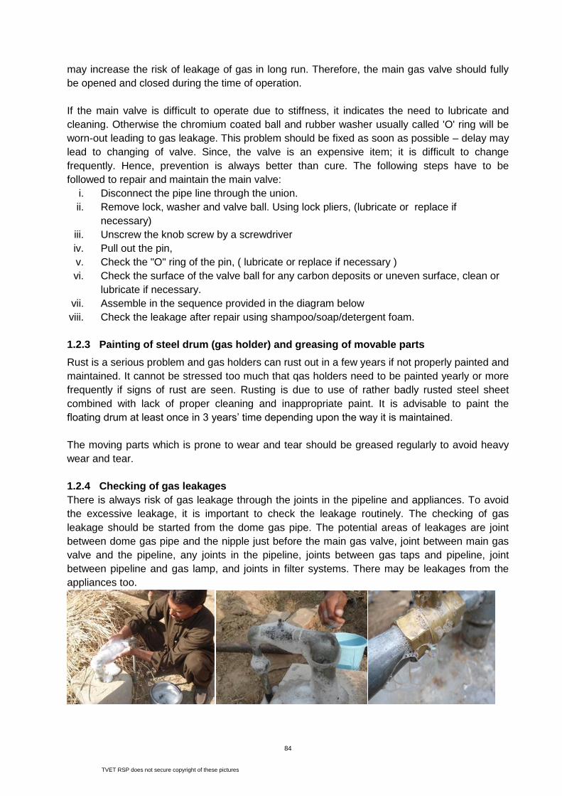
84
may increase the risk of leakage of gas in long run. Therefore, the main gas valve should fully
be opened and closed during the time of operation.
If the main valve is difficult to operate due to stiffness, it indicates the need to lubricate and
cleaning. Otherwise the chromium coated ball and rubber washer usually called 'O' ring will be
worn-out leading to gas leakage. This problem should be fixed as soon as possible – delay may
lead to changing of valve. Since, the valve is an expensive item; it is difficult to change
frequently. Hence, prevention is always better than cure. The following steps have to be
followed to repair and maintain the main valve:
i. Disconnect the pipe line through the union.
ii. Remove lock, washer and valve ball. Using lock pliers, (lubricate or replace if
necessary)
iii. Unscrew the knob screw by a screwdriver
iv. Pull out the pin,
v. Check the "O" ring of the pin, ( lubricate or replace if necessary )
vi. Check the surface of the valve ball for any carbon deposits or uneven surface, clean or
lubricate if necessary.
vii. Assemble in the sequence provided in the diagram below
viii. Check the leakage after repair using shampoo/soap/detergent foam.
1.2.3 Painting of steel drum (gas holder) and greasing of movable parts
Rust is a serious problem and gas holders can rust out in a few years if not properly painted and
maintained. It cannot be stressed too much that qas holders need to be painted yearly or more
frequently if signs of rust are seen. Rusting is due to use of rather badly rusted steel sheet
combined with lack of proper cleaning and inappropriate paint. It is advisable to paint the
floating drum at least once in 3 years’ time depending upon the way it is maintained.
The moving parts which is prone to wear and tear should be greased regularly to avoid heavy
wear and tear.
1.2.4 Checking of gas leakages
There is always risk of gas leakage through the joints in the pipeline and appliances. To avoid
the excessive leakage, it is important to check the leakage routinely. The checking of gas
leakage should be started from the dome gas pipe. The potential areas of leakages are joint
between dome gas pipe and the nipple just before the main gas valve, joint between main gas
valve and the pipeline, any joints in the pipeline, joints between gas taps and pipeline, joint
between pipeline and gas lamp, and joints in filter systems. There may be leakages from the
appliances too.
TVET RSP does not secure copyright of these pictures

85
Soap and water solution should be used to check gas leakage. Soap or detergent mixed with
water is vigorously shaken to make foam or bubbles. This foam is applied in the joints. If there is
leakage, the bubbles in the foam will either break or move. Coloured smoke can also be passed
to pipeline through rubber-hose pipe to check leakage. The escaping of coloured smoke from
the joints is easily visible if there is leakage. Moreover, the pipe near the joint turns to black if
there is leakage. Burning of matches or fire in the joint is not the right way to check leakage.
All the pipe joints should be checked using shampoo foam thoroughly. At the time of inspecting
leakage in the pipe line, main gas valve should be opened and the gas tap closed. If any
leakage is detected, it should be repaired immediately.
Steps to repair leakages from pipe joint are as follows:
i. Close the main gas valve.
ii. Open the leaking joint using pipe wrench turning it in anti-clock wise direction,
iii. Check the thread for possible damage - repair as necessary
iv. Apply at least 10 layers of Teflon tape or zinc putty or sealing agent over the threads
v. Re-fit the dismantled joint properly
vi. Check for leakage using shampoo foam.
1.2.5 Use of Water drain
The biogas conveyed from the gas holder is saturated with
water vapours. This water condenses when it comes in
contact with the walls of the pipe. If this condensed water is
not drained regularly, it will ultimately clog the pipeline and
block the flow of gas. The flame starts burning yellow initially
and in the long run if much water is accumulated the gas
stove does not burn at all. Hence, a water outlet to drain the
water is fitted in the pipeline. The main purpose of water drain
is to trap the condensed water and collect in it ensuring the
regular flow of gas from the pipeline. After some time this water drain is filled with water which
needs to be released out periodically. The general procedure of operating water drain is:
o Lift the cover-slab of the drain pit
o Turn the water releasing nut anti-clockwise until water flows out.
o Wait till the accumulated water flows out completely.
o Close the nut once gas starts coming out instead of water.
o Tighten the nut carefully.
As for other appliances, water drain pit should be inspected from time to time. Any foreign
materials deposited in the drain pit should be removed. The surrounding of the pit should be
cleaned to ensure that rain water does not enter into it.
The water drain should also be inspected to check for the functional status. The nylon washer
and water release screw holes should be checked. The following steps should be followed:
i. Close the main gas valve.
ii. Unscrew the water releasing screw,
iii. Check the hole in the water releasing screw: de-block the blockage, if necessary
iv. Check the condition and thickness of the nylon washer- replace it, if necessary
v. Assemble the parts correctly
vi. Check for gas leakage using shampoo/soap/detergent foam.

86
1.2.6 Cleaning of Overflow Opening
Digested slurry flows out of the displacement chamber (outlet tank) through the overflow
opening located at opposite side of the dome in the shorter wall of the outlet tank. This opening
is prone to clogging due to accumulation of slurry. This accumulated dried slurry has to be
removed from time to time to facilitate the continuous flow of slurry. If some portion of the
opening is blocked with dried slurry, it will increase the volume of the outlet tank. Increase in
volume of outlet will pose serious problem in the functioning of biodigester as it will result in
serious complications. One of these complications is the problem of slurry in the pipeline.
Therefore, the users should maintain the overflow level clean from dried slurry at all time.
Regular inspection of this opening is therefore necessary.
1.2.7 Use of Biogas Stove and Lamp
The gas produced in the biodigester is used with the burning of the gas stove. Gas tap
regulates the flow of biogas depending upon the pressure inside the biodigester. In the gas
stove, atmospheric pressure is regulated with the help of an
adjusting ring installed at the burner pipe containing 2 holes of
8 mm diameter. The ring and the gas tap should be adjusted
for high efficiency of stove. The ring should be adjusted in such
a way that the flame is blue, divergent and it burns with clear
hissing sound. If the flame is convergent and long, the
efficiency of stove will be very low. Biogas stoves with single
burner generally consumes about 350 to 400 litre of gas per
hour.
The user(s) should follow the following steps for operating the stove efficiently:
i. Ensure that the items to be cooked are ready near the stove.
ii. Cover the holes in the burner pipe completely with regulating ring.
iii. Burn the match or lighter before opening the gas valve and take it in one hand.
iv. While with the other hand open the gas tap slowly and lit the stove.
v. Place a cooking pot on the stove.
vi. Adjust the regulating ring in the stove until the flame burns bluish, short and the sound is
clearly audible.
vii. Ensure that the flame burns
concentrated in the bottom of the pot
without escaping outside.
viii. Lowered the flame as soon as the
food is simmering.
ix. Ensure that the stove is burned in
closed room as burning in open will have considerable heat lost.
TVET RSP does not secure copyright of these pictures

87
x. Ensure that the burner holes are not closed and the burner cavity is not filled with liquids
that escape while cooking.
xi. Never close the primary air intake fearing gas leakage from it.
During cooking, foods and liquid spill out from the cooking pot and block the flame port and
primary air holes. This leads to loss in efficiency of stove causing excessive gas use. This also
creates problems such as insufficient gas for next food items. To avoid such problem, stove
should be cleaned periodically.
The following are the steps to clean gas stove:
i. Pull out rubber hose from the nozzle of the stove.
ii. Pull out burner cap and clean all the flame ports,
iii. Check the burner cup for deposit of dirt and
clean it,
iv. Check the nozzle for possible blockage and de-
block it as necessary
v. Check the primary air hole for possible blockage
and de-block it as necessary
vi. Check regulator ring for free movement.
vii. Install the stove and check the performance.
Biogas produced in the household biodigester is used
for lighting too. Different types of biogas lamps are
available in the market. The Chinese model is widely used. Usually this model is supplied with a
battery operated starter. The lamp is lit with switching of the
starter. It is very easy to operate. Attention should be given
to install this switch out of the reach of the children. The
Chinese biogas lamps consume about 150 to 175 litres of
gas per hour. Regular inspection is necessary to check the
clogging of jet nozzle. Mantle should be changes when it
gets punctured or broken. The following points have to be
considered while operating a biogas lamp:
The glass-cover should be pre-treated with boiling in hot
water before it is placed in position. The holes in clay-part (carborendum) should be checked
any blockages regularly. While operating the lamp, one should ensure that the heat is
reasonably far from any materials that catch fire easily.
Gas lamp needs routine repair and maintenance for faultless operation. Dismantling of a biogas
lamp to clean its components, should be done carefully. The following steps are generally
followed:
i. Close the main gas valve.
ii. Unscrew the reducer bush in the lamp
iii. Unscrew the back nut and take off the reflector.
iv. Unscrew the clay part (carborendom) by turning anti clockwise very carefully
v. Inspect the nozzle, clean and be-block it if necessary
vi. Assemble in the sequence
vii. Check the performance.

88
1.2.8 Operation and Maintenance of Power Generator
Biogas can be used in both CI (compression ignition) engines and SI (spark ignition) engines.
The self-ignition temperature of biogas is high and hence it resists auto ignition, this is desirable
feature in spark ignition engines, as it will reduce the chances of knock. SI engine conversion to
biogas fuelling involved some engine modifications. Locally available diesel engines are
abundantly used in Pakistan to run with biogas. One horsepower power rating engine consumes
about 500 litres of biogas per hour. The following points need to be taken care while operating
an engine with biogas:
For ignition, turn off the biogas valve and initiate the engine by using diesel as fuel. Once the
engine starts and gets stable, regulate the diesel throttle to proper position (usually a little
below the middle position). When the engine runs normally, turn on the biogas valve slowly.
Regulated by the speed governor, the diesel feed reduces gradually. The rotating speed of the
engine becomes steady. If biogas inflow is too much, diesel feed will be stopped intermittently
and the engine will not be able to run smoothly. In this case, regulate the biogas valve to reduce
the biogas inflow until the engine operation is smooth. In the process of operation, the method
of regulating the rotation speed is the same as that of the pure diesel engine. When the rotating
speed of the engine or the load changes, regulate the biogas valve to increase or decrease
biogas inflow so as to ensure its normal operation and optimal consumption of diesel. To stop
the engine, turn off the biogas valve first and then the throttle.
Points for Attention:
Check biogas valve, pipes and joints regularly to inspect if there is any leakage.
Ensure safety measures against a fire or explosion.
Handle biogas valve smoothly, to avoid a sudden increased inflow of biogas into the engine,
for it effects the normal operation of the engine.
While the engine is running, try to keep the rotating speed steady, and avoid frequent
change in operation of biogas valve.
In case of shortage of biogas supply the engine needs to be fuelled wholly by diesel. In this
situation, it is unnecessary to stop the engine. Just turn off biogas valve and continue
operating the engine like a normal diesel engine.
Table-8 below summarizes common problems encountered with operating the generator with
biogas and likely solutions.
Table-4.2: Problems with biogas engine, causes and likely solutions
SN Problem Potential Cause Likely Solutions
1 After start, the engine speed
does not reach normal
The exhaust smoke is black
or white,
Sometimes engine stops
(a) Load is too much
(b) Biogas is fed into
engine too early
(c) Engine is cold,
especially in
winters,
(d) Engine is not
lubricated well,
(a) Start Engine and the
loads are put on one by
one,
(b) Initiate Engine on diesel
and then the let biogas in
gradually,
(c) Run engine without load
and biogas for a while

89
If the biogas supply is plentiful and load keeps steady, the biogas-diesel engine operated
correctly may save diesel 75-90% of the diesel. To achieve good results of diesel saving, biogas
supply should be plentiful and pressure of biogas coming into the engine should be above 0.07
Psi. More diesel fuel will be saved if the engine is operated for longer duration, load is kept
steadier and the engine is stopped for lesser times. Diesel will also be saved by avoiding
mistakes in the operation.
Controlling the biogas pressure that feeds the combustion engine is critical. When the engine
does not receive a constant pressure fuel supply its RPM begins to surge, which is not desirable
in a generator application. A pressure regulator in the form of blower should be used to
effectively regulate the biogas pressure at least at 4 psi. Trial and error method of adjusting
fuel/air mixture and timing will be helpful to find the "sweet spot" for ignition.
Maintenance routines recommended by the supplier/ manufacturer of the Power generator must
be followed for daily/ weekly and other periodic inspections. The engine manufacturers
recommend an accelerated oil change schedule for a diesel generator operating on biogas. This
enables capture and removal of the H2 S in the spent oil. The recommended oil change-
frequency for engines operating on raw biogas is once every 300 operating hours. This has
enabled Caterpillar 3306 engine at Langerwerf Dairy (California USA) for 45,000 hours between
major overhaul.
The engine safety devices should be checked monthly for proper function. Other engine
components require maintenance on monthly to yearly basis as recommended by the
manufacturers. The maintenance schedule recommended by the engine/ generator
manufacturers must be adhered to. As farms do most of their routine engine maintenance, their
cost of routine maintenance is low.
1.2.9 Regeneration of Biogas Filters
Biogas is generated by the anaerobic digestion of organic solids that contain small amounts of
H2S. Although the total percentage of H2S in biogas is relatively small, it is often sufficient
enough to corrode metals and damage parts of equipment. This can create maintenance and
(e) Quantity of air
intake is less
until it attains operating
temperature,
(d) Check oil level and
charge, if required.
Ii Engine speed does not
increase and the engine is
unable to take up the load
Throttle handle is at
minimum
Initiated engine with throttle
in the middle position.
Iii On feeding the biogas,
engine speed decreases, and
even the engine stops
Biogas is fed too
quickly resulting in too
much gas and less air
After initiation of engine on
diesel, turn on the gas valve
slowly and gradually.
Iv Explosive sound is produced
intermittently after initiation
Biogas inflow is too
much
Regulate the gas valve to
reduce biogas inflow
V Explosive sound is produced
intermittently during operation
The electrical load on
the engine has reduced
causing imperfect
combination of biogas
and diesel
Biogas valve should be
regulated slowly and
gradually to reduce biogas
inflow

90
operational problems especially in plants where the biogas is recovered to fuel engine-
generators or boilers. In addition to corrosion problems, H2S is a toxic air pollutant that can
create a severe odour nuisance in minute concentrations. The treatment of biogas for removal
of sulphur compounds has become increasingly important to restrict sulphur emissions. When
biogas is burned or flared, the H2S can generate sulphur dioxide (SO2) emissions. Biogas
contains H2S in concentrations from 500 to 3000 ppm or more, depending on the composition of
feeding materials – cattle dung in this case. The odour of hydrogen sulphide becomes offensive
at 3 to 5 ppm. An atmospheric concentration of 300 ppm can be lethal. Even small amounts of
hydrogen sulphide can cause piping corrosion, gas engine pitting, and piston ring clogging.
Many engine manufacturers require the H2S content to be as low as 100 ppm.
Biogas from cattle dung may consist as high as of 40% CO2 presence it. CO2 has no heating
value and its removal is required to increase the energy intensity of the gas per unit volume.
Sometimes, CO2 removal is also required because it forms a complex substance called
CO2.CO2 which is quite corrosive in presence of water. For power generation, CO2 presence in
biogas reduces the air fuel ratio of the engine because to supply the same thermal input the
system requires more biogas. Thus it reduces air flow into the engine under a constant volume.
Limited air flow into the engine reduces the maximum output of the engine. However the overall
efficiency of the engine does not change too much. Hence, for small scale power generation
plant CO2 removal is not mandatory.
Biogas filtration system consists of mechanisms to remove CO2, H2S and moisture from the gas.
Locally manufactured, simple mechanisms most widely used in different parts of the world could
be designed and installed under the framework of any biogas program in Pakistan.
a. CO2 Filtration:
For Carbon Dioxide filtration water scrubbing method is used. A steel cylinder with plain tap
water inside it has been placed. The biogas is bubbled in the water to reduce CO2. The water
can be replaced on weekly basis or bimonthly depending upon the change in colour of water,
which can be seen in the transparent rubber pipe (column tube) attached on the side of steel
case of the filter. The size of the cylinder is 8 feet in height and 10 inch diameter (5.45 ft3) for
100 m3 plant and one third of the tank is filled with water. For 50 m3 plants, the capacity is 2.3
ft3. The size of water scrubber has been found to be suitable.
b. H2S Filtration:
The Iron Sponge process is used to remove H2S. The unit consists of a gas tight cylindrical
steel tank. The gas containing H2S or the sour gas is passed through a bed of red oxide in the
form of steel wool. The steel wool basically is the rusted iron chips found in the lathe workshop.
The steel wool bed is placed at the bottom of the towers. The gas enters at the bottom of the
tower, then passes through the bed and finally comes out on the top of the tower. The
TVET RSP does not secure copyright of these pictures

91
dimension of steel tank used is 8 feet in height and 10 inch diameter (5.45 ft3) for 100 m3 plant.
The volume of tank for 50 m3 plant is 1.3 ft3. The amount of iron chips in in steel tank is reported
to be about 3 kgs. Almost one fourth of the tank is filled with iron chips.
The iron chips have a high affinity to react with H2S. The chemical reaction of red oxide with H2S
is given in the following equation. Fe2O3 + H2S = Fe2S3 + 3H2O (Manning and Thompson, 1991).
After reaction with H2S the iron chips becomes black iron sulphide. When the black corroded
iron sulphide reaches 75% height of the bed, it is time to change it and feed a fresh charge. The
corroded steel wool can be reused after being oxidized to rust by exposure to air or heating it.
The steel tanks are opaque and hence the change of colour of red oxide is not visible.
c. Moisture Filtration:
There are different materials used for moisture removal, such as alumina, silica gels, silica-
alumina gels and molecular sieves. In these cases, silica gel is used as an absorber. Silica gel
is a hard, rugged material with good abrasion resistance characteristics. It is the product of
chemical reaction between sulphuric acid and sodium silicate and consists almost solely of
silicon dioxide (SiO2). Gels can reduce the moisture content to 10 ppm and can be regenerated.
They adsorb heavy hydrocarbons and release them easily during regeneration. A filter made of
steel body casing is fabricated and filled with Silica Gel as moisture absorbents (desiccants)
through which biogas is allowed to pass. The volume of steel tank is about 5.45 ft3 for 100 m3
plant and 1.3 ft3 for 50 m3 size containing 2 and 3 kg of silica gel respectively. The silica that
was used for dehumidifier in these cases was found working well to eliminate the water content
in the biogas. The solid silica can be crashed to become grain and regenerated after heating.
For the regeneration of steel wool and silica gel, certain temperature needed. For steel wool the
required temperature is 48.9ºC and for silica gel it is 100ºC. The exhaust gas of the engine at
high temperature could be used through a heat exchanger to heat up steel wool and silica gel. A
small compressor is used to supply fresh air into the biogas stream; this air passes through the
heat exchange mechanism to carry the heat into the H2S and moisture removal unit.
For continuous regeneration or revivification of steel wool or ferric oxide a small amount of air or
oxygen is added to the inlet sour gas stream to oxidize the Fe2S3 back to Fe2O3 immediately
after the H2S is absorbed. The continuous regeneration reaction is given below.
Fe2S3 + 3 O = Fe2O3 + 3S (Manning and Thompson, 1991).
1.2.10 Composting of Slurry
If bio-slurry is composted the nutrient value will be added into it. Digested slurry is an excellent
material for fastening the rate of composting of refuse, crop waste and garbage etc. It also
provides moisture to the computable biomass. There are several ways of making compost. The
widely used method is pit method and semi dried methods of slurry composting. The following
steps have to be followed for pit composting of bio-slurry.
First of all, prepare two compost pits, with volume equal to total plant volume, by the side
of biogas plant at least 1 meter away from the plant
Spread a thick layer of dry materials (15 – 20 cm), such as dry forest litter, waste
grasses and straw, leftovers of animals feed and weeds collected from the fields, at the
bottom of the pit which will absorb the moisture of the slurry and prevent from leaching of
nutrients to the ground water system.

92
Let the slurry flow on the dry materials so that the dry material is soaked with the
moisture present in slurry.
Cover the slurry with a thin layer of straw or any dry materials or stable waste. This is
done to prevent slurry from drying. This preserves the plant nutrients.
Next day, let the slurry flow in the pit. If possible spread the slurry equally over the dry
materials in the pit and cover it with the same materials as used previously.
Repeat this process every day till the pit is filled slightly 15 – 20 cm over the ground level
and cover it with dry straw/ materials or a thin layer of soil and leave it for a month.
Provide shade to the compost pit either by making bamboo structure and planting it with
the creeping vegetables or by planting fruit trees like banana, fodder trees, green
manuring plants or pulses like horse gram. It prevents the evaporation loss of nutrients
from the compost pit.
After a month, turn the compost and cover it with the same dry materials or a thin layer
of soil.
Turn the compost of the pit again after 15 days and cover it with the same materials as
explained earlier. This process of turning will help the fast decomposition of composting
materials. The compost thus prepared will be moist and pulverized.
Start the filling of the second pit after the first pit is filled up. Follow the same procedure
in filling the second pit.
The decomposed slurry compost should be covered with dry materials or a thin layer of
soil while the compost is in the pit or stored outside the pit.
The compost should not be left exposed in the field for longer duration. It should be
mixed with the soil as early as possible. This helps in avoiding the loss of nutrients
because of excessive evaporation.
1.2.11 Breaking of Scum Layer
It is likely that a scum layer is formed in the digester because of the inert materials that float in
the surface, like straw,
hard or dried dung etc.
This layer obstructs the
flow of gas from digester
to gas holder. The gas
produced in the digester
cannot penetrate this layer
to reach the gas holder
and thus, flows out of the
manhole opening to the outlet. If the feeding is done properly with qualitative feed, this
problem never arises. However, if scum layer is formed, this should be broken. This could be
done by stirring the slurry inside the digester with the help of a rod or bamboo inserted through
manhole.
Never enter into the plant to break scum. Entry into the digester should be avoided when there
is slurry in the digester. For this the slurry should be removed for several days. Even after
emptying the plant, allow 24 hours aeration as precautionary measure. Before entering,
presence of harmful gases or sufficient oxygen should first be checked. Flames should be
avoided near or within the digester. When one person enters the digester, another person
should be constantly watching from outside to ensure the safety.

93
Scum formation can be minimized by agitation or stirring. Stirring is applicable only to the plants
of batch feeding. In industrialized countries and for large plants in developing countries, engine
driven stirring devices are the norm. Usually, but not always, they are operated automatically.
The user, however, should check the operation of the stirring device daily.
Small and medium size biogas plants have manual stirring devices that have to be turned by
hand as recommended. If there is no stirring device, poking with sticks through the inlet and
outlet is recommended. The stick should be strong, long enough but not too heavy. It should
have a plate fixed at the end (small enough to fit in the inlet-/outlet pipes) to produce a
movement of the slurry. Regular poking also ensures that the inlet/outlet pipes do not clog up.
Experience shows that stirring and poking is hardly ever done as frequently as it should be.
Farmers should be encouraged to run a trial on gas production with and without stirring. The
higher gas production will convince the user more than any advice. As ‘prevention is always
better than cure’ special care has to be provide to avoid cum formation. Correct feeding
practices will reduce the chance of scum formation.
1.2.12 Use of Pressure Gauge
Pressure gauge is fitted in the gas-pipeline near the point of application of biogas to monitor the
pressure of gas that flows to the appliances. When the needle of the pressure gauge indicates
higher pressure, then the gas tap should be adjusted to allow less gas to flow to the stove or
lamp and vice versa. Importantly, when the indicator shows full pressure, gas has to be used
otherwise there is chance of gas leakage to atmosphere, which should not happen from the
environmental point of view. Likewise, when the gas pressure is very low, one has to stop using
the gas to avoid slurry in the pipeline. If the pressure is less than 15 cm water column, it is not
preferable to use gas anymore.
A manometer is a tool used to measure the gas pressure inside the bio gas plant. It is simple in
construction and easy to use. (See figure below). Take two glass tubes 1-1.5 meter in length
with internal diameter of 1 cm. Fix them to a board or a wall inside a room and join the bottom
ends with a rubber hose or plastic tube as shown. By the side of each tube, mark graduations in
centimetre units. At the top of the tube AB, fix a round safety ball, or a bottle without a bottom.
The capacity of bottle should be more than 200 millilitre. Fill with coloured water (to facilitate
observations) up to the level of zero mark. Take Y tube and join to tube “A” and observe the
change in water column in the U-tube, consisting of tube A, tube B and the rubber hose. From
this we can tell the pressure inside the digester. For 10 cm difference in the water level on either
side there is a corresponding change in pressure of a 1/100 of an atmosphere. Standard
atmospheric pressure is 14.5 psi, therefore 10cm difference correspond to 0.145 psi difference
of pressure on the two sides.
Example: If the level in the tube “A” drops by 20 cm and the water level in tube “B” rises by 20
cm, then the pressure difference is 40 cm – this will be called an internal pit pressure of 40 cm.
It corresponds to the pit pressure of (40/10) x (0.145) psi; (which is 0.580 psi).

94
Note: The glass tube may be replaced with a tube made from any hard, transparent material
with low thermal expansion coefficient.
This manometer could be replaced with a pressure indicator available in the market and suitably
installed in the gas pipeline, Use manometer or the pressure meter to check gas pressure
before using gas. Pressure should be at 10-80 cm. When the compressor is operated on the
gas outlet; it should not be allowed to extract gas below the 1 PSI gas pressure in
digester.
1.2.13 Insulating the plant in Cold Areas
The rate of fermentation is much faster at high temperature. Most rural household biogas plants
(digesters) in developing countries operate at ambient temperatures, thus digester slurry
temperature is susceptible to seasonal variation but is more dependent on the ground
temperature than the atmospheric temperature. As a result, gas output in winter falls by up to 50
%. Below a slurry temperature of 10oC all the reactions cease to take place but revive gradually
with the rise in temperature. To ensure workable temperature inside the digester in cold season,
the following tips could be practiced:
o Plants should be constructed in a sunny place and any object blocking the sun should be
removed.
o Cover the dome portion of the biogas plant to maintain the temperature in the cold season
and/or colder regions of the country. Should always maintain 40 cm top filling on dome.
o Mix dung and water in the morning and let it heat till afternoon before feeding the plant, this
too will help to maintain the temperature in colder seasons/regions.

95
Radical drop in digester temperature, higher difference in minimum and maximum temperature
affects gas production negatively and causes problems to the plant functioning.
1.2.14 Changing of rubber hose pipes/connecting pipes
Rubber hose pipe used (i) to connect main gas pipeline and end use devices, and (ii) in filter
systems, may develop cracks due to heat and wear & tear due to longer use. The ends of
rubber hose pipe where stove/generator nozzle and gas tap/valve is fitted expands in diameter
causing leakage. Therefore, it should be checked for cracks and leakage of gas from the area
where it is fitted. If there are cracks rubber hose needs to be replaced and the expanded ends
should be cut off.
Steps to inspect rubber hose pipe:
i. Pull out the rubber hose from the nozzles,
ii. Bend or twist the rubber hose at several places and
observe for cracks
iii. If cracks are observed change the rubber hose
iv. Check the ends of rubber hose if the ends are enlarged,
cut off the portion that is expanded.
Topic-2: Common O & M Problems, Causes and Potential Solutions
It has been experienced that the biogas recovery projects have failed in past because of one
or more reasons listed below:
Operators did not have the skills or the time required to keep a marginal system operating.
Selected digester systems were not compatible with the manure handling methods.
Some designer/builders sold “cookie cutter” designs to farms. For example, of the 30 plug
flow digesters built, 19 were built by one designer and 90 percent failed.
The designer/builders installed the wrong type of equipment, such as incorrectly sized
engine-generators, gas transmission equipment, and electrical relays.
The systems became too expensive to maintain and repair because of poor system design.
Farmers did not receive adequate training and technical support for their systems.
There were no financial returns of the system or returns diminished over time.
Farms went out of business due to non-digester factors.
When users report problems with biodigester or if biodigester stops functioning, the following
are the steps to be taken to identify the potential problem:
Table-4.3: Checking of Biodigesters
TVET RSP does not secure copyright of these pictures

96
The following table summarises common problems, potential causes and likely solutions.
Table-4.4: Common Problems, causes and potential solutions
Problem Cause Potential Solution
Biogas is not
produced even after
10-15 days
No bacterial activity
inside the digester
o Ensure that the first feeding is done
with fresh cattle dung.
o Mix bio-slurry from existing plant as
seeding agent. Wait for a month and
see if gas production starts. If not,
then empty the digester, and refill
plant with fresh cattle dung.
Leakages in dome (gas
storage), or in pipes and
appliances
o Check the main gas valve if it has
leakage.
o Close the main gas valve and see if
the slurry level rises in outlet tank or
not. If the level rises, then there is
leakage from either pipeline or
appliances. Check for leakage and
correct it.
o If the slurry level does not rise even
after closing of main valve, there
may be leakage in dome.
o Wait for a month and see if gas
production starts. If not, then empty
the digester, check leakages from
dome and refill plant with fresh
cattle dung.
Stove does not burn
even after gas
production
More CO2 in gas Escape some gas daily for about a
week. When CO2 finishes, stove will
burn.
Defective fitting of pipe
and appliances
Check if the pipe and appliances are
fitted properly. Ensure that the main
valve is open, gas tap is open and air
When Biodigester Does not work, check the following information (twice)
• Feeding
– Quantity – Mixing ratio and mixing quality – Source (contamination, old / dry) – Quality of water – Inoculation required?
• Outlet
– Discharge? – Foam – Odour, colour, pH – Slurry level – fluctuations
• Pressure
– Dome leakage – Pipe leakage

97
intake in stove works properly
Enough gas in plant
but stove and lamp do
not burn
More CO2 during initial
digestion
Escape some gas daily for about a
week. When CO2 finishes, stove will
burn.
Clogging of gas pipe,
gas tap or gas jet due to
dirt
Be-block the pipeline.
Clean/un-clog the tap and jet
Clogging of pipeline due
to water or slurry from
digester
Drain water through outlet
Check the size of outlet tank and if it
bigger than recommended, lower the
height of overflow opening
Less gas production
than anticipated
Improper feeding (less or
more quantity, irregular,
more water, low temp. in
digester)
Correct the feeding practice and do as
recommended; Do not use more water
to clean inlet tank; Do not use much
water in toilet; Mix dung and water
properly
Leakage of gas from gas
holder and conveyance
system
Check if there is leaked from main
valve, pipeline and appliances with the
use of soap water solution. If no
leakage found then, check if gas is
leaked from dome. Close the main gas
valve; do not use gas for one or two
days. Check the slurry level in outlet. If
it is gradually decreasing, there must be
leakage from dome. Empty the plant
and apply treatment measures.
Formation of scum layer
in top or accumulation of
sludge in bottom
Do not use other materials than the
recommended for feeding; Stir slurry in
digester with pole or rod to break the
scum. Correct the water dung ratio.
Use of chemicals in
cleaning toilet
Avoid using chemicals in toilet; Use
brush and water only to clean; Empty
the plant if chemical is used, and fill with
fresh dung; Do not use dung from cattle
which is given strong antibiotics. Do not
use soap/detergent to clean inlet.
The flame is not
strong and blue, it is
pale and yellow
Clogging of gas tap and
burner holes with dirt or
accumulation of cooked
items
Clean the gas tap, oil it.
Clean the burner holes with needle boil
it in water.
Clean the secondary air mixing
chamber.
Water or little slurry is
accumulated in pipeline
Use water outlet to drain water.
Clean the slurry.
No or very little gas in
plant
Close the main gas valve and allow
time for gas production
Primary air intake is
blocked or not operated
Use primary air intake properly.
If the hole is blocked, de-block it.

98
properly
The stove burns with
long and weak flame
Improper mixing of
primary air
Adjust the primary air intake until the
flame becomes strong
Clogging of some of the
holes in the burner cap
Clean the burner cap and de-block the
holes with needle.
The flame ‘lifts off’ or
flame is too big
Excessive flow of gas,
high gas pressure
Reduce the gas flow.
Reduce air supply.
The flame
extinguishes or flame
is too small
Less flow of gas, not
enough pressure
Increase the gas flow.
Check for blockages.
Wait for some time till enough gas is
produced.
Slurry does not flow
out of overflow
opening
Lesser and irregular
feeding
Feed the plant as recommended
Cracks in digester wall
and/or outlet wall
Check the cracks in digester and outlet
walls; if found repair it.
Blocking of overflow
opening
Check the overflow opening regularly
and clean it as needed
The digested slurry
coming out of outlet
has strong foul smell
The digestion process is
not as anticipated may
be because of:
o Short-circuiting of
feeding in the
digester
o More quantity of
water added
o There is no bacteria
in digester
o Ensure that the inlet pipe discharges
just opposite to outlet opening.
o Ensure water dung ratio 1:1 while
mixing dung to feed into the digester
o Stop any adverse activities that kill
bacteria such as use of chemical to
clean latrines attached to biogas
plant.
More time needed to
cook food
Efficiency of flame is not
as anticipated due to
heat lost or defective
stove
o Ensure that the primary air intake is
adjusted properly to produce strong
blue flame that concentrates in the
bottom of cooking pot.
o Ensure that the stove is properly
maintained and used.
o Ensure that the area of cooking is
not windy and open. Locate stove in
closed space to avoid heat lost.
Water in the
manometer fluctuates
up and down
Water in the pipeline o Drain water from water trap. Ensure
that all the water in the pipeline is
drained away.
The engine does not
run properly with
biogas
As described in Table-
4.2
o As described in Table-4.2

99
Learning Units 4, 5 and 6
Unit 4 - C7.4: Explain methods for optimum utilization of biogas and bioslurry
Unit 5 – C7.5: Instruct users for effective operation and maintenance of biodigester
Unit 6 – C7.6: Ensure sustainable benefits from biodigester
Topic-1: Optimum Utilisation of Biogas and Bioslurry
1.1. Use of Biogas
The energy content of biogas is most commonly transformed into heat energy for cooking,
lighting and running simple dual-fuel engines. However, use of biogas for combustion engines
and for absorption fridges are less suitable for domestic biogas as they require large quantities
of gas and/or purified gas at a constant pressure. Also, it is also not feasible to compress biogas
into a liquid form and store/transport it in
gas cylinders. However, Biogas can be
used like any other combustible gas,
e.g. LPG. Each gas has its own
properties which must be observed for
efficient combustion. The main
influencing factors are: gas/air mixing
rate; flame speed; ignition temperature;
and gas pressure, respectively volume
of gas flow per time.
One ordinary biogas stove with a single burner, commonly used for domestic purpose,
consumes 350 to 400 litres of gas her hour. In other words, 10 kg of cattle dung will be enough
to produce enough gas to burn a stove for one hour. A biogas lamp consumes slightly less than
half the quantity needed for a single-burner stove (150 to 175 litres of gas per hour). Operating
an engine is not preferable with household biodigesters because of the fluctuations in gas
pressure and the presence of other gases than methane that will harm parts of the engine.
Compared to LPG, biogas has a lower calorific value and needs less air per cubic metre for
combustion. This means, with the same amount of air more gas is required. Therefore, gas jets
are larger in diameter when using biogas. About 7 litre of air are required for total combustion of
1 litre of biogas, while for butane it is 31 litres and for propane 24 litres. The flame speed of
biogas is relatively low, lower than that of LPG. Therefore, the flow speed must be less to avoid
lifting the flame off the burner. The flow speed is defined by the total volume of gas (biogas +
air) and the size of the opening the gas is passing through. The critical ignition temperature of
biogas is higher than that of diesel. Therefore, when biogas is used in engines, ignition spark
plugs are required or partly diesel must be added to the gas (dual fuel) to ignite the fuel and run
the engine. Because of its low flame speed, slow turning diesel engines (below 2000 RPM) suit
biogas better than fast turning diesel engines (above 5000RPM).
The efficiency of using biogas is 55% in stoves, 24% in engines but only 3% in lamps. A biogas
lamp is only half that efficient than a kerosene lamp. The most efficient way of using biogas is in
a heat-power combination where 88% efficiency can be reached. But his is only valid for larger
installations and under the condition that the exhaust heat is used profitably. The use of biogas
in stoves is best way of exploiting the energy needed by farm households.

100
1.2. Use of Bio-slurry
Biogas slurry is one of the two end products of the anaerobic digestion in the biogas plants. The
mixture of animal/human waste and water put into the biogas plant undergoes a process of
anaerobic digestion or fermentation in a bio-digester. During digestion, about 25 – 30% of the
total dry matter of animal/human waste will be converted into a combustible gas and the residue
of 70 – 75% of the total solids content of the fresh dung comes out as sludge which is known as
biogas slurry or bioslurry.
Biogas slurry consists of 93% water and 7% dry matter of which 4.5% is organic and 2.5%
inorganic matter. The percentage of NPK (Nitrogen, Phosphorus and Potassium) content of the
slurry on wet basis is 0.25, 0.13 and 0.12 while on dry basis it is 3.6, 1.8 and 3.6 respectively. In
addition to the major plant nutrients, it also provides micro-nutrients such as zinc, iron,
manganese and copper that are also essential for plants, but required in trace amounts.
Biogas slurry can be used for a variety of purposes, the main one being organic fertiliser in
farms, especially in vegetable and fruit gardens. The following are some of the applications:
Organic fertiliser in farms
Organic fertiliser for mushroom culture
Seed treatment
As supplement feed for some animals and fish
Organic fertiliser to grow algae to increase fish production

101
As organic fertiliser, it can be used wet or dry. The slurry can be used directly by mixing it with
irrigation water. Wet application is rather cumbersome; therefore farmers prefer to use dry slurry
in their farms. For the dry use, composting of the slurry is highly recommended.
The following table shows the N, P, K values in different types of organic fertiliser (BSP-2006):
Table-4.5: N, P, K values in different types of organic fertiliser
Nutrient Fresh
Bioslurry
(toilet not
attached)
Fresh
Bioslurry
(toilet
attached)
Composted
Bioslurry
Manure
from
Toilet
Farm-
yard-
manure
Cattle
urine
Nitrogen % 1.89 2.12 1.7 1.4 1.42 25
Phosphorus % 1.84 1.87 1.04 1.0 1.02 3.3
Potassium % 1.85 1.82 0.56 1.5 1.71 1.87
It can be seen from the above table that bio-slurry has better nutrient values in comparison to
other organic fertilisers. The effect of compost on crop production depends upon the type and
condition of the soil, the quality of the seeds, the climate and other factors. However, application
of compost will bring the following changes to the soil:
Improvement of the physical soil structure.
Increased soil fertility.
Increased water-holding capacity of the soil.
Enhanced activity of the micro-organisms in the soil.
Various research studies done in Nepal have
indicated that the use of bio-slurry helps in increasing
the yields of agricultural productions to a considerable
extent. Compared to farm yard manure, application of
digested slurry increased the yields of rice, wheat and
maize by 6.5 %, 8.9 % and 15.2 % respectively.
Effluent compost, if stored and applied properly,
improves soil fertility and increases cereal crop
production with 10-30 % compared to farm yard
manure (FYM). Several researches have shown that
the application of liquid effluent on paddy, wheat and
maize increases the yield by 10, 33 and 37% respectively. Compost application versus non
application has given a yield increase of 80% in cauliflower, 67% increase in wheat and 21% in
tomato. The most responsive crops to effluent compost are vegetables like root crops (carrots
and radish), potatoes, fruit trees and rice.
a. Application of Slurry in Semi-liquid Form
The most economical way to apply slurry is by means of gravity, either by a network of small
slurry furrows or by mixing slurry in the irrigation system. Both options require a gradient of at
least 1% (for irrigation water) and 2% (for slurry distribution), sloping from the biogas plant’s
overflow point to the fields.
TVET RSP does not secure copyright of these pictures

102
Making best and least labour-intensive use of the
slurry is an important planning parameter. Especially
where gravity distribution is feasible, the positioning of
the biogas plant and the expansion chamber and the
level of the expansion chamber overflow are of high
importance. In rather flat areas, it should be
considered to raise both the stable and the biogas-
plant in order to allow a slurry distribution by gravity.
The digested slurry can directly be applied in the field
using a bucket or a wheel barrow. An alternative to this is to discharge the slurry into an
irrigation canal. However, these methods of direct
application have some limitations. Firstly, not all farmers
have irrigation facility throughout the year. Secondly, in the
cascade system of irrigation in which water is supplied from
one field to another, slurry is not uniformly distributed in the
fields. The digested slurry is in a liquid form, it is difficult to
transport it to farms located far from the biogas plants. The
sludge and slurry could be applied to the crop or to the soil
both as basal and top dressings. Whenever it is sprayed or
applied to standing crop, it should be diluted with water at least at the ratio of 1:1. If it is not
diluted, the high concentration of available ammonia and the soluble phosphorus contained in
the slurry will produce toxic effect on plant growth “burning the leaves”.
b. Application of Slurry in Dried Form
The high water content of the slurry causes difficulties in
transporting it to the farms. Even if it is applied wet in the
field, tilling is difficult. Due to such difficulties, the farmers
usually dry the slurry before transporting it into the fields.
When fresh slurry is dried, the available nitrogen,
particularly ammonium, is lost by volatilization.
Therefore, the time factor has to be considered while
applying the slurry and in this regard, immediate use can
be a way of optimizing the results.
c. Utilization of Slurry for Compost Making
The above mentioned difficulties can be overcome by composting the slurry. If the slurry is
composted by mixing it with various dry organic materials such as dry leaves, straw, etc., the
following advantages can be realised:
- The dry waste materials around the farm and
homestead can be utilized.
- One part of the slurry will be sufficient to compost
about four parts of the plant materials.
- Increased amount of compost will be available in
farm.
- Water contained in the slurry will be absorbed by
dry materials. Thus, the manure will be moist and
pulverized. The pulverized manure can be easily
TVET RSP does not secure copyright of these pictures

103
transported to the fields.
Furthermore, the complete digestion of cattle dung in a biogas plant destroys weed seeds and
organisms that can cause plant diseases.
d. Digested Slurry as a Supplement in Ration of Animal and Fish
Digested slurry has been used to supplement feed for cattle, poultry and fish in experimental
basis. The encouraging results obtained from experiments are yet to be commonly practiced by
the users. The following subsections describe various experiments carried out in this area.
e. Digested Slurry as a Feed to Animals
Results from the Maya Farms in the Philippines showed that in addition to the plant nutrients,
considerable quantity of Vitamin Bi2 (over 3,000 mg of Bi: per kg of dry sludge) are synthesised
in the process of anaerobic digestion. The experiment has revealed that the digested slurry from
biogas plant provides 10 to 15% of the total feed requirement of some cattle, and 50% for ducks
(Gunner son and Stuckey, 1986). Dried sludge could be substituted In cattle feed with
satisfactory weight gains and savings of 50% in the feed concentrate used (Alviar. et al.. 1990).
The growth and development of Salmonella chloreasuis and Coli bacillus were inhibited under
anaerobic fermentation. The low availability of good quality forage is the result of low
productivity of rangeland as well as limited access to it. Only 37% of rangelands arc accessible
for forage collection (HMG/AsDB/ FINNIDA 1988). Therefore, addition of dried sludge in cattle
feed would improve the nutrient value of the available poor fodder.
f. Digested Slurry as a Feed to Fish
A comparative study on fish culture fed only with digested chicken slurry was carried out by
National Bureau of Environmental Protection (NBEP). Nanjing. China in 1989. The results
showed that the net fish yields of the ponds fed only with digested slurry and chicken manure
were 12,120 kg/ha and 3,412.5 kg/ha, respectively. The
net profit of the former has increased by 3.5 times
compared to that of the latter. This is an effective way
to raise the utilization rate of waste resources and to
promote further development of biogas as an integrated
system in the rural areas (Jiayu, Zhengfang and Qiuha,
1989).
An experiment was carried out in Fisheries Research
Complex of the Punjab Agricultural University,
Ludhiana, India to study the effects of biogas slurry on survival and growth of common carp.
The study concluded that growth rates of fish in terms of weight were 3.54 times higher in
biogas slurry treated tanks than in the control. Biogas slurry proved to be a better input for fish
pond than raw cow dung since the growth rate of common carp in raw cow dung treated tanks
were only 1.18 to 1.24 times higher than in the control. There was 100% survival of fish in
ponds fed with digested biogas slurry as compared to only 93% survival rate in ponds fed with
raw cow dung.
g. Other Uses
Bioslurry has been extensively used to grow mushroom in household or commercial farms in
different countries. Bioslurry Many extensive experiments performed in China have proved that
the digested slurry, when used as fertilizer, has strong effects on plant tolerance to diseases
TVET RSP does not secure copyright of these pictures

104
such as potato wilt (Pseudomonas salanacearum), late blight, cauliflower mosaic, etc. and thus
can be used as bio-chemical pesticide.
A series of experiments and analyses conducted in China in a
period of three years show that the cold-resistant properties of
early season rice seedling are effectively enhanced by soaking
seeds with digested slurry.
The survival rate increased by 8 to 13% and the quality of
seedlings raised by soaking seeds with digested slurry is much
higher than that of the control group during the recovering period
after low temperature stress. The seedlings germinated faster,
grew well and resisted diseases (Biogas Technology In China,
1989).
Foliar application of diluted slurry increases rate of wheat plant
growth, resists to lodging and increases size of grains and length of the ear. Foliar application in
grapes have been found to increase yield, length of fruityear, sugar content, fruit size, colour,
and resistance to mildew diseases. In cucumbers, it has been observed to increase resistance
to wilt diseases. In peach, it develops better fruit colour and early maturation.

105
Learning Units 8 and 9
Unit 7 - C8.3: Describe the roles and responsibilities of a biogas technician
Unit 8 - C8.4: Practice occupational health and safety measures
Topic-1: Role of Technician for Security and Safety Measures
When operating a biogas plant special attention has to be paid to avoid potential risks as
described below:
Breathing in biogas in a high concentration and over longer periods of time can cause
poisoning and death from suffocation. The hydrogen sulphide content of biogas is highly
poisonous. Non-purified biogas has a typical smell of rotten eggs. Purified biogas is
odourless and neutral. Therefore, all areas with biogas operating appliances should be well
ventilated. Gas pipes and fittings should be checked regularly for their gas-tightness and be
protected from damage. Gas appliances should always be under supervision during
operation. Everybody dealing with biogas, in particular children should be instructed well
and made aware of the potential dangers of biogas.
After emptying biogas plant for repair, it has to be sufficiently ventilated before entering into
the digester. In this case the danger of fire and explosion is high (gas/air mixture!). The so-
called chicken test (a chicken in a basket enters the plant before the person and if returns in
good condition it guarantees sufficient ventilation) is advised to be conducted to ensure
safety. While entering the digester. Make sure that there are at least two persons.
Biogas in form of a gas-air mixture with a share of 5 to 12 % of biogas is a source of ignition
and at higher temperatures it can easily explode. Danger of fire is high if the gas-air mixture
contains more than 12 % of biogas. Smoking and open fire must therefore be prohibited in
and around the biogas plant.
The initial filling of a biogas plant poses a particular danger, when biogas mixes with large
empty air-spaces. A farmer may want to use open fire/candle to check how full the plant is
during the process of filling already and cause an explosion. It should be avoided.
The digester of a biogas plant and the slurry storage facilities should be built in such a way
that neither persons nor animals are in danger of falling into them.
Moving and movable parts should have a protective casing to avoid catching persons or
animals.
Appliances operating on biogas normally have high surface temperatures. The danger of
burning is high, in particular for children and strangers. A casing of non-heat-conducting
material is advisable.
The mantle of the gas lamp is radioactive. The mantle has to be changed with utmost
caution. Especially the inhalation of crumbling particles must be avoided. Hands should be
washed immediately afterwards.
The piping system can become traps on the farm compound. As much as possible, pipes
should be laid some 30 cm underground. Pits for water traps, gas meters, main valves or
test-units should be covered by a concrete frame and covered with a heavy concrete lid.
General Instructions for Safety:
Check regularly all the pipes, gas valves, equipment for any possible leakages. The
leakage should only be checked with the foam of soap or shampoo; one can see

106
bubbles’ size increase in case of leakages. NEVER TRY TO CHECK LEAKAGE WITH A
FLAME.
Never smoke cigarette or turn on fire near biogas installations, including biogas plant,
fittings, generator, filters etc.
Daily feed the biogas plant with recommended dose of fresh dung, for proper functioning
of plant.
Always keep an eye on the pressure shown in pressure gauge before and during usage
of biogas
Slurry pits should be emptied out once filled with slurry, to avoid stoppage of overflow or
to avoid slurry going back in biogas plant.
Avoid any heavy vehicle like tractor, trolley, or any other heavy weight of any kind on
biogas plant to avoid any damage.
Lubricate the valves on regular intervals to avoid malfunctioning or leakages.
Shut the main valve after usage of biogas
Regularly clear the over flow opening, because slurry adhered to it becomes dry and
reduces the size of opening or sometimes blocks the opening.
Always keep all the equipment including generator, filters, fittings, etc. clean from dust
and moisture
Never try to alter the order of equipment on your own.
Never try to fix the leakages, or other damages yourself, always call the expert.
Any damage to any equipment, biogas plant part, fittings, appliances due to unavoidable
circumstance, climatic conditions, natural disaster, improper maintenance, not acting
upon the instructions in this manual, will be purely responsibility of biogas plant owner
and S/he will not claim any damages from Biogas Construction Company who
constructed the plant.
Generator:
Do not smoke near the generator or plant.
Generator should be placed in the shade and protected from moisture/rain.
As hot fume gases comes from the exhaust, the generator should be placed in ventilated
area where fresh air circulates continuously.
Keep generator away from fire and/or fire source.
Keep generator away from inflammable things like petrol, kerosene oil, etc.
Oil of generator should be checked regularly, if possible daily before operation.
Check oil level indicator before each use and add correct oil type as instructed by the
manufacturer or vendor.
Oil of generator should be changed regularly as per manufacturer’s instructions just
reduce the interval between two oil changes by half.
Do not run the generator when the oil level is low.
Before turning on the generator, check all the electrical connections, i.e. power button on
generator, it should be in OFF position.
Similarly when turning off the generator, always turn the power button in OFF position,
i.e. disconnect the generator from the power line.
There should be a proper change over in the house for changing the electrical line (from
wapda/national grid to generator or from generator to wapda/national grid).
All the electric equipment should be of very good quality and made up of heat resistant
materials.

107
The connecting wire from generator to change over should be of good quality.
Electrical connections should not be loose, otherwise sparking would cause fire.
Generator battery should be checked regularly and follow the instructions of
manufacturer for its up keep.
Check for any overflow or leakages and also check the battery water level.
Do not turn on the generator when the gas pressure is low.
Turn off the generator when gas pressure is low.
When turning off the generator, always close the gas valve first.
Disconnect generator from power supply during maintenance and/or repair.
Do not touch generator with wet hands to prevent risk of electric shock.
Do not attempt to touch mechanical parts when the generator is running, to avoid risk of
injury.
Do not allow children to touch the generator. Do not ask them to run it.
Do not allow persons having not enough knowledge about generator or its operation to
operate it.
Generator Filter Maintenance: Air filter should be checked and cleaned on regular
basis as per manufacturer’s instructions or physical observations.
Clean it with cleaning agent in every 50 hours. If it is too dusty, clean it in every 10
hours. After it is fully dry, insert it into clean oil. Use it when surplus oil is removed.
Starting Instructions:
Fill with oil and gasoline before starting.
Check oil level before every use.
Disconnect any electric device.
Open the fuel valve to OPEN position.
Move choke lever to CLOSE position.
Start the engine.
Move choke lever to OPEN position after engine starts.
Storage Instructions:
Drain the oil from the crankcase.
Drain gasoline from tank completely, then loosen the drain bolt of carburettor and drain
the fuel in carburettor.
Store the unit in cool and dry place, avoid direct sunlight.
Keep it away from children.
Petter Engine:
Keep engine in a proper ventilated area to avoid any accident.
Do not smoke near the Petter engine.
Oil of Petter engine should be changed regularly as per manufacturer’s instructions
Use good quality of oil in Petter engine.
Ensure continuous supply of water for Petter engine.
Check Petter engine regularly.
Over-hauling of Petter engine should be done after every 6 months.
Always start the Petter engine on diesel, and then substitute it with biogas.
Do not run the Petter engine when the gas pressure is too low.
When turning off the Petter engine, always close the gas valve first.

108
Do not allow children to touch the Petter engine while in operation or ask them to
operate it.
Do not allow persons having not enough knowledge about Petter engine or its operation
to operate it.
The usual range of fuel mixture, 70(gas):30(diesel) to 75(gas):25(diesel) ratio. The ratio
can vary case to case depending upon the condition and age of petter engine, the
quantity of load, size of engine, etc. sometimes the ration can even reduce to 50:50 due
to poor maintenance of engine.
Dynamo:
Do not run the dynamo continuous for longer period of time.
Do not put the entire load on a single face; otherwise the dynamo will be damaged.
Do not overload the dynamo.
To avoid overloading use an ampere meter, so that it wouldn’t cross the load limit.
Maximum load of 9 kW can be put on dynamo having capacity of 12 kW.
Do not touch dynamo with wet hands to prevent risk of electric shock.
Check all the electrical connections every time before turning on the dynamo.
Electric wire used for electricity should be of good quality.
Electrical connections should not be loose otherwise sparking would cause fire.
Keep children away while the dynamo is being used.
Do a regular checking and maintenance of dynamo.
Filters:
Place filters in suitable place, preferable under shade.
Do not smoke or lit any fire near the filters.
Filters pipe setting and welding joints should be checked regularly for any leakages.
The leakage should only be checked with the foam of soap or shampoo; one can see
bubbles’ size increase in case of leakages. NEVER TRY TO CHECK LEAKAGE WITH
FLAME.
Water of CO2 scrubber should be changed at least once in a month, earlier the better.
Ensure that the water is safely disposed.
Water level in CO2 scrubber should be checked regularly and always maintain its level
up to the marked point.
Oil in H2S filter has to be changed at least once in every two months. Ensure that the oil
is safely disposed.
Filter media in H2S filter have to be regenerated (dry in sunlight) at least once in every
two months.
Silica Gel in moisture filter should be dried in sunlight at least once in every month.
Oil level in H2S filter should be checked regularly and always maintain its level up to the
marked point.
Do not exceed or decrease the water/oil level from the marked point in CO2 scrubber
and H2S filter, just maintain its level up to the marked point.
At least 2 kg of Silica Gel should be filled in moisture filter for 50 cubic meter plant, and
3 kg for 100 cubic meter plant.

109
Self-Assessment Questions for Participants
The participants of the training/course should assess themselves at the end of the training
sessions/course designed for this module. The following probe-questions could be used as
guidance for self-assessment process:
SN Self-assessment Questions
1 What are the major operational activities needed to operate a biodigester trouble-free?
Why does a stove burn with yellow flame?
2 What happens if the biodigester is under-fed or over-fed?
3 What happens if the water drain is not operated properly?
4 What is scum? Why does it form? How to avoid scum formation?
5 What is the reason for an intermittent explosive sound in the generator after initiation?
6 What are the major uses of biogas?
7 What are different methods of using bioslurry in the farm?
8 Why is bioslurry better than conventional farm yard manure?
9 What are the safety measures while starting and operating a Petter Engine?
10 What is the quantity of biogas needed to operate a 10 horse power diesel engine for 4
hours?

110
Final Assessment of Competencies
Candidate’s Name
Assessor’s Name
Course Title Training of Biodigester Technicians (Masons) to Construct Floating Drum Biodigester for Running Pumps
Brief description of required competency
Enhanced knowledge and skills of a would-be technical supervisor (i) to construct quality biodigesters, and (ii) to ensure continued operation of the installed facility, so that the users are benefitted for long run.
Date of Assessment
Competency Expected Yes No Comments
Recall basic concepts of biogas production and benefits of biodigester technology
Read and interpret drawings of floating drum biodigesters
Select suitable type and appropriate size of floating drum biodigester and carry out basic calculations
Select construction materials and construction site
Construct structural components of a floating drum biodigester
Install pipeline, appliances and electro-mechanical components
Perform routine operation and minor maintenance tasks
Practice quality norms and ensure the compliance of quality standards while construction
The candidates performance is:
Competent
Not yet competent
Comments:
This signature confirms candidate’s agreement that the above record is a true reflection of the tasks performed. Signature of the Candidate: Date:
This signature confirms that the candidate has demonstrated competence in the theoretical understanding and practical performance and of the observed tasks. Signature of the Assessor: Date:

111
Annexes

112
Annex-1: Monitoring Parameters for fixed-dome Biodigester
SN Parameter Frequency Equipment Monitoring
1 Quantity of cattle-
dung
Daily at set times
(end of afternoon?)
Bucket, weighing
scale
Initially daily by Project
technician, later
perhaps by hh
2 Quantity of water Daily at set times
(end of afternoon?)
Bucket Initially daily by Project
technician, later
perhaps by hh
3 Mixing of dung
and water
Daily at set times
(end of afternoon?)
Visual Initially daily by Project
technician
4 Biogas
consumption
Continuous Gas flow meter,
Sulphur filter
Initially daily by
PROJECT technician,
later less
5 Digester
temperature
Daily at set times,
fixed position
Min-max
thermometer (or
more advanced?)
Daily by PROJECT
technician / continuous
6 Ambient
temperature
Daily at set times,
fixed position
Min-max
thermometer (or
more advanced?)
Daily by PROJECT
technician / continuous
7 pH Weekly at set point;
before feeding, in
the digester, in the
outlet discharge
point
pH meter, litmus
paper
Weekly by PROJECT
technician
8a Max gas pressure
before and after
the filter
Daily in the morning,
before first gas
consumption
Pressure meter Daily by PROJECT
technician, later
perhaps by hh
8b Max outlet slurry
level
Daily in the morning,
before first gas
consumption
Measurement stick,
measuring tape
Daily by PROJECT
technician, together
with pressure. Later
perhaps by hh
9 Min gas pressure
before and after
the filter
Daily in the evening,
after last gas
consumption
Pressure meter Daily by PROJECT
technician, together
with pressure. Later
perhaps by hh
10 Percentage of
Methane before
and after the
filtration
Once in a week Biogas Analyser Weekly by PROJECT
technicians
11a Generator/Engine
running hours
Daily Clock Initially daily by
PROJECT technician,
later by hh.
11b Biogas stove-use
hours
Daily Clock Initially daily by
PROJECT technician,
later by hh.
11c Biogas lamp-use
hours
Daily Clock Initially daily by
PROJECT technician,

113
later by hh.
12a Closing of main
valve
Daily in the evening,
after last gas
consumption
Clock Initially daily by
PROJECT technician,
later by hh.
12b Opening of main
valve
Daily in the morning,
before first gas
consumption
Clock Initially daily by
PROJECT technician,
later by hh.
13a TS and VS fresh
dung
Twice for each plant,
after process is
stabilized (three
months operation)
Containers, oven,
weighing scale,
simple lab
equipment
By research institute,
laboratory
13b TS and VS slurry
in outlet
Twice for each plant,
after process is
stabilized (three
months operation)
Containers, oven,
weighing scale,
simple lab
equipment
By research institute,
laboratory
14 Water tightness In sampled plant.
Once upon
commissioning and
once at the end of
the testing period
Lots of water,
measuring tape.
Details on Biogas
Technology Manual
By PROJECT Technical
Officers
15 Gas tightness For each plant.
Once upon
commissioning and
once at the end of
the testing period
Lots of water,
measuring tape,
pressure gauge.
Details on Biogas
Technology Manual
By PROJECT Technical
Officers
16 Sediment and
scum content
Each plant to be
checked, at the end
of the testing period
Buckets, visual,
weighing scale,
camera, folding rod
By PROJECT Technical
Officers
17 Daily Biogas
Production
At least once in a
month for 12 months
Measuring tape,
visual, gas flow
meter
By PROJECT Technical
Officers in the
beginning and later by
local technicians

114
Annex-2: Tools and Equipment
Routine Monitoring Tools
(a) Measuring Tape – 5m long
(b) Pressure Meter (Digital or analogue)
(c) pH Meter
(d) Digital Thermometer
Used for measuring different
components of biodigester.
To measure the
pH (acidity and
alkalinity) level of
the influent and
effluent.
To
measure/monit
or temperature
(ambient and
various
locations
inside the
biodigester).
Used to
measure gas
pressure and
detect leakages
in the
biodigester and
pipe systems.

115
To locate the exact
locations of
biodigesters.
(e) GPS Receivers
(f) Plier
(g) Screw Driver
(h) Pipe Wrench
Specialised Monitoring Tools
(a) Biogas Analyser

116
To assess the
performance of
filtration system
by measuring
the percentage
of methane and
CO2 in biogas.
To facilitate
measurement of
different
components of
filled
biodigesters
(b) Bioslurry Sampler
(c) Folding Pipe
(d) Foot Pump or Bicycle Pump

117
To measure the
quantity of
biogas
consumed by a
specific end
use
applications
such as
generators.
To check leakages
through gas holders,
pipelines and appliances.
(e) Biogas Flow Meter

118
Annex-3: Session Plan -Training of Biogas Technicians – Floating Drum Dome
Biodigesters
Time Topic Methodology Training Aids Expected Outcome
Day-1
8:00-9:00 Registration,
Introduction of
participants and
instructors. Objective
and schedule of training
and Pre-test.
Registration,
Classroom
presentation
Register,
Training Manual,
Presentation
slides
All participants are listed. Participants
know each other and their instructors.
Participants know the course
objective. The instructors know the
level of understanding of participants.
9:00-10:30 Introduction to
technology – Ideal
condition for gas
production
Classroom
presentation
Presentation
slides, Videos
Participants know the basic concepts
of biogas production, ideal conditions
for biogas production and
prerequisites for installation of
biodigesters
10:30-12:00 Types and Functioning
of biodigesters
Classroom
presentation
Drawings of a
biogas plant
Model of
Biodigester,
Presentation
slides
Participants know different types of
biodigesters, comparative merits and
demerits. They will be familiar with
the functioning of biodigesters.
12:00-13:00 Introduction to different
parts of a biodigesters
Classroom
presentation
Model of
Biodigester,
Presentation
slides, 3D
drawings
Participants know different
components of biodigester and their
interrelations
13:00-14:00 Lunch
14:00-15:00 Benefit of Biodigesters
and importance in
Pakistan
Classroom
presentation
Presentation
slides, Videos
Participants know the benefits of
biodigester at the household,
community and macro levels. The
know why biodigesters are important
for Pakistan
15:00-16:45 Basic Concept of
drawing
Class room
presentation
Objects of
different shapes,
Presentation
slides
Participants know basic concepts of
drawings and are familiar with plan,
section, elevation and isometric views
16:45-17:00 Recapitulation of the day Discussions Flip chart, white
board, marker
pens
Participants will be able to recall the
learning of the day.
Day-2
08:00-12:00 Reading and
interpretations of
drawing of biogas plant
Class room
presentation,
practical
drawing
Laminated
drawing with
measurement,
Model of a
biodigester
Participants know methods to do
correct measurements of different
plant-components, and be able to
identify plan and section projections
drawings of biodigesters.
12:00-13:00 Lunch Break
13:00-13:45 Correct size selection of
a biogas plant.
Classroom
presentation
Presentation
slides,
Construction
manual
Participants know how to calculate
amount of dung required for different
plants and be able to advise to select
suitable size of biodigesters.
13:45-14:30 Quality of Construction
Materials
Classroom,
Presentation
Presentation
slides,
Participants are familiar with quality
standards of construction material

119
and
demonstration
Construction
manual, bottle,
const. materials
and effect of sub-standard quality of
materials on durability/functioning of
a biodigester.
14:45-15:30 Construction Site
Selection
Classroom
presentation
Construction
manual, photos,
Video
Participants are able to select proper
site for plant construction. E.g.
minimum distance from water source
and stable, sunny place etc.
15:30-16:45 Overview of construction
of biodigesters
Classroom
presentation/
Video show
Construction
Manual,
Video/DVD
Participants are able to internalise
various steps of construction of
biodigesters.
16:45-17:00 Recapitulation of the day Discussion Flip chart, white
board, marker
pens, meta
cards
Participants will be able to recall the
learning of the day.
Day-3
8:00-10:30 Layout, Digester
Construction / Inlet and
toilet pipe connection
Class room
presentation /
Video show
Slides,
Construction
manual, Video
Participants are familiarised with the
construct of main digester following
and the procedures as mentioned in
the construction manual.
10:45-12:45 Fabrication and
installation of gas holder
Class room
presentation /
Video show
Slides,
Construction
manual, Video
Participants are able to tell the
correct procedures of fabrication
and installation of gas holder.
12:45-13:30 Lunch Break
13:30-14:00 Outlet construction Class room
presentation /
Video show
Slides,
Construction
manual, Video
Participants are able to tell the
correct procedures of outlet
construction as specified in the
construction manual.
14:00-14:30 Slab casting Class room
presentation /
Video show
Slides,
Construction
manual, Video
Participants are able to tell the
correct procedures of outlet slabs
construction as specified in the
construction manual.
14:45-15:45 Inlet construction Class room
presentation /
Video show
Slides,
Construction
manual, Video
Participants are able to tell the
correct procedures of inlet
construction as specified in the
construction manual.
15:45-16:30 Pipeline/appliances
fitting
Class room
presentation /
Video show
Slides,
Construction
manual, Video
Participants are able to tell the
correct procedures of pipeline fitting
with minimum joints.
16:30-17:00 Construction of Compost
pit
Class room
presentation /
Video show
Slides,
Construction
manual, Video
Participants are able to advise
farmers on digging correct size
compost pits.
17:00-17:15 Recapitulation of the day Discussion Flip chart, white
board, marker
pens, meta
cards
Participants will be able to recall the
learning of the day.
Day-4
Whole day Construction of
foundation and round
walls of digester
Practical
exercise
Construction
materials for on-
the-job work,
construction
tools
The participants know:
The centre of digester should
carefully be fixed and central pole
should tightly be secured. The
pole should be vertical.
Radius of digester should be
selected as per the drawing

120
The distance between the centre
of the pole to end of chord or
string should be equal to radius of
digester plus 15 mm for plaster.
Mortar ratio for wall construction
should be – 1:4 and that of PCC
is 1:3:6.
Bricks/stones should be soaked
in water before using
Each brick/stone has to be laid by
matching its side (rise) with the
chord/string fixed on the centre
pole.
Joints between brick/stones
should be well compacted. Joints
in adjacent layer should not fall in
a vertical line.
The lowest point of inlet pipe
should be 35 cm above the floor
The cavity in the back of the wall
should be filled properly
Day-5
Whole day Construction of Round
wall
Practical
exercise, on the-
job work
Construction
materials for on-
the-job work,
construction
tools
Same as day 4
Day-6
Whole day Plastering of Round wall Practical
exercise
Construction
materials for on-
the-job work,
construction
tools
The participants know:
The soil should be well
compacted before start floor
construction
The floor of digester should be
constructed with broken bricks or
stone and thick plaster of 1:4 ratio
The walls and floor of digester
should be plaster with smooth
surface – mortar ratio 1:3
(cement: sand)
Rest Day
Day-7
Whole day Observation of
fabrication of mild steel
gas holder in workshop
Practical
exercise
Fabrication
workshop
The participants know:
The specification of mils steel
sheet for gas holder
Welding and bracing methods
Day-8
Whole day Fixing of guide-frame
support gad holder
Practical
exercise
Construction
materials for on-
the-job work,
construction
tools
The participants know:
The methods of constructing
guide-frame to support the mild
steel gas holder
Methods to fix gas holder in place
Day-9

121
08:00-09:00 Sharing of field
experiences
Discussions,
Classroom
presentation
Flip chart, white
board, marker
pens, meta
cards
The participants share experiences
from the field; problems
encountered, solutions applied and
way forward
09:00-12:30 Introduction to Biogas
filtration methods
Classroom
Presentation
and
Demonstration
Presentation
slides, sample of
filters
Participants will be familiar with:
Fabrication process of filters
Installation process of CO2
scrubber
Installation process of H2S
remover
Installation process of Moisture
remover
Recharging methods of filter
media
12:30-13:30 Lunch
13:30-14:15 Modification of gasoline
and petrol engines to
operate with biogas
Classroom
Presentation
and
Demonstration
Presentation
slides, sample of
engines
Participants will be aware of the
need of some modification in
conventional engines to operate
with biogas.
14:15-15:00 Use of biogas for
operating duel fuel
engines and generators
Classroom
Presentation
and calculation
exercise
Presentation
slides, engines
Participants will know the gas
requirements and application of
biogas to operate engines.
15:00-17:00 Visit to filter
manufacturing workshop
Demonstration
and observation
Mechanical
workshop, tools
and equipment
Participants will observe the
process of manufacturing of filter
systems, filling of filter media and
other aspects of manufacturing
Day-10
8:00-10:30 Major operational
activities
Classroom
Presentation
and
Demonstration
O & M manual,
biogas
appliances
Participants will be able to realize
the importance of proper O&M
10:30-13:00 Routine maintenance
activities
Classroom
Presentation
and
Demonstration
O & M manual,
biogas
appliances,
maintenance
tools
Participants will acquainted with
basic knowledge on carrying out
routine O&M activities
13:00-14:00 Lunch
14:00-15:00 Potential problems and
likely solutions
Classroom
Presentation
and
Demonstration
O & M manual,
biogas
appliances
Participants will be able to identify
the potential problems and suggest
likely solutions
15:00-16:30 Dos and Don’ts Classroom
Presentation
and
Demonstration
O & M manual,
biogas
appliances
Participants will be familiar with the
factors that lead to long term trouble
free functioning of biodigesters
15:30-17:00 Recapitulation of the day Discussion Flip chart, meta
cards, white
board, marker
pens
Participants will be able to recall the
learning of the day.
Day-11
08:00-09:30 Need for and importance Class room Construction Participants will be aware of the

122
of quality assurances presentation and O&M
Manuals, QC
handbook
importance of QC and know the
basic quality standards
09:30-11:30 Case presentation Case
presentation and
discussion
Failure and
success cases,
meta cards,
marker pens
Participants will realise the
importance of quality assurance
from failure and success cases
11:30-13:00 Quality standards and
tolerance limits
Class room
presentation,
demonstration
Construction
and O&M
Manuals, QC
handbook
Participants will have knowledge on
quality standards to be complied
during installation of biodigester.
13:00-14:00 Lunch Break
14:00-15:00 Forms and formats for
quality monitoring
Class room
presentation,
demonstration
QC forms and
formats
Participants will be familiar with the
QC forms and formats.
15:00-16:00 QC process and data
management
Class room
presentation,
demonstration
Database
sample,
Presentation
slides
Participants will be familiar with
overall process of quality control,
data collection process and data
management system
16:00-16:45 Roles and
Responsibilities of
Masons and Supervisors
for quality assurance
Class room
presentation
Construction
and O&M
Manuals
Participants will be able to realize
their roles and responsibilities on
promotion, extension, construction
and O&M of biogas plants
16:45-17:00 Recapitulation of the day Discussion Flip chart, meta
cards, white
board, marker
pens
Participants will recall the learning
of the day.
Day-12
08:00-09:30 Optimisation of the use
of biogas –
diversification of end use
applications
Presentation,
discussion
Presentation
slides
Participants will be familiar with
various end use applications and
methods to optimally use biogas.
09:30-10:30 Characteristics of
bioslurry - Bioslurry vs.
Farm Yard Manure
(FYM)
Presentation Presentation
slides
Participants will know the basic
characteristics of bioslurry – with
special focus on nutrient contents
and they will be familiar with the
advantages of bioslurry over
conventional farm yard manure
10:30-11:30 Proper uses of bioslurry
– storing, handling,
application
Presentation Presentation
slides
Participants will learn various
aspects of bioslurry use – storing,
handling, application
11:30-13:00 Video on application of
bioslurry
Class room
presentation /
Video show
Slurry Manual,
Video
Participants will learn various
aspects of bioslurry – storing,
handling, application from the visual
aid
13:00-14:00 Lunch
14:00-15:00 Critical points that has to
be taken consideration
while commissioning
biogas plants
Class room
presentation,
discussion
Presentations
slides, case
story
The participants will be acquainted
with the critical points in which
special consideration has to be
given while construction and
installation
15:00-16:30 Common mistakes in
biogas plants
Class room
presentation,
Presentations
slides, case
The participants will know the
common mistakes made while

123
construction discussion story construction and installation and
prepare for avoiding such mistakes
16:30-17:00 Recapitulation of the day Discussion Flip chart, meta
cards, white
board, marker
pens
Participants will be able to recall the
learning of the day.
Rest Day
Day-13
Whole day Excavation work for
outlet tank
Inlet construction
Practical
exercise, On-
the-job work
Construction
materials for on-
the-job work,
construction
tools
The participants will learn the
following:
Excavation should start only after
the construction of manhole
The length, breadth and depth of
excavation should be as per the
construction manual
Care should be provided not to
dig more than needed
The foundation of the inlet pit
should be placed in well rammed,
hard and levelled surface.
In this rammed surface first of all
the rectangular base of inlet tank
is constructed.
The height of the base should be
decided in such a manner that the
floor of inlet tank is at least 15 cm
above the outlet overflow level.
Height of inlet walls should not be
more than 1m from the ground
level
The drain from cattle shed should
facilitate easy flow of feeding to
the digester
The mixing machine should be
fitted properly to facilitate easy
and effective mixing of water and
dung
Day-14
Whole day Construction of Inlet
completes.
Practical
exercise, On-
the-job work
Construction
materials for on-
the-job work,
construction
tools
Participants will learn that:
The inlet has to be complete with
a plastering of 1:3-4 cement sand
mortar.
Day-15
Whole day Fixing of mild steel
gas holder
Practical
exercise, On-
the-job work
Construction
materials for on-
the-job work,
construction
tools
Participants will know the methods
to fix mild steel gas holder in place.
Day-16
Whole day Construction of
outlet
Practical
exercise, On-
Construction
materials for on-
Participants will learn that:
The wall should be vertical with

124
foundation/floor the-job work the-job work,
construction
tools
no overlapping of joints in
adjacent layers
The base of outlet tank should be
prepared with broken
bricks/stones and a thick layer of
plastering
The foundation should be
concreted with 1:3:6 PCC.
Day-17
Whole day Construction of
outlet walls
Practical
exercise, On-
the-job work
Construction
materials for on-
the-job work,
construction
tools
Participants will learn that:
The length, breadth and height of
outlet should be as per the
drawing
The manhole walls should be
centred with 1:4 cement sand
mortar.
The overflow opening should be
in the longer wall parallel to the
hart-line
The overflow opening should be
built slightly higher than the
ground level (as per the drawing)
to avoid water entering into the
outlet during rainy season.
Day-18
Whole day Outlet construction
continues.
Practical
exercise, On-
the-job work
Construction
materials for on-
the-job work,
construction
tools
As in day-17
Rest Day
Day-19
Whole Day Plastering of Outlet
Construction
materials for on-
the-job work,
construction
tools
Participants will learn that:
The plastering of outlet should be
done in 1:4 cement sand mortar.
The plastered surface should be
smooth and well finished.
Day-20
Whole day Installation of Gas
Filtration system
Classroom
presentation and
Practical
exercise (On-
the-job work)
Filter system,
construction
tools
The participants will know how to
install CO2 scrubber, H2S removal
and moisture removal.
Day-21
Whole day Pipeline works
Practical
exercise, On-
the-job work
Pipes and
fittings, plumbing
tools and
equipment
Participants will learn that:
Select the shortest and safe
alignment for gas pipe
Avoid too many joints and bends
Water drain pit must be
constructed at the lowest point of
the pipe line where it is easily
accessible. When finished, the

125
inside dimension must be 40 X 40
cm and the height 50 cm. To
avoid rain water entering into the
drain pit the walls must be at least
5 cm above ground level. For
easy operation of the water drain
it must be installed 30 cm below
the ground level. The drain pit
slab has to be of 66 X 66 cm and
easy to handle by 1 person.
To avoid gas leakage Teflon tape
must be used to seal every joint.
One must minimise using
unnecessary fittings and unions in
the pipe line.
No unnecessary fittings should be
used in between the reducer of
dome gas pipe and the main
valve.
To prevent it from damage the
pipeline must be buried 30 cm
where possible.
Day-22
Whole day Finishing works and
lay out for slurry pit
Practical
exercise, On-
the-job work
Construction
materials for on-
the-job work,
construction
tools
Participants will learn that:
The methods to do layout for
constructing slurry pits
The compost pit must be
minimum 1 m away from the
outlet walls where the slurry can
flow into the pit by gravity.
2 compost pits equivalent to the
plant volume must be made.
Day-23
Whole Day Construction of Slurry
collection (Compost) pit,
finishing works
Practical
Exercise. On-
the-job work
Construction
materials for on-
the-job work,
construction
tools
Participants will learn that:
The depth of the compost pits
must not exceed more than 1m
and the distance between the two
compost pits must not be more
than 50 cm.
The length and width at the top
must be more than of the bottom
(trapezoidal shape) and add 10
cm mud on all sides to raise the
height from the ground level to
avoid rain water entering the
compost pits.
Cover the entire dome with at
least 30 cm thick layer of soil
Clean the site properly
Day-24
08:00-9:30 Recapitulations of the
whole training
Discussion Flip chart, white
board, meta
The participants will share their
experiences, and learning from

126
programme cards, marker
pens
the training
9:30-10:00 Questions and answers Discussions/writt
en questions
and answers
Flip chart, white
board. Meta
cards, marker
pens
The participants will put forward
any questions and queries –
verbally or in writing for
discussions
10:00-13:00 Assessment of trainees Written and
verbal tests,
simulation
situation,
interviews
Questionnaires,
interview
guidelines, case
for simulation
The participants will be assesses
using the standard assessment
protocol to evaluate the
learning and award the
certificate.
13:00-14:00 Lunch
14:14:30 Training evaluation Answering of
questionnaires
Evaluation
questionnaire
The participant will provide their
comments, suggestions and
feedback on the whole training
process.
14:30-15:30 Certificate distribution
and closing
Certificates Candidate will be awarded with
the certificate of completion.
Note:
(i) Layout work in the on-the-job venue should be done prior to the start of training so
that excavation work will be completed before the start of the on-the-job training on
the fourth day of the training.
(ii) Fabrication of steel drum should be done in the workshop simultaneously
(iii) The trainer should manage time for tea breaks in the morning and afternoon sessions
based upon time availability

127
Annex-4: Abbreviations Used in the Text
BCC - Biodigester Construction Company
CBO - Community Based Organisation
CER - Certified Emission Reduction
CI - Compression Ignition
C/N - Carbon Nitrogen Ratio
COD - Chemical Oxygen Demand
FYM - Farm Yard Manure
GGC - Gobar Gas (Biogas) Company
GI - Galvanised Iron
GPS - Global Positioning System
HDPE - High Density Poly Ethylene
HP - Horse Power (746 watts)
HTR - Hydraulic Retention Time
KJ - Kilo Joule
KN - Kilo-Newton
KVIC - Khadi and Village Industries Commission (India)
kWh - Kilo Watt Hours
LPG - Liquefied Petroleum Gas
MJ - Mega Joule
MS - Mild Steel
NAVTTC - National Vocational and Technical Training Commission
NPK - Nitrogen, Phosphorus, Potassium
NTP - Normal Temperature and Pressure
O&M - Operation and Maintenance
PCC - Plain Cement Concrete
PCRET - Pakistan Centre for Renewable Energy Technology
PKR - Pakistani Rupees (1 US$ = PKR 100, in January 2015)
PSDF - Punjab Skill Development Fund
Psi - Pound per Square Inch (Pressure)
PVC - Poly Vinyl Chloride
QC - Quality Control
QMS - Quality Management System
RCC - Reinforced Cement Concrete
RPM - Revolutions per Minute
SI - Spark Ignition
SNV - Netherlands Development Organisation
STP - Standard Temperature and Pressure
TVET - Technical and Vocational Education and Training
TEVTA - Technical Education and Vocational Training Authority
TS - Total Solid
VER - Verified Emission Reduction
VS - Volatile Solid