Embed Size (px)
Citation preview
Page 1 © 2016
Corp. 1605-L11
LGH SERIESService Literature3 to 6 ton7 to 21 kW11-2016
UNIT INFORMATION
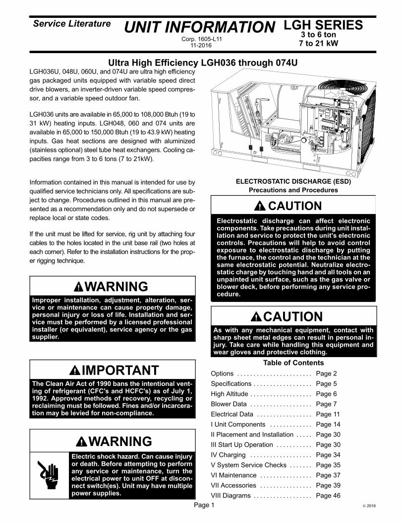
Ultra High Efficiency LGH036 through 074ULGH036U, 048U, 060U, and 074U are ultra high efficiency
gas packaged units equipped with variable speed direct
drive blowers, an inverter-driven variable speed compres
sor, and a variable speed outdoor fan.
LGH036 units are available in 65,000 to 108,000 Btuh (19 to
31 kW) heating inputs. LGH048, 060 and 074 units are
available in 65,000 to 150,000 Btuh (19 to 43.9 kW) heating
inputs. Gas heat sections are designed with aluminized
(stainless optional) steel tube heat exchangers. Cooling ca
pacities range from 3 to 6 tons (7 to 21kW).
Information contained in this manual is intended for use by
qualified service technicians only. All specifications are sub
ject to change. Procedures outlined in this manual are pre
sented as a recommendation only and do not supersede or
replace local or state codes.
If the unit must be lifted for service, rig unit by attaching four
cables to the holes located in the unit base rail (two holes at
each corner). Refer to the installation instructions for the prop
er rigging technique.
WARNINGImproper installation, adjustment, alteration, service or maintenance can cause property damage,personal injury or loss of life. Installation and service must be performed by a licensed professionalinstaller (or equivalent), service agency or the gassupplier.
IMPORTANTThe Clean Air Act of 1990 bans the intentional venting of refrigerant (CFC's and HCFC's) as of July 1,1992. Approved methods of recovery, recycling orreclaiming must be followed. Fines and/or incarceration may be levied for non-compliance.
WARNINGElectric shock hazard. Can cause injuryor death. Before attempting to performany service or maintenance, turn theelectrical power to unit OFF at disconnect switch(es). Unit may have multiplepower supplies.
CAUTIONElectrostatic discharge can affect electroniccomponents. Take precautions during unit installation and service to protect the unit's electroniccontrols. Precautions will help to avoid controlexposure to electrostatic discharge by puttingthe furnace, the control and the technician at thesame electrostatic potential. Neutralize electrostatic charge by touching hand and all tools on anunpainted unit surface, such as the gas valve orblower deck, before performing any service procedure.
ELECTROSTATIC DISCHARGE (ESD)
Precautions and Procedures
CAUTIONAs with any mechanical equipment, contact withsharp sheet metal edges can result in personal injury. Take care while handling this equipment andwear gloves and protective clothing.
Table of Contents
Options Page 2. . . . . . . . . . . . . . . . . . . . . . .
Specifications Page 5. . . . . . . . . . . . . . . . . .
High Altitude Page 6. . . . . . . . . . . . . . . . . . .
Blower Data Page 7. . . . . . . . . . . . . . . . . . .
Electrical Data Page 11. . . . . . . . . . . . . . . . .
I Unit Components Page 14. . . . . . . . . . . . .
II Placement and Installation Page 30. . . . .
III Start Up Operation Page 30. . . . . . . . . . .
IV Charging Page 34. . . . . . . . . . . . . . . . . . .
V System Service Checks Page 35. . . . . . .
VI Maintenance Page 37. . . . . . . . . . . . . . . .
VII Accessories Page 39. . . . . . . . . . . . . . . .
VIII Diagrams Page 46. . . . . . . . . . . . . . . . . .
Page 2
OPTIONS / ACCESSORIES
Item Model Number
Catalog Number
Unit Model No036 048 060 074
COOLING SYSTEMCondensate Drain Trap PVC - C1TRAP20AD2 76W26 OX OX OX OX
Copper - C1TRAP10AD2 76W27 OX OX OX OXDrain Pan Overflow Switch E1SNSR71AD1 68W88 OX OX OX OXService valves Factory O O O OHEATING SYSTEMBottom Gas Piping Kit T1GPKT01AN1 19W50 OX OX OX OXCombustion Air Intake Extensions T1EXTN10AN1 19W51 X X X XGas Heat Input Standard One-Stage - 65 kBtuh input Factory O O O O
Standard Two-Stage - 53/70 kBtuh input Factory 1 O 1 O 1 O 1 OMedium One-Stage - 108 kBtuh input Factory O O O O
Medium Two-Stage - 81/108 kBtuh input Factory O O O OHigh One-Stage - 150 kBtuh input Factory O O O
High Two-Stage - 113/150 kBtuh input Factory O O OHigh Four-Stage - 28/81/113/150 kBtuh input Factory 1 O 1 O 1 O
Low Temperature Vestibule Heater 208/230V-1 or 3ph - E1LTVH10A-1Y 54W23 OX OX OX OX460V-3ph - E1LTVH10A-1G 54W24 OX OX OX OX
LPG/Propane Conversion Kits
For One-Stage models - C1PROP10AP2 11U62 X X X XFor Two-Stage Standard models - C1PROP28A11 21A01 X X X X
For Two-Stage Medium and High models - C1PROP20AP2 11U63 X X X XFor Four-Stage High models - C1PROP30A11 21A02 X X X
Stainless Steel Heat Exchanger (Furnished as Standard when Four-Stage Heat is Ordered) Factory O O O OVertical Vent Extension C1EXTN20FF1 31W62 X X X XBLOWER - SUPPLY AIRMotors Direct Drive - 0.50 hp Factory O
Direct Drive - 0.75 hp Factory ODirect Drive - 1 hp Factory O O
CABINETCombination Coil/Hail Guards C1GARD51AT1 13T03 X X X XCorrosion Protection (indoor coil / outdoor coil) Factory O O O OCONTROLSCommercial Controls CPC Einstein Integration Factory O O O O
Prodigy® Control System - BACnet® Module - C0CTRL60AE1L 59W51 OX OX OX OXProdigy® Control System - LonTalk® Module - C0CTRL65FF1 54W27 OX OX OX OX
Novar® 2051 - C0CTRL40AA1 14U39 OX OX OX OXNovar® LSE Factory O O O O
L Connection® Building Automation System - - - X X X XDirty Filter Switch E1SNSR55AP1 53W66 OX OX OX OXGeneral Purpose Control Kit E1GPBK30C1 13J78 X X X XFresh Air Tempering C1SNSR75AD1 58W63 OX OX OX OXSmoke Detector - Supply or Return (Power board and one sensor) C1SNSR44AP1 53W78 OX OX OX OXSmoke Detector - Supply and Return (Power board and two sensors) C1SNSR43AP1 53W79 OX OX OX OX1 Standard Two-Stage Heat and High Four-Stage Heat is only available with Low NOx Models.
NOTE - Catalog and model numbers shown are for ordering field installed accessories. OX - Configure To Order (Factory Installed) or Field Installed O = Configure To Order (Factory Installed) X = Field Installed
Page 3
OPTIONS / ACCESSORIES
Item Model Number
Catalog Number
Unit Model No036 048 060 074
ELECTRICALVoltage 60 hz 208/230V - 3 phase Factory O O O O
460V - 3 phase Factory O O O OHACR Circuit Breakers Factory O O O ODisconnect Switch 80 amp - T2DISC080NH1 20W24 OX OX OX OXGFI Service Outlets 15 amp non-powered, field-wired - LTAGFIK10/15 74M70 OX OX OX OXWeatherproof Cover for GFI C1GFCI99FF1 10C89 X X X XECONOMIZERStandard Economizer With Outdoor Air Hood (Sensible Control) (Not for Title 24)Standard Economizer - Includes Barometric Relief Dampers and Exhaust Hood
E1ECON30A-2- 90W59 OX OX OX OX
Standard Economizer - Includes Barometric Relief Dampers and Exhaust Hood and Power Exhaust
Factory O O O O
Standard Economizer - No Exhaust Option Factory O O O OHigh Performance Economizer With Outdoor Air Hood (Sensible Control) (Approved for California Title 24 Building Standards)High Performance Economizer - Includes Barometric Relief Dampers with Exhaust Hood and Power Exhaust
E1ECON17A-1 10U54 OX OX OX OX
High Performance Economizer - No Exhaust Option Factory O O O OEconomizer AccessoriesHorizontal Economizer Conversion Kit T1HECK00AN1 17W45 X X X XEconomizer Controls (Not for Title 24)Differential Enthalpy Order 2 - C1SNSR64FF1 53W64 OX OX OX OXSensible Control Sensor is Furnished Factory O O O OSingle Enthalpy C1SNSR64FF1 53W64 OX OX OX OXGlobal Control Sensor Field Provided Factory O O O OBuilding Pressure Control E1GPBK10C1 13J77 X X X XOutdoor Air CFM Control E1GPBK20C1 13J76 X X X XOUTDOOR AIROutdoor Air Dampers With Outdoor Air HoodMotorized C1DAMP21A-1 15D17 OX OX OX OXManual C1DAMP11A-2 15D18 OX OX OX OXPOWER EXHAUST FANStandard StaticNote: Factory installed Power Exhaust Fan includes Exhaust Hood. Barometric Relief Dampers without Exhaust Hood are required (order separately).Note: Field installed Power Exhaust Fans do not include Exhaust Hood. Barometric Relief Dampers with Exhaust Hood are required (order separately).
208/230V-3ph - C1PWRE10A-1P 79W87 OX OX OX OX
460V-3ph - C1PWRE10A-1G 79W88 OX OX OX OX
BAROMETRIC RELIEF1 Barometric Relief Dampers with Exhaust Hood C1DAMP50A-1- 74W38 X X X X2 Barometric Relief Dampers without Exhaust Hood C1DAMP50A-2- 72W89 X X X X1 Required when Economizer is factory installed (no exhaust option) with field installed Power Exhaust Fan option.2 Required when Economizer is factory installed with factory installed Power Exhaust Fan option.
NOTE - Catalog and model numbers shown are for ordering field installed accessories. OX - Configure To Order (Factory Installed) or Field Installed O = Configure To Order (Factory Installed) X = Field Installed
Page 4
OPTIONS / ACCESSORIES
Item Model Number
Catalog Number
Unit Model No036 048 060 074
INDOOR AIR QUALITYAir FiltersHealthy Climate® High Efficiency Air FiltersOrder 4 per unit
MERV 8 (20 x 20 x 2 in.) - C1FLTR15D-1- 54W21 OX OX OX OXMERV 13 (20 x 20 x 2 in.) - C1FLTR40D-1- 52W39 OX OX OX OX
Replaceable Media Filter With Metal Mesh Frame (includes non-pleated filter media)
20 x 20 x 2 in. (Order 4) - K1FLTR30A-2 44N60 X X X X
Indoor Air Quality (CO2) SensorsSensor - Wall-mount, off-white plastic cover with LCD display C0SNSR50AE1L 77N39 X X X XSensor - Wall-mount, off-white plastic cover, no display C0SNSR52AE1L 87N53 X X X XSensor - Black plastic case with LCD display, rated for plenum mounting C0SNSR51AE1L 87N52 X X X XSensor - Wall-mount, black plastic case, no display, rated for plenum mounting C0MISC19AE1 87N54 X X X XCO2 Sensor Duct Mounting Kit - for downflow applications C0MISC19AE1- 85L43 X X X XAspiration Box - for duct mounting non-plenum rated CO2 sensors (87N53 or 77N39)
C0MISC16AE1- 90N43 X X X X
UVC Germicidal Lamps1 Healthy Climate® UVC Light Kit (208/230V-3ph) C1UVCL10AN1- 50W90 OX OX OX OXROOF CURBSHybrid Roof Curbs, Downflow8 in. height C1CURB70A-1 11F50 X X X X
14 in. height C1CURB71A-1 11F51 X X X X
18 in. height C1CURB72A-1 11F52 X X X X
24 in. height C1CURB73A-1 11F53 X X X X
Adjustable Pitched Curb14 in. height C1CURB55AT1 43W27 X X X X
Transition CurbMatches Energence® 036-074 Units to existing L Series® Curbs E1CURB60A-1 20W06 X X X X
CEILING DIFFUSERSStep-Down - Order one RTD11-95S 13K61 X X X X
Flush - Order one FD11-95S 13K56 X X X X
Transitions (Supply and Return) - Order one T1TRAN20N-1 17W54 X X X XSunsource® Commercial Energy SystemSolar Module CE Kit One 285W Solar Module (silver frame), One PanelClaw Polar
Bear III Mounting System and One Enphase M250 Microinverter10U67 X X X X
Solar Power Entry with Disconnect Factory O O O OEnphase Envoy Communications Gateway with Communications Booster (internal) 13L89 X X X XLine Communication Filter (external) C1C400D11A 10F93 X X X XTransformer (5 kW) E1TRFM15AD3Y (208Y to 208 VAC Delta) 11H71 X X X X
E1TRFM15AD2Y (230 VAC Delta) 11H28 X X X X
E1TRFM15AD3G (460 VAC Delta or Wye) 11H29 X X X X1 Lamps operate on 110-230V single-phase power supply. Step-down transformer may be ordered separately for 460V. Alternately, 110V power supply may be used to
directly power the UVC ballast(s).
NOTE - Catalog and model numbers shown are for ordering field installed accessories. OX - Configure To Order (Factory Installed) or Field Installed O = Configure To Order (Factory Installed) X = Field Installed
Page 5
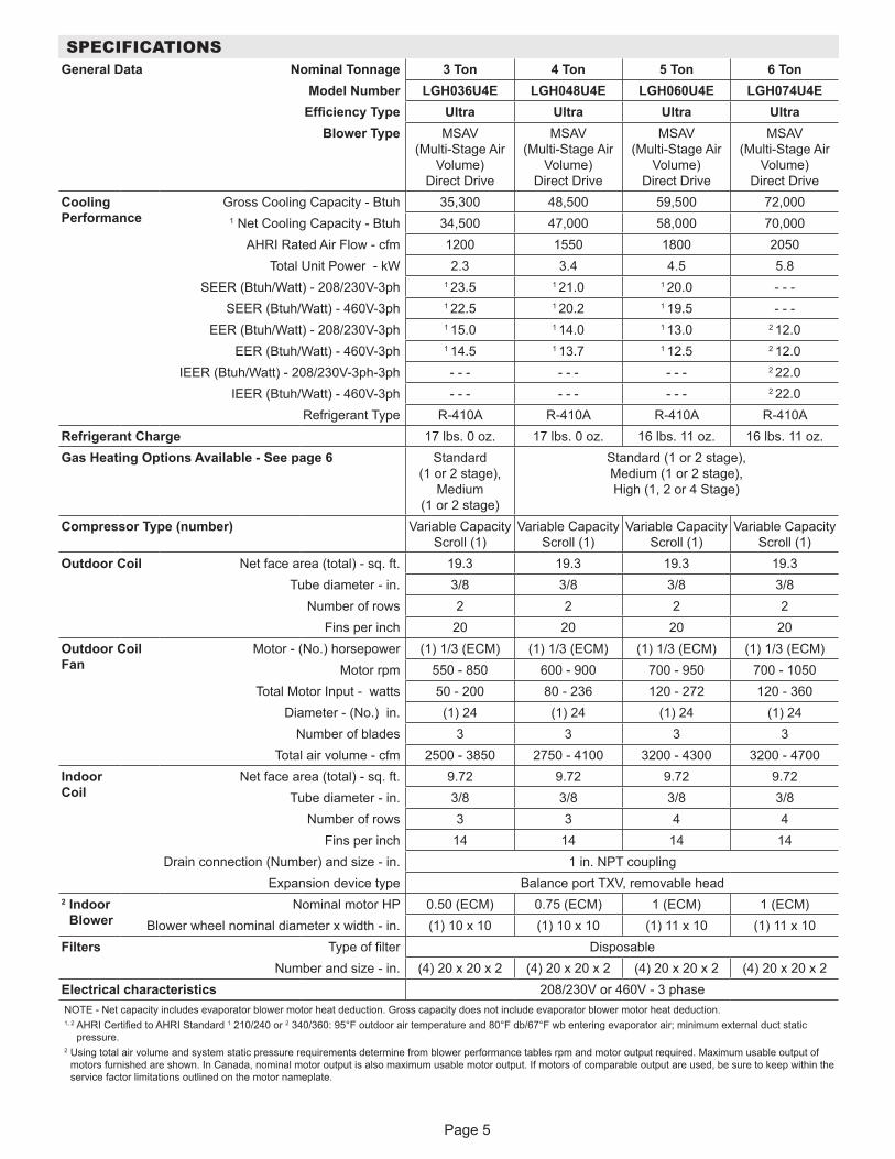
SPECIFICATIONSGeneral Data Nominal Tonnage 3 Ton 4 Ton 5 Ton 6 Ton
Model Number LGH036U4E LGH048U4E LGH060U4E LGH074U4EEfficiency Type Ultra Ultra Ultra Ultra
Blower Type MSAV (Multi-Stage Air
Volume) Direct Drive
MSAV (Multi-Stage Air
Volume) Direct Drive
MSAV (Multi-Stage Air
Volume) Direct Drive
MSAV (Multi-Stage Air
Volume) Direct Drive
Cooling Performance
Gross Cooling Capacity - Btuh 35,300 48,500 59,500 72,0001 Net Cooling Capacity - Btuh 34,500 47,000 58,000 70,000
AHRI Rated Air Flow - cfm 1200 1550 1800 2050Total Unit Power - kW 2.3 3.4 4.5 5.8
SEER (Btuh/Watt) - 208/230V-3ph 1 23.5 1 21.0 1 20.0 - - -SEER (Btuh/Watt) - 460V-3ph 1 22.5 1 20.2 1 19.5 - - -
EER (Btuh/Watt) - 208/230V-3ph 1 15.0 1 14.0 1 13.0 2 12.0 EER (Btuh/Watt) - 460V-3ph 1 14.5 1 13.7 1 12.5 2 12.0
IEER (Btuh/Watt) - 208/230V-3ph-3ph - - - - - - - - - 2 22.0IEER (Btuh/Watt) - 460V-3ph - - - - - - - - - 2 22.0
Refrigerant Type R-410A R-410A R-410A R-410ARefrigerant Charge 17 lbs. 0 oz. 17 lbs. 0 oz. 16 lbs. 11 oz. 16 lbs. 11 oz.Gas Heating Options Available - See page 6 Standard
(1 or 2 stage), Medium
(1 or 2 stage)
Standard (1 or 2 stage), Medium (1 or 2 stage), High (1, 2 or 4 Stage)
Compressor Type (number) Variable Capacity Scroll (1)
Variable Capacity Scroll (1)
Variable Capacity Scroll (1)
Variable Capacity Scroll (1)
Outdoor Coil Net face area (total) - sq. ft. 19.3 19.3 19.3 19.3Tube diameter - in. 3/8 3/8 3/8 3/8
Number of rows 2 2 2 2Fins per inch 20 20 20 20
Outdoor Coil Fan
Motor - (No.) horsepower (1) 1/3 (ECM) (1) 1/3 (ECM) (1) 1/3 (ECM) (1) 1/3 (ECM)Motor rpm 550 - 850 600 - 900 700 - 950 700 - 1050
Total Motor Input - watts 50 - 200 80 - 236 120 - 272 120 - 360Diameter - (No.) in. (1) 24 (1) 24 (1) 24 (1) 24
Number of blades 3 3 3 3Total air volume - cfm 2500 - 3850 2750 - 4100 3200 - 4300 3200 - 4700
Indoor Coil
Net face area (total) - sq. ft. 9.72 9.72 9.72 9.72Tube diameter - in. 3/8 3/8 3/8 3/8
Number of rows 3 3 4 4Fins per inch 14 14 14 14
Drain connection (Number) and size - in. 1 in. NPT couplingExpansion device type Balance port TXV, removable head
2 Indoor Blower
Nominal motor HP 0.50 (ECM) 0.75 (ECM) 1 (ECM) 1 (ECM)Blower wheel nominal diameter x width - in. (1) 10 x 10 (1) 10 x 10 (1) 11 x 10 (1) 11 x 10
Filters Type of filter DisposableNumber and size - in. (4) 20 x 20 x 2 (4) 20 x 20 x 2 (4) 20 x 20 x 2 (4) 20 x 20 x 2
Electrical characteristics 208/230V or 460V - 3 phaseNOTE - Net capacity includes evaporator blower motor heat deduction. Gross capacity does not include evaporator blower motor heat deduction.1, 2 AHRI Certified to AHRI Standard 1 210/240 or 2 340/360: 95°F outdoor air temperature and 80°F db/67°F wb entering evaporator air; minimum external duct static
pressure.2 Using total air volume and system static pressure requirements determine from blower performance tables rpm and motor output required. Maximum usable output of
motors furnished are shown. In Canada, nominal motor output is also maximum usable motor output. If motors of comparable output are used, be sure to keep within the service factor limitations outlined on the motor nameplate.
Page 6
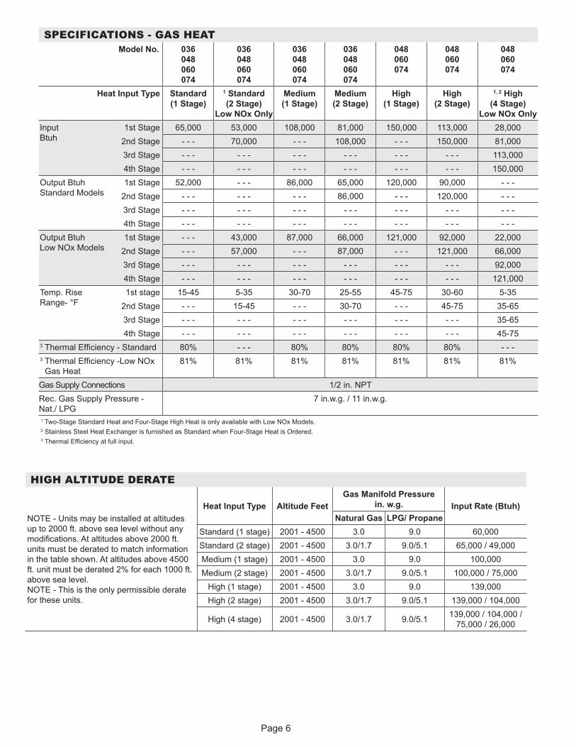
HIGH ALTITUDE DERATE
NOTE - Units may be installed at altitudes up to 2000 ft. above sea level without any modifications. At altitudes above 2000 ft. units must be derated to match information in the table shown. At altitudes above 4500 ft. unit must be derated 2% for each 1000 ft. above sea level. NOTE - This is the only permissible derate for these units.
Heat Input Type Altitude Feet Gas Manifold Pressure
in. w.g. Input Rate (Btuh) Natural Gas LPG/ Propane
Standard (1 stage) 2001 - 4500 3.0 9.0 60,000Standard (2 stage) 2001 - 4500 3.0/1.7 9.0/5.1 65,000 / 49,000Medium (1 stage) 2001 - 4500 3.0 9.0 100,000Medium (2 stage) 2001 - 4500 3.0/1.7 9.0/5.1 100,000 / 75,000
High (1 stage) 2001 - 4500 3.0 9.0 139,000High (2 stage) 2001 - 4500 3.0/1.7 9.0/5.1 139,000 / 104,000
High (4 stage) 2001 - 4500 3.0/1.7 9.0/5.1 139,000 / 104,000 / 75,000 / 26,000
SPECIFICATIONS - GAS HEAT Model No. 036
048 060 074
036 048 060 074
036 048 060 074
036 048 060 074
048 060 074
048 060 074
048 060 074
Heat Input Type Standard (1 Stage)
1 Standard (2 Stage)
Low NOx Only
Medium (1 Stage)
Medium (2 Stage)
High (1 Stage)
High (2 Stage)
1, 2 High (4 Stage)
Low NOx OnlyInput Btuh
1st Stage 65,000 53,000 108,000 81,000 150,000 113,000 28,0002nd Stage - - - 70,000 - - - 108,000 - - - 150,000 81,0003rd Stage - - - - - - - - - - - - - - - - - - 113,0004th Stage - - - - - - - - - - - - - - - - - - 150,000
Output Btuh Standard Models
1st Stage 52,000 - - - 86,000 65,000 120,000 90,000 - - -2nd Stage - - - - - - - - - 86,000 - - - 120,000 - - -3rd Stage - - - - - - - - - - - - - - - - - - - - -4th Stage - - - - - - - - - - - - - - - - - - - - -
Output Btuh Low NOx Models
1st Stage - - - 43,000 87,000 66,000 121,000 92,000 22,0002nd Stage - - - 57,000 - - - 87,000 - - - 121,000 66,0003rd Stage - - - - - - - - - - - - - - - - - - 92,0004th Stage - - - - - - - - - - - - - - - - - - 121,000
Temp. Rise Range- °F
1st stage 15-45 5-35 30-70 25-55 45-75 30-60 5-352nd Stage - - - 15-45 - - - 30-70 - - - 45-75 35-653rd Stage - - - - - - - - - - - - - - - - - - 35-654th Stage - - - - - - - - - - - - - - - - - - 45-75
3 Thermal Efficiency - Standard 80% - - - 80% 80% 80% 80% - - -3 Thermal Efficiency -Low NOx
Gas Heat81% 81% 81% 81% 81% 81% 81%
Gas Supply Connections 1/2 in. NPTRec. Gas Supply Pressure - Nat./ LPG
7 in.w.g. / 11 in.w.g.
1 Two-Stage Standard Heat and Four-Stage High Heat is only available with Low NOx Models.2 Stainless Steel Heat Exchanger is furnished as Standard when Four-Stage Heat is Ordered.3 Thermal Efficiency at full input.
Page 7
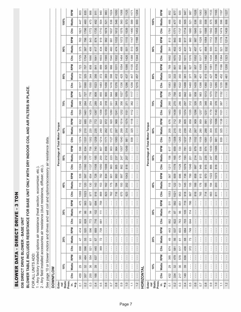
BLO
WE
R D
ATA
- D
IRE
CT
DR
IVE
- 3
TO
N03
6 D
IREC
T D
RIV
E B
LOW
ER -
BA
SE U
NIT
B
LOW
ER T
AB
LE IN
CLU
DES
RES
ISTA
NC
E FO
R B
ASE
UN
IT O
NLY
WIT
H D
RY IN
DO
OR
CO
IL A
ND
AIR
FIL
TER
S IN
PLA
CE.
FOR
ALL
UN
ITS
AD
D:
1 - A
ny fa
ctor
y in
stal
led
optio
ns a
ir re
sist
ance
(hea
t sec
tion,
eco
nom
izer
, etc
.).
2 - A
ny fi
eld
inst
alle
d ac
cess
orie
s ai
r res
ista
nce
(duc
t res
ista
nce,
diff
user
, etc
.).S
ee p
age
10 o
r blo
wer
mot
ors
and
driv
es a
nd w
et c
oil a
nd o
ptio
ns/a
cces
sory
air
resi
stan
ce d
ata.
DO
WN
FLO
WEx
ter-
nal
Stat
ic
Pres
s.
in.
w.g
.
Perc
enta
ge o
f Tot
al M
otor
Tor
que
10%
20%
30%
40%
50%
60%
70%
80%
90%
100%
Cfm
Wat
tsR
PMC
fmW
atts
RPM
Cfm
Wat
tsR
PMC
fmW
atts
RPM
Cfm
Wat
tsR
PMC
fmW
atts
RPM
Cfm
Wat
tsR
PMC
fmW
atts
RPM
Cfm
Wat
tsR
PMC
fmW
atts
RPM
0.1
459
2938
069
847
414
903
7647
510
6911
053
912
2415
359
813
7419
563
215
0024
867
716
1731
272
317
2937
576
318
2144
780
3
0.2
357
3246
459
655
520
828
8656
310
2312
059
711
8016
563
413
3121
068
514
6126
472
715
9032
575
717
0438
779
617
9646
083
5
0.3
255
3655
452
161
596
772
9460
797
713
065
411
3717
770
613
0222
072
014
3527
477
615
5034
480
816
6640
684
317
7247
386
6
0.4
166
3963
744
567
669
716
102
694
916
143
728
1108
185
740
1258
235
772
1397
289
808
1523
356
841
1641
417
874
1735
492
911
0.5
- - -
- - -
- - -
369
7273
966
111
175
986
915
378
210
5020
080
712
1424
982
213
5830
485
514
8337
288
916
0343
491
917
1050
494
0
0.6
- - -
- - -
- - -
- - -
- - -
- - -
- - -
- - -
- - -
823
162
834
1006
212
856
1171
262
872
1319
318
900
1456
383
920
1565
450
962
1674
521
983
0.7
- - -
- - -
- - -
- - -
- - -
- - -
- - -
- - -
- - -
762
175
901
963
223
903
1127
275
920
1280
331
944
1416
398
966
1540
460
991
1637
536
1024
0.8
- - -
- - -
- - -
- - -
- - -
- - -
- - -
- - -
- - -
716
184
950
905
237
964
1083
287
968
1241
344
986
1376
412
1011
1502
474
1032
1612
546
1050
0.9
- - -
- - -
- - -
- - -
- - -
- - -
- - -
- - -
- - -
670
193
997
862
247
1007
1040
299
1014
1202
356
1027
1336
425
1054
1464
488
1072
1576
560
1088
1.0
- - -
- - -
- - -
- - -
- - -
- - -
- - -
- - -
- - -
623
202
1043
818
257
1049
981
314
1074
1151
371
1079
1296
437
1095
1426
501
1110
1539
573
1125
1.1
- - -
- - -
- - -
- - -
- - -
- - -
- - -
- - -
- - -
- - -
- - -
- - -
- - -
- - -
- - -
938
325
1118
1112
382
1117
1256
447
1135
1388
513
1147
1490
589
1171
1.2
- - -
- - -
- - -
- - -
- - -
- - -
- - -
- - -
- - -
- - -
- - -
- - -
- - -
- - -
- - -
- - -
- - -
- - -
- - -
- - -
- - -
1215
457
1174
1344
526
1188
1453
600
1204
HO
RIZ
ON
TAL
Exte
r-na
l St
atic
Pr
ess.
in
. w
.g.
Perc
enta
ge o
f Tot
al M
otor
Tor
que
10%
20%
30%
40%
50%
60%
70%
80%
90%
100%
Cfm
Wat
tsR
PMC
fmW
atts
RPM
Cfm
Wat
tsR
PMC
fmW
atts
RPM
Cfm
Wat
tsR
PMC
fmW
atts
RPM
Cfm
Wat
tsR
PMC
fmW
atts
RPM
Cfm
Wat
tsR
PMC
fmW
atts
RPM
0.1
432
2939
567
449
443
882
7951
110
5311
556
712
1115
661
713
3420
567
614
6326
072
515
8332
276
916
9239
181
317
9146
685
2
0.2
334
3247
958
156
537
822
8758
210
2112
260
911
7816
565
913
0821
571
214
3927
075
815
6033
380
116
7040
284
317
7147
787
7
0.3
217
3657
851
761
603
763
9665
195
313
769
611
2817
972
012
6523
076
814
0028
680
915
2235
085
016
3442
088
817
3749
492
0
0.4
149
3963
643
668
684
703
105
719
918
145
738
1079
193
781
1237
239
805
1374
297
842
1498
361
881
1611
431
917
1714
505
947
0.5
- - -
- - -
- - -
372
7374
964
411
478
686
715
579
910
4620
182
011
9425
485
813
3531
289
114
6037
792
715
7644
796
016
8052
198
7
0.6
- - -
- - -
- - -
- - -
- - -
- - -
- - -
- - -
- - -
816
166
858
997
214
879
1152
267
909
1296
326
938
1435
387
957
1552
457
987
1645
536
1026
0.7
- - -
- - -
- - -
- - -
- - -
- - -
- - -
- - -
- - -
765
176
915
948
227
936
1109
280
959
1257
339
983
1398
401
1000
1517
471
1026
1611
550
1063
0.8
- - -
- - -
- - -
- - -
- - -
- - -
- - -
- - -
- - -
714
185
970
915
235
974
1081
288
991
1231
348
1013
1360
415
1041
1482
484
1064
1588
558
1087
0.9
- - -
- - -
- - -
- - -
- - -
- - -
- - -
- - -
- - -
663
194
1022
866
247
1030
1024
304
1052
1179
364
1070
1322
427
1081
1434
500
1112
1542
575
1133
1.0
- - -
- - -
- - -
- - -
- - -
- - -
- - -
- - -
- - -
611
203
1073
816
259
1085
981
315
1096
1140
376
1112
1285
438
1118
1399
511
1146
1508
586
1165
1.1
- - -
- - -
- - -
- - -
- - -
- - -
- - -
- - -
- - -
- - -
- - -
- - -
- - -
- - -
- - -
939
325
1138
1101
387
1152
1235
452
1166
1364
521
1178
1474
596
1197
1.2
- - -
- - -
- - -
- - -
- - -
- - -
- - -
- - -
- - -
- - -
- - -
- - -
- - -
- - -
- - -
- - -
- - -
- - -
- - -
- - -
- - -
1198
461
1200
1323
532
1214
1439
606
1227

Page 8
BLO
WE
R D
ATA
- D
IRE
CT
DR
IVE
- 4
TO
N04
8 D
IREC
T D
RIV
E B
LOW
ER -
BA
SE U
NIT
B
LOW
ER T
AB
LE IN
CLU
DES
RES
ISTA
NC
E FO
R B
ASE
UN
IT O
NLY
WIT
H D
RY IN
DO
OR
CO
IL A
ND
AIR
FIL
TER
S IN
PLA
CE.
FOR
ALL
UN
ITS
AD
D:
1 - A
ny fa
ctor
y in
stal
led
optio
ns a
ir re
sist
ance
(hea
t sec
tion,
eco
nom
izer
, etc
.).
2 - A
ny fi
eld
inst
alle
d ac
cess
orie
s ai
r res
ista
nce
(duc
t res
ista
nce,
diff
user
, etc
.).S
ee p
age
10 fo
r blo
wer
mot
ors
and
driv
es a
nd w
et c
oil a
nd o
ptio
ns/a
cces
sory
air
resi
stan
ce d
ata.
DO
WN
FLO
WEx
tern
al
Stat
ic
Pres
s.
in. w
.g.
Perc
enta
ge o
f Tot
al M
otor
Tor
que
10%
20%
30%
40%
50%
60%
70%
80%
90%
100%
Cfm
Wat
tsR
PMC
fmW
atts
RPM
Cfm
Wat
tsR
PMC
fmW
atts
RPM
Cfm
Wat
tsR
PMC
fmW
atts
RPM
Cfm
Wat
tsR
PMC
fmW
atts
RPM
Cfm
Wat
tsR
PMC
fmW
atts
RPM
0.1
682
4642
089
479
499
1148
131
579
1366
192
651
1551
268
726
1725
348
781
1885
445
840
2031
550
893
2165
669
950
2290
790
993
0.2
583
5251
083
687
562
1105
142
635
1329
204
697
1530
279
756
1695
368
827
1856
466
883
2006
567
925
2149
683
972
2271
813
1023
0.3
484
5960
177
896
629
1062
152
688
1292
217
744
1500
294
800
1675
380
856
1837
479
910
1981
585
958
2125
704
1005
2252
834
1051
0.4
410
6466
672
010
569
710
1916
273
912
5523
179
214
6930
984
116
4539
789
818
0849
895
019
5660
399
221
0072
310
3622
3385
110
76
0.5
- - -
- - -
- - -
662
114
764
961
176
805
1218
244
840
1428
327
895
1615
414
937
1780
515
987
1931
622
1025
2076
741
1066
2205
874
1111
0.6
- - -
- - -
- - -
- - -
- - -
- - -
- - -
- - -
- - -
1182
257
887
1398
341
934
1585
429
974
1751
532
1022
1906
641
1058
2052
758
1095
2186
886
1131
0.7
- - -
- - -
- - -
- - -
- - -
- - -
- - -
- - -
- - -
1145
270
933
1367
354
972
1555
443
1009
1722
548
1056
1874
663
1098
2028
774
1122
2148
903
1167
0.8
- - -
- - -
- - -
- - -
- - -
- - -
- - -
- - -
- - -
1096
287
992
1326
372
1021
1515
462
1056
1693
564
1090
1850
679
1129
1996
792
1157
2111
913
1196
0.9
- - -
- - -
- - -
- - -
- - -
- - -
- - -
- - -
- - -
1047
302
1047
1296
385
1058
1485
476
1090
1664
579
1123
1824
693
1157
1963
807
1188
2073
916
1219
1.0
- - -
- - -
- - -
- - -
- - -
- - -
- - -
- - -
- - -
1010
312
1085
1255
403
1107
1455
491
1125
1635
594
1155
1787
710
1195
1931
818
1216
2036
912
1236
1.1
- - -
- - -
- - -
- - -
- - -
- - -
- - -
- - -
- - -
- - -
- - -
- - -
- - -
- - -
- - -
1425
505
1160
1606
609
1188
1762
717
1216
1883
828
1250
1960
890
1260
1.2
- - -
- - -
- - -
- - -
- - -
- - -
- - -
- - -
- - -
- - -
- - -
- - -
- - -
- - -
- - -
- - -
- - -
- - -
- - -
- - -
- - -
1687
715
1254
1834
827
1275
1848
834
1274
HO
RIZ
ON
TAL
Exte
rnal
St
atic
Pr
ess.
in
. w.g
.
Perc
enta
ge o
f Tot
al M
otor
Tor
que
10%
20%
30%
40%
50%
60%
70%
80%
90%
100%
Cfm
Wat
tsR
PMC
fmW
atts
RPM
Cfm
Wat
tsR
PMC
fmW
atts
RPM
Cfm
Wat
tsR
PMC
fmW
atts
RPM
Cfm
Wat
tsR
PMC
fmW
atts
RPM
Cfm
Wat
tsR
PMC
fmW
atts
RPM
0.1
641
4644
387
582
522
1127
137
614
1334
202
691
1524
280
762
1694
367
827
1866
470
881
1997
581
955
2119
699
1010
2241
830
1058
0.2
568
5050
583
190
582
1097
144
650
1310
211
723
1504
290
793
1671
379
859
1829
484
921
1977
600
986
2106
715
1032
2227
846
1080
0.3
483
5658
477
898
647
1050
155
706
1269
225
777
1470
308
844
1642
396
900
1799
498
957
1953
621
1022
2079
743
1072
2199
873
1118
0.4
398
6266
172
410
670
710
0416
776
412
2824
083
114
3632
589
116
1241
394
117
7751
198
519
3064
010
5520
6275
810
9621
8188
811
40
0.5
- - -
- - -
- - -
671
113
763
957
179
822
1201
250
867
1413
335
921
1588
427
973
1748
530
1025
1906
657
1087
2036
777
1129
2153
904
1170
0.6
- - -
- - -
- - -
- - -
- - -
- - -
- - -
- - -
- - -
1161
265
919
1378
350
964
1552
447
1019
1718
549
1064
1874
676
1124
2000
796
1166
2115
917
1202
0.7
- - -
- - -
- - -
- - -
- - -
- - -
- - -
- - -
- - -
1120
279
970
1344
365
1006
1529
459
1049
1696
564
1093
1850
688
1150
1974
805
1189
2078
922
1228
0.8
- - -
- - -
- - -
- - -
- - -
- - -
- - -
- - -
- - -
1093
288
1003
1310
379
1047
1493
477
1091
1667
583
1131
1818
700
1180
1930
812
1220
2040
919
1246
0.9
- - -
- - -
- - -
- - -
- - -
- - -
- - -
- - -
- - -
1052
302
1051
1275
393
1087
1469
488
1118
1644
595
1158
1779
711
1213
1896
812
1239
1984
903
1265
1.0
- - -
- - -
- - -
- - -
- - -
- - -
- - -
- - -
- - -
1012
314
1096
1241
407
1128
1434
502
1155
1615
610
1191
1747
715
1235
1843
802
1259
1910
865
1276
1.1
- - -
- - -
- - -
- - -
- - -
- - -
- - -
- - -
- - -
- - -
- - -
- - -
- - -
- - -
- - -
1386
516
1201
1571
625
1232
1684
713
1266
1738
760
1277
1760
775
1282
1.2
- - -
- - -
- - -
- - -
- - -
- - -
- - -
- - -
- - -
- - -
- - -
- - -
- - -
- - -
- - -
- - -
- - -
- - -
- - -
- - -
- - -
1620
697
1282
1633
707
1283
1667
736
1296
Page 9
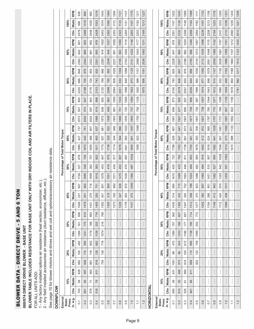
BLO
WE
R D
ATA
- D
IRE
CT
DR
IVE
- 5
AN
D 6
TO
N06
0/07
4 D
IREC
T D
RIV
E B
LOW
ER -
BA
SE U
NIT
B
LOW
ER T
AB
LE IN
CLU
DES
RES
ISTA
NC
E FO
R B
ASE
UN
IT O
NLY
WIT
H D
RY IN
DO
OR
CO
IL A
ND
AIR
FIL
TER
S IN
PLA
CE.
FOR
ALL
UN
ITS
AD
D:
1 - A
ny fa
ctor
y in
stal
led
optio
ns a
ir re
sist
ance
(hea
t sec
tion,
eco
nom
izer
, etc
.).
2 - A
ny fi
eld
inst
alle
d ac
cess
orie
s ai
r res
ista
nce
(duc
t res
ista
nce,
diff
user
, etc
.).S
ee p
age
10 fo
r blo
wer
mot
ors
and
driv
es a
nd w
et c
oil a
nd o
ptio
ns/a
cces
sory
air
resi
stan
ce d
ata.
DO
WN
FLO
WEx
tern
al
Stat
ic
Pres
s.
in. w
.g.
Perc
enta
ge o
f Tot
al M
otor
Tor
que
10%
20%
30%
40%
50%
60%
70%
80%
90%
100%
Cfm
Wat
tsR
PMC
fmW
atts
RPM
Cfm
Wat
tsR
PMC
fmW
atts
RPM
Cfm
Wat
tsR
PMC
fmW
atts
RPM
Cfm
Wat
tsR
PMC
fmW
atts
RPM
Cfm
Wat
tsR
PMC
fmW
atts
RPM
0.1
743
5842
899
210
049
212
8416
155
615
2623
160
717
2632
767
818
9042
773
720
7255
780
022
2068
684
823
6284
290
124
7899
693
8
0.2
661
6549
792
811
055
612
3117
561
014
7925
166
216
8534
872
618
7244
076
120
5257
482
721
9870
587
623
4486
092
524
6810
1696
9
0.3
579
7156
388
111
860
211
7918
866
314
3127
071
616
5836
275
718
3546
680
720
2459
786
321
7672
490
323
2288
195
224
4810
3599
3
0.4
518
7661
181
812
866
211
2620
271
614
0028
375
116
1838
380
218
1148
383
719
9561
989
821
5374
393
023
0190
097
824
2810
5310
16
0.5
- - -
- - -
- - -
754
138
719
1074
216
768
1352
301
801
1578
403
847
1775
507
881
1972
636
925
2120
769
968
2280
919
1002
2403
1074
1043
0.6
- - -
- - -
- - -
- - -
- - -
- - -
- - -
- - -
- - -
1305
319
850
1551
416
875
1738
529
922
1938
659
963
2098
785
992
2248
945
1037
2383
1090
1064
0.7
- - -
- - -
- - -
- - -
- - -
- - -
- - -
- - -
- - -
1273
330
882
1511
434
917
1714
544
948
1903
681
1000
2064
808
1026
2227
961
1059
2353
1113
1094
0.8
- - -
- - -
- - -
- - -
- - -
- - -
- - -
- - -
- - -
1226
347
928
1470
453
957
1678
564
986
1869
701
1033
2031
830
1058
2195
983
1090
2323
1133
1121
0.9
- - -
- - -
- - -
- - -
- - -
- - -
- - -
- - -
- - -
1178
363
972
1430
470
997
1641
583
1022
1835
720
1065
1998
849
1088
2163
1004
1119
2293
1151
1147
1.0
- - -
- - -
- - -
- - -
- - -
- - -
- - -
- - -
- - -
1147
374
1000
1390
487
1034
1605
601
1057
1800
737
1094
1953
873
1125
2131
1022
1146
2263
1167
1170
1.1
- - -
- - -
- - -
- - -
- - -
- - -
- - -
- - -
- - -
- - -
- - -
- - -
- - -
- - -
- - -
1556
623
1099
1755
756
1129
1920
888
1151
2089
1043
1177
2203
1193
1211
1.2
- - -
- - -
- - -
- - -
- - -
- - -
- - -
- - -
- - -
- - -
- - -
- - -
- - -
- - -
- - -
- - -
- - -
- - -
- - -
- - -
- - -
1875
906
1181
2036
1063
1211
2169
1213
1227
HO
RIZ
ON
TAL
Exte
rnal
St
atic
Pr
ess.
in
. w.g
.
Perc
enta
ge o
f Tot
al M
otor
Tor
que
10%
20%
30%
40%
50%
60%
70%
80%
90%
100%
Cfm
Wat
tsR
PMC
fmW
atts
RPM
Cfm
Wat
tsR
PMC
fmW
atts
RPM
Cfm
Wat
tsR
PMC
fmW
atts
RPM
Cfm
Wat
tsR
PMC
fmW
atts
RPM
Cfm
Wat
tsR
PMC
fmW
atts
RPM
0.1
695
4943
110
5188
470
1280
157
562
1430
314
665
1615
420
753
1798
526
807
1957
656
873
2100
793
925
2228
947
979
2351
1107
1022
0.2
610
5549
597
396
543
1233
166
607
1382
332
715
1589
433
782
1762
547
847
1927
677
905
2079
808
947
2207
965
1002
2332
1126
1043
0.3
525
6156
091
410
461
211
8617
765
713
4734
575
215
6344
681
117
3856
187
319
0769
092
720
4783
097
921
8698
210
2423
0811
4810
69
0.4
461
6661
185
611
569
511
3819
071
413
1235
878
815
2546
485
317
0258
191
118
7770
995
820
2684
499
921
6599
810
4622
8911
6410
88
0.5
- - -
- - -
- - -
822
122
749
1095
202
772
1277
370
823
1486
482
893
1678
593
936
1847
726
987
1995
864
1030
2144
1013
1067
2264
1182
1111
0.6
- - -
- - -
- - -
- - -
- - -
- - -
- - -
- - -
- - -
1242
382
857
1460
494
919
1642
612
972
1827
738
1007
1974
877
1050
2112
1035
1096
2239
1197
1133
0.7
- - -
- - -
- - -
- - -
- - -
- - -
- - -
- - -
- - -
1194
398
901
1421
510
957
1618
624
995
1787
760
1044
1943
896
1079
2091
1048
1115
2208
1213
1158
0.8
- - -
- - -
- - -
- - -
- - -
- - -
- - -
- - -
- - -
1148
413
943
1382
527
993
1582
641
1029
1757
775
1071
1912
914
1107
2059
1065
1142
2184
1223
1176
0.9
- - -
- - -
- - -
- - -
- - -
- - -
- - -
- - -
- - -
1112
424
974
1343
542
1028
1546
657
1061
1727
789
1096
1880
932
1135
2028
1081
1167
2147
1233
1200
1.0
- - -
- - -
- - -
- - -
- - -
- - -
- - -
- - -
- - -
1069
438
1011
1305
557
1062
1510
673
1092
1687
807
1129
1849
948
1162
1996
1095
1191
2110
1238
1221
1.1
- - -
- - -
- - -
- - -
- - -
- - -
- - -
- - -
- - -
- - -
- - -
- - -
- - -
- - -
- - -
1474
688
1122
1652
822
1156
1818
964
1188
1964
1107
1212
2060
1235
1243
1.2
- - -
- - -
- - -
- - -
- - -
- - -
- - -
- - -
- - -
- - -
- - -
- - -
- - -
- - -
- - -
- - -
- - -
- - -
- - -
- - -
- - -
1781
982
1217
1912
1123
1245
2010
1221
1258
Page 10
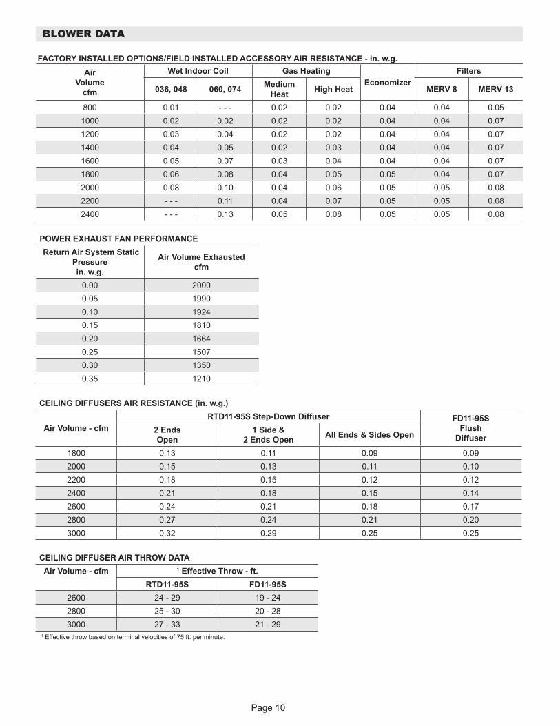
FACTORY INSTALLED OPTIONS/FIELD INSTALLED ACCESSORY AIR RESISTANCE - in. w.g.Air
Volume cfm
Wet Indoor Coil Gas HeatingEconomizer
Filters
036, 048 060, 074 Medium Heat High Heat MERV 8 MERV 13
800 0.01 - - - 0.02 0.02 0.04 0.04 0.051000 0.02 0.02 0.02 0.02 0.04 0.04 0.071200 0.03 0.04 0.02 0.02 0.04 0.04 0.071400 0.04 0.05 0.02 0.03 0.04 0.04 0.071600 0.05 0.07 0.03 0.04 0.04 0.04 0.071800 0.06 0.08 0.04 0.05 0.05 0.04 0.072000 0.08 0.10 0.04 0.06 0.05 0.05 0.082200 - - - 0.11 0.04 0.07 0.05 0.05 0.082400 - - - 0.13 0.05 0.08 0.05 0.05 0.08
POWER EXHAUST FAN PERFORMANCE Return Air System Static
Pressure in. w.g.
Air Volume Exhausted cfm
0.00 20000.05 19900.10 19240.15 18100.20 16640.25 15070.30 13500.35 1210
BLOWER DATA
CEILING DIFFUSERS AIR RESISTANCE (in. w.g.)
Air Volume - cfmRTD11-95S Step-Down Diffuser FD11-95S
Flush Diffuser
2 Ends Open
1 Side & 2 Ends Open All Ends & Sides Open
1800 0.13 0.11 0.09 0.092000 0.15 0.13 0.11 0.102200 0.18 0.15 0.12 0.122400 0.21 0.18 0.15 0.142600 0.24 0.21 0.18 0.172800 0.27 0.24 0.21 0.203000 0.32 0.29 0.25 0.25
CEILING DIFFUSER AIR THROW DATAAir Volume - cfm 1 Effective Throw - ft.
RTD11-95S FD11-95S2600 24 - 29 19 - 242800 25 - 30 20 - 283000 27 - 33 21 - 29
1 Effective throw based on terminal velocities of 75 ft. per minute.
Page 11
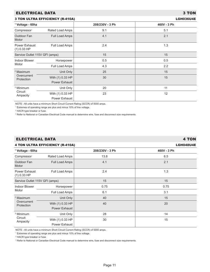
ELECTRICAL DATA 3 TON3 TON ULTRA EFFICIENCY (R-410A) LGH036U4E1 Voltage - 60hz 208/230V - 3 Ph 460V - 3 Ph
Compressor Rated Load Amps 9.1 5.1
Outdoor Fan Motor
Full Load Amps 4.1 2.1
Power Exhaust (1) 0.33 HP
Full Load Amps 2.4 1.3
Service Outlet 115V GFI (amps) 15 15
Indoor Blower Motor
Horsepower 0.5 0.5
Full Load Amps 4.3 2.22 Maximum
Overcurrent Protection
Unit Only 25 15
With (1) 0.33 HPPower Exhaust
30 15
3 Minimum Circuit Ampacity
Unit Only 20 11
With (1) 0.33 HPPower Exhaust
23 12
NOTE - All units have a minimum Short Circuit Current Rating (SCCR) of 5000 amps.1 Extremes of operating range are plus and minus 10% of line voltage.2 HACR type breaker or fuse.3 Refer to National or Canadian Electrical Code manual to determine wire, fuse and disconnect size requirements.
ELECTRICAL DATA 4 TON4 TON ULTRA EFFICIENCY (R-410A) LGH048U4E1 Voltage - 60hz 208/230V - 3 Ph 460V - 3 Ph
Compressor Rated Load Amps 13.8 6.5
Outdoor Fan Motor
Full Load Amps 4.1 2.1
Power Exhaust (1) 0.33 HP
Full Load Amps 2.4 1.3
Service Outlet 115V GFI (amps) 15 15
Indoor Blower Motor
Horsepower 0.75 0.75
Full Load Amps 6.1 3.12 Maximum
Overcurrent Protection
Unit Only 40 15
With (1) 0.33 HPPower Exhaust
40 20
3 Minimum Circuit Ampacity
Unit Only 28 14
With (1) 0.33 HPPower Exhaust
30 15
NOTE - All units have a minimum Short Circuit Current Rating (SCCR) of 5000 amps.1 Extremes of operating range are plus and minus 10% of line voltage.2 HACR type breaker or fuse.3 Refer to National or Canadian Electrical Code manual to determine wire, fuse and disconnect size requirements.
Page 12
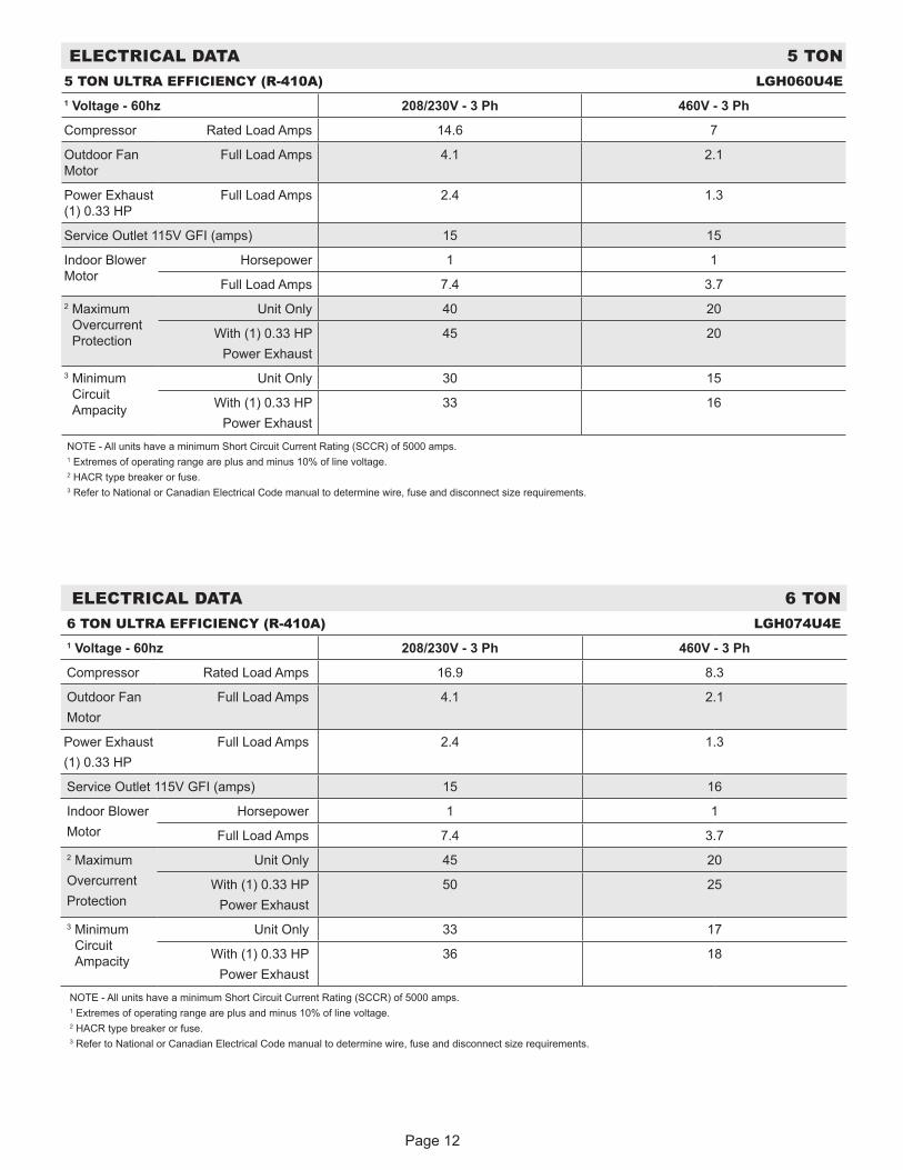
ELECTRICAL DATA 5 TON5 TON ULTRA EFFICIENCY (R-410A) LGH060U4E1 Voltage - 60hz 208/230V - 3 Ph 460V - 3 Ph
Compressor Rated Load Amps 14.6 7
Outdoor Fan Motor
Full Load Amps 4.1 2.1
Power Exhaust (1) 0.33 HP
Full Load Amps 2.4 1.3
Service Outlet 115V GFI (amps) 15 15
Indoor Blower Motor
Horsepower 1 1
Full Load Amps 7.4 3.72 Maximum
Overcurrent Protection
Unit Only 40 20
With (1) 0.33 HPPower Exhaust
45 20
3 Minimum Circuit Ampacity
Unit Only 30 15
With (1) 0.33 HPPower Exhaust
33 16
NOTE - All units have a minimum Short Circuit Current Rating (SCCR) of 5000 amps.1 Extremes of operating range are plus and minus 10% of line voltage.2 HACR type breaker or fuse.3 Refer to National or Canadian Electrical Code manual to determine wire, fuse and disconnect size requirements.
ELECTRICAL DATA 6 TON6 TON ULTRA EFFICIENCY (R-410A) LGH074U4E1 Voltage - 60hz 208/230V - 3 Ph 460V - 3 Ph
Compressor Rated Load Amps 16.9 8.3
Outdoor FanMotor
Full Load Amps 4.1 2.1
Power Exhaust(1) 0.33 HP
Full Load Amps 2.4 1.3
Service Outlet 115V GFI (amps) 15 16
Indoor BlowerMotor
Horsepower 1 1
Full Load Amps 7.4 3.72 MaximumOvercurrentProtection
Unit Only 45 20
With (1) 0.33 HPPower Exhaust
50 25
3 Minimum Circuit Ampacity
Unit Only 33 17
With (1) 0.33 HPPower Exhaust
36 18
NOTE - All units have a minimum Short Circuit Current Rating (SCCR) of 5000 amps.1 Extremes of operating range are plus and minus 10% of line voltage.2 HACR type breaker or fuse.3 Refer to National or Canadian Electrical Code manual to determine wire, fuse and disconnect size requirements.
Page 13
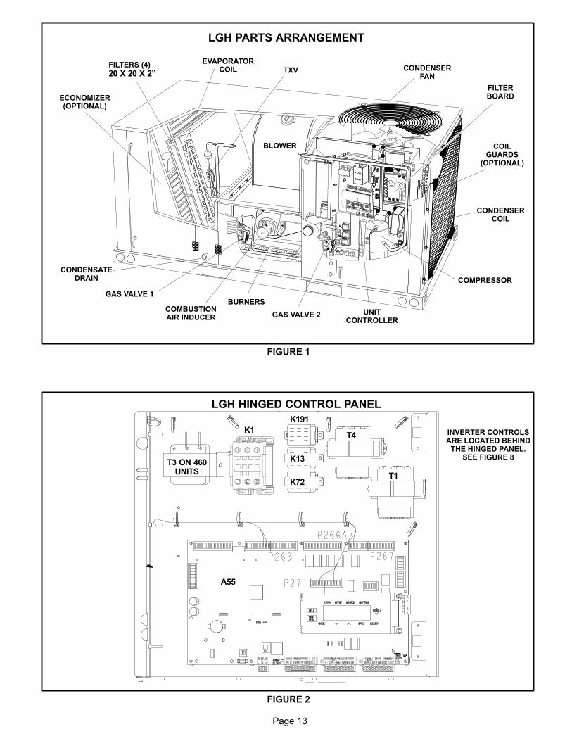
LGH PARTS ARRANGEMENT
FIGURE 1
EVAPORATORCOIL CONDENSER
FAN
CONDENSERCOIL
COMPRESSOR
CONDENSATEDRAIN
FILTERS (4)
20 X 20 X 2”
ECONOMIZER(OPTIONAL)
GAS VALVE 1BURNERS
COMBUSTIONAIR INDUCER
TXV
UNITCONTROLLER
BLOWER COILGUARDS
(OPTIONAL)
GAS VALVE 2
FILTERBOARD
LGH HINGED CONTROL PANEL
FIGURE 2
T3 ON 460UNITS
K191
K1
A55
T4
T1
K13
K72
INVERTER CONTROLSARE LOCATED BEHIND
THE HINGED PANEL.SEE FIGURE 8
Page 14
I-UNIT COMPONENTS
All 3 through 6 ton (7 through 21 kW) units are configure to
order units (CTO). The LGH unit components are shown
in figure 1. All units come standard with hinged unit pan
els. All L1, L2, and L3 wiring is color coded; L1 is red, L2 is
yellow, and L3 is blue.
A-Control Box Components
LGH control box components are shown in figure 2. The
control box is located in the upper right portion of the com
pressor compartment.
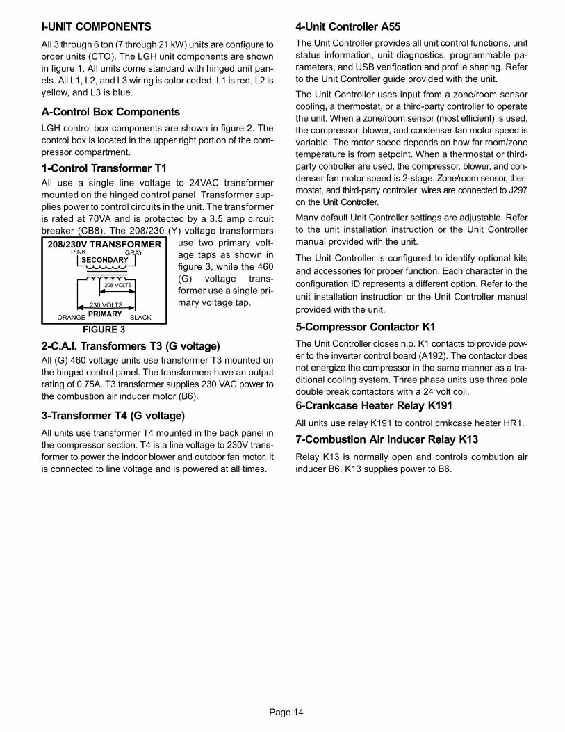
1-Control Transformer T1
All use a single line voltage to 24VAC transformer
mounted on the hinged control panel. Transformer sup
plies power to control circuits in the unit. The transformer
is rated at 70VA and is protected by a 3.5 amp circuit
breaker (CB8). The 208/230 (Y) voltage transformers
use two primary volt
age taps as shown in
figure 3, while the 460
(G) voltage trans
former use a single pri
mary voltage tap.
2-C.A.I. Transformers T3 (G voltage)
All (G) 460 voltage units use transformer T3 mounted on
the hinged control panel. The transformers have an output
rating of 0.75A. T3 transformer supplies 230 VAC power to
the combustion air inducer motor (B6).
3-Transformer T4 (G voltage)
All units use transformer T4 mounted in the back panel in
the compressor section. T4 is a line voltage to 230V trans
former to power the indoor blower and outdoor fan motor. It
is connected to line voltage and is powered at all times.
4-Unit Controller A55
The Unit Controller provides all unit control functions, unit
status information, unit diagnostics, programmable pa
rameters, and USB verification and profile sharing. Refer
to the Unit Controller guide provided with the unit.
The Unit Controller uses input from a zone/room sensor
cooling, a thermostat, or a third-party controller to operate
the unit. When a zone/room sensor (most efficient) is used,
the compressor, blower, and condenser fan motor speed is
variable. The motor speed depends on how far room/zone
temperature is from setpoint. When a thermostat or third-
party controller are used, the compressor, blower, and con
denser fan motor speed is 2-stage. Zone/room sensor, ther
mostat, and third-party controller wires are connected to J297
on the Unit Controller.
Many default Unit Controller settings are adjustable. Refer
to the unit installation instruction or the Unit Controller
manual provided with the unit.
The Unit Controller is configured to identify optional kits
and accessories for proper function. Each character in the
configuration ID represents a different option. Refer to the
unit installation instruction or the Unit Controller manual
provided with the unit.
5-Compressor Contactor K1
The Unit Controller closes n.o. K1 contacts to provide pow
er to the inverter control board (A192). The contactor does
not energize the compressor in the same manner as a tra
ditional cooling system. Three phase units use three pole
double break contactors with a 24 volt coil.
6-Crankcase Heater Relay K191
All units use relay K191 to control crnkcase heater HR1.
7-Combustion Air Inducer Relay K13
Relay K13 is normally open and controls combution air
inducer B6. K13 supplies power to B6.
FIGURE 3
PINK GRAY
ORANGE BLACK
230 VOLTS
208 VOLTS
PRIMARY
SECONDARY
208/230V TRANSFORMER
Page 15
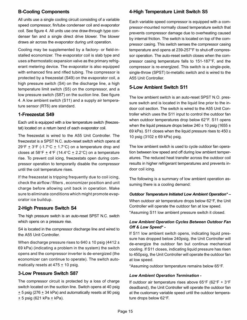
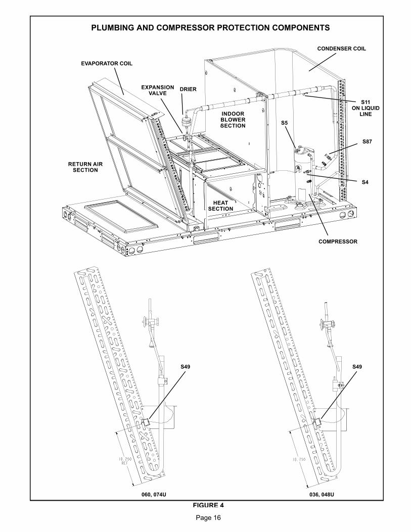
B-Cooling Components
All units use a single cooling circuit consisting of a variable
speed compressor, fin/tube condenser coil and evaporator
coil. See figure 4. All units use one draw-through type con
denser fan and a single direct drive blower. The blower
draws air across the evaporator during unit operation.
Cooling may be supplemented by a factory‐ or field‐in
stalled economizer. The evaporator coil is slab type and
uses a thermostatic expansion valve as the primary refrig
erant metering device. The evaporator is also equipped
with enhanced fins and rifled tubing. The compressor is
protected by a freezestat (S49) on the evaporator coil, a
high pressure switch (S4) on the discharge line, a high
temperature limit switch (S5) on the compressor, and a
low pressure switch (S87) on the suction line. See figure
4. A low ambient switch (S11) and a supply air tempera
ture sensor (RT6) are standard.
1-Freezestat S49
Each unit is equipped with a low temperature switch (freezes
tat) located on a return bend of each evaporator coil.
The freezestat is wired to the A55 Unit Controller. The
freezestat is a SPST N.C. auto-reset switch which opens at
29°F + 3°F (‐1.7°C + 1.7°C) on a temperature drop and
closes at 58°F + 4°F (14.4°C + 2.2°C) on a temperature
rise. To prevent coil icing, freezestats open during com
pressor operation to temporarily disable the compressor
until the coil temperature rises.
If the freezestat is tripping frequently due to coil icing,
check the airflow / filters , economizer position and unit
charge before allowing unit back in operation. Make
sure to eliminate conditions which might promote evap
orator ice buildup.
2-High Pressure Switch S4
The high pressure switch is an auto-reset SPST N.C. switch
which opens on a pressure rise.
S4 is located in the compressor discharge line and wired to
the A55 Unit Controller.
When discharge pressure rises to 640 ± 10 psig (4412 ±
69 kPa) (indicating a problem in the system) the switch
opens and the compressor inverter is de-energized (the
economizer can continue to operate). The switch auto
matically resets at 475 + 10 psig.
3-Low Pressure Switch S87
The compressor circuit is protected by a loss of charge
switch located on the suction line. Switch opens at 40 psig
+ 5 psig (276 + 34 kPa) and automatically resets at 90 psig
+ 5 psig (621 kPa + kPa).
4-High Temperature Limit Switch S5
Each variable speed compressor is equipped with a com
pressor-mounted normally closed temperature switch that
prevents compressor damage due to overheating caused
by internal friction. The switch is located on top of the com
pressor casing. This switch senses the compressor casing
temperature and opens at 239-257°F to shut-off compres
sor operation. The auto-reset switch closes when the com
pressor casing temperature falls to 151-187°F, and the
compressor is re-energized. This switch is a single-pole,
single-throw (SPST) bi-metallic switch and is wired to the
A55 Unit Controller.
5-Low Ambient Switch S11
The low ambient switch is an auto-reset SPST N.O. pres
sure switch and is located in the liquid line prior to the in
door coil section. The switch is wired to the A55 Unit Con
troller which uses the S11 input to control the outdoor fan
when outdoor temperatures drop below 62°F. S11 opens
when the liquid pressure drops below 240 ± 10 psig (1655 ±
69 kPa). S11 closes when the liquid pressure rises to 450 ±
10 psig (3102 ± 69 kPa) psig.
The low ambient switch is used to cycle outdoor fan opera
tion between low speed and off during low ambient temper
atures. The reduced heat transfer across the outdoor coil
results in higher refrigerant temperatures and prevents in
door coil icing.
The following is a summary of low ambient operation as
suming there is a cooling demand:
Outdoor Temperature Initiated Low Ambient Operation* –
When outdoor air temperature drops below 62°F, the Unit
Controller will operate the outdoor fan at low speed.
*Assuming S11 low ambient pressure switch it closed.
Low Ambient Operation Cycles Between Outdoor Fan
Off & Low Speed* -
If S11 low ambient switch opens, indicating liquid pres
sure has dropped below 240psig, the Unit Controller will
de-energize the outdoor fan but continue mechanical
cooling. If S11 closes, indicating liquid pressure has risen
to 450psig, the Unit Controller will operate the outdoor fan
at low speed.
*Assuming outdoor temperature remains below 65°F.
Low Ambient Operation Termination -
If outdoor air temperature rises above 65°F (62°F + 3°Fdeadband), the Unit Controller will operate the outdoor fan
at the customary variable speed until the outdoor tempera
ture drops below 62°F.
Page 16
PLUMBING AND COMPRESSOR PROTECTION COMPONENTS
EVAPORATOR COIL
CONDENSER COIL
DRIER
COMPRESSOR
RETURN AIRSECTION
036, 048U060, 074U
INDOORBLOWERSECTION
EXPANSIONVALVE
HEATSECTION
S49 S49
FIGURE 4
S5
S11ON LIQUID
LINE
S87
S4
Page 17
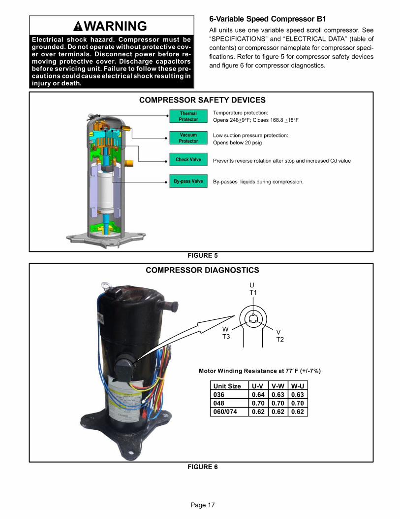
WARNINGElectrical shock hazard. Compressor must begrounded. Do not operate without protective cover over terminals. Disconnect power before removing protective cover. Discharge capacitorsbefore servicing unit. Failure to follow these precautions could cause electrical shock resulting ininjury or death.
6-Variable Speed Compressor B1
All units use one variable speed scroll compressor. See
“SPECIFICATIONS” and “ELECTRICAL DATA” (table of
contents) or compressor nameplate for compressor speci
fications. Refer to figure 5 for compressor safety devices
and figure 6 for compressor diagnostics.
COMPRESSOR SAFETY DEVICES
FIGURE 5
Temperature protection:
Opens 248+9°F; Closes 168.8 +18°F
Low suction pressure protection:
Opens below 20 psig
Prevents reverse rotation after stop and increased Cd value
By-passes liquids during compression.
COMPRESSOR DIAGNOSTICS
FIGURE 6
Motor Winding Resistance at 77°F (+/-7%)
UT1
VT2
WT3
Unit Size
036
048
060/074
U-V
0.64
0.70
0.62
V-W
0.63
0.70
0.62
W-U
0.63
0.70
0.62

Page 18
7-Compressor Inverter A192
WARNINGElectrical Hazard
High Voltage
Wait 7 Minutes
Electrical components may holdcharge. Do not remove this panel or service this area for 7 minutes after thepower has been removed.
See figure 8 for compressor inverter controls located be
hind the hinged control panel.
The inverter varies the compressor speed (capacity) by
converting an AC input signal to a pulse width modula
tion (PWM) output. To initiate cooling operation, the
Unit Controller (A55) supplies a control signal to the in
verter (A192) via a MODBUS protocol. Inverter status
and diagnostics are continuously monitored and report
ed to the Unit Controller such as:
-Improper Unit Controller input voltage compared to unit
model number
-High input voltage
-Low input voltage
-Imbalanced input voltage
-A communication issue - check MODBUS communica-
tion wire for good connections between the Unit
Controller and the inverter board.
An example of the Unit Controller displaying alarm 187 is
shown in figure 7. See table 1 for inverter-related alarms.
Inverter component wire routing is shown in figure 9.
WARNINGElectrical shock hazard. Variable speed compressor components must be grounded. Failure to follow these precautions could cause electricalshock resulting in injury or death.
ALARM 18712.4.2016 12: 02: 24ALARMING VALUE = 12INVERTER LOW LEVEL ALARM
UNIT CONTROLLER ALARM DISPLAY
12 - Compressor Current Limit13 - High Heat Sink Temperature Limit14 - High PFC Input Current
FIGURE 7
INVERTER LOWLEVEL ALARM
INVERTER CONTROLS BEHIND THE HINGED CONTROL PANEL
A192COMPRESSOR
INVERTER
T61INVERTER POWER
TRANSFORMER
FL1FILTER BOARD
L43REACTOR
INVERTER MODBUSCOMMUNICATION
HARNESS
FIGURE 8
Page 19
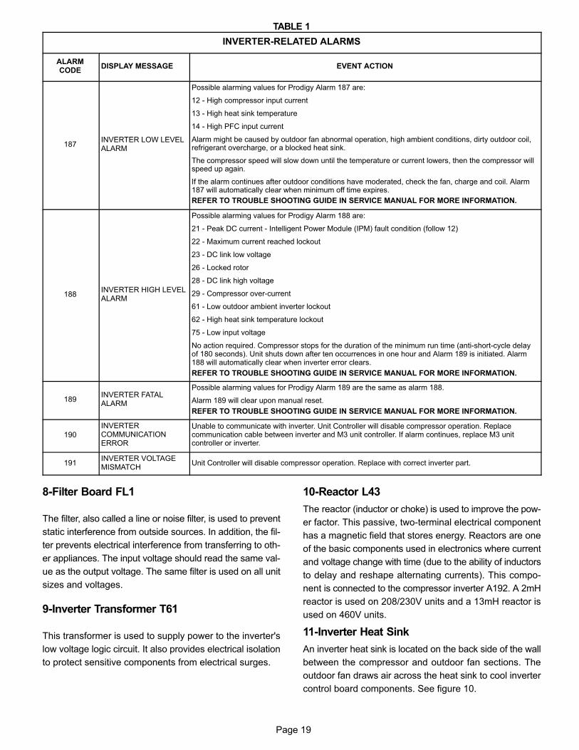
TABLE 1
INVERTER-RELATED ALARMS
ALARMCODE
DISPLAY MESSAGE EVENT ACTION
187INVERTER LOW LEVELALARM
Possible alarming values for Prodigy Alarm 187 are:
12 - High compressor input current
13 - High heat sink temperature
14 - High PFC input current
Alarm might be caused by outdoor fan abnormal operation, high ambient conditions, dirty outdoor coil,refrigerant overcharge, or a blocked heat sink.
The compressor speed will slow down until the temperature or current lowers, then the compressor willspeed up again.
If the alarm continues after outdoor conditions have moderated, check the fan, charge and coil. Alarm187 will automatically clear when minimum off time expires.
REFER TO TROUBLE SHOOTING GUIDE IN SERVICE MANUAL FOR MORE INFORMATION.
188INVERTER HIGH LEVELALARM
Possible alarming values for Prodigy Alarm 188 are:
21 - Peak DC current - Intelligent Power Module (IPM) fault condition (follow 12)
22 - Maximum current reached lockout
23 - DC link low voltage
26 - Locked rotor
28 - DC link high voltage
29 - Compressor over-current
61 - Low outdoor ambient inverter lockout
62 - High heat sink temperature lockout
75 - Low input voltage
No action required. Compressor stops for the duration of the minimum run time (anti-short-cycle delayof 180 seconds). Unit shuts down after ten occurrences in one hour and Alarm 189 is initiated. Alarm188 will automatically clear when inverter error clears.
REFER TO TROUBLE SHOOTING GUIDE IN SERVICE MANUAL FOR MORE INFORMATION.
189INVERTER FATALALARM
Possible alarming values for Prodigy Alarm 189 are the same as alarm 188.
Alarm 189 will clear upon manual reset.
REFER TO TROUBLE SHOOTING GUIDE IN SERVICE MANUAL FOR MORE INFORMATION.
190
INVERTERCOMMUNICATIONERROR
Unable to communicate with inverter. Unit Controller will disable compressor operation. Replacecommunication cable between inverter and M3 unit controller. If alarm continues, replace M3 unitcontroller or inverter.
191INVERTER VOLTAGEMISMATCH
Unit Controller will disable compressor operation. Replace with correct inverter part.
8-Filter Board FL1
The filter, also called a line or noise filter, is used to prevent
static interference from outside sources. In addition, the fil
ter prevents electrical interference from transferring to oth
er appliances. The input voltage should read the same val
ue as the output voltage. The same filter is used on all unit
sizes and voltages.
9-Inverter Transformer T61
This transformer is used to supply power to the inverter's
low voltage logic circuit. It also provides electrical isolation
to protect sensitive components from electrical surges.
10-Reactor L43
The reactor (inductor or choke) is used to improve the pow
er factor. This passive, two-terminal electrical component
has a magnetic field that stores energy. Reactors are one
of the basic components used in electronics where current
and voltage change with time (due to the ability of inductors
to delay and reshape alternating currents). This compo
nent is connected to the compressor inverter A192. A 2mH
reactor is used on 208/230V units and a 13mH reactor is
used on 460V units.
11-Inverter Heat Sink
An inverter heat sink is located on the back side of the wall
between the compressor and outdoor fan sections. The
outdoor fan draws air across the heat sink to cool inverter
control board components. See figure 10.
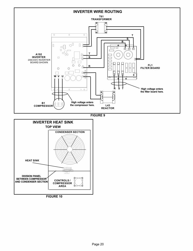
Page 20
INVERTER WIRE ROUTINGT61
TRANSFORMER
FL1FILTER BOARD
L43REACTOR
FIGURE 9
A192INVERTER
High voltage entersthe filter board here.
High voltage entersthe compressor here.
B1COMPRESSOR
R S T
R
S
T
R
S
T
W V U
208/230V INVERTERBOARD SHOWN
INVERTER HEAT SINKTOP VIEW
FIGURE 10
CONTROLS /COMPRESSOR
AREA
HEAT SINK
DIVISION PANELBETWEEN COMPRESSOR
AND CONDENSER SECTION
CONDENSER SECTION
Page 21
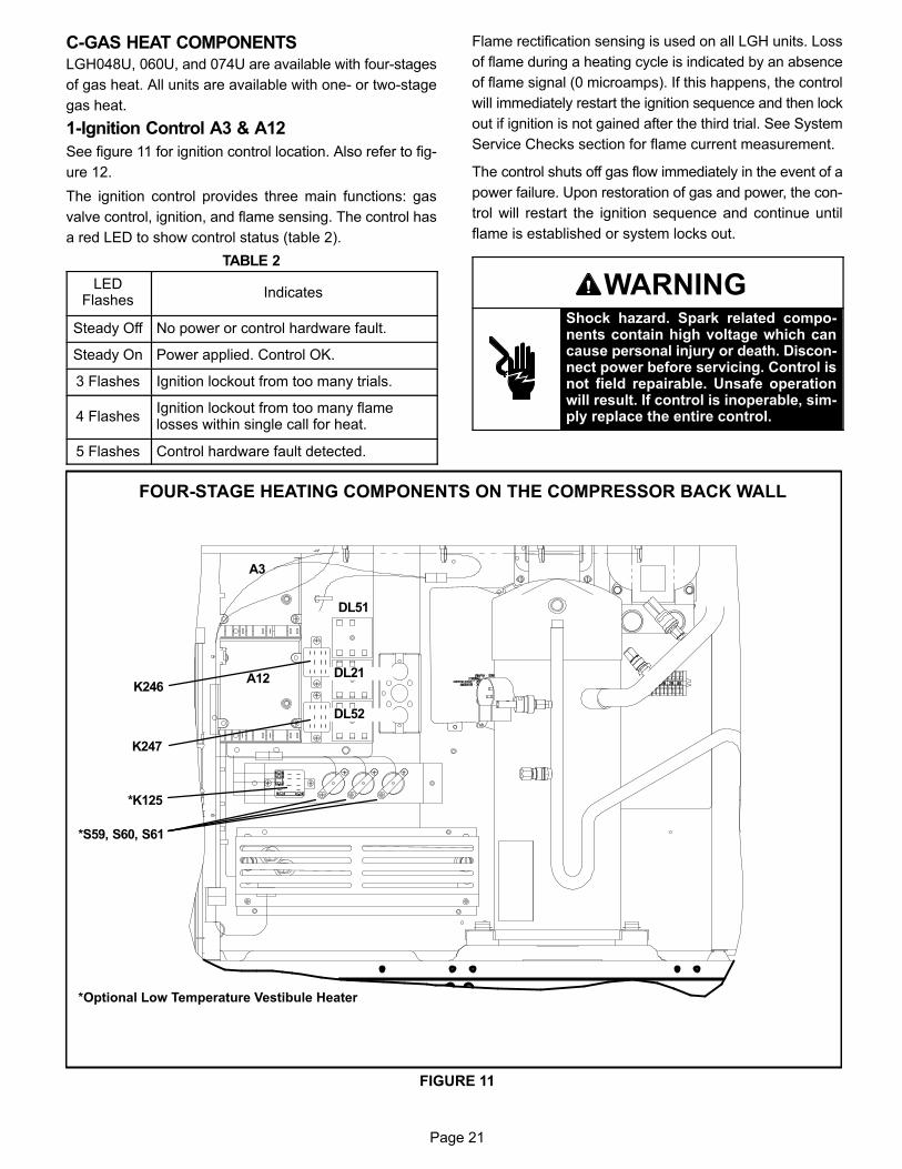
C-GAS HEAT COMPONENTSLGH048U, 060U, and 074U are available with four-stages
of gas heat. All units are available with one- or two-stage
gas heat.
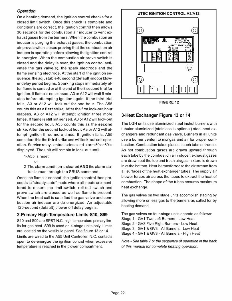
1-Ignition Control A3 & A12
See figure 11 for ignition control location. Also refer to fig
ure 12.
The ignition control provides three main functions: gas
valve control, ignition, and flame sensing. The control has
a red LED to show control status (table 2).
TABLE 2
LEDFlashes
Indicates
Steady Off No power or control hardware fault.
Steady On Power applied. Control OK.
3 Flashes Ignition lockout from too many trials.
4 FlashesIgnition lockout from too many flamelosses within single call for heat.
5 Flashes Control hardware fault detected.
Flame rectification sensing is used on all LGH units. Loss
of flame during a heating cycle is indicated by an absence
of flame signal (0 microamps). If this happens, the control
will immediately restart the ignition sequence and then lock
out if ignition is not gained after the third trial. See System
Service Checks section for flame current measurement.
The control shuts off gas flow immediately in the event of a
power failure. Upon restoration of gas and power, the con
trol will restart the ignition sequence and continue until
flame is established or system locks out.
WARNINGShock hazard. Spark related components contain high voltage which cancause personal injury or death. Disconnect power before servicing. Control isnot field repairable. Unsafe operationwill result. If control is inoperable, simply replace the entire control.
*S59, S60, S61
*K125
FIGURE 11
A3
A12
DL51
K246
K247
DL21
DL52
FOUR-STAGE HEATING COMPONENTS ON THE COMPRESSOR BACK WALL
*Optional Low Temperature Vestibule Heater
Page 22
Operation
On a heating demand, the ignition control checks for a
closed limit switch. Once this check is complete and
conditions are correct, the ignition control then allows
30 seconds for the combustion air inducer to vent ex
haust gases from the burners. When the combustion air
inducer is purging the exhaust gases, the combustion
air prove switch closes proving that the combustion air
inducer is operating before allowing the ignition control
to energize. When the combustion air prove switch is
closed and the delay is over, the ignition control acti
vates the gas valve(s), the spark electrode and the
flame sensing electrode. At the start of the ignition se
quence, the adjustable 40 second (default) indoor blow
er delay period begins. Sparking stops immediately af
ter flame is sensed or at the end of the 8 second trial for
ignition. If flame is not sensed, A3 or A12 will wait 5 min
utes before attempting ignition again. If the third trial
fails, A3 or A12 will lock-out for one hour. The A55
counts this as a first strike. After the first lock-out hour
elapses, A3 or A12 will attempt ignition three more
times. If flame is still not sensed, A3 or A12 will lock-out
for the second hour. A55 counts this as the second
strike. After the second lockout hour, A3 or A12 will at
tempt ignition three more times. If ignition fails, A55
considers this the third strike and will lock-out unit oper
ation. Service relay contacts close and alarm 59 or 69 is
displayed. The unit will remain in lock-out until:
1-A55 is reset
or
2-The alarm condition is cleared AND the alarm sta-
tus is read through the SBUS command.
Once the flame is sensed, the ignition control then pro
ceeds to “steady state” mode where all inputs are moni
tored to ensure the limit switch, roll-out switch and
prove switch are closed as well as flame is present.
When the heat call is satisfied the gas valve and com
bustion air inducer are de-energized. An adjustable
120-second (default) blower off delay begins.
2-Primary High Temperature Limits S10, S99
S10 and S99 are SPST N.C. high temperature primary lim
its for gas heat. S99 is used on 4-stage units only. Limits
are located on the vestibule panel. See figure 13 or 14.
Limits are wired to the A55 Unit Controller. N.C. contacts
open to de-energize the ignition control when excessive
temperature is reached in the blower compartment.
FIGURE 12
UTEC IGNITION CONTROL A3/A12
LE
D M
AIN
VA
LVE
PO
WE
R F
LAM
E S
EN
SE
GR
OU
ND
3-Heat Exchanger Figure 13 or 14
The LGH units use aluminized steel inshot burners with
tubular aluminized (stainless is optional) steel heat ex
changers and redundant gas valve. Burners in all units
use a burner venturi to mix gas and air for proper com
bustion. Combustion takes place at each tube entrance.
As hot combustion gases are drawn upward through
each tube by the combustion air inducer, exhaust gases
are drawn out the top and fresh air/gas mixture is drawn
in at the bottom. Heat is transferred to the air stream from
all surfaces of the heat exchanger tubes. The supply air
blower forces air across the tubes to extract the heat of
combustion. The shape of the tubes ensures maximum
heat exchange.
The gas valves on two stage units accomplish staging by
allowing more or less gas to the burners as called for by
heating demand.
The gas valves on four-stage units operate as follows:
Stage 1 - GV1 Two Left Burners - Low Heat
Stage 2 - GV3 Five Right Burners - Low Heat
Stage 3 - GV1 & GV3 - All Burners - Low Heat
Stage 4 - GV1 & GV3 - All Burners - High Heat
Note - See table 7 or the sequence of operation in the back
of this manual for complete heating operation.
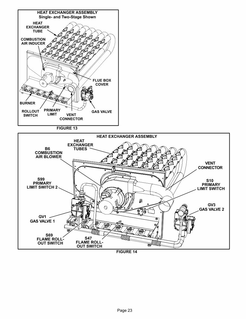
Page 23
HEAT EXCHANGER ASSEMBLYSingle- and Two-Stage Shown
FIGURE 13
BURNER
COMBUSTIONAIR INDUCER
VENTCONNECTOR
GAS VALVE
HEATEXCHANGER
TUBE
PRIMARYLIMIT
ROLLOUTSWITCH
FLUE BOXCOVER
HEAT EXCHANGER ASSEMBLY
FIGURE 14
S10PRIMARY
LIMIT SWITCH
S99PRIMARY
LIMIT SWITCH 2
B6COMBUSTIONAIR BLOWER
HEATEXCHANGER
TUBES
GV1GAS VALVE 1
GV3GAS VALVE 2
VENTCONNECTOR
S47FLAME ROLL-OUT SWITCH
S69FLAME ROLL-OUT SWITCH
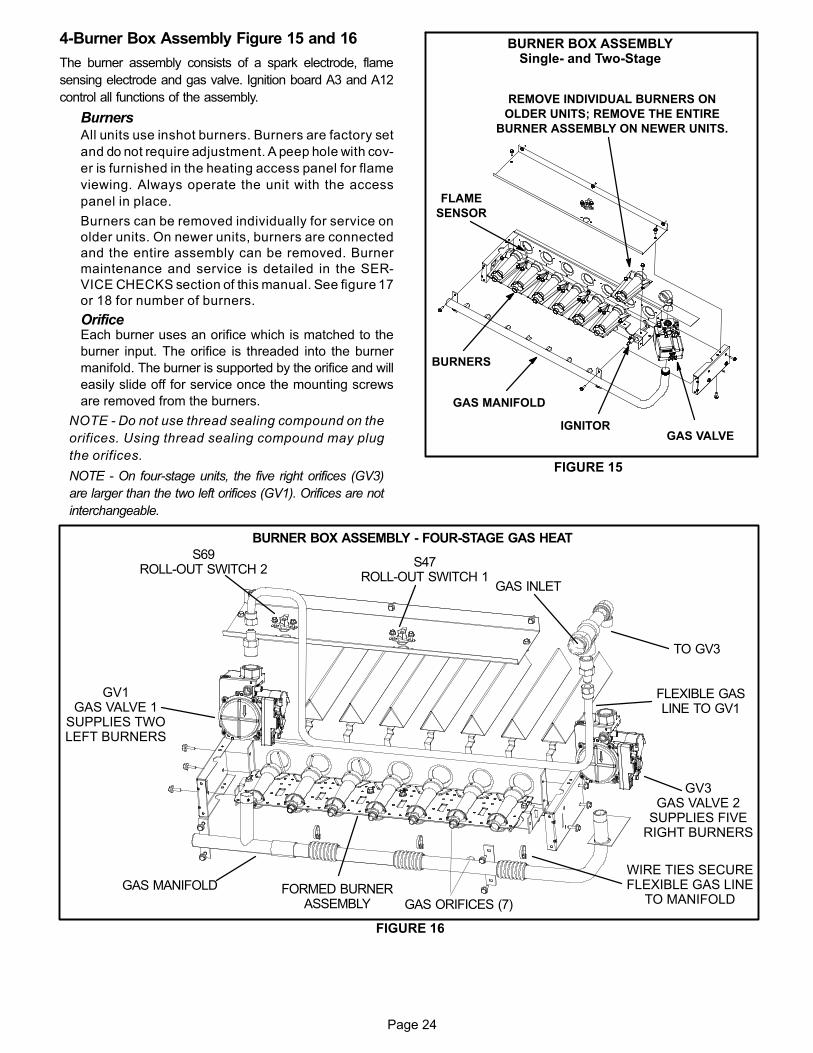
Page 24
4-Burner Box Assembly Figure 15 and 16
The burner assembly consists of a spark electrode, flame
sensing electrode and gas valve. Ignition board A3 and A12
control all functions of the assembly.
BurnersAll units use inshot burners. Burners are factory set
and do not require adjustment. A peep hole with cov
er is furnished in the heating access panel for flame
viewing. Always operate the unit with the access
panel in place.
Burners can be removed individually for service on
older units. On newer units, burners are connected
and the entire assembly can be removed. Burner
maintenance and service is detailed in the SER
VICE CHECKS section of this manual. See figure 17
or 18 for number of burners.
OrificeEach burner uses an orifice which is matched to the
burner input. The orifice is threaded into the burner
manifold. The burner is supported by the orifice and will
easily slide off for service once the mounting screws
are removed from the burners.
NOTE - Do not use thread sealing compound on the
orifices. Using thread sealing compound may plug
the orifices.
NOTE - On four-stage units, the five right orifices (GV3)
are larger than the two left orifices (GV1). Orifices are not
interchangeable.
FIGURE 15
BURNER BOX ASSEMBLYSingle- and Two-Stage
GAS VALVE
GAS MANIFOLD
FLAME
SENSOR
BURNERS
IGNITOR
REMOVE INDIVIDUAL BURNERS ON
OLDER UNITS; REMOVE THE ENTIRE
BURNER ASSEMBLY ON NEWER UNITS.
FIGURE 16
BURNER BOX ASSEMBLY - FOUR-STAGE GAS HEAT
GAS MANIFOLD
GV1GAS VALVE 1
SUPPLIES TWOLEFT BURNERS
GV3GAS VALVE 2
SUPPLIES FIVERIGHT BURNERS
FORMED BURNERASSEMBLY
S47ROLL-OUT SWITCH 1
S69ROLL-OUT SWITCH 2
TO GV3
GAS INLET
FLEXIBLE GASLINE TO GV1
WIRE TIES SECUREFLEXIBLE GAS LINE
TO MANIFOLDGAS ORIFICES (7)

Page 25
BURNER ORIENTATIONFour-Stage Heat
FIGURE 17
FS1FLAME
SENSOR
E1SPARK IGNITOR
E2SPARK IGNITOR
FS2FLAME
SENSOR
S69ROLL-OUT
SWITCH S47ROLL-OUT
SWITCH
150,000 BTUH - 7 BURNERS
FIGURE 18
BURNER ORIENTATIONOne- and Two-Stage Heat
150,000 BTUH - 7 BURNERS
108,000 BTUH - 5 BURNERS
65,000 BTUH - 3 BURNERS
SENSOR IGNITOR
SENSOR IGNITOR
SENSOR IGNITOR
5-Flame Roll-out Limit Switch S47, S69
S69 is used on four-stage gas heat units only. Flame
roll-out limit switches are SPST N.C. high temperature lim
its located just above the burner air intake opening in the burn
er enclosures (see figure 15 or 16). switches are wired to the
A55 Unit Controller. When the limit switch(s) senses flame
roll-out (indicating a blockage in the combustion air pas
sages), the flame roll-out limit trips, and the Unit Con
troller immediately closes the gas valve.
Limit is factory preset to open at 340�F + 16�F on a tem
perature rise on all units. All flame roll-out limits are
manual reset.
6-Combustion Air Prove Switch S18
Prove switch S18 is a SPST N.O. switch located to the
right of the induced draft assembly. See figure 19. S18
monitors combustion air inducer operation. Switch S18 is
wired to A55 Unit Controller via J271-8 and -9. A55 reads
the status of S18 and provides power to A3/A12 if B6 is
functioning normally. The switch closes at negative
0.10”W.C. + 0.05” (24.8 Pa + 12.4 Pa) on pressure fall.
This negative pressure fall and switch actuation allows
the ignition sequence to continue (proves, by closing, that
the combustion air inducer is operating before allowing
the gas valve to open.) The combustion air prove switch is
factory set and not adjustable.
7-Combustion Air Motor Capacitor C3
The combustion air inducer motors in all LGH units re
quire run capacitors. Capacitor C3 is connected to com
bustion air inducer B6. Ratings will be on side of capaci
tor or combustion air motor nameplate.
COMBUSTION AIR PROVING SWITCH
FIGURE 19
AIRTUBING
S18COMBUSTIONAIR PROVING
SWITCH

Page 26
8-Combustion Air Inducer B6
Combustion air inducers provide air to the corresponding
burners while clearing the combustion chamber of exhaust
gases. The inducer begins operating immediately upon re
ceiving a thermostat demand and is de-energized when
thermostat demand is satisfied.
The inducer uses a 208/230V single‐phase PSC motor
and a 5.24 in. x .96in. blower wheel. All motors operate at
3300RPM and are equipped with auto‐reset overload pro
tection. Two-speed units have reduced RPM for low
speed. Inducers are supplied by various manufacturers.
Ratings may vary by manufacturer. Specific inducer elec
trical ratings can be found on the unit rating plate.
The A55 Unit Controller energizes K13 relay to route pow
er to the combustion air blower motor. A3 then allows 30 to
seconds for the combustion air inducer to vent exhaust
gases from the burners. When the combustion air inducer
is purging the exhaust gases, the combustion air prove
switch closes, proving that the combustion air inducer is
operating before allowing the ignition sequence to contin
ue. When the combustion air prove switch is closed and the
delay is over, the A55 Unit Controller through the ignition
control activates the appropriate stage operator of the gas
valve, the spark and the flame sensing electrode. Sparking
stops immediately after flame is sensed or at the end of the
eight second trial for ignition.
On two-stage natural gas units, the inducer will operate on
low speed for first stage heat (W1) and ramp up to high
speed for second stage heat (W2).
On four-stage natural gas units, the inducer will operate on
low speed for first-, second-, and third-stage heat. The in
ducer will ramp up to high speed for fourth-stage heat.
All combustion air inducer motors are sealed and can
not be oiled. The inducer cannot be adjusted but can be
removed from the heat section for cleaning.
9-Gas Valves GV1, GV3
One- and two-stage gas units are equipped with either a 1-
or 2-stage gas valve, respectively. Four-stage gas units
are equipped with two, 2-stage gas valves. When a heating
demand is present, the valve(s) are energized in low fire by
the ignition control at the same time as the spark electrode.
On two- and four-stage units, if the heating demand in
creases, the high fire signal is provided directly to the gas
valve(s) by A55 without the use of the ignition control. Both
the low fire and high fire signals are required for the gas
valve(s) to operate in high fire.
A shut-off knob/switch is provided on the valve for manual
shut-off. The shut‐off knob/switch will immediately close
both stages without delay.
Both low fire and high fire (if applicable) valve outputs are
adjustable. Figures 23 and 24 show gas valve compo
nents. Table 3 shows factory gas valve operating manifold
pressures.
TABLE 3
Operating Manifold Pressure
Natural L.P.
Low High Low High
2.0 + 0.3” W.C. 3.5 + 0.3” W.C. 5.9” + 0.3” W.C 10.5” + 0.5” W.C.
The gas manifold pressure should be adjusted when the
unit is installed at altitudes higher than 2000 feet. See table
4 for the proper setting.
TABLE 4HIGH ALTITUDE DERATE
Altitude Ft.* Gas Manifold Pressure
2000-4500 See Unit Nameplate
4500 And Above Derate 2% / 1000 Ft. Above Sea Level
NOTE ‐ This is the only permissible derate for these units.
10-Spark Electrode (Ignitor) Figure 20
An electrode assembly is used for ignition spark. The
electrode is inserted through holes in the burner sup
port. The electrode tip protrudes into the flame enve
lope of the adjacent burner. The electrode assembly is fas
tened to burner supports and can be removed for service
without removing any part of the burners.
During ignition, spark travels through the spark electrode
(figure 20) and ignites the appropriate burner depending
on the heating stage. Flame travels from burner to burner
until all are lit.
The spark electrode is connected to the ignition control by
a 8 mm silicone‐insulated stranded high voltage wire. The
wire uses 1/4” (6.35 mm)female quick connect on both
ends of the wire.
NOTE - If electrode wire must be replaced, wire and
suppression must be same type cable.
The spark electrode assembly can be removed for inspection
by removing the screw securing the electrode assembly and
sliding it out of unit.
For proper unit operation, electrodes must be positioned and
gapped correctly.
Spark gap may be checked with appropriately sized twist drills
or feeler gauges. Disconnect power to the unit and remove
electrode assembly. The gap should be between 0.125” +
0.015” (3.2 mm + .4 mm). See figure 20.
IMPORTANTIn order to maximize spark energy to electrode, highvoltage wire should touch unit cabinet as little aspossible.
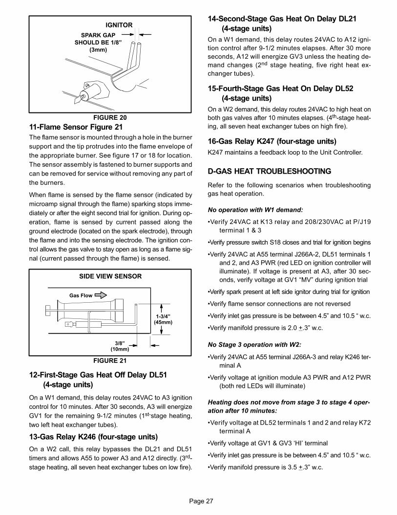
Page 27
FIGURE 20
IGNITOR
SPARK GAP
SHOULD BE 1/8”
(3mm)
11-Flame Sensor Figure 21
The flame sensor is mounted through a hole in the burner
support and the tip protrudes into the flame envelope of
the appropriate burner. See figure 17 or 18 for location.
The sensor assembly is fastened to burner supports and
can be removed for service without removing any part of
the burners.
When flame is sensed by the flame sensor (indicated by
microamp signal through the flame) sparking stops imme
diately or after the eight second trial for ignition. During op
eration, flame is sensed by current passed along the
ground electrode (located on the spark electrode), through
the flame and into the sensing electrode. The ignition con
trol allows the gas valve to stay open as long as a flame sig
nal (current passed through the flame) is sensed.
FIGURE 21
SIDE VIEW SENSOR
1-3/4”(45mm)
3/8”(10mm)
Gas Flow
12-First-Stage Gas Heat Off Delay DL51
(4-stage units)
On a W1 demand, this delay routes 24VAC to A3 ignition
control for 10 minutes. After 30 seconds, A3 will energize
GV1 for the remaining 9-1/2 minutes (1st-stage heating,
two left heat exchanger tubes).
13-Gas Relay K246 (four-stage units)
On a W2 call, this relay bypasses the DL21 and DL51
timers and allows A55 to power A3 and A12 directly. (3rd-
stage heating, all seven heat exchanger tubes on low fire).
14-Second-Stage Gas Heat On Delay DL21
(4-stage units)
On a W1 demand, this delay routes 24VAC to A12 igni
tion control after 9-1/2 minutes elapses. After 30 more
seconds, A12 will energize GV3 unless the heating de
mand changes (2nd stage heating, five right heat ex
changer tubes).
15-Fourth-Stage Gas Heat On Delay DL52
(4-stage units)
On a W2 demand, this delay routes 24VAC to high heat on
both gas valves after 10 minutes elapses. (4th-stage heat
ing, all seven heat exchanger tubes on high fire).
16-Gas Relay K247 (four-stage units)
K247 maintains a feedback loop to the Unit Controller.
D-GAS HEAT TROUBLESHOOTING
Refer to the following scenarios when troubleshooting
gas heat operation.
No operation with W1 demand:
•Verify 24VAC at K13 relay and 208/230VAC at P/J19
terminal 1 & 3
•Verify pressure switch S18 closes and trial for ignition begins
•Verify 24VAC at A55 terminal J266A-2, DL51 terminals 1
and 2, and A3 PWR (red LED on ignition controller will
illuminate). If voltage is present at A3, after 30 sec
onds, verify voltage at GV1 “MV” during ignition trial
•Verify spark present at left side ignitor during trial for ignition
•Verify flame sensor connections are not reversed
•Verify inlet gas pressure is be between 4.5” and 10.5 “ w.c.
•Verify manifold pressure is 2.0 +.3” w.c.
No Stage 3 operation with W2:
•Verify 24VAC at A55 terminal J266A-3 and relay K246 ter
minal A
•Verify voltage at ignition module A3 PWR and A12 PWR
(both red LEDs will illuminate)
Heating does not move from stage 3 to stage 4 oper
ation after 10 minutes:
•Verify voltage at DL52 terminals 1 and 2 and relay K72
terminal A
•Verify voltage at GV1 & GV3 ‘HI’ terminal
•Verify inlet gas pressure is be between 4.5” and 10.5 “ w.c.
•Verify manifold pressure is 3.5 +.3” w.c.
Page 28
E-BLOWER COMPARTMENT
Ultra high efficiency units are equipped with a variable
speed, direct drive blower. The installer is able to enter the
design-specified supply air CFM into the Unit Controller
for optimal efficiency. The Unit Controller calibrates the
supply air volume which eliminates the need to manually
take duct static measurements.
1-Blower Wheels
See table 5 for blower wheel type and size.
TABLE 5
BLOWER WHEELS
LGH Unit Type Size - in. (mm)
036U, 048U Direct 10 X 10 (254 X 254)
060U, 074U Direct 11 X 10 (279 X 254)
2-Indoor Blower Motor B3
All direct drive blower motors are electronically commutat
ed, brushless, DC motors. Low speed is approximately 2/3
of high speed. CFM adjustments are made by changing
Unit Controller parameters. Motors are equipped with
sealed ball bearings. All motor specifications are listed in
the SPECIFICATIONS (table of contents) in the front of this
manual. Units may be equipped with motors manufactured
by various manufacturers, therefore electrical FLA and
LRA specifications will vary. See unit rating plate for infor
mation specific to your unit.
IMPORTANTThree phase scroll compressors must be phased sequentially for correct compressor and blower rotation. Follow “COOLING START-UP” section of installation instructions to ensure proper compressor andblower operation.
A-Blower Operation
Refer to the Unit Controller Installation and Setup Guide to
energize blower. Use the menu navigation arrows and se
lect button; see Service - Test.
B-Determining Unit CFM
1- The following measurements must be made with air fil
ters in place.
IMPORTANT - A low speed adjustment less than 2/3 of
high speed will improve humidity removal; refer to product
data for more information.
2- With all access panels in place, measure static pres
sure external to unit (from supply to return). Blower
performance data is based on static pressure readings
taken in locations shown in figure 22.
Note - Static pressure readings can vary if not taken where
shown.
3- Measure the indoor blower wheel RPM. RPM can be
read from the A55 Unit Controller display on direct
drive blowers. See Unit Controller manual.
4- Referring to the blower tables in the front of this manu
al, use static pressure and RPM readings to determine
unit CFM. Apply the optional accessory air resistance.
C-Adjusting Unit CFM
The supply CFM can be adjusted by changing Unit Con
troller settings. Refer to table 6 for menu paths and de
fault settings. Record any CFM changes on the parame
ter settings label located on the inside of the
compressor access panel.
CAUTIONThe BLOWER CALIBRATION process starts the in
door blower at operational speeds and closes the eco
nomizer damper blades. Before starting this process,
replace any access panels and close all unit doors ex
cept compressor compartment door.
Blower calibration is required only on units that are new
ly installed or if there is a change in the duct work or air
filters after installation. After the new CFM values are
entered, use the down and up arrow buttons to select
START CALIBRATION. Push SAVE to start calibration.
The blower calibration status is displayed as a % com
plete. Upon successful completion, the Unit Controller
will display CALIBRATION SUCCESS and go back to
the blower calibration screen. Press the MAIN MENU
button to go to the main menu and press the BACK but
ton to go to the status screen.
If only the CFM values are updated, use the down and up
arrow buttons to select “CALIBRATION DONE”. Push
SAVE to enter the updated values. This selection will not
initiate calibration, resulting in less setup time. Press the
MAIN MENU button to go to the main menu and press the
BACK button to go to the status screen.
IMPORTANT - The default value for Cooling Low CFM is
lower than a traditional singe- or two-speed unit. If oper
ating the unit with a 2- or 3-stage controller (2- or
3-stage thermostat, DDC controller, etc.), it is recom
mended to increase the Cooling Low CFM default value
to a suitable level for part load cooling (typically 60% of
full load CFM).
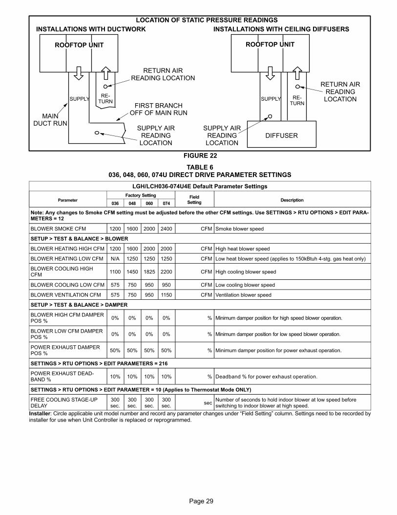
Page 29
FIGURE 22
LOCATION OF STATIC PRESSURE READINGS
SUPPLY AIRREADINGLOCATION
SUPPLYRE
TURN
INSTALLATIONS WITH DUCTWORK
SUPPLY RETURN
INSTALLATIONS WITH CEILING DIFFUSERS
MAINDUCT RUN
FIRST BRANCHOFF OF MAIN RUN
DIFFUSER
ROOFTOP UNIT ROOFTOP UNIT
SUPPLY AIRREADINGLOCATION
RETURN AIRREADING LOCATION
RETURN AIRREADINGLOCATION
TABLE 6036, 048, 060, 074U DIRECT DRIVE PARAMETER SETTINGS
LGH/LCH036-074U4E Default Parameter Settings
ParameterFactory Setting Field
SettingDescription
036 048 060 074
Note: Any changes to Smoke CFM setting must be adjusted before the other CFM settings. Use SETTINGS > RTU OPTIONS > EDIT PARAMETERS = 12
BLOWER SMOKE CFM 1200 1600 2000 2400 CFM Smoke blower speed
SETUP > TEST & BALANCE > BLOWER
BLOWER HEATING HIGH CFM 1200 1600 2000 2000 CFM High heat blower speed
BLOWER HEATING LOW CFM N/A 1250 1250 1250 CFM Low heat blower speed (applies to 150kBtuh 4-stg. gas heat only)
BLOWER COOLING HIGHCFM
1100 1450 1825 2200 CFM High cooling blower speed
BLOWER COOLING LOW CFM 575 750 950 950 CFM Low cooling blower speed
BLOWER VENTILATION CFM 575 750 950 1150 CFM Ventilation blower speed
SETUP > TEST & BALANCE > DAMPER
BLOWER HIGH CFM DAMPERPOS %
0% 0% 0% 0% % Minimum damper position for high speed blower operation.
BLOWER LOW CFM DAMPERPOS %
0% 0% 0% 0% % Minimum damper position for low speed blower operation.
POWER EXHAUST DAMPERPOS %
50% 50% 50% 50% % Minimum damper position for power exhaust operation.
SETTINGS > RTU OPTIONS > EDIT PARAMETERS = 216
POWER EXHAUST DEADBAND %
10% 10% 10% 10% % Deadband % for power exhaust operation.
SETTINGS > RTU OPTIONS > EDIT PARAMETER = 10 (Applies to Thermostat Mode ONLY)
FREE COOLING STAGE-UPDELAY
300sec.
300sec.
300sec.
300sec.
secNumber of seconds to hold indoor blower at low speed beforeswitching to indoor blower at high speed.
Installer: Circle applicable unit model number and record any parameter changes under “Field Setting” column. Settings need to be recorded byinstaller for use when Unit Controller is replaced or reprogrammed.
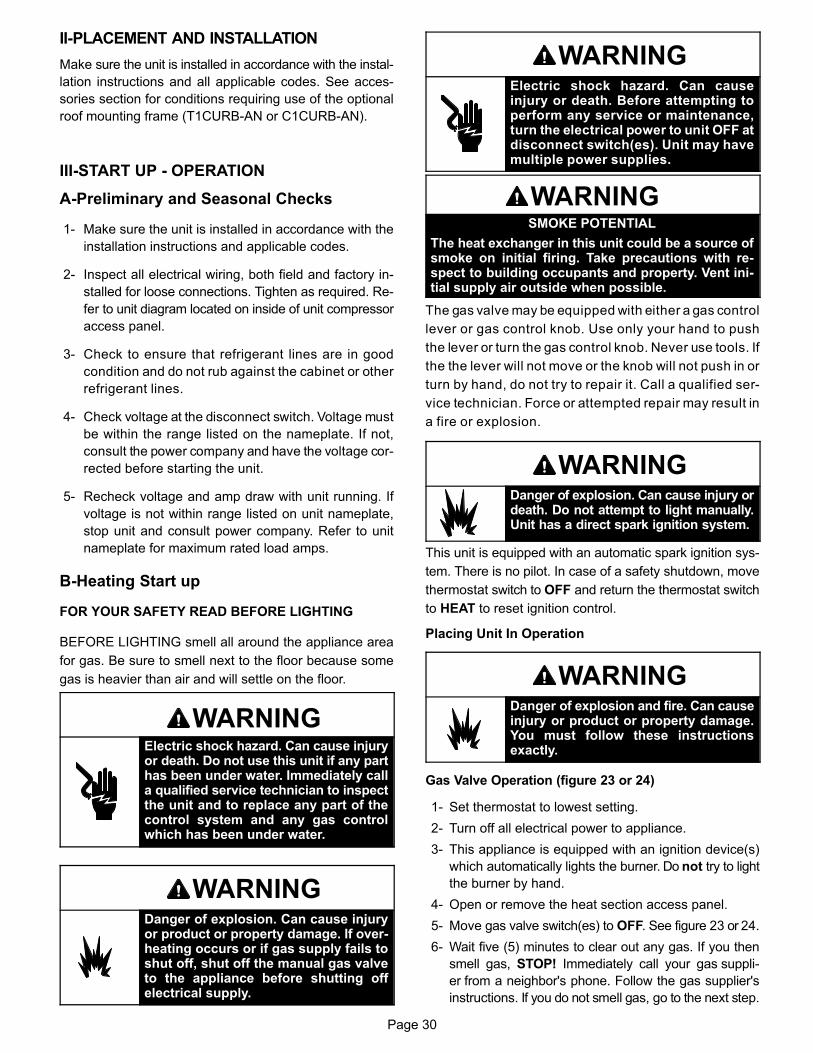
Page 30
II-PLACEMENT AND INSTALLATION
Make sure the unit is installed in accordance with the instal
lation instructions and all applicable codes. See acces
sories section for conditions requiring use of the optional
roof mounting frame (T1CURB-AN or C1CURB-AN).
III-START UP - OPERATION
A-Preliminary and Seasonal Checks
1- Make sure the unit is installed in accordance with the
installation instructions and applicable codes.
2- Inspect all electrical wiring, both field and factory in
stalled for loose connections. Tighten as required. Re
fer to unit diagram located on inside of unit compressor
access panel.
3- Check to ensure that refrigerant lines are in good
condition and do not rub against the cabinet or other
refrigerant lines.
4- Check voltage at the disconnect switch. Voltage must
be within the range listed on the nameplate. If not,
consult the power company and have the voltage cor
rected before starting the unit.
5- Recheck voltage and amp draw with unit running. If
voltage is not within range listed on unit nameplate,
stop unit and consult power company. Refer to unit
nameplate for maximum rated load amps.
B-Heating Start up
FOR YOUR SAFETY READ BEFORE LIGHTING
BEFORE LIGHTING smell all around the appliance area
for gas. Be sure to smell next to the floor because some
gas is heavier than air and will settle on the floor.
WARNINGElectric shock hazard. Can cause injuryor death. Do not use this unit if any parthas been under water. Immediately calla qualified service technician to inspectthe unit and to replace any part of thecontrol system and any gas controlwhich has been under water.
WARNINGDanger of explosion. Can cause injuryor product or property damage. If overheating occurs or if gas supply fails toshut off, shut off the manual gas valveto the appliance before shutting offelectrical supply.
WARNINGElectric shock hazard. Can causeinjury or death. Before attempting toperform any service or maintenance,turn the electrical power to unit OFF atdisconnect switch(es). Unit may havemultiple power supplies.
WARNINGSMOKE POTENTIAL
The heat exchanger in this unit could be a source ofsmoke on initial firing. Take precautions with respect to building occupants and property. Vent initial supply air outside when possible.
The gas valve may be equipped with either a gas control
lever or gas control knob. Use only your hand to push
the lever or turn the gas control knob. Never use tools. If
the the lever will not move or the knob will not push in or
turn by hand, do not try to repair it. Call a qualified ser
vice technician. Force or attempted repair may result in
a fire or explosion.
WARNINGDanger of explosion. Can cause injury ordeath. Do not attempt to light manually.Unit has a direct spark ignition system.
This unit is equipped with an automatic spark ignition sys
tem. There is no pilot. In case of a safety shutdown, move
thermostat switch to OFF and return the thermostat switch
to HEAT to reset ignition control.
Placing Unit In Operation
WARNINGDanger of explosion and fire. Can causeinjury or product or property damage.You must follow these instructionsexactly.
Gas Valve Operation (figure 23 or 24)
1- Set thermostat to lowest setting.
2- Turn off all electrical power to appliance.
3- This appliance is equipped with an ignition device(s)
which automatically lights the burner. Do not try to light
the burner by hand.
4- Open or remove the heat section access panel.
5- Move gas valve switch(es) to OFF. See figure 23 or 24.
6- Wait five (5) minutes to clear out any gas. If you then
smell gas, STOP! Immediately call your gas suppli
er from a neighbor's phone. Follow the gas supplier's
instructions. If you do not smell gas, go to the next step.
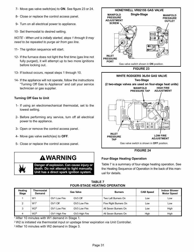
Page 31
7- Move gas valve switch(es) to ON. See figure 23 or 24.
8- Close or replace the control access panel.
9- Turn on all electrical power to appliance.
10- Set thermostat to desired setting.
NOTE - When unit is initially started, steps 1 through 9 may
need to be repeated to purge air from gas line.
11- The ignition sequence will start.
12- If the furnace does not light the first time (gas line not
fully purged), it will attempt up to two more ignitions
before locking out.
13- If lockout occurs, repeat steps 1 through 10.
14- If the appliance will not operate, follow the instructions
“Turning Off Gas to Appliance” and call your service
technician or gas supplier.
Turning Off Gas to Unit
1- If using an electromechanical thermostat, set to the
lowest setting.
2- Before performing any service, turn off all electrical
power to the appliance.
3- Open or remove the control access panel.
4- Move gas valve switch(es) to OFF.
5- Close or replace the control access panel.
WARNINGDanger of explosion. Can cause injury ordeath. Do not attempt to light manually.Unit has a direct spark ignition system.
MANIFOLDPRESSURE
OUTLET
Gas valve switch shown in ON position.
INLETPRESSURE
PORT
MANIFOLDPRESSURE
ADJUSTMENTSCREW
FIGURE 23
HONEYWELL VR8215S GAS VALVE
Single-Stage
FIGURE 24
WHITE RODGERS 36J54 GAS VALVE
Two-Stage
(2 two-stage valves are used on four-stage heat units)
Gas valve switch is shown in OFF position.
LOW FIREADJUSTMENT
HIGH FIREADJUSTMENT
INLETPRESSURE
TAP
MANIFOLDPRESSURE TAP
Four-Stage Heating Operation
Table 7 is a summary of four-stage heating operation. See
the Heating Sequence of Operation in the back of this man
ual for details.
TABLE 7FOUR-STAGE HEATING OPERATION
HeatingStage
ThermostatDemand
Gas Valve Burners CAB SpeedIndoor BlowerMotor Speed
1 W1 GV1 Low Fire GV3 Off Two Left Burners On Low Low
2 W11 GV1 Off GV3 Low Fire Five Right Burners On Low Low
3 W22 GV1 Low Fire GV3 Low Fire All Seven Burners On Low High
4 W23 GV1 High Fire GV3 High Fire All Seven Burners On High High
1 After 10 minutes with W1 demand in Stage 1.2 W2 is initiated via thermostat input or upstage timer expiration via Unit Controller.3 After 10 minutes with W2 demand in Stage 3.
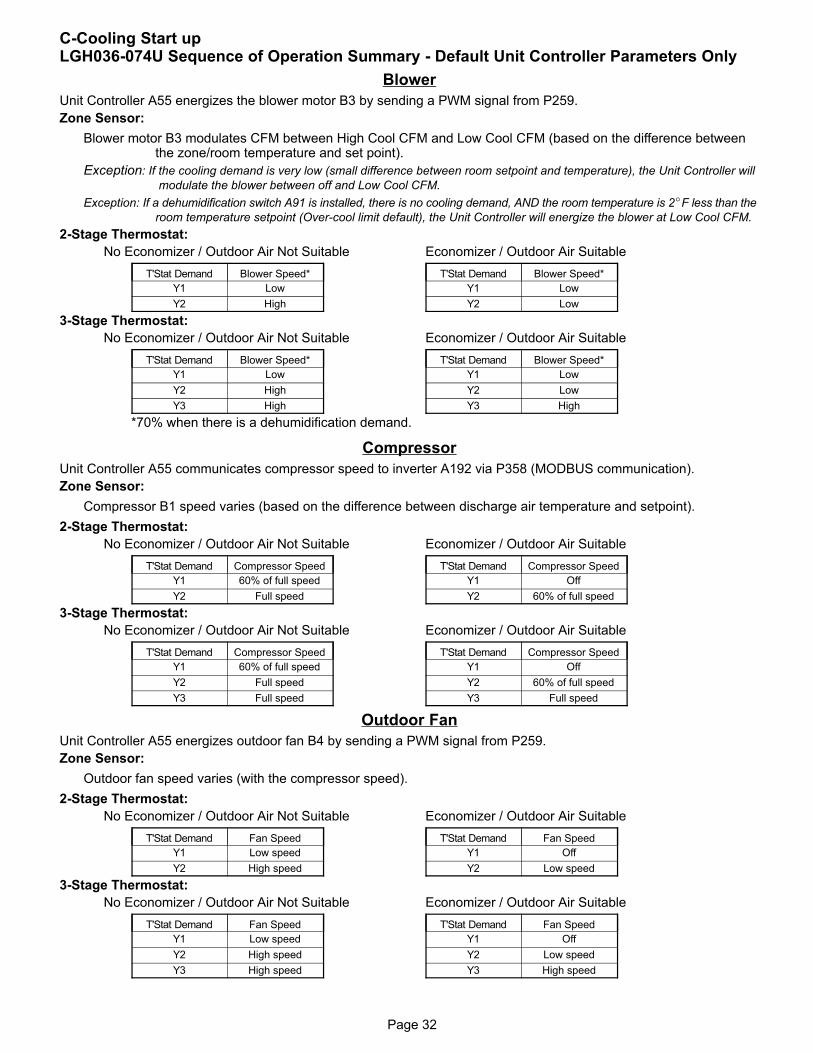
Page 32
C-Cooling Start upLGH036-074U Sequence of Operation Summary - Default Unit Controller Parameters Only
Blower
Unit Controller A55 energizes the blower motor B3 by sending a PWM signal from P259.
Zone Sensor:
Blower motor B3 modulates CFM between High Cool CFM and Low Cool CFM (based on the difference betweenthe zone/room temperature and set point).
Exception: If the cooling demand is very low (small difference between room setpoint and temperature), the Unit Controller will
modulate the blower between off and Low Cool CFM.
Exception: If a dehumidification switch A91 is installed, there is no cooling demand, AND the room temperature is 2�F less than the
room temperature setpoint (Over-cool limit default), the Unit Controller will energize the blower at Low Cool CFM.
2-Stage Thermostat:
No Economizer / Outdoor Air Not Suitable
T'Stat Demand Blower Speed*
Y1 Low
Y2 High
Economizer / Outdoor Air Suitable
T'Stat Demand Blower Speed*
Y1 Low
Y2 Low
3-Stage Thermostat:
No Economizer / Outdoor Air Not Suitable
T'Stat Demand Blower Speed*
Y1 Low
Y2 High
Y3 High
Economizer / Outdoor Air Suitable
T'Stat Demand Blower Speed*
Y1 Low
Y2 Low
Y3 High
*70% when there is a dehumidification demand.
Compressor
Unit Controller A55 communicates compressor speed to inverter A192 via P358 (MODBUS communication).
Zone Sensor:
Compressor B1 speed varies (based on the difference between discharge air temperature and setpoint).
2-Stage Thermostat:
No Economizer / Outdoor Air Not Suitable
T'Stat Demand Compressor Speed
Y1 60% of full speed
Y2 Full speed
Economizer / Outdoor Air Suitable
T'Stat Demand Compressor Speed
Y1 Off
Y2 60% of full speed
3-Stage Thermostat:
No Economizer / Outdoor Air Not Suitable
T'Stat Demand Compressor Speed
Y1 60% of full speed
Y2 Full speed
Y3 Full speed
Economizer / Outdoor Air Suitable
T'Stat Demand Compressor Speed
Y1 Off
Y2 60% of full speed
Y3 Full speed
Outdoor Fan
Unit Controller A55 energizes outdoor fan B4 by sending a PWM signal from P259.
Zone Sensor:
Outdoor fan speed varies (with the compressor speed).
2-Stage Thermostat:
No Economizer / Outdoor Air Not Suitable
T'Stat Demand Fan Speed
Y1 Low speed
Y2 High speed
Economizer / Outdoor Air Suitable
T'Stat Demand Fan Speed
Y1 Off
Y2 Low speed
3-Stage Thermostat:
No Economizer / Outdoor Air Not Suitable
T'Stat Demand Fan Speed
Y1 Low speed
Y2 High speed
Y3 High speed
Economizer / Outdoor Air Suitable
T'Stat Demand Fan Speed
Y1 Off
Y2 Low speed
Y3 High speed
Page 33
Three Phase Scroll Compressor Voltage Phasing
Three phase scroll compressors must be phased se
quentially to ensure correct compressor and blower rota
tion and operation. Compressor and blower are wired in
phase at the factory.
1- Observe suction and discharge pressures and blower
rotation on unit start-up.
2- Suction pressure must drop, discharge pressure must
rise, and blower rotation must match rotation marking.
If pressure differential is not observed or blower rotation is
not correct:
3- Disconnect all remote electrical power supplies.
4- Reverse any two field-installed wires connected to the
line side of K1 contactor. Do not reverse wires at blow
er contactor.
5- Make sure the connections are tight.
Discharge and suction pressures should operate at their
normal start‐up ranges.
D-Safety or Emergency Shutdown
Turn off power to unit. Close manual and main gas valves.
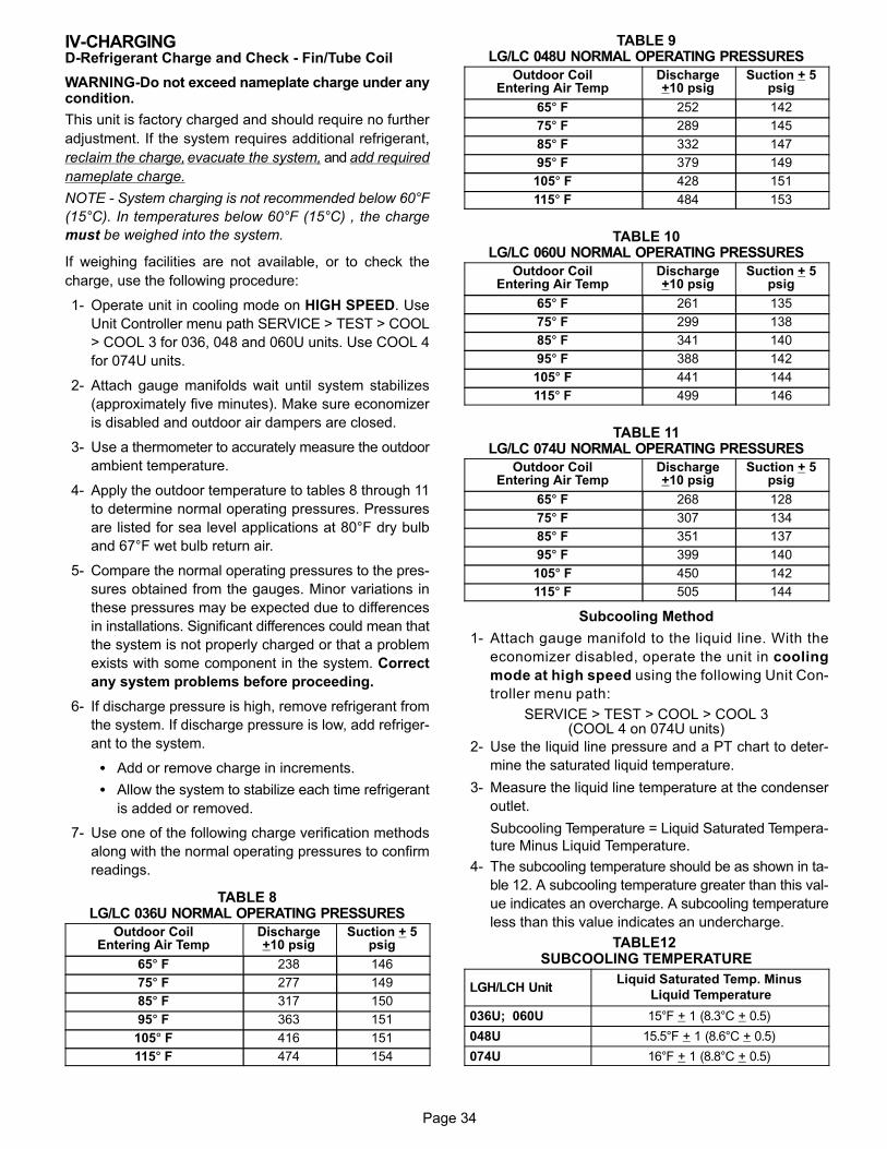
Page 34
IV-CHARGING D-Refrigerant Charge and Check - Fin/Tube Coil
WARNING-Do not exceed nameplate charge under anycondition.
This unit is factory charged and should require no further
adjustment. If the system requires additional refrigerant,
reclaim the charge, evacuate the system, and add required
nameplate charge.
NOTE - System charging is not recommended below 60°F
(15°C). In temperatures below 60°F (15°C) , the charge
must be weighed into the system.
If weighing facilities are not available, or to check the
charge, use the following procedure:
1- Operate unit in cooling mode on HIGH SPEED. Use
Unit Controller menu path SERVICE > TEST > COOL
> COOL 3 for 036, 048 and 060U units. Use COOL 4
for 074U units.
2- Attach gauge manifolds wait until system stabilizes
(approximately five minutes). Make sure economizer
is disabled and outdoor air dampers are closed.
3- Use a thermometer to accurately measure the outdoor
ambient temperature.
4- Apply the outdoor temperature to tables 8 through 11
to determine normal operating pressures. Pressures
are listed for sea level applications at 80°F dry bulb
and 67°F wet bulb return air.
5- Compare the normal operating pressures to the pres
sures obtained from the gauges. Minor variations in
these pressures may be expected due to differences
in installations. Significant differences could mean that
the system is not properly charged or that a problem
exists with some component in the system. Correct
any system problems before proceeding.
6- If discharge pressure is high, remove refrigerant from
the system. If discharge pressure is low, add refriger
ant to the system.
� Add or remove charge in increments.
� Allow the system to stabilize each time refrigerant
is added or removed.
7- Use one of the following charge verification methods
along with the normal operating pressures to confirm
readings.
TABLE 8LG/LC 036U NORMAL OPERATING PRESSURES
Outdoor CoilEntering Air Temp
Discharge+10 psig
Suction + 5psig
65� F 238 146
75� F 277 149
85� F 317 150
95� F 363 151
105� F 416 151
115� F 474 154
TABLE 9LG/LC 048U NORMAL OPERATING PRESSURES
Outdoor CoilEntering Air Temp
Discharge+10 psig
Suction + 5psig
65� F 252 142
75� F 289 145
85� F 332 147
95� F 379 149
105� F 428 151
115� F 484 153
TABLE 10LG/LC 060U NORMAL OPERATING PRESSURES
Outdoor CoilEntering Air Temp
Discharge+10 psig
Suction + 5psig
65� F 261 135
75� F 299 138
85� F 341 140
95� F 388 142
105� F 441 144
115� F 499 146
TABLE 11LG/LC 074U NORMAL OPERATING PRESSURES
Outdoor CoilEntering Air Temp
Discharge+10 psig
Suction + 5psig
65� F 268 128
75� F 307 134
85� F 351 137
95� F 399 140
105� F 450 142
115� F 505 144
Subcooling Method
1- Attach gauge manifold to the liquid line. With the
economizer disabled, operate the unit in cooling
mode at high speed using the following Unit Con
troller menu path:
SERVICE > TEST > COOL > COOL 3(COOL 4 on 074U units)
2- Use the liquid line pressure and a PT chart to deter
mine the saturated liquid temperature.
3- Measure the liquid line temperature at the condenser
outlet.
Subcooling Temperature = Liquid Saturated Tempera
ture Minus Liquid Temperature.
4- The subcooling temperature should be as shown in ta
ble 12. A subcooling temperature greater than this val
ue indicates an overcharge. A subcooling temperature
less than this value indicates an undercharge.
TABLE12 SUBCOOLING TEMPERATURE
LGH/LCH UnitLiquid Saturated Temp. Minus
Liquid Temperature
036U; 060U 15°F + 1 (8.3°C + 0.5)
048U 15.5°F + 1 (8.6°C + 0.5)
074U 16°F + 1 (8.8°C + 0.5)
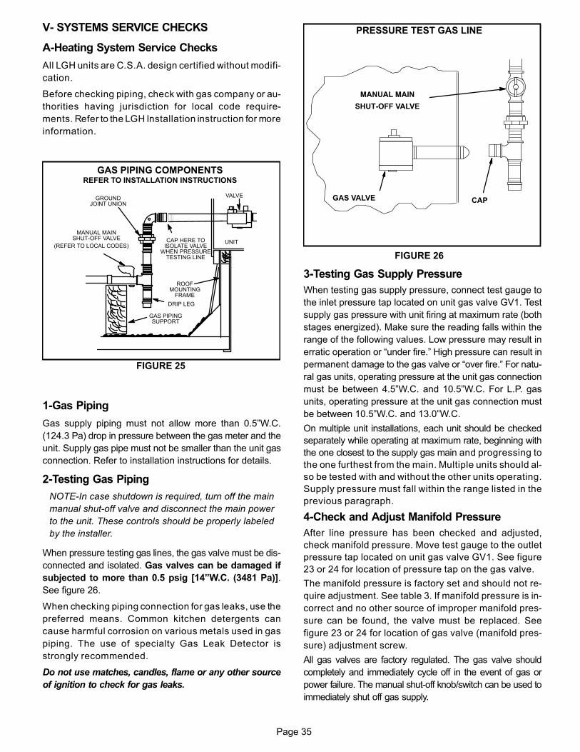
Page 35
V- SYSTEMS SERVICE CHECKS
A-Heating System Service Checks
All LGH units are C.S.A. design certified without modifi
cation.
Before checking piping, check with gas company or au
thorities having jurisdiction for local code require
ments. Refer to the LGH Installation instruction for more
information.
UNIT
GROUNDJOINT UNION
MANUAL MAINSHUT-OFF VALVE
(REFER TO LOCAL CODES)
GAS PIPINGSUPPORT
DRIP LEG
ROOFMOUNTING
FRAME
GAS PIPING COMPONENTSREFER TO INSTALLATION INSTRUCTIONS
VALVE
CAP HERE TOISOLATE VALVE
WHEN PRESSURETESTING LINE
FIGURE 25
1-Gas Piping
Gas supply piping must not allow more than 0.5”W.C.
(124.3 Pa) drop in pressure between the gas meter and the
unit. Supply gas pipe must not be smaller than the unit gas
connection. Refer to installation instructions for details.
2-Testing Gas Piping
NOTE-In case shutdown is required, turn off the main
manual shut‐off valve and disconnect the main power
to the unit. These controls should be properly labeled
by the installer.
When pressure testing gas lines, the gas valve must be dis
connected and isolated. Gas valves can be damaged if
subjected to more than 0.5 psig [14”W.C. (3481 Pa)].
See figure 26.
When checking piping connection for gas leaks, use the
preferred means. Common kitchen detergents can
cause harmful corrosion on various metals used in gas
piping. The use of specialty Gas Leak Detector is
strongly recommended.
Do not use matches, candles, flame or any other source
of ignition to check for gas leaks.
GAS VALVE CAP
MANUAL MAIN
SHUT-OFF VALVE
FIGURE 26
PRESSURE TEST GAS LINE
3-Testing Gas Supply Pressure
When testing gas supply pressure, connect test gauge to
the inlet pressure tap located on unit gas valve GV1. Test
supply gas pressure with unit firing at maximum rate (both
stages energized). Make sure the reading falls within the
range of the following values. Low pressure may result in
erratic operation or “under fire.” High pressure can result in
permanent damage to the gas valve or “over fire.” For natu
ral gas units, operating pressure at the unit gas connection
must be between 4.5”W.C. and 10.5”W.C. For L.P. gas
units, operating pressure at the unit gas connection must
be between 10.5”W.C. and 13.0”W.C.
On multiple unit installations, each unit should be checked
separately while operating at maximum rate, beginning with
the one closest to the supply gas main and progressing to
the one furthest from the main. Multiple units should al
so be tested with and without the other units operating.
Supply pressure must fall within the range listed in the
previous paragraph.
4-Check and Adjust Manifold Pressure
After line pressure has been checked and adjusted,
check manifold pressure. Move test gauge to the outlet
pressure tap located on unit gas valve GV1. See figure
23 or 24 for location of pressure tap on the gas valve.
The manifold pressure is factory set and should not re
quire adjustment. See table 3. If manifold pressure is in
correct and no other source of improper manifold pres
sure can be found, the valve must be replaced. See
figure 23 or 24 for location of gas valve (manifold pres
sure) adjustment screw.
All gas valves are factory regulated. The gas valve should
completely and immediately cycle off in the event of gas or
power failure. The manual shut‐off knob/switch can be used to
immediately shut off gas supply.
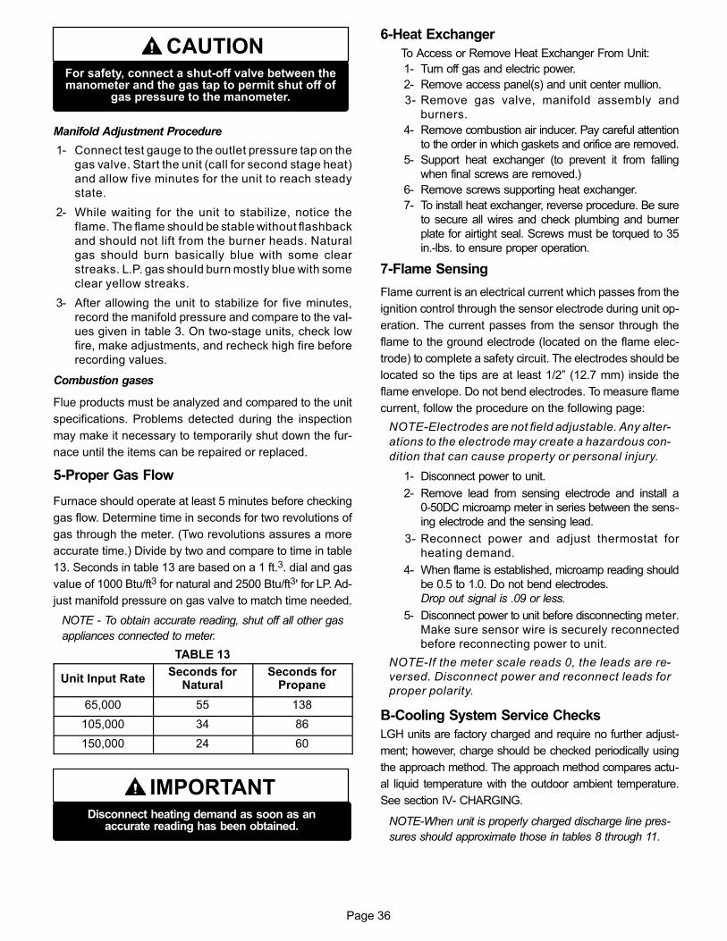
Page 36
CAUTIONFor safety, connect a shut‐off valve between themanometer and the gas tap to permit shut off of
gas pressure to the manometer.
Manifold Adjustment Procedure
1- Connect test gauge to the outlet pressure tap on the
gas valve. Start the unit (call for second stage heat)
and allow five minutes for the unit to reach steady
state.
2- While waiting for the unit to stabilize, notice the
flame. The flame should be stable without flashback
and should not lift from the burner heads. Natural
gas should burn basically blue with some clear
streaks. L.P. gas should burn mostly blue with some
clear yellow streaks.
3- After allowing the unit to stabilize for five minutes,
record the manifold pressure and compare to the val
ues given in table 3. On two-stage units, check low
fire, make adjustments, and recheck high fire before
recording values.
Combustion gases
Flue products must be analyzed and compared to the unit
specifications. Problems detected during the inspection
may make it necessary to temporarily shut down the fur
nace until the items can be repaired or replaced.
5-Proper Gas Flow
Furnace should operate at least 5 minutes before checking
gas flow. Determine time in seconds for two revolutions of
gas through the meter. (Two revolutions assures a more
accurate time.) Divide by two and compare to time in table
13. Seconds in table 13 are based on a 1 ft.3. dial and gas
value of 1000 Btu/ft3 for natural and 2500 Btu/ft3' for LP. Ad
just manifold pressure on gas valve to match time needed.
NOTE - To obtain accurate reading, shut off all other gas
appliances connected to meter.
TABLE 13
Unit Input RateSeconds for
NaturalSeconds for
Propane
65,000 55 138
105,000 34 86
150,000 24 60
IMPORTANTDisconnect heating demand as soon as an
accurate reading has been obtained.
6-Heat Exchanger
To Access or Remove Heat Exchanger From Unit:
1- Turn off gas and electric power.
2- Remove access panel(s) and unit center mullion.
3- Remove gas valve, manifold assembly and
burners.
4- Remove combustion air inducer. Pay careful attention
to the order in which gaskets and orifice are removed.
5- Support heat exchanger (to prevent it from falling
when final screws are removed.)
6- Remove screws supporting heat exchanger.
7- To install heat exchanger, reverse procedure. Be sure
to secure all wires and check plumbing and burner
plate for airtight seal. Screws must be torqued to 35
in.‐lbs. to ensure proper operation.
7-Flame Sensing
Flame current is an electrical current which passes from the
ignition control through the sensor electrode during unit op
eration. The current passes from the sensor through the
flame to the ground electrode (located on the flame elec
trode) to complete a safety circuit. The electrodes should be
located so the tips are at least 1/2” (12.7 mm) inside the
flame envelope. Do not bend electrodes. To measure flame
current, follow the procedure on the following page:
NOTE-Electrodes are not field adjustable. Any alter
ations to the electrode may create a hazardous con
dition that can cause property or personal injury.
1- Disconnect power to unit.
2- Remove lead from sensing electrode and install a
0-50DC microamp meter in series between the sens
ing electrode and the sensing lead.
3- Reconnect power and adjust thermostat for
heating demand.
4- When flame is established, microamp reading should
be 0.5 to 1.0. Do not bend electrodes.
Drop out signal is .09 or less.
5- Disconnect power to unit before disconnecting meter.
Make sure sensor wire is securely reconnected
before reconnecting power to unit.
NOTE-If the meter scale reads 0, the leads are re
versed. Disconnect power and reconnect leads for
proper polarity.
B-Cooling System Service Checks
LGH units are factory charged and require no further adjust
ment; however, charge should be checked periodically using
the approach method. The approach method compares actu
al liquid temperature with the outdoor ambient temperature.
See section IV- CHARGING.
NOTE-When unit is properly charged discharge line pres
sures should approximate those in tables 8 through 11.
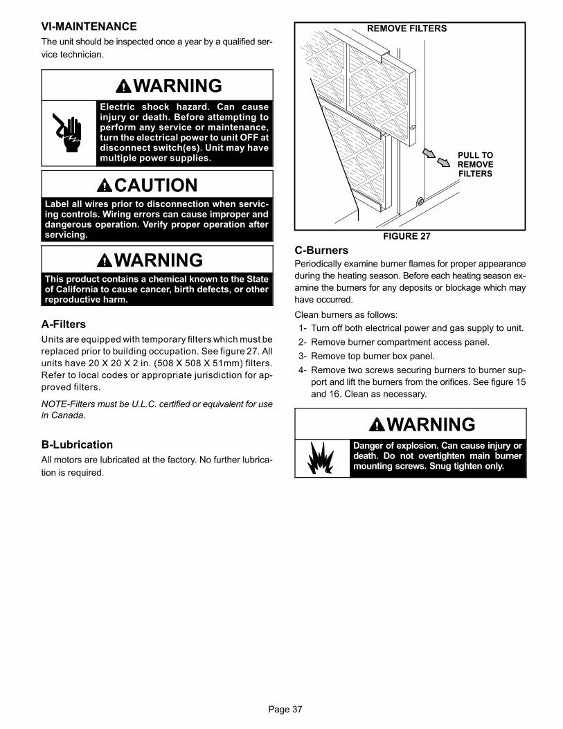
Page 37
VI-MAINTENANCE
The unit should be inspected once a year by a qualified ser
vice technician.
WARNINGElectric shock hazard. Can causeinjury or death. Before attempting toperform any service or maintenance,turn the electrical power to unit OFF atdisconnect switch(es). Unit may havemultiple power supplies.
CAUTIONLabel all wires prior to disconnection when servicing controls. Wiring errors can cause improper anddangerous operation. Verify proper operation afterservicing.
WARNINGThis product contains a chemical known to the Stateof California to cause cancer, birth defects, or otherreproductive harm.
A-Filters
Units are equipped with temporary filters which must be
replaced prior to building occupation. See figure 27. All
units have 20 X 20 X 2 in. (508 X 508 X 51mm) filters.
Refer to local codes or appropriate jurisdiction for ap
proved filters.
NOTE-Filters must be U.L.C. certified or equivalent for use
in Canada.
B-Lubrication
All motors are lubricated at the factory. No further lubrica
tion is required.
FIGURE 27
REMOVE FILTERS
PULL TOREMOVEFILTERS
C-BurnersPeriodically examine burner flames for proper appearance
during the heating season. Before each heating season ex
amine the burners for any deposits or blockage which may
have occurred.
Clean burners as follows:
1- Turn off both electrical power and gas supply to unit.
2- Remove burner compartment access panel.
3- Remove top burner box panel.
4- Remove two screws securing burners to burner sup
port and lift the burners from the orifices. See figure 15
and 16. Clean as necessary.
WARNINGDanger of explosion. Can cause injury ordeath. Do not overtighten main burnermounting screws. Snug tighten only.
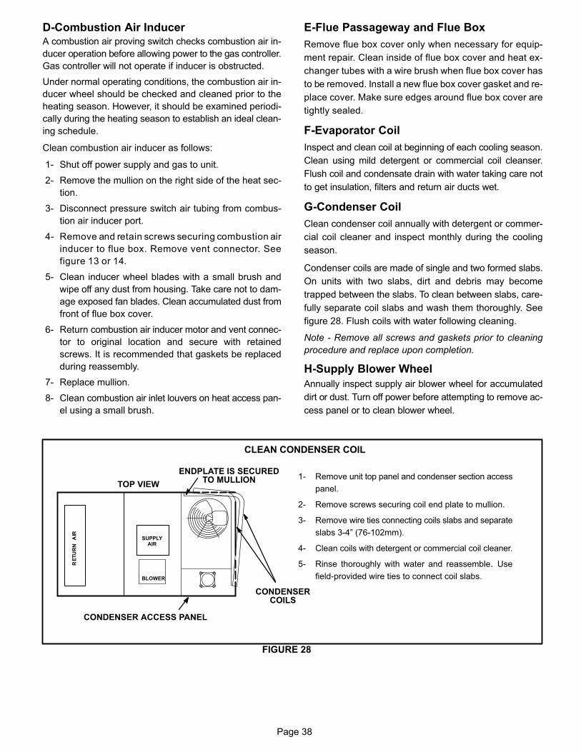
Page 38
D-Combustion Air InducerA combustion air proving switch checks combustion air in
ducer operation before allowing power to the gas controller.
Gas controller will not operate if inducer is obstructed.
Under normal operating conditions, the combustion air in
ducer wheel should be checked and cleaned prior to the
heating season. However, it should be examined periodi
cally during the heating season to establish an ideal clean
ing schedule.
Clean combustion air inducer as follows:
1- Shut off power supply and gas to unit.
2- Remove the mullion on the right side of the heat sec
tion.
3- Disconnect pressure switch air tubing from combus
tion air inducer port.
4- Remove and retain screws securing combustion air
inducer to flue box. Remove vent connector. See
figure 13 or 14.
5- Clean inducer wheel blades with a small brush and
wipe off any dust from housing. Take care not to dam
age exposed fan blades. Clean accumulated dust from
front of flue box cover.
6- Return combustion air inducer motor and vent connec
tor to original location and secure with retained
screws. It is recommended that gaskets be replaced
during reassembly.
7- Replace mullion.
8- Clean combustion air inlet louvers on heat access pan
el using a small brush.
E-Flue Passageway and Flue Box
Remove flue box cover only when necessary for equip
ment repair. Clean inside of flue box cover and heat ex
changer tubes with a wire brush when flue box cover has
to be removed. Install a new flue box cover gasket and re
place cover. Make sure edges around flue box cover are
tightly sealed.
F-Evaporator Coil
Inspect and clean coil at beginning of each cooling season.
Clean using mild detergent or commercial coil cleanser.
Flush coil and condensate drain with water taking care not
to get insulation, filters and return air ducts wet.
G-Condenser Coil
Clean condenser coil annually with detergent or commer
cial coil cleaner and inspect monthly during the cooling
season.
Condenser coils are made of single and two formed slabs.
On units with two slabs, dirt and debris may become
trapped between the slabs. To clean between slabs, care
fully separate coil slabs and wash them thoroughly. See
figure 28. Flush coils with water following cleaning.
Note - Remove all screws and gaskets prior to cleaning
procedure and replace upon completion.
H-Supply Blower Wheel
Annually inspect supply air blower wheel for accumulated
dirt or dust. Turn off power before attempting to remove ac
cess panel or to clean blower wheel.
FIGURE 28
CLEAN CONDENSER COIL
TOP VIEW
CONDENSERCOILS
BLOWER
CONDENSER ACCESS PANEL
ENDPLATE IS SECUREDTO MULLION
SUPPLYAIR
1- Remove unit top panel and condenser section access
panel.
2- Remove screws securing coil end plate to mullion.
3- Remove wire ties connecting coils slabs and separate
slabs 3-4” (76-102mm).
4- Clean coils with detergent or commercial coil cleaner.
5- Rinse thoroughly with water and reassemble. Use
field-provided wire ties to connect coil slabs.
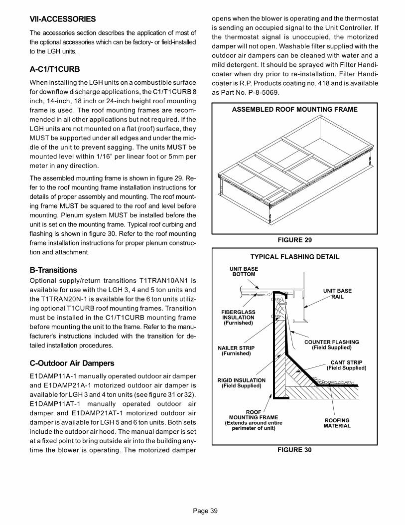
Page 39
VII-ACCESSORIES
The accessories section describes the application of most of
the optional accessories which can be factory- or field-installed
to the LGH units.
A-C1/T1CURB
When installing the LGH units on a combustible surface
for downflow discharge applications, the C1/T1CURB 8
inch, 14‐inch, 18 inch or 24‐inch height roof mounting
frame is used. The roof mounting frames are recom
mended in all other applications but not required. If the
LGH units are not mounted on a flat (roof) surface, they
MUST be supported under all edges and under the mid
dle of the unit to prevent sagging. The units MUST be
mounted level within 1/16” per linear foot or 5mm per
meter in any direction.
The assembled mounting frame is shown in figure 29. Re
fer to the roof mounting frame installation instructions for
details of proper assembly and mounting. The roof mount
ing frame MUST be squared to the roof and level before
mounting. Plenum system MUST be installed before the
unit is set on the mounting frame. Typical roof curbing and
flashing is shown in figure 30. Refer to the roof mounting
frame installation instructions for proper plenum construc
tion and attachment.
B-Transitions
Optional supply/return transitions T1TRAN10AN1 is
available for use with the LGH 3, 4 and 5 ton units and
the T1TRAN20N-1 is available for the 6 ton units utiliz
ing optional T1CURB roof mounting frames. Transition
must be installed in the C1/T1CURB mounting frame
before mounting the unit to the frame. Refer to the manu
facturer's instructions included with the transition for de
tailed installation procedures.
C-Outdoor Air Dampers
E1DAMP11A-1 manually operated outdoor air damper
and E1DAMP21A-1 motorized outdoor air damper is
available for LGH 3 and 4 ton units (see figure 31 or 32).
E1DAMP11AT-1 manually operated outdoor air
damper and E1DAMP21AT-1 motorized outdoor air
damper is available for LGH 5 and 6 ton units. Both sets
include the outdoor air hood. The manual damper is set
at a fixed point to bring outside air into the building any
time the blower is operating. The motorized damper
opens when the blower is operating and the thermostat
is sending an occupied signal to the Unit Controller. If
the thermostat signal is unoccupied, the motorized
damper will not open. Washable filter supplied with the
outdoor air dampers can be cleaned with water and a
mild detergent. It should be sprayed with Filter Handi
coater when dry prior to re-installation. Filter Handi
coater is R.P. Products coating no. 418 and is available
as Part No. P-8-5069.
FIGURE 29
ASSEMBLED ROOF MOUNTING FRAME
FIGURE 30
ROOFMOUNTING FRAME
(Extends around entireperimeter of unit)
FIBERGLASSINSULATION(Furnished)
COUNTER FLASHING(Field Supplied)
UNIT BASEBOTTOM
RIGID INSULATION(Field Supplied)
ROOFINGMATERIAL
CANT STRIP(Field Supplied)
NAILER STRIP(Furnished)
UNIT BASERAIL
TYPICAL FLASHING DETAIL
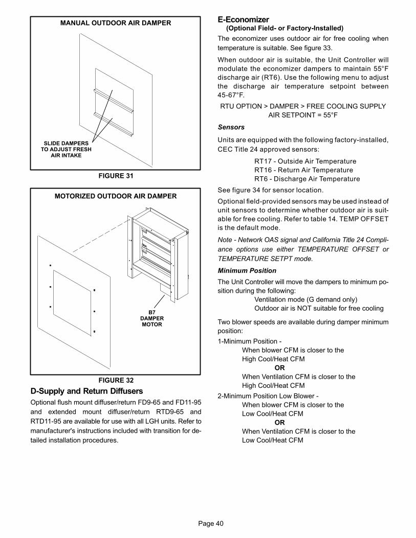
Page 40
FIGURE 31
SLIDE DAMPERSTO ADJUST FRESH
AIR INTAKE
MANUAL OUTDOOR AIR DAMPER
FIGURE 32
B7DAMPERMOTOR
MOTORIZED OUTDOOR AIR DAMPER
D-Supply and Return Diffusers
Optional flush mount diffuser/return FD9-65 and FD11-95
and extended mount diffuser/return RTD9-65 and
RTD11-95 are available for use with all LGH units. Refer to
manufacturer's instructions included with transition for de
tailed installation procedures.
E-Economizer(Optional Field- or Factory-Installed)
The economizer uses outdoor air for free cooling when
temperature is suitable. See figure 33.
When outdoor air is suitable, the Unit Controller will
modulate the economizer dampers to maintain 55°F
discharge air (RT6). Use the following menu to adjust
the discharge air temperature setpoint between
45-67°F.
RTU OPTION > DAMPER > FREE COOLING SUPPLY
AIR SETPOINT = 55°F
Sensors
Units are equipped with the following factory-installed,
CEC Title 24 approved sensors:
RT17 - Outside Air Temperature
RT16 - Return Air Temperature
RT6 - Discharge Air Temperature
See figure 34 for sensor location.
Optional field-provided sensors may be used instead of
unit sensors to determine whether outdoor air is suit
able for free cooling. Refer to table 14. TEMP OFFSET
is the default mode.
Note - Network OAS signal and California Title 24 Compli
ance options use either TEMPERATURE OFFSET or
TEMPERATURE SETPT mode.
Minimum Position
The Unit Controller will move the dampers to minimum po
sition during the following:
Ventilation mode (G demand only)
Outdoor air is NOT suitable for free cooling
Two blower speeds are available during damper minimum
position:
1-Minimum Position -
When blower CFM is closer to the
High Cool/Heat CFM
OR
When Ventilation CFM is closer to the
High Cool/Heat CFM
2-Minimum Position Low Blower -
When blower CFM is closer to the
Low Cool/Heat CFM
OR
When Ventilation CFM is closer to the
Low Cool/Heat CFM

Page 41
GED (Gravity Exhaust / Barometric Relief Dampers)
Field-Installed Option
The GED is located in the economizer except in downflow
applications or when a PEF (power exhaust fan) is NOT in
stalled. In horizontal airflow applications or when a PEF is
installed, the GED is located in the exhaust air hood.
Horizontal Air Discharge Economizers
The economizer is located in the unit the same as down
flow applications but note the position of the return air duct.
The duct attaches to a duct transition and duct inlet on the
end of the unit. An optional GED is located in the duct tran
sition. See figure 35.
FIGURE 33
ECONOMIZER
ECONOMIZER(STANDARD
ECONOMIZERSHOWN)
RETURN AIROPENING
UNIT
B7DAMPER MOTOR
A2 SENSOR(REMOTE FOR USE WITH
DDC CONTROLLED UNITS)
RT16SENSOR
SMOKE DETECTOR(WHEN EQUIPPED)
FIGURE 34
SENSOR LOCATION
RT17OUTDOOR AIR SENSOR(SECURED TO INSIDE OF
CORNER MULLION)
RT16RETURN
AIR SENSOR RT6DISCHARGEAIR SENSOR
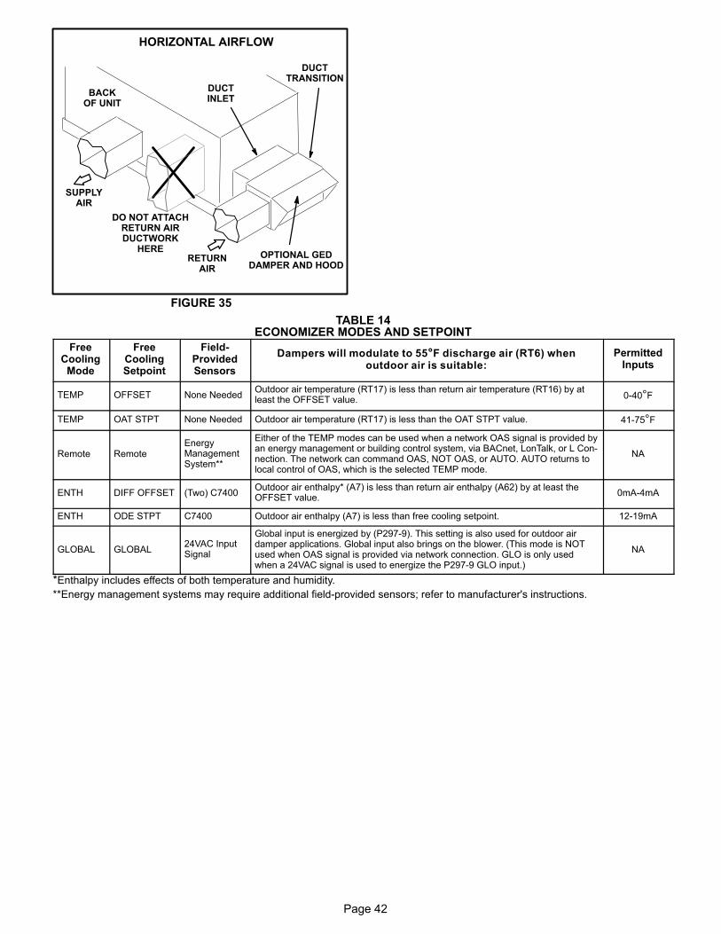
Page 42
FIGURE 35
HORIZONTAL AIRFLOW
BACKOF UNIT
DO NOT ATTACHRETURN AIRDUCTWORK
HERE
SUPPLYAIR
RETURNAIR
DUCTTRANSITION
DUCTINLET
OPTIONAL GEDDAMPER AND HOOD
TABLE 14ECONOMIZER MODES AND SETPOINT
FreeCoolingMode
FreeCoolingSetpoint
Field-ProvidedSensors
Dampers will modulate to 55°F discharge air (RT6) whenoutdoor air is suitable:
PermittedInputs
TEMP OFFSET None NeededOutdoor air temperature (RT17) is less than return air temperature (RT16) by atleast the OFFSET value. 0-40°F
TEMP OAT STPT None Needed Outdoor air temperature (RT17) is less than the OAT STPT value. 41-75°F
Remote RemoteEnergyManagementSystem**
Either of the TEMP modes can be used when a network OAS signal is provided byan energy management or building control system, via BACnet, LonTalk, or L Connection. The network can command OAS, NOT OAS, or AUTO. AUTO returns tolocal control of OAS, which is the selected TEMP mode.
NA
ENTH DIFF OFFSET (Two) C7400Outdoor air enthalpy* (A7) is less than return air enthalpy (A62) by at least theOFFSET value.
0mA-4mA
ENTH ODE STPT C7400 Outdoor air enthalpy (A7) is less than free cooling setpoint. 12-19mA
GLOBAL GLOBAL24VAC InputSignal
Global input is energized by (P297-9). This setting is also used for outdoor airdamper applications. Global input also brings on the blower. (This mode is NOTused when OAS signal is provided via network connection. GLO is only usedwhen a 24VAC signal is used to energize the P297-9 GLO input.)
NA
*Enthalpy includes effects of both temperature and humidity.
**Energy management systems may require additional field-provided sensors; refer to manufacturer's instructions.
Page 43
Outdoor Air Damper and Economizer Operation
DIRECT DRIVE DRIVE SYSTEM OPERATION:
Note: Direct drive units feature ECM condenser fans that are staged to match the compressor's capacity. When the com
pressor is operating at first stage, the condenser fan is operating at low speed. The condenser fan switches to high speed
when the compressor switches to second stage to match operation.
Modulating Outdoor Air Damper:
Damper minimum positions #1 and 2 are adjusted during unit setup to provide minimum fresh air requirements at the indi
cated supply fan speeds per ASHRAE 62.1.
-Supply fan is off and the outdoor air damper is closed
-Supply fan is on low speed and the outdoor air damper is at minimum position 1
-Supply fan is on high speed and the outdoor air damper is at minimum position 2
1Outdoor Air is Suitable
Note: When outdoor air is not suitable during the occupied time period, damper modulates to minimum position. When out
door air is not suitable during the unoccupied time period, damper modulates closed.
Cooling - Thermostat or Zone Sensor Mode (Up to 3 stages Y1, Y2, Y3)
Y1 demand:
1st-Compressor is off, supply fan is on low speed, economizer modulates (minimum to maximum
open position) to maintain 55°F supply air temperature (default unit controller setting)
2nd-After 5 minutes (default unit controller setting), supply fan switches to high speed. Economizer
continues modulating with supply fan on high speed to maintain 55°F supply air temperature
Y2 demand:
1st-Compressor is off, supply fan is on high speed, and economizer modulates to maintain 55°F
supply air temperature
2nd-Economizer opens to maximum. If economizer stays at maximum open for 3 minutes (default
unit controller setting) compressor is energized and operates at first stage while supply fan stays on
high speed.
1Outdoor air suitability is determined by the energy state of outdoor ambient (enthalpy or sensible) and its ability
to achieve the desired free cooling effects. Outdoor air suitability can also be determined by a third party
controller and provided to the RTU via a network connection.
Y3 demand:
1st-Economizer is at maximum open and compressor operates at first stage. If economizer stays at
maximum open for 3 minutes (default unit controller setting) compressor switches to second stage
operation while supply fan stays on high speed
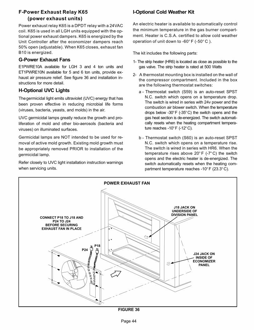
Page 44
F-Power Exhaust Relay K65
(power exhaust units)
Power exhaust relay K65 is a DPDT relay with a 24VAC
coil. K65 is used in all LGH units equipped with the op
tional power exhaust dampers. K65 is energized by the
Unit Controller after the economizer dampers reach
50% open (adjustable). When K65 closes, exhaust fan
B10 is energized.
G-Power Exhaust Fans
E1PWRE10A available for LGH 3 and 4 ton units and
ET1PWRE10N available for 5 and 6 ton units, provide ex
haust air pressure relief. See figure 36 and installation in
structions for more detail.
H-Optional UVC Lights
The germicidal light emits ultraviolet (UVC) energy that has
been proven effective in reducing microbial life forms
(viruses, bacteria, yeasts, and molds) in the air.
UVC germicidal lamps greatly reduce the growth and pro
liferation of mold and other bio-aerosols (bacteria and
viruses) on illuminated surfaces.
Germicidal lamps are NOT intended to be used for re
moval of active mold growth. Existing mold growth must
be appropriately removed PRIOR to installation of the
germicidal lamp.
Refer closely to UVC light installation instruction warnings
when servicing units.
I-Optional Cold Weather Kit
An electric heater is available to automatically control
the minimum temperature in the gas burner compart
ment. Heater is C.S.A. certified to allow cold weather
operation of unit down to ‐60° F (‐50° C ).
The kit includes the following parts:
1- The strip heater (HR6) is located as close as possible to the
gas valve. The strip heater is rated at 500 Watts
2- A thermostat mounting box is installed on the wall of
the compressor compartment. Included in the box
are the following thermostat switches:
a - Thermostat switch (S59) is an auto‐reset SPST
N.C. switch which opens on a temperature drop.
The switch is wired in series with 24v power and the
combustion air blower switch. When the temperature
drops below ‐30°F (-35°C) the switch opens and the
gas heat section is de‐energized. The switch automati
cally resets when the heating compartment tempera
ture reaches -10°F (-12°C).
b - Thermostat switch (S60) is an auto‐reset SPST
N.C. switch which opens on a temperature rise.
The switch is wired in series with HR6. When the
temperature rises above 20° F (‐7°C) the switch
opens and the electric heater is de‐energized. The
switch automatically resets when the heating com
partment temperature reaches ‐10°F (23.3°C).
FIGURE 36
POWER EXHAUST FAN
P24
J24 JACK ONINSIDE OF
ECONOMIZERPANEL
CONNECT P18 TO J18 ANDP24 TO J24
BEFORE SECURINGEXHAUST FAN IN PLACE
P18
J18 JACK ONUNDERSIDE OFDIVISION PANEL
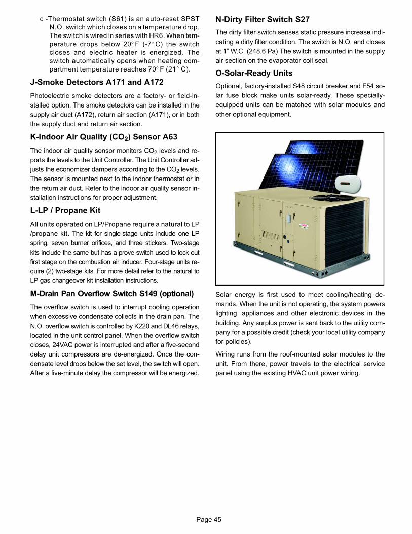
Page 45
c -Thermostat switch (S61) is an auto‐reset SPST
N.O. switch which closes on a temperature drop.
The switch is wired in series with HR6. When tem
perature drops below 20° F (‐7° C) the switch
closes and electric heater is energized. The
switch automatically opens when heating com
partment temperature reaches 70° F (21° C).
J-Smoke Detectors A171 and A172
Photoelectric smoke detectors are a factory- or field-in
stalled option. The smoke detectors can be installed in the
supply air duct (A172), return air section (A171), or in both
the supply duct and return air section.
K-Indoor Air Quality (CO2) Sensor A63
The indoor air quality sensor monitors CO2 levels and re
ports the levels to the Unit Controller. The Unit Controller ad
justs the economizer dampers according to the CO2 levels.
The sensor is mounted next to the indoor thermostat or in
the return air duct. Refer to the indoor air quality sensor in
stallation instructions for proper adjustment.
L-LP / Propane Kit
All units operated on LP/Propane require a natural to LP
/propane kit. The kit for single-stage units include one LP
spring, seven burner orifices, and three stickers. Two-stage
kits include the same but has a prove switch used to lock out
first stage on the combustion air inducer. Four-stage units re
quire (2) two-stage kits. For more detail refer to the natural to
LP gas changeover kit installation instructions.
M-Drain Pan Overflow Switch S149 (optional)
The overflow switch is used to interrupt cooling operation
when excessive condensate collects in the drain pan. The
N.O. overflow switch is controlled by K220 and DL46 relays,
located in the unit control panel. When the overflow switch
closes, 24VAC power is interrupted and after a five-second
delay unit compressors are de-energized. Once the con
densate level drops below the set level, the switch will open.
After a five-minute delay the compressor will be energized.
N-Dirty Filter Switch S27
The dirty filter switch senses static pressure increase indi
cating a dirty filter condition. The switch is N.O. and closes
at 1” W.C. (248.6 Pa) The switch is mounted in the supply
air section on the evaporator coil seal.
O-Solar-Ready Units
Optional, factory-installed S48 circuit breaker and F54 so
lar fuse block make units solar-ready. These specially-
equipped units can be matched with solar modules and
other optional equipment.
Solar energy is first used to meet cooling/heating de
mands. When the unit is not operating, the system powers
lighting, appliances and other electronic devices in the
building. Any surplus power is sent back to the utility com
pany for a possible credit (check your local utility company
for policies).
Wiring runs from the roof-mounted solar modules to the
unit. From there, power travels to the electrical service
panel using the existing HVAC unit power wiring.
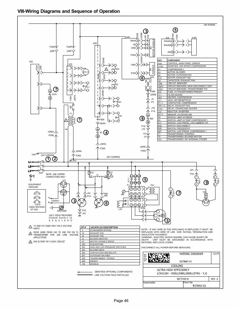
Page 46
VIII-Wiring Diagrams and Sequence of Operation
1
3
4
59
2
6
7
3
1
5
6
5
7
8
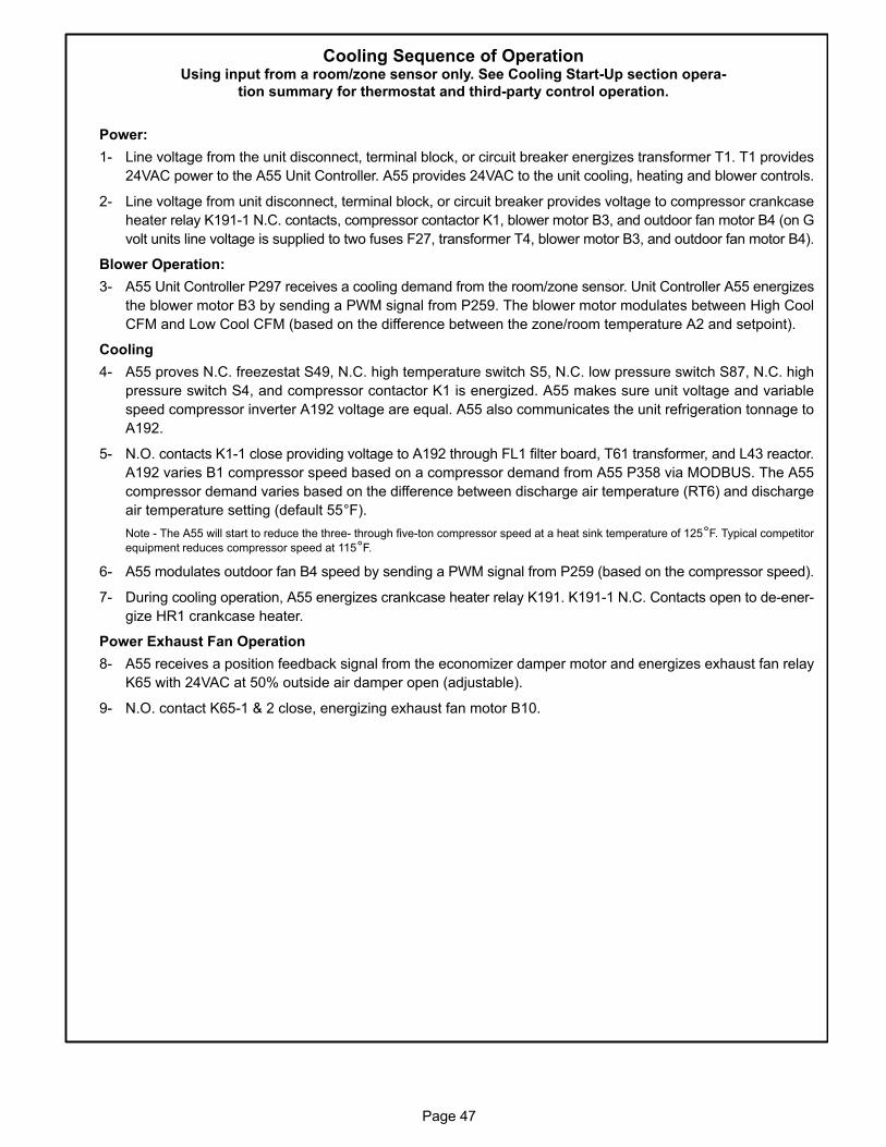
Page 47
Cooling Sequence of OperationUsing input from a room/zone sensor only. See Cooling Start-Up section opera
tion summary for thermostat and third-party control operation.
Power:
1- Line voltage from the unit disconnect, terminal block, or circuit breaker energizes transformer T1. T1 provides
24VAC power to the A55 Unit Controller. A55 provides 24VAC to the unit cooling, heating and blower controls.
2- Line voltage from unit disconnect, terminal block, or circuit breaker provides voltage to compressor crankcase
heater relay K191-1 N.C. contacts, compressor contactor K1, blower motor B3, and outdoor fan motor B4 (on G
volt units line voltage is supplied to two fuses F27, transformer T4, blower motor B3, and outdoor fan motor B4).
Blower Operation:
3- A55 Unit Controller P297 receives a cooling demand from the room/zone sensor. Unit Controller A55 energizes
the blower motor B3 by sending a PWM signal from P259. The blower motor modulates between High Cool
CFM and Low Cool CFM (based on the difference between the zone/room temperature A2 and setpoint).
Cooling
4- A55 proves N.C. freezestat S49, N.C. high temperature switch S5, N.C. low pressure switch S87, N.C. high
pressure switch S4, and compressor contactor K1 is energized. A55 makes sure unit voltage and variable
speed compressor inverter A192 voltage are equal. A55 also communicates the unit refrigeration tonnage to
A192.
5- N.O. contacts K1-1 close providing voltage to A192 through FL1 filter board, T61 transformer, and L43 reactor.
A192 varies B1 compressor speed based on a compressor demand from A55 P358 via MODBUS. The A55
compressor demand varies based on the difference between discharge air temperature (RT6) and discharge
air temperature setting (default 55°F).
Note - The A55 will start to reduce the three- through five-ton compressor speed at a heat sink temperature of 125°F. Typical competitor
equipment reduces compressor speed at 115°F.
6- A55 modulates outdoor fan B4 speed by sending a PWM signal from P259 (based on the compressor speed).
7- During cooling operation, A55 energizes crankcase heater relay K191. K191-1 N.C. Contacts open to de-ener
gize HR1 crankcase heater.
Power Exhaust Fan Operation
8- A55 receives a position feedback signal from the economizer damper motor and energizes exhaust fan relay
K65 with 24VAC at 50% outside air damper open (adjustable).
9- N.O. contact K65-1 & 2 close, energizing exhaust fan motor B10.
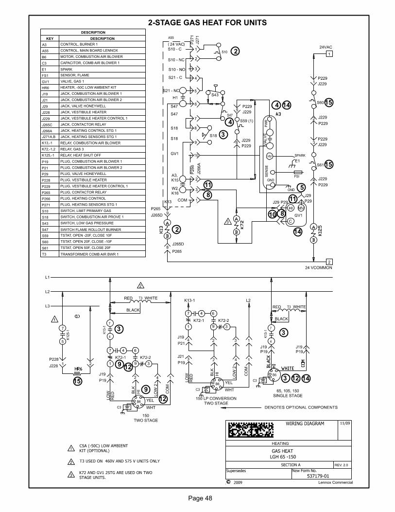
Page 48
Lennox Commercial
HEATING
REV. 2.0
DESCRIPTION
KEY DESCRIPTION
A3 CONTROL, BURNER 1
A55 CONTROL, MAIN BOARD LENNOX
B6 MOTOR, COMBUSTION AIR BLOWER
C3 CAPACITOR, COMB AIR BLOWER 1
E1 SPARK
FS1 SENSOR, FLAME
GV1 VALVE, GAS 1
HR6 HEATER, -50C LOW AMBIENT KIT
J19 JACK, COMBUSTION AIR BLOWER 1
J21 JACK, COMBUSTION AIR BLOWER 2
J29 JACK, VALVE HONEYWELL
J228 JACK, VESTIBULE HEATER
J229 JACK, VESTIBULE HEATER CONTROL 1
J265C JACK, CONTACTOR RELAY
J266A JACK, HEATING CONTROL STG 1
J271A,B JACK, HEATING SENSORS STG 1
K13,-1 RELAY, COMBUSTION AIR BLOWER
K72,-1,2 RELAY, GAS 3
K125,-1 RELAY, HEAT SHUT OFF
P19 PLUG, COMBUSTION AIR BLOWER 1
P21 PLUG, COMBUSTION AIR BLOWER 2
P29 PLUG, VALVE HONEYWELL
P228 PLUG, VESTIBULE HEATER
P229 PLUG, VESTIBULE HEATER CONTROL 1
P265 PLUG, CONTACTOR RELAY
P266 PLUG, HEATING CONTROL
P271 PLUG, HEATING SENSORS STG 1
S10 SWITCH, LIMIT PRIMARY GAS
S18 SWITCH, COMBUSTION AIR PROVE 1
S43 SWITCH, LOW GAS PRESSURE
S47 SWITCH FLAME ROLLOUT BURNER
S59 TSTAT, OPEN -20F, CLOSE 10F
S60 TSTAT, OPEN 20F, CLOSE -10F
S61 TSTAT, OPEN 50F, CLOSE 20F
T3 TRANSFORMER COMB AIR BWR 1
S60
S61
S59 (1)
2-STAGE GAS HEAT FOR UNITS
2
8
5
4
3
9
10
11
12
14
15
2
33
4
8
9
11
12
123
14
14
15
15
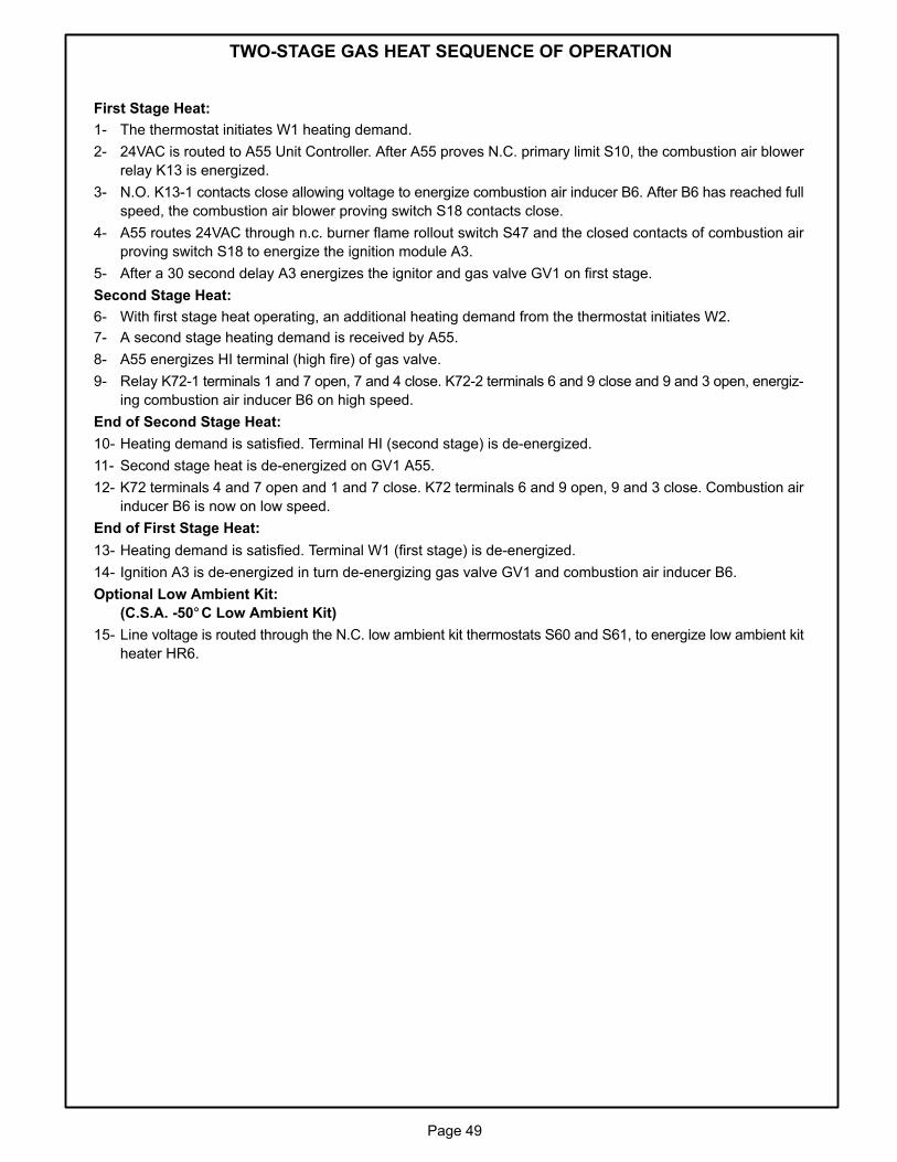
Page 49
TWO-STAGE GAS HEAT SEQUENCE OF OPERATION
First Stage Heat:
1- The thermostat initiates W1 heating demand.
2- 24VAC is routed to A55 Unit Controller. After A55 proves N.C. primary limit S10, the combustion air blower
relay K13 is energized.
3- N.O. K13-1 contacts close allowing voltage to energize combustion air inducer B6. After B6 has reached full
speed, the combustion air blower proving switch S18 contacts close.
4- A55 routes 24VAC through n.c. burner flame rollout switch S47 and the closed contacts of combustion air
proving switch S18 to energize the ignition module A3.
5- After a 30 second delay A3 energizes the ignitor and gas valve GV1 on first stage.
Second Stage Heat:
6- With first stage heat operating, an additional heating demand from the thermostat initiates W2.
7- A second stage heating demand is received by A55.
8- A55 energizes HI terminal (high fire) of gas valve.
9- Relay K72-1 terminals 1 and 7 open, 7 and 4 close. K72-2 terminals 6 and 9 close and 9 and 3 open, energiz
ing combustion air inducer B6 on high speed.
End of Second Stage Heat:
10- Heating demand is satisfied. Terminal HI (second stage) is de-energized.
11- Second stage heat is de-energized on GV1 A55.
12- K72 terminals 4 and 7 open and 1 and 7 close. K72 terminals 6 and 9 open, 9 and 3 close. Combustion air
inducer B6 is now on low speed.
End of First Stage Heat:
13- Heating demand is satisfied. Terminal W1 (first stage) is de-energized.
14- Ignition A3 is de-energized in turn de-energizing gas valve GV1 and combustion air inducer B6.
Optional Low Ambient Kit:
(C.S.A. -50°C Low Ambient Kit)
15- Line voltage is routed through the N.C. low ambient kit thermostats S60 and S61, to energize low ambient kit
heater HR6.
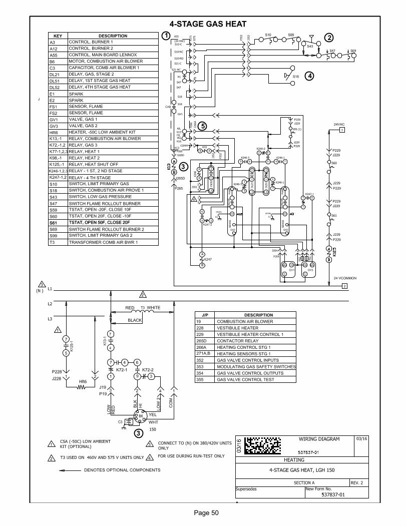
Page 50
4-STAGE GAS HEAT
3
2
4
1
5
3
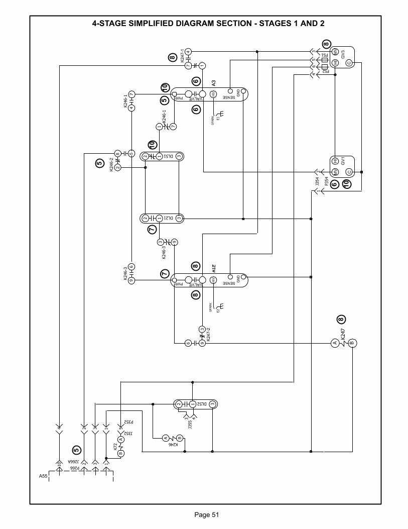
Page 51
4-STAGE SIMPLIFIED DIAGRAM SECTION - STAGES 1 AND 2
A55
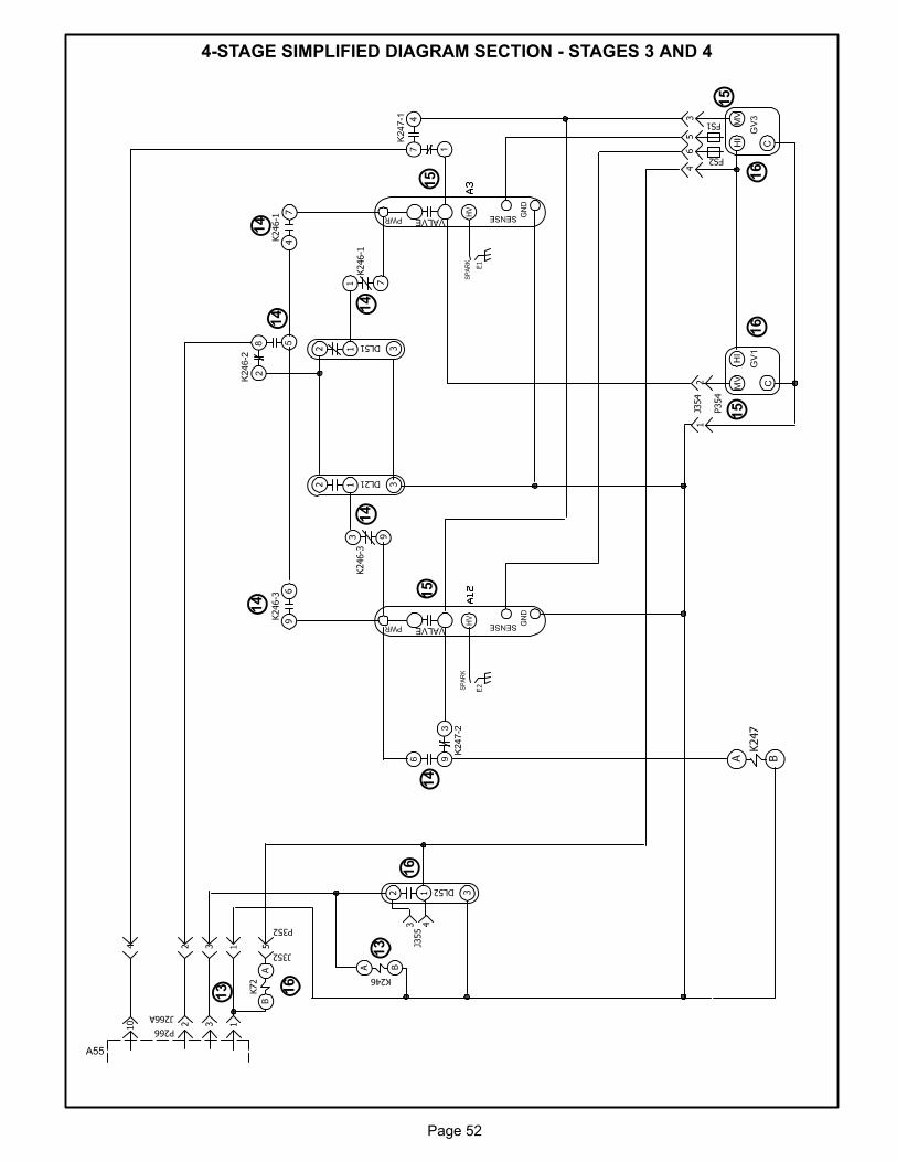
Page 52
4-STAGE SIMPLIFIED DIAGRAM SECTION - STAGES 3 AND 4
A55
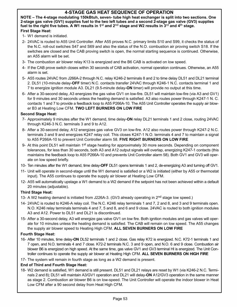
Page 53
4-STAGE GAS HEAT SEQUENCE OF OPERATIONNOTE – The 4-stage modulating 150kBtuh, seven- tube high heat exchanger is split into two sections. One2-stage gas valve (GV1) supplies fuel to the two left tubes and a second 2-stage gas valve (GV3) suppliesfuel to the right five tubes. A W1 results in 1st and 2nd stage and W2 results in 3rd and 4th stage.
First Stage Heat:
1- W1 demand is initiated.
2- 24VAC is routed to A55 Unit Controller. After A55 proves N.C. primary limits S10 and S99, it checks the status of
the N.C. roll-out switches S47 and S69 and also the status of the N.O. combustion air proving switch S18. If the
switches are closed and the CAB proving switch is open, the normal starting sequence is continued. Otherwise,
an A55 alarm will be set.
3- The combustion air blower relay K13 is energized and the B6 CAB is activated on low speed.
4- If the CAB prove switch closes within 30 seconds of CAB activation, normal operation continues. Otherwise, an A55
alarm is set.
5- A55 routes 24VAC from J266A-2 through N.C. relay K246-2 terminals 8 and 2 to time delay DL51 and DL21 terminal
2. DL51 (10-minute delay-OFF timer) N.C. contacts transfer 24VAC through K246-1 N.C. contacts terminal 1 and
7 to energize ignition module A3. DL21 (9.5-minute delay-ON timer) will provide no output at this time.
6- After a 30-second delay, A3 energizes the gas valve GV1 on low-fire. DL51 will maintain low-fire (via A3 and GV1)
for 9 minutes and 30 seconds unless the heating demand is satisfied. A3 also routes power through K247-1 N. C.
contacts 1 and 7 to provide a feedback loop to A55 P266A-10. The A55 Unit Controller operates the supply air blow
er B3 at Heating Low CFM. TWO LEFT BURNERS ON LOW FIRE
Second Stage Heat:
7- Approximately 9 minutes after the W1 demand, time delay-ON relay DL21 terminals 1 and 2 close, routing 24VAC
through K246-3 N.C. terminals 3 and 9 to A12.
8- After a 30-second delay, A12 energizes gas valve GV3 on low-fire. A12 also routes power through K247-2 N.C.
terminals 3 and 9 and energizes K247 relay coil. This closes K247-1 N.O. terminals 4 and 7 to maintain a signal
to A55 P266A-10 to prevent Unit Controller alarm 58. FIVE RIGHT BURNERS ON LOW FIRE
9- At this point DL51 will maintain 1st stage heating for approximately 30 more seconds. Depending on component
tolerances, for less than 30 seconds, both A3 and A12 output signals will overlap, energizing K247-1 contacts (this
maintains the feedback loop to A55 P266A-10 and prevents Unit Controller alarm 58). Both GV1 and GV3 will oper
ate on low speed briefly.
10- Ten minutes after the W1 demand, time delay-OFF DL51 opens terminals 1 and 2, de-energizing A3 and turning off GV1.
11- Unit will operate in second-stage until the W1 demand is satisfied or a W2 is initiated (either by A55 or thermostat
input). The A55 continues to operate the supply air blower at Heating Low CFM.
12- A55 will automatically upstage a W1 demand to a W2 demand if the setpoint has not been achieved within a default
20 minutes (adjustable).
Third Stage Heat:
13- A W2 heating demand is initiated from J226A-3. (GV3 already operating in 2nd stage low speed.)
14- 24VAC is routed to K246-A relay coil. The N.C. K246 relay terminals 1 and 7, 2 and 8, and 3 and 9 terminals open.
N.O. K246 relay terminals terminals 4 and 7, 5 and 8, and 6 and 9 close. 24VAC is routed to both ignition modules
A3 and A12. Power to DL51 and DL21 is discontinued.
15- After a 30-second delay, A3 will energize gas valve GV1 on low fire. Both ignition modules and gas valves will oper
ate for 10 minutes unless the heating demand is satisfied. The CAB will remain on low speed. The A55 changes
the supply air blower speed to Heating High CFM. ALL SEVEN BURNERS ON LOW FIRE
Fourth Stage Heat:
16- After 10 minutes, time delay-ON DL52 terminals 1 and 2 close. Gas relay K72 is energized. N.C. K72-1 terminals 1 and
7 open, and N.O. terminals 4 and 7 close. K72-2 terminals N.C. 3 and 9 open, and N.O. 6 and 9 close. Combustion air
blower B6 is energized on high speed. At the same time, gas valve GV1 and GV3 terminal HI is energized. The Unit Con
troller continues to operate the supply air blower at Heating High CFM. ALL SEVEN BURNERS ON HIGH FIRE
17- The system will remain in fourth stage as long as a W2 demand is present.
End of Third and Fourth Stage Heat:
18- W2 demand is satisfied, W1 demand is still present. DL51 and DL21 relays are reset by W1 (via K246-2 N.C. Termi
nals 2 and 8); DL51 will maintain A3/GV1 operation and DL21 will delay-ON A12/GV3 operation in the same manner
as stage 2. Combustion air blower B6 is on low-speed. The Unit Controller will operate the indoor blower in Heat
Low CFM after a 90 second delay from Heat High CFM.
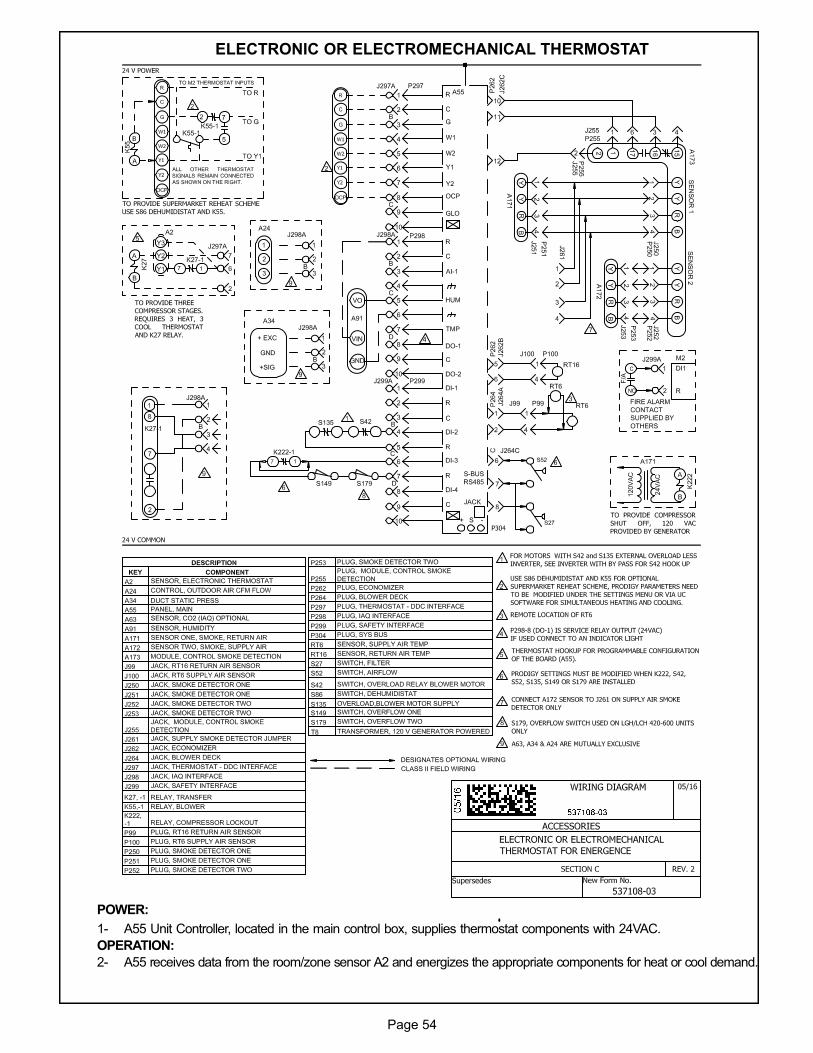
Page 54
ELECTRONIC OR ELECTROMECHANICAL THERMOSTAT
POWER:
1- A55 Unit Controller, located in the main control box, supplies thermostat components with 24VAC.
OPERATION:
2- A55 receives data from the room/zone sensor A2 and energizes the appropriate components for heat or cool demand.
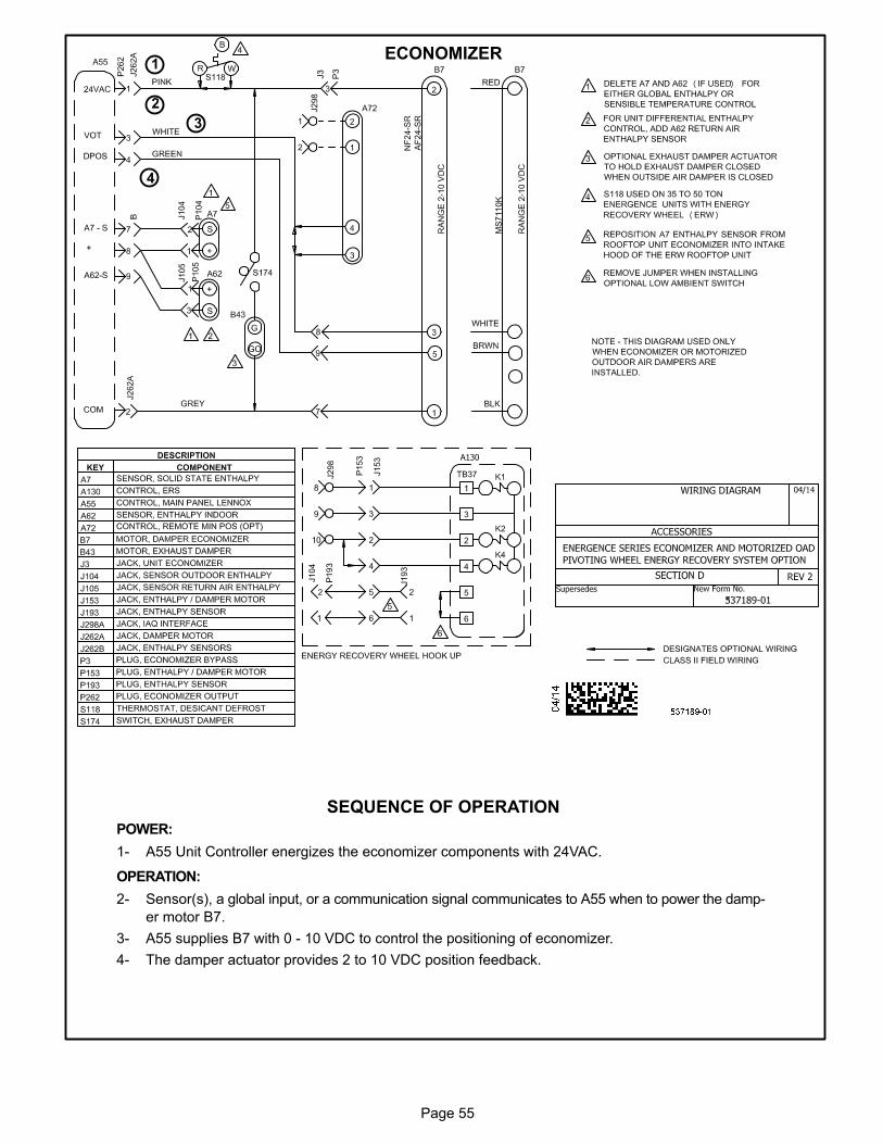
Page 55
ECONOMIZER
SEQUENCE OF OPERATION
POWER:
1- A55 Unit Controller energizes the economizer components with 24VAC.
OPERATION:
2- Sensor(s), a global input, or a communication signal communicates to A55 when to power the damp
er motor B7.
3- A55 supplies B7 with 0 - 10 VDC to control the positioning of economizer.
4- The damper actuator provides 2 to 10 VDC position feedback.
3
4
2
1