Embed Size (px)
Citation preview
UML Activity Diagramsas a Workflow Specification Language
Marlon Dumas and Arthur H.M. ter Hofstede
Cooperative Information Systems Research CentreQueensland University of Technology
GPO Box 2434, Brisbane QLD 4001, Australia{m.dumas, a.terhofstede}@qut.edu.au
Abstract. If UML activity diagrams are to succeed as a standard inthe area of organisational process modeling, they need to compare wellto alternative languages such as those provided by commercial WorkflowManagement Systems. This paper examines the expressiveness and theadequacy of activity diagrams for workflow specification, by systemati-cally evaluating their ability to capture a collection of workflow patterns.This analysis provides insights into the relative strengths and weaknessesof activity diagrams. In particular, it is shown that, given an appropriateclarification of their semantics, activity diagrams are able to capture situ-ations arising in practice, which cannot be captured by most commercialWorkflow Management Systems. On the other hand, the study showsthat activity diagrams fail to capture some useful situations, therebysuggesting directions for improvement.
1 Introduction
UML activity diagrams are intended to model both computational and organi-sational processes (i.e. workflows) [14, 15]. However, if activity diagrams are tosucceed as a standard in the area of organisational process modeling, they shouldcompare favorably to the languages currently used for this purpose, that is, thosesupported by existing Workflow Management Systems (WFMS).
In this paper, we investigate the expressiveness and adequacy of the activitydiagrams notation for workflow specification, by systematically confronting itwith a set of control-flow workflow patterns, i.e. abstracted forms of recurringsituations related to the ordering of activities in a workflow, and the flow ofexecution between them. Many of these patterns are documented in [3, 4], anda comparison of several WFMS based on these patterns is provided in [4].
Our evaluation demonstrates that activity diagrams support the majority ofthe patterns considered, including some which are typically not supported bycommercial WFMS. This is essentially due to the fact that activity diagramsintegrate signal sending and processing at the conceptual level, whereas mostcommercial WFMS only support them as a low-level implementation mechanism.
While activity diagrams compare well to existing WFMS in this respect, theyexhibit the major drawback that their syntax and semantics are not fully de-
fined in the standard’s documentation1. Indeed, while the features inherited fromHarel’s statecharts [9] have a formal operational semantics, the features specificto activity diagrams are only partially formalised in the standard (through OCLstatements), and their description in natural language leaves room for some am-biguities that we point out throughout the paper. We hope that some of theseambiguities will be clarified in future releases of the standard.
The rest of the paper is structured as follows. Section 2 discusses some seman-tical issues of the activity diagrams notation, focusing on control-flow aspects.Sections 3, 4, and 5 evaluate the capabilities of activity diagrams against dif-ferent families of workflow patterns. The patterns considered in sections 3 and4 are extracted from [4], while those discussed in section 5 are variants of thewell-known producer-consumer pattern. Finally, section 6 points to related work,and section 7 discusses directions for improving the activity diagrams notation.
2 Overview of activity diagrams
The aims of the following overview are (i) to discuss the semantics and prop-erties of critical constructs used in the rest of the paper, (ii) to identify someambiguities in the standard, and (iii) to explain how this paper deals with theseambiguities. It is not intended as an introductory overview. Readers not familiarwith activity diagrams may refer to e.g. [8].
2.1 States and transitions
UML activity diagrams are special cases of UML state diagrams, which in turnare graphical representations of state machines. The state machine formalism asdefined in the UML, is a variant of Harel’s statecharts [9].
State machines are transition systems whose arcs are labeled by ECA (Event-Condition-Action) rules. The occurrence of an event fires a transition if (i) themachine is in the source state of the transition, (ii) the type of the event oc-currence matches the event description of the transition, and (iii) the conditionof the transition holds. The event (also called trigger), condition (also calledguard), and action parts of a transition are all optional. A transition withoutan event is said to be triggerless. Triggerless transitions are enabled when theaction or activity attached to their source state is completed.
A state can contain an entire state machine within it, leading to the con-cept of compound state. Compound states come in two flavours: OR and AND.An OR-state contains a single statechart, while an AND-state contains sev-eral statecharts (separated by dashed lines) which are intended to be executedconcurrently. Each of these statecharts is called a concurrent region. When acompound state is entered, its initial transition(s) are taken. The execution ofa compound state is considered to be complete when it reaches (all) its finalstate(s). Initial states are denoted by filled circles, while final states are denotedby two concentric circles: one filled and one unfilled (see figure 1).1 When discussing the syntax and semantics of activity diagrams, we take as sole
reference the final draft delivered by the UML Revision Task Force 1.4 [14].
To appear in UML’2001. 2
A
B
C
*
D
e2e1
[C1]
[C2]
E
Fig. 1. An example of an activity diagram.
Actions or sequences of actions can be attached to basic (i.e. non-compound)states. In this respect, one can distinguish the following kinds of basic states:
– Wait state: no action or activity is performed. A state of this kind is exitedwhen one of its outgoing transitions fires due to an event occurrence. Theunlabeled state with a thick border in figure 1 is an example of a wait state.
– Action state: a single action is attached to a state. The execution of anaction is non-interruptible, so that the transitions emanating from such astate cannot fire until the action is completed. The states labeled A throughE in figure 1 are examples of action states (their labels are action names).
– Activity-in-state: an activity (expressed as a sequence of actions) is attachedto the state. The execution of this activity can be aborted prior to its com-pletion if one of the state’s outgoing transitions fires. We found no definitionof the term “activity abortion” in the standard, so it is not clear if an activityabortion means that no more actions in the sequence are executed (interrup-tion semantics), or if it means that the system’s state before the activity’scommencement is restored (abortion semantics of ACID transactions).
A subactivity state is recursively defined as a compound state whose decom-position contains exclusively action and subactivity states. In [14] page 3-161, itis said that “an activity diagram is a special case of a state diagram in which all(or at least most) of the states are either action or subactivity states, and all (orat least most) of the transitions are [triggerless]”. Unfortunately, no definition of“at least most” is given. Does it mean at least 50% of the states and transitions?In this paper, we assume that there is no quota on the percentage of action,subactivity states, and triggerless transitions, within an activity diagram. In-deed, wait states, activity-in-states, and transitions with triggers, are extremelyuseful features when it comes to model workflows, since they naturally captureexception handling and inter-process communication as pointed out in [16, 1].
2.2 Forks and joins
AND-states provide a means to express that a number of activities are intendedto be executed concurrently. Still, activity diagrams also offer two other con-structs for expressing concurrency, namely forks and joins. A fork (represented
To appear in UML’2001. 3
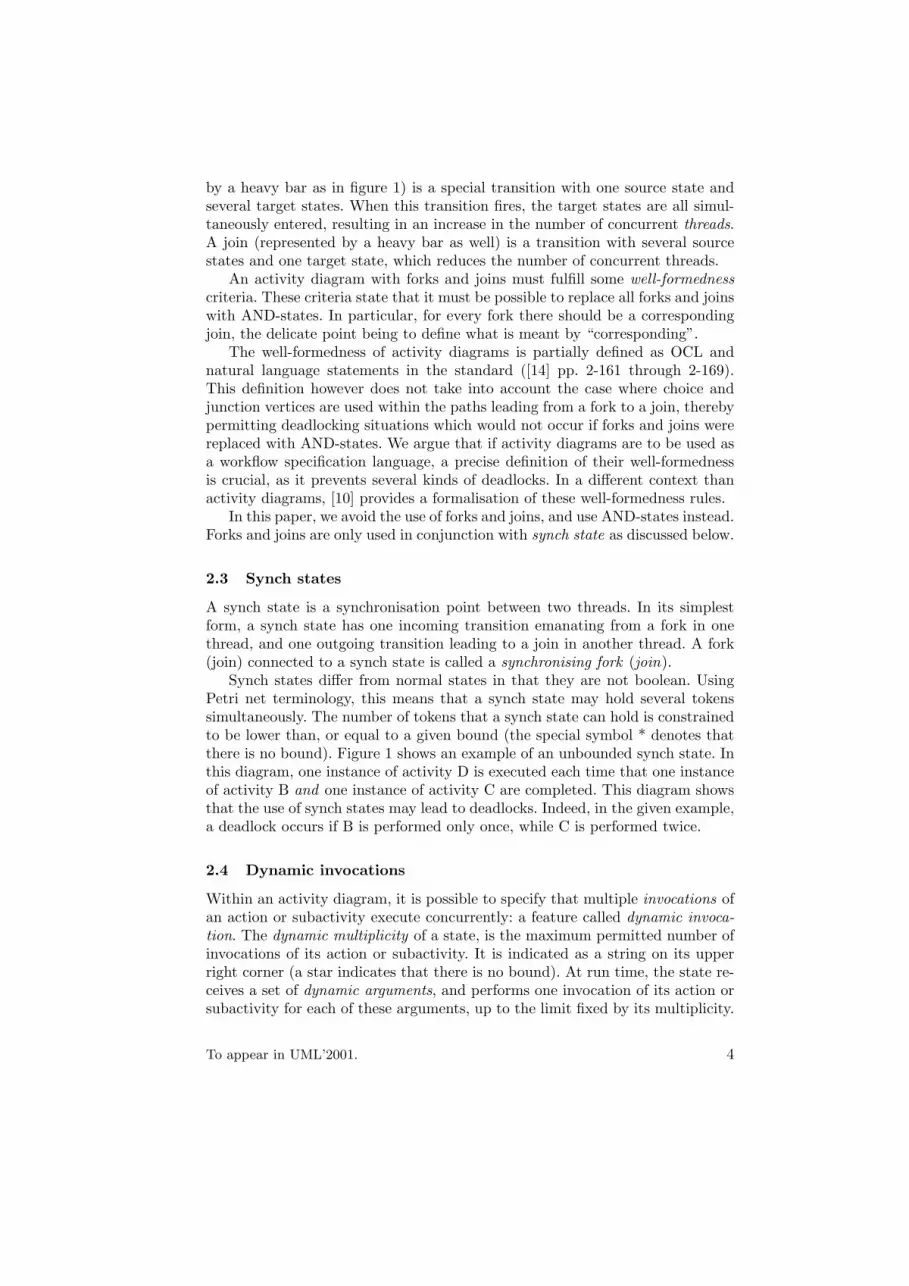
by a heavy bar as in figure 1) is a special transition with one source state andseveral target states. When this transition fires, the target states are all simul-taneously entered, resulting in an increase in the number of concurrent threads.A join (represented by a heavy bar as well) is a transition with several sourcestates and one target state, which reduces the number of concurrent threads.
An activity diagram with forks and joins must fulfill some well-formednesscriteria. These criteria state that it must be possible to replace all forks and joinswith AND-states. In particular, for every fork there should be a correspondingjoin, the delicate point being to define what is meant by “corresponding”.
The well-formedness of activity diagrams is partially defined as OCL andnatural language statements in the standard ([14] pp. 2-161 through 2-169).This definition however does not take into account the case where choice andjunction vertices are used within the paths leading from a fork to a join, therebypermitting deadlocking situations which would not occur if forks and joins werereplaced with AND-states. We argue that if activity diagrams are to be used asa workflow specification language, a precise definition of their well-formednessis crucial, as it prevents several kinds of deadlocks. In a different context thanactivity diagrams, [10] provides a formalisation of these well-formedness rules.
In this paper, we avoid the use of forks and joins, and use AND-states instead.Forks and joins are only used in conjunction with synch state as discussed below.
2.3 Synch states
A synch state is a synchronisation point between two threads. In its simplestform, a synch state has one incoming transition emanating from a fork in onethread, and one outgoing transition leading to a join in another thread. A fork(join) connected to a synch state is called a synchronising fork (join).
Synch states differ from normal states in that they are not boolean. UsingPetri net terminology, this means that a synch state may hold several tokenssimultaneously. The number of tokens that a synch state can hold is constrainedto be lower than, or equal to a given bound (the special symbol * denotes thatthere is no bound). Figure 1 shows an example of an unbounded synch state. Inthis diagram, one instance of activity D is executed each time that one instanceof activity B and one instance of activity C are completed. This diagram showsthat the use of synch states may lead to deadlocks. Indeed, in the given example,a deadlock occurs if B is performed only once, while C is performed twice.
2.4 Dynamic invocations
Within an activity diagram, it is possible to specify that multiple invocations ofan action or subactivity execute concurrently: a feature called dynamic invoca-tion. The dynamic multiplicity of a state, is the maximum permitted number ofinvocations of its action or subactivity. It is indicated as a string on its upperright corner (a star indicates that there is no bound). At run time, the state re-ceives a set of dynamic arguments, and performs one invocation of its action orsubactivity for each of these arguments, up to the limit fixed by its multiplicity.
To appear in UML’2001. 4
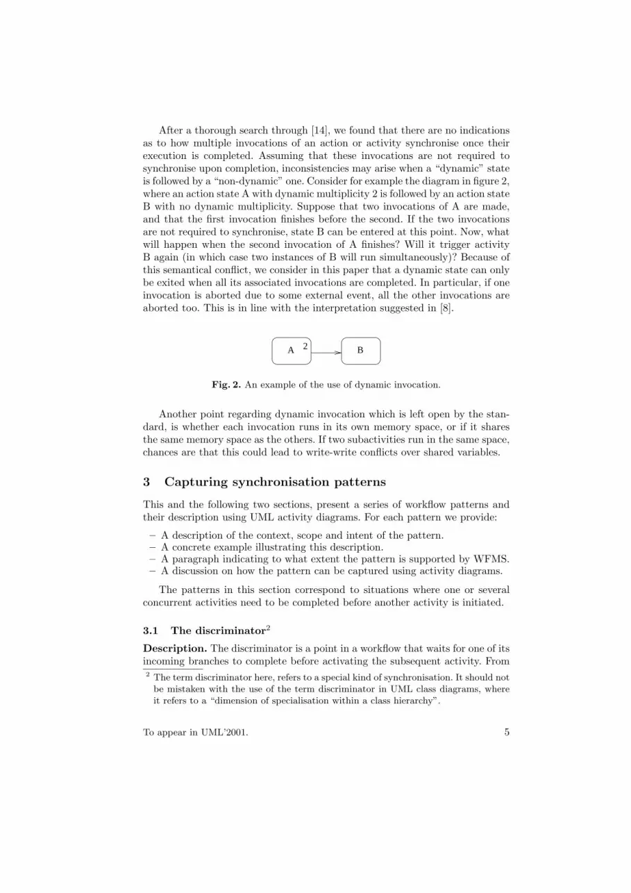
After a thorough search through [14], we found that there are no indicationsas to how multiple invocations of an action or activity synchronise once theirexecution is completed. Assuming that these invocations are not required tosynchronise upon completion, inconsistencies may arise when a “dynamic” stateis followed by a “non-dynamic” one. Consider for example the diagram in figure 2,where an action state A with dynamic multiplicity 2 is followed by an action stateB with no dynamic multiplicity. Suppose that two invocations of A are made,and that the first invocation finishes before the second. If the two invocationsare not required to synchronise, state B can be entered at this point. Now, whatwill happen when the second invocation of A finishes? Will it trigger activityB again (in which case two instances of B will run simultaneously)? Because ofthis semantical conflict, we consider in this paper that a dynamic state can onlybe exited when all its associated invocations are completed. In particular, if oneinvocation is aborted due to some external event, all the other invocations areaborted too. This is in line with the interpretation suggested in [8].
A 2 B
Fig. 2. An example of the use of dynamic invocation.
Another point regarding dynamic invocation which is left open by the stan-dard, is whether each invocation runs in its own memory space, or if it sharesthe same memory space as the others. If two subactivities run in the same space,chances are that this could lead to write-write conflicts over shared variables.
3 Capturing synchronisation patterns
This and the following two sections, present a series of workflow patterns andtheir description using UML activity diagrams. For each pattern we provide:
– A description of the context, scope and intent of the pattern.– A concrete example illustrating this description.– A paragraph indicating to what extent the pattern is supported by WFMS.– A discussion on how the pattern can be captured using activity diagrams.
The patterns in this section correspond to situations where one or severalconcurrent activities need to be completed before another activity is initiated.
3.1 The discriminator2
Description. The discriminator is a point in a workflow that waits for one of itsincoming branches to complete before activating the subsequent activity. From2 The term discriminator here, refers to a special kind of synchronisation. It should not
be mistaken with the use of the term discriminator in UML class diagrams, whereit refers to a “dimension of specialisation within a class hierarchy”.
To appear in UML’2001. 5
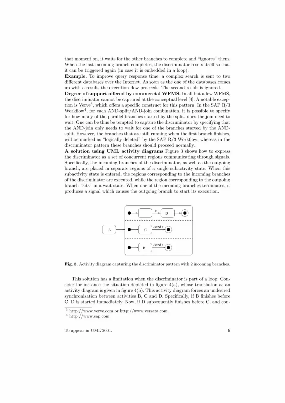
that moment on, it waits for the other branches to complete and “ignores” them.When the last incoming branch completes, the discriminator resets itself so thatit can be triggered again (in case it is embedded in a loop).Example. To improve query response time, a complex search is sent to twodifferent databases over the Internet. As soon as the one of the databases comesup with a result, the execution flow proceeds. The second result is ignored.Degree of support offered by commercial WFMS. In all but a few WFMS,the discriminator cannot be captured at the conceptual level [4]. A notable excep-tion is Verve3, which offers a specific construct for this pattern. In the SAP R/3Workflow4, for each AND-split/AND-join combination, it is possible to specifyfor how many of the parallel branches started by the split, does the join need towait. One can be thus be tempted to capture the discriminator by specifying thatthe AND-join only needs to wait for one of the branches started by the AND-split. However, the branches that are still running when the first branch finishes,will be marked as “logically deleted” by the SAP R/3 Workflow, whereas in thediscriminator pattern these branches should proceed normally.A solution using UML activity diagrams Figure 3 shows how to expressthe discriminator as a set of concurrent regions communicating through signals.Specifically, the incoming branches of the discriminator, as well as the outgoingbranch, are placed in separate regions of a single subactivity state. When thissubactivity state is entered, the regions corresponding to the incoming branchesof the discriminator are executed, while the region corresponding to the outgoingbranch “sits” in a wait state. When one of the incoming branches terminates, itproduces a signal which causes the outgoing branch to start its execution.
C/send e
B/send e
eD
A
Fig. 3. Activity diagram capturing the discriminator pattern with 2 incoming branches.
This solution has a limitation when the discriminator is part of a loop. Con-sider for instance the situation depicted in figure 4(a), whose translation as anactivity diagram is given in figure 4(b). This activity diagram forces an undesiredsynchronisation between activities B, C and D. Specifically, if B finishes beforeC, D is started immediately. Now, if D subsequently finishes before C, and con-3 http://www.verve.com or http://www.versata.com.4 http://www.sap.com.
To appear in UML’2001. 6
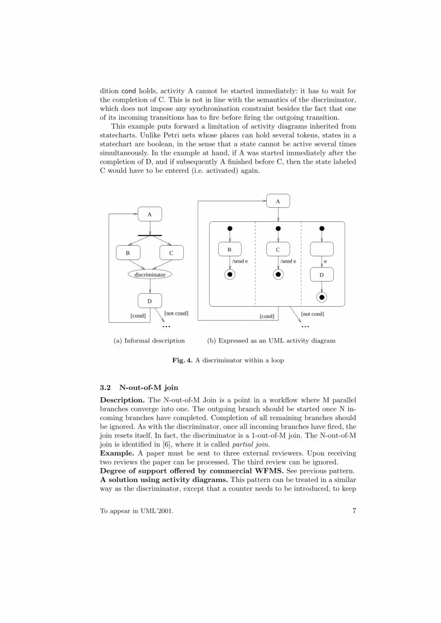
dition cond holds, activity A cannot be started immediately: it has to wait forthe completion of C. This is not in line with the semantics of the discriminator,which does not impose any synchronisation constraint besides the fact that oneof its incoming transitions has to fire before firing the outgoing transition.
This example puts forward a limitation of activity diagrams inherited fromstatecharts. Unlike Petri nets whose places can hold several tokens, states in astatechart are boolean, in the sense that a state cannot be active several timessimultaneously. In the example at hand, if A was started immediately after thecompletion of D, and if subsequently A finished before C, then the state labeledC would have to be entered (i.e. activated) again.
CB
D
[cond] [not cond]
...
A
discriminator
(a) Informal description
D
A
/send e/send e e
B C
[cond] [not cond]
...
(b) Expressed as an UML activity diagram
Fig. 4. A discriminator within a loop
3.2 N-out-of-M join
Description. The N-out-of-M Join is a point in a workflow where M parallelbranches converge into one. The outgoing branch should be started once N in-coming branches have completed. Completion of all remaining branches shouldbe ignored. As with the discriminator, once all incoming branches have fired, thejoin resets itself. In fact, the discriminator is a 1-out-of-M join. The N-out-of-Mjoin is identified in [6], where it is called partial join.Example. A paper must be sent to three external reviewers. Upon receivingtwo reviews the paper can be processed. The third review can be ignored.Degree of support offered by commercial WFMS. See previous pattern.A solution using activity diagrams. This pattern can be treated in a similarway as the discriminator, except that a counter needs to be introduced, to keep
To appear in UML’2001. 7
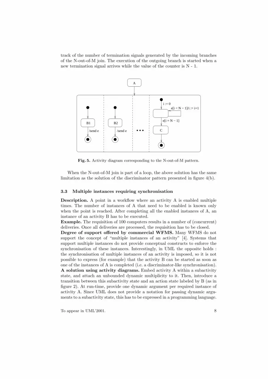
track of the number of termination signals generated by the incoming branchesof the N-out-of-M join. The execution of the outgoing branch is started when anew termination signal arrives while the value of the counter is N - 1.
B1 B2
/send e/send e
A
C
e[i = N − 1]
e[i < N − 1]/i := i+1i := 0
Fig. 5. Activity diagram corresponding to the N-out-of-M pattern.
When the N-out-of-M join is part of a loop, the above solution has the samelimitation as the solution of the discriminator pattern presented in figure 4(b).
3.3 Multiple instances requiring synchronisation
Description. A point in a workflow where an activity A is enabled multipletimes. The number of instances of A that need to be enabled is known onlywhen the point is reached. After completing all the enabled instances of A, aninstance of an activity B has to be executed.Example. The requisition of 100 computers results in a number of (concurrent)deliveries. Once all deliveries are processed, the requisition has to be closed.Degree of support offered by commercial WFMS. Many WFMS do notsupport the concept of “multiple instances of an activity” [4]. Systems thatsupport multiple instances do not provide conceptual constructs to enforce thesynchronisation of these instances. Interestingly, in UML the opposite holds :the synchronisation of multiple instances of an activity is imposed, so it is notpossible to express (for example) that the activity B can be started as soon asone of the instances of A is completed (i.e. a discriminator-like synchronisation).A solution using activity diagrams. Embed activity A within a subactivitystate, and attach an unbounded dynamic multiplicity to it. Then, introduce atransition between this subactivity state and an action state labeled by B (as infigure 2). At run-time, provide one dynamic argument per required instance ofactivity A. Since UML does not provide a notation for passing dynamic argu-ments to a subactivity state, this has to be expressed in a programming language.
To appear in UML’2001. 8
4 Capturing state-based patterns
In real workflows, where human and material resources are not always available,activities are more often in a waiting state than in a processing one [4]. Thisfact is central in the following two patterns, where a distinction is made betweenthe moment when an activity is enabled, and that when it starts running. Inthe first pattern, the choice between two alternative enabled activities is delayeduntil an event occurs. In the second pattern, several enabled activities have tobe processed, but at any point in time, at most one of them can be running.
4.1 Deferred choice
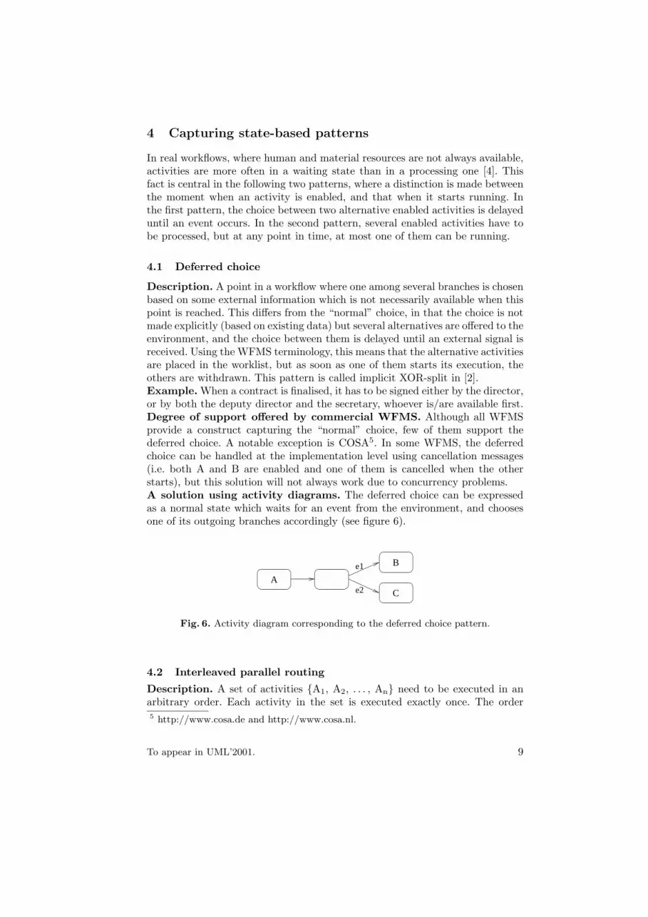
Description. A point in a workflow where one among several branches is chosenbased on some external information which is not necessarily available when thispoint is reached. This differs from the “normal” choice, in that the choice is notmade explicitly (based on existing data) but several alternatives are offered to theenvironment, and the choice between them is delayed until an external signal isreceived. Using the WFMS terminology, this means that the alternative activitiesare placed in the worklist, but as soon as one of them starts its execution, theothers are withdrawn. This pattern is called implicit XOR-split in [2].Example. When a contract is finalised, it has to be signed either by the director,or by both the deputy director and the secretary, whoever is/are available first.Degree of support offered by commercial WFMS. Although all WFMSprovide a construct capturing the “normal” choice, few of them support thedeferred choice. A notable exception is COSA5. In some WFMS, the deferredchoice can be handled at the implementation level using cancellation messages(i.e. both A and B are enabled and one of them is cancelled when the otherstarts), but this solution will not always work due to concurrency problems.A solution using activity diagrams. The deferred choice can be expressedas a normal state which waits for an event from the environment, and choosesone of its outgoing branches accordingly (see figure 6).
e1
e2 C
B
A
Fig. 6. Activity diagram corresponding to the deferred choice pattern.
4.2 Interleaved parallel routing
Description. A set of activities {A1, A2, . . . , An} need to be executed in anarbitrary order. Each activity in the set is executed exactly once. The order5 http://www.cosa.de and http://www.cosa.nl.
To appear in UML’2001. 9
between the activities is decided at run-time: it is not until one activity is com-pleted that the decision on what to do next is taken. In any case, no two activitiesamong A1, . . . , An can be active at the same time.Example. The army requires every applicant to take 3 tests: an optical, a med-ical, and a mental. These tests can be conducted in any order but obviously notat the same time. When an applicant completes a test, the decision of which testto perform next is taken depending on the presence of the relevant doctors. If forexample the doctor responsible for the optical test is present, while the doctorfor the medical one is absent, the optical test is performed before the medical.Degree of support offered by commercial WFMS. In many WFMS, thispattern cannot be expressed at the conceptual level. At the implementation level,it can be coded by introducing a resource shared by all activities A1, . . . , An.This shared resource acts as a semaphore, forcing a serialization of the activities.
Since this pattern can be expressed in terms of the deferred choice pattern(see below), it can be captured in those WFMS supporting the deferred choice [4].Solutions using activity diagrams. This pattern can be expressed in termsof the deferred choice as follows. First, a deferred choice is made between nbranches, such that the ith branch starts with activity Ai (1 ≤ i ≤ n). In thebranch that leads to activity A1, another deferred choice is made (after A1 isexecuted) between n – 1 branches respectively starting with A2, . . . , An. Asimilar nested deferred choice is also made in all the other branches of the firstdeferred choice. This process of nesting deferred choices is recursively repeated,until all the permutations of A1, ..., An are enumerated. Clearly, for a largenumber of activities, this combinatorial explosion is undesirable.
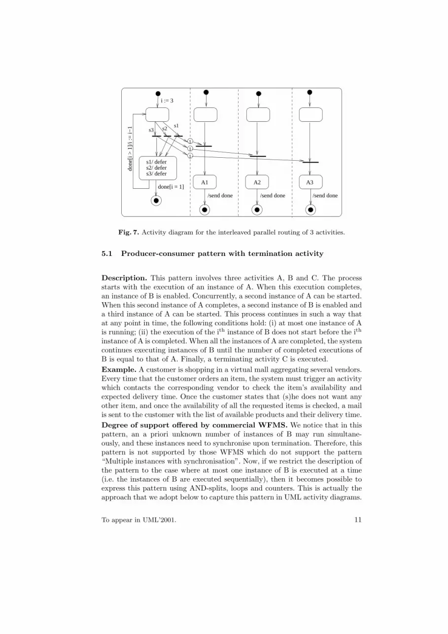
A better alternative is to enforce the interleaving of activities by placing eachactivity in a separate concurrent region, and blocking their execution throughsynch states emanating from a single “blocking region” (this is the leftmostregion in figure 7). A token is inserted into the synch state blocking an activityAi, only after the processing of the event that enables the execution of Ai.When Ai starts its execution, the blocking region enters a state which defersthe occurrences of events that may unblock the execution of other activities. Forinstance, in figure 7 events s1, s2 and s3 are used to indicate that activities A1,A2 and A3 respectively, can be executed. If one of these events occurs while oneof the activities is being executed, the processing of this occurrence is deferreduntil the ongoing activity execution has completed.
5 Producer-consumer patterns
The patterns in this section are variants of the producer-consumer pattern foundin distributed systems design. They correspond to situations where several in-stances of an activity A (the producer) are executed sequentially, and the termi-nation of each of these instances triggers the execution of an instance of anotheractivity B (the consumer). The instances of A and B execute concurrently, butsome asymetric inter-dependencies link them (a “B” is caused by an “A”).
To appear in UML’2001. 10
done[i = 1]
s3
1
1
1
done
[i >
1]/i
:= i−
1 s1s2
s1/ defers2/ defers3/ defer
/send done
A1
/send done
A2
/send done
A3
i := 3
Fig. 7. Activity diagram for the interleaved parallel routing of 3 activities.
5.1 Producer-consumer pattern with termination activity
Description. This pattern involves three activities A, B and C. The processstarts with the execution of an instance of A. When this execution completes,an instance of B is enabled. Concurrently, a second instance of A can be started.When this second instance of A completes, a second instance of B is enabled anda third instance of A can be started. This process continues in such a way thatat any point in time, the following conditions hold: (i) at most one instance of Ais running; (ii) the execution of the ith instance of B does not start before the ith
instance of A is completed. When all the instances of A are completed, the systemcontinues executing instances of B until the number of completed executions ofB is equal to that of A. Finally, a terminating activity C is executed.Example. A customer is shopping in a virtual mall aggregating several vendors.Every time that the customer orders an item, the system must trigger an activitywhich contacts the corresponding vendor to check the item’s availability andexpected delivery time. Once the customer states that (s)he does not want anyother item, and once the availability of all the requested items is checked, a mailis sent to the customer with the list of available products and their delivery time.Degree of support offered by commercial WFMS. We notice that in thispattern, an a priori unknown number of instances of B may run simultane-ously, and these instances need to synchronise upon termination. Therefore, thispattern is not supported by those WFMS which do not support the pattern“Multiple instances with synchronisation”. Now, if we restrict the description ofthe pattern to the case where at most one instance of B is executed at a time(i.e. the instances of B are executed sequentially), then it becomes possible toexpress this pattern using AND-splits, loops and counters. This is actually theapproach that we adopt below to capture this pattern in UML activity diagrams.
To appear in UML’2001. 11
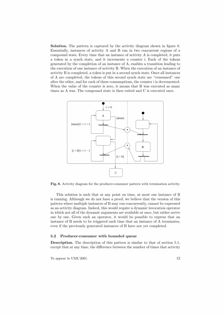
Solution. The pattern is captured by the activity diagram shown in figure 8.Essentially, instances of activity A and B run in two concurrent regions of acompound state. Every time that an instance of activity A is completed, it putsa token in a synch state, and it increments a counter i. Each of the tokensgenerated by the completion of an instance of A, enables a transition leading tothe execution of one instance of activity B. When the execution of an instance ofactivity B is completed, a token is put in a second synch state. Once all instancesof A are completed, the tokens of this second synch state are “consumed” oneafter the other, and for each of these consumptions, the counter i is decremented.When the value of the counter is zero, it means that B was executed as manytimes as A was. The compound state is then exited and C is executed once.
*
[i > 0]/i := i − 1
*
[done]
[more]/i := i + 1
B
C
[i = 0]
A
i := 0
Fig. 8. Activity diagram for the producer-consumer pattern with termination activity.
This solution is such that at any point on time, at most one instance of Bis running. Although we do not have a proof, we believe that the version of thispattern where multiple instances of B may run concurrently, cannot be expressedas an activity diagram. Indeed, this would require a dynamic invocation operatorin which not all of the dynamic arguments are available at once, but rather arriveone by one. Given such an operator, it would be possible to express that aninstance of B needs to be triggered each time that an instance of A terminates,even if the previously generated instances of B have not yet completed.
5.2 Producer-consumer with bounded queue
Description. The description of this pattern is similar to that of section 5.1,except that at any time, the difference between the number of times that activity
To appear in UML’2001. 12
A has been executed, and the number of times that activity B has been executed,is bounded by an integer called the size of the queue.Example. To obtain an ID card, an applicant has to complete a form andpresent it to an officer for verification. Once the officer has checked the form,the applicant is sent to a photographer’s room. However, the queue leading fromthe officer’s counter to the photographer’s room cannot contain more than 5persons. Should the queue contain 5 persons, the officer would stop acceptingapplications until one of these persons enters the photographer’s room.Degree of support offered by commercial WFMS. See previous pattern.Solution. The idea is to modify the diagram of figure 8, in such a way that twoseparate counters are kept: one counting the executions of A (na), and the othercounting the executions of B (nb). Every time that activity A is completed, ifthe boolean variable “more” is true, a waiting state is entered, which is onlyexited when the condition na− nb < s holds (where s is the size of the queue).
6 Related work
The suitability of statechart-based notations for workflow specification has beenrecognised by many studies. For instance, [12] argues that statecharts are per-ceived by practitioners as being more intuitive and easier to learn than alter-native formal notations such as Petri nets (whose suitability for workflow spec-ification is advocated in e.g. [2]), yet have an equally rigorous semantics. Morerecently, [16] and [1] illustrate through selected case studies, the adequacy andlimitations of activity diagrams for business process modeling. None of these ref-erences however undertakes a systematic evaluation of the capabilities of stat-echarts/activity diagrams for workflow specification as in the present paper.Interestingly, [16] agrees with us in saying that wait states and activity-in-statesare crucial for workflow modeling, thereby sustaining our position that no re-strictions on their use should be imposed as currently suggested by the standard.
The issue of defining a precise semantics of UML is the subject of intensiveinvestigations, as evidenced by the number of projects, forums, and workshops inthis area (see [13] for a list of links). Unfortunately, within this stream of research,activity diagrams have received relatively little attention, despite the fact thatthey are “one of the most unexpected parts of the UML” [8]. Ongoing effortssuch as those reported in [5] and [7] are attempting to fill this gap. [5] defines analgebraic semantics of the core constructs of activity diagrams. It does not dealhowever with features such as synch states, dynamic invocation and deferredevents. In this regard, the formalisation given in [7] is more complete. Based onthe Statemate semantics of statecharts [9], this formalisation covers all activitydiagrams constructs (except synch states and swimlanes), and considers issuessuch as data manipulation. The authors however do not formalise syntacticalconstraints such as the well-formedness rules linking forks with joins, which areessential to avoid some deadlocking situations. These syntactical constraints andsome of their expressive power implications are studied in [10].
To appear in UML’2001. 13
To summarise, we can state that the formalisation of the activity diagramsnotation, and the evaluation of its suitability for workflow specification, are stillopen issues. It is expected that the ongoing OMG RFP “UML extensions forworkflow process definition” [17] will provide an occasion to address them.
7 Conclusion
This paper presented an evaluation of UML activity diagrams against a set ofworkflow patterns involving control-flow aspects. Some of these patterns are ex-tracted from [4], while others are variants of the producer-consumer pattern.Actually, we have confronted activity diagrams against the 22 control-flow pat-terns in [4], although for space reasons we have just presented some of them.
From this systematic evaluation, we conclude that in the context of workflowspecification, the strong points of activity diagrams with respect to alternativelanguages provided by commercial WFMS are essentially the followings:
– They support signal sending and receiving at the conceptual level.– They support both waiting states and processing states.– They provide a seamless mechanism for decomposing an activity specification
into subactivities. The combination of this decomposition capability withsignal sending yields a powerful approach to handling activity interruptions.
However, activity diagrams exhibit the following drawbacks:
– Some of their constructs lack a precise syntax and semantics. For instance,the well-formedness rules linking forks with joins are not fully defined, norare the concepts of dynamic invocation and deferred events, among others.
– They do not fully capture important kinds of synchronisation such as thediscriminator and the N-out-of-M join (see section 3). Similarly, to the bestof our knowledge, they do not fully support the producer-consumer patternwith termination activity (see section 5.1).
We encourage the participants of the OMG RFP “UML extensions for work-flow definition” [17], to consider these two points in their proposals. Actually,[17] mentions the issue of capturing the N-out-of-N join, although it does notdiscuss what is the expected behaviour of this pattern when embedded in a loop.
In this paper, we focused on the control-flow perspective. However, work-flows can also be viewed from a data and from a resource perspective [11]. Thedata perspective relates to the flow of information between activities, while theresource perspective defines human and device roles responsible for handlingactivities. The data and resource perspectives may be captured through objectflows and swimlanes respectively. Assessing the suitability of these constructsagainst appropriate workflow patterns is a perspective to our work.
Another perspective is to study how the concepts and constructs of UML ac-tivity diagrams compare to those of the Workflow Management Coalition’s Ref-erence Model [18]. Such an effort could trace the road towards defining mappingsfrom activity diagrams into vendor-specific workflow specification languages.
To appear in UML’2001. 14

References
1. J.Ø. Aagedal and Z. Milosevic. ODP enterprise language: An UML perspective.In Proc. of The 3rd International Conference on Enterprise Distributed ObjectComputing, Mannheim, Germany, 1999. IEEE Press.
2. W.M.P. van der Aalst. The application of Petri nets to workflow management.The Journal of Circuits, Systems and Computers, 8(1):21–66, 1998.
3. W.M.P. van der Aalst, A.P. Barros, A.H.M. ter Hofstede, and B. Kiepuszewski.Advanced workflow patterns. In Proc. of the 5th IFCIS Int. Conference on Coop-erative Information Systems, Eilat, Israel, September 2000. Springer Verlag.
4. W.M.P. van der Aalst, A.H.M ter Hofstede, B. Kiepuszewski, and A. Barros. Work-flow patterns. Technical Report WP 47, BETA Research Institute, 2000. AccessedMarch 2001 from http://tmitwww.tm.tue.nl/research/patterns.
5. E. Borger, A. Cavarra, and E. Riccobene. An ASM semantics for UML activitydiagrams. In Proc. of the International Conference on Algebraic Methodology andSoftware Technology (AMAST), Iowa City, IO, USA, May 2000. Springer Verlag.
6. F. Casati, S. Ceri, B. Pernici, and G. Pozzi. Conceptual modeling of workflows. InProc. of the 14th International Object-Oriented and Entity-Relationship ModellingConference (OOER’95), pages 341–354. Springer Verlag, December 1995.
7. R. Eshuis and R. Wieringa. A formal semantics for UML activity diagrams –Formalising workflow models. Technical Report CTIT-01-04, University of Twente,Department of Computer Science, 2001.
8. M. Fowler and K. Scott. UML Distilled: A Brief Guide to the Standard ObjectModeling Language (Second Edition). Addison Wesley, Readings MA, USA, 2000.
9. D. Harel and A. Naamad. The statemate semantics of statecharts. ACM Trans-actions on Software Engineering and Methodology, 5(4):293–333, October 1996.
10. B. Kiepuszewski, A.H.M. ter Hofstede, and C. Bussler. On structured workflowmodelling. In Proc. of the Int. Conference on Advanced Information Systems En-gineering (CAiSE), Stockholm, Sweden, June 2000. Springer Verlag.
11. F. Leymann and D. Roller. Production Workflow: Concepts and Techniques. Pren-tice Hall, Upper Saddle River, NJ, USA, 2000.
12. P. Muth, D. Wodtke, J. Weissenfels, A.K. Dittrich, and G. Weikum. From central-ized workflow specification to distributed workflow execution. Journal of IntelligentInformation Systems, 10(2), March 1998.
13. The precise UML group. Home page. http://www.cs.york.ac.uk/puml/.14. UML Revision Task Force. OMG Unified Modeling Language Specification, Version
1.4 (final draft). February 2001.15. J. Rumbaugh, I. Jacobson, and G. Booch. The Unified Modeling Language Refer-
ence Manual. Addison-Wesley, 1999.16. M. Schader and A. Korthaus. Modeling business processes as part of the
BOOSTER approach to business object-oriented systems development based onUML. In Proc. of The Second International Enterprise Distributed Object Com-puting Workshop (EDOC). IEEE Press, 1998.
17. The Object Management Group. UML Extensions for Workflow Process Defi-nition, RFP-bom/2000-12-11. Accessed on June 2001 from ftp://ftp.omg.org/
pub/docs/bom/00-12-11.pdf.18. The Workflow Management Coalition. The Workflow Reference Model. http:
//www.aiim.org/wfmc/standards/docs/tc003v11.pdf, accessed on January 2001.
To appear in UML’2001. 15