Embed Size (px)
Citation preview

ACI Structural Journal/September-October 2011 601
Title no. 108-S57
ACI STRUCTURAL JOURNAL TECHNICAL PAPER
ACI Structural Journal, V. 108, No. 5, September-October 2011.MS No. S-2010-101.R1 received September 14, 2010, and reviewed under Institute
publication policies. Copyright © 2011, American Concrete Institute. All rights reserved, including the making of copies unless permission is obtained from the copyright proprietors. Pertinent discussion including author’s closure, if any, will be published in the July-August 2012 ACI Structural Journal if the discussion is received by March 1, 2012.
Ultra-High-Performance Concrete Bridge Deck Reinforced with High-Strength Steelby Muhammad Azhar Saleem, Amir Mirmiran, Jun Xia, and Kevin Mackie
There is currently a need to develop lightweight bridge deck systems with solid riding surfaces to replace the open-grid steel decks from moveable bridges. Open-grid steel decks present several problems, including poor rideability, high noise levels, susceptibility to fatigue damage, and high maintenance costs. There is a great opportunity to use advanced materials, such as ultra-high-performance concrete (UHPC), to develop new lightweight bridge deck systems. In this study, a low-profile UHPC deck system has been developed that satisfies the strength and serviceability requirements, addresses the concerns with open-grid steel decks, and meets the strict self-weight requirements for moveable bridges. The detailed experimental study shows that the proposed system has great potential to serve as an alternative to open-grid steel decks. Shear was the governing mode of failure in most of the specimens; however, it was not as abrupt and catastrophic as the commonly seen shear failure mode. Standard 180-degree hooks on both ends of the flexural reinforcement help avoid bond failure. The establishment of the development length of high-strength steel for UHPC, deck-deck connection, deck-girder connection, and fatigue performance still need to be investigated before the system is ready for implementation.
Keywords: beam; bridge; deck; high-strength steel; shear; ultra-high-performance concrete.
INTRODUCTION According to the National Bridge Inventory (2008), there
are 71,466 structurally deficient and 79,922 functionally obsolete bridges in the U.S. A majority of these bridges need deck repairs (Naaman and Chandrangsu 2004). Therefore, there is a vital need to develop lightweight bridge deck systems that could be used to rehabilitate a critical component in the aging infrastructure. Moveable bridges are also a victim of deterioration and require urgent repair and restoration. Open-grid steel decks are commonly used on moveable bridges because they are lightweight and easy to install. The self-weight of moveable bridge decks is typically limited to 25 lb/ft2 (1.2 kN/m2), which makes the open steel grid deck a suitable choice because these decks, on average, weigh between 14 and 25 lb/ft2 (0.67 and 1.2 kN/m2). These decks have major shortcomings, however, including poor rideability, high maintenance cost, high noise levels, and susceptibility to fatigue damage (Mirmiran et al. 2009).
A new type of ultra-high-performance concrete (UHPC) waffle slab deck was developed that includes a solid riding surface and is within the acceptable self-weight limit for moveable bridge decks. The unit weight of UHPC (156 lb/ft3 [2500 kg/m3]) is similar to that of conventional concrete but with much higher strength. Therefore, it results in shallower sections and ultimately a lower self-weight than an equivalent capacity conventional concrete deck. The proposed UHPC deck has a low profile of only 5 in. (127 mm) depth, which is compatible with the open-grid steel decks that typically span
a girder spacing of 4 ft (1219 mm). This paper presents the experimental characterization of the proposed deck system.
UHPC is an advanced structural material composed of a high-strength cementitious matrix and steel fibers (Habel et al. 2007) with better durability and higher tensile strength than other cementitious materials (Habel et al. 2006; Graybeal 2007). The most distinguishing characteristics of UHPC are the lack of coarse aggregate, the use of fibers, and the low water-cement ratio (w/c). The use of silica fumes, ground quartz, and only fine aggregates creates a dense matrix, which in turn results in a significant increase in strength as compared to regular concrete, which has both fine and coarse aggregates. The fibers in the matrix are designed to provide bond at the micro level and help control the cracks. The fibers act as micro-reinforcement, similar to mild steel reinforcement in conventional reinforced concrete at the macro level (Perry 2003; Harris and Roberts-Wollmann 2005). The compressive strength of UHPC is four to eight times higher than conventional concrete. Heat treatment of UHPC with steaming at 90ºC (194ºF) and 95% relative humidity for 48 hours significantly enhances the compressive strength and modulus of elasticity, decreases the creep coefficient, and nearly eliminates long-term shrinkage (Graybeal 2006). Graybeal and Hartmann (2003) found that the tensile strength of UHPC ranges from 0.9 to 1.7 ksi (6.2 to 12 MPa) with various curing regimes. Harris and Roberts-Wollmann (2005) argued that the high tensile strength of UHPC is achieved as a result of the interaction of steel fibers at the microscopic level and their ability to sustain load after the onset of cracking. In addition, UHPC achieves flexural strengths ranging from 5.0 to 7.2 ksi (35 to 50 MPa) based on standard flexural beam tests (Perry and Zakariasen 2003).
Constituent materials of the UHPC used for this project include cement, silica fumes, ground quartz, sand, steel fibers (2% by volume), high-range water-reducing admixture, and water. The straight high-strength steel fibers have a diameter of 0.008 in. (0.2 mm) and a length of 0.5 in. (13 mm). The critical fiber-volume fraction to achieve the homogeneous distribution is approximately 0.4 to 0.5% (Vodicka et al. 2004). Taerwe et al. (1999) also achieved the homogeneous distribution for up to 8% fiber-volume fraction when using short steel fibers. Therefore, 2% of steel-fiber volume fraction is a suitable amount to achieve a homogeneous distribution without
www.modiriat-s
akht.blo
gfa.com

602 ACI Structural Journal/September-October 2011
compromising the workability of the cement paste. The proportions of the constituent materials used in this research are presented in Table 1.
In recent years, UHPC has been used in the construction of highway and pedestrian bridges (Blais and Couture 1999; Hajar et al. 2003; Graybeal 2006) in the U.S., New Zealand, South Korea, Japan, and Australia. Naaman and Chandrangsu (2004) developed a UHPC deck with only one layer of steel reinforcing bars at the bottom instead of four (two at the bottom and two at the top). They concluded that by using UHPC instead of conventional concrete, approximately 70% of the reinforcement could be eliminated and a significant reduction in crack widths could be achieved. Graybeal (2007), Perry (2007), and Toutlemonde (2007) have also developed bridge decks with UHPC, but with higher self-weights that exceed the limits for moveable bridges. Nonetheless, test results on these decks have demonstrated
the feasibility of UHPC as a promising material for bridge deck applications. Harris and Roberts-Wollmann (2005) evaluated the punching shear capacity of UHPC slabs by testing twelve 45 x 45 in. (1143 x 1143 mm) slabs of various thicknesses. They concluded that a thickness of 1 in. (25.4 mm) of a UHPC deck is sufficient to prevent the punching shear failure under 8 x 20 in. (203 x 508 mm) wheel load of 37.2 kips (166 kN). Naaman et al. (2007) stated that the punching shear resistance increases significantly with the addition of fibers because they develop tensile strain hardening and minimize the spalling of the concrete cover at large deformations.
A major cause of early deterioration in reinforced concrete structures is the corrosion of reinforcing bars (Sahmaran et al. 2008). To mitigate this issue, high-strength steel (HSS) bars from MMFX Technologies of Irvine, CA, were used in the proposed deck system. These uncoated, high-strength, corrosion-resistant microcomposite bars are made from a low-carbon chromium alloy steel. The corrosion resistance of this type of reinforcing bar has been tested through accelerated laboratory deterioration tests, and the results show a generally good corrosion resistance compared to black bars (Hartt et al. 2007). Field applications of MMFX include reinforcement in bridge decks by the Iowa and Kentucky Departments of Transportation. The Delaware Department of Transportation also considered using these bars in its I-95 Service Road Bridge 1-712-B in 2005 (Chajes et al. 2005).
RESEARCH SIGNIFICANCEThe rehabilitation of aging infrastructure in North America
is an enormous challenge faced by transportation agencies. Advanced materials such as UHPC can provide alternative solutions. No prior research has focused on developing lightweight UHPC systems for moveable bridges with strict weight, geometric, and strength constraints. The proposed waffle slab UHPC-HSS deck system is experimentally shown to meet these requirements and has the potential to replace the open-grid steel decks currently in use on most moveable bridges. The concept has potential applications in other types of bridges that require a lightweight deck.
SYSTEM DESIGN AND DESCRIPTIONThe proposed waffle deck system is composed of
longitudinal and transverse ribs. The longitudinal ribs span between the girders and act as the primary load-carrying members for the deck. The smaller transverse ribs run parallel to the direction of traffic and connect the longitudinal ribs. The schematic of a single unit of the proposed deck is shown in Fig. 1.
The simplified stress-strain relation of UHPC (Graybeal 2006), as shown in Fig. 2, was used for the preliminary design of the deck with a modulus of elasticity of 8000 ksi (55.2 GPa) and tensile and compressive strengths of 1.13 and 28 ksi (7.8 and 193 MPa), respectively. The ultimate strains in compression and tension are 0.0035 and 0.007, respectively. Some researchers have suggested smaller values for the ultimate tensile strain for UHPC prepared with smooth steel fibers. Calculations have shown, however, that there is no noticeable difference in initial stiffness, ultimate sectional moment capacity, or ultimate curvature due to different ultimate tensile strains. The mechanical properties as provided by the manufacturer are shown in Table 2. The stress-strain curve for the HSS reinforcing bar from the uniaxial tensile test performed by the authors is shown in Fig. 3. To be conservative, an elastic-
Muhammad Azhar Saleem is a PhD Candidate in the Department of Civil and Environmental Engineering at Florida International University, Miami, FL. He received his BS and MS from the University of Engineering and Technology, Lahore, Pakistan, in 2003 and 2005, respectively. His research interests include the development of lightweight bridge decks and the seismic evaluation and rehabilitation of concrete structures.
Amir Mirmiran, FACI, is a Professor and Dean at the College of Engineering and Computing at Florida International University. He is a member of ACI Committee 440, Fiber-Reinforced Polymer Reinforcement, and Joint ACI-ASCE Committee 343, Concrete Bridge Design. His research interests include high-strength concrete and advanced composite materials for bridge applications.
ACI member Jun Xia is a PhD Candidate in the Department of Civil, Construction, and Environmental Engineering at the University of Central Florida, Orlando, FL. His research interests include the development of lightweight bridge decks and novel materials and systems.
ACI member Kevin Mackie is an Assistant Professor of structural engineering at the University of Central Florida. He received his MS and PhD from the University of California, Berkeley, Berkeley, CA. He is a member of ACI Committee 341, Earthquake-Resistant Concrete Bridges. His research interests include performance-based engineering; advanced materials and composites for bridges; engineering under uncertainty; and the testing, analysis, and performance-based assessment of concrete bridges.
Table 1— Proportions of UHPC constituent materials*
Constituent materials Percentage by weight Weight relative to cement
Cement 28.6 1.00
Silica fume 9.3 0.33
Ground quartz 8.5 0.30
Fine sand 41.1 1.44
Steel fibers 6.4 0.22
High-range water-reducing admixture
0.5 0.02
Water 5.6 0.20
Sum 100 —
*Source: http://www.lafargenorthamerica.com (May 1, 2008).

ACI Structural Journal/September-October 2011 603
perfectly plastic model was used for the HSS reinforcing bars with a yield strength of 75 ksi (517 MPa). Based on the self-weight limit of 25 lb/ft2 (1.2 kN/m2), a series of cross sections were developed and a sensitivity analysis was performed to help with the sizing of the proposed deck system. Factors considered included the reinforcement ratio, flange width and thickness, and rib depth and thickness in both directions. A flange thickness of 1 in. (25.4 mm) was selected according to Harris and Roberts-Wollmann (2005) to avoid punching shear failure. The overall depth was limited to 5 in. (127 mm) to be compatible with current open-grid steel decks. The section was singly reinforced with one No. 7 (No. 22M) bar at a minimum clear cover of 0.5 in. (13 mm).
To decide the minimum number of webs of the deck system that should be used in the experimental investigation, a preliminary finite element (FE) analysis was performed using MSC Patran/Nastran. Four node shell elements were used for both the webs and slabs, whereas truss elements were used for steel reinforcement. The truss elements shared the nodes with the quad elements, representing the webs to simulate a perfect bond between the reinforcement and concrete. All materials were treated as elastic in this stage and corresponding moduli of elasticity and Poisson’s ratios were used in the program. The distributed load was applied on the top of the deck surface at the center on a 10 x 20 in. (508 x 254 mm) rectangular region to represent the loading patch. The deck was simply supported at the two edges. The maximum deflection of the deck system versus the different number of webs is plotted in Fig. 4. It was found that the load can be transferred transversely as far as up to two webs on either side of the web being loaded, so this geometric configuration was used for the experiments. The distribution factor, which is defined as the percentage of the total load resisted by the central deck unit, can be estimated based on the deflections of all webs, and the result turned out to be approximately 36% for a five-web deck model.
EXPERIMENTAL PROGRAMThe primary objective of this experimental work was to
evaluate the behavior of the proposed deck at service and ultimate loading conditions and investigate its failure modes. The experimental program included testing single- and multi-unit deck panels with simple- and two-span configurations.
Fig. 2—Idealized stress-strain relationship of UHPC for preliminary specimen design.
Table 2—Mechanical properties of UHPC*
Density 156 lb/ft3 (2500 kg/m3)
Compressive strength 22 to 26 ksi (150 to 180 MPa)
Tensile strength 1.2 ksi (8 MPa)
Modulus of elasticity 7250 ksi (50,000 MPa)
Flexural strength 4.4 to 5.8 ksi (30 to 40 MPa)
Poisson’s ratio 0.2
Shrinkage <0.00001
Creep factor 0.3
Thermal expansion coefficient 1.18 × 10⁻⁵/°C (6.56–6/°F)*Source: http://www.lafargenorthamerica.com (February 22, 2009).
Specimens were prepared in five separate castings without any heat treatment (refer to Table 3). The formwork for the specimens was initially made of plywood. Later castings were made with polystyrene forms, however, for their ease in cutting, assembling, and transporting the specimens.
Because the concrete has self-consolidating characteristics, no internal or external vibrations were applied during the casting. Material was introduced from one end of the formwork and was allowed to flow to the other end. Whenever more material was required, it was introduced behind the leading edge of the flowing material. The same casting method was used for all specimens to maintain a similar fiber distribution. One simple-span specimen was cut after testing to examine the spatial distribution of the
Fig. 1—Schematics of single-unit deck panel.
Fig. 3—Stress-strain curve for high-strength steel.

604 ACI Structural Journal/September-October 2011
fibers. It was observed that the fibers tend to align with the formwork (Fehling and Bunje 2008), which may cause a nonhomogenous distribution of the fibers. Initially, the authors (Fehling and Bunje 2008) intended to apply heat treatment for curing, but the required temperature of 90°C (194°F) could not be achieved. Therefore, the traditional method of moist curing was used instead. The specimens were sealed with plastic sheets for 28 days to prevent the loss of moisture. At a later stage, the testing of the specimens showed that the strengths achieved without heat treatment were sufficient to satisfy the ultimate load requirements.
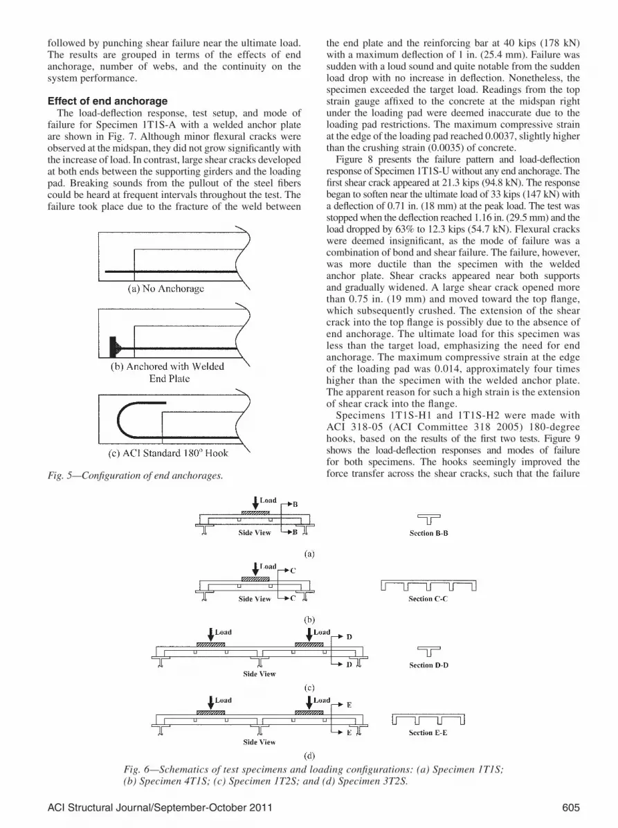
Initially, four single-T simple-span (1T1S) specimens were tested with three different end anchorage options (Fig. 5) for the bottom flexural reinforcing bars: 1) a 2 x 2 in. (51 x 51 mm) welded steel plate; 2) a 180-degree hook; and 3) no
Fig. 4—FE analysis: (a) FE model; and (b) deflection response.
Table 3—Test matrix
Number Specimen name Quantity 28-day compressive strength, ksi (MPa) Flexural reinforcement End anchorage
1 1T1S*-A 1 28 (193) One No. 7† Anchored
2 1T1S-U 1 28 (193) One No. 7 Unanchored
3 1T1S-H1 1 18 (124) One No. 7 180-degree hook
4 1T1S-H2 1 27 (186) One No. 7 180-degree hook
5 4T1S-H 1 26 (179) One No. 7 (in each rib) 180-degree hook
6 1T2S-H 1 22 (152) One No. 7 180-degree hook
7 3T2S-H 1 27 (186) One No. 7 (in each rib) 180-degree hook*1T1S means single-T simple-span deck specimen with 4 ft (1219 mm) span length.†One No. 7 of U.S. customary reinforcing bar (one No. 22 SI reinforcing bar).Notes: A is anchored; U is unanchored; H is 180-degree hook.
anchorage. Based on the test results, the authors decided to use the 180-degree hook for the end anchorage in subsequent specimens. The deck design was then expanded to four-T simple-span (4T1S), single-T two-span (1T2S), and three-T two-span (3T2S) specimens. The specimen test matrix is summarized in Table 3 and the schematics of the test specimens and loading configurations are shown in Fig. 6. Table 3 also describes the compressive strengths for various batches. The compressive strengths were obtained by testing cylinders with a diameter of 4 in. (102 mm) and a length of 8 in. (203 mm). To ensure the uniform distribution of load, the edges of the cylinders were grounded before testing. Load was applied at a rate of 35 psi/s (0.24 MPa/s).
The simple-span specimens were subjected to a single load, whereas the two-span specimens were loaded simultaneously at the middle of each span. Loads were applied on an AASHTO-prescribed footprint of 20 x 10 in. (508 x 254 mm) for an HS-20 truck dual-tire wheel, using a neoprene pad with a steel plate on top and with the longer side oriented perpendicular to the traffic. The simple-span specimens had a center-to-center (c/c) spacing of 4 ft (1219 mm) between the supporting steel girders. The same arrangement was used for the two-span specimens. The distance between the two loading pads was 4 ft (1219 mm), which is more critical than the standard wheel base of 6 ft (1829 mm) for an HS truck. Both the panel and beam actions were examined at the service and ultimate load levels.
String potentiometers with a range of 12 in. (305 mm) and strain gauges were installed at critical locations to acquire the deflection and strain data. A hydraulic actuator with a capacity of 235 kips (1046 kN) was used to apply the load. A displacement control procedure was adopted for all tests at a rate of 0.015 in./min (0.38 mm/min). All instruments were connected to a data acquisition system with a sampling frequency of 1 Hz. The target live load was 37.2 kips (166 kN), including the dynamic impact factor and load factor, based on the AASHTO LRFD recommendations (2005). The supporting girders were W24 x 68 (W610 x 101), which are typically used in moveable bridges.
DISCUSSION OF TEST RESULTSAll specimens were continuously monitored during the
tests. Any excessive cracking, deflection, or significant load drop was considered as a sign of failure and an indicator to stop the test. The dominant mode of failure in all specimens was beam shear. In the multi-unit specimens (Specimens 4T1S and 3T2S), beam shear failure was
ACI Structural Journal/September-October 2011 605
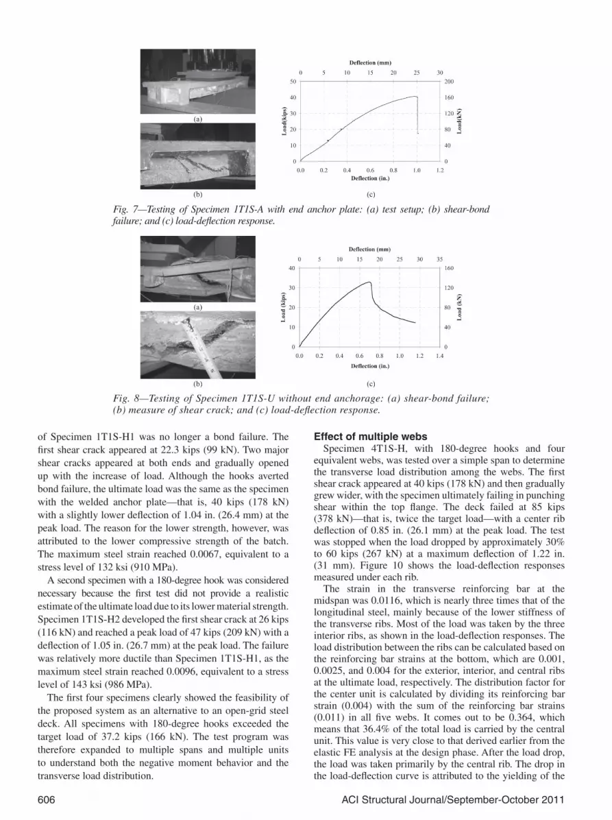
the end plate and the reinforcing bar at 40 kips (178 kN) with a maximum deflection of 1 in. (25.4 mm). Failure was sudden with a loud sound and quite notable from the sudden load drop with no increase in deflection. Nonetheless, the specimen exceeded the target load. Readings from the top strain gauge affixed to the concrete at the midspan right under the loading pad were deemed inaccurate due to the loading pad restrictions. The maximum compressive strain at the edge of the loading pad reached 0.0037, slightly higher than the crushing strain (0.0035) of concrete.
Figure 8 presents the failure pattern and load-deflection response of Specimen 1T1S-U without any end anchorage. The first shear crack appeared at 21.3 kips (94.8 kN). The response began to soften near the ultimate load of 33 kips (147 kN) with a deflection of 0.71 in. (18 mm) at the peak load. The test was stopped when the deflection reached 1.16 in. (29.5 mm) and the load dropped by 63% to 12.3 kips (54.7 kN). Flexural cracks were deemed insignificant, as the mode of failure was a combination of bond and shear failure. The failure, however, was more ductile than the specimen with the welded anchor plate. Shear cracks appeared near both supports and gradually widened. A large shear crack opened more than 0.75 in. (19 mm) and moved toward the top flange, which subsequently crushed. The extension of the shear crack into the top flange is possibly due to the absence of end anchorage. The ultimate load for this specimen was less than the target load, emphasizing the need for end anchorage. The maximum compressive strain at the edge of the loading pad was 0.014, approximately four times higher than the specimen with the welded anchor plate. The apparent reason for such a high strain is the extension of shear crack into the flange.
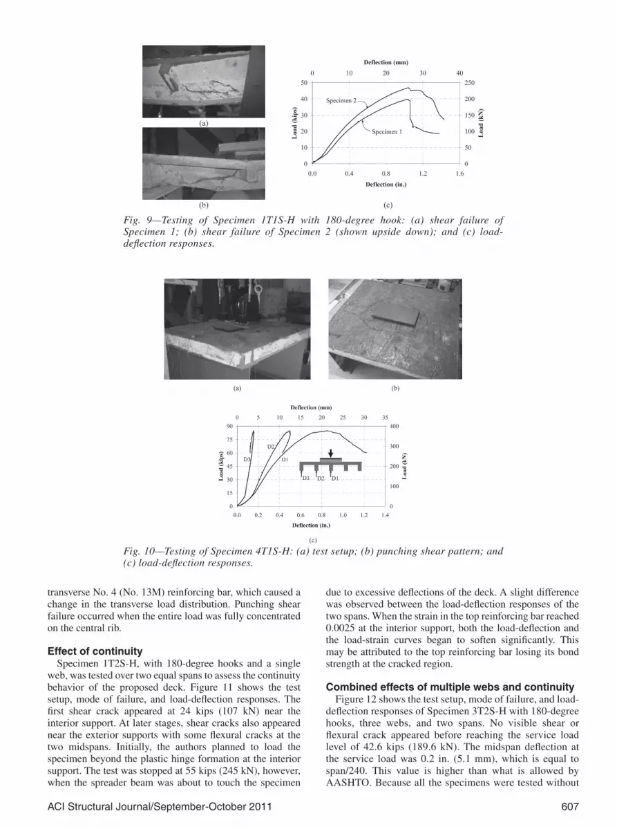
Specimens 1T1S-H1 and 1T1S-H2 were made with ACI 318-05 (ACI Committee 318 2005) 180-degree hooks, based on the results of the first two tests. Figure 9 shows the load-deflection responses and modes of failure for both specimens. The hooks seemingly improved the force transfer across the shear cracks, such that the failure
followed by punching shear failure near the ultimate load. The results are grouped in terms of the effects of end anchorage, number of webs, and the continuity on the system performance.
Effect of end anchorageThe load-deflection response, test setup, and mode of
failure for Specimen 1T1S-A with a welded anchor plate are shown in Fig. 7. Although minor flexural cracks were observed at the midspan, they did not grow significantly with the increase of load. In contrast, large shear cracks developed at both ends between the supporting girders and the loading pad. Breaking sounds from the pullout of the steel fibers could be heard at frequent intervals throughout the test. The failure took place due to the fracture of the weld between
Fig. 5—Configuration of end anchorages.
Fig. 6—Schematics of test specimens and loading configurations: (a) Specimen 1T1S; (b) Specimen 4T1S; (c) Specimen 1T2S; and (d) Specimen 3T2S.
606 ACI Structural Journal/September-October 2011
Effect of multiple webs Specimen 4T1S-H, with 180-degree hooks and four
equivalent webs, was tested over a simple span to determine the transverse load distribution among the webs. The first shear crack appeared at 40 kips (178 kN) and then gradually grew wider, with the specimen ultimately failing in punching shear within the top flange. The deck failed at 85 kips (378 kN)—that is, twice the target load—with a center rib deflection of 0.85 in. (26.1 mm) at the peak load. The test was stopped when the load dropped by approximately 30% to 60 kips (267 kN) at a maximum deflection of 1.22 in. (31 mm). Figure 10 shows the load-deflection responses measured under each rib.
The strain in the transverse reinforcing bar at the midspan was 0.0116, which is nearly three times that of the longitudinal steel, mainly because of the lower stiffness of the transverse ribs. Most of the load was taken by the three interior ribs, as shown in the load-deflection responses. The load distribution between the ribs can be calculated based on the reinforcing bar strains at the bottom, which are 0.001, 0.0025, and 0.004 for the exterior, interior, and central ribs at the ultimate load, respectively. The distribution factor for the center unit is calculated by dividing its reinforcing bar strain (0.004) with the sum of the reinforcing bar strains (0.011) in all five webs. It comes out to be 0.364, which means that 36.4% of the total load is carried by the central unit. This value is very close to that derived earlier from the elastic FE analysis at the design phase. After the load drop, the load was taken primarily by the central rib. The drop in the load-deflection curve is attributed to the yielding of the
of Specimen 1T1S-H1 was no longer a bond failure. The first shear crack appeared at 22.3 kips (99 kN). Two major shear cracks appeared at both ends and gradually opened up with the increase of load. Although the hooks averted bond failure, the ultimate load was the same as the specimen with the welded anchor plate—that is, 40 kips (178 kN) with a slightly lower deflection of 1.04 in. (26.4 mm) at the peak load. The reason for the lower strength, however, was attributed to the lower compressive strength of the batch. The maximum steel strain reached 0.0067, equivalent to a stress level of 132 ksi (910 MPa).
A second specimen with a 180-degree hook was considered necessary because the first test did not provide a realistic estimate of the ultimate load due to its lower material strength. Specimen 1T1S-H2 developed the first shear crack at 26 kips (116 kN) and reached a peak load of 47 kips (209 kN) with a deflection of 1.05 in. (26.7 mm) at the peak load. The failure was relatively more ductile than Specimen 1T1S-H1, as the maximum steel strain reached 0.0096, equivalent to a stress level of 143 ksi (986 MPa).
The first four specimens clearly showed the feasibility of the proposed system as an alternative to an open-grid steel deck. All specimens with 180-degree hooks exceeded the target load of 37.2 kips (166 kN). The test program was therefore expanded to multiple spans and multiple units to understand both the negative moment behavior and the transverse load distribution.
Fig. 7—Testing of Specimen 1T1S-A with end anchor plate: (a) test setup; (b) shear-bond failure; and (c) load-deflection response.
Fig. 8—Testing of Specimen 1T1S-U without end anchorage: (a) shear-bond failure; (b) measure of shear crack; and (c) load-deflection response.
ACI Structural Journal/September-October 2011 607
transverse No. 4 (No. 13M) reinforcing bar, which caused a change in the transverse load distribution. Punching shear failure occurred when the entire load was fully concentrated on the central rib.
Effect of continuitySpecimen 1T2S-H, with 180-degree hooks and a single
web, was tested over two equal spans to assess the continuity behavior of the proposed deck. Figure 11 shows the test setup, mode of failure, and load-deflection responses. The first shear crack appeared at 24 kips (107 kN) near the interior support. At later stages, shear cracks also appeared near the exterior supports with some flexural cracks at the two midspans. Initially, the authors planned to load the specimen beyond the plastic hinge formation at the interior support. The test was stopped at 55 kips (245 kN), however, when the spreader beam was about to touch the specimen
due to excessive deflections of the deck. A slight difference was observed between the load-deflection responses of the two spans. When the strain in the top reinforcing bar reached 0.0025 at the interior support, both the load-deflection and the load-strain curves began to soften significantly. This may be attributed to the top reinforcing bar losing its bond strength at the cracked region.
Combined effects of multiple webs and continuityFigure 12 shows the test setup, mode of failure, and load-
deflection responses of Specimen 3T2S-H with 180-degree hooks, three webs, and two spans. No visible shear or flexural crack appeared before reaching the service load level of 42.6 kips (189.6 kN). The midspan deflection at the service load was 0.2 in. (5.1 mm), which is equal to span/240. This value is higher than what is allowed by AASHTO. Because all the specimens were tested without
Fig. 9—Testing of Specimen 1T1S-H with 180-degree hook: (a) shear failure of Specimen 1; (b) shear failure of Specimen 2 (shown upside down); and (c) load-deflection responses.
Fig. 10—Testing of Specimen 4T1S-H: (a) test setup; (b) punching shear pattern; and (c) load-deflection responses.

608 ACI Structural Journal/September-October 2011
deck-girder connections, higher deflections are expected. Similar to the previous specimens, shear was the dominant mode of failure and flexural cracks were minimal. The first flexural crack was observed at the top of the interior support section at 49 kips (218 kN). It was followed by several shear cracks on the two interior ribs near the interior support. These cracks continued to grow, ultimately leading to the punching shear of the flange. As the punching began, the top flexural crack at the support section closed. The ultimate load was 147 kips (654 kN)—that is, 73.5 kips (327 kN) for each span with deflections of 1 and 0.77 in. (25.4 and 19.6 mm) at the peak load for the north and south spans, respectively. The ultimate load for each span is nearly twice the target load of 37.2 kips (166 kN).
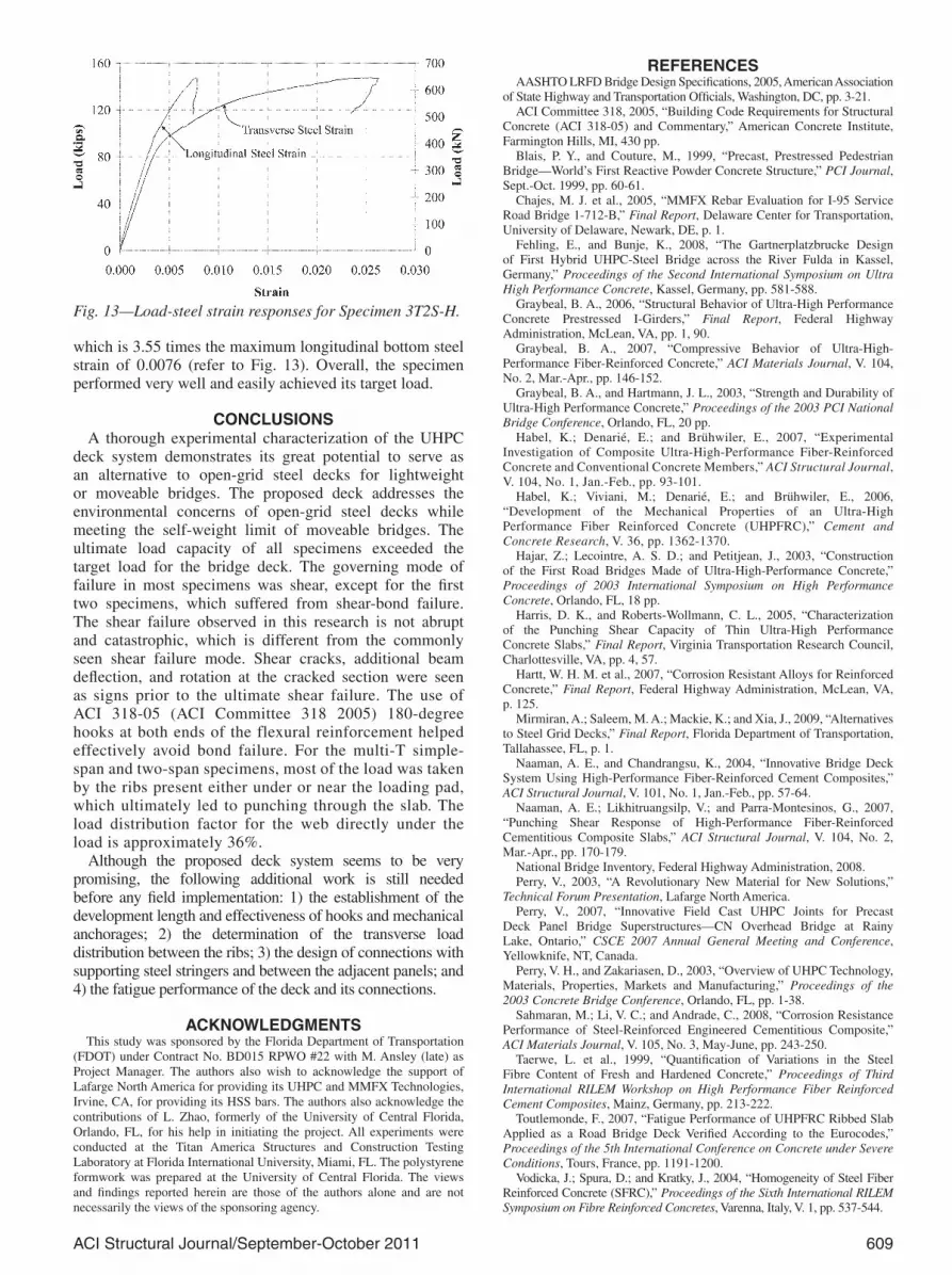
The load-deflection curves show that the majority of the load was taken by the two interior ribs because the loading pad was placed on top of the deck at the location between them. The top concrete strain at the midspan did not reach its ultimate value of 0.0035. The bottom compressive strain at the interior support section, however, was very high (0.016), indicating the crushing of concrete. The strain gauges at the interior support section on the top steel bars were damaged at approximately 90 kips (401 kN) when the strain was 0.0036. The crack that appeared in the top flange at the interior support section at 49 kips (218 kN) likely penetrated to the level of the top steel bars and damaged the strain gauges. Similar to Specimen 4T1S-H, the transverse steel strain was high. The maximum transverse steel strain reached 0.027,
Fig. 11—Testing of Specimen 1T2S-H: (a) test setup; (b) shear failure; and (c) load-deflection responses.
Fig. 12—Testing of Specimen 3T2S-H: (a) test setup; (b) punching shear pattern; and (c) load-deflection responses for north span.
ACI Structural Journal/September-October 2011 609
REFERENCESAASHTO LRFD Bridge Design Specifications, 2005, American Association
of State Highway and Transportation Officials, Washington, DC, pp. 3-21.ACI Committee 318, 2005, “Building Code Requirements for Structural
Concrete (ACI 318-05) and Commentary,” American Concrete Institute, Farmington Hills, MI, 430 pp.
Blais, P. Y., and Couture, M., 1999, “Precast, Prestressed Pedestrian Bridge—World’s First Reactive Powder Concrete Structure,” PCI Journal, Sept.-Oct. 1999, pp. 60-61.
Chajes, M. J. et al., 2005, “MMFX Rebar Evaluation for I-95 Service Road Bridge 1-712-B,” Final Report, Delaware Center for Transportation, University of Delaware, Newark, DE, p. 1.
Fehling, E., and Bunje, K., 2008, “The Gartnerplatzbrucke Design of First Hybrid UHPC-Steel Bridge across the River Fulda in Kassel, Germany,” Proceedings of the Second International Symposium on Ultra High Performance Concrete, Kassel, Germany, pp. 581-588.
Graybeal, B. A., 2006, “Structural Behavior of Ultra-High Performance Concrete Prestressed I-Girders,” Final Report, Federal Highway Administration, McLean, VA, pp. 1, 90.
Graybeal, B. A., 2007, “Compressive Behavior of Ultra-High-Performance Fiber-Reinforced Concrete,” ACI Materials Journal, V. 104, No. 2, Mar.-Apr., pp. 146-152.
Graybeal, B. A., and Hartmann, J. L., 2003, “Strength and Durability of Ultra-High Performance Concrete,” Proceedings of the 2003 PCI National Bridge Conference, Orlando, FL, 20 pp.
Habel, K.; Denarié, E.; and Brühwiler, E., 2007, “Experimental Investigation of Composite Ultra-High-Performance Fiber-Reinforced Concrete and Conventional Concrete Members,” ACI Structural Journal, V. 104, No. 1, Jan.-Feb., pp. 93-101.
Habel, K.; Viviani, M.; Denarié, E.; and Brühwiler, E., 2006, “Development of the Mechanical Properties of an Ultra-High Performance Fiber Reinforced Concrete (UHPFRC),” Cement and Concrete Research, V. 36, pp. 1362-1370.
Hajar, Z.; Lecointre, A. S. D.; and Petitjean, J., 2003, “Construction of the First Road Bridges Made of Ultra-High-Performance Concrete,” Proceedings of 2003 International Symposium on High Performance Concrete, Orlando, FL, 18 pp.
Harris, D. K., and Roberts-Wollmann, C. L., 2005, “Characterization of the Punching Shear Capacity of Thin Ultra-High Performance Concrete Slabs,” Final Report, Virginia Transportation Research Council, Charlottesville, VA, pp. 4, 57.
Hartt, W. H. M. et al., 2007, “Corrosion Resistant Alloys for Reinforced Concrete,” Final Report, Federal Highway Administration, McLean, VA, p. 125.
Mirmiran, A.; Saleem, M. A.; Mackie, K.; and Xia, J., 2009, “Alternatives to Steel Grid Decks,” Final Report, Florida Department of Transportation, Tallahassee, FL, p. 1.
Naaman, A. E., and Chandrangsu, K., 2004, “Innovative Bridge Deck System Using High-Performance Fiber-Reinforced Cement Composites,” ACI Structural Journal, V. 101, No. 1, Jan.-Feb., pp. 57-64.
Naaman, A. E.; Likhitruangsilp, V.; and Parra-Montesinos, G., 2007, “Punching Shear Response of High-Performance Fiber-Reinforced Cementitious Composite Slabs,” ACI Structural Journal, V. 104, No. 2, Mar.-Apr., pp. 170-179.
National Bridge Inventory, Federal Highway Administration, 2008.Perry, V., 2003, “A Revolutionary New Material for New Solutions,”
Technical Forum Presentation, Lafarge North America. Perry, V., 2007, “Innovative Field Cast UHPC Joints for Precast
Deck Panel Bridge Superstructures—CN Overhead Bridge at Rainy Lake, Ontario,” CSCE 2007 Annual General Meeting and Conference, Yellowknife, NT, Canada.
Perry, V. H., and Zakariasen, D., 2003, “Overview of UHPC Technology, Materials, Properties, Markets and Manufacturing,” Proceedings of the 2003 Concrete Bridge Conference, Orlando, FL, pp. 1-38.
Sahmaran, M.; Li, V. C.; and Andrade, C., 2008, “Corrosion Resistance Performance of Steel-Reinforced Engineered Cementitious Composite,” ACI Materials Journal, V. 105, No. 3, May-June, pp. 243-250.
Taerwe, L. et al., 1999, “Quantification of Variations in the Steel Fibre Content of Fresh and Hardened Concrete,” Proceedings of Third International RILEM Workshop on High Performance Fiber Reinforced Cement Composites, Mainz, Germany, pp. 213-222.
Toutlemonde, F., 2007, “Fatigue Performance of UHPFRC Ribbed Slab Applied as a Road Bridge Deck Verified According to the Eurocodes,” Proceedings of the 5th International Conference on Concrete under Severe Conditions, Tours, France, pp. 1191-1200.
Vodicka, J.; Spura, D.; and Kratky, J., 2004, “Homogeneity of Steel Fiber Reinforced Concrete (SFRC),” Proceedings of the Sixth International RILEM Symposium on Fibre Reinforced Concretes, Varenna, Italy, V. 1, pp. 537-544.
which is 3.55 times the maximum longitudinal bottom steel strain of 0.0076 (refer to Fig. 13). Overall, the specimen performed very well and easily achieved its target load.
CONCLUSIONSA thorough experimental characterization of the UHPC
deck system demonstrates its great potential to serve as an alternative to open-grid steel decks for lightweight or moveable bridges. The proposed deck addresses the environmental concerns of open-grid steel decks while meeting the self-weight limit of moveable bridges. The ultimate load capacity of all specimens exceeded the target load for the bridge deck. The governing mode of failure in most specimens was shear, except for the first two specimens, which suffered from shear-bond failure. The shear failure observed in this research is not abrupt and catastrophic, which is different from the commonly seen shear failure mode. Shear cracks, additional beam deflection, and rotation at the cracked section were seen as signs prior to the ultimate shear failure. The use of ACI 318-05 (ACI Committee 318 2005) 180-degree hooks at both ends of the flexural reinforcement helped effectively avoid bond failure. For the multi-T simple-span and two-span specimens, most of the load was taken by the ribs present either under or near the loading pad, which ultimately led to punching through the slab. The load distribution factor for the web directly under the load is approximately 36%.
Although the proposed deck system seems to be very promising, the following additional work is still needed before any field implementation: 1) the establishment of the development length and effectiveness of hooks and mechanical anchorages; 2) the determination of the transverse load distribution between the ribs; 3) the design of connections with supporting steel stringers and between the adjacent panels; and 4) the fatigue performance of the deck and its connections.
ACKNOWLEDGMENTSThis study was sponsored by the Florida Department of Transportation
(FDOT) under Contract No. BD015 RPWO #22 with M. Ansley (late) as Project Manager. The authors also wish to acknowledge the support of Lafarge North America for providing its UHPC and MMFX Technologies, Irvine, CA, for providing its HSS bars. The authors also acknowledge the contributions of L. Zhao, formerly of the University of Central Florida, Orlando, FL, for his help in initiating the project. All experiments were conducted at the Titan America Structures and Construction Testing Laboratory at Florida International University, Miami, FL. The polystyrene formwork was prepared at the University of Central Florida. The views and findings reported herein are those of the authors alone and are not necessarily the views of the sponsoring agency.
Fig. 13—Load-steel strain responses for Specimen 3T2S-H.


