Embed Size (px)
Citation preview

UDesignToward A User-Centered Architecture
by
Yaniv Corem (Ophir)Bachelor of Architecture Faculty of Architecture and Town Planning
Technion - Israel Institute of Technology 2005
Submitted to the Department of Electrical Engineering and Computer Scienceand the Department of Architecture
in Partial Fulfi llment of the Requirements for the Degrees of
Master of Science in Electrical Engineering and Computer Scienceand
Master of Science in Architecture Studies
at theMassachusetts Institute of Technology
June 2010
copy 2010 Massachusetts Institute of TechnologyAll Rights Reserved
Signature of AuthorDepartment of Electrical Engineering and Computer Science
May 21 2010
Certifi ed byKent Larson
Principal Research Scientist Department of Architecture
Thesis Supervisor
Certifi ed byUna-May OrsquoReilly
Principal Research ScientistComputer Science and Artifi cial Intelligence Lab
Thesis Supervisor
Accepted byJulian Beinart
Professor of ArchitectureChair Department Committee on Graduate Students
Accepted byTerry P Orlando
Professor of Electrical Engineering and Computer ScienceChair Department Committee on Graduate Students
Thesis Committee
Kent Larson
Principal Research Scientist Department of Architecture
Thesis Supervisor
Una-May OrsquoReilly
Principal Research ScientistComputer Science and Artifi cial Intelligence Lab
Thesis Supervisor
Terry Knight
Professor of Design amp ComputationDepartment of Architecture
Thesis Reader
UDesignToward A User-Centered Architecture
by
Yaniv Corem (Ophir)
Submitted to the Department of Electrical Engineering and Computer Scienceand the Department of Architecture on May 21 2010
in Partial Fulfi llment of the Requirements for the Degrees ofMaster of Science in Electrical Engineering and Computer Science
andMaster of Science in Architecture Studies
ABSTRACT
As more companies encourage users to participate in the design of personalized products through online confi guration tools a new kind of user-centered business model emerges One of the outcomes of this transformation is the restructuring of a companyrsquos products - from a one-size-fi ts-all to a kit-of-parts - allowing customers to mix-n-match A similar process is taking place in architectural design as more research projects and a few commercial applications employ mass-customization techniques to allow users to design and build their own living solutions
In this thesis I propose a framework for user-centered architecture called UDesign and describe its implementation as a web application that allows users to design their own custom apartment UDesign includes a sample one-bedroom apartment which users can customize through a kit-of-parts approach ie a catalog of rooms (called assemblies) that can be combined to create a complete fl oor plan solution While available confi guration tools in architecture require the user to think like an expert eg integrate form and function UDesign takes a novel approach by deploying a suite of machine learning algorithms coupled with data from Facebook to model usersrsquo design preferences and match them with design solutions Users can take advantage of these recommendations as their design starting point and continue to explore other alternatives by dragging and dropping rooms from the catalog on to the sample fl oor plan As users explore design solutions UDesign updates its recommendations to guide users through the design space and help them fi nd solutions that best fi t their needs Finally UDesignrsquos integration with Facebook allows users to share their designs making UDesign part of their social network
Thesis Supervisor Kent LarsonTitle Principal Research Scientist
Thesis Supervisor Una-May OrsquoReillyTitle Principal Research Scientist
3
4
Acknowledgments
Kent Larson for taking me under his wing | Una-May OrsquoReilly for taking a chance and opening the door | Terry Knight for reading caring and always being there | Daniel Smithwick for watching my back and being a friend | Yonatan Friedman for getting me through Machine Learning with a mechanical pencil and a worn-out eraser | Liraz Greenfeld for trying to teach me electronics | Takehiko Nagakura for teaching me to respect the old Masters | Aaron Sprecher amp Eran Neuman for the endless support and inspiration | The Makluba Club (Duks Kaustuv Carl and Daniel) for putting up with me | The Israeli Mafi a (Yoni Orit Tal and Itai) for reminding me how old I am but keeping me young at heart | The Fantastic Four (Natsuki Chai Oliver and Gerhard) for getting me wasted and dancing in Helsinki | Jarmo and the Finns for the warm hospitality in Helsinki | The Admins (Cynthia Janet and Daniela) for making business feel like pleasure | Dad for teaching me math when everyone else gave up | Mom for making me the man I am today | Sis for never giving up on us | Bro for letting me be a big brother | Gila amp Yotam for being the loves of my life
5
UDesignToward A User-Centered Architecture
by Yaniv Corem (Ophir)
6
for Gila amp Yotam
7
Table of Contents1 IntroducƟ on
11 Yona Friedman111 The InformaƟ on (Short-) Circuit112 The Two Loop System113 Going Forward114 References amp Suggested Reading List
2 Prior Work21 Smithwick22 Duarte23 Plewe24 Phillips25 References amp Suggested Reading List
3 Algorithms31 CollaboraƟ ve Filtering
311 User-Based RecommendaƟ ons312 Item-Based RecommendaƟ ons313 User-Based vs Item-Based RecommendaƟ ons
32 Clustering321 Hierarchical Clustering322 K-means Clustering323 MulƟ dimensional Scaling324 Hierarchical Clustering vs K-means Clustering vs MulƟ dimensional Scaling
33 Feature ExtracƟ on331 Non-NegaƟ ve Matrix FactorizaƟ on
34 Conclusions35 References amp Suggested Reading List
8
4 UDesign41 A Framework For User-Centered Architecture42 ImplementaƟ on
421 Data422 PersonalizaƟ on423 Design424 Contribute425 Feedback426 References amp Suggested Reading List
5 Conclusions51 Yona Friedman Reloaded52 RepresentaƟ on53 Scalability54 CollaboraƟ on55 Data CollecƟ on56 RecommendaƟ ons57 Usability58 ContribuƟ ons59 References amp Suggested Reading List
6 Appendix61 List of assemblies and soluƟ ons
9
Yona Friedman
A Hungarian-born French architect urban planner and designer In 1958 Friedman published his
fi rst manifesto Mobile Architecture which described a new kind of mobility in architecture - not of
buildings but of inhabitants Mobile architecture was the ldquodwelling decided on by the occupantrdquo by
way of ldquoinfrastructures that are neither determined nor determiningrdquo Mobile architecture embodies
an architecture that responds to a ldquomobile societyrdquo In his wriƟ ngs Friedman criƟ cizes contemporary
architecture for its lack of responsiveness to users and their needs Friedman argues that the invenƟ on of
the average user as a method devised by architects to deal with the complexiƟ es of designing for mulƟ ple
users is immoral and destrucƟ ve In the mid-70rsquos Friedman published an infl uenƟ al book called Toward
A ScienƟ fi c Architecture (Friedman 1975) where he fi rst voiced his criƟ que of the architectural design
process as well as proposed a soluƟ on which he called The Two Loop System In Friedmanrsquos system the
fi rst loop consƟ tutes a repertoire of ldquoall possible design soluƟ onsrdquo that is made available for the user
to choose from The second loop Ɵ es the individual user to the community by informing all users of the
individualrsquos selecƟ on and how it may aī ect them
This secƟ on introduces the work of Yona Friedman in the context of parƟ cipatory design More specifi cally
Friedmanrsquos proposal of The Two Loop System a user-centered design process is examined and used as the
starƟ ng point of this thesis
1| IntroducƟ on
10
Friedman argues that the architectural design process originated from a very primiƟ ve interacƟ on between
user and product in which a user conceived planned and executed the producƟ on of his home ie the
product The design process was personal a one-on-one interacƟ on where a userrsquos decision was informed
by the expected use of the fi nished product Moreover responsibility over the outcome was enƟ rely in
the hands of the user With Ɵ me some users began building homes for others and a new stakeholder was
introduced into the design process - the builder As the building task became more complex the builder
needed someone who could translate usersrsquo needs into building instrucƟ ons - the architect By then the
design process was very diī erent from its original primiƟ ve form It was no longer personal and included
both architect and builder as mediators between the user and product Friedman refers to the connecƟ ng
thread between user and product as the informaƟ on circuit ie the way in which a userrsquos needs travel as
informaƟ on through the architect on to the builder and fi nally to the product
The contemporary architectural design process is not much diī erent than Friedmanrsquos formulaƟ on and the
fact that it has remained unchanged for so many years suggests that it works As a maƩ er of fact as long
as the complexity of the informaƟ on circuit is low ie an architect having to deal with a handful of users
the design process seems to work quite well However as soon as complexity increases (eg by adding
more users) the design process starts to break down It simply does not scale well
The informaƟ on (short-) circuit
Figure 11 Jammed circuit (Friedman 1975)
11
With mulƟ ple users the architectrsquos job of translaƟ ng usersrsquo demands into building instrucƟ ons involves
a signifi cant amount of resources For every user the architect must go back and forth through a lengthy
process involving many parts - QampA sketching building models and more - in order to beƩ er understand
the user and tailor the product to his needs Friedman voices the architectrsquos dilemma increase the number
of architects so that there is an architect for every user or come up with an average user that represents
the average properƟ es of all users For lack of a beƩ er opƟ on Friedman claims architects adopted the
average user approach
The two loops proposed by Friedman is a system which restructures the tradiƟ onal design process in
order to overcome its inherent problem ie the informaƟ on short-circuit The fi rst loop in the system
involves only the individual user interacƟ ng with a repertoire of all possible designs from which he can
pick and choose The repertoire includes a warning system thatrsquos embedded into every design to prevent
the user from making mistakes (eg picking two designs that donrsquot fi t) The second loop involves the
community of users and is responsible for informing the community of decisions made by the individual
that could potenƟ ally infl uence others Note that Friedmanrsquos soluƟ on to the informaƟ on short-circuit
is to completely remove the architect from the design process and replace him with an objecƟ ve and
automated component (the repertoire)
The Two Loop System
Figure 12 Broken circuit (Friedman 1975)
12
Going Forward
Figure 13 The Two Loop System - feedback (Friedman 1975)
The Two Loop System operates on two levels The fi rst is local when a user is presented with a number of
diī erent design soluƟ ons from which to choose and a warning system that helps to guide his decisions
The second is global when the design process becomes part of a community with users who are fully
aware of the implicaƟ ons of its membersrsquo design decisions the trade-oī s as well as its idenƟ ty as a whole
AŌ er removing him from the design process Friedman proposes to introduce the architect back into the
system by placing him within the fi rst loop as creator and manager of the repertoire In his new place
in the process the architect is no longer an obstacle between user and product but instead becomes a
facilitator of user-centered design With the applicaƟ on of the two loops the design process becomes
scalable Before the design process would break as the number of users increased primarily because all
informaƟ on had to go through a single line of communicaƟ on resulƟ ng in a communicaƟ on short-circuit
The Two Loop System provides mulƟ ple lines of communicaƟ on one per user which are all decoupled
prevenƟ ng interdependencies that could result in an informaƟ on short-circuit
Friedmanrsquos work planted the seed that is this thesis His criƟ que of the architectural design process raises
many quesƟ ons What is user-centered architecture How does it work How is it beƩ er than the current
pracƟ ce This thesis aims to tackle these diĸ cult quesƟ ons The next chapter will give a brief overview
of past research conducted at MITrsquos Department of Architecture concerning user-centered architecture
from diī erent perspecƟ ves Chapter three will present a suite of algorithm from machine learning and
13
References amp Suggested Reading List1 hƩ penwikipediaorgwikiYona_Friedman (May 20 2010)2 Friedman Y (1975) Toward A ScienƟ fi c Architecture MIT Press
their applicaƟ on to a problem iniƟ ally posed by Friedman ie matching users to designs The soluƟ on to
this problem comes from an unexpected source ie users themselves where the proposed algorithms
learn the design preferences of a user from other like-minded users Then chapter four describes the
implementaƟ on of a web applicaƟ on that allows user to create their own custom apartment inspired in
part by Friedmanrsquos Two Loop System The web applicaƟ on UDesign is a proof-of-concept of user-centered
architecture that deploys the algorithms described in chapter three to provide users with recommendaƟ ons
as a way of guiding them through the design process Finally the last chapter draws conclusions from
various topics discussed in this thesis as well as outlines its contribuƟ ons
Figure 14 The Two Loop System - scalability (Friedman 1975)
ͳͶ
This chapter presents prior work by four researchers at MIT who have addressed various aspects of user-
centered architecture
Smithwickrsquos work pieces together exisƟ ng ideas into a cohesive whole outlined by the following scenario
A user joins an open-source online design community where he can browse designs by other members
design and share his own send any design to fabricaƟ on and get back a kit-of-parts to assemble discuss
his design or the design of others parƟ cipate in joint designs and so on The scenario has three underlying
components (1) design - facilitated by tools and soŌ ware available to all users via the Web for free (2)
fabricaƟ on - facilitated by local and small-scale CNC fabricaƟ on faciliƟ es and (3) community - facilitated by
exisƟ ng (and increasingly popular) Web 20 infrastructure (social networking sites blogs etc)
Smithwickrsquos vision shares much in common with the ideas of Yona Friedman as discussed in the fi rst
chapter There is a reference to soŌ ware and hardware in both Smithwickrsquos and Friedmanrsquos work thatrsquos
joined together by a third more virtual enƟ ty - the Web (Smithwick) or feedback loop (Friedman)
Smithwick
2| Prior Work
Figure 21 Get Physical (Smithwick 2009)
ͳͷ
Duartersquos work describes the process of trying to learn the underlying rules of Alvaro Sizarsquos Malagueira
houses through discursive shape grammar Duarte uses the learned grammar to develop his own user-
centered design process to provide mass-customized housing The work has several interesƟ ng aspects
The fi rst aspect is the ability to learn an architectrsquos design methodology or style Whether through discursive
shape grammars or other methods Duartersquos work shows that (a) there is an underlying paƩ ern in how
architects design and (b) the ability to design systems that capture these paƩ erns is a powerful tool
The second aspect relates to how this tool is used For example an architectrsquos design paƩ ern can be
used to create a larger variety of design soluƟ ons for users perhaps way beyond the architectrsquos original
repertoire Furthermore turning an architectrsquos design paƩ ern into a tool empowers users to experiment
with the design paƩ erns themselves in a safe and predictable environment
The third aspect is the plaƞ orm Duarte chooses for the distribuƟ on of his system ie the Web Duarte
recognizes the power of the Web as a place where millions of people can explore share and create designs
The end result of Duartersquos work is a website where users can create their own home based on Sizarsquos design
paƩ ern
Duarte
Figure 22 Discursive Grammar (Duarte 2001)
ͳ
Plewersquos work presents a bricolage approach to designing mass-customized housing for low to middle
income families as an alternaƟ ve to the exisƟ ng tract home paradigm As a proof-of-concept Plewe
developed a design tool which included a 3D environment a library of components and a way for users to
search the library and fi nd what they need Users who wanted to create their own custom home would use
Plewersquos tool to search the library by using keywords like ldquoconcreterdquo fi nd the components they liked add
them to the 3D authoring environment adjust the components unƟ l theyrsquore saƟ sfi ed and fi nally create
construcƟ on documents for the contractor
Plewersquos approach - the library of components search and selecƟ on as a process of design and an emphasis
on what the user wants - provides the technical base for the work described in this thesis
Plewe
Figure 23 Screenshot of H++ (Plewe 2008)
ͳ
Phillipsrsquos work defi nes design as a process of searching and provides the conceptual and technical
framework to support search in Web-based design tools for everyday users The work is moƟ vated by the
noƟ on of user-centered design ndash users creaƟ ng their own living soluƟ ons - and the fabricaƟ on abiliƟ es
to support it Phillips proposes a way of combining Building InformaƟ on Modeling (BIM) modern search
methods and an Object Oriented Programming (OOP) approach to create a space of design soluƟ ons that
ldquocan be searched directly without indexingrdquo
Phillips
Figure 24 Design By Searching (Phillips 2007)
References amp Suggested Reading List1 Smithwick D (2009) Architectural Design 20 An Online Plaƞ orm for the Mass CustomizaƟ on
of Architectural Structures Masters Thesis MassachuseƩ s InsƟ tute of Technology Cambridge MassachuseƩ s
2 Duarte J (2001) Customizing Mass Housing A Discursive Grammar for Sizarsquos Malagueira Houses PhD Thesis MassachuseƩ s InsƟ tute of Technology Cambridge MassachuseƩ s
3 Plewe T (2008) BesƟ ng the Tract Home A soŌ ware-Based Bricolage Approach to Aī ordable Custom Housing Masters Thesis MassachuseƩ s InsƟ tute of Technology Cambridge MassachuseƩ s
4 Phillips G (2007) Design By Searching A System for CreaƟ ng and EvaluaƟ ng Complex Architectural Assemblies Masters Thesis MassachuseƩ s InsƟ tute of Technology Cambridge MassachuseƩ s
18
Within user-centered architecture a set of criƟ cal tasks is the ability to model users designs and the
relaƟ onship between them To tackle these diĸ cult tasks this secƟ on explores the following machine
learning algorithms by way of experimentaƟ on and considers their potenƟ al contribuƟ on to the tasks at
hand
bull CollaboraƟ ve Filtering (User-based Item-based) - is used to match users to design soluƟ ons by way
of recommendaƟ ons
bull Clustering (Hierarchical K-means MulƟ dimensional Scaling) - is used to discover groups of users and
design soluƟ ons
bull Feature ExtracƟ on (Non-NegaƟ ve Matrix FactorizaƟ on) - is used to uncover the latent features of a
design soluƟ on
For the purpose of these experiments a unique data set was created with the help of 30 architects (referred
to as criƟ cs) who were asked to rate on a scale of 1 (low) to 5 (high) 20 architectural fl oor plans of a one
bedroom apartment Figure 31 shows a sample page from a booklet given to each criƟ c containing the
fl oor plan and raƟ ng box CriƟ csrsquo raƟ ngs were collected into a 30 by 20 matrix (referred to as the raƟ ng
matrix) with rows represenƟ ng criƟ cs and columns represenƟ ng fl oor plans (Figure 32)
The highest average fl oor plan raƟ ng was 383 and the lowest was 237 The highest average criƟ c raƟ ng
was 39 and the lowest 125 The results indicate that most criƟ cs rated according to the highest average
fl oor plan raƟ ng and chose to rate higher than the lowest average fl oor plan raƟ ng However criƟ c_9
gave all but three fl oor plans a raƟ ng of 1 bringing the average of the lowest criƟ c raƟ ng down Also the
standard deviaƟ on for criƟ c_9rsquos raƟ ngs (064) suggests an outlier and was excluded from the experiments
3| Algorithms
$amp()(+Attributes-0$1)20$34345$+$367489335780lt0=4431gt5$$03424316$345$431A20780755B4C0D240EF2465$$0345$(G0H4=44314$34B30)I734345$0-+5I0$1BB0371lt57-07gtI742154AI34456DG5E)(0G440$1Add your ow
n
RATING
19
Figure 31 How would you rate this fl oor plan
13
13
13
13
13
13
13
13
13
13
13
13
13
13
13
13
13
13
13
13
13
13
13
13
13
13
13
13
13
13
13
20
Figure 32 RaƟ ng matrix
21
CollaboraƟ ve Filtering (CF) is a method for making automaƟ c predicƟ ons (fi ltering) about the interest or
taste of a user by collecƟ ng and analyzing the personal preferences of many other users (collaboraƟ ve)
The fi rst system to use CF was the InformaƟ on Tapestry project at Xerox PARC (Goldberg et al 1992)
In general CF systems can be categorized as user-based or item-based User-based CF systems do the
following
bull Look for users who share the same raƟ ng paƩ ern with the acƟ ve user (ie the user for whom we are
trying to make a predicƟ on)
bull Use the raƟ ngs from those like-minded users to formulate a predicƟ on for the acƟ ve user
AlternaƟ vely item-based CF systems focus on items and the relaƟ onships amongst them to make
predicƟ ons eg ldquoUsers who bought X also bought Yrdquo (popularized by Amazoncom) Item-based CF
systems do the following
bull Build a Similarity Matrix to determine the relaƟ onship between pairs of items
bull Use the Similarity Matrix and userrsquos personal data to formulate a predicƟ on
CollaboraƟ ve Filtering
22
When wersquore interested in fi nding good recommendaƟ ons we tend to turn to people with a similar taste
to ours User-based collaboraƟ ve fi ltering takes the same approach by comparing us the acƟ ve user with
everyone else fi nding those who are most similar and using their preferences to make a predicƟ on about
what we like In user-centered architecture this approach takes advantage of design preferences and
taste expressed by various users to help other users fi nd what they need To illustrate how user-based
collaboraƟ ve fi ltering works a brief experiment was conducted using the data set of fl oor plan raƟ ngs to
predict a raƟ ng for a fi cƟ Ɵ ous user (referred to as CriƟ c_N) who rated some but not all the fl oor plans
The algorithm (Segaran 2007) presented in pseudocode (Figure 33) starts by iteraƟ ng through all users
and compuƟ ng their similarity to CriƟ c_N using a Pearson correlaƟ on coeĸ cient (Eq 31) Then the
algorithm iterates through every item ie fl oor plan and computes the weighted average raƟ ng (Eq
32) by mulƟ plying each of the raƟ ngs by the criƟ csrsquos similarity score and summing over all the scores
The intuiƟ on behind weighƟ ng the raƟ ngs is that users who are more like CriƟ c_N will have more weight
put on their raƟ ngs whereas raƟ ngs by users who are diī erent will receive very liƩ le weight Finally the
algorithm normalizes sorts and returns the result as predicted raƟ ngs for CriƟ c_N (Figure 34)
C CriƟ cM RaƟ ng MatrixU AcƟ ve UserFor each C in M If C is not U Then compute Similarity of C and U (see Eq 31)For each Item in M If Item was not rated by U Then compute user similarity weighted average raƟ ng (see Eq 32) And store it in ListNormalize ListSort List based on normalized weighted similarityReturn List
User-Based RecommendaƟ ons
Figure 33 Pseudocode for user-based recommendaƟ on
13
13 13
13 13
13
13
13
13 13
23
(Eq 31)
(Eq 32)
(Eq 33)
In order to measure the predicƟ ve power of the proposed algorithm the raƟ ngs matrix was transformed
into a test set by randomly deleƟ ng raƟ ngs in criƟ cs 1 through 8 The missing raƟ ngs were then esƟ mated
and the Root Mean Square Error (Eq 33) was computed yielding a value of 114 (Figure 35) To evaluate
this result (114) RMSE was calculated ten more Ɵ mes subsƟ tuƟ ng missing raƟ ngs with random numbers
between 1 and 5 yielding an average value of 195 The results show that the algorithm makes predicƟ ons
which are beƩ er than chance with an error that is 58 of the random error In addiƟ on RMSE was
calculated for CriƟ c_30 with 5 10 and 15 raƟ ngs yielding 131 124 and 087 respecƟ vely These results
indicate that by raƟ ng more fl oor plans criƟ cs improve the accuracy of the recommendaƟ ons they get
Figure 34 Predicted raƟ ngs (in green) and iniƟ al raƟ ngs (in yellow) for CriƟ c_N
13
13
13
13
13
24
Figure 35 Test matrixPredicted raƟ ngs (in green) and iniƟ al raƟ ngs (in yellow) for criƟ cs 1 through 8 used to calculate algorithmrsquos predicƟ ve power by measuring the Root Mean Square Error (RMSE)
25
When a data set like the raƟ ng matrix becomes very large a user-based approach might start to break
down due to the computaƟ onal cost of usersrsquo pairwise comparison An item-based approach alleviates
this problem by pre-compuƟ ng a similarity matrix for all items The assumpƟ on is that items do not change
as frequently as users therefore the similarity matrix will only need to be updated every once in a while
Amazoncom for example uses an item-based approach ie item-to-item collaboraƟ ve fi ltering (Linden
et al 2003) to recommend products to its users (Figure 36)
Making recommendaƟ ons using item-based collaboraƟ ve fi ltering consists of the following steps pre-
compuƟ ng an item-to-item similarity matrix looking up the acƟ ve userrsquos top-rated items and creaƟ ng
a weighted list of the most similar items To illustrate how this works an algorithm (Segaran 2007) was
tested with the raƟ ngs matrix to get recommendaƟ ons for CriƟ c_N (Figure 37)
CriƟ c_Nrsquos rated items
(50 SOL25) (20 SOL81) (10 SOL158)
CriƟ c_Nrsquos recommended items
(50 SOL9) (365 SOL74) (324 SOL144) (285 SOL202) (281 SOL228) (267 SOL224) (249 SOL212)
(243 SOL33) (209 SOL125) (15 SOL38) (142 SOL59) (141 SOL54) (10 SOL139)
Item-Based RecommendaƟ ons
Pre-compute item similarity matrix with user-based approach but subsƟ tuƟ ng items for users by transposing the raƟ ng matrixFor each Item1 in Userrsquos items For each Item2 in Item1rsquos similarity matrix If User has already rated Item2 Then conƟ nue to the next iteraƟ on of the loop Compute item similarity weighted raƟ ng (see Eq 32) Compute average of weighted item raƟ ngs And save them in ListSort List based on normalized weighted item similarityReturn List
Figure 36 Pseudocode for item-based recommendaƟ on
Figure 37 Item-based recommendaƟ ons for CriƟ c_N
26
Figure 37 shows that given CriƟ c_Nrsquos high raƟ ng of fl oor plan SOL25 the algorithm recommended SOL9
as the highest ranking (best matching) item Figure 38 validates the algorithmrsquos precision and predicƟ ve
power as the two fl oor plans are nearly idenƟ cal There are some minor diī erences between the two
fl oor plans for example SOL9 has a bar-top dining table but SOL25 has a 6-seat standalone dining table
However the overall similarity of the two fl oor plans is evident and emerges from the usersrsquo raƟ ngs
In order to compare the performance of the algorithm a random criƟ c was selected (CriƟ c_30) all but the
fi rst fi ve of his raƟ ngs deleted and then predicted by each of the algorithms The RMSE for the user-based
algorithm was 118 and the item-based algorithm was 161 indicaƟ ng that user-based recommendaƟ ons
are more accurate than item-based recommendaƟ ons However there are other issues to consider besides
accuracy when choosing one algorithm over the other for example size of data set and frequency of
change have a tremendous infl uence on the performance of these algorithms
User-Based vs Item-Based RecommendaƟ ons
Figure 38 SOL9 (LeŌ ) and SOL25 (Right) with a similarity score of 004
27
Clustering or Cluster Analysis is a way of discovering and visualizing groups of things - people news
stories blogs and more This secƟ on will focus on two clustering techniques - Hierarchical and K-means -
and apply them to the raƟ ngs matrix in order to discover groups of criƟ cs and fl oor plans In user-centered
architecture these clusters can be uƟ lized for example to infer a new userrsquos design preferences by fi nding
his cluster membership A user who has been assigned to a certain cluster shares the design preferences
of that cluster making it possible to tailor design recommendaƟ ons to his taste
Figure 39 is the pseudocode for a simple hierarchical clustering algorithm (Segaran 2007) The algorithm
starts by assigning each item ie fl oor plan to a cluster of its own Then the distance between every pair
of clusters is calculated and the closest (most similar) ones are merged together to form a new cluster
The process is repeated unƟ l there is only one cluster leŌ The algorithm uses the Pearson correlaƟ on
coeĸ cient to compute the distance between clusters
Figure 310 shows the groups of criƟ cs discovered when running the hierarchical clustering algorithm on
the raƟ ng matrix The dendrogram clearly separates the criƟ cs into two groups each characterized by
its own design preferences as extracted from the raƟ ngs Each of the two main clusters contains smaller
clusters for example criƟ cs 16 8 30 6 11 and 3 form a cluster within the bigger cluster at the top
of Figure 310 Rated fl oor plans were also clustered (Figure 311) by running the hierarchical clustering
algorithm on a rotated raƟ ng matrix Clustering shows two disƟ nct clusters made up of smaller clusters
such as fl oor plans SOL9 25 74 224 and 228 (Figure 312)
Clustering
Hierarchical Clustering
Figure 39 Pseudocode for hierarchical clustering
IniƟ alize all rows to be clustersCreate BigClusterWhile number of Clusters is bigger than 1 For each pair of Clusters Find the pair with the smallest distance Calculate the average of the two Clusters Combine the two clusters to form a new Cluster Add new Cluster to BigClusterReturn BigCluster
28
Gender analysis (MaleFemale )Top cluster - 6040BoƩ om cluster - 5050
Analysis reveals that clusters are gender neutral suggesƟ ng that gender may not play a role in the design preferences of architects
Figure 310 Hierarchical clustering of criƟ cs
29
Figure 311 Hierarchical clustering of fl oor plans
30
Figure 312 Clustered fl oor plans
AƩ ributes of clustered fl oor plans (parƟ al list)bull A small bathroombull A large kitchenbull A dining tablebull Clearly defi ned private amp public spaces
SOL9
SOL74
SOL25
SOL224
SOL228
31
Hierarchical clustering is computaƟ onally expensive because the pairwise distance calculaƟ ons have to
be carried out every Ɵ me clusters are merged therefore this method might break down on larger data
sets K-means clustering takes a diī erent approach because the number of clusters is specifi ed in advance
removing some of the ambiguity in dividing up the data
The K-means clustering algorithm (Segaran 2007) presented as pseudocode (Figure 313) starts by
randomly placing centroids ie center of the cluster and assigning every item to the nearest one Then
each centroid is shiŌ ed to the average locaƟ on of the items it contains items are reassigned and the
process repeats itself unƟ l the assignments stop changing
Figure 314 shows the K-means clustering of fl oor plans with diī erent values of K
K-means Clustering
Figure 313 Pseudocode for K-means clustering
M RaƟ ng MatrixFor each Item in M Compute the Min and Max value of Item Create K randomly placed centroids While assignment of Item is changing Find the closest centroid to Item Assign Item to centroid Move centroid to average locaƟ on of ItemsReturn K Clusters
K=8 SOL(158 169 268) (144 149) (925) (74) (33) (150) (202 212224 228) (38 54 59 81 125 139)
K=5 SOL(54 59 125 139 158) (25 74 144 202 224) (33 228 268) (149 150 169) (9 38 81 212)
K=3 SOL(9 25 74 228) (38 81 144 149 150 202 212 224) (33 54 59 125 139 158 169 268)
Figure 314 K-means clustering of fl oor plans
32
Items in the raƟ ng matrix are mulƟ dimensional ie each fl oor plan is represented by a vector of 30
raƟ ngs MulƟ dimensional scaling is a technique for fi nding a two-dimensional representaƟ on of the raƟ ng
matrix which is someƟ mes easier to understand than a dendrogram
The algorithm (Segaran 2007) presented as pseudocode (Figure 314) starts by calculaƟ ng the target
distances between all the items Next all items are placed randomly on a two-dimensional plane The
current distances between all the items are calculated using the actual distance ie the sum of the
squared diī erences For every pair of items the target distance is compared to the current distance to
calculate the error Every item is moved a small amount in proporƟ on to the direcƟ on of the error between
the two items The process is repeated unƟ l the total error cannot be reduced by moving any of the items
Figure 315 shows the results of running the mulƟ dimensional scaling algorithm on the raƟ ng matrix
All three methods when applied to the fl oor plans produced comparable results making the choice
of any one method unclear This is due to the small size of the data set and some ad-hoc choices of
parameters for the algorithms With a more extensive data set one expects to evaluate and choose based
upon computaƟ onal cost of the algorithm moƟ vaƟ on for and use of the derived informaƟ on and auxiliary
informaƟ on from the problem domain
MulƟ dimensional Scaling
Hierarchical Clustering vs K-means Clustering vs MulƟ dimensional Scaling
Figure 314 Pseudocode for MulƟ dimensional scaling
M RaƟ ng MatrixFor each Item1 and Item2 in M Compute the real distance between Item1 and Item 2 Randomly place Item1 and Item2 in 2D spaceWhile TotalError is changing Find the projected distance between Item1 and Item2 Calculate Error between real and projected distance Move Item1 and Item2 in proporƟ on to Error Update TotalErrorReturn locaƟ on of Items
SOL228
SOL38
SOL59
SOL54
SOL33SOL125
SOL139
SOL169
SOL268
SOL150
SOL149
SOL144
SOL9
SOL224
SOL25
SOL74
SOL158
SOL212
SOL81
SOL202
33
Figure 315 MulƟ dimensional scaling of raƟ ng matrixColored boxes correspond to the hierarchical clustering in Figure 311
=X
Plan 4
Features Matrix Weights Matrix
Plan 4
34
Figure 316 Non-NegaƟ ve Matrix FactorizaƟ on
The rated fl oor plans in the data set share certain features such as an open kitchen private vs public
spaces and others These features are latent - hidden between the raƟ ngs - and in order to extract them
the raƟ ng matrix has to be factored It is important to note that these features are not the same as the
aƩ ributes given to the criƟ cs to help them rate the fl oor plans There is no way to be absolutely sure of
what a feature represent All that can be done is to examine the set of fl oor plans which share the feature
and aƩ empt to visually arƟ culate it
Figure 316 describes the process of matrix factorizaƟ on The goal is to factor the matrix ie fi nd two
smaller (lower rank) matrices - a features matrix and a weights matrix - that when mulƟ plied together
reconstruct the original matrix The features matrix has features for rows and fl oor plans for columns
The value in each cell of the matrix indicates how important that fl oor plan is to the feature The weights
matrix maps the features to the raƟ ng matrix Each row is a criƟ c and each column is a feature The value
in each cell of the matrix indicates how much a feature applies to a fl oor plan Therefore reconstrucƟ ng
the raƟ ng matrix is a maƩ er of combining rows from the features matrix in diī erent amounts The weights
matrix maps the features to the raƟ ngs Non-negaƟ ve refers to the fact that all features and weights must
be posiƟ ve For a more comprehensive descripƟ on of the algorithm see (Segaran 2007)
Using a Non-NegaƟ ve Matrix FactorizaƟ on algorithm the raƟ ng matrix was factored into a features matrix
and a weights matrix The algorithm was programmed to fi nd 10 features Figure 317 represents 5 of
the 10 features as a list of fl oor plans that contain the feature As menƟ oned the features are latent
therefore feature 5 for example is shared by fl oor plans 149 150 169 and 268 An hypothesis of what
the feature represents is proposed by looking at the commonaliƟ es of the fl oor plans that defi ne the
feature (Figure 318)
Feature ExtracƟ on (Non-NegaƟ ve Matrix FactorizaƟ on)
35
Figure 317 5 features extracted from the raƟ ng matrix
(SOL81 SOL224)
(SOL149 SOL150 SOL169 SOL268)
(SOL202 SOL212)
(SOL158 SOL228)
(SOL33 SOL54 SOL59 SOL125 SOL139)
Feature 4
Feature 5
Feature 7
Feature 8
Feature 9
ConclusionsThe dataset used in these experiments is extremely small compared to the Neƞ lix or Amazon data sets
Nevertheless each of the applied methods revealed some interesƟ ng informaƟ on about the data - criƟ cs
fl oor plans and the relaƟ onship between them
CollaboraƟ ve fi ltering whether user or item based showed that it is possible to leverage a communityrsquos
opinion expressed through raƟ ngs in order to help an individual fi nd what he likes Analysis of the
algorithm showed that it performs much beƩ er than a random guess
Clustering - Hierarchical K-means or MulƟ dimensional Scaling - showed that it is possible to fi nd groups of
criƟ cs and fl oor plans and uncover their common characterisƟ cs With a large enough data set clustering
can be used to extract user and design typologies which can help stakeholders in the building industry -
contractors developers architects etc - tailor their services to clientsrsquo needs
Feature ExtracƟ on showed that it is possible to extract the features of a fl oor plan in order to create a
design vector The design vector can be used to score fl oor plans based on a userrsquos interest in one or all of
its features allowing the user to explore the design space in mulƟ ple direcƟ ons
36
Figure 318 ArƟ culaƟ ng Feature 5 through its fl oor plansFeature 5 could be the free-standing column that appears in all the fl oor plans below
SOL149 SOL150
SOL169 SOL268
37
References amp Suggested Reading List1 Billsus D amp Pazzani M J (1998) Learning collaboraƟ ve informaƟ on fi lters Proceedings of the 15th
InternaƟ onal Conference on Machine Learning pp 46ndash542 Blei D M Ng A Y amp Jordan M I (2002) Latent Dirichlet allocaƟ on Advances in Neural InformaƟ on
Processing Systems 143 Breese J S Heckerman D and Kardie C (1998) Empirical analysis of predicƟ ve algorithms for
collaboraƟ ve fi ltering In Proceedings of the 14th Conf on Uncertainty in ArƟ fi cial Intelligence pp 43ndash52
4 Goldberg D Nichols D Oki BM amp Terry D (1991) Using CollaboraƟ ve Filtering to Weave an InformaƟ on Tapestry Comm ACM vol 35 no 12 pp 61-70
5 Herlocker JL Konstan JA Borchers A and Riedl J (1999) An Algorithmic Framework for Performing CollaboraƟ ve Filtering Proc 22nd Ann Intrsquol ACM SIGIR Conf Research and Development in InformaƟ on Retrieval (SIGIR rsquo99)
6 Herlocker JL Konstan JA Terveen LG and Riedl JT (2004) EvaluaƟ ng CollaboraƟ ve Filtering Recommender Systems ACM Trans InformaƟ on Systems vol 22 no 1 pp 5-53
7 Hofmann T (2004) Latent semanƟ c models for collaboraƟ ve fi ltering ACM TransacƟ ons on InformaƟ on Systems 22 pp 89ndash115
8 Koren Y Bell R Volinsky C (2009) Matrix FactorizaƟ on Techniques for Recommender Systems IEEE Computer 082009 Volume 42 Issue 8 pp30-37
9 Linden G Smith B and York J (2003) Amazoncom RecommendaƟ ons Item-to-Item CollaboraƟ ve Filtering IEEE Internet CompuƟ ng
10 Marlin B (2004) CollaboraƟ ve fi ltering A machine learning perspecƟ ve Masterrsquos thesis University of Toronto Computer Science Department
11 Segaran T (2007) Programming CollecƟ ve Intelligence OrsquoReilly Media12 Srebro N Rennie J D M amp Jaakkola T S (2005) Maximum margin matrix factorizaƟ on Advances
in Neural InformaƟ on Processing Systems 17
38
4| UDesignWhen a user wishes to purchase an apartment from a developer he is usually presented with a few sample
apartments from which to choose These sample apartments usually oī er very few parameters that can
be changed because they are designed to fi t the taste and lifestyle of an average user The soluƟ on to
this problem can be found in two diī erent places - hardware and soŌ ware - which complement each
other to create user-centered architecture On the one hand there is hardware the building technology
that is responsible for making sure usersrsquo designs are feasible The mass-customizaƟ on community in
architecture has made considerable progress in recent years and managed to push fabricaƟ on technology
forward On the other hand there is soŌ ware the interface that is responsible for making sure users can
express their wants and needs The ability of an interface to meet usersrsquo needs depends on its front-end -
how easy it is to use the interface - and back-end - how the objects of design are represented internally in
the system This secƟ on will focus on the soŌ ware and illustrate through the implementaƟ on of UDesign
what are some of the issues to consider in terms of soŌ ware for user-centered architecture
As a framework UDesign mediates between the user and stakeholders in the building industry - architects
developers contractors suppliers realtors and community - in order to create a product in this case
an apartment Figure 41 outlines the components and relaƟ onships of user-centered architecture as a
series of four concentric circles - User UDesign Data and Stakeholders - fl oaƟ ng in Design Space the
space of design soluƟ ons oī ered to the user Metaphorically as the user is designing his own product
he is navigaƟ ng through the design space cocooned within these layers of UDesign and Stakeholders
through which he communicates his ideas about the product To visualize the metaphor imagine Figure
A Framework For User-Centered Architecture
39
Architect
Developer
DesignSpace
Realtor
Supplier
CommunityContractor
DesignLogic
Feedback
User
Stakeholders
UDesign
Data
41 as a ball fl oaƟ ng in space and rays of informaƟ on shooƟ ng from its center (User) guided by an inner
mechanism (UDesign Stakeholders) trying to fi nd an anchor in space (Design)
UDesign is comprised of four parts Design CommunicaƟ on Feedback and Logic Design is responsible
for visualizing the design space and interacƟ ng with the user In a way it is the front-end of the interface
Design includes the library of parts from which a user can choose to create his design (Friedmanrsquos
repertoire) tools to transform and edit the design and ways to explore the design space CommunicaƟ on
is responsible for the exchange of informaƟ on between user and stakeholders The radial arrangement
facilitates mulƟ ple channels of communicaƟ on at any given point in Ɵ me For example a user can
communicate with the architect in order to get professional feedback about his design while also geƫ ng
feedback from the community CommunicaƟ on must pass through UDesign to avoid overloading the user
therefore messages are stored in a queue and ordered by their relevancy to the current context of the
design process Feedback is responsible for conƟ nuously collecƟ ng informaƟ on about the state of the
design process analyzing it and providing noƟ fi caƟ ons at the right Ɵ me and place For example when a
user selects a design component he is immediately given feedback about the availability of the component
Figure 41 User-Centered Architecture
40
UDesign was implemented in Adobe Flex Builder 3 an IDE (Integrated Development Environment)
for creaƟ ng cross-plaƞ orm RIA (Rich Internet ApplicaƟ on) based on Adobe Flash A typical applicaƟ on
development process was followed including
bull Defi ning an applicaƟ on interface using a set of pre-defi ned components (forms buƩ ons and so on)
as MXML Components
bull Arranging components to create a User Interface (UI) design
bull Using styles and themes to defi ne the visual design CSS skins etc
bull Adding dynamic behavior using proper event-driven programming techniques
bull Defi ning and connecƟ ng to data services as needed MySQL ColdFusion etc
bull Compiling the source code into an SWF fi le that can be read by Flash Player and embedded within an
HTML fi le
UDesign is comprised of fi ve parts Data PersonalizaƟ on Design Contribute and Feedback (Figure 42)
where Data consƟ tutes most of the back-end and the remaining parts the front-end
The data in UDesign is stored in tables within a MySQL database that resides on a server The mxml
applicaƟ on makes requests to the database through a Flex HTTPService component In turn the
HTTPService component calls one of fi ve methods (FindAll Insert Update Delete Count) encapsulated
within a PHP fi le which then retrieves the data from the appropriate table of the database and returns the
data to the applicaƟ on in an E4X format (Figure 43)
ImplementaƟ on
Data
its price compaƟ bility with other components and more Stakeholders can use UDesignrsquos feedback to get
informaƟ on about their users - purchase history preferences lifestyle status state of the design and
more Logic is responsible for holding everything (Design CommunicaƟ on and Feedback) together so that
usersrsquo experience of UDesign is both producƟ ve and posiƟ ve Logic is supported by a suite of algorithms
from diī erent categories - user interacƟ on network database machine learning - some of which are
described in more detail in chapter 3 (Algorithms) as well as in the next secƟ on (ImplementaƟ on)
41
HTTPService
Data
Design
Contribute
Feedback
PHP
HTTPService PHP
MySQL
ContributeView
assembliesService
tagsService
usersService
Database
FeedbackView Feedback
HomeView Facebook Connect
currUser (Facebook)
UDesigners at work
Survey
DesignView
Assemblies
Tags
Users
feedbackService
IntroHomePage
PersonalizedHomePage
Floorplan
Catalog currUser (Facebook)
assembliesrooms
by selected rooms
GridCell (A1-C2)
clear
Figure 42 UDesign - system overview
42
FindAllInsertUpdateDeleteCount
Table 1Table 2Table 3
Request Request
Response ResponseFLEX PHP MySQL
E4X
The database includes the following tables
bull assemblies (Figure 44)
bull soluƟ ons (Figure 45)
bull users_saved_soluƟ ons (Figure 46)
bull users (Figure 47)
bull design_profi le (Figure 48)
bull soluƟ on_vector (Figure 49)
bull feedback (Figure 410)
Figure 43 Data pipeline
43
Table assemblies
This table holds the 48 assemblies (custom-designed rooms) available to the user on the Design page of
UDesign
Fields id room id | label room label | type room type | descripƟ on room descripƟ on | price room
price | cell an index indicaƟ ng to what funcƟ onal zone the room belongs (more details below) | area
room area (sqŌ ) | dimx room dimension in x-axis (pixels) | dimy room dimension in y-axis (pixels) | locx
room posiƟ on in x-axis (pixels) | locy room posiƟ on in y-axis (pixels) | color room color code | fi t a fl ag
indicaƟ ng whether the room fi tsdoesnrsquot fi t with the userrsquos design (more details below)
Table soluƟ ons
This table holds the 285 soluƟ ons (custom-designed fl oor plans) available to the user on the Design page
of UDesign
Fields id fl oor plan id | label fl oor plan label | A1 - C2 a funcƟ onal zone in the fl oor plan (more details
below)
Table users_saved_soluƟ ons
This table holds usersrsquo saved soluƟ ons (custom-designed fl oor plans) created by users on the Design page
of UDesign
Fields id fl oor plan id | label fl oor plan label | A1 - C2 a funcƟ onal zone in the fl oor plan (more details
below)
Table users
This table temporarily holds usersrsquo personal informaƟ on obtained from their Facebook account (more
details about UDesignrsquos connecƟ on to Facebook in the secƟ on about PersonalizaƟ on)
Fields (Facebook generated) uid userrsquos id | about_me userrsquos personal message | acƟ viƟ es userrsquos
favorite acƟ viƟ es | birthday userrsquos birthday | books userrsquos favorite books | fi rst_name userrsquos fi rst name
| interests userrsquos interests | last_name userrsquos last name | movies userrsquos favorite movies | music userrsquos
favorite music | pic userrsquos profi le picture | relaƟ onship_status userrsquos current relaƟ onship status | sex
userrsquos gender | wall_count number of posts on userrsquos wall
44
Table design_profi le
This table holds usersrsquo design profi le Users are presented with ten parameters of lifestyle and asked to
rate their importance on a scale of one (low) to fi ve (high)
Fields id userrsquos Facebook id | watch importance of watching TVMovies | entertain importance
of entertaining | cook importance of cooking | work importance of being able to work from home |
privacy importance of privacy | pamper importance of pampering | storage importance of storage |
kitchen_dining importance of physicalvisual connecƟ on between kitchen and dining room | bed_bath
importance of physicalvisual connecƟ on between bedroom and bathroom | fl exible importance of
fl exible living space
Table soluƟ on_vector
This table holds the design vectors for 71 out of 285 soluƟ ons (custom-designed fl oor plans) where each
soluƟ on is represented as a diī erent combinaƟ on of the same parameters used to defi ne userrsquos design
profi le (more details in the secƟ on about the Design page) Values indicate how much the corresponding
parameter is present in the soluƟ on
Fields label soluƟ on label | watch supports watching TVMovies | entertain supports entertaining |
cook supports cooking | work supports being able to work from home | privacy supports privacy |
pamper supports pampering | storage amount of storage | kitchen_dining degree of physicalvisual
connecƟ on between bedroom and bathroom | bed_bath degree of physicalvisual connecƟ on between
bedroom and bathroom | fl exible amount of fl exible living space
Table feedback
This table holds usersrsquo feedback submiƩ ed through the feedback form on UDesign (more details below)
Fields subject subject of the feedback | content content of the feedback
45
id label type description price cell area dimx dimy locx locy color fitid label type description price cell area dimx dimy locx locy color fitA11BT001 Bathroom Bathroom 99 A1 68 174 166 0 0 0x0071BC 0A11BT002 Bathroom Bathroom 99 A1 68 174 166 0 0 0x0071BC 0A12BT001 Bathroom Bathroom 99 A1 100 250 166 0 0 0x0071BC 0
id label A1 A2 B1 B2 C1 C2id label A1 A2 B1 B2 C1 C2SOL1 322000 A12BT001 A21KT001 B15ST001 B21DN001 C15BD001 C23LV001SOL10 123000 A11BT001 A22KT005 B15ST001 B21DN001 C15BD001 C23LV001SOL100 453243 A11BT001 A22KT004 B12BD001 B25DN001 C12BD001 C25LV004
id label A1 A2 B1 B2 C1 C2id label A1 A2 B1 B2 C1 C2652795248 A11BT001 A22KT003 B13BD001 B25DN001 C11ST001 C25LV002717158422 brain drain A11BT001 A22KT001 B15ST004 B25DN002 C13BD001 C23LV001533833493 carlyu A12BT001 A21KT001 B15ST001 B21DN001 C15BD001 C23LV001
id watch entertain cook work privacy pamper storage kitchen_dining bed_bath flexibleid watch entertain cook work privacy pamper storage kitchen_dining bed_bath flexible1065658831 3 5 5 1 1 1 3 5 1 1542150884 5 2 4 1 4 1 3 1 1 1566433466 1 5 5 2 2 1 2 4 2 1
label watch entertain cook work privacy pamper storage kitchen_dining bed_bath flexiblelabel watch entertain cook work privacy pamper storage kitchen_dining bed_bath flexibleSOL1 3 2 2 5 4 5 3 5 1 1SOL2 3 2 2 4 4 5 4 5 5 1SOL3 3 2 2 5 4 5 4 1 1 1
subject contentsubjectthis is my feedback feedback feedbackscrolling hi junnoNice work Good start Maybe I am to quick to try out everything-
the scroll bar or the arrow It is just a little bit annoying )-And will I be abproportions to the lenght of the walls I tried the little pen and ruler tool b
Figure 44 - 410 Database tables (from top to boƩ om)
46
PersonalizaƟ on
UDesignrsquos home page has two states an introducƟ on page (Figure 411) and a personalized page (Figure
412) The introducƟ on page is the fi rst page to be displayed when a user fi rst loads the applicaƟ on It
contains informaƟ on about the applicaƟ on and how to use it To start using the applicaƟ on a user must log
in using their Facebook account by pressing the Facebook Connect buƩ on Facebook Connect is integrated
into the Adobe Flex applicaƟ on using the Facebook API and corresponding Flash-Flex libraries By signing
in to UDesign through Facebook Connect a user gives the applicaƟ on permission to make requests to
Facebook and retrieve their personal informaƟ on (according to the userrsquos privacy seƫ ngs)
The informaƟ on from Facebook now encapsulated as a FacebookUser object is leveraged to provide the
user with tailored recommendaƟ ons of design soluƟ ons ie custom-designed fl oor plans As shown in
chapter 3 (Algorithms) usersrsquo informaƟ on whether itrsquos raƟ ngs or a Facebook profi le can be represented
as a vector (Figure 413) and compared to other users in order to cluster the UDesign community Once
a user is clustered other members of the cluster become his design criƟ cs and their design soluƟ ons are
oī ered as recommendaƟ ons (Figure 414) That is the case with a new user or a user who has not created
rated or saved any design soluƟ ons When a user has given feedback implicitly (by saving certain design
soluƟ ons) or explicitly (by raƟ ng design soluƟ ons) his recommendaƟ ons are updated and improved
through a user-based collaboraƟ ve fi ltering algorithm As shown in chapter 3 (Algorithms) the algorithm
Figure 411 IntroducƟ on home page
47
compares the current user to the enƟ re UDesign community fi nds the most similar users and collects
the highest rated design soluƟ ons from these users as recommendaƟ ons Consequently the more design
soluƟ ons users rate the more accurate UDesignrsquos recommendaƟ ons get (see chapter 3)
Once the user has logged in and UDesign has made a request to Facebook to retrieve the userrsquos personal
informaƟ on the applicaƟ on waits for the response and then temporarily stores it as a FacebookUser object
for the duraƟ on of the session If log in is successful the user is automaƟ cally navigated to a personalized
home page which includes the following userrsquos Facebook picture and name userrsquos Rated Design Profi le
UDesigners at work and Survey
The userrsquos Rated Design Profi le (Figure 415) is a set of ten lifestyle parameters that capture the userrsquos
preferences in respect to the database of 285 fl oor plans available in UDesign For each opƟ on the user
has to rate the importance of that aspect on a scale of one (low) to fi ve (high) For example if the user
is an avid baker he might rate high the following parameters cooking connecƟ on between kitchen and
dinning and entertaining to refl ect their importance in his lifestyle The user has the opƟ on to go back and
change his raƟ ngs at any Ɵ me by making the changes and pressing the Update buƩ on The Rated Design
Profi le complements the Facebook informaƟ on as they are both used to model the user and provide him
Figure 412 Personalized home page
48
with recommendaƟ ons of design soluƟ ons
UDesigners at work features the Facebook profi le pictures of the UDesign community with which the
current user may wish to interact - comment on designs share designs ask quesƟ ons share informaƟ on
and more Finally a short survey is included with various design styles and lifestyle parameters The user
is asked to indicate whether or not they are relevant to him The results of the survey are collected and
aggregated across the enƟ re UDesign community to understand trends and user typologies
49
Age Sex School Job
32 Male MIT House_n
29 Male MIT House_n
Yes
Yes
In a
Figure 413 User vectors
Design
The Design page (Figure 416) is where users create their custom apartment and it includes three main
components fl oor Plan catalog and recommendaƟ ons
The fl oor plan (Figure 417) has two components - toolbar and sample fl oor plan - with which a user can
interact to create their design The toolbar oī ers the following funcƟ onality
bull Open a saved project - will load a saved design from the database
bull Create a new project - will create a new project in the database
bull Save a project - will save the current state of the design in the database
bull Undo - will undo the userrsquos last operaƟ on
bull Publish to Facebook - will post the current state of the design to the userrsquos Facebook feed (Figures
417A and 417B)
bull Clear the project - will remove everything from the sample fl oor plan
The sample fl oor plan is the empty canvas on to which a user drags and drops rooms from the catalog
(Figure 418) UDesign was implemented with a single sample fl oor plan as a proof-of-concept However
in reality UDesign should be able to oī er users a variety of fl oor plans to customize as well as an opƟ on
to create their own fl oor plan from scratch Figure 419 explains how the sample fl oor plan is structured
such that it supports customizing EssenƟ ally the fl oor plan is divided into six funcƟ onal zones - A1 A2
B1 B2 C1 C2 - where each zone can hold one or more funcƟ ons Zones A1 and A2 have hard-coded
constraints ie A1 can only hold a bathroom and A2 a kitchen These constraints are imposed by the
50
NEW USER
Figure 414 Clustering users to fi nd recommendaƟ ons
51
Figure 415 Rated Design Profi le
buildingrsquos infrastructure for example the locaƟ on of plumbing risers The remaining zones can each take
a number of prescribed funcƟ ons - dining room bedroom closet media room and more - according to
the userrsquos choice
The Catalog (420) holds the assemblies (custom-designed rooms) that a user can add to the sample fl oor
plan The catalog includes an informaƟ on box with the userrsquos Facebook name and the Ɵ tle of the project
It also has a drop-down list of room types that fi lters the available rooms according to the selected type
eg bathroom kitchen dining etc Rooms are represented as Ɵ les When a room is clicked a pop-up
window appears with addiƟ onal details Room Ɵ les can be dragged and dropped onto the fl oor plan
(Figure 418) Each room has a prescribed locaƟ on within the fl oor plan to refl ect real-world constraints
Once a room has been dragged and dropped on to the fl oor plan an algorithm (Figure 421) updates the
rooms in the catalog to refl ect which ones fi t and which ones donrsquot with the userrsquos current selecƟ on of
rooms The ill-fi ƫ ng rooms are grayed-out (disabled) The recommendaƟ on lists also update (see below)
The recommendaƟ ons (Figure 422) are represented as two lists of soluƟ ons (custom-designed fl oor
52
Figure 416 Design page
plans) that are updated to refl ect (a) soluƟ ons which are compaƟ ble with the userrsquos currently selected
rooms and (b) the ten highest ranking soluƟ ons which best fi t the userrsquos Design Profi le RecommendaƟ ons
Based on your selecƟ on of rooms (Figure 422) are generated and updated using the algorithm described
in Figure 421 RecommendaƟ ons Based on your design profi le (Figure 422) are generated and updated
using the user-based recommendaƟ on algorithm described in chapter 3 (Figure 33) When a user clicks on
any of the recommendaƟ ons a pop-up window appears with addiƟ onal details about the selected fl oor
plan an explanaƟ on of why the fl oor plan was recommended and an opƟ on to add the selected fl oor plan
to the sample fl oor plan (Figure 423) If the user clicks the Add To My Project buƩ on the userrsquos sample
fl oor plan is cleared and the rooms of the currently selected fl oor plan are added instead
From a usability perspecƟ ve the Design page uses the direct manipulaƟ on design paƩ ern to facilitate a
seamless intuiƟ ve and eĸ cient design process for users Following a gradual learning curve a user can
create his own custom fl oor plan within a maƩ er of minutes by using the catalogrsquos drop-down menu
locaƟ ng a room and adding it to the sample fl oor plan
53
Figure 417 Floor Plan Component - sample fl oor plan and toolbar
Figure 417A PosƟ ng a fl oor plan to Facebook from within UDesign
54
Figure 417B The posted fl oor plan in Facebook
Figure 418 Drag and drop rooms
55
UDesign
How does it work
174 250
166
89
148
207
159
218
277
234 310
A1 A2
B1 B2
C1 C2
Figure 419 How does it work
56
UDesign
How does it work
174 pixels
166 pixels
Figure 419 How does it work (conƟ nued)
57
UDesign
How does it work
A1
B1
C1
A2
B2
C2
Figure 419 How does it work (conƟ nued)
58
Figure 420 Catalog
Figure 421 Pseudocode of algorithm for updaƟ ng soluƟ ons and assemblies
For each SoluƟ on For each Assembly in SoluƟ on If Assembly is in the userrsquos sample fl oor plan Save SoluƟ on Save AssemblyFor each SoluƟ on in RecommendaƟ ons Update SoluƟ onFor each Assembly in Catalog Update Assembly
59
Figure 422 RecommendaƟ ons
Figure 423 SoluƟ on details
60
Figure 424 Contribute page
UDesign is intended to be extended by its user community A user who is interested in contribuƟ ng a
new design can download the Starter Kit (a template fi le of available rooms in Adobe Illustrator andor
Autodesk Autocad format) design their own room or fl oor plan and send it via e-mail to be added to
the UDesign database (Figure 424) The ldquostarter kitrdquo is a fi le containing drawings However the current
approach is far from ideal and leaves much to be desired As an improvement the web applicaƟ on can
include an integrated confi guraƟ on tool which will let users edit any available assembly and save it as
their own A more comprehensive discussion of how to extend and scale UDesign is reserved for the
conclusions
To improve UDesign a simple feedback form is implemented allowing users to write comments and
suggesƟ ons and submit them to the system (Figure 425) Once a form is submiƩ ed it is saved in the
feedback table (Figure 410) and awaits a response by the applicaƟ on administrator
Contribute
Feedback
61
Figure 425 Feedback page
References amp Suggested Reading List1 UDesign hƩ ppeoplecsailmitedujunnohgp (May 20 2010)
62
This thesis proposes a framework for user-centered architecture and provides a proof-of-concept in the
form of a web applicaƟ on that allows users to create their own custom apartment The ideas presented
in this thesis are merely a starƟ ng point and fall short of solving the problem To miƟ gate the situaƟ on
this secƟ on suggests ways of improving some of the ideas presented as well as addiƟ onal direcƟ ons for
future work
This thesis started out by framing its conceptual framework through the work of Yona Friedman on user-
centered design Friedmanrsquos work is compelling however it is sƟ ll very much focused on the architect as
the sole cause of problems in the design process As I have shown in chapters three and four a community-
based approach supported by collaboraƟ ve fi ltering algorithms and social networks (eg Facebook) can
provide users with the safety net they need in order to feel comfortable designing their own spaces and
living soluƟ ons There is a specifi c reference by Friedman when he talks about the repertoire to all
possible design soluƟ ons which I fi nd problemaƟ c It seems to me that any system that forces its users
to navigate through a huge corpus of data compromises its usability For example if the repertoire had
thousands of possible design soluƟ ons would a user be able to fi nd what he needs And if he could how
long would it take him These quesƟ ons raise doubts in my mind as to the ability of Friedmanrsquos system to
respond to usersrsquo needs in terms of eĸ ciency (Ɵ me) and visibility (fi nding what they need) Furthermore
any system that proposes to fi nd ALL possible soluƟ ons must also address the issue of Completeness or in
Yona Friedman Reloaded
5| Conclusions
63
RepresentaƟ on
other words provide proof that there are no other possible design soluƟ ons beyond those found in the
repertoire Finally I would argue that users arenrsquot interested in all possible design soluƟ ons but just those
that fi t their needs Finding these needs is a diĸ cult problem with the beginning of a soluƟ on in chapters
three and four
Marshall McLuhan (McLuhan 1964) coined the phrase ldquoThe medium is the messagerdquo The medium in the
context of architectural design is how we choose to represent the fi nished product Whether through 2D
fl oor plans or 4D fl y-through animaƟ ons the message has to be received and understood on the userrsquos
side The fact that users are not trained at deciphering architecturally-encoded messages (architectural
notaƟ on symbols etc) makes the task of representaƟ on that much more diĸ cult The representaƟ on
chosen for the implementaƟ on of UDesign ie a 2D fl oor plan layout comprised of funcƟ onal zones or
assemblies in PNG format leaves much to be desired First the use of the PNG format seriously hinders
usersrsquo freedom to make changes to the design at room level While only having to deal with small chunks
of space simplifi es the design task on the userrsquos end it also presents a problem when a user only wants
to move the bed in the master bedroom one foot to the leŌ This limitaƟ on will cause users to become
frustrated and the enƟ re user-centered design process to break Therefore representaƟ on should provide
users more freedom by increasing the granularity of the medium For example enabling users to edit
assemblies and then save them as their own custom components Having said that perhaps the problem
is not granularity but dimensionality In many informal discussions I conducted with users (non-experts
designers if you will) Irsquove come to realize that fl oor plans are a poor conduit for the architectural message
Most users just donrsquot get them They have a hard Ɵ me ldquosensingrdquo the space through a 2D representaƟ on
and yearn for a more engaging spaƟ al experience At this point I am tempted to suggest Virtual Reality as a
more appropriate medium for architectural data and design however it doesnrsquot seem like a viable opƟ on
in the foreseeable future If we were to consider (hypotheƟ cally speaking of course) Virtual Reality I
would imagine users being able to connect through some device to a virtual world where they could create
their own living spaces walk through them share them with others and so on A hint of the potenƟ al
of this scenario surfaced when architects started taking advantage of SecondLife by designing homes for
usersrsquo avatars UnƟ l Virtual Reality catches up videoonline games and virtual worlds provide a beƩ er
alternaƟ ve in my opinion to 2D fl oor plan layouts or even 4D walk-through animaƟ ons In an interacƟ ve
virtual environment users can create their design in 3D space walk around interact with objects explore
64
views and perspecƟ ve really ldquoseerdquo and ldquofeelrdquo the consequences of their acƟ ons and be able to share that
experience with others Another thing to consider about representaƟ on when venturing into 3D space is
the level of abstracƟ on appropriate for usersrsquo comprehension VideoOnline games are fun because they
tend to be an abstract representaƟ on of the real environment for the purpose of reducing the cogniƟ ve
load on the user On the other hand architectural design has many varying levels of abstracƟ on which are
linked to the context and posiƟ on within the design process So the quesƟ on becomes would users want
to see everything - from the texture of a wooden fl oor to the fi nish of the kitchen cabinets Or would
the level of detail dynamically change to match the userrsquos focus and locaƟ on within the design process
I suspect a dynamic and gradient control over spaƟ al details is probably more appropriate and less likely
to overwhelm the non-expert user
Scalability
At the heart of user-centered architecture is scalability - how can we create a plaƞ orm that supports
the design processes of mulƟ ple users Scalability is Ɵ ghtly coupled with representaƟ on in the sense
that representaƟ on ulƟ mately determines the degree to which a user-centered design process can scale
For example the representaƟ on chosen for implementaƟ on of UDesign has a low degree of scalability
because users canrsquot edit assemblies or create their own assemblies which is necessary if the catalog (or
repertoire) is to grow and expand A more fl exible representaƟ on one where users can manipulate low-
level components such as pieces of furniture would result in beƩ er scalability allowing users to extend
the iniƟ al catalog of assemblies Another issue to consider in regards to scalability is that of constraints
or rather the need to enforce and validate constraints In architectural design components across various
scales relate to each other in various ways through interdependencies or constraints As the number and
types of components increase so do the constraints and the complexity of validaƟ ng them For example
UDesign implicitly enforces constraints on room adjacencies through the soŌ suggesƟ ons it provides to the
user That means that if the user chooses to ignore the recommendaƟ ons he can easily place mismatching
rooms next to each other What is needed in UDesign specifi cally and user-centered design systems in
general is an adapƟ ve constraint management approach with some noƟ on of learning Ideally such a
management approach would start with a small set of predefi ned constraints and learn new constraints
from usersrsquo acƟ ons and design paƩ erns The goal is to avoid having to hard-code the constraints but rather
infer them from what users do as they are designing Winston (Winston 1972) developed the noƟ on of
learning (constraints) from examples and demonstrated the applicaƟ on of his approach in the construcƟ on
65
of an arch Using examples of what consƟ tutes an arch (good examples) what doesnrsquot (bad examples)
and whatrsquos close enough (near miss) Winstonrsquos approach incrementally constructs a semanƟ c net that is a
representaƟ on of the arch and its embedded constraints A similar approach may be applicable in UDesign
where a userrsquos acƟ ons are being tracked parsed and interpreted to construct a semanƟ c representaƟ on
of his design and its embedded constraints
CollaboraƟ on
Architectural design is a collaboraƟ ve eī ort that includes the input of many diī erent experts such as
architects contractors users and many others Therefore therersquos no reason why non-experts couldnrsquot
take advantage of the same approach and collaborate amongst themselves to help each other create
beƩ er designs CollaboraƟ on is addressed in UDesign by giving users the opƟ on to publish their work on
Facebook This form of social collaboraƟ on can potenƟ ally help a user who is trying to get some feedback
However what is needed is an addiƟ onal form of collaboraƟ on where a user can remotely interact with
another userrsquos design Hands-on remote collaboraƟ on is a more expressive approach to design that
facilitates users designing together
Data CollecƟ on
The majority of approaches discussed in this thesis (eg the algorithms in chapter three) are data-driven
meaning that without suĸ cient data they become inaccurate or just donrsquot work In fact the more
data the less sensiƟ ve these algorithms are to outliers and the more accurate the recommendaƟ ons
Unfortunately in the course of wriƟ ng this thesis and developing UDesign I was unable to collect as much
data as I had hoped As a result I can only speculate as to the performance and potenƟ al contribuƟ on of
my approach to user-centered architecture
RecommendaƟ ons
As a corollary to data collecƟ on this thesis lacks a comprehensive evaluaƟ on of the diī erent methods
discussed in chapter three In order to eī ecƟ vely measure the performance of various collaboraƟ ve
fi ltering approaches one needs access to a suĸ ciently large data set I believe that with addiƟ onal Ɵ me
and eī ort such a data set can be obtained for architectural design specifi cally in the residenƟ al sector
and then the collaboraƟ ve fi ltering methods discussed in this thesis will be able to accurately match users
and design soluƟ ons
66
Usability
For any user-centered architecture framework to be successful it must fi rst be usable UDesign was
implemented as a web applicaƟ on following standard usability design guidelines and an iteraƟ ve UI design
process However there is much more that can be done in terms of prototyping UI design and user
tesƟ ng
ContribuƟ ons
In this thesis I propose a framework for user-centered architecture called UDesign and describe its
implementaƟ on as a web applicaƟ on that allows users to design their own custom apartment UDesign
includes a sample one-bedroom apartment which users can customize through a kit-of-parts approach
ie a catalog of rooms (called assemblies) that can be combined to create a complete fl oor plan soluƟ on
While available confi guraƟ on tools in architecture require the user to think like an expert eg integrate
form and funcƟ on UDesign takes a novel approach by deploying a suite of machine learning algorithms
coupled with data from Facebook to model usersrsquo design preferences and match them with design
soluƟ ons Users can take advantage of these recommendaƟ ons as their design starƟ ng point and conƟ nue
to explore other alternaƟ ves by dragging and dropping rooms from the catalog on to the sample fl oor
plan As users explore design soluƟ ons UDesign updates its recommendaƟ ons to guide users through the
design space and helps them fi nd soluƟ ons that best fi t their needs Finally UDesignrsquos integraƟ on with
Facebook allows users to share their designs making UDesign part of their social network
References amp Suggested Reading List1 Winston P H (1970) Learning Structural DescripƟ ons From Examples AI Technical Reports ArƟ fi cial
Intelligence Lab MassachuseƩ s InsƟ tute of Technology Cambridge MassachuseƩ s2 McLuhan M (1964) Understanding Media The Extensions of Man 1st Ed McGraw Hill NY 1964
reissued MIT Press 1994 with introducƟ on by Lewis H Lapham reissued by Gingko Press 2003 ISBN 1-58423-073-8
Appendix
Assemblies
A compilaƟ on of assemblies (rooms) and soluƟ ons (fl oor plans) included in UDesign and throughout the thesis Total number of assemblies = 48 soluƟ ons = 285 Only 20 of each are shown here
A11BT001
A12BT001
A11BT002
A12BT002
ͺ
A21KT001
A22KT001
A21KT002
A22KT002
ͻ
A22KT003 A22KT004
Ͳ
A22KT005
B11CL001
A22KT006
B12BD001
ͳ
B12CL001
B14CL001
B13BD001
B15ME001
ʹ
B15ST001
B15ST003
B15ST002
B15ST004
͵
B16BD001
B22DN001
B21DN001
B24DN001
Ͷ
B24DN002
B25DN002
B25DN001
B25DN003
ͷ
C11ST001
C12CL001
C12BD001
C12ST001
C13BD001
C14ST002
C14ST001
C15BD001
C15BD002
C16BD001
ͺ
C16DB002
C22LV001
ͻ
C23LV001
C25LV001
ͺͲ
C25LV002
C25LV003
ͺͳ
C25LV004
C26LV001
ͺʹ
SoluƟ ons
SOL9
ͺ͵
SOL25
ͺͶ
SOL33
ͺͷ
SOL38
ͺ
SOL54
ͺ
SOL59
ͺͺ
SOL74
ͺͻ
SOL81
ͻͲ
SOL125
ͻͳ
SOL139
ͻʹ
SOL144
ͻ͵
SOL149
ͻͶ
SOL150
ͻͷ
SOL158
ͻ
SOL169
ͻ
SOL202
ͻͺ
SOL212
ͻͻ
SOL224
ͳͲͲ
SOL228
ͳͲͳ
SOL268

UDesignToward A User-Centered Architecture
by
Yaniv Corem (Ophir)
Submitted to the Department of Electrical Engineering and Computer Scienceand the Department of Architecture on May 21 2010
in Partial Fulfi llment of the Requirements for the Degrees ofMaster of Science in Electrical Engineering and Computer Science
andMaster of Science in Architecture Studies
ABSTRACT
As more companies encourage users to participate in the design of personalized products through online confi guration tools a new kind of user-centered business model emerges One of the outcomes of this transformation is the restructuring of a companyrsquos products - from a one-size-fi ts-all to a kit-of-parts - allowing customers to mix-n-match A similar process is taking place in architectural design as more research projects and a few commercial applications employ mass-customization techniques to allow users to design and build their own living solutions
In this thesis I propose a framework for user-centered architecture called UDesign and describe its implementation as a web application that allows users to design their own custom apartment UDesign includes a sample one-bedroom apartment which users can customize through a kit-of-parts approach ie a catalog of rooms (called assemblies) that can be combined to create a complete fl oor plan solution While available confi guration tools in architecture require the user to think like an expert eg integrate form and function UDesign takes a novel approach by deploying a suite of machine learning algorithms coupled with data from Facebook to model usersrsquo design preferences and match them with design solutions Users can take advantage of these recommendations as their design starting point and continue to explore other alternatives by dragging and dropping rooms from the catalog on to the sample fl oor plan As users explore design solutions UDesign updates its recommendations to guide users through the design space and help them fi nd solutions that best fi t their needs Finally UDesignrsquos integration with Facebook allows users to share their designs making UDesign part of their social network
Thesis Supervisor Kent LarsonTitle Principal Research Scientist
Thesis Supervisor Una-May OrsquoReillyTitle Principal Research Scientist
3
4
Acknowledgments
Kent Larson for taking me under his wing | Una-May OrsquoReilly for taking a chance and opening the door | Terry Knight for reading caring and always being there | Daniel Smithwick for watching my back and being a friend | Yonatan Friedman for getting me through Machine Learning with a mechanical pencil and a worn-out eraser | Liraz Greenfeld for trying to teach me electronics | Takehiko Nagakura for teaching me to respect the old Masters | Aaron Sprecher amp Eran Neuman for the endless support and inspiration | The Makluba Club (Duks Kaustuv Carl and Daniel) for putting up with me | The Israeli Mafi a (Yoni Orit Tal and Itai) for reminding me how old I am but keeping me young at heart | The Fantastic Four (Natsuki Chai Oliver and Gerhard) for getting me wasted and dancing in Helsinki | Jarmo and the Finns for the warm hospitality in Helsinki | The Admins (Cynthia Janet and Daniela) for making business feel like pleasure | Dad for teaching me math when everyone else gave up | Mom for making me the man I am today | Sis for never giving up on us | Bro for letting me be a big brother | Gila amp Yotam for being the loves of my life
5
UDesignToward A User-Centered Architecture
by Yaniv Corem (Ophir)
6
for Gila amp Yotam
7
Table of Contents1 IntroducƟ on
11 Yona Friedman111 The InformaƟ on (Short-) Circuit112 The Two Loop System113 Going Forward114 References amp Suggested Reading List
2 Prior Work21 Smithwick22 Duarte23 Plewe24 Phillips25 References amp Suggested Reading List
3 Algorithms31 CollaboraƟ ve Filtering
311 User-Based RecommendaƟ ons312 Item-Based RecommendaƟ ons313 User-Based vs Item-Based RecommendaƟ ons
32 Clustering321 Hierarchical Clustering322 K-means Clustering323 MulƟ dimensional Scaling324 Hierarchical Clustering vs K-means Clustering vs MulƟ dimensional Scaling
33 Feature ExtracƟ on331 Non-NegaƟ ve Matrix FactorizaƟ on
34 Conclusions35 References amp Suggested Reading List
8
4 UDesign41 A Framework For User-Centered Architecture42 ImplementaƟ on
421 Data422 PersonalizaƟ on423 Design424 Contribute425 Feedback426 References amp Suggested Reading List
5 Conclusions51 Yona Friedman Reloaded52 RepresentaƟ on53 Scalability54 CollaboraƟ on55 Data CollecƟ on56 RecommendaƟ ons57 Usability58 ContribuƟ ons59 References amp Suggested Reading List
6 Appendix61 List of assemblies and soluƟ ons
9
Yona Friedman
A Hungarian-born French architect urban planner and designer In 1958 Friedman published his
fi rst manifesto Mobile Architecture which described a new kind of mobility in architecture - not of
buildings but of inhabitants Mobile architecture was the ldquodwelling decided on by the occupantrdquo by
way of ldquoinfrastructures that are neither determined nor determiningrdquo Mobile architecture embodies
an architecture that responds to a ldquomobile societyrdquo In his wriƟ ngs Friedman criƟ cizes contemporary
architecture for its lack of responsiveness to users and their needs Friedman argues that the invenƟ on of
the average user as a method devised by architects to deal with the complexiƟ es of designing for mulƟ ple
users is immoral and destrucƟ ve In the mid-70rsquos Friedman published an infl uenƟ al book called Toward
A ScienƟ fi c Architecture (Friedman 1975) where he fi rst voiced his criƟ que of the architectural design
process as well as proposed a soluƟ on which he called The Two Loop System In Friedmanrsquos system the
fi rst loop consƟ tutes a repertoire of ldquoall possible design soluƟ onsrdquo that is made available for the user
to choose from The second loop Ɵ es the individual user to the community by informing all users of the
individualrsquos selecƟ on and how it may aī ect them
This secƟ on introduces the work of Yona Friedman in the context of parƟ cipatory design More specifi cally
Friedmanrsquos proposal of The Two Loop System a user-centered design process is examined and used as the
starƟ ng point of this thesis
1| IntroducƟ on
10
Friedman argues that the architectural design process originated from a very primiƟ ve interacƟ on between
user and product in which a user conceived planned and executed the producƟ on of his home ie the
product The design process was personal a one-on-one interacƟ on where a userrsquos decision was informed
by the expected use of the fi nished product Moreover responsibility over the outcome was enƟ rely in
the hands of the user With Ɵ me some users began building homes for others and a new stakeholder was
introduced into the design process - the builder As the building task became more complex the builder
needed someone who could translate usersrsquo needs into building instrucƟ ons - the architect By then the
design process was very diī erent from its original primiƟ ve form It was no longer personal and included
both architect and builder as mediators between the user and product Friedman refers to the connecƟ ng
thread between user and product as the informaƟ on circuit ie the way in which a userrsquos needs travel as
informaƟ on through the architect on to the builder and fi nally to the product
The contemporary architectural design process is not much diī erent than Friedmanrsquos formulaƟ on and the
fact that it has remained unchanged for so many years suggests that it works As a maƩ er of fact as long
as the complexity of the informaƟ on circuit is low ie an architect having to deal with a handful of users
the design process seems to work quite well However as soon as complexity increases (eg by adding
more users) the design process starts to break down It simply does not scale well
The informaƟ on (short-) circuit
Figure 11 Jammed circuit (Friedman 1975)
11
With mulƟ ple users the architectrsquos job of translaƟ ng usersrsquo demands into building instrucƟ ons involves
a signifi cant amount of resources For every user the architect must go back and forth through a lengthy
process involving many parts - QampA sketching building models and more - in order to beƩ er understand
the user and tailor the product to his needs Friedman voices the architectrsquos dilemma increase the number
of architects so that there is an architect for every user or come up with an average user that represents
the average properƟ es of all users For lack of a beƩ er opƟ on Friedman claims architects adopted the
average user approach
The two loops proposed by Friedman is a system which restructures the tradiƟ onal design process in
order to overcome its inherent problem ie the informaƟ on short-circuit The fi rst loop in the system
involves only the individual user interacƟ ng with a repertoire of all possible designs from which he can
pick and choose The repertoire includes a warning system thatrsquos embedded into every design to prevent
the user from making mistakes (eg picking two designs that donrsquot fi t) The second loop involves the
community of users and is responsible for informing the community of decisions made by the individual
that could potenƟ ally infl uence others Note that Friedmanrsquos soluƟ on to the informaƟ on short-circuit
is to completely remove the architect from the design process and replace him with an objecƟ ve and
automated component (the repertoire)
The Two Loop System
Figure 12 Broken circuit (Friedman 1975)
12
Going Forward
Figure 13 The Two Loop System - feedback (Friedman 1975)
The Two Loop System operates on two levels The fi rst is local when a user is presented with a number of
diī erent design soluƟ ons from which to choose and a warning system that helps to guide his decisions
The second is global when the design process becomes part of a community with users who are fully
aware of the implicaƟ ons of its membersrsquo design decisions the trade-oī s as well as its idenƟ ty as a whole
AŌ er removing him from the design process Friedman proposes to introduce the architect back into the
system by placing him within the fi rst loop as creator and manager of the repertoire In his new place
in the process the architect is no longer an obstacle between user and product but instead becomes a
facilitator of user-centered design With the applicaƟ on of the two loops the design process becomes
scalable Before the design process would break as the number of users increased primarily because all
informaƟ on had to go through a single line of communicaƟ on resulƟ ng in a communicaƟ on short-circuit
The Two Loop System provides mulƟ ple lines of communicaƟ on one per user which are all decoupled
prevenƟ ng interdependencies that could result in an informaƟ on short-circuit
Friedmanrsquos work planted the seed that is this thesis His criƟ que of the architectural design process raises
many quesƟ ons What is user-centered architecture How does it work How is it beƩ er than the current
pracƟ ce This thesis aims to tackle these diĸ cult quesƟ ons The next chapter will give a brief overview
of past research conducted at MITrsquos Department of Architecture concerning user-centered architecture
from diī erent perspecƟ ves Chapter three will present a suite of algorithm from machine learning and
13
References amp Suggested Reading List1 hƩ penwikipediaorgwikiYona_Friedman (May 20 2010)2 Friedman Y (1975) Toward A ScienƟ fi c Architecture MIT Press
their applicaƟ on to a problem iniƟ ally posed by Friedman ie matching users to designs The soluƟ on to
this problem comes from an unexpected source ie users themselves where the proposed algorithms
learn the design preferences of a user from other like-minded users Then chapter four describes the
implementaƟ on of a web applicaƟ on that allows user to create their own custom apartment inspired in
part by Friedmanrsquos Two Loop System The web applicaƟ on UDesign is a proof-of-concept of user-centered
architecture that deploys the algorithms described in chapter three to provide users with recommendaƟ ons
as a way of guiding them through the design process Finally the last chapter draws conclusions from
various topics discussed in this thesis as well as outlines its contribuƟ ons
Figure 14 The Two Loop System - scalability (Friedman 1975)
ͳͶ
This chapter presents prior work by four researchers at MIT who have addressed various aspects of user-
centered architecture
Smithwickrsquos work pieces together exisƟ ng ideas into a cohesive whole outlined by the following scenario
A user joins an open-source online design community where he can browse designs by other members
design and share his own send any design to fabricaƟ on and get back a kit-of-parts to assemble discuss
his design or the design of others parƟ cipate in joint designs and so on The scenario has three underlying
components (1) design - facilitated by tools and soŌ ware available to all users via the Web for free (2)
fabricaƟ on - facilitated by local and small-scale CNC fabricaƟ on faciliƟ es and (3) community - facilitated by
exisƟ ng (and increasingly popular) Web 20 infrastructure (social networking sites blogs etc)
Smithwickrsquos vision shares much in common with the ideas of Yona Friedman as discussed in the fi rst
chapter There is a reference to soŌ ware and hardware in both Smithwickrsquos and Friedmanrsquos work thatrsquos
joined together by a third more virtual enƟ ty - the Web (Smithwick) or feedback loop (Friedman)
Smithwick
2| Prior Work
Figure 21 Get Physical (Smithwick 2009)
ͳͷ
Duartersquos work describes the process of trying to learn the underlying rules of Alvaro Sizarsquos Malagueira
houses through discursive shape grammar Duarte uses the learned grammar to develop his own user-
centered design process to provide mass-customized housing The work has several interesƟ ng aspects
The fi rst aspect is the ability to learn an architectrsquos design methodology or style Whether through discursive
shape grammars or other methods Duartersquos work shows that (a) there is an underlying paƩ ern in how
architects design and (b) the ability to design systems that capture these paƩ erns is a powerful tool
The second aspect relates to how this tool is used For example an architectrsquos design paƩ ern can be
used to create a larger variety of design soluƟ ons for users perhaps way beyond the architectrsquos original
repertoire Furthermore turning an architectrsquos design paƩ ern into a tool empowers users to experiment
with the design paƩ erns themselves in a safe and predictable environment
The third aspect is the plaƞ orm Duarte chooses for the distribuƟ on of his system ie the Web Duarte
recognizes the power of the Web as a place where millions of people can explore share and create designs
The end result of Duartersquos work is a website where users can create their own home based on Sizarsquos design
paƩ ern
Duarte
Figure 22 Discursive Grammar (Duarte 2001)
ͳ
Plewersquos work presents a bricolage approach to designing mass-customized housing for low to middle
income families as an alternaƟ ve to the exisƟ ng tract home paradigm As a proof-of-concept Plewe
developed a design tool which included a 3D environment a library of components and a way for users to
search the library and fi nd what they need Users who wanted to create their own custom home would use
Plewersquos tool to search the library by using keywords like ldquoconcreterdquo fi nd the components they liked add
them to the 3D authoring environment adjust the components unƟ l theyrsquore saƟ sfi ed and fi nally create
construcƟ on documents for the contractor
Plewersquos approach - the library of components search and selecƟ on as a process of design and an emphasis
on what the user wants - provides the technical base for the work described in this thesis
Plewe
Figure 23 Screenshot of H++ (Plewe 2008)
ͳ
Phillipsrsquos work defi nes design as a process of searching and provides the conceptual and technical
framework to support search in Web-based design tools for everyday users The work is moƟ vated by the
noƟ on of user-centered design ndash users creaƟ ng their own living soluƟ ons - and the fabricaƟ on abiliƟ es
to support it Phillips proposes a way of combining Building InformaƟ on Modeling (BIM) modern search
methods and an Object Oriented Programming (OOP) approach to create a space of design soluƟ ons that
ldquocan be searched directly without indexingrdquo
Phillips
Figure 24 Design By Searching (Phillips 2007)
References amp Suggested Reading List1 Smithwick D (2009) Architectural Design 20 An Online Plaƞ orm for the Mass CustomizaƟ on
of Architectural Structures Masters Thesis MassachuseƩ s InsƟ tute of Technology Cambridge MassachuseƩ s
2 Duarte J (2001) Customizing Mass Housing A Discursive Grammar for Sizarsquos Malagueira Houses PhD Thesis MassachuseƩ s InsƟ tute of Technology Cambridge MassachuseƩ s
3 Plewe T (2008) BesƟ ng the Tract Home A soŌ ware-Based Bricolage Approach to Aī ordable Custom Housing Masters Thesis MassachuseƩ s InsƟ tute of Technology Cambridge MassachuseƩ s
4 Phillips G (2007) Design By Searching A System for CreaƟ ng and EvaluaƟ ng Complex Architectural Assemblies Masters Thesis MassachuseƩ s InsƟ tute of Technology Cambridge MassachuseƩ s
18
Within user-centered architecture a set of criƟ cal tasks is the ability to model users designs and the
relaƟ onship between them To tackle these diĸ cult tasks this secƟ on explores the following machine
learning algorithms by way of experimentaƟ on and considers their potenƟ al contribuƟ on to the tasks at
hand
bull CollaboraƟ ve Filtering (User-based Item-based) - is used to match users to design soluƟ ons by way
of recommendaƟ ons
bull Clustering (Hierarchical K-means MulƟ dimensional Scaling) - is used to discover groups of users and
design soluƟ ons
bull Feature ExtracƟ on (Non-NegaƟ ve Matrix FactorizaƟ on) - is used to uncover the latent features of a
design soluƟ on
For the purpose of these experiments a unique data set was created with the help of 30 architects (referred
to as criƟ cs) who were asked to rate on a scale of 1 (low) to 5 (high) 20 architectural fl oor plans of a one
bedroom apartment Figure 31 shows a sample page from a booklet given to each criƟ c containing the
fl oor plan and raƟ ng box CriƟ csrsquo raƟ ngs were collected into a 30 by 20 matrix (referred to as the raƟ ng
matrix) with rows represenƟ ng criƟ cs and columns represenƟ ng fl oor plans (Figure 32)
The highest average fl oor plan raƟ ng was 383 and the lowest was 237 The highest average criƟ c raƟ ng
was 39 and the lowest 125 The results indicate that most criƟ cs rated according to the highest average
fl oor plan raƟ ng and chose to rate higher than the lowest average fl oor plan raƟ ng However criƟ c_9
gave all but three fl oor plans a raƟ ng of 1 bringing the average of the lowest criƟ c raƟ ng down Also the
standard deviaƟ on for criƟ c_9rsquos raƟ ngs (064) suggests an outlier and was excluded from the experiments
3| Algorithms
$amp()(+Attributes-0$1)20$34345$+$367489335780lt0=4431gt5$$03424316$345$431A20780755B4C0D240EF2465$$0345$(G0H4=44314$34B30)I734345$0-+5I0$1BB0371lt57-07gtI742154AI34456DG5E)(0G440$1Add your ow
n
RATING
19
Figure 31 How would you rate this fl oor plan
13
13
13
13
13
13
13
13
13
13
13
13
13
13
13
13
13
13
13
13
13
13
13
13
13
13
13
13
13
13
13
20
Figure 32 RaƟ ng matrix
21
CollaboraƟ ve Filtering (CF) is a method for making automaƟ c predicƟ ons (fi ltering) about the interest or
taste of a user by collecƟ ng and analyzing the personal preferences of many other users (collaboraƟ ve)
The fi rst system to use CF was the InformaƟ on Tapestry project at Xerox PARC (Goldberg et al 1992)
In general CF systems can be categorized as user-based or item-based User-based CF systems do the
following
bull Look for users who share the same raƟ ng paƩ ern with the acƟ ve user (ie the user for whom we are
trying to make a predicƟ on)
bull Use the raƟ ngs from those like-minded users to formulate a predicƟ on for the acƟ ve user
AlternaƟ vely item-based CF systems focus on items and the relaƟ onships amongst them to make
predicƟ ons eg ldquoUsers who bought X also bought Yrdquo (popularized by Amazoncom) Item-based CF
systems do the following
bull Build a Similarity Matrix to determine the relaƟ onship between pairs of items
bull Use the Similarity Matrix and userrsquos personal data to formulate a predicƟ on
CollaboraƟ ve Filtering
22
When wersquore interested in fi nding good recommendaƟ ons we tend to turn to people with a similar taste
to ours User-based collaboraƟ ve fi ltering takes the same approach by comparing us the acƟ ve user with
everyone else fi nding those who are most similar and using their preferences to make a predicƟ on about
what we like In user-centered architecture this approach takes advantage of design preferences and
taste expressed by various users to help other users fi nd what they need To illustrate how user-based
collaboraƟ ve fi ltering works a brief experiment was conducted using the data set of fl oor plan raƟ ngs to
predict a raƟ ng for a fi cƟ Ɵ ous user (referred to as CriƟ c_N) who rated some but not all the fl oor plans
The algorithm (Segaran 2007) presented in pseudocode (Figure 33) starts by iteraƟ ng through all users
and compuƟ ng their similarity to CriƟ c_N using a Pearson correlaƟ on coeĸ cient (Eq 31) Then the
algorithm iterates through every item ie fl oor plan and computes the weighted average raƟ ng (Eq
32) by mulƟ plying each of the raƟ ngs by the criƟ csrsquos similarity score and summing over all the scores
The intuiƟ on behind weighƟ ng the raƟ ngs is that users who are more like CriƟ c_N will have more weight
put on their raƟ ngs whereas raƟ ngs by users who are diī erent will receive very liƩ le weight Finally the
algorithm normalizes sorts and returns the result as predicted raƟ ngs for CriƟ c_N (Figure 34)
C CriƟ cM RaƟ ng MatrixU AcƟ ve UserFor each C in M If C is not U Then compute Similarity of C and U (see Eq 31)For each Item in M If Item was not rated by U Then compute user similarity weighted average raƟ ng (see Eq 32) And store it in ListNormalize ListSort List based on normalized weighted similarityReturn List
User-Based RecommendaƟ ons
Figure 33 Pseudocode for user-based recommendaƟ on
13
13 13
13 13
13
13
13
13 13
23
(Eq 31)
(Eq 32)
(Eq 33)
In order to measure the predicƟ ve power of the proposed algorithm the raƟ ngs matrix was transformed
into a test set by randomly deleƟ ng raƟ ngs in criƟ cs 1 through 8 The missing raƟ ngs were then esƟ mated
and the Root Mean Square Error (Eq 33) was computed yielding a value of 114 (Figure 35) To evaluate
this result (114) RMSE was calculated ten more Ɵ mes subsƟ tuƟ ng missing raƟ ngs with random numbers
between 1 and 5 yielding an average value of 195 The results show that the algorithm makes predicƟ ons
which are beƩ er than chance with an error that is 58 of the random error In addiƟ on RMSE was
calculated for CriƟ c_30 with 5 10 and 15 raƟ ngs yielding 131 124 and 087 respecƟ vely These results
indicate that by raƟ ng more fl oor plans criƟ cs improve the accuracy of the recommendaƟ ons they get
Figure 34 Predicted raƟ ngs (in green) and iniƟ al raƟ ngs (in yellow) for CriƟ c_N
13
13
13
13
13
24
Figure 35 Test matrixPredicted raƟ ngs (in green) and iniƟ al raƟ ngs (in yellow) for criƟ cs 1 through 8 used to calculate algorithmrsquos predicƟ ve power by measuring the Root Mean Square Error (RMSE)
25
When a data set like the raƟ ng matrix becomes very large a user-based approach might start to break
down due to the computaƟ onal cost of usersrsquo pairwise comparison An item-based approach alleviates
this problem by pre-compuƟ ng a similarity matrix for all items The assumpƟ on is that items do not change
as frequently as users therefore the similarity matrix will only need to be updated every once in a while
Amazoncom for example uses an item-based approach ie item-to-item collaboraƟ ve fi ltering (Linden
et al 2003) to recommend products to its users (Figure 36)
Making recommendaƟ ons using item-based collaboraƟ ve fi ltering consists of the following steps pre-
compuƟ ng an item-to-item similarity matrix looking up the acƟ ve userrsquos top-rated items and creaƟ ng
a weighted list of the most similar items To illustrate how this works an algorithm (Segaran 2007) was
tested with the raƟ ngs matrix to get recommendaƟ ons for CriƟ c_N (Figure 37)
CriƟ c_Nrsquos rated items
(50 SOL25) (20 SOL81) (10 SOL158)
CriƟ c_Nrsquos recommended items
(50 SOL9) (365 SOL74) (324 SOL144) (285 SOL202) (281 SOL228) (267 SOL224) (249 SOL212)
(243 SOL33) (209 SOL125) (15 SOL38) (142 SOL59) (141 SOL54) (10 SOL139)
Item-Based RecommendaƟ ons
Pre-compute item similarity matrix with user-based approach but subsƟ tuƟ ng items for users by transposing the raƟ ng matrixFor each Item1 in Userrsquos items For each Item2 in Item1rsquos similarity matrix If User has already rated Item2 Then conƟ nue to the next iteraƟ on of the loop Compute item similarity weighted raƟ ng (see Eq 32) Compute average of weighted item raƟ ngs And save them in ListSort List based on normalized weighted item similarityReturn List
Figure 36 Pseudocode for item-based recommendaƟ on
Figure 37 Item-based recommendaƟ ons for CriƟ c_N
26
Figure 37 shows that given CriƟ c_Nrsquos high raƟ ng of fl oor plan SOL25 the algorithm recommended SOL9
as the highest ranking (best matching) item Figure 38 validates the algorithmrsquos precision and predicƟ ve
power as the two fl oor plans are nearly idenƟ cal There are some minor diī erences between the two
fl oor plans for example SOL9 has a bar-top dining table but SOL25 has a 6-seat standalone dining table
However the overall similarity of the two fl oor plans is evident and emerges from the usersrsquo raƟ ngs
In order to compare the performance of the algorithm a random criƟ c was selected (CriƟ c_30) all but the
fi rst fi ve of his raƟ ngs deleted and then predicted by each of the algorithms The RMSE for the user-based
algorithm was 118 and the item-based algorithm was 161 indicaƟ ng that user-based recommendaƟ ons
are more accurate than item-based recommendaƟ ons However there are other issues to consider besides
accuracy when choosing one algorithm over the other for example size of data set and frequency of
change have a tremendous infl uence on the performance of these algorithms
User-Based vs Item-Based RecommendaƟ ons
Figure 38 SOL9 (LeŌ ) and SOL25 (Right) with a similarity score of 004
27
Clustering or Cluster Analysis is a way of discovering and visualizing groups of things - people news
stories blogs and more This secƟ on will focus on two clustering techniques - Hierarchical and K-means -
and apply them to the raƟ ngs matrix in order to discover groups of criƟ cs and fl oor plans In user-centered
architecture these clusters can be uƟ lized for example to infer a new userrsquos design preferences by fi nding
his cluster membership A user who has been assigned to a certain cluster shares the design preferences
of that cluster making it possible to tailor design recommendaƟ ons to his taste
Figure 39 is the pseudocode for a simple hierarchical clustering algorithm (Segaran 2007) The algorithm
starts by assigning each item ie fl oor plan to a cluster of its own Then the distance between every pair
of clusters is calculated and the closest (most similar) ones are merged together to form a new cluster
The process is repeated unƟ l there is only one cluster leŌ The algorithm uses the Pearson correlaƟ on
coeĸ cient to compute the distance between clusters
Figure 310 shows the groups of criƟ cs discovered when running the hierarchical clustering algorithm on
the raƟ ng matrix The dendrogram clearly separates the criƟ cs into two groups each characterized by
its own design preferences as extracted from the raƟ ngs Each of the two main clusters contains smaller
clusters for example criƟ cs 16 8 30 6 11 and 3 form a cluster within the bigger cluster at the top
of Figure 310 Rated fl oor plans were also clustered (Figure 311) by running the hierarchical clustering
algorithm on a rotated raƟ ng matrix Clustering shows two disƟ nct clusters made up of smaller clusters
such as fl oor plans SOL9 25 74 224 and 228 (Figure 312)
Clustering
Hierarchical Clustering
Figure 39 Pseudocode for hierarchical clustering
IniƟ alize all rows to be clustersCreate BigClusterWhile number of Clusters is bigger than 1 For each pair of Clusters Find the pair with the smallest distance Calculate the average of the two Clusters Combine the two clusters to form a new Cluster Add new Cluster to BigClusterReturn BigCluster
28
Gender analysis (MaleFemale )Top cluster - 6040BoƩ om cluster - 5050
Analysis reveals that clusters are gender neutral suggesƟ ng that gender may not play a role in the design preferences of architects
Figure 310 Hierarchical clustering of criƟ cs
29
Figure 311 Hierarchical clustering of fl oor plans
30
Figure 312 Clustered fl oor plans
AƩ ributes of clustered fl oor plans (parƟ al list)bull A small bathroombull A large kitchenbull A dining tablebull Clearly defi ned private amp public spaces
SOL9
SOL74
SOL25
SOL224
SOL228
31
Hierarchical clustering is computaƟ onally expensive because the pairwise distance calculaƟ ons have to
be carried out every Ɵ me clusters are merged therefore this method might break down on larger data
sets K-means clustering takes a diī erent approach because the number of clusters is specifi ed in advance
removing some of the ambiguity in dividing up the data
The K-means clustering algorithm (Segaran 2007) presented as pseudocode (Figure 313) starts by
randomly placing centroids ie center of the cluster and assigning every item to the nearest one Then
each centroid is shiŌ ed to the average locaƟ on of the items it contains items are reassigned and the
process repeats itself unƟ l the assignments stop changing
Figure 314 shows the K-means clustering of fl oor plans with diī erent values of K
K-means Clustering
Figure 313 Pseudocode for K-means clustering
M RaƟ ng MatrixFor each Item in M Compute the Min and Max value of Item Create K randomly placed centroids While assignment of Item is changing Find the closest centroid to Item Assign Item to centroid Move centroid to average locaƟ on of ItemsReturn K Clusters
K=8 SOL(158 169 268) (144 149) (925) (74) (33) (150) (202 212224 228) (38 54 59 81 125 139)
K=5 SOL(54 59 125 139 158) (25 74 144 202 224) (33 228 268) (149 150 169) (9 38 81 212)
K=3 SOL(9 25 74 228) (38 81 144 149 150 202 212 224) (33 54 59 125 139 158 169 268)
Figure 314 K-means clustering of fl oor plans
32
Items in the raƟ ng matrix are mulƟ dimensional ie each fl oor plan is represented by a vector of 30
raƟ ngs MulƟ dimensional scaling is a technique for fi nding a two-dimensional representaƟ on of the raƟ ng
matrix which is someƟ mes easier to understand than a dendrogram
The algorithm (Segaran 2007) presented as pseudocode (Figure 314) starts by calculaƟ ng the target
distances between all the items Next all items are placed randomly on a two-dimensional plane The
current distances between all the items are calculated using the actual distance ie the sum of the
squared diī erences For every pair of items the target distance is compared to the current distance to
calculate the error Every item is moved a small amount in proporƟ on to the direcƟ on of the error between
the two items The process is repeated unƟ l the total error cannot be reduced by moving any of the items
Figure 315 shows the results of running the mulƟ dimensional scaling algorithm on the raƟ ng matrix
All three methods when applied to the fl oor plans produced comparable results making the choice
of any one method unclear This is due to the small size of the data set and some ad-hoc choices of
parameters for the algorithms With a more extensive data set one expects to evaluate and choose based
upon computaƟ onal cost of the algorithm moƟ vaƟ on for and use of the derived informaƟ on and auxiliary
informaƟ on from the problem domain
MulƟ dimensional Scaling
Hierarchical Clustering vs K-means Clustering vs MulƟ dimensional Scaling
Figure 314 Pseudocode for MulƟ dimensional scaling
M RaƟ ng MatrixFor each Item1 and Item2 in M Compute the real distance between Item1 and Item 2 Randomly place Item1 and Item2 in 2D spaceWhile TotalError is changing Find the projected distance between Item1 and Item2 Calculate Error between real and projected distance Move Item1 and Item2 in proporƟ on to Error Update TotalErrorReturn locaƟ on of Items
SOL228
SOL38
SOL59
SOL54
SOL33SOL125
SOL139
SOL169
SOL268
SOL150
SOL149
SOL144
SOL9
SOL224
SOL25
SOL74
SOL158
SOL212
SOL81
SOL202
33
Figure 315 MulƟ dimensional scaling of raƟ ng matrixColored boxes correspond to the hierarchical clustering in Figure 311
=X
Plan 4
Features Matrix Weights Matrix
Plan 4
34
Figure 316 Non-NegaƟ ve Matrix FactorizaƟ on
The rated fl oor plans in the data set share certain features such as an open kitchen private vs public
spaces and others These features are latent - hidden between the raƟ ngs - and in order to extract them
the raƟ ng matrix has to be factored It is important to note that these features are not the same as the
aƩ ributes given to the criƟ cs to help them rate the fl oor plans There is no way to be absolutely sure of
what a feature represent All that can be done is to examine the set of fl oor plans which share the feature
and aƩ empt to visually arƟ culate it
Figure 316 describes the process of matrix factorizaƟ on The goal is to factor the matrix ie fi nd two
smaller (lower rank) matrices - a features matrix and a weights matrix - that when mulƟ plied together
reconstruct the original matrix The features matrix has features for rows and fl oor plans for columns
The value in each cell of the matrix indicates how important that fl oor plan is to the feature The weights
matrix maps the features to the raƟ ng matrix Each row is a criƟ c and each column is a feature The value
in each cell of the matrix indicates how much a feature applies to a fl oor plan Therefore reconstrucƟ ng
the raƟ ng matrix is a maƩ er of combining rows from the features matrix in diī erent amounts The weights
matrix maps the features to the raƟ ngs Non-negaƟ ve refers to the fact that all features and weights must
be posiƟ ve For a more comprehensive descripƟ on of the algorithm see (Segaran 2007)
Using a Non-NegaƟ ve Matrix FactorizaƟ on algorithm the raƟ ng matrix was factored into a features matrix
and a weights matrix The algorithm was programmed to fi nd 10 features Figure 317 represents 5 of
the 10 features as a list of fl oor plans that contain the feature As menƟ oned the features are latent
therefore feature 5 for example is shared by fl oor plans 149 150 169 and 268 An hypothesis of what
the feature represents is proposed by looking at the commonaliƟ es of the fl oor plans that defi ne the
feature (Figure 318)
Feature ExtracƟ on (Non-NegaƟ ve Matrix FactorizaƟ on)
35
Figure 317 5 features extracted from the raƟ ng matrix
(SOL81 SOL224)
(SOL149 SOL150 SOL169 SOL268)
(SOL202 SOL212)
(SOL158 SOL228)
(SOL33 SOL54 SOL59 SOL125 SOL139)
Feature 4
Feature 5
Feature 7
Feature 8
Feature 9
ConclusionsThe dataset used in these experiments is extremely small compared to the Neƞ lix or Amazon data sets
Nevertheless each of the applied methods revealed some interesƟ ng informaƟ on about the data - criƟ cs
fl oor plans and the relaƟ onship between them
CollaboraƟ ve fi ltering whether user or item based showed that it is possible to leverage a communityrsquos
opinion expressed through raƟ ngs in order to help an individual fi nd what he likes Analysis of the
algorithm showed that it performs much beƩ er than a random guess
Clustering - Hierarchical K-means or MulƟ dimensional Scaling - showed that it is possible to fi nd groups of
criƟ cs and fl oor plans and uncover their common characterisƟ cs With a large enough data set clustering
can be used to extract user and design typologies which can help stakeholders in the building industry -
contractors developers architects etc - tailor their services to clientsrsquo needs
Feature ExtracƟ on showed that it is possible to extract the features of a fl oor plan in order to create a
design vector The design vector can be used to score fl oor plans based on a userrsquos interest in one or all of
its features allowing the user to explore the design space in mulƟ ple direcƟ ons
36
Figure 318 ArƟ culaƟ ng Feature 5 through its fl oor plansFeature 5 could be the free-standing column that appears in all the fl oor plans below
SOL149 SOL150
SOL169 SOL268
37
References amp Suggested Reading List1 Billsus D amp Pazzani M J (1998) Learning collaboraƟ ve informaƟ on fi lters Proceedings of the 15th
InternaƟ onal Conference on Machine Learning pp 46ndash542 Blei D M Ng A Y amp Jordan M I (2002) Latent Dirichlet allocaƟ on Advances in Neural InformaƟ on
Processing Systems 143 Breese J S Heckerman D and Kardie C (1998) Empirical analysis of predicƟ ve algorithms for
collaboraƟ ve fi ltering In Proceedings of the 14th Conf on Uncertainty in ArƟ fi cial Intelligence pp 43ndash52
4 Goldberg D Nichols D Oki BM amp Terry D (1991) Using CollaboraƟ ve Filtering to Weave an InformaƟ on Tapestry Comm ACM vol 35 no 12 pp 61-70
5 Herlocker JL Konstan JA Borchers A and Riedl J (1999) An Algorithmic Framework for Performing CollaboraƟ ve Filtering Proc 22nd Ann Intrsquol ACM SIGIR Conf Research and Development in InformaƟ on Retrieval (SIGIR rsquo99)
6 Herlocker JL Konstan JA Terveen LG and Riedl JT (2004) EvaluaƟ ng CollaboraƟ ve Filtering Recommender Systems ACM Trans InformaƟ on Systems vol 22 no 1 pp 5-53
7 Hofmann T (2004) Latent semanƟ c models for collaboraƟ ve fi ltering ACM TransacƟ ons on InformaƟ on Systems 22 pp 89ndash115
8 Koren Y Bell R Volinsky C (2009) Matrix FactorizaƟ on Techniques for Recommender Systems IEEE Computer 082009 Volume 42 Issue 8 pp30-37
9 Linden G Smith B and York J (2003) Amazoncom RecommendaƟ ons Item-to-Item CollaboraƟ ve Filtering IEEE Internet CompuƟ ng
10 Marlin B (2004) CollaboraƟ ve fi ltering A machine learning perspecƟ ve Masterrsquos thesis University of Toronto Computer Science Department
11 Segaran T (2007) Programming CollecƟ ve Intelligence OrsquoReilly Media12 Srebro N Rennie J D M amp Jaakkola T S (2005) Maximum margin matrix factorizaƟ on Advances
in Neural InformaƟ on Processing Systems 17
38
4| UDesignWhen a user wishes to purchase an apartment from a developer he is usually presented with a few sample
apartments from which to choose These sample apartments usually oī er very few parameters that can
be changed because they are designed to fi t the taste and lifestyle of an average user The soluƟ on to
this problem can be found in two diī erent places - hardware and soŌ ware - which complement each
other to create user-centered architecture On the one hand there is hardware the building technology
that is responsible for making sure usersrsquo designs are feasible The mass-customizaƟ on community in
architecture has made considerable progress in recent years and managed to push fabricaƟ on technology
forward On the other hand there is soŌ ware the interface that is responsible for making sure users can
express their wants and needs The ability of an interface to meet usersrsquo needs depends on its front-end -
how easy it is to use the interface - and back-end - how the objects of design are represented internally in
the system This secƟ on will focus on the soŌ ware and illustrate through the implementaƟ on of UDesign
what are some of the issues to consider in terms of soŌ ware for user-centered architecture
As a framework UDesign mediates between the user and stakeholders in the building industry - architects
developers contractors suppliers realtors and community - in order to create a product in this case
an apartment Figure 41 outlines the components and relaƟ onships of user-centered architecture as a
series of four concentric circles - User UDesign Data and Stakeholders - fl oaƟ ng in Design Space the
space of design soluƟ ons oī ered to the user Metaphorically as the user is designing his own product
he is navigaƟ ng through the design space cocooned within these layers of UDesign and Stakeholders
through which he communicates his ideas about the product To visualize the metaphor imagine Figure
A Framework For User-Centered Architecture
39
Architect
Developer
DesignSpace
Realtor
Supplier
CommunityContractor
DesignLogic
Feedback
User
Stakeholders
UDesign
Data
41 as a ball fl oaƟ ng in space and rays of informaƟ on shooƟ ng from its center (User) guided by an inner
mechanism (UDesign Stakeholders) trying to fi nd an anchor in space (Design)
UDesign is comprised of four parts Design CommunicaƟ on Feedback and Logic Design is responsible
for visualizing the design space and interacƟ ng with the user In a way it is the front-end of the interface
Design includes the library of parts from which a user can choose to create his design (Friedmanrsquos
repertoire) tools to transform and edit the design and ways to explore the design space CommunicaƟ on
is responsible for the exchange of informaƟ on between user and stakeholders The radial arrangement
facilitates mulƟ ple channels of communicaƟ on at any given point in Ɵ me For example a user can
communicate with the architect in order to get professional feedback about his design while also geƫ ng
feedback from the community CommunicaƟ on must pass through UDesign to avoid overloading the user
therefore messages are stored in a queue and ordered by their relevancy to the current context of the
design process Feedback is responsible for conƟ nuously collecƟ ng informaƟ on about the state of the
design process analyzing it and providing noƟ fi caƟ ons at the right Ɵ me and place For example when a
user selects a design component he is immediately given feedback about the availability of the component
Figure 41 User-Centered Architecture
40
UDesign was implemented in Adobe Flex Builder 3 an IDE (Integrated Development Environment)
for creaƟ ng cross-plaƞ orm RIA (Rich Internet ApplicaƟ on) based on Adobe Flash A typical applicaƟ on
development process was followed including
bull Defi ning an applicaƟ on interface using a set of pre-defi ned components (forms buƩ ons and so on)
as MXML Components
bull Arranging components to create a User Interface (UI) design
bull Using styles and themes to defi ne the visual design CSS skins etc
bull Adding dynamic behavior using proper event-driven programming techniques
bull Defi ning and connecƟ ng to data services as needed MySQL ColdFusion etc
bull Compiling the source code into an SWF fi le that can be read by Flash Player and embedded within an
HTML fi le
UDesign is comprised of fi ve parts Data PersonalizaƟ on Design Contribute and Feedback (Figure 42)
where Data consƟ tutes most of the back-end and the remaining parts the front-end
The data in UDesign is stored in tables within a MySQL database that resides on a server The mxml
applicaƟ on makes requests to the database through a Flex HTTPService component In turn the
HTTPService component calls one of fi ve methods (FindAll Insert Update Delete Count) encapsulated
within a PHP fi le which then retrieves the data from the appropriate table of the database and returns the
data to the applicaƟ on in an E4X format (Figure 43)
ImplementaƟ on
Data
its price compaƟ bility with other components and more Stakeholders can use UDesignrsquos feedback to get
informaƟ on about their users - purchase history preferences lifestyle status state of the design and
more Logic is responsible for holding everything (Design CommunicaƟ on and Feedback) together so that
usersrsquo experience of UDesign is both producƟ ve and posiƟ ve Logic is supported by a suite of algorithms
from diī erent categories - user interacƟ on network database machine learning - some of which are
described in more detail in chapter 3 (Algorithms) as well as in the next secƟ on (ImplementaƟ on)
41
HTTPService
Data
Design
Contribute
Feedback
PHP
HTTPService PHP
MySQL
ContributeView
assembliesService
tagsService
usersService
Database
FeedbackView Feedback
HomeView Facebook Connect
currUser (Facebook)
UDesigners at work
Survey
DesignView
Assemblies
Tags
Users
feedbackService
IntroHomePage
PersonalizedHomePage
Floorplan
Catalog currUser (Facebook)
assembliesrooms
by selected rooms
GridCell (A1-C2)
clear
Figure 42 UDesign - system overview
42
FindAllInsertUpdateDeleteCount
Table 1Table 2Table 3
Request Request
Response ResponseFLEX PHP MySQL
E4X
The database includes the following tables
bull assemblies (Figure 44)
bull soluƟ ons (Figure 45)
bull users_saved_soluƟ ons (Figure 46)
bull users (Figure 47)
bull design_profi le (Figure 48)
bull soluƟ on_vector (Figure 49)
bull feedback (Figure 410)
Figure 43 Data pipeline
43
Table assemblies
This table holds the 48 assemblies (custom-designed rooms) available to the user on the Design page of
UDesign
Fields id room id | label room label | type room type | descripƟ on room descripƟ on | price room
price | cell an index indicaƟ ng to what funcƟ onal zone the room belongs (more details below) | area
room area (sqŌ ) | dimx room dimension in x-axis (pixels) | dimy room dimension in y-axis (pixels) | locx
room posiƟ on in x-axis (pixels) | locy room posiƟ on in y-axis (pixels) | color room color code | fi t a fl ag
indicaƟ ng whether the room fi tsdoesnrsquot fi t with the userrsquos design (more details below)
Table soluƟ ons
This table holds the 285 soluƟ ons (custom-designed fl oor plans) available to the user on the Design page
of UDesign
Fields id fl oor plan id | label fl oor plan label | A1 - C2 a funcƟ onal zone in the fl oor plan (more details
below)
Table users_saved_soluƟ ons
This table holds usersrsquo saved soluƟ ons (custom-designed fl oor plans) created by users on the Design page
of UDesign
Fields id fl oor plan id | label fl oor plan label | A1 - C2 a funcƟ onal zone in the fl oor plan (more details
below)
Table users
This table temporarily holds usersrsquo personal informaƟ on obtained from their Facebook account (more
details about UDesignrsquos connecƟ on to Facebook in the secƟ on about PersonalizaƟ on)
Fields (Facebook generated) uid userrsquos id | about_me userrsquos personal message | acƟ viƟ es userrsquos
favorite acƟ viƟ es | birthday userrsquos birthday | books userrsquos favorite books | fi rst_name userrsquos fi rst name
| interests userrsquos interests | last_name userrsquos last name | movies userrsquos favorite movies | music userrsquos
favorite music | pic userrsquos profi le picture | relaƟ onship_status userrsquos current relaƟ onship status | sex
userrsquos gender | wall_count number of posts on userrsquos wall
44
Table design_profi le
This table holds usersrsquo design profi le Users are presented with ten parameters of lifestyle and asked to
rate their importance on a scale of one (low) to fi ve (high)
Fields id userrsquos Facebook id | watch importance of watching TVMovies | entertain importance
of entertaining | cook importance of cooking | work importance of being able to work from home |
privacy importance of privacy | pamper importance of pampering | storage importance of storage |
kitchen_dining importance of physicalvisual connecƟ on between kitchen and dining room | bed_bath
importance of physicalvisual connecƟ on between bedroom and bathroom | fl exible importance of
fl exible living space
Table soluƟ on_vector
This table holds the design vectors for 71 out of 285 soluƟ ons (custom-designed fl oor plans) where each
soluƟ on is represented as a diī erent combinaƟ on of the same parameters used to defi ne userrsquos design
profi le (more details in the secƟ on about the Design page) Values indicate how much the corresponding
parameter is present in the soluƟ on
Fields label soluƟ on label | watch supports watching TVMovies | entertain supports entertaining |
cook supports cooking | work supports being able to work from home | privacy supports privacy |
pamper supports pampering | storage amount of storage | kitchen_dining degree of physicalvisual
connecƟ on between bedroom and bathroom | bed_bath degree of physicalvisual connecƟ on between
bedroom and bathroom | fl exible amount of fl exible living space
Table feedback
This table holds usersrsquo feedback submiƩ ed through the feedback form on UDesign (more details below)
Fields subject subject of the feedback | content content of the feedback
45
id label type description price cell area dimx dimy locx locy color fitid label type description price cell area dimx dimy locx locy color fitA11BT001 Bathroom Bathroom 99 A1 68 174 166 0 0 0x0071BC 0A11BT002 Bathroom Bathroom 99 A1 68 174 166 0 0 0x0071BC 0A12BT001 Bathroom Bathroom 99 A1 100 250 166 0 0 0x0071BC 0
id label A1 A2 B1 B2 C1 C2id label A1 A2 B1 B2 C1 C2SOL1 322000 A12BT001 A21KT001 B15ST001 B21DN001 C15BD001 C23LV001SOL10 123000 A11BT001 A22KT005 B15ST001 B21DN001 C15BD001 C23LV001SOL100 453243 A11BT001 A22KT004 B12BD001 B25DN001 C12BD001 C25LV004
id label A1 A2 B1 B2 C1 C2id label A1 A2 B1 B2 C1 C2652795248 A11BT001 A22KT003 B13BD001 B25DN001 C11ST001 C25LV002717158422 brain drain A11BT001 A22KT001 B15ST004 B25DN002 C13BD001 C23LV001533833493 carlyu A12BT001 A21KT001 B15ST001 B21DN001 C15BD001 C23LV001
id watch entertain cook work privacy pamper storage kitchen_dining bed_bath flexibleid watch entertain cook work privacy pamper storage kitchen_dining bed_bath flexible1065658831 3 5 5 1 1 1 3 5 1 1542150884 5 2 4 1 4 1 3 1 1 1566433466 1 5 5 2 2 1 2 4 2 1
label watch entertain cook work privacy pamper storage kitchen_dining bed_bath flexiblelabel watch entertain cook work privacy pamper storage kitchen_dining bed_bath flexibleSOL1 3 2 2 5 4 5 3 5 1 1SOL2 3 2 2 4 4 5 4 5 5 1SOL3 3 2 2 5 4 5 4 1 1 1
subject contentsubjectthis is my feedback feedback feedbackscrolling hi junnoNice work Good start Maybe I am to quick to try out everything-
the scroll bar or the arrow It is just a little bit annoying )-And will I be abproportions to the lenght of the walls I tried the little pen and ruler tool b
Figure 44 - 410 Database tables (from top to boƩ om)
46
PersonalizaƟ on
UDesignrsquos home page has two states an introducƟ on page (Figure 411) and a personalized page (Figure
412) The introducƟ on page is the fi rst page to be displayed when a user fi rst loads the applicaƟ on It
contains informaƟ on about the applicaƟ on and how to use it To start using the applicaƟ on a user must log
in using their Facebook account by pressing the Facebook Connect buƩ on Facebook Connect is integrated
into the Adobe Flex applicaƟ on using the Facebook API and corresponding Flash-Flex libraries By signing
in to UDesign through Facebook Connect a user gives the applicaƟ on permission to make requests to
Facebook and retrieve their personal informaƟ on (according to the userrsquos privacy seƫ ngs)
The informaƟ on from Facebook now encapsulated as a FacebookUser object is leveraged to provide the
user with tailored recommendaƟ ons of design soluƟ ons ie custom-designed fl oor plans As shown in
chapter 3 (Algorithms) usersrsquo informaƟ on whether itrsquos raƟ ngs or a Facebook profi le can be represented
as a vector (Figure 413) and compared to other users in order to cluster the UDesign community Once
a user is clustered other members of the cluster become his design criƟ cs and their design soluƟ ons are
oī ered as recommendaƟ ons (Figure 414) That is the case with a new user or a user who has not created
rated or saved any design soluƟ ons When a user has given feedback implicitly (by saving certain design
soluƟ ons) or explicitly (by raƟ ng design soluƟ ons) his recommendaƟ ons are updated and improved
through a user-based collaboraƟ ve fi ltering algorithm As shown in chapter 3 (Algorithms) the algorithm
Figure 411 IntroducƟ on home page
47
compares the current user to the enƟ re UDesign community fi nds the most similar users and collects
the highest rated design soluƟ ons from these users as recommendaƟ ons Consequently the more design
soluƟ ons users rate the more accurate UDesignrsquos recommendaƟ ons get (see chapter 3)
Once the user has logged in and UDesign has made a request to Facebook to retrieve the userrsquos personal
informaƟ on the applicaƟ on waits for the response and then temporarily stores it as a FacebookUser object
for the duraƟ on of the session If log in is successful the user is automaƟ cally navigated to a personalized
home page which includes the following userrsquos Facebook picture and name userrsquos Rated Design Profi le
UDesigners at work and Survey
The userrsquos Rated Design Profi le (Figure 415) is a set of ten lifestyle parameters that capture the userrsquos
preferences in respect to the database of 285 fl oor plans available in UDesign For each opƟ on the user
has to rate the importance of that aspect on a scale of one (low) to fi ve (high) For example if the user
is an avid baker he might rate high the following parameters cooking connecƟ on between kitchen and
dinning and entertaining to refl ect their importance in his lifestyle The user has the opƟ on to go back and
change his raƟ ngs at any Ɵ me by making the changes and pressing the Update buƩ on The Rated Design
Profi le complements the Facebook informaƟ on as they are both used to model the user and provide him
Figure 412 Personalized home page
48
with recommendaƟ ons of design soluƟ ons
UDesigners at work features the Facebook profi le pictures of the UDesign community with which the
current user may wish to interact - comment on designs share designs ask quesƟ ons share informaƟ on
and more Finally a short survey is included with various design styles and lifestyle parameters The user
is asked to indicate whether or not they are relevant to him The results of the survey are collected and
aggregated across the enƟ re UDesign community to understand trends and user typologies
49
Age Sex School Job
32 Male MIT House_n
29 Male MIT House_n
Yes
Yes
In a
Figure 413 User vectors
Design
The Design page (Figure 416) is where users create their custom apartment and it includes three main
components fl oor Plan catalog and recommendaƟ ons
The fl oor plan (Figure 417) has two components - toolbar and sample fl oor plan - with which a user can
interact to create their design The toolbar oī ers the following funcƟ onality
bull Open a saved project - will load a saved design from the database
bull Create a new project - will create a new project in the database
bull Save a project - will save the current state of the design in the database
bull Undo - will undo the userrsquos last operaƟ on
bull Publish to Facebook - will post the current state of the design to the userrsquos Facebook feed (Figures
417A and 417B)
bull Clear the project - will remove everything from the sample fl oor plan
The sample fl oor plan is the empty canvas on to which a user drags and drops rooms from the catalog
(Figure 418) UDesign was implemented with a single sample fl oor plan as a proof-of-concept However
in reality UDesign should be able to oī er users a variety of fl oor plans to customize as well as an opƟ on
to create their own fl oor plan from scratch Figure 419 explains how the sample fl oor plan is structured
such that it supports customizing EssenƟ ally the fl oor plan is divided into six funcƟ onal zones - A1 A2
B1 B2 C1 C2 - where each zone can hold one or more funcƟ ons Zones A1 and A2 have hard-coded
constraints ie A1 can only hold a bathroom and A2 a kitchen These constraints are imposed by the
50
NEW USER
Figure 414 Clustering users to fi nd recommendaƟ ons
51
Figure 415 Rated Design Profi le
buildingrsquos infrastructure for example the locaƟ on of plumbing risers The remaining zones can each take
a number of prescribed funcƟ ons - dining room bedroom closet media room and more - according to
the userrsquos choice
The Catalog (420) holds the assemblies (custom-designed rooms) that a user can add to the sample fl oor
plan The catalog includes an informaƟ on box with the userrsquos Facebook name and the Ɵ tle of the project
It also has a drop-down list of room types that fi lters the available rooms according to the selected type
eg bathroom kitchen dining etc Rooms are represented as Ɵ les When a room is clicked a pop-up
window appears with addiƟ onal details Room Ɵ les can be dragged and dropped onto the fl oor plan
(Figure 418) Each room has a prescribed locaƟ on within the fl oor plan to refl ect real-world constraints
Once a room has been dragged and dropped on to the fl oor plan an algorithm (Figure 421) updates the
rooms in the catalog to refl ect which ones fi t and which ones donrsquot with the userrsquos current selecƟ on of
rooms The ill-fi ƫ ng rooms are grayed-out (disabled) The recommendaƟ on lists also update (see below)
The recommendaƟ ons (Figure 422) are represented as two lists of soluƟ ons (custom-designed fl oor
52
Figure 416 Design page
plans) that are updated to refl ect (a) soluƟ ons which are compaƟ ble with the userrsquos currently selected
rooms and (b) the ten highest ranking soluƟ ons which best fi t the userrsquos Design Profi le RecommendaƟ ons
Based on your selecƟ on of rooms (Figure 422) are generated and updated using the algorithm described
in Figure 421 RecommendaƟ ons Based on your design profi le (Figure 422) are generated and updated
using the user-based recommendaƟ on algorithm described in chapter 3 (Figure 33) When a user clicks on
any of the recommendaƟ ons a pop-up window appears with addiƟ onal details about the selected fl oor
plan an explanaƟ on of why the fl oor plan was recommended and an opƟ on to add the selected fl oor plan
to the sample fl oor plan (Figure 423) If the user clicks the Add To My Project buƩ on the userrsquos sample
fl oor plan is cleared and the rooms of the currently selected fl oor plan are added instead
From a usability perspecƟ ve the Design page uses the direct manipulaƟ on design paƩ ern to facilitate a
seamless intuiƟ ve and eĸ cient design process for users Following a gradual learning curve a user can
create his own custom fl oor plan within a maƩ er of minutes by using the catalogrsquos drop-down menu
locaƟ ng a room and adding it to the sample fl oor plan
53
Figure 417 Floor Plan Component - sample fl oor plan and toolbar
Figure 417A PosƟ ng a fl oor plan to Facebook from within UDesign
54
Figure 417B The posted fl oor plan in Facebook
Figure 418 Drag and drop rooms
55
UDesign
How does it work
174 250
166
89
148
207
159
218
277
234 310
A1 A2
B1 B2
C1 C2
Figure 419 How does it work
56
UDesign
How does it work
174 pixels
166 pixels
Figure 419 How does it work (conƟ nued)
57
UDesign
How does it work
A1
B1
C1
A2
B2
C2
Figure 419 How does it work (conƟ nued)
58
Figure 420 Catalog
Figure 421 Pseudocode of algorithm for updaƟ ng soluƟ ons and assemblies
For each SoluƟ on For each Assembly in SoluƟ on If Assembly is in the userrsquos sample fl oor plan Save SoluƟ on Save AssemblyFor each SoluƟ on in RecommendaƟ ons Update SoluƟ onFor each Assembly in Catalog Update Assembly
59
Figure 422 RecommendaƟ ons
Figure 423 SoluƟ on details
60
Figure 424 Contribute page
UDesign is intended to be extended by its user community A user who is interested in contribuƟ ng a
new design can download the Starter Kit (a template fi le of available rooms in Adobe Illustrator andor
Autodesk Autocad format) design their own room or fl oor plan and send it via e-mail to be added to
the UDesign database (Figure 424) The ldquostarter kitrdquo is a fi le containing drawings However the current
approach is far from ideal and leaves much to be desired As an improvement the web applicaƟ on can
include an integrated confi guraƟ on tool which will let users edit any available assembly and save it as
their own A more comprehensive discussion of how to extend and scale UDesign is reserved for the
conclusions
To improve UDesign a simple feedback form is implemented allowing users to write comments and
suggesƟ ons and submit them to the system (Figure 425) Once a form is submiƩ ed it is saved in the
feedback table (Figure 410) and awaits a response by the applicaƟ on administrator
Contribute
Feedback
61
Figure 425 Feedback page
References amp Suggested Reading List1 UDesign hƩ ppeoplecsailmitedujunnohgp (May 20 2010)
62
This thesis proposes a framework for user-centered architecture and provides a proof-of-concept in the
form of a web applicaƟ on that allows users to create their own custom apartment The ideas presented
in this thesis are merely a starƟ ng point and fall short of solving the problem To miƟ gate the situaƟ on
this secƟ on suggests ways of improving some of the ideas presented as well as addiƟ onal direcƟ ons for
future work
This thesis started out by framing its conceptual framework through the work of Yona Friedman on user-
centered design Friedmanrsquos work is compelling however it is sƟ ll very much focused on the architect as
the sole cause of problems in the design process As I have shown in chapters three and four a community-
based approach supported by collaboraƟ ve fi ltering algorithms and social networks (eg Facebook) can
provide users with the safety net they need in order to feel comfortable designing their own spaces and
living soluƟ ons There is a specifi c reference by Friedman when he talks about the repertoire to all
possible design soluƟ ons which I fi nd problemaƟ c It seems to me that any system that forces its users
to navigate through a huge corpus of data compromises its usability For example if the repertoire had
thousands of possible design soluƟ ons would a user be able to fi nd what he needs And if he could how
long would it take him These quesƟ ons raise doubts in my mind as to the ability of Friedmanrsquos system to
respond to usersrsquo needs in terms of eĸ ciency (Ɵ me) and visibility (fi nding what they need) Furthermore
any system that proposes to fi nd ALL possible soluƟ ons must also address the issue of Completeness or in
Yona Friedman Reloaded
5| Conclusions
63
RepresentaƟ on
other words provide proof that there are no other possible design soluƟ ons beyond those found in the
repertoire Finally I would argue that users arenrsquot interested in all possible design soluƟ ons but just those
that fi t their needs Finding these needs is a diĸ cult problem with the beginning of a soluƟ on in chapters
three and four
Marshall McLuhan (McLuhan 1964) coined the phrase ldquoThe medium is the messagerdquo The medium in the
context of architectural design is how we choose to represent the fi nished product Whether through 2D
fl oor plans or 4D fl y-through animaƟ ons the message has to be received and understood on the userrsquos
side The fact that users are not trained at deciphering architecturally-encoded messages (architectural
notaƟ on symbols etc) makes the task of representaƟ on that much more diĸ cult The representaƟ on
chosen for the implementaƟ on of UDesign ie a 2D fl oor plan layout comprised of funcƟ onal zones or
assemblies in PNG format leaves much to be desired First the use of the PNG format seriously hinders
usersrsquo freedom to make changes to the design at room level While only having to deal with small chunks
of space simplifi es the design task on the userrsquos end it also presents a problem when a user only wants
to move the bed in the master bedroom one foot to the leŌ This limitaƟ on will cause users to become
frustrated and the enƟ re user-centered design process to break Therefore representaƟ on should provide
users more freedom by increasing the granularity of the medium For example enabling users to edit
assemblies and then save them as their own custom components Having said that perhaps the problem
is not granularity but dimensionality In many informal discussions I conducted with users (non-experts
designers if you will) Irsquove come to realize that fl oor plans are a poor conduit for the architectural message
Most users just donrsquot get them They have a hard Ɵ me ldquosensingrdquo the space through a 2D representaƟ on
and yearn for a more engaging spaƟ al experience At this point I am tempted to suggest Virtual Reality as a
more appropriate medium for architectural data and design however it doesnrsquot seem like a viable opƟ on
in the foreseeable future If we were to consider (hypotheƟ cally speaking of course) Virtual Reality I
would imagine users being able to connect through some device to a virtual world where they could create
their own living spaces walk through them share them with others and so on A hint of the potenƟ al
of this scenario surfaced when architects started taking advantage of SecondLife by designing homes for
usersrsquo avatars UnƟ l Virtual Reality catches up videoonline games and virtual worlds provide a beƩ er
alternaƟ ve in my opinion to 2D fl oor plan layouts or even 4D walk-through animaƟ ons In an interacƟ ve
virtual environment users can create their design in 3D space walk around interact with objects explore
64
views and perspecƟ ve really ldquoseerdquo and ldquofeelrdquo the consequences of their acƟ ons and be able to share that
experience with others Another thing to consider about representaƟ on when venturing into 3D space is
the level of abstracƟ on appropriate for usersrsquo comprehension VideoOnline games are fun because they
tend to be an abstract representaƟ on of the real environment for the purpose of reducing the cogniƟ ve
load on the user On the other hand architectural design has many varying levels of abstracƟ on which are
linked to the context and posiƟ on within the design process So the quesƟ on becomes would users want
to see everything - from the texture of a wooden fl oor to the fi nish of the kitchen cabinets Or would
the level of detail dynamically change to match the userrsquos focus and locaƟ on within the design process
I suspect a dynamic and gradient control over spaƟ al details is probably more appropriate and less likely
to overwhelm the non-expert user
Scalability
At the heart of user-centered architecture is scalability - how can we create a plaƞ orm that supports
the design processes of mulƟ ple users Scalability is Ɵ ghtly coupled with representaƟ on in the sense
that representaƟ on ulƟ mately determines the degree to which a user-centered design process can scale
For example the representaƟ on chosen for implementaƟ on of UDesign has a low degree of scalability
because users canrsquot edit assemblies or create their own assemblies which is necessary if the catalog (or
repertoire) is to grow and expand A more fl exible representaƟ on one where users can manipulate low-
level components such as pieces of furniture would result in beƩ er scalability allowing users to extend
the iniƟ al catalog of assemblies Another issue to consider in regards to scalability is that of constraints
or rather the need to enforce and validate constraints In architectural design components across various
scales relate to each other in various ways through interdependencies or constraints As the number and
types of components increase so do the constraints and the complexity of validaƟ ng them For example
UDesign implicitly enforces constraints on room adjacencies through the soŌ suggesƟ ons it provides to the
user That means that if the user chooses to ignore the recommendaƟ ons he can easily place mismatching
rooms next to each other What is needed in UDesign specifi cally and user-centered design systems in
general is an adapƟ ve constraint management approach with some noƟ on of learning Ideally such a
management approach would start with a small set of predefi ned constraints and learn new constraints
from usersrsquo acƟ ons and design paƩ erns The goal is to avoid having to hard-code the constraints but rather
infer them from what users do as they are designing Winston (Winston 1972) developed the noƟ on of
learning (constraints) from examples and demonstrated the applicaƟ on of his approach in the construcƟ on
65
of an arch Using examples of what consƟ tutes an arch (good examples) what doesnrsquot (bad examples)
and whatrsquos close enough (near miss) Winstonrsquos approach incrementally constructs a semanƟ c net that is a
representaƟ on of the arch and its embedded constraints A similar approach may be applicable in UDesign
where a userrsquos acƟ ons are being tracked parsed and interpreted to construct a semanƟ c representaƟ on
of his design and its embedded constraints
CollaboraƟ on
Architectural design is a collaboraƟ ve eī ort that includes the input of many diī erent experts such as
architects contractors users and many others Therefore therersquos no reason why non-experts couldnrsquot
take advantage of the same approach and collaborate amongst themselves to help each other create
beƩ er designs CollaboraƟ on is addressed in UDesign by giving users the opƟ on to publish their work on
Facebook This form of social collaboraƟ on can potenƟ ally help a user who is trying to get some feedback
However what is needed is an addiƟ onal form of collaboraƟ on where a user can remotely interact with
another userrsquos design Hands-on remote collaboraƟ on is a more expressive approach to design that
facilitates users designing together
Data CollecƟ on
The majority of approaches discussed in this thesis (eg the algorithms in chapter three) are data-driven
meaning that without suĸ cient data they become inaccurate or just donrsquot work In fact the more
data the less sensiƟ ve these algorithms are to outliers and the more accurate the recommendaƟ ons
Unfortunately in the course of wriƟ ng this thesis and developing UDesign I was unable to collect as much
data as I had hoped As a result I can only speculate as to the performance and potenƟ al contribuƟ on of
my approach to user-centered architecture
RecommendaƟ ons
As a corollary to data collecƟ on this thesis lacks a comprehensive evaluaƟ on of the diī erent methods
discussed in chapter three In order to eī ecƟ vely measure the performance of various collaboraƟ ve
fi ltering approaches one needs access to a suĸ ciently large data set I believe that with addiƟ onal Ɵ me
and eī ort such a data set can be obtained for architectural design specifi cally in the residenƟ al sector
and then the collaboraƟ ve fi ltering methods discussed in this thesis will be able to accurately match users
and design soluƟ ons
66
Usability
For any user-centered architecture framework to be successful it must fi rst be usable UDesign was
implemented as a web applicaƟ on following standard usability design guidelines and an iteraƟ ve UI design
process However there is much more that can be done in terms of prototyping UI design and user
tesƟ ng
ContribuƟ ons
In this thesis I propose a framework for user-centered architecture called UDesign and describe its
implementaƟ on as a web applicaƟ on that allows users to design their own custom apartment UDesign
includes a sample one-bedroom apartment which users can customize through a kit-of-parts approach
ie a catalog of rooms (called assemblies) that can be combined to create a complete fl oor plan soluƟ on
While available confi guraƟ on tools in architecture require the user to think like an expert eg integrate
form and funcƟ on UDesign takes a novel approach by deploying a suite of machine learning algorithms
coupled with data from Facebook to model usersrsquo design preferences and match them with design
soluƟ ons Users can take advantage of these recommendaƟ ons as their design starƟ ng point and conƟ nue
to explore other alternaƟ ves by dragging and dropping rooms from the catalog on to the sample fl oor
plan As users explore design soluƟ ons UDesign updates its recommendaƟ ons to guide users through the
design space and helps them fi nd soluƟ ons that best fi t their needs Finally UDesignrsquos integraƟ on with
Facebook allows users to share their designs making UDesign part of their social network
References amp Suggested Reading List1 Winston P H (1970) Learning Structural DescripƟ ons From Examples AI Technical Reports ArƟ fi cial
Intelligence Lab MassachuseƩ s InsƟ tute of Technology Cambridge MassachuseƩ s2 McLuhan M (1964) Understanding Media The Extensions of Man 1st Ed McGraw Hill NY 1964
reissued MIT Press 1994 with introducƟ on by Lewis H Lapham reissued by Gingko Press 2003 ISBN 1-58423-073-8
Appendix
Assemblies
A compilaƟ on of assemblies (rooms) and soluƟ ons (fl oor plans) included in UDesign and throughout the thesis Total number of assemblies = 48 soluƟ ons = 285 Only 20 of each are shown here
A11BT001
A12BT001
A11BT002
A12BT002
ͺ
A21KT001
A22KT001
A21KT002
A22KT002
ͻ
A22KT003 A22KT004
Ͳ
A22KT005
B11CL001
A22KT006
B12BD001
ͳ
B12CL001
B14CL001
B13BD001
B15ME001
ʹ
B15ST001
B15ST003
B15ST002
B15ST004
͵
B16BD001
B22DN001
B21DN001
B24DN001
Ͷ
B24DN002
B25DN002
B25DN001
B25DN003
ͷ
C11ST001
C12CL001
C12BD001
C12ST001
C13BD001
C14ST002
C14ST001
C15BD001
C15BD002
C16BD001
ͺ
C16DB002
C22LV001
ͻ
C23LV001
C25LV001
ͺͲ
C25LV002
C25LV003
ͺͳ
C25LV004
C26LV001
ͺʹ
SoluƟ ons
SOL9
ͺ͵
SOL25
ͺͶ
SOL33
ͺͷ
SOL38
ͺ
SOL54
ͺ
SOL59
ͺͺ
SOL74
ͺͻ
SOL81
ͻͲ
SOL125
ͻͳ
SOL139
ͻʹ
SOL144
ͻ͵
SOL149
ͻͶ
SOL150
ͻͷ
SOL158
ͻ
SOL169
ͻ
SOL202
ͻͺ
SOL212
ͻͻ
SOL224
ͳͲͲ
SOL228
ͳͲͳ
SOL268
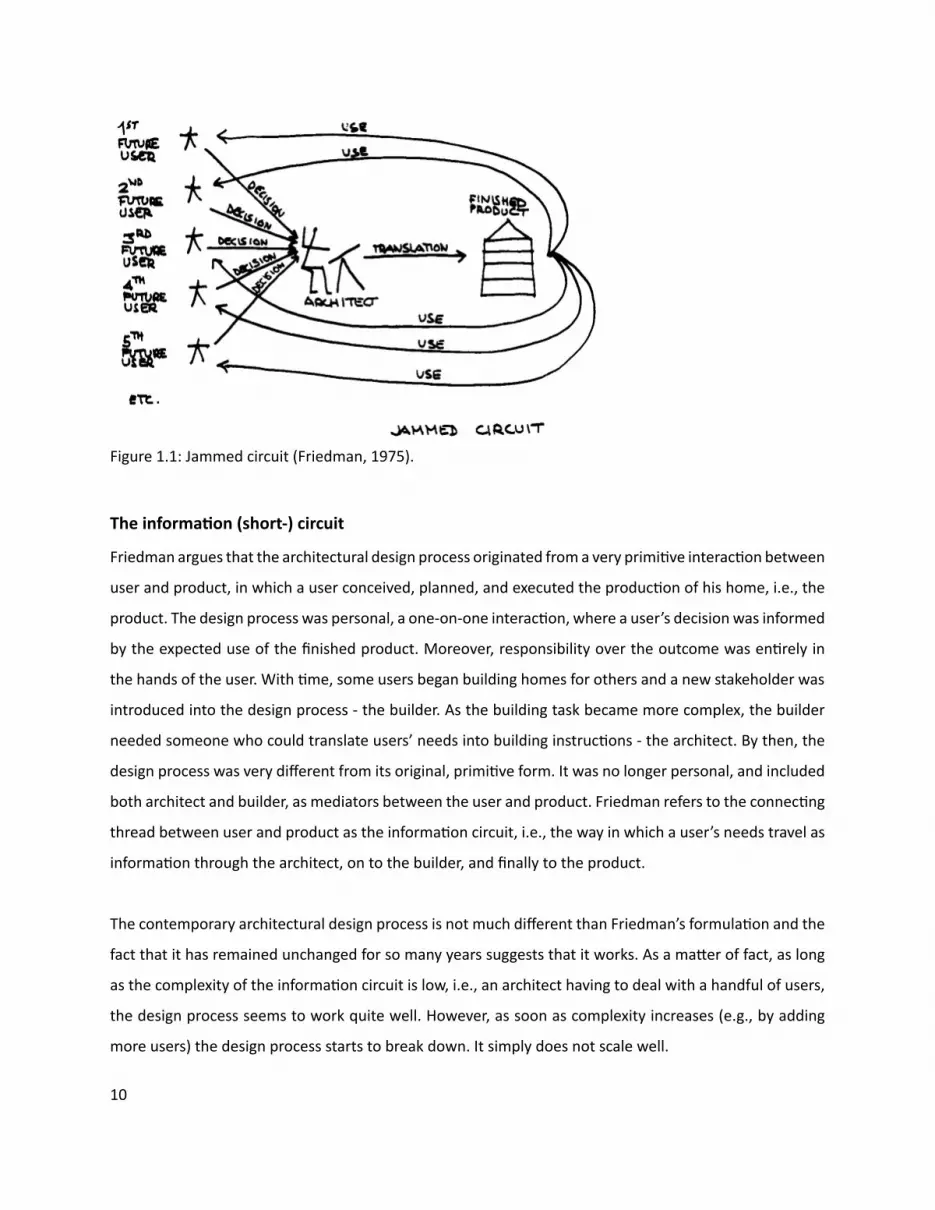
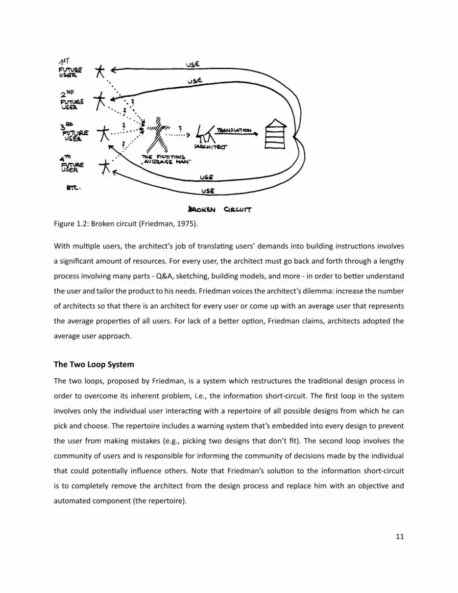
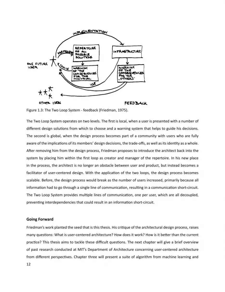
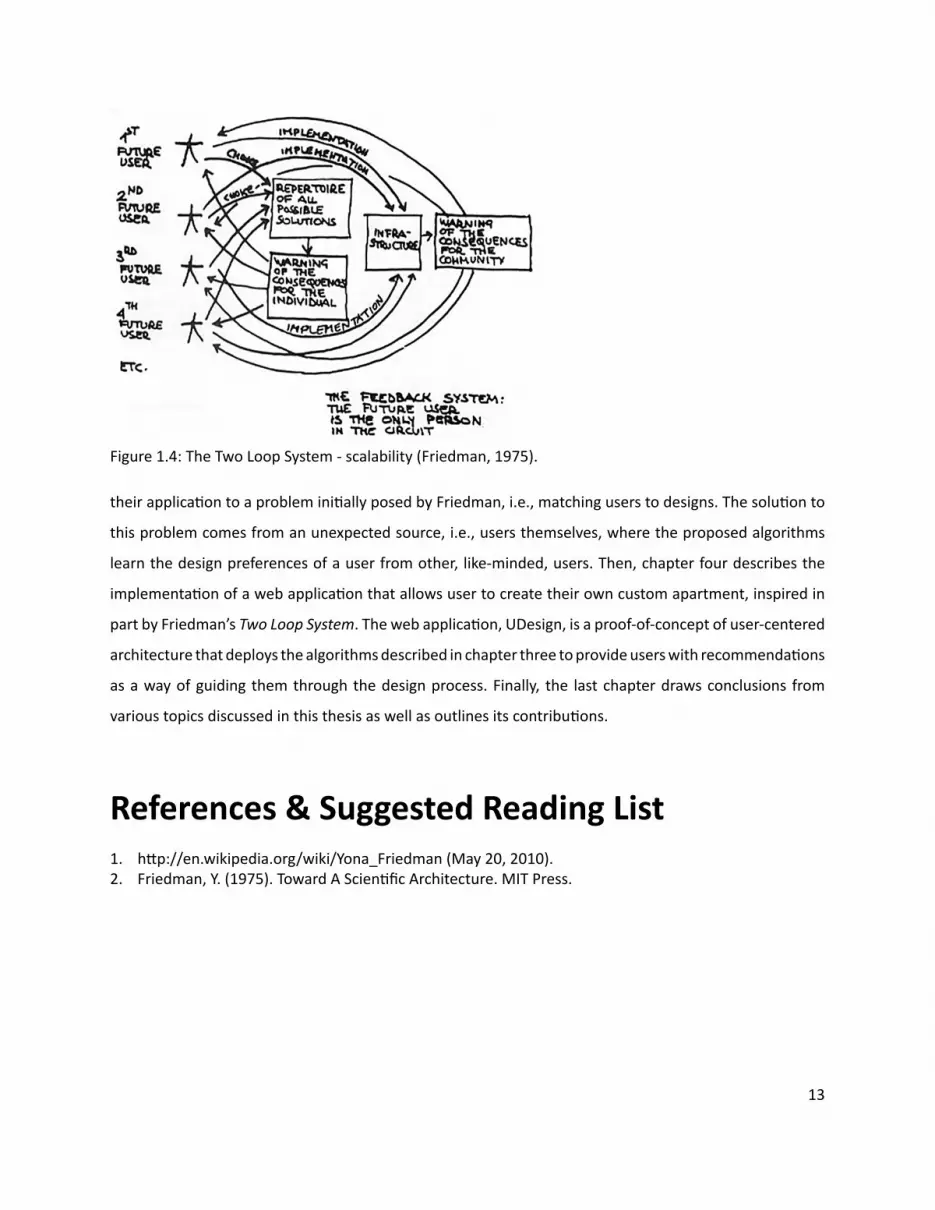
13
References amp Suggested Reading List1 hƩ penwikipediaorgwikiYona_Friedman (May 20 2010)2 Friedman Y (1975) Toward A ScienƟ fi c Architecture MIT Press
their applicaƟ on to a problem iniƟ ally posed by Friedman ie matching users to designs The soluƟ on to
this problem comes from an unexpected source ie users themselves where the proposed algorithms
learn the design preferences of a user from other like-minded users Then chapter four describes the
implementaƟ on of a web applicaƟ on that allows user to create their own custom apartment inspired in
part by Friedmanrsquos Two Loop System The web applicaƟ on UDesign is a proof-of-concept of user-centered
architecture that deploys the algorithms described in chapter three to provide users with recommendaƟ ons
as a way of guiding them through the design process Finally the last chapter draws conclusions from
various topics discussed in this thesis as well as outlines its contribuƟ ons
Figure 14 The Two Loop System - scalability (Friedman 1975)
ͳͶ
This chapter presents prior work by four researchers at MIT who have addressed various aspects of user-
centered architecture
Smithwickrsquos work pieces together exisƟ ng ideas into a cohesive whole outlined by the following scenario
A user joins an open-source online design community where he can browse designs by other members
design and share his own send any design to fabricaƟ on and get back a kit-of-parts to assemble discuss
his design or the design of others parƟ cipate in joint designs and so on The scenario has three underlying
components (1) design - facilitated by tools and soŌ ware available to all users via the Web for free (2)
fabricaƟ on - facilitated by local and small-scale CNC fabricaƟ on faciliƟ es and (3) community - facilitated by
exisƟ ng (and increasingly popular) Web 20 infrastructure (social networking sites blogs etc)
Smithwickrsquos vision shares much in common with the ideas of Yona Friedman as discussed in the fi rst
chapter There is a reference to soŌ ware and hardware in both Smithwickrsquos and Friedmanrsquos work thatrsquos
joined together by a third more virtual enƟ ty - the Web (Smithwick) or feedback loop (Friedman)
Smithwick
2| Prior Work
Figure 21 Get Physical (Smithwick 2009)
ͳͷ
Duartersquos work describes the process of trying to learn the underlying rules of Alvaro Sizarsquos Malagueira
houses through discursive shape grammar Duarte uses the learned grammar to develop his own user-
centered design process to provide mass-customized housing The work has several interesƟ ng aspects
The fi rst aspect is the ability to learn an architectrsquos design methodology or style Whether through discursive
shape grammars or other methods Duartersquos work shows that (a) there is an underlying paƩ ern in how
architects design and (b) the ability to design systems that capture these paƩ erns is a powerful tool
The second aspect relates to how this tool is used For example an architectrsquos design paƩ ern can be
used to create a larger variety of design soluƟ ons for users perhaps way beyond the architectrsquos original
repertoire Furthermore turning an architectrsquos design paƩ ern into a tool empowers users to experiment
with the design paƩ erns themselves in a safe and predictable environment
The third aspect is the plaƞ orm Duarte chooses for the distribuƟ on of his system ie the Web Duarte
recognizes the power of the Web as a place where millions of people can explore share and create designs
The end result of Duartersquos work is a website where users can create their own home based on Sizarsquos design
paƩ ern
Duarte
Figure 22 Discursive Grammar (Duarte 2001)
ͳ
Plewersquos work presents a bricolage approach to designing mass-customized housing for low to middle
income families as an alternaƟ ve to the exisƟ ng tract home paradigm As a proof-of-concept Plewe
developed a design tool which included a 3D environment a library of components and a way for users to
search the library and fi nd what they need Users who wanted to create their own custom home would use
Plewersquos tool to search the library by using keywords like ldquoconcreterdquo fi nd the components they liked add
them to the 3D authoring environment adjust the components unƟ l theyrsquore saƟ sfi ed and fi nally create
construcƟ on documents for the contractor
Plewersquos approach - the library of components search and selecƟ on as a process of design and an emphasis
on what the user wants - provides the technical base for the work described in this thesis
Plewe
Figure 23 Screenshot of H++ (Plewe 2008)
ͳ
Phillipsrsquos work defi nes design as a process of searching and provides the conceptual and technical
framework to support search in Web-based design tools for everyday users The work is moƟ vated by the
noƟ on of user-centered design ndash users creaƟ ng their own living soluƟ ons - and the fabricaƟ on abiliƟ es
to support it Phillips proposes a way of combining Building InformaƟ on Modeling (BIM) modern search
methods and an Object Oriented Programming (OOP) approach to create a space of design soluƟ ons that
ldquocan be searched directly without indexingrdquo
Phillips
Figure 24 Design By Searching (Phillips 2007)
References amp Suggested Reading List1 Smithwick D (2009) Architectural Design 20 An Online Plaƞ orm for the Mass CustomizaƟ on
of Architectural Structures Masters Thesis MassachuseƩ s InsƟ tute of Technology Cambridge MassachuseƩ s
2 Duarte J (2001) Customizing Mass Housing A Discursive Grammar for Sizarsquos Malagueira Houses PhD Thesis MassachuseƩ s InsƟ tute of Technology Cambridge MassachuseƩ s
3 Plewe T (2008) BesƟ ng the Tract Home A soŌ ware-Based Bricolage Approach to Aī ordable Custom Housing Masters Thesis MassachuseƩ s InsƟ tute of Technology Cambridge MassachuseƩ s
4 Phillips G (2007) Design By Searching A System for CreaƟ ng and EvaluaƟ ng Complex Architectural Assemblies Masters Thesis MassachuseƩ s InsƟ tute of Technology Cambridge MassachuseƩ s
18
Within user-centered architecture a set of criƟ cal tasks is the ability to model users designs and the
relaƟ onship between them To tackle these diĸ cult tasks this secƟ on explores the following machine
learning algorithms by way of experimentaƟ on and considers their potenƟ al contribuƟ on to the tasks at
hand
bull CollaboraƟ ve Filtering (User-based Item-based) - is used to match users to design soluƟ ons by way
of recommendaƟ ons
bull Clustering (Hierarchical K-means MulƟ dimensional Scaling) - is used to discover groups of users and
design soluƟ ons
bull Feature ExtracƟ on (Non-NegaƟ ve Matrix FactorizaƟ on) - is used to uncover the latent features of a
design soluƟ on
For the purpose of these experiments a unique data set was created with the help of 30 architects (referred
to as criƟ cs) who were asked to rate on a scale of 1 (low) to 5 (high) 20 architectural fl oor plans of a one
bedroom apartment Figure 31 shows a sample page from a booklet given to each criƟ c containing the
fl oor plan and raƟ ng box CriƟ csrsquo raƟ ngs were collected into a 30 by 20 matrix (referred to as the raƟ ng
matrix) with rows represenƟ ng criƟ cs and columns represenƟ ng fl oor plans (Figure 32)
The highest average fl oor plan raƟ ng was 383 and the lowest was 237 The highest average criƟ c raƟ ng
was 39 and the lowest 125 The results indicate that most criƟ cs rated according to the highest average
fl oor plan raƟ ng and chose to rate higher than the lowest average fl oor plan raƟ ng However criƟ c_9
gave all but three fl oor plans a raƟ ng of 1 bringing the average of the lowest criƟ c raƟ ng down Also the
standard deviaƟ on for criƟ c_9rsquos raƟ ngs (064) suggests an outlier and was excluded from the experiments
3| Algorithms
$amp()(+Attributes-0$1)20$34345$+$367489335780lt0=4431gt5$$03424316$345$431A20780755B4C0D240EF2465$$0345$(G0H4=44314$34B30)I734345$0-+5I0$1BB0371lt57-07gtI742154AI34456DG5E)(0G440$1Add your ow
n
RATING
19
Figure 31 How would you rate this fl oor plan
13
13
13
13
13
13
13
13
13
13
13
13
13
13
13
13
13
13
13
13
13
13
13
13
13
13
13
13
13
13
13
20
Figure 32 RaƟ ng matrix
21
CollaboraƟ ve Filtering (CF) is a method for making automaƟ c predicƟ ons (fi ltering) about the interest or
taste of a user by collecƟ ng and analyzing the personal preferences of many other users (collaboraƟ ve)
The fi rst system to use CF was the InformaƟ on Tapestry project at Xerox PARC (Goldberg et al 1992)
In general CF systems can be categorized as user-based or item-based User-based CF systems do the
following
bull Look for users who share the same raƟ ng paƩ ern with the acƟ ve user (ie the user for whom we are
trying to make a predicƟ on)
bull Use the raƟ ngs from those like-minded users to formulate a predicƟ on for the acƟ ve user
AlternaƟ vely item-based CF systems focus on items and the relaƟ onships amongst them to make
predicƟ ons eg ldquoUsers who bought X also bought Yrdquo (popularized by Amazoncom) Item-based CF
systems do the following
bull Build a Similarity Matrix to determine the relaƟ onship between pairs of items
bull Use the Similarity Matrix and userrsquos personal data to formulate a predicƟ on
CollaboraƟ ve Filtering
22
When wersquore interested in fi nding good recommendaƟ ons we tend to turn to people with a similar taste
to ours User-based collaboraƟ ve fi ltering takes the same approach by comparing us the acƟ ve user with
everyone else fi nding those who are most similar and using their preferences to make a predicƟ on about
what we like In user-centered architecture this approach takes advantage of design preferences and
taste expressed by various users to help other users fi nd what they need To illustrate how user-based
collaboraƟ ve fi ltering works a brief experiment was conducted using the data set of fl oor plan raƟ ngs to
predict a raƟ ng for a fi cƟ Ɵ ous user (referred to as CriƟ c_N) who rated some but not all the fl oor plans
The algorithm (Segaran 2007) presented in pseudocode (Figure 33) starts by iteraƟ ng through all users
and compuƟ ng their similarity to CriƟ c_N using a Pearson correlaƟ on coeĸ cient (Eq 31) Then the
algorithm iterates through every item ie fl oor plan and computes the weighted average raƟ ng (Eq
32) by mulƟ plying each of the raƟ ngs by the criƟ csrsquos similarity score and summing over all the scores
The intuiƟ on behind weighƟ ng the raƟ ngs is that users who are more like CriƟ c_N will have more weight
put on their raƟ ngs whereas raƟ ngs by users who are diī erent will receive very liƩ le weight Finally the
algorithm normalizes sorts and returns the result as predicted raƟ ngs for CriƟ c_N (Figure 34)
C CriƟ cM RaƟ ng MatrixU AcƟ ve UserFor each C in M If C is not U Then compute Similarity of C and U (see Eq 31)For each Item in M If Item was not rated by U Then compute user similarity weighted average raƟ ng (see Eq 32) And store it in ListNormalize ListSort List based on normalized weighted similarityReturn List
User-Based RecommendaƟ ons
Figure 33 Pseudocode for user-based recommendaƟ on
13
13 13
13 13
13
13
13
13 13
23
(Eq 31)
(Eq 32)
(Eq 33)
In order to measure the predicƟ ve power of the proposed algorithm the raƟ ngs matrix was transformed
into a test set by randomly deleƟ ng raƟ ngs in criƟ cs 1 through 8 The missing raƟ ngs were then esƟ mated
and the Root Mean Square Error (Eq 33) was computed yielding a value of 114 (Figure 35) To evaluate
this result (114) RMSE was calculated ten more Ɵ mes subsƟ tuƟ ng missing raƟ ngs with random numbers
between 1 and 5 yielding an average value of 195 The results show that the algorithm makes predicƟ ons
which are beƩ er than chance with an error that is 58 of the random error In addiƟ on RMSE was
calculated for CriƟ c_30 with 5 10 and 15 raƟ ngs yielding 131 124 and 087 respecƟ vely These results
indicate that by raƟ ng more fl oor plans criƟ cs improve the accuracy of the recommendaƟ ons they get
Figure 34 Predicted raƟ ngs (in green) and iniƟ al raƟ ngs (in yellow) for CriƟ c_N
13
13
13
13
13
24
Figure 35 Test matrixPredicted raƟ ngs (in green) and iniƟ al raƟ ngs (in yellow) for criƟ cs 1 through 8 used to calculate algorithmrsquos predicƟ ve power by measuring the Root Mean Square Error (RMSE)
25
When a data set like the raƟ ng matrix becomes very large a user-based approach might start to break
down due to the computaƟ onal cost of usersrsquo pairwise comparison An item-based approach alleviates
this problem by pre-compuƟ ng a similarity matrix for all items The assumpƟ on is that items do not change
as frequently as users therefore the similarity matrix will only need to be updated every once in a while
Amazoncom for example uses an item-based approach ie item-to-item collaboraƟ ve fi ltering (Linden
et al 2003) to recommend products to its users (Figure 36)
Making recommendaƟ ons using item-based collaboraƟ ve fi ltering consists of the following steps pre-
compuƟ ng an item-to-item similarity matrix looking up the acƟ ve userrsquos top-rated items and creaƟ ng
a weighted list of the most similar items To illustrate how this works an algorithm (Segaran 2007) was
tested with the raƟ ngs matrix to get recommendaƟ ons for CriƟ c_N (Figure 37)
CriƟ c_Nrsquos rated items
(50 SOL25) (20 SOL81) (10 SOL158)
CriƟ c_Nrsquos recommended items
(50 SOL9) (365 SOL74) (324 SOL144) (285 SOL202) (281 SOL228) (267 SOL224) (249 SOL212)
(243 SOL33) (209 SOL125) (15 SOL38) (142 SOL59) (141 SOL54) (10 SOL139)
Item-Based RecommendaƟ ons
Pre-compute item similarity matrix with user-based approach but subsƟ tuƟ ng items for users by transposing the raƟ ng matrixFor each Item1 in Userrsquos items For each Item2 in Item1rsquos similarity matrix If User has already rated Item2 Then conƟ nue to the next iteraƟ on of the loop Compute item similarity weighted raƟ ng (see Eq 32) Compute average of weighted item raƟ ngs And save them in ListSort List based on normalized weighted item similarityReturn List
Figure 36 Pseudocode for item-based recommendaƟ on
Figure 37 Item-based recommendaƟ ons for CriƟ c_N
26
Figure 37 shows that given CriƟ c_Nrsquos high raƟ ng of fl oor plan SOL25 the algorithm recommended SOL9
as the highest ranking (best matching) item Figure 38 validates the algorithmrsquos precision and predicƟ ve
power as the two fl oor plans are nearly idenƟ cal There are some minor diī erences between the two
fl oor plans for example SOL9 has a bar-top dining table but SOL25 has a 6-seat standalone dining table
However the overall similarity of the two fl oor plans is evident and emerges from the usersrsquo raƟ ngs
In order to compare the performance of the algorithm a random criƟ c was selected (CriƟ c_30) all but the
fi rst fi ve of his raƟ ngs deleted and then predicted by each of the algorithms The RMSE for the user-based
algorithm was 118 and the item-based algorithm was 161 indicaƟ ng that user-based recommendaƟ ons
are more accurate than item-based recommendaƟ ons However there are other issues to consider besides
accuracy when choosing one algorithm over the other for example size of data set and frequency of
change have a tremendous infl uence on the performance of these algorithms
User-Based vs Item-Based RecommendaƟ ons
Figure 38 SOL9 (LeŌ ) and SOL25 (Right) with a similarity score of 004
27
Clustering or Cluster Analysis is a way of discovering and visualizing groups of things - people news
stories blogs and more This secƟ on will focus on two clustering techniques - Hierarchical and K-means -
and apply them to the raƟ ngs matrix in order to discover groups of criƟ cs and fl oor plans In user-centered
architecture these clusters can be uƟ lized for example to infer a new userrsquos design preferences by fi nding
his cluster membership A user who has been assigned to a certain cluster shares the design preferences
of that cluster making it possible to tailor design recommendaƟ ons to his taste
Figure 39 is the pseudocode for a simple hierarchical clustering algorithm (Segaran 2007) The algorithm
starts by assigning each item ie fl oor plan to a cluster of its own Then the distance between every pair
of clusters is calculated and the closest (most similar) ones are merged together to form a new cluster
The process is repeated unƟ l there is only one cluster leŌ The algorithm uses the Pearson correlaƟ on
coeĸ cient to compute the distance between clusters
Figure 310 shows the groups of criƟ cs discovered when running the hierarchical clustering algorithm on
the raƟ ng matrix The dendrogram clearly separates the criƟ cs into two groups each characterized by
its own design preferences as extracted from the raƟ ngs Each of the two main clusters contains smaller
clusters for example criƟ cs 16 8 30 6 11 and 3 form a cluster within the bigger cluster at the top
of Figure 310 Rated fl oor plans were also clustered (Figure 311) by running the hierarchical clustering
algorithm on a rotated raƟ ng matrix Clustering shows two disƟ nct clusters made up of smaller clusters
such as fl oor plans SOL9 25 74 224 and 228 (Figure 312)
Clustering
Hierarchical Clustering
Figure 39 Pseudocode for hierarchical clustering
IniƟ alize all rows to be clustersCreate BigClusterWhile number of Clusters is bigger than 1 For each pair of Clusters Find the pair with the smallest distance Calculate the average of the two Clusters Combine the two clusters to form a new Cluster Add new Cluster to BigClusterReturn BigCluster
28
Gender analysis (MaleFemale )Top cluster - 6040BoƩ om cluster - 5050
Analysis reveals that clusters are gender neutral suggesƟ ng that gender may not play a role in the design preferences of architects
Figure 310 Hierarchical clustering of criƟ cs
29
Figure 311 Hierarchical clustering of fl oor plans
30
Figure 312 Clustered fl oor plans
AƩ ributes of clustered fl oor plans (parƟ al list)bull A small bathroombull A large kitchenbull A dining tablebull Clearly defi ned private amp public spaces
SOL9
SOL74
SOL25
SOL224
SOL228
31
Hierarchical clustering is computaƟ onally expensive because the pairwise distance calculaƟ ons have to
be carried out every Ɵ me clusters are merged therefore this method might break down on larger data
sets K-means clustering takes a diī erent approach because the number of clusters is specifi ed in advance
removing some of the ambiguity in dividing up the data
The K-means clustering algorithm (Segaran 2007) presented as pseudocode (Figure 313) starts by
randomly placing centroids ie center of the cluster and assigning every item to the nearest one Then
each centroid is shiŌ ed to the average locaƟ on of the items it contains items are reassigned and the
process repeats itself unƟ l the assignments stop changing
Figure 314 shows the K-means clustering of fl oor plans with diī erent values of K
K-means Clustering
Figure 313 Pseudocode for K-means clustering
M RaƟ ng MatrixFor each Item in M Compute the Min and Max value of Item Create K randomly placed centroids While assignment of Item is changing Find the closest centroid to Item Assign Item to centroid Move centroid to average locaƟ on of ItemsReturn K Clusters
K=8 SOL(158 169 268) (144 149) (925) (74) (33) (150) (202 212224 228) (38 54 59 81 125 139)
K=5 SOL(54 59 125 139 158) (25 74 144 202 224) (33 228 268) (149 150 169) (9 38 81 212)
K=3 SOL(9 25 74 228) (38 81 144 149 150 202 212 224) (33 54 59 125 139 158 169 268)
Figure 314 K-means clustering of fl oor plans
32
Items in the raƟ ng matrix are mulƟ dimensional ie each fl oor plan is represented by a vector of 30
raƟ ngs MulƟ dimensional scaling is a technique for fi nding a two-dimensional representaƟ on of the raƟ ng
matrix which is someƟ mes easier to understand than a dendrogram
The algorithm (Segaran 2007) presented as pseudocode (Figure 314) starts by calculaƟ ng the target
distances between all the items Next all items are placed randomly on a two-dimensional plane The
current distances between all the items are calculated using the actual distance ie the sum of the
squared diī erences For every pair of items the target distance is compared to the current distance to
calculate the error Every item is moved a small amount in proporƟ on to the direcƟ on of the error between
the two items The process is repeated unƟ l the total error cannot be reduced by moving any of the items
Figure 315 shows the results of running the mulƟ dimensional scaling algorithm on the raƟ ng matrix
All three methods when applied to the fl oor plans produced comparable results making the choice
of any one method unclear This is due to the small size of the data set and some ad-hoc choices of
parameters for the algorithms With a more extensive data set one expects to evaluate and choose based
upon computaƟ onal cost of the algorithm moƟ vaƟ on for and use of the derived informaƟ on and auxiliary
informaƟ on from the problem domain
MulƟ dimensional Scaling
Hierarchical Clustering vs K-means Clustering vs MulƟ dimensional Scaling
Figure 314 Pseudocode for MulƟ dimensional scaling
M RaƟ ng MatrixFor each Item1 and Item2 in M Compute the real distance between Item1 and Item 2 Randomly place Item1 and Item2 in 2D spaceWhile TotalError is changing Find the projected distance between Item1 and Item2 Calculate Error between real and projected distance Move Item1 and Item2 in proporƟ on to Error Update TotalErrorReturn locaƟ on of Items
SOL228
SOL38
SOL59
SOL54
SOL33SOL125
SOL139
SOL169
SOL268
SOL150
SOL149
SOL144
SOL9
SOL224
SOL25
SOL74
SOL158
SOL212
SOL81
SOL202
33
Figure 315 MulƟ dimensional scaling of raƟ ng matrixColored boxes correspond to the hierarchical clustering in Figure 311
=X
Plan 4
Features Matrix Weights Matrix
Plan 4
34
Figure 316 Non-NegaƟ ve Matrix FactorizaƟ on
The rated fl oor plans in the data set share certain features such as an open kitchen private vs public
spaces and others These features are latent - hidden between the raƟ ngs - and in order to extract them
the raƟ ng matrix has to be factored It is important to note that these features are not the same as the
aƩ ributes given to the criƟ cs to help them rate the fl oor plans There is no way to be absolutely sure of
what a feature represent All that can be done is to examine the set of fl oor plans which share the feature
and aƩ empt to visually arƟ culate it
Figure 316 describes the process of matrix factorizaƟ on The goal is to factor the matrix ie fi nd two
smaller (lower rank) matrices - a features matrix and a weights matrix - that when mulƟ plied together
reconstruct the original matrix The features matrix has features for rows and fl oor plans for columns
The value in each cell of the matrix indicates how important that fl oor plan is to the feature The weights
matrix maps the features to the raƟ ng matrix Each row is a criƟ c and each column is a feature The value
in each cell of the matrix indicates how much a feature applies to a fl oor plan Therefore reconstrucƟ ng
the raƟ ng matrix is a maƩ er of combining rows from the features matrix in diī erent amounts The weights
matrix maps the features to the raƟ ngs Non-negaƟ ve refers to the fact that all features and weights must
be posiƟ ve For a more comprehensive descripƟ on of the algorithm see (Segaran 2007)
Using a Non-NegaƟ ve Matrix FactorizaƟ on algorithm the raƟ ng matrix was factored into a features matrix
and a weights matrix The algorithm was programmed to fi nd 10 features Figure 317 represents 5 of
the 10 features as a list of fl oor plans that contain the feature As menƟ oned the features are latent
therefore feature 5 for example is shared by fl oor plans 149 150 169 and 268 An hypothesis of what
the feature represents is proposed by looking at the commonaliƟ es of the fl oor plans that defi ne the
feature (Figure 318)
Feature ExtracƟ on (Non-NegaƟ ve Matrix FactorizaƟ on)
35
Figure 317 5 features extracted from the raƟ ng matrix
(SOL81 SOL224)
(SOL149 SOL150 SOL169 SOL268)
(SOL202 SOL212)
(SOL158 SOL228)
(SOL33 SOL54 SOL59 SOL125 SOL139)
Feature 4
Feature 5
Feature 7
Feature 8
Feature 9
ConclusionsThe dataset used in these experiments is extremely small compared to the Neƞ lix or Amazon data sets
Nevertheless each of the applied methods revealed some interesƟ ng informaƟ on about the data - criƟ cs
fl oor plans and the relaƟ onship between them
CollaboraƟ ve fi ltering whether user or item based showed that it is possible to leverage a communityrsquos
opinion expressed through raƟ ngs in order to help an individual fi nd what he likes Analysis of the
algorithm showed that it performs much beƩ er than a random guess
Clustering - Hierarchical K-means or MulƟ dimensional Scaling - showed that it is possible to fi nd groups of
criƟ cs and fl oor plans and uncover their common characterisƟ cs With a large enough data set clustering
can be used to extract user and design typologies which can help stakeholders in the building industry -
contractors developers architects etc - tailor their services to clientsrsquo needs
Feature ExtracƟ on showed that it is possible to extract the features of a fl oor plan in order to create a
design vector The design vector can be used to score fl oor plans based on a userrsquos interest in one or all of
its features allowing the user to explore the design space in mulƟ ple direcƟ ons
36
Figure 318 ArƟ culaƟ ng Feature 5 through its fl oor plansFeature 5 could be the free-standing column that appears in all the fl oor plans below
SOL149 SOL150
SOL169 SOL268
37
References amp Suggested Reading List1 Billsus D amp Pazzani M J (1998) Learning collaboraƟ ve informaƟ on fi lters Proceedings of the 15th
InternaƟ onal Conference on Machine Learning pp 46ndash542 Blei D M Ng A Y amp Jordan M I (2002) Latent Dirichlet allocaƟ on Advances in Neural InformaƟ on
Processing Systems 143 Breese J S Heckerman D and Kardie C (1998) Empirical analysis of predicƟ ve algorithms for
collaboraƟ ve fi ltering In Proceedings of the 14th Conf on Uncertainty in ArƟ fi cial Intelligence pp 43ndash52
4 Goldberg D Nichols D Oki BM amp Terry D (1991) Using CollaboraƟ ve Filtering to Weave an InformaƟ on Tapestry Comm ACM vol 35 no 12 pp 61-70
5 Herlocker JL Konstan JA Borchers A and Riedl J (1999) An Algorithmic Framework for Performing CollaboraƟ ve Filtering Proc 22nd Ann Intrsquol ACM SIGIR Conf Research and Development in InformaƟ on Retrieval (SIGIR rsquo99)
6 Herlocker JL Konstan JA Terveen LG and Riedl JT (2004) EvaluaƟ ng CollaboraƟ ve Filtering Recommender Systems ACM Trans InformaƟ on Systems vol 22 no 1 pp 5-53
7 Hofmann T (2004) Latent semanƟ c models for collaboraƟ ve fi ltering ACM TransacƟ ons on InformaƟ on Systems 22 pp 89ndash115
8 Koren Y Bell R Volinsky C (2009) Matrix FactorizaƟ on Techniques for Recommender Systems IEEE Computer 082009 Volume 42 Issue 8 pp30-37
9 Linden G Smith B and York J (2003) Amazoncom RecommendaƟ ons Item-to-Item CollaboraƟ ve Filtering IEEE Internet CompuƟ ng
10 Marlin B (2004) CollaboraƟ ve fi ltering A machine learning perspecƟ ve Masterrsquos thesis University of Toronto Computer Science Department
11 Segaran T (2007) Programming CollecƟ ve Intelligence OrsquoReilly Media12 Srebro N Rennie J D M amp Jaakkola T S (2005) Maximum margin matrix factorizaƟ on Advances
in Neural InformaƟ on Processing Systems 17
38
4| UDesignWhen a user wishes to purchase an apartment from a developer he is usually presented with a few sample
apartments from which to choose These sample apartments usually oī er very few parameters that can
be changed because they are designed to fi t the taste and lifestyle of an average user The soluƟ on to
this problem can be found in two diī erent places - hardware and soŌ ware - which complement each
other to create user-centered architecture On the one hand there is hardware the building technology
that is responsible for making sure usersrsquo designs are feasible The mass-customizaƟ on community in
architecture has made considerable progress in recent years and managed to push fabricaƟ on technology
forward On the other hand there is soŌ ware the interface that is responsible for making sure users can
express their wants and needs The ability of an interface to meet usersrsquo needs depends on its front-end -
how easy it is to use the interface - and back-end - how the objects of design are represented internally in
the system This secƟ on will focus on the soŌ ware and illustrate through the implementaƟ on of UDesign
what are some of the issues to consider in terms of soŌ ware for user-centered architecture
As a framework UDesign mediates between the user and stakeholders in the building industry - architects
developers contractors suppliers realtors and community - in order to create a product in this case
an apartment Figure 41 outlines the components and relaƟ onships of user-centered architecture as a
series of four concentric circles - User UDesign Data and Stakeholders - fl oaƟ ng in Design Space the
space of design soluƟ ons oī ered to the user Metaphorically as the user is designing his own product
he is navigaƟ ng through the design space cocooned within these layers of UDesign and Stakeholders
through which he communicates his ideas about the product To visualize the metaphor imagine Figure
A Framework For User-Centered Architecture
39
Architect
Developer
DesignSpace
Realtor
Supplier
CommunityContractor
DesignLogic
Feedback
User
Stakeholders
UDesign
Data
41 as a ball fl oaƟ ng in space and rays of informaƟ on shooƟ ng from its center (User) guided by an inner
mechanism (UDesign Stakeholders) trying to fi nd an anchor in space (Design)
UDesign is comprised of four parts Design CommunicaƟ on Feedback and Logic Design is responsible
for visualizing the design space and interacƟ ng with the user In a way it is the front-end of the interface
Design includes the library of parts from which a user can choose to create his design (Friedmanrsquos
repertoire) tools to transform and edit the design and ways to explore the design space CommunicaƟ on
is responsible for the exchange of informaƟ on between user and stakeholders The radial arrangement
facilitates mulƟ ple channels of communicaƟ on at any given point in Ɵ me For example a user can
communicate with the architect in order to get professional feedback about his design while also geƫ ng
feedback from the community CommunicaƟ on must pass through UDesign to avoid overloading the user
therefore messages are stored in a queue and ordered by their relevancy to the current context of the
design process Feedback is responsible for conƟ nuously collecƟ ng informaƟ on about the state of the
design process analyzing it and providing noƟ fi caƟ ons at the right Ɵ me and place For example when a
user selects a design component he is immediately given feedback about the availability of the component
Figure 41 User-Centered Architecture
40
UDesign was implemented in Adobe Flex Builder 3 an IDE (Integrated Development Environment)
for creaƟ ng cross-plaƞ orm RIA (Rich Internet ApplicaƟ on) based on Adobe Flash A typical applicaƟ on
development process was followed including
bull Defi ning an applicaƟ on interface using a set of pre-defi ned components (forms buƩ ons and so on)
as MXML Components
bull Arranging components to create a User Interface (UI) design
bull Using styles and themes to defi ne the visual design CSS skins etc
bull Adding dynamic behavior using proper event-driven programming techniques
bull Defi ning and connecƟ ng to data services as needed MySQL ColdFusion etc
bull Compiling the source code into an SWF fi le that can be read by Flash Player and embedded within an
HTML fi le
UDesign is comprised of fi ve parts Data PersonalizaƟ on Design Contribute and Feedback (Figure 42)
where Data consƟ tutes most of the back-end and the remaining parts the front-end
The data in UDesign is stored in tables within a MySQL database that resides on a server The mxml
applicaƟ on makes requests to the database through a Flex HTTPService component In turn the
HTTPService component calls one of fi ve methods (FindAll Insert Update Delete Count) encapsulated
within a PHP fi le which then retrieves the data from the appropriate table of the database and returns the
data to the applicaƟ on in an E4X format (Figure 43)
ImplementaƟ on
Data
its price compaƟ bility with other components and more Stakeholders can use UDesignrsquos feedback to get
informaƟ on about their users - purchase history preferences lifestyle status state of the design and
more Logic is responsible for holding everything (Design CommunicaƟ on and Feedback) together so that
usersrsquo experience of UDesign is both producƟ ve and posiƟ ve Logic is supported by a suite of algorithms
from diī erent categories - user interacƟ on network database machine learning - some of which are
described in more detail in chapter 3 (Algorithms) as well as in the next secƟ on (ImplementaƟ on)
41
HTTPService
Data
Design
Contribute
Feedback
PHP
HTTPService PHP
MySQL
ContributeView
assembliesService
tagsService
usersService
Database
FeedbackView Feedback
HomeView Facebook Connect
currUser (Facebook)
UDesigners at work
Survey
DesignView
Assemblies
Tags
Users
feedbackService
IntroHomePage
PersonalizedHomePage
Floorplan
Catalog currUser (Facebook)
assembliesrooms
by selected rooms
GridCell (A1-C2)
clear
Figure 42 UDesign - system overview
42
FindAllInsertUpdateDeleteCount
Table 1Table 2Table 3
Request Request
Response ResponseFLEX PHP MySQL
E4X
The database includes the following tables
bull assemblies (Figure 44)
bull soluƟ ons (Figure 45)
bull users_saved_soluƟ ons (Figure 46)
bull users (Figure 47)
bull design_profi le (Figure 48)
bull soluƟ on_vector (Figure 49)
bull feedback (Figure 410)
Figure 43 Data pipeline
43
Table assemblies
This table holds the 48 assemblies (custom-designed rooms) available to the user on the Design page of
UDesign
Fields id room id | label room label | type room type | descripƟ on room descripƟ on | price room
price | cell an index indicaƟ ng to what funcƟ onal zone the room belongs (more details below) | area
room area (sqŌ ) | dimx room dimension in x-axis (pixels) | dimy room dimension in y-axis (pixels) | locx
room posiƟ on in x-axis (pixels) | locy room posiƟ on in y-axis (pixels) | color room color code | fi t a fl ag
indicaƟ ng whether the room fi tsdoesnrsquot fi t with the userrsquos design (more details below)
Table soluƟ ons
This table holds the 285 soluƟ ons (custom-designed fl oor plans) available to the user on the Design page
of UDesign
Fields id fl oor plan id | label fl oor plan label | A1 - C2 a funcƟ onal zone in the fl oor plan (more details
below)
Table users_saved_soluƟ ons
This table holds usersrsquo saved soluƟ ons (custom-designed fl oor plans) created by users on the Design page
of UDesign
Fields id fl oor plan id | label fl oor plan label | A1 - C2 a funcƟ onal zone in the fl oor plan (more details
below)
Table users
This table temporarily holds usersrsquo personal informaƟ on obtained from their Facebook account (more
details about UDesignrsquos connecƟ on to Facebook in the secƟ on about PersonalizaƟ on)
Fields (Facebook generated) uid userrsquos id | about_me userrsquos personal message | acƟ viƟ es userrsquos
favorite acƟ viƟ es | birthday userrsquos birthday | books userrsquos favorite books | fi rst_name userrsquos fi rst name
| interests userrsquos interests | last_name userrsquos last name | movies userrsquos favorite movies | music userrsquos
favorite music | pic userrsquos profi le picture | relaƟ onship_status userrsquos current relaƟ onship status | sex
userrsquos gender | wall_count number of posts on userrsquos wall
44
Table design_profi le
This table holds usersrsquo design profi le Users are presented with ten parameters of lifestyle and asked to
rate their importance on a scale of one (low) to fi ve (high)
Fields id userrsquos Facebook id | watch importance of watching TVMovies | entertain importance
of entertaining | cook importance of cooking | work importance of being able to work from home |
privacy importance of privacy | pamper importance of pampering | storage importance of storage |
kitchen_dining importance of physicalvisual connecƟ on between kitchen and dining room | bed_bath
importance of physicalvisual connecƟ on between bedroom and bathroom | fl exible importance of
fl exible living space
Table soluƟ on_vector
This table holds the design vectors for 71 out of 285 soluƟ ons (custom-designed fl oor plans) where each
soluƟ on is represented as a diī erent combinaƟ on of the same parameters used to defi ne userrsquos design
profi le (more details in the secƟ on about the Design page) Values indicate how much the corresponding
parameter is present in the soluƟ on
Fields label soluƟ on label | watch supports watching TVMovies | entertain supports entertaining |
cook supports cooking | work supports being able to work from home | privacy supports privacy |
pamper supports pampering | storage amount of storage | kitchen_dining degree of physicalvisual
connecƟ on between bedroom and bathroom | bed_bath degree of physicalvisual connecƟ on between
bedroom and bathroom | fl exible amount of fl exible living space
Table feedback
This table holds usersrsquo feedback submiƩ ed through the feedback form on UDesign (more details below)
Fields subject subject of the feedback | content content of the feedback
45
id label type description price cell area dimx dimy locx locy color fitid label type description price cell area dimx dimy locx locy color fitA11BT001 Bathroom Bathroom 99 A1 68 174 166 0 0 0x0071BC 0A11BT002 Bathroom Bathroom 99 A1 68 174 166 0 0 0x0071BC 0A12BT001 Bathroom Bathroom 99 A1 100 250 166 0 0 0x0071BC 0
id label A1 A2 B1 B2 C1 C2id label A1 A2 B1 B2 C1 C2SOL1 322000 A12BT001 A21KT001 B15ST001 B21DN001 C15BD001 C23LV001SOL10 123000 A11BT001 A22KT005 B15ST001 B21DN001 C15BD001 C23LV001SOL100 453243 A11BT001 A22KT004 B12BD001 B25DN001 C12BD001 C25LV004
id label A1 A2 B1 B2 C1 C2id label A1 A2 B1 B2 C1 C2652795248 A11BT001 A22KT003 B13BD001 B25DN001 C11ST001 C25LV002717158422 brain drain A11BT001 A22KT001 B15ST004 B25DN002 C13BD001 C23LV001533833493 carlyu A12BT001 A21KT001 B15ST001 B21DN001 C15BD001 C23LV001
id watch entertain cook work privacy pamper storage kitchen_dining bed_bath flexibleid watch entertain cook work privacy pamper storage kitchen_dining bed_bath flexible1065658831 3 5 5 1 1 1 3 5 1 1542150884 5 2 4 1 4 1 3 1 1 1566433466 1 5 5 2 2 1 2 4 2 1
label watch entertain cook work privacy pamper storage kitchen_dining bed_bath flexiblelabel watch entertain cook work privacy pamper storage kitchen_dining bed_bath flexibleSOL1 3 2 2 5 4 5 3 5 1 1SOL2 3 2 2 4 4 5 4 5 5 1SOL3 3 2 2 5 4 5 4 1 1 1
subject contentsubjectthis is my feedback feedback feedbackscrolling hi junnoNice work Good start Maybe I am to quick to try out everything-
the scroll bar or the arrow It is just a little bit annoying )-And will I be abproportions to the lenght of the walls I tried the little pen and ruler tool b
Figure 44 - 410 Database tables (from top to boƩ om)
46
PersonalizaƟ on
UDesignrsquos home page has two states an introducƟ on page (Figure 411) and a personalized page (Figure
412) The introducƟ on page is the fi rst page to be displayed when a user fi rst loads the applicaƟ on It
contains informaƟ on about the applicaƟ on and how to use it To start using the applicaƟ on a user must log
in using their Facebook account by pressing the Facebook Connect buƩ on Facebook Connect is integrated
into the Adobe Flex applicaƟ on using the Facebook API and corresponding Flash-Flex libraries By signing
in to UDesign through Facebook Connect a user gives the applicaƟ on permission to make requests to
Facebook and retrieve their personal informaƟ on (according to the userrsquos privacy seƫ ngs)
The informaƟ on from Facebook now encapsulated as a FacebookUser object is leveraged to provide the
user with tailored recommendaƟ ons of design soluƟ ons ie custom-designed fl oor plans As shown in
chapter 3 (Algorithms) usersrsquo informaƟ on whether itrsquos raƟ ngs or a Facebook profi le can be represented
as a vector (Figure 413) and compared to other users in order to cluster the UDesign community Once
a user is clustered other members of the cluster become his design criƟ cs and their design soluƟ ons are
oī ered as recommendaƟ ons (Figure 414) That is the case with a new user or a user who has not created
rated or saved any design soluƟ ons When a user has given feedback implicitly (by saving certain design
soluƟ ons) or explicitly (by raƟ ng design soluƟ ons) his recommendaƟ ons are updated and improved
through a user-based collaboraƟ ve fi ltering algorithm As shown in chapter 3 (Algorithms) the algorithm
Figure 411 IntroducƟ on home page
47
compares the current user to the enƟ re UDesign community fi nds the most similar users and collects
the highest rated design soluƟ ons from these users as recommendaƟ ons Consequently the more design
soluƟ ons users rate the more accurate UDesignrsquos recommendaƟ ons get (see chapter 3)
Once the user has logged in and UDesign has made a request to Facebook to retrieve the userrsquos personal
informaƟ on the applicaƟ on waits for the response and then temporarily stores it as a FacebookUser object
for the duraƟ on of the session If log in is successful the user is automaƟ cally navigated to a personalized
home page which includes the following userrsquos Facebook picture and name userrsquos Rated Design Profi le
UDesigners at work and Survey
The userrsquos Rated Design Profi le (Figure 415) is a set of ten lifestyle parameters that capture the userrsquos
preferences in respect to the database of 285 fl oor plans available in UDesign For each opƟ on the user
has to rate the importance of that aspect on a scale of one (low) to fi ve (high) For example if the user
is an avid baker he might rate high the following parameters cooking connecƟ on between kitchen and
dinning and entertaining to refl ect their importance in his lifestyle The user has the opƟ on to go back and
change his raƟ ngs at any Ɵ me by making the changes and pressing the Update buƩ on The Rated Design
Profi le complements the Facebook informaƟ on as they are both used to model the user and provide him
Figure 412 Personalized home page
48
with recommendaƟ ons of design soluƟ ons
UDesigners at work features the Facebook profi le pictures of the UDesign community with which the
current user may wish to interact - comment on designs share designs ask quesƟ ons share informaƟ on
and more Finally a short survey is included with various design styles and lifestyle parameters The user
is asked to indicate whether or not they are relevant to him The results of the survey are collected and
aggregated across the enƟ re UDesign community to understand trends and user typologies
49
Age Sex School Job
32 Male MIT House_n
29 Male MIT House_n
Yes
Yes
In a
Figure 413 User vectors
Design
The Design page (Figure 416) is where users create their custom apartment and it includes three main
components fl oor Plan catalog and recommendaƟ ons
The fl oor plan (Figure 417) has two components - toolbar and sample fl oor plan - with which a user can
interact to create their design The toolbar oī ers the following funcƟ onality
bull Open a saved project - will load a saved design from the database
bull Create a new project - will create a new project in the database
bull Save a project - will save the current state of the design in the database
bull Undo - will undo the userrsquos last operaƟ on
bull Publish to Facebook - will post the current state of the design to the userrsquos Facebook feed (Figures
417A and 417B)
bull Clear the project - will remove everything from the sample fl oor plan
The sample fl oor plan is the empty canvas on to which a user drags and drops rooms from the catalog
(Figure 418) UDesign was implemented with a single sample fl oor plan as a proof-of-concept However
in reality UDesign should be able to oī er users a variety of fl oor plans to customize as well as an opƟ on
to create their own fl oor plan from scratch Figure 419 explains how the sample fl oor plan is structured
such that it supports customizing EssenƟ ally the fl oor plan is divided into six funcƟ onal zones - A1 A2
B1 B2 C1 C2 - where each zone can hold one or more funcƟ ons Zones A1 and A2 have hard-coded
constraints ie A1 can only hold a bathroom and A2 a kitchen These constraints are imposed by the
50
NEW USER
Figure 414 Clustering users to fi nd recommendaƟ ons
51
Figure 415 Rated Design Profi le
buildingrsquos infrastructure for example the locaƟ on of plumbing risers The remaining zones can each take
a number of prescribed funcƟ ons - dining room bedroom closet media room and more - according to
the userrsquos choice
The Catalog (420) holds the assemblies (custom-designed rooms) that a user can add to the sample fl oor
plan The catalog includes an informaƟ on box with the userrsquos Facebook name and the Ɵ tle of the project
It also has a drop-down list of room types that fi lters the available rooms according to the selected type
eg bathroom kitchen dining etc Rooms are represented as Ɵ les When a room is clicked a pop-up
window appears with addiƟ onal details Room Ɵ les can be dragged and dropped onto the fl oor plan
(Figure 418) Each room has a prescribed locaƟ on within the fl oor plan to refl ect real-world constraints
Once a room has been dragged and dropped on to the fl oor plan an algorithm (Figure 421) updates the
rooms in the catalog to refl ect which ones fi t and which ones donrsquot with the userrsquos current selecƟ on of
rooms The ill-fi ƫ ng rooms are grayed-out (disabled) The recommendaƟ on lists also update (see below)
The recommendaƟ ons (Figure 422) are represented as two lists of soluƟ ons (custom-designed fl oor
52
Figure 416 Design page
plans) that are updated to refl ect (a) soluƟ ons which are compaƟ ble with the userrsquos currently selected
rooms and (b) the ten highest ranking soluƟ ons which best fi t the userrsquos Design Profi le RecommendaƟ ons
Based on your selecƟ on of rooms (Figure 422) are generated and updated using the algorithm described
in Figure 421 RecommendaƟ ons Based on your design profi le (Figure 422) are generated and updated
using the user-based recommendaƟ on algorithm described in chapter 3 (Figure 33) When a user clicks on
any of the recommendaƟ ons a pop-up window appears with addiƟ onal details about the selected fl oor
plan an explanaƟ on of why the fl oor plan was recommended and an opƟ on to add the selected fl oor plan
to the sample fl oor plan (Figure 423) If the user clicks the Add To My Project buƩ on the userrsquos sample
fl oor plan is cleared and the rooms of the currently selected fl oor plan are added instead
From a usability perspecƟ ve the Design page uses the direct manipulaƟ on design paƩ ern to facilitate a
seamless intuiƟ ve and eĸ cient design process for users Following a gradual learning curve a user can
create his own custom fl oor plan within a maƩ er of minutes by using the catalogrsquos drop-down menu
locaƟ ng a room and adding it to the sample fl oor plan
53
Figure 417 Floor Plan Component - sample fl oor plan and toolbar
Figure 417A PosƟ ng a fl oor plan to Facebook from within UDesign
54
Figure 417B The posted fl oor plan in Facebook
Figure 418 Drag and drop rooms
55
UDesign
How does it work
174 250
166
89
148
207
159
218
277
234 310
A1 A2
B1 B2
C1 C2
Figure 419 How does it work
56
UDesign
How does it work
174 pixels
166 pixels
Figure 419 How does it work (conƟ nued)
57
UDesign
How does it work
A1
B1
C1
A2
B2
C2
Figure 419 How does it work (conƟ nued)
58
Figure 420 Catalog
Figure 421 Pseudocode of algorithm for updaƟ ng soluƟ ons and assemblies
For each SoluƟ on For each Assembly in SoluƟ on If Assembly is in the userrsquos sample fl oor plan Save SoluƟ on Save AssemblyFor each SoluƟ on in RecommendaƟ ons Update SoluƟ onFor each Assembly in Catalog Update Assembly
59
Figure 422 RecommendaƟ ons
Figure 423 SoluƟ on details
60
Figure 424 Contribute page
UDesign is intended to be extended by its user community A user who is interested in contribuƟ ng a
new design can download the Starter Kit (a template fi le of available rooms in Adobe Illustrator andor
Autodesk Autocad format) design their own room or fl oor plan and send it via e-mail to be added to
the UDesign database (Figure 424) The ldquostarter kitrdquo is a fi le containing drawings However the current
approach is far from ideal and leaves much to be desired As an improvement the web applicaƟ on can
include an integrated confi guraƟ on tool which will let users edit any available assembly and save it as
their own A more comprehensive discussion of how to extend and scale UDesign is reserved for the
conclusions
To improve UDesign a simple feedback form is implemented allowing users to write comments and
suggesƟ ons and submit them to the system (Figure 425) Once a form is submiƩ ed it is saved in the
feedback table (Figure 410) and awaits a response by the applicaƟ on administrator
Contribute
Feedback
61
Figure 425 Feedback page
References amp Suggested Reading List1 UDesign hƩ ppeoplecsailmitedujunnohgp (May 20 2010)
62
This thesis proposes a framework for user-centered architecture and provides a proof-of-concept in the
form of a web applicaƟ on that allows users to create their own custom apartment The ideas presented
in this thesis are merely a starƟ ng point and fall short of solving the problem To miƟ gate the situaƟ on
this secƟ on suggests ways of improving some of the ideas presented as well as addiƟ onal direcƟ ons for
future work
This thesis started out by framing its conceptual framework through the work of Yona Friedman on user-
centered design Friedmanrsquos work is compelling however it is sƟ ll very much focused on the architect as
the sole cause of problems in the design process As I have shown in chapters three and four a community-
based approach supported by collaboraƟ ve fi ltering algorithms and social networks (eg Facebook) can
provide users with the safety net they need in order to feel comfortable designing their own spaces and
living soluƟ ons There is a specifi c reference by Friedman when he talks about the repertoire to all
possible design soluƟ ons which I fi nd problemaƟ c It seems to me that any system that forces its users
to navigate through a huge corpus of data compromises its usability For example if the repertoire had
thousands of possible design soluƟ ons would a user be able to fi nd what he needs And if he could how
long would it take him These quesƟ ons raise doubts in my mind as to the ability of Friedmanrsquos system to
respond to usersrsquo needs in terms of eĸ ciency (Ɵ me) and visibility (fi nding what they need) Furthermore
any system that proposes to fi nd ALL possible soluƟ ons must also address the issue of Completeness or in
Yona Friedman Reloaded
5| Conclusions
63
RepresentaƟ on
other words provide proof that there are no other possible design soluƟ ons beyond those found in the
repertoire Finally I would argue that users arenrsquot interested in all possible design soluƟ ons but just those
that fi t their needs Finding these needs is a diĸ cult problem with the beginning of a soluƟ on in chapters
three and four
Marshall McLuhan (McLuhan 1964) coined the phrase ldquoThe medium is the messagerdquo The medium in the
context of architectural design is how we choose to represent the fi nished product Whether through 2D
fl oor plans or 4D fl y-through animaƟ ons the message has to be received and understood on the userrsquos
side The fact that users are not trained at deciphering architecturally-encoded messages (architectural
notaƟ on symbols etc) makes the task of representaƟ on that much more diĸ cult The representaƟ on
chosen for the implementaƟ on of UDesign ie a 2D fl oor plan layout comprised of funcƟ onal zones or
assemblies in PNG format leaves much to be desired First the use of the PNG format seriously hinders
usersrsquo freedom to make changes to the design at room level While only having to deal with small chunks
of space simplifi es the design task on the userrsquos end it also presents a problem when a user only wants
to move the bed in the master bedroom one foot to the leŌ This limitaƟ on will cause users to become
frustrated and the enƟ re user-centered design process to break Therefore representaƟ on should provide
users more freedom by increasing the granularity of the medium For example enabling users to edit
assemblies and then save them as their own custom components Having said that perhaps the problem
is not granularity but dimensionality In many informal discussions I conducted with users (non-experts
designers if you will) Irsquove come to realize that fl oor plans are a poor conduit for the architectural message
Most users just donrsquot get them They have a hard Ɵ me ldquosensingrdquo the space through a 2D representaƟ on
and yearn for a more engaging spaƟ al experience At this point I am tempted to suggest Virtual Reality as a
more appropriate medium for architectural data and design however it doesnrsquot seem like a viable opƟ on
in the foreseeable future If we were to consider (hypotheƟ cally speaking of course) Virtual Reality I
would imagine users being able to connect through some device to a virtual world where they could create
their own living spaces walk through them share them with others and so on A hint of the potenƟ al
of this scenario surfaced when architects started taking advantage of SecondLife by designing homes for
usersrsquo avatars UnƟ l Virtual Reality catches up videoonline games and virtual worlds provide a beƩ er
alternaƟ ve in my opinion to 2D fl oor plan layouts or even 4D walk-through animaƟ ons In an interacƟ ve
virtual environment users can create their design in 3D space walk around interact with objects explore
64
views and perspecƟ ve really ldquoseerdquo and ldquofeelrdquo the consequences of their acƟ ons and be able to share that
experience with others Another thing to consider about representaƟ on when venturing into 3D space is
the level of abstracƟ on appropriate for usersrsquo comprehension VideoOnline games are fun because they
tend to be an abstract representaƟ on of the real environment for the purpose of reducing the cogniƟ ve
load on the user On the other hand architectural design has many varying levels of abstracƟ on which are
linked to the context and posiƟ on within the design process So the quesƟ on becomes would users want
to see everything - from the texture of a wooden fl oor to the fi nish of the kitchen cabinets Or would
the level of detail dynamically change to match the userrsquos focus and locaƟ on within the design process
I suspect a dynamic and gradient control over spaƟ al details is probably more appropriate and less likely
to overwhelm the non-expert user
Scalability
At the heart of user-centered architecture is scalability - how can we create a plaƞ orm that supports
the design processes of mulƟ ple users Scalability is Ɵ ghtly coupled with representaƟ on in the sense
that representaƟ on ulƟ mately determines the degree to which a user-centered design process can scale
For example the representaƟ on chosen for implementaƟ on of UDesign has a low degree of scalability
because users canrsquot edit assemblies or create their own assemblies which is necessary if the catalog (or
repertoire) is to grow and expand A more fl exible representaƟ on one where users can manipulate low-
level components such as pieces of furniture would result in beƩ er scalability allowing users to extend
the iniƟ al catalog of assemblies Another issue to consider in regards to scalability is that of constraints
or rather the need to enforce and validate constraints In architectural design components across various
scales relate to each other in various ways through interdependencies or constraints As the number and
types of components increase so do the constraints and the complexity of validaƟ ng them For example
UDesign implicitly enforces constraints on room adjacencies through the soŌ suggesƟ ons it provides to the
user That means that if the user chooses to ignore the recommendaƟ ons he can easily place mismatching
rooms next to each other What is needed in UDesign specifi cally and user-centered design systems in
general is an adapƟ ve constraint management approach with some noƟ on of learning Ideally such a
management approach would start with a small set of predefi ned constraints and learn new constraints
from usersrsquo acƟ ons and design paƩ erns The goal is to avoid having to hard-code the constraints but rather
infer them from what users do as they are designing Winston (Winston 1972) developed the noƟ on of
learning (constraints) from examples and demonstrated the applicaƟ on of his approach in the construcƟ on
65
of an arch Using examples of what consƟ tutes an arch (good examples) what doesnrsquot (bad examples)
and whatrsquos close enough (near miss) Winstonrsquos approach incrementally constructs a semanƟ c net that is a
representaƟ on of the arch and its embedded constraints A similar approach may be applicable in UDesign
where a userrsquos acƟ ons are being tracked parsed and interpreted to construct a semanƟ c representaƟ on
of his design and its embedded constraints
CollaboraƟ on
Architectural design is a collaboraƟ ve eī ort that includes the input of many diī erent experts such as
architects contractors users and many others Therefore therersquos no reason why non-experts couldnrsquot
take advantage of the same approach and collaborate amongst themselves to help each other create
beƩ er designs CollaboraƟ on is addressed in UDesign by giving users the opƟ on to publish their work on
Facebook This form of social collaboraƟ on can potenƟ ally help a user who is trying to get some feedback
However what is needed is an addiƟ onal form of collaboraƟ on where a user can remotely interact with
another userrsquos design Hands-on remote collaboraƟ on is a more expressive approach to design that
facilitates users designing together
Data CollecƟ on
The majority of approaches discussed in this thesis (eg the algorithms in chapter three) are data-driven
meaning that without suĸ cient data they become inaccurate or just donrsquot work In fact the more
data the less sensiƟ ve these algorithms are to outliers and the more accurate the recommendaƟ ons
Unfortunately in the course of wriƟ ng this thesis and developing UDesign I was unable to collect as much
data as I had hoped As a result I can only speculate as to the performance and potenƟ al contribuƟ on of
my approach to user-centered architecture
RecommendaƟ ons
As a corollary to data collecƟ on this thesis lacks a comprehensive evaluaƟ on of the diī erent methods
discussed in chapter three In order to eī ecƟ vely measure the performance of various collaboraƟ ve
fi ltering approaches one needs access to a suĸ ciently large data set I believe that with addiƟ onal Ɵ me
and eī ort such a data set can be obtained for architectural design specifi cally in the residenƟ al sector
and then the collaboraƟ ve fi ltering methods discussed in this thesis will be able to accurately match users
and design soluƟ ons
66
Usability
For any user-centered architecture framework to be successful it must fi rst be usable UDesign was
implemented as a web applicaƟ on following standard usability design guidelines and an iteraƟ ve UI design
process However there is much more that can be done in terms of prototyping UI design and user
tesƟ ng
ContribuƟ ons
In this thesis I propose a framework for user-centered architecture called UDesign and describe its
implementaƟ on as a web applicaƟ on that allows users to design their own custom apartment UDesign
includes a sample one-bedroom apartment which users can customize through a kit-of-parts approach
ie a catalog of rooms (called assemblies) that can be combined to create a complete fl oor plan soluƟ on
While available confi guraƟ on tools in architecture require the user to think like an expert eg integrate
form and funcƟ on UDesign takes a novel approach by deploying a suite of machine learning algorithms
coupled with data from Facebook to model usersrsquo design preferences and match them with design
soluƟ ons Users can take advantage of these recommendaƟ ons as their design starƟ ng point and conƟ nue
to explore other alternaƟ ves by dragging and dropping rooms from the catalog on to the sample fl oor
plan As users explore design soluƟ ons UDesign updates its recommendaƟ ons to guide users through the
design space and helps them fi nd soluƟ ons that best fi t their needs Finally UDesignrsquos integraƟ on with
Facebook allows users to share their designs making UDesign part of their social network
References amp Suggested Reading List1 Winston P H (1970) Learning Structural DescripƟ ons From Examples AI Technical Reports ArƟ fi cial
Intelligence Lab MassachuseƩ s InsƟ tute of Technology Cambridge MassachuseƩ s2 McLuhan M (1964) Understanding Media The Extensions of Man 1st Ed McGraw Hill NY 1964
reissued MIT Press 1994 with introducƟ on by Lewis H Lapham reissued by Gingko Press 2003 ISBN 1-58423-073-8
Appendix
Assemblies
A compilaƟ on of assemblies (rooms) and soluƟ ons (fl oor plans) included in UDesign and throughout the thesis Total number of assemblies = 48 soluƟ ons = 285 Only 20 of each are shown here
A11BT001
A12BT001
A11BT002
A12BT002
ͺ
A21KT001
A22KT001
A21KT002
A22KT002
ͻ
A22KT003 A22KT004
Ͳ
A22KT005
B11CL001
A22KT006
B12BD001
ͳ
B12CL001
B14CL001
B13BD001
B15ME001
ʹ
B15ST001
B15ST003
B15ST002
B15ST004
͵
B16BD001
B22DN001
B21DN001
B24DN001
Ͷ
B24DN002
B25DN002
B25DN001
B25DN003
ͷ
C11ST001
C12CL001
C12BD001
C12ST001
C13BD001
C14ST002
C14ST001
C15BD001
C15BD002
C16BD001
ͺ
C16DB002
C22LV001
ͻ
C23LV001
C25LV001
ͺͲ
C25LV002
C25LV003
ͺͳ
C25LV004
C26LV001
ͺʹ
SoluƟ ons
SOL9
ͺ͵
SOL25
ͺͶ
SOL33
ͺͷ
SOL38
ͺ
SOL54
ͺ
SOL59
ͺͺ
SOL74
ͺͻ
SOL81
ͻͲ
SOL125
ͻͳ
SOL139
ͻʹ
SOL144
ͻ͵
SOL149
ͻͶ
SOL150
ͻͷ
SOL158
ͻ
SOL169
ͻ
SOL202
ͻͺ
SOL212
ͻͻ
SOL224
ͳͲͲ
SOL228
ͳͲͳ
SOL268
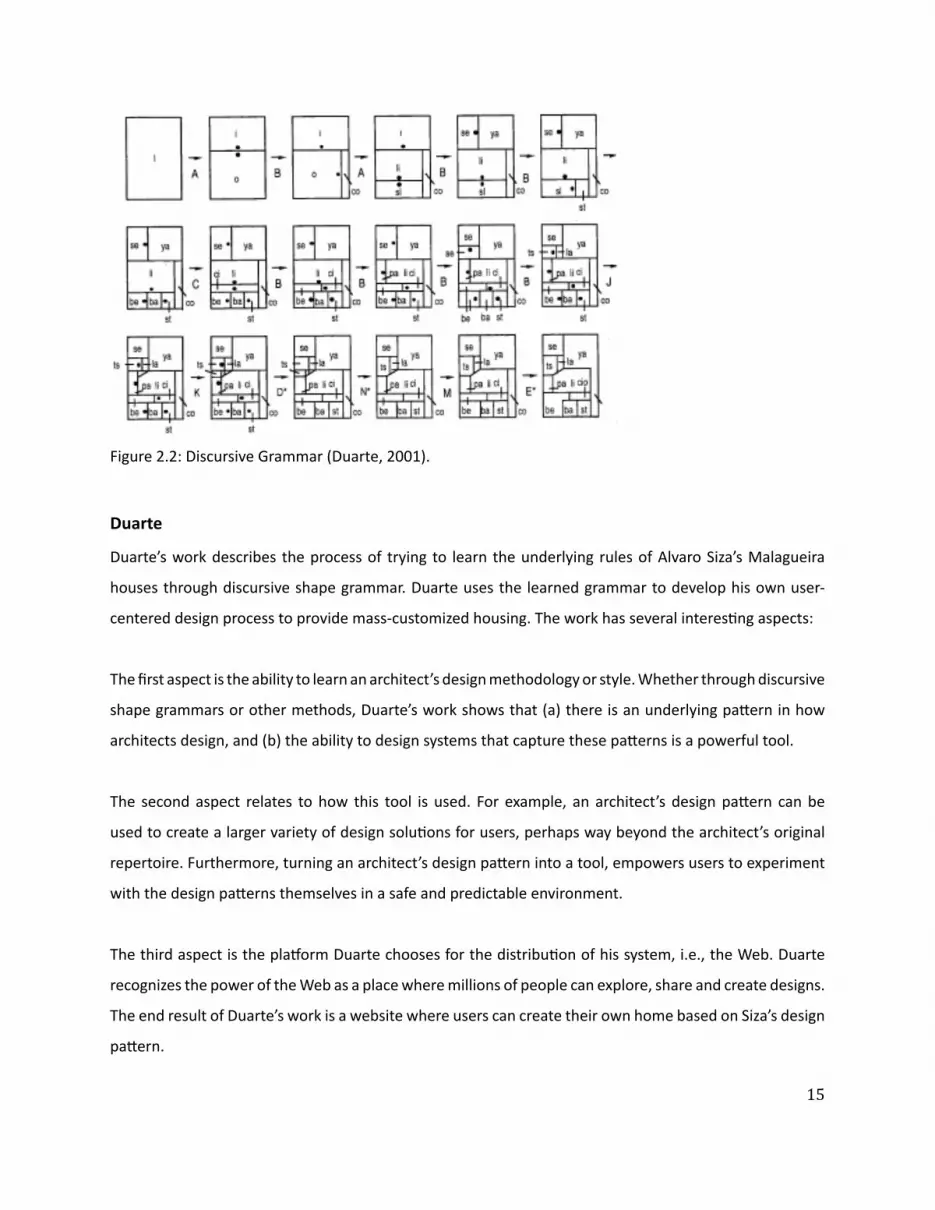
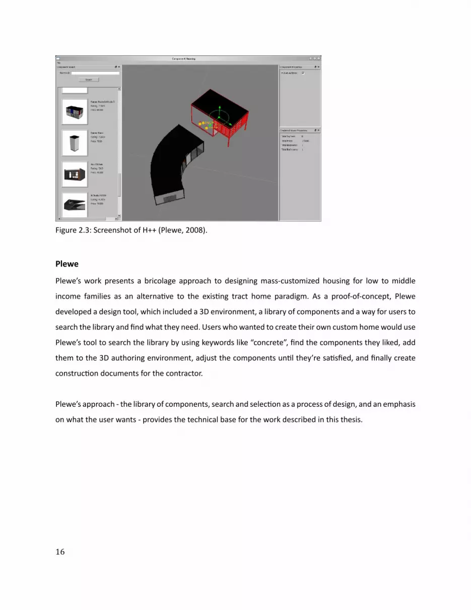
ͳ
Plewersquos work presents a bricolage approach to designing mass-customized housing for low to middle
income families as an alternaƟ ve to the exisƟ ng tract home paradigm As a proof-of-concept Plewe
developed a design tool which included a 3D environment a library of components and a way for users to
search the library and fi nd what they need Users who wanted to create their own custom home would use
Plewersquos tool to search the library by using keywords like ldquoconcreterdquo fi nd the components they liked add
them to the 3D authoring environment adjust the components unƟ l theyrsquore saƟ sfi ed and fi nally create
construcƟ on documents for the contractor
Plewersquos approach - the library of components search and selecƟ on as a process of design and an emphasis
on what the user wants - provides the technical base for the work described in this thesis
Plewe
Figure 23 Screenshot of H++ (Plewe 2008)
ͳ
Phillipsrsquos work defi nes design as a process of searching and provides the conceptual and technical
framework to support search in Web-based design tools for everyday users The work is moƟ vated by the
noƟ on of user-centered design ndash users creaƟ ng their own living soluƟ ons - and the fabricaƟ on abiliƟ es
to support it Phillips proposes a way of combining Building InformaƟ on Modeling (BIM) modern search
methods and an Object Oriented Programming (OOP) approach to create a space of design soluƟ ons that
ldquocan be searched directly without indexingrdquo
Phillips
Figure 24 Design By Searching (Phillips 2007)
References amp Suggested Reading List1 Smithwick D (2009) Architectural Design 20 An Online Plaƞ orm for the Mass CustomizaƟ on
of Architectural Structures Masters Thesis MassachuseƩ s InsƟ tute of Technology Cambridge MassachuseƩ s
2 Duarte J (2001) Customizing Mass Housing A Discursive Grammar for Sizarsquos Malagueira Houses PhD Thesis MassachuseƩ s InsƟ tute of Technology Cambridge MassachuseƩ s
3 Plewe T (2008) BesƟ ng the Tract Home A soŌ ware-Based Bricolage Approach to Aī ordable Custom Housing Masters Thesis MassachuseƩ s InsƟ tute of Technology Cambridge MassachuseƩ s
4 Phillips G (2007) Design By Searching A System for CreaƟ ng and EvaluaƟ ng Complex Architectural Assemblies Masters Thesis MassachuseƩ s InsƟ tute of Technology Cambridge MassachuseƩ s
18
Within user-centered architecture a set of criƟ cal tasks is the ability to model users designs and the
relaƟ onship between them To tackle these diĸ cult tasks this secƟ on explores the following machine
learning algorithms by way of experimentaƟ on and considers their potenƟ al contribuƟ on to the tasks at
hand
bull CollaboraƟ ve Filtering (User-based Item-based) - is used to match users to design soluƟ ons by way
of recommendaƟ ons
bull Clustering (Hierarchical K-means MulƟ dimensional Scaling) - is used to discover groups of users and
design soluƟ ons
bull Feature ExtracƟ on (Non-NegaƟ ve Matrix FactorizaƟ on) - is used to uncover the latent features of a
design soluƟ on
For the purpose of these experiments a unique data set was created with the help of 30 architects (referred
to as criƟ cs) who were asked to rate on a scale of 1 (low) to 5 (high) 20 architectural fl oor plans of a one
bedroom apartment Figure 31 shows a sample page from a booklet given to each criƟ c containing the
fl oor plan and raƟ ng box CriƟ csrsquo raƟ ngs were collected into a 30 by 20 matrix (referred to as the raƟ ng
matrix) with rows represenƟ ng criƟ cs and columns represenƟ ng fl oor plans (Figure 32)
The highest average fl oor plan raƟ ng was 383 and the lowest was 237 The highest average criƟ c raƟ ng
was 39 and the lowest 125 The results indicate that most criƟ cs rated according to the highest average
fl oor plan raƟ ng and chose to rate higher than the lowest average fl oor plan raƟ ng However criƟ c_9
gave all but three fl oor plans a raƟ ng of 1 bringing the average of the lowest criƟ c raƟ ng down Also the
standard deviaƟ on for criƟ c_9rsquos raƟ ngs (064) suggests an outlier and was excluded from the experiments
3| Algorithms
$amp()(+Attributes-0$1)20$34345$+$367489335780lt0=4431gt5$$03424316$345$431A20780755B4C0D240EF2465$$0345$(G0H4=44314$34B30)I734345$0-+5I0$1BB0371lt57-07gtI742154AI34456DG5E)(0G440$1Add your ow
n
RATING
19
Figure 31 How would you rate this fl oor plan
13
13
13
13
13
13
13
13
13
13
13
13
13
13
13
13
13
13
13
13
13
13
13
13
13
13
13
13
13
13
13
20
Figure 32 RaƟ ng matrix
21
CollaboraƟ ve Filtering (CF) is a method for making automaƟ c predicƟ ons (fi ltering) about the interest or
taste of a user by collecƟ ng and analyzing the personal preferences of many other users (collaboraƟ ve)
The fi rst system to use CF was the InformaƟ on Tapestry project at Xerox PARC (Goldberg et al 1992)
In general CF systems can be categorized as user-based or item-based User-based CF systems do the
following
bull Look for users who share the same raƟ ng paƩ ern with the acƟ ve user (ie the user for whom we are
trying to make a predicƟ on)
bull Use the raƟ ngs from those like-minded users to formulate a predicƟ on for the acƟ ve user
AlternaƟ vely item-based CF systems focus on items and the relaƟ onships amongst them to make
predicƟ ons eg ldquoUsers who bought X also bought Yrdquo (popularized by Amazoncom) Item-based CF
systems do the following
bull Build a Similarity Matrix to determine the relaƟ onship between pairs of items
bull Use the Similarity Matrix and userrsquos personal data to formulate a predicƟ on
CollaboraƟ ve Filtering
22
When wersquore interested in fi nding good recommendaƟ ons we tend to turn to people with a similar taste
to ours User-based collaboraƟ ve fi ltering takes the same approach by comparing us the acƟ ve user with
everyone else fi nding those who are most similar and using their preferences to make a predicƟ on about
what we like In user-centered architecture this approach takes advantage of design preferences and
taste expressed by various users to help other users fi nd what they need To illustrate how user-based
collaboraƟ ve fi ltering works a brief experiment was conducted using the data set of fl oor plan raƟ ngs to
predict a raƟ ng for a fi cƟ Ɵ ous user (referred to as CriƟ c_N) who rated some but not all the fl oor plans
The algorithm (Segaran 2007) presented in pseudocode (Figure 33) starts by iteraƟ ng through all users
and compuƟ ng their similarity to CriƟ c_N using a Pearson correlaƟ on coeĸ cient (Eq 31) Then the
algorithm iterates through every item ie fl oor plan and computes the weighted average raƟ ng (Eq
32) by mulƟ plying each of the raƟ ngs by the criƟ csrsquos similarity score and summing over all the scores
The intuiƟ on behind weighƟ ng the raƟ ngs is that users who are more like CriƟ c_N will have more weight
put on their raƟ ngs whereas raƟ ngs by users who are diī erent will receive very liƩ le weight Finally the
algorithm normalizes sorts and returns the result as predicted raƟ ngs for CriƟ c_N (Figure 34)
C CriƟ cM RaƟ ng MatrixU AcƟ ve UserFor each C in M If C is not U Then compute Similarity of C and U (see Eq 31)For each Item in M If Item was not rated by U Then compute user similarity weighted average raƟ ng (see Eq 32) And store it in ListNormalize ListSort List based on normalized weighted similarityReturn List
User-Based RecommendaƟ ons
Figure 33 Pseudocode for user-based recommendaƟ on
13
13 13
13 13
13
13
13
13 13
23
(Eq 31)
(Eq 32)
(Eq 33)
In order to measure the predicƟ ve power of the proposed algorithm the raƟ ngs matrix was transformed
into a test set by randomly deleƟ ng raƟ ngs in criƟ cs 1 through 8 The missing raƟ ngs were then esƟ mated
and the Root Mean Square Error (Eq 33) was computed yielding a value of 114 (Figure 35) To evaluate
this result (114) RMSE was calculated ten more Ɵ mes subsƟ tuƟ ng missing raƟ ngs with random numbers
between 1 and 5 yielding an average value of 195 The results show that the algorithm makes predicƟ ons
which are beƩ er than chance with an error that is 58 of the random error In addiƟ on RMSE was
calculated for CriƟ c_30 with 5 10 and 15 raƟ ngs yielding 131 124 and 087 respecƟ vely These results
indicate that by raƟ ng more fl oor plans criƟ cs improve the accuracy of the recommendaƟ ons they get
Figure 34 Predicted raƟ ngs (in green) and iniƟ al raƟ ngs (in yellow) for CriƟ c_N
13
13
13
13
13
24
Figure 35 Test matrixPredicted raƟ ngs (in green) and iniƟ al raƟ ngs (in yellow) for criƟ cs 1 through 8 used to calculate algorithmrsquos predicƟ ve power by measuring the Root Mean Square Error (RMSE)
25
When a data set like the raƟ ng matrix becomes very large a user-based approach might start to break
down due to the computaƟ onal cost of usersrsquo pairwise comparison An item-based approach alleviates
this problem by pre-compuƟ ng a similarity matrix for all items The assumpƟ on is that items do not change
as frequently as users therefore the similarity matrix will only need to be updated every once in a while
Amazoncom for example uses an item-based approach ie item-to-item collaboraƟ ve fi ltering (Linden
et al 2003) to recommend products to its users (Figure 36)
Making recommendaƟ ons using item-based collaboraƟ ve fi ltering consists of the following steps pre-
compuƟ ng an item-to-item similarity matrix looking up the acƟ ve userrsquos top-rated items and creaƟ ng
a weighted list of the most similar items To illustrate how this works an algorithm (Segaran 2007) was
tested with the raƟ ngs matrix to get recommendaƟ ons for CriƟ c_N (Figure 37)
CriƟ c_Nrsquos rated items
(50 SOL25) (20 SOL81) (10 SOL158)
CriƟ c_Nrsquos recommended items
(50 SOL9) (365 SOL74) (324 SOL144) (285 SOL202) (281 SOL228) (267 SOL224) (249 SOL212)
(243 SOL33) (209 SOL125) (15 SOL38) (142 SOL59) (141 SOL54) (10 SOL139)
Item-Based RecommendaƟ ons
Pre-compute item similarity matrix with user-based approach but subsƟ tuƟ ng items for users by transposing the raƟ ng matrixFor each Item1 in Userrsquos items For each Item2 in Item1rsquos similarity matrix If User has already rated Item2 Then conƟ nue to the next iteraƟ on of the loop Compute item similarity weighted raƟ ng (see Eq 32) Compute average of weighted item raƟ ngs And save them in ListSort List based on normalized weighted item similarityReturn List
Figure 36 Pseudocode for item-based recommendaƟ on
Figure 37 Item-based recommendaƟ ons for CriƟ c_N
26
Figure 37 shows that given CriƟ c_Nrsquos high raƟ ng of fl oor plan SOL25 the algorithm recommended SOL9
as the highest ranking (best matching) item Figure 38 validates the algorithmrsquos precision and predicƟ ve
power as the two fl oor plans are nearly idenƟ cal There are some minor diī erences between the two
fl oor plans for example SOL9 has a bar-top dining table but SOL25 has a 6-seat standalone dining table
However the overall similarity of the two fl oor plans is evident and emerges from the usersrsquo raƟ ngs
In order to compare the performance of the algorithm a random criƟ c was selected (CriƟ c_30) all but the
fi rst fi ve of his raƟ ngs deleted and then predicted by each of the algorithms The RMSE for the user-based
algorithm was 118 and the item-based algorithm was 161 indicaƟ ng that user-based recommendaƟ ons
are more accurate than item-based recommendaƟ ons However there are other issues to consider besides
accuracy when choosing one algorithm over the other for example size of data set and frequency of
change have a tremendous infl uence on the performance of these algorithms
User-Based vs Item-Based RecommendaƟ ons
Figure 38 SOL9 (LeŌ ) and SOL25 (Right) with a similarity score of 004
27
Clustering or Cluster Analysis is a way of discovering and visualizing groups of things - people news
stories blogs and more This secƟ on will focus on two clustering techniques - Hierarchical and K-means -
and apply them to the raƟ ngs matrix in order to discover groups of criƟ cs and fl oor plans In user-centered
architecture these clusters can be uƟ lized for example to infer a new userrsquos design preferences by fi nding
his cluster membership A user who has been assigned to a certain cluster shares the design preferences
of that cluster making it possible to tailor design recommendaƟ ons to his taste
Figure 39 is the pseudocode for a simple hierarchical clustering algorithm (Segaran 2007) The algorithm
starts by assigning each item ie fl oor plan to a cluster of its own Then the distance between every pair
of clusters is calculated and the closest (most similar) ones are merged together to form a new cluster
The process is repeated unƟ l there is only one cluster leŌ The algorithm uses the Pearson correlaƟ on
coeĸ cient to compute the distance between clusters
Figure 310 shows the groups of criƟ cs discovered when running the hierarchical clustering algorithm on
the raƟ ng matrix The dendrogram clearly separates the criƟ cs into two groups each characterized by
its own design preferences as extracted from the raƟ ngs Each of the two main clusters contains smaller
clusters for example criƟ cs 16 8 30 6 11 and 3 form a cluster within the bigger cluster at the top
of Figure 310 Rated fl oor plans were also clustered (Figure 311) by running the hierarchical clustering
algorithm on a rotated raƟ ng matrix Clustering shows two disƟ nct clusters made up of smaller clusters
such as fl oor plans SOL9 25 74 224 and 228 (Figure 312)
Clustering
Hierarchical Clustering
Figure 39 Pseudocode for hierarchical clustering
IniƟ alize all rows to be clustersCreate BigClusterWhile number of Clusters is bigger than 1 For each pair of Clusters Find the pair with the smallest distance Calculate the average of the two Clusters Combine the two clusters to form a new Cluster Add new Cluster to BigClusterReturn BigCluster
28
Gender analysis (MaleFemale )Top cluster - 6040BoƩ om cluster - 5050
Analysis reveals that clusters are gender neutral suggesƟ ng that gender may not play a role in the design preferences of architects
Figure 310 Hierarchical clustering of criƟ cs
29
Figure 311 Hierarchical clustering of fl oor plans
30
Figure 312 Clustered fl oor plans
AƩ ributes of clustered fl oor plans (parƟ al list)bull A small bathroombull A large kitchenbull A dining tablebull Clearly defi ned private amp public spaces
SOL9
SOL74
SOL25
SOL224
SOL228
31
Hierarchical clustering is computaƟ onally expensive because the pairwise distance calculaƟ ons have to
be carried out every Ɵ me clusters are merged therefore this method might break down on larger data
sets K-means clustering takes a diī erent approach because the number of clusters is specifi ed in advance
removing some of the ambiguity in dividing up the data
The K-means clustering algorithm (Segaran 2007) presented as pseudocode (Figure 313) starts by
randomly placing centroids ie center of the cluster and assigning every item to the nearest one Then
each centroid is shiŌ ed to the average locaƟ on of the items it contains items are reassigned and the
process repeats itself unƟ l the assignments stop changing
Figure 314 shows the K-means clustering of fl oor plans with diī erent values of K
K-means Clustering
Figure 313 Pseudocode for K-means clustering
M RaƟ ng MatrixFor each Item in M Compute the Min and Max value of Item Create K randomly placed centroids While assignment of Item is changing Find the closest centroid to Item Assign Item to centroid Move centroid to average locaƟ on of ItemsReturn K Clusters
K=8 SOL(158 169 268) (144 149) (925) (74) (33) (150) (202 212224 228) (38 54 59 81 125 139)
K=5 SOL(54 59 125 139 158) (25 74 144 202 224) (33 228 268) (149 150 169) (9 38 81 212)
K=3 SOL(9 25 74 228) (38 81 144 149 150 202 212 224) (33 54 59 125 139 158 169 268)
Figure 314 K-means clustering of fl oor plans
32
Items in the raƟ ng matrix are mulƟ dimensional ie each fl oor plan is represented by a vector of 30
raƟ ngs MulƟ dimensional scaling is a technique for fi nding a two-dimensional representaƟ on of the raƟ ng
matrix which is someƟ mes easier to understand than a dendrogram
The algorithm (Segaran 2007) presented as pseudocode (Figure 314) starts by calculaƟ ng the target
distances between all the items Next all items are placed randomly on a two-dimensional plane The
current distances between all the items are calculated using the actual distance ie the sum of the
squared diī erences For every pair of items the target distance is compared to the current distance to
calculate the error Every item is moved a small amount in proporƟ on to the direcƟ on of the error between
the two items The process is repeated unƟ l the total error cannot be reduced by moving any of the items
Figure 315 shows the results of running the mulƟ dimensional scaling algorithm on the raƟ ng matrix
All three methods when applied to the fl oor plans produced comparable results making the choice
of any one method unclear This is due to the small size of the data set and some ad-hoc choices of
parameters for the algorithms With a more extensive data set one expects to evaluate and choose based
upon computaƟ onal cost of the algorithm moƟ vaƟ on for and use of the derived informaƟ on and auxiliary
informaƟ on from the problem domain
MulƟ dimensional Scaling
Hierarchical Clustering vs K-means Clustering vs MulƟ dimensional Scaling
Figure 314 Pseudocode for MulƟ dimensional scaling
M RaƟ ng MatrixFor each Item1 and Item2 in M Compute the real distance between Item1 and Item 2 Randomly place Item1 and Item2 in 2D spaceWhile TotalError is changing Find the projected distance between Item1 and Item2 Calculate Error between real and projected distance Move Item1 and Item2 in proporƟ on to Error Update TotalErrorReturn locaƟ on of Items
SOL228
SOL38
SOL59
SOL54
SOL33SOL125
SOL139
SOL169
SOL268
SOL150
SOL149
SOL144
SOL9
SOL224
SOL25
SOL74
SOL158
SOL212
SOL81
SOL202
33
Figure 315 MulƟ dimensional scaling of raƟ ng matrixColored boxes correspond to the hierarchical clustering in Figure 311
=X
Plan 4
Features Matrix Weights Matrix
Plan 4
34
Figure 316 Non-NegaƟ ve Matrix FactorizaƟ on
The rated fl oor plans in the data set share certain features such as an open kitchen private vs public
spaces and others These features are latent - hidden between the raƟ ngs - and in order to extract them
the raƟ ng matrix has to be factored It is important to note that these features are not the same as the
aƩ ributes given to the criƟ cs to help them rate the fl oor plans There is no way to be absolutely sure of
what a feature represent All that can be done is to examine the set of fl oor plans which share the feature
and aƩ empt to visually arƟ culate it
Figure 316 describes the process of matrix factorizaƟ on The goal is to factor the matrix ie fi nd two
smaller (lower rank) matrices - a features matrix and a weights matrix - that when mulƟ plied together
reconstruct the original matrix The features matrix has features for rows and fl oor plans for columns
The value in each cell of the matrix indicates how important that fl oor plan is to the feature The weights
matrix maps the features to the raƟ ng matrix Each row is a criƟ c and each column is a feature The value
in each cell of the matrix indicates how much a feature applies to a fl oor plan Therefore reconstrucƟ ng
the raƟ ng matrix is a maƩ er of combining rows from the features matrix in diī erent amounts The weights
matrix maps the features to the raƟ ngs Non-negaƟ ve refers to the fact that all features and weights must
be posiƟ ve For a more comprehensive descripƟ on of the algorithm see (Segaran 2007)
Using a Non-NegaƟ ve Matrix FactorizaƟ on algorithm the raƟ ng matrix was factored into a features matrix
and a weights matrix The algorithm was programmed to fi nd 10 features Figure 317 represents 5 of
the 10 features as a list of fl oor plans that contain the feature As menƟ oned the features are latent
therefore feature 5 for example is shared by fl oor plans 149 150 169 and 268 An hypothesis of what
the feature represents is proposed by looking at the commonaliƟ es of the fl oor plans that defi ne the
feature (Figure 318)
Feature ExtracƟ on (Non-NegaƟ ve Matrix FactorizaƟ on)
35
Figure 317 5 features extracted from the raƟ ng matrix
(SOL81 SOL224)
(SOL149 SOL150 SOL169 SOL268)
(SOL202 SOL212)
(SOL158 SOL228)
(SOL33 SOL54 SOL59 SOL125 SOL139)
Feature 4
Feature 5
Feature 7
Feature 8
Feature 9
ConclusionsThe dataset used in these experiments is extremely small compared to the Neƞ lix or Amazon data sets
Nevertheless each of the applied methods revealed some interesƟ ng informaƟ on about the data - criƟ cs
fl oor plans and the relaƟ onship between them
CollaboraƟ ve fi ltering whether user or item based showed that it is possible to leverage a communityrsquos
opinion expressed through raƟ ngs in order to help an individual fi nd what he likes Analysis of the
algorithm showed that it performs much beƩ er than a random guess
Clustering - Hierarchical K-means or MulƟ dimensional Scaling - showed that it is possible to fi nd groups of
criƟ cs and fl oor plans and uncover their common characterisƟ cs With a large enough data set clustering
can be used to extract user and design typologies which can help stakeholders in the building industry -
contractors developers architects etc - tailor their services to clientsrsquo needs
Feature ExtracƟ on showed that it is possible to extract the features of a fl oor plan in order to create a
design vector The design vector can be used to score fl oor plans based on a userrsquos interest in one or all of
its features allowing the user to explore the design space in mulƟ ple direcƟ ons
36
Figure 318 ArƟ culaƟ ng Feature 5 through its fl oor plansFeature 5 could be the free-standing column that appears in all the fl oor plans below
SOL149 SOL150
SOL169 SOL268
37
References amp Suggested Reading List1 Billsus D amp Pazzani M J (1998) Learning collaboraƟ ve informaƟ on fi lters Proceedings of the 15th
InternaƟ onal Conference on Machine Learning pp 46ndash542 Blei D M Ng A Y amp Jordan M I (2002) Latent Dirichlet allocaƟ on Advances in Neural InformaƟ on
Processing Systems 143 Breese J S Heckerman D and Kardie C (1998) Empirical analysis of predicƟ ve algorithms for
collaboraƟ ve fi ltering In Proceedings of the 14th Conf on Uncertainty in ArƟ fi cial Intelligence pp 43ndash52
4 Goldberg D Nichols D Oki BM amp Terry D (1991) Using CollaboraƟ ve Filtering to Weave an InformaƟ on Tapestry Comm ACM vol 35 no 12 pp 61-70
5 Herlocker JL Konstan JA Borchers A and Riedl J (1999) An Algorithmic Framework for Performing CollaboraƟ ve Filtering Proc 22nd Ann Intrsquol ACM SIGIR Conf Research and Development in InformaƟ on Retrieval (SIGIR rsquo99)
6 Herlocker JL Konstan JA Terveen LG and Riedl JT (2004) EvaluaƟ ng CollaboraƟ ve Filtering Recommender Systems ACM Trans InformaƟ on Systems vol 22 no 1 pp 5-53
7 Hofmann T (2004) Latent semanƟ c models for collaboraƟ ve fi ltering ACM TransacƟ ons on InformaƟ on Systems 22 pp 89ndash115
8 Koren Y Bell R Volinsky C (2009) Matrix FactorizaƟ on Techniques for Recommender Systems IEEE Computer 082009 Volume 42 Issue 8 pp30-37
9 Linden G Smith B and York J (2003) Amazoncom RecommendaƟ ons Item-to-Item CollaboraƟ ve Filtering IEEE Internet CompuƟ ng
10 Marlin B (2004) CollaboraƟ ve fi ltering A machine learning perspecƟ ve Masterrsquos thesis University of Toronto Computer Science Department
11 Segaran T (2007) Programming CollecƟ ve Intelligence OrsquoReilly Media12 Srebro N Rennie J D M amp Jaakkola T S (2005) Maximum margin matrix factorizaƟ on Advances
in Neural InformaƟ on Processing Systems 17
38
4| UDesignWhen a user wishes to purchase an apartment from a developer he is usually presented with a few sample
apartments from which to choose These sample apartments usually oī er very few parameters that can
be changed because they are designed to fi t the taste and lifestyle of an average user The soluƟ on to
this problem can be found in two diī erent places - hardware and soŌ ware - which complement each
other to create user-centered architecture On the one hand there is hardware the building technology
that is responsible for making sure usersrsquo designs are feasible The mass-customizaƟ on community in
architecture has made considerable progress in recent years and managed to push fabricaƟ on technology
forward On the other hand there is soŌ ware the interface that is responsible for making sure users can
express their wants and needs The ability of an interface to meet usersrsquo needs depends on its front-end -
how easy it is to use the interface - and back-end - how the objects of design are represented internally in
the system This secƟ on will focus on the soŌ ware and illustrate through the implementaƟ on of UDesign
what are some of the issues to consider in terms of soŌ ware for user-centered architecture
As a framework UDesign mediates between the user and stakeholders in the building industry - architects
developers contractors suppliers realtors and community - in order to create a product in this case
an apartment Figure 41 outlines the components and relaƟ onships of user-centered architecture as a
series of four concentric circles - User UDesign Data and Stakeholders - fl oaƟ ng in Design Space the
space of design soluƟ ons oī ered to the user Metaphorically as the user is designing his own product
he is navigaƟ ng through the design space cocooned within these layers of UDesign and Stakeholders
through which he communicates his ideas about the product To visualize the metaphor imagine Figure
A Framework For User-Centered Architecture
39
Architect
Developer
DesignSpace
Realtor
Supplier
CommunityContractor
DesignLogic
Feedback
User
Stakeholders
UDesign
Data
41 as a ball fl oaƟ ng in space and rays of informaƟ on shooƟ ng from its center (User) guided by an inner
mechanism (UDesign Stakeholders) trying to fi nd an anchor in space (Design)
UDesign is comprised of four parts Design CommunicaƟ on Feedback and Logic Design is responsible
for visualizing the design space and interacƟ ng with the user In a way it is the front-end of the interface
Design includes the library of parts from which a user can choose to create his design (Friedmanrsquos
repertoire) tools to transform and edit the design and ways to explore the design space CommunicaƟ on
is responsible for the exchange of informaƟ on between user and stakeholders The radial arrangement
facilitates mulƟ ple channels of communicaƟ on at any given point in Ɵ me For example a user can
communicate with the architect in order to get professional feedback about his design while also geƫ ng
feedback from the community CommunicaƟ on must pass through UDesign to avoid overloading the user
therefore messages are stored in a queue and ordered by their relevancy to the current context of the
design process Feedback is responsible for conƟ nuously collecƟ ng informaƟ on about the state of the
design process analyzing it and providing noƟ fi caƟ ons at the right Ɵ me and place For example when a
user selects a design component he is immediately given feedback about the availability of the component
Figure 41 User-Centered Architecture
40
UDesign was implemented in Adobe Flex Builder 3 an IDE (Integrated Development Environment)
for creaƟ ng cross-plaƞ orm RIA (Rich Internet ApplicaƟ on) based on Adobe Flash A typical applicaƟ on
development process was followed including
bull Defi ning an applicaƟ on interface using a set of pre-defi ned components (forms buƩ ons and so on)
as MXML Components
bull Arranging components to create a User Interface (UI) design
bull Using styles and themes to defi ne the visual design CSS skins etc
bull Adding dynamic behavior using proper event-driven programming techniques
bull Defi ning and connecƟ ng to data services as needed MySQL ColdFusion etc
bull Compiling the source code into an SWF fi le that can be read by Flash Player and embedded within an
HTML fi le
UDesign is comprised of fi ve parts Data PersonalizaƟ on Design Contribute and Feedback (Figure 42)
where Data consƟ tutes most of the back-end and the remaining parts the front-end
The data in UDesign is stored in tables within a MySQL database that resides on a server The mxml
applicaƟ on makes requests to the database through a Flex HTTPService component In turn the
HTTPService component calls one of fi ve methods (FindAll Insert Update Delete Count) encapsulated
within a PHP fi le which then retrieves the data from the appropriate table of the database and returns the
data to the applicaƟ on in an E4X format (Figure 43)
ImplementaƟ on
Data
its price compaƟ bility with other components and more Stakeholders can use UDesignrsquos feedback to get
informaƟ on about their users - purchase history preferences lifestyle status state of the design and
more Logic is responsible for holding everything (Design CommunicaƟ on and Feedback) together so that
usersrsquo experience of UDesign is both producƟ ve and posiƟ ve Logic is supported by a suite of algorithms
from diī erent categories - user interacƟ on network database machine learning - some of which are
described in more detail in chapter 3 (Algorithms) as well as in the next secƟ on (ImplementaƟ on)
41
HTTPService
Data
Design
Contribute
Feedback
PHP
HTTPService PHP
MySQL
ContributeView
assembliesService
tagsService
usersService
Database
FeedbackView Feedback
HomeView Facebook Connect
currUser (Facebook)
UDesigners at work
Survey
DesignView
Assemblies
Tags
Users
feedbackService
IntroHomePage
PersonalizedHomePage
Floorplan
Catalog currUser (Facebook)
assembliesrooms
by selected rooms
GridCell (A1-C2)
clear
Figure 42 UDesign - system overview
42
FindAllInsertUpdateDeleteCount
Table 1Table 2Table 3
Request Request
Response ResponseFLEX PHP MySQL
E4X
The database includes the following tables
bull assemblies (Figure 44)
bull soluƟ ons (Figure 45)
bull users_saved_soluƟ ons (Figure 46)
bull users (Figure 47)
bull design_profi le (Figure 48)
bull soluƟ on_vector (Figure 49)
bull feedback (Figure 410)
Figure 43 Data pipeline
43
Table assemblies
This table holds the 48 assemblies (custom-designed rooms) available to the user on the Design page of
UDesign
Fields id room id | label room label | type room type | descripƟ on room descripƟ on | price room
price | cell an index indicaƟ ng to what funcƟ onal zone the room belongs (more details below) | area
room area (sqŌ ) | dimx room dimension in x-axis (pixels) | dimy room dimension in y-axis (pixels) | locx
room posiƟ on in x-axis (pixels) | locy room posiƟ on in y-axis (pixels) | color room color code | fi t a fl ag
indicaƟ ng whether the room fi tsdoesnrsquot fi t with the userrsquos design (more details below)
Table soluƟ ons
This table holds the 285 soluƟ ons (custom-designed fl oor plans) available to the user on the Design page
of UDesign
Fields id fl oor plan id | label fl oor plan label | A1 - C2 a funcƟ onal zone in the fl oor plan (more details
below)
Table users_saved_soluƟ ons
This table holds usersrsquo saved soluƟ ons (custom-designed fl oor plans) created by users on the Design page
of UDesign
Fields id fl oor plan id | label fl oor plan label | A1 - C2 a funcƟ onal zone in the fl oor plan (more details
below)
Table users
This table temporarily holds usersrsquo personal informaƟ on obtained from their Facebook account (more
details about UDesignrsquos connecƟ on to Facebook in the secƟ on about PersonalizaƟ on)
Fields (Facebook generated) uid userrsquos id | about_me userrsquos personal message | acƟ viƟ es userrsquos
favorite acƟ viƟ es | birthday userrsquos birthday | books userrsquos favorite books | fi rst_name userrsquos fi rst name
| interests userrsquos interests | last_name userrsquos last name | movies userrsquos favorite movies | music userrsquos
favorite music | pic userrsquos profi le picture | relaƟ onship_status userrsquos current relaƟ onship status | sex
userrsquos gender | wall_count number of posts on userrsquos wall
44
Table design_profi le
This table holds usersrsquo design profi le Users are presented with ten parameters of lifestyle and asked to
rate their importance on a scale of one (low) to fi ve (high)
Fields id userrsquos Facebook id | watch importance of watching TVMovies | entertain importance
of entertaining | cook importance of cooking | work importance of being able to work from home |
privacy importance of privacy | pamper importance of pampering | storage importance of storage |
kitchen_dining importance of physicalvisual connecƟ on between kitchen and dining room | bed_bath
importance of physicalvisual connecƟ on between bedroom and bathroom | fl exible importance of
fl exible living space
Table soluƟ on_vector
This table holds the design vectors for 71 out of 285 soluƟ ons (custom-designed fl oor plans) where each
soluƟ on is represented as a diī erent combinaƟ on of the same parameters used to defi ne userrsquos design
profi le (more details in the secƟ on about the Design page) Values indicate how much the corresponding
parameter is present in the soluƟ on
Fields label soluƟ on label | watch supports watching TVMovies | entertain supports entertaining |
cook supports cooking | work supports being able to work from home | privacy supports privacy |
pamper supports pampering | storage amount of storage | kitchen_dining degree of physicalvisual
connecƟ on between bedroom and bathroom | bed_bath degree of physicalvisual connecƟ on between
bedroom and bathroom | fl exible amount of fl exible living space
Table feedback
This table holds usersrsquo feedback submiƩ ed through the feedback form on UDesign (more details below)
Fields subject subject of the feedback | content content of the feedback
45
id label type description price cell area dimx dimy locx locy color fitid label type description price cell area dimx dimy locx locy color fitA11BT001 Bathroom Bathroom 99 A1 68 174 166 0 0 0x0071BC 0A11BT002 Bathroom Bathroom 99 A1 68 174 166 0 0 0x0071BC 0A12BT001 Bathroom Bathroom 99 A1 100 250 166 0 0 0x0071BC 0
id label A1 A2 B1 B2 C1 C2id label A1 A2 B1 B2 C1 C2SOL1 322000 A12BT001 A21KT001 B15ST001 B21DN001 C15BD001 C23LV001SOL10 123000 A11BT001 A22KT005 B15ST001 B21DN001 C15BD001 C23LV001SOL100 453243 A11BT001 A22KT004 B12BD001 B25DN001 C12BD001 C25LV004
id label A1 A2 B1 B2 C1 C2id label A1 A2 B1 B2 C1 C2652795248 A11BT001 A22KT003 B13BD001 B25DN001 C11ST001 C25LV002717158422 brain drain A11BT001 A22KT001 B15ST004 B25DN002 C13BD001 C23LV001533833493 carlyu A12BT001 A21KT001 B15ST001 B21DN001 C15BD001 C23LV001
id watch entertain cook work privacy pamper storage kitchen_dining bed_bath flexibleid watch entertain cook work privacy pamper storage kitchen_dining bed_bath flexible1065658831 3 5 5 1 1 1 3 5 1 1542150884 5 2 4 1 4 1 3 1 1 1566433466 1 5 5 2 2 1 2 4 2 1
label watch entertain cook work privacy pamper storage kitchen_dining bed_bath flexiblelabel watch entertain cook work privacy pamper storage kitchen_dining bed_bath flexibleSOL1 3 2 2 5 4 5 3 5 1 1SOL2 3 2 2 4 4 5 4 5 5 1SOL3 3 2 2 5 4 5 4 1 1 1
subject contentsubjectthis is my feedback feedback feedbackscrolling hi junnoNice work Good start Maybe I am to quick to try out everything-
the scroll bar or the arrow It is just a little bit annoying )-And will I be abproportions to the lenght of the walls I tried the little pen and ruler tool b
Figure 44 - 410 Database tables (from top to boƩ om)
46
PersonalizaƟ on
UDesignrsquos home page has two states an introducƟ on page (Figure 411) and a personalized page (Figure
412) The introducƟ on page is the fi rst page to be displayed when a user fi rst loads the applicaƟ on It
contains informaƟ on about the applicaƟ on and how to use it To start using the applicaƟ on a user must log
in using their Facebook account by pressing the Facebook Connect buƩ on Facebook Connect is integrated
into the Adobe Flex applicaƟ on using the Facebook API and corresponding Flash-Flex libraries By signing
in to UDesign through Facebook Connect a user gives the applicaƟ on permission to make requests to
Facebook and retrieve their personal informaƟ on (according to the userrsquos privacy seƫ ngs)
The informaƟ on from Facebook now encapsulated as a FacebookUser object is leveraged to provide the
user with tailored recommendaƟ ons of design soluƟ ons ie custom-designed fl oor plans As shown in
chapter 3 (Algorithms) usersrsquo informaƟ on whether itrsquos raƟ ngs or a Facebook profi le can be represented
as a vector (Figure 413) and compared to other users in order to cluster the UDesign community Once
a user is clustered other members of the cluster become his design criƟ cs and their design soluƟ ons are
oī ered as recommendaƟ ons (Figure 414) That is the case with a new user or a user who has not created
rated or saved any design soluƟ ons When a user has given feedback implicitly (by saving certain design
soluƟ ons) or explicitly (by raƟ ng design soluƟ ons) his recommendaƟ ons are updated and improved
through a user-based collaboraƟ ve fi ltering algorithm As shown in chapter 3 (Algorithms) the algorithm
Figure 411 IntroducƟ on home page
47
compares the current user to the enƟ re UDesign community fi nds the most similar users and collects
the highest rated design soluƟ ons from these users as recommendaƟ ons Consequently the more design
soluƟ ons users rate the more accurate UDesignrsquos recommendaƟ ons get (see chapter 3)
Once the user has logged in and UDesign has made a request to Facebook to retrieve the userrsquos personal
informaƟ on the applicaƟ on waits for the response and then temporarily stores it as a FacebookUser object
for the duraƟ on of the session If log in is successful the user is automaƟ cally navigated to a personalized
home page which includes the following userrsquos Facebook picture and name userrsquos Rated Design Profi le
UDesigners at work and Survey
The userrsquos Rated Design Profi le (Figure 415) is a set of ten lifestyle parameters that capture the userrsquos
preferences in respect to the database of 285 fl oor plans available in UDesign For each opƟ on the user
has to rate the importance of that aspect on a scale of one (low) to fi ve (high) For example if the user
is an avid baker he might rate high the following parameters cooking connecƟ on between kitchen and
dinning and entertaining to refl ect their importance in his lifestyle The user has the opƟ on to go back and
change his raƟ ngs at any Ɵ me by making the changes and pressing the Update buƩ on The Rated Design
Profi le complements the Facebook informaƟ on as they are both used to model the user and provide him
Figure 412 Personalized home page
48
with recommendaƟ ons of design soluƟ ons
UDesigners at work features the Facebook profi le pictures of the UDesign community with which the
current user may wish to interact - comment on designs share designs ask quesƟ ons share informaƟ on
and more Finally a short survey is included with various design styles and lifestyle parameters The user
is asked to indicate whether or not they are relevant to him The results of the survey are collected and
aggregated across the enƟ re UDesign community to understand trends and user typologies
49
Age Sex School Job
32 Male MIT House_n
29 Male MIT House_n
Yes
Yes
In a
Figure 413 User vectors
Design
The Design page (Figure 416) is where users create their custom apartment and it includes three main
components fl oor Plan catalog and recommendaƟ ons
The fl oor plan (Figure 417) has two components - toolbar and sample fl oor plan - with which a user can
interact to create their design The toolbar oī ers the following funcƟ onality
bull Open a saved project - will load a saved design from the database
bull Create a new project - will create a new project in the database
bull Save a project - will save the current state of the design in the database
bull Undo - will undo the userrsquos last operaƟ on
bull Publish to Facebook - will post the current state of the design to the userrsquos Facebook feed (Figures
417A and 417B)
bull Clear the project - will remove everything from the sample fl oor plan
The sample fl oor plan is the empty canvas on to which a user drags and drops rooms from the catalog
(Figure 418) UDesign was implemented with a single sample fl oor plan as a proof-of-concept However
in reality UDesign should be able to oī er users a variety of fl oor plans to customize as well as an opƟ on
to create their own fl oor plan from scratch Figure 419 explains how the sample fl oor plan is structured
such that it supports customizing EssenƟ ally the fl oor plan is divided into six funcƟ onal zones - A1 A2
B1 B2 C1 C2 - where each zone can hold one or more funcƟ ons Zones A1 and A2 have hard-coded
constraints ie A1 can only hold a bathroom and A2 a kitchen These constraints are imposed by the
50
NEW USER
Figure 414 Clustering users to fi nd recommendaƟ ons
51
Figure 415 Rated Design Profi le
buildingrsquos infrastructure for example the locaƟ on of plumbing risers The remaining zones can each take
a number of prescribed funcƟ ons - dining room bedroom closet media room and more - according to
the userrsquos choice
The Catalog (420) holds the assemblies (custom-designed rooms) that a user can add to the sample fl oor
plan The catalog includes an informaƟ on box with the userrsquos Facebook name and the Ɵ tle of the project
It also has a drop-down list of room types that fi lters the available rooms according to the selected type
eg bathroom kitchen dining etc Rooms are represented as Ɵ les When a room is clicked a pop-up
window appears with addiƟ onal details Room Ɵ les can be dragged and dropped onto the fl oor plan
(Figure 418) Each room has a prescribed locaƟ on within the fl oor plan to refl ect real-world constraints
Once a room has been dragged and dropped on to the fl oor plan an algorithm (Figure 421) updates the
rooms in the catalog to refl ect which ones fi t and which ones donrsquot with the userrsquos current selecƟ on of
rooms The ill-fi ƫ ng rooms are grayed-out (disabled) The recommendaƟ on lists also update (see below)
The recommendaƟ ons (Figure 422) are represented as two lists of soluƟ ons (custom-designed fl oor
52
Figure 416 Design page
plans) that are updated to refl ect (a) soluƟ ons which are compaƟ ble with the userrsquos currently selected
rooms and (b) the ten highest ranking soluƟ ons which best fi t the userrsquos Design Profi le RecommendaƟ ons
Based on your selecƟ on of rooms (Figure 422) are generated and updated using the algorithm described
in Figure 421 RecommendaƟ ons Based on your design profi le (Figure 422) are generated and updated
using the user-based recommendaƟ on algorithm described in chapter 3 (Figure 33) When a user clicks on
any of the recommendaƟ ons a pop-up window appears with addiƟ onal details about the selected fl oor
plan an explanaƟ on of why the fl oor plan was recommended and an opƟ on to add the selected fl oor plan
to the sample fl oor plan (Figure 423) If the user clicks the Add To My Project buƩ on the userrsquos sample
fl oor plan is cleared and the rooms of the currently selected fl oor plan are added instead
From a usability perspecƟ ve the Design page uses the direct manipulaƟ on design paƩ ern to facilitate a
seamless intuiƟ ve and eĸ cient design process for users Following a gradual learning curve a user can
create his own custom fl oor plan within a maƩ er of minutes by using the catalogrsquos drop-down menu
locaƟ ng a room and adding it to the sample fl oor plan
53
Figure 417 Floor Plan Component - sample fl oor plan and toolbar
Figure 417A PosƟ ng a fl oor plan to Facebook from within UDesign
54
Figure 417B The posted fl oor plan in Facebook
Figure 418 Drag and drop rooms
55
UDesign
How does it work
174 250
166
89
148
207
159
218
277
234 310
A1 A2
B1 B2
C1 C2
Figure 419 How does it work
56
UDesign
How does it work
174 pixels
166 pixels
Figure 419 How does it work (conƟ nued)
57
UDesign
How does it work
A1
B1
C1
A2
B2
C2
Figure 419 How does it work (conƟ nued)
58
Figure 420 Catalog
Figure 421 Pseudocode of algorithm for updaƟ ng soluƟ ons and assemblies
For each SoluƟ on For each Assembly in SoluƟ on If Assembly is in the userrsquos sample fl oor plan Save SoluƟ on Save AssemblyFor each SoluƟ on in RecommendaƟ ons Update SoluƟ onFor each Assembly in Catalog Update Assembly
59
Figure 422 RecommendaƟ ons
Figure 423 SoluƟ on details
60
Figure 424 Contribute page
UDesign is intended to be extended by its user community A user who is interested in contribuƟ ng a
new design can download the Starter Kit (a template fi le of available rooms in Adobe Illustrator andor
Autodesk Autocad format) design their own room or fl oor plan and send it via e-mail to be added to
the UDesign database (Figure 424) The ldquostarter kitrdquo is a fi le containing drawings However the current
approach is far from ideal and leaves much to be desired As an improvement the web applicaƟ on can
include an integrated confi guraƟ on tool which will let users edit any available assembly and save it as
their own A more comprehensive discussion of how to extend and scale UDesign is reserved for the
conclusions
To improve UDesign a simple feedback form is implemented allowing users to write comments and
suggesƟ ons and submit them to the system (Figure 425) Once a form is submiƩ ed it is saved in the
feedback table (Figure 410) and awaits a response by the applicaƟ on administrator
Contribute
Feedback
61
Figure 425 Feedback page
References amp Suggested Reading List1 UDesign hƩ ppeoplecsailmitedujunnohgp (May 20 2010)
62
This thesis proposes a framework for user-centered architecture and provides a proof-of-concept in the
form of a web applicaƟ on that allows users to create their own custom apartment The ideas presented
in this thesis are merely a starƟ ng point and fall short of solving the problem To miƟ gate the situaƟ on
this secƟ on suggests ways of improving some of the ideas presented as well as addiƟ onal direcƟ ons for
future work
This thesis started out by framing its conceptual framework through the work of Yona Friedman on user-
centered design Friedmanrsquos work is compelling however it is sƟ ll very much focused on the architect as
the sole cause of problems in the design process As I have shown in chapters three and four a community-
based approach supported by collaboraƟ ve fi ltering algorithms and social networks (eg Facebook) can
provide users with the safety net they need in order to feel comfortable designing their own spaces and
living soluƟ ons There is a specifi c reference by Friedman when he talks about the repertoire to all
possible design soluƟ ons which I fi nd problemaƟ c It seems to me that any system that forces its users
to navigate through a huge corpus of data compromises its usability For example if the repertoire had
thousands of possible design soluƟ ons would a user be able to fi nd what he needs And if he could how
long would it take him These quesƟ ons raise doubts in my mind as to the ability of Friedmanrsquos system to
respond to usersrsquo needs in terms of eĸ ciency (Ɵ me) and visibility (fi nding what they need) Furthermore
any system that proposes to fi nd ALL possible soluƟ ons must also address the issue of Completeness or in
Yona Friedman Reloaded
5| Conclusions
63
RepresentaƟ on
other words provide proof that there are no other possible design soluƟ ons beyond those found in the
repertoire Finally I would argue that users arenrsquot interested in all possible design soluƟ ons but just those
that fi t their needs Finding these needs is a diĸ cult problem with the beginning of a soluƟ on in chapters
three and four
Marshall McLuhan (McLuhan 1964) coined the phrase ldquoThe medium is the messagerdquo The medium in the
context of architectural design is how we choose to represent the fi nished product Whether through 2D
fl oor plans or 4D fl y-through animaƟ ons the message has to be received and understood on the userrsquos
side The fact that users are not trained at deciphering architecturally-encoded messages (architectural
notaƟ on symbols etc) makes the task of representaƟ on that much more diĸ cult The representaƟ on
chosen for the implementaƟ on of UDesign ie a 2D fl oor plan layout comprised of funcƟ onal zones or
assemblies in PNG format leaves much to be desired First the use of the PNG format seriously hinders
usersrsquo freedom to make changes to the design at room level While only having to deal with small chunks
of space simplifi es the design task on the userrsquos end it also presents a problem when a user only wants
to move the bed in the master bedroom one foot to the leŌ This limitaƟ on will cause users to become
frustrated and the enƟ re user-centered design process to break Therefore representaƟ on should provide
users more freedom by increasing the granularity of the medium For example enabling users to edit
assemblies and then save them as their own custom components Having said that perhaps the problem
is not granularity but dimensionality In many informal discussions I conducted with users (non-experts
designers if you will) Irsquove come to realize that fl oor plans are a poor conduit for the architectural message
Most users just donrsquot get them They have a hard Ɵ me ldquosensingrdquo the space through a 2D representaƟ on
and yearn for a more engaging spaƟ al experience At this point I am tempted to suggest Virtual Reality as a
more appropriate medium for architectural data and design however it doesnrsquot seem like a viable opƟ on
in the foreseeable future If we were to consider (hypotheƟ cally speaking of course) Virtual Reality I
would imagine users being able to connect through some device to a virtual world where they could create
their own living spaces walk through them share them with others and so on A hint of the potenƟ al
of this scenario surfaced when architects started taking advantage of SecondLife by designing homes for
usersrsquo avatars UnƟ l Virtual Reality catches up videoonline games and virtual worlds provide a beƩ er
alternaƟ ve in my opinion to 2D fl oor plan layouts or even 4D walk-through animaƟ ons In an interacƟ ve
virtual environment users can create their design in 3D space walk around interact with objects explore
64
views and perspecƟ ve really ldquoseerdquo and ldquofeelrdquo the consequences of their acƟ ons and be able to share that
experience with others Another thing to consider about representaƟ on when venturing into 3D space is
the level of abstracƟ on appropriate for usersrsquo comprehension VideoOnline games are fun because they
tend to be an abstract representaƟ on of the real environment for the purpose of reducing the cogniƟ ve
load on the user On the other hand architectural design has many varying levels of abstracƟ on which are
linked to the context and posiƟ on within the design process So the quesƟ on becomes would users want
to see everything - from the texture of a wooden fl oor to the fi nish of the kitchen cabinets Or would
the level of detail dynamically change to match the userrsquos focus and locaƟ on within the design process
I suspect a dynamic and gradient control over spaƟ al details is probably more appropriate and less likely
to overwhelm the non-expert user
Scalability
At the heart of user-centered architecture is scalability - how can we create a plaƞ orm that supports
the design processes of mulƟ ple users Scalability is Ɵ ghtly coupled with representaƟ on in the sense
that representaƟ on ulƟ mately determines the degree to which a user-centered design process can scale
For example the representaƟ on chosen for implementaƟ on of UDesign has a low degree of scalability
because users canrsquot edit assemblies or create their own assemblies which is necessary if the catalog (or
repertoire) is to grow and expand A more fl exible representaƟ on one where users can manipulate low-
level components such as pieces of furniture would result in beƩ er scalability allowing users to extend
the iniƟ al catalog of assemblies Another issue to consider in regards to scalability is that of constraints
or rather the need to enforce and validate constraints In architectural design components across various
scales relate to each other in various ways through interdependencies or constraints As the number and
types of components increase so do the constraints and the complexity of validaƟ ng them For example
UDesign implicitly enforces constraints on room adjacencies through the soŌ suggesƟ ons it provides to the
user That means that if the user chooses to ignore the recommendaƟ ons he can easily place mismatching
rooms next to each other What is needed in UDesign specifi cally and user-centered design systems in
general is an adapƟ ve constraint management approach with some noƟ on of learning Ideally such a
management approach would start with a small set of predefi ned constraints and learn new constraints
from usersrsquo acƟ ons and design paƩ erns The goal is to avoid having to hard-code the constraints but rather
infer them from what users do as they are designing Winston (Winston 1972) developed the noƟ on of
learning (constraints) from examples and demonstrated the applicaƟ on of his approach in the construcƟ on
65
of an arch Using examples of what consƟ tutes an arch (good examples) what doesnrsquot (bad examples)
and whatrsquos close enough (near miss) Winstonrsquos approach incrementally constructs a semanƟ c net that is a
representaƟ on of the arch and its embedded constraints A similar approach may be applicable in UDesign
where a userrsquos acƟ ons are being tracked parsed and interpreted to construct a semanƟ c representaƟ on
of his design and its embedded constraints
CollaboraƟ on
Architectural design is a collaboraƟ ve eī ort that includes the input of many diī erent experts such as
architects contractors users and many others Therefore therersquos no reason why non-experts couldnrsquot
take advantage of the same approach and collaborate amongst themselves to help each other create
beƩ er designs CollaboraƟ on is addressed in UDesign by giving users the opƟ on to publish their work on
Facebook This form of social collaboraƟ on can potenƟ ally help a user who is trying to get some feedback
However what is needed is an addiƟ onal form of collaboraƟ on where a user can remotely interact with
another userrsquos design Hands-on remote collaboraƟ on is a more expressive approach to design that
facilitates users designing together
Data CollecƟ on
The majority of approaches discussed in this thesis (eg the algorithms in chapter three) are data-driven
meaning that without suĸ cient data they become inaccurate or just donrsquot work In fact the more
data the less sensiƟ ve these algorithms are to outliers and the more accurate the recommendaƟ ons
Unfortunately in the course of wriƟ ng this thesis and developing UDesign I was unable to collect as much
data as I had hoped As a result I can only speculate as to the performance and potenƟ al contribuƟ on of
my approach to user-centered architecture
RecommendaƟ ons
As a corollary to data collecƟ on this thesis lacks a comprehensive evaluaƟ on of the diī erent methods
discussed in chapter three In order to eī ecƟ vely measure the performance of various collaboraƟ ve
fi ltering approaches one needs access to a suĸ ciently large data set I believe that with addiƟ onal Ɵ me
and eī ort such a data set can be obtained for architectural design specifi cally in the residenƟ al sector
and then the collaboraƟ ve fi ltering methods discussed in this thesis will be able to accurately match users
and design soluƟ ons
66
Usability
For any user-centered architecture framework to be successful it must fi rst be usable UDesign was
implemented as a web applicaƟ on following standard usability design guidelines and an iteraƟ ve UI design
process However there is much more that can be done in terms of prototyping UI design and user
tesƟ ng
ContribuƟ ons
In this thesis I propose a framework for user-centered architecture called UDesign and describe its
implementaƟ on as a web applicaƟ on that allows users to design their own custom apartment UDesign
includes a sample one-bedroom apartment which users can customize through a kit-of-parts approach
ie a catalog of rooms (called assemblies) that can be combined to create a complete fl oor plan soluƟ on
While available confi guraƟ on tools in architecture require the user to think like an expert eg integrate
form and funcƟ on UDesign takes a novel approach by deploying a suite of machine learning algorithms
coupled with data from Facebook to model usersrsquo design preferences and match them with design
soluƟ ons Users can take advantage of these recommendaƟ ons as their design starƟ ng point and conƟ nue
to explore other alternaƟ ves by dragging and dropping rooms from the catalog on to the sample fl oor
plan As users explore design soluƟ ons UDesign updates its recommendaƟ ons to guide users through the
design space and helps them fi nd soluƟ ons that best fi t their needs Finally UDesignrsquos integraƟ on with
Facebook allows users to share their designs making UDesign part of their social network
References amp Suggested Reading List1 Winston P H (1970) Learning Structural DescripƟ ons From Examples AI Technical Reports ArƟ fi cial
Intelligence Lab MassachuseƩ s InsƟ tute of Technology Cambridge MassachuseƩ s2 McLuhan M (1964) Understanding Media The Extensions of Man 1st Ed McGraw Hill NY 1964
reissued MIT Press 1994 with introducƟ on by Lewis H Lapham reissued by Gingko Press 2003 ISBN 1-58423-073-8
Appendix
Assemblies
A compilaƟ on of assemblies (rooms) and soluƟ ons (fl oor plans) included in UDesign and throughout the thesis Total number of assemblies = 48 soluƟ ons = 285 Only 20 of each are shown here
A11BT001
A12BT001
A11BT002
A12BT002
ͺ
A21KT001
A22KT001
A21KT002
A22KT002
ͻ
A22KT003 A22KT004
Ͳ
A22KT005
B11CL001
A22KT006
B12BD001
ͳ
B12CL001
B14CL001
B13BD001
B15ME001
ʹ
B15ST001
B15ST003
B15ST002
B15ST004
͵
B16BD001
B22DN001
B21DN001
B24DN001
Ͷ
B24DN002
B25DN002
B25DN001
B25DN003
ͷ
C11ST001
C12CL001
C12BD001
C12ST001
C13BD001
C14ST002
C14ST001
C15BD001
C15BD002
C16BD001
ͺ
C16DB002
C22LV001
ͻ
C23LV001
C25LV001
ͺͲ
C25LV002
C25LV003
ͺͳ
C25LV004
C26LV001
ͺʹ
SoluƟ ons
SOL9
ͺ͵
SOL25
ͺͶ
SOL33
ͺͷ
SOL38
ͺ
SOL54
ͺ
SOL59
ͺͺ
SOL74
ͺͻ
SOL81
ͻͲ
SOL125
ͻͳ
SOL139
ͻʹ
SOL144
ͻ͵
SOL149
ͻͶ
SOL150
ͻͷ
SOL158
ͻ
SOL169
ͻ
SOL202
ͻͺ
SOL212
ͻͻ
SOL224
ͳͲͲ
SOL228
ͳͲͳ
SOL268
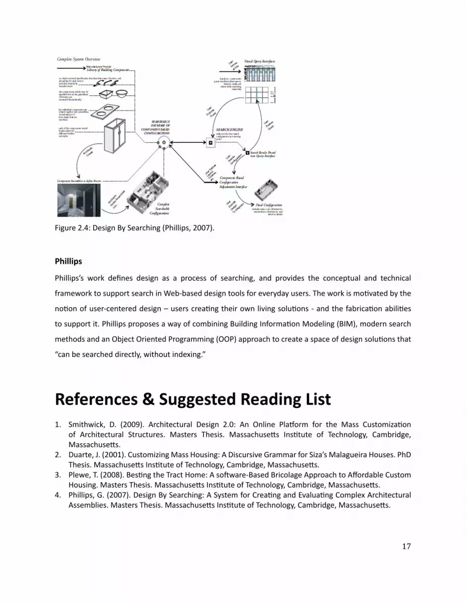
ͳ
Phillipsrsquos work defi nes design as a process of searching and provides the conceptual and technical
framework to support search in Web-based design tools for everyday users The work is moƟ vated by the
noƟ on of user-centered design ndash users creaƟ ng their own living soluƟ ons - and the fabricaƟ on abiliƟ es
to support it Phillips proposes a way of combining Building InformaƟ on Modeling (BIM) modern search
methods and an Object Oriented Programming (OOP) approach to create a space of design soluƟ ons that
ldquocan be searched directly without indexingrdquo
Phillips
Figure 24 Design By Searching (Phillips 2007)
References amp Suggested Reading List1 Smithwick D (2009) Architectural Design 20 An Online Plaƞ orm for the Mass CustomizaƟ on
of Architectural Structures Masters Thesis MassachuseƩ s InsƟ tute of Technology Cambridge MassachuseƩ s
2 Duarte J (2001) Customizing Mass Housing A Discursive Grammar for Sizarsquos Malagueira Houses PhD Thesis MassachuseƩ s InsƟ tute of Technology Cambridge MassachuseƩ s
3 Plewe T (2008) BesƟ ng the Tract Home A soŌ ware-Based Bricolage Approach to Aī ordable Custom Housing Masters Thesis MassachuseƩ s InsƟ tute of Technology Cambridge MassachuseƩ s
4 Phillips G (2007) Design By Searching A System for CreaƟ ng and EvaluaƟ ng Complex Architectural Assemblies Masters Thesis MassachuseƩ s InsƟ tute of Technology Cambridge MassachuseƩ s
18
Within user-centered architecture a set of criƟ cal tasks is the ability to model users designs and the
relaƟ onship between them To tackle these diĸ cult tasks this secƟ on explores the following machine
learning algorithms by way of experimentaƟ on and considers their potenƟ al contribuƟ on to the tasks at
hand
bull CollaboraƟ ve Filtering (User-based Item-based) - is used to match users to design soluƟ ons by way
of recommendaƟ ons
bull Clustering (Hierarchical K-means MulƟ dimensional Scaling) - is used to discover groups of users and
design soluƟ ons
bull Feature ExtracƟ on (Non-NegaƟ ve Matrix FactorizaƟ on) - is used to uncover the latent features of a
design soluƟ on
For the purpose of these experiments a unique data set was created with the help of 30 architects (referred
to as criƟ cs) who were asked to rate on a scale of 1 (low) to 5 (high) 20 architectural fl oor plans of a one
bedroom apartment Figure 31 shows a sample page from a booklet given to each criƟ c containing the
fl oor plan and raƟ ng box CriƟ csrsquo raƟ ngs were collected into a 30 by 20 matrix (referred to as the raƟ ng
matrix) with rows represenƟ ng criƟ cs and columns represenƟ ng fl oor plans (Figure 32)
The highest average fl oor plan raƟ ng was 383 and the lowest was 237 The highest average criƟ c raƟ ng
was 39 and the lowest 125 The results indicate that most criƟ cs rated according to the highest average
fl oor plan raƟ ng and chose to rate higher than the lowest average fl oor plan raƟ ng However criƟ c_9
gave all but three fl oor plans a raƟ ng of 1 bringing the average of the lowest criƟ c raƟ ng down Also the
standard deviaƟ on for criƟ c_9rsquos raƟ ngs (064) suggests an outlier and was excluded from the experiments
3| Algorithms
$amp()(+Attributes-0$1)20$34345$+$367489335780lt0=4431gt5$$03424316$345$431A20780755B4C0D240EF2465$$0345$(G0H4=44314$34B30)I734345$0-+5I0$1BB0371lt57-07gtI742154AI34456DG5E)(0G440$1Add your ow
n
RATING
19
Figure 31 How would you rate this fl oor plan
13
13
13
13
13
13
13
13
13
13
13
13
13
13
13
13
13
13
13
13
13
13
13
13
13
13
13
13
13
13
13
20
Figure 32 RaƟ ng matrix
21
CollaboraƟ ve Filtering (CF) is a method for making automaƟ c predicƟ ons (fi ltering) about the interest or
taste of a user by collecƟ ng and analyzing the personal preferences of many other users (collaboraƟ ve)
The fi rst system to use CF was the InformaƟ on Tapestry project at Xerox PARC (Goldberg et al 1992)
In general CF systems can be categorized as user-based or item-based User-based CF systems do the
following
bull Look for users who share the same raƟ ng paƩ ern with the acƟ ve user (ie the user for whom we are
trying to make a predicƟ on)
bull Use the raƟ ngs from those like-minded users to formulate a predicƟ on for the acƟ ve user
AlternaƟ vely item-based CF systems focus on items and the relaƟ onships amongst them to make
predicƟ ons eg ldquoUsers who bought X also bought Yrdquo (popularized by Amazoncom) Item-based CF
systems do the following
bull Build a Similarity Matrix to determine the relaƟ onship between pairs of items
bull Use the Similarity Matrix and userrsquos personal data to formulate a predicƟ on
CollaboraƟ ve Filtering
22
When wersquore interested in fi nding good recommendaƟ ons we tend to turn to people with a similar taste
to ours User-based collaboraƟ ve fi ltering takes the same approach by comparing us the acƟ ve user with
everyone else fi nding those who are most similar and using their preferences to make a predicƟ on about
what we like In user-centered architecture this approach takes advantage of design preferences and
taste expressed by various users to help other users fi nd what they need To illustrate how user-based
collaboraƟ ve fi ltering works a brief experiment was conducted using the data set of fl oor plan raƟ ngs to
predict a raƟ ng for a fi cƟ Ɵ ous user (referred to as CriƟ c_N) who rated some but not all the fl oor plans
The algorithm (Segaran 2007) presented in pseudocode (Figure 33) starts by iteraƟ ng through all users
and compuƟ ng their similarity to CriƟ c_N using a Pearson correlaƟ on coeĸ cient (Eq 31) Then the
algorithm iterates through every item ie fl oor plan and computes the weighted average raƟ ng (Eq
32) by mulƟ plying each of the raƟ ngs by the criƟ csrsquos similarity score and summing over all the scores
The intuiƟ on behind weighƟ ng the raƟ ngs is that users who are more like CriƟ c_N will have more weight
put on their raƟ ngs whereas raƟ ngs by users who are diī erent will receive very liƩ le weight Finally the
algorithm normalizes sorts and returns the result as predicted raƟ ngs for CriƟ c_N (Figure 34)
C CriƟ cM RaƟ ng MatrixU AcƟ ve UserFor each C in M If C is not U Then compute Similarity of C and U (see Eq 31)For each Item in M If Item was not rated by U Then compute user similarity weighted average raƟ ng (see Eq 32) And store it in ListNormalize ListSort List based on normalized weighted similarityReturn List
User-Based RecommendaƟ ons
Figure 33 Pseudocode for user-based recommendaƟ on
13
13 13
13 13
13
13
13
13 13
23
(Eq 31)
(Eq 32)
(Eq 33)
In order to measure the predicƟ ve power of the proposed algorithm the raƟ ngs matrix was transformed
into a test set by randomly deleƟ ng raƟ ngs in criƟ cs 1 through 8 The missing raƟ ngs were then esƟ mated
and the Root Mean Square Error (Eq 33) was computed yielding a value of 114 (Figure 35) To evaluate
this result (114) RMSE was calculated ten more Ɵ mes subsƟ tuƟ ng missing raƟ ngs with random numbers
between 1 and 5 yielding an average value of 195 The results show that the algorithm makes predicƟ ons
which are beƩ er than chance with an error that is 58 of the random error In addiƟ on RMSE was
calculated for CriƟ c_30 with 5 10 and 15 raƟ ngs yielding 131 124 and 087 respecƟ vely These results
indicate that by raƟ ng more fl oor plans criƟ cs improve the accuracy of the recommendaƟ ons they get
Figure 34 Predicted raƟ ngs (in green) and iniƟ al raƟ ngs (in yellow) for CriƟ c_N
13
13
13
13
13
24
Figure 35 Test matrixPredicted raƟ ngs (in green) and iniƟ al raƟ ngs (in yellow) for criƟ cs 1 through 8 used to calculate algorithmrsquos predicƟ ve power by measuring the Root Mean Square Error (RMSE)
25
When a data set like the raƟ ng matrix becomes very large a user-based approach might start to break
down due to the computaƟ onal cost of usersrsquo pairwise comparison An item-based approach alleviates
this problem by pre-compuƟ ng a similarity matrix for all items The assumpƟ on is that items do not change
as frequently as users therefore the similarity matrix will only need to be updated every once in a while
Amazoncom for example uses an item-based approach ie item-to-item collaboraƟ ve fi ltering (Linden
et al 2003) to recommend products to its users (Figure 36)
Making recommendaƟ ons using item-based collaboraƟ ve fi ltering consists of the following steps pre-
compuƟ ng an item-to-item similarity matrix looking up the acƟ ve userrsquos top-rated items and creaƟ ng
a weighted list of the most similar items To illustrate how this works an algorithm (Segaran 2007) was
tested with the raƟ ngs matrix to get recommendaƟ ons for CriƟ c_N (Figure 37)
CriƟ c_Nrsquos rated items
(50 SOL25) (20 SOL81) (10 SOL158)
CriƟ c_Nrsquos recommended items
(50 SOL9) (365 SOL74) (324 SOL144) (285 SOL202) (281 SOL228) (267 SOL224) (249 SOL212)
(243 SOL33) (209 SOL125) (15 SOL38) (142 SOL59) (141 SOL54) (10 SOL139)
Item-Based RecommendaƟ ons
Pre-compute item similarity matrix with user-based approach but subsƟ tuƟ ng items for users by transposing the raƟ ng matrixFor each Item1 in Userrsquos items For each Item2 in Item1rsquos similarity matrix If User has already rated Item2 Then conƟ nue to the next iteraƟ on of the loop Compute item similarity weighted raƟ ng (see Eq 32) Compute average of weighted item raƟ ngs And save them in ListSort List based on normalized weighted item similarityReturn List
Figure 36 Pseudocode for item-based recommendaƟ on
Figure 37 Item-based recommendaƟ ons for CriƟ c_N
26
Figure 37 shows that given CriƟ c_Nrsquos high raƟ ng of fl oor plan SOL25 the algorithm recommended SOL9
as the highest ranking (best matching) item Figure 38 validates the algorithmrsquos precision and predicƟ ve
power as the two fl oor plans are nearly idenƟ cal There are some minor diī erences between the two
fl oor plans for example SOL9 has a bar-top dining table but SOL25 has a 6-seat standalone dining table
However the overall similarity of the two fl oor plans is evident and emerges from the usersrsquo raƟ ngs
In order to compare the performance of the algorithm a random criƟ c was selected (CriƟ c_30) all but the
fi rst fi ve of his raƟ ngs deleted and then predicted by each of the algorithms The RMSE for the user-based
algorithm was 118 and the item-based algorithm was 161 indicaƟ ng that user-based recommendaƟ ons
are more accurate than item-based recommendaƟ ons However there are other issues to consider besides
accuracy when choosing one algorithm over the other for example size of data set and frequency of
change have a tremendous infl uence on the performance of these algorithms
User-Based vs Item-Based RecommendaƟ ons
Figure 38 SOL9 (LeŌ ) and SOL25 (Right) with a similarity score of 004
27
Clustering or Cluster Analysis is a way of discovering and visualizing groups of things - people news
stories blogs and more This secƟ on will focus on two clustering techniques - Hierarchical and K-means -
and apply them to the raƟ ngs matrix in order to discover groups of criƟ cs and fl oor plans In user-centered
architecture these clusters can be uƟ lized for example to infer a new userrsquos design preferences by fi nding
his cluster membership A user who has been assigned to a certain cluster shares the design preferences
of that cluster making it possible to tailor design recommendaƟ ons to his taste
Figure 39 is the pseudocode for a simple hierarchical clustering algorithm (Segaran 2007) The algorithm
starts by assigning each item ie fl oor plan to a cluster of its own Then the distance between every pair
of clusters is calculated and the closest (most similar) ones are merged together to form a new cluster
The process is repeated unƟ l there is only one cluster leŌ The algorithm uses the Pearson correlaƟ on
coeĸ cient to compute the distance between clusters
Figure 310 shows the groups of criƟ cs discovered when running the hierarchical clustering algorithm on
the raƟ ng matrix The dendrogram clearly separates the criƟ cs into two groups each characterized by
its own design preferences as extracted from the raƟ ngs Each of the two main clusters contains smaller
clusters for example criƟ cs 16 8 30 6 11 and 3 form a cluster within the bigger cluster at the top
of Figure 310 Rated fl oor plans were also clustered (Figure 311) by running the hierarchical clustering
algorithm on a rotated raƟ ng matrix Clustering shows two disƟ nct clusters made up of smaller clusters
such as fl oor plans SOL9 25 74 224 and 228 (Figure 312)
Clustering
Hierarchical Clustering
Figure 39 Pseudocode for hierarchical clustering
IniƟ alize all rows to be clustersCreate BigClusterWhile number of Clusters is bigger than 1 For each pair of Clusters Find the pair with the smallest distance Calculate the average of the two Clusters Combine the two clusters to form a new Cluster Add new Cluster to BigClusterReturn BigCluster
28
Gender analysis (MaleFemale )Top cluster - 6040BoƩ om cluster - 5050
Analysis reveals that clusters are gender neutral suggesƟ ng that gender may not play a role in the design preferences of architects
Figure 310 Hierarchical clustering of criƟ cs
29
Figure 311 Hierarchical clustering of fl oor plans
30
Figure 312 Clustered fl oor plans
AƩ ributes of clustered fl oor plans (parƟ al list)bull A small bathroombull A large kitchenbull A dining tablebull Clearly defi ned private amp public spaces
SOL9
SOL74
SOL25
SOL224
SOL228
31
Hierarchical clustering is computaƟ onally expensive because the pairwise distance calculaƟ ons have to
be carried out every Ɵ me clusters are merged therefore this method might break down on larger data
sets K-means clustering takes a diī erent approach because the number of clusters is specifi ed in advance
removing some of the ambiguity in dividing up the data
The K-means clustering algorithm (Segaran 2007) presented as pseudocode (Figure 313) starts by
randomly placing centroids ie center of the cluster and assigning every item to the nearest one Then
each centroid is shiŌ ed to the average locaƟ on of the items it contains items are reassigned and the
process repeats itself unƟ l the assignments stop changing
Figure 314 shows the K-means clustering of fl oor plans with diī erent values of K
K-means Clustering
Figure 313 Pseudocode for K-means clustering
M RaƟ ng MatrixFor each Item in M Compute the Min and Max value of Item Create K randomly placed centroids While assignment of Item is changing Find the closest centroid to Item Assign Item to centroid Move centroid to average locaƟ on of ItemsReturn K Clusters
K=8 SOL(158 169 268) (144 149) (925) (74) (33) (150) (202 212224 228) (38 54 59 81 125 139)
K=5 SOL(54 59 125 139 158) (25 74 144 202 224) (33 228 268) (149 150 169) (9 38 81 212)
K=3 SOL(9 25 74 228) (38 81 144 149 150 202 212 224) (33 54 59 125 139 158 169 268)
Figure 314 K-means clustering of fl oor plans
32
Items in the raƟ ng matrix are mulƟ dimensional ie each fl oor plan is represented by a vector of 30
raƟ ngs MulƟ dimensional scaling is a technique for fi nding a two-dimensional representaƟ on of the raƟ ng
matrix which is someƟ mes easier to understand than a dendrogram
The algorithm (Segaran 2007) presented as pseudocode (Figure 314) starts by calculaƟ ng the target
distances between all the items Next all items are placed randomly on a two-dimensional plane The
current distances between all the items are calculated using the actual distance ie the sum of the
squared diī erences For every pair of items the target distance is compared to the current distance to
calculate the error Every item is moved a small amount in proporƟ on to the direcƟ on of the error between
the two items The process is repeated unƟ l the total error cannot be reduced by moving any of the items
Figure 315 shows the results of running the mulƟ dimensional scaling algorithm on the raƟ ng matrix
All three methods when applied to the fl oor plans produced comparable results making the choice
of any one method unclear This is due to the small size of the data set and some ad-hoc choices of
parameters for the algorithms With a more extensive data set one expects to evaluate and choose based
upon computaƟ onal cost of the algorithm moƟ vaƟ on for and use of the derived informaƟ on and auxiliary
informaƟ on from the problem domain
MulƟ dimensional Scaling
Hierarchical Clustering vs K-means Clustering vs MulƟ dimensional Scaling
Figure 314 Pseudocode for MulƟ dimensional scaling
M RaƟ ng MatrixFor each Item1 and Item2 in M Compute the real distance between Item1 and Item 2 Randomly place Item1 and Item2 in 2D spaceWhile TotalError is changing Find the projected distance between Item1 and Item2 Calculate Error between real and projected distance Move Item1 and Item2 in proporƟ on to Error Update TotalErrorReturn locaƟ on of Items
SOL228
SOL38
SOL59
SOL54
SOL33SOL125
SOL139
SOL169
SOL268
SOL150
SOL149
SOL144
SOL9
SOL224
SOL25
SOL74
SOL158
SOL212
SOL81
SOL202
33
Figure 315 MulƟ dimensional scaling of raƟ ng matrixColored boxes correspond to the hierarchical clustering in Figure 311
=X
Plan 4
Features Matrix Weights Matrix
Plan 4
34
Figure 316 Non-NegaƟ ve Matrix FactorizaƟ on
The rated fl oor plans in the data set share certain features such as an open kitchen private vs public
spaces and others These features are latent - hidden between the raƟ ngs - and in order to extract them
the raƟ ng matrix has to be factored It is important to note that these features are not the same as the
aƩ ributes given to the criƟ cs to help them rate the fl oor plans There is no way to be absolutely sure of
what a feature represent All that can be done is to examine the set of fl oor plans which share the feature
and aƩ empt to visually arƟ culate it
Figure 316 describes the process of matrix factorizaƟ on The goal is to factor the matrix ie fi nd two
smaller (lower rank) matrices - a features matrix and a weights matrix - that when mulƟ plied together
reconstruct the original matrix The features matrix has features for rows and fl oor plans for columns
The value in each cell of the matrix indicates how important that fl oor plan is to the feature The weights
matrix maps the features to the raƟ ng matrix Each row is a criƟ c and each column is a feature The value
in each cell of the matrix indicates how much a feature applies to a fl oor plan Therefore reconstrucƟ ng
the raƟ ng matrix is a maƩ er of combining rows from the features matrix in diī erent amounts The weights
matrix maps the features to the raƟ ngs Non-negaƟ ve refers to the fact that all features and weights must
be posiƟ ve For a more comprehensive descripƟ on of the algorithm see (Segaran 2007)
Using a Non-NegaƟ ve Matrix FactorizaƟ on algorithm the raƟ ng matrix was factored into a features matrix
and a weights matrix The algorithm was programmed to fi nd 10 features Figure 317 represents 5 of
the 10 features as a list of fl oor plans that contain the feature As menƟ oned the features are latent
therefore feature 5 for example is shared by fl oor plans 149 150 169 and 268 An hypothesis of what
the feature represents is proposed by looking at the commonaliƟ es of the fl oor plans that defi ne the
feature (Figure 318)
Feature ExtracƟ on (Non-NegaƟ ve Matrix FactorizaƟ on)
35
Figure 317 5 features extracted from the raƟ ng matrix
(SOL81 SOL224)
(SOL149 SOL150 SOL169 SOL268)
(SOL202 SOL212)
(SOL158 SOL228)
(SOL33 SOL54 SOL59 SOL125 SOL139)
Feature 4
Feature 5
Feature 7
Feature 8
Feature 9
ConclusionsThe dataset used in these experiments is extremely small compared to the Neƞ lix or Amazon data sets
Nevertheless each of the applied methods revealed some interesƟ ng informaƟ on about the data - criƟ cs
fl oor plans and the relaƟ onship between them
CollaboraƟ ve fi ltering whether user or item based showed that it is possible to leverage a communityrsquos
opinion expressed through raƟ ngs in order to help an individual fi nd what he likes Analysis of the
algorithm showed that it performs much beƩ er than a random guess
Clustering - Hierarchical K-means or MulƟ dimensional Scaling - showed that it is possible to fi nd groups of
criƟ cs and fl oor plans and uncover their common characterisƟ cs With a large enough data set clustering
can be used to extract user and design typologies which can help stakeholders in the building industry -
contractors developers architects etc - tailor their services to clientsrsquo needs
Feature ExtracƟ on showed that it is possible to extract the features of a fl oor plan in order to create a
design vector The design vector can be used to score fl oor plans based on a userrsquos interest in one or all of
its features allowing the user to explore the design space in mulƟ ple direcƟ ons
36
Figure 318 ArƟ culaƟ ng Feature 5 through its fl oor plansFeature 5 could be the free-standing column that appears in all the fl oor plans below
SOL149 SOL150
SOL169 SOL268
37
References amp Suggested Reading List1 Billsus D amp Pazzani M J (1998) Learning collaboraƟ ve informaƟ on fi lters Proceedings of the 15th
InternaƟ onal Conference on Machine Learning pp 46ndash542 Blei D M Ng A Y amp Jordan M I (2002) Latent Dirichlet allocaƟ on Advances in Neural InformaƟ on
Processing Systems 143 Breese J S Heckerman D and Kardie C (1998) Empirical analysis of predicƟ ve algorithms for
collaboraƟ ve fi ltering In Proceedings of the 14th Conf on Uncertainty in ArƟ fi cial Intelligence pp 43ndash52
4 Goldberg D Nichols D Oki BM amp Terry D (1991) Using CollaboraƟ ve Filtering to Weave an InformaƟ on Tapestry Comm ACM vol 35 no 12 pp 61-70
5 Herlocker JL Konstan JA Borchers A and Riedl J (1999) An Algorithmic Framework for Performing CollaboraƟ ve Filtering Proc 22nd Ann Intrsquol ACM SIGIR Conf Research and Development in InformaƟ on Retrieval (SIGIR rsquo99)
6 Herlocker JL Konstan JA Terveen LG and Riedl JT (2004) EvaluaƟ ng CollaboraƟ ve Filtering Recommender Systems ACM Trans InformaƟ on Systems vol 22 no 1 pp 5-53
7 Hofmann T (2004) Latent semanƟ c models for collaboraƟ ve fi ltering ACM TransacƟ ons on InformaƟ on Systems 22 pp 89ndash115
8 Koren Y Bell R Volinsky C (2009) Matrix FactorizaƟ on Techniques for Recommender Systems IEEE Computer 082009 Volume 42 Issue 8 pp30-37
9 Linden G Smith B and York J (2003) Amazoncom RecommendaƟ ons Item-to-Item CollaboraƟ ve Filtering IEEE Internet CompuƟ ng
10 Marlin B (2004) CollaboraƟ ve fi ltering A machine learning perspecƟ ve Masterrsquos thesis University of Toronto Computer Science Department
11 Segaran T (2007) Programming CollecƟ ve Intelligence OrsquoReilly Media12 Srebro N Rennie J D M amp Jaakkola T S (2005) Maximum margin matrix factorizaƟ on Advances
in Neural InformaƟ on Processing Systems 17
38
4| UDesignWhen a user wishes to purchase an apartment from a developer he is usually presented with a few sample
apartments from which to choose These sample apartments usually oī er very few parameters that can
be changed because they are designed to fi t the taste and lifestyle of an average user The soluƟ on to
this problem can be found in two diī erent places - hardware and soŌ ware - which complement each
other to create user-centered architecture On the one hand there is hardware the building technology
that is responsible for making sure usersrsquo designs are feasible The mass-customizaƟ on community in
architecture has made considerable progress in recent years and managed to push fabricaƟ on technology
forward On the other hand there is soŌ ware the interface that is responsible for making sure users can
express their wants and needs The ability of an interface to meet usersrsquo needs depends on its front-end -
how easy it is to use the interface - and back-end - how the objects of design are represented internally in
the system This secƟ on will focus on the soŌ ware and illustrate through the implementaƟ on of UDesign
what are some of the issues to consider in terms of soŌ ware for user-centered architecture
As a framework UDesign mediates between the user and stakeholders in the building industry - architects
developers contractors suppliers realtors and community - in order to create a product in this case
an apartment Figure 41 outlines the components and relaƟ onships of user-centered architecture as a
series of four concentric circles - User UDesign Data and Stakeholders - fl oaƟ ng in Design Space the
space of design soluƟ ons oī ered to the user Metaphorically as the user is designing his own product
he is navigaƟ ng through the design space cocooned within these layers of UDesign and Stakeholders
through which he communicates his ideas about the product To visualize the metaphor imagine Figure
A Framework For User-Centered Architecture
39
Architect
Developer
DesignSpace
Realtor
Supplier
CommunityContractor
DesignLogic
Feedback
User
Stakeholders
UDesign
Data
41 as a ball fl oaƟ ng in space and rays of informaƟ on shooƟ ng from its center (User) guided by an inner
mechanism (UDesign Stakeholders) trying to fi nd an anchor in space (Design)
UDesign is comprised of four parts Design CommunicaƟ on Feedback and Logic Design is responsible
for visualizing the design space and interacƟ ng with the user In a way it is the front-end of the interface
Design includes the library of parts from which a user can choose to create his design (Friedmanrsquos
repertoire) tools to transform and edit the design and ways to explore the design space CommunicaƟ on
is responsible for the exchange of informaƟ on between user and stakeholders The radial arrangement
facilitates mulƟ ple channels of communicaƟ on at any given point in Ɵ me For example a user can
communicate with the architect in order to get professional feedback about his design while also geƫ ng
feedback from the community CommunicaƟ on must pass through UDesign to avoid overloading the user
therefore messages are stored in a queue and ordered by their relevancy to the current context of the
design process Feedback is responsible for conƟ nuously collecƟ ng informaƟ on about the state of the
design process analyzing it and providing noƟ fi caƟ ons at the right Ɵ me and place For example when a
user selects a design component he is immediately given feedback about the availability of the component
Figure 41 User-Centered Architecture
40
UDesign was implemented in Adobe Flex Builder 3 an IDE (Integrated Development Environment)
for creaƟ ng cross-plaƞ orm RIA (Rich Internet ApplicaƟ on) based on Adobe Flash A typical applicaƟ on
development process was followed including
bull Defi ning an applicaƟ on interface using a set of pre-defi ned components (forms buƩ ons and so on)
as MXML Components
bull Arranging components to create a User Interface (UI) design
bull Using styles and themes to defi ne the visual design CSS skins etc
bull Adding dynamic behavior using proper event-driven programming techniques
bull Defi ning and connecƟ ng to data services as needed MySQL ColdFusion etc
bull Compiling the source code into an SWF fi le that can be read by Flash Player and embedded within an
HTML fi le
UDesign is comprised of fi ve parts Data PersonalizaƟ on Design Contribute and Feedback (Figure 42)
where Data consƟ tutes most of the back-end and the remaining parts the front-end
The data in UDesign is stored in tables within a MySQL database that resides on a server The mxml
applicaƟ on makes requests to the database through a Flex HTTPService component In turn the
HTTPService component calls one of fi ve methods (FindAll Insert Update Delete Count) encapsulated
within a PHP fi le which then retrieves the data from the appropriate table of the database and returns the
data to the applicaƟ on in an E4X format (Figure 43)
ImplementaƟ on
Data
its price compaƟ bility with other components and more Stakeholders can use UDesignrsquos feedback to get
informaƟ on about their users - purchase history preferences lifestyle status state of the design and
more Logic is responsible for holding everything (Design CommunicaƟ on and Feedback) together so that
usersrsquo experience of UDesign is both producƟ ve and posiƟ ve Logic is supported by a suite of algorithms
from diī erent categories - user interacƟ on network database machine learning - some of which are
described in more detail in chapter 3 (Algorithms) as well as in the next secƟ on (ImplementaƟ on)
41
HTTPService
Data
Design
Contribute
Feedback
PHP
HTTPService PHP
MySQL
ContributeView
assembliesService
tagsService
usersService
Database
FeedbackView Feedback
HomeView Facebook Connect
currUser (Facebook)
UDesigners at work
Survey
DesignView
Assemblies
Tags
Users
feedbackService
IntroHomePage
PersonalizedHomePage
Floorplan
Catalog currUser (Facebook)
assembliesrooms
by selected rooms
GridCell (A1-C2)
clear
Figure 42 UDesign - system overview
42
FindAllInsertUpdateDeleteCount
Table 1Table 2Table 3
Request Request
Response ResponseFLEX PHP MySQL
E4X
The database includes the following tables
bull assemblies (Figure 44)
bull soluƟ ons (Figure 45)
bull users_saved_soluƟ ons (Figure 46)
bull users (Figure 47)
bull design_profi le (Figure 48)
bull soluƟ on_vector (Figure 49)
bull feedback (Figure 410)
Figure 43 Data pipeline
43
Table assemblies
This table holds the 48 assemblies (custom-designed rooms) available to the user on the Design page of
UDesign
Fields id room id | label room label | type room type | descripƟ on room descripƟ on | price room
price | cell an index indicaƟ ng to what funcƟ onal zone the room belongs (more details below) | area
room area (sqŌ ) | dimx room dimension in x-axis (pixels) | dimy room dimension in y-axis (pixels) | locx
room posiƟ on in x-axis (pixels) | locy room posiƟ on in y-axis (pixels) | color room color code | fi t a fl ag
indicaƟ ng whether the room fi tsdoesnrsquot fi t with the userrsquos design (more details below)
Table soluƟ ons
This table holds the 285 soluƟ ons (custom-designed fl oor plans) available to the user on the Design page
of UDesign
Fields id fl oor plan id | label fl oor plan label | A1 - C2 a funcƟ onal zone in the fl oor plan (more details
below)
Table users_saved_soluƟ ons
This table holds usersrsquo saved soluƟ ons (custom-designed fl oor plans) created by users on the Design page
of UDesign
Fields id fl oor plan id | label fl oor plan label | A1 - C2 a funcƟ onal zone in the fl oor plan (more details
below)
Table users
This table temporarily holds usersrsquo personal informaƟ on obtained from their Facebook account (more
details about UDesignrsquos connecƟ on to Facebook in the secƟ on about PersonalizaƟ on)
Fields (Facebook generated) uid userrsquos id | about_me userrsquos personal message | acƟ viƟ es userrsquos
favorite acƟ viƟ es | birthday userrsquos birthday | books userrsquos favorite books | fi rst_name userrsquos fi rst name
| interests userrsquos interests | last_name userrsquos last name | movies userrsquos favorite movies | music userrsquos
favorite music | pic userrsquos profi le picture | relaƟ onship_status userrsquos current relaƟ onship status | sex
userrsquos gender | wall_count number of posts on userrsquos wall
44
Table design_profi le
This table holds usersrsquo design profi le Users are presented with ten parameters of lifestyle and asked to
rate their importance on a scale of one (low) to fi ve (high)
Fields id userrsquos Facebook id | watch importance of watching TVMovies | entertain importance
of entertaining | cook importance of cooking | work importance of being able to work from home |
privacy importance of privacy | pamper importance of pampering | storage importance of storage |
kitchen_dining importance of physicalvisual connecƟ on between kitchen and dining room | bed_bath
importance of physicalvisual connecƟ on between bedroom and bathroom | fl exible importance of
fl exible living space
Table soluƟ on_vector
This table holds the design vectors for 71 out of 285 soluƟ ons (custom-designed fl oor plans) where each
soluƟ on is represented as a diī erent combinaƟ on of the same parameters used to defi ne userrsquos design
profi le (more details in the secƟ on about the Design page) Values indicate how much the corresponding
parameter is present in the soluƟ on
Fields label soluƟ on label | watch supports watching TVMovies | entertain supports entertaining |
cook supports cooking | work supports being able to work from home | privacy supports privacy |
pamper supports pampering | storage amount of storage | kitchen_dining degree of physicalvisual
connecƟ on between bedroom and bathroom | bed_bath degree of physicalvisual connecƟ on between
bedroom and bathroom | fl exible amount of fl exible living space
Table feedback
This table holds usersrsquo feedback submiƩ ed through the feedback form on UDesign (more details below)
Fields subject subject of the feedback | content content of the feedback
45
id label type description price cell area dimx dimy locx locy color fitid label type description price cell area dimx dimy locx locy color fitA11BT001 Bathroom Bathroom 99 A1 68 174 166 0 0 0x0071BC 0A11BT002 Bathroom Bathroom 99 A1 68 174 166 0 0 0x0071BC 0A12BT001 Bathroom Bathroom 99 A1 100 250 166 0 0 0x0071BC 0
id label A1 A2 B1 B2 C1 C2id label A1 A2 B1 B2 C1 C2SOL1 322000 A12BT001 A21KT001 B15ST001 B21DN001 C15BD001 C23LV001SOL10 123000 A11BT001 A22KT005 B15ST001 B21DN001 C15BD001 C23LV001SOL100 453243 A11BT001 A22KT004 B12BD001 B25DN001 C12BD001 C25LV004
id label A1 A2 B1 B2 C1 C2id label A1 A2 B1 B2 C1 C2652795248 A11BT001 A22KT003 B13BD001 B25DN001 C11ST001 C25LV002717158422 brain drain A11BT001 A22KT001 B15ST004 B25DN002 C13BD001 C23LV001533833493 carlyu A12BT001 A21KT001 B15ST001 B21DN001 C15BD001 C23LV001
id watch entertain cook work privacy pamper storage kitchen_dining bed_bath flexibleid watch entertain cook work privacy pamper storage kitchen_dining bed_bath flexible1065658831 3 5 5 1 1 1 3 5 1 1542150884 5 2 4 1 4 1 3 1 1 1566433466 1 5 5 2 2 1 2 4 2 1
label watch entertain cook work privacy pamper storage kitchen_dining bed_bath flexiblelabel watch entertain cook work privacy pamper storage kitchen_dining bed_bath flexibleSOL1 3 2 2 5 4 5 3 5 1 1SOL2 3 2 2 4 4 5 4 5 5 1SOL3 3 2 2 5 4 5 4 1 1 1
subject contentsubjectthis is my feedback feedback feedbackscrolling hi junnoNice work Good start Maybe I am to quick to try out everything-
the scroll bar or the arrow It is just a little bit annoying )-And will I be abproportions to the lenght of the walls I tried the little pen and ruler tool b
Figure 44 - 410 Database tables (from top to boƩ om)
46
PersonalizaƟ on
UDesignrsquos home page has two states an introducƟ on page (Figure 411) and a personalized page (Figure
412) The introducƟ on page is the fi rst page to be displayed when a user fi rst loads the applicaƟ on It
contains informaƟ on about the applicaƟ on and how to use it To start using the applicaƟ on a user must log
in using their Facebook account by pressing the Facebook Connect buƩ on Facebook Connect is integrated
into the Adobe Flex applicaƟ on using the Facebook API and corresponding Flash-Flex libraries By signing
in to UDesign through Facebook Connect a user gives the applicaƟ on permission to make requests to
Facebook and retrieve their personal informaƟ on (according to the userrsquos privacy seƫ ngs)
The informaƟ on from Facebook now encapsulated as a FacebookUser object is leveraged to provide the
user with tailored recommendaƟ ons of design soluƟ ons ie custom-designed fl oor plans As shown in
chapter 3 (Algorithms) usersrsquo informaƟ on whether itrsquos raƟ ngs or a Facebook profi le can be represented
as a vector (Figure 413) and compared to other users in order to cluster the UDesign community Once
a user is clustered other members of the cluster become his design criƟ cs and their design soluƟ ons are
oī ered as recommendaƟ ons (Figure 414) That is the case with a new user or a user who has not created
rated or saved any design soluƟ ons When a user has given feedback implicitly (by saving certain design
soluƟ ons) or explicitly (by raƟ ng design soluƟ ons) his recommendaƟ ons are updated and improved
through a user-based collaboraƟ ve fi ltering algorithm As shown in chapter 3 (Algorithms) the algorithm
Figure 411 IntroducƟ on home page
47
compares the current user to the enƟ re UDesign community fi nds the most similar users and collects
the highest rated design soluƟ ons from these users as recommendaƟ ons Consequently the more design
soluƟ ons users rate the more accurate UDesignrsquos recommendaƟ ons get (see chapter 3)
Once the user has logged in and UDesign has made a request to Facebook to retrieve the userrsquos personal
informaƟ on the applicaƟ on waits for the response and then temporarily stores it as a FacebookUser object
for the duraƟ on of the session If log in is successful the user is automaƟ cally navigated to a personalized
home page which includes the following userrsquos Facebook picture and name userrsquos Rated Design Profi le
UDesigners at work and Survey
The userrsquos Rated Design Profi le (Figure 415) is a set of ten lifestyle parameters that capture the userrsquos
preferences in respect to the database of 285 fl oor plans available in UDesign For each opƟ on the user
has to rate the importance of that aspect on a scale of one (low) to fi ve (high) For example if the user
is an avid baker he might rate high the following parameters cooking connecƟ on between kitchen and
dinning and entertaining to refl ect their importance in his lifestyle The user has the opƟ on to go back and
change his raƟ ngs at any Ɵ me by making the changes and pressing the Update buƩ on The Rated Design
Profi le complements the Facebook informaƟ on as they are both used to model the user and provide him
Figure 412 Personalized home page
48
with recommendaƟ ons of design soluƟ ons
UDesigners at work features the Facebook profi le pictures of the UDesign community with which the
current user may wish to interact - comment on designs share designs ask quesƟ ons share informaƟ on
and more Finally a short survey is included with various design styles and lifestyle parameters The user
is asked to indicate whether or not they are relevant to him The results of the survey are collected and
aggregated across the enƟ re UDesign community to understand trends and user typologies
49
Age Sex School Job
32 Male MIT House_n
29 Male MIT House_n
Yes
Yes
In a
Figure 413 User vectors
Design
The Design page (Figure 416) is where users create their custom apartment and it includes three main
components fl oor Plan catalog and recommendaƟ ons
The fl oor plan (Figure 417) has two components - toolbar and sample fl oor plan - with which a user can
interact to create their design The toolbar oī ers the following funcƟ onality
bull Open a saved project - will load a saved design from the database
bull Create a new project - will create a new project in the database
bull Save a project - will save the current state of the design in the database
bull Undo - will undo the userrsquos last operaƟ on
bull Publish to Facebook - will post the current state of the design to the userrsquos Facebook feed (Figures
417A and 417B)
bull Clear the project - will remove everything from the sample fl oor plan
The sample fl oor plan is the empty canvas on to which a user drags and drops rooms from the catalog
(Figure 418) UDesign was implemented with a single sample fl oor plan as a proof-of-concept However
in reality UDesign should be able to oī er users a variety of fl oor plans to customize as well as an opƟ on
to create their own fl oor plan from scratch Figure 419 explains how the sample fl oor plan is structured
such that it supports customizing EssenƟ ally the fl oor plan is divided into six funcƟ onal zones - A1 A2
B1 B2 C1 C2 - where each zone can hold one or more funcƟ ons Zones A1 and A2 have hard-coded
constraints ie A1 can only hold a bathroom and A2 a kitchen These constraints are imposed by the
50
NEW USER
Figure 414 Clustering users to fi nd recommendaƟ ons
51
Figure 415 Rated Design Profi le
buildingrsquos infrastructure for example the locaƟ on of plumbing risers The remaining zones can each take
a number of prescribed funcƟ ons - dining room bedroom closet media room and more - according to
the userrsquos choice
The Catalog (420) holds the assemblies (custom-designed rooms) that a user can add to the sample fl oor
plan The catalog includes an informaƟ on box with the userrsquos Facebook name and the Ɵ tle of the project
It also has a drop-down list of room types that fi lters the available rooms according to the selected type
eg bathroom kitchen dining etc Rooms are represented as Ɵ les When a room is clicked a pop-up
window appears with addiƟ onal details Room Ɵ les can be dragged and dropped onto the fl oor plan
(Figure 418) Each room has a prescribed locaƟ on within the fl oor plan to refl ect real-world constraints
Once a room has been dragged and dropped on to the fl oor plan an algorithm (Figure 421) updates the
rooms in the catalog to refl ect which ones fi t and which ones donrsquot with the userrsquos current selecƟ on of
rooms The ill-fi ƫ ng rooms are grayed-out (disabled) The recommendaƟ on lists also update (see below)
The recommendaƟ ons (Figure 422) are represented as two lists of soluƟ ons (custom-designed fl oor
52
Figure 416 Design page
plans) that are updated to refl ect (a) soluƟ ons which are compaƟ ble with the userrsquos currently selected
rooms and (b) the ten highest ranking soluƟ ons which best fi t the userrsquos Design Profi le RecommendaƟ ons
Based on your selecƟ on of rooms (Figure 422) are generated and updated using the algorithm described
in Figure 421 RecommendaƟ ons Based on your design profi le (Figure 422) are generated and updated
using the user-based recommendaƟ on algorithm described in chapter 3 (Figure 33) When a user clicks on
any of the recommendaƟ ons a pop-up window appears with addiƟ onal details about the selected fl oor
plan an explanaƟ on of why the fl oor plan was recommended and an opƟ on to add the selected fl oor plan
to the sample fl oor plan (Figure 423) If the user clicks the Add To My Project buƩ on the userrsquos sample
fl oor plan is cleared and the rooms of the currently selected fl oor plan are added instead
From a usability perspecƟ ve the Design page uses the direct manipulaƟ on design paƩ ern to facilitate a
seamless intuiƟ ve and eĸ cient design process for users Following a gradual learning curve a user can
create his own custom fl oor plan within a maƩ er of minutes by using the catalogrsquos drop-down menu
locaƟ ng a room and adding it to the sample fl oor plan
53
Figure 417 Floor Plan Component - sample fl oor plan and toolbar
Figure 417A PosƟ ng a fl oor plan to Facebook from within UDesign
54
Figure 417B The posted fl oor plan in Facebook
Figure 418 Drag and drop rooms
55
UDesign
How does it work
174 250
166
89
148
207
159
218
277
234 310
A1 A2
B1 B2
C1 C2
Figure 419 How does it work
56
UDesign
How does it work
174 pixels
166 pixels
Figure 419 How does it work (conƟ nued)
57
UDesign
How does it work
A1
B1
C1
A2
B2
C2
Figure 419 How does it work (conƟ nued)
58
Figure 420 Catalog
Figure 421 Pseudocode of algorithm for updaƟ ng soluƟ ons and assemblies
For each SoluƟ on For each Assembly in SoluƟ on If Assembly is in the userrsquos sample fl oor plan Save SoluƟ on Save AssemblyFor each SoluƟ on in RecommendaƟ ons Update SoluƟ onFor each Assembly in Catalog Update Assembly
59
Figure 422 RecommendaƟ ons
Figure 423 SoluƟ on details
60
Figure 424 Contribute page
UDesign is intended to be extended by its user community A user who is interested in contribuƟ ng a
new design can download the Starter Kit (a template fi le of available rooms in Adobe Illustrator andor
Autodesk Autocad format) design their own room or fl oor plan and send it via e-mail to be added to
the UDesign database (Figure 424) The ldquostarter kitrdquo is a fi le containing drawings However the current
approach is far from ideal and leaves much to be desired As an improvement the web applicaƟ on can
include an integrated confi guraƟ on tool which will let users edit any available assembly and save it as
their own A more comprehensive discussion of how to extend and scale UDesign is reserved for the
conclusions
To improve UDesign a simple feedback form is implemented allowing users to write comments and
suggesƟ ons and submit them to the system (Figure 425) Once a form is submiƩ ed it is saved in the
feedback table (Figure 410) and awaits a response by the applicaƟ on administrator
Contribute
Feedback
61
Figure 425 Feedback page
References amp Suggested Reading List1 UDesign hƩ ppeoplecsailmitedujunnohgp (May 20 2010)
62
This thesis proposes a framework for user-centered architecture and provides a proof-of-concept in the
form of a web applicaƟ on that allows users to create their own custom apartment The ideas presented
in this thesis are merely a starƟ ng point and fall short of solving the problem To miƟ gate the situaƟ on
this secƟ on suggests ways of improving some of the ideas presented as well as addiƟ onal direcƟ ons for
future work
This thesis started out by framing its conceptual framework through the work of Yona Friedman on user-
centered design Friedmanrsquos work is compelling however it is sƟ ll very much focused on the architect as
the sole cause of problems in the design process As I have shown in chapters three and four a community-
based approach supported by collaboraƟ ve fi ltering algorithms and social networks (eg Facebook) can
provide users with the safety net they need in order to feel comfortable designing their own spaces and
living soluƟ ons There is a specifi c reference by Friedman when he talks about the repertoire to all
possible design soluƟ ons which I fi nd problemaƟ c It seems to me that any system that forces its users
to navigate through a huge corpus of data compromises its usability For example if the repertoire had
thousands of possible design soluƟ ons would a user be able to fi nd what he needs And if he could how
long would it take him These quesƟ ons raise doubts in my mind as to the ability of Friedmanrsquos system to
respond to usersrsquo needs in terms of eĸ ciency (Ɵ me) and visibility (fi nding what they need) Furthermore
any system that proposes to fi nd ALL possible soluƟ ons must also address the issue of Completeness or in
Yona Friedman Reloaded
5| Conclusions
63
RepresentaƟ on
other words provide proof that there are no other possible design soluƟ ons beyond those found in the
repertoire Finally I would argue that users arenrsquot interested in all possible design soluƟ ons but just those
that fi t their needs Finding these needs is a diĸ cult problem with the beginning of a soluƟ on in chapters
three and four
Marshall McLuhan (McLuhan 1964) coined the phrase ldquoThe medium is the messagerdquo The medium in the
context of architectural design is how we choose to represent the fi nished product Whether through 2D
fl oor plans or 4D fl y-through animaƟ ons the message has to be received and understood on the userrsquos
side The fact that users are not trained at deciphering architecturally-encoded messages (architectural
notaƟ on symbols etc) makes the task of representaƟ on that much more diĸ cult The representaƟ on
chosen for the implementaƟ on of UDesign ie a 2D fl oor plan layout comprised of funcƟ onal zones or
assemblies in PNG format leaves much to be desired First the use of the PNG format seriously hinders
usersrsquo freedom to make changes to the design at room level While only having to deal with small chunks
of space simplifi es the design task on the userrsquos end it also presents a problem when a user only wants
to move the bed in the master bedroom one foot to the leŌ This limitaƟ on will cause users to become
frustrated and the enƟ re user-centered design process to break Therefore representaƟ on should provide
users more freedom by increasing the granularity of the medium For example enabling users to edit
assemblies and then save them as their own custom components Having said that perhaps the problem
is not granularity but dimensionality In many informal discussions I conducted with users (non-experts
designers if you will) Irsquove come to realize that fl oor plans are a poor conduit for the architectural message
Most users just donrsquot get them They have a hard Ɵ me ldquosensingrdquo the space through a 2D representaƟ on
and yearn for a more engaging spaƟ al experience At this point I am tempted to suggest Virtual Reality as a
more appropriate medium for architectural data and design however it doesnrsquot seem like a viable opƟ on
in the foreseeable future If we were to consider (hypotheƟ cally speaking of course) Virtual Reality I
would imagine users being able to connect through some device to a virtual world where they could create
their own living spaces walk through them share them with others and so on A hint of the potenƟ al
of this scenario surfaced when architects started taking advantage of SecondLife by designing homes for
usersrsquo avatars UnƟ l Virtual Reality catches up videoonline games and virtual worlds provide a beƩ er
alternaƟ ve in my opinion to 2D fl oor plan layouts or even 4D walk-through animaƟ ons In an interacƟ ve
virtual environment users can create their design in 3D space walk around interact with objects explore
64
views and perspecƟ ve really ldquoseerdquo and ldquofeelrdquo the consequences of their acƟ ons and be able to share that
experience with others Another thing to consider about representaƟ on when venturing into 3D space is
the level of abstracƟ on appropriate for usersrsquo comprehension VideoOnline games are fun because they
tend to be an abstract representaƟ on of the real environment for the purpose of reducing the cogniƟ ve
load on the user On the other hand architectural design has many varying levels of abstracƟ on which are
linked to the context and posiƟ on within the design process So the quesƟ on becomes would users want
to see everything - from the texture of a wooden fl oor to the fi nish of the kitchen cabinets Or would
the level of detail dynamically change to match the userrsquos focus and locaƟ on within the design process
I suspect a dynamic and gradient control over spaƟ al details is probably more appropriate and less likely
to overwhelm the non-expert user
Scalability
At the heart of user-centered architecture is scalability - how can we create a plaƞ orm that supports
the design processes of mulƟ ple users Scalability is Ɵ ghtly coupled with representaƟ on in the sense
that representaƟ on ulƟ mately determines the degree to which a user-centered design process can scale
For example the representaƟ on chosen for implementaƟ on of UDesign has a low degree of scalability
because users canrsquot edit assemblies or create their own assemblies which is necessary if the catalog (or
repertoire) is to grow and expand A more fl exible representaƟ on one where users can manipulate low-
level components such as pieces of furniture would result in beƩ er scalability allowing users to extend
the iniƟ al catalog of assemblies Another issue to consider in regards to scalability is that of constraints
or rather the need to enforce and validate constraints In architectural design components across various
scales relate to each other in various ways through interdependencies or constraints As the number and
types of components increase so do the constraints and the complexity of validaƟ ng them For example
UDesign implicitly enforces constraints on room adjacencies through the soŌ suggesƟ ons it provides to the
user That means that if the user chooses to ignore the recommendaƟ ons he can easily place mismatching
rooms next to each other What is needed in UDesign specifi cally and user-centered design systems in
general is an adapƟ ve constraint management approach with some noƟ on of learning Ideally such a
management approach would start with a small set of predefi ned constraints and learn new constraints
from usersrsquo acƟ ons and design paƩ erns The goal is to avoid having to hard-code the constraints but rather
infer them from what users do as they are designing Winston (Winston 1972) developed the noƟ on of
learning (constraints) from examples and demonstrated the applicaƟ on of his approach in the construcƟ on
65
of an arch Using examples of what consƟ tutes an arch (good examples) what doesnrsquot (bad examples)
and whatrsquos close enough (near miss) Winstonrsquos approach incrementally constructs a semanƟ c net that is a
representaƟ on of the arch and its embedded constraints A similar approach may be applicable in UDesign
where a userrsquos acƟ ons are being tracked parsed and interpreted to construct a semanƟ c representaƟ on
of his design and its embedded constraints
CollaboraƟ on
Architectural design is a collaboraƟ ve eī ort that includes the input of many diī erent experts such as
architects contractors users and many others Therefore therersquos no reason why non-experts couldnrsquot
take advantage of the same approach and collaborate amongst themselves to help each other create
beƩ er designs CollaboraƟ on is addressed in UDesign by giving users the opƟ on to publish their work on
Facebook This form of social collaboraƟ on can potenƟ ally help a user who is trying to get some feedback
However what is needed is an addiƟ onal form of collaboraƟ on where a user can remotely interact with
another userrsquos design Hands-on remote collaboraƟ on is a more expressive approach to design that
facilitates users designing together
Data CollecƟ on
The majority of approaches discussed in this thesis (eg the algorithms in chapter three) are data-driven
meaning that without suĸ cient data they become inaccurate or just donrsquot work In fact the more
data the less sensiƟ ve these algorithms are to outliers and the more accurate the recommendaƟ ons
Unfortunately in the course of wriƟ ng this thesis and developing UDesign I was unable to collect as much
data as I had hoped As a result I can only speculate as to the performance and potenƟ al contribuƟ on of
my approach to user-centered architecture
RecommendaƟ ons
As a corollary to data collecƟ on this thesis lacks a comprehensive evaluaƟ on of the diī erent methods
discussed in chapter three In order to eī ecƟ vely measure the performance of various collaboraƟ ve
fi ltering approaches one needs access to a suĸ ciently large data set I believe that with addiƟ onal Ɵ me
and eī ort such a data set can be obtained for architectural design specifi cally in the residenƟ al sector
and then the collaboraƟ ve fi ltering methods discussed in this thesis will be able to accurately match users
and design soluƟ ons
66
Usability
For any user-centered architecture framework to be successful it must fi rst be usable UDesign was
implemented as a web applicaƟ on following standard usability design guidelines and an iteraƟ ve UI design
process However there is much more that can be done in terms of prototyping UI design and user
tesƟ ng
ContribuƟ ons
In this thesis I propose a framework for user-centered architecture called UDesign and describe its
implementaƟ on as a web applicaƟ on that allows users to design their own custom apartment UDesign
includes a sample one-bedroom apartment which users can customize through a kit-of-parts approach
ie a catalog of rooms (called assemblies) that can be combined to create a complete fl oor plan soluƟ on
While available confi guraƟ on tools in architecture require the user to think like an expert eg integrate
form and funcƟ on UDesign takes a novel approach by deploying a suite of machine learning algorithms
coupled with data from Facebook to model usersrsquo design preferences and match them with design
soluƟ ons Users can take advantage of these recommendaƟ ons as their design starƟ ng point and conƟ nue
to explore other alternaƟ ves by dragging and dropping rooms from the catalog on to the sample fl oor
plan As users explore design soluƟ ons UDesign updates its recommendaƟ ons to guide users through the
design space and helps them fi nd soluƟ ons that best fi t their needs Finally UDesignrsquos integraƟ on with
Facebook allows users to share their designs making UDesign part of their social network
References amp Suggested Reading List1 Winston P H (1970) Learning Structural DescripƟ ons From Examples AI Technical Reports ArƟ fi cial
Intelligence Lab MassachuseƩ s InsƟ tute of Technology Cambridge MassachuseƩ s2 McLuhan M (1964) Understanding Media The Extensions of Man 1st Ed McGraw Hill NY 1964
reissued MIT Press 1994 with introducƟ on by Lewis H Lapham reissued by Gingko Press 2003 ISBN 1-58423-073-8
Appendix
Assemblies
A compilaƟ on of assemblies (rooms) and soluƟ ons (fl oor plans) included in UDesign and throughout the thesis Total number of assemblies = 48 soluƟ ons = 285 Only 20 of each are shown here
A11BT001
A12BT001
A11BT002
A12BT002
ͺ
A21KT001
A22KT001
A21KT002
A22KT002
ͻ
A22KT003 A22KT004
Ͳ
A22KT005
B11CL001
A22KT006
B12BD001
ͳ
B12CL001
B14CL001
B13BD001
B15ME001
ʹ
B15ST001
B15ST003
B15ST002
B15ST004
͵
B16BD001
B22DN001
B21DN001
B24DN001
Ͷ
B24DN002
B25DN002
B25DN001
B25DN003
ͷ
C11ST001
C12CL001
C12BD001
C12ST001
C13BD001
C14ST002
C14ST001
C15BD001
C15BD002
C16BD001
ͺ
C16DB002
C22LV001
ͻ
C23LV001
C25LV001
ͺͲ
C25LV002
C25LV003
ͺͳ
C25LV004
C26LV001
ͺʹ
SoluƟ ons
SOL9
ͺ͵
SOL25
ͺͶ
SOL33
ͺͷ
SOL38
ͺ
SOL54
ͺ
SOL59
ͺͺ
SOL74
ͺͻ
SOL81
ͻͲ
SOL125
ͻͳ
SOL139
ͻʹ
SOL144
ͻ͵
SOL149
ͻͶ
SOL150
ͻͷ
SOL158
ͻ
SOL169
ͻ
SOL202
ͻͺ
SOL212
ͻͻ
SOL224
ͳͲͲ
SOL228
ͳͲͳ
SOL268
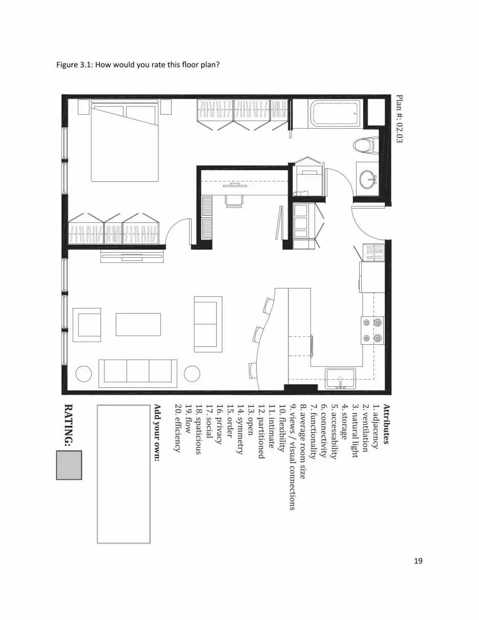
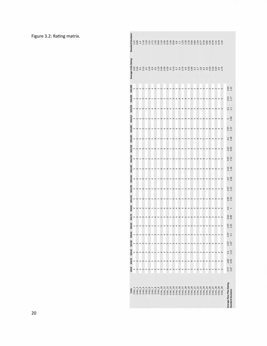
13
13
13
13
13
13
13
13
13
13
13
13
13
13
13
13
13
13
13
13
13
13
13
13
13
13
13
13
13
13
13
20
Figure 32 RaƟ ng matrix
21
CollaboraƟ ve Filtering (CF) is a method for making automaƟ c predicƟ ons (fi ltering) about the interest or
taste of a user by collecƟ ng and analyzing the personal preferences of many other users (collaboraƟ ve)
The fi rst system to use CF was the InformaƟ on Tapestry project at Xerox PARC (Goldberg et al 1992)
In general CF systems can be categorized as user-based or item-based User-based CF systems do the
following
bull Look for users who share the same raƟ ng paƩ ern with the acƟ ve user (ie the user for whom we are
trying to make a predicƟ on)
bull Use the raƟ ngs from those like-minded users to formulate a predicƟ on for the acƟ ve user
AlternaƟ vely item-based CF systems focus on items and the relaƟ onships amongst them to make
predicƟ ons eg ldquoUsers who bought X also bought Yrdquo (popularized by Amazoncom) Item-based CF
systems do the following
bull Build a Similarity Matrix to determine the relaƟ onship between pairs of items
bull Use the Similarity Matrix and userrsquos personal data to formulate a predicƟ on
CollaboraƟ ve Filtering
22
When wersquore interested in fi nding good recommendaƟ ons we tend to turn to people with a similar taste
to ours User-based collaboraƟ ve fi ltering takes the same approach by comparing us the acƟ ve user with
everyone else fi nding those who are most similar and using their preferences to make a predicƟ on about
what we like In user-centered architecture this approach takes advantage of design preferences and
taste expressed by various users to help other users fi nd what they need To illustrate how user-based
collaboraƟ ve fi ltering works a brief experiment was conducted using the data set of fl oor plan raƟ ngs to
predict a raƟ ng for a fi cƟ Ɵ ous user (referred to as CriƟ c_N) who rated some but not all the fl oor plans
The algorithm (Segaran 2007) presented in pseudocode (Figure 33) starts by iteraƟ ng through all users
and compuƟ ng their similarity to CriƟ c_N using a Pearson correlaƟ on coeĸ cient (Eq 31) Then the
algorithm iterates through every item ie fl oor plan and computes the weighted average raƟ ng (Eq
32) by mulƟ plying each of the raƟ ngs by the criƟ csrsquos similarity score and summing over all the scores
The intuiƟ on behind weighƟ ng the raƟ ngs is that users who are more like CriƟ c_N will have more weight
put on their raƟ ngs whereas raƟ ngs by users who are diī erent will receive very liƩ le weight Finally the
algorithm normalizes sorts and returns the result as predicted raƟ ngs for CriƟ c_N (Figure 34)
C CriƟ cM RaƟ ng MatrixU AcƟ ve UserFor each C in M If C is not U Then compute Similarity of C and U (see Eq 31)For each Item in M If Item was not rated by U Then compute user similarity weighted average raƟ ng (see Eq 32) And store it in ListNormalize ListSort List based on normalized weighted similarityReturn List
User-Based RecommendaƟ ons
Figure 33 Pseudocode for user-based recommendaƟ on
13
13 13
13 13
13
13
13
13 13
23
(Eq 31)
(Eq 32)
(Eq 33)
In order to measure the predicƟ ve power of the proposed algorithm the raƟ ngs matrix was transformed
into a test set by randomly deleƟ ng raƟ ngs in criƟ cs 1 through 8 The missing raƟ ngs were then esƟ mated
and the Root Mean Square Error (Eq 33) was computed yielding a value of 114 (Figure 35) To evaluate
this result (114) RMSE was calculated ten more Ɵ mes subsƟ tuƟ ng missing raƟ ngs with random numbers
between 1 and 5 yielding an average value of 195 The results show that the algorithm makes predicƟ ons
which are beƩ er than chance with an error that is 58 of the random error In addiƟ on RMSE was
calculated for CriƟ c_30 with 5 10 and 15 raƟ ngs yielding 131 124 and 087 respecƟ vely These results
indicate that by raƟ ng more fl oor plans criƟ cs improve the accuracy of the recommendaƟ ons they get
Figure 34 Predicted raƟ ngs (in green) and iniƟ al raƟ ngs (in yellow) for CriƟ c_N
13
13
13
13
13
24
Figure 35 Test matrixPredicted raƟ ngs (in green) and iniƟ al raƟ ngs (in yellow) for criƟ cs 1 through 8 used to calculate algorithmrsquos predicƟ ve power by measuring the Root Mean Square Error (RMSE)
25
When a data set like the raƟ ng matrix becomes very large a user-based approach might start to break
down due to the computaƟ onal cost of usersrsquo pairwise comparison An item-based approach alleviates
this problem by pre-compuƟ ng a similarity matrix for all items The assumpƟ on is that items do not change
as frequently as users therefore the similarity matrix will only need to be updated every once in a while
Amazoncom for example uses an item-based approach ie item-to-item collaboraƟ ve fi ltering (Linden
et al 2003) to recommend products to its users (Figure 36)
Making recommendaƟ ons using item-based collaboraƟ ve fi ltering consists of the following steps pre-
compuƟ ng an item-to-item similarity matrix looking up the acƟ ve userrsquos top-rated items and creaƟ ng
a weighted list of the most similar items To illustrate how this works an algorithm (Segaran 2007) was
tested with the raƟ ngs matrix to get recommendaƟ ons for CriƟ c_N (Figure 37)
CriƟ c_Nrsquos rated items
(50 SOL25) (20 SOL81) (10 SOL158)
CriƟ c_Nrsquos recommended items
(50 SOL9) (365 SOL74) (324 SOL144) (285 SOL202) (281 SOL228) (267 SOL224) (249 SOL212)
(243 SOL33) (209 SOL125) (15 SOL38) (142 SOL59) (141 SOL54) (10 SOL139)
Item-Based RecommendaƟ ons
Pre-compute item similarity matrix with user-based approach but subsƟ tuƟ ng items for users by transposing the raƟ ng matrixFor each Item1 in Userrsquos items For each Item2 in Item1rsquos similarity matrix If User has already rated Item2 Then conƟ nue to the next iteraƟ on of the loop Compute item similarity weighted raƟ ng (see Eq 32) Compute average of weighted item raƟ ngs And save them in ListSort List based on normalized weighted item similarityReturn List
Figure 36 Pseudocode for item-based recommendaƟ on
Figure 37 Item-based recommendaƟ ons for CriƟ c_N
26
Figure 37 shows that given CriƟ c_Nrsquos high raƟ ng of fl oor plan SOL25 the algorithm recommended SOL9
as the highest ranking (best matching) item Figure 38 validates the algorithmrsquos precision and predicƟ ve
power as the two fl oor plans are nearly idenƟ cal There are some minor diī erences between the two
fl oor plans for example SOL9 has a bar-top dining table but SOL25 has a 6-seat standalone dining table
However the overall similarity of the two fl oor plans is evident and emerges from the usersrsquo raƟ ngs
In order to compare the performance of the algorithm a random criƟ c was selected (CriƟ c_30) all but the
fi rst fi ve of his raƟ ngs deleted and then predicted by each of the algorithms The RMSE for the user-based
algorithm was 118 and the item-based algorithm was 161 indicaƟ ng that user-based recommendaƟ ons
are more accurate than item-based recommendaƟ ons However there are other issues to consider besides
accuracy when choosing one algorithm over the other for example size of data set and frequency of
change have a tremendous infl uence on the performance of these algorithms
User-Based vs Item-Based RecommendaƟ ons
Figure 38 SOL9 (LeŌ ) and SOL25 (Right) with a similarity score of 004
27
Clustering or Cluster Analysis is a way of discovering and visualizing groups of things - people news
stories blogs and more This secƟ on will focus on two clustering techniques - Hierarchical and K-means -
and apply them to the raƟ ngs matrix in order to discover groups of criƟ cs and fl oor plans In user-centered
architecture these clusters can be uƟ lized for example to infer a new userrsquos design preferences by fi nding
his cluster membership A user who has been assigned to a certain cluster shares the design preferences
of that cluster making it possible to tailor design recommendaƟ ons to his taste
Figure 39 is the pseudocode for a simple hierarchical clustering algorithm (Segaran 2007) The algorithm
starts by assigning each item ie fl oor plan to a cluster of its own Then the distance between every pair
of clusters is calculated and the closest (most similar) ones are merged together to form a new cluster
The process is repeated unƟ l there is only one cluster leŌ The algorithm uses the Pearson correlaƟ on
coeĸ cient to compute the distance between clusters
Figure 310 shows the groups of criƟ cs discovered when running the hierarchical clustering algorithm on
the raƟ ng matrix The dendrogram clearly separates the criƟ cs into two groups each characterized by
its own design preferences as extracted from the raƟ ngs Each of the two main clusters contains smaller
clusters for example criƟ cs 16 8 30 6 11 and 3 form a cluster within the bigger cluster at the top
of Figure 310 Rated fl oor plans were also clustered (Figure 311) by running the hierarchical clustering
algorithm on a rotated raƟ ng matrix Clustering shows two disƟ nct clusters made up of smaller clusters
such as fl oor plans SOL9 25 74 224 and 228 (Figure 312)
Clustering
Hierarchical Clustering
Figure 39 Pseudocode for hierarchical clustering
IniƟ alize all rows to be clustersCreate BigClusterWhile number of Clusters is bigger than 1 For each pair of Clusters Find the pair with the smallest distance Calculate the average of the two Clusters Combine the two clusters to form a new Cluster Add new Cluster to BigClusterReturn BigCluster
28
Gender analysis (MaleFemale )Top cluster - 6040BoƩ om cluster - 5050
Analysis reveals that clusters are gender neutral suggesƟ ng that gender may not play a role in the design preferences of architects
Figure 310 Hierarchical clustering of criƟ cs
29
Figure 311 Hierarchical clustering of fl oor plans
30
Figure 312 Clustered fl oor plans
AƩ ributes of clustered fl oor plans (parƟ al list)bull A small bathroombull A large kitchenbull A dining tablebull Clearly defi ned private amp public spaces
SOL9
SOL74
SOL25
SOL224
SOL228
31
Hierarchical clustering is computaƟ onally expensive because the pairwise distance calculaƟ ons have to
be carried out every Ɵ me clusters are merged therefore this method might break down on larger data
sets K-means clustering takes a diī erent approach because the number of clusters is specifi ed in advance
removing some of the ambiguity in dividing up the data
The K-means clustering algorithm (Segaran 2007) presented as pseudocode (Figure 313) starts by
randomly placing centroids ie center of the cluster and assigning every item to the nearest one Then
each centroid is shiŌ ed to the average locaƟ on of the items it contains items are reassigned and the
process repeats itself unƟ l the assignments stop changing
Figure 314 shows the K-means clustering of fl oor plans with diī erent values of K
K-means Clustering
Figure 313 Pseudocode for K-means clustering
M RaƟ ng MatrixFor each Item in M Compute the Min and Max value of Item Create K randomly placed centroids While assignment of Item is changing Find the closest centroid to Item Assign Item to centroid Move centroid to average locaƟ on of ItemsReturn K Clusters
K=8 SOL(158 169 268) (144 149) (925) (74) (33) (150) (202 212224 228) (38 54 59 81 125 139)
K=5 SOL(54 59 125 139 158) (25 74 144 202 224) (33 228 268) (149 150 169) (9 38 81 212)
K=3 SOL(9 25 74 228) (38 81 144 149 150 202 212 224) (33 54 59 125 139 158 169 268)
Figure 314 K-means clustering of fl oor plans
32
Items in the raƟ ng matrix are mulƟ dimensional ie each fl oor plan is represented by a vector of 30
raƟ ngs MulƟ dimensional scaling is a technique for fi nding a two-dimensional representaƟ on of the raƟ ng
matrix which is someƟ mes easier to understand than a dendrogram
The algorithm (Segaran 2007) presented as pseudocode (Figure 314) starts by calculaƟ ng the target
distances between all the items Next all items are placed randomly on a two-dimensional plane The
current distances between all the items are calculated using the actual distance ie the sum of the
squared diī erences For every pair of items the target distance is compared to the current distance to
calculate the error Every item is moved a small amount in proporƟ on to the direcƟ on of the error between
the two items The process is repeated unƟ l the total error cannot be reduced by moving any of the items
Figure 315 shows the results of running the mulƟ dimensional scaling algorithm on the raƟ ng matrix
All three methods when applied to the fl oor plans produced comparable results making the choice
of any one method unclear This is due to the small size of the data set and some ad-hoc choices of
parameters for the algorithms With a more extensive data set one expects to evaluate and choose based
upon computaƟ onal cost of the algorithm moƟ vaƟ on for and use of the derived informaƟ on and auxiliary
informaƟ on from the problem domain
MulƟ dimensional Scaling
Hierarchical Clustering vs K-means Clustering vs MulƟ dimensional Scaling
Figure 314 Pseudocode for MulƟ dimensional scaling
M RaƟ ng MatrixFor each Item1 and Item2 in M Compute the real distance between Item1 and Item 2 Randomly place Item1 and Item2 in 2D spaceWhile TotalError is changing Find the projected distance between Item1 and Item2 Calculate Error between real and projected distance Move Item1 and Item2 in proporƟ on to Error Update TotalErrorReturn locaƟ on of Items
SOL228
SOL38
SOL59
SOL54
SOL33SOL125
SOL139
SOL169
SOL268
SOL150
SOL149
SOL144
SOL9
SOL224
SOL25
SOL74
SOL158
SOL212
SOL81
SOL202
33
Figure 315 MulƟ dimensional scaling of raƟ ng matrixColored boxes correspond to the hierarchical clustering in Figure 311
=X
Plan 4
Features Matrix Weights Matrix
Plan 4
34
Figure 316 Non-NegaƟ ve Matrix FactorizaƟ on
The rated fl oor plans in the data set share certain features such as an open kitchen private vs public
spaces and others These features are latent - hidden between the raƟ ngs - and in order to extract them
the raƟ ng matrix has to be factored It is important to note that these features are not the same as the
aƩ ributes given to the criƟ cs to help them rate the fl oor plans There is no way to be absolutely sure of
what a feature represent All that can be done is to examine the set of fl oor plans which share the feature
and aƩ empt to visually arƟ culate it
Figure 316 describes the process of matrix factorizaƟ on The goal is to factor the matrix ie fi nd two
smaller (lower rank) matrices - a features matrix and a weights matrix - that when mulƟ plied together
reconstruct the original matrix The features matrix has features for rows and fl oor plans for columns
The value in each cell of the matrix indicates how important that fl oor plan is to the feature The weights
matrix maps the features to the raƟ ng matrix Each row is a criƟ c and each column is a feature The value
in each cell of the matrix indicates how much a feature applies to a fl oor plan Therefore reconstrucƟ ng
the raƟ ng matrix is a maƩ er of combining rows from the features matrix in diī erent amounts The weights
matrix maps the features to the raƟ ngs Non-negaƟ ve refers to the fact that all features and weights must
be posiƟ ve For a more comprehensive descripƟ on of the algorithm see (Segaran 2007)
Using a Non-NegaƟ ve Matrix FactorizaƟ on algorithm the raƟ ng matrix was factored into a features matrix
and a weights matrix The algorithm was programmed to fi nd 10 features Figure 317 represents 5 of
the 10 features as a list of fl oor plans that contain the feature As menƟ oned the features are latent
therefore feature 5 for example is shared by fl oor plans 149 150 169 and 268 An hypothesis of what
the feature represents is proposed by looking at the commonaliƟ es of the fl oor plans that defi ne the
feature (Figure 318)
Feature ExtracƟ on (Non-NegaƟ ve Matrix FactorizaƟ on)
35
Figure 317 5 features extracted from the raƟ ng matrix
(SOL81 SOL224)
(SOL149 SOL150 SOL169 SOL268)
(SOL202 SOL212)
(SOL158 SOL228)
(SOL33 SOL54 SOL59 SOL125 SOL139)
Feature 4
Feature 5
Feature 7
Feature 8
Feature 9
ConclusionsThe dataset used in these experiments is extremely small compared to the Neƞ lix or Amazon data sets
Nevertheless each of the applied methods revealed some interesƟ ng informaƟ on about the data - criƟ cs
fl oor plans and the relaƟ onship between them
CollaboraƟ ve fi ltering whether user or item based showed that it is possible to leverage a communityrsquos
opinion expressed through raƟ ngs in order to help an individual fi nd what he likes Analysis of the
algorithm showed that it performs much beƩ er than a random guess
Clustering - Hierarchical K-means or MulƟ dimensional Scaling - showed that it is possible to fi nd groups of
criƟ cs and fl oor plans and uncover their common characterisƟ cs With a large enough data set clustering
can be used to extract user and design typologies which can help stakeholders in the building industry -
contractors developers architects etc - tailor their services to clientsrsquo needs
Feature ExtracƟ on showed that it is possible to extract the features of a fl oor plan in order to create a
design vector The design vector can be used to score fl oor plans based on a userrsquos interest in one or all of
its features allowing the user to explore the design space in mulƟ ple direcƟ ons
36
Figure 318 ArƟ culaƟ ng Feature 5 through its fl oor plansFeature 5 could be the free-standing column that appears in all the fl oor plans below
SOL149 SOL150
SOL169 SOL268
37
References amp Suggested Reading List1 Billsus D amp Pazzani M J (1998) Learning collaboraƟ ve informaƟ on fi lters Proceedings of the 15th
InternaƟ onal Conference on Machine Learning pp 46ndash542 Blei D M Ng A Y amp Jordan M I (2002) Latent Dirichlet allocaƟ on Advances in Neural InformaƟ on
Processing Systems 143 Breese J S Heckerman D and Kardie C (1998) Empirical analysis of predicƟ ve algorithms for
collaboraƟ ve fi ltering In Proceedings of the 14th Conf on Uncertainty in ArƟ fi cial Intelligence pp 43ndash52
4 Goldberg D Nichols D Oki BM amp Terry D (1991) Using CollaboraƟ ve Filtering to Weave an InformaƟ on Tapestry Comm ACM vol 35 no 12 pp 61-70
5 Herlocker JL Konstan JA Borchers A and Riedl J (1999) An Algorithmic Framework for Performing CollaboraƟ ve Filtering Proc 22nd Ann Intrsquol ACM SIGIR Conf Research and Development in InformaƟ on Retrieval (SIGIR rsquo99)
6 Herlocker JL Konstan JA Terveen LG and Riedl JT (2004) EvaluaƟ ng CollaboraƟ ve Filtering Recommender Systems ACM Trans InformaƟ on Systems vol 22 no 1 pp 5-53
7 Hofmann T (2004) Latent semanƟ c models for collaboraƟ ve fi ltering ACM TransacƟ ons on InformaƟ on Systems 22 pp 89ndash115
8 Koren Y Bell R Volinsky C (2009) Matrix FactorizaƟ on Techniques for Recommender Systems IEEE Computer 082009 Volume 42 Issue 8 pp30-37
9 Linden G Smith B and York J (2003) Amazoncom RecommendaƟ ons Item-to-Item CollaboraƟ ve Filtering IEEE Internet CompuƟ ng
10 Marlin B (2004) CollaboraƟ ve fi ltering A machine learning perspecƟ ve Masterrsquos thesis University of Toronto Computer Science Department
11 Segaran T (2007) Programming CollecƟ ve Intelligence OrsquoReilly Media12 Srebro N Rennie J D M amp Jaakkola T S (2005) Maximum margin matrix factorizaƟ on Advances
in Neural InformaƟ on Processing Systems 17
38
4| UDesignWhen a user wishes to purchase an apartment from a developer he is usually presented with a few sample
apartments from which to choose These sample apartments usually oī er very few parameters that can
be changed because they are designed to fi t the taste and lifestyle of an average user The soluƟ on to
this problem can be found in two diī erent places - hardware and soŌ ware - which complement each
other to create user-centered architecture On the one hand there is hardware the building technology
that is responsible for making sure usersrsquo designs are feasible The mass-customizaƟ on community in
architecture has made considerable progress in recent years and managed to push fabricaƟ on technology
forward On the other hand there is soŌ ware the interface that is responsible for making sure users can
express their wants and needs The ability of an interface to meet usersrsquo needs depends on its front-end -
how easy it is to use the interface - and back-end - how the objects of design are represented internally in
the system This secƟ on will focus on the soŌ ware and illustrate through the implementaƟ on of UDesign
what are some of the issues to consider in terms of soŌ ware for user-centered architecture
As a framework UDesign mediates between the user and stakeholders in the building industry - architects
developers contractors suppliers realtors and community - in order to create a product in this case
an apartment Figure 41 outlines the components and relaƟ onships of user-centered architecture as a
series of four concentric circles - User UDesign Data and Stakeholders - fl oaƟ ng in Design Space the
space of design soluƟ ons oī ered to the user Metaphorically as the user is designing his own product
he is navigaƟ ng through the design space cocooned within these layers of UDesign and Stakeholders
through which he communicates his ideas about the product To visualize the metaphor imagine Figure
A Framework For User-Centered Architecture
39
Architect
Developer
DesignSpace
Realtor
Supplier
CommunityContractor
DesignLogic
Feedback
User
Stakeholders
UDesign
Data
41 as a ball fl oaƟ ng in space and rays of informaƟ on shooƟ ng from its center (User) guided by an inner
mechanism (UDesign Stakeholders) trying to fi nd an anchor in space (Design)
UDesign is comprised of four parts Design CommunicaƟ on Feedback and Logic Design is responsible
for visualizing the design space and interacƟ ng with the user In a way it is the front-end of the interface
Design includes the library of parts from which a user can choose to create his design (Friedmanrsquos
repertoire) tools to transform and edit the design and ways to explore the design space CommunicaƟ on
is responsible for the exchange of informaƟ on between user and stakeholders The radial arrangement
facilitates mulƟ ple channels of communicaƟ on at any given point in Ɵ me For example a user can
communicate with the architect in order to get professional feedback about his design while also geƫ ng
feedback from the community CommunicaƟ on must pass through UDesign to avoid overloading the user
therefore messages are stored in a queue and ordered by their relevancy to the current context of the
design process Feedback is responsible for conƟ nuously collecƟ ng informaƟ on about the state of the
design process analyzing it and providing noƟ fi caƟ ons at the right Ɵ me and place For example when a
user selects a design component he is immediately given feedback about the availability of the component
Figure 41 User-Centered Architecture
40
UDesign was implemented in Adobe Flex Builder 3 an IDE (Integrated Development Environment)
for creaƟ ng cross-plaƞ orm RIA (Rich Internet ApplicaƟ on) based on Adobe Flash A typical applicaƟ on
development process was followed including
bull Defi ning an applicaƟ on interface using a set of pre-defi ned components (forms buƩ ons and so on)
as MXML Components
bull Arranging components to create a User Interface (UI) design
bull Using styles and themes to defi ne the visual design CSS skins etc
bull Adding dynamic behavior using proper event-driven programming techniques
bull Defi ning and connecƟ ng to data services as needed MySQL ColdFusion etc
bull Compiling the source code into an SWF fi le that can be read by Flash Player and embedded within an
HTML fi le
UDesign is comprised of fi ve parts Data PersonalizaƟ on Design Contribute and Feedback (Figure 42)
where Data consƟ tutes most of the back-end and the remaining parts the front-end
The data in UDesign is stored in tables within a MySQL database that resides on a server The mxml
applicaƟ on makes requests to the database through a Flex HTTPService component In turn the
HTTPService component calls one of fi ve methods (FindAll Insert Update Delete Count) encapsulated
within a PHP fi le which then retrieves the data from the appropriate table of the database and returns the
data to the applicaƟ on in an E4X format (Figure 43)
ImplementaƟ on
Data
its price compaƟ bility with other components and more Stakeholders can use UDesignrsquos feedback to get
informaƟ on about their users - purchase history preferences lifestyle status state of the design and
more Logic is responsible for holding everything (Design CommunicaƟ on and Feedback) together so that
usersrsquo experience of UDesign is both producƟ ve and posiƟ ve Logic is supported by a suite of algorithms
from diī erent categories - user interacƟ on network database machine learning - some of which are
described in more detail in chapter 3 (Algorithms) as well as in the next secƟ on (ImplementaƟ on)
41
HTTPService
Data
Design
Contribute
Feedback
PHP
HTTPService PHP
MySQL
ContributeView
assembliesService
tagsService
usersService
Database
FeedbackView Feedback
HomeView Facebook Connect
currUser (Facebook)
UDesigners at work
Survey
DesignView
Assemblies
Tags
Users
feedbackService
IntroHomePage
PersonalizedHomePage
Floorplan
Catalog currUser (Facebook)
assembliesrooms
by selected rooms
GridCell (A1-C2)
clear
Figure 42 UDesign - system overview
42
FindAllInsertUpdateDeleteCount
Table 1Table 2Table 3
Request Request
Response ResponseFLEX PHP MySQL
E4X
The database includes the following tables
bull assemblies (Figure 44)
bull soluƟ ons (Figure 45)
bull users_saved_soluƟ ons (Figure 46)
bull users (Figure 47)
bull design_profi le (Figure 48)
bull soluƟ on_vector (Figure 49)
bull feedback (Figure 410)
Figure 43 Data pipeline
43
Table assemblies
This table holds the 48 assemblies (custom-designed rooms) available to the user on the Design page of
UDesign
Fields id room id | label room label | type room type | descripƟ on room descripƟ on | price room
price | cell an index indicaƟ ng to what funcƟ onal zone the room belongs (more details below) | area
room area (sqŌ ) | dimx room dimension in x-axis (pixels) | dimy room dimension in y-axis (pixels) | locx
room posiƟ on in x-axis (pixels) | locy room posiƟ on in y-axis (pixels) | color room color code | fi t a fl ag
indicaƟ ng whether the room fi tsdoesnrsquot fi t with the userrsquos design (more details below)
Table soluƟ ons
This table holds the 285 soluƟ ons (custom-designed fl oor plans) available to the user on the Design page
of UDesign
Fields id fl oor plan id | label fl oor plan label | A1 - C2 a funcƟ onal zone in the fl oor plan (more details
below)
Table users_saved_soluƟ ons
This table holds usersrsquo saved soluƟ ons (custom-designed fl oor plans) created by users on the Design page
of UDesign
Fields id fl oor plan id | label fl oor plan label | A1 - C2 a funcƟ onal zone in the fl oor plan (more details
below)
Table users
This table temporarily holds usersrsquo personal informaƟ on obtained from their Facebook account (more
details about UDesignrsquos connecƟ on to Facebook in the secƟ on about PersonalizaƟ on)
Fields (Facebook generated) uid userrsquos id | about_me userrsquos personal message | acƟ viƟ es userrsquos
favorite acƟ viƟ es | birthday userrsquos birthday | books userrsquos favorite books | fi rst_name userrsquos fi rst name
| interests userrsquos interests | last_name userrsquos last name | movies userrsquos favorite movies | music userrsquos
favorite music | pic userrsquos profi le picture | relaƟ onship_status userrsquos current relaƟ onship status | sex
userrsquos gender | wall_count number of posts on userrsquos wall
44
Table design_profi le
This table holds usersrsquo design profi le Users are presented with ten parameters of lifestyle and asked to
rate their importance on a scale of one (low) to fi ve (high)
Fields id userrsquos Facebook id | watch importance of watching TVMovies | entertain importance
of entertaining | cook importance of cooking | work importance of being able to work from home |
privacy importance of privacy | pamper importance of pampering | storage importance of storage |
kitchen_dining importance of physicalvisual connecƟ on between kitchen and dining room | bed_bath
importance of physicalvisual connecƟ on between bedroom and bathroom | fl exible importance of
fl exible living space
Table soluƟ on_vector
This table holds the design vectors for 71 out of 285 soluƟ ons (custom-designed fl oor plans) where each
soluƟ on is represented as a diī erent combinaƟ on of the same parameters used to defi ne userrsquos design
profi le (more details in the secƟ on about the Design page) Values indicate how much the corresponding
parameter is present in the soluƟ on
Fields label soluƟ on label | watch supports watching TVMovies | entertain supports entertaining |
cook supports cooking | work supports being able to work from home | privacy supports privacy |
pamper supports pampering | storage amount of storage | kitchen_dining degree of physicalvisual
connecƟ on between bedroom and bathroom | bed_bath degree of physicalvisual connecƟ on between
bedroom and bathroom | fl exible amount of fl exible living space
Table feedback
This table holds usersrsquo feedback submiƩ ed through the feedback form on UDesign (more details below)
Fields subject subject of the feedback | content content of the feedback
45
id label type description price cell area dimx dimy locx locy color fitid label type description price cell area dimx dimy locx locy color fitA11BT001 Bathroom Bathroom 99 A1 68 174 166 0 0 0x0071BC 0A11BT002 Bathroom Bathroom 99 A1 68 174 166 0 0 0x0071BC 0A12BT001 Bathroom Bathroom 99 A1 100 250 166 0 0 0x0071BC 0
id label A1 A2 B1 B2 C1 C2id label A1 A2 B1 B2 C1 C2SOL1 322000 A12BT001 A21KT001 B15ST001 B21DN001 C15BD001 C23LV001SOL10 123000 A11BT001 A22KT005 B15ST001 B21DN001 C15BD001 C23LV001SOL100 453243 A11BT001 A22KT004 B12BD001 B25DN001 C12BD001 C25LV004
id label A1 A2 B1 B2 C1 C2id label A1 A2 B1 B2 C1 C2652795248 A11BT001 A22KT003 B13BD001 B25DN001 C11ST001 C25LV002717158422 brain drain A11BT001 A22KT001 B15ST004 B25DN002 C13BD001 C23LV001533833493 carlyu A12BT001 A21KT001 B15ST001 B21DN001 C15BD001 C23LV001
id watch entertain cook work privacy pamper storage kitchen_dining bed_bath flexibleid watch entertain cook work privacy pamper storage kitchen_dining bed_bath flexible1065658831 3 5 5 1 1 1 3 5 1 1542150884 5 2 4 1 4 1 3 1 1 1566433466 1 5 5 2 2 1 2 4 2 1
label watch entertain cook work privacy pamper storage kitchen_dining bed_bath flexiblelabel watch entertain cook work privacy pamper storage kitchen_dining bed_bath flexibleSOL1 3 2 2 5 4 5 3 5 1 1SOL2 3 2 2 4 4 5 4 5 5 1SOL3 3 2 2 5 4 5 4 1 1 1
subject contentsubjectthis is my feedback feedback feedbackscrolling hi junnoNice work Good start Maybe I am to quick to try out everything-
the scroll bar or the arrow It is just a little bit annoying )-And will I be abproportions to the lenght of the walls I tried the little pen and ruler tool b
Figure 44 - 410 Database tables (from top to boƩ om)
46
PersonalizaƟ on
UDesignrsquos home page has two states an introducƟ on page (Figure 411) and a personalized page (Figure
412) The introducƟ on page is the fi rst page to be displayed when a user fi rst loads the applicaƟ on It
contains informaƟ on about the applicaƟ on and how to use it To start using the applicaƟ on a user must log
in using their Facebook account by pressing the Facebook Connect buƩ on Facebook Connect is integrated
into the Adobe Flex applicaƟ on using the Facebook API and corresponding Flash-Flex libraries By signing
in to UDesign through Facebook Connect a user gives the applicaƟ on permission to make requests to
Facebook and retrieve their personal informaƟ on (according to the userrsquos privacy seƫ ngs)
The informaƟ on from Facebook now encapsulated as a FacebookUser object is leveraged to provide the
user with tailored recommendaƟ ons of design soluƟ ons ie custom-designed fl oor plans As shown in
chapter 3 (Algorithms) usersrsquo informaƟ on whether itrsquos raƟ ngs or a Facebook profi le can be represented
as a vector (Figure 413) and compared to other users in order to cluster the UDesign community Once
a user is clustered other members of the cluster become his design criƟ cs and their design soluƟ ons are
oī ered as recommendaƟ ons (Figure 414) That is the case with a new user or a user who has not created
rated or saved any design soluƟ ons When a user has given feedback implicitly (by saving certain design
soluƟ ons) or explicitly (by raƟ ng design soluƟ ons) his recommendaƟ ons are updated and improved
through a user-based collaboraƟ ve fi ltering algorithm As shown in chapter 3 (Algorithms) the algorithm
Figure 411 IntroducƟ on home page
47
compares the current user to the enƟ re UDesign community fi nds the most similar users and collects
the highest rated design soluƟ ons from these users as recommendaƟ ons Consequently the more design
soluƟ ons users rate the more accurate UDesignrsquos recommendaƟ ons get (see chapter 3)
Once the user has logged in and UDesign has made a request to Facebook to retrieve the userrsquos personal
informaƟ on the applicaƟ on waits for the response and then temporarily stores it as a FacebookUser object
for the duraƟ on of the session If log in is successful the user is automaƟ cally navigated to a personalized
home page which includes the following userrsquos Facebook picture and name userrsquos Rated Design Profi le
UDesigners at work and Survey
The userrsquos Rated Design Profi le (Figure 415) is a set of ten lifestyle parameters that capture the userrsquos
preferences in respect to the database of 285 fl oor plans available in UDesign For each opƟ on the user
has to rate the importance of that aspect on a scale of one (low) to fi ve (high) For example if the user
is an avid baker he might rate high the following parameters cooking connecƟ on between kitchen and
dinning and entertaining to refl ect their importance in his lifestyle The user has the opƟ on to go back and
change his raƟ ngs at any Ɵ me by making the changes and pressing the Update buƩ on The Rated Design
Profi le complements the Facebook informaƟ on as they are both used to model the user and provide him
Figure 412 Personalized home page
48
with recommendaƟ ons of design soluƟ ons
UDesigners at work features the Facebook profi le pictures of the UDesign community with which the
current user may wish to interact - comment on designs share designs ask quesƟ ons share informaƟ on
and more Finally a short survey is included with various design styles and lifestyle parameters The user
is asked to indicate whether or not they are relevant to him The results of the survey are collected and
aggregated across the enƟ re UDesign community to understand trends and user typologies
49
Age Sex School Job
32 Male MIT House_n
29 Male MIT House_n
Yes
Yes
In a
Figure 413 User vectors
Design
The Design page (Figure 416) is where users create their custom apartment and it includes three main
components fl oor Plan catalog and recommendaƟ ons
The fl oor plan (Figure 417) has two components - toolbar and sample fl oor plan - with which a user can
interact to create their design The toolbar oī ers the following funcƟ onality
bull Open a saved project - will load a saved design from the database
bull Create a new project - will create a new project in the database
bull Save a project - will save the current state of the design in the database
bull Undo - will undo the userrsquos last operaƟ on
bull Publish to Facebook - will post the current state of the design to the userrsquos Facebook feed (Figures
417A and 417B)
bull Clear the project - will remove everything from the sample fl oor plan
The sample fl oor plan is the empty canvas on to which a user drags and drops rooms from the catalog
(Figure 418) UDesign was implemented with a single sample fl oor plan as a proof-of-concept However
in reality UDesign should be able to oī er users a variety of fl oor plans to customize as well as an opƟ on
to create their own fl oor plan from scratch Figure 419 explains how the sample fl oor plan is structured
such that it supports customizing EssenƟ ally the fl oor plan is divided into six funcƟ onal zones - A1 A2
B1 B2 C1 C2 - where each zone can hold one or more funcƟ ons Zones A1 and A2 have hard-coded
constraints ie A1 can only hold a bathroom and A2 a kitchen These constraints are imposed by the
50
NEW USER
Figure 414 Clustering users to fi nd recommendaƟ ons
51
Figure 415 Rated Design Profi le
buildingrsquos infrastructure for example the locaƟ on of plumbing risers The remaining zones can each take
a number of prescribed funcƟ ons - dining room bedroom closet media room and more - according to
the userrsquos choice
The Catalog (420) holds the assemblies (custom-designed rooms) that a user can add to the sample fl oor
plan The catalog includes an informaƟ on box with the userrsquos Facebook name and the Ɵ tle of the project
It also has a drop-down list of room types that fi lters the available rooms according to the selected type
eg bathroom kitchen dining etc Rooms are represented as Ɵ les When a room is clicked a pop-up
window appears with addiƟ onal details Room Ɵ les can be dragged and dropped onto the fl oor plan
(Figure 418) Each room has a prescribed locaƟ on within the fl oor plan to refl ect real-world constraints
Once a room has been dragged and dropped on to the fl oor plan an algorithm (Figure 421) updates the
rooms in the catalog to refl ect which ones fi t and which ones donrsquot with the userrsquos current selecƟ on of
rooms The ill-fi ƫ ng rooms are grayed-out (disabled) The recommendaƟ on lists also update (see below)
The recommendaƟ ons (Figure 422) are represented as two lists of soluƟ ons (custom-designed fl oor
52
Figure 416 Design page
plans) that are updated to refl ect (a) soluƟ ons which are compaƟ ble with the userrsquos currently selected
rooms and (b) the ten highest ranking soluƟ ons which best fi t the userrsquos Design Profi le RecommendaƟ ons
Based on your selecƟ on of rooms (Figure 422) are generated and updated using the algorithm described
in Figure 421 RecommendaƟ ons Based on your design profi le (Figure 422) are generated and updated
using the user-based recommendaƟ on algorithm described in chapter 3 (Figure 33) When a user clicks on
any of the recommendaƟ ons a pop-up window appears with addiƟ onal details about the selected fl oor
plan an explanaƟ on of why the fl oor plan was recommended and an opƟ on to add the selected fl oor plan
to the sample fl oor plan (Figure 423) If the user clicks the Add To My Project buƩ on the userrsquos sample
fl oor plan is cleared and the rooms of the currently selected fl oor plan are added instead
From a usability perspecƟ ve the Design page uses the direct manipulaƟ on design paƩ ern to facilitate a
seamless intuiƟ ve and eĸ cient design process for users Following a gradual learning curve a user can
create his own custom fl oor plan within a maƩ er of minutes by using the catalogrsquos drop-down menu
locaƟ ng a room and adding it to the sample fl oor plan
53
Figure 417 Floor Plan Component - sample fl oor plan and toolbar
Figure 417A PosƟ ng a fl oor plan to Facebook from within UDesign
54
Figure 417B The posted fl oor plan in Facebook
Figure 418 Drag and drop rooms
55
UDesign
How does it work
174 250
166
89
148
207
159
218
277
234 310
A1 A2
B1 B2
C1 C2
Figure 419 How does it work
56
UDesign
How does it work
174 pixels
166 pixels
Figure 419 How does it work (conƟ nued)
57
UDesign
How does it work
A1
B1
C1
A2
B2
C2
Figure 419 How does it work (conƟ nued)
58
Figure 420 Catalog
Figure 421 Pseudocode of algorithm for updaƟ ng soluƟ ons and assemblies
For each SoluƟ on For each Assembly in SoluƟ on If Assembly is in the userrsquos sample fl oor plan Save SoluƟ on Save AssemblyFor each SoluƟ on in RecommendaƟ ons Update SoluƟ onFor each Assembly in Catalog Update Assembly
59
Figure 422 RecommendaƟ ons
Figure 423 SoluƟ on details
60
Figure 424 Contribute page
UDesign is intended to be extended by its user community A user who is interested in contribuƟ ng a
new design can download the Starter Kit (a template fi le of available rooms in Adobe Illustrator andor
Autodesk Autocad format) design their own room or fl oor plan and send it via e-mail to be added to
the UDesign database (Figure 424) The ldquostarter kitrdquo is a fi le containing drawings However the current
approach is far from ideal and leaves much to be desired As an improvement the web applicaƟ on can
include an integrated confi guraƟ on tool which will let users edit any available assembly and save it as
their own A more comprehensive discussion of how to extend and scale UDesign is reserved for the
conclusions
To improve UDesign a simple feedback form is implemented allowing users to write comments and
suggesƟ ons and submit them to the system (Figure 425) Once a form is submiƩ ed it is saved in the
feedback table (Figure 410) and awaits a response by the applicaƟ on administrator
Contribute
Feedback
61
Figure 425 Feedback page
References amp Suggested Reading List1 UDesign hƩ ppeoplecsailmitedujunnohgp (May 20 2010)
62
This thesis proposes a framework for user-centered architecture and provides a proof-of-concept in the
form of a web applicaƟ on that allows users to create their own custom apartment The ideas presented
in this thesis are merely a starƟ ng point and fall short of solving the problem To miƟ gate the situaƟ on
this secƟ on suggests ways of improving some of the ideas presented as well as addiƟ onal direcƟ ons for
future work
This thesis started out by framing its conceptual framework through the work of Yona Friedman on user-
centered design Friedmanrsquos work is compelling however it is sƟ ll very much focused on the architect as
the sole cause of problems in the design process As I have shown in chapters three and four a community-
based approach supported by collaboraƟ ve fi ltering algorithms and social networks (eg Facebook) can
provide users with the safety net they need in order to feel comfortable designing their own spaces and
living soluƟ ons There is a specifi c reference by Friedman when he talks about the repertoire to all
possible design soluƟ ons which I fi nd problemaƟ c It seems to me that any system that forces its users
to navigate through a huge corpus of data compromises its usability For example if the repertoire had
thousands of possible design soluƟ ons would a user be able to fi nd what he needs And if he could how
long would it take him These quesƟ ons raise doubts in my mind as to the ability of Friedmanrsquos system to
respond to usersrsquo needs in terms of eĸ ciency (Ɵ me) and visibility (fi nding what they need) Furthermore
any system that proposes to fi nd ALL possible soluƟ ons must also address the issue of Completeness or in
Yona Friedman Reloaded
5| Conclusions
63
RepresentaƟ on
other words provide proof that there are no other possible design soluƟ ons beyond those found in the
repertoire Finally I would argue that users arenrsquot interested in all possible design soluƟ ons but just those
that fi t their needs Finding these needs is a diĸ cult problem with the beginning of a soluƟ on in chapters
three and four
Marshall McLuhan (McLuhan 1964) coined the phrase ldquoThe medium is the messagerdquo The medium in the
context of architectural design is how we choose to represent the fi nished product Whether through 2D
fl oor plans or 4D fl y-through animaƟ ons the message has to be received and understood on the userrsquos
side The fact that users are not trained at deciphering architecturally-encoded messages (architectural
notaƟ on symbols etc) makes the task of representaƟ on that much more diĸ cult The representaƟ on
chosen for the implementaƟ on of UDesign ie a 2D fl oor plan layout comprised of funcƟ onal zones or
assemblies in PNG format leaves much to be desired First the use of the PNG format seriously hinders
usersrsquo freedom to make changes to the design at room level While only having to deal with small chunks
of space simplifi es the design task on the userrsquos end it also presents a problem when a user only wants
to move the bed in the master bedroom one foot to the leŌ This limitaƟ on will cause users to become
frustrated and the enƟ re user-centered design process to break Therefore representaƟ on should provide
users more freedom by increasing the granularity of the medium For example enabling users to edit
assemblies and then save them as their own custom components Having said that perhaps the problem
is not granularity but dimensionality In many informal discussions I conducted with users (non-experts
designers if you will) Irsquove come to realize that fl oor plans are a poor conduit for the architectural message
Most users just donrsquot get them They have a hard Ɵ me ldquosensingrdquo the space through a 2D representaƟ on
and yearn for a more engaging spaƟ al experience At this point I am tempted to suggest Virtual Reality as a
more appropriate medium for architectural data and design however it doesnrsquot seem like a viable opƟ on
in the foreseeable future If we were to consider (hypotheƟ cally speaking of course) Virtual Reality I
would imagine users being able to connect through some device to a virtual world where they could create
their own living spaces walk through them share them with others and so on A hint of the potenƟ al
of this scenario surfaced when architects started taking advantage of SecondLife by designing homes for
usersrsquo avatars UnƟ l Virtual Reality catches up videoonline games and virtual worlds provide a beƩ er
alternaƟ ve in my opinion to 2D fl oor plan layouts or even 4D walk-through animaƟ ons In an interacƟ ve
virtual environment users can create their design in 3D space walk around interact with objects explore
64
views and perspecƟ ve really ldquoseerdquo and ldquofeelrdquo the consequences of their acƟ ons and be able to share that
experience with others Another thing to consider about representaƟ on when venturing into 3D space is
the level of abstracƟ on appropriate for usersrsquo comprehension VideoOnline games are fun because they
tend to be an abstract representaƟ on of the real environment for the purpose of reducing the cogniƟ ve
load on the user On the other hand architectural design has many varying levels of abstracƟ on which are
linked to the context and posiƟ on within the design process So the quesƟ on becomes would users want
to see everything - from the texture of a wooden fl oor to the fi nish of the kitchen cabinets Or would
the level of detail dynamically change to match the userrsquos focus and locaƟ on within the design process
I suspect a dynamic and gradient control over spaƟ al details is probably more appropriate and less likely
to overwhelm the non-expert user
Scalability
At the heart of user-centered architecture is scalability - how can we create a plaƞ orm that supports
the design processes of mulƟ ple users Scalability is Ɵ ghtly coupled with representaƟ on in the sense
that representaƟ on ulƟ mately determines the degree to which a user-centered design process can scale
For example the representaƟ on chosen for implementaƟ on of UDesign has a low degree of scalability
because users canrsquot edit assemblies or create their own assemblies which is necessary if the catalog (or
repertoire) is to grow and expand A more fl exible representaƟ on one where users can manipulate low-
level components such as pieces of furniture would result in beƩ er scalability allowing users to extend
the iniƟ al catalog of assemblies Another issue to consider in regards to scalability is that of constraints
or rather the need to enforce and validate constraints In architectural design components across various
scales relate to each other in various ways through interdependencies or constraints As the number and
types of components increase so do the constraints and the complexity of validaƟ ng them For example
UDesign implicitly enforces constraints on room adjacencies through the soŌ suggesƟ ons it provides to the
user That means that if the user chooses to ignore the recommendaƟ ons he can easily place mismatching
rooms next to each other What is needed in UDesign specifi cally and user-centered design systems in
general is an adapƟ ve constraint management approach with some noƟ on of learning Ideally such a
management approach would start with a small set of predefi ned constraints and learn new constraints
from usersrsquo acƟ ons and design paƩ erns The goal is to avoid having to hard-code the constraints but rather
infer them from what users do as they are designing Winston (Winston 1972) developed the noƟ on of
learning (constraints) from examples and demonstrated the applicaƟ on of his approach in the construcƟ on
65
of an arch Using examples of what consƟ tutes an arch (good examples) what doesnrsquot (bad examples)
and whatrsquos close enough (near miss) Winstonrsquos approach incrementally constructs a semanƟ c net that is a
representaƟ on of the arch and its embedded constraints A similar approach may be applicable in UDesign
where a userrsquos acƟ ons are being tracked parsed and interpreted to construct a semanƟ c representaƟ on
of his design and its embedded constraints
CollaboraƟ on
Architectural design is a collaboraƟ ve eī ort that includes the input of many diī erent experts such as
architects contractors users and many others Therefore therersquos no reason why non-experts couldnrsquot
take advantage of the same approach and collaborate amongst themselves to help each other create
beƩ er designs CollaboraƟ on is addressed in UDesign by giving users the opƟ on to publish their work on
Facebook This form of social collaboraƟ on can potenƟ ally help a user who is trying to get some feedback
However what is needed is an addiƟ onal form of collaboraƟ on where a user can remotely interact with
another userrsquos design Hands-on remote collaboraƟ on is a more expressive approach to design that
facilitates users designing together
Data CollecƟ on
The majority of approaches discussed in this thesis (eg the algorithms in chapter three) are data-driven
meaning that without suĸ cient data they become inaccurate or just donrsquot work In fact the more
data the less sensiƟ ve these algorithms are to outliers and the more accurate the recommendaƟ ons
Unfortunately in the course of wriƟ ng this thesis and developing UDesign I was unable to collect as much
data as I had hoped As a result I can only speculate as to the performance and potenƟ al contribuƟ on of
my approach to user-centered architecture
RecommendaƟ ons
As a corollary to data collecƟ on this thesis lacks a comprehensive evaluaƟ on of the diī erent methods
discussed in chapter three In order to eī ecƟ vely measure the performance of various collaboraƟ ve
fi ltering approaches one needs access to a suĸ ciently large data set I believe that with addiƟ onal Ɵ me
and eī ort such a data set can be obtained for architectural design specifi cally in the residenƟ al sector
and then the collaboraƟ ve fi ltering methods discussed in this thesis will be able to accurately match users
and design soluƟ ons
66
Usability
For any user-centered architecture framework to be successful it must fi rst be usable UDesign was
implemented as a web applicaƟ on following standard usability design guidelines and an iteraƟ ve UI design
process However there is much more that can be done in terms of prototyping UI design and user
tesƟ ng
ContribuƟ ons
In this thesis I propose a framework for user-centered architecture called UDesign and describe its
implementaƟ on as a web applicaƟ on that allows users to design their own custom apartment UDesign
includes a sample one-bedroom apartment which users can customize through a kit-of-parts approach
ie a catalog of rooms (called assemblies) that can be combined to create a complete fl oor plan soluƟ on
While available confi guraƟ on tools in architecture require the user to think like an expert eg integrate
form and funcƟ on UDesign takes a novel approach by deploying a suite of machine learning algorithms
coupled with data from Facebook to model usersrsquo design preferences and match them with design
soluƟ ons Users can take advantage of these recommendaƟ ons as their design starƟ ng point and conƟ nue
to explore other alternaƟ ves by dragging and dropping rooms from the catalog on to the sample fl oor
plan As users explore design soluƟ ons UDesign updates its recommendaƟ ons to guide users through the
design space and helps them fi nd soluƟ ons that best fi t their needs Finally UDesignrsquos integraƟ on with
Facebook allows users to share their designs making UDesign part of their social network
References amp Suggested Reading List1 Winston P H (1970) Learning Structural DescripƟ ons From Examples AI Technical Reports ArƟ fi cial
Intelligence Lab MassachuseƩ s InsƟ tute of Technology Cambridge MassachuseƩ s2 McLuhan M (1964) Understanding Media The Extensions of Man 1st Ed McGraw Hill NY 1964
reissued MIT Press 1994 with introducƟ on by Lewis H Lapham reissued by Gingko Press 2003 ISBN 1-58423-073-8
Appendix
Assemblies
A compilaƟ on of assemblies (rooms) and soluƟ ons (fl oor plans) included in UDesign and throughout the thesis Total number of assemblies = 48 soluƟ ons = 285 Only 20 of each are shown here
A11BT001
A12BT001
A11BT002
A12BT002
ͺ
A21KT001
A22KT001
A21KT002
A22KT002
ͻ
A22KT003 A22KT004
Ͳ
A22KT005
B11CL001
A22KT006
B12BD001
ͳ
B12CL001
B14CL001
B13BD001
B15ME001
ʹ
B15ST001
B15ST003
B15ST002
B15ST004
͵
B16BD001
B22DN001
B21DN001
B24DN001
Ͷ
B24DN002
B25DN002
B25DN001
B25DN003
ͷ
C11ST001
C12CL001
C12BD001
C12ST001
C13BD001
C14ST002
C14ST001
C15BD001
C15BD002
C16BD001
ͺ
C16DB002
C22LV001
ͻ
C23LV001
C25LV001
ͺͲ
C25LV002
C25LV003
ͺͳ
C25LV004
C26LV001
ͺʹ
SoluƟ ons
SOL9
ͺ͵
SOL25
ͺͶ
SOL33
ͺͷ
SOL38
ͺ
SOL54
ͺ
SOL59
ͺͺ
SOL74
ͺͻ
SOL81
ͻͲ
SOL125
ͻͳ
SOL139
ͻʹ
SOL144
ͻ͵
SOL149
ͻͶ
SOL150
ͻͷ
SOL158
ͻ
SOL169
ͻ
SOL202
ͻͺ
SOL212
ͻͻ
SOL224
ͳͲͲ
SOL228
ͳͲͳ
SOL268

13
13 13
13 13
13
13
13
13 13
23
(Eq 31)
(Eq 32)
(Eq 33)
In order to measure the predicƟ ve power of the proposed algorithm the raƟ ngs matrix was transformed
into a test set by randomly deleƟ ng raƟ ngs in criƟ cs 1 through 8 The missing raƟ ngs were then esƟ mated
and the Root Mean Square Error (Eq 33) was computed yielding a value of 114 (Figure 35) To evaluate
this result (114) RMSE was calculated ten more Ɵ mes subsƟ tuƟ ng missing raƟ ngs with random numbers
between 1 and 5 yielding an average value of 195 The results show that the algorithm makes predicƟ ons
which are beƩ er than chance with an error that is 58 of the random error In addiƟ on RMSE was
calculated for CriƟ c_30 with 5 10 and 15 raƟ ngs yielding 131 124 and 087 respecƟ vely These results
indicate that by raƟ ng more fl oor plans criƟ cs improve the accuracy of the recommendaƟ ons they get
Figure 34 Predicted raƟ ngs (in green) and iniƟ al raƟ ngs (in yellow) for CriƟ c_N
13
13
13
13
13
24
Figure 35 Test matrixPredicted raƟ ngs (in green) and iniƟ al raƟ ngs (in yellow) for criƟ cs 1 through 8 used to calculate algorithmrsquos predicƟ ve power by measuring the Root Mean Square Error (RMSE)
25
When a data set like the raƟ ng matrix becomes very large a user-based approach might start to break
down due to the computaƟ onal cost of usersrsquo pairwise comparison An item-based approach alleviates
this problem by pre-compuƟ ng a similarity matrix for all items The assumpƟ on is that items do not change
as frequently as users therefore the similarity matrix will only need to be updated every once in a while
Amazoncom for example uses an item-based approach ie item-to-item collaboraƟ ve fi ltering (Linden
et al 2003) to recommend products to its users (Figure 36)
Making recommendaƟ ons using item-based collaboraƟ ve fi ltering consists of the following steps pre-
compuƟ ng an item-to-item similarity matrix looking up the acƟ ve userrsquos top-rated items and creaƟ ng
a weighted list of the most similar items To illustrate how this works an algorithm (Segaran 2007) was
tested with the raƟ ngs matrix to get recommendaƟ ons for CriƟ c_N (Figure 37)
CriƟ c_Nrsquos rated items
(50 SOL25) (20 SOL81) (10 SOL158)
CriƟ c_Nrsquos recommended items
(50 SOL9) (365 SOL74) (324 SOL144) (285 SOL202) (281 SOL228) (267 SOL224) (249 SOL212)
(243 SOL33) (209 SOL125) (15 SOL38) (142 SOL59) (141 SOL54) (10 SOL139)
Item-Based RecommendaƟ ons
Pre-compute item similarity matrix with user-based approach but subsƟ tuƟ ng items for users by transposing the raƟ ng matrixFor each Item1 in Userrsquos items For each Item2 in Item1rsquos similarity matrix If User has already rated Item2 Then conƟ nue to the next iteraƟ on of the loop Compute item similarity weighted raƟ ng (see Eq 32) Compute average of weighted item raƟ ngs And save them in ListSort List based on normalized weighted item similarityReturn List
Figure 36 Pseudocode for item-based recommendaƟ on
Figure 37 Item-based recommendaƟ ons for CriƟ c_N
26
Figure 37 shows that given CriƟ c_Nrsquos high raƟ ng of fl oor plan SOL25 the algorithm recommended SOL9
as the highest ranking (best matching) item Figure 38 validates the algorithmrsquos precision and predicƟ ve
power as the two fl oor plans are nearly idenƟ cal There are some minor diī erences between the two
fl oor plans for example SOL9 has a bar-top dining table but SOL25 has a 6-seat standalone dining table
However the overall similarity of the two fl oor plans is evident and emerges from the usersrsquo raƟ ngs
In order to compare the performance of the algorithm a random criƟ c was selected (CriƟ c_30) all but the
fi rst fi ve of his raƟ ngs deleted and then predicted by each of the algorithms The RMSE for the user-based
algorithm was 118 and the item-based algorithm was 161 indicaƟ ng that user-based recommendaƟ ons
are more accurate than item-based recommendaƟ ons However there are other issues to consider besides
accuracy when choosing one algorithm over the other for example size of data set and frequency of
change have a tremendous infl uence on the performance of these algorithms
User-Based vs Item-Based RecommendaƟ ons
Figure 38 SOL9 (LeŌ ) and SOL25 (Right) with a similarity score of 004
27
Clustering or Cluster Analysis is a way of discovering and visualizing groups of things - people news
stories blogs and more This secƟ on will focus on two clustering techniques - Hierarchical and K-means -
and apply them to the raƟ ngs matrix in order to discover groups of criƟ cs and fl oor plans In user-centered
architecture these clusters can be uƟ lized for example to infer a new userrsquos design preferences by fi nding
his cluster membership A user who has been assigned to a certain cluster shares the design preferences
of that cluster making it possible to tailor design recommendaƟ ons to his taste
Figure 39 is the pseudocode for a simple hierarchical clustering algorithm (Segaran 2007) The algorithm
starts by assigning each item ie fl oor plan to a cluster of its own Then the distance between every pair
of clusters is calculated and the closest (most similar) ones are merged together to form a new cluster
The process is repeated unƟ l there is only one cluster leŌ The algorithm uses the Pearson correlaƟ on
coeĸ cient to compute the distance between clusters
Figure 310 shows the groups of criƟ cs discovered when running the hierarchical clustering algorithm on
the raƟ ng matrix The dendrogram clearly separates the criƟ cs into two groups each characterized by
its own design preferences as extracted from the raƟ ngs Each of the two main clusters contains smaller
clusters for example criƟ cs 16 8 30 6 11 and 3 form a cluster within the bigger cluster at the top
of Figure 310 Rated fl oor plans were also clustered (Figure 311) by running the hierarchical clustering
algorithm on a rotated raƟ ng matrix Clustering shows two disƟ nct clusters made up of smaller clusters
such as fl oor plans SOL9 25 74 224 and 228 (Figure 312)
Clustering
Hierarchical Clustering
Figure 39 Pseudocode for hierarchical clustering
IniƟ alize all rows to be clustersCreate BigClusterWhile number of Clusters is bigger than 1 For each pair of Clusters Find the pair with the smallest distance Calculate the average of the two Clusters Combine the two clusters to form a new Cluster Add new Cluster to BigClusterReturn BigCluster
28
Gender analysis (MaleFemale )Top cluster - 6040BoƩ om cluster - 5050
Analysis reveals that clusters are gender neutral suggesƟ ng that gender may not play a role in the design preferences of architects
Figure 310 Hierarchical clustering of criƟ cs
29
Figure 311 Hierarchical clustering of fl oor plans
30
Figure 312 Clustered fl oor plans
AƩ ributes of clustered fl oor plans (parƟ al list)bull A small bathroombull A large kitchenbull A dining tablebull Clearly defi ned private amp public spaces
SOL9
SOL74
SOL25
SOL224
SOL228
31
Hierarchical clustering is computaƟ onally expensive because the pairwise distance calculaƟ ons have to
be carried out every Ɵ me clusters are merged therefore this method might break down on larger data
sets K-means clustering takes a diī erent approach because the number of clusters is specifi ed in advance
removing some of the ambiguity in dividing up the data
The K-means clustering algorithm (Segaran 2007) presented as pseudocode (Figure 313) starts by
randomly placing centroids ie center of the cluster and assigning every item to the nearest one Then
each centroid is shiŌ ed to the average locaƟ on of the items it contains items are reassigned and the
process repeats itself unƟ l the assignments stop changing
Figure 314 shows the K-means clustering of fl oor plans with diī erent values of K
K-means Clustering
Figure 313 Pseudocode for K-means clustering
M RaƟ ng MatrixFor each Item in M Compute the Min and Max value of Item Create K randomly placed centroids While assignment of Item is changing Find the closest centroid to Item Assign Item to centroid Move centroid to average locaƟ on of ItemsReturn K Clusters
K=8 SOL(158 169 268) (144 149) (925) (74) (33) (150) (202 212224 228) (38 54 59 81 125 139)
K=5 SOL(54 59 125 139 158) (25 74 144 202 224) (33 228 268) (149 150 169) (9 38 81 212)
K=3 SOL(9 25 74 228) (38 81 144 149 150 202 212 224) (33 54 59 125 139 158 169 268)
Figure 314 K-means clustering of fl oor plans
32
Items in the raƟ ng matrix are mulƟ dimensional ie each fl oor plan is represented by a vector of 30
raƟ ngs MulƟ dimensional scaling is a technique for fi nding a two-dimensional representaƟ on of the raƟ ng
matrix which is someƟ mes easier to understand than a dendrogram
The algorithm (Segaran 2007) presented as pseudocode (Figure 314) starts by calculaƟ ng the target
distances between all the items Next all items are placed randomly on a two-dimensional plane The
current distances between all the items are calculated using the actual distance ie the sum of the
squared diī erences For every pair of items the target distance is compared to the current distance to
calculate the error Every item is moved a small amount in proporƟ on to the direcƟ on of the error between
the two items The process is repeated unƟ l the total error cannot be reduced by moving any of the items
Figure 315 shows the results of running the mulƟ dimensional scaling algorithm on the raƟ ng matrix
All three methods when applied to the fl oor plans produced comparable results making the choice
of any one method unclear This is due to the small size of the data set and some ad-hoc choices of
parameters for the algorithms With a more extensive data set one expects to evaluate and choose based
upon computaƟ onal cost of the algorithm moƟ vaƟ on for and use of the derived informaƟ on and auxiliary
informaƟ on from the problem domain
MulƟ dimensional Scaling
Hierarchical Clustering vs K-means Clustering vs MulƟ dimensional Scaling
Figure 314 Pseudocode for MulƟ dimensional scaling
M RaƟ ng MatrixFor each Item1 and Item2 in M Compute the real distance between Item1 and Item 2 Randomly place Item1 and Item2 in 2D spaceWhile TotalError is changing Find the projected distance between Item1 and Item2 Calculate Error between real and projected distance Move Item1 and Item2 in proporƟ on to Error Update TotalErrorReturn locaƟ on of Items
SOL228
SOL38
SOL59
SOL54
SOL33SOL125
SOL139
SOL169
SOL268
SOL150
SOL149
SOL144
SOL9
SOL224
SOL25
SOL74
SOL158
SOL212
SOL81
SOL202
33
Figure 315 MulƟ dimensional scaling of raƟ ng matrixColored boxes correspond to the hierarchical clustering in Figure 311
=X
Plan 4
Features Matrix Weights Matrix
Plan 4
34
Figure 316 Non-NegaƟ ve Matrix FactorizaƟ on
The rated fl oor plans in the data set share certain features such as an open kitchen private vs public
spaces and others These features are latent - hidden between the raƟ ngs - and in order to extract them
the raƟ ng matrix has to be factored It is important to note that these features are not the same as the
aƩ ributes given to the criƟ cs to help them rate the fl oor plans There is no way to be absolutely sure of
what a feature represent All that can be done is to examine the set of fl oor plans which share the feature
and aƩ empt to visually arƟ culate it
Figure 316 describes the process of matrix factorizaƟ on The goal is to factor the matrix ie fi nd two
smaller (lower rank) matrices - a features matrix and a weights matrix - that when mulƟ plied together
reconstruct the original matrix The features matrix has features for rows and fl oor plans for columns
The value in each cell of the matrix indicates how important that fl oor plan is to the feature The weights
matrix maps the features to the raƟ ng matrix Each row is a criƟ c and each column is a feature The value
in each cell of the matrix indicates how much a feature applies to a fl oor plan Therefore reconstrucƟ ng
the raƟ ng matrix is a maƩ er of combining rows from the features matrix in diī erent amounts The weights
matrix maps the features to the raƟ ngs Non-negaƟ ve refers to the fact that all features and weights must
be posiƟ ve For a more comprehensive descripƟ on of the algorithm see (Segaran 2007)
Using a Non-NegaƟ ve Matrix FactorizaƟ on algorithm the raƟ ng matrix was factored into a features matrix
and a weights matrix The algorithm was programmed to fi nd 10 features Figure 317 represents 5 of
the 10 features as a list of fl oor plans that contain the feature As menƟ oned the features are latent
therefore feature 5 for example is shared by fl oor plans 149 150 169 and 268 An hypothesis of what
the feature represents is proposed by looking at the commonaliƟ es of the fl oor plans that defi ne the
feature (Figure 318)
Feature ExtracƟ on (Non-NegaƟ ve Matrix FactorizaƟ on)
35
Figure 317 5 features extracted from the raƟ ng matrix
(SOL81 SOL224)
(SOL149 SOL150 SOL169 SOL268)
(SOL202 SOL212)
(SOL158 SOL228)
(SOL33 SOL54 SOL59 SOL125 SOL139)
Feature 4
Feature 5
Feature 7
Feature 8
Feature 9
ConclusionsThe dataset used in these experiments is extremely small compared to the Neƞ lix or Amazon data sets
Nevertheless each of the applied methods revealed some interesƟ ng informaƟ on about the data - criƟ cs
fl oor plans and the relaƟ onship between them
CollaboraƟ ve fi ltering whether user or item based showed that it is possible to leverage a communityrsquos
opinion expressed through raƟ ngs in order to help an individual fi nd what he likes Analysis of the
algorithm showed that it performs much beƩ er than a random guess
Clustering - Hierarchical K-means or MulƟ dimensional Scaling - showed that it is possible to fi nd groups of
criƟ cs and fl oor plans and uncover their common characterisƟ cs With a large enough data set clustering
can be used to extract user and design typologies which can help stakeholders in the building industry -
contractors developers architects etc - tailor their services to clientsrsquo needs
Feature ExtracƟ on showed that it is possible to extract the features of a fl oor plan in order to create a
design vector The design vector can be used to score fl oor plans based on a userrsquos interest in one or all of
its features allowing the user to explore the design space in mulƟ ple direcƟ ons
36
Figure 318 ArƟ culaƟ ng Feature 5 through its fl oor plansFeature 5 could be the free-standing column that appears in all the fl oor plans below
SOL149 SOL150
SOL169 SOL268
37
References amp Suggested Reading List1 Billsus D amp Pazzani M J (1998) Learning collaboraƟ ve informaƟ on fi lters Proceedings of the 15th
InternaƟ onal Conference on Machine Learning pp 46ndash542 Blei D M Ng A Y amp Jordan M I (2002) Latent Dirichlet allocaƟ on Advances in Neural InformaƟ on
Processing Systems 143 Breese J S Heckerman D and Kardie C (1998) Empirical analysis of predicƟ ve algorithms for
collaboraƟ ve fi ltering In Proceedings of the 14th Conf on Uncertainty in ArƟ fi cial Intelligence pp 43ndash52
4 Goldberg D Nichols D Oki BM amp Terry D (1991) Using CollaboraƟ ve Filtering to Weave an InformaƟ on Tapestry Comm ACM vol 35 no 12 pp 61-70
5 Herlocker JL Konstan JA Borchers A and Riedl J (1999) An Algorithmic Framework for Performing CollaboraƟ ve Filtering Proc 22nd Ann Intrsquol ACM SIGIR Conf Research and Development in InformaƟ on Retrieval (SIGIR rsquo99)
6 Herlocker JL Konstan JA Terveen LG and Riedl JT (2004) EvaluaƟ ng CollaboraƟ ve Filtering Recommender Systems ACM Trans InformaƟ on Systems vol 22 no 1 pp 5-53
7 Hofmann T (2004) Latent semanƟ c models for collaboraƟ ve fi ltering ACM TransacƟ ons on InformaƟ on Systems 22 pp 89ndash115
8 Koren Y Bell R Volinsky C (2009) Matrix FactorizaƟ on Techniques for Recommender Systems IEEE Computer 082009 Volume 42 Issue 8 pp30-37
9 Linden G Smith B and York J (2003) Amazoncom RecommendaƟ ons Item-to-Item CollaboraƟ ve Filtering IEEE Internet CompuƟ ng
10 Marlin B (2004) CollaboraƟ ve fi ltering A machine learning perspecƟ ve Masterrsquos thesis University of Toronto Computer Science Department
11 Segaran T (2007) Programming CollecƟ ve Intelligence OrsquoReilly Media12 Srebro N Rennie J D M amp Jaakkola T S (2005) Maximum margin matrix factorizaƟ on Advances
in Neural InformaƟ on Processing Systems 17
38
4| UDesignWhen a user wishes to purchase an apartment from a developer he is usually presented with a few sample
apartments from which to choose These sample apartments usually oī er very few parameters that can
be changed because they are designed to fi t the taste and lifestyle of an average user The soluƟ on to
this problem can be found in two diī erent places - hardware and soŌ ware - which complement each
other to create user-centered architecture On the one hand there is hardware the building technology
that is responsible for making sure usersrsquo designs are feasible The mass-customizaƟ on community in
architecture has made considerable progress in recent years and managed to push fabricaƟ on technology
forward On the other hand there is soŌ ware the interface that is responsible for making sure users can
express their wants and needs The ability of an interface to meet usersrsquo needs depends on its front-end -
how easy it is to use the interface - and back-end - how the objects of design are represented internally in
the system This secƟ on will focus on the soŌ ware and illustrate through the implementaƟ on of UDesign
what are some of the issues to consider in terms of soŌ ware for user-centered architecture
As a framework UDesign mediates between the user and stakeholders in the building industry - architects
developers contractors suppliers realtors and community - in order to create a product in this case
an apartment Figure 41 outlines the components and relaƟ onships of user-centered architecture as a
series of four concentric circles - User UDesign Data and Stakeholders - fl oaƟ ng in Design Space the
space of design soluƟ ons oī ered to the user Metaphorically as the user is designing his own product
he is navigaƟ ng through the design space cocooned within these layers of UDesign and Stakeholders
through which he communicates his ideas about the product To visualize the metaphor imagine Figure
A Framework For User-Centered Architecture
39
Architect
Developer
DesignSpace
Realtor
Supplier
CommunityContractor
DesignLogic
Feedback
User
Stakeholders
UDesign
Data
41 as a ball fl oaƟ ng in space and rays of informaƟ on shooƟ ng from its center (User) guided by an inner
mechanism (UDesign Stakeholders) trying to fi nd an anchor in space (Design)
UDesign is comprised of four parts Design CommunicaƟ on Feedback and Logic Design is responsible
for visualizing the design space and interacƟ ng with the user In a way it is the front-end of the interface
Design includes the library of parts from which a user can choose to create his design (Friedmanrsquos
repertoire) tools to transform and edit the design and ways to explore the design space CommunicaƟ on
is responsible for the exchange of informaƟ on between user and stakeholders The radial arrangement
facilitates mulƟ ple channels of communicaƟ on at any given point in Ɵ me For example a user can
communicate with the architect in order to get professional feedback about his design while also geƫ ng
feedback from the community CommunicaƟ on must pass through UDesign to avoid overloading the user
therefore messages are stored in a queue and ordered by their relevancy to the current context of the
design process Feedback is responsible for conƟ nuously collecƟ ng informaƟ on about the state of the
design process analyzing it and providing noƟ fi caƟ ons at the right Ɵ me and place For example when a
user selects a design component he is immediately given feedback about the availability of the component
Figure 41 User-Centered Architecture
40
UDesign was implemented in Adobe Flex Builder 3 an IDE (Integrated Development Environment)
for creaƟ ng cross-plaƞ orm RIA (Rich Internet ApplicaƟ on) based on Adobe Flash A typical applicaƟ on
development process was followed including
bull Defi ning an applicaƟ on interface using a set of pre-defi ned components (forms buƩ ons and so on)
as MXML Components
bull Arranging components to create a User Interface (UI) design
bull Using styles and themes to defi ne the visual design CSS skins etc
bull Adding dynamic behavior using proper event-driven programming techniques
bull Defi ning and connecƟ ng to data services as needed MySQL ColdFusion etc
bull Compiling the source code into an SWF fi le that can be read by Flash Player and embedded within an
HTML fi le
UDesign is comprised of fi ve parts Data PersonalizaƟ on Design Contribute and Feedback (Figure 42)
where Data consƟ tutes most of the back-end and the remaining parts the front-end
The data in UDesign is stored in tables within a MySQL database that resides on a server The mxml
applicaƟ on makes requests to the database through a Flex HTTPService component In turn the
HTTPService component calls one of fi ve methods (FindAll Insert Update Delete Count) encapsulated
within a PHP fi le which then retrieves the data from the appropriate table of the database and returns the
data to the applicaƟ on in an E4X format (Figure 43)
ImplementaƟ on
Data
its price compaƟ bility with other components and more Stakeholders can use UDesignrsquos feedback to get
informaƟ on about their users - purchase history preferences lifestyle status state of the design and
more Logic is responsible for holding everything (Design CommunicaƟ on and Feedback) together so that
usersrsquo experience of UDesign is both producƟ ve and posiƟ ve Logic is supported by a suite of algorithms
from diī erent categories - user interacƟ on network database machine learning - some of which are
described in more detail in chapter 3 (Algorithms) as well as in the next secƟ on (ImplementaƟ on)
41
HTTPService
Data
Design
Contribute
Feedback
PHP
HTTPService PHP
MySQL
ContributeView
assembliesService
tagsService
usersService
Database
FeedbackView Feedback
HomeView Facebook Connect
currUser (Facebook)
UDesigners at work
Survey
DesignView
Assemblies
Tags
Users
feedbackService
IntroHomePage
PersonalizedHomePage
Floorplan
Catalog currUser (Facebook)
assembliesrooms
by selected rooms
GridCell (A1-C2)
clear
Figure 42 UDesign - system overview
42
FindAllInsertUpdateDeleteCount
Table 1Table 2Table 3
Request Request
Response ResponseFLEX PHP MySQL
E4X
The database includes the following tables
bull assemblies (Figure 44)
bull soluƟ ons (Figure 45)
bull users_saved_soluƟ ons (Figure 46)
bull users (Figure 47)
bull design_profi le (Figure 48)
bull soluƟ on_vector (Figure 49)
bull feedback (Figure 410)
Figure 43 Data pipeline
43
Table assemblies
This table holds the 48 assemblies (custom-designed rooms) available to the user on the Design page of
UDesign
Fields id room id | label room label | type room type | descripƟ on room descripƟ on | price room
price | cell an index indicaƟ ng to what funcƟ onal zone the room belongs (more details below) | area
room area (sqŌ ) | dimx room dimension in x-axis (pixels) | dimy room dimension in y-axis (pixels) | locx
room posiƟ on in x-axis (pixels) | locy room posiƟ on in y-axis (pixels) | color room color code | fi t a fl ag
indicaƟ ng whether the room fi tsdoesnrsquot fi t with the userrsquos design (more details below)
Table soluƟ ons
This table holds the 285 soluƟ ons (custom-designed fl oor plans) available to the user on the Design page
of UDesign
Fields id fl oor plan id | label fl oor plan label | A1 - C2 a funcƟ onal zone in the fl oor plan (more details
below)
Table users_saved_soluƟ ons
This table holds usersrsquo saved soluƟ ons (custom-designed fl oor plans) created by users on the Design page
of UDesign
Fields id fl oor plan id | label fl oor plan label | A1 - C2 a funcƟ onal zone in the fl oor plan (more details
below)
Table users
This table temporarily holds usersrsquo personal informaƟ on obtained from their Facebook account (more
details about UDesignrsquos connecƟ on to Facebook in the secƟ on about PersonalizaƟ on)
Fields (Facebook generated) uid userrsquos id | about_me userrsquos personal message | acƟ viƟ es userrsquos
favorite acƟ viƟ es | birthday userrsquos birthday | books userrsquos favorite books | fi rst_name userrsquos fi rst name
| interests userrsquos interests | last_name userrsquos last name | movies userrsquos favorite movies | music userrsquos
favorite music | pic userrsquos profi le picture | relaƟ onship_status userrsquos current relaƟ onship status | sex
userrsquos gender | wall_count number of posts on userrsquos wall
44
Table design_profi le
This table holds usersrsquo design profi le Users are presented with ten parameters of lifestyle and asked to
rate their importance on a scale of one (low) to fi ve (high)
Fields id userrsquos Facebook id | watch importance of watching TVMovies | entertain importance
of entertaining | cook importance of cooking | work importance of being able to work from home |
privacy importance of privacy | pamper importance of pampering | storage importance of storage |
kitchen_dining importance of physicalvisual connecƟ on between kitchen and dining room | bed_bath
importance of physicalvisual connecƟ on between bedroom and bathroom | fl exible importance of
fl exible living space
Table soluƟ on_vector
This table holds the design vectors for 71 out of 285 soluƟ ons (custom-designed fl oor plans) where each
soluƟ on is represented as a diī erent combinaƟ on of the same parameters used to defi ne userrsquos design
profi le (more details in the secƟ on about the Design page) Values indicate how much the corresponding
parameter is present in the soluƟ on
Fields label soluƟ on label | watch supports watching TVMovies | entertain supports entertaining |
cook supports cooking | work supports being able to work from home | privacy supports privacy |
pamper supports pampering | storage amount of storage | kitchen_dining degree of physicalvisual
connecƟ on between bedroom and bathroom | bed_bath degree of physicalvisual connecƟ on between
bedroom and bathroom | fl exible amount of fl exible living space
Table feedback
This table holds usersrsquo feedback submiƩ ed through the feedback form on UDesign (more details below)
Fields subject subject of the feedback | content content of the feedback
45
id label type description price cell area dimx dimy locx locy color fitid label type description price cell area dimx dimy locx locy color fitA11BT001 Bathroom Bathroom 99 A1 68 174 166 0 0 0x0071BC 0A11BT002 Bathroom Bathroom 99 A1 68 174 166 0 0 0x0071BC 0A12BT001 Bathroom Bathroom 99 A1 100 250 166 0 0 0x0071BC 0
id label A1 A2 B1 B2 C1 C2id label A1 A2 B1 B2 C1 C2SOL1 322000 A12BT001 A21KT001 B15ST001 B21DN001 C15BD001 C23LV001SOL10 123000 A11BT001 A22KT005 B15ST001 B21DN001 C15BD001 C23LV001SOL100 453243 A11BT001 A22KT004 B12BD001 B25DN001 C12BD001 C25LV004
id label A1 A2 B1 B2 C1 C2id label A1 A2 B1 B2 C1 C2652795248 A11BT001 A22KT003 B13BD001 B25DN001 C11ST001 C25LV002717158422 brain drain A11BT001 A22KT001 B15ST004 B25DN002 C13BD001 C23LV001533833493 carlyu A12BT001 A21KT001 B15ST001 B21DN001 C15BD001 C23LV001
id watch entertain cook work privacy pamper storage kitchen_dining bed_bath flexibleid watch entertain cook work privacy pamper storage kitchen_dining bed_bath flexible1065658831 3 5 5 1 1 1 3 5 1 1542150884 5 2 4 1 4 1 3 1 1 1566433466 1 5 5 2 2 1 2 4 2 1
label watch entertain cook work privacy pamper storage kitchen_dining bed_bath flexiblelabel watch entertain cook work privacy pamper storage kitchen_dining bed_bath flexibleSOL1 3 2 2 5 4 5 3 5 1 1SOL2 3 2 2 4 4 5 4 5 5 1SOL3 3 2 2 5 4 5 4 1 1 1
subject contentsubjectthis is my feedback feedback feedbackscrolling hi junnoNice work Good start Maybe I am to quick to try out everything-
the scroll bar or the arrow It is just a little bit annoying )-And will I be abproportions to the lenght of the walls I tried the little pen and ruler tool b
Figure 44 - 410 Database tables (from top to boƩ om)
46
PersonalizaƟ on
UDesignrsquos home page has two states an introducƟ on page (Figure 411) and a personalized page (Figure
412) The introducƟ on page is the fi rst page to be displayed when a user fi rst loads the applicaƟ on It
contains informaƟ on about the applicaƟ on and how to use it To start using the applicaƟ on a user must log
in using their Facebook account by pressing the Facebook Connect buƩ on Facebook Connect is integrated
into the Adobe Flex applicaƟ on using the Facebook API and corresponding Flash-Flex libraries By signing
in to UDesign through Facebook Connect a user gives the applicaƟ on permission to make requests to
Facebook and retrieve their personal informaƟ on (according to the userrsquos privacy seƫ ngs)
The informaƟ on from Facebook now encapsulated as a FacebookUser object is leveraged to provide the
user with tailored recommendaƟ ons of design soluƟ ons ie custom-designed fl oor plans As shown in
chapter 3 (Algorithms) usersrsquo informaƟ on whether itrsquos raƟ ngs or a Facebook profi le can be represented
as a vector (Figure 413) and compared to other users in order to cluster the UDesign community Once
a user is clustered other members of the cluster become his design criƟ cs and their design soluƟ ons are
oī ered as recommendaƟ ons (Figure 414) That is the case with a new user or a user who has not created
rated or saved any design soluƟ ons When a user has given feedback implicitly (by saving certain design
soluƟ ons) or explicitly (by raƟ ng design soluƟ ons) his recommendaƟ ons are updated and improved
through a user-based collaboraƟ ve fi ltering algorithm As shown in chapter 3 (Algorithms) the algorithm
Figure 411 IntroducƟ on home page
47
compares the current user to the enƟ re UDesign community fi nds the most similar users and collects
the highest rated design soluƟ ons from these users as recommendaƟ ons Consequently the more design
soluƟ ons users rate the more accurate UDesignrsquos recommendaƟ ons get (see chapter 3)
Once the user has logged in and UDesign has made a request to Facebook to retrieve the userrsquos personal
informaƟ on the applicaƟ on waits for the response and then temporarily stores it as a FacebookUser object
for the duraƟ on of the session If log in is successful the user is automaƟ cally navigated to a personalized
home page which includes the following userrsquos Facebook picture and name userrsquos Rated Design Profi le
UDesigners at work and Survey
The userrsquos Rated Design Profi le (Figure 415) is a set of ten lifestyle parameters that capture the userrsquos
preferences in respect to the database of 285 fl oor plans available in UDesign For each opƟ on the user
has to rate the importance of that aspect on a scale of one (low) to fi ve (high) For example if the user
is an avid baker he might rate high the following parameters cooking connecƟ on between kitchen and
dinning and entertaining to refl ect their importance in his lifestyle The user has the opƟ on to go back and
change his raƟ ngs at any Ɵ me by making the changes and pressing the Update buƩ on The Rated Design
Profi le complements the Facebook informaƟ on as they are both used to model the user and provide him
Figure 412 Personalized home page
48
with recommendaƟ ons of design soluƟ ons
UDesigners at work features the Facebook profi le pictures of the UDesign community with which the
current user may wish to interact - comment on designs share designs ask quesƟ ons share informaƟ on
and more Finally a short survey is included with various design styles and lifestyle parameters The user
is asked to indicate whether or not they are relevant to him The results of the survey are collected and
aggregated across the enƟ re UDesign community to understand trends and user typologies
49
Age Sex School Job
32 Male MIT House_n
29 Male MIT House_n
Yes
Yes
In a
Figure 413 User vectors
Design
The Design page (Figure 416) is where users create their custom apartment and it includes three main
components fl oor Plan catalog and recommendaƟ ons
The fl oor plan (Figure 417) has two components - toolbar and sample fl oor plan - with which a user can
interact to create their design The toolbar oī ers the following funcƟ onality
bull Open a saved project - will load a saved design from the database
bull Create a new project - will create a new project in the database
bull Save a project - will save the current state of the design in the database
bull Undo - will undo the userrsquos last operaƟ on
bull Publish to Facebook - will post the current state of the design to the userrsquos Facebook feed (Figures
417A and 417B)
bull Clear the project - will remove everything from the sample fl oor plan
The sample fl oor plan is the empty canvas on to which a user drags and drops rooms from the catalog
(Figure 418) UDesign was implemented with a single sample fl oor plan as a proof-of-concept However
in reality UDesign should be able to oī er users a variety of fl oor plans to customize as well as an opƟ on
to create their own fl oor plan from scratch Figure 419 explains how the sample fl oor plan is structured
such that it supports customizing EssenƟ ally the fl oor plan is divided into six funcƟ onal zones - A1 A2
B1 B2 C1 C2 - where each zone can hold one or more funcƟ ons Zones A1 and A2 have hard-coded
constraints ie A1 can only hold a bathroom and A2 a kitchen These constraints are imposed by the
50
NEW USER
Figure 414 Clustering users to fi nd recommendaƟ ons
51
Figure 415 Rated Design Profi le
buildingrsquos infrastructure for example the locaƟ on of plumbing risers The remaining zones can each take
a number of prescribed funcƟ ons - dining room bedroom closet media room and more - according to
the userrsquos choice
The Catalog (420) holds the assemblies (custom-designed rooms) that a user can add to the sample fl oor
plan The catalog includes an informaƟ on box with the userrsquos Facebook name and the Ɵ tle of the project
It also has a drop-down list of room types that fi lters the available rooms according to the selected type
eg bathroom kitchen dining etc Rooms are represented as Ɵ les When a room is clicked a pop-up
window appears with addiƟ onal details Room Ɵ les can be dragged and dropped onto the fl oor plan
(Figure 418) Each room has a prescribed locaƟ on within the fl oor plan to refl ect real-world constraints
Once a room has been dragged and dropped on to the fl oor plan an algorithm (Figure 421) updates the
rooms in the catalog to refl ect which ones fi t and which ones donrsquot with the userrsquos current selecƟ on of
rooms The ill-fi ƫ ng rooms are grayed-out (disabled) The recommendaƟ on lists also update (see below)
The recommendaƟ ons (Figure 422) are represented as two lists of soluƟ ons (custom-designed fl oor
52
Figure 416 Design page
plans) that are updated to refl ect (a) soluƟ ons which are compaƟ ble with the userrsquos currently selected
rooms and (b) the ten highest ranking soluƟ ons which best fi t the userrsquos Design Profi le RecommendaƟ ons
Based on your selecƟ on of rooms (Figure 422) are generated and updated using the algorithm described
in Figure 421 RecommendaƟ ons Based on your design profi le (Figure 422) are generated and updated
using the user-based recommendaƟ on algorithm described in chapter 3 (Figure 33) When a user clicks on
any of the recommendaƟ ons a pop-up window appears with addiƟ onal details about the selected fl oor
plan an explanaƟ on of why the fl oor plan was recommended and an opƟ on to add the selected fl oor plan
to the sample fl oor plan (Figure 423) If the user clicks the Add To My Project buƩ on the userrsquos sample
fl oor plan is cleared and the rooms of the currently selected fl oor plan are added instead
From a usability perspecƟ ve the Design page uses the direct manipulaƟ on design paƩ ern to facilitate a
seamless intuiƟ ve and eĸ cient design process for users Following a gradual learning curve a user can
create his own custom fl oor plan within a maƩ er of minutes by using the catalogrsquos drop-down menu
locaƟ ng a room and adding it to the sample fl oor plan
53
Figure 417 Floor Plan Component - sample fl oor plan and toolbar
Figure 417A PosƟ ng a fl oor plan to Facebook from within UDesign
54
Figure 417B The posted fl oor plan in Facebook
Figure 418 Drag and drop rooms
55
UDesign
How does it work
174 250
166
89
148
207
159
218
277
234 310
A1 A2
B1 B2
C1 C2
Figure 419 How does it work
56
UDesign
How does it work
174 pixels
166 pixels
Figure 419 How does it work (conƟ nued)
57
UDesign
How does it work
A1
B1
C1
A2
B2
C2
Figure 419 How does it work (conƟ nued)
58
Figure 420 Catalog
Figure 421 Pseudocode of algorithm for updaƟ ng soluƟ ons and assemblies
For each SoluƟ on For each Assembly in SoluƟ on If Assembly is in the userrsquos sample fl oor plan Save SoluƟ on Save AssemblyFor each SoluƟ on in RecommendaƟ ons Update SoluƟ onFor each Assembly in Catalog Update Assembly
59
Figure 422 RecommendaƟ ons
Figure 423 SoluƟ on details
60
Figure 424 Contribute page
UDesign is intended to be extended by its user community A user who is interested in contribuƟ ng a
new design can download the Starter Kit (a template fi le of available rooms in Adobe Illustrator andor
Autodesk Autocad format) design their own room or fl oor plan and send it via e-mail to be added to
the UDesign database (Figure 424) The ldquostarter kitrdquo is a fi le containing drawings However the current
approach is far from ideal and leaves much to be desired As an improvement the web applicaƟ on can
include an integrated confi guraƟ on tool which will let users edit any available assembly and save it as
their own A more comprehensive discussion of how to extend and scale UDesign is reserved for the
conclusions
To improve UDesign a simple feedback form is implemented allowing users to write comments and
suggesƟ ons and submit them to the system (Figure 425) Once a form is submiƩ ed it is saved in the
feedback table (Figure 410) and awaits a response by the applicaƟ on administrator
Contribute
Feedback
61
Figure 425 Feedback page
References amp Suggested Reading List1 UDesign hƩ ppeoplecsailmitedujunnohgp (May 20 2010)
62
This thesis proposes a framework for user-centered architecture and provides a proof-of-concept in the
form of a web applicaƟ on that allows users to create their own custom apartment The ideas presented
in this thesis are merely a starƟ ng point and fall short of solving the problem To miƟ gate the situaƟ on
this secƟ on suggests ways of improving some of the ideas presented as well as addiƟ onal direcƟ ons for
future work
This thesis started out by framing its conceptual framework through the work of Yona Friedman on user-
centered design Friedmanrsquos work is compelling however it is sƟ ll very much focused on the architect as
the sole cause of problems in the design process As I have shown in chapters three and four a community-
based approach supported by collaboraƟ ve fi ltering algorithms and social networks (eg Facebook) can
provide users with the safety net they need in order to feel comfortable designing their own spaces and
living soluƟ ons There is a specifi c reference by Friedman when he talks about the repertoire to all
possible design soluƟ ons which I fi nd problemaƟ c It seems to me that any system that forces its users
to navigate through a huge corpus of data compromises its usability For example if the repertoire had
thousands of possible design soluƟ ons would a user be able to fi nd what he needs And if he could how
long would it take him These quesƟ ons raise doubts in my mind as to the ability of Friedmanrsquos system to
respond to usersrsquo needs in terms of eĸ ciency (Ɵ me) and visibility (fi nding what they need) Furthermore
any system that proposes to fi nd ALL possible soluƟ ons must also address the issue of Completeness or in
Yona Friedman Reloaded
5| Conclusions
63
RepresentaƟ on
other words provide proof that there are no other possible design soluƟ ons beyond those found in the
repertoire Finally I would argue that users arenrsquot interested in all possible design soluƟ ons but just those
that fi t their needs Finding these needs is a diĸ cult problem with the beginning of a soluƟ on in chapters
three and four
Marshall McLuhan (McLuhan 1964) coined the phrase ldquoThe medium is the messagerdquo The medium in the
context of architectural design is how we choose to represent the fi nished product Whether through 2D
fl oor plans or 4D fl y-through animaƟ ons the message has to be received and understood on the userrsquos
side The fact that users are not trained at deciphering architecturally-encoded messages (architectural
notaƟ on symbols etc) makes the task of representaƟ on that much more diĸ cult The representaƟ on
chosen for the implementaƟ on of UDesign ie a 2D fl oor plan layout comprised of funcƟ onal zones or
assemblies in PNG format leaves much to be desired First the use of the PNG format seriously hinders
usersrsquo freedom to make changes to the design at room level While only having to deal with small chunks
of space simplifi es the design task on the userrsquos end it also presents a problem when a user only wants
to move the bed in the master bedroom one foot to the leŌ This limitaƟ on will cause users to become
frustrated and the enƟ re user-centered design process to break Therefore representaƟ on should provide
users more freedom by increasing the granularity of the medium For example enabling users to edit
assemblies and then save them as their own custom components Having said that perhaps the problem
is not granularity but dimensionality In many informal discussions I conducted with users (non-experts
designers if you will) Irsquove come to realize that fl oor plans are a poor conduit for the architectural message
Most users just donrsquot get them They have a hard Ɵ me ldquosensingrdquo the space through a 2D representaƟ on
and yearn for a more engaging spaƟ al experience At this point I am tempted to suggest Virtual Reality as a
more appropriate medium for architectural data and design however it doesnrsquot seem like a viable opƟ on
in the foreseeable future If we were to consider (hypotheƟ cally speaking of course) Virtual Reality I
would imagine users being able to connect through some device to a virtual world where they could create
their own living spaces walk through them share them with others and so on A hint of the potenƟ al
of this scenario surfaced when architects started taking advantage of SecondLife by designing homes for
usersrsquo avatars UnƟ l Virtual Reality catches up videoonline games and virtual worlds provide a beƩ er
alternaƟ ve in my opinion to 2D fl oor plan layouts or even 4D walk-through animaƟ ons In an interacƟ ve
virtual environment users can create their design in 3D space walk around interact with objects explore
64
views and perspecƟ ve really ldquoseerdquo and ldquofeelrdquo the consequences of their acƟ ons and be able to share that
experience with others Another thing to consider about representaƟ on when venturing into 3D space is
the level of abstracƟ on appropriate for usersrsquo comprehension VideoOnline games are fun because they
tend to be an abstract representaƟ on of the real environment for the purpose of reducing the cogniƟ ve
load on the user On the other hand architectural design has many varying levels of abstracƟ on which are
linked to the context and posiƟ on within the design process So the quesƟ on becomes would users want
to see everything - from the texture of a wooden fl oor to the fi nish of the kitchen cabinets Or would
the level of detail dynamically change to match the userrsquos focus and locaƟ on within the design process
I suspect a dynamic and gradient control over spaƟ al details is probably more appropriate and less likely
to overwhelm the non-expert user
Scalability
At the heart of user-centered architecture is scalability - how can we create a plaƞ orm that supports
the design processes of mulƟ ple users Scalability is Ɵ ghtly coupled with representaƟ on in the sense
that representaƟ on ulƟ mately determines the degree to which a user-centered design process can scale
For example the representaƟ on chosen for implementaƟ on of UDesign has a low degree of scalability
because users canrsquot edit assemblies or create their own assemblies which is necessary if the catalog (or
repertoire) is to grow and expand A more fl exible representaƟ on one where users can manipulate low-
level components such as pieces of furniture would result in beƩ er scalability allowing users to extend
the iniƟ al catalog of assemblies Another issue to consider in regards to scalability is that of constraints
or rather the need to enforce and validate constraints In architectural design components across various
scales relate to each other in various ways through interdependencies or constraints As the number and
types of components increase so do the constraints and the complexity of validaƟ ng them For example
UDesign implicitly enforces constraints on room adjacencies through the soŌ suggesƟ ons it provides to the
user That means that if the user chooses to ignore the recommendaƟ ons he can easily place mismatching
rooms next to each other What is needed in UDesign specifi cally and user-centered design systems in
general is an adapƟ ve constraint management approach with some noƟ on of learning Ideally such a
management approach would start with a small set of predefi ned constraints and learn new constraints
from usersrsquo acƟ ons and design paƩ erns The goal is to avoid having to hard-code the constraints but rather
infer them from what users do as they are designing Winston (Winston 1972) developed the noƟ on of
learning (constraints) from examples and demonstrated the applicaƟ on of his approach in the construcƟ on
65
of an arch Using examples of what consƟ tutes an arch (good examples) what doesnrsquot (bad examples)
and whatrsquos close enough (near miss) Winstonrsquos approach incrementally constructs a semanƟ c net that is a
representaƟ on of the arch and its embedded constraints A similar approach may be applicable in UDesign
where a userrsquos acƟ ons are being tracked parsed and interpreted to construct a semanƟ c representaƟ on
of his design and its embedded constraints
CollaboraƟ on
Architectural design is a collaboraƟ ve eī ort that includes the input of many diī erent experts such as
architects contractors users and many others Therefore therersquos no reason why non-experts couldnrsquot
take advantage of the same approach and collaborate amongst themselves to help each other create
beƩ er designs CollaboraƟ on is addressed in UDesign by giving users the opƟ on to publish their work on
Facebook This form of social collaboraƟ on can potenƟ ally help a user who is trying to get some feedback
However what is needed is an addiƟ onal form of collaboraƟ on where a user can remotely interact with
another userrsquos design Hands-on remote collaboraƟ on is a more expressive approach to design that
facilitates users designing together
Data CollecƟ on
The majority of approaches discussed in this thesis (eg the algorithms in chapter three) are data-driven
meaning that without suĸ cient data they become inaccurate or just donrsquot work In fact the more
data the less sensiƟ ve these algorithms are to outliers and the more accurate the recommendaƟ ons
Unfortunately in the course of wriƟ ng this thesis and developing UDesign I was unable to collect as much
data as I had hoped As a result I can only speculate as to the performance and potenƟ al contribuƟ on of
my approach to user-centered architecture
RecommendaƟ ons
As a corollary to data collecƟ on this thesis lacks a comprehensive evaluaƟ on of the diī erent methods
discussed in chapter three In order to eī ecƟ vely measure the performance of various collaboraƟ ve
fi ltering approaches one needs access to a suĸ ciently large data set I believe that with addiƟ onal Ɵ me
and eī ort such a data set can be obtained for architectural design specifi cally in the residenƟ al sector
and then the collaboraƟ ve fi ltering methods discussed in this thesis will be able to accurately match users
and design soluƟ ons
66
Usability
For any user-centered architecture framework to be successful it must fi rst be usable UDesign was
implemented as a web applicaƟ on following standard usability design guidelines and an iteraƟ ve UI design
process However there is much more that can be done in terms of prototyping UI design and user
tesƟ ng
ContribuƟ ons
In this thesis I propose a framework for user-centered architecture called UDesign and describe its
implementaƟ on as a web applicaƟ on that allows users to design their own custom apartment UDesign
includes a sample one-bedroom apartment which users can customize through a kit-of-parts approach
ie a catalog of rooms (called assemblies) that can be combined to create a complete fl oor plan soluƟ on
While available confi guraƟ on tools in architecture require the user to think like an expert eg integrate
form and funcƟ on UDesign takes a novel approach by deploying a suite of machine learning algorithms
coupled with data from Facebook to model usersrsquo design preferences and match them with design
soluƟ ons Users can take advantage of these recommendaƟ ons as their design starƟ ng point and conƟ nue
to explore other alternaƟ ves by dragging and dropping rooms from the catalog on to the sample fl oor
plan As users explore design soluƟ ons UDesign updates its recommendaƟ ons to guide users through the
design space and helps them fi nd soluƟ ons that best fi t their needs Finally UDesignrsquos integraƟ on with
Facebook allows users to share their designs making UDesign part of their social network
References amp Suggested Reading List1 Winston P H (1970) Learning Structural DescripƟ ons From Examples AI Technical Reports ArƟ fi cial
Intelligence Lab MassachuseƩ s InsƟ tute of Technology Cambridge MassachuseƩ s2 McLuhan M (1964) Understanding Media The Extensions of Man 1st Ed McGraw Hill NY 1964
reissued MIT Press 1994 with introducƟ on by Lewis H Lapham reissued by Gingko Press 2003 ISBN 1-58423-073-8
Appendix
Assemblies
A compilaƟ on of assemblies (rooms) and soluƟ ons (fl oor plans) included in UDesign and throughout the thesis Total number of assemblies = 48 soluƟ ons = 285 Only 20 of each are shown here
A11BT001
A12BT001
A11BT002
A12BT002
ͺ
A21KT001
A22KT001
A21KT002
A22KT002
ͻ
A22KT003 A22KT004
Ͳ
A22KT005
B11CL001
A22KT006
B12BD001
ͳ
B12CL001
B14CL001
B13BD001
B15ME001
ʹ
B15ST001
B15ST003
B15ST002
B15ST004
͵
B16BD001
B22DN001
B21DN001
B24DN001
Ͷ
B24DN002
B25DN002
B25DN001
B25DN003
ͷ
C11ST001
C12CL001
C12BD001
C12ST001
C13BD001
C14ST002
C14ST001
C15BD001
C15BD002
C16BD001
ͺ
C16DB002
C22LV001
ͻ
C23LV001
C25LV001
ͺͲ
C25LV002
C25LV003
ͺͳ
C25LV004
C26LV001
ͺʹ
SoluƟ ons
SOL9
ͺ͵
SOL25
ͺͶ
SOL33
ͺͷ
SOL38
ͺ
SOL54
ͺ
SOL59
ͺͺ
SOL74
ͺͻ
SOL81
ͻͲ
SOL125
ͻͳ
SOL139
ͻʹ
SOL144
ͻ͵
SOL149
ͻͶ
SOL150
ͻͷ
SOL158
ͻ
SOL169
ͻ
SOL202
ͻͺ
SOL212
ͻͻ
SOL224
ͳͲͲ
SOL228
ͳͲͳ
SOL268
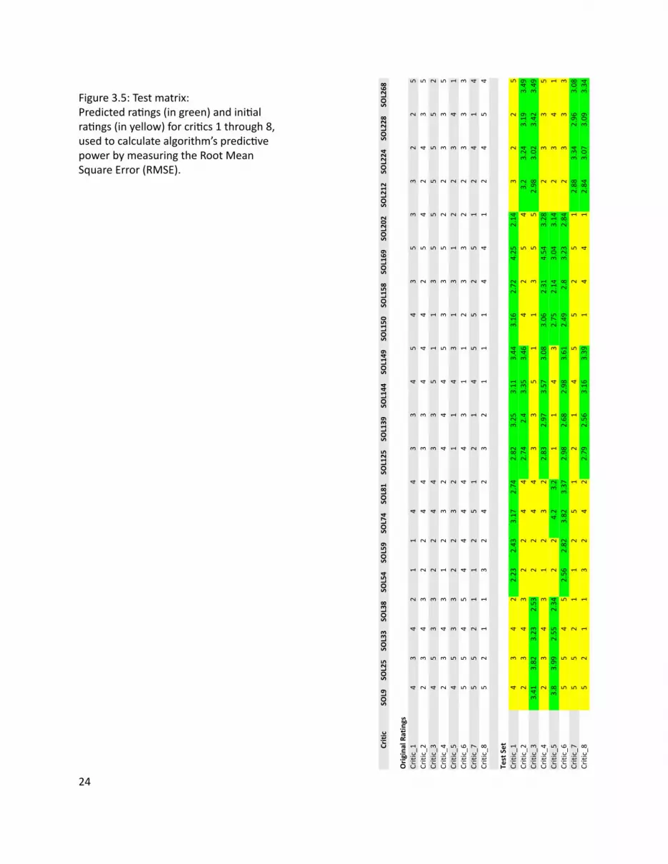
13
13
13
13
13
24
Figure 35 Test matrixPredicted raƟ ngs (in green) and iniƟ al raƟ ngs (in yellow) for criƟ cs 1 through 8 used to calculate algorithmrsquos predicƟ ve power by measuring the Root Mean Square Error (RMSE)
25
When a data set like the raƟ ng matrix becomes very large a user-based approach might start to break
down due to the computaƟ onal cost of usersrsquo pairwise comparison An item-based approach alleviates
this problem by pre-compuƟ ng a similarity matrix for all items The assumpƟ on is that items do not change
as frequently as users therefore the similarity matrix will only need to be updated every once in a while
Amazoncom for example uses an item-based approach ie item-to-item collaboraƟ ve fi ltering (Linden
et al 2003) to recommend products to its users (Figure 36)
Making recommendaƟ ons using item-based collaboraƟ ve fi ltering consists of the following steps pre-
compuƟ ng an item-to-item similarity matrix looking up the acƟ ve userrsquos top-rated items and creaƟ ng
a weighted list of the most similar items To illustrate how this works an algorithm (Segaran 2007) was
tested with the raƟ ngs matrix to get recommendaƟ ons for CriƟ c_N (Figure 37)
CriƟ c_Nrsquos rated items
(50 SOL25) (20 SOL81) (10 SOL158)
CriƟ c_Nrsquos recommended items
(50 SOL9) (365 SOL74) (324 SOL144) (285 SOL202) (281 SOL228) (267 SOL224) (249 SOL212)
(243 SOL33) (209 SOL125) (15 SOL38) (142 SOL59) (141 SOL54) (10 SOL139)
Item-Based RecommendaƟ ons
Pre-compute item similarity matrix with user-based approach but subsƟ tuƟ ng items for users by transposing the raƟ ng matrixFor each Item1 in Userrsquos items For each Item2 in Item1rsquos similarity matrix If User has already rated Item2 Then conƟ nue to the next iteraƟ on of the loop Compute item similarity weighted raƟ ng (see Eq 32) Compute average of weighted item raƟ ngs And save them in ListSort List based on normalized weighted item similarityReturn List
Figure 36 Pseudocode for item-based recommendaƟ on
Figure 37 Item-based recommendaƟ ons for CriƟ c_N
26
Figure 37 shows that given CriƟ c_Nrsquos high raƟ ng of fl oor plan SOL25 the algorithm recommended SOL9
as the highest ranking (best matching) item Figure 38 validates the algorithmrsquos precision and predicƟ ve
power as the two fl oor plans are nearly idenƟ cal There are some minor diī erences between the two
fl oor plans for example SOL9 has a bar-top dining table but SOL25 has a 6-seat standalone dining table
However the overall similarity of the two fl oor plans is evident and emerges from the usersrsquo raƟ ngs
In order to compare the performance of the algorithm a random criƟ c was selected (CriƟ c_30) all but the
fi rst fi ve of his raƟ ngs deleted and then predicted by each of the algorithms The RMSE for the user-based
algorithm was 118 and the item-based algorithm was 161 indicaƟ ng that user-based recommendaƟ ons
are more accurate than item-based recommendaƟ ons However there are other issues to consider besides
accuracy when choosing one algorithm over the other for example size of data set and frequency of
change have a tremendous infl uence on the performance of these algorithms
User-Based vs Item-Based RecommendaƟ ons
Figure 38 SOL9 (LeŌ ) and SOL25 (Right) with a similarity score of 004
27
Clustering or Cluster Analysis is a way of discovering and visualizing groups of things - people news
stories blogs and more This secƟ on will focus on two clustering techniques - Hierarchical and K-means -
and apply them to the raƟ ngs matrix in order to discover groups of criƟ cs and fl oor plans In user-centered
architecture these clusters can be uƟ lized for example to infer a new userrsquos design preferences by fi nding
his cluster membership A user who has been assigned to a certain cluster shares the design preferences
of that cluster making it possible to tailor design recommendaƟ ons to his taste
Figure 39 is the pseudocode for a simple hierarchical clustering algorithm (Segaran 2007) The algorithm
starts by assigning each item ie fl oor plan to a cluster of its own Then the distance between every pair
of clusters is calculated and the closest (most similar) ones are merged together to form a new cluster
The process is repeated unƟ l there is only one cluster leŌ The algorithm uses the Pearson correlaƟ on
coeĸ cient to compute the distance between clusters
Figure 310 shows the groups of criƟ cs discovered when running the hierarchical clustering algorithm on
the raƟ ng matrix The dendrogram clearly separates the criƟ cs into two groups each characterized by
its own design preferences as extracted from the raƟ ngs Each of the two main clusters contains smaller
clusters for example criƟ cs 16 8 30 6 11 and 3 form a cluster within the bigger cluster at the top
of Figure 310 Rated fl oor plans were also clustered (Figure 311) by running the hierarchical clustering
algorithm on a rotated raƟ ng matrix Clustering shows two disƟ nct clusters made up of smaller clusters
such as fl oor plans SOL9 25 74 224 and 228 (Figure 312)
Clustering
Hierarchical Clustering
Figure 39 Pseudocode for hierarchical clustering
IniƟ alize all rows to be clustersCreate BigClusterWhile number of Clusters is bigger than 1 For each pair of Clusters Find the pair with the smallest distance Calculate the average of the two Clusters Combine the two clusters to form a new Cluster Add new Cluster to BigClusterReturn BigCluster
28
Gender analysis (MaleFemale )Top cluster - 6040BoƩ om cluster - 5050
Analysis reveals that clusters are gender neutral suggesƟ ng that gender may not play a role in the design preferences of architects
Figure 310 Hierarchical clustering of criƟ cs
29
Figure 311 Hierarchical clustering of fl oor plans
30
Figure 312 Clustered fl oor plans
AƩ ributes of clustered fl oor plans (parƟ al list)bull A small bathroombull A large kitchenbull A dining tablebull Clearly defi ned private amp public spaces
SOL9
SOL74
SOL25
SOL224
SOL228
31
Hierarchical clustering is computaƟ onally expensive because the pairwise distance calculaƟ ons have to
be carried out every Ɵ me clusters are merged therefore this method might break down on larger data
sets K-means clustering takes a diī erent approach because the number of clusters is specifi ed in advance
removing some of the ambiguity in dividing up the data
The K-means clustering algorithm (Segaran 2007) presented as pseudocode (Figure 313) starts by
randomly placing centroids ie center of the cluster and assigning every item to the nearest one Then
each centroid is shiŌ ed to the average locaƟ on of the items it contains items are reassigned and the
process repeats itself unƟ l the assignments stop changing
Figure 314 shows the K-means clustering of fl oor plans with diī erent values of K
K-means Clustering
Figure 313 Pseudocode for K-means clustering
M RaƟ ng MatrixFor each Item in M Compute the Min and Max value of Item Create K randomly placed centroids While assignment of Item is changing Find the closest centroid to Item Assign Item to centroid Move centroid to average locaƟ on of ItemsReturn K Clusters
K=8 SOL(158 169 268) (144 149) (925) (74) (33) (150) (202 212224 228) (38 54 59 81 125 139)
K=5 SOL(54 59 125 139 158) (25 74 144 202 224) (33 228 268) (149 150 169) (9 38 81 212)
K=3 SOL(9 25 74 228) (38 81 144 149 150 202 212 224) (33 54 59 125 139 158 169 268)
Figure 314 K-means clustering of fl oor plans
32
Items in the raƟ ng matrix are mulƟ dimensional ie each fl oor plan is represented by a vector of 30
raƟ ngs MulƟ dimensional scaling is a technique for fi nding a two-dimensional representaƟ on of the raƟ ng
matrix which is someƟ mes easier to understand than a dendrogram
The algorithm (Segaran 2007) presented as pseudocode (Figure 314) starts by calculaƟ ng the target
distances between all the items Next all items are placed randomly on a two-dimensional plane The
current distances between all the items are calculated using the actual distance ie the sum of the
squared diī erences For every pair of items the target distance is compared to the current distance to
calculate the error Every item is moved a small amount in proporƟ on to the direcƟ on of the error between
the two items The process is repeated unƟ l the total error cannot be reduced by moving any of the items
Figure 315 shows the results of running the mulƟ dimensional scaling algorithm on the raƟ ng matrix
All three methods when applied to the fl oor plans produced comparable results making the choice
of any one method unclear This is due to the small size of the data set and some ad-hoc choices of
parameters for the algorithms With a more extensive data set one expects to evaluate and choose based
upon computaƟ onal cost of the algorithm moƟ vaƟ on for and use of the derived informaƟ on and auxiliary
informaƟ on from the problem domain
MulƟ dimensional Scaling
Hierarchical Clustering vs K-means Clustering vs MulƟ dimensional Scaling
Figure 314 Pseudocode for MulƟ dimensional scaling
M RaƟ ng MatrixFor each Item1 and Item2 in M Compute the real distance between Item1 and Item 2 Randomly place Item1 and Item2 in 2D spaceWhile TotalError is changing Find the projected distance between Item1 and Item2 Calculate Error between real and projected distance Move Item1 and Item2 in proporƟ on to Error Update TotalErrorReturn locaƟ on of Items
SOL228
SOL38
SOL59
SOL54
SOL33SOL125
SOL139
SOL169
SOL268
SOL150
SOL149
SOL144
SOL9
SOL224
SOL25
SOL74
SOL158
SOL212
SOL81
SOL202
33
Figure 315 MulƟ dimensional scaling of raƟ ng matrixColored boxes correspond to the hierarchical clustering in Figure 311
=X
Plan 4
Features Matrix Weights Matrix
Plan 4
34
Figure 316 Non-NegaƟ ve Matrix FactorizaƟ on
The rated fl oor plans in the data set share certain features such as an open kitchen private vs public
spaces and others These features are latent - hidden between the raƟ ngs - and in order to extract them
the raƟ ng matrix has to be factored It is important to note that these features are not the same as the
aƩ ributes given to the criƟ cs to help them rate the fl oor plans There is no way to be absolutely sure of
what a feature represent All that can be done is to examine the set of fl oor plans which share the feature
and aƩ empt to visually arƟ culate it
Figure 316 describes the process of matrix factorizaƟ on The goal is to factor the matrix ie fi nd two
smaller (lower rank) matrices - a features matrix and a weights matrix - that when mulƟ plied together
reconstruct the original matrix The features matrix has features for rows and fl oor plans for columns
The value in each cell of the matrix indicates how important that fl oor plan is to the feature The weights
matrix maps the features to the raƟ ng matrix Each row is a criƟ c and each column is a feature The value
in each cell of the matrix indicates how much a feature applies to a fl oor plan Therefore reconstrucƟ ng
the raƟ ng matrix is a maƩ er of combining rows from the features matrix in diī erent amounts The weights
matrix maps the features to the raƟ ngs Non-negaƟ ve refers to the fact that all features and weights must
be posiƟ ve For a more comprehensive descripƟ on of the algorithm see (Segaran 2007)
Using a Non-NegaƟ ve Matrix FactorizaƟ on algorithm the raƟ ng matrix was factored into a features matrix
and a weights matrix The algorithm was programmed to fi nd 10 features Figure 317 represents 5 of
the 10 features as a list of fl oor plans that contain the feature As menƟ oned the features are latent
therefore feature 5 for example is shared by fl oor plans 149 150 169 and 268 An hypothesis of what
the feature represents is proposed by looking at the commonaliƟ es of the fl oor plans that defi ne the
feature (Figure 318)
Feature ExtracƟ on (Non-NegaƟ ve Matrix FactorizaƟ on)
35
Figure 317 5 features extracted from the raƟ ng matrix
(SOL81 SOL224)
(SOL149 SOL150 SOL169 SOL268)
(SOL202 SOL212)
(SOL158 SOL228)
(SOL33 SOL54 SOL59 SOL125 SOL139)
Feature 4
Feature 5
Feature 7
Feature 8
Feature 9
ConclusionsThe dataset used in these experiments is extremely small compared to the Neƞ lix or Amazon data sets
Nevertheless each of the applied methods revealed some interesƟ ng informaƟ on about the data - criƟ cs
fl oor plans and the relaƟ onship between them
CollaboraƟ ve fi ltering whether user or item based showed that it is possible to leverage a communityrsquos
opinion expressed through raƟ ngs in order to help an individual fi nd what he likes Analysis of the
algorithm showed that it performs much beƩ er than a random guess
Clustering - Hierarchical K-means or MulƟ dimensional Scaling - showed that it is possible to fi nd groups of
criƟ cs and fl oor plans and uncover their common characterisƟ cs With a large enough data set clustering
can be used to extract user and design typologies which can help stakeholders in the building industry -
contractors developers architects etc - tailor their services to clientsrsquo needs
Feature ExtracƟ on showed that it is possible to extract the features of a fl oor plan in order to create a
design vector The design vector can be used to score fl oor plans based on a userrsquos interest in one or all of
its features allowing the user to explore the design space in mulƟ ple direcƟ ons
36
Figure 318 ArƟ culaƟ ng Feature 5 through its fl oor plansFeature 5 could be the free-standing column that appears in all the fl oor plans below
SOL149 SOL150
SOL169 SOL268
37
References amp Suggested Reading List1 Billsus D amp Pazzani M J (1998) Learning collaboraƟ ve informaƟ on fi lters Proceedings of the 15th
InternaƟ onal Conference on Machine Learning pp 46ndash542 Blei D M Ng A Y amp Jordan M I (2002) Latent Dirichlet allocaƟ on Advances in Neural InformaƟ on
Processing Systems 143 Breese J S Heckerman D and Kardie C (1998) Empirical analysis of predicƟ ve algorithms for
collaboraƟ ve fi ltering In Proceedings of the 14th Conf on Uncertainty in ArƟ fi cial Intelligence pp 43ndash52
4 Goldberg D Nichols D Oki BM amp Terry D (1991) Using CollaboraƟ ve Filtering to Weave an InformaƟ on Tapestry Comm ACM vol 35 no 12 pp 61-70
5 Herlocker JL Konstan JA Borchers A and Riedl J (1999) An Algorithmic Framework for Performing CollaboraƟ ve Filtering Proc 22nd Ann Intrsquol ACM SIGIR Conf Research and Development in InformaƟ on Retrieval (SIGIR rsquo99)
6 Herlocker JL Konstan JA Terveen LG and Riedl JT (2004) EvaluaƟ ng CollaboraƟ ve Filtering Recommender Systems ACM Trans InformaƟ on Systems vol 22 no 1 pp 5-53
7 Hofmann T (2004) Latent semanƟ c models for collaboraƟ ve fi ltering ACM TransacƟ ons on InformaƟ on Systems 22 pp 89ndash115
8 Koren Y Bell R Volinsky C (2009) Matrix FactorizaƟ on Techniques for Recommender Systems IEEE Computer 082009 Volume 42 Issue 8 pp30-37
9 Linden G Smith B and York J (2003) Amazoncom RecommendaƟ ons Item-to-Item CollaboraƟ ve Filtering IEEE Internet CompuƟ ng
10 Marlin B (2004) CollaboraƟ ve fi ltering A machine learning perspecƟ ve Masterrsquos thesis University of Toronto Computer Science Department
11 Segaran T (2007) Programming CollecƟ ve Intelligence OrsquoReilly Media12 Srebro N Rennie J D M amp Jaakkola T S (2005) Maximum margin matrix factorizaƟ on Advances
in Neural InformaƟ on Processing Systems 17
38
4| UDesignWhen a user wishes to purchase an apartment from a developer he is usually presented with a few sample
apartments from which to choose These sample apartments usually oī er very few parameters that can
be changed because they are designed to fi t the taste and lifestyle of an average user The soluƟ on to
this problem can be found in two diī erent places - hardware and soŌ ware - which complement each
other to create user-centered architecture On the one hand there is hardware the building technology
that is responsible for making sure usersrsquo designs are feasible The mass-customizaƟ on community in
architecture has made considerable progress in recent years and managed to push fabricaƟ on technology
forward On the other hand there is soŌ ware the interface that is responsible for making sure users can
express their wants and needs The ability of an interface to meet usersrsquo needs depends on its front-end -
how easy it is to use the interface - and back-end - how the objects of design are represented internally in
the system This secƟ on will focus on the soŌ ware and illustrate through the implementaƟ on of UDesign
what are some of the issues to consider in terms of soŌ ware for user-centered architecture
As a framework UDesign mediates between the user and stakeholders in the building industry - architects
developers contractors suppliers realtors and community - in order to create a product in this case
an apartment Figure 41 outlines the components and relaƟ onships of user-centered architecture as a
series of four concentric circles - User UDesign Data and Stakeholders - fl oaƟ ng in Design Space the
space of design soluƟ ons oī ered to the user Metaphorically as the user is designing his own product
he is navigaƟ ng through the design space cocooned within these layers of UDesign and Stakeholders
through which he communicates his ideas about the product To visualize the metaphor imagine Figure
A Framework For User-Centered Architecture
39
Architect
Developer
DesignSpace
Realtor
Supplier
CommunityContractor
DesignLogic
Feedback
User
Stakeholders
UDesign
Data
41 as a ball fl oaƟ ng in space and rays of informaƟ on shooƟ ng from its center (User) guided by an inner
mechanism (UDesign Stakeholders) trying to fi nd an anchor in space (Design)
UDesign is comprised of four parts Design CommunicaƟ on Feedback and Logic Design is responsible
for visualizing the design space and interacƟ ng with the user In a way it is the front-end of the interface
Design includes the library of parts from which a user can choose to create his design (Friedmanrsquos
repertoire) tools to transform and edit the design and ways to explore the design space CommunicaƟ on
is responsible for the exchange of informaƟ on between user and stakeholders The radial arrangement
facilitates mulƟ ple channels of communicaƟ on at any given point in Ɵ me For example a user can
communicate with the architect in order to get professional feedback about his design while also geƫ ng
feedback from the community CommunicaƟ on must pass through UDesign to avoid overloading the user
therefore messages are stored in a queue and ordered by their relevancy to the current context of the
design process Feedback is responsible for conƟ nuously collecƟ ng informaƟ on about the state of the
design process analyzing it and providing noƟ fi caƟ ons at the right Ɵ me and place For example when a
user selects a design component he is immediately given feedback about the availability of the component
Figure 41 User-Centered Architecture
40
UDesign was implemented in Adobe Flex Builder 3 an IDE (Integrated Development Environment)
for creaƟ ng cross-plaƞ orm RIA (Rich Internet ApplicaƟ on) based on Adobe Flash A typical applicaƟ on
development process was followed including
bull Defi ning an applicaƟ on interface using a set of pre-defi ned components (forms buƩ ons and so on)
as MXML Components
bull Arranging components to create a User Interface (UI) design
bull Using styles and themes to defi ne the visual design CSS skins etc
bull Adding dynamic behavior using proper event-driven programming techniques
bull Defi ning and connecƟ ng to data services as needed MySQL ColdFusion etc
bull Compiling the source code into an SWF fi le that can be read by Flash Player and embedded within an
HTML fi le
UDesign is comprised of fi ve parts Data PersonalizaƟ on Design Contribute and Feedback (Figure 42)
where Data consƟ tutes most of the back-end and the remaining parts the front-end
The data in UDesign is stored in tables within a MySQL database that resides on a server The mxml
applicaƟ on makes requests to the database through a Flex HTTPService component In turn the
HTTPService component calls one of fi ve methods (FindAll Insert Update Delete Count) encapsulated
within a PHP fi le which then retrieves the data from the appropriate table of the database and returns the
data to the applicaƟ on in an E4X format (Figure 43)
ImplementaƟ on
Data
its price compaƟ bility with other components and more Stakeholders can use UDesignrsquos feedback to get
informaƟ on about their users - purchase history preferences lifestyle status state of the design and
more Logic is responsible for holding everything (Design CommunicaƟ on and Feedback) together so that
usersrsquo experience of UDesign is both producƟ ve and posiƟ ve Logic is supported by a suite of algorithms
from diī erent categories - user interacƟ on network database machine learning - some of which are
described in more detail in chapter 3 (Algorithms) as well as in the next secƟ on (ImplementaƟ on)
41
HTTPService
Data
Design
Contribute
Feedback
PHP
HTTPService PHP
MySQL
ContributeView
assembliesService
tagsService
usersService
Database
FeedbackView Feedback
HomeView Facebook Connect
currUser (Facebook)
UDesigners at work
Survey
DesignView
Assemblies
Tags
Users
feedbackService
IntroHomePage
PersonalizedHomePage
Floorplan
Catalog currUser (Facebook)
assembliesrooms
by selected rooms
GridCell (A1-C2)
clear
Figure 42 UDesign - system overview
42
FindAllInsertUpdateDeleteCount
Table 1Table 2Table 3
Request Request
Response ResponseFLEX PHP MySQL
E4X
The database includes the following tables
bull assemblies (Figure 44)
bull soluƟ ons (Figure 45)
bull users_saved_soluƟ ons (Figure 46)
bull users (Figure 47)
bull design_profi le (Figure 48)
bull soluƟ on_vector (Figure 49)
bull feedback (Figure 410)
Figure 43 Data pipeline
43
Table assemblies
This table holds the 48 assemblies (custom-designed rooms) available to the user on the Design page of
UDesign
Fields id room id | label room label | type room type | descripƟ on room descripƟ on | price room
price | cell an index indicaƟ ng to what funcƟ onal zone the room belongs (more details below) | area
room area (sqŌ ) | dimx room dimension in x-axis (pixels) | dimy room dimension in y-axis (pixels) | locx
room posiƟ on in x-axis (pixels) | locy room posiƟ on in y-axis (pixels) | color room color code | fi t a fl ag
indicaƟ ng whether the room fi tsdoesnrsquot fi t with the userrsquos design (more details below)
Table soluƟ ons
This table holds the 285 soluƟ ons (custom-designed fl oor plans) available to the user on the Design page
of UDesign
Fields id fl oor plan id | label fl oor plan label | A1 - C2 a funcƟ onal zone in the fl oor plan (more details
below)
Table users_saved_soluƟ ons
This table holds usersrsquo saved soluƟ ons (custom-designed fl oor plans) created by users on the Design page
of UDesign
Fields id fl oor plan id | label fl oor plan label | A1 - C2 a funcƟ onal zone in the fl oor plan (more details
below)
Table users
This table temporarily holds usersrsquo personal informaƟ on obtained from their Facebook account (more
details about UDesignrsquos connecƟ on to Facebook in the secƟ on about PersonalizaƟ on)
Fields (Facebook generated) uid userrsquos id | about_me userrsquos personal message | acƟ viƟ es userrsquos
favorite acƟ viƟ es | birthday userrsquos birthday | books userrsquos favorite books | fi rst_name userrsquos fi rst name
| interests userrsquos interests | last_name userrsquos last name | movies userrsquos favorite movies | music userrsquos
favorite music | pic userrsquos profi le picture | relaƟ onship_status userrsquos current relaƟ onship status | sex
userrsquos gender | wall_count number of posts on userrsquos wall
44
Table design_profi le
This table holds usersrsquo design profi le Users are presented with ten parameters of lifestyle and asked to
rate their importance on a scale of one (low) to fi ve (high)
Fields id userrsquos Facebook id | watch importance of watching TVMovies | entertain importance
of entertaining | cook importance of cooking | work importance of being able to work from home |
privacy importance of privacy | pamper importance of pampering | storage importance of storage |
kitchen_dining importance of physicalvisual connecƟ on between kitchen and dining room | bed_bath
importance of physicalvisual connecƟ on between bedroom and bathroom | fl exible importance of
fl exible living space
Table soluƟ on_vector
This table holds the design vectors for 71 out of 285 soluƟ ons (custom-designed fl oor plans) where each
soluƟ on is represented as a diī erent combinaƟ on of the same parameters used to defi ne userrsquos design
profi le (more details in the secƟ on about the Design page) Values indicate how much the corresponding
parameter is present in the soluƟ on
Fields label soluƟ on label | watch supports watching TVMovies | entertain supports entertaining |
cook supports cooking | work supports being able to work from home | privacy supports privacy |
pamper supports pampering | storage amount of storage | kitchen_dining degree of physicalvisual
connecƟ on between bedroom and bathroom | bed_bath degree of physicalvisual connecƟ on between
bedroom and bathroom | fl exible amount of fl exible living space
Table feedback
This table holds usersrsquo feedback submiƩ ed through the feedback form on UDesign (more details below)
Fields subject subject of the feedback | content content of the feedback
45
id label type description price cell area dimx dimy locx locy color fitid label type description price cell area dimx dimy locx locy color fitA11BT001 Bathroom Bathroom 99 A1 68 174 166 0 0 0x0071BC 0A11BT002 Bathroom Bathroom 99 A1 68 174 166 0 0 0x0071BC 0A12BT001 Bathroom Bathroom 99 A1 100 250 166 0 0 0x0071BC 0
id label A1 A2 B1 B2 C1 C2id label A1 A2 B1 B2 C1 C2SOL1 322000 A12BT001 A21KT001 B15ST001 B21DN001 C15BD001 C23LV001SOL10 123000 A11BT001 A22KT005 B15ST001 B21DN001 C15BD001 C23LV001SOL100 453243 A11BT001 A22KT004 B12BD001 B25DN001 C12BD001 C25LV004
id label A1 A2 B1 B2 C1 C2id label A1 A2 B1 B2 C1 C2652795248 A11BT001 A22KT003 B13BD001 B25DN001 C11ST001 C25LV002717158422 brain drain A11BT001 A22KT001 B15ST004 B25DN002 C13BD001 C23LV001533833493 carlyu A12BT001 A21KT001 B15ST001 B21DN001 C15BD001 C23LV001
id watch entertain cook work privacy pamper storage kitchen_dining bed_bath flexibleid watch entertain cook work privacy pamper storage kitchen_dining bed_bath flexible1065658831 3 5 5 1 1 1 3 5 1 1542150884 5 2 4 1 4 1 3 1 1 1566433466 1 5 5 2 2 1 2 4 2 1
label watch entertain cook work privacy pamper storage kitchen_dining bed_bath flexiblelabel watch entertain cook work privacy pamper storage kitchen_dining bed_bath flexibleSOL1 3 2 2 5 4 5 3 5 1 1SOL2 3 2 2 4 4 5 4 5 5 1SOL3 3 2 2 5 4 5 4 1 1 1
subject contentsubjectthis is my feedback feedback feedbackscrolling hi junnoNice work Good start Maybe I am to quick to try out everything-
the scroll bar or the arrow It is just a little bit annoying )-And will I be abproportions to the lenght of the walls I tried the little pen and ruler tool b
Figure 44 - 410 Database tables (from top to boƩ om)
46
PersonalizaƟ on
UDesignrsquos home page has two states an introducƟ on page (Figure 411) and a personalized page (Figure
412) The introducƟ on page is the fi rst page to be displayed when a user fi rst loads the applicaƟ on It
contains informaƟ on about the applicaƟ on and how to use it To start using the applicaƟ on a user must log
in using their Facebook account by pressing the Facebook Connect buƩ on Facebook Connect is integrated
into the Adobe Flex applicaƟ on using the Facebook API and corresponding Flash-Flex libraries By signing
in to UDesign through Facebook Connect a user gives the applicaƟ on permission to make requests to
Facebook and retrieve their personal informaƟ on (according to the userrsquos privacy seƫ ngs)
The informaƟ on from Facebook now encapsulated as a FacebookUser object is leveraged to provide the
user with tailored recommendaƟ ons of design soluƟ ons ie custom-designed fl oor plans As shown in
chapter 3 (Algorithms) usersrsquo informaƟ on whether itrsquos raƟ ngs or a Facebook profi le can be represented
as a vector (Figure 413) and compared to other users in order to cluster the UDesign community Once
a user is clustered other members of the cluster become his design criƟ cs and their design soluƟ ons are
oī ered as recommendaƟ ons (Figure 414) That is the case with a new user or a user who has not created
rated or saved any design soluƟ ons When a user has given feedback implicitly (by saving certain design
soluƟ ons) or explicitly (by raƟ ng design soluƟ ons) his recommendaƟ ons are updated and improved
through a user-based collaboraƟ ve fi ltering algorithm As shown in chapter 3 (Algorithms) the algorithm
Figure 411 IntroducƟ on home page
47
compares the current user to the enƟ re UDesign community fi nds the most similar users and collects
the highest rated design soluƟ ons from these users as recommendaƟ ons Consequently the more design
soluƟ ons users rate the more accurate UDesignrsquos recommendaƟ ons get (see chapter 3)
Once the user has logged in and UDesign has made a request to Facebook to retrieve the userrsquos personal
informaƟ on the applicaƟ on waits for the response and then temporarily stores it as a FacebookUser object
for the duraƟ on of the session If log in is successful the user is automaƟ cally navigated to a personalized
home page which includes the following userrsquos Facebook picture and name userrsquos Rated Design Profi le
UDesigners at work and Survey
The userrsquos Rated Design Profi le (Figure 415) is a set of ten lifestyle parameters that capture the userrsquos
preferences in respect to the database of 285 fl oor plans available in UDesign For each opƟ on the user
has to rate the importance of that aspect on a scale of one (low) to fi ve (high) For example if the user
is an avid baker he might rate high the following parameters cooking connecƟ on between kitchen and
dinning and entertaining to refl ect their importance in his lifestyle The user has the opƟ on to go back and
change his raƟ ngs at any Ɵ me by making the changes and pressing the Update buƩ on The Rated Design
Profi le complements the Facebook informaƟ on as they are both used to model the user and provide him
Figure 412 Personalized home page
48
with recommendaƟ ons of design soluƟ ons
UDesigners at work features the Facebook profi le pictures of the UDesign community with which the
current user may wish to interact - comment on designs share designs ask quesƟ ons share informaƟ on
and more Finally a short survey is included with various design styles and lifestyle parameters The user
is asked to indicate whether or not they are relevant to him The results of the survey are collected and
aggregated across the enƟ re UDesign community to understand trends and user typologies
49
Age Sex School Job
32 Male MIT House_n
29 Male MIT House_n
Yes
Yes
In a
Figure 413 User vectors
Design
The Design page (Figure 416) is where users create their custom apartment and it includes three main
components fl oor Plan catalog and recommendaƟ ons
The fl oor plan (Figure 417) has two components - toolbar and sample fl oor plan - with which a user can
interact to create their design The toolbar oī ers the following funcƟ onality
bull Open a saved project - will load a saved design from the database
bull Create a new project - will create a new project in the database
bull Save a project - will save the current state of the design in the database
bull Undo - will undo the userrsquos last operaƟ on
bull Publish to Facebook - will post the current state of the design to the userrsquos Facebook feed (Figures
417A and 417B)
bull Clear the project - will remove everything from the sample fl oor plan
The sample fl oor plan is the empty canvas on to which a user drags and drops rooms from the catalog
(Figure 418) UDesign was implemented with a single sample fl oor plan as a proof-of-concept However
in reality UDesign should be able to oī er users a variety of fl oor plans to customize as well as an opƟ on
to create their own fl oor plan from scratch Figure 419 explains how the sample fl oor plan is structured
such that it supports customizing EssenƟ ally the fl oor plan is divided into six funcƟ onal zones - A1 A2
B1 B2 C1 C2 - where each zone can hold one or more funcƟ ons Zones A1 and A2 have hard-coded
constraints ie A1 can only hold a bathroom and A2 a kitchen These constraints are imposed by the
50
NEW USER
Figure 414 Clustering users to fi nd recommendaƟ ons
51
Figure 415 Rated Design Profi le
buildingrsquos infrastructure for example the locaƟ on of plumbing risers The remaining zones can each take
a number of prescribed funcƟ ons - dining room bedroom closet media room and more - according to
the userrsquos choice
The Catalog (420) holds the assemblies (custom-designed rooms) that a user can add to the sample fl oor
plan The catalog includes an informaƟ on box with the userrsquos Facebook name and the Ɵ tle of the project
It also has a drop-down list of room types that fi lters the available rooms according to the selected type
eg bathroom kitchen dining etc Rooms are represented as Ɵ les When a room is clicked a pop-up
window appears with addiƟ onal details Room Ɵ les can be dragged and dropped onto the fl oor plan
(Figure 418) Each room has a prescribed locaƟ on within the fl oor plan to refl ect real-world constraints
Once a room has been dragged and dropped on to the fl oor plan an algorithm (Figure 421) updates the
rooms in the catalog to refl ect which ones fi t and which ones donrsquot with the userrsquos current selecƟ on of
rooms The ill-fi ƫ ng rooms are grayed-out (disabled) The recommendaƟ on lists also update (see below)
The recommendaƟ ons (Figure 422) are represented as two lists of soluƟ ons (custom-designed fl oor
52
Figure 416 Design page
plans) that are updated to refl ect (a) soluƟ ons which are compaƟ ble with the userrsquos currently selected
rooms and (b) the ten highest ranking soluƟ ons which best fi t the userrsquos Design Profi le RecommendaƟ ons
Based on your selecƟ on of rooms (Figure 422) are generated and updated using the algorithm described
in Figure 421 RecommendaƟ ons Based on your design profi le (Figure 422) are generated and updated
using the user-based recommendaƟ on algorithm described in chapter 3 (Figure 33) When a user clicks on
any of the recommendaƟ ons a pop-up window appears with addiƟ onal details about the selected fl oor
plan an explanaƟ on of why the fl oor plan was recommended and an opƟ on to add the selected fl oor plan
to the sample fl oor plan (Figure 423) If the user clicks the Add To My Project buƩ on the userrsquos sample
fl oor plan is cleared and the rooms of the currently selected fl oor plan are added instead
From a usability perspecƟ ve the Design page uses the direct manipulaƟ on design paƩ ern to facilitate a
seamless intuiƟ ve and eĸ cient design process for users Following a gradual learning curve a user can
create his own custom fl oor plan within a maƩ er of minutes by using the catalogrsquos drop-down menu
locaƟ ng a room and adding it to the sample fl oor plan
53
Figure 417 Floor Plan Component - sample fl oor plan and toolbar
Figure 417A PosƟ ng a fl oor plan to Facebook from within UDesign
54
Figure 417B The posted fl oor plan in Facebook
Figure 418 Drag and drop rooms
55
UDesign
How does it work
174 250
166
89
148
207
159
218
277
234 310
A1 A2
B1 B2
C1 C2
Figure 419 How does it work
56
UDesign
How does it work
174 pixels
166 pixels
Figure 419 How does it work (conƟ nued)
57
UDesign
How does it work
A1
B1
C1
A2
B2
C2
Figure 419 How does it work (conƟ nued)
58
Figure 420 Catalog
Figure 421 Pseudocode of algorithm for updaƟ ng soluƟ ons and assemblies
For each SoluƟ on For each Assembly in SoluƟ on If Assembly is in the userrsquos sample fl oor plan Save SoluƟ on Save AssemblyFor each SoluƟ on in RecommendaƟ ons Update SoluƟ onFor each Assembly in Catalog Update Assembly
59
Figure 422 RecommendaƟ ons
Figure 423 SoluƟ on details
60
Figure 424 Contribute page
UDesign is intended to be extended by its user community A user who is interested in contribuƟ ng a
new design can download the Starter Kit (a template fi le of available rooms in Adobe Illustrator andor
Autodesk Autocad format) design their own room or fl oor plan and send it via e-mail to be added to
the UDesign database (Figure 424) The ldquostarter kitrdquo is a fi le containing drawings However the current
approach is far from ideal and leaves much to be desired As an improvement the web applicaƟ on can
include an integrated confi guraƟ on tool which will let users edit any available assembly and save it as
their own A more comprehensive discussion of how to extend and scale UDesign is reserved for the
conclusions
To improve UDesign a simple feedback form is implemented allowing users to write comments and
suggesƟ ons and submit them to the system (Figure 425) Once a form is submiƩ ed it is saved in the
feedback table (Figure 410) and awaits a response by the applicaƟ on administrator
Contribute
Feedback
61
Figure 425 Feedback page
References amp Suggested Reading List1 UDesign hƩ ppeoplecsailmitedujunnohgp (May 20 2010)
62
This thesis proposes a framework for user-centered architecture and provides a proof-of-concept in the
form of a web applicaƟ on that allows users to create their own custom apartment The ideas presented
in this thesis are merely a starƟ ng point and fall short of solving the problem To miƟ gate the situaƟ on
this secƟ on suggests ways of improving some of the ideas presented as well as addiƟ onal direcƟ ons for
future work
This thesis started out by framing its conceptual framework through the work of Yona Friedman on user-
centered design Friedmanrsquos work is compelling however it is sƟ ll very much focused on the architect as
the sole cause of problems in the design process As I have shown in chapters three and four a community-
based approach supported by collaboraƟ ve fi ltering algorithms and social networks (eg Facebook) can
provide users with the safety net they need in order to feel comfortable designing their own spaces and
living soluƟ ons There is a specifi c reference by Friedman when he talks about the repertoire to all
possible design soluƟ ons which I fi nd problemaƟ c It seems to me that any system that forces its users
to navigate through a huge corpus of data compromises its usability For example if the repertoire had
thousands of possible design soluƟ ons would a user be able to fi nd what he needs And if he could how
long would it take him These quesƟ ons raise doubts in my mind as to the ability of Friedmanrsquos system to
respond to usersrsquo needs in terms of eĸ ciency (Ɵ me) and visibility (fi nding what they need) Furthermore
any system that proposes to fi nd ALL possible soluƟ ons must also address the issue of Completeness or in
Yona Friedman Reloaded
5| Conclusions
63
RepresentaƟ on
other words provide proof that there are no other possible design soluƟ ons beyond those found in the
repertoire Finally I would argue that users arenrsquot interested in all possible design soluƟ ons but just those
that fi t their needs Finding these needs is a diĸ cult problem with the beginning of a soluƟ on in chapters
three and four
Marshall McLuhan (McLuhan 1964) coined the phrase ldquoThe medium is the messagerdquo The medium in the
context of architectural design is how we choose to represent the fi nished product Whether through 2D
fl oor plans or 4D fl y-through animaƟ ons the message has to be received and understood on the userrsquos
side The fact that users are not trained at deciphering architecturally-encoded messages (architectural
notaƟ on symbols etc) makes the task of representaƟ on that much more diĸ cult The representaƟ on
chosen for the implementaƟ on of UDesign ie a 2D fl oor plan layout comprised of funcƟ onal zones or
assemblies in PNG format leaves much to be desired First the use of the PNG format seriously hinders
usersrsquo freedom to make changes to the design at room level While only having to deal with small chunks
of space simplifi es the design task on the userrsquos end it also presents a problem when a user only wants
to move the bed in the master bedroom one foot to the leŌ This limitaƟ on will cause users to become
frustrated and the enƟ re user-centered design process to break Therefore representaƟ on should provide
users more freedom by increasing the granularity of the medium For example enabling users to edit
assemblies and then save them as their own custom components Having said that perhaps the problem
is not granularity but dimensionality In many informal discussions I conducted with users (non-experts
designers if you will) Irsquove come to realize that fl oor plans are a poor conduit for the architectural message
Most users just donrsquot get them They have a hard Ɵ me ldquosensingrdquo the space through a 2D representaƟ on
and yearn for a more engaging spaƟ al experience At this point I am tempted to suggest Virtual Reality as a
more appropriate medium for architectural data and design however it doesnrsquot seem like a viable opƟ on
in the foreseeable future If we were to consider (hypotheƟ cally speaking of course) Virtual Reality I
would imagine users being able to connect through some device to a virtual world where they could create
their own living spaces walk through them share them with others and so on A hint of the potenƟ al
of this scenario surfaced when architects started taking advantage of SecondLife by designing homes for
usersrsquo avatars UnƟ l Virtual Reality catches up videoonline games and virtual worlds provide a beƩ er
alternaƟ ve in my opinion to 2D fl oor plan layouts or even 4D walk-through animaƟ ons In an interacƟ ve
virtual environment users can create their design in 3D space walk around interact with objects explore
64
views and perspecƟ ve really ldquoseerdquo and ldquofeelrdquo the consequences of their acƟ ons and be able to share that
experience with others Another thing to consider about representaƟ on when venturing into 3D space is
the level of abstracƟ on appropriate for usersrsquo comprehension VideoOnline games are fun because they
tend to be an abstract representaƟ on of the real environment for the purpose of reducing the cogniƟ ve
load on the user On the other hand architectural design has many varying levels of abstracƟ on which are
linked to the context and posiƟ on within the design process So the quesƟ on becomes would users want
to see everything - from the texture of a wooden fl oor to the fi nish of the kitchen cabinets Or would
the level of detail dynamically change to match the userrsquos focus and locaƟ on within the design process
I suspect a dynamic and gradient control over spaƟ al details is probably more appropriate and less likely
to overwhelm the non-expert user
Scalability
At the heart of user-centered architecture is scalability - how can we create a plaƞ orm that supports
the design processes of mulƟ ple users Scalability is Ɵ ghtly coupled with representaƟ on in the sense
that representaƟ on ulƟ mately determines the degree to which a user-centered design process can scale
For example the representaƟ on chosen for implementaƟ on of UDesign has a low degree of scalability
because users canrsquot edit assemblies or create their own assemblies which is necessary if the catalog (or
repertoire) is to grow and expand A more fl exible representaƟ on one where users can manipulate low-
level components such as pieces of furniture would result in beƩ er scalability allowing users to extend
the iniƟ al catalog of assemblies Another issue to consider in regards to scalability is that of constraints
or rather the need to enforce and validate constraints In architectural design components across various
scales relate to each other in various ways through interdependencies or constraints As the number and
types of components increase so do the constraints and the complexity of validaƟ ng them For example
UDesign implicitly enforces constraints on room adjacencies through the soŌ suggesƟ ons it provides to the
user That means that if the user chooses to ignore the recommendaƟ ons he can easily place mismatching
rooms next to each other What is needed in UDesign specifi cally and user-centered design systems in
general is an adapƟ ve constraint management approach with some noƟ on of learning Ideally such a
management approach would start with a small set of predefi ned constraints and learn new constraints
from usersrsquo acƟ ons and design paƩ erns The goal is to avoid having to hard-code the constraints but rather
infer them from what users do as they are designing Winston (Winston 1972) developed the noƟ on of
learning (constraints) from examples and demonstrated the applicaƟ on of his approach in the construcƟ on
65
of an arch Using examples of what consƟ tutes an arch (good examples) what doesnrsquot (bad examples)
and whatrsquos close enough (near miss) Winstonrsquos approach incrementally constructs a semanƟ c net that is a
representaƟ on of the arch and its embedded constraints A similar approach may be applicable in UDesign
where a userrsquos acƟ ons are being tracked parsed and interpreted to construct a semanƟ c representaƟ on
of his design and its embedded constraints
CollaboraƟ on
Architectural design is a collaboraƟ ve eī ort that includes the input of many diī erent experts such as
architects contractors users and many others Therefore therersquos no reason why non-experts couldnrsquot
take advantage of the same approach and collaborate amongst themselves to help each other create
beƩ er designs CollaboraƟ on is addressed in UDesign by giving users the opƟ on to publish their work on
Facebook This form of social collaboraƟ on can potenƟ ally help a user who is trying to get some feedback
However what is needed is an addiƟ onal form of collaboraƟ on where a user can remotely interact with
another userrsquos design Hands-on remote collaboraƟ on is a more expressive approach to design that
facilitates users designing together
Data CollecƟ on
The majority of approaches discussed in this thesis (eg the algorithms in chapter three) are data-driven
meaning that without suĸ cient data they become inaccurate or just donrsquot work In fact the more
data the less sensiƟ ve these algorithms are to outliers and the more accurate the recommendaƟ ons
Unfortunately in the course of wriƟ ng this thesis and developing UDesign I was unable to collect as much
data as I had hoped As a result I can only speculate as to the performance and potenƟ al contribuƟ on of
my approach to user-centered architecture
RecommendaƟ ons
As a corollary to data collecƟ on this thesis lacks a comprehensive evaluaƟ on of the diī erent methods
discussed in chapter three In order to eī ecƟ vely measure the performance of various collaboraƟ ve
fi ltering approaches one needs access to a suĸ ciently large data set I believe that with addiƟ onal Ɵ me
and eī ort such a data set can be obtained for architectural design specifi cally in the residenƟ al sector
and then the collaboraƟ ve fi ltering methods discussed in this thesis will be able to accurately match users
and design soluƟ ons
66
Usability
For any user-centered architecture framework to be successful it must fi rst be usable UDesign was
implemented as a web applicaƟ on following standard usability design guidelines and an iteraƟ ve UI design
process However there is much more that can be done in terms of prototyping UI design and user
tesƟ ng
ContribuƟ ons
In this thesis I propose a framework for user-centered architecture called UDesign and describe its
implementaƟ on as a web applicaƟ on that allows users to design their own custom apartment UDesign
includes a sample one-bedroom apartment which users can customize through a kit-of-parts approach
ie a catalog of rooms (called assemblies) that can be combined to create a complete fl oor plan soluƟ on
While available confi guraƟ on tools in architecture require the user to think like an expert eg integrate
form and funcƟ on UDesign takes a novel approach by deploying a suite of machine learning algorithms
coupled with data from Facebook to model usersrsquo design preferences and match them with design
soluƟ ons Users can take advantage of these recommendaƟ ons as their design starƟ ng point and conƟ nue
to explore other alternaƟ ves by dragging and dropping rooms from the catalog on to the sample fl oor
plan As users explore design soluƟ ons UDesign updates its recommendaƟ ons to guide users through the
design space and helps them fi nd soluƟ ons that best fi t their needs Finally UDesignrsquos integraƟ on with
Facebook allows users to share their designs making UDesign part of their social network
References amp Suggested Reading List1 Winston P H (1970) Learning Structural DescripƟ ons From Examples AI Technical Reports ArƟ fi cial
Intelligence Lab MassachuseƩ s InsƟ tute of Technology Cambridge MassachuseƩ s2 McLuhan M (1964) Understanding Media The Extensions of Man 1st Ed McGraw Hill NY 1964
reissued MIT Press 1994 with introducƟ on by Lewis H Lapham reissued by Gingko Press 2003 ISBN 1-58423-073-8
Appendix
Assemblies
A compilaƟ on of assemblies (rooms) and soluƟ ons (fl oor plans) included in UDesign and throughout the thesis Total number of assemblies = 48 soluƟ ons = 285 Only 20 of each are shown here
A11BT001
A12BT001
A11BT002
A12BT002
ͺ
A21KT001
A22KT001
A21KT002
A22KT002
ͻ
A22KT003 A22KT004
Ͳ
A22KT005
B11CL001
A22KT006
B12BD001
ͳ
B12CL001
B14CL001
B13BD001
B15ME001
ʹ
B15ST001
B15ST003
B15ST002
B15ST004
͵
B16BD001
B22DN001
B21DN001
B24DN001
Ͷ
B24DN002
B25DN002
B25DN001
B25DN003
ͷ
C11ST001
C12CL001
C12BD001
C12ST001
C13BD001
C14ST002
C14ST001
C15BD001
C15BD002
C16BD001
ͺ
C16DB002
C22LV001
ͻ
C23LV001
C25LV001
ͺͲ
C25LV002
C25LV003
ͺͳ
C25LV004
C26LV001
ͺʹ
SoluƟ ons
SOL9
ͺ͵
SOL25
ͺͶ
SOL33
ͺͷ
SOL38
ͺ
SOL54
ͺ
SOL59
ͺͺ
SOL74
ͺͻ
SOL81
ͻͲ
SOL125
ͻͳ
SOL139
ͻʹ
SOL144
ͻ͵
SOL149
ͻͶ
SOL150
ͻͷ
SOL158
ͻ
SOL169
ͻ
SOL202
ͻͺ
SOL212
ͻͻ
SOL224
ͳͲͲ
SOL228
ͳͲͳ
SOL268
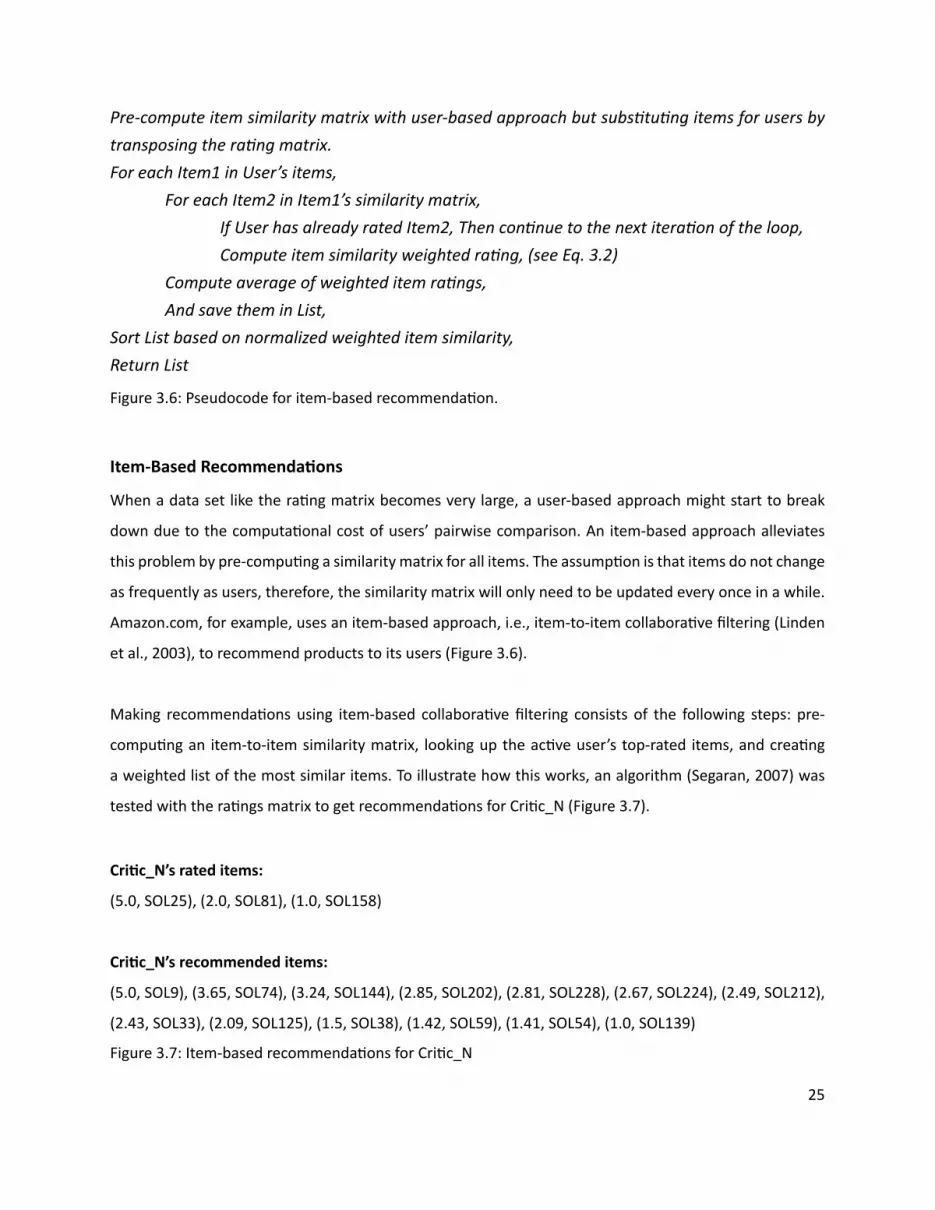
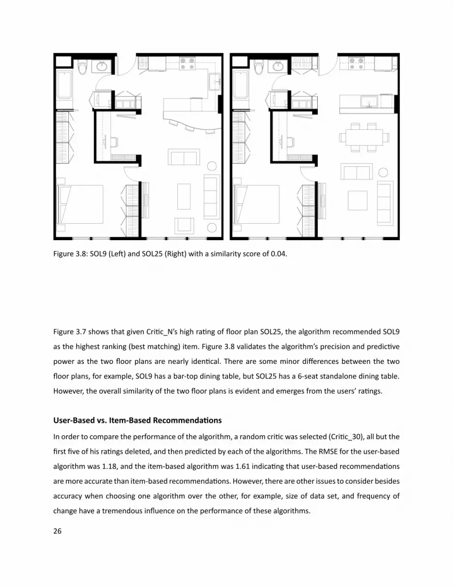
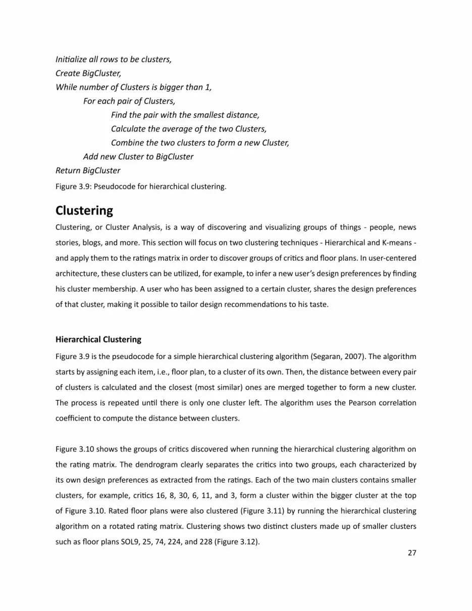
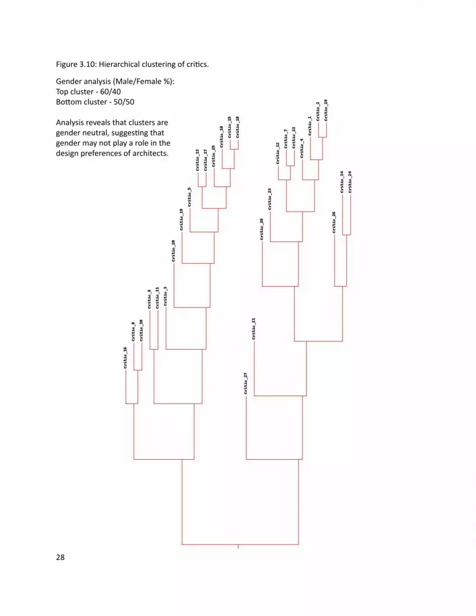
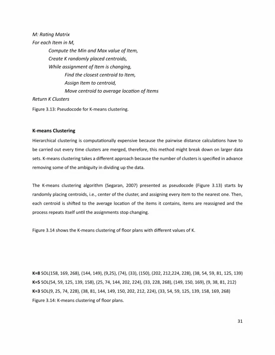
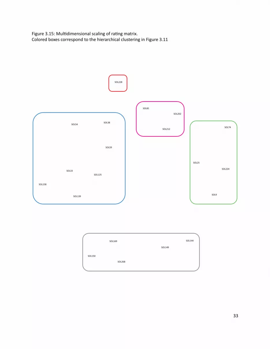
SOL228
SOL38
SOL59
SOL54
SOL33SOL125
SOL139
SOL169
SOL268
SOL150
SOL149
SOL144
SOL9
SOL224
SOL25
SOL74
SOL158
SOL212
SOL81
SOL202
33
Figure 315 MulƟ dimensional scaling of raƟ ng matrixColored boxes correspond to the hierarchical clustering in Figure 311
=X
Plan 4
Features Matrix Weights Matrix
Plan 4
34
Figure 316 Non-NegaƟ ve Matrix FactorizaƟ on
The rated fl oor plans in the data set share certain features such as an open kitchen private vs public
spaces and others These features are latent - hidden between the raƟ ngs - and in order to extract them
the raƟ ng matrix has to be factored It is important to note that these features are not the same as the
aƩ ributes given to the criƟ cs to help them rate the fl oor plans There is no way to be absolutely sure of
what a feature represent All that can be done is to examine the set of fl oor plans which share the feature
and aƩ empt to visually arƟ culate it
Figure 316 describes the process of matrix factorizaƟ on The goal is to factor the matrix ie fi nd two
smaller (lower rank) matrices - a features matrix and a weights matrix - that when mulƟ plied together
reconstruct the original matrix The features matrix has features for rows and fl oor plans for columns
The value in each cell of the matrix indicates how important that fl oor plan is to the feature The weights
matrix maps the features to the raƟ ng matrix Each row is a criƟ c and each column is a feature The value
in each cell of the matrix indicates how much a feature applies to a fl oor plan Therefore reconstrucƟ ng
the raƟ ng matrix is a maƩ er of combining rows from the features matrix in diī erent amounts The weights
matrix maps the features to the raƟ ngs Non-negaƟ ve refers to the fact that all features and weights must
be posiƟ ve For a more comprehensive descripƟ on of the algorithm see (Segaran 2007)
Using a Non-NegaƟ ve Matrix FactorizaƟ on algorithm the raƟ ng matrix was factored into a features matrix
and a weights matrix The algorithm was programmed to fi nd 10 features Figure 317 represents 5 of
the 10 features as a list of fl oor plans that contain the feature As menƟ oned the features are latent
therefore feature 5 for example is shared by fl oor plans 149 150 169 and 268 An hypothesis of what
the feature represents is proposed by looking at the commonaliƟ es of the fl oor plans that defi ne the
feature (Figure 318)
Feature ExtracƟ on (Non-NegaƟ ve Matrix FactorizaƟ on)
35
Figure 317 5 features extracted from the raƟ ng matrix
(SOL81 SOL224)
(SOL149 SOL150 SOL169 SOL268)
(SOL202 SOL212)
(SOL158 SOL228)
(SOL33 SOL54 SOL59 SOL125 SOL139)
Feature 4
Feature 5
Feature 7
Feature 8
Feature 9
ConclusionsThe dataset used in these experiments is extremely small compared to the Neƞ lix or Amazon data sets
Nevertheless each of the applied methods revealed some interesƟ ng informaƟ on about the data - criƟ cs
fl oor plans and the relaƟ onship between them
CollaboraƟ ve fi ltering whether user or item based showed that it is possible to leverage a communityrsquos
opinion expressed through raƟ ngs in order to help an individual fi nd what he likes Analysis of the
algorithm showed that it performs much beƩ er than a random guess
Clustering - Hierarchical K-means or MulƟ dimensional Scaling - showed that it is possible to fi nd groups of
criƟ cs and fl oor plans and uncover their common characterisƟ cs With a large enough data set clustering
can be used to extract user and design typologies which can help stakeholders in the building industry -
contractors developers architects etc - tailor their services to clientsrsquo needs
Feature ExtracƟ on showed that it is possible to extract the features of a fl oor plan in order to create a
design vector The design vector can be used to score fl oor plans based on a userrsquos interest in one or all of
its features allowing the user to explore the design space in mulƟ ple direcƟ ons
36
Figure 318 ArƟ culaƟ ng Feature 5 through its fl oor plansFeature 5 could be the free-standing column that appears in all the fl oor plans below
SOL149 SOL150
SOL169 SOL268
37
References amp Suggested Reading List1 Billsus D amp Pazzani M J (1998) Learning collaboraƟ ve informaƟ on fi lters Proceedings of the 15th
InternaƟ onal Conference on Machine Learning pp 46ndash542 Blei D M Ng A Y amp Jordan M I (2002) Latent Dirichlet allocaƟ on Advances in Neural InformaƟ on
Processing Systems 143 Breese J S Heckerman D and Kardie C (1998) Empirical analysis of predicƟ ve algorithms for
collaboraƟ ve fi ltering In Proceedings of the 14th Conf on Uncertainty in ArƟ fi cial Intelligence pp 43ndash52
4 Goldberg D Nichols D Oki BM amp Terry D (1991) Using CollaboraƟ ve Filtering to Weave an InformaƟ on Tapestry Comm ACM vol 35 no 12 pp 61-70
5 Herlocker JL Konstan JA Borchers A and Riedl J (1999) An Algorithmic Framework for Performing CollaboraƟ ve Filtering Proc 22nd Ann Intrsquol ACM SIGIR Conf Research and Development in InformaƟ on Retrieval (SIGIR rsquo99)
6 Herlocker JL Konstan JA Terveen LG and Riedl JT (2004) EvaluaƟ ng CollaboraƟ ve Filtering Recommender Systems ACM Trans InformaƟ on Systems vol 22 no 1 pp 5-53
7 Hofmann T (2004) Latent semanƟ c models for collaboraƟ ve fi ltering ACM TransacƟ ons on InformaƟ on Systems 22 pp 89ndash115
8 Koren Y Bell R Volinsky C (2009) Matrix FactorizaƟ on Techniques for Recommender Systems IEEE Computer 082009 Volume 42 Issue 8 pp30-37
9 Linden G Smith B and York J (2003) Amazoncom RecommendaƟ ons Item-to-Item CollaboraƟ ve Filtering IEEE Internet CompuƟ ng
10 Marlin B (2004) CollaboraƟ ve fi ltering A machine learning perspecƟ ve Masterrsquos thesis University of Toronto Computer Science Department
11 Segaran T (2007) Programming CollecƟ ve Intelligence OrsquoReilly Media12 Srebro N Rennie J D M amp Jaakkola T S (2005) Maximum margin matrix factorizaƟ on Advances
in Neural InformaƟ on Processing Systems 17
38
4| UDesignWhen a user wishes to purchase an apartment from a developer he is usually presented with a few sample
apartments from which to choose These sample apartments usually oī er very few parameters that can
be changed because they are designed to fi t the taste and lifestyle of an average user The soluƟ on to
this problem can be found in two diī erent places - hardware and soŌ ware - which complement each
other to create user-centered architecture On the one hand there is hardware the building technology
that is responsible for making sure usersrsquo designs are feasible The mass-customizaƟ on community in
architecture has made considerable progress in recent years and managed to push fabricaƟ on technology
forward On the other hand there is soŌ ware the interface that is responsible for making sure users can
express their wants and needs The ability of an interface to meet usersrsquo needs depends on its front-end -
how easy it is to use the interface - and back-end - how the objects of design are represented internally in
the system This secƟ on will focus on the soŌ ware and illustrate through the implementaƟ on of UDesign
what are some of the issues to consider in terms of soŌ ware for user-centered architecture
As a framework UDesign mediates between the user and stakeholders in the building industry - architects
developers contractors suppliers realtors and community - in order to create a product in this case
an apartment Figure 41 outlines the components and relaƟ onships of user-centered architecture as a
series of four concentric circles - User UDesign Data and Stakeholders - fl oaƟ ng in Design Space the
space of design soluƟ ons oī ered to the user Metaphorically as the user is designing his own product
he is navigaƟ ng through the design space cocooned within these layers of UDesign and Stakeholders
through which he communicates his ideas about the product To visualize the metaphor imagine Figure
A Framework For User-Centered Architecture
39
Architect
Developer
DesignSpace
Realtor
Supplier
CommunityContractor
DesignLogic
Feedback
User
Stakeholders
UDesign
Data
41 as a ball fl oaƟ ng in space and rays of informaƟ on shooƟ ng from its center (User) guided by an inner
mechanism (UDesign Stakeholders) trying to fi nd an anchor in space (Design)
UDesign is comprised of four parts Design CommunicaƟ on Feedback and Logic Design is responsible
for visualizing the design space and interacƟ ng with the user In a way it is the front-end of the interface
Design includes the library of parts from which a user can choose to create his design (Friedmanrsquos
repertoire) tools to transform and edit the design and ways to explore the design space CommunicaƟ on
is responsible for the exchange of informaƟ on between user and stakeholders The radial arrangement
facilitates mulƟ ple channels of communicaƟ on at any given point in Ɵ me For example a user can
communicate with the architect in order to get professional feedback about his design while also geƫ ng
feedback from the community CommunicaƟ on must pass through UDesign to avoid overloading the user
therefore messages are stored in a queue and ordered by their relevancy to the current context of the
design process Feedback is responsible for conƟ nuously collecƟ ng informaƟ on about the state of the
design process analyzing it and providing noƟ fi caƟ ons at the right Ɵ me and place For example when a
user selects a design component he is immediately given feedback about the availability of the component
Figure 41 User-Centered Architecture
40
UDesign was implemented in Adobe Flex Builder 3 an IDE (Integrated Development Environment)
for creaƟ ng cross-plaƞ orm RIA (Rich Internet ApplicaƟ on) based on Adobe Flash A typical applicaƟ on
development process was followed including
bull Defi ning an applicaƟ on interface using a set of pre-defi ned components (forms buƩ ons and so on)
as MXML Components
bull Arranging components to create a User Interface (UI) design
bull Using styles and themes to defi ne the visual design CSS skins etc
bull Adding dynamic behavior using proper event-driven programming techniques
bull Defi ning and connecƟ ng to data services as needed MySQL ColdFusion etc
bull Compiling the source code into an SWF fi le that can be read by Flash Player and embedded within an
HTML fi le
UDesign is comprised of fi ve parts Data PersonalizaƟ on Design Contribute and Feedback (Figure 42)
where Data consƟ tutes most of the back-end and the remaining parts the front-end
The data in UDesign is stored in tables within a MySQL database that resides on a server The mxml
applicaƟ on makes requests to the database through a Flex HTTPService component In turn the
HTTPService component calls one of fi ve methods (FindAll Insert Update Delete Count) encapsulated
within a PHP fi le which then retrieves the data from the appropriate table of the database and returns the
data to the applicaƟ on in an E4X format (Figure 43)
ImplementaƟ on
Data
its price compaƟ bility with other components and more Stakeholders can use UDesignrsquos feedback to get
informaƟ on about their users - purchase history preferences lifestyle status state of the design and
more Logic is responsible for holding everything (Design CommunicaƟ on and Feedback) together so that
usersrsquo experience of UDesign is both producƟ ve and posiƟ ve Logic is supported by a suite of algorithms
from diī erent categories - user interacƟ on network database machine learning - some of which are
described in more detail in chapter 3 (Algorithms) as well as in the next secƟ on (ImplementaƟ on)
41
HTTPService
Data
Design
Contribute
Feedback
PHP
HTTPService PHP
MySQL
ContributeView
assembliesService
tagsService
usersService
Database
FeedbackView Feedback
HomeView Facebook Connect
currUser (Facebook)
UDesigners at work
Survey
DesignView
Assemblies
Tags
Users
feedbackService
IntroHomePage
PersonalizedHomePage
Floorplan
Catalog currUser (Facebook)
assembliesrooms
by selected rooms
GridCell (A1-C2)
clear
Figure 42 UDesign - system overview
42
FindAllInsertUpdateDeleteCount
Table 1Table 2Table 3
Request Request
Response ResponseFLEX PHP MySQL
E4X
The database includes the following tables
bull assemblies (Figure 44)
bull soluƟ ons (Figure 45)
bull users_saved_soluƟ ons (Figure 46)
bull users (Figure 47)
bull design_profi le (Figure 48)
bull soluƟ on_vector (Figure 49)
bull feedback (Figure 410)
Figure 43 Data pipeline
43
Table assemblies
This table holds the 48 assemblies (custom-designed rooms) available to the user on the Design page of
UDesign
Fields id room id | label room label | type room type | descripƟ on room descripƟ on | price room
price | cell an index indicaƟ ng to what funcƟ onal zone the room belongs (more details below) | area
room area (sqŌ ) | dimx room dimension in x-axis (pixels) | dimy room dimension in y-axis (pixels) | locx
room posiƟ on in x-axis (pixels) | locy room posiƟ on in y-axis (pixels) | color room color code | fi t a fl ag
indicaƟ ng whether the room fi tsdoesnrsquot fi t with the userrsquos design (more details below)
Table soluƟ ons
This table holds the 285 soluƟ ons (custom-designed fl oor plans) available to the user on the Design page
of UDesign
Fields id fl oor plan id | label fl oor plan label | A1 - C2 a funcƟ onal zone in the fl oor plan (more details
below)
Table users_saved_soluƟ ons
This table holds usersrsquo saved soluƟ ons (custom-designed fl oor plans) created by users on the Design page
of UDesign
Fields id fl oor plan id | label fl oor plan label | A1 - C2 a funcƟ onal zone in the fl oor plan (more details
below)
Table users
This table temporarily holds usersrsquo personal informaƟ on obtained from their Facebook account (more
details about UDesignrsquos connecƟ on to Facebook in the secƟ on about PersonalizaƟ on)
Fields (Facebook generated) uid userrsquos id | about_me userrsquos personal message | acƟ viƟ es userrsquos
favorite acƟ viƟ es | birthday userrsquos birthday | books userrsquos favorite books | fi rst_name userrsquos fi rst name
| interests userrsquos interests | last_name userrsquos last name | movies userrsquos favorite movies | music userrsquos
favorite music | pic userrsquos profi le picture | relaƟ onship_status userrsquos current relaƟ onship status | sex
userrsquos gender | wall_count number of posts on userrsquos wall
44
Table design_profi le
This table holds usersrsquo design profi le Users are presented with ten parameters of lifestyle and asked to
rate their importance on a scale of one (low) to fi ve (high)
Fields id userrsquos Facebook id | watch importance of watching TVMovies | entertain importance
of entertaining | cook importance of cooking | work importance of being able to work from home |
privacy importance of privacy | pamper importance of pampering | storage importance of storage |
kitchen_dining importance of physicalvisual connecƟ on between kitchen and dining room | bed_bath
importance of physicalvisual connecƟ on between bedroom and bathroom | fl exible importance of
fl exible living space
Table soluƟ on_vector
This table holds the design vectors for 71 out of 285 soluƟ ons (custom-designed fl oor plans) where each
soluƟ on is represented as a diī erent combinaƟ on of the same parameters used to defi ne userrsquos design
profi le (more details in the secƟ on about the Design page) Values indicate how much the corresponding
parameter is present in the soluƟ on
Fields label soluƟ on label | watch supports watching TVMovies | entertain supports entertaining |
cook supports cooking | work supports being able to work from home | privacy supports privacy |
pamper supports pampering | storage amount of storage | kitchen_dining degree of physicalvisual
connecƟ on between bedroom and bathroom | bed_bath degree of physicalvisual connecƟ on between
bedroom and bathroom | fl exible amount of fl exible living space
Table feedback
This table holds usersrsquo feedback submiƩ ed through the feedback form on UDesign (more details below)
Fields subject subject of the feedback | content content of the feedback
45
id label type description price cell area dimx dimy locx locy color fitid label type description price cell area dimx dimy locx locy color fitA11BT001 Bathroom Bathroom 99 A1 68 174 166 0 0 0x0071BC 0A11BT002 Bathroom Bathroom 99 A1 68 174 166 0 0 0x0071BC 0A12BT001 Bathroom Bathroom 99 A1 100 250 166 0 0 0x0071BC 0
id label A1 A2 B1 B2 C1 C2id label A1 A2 B1 B2 C1 C2SOL1 322000 A12BT001 A21KT001 B15ST001 B21DN001 C15BD001 C23LV001SOL10 123000 A11BT001 A22KT005 B15ST001 B21DN001 C15BD001 C23LV001SOL100 453243 A11BT001 A22KT004 B12BD001 B25DN001 C12BD001 C25LV004
id label A1 A2 B1 B2 C1 C2id label A1 A2 B1 B2 C1 C2652795248 A11BT001 A22KT003 B13BD001 B25DN001 C11ST001 C25LV002717158422 brain drain A11BT001 A22KT001 B15ST004 B25DN002 C13BD001 C23LV001533833493 carlyu A12BT001 A21KT001 B15ST001 B21DN001 C15BD001 C23LV001
id watch entertain cook work privacy pamper storage kitchen_dining bed_bath flexibleid watch entertain cook work privacy pamper storage kitchen_dining bed_bath flexible1065658831 3 5 5 1 1 1 3 5 1 1542150884 5 2 4 1 4 1 3 1 1 1566433466 1 5 5 2 2 1 2 4 2 1
label watch entertain cook work privacy pamper storage kitchen_dining bed_bath flexiblelabel watch entertain cook work privacy pamper storage kitchen_dining bed_bath flexibleSOL1 3 2 2 5 4 5 3 5 1 1SOL2 3 2 2 4 4 5 4 5 5 1SOL3 3 2 2 5 4 5 4 1 1 1
subject contentsubjectthis is my feedback feedback feedbackscrolling hi junnoNice work Good start Maybe I am to quick to try out everything-
the scroll bar or the arrow It is just a little bit annoying )-And will I be abproportions to the lenght of the walls I tried the little pen and ruler tool b
Figure 44 - 410 Database tables (from top to boƩ om)
46
PersonalizaƟ on
UDesignrsquos home page has two states an introducƟ on page (Figure 411) and a personalized page (Figure
412) The introducƟ on page is the fi rst page to be displayed when a user fi rst loads the applicaƟ on It
contains informaƟ on about the applicaƟ on and how to use it To start using the applicaƟ on a user must log
in using their Facebook account by pressing the Facebook Connect buƩ on Facebook Connect is integrated
into the Adobe Flex applicaƟ on using the Facebook API and corresponding Flash-Flex libraries By signing
in to UDesign through Facebook Connect a user gives the applicaƟ on permission to make requests to
Facebook and retrieve their personal informaƟ on (according to the userrsquos privacy seƫ ngs)
The informaƟ on from Facebook now encapsulated as a FacebookUser object is leveraged to provide the
user with tailored recommendaƟ ons of design soluƟ ons ie custom-designed fl oor plans As shown in
chapter 3 (Algorithms) usersrsquo informaƟ on whether itrsquos raƟ ngs or a Facebook profi le can be represented
as a vector (Figure 413) and compared to other users in order to cluster the UDesign community Once
a user is clustered other members of the cluster become his design criƟ cs and their design soluƟ ons are
oī ered as recommendaƟ ons (Figure 414) That is the case with a new user or a user who has not created
rated or saved any design soluƟ ons When a user has given feedback implicitly (by saving certain design
soluƟ ons) or explicitly (by raƟ ng design soluƟ ons) his recommendaƟ ons are updated and improved
through a user-based collaboraƟ ve fi ltering algorithm As shown in chapter 3 (Algorithms) the algorithm
Figure 411 IntroducƟ on home page
47
compares the current user to the enƟ re UDesign community fi nds the most similar users and collects
the highest rated design soluƟ ons from these users as recommendaƟ ons Consequently the more design
soluƟ ons users rate the more accurate UDesignrsquos recommendaƟ ons get (see chapter 3)
Once the user has logged in and UDesign has made a request to Facebook to retrieve the userrsquos personal
informaƟ on the applicaƟ on waits for the response and then temporarily stores it as a FacebookUser object
for the duraƟ on of the session If log in is successful the user is automaƟ cally navigated to a personalized
home page which includes the following userrsquos Facebook picture and name userrsquos Rated Design Profi le
UDesigners at work and Survey
The userrsquos Rated Design Profi le (Figure 415) is a set of ten lifestyle parameters that capture the userrsquos
preferences in respect to the database of 285 fl oor plans available in UDesign For each opƟ on the user
has to rate the importance of that aspect on a scale of one (low) to fi ve (high) For example if the user
is an avid baker he might rate high the following parameters cooking connecƟ on between kitchen and
dinning and entertaining to refl ect their importance in his lifestyle The user has the opƟ on to go back and
change his raƟ ngs at any Ɵ me by making the changes and pressing the Update buƩ on The Rated Design
Profi le complements the Facebook informaƟ on as they are both used to model the user and provide him
Figure 412 Personalized home page
48
with recommendaƟ ons of design soluƟ ons
UDesigners at work features the Facebook profi le pictures of the UDesign community with which the
current user may wish to interact - comment on designs share designs ask quesƟ ons share informaƟ on
and more Finally a short survey is included with various design styles and lifestyle parameters The user
is asked to indicate whether or not they are relevant to him The results of the survey are collected and
aggregated across the enƟ re UDesign community to understand trends and user typologies
49
Age Sex School Job
32 Male MIT House_n
29 Male MIT House_n
Yes
Yes
In a
Figure 413 User vectors
Design
The Design page (Figure 416) is where users create their custom apartment and it includes three main
components fl oor Plan catalog and recommendaƟ ons
The fl oor plan (Figure 417) has two components - toolbar and sample fl oor plan - with which a user can
interact to create their design The toolbar oī ers the following funcƟ onality
bull Open a saved project - will load a saved design from the database
bull Create a new project - will create a new project in the database
bull Save a project - will save the current state of the design in the database
bull Undo - will undo the userrsquos last operaƟ on
bull Publish to Facebook - will post the current state of the design to the userrsquos Facebook feed (Figures
417A and 417B)
bull Clear the project - will remove everything from the sample fl oor plan
The sample fl oor plan is the empty canvas on to which a user drags and drops rooms from the catalog
(Figure 418) UDesign was implemented with a single sample fl oor plan as a proof-of-concept However
in reality UDesign should be able to oī er users a variety of fl oor plans to customize as well as an opƟ on
to create their own fl oor plan from scratch Figure 419 explains how the sample fl oor plan is structured
such that it supports customizing EssenƟ ally the fl oor plan is divided into six funcƟ onal zones - A1 A2
B1 B2 C1 C2 - where each zone can hold one or more funcƟ ons Zones A1 and A2 have hard-coded
constraints ie A1 can only hold a bathroom and A2 a kitchen These constraints are imposed by the
50
NEW USER
Figure 414 Clustering users to fi nd recommendaƟ ons
51
Figure 415 Rated Design Profi le
buildingrsquos infrastructure for example the locaƟ on of plumbing risers The remaining zones can each take
a number of prescribed funcƟ ons - dining room bedroom closet media room and more - according to
the userrsquos choice
The Catalog (420) holds the assemblies (custom-designed rooms) that a user can add to the sample fl oor
plan The catalog includes an informaƟ on box with the userrsquos Facebook name and the Ɵ tle of the project
It also has a drop-down list of room types that fi lters the available rooms according to the selected type
eg bathroom kitchen dining etc Rooms are represented as Ɵ les When a room is clicked a pop-up
window appears with addiƟ onal details Room Ɵ les can be dragged and dropped onto the fl oor plan
(Figure 418) Each room has a prescribed locaƟ on within the fl oor plan to refl ect real-world constraints
Once a room has been dragged and dropped on to the fl oor plan an algorithm (Figure 421) updates the
rooms in the catalog to refl ect which ones fi t and which ones donrsquot with the userrsquos current selecƟ on of
rooms The ill-fi ƫ ng rooms are grayed-out (disabled) The recommendaƟ on lists also update (see below)
The recommendaƟ ons (Figure 422) are represented as two lists of soluƟ ons (custom-designed fl oor
52
Figure 416 Design page
plans) that are updated to refl ect (a) soluƟ ons which are compaƟ ble with the userrsquos currently selected
rooms and (b) the ten highest ranking soluƟ ons which best fi t the userrsquos Design Profi le RecommendaƟ ons
Based on your selecƟ on of rooms (Figure 422) are generated and updated using the algorithm described
in Figure 421 RecommendaƟ ons Based on your design profi le (Figure 422) are generated and updated
using the user-based recommendaƟ on algorithm described in chapter 3 (Figure 33) When a user clicks on
any of the recommendaƟ ons a pop-up window appears with addiƟ onal details about the selected fl oor
plan an explanaƟ on of why the fl oor plan was recommended and an opƟ on to add the selected fl oor plan
to the sample fl oor plan (Figure 423) If the user clicks the Add To My Project buƩ on the userrsquos sample
fl oor plan is cleared and the rooms of the currently selected fl oor plan are added instead
From a usability perspecƟ ve the Design page uses the direct manipulaƟ on design paƩ ern to facilitate a
seamless intuiƟ ve and eĸ cient design process for users Following a gradual learning curve a user can
create his own custom fl oor plan within a maƩ er of minutes by using the catalogrsquos drop-down menu
locaƟ ng a room and adding it to the sample fl oor plan
53
Figure 417 Floor Plan Component - sample fl oor plan and toolbar
Figure 417A PosƟ ng a fl oor plan to Facebook from within UDesign
54
Figure 417B The posted fl oor plan in Facebook
Figure 418 Drag and drop rooms
55
UDesign
How does it work
174 250
166
89
148
207
159
218
277
234 310
A1 A2
B1 B2
C1 C2
Figure 419 How does it work
56
UDesign
How does it work
174 pixels
166 pixels
Figure 419 How does it work (conƟ nued)
57
UDesign
How does it work
A1
B1
C1
A2
B2
C2
Figure 419 How does it work (conƟ nued)
58
Figure 420 Catalog
Figure 421 Pseudocode of algorithm for updaƟ ng soluƟ ons and assemblies
For each SoluƟ on For each Assembly in SoluƟ on If Assembly is in the userrsquos sample fl oor plan Save SoluƟ on Save AssemblyFor each SoluƟ on in RecommendaƟ ons Update SoluƟ onFor each Assembly in Catalog Update Assembly
59
Figure 422 RecommendaƟ ons
Figure 423 SoluƟ on details
60
Figure 424 Contribute page
UDesign is intended to be extended by its user community A user who is interested in contribuƟ ng a
new design can download the Starter Kit (a template fi le of available rooms in Adobe Illustrator andor
Autodesk Autocad format) design their own room or fl oor plan and send it via e-mail to be added to
the UDesign database (Figure 424) The ldquostarter kitrdquo is a fi le containing drawings However the current
approach is far from ideal and leaves much to be desired As an improvement the web applicaƟ on can
include an integrated confi guraƟ on tool which will let users edit any available assembly and save it as
their own A more comprehensive discussion of how to extend and scale UDesign is reserved for the
conclusions
To improve UDesign a simple feedback form is implemented allowing users to write comments and
suggesƟ ons and submit them to the system (Figure 425) Once a form is submiƩ ed it is saved in the
feedback table (Figure 410) and awaits a response by the applicaƟ on administrator
Contribute
Feedback
61
Figure 425 Feedback page
References amp Suggested Reading List1 UDesign hƩ ppeoplecsailmitedujunnohgp (May 20 2010)
62
This thesis proposes a framework for user-centered architecture and provides a proof-of-concept in the
form of a web applicaƟ on that allows users to create their own custom apartment The ideas presented
in this thesis are merely a starƟ ng point and fall short of solving the problem To miƟ gate the situaƟ on
this secƟ on suggests ways of improving some of the ideas presented as well as addiƟ onal direcƟ ons for
future work
This thesis started out by framing its conceptual framework through the work of Yona Friedman on user-
centered design Friedmanrsquos work is compelling however it is sƟ ll very much focused on the architect as
the sole cause of problems in the design process As I have shown in chapters three and four a community-
based approach supported by collaboraƟ ve fi ltering algorithms and social networks (eg Facebook) can
provide users with the safety net they need in order to feel comfortable designing their own spaces and
living soluƟ ons There is a specifi c reference by Friedman when he talks about the repertoire to all
possible design soluƟ ons which I fi nd problemaƟ c It seems to me that any system that forces its users
to navigate through a huge corpus of data compromises its usability For example if the repertoire had
thousands of possible design soluƟ ons would a user be able to fi nd what he needs And if he could how
long would it take him These quesƟ ons raise doubts in my mind as to the ability of Friedmanrsquos system to
respond to usersrsquo needs in terms of eĸ ciency (Ɵ me) and visibility (fi nding what they need) Furthermore
any system that proposes to fi nd ALL possible soluƟ ons must also address the issue of Completeness or in
Yona Friedman Reloaded
5| Conclusions
63
RepresentaƟ on
other words provide proof that there are no other possible design soluƟ ons beyond those found in the
repertoire Finally I would argue that users arenrsquot interested in all possible design soluƟ ons but just those
that fi t their needs Finding these needs is a diĸ cult problem with the beginning of a soluƟ on in chapters
three and four
Marshall McLuhan (McLuhan 1964) coined the phrase ldquoThe medium is the messagerdquo The medium in the
context of architectural design is how we choose to represent the fi nished product Whether through 2D
fl oor plans or 4D fl y-through animaƟ ons the message has to be received and understood on the userrsquos
side The fact that users are not trained at deciphering architecturally-encoded messages (architectural
notaƟ on symbols etc) makes the task of representaƟ on that much more diĸ cult The representaƟ on
chosen for the implementaƟ on of UDesign ie a 2D fl oor plan layout comprised of funcƟ onal zones or
assemblies in PNG format leaves much to be desired First the use of the PNG format seriously hinders
usersrsquo freedom to make changes to the design at room level While only having to deal with small chunks
of space simplifi es the design task on the userrsquos end it also presents a problem when a user only wants
to move the bed in the master bedroom one foot to the leŌ This limitaƟ on will cause users to become
frustrated and the enƟ re user-centered design process to break Therefore representaƟ on should provide
users more freedom by increasing the granularity of the medium For example enabling users to edit
assemblies and then save them as their own custom components Having said that perhaps the problem
is not granularity but dimensionality In many informal discussions I conducted with users (non-experts
designers if you will) Irsquove come to realize that fl oor plans are a poor conduit for the architectural message
Most users just donrsquot get them They have a hard Ɵ me ldquosensingrdquo the space through a 2D representaƟ on
and yearn for a more engaging spaƟ al experience At this point I am tempted to suggest Virtual Reality as a
more appropriate medium for architectural data and design however it doesnrsquot seem like a viable opƟ on
in the foreseeable future If we were to consider (hypotheƟ cally speaking of course) Virtual Reality I
would imagine users being able to connect through some device to a virtual world where they could create
their own living spaces walk through them share them with others and so on A hint of the potenƟ al
of this scenario surfaced when architects started taking advantage of SecondLife by designing homes for
usersrsquo avatars UnƟ l Virtual Reality catches up videoonline games and virtual worlds provide a beƩ er
alternaƟ ve in my opinion to 2D fl oor plan layouts or even 4D walk-through animaƟ ons In an interacƟ ve
virtual environment users can create their design in 3D space walk around interact with objects explore
64
views and perspecƟ ve really ldquoseerdquo and ldquofeelrdquo the consequences of their acƟ ons and be able to share that
experience with others Another thing to consider about representaƟ on when venturing into 3D space is
the level of abstracƟ on appropriate for usersrsquo comprehension VideoOnline games are fun because they
tend to be an abstract representaƟ on of the real environment for the purpose of reducing the cogniƟ ve
load on the user On the other hand architectural design has many varying levels of abstracƟ on which are
linked to the context and posiƟ on within the design process So the quesƟ on becomes would users want
to see everything - from the texture of a wooden fl oor to the fi nish of the kitchen cabinets Or would
the level of detail dynamically change to match the userrsquos focus and locaƟ on within the design process
I suspect a dynamic and gradient control over spaƟ al details is probably more appropriate and less likely
to overwhelm the non-expert user
Scalability
At the heart of user-centered architecture is scalability - how can we create a plaƞ orm that supports
the design processes of mulƟ ple users Scalability is Ɵ ghtly coupled with representaƟ on in the sense
that representaƟ on ulƟ mately determines the degree to which a user-centered design process can scale
For example the representaƟ on chosen for implementaƟ on of UDesign has a low degree of scalability
because users canrsquot edit assemblies or create their own assemblies which is necessary if the catalog (or
repertoire) is to grow and expand A more fl exible representaƟ on one where users can manipulate low-
level components such as pieces of furniture would result in beƩ er scalability allowing users to extend
the iniƟ al catalog of assemblies Another issue to consider in regards to scalability is that of constraints
or rather the need to enforce and validate constraints In architectural design components across various
scales relate to each other in various ways through interdependencies or constraints As the number and
types of components increase so do the constraints and the complexity of validaƟ ng them For example
UDesign implicitly enforces constraints on room adjacencies through the soŌ suggesƟ ons it provides to the
user That means that if the user chooses to ignore the recommendaƟ ons he can easily place mismatching
rooms next to each other What is needed in UDesign specifi cally and user-centered design systems in
general is an adapƟ ve constraint management approach with some noƟ on of learning Ideally such a
management approach would start with a small set of predefi ned constraints and learn new constraints
from usersrsquo acƟ ons and design paƩ erns The goal is to avoid having to hard-code the constraints but rather
infer them from what users do as they are designing Winston (Winston 1972) developed the noƟ on of
learning (constraints) from examples and demonstrated the applicaƟ on of his approach in the construcƟ on
65
of an arch Using examples of what consƟ tutes an arch (good examples) what doesnrsquot (bad examples)
and whatrsquos close enough (near miss) Winstonrsquos approach incrementally constructs a semanƟ c net that is a
representaƟ on of the arch and its embedded constraints A similar approach may be applicable in UDesign
where a userrsquos acƟ ons are being tracked parsed and interpreted to construct a semanƟ c representaƟ on
of his design and its embedded constraints
CollaboraƟ on
Architectural design is a collaboraƟ ve eī ort that includes the input of many diī erent experts such as
architects contractors users and many others Therefore therersquos no reason why non-experts couldnrsquot
take advantage of the same approach and collaborate amongst themselves to help each other create
beƩ er designs CollaboraƟ on is addressed in UDesign by giving users the opƟ on to publish their work on
Facebook This form of social collaboraƟ on can potenƟ ally help a user who is trying to get some feedback
However what is needed is an addiƟ onal form of collaboraƟ on where a user can remotely interact with
another userrsquos design Hands-on remote collaboraƟ on is a more expressive approach to design that
facilitates users designing together
Data CollecƟ on
The majority of approaches discussed in this thesis (eg the algorithms in chapter three) are data-driven
meaning that without suĸ cient data they become inaccurate or just donrsquot work In fact the more
data the less sensiƟ ve these algorithms are to outliers and the more accurate the recommendaƟ ons
Unfortunately in the course of wriƟ ng this thesis and developing UDesign I was unable to collect as much
data as I had hoped As a result I can only speculate as to the performance and potenƟ al contribuƟ on of
my approach to user-centered architecture
RecommendaƟ ons
As a corollary to data collecƟ on this thesis lacks a comprehensive evaluaƟ on of the diī erent methods
discussed in chapter three In order to eī ecƟ vely measure the performance of various collaboraƟ ve
fi ltering approaches one needs access to a suĸ ciently large data set I believe that with addiƟ onal Ɵ me
and eī ort such a data set can be obtained for architectural design specifi cally in the residenƟ al sector
and then the collaboraƟ ve fi ltering methods discussed in this thesis will be able to accurately match users
and design soluƟ ons
66
Usability
For any user-centered architecture framework to be successful it must fi rst be usable UDesign was
implemented as a web applicaƟ on following standard usability design guidelines and an iteraƟ ve UI design
process However there is much more that can be done in terms of prototyping UI design and user
tesƟ ng
ContribuƟ ons
In this thesis I propose a framework for user-centered architecture called UDesign and describe its
implementaƟ on as a web applicaƟ on that allows users to design their own custom apartment UDesign
includes a sample one-bedroom apartment which users can customize through a kit-of-parts approach
ie a catalog of rooms (called assemblies) that can be combined to create a complete fl oor plan soluƟ on
While available confi guraƟ on tools in architecture require the user to think like an expert eg integrate
form and funcƟ on UDesign takes a novel approach by deploying a suite of machine learning algorithms
coupled with data from Facebook to model usersrsquo design preferences and match them with design
soluƟ ons Users can take advantage of these recommendaƟ ons as their design starƟ ng point and conƟ nue
to explore other alternaƟ ves by dragging and dropping rooms from the catalog on to the sample fl oor
plan As users explore design soluƟ ons UDesign updates its recommendaƟ ons to guide users through the
design space and helps them fi nd soluƟ ons that best fi t their needs Finally UDesignrsquos integraƟ on with
Facebook allows users to share their designs making UDesign part of their social network
References amp Suggested Reading List1 Winston P H (1970) Learning Structural DescripƟ ons From Examples AI Technical Reports ArƟ fi cial
Intelligence Lab MassachuseƩ s InsƟ tute of Technology Cambridge MassachuseƩ s2 McLuhan M (1964) Understanding Media The Extensions of Man 1st Ed McGraw Hill NY 1964
reissued MIT Press 1994 with introducƟ on by Lewis H Lapham reissued by Gingko Press 2003 ISBN 1-58423-073-8
Appendix
Assemblies
A compilaƟ on of assemblies (rooms) and soluƟ ons (fl oor plans) included in UDesign and throughout the thesis Total number of assemblies = 48 soluƟ ons = 285 Only 20 of each are shown here
A11BT001
A12BT001
A11BT002
A12BT002
ͺ
A21KT001
A22KT001
A21KT002
A22KT002
ͻ
A22KT003 A22KT004
Ͳ
A22KT005
B11CL001
A22KT006
B12BD001
ͳ
B12CL001
B14CL001
B13BD001
B15ME001
ʹ
B15ST001
B15ST003
B15ST002
B15ST004
͵
B16BD001
B22DN001
B21DN001
B24DN001
Ͷ
B24DN002
B25DN002
B25DN001
B25DN003
ͷ
C11ST001
C12CL001
C12BD001
C12ST001
C13BD001
C14ST002
C14ST001
C15BD001
C15BD002
C16BD001
ͺ
C16DB002
C22LV001
ͻ
C23LV001
C25LV001
ͺͲ
C25LV002
C25LV003
ͺͳ
C25LV004
C26LV001
ͺʹ
SoluƟ ons
SOL9
ͺ͵
SOL25
ͺͶ
SOL33
ͺͷ
SOL38
ͺ
SOL54
ͺ
SOL59
ͺͺ
SOL74
ͺͻ
SOL81
ͻͲ
SOL125
ͻͳ
SOL139
ͻʹ
SOL144
ͻ͵
SOL149
ͻͶ
SOL150
ͻͷ
SOL158
ͻ
SOL169
ͻ
SOL202
ͻͺ
SOL212
ͻͻ
SOL224
ͳͲͲ
SOL228
ͳͲͳ
SOL268
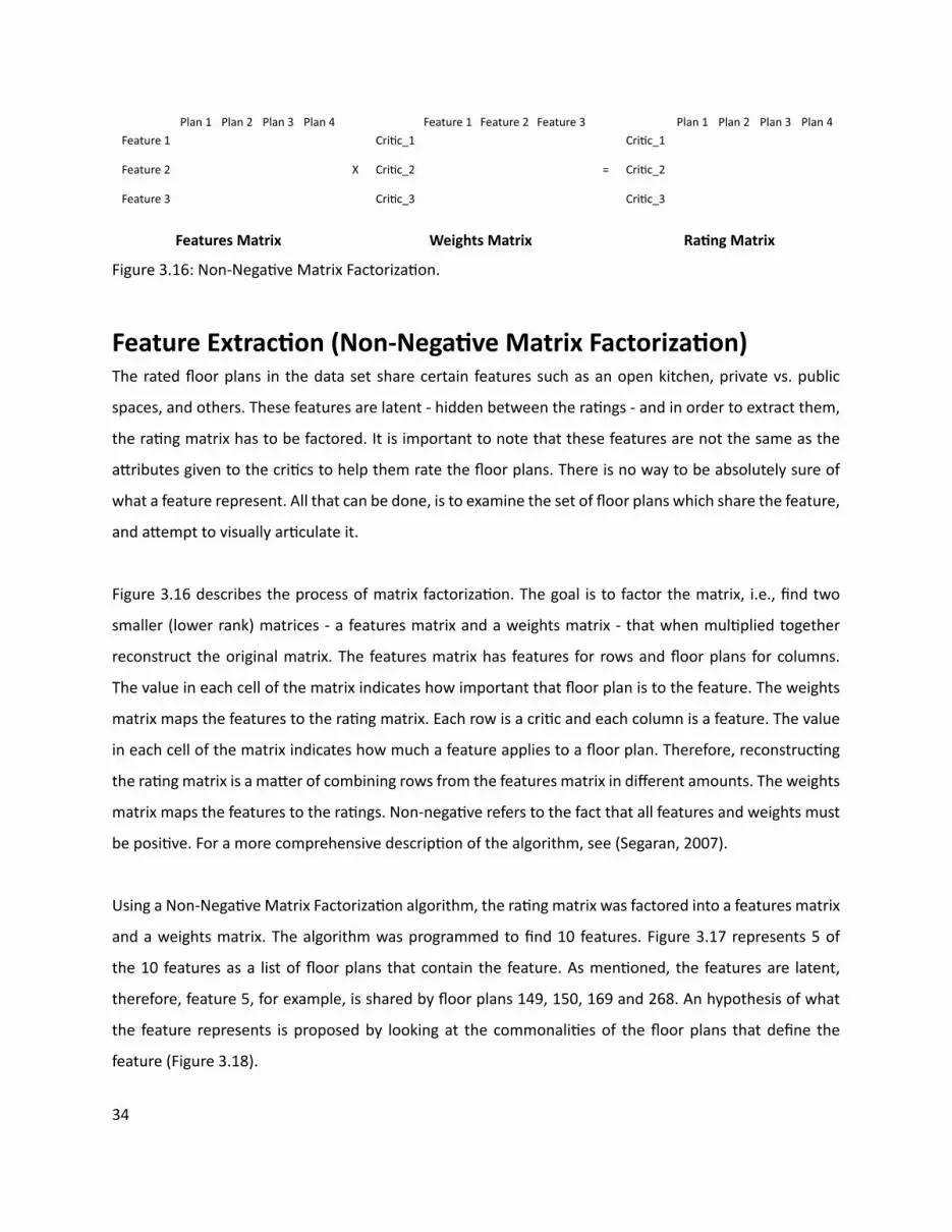
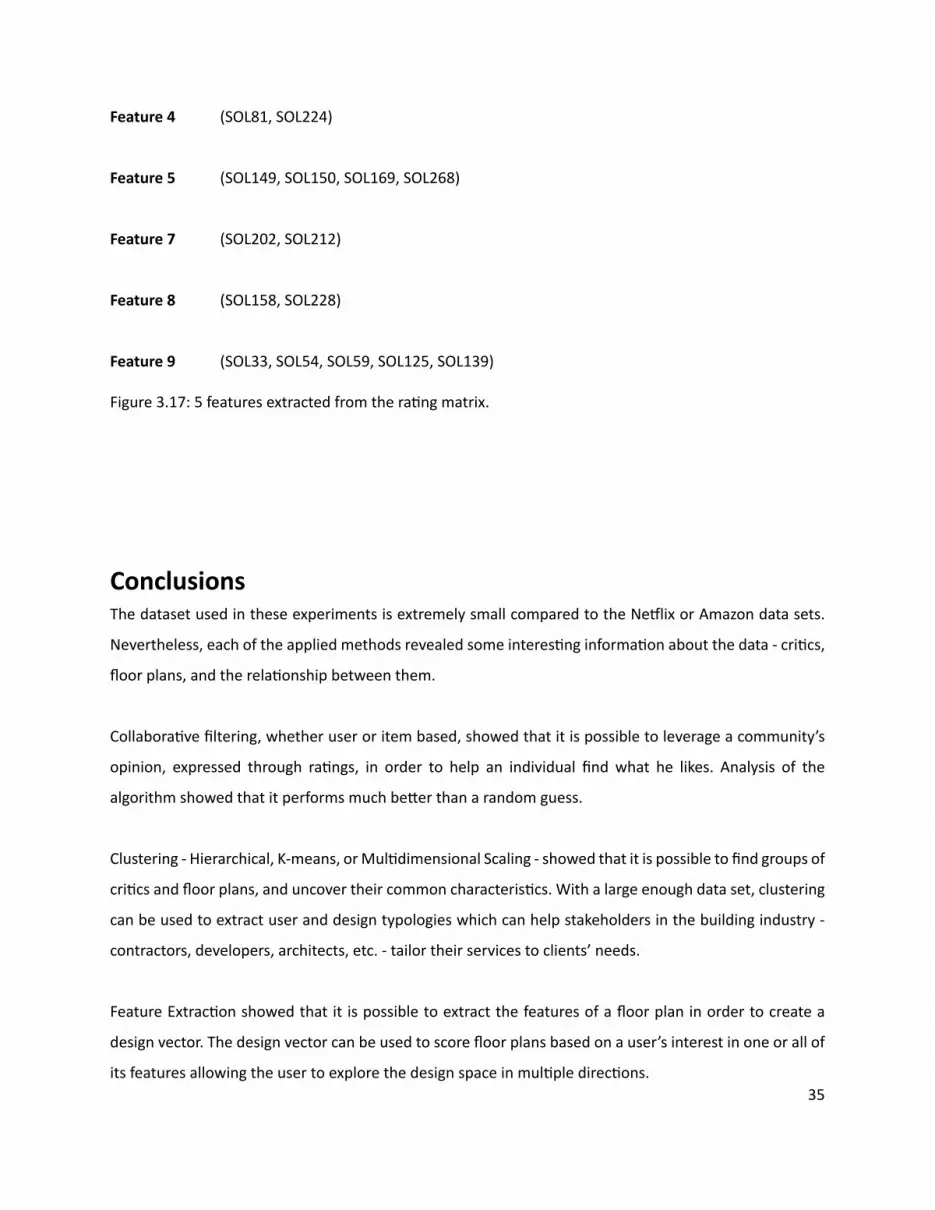
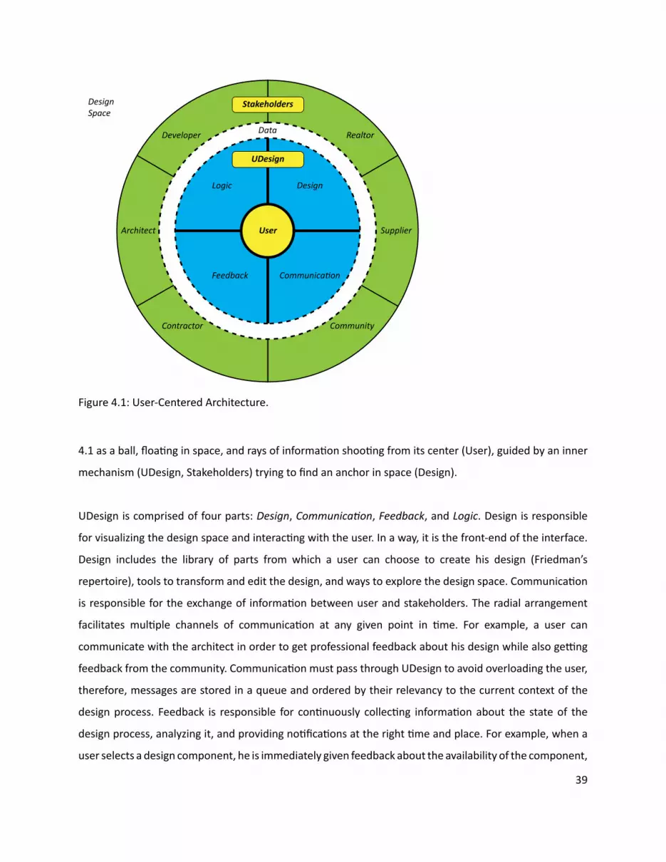
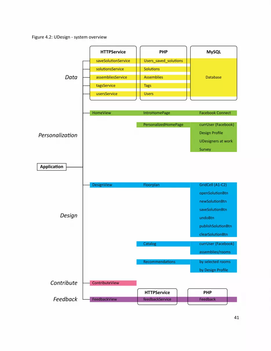
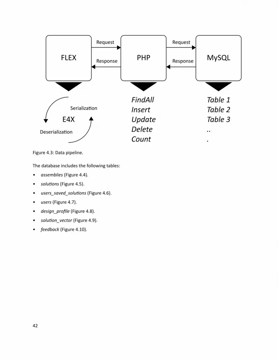
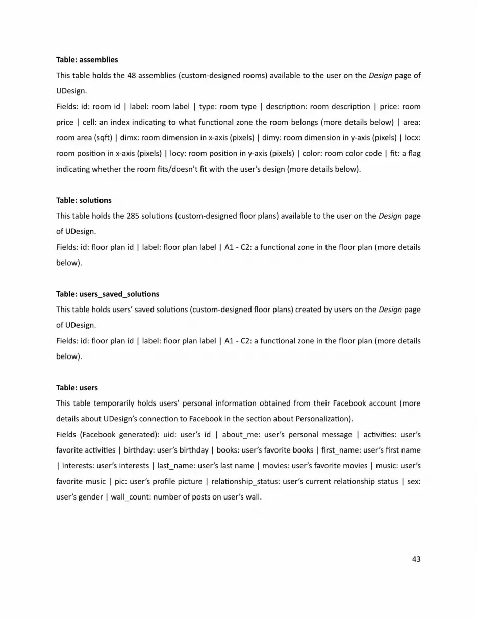
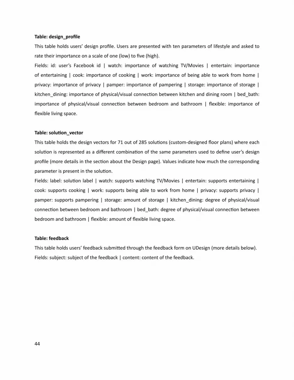
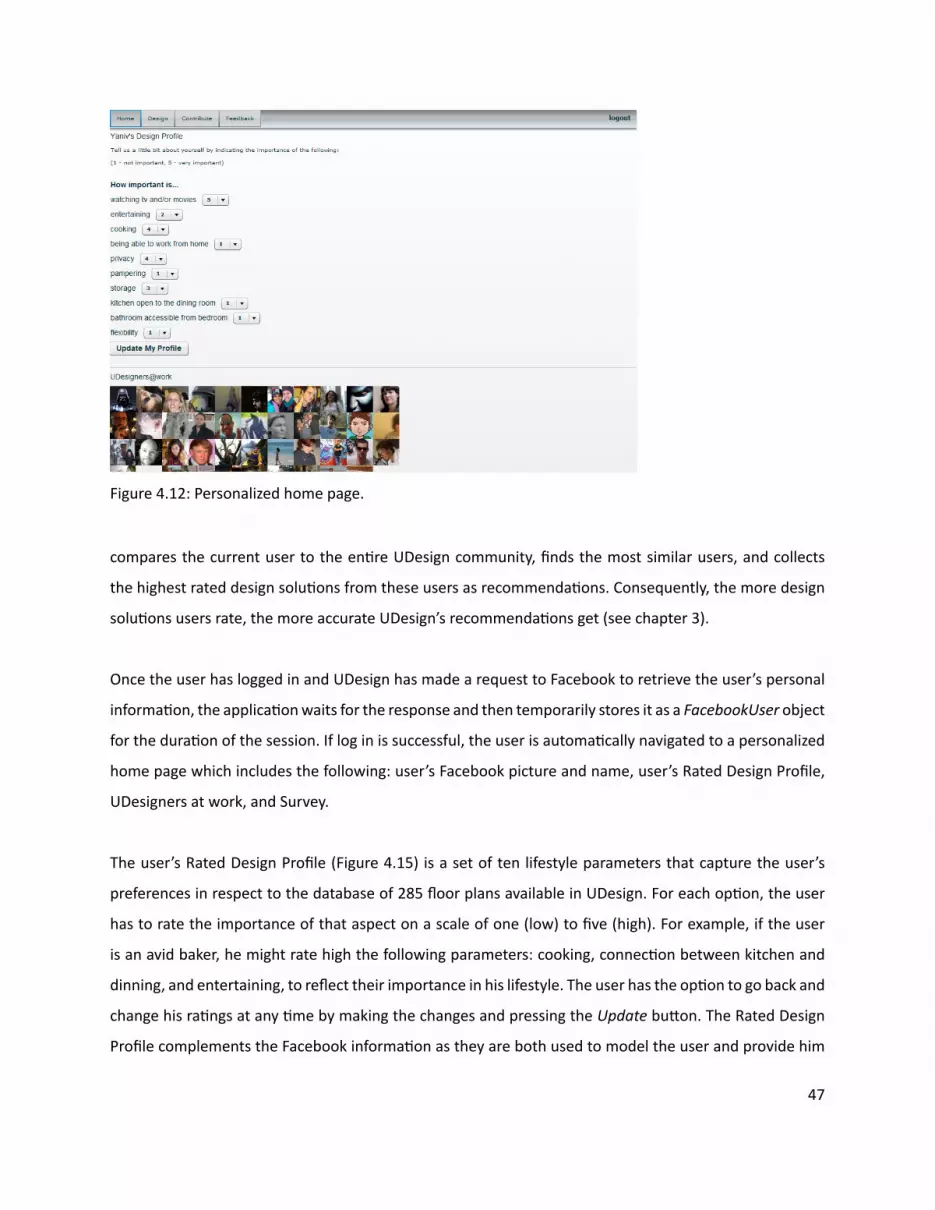
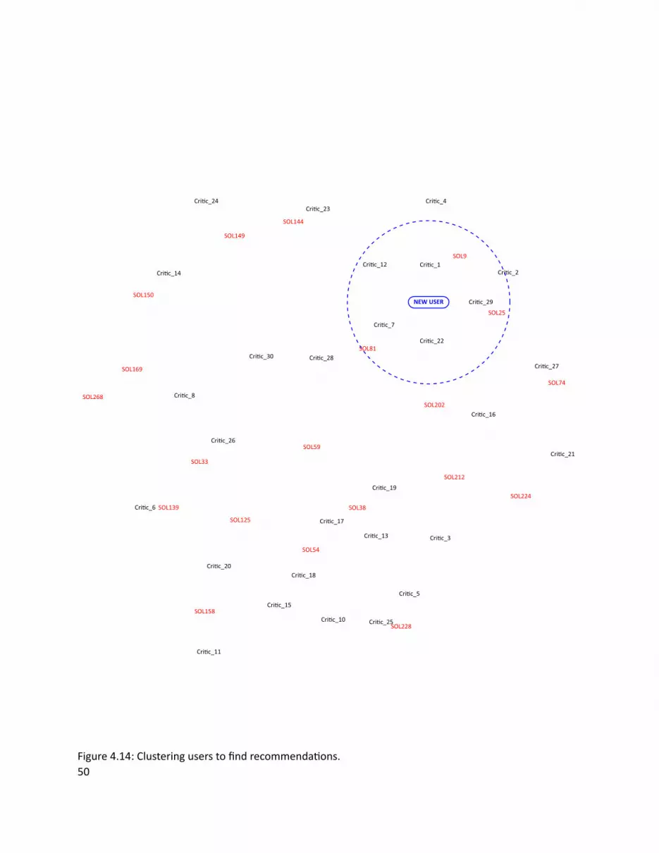
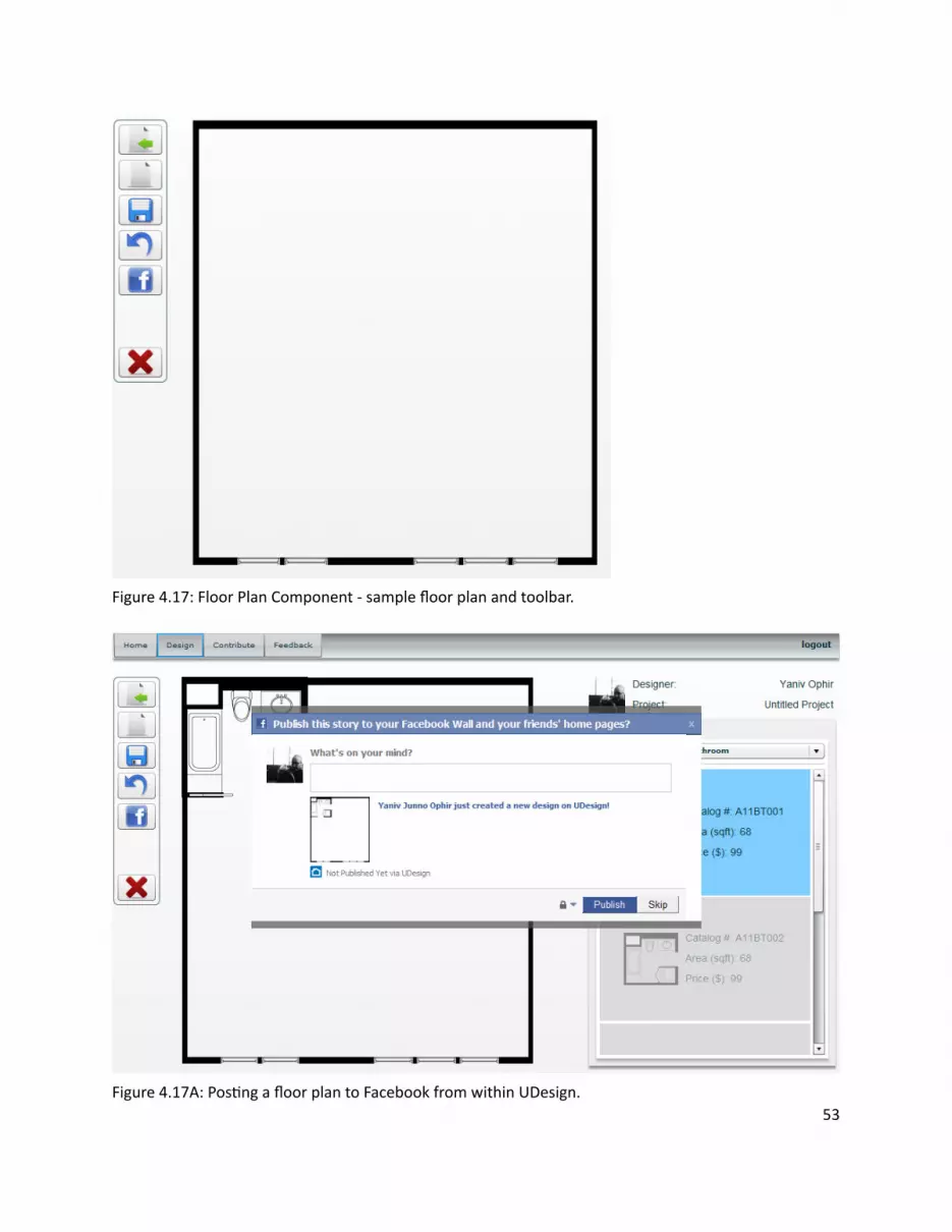
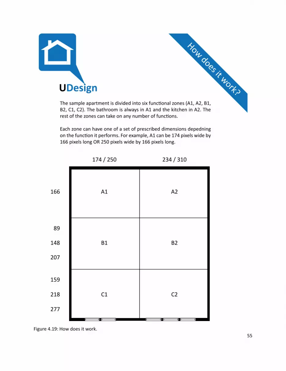
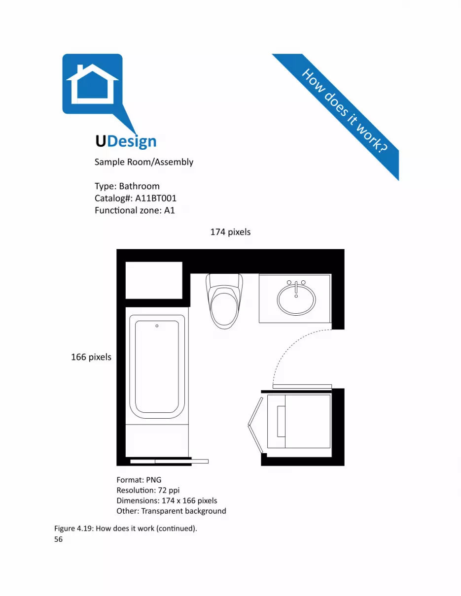
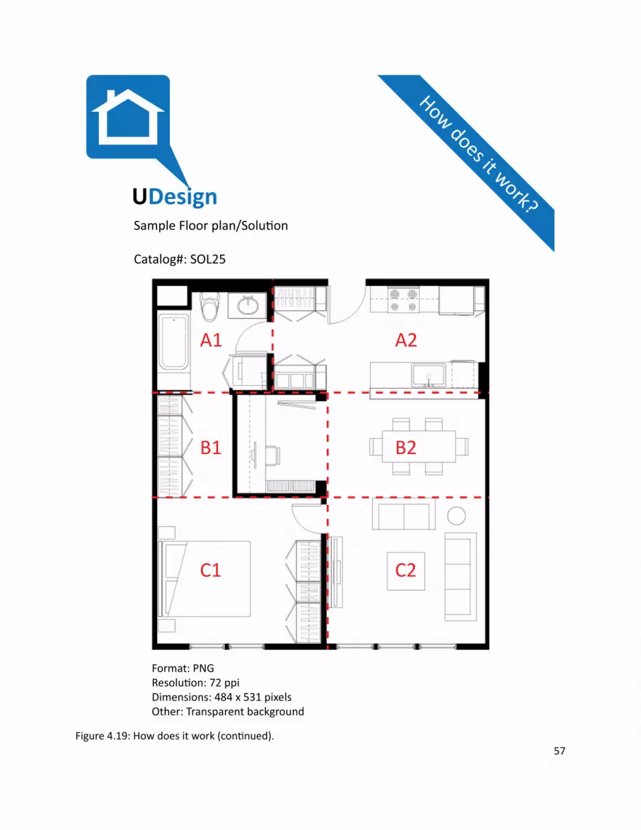
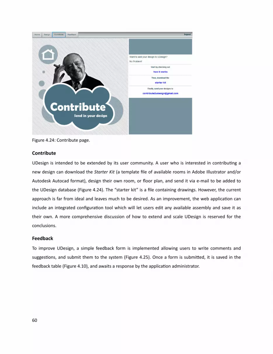
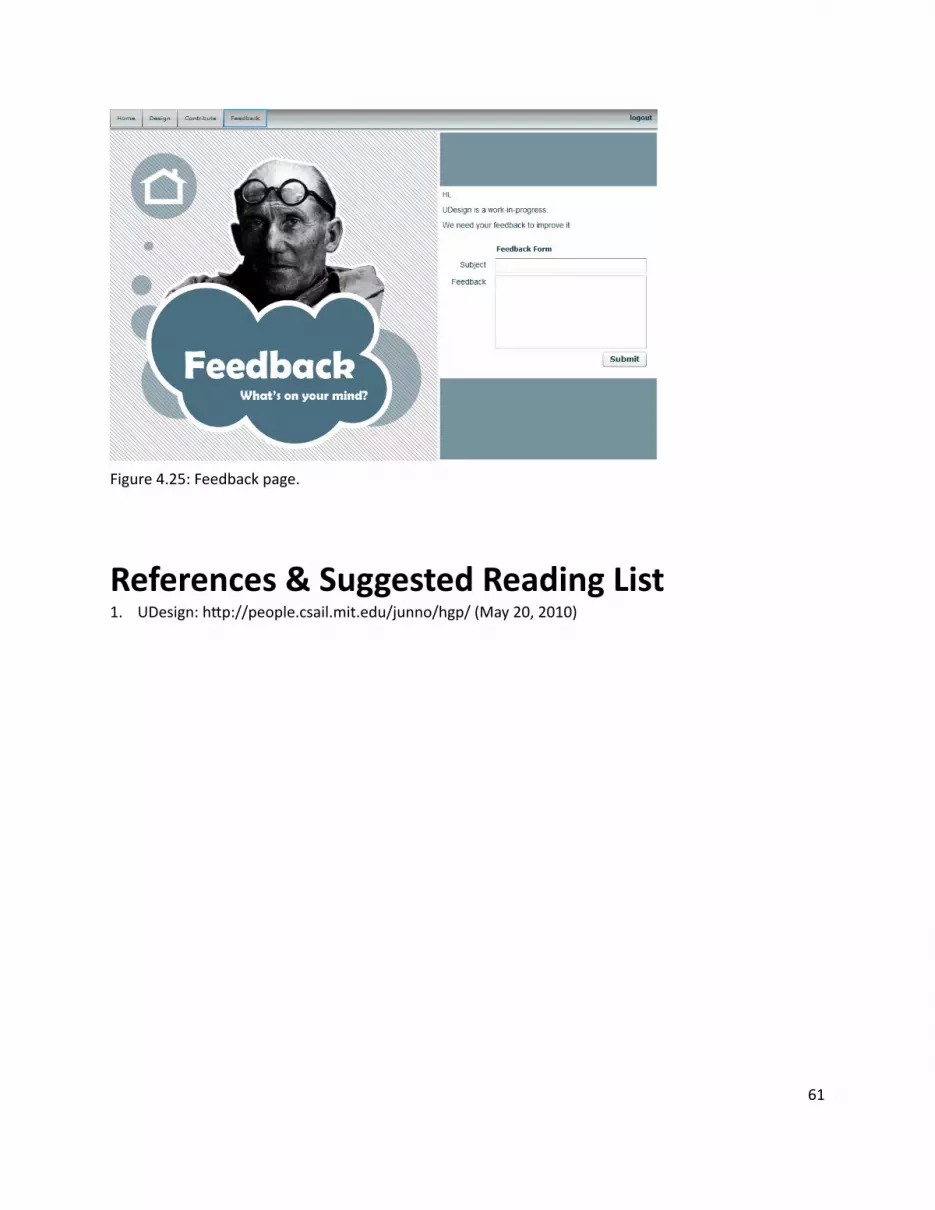
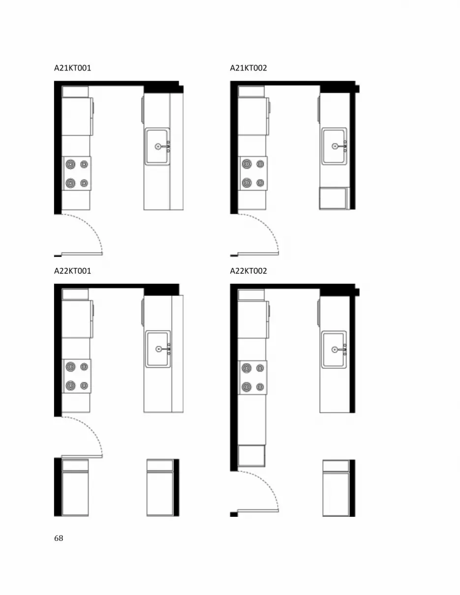
ͺ
A21KT001
A22KT001
A21KT002
A22KT002
ͻ
A22KT003 A22KT004
Ͳ
A22KT005
B11CL001
A22KT006
B12BD001
ͳ
B12CL001
B14CL001
B13BD001
B15ME001
ʹ
B15ST001
B15ST003
B15ST002
B15ST004
͵
B16BD001
B22DN001
B21DN001
B24DN001
Ͷ
B24DN002
B25DN002
B25DN001
B25DN003
ͷ
C11ST001
C12CL001
C12BD001
C12ST001
C13BD001
C14ST002
C14ST001
C15BD001
C15BD002
C16BD001
ͺ
C16DB002
C22LV001
ͻ
C23LV001
C25LV001
ͺͲ
C25LV002
C25LV003
ͺͳ
C25LV004
C26LV001
ͺʹ
SoluƟ ons
SOL9
ͺ͵
SOL25
ͺͶ
SOL33
ͺͷ
SOL38
ͺ
SOL54
ͺ
SOL59
ͺͺ
SOL74
ͺͻ
SOL81
ͻͲ
SOL125
ͻͳ
SOL139
ͻʹ
SOL144
ͻ͵
SOL149
ͻͶ
SOL150
ͻͷ
SOL158
ͻ
SOL169
ͻ
SOL202
ͻͺ
SOL212
ͻͻ
SOL224
ͳͲͲ
SOL228
ͳͲͳ
SOL268

ͻ
A22KT003 A22KT004
Ͳ
A22KT005
B11CL001
A22KT006
B12BD001
ͳ
B12CL001
B14CL001
B13BD001
B15ME001
ʹ
B15ST001
B15ST003
B15ST002
B15ST004
͵
B16BD001
B22DN001
B21DN001
B24DN001
Ͷ
B24DN002
B25DN002
B25DN001
B25DN003
ͷ
C11ST001
C12CL001
C12BD001
C12ST001
C13BD001
C14ST002
C14ST001
C15BD001
C15BD002
C16BD001
ͺ
C16DB002
C22LV001
ͻ
C23LV001
C25LV001
ͺͲ
C25LV002
C25LV003
ͺͳ
C25LV004
C26LV001
ͺʹ
SoluƟ ons
SOL9
ͺ͵
SOL25
ͺͶ
SOL33
ͺͷ
SOL38
ͺ
SOL54
ͺ
SOL59
ͺͺ
SOL74
ͺͻ
SOL81
ͻͲ
SOL125
ͻͳ
SOL139
ͻʹ
SOL144
ͻ͵
SOL149
ͻͶ
SOL150
ͻͷ
SOL158
ͻ
SOL169
ͻ
SOL202
ͻͺ
SOL212
ͻͻ
SOL224
ͳͲͲ
SOL228
ͳͲͳ
SOL268
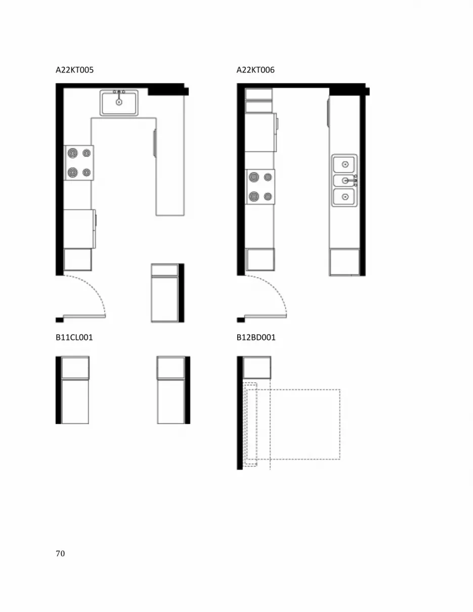
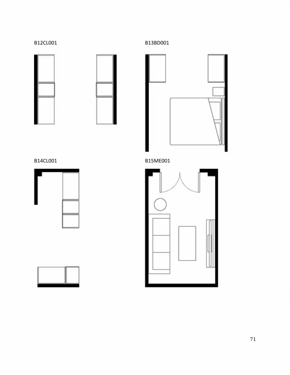
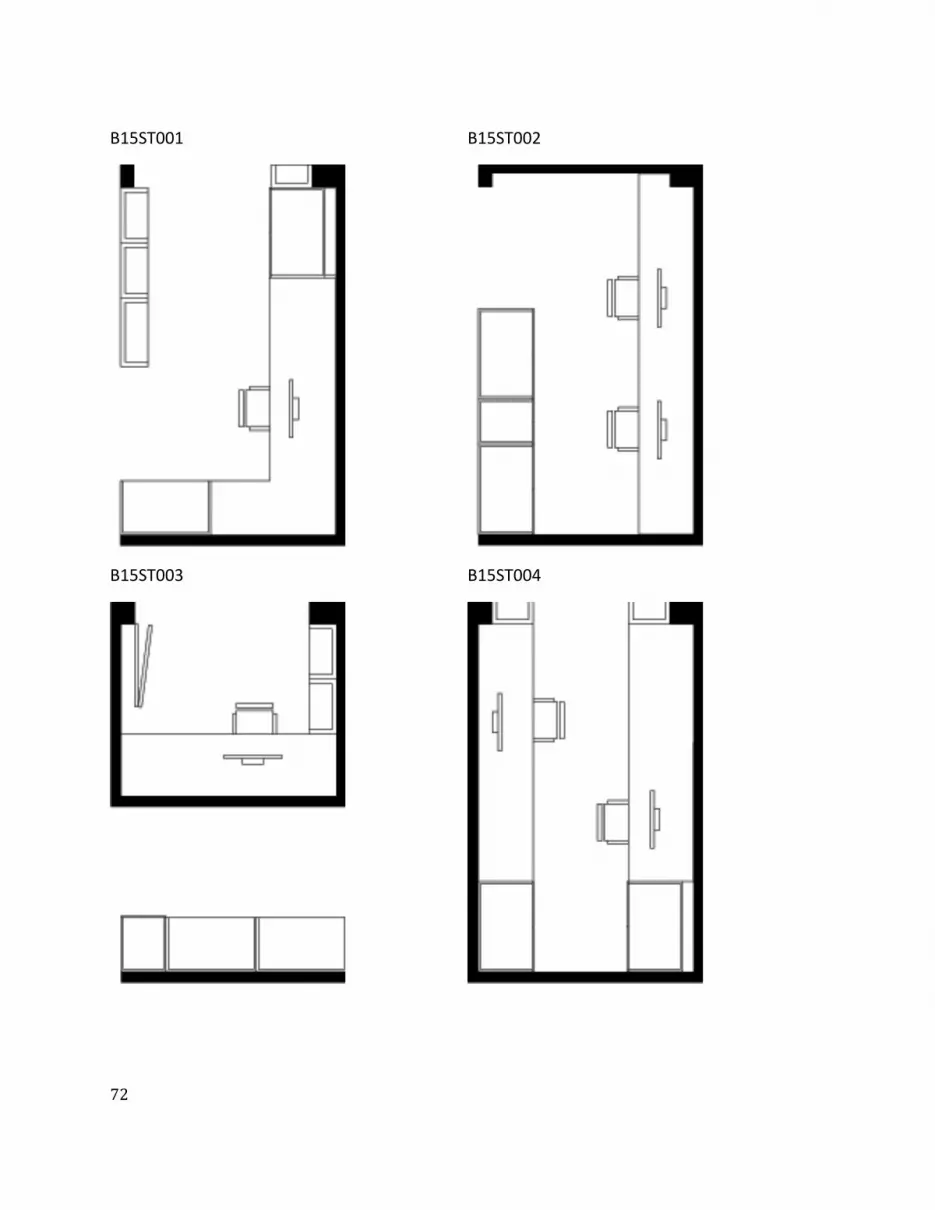
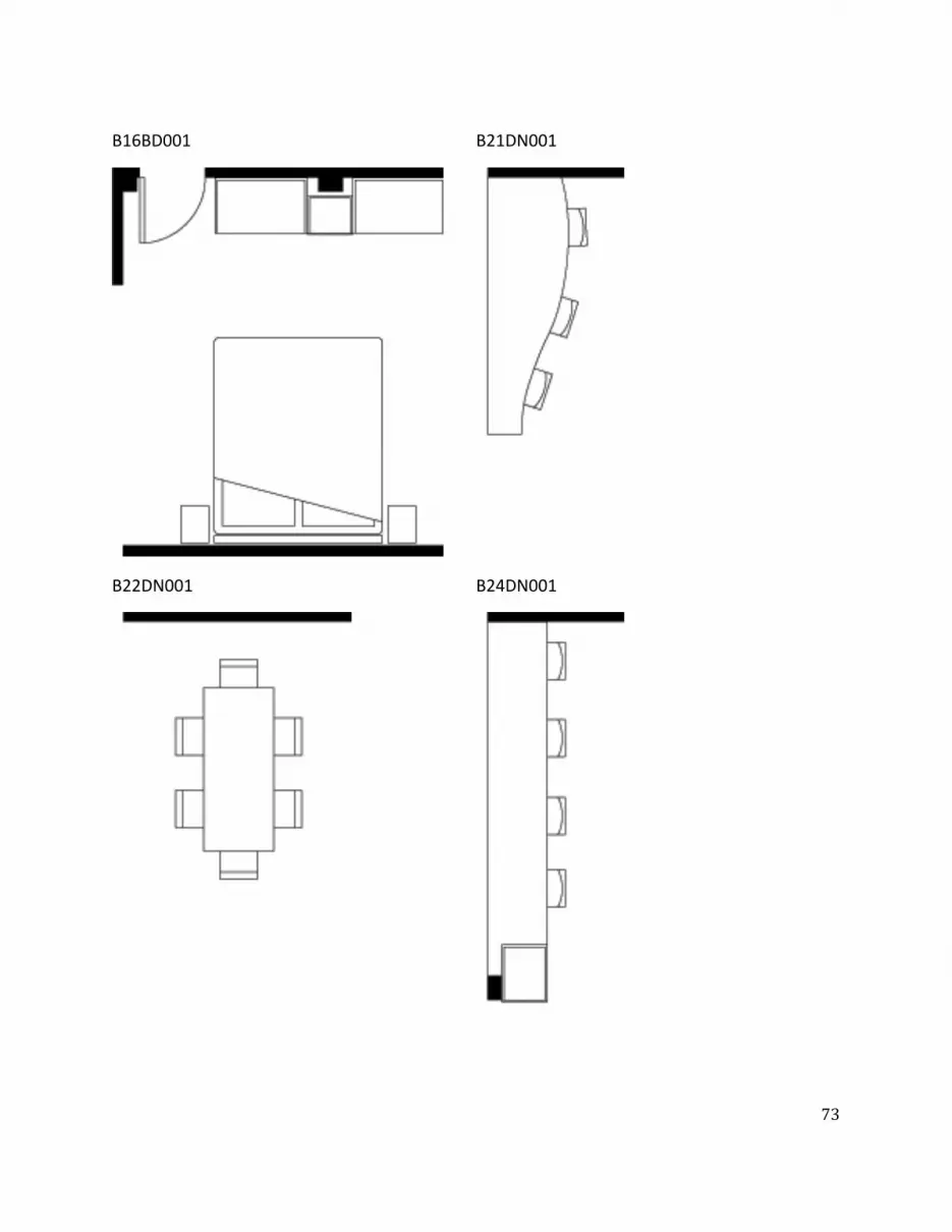
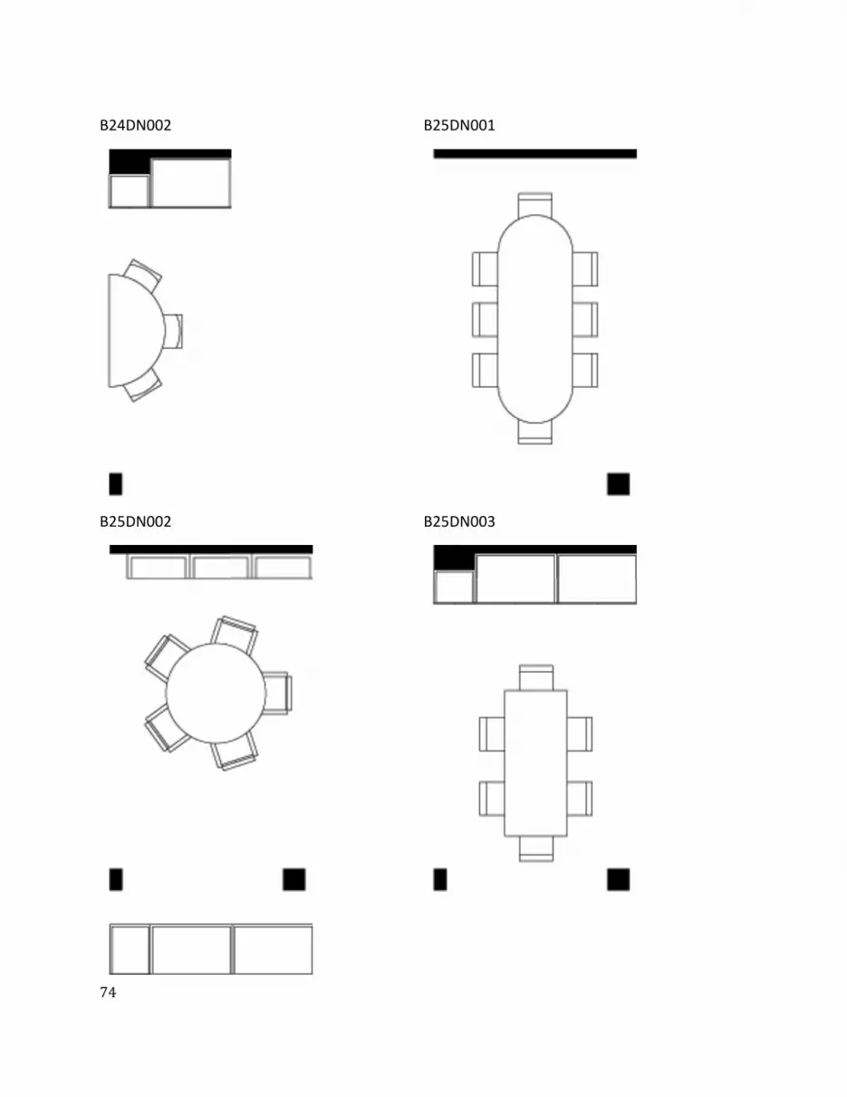
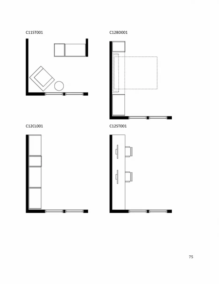
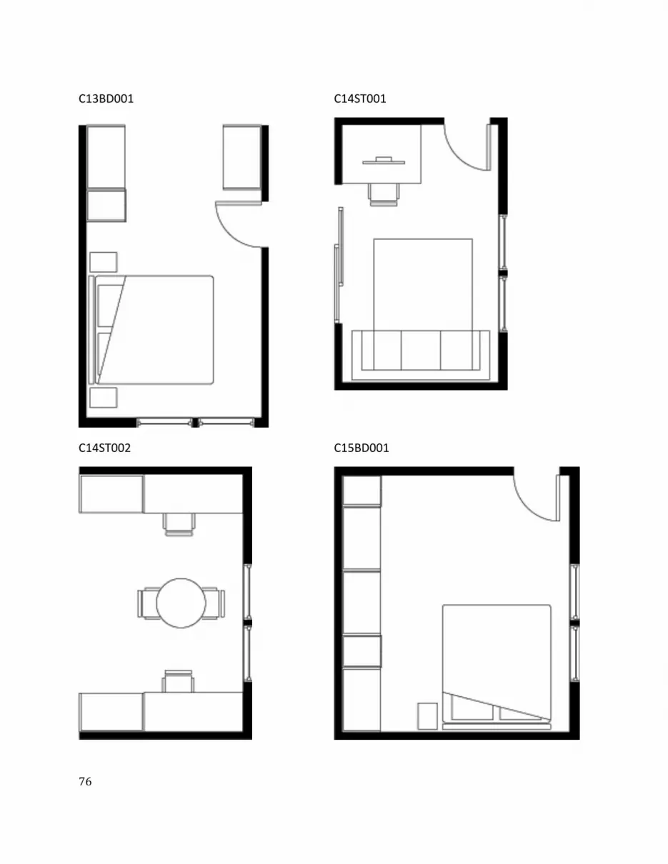
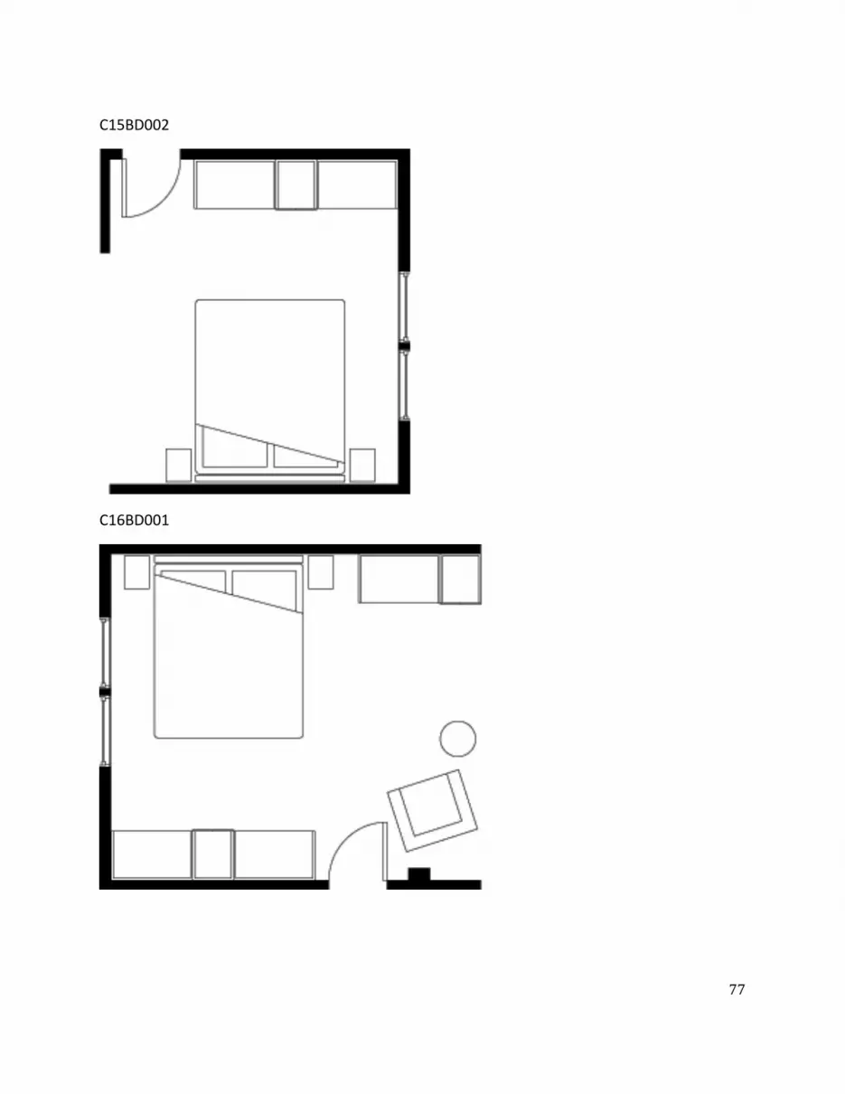
C15BD002
C16BD001
ͺ
C16DB002
C22LV001
ͻ
C23LV001
C25LV001
ͺͲ
C25LV002
C25LV003
ͺͳ
C25LV004
C26LV001
ͺʹ
SoluƟ ons
SOL9
ͺ͵
SOL25
ͺͶ
SOL33
ͺͷ
SOL38
ͺ
SOL54
ͺ
SOL59
ͺͺ
SOL74
ͺͻ
SOL81
ͻͲ
SOL125
ͻͳ
SOL139
ͻʹ
SOL144
ͻ͵
SOL149
ͻͶ
SOL150
ͻͷ
SOL158
ͻ
SOL169
ͻ
SOL202
ͻͺ
SOL212
ͻͻ
SOL224
ͳͲͲ
SOL228
ͳͲͳ
SOL268

ͺ
C16DB002
C22LV001
ͻ
C23LV001
C25LV001
ͺͲ
C25LV002
C25LV003
ͺͳ
C25LV004
C26LV001
ͺʹ
SoluƟ ons
SOL9
ͺ͵
SOL25
ͺͶ
SOL33
ͺͷ
SOL38
ͺ
SOL54
ͺ
SOL59
ͺͺ
SOL74
ͺͻ
SOL81
ͻͲ
SOL125
ͻͳ
SOL139
ͻʹ
SOL144
ͻ͵
SOL149
ͻͶ
SOL150
ͻͷ
SOL158
ͻ
SOL169
ͻ
SOL202
ͻͺ
SOL212
ͻͻ
SOL224
ͳͲͲ
SOL228
ͳͲͳ
SOL268
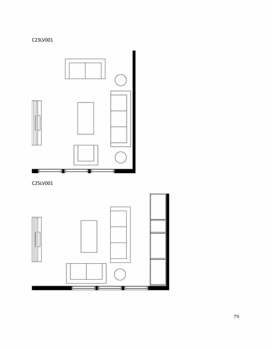
ͻ
C23LV001
C25LV001
ͺͲ
C25LV002
C25LV003
ͺͳ
C25LV004
C26LV001
ͺʹ
SoluƟ ons
SOL9
ͺ͵
SOL25
ͺͶ
SOL33
ͺͷ
SOL38
ͺ
SOL54
ͺ
SOL59
ͺͺ
SOL74
ͺͻ
SOL81
ͻͲ
SOL125
ͻͳ
SOL139
ͻʹ
SOL144
ͻ͵
SOL149
ͻͶ
SOL150
ͻͷ
SOL158
ͻ
SOL169
ͻ
SOL202
ͻͺ
SOL212
ͻͻ
SOL224
ͳͲͲ
SOL228
ͳͲͳ
SOL268
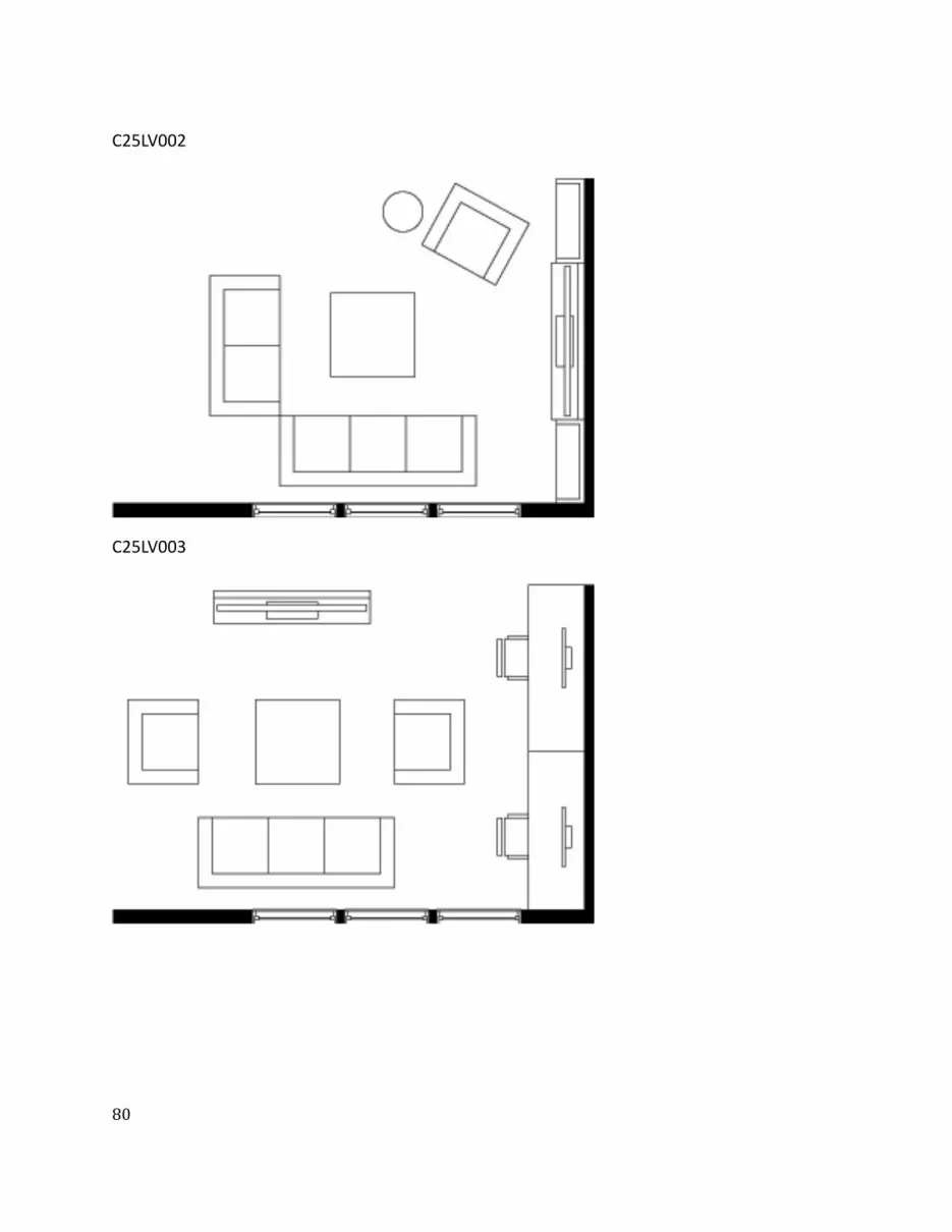
ͺͲ
C25LV002
C25LV003
ͺͳ
C25LV004
C26LV001
ͺʹ
SoluƟ ons
SOL9
ͺ͵
SOL25
ͺͶ
SOL33
ͺͷ
SOL38
ͺ
SOL54
ͺ
SOL59
ͺͺ
SOL74
ͺͻ
SOL81
ͻͲ
SOL125
ͻͳ
SOL139
ͻʹ
SOL144
ͻ͵
SOL149
ͻͶ
SOL150
ͻͷ
SOL158
ͻ
SOL169
ͻ
SOL202
ͻͺ
SOL212
ͻͻ
SOL224
ͳͲͲ
SOL228
ͳͲͳ
SOL268

ͺͳ
C25LV004
C26LV001
ͺʹ
SoluƟ ons
SOL9
ͺ͵
SOL25
ͺͶ
SOL33
ͺͷ
SOL38
ͺ
SOL54
ͺ
SOL59
ͺͺ
SOL74
ͺͻ
SOL81
ͻͲ
SOL125
ͻͳ
SOL139
ͻʹ
SOL144
ͻ͵
SOL149
ͻͶ
SOL150
ͻͷ
SOL158
ͻ
SOL169
ͻ
SOL202
ͻͺ
SOL212
ͻͻ
SOL224
ͳͲͲ
SOL228
ͳͲͳ
SOL268
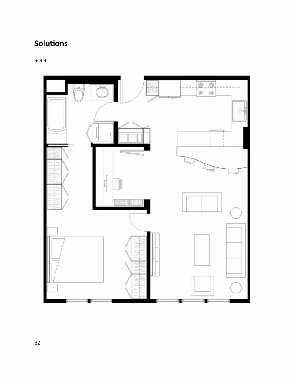
ͺʹ
SoluƟ ons
SOL9
ͺ͵
SOL25
ͺͶ
SOL33
ͺͷ
SOL38
ͺ
SOL54
ͺ
SOL59
ͺͺ
SOL74
ͺͻ
SOL81
ͻͲ
SOL125
ͻͳ
SOL139
ͻʹ
SOL144
ͻ͵
SOL149
ͻͶ
SOL150
ͻͷ
SOL158
ͻ
SOL169
ͻ
SOL202
ͻͺ
SOL212
ͻͻ
SOL224
ͳͲͲ
SOL228
ͳͲͳ
SOL268
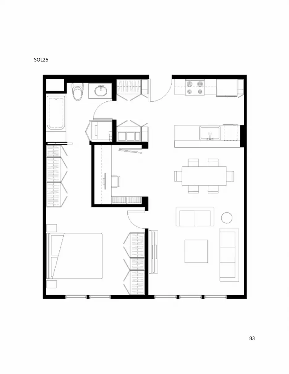
ͺ͵
SOL25
ͺͶ
SOL33
ͺͷ
SOL38
ͺ
SOL54
ͺ
SOL59
ͺͺ
SOL74
ͺͻ
SOL81
ͻͲ
SOL125
ͻͳ
SOL139
ͻʹ
SOL144
ͻ͵
SOL149
ͻͶ
SOL150
ͻͷ
SOL158
ͻ
SOL169
ͻ
SOL202
ͻͺ
SOL212
ͻͻ
SOL224
ͳͲͲ
SOL228
ͳͲͳ
SOL268
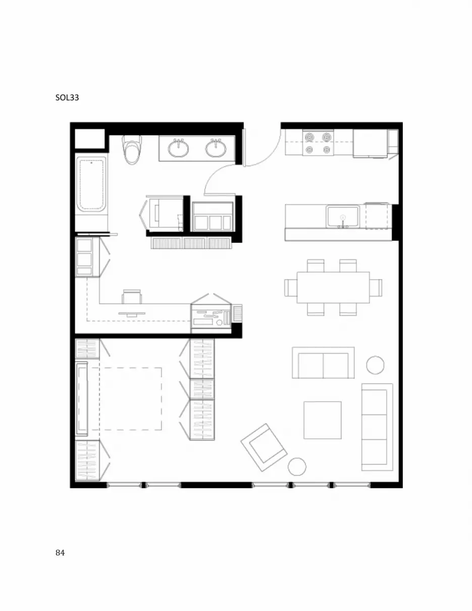
ͺͶ
SOL33
ͺͷ
SOL38
ͺ
SOL54
ͺ
SOL59
ͺͺ
SOL74
ͺͻ
SOL81
ͻͲ
SOL125
ͻͳ
SOL139
ͻʹ
SOL144
ͻ͵
SOL149
ͻͶ
SOL150
ͻͷ
SOL158
ͻ
SOL169
ͻ
SOL202
ͻͺ
SOL212
ͻͻ
SOL224
ͳͲͲ
SOL228
ͳͲͳ
SOL268
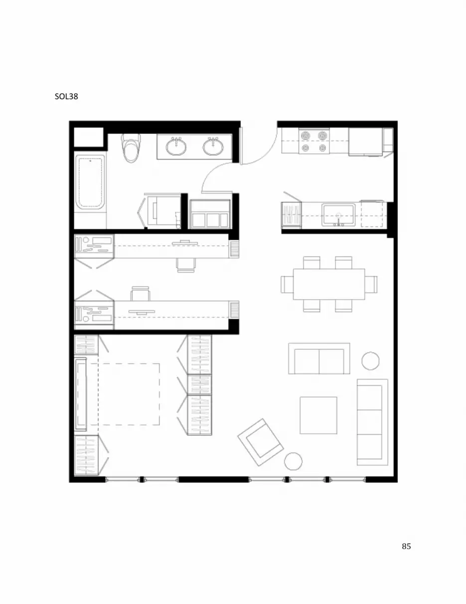
ͺͷ
SOL38
ͺ
SOL54
ͺ
SOL59
ͺͺ
SOL74
ͺͻ
SOL81
ͻͲ
SOL125
ͻͳ
SOL139
ͻʹ
SOL144
ͻ͵
SOL149
ͻͶ
SOL150
ͻͷ
SOL158
ͻ
SOL169
ͻ
SOL202
ͻͺ
SOL212
ͻͻ
SOL224
ͳͲͲ
SOL228
ͳͲͳ
SOL268
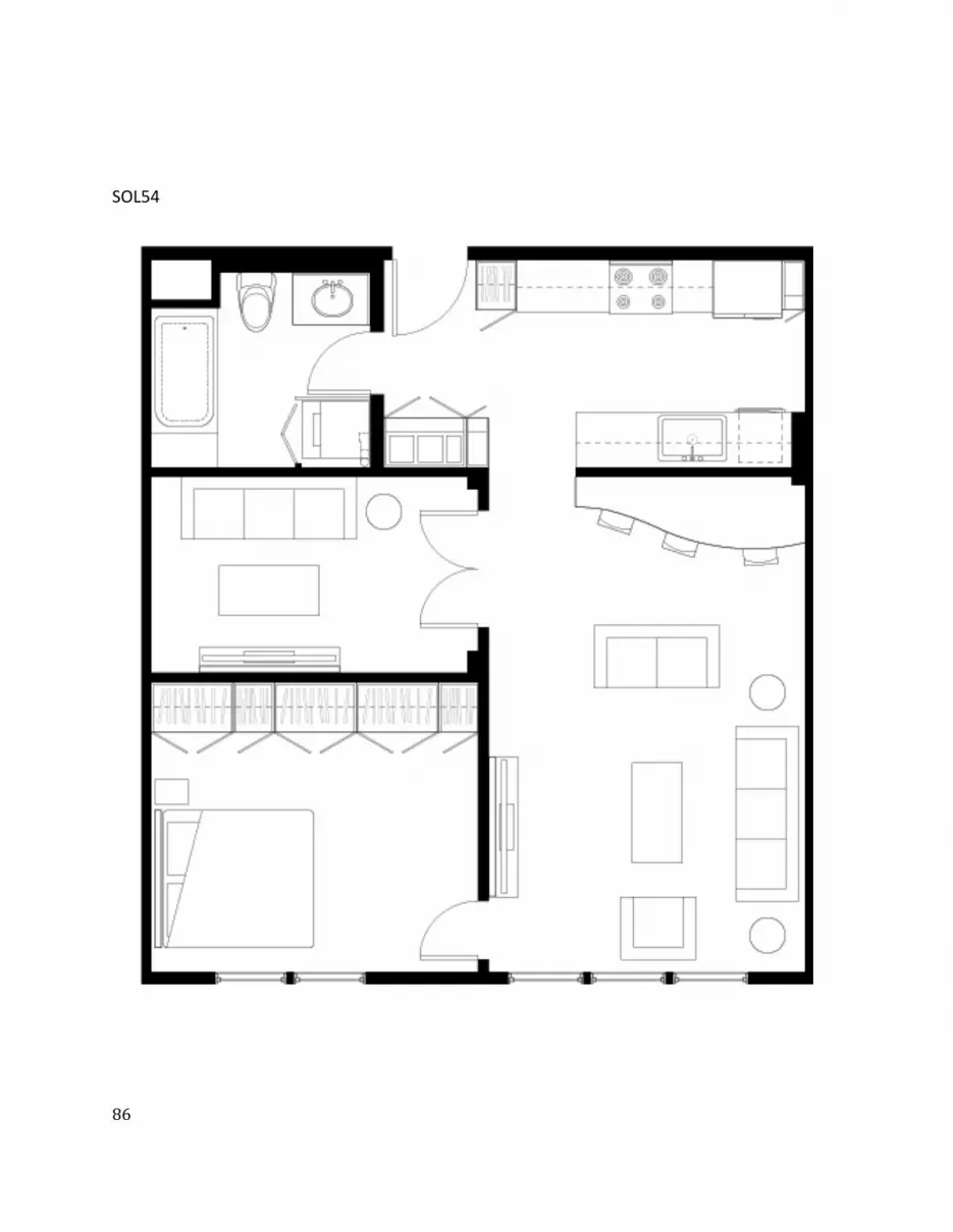
ͺ
SOL54
ͺ
SOL59
ͺͺ
SOL74
ͺͻ
SOL81
ͻͲ
SOL125
ͻͳ
SOL139
ͻʹ
SOL144
ͻ͵
SOL149
ͻͶ
SOL150
ͻͷ
SOL158
ͻ
SOL169
ͻ
SOL202
ͻͺ
SOL212
ͻͻ
SOL224
ͳͲͲ
SOL228
ͳͲͳ
SOL268
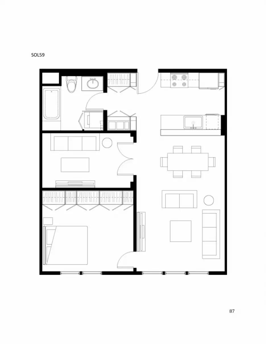
ͺ
SOL59
ͺͺ
SOL74
ͺͻ
SOL81
ͻͲ
SOL125
ͻͳ
SOL139
ͻʹ
SOL144
ͻ͵
SOL149
ͻͶ
SOL150
ͻͷ
SOL158
ͻ
SOL169
ͻ
SOL202
ͻͺ
SOL212
ͻͻ
SOL224
ͳͲͲ
SOL228
ͳͲͳ
SOL268
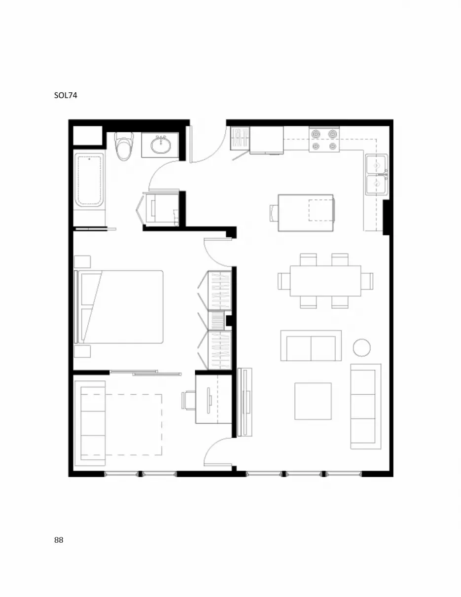
ͺͺ
SOL74
ͺͻ
SOL81
ͻͲ
SOL125
ͻͳ
SOL139
ͻʹ
SOL144
ͻ͵
SOL149
ͻͶ
SOL150
ͻͷ
SOL158
ͻ
SOL169
ͻ
SOL202
ͻͺ
SOL212
ͻͻ
SOL224
ͳͲͲ
SOL228
ͳͲͳ
SOL268

ͺͻ
SOL81
ͻͲ
SOL125
ͻͳ
SOL139
ͻʹ
SOL144
ͻ͵
SOL149
ͻͶ
SOL150
ͻͷ
SOL158
ͻ
SOL169
ͻ
SOL202
ͻͺ
SOL212
ͻͻ
SOL224
ͳͲͲ
SOL228
ͳͲͳ
SOL268
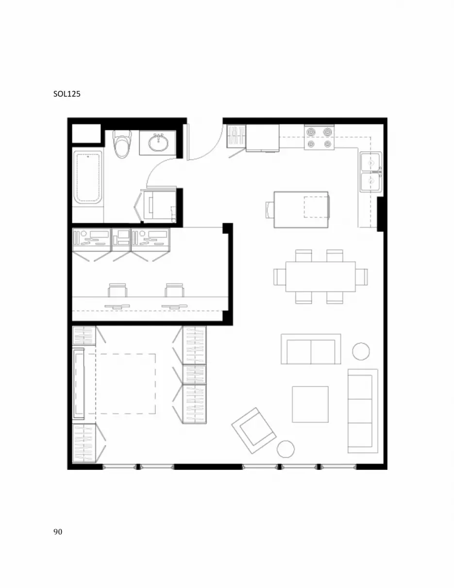
ͻͲ
SOL125
ͻͳ
SOL139
ͻʹ
SOL144
ͻ͵
SOL149
ͻͶ
SOL150
ͻͷ
SOL158
ͻ
SOL169
ͻ
SOL202
ͻͺ
SOL212
ͻͻ
SOL224
ͳͲͲ
SOL228
ͳͲͳ
SOL268
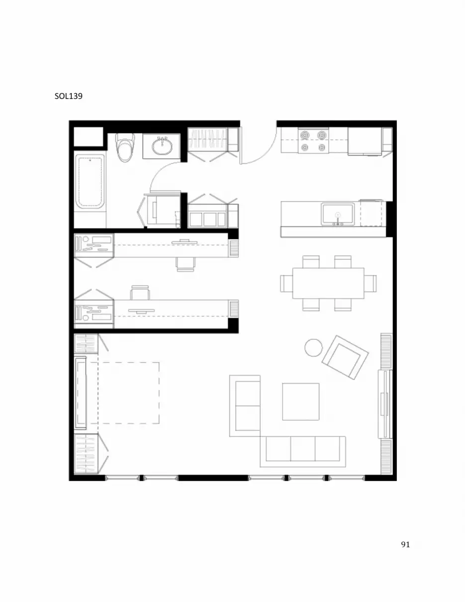
ͻͳ
SOL139
ͻʹ
SOL144
ͻ͵
SOL149
ͻͶ
SOL150
ͻͷ
SOL158
ͻ
SOL169
ͻ
SOL202
ͻͺ
SOL212
ͻͻ
SOL224
ͳͲͲ
SOL228
ͳͲͳ
SOL268

ͻʹ
SOL144
ͻ͵
SOL149
ͻͶ
SOL150
ͻͷ
SOL158
ͻ
SOL169
ͻ
SOL202
ͻͺ
SOL212
ͻͻ
SOL224
ͳͲͲ
SOL228
ͳͲͳ
SOL268

ͻ͵
SOL149
ͻͶ
SOL150
ͻͷ
SOL158
ͻ
SOL169
ͻ
SOL202
ͻͺ
SOL212
ͻͻ
SOL224
ͳͲͲ
SOL228
ͳͲͳ
SOL268

ͻͶ
SOL150
ͻͷ
SOL158
ͻ
SOL169
ͻ
SOL202
ͻͺ
SOL212
ͻͻ
SOL224
ͳͲͲ
SOL228
ͳͲͳ
SOL268
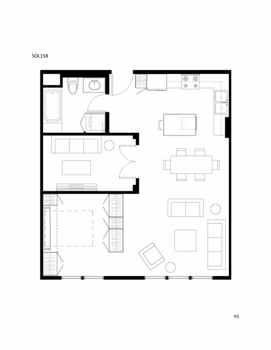
ͻͷ
SOL158
ͻ
SOL169
ͻ
SOL202
ͻͺ
SOL212
ͻͻ
SOL224
ͳͲͲ
SOL228
ͳͲͳ
SOL268
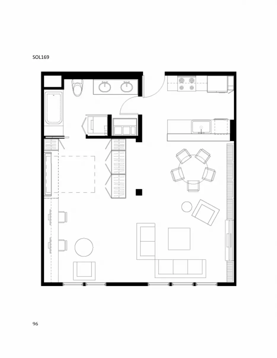
ͻ
SOL169
ͻ
SOL202
ͻͺ
SOL212
ͻͻ
SOL224
ͳͲͲ
SOL228
ͳͲͳ
SOL268
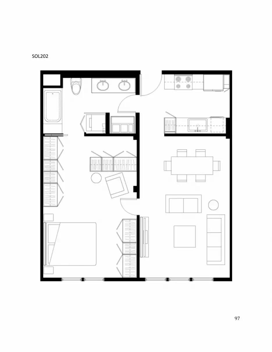
ͻ
SOL202
ͻͺ
SOL212
ͻͻ
SOL224
ͳͲͲ
SOL228
ͳͲͳ
SOL268
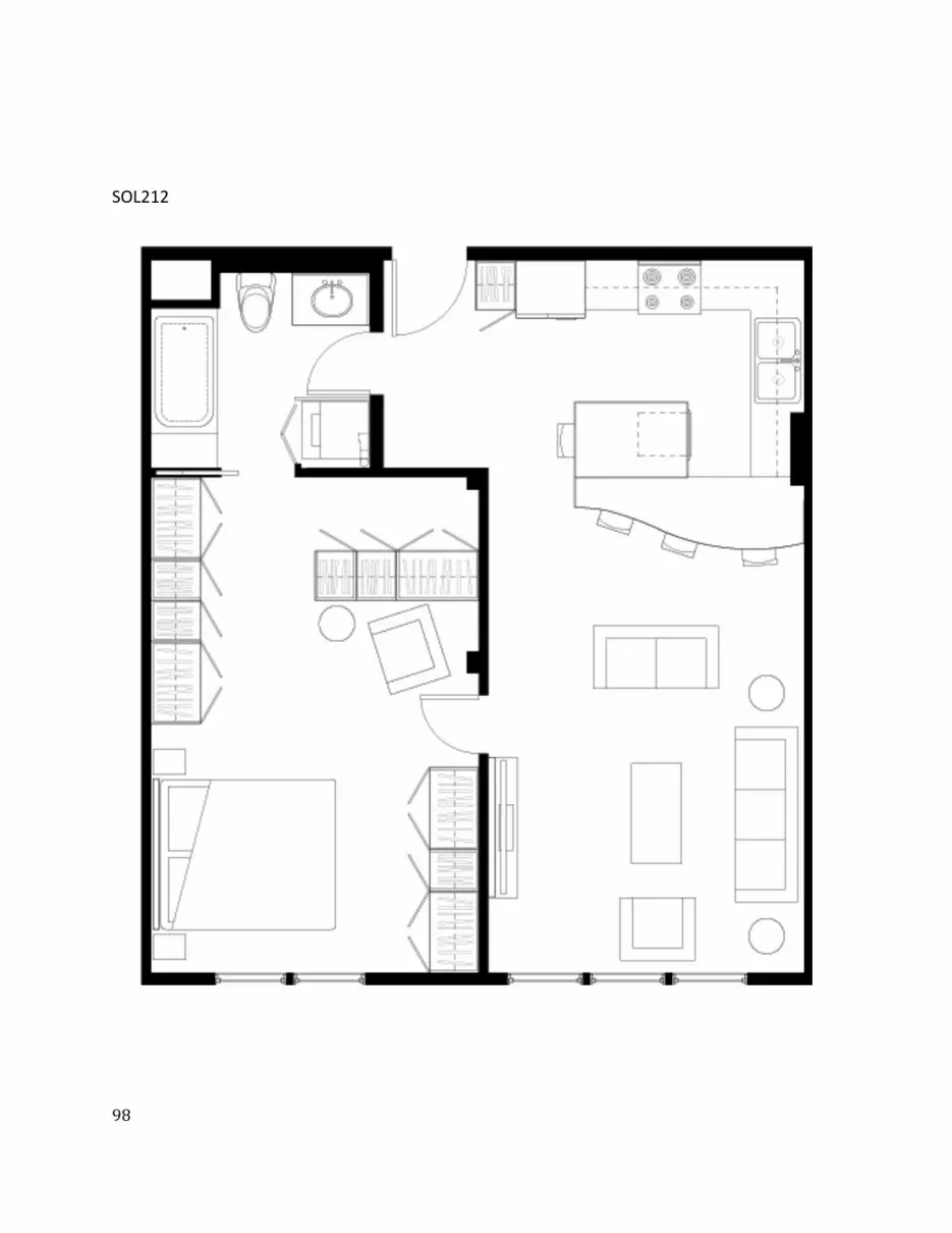
ͻͺ
SOL212
ͻͻ
SOL224
ͳͲͲ
SOL228
ͳͲͳ
SOL268
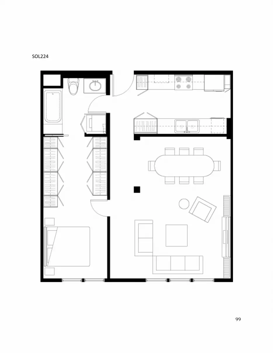
ͻͻ
SOL224
ͳͲͲ
SOL228
ͳͲͳ
SOL268

ͳͲͲ
SOL228
ͳͲͳ
SOL268
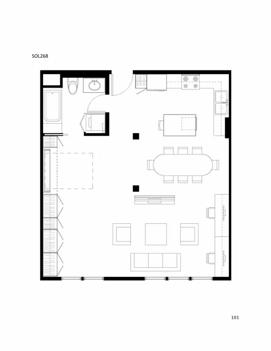
ͳͲͳ
SOL268


