Embed Size (px)
Citation preview

i
UCE Revision PhysicsPaper 1 and 2
Student’s Book
ii
Published by
Longhorn Publishers (K) Ltd.,Funzi Road, Industrial Area,P.O. Box 18033 - 00500,Nairobi, Kenya.
Longhorn Publishers (U) Ltd.,Plot 731, Kamwokya Area,Mawanda Road,P.O. Box 24745,Kampala, Uganda.
Longhorn Publishers (T) Ltd.,Plot No. 4, Block 37B, Kinondoni,Kawawa Road,P.O. Box 1237,Dar es Salaam, Tanzania.
© J. Mwelese, S. Karanja, 2012
All rights reserved. No part of this publication may be reproduced, stored in a re-trieval system or transmitted in any form or by any means, electronic, mechanical, photocopying, recording or otherwise without the prior written permission of the publisher.
First published in 2012
ISBN 978 9966 36 057 3
Design and Layout by Sublime Media
Printed by English Press Ltd, off Enterprise Road, Industrial Area, P.O. Box 30127 - 00100Nairobi, Kenya.
iii
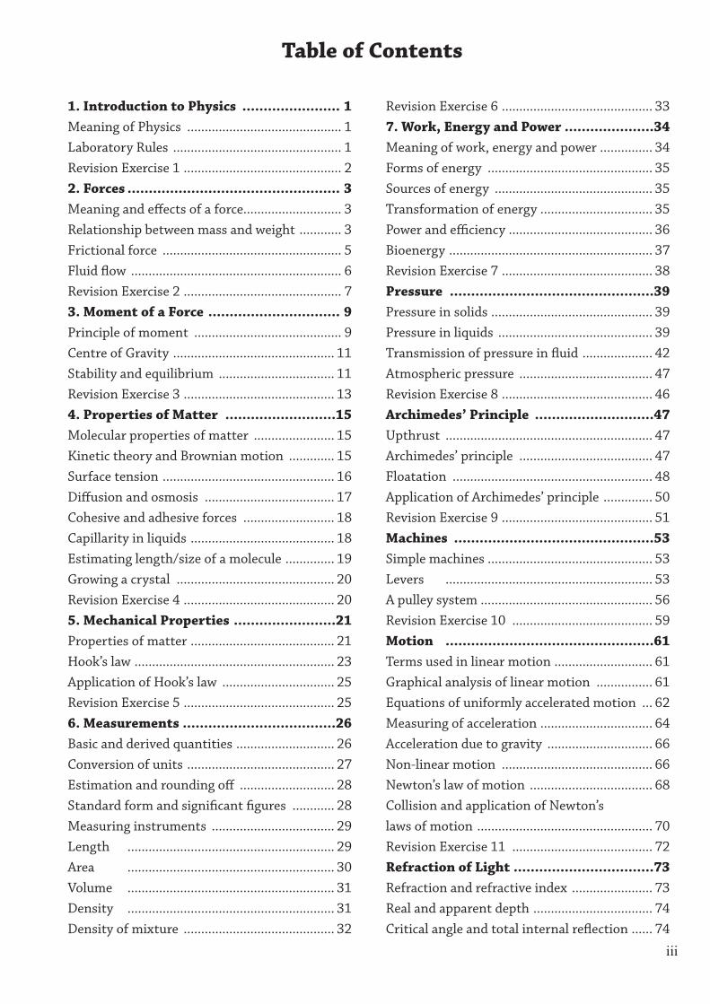
1. Introduction to Physics ....................... 1Meaning of Physics ............................................ 1Laboratory Rules ................................................ 1Revision Exercise 1 ............................................. 22. Forces .................................................. 3Meaning and effects of a force............................ 3Relationship between mass and weight ............ 3Frictional force ................................................... 5Fluid flow ............................................................ 6Revision Exercise 2 ............................................. 73. Moment of a Force ............................... 9Principle of moment .......................................... 9Centre of Gravity .............................................. 11Stability and equilibrium ................................. 11Revision Exercise 3 ........................................... 134. Properties of Matter ..........................15Molecular properties of matter ....................... 15Kinetic theory and Brownian motion ............. 15Surface tension ................................................. 16Diffusion and osmosis ..................................... 17Cohesive and adhesive forces .......................... 18Capillarity in liquids ......................................... 18Estimating length/size of a molecule .............. 19Growing a crystal ............................................. 20Revision Exercise 4 ........................................... 205. Mechanical Properties ........................21Properties of matter ......................................... 21Hook’s law ......................................................... 23Application of Hook’s law ................................ 25Revision Exercise 5 ........................................... 256. Measurements ....................................26Basic and derived quantities ............................ 26Conversion of units .......................................... 27Estimation and rounding off ........................... 28Standard form and significant figures ............ 28Measuring instruments ................................... 29Length ........................................................... 29Area ........................................................... 30Volume ........................................................... 31Density ........................................................... 31Density of mixture ........................................... 32
Revision Exercise 6 ........................................... 337. Work, Energy and Power .....................34Meaning of work, energy and power ............... 34Forms of energy ............................................... 35Sources of energy ............................................. 35Transformation of energy ................................ 35Power and efficiency ......................................... 36Bioenergy .......................................................... 37Revision Exercise 7 ........................................... 38Pressure ................................................39Pressure in solids .............................................. 39Pressure in liquids ............................................ 39Transmission of pressure in fluid .................... 42Atmospheric pressure ...................................... 47Revision Exercise 8 ........................................... 46Archimedes’ Principle ............................47Upthrust ........................................................... 47Archimedes’ principle ...................................... 47Floatation ......................................................... 48Application of Archimedes’ principle .............. 50Revision Exercise 9 ........................................... 51Machines ...............................................53Simple machines ............................................... 53Levers ........................................................... 53A pulley system ................................................. 56Revision Exercise 10 ........................................ 59Motion .................................................61Terms used in linear motion ............................ 61Graphical analysis of linear motion ................ 61Equations of uniformly accelerated motion ... 62Measuring of acceleration ................................ 64Acceleration due to gravity .............................. 66Non-linear motion ........................................... 66Newton’s law of motion ................................... 68Collision and application of Newton’s laws of motion .................................................. 70Revision Exercise 11 ........................................ 72Refraction of Light .................................73Refraction and refractive index ....................... 73Real and apparent depth .................................. 74Critical angle and total internal reflection ...... 74
Table of Contents
iv
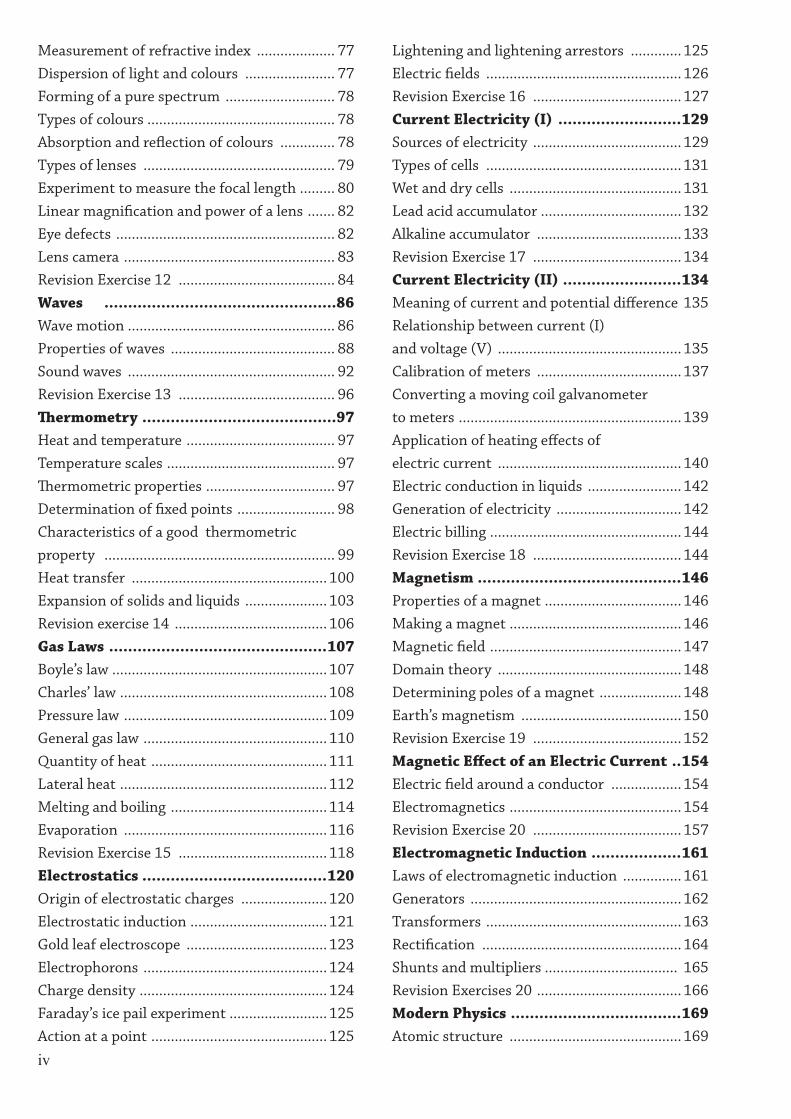
Measurement of refractive index .................... 77Dispersion of light and colours ....................... 77Forming of a pure spectrum ............................ 78Types of colours ................................................ 78Absorption and reflection of colours .............. 78Types of lenses ................................................. 79Experiment to measure the focal length ......... 80Linear magnification and power of a lens ....... 82Eye defects ........................................................ 82Lens camera ...................................................... 83Revision Exercise 12 ........................................ 84Waves .................................................86Wave motion ..................................................... 86Properties of waves .......................................... 88Sound waves ..................................................... 92Revision Exercise 13 ........................................ 96Thermometry .........................................97Heat and temperature ...................................... 97Temperature scales ........................................... 97Thermometric properties ................................. 97Determination of fixed points ......................... 98Characteristics of a good thermometric property ........................................................... 99Heat transfer .................................................. 100Expansion of solids and liquids ..................... 103Revision exercise 14 ....................................... 106Gas Laws ..............................................107Boyle’s law ....................................................... 107Charles’ law ..................................................... 108Pressure law .................................................... 109General gas law ............................................... 110Quantity of heat ............................................. 111Lateral heat ..................................................... 112Melting and boiling ........................................ 114Evaporation .................................................... 116Revision Exercise 15 ...................................... 118Electrostatics .......................................120Origin of electrostatic charges ...................... 120Electrostatic induction ................................... 121Gold leaf electroscope .................................... 123Electrophorons ............................................... 124Charge density ................................................ 124Faraday’s ice pail experiment ......................... 125Action at a point ............................................. 125
Lightening and lightening arrestors ............. 125Electric fields .................................................. 126Revision Exercise 16 ...................................... 127Current Electricity (I) ..........................129Sources of electricity ...................................... 129Types of cells .................................................. 131Wet and dry cells ............................................ 131Lead acid accumulator .................................... 132Alkaline accumulator ..................................... 133Revision Exercise 17 ...................................... 134Current Electricity (II) .........................134Meaning of current and potential difference 135Relationship between current (I) and voltage (V) ............................................... 135Calibration of meters ..................................... 137Converting a moving coil galvanometer to meters ......................................................... 139Application of heating effects of electric current ............................................... 140Electric conduction in liquids ........................ 142Generation of electricity ................................ 142Electric billing ................................................. 144Revision Exercise 18 ...................................... 144Magnetism ...........................................146Properties of a magnet ................................... 146Making a magnet ............................................ 146Magnetic field ................................................. 147Domain theory ............................................... 148Determining poles of a magnet ..................... 148Earth’s magnetism ......................................... 150Revision Exercise 19 ...................................... 152Magnetic Effect of an Electric Current ..154Electric field around a conductor .................. 154Electromagnetics ............................................ 154Revision Exercise 20 ...................................... 157Electromagnetic Induction ...................161Laws of electromagnetic induction ............... 161Generators ...................................................... 162Transformers .................................................. 163Rectification ................................................... 164Shunts and multipliers .................................. 165Revision Exercises 20 ..................................... 166Modern Physics ....................................169Atomic structure ............................................ 169

v
Radioactivity ................................................... 169Properties of radioactive emissions .............. 170Half-life of radioactive materials ................... 171Uses and hazards of radioactivity ................. 171
Nuclear fusion and fission ............................. 172Photoelectric and thermionic emissions ...... 173Cathode ray oscilloscope ................................ 174X-rays ......................................................... 176Production of X-rays ...................................... 176
1
1.1 : Introduction to physics as a natural science1. (a) What is physics. It is the study of matter in relation to energy (Defines matter and energy). (b) Name any four branches of natural sciences. • Physics. • Biology. • Agriculture. • Chemistry. (c) Give any five career opportunities in physics: • Engineering. • Agriculture. • Radiography. • Medicine. • Astronomy. • Teaching/lecturing • Geology etc.2. (a) What steps are involved in scientific approach ? • Experimentation. • Measurements. • Analysis. • Conclusion where necessary. (b) Give branches of physics. • Mechanics: deals with forces under various conditions. • Properties of matter. • Optics (a) Geometrical optics (light) (b) Physical optics (waves) • Heat: Energy in motion due to temperature difference. • Sound: Due to vibration of objects. • Electricity: (a) Static electricity (electrostatics) (b) Current electricity • Magnetism. • Electromagnetic induction
(Relationship between magnetism and electricity). • Modern physics: (a) Atomic physics (b) Nuclear physics (c) Electronics. (c) Give reasons why we study physics? • To help society understand why certain things behave the way they do. Example (a) Why the sky appears blue; (b) The behaviour of planetary systems (sun, moon, etc.) to mention but a few. • Provides skills to people who in turn provide services to others in the community. • To discover new things that have not been discovered yet. • Helps us to acquire jobs e.g. doctors, teachers to mention but a few. • Helps the society to understand phenomenon; natural or artificial.
1.2 : Laboratory rules and precautions3. (a) List down basic laboratory rules: • Strictly adhere to instructions as given by your teacher (the instructor). • Do not eat, drink or smoke while in a laboratory. • Inform your teacher at once about any accident. • While in a laboratory do not run, play or throw things. • Do not touch live open electrical circuits. • Be punctual. • Read or listen carefully to the experiment instructions to avoid wastage during the experiment.
INTRODUCTION TO PHYSICS1

2
(b) A good laboratory must have a fire extinguisher and first aid kit. List down items that make up a first aid kit. • A pair of scissors • Bandages • Adhesive plaster • Sterilised cotton wool and gauze • Dilute antiseptic solution • Safety pins • Forceps • Gloves.
Revision Exercise 11. Explain how physics is important in agriculture.
2. Discuss how physics can be used to boost economy of a country.
3. State instances where physics relate to history and business.
4. Group the laboratory rules under the following headlines. (a) Electricity. (b) Heat. (c) General rules.
5. What will be the first step to do when you smell unusual gas in the labarotory?

3
2.1 : Meaning and effects of a force1.(a)(i) Define the term force and state its SI unit. Is a pull or push on a body. Its SI unit is the newton (N). (ii) Briefly explain seven types of a force. • Friction. A force that opposes relative motion. • Gravitational force. Pulls on objects towards centre of planet e.g. weight. • Electric force. Exists in electric fields. • Magnetic force : Exists in magnetic fields. • Action and reaction. Are force that are equal and opposite e.g. on a body resting on a floor. • Centripetal. Force that keeps the body moving in a circle. • Elastic force. The force needed to cause an extension in an elastic object ( i.e. stretching or compressing spring ). • Adhesion. Force of attraction between molecules of a liquid and its container. • Cohesion. force of attraction between molecules of the same material, to mention but a few. (iii) Explain briefly three effects of a force. • A force can change the state of motion of a body. Force can start, increase, reduce and stop motion. • Force changes the direction of motion of a body. • Force can change the shape of a body i.e. distort, bend, stretch and compress a spring. • A force can produce a turning effect on a body. • Force can cause noise and heat. • A force can cause wear and tear.
ForcES
2.2 : realtionship between mass and weight 2.(a) Define the following terms: (i) Mass. Mass is the amount of matter in a body. Its SI unit is a kilogram (kg). (ii)Weight. Weight is the gravitational pull on a body. Its SI unit is the newton (N). (b) Give any three differences between mass and weight.
Mass Weight• It is the amount of matter in a body
• It is a gravitational pull on a body
• It is a scalar quantity
• It is a vector quantity
• Measured using beam balance
• Measured using spring balance
• Measured in kilograms (kg)
• Measured in Newtons (N)
• It is constant everywhere
• It changes from one place to place on the earth’s surface as well as from one planet to another.
Table 1.1 : Differences between mass and weight (c) Detertmine the weight of the following masses. (i) 2 kg. W = mg , g = 10 ms–2
= 2 × 10 = 20 N (ii)26 500.25 g. Since 1 Kg ⇒ 1000 g ⇒ 26500.25 g 2650025
1000 × 100 kg
W = mg
= 2650025100000
× 10 = 265.0025 N
2
4
(iii) 0.0731 kg. 0.0731 kg = 731
10000kg
W = mg, g = 10 ms–2
= 7311000
× 10 = 0.731 N = 7.31 x 10⁻¹ N (iv) 430 mg. 430 mg 1 g = 1 000 mg = ( 430
1000) g ÷ 1000
= 430
1000000 W = mg
= 4301000000
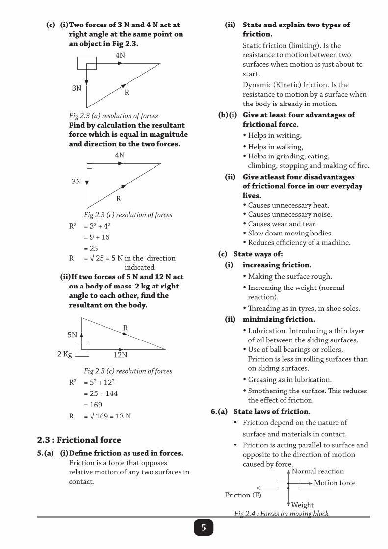
× 10 = 4.3 N 3.(a) Briefly describe how mass and weight of a body is measured. Mass of a body is the quantity (amount) of matter in the body. The mass of a body is measured by balancing it against a known mass.
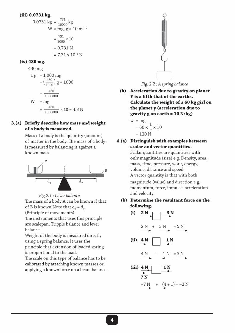
Fig. 2.2 : A spring balance (b) Acceleration due to gravity on planet Y is a fifth that of the earths. calculate the weight of a 60 kg girl on the planet y (acceleration due to gravity g on earth = 10 N/kg) w = mg = 60 ×
15 × 10
= 120 N4.(a) Distinguish with examples between scalar and vector quantities. Scalar quantities are quantities with only magnitude (size) e.g. Density, area, mass, time, pressure, work, energy, volume, distance and speed. A vector quantity is that with both magnitude (value) and direction e.g. momentum, force, impulse, acceleration and velocity. (b) Determine the resultant force on the following. (i) 2 N 3 N
2 N + 3 N = 5 N
(ii) 4 N 1 N
4 N – 1 N = 3 N
(iii) 4 N 1 N
–7 N + (4 + 1) = –2 N
Fig.2.1 : Lever balance The mass of a body A can be known if that of B is known.Note that d1 = d2. (Principle of movements). The instruments that uses this principle are scalepan, Tripple balance and lever balance. Weight of the body is measured directly using a spring balance. It uses the principle that extension of loaded spring is proportional to the load. The scale on this type of balance has to be calibrated by attaching known masses or applying a known force on a beam balance.
7 N
5
(c) (i) Two forces of 3 N and 4 N act at right angle at the same point on an object in Fig 2.3.
(ii) State and explain two types of friction. Static friction (limiting). Is the resistance to motion between two surfaces when motion is just about to start. Dynamic (Kinetic) friction. Is the resistance to motion by a surface when the body is already in motion. (b)(i) Give at least four advantages of frictional force. • Helps in writing, • Helps in walking, • Helps in grinding, eating, climbing, stopping and making of fire. (ii) Give atleast four disadvantages of frictional force in our everyday lives. • Causes unnecessary heat. • Causes unnecessary noise. • Causes wear and tear. • Slow down moving bodies. • Reduces efficiency of a machine. (c) State ways of: (i) increasing friction. • Making the surface rough. • Increasing the weight (normal reaction). • Threading as in tyres, in shoe soles. (ii) minimizing friction. • Lubrication. Introducing a thin layer of oil between the sliding surfaces. • Use of ball bearings or rollers. Friction is less in rolling surfaces than on sliding surfaces. • Greasing as in lubrication. • Smothening the surface. This reduces the effect of friction.6.(a) State laws of friction. • Friction depend on the nature of surface and materials in contact. • Friction is acting parallel to surface and opposite to the direction of motion caused by force.
Fig 2.3 (a) resolution of forces Find by calculation the resultant force which is equal in magnitude and direction to the two forces.
4N
R3N
Fig 2.3 (c) resolution of forces R2 = 32 + 42
= 9 + 16 = 25 R = √ 25 = 5 N in the direction indicated (ii)If two forces of 5 N and 12 N act on a body of mass 2 kg at right angle to each other, find the resultant on the body.
4N
R
3N
Fig 2.3 (c) resolution of forces R2 = 52 + 122
= 25 + 144 = 169 R = √ 169 = 13 N
2.3 : Frictional force5.(a) (i) Define friction as used in forces. Friction is a force that opposes relative motion of any two surfaces in contact.
Weight
Motion forceNormal reaction
Friction (F)
Fig 2.4 : Forces on moving block
12N
5NR
2 Kg

6
• Friction is proportional to the pressing force (normal reaction) i.e. F =µR. • Friction is independent of the speed. (b) An object of mass 0.5 kg rests on a horizontal surface and a force of 4.0 N is required to make it move. (i) Sketch a diagram showing all the forces acting on this body .
0.5 g (W = mg) Weight
Pull (4.0N)
Normal reaction
Frictional force (F)
R
Fig 2.5 : Forces acting on moving object (ii)calculate the coefficient of static friction. From F = µR but R = mg = 0.5 × 10 = 5 N µ = F
R = 4.0
5.0
= 0.8 (c) A block of mass 250 kg is pulled on a lavelled ground. The coefficient of sliding friction between the block and the ground is 0.4. If the block has a uniform acceleration. Determine the force pulling it? R = mg = 250 × 10 = 2 500 N
From F = µR
µ = FR
0.4 = F
2500
F = 1 000 N (d) Describe an experiment, you would use to determine the coefficient of static friction. • Static friction exists upto a point when motion just starts. So its value can be determined by adding known weights to a pan shown as in the Fig 2.6.
Fig 2.6 : Determining the coefficient of static friction • A block of wood of known mass is connected to a pan using a string which passes over a pulley. Known weights (mass) are added unto the pan until the wood just begins to move. (The masses or weights including that of the pan, F is recorded). The value of F is the static friction acting on the wooden block. From µ = Frictional Force
Normal reaction
µ = FR
where R is the normal reaction (R = mg). Hence, the coefficient µ, of static friction can be determined.
2.4 : Fluid flow7.(a) Define the term a fluid. A fluid is any substance that flows freely e.g. gases and liquids. (b) Explain the meaning of the following terms : (i) Viscosity. Viscosity is the resistance offered by fluid to oppose the motion of a body in fluids. (ii) Streamline flow. Streamline flow is the type of fluid flow where fluid layers are equidistant from each other and the layers move with the same velocity in the same direction. (iii) Turbulent flow. Turbulent flow is the type of fluid flow, where fluid layers move with different velocity in different directions.
W = mg
Weights in a pan
Pulley
R
block of wood
Table
7
(c) List down applications of streamline flow. • Helps in Lift on an aerofoil (aeroplane). • Modern cars are made narrow in the front to cut through air easily. • Motion of birds in air depends on streamline flow.8.(a) Explain the meaning of fluid friction? Fluid friction is the resistance to the motion of a body passing through a fluid. At times called viscous drug. The more viscous a fluid is e.g. glycerine, the greater the fluid friction. (b) State factors that affect viscosity. • Temperature. • Nature of the fluid (medium in which the body is moving). • Weight of the body. (c) Describe the motion of a ball bearing when dropped in a transparent jar filled with glycerine.
Velocity(ms–1)
Time t (s)
Vo
F is ViscosityU is UpthrustW is Weight
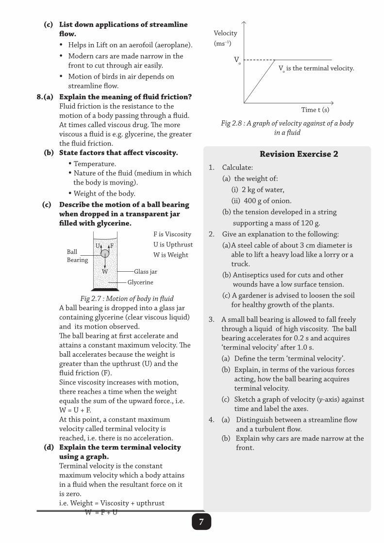
Fig 2.7 : Motion of body in fluid A ball bearing is dropped into a glass jar containing glycerine (clear viscous liquid) and its motion observed. The ball bearing at first accelerate and attains a constant maximum velocity. The ball accelerates because the weight is greater than the upthrust (U) and the fluid friction (F). Since viscosity increases with motion, there reaches a time when the weight equals the sum of the upward force., i.e. W = U + F. At this point, a constant maximum velocity called terminal velocity is reached, i.e. there is no acceleration. (d) Explain the term terminal velocity using a graph. Terminal velocity is the constant maximum velocity which a body attains in a fluid when the resultant force on it is zero. i.e. Weight = Viscosity + upthrust W = F + U
Vo is the terminal velocity.
Fig 2.8 : A graph of velocity against of a body in a fluid
revision Exercise 21. Calculate: (a) the weight of: (i) 2 kg of water, (ii) 400 g of onion. (b) the tension developed in a string supporting a mass of 120 g.2. Give an explanation to the following: (a) A steel cable of about 3 cm diameter is able to lift a heavy load like a lorry or a truck. (b) Antiseptics used for cuts and other wounds have a low surface tension. (c) A gardener is advised to loosen the soil for healthy growth of the plants.
3. A small ball bearing is allowed to fall freely through a liquid of high viscosity. The ball bearing accelerates for 0.2 s and acquires ‘terminal velocity’ after 1.0 s. (a) Define the term ‘terminal velocity’. (b) Explain, in terms of the various forces
acting, how the ball bearing acquires terminal velocity.
(c) Sketch a graph of velocity (y-axis) against time and label the axes.
4. (a) Distinguish between a streamline flow and a turbulent flow. (b) Explain why cars are made narrow at the front.
8
5. Explain the following statements: (a) An air flow over the wings of an aircraft
causes a lift. (b) Flags flutter in a breeze. (c) It is dangerous to stand near the edge of
a platform in a railway station, when a train passes without stopping.
(d) A spinning ball curves during its flight. (e) It is difficult to push a table tennis
ball completely out of the funnel, held upright, by blowing air from underneath through `the narrow end of the funnel.
(f) In a strong wind, the thatched roof of a hut can be completely lifted off although the walls are not appreciably damaged.
9
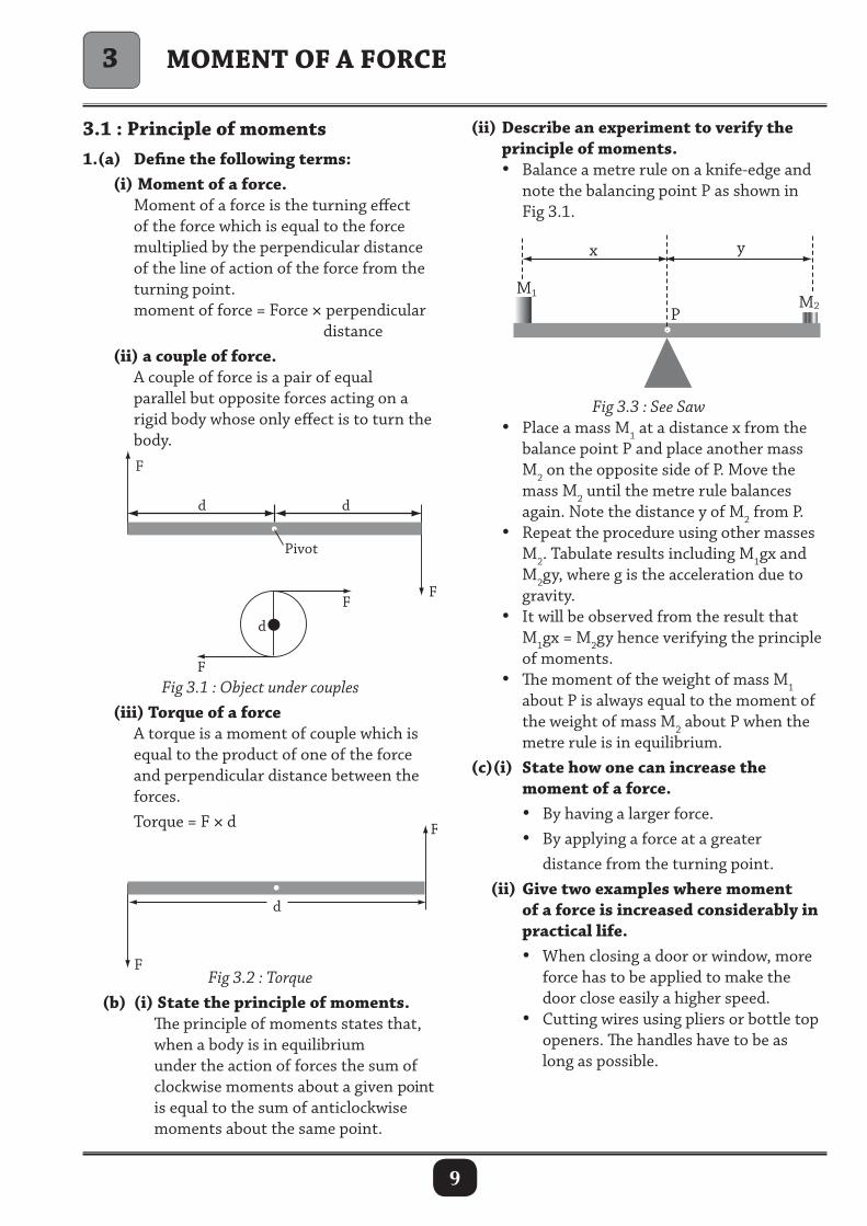
3.1 : Principle of moments1.(a) Define the following terms: (i) Moment of a force. Moment of a force is the turning effect of the force which is equal to the force multiplied by the perpendicular distance of the line of action of the force from the turning point. moment of force = Force × perpendicular distance (ii) a couple of force. A couple of force is a pair of equal parallel but opposite forces acting on a rigid body whose only effect is to turn the body.
(ii) Describe an experiment to verify the principle of moments. • Balance a metre rule on a knife-edge and note the balancing point P as shown in Fig 3.1.
MoMent of a force
x y
P M2
M1
Fig 3.1 : Object under couples (iii) torque of a force A torque is a moment of couple which is equal to the product of one of the force and perpendicular distance between the forces. Torque = F × d
d d
d
F
F
F
Pivot
F
d
F
F
Fig 3.2 : Torque (b) (i) State the principle of moments. The principle of moments states that, when a body is in equilibrium under the action of forces the sum of clockwise moments about a given point is equal to the sum of anticlockwise moments about the same point.
Fig 3.3 : See Saw • Place a mass M1 at a distance x from the balance point P and place another mass M2 on the opposite side of P. Move the mass M2 until the metre rule balances again. Note the distance y of M2 from P. • Repeat the procedure using other masses M2. Tabulate results including M1gx and M2gy, where g is the acceleration due to gravity. • It will be observed from the result that M1gx = M2gy hence verifying the principle of moments. • The moment of the weight of mass M1 about P is always equal to the moment of the weight of mass M2 about P when the metre rule is in equilibrium.(c)(i) State how one can increase the moment of a force. • By having a larger force. • By applying a force at a greater distance from the turning point. (ii) Give two examples where moment of a force is increased considerably in practical life. • When closing a door or window, more force has to be applied to make the door close easily a higher speed. • Cutting wires using pliers or bottle top openers. The handles have to be as long as possible.
3
10
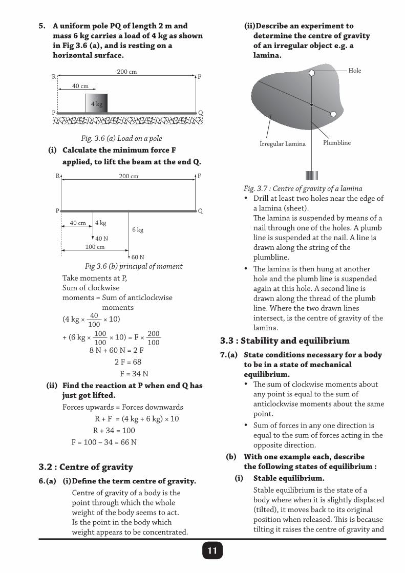
N 25 m
String Bar magnets 15 m
A mass of 200 kg
N T
S
2.(i) explain why the handle of car door is placed away from the hinges A force is applied at a greater possible distance from the hinges (pivot or fulcrum). This gives the maximum moment and a force applied to open the will be reduced. (ii) If the handle is 80 cm from the hinges and a force of 65 n is applied to open the door. calculate the moment of a force. Moment of force = Force × distance = 65 × 0.8 = 52 Nm. (iii) State and explain the best direction for the force when the door is being opened. At right angle to the plane of the door. Moment is the product of perpendicular distance and force. In order for moment to be maximum, force should be applied at a right angle to the plane of the door. (iv) State two applications of the principle of moments. Principle of moments is applied in: • weighing scales in balances. • sea saw. • suspension bridges. • door handle.3.(a) Give any effect of both moment and couple of a force. Causes turning effect on a body about a fixed point called a pivot. (b) Give any three applications of moments or couple of a force. • Opening or closing of doors. • Closing a lid of a container, e.g. Geometrical instrument box. • A pair of scissors or garden shears in use. • Children playing on a seesaw. • A wheelbarrow being used to lift some load. • A beam balance being used to find the mass of an object. • A screwdriver being used to tighten and loosen a screw.
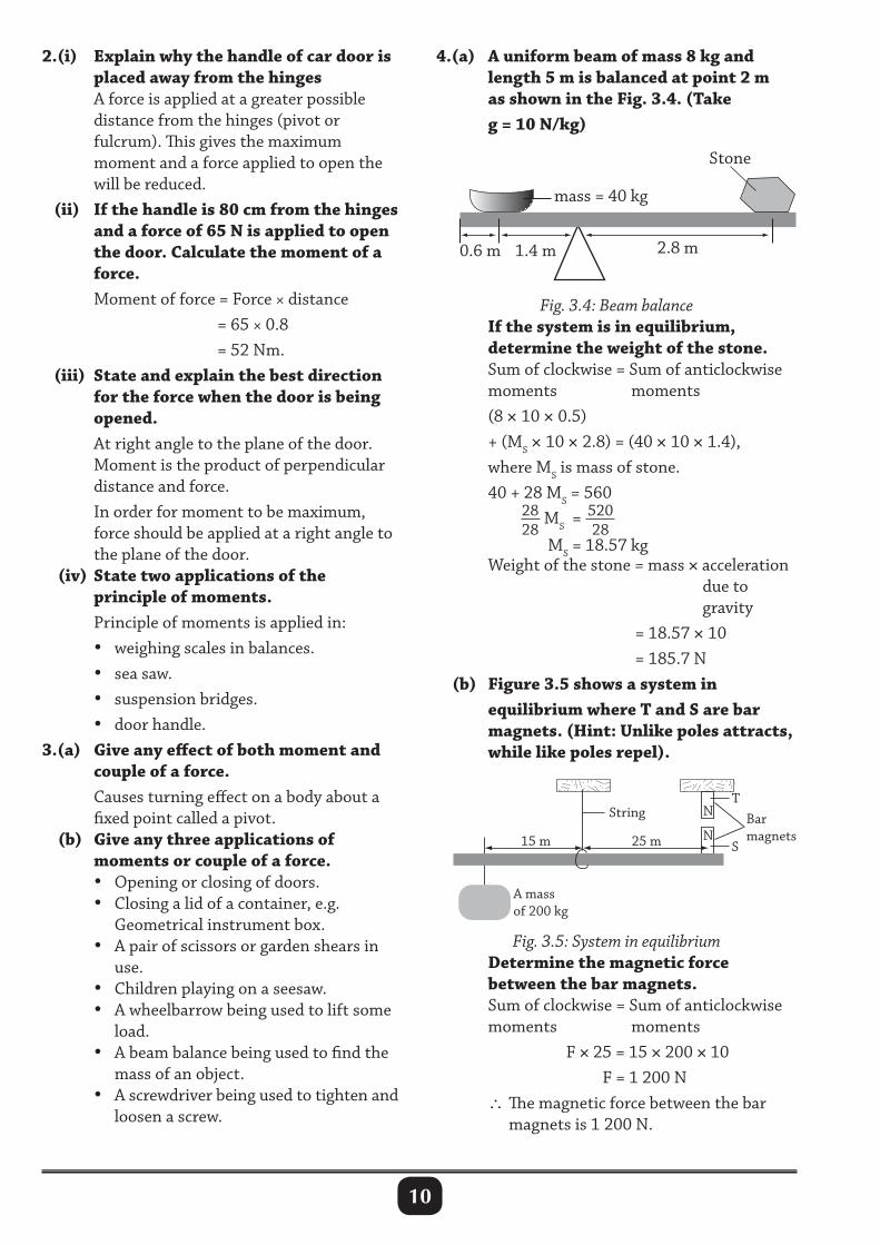
4.(a) a uniform beam of mass 8 kg and length 5 m is balanced at point 2 m as shown in the fig. 3.4. (take g = 10 n/kg)
2.8 m
Stone
mass = 40 kg
0.6 m 1.4 m
Fig. 3.4: Beam balance If the system is in equilibrium, determine the weight of the stone. Sum of clockwise = Sum of anticlockwise moments moments (8 × 10 × 0.5) + (MS × 10 × 2.8) = (40 × 10 × 1.4), where MS is mass of stone. 40 + 28 MS = 560 28
28 MS = 520
28
MS = 18.57 kg Weight of the stone = mass × acceleration due to gravity = 18.57 × 10 = 185.7 N (b) figure 3.5 shows a system in equilibrium where t and S are bar magnets. (Hint: Unlike poles attracts, while like poles repel).
Fig. 3.5: System in equilibrium Determine the magnetic force between the bar magnets. Sum of clockwise = Sum of anticlockwise moments moments F × 25 = 15 × 200 × 10 F = 1 200 N ∴ The magnetic force between the bar magnets is 1 200 N.
11
5. a uniform pole PQ of length 2 m and mass 6 kg carries a load of 4 kg as shown in fig 3.6 (a), and is resting on a horizontal surface.
(ii)Describe an experiment to determine the centre of gravity of an irregular object e.g. a lamina.
Fig. 3.6 (a) Load on a pole (i) calculate the minimum force f applied, to lift the beam at the end Q.
P
R
Q
F
4 kg 6 kg
200 cm
40 cm
40 N
60 N
100 cm
Fig 3.6 (b) principal of moment Take moments at P, Sum of clockwise moments = Sum of anticlockwise moments (4 kg × 40
100 × 10)
+ (6 kg × 100100
× 10) = F × 200100
8 N + 60 N = 2 F 2 F = 68 F = 34 N (ii) find the reaction at P when end Q has just got lifted. Forces upwards = Forces downwards R + F = (4 kg + 6 kg) × 10 R + 34 = 100 F = 100 – 34 = 66 N
3.2 : centre of gravity6.(a) (i) Define the term centre of gravity. Centre of gravity of a body is the point through which the whole weight of the body seems to act. Is the point in the body which weight appears to be concentrated.
Fig. 3.7 : Centre of gravity of a lamina • Drill at least two holes near the edge of a lamina (sheet). The lamina is suspended by means of a nail through one of the holes. A plumb line is suspended at the nail. A line is drawn along the string of the plumbline. • The lamina is then hung at another hole and the plumb line is suspended again at this hole. A second line is drawn along the thread of the plumb line. Where the two drawn lines intersect, is the centre of gravity of the lamina.
3.3 : Stability and equilibrium7.(a) State conditions necessary for a body to be in a state of mechanical equilibrium. • The sum of clockwise moments about any point is equal to the sum of anticlockwise moments about the same point. • Sum of forces in any one direction is equal to the sum of forces acting in the opposite direction. (b) With one example each, describe the following states of equilibrium : (i) Stable equilibrium. Stable equilibrium is the state of a body where when it is slightly displaced (tilted), it moves back to its original position when released. This is because tilting it raises the centre of gravity and
12
Water
Centre ofgravity
(a) (b)
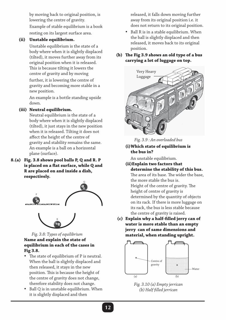
by moving back to original position, is lowering the centre of gravity. Example of stable equilibrium is a book resting on its largest surface area. (ii) Unstable equilibrium. Unstable equilibrium is the state of a body where when it is slightly displaced (tilted), it moves further away from its original position when it is released. This is because tilting it lowers the centre of gravity and by moving further, it is lowering the centre of gravity and becoming more stable in a new position. An example is a bottle standing upside down. (iii) neutral equilibrium. Neutral equilibrium is the state of a body where when it is slightly displaced (tilted), it just stays in the new position when it is released. Tilting it does not affect the height of the centre of gravity and stability remains the same. An example is a ball on a horizontal plane (surface).8.(a) fig. 3.8 shows pool balls P, Q and r. P is placed on a flat surface, while Q and r are placed on and inside a dish, respectively.
released, it falls down moving further away from its original position i.e. it does not return to its original position. • Ball R is in a stable equilibrium. When the ball is slightly displaced and then released, it moves back to its original position. (b) The fig 3.9 shows an old type of a bus carrying a lot of luggage on top.
Fig. 3.9 : An overloaded bus (i) Which state of equilibrium is the bus in? An unstable equilibrium. (ii)explain two factors that determine the stability of this bus. The area of its base. The wider the base, the more stable the bus is. Height of the centre of gravity. The height of centre of gravity is determined by the quantity of objects on its rack. If there is more luggage on its rack, the bus is less stable because the centre of gravity is raised. (c) explain why a half-filled jerry can of water is more stable than an empty jerry can of same dimensions and material, when standing upright.Fig. 3.8: Types of equilibrium
name and explain the state of equilibrium in each of the cases in fig 3.8. • The state of equilibrium of P is neutral. When the ball is slightly displaced and then released, it stays in the new position. This is because the height of the centre of gravity does not change, therefore stability does not change. • Ball Q is in unstable equilibrium. When it is slightly displaced and then
Very HeavyLuggage
Fig. 3.10 (a) Empty jerrican (b) Half filled jerrican
13
When the jerry can is empty its centre of gravity is near the mid-point of the jerry can. When the jerry can is half-filled with water the centre of gravity is lowered due to the weight of water in lower half. This makes the half-filled jerry can more stable than the empty one.9.(a) State the measures taken to increase stability of a double-decker bus. (i) during its construction • The engine and chassis of the bus are placed as low as possible. • The upper deck and seats are made of light material. • The bus is constructed with a wide base area. • Luggage compartments are placed under the seats. (ii) when it is operating on the road. Standing passengers may be allowed in the lower deck but not the upper one i.e. the passengers are advised to always be seated.
revision exercise 31. Define the following terms. (a) Moment of a force. (b) A couple. (c) Centre of gravity.
2. A force of 20 N is applied to open the gate of a fence at a distance of 1.4 m from the pivot. Calculate the moment of force about the hinges.
3. A person applies a force of 500 N and produces a moment of force of 300 Nm about the wheels of a wheel cart (Figure 3.11). Calculate the perpendicular distance x from the line of action of the force to the wheels.
4. A uniform metre rule is balanced horizontally at its centre. When a mass of 5 g is suspended at the 4 cm mark, the rule balances horizontally if a mass M is suspended at the 60 cm mark. Calculate M.
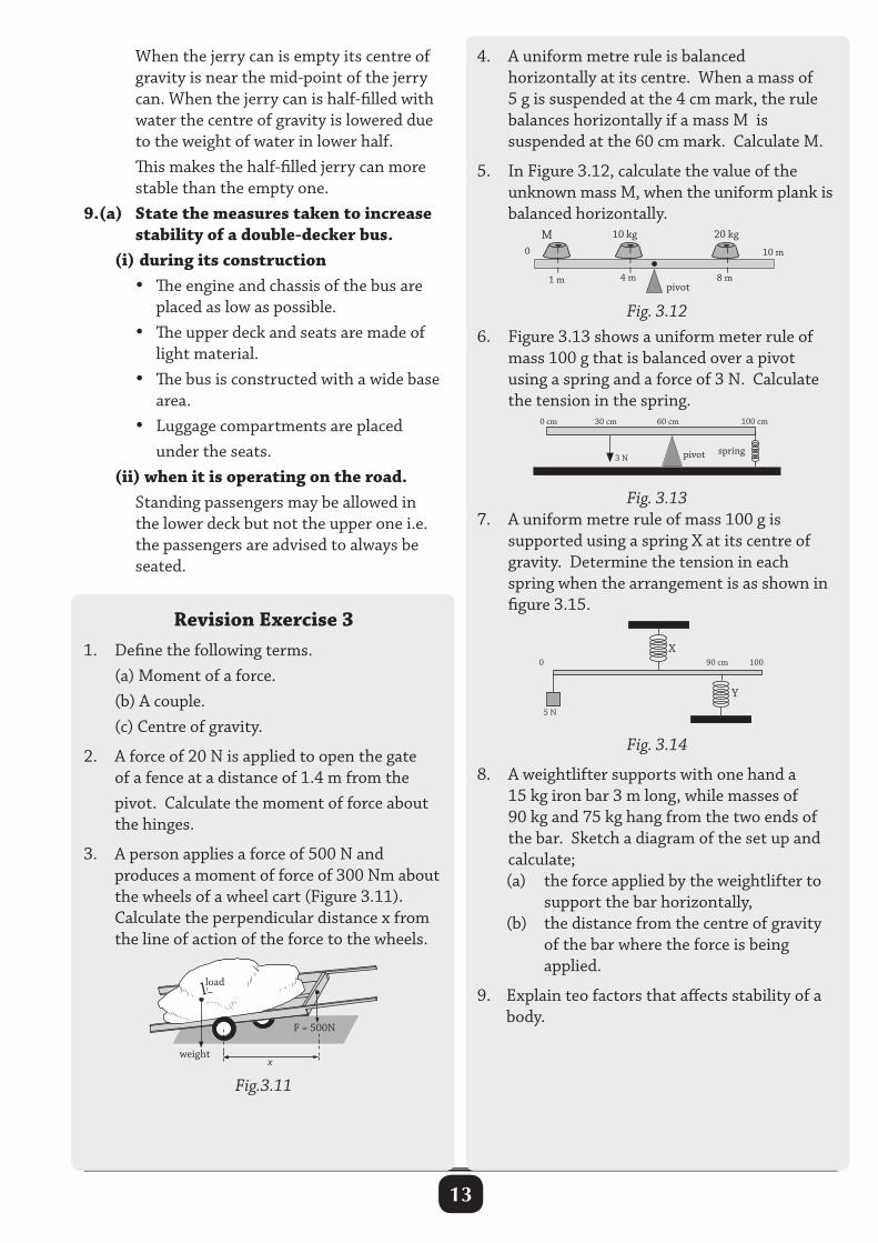
5. In Figure 3.12, calculate the value of the unknown mass M, when the uniform plank is balanced horizontally.
Fig. 3.126. Figure 3.13 shows a uniform meter rule of mass 100 g that is balanced over a pivot using a spring and a force of 3 N. Calculate the tension in the spring.
Fig. 3.137. A uniform metre rule of mass 100 g is supported using a spring X at its centre of gravity. Determine the tension in each spring when the arrangement is as shown in figure 3.15.
Fig. 3.14
8. A weightlifter supports with one hand a 15 kg iron bar 3 m long, while masses of 90 kg and 75 kg hang from the two ends of the bar. Sketch a diagram of the set up and calculate; (a) the force applied by the weightlifter to
support the bar horizontally, (b) the distance from the centre of gravity
of the bar where the force is being applied.
9. Explain teo factors that affects stability of a body.
20 kgM 10 kg
1 m 4 m 8 m
10 m0
– –
–
– –
–
– –
–
pivot
30 cm 100 cm60 cm0 cm
3 Nspringpivot
weight
load
F = 500N
x
load
5 N
Y
X90 cm0 100
Fig.3.11
14
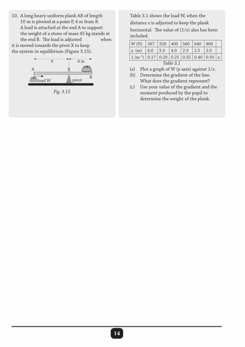
10. A long heavy uniform plank AB of length 10 m is pivoted at a point P, 4 m from B. A load is attached at the end A to support the weight of a stone of mass 45 kg stands at the end B. The load is adjusted when it is moved towards the pivot X to keep the system in equilibrium (Figure 3.15).
Fig. 3.15
Table 3.1 shows the load W, when the distance x is adjusted to keep the plank horizontal. The value of (1/x) also has been included.
W (N) 267 320 400 560 640 800x (m) 6.0 5.0 4.0 2.9 2.5 2.01 (m–1) 0.17 0.20 0.25 0.35 0.40 0.50 x
Table 3.1 (a) Plot a graph of W (y-axis) against 1/x. (b) Determine the gradient of the line.
What does the gradient represent? (c) Use your value of the gradient and the
moment produced by the pupil to determine the weight of the plank.
X
B
A
load W
x 4 m
pivot
15
PROPERTIES OF MATTER
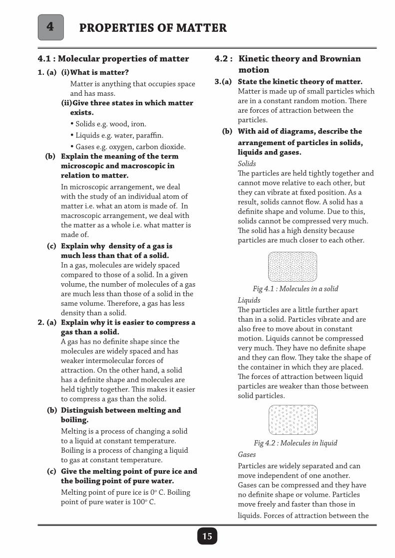
4.2 : Kinetic theory and Brownian motion3.(a) State the kinetic theory of matter. Matter is made up of small particles which are in a constant random motion. There are forces of attraction between the particles. (b) With aid of diagrams, describe the arrangement of particles in solids, liquids and gases. Solids The particles are held tightly together and cannot move relative to each other, but they can vibrate at fixed position. As a result, solids cannot flow. A solid has a definite shape and volume. Due to this, solids cannot be compressed very much. The solid has a high density because particles are much closer to each other.
4.1 : Molecular properties of matter1. (a) (i) What is matter? Matter is anything that occupies space and has mass. (ii)Give three states in which matter exists. • Solids e.g. wood, iron. • Liquids e.g. water, paraffin. • Gases e.g. oxygen, carbon dioxide. (b) Explain the meaning of the term microscopic and macroscopic in relation to matter. In microscopic arrangement, we deal with the study of an individual atom of matter i.e. what an atom is made of. In macroscopic arrangement, we deal with the matter as a whole i.e. what matter is made of. (c) Explain why density of a gas is much less than that of a solid. In a gas, molecules are widely spaced compared to those of a solid. In a given volume, the number of molecules of a gas are much less than those of a solid in the same volume. Therefore, a gas has less density than a solid.2. (a) Explain why it is easier to compress a gas than a solid. A gas has no definite shape since the molecules are widely spaced and has weaker intermolecular forces of attraction. On the other hand, a solid has a definite shape and molecules are held tightly together. This makes it easier to compress a gas than the solid. (b) Distinguish between melting and boiling. Melting is a process of changing a solid to a liquid at constant temperature. Boiling is a process of changing a liquid to gas at constant temperature. (c) Give the melting point of pure ice and the boiling point of pure water. Melting point of pure ice is 0o C. Boiling point of pure water is 100o C.
Fig 4.1 : Molecules in a solid Liquids The particles are a little further apart than in a solid. Particles vibrate and are also free to move about in constant motion. Liquids cannot be compressed very much. They have no definite shape and they can flow. They take the shape of the container in which they are placed. The forces of attraction between liquid particles are weaker than those between solid particles.
Fig 4.2 : Molecules in liquid Gases Particles are widely separated and can move independent of one another. Gases can be compressed and they have no definite shape or volume. Particles move freely and faster than those in liquids. Forces of attraction between the
4
16
particles of a gas are much weaker than those between liquid and solid particles. The density of a gas is very much less than that of solid and liquid.
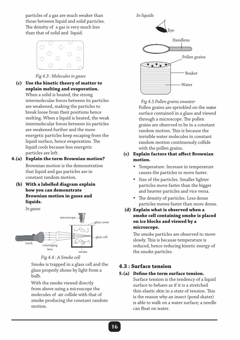
Fig 4.3 : Molecules in gases (c) Use the kinetic theory of matter to explain melting and evaporation. When a solid is heated, the strong intermolecular forces between its particles are weakened, making the particles to break loose from their positions hence melting. When a liquid is heated, the weak intermolecular forces between its particles are weakened further and the more energetic particles keep escaping from the liquid surface, hence evaporation. The liquid cools because less energetic particles are left.4.(a) Explain the term Brownian motion? Brownian motion is the demonstration that liquid and gas particles are in constant random motion. (b) With a labelled diagram explain how you can demonstrate Brownian motion in gases and liquids. In gases
Fig 4.5 Pollen grains onwater Pollen grains are sprinkled on the water surface contained in a glass and viewed through a microscope. The pollen grains are observed to be in a constant random motion. This is because the invisible water molecules in constant random motion continuously collide with the pollen grains. (c) Explain factors that affect Brownian motion. • Temperature. Increase in temperature causes the particles to move faster. • Size of the particles. Smaller lighter particles move faster than the bigger and heavier particles and vice versa. • The density of particles. Less dense particles moves faster than more dense. (d) Explain what is observed when a smoke cell containing smoke is placed on ice blocks and viewed by a microscope. The smoke particles are observed to move slowly. This is because temperature is reduced, hence reducing kinetic energy of the smoke particles.
4.3 : Surface tension5.(a) Define the term surface tension. Surface tension is the tendency of a liquid surface to behave as if it is a stretched thin elastic skin in a state of tension. This is the reason why an insect (pond skater) is able to walk on a water surface; a needle can float on water.
Handlens
Eye
Water
Beaker
Pollen grains
Fig 4.4 : A Smoke cell Smoke is trapped in a glass cell and the glass properly shone by light from a bulb. With the smoke viewed directly from above using a microscope the molecules of air collide with that of smoke producing the constant random motion.
torch converging
lens smoke
glass cell
glass cover microscope
In liquids
17
(b) (i) Describe an experiment to prove the existence of surface tension in liquids. Place a blotting paper on the surface of the water in a beaker. Place an office pin on the blotting paper and leave the set up for sometime. The blotting paper eventually sinks leaving the pin floating. (ii) State any two factors that affect surface tension in liquids. Temperature. Increase in temperature of a liquid reduces its surface tension. Impuritties. Addition of detergents (soup) reduces surface tension of a liquid. (c) (i) State applications of surface tension. • Some small insects are able to walk on the water surface. • Damp sand feels firmer than dry sand because any liquid will try to form the smallest surface area. • Liquids drops from the taps, always tend to be spherical in shape and appears stretching. • Needles and razor blade may float on the surface of water. (ii) Explain why camphor darts on the water surface. Camphor is a hydrophobic substance which does not easily dissolve in water. When a small piece of camphor is placed on the water surface, it moves in an irregular path (darts). This is due to the camphor dissolving slightly and reducing on surface tension on its one side. The camphor does not dissolve equally all round the piece and alteration in surface tension is not balanced. The unequal forces acting around the piece will cause it to move in an irregular path, hence darting. Small light boats or ducks can be made to sail by attaching small pieces of camphor on them.
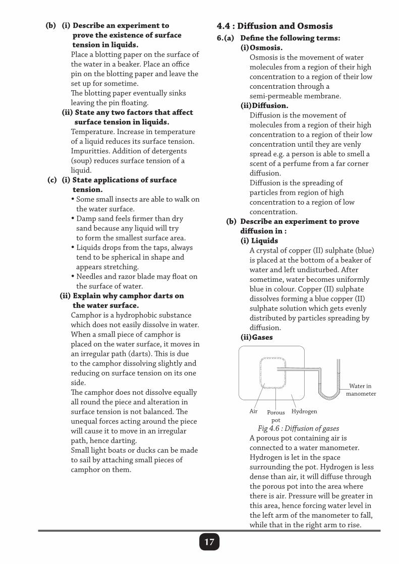
4.4 : Diffusion and Osmosis6.(a) Define the following terms: (i) Osmosis. Osmosis is the movement of water molecules from a region of their high concentration to a region of their low concentration through a semi-permeable membrane. (ii)Diffusion. Diffusion is the movement of molecules from a region of their high concentration to a region of their low concentration until they are venly spread e.g. a person is able to smell a scent of a perfume from a far corner diffusion. Diffusion is the spreading of particles from region of high concentration to a region of low concentration. (b) Describe an experiment to prove diffusion in : (i) Liquids A crystal of copper (II) sulphate (blue) is placed at the bottom of a beaker of water and left undisturbed. After sometime, water becomes uniformly blue in colour. Copper (II) sulphate dissolves forming a blue copper (II) sulphate solution which gets evenly distributed by particles spreading by diffusion. (ii)Gases
Hydrogen Air Porous pot
Water in manometer
Fig 4.6 : Diffusion of gases A porous pot containing air is connected to a water manometer. Hydrogen is let in the space surrounding the pot. Hydrogen is less dense than air, it will diffuse through the porous pot into the area where there is air. Pressure will be greater in this area, hence forcing water level in the left arm of the manometer to fall, while that in the right arm to rise.
18
(c) State and explain factors affecting rate of diffusion. • Temperature. The higher the temperature the higher the rate of diffusion. • Density. The lower the density the higher the rate of diffusion. • Size of molecules. The smaller the particles, the faster the rate of diffusion. • Concentration. The rate of diffusion is high when concentration of a substance is high. (d) State three applications of diffusion. • The smell of a perfume is able to spread through the whole room because of diffusion. This helps in freshening the room. • Gases (oxygen and carbon dioxide) can be breathed in and out of bodies of living organisms by simple diffusion. • Colouring of drinks like soft drinks (sodas) is possible due to diffusion. • The harmful effect of pollution is minimized in a lake or ocean by diffusion. Chemical pollutants move from a region of high concentration to a region of low concentration in large water bodies hence reducing on their harmful effect.7. (i) Describe an experiment to show osmosis. Make a hole on a piece of freshly cut potato. Pour concentrated salty water into the hole. Leave the set up for sometime undisturbed. After sometime the salty water level rises meaning water move from the potato to the hole, hence osmosis. (ii)Explain why bean seeds poured in a sauce pan containing water increase in size. The bean seeds absorb water through pores on its seed coat. Water molecules at their high concentration move to the bean (at their low concentration), due to osmosis.
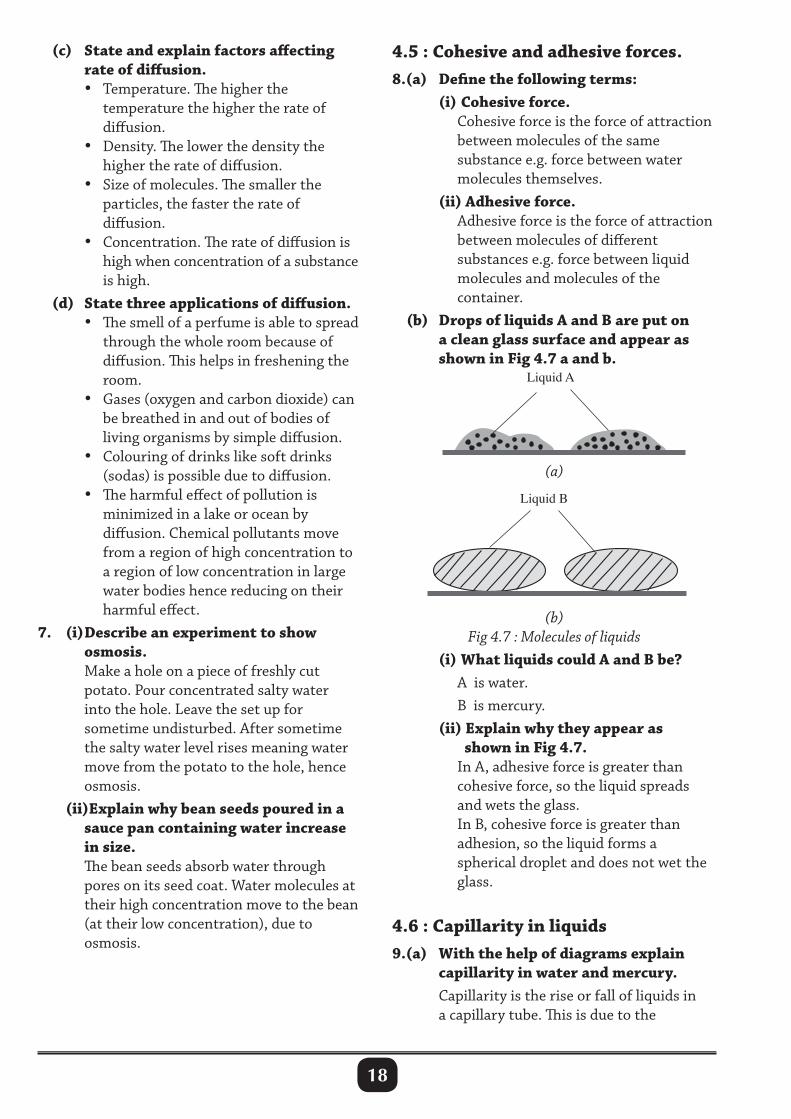
4.5 : Cohesive and adhesive forces.8.(a) Define the following terms: (i) Cohesive force. Cohesive force is the force of attraction between molecules of the same substance e.g. force between water molecules themselves. (ii) Adhesive force. Adhesive force is the force of attraction between molecules of different substances e.g. force between liquid molecules and molecules of the container. (b) Drops of liquids A and B are put on a clean glass surface and appear as shown in Fig 4.7 a and b.
Liquid A
Liquid B
(a)
(b)Fig 4.7 : Molecules of liquids
(i) What liquids could A and B be? A is water. B is mercury. (ii) Explain why they appear as shown in Fig 4.7. In A, adhesive force is greater than cohesive force, so the liquid spreads and wets the glass. In B, cohesive force is greater than adhesion, so the liquid forms a spherical droplet and does not wet the glass.
4.6 : Capillarity in liquids9.(a) With the help of diagrams explain capillarity in water and mercury. Capillarity is the rise or fall of liquids in a capillary tube. This is due to the
19
• Measure the diameter, d of the patch using a ruler. If the patch forms a cylindrical film of diameter, d and thickness t. • The area of the film (patch) = πd2
4 • The volume of the film (acid), V will be: V = πd2
4 × t ⇒ t = 4 Vπd2
Hence the size or length or thickness t of a molecule can be obtained.
Narrow tube Wide tube
Water
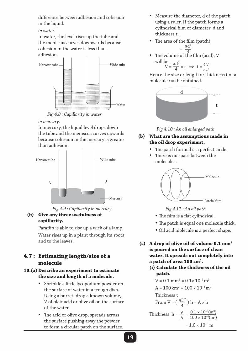
difference between adhesion and cohesion in the liquid. in water. In water, the level rises up the tube and the meniscus curves downwards because cohesion in the water is less than adhesion.
Fig 4.8 : Capillarity in water in mercury. In mercury, the liquid level drops down the tube and the meniscus curves upwards because cohesion in the mercury is greater than adhesion.
d
t
Molecule
Patch/ flim
Fig 4.10 : An oil enlarged path (b) What are the assumptions made in the oil drop experiment. • The patch formed is a perfect circle. • There is no space between the molecules.Narrow tube Wide tube
Mercury
Fig 4.9 : Capillarity in mercury (b) Give any three usefulness of capillarity. Paraffin is able to rise up a wick of a lamp. Water rises up in a plant through its roots and to the leaves.
4.7 : Estimating length/size of a molecule10.(a) Describe an experiment to estimate the size and length of a molecule. • Sprinkle a little lycopodium powder on the surface of water in a trough dish. Using a burret, drop a known volume, V of oleic acid or olive oil on the surface of the water. • The acid or olive drop, spreads across the surface pushing away the powder to form a circular patch on the surface.
Fig 4.11 : An oil path • The film is a flat cylindrical. • The patch is equal one molecule thick. • Oil acid molecule is a perfect shape.
(c) A drop of olive oil of volume 0.1 mm3 is poured on the surface of clean water. It spreads out completely into a patch of area 100 cm2. (i) Calculate the thickness of the oil patch. V = 0.1 mm3 = 0.1× 10⁻⁹ m3
A = 100 cm2 = 100 × 10–4 m2
Thickness t From V = ( πD2
4 ) h = A × h
Thickness h = VA
= 0.1 × 10⁻⁹(m3)100 × 10–4(m2)
= 1.0 × 10⁻⁸ m
20
(ii) Estimate the number of molecules in the given volume. Volume of one molecule (sphere), V = 4
3πr3 or 4
3π( d
2)3
r = h2
= 0.5 × 10⁻⁸ m. The number of molecules = Total Volume of film (oil/ Acid)
Volume of one molecule
= 6.37 × 1025 Molecules
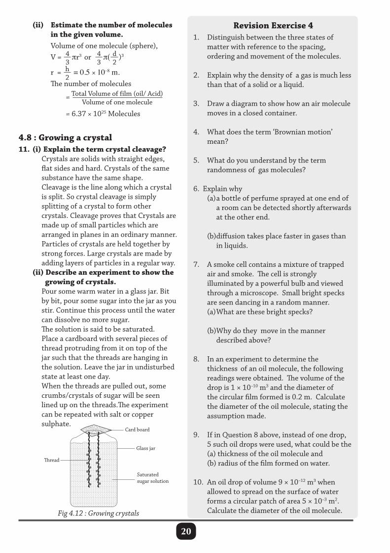
4.8 : Growing a crystal 11. (i) Explain the term crystal cleavage? Crystals are solids with straight edges, flat sides and hard. Crystals of the same substance have the same shape. Cleavage is the line along which a crystal is split. So crystal cleavage is simply splitting of a crystal to form other crystals. Cleavage proves that Crystals are made up of small particles which are arranged in planes in an ordinary manner. Particles of crystals are held together by strong forces. Large crystals are made by adding layers of particles in a regular way. (ii) Describe an experiment to show the growing of crystals. Pour some warm water in a glass jar. Bit by bit, pour some sugar into the jar as you stir. Continue this process until the water can dissolve no more sugar. The solution is said to be saturated. Place a cardboard with several pieces of thread protruding from it on top of the jar such that the threads are hanging in the solution. Leave the jar in undisturbed state at least one day. When the threads are pulled out, some crumbs/crystals of sugar will be seen lined up on the threads.The experiment can be repeated with salt or copper sulphate.
read
Card board
Glass jar
Saturated sugar solution
Fig 4.12 : Growing crystals
Revision Exercise 41. Distinguish between the three states of matter with reference to the spacing, ordering and movement of the molecules.
2. Explain why the density of a gas is much less than that of a solid or a liquid.
3. Draw a diagram to show how an air molecule moves in a closed container.
4. What does the term ‘Brownian motion’ mean?
5. What do you understand by the term randomness of gas molecules?
6. Explain why (a) a bottle of perfume sprayed at one end of a room can be detected shortly afterwards at the other end.
(b)diffusion takes place faster in gases than in liquids.
7. A smoke cell contains a mixture of trapped air and smoke. The cell is strongly illuminated by a powerful bulb and viewed through a microscope. Small bright specks are seen dancing in a random manner. (a) What are these bright specks?
(b)Why do they move in the manner described above?
8. In an experiment to determine the thickness of an oil molecule, the following readings were obtained. The volume of the drop is 1 × 10⁻¹⁰ m3 and the diameter of the circular film formed is 0.2 m. Calculate the diameter of the oil molecule, stating the assumption made.
9. If in Question 8 above, instead of one drop, 5 such oil drops were used, what could be the (a) thickness of the oil molecule and (b) radius of the film formed on water.
10. An oil drop of volume 9 × 10–12 m3 when allowed to spread on the surface of water forms a circular patch of area 5 × 10⁻³ m2. Calculate the diameter of the oil molecule.
21
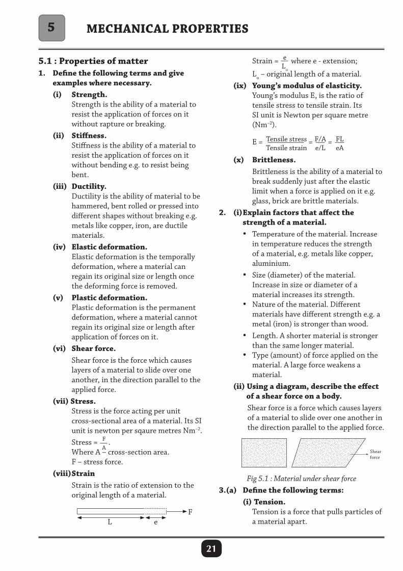
5.1 : Properties of matter 1. Define the following terms and give examples where necessary. (i) Strength. Strength is the ability of a material to resist the application of forces on it without rapture or breaking. (ii) Stiffness. Stiffness is the ability of a material to resist the application of forces on it without bending e.g. to resist being bent. (iii) Ductility. Ductility is the ability of material to be hammered, bent rolled or pressed into different shapes without breaking e.g. metals like copper, iron, are ductile materials. (iv) Elastic deformation. Elastic deformation is the temporally deformation, where a material can regain its original size or length once the deforming force is removed. (v) Plastic deformation. Plastic deformation is the permanent deformation, where a material cannot regain its original size or length after application of forces on it. (vi) Shear force. Shear force is the force which causes layers of a material to slide over one another, in the direction parallel to the applied force. (vii) Stress. Stress is the force acting per unit cross-sectional area of a material. Its SI unit is newton per sqaure metres Nm–2. Stress = F
A.
Where A – cross-section area. F – stress force. (viii) Strain Strain is the ratio of extension to the original length of a material.
Strain = eLo
where e - extension; Lo – original length of a material. (ix) Young’s modulus of elasticity. Young’s modulus E, is the ratio of tensile stress to tensile strain. Its SI unit is Newton per square metre (Nm–2).
E = Tensile stressTensile strain
= F/Ae/L
= FLeA
(x) Brittleness. Brittleness is the ability of a material to break suddenly just after the elastic limit when a force is applied on it e.g. glass, brick are brittle materials.2. (i) Explain factors that affect the strength of a material. • Temperature of the material. Increase in temperature reduces the strength of a material, e.g. metals like copper, aluminium. • Size (diameter) of the material. Increase in size or diameter of a material increases its strength. • Nature of the material. Different materials have different strength e.g. a metal (iron) is stronger than wood. • Length. A shorter material is stronger than the same longer material. • Type (amount) of force applied on the material. A large force weakens a material. (ii) Using a diagram, describe the effect of a shear force on a body. Shear force is a force which causes layers of a material to slide over one another in the direction parallel to the applied force.
MECHANICAL PROPERTIES
L eF
5
Fig 5.1 : Material under shear force3.(a) Define the following terms: (i) Tension. Tension is a force that pulls particles of a material apart.
22
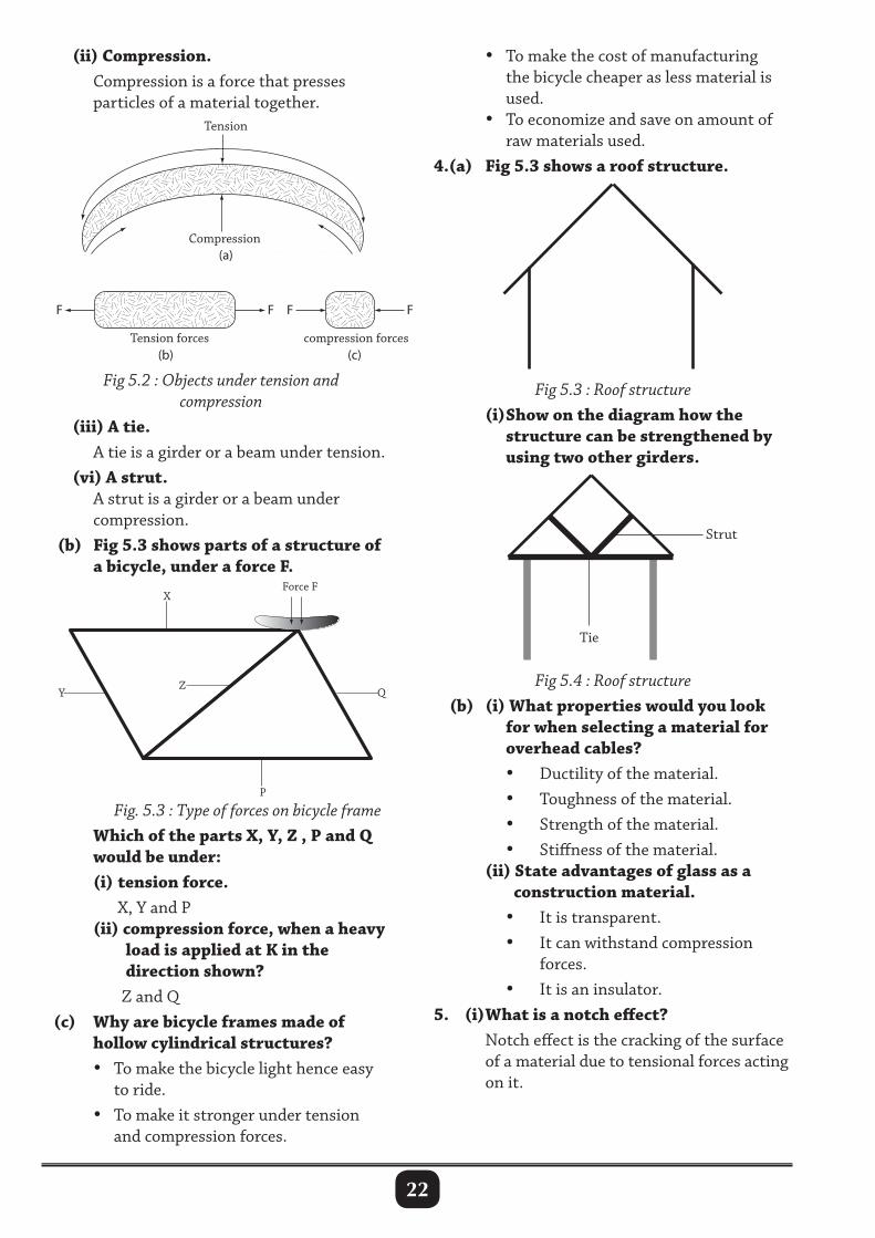
(ii) Compression. Compression is a force that presses particles of a material together.
• To make the cost of manufacturing the bicycle cheaper as less material is used. • To economize and save on amount of raw materials used.4.(a) Fig 5.3 shows a roof structure.
Tension
Compression
Tension forces compression forces
F F F
(a)
(b) (c)
F
Strut
Tie
Fig 5.2 : Objects under tension and compression
(iii) A tie. A tie is a girder or a beam under tension. (vi) A strut. A strut is a girder or a beam under compression. (b) Fig 5.3 shows parts of a structure of a bicycle, under a force F.
Fig 5.3 : Roof structure (i) Show on the diagram how the structure can be strengthened by using two other girders.
Fig 5.4 : Roof structure (b) (i) What properties would you look for when selecting a material for overhead cables? • Ductility of the material. • Toughness of the material. • Strength of the material. • Stiffness of the material. (ii) State advantages of glass as a construction material. • It is transparent. • It can withstand compression forces. • It is an insulator.5. (i) What is a notch effect? Notch effect is the cracking of the surface of a material due to tensional forces acting on it.
Fig. 5.3 : Type of forces on bicycle frame Which of the parts X, Y, Z , P and Q would be under: (i) tension force. X, Y and P (ii) compression force, when a heavy load is applied at K in the direction shown? Z and Q (c) Why are bicycle frames made of hollow cylindrical structures? • To make the bicycle light hence easy to ride. • To make it stronger under tension and compression forces.
23
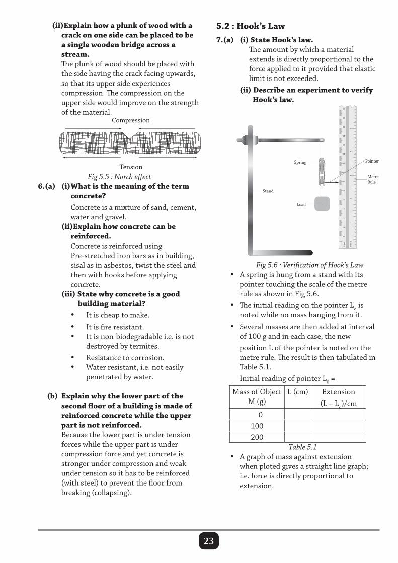
5.2 : Hook’s Law7.(a) (i) State Hook’s law. The amount by which a material extends is directly proportional to the force applied to it provided that elastic limit is not exceeded. (ii) Describe an experiment to verify Hook’s law.
0 cm
0 1
2 3
4 5
Inch
1 2
3 4
5 6
7
8 9
10
11
12
13
14
15
Spring
Metre Rule
Pointer
Load
Stand
(ii)Explain how a plunk of wood with a crack on one side can be placed to be a single wooden bridge across a stream. The plunk of wood should be placed with the side having the crack facing upwards, so that its upper side experiences compression. The compression on the upper side would improve on the strength of the material.
Fig 5.5 : Norch effect 6.(a) (i) What is the meaning of the term concrete? Concrete is a mixture of sand, cement, water and gravel. (ii)Explain how concrete can be reinforced. Concrete is reinforced using Pre-stretched iron bars as in building, sisal as in asbestos, twist the steel and then with hooks before applying concrete. (iii) State why concrete is a good building material? • It is cheap to make. • It is fire resistant. • It is non-biodegradable i.e. is not destroyed by termites. • Resistance to corrosion. • Water resistant, i.e. not easily penetrated by water.
(b) Explain why the lower part of the second floor of a building is made of reinforced concrete while the upper part is not reinforced. Because the lower part is under tension forces while the upper part is under compression force and yet concrete is stronger under compression and weak under tension so it has to be reinforced (with steel) to prevent the floor from breaking (collapsing).
Fig 5.6 : Verification of Hook’s Law • A spring is hung from a stand with its pointer touching the scale of the metre rule as shown in Fig 5.6. • The initial reading on the pointer Lo is noted while no mass hanging from it. • Several masses are then added at interval of 100 g and in each case, the new position L of the pointer is noted on the metre rule. The result is then tabulated in Table 5.1. Initial reading of pointer L0 =
Mass of Object M (g)
L (cm) Extension (L – Lo)/cm
0100200
Table 5.1 • A graph of mass against extension when ploted gives a straight line graph; i.e. force is directly proportional to extension.
24
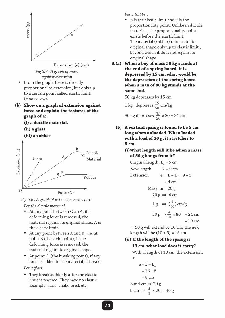
For a Rubber, • E is the elastic limit and P is the proportionality point. Unlike in ductile materials, the proportionality point exists before the elastic limit. The material (rubber) returns to its original shape only up to elastic limit , beyond which it does not regain its original shape.8.(a) When a boy of mass 50 kg stands at the end of a spring board, it is depressed by 15 cm, what would be the depression of the spring board when a man of 80 kg stands at the same end. 50 kg depresses by 15 cm 1 kg depresses 15
50 cm/kg
80 kg depresses 1550
× 80 = 24 cm
(b) A vertical spring is found to be 5 cm long when unloaded. When loaded with a load of 20 g, it stretches to 9 cm. (i)What length will it be when a mass of 50 g hangs from it? Original length, Lo = 5 cm New length L = 9 cm Extension e = L – Lo = 9 – 5 = 4 cm Mass, m = 20 g 20 g ⇒ 4 cm 1 g ⇒ ( 4
20) cm/g
50 g ⇒ 420
× 80 = 24 cm = 10 cm ∴ 50 g will extend by 10 cm. The new length will be (10 + 5) = 15 cm. (ii) If the length of the spring is 13 cm, what load does it carry? With a length of 13 cm, the extension, e. e = L – Lo
= 13 – 5 = 8 cm But 4 cm ⇒ 20 g 8 cm ⇒ 8
4 × 20 = 40 g
Force (N)
Glass
Rubber
DuctileMaterial
C
B
A
PE
O
Exte
nsio
n (c
m)
Fig 5.7 : A graph of mass against extension
• From the graph; force is directly proportional to extension, but only up to a certain point called elastic limit. (Hook’s law). (b) Show on a graph of extension against force and explain the features of the graph of a: (i) a ductile material. (ii) a glass. (iii) a rubber
××
××
×m
ass
(g)
Extension, (e) (cm)
Fig 5.8 : A graph of extension verses force For the ductile material, • At any point between O an A, if a deforming force is removed, the material regains its original shape. A is the elastic limit. • At any point between A and B , i.e. at point B (the yield point), if the deforming force is removed, the material regain its original shape. • At point C, (the breaking point), if any force is added to the material, it breaks. For a glass, • They break suddenly after the elastic limit is reached. They have no elastic. Example: glass, chalk, brick etc.
25
∴ When length is 13 cm, the load is 40 g.
5.3 : Application of Hook’s law9.(a) State one application and limitation of Hook’s law. Application • Hook’s law is applied in the calibration of a spring balance. • Concept of Hook’s law is used in making of some types of shock absorbers in machines e.g. vehicles, cranes. Limitations • Hook’s law is only limited to specific length of a material beyond which the law does not hold. (b) State and explain any two applications of elasticity. • Concrete is used to withstand a large force when under compression than in tension extra force causes breakages. • Steel materials are strong both in compression and tension and are stiff. • Ductile materials can be rolled like sheets or drawn into wires or other required shapes as used in metal industries. • Strong, light, stiff and heat resistant materials are often preferred in modern technology construction. • In manufacturing, elasticity is employed in making of shock absorbers bearing in mind the different weights of vehicles. • Car tyres are elastic to accommodate pressure inflated in the tube.
Revision Exercise 51. Define the following terms. (a) Elastic deformation. (b) A strut. (c) A tie. (d) Concrete.2. The length of an unstretched spring is 6 cm. When a mass of 100 g is attached to it, the new length is 8.5 cm. Calculate the spring constant of the spring in newtons per metre.
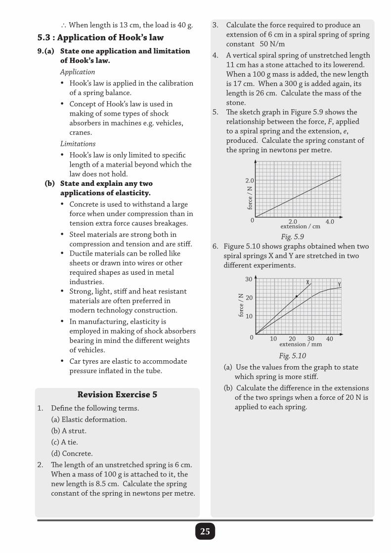
3. Calculate the force required to produce an extension of 6 cm in a spiral spring of spring constant 50 N/m4. A vertical spiral spring of unstretched length 11 cm has a stone attached to its lowerend. When a 100 g mass is added, the new length is 17 cm. When a 300 g is added again, its length is 26 cm. Calculate the mass of the stone.5. The sketch graph in Figure 5.9 shows the relationship between the force, F, applied to a spiral spring and the extension, e, produced. Calculate the spring constant of the spring in newtons per metre.
Fig. 5.96. Figure 5.10 shows graphs obtained when two spiral springs X and Y are stretched in two different experiments.
Fig. 5.10 (a) Use the values from the graph to state
which spring is more stiff. (b) Calculate the difference in the extensions
of the two springs when a force of 20 N is applied to each spring.
2.0
0 2.0 4.0extension / cm
forc
e /
N
20
0 20 40extension / mm
forc
e /
N
10 30
10
30
•
X Y
26
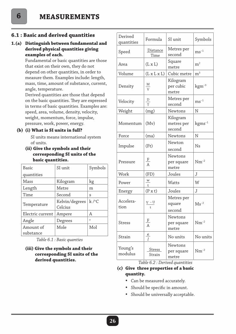
6.1 : Basic and derived quantities1.(a) Distinguish between fundamental and derived physical quantities giving examples of each. Fundamental or basic quantities are those that exist on their own, they do not depend on other quantities, in order to measure them. Examples include: length, mass, time, amount of substance, current, angle, temperature. Derived quantities are those that depend on the basic quantities. They are expressed in terms of basic quantities. Examples are: speed, area, volume, density, velocity, weight, momentum, force, impulse, pressure, work, power, energy. (b) (i) What is SI units in full? SI units means international system of units. (ii) Give the symbols and their corresponding SI units of the basic quantities.
Basic quantities
SI unit Symbols
Mass Kilogram kgLength Metre mTime Second s
TemperatureKelvin/degrees Celcius
k /oC
Electric current Ampere AAngle Degrees o
Amount of substance
Mole Mol
Table 6.1 : Basic quanties
Derived quantities
Formula SI unit Symbols
Speed DistanceTime
Metres per second
ms–1
Area (L x L)Square metre
m2
Volume (L x L x L) Cubic metre m3
Density MV
Kilogram per cubic metre
kgm–3
Velocity DT
Metres per second
ms–1
Weight (mg) Newtons N
Momentum (Mv)Kilogram metres per second
kgms–1
Force (ma) Newtons N
Impulse (Ft)Newton second
Ns
Pressure FA
Newtons per square metre
Nm–2
Work (FD) Joules J
Power wt
Watts W
Energy (P x t) Joules J
Accelera-tion
V – U t
Metres per square second
Ms–2
Stress FA
Newtons per square metre
Nm–2
Strain el No units No units
Young’s modulus
StressStrain
Newtons per square metre
Nm–2
Table 6.2 : Derived quantities(c) Give three properties of a basic quantity. • Can be measured accurately. • Should be specific in amount. • Should be universally acceptable.
MEASUREMENTS6
(iii) Give the symbols and their corresponding SI units of the derived quantities.
27
(d) Besides SI units, give other units of basic quantities that are used in measurement.
Quantities UnitsLength Centimetres (cm),
millimetres(mm), kilometres (km)
Time Minutes, hoursMass Grams, milligrams, tonnesCurrent Milliamperes (mA),
Microamperes (µA)Table 6.3 : Other units
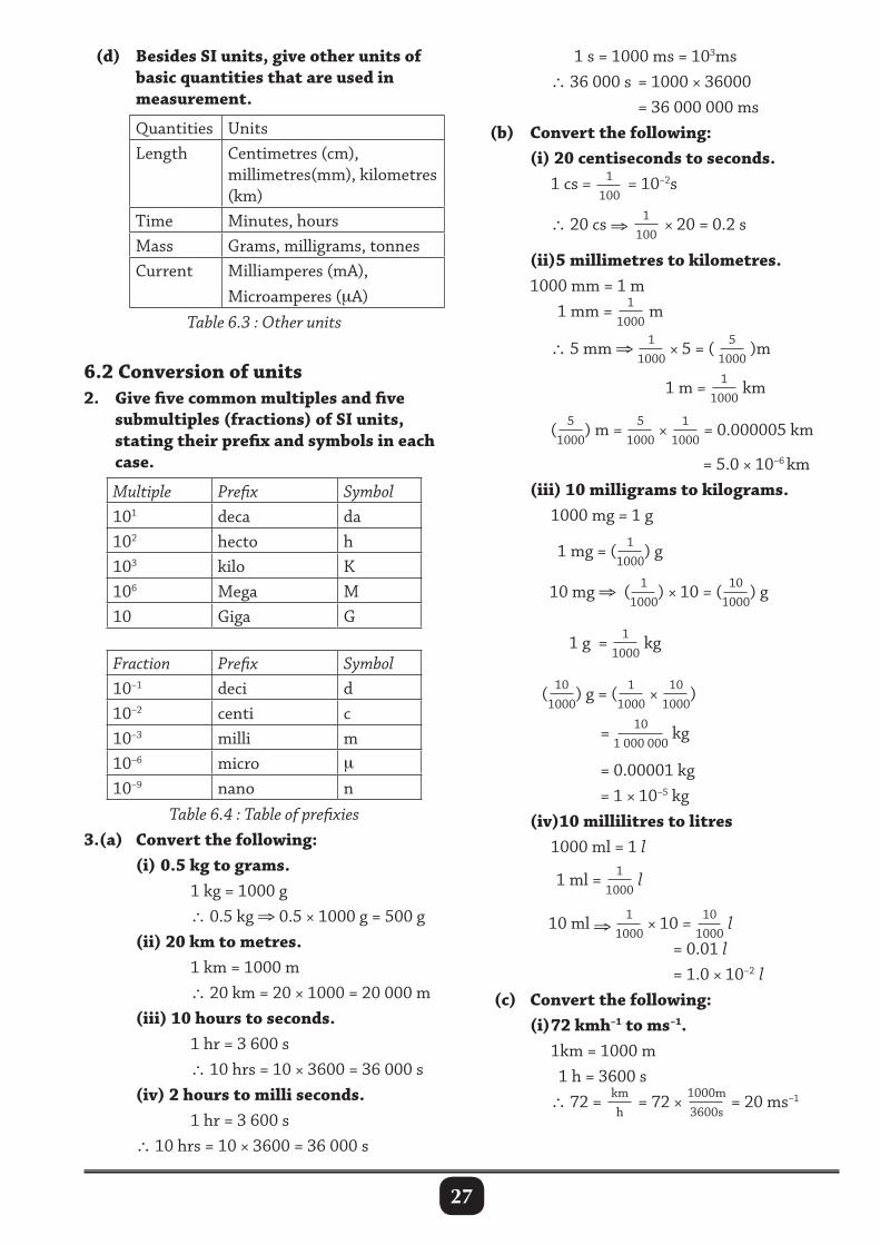
6.2 Conversion of units2. Give five common multiples and five submultiples (fractions) of SI units, stating their prefix and symbols in each case.
Multiple Prefix Symbol101 deca da 102 hecto h103 kilo K106 Mega M10 Giga G
Fraction Prefix Symbol10–1 deci d10–2 centi c10–3 milli m10–6 micro µ
10–9 nano nTable 6.4 : Table of prefixies
3.(a) Convert the following: (i) 0.5 kg to grams. 1 kg = 1000 g ∴ 0.5 kg ⇒ 0.5 × 1000 g = 500 g (ii) 20 km to metres. 1 km = 1000 m ∴ 20 km = 20 × 1000 = 20 000 m (iii) 10 hours to seconds. 1 hr = 3 600 s ∴ 10 hrs = 10 × 3600 = 36 000 s (iv) 2 hours to milli seconds. 1 hr = 3 600 s ∴ 10 hrs = 10 × 3600 = 36 000 s
1 s = 1000 ms = 103ms ∴ 36 000 s = 1000 × 36000 = 36 000 000 ms (b) Convert the following: (i) 20 centiseconds to seconds. 1 cs = 1
100 = 10–2s
∴ 20 cs ⇒ 1100
× 20 = 0.2 s
(ii)5 millimetres to kilometres. 1000 mm = 1 m 1 mm = 1
1000 m
∴ 5 mm ⇒ 1
1000 × 5 = ( 5
1000 )m
1 m = 11000
km ( 5
1000) m = 5
1000 × 1
1000 = 0.000005 km
= 5.0 × 10⁻⁶ km (iii) 10 milligrams to kilograms. 1000 mg = 1 g 1 mg = ( 1
1000) g
10 mg ⇒ ( 1
1000) × 10 = ( 10
1000) g
1 g = 11000
kg
( 101000
) g = ( 11000
× 101000
)
= 10
1 000 000 kg
= 0.00001 kg = 1 × 10⁻⁵ kg (iv)10 millilitres to litres 1000 ml = 1 l 1 ml = 1
1000 l
10 ml ⇒ 11000
× 10 = 101000
l = 0.01 l = 1.0 × 10⁻² l (c) Convert the following: (i) 72 kmh–1 to ms–1. 1km = 1000 m 1 h = 3600 s ∴ 72 = km
h = 72 × 1000m
3600s = 20 ms–1
28
(ii) 1000 kgm–3 to gcm–3
1 g = 11000
kg 1 cm = 1
100 m
(1cm)3 = ( 1100
m)3 = 11 000 000
m3
∴ 1000 kgm–3 × 1
1000 kg
=1 glm–3
(iii) 13 600 kgm–3 to gcm–3
1 kg = 1000g 1 m = 100 cm (1m)3 = (100 cm)3 = 1 000 000 cm3
∴ 3600 kgm3 = 3600 × 1000
1 000 000cm3 = 3.6 gcm–3
4. Convert the following: (a) (i) 1 l to cm3. 1 l = 1000 cm3
(ii) 0.5 l to cm3. 1 l = 1000cm3
∴ 0.5 l = 1000 × 0.5 = 500 cm3
(iii) 2 l to m3
1 l = 1000 cm3
∴ 2 l = 2 × 1000 = 2000 cm3
(b) (i) 500 cm3 to l. 1000 cm3 = 1 l 1 cm3 = 1
1000 l
∴ 500 cm3 = 11000
× 500
= 5001000
l = 0.5 l
(ii)2.6m3 to l. 1 m = 100 cm (1m)3 = (100cm)3
1m × 1m × 1m = 100cm × 100cm × 100cm 1m3 = 1 000 000 cm3
but 1000 cm3 = 1 l 1 cm3 = 1
1000 l
∴1 000 000 cm3 = 1
1000 × 1 000 000
= 1000 l ∴ 1m3 = 1000 l ∴ 2.6 m3 = 2.6 × 1000 = 2 600 l
(iii) 1000 l to m3
1000 l = 1m3
1 l = 11000
m3 ∴ 10000 l = 1
1000 × 10 000
= 10 m3
6.3 : Estimation and rounding off5.(a) With examples, explain the term estimation.
Estimation means giving an approximates value of a number in the simplest form. Estimation involves rounding off numbers. When rounding off numbers: 5,6,7,8,9 are rounded upwards 0,1,2,3,4 are rounded downwards. (b) Estimate the value of the following without using a calculator: (i) 2.08 x 7.984 2.08 × 7.894 ≈ 2 × 8 ≅ 16 (ii) 54.784 × 2.14 54.784 × 2.14 ≈ 55 × 2 ≅ 110 (iii) 19.963 – 2.7
4.234 19.963 ≅ 20 (rounded up) 2.7 ≈ 3 (rounded up) 4.234 ≈ 4 (rounded down) ∴ 19.963 – 2.7
4.234 ≈ 20 – 3
4≅ 17
4 = 4.25
(iv)708 : 6.89 708 ≅ 700 (large number close to 708) 6.89 ≅ 7 (rounded up) 708 : 6.89 ≈ 700 : 7 ≈ 100 : 1
6.4 : Standard form and significant figures6.(a) What is meant by the term scientific notation. Scientific notation refers to a way of expressing a number using powers of 10, in form of P × 10n
Where n is an integer. n = --- –2, –1, 0, 1, 2, 3 --- and 1 ≤ P < 10 i.e. P lies between 1 and 10.
29
Examples P = 1.32 , 2.96, 5.443 etc. Examples of standard form 4.023 × 10⁶, 1.418 × 10⁻⁷, 8.4567842 × 10⁻¹, 7.00112 × 10⁹ (b) Express the following numbers in scientific form. (i) 20914 20914 = 2.0914 × 10⁴
(ii) 39764.044 39764.044 = 3.9764044 × 10⁴
(iii) 0.0000058 0.0000058 = 5.8 × 10⁻⁶
(iv) 0.0010731 0.0010731 = 1.0731 × 10⁻³
7. What is a significant figure? Significant figures is an important figure, in a given number, e.g. 410021.6072 to 1sf = 400 000.0000 2sf = 410 000.0000 6sf = 410 021.0000 3sf = 410 000.0000 7sf = 410 021.6100 4sf = 410 000.0000 8sf = 410 021.6070 5sf = 410 020.0000 9sf = 410 021.6072 Zero may or may not be a significant figure depending on its position, e.g. in the 2sf (410 000.000) the first two zeros are significant figures out of the rest are just place holders, i.e. the only significant figures in the figure are 4100.
6.5 : Measuring Instruments8. For each of the following physical quantities, write down the instruments used to measure them.
Physical quantity InstrumentsMass of an object Beam balanceLength of a text book Metre rulePerimeter of a football pitch
Tape measure
Diameter of a thin wire
Micrometre screw gauge
Diameter of a test tube
Vernier calliper
Time to cover 100 m by a sprinter
Stop clock
Volume of a liquid Measuring cylinderPipette, burette
Height of a table metre rulerThickness of a ruler micrometer screw gauge
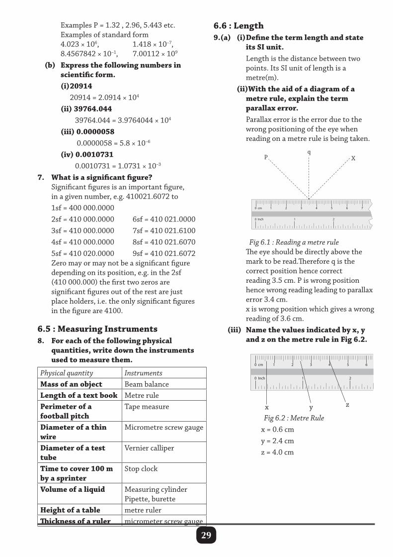
6.6 : Length9.(a) (i) Define the term length and state its SI unit. Length is the distance between two points. Its SI unit of length is a metre(m). (ii)With the aid of a diagram of a metre rule, explain the term parallax error. Parallax error is the error due to the wrong positioning of the eye when reading on a metre rule is being taken.
Fig 6.1 : Reading a metre rule The eye should be directly above the mark to be read.Therefore q is the correct position hence correct reading 3.5 cm. P is wrong position hence wrong reading leading to parallax error 3.4 cm. x is wrong position which gives a wrong reading of 3.6 cm. (iii) Name the values indicated by x, y and z on the metre rule in Fig 6.2.
Fig 6.2 : Metre Rule x = 0.6 cm y = 2.4 cm z = 4.0 cm
30
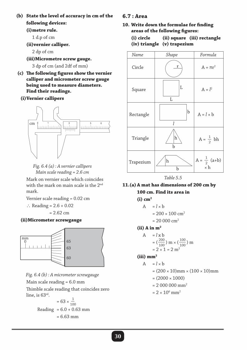
(b) State the level of accuracy in cm of the following devices: (i) metre rule. 1 d.p of cm (ii)vernier calliper. 2 dp of cm (iii)Micrometre screw gauge. 3 dp of cm (and 2df of mm) (c) The following figures show the vernier calliper and micrometer screw gauge being used to measure diameters. Find their readings. (i) Vernier callipers
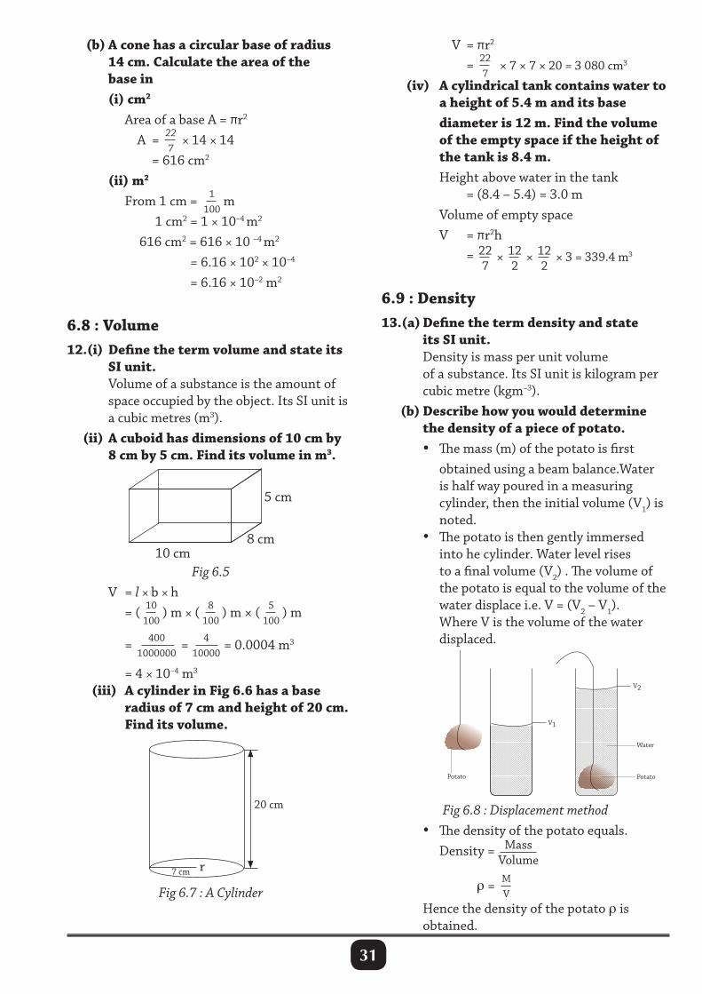
6.7 : Area10. Write down the formulae for finding areas of the following figures: (i) circle (ii) square (iii) rectangle (iv) triangle (v) trapezium
r
l
b
h
bFig. 6.4 (a) : A vernier callipersMain scale reading = 2.6 cm
Mark on vernier scale which coincides with the mark on main scale is the 2nd mark. Vernier scale reading = 0.02 cm ∴Reading = 2.6 + 0.02 = 2.62 cm (ii)Micrometer screwgauge
L
L
h
b
Name Shape Formula
Circle
Square
Rectangle
Triangle
Trapezium
A = πr2
A = l2
A = l × b
A = 12
bh
A = 12
(a+b) × h
Table 5.511.(a) A mat has dimensions of 200 cm by 100 cm. Find its area in (i) cm2
A = l × b = 200 × 100 cm2
= 20 000 cm2
(ii) A in m2
A = l x b = ( 200
100) m × ( 100
100) m
= 2 × 1 = 2 m2
(iii) mm2
A = l × b = (200 × 10)mm × (100 × 10)mm = (2000 × 1000) = 2 000 000 mm2
= 2 × 106 mm2
Fig. 6.4 (b) : A micrometer screwgauge Main scale reading = 6.0 mm Thimble scale reading that coincides zero line, is 63rd. = 63 × 1
100
Reading = 6.0 + 0.63 mm = 6.63 mm
test tube
a
0 1 3 5 6cm
65
63
60
mm0
31
V = πr2
= 227
× 7 × 7 × 20 = 3 080 cm3 (iv) A cylindrical tank contains water to a height of 5.4 m and its base diameter is 12 m. Find the volume of the empty space if the height of the tank is 8.4 m. Height above water in the tank = (8.4 – 5.4) = 3.0 m Volume of empty space V = πr2h = 22
7× 12
2× 12
2× 3 = 339.4 m3
6.9 : Density13.(a) Define the term density and state its SI unit. Density is mass per unit volume of a substance. Its SI unit is kilogram per cubic metre (kgm–3). (b) Describe how you would determine the density of a piece of potato. • The mass (m) of the potato is first obtained using a beam balance.Water is half way poured in a measuring cylinder, then the initial volume (V1) is noted. • The potato is then gently immersed into he cylinder. Water level rises to a final volume (V2) . The volume of the potato is equal to the volume of the water displace i.e. V = (V2 – V1). Where V is the volume of the water displaced.
(b) A cone has a circular base of radius 14 cm. Calculate the area of the base in (i) cm2
Area of a base A = πr2
A = 227
× 14 × 14 = 616 cm2
(ii) m2
From 1 cm = 1100
m 1 cm2 = 1 × 10⁻⁴ m2
616 cm2 = 616 × 10 –4 m2
= 6.16 × 102 × 10–4
= 6.16 × 10⁻² m2
6.8 : Volume12.(i) Define the term volume and state its SI unit. Volume of a substance is the amount of space occupied by the object. Its SI unit is a cubic metres (m3). (ii) A cuboid has dimensions of 10 cm by 8 cm by 5 cm. Find its volume in m3.
10 cm8 cm
5 cm
Fig 6.5 V = l × b × h = ( 10
100) m × ( 8
100) m × ( 5
100) m
= 400
1000000= 4
10000 = 0.0004 m3
= 4 × 10⁻⁴ m3
(iii) A cylinder in Fig 6.6 has a base radius of 7 cm and height of 20 cm. Find its volume.
Fig 6.7 : A Cylinder
20 cm
7 cm r
Potato
V1
Potato
Water
V2
Fig 6.8 : Displacement method • The density of the potato equals. Density = Mass
Volume
ρ = M
V Hence the density of the potato ρ is obtained.
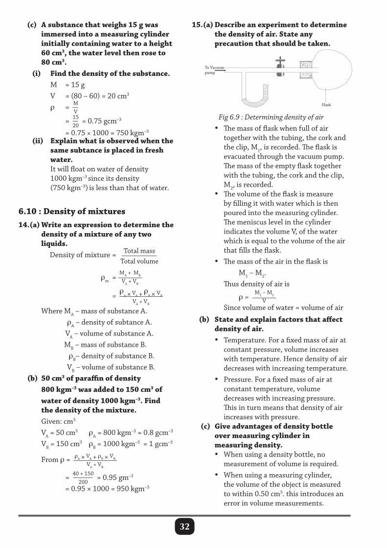
32
(c) A substance that weighs 15 g was immersed into a measuring cylinder initially containing water to a height 60 cm3, the water level then rose to 80 cm3. (i) Find the density of the substance. M = 15 g V = (80 – 60) = 20 cm3 ρ = M
V
= 1520
= 0.75 gcm–3
= 0.75 × 1000 = 750 kgm–3
(ii) Explain what is observed when the same subtance is placed in fresh water. It will float on water of density 1000 kgm–3 since its density (750 kgm–3) is less than that of water.
6.10 : Density of mixtures14.(a) Write an expression to determine the density of a mixture of any two liquids. Density of mixture = Total mass
Total volume
ρm =
MA + MB
VA + VB
=ρ
A × VA + ρB × VB
VA + VB
Where MA – mass of substance A. ρA – density of subtance A. VA – volume of substance A. MB – mass of substance B. ρB– density of substance B. VB – volume of substance B. (b) 50 cm3 of paraffin of density 800 kgm–3 was added to 150 cm3 of water of density 1000 kgm–3. Find the density of the mixture. Given: cm3
VA = 50 cm3 ρA = 800 kgm–3 = 0.8 gcm–3
VB = 150 cm3 ρB = 1000 kgm–3 = 1 gcm–3
From ρ = ρA × VA + ρB × VB
VA + VB = 40 + 150
200 = 0.95 gm–3
= 0.95 × 1000 = 950 kgm–3
15.(a) Describe an experiment to determine the density of air. State any precaution that should be taken.
Flask
To Vacuum pump
Fig 6.9 : Determining density of air • The mass of flask when full of air together with the tubing, the cork and the clip, M1, is recorded. The flask is evacuated through the vacuum pump. The mass of the empty flask together with the tubing, the cork and the clip, M2, is recorded. • The volume of the flask is measure by filling it with water which is then poured into the measuring cylinder. The meniscus level in the cylinder indicates the volume V, of the water which is equal to the volume of the air that fills the flask. • The mass of the air in the flask is M1 – M2. Thus density of air is
ρ = M1 – M2
V Since volume of water = volume of air
(b) State and explain factors that affect density of air. • Temperature. For a fixed mass of air at constant pressure, volume increases with temperature. Hence density of air decreases with increasing temperature. • Pressure. For a fixed mass of air at constant temperature, volume decreases with increasing pressure. This in turn means that density of air increases with pressure. (c) Give advantages of density bottle over measuring cylinder in measuring density. • When using a density bottle, no measurement of volume is required. • When using a measuring cylinder, the volume of the object is measured to within 0.50 cm3. this introduces an error in volume measurements.
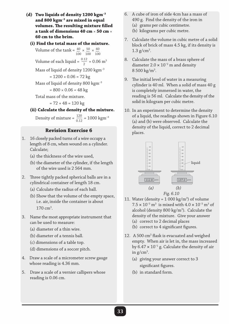
33
(d) Two liquids of density 1200 kgm–3 and 800 kgm–3 are mixed in equal volumes. The resulting mixture filled a tank of dimensions 40 cm × 50 cm × 60 cm to the brim. (i) Find the total mass of the mixture. Volume of the tank = 40
100× 50
100× 60
100
Volume of each liquid = 0.12
2 = 0.06 m3
Mass of liquid of density 1200 kgm–3 = 1200 × 0.06 = 72 kg Mass of liquid of density 800 kgm–3 = 800 × 0.06 = 48 kg Total mass of the mixture. = 72 + 48 = 120 kg (ii) Calculate the density of the mixture. Density of mixture = 120
0.12 = 1000 kgm–3
Revision Exercise 6 1. 16 closely packed turns of a wire occupy a length of 8 cm, when wound on a cylinder. Calculate; (a) the thickness of the wire used, (b) the diameter of the cylinder, if the length of the wire used is 2 564 mm.
2. Three tightly packed spherical balls are in a cylindrical container of length 18 cm. (a) Calculate the radius of each ball. (b) Show that the volume of the empty space, i.e. air, inside the container is about 170 cm3.
3. Name the most appropriate instrument that can be used to measure: (a) diameter of a thin wire. (b) diameter of a tennis ball. (c) dimensions of a table top. (d) dimensions of a soccer pitch.
4. Draw a scale of a micrometer screw gauge whose reading is 4.36 mm.
5. Draw a scale of a vernier callipers whose reading is 0.06 cm.
6. A cube of iron of side 4cm has a mass of 490 g. Find the density of the iron in (a) grams per cubic centimetre. (b) kilograms per cubic metre.
7. Calculate the volume in cubic metre of a solid block of brick of mass 4.5 kg, if its density is 1.3 g/cm3.
8. Calculate the mass of a brass sphere of diameter 2.0 × 10⁻² m and density 8 500 kg/m3.
9. The initial level of water in a measuring cylinder is 40 ml. When a solid of mass 40 g is completely immersed in water, the reading is 56 ml. Calculate the density of the solid in kilogram per cubic metre.
10. In an experiment to determine the density of a liquid, the readings shown in Figure 6.10 (a) and (b) were observed. Calculate the density of the liquid, correct to 2 decimal places.
(a) (b)Fig. 6.10
11. Water (density = 1 000 kg/m3) of volume 7.5 × 10⁻³ m3 is mixed with 4.0 × 10⁻³ m3 of alcohol (density 800 kg/m3). Calculate the density of the mixture. Give your answer (a) correct to 2 decimal places (b) correct to 4 significant figures.
12. A 500 cm3 flask is evacuated and weighed empty. When air is let in, the mass increased by 6.47 × 10⁻¹ g. Calculate the density of air in g/cm3. (a) giving your answer correct to 3 significant figures. (b) in standard form.
112.8 grams
6060
5050
4040
3030
2020
1010
00
mlml
liquid
137.0 grams
34
7.1 : Meaning of work, energy and power1. Define the following terms: (i) Work. Work is the product of force and distance moved in the direction of a force. It’s measured in joules (J). (ii) Energy. Energy is the ability or capacity to do work. Anything that has energy does work. Its SI unit is a joule (J). (iii) Power. Power is the rate at which work is done. Power = work done
time taken
P = wt
, W = F × S
Power is the rate of energy transfer.
Power = energy transfered
time taken
Its SI unit is a watt (W). (iv) State the relationship between work done and energy. Work done by an external force on a body is equal to change in Kinetic energy of a body.2.(a) The work done by the engine of a car when it moves through a horizontal distance of 200 m is 4 × 10⁸ J. Calculate the frictional force between the tyres of the car and the road. W = F x S 4 × 108 = F × 200 ∴ F = 2 × 10⁶ N The frictional force = 2 000 000 N = 2.0 × 10⁶ N (b) A girl of mass 40 kg ran up a flight of 20 stairs each of 20 cm, in 4 seconds. Calculate: (i) the total work she did. W = F × S = mg × S = 40 × 10 × 20
100 × 20
= 1600 J (ii)her average power.
P = wt
= 16004
= 400 W
(iii)Explain why she uses less energy to climb up than to run on a horizontal ground. More force is needed in climbing because it involves doing work against gravitational force each time she lifts up herself to climb. On the contrary, running on the horizontal floor, one has to overcome mainly friction and air resistance and these require little force to over come them hence less work done, compared to climbing. (c) An engine raises 50 kg of water through a vertical height of 500 metres in 25 minutes. Find: (i) the amount of work done. Work done = Force x distance W = F × h = mg × h = 50 × 10 × 500 = 250 000 J (ii) the power of the engine. The power of the engine
P = wt
= 250 000 (J)25 × 60 (S)
=10 000 (J)
60 (S)= 166.7 W
(d) (i) Calculate the work done by an athlete of mass 80 kg running through 400 metres. W = F × S = mg × s = 80 × 10 × 400 = 320 000 J = 320 KJ
WORK, ENERGY AND POWER7
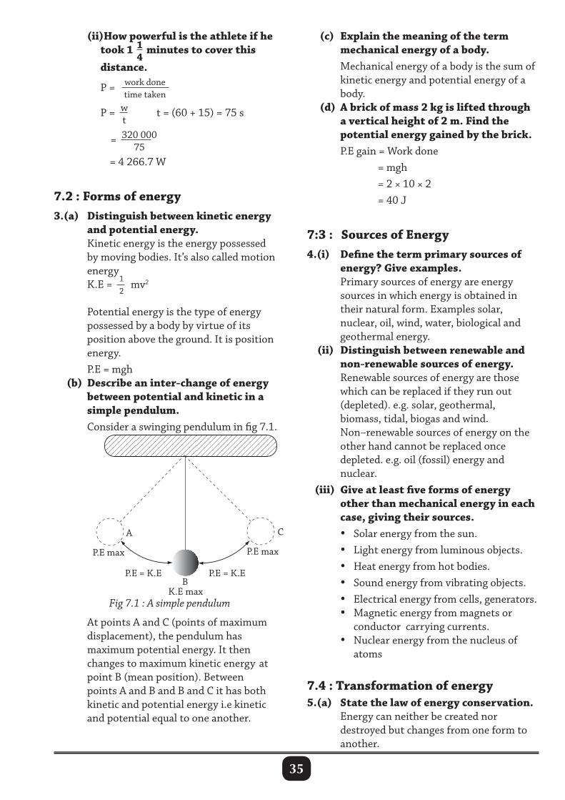
35
(ii)How powerful is the athlete if he took 1 1
4minutes to cover this
distance.
P = work donetime taken
P = w
t t = (60 + 15) = 75 s
= 320 00075
= 4 266.7 W
7.2 : Forms of energy3.(a) Distinguish between kinetic energy and potential energy. Kinetic energy is the energy possessed by moving bodies. It’s also called motion energy K.E = 1
2mv2
Potential energy is the type of energy possessed by a body by virtue of its position above the ground. It is position energy. P.E = mgh (b) Describe an inter-change of energy between potential and kinetic in a simple pendulum. Consider a swinging pendulum in fig 7.1.
(c) Explain the meaning of the term mechanical energy of a body. Mechanical energy of a body is the sum of kinetic energy and potential energy of a body. (d) A brick of mass 2 kg is lifted through a vertical height of 2 m. Find the potential energy gained by the brick. P.E gain = Work done = mgh = 2 × 10 × 2 = 40 J
7:3 : Sources of Energy4.(i) Define the term primary sources of energy? Give examples. Primary sources of energy are energy sources in which energy is obtained in their natural form. Examples solar, nuclear, oil, wind, water, biological and geothermal energy. (ii) Distinguish between renewable and non-renewable sources of energy. Renewable sources of energy are those which can be replaced if they run out (depleted). e.g. solar, geothermal, biomass, tidal, biogas and wind. Non–renewable sources of energy on the other hand cannot be replaced once depleted. e.g. oil (fossil) energy and nuclear. (iii) Give at least five forms of energy other than mechanical energy in each case, giving their sources. • Solar energy from the sun. • Light energy from luminous objects. • Heat energy from hot bodies. • Sound energy from vibrating objects. • Electrical energy from cells, generators. • Magnetic energy from magnets or conductor carrying currents. • Nuclear energy from the nucleus of atoms
7.4 : Transformation of energy5.(a) State the law of energy conservation. Energy can neither be created nor destroyed but changes from one form to another.
K.E max
P.E maxP.E max
A
B
C
P.E = K.E P.E = K.E
Fig 7.1 : A simple pendulum
At points A and C (points of maximum displacement), the pendulum has maximum potential energy. It then changes to maximum kinetic energy at point B (mean position). Between points A and B and B and C it has both kinetic and potential energy i.e kinetic and potential equal to one another.
36
(b) Briefly describe the energy changes that take place in: (i) a stone released from rest. A stone in a hand has potential energy; on releasing, it will have both P.E and K.E while falling through. Energy turns to kinetic. While landing it is converted to heat, sound and eventually internal energy after landing. (ii) a cell. Chemical to electrical energy. (iii) a radio. Chemical energy from a cell to electrical energy in wires to sound energy. (iv) heater (or a hot plate). Electrical to heat energy. (v) solar panel. Solar energy to electrical to light energy. (vi) a bulb. Electrical to heat and light energy. (vii) a generator. Mechanical energy to electrical energy. (viii) a motor. Electrical energy to mechanical energy. (ix) nuclear reactor. Nuclear energy in nucleus to mechanical energy to electrical energy.
7.5 : Power and Efficiency6.(a) Briefly describe an experiment you would use to determine the efficiency of a waterpump. • Measure the height, h of the pipe delivering the water. Measure the mass of the water, m, delivered in t seconds. The mass per second = m
t .
• If the potential difference across the terminals of the motor is V and the current through it is I. The power of the motor = VI. • The useful work done by the motor = mgh • Work input by the pump = VIt.
Efficiency = work outputwork input
× 100%
= mghVIt
× 100% (b) An electric motor has an input power of 800 W. Find how much electrical energy is converts in 10 minutes. P = E
t= 800 = E
10 × 60
E = 800 × 600 = 480 000 J
= 480 KJ (c) After acquiring a job, Stellah wanted to solve her transport problem. So, she got a loan with the next thing in her mind was a brandy new Ipsum car. Advice her on which Ipsum to pick from the yard basing on the efficiency of the engine. Since one should base on the efficience of the engine needed. Fill tank of the any of vehicle she admired with same amount of fuel say 2 l of petrol. Then drive the vehicles on the same road, at the same speed. The most efficient engine will cover the greatest distance on the same amount of fuel in the same time. (d) Give the differences between petrol and diesel engine.
Petrol engine Diesel engineUses petrol Uses dieselHas a carbonator Has an injectorHas a spark plug Has no spark plug
7. Using diagrams describe the working of a four stroke petrol engine. Four stroke engine. Commonly used in motor vehicles. It uses petrol and air. The valves (inlet and outlet) are opened by means of cams and camshaft, driven by the crank shaft. The arrow shows movement of cylinder. I is inlet valve, O is outlet valve. Charging or induction stage The piston moves upwards, meanwhile the inlet valve opens to let in fuel and air mixture into the cylinder.
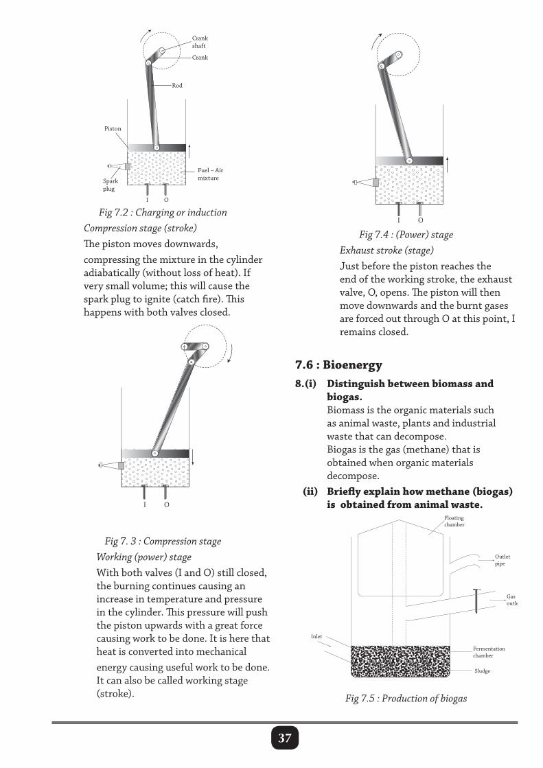
37
Fig 7.2 : Charging or induction Compression stage (stroke) The piston moves downwards, compressing the mixture in the cylinder adiabatically (without loss of heat). If very small volume; this will cause the spark plug to ignite (catch fire). This happens with both valves closed.
Fig 7.4 : (Power) stage Exhaust stroke (stage) Just before the piston reaches the end of the working stroke, the exhaust valve, O, opens. The piston will then move downwards and the burnt gases are forced out through O at this point, I remains closed.
7.6 : Bioenergy8.(i) Distinguish between biomass and biogas. Biomass is the organic materials such as animal waste, plants and industrial waste that can decompose. Biogas is the gas (methane) that is obtained when organic materials decompose. (ii) Briefly explain how methane (biogas) is obtained from animal waste.
Fig 7. 3 : Compression stage Working (power) stage With both valves (I and O) still closed, the burning continues causing an increase in temperature and pressure in the cylinder. This pressure will push the piston upwards with a great force causing work to be done. It is here that heat is converted into mechanical energy causing useful work to be done. It can also be called working stage (stroke). Fig 7.5 : Production of biogas
38
Animal wastes are fed into the fermentation chamber, where methane gas is formed in the process and directed through the outlet for use especially in cooking. The by-product of fermentation (sludge) is collected at the bottom of the fermentation chamber.
Revision Exercise 71. Define the following term stating their SI units. (a) Energy. (b) Work done. (c) Power.2. A car moves with uniform speed through a distance of 40 m and the net resistive force acting on the car is 3 000 N. (a) What is the forward driving force acting on the car? Explain your answer. (b) Calculate the work done by the driving force. (c) State the useful work done. 3. A pupil of mass 50 kg climbs a staircase of vertical height 6 m. Calculate the work done by the pupil.
4. An elevator of mass 2 000 kg carries people of mass 800 kg through a vertical distance of 8 m. Calculate the gravitational potential energy of the elevator at the top most point.
5. A 100 g ball falls vertically down from a height of 3.2 m on a horizontal surface and rebounds to a height of 1.8 m. Calculate
(a) the velocity of the ball just before hitting the surface,
(b) the rebound velocity, (c) the loss of kinetic energy. (d) Sketch a graph of velocity against time
for the motion, till the ball reaches 1.8 m after bouncing back from the surface. Label the axis with proper values and units.
6. Name the transducer in the following energy conversions: chemical to electrical, heat to electrical, electrical to sound, mechanical to electrical.
7. An electrical iron of power 750 W is used for 40 minutes. Calculate the electrical work done.
8. A ball of mass 100 g falls freely from a tower of height 40 m. Calculate the kinetic energy of the ball as it hits the ground.
9. A worker wants to load a drum of weight 1 000 N on a truck whose floor is 1 m above the ground. The man rolls the drum up a plank 3 m long with a force of 400 N. Calculate: (i) the work output, (ii) the work input, (iii) efficiency of the machine.
10. Give four uses of Biogas.
11. Why do people prefer renewable energy to non-renewable energy.
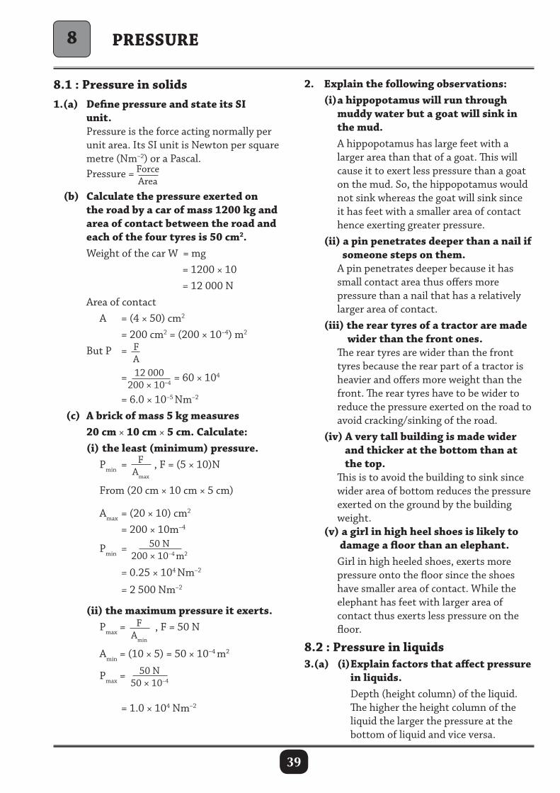
39
8.1 : Pressure in solids1.(a) Define pressure and state its SI unit. Pressure is the force acting normally per unit area. Its SI unit is Newton per square metre (Nm–2) or a Pascal. Pressure = Force
Area
(b) Calculate the pressure exerted on the road by a car of mass 1200 kg and area of contact between the road and each of the four tyres is 50 cm2. Weight of the car W = mg = 1200 × 10 = 12 000 N Area of contact A = (4 × 50) cm2
= 200 cm2 = (200 × 10–4) m2
But P = FA
= 12 000200 × 10–4
= 60 × 104
= 6.0 × 10⁻⁵ Nm–2
(c) A brick of mass 5 kg measures 20 cm × 10 cm × 5 cm. Calculate: (i) the least (minimum) pressure. Pmin = F
Amax
, F = (5 × 10)N
From (20 cm × 10 cm × 5 cm)
Amax = (20 × 10) cm2 = 200 × 10m–4
Pmin = 50 N200 × 10–4 m2
= 0.25 × 10⁴ Nm–2
= 2 500 Nm–2
(ii) the maximum pressure it exerts. Pmax =
FAmin
, F = 50 N
Amin = (10 × 5) = 50 × 10–4 m2
Pmax =50 N
50 × 10–4
= 1.0 × 10⁴ Nm–2
2. Explain the following observations: (i) a hippopotamus will run through muddy water but a goat will sink in the mud. A hippopotamus has large feet with a larger area than that of a goat. This will cause it to exert less pressure than a goat on the mud. So, the hippopotamus would not sink whereas the goat will sink since it has feet with a smaller area of contact hence exerting greater pressure. (ii) a pin penetrates deeper than a nail if someone steps on them. A pin penetrates deeper because it has small contact area thus offers more pressure than a nail that has a relatively larger area of contact. (iii) the rear tyres of a tractor are made wider than the front ones. The rear tyres are wider than the front tyres because the rear part of a tractor is heavier and offers more weight than the front. The rear tyres have to be wider to reduce the pressure exerted on the road to avoid cracking/sinking of the road. (iv) A very tall building is made wider and thicker at the bottom than at the top. This is to avoid the building to sink since wider area of bottom reduces the pressure exerted on the ground by the building weight. (v) a girl in high heel shoes is likely to damage a floor than an elephant. Girl in high heeled shoes, exerts more pressure onto the floor since the shoes have smaller area of contact. While the elephant has feet with larger area of contact thus exerts less pressure on the floor.
8.2 : Pressure in liquids3.(a) (i) Explain factors that affect pressure in liquids. Depth (height column) of the liquid. The higher the height column of the liquid the larger the pressure at the bottom of liquid and vice versa.
PRESSURE8
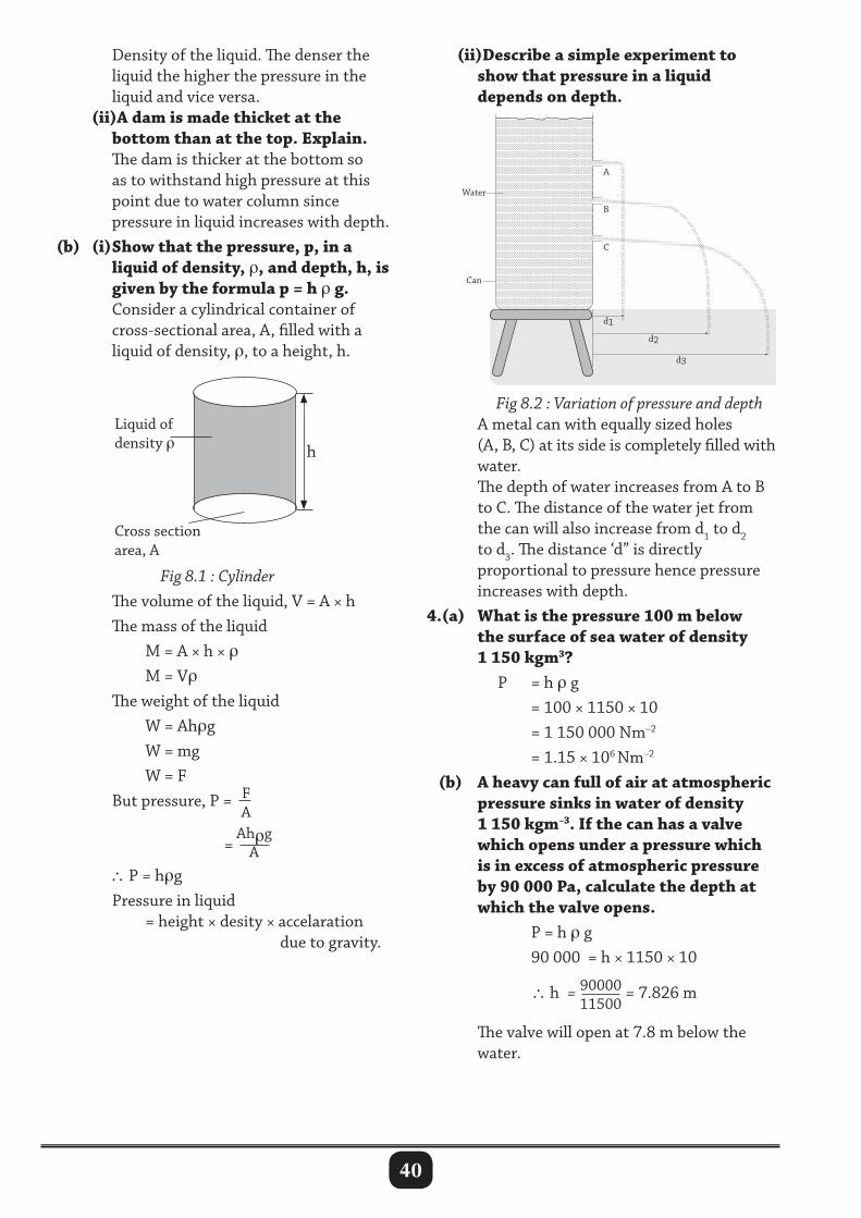
40
Density of the liquid. The denser the liquid the higher the pressure in the liquid and vice versa. (ii)A dam is made thicket at the bottom than at the top. Explain. The dam is thicker at the bottom so as to withstand high pressure at this point due to water column since pressure in liquid increases with depth. (b) (i) Show that the pressure, p, in a liquid of density, ρ, and depth, h, is given by the formula p = h ρ g. Consider a cylindrical container of cross-sectional area, A, filled with a liquid of density, ρ, to a height, h.
Water
Can
d1
C
B
A
d2
d3
(ii)Describe a simple experiment to show that pressure in a liquid depends on depth.
h
Liquid ofdensity ρ
Cross section area, A
Fig 8.1 : Cylinder The volume of the liquid, V = A × h The mass of the liquid M = A × h × ρ M = Vρ The weight of the liquid W = Ahρg W = mg W = F But pressure, P = F
A
=
AhρgA
∴ P = hρg Pressure in liquid = height × desity × accelaration due to gravity.
Fig 8.2 : Variation of pressure and depth A metal can with equally sized holes (A, B, C) at its side is completely filled with water. The depth of water increases from A to B to C. The distance of the water jet from the can will also increase from d1 to d2 to d3. The distance ‘d” is directly proportional to pressure hence pressure increases with depth.4.(a) What is the pressure 100 m below the surface of sea water of density 1 150 kgm3? P = h ρ g = 100 × 1150 × 10 = 1 150 000 Nm–2
= 1.15 × 10⁶ Nm–2
(b) A heavy can full of air at atmospheric pressure sinks in water of density 1 150 kgm–3. If the can has a valve which opens under a pressure which is in excess of atmospheric pressure by 90 000 Pa, calculate the depth at which the valve opens. P = h ρ g 90 000 = h × 1150 × 10
∴ h = 90000
11500 = 7.826 m
The valve will open at 7.8 m below the water.
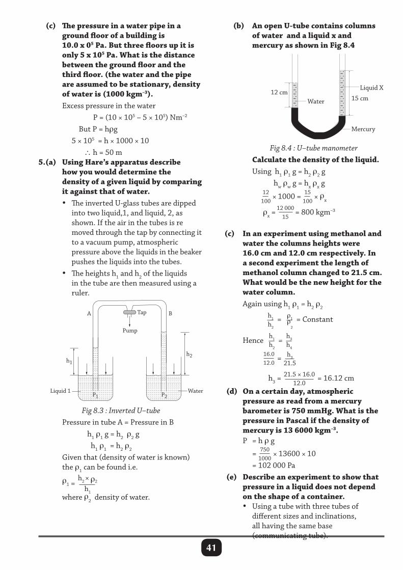
41
(c) The pressure in a water pipe in a ground floor of a building is 10.0 x 05 Pa. But three floors up it is only 5 x 10⁵ Pa. What is the distance between the ground floor and the third floor. (the water and the pipe are assumed to be stationary, density of water is (1000 kgm–3). Excess pressure in the water P = (10 × 105 – 5 × 10⁵) Nm–2
But P = hρg 5 × 105 = h × 1000 × 10 ∴ h = 50 m5.(a) Using Hare’s apparatus describe how you would determine the density of a given liquid by comparing it against that of water. • The inverted U-glass tubes are dipped into two liquid,1, and liquid, 2, as shown. If the air in the tubes is re moved through the tap by connecting it to a vacuum pump, atmospheric pressure above the liquids in the beaker pushes the liquids into the tubes. • The heights h1 and h2 of the liquids in the tube are then measured using a ruler.
Water 12 cm
15 cm
Liquid X
Mercury
Liquid 1 P1
h1
h2
B A
P2 Water
Pump
Tap
(b) An open U-tube contains columns of water and a liquid x and mercury as shown in Fig 8.4
Fig 8.4 : U–tube manometer Calculate the density of the liquid. Using h1 ρ1 g = h2 ρ2 g hw ρw g = hx ρx g
12
100× 1000 = 15
100× ρx
ρx =12 000
15= 800 kgm–3
(c) In an experiment using methanol and water the columns heights were 16.0 cm and 12.0 cm respectively. In a second experiment the length of methanol column changed to 21.5 cm. What would be the new height for the water column. Again using h1 ρ1 = h2 ρ2
h1
h2
= ρ1ρ
2
= Constant
Hence h1
h2
=h3
h4 16.0
12.0 = h3
21.5
h3 = 21.5 × 16.0
12.0 = 16.12 cm
(d) On a certain day, atmospheric pressure as read from a mercury barometer is 750 mmHg. What is the pressure in Pascal if the density of mercury is 13 6000 kgm–3. P = h ρ g
= 7501000
× 13600 × 10 = 102 000 Pa (e) Describe an experiment to show that pressure in a liquid does not depend on the shape of a container. • Using a tube with three tubes of different sizes and inclinations, all having the same base (communicating tube).
Fig 8.3 : Inverted U–tube Pressure in tube A = Pressure in B h1 ρ1 g = h2 ρ2 g h1 ρ1 = h2 ρ2
Given that (density of water is known) the ρ1 can be found i.e.
ρ1 = h2 × ρ2
h1
where ρ2 density of water.
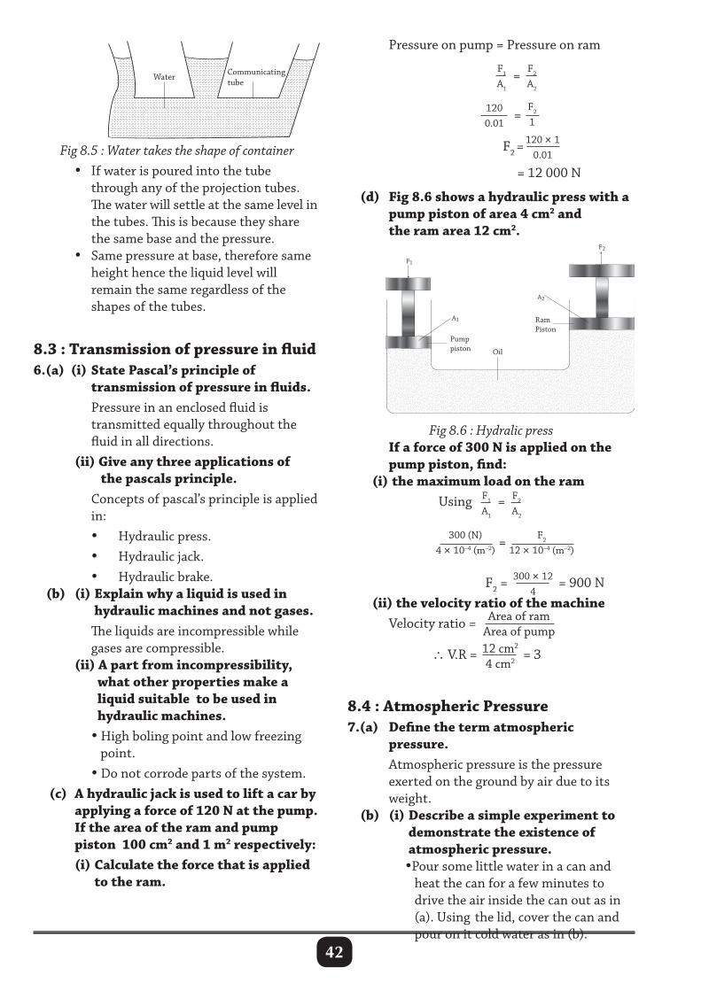
42
Pressure on pump = Pressure on ram F1
A1
= F2
A2
1200.01
= F2
1
F2 =
120 × 10.01
= 12 000 N (d) Fig 8.6 shows a hydraulic press with a pump piston of area 4 cm2 and the ram area 12 cm2.
Communicating tube
Water
Fig 8.5 : Water takes the shape of container • If water is poured into the tube through any of the projection tubes. The water will settle at the same level in the tubes. This is because they share the same base and the pressure. • Same pressure at base, therefore same height hence the liquid level will remain the same regardless of the shapes of the tubes.
8.3 : Transmission of pressure in fluid6.(a) (i) State Pascal’s principle of transmission of pressure in fluids. Pressure in an enclosed fluid is transmitted equally throughout the fluid in all directions. (ii) Give any three applications of the pascals principle. Concepts of pascal’s principle is applied in: • Hydraulic press. • Hydraulic jack. • Hydraulic brake. (b) (i) Explain why a liquid is used in hydraulic machines and not gases. The liquids are incompressible while gases are compressible. (ii) A part from incompressibility, what other properties make a liquid suitable to be used in hydraulic machines. • High boling point and low freezing point. • Do not corrode parts of the system. (c) A hydraulic jack is used to lift a car by applying a force of 120 N at the pump. If the area of the ram and pump piston 100 cm2 and 1 m2 respectively: (i) Calculate the force that is applied to the ram.
Fig 8.6 : Hydralic press If a force of 300 N is applied on the pump piston, find: (i) the maximum load on the ram Using F1
A1
= F2
A2
300 (N)4 × 10⁻⁴ (m–2)
= F2
12 × 10–4 (m–2)
F2 =300 × 12
4= 900 N
(ii) the velocity ratio of the machine Velocity ratio = Area of ram
Area of pump
∴ V.R = 12 cm2
4 cm2 = 3
8.4 : Atmospheric Pressure7.(a) Define the term atmospheric pressure. Atmospheric pressure is the pressure exerted on the ground by air due to its weight. (b) (i) Describe a simple experiment to demonstrate the existence of atmospheric pressure. •Pour some little water in a can and heat the can for a few minutes to drive the air inside the can out as in (a). Using the lid, cover the can and pour on it cold water as in (b).
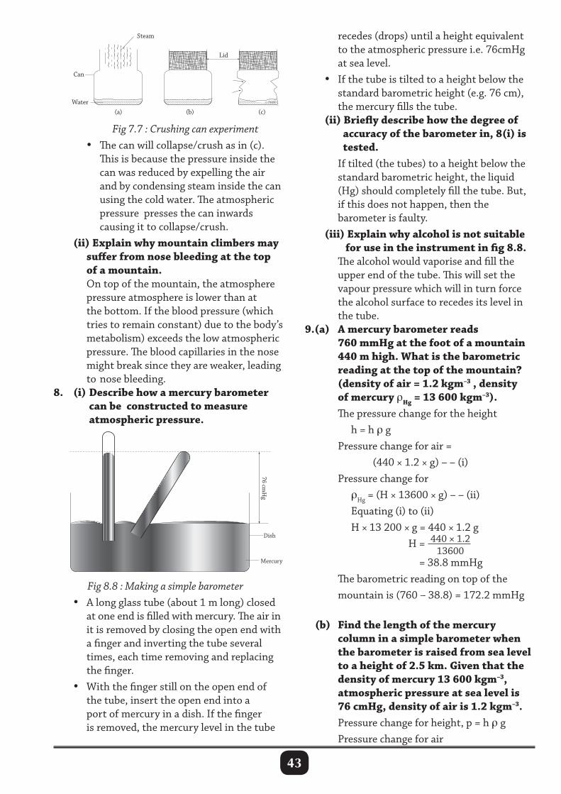
43
Fig 7.7 : Crushing can experiment • The can will collapse/crush as in (c). This is because the pressure inside the can was reduced by expelling the air and by condensing steam inside the can using the cold water. The atmospheric pressure presses the can inwards causing it to collapse/crush. (ii) Explain why mountain climbers may suffer from nose bleeding at the top of a mountain. On top of the mountain, the atmosphere pressure atmosphere is lower than at the bottom. If the blood pressure (which tries to remain constant) due to the body’s metabolism) exceeds the low atmospheric pressure. The blood capillaries in the nose might break since they are weaker, leading to nose bleeding.8. (i) Describe how a mercury barometer can be constructed to measure atmospheric pressure.
recedes (drops) until a height equivalent to the atmospheric pressure i.e. 76cmHg at sea level. • If the tube is tilted to a height below the standard barometric height (e.g. 76 cm), the mercury fills the tube. (ii) Briefly describe how the degree of accuracy of the barometer in, 8(i) is tested. If tilted (the tubes) to a height below the standard barometric height, the liquid (Hg) should completely fill the tube. But, if this does not happen, then the barometer is faulty. (iii) Explain why alcohol is not suitable for use in the instrument in fig 8.8. The alcohol would vaporise and fill the upper end of the tube. This will set the vapour pressure which will in turn force the alcohol surface to recedes its level in the tube.9.(a) A mercury barometer reads 760 mmHg at the foot of a mountain 440 m high. What is the barometric reading at the top of the mountain? (density of air = 1.2 kgm–3 , density of mercury ρHg = 13 600 kgm–3). The pressure change for the height h = h ρ g Pressure change for air = (440 × 1.2 × g) – – (i) Pressure change for ρHg = (H × 13600 × g) – – (ii) Equating (i) to (ii) H × 13 200 × g = 440 × 1.2 g H = 440 × 1.2
13600 = 38.8 mmHg The barometric reading on top of the mountain is (760 – 38.8) = 172.2 mmHg
(b) Find the length of the mercury column in a simple barometer when the barometer is raised from sea level to a height of 2.5 km. Given that the density of mercury 13 600 kgm–3, atmospheric pressure at sea level is 76 cmHg, density of air is 1.2 kgm–3. Pressure change for height, p = h ρ g Pressure change for air
Lid
Water (a) (b) (c)
Can
Steam
Fig 8.8 : Making a simple barometer • A long glass tube (about 1 m long) closed at one end is filled with mercury. The air in it is removed by closing the open end with a finger and inverting the tube several times, each time removing and replacing the finger. • With the finger still on the open end of the tube, insert the open end into a port of mercury in a dish. If the finger is removed, the mercury level in the tube
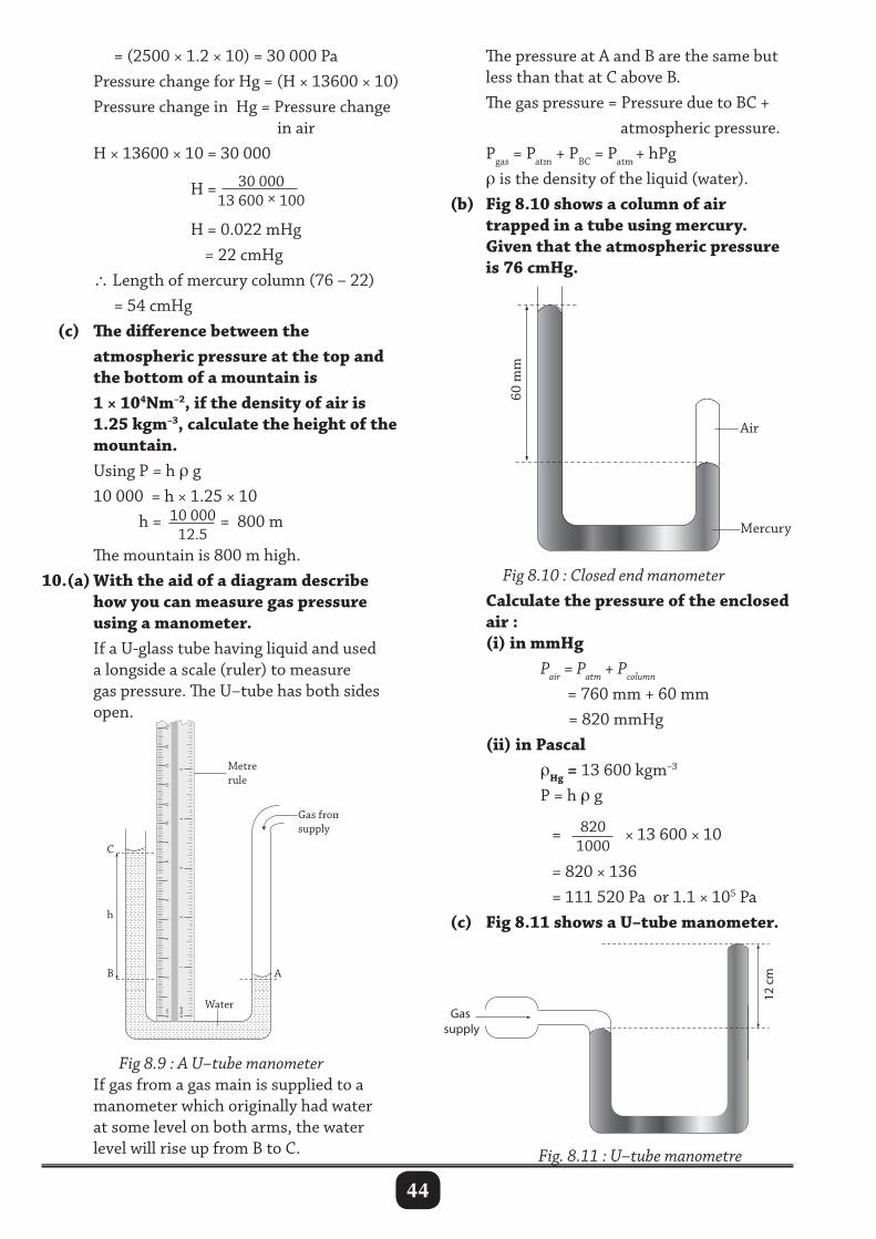
44
= (2500 × 1.2 × 10) = 30 000 Pa Pressure change for Hg = (H × 13600 × 10) Pressure change in Hg = Pressure change in air H × 13600 × 10 = 30 000 H = 30 000
13 600 × 100
H = 0.022 mHg = 22 cmHg ∴ Length of mercury column (76 – 22) = 54 cmHg (c) The difference between the atmospheric pressure at the top and the bottom of a mountain is 1 × 10⁴Nm–2, if the density of air is 1.25 kgm–3, calculate the height of the mountain. Using P = h ρ g 10 000 = h × 1.25 × 10 h = 10 000
12.5= 800 m
The mountain is 800 m high.10.(a) With the aid of a diagram describe how you can measure gas pressure using a manometer. If a U-glass tube having liquid and used a longside a scale (ruler) to measure gas pressure. The U–tube has both sides open.
The pressure at A and B are the same but less than that at C above B. The gas pressure = Pressure due to BC + atmospheric pressure. Pgas = Patm + PBC = Patm + hPg ρ is the density of the liquid (water). (b) Fig 8.10 shows a column of air trapped in a tube using mercury. Given that the atmospheric pressure is 76 cmHg.
A B
C
h
Gas from supply
0 cm
0 1
2 3
4 5
Inch
1 2
3 4
5 6
7
8 9
10
11
12
13
14
15
Metre rule
Water
Fig 8.9 : A U–tube manometer If gas from a gas main is supplied to a manometer which originally had water at some level on both arms, the water level will rise up from B to C.
Fig 8.10 : Closed end manometer Calculate the pressure of the enclosed air : (i) in mmHg Pair = Patm + Pcolumn
= 760 mm + 60 mm = 820 mmHg (ii) in Pascal ρHg = 13 600 kgm–3
P = h ρ g
= 820
1000× 13 600 × 10
= 820 × 136 = 111 520 Pa or 1.1 × 10⁵ Pa (c) Fig 8.11 shows a U–tube manometer.
Fig. 8.11 : U–tube manometre
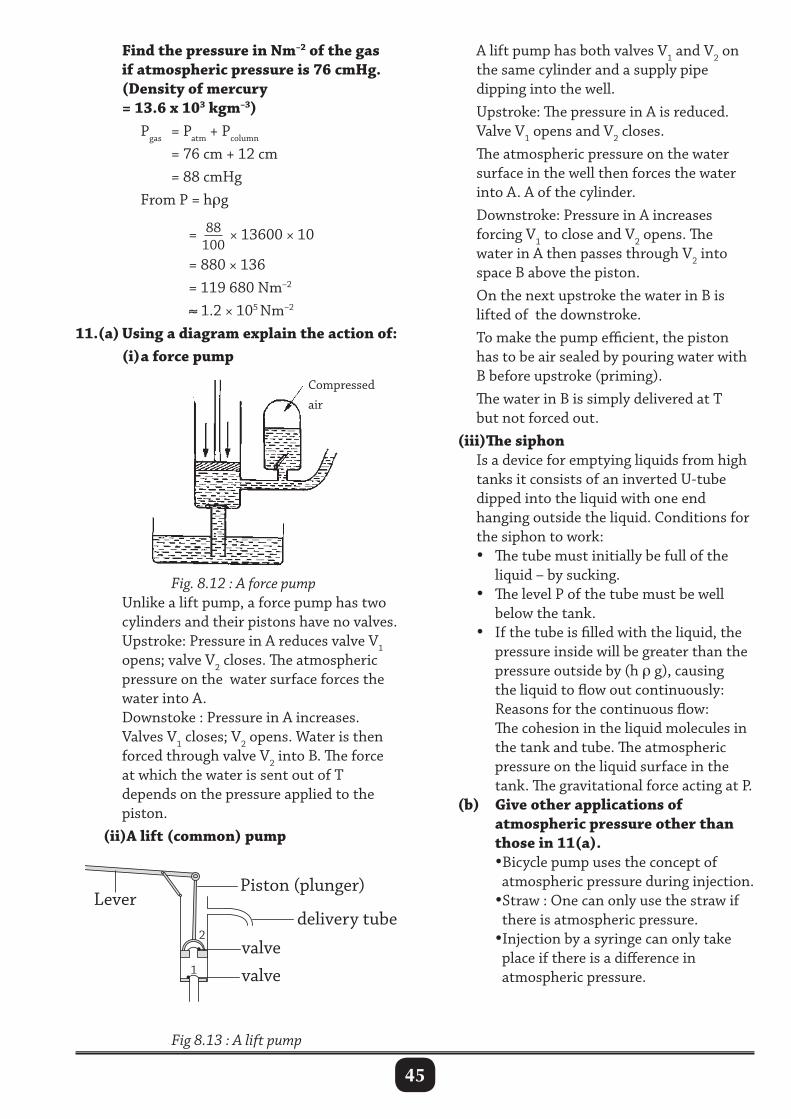
45
A lift pump has both valves V1 and V2 on the same cylinder and a supply pipe dipping into the well. Upstroke: The pressure in A is reduced. Valve V1 opens and V2 closes. The atmospheric pressure on the water surface in the well then forces the water into A. A of the cylinder. Downstroke: Pressure in A increases forcing V1 to close and V2 opens. The water in A then passes through V2 into space B above the piston. On the next upstroke the water in B is lifted of the downstroke. To make the pump efficient, the piston has to be air sealed by pouring water with B before upstroke (priming). The water in B is simply delivered at T but not forced out. (iii)The siphon Is a device for emptying liquids from high tanks it consists of an inverted U-tube dipped into the liquid with one end hanging outside the liquid. Conditions for the siphon to work: • The tube must initially be full of the liquid – by sucking. • The level P of the tube must be well below the tank. • If the tube is filled with the liquid, the pressure inside will be greater than the pressure outside by (h ρ g), causing the liquid to flow out continuously: Reasons for the continuous flow: The cohesion in the liquid molecules in the tank and tube. The atmospheric pressure on the liquid surface in the tank. The gravitational force acting at P. (b) Give other applications of atmospheric pressure other than those in 11(a). •Bicycle pump uses the concept of atmospheric pressure during injection. •Straw : One can only use the straw if there is atmospheric pressure. •Injection by a syringe can only take place if there is a difference in atmospheric pressure.
Find the pressure in Nm–2 of the gas if atmospheric pressure is 76 cmHg. (Density of mercury = 13.6 x 10³ kgm–3) Pgas = Patm + Pcolumn
= 76 cm + 12 cm = 88 cmHg From P = hρg
= 88100
× 13600 × 10 = 880 × 136 = 119 680 Nm–2
≈ 1.2 × 10⁵ Nm–2
11.(a) Using a diagram explain the action of: (i) a force pump
Fig. 8.12 : A force pump Unlike a lift pump, a force pump has two cylinders and their pistons have no valves. Upstroke: Pressure in A reduces valve V1 opens; valve V2 closes. The atmospheric pressure on the water surface forces the water into A. Downstoke : Pressure in A increases. Valves V1 closes; V2 opens. Water is then forced through valve V2 into B. The force at which the water is sent out of T depends on the pressure applied to the piston. (ii)A lift (common) pump
Fig 8.13 : A lift pump
Compressed air
Piston (plunger)
delivery tubeLever
valvevalve
1
2
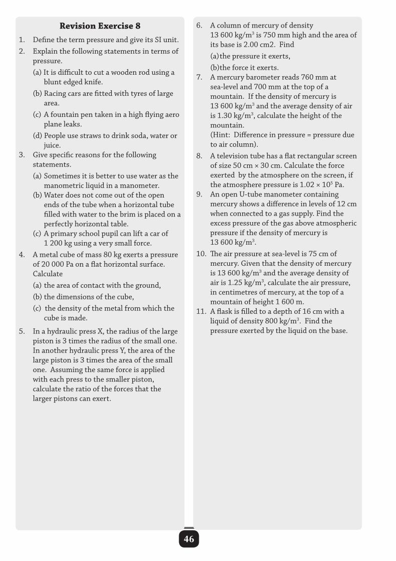
46
Revision Exercise 81. Define the term pressure and give its SI unit.2. Explain the following statements in terms of pressure. (a) It is difficult to cut a wooden rod using a blunt edged knife. (b) Racing cars are fitted with tyres of large area. (c) A fountain pen taken in a high flying aero plane leaks. (d) People use straws to drink soda, water or juice.3. Give specific reasons for the following statements. (a) Sometimes it is better to use water as the manometric liquid in a manometer. (b) Water does not come out of the open ends of the tube when a horizontal tube filled with water to the brim is placed on a perfectly horizontal table. (c) A primary school pupil can lift a car of 1 200 kg using a very small force.4. A metal cube of mass 80 kg exerts a pressure of 20 000 Pa on a flat horizontal surface. Calculate (a) the area of contact with the ground, (b) the dimensions of the cube, (c) the density of the metal from which the cube is made.
5. In a hydraulic press X, the radius of the large piston is 3 times the radius of the small one. In another hydraulic press Y, the area of the large piston is 3 times the area of the small one. Assuming the same force is applied with each press to the smaller piston, calculate the ratio of the forces that the larger pistons can exert.
6. A column of mercury of density 13 600 kg/m3 is 750 mm high and the area of its base is 2.00 cm2. Find (a) the pressure it exerts, (b)the force it exerts.7. A mercury barometer reads 760 mm at sea-level and 700 mm at the top of a mountain. If the density of mercury is 13 600 kg/m3 and the average density of air is 1.30 kg/m3, calculate the height of the mountain. (Hint: Difference in pressure = pressure due to air column).8. A television tube has a flat rectangular screen of size 50 cm × 30 cm. Calculate the force exerted by the atmosphere on the screen, if the atmosphere pressure is 1.02 × 10⁵ Pa.9. An open U-tube manometer containing mercury shows a difference in levels of 12 cm when connected to a gas supply. Find the excess pressure of the gas above atmospheric pressure if the density of mercury is 13 600 kg/m3.10. The air pressure at sea-level is 75 cm of mercury. Given that the density of mercury is 13 600 kg/m3 and the average density of air is 1.25 kg/m3, calculate the air pressure, in centimetres of mercury, at the top of a mountain of height 1 600 m.11. A flask is filled to a depth of 16 cm with a liquid of density 800 kg/m3. Find the pressure exerted by the liquid on the base.
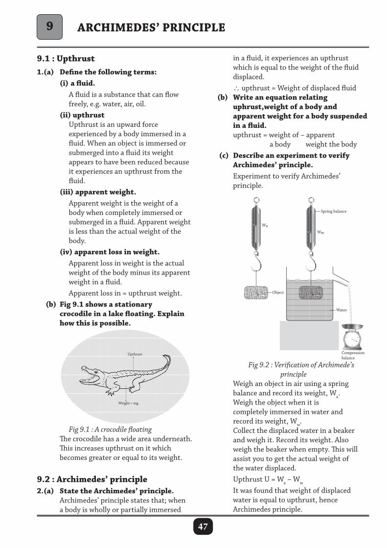
47
ARCHIMEDES’ PRINCIPLE
9.1 : Upthrust1.(a) Define the following terms: (i) a fluid. A fluid is a substance that can flow freely, e.g. water, air, oil. (ii) upthrust Upthrust is an upward force experienced by a body immersed in a fluid. When an object is immersed or submerged into a fluid its weight appears to have been reduced because it experiences an upthrust from the fluid. (iii) apparent weight. Apparent weight is the weight of a body when completely immersed or submerged in a fluid. Apparent weight is less than the actual weight of the body. (iv) apparent loss in weight. Apparent loss in weight is the actual weight of the body minus its apparent weight in a fluid. Apparent loss in = upthrust weight. (b) Fig 9.1 shows a stationary crocodile in a lake floating. Explain how this is possible.
in a fluid, it experiences an upthrust which is equal to the weight of the fluid displaced. ∴ upthrust = Weight of displaced fluid (b) Write an equation relating uphrust,weight of a body and apparent weight for a body suspended in a fluid. upthrust = weight of – apparent a body weight the body (c) Describe an experiment to verify Archimedes’ principle. Experiment to verify Archimedes’ principle.
Weight = mg
Upthrust
10
20
30
40
50
60
70
80
10
20
30
40
50
60
70
80
1
3
2 4
Wa
Object
Water
Compression balance
Ww
Spring balance
Fig 9.2 : Verification of Archimede’s principle Weigh an object in air using a spring balance and record its weight, Wa. Weigh the object when it is completely immersed in water and record its weight, Ww. Collect the displaced water in a beaker and weigh it. Record its weight. Also weigh the beaker when empty. This will assist you to get the actual weight of the water displaced. Upthrust U = Wa – Ww
It was found that weight of displaced water is equal to upthrust, hence Archimedes principle.
9
Fig 9.1 : A crocodile floating The crocodile has a wide area underneath. This increases upthrust on it which becomes greater or equal to its weight.
9.2 : Archimedes’ principle2.(a) State the Archimedes’ principle. Archimedes’ principle states that; when a body is wholly or partially immersed
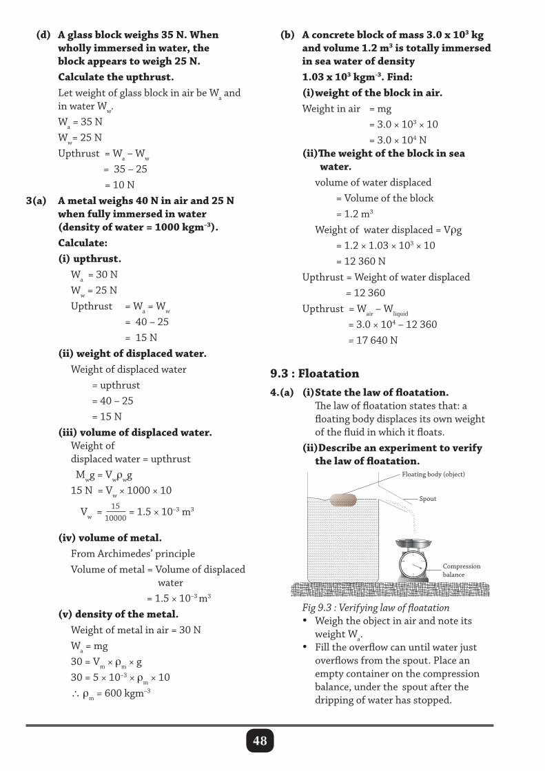
48
(d) A glass block weighs 35 N. When wholly immersed in water, the block appears to weigh 25 N. Calculate the upthrust. Let weight of glass block in air be Wa and in water Ww. Wa = 35 N Ww= 25 N Upthrust = Wa – Ww
= 35 – 25 = 10 N3(a) A metal weighs 40 N in air and 25 N when fully immersed in water (density of water = 1000 kgm–3). Calculate: (i) upthrust. Wa = 30 N Ww = 25 N Upthrust = Wa = Ww
= 40 – 25 = 15 N (ii) weight of displaced water. Weight of displaced water = upthrust = 40 – 25 = 15 N (iii) volume of displaced water. Weight of displaced water = upthrust Mwg = Vwρwg 15 N = Vw × 1000 × 10 Vw = 15
10000= 1.5 × 10⁻³ m3
(iv) volume of metal. From Archimedes’ principle Volume of metal = Volume of displaced water = 1.5 × 10⁻³ m3
(v) density of the metal. Weight of metal in air = 30 N Wa = mg 30 = Vm × ρm × g 30 = 5 × 10⁻³ × ρm × 10 ∴ ρm = 600 kgm–3
(b) A concrete block of mass 3.0 x 10³ kg and volume 1.2 m3 is totally immersed in sea water of density 1.03 x 10³ kgm-3. Find: (i) weight of the block in air. Weight in air = mg = 3.0 × 103 × 10 = 3.0 × 10⁴ N (ii)The weight of the block in sea water. volume of water displaced = Volume of the block = 1.2 m3
Weight of water displaced = Vρg = 1.2 × 1.03 × 103 × 10 = 12 360 N Upthrust = Weight of water displaced = 12 360 Upthrust = Wair – Wliquid
= 3.0 × 10⁴ – 12 360 = 17 640 N
9.3 : Floatation4.(a) (i) State the law of floatation. The law of floatation states that: a floating body displaces its own weight of the fluid in which it floats. (ii)Describe an experiment to verify the law of floatation.
1
3
2 4
Spout
Floating body (object)
Compression balance
Fig 9.3 : Verifying law of floatation • Weigh the object in air and note its weight Wa. • Fill the overflow can until water just overflows from the spout. Place an empty container on the compression balance, under the spout after the dripping of water has stopped.
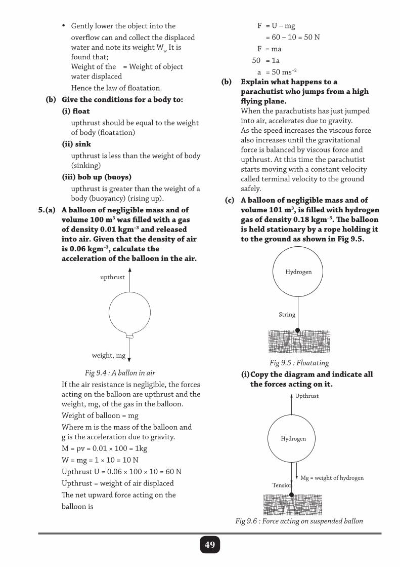
49
• Gently lower the object into the overflow can and collect the displaced water and note its weight Ww It is found that; Weight of the = Weight of object water displaced Hence the law of floatation. (b) Give the conditions for a body to: (i) float upthrust should be equal to the weight of body (floatation) (ii) sink upthrust is less than the weight of body (sinking) (iii) bob up (buoys) upthrust is greater than the weight of a body (buoyancy) (rising up).5.(a) A balloon of negligible mass and of volume 100 m3 was filled with a gas of density 0.01 kgm–3 and released into air. Given that the density of air is 0.06 kgm–3, calculate the acceleration of the balloon in the air.
F = U – mg = 60 – 10 = 50 N F = ma 50 = 1a a = 50 ms–2
(b) Explain what happens to a parachutist who jumps from a high flying plane. When the parachutists has just jumped into air, accelerates due to gravity. As the speed increases the viscous force also increases until the gravitational force is balanced by viscous force and upthrust. At this time the parachutist starts moving with a constant velocity called terminal velocity to the ground safely. (c) A balloon of negligible mass and of volume 101 m3, is filled with hydrogen gas of density 0.18 kgm–3. The balloon is held stationary by a rope holding it to the ground as shown in Fig 9.5.
upthrust
weight, mg
Fig 9.4 : A ballon in air If the air resistance is negligible, the forces acting on the balloon are upthrust and the weight, mg, of the gas in the balloon. Weight of balloon = mg Where m is the mass of the balloon and g is the acceleration due to gravity. M = ρv = 0.01 × 100 = 1kg W = mg = 1 × 10 = 10 N Upthrust U = 0.06 × 100 × 10 = 60 N Upthrust = weight of air displaced The net upward force acting on the balloon is
Hydrogen
String
Fig 9.5 : Floatating (i) Copy the diagram and indicate all the forces acting on it.
Hydrogen
Tension
Upthrust
Mg = weight of hydrogen
Fig 9.6 : Force acting on suspended ballon
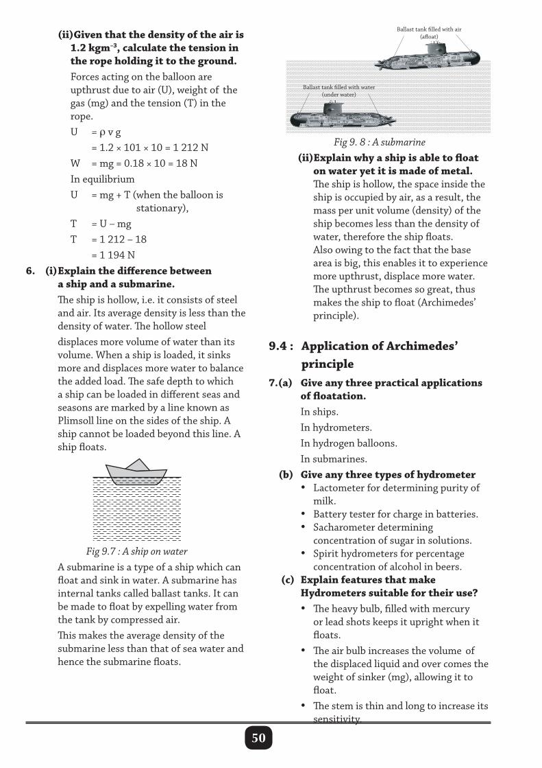
50
(ii)Given that the density of the air is 1.2 kgm–3, calculate the tension in the rope holding it to the ground. Forces acting on the balloon are upthrust due to air (U), weight of the gas (mg) and the tension (T) in the rope. U = ρ v g = 1.2 × 101 × 10 = 1 212 N W = mg = 0.18 × 10 = 18 N In equilibrium U = mg + T (when the balloon is stationary), T = U – mg T = 1 212 – 18 = 1 194 N6. (i) Explain the difference between a ship and a submarine. The ship is hollow, i.e. it consists of steel and air. Its average density is less than the density of water. The hollow steel displaces more volume of water than its volume. When a ship is loaded, it sinks more and displaces more water to balance the added load. The safe depth to which a ship can be loaded in different seas and seasons are marked by a line known as Plimsoll line on the sides of the ship. A ship cannot be loaded beyond this line. A ship floats.
Fig 9. 8 : A submarine (ii)Explain why a ship is able to float on water yet it is made of metal. The ship is hollow, the space inside the ship is occupied by air, as a result, the mass per unit volume (density) of the ship becomes less than the density of water, therefore the ship floats. Also owing to the fact that the base area is big, this enables it to experience more upthrust, displace more water. The upthrust becomes so great, thus makes the ship to float (Archimedes’ principle).
9.4 : Application of Archimedes’ principle7.(a) Give any three practical applications of floatation. In ships. In hydrometers. In hydrogen balloons. In submarines. (b) Give any three types of hydrometer • Lactometer for determining purity of milk. • Battery tester for charge in batteries. • Sacharometer determining concentration of sugar in solutions. • Spirit hydrometers for percentage concentration of alcohol in beers. (c) Explain features that make Hydrometers suitable for their use? • The heavy bulb, filled with mercury or lead shots keeps it upright when it floats. • The air bulb increases the volume of the displaced liquid and over comes the weight of sinker (mg), allowing it to float. • The stem is thin and long to increase its sensitivity.
Ballast tank lled with air(aoat)
Ballast tank lled with water(under water)
Fig 9.7 : A ship on water A submarine is a type of a ship which can float and sink in water. A submarine has internal tanks called ballast tanks. It can be made to float by expelling water from the tank by compressed air. This makes the average density of the submarine less than that of sea water and hence the submarine floats.
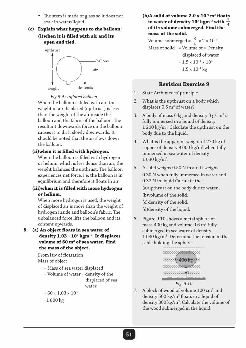
51
• The stem is made of glass so it does not soak in water/liquid. (c) Explain what happens to the balloon: (i) when it is filled with air and its open end tied.
(b)A solid of volume 2.0 x 10⁻⁴ m3 floats in water of density 103 kgm–3 with 3
4
of its volume submerged. Find the mass of the solid. Volume submerged = 3
4× 2 × 10–4
Mass of solid = Volume of × Density displaced of water = 1.5 × 10–4 × 103
= 1.5 × 10⁻¹ kg
Revision Exercise 91. State Archimedes’ principle.
2. What is the upthrust on a body which displaces 0.5 m3 of water?
3. A body of mass 6 kg and density 8 g/cm3 is fully immersed in a liquid of density 1 200 kg/m3. Calculate the upthrust on the body due to the liquid.
4. What is the apparent weight of 270 kg of copper of density 9 000 kg/m3 when fully immersed in sea water of density 1 030 kg/m3.
5. A solid weighs 0.50 N in air. It weighs 0.30 N when fully immersed in water and 0.32 N in liquid.Calculate the: (a) upthrust on the body due to water . (b)volume of the solid. (c) density of the solid. (d)density of the liquid.
6. Figure 9.10 shows a metal sphere of mass 400 kg and volume 0.6 m3 fully submerged in sea water of density 1 030 kg/m3. Determine the tension in the cable holding the sphere.
upthrust
weight
air
descends
ballons
Fig 9.9 : Inflated balloon When the balloon is filled with air, the weight of air displaced (upthrust) is less than the weight of the air inside the balloon and the fabric of the balloon. The resultant downwards force on the balloon causes it to drift slowly downwards. It should be noted that the air slows down the balloon. (ii)when it is filled with hydrogen. When the balloon is filled with hydrogen or helium, which is less dense than air, the weight balances the upthrust. The balloon experiences net force, i.e. the balloon is in equilibrium and therefore it floats in air. (iii)when it is filled with more hydrogen or helium. When more hydrogen is used, the weight of displaced air is more than the weight of hydrogen inside and balloon’s fabric. The unbalanced force lifts the balloon and its content upwards.8. (a) An object floats in sea water of density 1.03 × 10³ kgm–3. It displaces volume of 60 m3 of sea water. Find the mass of the object. From law of floatation Mass of object = Mass of sea water displaced = Volume of water × density of the displaced of sea water = 60 × 1.03 × 103
=1 800 kg
Fig. 9.10
– – – – – – – – – – – – – – – – – – – – – – – – – – – – – – – – – – – – – – – – – – – – – – – – – – – – – – – – – – – – – – – – – – – – – – – – – – – – – – – – – – – – – – – – – – – – – – – – – – – – – – – – – – – – – – – – – – – – – – – – – – – – – – – – – – – – – – – – – – – – – – – – – – – – – – – – – – – – – – – – – – – – – – – – – – – – – – – – – – – – – – – – – – – – – – – – – – – – – – – – – – – – – – – – – – – – – – – – – – – – – – – – – – – – – – – – – – – – – – – – – – – – – – – – – – – – – – – – – – – – – – – – – – – – – – – – – – – – – – – – – – – – – – – – – – – – – – – – – – – – – – – – – – – – – – – – – – – – – – – – – – – – – – – – – – – – – – – – – – – – – – – – – – – – – – – – – – – – – – – – – – – – – – – – – – – – – – – – – – – – – – – – – – – – – – – – – – – – – – – – – – – – – – – – – – – – – – – – – – – – – – – – – – – – – – – – – – – – – – – – – – – – – – – – – – – – – – T
7. A block of wood of volume 100 cm3 and density 500 kg/m3 floats in a liquid of density 800 kg/m3. Calculate the volume of the wood submerged in the liquid.
400 kg
52
8. A solid metal block of cross-sectional area 4 cm2 and of density 2.5 g/cm3, is fully submerged in water at a depth of 12 cm from the free surface of water. (a) Calculate the downward force acting on the top face. (b) If the upward force acting on the bottom face is 1.5 N, calculate the volume of the block. (c) Calculate the apparent weight of the block in water. 9. A wooden raft of density 240 kg/m3 is 4 m long, 3 m wide and 0.5 m thick. Determine (a) the volume of the raft submerged when it floats in water. (b) the minimum mass that should be placed on the top of the wooden raft so that the raft is completely submerged in water.10. A weather forecasting balloon is made of a fabric of mass 40 kg. Calculate the volume of hydrogen in the balloon which would just support an additional mass of 80 kg when floating in air. (Density of hydrogen = 0.09 kg/m3 and air = 1.29 kg/m3)
11. A hydrometer weighing 9.8 g floats in a liquid of density 0.87 g/cm3. Determine the volume of the immersed part.
12. A piece of glass weighs 0.250 N in air, 0.154 N in water and 0.169 N in oil. Find (a) the relative density of glass, (b)the relative density of oil, (c) the density of oil.
13. A block of wood weighs 4.8 N in air. If density of wood is 600 kg/m3, determine (a) the volume of the block submerged when it floats in water. (b)the minimum mass that should be placed on the top of the block so that the block is completely submerged in water.
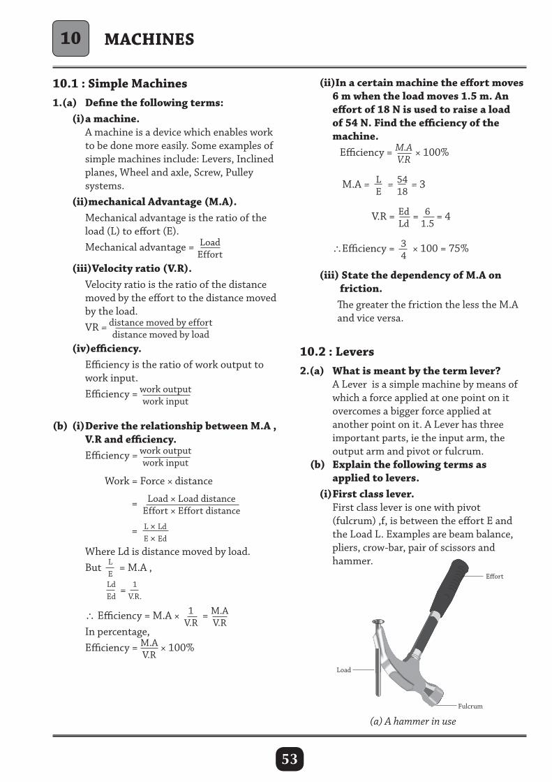
53
10.1 : Simple Machines1.(a) Define the following terms: (i) a machine. A machine is a device which enables work to be done more easily. Some examples of simple machines include: Levers, Inclined planes, Wheel and axle, Screw, Pulley systems. (ii)mechanical Advantage (M.A). Mechanical advantage is the ratio of the load (L) to effort (E). Mechanical advantage = Load
Effort
(iii)Velocity ratio (V.R). Velocity ratio is the ratio of the distance moved by the effort to the distance moved by the load. VR = distance moved by effort
distance moved by load (iv)efficiency. Efficiency is the ratio of work output to work input. Efficiency = work output
work input
(b) (i) Derive the relationship between M.A , V.R and efficiency. Efficiency = work output
work input
Work = Force × distance
= Load × Load distanceEffort × Effort distance
=
L × LdE × Ed
Where Ld is distance moved by load. But L
E= M.A ,
LdEd
= 1V.R.
∴Efficiency = M.A × 1V.R
= M.AV.R
In percentage, Efficiency = M.A
V.R × 100%
(ii)In a certain machine the effort moves 6 m when the load moves 1.5 m. An effort of 18 N is used to raise a load of 54 N. Find the efficiency of the machine. Efficiency = M.A
V.R × 100%
M.A = LE
= 5418
= 3
V.R = EdLd
= 61.5
= 4 ∴Efficiency = 3
4× 100 = 75%
(iii) State the dependency of M.A on friction. The greater the friction the less the M.A and vice versa.
10.2 : Levers2.(a) What is meant by the term lever? A Lever is a simple machine by means of which a force applied at one point on it overcomes a bigger force applied at another point on it. A Lever has three important parts, ie the input arm, the output arm and pivot or fulcrum. (b) Explain the following terms as applied to levers. (i) First class lever. First class lever is one with pivot (fulcrum) ,f, is between the effort E and the Load L. Examples are beam balance, pliers, crow-bar, pair of scissors and hammer.
MACHINES
Eort
Fulcrum
Load
(a) A hammer in use
10
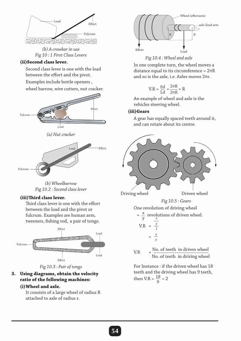
54
(b) A crowbar in useFig 10 : 1 First Class Levers
(ii)Second class lever. Second class lever is one with the load between the effort and the pivot. Examples include bottle openers , wheel barrow, wire cutters, nut cracker.
Fig 10.4 : Wheel and axle In one complete turn, the wheel moves a distance equal to its circumference = 2πR and so is the axle, i.e. Axles moves 2πr.
V.R = Ed
Ld=
2πR2πR
= R
An example of wheel and axle is the vehicles steering wheel. (iii)Gears A gear has equally spaced teeth around it, and can rotate about its centre.
Load
Eort
Fulcrum
Load Eort
Fulcrum
(iii)Third class lever. Third class lever is one with the effort between the load and the pivot or fulcrum. Examples are human arm, tweezers, fishing rod, a pair of tongs.
Fig 10.3 : Pair of tongs3. Using diagrams, obtain the velocity ratio of the following machines: (i) Wheel and axle. It consists of a large wheel of radius R attached to axle of radius r.
R R
r
Eort Load
axle (load arm)
Wheel (eortarm)
Fig 10.5 : Gears One revolution of driving wheel = x
yrevolutions of driven wheel.
V.R =
xy1
= xy
V.R = No. of teeth in driven wheel No. of teeth in driving wheel For Instance : if the driven wheel has 18 teeth and the driving wheel has 9 teeth, then V.R = 18
9= 2
Load
Fulcrum
Eort
(a) Nut cracker
(b) WheelbarrowFig 10.2 : Second class lever
Driving wheel Driven wheel
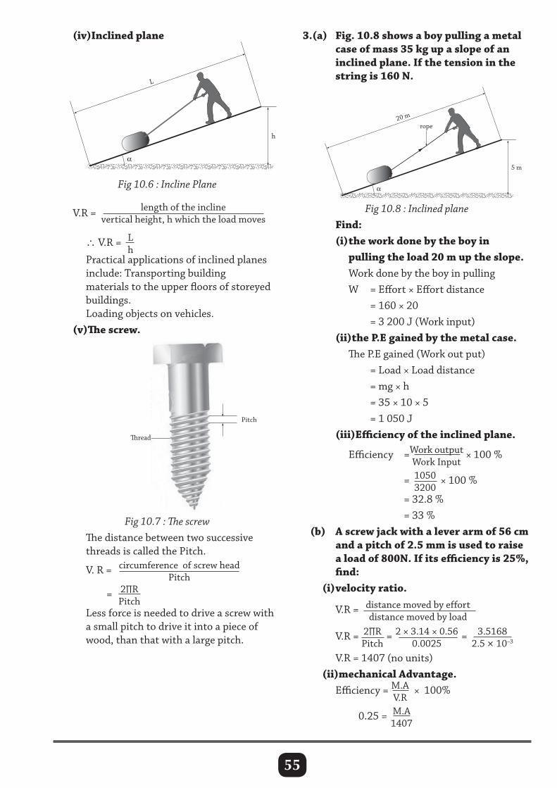
55
(iv)Inclined plane
L
h
Fig 10.6 : Incline Plane
V.R = length of the inclinevertical height, h which the load moves
∴ V.R = L
h
Practical applications of inclined planes include: Transporting building materials to the upper floors of storeyed buildings. Loading objects on vehicles. (v)The screw.
Fig 10.7 : The screw The distance between two successive threads is called the Pitch. V. R = circumference of screw head
Pitch = 2∏R
Pitch
Less force is needed to drive a screw with a small pitch to drive it into a piece of wood, than that with a large pitch.
3.(a) Fig. 10.8 shows a boy pulling a metal case of mass 35 kg up a slope of an inclined plane. If the tension in the string is 160 N.
Fig 10.8 : Inclined plane Find: (i) the work done by the boy in pulling the load 20 m up the slope. Work done by the boy in pulling W = Effort × Effort distance = 160 × 20 = 3 200 J (Work input) (ii)the P.E gained by the metal case. The P.E gained (Work out put) = Load × Load distance = mg × h = 35 × 10 × 5 = 1 050 J (iii)Efficiency of the inclined plane. Efficiency =Work output
Work Input × 100 %
= 10503200
× 100 %
= 32.8 % = 33 % (b) A screw jack with a lever arm of 56 cm and a pitch of 2.5 mm is used to raise a load of 800N. If its efficiency is 25%, find: (i) velocity ratio.
V.R = distance moved by effortdistance moved by load
V.R = 2∏RPitch
= 2 × 3.14 × 0.560.0025
= 3.51682.5 × 10–3
V.R = 1407 (no units) (ii)mechanical Advantage. Efficiency = M.A
V.R × 100%
0.25 = M.A
1407
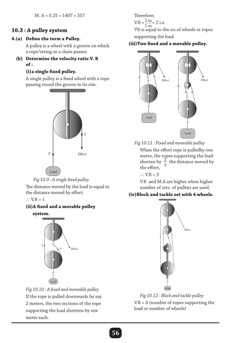
56
M. A = 0.25 × 1407 = 357
10.3 : A pulley system4.(a) Define the term a Pulley. A pulley is a wheel with a groove on which a rope/string or a chain passes. (b) Determine the velocity ratio V. R of : (i) a single fixed pulley. A single pulley is a fixed wheel with a rope passing round the groove in its rim.
Therefore; V.R =2 m
1 m= 2 i.e.
VR is equal to the no.of wheels or ropes supporting the load. (iii)Two fixed and a movable pulley.
Load
Eort
Load
EortT
T
Fig 10.9 : A single fixed pulley The distance moved by the load is equal to the distance moved by effort. ∴ V.R = 1 (ii)A fixed and a movable pulley system.
Fig 10.11 : Fixed and moveable pulley When the effort rope is pulledby one metre, the ropes supporting the load shorten by 1
3the distance moved by
the effort, ∴ V.R = 3 V.R and M.A are higher when higher number of sets of pulleys are used. (iv)Block and tackle set with 4 wheels.
Fig 10.10 : A fixed and moveable pulley If the rope is pulled downwards by say 2 meters, the two sections of the rope supporting the load shortens by one meter each.
Fig 10.12 : Block and tackle pulley V.R = 4 (number of ropes supporting the load or number of wheels)
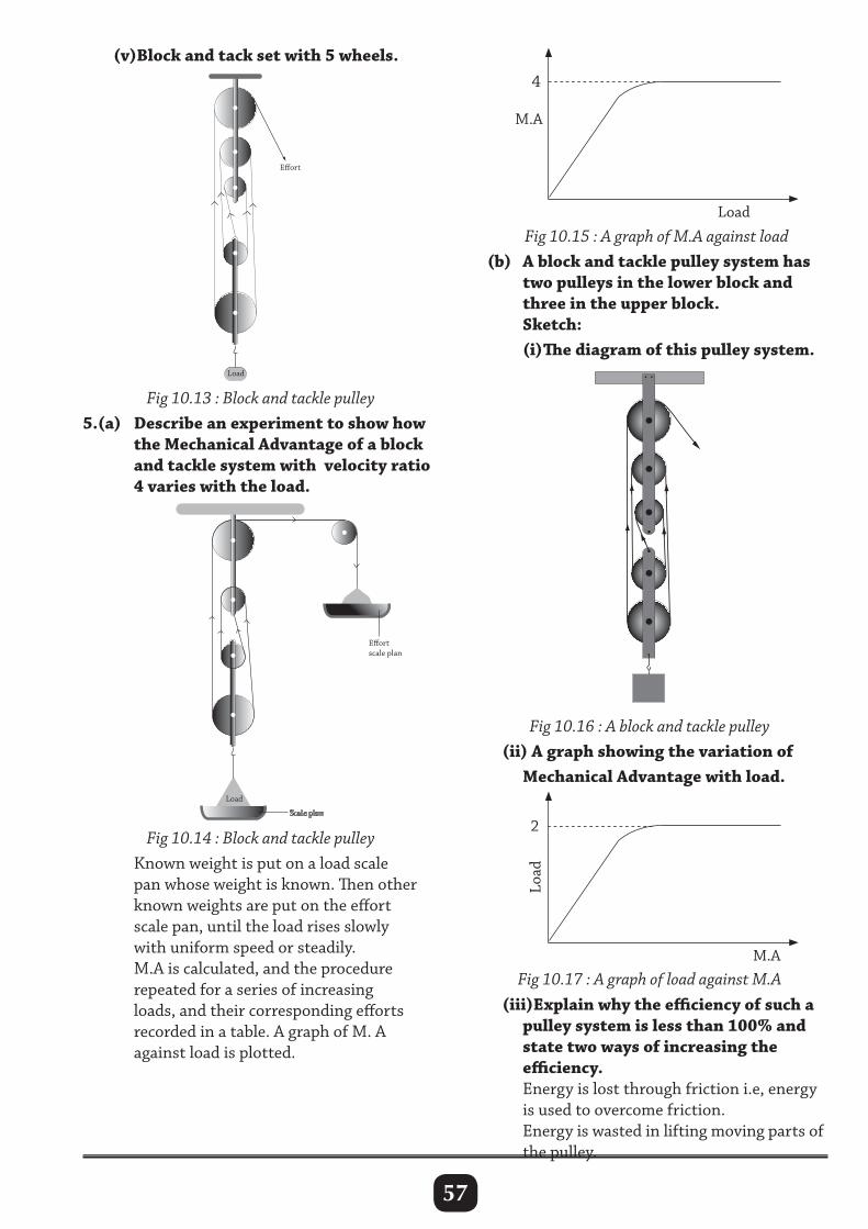
57
(v)Block and tack set with 5 wheels.
Load
Eort
Load
Eortscale plan
4
Load
Fig 10.13 : Block and tackle pulley5.(a) Describe an experiment to show how the Mechanical Advantage of a block and tackle system with velocity ratio 4 varies with the load.
Fig 10.14 : Block and tackle pulley Known weight is put on a load scale pan whose weight is known. Then other known weights are put on the effort scale pan, until the load rises slowly with uniform speed or steadily. M.A is calculated, and the procedure repeated for a series of increasing loads, and their corresponding efforts recorded in a table. A graph of M. A against load is plotted.
Fig 10.15 : A graph of M.A against load (b) A block and tackle pulley system has two pulleys in the lower block and three in the upper block. Sketch: (i) The diagram of this pulley system.
Fig 10.16 : A block and tackle pulley (ii) A graph showing the variation of Mechanical Advantage with load.
Load
M.A
2
M.A
Fig 10.17 : A graph of load against M.A (iii)Explain why the efficiency of such a pulley system is less than 100% and state two ways of increasing the efficiency. Energy is lost through friction i.e, energy is used to overcome friction. Energy is wasted in lifting moving parts of the pulley.
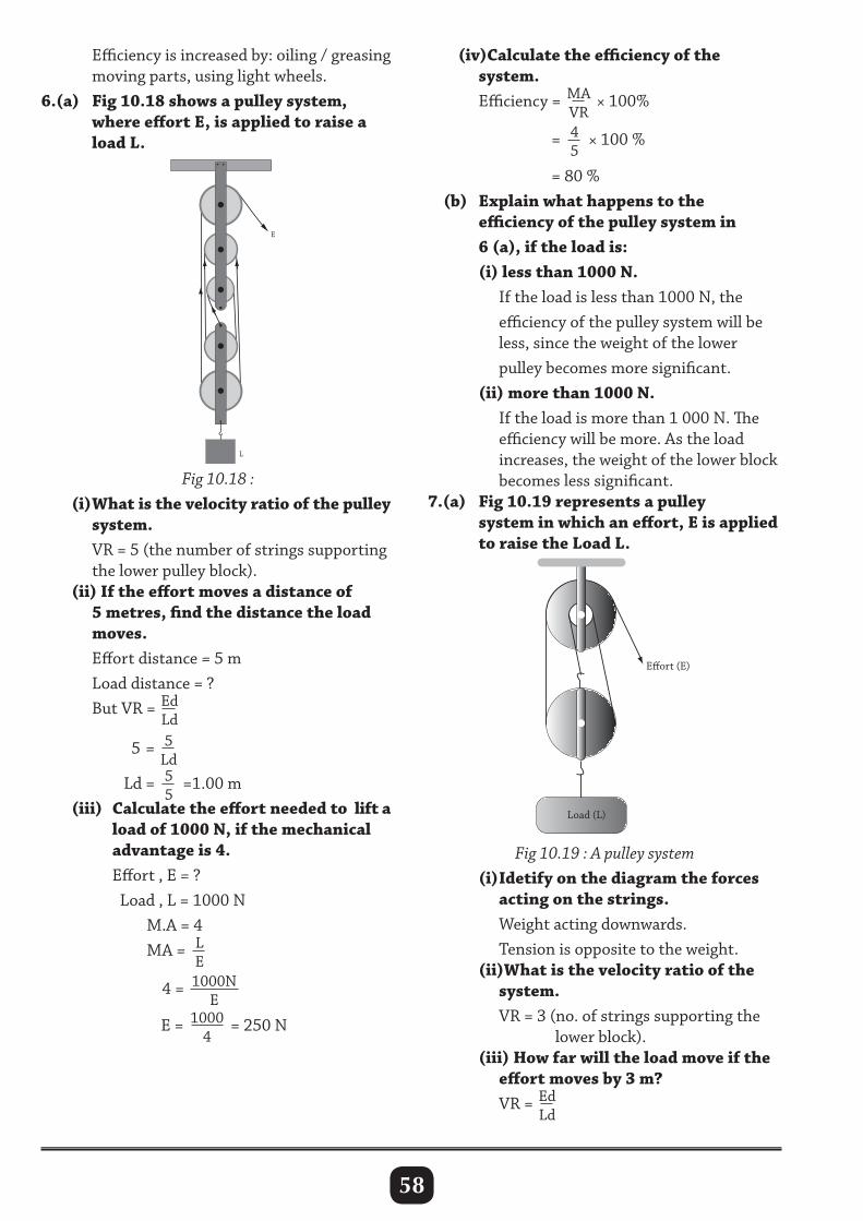
58
(iv)Calculate the efficiency of the system. Efficiency = MA
VR × 100%
= 4
5× 100 %
= 80 % (b) Explain what happens to the efficiency of the pulley system in 6 (a), if the load is: (i) less than 1000 N. If the load is less than 1000 N, the efficiency of the pulley system will be less, since the weight of the lower pulley becomes more significant. (ii) more than 1000 N. If the load is more than 1 000 N. The efficiency will be more. As the load increases, the weight of the lower block becomes less significant.7.(a) Fig 10.19 represents a pulley system in which an effort, E is applied to raise the Load L.
Efficiency is increased by: oiling / greasing moving parts, using light wheels.6.(a) Fig 10.18 shows a pulley system, where effort E, is applied to raise a load L.
Eort (E)
Load (L)
Fig 10.18 : (i) What is the velocity ratio of the pulley system. VR = 5 (the number of strings supporting the lower pulley block). (ii) If the effort moves a distance of 5 metres, find the distance the load moves. Effort distance = 5 m Load distance = ? But VR = Ed
Ld
5 = 5Ld
Ld = 55
=1.00 m (iii) Calculate the effort needed to lift a load of 1000 N, if the mechanical advantage is 4. Effort , E = ? Load , L = 1000 N M.A = 4 MA = L
E
4 = 1000NE
E = 10004
= 250 N
E
L
Fig 10.19 : A pulley system (i) Idetify on the diagram the forces acting on the strings. Weight acting downwards. Tension is opposite to the weight. (ii)What is the velocity ratio of the system. VR = 3 (no. of strings supporting the lower block). (iii) How far will the load move if the effort moves by 3 m? VR = Ed
Ld
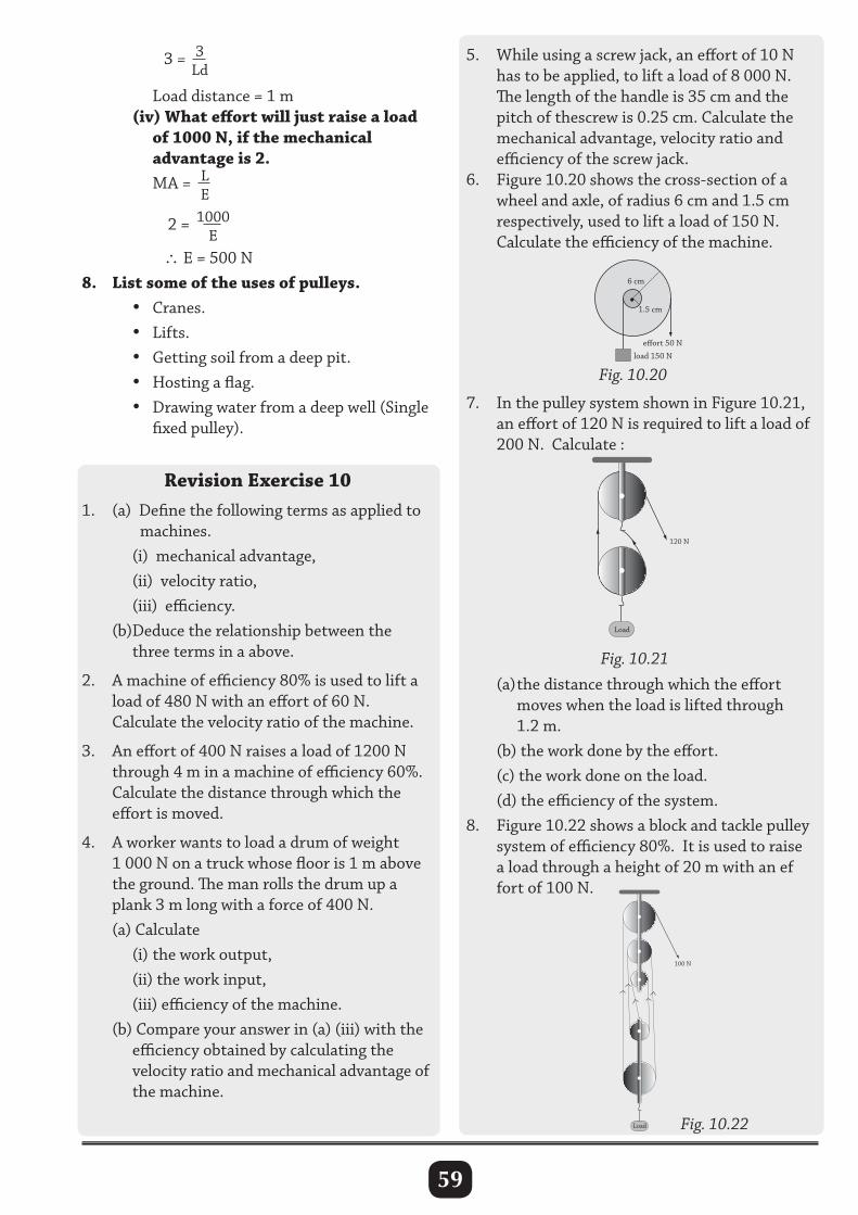
59
3 = 3Ld
Load distance = 1 m
(iv) What effort will just raise a load of 1000 N, if the mechanical advantage is 2. MA = L
E 2 = 1000
E
∴E = 500 N8. List some of the uses of pulleys. • Cranes. • Lifts. • Getting soil from a deep pit. • Hosting a flag. • Drawing water from a deep well (Single fixed pulley).
Revision Exercise 101. (a) Define the following terms as applied to machines. (i) mechanical advantage, (ii) velocity ratio, (iii) efficiency. (b)Deduce the relationship between the three terms in a above.
2. A machine of efficiency 80% is used to lift a load of 480 N with an effort of 60 N. Calculate the velocity ratio of the machine.
3. An effort of 400 N raises a load of 1200 N through 4 m in a machine of efficiency 60%. Calculate the distance through which the effort is moved.
4. A worker wants to load a drum of weight 1 000 N on a truck whose floor is 1 m above the ground. The man rolls the drum up a plank 3 m long with a force of 400 N. (a) Calculate (i) the work output, (ii) the work input, (iii) efficiency of the machine. (b) Compare your answer in (a) (iii) with the efficiency obtained by calculating the velocity ratio and mechanical advantage of the machine.
5. While using a screw jack, an effort of 10 N has to be applied, to lift a load of 8 000 N. The length of the handle is 35 cm and the pitch of thescrew is 0.25 cm. Calculate the mechanical advantage, velocity ratio and efficiency of the screw jack.6. Figure 10.20 shows the cross-section of a wheel and axle, of radius 6 cm and 1.5 cm respectively, used to lift a load of 150 N. Calculate the efficiency of the machine.
Fig. 10.20
•1.5 cm
6 cm
effort 50 N
load 150 N
7. In the pulley system shown in Figure 10.21, an effort of 120 N is required to lift a load of 200 N. Calculate :
(a) the distance through which the effort moves when the load is lifted through 1.2 m. (b) the work done by the effort. (c) the work done on the load. (d) the efficiency of the system.8. Figure 10.22 shows a block and tackle pulley system of efficiency 80%. It is used to raise a load through a height of 20 m with an ef fort of 100 N.
Fig. 10.21
Load
120 N
Load
100 N
Fig. 10.22

60
(a) What is the velocity ratio of the system? (b) Calculate. (i) the load raised. (ii) the work done by the effort, (iii) the energy wasted.
9. A load of 3 000 N is pulled along an inclined plane of length 8 m by a force of 2 100 N. Calculate the efficiency of the system if the load is raised through a vertical distance of 4 m.
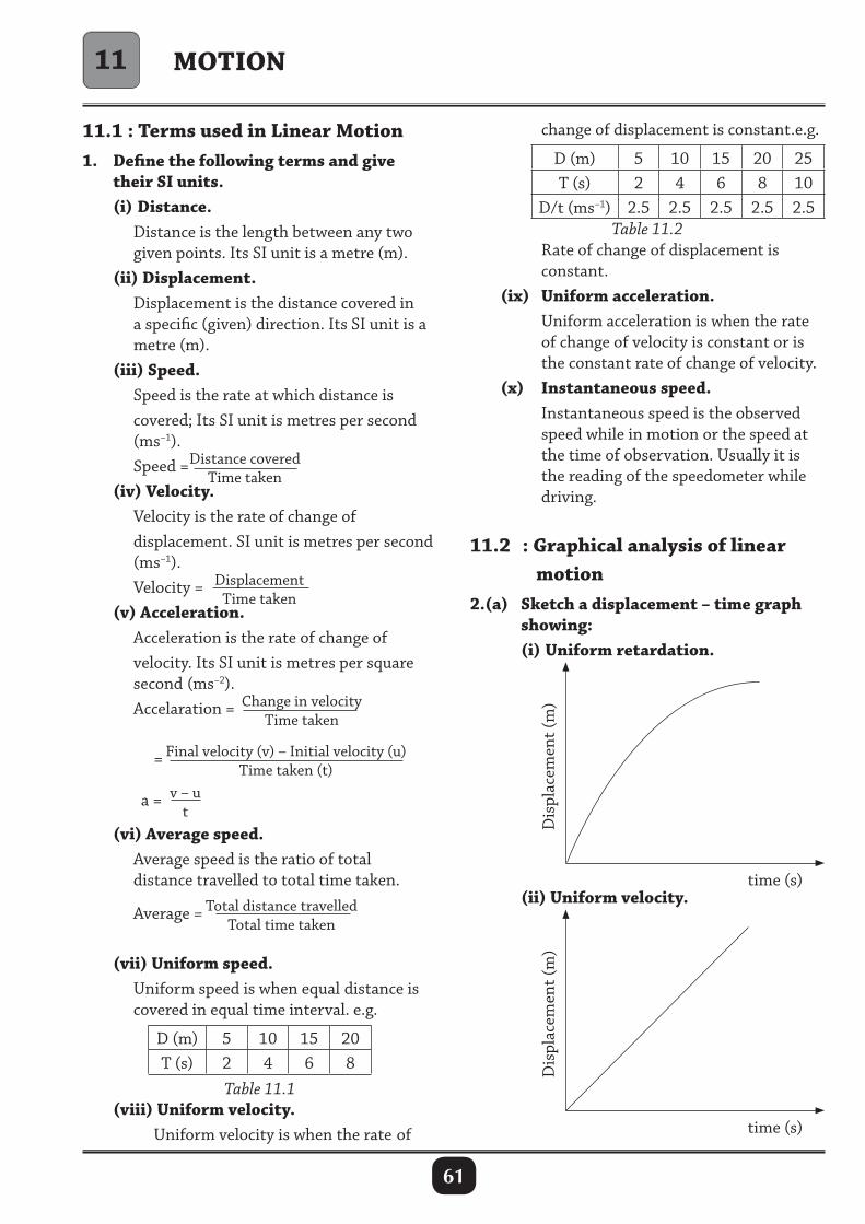
61
MOTION
11.1 : Terms used in Linear Motion1. Define the following terms and give their SI units. (i) Distance. Distance is the length between any two given points. Its SI unit is a metre (m). (ii) Displacement. Displacement is the distance covered in a specific (given) direction. Its SI unit is a metre (m). (iii) Speed. Speed is the rate at which distance is covered; Its SI unit is metres per second (ms–1). Speed =Distance covered
Time taken (iv) Velocity. Velocity is the rate of change of displacement. SI unit is metres per second (ms–1). Velocity = Displacement
Time taken (v) Acceleration. Acceleration is the rate of change of velocity. Its SI unit is metres per square second (ms–2). Accelaration = Change in velocity
Time taken
= Final velocity (v) – Initial velocity (u)Time taken (t)
a = v – ut
(vi) Average speed. Average speed is the ratio of total distance travelled to total time taken.
Average = Total distance travelledTotal time taken
(vii) Uniform speed. Uniform speed is when equal distance is covered in equal time interval. e.g.
D (m) 5 10 15 20T (s) 2 4 6 8
Table 11.1 (viii) Uniform velocity. Uniform velocity is when the rate of
change of displacement is constant.e.g.
D (m) 5 10 15 20 25T (s) 2 4 6 8 10
D/t (ms–1) 2.5 2.5 2.5 2.5 2.5Table 11.2
Rate of change of displacement is constant. (ix) Uniform acceleration. Uniform acceleration is when the rate of change of velocity is constant or is the constant rate of change of velocity. (x) Instantaneous speed. Instantaneous speed is the observed speed while in motion or the speed at the time of observation. Usually it is the reading of the speedometer while driving.
11.2 : Graphical analysis of linear motion2.(a) Sketch a displacement – time graph showing: (i) Uniform retardation.
Dis
plac
emen
t (m
)
time (s) (ii) Uniform velocity.
Dis
plac
emen
t (m
)
time (s)
11
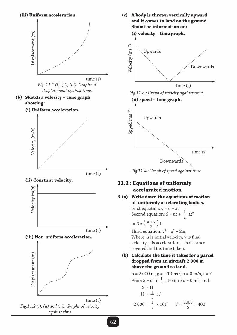
62
(iii) Uniform acceleration. (c) A body is thrown vertically upward and it comes to land on the ground. Show the information on: (i) velocity – time graph.
Upwards
Downwards
Velo
city
(ms–1
)
time (s)
Upwards
Downwards
Sppe
d (m
s–1)
time (s)
Dis
plac
emen
t (m
)
time (s) Fig. 11.1 (i), (ii), (iii): Graphs of Displacement against time. (b) Sketch a velocity – time graph showing: (i) Uniform acceleration.
Velo
city
(m/s
)
time (s) (ii) Constant velocity.
Velo
city
(m/s
)
time (s)
Dis
plac
emen
t (m
)
time (s)
Fig 11.3 : Graph of velocity against time (ii) speed – time graph.
Fig 11.4 : Graph of speed against time
11.2 : Equations of uniformly accelarated motion3.(a) Write down the equations of motion of uniformly accelarating bodies. First equation: v = u + at Second equation: S = ut + 1
2at2
or S = ( u + v2
) t Third equation: v2 = u2 + 2as Where: u is initial velocity, v is final velocity, a is acceleration, s is distance covered and t is time taken. (b) Calculate the time it takes for a parcel dropped from an aircraft 2 000 m above the ground to land. h = 2 000 m, g = – 10ms-2, u = 0 m/s, t = ? From S = ut + 1
2at2 since u = 0 mls and
S = H H = 1
2at2
2 000 = 1
2× 10t2 t2 = 2000
5= 400
(iii) Non-uniform acceleration.
Fig.11.2 (i), (ii) and (iii): Graphs of velocity against time
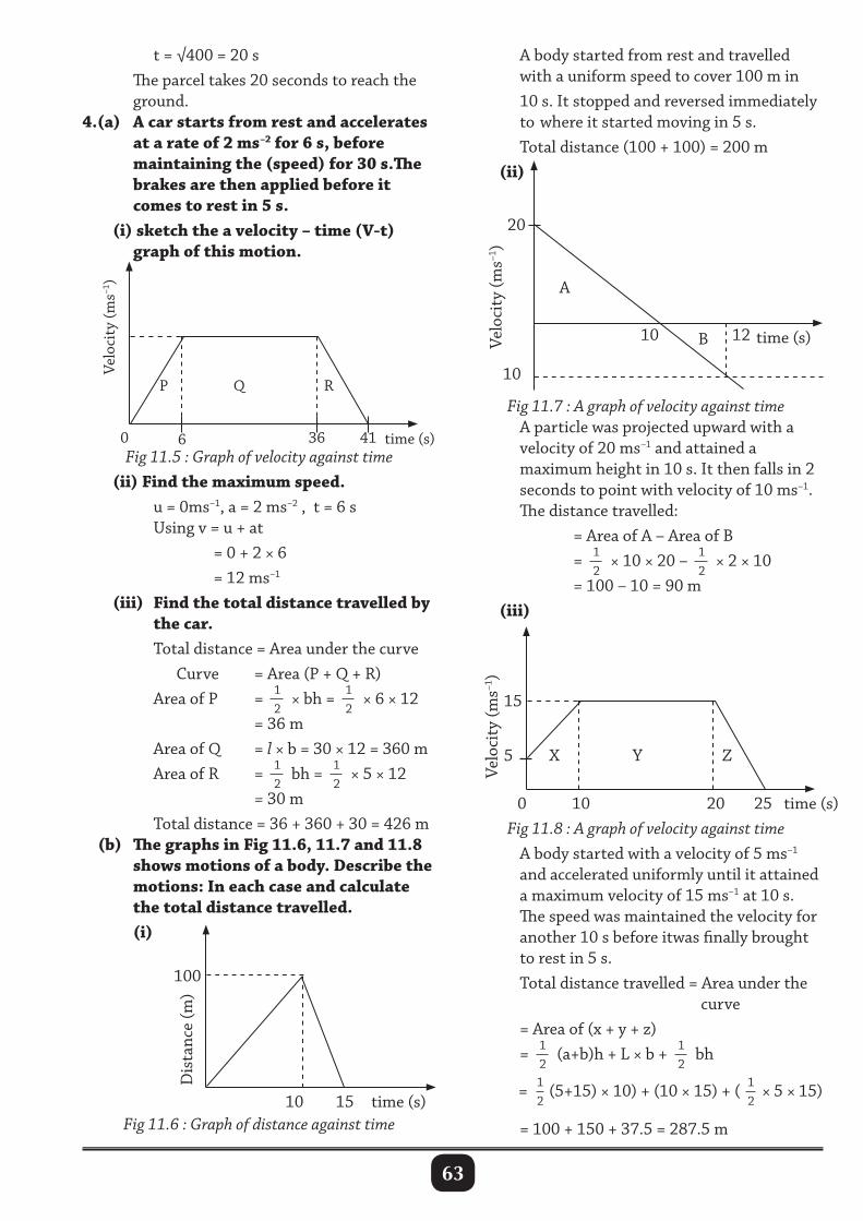
63
t = √400 = 20 s The parcel takes 20 seconds to reach the ground.4.(a) A car starts from rest and accelerates at a rate of 2 ms–2 for 6 s, before maintaining the (speed) for 30 s.The brakes are then applied before it comes to rest in 5 s. (i) sketch the a velocity – time (V-t) graph of this motion.
A body started from rest and travelled with a uniform speed to cover 100 m in 10 s. It stopped and reversed immediately to where it started moving in 5 s. Total distance (100 + 100) = 200 m (ii)
Velo
city
(ms–1
)
time (s)
20
A
10
10
B 12
Dis
tanc
e (m
)
time (s)10 15
Fig 11.5 : Graph of velocity against time (ii) Find the maximum speed. u = 0ms–1, a = 2 ms–2 , t = 6 s Using v = u + at = 0 + 2 × 6 = 12 ms–1 (iii) Find the total distance travelled by the car. Total distance = Area under the curve Curve = Area (P + Q + R) Area of P = 1
2× bh = 1
2× 6 × 12
= 36 m Area of Q = l × b = 30 × 12 = 360 m Area of R = 1
2bh = 1
2× 5 × 12
= 30 m Total distance = 36 + 360 + 30 = 426 m (b) The graphs in Fig 11.6, 11.7 and 11.8 shows motions of a body. Describe the motions: In each case and calculate the total distance travelled. (i)
Fig 11.7 : A graph of velocity against time A particle was projected upward with a velocity of 20 ms–1 and attained a maximum height in 10 s. It then falls in 2 seconds to point with velocity of 10 ms–1. The distance travelled: = Area of A – Area of B = 1
2× 10 × 20 – 1
2× 2 × 10
= 100 – 10 = 90 m (iii)
Fig 11.8 : A graph of velocity against time A body started with a velocity of 5 ms–1 and accelerated uniformly until it attained a maximum velocity of 15 ms–1 at 10 s. The speed was maintained the velocity for another 10 s before itwas finally brought to rest in 5 s. Total distance travelled = Area under the curve = Area of (x + y + z) = 1
2(a+b)h + L × b + 1
2bh
= 1
2(5+15) × 10) + (10 × 15) + ( 1
2× 5 × 15)
= 100 + 150 + 37.5 = 287.5 m
Velo
city
(ms–1
)
time (s)0 6 36 41
QP R
Fig 11.6 : Graph of distance against time
100
Velo
city
(ms–1
)
time (s)0 10 20 25
5
15
X Y Z
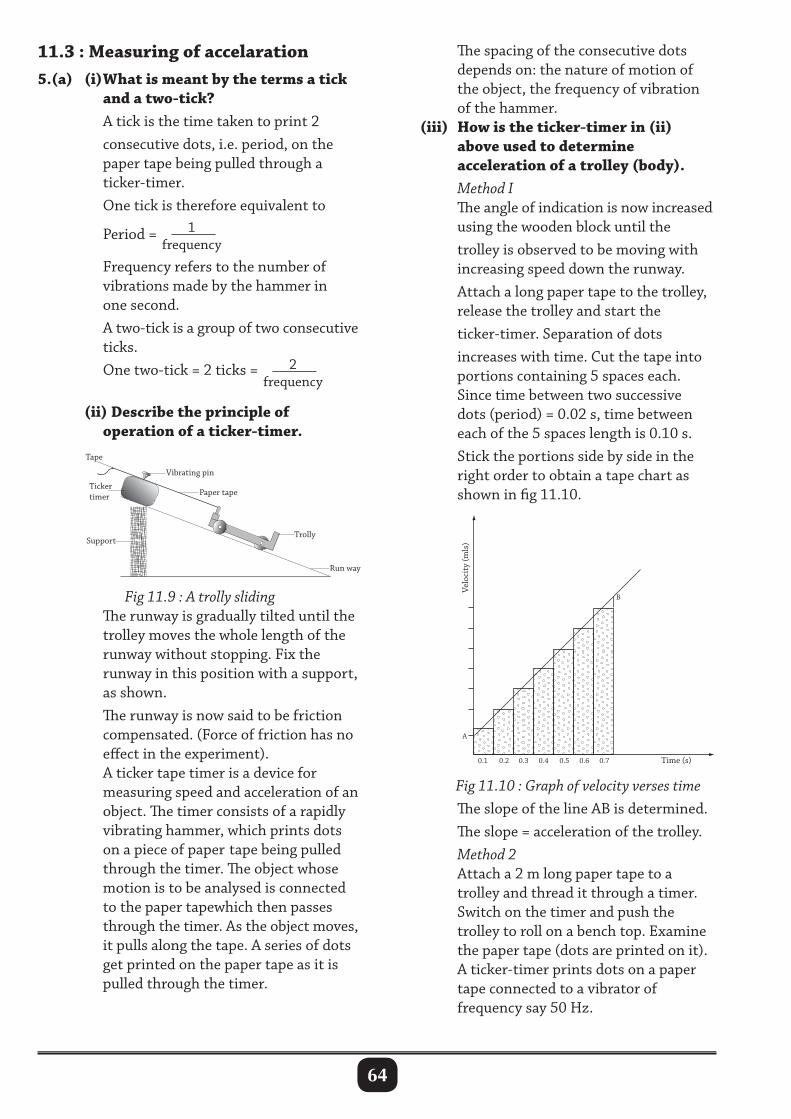
64
A
0.1 0.2 0.3 0.4 0.5 0.6 0.7 Time (s)
Velo
city
(mls
)
B
The spacing of the consecutive dots depends on: the nature of motion of the object, the frequency of vibration of the hammer. (iii) How is the ticker-timer in (ii) above used to determine acceleration of a trolley (body). Method I The angle of indication is now increased using the wooden block until the trolley is observed to be moving with increasing speed down the runway. Attach a long paper tape to the trolley, release the trolley and start the ticker-timer. Separation of dots increases with time. Cut the tape into portions containing 5 spaces each. Since time between two successive dots (period) = 0.02 s, time between each of the 5 spaces length is 0.10 s. Stick the portions side by side in the right order to obtain a tape chart as shown in fig 11.10.
11.3 : Measuring of accelaration5.(a) (i) What is meant by the terms a tick and a two-tick? A tick is the time taken to print 2 consecutive dots, i.e. period, on the paper tape being pulled through a ticker-timer. One tick is therefore equivalent to
Period = 1frequency
Frequency refers to the number of vibrations made by the hammer in one second. A two-tick is a group of two consecutive ticks. One two-tick = 2 ticks = 2
frequency
(ii) Describe the principle of operation of a ticker-timer.
Fig 11.9 : A trolly sliding The runway is gradually tilted until the trolley moves the whole length of the runway without stopping. Fix the runway in this position with a support, as shown. The runway is now said to be friction compensated. (Force of friction has no effect in the experiment). A ticker tape timer is a device for measuring speed and acceleration of an object. The timer consists of a rapidly vibrating hammer, which prints dots on a piece of paper tape being pulled through the timer. The object whose motion is to be analysed is connected to the paper tapewhich then passes through the timer. As the object moves, it pulls along the tape. A series of dots get printed on the paper tape as it is pulled through the timer.
Fig 11.10 : Graph of velocity verses time The slope of the line AB is determined. The slope = acceleration of the trolley. Method 2 Attach a 2 m long paper tape to a trolley and thread it through a timer. Switch on the timer and push the trolley to roll on a bench top. Examine the paper tape (dots are printed on it). A ticker-timer prints dots on a paper tape connected to a vibrator of frequency say 50 Hz.
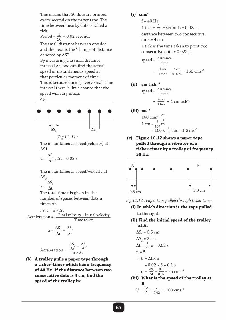
65
This means that 50 dots are printed every second on the paper tape. The time between nearby dots is called a tick. Period = 1
50= 0.02 seconds
The small distance between one dot and the next is the “change of distance denoted by ∆S”. By measuring the small distance interval ∆t, one can find the actual speed or instantaneous speed at that particular moment of time. This is because during a very small time interval there is little chance that the speed will vary much. e.g.
(i) cms–1 f = 40 Hz 1 tick = 1
f= seconds = 0.025 s
distance between two consecutive dots = 4 cm 1 tick is the time taken to print two consecutive dots = 0.025 s speed = distance
time
= 4 cm1 tick
= 4 cm0.025s
= 160 cms–1
(ii) cm tick –1
speed = distancetime
= 4 cm1 tick
= 4 cm tick–1
(iii) ms–1
160 cms–1 cms
1 cm = 1100
m = 160 × 1
100ms = 1.6 ms–1
(c) Figure 10.12 shows a paper tape pulled through a vibrator of a ticker-timer by a trolley of frequency 50 Hz.
∆S2 ∆S1
Fig 11. 11 : The instantaneous speed(velocity) at ∆S1
u =∆S1
∆t, ∆t = 0.02 s
The instantaneous speed/velocity at ∆S2
v =∆S1
∆t The total time t is given by the number of spaces between dots n times ∆t. i.e. t = n × ∆t Acceleration = Final velocity – Initial velocity
Time taken
a =∆S1
∆t–∆S1
∆t
Acceleration = ∆S2∆t
– ∆S1∆t
n × ∆t (b) A trolley pulls a paper tape through a ticker–timer which has a frequency of 40 Hz. If the distance between two consecutive dots is 4 cm, find the speed of the trolley in:
0.5 cm 2.0 cm
BA
Fig 11.12 : Paper tape pulled through ticker timer (i) In which direction is the tape pulled. to the right. (ii) Find the initial speed of the trolley at A. ∆S1 = 0.5 cm ∆S2 = 2 cm ∆t = 1
50s = 0.02 s
n = 5 ∴ t = ∆t x n = 0.02 × 5 = 0.1 s ∴ u = ∆S1
∆t = 0.50.02
= 25 cms–1
(iii) What is the speed of the trolley at B. V = ∆S2
∆t = 20.02
= 100 cms–1
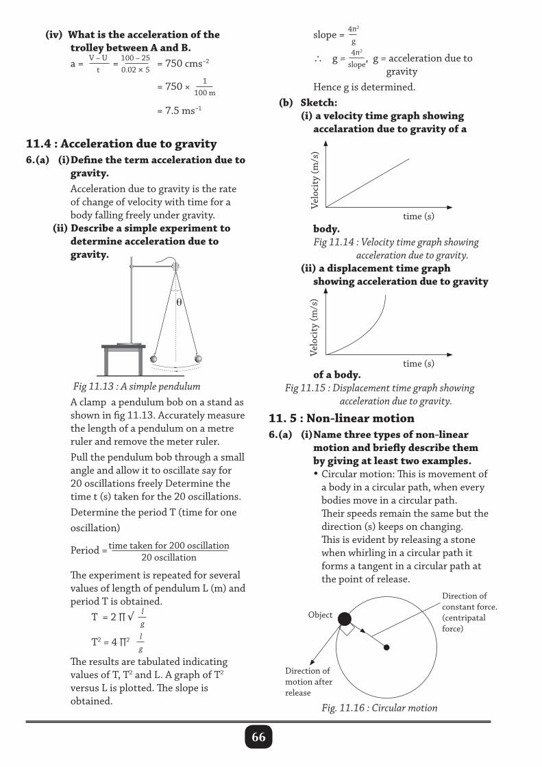
66
time (s)
Velo
city
(m/s
)
time (s)
Velo
city
(m/s
)
(iv) What is the acceleration of the trolley between A and B. a = V – U
t = 100 – 25
0.02 × 5 = 750 cms–2
= 750 × 1
100 m = 7.5 ms–1
11.4 : Acceleration due to gravity6.(a) (i) Define the term acceleration due to gravity. Acceleration due to gravity is the rate of change of velocity with time for a body falling freely under gravity. (ii) Describe a simple experiment to determine acceleration due to gravity.
slope = 4π2
g ∴ g = 4π2
slope, g = acceleration due to
gravity Hence g is determined. (b) Sketch: (i) a velocity time graph showing accelaration due to gravity of a
Fig 11.13 : A simple pendulum A clamp a pendulum bob on a stand as shown in fig 11.13. Accurately measure the length of a pendulum on a metre ruler and remove the meter ruler. Pull the pendulum bob through a small angle and allow it to oscillate say for 20 oscillations freely Determine the time t (s) taken for the 20 oscillations. Determine the period T (time for one oscillation)
Period =time taken for 200 oscillation20 oscillation
The experiment is repeated for several values of length of pendulum L (m) and period T is obtained. T = 2 ∏ √ l
g
T2 = 4 ∏2 lg
The results are tabulated indicating values of T, T2 and L. A graph of T2 versus L is plotted. The slope is obtained.
body. Fig 11.14 : Velocity time graph showing acceleration due to gravity. (ii) a displacement time graph showing acceleration due to gravity
of a body.Fig 11.15 : Displacement time graph showing
acceleration due to gravity.
11. 5 : Non-linear motion6.(a) (i) Name three types of non-linear motion and briefly describe them by giving at least two examples. • Circular motion: This is movement of a body in a circular path, when every bodies move in a circular path. Their speeds remain the same but the direction (s) keeps on changing. This is evident by releasing a stone when whirling in a circular path it forms a tangent in a circular path at the point of release.
Direction ofmotion afterrelease
Object
Direction ofconstant force.(centripatalforce)
Fig. 11.16 : Circular motion
θ
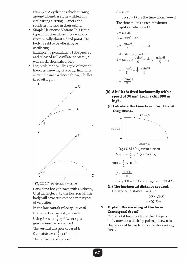
67
Example: A cyclist or vehicle turning around a bend. A stone whirled in a circle using a string. Planets and satellites moving in their orbits. • Simple Harmonic Motion: This is the type of motion where a body moves rhythmically about a fixed point. The body is said to be vibrating or oscillating. Examples: a pendulum, a tube pressed and released will oscillate on water, a wall clock, shock absorbers. • Projectile Motion: This type of motion involves throwing of a body. Examples: a javelin throw, a discus throw, a bullet fired off a gun.
S = u × t = ucosθ × t (t is the time taken) ––– 2 The time taken to rach maximum height i.e. when v = O v = u + at O = usinθ – gt t = usinθ
g ------------ 3
Substituting 3 into 1 S = usinθ × usinθ
g – 12
u2 usin2θg × g
= u2sin2θ
g – 12
usin2θg
S = u2sin2θg
(b) A bullet is fired horizontally with a speed of 30 ms–1 from a cliff 900 m high. (i) Calculate the time taken for it to hit the ground.
time (s)
30 m/s
900 m
U
θ
U
θ
HFig 11.17 : Projecticle motion
Consider a body thrown with a velocity, U, at an angle, θ, to the horizontal. The body will have two components (types of velocities): In the horizontal: velocity = u cosθ In the vertical velocity = u sinθ Using S = ut +
12 gt2 (where g is
gravitational acceleration) The vertical distance covered is S = u sinθ × t +
12 g t2 ––––– 1
The horizontal distance
Fig 11.18 : Projection motion S = ut + 1
2gt2 (vertically)
900 = 12
× 10 t2
t2 = 1800
10
t = √180 = 13.42 s i.e. ignore – 13.42 s (ii) The horizontal distance covered. Horizontal distance = s × t = 30 × √180 = 402.5 m7. Explain the meaning of the term Centripetal force? Centripetal force is a force that keeps a body move in a circle by pulling it towards the centre of he circle. It is a centre seeking force.
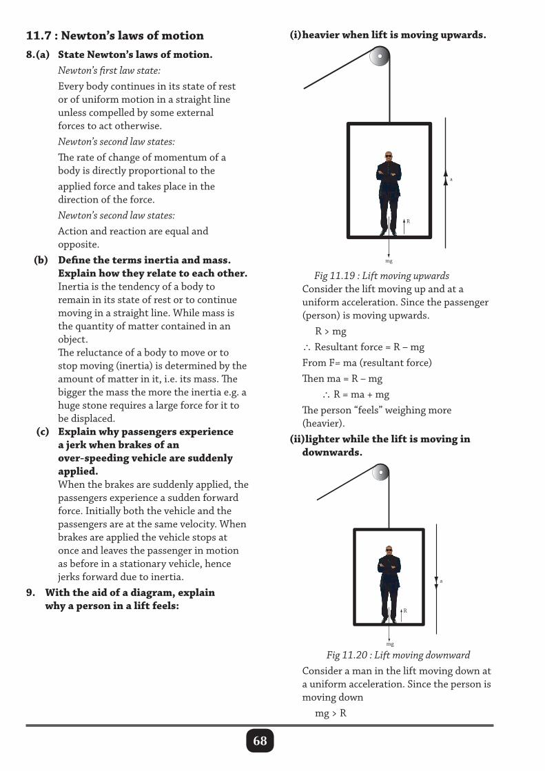
68
11.7 : Newton’s laws of motion8.(a) State Newton’s laws of motion. Newton’s first law state: Every body continues in its state of rest or of uniform motion in a straight line unless compelled by some external forces to act otherwise. Newton’s second law states: The rate of change of momentum of a body is directly proportional to the applied force and takes place in the direction of the force. Newton’s second law states: Action and reaction are equal and opposite. (b) Define the terms inertia and mass. Explain how they relate to each other. Inertia is the tendency of a body to remain in its state of rest or to continue moving in a straight line. While mass is the quantity of matter contained in an object. The reluctance of a body to move or to stop moving (inertia) is determined by the amount of matter in it, i.e. its mass. The bigger the mass the more the inertia e.g. a huge stone requires a large force for it to be displaced. (c) Explain why passengers experience a jerk when brakes of an over-speeding vehicle are suddenly applied. When the brakes are suddenly applied, the passengers experience a sudden forward force. Initially both the vehicle and the passengers are at the same velocity. When brakes are applied the vehicle stops at once and leaves the passenger in motion as before in a stationary vehicle, hence jerks forward due to inertia. 9. With the aid of a diagram, explain why a person in a lift feels:
(i) heavier when lift is moving upwards.
Fig 11.19 : Lift moving upwards Consider the lift moving up and at a uniform acceleration. Since the passenger (person) is moving upwards. R > mg ∴Resultant force = R – mg From F= ma (resultant force) Then ma = R – mg ∴ R = ma + mg The person “feels” weighing more (heavier). (ii)lighter while the lift is moving in downwards.
Fig 11.20 : Lift moving downward Consider a man in the lift moving down at a uniform acceleration. Since the person is moving down mg > R
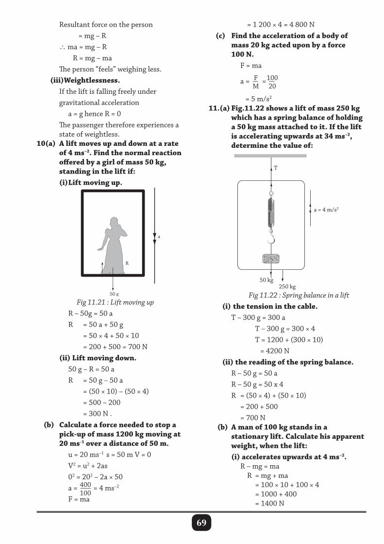
69
Resultant force on the person = mg – R ∴ ma = mg – R R = mg – ma The person “feels” weighing less. (iii)Weightlessness. If the lift is falling freely under gravitational acceleration a = g hence R = 0 The passenger therefore experiences a state of weightless.10(a) A lift moves up and down at a rate of 4 ms–2. Find the normal reaction offered by a girl of mass 50 kg, standing in the lift if: (i) Lift moving up.
50 g
R
a
10
20
30
40
50
60
70
80
50 kg 250 kg
a = 4 m/s2
T
Fig 11.21 : Lift moving up R – 50g = 50 a R = 50 a + 50 g = 50 × 4 + 50 × 10 = 200 + 500 = 700 N (ii) Lift moving down. 50 g – R = 50 a R = 50 g – 50 a = (50 × 10) – (50 × 4) = 500 – 200 = 300 N . (b) Calculate a force needed to stop a pick-up of mass 1200 kg moving at 20 ms-1 over a distance of 50 m. u = 20 ms–1 s = 50 m V = 0 V2 = u2 + 2as 02 = 202 – 2a × 50 a = 400
100 = 4 ms–2
F = ma
= 1 200 × 4 = 4 800 N (c) Find the acceleration of a body of mass 20 kg acted upon by a force 100 N. F = ma a = F
M=100
20
= 5 m/s2 11.(a) Fig.11.22 shows a lift of mass 250 kg which has a spring balance of holding a 50 kg mass attached to it. If the lift is accelerating upwards at 34 ms–2, determine the value of:
Fig 11.22 : Spring balance in a lift (i) the tension in the cable. T – 300 g = 300 a T – 300 g = 300 × 4 T = 1200 + (300 × 10) = 4200 N (ii) the reading of the spring balance. R – 50 g = 50 a R – 50 g = 50 x 4 R = (50 × 4) + (50 × 10) = 200 + 500 = 700 N (b) A man of 100 kg stands in a stationary lift. Calculate his apparent weight, when the lift: (i) accelerates upwards at 4 ms–2. R – mg = ma R = mg + ma = 100 × 10 + 100 × 4 = 1000 + 400 = 1400 N
70
(ii) accelerates downwards at 4 ms–2
mg – R = ma R = mg – ma = (100 × 10) – (100 × 4) = 1000 – 400 = 600 N (iii) falls freely under gravity. a = g mg – R = ma but a = g ∴R = 0
11.7 : Collision and application of Newton’s laws of motion12.(a) Distinguish between elastic and inelastic collusion. Elastic collision is type of collusion where bodies collide and separate after the collision. Both kinetic energy and momentum are conserved. Inelastic collision is where bodies collide and stick together after the collision. Only momenta is conserved. (b) Define the following terms and give their SI units. (i) Momentum Momentum is the product of mass and velocity of the body. Momentum = mass x velocity P = m × v SI units is kilogram metres per second (kgms-1). (ii) Impulse Impulse is the product of force and time, i.e. force applied over a very short time. Impulse = Force x time I = Ft It is equal to change in momentum of a body. Its SI unit is Newton Second (Ns). (c) State the law of Conservation of momentum Momenta before collision is equal to momenta after collision or Sum of momentum before collision equals to sum of momentum after collision.
13. Show how Newton’s third law is related to momenta for any two bodies involved in a collision. When body A strikes another body B Force of A on B = force of B on A –––(a) Negative sign shows that the forces are opposite in direction i.e. FA = -FB
MAaA = MBaB ––––– b From Newton’s second law
MA( vA – uAt ) = –MB( vB – uB
t )–––– c
Where uA and uB are velocities before impact. vA and vB are velocities after impact. t is the time of impact. Dividing t on both sides of (c), we get MA (vA – uA) = MB (vB – uB) or MAuA + MBuB = MAvA + MBvB
∴Sum of initial = Sum of final momenta momenta
14.(a) A truck of mass 104 kg moving with a velocity of 2 ms-1 collides with a stationary truck of mass 6 x 10³ kg. Both trucks move together after impact. What is their common velocity? Applying law of conservation of momentum (M1u1 + M2u2) = (m1 + m2)v (104 × 2) + (6 × 103 × 0) = (10 + 6.0) × 103 v 20 = 16 v v = 1.25 m/s (b) A gun of mass 60,000 kg fires a shell of mass 100 kg with a velocity of 500 m/s. Find the velocity of recoil of the gun. Mgug = MSuS where Mg of gun and Ms of shell. 60 000 v = 100 × 500
v = 100 × 50060000
= 0.83 m/s
The velocity of recoil is 0.83 m/s
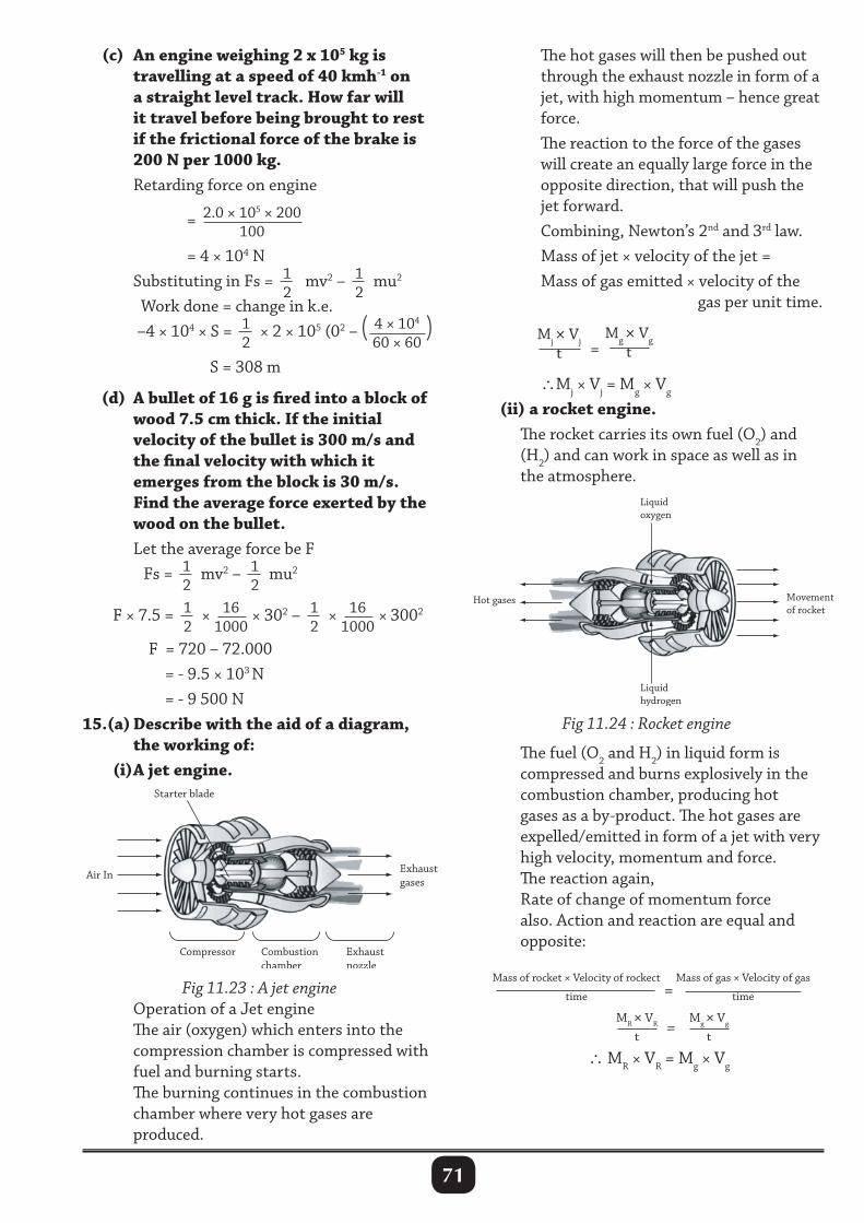
71
(c) An engine weighing 2 x 10⁵ kg is travelling at a speed of 40 kmh-1 on a straight level track. How far will it travel before being brought to rest if the frictional force of the brake is 200 N per 1000 kg. Retarding force on engine = 2.0 × 105 × 200
100
= 4 × 10⁴ N Substituting in Fs = 1
2 mv2 – 1
2mu2
Work done = change in k.e. –4 × 10⁴ × S = 1
2× 2 × 105 (02 – ( 4 × 10⁴
60 × 60)
S = 308 m
(d) A bullet of 16 g is fired into a block of wood 7.5 cm thick. If the initial velocity of the bullet is 300 m/s and the final velocity with which it emerges from the block is 30 m/s. Find the average force exerted by the wood on the bullet. Let the average force be F Fs = 1
2mv2 – 1
2mu2
F × 7.5 = 12
× 161000
× 302 – 12
× 161000
× 3002
F = 720 – 72.000 = - 9.5 × 10³ N = - 9 500 N15.(a) Describe with the aid of a diagram, the working of: (i) A jet engine.
The hot gases will then be pushed out through the exhaust nozzle in form of a jet, with high momentum – hence great force. The reaction to the force of the gases will create an equally large force in the opposite direction, that will push the jet forward. Combining, Newton’s 2nd and 3rd law. Mass of jet × velocity of the jet = Mass of gas emitted × velocity of the gas per unit time.
Mj × Vj
t =Mg × Vg
t
∴Mj × Vj = Mg × Vg
(ii) a rocket engine. The rocket carries its own fuel (O2) and (H2) and can work in space as well as in the atmosphere.
Movement of rocket
Liquidoxygen
Liquid hydrogen
Hot gases
Compressor Exhaust nozzle
Exhaust gases
Air In
Starter blade
Combustion chamber
Fig 11.23 : A jet engine Operation of a Jet engine The air (oxygen) which enters into the compression chamber is compressed with fuel and burning starts. The burning continues in the combustion chamber where very hot gases are produced.
Fig 11.24 : Rocket engine
The fuel (O2 and H2) in liquid form is compressed and burns explosively in the combustion chamber, producing hot gases as a by-product. The hot gases are expelled/emitted in form of a jet with very high velocity, momentum and force. The reaction again, Rate of change of momentum force also. Action and reaction are equal and opposite:
Mass of rocket × Velocity of rockect
time =
Mass of gas × Velocity of gas
time
MR × VR
t= Mg × Vg
t
∴ MR × VR = Mg × Vg
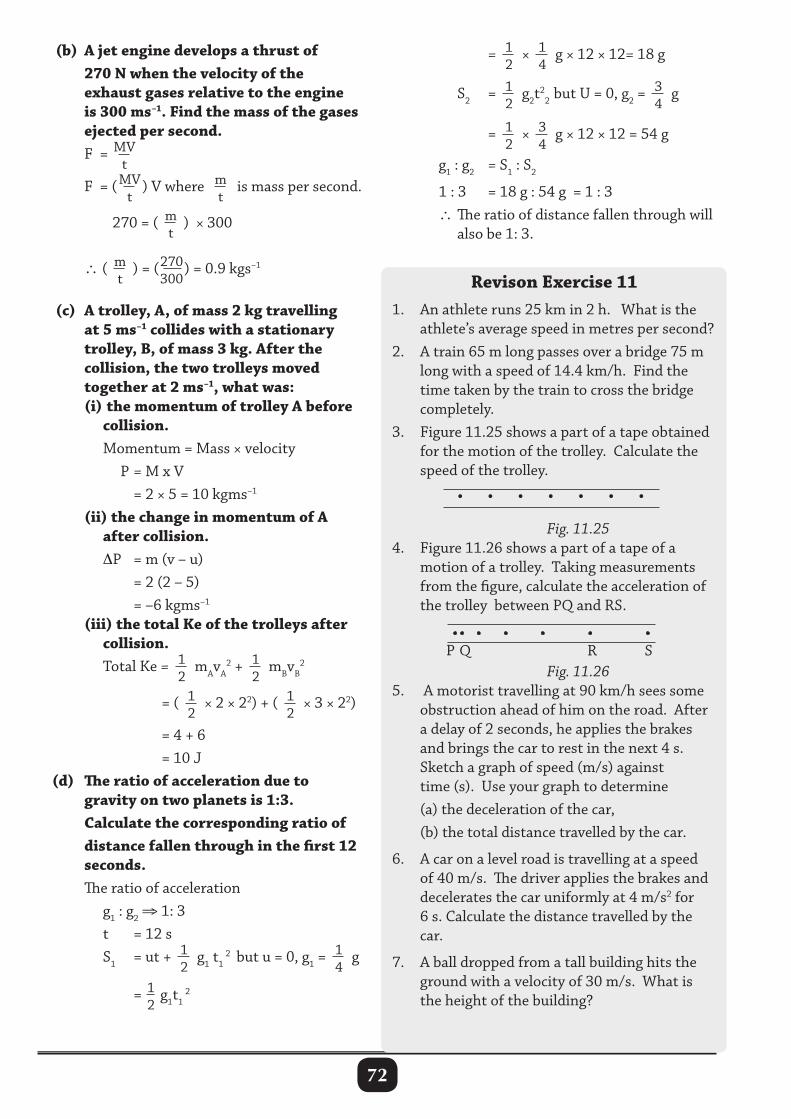
72
(b) A jet engine develops a thrust of 270 N when the velocity of the exhaust gases relative to the engine is 300 ms–1. Find the mass of the gases ejected per second. F = MV
t
F = ( MV
t) V where m
t is mass per second.
270 = ( mt
) × 300
∴( mt
) = (270300
) = 0.9 kgs–1
(c) A trolley, A, of mass 2 kg travelling at 5 ms–1 collides with a stationary trolley, B, of mass 3 kg. After the collision, the two trolleys moved together at 2 ms–1, what was: (i) the momentum of trolley A before collision. Momentum = Mass × velocity P = M x V = 2 × 5 = 10 kgms–1
(ii) the change in momentum of A after collision. ∆P = m (v – u) = 2 (2 – 5) = –6 kgms–1
(iii) the total Ke of the trolleys after collision. Total Ke = 1
2mAvA
2 + 12
mBvB2
= ( 1
2× 2 × 22) + ( 1
2× 3 × 22)
= 4 + 6 = 10 J (d) The ratio of acceleration due to gravity on two planets is 1:3. Calculate the corresponding ratio of distance fallen through in the first 12 seconds. The ratio of acceleration g1 : g2 ⇒ 1: 3 t = 12 s S1 = ut + 1
2g1 t1
2 but u = 0, g1 =14
g
= 12
g1t1 2
= 12
× 14
g × 12 × 12= 18 g
S2 = 12
g2t2
2 but U = 0, g2 =34
g
= 1
2× 3
4g × 12 × 12 = 54 g
g1 : g2 = S1 : S2
1 : 3 = 18 g : 54 g = 1 : 3 ∴ The ratio of distance fallen through will also be 1: 3.
Revison Exercise 111. An athlete runs 25 km in 2 h. What is the athlete’s average speed in metres per second?2. A train 65 m long passes over a bridge 75 m long with a speed of 14.4 km/h. Find the time taken by the train to cross the bridge completely.3. Figure 11.25 shows a part of a tape obtained for the motion of the trolley. Calculate the speed of the trolley.
• • • • • • •
P Q R S
Fig. 11.254. Figure 11.26 shows a part of a tape of a motion of a trolley. Taking measurements from the figure, calculate the acceleration of the trolley between PQ and RS.
Fig. 11.265. A motorist travelling at 90 km/h sees some obstruction ahead of him on the road. After a delay of 2 seconds, he applies the brakes and brings the car to rest in the next 4 s. Sketch a graph of speed (m/s) against time (s). Use your graph to determine (a) the deceleration of the car, (b) the total distance travelled by the car.
6. A car on a level road is travelling at a speed of 40 m/s. The driver applies the brakes and decelerates the car uniformly at 4 m/s2 for 6 s. Calculate the distance travelled by the car.
7. A ball dropped from a tall building hits the ground with a velocity of 30 m/s. What is the height of the building?
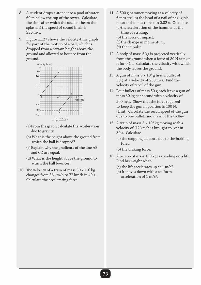
73
8. A student drops a stone into a pool of water 60 m below the top of the tower. Calculate the time after which the student hears the splash, if the speed of sound in air is 330 m/s.
9. Figure 11.27 shows the velocity-time graph for part of the motion of a ball, which is dropped from a certain height above the ground and allowed to bounce from the ground.
4.0
2.0
0
–2.0
–4.0
5.0
–3.0
– – – – – – – – – – – – – – – – –
– – – – – – – – – – – – – – – – –
0.5 0.8 1.0time (s)
velocity (m/s)
B
A
C
D
Fig. 11.27
(a) From the graph calculate the acceleration due to gravity. (b) What is the height above the ground from which the ball is dropped? (c) Explain why the gradients of the line AB and CD are equal. (d) What is the height above the ground to which the ball bounces?
10. The velocity of a train of mass 30 × 103 kg changes from 36 km/h to 72 km/h in 40 s. Calculate the accelerating force.
11. A 500 g hammer moving at a velocity of 6 m/s strikes the head of a nail of negligible mass and comes to rest in 0.02 s. Calculate (a) the acceleration of the hammer at the time of striking, (b) the force of impact, (c) the change in momentum, (d) the impulse.
12. A body of mass 5 kg is projected vertically from the ground when a force of 80 N acts on it for 0.1 s. Calculate the velocity with which the body leaves the ground.
13. A gun of mass 9 × 10³ g fires a bullet of 50 g at a velocity of 250 m/s. Find the velocity of recoil of the gun. 14. Four bullets of mass 50 g each leave a gun of mass 30 kg per second with a velocity of 500 m/s. Show that the force required to keep the gun in position is 100 N. (Hint: Calculate the recoil speed of the gun due to one bullet, and mass of the trolley.
15. A train of mass 3 × 10⁴ kg moving with a velocity of 72 km/h is brought to rest in 30 s. Calculate (a) the stopping distance due to the braking force, (b) the braking force.
16. A person of mass 100 kg is standing on a lift. Find his weight when (a) the lift accelerates up at 1 m/s2, (b) it moves down with a uniform acceleration of 1 m/s2.
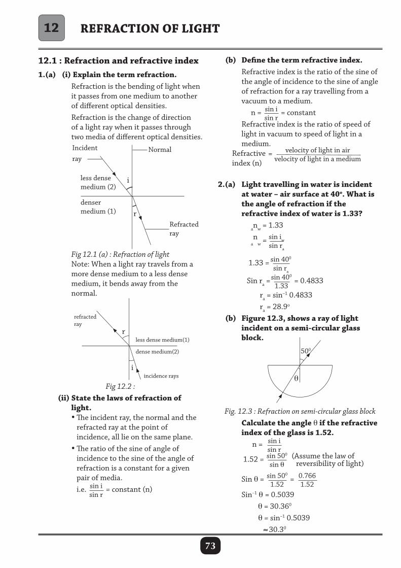
73
REFRACTION OF LIGHT
12.1 : Refraction and refractive index1.(a) (i) Explain the term refraction. Refraction is the bending of light when it passes from one medium to another of different optical densities. Refraction is the change of direction of a light ray when it passes through two media of different optical densities.
(b) Define the term refractive index. Refractive index is the ratio of the sine of the angle of incidence to the sine of angle of refraction for a ray travelling from a vacuum to a medium. n = sin i
sin r= constant
Refractive index is the ratio of speed of light in vacuum to speed of light in a medium. Refractive index (n)
= velocity of light in airvelocity of light in a medium
2.(a) Light travelling in water is incident at water – air surface at 40o. What is the angle of refraction if the refractive index of water is 1.33? anw = 1.33
an
w = sin iwsin ra
1.33 = sin 400
sin ra
Sin ra =sin 400
1.33 = 0.4833
ra = sin–1 0.4833 ra = 28.9o (b) Figure 12.3, shows a ray of light incident on a semi-circular glass block.
Fig 12.1 (a) : Refraction of light Note: When a light ray travels from a more dense medium to a less dense medium, it bends away from the normal.
r
i
refractedray
less dense medium(1)
dense medium(2)
incidence rays
Fig 12.2 : (ii) State the laws of refraction of light. •The incident ray, the normal and the refracted ray at the point of incidence, all lie on the same plane. • The ratio of the sine of angle of incidence to the sine of the angle of refraction is a constant for a given pair of media. i.e. sin i
sin r= constant (n)
12
i
rRefractedray
less densemedium (2)
NormalIncidentray
densermedium (1)
500
θ
Fig. 12.3 : Refraction on semi-circular glass block Calculate the angle θ if the refractive index of the glass is 1.52. n = sin i
sin r
1.52 = sin 500
sin θ (Assume the law of
reversibility of light)
Sin θ = sin 500
1.52= 0.766
1.52
Sin–1 θ= 0.5039 θ = 30.360
θ = sin–1 0.5039 ≈30.30
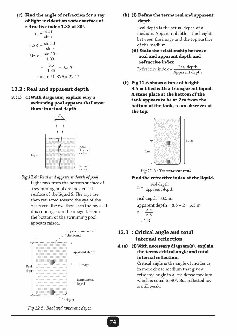
74
Bottom surface
Liquid
Liquid
S
Image of bottom surface
Bottom
Image of bottom I
Liquid surface
(c) Find the angle of refraction for a ray of light incident on water surface of refractive index 1.33 at 30o. n = sin i
sin r
1.33 = sin 330
sin r
Sin r = sin 330
1.33
= 0.51.33
= 0.376
r = sin–1 0.376 = 22.1o
12.2 : Real and apparent depth3.(a) (i) With diagrams, explain why a swimming pool appears shallower than its actual depth.
apparent depth
apparent surface of the liquid
image
object
transparent liquid
Real depth
(b) (i) Define the terms real and apparent depth. Real depth is the actual depth of a medium. Apparent depth is the height between the image and the top surface of the medium. (ii) State the relationship between real and apparent depth and refractive index Refractive index = Real depth
Apparent depth (f) Fig 12.6 shows a tank of height 8.5 m filled with a transparent liquid. A stone place at the bottom of the tank appears to be at 2 m from the bottom of the tank, to an observer at the top.
Fig 12.6 : Transparent tank Find the refractive index of the liquid. n =
real depth apparent depth
real depth = 8.5 m apparent depth = 8.5 – 2 = 6.5 m n = 8.5
6.5 = 1.3
12.3 : Critical angle and total internal reflection4.(a) (i) With necessary diagram(s), explain the terms critical angle and total internal reflection. Critical angle is the angle of incidence in more dense medium that give a refracted angle in a less dense medium which is equal to 90o. But reflected ray is still weak.
Fig 12.4 : Real and apparent depth of pool Light rays from the bottom surface of a swimming pool are incident at surface of the liquid S. The rays are then refracted toward the eye of the observer. The eye then sees the ray as if it is coming from the image I. Hence the bottom of the swimming pool appears raised.
Fig 12.5 : Real and apparent depth
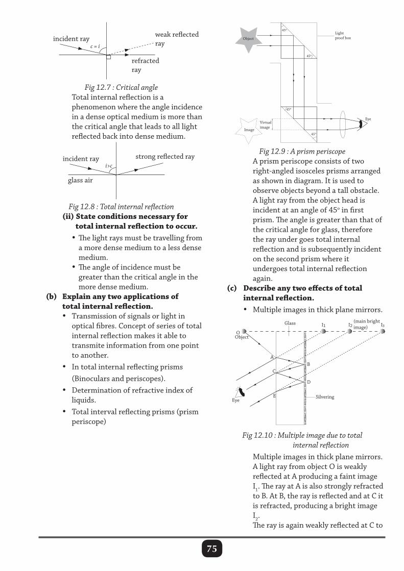
75
Fig 12.7 : Critical angle Total internal reflection is a phenomenon where the angle incidence in a dense optical medium is more than the critical angle that leads to all light reflected back into dense medium.
45o
45o
45o
45o
Image
Object
Virtual image
Eye
Light proof box
weak reflected ray
refractedray
incident rayc = i
strong reflected ray
glass air
incident rayi>c
Fig 12.8 : Total internal reflection (ii) State conditions necessary for total internal reflection to occur. •The light rays must be travelling from a more dense medium to a less dense medium. • The angle of incidence must be greater than the critical angle in the more dense medium. (b) Explain any two applications of total internal reflection. • Transmission of signals or light in optical fibres. Concept of series of total internal reflection makes it able to transmite information from one point to another. • In total internal reflecting prisms (Binoculars and periscopes). • Determination of refractive index of liquids. • Total interval reflecting prisms (prism periscope)
Fig 12.9 : A prism periscope A prism periscope consists of two right-angled isosceles prisms arranged as shown in diagram. It is used to observe objects beyond a tall obstacle. A light ray from the object head is incident at an angle of 45o in first prism. The angle is greater than that of the critical angle for glass, therefore the ray under goes total internal reflection and is subsequently incident on the second prism where it undergoes total internal reflection again. (c) Describe any two effects of total internal reflection. • Multiple images in thick plane mirrors.
EyeSilvering
(main bright image)
Object
Glass I1
A
C
O
E
B
D
I2 I3
Fig 12.10 : Multiple image due to total internal reflection Multiple images in thick plane mirrors. A light ray from object O is weakly reflected at A producing a faint image I1. The ray at A is also strongly refracted to B. At B, the ray is reflected and at C it is refracted, producing a bright image I2. The ray is again weakly reflected at C to
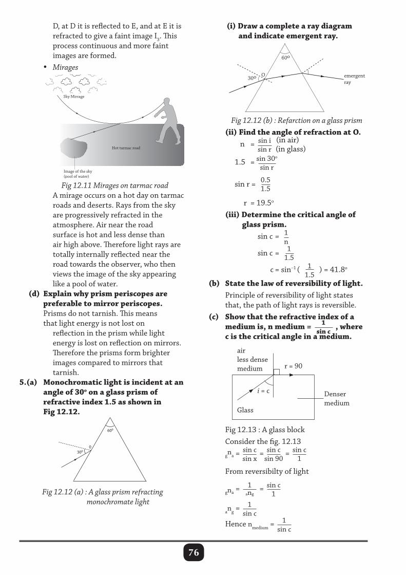
76
Sky Mirrage
Hot tarmac road
Image of the sky (pool of water)
(i) Draw a complete a ray diagram and indicate emergent ray.
D, at D it is reflected to E, and at E it is refracted to give a faint image I3. This process continuous and more faint images are formed. • Mirages
Fig 12.12 (b) : Refarction on a glass prism (ii) Find the angle of refraction at O. n = sin i
sin r (in air)
(in glass)
1.5 = sin 30o
sin r
sin r = 0.51.5
r = 19.5o
(iii) Determine the critical angle of glass prism. sin c = 1
n
sin c = 11.5
c = sin–1 ( 11.5
) = 41.8o
(b) State the law of reversibility of light. Principle of reversibility of light states that, the path of light rays is reversible. (c) Show that the refractive index of a medium is, n medium = 1
sin c, where
c is the critical angle in a medium.
Fig 12.11 Mirages on tarmac road A mirage occurs on a hot day on tarmac roads and deserts. Rays from the sky are progressively refracted in the atmosphere. Air near the road surface is hot and less dense than air high above. Therefore light rays are totally internally reflected near the road towards the observer, who then views the image of the sky appearing like a pool of water. (d) Explain why prism periscopes are preferable to mirror periscopes. Prisms do not tarnish. This means that light energy is not lost on reflection in the prism while light energy is lost on reflection on mirrors. Therefore the prisms form brighter images compared to mirrors that tarnish.5.(a) Monochromatic light is incident at an angle of 30o on a glass prism of refractive index 1.5 as shown in Fig 12.12.
Fig 12.12 (a) : A glass prism refracting monochromate light
airless densemedium r = 90
i = c Denser medium
Glass
Fig 12.13 : A glass block Consider the fig. 12.13 gna =
sin csin x
= sin csin 90
= sin c1
From reversibilty of light
gna =
1ang
= sin c1
ang =1
sin c Hence nmedium = 1
sin c
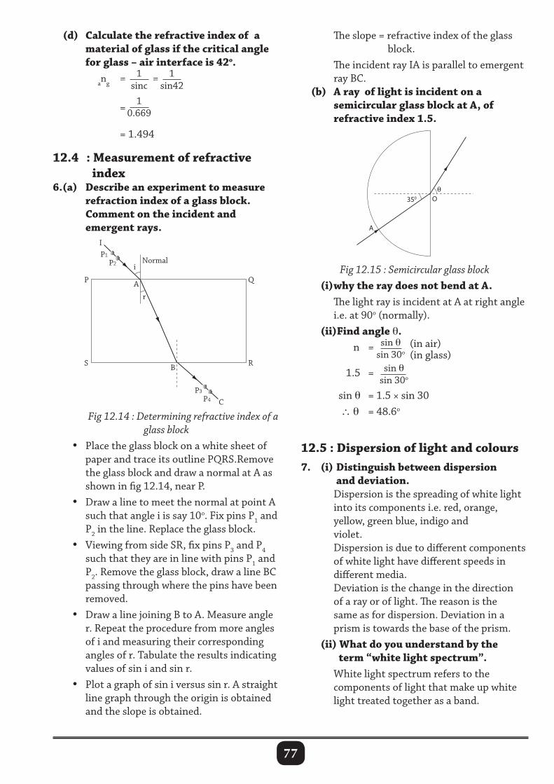
77
(d) Calculate the refractive index of a material of glass if the critical angle for glass – air interface is 42o. ang = 1
sinc= 1
sin42
=1
0.669
= 1.494
12.4 : Measurement of refractive index6.(a) Describe an experiment to measure refraction index of a glass block. Comment on the incident and emergent rays.
The slope = refractive index of the glass block. The incident ray IA is parallel to emergent ray BC. (b) A ray of light is incident on a semicircular glass block at A, of refractive index 1.5.
Fig 12.14 : Determining refractive index of a glass block
• Place the glass block on a white sheet of paper and trace its outline PQRS.Remove the glass block and draw a normal at A as shown in fig 12.14, near P. • Draw a line to meet the normal at point A such that angle i is say 10o. Fix pins P1 and P2 in the line. Replace the glass block. • Viewing from side SR, fix pins P3 and P4 such that they are in line with pins P1 and P2. Remove the glass block, draw a line BC passing through where the pins have been removed. • Draw a line joining B to A. Measure angle r. Repeat the procedure from more angles of i and measuring their corresponding angles of r. Tabulate the results indicating values of sin i and sin r. • Plot a graph of sin i versus sin r. A straight line graph through the origin is obtained and the slope is obtained.
Fig 12.15 : Semicircular glass block (i) why the ray does not bend at A. The light ray is incident at A at right angle i.e. at 90o (normally). (ii)Find angle θ. n = sin θ
sin 30o (in air)
(in glass)
1.5 = sin θsin 30o
sin θ = 1.5 × sin 30 ∴ θ = 48.6o
12.5 : Dispersion of light and colours7. (i) Distinguish between dispersion and deviation. Dispersion is the spreading of white light into its components i.e. red, orange, yellow, green blue, indigo and violet. Dispersion is due to different components of white light have different speeds in different media. Deviation is the change in the direction of a ray or of light. The reason is the same as for dispersion. Deviation in a prism is towards the base of the prism. (ii) What do you understand by the term “white light spectrum”. White light spectrum refers to the components of light that make up white light treated together as a band.
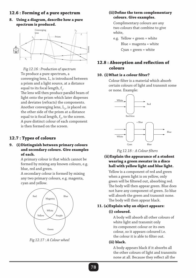
78
12.6 : Forming of a pure spectrum8. Using a diagram, describe how a pure spectrum is produced.
(ii)Define the term complementary colours. Give examples. Complimentary colours are any two colours that combine to give white, e.g. Yellow + green = white Blue + magenta = white Cyan + green = white
12.8 : Absorption and reflection of colours10. (i) What is a colour filter? Colour filter is a material which absorb certain colours of light and transmit some or none. Example:
f
f1
L2
PrismL1
Converginglens
Scre
en
White
Yellow Purple
Red Blue
Green
Magenta
Fig 12.16 : Production of spectrum To produce a pure spectrum, a converging lens, L, is introduced between a prism and a light source, at a distance equal to its focal length, f1. The lens will then produce parallel beam of light onto the prism which later disperses and deviates (refracts) the components. Another converging lens, L2, is placed on the other side of the prism at a distance equal to is focal length, f2, to the screen. A pure distinct colour of each component is then formed on the screen.
12.7 : Types of colours9. (i) Distinguish between primary colours and secondary colours. Give examples of each. A primary colour is that which cannot be formed by mixing any known colours, e.g. blue, red and green. A secondary colour is formed by mixing any two primary colours, e.g. magenta, cyan and yellow.
Fig 12.18 : A Colour filters (ii)Explain the appearance of a student wearing a green sweater in a disco hall with yellow light and blue light. Yellow is a component of red and green when a green light is on yellow, only green will be filtered out, absorbing red. The body will then appear green. Blue does not have any component of green. So blue will absorb the green and transmit none. The body will then appear black.11. (a)Explain why an object appears: (i) coloured. A body will absorb all other colours of white light and transmit only its component colour or its own colour, so it appears coloured i.e. the colour it is able to filter out. (ii) black. A body appears black if it absorbs all the other colours of light and transmits none at all. Because they reflect all the
Fig 12.17 : A Colour wheel
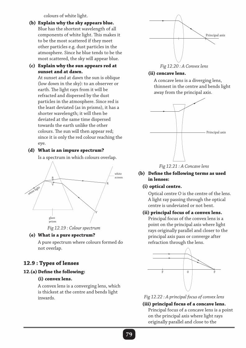
79
colours of white light. (b) Explain why the sky appears blue. Blue has the shortest wavelength of all components of white light. This makes it to be the most scattered if they meet other particles e.g. dust particles in the atmosphere. Since he blue tends to be the most scattered, the sky will appear blue. (c) Explain why the sun appears red at sunset and at dawn. At sunset and at dawn the sun is oblique (low down in the sky): to an observer or earth. The light rays from it will be refracted and dispersed by the dust particles in the atmosphere. Since red is the least deviated (as in prisms), it has a shorter wavelength; it will then be deviated at the same time dispersed towards the earth unlike the other colours. The sun will then appear red; since it is only the red colour reaching the eye. (d) What is an impure spectrum? Is a spectrum in which colours overlap.
Fig 12.20 : A Convex lens (ii) concave lens. A concave lens is a diverging lens, thinnest in the centre and bends light away from the principal axis.
0 F F
Principal axis
Principal axis
0 F F
Principal axis
Principal axis
Fig 12.21 : A Concave lens (b) Define the following terms as used in lenses: (i) optical centre. Optical centre O is the centre of the lens. A light ray passing through the optical centre is undeviated or not bent. (ii) principal focus of a convex lens. Principal focus of the convex lens is a point on the principal axis where light rays originally parallel and closer to the principal axis pass or converge after refraction through the lens.
Fig 12.19 : Colour spectrum (e) What is a pure spectrum? A pure spectrum where colours formed do not overlap.
12.9 : Types of lenses12.(a) Define the following: (i) convex lens. A convex lens is a converging lens, which is thickest at the centre and bends light inwards.
0 F F
Principal axis
Principal axis
Fig 12.22 : A principal focus of convex lens (iii) principal focus of a concave lens. Principal focus of a concave lens is a point on the principal axis where light rays originally parallel and close to the
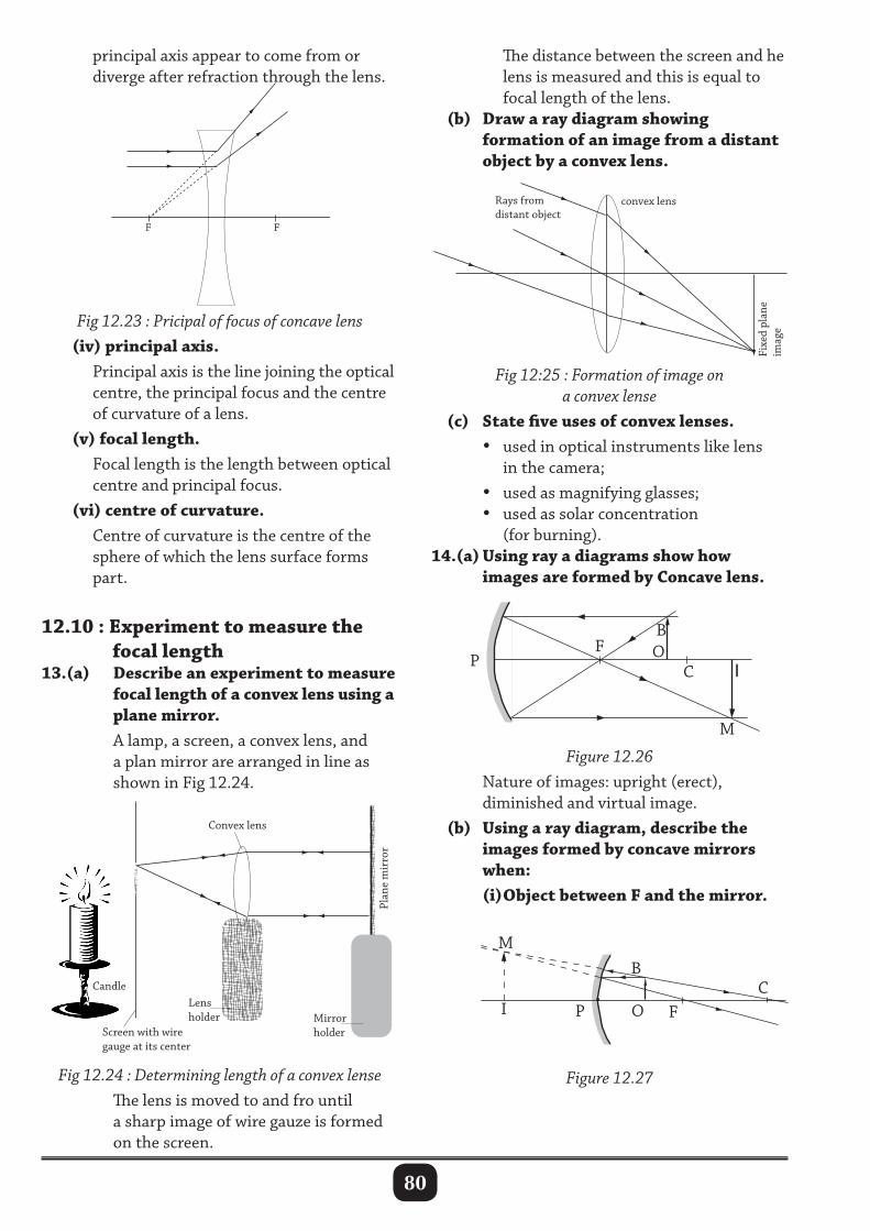
80
Candle Lens holder Mirror
holder
Convex lens
Plan
e m
irro
r
Screen with wire gauge at its center
Fixe
d pl
ane
imag
e
convex lens Rays from distant object
principal axis appear to come from or diverge after refraction through the lens.
The distance between the screen and he lens is measured and this is equal to focal length of the lens. (b) Draw a ray diagram showing formation of an image from a distant object by a convex lens.
F F
Fig 12.23 : Pricipal of focus of concave lens (iv) principal axis. Principal axis is the line joining the optical centre, the principal focus and the centre of curvature of a lens. (v) focal length. Focal length is the length between optical centre and principal focus. (vi) centre of curvature. Centre of curvature is the centre of the sphere of which the lens surface forms part.
12.10 : Experiment to measure the focal length13.(a) Describe an experiment to measure focal length of a convex lens using a plane mirror. A lamp, a screen, a convex lens, and a plan mirror are arranged in line as shown in Fig 12.24.
Fig 12:25 : Formation of image on a convex lense
(c) State five uses of convex lenses. • used in optical instruments like lens in the camera; • used as magnifying glasses; • used as solar concentration (for burning).14.(a) Using ray a diagrams show how images are formed by Concave lens.
Fig 12.24 : Determining length of a convex lense The lens is moved to and fro until a sharp image of wire gauze is formed on the screen.
Figure 12.26 Nature of images: upright (erect), diminished and virtual image. (b) Using a ray diagram, describe the images formed by concave mirrors when: (i) Object between F and the mirror.
BO
ICP
F
M
BC
OI F
M
P
Figure 12.27
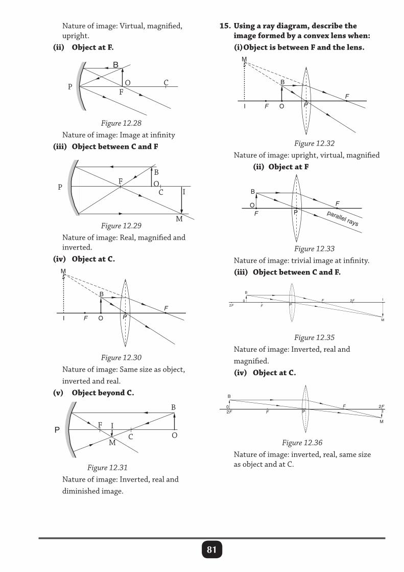
81
Nature of image: Virtual, magnified, upright. (ii) Object at F.
Figure 12.28 Nature of image: Image at infinity (iii) Object between C and F
15. Using a ray diagram, describe the image formed by a convex lens when: (i) Object is between F and the lens.
Figure 12.29 Nature of image: Real, magnified and inverted. (iv) Object at C.
Figure 12.32 Nature of image: upright, virtual, magnified (ii) Object at F
Figure 12.33 Nature of image: trivial image at infinity. (iii) Object between C and F.
Figure 12.30 Nature of image: Same size as object, inverted and real. (v) Object beyond C.
B
OP CF
BO
ICP
F
M
F
FI O
B
M
P
Figure 12.31 Nature of image: Inverted, real and diminished image.
PM
FC
B
OI
F
FI O
B
M
P
F
F
B
OP parallel rays
Figure 12.35 Nature of image: Inverted, real and magnified. (iv) Object at C.
F I2F
F2F
B
0P
M
Figure 12.36 Nature of image: inverted, real, same size as object and at C.
FI
2FF2F
B
0P
M
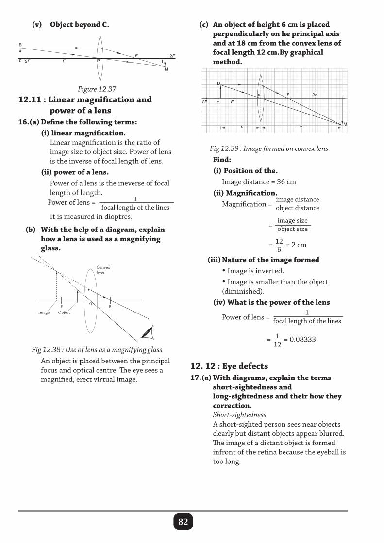
82
(v) Object beyond C. (c) An object of height 6 cm is placed perpendicularly on he principal axis and at 18 cm from the convex lens of focal length 12 cm.By graphical method.
Figure 12.3712.11 : Linear magnification and power of a lens16.(a) Define the following terms: (i) linear magnification. Linear magnification is the ratio of image size to object size. Power of lens is the inverse of focal length of lens. (ii) power of a lens. Power of a lens is the ineverse of focal length of length. Power of lens = 1
focal length of the lines
It is measured in dioptres.
(b) With the help of a diagram, explain how a lens is used as a magnifying glass.
Fig 12.38 : Use of lens as a magnifying glass An object is placed between the principal focus and optical centre. The eye sees a magnified, erect virtual image.
Fig 12.39 : Image formed on convex lens Find: (i) Position of the. Image distance = 36 cm (ii) Magnification. Magnification =
image distance object distance
=
image size object size
=126
= 2 cm (iii) Nature of the image formed •Image is inverted. •Image is smaller than the object (diminished). (iv) What is the power of the lens
Power of lens = 1
focal length of the lines
= 112
= 0.08333
12. 12 : Eye defects17.(a) With diagrams, explain the terms short-sightedness and long-sightedness and their how they correction. Short-sightedness A short-sighted person sees near objects clearly but distant objects appear blurred. The image of a distant object is formed infront of the retina because the eyeball is too long.
F
Image Object
Convex lens
O F
FI
2FF2F
B
0 P
M
FFFF
FFFFFF
uuuu vvvv
2F2F2F2F
2F2FF2F2FF2F2FF III
MMMMMM
BBBBBB
OOOOOOPPPP
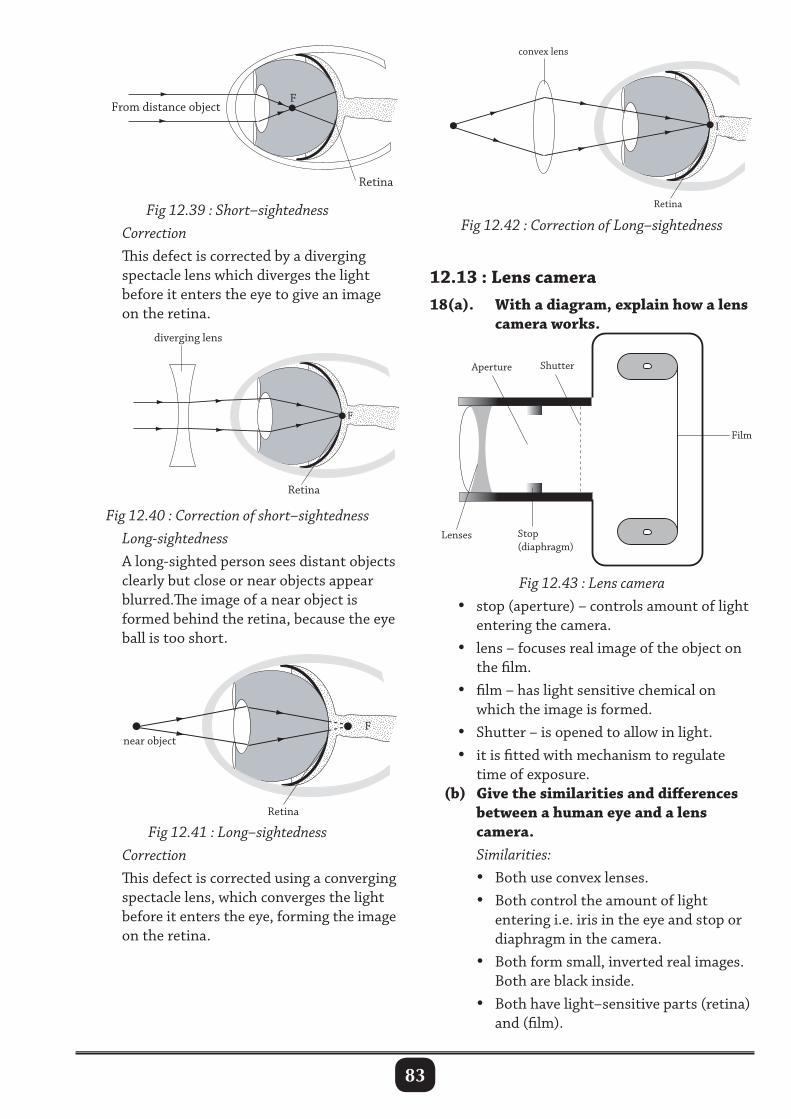
83
Fig 12.39 : Short–sightedness Correction This defect is corrected by a diverging spectacle lens which diverges the light before it enters the eye to give an image on the retina.
F
Retina
From distance object
F
Retina
diverging lens
Fig 12.42 : Correction of Long–sightedness
12.13 : Lens camera18(a). With a diagram, explain how a lens camera works.
Fig 12.43 : Lens camera • stop (aperture) – controls amount of light entering the camera. • lens – focuses real image of the object on the film. • film – has light sensitive chemical on which the image is formed. • Shutter – is opened to allow in light. • it is fitted with mechanism to regulate time of exposure. (b) Give the similarities and differences between a human eye and a lens camera. Similarities: • Both use convex lenses. • Both control the amount of light entering i.e. iris in the eye and stop or diaphragm in the camera. • Both form small, inverted real images. Both are black inside. • Both have light–sensitive parts (retina) and (film).
Fig 12.40 : Correction of short–sightedness Long-sightedness A long-sighted person sees distant objects clearly but close or near objects appear blurred.The image of a near object is formed behind the retina, because the eye ball is too short.
Fig 12.41 : Long–sightedness Correction This defect is corrected using a converging spectacle lens, which converges the light before it enters the eye, forming the image on the retina.
I
Retina
convex lens
Film
Shutter
Stop (diaphragm)
Lenses
Aperture
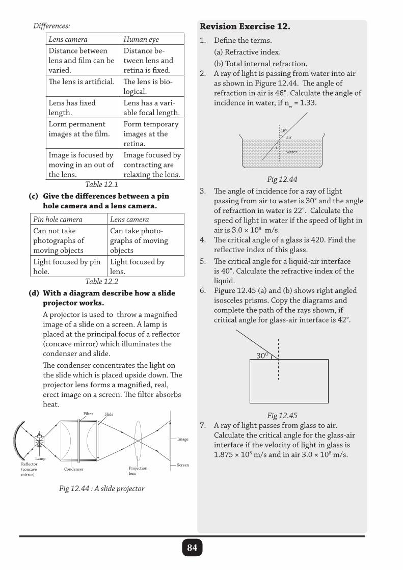
84
Revision Exercise 12.1. Define the terms. (a) Refractive index. (b) Total internal refraction.2. A ray of light is passing from water into air as shown in Figure 12.44. The angle of refraction in air is 46°. Calculate the angle of incidence in water, if nw = 1.33.
Differences:
Lens camera Human eyeDistance between lens and film can be varied.
Distance be-tween lens and retina is fixed.
The lens is artificial. The lens is bio-logical.
Lens has fixed length.
Lens has a vari-able focal length.
Lorm permanent images at the film.
Form temporary images at the retina.
Image is focused by moving in an out of the lens.
Image focused by contracting are relaxing the lens.
Table 12.1 (c) Give the differences between a pin hole camera and a lens camera.
Pin hole camera Lens cameraCan not take photographs of moving objects
Can take photo-graphs of moving objects
Light focused by pin hole.
Light focused by lens.
Table 12.2 (d) With a diagram describe how a slide projector works. A projector is used to throw a magnified image of a slide on a screen. A lamp is placed at the principal focus of a reflector (concave mirror) which illuminates the condenser and slide. The condenser concentrates the light on the slide which is placed upside down. The projector lens forms a magnified, real, erect image on a screen. The filter absorbs heat.
Fig 12.443. The angle of incidence for a ray of light passing from air to water is 30° and the angle of refraction in water is 22°. Calculate the speed of light in water if the speed of light in air is 3.0 × 10⁸ m/s.4. The critical angle of a glass is 420. Find the reflective index of this glass.5. The critical angle for a liquid-air interface is 40°. Calculate the refractive index of the liquid.6. Figure 12.45 (a) and (b) shows right angled isosceles prisms. Copy the diagrams and complete the path of the rays shown, if critical angle for glass-air interface is 42°.
Fig 12.44 : A slide projector
Reector(concavemirror)
Lamp
Condenser
Filter Slide
Projection lens
Image
Screen
46o
i
air
water
30O
Fig 12.457. A ray of light passes from glass to air. Calculate the critical angle for the glass-air interface if the velocity of light in glass is 1.875 × 10⁸ m/s and in air 3.0 × 10⁸ m/s.
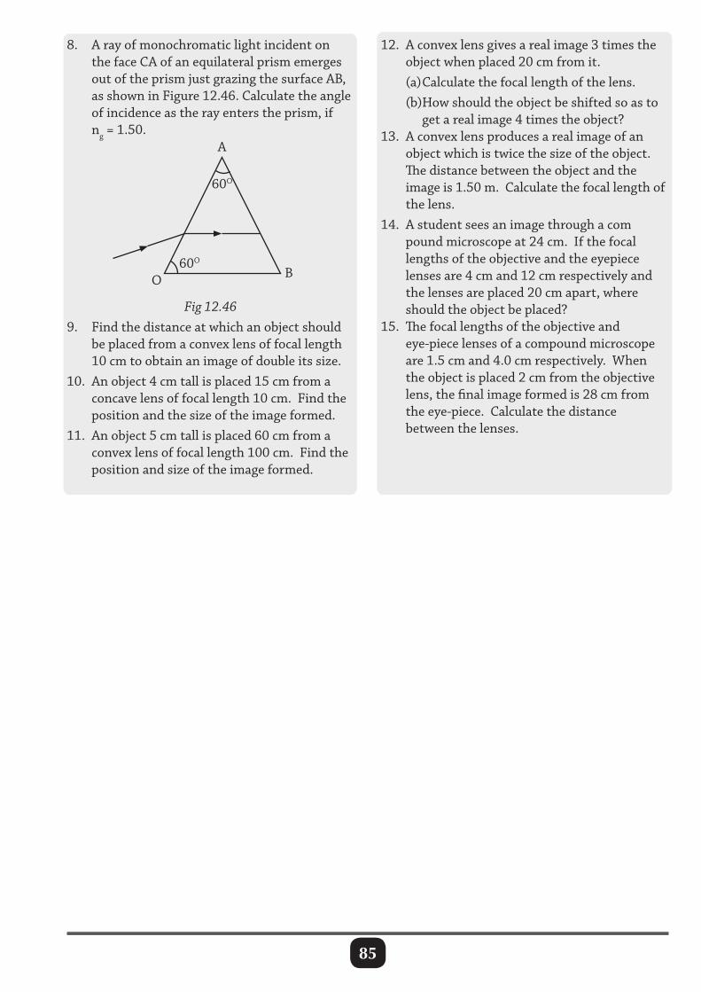
85
8. A ray of monochromatic light incident on the face CA of an equilateral prism emerges out of the prism just grazing the surface AB, as shown in Figure 12.46. Calculate the angle of incidence as the ray enters the prism, if ng = 1.50.
Fig 12.469. Find the distance at which an object should be placed from a convex lens of focal length 10 cm to obtain an image of double its size.10. An object 4 cm tall is placed 15 cm from a concave lens of focal length 10 cm. Find the position and the size of the image formed.11. An object 5 cm tall is placed 60 cm from a convex lens of focal length 100 cm. Find the position and size of the image formed.
12. A convex lens gives a real image 3 times the object when placed 20 cm from it. (a) Calculate the focal length of the lens. (b)How should the object be shifted so as to get a real image 4 times the object?13. A convex lens produces a real image of an object which is twice the size of the object. The distance between the object and the image is 1.50 m. Calculate the focal length of the lens.14. A student sees an image through a com pound microscope at 24 cm. If the focal lengths of the objective and the eyepiece lenses are 4 cm and 12 cm respectively and the lenses are placed 20 cm apart, where should the object be placed?15. The focal lengths of the objective and eye-piece lenses of a compound microscope are 1.5 cm and 4.0 cm respectively. When the object is placed 2 cm from the objective lens, the final image formed is 28 cm from the eye-piece. Calculate the distance between the lenses.
60O
60O
BO
A
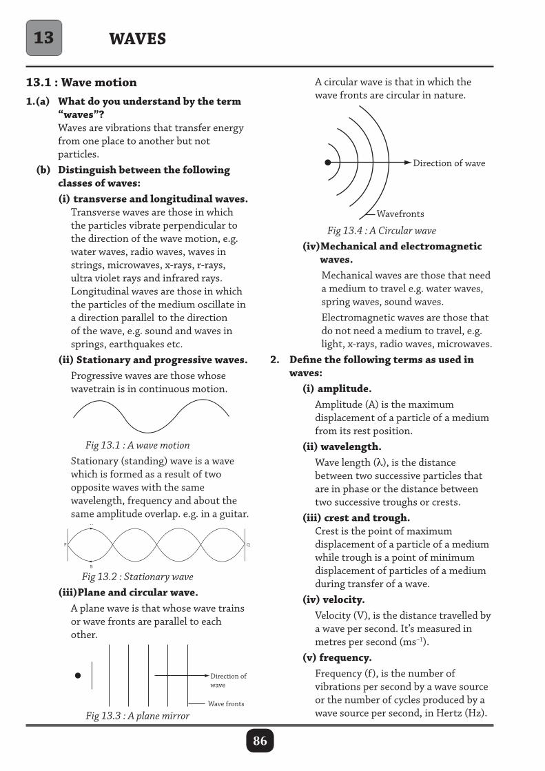
86
WAVES
13.1 : Wave motion1.(a) What do you understand by the term “waves”? Waves are vibrations that transfer energy from one place to another but not particles. (b) Distinguish between the following classes of waves: (i) transverse and longitudinal waves. Transverse waves are those in which the particles vibrate perpendicular to the direction of the wave motion, e.g. water waves, radio waves, waves in strings, microwaves, x-rays, r-rays, ultra violet rays and infrared rays. Longitudinal waves are those in which the particles of the medium oscillate in a direction parallel to the direction of the wave, e.g. sound and waves in springs, earthquakes etc. (ii) Stationary and progressive waves. Progressive waves are those whose wavetrain is in continuous motion.
A circular wave is that in which the wave fronts are circular in nature.
Fig 13.2 : Stationary wave (iii)Plane and circular wave. A plane wave is that whose wave trains or wave fronts are parallel to each other.
Direction of wave
Wavefronts
Fig 13.4 : A Circular wave (iv)Mechanical and electromagnetic waves. Mechanical waves are those that need a medium to travel e.g. water waves, spring waves, sound waves. Electromagnetic waves are those that do not need a medium to travel, e.g. light, x-rays, radio waves, microwaves.2. Define the following terms as used in waves: (i) amplitude. Amplitude (A) is the maximum displacement of a particle of a medium from its rest position. (ii) wavelength. Wave length (λ), is the distance between two successive particles that are in phase or the distance between two successive troughs or crests. (iii) crest and trough. Crest is the point of maximum displacement of a particle of a medium while trough is a point of minimum displacement of particles of a medium during transfer of a wave. (iv) velocity. Velocity (V), is the distance travelled by a wave per second. It’s measured in metres per second (ms–1). (v) frequency. Frequency (f), is the number of vibrations per second by a wave source or the number of cycles produced by a wave source per second, in Hertz (Hz).
Fig 13.1 : A wave motion Stationary (standing) wave is a wave which is formed as a result of two opposite waves with the same wavelength, frequency and about the same amplitude overlap. e.g. in a guitar.
Wave fronts
Direction of wave
Fig 13.3 : A plane mirror
13
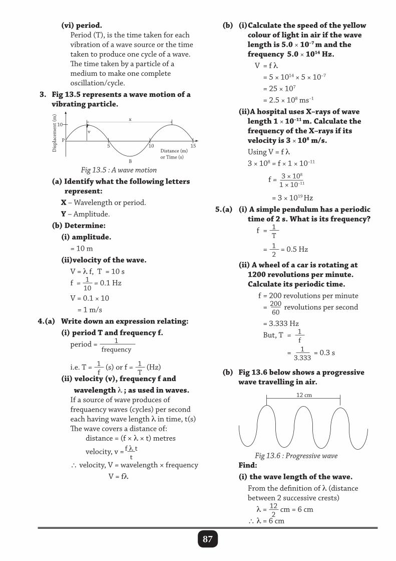
87
WAVES
P
B
Distance (m)or Time (s)
Dis
plac
emen
t (m
)
5
10 v
10 15
x
(vi) period. Period (T), is the time taken for each vibration of a wave source or the time taken to produce one cycle of a wave. The time taken by a particle of a medium to make one complete oscillation/cycle. 3. Fig 13.5 represents a wave motion of a vibrating particle.
(b) (i) Calculate the speed of the yellow colour of light in air if the wave length is 5.0 × 10⁻⁷ m and the frequency 5.0 × 10¹⁴ Hz. V = f λ = 5 × 1014 × 5 × 10–7
= 25 × 107
= 2.5 × 10⁸ ms–1
(ii)A hospital uses X–rays of wave length 1 × 10–11 m. Calculate the frequency of the X–rays if its velocity is 3 × 10⁸ m/s. Using V = f λ 3 × 108 = f × 1 × 10–11
f = 3 × 10⁸
1 × 10–11
= 3 × 10¹⁹ Hz5.(a) (i) A simple pendulum has a periodic time of 2 s. What is its frequency? f = 1
T
= 12
= 0.5 Hz (ii) A wheel of a car is rotating at 1200 revolutions per minute. Calculate its periodic time. f = 200 revolutions per minute = 200
60 revolutions per second
= 3.333 Hz But, T = 1
f
= 13.333
= 0.3 s
(b) Fig 13.6 below shows a progressive wave travelling in air.
Fig 13.5 : A wave motion (a) Identify what the following letters represent: X – Wavelength or period. Y – Amplitude. (b) Determine: (i) amplitude. = 10 m (ii)velocity of the wave. V = λ f, T = 10 s f = 1
10= 0.1 Hz
V = 0.1 × 10 = 1 m/s4.(a) Write down an expression relating: (i) period T and frequency f. period = 1
frequency
i.e. T = 1f
(s) or f = 1T
(Hz) (ii) velocity (v), frequency f and wavelength λ ; as used in waves. If a source of wave produces of frequaency waves (cycles) per second each having wave length λ in time, t(s) The wave covers a distance of: distance = (f × λ × t) metres
velocity, v = f λ tt
∴ velocity, V = wavelength × frequency V = fλ
Fig 13.6 : Progressive wave Find: (i) the wave length of the wave. From the definition of λ (distance between 2 successive crests) λ = 12
2cm = 6 cm
∴ λ = 6 cm
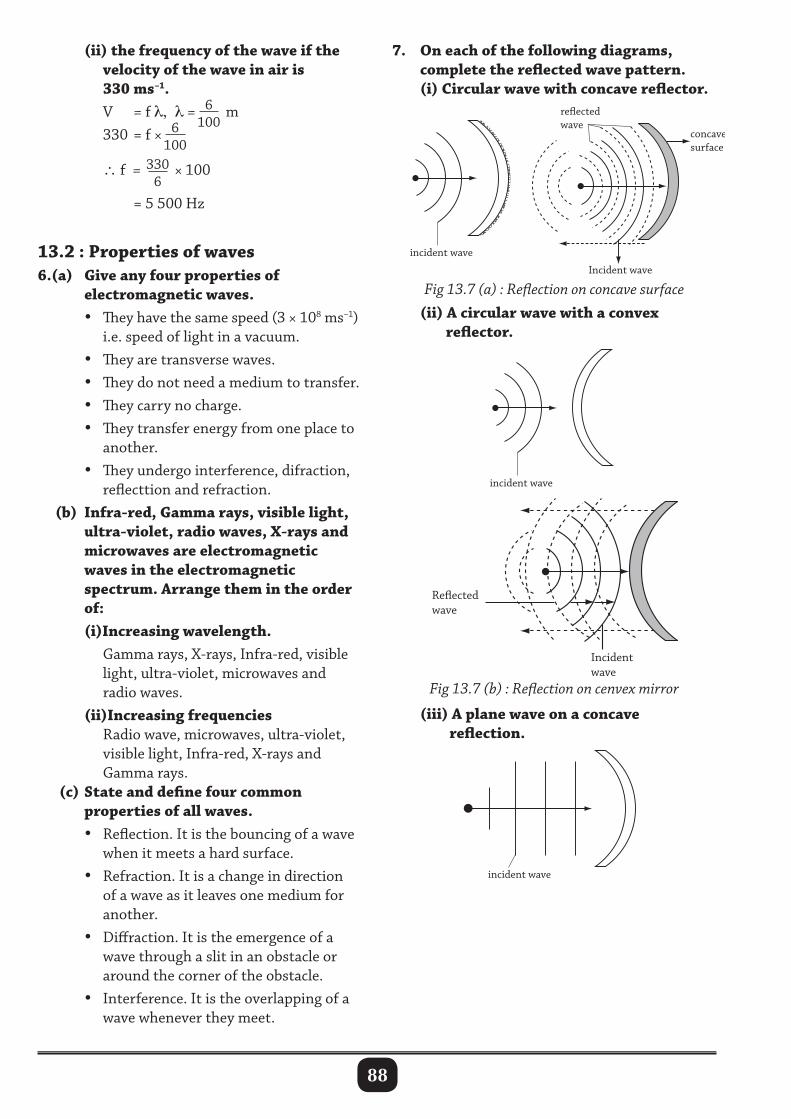
88
(ii) the frequency of the wave if the velocity of the wave in air is 330 ms–1. V = f λ, λ = 6
100 m
330 = f × 6100
∴ f = 330
6 × 100
= 5 500 Hz
13.2 : Properties of waves6.(a) Give any four properties of electromagnetic waves. • They have the same speed (3 × 10⁸ ms–1) i.e. speed of light in a vacuum. • They are transverse waves. • They do not need a medium to transfer. • They carry no charge. • They transfer energy from one place to another. • They undergo interference, difraction, reflecttion and refraction. (b) Infra-red, Gamma rays, visible light, ultra-violet, radio waves, X-rays and microwaves are electromagnetic waves in the electromagnetic spectrum. Arrange them in the order of: (i)Increasing wavelength. Gamma rays, X-rays, Infra-red, visible light, ultra-violet, microwaves and radio waves. (ii)Increasing frequencies Radio wave, microwaves, ultra-violet, visible light, Infra-red, X-rays and Gamma rays. (c) State and define four common properties of all waves. • Reflection. It is the bouncing of a wave when it meets a hard surface. • Refraction. It is a change in direction of a wave as it leaves one medium for another. • Diffraction. It is the emergence of a wave through a slit in an obstacle or around the corner of the obstacle. • Interference. It is the overlapping of a wave whenever they meet.
concave surface
Incident wave
Incident wave
Incident wave
Reectedwave
Reectedwave
reected wave
7. On each of the following diagrams, complete the reflected wave pattern. (i) Circular wave with concave reflector.
Fig 13.7 (a) : Reflection on concave surface
(ii) A circular wave with a convex reflector.
concave surface
Incident wave
Incident wave
Incident wave
Reectedwave
Reectedwave
reected wave
Fig 13.7 (b) : Reflection on cenvex mirror
(iii) A plane wave on a concave reflection.
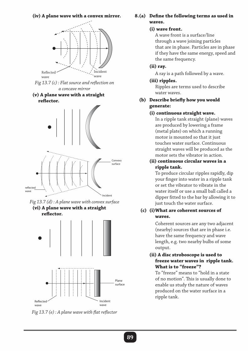
89
8.(a) Define the following terms as used in waves. (i) wave front. A wave front is a surface/line through a wave joining particles that are in phase. Particles are in phase if they have the same energy, speed and the same frequency. (ii) ray. A ray is a path followed by a wave. (iii) ripples. Ripples are terms used to describe water waves. (b) Describe briefly how you would generate: (i) continuous straight wave. In a ripple tank straight (plane) waves are produced by lowering a frame (metal plate) on which a running motor is mounted so that it just touches water surface. Continuous straight waves will be produced as the motor sets the vibrator in action. (ii) continuous circular waves in a ripple tank. To produce circular ripples rapidly, dip your finger into water in a ripple tank or set the vibrator to vibrate in the water itself or use a small ball called a dipper fitted to the bar by allowing it to just touch the water surface. (c) (i) What are coherent sources of waves. Coherent sources are any two adjacent (nearby) sources that are in phase i.e. have the same frequency and wave length, e.g. two nearby bulbs of some output. (ii) A disc stroboscope is used to freeze water waves in ripple tank. What is to “freeze”? To “freeze” means to “hold in a state of no motion”. This is usually done to enable us study the nature of waves produced on the water surface in a ripple tank.
concave surface
Incident wave
Incident wave
Incident wave
Reectedwave
Reectedwave
reected wave
Fig 13.7 (c) : Flat source and reflection on a concave mirror
(iv) A plane wave with a convex mirror.
(v) A plane wave with a straight reflector.
Fig 13.7 (d) : A plane wave with convex surface (vi) A plane wave with a straight reflector.
Fig 13.7 (e) : A plane wave with flat reflector
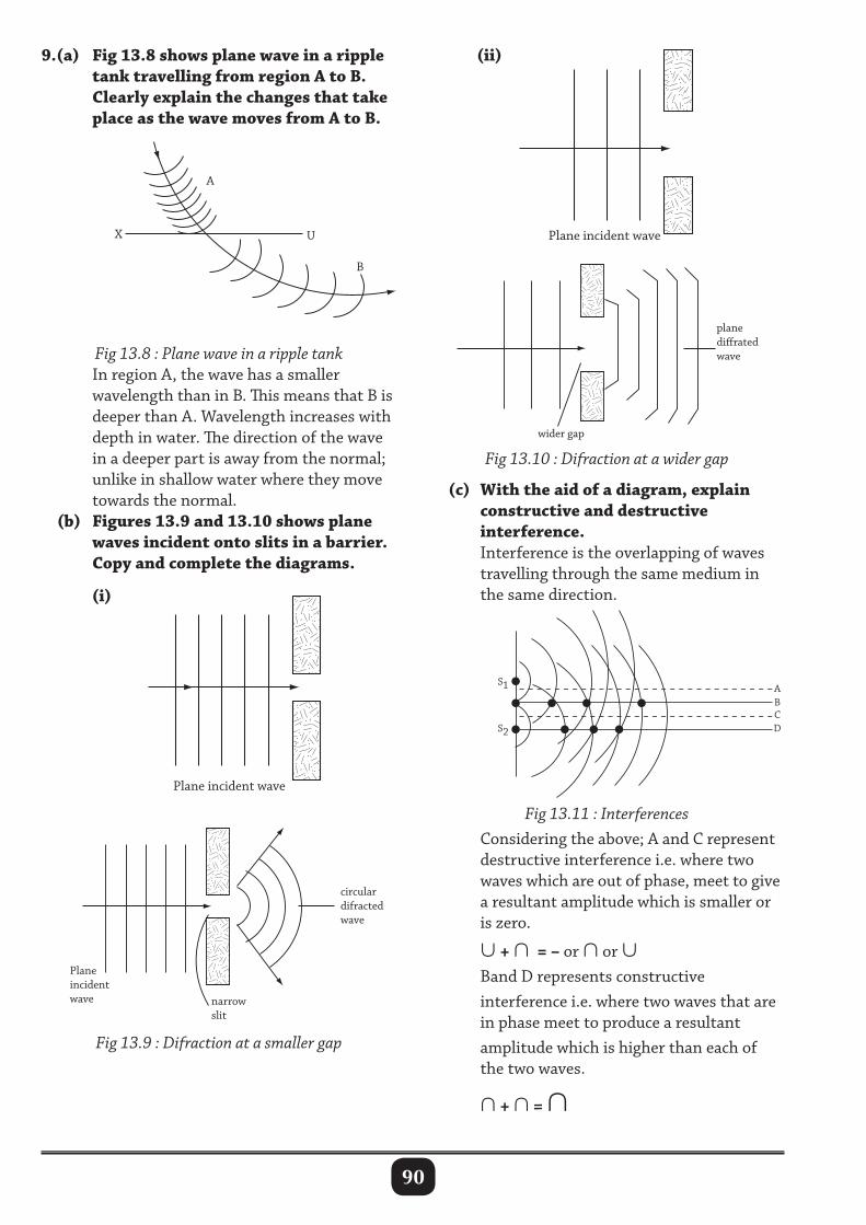
90
9.(a) Fig 13.8 shows plane wave in a ripple tank travelling from region A to B. Clearly explain the changes that take place as the wave moves from A to B.
Fig 13.8 : Plane wave in a ripple tank In region A, the wave has a smaller wavelength than in B. This means that B is deeper than A. Wavelength increases with depth in water. The direction of the wave in a deeper part is away from the normal; unlike in shallow water where they move towards the normal. (b) Figures 13.9 and 13.10 shows plane waves incident onto slits in a barrier. Copy and complete the diagrams.
Fig 13.9 : Difraction at a smaller gap
(c) With the aid of a diagram, explain constructive and destructive interference. Interference is the overlapping of waves travelling through the same medium in the same direction.
Fig 13.10 : Difraction at a wider gap
Fig 13.11 : Interferences Considering the above; A and C represent destructive interference i.e. where two waves which are out of phase, meet to give a resultant amplitude which is smaller or is zero.
∪ + ∩ = – or ∩ or ∪ Band D represents constructive interference i.e. where two waves that are in phase meet to produce a resultant amplitude which is higher than each of the two waves.
∩ + ∩ = ∩
(i)
(ii)
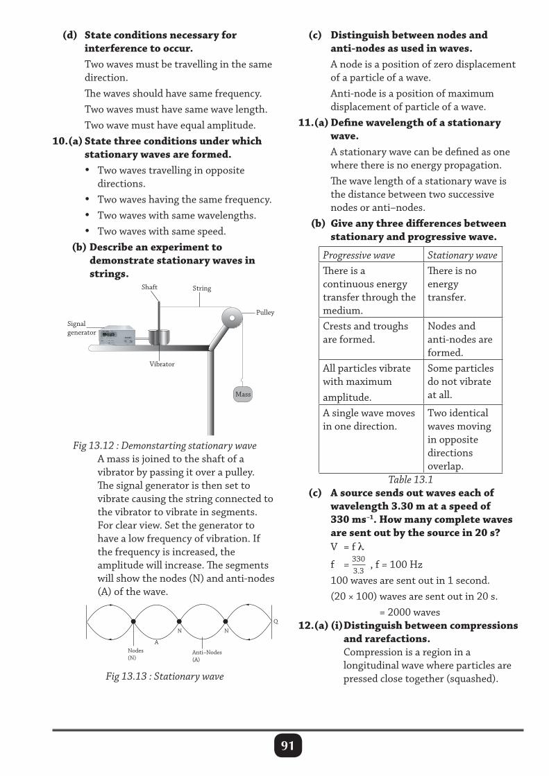
91
Mass
Pulley
StringShaft
Signalgenerator
Vibrator
(d) State conditions necessary for interference to occur. Two waves must be travelling in the same direction. The waves should have same frequency. Two waves must have same wave length. Two wave must have equal amplitude.10.(a) State three conditions under which stationary waves are formed. • Two waves travelling in opposite directions. • Two waves having the same frequency. • Two waves with same wavelengths. • Two waves with same speed. (b) Describe an experiment to demonstrate stationary waves in strings.
(c) Distinguish between nodes and anti-nodes as used in waves. A node is a position of zero displacement of a particle of a wave. Anti-node is a position of maximum displacement of particle of a wave.11.(a) Define wavelength of a stationary wave. A stationary wave can be defined as one where there is no energy propagation. The wave length of a stationary wave is the distance between two successive nodes or anti–nodes. (b) Give any three differences between stationary and progressive wave.
Progressive wave Stationary waveThere is a continuous energy transfer through the medium.
There is no energy transfer.
Crests and troughs are formed.
Nodes and anti-nodes are formed.
All particles vibrate with maximum amplitude.
Some particles do not vibrate at all.
A single wave moves in one direction.
Two identical waves moving in opposite directions overlap.
Table 13.1 (c) A source sends out waves each of wavelength 3.30 m at a speed of 330 ms–1. How many complete waves are sent out by the source in 20 s? V = f λ
f = 3303.3
, f = 100 Hz 100 waves are sent out in 1 second. (20 × 100) waves are sent out in 20 s. = 2000 waves12.(a) (i) Distinguish between compressions and rarefactions. Compression is a region in a longitudinal wave where particles are pressed close together (squashed).
Fig 13.12 : Demonstarting stationary wave A mass is joined to the shaft of a vibrator by passing it over a pulley. The signal generator is then set to vibrate causing the string connected to the vibrator to vibrate in segments. For clear view. Set the generator to have a low frequency of vibration. If the frequency is increased, the amplitude will increase. The segments will show the nodes (N) and anti-nodes (A) of the wave.
Fig 13.13 : Stationary wave
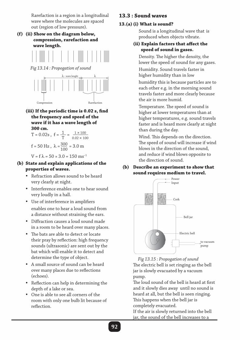
92
Rarefaction is a region in a longitudinal wave where the molecules are spaced out (region of low pressure). (f) (ii) Show on the diagram below, compression, rarefaction and wave length.
13.3 : Sound waves13.(a) (i) What is sound? Sound is a longitudinal wave that is produced when objects vibrate. (ii) Explain factors that affect the speed of sound in gases. Density. The higher the density, the lower the speed of sound for any gases. Humidity. Sound travels faster in higher humidity than in low humidity this is because particles are to each other e.g. in the morning sound travels faster and more clearly because the air is more humid. Temperature. The speed of sound is higher at lower temperatures than at higher temperatures, e.g. sound travels faster and is heard more clearly at night than during the day. Wind. This depends on the direction. The speed of sound will increase if wind blows in the direction of the sound, and reduce if wind blows opposite to the direction of sound. (b) Describe an experiment to show that sound requires medium to travel.
Electric bell
to vacuumpump
Bell jar
PowerInput
Cork
Compression Rarefaction
– wave lenght
(iii) If the periodic time is 0.02 s, find the frequency and speed of the wave if it has a wave length of 300 cm. T = 0.02s , f = 1
T= 1 × 100
0.02 × 100
f = 50 Hz , λ = 300
100 = 3.0 m
V = f λ = 50 × 3.0 = 150 ms–1
(b) State and explain applications of the properties of waves. • Refraction allows sound to be heard very clearly at night. • Interference enables one to hear sound very loudly in a hall. • Use of interference in amplifiers enables one to hear a loud sound from a distance without straining the ears. • Diffraction causes a loud sound made in a room to be heard over many places. • The bats are able to detect or locate their pray by reflection: high frequency sounds (ultrasonic) are sent out by the bat which will enable it to detect and determine the type of object. • A small source of sound can be heard over many places due to reflections (echoes). • Reflection can help in determining the depth of a lake or sea. • One is able to see all corners of the room with only one bulb lit because of reflection.
Fig 13.15 : Propogation of sound The electric bell is set ringing as the bell jar is slowly evacuated by a vacuum pump. The loud sound of the bell is heard at first and it slowly dies away until no sound is heard at all, but the bell is seen ringing. This happens when the bell jar is completely evacuated. If the air is slowly returned into the bell jar, the sound of the bell increases to a
Fig 13.14 : Propogation of sound
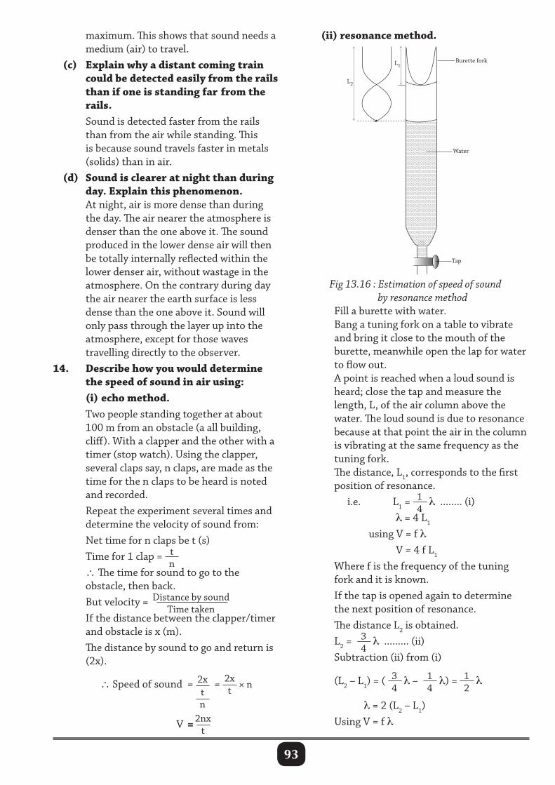
93
maximum. This shows that sound needs a medium (air) to travel. (c) Explain why a distant coming train could be detected easily from the rails than if one is standing far from the rails. Sound is detected faster from the rails than from the air while standing. This is because sound travels faster in metals (solids) than in air. (d) Sound is clearer at night than during day. Explain this phenomenon. At night, air is more dense than during the day. The air nearer the atmosphere is denser than the one above it. The sound produced in the lower dense air will then be totally internally reflected within the lower denser air, without wastage in the atmosphere. On the contrary during day the air nearer the earth surface is less dense than the one above it. Sound will only pass through the layer up into the atmosphere, except for those waves travelling directly to the observer.14. Describe how you would determine the speed of sound in air using: (i) echo method. Two people standing together at about 100 m from an obstacle (a all building, cliff). With a clapper and the other with a timer (stop watch). Using the clapper, several claps say, n claps, are made as the time for the n claps to be heard is noted and recorded. Repeat the experiment several times and determine the velocity of sound from: Net time for n claps be t (s) Time for 1 clap = t
n ∴ The time for sound to go to the obstacle, then back. But velocity = Distance by sound
Time taken If the distance between the clapper/timer and obstacle is x (m). The distance by sound to go and return is (2x).
∴ Speed of sound = 2xtn
= 2xt
× n
V = 2nxt
(ii) resonance method.
L2
Burette fork
Water
Tap
L1
Fig 13.16 : Estimation of speed of sound by resonance method Fill a burette with water. Bang a tuning fork on a table to vibrate and bring it close to the mouth of the burette, meanwhile open the lap for water to flow out. A point is reached when a loud sound is heard; close the tap and measure the length, L, of the air column above the water. The loud sound is due to resonance because at that point the air in the column is vibrating at the same frequency as the tuning fork. The distance, L1, corresponds to the first position of resonance. i.e. L1 =
14
λ ........ (i) λ = 4 L1
using V = f λ V = 4 f L1
Where f is the frequency of the tuning fork and it is known. If the tap is opened again to determine the next position of resonance. The distance L2 is obtained. L2 = 3
4λ ......... (ii)
Subtraction (ii) from (i)
(L2 – L1) = ( 34
λ – 14
λ) = 12
λ
λ = 2 (L2 – L1) Using V = f λ
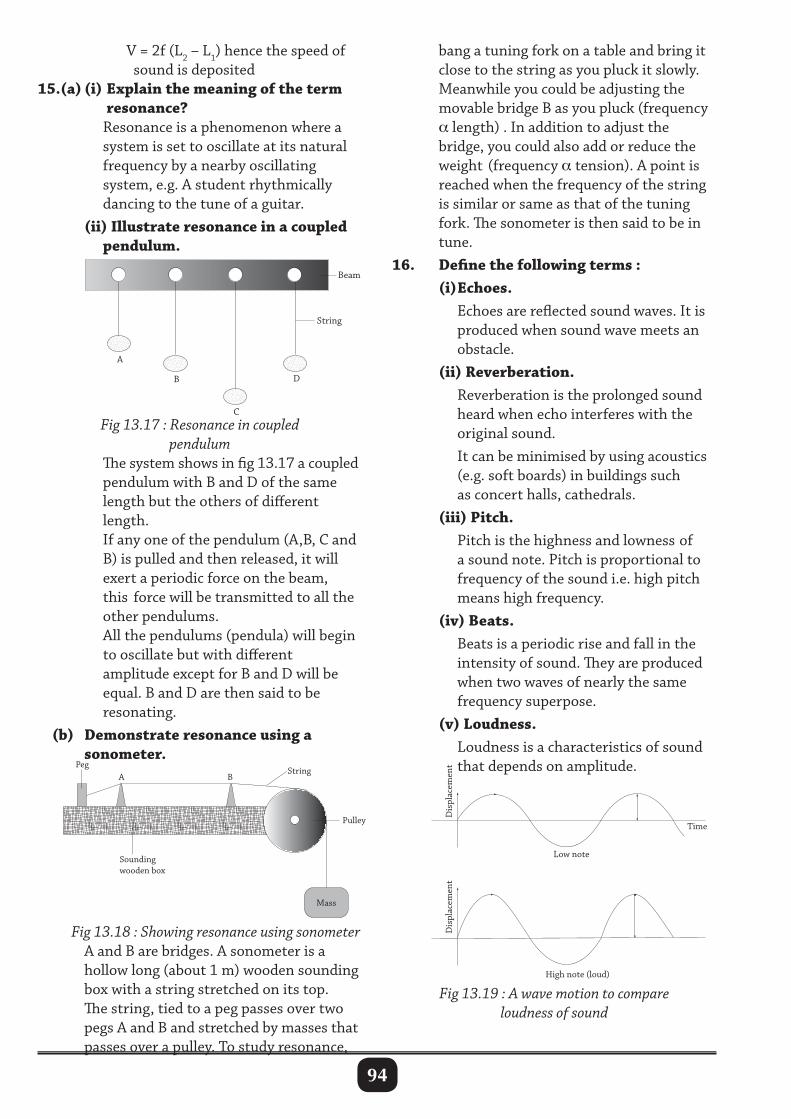
94
V = 2f (L2 – L1) hence the speed of sound is deposited15.(a) (i) Explain the meaning of the term resonance? Resonance is a phenomenon where a system is set to oscillate at its natural frequency by a nearby oscillating system, e.g. A student rhythmically dancing to the tune of a guitar. (ii) Illustrate resonance in a coupled pendulum.
bang a tuning fork on a table and bring it close to the string as you pluck it slowly. Meanwhile you could be adjusting the movable bridge B as you pluck (frequency α length) . In addition to adjust the bridge, you could also add or reduce the weight (frequency α tension). A point is reached when the frequency of the string is similar or same as that of the tuning fork. The sonometer is then said to be in tune.16. Define the following terms : (i) Echoes. Echoes are reflected sound waves. It is produced when sound wave meets an obstacle. (ii) Reverberation. Reverberation is the prolonged sound heard when echo interferes with the original sound. It can be minimised by using acoustics (e.g. soft boards) in buildings such as concert halls, cathedrals. (iii) Pitch. Pitch is the highness and lowness of a sound note. Pitch is proportional to frequency of the sound i.e. high pitch means high frequency. (iv) Beats. Beats is a periodic rise and fall in the intensity of sound. They are produced when two waves of nearly the same frequency superpose. (v) Loudness. Loudness is a characteristics of sound that depends on amplitude.
String
A
B
C
D
Beam
Fig 13.17 : Resonance in coupled pendulum
The system shows in fig 13.17 a coupled pendulum with B and D of the same length but the others of different length. If any one of the pendulum (A,B, C and B) is pulled and then released, it will exert a periodic force on the beam, this force will be transmitted to all the other pendulums. All the pendulums (pendula) will begin to oscillate but with different amplitude except for B and D will be equal. B and D are then said to be resonating. (b) Demonstrate resonance using a sonometer.
Mass
Pulley
Sounding wooden box
String Peg
A B
Fig 13.18 : Showing resonance using sonometer A and B are bridges. A sonometer is a hollow long (about 1 m) wooden sounding box with a string stretched on its top. The string, tied to a peg passes over two pegs A and B and stretched by masses that passes over a pulley. To study resonance,
Time
Dis
plac
emen
tD
ispl
acem
ent
Low note
High note (loud)
Fig 13.19 : A wave motion to compare loudness of sound
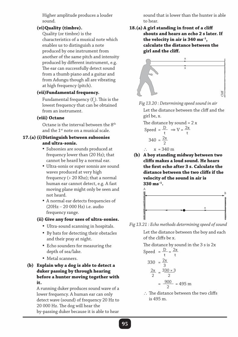
95
sound that is lower than the hunter is able to hear.18.(a) A girl standing in front of a cliff shouts and hears an echo 2 s later. If the velocity in air is 340 ms–1, calculate the distance between the girl and the cliff.
Higher amplitude produces a louder sound. (vi)Quality (timbre). Quality (or timbre) is the characteristics of a musical note which enables us to distinguish a note produced by one instrument from another of the same pitch and intensity produced by different instrument, e.g. The ear can successfully detect sound from a thumb piano and a guitar and from Adungu though all are vibrating at high frequency (pitch). (vii)Fundamental frequency. Fundamental frequency (fo). This is the lowest frequency that can be obtained from an instrument. (viii) Octane Octane is the interval between the 8th and the 1st note on a musical scale.17.(a) (i) Distinguish between subsonies and ultra-sonis. • Subsonies are sounds produced at frequency lower than (20 Hz); that cannot be heard by a normal ear. • Ultra-sonis or super sonnis are sound waves produced at very high frequency (> 20 Khz); that a normal human ear cannot detect, e.g. A fast moving plane might only be seen and not heard. • A normal ear detects frequencies of (20Hz – 20 000 Hz) i.e. audio frequency range. (ii) Give any four uses of ultra-sonies. • Ultra-sound scanning in hospitals. • By bats for detecting their obstacles and their pray at night. • Echo sounders for measuring the depth of sea/lake. • Metal scanners. (b) Explain why a dog is able to detect a duker passing by through hearing before a hunter moving together with it. A running duker produces sound wave of a lower frequency. A human ear can only detect wave (sound) of frequency 20 Hz to 20 000 Hz. The dog will hear the by-passing duker because it is able to hear
Fig 13.20 : Determining speed sound in air Let the distance between the cliff and the girl be, x. The distance by sound = 2 x Speed = D
t ⇒ V = 2x
t
340 = 2x2
∴ x = 340 m (b) A boy standing midway between two cliffs makes a loud sound. He hears the first echo after 3 s. Calculate the distance between the two cliffs if the velocity of the sound in air is 330 ms–1.
Fig 13.21 : Echo methods determining speed of sound
AB
x
Let the distance between the boy and each of the cliffs be x. The distance by sound in the 3 s is 2x Speed = D
t= 2x
t
330 = 2x3
2x2
= 330 × 32
= 900
2= 495 m
∴ The distance between the two cliffs is 495 m.
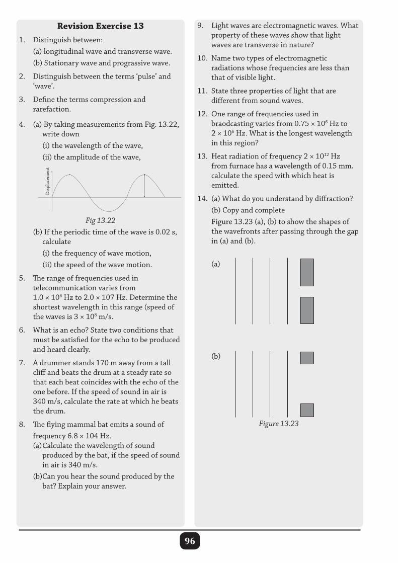
96
Revision Exercise 131. Distinguish between: (a) longitudinal wave and transverse wave. (b) Stationary wave and prograssive wave.
2. Distinguish between the terms ‘pulse’ and ‘wave’.
3. Define the terms compression and rarefaction.
4. (a) By taking measurements from Fig. 13.22, write down (i) the wavelength of the wave, (ii) the amplitude of the wave,
9. Light waves are electromagnetic waves. What property of these waves show that light waves are transverse in nature?
10. Name two types of electromagnetic radiations whose frequencies are less than that of visible light.
11. State three properties of light that are different from sound waves.
12. One range of frequencies used in braodcasting varies from 0.75 × 10⁶ Hz to 2 × 10⁶ Hz. What is the longest wavelength in this region?
13. Heat radiation of frequency 2 × 10¹² Hz from furnace has a wavelength of 0.15 mm. calculate the speed with which heat is emitted.
14. (a) What do you understand by diffraction? (b) Copy and complete Figure 13.23 (a), (b) to show the shapes of the wavefronts after passing through the gap in (a) and (b). (a)
(b)
Figure 13.23
Fig 13.22 (b) If the periodic time of the wave is 0.02 s, calculate (i) the frequency of wave motion, (ii) the speed of the wave motion.
5. The range of frequencies used in telecommunication varies from 1.0 × 10⁶ Hz to 2.0 × 10⁷ Hz. Determine the shortest wavelength in this range (speed of the waves is 3 × 10⁸ m/s.
6. What is an echo? State two conditions that must be satisfied for the echo to be produced and heard clearly.
7. A drummer stands 170 m away from a tall cliff and beats the drum at a steady rate so that each beat coincides with the echo of the one before. If the speed of sound in air is 340 m/s, calculate the rate at which he beats the drum.
8. The flying mammal bat emits a sound of frequency 6.8 × 10⁴ Hz. (a) Calculate the wavelength of sound produced by the bat, if the speed of sound in air is 340 m/s. (b)Can you hear the sound produced by the bat? Explain your answer.
Dis
plac
emen
t
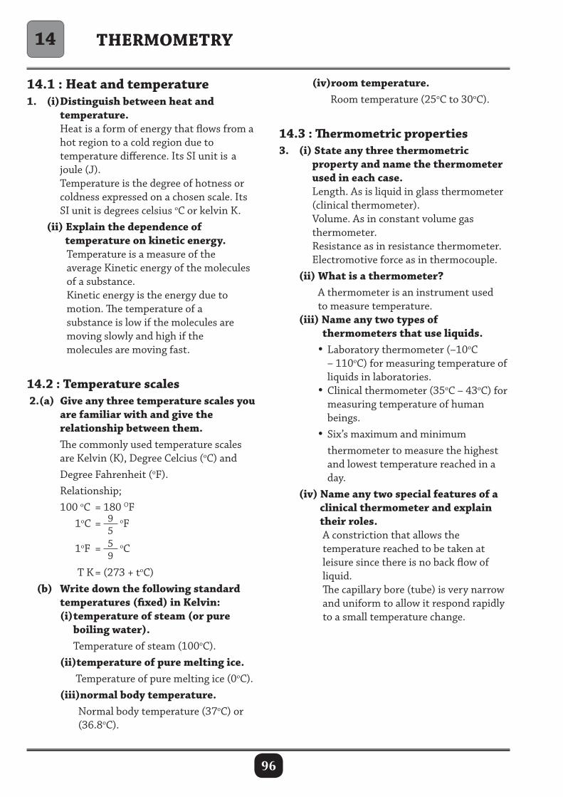
96
THERMOMETRY
14.1 : Heat and temperature1. (i) Distinguish between heat and temperature. Heat is a form of energy that flows from a hot region to a cold region due to temperature difference. Its SI unit is a joule (J). Temperature is the degree of hotness or coldness expressed on a chosen scale. Its SI unit is degrees celsius oC or kelvin K. (ii) Explain the dependence of temperature on kinetic energy. Temperature is a measure of the average Kinetic energy of the molecules of a substance. Kinetic energy is the energy due to motion. The temperature of a substance is low if the molecules are moving slowly and high if the molecules are moving fast.
14.2 : Temperature scales 2.(a) Give any three temperature scales you are familiar with and give the relationship between them. The commonly used temperature scales are Kelvin (K), Degree Celcius (oC) and Degree Fahrenheit (oF). Relationship; 100 oC = 180 OF 1oC = 9
5oF
1oF = 5
9oC
T K = (273 + toC) (b) Write down the following standard temperatures (fixed) in Kelvin: (i) temperature of steam (or pure boiling water). Temperature of steam (100oC). (ii)temperature of pure melting ice. Temperature of pure melting ice (0oC). (iii)normal body temperature. Normal body temperature (37oC) or (36.8oC).
(iv)room temperature. Room temperature (25oC to 30oC).
14.3 : Thermometric properties3. (i) State any three thermometric property and name the thermometer used in each case. Length. As is liquid in glass thermometer (clinical thermometer). Volume. As in constant volume gas thermometer. Resistance as in resistance thermometer. Electromotive force as in thermocouple. (ii) What is a thermometer? A thermometer is an instrument used to measure temperature. (iii) Name any two types of thermometers that use liquids. • Laboratory thermometer (–10oC – 110oC) for measuring temperature of liquids in laboratories. • Clinical thermometer (35oC – 43oC) for measuring temperature of human beings. • Six’s maximum and minimum thermometer to measure the highest and lowest temperature reached in a day. (iv) Name any two special features of a clinical thermometer and explain their roles. A constriction that allows the temperature reached to be taken at leisure since there is no back flow of liquid. The capillary bore (tube) is very narrow and uniform to allow it respond rapidly to a small temperature change.
14
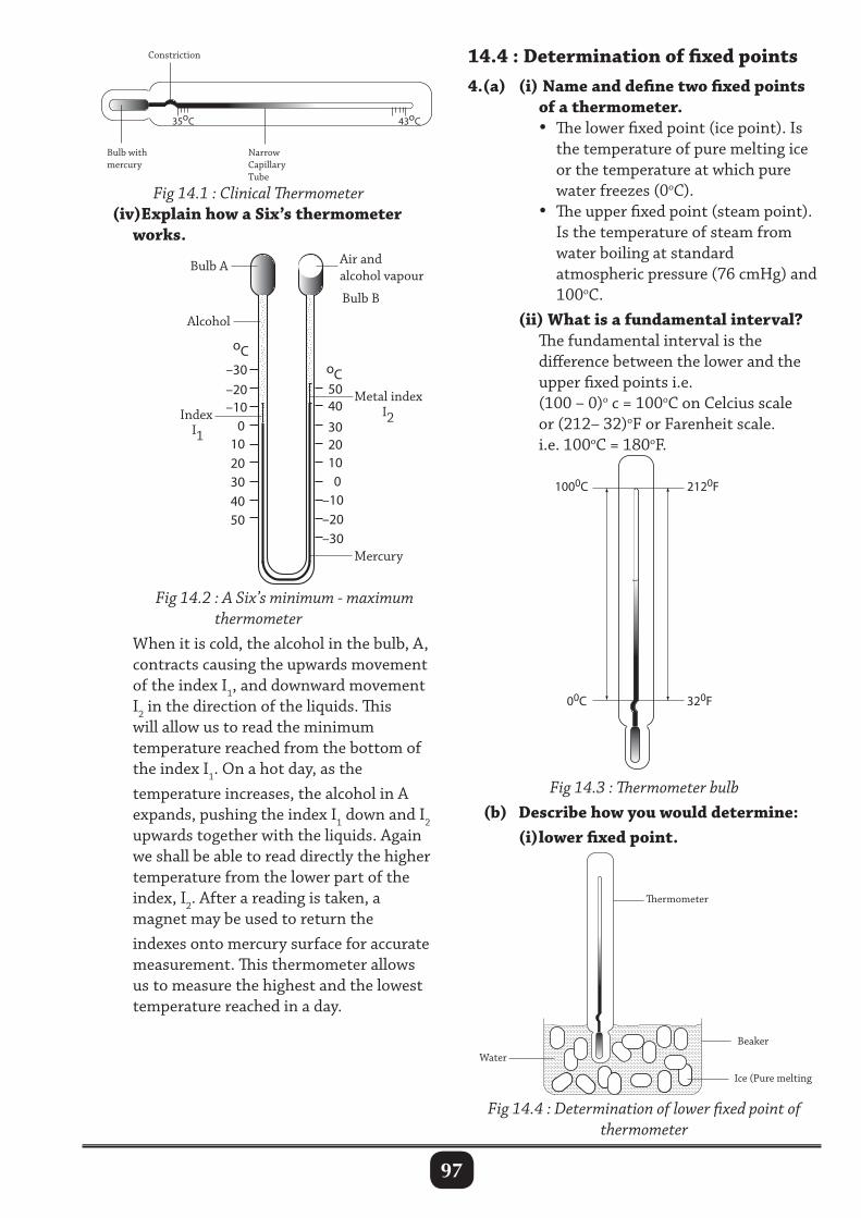
97
14.4 : Determination of fixed points4.(a) (i) Name and define two fixed points of a thermometer. • The lower fixed point (ice point). Is the temperature of pure melting ice or the temperature at which pure water freezes (0oC). • The upper fixed point (steam point). Is the temperature of steam from water boiling at standard atmospheric pressure (76 cmHg) and 100oC. (ii) What is a fundamental interval? The fundamental interval is the difference between the lower and the upper fixed points i.e. (100 – 0)o c = 100oC on Celcius scale or (212– 32)oF or Farenheit scale. i.e. 100oC = 180oF.
35oC
Bulb with mercury
Narrow Capillary Tube
Constriction
43oC
oC oC –30
–20 –10
0 10
20 30
50 40
30 20 10
–10
–20
–30
0
40 50
Air and alcohol vapour
Bulb B
Metal index Index
I1
I2
Bulb A
Alcohol
Mercury
Fig 14.1 : Clinical Thermometer (iv)Explain how a Six’s thermometer works.
Fig 14.3 : Thermometer bulb (b) Describe how you would determine: (i) lower fixed point.
Fig 14.2 : A Six’s minimum - maximum thermometer
When it is cold, the alcohol in the bulb, A, contracts causing the upwards movement of the index I1, and downward movement I2 in the direction of the liquids. This will allow us to read the minimum temperature reached from the bottom of the index I1. On a hot day, as the temperature increases, the alcohol in A expands, pushing the index I1 down and I2 upwards together with the liquids. Again we shall be able to read directly the higher temperature from the lower part of the index, I2. After a reading is taken, a magnet may be used to return the indexes onto mercury surface for accurate measurement. This thermometer allows us to measure the highest and the lowest temperature reached in a day.
ermometer
Water Beaker
Ice (Pure melting ice)
Fig 14.4 : Determination of lower fixed point of thermometer
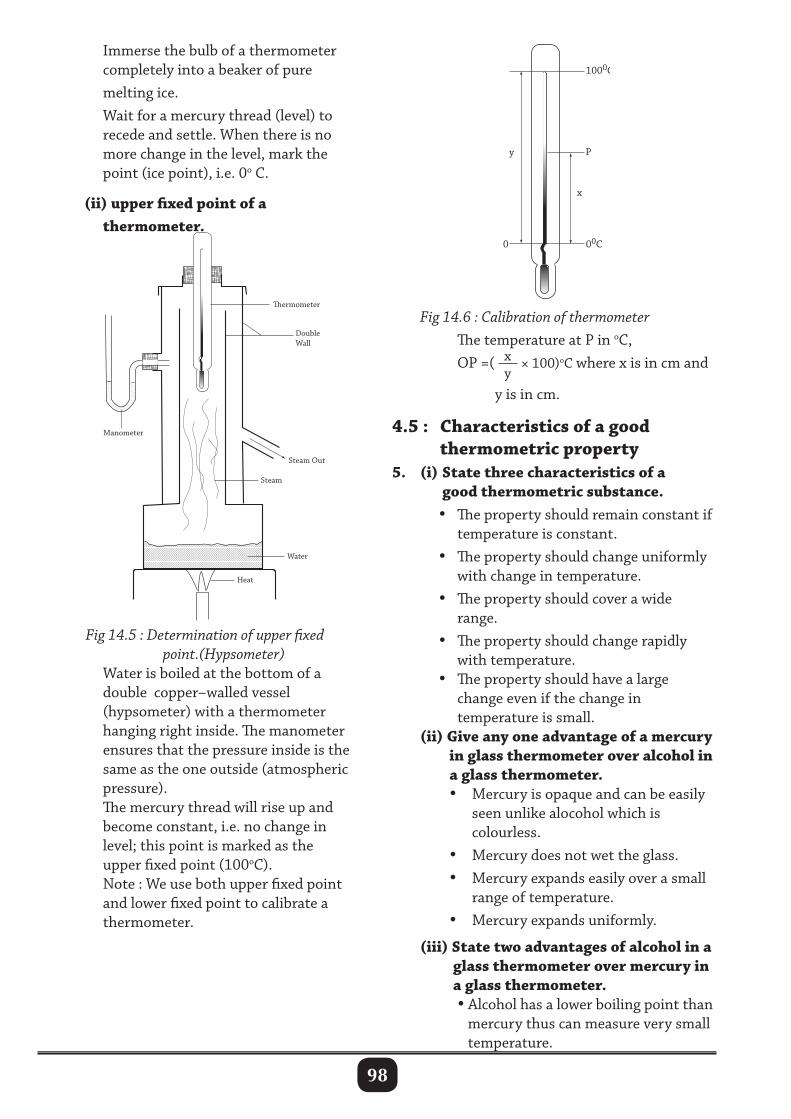
98
Immerse the bulb of a thermometer completely into a beaker of pure melting ice. Wait for a mercury thread (level) to recede and settle. When there is no more change in the level, mark the point (ice point), i.e. 0o C.
(ii) upper fixed point of a thermometer.
Heat
Water
Steam
Steam Out
Manometer
Double Wall
ermometer
Fig 14.6 : Calibration of thermometer The temperature at P in oC, OP =( x
y× 100)oC where x is in cm and
y is in cm.
4.5 : Characteristics of a good thermometric property5. (i) State three characteristics of a good thermometric substance. • The property should remain constant if temperature is constant. • The property should change uniformly with change in temperature. • The property should cover a wide range. • The property should change rapidly with temperature. • The property should have a large change even if the change in temperature is small. (ii) Give any one advantage of a mercury in glass thermometer over alcohol in a glass thermometer. • Mercury is opaque and can be easily seen unlike alocohol which is colourless. • Mercury does not wet the glass. • Mercury expands easily over a small range of temperature. • Mercury expands uniformly.
(iii) State two advantages of alcohol in a glass thermometer over mercury in a glass thermometer. • Alcohol has a lower boiling point than mercury thus can measure very small temperature.
Fig 14.5 : Determination of upper fixed point.(Hypsometer) Water is boiled at the bottom of a double copper–walled vessel (hypsometer) with a thermometer hanging right inside. The manometer ensures that the pressure inside is the same as the one outside (atmospheric pressure). The mercury thread will rise up and become constant, i.e. no change in level; this point is marked as the upper fixed point (100oC). Note : We use both upper fixed point and lower fixed point to calibrate a thermometer.
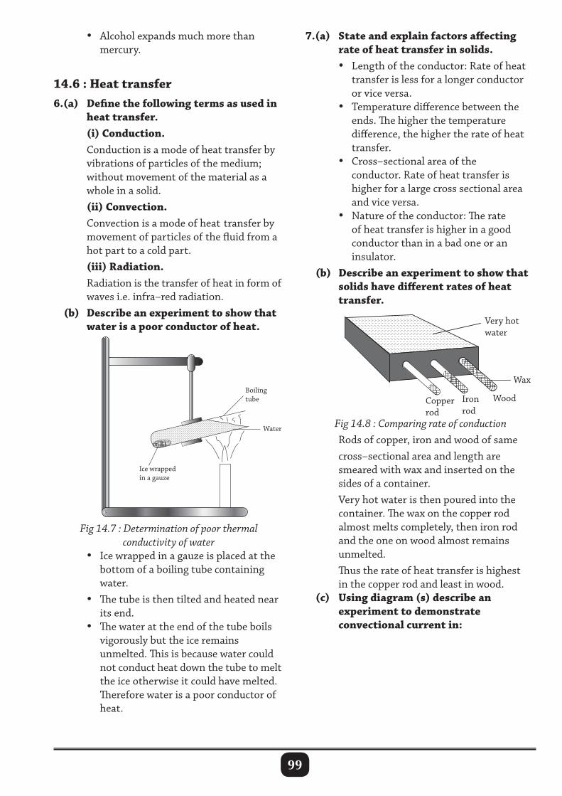
99
• Alcohol expands much more than mercury.
14.6 : Heat transfer6.(a) Define the following terms as used in heat transfer. (i) Conduction. Conduction is a mode of heat transfer by vibrations of particles of the medium; without movement of the material as a whole in a solid. (ii) Convection. Convection is a mode of heat transfer by movement of particles of the fluid from a hot part to a cold part. (iii) Radiation. Radiation is the transfer of heat in form of waves i.e. infra–red radiation. (b) Describe an experiment to show that water is a poor conductor of heat.
7.(a) State and explain factors affecting rate of heat transfer in solids. • Length of the conductor: Rate of heat transfer is less for a longer conductor or vice versa. • Temperature difference between the ends. The higher the temperature difference, the higher the rate of heat transfer. • Cross–sectional area of the conductor. Rate of heat transfer is higher for a large cross sectional area and vice versa. • Nature of the conductor: The rate of heat transfer is higher in a good conductor than in a bad one or an insulator. (b) Describe an experiment to show that solids have different rates of heat transfer.
Ice wrapped in a gauze
Water
Boiling tube
Fig 14.7 : Determination of poor thermal conductivity of water
• Ice wrapped in a gauze is placed at the bottom of a boiling tube containing water. • The tube is then tilted and heated near its end. • The water at the end of the tube boils vigorously but the ice remains unmelted. This is because water could not conduct heat down the tube to melt the ice otherwise it could have melted. Therefore water is a poor conductor of heat.
Wood
Wax
Very hot water
Copper rod
Iron rod
Fig 14.8 : Comparing rate of conduction Rods of copper, iron and wood of same cross–sectional area and length are smeared with wax and inserted on the sides of a container. Very hot water is then poured into the container. The wax on the copper rod almost melts completely, then iron rod and the one on wood almost remains unmelted. Thus the rate of heat transfer is highest in the copper rod and least in wood. (c) Using diagram (s) describe an experiment to demonstrate convectional current in:
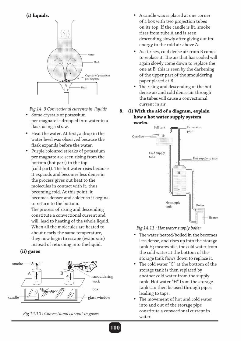
100
(i) liquids. • A candle wax is placed at one corner of a box with two projection tubes on its top. If the candle is lit, smoke rises from tube A and is seen descending slowly after giving out its energy to the cold air above A. • As it rises, cold dense air from B comes to replace it. The air that has cooled will again slowly come down to replace the one at B. this is seen by the darkening of the upper part of the smouldering paper placed at B. • The rising and descending of the hot dense air and cold dense air through the tubes will cause a convectional current in air.8. (i) With the aid of a diagram, explain how a hot water supply system works.
Heat
Crystals of pottasium per magnate
Flask
Water
Fig 14. 9 Convectional currents in liquids • Some crystals of potassium per magnate is dropped into water in a flask using a straw. • Heat the water. At first, a drop in the water level was observed because the flask expands before the water. • Purple coloured streaks of potassium per magnate are seen rising from the bottom (hot part) to the top (cold part). The hot water rises because it expands and becomes less dense in the process gives out heat to the molecules in contact with it, thus becoming cold. At this point, it becomes denser and colder so it begins to return to the bottom. The process of rising and descending constitute a convectional current and will lead to heating of the whole liquid. When all the molecules are heated to about nearly the same temperature, they now begin to escape (evaporate) instead of returning into the liquid. (ii) gases
Fig 14.11 : Hot water supply bolier • The water heated/boiled in the becomes less dense, and rises up into the storage tank H; meanwhile, the cold water from the cold water at the bottom of the storage tank flows down to replace it. • The cold water “C” at the bottom of the storage tank is then replaced by another cold water from the supply tank. Hot water “H” from the storage tank can then be used through pipes leading to taps. • The movement of hot and cold water into and out of the storage pipe constitute a convectional current in water.
Fig 14.10 : Convectional current in gases
Boiler
H
C
Heater
Expansion pipe
Overow
Ball cork
Cold supply tank
Hot supply tank
Hot supply to taps
smoke
smouldering wick
box
glass window
A B
candle
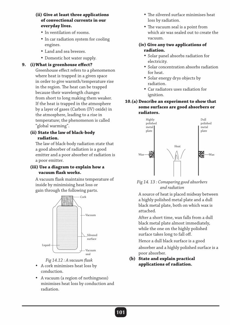
101
(ii) Give at least three applications of convectional currents in our everyday lives. • In ventilation of rooms. • In car radiation system for cooling engines. • Land and sea breezes. • Domestic hot water supply.9. (i) What is greenhouse effect? Greenhouse effect refers to a phenomenon where heat is trapped in a given space in order to give warmth/temperature rise in the region. The heat can be trapped because their wavelength changes from short to long making them weaker. If the heat is trapped in the atmosphere by a layer of gases (Carbon (IV) oxide) in the atmosphere, leading to a rise in temperature; the phenomenon is called “global warming”. (ii) State the law of black-body radiation. The law of black-body radiation state that a good absorber of radiation is a good emitter and a poor absorber of radiation is a poor emitter. (iii) Use a diagram to explain how a vacuum flask works. A vacuum flask maintains temperature of inside by minimising heat loss or gain through the following parts.
• The silvered surface minimises heat loss by radiation. •The vacuum seal is a point from which air was sealed out to create the vacuum. (iv) Give any two applications of radiation. • Solar panel absorbs radiation for electricity. • Solar concentration absorbs radiation for heat. • Solar energy drys objects by radiation. • Car radiators uses radiation for ignition.10.(a) Describe an experiment to show that some surfaces are good absorbers or radiators.
Liquid
Vacuum seal
Cork
Silvered surface
Vacuum
Fig 14. 13 : Comaparing good absorbers and radiation
A source of heat is placed midway between a highly polished metal plate and a dull black metal plate, both on which wax is attached. After a short time, wax falls from a dull black metal plate almost immediately, while the one on the highly polished surface takes long to fall off. Hence a dull black surface is a good absorber and a highly polished surface is a poor absorber. (b) State and explain practical applications of radiation.
Fig 14.12 : A vacuum flask • A cork minimises heat loss by conduction. • A vacuum (a region of nothingness) minimises heat loss by conduction and radiation.
Wax Wax
Heat
Highly polished metal plate
Dull polished metal plate
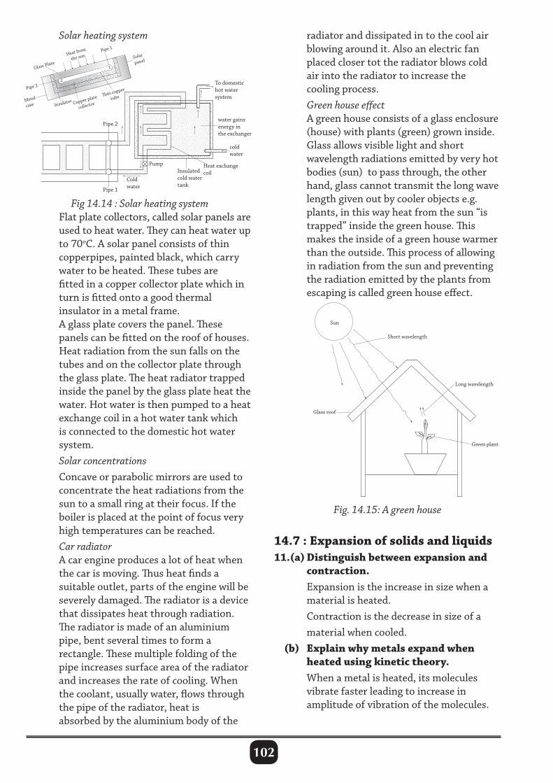
102
Solar heating system
Fig 14.14 : Solar heating system Flat plate collectors, called solar panels are used to heat water. They can heat water up to 70oC. A solar panel consists of thin copperpipes, painted black, which carry water to be heated. These tubes are fitted in a copper collector plate which in turn is fitted onto a good thermal insulator in a metal frame. A glass plate covers the panel. These panels can be fitted on the roof of houses. Heat radiation from the sun falls on the tubes and on the collector plate through the glass plate. The heat radiator trapped inside the panel by the glass plate heat the water. Hot water is then pumped to a heat exchange coil in a hot water tank which is connected to the domestic hot water system. Solar concentrations Concave or parabolic mirrors are used to concentrate the heat radiations from the sun to a small ring at their focus. If the boiler is placed at the point of focus very high temperatures can be reached. Car radiator A car engine produces a lot of heat when the car is moving. Thus heat finds a suitable outlet, parts of the engine will be severely damaged. The radiator is a device that dissipates heat through radiation. The radiator is made of an aluminium pipe, bent several times to form a rectangle. These multiple folding of the pipe increases surface area of the radiator and increases the rate of cooling. When the coolant, usually water, flows through the pipe of the radiator, heat is absorbed by the aluminium body of the
radiator and dissipated in to the cool air blowing around it. Also an electric fan placed closer tot the radiator blows cold air into the radiator to increase the cooling process. Green house effect A green house consists of a glass enclosure (house) with plants (green) grown inside. Glass allows visible light and short wavelength radiations emitted by very hot bodies (sun) to pass through, the other hand, glass cannot transmit the long wave length given out by cooler objects e.g. plants, in this way heat from the sun “is trapped” inside the green house. This makes the inside of a green house warmer than the outside. This process of allowing in radiation from the sun and preventing the radiation emitted by the plants from escaping is called green house effect.
Sun
Short wavelength
Glass roof
Long wavelength
Green plant
Fig. 14.15: A green house
14.7 : Expansion of solids and liquids11.(a) Distinguish between expansion and contraction. Expansion is the increase in size when a material is heated. Contraction is the decrease in size of a material when cooled. (b) Explain why metals expand when heated using kinetic theory. When a metal is heated, its molecules vibrate faster leading to increase in amplitude of vibration of the molecules.
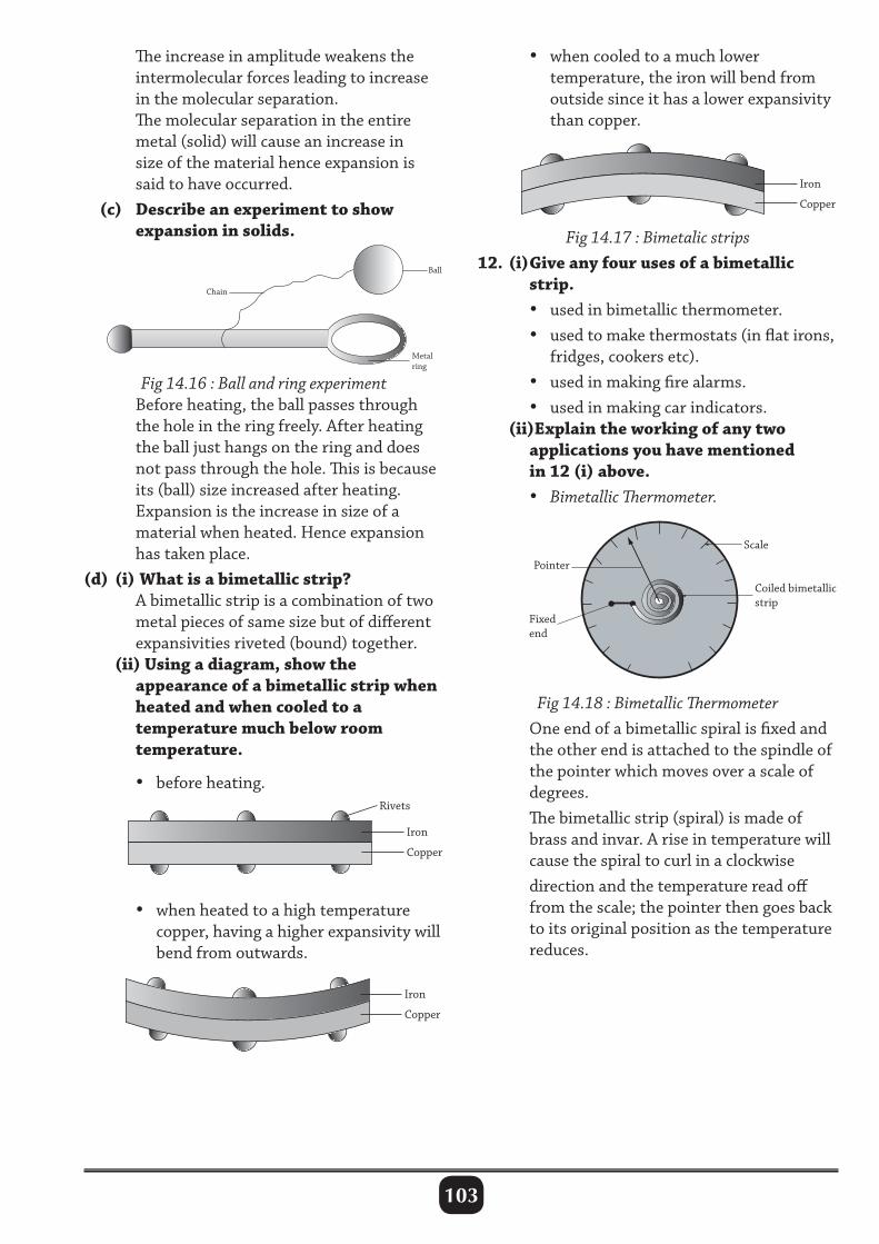
103
The increase in amplitude weakens the intermolecular forces leading to increase in the molecular separation. The molecular separation in the entire metal (solid) will cause an increase in size of the material hence expansion is said to have occurred. (c) Describe an experiment to show expansion in solids. Fig 14.17 : Bimetalic strips
12. (i) Give any four uses of a bimetallic strip. • used in bimetallic thermometer. • used to make thermostats (in flat irons, fridges, cookers etc). • used in making fire alarms. • used in making car indicators. (ii)Explain the working of any two applications you have mentioned in 12 (i) above. • Bimetallic Thermometer.
Fig 14.16 : Ball and ring experiment Before heating, the ball passes through the hole in the ring freely. After heating the ball just hangs on the ring and does not pass through the hole. This is because its (ball) size increased after heating. Expansion is the increase in size of a material when heated. Hence expansion has taken place.(d) (i) What is a bimetallic strip? A bimetallic strip is a combination of two metal pieces of same size but of different expansivities riveted (bound) together. (ii) Using a diagram, show the appearance of a bimetallic strip when heated and when cooled to a temperature much below room temperature.
Rivets
Iron
Copper
Iron
Copper
Iron
Copper
Rivets
Iron
Copper
Iron
Copper
Iron
Copper
• before heating.
• when heated to a high temperature copper, having a higher expansivity will bend from outwards.
• when cooled to a much lower temperature, the iron will bend from outside since it has a lower expansivity than copper.
Rivets
Iron
Copper
Iron
Copper
Iron
Copper
Fig 14.18 : Bimetallic Thermometer One end of a bimetallic spiral is fixed and the other end is attached to the spindle of the pointer which moves over a scale of degrees. The bimetallic strip (spiral) is made of brass and invar. A rise in temperature will cause the spiral to curl in a clockwise direction and the temperature read off from the scale; the pointer then goes back to its original position as the temperature reduces.
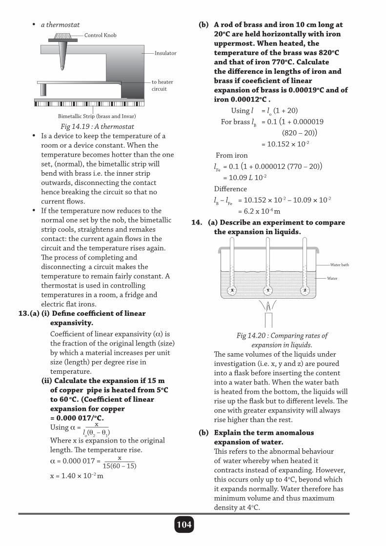
104
• a thermostat (b) A rod of brass and iron 10 cm long at 20oC are held horizontally with iron uppermost. When heated, the temperature of the brass was 820oC and that of iron 770oC. Calculate the difference in lengths of iron and brass if coeeficient of linear expansion of brass is 0.00019oC and of iron 0.00012oC . Using l = lo (1 + 20) For brass lB = 0.1 (1 + 0.000019 (820 – 20)) = 10.152 × 10⁻²
From iron lFe = 0.1 (1 + 0.000012 (770 – 20)) = 10.09 L 10-2
Difference lB – lFe = 10.152 × 10⁻² – 10.09 × 10-2
= 6.2 x 10⁻⁴ m14. (a) Describe an experiment to compare the expansion in liquids.
Control Knob
Insulator
to heater circuit
Bimetallic Strip (brass and Invar)
Fig 14.19 : A thermostat • Is a device to keep the temperature of a room or a device constant. When the temperature becomes hotter than the one set, (normal), the bimetallic strip will bend with brass i.e. the inner strip outwards, disconnecting the contact hence breaking the circuit so that no current flows. • If the temperature now reduces to the normal one set by the nob, the bimetallic strip cools, straightens and remakes contact: the current again flows in the circuit and the temperature rises again. The process of completing and disconnecting a circuit makes the temperature to remain fairly constant. A thermostat is used in controlling temperatures in a room, a fridge and electric flat irons.13.(a) (i) Define coefficient of linear expansivity. Coefficient of linear expansivity (α) is the fraction of the original length (size) by which a material increases per unit size (length) per degree rise in temperature. (ii) Calculate the expansion if 15 m of copper pipe is heated from 5oC to 60 oC. (Coefficient of linear expansion for copper = 0.000 017/oC. Using α = x
lo(θ2 – θ1) Where x is expansion to the original length. The temperature rise. α = 0.000 017 = x
15(60 – 15)
x = 1.40 × 10⁻² m
X Y Z
Water bath
Water
Fig 14.20 : Comparing rates of expansion in liquids. The same volumes of the liquids under investigation (i.e. x, y and z) are poured into a flask before inserting the content into a water bath. When the water bath is heated from the bottom, the liquids will rise up the flask but to different levels. The one with greater expansivity will always rise higher than the rest.
(b) Explain the term anomalous expansion of water. This refers to the abnormal behaviour of water whereby when heated it contracts instead of expanding. However, this occurs only up to 4oC, beyond which it expands normally. Water therefore has minimum volume and thus maximum density at 4oC.
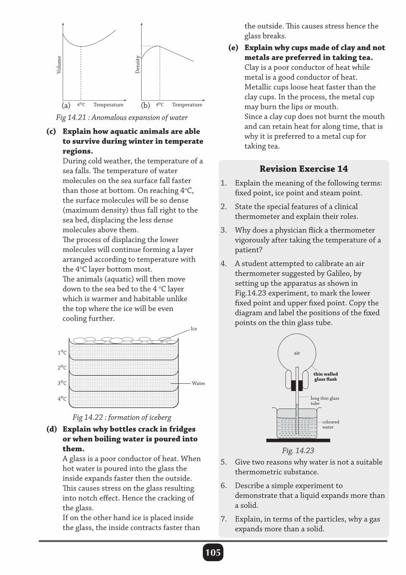
105
the outside. This causes stress hence the glass breaks. (e) Explain why cups made of clay and not metals are preferred in taking tea. Clay is a poor conductor of heat while metal is a good conductor of heat. Metallic cups loose heat faster than the clay cups. In the process, the metal cup may burn the lips or mouth. Since a clay cup does not burnt the mouth and can retain heat for along time, that is why it is preferred to a metal cup for taking tea.
Revision Exercise 141. Explain the meaning of the following terms: fixed point, ice point and steam point.
2. State the special features of a clinical thermometer and explain their roles.
3. Why does a physician flick a thermometer vigorously after taking the temperature of a patient?
4. A student attempted to calibrate an air thermometer suggested by Galileo, by setting up the apparatus as shown in Fig.14.23 experiment, to mark the lower fixed point and upper fixed point. Copy the diagram and label the positions of the fixed points on the thin glass tube.
Volu
me
Temperature 4oC
Den
sity
Temperature 4oC
Volu
me
Temperature 4oC
Den
sity
Temperature 4oC
Fig 14.21 : Anomalous expansion of water(a) (b)
(c) Explain how aquatic animals are able to survive during winter in temperate regions. During cold weather, the temperature of a sea falls. The temperature of water molecules on the sea surface fall faster than those at bottom. On reaching 4oC, the surface molecules will be so dense (maximum density) thus fall right to the sea bed, displacing the less dense molecules above them. The process of displacing the lower molecules will continue forming a layer arranged according to temperature with the 4oC layer bottom most. The animals (aquatic) will then move down to the sea bed to the 4 oC layer which is warmer and habitable unlike the top where the ice will be even cooling further.
1oC
2oC
3oC
4oC
Water
Ice
Fig 14.22 : formation of iceberg (d) Explain why bottles crack in fridges or when boiling water is poured into them. A glass is a poor conductor of heat. When hot water is poured into the glass the inside expands faster then the outside. This causes stress on the glass resulting into notch effect. Hence the cracking of the glass. If on the other hand ice is placed inside the glass, the inside contracts faster than
thin walled glass flask
Fig. 14.23
air
long thin glass tube
coloured water
–––––
–––
––
––
– – – – – – – – – – – – – – – – – – – – – – – – – – – – – – – – – – – – – – – – – – – – – – – – – – – – – – – – – – – – – – – – – – – – – – – – – – – – – – – – – – – – – – – – – – – – – – – – – – – – – – – – – – – – – – – – – – –
5. Give two reasons why water is not a suitable thermometric substance.
6. Describe a simple experiment to demonstrate that a liquid expands more than a solid.
7. Explain, in terms of the particles, why a gas expands more than a solid.
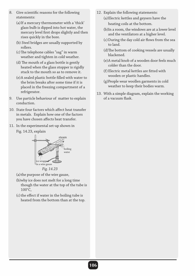
106
8. Give scientific reasons for the following statements: (a) If a mercury thermometer with a ‘thick’ glass bulb is dipped into hot water, the mercury level first drops slightly and then rises quickly in the bore. (b) Steel bridges are usually supported by rollers. (c) The telephone cables “sag” in warm weather and tighten in cold weather. (d) The mouth of a glass bottle is gently heated when the glass stopper is rigidly stuck to the mouth so as to remove it. (e) A sealed plastic bottle filled with water to the brim breaks after some time if it is placed in the freezing compartment of a refrigerator.
9. Use particle behaviour of matter to explain conduction.
10. State four factors which affect heat transfer in metals. Explain how one of the factors you have chosen affects heat transfer.
11. In the experimental set-up shown in Fig. 14.23, explain
steam
boiling water
Fig. 14.23
ice wrapped in a wire gauze
(a) the purpose of the wire gauze, (b)why ice does not melt for a long time though the water at the top of the tube is 100°C, (c) the effect if water in the boiling tube is heated from the bottom than at the top.
12. Explain the following statements: (a) Electric kettles and geysers have the heating coils at the bottom. (b)In a room, the windows are at a lower level and the ventilators at a higher level. (c) During the day cold air flows from the sea to land. (d)The bottom of cooking vessels are usually blackened. (e) A metal knob of a wooden door feels much colder than the door. (f) Electric metal kettles are fitted with wooden or plastic handles. (g)People wear woollen garments in cold weather to keep their bodies warm.
13. With a simple diagram, explain the working of a vacuum flask.
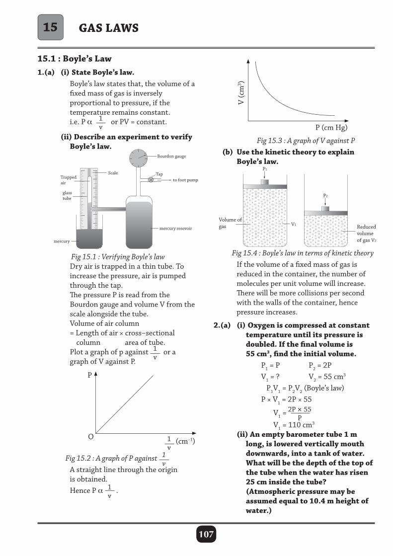
107
15.1 : Boyle’s Law1.(a) (i) State Boyle’s law. Boyle’s law states that, the volume of a fixed mass of gas is inversely proportional to pressure, if the temperature remains constant. i.e. P α 1
v or PV = constant.
(ii) Describe an experiment to verify Boyle’s law.
GAS LAWS
Fig 15.1 : Verifying Boyle’s law Dry air is trapped in a thin tube. To increase the pressure, air is pumped through the tap. The pressure P is read from the Bourdon gauge and volume V from the scale alongside the tube. Volume of air column = Length of air × cross–sectional column area of tube. Plot a graph of p against 1
v or a
graph of V against P.
P
1v
(cm–1)O
Fig 15.3 : A graph of V against P (b) Use the kinetic theory to explain Boyle’s law.
Volume of gas Reduced
volumeof gas V2
V1
P2
P1
Fig 15.2 : A graph of P against 1v
A straight line through the origin is obtained. Hence P α 1
v.
V (c
m3 )
P (cm Hg)
Fig 15.4 : Boyle’s law in terms of kinetic theory If the volume of a fixed mass of gas is reduced in the container, the number of molecules per unit volume will increase. There will be more collisions per second with the walls of the container, hence pressure increases.
2.(a) (i) Oxygen is compressed at constant temperature until its pressure is doubled. If the final volume is 55 cm3, find the initial volume. P1 = P P2 = 2P V1 = ? V2 = 55 cm3
P1V1 = P2V2 (Boyle’s law) P × V1 = 2P × 55
V1 =2P × 55
P V1 = 110 cm3
(ii) An empty barometer tube 1 m long, is lowered vertically mouth downwards, into a tank of water. What will be the depth of the top of the tube when the water has risen 25 cm inside the tube? (Atmospheric pressure may be assumed equal to 10.4 m height of water.)
15
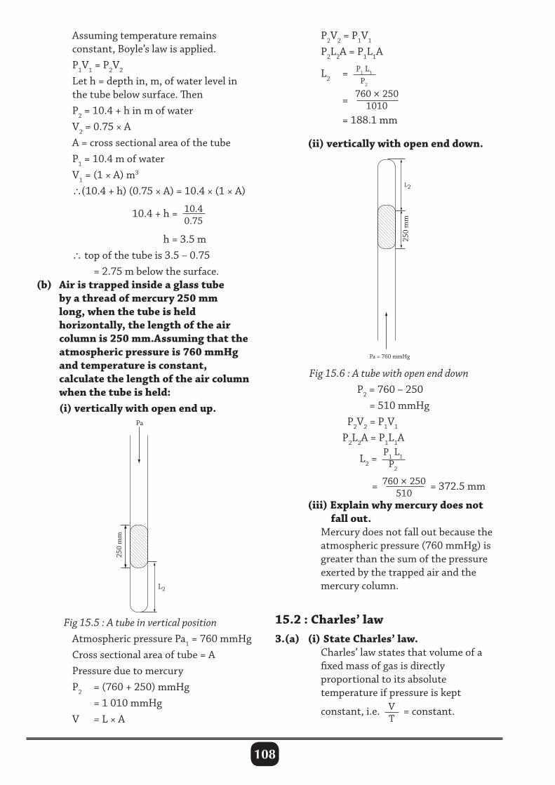
108
Pa
250
mm
Pa = 760 mmHg
L2
L2
250
mm
Assuming temperature remains constant, Boyle’s law is applied. P1V1 = P2V2
Let h = depth in, m, of water level in the tube below surface. Then P2 = 10.4 + h in m of water V2 = 0.75 × A A = cross sectional area of the tube P1 = 10.4 m of water V1 = (1 × A) m3
∴(10.4 + h) (0.75 × A) = 10.4 × (1 × A) 10.4 + h = 10.4
0.75
h = 3.5 m ∴ top of the tube is 3.5 – 0.75 = 2.75 m below the surface. (b) Air is trapped inside a glass tube by a thread of mercury 250 mm long, when the tube is held horizontally, the length of the air column is 250 mm.Assuming that the atmospheric pressure is 760 mmHg and temperature is constant, calculate the length of the air column when the tube is held: (i) vertically with open end up.
P2V2 = P1V1
P2L2A = P1L1A
L2 = P1 L1 P2
=760 × 250
1010
= 188.1 mm
(ii) vertically with open end down.
Pa
250
mm
Pa = 760 mmHg
L2
L2
250
mm
Fig 15.6 : A tube with open end down P2 = 760 – 250 = 510 mmHg P2V2 = P1V1
P2L2A = P1L1A
L2 =P1 L1
P2
=760 × 250
510= 372.5 mm
(iii) Explain why mercury does not fall out. Mercury does not fall out because the atmospheric pressure (760 mmHg) is greater than the sum of the pressure exerted by the trapped air and the mercury column.
15.2 : Charles’ law3.(a) (i) State Charles’ law. Charles’ law states that volume of a fixed mass of gas is directly proportional to its absolute temperature if pressure is kept
constant, i.e. VT
= constant.
Fig 15.5 : A tube in vertical position Atmospheric pressure Pa1 = 760 mmHg Cross sectional area of tube = A Pressure due to mercury P2 = (760 + 250) mmHg = 1 010 mmHg V = L × A
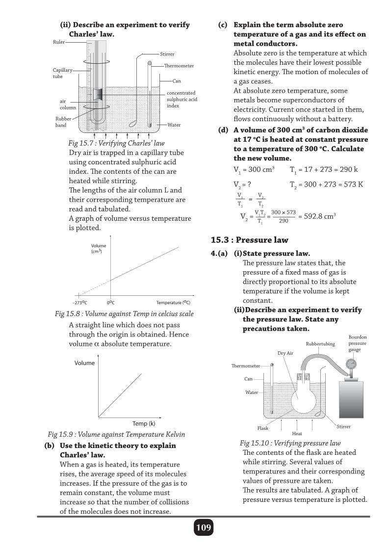
109
(ii) Describe an experiment to verify Charles’ law.
(c) Explain the term absolute zero temperature of a gas and its effect on metal conductors. Absolute zero is the temperature at which the molecules have their lowest possible kinetic energy. The motion of molecules of a gas ceases. At absolute zero temperature, some metals become superconductors of electricity. Current once started in them, flows continuously without a battery. (d) A volume of 300 cm3 of carbon dioxide at 17 oC is heated at constant pressure to a temperature of 300 oC. Calculate the new volume. V1 = 300 cm3 T1 = 17 + 273 = 290 k
V2 = ? T2 = 300 + 273 = 573 K V1
T1
= V2
T2
V2 =V1T2
T1
=300 × 573290
= 592.8 cm3
15.3 : Pressure law4.(a) (i) State pressure law. The pressure law states that, the pressure of a fixed mass of gas is directly proportional to its absolute temperature if the volume is kept constant. (ii)Describe an experiment to verify the pressure law. State any precautions taken.
3
Ruler
Can
ermometer
Stirrer
Water
Heat
concentrated sulphuric acid index
Capillary tube
air column
Rubber band
Fig 15.7 : Verifying Charles’ law Dry air is trapped in a capillary tube using concentrated sulphuric acid index. The contents of the can are heated while stirring. The lengths of the air column L and their corresponding temperature are read and tabulated. A graph of volume versus temperature is plotted.
Fig 15.8 : Volume against Temp in celcius scale A straight line which does not pass through the origin is obtained. Hence volume α absolute temperature.
Fig 15.9 : Volume against Temperature Kelvin (b) Use the kinetic theory to explain Charles’ law. When a gas is heated, its temperature rises, the average speed of its molecules increases. If the pressure of the gas is to remain constant, the volume must increase so that the number of collisions of the molecules does not increase.
ermometer
Water
HeatFlask Stirrer
Rubbertubing Bourdon pressuregauge
Can
Dry Air
Fig 15.10 : Verifying pressure law The contents of the flask are heated while stirring. Several values of temperatures and their corresponding values of pressure are taken. The results are tabulated. A graph of pressure versus temperature is plotted.
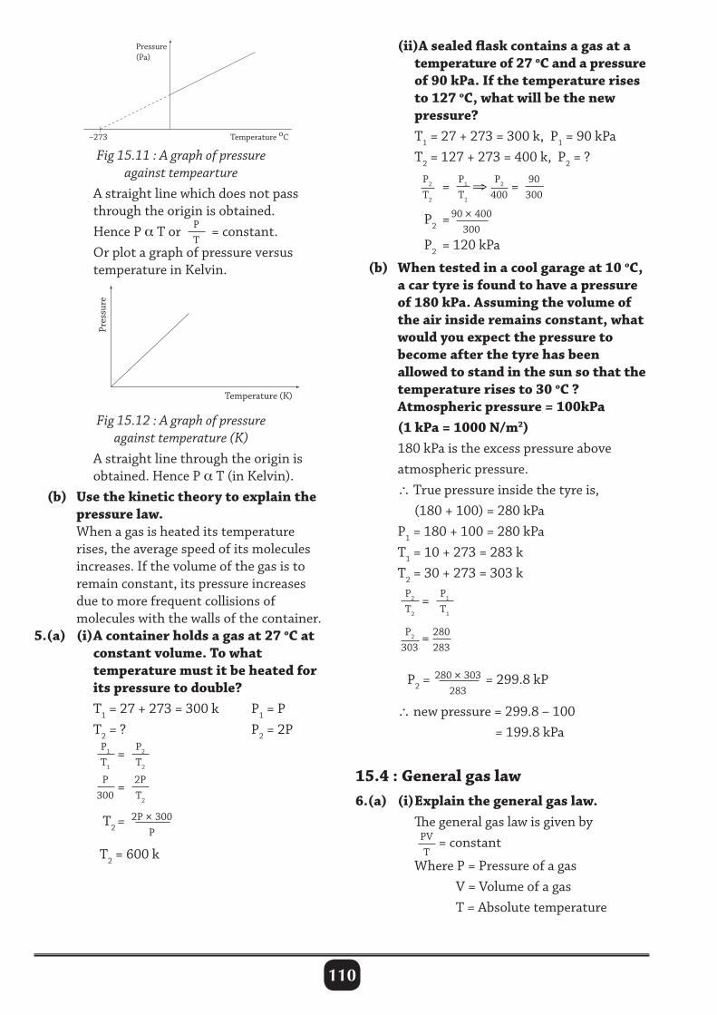
110
Pressure (Pa)
Temperature oC –273
Pres
sure
Temperature (K)
Fig 15.11 : A graph of pressure against tempearture
A straight line which does not pass through the origin is obtained. Hence P α T or P
T = constant.
Or plot a graph of pressure versus temperature in Kelvin.
(ii)A sealed flask contains a gas at a temperature of 27 oC and a pressure of 90 kPa. If the temperature rises to 127 oC, what will be the new pressure? T1 = 27 + 273 = 300 k, P1 = 90 kPa T2 = 127 + 273 = 400 k, P2 = ?
P2
T2
= P1
T1
⇒P2
400= 90
300
P2 =90 × 400
300 P2 = 120 kPa
(b) When tested in a cool garage at 10 oC, a car tyre is found to have a pressure of 180 kPa. Assuming the volume of the air inside remains constant, what would you expect the pressure to become after the tyre has been allowed to stand in the sun so that the temperature rises to 30 oC ? Atmospheric pressure = 100kPa (1 kPa = 1000 N/m2) 180 kPa is the excess pressure above atmospheric pressure. ∴ True pressure inside the tyre is, (180 + 100) = 280 kPa P1 = 180 + 100 = 280 kPa T1 = 10 + 273 = 283 k T2 = 30 + 273 = 303 k
P2
T2
= P1
T1
P2
303= 280
283
P2 =280 × 303
283= 299.8 kP
∴ new pressure = 299.8 – 100 = 199.8 kPa
15.4 : General gas law6.(a) (i) Explain the general gas law. The general gas law is given by PV
T= constant
Where P = Pressure of a gas V = Volume of a gas T = Absolute temperature
Pressure (Pa)
Temperature oC –273
Pres
sure
Temperature (K)
Fig 15.12 : A graph of pressure against temperature (K)
A straight line through the origin is obtained. Hence P α T (in Kelvin). (b) Use the kinetic theory to explain the pressure law. When a gas is heated its temperature rises, the average speed of its molecules increases. If the volume of the gas is to remain constant, its pressure increases due to more frequent collisions of molecules with the walls of the container.5.(a) (i) A container holds a gas at 27 oC at constant volume. To what temperature must it be heated for its pressure to double? T1 = 27 + 273 = 300 k P1 = P T2 = ? P2 = 2P P1
T1
= P2
T2
P
300= 2P
T2
T2 = 2P × 300P
T2 = 600 k
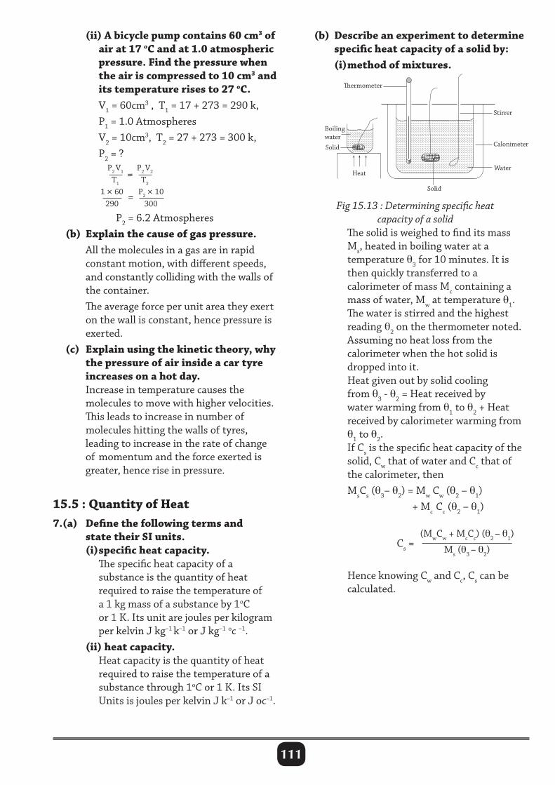
111
(ii) A bicycle pump contains 60 cm3 of air at 17 oC and at 1.0 atmospheric pressure. Find the pressure when the air is compressed to 10 cm3 and its temperature rises to 27 oC. V1 = 60cm3 , T1 = 17 + 273 = 290 k, P1 = 1.0 Atmospheres V2 = 10cm3, T2 = 27 + 273 = 300 k, P2 = ?
P2 V1
T1
= P2 V2
T2 1 × 60
290 = P2 × 10
300
P2 = 6.2 Atmospheres (b) Explain the cause of gas pressure. All the molecules in a gas are in rapid constant motion, with different speeds, and constantly colliding with the walls of the container. The average force per unit area they exert on the wall is constant, hence pressure is exerted. (c) Explain using the kinetic theory, why the pressure of air inside a car tyre increases on a hot day. Increase in temperature causes the molecules to move with higher velocities. This leads to increase in number of molecules hitting the walls of tyres, leading to increase in the rate of change of momentum and the force exerted is greater, hence rise in pressure.
15.5 : Quantity of Heat7.(a) Define the following terms and state their SI units. (i) specific heat capacity. The specific heat capacity of a substance is the quantity of heat required to raise the temperature of a 1 kg mass of a substance by 1oC or 1 K. Its unit are joules per kilogram per kelvin J kg–1 k–1 or J kg–1 oc –1. (ii) heat capacity. Heat capacity is the quantity of heat required to raise the temperature of a substance through 1oC or 1 K. Its SI Units is joules per kelvin J k–1 or J oc–1.
(b) Describe an experiment to determine specific heat capacity of a solid by: (i) method of mixtures.
ermometer
Solid
Water
Stirrer
CalonimeterSolid
Heat
Boilingwater
Fig 15.13 : Determining specific heat capacity of a solid
The solid is weighed to find its mass Ms, heated in boiling water at a temperature θ3 for 10 minutes. It is then quickly transferred to a calorimeter of mass Mc containing a mass of water, Mw at temperature θ1. The water is stirred and the highest reading θ2 on the thermometer noted. Assuming no heat loss from the calorimeter when the hot solid is dropped into it. Heat given out by solid cooling from θ3 - θ2 = Heat received by water warming from θ1 to θ2 + Heat received by calorimeter warming from θ1 to θ2. If Cs is the specific heat capacity of the solid, Cw that of water and Cc that of the calorimeter, then MsCs (θ3– θ2) = Mw Cw (θ2 – θ1) + Mc Cc (θ2 – θ1)
Cs =(MwCw + McCc) (θ2 – θ1)
Ms (θ3 – θ2)
Hence knowing Cw and Cc, Cs can be calculated.
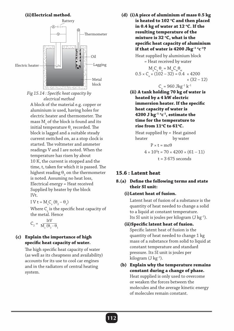
112
(ii)Electrical method. (d) (i) A piece of aluminium of mass 0.5 kg is heated to 102 oC and then placed in 0.4 kg of water at 12 oC. If the resulting temperature of the mixture is 32 oC, what is the specific heat capacity of aluminium if that of water is 4200 Jkg–1 oc–1? Heat supplied by aluminium block = Heat received by water MaCa θa = MwCwθw
0.5 × Ca × (102 – 32) = 0.4 × 4200 × (32 – 12) Ca = 960 Jkg–1 k–1
(ii) A tank holding 70 kg of water is heated by a 4 kW electric immersion heater. If the specific heat capacity of water is 4200 J kg–1 oc-1, estimate the time for the temperature to rise from 11oC to 61oC. Heat supplied by = Heat gained heater by water P × t = mcθ
4 × 10³t = 70 × 4200 × (61 – 11) t = 3 675 seconds
15.6 : Latent heat8.(a) Define the following terms and state their SI unit: (i) Latent heat of fusion. Latent heat of fusion of a substance is the quantity of heat needed to change a solid to a liquid at constant temperature. Its SI unit is joules per kilogram (J kg–1). (ii)Specific latent heat of fusion. Specific latent heat of fusion is the quantity of heat needed to change 1 kg mass of a substance from solid to liquid at constant temperature and standard pressure. Its SI unit is joules per kilogram (J kg–1). (b) Explain why the temperature remains constant during a change of phase. Heat supplied is only used to overcome or weaken the forces between the molecules and the average kinetic energy of molecules remain constant.
Fig 15.14 : Specific heat capacity by electrical method
A block of the material e.g. copper or aluminium is used, having holes for electric heater and thermometer. The mass Ms of the block is found and its initial temperature θ1 recorded. The block is lagged and a suitable steady current switched on, as a stop clock is started. The voltmeter and ammeter readings V and I are noted. When the temperature has risen by about 10 K, the current is stopped and the time, t, taken for which it is passed. The highest reading θ2 on the thermometer is noted. Assuming no heat loss, Electrical energy = Heat received Supplied by heater by the block IVt. I V t = MsCs (θ2 – θ1) Where Cs is the specific heat capacity of the metal. Hence
C2 = ItV
Ms (θ2 - θ1
(c) Explain the importance of high specific heat capacity of water. The high specific heat capacity of water (as well as its cheapness and availability) accounts for its use to cool car engines and in the radiators of central heating system.
V
A
Battery
ermometer
Electric heater Lagging
Oil
Metal block
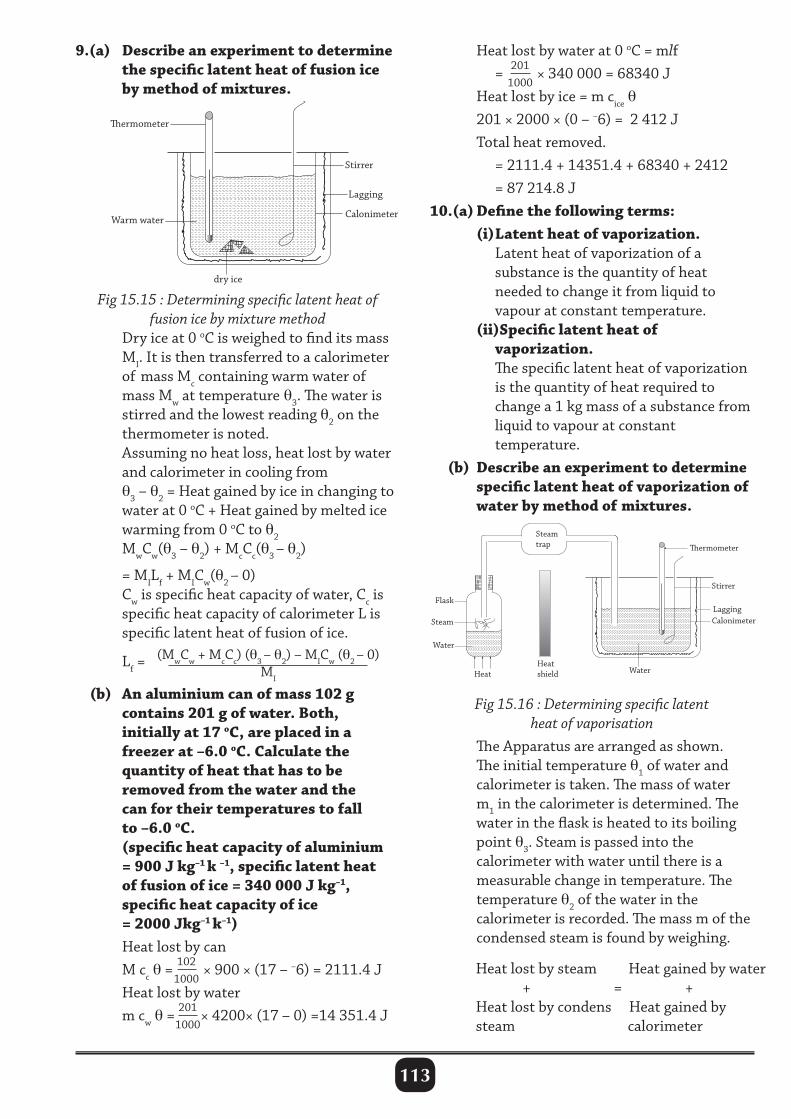
113
9.(a) Describe an experiment to determine the specific latent heat of fusion ice by method of mixtures.
Heat lost by water at 0 oC = mlf = 201
1000 × 340 000 = 68340 J
Heat lost by ice = m cice θ 201 × 2000 × (0 – –6) = 2 412 J Total heat removed. = 2111.4 + 14351.4 + 68340 + 2412 = 87 214.8 J10.(a) Define the following terms: (i) Latent heat of vaporization. Latent heat of vaporization of a substance is the quantity of heat needed to change it from liquid to vapour at constant temperature. (ii)Specific latent heat of vaporization. The specific latent heat of vaporization is the quantity of heat required to change a 1 kg mass of a substance from liquid to vapour at constant temperature. (b) Describe an experiment to determine specific latent heat of vaporization of water by method of mixtures.
ermometer
Stirrer
Calonimeter
dry ice
Warm water
Lagging
Fig 15.15 : Determining specific latent heat of fusion ice by mixture method
Dry ice at 0 oC is weighed to find its mass MI. It is then transferred to a calorimeter of mass Mc containing warm water of mass Mw at temperature θ3. The water is stirred and the lowest reading θ2 on the thermometer is noted. Assuming no heat loss, heat lost by water and calorimeter in cooling from θ3 – θ2 = Heat gained by ice in changing to water at 0 oC + Heat gained by melted ice warming from 0 oC to θ2
MwCw(θ3 – θ2) + McCc(θ3 – θ2)
= MILf + MICw(θ2 – 0) Cw is specific heat capacity of water, Cc is specific heat capacity of calorimeter L is specific latent heat of fusion of ice. Lf =
(MwCw + McCc) (θ3 – θ2) – MICw (θ2 – 0)MI
(b) An aluminium can of mass 102 g contains 201 g of water. Both, initially at 17 oC, are placed in a freezer at –6.0 oC. Calculate the quantity of heat that has to be removed from the water and the can for their temperatures to fall to –6.0 oC. (specific heat capacity of aluminium = 900 J kg–1 k –1, specific latent heat of fusion of ice = 340 000 J kg–1, specific heat capacity of ice = 2000 Jkg–1 k–1) Heat lost by can M cc θ = 102
1000 × 900 × (17 – –6) = 2111.4 J
Heat lost by water m cw θ = 201
1000× 4200× (17 – 0) =14 351.4 J
Stirrer
Calonimeter Lagging
ermometer
Water Heat
Water
Steam
Flask
Steam trap
Heat shield
Fig 15.16 : Determining specific latent heat of vaporisation
The Apparatus are arranged as shown. The initial temperature θ1 of water and calorimeter is taken. The mass of water m1 in the calorimeter is determined. The water in the flask is heated to its boiling point θ3. Steam is passed into the calorimeter with water until there is a measurable change in temperature. The temperature θ2 of the water in the calorimeter is recorded. The mass m of the condensed steam is found by weighing.
Heat lost by steam Heat gained by water + = +Heat lost by condens Heat gained by steam calorimeter
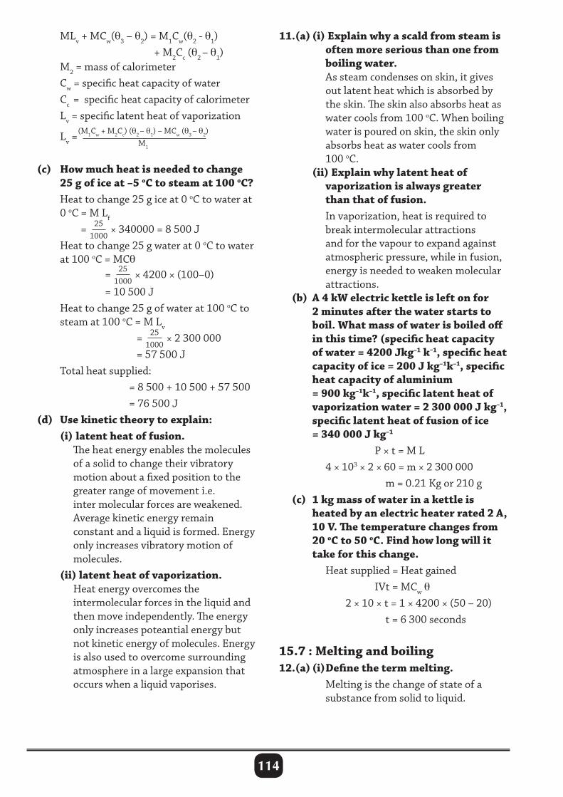
114
MLv + MCw(θ3 – θ2) = M1Cw(θ2 - θ1) + M2Cc (θ2 – θ1) M2 = mass of calorimeter Cw = specific heat capacity of water Cc = specific heat capacity of calorimeter Lv = specific latent heat of vaporization
Lv =(M1Cw + M2Cc) (θ2 – θ1) – MCw (θ3 – θ2)
M1
(c) How much heat is needed to change 25 g of ice at –5 oC to steam at 100 oC? Heat to change 25 g ice at 0 oC to water at 0 oC = M Lf
= 251000
× 340000 = 8 500 J Heat to change 25 g water at 0 oC to water at 100 oC = MCθ
= 251000
× 4200 × (100–0)
= 10 500 J Heat to change 25 g of water at 100 oC to steam at 100 oC = M Lv
= 251000
× 2 300 000 = 57 500 J Total heat supplied: = 8 500 + 10 500 + 57 500 = 76 500 J (d) Use kinetic theory to explain: (i) latent heat of fusion. The heat energy enables the molecules of a solid to change their vibratory motion about a fixed position to the greater range of movement i.e. inter molecular forces are weakened. Average kinetic energy remain constant and a liquid is formed. Energy only increases vibratory motion of molecules. (ii) latent heat of vaporization. Heat energy overcomes the intermolecular forces in the liquid and then move independently. The energy only increases poteantial energy but not kinetic energy of molecules. Energy is also used to overcome surrounding atmosphere in a large expansion that occurs when a liquid vaporises.
11.(a) (i) Explain why a scald from steam is often more serious than one from boiling water. As steam condenses on skin, it gives out latent heat which is absorbed by the skin. The skin also absorbs heat as water cools from 100 oC. When boiling water is poured on skin, the skin only absorbs heat as water cools from 100 oC. (ii) Explain why latent heat of vaporization is always greater than that of fusion. In vaporization, heat is required to break intermolecular attractions and for the vapour to expand against atmospheric pressure, while in fusion, energy is needed to weaken molecular attractions. (b) A 4 kW electric kettle is left on for 2 minutes after the water starts to boil. What mass of water is boiled off in this time? (specific heat capacity of water = 4200 Jkg–1 k–1, specific heat capacity of ice = 200 J kg–1k–1, specific heat capacity of aluminium = 900 kg–1k–1, specific latent heat of vaporization water = 2 300 000 J kg–1, specific latent heat of fusion of ice = 340 000 J kg–1
P × t = M L 4 × 103 × 2 × 60 = m × 2 300 000 m = 0.21 Kg or 210 g (c) 1 kg mass of water in a kettle is heated by an electric heater rated 2 A, 10 V. The temperature changes from 20 oC to 50 oC. Find how long will it take for this change. Heat supplied = Heat gained IVt = MCw θ 2 × 10 × t = 1 × 4200 × (50 – 20) t = 6 300 seconds
15.7 : Melting and boiling12.(a) (i) Define the term melting. Melting is the change of state of a substance from solid to liquid.
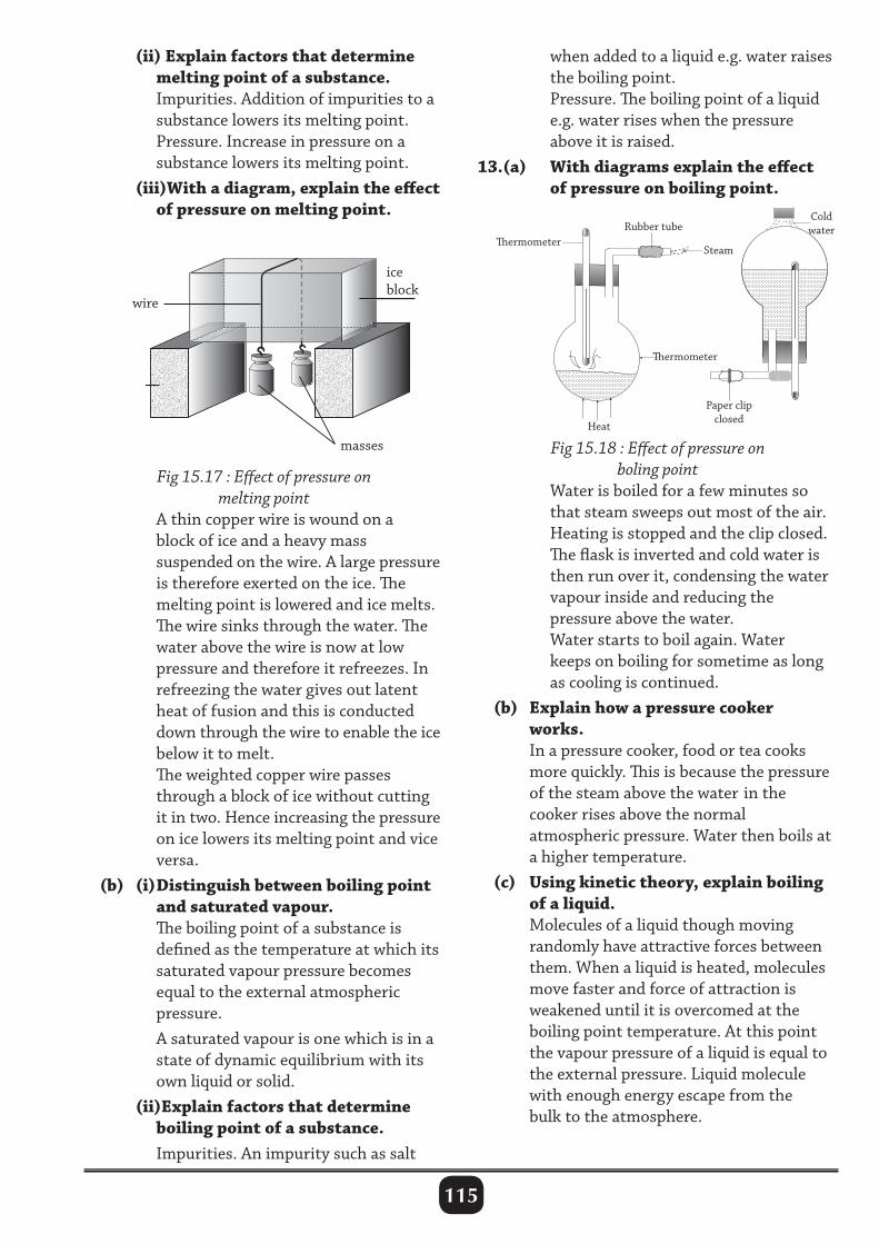
115
(ii) Explain factors that determine melting point of a substance. Impurities. Addition of impurities to a substance lowers its melting point. Pressure. Increase in pressure on a substance lowers its melting point. (iii)With a diagram, explain the effect of pressure on melting point.
when added to a liquid e.g. water raises the boiling point. Pressure. The boiling point of a liquid e.g. water rises when the pressure above it is raised.13.(a) With diagrams explain the effect of pressure on boiling point.
Fig 15.18 : Effect of pressure on boling point
Water is boiled for a few minutes so that steam sweeps out most of the air. Heating is stopped and the clip closed. The flask is inverted and cold water is then run over it, condensing the water vapour inside and reducing the pressure above the water. Water starts to boil again. Water keeps on boiling for sometime as long as cooling is continued. (b) Explain how a pressure cooker works. In a pressure cooker, food or tea cooks more quickly. This is because the pressure of the steam above the water in the cooker rises above the normal atmospheric pressure. Water then boils at a higher temperature. (c) Using kinetic theory, explain boiling of a liquid. Molecules of a liquid though moving randomly have attractive forces between them. When a liquid is heated, molecules move faster and force of attraction is weakened until it is overcomed at the boiling point temperature. At this point the vapour pressure of a liquid is equal to the external pressure. Liquid molecule with enough energy escape from the bulk to the atmosphere.
Fig 15.17 : Effect of pressure on melting point
A thin copper wire is wound on a block of ice and a heavy mass suspended on the wire. A large pressure is therefore exerted on the ice. The melting point is lowered and ice melts. The wire sinks through the water. The water above the wire is now at low pressure and therefore it refreezes. In refreezing the water gives out latent heat of fusion and this is conducted down through the wire to enable the ice below it to melt. The weighted copper wire passes through a block of ice without cutting it in two. Hence increasing the pressure on ice lowers its melting point and vice versa. (b) (i) Distinguish between boiling point and saturated vapour. The boiling point of a substance is defined as the temperature at which its saturated vapour pressure becomes equal to the external atmospheric pressure. A saturated vapour is one which is in a state of dynamic equilibrium with its own liquid or solid. (ii)Explain factors that determine boiling point of a substance. Impurities. An impurity such as salt
ermometer
ermometer
Steam
Heat
Rubber tubeColdwater
Paper clipclosed
wire
iceblock
masses
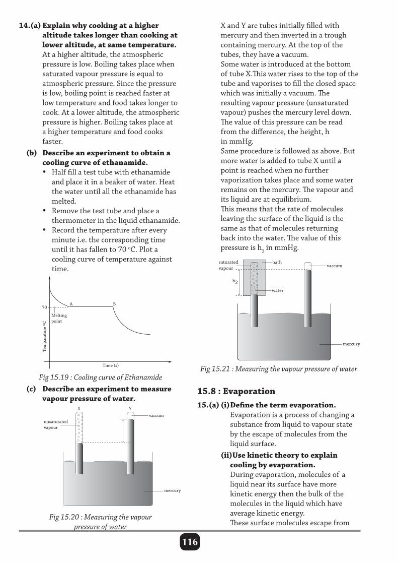
116
14.(a) Explain why cooking at a higher altitude takes longer than cooking at lower altitude, at same temperature. At a higher altitude, the atmospheric pressure is low. Boiling takes place when saturated vapour pressure is equal to atmospheric pressure. Since the pressure is low, boiling point is reached faster at low temperature and food takes longer to cook. At a lower altitude, the atmospheric pressure is higher. Boiling takes place at a higher temperature and food cooks faster. (b) Describe an experiment to obtain a cooling curve of ethanamide. • Half fill a test tube with ethanamide and place it in a beaker of water. Heat the water until all the ethanamide has melted. • Remove the test tube and place a thermometer in the liquid ethanamide. • Record the temperature after every minute i.e. the corresponding time until it has fallen to 70 oC. Plot a cooling curve of temperature against time.
X and Y are tubes initially filled with mercury and then inverted in a trough containing mercury. At the top of the tubes, they have a vacuum. Some water is introduced at the bottom of tube X.This water rises to the top of the tube and vaporises to fill the closed space which was initially a vacuum. The resulting vapour pressure (unsaturated vapour) pushes the mercury level down. The value of this pressure can be read from the difference, the height, h in mmHg. Same procedure is followed as above. But more water is added to tube X until a point is reached when no further vaporization takes place and some water remains on the mercury. The vapour and its liquid are at equilibrium. This means that the rate of molecules leaving the surface of the liquid is the same as that of molecules returning back into the water. The value of this pressure is h2 in mmHg.
Tem
para
ture
oC
Melting point
Time (s)
A 70
B
Fig 15.21 : Measuring the vapour pressure of water
15.8 : Evaporation15.(a) (i) Define the term evaporation. Evaporation is a process of changing a substance from liquid to vapour state by the escape of molecules from the liquid surface. (ii)Use kinetic theory to explain cooling by evaporation. During evaporation, molecules of a liquid near its surface have more kinetic energy then the bulk of the molecules in the liquid which have average kinetic energy. These surface molecules escape from
Fig 15.19 : Cooling curve of Ethanamide (c) Describe an experiment to measure vapour pressure of water.
Fig 15.20 : Measuring the vapour pressure of water
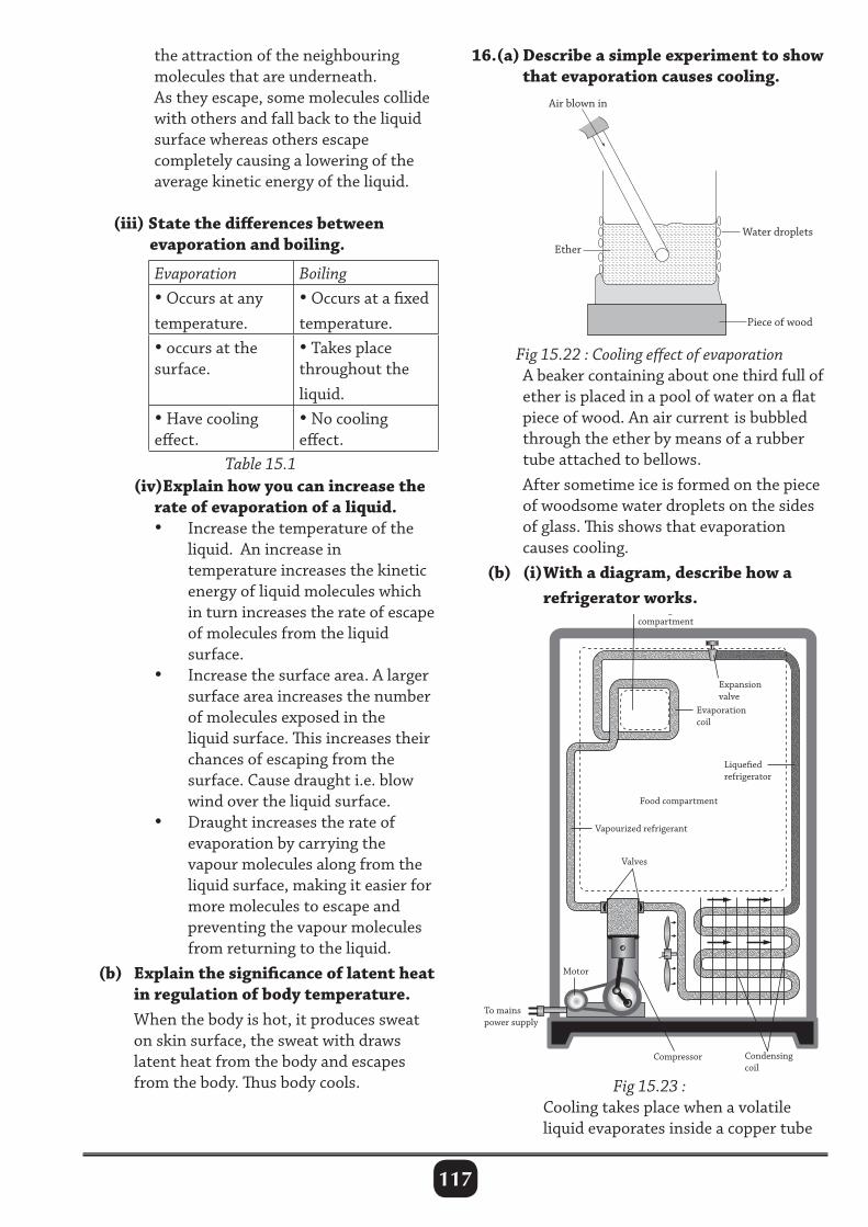
117
the attraction of the neighbouring molecules that are underneath. As they escape, some molecules collide with others and fall back to the liquid surface whereas others escape completely causing a lowering of the average kinetic energy of the liquid.
(iii) State the differences between evaporation and boiling.
Evaporation Boiling• Occurs at any temperature.
• Occurs at a fixed temperature.
• occurs at the surface.
• Takes place throughout the liquid.
• Have cooling effect.
• No cooling effect.
Table 15.1 (iv)Explain how you can increase the rate of evaporation of a liquid. • Increase the temperature of the liquid. An increase in temperature increases the kinetic energy of liquid molecules which in turn increases the rate of escape of molecules from the liquid surface. • Increase the surface area. A larger surface area increases the number of molecules exposed in the liquid surface. This increases their chances of escaping from the surface. Cause draught i.e. blow wind over the liquid surface. • Draught increases the rate of evaporation by carrying the vapour molecules along from the liquid surface, making it easier for more molecules to escape and preventing the vapour molecules from returning to the liquid. (b) Explain the significance of latent heat in regulation of body temperature. When the body is hot, it produces sweat on skin surface, the sweat with draws latent heat from the body and escapes from the body. Thus body cools.
16.(a) Describe a simple experiment to show that evaporation causes cooling.
Air blown in
Ether
Water droplets
Piece of wood
Fig 15.22 : Cooling effect of evaporation A beaker containing about one third full of ether is placed in a pool of water on a flat piece of wood. An air current is bubbled through the ether by means of a rubber tube attached to bellows. After sometime ice is formed on the piece of woodsome water droplets on the sides of glass. This shows that evaporation causes cooling. (b) (i) With a diagram, describe how a refrigerator works.
Freezing compartment
Expansion valve
Evaporation coil
Liqueed refrigerator
Food compartment
Vapourized refrigerant
Valves
Motor
To mainspower supply
Condensingcoil
Compressor
Fig 15.23 : Cooling takes place when a volatile liquid evaporates inside a copper tube
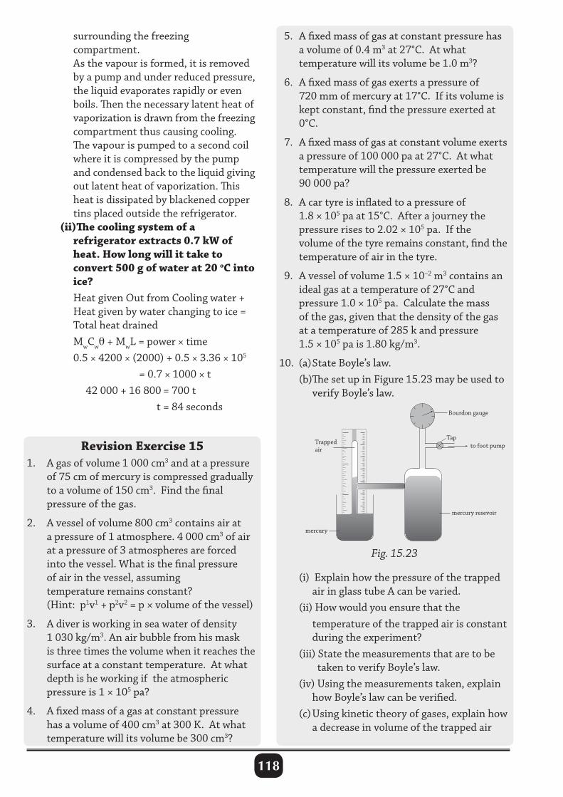
118
surrounding the freezing compartment. As the vapour is formed, it is removed by a pump and under reduced pressure, the liquid evaporates rapidly or even boils. Then the necessary latent heat of vaporization is drawn from the freezing compartment thus causing cooling. The vapour is pumped to a second coil where it is compressed by the pump and condensed back to the liquid giving out latent heat of vaporization. This heat is dissipated by blackened copper tins placed outside the refrigerator. (ii)The cooling system of a refrigerator extracts 0.7 kW of heat. How long will it take to convert 500 g of water at 20 oC into ice? Heat given Out from Cooling water + Heat given by water changing to ice = Total heat drained MwCwθ + MwL = power × time 0.5 × 4200 × (2000) + 0.5 × 3.36 × 105 = 0.7 × 1000 × t 42 000 + 16 800 = 700 t t = 84 seconds
Revision Exercise 151. A gas of volume 1 000 cm3 and at a pressure of 75 cm of mercury is compressed gradually to a volume of 150 cm3. Find the final pressure of the gas.
2. A vessel of volume 800 cm3 contains air at a pressure of 1 atmosphere. 4 000 cm3 of air at a pressure of 3 atmospheres are forced into the vessel. What is the final pressure of air in the vessel, assuming temperature remains constant? (Hint: p1v1 + p2v2 = p × volume of the vessel)
3. A diver is working in sea water of density 1 030 kg/m3. An air bubble from his mask is three times the volume when it reaches the surface at a constant temperature. At what depth is he working if the atmospheric pressure is 1 × 10⁵ pa?
4. A fixed mass of a gas at constant pressure has a volume of 400 cm3 at 300 K. At what temperature will its volume be 300 cm3?
5. A fixed mass of gas at constant pressure has a volume of 0.4 m3 at 27°C. At what temperature will its volume be 1.0 m3?
6. A fixed mass of gas exerts a pressure of 720 mm of mercury at 17°C. If its volume is kept constant, find the pressure exerted at 0°C.
7. A fixed mass of gas at constant volume exerts a pressure of 100 000 pa at 27°C. At what temperature will the pressure exerted be 90 000 pa?
8. A car tyre is inflated to a pressure of 1.8 × 10⁵ pa at 15°C. After a journey the pressure rises to 2.02 × 10⁵ pa. If the volume of the tyre remains constant, find the temperature of air in the tyre.
9. A vessel of volume 1.5 × 10⁻² m3 contains an ideal gas at a temperature of 27°C and pressure 1.0 × 10⁵ pa. Calculate the mass of the gas, given that the density of the gas at a temperature of 285 k and pressure 1.5 × 10⁵ pa is 1.80 kg/m3.
10. (a) State Boyle’s law. (b)The set up in Figure 15.23 may be used to verify Boyle’s law.
Fig. 15.23
(i) Explain how the pressure of the trapped air in glass tube A can be varied. (ii) How would you ensure that the temperature of the trapped air is constant during the experiment? (iii) State the measurements that are to be taken to verify Boyle’s law. (iv) Using the measurements taken, explain how Boyle’s law can be verified. (c) Using kinetic theory of gases, explain how a decrease in volume of the trapped air
3
78
1415
Trappedair
mercury
mercury resevoir
to foot pumpTap
Bourdon gauge
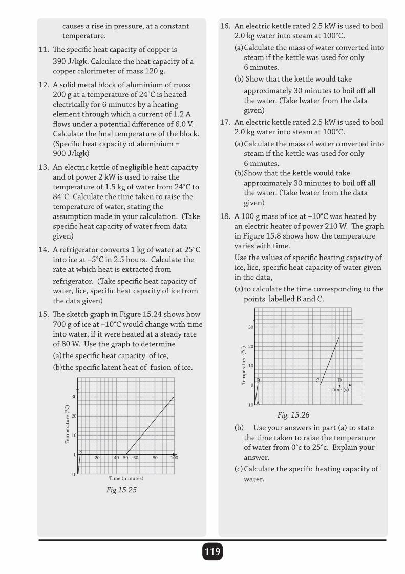
119
causes a rise in pressure, at a constant temperature.
11. The specific heat capacity of copper is 390 J/kgk. Calculate the heat capacity of a copper calorimeter of mass 120 g.
12. A solid metal block of aluminium of mass 200 g at a temperature of 24°C is heated electrically for 6 minutes by a heating element through which a current of 1.2 A flows under a potential difference of 6.0 V. Calculate the final temperature of the block. (Specific heat capacity of aluminium = 900 J/kgk)
13. An electric kettle of negligible heat capacity and of power 2 kW is used to raise the temperature of 1.5 kg of water from 24°C to 84°C. Calculate the time taken to raise the temperature of water, stating the assumption made in your calculation. (Take specific heat capacity of water from data given)
14. A refrigerator converts 1 kg of water at 25°C into ice at –5°C in 2.5 hours. Calculate the rate at which heat is extracted from refrigerator. (Take specific heat capacity of water, lice, specific heat capacity of ice from the data given)
15. The sketch graph in Figure 15.24 shows how 700 g of ice at –10°C would change with time into water, if it were heated at a steady rate of 80 W. Use the graph to determine (a) the specific heat capacity of ice, (b)the specific latent heat of fusion of ice.
30
20
10
0
–10
20 40 60 80 100503
Time (minutes)
Tem
pera
ture
(°C)
16. An electric kettle rated 2.5 kW is used to boil 2.0 kg water into steam at 100°C. (a) Calculate the mass of water converted into steam if the kettle was used for only 6 minutes. (b) Show that the kettle would take approximately 30 minutes to boil off all the water. (Take lwater from the data given)17. An electric kettle rated 2.5 kW is used to boil 2.0 kg water into steam at 100°C. (a) Calculate the mass of water converted into steam if the kettle was used for only 6 minutes. (b)Show that the kettle would take approximately 30 minutes to boil off all the water. (Take lwater from the data given)
18. A 100 g mass of ice at –10°C was heated by an electric heater of power 210 W. The graph in Figure 15.8 shows how the temperature varies with time. Use the values of specific heating capacity of ice, lice, specific heat capacity of water given in the data, (a) to calculate the time corresponding to the points labelled B and C.
Fig 15.25
30
20
10
0
–10
Tem
pera
ture
(°C)
Time (s)
A
CB D•
Fig. 15.26
(b) Use your answers in part (a) to state the time taken to raise the temperature of water from 0°c to 25°c. Explain your answer. (c) Calculate the specific heating capacity of water.
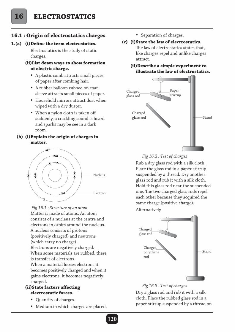
120
ELECTROSTATICS
16.1 : Origin of electrostatics charges1.(a) (i) Define the term electrostatics. Electrostatics is the study of static charges. (ii)List down ways to show formation of electric charge. • A plastic comb attracts small pieces of paper after combing hair. • A rubber balloon rubbed on coat sleeve attracts small pieces of paper. • Household mirrors attract dust when wiped with a dry duster. • When a nylon cloth is taken off suddenly, a crackling sound is heard and sparks may be see in a dark room. (b) (i) Explain the origin of charges in matter.
• Separation of charges. (c) (i) State the law of electrostatics. The law of electrostatics states that, like charges repel and unlike charges attract. (ii)Describe a simple experiment to illustrate the law of electrostatics.
x
x x x
x x
x
x x
x x
x x
Nucleus
Electron
Fig 16.1 : Structure of an atom Matter is made of atoms. An atom consists of a nucleus at the centre and electrons in orbits around the nucleus. A nucleus consists of protons (positively charged) and neutrons (which carry no charge). Electrons are negatively charged. When some materials are rubbed, there is transfer of electrons. When a material looses electrons it becomes positively charged and when it gains electrons, it becomes negatively charged. (ii)State factors affecting electrostatic forces. • Quantity of charges. • Medium in which charges are placed.
Fig 16.2 : Test of charges Rub a dry glass rod with a silk cloth. Place the glass rod in a paper stirrup suspended by a thread. Dry another glass rod and rub it with a silk cloth. Hold this glass rod near the suspended one. The two charged glass rods repel each other because they acquired the same charge (positive charge). Alternatively
Fig 16.3 : Test of charges
16
Dry a glass rod and rub it with a silk cloth. Place the rubbed glass rod in a paper stirrup suspended by a thread on
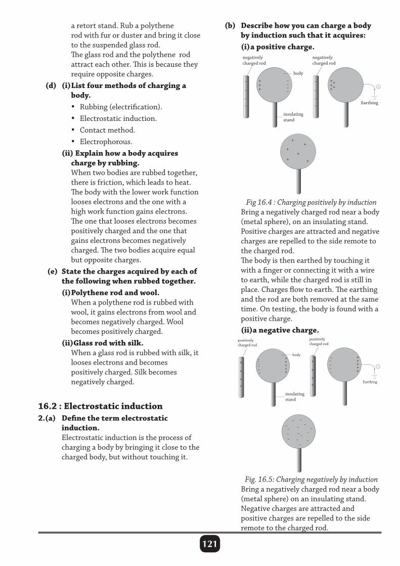
121
a retort stand. Rub a polythene rod with fur or duster and bring it close to the suspended glass rod. The glass rod and the polythene rod attract each other. This is because they require opposite charges. (d) (i) List four methods of charging a body. • Rubbing (electrification). • Electrostatic induction. • Contact method. • Electrophorous. (ii) Explain how a body acquires charge by rubbing. When two bodies are rubbed together, there is friction, which leads to heat. The body with the lower work function looses electrons and the one with a high work function gains electrons. The one that looses electrons becomes positively charged and the one that gains electrons becomes negatively charged. The two bodies acquire equal but opposite charges. (e) State the charges acquired by each of the following when rubbed together. (i) Polythene rod and wool. When a polythene rod is rubbed with wool, it gains electrons from wool and becomes negatively charged. Wool becomes positively charged. (ii)Glass rod with silk. When a glass rod is rubbed with silk, it looses electrons and becomes positively charged. Silk becomes negatively charged.
16.2 : Electrostatic induction2.(a) Define the term electrostatic induction. Electrostatic induction is the process of charging a body by bringing it close to the charged body, but without touching it.
(b) Describe how you can charge a body by induction such that it acquires: (i) a positive charge.
+ + +
– – – –
–
–
–
–
negativelycharged rod
body
insulating stand
+ + + +
+
+
+ +
+ +
+
–
–
–
–
negativelycharged rod
Earthing
–
Fig 16.4 : Charging positively by induction Bring a negatively charged rod near a body (metal sphere), on an insulating stand. Positive charges are attracted and negative charges are repelled to the side remote to the charged rod. The body is then earthed by touching it with a finger or connecting it with a wire to earth, while the charged rod is still in place. Charges flow to earth. The earthing and the rod are both removed at the same time. On testing, the body is found with a positive charge. (ii)a negative charge.
Fig. 16.5: Charging negatively by induction Bring a negatively charged rod near a body (metal sphere) on an insulating stand. Negative charges are attracted and positive charges are repelled to the side remote to the charged rod.
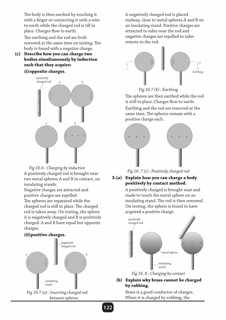
122
The body is then earthed by touching it with a finger or connecting it with a wire to earth while the charged rod is till in place. Charges flow to earth. The earthing and the rod are both removed at the same time on testing. The body is found with a negative charge. (c) Describe how you can charge two bodies simultaneously by induction such that they acquire: (i) opposite charges.
++++
+
–
–
–
–
Earthing
–
++++
+
– – – –
+ + + +
–– –– + ++ +
positively charged rod
A
A
B
B
+
+
+
Fig 16.6 : Charging by induction A positively charged rod is brought near two metal spheres A and B in contact, on insulating stands. Negative charges are attracted and positive charges are repelled. The spheres are separated while the charged rod is still in place. The charged rod is taken away. On testing, the sphere A is negatively charged and B is positively charged. A and B have equal but opposite charges. (ii)positive charges.
A negatively charged rod is placed midway, close to metal spheres A and B on an insulating stand. Positive charges are attracted to sides near the rod and negative charges are repelled to sides remote to the rod.
Fig 16.7 (b) : Earthing The spheres are then earthed while the rod is still in place. Charges flow to earth. Earthing and the rod are removed at the same time. The spheres remain with a positive charge each.
Fig 16. 7 (c) : Positively charged rod 3.(a) Explain how you can charge a body positively by contact method. A positively charged is brought near and made to touch the metal sphere on an insulating stand. The rod is then removed. On testing, the sphere is found to have acquired a positive charge.
Fig 16.7 (a) : Inserting charged rod between spheres
Fig 16. 8 : Charging by contact (b) Explain why brass cannot be charged by rubbing. Brass is a good conductor of charges. When it is charged by rubbing, the
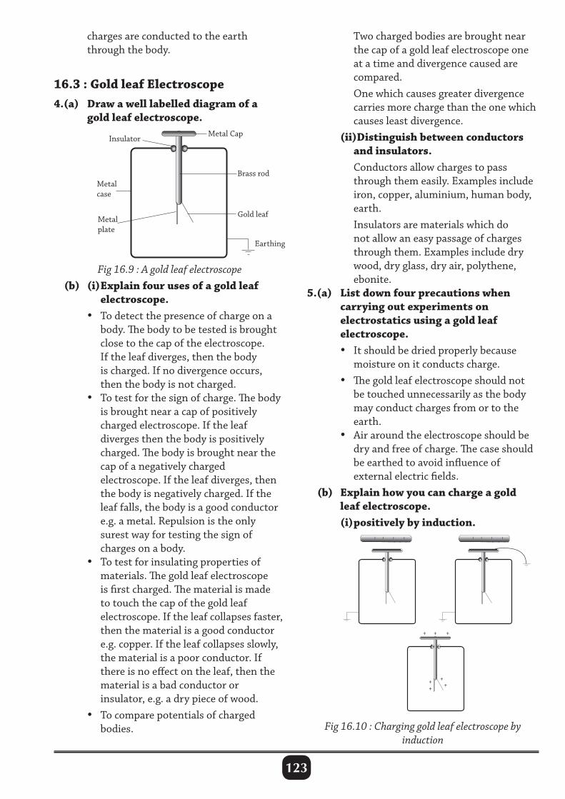
123
Metal Cap
Brass rod
Insulator
Gold leaf
Earthing
Metal plate
Metal case
charges are conducted to the earth through the body.
16.3 : Gold leaf Electroscope4.(a) Draw a well labelled diagram of a gold leaf electroscope.
Two charged bodies are brought near the cap of a gold leaf electroscope one at a time and divergence caused are compared. One which causes greater divergence carries more charge than the one which causes least divergence. (ii)Distinguish between conductors and insulators. Conductors allow charges to pass through them easily. Examples include iron, copper, aluminium, human body, earth. Insulators are materials which do not allow an easy passage of charges through them. Examples include dry wood, dry glass, dry air, polythene, ebonite. 5.(a) List down four precautions when carrying out experiments on electrostatics using a gold leaf electroscope. • It should be dried properly because moisture on it conducts charge. • The gold leaf electroscope should not be touched unnecessarily as the body may conduct charges from or to the earth. • Air around the electroscope should be dry and free of charge. The case should be earthed to avoid influence of external electric fields. (b) Explain how you can charge a gold leaf electroscope. (i) positively by induction.
Fig 16.9 : A gold leaf electroscope (b) (i) Explain four uses of a gold leaf electroscope. • To detect the presence of charge on a body. The body to be tested is brought close to the cap of the electroscope. If the leaf diverges, then the body is charged. If no divergence occurs, then the body is not charged. • To test for the sign of charge. The body is brought near a cap of positively charged electroscope. If the leaf diverges then the body is positively charged. The body is brought near the cap of a negatively charged electroscope. If the leaf diverges, then the body is negatively charged. If the leaf falls, the body is a good conductor e.g. a metal. Repulsion is the only surest way for testing the sign of charges on a body. • To test for insulating properties of materials. The gold leaf electroscope is first charged. The material is made to touch the cap of the gold leaf electroscope. If the leaf collapses faster, then the material is a good conductor e.g. copper. If the leaf collapses slowly, the material is a poor conductor. If there is no effect on the leaf, then the material is a bad conductor or insulator, e.g. a dry piece of wood. • To compare potentials of charged bodies.
– – – – – – – –
+ +
+ + +
+
+
Fig 16.10 : Charging gold leaf electroscope by induction
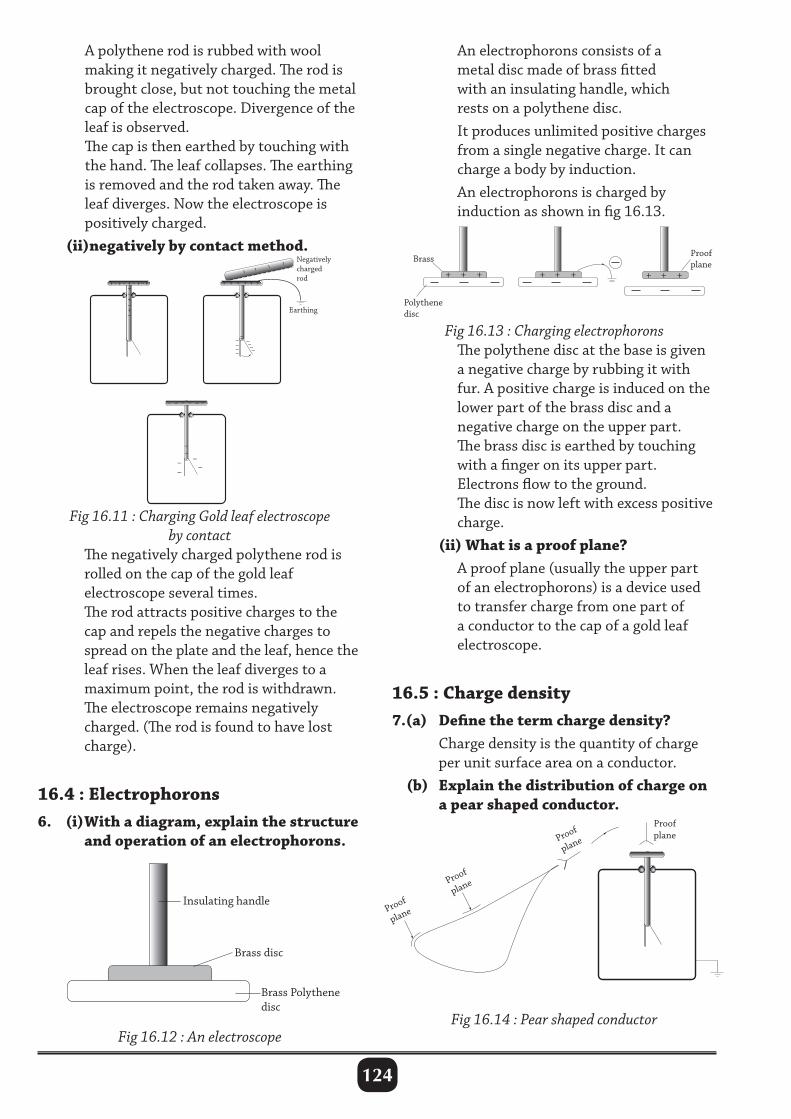
124
A polythene rod is rubbed with wool making it negatively charged. The rod is brought close, but not touching the metal cap of the electroscope. Divergence of the leaf is observed. The cap is then earthed by touching with the hand. The leaf collapses. The earthing is removed and the rod taken away. The leaf diverges. Now the electroscope is positively charged. (ii)negatively by contact method.
An electrophorons consists of a metal disc made of brass fitted with an insulating handle, which rests on a polythene disc. It produces unlimited positive charges from a single negative charge. It can charge a body by induction. An electrophorons is charged by induction as shown in fig 16.13.
Insulating handle
Brass disc
Brass Polythene disc
+ – + – + + – + – + –
––– –––––––
– + – + + + + + + +
–
–––
–
––––
––
–
Earthing
Negativelychargedrod
––––
Fig 16.11 : Charging Gold leaf electroscope by contact
The negatively charged polythene rod is rolled on the cap of the gold leaf electroscope several times. The rod attracts positive charges to the cap and repels the negative charges to spread on the plate and the leaf, hence the leaf rises. When the leaf diverges to a maximum point, the rod is withdrawn. The electroscope remains negatively charged. (The rod is found to have lost charge).
16.4 : Electrophorons6. (i) With a diagram, explain the structure and operation of an electrophorons.
Fig 16.13 : Charging electrophorons The polythene disc at the base is given a negative charge by rubbing it with fur. A positive charge is induced on the lower part of the brass disc and a negative charge on the upper part. The brass disc is earthed by touching with a finger on its upper part. Electrons flow to the ground. The disc is now left with excess positive charge. (ii) What is a proof plane? A proof plane (usually the upper part of an electrophorons) is a device used to transfer charge from one part of a conductor to the cap of a gold leaf electroscope.
16.5 : Charge density7.(a) Define the term charge density? Charge density is the quantity of charge per unit surface area on a conductor. (b) Explain the distribution of charge on a pear shaped conductor.
Fig 16.12 : An electroscopeFig 16.14 : Pear shaped conductor
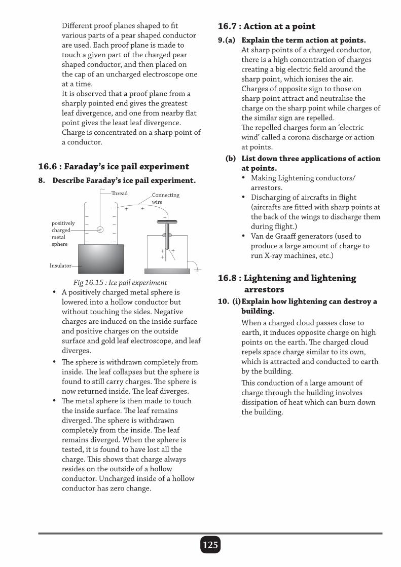
125
Different proof planes shaped to fit various parts of a pear shaped conductor are used. Each proof plane is made to touch a given part of the charged pear shaped conductor, and then placed on the cap of an uncharged electroscope one at a time. It is observed that a proof plane from a sharply pointed end gives the greatest leaf divergence, and one from nearby flat point gives the least leaf divergence. Charge is concentrated on a sharp point of a conductor.
16.6 : Faraday’s ice pail experiment8. Describe Faraday’s ice pail experiment.
16.7 : Action at a point9.(a) Explain the term action at points. At sharp points of a charged conductor, there is a high concentration of charges creating a big electric field around the sharp point, which ionises the air. Charges of opposite sign to those on sharp point attract and neutralise the charge on the sharp point while charges of the similar sign are repelled. The repelled charges form an ‘electric wind’ called a corona discharge or action at points. (b) List down three applications of action at points. • Making Lightening conductors/ arrestors. • Discharging of aircrafts in flight (aircrafts are fitted with sharp points at the back of the wings to discharge them during flight.) • Van de Graaff generators (used to produce a large amount of charge to run X-ray machines, etc.)
16.8 : Lightening and lightening arrestors10. (i) Explain how lightening can destroy a building. When a charged cloud passes close to earth, it induces opposite charge on high points on the earth. The charged cloud repels space charge similar to its own, which is attracted and conducted to earth by the building. This conduction of a large amount of charge through the building involves dissipation of heat which can burn down the building.
Fig 16.15 : Ice pail experiment • A positively charged metal sphere is lowered into a hollow conductor but without touching the sides. Negative charges are induced on the inside surface and positive charges on the outside surface and gold leaf electroscope, and leaf diverges. • The sphere is withdrawn completely from inside. The leaf collapses but the sphere is found to still carry charges. The sphere is now returned inside. The leaf diverges. • The metal sphere is then made to touch the inside surface. The leaf remains diverged. The sphere is withdrawn completely from the inside. The leaf remains diverged. When the sphere is tested, it is found to have lost all the charge. This shows that charge always resides on the outside of a hollow conductor. Uncharged inside of a hollow conductor has zero change.
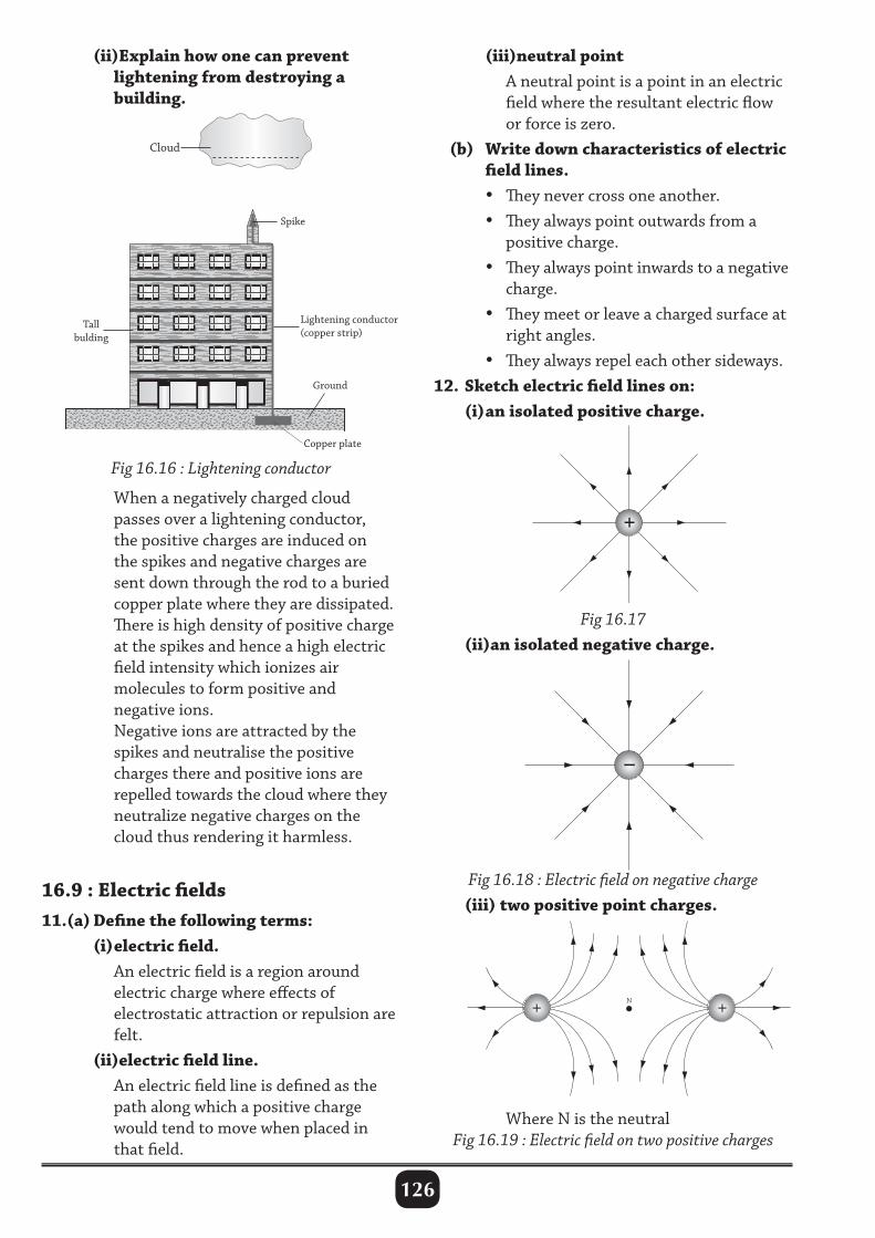
126
(ii)Explain how one can prevent lightening from destroying a building.
Where N is the neutralFig 16.19 : Electric field on two positive charges
Fig 16.16 : Lightening conductor
When a negatively charged cloud passes over a lightening conductor, the positive charges are induced on the spikes and negative charges are sent down through the rod to a buried copper plate where they are dissipated. There is high density of positive charge at the spikes and hence a high electric field intensity which ionizes air molecules to form positive and negative ions. Negative ions are attracted by the spikes and neutralise the positive charges there and positive ions are repelled towards the cloud where they neutralize negative charges on the cloud thus rendering it harmless.
16.9 : Electric fields11.(a) Define the following terms: (i) electric field. An electric field is a region around electric charge where effects of electrostatic attraction or repulsion are felt. (ii)electric field line. An electric field line is defined as the path along which a positive charge would tend to move when placed in that field.
(iii)neutral point A neutral point is a point in an electric field where the resultant electric flow or force is zero. (b) Write down characteristics of electric field lines. • They never cross one another. • They always point outwards from a positive charge. • They always point inwards to a negative charge. • They meet or leave a charged surface at right angles. • They always repel each other sideways.12. Sketch electric field lines on: (i) an isolated positive charge.
+ +
– –
Fig 16.17 (ii)an isolated negative charge.
Fig 16.18 : Electric field on negative charge (iii) two positive point charges.
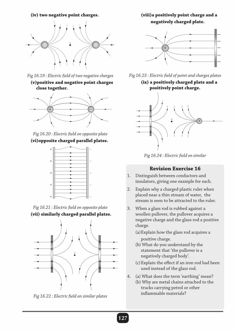
127
(iv) two negative point charges.
Fig 16.19 : Electric field of two negative charges (v)positive and negative point charges close together.
Fig 16.20 : Electric field on opposite plate (vi)opposite charged parallel plates.
+ +
– –
–
–
–
–
–
+
+
+
+
+
(viii)a positively point charge and a negatively charged plate.
–
–
–
–
–
+
+
+
+
+
Fig 16.23 : Electric field of point and charges plates (ix) a positively charged plate and a positively point charge.
Fig 16.21 : Electric field on opposite plate (vii) similarly charged parallel plates.
Fig 16.24 : Electric field on similar
Revision Exercise 161. Distinguish between conductors and insulators, giving one example for each.
2. Explain why a charged plastic ruler when placed near a thin stream of water, the stream is seen to be attracted to the ruler.
3. When a glass rod is rubbed against a woollen pullover, the pullover acquires a negative charge and the glass rod a positive charge. (a) Explain how the glass rod acquires a positive charge. (b) What do you understand by the statement that ‘the pullover is a negatively charged body’. (c) Explain the effect if an iron rod had been used instead of the glass rod.
4. (a) What does the term ‘earthing’ mean? (b) Why are metal chains attached to the trucks carrying petrol or other inflammable materials?Fig 16.22 : Electric field on similar plates
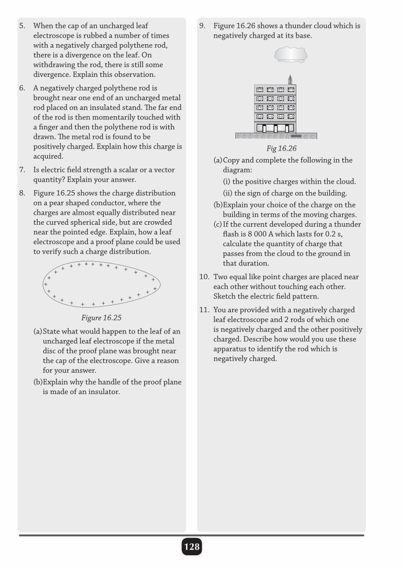
128
5. When the cap of an uncharged leaf electroscope is rubbed a number of times with a negatively charged polythene rod, there is a divergence on the leaf. On withdrawing the rod, there is still some divergence. Explain this observation.
6. A negatively charged polythene rod is brought near one end of an uncharged metal rod placed on an insulated stand. The far end of the rod is then momentarily touched with a finger and then the polythene rod is with drawn. The metal rod is found to be positively charged. Explain how this charge is acquired.
7. Is electric field strength a scalar or a vector quantity? Explain your answer.
8. Figure 16.25 shows the charge distribution on a pear shaped conductor, where the charges are almost equally distributed near the curved spherical side, but are crowded near the pointed edge. Explain, how a leaf electroscope and a proof plane could be used to verify such a charge distribution.
9. Figure 16.26 shows a thunder cloud which is negatively charged at its base.
Fig 16.26 (a) Copy and complete the following in the diagram: (i) the positive charges within the cloud. (ii) the sign of charge on the building. (b)Explain your choice of the charge on the building in terms of the moving charges. (c) If the current developed during a thunder flash is 8 000 A which lasts for 0.2 s, calculate the quantity of charge that passes from the cloud to the ground in that duration.
10. Two equal like point charges are placed near each other without touching each other. Sketch the electric field pattern.
11. You are provided with a negatively charged leaf electroscope and 2 rods of which one is negatively charged and the other positively charged. Describe how would you use these apparatus to identify the rod which is negatively charged.
++++
++++
+ + + + + + + + + +
+ + + + + + ++
+
+
Figure 16.25
(a) State what would happen to the leaf of an uncharged leaf electroscope if the metal disc of the proof plane was brought near the cap of the electroscope. Give a reason for your answer. (b)Explain why the handle of the proof plane is made of an insulator.

129
CURRENT ELECTRICITY I
17.1 : Sources of electricity1.(a) (i) Define an electric current and state its SI unit of measurement. An electric current is the rate of flow of charge through a given point in a conductor. It is measured in amperes (A), by a device called an ammeter. (ii)A battery is rated 35 Ah. How long will it work if it is steadily supplying a current of 5 A?
From I = Q
T Q – charge
I = current Q = I t, I = 5 A, Q = 35 Ah 35 Ah = 5 t t = 7 hours (b) (i) Define the term electromotive force (emf) and give its SI unit. Electromotive force is the total energy delivered by a source of electricity to move 1coulomb of charge around a complete circuit which includes the source itself. Its SI unit is a volt (v). (ii)Name any seven common sources of electricity. • chemical cells (primary and secondary cells). • generators (direct and alternating current generators). • solar cells. • the bicycle dynamo. • thermocouple. • Piezo electricity. • The photo tube.2. Explain why Aluminium is a conductor whereas Polythene is an insulator. Metals like aluminium have free electrons. The electrons are delocalised in their structure and can easily move through the metal from one atom to another. Therefore, they are conductors. In materials like polythene, the electrons are held firmly to the atoms, i.e. they are
Fig 17.1: Electric circuit Identify the mistakes in the circuit and draw the circuit with mistakes corrected, stating how they are corrected. • The voltmeter is connected in series with the battery. Hardly any current would flow in the circuit due to the high resistance of the voltmeter. • The ammeter is connected in parallel with the component P.
not free to move about in the material. These materials do not allow electric charge to flow through them and therefore are called insulators.3.(a) A form three student attempted to use a circuit in Fig.17.1 to investigate the current–voltage characteristics of a component P.
Fig 17.2 : Correct diagram electric urcuit
17
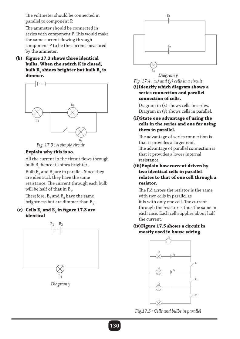
130
The voltmeter should be connected in parallel to component P. The ammeter should be connected in series with component P. This would make the same current flowing through component P to be the current measured by the ammeter. (b) Figure 17.3 shows three identical bulbs. When the switch K is closed, bulb B1 shines brighter but bulb B2 is dimmer.
Fig. 17.3 : A simple circuit Explain why this is so. All the current in the circuit flows through bulb B1 hence it shines brighter. Bulb B2 and B3 are in parallel. Since they are identical, they have the same resistance. The current through each bulb will be half of that in B1. Therefore, B2 and B3 have the same brightness but are dimmer than B1.
(c) Cells E1 and E2 in figure 17.3 are identical
E1
E2
L2
Diagram yFig. 17.4 : (x) and (y) cells in a circuit
(i) Identify which diagram shows a series connection and parallel connection of cells. Diagram in (x) shows cells in series. Diagram in (y) shows cells in parallel. (ii)State one advantage of using the cells in the series and one for using them in parallel. The advantage of series connection is that it provides a larger emf. The advantage of parallel connection is that it provides a lower internal resistance. (iii)Explain how current driven by two identical cells in parallel relates to that of one cell through a resistor. The P.d across the resistor is the same with two cells in parallel as it is with only one cell. The current through the resistor is thus the same in each case. Each cell supplies about half the current. (iv)Figure 17.5 shows a circuit in mostly used in house wiring.
Diagram y
Fig.17.5 : Cells and bulbs in parallel
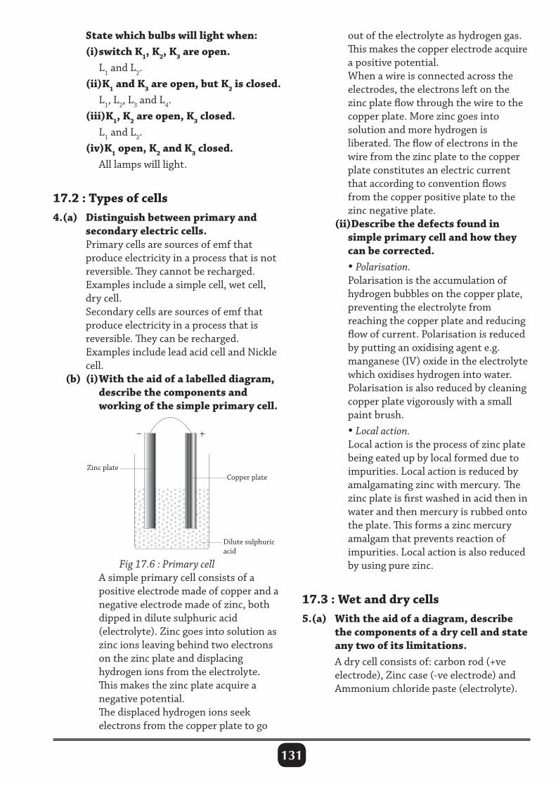
131
out of the electrolyte as hydrogen gas. This makes the copper electrode acquire a positive potential. When a wire is connected across the electrodes, the electrons left on the zinc plate flow through the wire to the copper plate. More zinc goes into solution and more hydrogen is liberated. The flow of electrons in the wire from the zinc plate to the copper plate constitutes an electric current that according to convention flows from the copper positive plate to the zinc negative plate. (ii)Describe the defects found in simple primary cell and how they can be corrected. • Polarisation. Polarisation is the accumulation of hydrogen bubbles on the copper plate, preventing the electrolyte from reaching the copper plate and reducing flow of current. Polarisation is reduced by putting an oxidising agent e.g. manganese (IV) oxide in the electrolyte which oxidises hydrogen into water. Polarisation is also reduced by cleaning copper plate vigorously with a small paint brush. • Local action. Local action is the process of zinc plate being eated up by local formed due to impurities. Local action is reduced by amalgamating zinc with mercury. The zinc plate is first washed in acid then in water and then mercury is rubbed onto the plate. This forms a zinc mercury amalgam that prevents reaction of impurities. Local action is also reduced by using pure zinc.
17.3 : Wet and dry cells5.(a) With the aid of a diagram, describe the components of a dry cell and state any two of its limitations. A dry cell consists of: carbon rod (+ve electrode), Zinc case (-ve electrode) and Ammonium chloride paste (electrolyte).
State which bulbs will light when: (i) switch K1, K2, K3 are open. L1 and L2. (ii)K1 and K3 are open, but K2 is closed. L1, L2, L3 and L4. (iii)K1, K2 are open, K3 closed. L1 and L2. (iv)K1 open, K2 and K3 closed. All lamps will light.
17.2 : Types of cells4.(a) Distinguish between primary and secondary electric cells. Primary cells are sources of emf that produce electricity in a process that is not reversible. They cannot be recharged. Examples include a simple cell, wet cell, dry cell. Secondary cells are sources of emf that produce electricity in a process that is reversible. They can be recharged. Examples include lead acid cell and Nickle cell. (b) (i) With the aid of a labelled diagram, describe the components and working of the simple primary cell.
Copper plateZinc plate
Dilute sulphuricacid
Fig 17.6 : Primary cell A simple primary cell consists of a positive electrode made of copper and a negative electrode made of zinc, both dipped in dilute sulphuric acid (electrolyte). Zinc goes into solution as zinc ions leaving behind two electrons on the zinc plate and displacing hydrogen ions from the electrolyte. This makes the zinc plate acquire a negative potential. The displaced hydrogen ions seek electrons from the copper plate to go
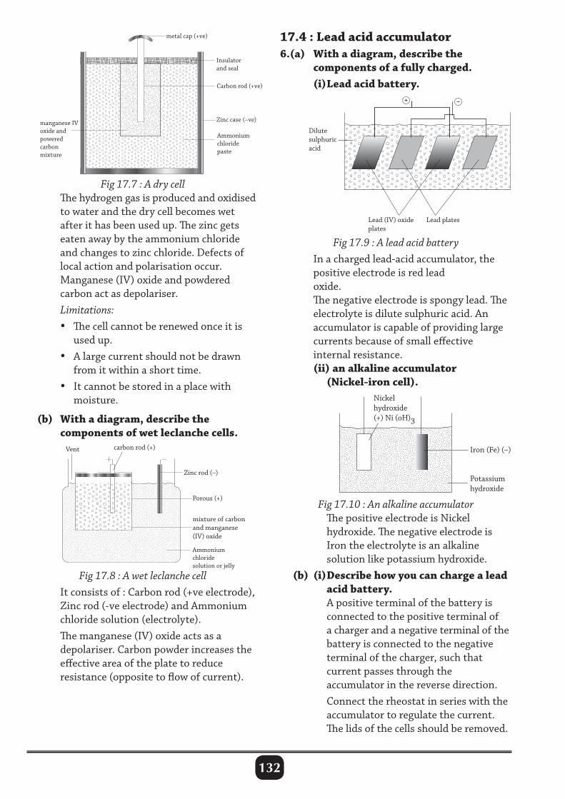
132
17.4 : Lead acid accumulator6.(a) With a diagram, describe the components of a fully charged. (i) Lead acid battery.Carbon rod (+ve)
Insulator and seal
metal cap (+ve)
manganese IVoxide and powered carbonmixture
Zinc case (–ve)
Ammonium chloridepaste
Fig 17.7 : A dry cell The hydrogen gas is produced and oxidised to water and the dry cell becomes wet after it has been used up. The zinc gets eaten away by the ammonium chloride and changes to zinc chloride. Defects of local action and polarisation occur. Manganese (IV) oxide and powdered carbon act as depolariser. Limitations: • The cell cannot be renewed once it is used up. • A large current should not be drawn from it within a short time. • It cannot be stored in a place with moisture.
(b) With a diagram, describe the components of wet leclanche cells.
Dilutesulphuricacid
Lead (IV) oxideplates
Lead plates
Fig 17.9 : A lead acid battery In a charged lead-acid accumulator, the positive electrode is red lead oxide. The negative electrode is spongy lead. The electrolyte is dilute sulphuric acid. An accumulator is capable of providing large currents because of small effective internal resistance. (ii) an alkaline accumulator (Nickel-iron cell).
Vent
Porous (+)
Ammoniumchloride solution or jelly
carbon rod (+)
Zinc rod (–)
mixture of carbon and manganese (IV) oxide
Fig 17.8 : A wet leclanche cell It consists of : Carbon rod (+ve electrode), Zinc rod (-ve electrode) and Ammonium chloride solution (electrolyte). The manganese (IV) oxide acts as a depolariser. Carbon powder increases the effective area of the plate to reduce resistance (opposite to flow of current).
Iron (Fe) (–)
Potassium hydroxide
Nickelhydroxide(+) Ni (oH)3
Fig 17.10 : An alkaline accumulator The positive electrode is Nickel hydroxide. The negative electrode is Iron the electrolyte is an alkaline solution like potassium hydroxide. (b) (i) Describe how you can charge a lead acid battery. A positive terminal of the battery is connected to the positive terminal of a charger and a negative terminal of the battery is connected to the negative terminal of the charger, such that current passes through the accumulator in the reverse direction. Connect the rheostat in series with the accumulator to regulate the current. The lids of the cells should be removed.
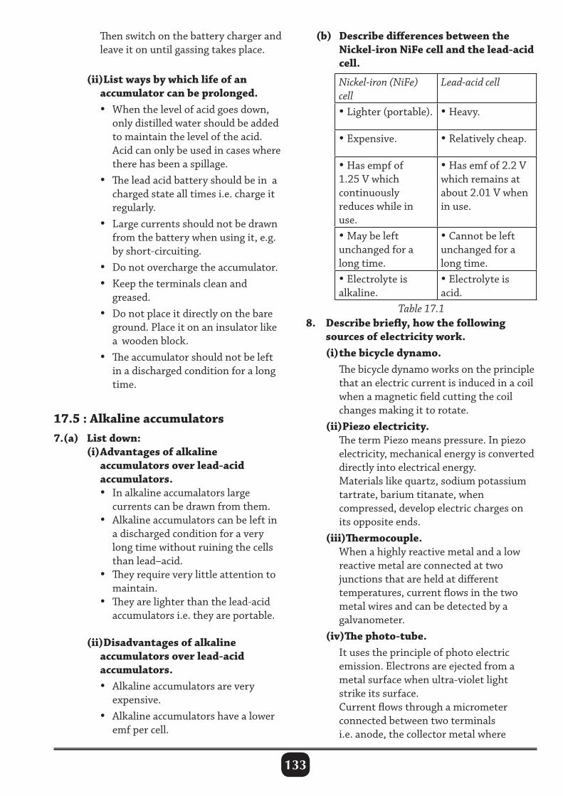
133
Then switch on the battery charger and leave it on until gassing takes place.
(ii)List ways by which life of an accumulator can be prolonged. • When the level of acid goes down, only distilled water should be added to maintain the level of the acid. Acid can only be used in cases where there has been a spillage. • The lead acid battery should be in a charged state all times i.e. charge it regularly. • Large currents should not be drawn from the battery when using it, e.g. by short-circuiting. • Do not overcharge the accumulator. • Keep the terminals clean and greased. • Do not place it directly on the bare ground. Place it on an insulator like a wooden block. • The accumulator should not be left in a discharged condition for a long time.
17.5 : Alkaline accumulators7.(a) List down: (i) Advantages of alkaline accumulators over lead-acid accumulators. • In alkaline accumalators large currents can be drawn from them. • Alkaline accumulators can be left in a discharged condition for a very long time without ruining the cells than lead–acid. • They require very little attention to maintain. • They are lighter than the lead-acid accumulators i.e. they are portable.
(ii)Disadvantages of alkaline accumulators over lead-acid accumulators. • Alkaline accumulators are very expensive. • Alkaline accumulators have a lower emf per cell.
(b) Describe differences between the Nickel-iron NiFe cell and the lead-acid cell.
Nickel-iron (NiFe) cell
Lead-acid cell
•Lighter (portable). •Heavy.
•Expensive. •Relatively cheap.
•Has empf of 1.25 V which continuously reduces while in use.
•Has emf of 2.2 V which remains at about 2.01 V when in use.
•May be left unchanged for a long time.
•Cannot be left unchanged for a long time.
•Electrolyte is alkaline.
•Electrolyte is acid.
Table 17.18. Describe briefly, how the following sources of electricity work. (i) the bicycle dynamo. The bicycle dynamo works on the principle that an electric current is induced in a coil when a magnetic field cutting the coil changes making it to rotate. (ii)Piezo electricity. The term Piezo means pressure. In piezo electricity, mechanical energy is converted directly into electrical energy. Materials like quartz, sodium potassium tartrate, barium titanate, when compressed, develop electric charges on its opposite ends. (iii)Thermocouple. When a highly reactive metal and a low reactive metal are connected at two junctions that are held at different temperatures, current flows in the two metal wires and can be detected by a galvanometer. (iv)The photo-tube. It uses the principle of photo electric emission. Electrons are ejected from a metal surface when ultra-violet light strike its surface. Current flows through a micrometer connected between two terminals i.e. anode, the collector metal where
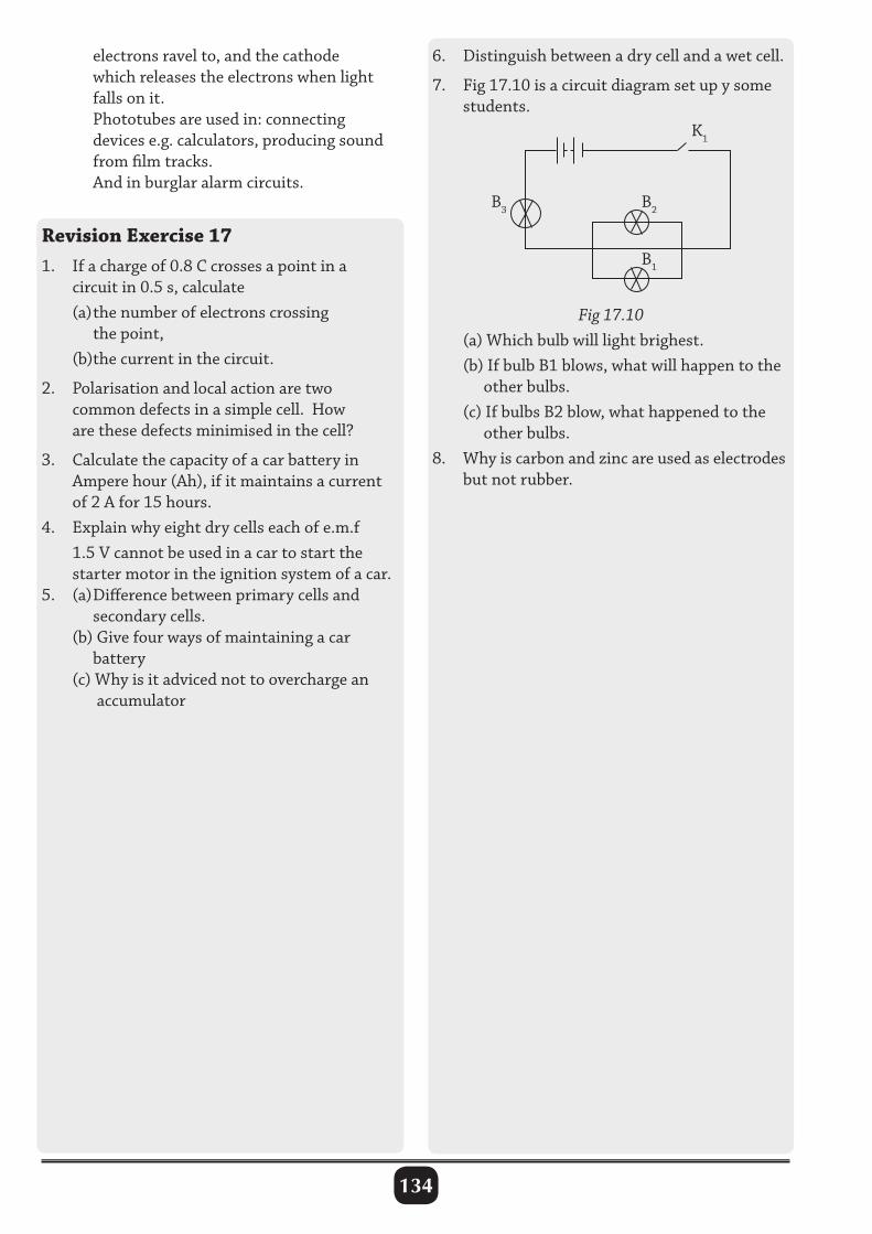
134
electrons ravel to, and the cathode which releases the electrons when light falls on it. Phototubes are used in: connecting devices e.g. calculators, producing sound from film tracks. And in burglar alarm circuits.
Revision Exercise 171. If a charge of 0.8 C crosses a point in a circuit in 0.5 s, calculate (a) the number of electrons crossing the point, (b)the current in the circuit.
2. Polarisation and local action are two common defects in a simple cell. How are these defects minimised in the cell?
3. Calculate the capacity of a car battery in Ampere hour (Ah), if it maintains a current of 2 A for 15 hours.4. Explain why eight dry cells each of e.m.f 1.5 V cannot be used in a car to start the starter motor in the ignition system of a car.5. (a) Difference between primary cells and secondary cells. (b) Give four ways of maintaining a car battery (c) Why is it adviced not to overcharge an accumulator
6. Distinguish between a dry cell and a wet cell.
7. Fig 17.10 is a circuit diagram set up y some students.
Fig 17.10 (a) Which bulb will light brighest. (b) If bulb B1 blows, what will happen to the other bulbs. (c) If bulbs B2 blow, what happened to the other bulbs.8. Why is carbon and zinc are used as electrodes but not rubber.
K1
B2
B1
B3
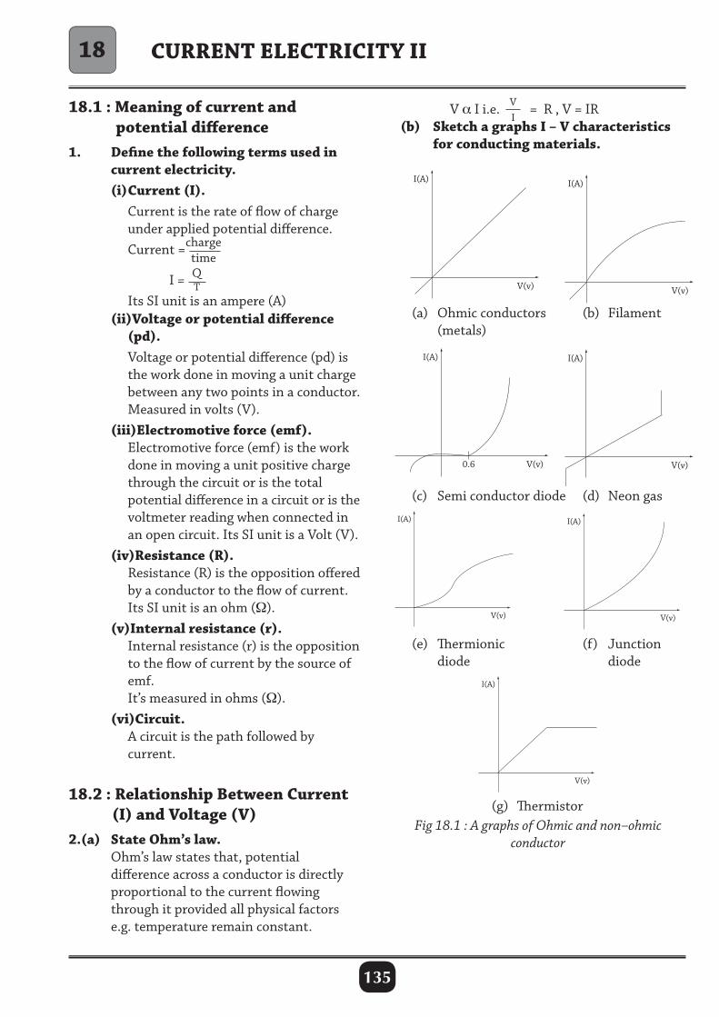
135
CURRENT ELECTRICITY II
18.1 : Meaning of current and potential difference1. Define the following terms used in current electricity. (i) Current (I). Current is the rate of flow of charge under applied potential difference. Current =charge
time
I = QT
Its SI unit is an ampere (A) (ii)Voltage or potential difference (pd). Voltage or potential difference (pd) is the work done in moving a unit charge between any two points in a conductor. Measured in volts (V). (iii)Electromotive force (emf). Electromotive force (emf) is the work done in moving a unit positive charge through the circuit or is the total potential difference in a circuit or is the voltmeter reading when connected in an open circuit. Its SI unit is a Volt (V). (iv)Resistance (R). Resistance (R) is the opposition offered by a conductor to the flow of current. Its SI unit is an ohm (Ω). (v)Internal resistance (r). Internal resistance (r) is the opposition to the flow of current by the source of emf. It’s measured in ohms (Ω). (vi)Circuit. A circuit is the path followed by current.
18.2 : Relationship Between Current (I) and Voltage (V)2.(a) State Ohm’s law. Ohm’s law states that, potential difference across a conductor is directly proportional to the current flowing through it provided all physical factors e.g. temperature remain constant.
V α I i.e. VI
= R , V = IR (b) Sketch a graphs I – V characteristics for conducting materials.
(a) Ohmic conductors (metals)
Fig 18.1 : A graphs of Ohmic and non–ohmic conductor
(b) Filament
(c) Semi conductor diode (d) Neon gas
(e) Thermionic diode
(f) Junction diode
(g) Thermistor
18
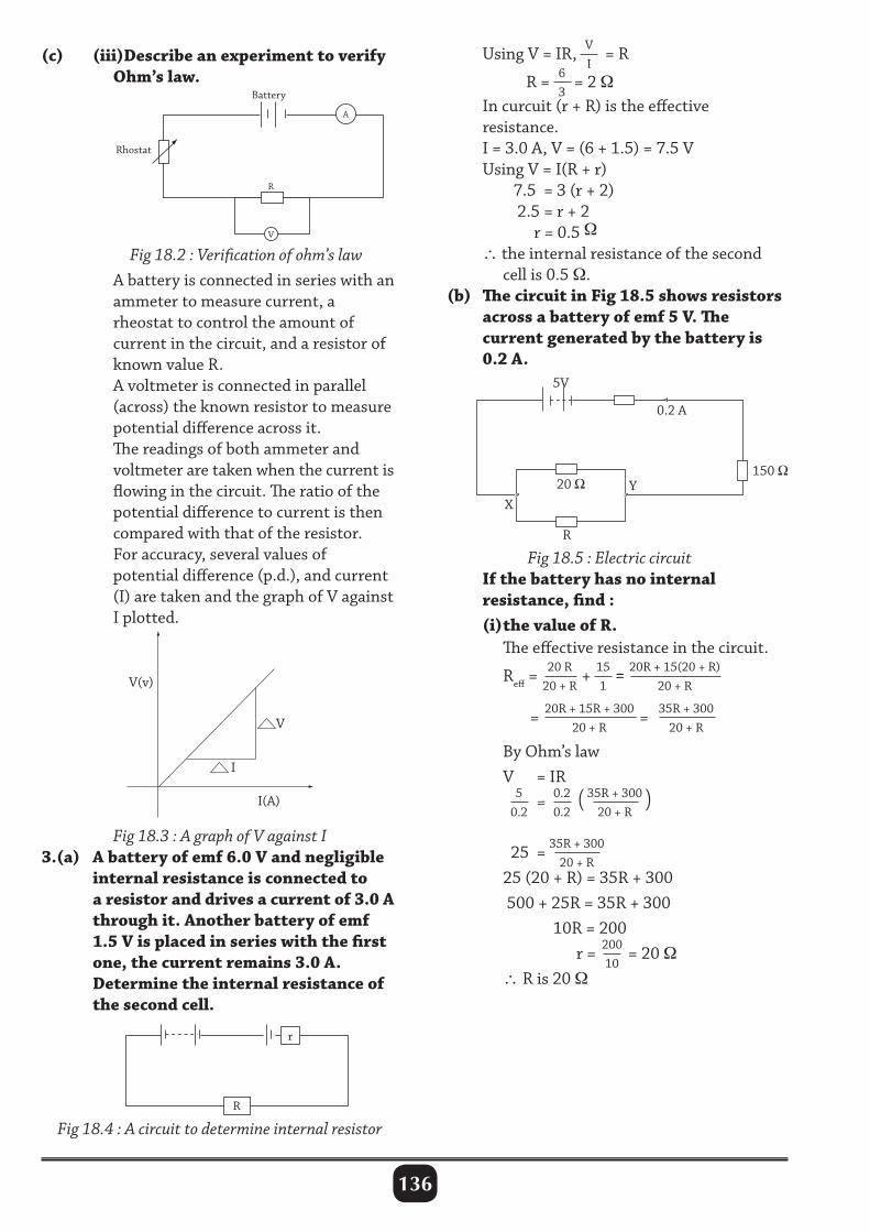
136
(c) (iii)Describe an experiment to verify Ohm’s law.
V
R
A
Battery
Rhostat
Using V = IR, VI
= R
R = 63
= 2 Ω In curcuit (r + R) is the effective resistance. I = 3.0 A, V = (6 + 1.5) = 7.5 V Using V = I(R + r) 7.5 = 3 (r + 2) 2.5 = r + 2 r = 0.5 Ω ∴ the internal resistance of the second cell is 0.5 Ω. (b) The circuit in Fig 18.5 shows resistors across a battery of emf 5 V. The current generated by the battery is 0.2 A.
Fig 18.2 : Verification of ohm’s law A battery is connected in series with an ammeter to measure current, a rheostat to control the amount of current in the circuit, and a resistor of known value R. A voltmeter is connected in parallel (across) the known resistor to measure potential difference across it. The readings of both ammeter and voltmeter are taken when the current is flowing in the circuit. The ratio of the potential difference to current is then compared with that of the resistor. For accuracy, several values of potential difference (p.d.), and current (I) are taken and the graph of V against I plotted.
Fig 18.5 : Electric circuit If the battery has no internal resistance, find : (i) the value of R. The effective resistance in the circuit.
Reff = 20 R20 + R
+ 151
= 20R + 15(20 + R)20 + R
=
20R + 15R + 30020 + R
= 35R + 30020 + R
By Ohm’s law V = IR 5
0.2 = 0.2
0.2 ( 35R + 300
20 + R)
25 = 35R + 30020 + R
25 (20 + R) = 35R + 300 500 + 25R = 35R + 300 10R = 200 r = 200
10 = 20 Ω
∴ R is 20 Ω
Fig 18.3 : A graph of V against I3.(a) A battery of emf 6.0 V and negligible internal resistance is connected to a resistor and drives a current of 3.0 A through it. Another battery of emf 1.5 V is placed in series with the first one, the current remains 3.0 A. Determine the internal resistance of the second cell.
Fig 18.4 : A circuit to determine internal resistor
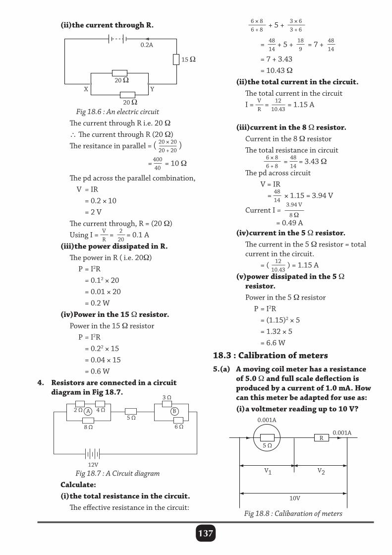
137
(ii)the current through R. 6 × 86 + 8
+ 5 + 3 × 63 + 6
= 4814
+ 5 + 189
= 7 + 4814
= 7 + 3.43 = 10.43 Ω (ii)the total current in the circuit. The total current in the circuit I = V
R= 12
10.43= 1.15 A
(iii)current in the 8 Ω resistor. Current in the 8 Ω resistor The total resistance in circuit 6 × 8
6 + 8= 48
14= 3.43 Ω
The pd across circuit V = IR = 48
14 × 1.15 = 3.94 V
Current I =3.94 V
8 Ω
= 0.49 A (iv)current in the 5 Ω resistor. The current in the 5 Ω resistor = total current in the circuit. = ( 12
10.43) = 1.15 A
(v)power dissipated in the 5 Ω resistor. Power in the 5 Ω resistor P = I2R = (1.15)2 × 5 = 1.32 × 5 = 6.6 W
18.3 : Calibration of meters5.(a) A moving coil meter has a resistance of 5.0 Ω and full scale deflection is produced by a current of 1.0 mA. How can this meter be adapted for use as: (i) a voltmeter reading up to 10 V?
Fig 18.6 : An electric circuit The current through R i.e. 20 Ω ∴ The current through R (20 Ω) The resitance in parallel = ( 20 × 20
20 + 20)
=40040
= 10 Ω
The pd across the parallel combination, V = IR = 0.2 × 10 = 2 V The current through, R = (20 Ω) Using I = V
R= 2
20= 0.1 A
(iii)the power dissipated in R. The power in R ( i.e. 20Ω) P = I2R = 0.12 × 20 = 0.01 × 20 = 0.2 W (iv)Power in the 15 Ω resistor. Power in the 15 Ω resistor P = I2R = 0.22 × 15 = 0.04 × 15 = 0.6 W4. Resistors are connected in a circuit diagram in Fig 18.7.
Fig 18.7 : A Circuit diagram Calculate: (i) the total resistance in the circuit. The effective resistance in the circuit:
Fig 18.8 : Calibaration of meters
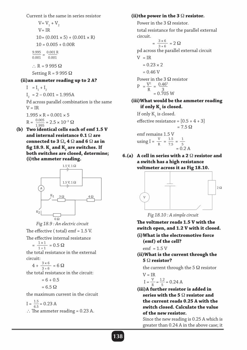
138
Current is the same in series resistor V = V1 + V2 V = IR 10 = (0.001 × 5) + (0.001 × R) 10 = 0.005 + 0.00R
9.9950.001
= 0.001 R0.001
∴ R = 9 995 Ω Setting R = 9 995 Ω (ii)an ammeter reading up to 2 A? I = I1 + I2
I2 = 2 – 0.001 = 1.995A Pd across parallel combination is the same V = IR 1.995 × R = 0.001 × 5 R = 0.005
1.995= 2.5 × 10⁻³ Ω
(b) Two identical cells each of emf 1.5 V and internal resistance 0.1 Ω are connected to 3 Ω, 4 Ω and 6 Ω as in fig 18.9. K1 and K2 are switches. If both switches are closed, determine; (i) the ammeter reading.
(ii)the power in the 3 Ω resistor. Power in the 3 Ω resistor. total resistance for the parallel external circuit. = 3 × 6
3 + 6= 2 Ω
pd across the parallel external circuit V = IR = 0.23 × 2 = 0.46 V Power in the 3 Ω resistor P = V2
R = 0.462
3
= 0.705 W (iii)What would be the ammeter reading if only K1 is closed. If only K1 is closed. effective resistance = [0.5 + 4 + 3] = 7.5 Ω emf remains 1.5 V using I = V
R = 1.5
7.5 = 1
5
= 0.2 A6.(a) A cell in series with a 2 Ω resistor and a switch has a high resistance voltmeter across it as Fig 18.10.
1.5 V, 1
3
6
4
1.5 V, 1
A
K1
K2 Fig 18.10 : A simple circuit The voltmeter reads 1.5 V with the switch open, and 1.2 V with it closed. (i) What is the electromotive force (emf) of the cell? emf = 1.5 V (ii)What is the current through the 5 Ω resistor? the current through the 5 Ω resistor V = IR I = V
R= 1.2
5= 0.24 A
(iii)A further resistor is added in series with the 5 Ω resistor and the current reads 0.25 A with the switch closed. Calculate the value of the new resistor. Since the new reading is 0.25 A which is greater than 0.24 A in the above case; it
Fig 18.9 : An electric circuit The effective ( total) emf = 1.5 V. The effective internal resistance = 1 × 1
1 + 1= 0.5 Ω
the total resistance in the external circuit: 4 + 3 × 6
3 + 6= 6 Ω
the total resistance in the circuit: = 6 + 0.5 = 6.5 Ω the maximum current in the circuit
I = 1.56.5
= 0.23 A ∴ The ammeter reading = 0.23 A.
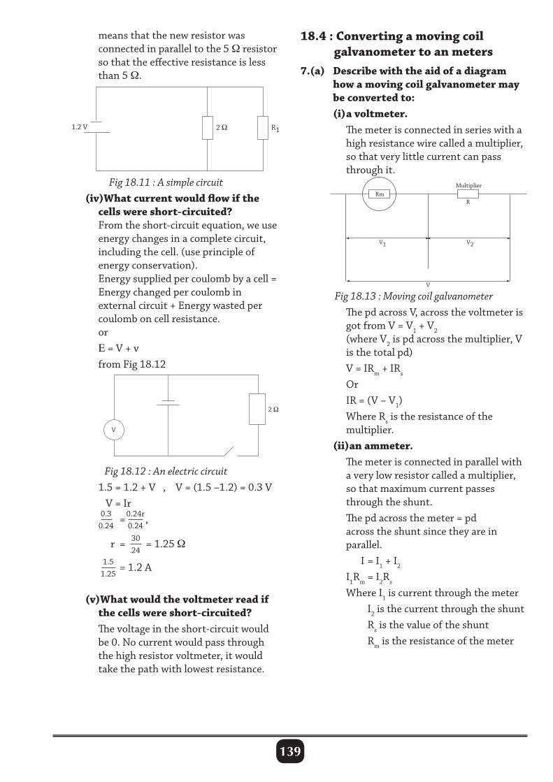
139
means that the new resistor was connected in parallel to the 5 Ω resistor so that the effective resistance is less than 5 Ω.
18.4 : Converting a moving coil galvanometer to an meters7.(a) Describe with the aid of a diagram how a moving coil galvanometer may be converted to: (i) a voltmeter. The meter is connected in series with a high resistance wire called a multiplier, so that very little current can pass through it.
Fig 18.11 : A simple circuit (iv)What current would flow if the cells were short-circuited? From the short-circuit equation, we use energy changes in a complete circuit, including the cell. (use principle of energy conservation). Energy supplied per coulomb by a cell = Energy changed per coulomb in external circuit + Energy wasted per coulomb on cell resistance. or E = V + v from Fig 18.12
Fig 18.13 : Moving coil galvanometer The pd across V, across the voltmeter is got from V = V1 + V2 (where V2 is pd across the multiplier, V is the total pd) V = IRm + IRs
Or IR = (V – V1) Where Rs is the resistance of the multiplier. (ii)an ammeter. The meter is connected in parallel with a very low resistor called a multiplier, so that maximum current passes through the shunt. The pd across the meter = pd across the shunt since they are in parallel. I = I1 + I2
I1Rm = I2Rs
Where I1 is current through the meter I2 is the current through the shunt Rs is the value of the shunt Rm is the resistance of the meter
Fig 18.12 : An electric circuit 1.5 = 1.2 + V , V = (1.5 –1.2) = 0.3 V V = Ir 0.3
0.24 =0.24r
0.24,
r = 30
24 = 1.25 Ω
1.51.25
= 1.2 A
(v)What would the voltmeter read if the cells were short-circuited? The voltage in the short-circuit would be 0. No current would pass through the high resistor voltmeter, it would take the path with lowest resistance.
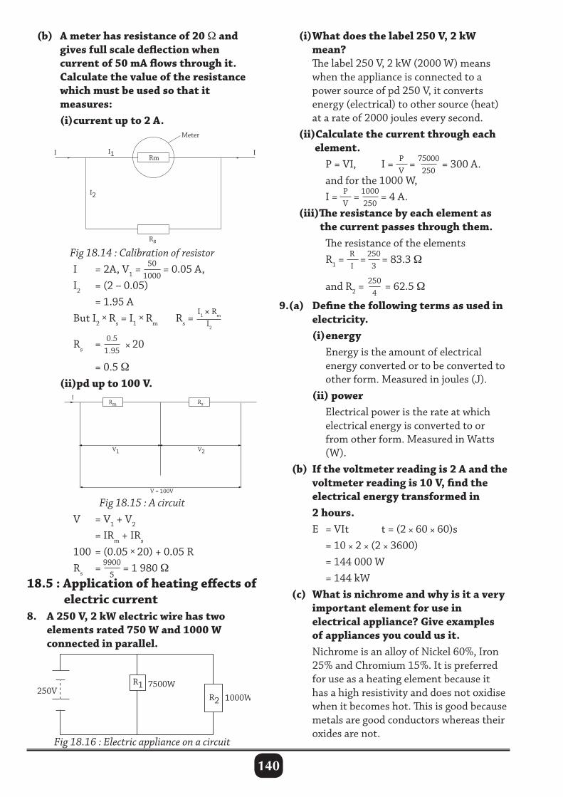
140
(b) A meter has resistance of 20 Ω and gives full scale deflection when current of 50 mA flows through it. Calculate the value of the resistance which must be used so that it measures: (i) current up to 2 A.
(i) What does the label 250 V, 2 kW mean? The label 250 V, 2 kW (2000 W) means when the appliance is connected to a power source of pd 250 V, it converts energy (electrical) to other source (heat) at a rate of 2000 joules every second. (ii)Calculate the current through each element. P = VI, I = P
V= 75000
250 = 300 A.
and for the 1000 W, I = P
V= 1000
250= 4 A.
(iii)The resistance by each element as the current passes through them. The resistance of the elements R1 =
RI
= 2503
= 83.3 Ω
and R2 = 2504
= 62.5 Ω
9.(a) Define the following terms as used in electricity. (i) energy Energy is the amount of electrical energy converted or to be converted to other form. Measured in joules (J). (ii) power Electrical power is the rate at which electrical energy is converted to or from other form. Measured in Watts (W). (b) If the voltmeter reading is 2 A and the voltmeter reading is 10 V, find the electrical energy transformed in 2 hours. E = VIt t = (2 × 60 × 60)s = 10 × 2 × (2 × 3600) = 144 000 W = 144 kW (c) What is nichrome and why is it a very important element for use in electrical appliance? Give examples of appliances you could us it. Nichrome is an alloy of Nickel 60%, Iron 25% and Chromium 15%. It is preferred for use as a heating element because it has a high resistivity and does not oxidise when it becomes hot. This is good because metals are good conductors whereas their oxides are not.
Fig 18.14 : Calibration of resistor I = 2A, V1 =
501000
= 0.05 A, I2 = (2 – 0.05) = 1.95 A But I2 × Rs = I1 × Rm Rs =
I1 × Rm
I2
Rs = 0.51.95
× 20
= 0.5 Ω (ii)pd up to 100 V.
Fig 18.15 : A circuit V = V1 + V2
= IRm + IRs
100 = (0.05 × 20) + 0.05 R Rs = 9900
5= 1 980 Ω
18.5 : Application of heating effects of electric current8. A 250 V, 2 kW electric wire has two elements rated 750 W and 1000 W connected in parallel.
250V R1
R2
7500W
1000W
Fig 18.16 : Electric appliance on a circuit
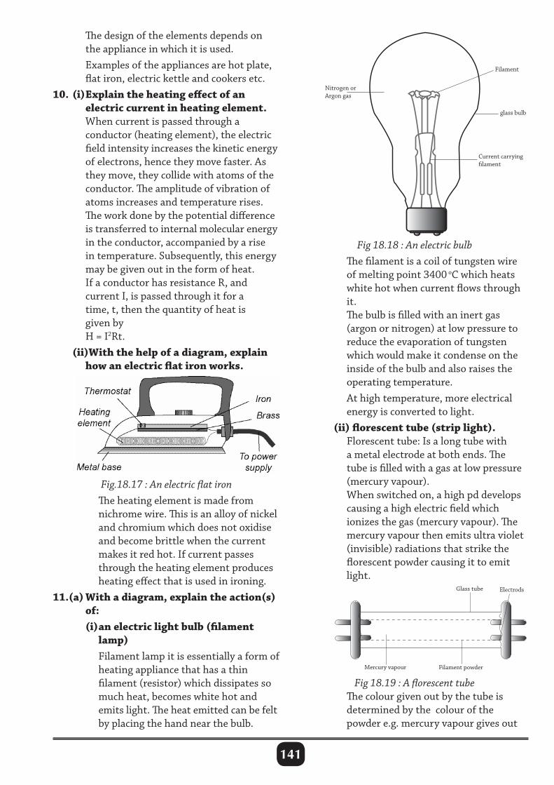
141
The design of the elements depends on the appliance in which it is used. Examples of the appliances are hot plate, flat iron, electric kettle and cookers etc.10. (i) Explain the heating effect of an electric current in heating element. When current is passed through a conductor (heating element), the electric field intensity increases the kinetic energy of electrons, hence they move faster. As they move, they collide with atoms of the conductor. The amplitude of vibration of atoms increases and temperature rises. The work done by the potential difference is transferred to internal molecular energy in the conductor, accompanied by a rise in temperature. Subsequently, this energy may be given out in the form of heat. If a conductor has resistance R, and current I, is passed through it for a time, t, then the quantity of heat is given by H = I2Rt. (ii)With the help of a diagram, explain how an electric flat iron works.
Fig 18.18 : An electric bulb The filament is a coil of tungsten wire of melting point 3400 oC which heats white hot when current flows through it. The bulb is filled with an inert gas (argon or nitrogen) at low pressure to reduce the evaporation of tungsten which would make it condense on the inside of the bulb and also raises the operating temperature. At high temperature, more electrical energy is converted to light. (ii) florescent tube (strip light). Florescent tube: Is a long tube with a metal electrode at both ends. The tube is filled with a gas at low pressure (mercury vapour). When switched on, a high pd develops causing a high electric field which ionizes the gas (mercury vapour). The mercury vapour then emits ultra violet (invisible) radiations that strike the florescent powder causing it to emit light.
Nitrogen orArgon gas
Filament
glass bulb
Current carryinglament
Fig.18.17 : An electric flat iron The heating element is made from nichrome wire. This is an alloy of nickel and chromium which does not oxidise and become brittle when the current makes it red hot. If current passes through the heating element produces heating effect that is used in ironing.11.(a) With a diagram, explain the action(s) of: (i) an electric light bulb (filament lamp) Filament lamp it is essentially a form of heating appliance that has a thin filament (resistor) which dissipates so much heat, becomes white hot and emits light. The heat emitted can be felt by placing the hand near the bulb.
Fig 18.19 : A florescent tube The colour given out by the tube is determined by the colour of the powder e.g. mercury vapour gives out
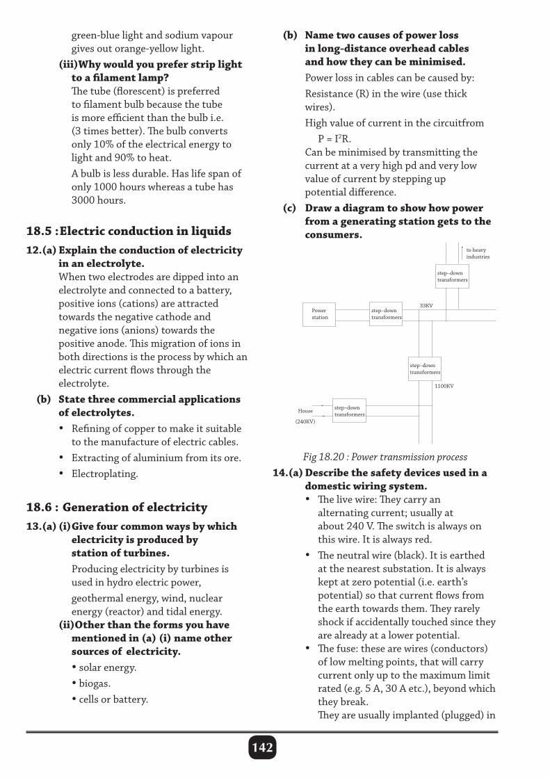
142
green-blue light and sodium vapour gives out orange-yellow light. (iii)Why would you prefer strip light to a filament lamp? The tube (florescent) is preferred to filament bulb because the tube is more efficient than the bulb i.e. (3 times better). The bulb converts only 10% of the electrical energy to light and 90% to heat. A bulb is less durable. Has life span of only 1000 hours whereas a tube has 3000 hours.
18.5 : Electric conduction in liquids12.(a) Explain the conduction of electricity in an electrolyte. When two electrodes are dipped into an electrolyte and connected to a battery, positive ions (cations) are attracted towards the negative cathode and negative ions (anions) towards the positive anode. This migration of ions in both directions is the process by which an electric current flows through the electrolyte. (b) State three commercial applications of electrolytes. • Refining of copper to make it suitable to the manufacture of electric cables. • Extracting of aluminium from its ore. • Electroplating.
18.6 : Generation of electricity13.(a) (i) Give four common ways by which electricity is produced by station of turbines. Producing electricity by turbines is used in hydro electric power, geothermal energy, wind, nuclear energy (reactor) and tidal energy. (ii)Other than the forms you have mentioned in (a) (i) name other sources of electricity. • solar energy. • biogas. • cells or battery.
(b) Name two causes of power loss in long-distance overhead cables and how they can be minimised. Power loss in cables can be caused by: Resistance (R) in the wire (use thick wires). High value of current in the circuitfrom P = I2R. Can be minimised by transmitting the current at a very high pd and very low value of current by stepping up potential difference. (c) Draw a diagram to show how power from a generating station gets to the consumers.
Fig 18.20 : Power transmission process14.(a) Describe the safety devices used in a domestic wiring system. • The live wire: They carry an alternating current; usually at about 240 V. The switch is always on this wire. It is always red. • The neutral wire (black). It is earthed at the nearest substation. It is always kept at zero potential (i.e. earth’s potential) so that current flows from the earth towards them. They rarely shock if accidentally touched since they are already at a lower potential. • The fuse: these are wires (conductors) of low melting points, that will carry current only up to the maximum limit rated (e.g. 5 A, 30 A etc.), beyond which they break. They are usually implanted (plugged) in
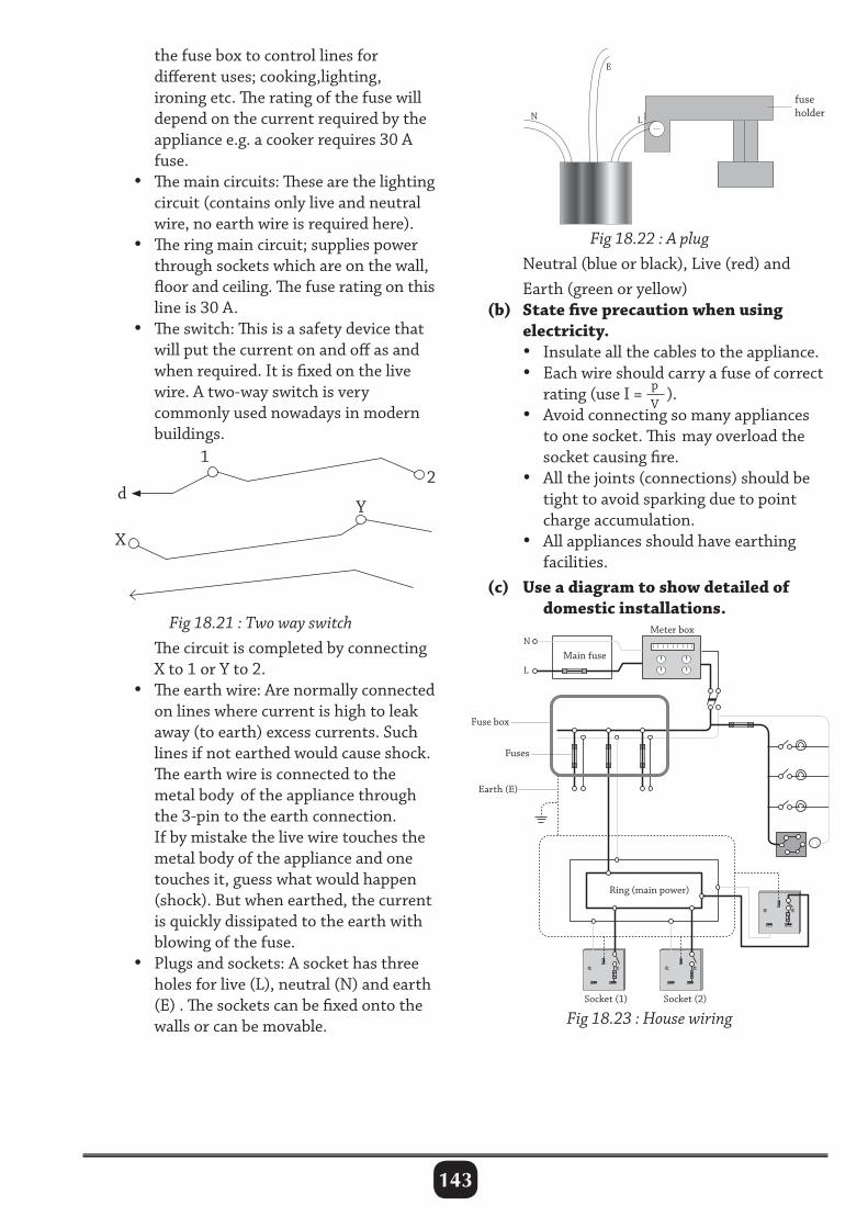
143
d
12
X
Y
E
L
fuse holderN
Fig 18.22 : A plug Neutral (blue or black), Live (red) and Earth (green or yellow) (b) State five precaution when using electricity. • Insulate all the cables to the appliance. • Each wire should carry a fuse of correct rating (use I = p
V).
• Avoid connecting so many appliances to one socket. This may overload the socket causing fire. • All the joints (connections) should be tight to avoid sparking due to point charge accumulation. • All appliances should have earthing facilities. (c) Use a diagram to show detailed of domestic installations.
the fuse box to control lines for different uses; cooking,lighting, ironing etc. The rating of the fuse will depend on the current required by the appliance e.g. a cooker requires 30 A fuse. • The main circuits: These are the lighting circuit (contains only live and neutral wire, no earth wire is required here). • The ring main circuit; supplies power through sockets which are on the wall, floor and ceiling. The fuse rating on this line is 30 A. • The switch: This is a safety device that will put the current on and off as and when required. It is fixed on the live wire. A two-way switch is very commonly used nowadays in modern buildings.
Fig 18.23 : House wiring
Fig 18.21 : Two way switch The circuit is completed by connecting X to 1 or Y to 2. • The earth wire: Are normally connected on lines where current is high to leak away (to earth) excess currents. Such lines if not earthed would cause shock. The earth wire is connected to the metal body of the appliance through the 3-pin to the earth connection. If by mistake the live wire touches the metal body of the appliance and one touches it, guess what would happen (shock). But when earthed, the current is quickly dissipated to the earth with blowing of the fuse. • Plugs and sockets: A socket has three holes for live (L), neutral (N) and earth (E) . The sockets can be fixed onto the walls or can be movable.
N
L
Main fuse
Earth (E)
Fuses
Fuse box
Socket (1) Socket (2)
Ring (main power)
Meter box
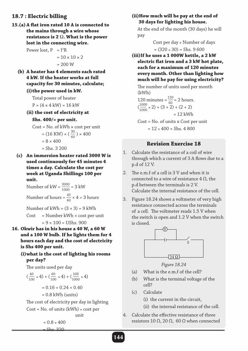
144
18.7 : Electric billing15.(a) A flat iron rated 10 A is connected to the mains through a wire whose resistance is 2 Ω. What is the power lost in the connecting wire. Power lost, P = I2R = 10 × 10 × 2 = 200 W (b) A heater has 4 elements each rated 4 kW. If the heater works at full capacity for 30 minutes, calculate; (i) the power used in kW. Total power of heater P = (4 × 4 kW) = 16 kW (ii) the cost of electricity at Shs. 400/= per unit. Cost = No. of kWh × cost per unit = (16 KW) × ( 30
60) × 400
= 8 × 400 = Shs. 3 200 (c) An immersion heater rated 3000 W is used continuously for 45 minutes 4 times a day. Calculate the cost per week at Uganda Shillings 100 per unit. Number of kW = 3000
1000= 3 kW
Number of hours = 4560
× 4 = 3 hours
Number of kWh = (3 × 3) = 9 kWh Cost = Number kWh × cost per unit = 9 × 100 = UShs. 90016. Okwir has in his house a 40 W, a 60 W and a 100 W bulb. If he lights them for 4 hours each day and the cost of electricity is Shs 400 per unit. (i) what is the cost of lighting his rooms per day? The units used per day
( 40100
× 4) + ( 60100
× 4) + ( 1001000
× 4)
= 0.16 + 0.24 + 0.40 = 0.8 kWh (units) The cost of electricity per day in lighting Cost = No. of units (kWh) × cost per unit = 0.8 × 400 = Shs. 320
(ii)How much will he pay at the end of 30 days for lighting his house. At the end of the month (30 days) he will pay Cost per day × Number of days = (320 × 30) = Shs. 9 600 (iii)If he uses a 1 000W kettle, a 2 kW electric flat iron and a 3 kW hot plate, each for a maximum of 120 minutes every month. Other than lighting how much will he pay for using electricity? The number of units used per month (kWh) 120 minutes = 120
60= 2 hours.
(10001000
× 2) + (3 + 2) + (2 + 2) = 12 kWh Cost = No. of units x Cost per unit = 12 × 400 = Shs. 4 800
Revision Exercise 181. Calculate the resistance of a coil of wire through which a current of 3 A flows due to a p.d of 12 V.
2. The e.m.f of a cell is 3 V and when it is connected to a wire of resistance 4 Ω, the p.d between the terminals is 2 V. Calculate the internal resistance of the cell.
3. Figure 18.24 shows a voltmeter of very high resistance connected across the terminals of a cell. The voltmeter reads 1.5 V when the switch is open and 1.2 V when the switch is closed.
Figure 18.24 (a) What is the e.m.f of the cell? (b) What is the terminal voltage of the cell? (c) Calculate (i) the current in the circuit, (ii) the internal resistance of the cell.
4. Calculate the effective resistance of three resistors 10 Ω, 20 Ω, 60 Ω when connected
S
24 Ω
V
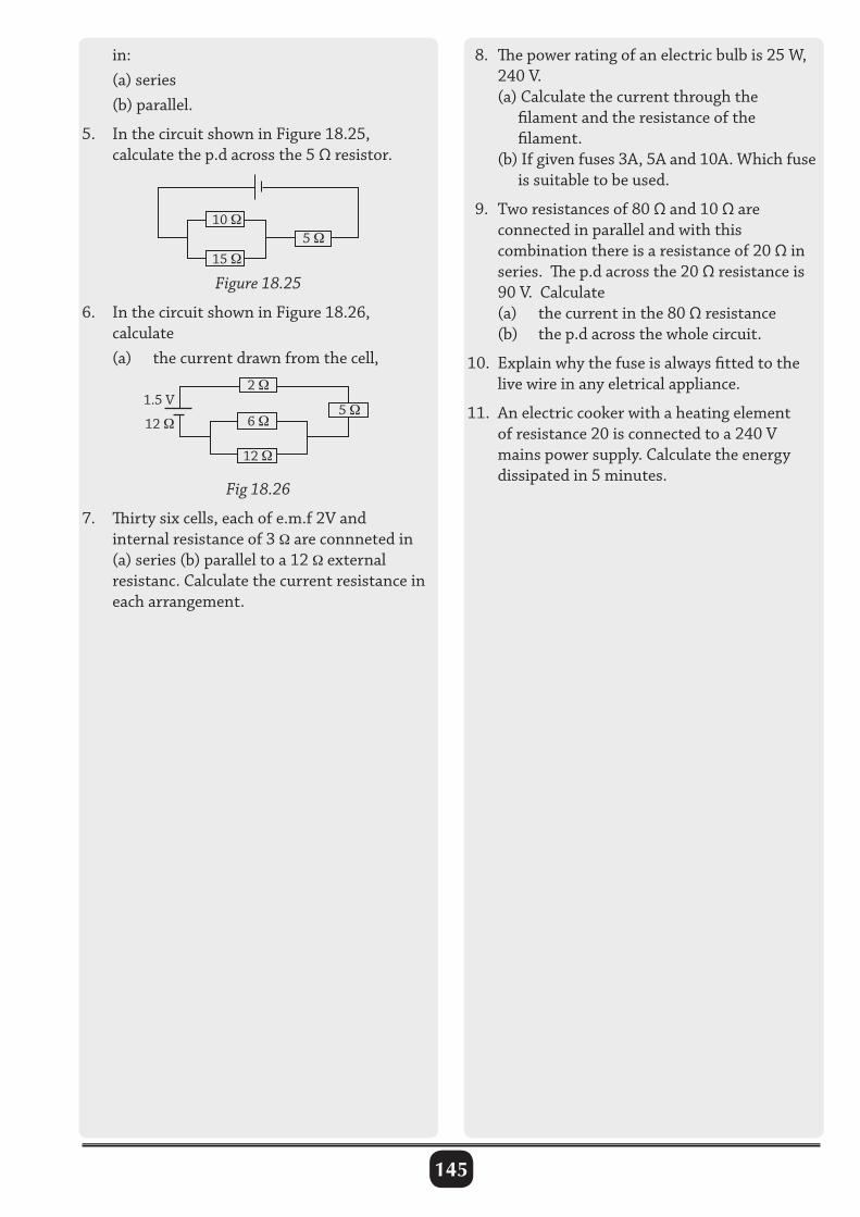
145
in: (a) series (b) parallel.
5. In the circuit shown in Figure 18.25, calculate the p.d across the 5 Ω resistor.
8. The power rating of an electric bulb is 25 W, 240 V. (a) Calculate the current through the filament and the resistance of the filament. (b) If given fuses 3A, 5A and 10A. Which fuse is suitable to be used.
9. Two resistances of 80 Ω and 10 Ω are connected in parallel and with this combination there is a resistance of 20 Ω in series. The p.d across the 20 Ω resistance is 90 V. Calculate (a) the current in the 80 Ω resistance (b) the p.d across the whole circuit.
10. Explain why the fuse is always fitted to the live wire in any eletrical appliance.
11. An electric cooker with a heating element of resistance 20 is connected to a 240 V mains power supply. Calculate the energy dissipated in 5 minutes.
Figure 18.25
6. In the circuit shown in Figure 18.26, calculate (a) the current drawn from the cell,
1.5 V
12 Ω
Fig 18.26
7. Thirty six cells, each of e.m.f 2V and internal resistance of 3 Ω are connneted in (a) series (b) parallel to a 12 Ω external resistanc. Calculate the current resistance in each arrangement.
5 Ω
2 Ω
5 Ω 15 Ω
10 Ω
6 Ω
12 Ω
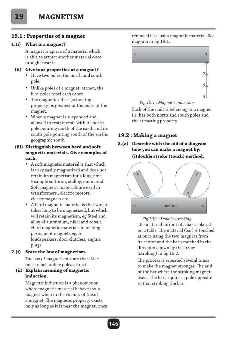
146
19.1 : Properties of a magnet1.(i) What is a magnet? A magnet is apiece of a material which is able to attract another material once brought near it. (ii) Give four properties of a magnet? • Have two poles; the north and south pole. • Unlike poles of a magnet attract, the like poles repel each other. • The magnetic effect (attracting property) is greatest at the poles of the magnet. • When a magnet is suspended and allowed to rest; it rests with its north pole pointing north of the earth and its south pole pointing south of the earths geographic south. (iii) Distinguish between hard and soft magnetic materials. Give examples of each. • A soft magnetic material is that which is very easily magnetized and does not retain its magnetism for a long time. Example soft iron, stalloy, mumental. Soft magnetic materials are used in transformers , electric motors, electromagnets etc. • A hard magnetic material is that which takes long to be magnetized, but which will retain its magnetism, eg Steel and alloy of aluminium, nikel and cobalt. Hard magnetic materials in making permanent magnets eg. In loudspeakers, door clutches, engine plugs.2.(i) State the law of magnetism. The law of magnetism state that: Like poles repel; unlike poles attract. (ii) Explain meaning of magnetic induction. Magnetic induction is a phenomenon where magnetic material behaves as a magnet when in the vicinity of (near) a magnet. The magnetic property exists only as long as it is near the magnet; once
removed it is just a magnetic material. See diagram in fig 19.1.
MAGNETISM
Fig 19.1 : Magnetic induction Each of the nails is behaving as a magnet i.e. has both north and south poles and the attracting property.
19.2 : Making a magnet3.(a) Describe with the aid of a diagram how you can make a magnet by: (i) double stroke (touch) method.
Fig 19.2 : Double strocking The material infront of a bar is placed on a table. The material (bar) is touched at once using the two magnets from its centre and the bar scratched in the direction shown by the arrow (stroking) in fig 19.2. The process is repeated several times to make the magnet stronger. The end of the bar where the stroking magnet leaves the bar acquires a pole opposite to that stroking the bar.
19
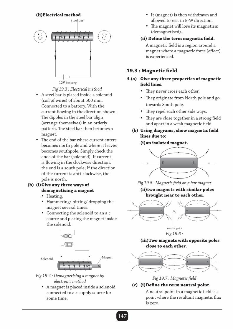
147
(ii)Electrical method • It (magnet) is then withdrawn and allowed to rest in E-W direction. • The magnet will lose its magnetism (demagnetised). (ii) Define the term magnetic field. A magnetic field is a region around a magnet where a magnetic force (effect) is experienced.
19.3 : Magnetic field 4.(a) Give any three properties of magnetic field lines. • They never cross each other. • They originate from North pole and go towards South pole. • They repel each other side ways. • They are close together in a strong field and apart in a weak magnetic field. (b) Using diagrams, show magnetic field lines due to: (i) an isolated magnet.
Fig 19.3 : Electrical method • A steel bar is placed inside a solenoid (coil of wires) of about 500 mm. Connected to a battery. With the current flowing in the direction shown. The dipoles in the steel bar align (arrange themselves) in an orderly pattern. The steel bar then becomes a magnet. • The end of the bar where current enters becomes north pole and where it leaves becomes southpole. Simply check the ends of the bar (solenoid); If current is flowing in the clockwise direction, the end is a south pole; If the direction of the current is anti-clockwise, the pole is north. (b) (i) Give any three ways of demagnetising a magnet • Heating. • Hammering/ hitting/ dropping the magnet several times. • Connecting the solenoid to an a.c source and placing the magnet inside the solenoid.
N S
S N N S
S N S N
neutral point
N S
S N N S
S N S N
neutral point
N S
S N N S
S N S N
neutral point
Fig 19.4 : Demagnetising a magnet by electronic method
• A magnet is placed inside a solenoid connected to a.c supply source for some time.
Fig 19.5 : Magnetic field on a bar magnet (ii)two magnets with similar poles brought near to each other.
Fig 19.6 : (iii)Two magnets with opposite poles close to each other.
Fig 19.7 : Magnetic field (c) (i) Define the term neutral point. A neutral point in a magnetic field is a point where the resultant magnetic flux is zero.
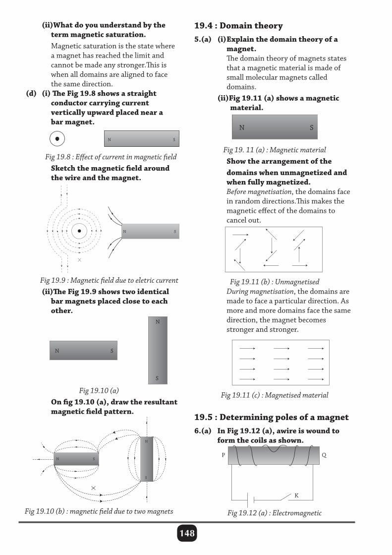
148
(ii)What do you understand by the term magnetic saturation. Magnetic saturation is the state where a magnet has reached the limit and cannot be made any stronger.This is when all domains are aligned to face the same direction. (d) (i) The Fig 19.8 shows a straight conductor carrying current vertically upward placed near a bar magnet.
19.4 : Domain theory5.(a) (i) Explain the domain theory of a magnet. The domain theory of magnets states that a magnetic material is made of small molecular magnets called domains. (ii)Fig 19.11 (a) shows a magnetic material.
Fig 19.8 : Effect of current in magnetic field Sketch the magnetic field around the wire and the magnet.
Fig 19.9 : Magnetic field due to eletric current (ii)The Fig 19.9 shows two identical bar magnets placed close to each other.
Fig 19. 11 (a) : Magnetic material Show the arrangement of the domains when unmagnetized and when fully magnetized. Before magnetisation, the domains face in random directions.This makes the magnetic effect of the domains to cancel out.
Fig 19.10 (a) On fig 19.10 (a), draw the resultant magnetic field pattern.
Fig 19.10 (b) : magnetic field due to two magnets
Fig 19.11 (b) : Unmagnetised During magnetisation, the domains are made to face a particular direction. As more and more domains face the same direction, the magnet becomes stronger and stronger.
Fig 19.11 (c) : Magnetised material
19.5 : Determining poles of a magnet6.(a) In Fig 19.12 (a), awire is wound to form the coils as shown.
Fig 19.12 (a) : Electromagnetic
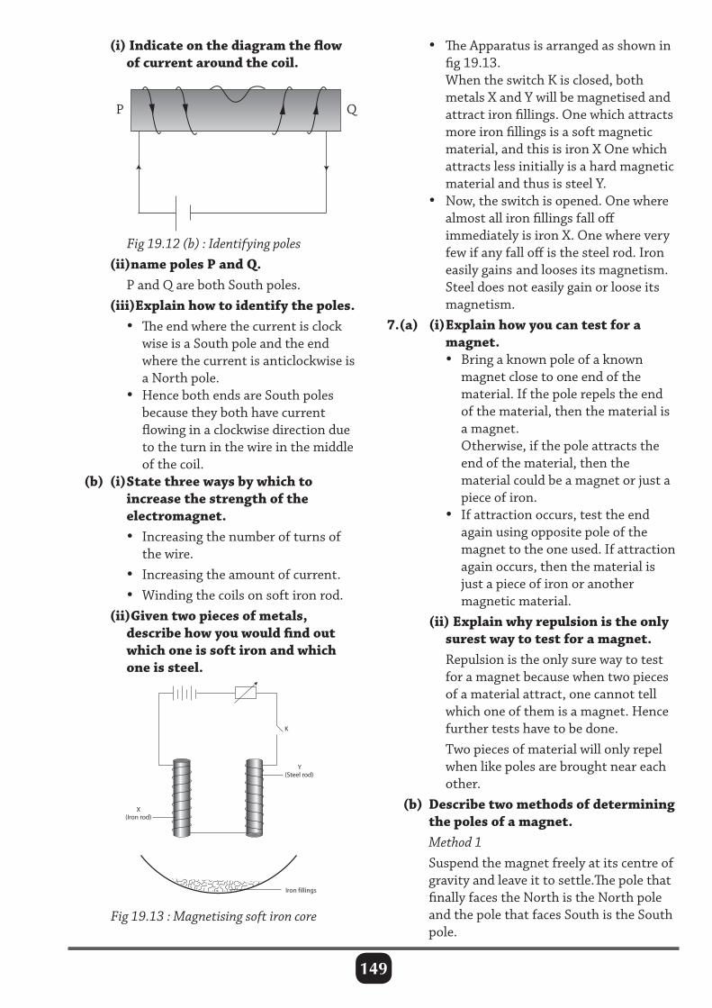
149
• The Apparatus is arranged as shown in fig 19.13. When the switch K is closed, both metals X and Y will be magnetised and attract iron fillings. One which attracts more iron fillings is a soft magnetic material, and this is iron X One which attracts less initially is a hard magnetic material and thus is steel Y. • Now, the switch is opened. One where almost all iron fillings fall off immediately is iron X. One where very few if any fall off is the steel rod. Iron easily gains and looses its magnetism. Steel does not easily gain or loose its magnetism.7.(a) (i) Explain how you can test for a magnet. • Bring a known pole of a known magnet close to one end of the material. If the pole repels the end of the material, then the material is a magnet. Otherwise, if the pole attracts the end of the material, then the material could be a magnet or just a piece of iron. • If attraction occurs, test the end again using opposite pole of the magnet to the one used. If attraction again occurs, then the material is just a piece of iron or another magnetic material. (ii) Explain why repulsion is the only surest way to test for a magnet. Repulsion is the only sure way to test for a magnet because when two pieces of a material attract, one cannot tell which one of them is a magnet. Hence further tests have to be done. Two pieces of material will only repel when like poles are brought near each other. (b) Describe two methods of determining the poles of a magnet. Method 1 Suspend the magnet freely at its centre of gravity and leave it to settle.The pole that finally faces the North is the North pole and the pole that faces South is the South pole.
(i) Indicate on the diagram the flow of current around the coil.
Fig 19.12 (b) : Identifying poles (ii)name poles P and Q. P and Q are both South poles. (iii)Explain how to identify the poles. •The end where the current is clock wise is a South pole and the end where the current is anticlockwise is a North pole. • Hence both ends are South poles because they both have current flowing in a clockwise direction due to the turn in the wire in the middle of the coil. (b) (i) State three ways by which to increase the strength of the electromagnet. • Increasing the number of turns of the wire. • Increasing the amount of current. • Winding the coils on soft iron rod. (ii)Given two pieces of metals, describe how you would find out which one is soft iron and which one is steel.
Fig 19.13 : Magnetising soft iron core
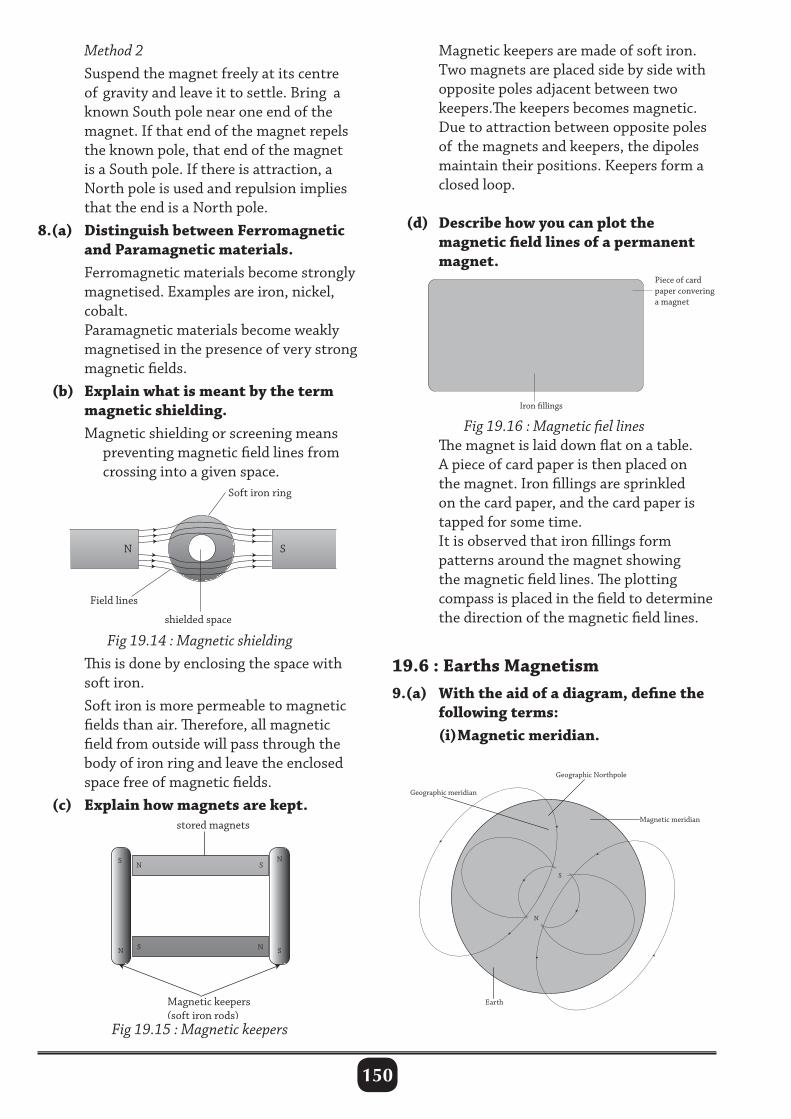
150
Method 2 Suspend the magnet freely at its centre of gravity and leave it to settle. Bring a known South pole near one end of the magnet. If that end of the magnet repels the known pole, that end of the magnet is a South pole. If there is attraction, a North pole is used and repulsion implies that the end is a North pole.8.(a) Distinguish between Ferromagnetic and Paramagnetic materials. Ferromagnetic materials become strongly magnetised. Examples are iron, nickel, cobalt. Paramagnetic materials become weakly magnetised in the presence of very strong magnetic fields. (b) Explain what is meant by the term magnetic shielding. Magnetic shielding or screening means preventing magnetic field lines from crossing into a given space.
Magnetic keepers are made of soft iron. Two magnets are placed side by side with opposite poles adjacent between two keepers.The keepers becomes magnetic. Due to attraction between opposite poles of the magnets and keepers, the dipoles maintain their positions. Keepers form a closed loop.
(d) Describe how you can plot the magnetic field lines of a permanent magnet.
Fig 19.14 : Magnetic shielding This is done by enclosing the space with soft iron. Soft iron is more permeable to magnetic fields than air. Therefore, all magnetic field from outside will pass through the body of iron ring and leave the enclosed space free of magnetic fields. (c) Explain how magnets are kept.
S
S
S
S N
N
N
Magnetic keepers(soft iron rods)
stored magnets
N
Fig 19.15 : Magnetic keepers
Fig 19.16 : Magnetic fiel lines The magnet is laid down flat on a table. A piece of card paper is then placed on the magnet. Iron fillings are sprinkled on the card paper, and the card paper is tapped for some time. It is observed that iron fillings form patterns around the magnet showing the magnetic field lines. The plotting compass is placed in the field to determine the direction of the magnetic field lines.
19.6 : Earths Magnetism9.(a) With the aid of a diagram, define the following terms: (i) Magnetic meridian.
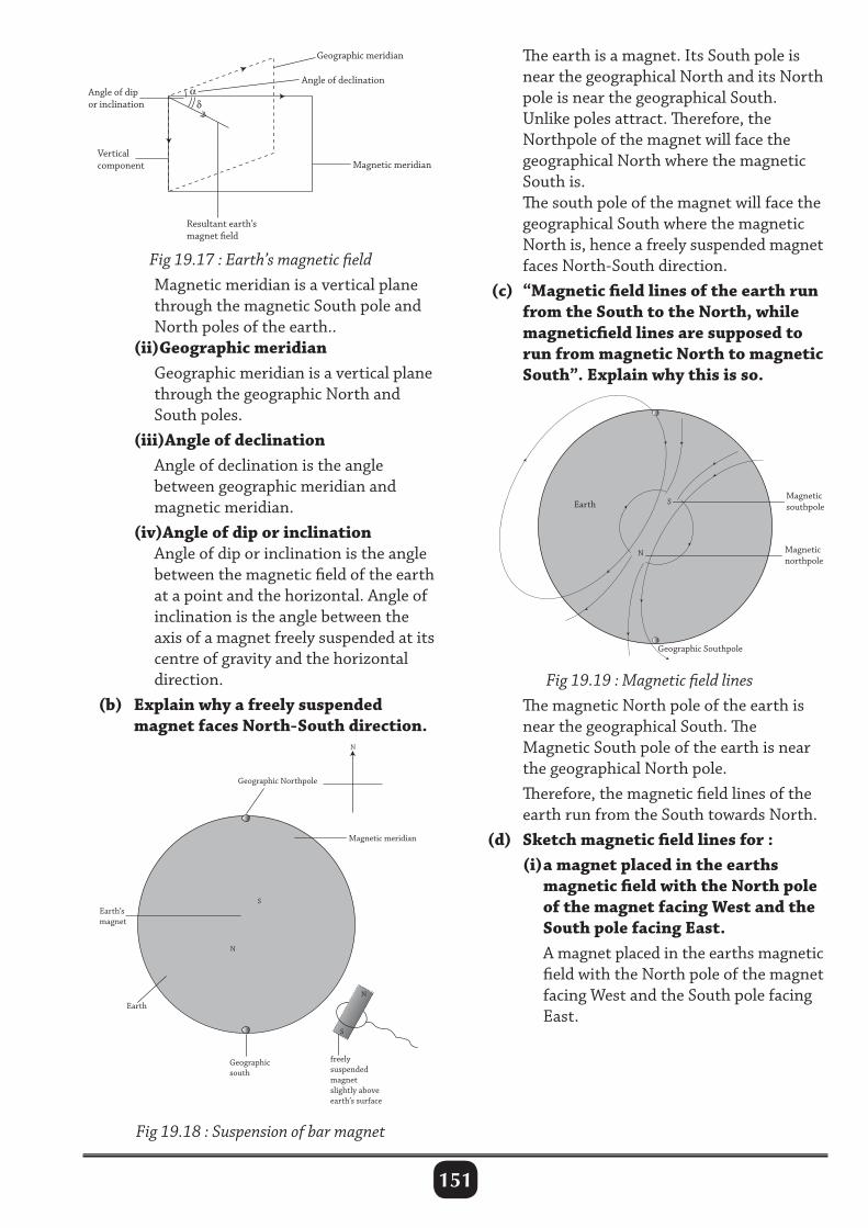
151
The earth is a magnet. Its South pole is near the geographical North and its North pole is near the geographical South. Unlike poles attract. Therefore, the Northpole of the magnet will face the geographical North where the magnetic South is. The south pole of the magnet will face the geographical South where the magnetic North is, hence a freely suspended magnet faces North-South direction. (c) “Magnetic field lines of the earth run from the South to the North, while magneticfield lines are supposed to run from magnetic North to magnetic South”. Explain why this is so.
N
Magnetic southpole Earth
Geographic Southpole
S
Magnetic northpole
Fig 19.17 : Earth’s magnetic field Magnetic meridian is a vertical plane through the magnetic South pole and North poles of the earth.. (ii)Geographic meridian Geographic meridian is a vertical plane through the geographic North and South poles. (iii)Angle of declination Angle of declination is the angle between geographic meridian and magnetic meridian. (iv)Angle of dip or inclination Angle of dip or inclination is the angle between the magnetic field of the earth at a point and the horizontal. Angle of inclination is the angle between the axis of a magnet freely suspended at its centre of gravity and the horizontal direction. (b) Explain why a freely suspended magnet faces North-South direction.
Fig 19.18 : Suspension of bar magnet
Fig 19.19 : Magnetic field lines The magnetic North pole of the earth is near the geographical South. The Magnetic South pole of the earth is near the geographical North pole. Therefore, the magnetic field lines of the earth run from the South towards North. (d) Sketch magnetic field lines for : (i) a magnet placed in the earths magnetic field with the North pole of the magnet facing West and the South pole facing East. A magnet placed in the earths magnetic field with the North pole of the magnet facing West and the South pole facing East.
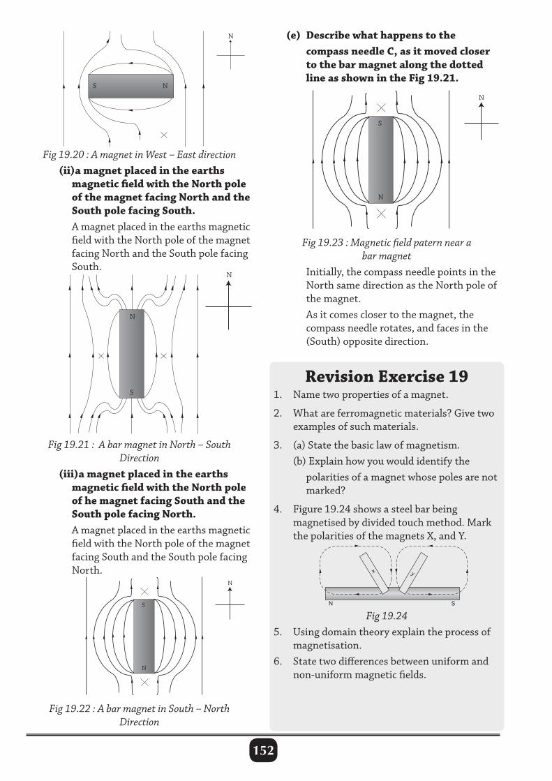
152
(e) Describe what happens to the compass needle C, as it moved closer to the bar magnet along the dotted line as shown in the Fig 19.21.
Fig 19.20 : A magnet in West – East direction (ii)a magnet placed in the earths magnetic field with the North pole of the magnet facing North and the South pole facing South. A magnet placed in the earths magnetic field with the North pole of the magnet facing North and the South pole facing South.
Fig 19.21 : A bar magnet in North – South Direction
(iii)a magnet placed in the earths magnetic field with the North pole of he magnet facing South and the South pole facing North. A magnet placed in the earths magnetic field with the North pole of the magnet facing South and the South pole facing North.
Fig 19.23 : Magnetic field patern near a bar magnet
Initially, the compass needle points in the North same direction as the North pole of the magnet. As it comes closer to the magnet, the compass needle rotates, and faces in the (South) opposite direction.
Revision Exercise 191. Name two properties of a magnet.
2. What are ferromagnetic materials? Give two examples of such materials.
3. (a) State the basic law of magnetism. (b) Explain how you would identify the polarities of a magnet whose poles are not marked?
4. Figure 19.24 shows a steel bar being magnetised by divided touch method. Mark the polarities of the magnets X, and Y.
Fig 19.22 : A bar magnet in South – North Direction
N S
x y
Fig 19.245. Using domain theory explain the process of magnetisation.6. State two differences between uniform and non-uniform magnetic fields.
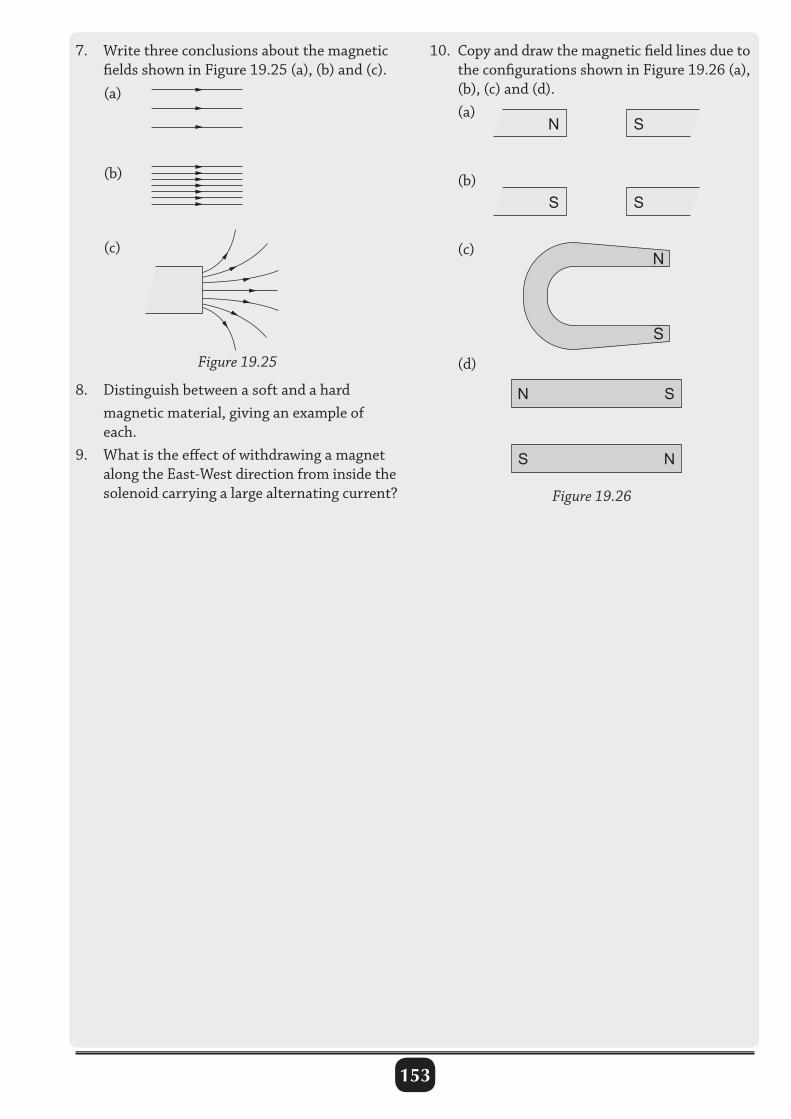
153
(a)
(b)
(c)
Figure 19.25
N S
S S
N
S
N S
S N
Figure 19.26
7. Write three conclusions about the magnetic fields shown in Figure 19.25 (a), (b) and (c).
10. Copy and draw the magnetic field lines due to the configurations shown in Figure 19.26 (a), (b), (c) and (d). (a)
(b)
(c)
(d)
8. Distinguish between a soft and a hard magnetic material, giving an example of each.9. What is the effect of withdrawing a magnet along the East-West direction from inside the solenoid carrying a large alternating current?
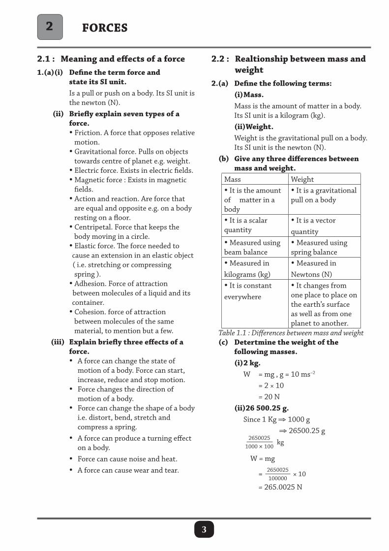
3
2.1 : Meaning and effects of a force1.(a)(i) Define the term force and state its SI unit. Is a pull or push on a body. Its SI unit is the newton (N). (ii) Briefly explain seven types of a force. • Friction. A force that opposes relative motion. • Gravitational force. Pulls on objects towards centre of planet e.g. weight. • Electric force. Exists in electric fields. • Magnetic force : Exists in magnetic fields. • Action and reaction. Are force that are equal and opposite e.g. on a body resting on a floor. • Centripetal. Force that keeps the body moving in a circle. • Elastic force. The force needed to cause an extension in an elastic object ( i.e. stretching or compressing spring ). • Adhesion. Force of attraction between molecules of a liquid and its container. • Cohesion. force of attraction between molecules of the same material, to mention but a few. (iii) Explain briefly three effects of a force. • A force can change the state of motion of a body. Force can start, increase, reduce and stop motion. • Force changes the direction of motion of a body. • Force can change the shape of a body i.e. distort, bend, stretch and compress a spring. • A force can produce a turning effect on a body. • Force can cause noise and heat. • A force can cause wear and tear.
ForcES
2.2 : realtionship between mass and weight 2.(a) Define the following terms: (i) Mass. Mass is the amount of matter in a body. Its SI unit is a kilogram (kg). (ii)Weight. Weight is the gravitational pull on a body. Its SI unit is the newton (N). (b) Give any three differences between mass and weight.
Mass Weight• It is the amount of matter in a body
• It is a gravitational pull on a body
• It is a scalar quantity
• It is a vector quantity
• Measured using beam balance
• Measured using spring balance
• Measured in kilograms (kg)
• Measured in Newtons (N)
• It is constant everywhere
• It changes from one place to place on the earth’s surface as well as from one planet to another.
Table 1.1 : Differences between mass and weight (c) Detertmine the weight of the following masses. (i) 2 kg. W = mg , g = 10 ms–2
= 2 × 10 = 20 N (ii)26 500.25 g. Since 1 Kg ⇒ 1000 g ⇒ 26500.25 g 2650025
1000 × 100 kg
W = mg
= 2650025100000
× 10 = 265.0025 N
2

4
(iii) 0.0731 kg. 0.0731 kg = 731
10000kg
W = mg, g = 10 ms–2
= 7311000
× 10 = 0.731 N = 7.31 x 10⁻¹ N (iv) 430 mg. 430 mg 1 g = 1 000 mg = ( 430
1000) g ÷ 1000
= 430
1000000 W = mg
= 4301000000
× 10 = 4.3 N 3.(a) Briefly describe how mass and weight of a body is measured. Mass of a body is the quantity (amount) of matter in the body. The mass of a body is measured by balancing it against a known mass.
Fig. 2.2 : A spring balance (b) Acceleration due to gravity on planet Y is a fifth that of the earths. calculate the weight of a 60 kg girl on the planet y (acceleration due to gravity g on earth = 10 N/kg) w = mg = 60 ×
15 × 10
= 120 N4.(a) Distinguish with examples between scalar and vector quantities. Scalar quantities are quantities with only magnitude (size) e.g. Density, area, mass, time, pressure, work, energy, volume, distance and speed. A vector quantity is that with both magnitude (value) and direction e.g. momentum, force, impulse, acceleration and velocity. (b) Determine the resultant force on the following. (i) 2 N 3 N
2 N + 3 N = 5 N
(ii) 4 N 1 N
4 N – 1 N = 3 N
(iii) 4 N 1 N
–7 N + (4 + 1) = –2 N
Fig.2.1 : Lever balance The mass of a body A can be known if that of B is known.Note that d1 = d2. (Principle of movements). The instruments that uses this principle are scalepan, Tripple balance and lever balance. Weight of the body is measured directly using a spring balance. It uses the principle that extension of loaded spring is proportional to the load. The scale on this type of balance has to be calibrated by attaching known masses or applying a known force on a beam balance.
7 N

5
(c) (i) Two forces of 3 N and 4 N act at right angle at the same point on an object in Fig 2.3.
(ii) State and explain two types of friction. Static friction (limiting). Is the resistance to motion between two surfaces when motion is just about to start. Dynamic (Kinetic) friction. Is the resistance to motion by a surface when the body is already in motion. (b)(i) Give at least four advantages of frictional force. • Helps in writing, • Helps in walking, • Helps in grinding, eating, climbing, stopping and making of fire. (ii) Give atleast four disadvantages of frictional force in our everyday lives. • Causes unnecessary heat. • Causes unnecessary noise. • Causes wear and tear. • Slow down moving bodies. • Reduces efficiency of a machine. (c) State ways of: (i) increasing friction. • Making the surface rough. • Increasing the weight (normal reaction). • Threading as in tyres, in shoe soles. (ii) minimizing friction. • Lubrication. Introducing a thin layer of oil between the sliding surfaces. • Use of ball bearings or rollers. Friction is less in rolling surfaces than on sliding surfaces. • Greasing as in lubrication. • Smothening the surface. This reduces the effect of friction.6.(a) State laws of friction. • Friction depend on the nature of surface and materials in contact. • Friction is acting parallel to surface and opposite to the direction of motion caused by force.
Fig 2.3 (a) resolution of forces Find by calculation the resultant force which is equal in magnitude and direction to the two forces.
4N
R3N
Fig 2.3 (c) resolution of forces R2 = 32 + 42
= 9 + 16 = 25 R = √ 25 = 5 N in the direction indicated (ii)If two forces of 5 N and 12 N act on a body of mass 2 kg at right angle to each other, find the resultant on the body.
4N
R
3N
Fig 2.3 (c) resolution of forces R2 = 52 + 122
= 25 + 144 = 169 R = √ 169 = 13 N
2.3 : Frictional force5.(a) (i) Define friction as used in forces. Friction is a force that opposes relative motion of any two surfaces in contact.
Weight
Motion forceNormal reaction
Friction (F)
Fig 2.4 : Forces on moving block
12N
5NR
2 Kg
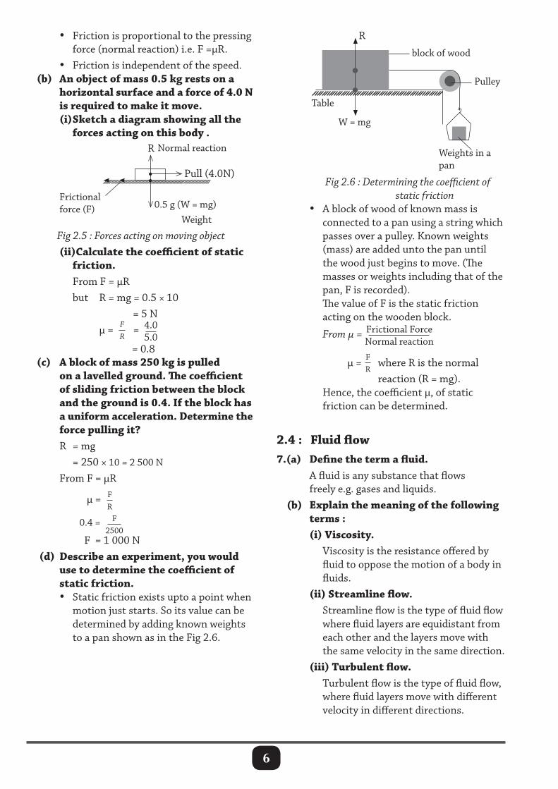
6
• Friction is proportional to the pressing force (normal reaction) i.e. F =µR. • Friction is independent of the speed. (b) An object of mass 0.5 kg rests on a horizontal surface and a force of 4.0 N is required to make it move. (i) Sketch a diagram showing all the forces acting on this body .
0.5 g (W = mg) Weight
Pull (4.0N)
Normal reaction
Frictional force (F)
R
Fig 2.5 : Forces acting on moving object (ii)calculate the coefficient of static friction. From F = µR but R = mg = 0.5 × 10 = 5 N µ = F
R = 4.0
5.0
= 0.8 (c) A block of mass 250 kg is pulled on a lavelled ground. The coefficient of sliding friction between the block and the ground is 0.4. If the block has a uniform acceleration. Determine the force pulling it? R = mg = 250 × 10 = 2 500 N
From F = µR
µ = FR
0.4 = F
2500
F = 1 000 N (d) Describe an experiment, you would use to determine the coefficient of static friction. • Static friction exists upto a point when motion just starts. So its value can be determined by adding known weights to a pan shown as in the Fig 2.6.
Fig 2.6 : Determining the coefficient of static friction • A block of wood of known mass is connected to a pan using a string which passes over a pulley. Known weights (mass) are added unto the pan until the wood just begins to move. (The masses or weights including that of the pan, F is recorded). The value of F is the static friction acting on the wooden block. From µ = Frictional Force
Normal reaction
µ = FR
where R is the normal reaction (R = mg). Hence, the coefficient µ, of static friction can be determined.
2.4 : Fluid flow7.(a) Define the term a fluid. A fluid is any substance that flows freely e.g. gases and liquids. (b) Explain the meaning of the following terms : (i) Viscosity. Viscosity is the resistance offered by fluid to oppose the motion of a body in fluids. (ii) Streamline flow. Streamline flow is the type of fluid flow where fluid layers are equidistant from each other and the layers move with the same velocity in the same direction. (iii) Turbulent flow. Turbulent flow is the type of fluid flow, where fluid layers move with different velocity in different directions.
W = mg
Weights in a pan
Pulley
R
block of wood
Table

7
(c) List down applications of streamline flow. • Helps in Lift on an aerofoil (aeroplane). • Modern cars are made narrow in the front to cut through air easily. • Motion of birds in air depends on streamline flow.8.(a) Explain the meaning of fluid friction? Fluid friction is the resistance to the motion of a body passing through a fluid. At times called viscous drug. The more viscous a fluid is e.g. glycerine, the greater the fluid friction. (b) State factors that affect viscosity. • Temperature. • Nature of the fluid (medium in which the body is moving). • Weight of the body. (c) Describe the motion of a ball bearing when dropped in a transparent jar filled with glycerine.
Velocity(ms–1)
Time t (s)
Vo
F is ViscosityU is UpthrustW is Weight
Fig 2.7 : Motion of body in fluid A ball bearing is dropped into a glass jar containing glycerine (clear viscous liquid) and its motion observed. The ball bearing at first accelerate and attains a constant maximum velocity. The ball accelerates because the weight is greater than the upthrust (U) and the fluid friction (F). Since viscosity increases with motion, there reaches a time when the weight equals the sum of the upward force., i.e. W = U + F. At this point, a constant maximum velocity called terminal velocity is reached, i.e. there is no acceleration. (d) Explain the term terminal velocity using a graph. Terminal velocity is the constant maximum velocity which a body attains in a fluid when the resultant force on it is zero. i.e. Weight = Viscosity + upthrust W = F + U
Vo is the terminal velocity.
Fig 2.8 : A graph of velocity against of a body in a fluid
revision Exercise 21. Calculate: (a) the weight of: (i) 2 kg of water, (ii) 400 g of onion. (b) the tension developed in a string supporting a mass of 120 g.2. Give an explanation to the following: (a) A steel cable of about 3 cm diameter is able to lift a heavy load like a lorry or a truck. (b) Antiseptics used for cuts and other wounds have a low surface tension. (c) A gardener is advised to loosen the soil for healthy growth of the plants.
3. A small ball bearing is allowed to fall freely through a liquid of high viscosity. The ball bearing accelerates for 0.2 s and acquires ‘terminal velocity’ after 1.0 s. (a) Define the term ‘terminal velocity’. (b) Explain, in terms of the various forces
acting, how the ball bearing acquires terminal velocity.
(c) Sketch a graph of velocity (y-axis) against time and label the axes.
4. (a) Distinguish between a streamline flow and a turbulent flow. (b) Explain why cars are made narrow at the front.

8
5. Explain the following statements: (a) An air flow over the wings of an aircraft
causes a lift. (b) Flags flutter in a breeze. (c) It is dangerous to stand near the edge of
a platform in a railway station, when a train passes without stopping.
(d) A spinning ball curves during its flight. (e) It is difficult to push a table tennis
ball completely out of the funnel, held upright, by blowing air from underneath through `the narrow end of the funnel.
(f) In a strong wind, the thatched roof of a hut can be completely lifted off although the walls are not appreciably damaged.
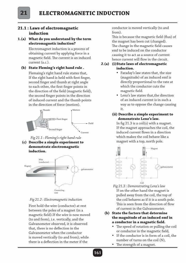
161
21.1 : Laws of electromagnetic induction1.(a) What do you understand by the term electromagnetic induction? Electromagnet induction is a process of obtaining current by applying force in a magnetic field. The current is an induced current (a.c.). (b) State Fleming’s right hand rule . Flemaing’s right hand rule states that, If the right hand is held with first finger, second finger and thumb at right angle to each other, the first finger points in the direction of the field (magnetic field), the second finger points in the direction of induced current and the thumb points in the direction of force (motion).
conductor is moved vertically (to and from). This is because the magnetic field (flux) of the magnet has been cut (changed). The change in the magnetic field causes emf to be induced on the conductor causing it to act as a source of current hence current will flow in the circuit.2.(a) (i) State laws of electromagnetic induction. • Faraday’s law states that, the size (magnitude) of an induced emf is directly proportional to the rate at which the conductor cuts the magnetic field. • Lenz’s law states that,the direction of an induced current is in such a way as to oppose the change causing it. (ii) Describe a simple experiment to demonstrate Lenz’s law. In fig 21.3 is a coil(s) with a magnet. If the magnet approaches the coil, the induced current flows in a direction which makes the coil behave like a magnet with a top, north pole.
ELECTROMAGNETIC INDUCTION
Fig 21.1 : Fleming’s right hand rule (c) Describe a simple experiment to demonstrate electromagnetic induction.
S
N
Fig 21.2 : Electromagnetic induction
First hold the wire (conductor) at rest between the poles of a magnet (in a magnetic field).If the wire is now moved (to and from), i.e. vertically, and the Galvanometer observed, it is observed that, there is no deflection in the Galvanometer when the conductor is moved vertically (to and from); while there is a deflection in the meter if the
Fig 21.3 : Demonstrating Lenz’s law If on the other hand the magnet is pulled away from the coil, the top of the coil behaves as if it is a south pole. This is seen from the direction of flow of current in the Galvanometer. (b) State the factors that determine the magnitude of an induced emf in a conductor in a magnetic field. • The speed of rotation or pulling the coil or conductor in the magnetic field, • If the conductor is in form of a coil, the number of turns on the coil (N), • The strength of a magnet.
21
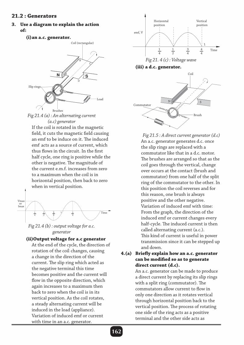
162
21.2 : Generators3. Use a diagram to explain the action of: (i) an a.c. generator.
A
B
Coil (rectangular)
Slip rings
Load
Brushes
C
D
Fig 21.4 (a) : An alternating current (a.c) generator
If the coil is rotated in the magnetic field, it cuts the magnetic field causing an emf to be induce on it. The induced emf acts as a source of current, which thus flows in the circuit. In the first half cycle, one ring is positive while the other is negative. The magnitude of the current e.m.f. increases from zero to a maximum when the coil is in horizontal position, then back to zero when in vertical position.
1 4
3 4
5 4
1 2
1
Imax
Time
Vmax or
Fig 21.4 (b) : output voltage for a.c. generator
(ii)Output voltage for a.c generator At the end of the cycle, the direction of rotation of the coil changes, causing a change in the direction of the current. The slip ring which acted as the negative terminal this time becomes positive and the current will flow in the opposite direction, which again increases to a maximum then back to zero when the coil is in its vertical position. As the coil rotates, a steady alternating current will be induced in the load (appliance). Variation of induced emf or current with time in an a.c. generator.
Fig 21. 4 (c) : Voltage wave (iii) a d.c. generator.
Fig 21.5 : A direct current generator (d.c) An a.c. generator generates d.c. once the slip rings are replaced with a commutator like that in a d.c. motor. The brushes are arranged so that as the coil goes through the vertical, change over occurs at the contact (brush and commutator) from one half of the split ring of the commutator to the other. In this position the coil reverses and for this reason, one brush is always positive and the other negative. Variation of induced emf with time: From the graph, the direction of the induced emf or current changes every half-cycle. The induced current is then called alternating current (a.c.). This kind of current is useful in power transmission since it can be stepped up and down.4.(a) Briefly explain how an a.c. generator can be modified so as to generate direct current (d.c). An a.c. generator can be made to produce a direct current by replacing its slip rings with a split ring (commutator). The commutators allow current to flow in only one direction as it rotates vertical through horizontal position back to the vertical position. The process of rotating one side of the ring acts as a positive terminal and the other side acts as
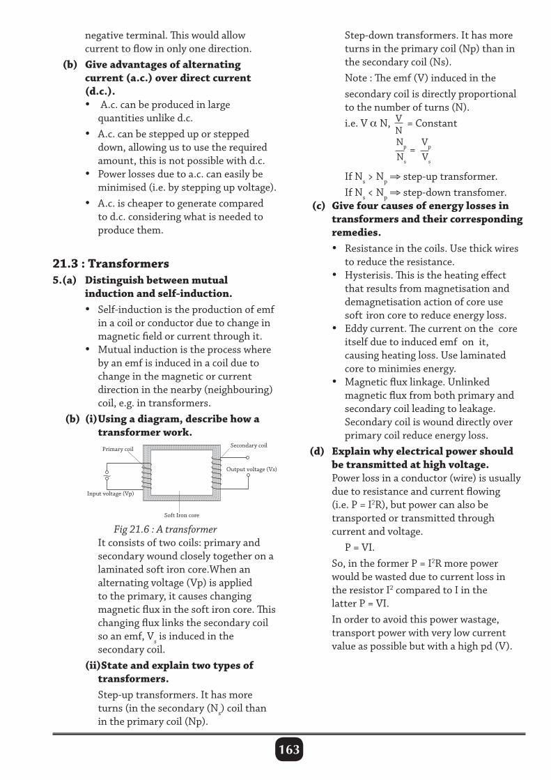
163
negative terminal. This would allow current to flow in only one direction. (b) Give advantages of alternating current (a.c.) over direct current (d.c.). • A.c. can be produced in large quantities unlike d.c. • A.c. can be stepped up or stepped down, allowing us to use the required amount, this is not possible with d.c. • Power losses due to a.c. can easily be minimised (i.e. by stepping up voltage). • A.c. is cheaper to generate compared to d.c. considering what is needed to produce them.
21.3 : Transformers 5.(a) Distinguish between mutual induction and self-induction. • Self-induction is the production of emf in a coil or conductor due to change in magnetic field or current through it. • Mutual induction is the process where by an emf is induced in a coil due to change in the magnetic or current direction in the nearby (neighbouring) coil, e.g. in transformers. (b) (i) Using a diagram, describe how a transformer work.
Step-down transformers. It has more turns in the primary coil (Np) than in the secondary coil (Ns). Note : The emf (V) induced in the secondary coil is directly proportional to the number of turns (N). i.e. V α N, V
N = Constant
Np
Ns
= Vp
Vs
If Ns > Np ⇒ step-up transformer. If Ns < Np ⇒ step-down transfomer. (c) Give four causes of energy losses in transformers and their corresponding remedies. • Resistance in the coils. Use thick wires to reduce the resistance. • Hysterisis. This is the heating effect that results from magnetisation and demagnetisation action of core use soft iron core to reduce energy loss. • Eddy current. The current on the core itself due to induced emf on it, causing heating loss. Use laminated core to minimies energy. • Magnetic flux linkage. Unlinked magnetic flux from both primary and secondary coil leading to leakage. Secondary coil is wound directly over primary coil reduce energy loss. (d) Explain why electrical power should be transmitted at high voltage. Power loss in a conductor (wire) is usually due to resistance and current flowing (i.e. P = I2R), but power can also be transported or transmitted through current and voltage. P = VI. So, in the former P = I2R more power would be wasted due to current loss in the resistor I2 compared to I in the latter P = VI. In order to avoid this power wastage, transport power with very low current value as possible but with a high pd (V).
Input voltage (Vp)
Primary coil
Soft Iron core
Secondary coil
Output voltage (Vs)
Fig 21.6 : A transformer It consists of two coils: primary and secondary wound closely together on a laminated soft iron core.When an alternating voltage (Vp) is applied to the primary, it causes changing magnetic flux in the soft iron core. This changing flux links the secondary coil so an emf, Vs is induced in the secondary coil. (ii)State and explain two types of transformers. Step-up transformers. It has more turns (in the secondary (Ns) coil than in the primary coil (Np).
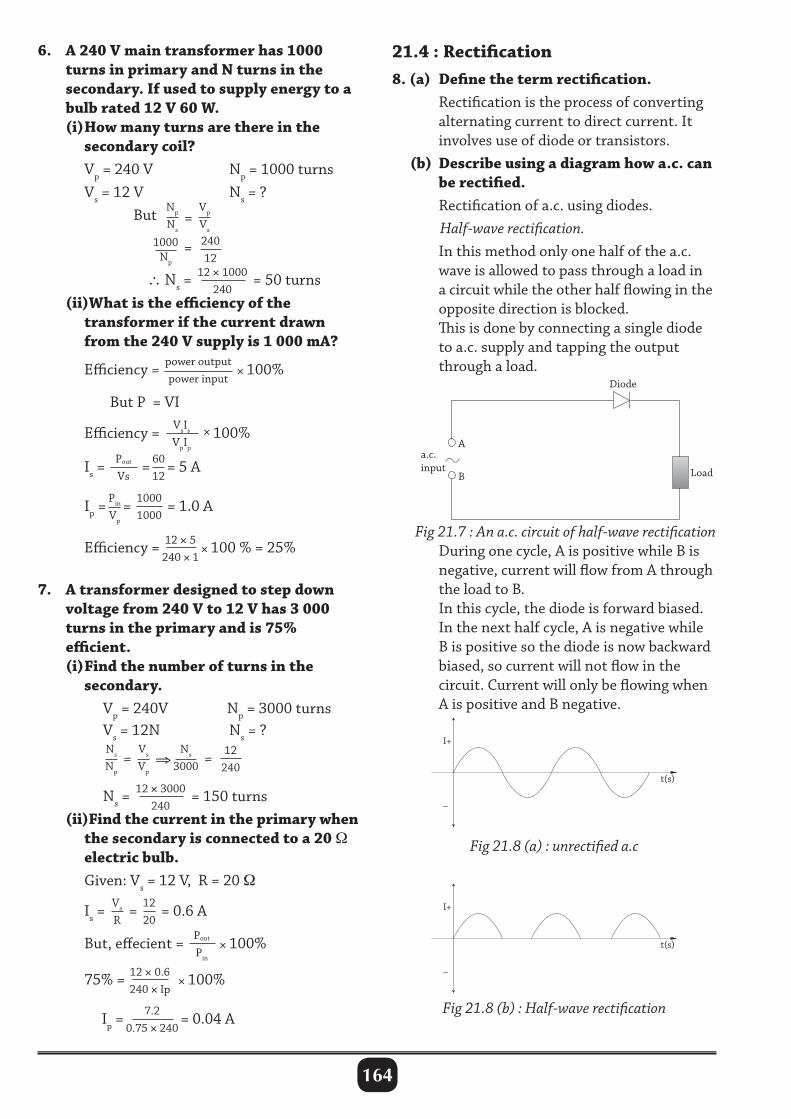
164
6. A 240 V main transformer has 1000 turns in primary and N turns in the secondary. If used to supply energy to a bulb rated 12 V 60 W. (i) How many turns are there in the secondary coil? Vp = 240 V Np = 1000 turns Vs = 12 V Ns = ? But Np
Ns
= Vp
Vs
1000
Np
= 24012
∴ Ns =12 × 1000
240= 50 turns
(ii)What is the efficiency of the transformer if the current drawn from the 240 V supply is 1 000 mA? Efficiency = power output
power input × 100%
But P = VI
Efficiency = VsIs
VpIp
× 100%
Is =Pout
Vs= 60
12= 5 A
Ip =Pin
Vp
= 10001000
= 1.0 A
Efficiency = 12 × 5240 × 1
× 100 % = 25% 7. A transformer designed to step down voltage from 240 V to 12 V has 3 000 turns in the primary and is 75% efficient. (i) Find the number of turns in the secondary. Vp = 240V Np = 3000 turns Vs = 12N Ns = ? Ns
Np
= Vs
Vp
⇒Ns
3000 = 12
240
Ns =12 × 3000
240= 150 turns
(ii)Find the current in the primary when the secondary is connected to a 20 Ω electric bulb. Given: Vs = 12 V, R = 20 Ω
Is = Vs
R
= 1220
= 0.6 A
But, effecient = Pout
Pin
× 100%
75% = 12 × 0.6240 × Ip
× 100%
Ip =7.2
0.75 × 240= 0.04 A
21.4 : Rectification8. (a) Define the term rectification. Rectification is the process of converting alternating current to direct current. It involves use of diode or transistors. (b) Describe using a diagram how a.c. can be rectified. Rectification of a.c. using diodes. Half-wave rectification. In this method only one half of the a.c. wave is allowed to pass through a load in a circuit while the other half flowing in the opposite direction is blocked. This is done by connecting a single diode to a.c. supply and tapping the output through a load.
Fig 21.8 (a) : unrectified a.c
Fig 21.8 (b) : Half-wave rectification
B Load
Diode
a.c.input
A
Fig 21.7 : An a.c. circuit of half-wave rectification During one cycle, A is positive while B is negative, current will flow from A through the load to B. In this cycle, the diode is forward biased. In the next half cycle, A is negative while B is positive so the diode is now backward biased, so current will not flow in the circuit. Current will only be flowing when A is positive and B negative.
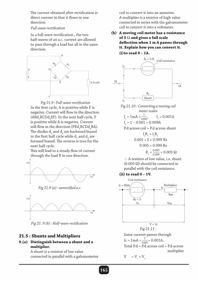
165
coil to convert it into an ammeter. A multiplier is a resistor of high value connected in series with the galvanometer coil to convert it into a voltmeter. (b) A moving coil meter has a resistance of 5 Ω and gives a full scale deflection when 1 m A passes through it. Explain how you can convert it. (i) to read 0 – 1A.
Fig 21.9 (a) : unrectified a.c
Fig 21. 9 (b) : Half-wave rectification
The current obtained after rectification is direct current in that it flows in one direction. Full-wave rectification
In a full-wave rectification., the two half-waves of an a.c. current are allowed to pass through a load but all in the same direction.
Fig 21.9 : Full-wave rectification In the first cycle, A is positive while F is negative. Current will flow in the direction (ABd1RCDd3EF). In the next half cycle, F is positive while A is negative. Current will flow in the direction (FEd2RCDd4BA). The diodes d2 and d4 are backward biased in the first half cycle while d1 and d3 are forward biased. The reverse is true for the next half cycle. This will lead to a steady flow of current through the load R in one direction.
Shunt
Rs
Is
Ic
Rc = 5 Ω Coil resistance
IA IA
Fig 21.10 : Converting a moving coil meter scales
Ic = 1mA = 11000
, Ic = 0.001A Is = 1 – 0.001 = 0.999A P.d across coil = P.d across shunt IcRc = IsRs
0.001 × 5 = 0.999 Rs 0.005 = 0.999 Rs
Rs = 0.0050.999
= 0.005 Ω
∴ A resistor of low value, i.e. shunt (0.005 Ω) should be connected in parallel with the coil resistance. (ii) to read 0 – 1V.
21.5 : Shunts and Multipliers 9.(a) Distinguish between a shunt and a multiplier. A shunt is a resistor of low value connected in parallel with a galvanometer
Fig 21.11 : Same current passes through Ic = 1mA = 1
1000= 0.001A.
Total P.d = P.d across coil + P.d across multiplier V = Vc + Vs
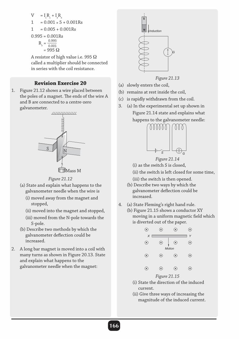
166
V = IcRc + IsRs
1 = 0.001 × 5 + 0.001Rs 1 = 0.005 + 0.001Rs 0.995 = 0.001Rs Rs = 0.995
0.001
= 995 Ω A resistor of high value i.e. 995 Ω called a multiplier should be connected in series with the coil resistance.
Revision Exercise 201. Figure 21.12 shows a wire placed between the poles of a magnet. The ends of the wire A and B are connected to a centre-zero galvanometer.
Figure 21.12
Mass M
NS
(a) State and explain what happens to the galvanometer needle when the wire is (i) moved away from the magnet and stopped, (ii) moved into the magnet and stopped, (iii) moved from the N-pole towards the S-pole. (b) Describe two methods by which the galvanometer deflection could be increased.
2. A long bar magnet is moved into a coil with many turns as shown in Figure 20.13. State and explain what happens to the galvanometer needle when the magnet:
Figure 21.13(a) slowly enters the coil,(b) remains at rest inside the coil,(c) is rapidly withdrawn from the coil.3. (a) In the experimental set up shown in Figure 21.14 state and explains what happens to the galvanometer needle:
(i) as the switch S is closed, (ii) the switch is left closed for some time, (iii) the switch is then opened. (b) Describe two ways by which the galvanometer deflection could be increased.
4. (a) State Fleming’s right hand rule. (b) Figure 21.15 shows a conductor XY moving in a uniform magnetic field which is diverted out of the paper.
N
S
Induction
G
Figure 21.14S G
Figure 21.15
X Y
Motion
(i) State the direction of the induced current. (ii) Give three ways of increasing the magnitude of the induced current.
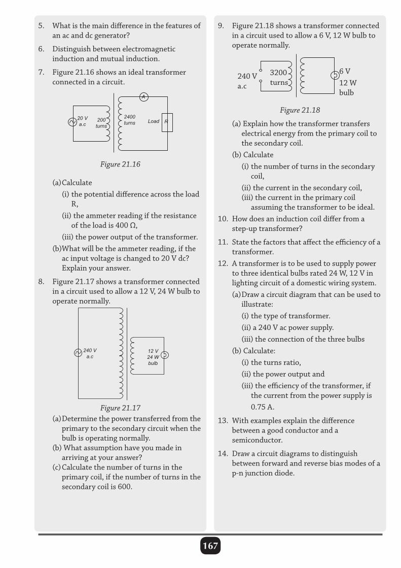
167
5. What is the main difference in the features of an ac and dc generator?
6. Distinguish between electromagnetic induction and mutual induction.
7. Figure 21.16 shows an ideal transformer connected in a circuit.
6 V12 W bulb
3200 turns
240 V a.c
Figure 21.18
9. Figure 21.18 shows a transformer connected in a circuit used to allow a 6 V, 12 W bulb to operate normally.
(a) Calculate (i) the potential difference across the load R, (ii) the ammeter reading if the resistance of the load is 400 Ω, (iii) the power output of the transformer. (b)What will be the ammeter reading, if the ac input voltage is changed to 20 V dc? Explain your answer.
8. Figure 21.17 shows a transformer connected in a circuit used to allow a 12 V, 24 W bulb to operate normally.
Figure 21.17
240 Va.c
12 V24 W bulb
Figure 21.16
20 Va.c
200turns
2400turns Load R
A
(a) Determine the power transferred from the primary to the secondary circuit when the bulb is operating normally. (b) What assumption have you made in arriving at your answer? (c) Calculate the number of turns in the primary coil, if the number of turns in the secondary coil is 600.
(a) Explain how the transformer transfers electrical energy from the primary coil to the secondary coil. (b) Calculate (i) the number of turns in the secondary coil, (ii) the current in the secondary coil, (iii) the current in the primary coil assuming the transformer to be ideal. 10. How does an induction coil differ from a step-up transformer?
11. State the factors that affect the efficiency of a transformer.12. A transformer is to be used to supply power to three identical bulbs rated 24 W, 12 V in lighting circuit of a domestic wiring system. (a) Draw a circuit diagram that can be used to illustrate: (i) the type of transformer. (ii) a 240 V ac power supply. (iii) the connection of the three bulbs (b) Calculate: (i) the turns ratio, (ii) the power output and (iii) the efficiency of the transformer, if the current from the power supply is 0.75 A.
13. With examples explain the difference between a good conductor and a semiconductor.
14. Draw a circuit diagrams to distinguish between forward and reverse bias modes of a p-n junction diode.

168
15. For each circuit shown in Figure 21.19, sketch a curve to show the variation of current with time as displayed on a C.R.O screen.
Figure 21.19
16. Figure 21.20 shows a rectifier circuit for an alternating current (a.c)
Figure 21.20
D3
D1 D2
D4 R
Y
X
(a) Describe the rectification process and mark the polarities of the terminals X and Y. (b) Sketch a graph to show how the p.d. across the resistor R varies with time.
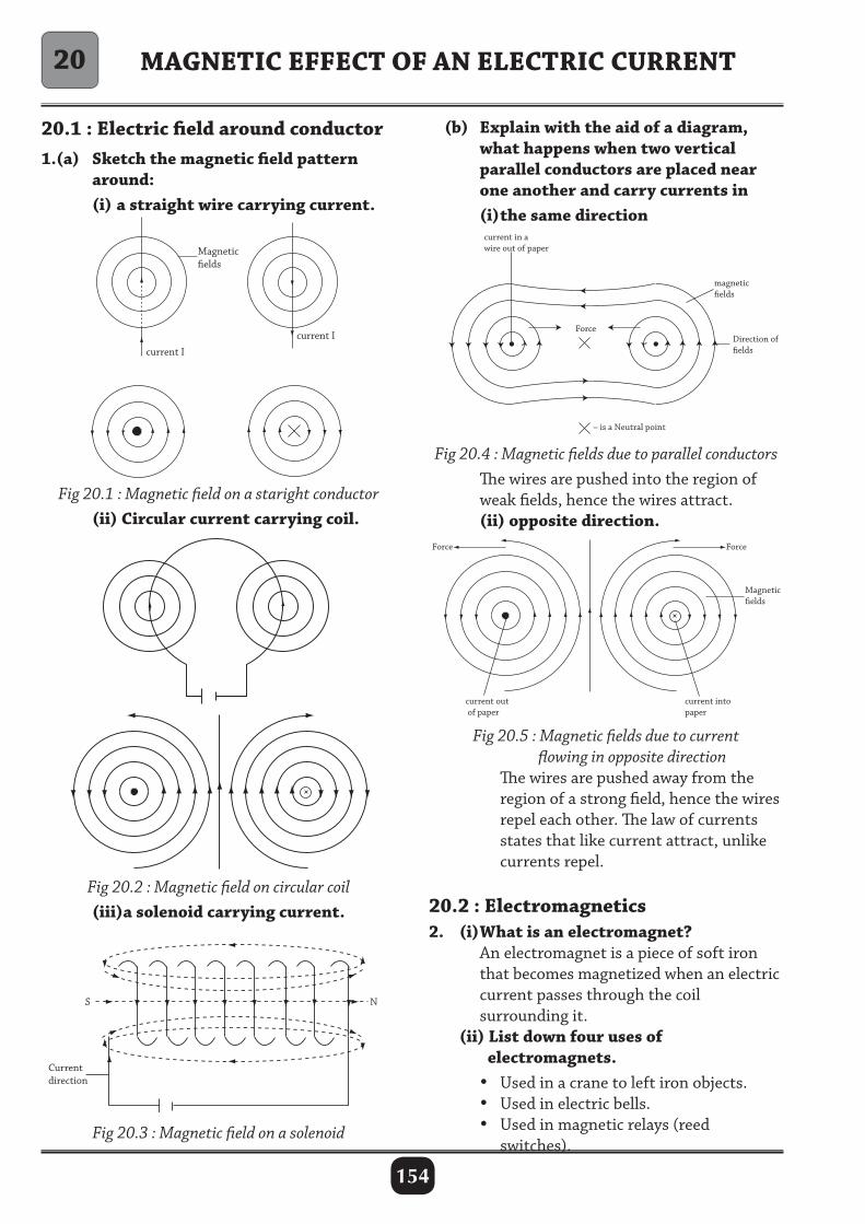
154
20.1 : Electric field around conductor1.(a) Sketch the magnetic field pattern around: (i) a straight wire carrying current.
(b) Explain with the aid of a diagram, what happens when two vertical parallel conductors are placed near one another and carry currents in (i) the same direction
MAGNETIC EFFECT OF AN ELECTRIC CURRENT
Magneticelds
current I
current I
Fig 20.1 : Magnetic field on a staright conductor (ii) Circular current carrying coil.
Magneticelds
current I
current I
Fig 20.2 : Magnetic field on circular coil (iii)a solenoid carrying current.
Fig 20.3 : Magnetic field on a solenoid
Fig 20.4 : Magnetic fields due to parallel conductors The wires are pushed into the region of weak fields, hence the wires attract. (ii) opposite direction.
Fig 20.5 : Magnetic fields due to current flowing in opposite direction The wires are pushed away from the region of a strong field, hence the wires repel each other. The law of currents states that like current attract, unlike currents repel.
20.2 : Electromagnetics2. (i) What is an electromagnet? An electromagnet is a piece of soft iron that becomes magnetized when an electric current passes through the coil surrounding it. (ii) List down four uses of electromagnets. • Used in a crane to left iron objects. • Used in electric bells. • Used in magnetic relays (reed switches).
20
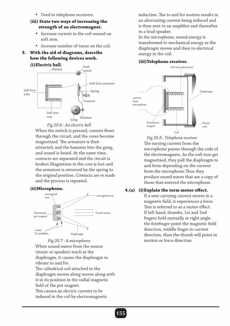
155
• Used in telephone receivers. (iii) State two ways of increasing the strength of an electromagnet. • Increase current in the coil wound on soft iron. • Increase number of turns on the coil.3. With the aid of diagrams, describe how the following devices work. (i) Electric bell.
induction. The to and fro motion results in an alternating current being induced and is then sent to an amplifier and thereafter to a loud speaker. In the microphone, sound energy is transformed to mechanical energy as the diaphragm moves and then to electrical energy in the coil.
(iii)Telephone receiver.
S
S
N
N
S
Coil
Permanent magnet
current from microphone
Plastic case
Diaphragm
soft iron pole pieces
Fig 20.8 : Telephone receiver The varying current from the microphone passes through the coils of the electromagnets. As the soft iron get magnetized, they pull the diaphragm to and from depending on the current from the microphone.Thus they produce sound waves that are a copy of those that entered the microphone.
4.(a) (i) Explain the term motor effect. If a wire carrying current moves in a magnetic field, it experiences a force. This is referred to as a motor effect. If left hand, thumbs, 1st and 2nd fingers held mutually at right angle. the forefinger point the magnetic field direction, middle finger in current direction, then the thumb will point in motion or force direction.
S
N
Fig 20.6 : An electric bell When the switch is pressed, current flows through the circuit, and the cores become magnetized. The armature is then attracted, and the hammer hits the gong, and sound is heard. At the same time, contacts are separated and the circuit is broken.Magnetism in the core is lost and the armature is returned by the spring to the original position. Contacts are re made and the process is repeated.
(ii)Microphone.
Fig 20.7 : A microphone When sound waves from the source (music or speaker) reach at the diaphragm, it causes the diaphragm to vibrate to and fro. The cylindrical coil attached to the diaphragm moves along moves along with it in its position in the radial magnetic field of the pot magnet. This causes an electric current to be induced in the coil by electromagnetic
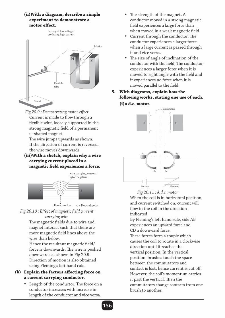
156
(ii)With a diagram, describe a simple experiment to demonstrate a motor effect.
• The strength of the magnet. A conductor moved in a strong magnetic field experiences a large force than when moved in a weak magnetic field. • Current through the conductor. The conductor experiences a larger force when a large current is passed through it and vice versa. • The size of angle of inclination of the conductor with the field. The conductor experiences a larger force when it is moved to right angle with the field and it experiences no force when it is moved parallel to the field.5. With diagrams, explain how the following works, stating one use of each. (i) a d.c. motor.
axis rotation
B C
A
B1
C1
Battery Rheostat
C2
B2 –
+
N S
D
N
Flexiblewire
Battery of low voltage,producing high current
Stand
S
Motion
Fig 20.9 : Demostrating motor effect Current is made to flow through a flexible wire, loosely supported in the strong magnetic field of a permanent u–shaped magnet. The wire jumps upwards as shown. If the direction of current is reversed, the wire moves downwards. (iii)With a sketch, explain why a wire carrying current placed in a magnetic field experiences a force.
Fig 20.10 : Effect of magnetic field current carrying wire
The magnetic fields due to wire and magnet interact such that there are more magnetic field lines above the wire than below. Hence the resultant magnetic field/ force is downwards. The wire is pushed downwards as shown in Fig 20.9. Direction of motion is also obtained using Fleming’s left hand rule. (b) Explain the factors affecting force on a current carrying conductor. • Length of the conductor. The force on a conductor increases with increase in length of the conductor and vice versa.
Fig 20.11 : A d.c. motor When the coil is in horizontal position, and current switched on, current will flow in the coil in the direction indicated. By Fleming’s left hand rule, side AB experiences an upward force and CD a downward force. These forces form a couple which causes the coil to rotate in a clockwise direction until if reaches the vertical position. In the vertical position, brushes touch the space between the commutators and contact is lost, hence current is cut off. However, the coil’s momentum carries it past the vertical. Then the commutators change contacts from one brush to another.
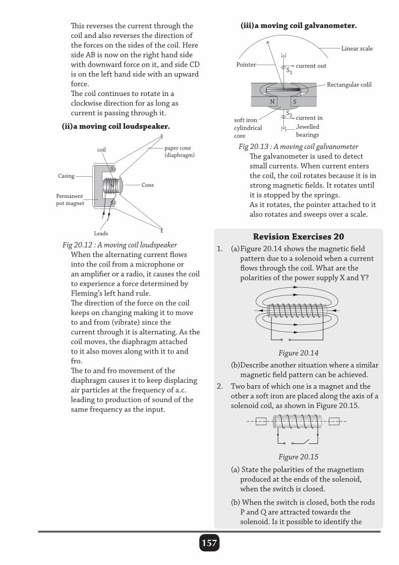
157
This reverses the current through the coil and also reverses the direction of the forces on the sides of the coil. Here side AB is now on the right hand side with downward force on it, and side CD is on the left hand side with an upward force. The coil continues to rotate in a clockwise direction for as long as current is passing through it.
(ii)a moving coil loudspeaker.
(iii)a moving coil galvanometer.
Fig 20.12 : A moving coil loudspeaker When the alternating current flows into the coil from a microphone or an amplifier or a radio, it causes the coil to experience a force determined by Fleming’s left hand rule. The direction of the force on the coil keeps on changing making it to move to and from (vibrate) since the current through it is alternating. As the coil moves, the diaphragm attached to it also moves along with it to and fro. The to and fro movement of the diaphragm causes it to keep displacing air particles at the frequency of a.c. leading to production of sound of the same frequency as the input.
(b)Describe another situation where a similar magnetic field pattern can be achieved.2. Two bars of which one is a magnet and the other a soft iron are placed along the axis of a solenoid coil, as shown in Figure 20.15.
Fig 20.13 : A moving coil galvanometer The galvanometer is used to detect small currents. When current enters the coil, the coil rotates because it is in strong magnetic fields. It rotates until it is stopped by the springs. As it rotates, the pointer attached to it also rotates and sweeps over a scale.
Revision Exercises 201. (a) Figure 20.14 shows the magnetic field pattern due to a solenoid when a current flows through the coil. What are the polarities of the power supply X and Y?
Figure 20.14
Figure 20.15
(a) State the polarities of the magnetism produced at the ends of the solenoid, when the switch is closed.
(b) When the switch is closed, both the rods P and Q are attracted towards the solenoid. Is it possible to identify the
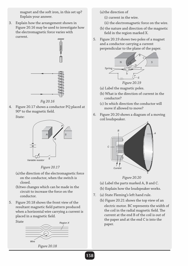
158
magnet and the soft iron, in this set up? Explain your answer.
3. Explain how the arrangement shown in Figure 20.16 may be used to investigate how the electromagnetic force varies with current.
N S
P
Q
SVariable resistor
Figure 20.17
Fig 20.164. Figure 20.17 shows a conductor PQ placed at 90º to the magnetic field. State:
Region X
Wire
Figure 20.18
(a) the direction of (i) current in the wire. (ii) the electromagnetic force on the wire. (b) the nature and direction of the magnetic field in the region marked X.
5. Figure 20.19 shows two poles of a magnet and a conductor carrying a current perpendicular to the plane of the paper.
Figure 20.19
Current
C
BA
Figure 20.20
(a) Label the magnetic poles. (b) What is the direction of current in the conductor? (c) In which direction the conductor will move if allowed to move?
6. Figure 20.20 shows a diagram of a moving coil loudspeaker.
(a) the direction of the electromagnetic force on the conductor, when the switch is closed. (b)two changes which can be made in the circuit to increase the force on the conductor.
5. Figure 20.18 shows the front view of the resultant magnetic field pattern produced when a horizontal wire carrying a current is placed in a magnetic field. State
(a) Label the parts marked A, B and C. (b) Explain how the loudspeaker works.
7. (a) State Fleming’s left hand rule. (b) Figure 20.21 shows the top view of an electric motor. BC represents the width of the coil in the radial magnetic field. The current at the end B of the coil is out of the paper and at the end C is into the paper.
N SAD
C
a
d
b
Spring
B
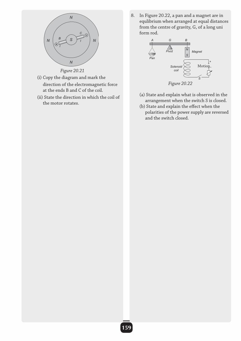
159
N N
N
N
S B
C
I
I
Figure 20.21 (i) Copy the diagram and mark the direction of the electromagnetic force at the ends B and C of the coil. (ii) State the direction in which the coil of the motor rotates.
Solenoid coil
Pivot
Pan
Magnet
A G B
S
+
–
Figure 20.22
S
N
8. In Figure 20.22, a pan and a magnet are in equlibrium when arranged at equal distances from the centre of gravity, G, of a long uni form rod.
Motion
(a) State and explain what is observed in the arrangement when the switch S is closed. (b) State and explain the effect when the polarities of the power supply are reversed and the switch closed.
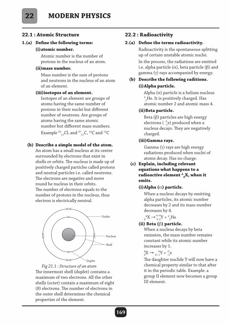
169
MODERN PHYSICS
22.1 : Atomic Structure1.(a) Define the following terms: (i) atomic number. Atomic number is the number of protons in the nucleus of an atom. (ii)mass number. Mass number is the sum of protons and neutrons in the nucleus of an atom of an element. (iii)isotopes of an element. Isotopes of an element are groups of atoms having the same number of protons in their nuclei but different number of neutrons. Are groups of atoms having the same atomic number but different mass numbers. Example 35
17CL and 3717C, 14C and 12C
(b) Describe a simple model of the atom. An atom has a small nucleus at its centre surrounded by electrons that exist in shells or orbits. The nucleus is made up of positively charged particles called protons and neutral particles i.e. called neutrons. The electrons are negative and move round he nucleus in their orbits. The number of electrons equals to the number of protons in the nucleus, thus electron is electrically neutral.
22.2 : Radioactivity2.(a) Define the terms radioactivity. Radioactivity is the spontaneous splitting up of certain unstable atomic nuclei. In the process, the radiations are emitted i.e. alpha particle (α), beta particle (β) and gamma (γ) rays accompanied by energy. (b) Describe the following raditions. (i) Alpha particle. Alpha (α) particle is a helium nucleus 4
2He. It is positively charged. Has atomic number 2 and atomic mass 4. (ii)Beta particle. Beta (β) particles are high energy electrons ( –1e) produced when a nucleus decays. They are negatively charged. (iii)Gamma rays. Gamma (γ) rays are high energy radiations produced when nuclei of atoms decay. Has no charge. (c) Explain, including relevant equations what happens to a radioactive element A
ZX, when it emits. (i) Alpha (α) particle. When a nucleus decays by emitting alpha particles, its atomic number decreases by 2 and its mass number decreases by 4. Z
AX → 2–2Y + 42He
(ii) Beta (β) particle. When a nucleus decays by beta emission, the mass number remains constant while its atomic number increases by 1. ZX → Z+ 1Y + –1e The daughter nuclide Y will now have a chemical property similar to that after it in the periodic table. Example: a group II element now becomes a group III element.
A–4
22
Fig 21.1 : Structure of an atom The innermost shell (duplet) contains a maximum of two electrons. All the other shells (octet) contain a maximum of eight (8) electrons. The number of electrons in the outer shell determines the chemical properties of the element.
0
A A O
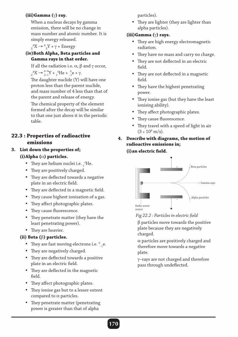
170
(iii)Gamma (γ) ray. When a nucleus decays by gamma emission, there will be no change in mass number and atomic number. It is simply energy released. Z
AX → AZY + γ + Energy
(iv)Both Alpha, Beta particles and Gamma rays in that order. If all the radiation i.e. α, β and γ occur, Z
AX → Z–1Y + 24He + –1e + γ.
The daughter nuclide (Y) will have one proton less than the parent nuclide, and mass number of 4 less than that of the parent and release of energy. The chemical property of the element formed after the decay will be similar to that one just above it in the periodic table.
22.3 : Properties of radioactive emissions3. List down the properties of; (i) Alpha (α) particles. • They are helium nuclei i.e. 2
4He. • They are positively charged. • They are deflected towards a negative plate in an electric field. • They are deflected in a magnetic field. • They cause highest ionisation of a gas. • They affect photographic plates. • They cause fluorescence. • They penetrate matter (they have the least penetrating power). • They are heavier. (ii) Beta (β) particles. • They are fast moving electrons i.e. 0
–1e. • They are negatively charged. • They are deflected towards a positive plate in an electric field. • They are deflected in the magnetic field. • They affect photographic plates. • They ionise gas but to a lesser extent compared to α particles. • They penetrate matter (penetrating power is greater than that of alpha
particles). • They are lighter (they are lighter than alpha particles). (iii)Gamma (γ) rays. • They are high energy electromagnetic radiation. • They have no mass and carry no charge. • They are not deflected in an electric field. • They are not deflected in a magnetic field. • They have the highest penetrating power. • They ionise gas (but they have the least ionising ability). • They affect photographic plates. • They cause fluorescence. • They travel with a speed of light in air (3 × 10⁸ m/s).4. Describe with diagrams, the motion of radioactive emissions in; (i) an electric field.
Fig 22.2 : Particles in electric field β particles move towards the positive plate because they are negatively charged. α particles are positively charged and therefore move towards a negative plate. γ–rays are not charged and therefore pass through undeflected.
A–4 0
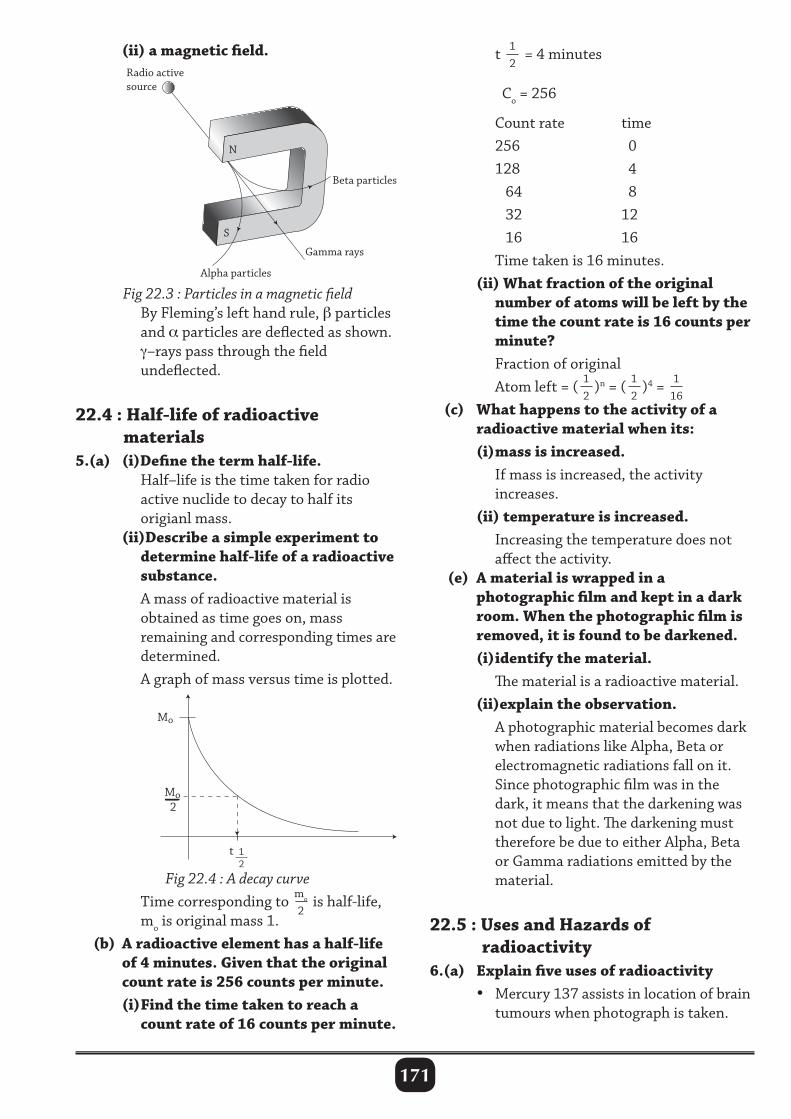
171
(ii) a magnetic field. t 12
= 4 minutes Co = 256
Count rate time 256 0 128 4 64 8 32 12 16 16 Time taken is 16 minutes. (ii) What fraction of the original number of atoms will be left by the time the count rate is 16 counts per minute? Fraction of original Atom left = ( 1
2)n = ( 1
2)4 = 1
16 (c) What happens to the activity of a radioactive material when its: (i) mass is increased. If mass is increased, the activity increases. (ii) temperature is increased. Increasing the temperature does not affect the activity. (e) A material is wrapped in a photographic film and kept in a dark room. When the photographic film is removed, it is found to be darkened. (i) identify the material. The material is a radioactive material. (ii)explain the observation. A photographic material becomes dark when radiations like Alpha, Beta or electromagnetic radiations fall on it. Since photographic film was in the dark, it means that the darkening was not due to light. The darkening must therefore be due to either Alpha, Beta or Gamma radiations emitted by the material.
22.5 : Uses and Hazards of radioactivity6.(a) Explain five uses of radioactivity • Mercury 137 assists in location of brain tumours when photograph is taken.
Fig 22.3 : Particles in a magnetic field By Fleming’s left hand rule, β particles and α particles are deflected as shown. γ–rays pass through the field undeflected.
22.4 : Half-life of radioactive materials 5.(a) (i)Define the term half-life. Half–life is the time taken for radio active nuclide to decay to half its origianl mass. (ii)Describe a simple experiment to determine half-life of a radioactive substance. A mass of radioactive material is obtained as time goes on, mass remaining and corresponding times are determined. A graph of mass versus time is plotted.
Mo
Mo 2
t 1 2
Fig 22.4 : A decay curve Time corresponding to mo
2 is half-life,
mo is original mass 1. (b) A radioactive element has a half-life of 4 minutes. Given that the original count rate is 256 counts per minute. (i) Find the time taken to reach a count rate of 16 counts per minute.
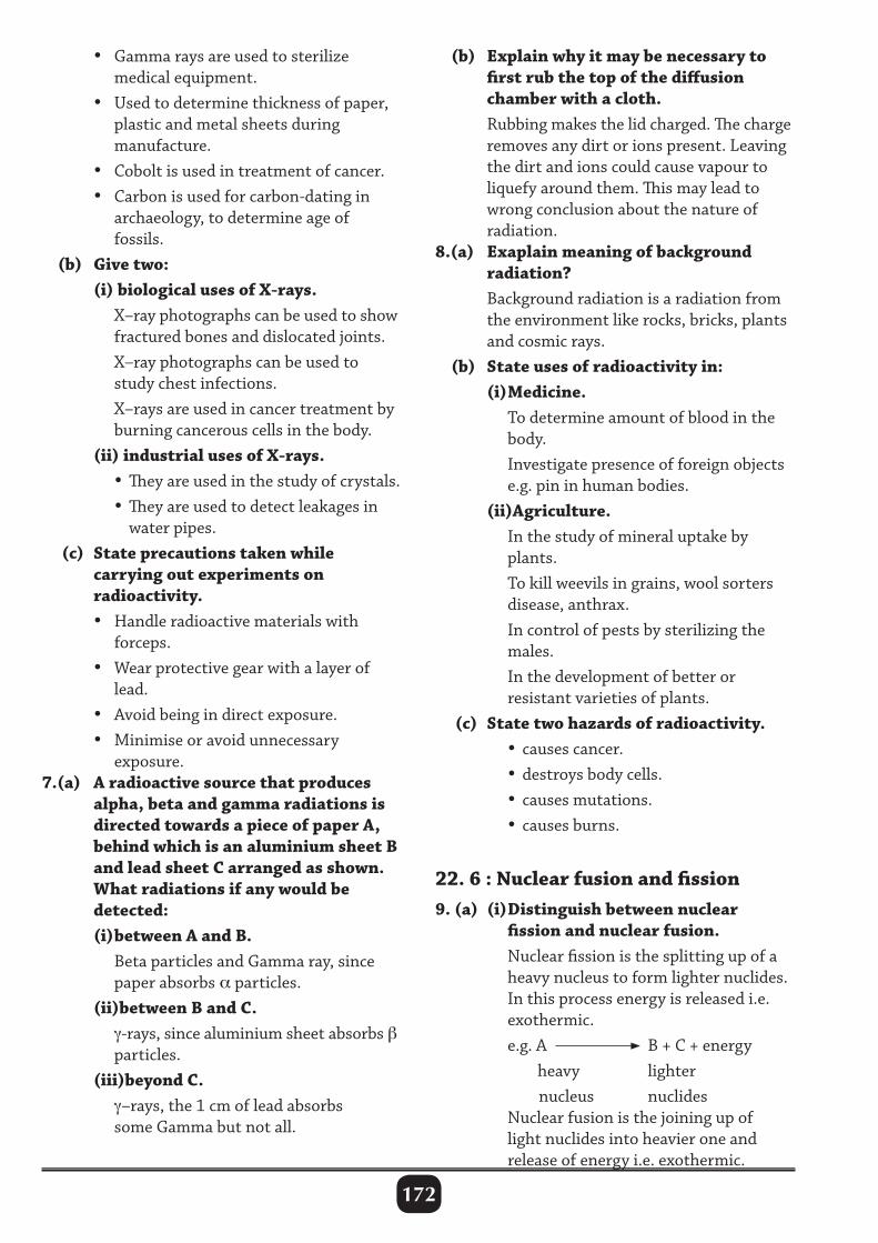
172
• Gamma rays are used to sterilize medical equipment. • Used to determine thickness of paper, plastic and metal sheets during manufacture. • Cobolt is used in treatment of cancer. • Carbon is used for carbon-dating in archaeology, to determine age of fossils. (b) Give two: (i) biological uses of X-rays. X–ray photographs can be used to show fractured bones and dislocated joints. X–ray photographs can be used to study chest infections. X–rays are used in cancer treatment by burning cancerous cells in the body. (ii) industrial uses of X-rays. • They are used in the study of crystals. • They are used to detect leakages in water pipes. (c) State precautions taken while carrying out experiments on radioactivity. • Handle radioactive materials with forceps. • Wear protective gear with a layer of lead. • Avoid being in direct exposure. • Minimise or avoid unnecessary exposure.7.(a) A radioactive source that produces alpha, beta and gamma radiations is directed towards a piece of paper A, behind which is an aluminium sheet B and lead sheet C arranged as shown. What radiations if any would be detected: (i) between A and B. Beta particles and Gamma ray, since paper absorbs α particles. (ii)between B and C. γ-rays, since aluminium sheet absorbs β particles. (iii)beyond C. γ–rays, the 1 cm of lead absorbs some Gamma but not all.
(b) Explain why it may be necessary to first rub the top of the diffusion chamber with a cloth. Rubbing makes the lid charged. The charge removes any dirt or ions present. Leaving the dirt and ions could cause vapour to liquefy around them. This may lead to wrong conclusion about the nature of radiation.8.(a) Exaplain meaning of background radiation? Background radiation is a radiation from the environment like rocks, bricks, plants and cosmic rays. (b) State uses of radioactivity in: (i) Medicine. To determine amount of blood in the body. Investigate presence of foreign objects e.g. pin in human bodies. (ii)Agriculture. In the study of mineral uptake by plants. To kill weevils in grains, wool sorters disease, anthrax. In control of pests by sterilizing the males. In the development of better or resistant varieties of plants. (c) State two hazards of radioactivity. • causes cancer. • destroys body cells. • causes mutations. • causes burns.
22. 6 : Nuclear fusion and fission9. (a) (i) Distinguish between nuclear fission and nuclear fusion. Nuclear fission is the splitting up of a heavy nucleus to form lighter nuclides. In this process energy is released i.e. exothermic. e.g. A B + C + energy heavy lighter nucleus nuclides Nuclear fusion is the joining up of light nuclides into heavier one and release of energy i.e. exothermic.
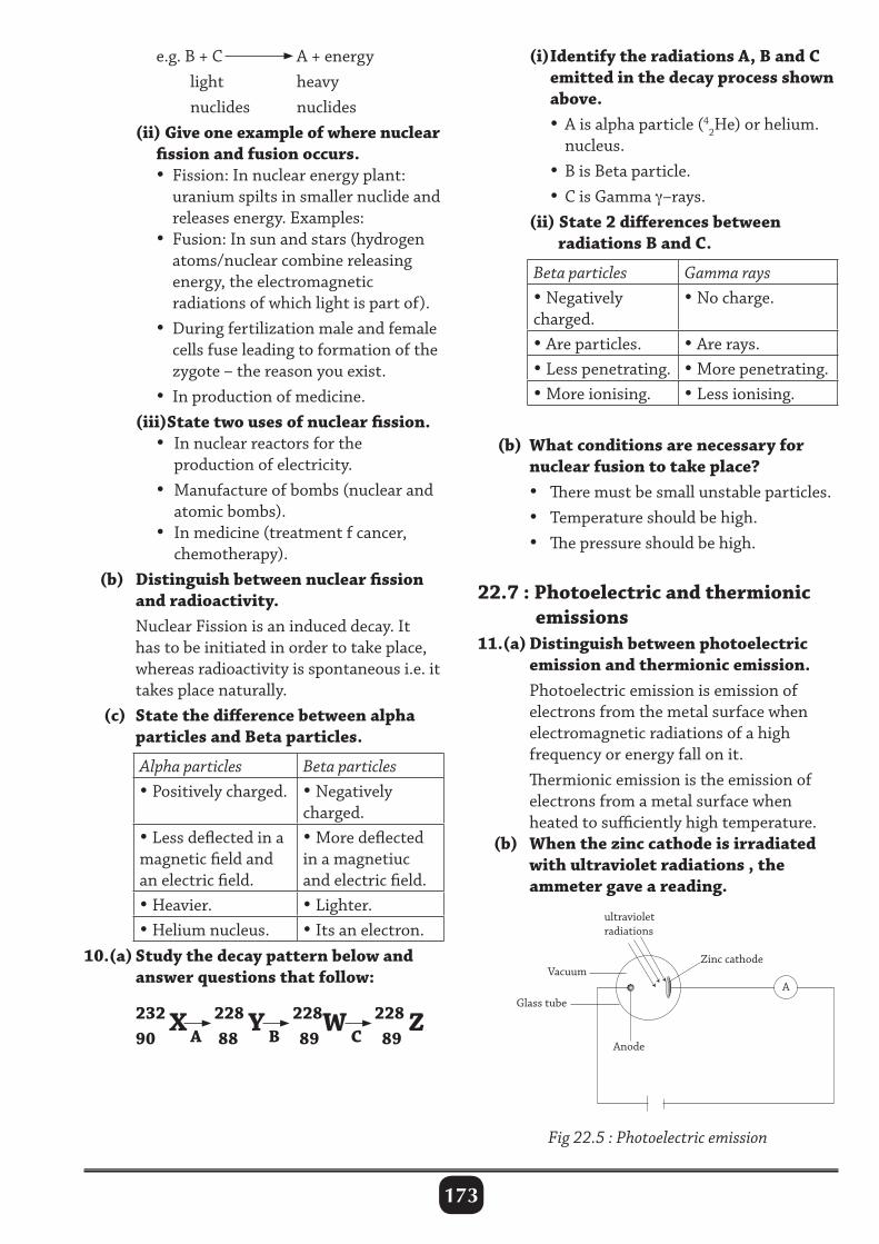
173
e.g. B + C A + energy light heavy nuclides nuclides (ii) Give one example of where nuclear fission and fusion occurs. • Fission: In nuclear energy plant: uranium spilts in smaller nuclide and releases energy. Examples: • Fusion: In sun and stars (hydrogen atoms/nuclear combine releasing energy, the electromagnetic radiations of which light is part of). • During fertilization male and female cells fuse leading to formation of the zygote – the reason you exist. • In production of medicine. (iii)State two uses of nuclear fission. • In nuclear reactors for the production of electricity. • Manufacture of bombs (nuclear and atomic bombs). • In medicine (treatment f cancer, chemotherapy). (b) Distinguish between nuclear fission and radioactivity. Nuclear Fission is an induced decay. It has to be initiated in order to take place, whereas radioactivity is spontaneous i.e. it takes place naturally. (c) State the difference between alpha particles and Beta particles.
Alpha particles Beta particles• Positively charged. • Negatively
charged.• Less deflected in a magnetic field and an electric field.
• More deflected in a magnetiuc and electric field.
• Heavier. • Lighter.• Helium nucleus. • Its an electron.
10.(a) Study the decay pattern below and answer questions that follow:
232 X 228 Y 228W 228 Z
90 88 89 89
(i) Identify the radiations A, B and C emitted in the decay process shown above. • A is alpha particle (4
2He) or helium. nucleus. • B is Beta particle. • C is Gamma γ–rays. (ii) State 2 differences between radiations B and C.
Beta particles Gamma rays• Negatively charged.
• No charge.
• Are particles. • Are rays.• Less penetrating. • More penetrating.• More ionising. • Less ionising.
(b) What conditions are necessary for nuclear fusion to take place? • There must be small unstable particles. • Temperature should be high. • The pressure should be high. 22.7 : Photoelectric and thermionic emissions11.(a) Distinguish between photoelectric emission and thermionic emission. Photoelectric emission is emission of electrons from the metal surface when electromagnetic radiations of a high frequency or energy fall on it. Thermionic emission is the emission of electrons from a metal surface when heated to sufficiently high temperature. (b) When the zinc cathode is irradiated with ultraviolet radiations , the ammeter gave a reading.
A B C
A
Zinc cathode
ultravioletradiations
Vacuum
Anode
Glass tube
Fig 22.5 : Photoelectric emission
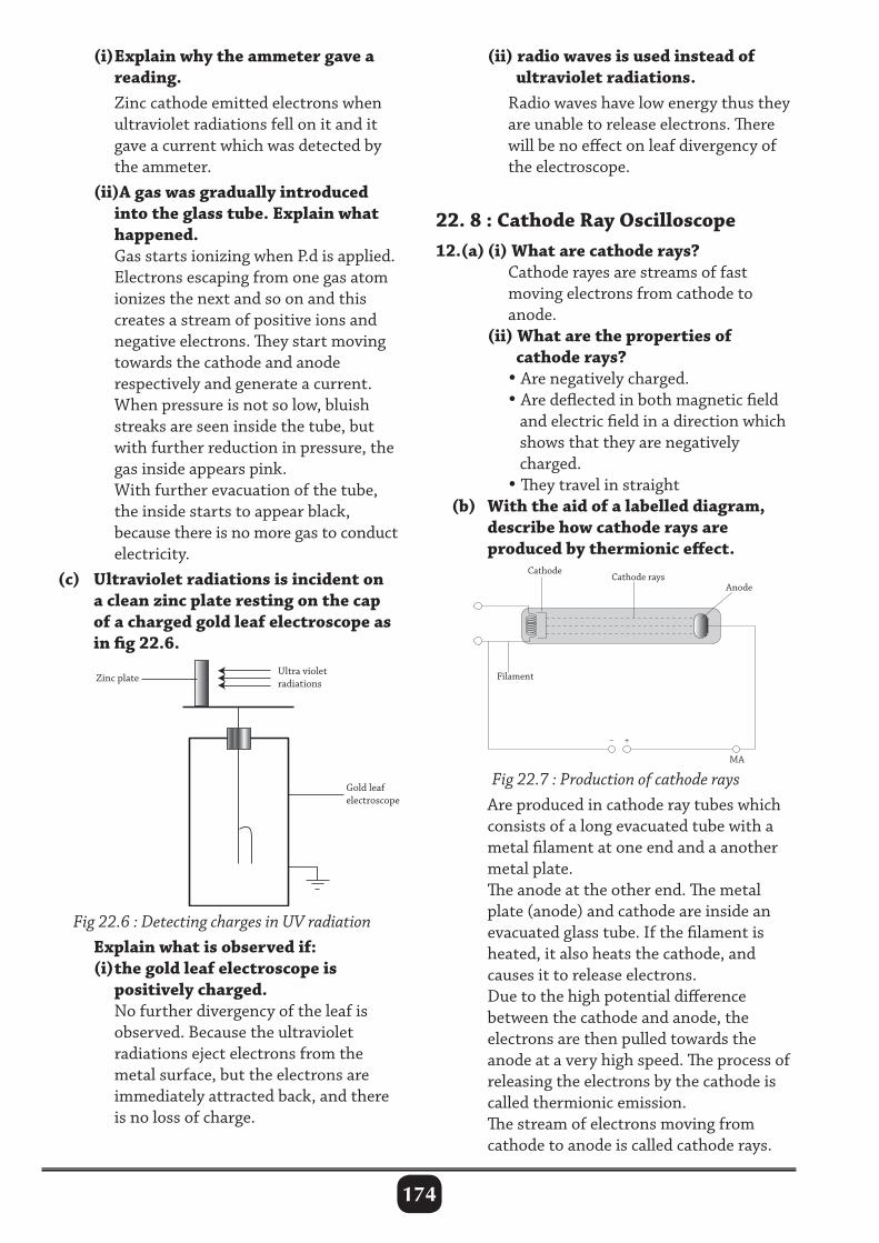
174
(i) Explain why the ammeter gave a reading. Zinc cathode emitted electrons when ultraviolet radiations fell on it and it gave a current which was detected by the ammeter. (ii)A gas was gradually introduced into the glass tube. Explain what happened. Gas starts ionizing when P.d is applied. Electrons escaping from one gas atom ionizes the next and so on and this creates a stream of positive ions and negative electrons. They start moving towards the cathode and anode respectively and generate a current. When pressure is not so low, bluish streaks are seen inside the tube, but with further reduction in pressure, the gas inside appears pink. With further evacuation of the tube, the inside starts to appear black, because there is no more gas to conduct electricity. (c) Ultraviolet radiations is incident on a clean zinc plate resting on the cap of a charged gold leaf electroscope as in fig 22.6.
Fig 22.6 : Detecting charges in UV radiation Explain what is observed if: (i) the gold leaf electroscope is positively charged. No further divergency of the leaf is observed. Because the ultraviolet radiations eject electrons from the metal surface, but the electrons are immediately attracted back, and there is no loss of charge.
(ii) radio waves is used instead of ultraviolet radiations. Radio waves have low energy thus they are unable to release electrons. There will be no effect on leaf divergency of the electroscope.
22. 8 : Cathode Ray Oscilloscope12.(a) (i) What are cathode rays? Cathode rayes are streams of fast moving electrons from cathode to anode. (ii) What are the properties of cathode rays? • Are negatively charged. • Are deflected in both magnetic field and electric field in a direction which shows that they are negatively charged. • They travel in straight (b) With the aid of a labelled diagram, describe how cathode rays are produced by thermionic effect.
Fig 22.7 : Production of cathode rays Are produced in cathode ray tubes which consists of a long evacuated tube with a metal filament at one end and a another metal plate. The anode at the other end. The metal plate (anode) and cathode are inside an evacuated glass tube. If the filament is heated, it also heats the cathode, and causes it to release electrons. Due to the high potential difference between the cathode and anode, the electrons are then pulled towards the anode at a very high speed. The process of releasing the electrons by the cathode is called thermionic emission. The stream of electrons moving from cathode to anode is called cathode rays.
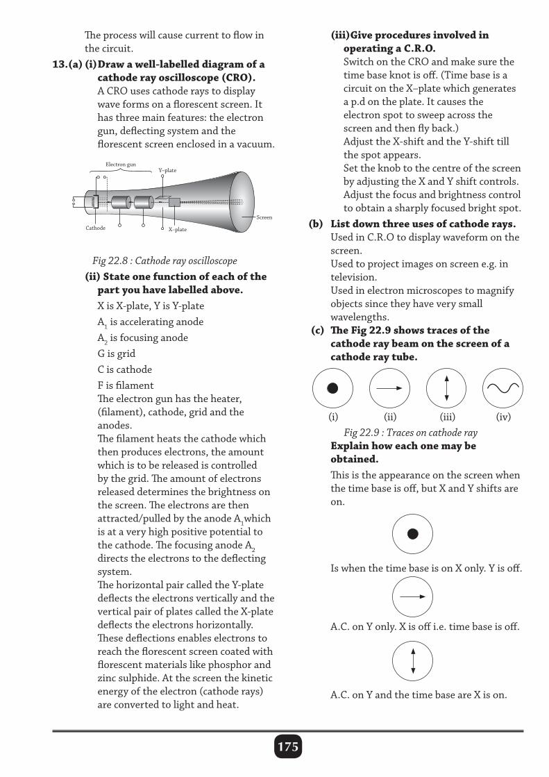
175
The process will cause current to flow in the circuit.13.(a) (i) Draw a well-labelled diagram of a cathode ray oscilloscope (CRO). A CRO uses cathode rays to display wave forms on a florescent screen. It has three main features: the electron gun, deflecting system and the florescent screen enclosed in a vacuum.
(iii)Give procedures involved in operating a C.R.O. Switch on the CRO and make sure the time base knot is off. (Time base is a circuit on the X–plate which generates a p.d on the plate. It causes the electron spot to sweep across the screen and then fly back.) Adjust the X-shift and the Y-shift till the spot appears. Set the knob to the centre of the screen by adjusting the X and Y shift controls. Adjust the focus and brightness control to obtain a sharply focused bright spot. (b) List down three uses of cathode rays. Used in C.R.O to display waveform on the screen. Used to project images on screen e.g. in television. Used in electron microscopes to magnify objects since they have very small wavelengths. (c) The Fig 22.9 shows traces of the cathode ray beam on the screen of a cathode ray tube.
Electron gun
Cathode
Y–plate
Screen
X–plate
(i) (ii) (iii) (iv)Fig 22.9 : Traces on cathode ray
Explain how each one may be obtained. This is the appearance on the screen when the time base is off, but X and Y shifts are on.
Fig 22.8 : Cathode ray oscilloscope (ii) State one function of each of the part you have labelled above. X is X-plate, Y is Y-plate A1 is accelerating anode A2 is focusing anode G is grid C is cathode F is filament The electron gun has the heater, (filament), cathode, grid and the anodes. The filament heats the cathode which then produces electrons, the amount which is to be released is controlled by the grid. The amount of electrons released determines the brightness on the screen. The electrons are then attracted/pulled by the anode A1which is at a very high positive potential to the cathode. The focusing anode A2 directs the electrons to the deflecting system. The horizontal pair called the Y-plate deflects the electrons vertically and the vertical pair of plates called the X-plate deflects the electrons horizontally. These deflections enables electrons to reach the florescent screen coated with florescent materials like phosphor and zinc sulphide. At the screen the kinetic energy of the electron (cathode rays) are converted to light and heat.
Is when the time base is on X only. Y is off.
A.C. on Y only. X is off i.e. time base is off.
A.C. on Y and the time base are X is on.
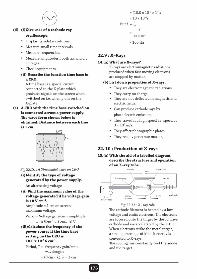
176
(d) (i) Give uses of a cathode ray oscilloscope: • Display (study) waveforms. • Measure small time intervals. • Measure frequencies. • Measure amplitudes f both a.c and d.c voltages. • Check equipments. (ii) Describe the function time base in a CRO. A time base is a special circuit connected to the X-plate which produces signals on the screen when switched on i.e. when p.d is on the X-plate. (e) A CRO with the time base switched on is connected across a power supply. The wave form shown below is obtained. Distance between each line is 1 cm.
= (10.0 × 10–3 × 1) s = 10 × 10–3s But f = 1
T
=
1
10 × 10–3
= 100 Hz
22.9 : X–Rays14.(a) What are X–rays? X–rays are electromagnetic radiations produced when fast moving electrons are stopped by matter. (b) List down properties of X–rays. • They are electromagnetic radiations. • They carry no charge. • They are not deflected in magnetic and electric fields. • Can produce cathode rays by photoelectric emission. • They travel at a high speed i.e. speed of 3 × 10⁸ m/s. • They affect photographic plates. • They readily penetrate matter.
22. 10 : Production of X-rays15.(a) With the aid of a labelled diagram, describe the structure and operation of an X–ray tube.
Fig 22.11 : X - ray tube The cathode filament is heated by a low voltage and emits electrons. The electrons are focused onto the target by the concave cathode and are accelerated by the E.H.T. When electrons strike the metal target, a small percentage of kinetic energy is converted to X–rays. The cooling fins constantly cool the anode and the target.
Fig 22.10 : A Sinasuadal wave on CRO (i) Identify the type of voltage generated by the power supply. An alternating voltage (ii) Find the maximum value of the voltage generated if he voltage gain is 10 V cm–1. Amplitude = 1 cm on screen maximum voltage, Vmax = Voltage gain/cm × amplitude = 10 Vcm–1 × 1 cm= 10 V (iii)Calculate the frequency of the power source if the time base setting on the CRO is 10.0 x 10⁻³ S cm–1. Period, T = frequency gain/cm × wavelength = (f/cm × λ), λ = 1 cm
1 cm
1 cm
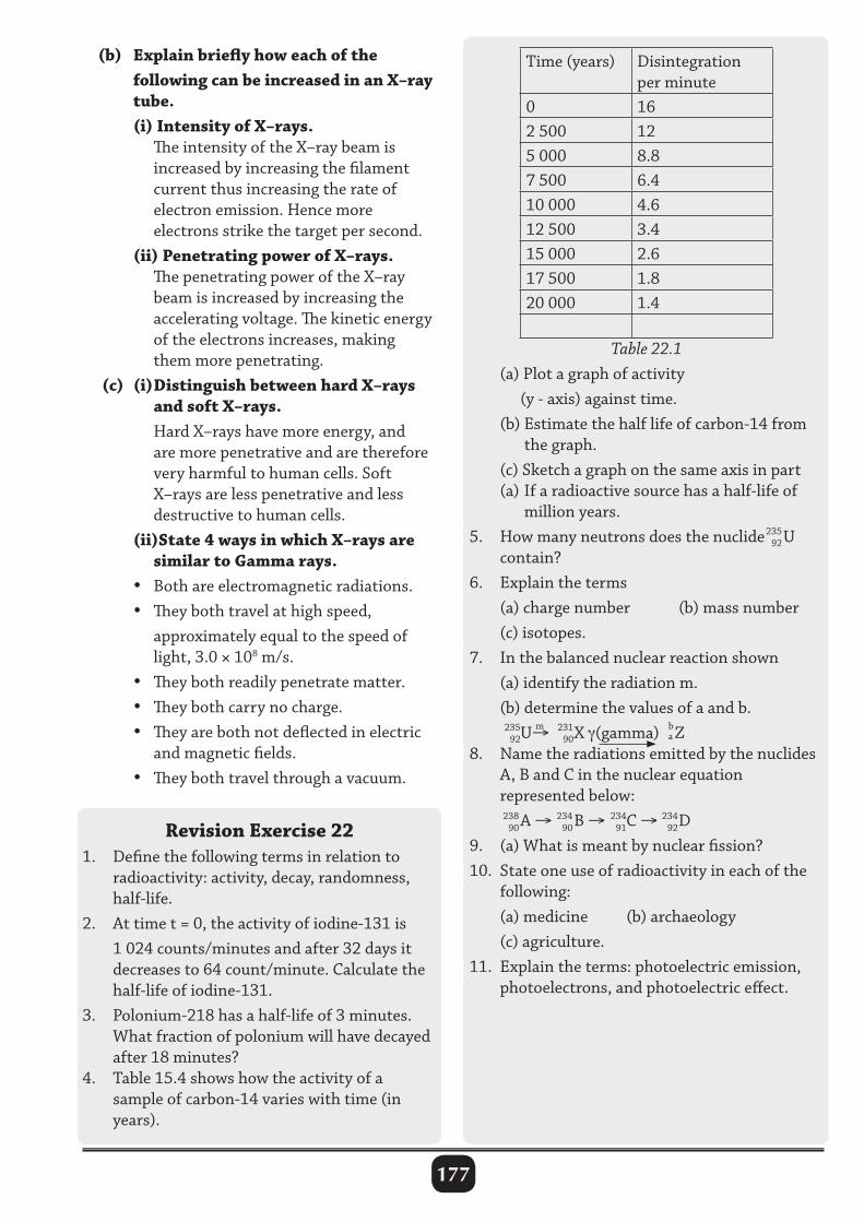
177
(b) Explain briefly how each of the following can be increased in an X–ray tube. (i) Intensity of X–rays. The intensity of the X–ray beam is increased by increasing the filament current thus increasing the rate of electron emission. Hence more electrons strike the target per second. (ii) Penetrating power of X–rays. The penetrating power of the X–ray beam is increased by increasing the accelerating voltage. The kinetic energy of the electrons increases, making them more penetrating. (c) (i) Distinguish between hard X–rays and soft X–rays. Hard X–rays have more energy, and are more penetrative and are therefore very harmful to human cells. Soft X–rays are less penetrative and less destructive to human cells. (ii)State 4 ways in which X–rays are similar to Gamma rays. • Both are electromagnetic radiations. • They both travel at high speed, approximately equal to the speed of light, 3.0 × 10⁸ m/s. • They both readily penetrate matter. • They both carry no charge. • They are both not deflected in electric and magnetic fields. • They both travel through a vacuum.
Revision Exercise 221. Define the following terms in relation to radioactivity: activity, decay, randomness, half-life.2. At time t = 0, the activity of iodine-131 is 1 024 counts/minutes and after 32 days it decreases to 64 count/minute. Calculate the half-life of iodine-131.3. Polonium-218 has a half-life of 3 minutes. What fraction of polonium will have decayed after 18 minutes?4. Table 15.4 shows how the activity of a sample of carbon-14 varies with time (in years).
Time (years) Disintegration per minute
0 162 500 12 5 000 8.8 7 500 6.410 000 4.612 500 3.415 000 2.617 500 1.820 000 1.4
Table 22.1 (a) Plot a graph of activity (y - axis) against time. (b) Estimate the half life of carbon-14 from the graph. (c) Sketch a graph on the same axis in part (a) If a radioactive source has a half-life of million years.5. How many neutrons does the nuclide U contain?6. Explain the terms (a) charge number (b) mass number (c) isotopes.7. In the balanced nuclear reaction shown (a) identify the radiation m. (b) determine the values of a and b. U→ X γ(gamma) Z8. Name the radiations emitted by the nuclides A, B and C in the nuclear equation represented below: A → B → C → D9. (a) What is meant by nuclear fission?10. State one use of radioactivity in each of the following: (a) medicine (b) archaeology (c) agriculture.11. Explain the terms: photoelectric emission, photoelectrons, and photoelectric effect.
235
238 234 234 234
231
235
bm92
90 90 91 92
90
92
a
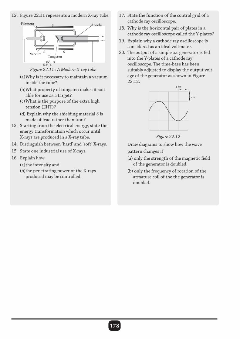
178
12. Figure 22.11 represents a modern X-ray tube. 17. State the function of the control grid of a cathode ray oscilloscope.18. Why is the horizontal pair of plates in a cathode ray oscilloscope called the Y-plates?19. Explain why a cathode ray oscilloscope is considered as an ideal voltmeter.20. The output of a simple a.c generator is fed into the Y-plates of a cathode ray oscilloscope. The time-base has been suitably adjusted to display the output volt age of the generator as shown in Figure 22.12.
(a) Why is it necessary to maintain a vacuum inside the tube? (b)What property of tungsten makes it suit able for use as a target? (c) What is the purpose of the extra high tension (EHT)? (d) Explain why the shielding material S is made of lead rather than iron?13. Starting from the electrical energy, state the energy transformation which occur until X-rays are produced in a X-ray tube.14. Distinguish between ‘hard’ and ‘soft’ X-rays.15. State one industrial use of X-rays.16. Explain how (a) the intensity and (b)the penetrating power of the X-rays produced may be controlled.
Figure 22.11 : A Modern X-ray tube
TungstenVaccum
Filament Anode
VE.H.T.
S
SS
Figure 22.12
1 cm
1 cm
Draw diagrams to show how the wave pattern changes if (a) only the strength of the magnetic field of the generator is doubled, (b) only the frequency of rotation of the armature coil of the the generator is doubled.
179
TEST PAPER 1
Name .................................................................. Center and Index No .............................
535/1PHYSICSPaper 12 1
4 hours
PHYSICS Paper 1 2 hours 15 minutes
INSTRUCTIONS TO CANDIDATES • Attemptallquestions. • SectionAcontains40objectivestypequestions.YouarerequiredtowritethecorrectanswerA, B,CorDagainsteachboxontherighthandside. • SectionBcontains10structuredquestions.Answersaretobewritteninthespacesprovidedon thequestionpaper. • Mathematicaltables,sliderulesandsilentnon-programmablecalculatorsmaybeused. • Accelerationduetogravity=10ms–2
• Specificheatcapacityofwater=4200Jkg–1 K–1
For Examiner’s Use Only
Q.41 Q.42 Q.43 Q.44 Q.45 Q.46 Q.47 Q.48 Q.49 Q.50 MCQ Total
Turnover
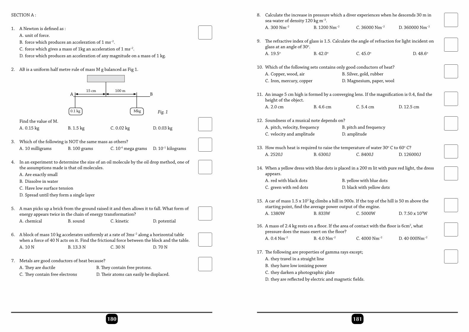
181180
SECTIONA:
1. ANewtonisdefinedas: A.unitofforce. B. forcewhichproducesanaccelerationof1ms–2. C. forcewhichgivesamassof1kganaccelerationof1ms–2. D.forcewhichproducesanaccelerationofanymagnitudeonamassof1kg.
2. ABisauniformhalfmetreruleofmassMgbalancedasFig1.
8. Calculatetheincreaseinpressurewhichadiverexperienceswhenhedescends30min sea-waterofdensity120kgm–3. A.300Nm–2 B.1200Nm–2 C.36000Nm–2 D.360000Nm–2
9. Therefractiveindexofglassis1.5.Calculatetheangleofrefractionforlightincidenton glassatanangleof30o. A.19.5o B.42.0o C.45.0o D.48.6o
10. Whichofthefollowingsetscontainsonlygoodconductorsofheat? A.Copper,wood,air B.Silver,gold,rubber C.Iron,mercury,copper D.Magnesium,paper,wool
11. Animage5cmhighisformedbyaconverginglens.Ifthemagnificationis0.4,findthe heightoftheobject. A.2.0cm B.4.6cm C.5.4cm D.12.5cm
12. Soundnessofamusicalnotedependson? A.pitch,velocity,frequency B.pitchandfrequency C.velocityandamplitude D.amplitude
13. Howmuchheatisrequiredtoraisethetemperatureofwater30oCto60oC? A.2520J B.6300J C.8400J D.126000J
14. Whenayellowdresswithbluedotsisplacedina200mlitwithpureredlight,thedress appears. A.redwithblackdots B.yellowwithbluedots C.greenwithreddots D.blackwithyellowdots
15. Acarofmass1.5x103kgclimbsahillin900s.Ifthetopofthehillis50mabovethe startingpoint,findtheaveragepoweroutputoftheengine. A.1380W B.833W C.5000W D.7.50x103W
16. Amassof2.4kgrestsonafloor.Iftheareaofcontactwiththeflooris6cm2,what pressuredoesthemassexertonthefloor? A.0.4Nm–2 B.4.0Nm–2 C.4000Nm–2 D.40000Nm–2
17. Thefollowingarepropertiesofgammaraysexcept; A.theytravelinastraightline B. theyhavelowionizingpower C. theydarkenaphotographicplate D.theyarereflectedbyelectricandmagneticfields.
FindthevalueofM. A.0.15kg B.1.5kg C.0.02kg D.0.03kg
3. WhichofthefollowingisNOTthesamemassasothers? A.10milligrams B.100grams C.10-4megagrams D.10–1kilograms
4. Inanexperimenttodeterminethesizeofanoilmoleculebytheoildropmethod,oneof theassumptionsmadeisthatoilmolecules. A.Areexactlysmall B. Dissolveinwater C.Havelowsurfacetension D.Spreaduntiltheyformasinglelayer
5. Amanpicksupabrickfromthegroundraiseditandthenallowsittofall.Whatformof energyappearstwiceinthechainofenergytransformation? A.chemical B.sound C.kinetic D.potential
6. Ablockofmass10kgacceleratesuniformlyatarateof3ms–2alongahorizontaltable whenaforceof40Nactsonit.Findthefrictionalforcebetweentheblockandthetable. A.10N B.13.3N C.30N D.70N
7. Metalsaregoodconductorsofheatbecause? A.Theyareductile B.Theycontainfreeprotons. C.Theycontainfreeelectrons D.Theiratomscaneasilybedisplaced.
A
0.1kg Mkg
15cm 100mB
Fig. 1
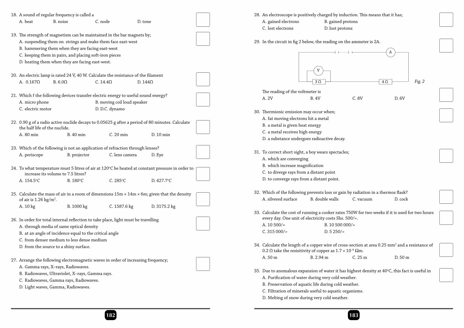
183182
18. Asoundofregularfrequencyiscalleda A.beat B.noise C.node D.tone
19. Thestrengthofmagnetismcanbemaintainedinthebarmagnetsby; A.suspendingthemonstringsandmakethemfaceeast-west B. hammeringthemwhentheyarefacingeast-west C.keepingtheminpairs,andplacingsoft-ironpieces D.heatingthemwhentheyarefacingeast-west.
20. Anelectriclampisrated24V,40W.Calculatetheresistanceofthefilament A.0.167Ω B.6.0Ω C.14.4Ω D.144Ω
21. Whichfthefollowingdevicestransferelectricenergytousefulsoundenergy? A.microphone B.movingcoilloudspeaker C.electricmotor D.D.C.dynamo
22. 0.90gofaradioactivenuclidedecaysto0.05625gafteraperiodof80minutes.Calculate thehalflifeofthenuclide. A.80min B.40min C.20min D.10min
23. Whichofthefollowingisnotanapplicationofrefractionthroughlenses? A.periscope B.projector C.lenscamera D.Eye
24. Towhattemperaturemust5litresofairat120oCbeheatedatconstantpressureinorderto increaseitsvolumeto7.5litres? A.154.5oC B.180oC C.285oC D.427.7oC
25. Calculatethemassofairinaroomofdimensions15m×14m×6m;giventhatthedensity ofairis1.26kg/m3. A.10kg B.1000kg C.1587.6kg D.3175.2kg
26. Inorderfortotalinternalreflectiontotakeplace,lightmustbetravelling A.throughmediaofsameopticaldensity B. atanangleofincidenceequaltothecriticalangle C. fromdensermediumtolessdensemedium D.fromthesourcetoashinysurface.
27. Arrangethefollowingelectromagneticwavesinorderofincreasingfrequency; A.Gammarays,X–rays,Radiowaves. B. Radiowaves,Ultraviolet,X–rays,Gammarays. C.Radiowaves,Gammarays,Radiowaves. D.Lightwaves,Gamma,Radiowaves.
28. Anelectroscopeispositivelychargedbyinduction.Thismeansthatithas; A.gainedelectrons B.gainedprotons C.lostelectrons D.lostprotons
29. Inthecircuitinfig2below,thereadingontheammeteris2A.
Thereadingofthevoltmeteris A.2V B.4V C.8V D.6V
30. Thermionicemissionmayoccurwhen; A.fatmovingelectronshitametal B. ametalisgivenheatenergy C.ametalreceiveshighenergy D.asubstanceundergoesradioactivedecay.
31. Tocorrectshortsight,aboywearsspectacles; A.whichareconverging B. whichincreasemagnification C. todivergeraysfromadistantpoint D.toconvergeraysfromadistantpoint.
32. Whichofthefollowingpreventslossorgainbyradiationinathermosflask? A.silveredsurface B.doublewalls C.vacuum D.cock
33. Calculatethecostofrunningacookerrates750Wfortwoweeksifitisusedfortwohours everyday.OneunitofelectricitycostsShs.500/=. A.10500/= B.10500000/= C.315000/= D.5250/=
34. Calculatethelengthofacopperwireofcross-sectionatarea0.25mm2andaresistanceof 0.2Ωtaketheresisitivityofcopperas1.7×10–8 Ωm. A.50m B.2.94m C.25m D.50m
35. Duetoanomalousexpansionofwaterithashighestdensityat40oC,thisfactisusefulin A.Purificationofwaterduringverycoldweather. B. Preservationofaquaticlifeduringcoldweather. C.Filtrationofmineralsusefultoaquaticorganisms. D.Meltingofsnowduringverycoldweather.
A
4 Ω
V
3 Ω Fig. 2
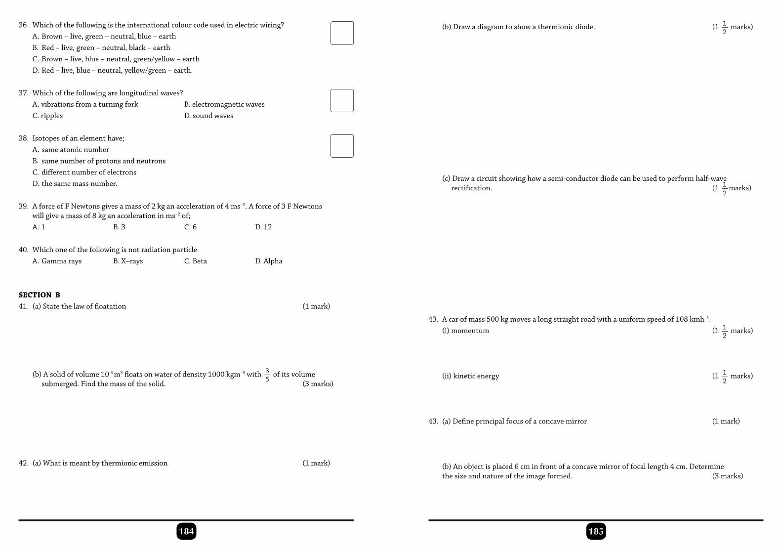
185184
36. Whichofthefollowingistheinternationalcolourcodeusedinelectricwiring? A.Brown–live,green–neutral,blue–earth B. Red–live,green–neutral,black–earth C.Brown–live,blue–neutral,green/yellow–earth D.Red–live,blue–neutral,yellow/green–earth.
37. Whichofthefollowingarelongitudinalwaves? A.vibrationsfromaturningfork B.electromagneticwaves C.ripples D.soundwaves
38. Isotopesofanelementhave; A.sameatomicnumber B. samenumberofprotonsandneutrons C.differentnumberofelectrons D.thesamemassnumber.
39. AforceofFNewtonsgivesamassof2kganaccelerationof4ms–2.Aforceof3FNewtons willgiveamassof8kganaccelerationinms–2of; A.1 B.3 C.6 D.12
40. Whichoneofthefollowingisnotradiationparticle A.Gammarays B.X–rays C.Beta D.Alpha
SECTION B41. (a)Statethelawoffloatation (1mark)
(b)Asolidofvolume10-4m3floatsonwaterofdensity1000kgm–3with 35ofitsvolume
submerged.Findthemassofthesolid. (3marks)
42. (a)Whatismeantbythermionicemission (1mark)
(b)Drawadiagramtoshowathermionicdiode. (1 12marks)
(c)Drawacircuitshowinghowasemi-conductordiodecanbeusedtoperformhalf-wave rectification. (1 1
2marks)
43. Acarofmass500kgmovesalongstraightroadwithauniformspeedof108kmh–1. (i)momentum (1 1
2marks)
(ii)kineticenergy (1 12marks)
43. (a)Defineprincipalfocusofaconcavemirror (1mark)
(b)Anobjectisplaced6cminfrontofaconcavemirroroffocallength4cm.Determine thesizeandnatureoftheimageformed. (3marks)
187186
45.(a)Whatismeantbymagneticpoles. (1mark)
(b)Brieflydescribehowthepolarityofamagnetcanbetested. (1 12marks)
(c)Drawacircuitdiagramtoshowhowasteelbarcanbemagnetizedelectrically.
(ii)theefficiencyiftheprimarycircuitis3Aandthesecondarycurrentis5A?
47. (a)Statethelawsofreflectionofsound. (1mark)
(b)Peterstood10mfromahighcliffandclappedhishands.0.06secondslaterhe receivedanecho.Calculatethevelocityofsoundinair. (1 1
2marks)
(c)Ifthereare10wavelengthsofsoundoccupyingthespacebetweenPeterandthecliff, calculatethefrequencyofthesoundwavesproduced. (1 1
2marks)
48. (a)Thehalflifeofthenuclide16Nis7.8seconds. Whatdoesthisstatementmeans? (1mark)
(b)Asampleofthistypeofnitrogenisobservedfor29.2seconds,calculatethefraction oftheoriginalradioactiveisotoperemainingafterthistime. (3marks)
49. (a)Statetwousesofx–rays (2marks)
(b)Giveonehazardofx–rays (2mark)
50. (a)Explainthedifferencebetweenagoodconductorandsemiconductor. (1mark)
(b)Explainwhyargongasisusedinfillamentlamp.
**END**
(1 12marks)
46. (a)Drawadiagramshowingastep-uptransformer. (1mark)
(b)Atransformerhas1000turnsintheprimaryand500turnsinthesecondary.Its primarycoilisconnectedto240Vmains.Whatis (i)thesecondaryvoltage? (1 1
2marks)
(1 12marks)
P h y s i c s188
TEST PAPER 2
Name: Center and Index No.
PHYSICSPaper 220132 1
4 hours
PHYSICS Paper 2 2 hours 15 minutes
INSTRUCTIONS TO CANDIDATES : 1. Answer any five questions 2. Any additional questions will not be marked Acceleration due to gravity = 10ms–2
Specific heat capacity of water = 4200Jkg–1 K–1
Specific latent heat of fusion of water=340000 Jkg–1 Speed of sound in air = 330ms–1
Speed of light = 3.0 × 10⁸ms–1
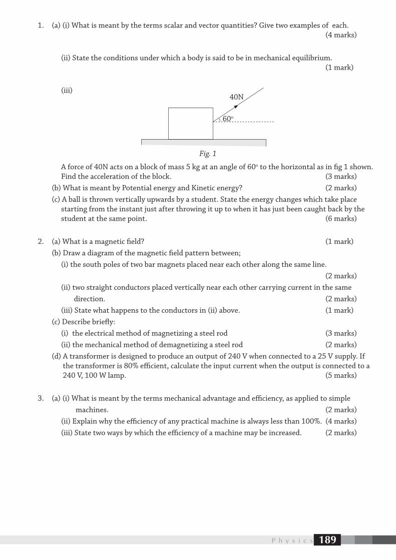
P h y s i c s 189
1. (a) (i) What is meant by the terms scalar and vector quantities? Give two examples of each. (4 marks)
(ii) State the conditions under which a body is said to be in mechanical equilibrium. (1 mark)
(iii)
A force of 40N acts on a block of mass 5 kg at an angle of 60o to the horizontal as in fig 1 shown. Find the acceleration of the block. (3 marks) (b) What is meant by Potential energy and Kinetic energy? (2 marks) (c) A ball is thrown vertically upwards by a student. State the energy changes which take place starting from the instant just after throwing it up to when it has just been caught back by the student at the same point. (6 marks)
2. (a) What is a magnetic field? (1 mark) (b) Draw a diagram of the magnetic field pattern between; (i) the south poles of two bar magnets placed near each other along the same line. (2 marks) (ii) two straight conductors placed vertically near each other carrying current in the same direction. (2 marks) (iii) State what happens to the conductors in (ii) above. (1 mark) (c) Describe briefly: (i) the electrical method of magnetizing a steel rod (3 marks) (ii) the mechanical method of demagnetizing a steel rod (2 marks) (d) A transformer is designed to produce an output of 240 V when connected to a 25 V supply. If the transformer is 80% efficient, calculate the input current when the output is connected to a 240 V, 100 W lamp. (5 marks)
3. (a) (i) What is meant by the terms mechanical advantage and efficiency, as applied to simple machines. (2 marks) (ii) Explain why the efficiency of any practical machine is always less than 100%. (4 marks) (iii) State two ways by which the efficiency of a machine may be increased. (2 marks)
60o
40N
Fig. 1
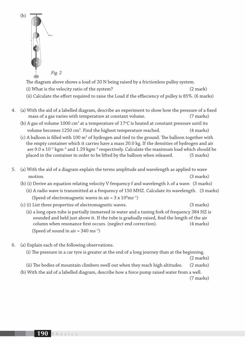
P h y s i c s190
(b)
The diagram above shows a load of 20 N being raised by a frictionless pulley system. (i) What is the velocity ratio of the system? (2 mark) (ii) Calculate the effort required to raise the Load if the effieciency of pulley is 85%. (6 marks)
4. (a) With the aid of a labelled diagram, describe an experiment to show how the pressure of a fixed mass of a gas varies with temperature at constant volume. (7 marks) (b) A gas of volume 1000 cm3 at a temperature of 17oC is heated at constant pressure until its volume becomes 1250 cm3. Find the highest temperature reached. (4 marks) (c) A balloon is filled with 100 m3 of hydrogen and tied to the ground. The balloon together with the empty container which it carries have a mass 20.0 kg. If the densities of hydrogen and air are 9.0 x 10⁻² kgm–3 and 1.29 kgm–3 respectively. Calculate the maximum load which should be placed in the container in order to be lifted by the balloon when released. (5 marks)
5. (a) With the aid of a diagram explain the terms amplitude and wavelength as applied to wave motion. (3 marks) (b) (i) Derive an equation relating velocity V frequency f and wavelength λ of a wave. (3 marks) (ii) A radio wave is transmitted at a frequency of 150 MHZ. Calculate its wavelength. (3 marks) (Speed of electromagnetic waves in air = 3 x 10⁸ms–1) (c) (i) List three properties of electromagnetic waves. (3 marks) (ii) a long open tube is partially immersed in water and a tuning fork of frequency 384 HZ is sounded and held just above it. If the tube is gradually raised, find the length of the air column when resonance first occurs. (neglect end correction). (4 marks) (Speed of sound in air = 340 ms–1)
6. (a) Explain each of the following observations. (i) The pressure in a car tyre is greater at the end of a long journey than at the beginning. (2 marks) (ii) The bodies of mountain climbers swell out when they reach high altitudes. (2 marks) (b) With the aid of a labelled diagram, describe how a force pump raised water from a well. (7 marks)
20 N
Eort
Fig. 2
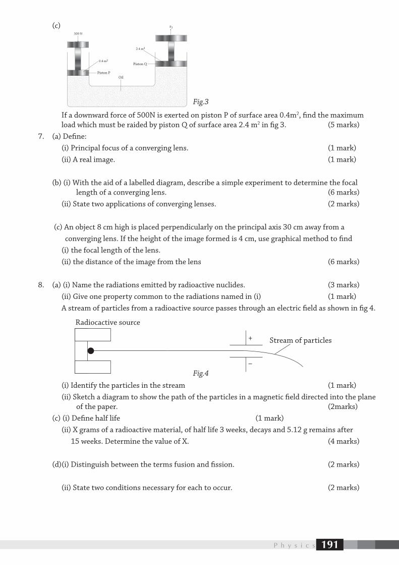
P h y s i c s 191
(c)
If a downward force of 500N is exerted on piston P of surface area 0.4m2, find the maximum load which must be raided by piston Q of surface area 2.4 m2 in fig 3. (5 marks)7. (a) Define: (i) Principal focus of a converging lens. (1 mark) (ii) A real image. (1 mark)
(b) (i) With the aid of a labelled diagram, describe a simple experiment to determine the focal length of a converging lens. (6 marks) (ii) State two applications of converging lenses. (2 marks)
(c) An object 8 cm high is placed perpendicularly on the principal axis 30 cm away from a converging lens. If the height of the image formed is 4 cm, use graphical method to find (i) the focal length of the lens. (ii) the distance of the image from the lens (6 marks)
8. (a) (i) Name the radiations emitted by radioactive nuclides. (3 marks) (ii) Give one property common to the radiations named in (i) (1 mark) A stream of particles from a radioactive source passes through an electric field as shown in fig 4.
(i) Identify the particles in the stream (1 mark) (ii) Sketch a diagram to show the path of the particles in a magnetic field directed into the plane of the paper. (2marks) (c) (i) Define half life (1 mark) (ii) X grams of a radioactive material, of half life 3 weeks, decays and 5.12 g remains after 15 weeks. Determine the value of X. (4 marks)
(d)(i) Distinguish between the terms fusion and fission. (2 marks)
(ii) State two conditions necessary for each to occur. (2 marks)
–
+
Radiocactive source
Stream of particles
500 N
0.4 m2
F2
2.4 m2
Piston POil
Piston Q
Fig.3
Fig.4
192
TEST PAPER 2
Name Center and Index No.
535/1PHYSICSPaper 12 1
4 hours
PHYSICS
Paper 12 hours 15 minutes
INSTRUCTIONS TO CANDIDATES • Attemptallquestions. • SectionAcontains40objectivestypequestions.YouarerequiredtowritethecorrectanswerA, B,CorDagainsteachboxontherighthandside. • SectionBcontains10structuredquestions.Answersaretobewritteninthespacesprovidedon thequestionpaper. • Mathematicaltables,sliderulesandsilentnon-programmablecalculatorsmaybeused. • Accelerationduetogravity=10ms–2
• Specificheatcapacityofwater=4200Jkg–1 K–1
For Examiner’s Use Only
Q.41 Q.42 Q.43 Q.44 Q.45 Q.46 Q.47 Q.48 Q.49 Q.50 MCQ Total
Turn over
PHYSICS Paper 12 hours 15 minutes
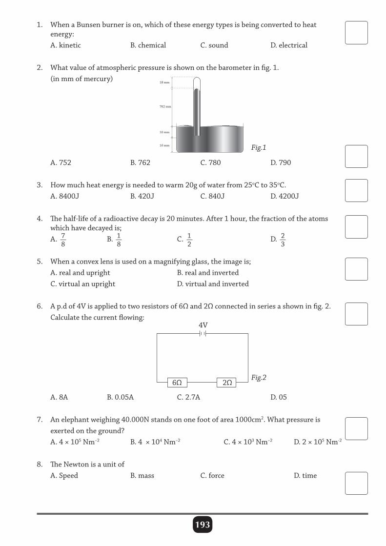
193
1. WhenaBunsenburnerison,whichoftheseenergytypesisbeingconvertedtoheat energy: A.kinetic B.chemical C.sound D.electrical
2. Whatvalueofatmosphericpressureisshownonthebarometerinfig.1. (inmmofmercury)
A.752 B.762 C.780 D.790
3. Howmuchheatenergyisneededtowarm20gofwaterfrom25oCto35oC. A.8400J B.420J C.840J D.4200J
4. Thehalf-lifeofaradioactivedecayis20minutes.After1hour,thefractionoftheatoms whichhavedecayedis; A. 7
8 B. 1
8 C. 1
2 D. 2
3
5. Whenaconvexlensisusedonamagnifyingglass,theimageis; A.realandupright B.realandinverted C.virtualanupright D.virtualandinverted
6. Ap.dof4Visappliedtotworesistorsof6Ωand2Ωconnectedinseriesashowninfig.2. Calculatethecurrentflowing:
A.8A B.0.05A C.2.7A D.05
7. Anelephantweighing40.000Nstandsononefootofarea1000cm2.Whatpressureis exertedontheground? A.4×105Nm–2 B.4×104Nm–2 C.4×103Nm–2 D.2×105Nm-2
8. TheNewtonisaunitof A.Speed B.mass C.force D.time
762 mm
10 mm
18 mm
10 mm Fig.1
Fig.26Ω 2Ω
4V
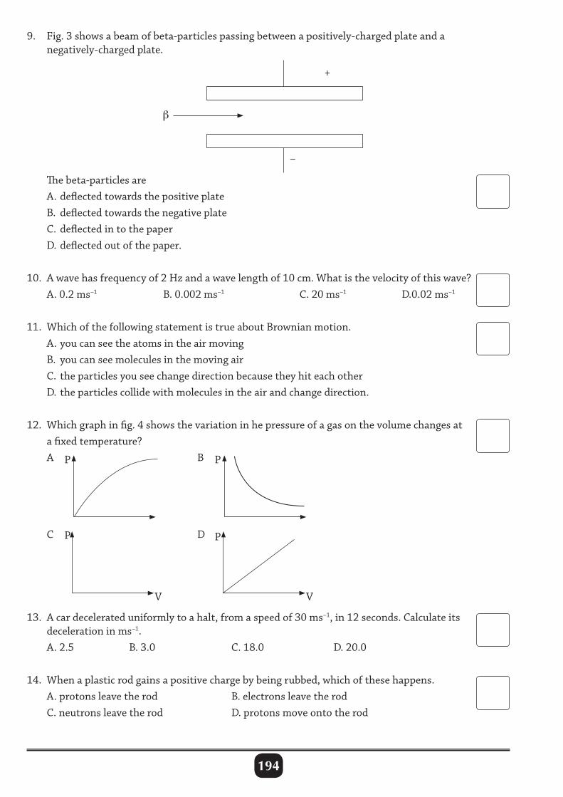
194
9. Fig.3showsabeamofbeta-particlespassingbetweenapositively-chargedplateanda negatively-chargedplate.
Thebeta-particlesare A.deflectedtowardsthepositiveplate B. deflectedtowardsthenegativeplate C.deflectedintothepaper D.deflectedoutofthepaper.
10. Awavehasfrequencyof2Hzandawavelengthof10cm.Whatisthevelocityofthiswave? A.0.2ms–1 B.0.002ms–1 C.20ms–1 D.0.02ms–1
11. WhichofthefollowingstatementistrueaboutBrownianmotion. A.youcanseetheatomsintheairmoving B. youcanseemoleculesinthemovingair C. theparticlesyouseechangedirectionbecausetheyhiteachother D.theparticlescollidewithmoleculesintheairandchangedirection.
12. Whichgraphinfig.4showsthevariationinhepressureofagasonthevolumechangesat afixedtemperature? A B
C D
13. Acardecelerateduniformlytoahalt,fromaspeedof30ms–1,in12seconds.Calculateits decelerationinms–1. A.2.5 B.3.0 C.18.0 D.20.0
14. Whenaplasticrodgainsapositivechargebybeingrubbed,whichofthesehappens. A.protonsleavetherod B.electronsleavetherod C.neutronsleavetherod D.protonsmoveontotherod
–
+
P
P
V
P
P
V
β
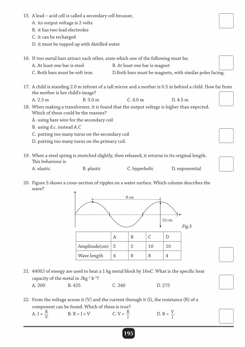
195
15. Alead–acidcelliscalledasecondarycellbecause; A.itsoutputvoltageis2volts B. ithastwoleadelectrodes C. itcanberecharged D. itmustbetoppedupwithdistilledwater
16. Iftwometalbarsattracteachother,statewhichoneofthefollowingmustbe; A.Atleastonebarissteel B.Atleastonebarismagnet C.Bothbarsmustbesoftiron D.Bothbarsmustbemagnets,withsimilarpolesfacing.
17. Achildisstanding2.0minfrontofatallmirrorandamotheris0.5mbehindachild.Howfarfrom themotherisherchild’simage? A.2.5m B.3.0m C.4.0m D.4.5m18. Whenmakingatransformer,itisfoundthattheoutputvoltageishigherthanexpected. Whichofthesecouldbethereasons? A.usingbarewireforthesecondarycoil B. usingd.c.insteadA.C C.puttingtoomanyturnsonthesecondarycoil D.puttingtoomanyturnsontheprimarycoil.
19. Whenasteelspringisstretchedslightly,thenreleased,itreturnstoitsoriginallength. Thisbehaviouris A.elastic B.plastic C.hyperbolic D.exponential
20. Figure5showsacross-sectionofripplesonawatersurface.Whichcolumndescribesthe wave?
10 cm
8 cm
Fig.5
A B C D
Amplitude(cm) 5 5 10 10
Wavelength 4 8 8 4
21. 4400Jofenergyareusedtoheata1kgmetalblockby16oC.Whatisthespecificheat capacityofthemetalinJkg–1k–1? A.200 B.425 C.240 D.275
22. Fromthevoltageacrossit(V)andthecurrentthroughit(I),theresistance(R)ofa componentcanbefound.Whichoftheseistrue? A.I= R
V B.R=I×V C.V= R
I D.R= V
I
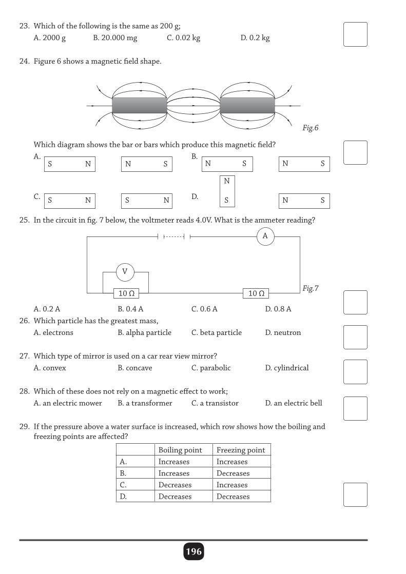
196
23. Whichofthefollowingisthesameas200g; A.2000g B.20.000mg C.0.02kg D.0.2kg
24. Figure6showsamagneticfieldshape.
Whichdiagramshowsthebarorbarswhichproducethismagneticfield? A. B.
C. D.
25. Inthecircuitinfig.7below,thevoltmeterreads4.0V.Whatistheammeterreading?
A.0.2A B.0.4A C.0.6A D.0.8A26. Whichparticlehasthegreatestmass, A.electrons B.alphaparticle C.betaparticle D.neutron
27. Whichtypeofmirrorisusedonacarrearviewmirror? A.convex B.concave C.parabolic D.cylindrical
28. Whichofthesedoesnotrelyonamagneticeffecttowork; A.anelectricmower B.atransformer C.atransistor D.anelectricbell
29. Ifthepressureaboveawatersurfaceisincreased,whichrowshowshowtheboilingand freezingpointsareaffected?
Boilingpoint FreezingpointA. Increases IncreasesB. Increases DecreasesC. Decreases IncreasesD. Decreases Decreases
Fig.6
Fig.7
S
S S
NN
N
N
SN
S N
NS
N S
S
A
10Ω
V
10Ω
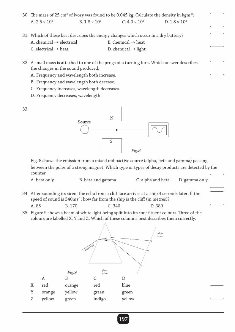
197
30. Themassof25cm3ofivorywasfoundtobe0.045kg.Calculatethedensityinkgm-3; A.2.5×103 B.1.8×103 C.4.0×103 D.1.8×102
31. Whichofthesebestdescribestheenergychangeswhichoccurinadrybattery? A.chemical→electrical B.chemical→heat C.electrical→heat D.chemical→light
32. Asmallmassisattachedtooneoftheprngsofaturningfork.Whichanswerdescribes thechangesinthesoundproduced; A.Frequencyandwavelengthbothincrease. B. Frequencyandwavelengthbothdecease. C.Frequencyincreases,wavelengthdecreases. D.Frequencydecreases,wavelength
33.
Fig.8showstheemissionfromamixedradioactivesource(alpha,betaandgamma)passing betweenthepolesofastrongmagnet.Whichtypeortypesofdecayproductsaredetectedbythe counter. A.betaonly B.betaandgamma C.alphaandbeta D.gammaonly
34. Aftersoundingitssiren,theechofromaclifffacearrivesataship4secondslater.Ifthe speedofsoundis340ms-1;howfarfromtheshipisthecliff(inmetres)? A.85 B.170 C.340 D.68035. Figure9showsabeamofwhitelightbeingsplitintoitsconstituentcolours.Threeofthe coloursarelabelledX,YandZ.Whichofthesecolumnsbestdescribesthemcorrectly.
S
NSource
Fig.8
Fig.9
white light
X
Y
whitescreen
glassprism
Z
A B C D X red orange red blue Y orange yellow green green Z yellow green indigo yellow
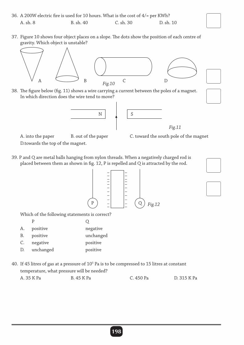
198
36. A200Welectricfireisusedfor10hours.Whatisthecostof4/=perKWh? A.sh.8 B.sh.40 C.sh.30 D.sh.10
37. Figure10showsfourobjectplacesonaslope.Thedotsshowthepositionofeachcentreof gravity.Whichobjectisunstable?
A.intothepaper B.outofthepaper C.towardthesouthpoleofthemagnet D.towardsthetopofthemagnet.
39.PandQaremetalballshangingfromnylonthreads.Whenanegativelychargedrodis placedbetweenthemasshowninfig.12,PisrepelledandQisattractedbytherod.
Whichofthefollowingstatementsiscorrect? P Q A. positive negative B. positive unchanged C. negative positive D. unchanged positive
40. If45litresofgasatapressureof105Paistobecompressedto15litresatconstant temperature,whatpressurewillbeneeded? A.35KPa B.45KPa C.450Pa D.315KPa
Fig.10
Fig.11
Fig.12
A B C D
N S
–––––– ––––––––––––––
––
P Q
38. Thefigurebelow(fig.11)showsawirecarryingacurrentbetweenthepolesofamagnet. Inwhichdirectiondoesthewiretendtomove?
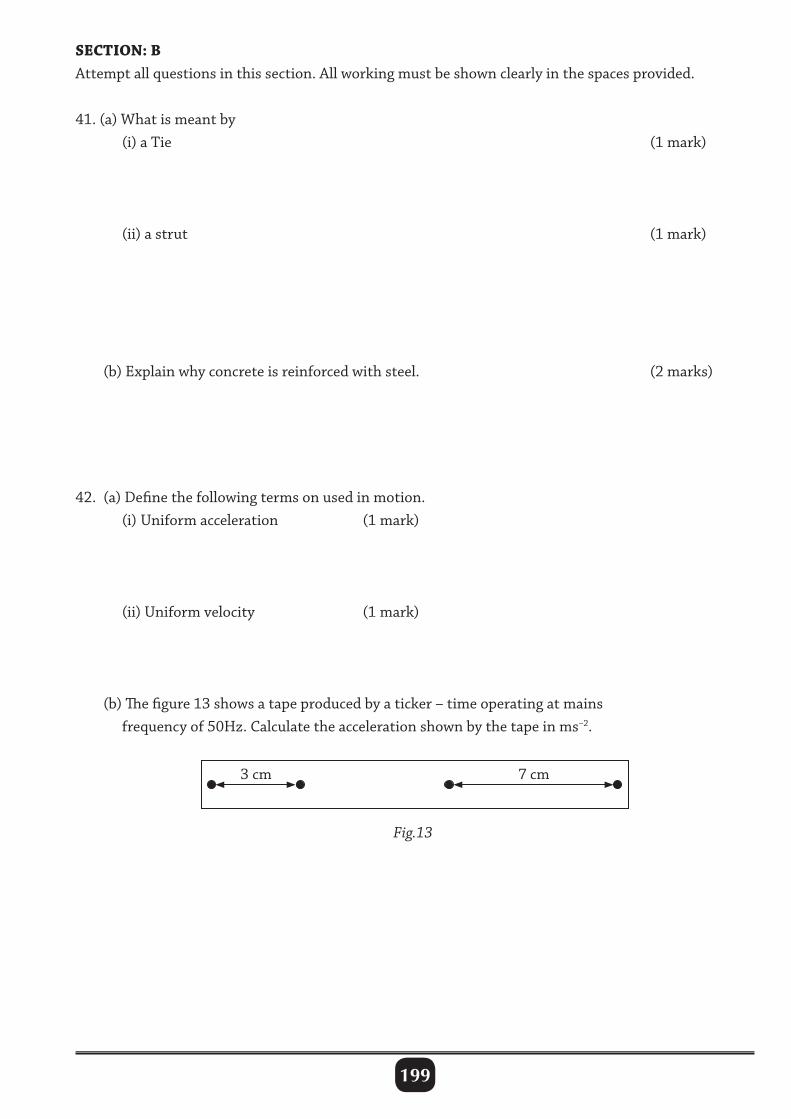
199
SECTION: BAttemptallquestionsinthissection.Allworkingmustbeshownclearlyinthespacesprovided.
41.(a)Whatismeantby (i)aTie (1mark)
(ii)astrut (1mark)
(b)Explainwhyconcreteisreinforcedwithsteel. (2marks)
42. (a)Definethefollowingtermsonusedinmotion. (i)Uniformacceleration (1mark)
(ii)Uniformvelocity (1mark)
(b)Thefigure13showsatapeproducedbyaticker–timeoperatingatmains frequencyof50Hz.Calculatetheaccelerationshownbythetapeinms–2.
3cm 7cm
Fig.13
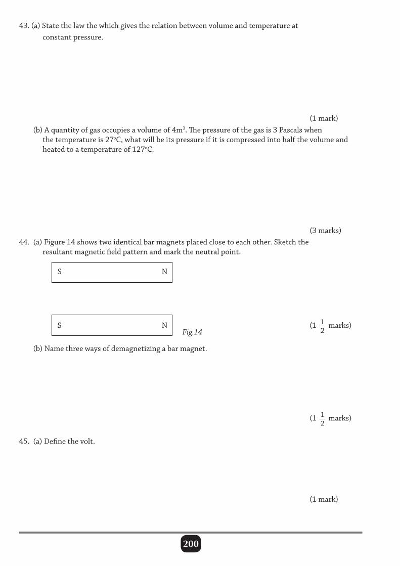
200
43.(a)Statethelawthewhichgivestherelationbetweenvolumeandtemperatureat constantpressure.
(1mark) (b)Aquantityofgasoccupiesavolumeof4m3.Thepressureofthegasis3Pascalswhen thetemperatureis27oC,whatwillbeitspressureifitiscompressedintohalfthevolumeand heatedtoatemperatureof127oC.
(3marks)44. (a)Figure14showstwoidenticalbarmagnetsplacedclosetoeachother.Sketchthe resultantmagneticfieldpatternandmarktheneutralpoint.
(1 12marks)
(b)Namethreewaysofdemagnetizingabarmagnet.
(1 12marks)
45. (a)Definethevolt.
(1mark)
Fig.14
N
N
S
S
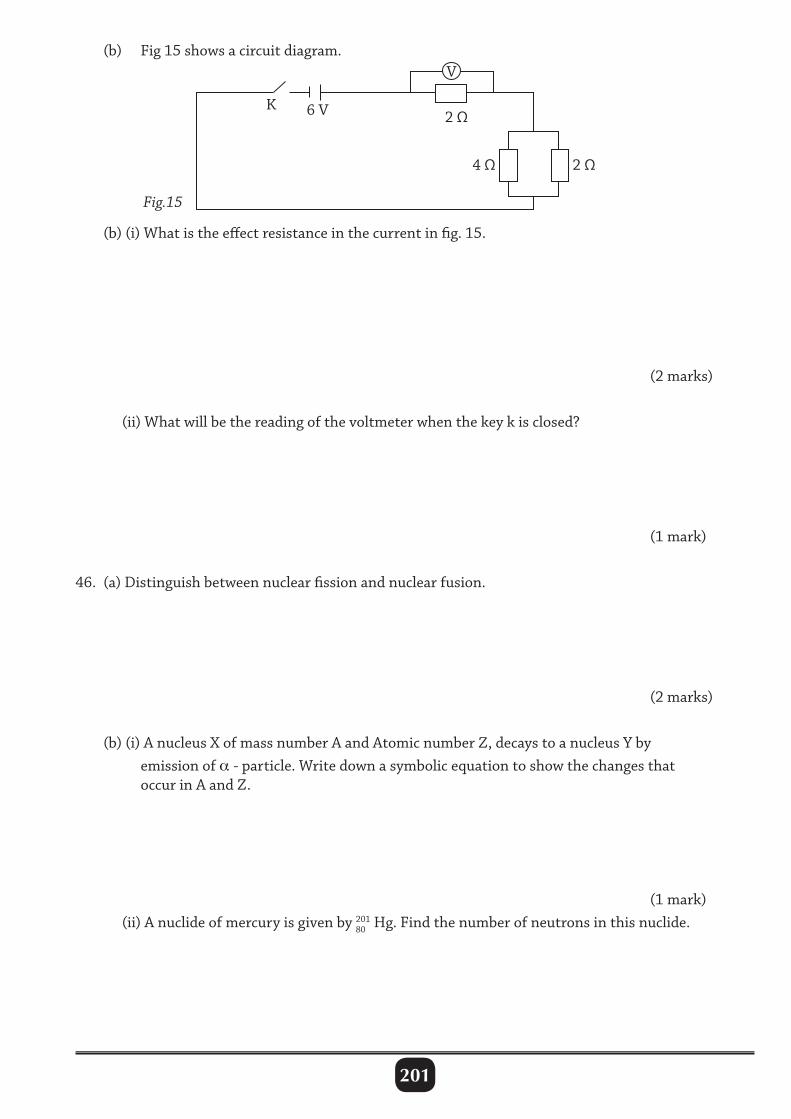
201
(b) Fig15showsacircuitdiagram.
(b)(i)Whatistheeffectresistanceinthecurrentinfig.15.
(2marks)
(ii)Whatwillbethereadingofthevoltmeterwhenthekeykisclosed?
(1mark)
46. (a)Distinguishbetweennuclearfissionandnuclearfusion.
(2marks)
(b)(i)AnucleusXofmassnumberAandAtomicnumberZ,decaystoanucleusYby emissionofα -particle.Writedownasymbolicequationtoshowthechangesthat occurinAandZ.
(1mark) (ii)Anuclideofmercuryisgivenby201Hg.Findthenumberofneutronsinthisnuclide.
2Ω
4Ω 2Ω
6V
V
K
Fig.15
80
202
47. (a)Statethetwolawsofrefraction. (i)
(1mark)
(ii)
(2marks)
(b)Arayoflighttravellingthroughairstrikeswateratanangleof500tothesurface. Giventherefractiveindexofwateris1.33,findtheangleofrefraction.
(2marks)
48. (a)Definepotentialandkineticenergyasusedinmechanics. (i)
(1mark)
(ii)
(1mark)
(b)Aboywhosemassis40kgcanrunupaflightof45stepseach16cmhighin5.2 seconds.Findthepowerdeveloped.
(2marks)
203
49. (a)Statetheconditionsfortheoccurrenceofdestructiveinterferenceofwaves.
(2marks)
(b)Sophiestood100mfromahighcliffandclappedherhands.0.6secondslatershe receivedanecho.Calculatethevelocityofsoundinair.
(2marks)
50. (a)Definethefollowingtermsasusedinmachines. (i)velocityration
(1mark)
(ii)mechanicaladvantage
(1mark)
(b)Amachinewithavelocityratioof4needs2000Jofenergytoliftaloadof400N throughaverticaldistanceo2.5m.Calculate: (i)theefficiencyofthemachine
(1mark) (ii)themechanicaladvantage
(1mark)
204
TEST PAPER 2
Name: Center and Index No.
PHYSICSPaper 220132 1
4 hours
PHYSICS Paper 2 2 hours 15 minutes
INSTRUCTIONS TO CANDIDATES : 1. Answer any five questions 2. Any additional questions will not be marked Acceleration due to gravity = 10ms–2
Specific heat capacity of water = 4200Jkg–1 K–1
Specific latent heat of fusion of water=340000 Jkg–1 Speed of sound in air = 330ms–1
Speed of light = 3.0 × 10⁸ms–1
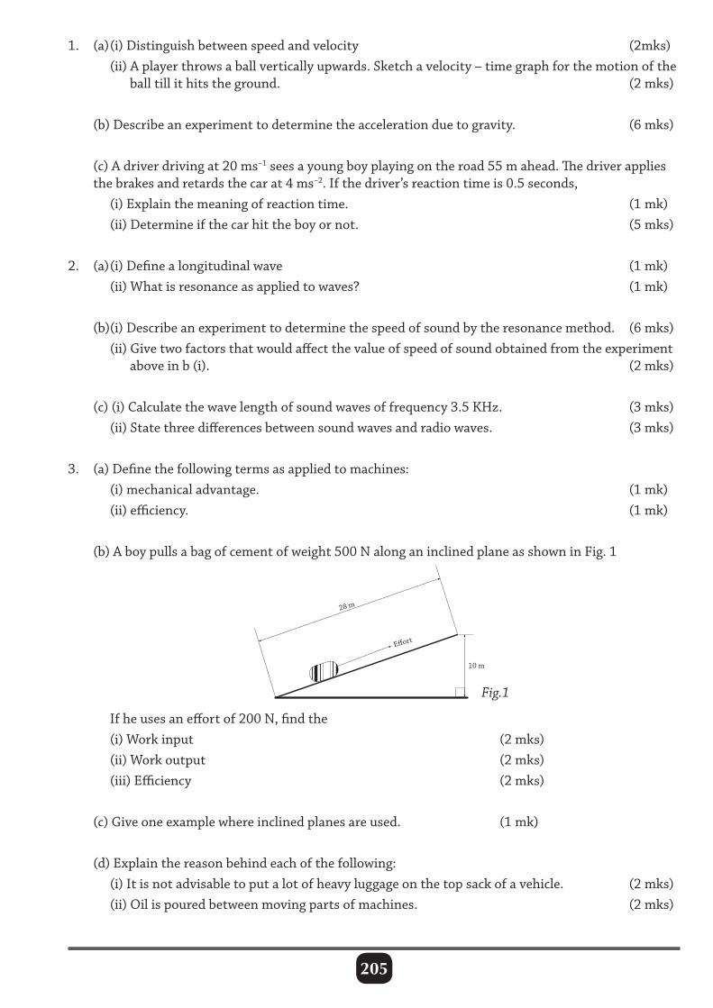
205
1. (a) (i) Distinguish between speed and velocity (2mks) (ii) A player throws a ball vertically upwards. Sketch a velocity – time graph for the motion of the ball till it hits the ground. (2 mks)
(b) Describe an experiment to determine the acceleration due to gravity. (6 mks)
(c) A driver driving at 20 ms–1 sees a young boy playing on the road 55 m ahead. The driver applies the brakes and retards the car at 4 ms–2. If the driver’s reaction time is 0.5 seconds, (i) Explain the meaning of reaction time. (1 mk) (ii) Determine if the car hit the boy or not. (5 mks)
2. (a) (i) Define a longitudinal wave (1 mk) (ii) What is resonance as applied to waves? (1 mk)
(b)(i) Describe an experiment to determine the speed of sound by the resonance method. (6 mks) (ii) Give two factors that would affect the value of speed of sound obtained from the experiment above in b (i). (2 mks)
(c) (i) Calculate the wave length of sound waves of frequency 3.5 KHz. (3 mks) (ii) State three differences between sound waves and radio waves. (3 mks)
3. (a) Define the following terms as applied to machines: (i) mechanical advantage. (1 mk) (ii) efficiency. (1 mk)
(b) A boy pulls a bag of cement of weight 500 N along an inclined plane as shown in Fig. 1
If he uses an effort of 200 N, find the (i) Work input (2 mks) (ii) Work output (2 mks) (iii) Efficiency (2 mks)
(c) Give one example where inclined planes are used. (1 mk) (d) Explain the reason behind each of the following: (i) It is not advisable to put a lot of heavy luggage on the top sack of a vehicle. (2 mks) (ii) Oil is poured between moving parts of machines. (2 mks)
28 m
Eort
10 m
Fig.1
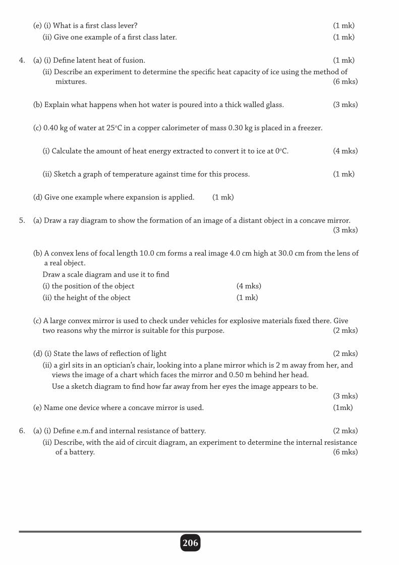
206
(e) (i) What is a first class lever? (1 mk) (ii) Give one example of a first class later. (1 mk)
4. (a) (i) Define latent heat of fusion. (1 mk) (ii) Describe an experiment to determine the specific heat capacity of ice using the method of mixtures. (6 mks)
(b) Explain what happens when hot water is poured into a thick walled glass. (3 mks)
(c) 0.40 kg of water at 25oC in a copper calorimeter of mass 0.30 kg is placed in a freezer.
(i) Calculate the amount of heat energy extracted to convert it to ice at 0oC. (4 mks)
(ii) Sketch a graph of temperature against time for this process. (1 mk)
(d) Give one example where expansion is applied. (1 mk)
5. (a) Draw a ray diagram to show the formation of an image of a distant object in a concave mirror. (3 mks)
(b) A convex lens of focal length 10.0 cm forms a real image 4.0 cm high at 30.0 cm from the lens of a real object. Draw a scale diagram and use it to find (i) the position of the object (4 mks) (ii) the height of the object (1 mk)
(c) A large convex mirror is used to check under vehicles for explosive materials fixed there. Give two reasons why the mirror is suitable for this purpose. (2 mks)
(d) (i) State the laws of reflection of light (2 mks) (ii) a girl sits in an optician’s chair, looking into a plane mirror which is 2 m away from her, and views the image of a chart which faces the mirror and 0.50 m behind her head. Use a sketch diagram to find how far away from her eyes the image appears to be. (3 mks) (e) Name one device where a concave mirror is used. (1mk)
6. (a) (i) Define e.m.f and internal resistance of battery. (2 mks) (ii) Describe, with the aid of circuit diagram, an experiment to determine the internal resistance of a battery. (6 mks)
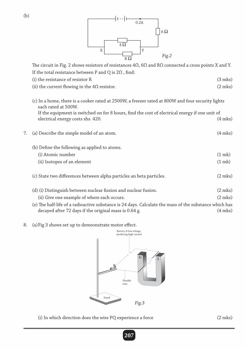
207
(b)
The circuit in Fig. 2 shows resistors of resistances 4Ω, 6Ω and RΩ connected a cross points X and Y. If the total resistance between P and Q is 2Ω , find: (i) the resistance of resistor R (3 mks) (ii) the current flowing in the 4Ω resistor. (2 mks)
(c) In a home, there is a cooker rated at 2500W, a freezer rated at 800W and four security lights each rated at 500W. If the equipment is switched on for 8 hours, find the cost of electrical energy if one unit of electrical energy costs shs. 420. (4 mks)
7. (a) Describe the simple model of an atom. (4 mks)
(b) Define the following as applied to atoms. (i) Atomic number (1 mk) (ii) Isotopes of an element (1 mk)
(c) State two differences between alpha particles an beta particles. (2 mks)
(d) (i) Distinguish between nuclear fission and nuclear fusion. (2 mks) (ii) Give one example of where each occurs. (2 mks) (e) The half-life of a radioactive substance is 24 days. Calculate the mass of the substance which has decayed after 72 days if the original mass is 0.64 g. (4 mks)
8. (a) Fig 3 shows set up to demeonstrate motor effect.
0.2A
6
YX4
R
N
Flexiblewire
Battery of low voltage,producing high current
Stand
S
(i) In which direction does the wire PQ experience a force (2 mks)
Fig.2
Fig.3

208
(ii) State two forces by which the force on PQ can be increased. (2 mks)
(b) With the aid of a labelled diagram, describe the mode of operation of a transformer. (6 mks) (c) A transformer designed to step down voltage from 240 V to 12 V has 200 turns in the secondary and it is 80% efficient. (i) Find the number of turns in the primary coil. (2 mks) (ii) determine the current in the primary when the secondary is connected to a 16 Ω bulb. (4 mks)
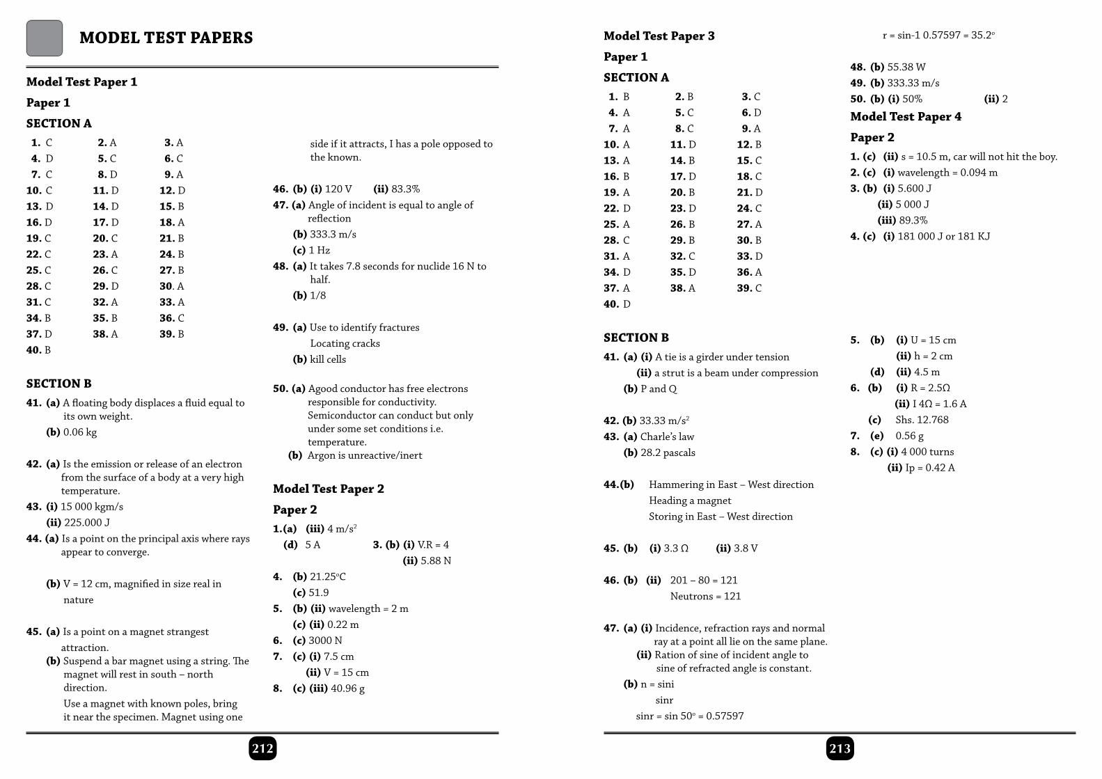
213212
Model Test Paper 1
Paper 1
SECTION A 1. C 2. A 3. A 4. D 5. C 6. C 7. C 8. D 9. A10. C 11. D 12. D13. D 14. D 15. B16. D 17. D 18. A19. C 20. C 21. B22. C 23. A 24. B25. C 26. C 27. B28. C 29. D 30. A31. C 32. A 33. A34. B 35. B 36. C37. D 38. A 39. B40. B
SECTION B41. (a) A floating body displaces a fluid equal to its own weight. (b) 0.06 kg
42. (a) Is the emission or release of an electron from the surface of a body at a very high temperature.43. (i) 15 000 kgm/s (ii) 225.000 J44. (a) Is a point on the principal axis where rays appear to converge.
(b) V = 12 cm, magnified in size real in nature
45. (a) Is a point on a magnet strangest attraction. (b) Suspend a bar magnet using a string. The magnet will rest in south – north direction. Use a magnet with known poles, bring it near the specimen. Magnet using one
MOdEl TEST PAPErS
side if it attracts, I has a pole opposed to the known.
46. (b) (i) 120 V (ii) 83.3%47. (a) Angle of incident is equal to angle of reflection (b) 333.3 m/s (c) 1 Hz48. (a) It takes 7.8 seconds for nuclide 16 N to half. (b) 1/8
49. (a) Use to identify fractures Locating cracks (b) kill cells
50. (a) Agood conductor has free electrons responsible for conductivity. Semiconductor can conduct but only under some set conditions i.e. temperature. (b) Argon is unreactive/inert
Model Test Paper 2
Paper 21.(a) (iii) 4 m/s2
(d) 5 A 3. (b) (i) V.R = 4 (ii) 5.88 N4. (b) 21.25oC (c) 51.95. (b) (ii) wavelength = 2 m (c) (ii) 0.22 m6. (c) 3000 N7. (c) (i) 7.5 cm (ii) V = 15 cm8. (c) (iii) 40.96 g
Model Test Paper 3
Paper 1
SECTION A 1. B 2. B 3. C 4. A 5. C 6. D 7. A 8. C 9. A10. A 11. D 12. B13. A 14. B 15. C16. B 17. D 18. C19. A 20. B 21. D22. D 23. D 24. C25. A 26. B 27. A28. C 29. B 30. B31. A 32. C 33. D34. D 35. D 36. A37. A 38. A 39. C40. D
SECTION B41. (a) (i) A tie is a girder under tension (ii) a strut is a beam under compression (b) P and Q
42. (b) 33.33 m/s2
43. (a) Charle’s law (b) 28.2 pascals
44.(b) Hammering in East – West direction Heading a magnet Storing in East – West direction
45. (b) (i) 3.3 Ω (ii) 3.8 V
46. (b) (ii) 201 – 80 = 121 Neutrons = 121
47. (a) (i) Incidence, refraction rays and normal ray at a point all lie on the same plane. (ii) Ration of sine of incident angle to sine of refracted angle is constant. (b) n = sini sinr sinr = sin 50o = 0.57597
r = sin-1 0.57597 = 35.2o
48. (b) 55.38 W49. (b) 333.33 m/s50. (b) (i) 50% (ii) 2
Model Test Paper 4
Paper 21. (c) (ii) s = 10.5 m, car will not hit the boy.2. (c) (i) wavelength = 0.094 m3. (b) (i) 5.600 J (ii) 5 000 J (iii) 89.3%4. (c) (i) 181 000 J or 181 KJ
5. (b) (i) U = 15 cm (ii) h = 2 cm (d) (ii) 4.5 m6. (b) (i) R = 2.5Ω (ii) I 4Ω = 1.6 A (c) Shs. 12.7687. (e) 0.56 g8. (c) (i) 4 000 turns (ii) Ip = 0.42 A

209
Numerical Solutions
Revision Exercise 21. (a) (i) 20 N (ii) 4 N (b) 1.2 N
Revision Exercise 32. 24 Nm 3. 0.6 m4. 23 g 5. 12.5 kg6. 2.5 N 7. x = 12.25 N y = 6.24 N8. (a) 1800 N 10. (b) 1600 Nm moment (b) 0.125 m due to W. (c) 200 N
Revision Exercise 48. 3.2 0 pt 10-9 m9. (a) 3.2 × 10⁻⁹ m (b) 0.22 m10. 1.8 x 10⁻⁹ m
Revision Exercise 52. 40 N/m 3. 3.0 N4. 100 g 6. (a) X (b) 8 mm
Revision Exercise 6 1. (a) 0.5 cm (b) 51 mm 2. (a) 3 cm 6. (a) 7.656 g/cm3 (b) 7.656 kg/m3
7. 0.00346 m3
8. 3.56 × 10⁻² kg 9. 2 500 kg/m3
10. 0.81 g/cm3
11. (a) 930.434 kg/m3 (b) 930.4 kg/m3
12. (a) 0.00129 g/cm3 (b) 1.29 × 10⁻³ g/cm3
ANSwERS
Revision Exercise 72. (a) 3 000 N, uniform speed (acceleration = 0) (b) 1.2 x 10⁵ J (c) 0 (zero)3. 3 000 J 4. 2.24 × 10⁵ J5. (a) 8 m/s (b) 6 m/s (c) 1.4 J7. 1.8 × 10⁶ J8. 40 J9. (i) 1 000 J (ii) 1 200 J (iii) 83.3%
Revision Exercise 8 4. (a) 0.04 m2 (b) 0.2 m (c) 10 000 kg/m3
5. X : Y = 3 :1 6. (a) 1.02 × 10⁵ Pa (b) 20.4 N 7. 628 m 8. 15 300 N 9. 16 320 N/m2
10. 60.3 cm of mercury11. 1280 Pa
Revision Exercise 9 2. 5 000 N 3. 9 N 4. 2391 N 5. (a) 0.20 N (b) 2 × 10⁻⁵m3
(c) 2 500 kg/m3 (d) 900 kg/m3
6. 2180 N 7. 62.5 cm3
8. (a) 0.48 N (b) 102 cm3 (c) 1.53 N 9. (a) 1.4 m3 (b) 4560 kg10. 100 m3 11. 11.3 cm3
12. (a) 2.6 (b) 0.843 (c) 843 kg/m3
13. (a) 480 cm3 (b) 320 g
Revision Exercise 102. 10 3. 20 m4. (a) (i) 1 000 J (ii) 1 200 J (iii) 83.3%
210
5. 800, 880, 91% 6. 75% 7. 9 revolutions 8. (a) 2.4 m (b) 288 J (c) 240 J (d) 83.3 % 9. (a) 5 (b) (i) 400 N (ii) 10 000 J (iii) 2 000 J10. 714%
Revision Exercise 11 1. 3.47 m/s 2. 35 s 3. 0.4 m/s 4. 6.5 m/s2
5. (a) 6.25 m/s2 (b) 100 m 6. 168 m 7. 45 m 8. 3.64 s 9. (a) 10 m/s2 (b) 1.25 m (c) g is uniform (d) 0.45 m10. 7.5 × 10³ N11. (a) –300 m/s2 (b) 150 N (c) 3 kg m/s (d) 3 Ns12. 1.6 m/s 13. 1.39 m/s15. (a) 300 m (b) 2 × 10⁴ N16. (a) 1100 N (b) 900 N
Revision Exercise 122. < i = 32.7o 3. 2.25 × 10⁸ m/s4. 12 cm 5. 1.566. (a) The ray undergoes total internal reflection at the surfaces BA and CA and emerges out of the prism parallel to the incident ray. (b) The ray undergoes total internal reflection at CB and emerges out at 90o to the incident ray. 7. 38.7o 8. 27.9o
9. 15 cm 10. V = -6 cm, 1.6 cm11. 150 cm, 12.5 cm12. (a) 15 cm (b) 1.25 cm towards the lens13. 33.3 cm14. 6 cm 15. 9.5 cm
Revision Exercise 13 4. (a) (i) 3.4 cm (ii) 2 cm (b) (i) 50 Hz (ii) 170 cm/s 5. 15 m 7. 1 Hz 8. (a) 5 × 10⁻³ m (b) No. the frequency is above 20 000 Hz or above the human audible range.12. 400 m13. 3 × 10³ m/s
Revision Exercise 15 1. 500 cm of mercury 2. 16 atmospheres 3. 19.4 m 4. 225 K (or –43oC) 5. 750 K (or 477oC) 6. 678 mm of mercury pressure 7. 270 K (or –3o C) 8. 50.2oC 9. 1.7 x 10⁻² kg11. 46.8 J/k12. 38.4 oC 13. 3 min 9 s14. 50.2 J/s 15. (a) 2057 J/kgk (b) 3.2 × 10⁵ J/kg16. (a) 0.398 kg18. (a) B = 10s C = 10 + 160 = 170 s (b) 1 division = 10 s CD = 5 divisions = 50 s (c) 4200 J/kgk
Revision Exercise 16(c) 1600 C
Revision Exercise 171. (a) 5 x 10¹⁸ (b) 1.6 A3. 30 Ah5. (a) 4.5 mV (b) 0.90 V
Revision Exercise 181. 4Ω 2. 2Ω3. (a) 1.5 V (b) 1.2 V
211
(c) (i) 0.5 A (ii) 0.6Ω5. 2.5 V6. (a) 0.125 A (b) 0.250 V7. (a) 0.6 A (b) 0.166 A8. (a) 2.4 V (b) 18Ω9. (a) 0.5 A (b) 130 V
Revision Exercise 21 7. (a) (i) 240 V (ii) 0.6 A (iii) 144 W (b) Zero. A transformer works only on a/c voltage. 8. (a) 24 W (c) 12 000 9. (b) (i) 80 (ii) 2 A (iii) 0.05 A12. (b) (i) 20 : 1 (ii) 24 x 3 = 72 W (iii) 40%
Revision Exercise 222. 8 days3. 63/644. (a) 48, 24, 12, 6 (b) No7. (a) m is α (4 He) (b) a = 90, b = 2318. α, β, β


![Nietzsche - Revision [Full]](https://img.dokumen.tips/doc/110x75/63618ee01b0df99ce1022aa0/nietzsche-revision-full.jpg)


