Embed Size (px)
Citation preview

Two Design Problems for the
IP/MPLS over WDM NetworksEligijus Kubilinskas1 and Michal Piorol"2
1Department of Communication Systems, Lund University, BOX 118 SE-221 00, Lund, Sweden2lnstitute of Telecommunications, Warsaw University of Technology, Nowowiejska 15/19, 00-665 Warszawa, Poland
Email: {Eligijus.Kubilinskas,Michal.Pioro}@telecom.lth.se
Abstract- Design problems related to the Next GenerationInternet core networks can be difficult to solve in an exactway. Hence, for large networks they may require approximatealgorithms. The paper considers two optimization problems foroff-line design of robust NGI core networks carrying elastic trafficwith a two-layer IP/MPLS over WDM architecture. The problemsare ANP-hard and are formulated as mixed-integer programs. Anefficient approximate iterative method based on separate designof the two layers Is proposed for solving the problems; the methodIs illustrated with numerical examples.
Index Terms-Multi-layer network design, resilience, propor-tional fairness, approximate algorithms
I. INTRODUCTION
The emerging architectures and technologies for Next Gen-eration Internet (NGI) core networks introduce a whole spec-trum of new functions and features. Internet Protocol (IP),enhanced with MPLS traffic switching capabilities is usedtoday and is foreseen to be used in the next generationInternet networks. Recent advances in the wavelength divisionmultiplexing (WDM) technology make it a strong candidatefor the basic technology in the next generation optical trans-port network (OTN). Thus one of the possible architecturesfor NGI is IP/MPLS-over-(D)WDM. Different strategies forthe interconnection (inter-operation) of the layers as well ascontrol protocols are currently developed, namely GeneralizedMPLS (GMPLS) [1] defined by IETF, and automatic switchedoptical network (ASON) defined by ITU-T. These technologieswill allow network operators to employ flexible, coordinatedresilience schemes as well as better means for traffic engineer-ing. The protection/restoration mechanisms operating in meshnetwork topologies will provide higher capacity utilizationand cost efficiency than the currently widely deployed ring-based protection mechanisms. Besides, in some cases it willbe beneficial to implement resilience schemes on the IP/MPLSlayer instead of the optical layer.
Emerging new network architectures and technologies re-quire new network design methods. The methods have toaccount for multiple layers of resources in the network,resilience, fair flow allocation and other different require-ments if efficient resource utilization is to be achieved. Suchproblems are usually hard to solve and often are NP-hard.This paper addresses two IP/MPLS-over-WDM network di-mensioning and flow allocation problems, given a budget forlink capacity installation. The two network design problems
(NDPs) presented in the paper employ two different protectionmechanisms. The first problem implements network protectiononly in the WDM layer, where flow splitting into severaldiverse paths is used as a mean of protection. The seconddesign problem implements resilience only in IP/MPLS layerby using hot standby path protection. Main advantages ofhaving recovery mechanisms in the lower layer are low numberof recovery actions needed (since protection/restoration isperformed on the coarsest granularity), as well as the failureis not propagated to the upper layer. A disadvantage of sucha scheme, though, is that failures in the upper layer maynot be resolved. Whereas having a recovery mechanism inthe upper layer allows for protection against the upper layerfailures, as well as provides more efficient resource utilization.A disadvantage, though, is that more recovery actions areneeded to recover from a failure in the lower layer [2].Our formulations can, for example, be considered as mo-
deling a system of interconnected networks (LANs or MANs).Each pair of networks (also called a demand in sequel) canconsume (within certain bounds) any bandwidth allocated toit for data transfers, and the issue is to allocate bandwidth tothe pairs of networks in a fair way within the assumed budget.
The proposed models implement proportionally fair (PF)[3] capacity sharing between demands. PF is a trade-offbetween pure fairness represented by the max-min fairnessprinciple [4] and the throughput maximization. Link capacitiesare assumed to be installed in modules and flows (of WDMlayer) are integer. The considered design problems areformulated as MIP programs. Since the design problemsare NP-hard, approximate method and algorithms areproposed for solving them. The solution method is based onthe approach of separating the layers of the problem, andoptimizing them separately in an iterative way. The proposedsolution technique is the novelty of this study.
II. DESIGN PROBLEM OF THE NETWORK WITHPROTECTION VIA PATH DIVERSITY IN WDM LAYER
The network design problem presented below (alsoconsidered in [5]) consists in finding flow allocations in theupper (IP/MPLS) layer and in the lower (WDM) layer, aswell as link capacities in both layers, given the budget forinstalling capacity in the lower layer links. The followingrequirements are taken into account in the considered network
0-7803-9439-9/05/$20.00 ©2005 IEEE241

design problem: 1) flow realizing each demand must berealized on a single path in the upper layer; 2) capacitiesof the links are installed in modules of a fixed size; 3) theavailable capacity is shared between demands according tothe PF principle; 4) protection of flows in case of failuresis assured in the lower layer using path diversity. The MIPformulation of the NDP is as follows:
Problem PD: a two layer network design problem withprotection via path diversity in WDM layer.
Vdphd < Xdp < VdpHd,
E Z6edpXdp < MYe X
d p
Z Zeq - Ye ,q
Zeq . rYe//nel ,
demands between S-D pairs of theIP/MPLS layerlinks of the IP/MPLS layercandidate paths for realizing demand dlinks of the WDM layercandidate paths for realizing capacityof link e
stantsWd revenue coefficient for demand dhd lower bound for total flow realizing demand dHd upper bound for total flow realizing demand d49 cost of installing one capacity module on link g
(including equipment cost)M module size of the demand for WDM layerN module size for WDM layer link capacities
(=number of wavelengths per fiber)5edp = 1 if link e belongs to path p realizing
demand d; 0, otherwise79eq = 1 if link g belongs to path q realizing capacity
of link e; 0, otherwisene diversity factor for realizing capacity of link e
-lablesXdp continuous flow allocated to path p of demand dVdp binary variable equal to 1 if path p is used
to realize the total volume of demand d;0, otherwise
Ye integer number of modules M to be installedon link e in the MPLS layer
Zeq integer flow allocated to path q realizing capacityof link e
Ug integer number of modules N (fibers) to beinstalled on (physical) link g in the WDM layer
objectivemaximize R = E Wd log Xd (1)
(8)
(9),V'YeqZeq . Nu9e q
In this model all flows xdp of the MPLS layer traversinga given link e sum up to the load of the link and imply itscapacity Mye. Then the number of modules Ye of a given linke forms a demand volume for the WDM layer, which has tobe realized by the WDM layer flows Ze,q
Constraint (2) imposes budget B for installing capacity inthe lower layer links (fibers). Constraints (3) give the totalamount of flow, assigned for each demand d, which is thenused in the objective function. Constraints (4)-(5) assure thatonly one path p (LSP) is used to realize flow for each demandd. At the same time constraints (5) impose lower and upperbound for the the flow realizing each demand d. We wouldlike to emphasize the role of the upper and lower bounds.The upper bounds Hd serve as a means for limiting excessiveallocations of network bandwidth to demands (in order toavoid cases when the reserved bandwidth will never be used).Similarly, the lower bounds hd do not allow for too smallbandwidth allocations and provide specific guarantees for thedemands. Note that assigning the same value to lower andupper bound of any demand implies fixed bandwidth allocationto the demand.
Constraints (6) assure that all the flows routed on each linke do not exceed its capacity which is allocated in modules ofsize M. Modularity of the links is introduced in order to havemodular demand volumes for the lower layer. Constraints (8)force the demand volumes Ye to be split into at least ne pathsin the WDM layer. Constraints (9), similarly to (6), assure thatall the flows routed on each physical link g do not exceed itscapacity allocated in modules of size N.Note that constraints (8) are non-linear. Still, they can be
slightly changed and replaced by linear constraints
Zeq (Ye//ne) + 1 X
constraints
9
EXdp = Xd,
p
EVdp = 1,
p
e= 1,2)III)(E0q-=l121 .. Qe (I10)
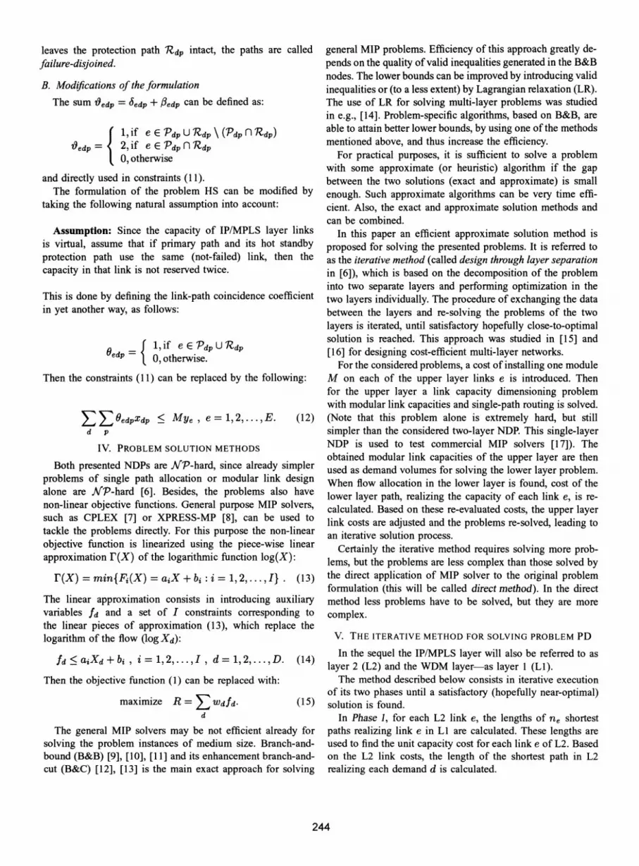
A. Interpretation of module sizesIn general, module sizes M and N have the following
(2) interpretation (See Figure 1 for illustration). If demands inthe IP/MPLS layer are imposed in units of size L, then
(3) M represents a number of L-size units. And Ye gives an
amount of modules M installed on a link e. A module size N(4) represents a number of M-size modules. Capacity ug gives an
amount of modules N installed on a link g. For example, if
242
indicesd = 1,2,...,D
e = 1,2,...,IEp= 17 2j...,Pdg9= 1,2, ...,IGq = 17 2,.-.Qe
(5)(6)
(7)
con
var
d = 11 2I...7 D I
p = 1, 27..., Pd
q 1)2) ... iQeg 112, ... IG

Upper layer i1 =Capecity %_2
ofsizM of size M
Demand / -rnodule Lower layer
of size L capacity|module
of size N
Fig. 1. Relation between capacity modules.
demands on IP/MPLS layer are imposed in STM-1 sizes, i.e.,L = 155,52 Mbps, and M = 64, then installing Ye = 1module M on a link e results in capacity of the link of9,952 Gbps (which corresponds to STM-64), and in DWDMlayer it requires OC-192 channel, i.e., I wavelength. Then, ifN = 128, and u9 = 1 module of size N is installed on a linkg, it corresponds of installing a fiber with 128 wavelengths,carrying approximately 10 Gbps each.
So size of module M can be chosen to be equal tocapacity carried by one lightpath in WDM network. WhereasN represents number of wavelengths per fiber and ug gives anumber of fibers to be installed on a link.
B. Protection mechanismAs it was mentioned, protection is achieved by splitting
flows of the lower layer Zeq (realizing capacities Ye) into apredefined number (ne) of diverse paths. If candidate pathsfor WDM layer flows are link (node) disjoint then in a caseof a single link (node) failure at most 100/ne% of the demande volume is lost and the rest of it survives.
III. DESIGN PROBLEM OF THE NETWORK WITH HOTSTANDBY PATH PROTECTION IN IP/MPLS LAYER
The following network design problem (NDP) models anetwork scenario where single path routing and hot standbypath protection is used in the IP/MPLS layer, no resilience isimplemented in the WDM layer, and capacities are installedin modules in both layers. Bifurcation of flows in theWDM layer is allowed. Most of the entities used in thisformulation are the same as for problem PD presented before.Although, some entities are redefined and additional entitiesare introduced here as required for the problem presentation.
Problem HS: a two layer network design problem with hotstandby path protection in IP/MPLS layer.
indicesd = 1, 2, ..., D demands between S-D pairs of the
IP/MPLS layere = 1, 2, ..., E links of the IP/MPLS layerp = 1, 2, ..., Pd candidate pair of (primary, protection)
paths (Pdp, lZdp) for realizingdemand d
g = 1, 2,...,G links of the WDM layer
q = 1, 2, ..., Qe candidate paths for realizing capacityof link e
constantsWd revenue coefficient for demand dhd lower bound for total flow realizing demand dHd upper bound for total flow realizing demand d
cost of installing one capacity module on link g(including equipment cost)
M module size of the demand for WDM layerN module size for WDM layer link capacities
(=number of wavelengths per fiber)6edp = 1 if link e belongs to the primary path 'Pdp
realizing demand d; 0, otherwisei6edp = 1 if link e belongs to the protection path RRdp,
protecting path p of demand d; 0, otherwise'Ygeq = 1 if link g belongs to path q realizing capacity
of link e, 0 otherwisevariables
Xdp continuous flow allocated to path pair p,('Pdp, Rdp), of demand d
Vdp binary variable equal to 1 if path pair p is usedto realize total volume of demand d; 0 otherwise
Zeq integer flow allocated to path q realizing capacityof link e
u9 integer number of modules N (fibers) to beinstalled on (physical) link g in the WDM layer
objective (1)constraints (2)-(5), (7), (9) and:
7I j(Jedp+3edp)Xdp < Mye , e= 1, 2, ..,E. (11)d p
Most of the constraints are the same as for the problemPD. Just the constraints (11) are different. These constraintsassure that all the flows routed on each link e, including thebandwidth reserved for the hot standby paths, do not exceedthe capacity of link e, which is allocated in modules of size M.Note, that in this formulation, constraints (4)-(5) assure thatonly one path pair p is used to realize the total flow for eachdemand d. Thus a single primary path Pdp is used to carryall the flow of demand d, and only a single protection pathlRdp is used to protect the primary path against all (foreseen)failures.The capacity modules have the same meaning as for the
problem PD (see Section Il-A).
A. Protection mechanism andfailure-disjoint pathsThis problem formulation employs hot standby path pro-
tection on IP/MPLS layer. It implies, that for each demandd, a primary path Pdp is set up, as well as a path lZdpprotecting Pdp. Identical resources are reserved on the hotstandby (protection) path, as those needed on primary path. Soif the primary path fails, the traffic is automatically switchedto the protection path, thus assuring 100% availability of theresources. The protection mechanism is analogous to 1: 1, or1 + 1 protection (the model is the same for both).
If the two paths, primary and protection, are chosen in sucha way, that any failure which affects the primary path Pdp
243
leaves the protection path lZdp intact, the paths are calledfailure-disjoined.B. Modifications of the formulation
The sum t9edp = 5edp + /edp can be defined as:
1, if e E -PdpuU Rdp \ (Pdp n Rdp)V3edp= 2, if e E Pdpnl1Zdp
0, otherwiseand directly used in constraints (1 1).The formulation of the problem HS can be modified by
taking the following natural assumption into account:
Assumption: Since the capacity of IP/MPLS layer linksis virtual, assume that if primary path and its hot standbyprotection path use the same (not-failed) link, then thecapacity in that link is not reserved twice.
This is done by defining the link-path coincidence coefficientin yet another way, as follows:
Oedp = if eE PdpU Rdpep Otherwise.Then the constraints (11) can be replaced by the following:
Z Z9OedpXdp < Mye , e=1,2,...,E. (12)d p
IV. PROBLEM SOLUTION METHODS
Both presented NDPs are flP-hard, since already simplerproblems of single path allocation or modular link designalone are JAP-hard [6]. Besides, the problems also havenon-linear objective functions. General purpose MIP solvers,such as CPLEX [7] or XPRESS-MP [8], can be used totackle the problems directly. For this purpose the non-linearobjective function is linearized using the piece-wise linearapproximation r(x) of the logarithmic function log(X):
r(x) = min{F,(X) = aiX + bi: i = 1,2,...,I} . (13)
The linear approximation consists in introducing auxiliaryvariables fd and a set of I constraints corresponding tothe linear pieces of approximation (13), which replace thelogarithm of the flow (logXd):
fd <5 aiXd + bi i = 1,2,...,II, d=-1,2,...,ID. (14)Then the objective function (1) can be replaced with:
maximize R =E Wdfd- (15)d
The general MIP solvers may be not efficient already forsolving the problem instances of medium size. Branch-and-bound (B&B) [9], [10], [11] and its enhancement branch-and-cut (B&C) [12], [13] is the main exact approach for solving
general MIP problems. Efficiency of this approach greatly de-pends on the quality ofvalid inequalities generated in the B&Bnodes. The lower bounds can be improved by introducing validinequalities or (to a less extent) by Lagrangian relaxation (LR).The use of LR for solving multi-layer problems was studiedin e.g., [14]. Problem-specific algorithms, based on B&B, areable to attain better lower bounds, by using one ofthe methodsmentioned above, and thus increase the efficiency.
For practical purposes, it is sufficient to solve a problemwith some approximate (or heuristic) algorithm if the gapbetween the two solutions (exact and approximate) is smallenough. Such approximate algorithms can be very time effi-cient. Also, the exact and approximate solution methods andcan be combined.
In this paper an efficient approximate solution method isproposed for solving the presented problems. It is referred toas the iterative method (called design through layer separationin [6]), which is based on the decomposition of the probleminto two separate layers and performing optimization in thetwo layers individually. The procedure of exchanging the databetween the layers and re-solving the problems of the twolayers is iterated, until satisfactory hopefully close-to-optimalsolution is reached. This approach was studied in [15] and[16] for designing cost-efficient multi-layer networks.
For the considered problems, a cost of installing one moduleM on each of the upper layer links e is introduced. Thenfor the upper layer a link capacity dimensioning problemwith modular link capacities and single-path routing is solved.(Note that this problem alone is extremely hard, but stillsimpler than the considered two-layer NDP. This single-layerNDP is used to test commercial MIP solvers [17]). Theobtained modular link capacities of the upper layer are thenused as demand volumes for solving the lower layer problem.When flow allocation in the lower layer is found, cost of thelower layer path, realizing the capacity of each link e, is re-calculated. Based on these re-evaluated costs, the upper layerlink costs are adjusted and the problems re-solved, leading toan iterative solution process.
Certainly the iterative method requires solving more prob-lems, but the problems are less complex than those solved bythe direct application of MIP solver to the original problemformulation (this will be called direct method). In the directmethod less problems have to be solved, but they are morecomplex.
V. THE ITERATIVE METHOD FOR SOLVING PROBLEM PD
In the sequel the IP/MPLS layer will also be referred to aslayer 2 (L2) and the WDM layer-as layer 1 (LI).
The method described below consists in iterative executionof its two phases until a satisfactory (hopefully near-optimal)solution is found.
In Phase 1, for each L2 link e, the lengths of ne shortestpaths realizing link e in LI are calculated. These lengths areused to find the unit capacity cost for each link e of L2. Basedon the L2 link costs, the length of the shortest path in L2realizing each demand d is calculated.
244

In Phase 2 two consecutive separate optimization problems,for L2 and LI, are solved. First the problem for L2 is solvedresulting in the L2 flows and link capacities. Each demandd is allocated to the single shortest path (with respect to thecosts calculated in Phase 1) in L2. Capacities of the L2 linksare then used as demand volumes for LI, and the problem forLI is solved. As a result, capacities of LI links, as well as LIflows are found. For each L2 link e, its flows in LI are splitto ne shortest paths, with respect to the lengths calculated inPhase 1.
After Phase 2 the updated costs of links and lengths ofpaths are recalculated (in Phase 1), and so the algorithmproceeds, until a satisfactory solution is found. The algorithmis described formally in the next section.
A. Approximate iterative algorithmStep 1: Calculate initial costs as described in Section V-C.Step 2: For each demand d find one path, Pd, shortest withrespect to the link costs Se. (Each such path is defined asPd = {e: 6ed = 1}, so its length is |PdI = Ee 6ed'e.) Thepath index, p, is omitted in the variables and constants of thefollowing formulation, because only one path, Pd, is usedfor each demand d. Solve the following design problem for L2.
Objective:
Subject to:
(23)E Zeq - Ye XqEQe
Zeq . [Ye/nel ,
q E Qe
Z11 'YgeqZeq. Nu9,e qE Qe
(24)
(25)
After solving the above problem, the current loads of the LIlinks are given by:
(26)U9= Pfgeqzeq v g1,2, .... G,e qEQe
where fi9 are non-negative continuous variables. The linkloads Ui9 will be used to update the costs of links in Step 4of the algorithm.
Step 4: Store the current solution. Update the costs asdescribed in Section V-D. If the resulting cost vectorC = (C,I (2,.. - 7(G) is the same as the cost vector usedin one of the previous iterations (or if the iteration limit isexceeded) stop the computations. Select a feasible solutionwith the highest value of R*. Else goto Step 2.
maximize R =E Wdfdd
Subject to:
hd < Xd < Hd ,
Z 6edXd . MYe X
d
E KeYe < B
e=1,2,..., E
fd < aiXd + bi, -=1,2,...,DId=1,2,...,7D.
After solving the above MIP problem (where Ye are intethe current loads of the L2 links are given by:
YeZ edXd ,e = 1 27... Ed
where Ye are non-negative continuous variables. Theloads Ye will be used to update the costs of links in StAlso, let R* be the optimal value of (16).
(16) B. CommentsWhen solving the MIP problem in Step 2, it is assumed
that the budget B is sufficiently large, so that the problem(17) is feasible, irrespectively of which set of shortest paths is
(17) chosen to realize the demands. Note, that if the problem is(18) relaxed (i.e., constraint (18) for each link e is replaced by
Ed 6edXd . Ye and Ye iS made continuous), constraints (17)(19) and (20) are removed, and the original objective function (1)
is used, then there exists an explicit solution for the resultingproblem (see Chapter 8 in [6]):
(20) BWd,gers) EZdwId (7%. 1
(21)
linkep 4.
Step 3: For each link e let Qe be the set of indices q of neshortest paths in LI with respect to the link costs C9. Solvethe following design problem for LI, realizing the given L2link capacities (Ye) by flows Zeq in LI.
Objective:
C. Defining initial costsIn Step 1 of the algorithm the initial costs of links and
lengths of the shortest paths in both layers are calculated asfollows.
Let us define the cost of installing one capacity unit in alink of LI as:
(28)
For each link e find a set ofne shortest paths in LI with respectto the link costs Cg. Let Qe be a set of indices q of these paths.Then the length of (a cost of installing one capacity unit on)path q is defined as:
(22)minimize 23 u99
IIeq = YgeqqCg , e = 1,2,...,E , q e Qe,9
245
(29)
(g=.glN I g-112, ...IG.

and the average cost of installing one capacity unit on ashortest path in LI for realizing capacity ofL2 link e is definedas:
Ke ( E eq)/fe , e = 1,2, ...,E. (30)qEQe
Then the cost of installing one capacity unit on L2 link e is:
se =Ite/M , e=1,2,...,E. (31)
The presented algorithm is based on allocation of flowsin the network on the shortest paths, and therefore requiresfinding one shortest path (one shortest pair of disjoint pathsfor problem HS) in L2 for realizing each demand d, as wellas ne shortest paths (ne = 1 for problem HS) in LI for flowsrealizing capacities of links e. There are two approaches offinding the shortest paths needed for the calculations. First,one can search for the shortest paths only in the predefinedlists of candidate paths. Second, a global search for the paths(using a shortest-path algorithm) can be performed in the graphof the corresponding layer. In both cases, the C. and Se costsare used for the calculations.
D. Updating the costsAfter each iteration of the algorithm, the costs have to be
updated. The goal is to have as little modules installed on thelinks and as high links utilization as possible, since this leadsto the smallest overall network cost. One way to achieve thisis to take into account the utilization of the installed capacitymodules on the links, when calculating capacity unit costs. Ifthe installed modules on a link are under-utilized the capacityunit cost on this link will be increased. This objective can berealized by the adjusted cost calculations which are performedas follows.The cost of installing one capacity unit on LI link g iscalculated as:
g = (GUq1g/ , 9 = 1, 2, ...,7 GI (32)and the cost of installing one capacity unit on L2 link e is:
Se=reYe /2e , e 1 2,..*,E (33)
where rKe is calculated as in (30). The remaining requiredentities are calculated as in Section V-C, using costs C. and4e calculated from (32) and (33), respectively.
VI. THE ITERATIVE METHOD FOR SOLVING PROBLEM HS
Analogously to problem PD, the resolution method forproblem HS consists in iterative executing of its two phasesuntil a satisfactory solution is found.
In Phase 1, for each L2 link e the length (cost) of its shortestpath in LI is calculated. These costs are used to find capacityunit costs of the L2 links. Based on these L2 link costs,a shortest pair of failure-disjoint paths in L2 realizing eachdemand d is found and its length is calculated.
In Phase 2 two consecutive separate optimization problems,for L2 and LI, are solved. First, the problem for L2 is solvedresulting in the L2 flows and link capacities. Each demandd is allocated to one of the shortest (primary, backup) pathpairs (with respect to the lengths calculated in Phase 1) in L2.Resulting capacities of the L2 links are then used as demandvolumes for LI, and the problem for LI is solved. As a result,capacities of the LI links, as well as the LI flows are found.There are no restrictions imposed on how flows in LI shall beallocated. Thus, flow bifurcation in LI is allowed in solvingthe modular dimensioning problem for LI.
After Phase 2 the updated costs of links and lengths of pathsare recalculated (in Phase 1), and so the algorithm proceeds,until a satisfactory solution is found. Initial costs and updatedcosts for this problem are calculated in the same way asfor problem PD (see Sections V-C-V-D), except that nowa number of diverse paths in the lower layer ne is set to 1.The algorithm is described formally in the following section.
A. Approximate iterative algorithmThe iterative algorithm for problem HS is very similar
to that of Problem PD, presented in Section V-A. Belowonly the differences with respect to the previous algorithmare presented. Steps I and 4 are exactly the same for bothalgorithms.
Step 2: For each demand d find one of the shortestpairs of failure-disjoint paths, (Pdp, R-dp), with respectto the link costs ce. (Each such path pair is defined as(Pdp,ZRdp) = {e: O9edp = 1}, so its length is I(Pdp,lZdp)I =Ee Oedp'e.) The path pair index p is omitted in the variablesand constants in the formulation, because only one (shortest)predefined pair of paths, (Pd, Rd), is used for each demandd. Solve the design problem (I 6)-(20) for L2, and calculateL2 link loads from (21).
Step 3: Solve the following design problem for LI, realizingthe given L2 link capacities (Ye) by flows zeq in LI.
Objective: (22)
Subject to: (23) and (25).
Calculate the current loads of the LI links from (26).
VII. NUMERICAL EXAMPLES
The proposed iterative algorithms for both problems havebeen tested on a number of randomly generated networktopologies. Network sizes were ranging from 12 to 60 nodesin the lower (WDM) layer. The upper (IP/MPLS) layer usuallycontained slightly less nodes. The selected test networks aresummarized in Table I. The aim of the numerical experimentswas to examine the time efficiency and solution quality(maximum value of revenue R*) of the iterative algorithms,as compared to the direct algorithms (applications of CPLEXMIP solver to the problem formulations in their original form).
246

For the experiments the values B = 1000010, M = 64, andN = 128 were used.
All the programs were implemented in mathematical mod-eling language AMPL ver. 20021031 [18], and CPLEX 9 wasused as a solver. Problems were solved on a PC with Pentium-4 2,6 GHz CPU and 1 GB of RAM, running the Windows XPPro operating system. Table II shows the computational resultsfor both, iterative and direct, solution methods as appliedto problem PD. Table III shows corresponding results forproblem HS. The solution time indicated in the tables is awall-clock time.As it can be seen from the Tables II and III, the smaller is
the network (simpler NDP), the closer are the solution times ofthe iterative and direct algorithms. And vice versa, the largeris the network (more complicated NDP), the bigger is thedifference between the solution times of the iterative and directalgorithms. For the considered network examples the iterativealgorithms (for both problems) had much better time
TABLE INETWORKS USED FOR EXPERIMENTS.
# pathsNetwork layer #nodes #links per # demands
___I demand
N12 L2 12 22 6-14 66Li 12 18 2-3 -
N30 L2 25 56 4-5 300Li 30 68 4-5 -
N41 L2 21 37 6 209L1 41 72 3 -
N60 L2 50 125 3 1225Li 60 142 3
TABLE ITCOMPUTATIONAL RESULTS FOR PROBLEM PD.
|Network |Execution time, [sj RevenuelIterative [ Direct Iterative Direct
N12 0,67 0,46 1188193,49 1188193,49N30 1, 15 5,90 5400879,54 5400874,47N41 1,63 128,45 3129647,89 3129888,61N60 5,93 2610,99 19132276,27 19132438,90
TABLE IIICOMPUTATIONAL RESULTS FOR PROBLEM HS.
Network [ Execution time, [s] RevenueIterative Direct Iterative Direct
N12 0,96 10,95 1188193,49 1188193,49N30 5,26 25,67 4989050, 17 4989308,47N41 5,46 91,84 2390451, 15 2452949,06N60 43,26 1834,43 14534368,16 14535807,04
efficiency, except for one case: problem PD for network N12was solved slightly faster using the direct approach. Althoughthe direct algorithms produced marginally better solutions, inall the cases, except one, the gap between the optimal revenuesR* obtained by the direct and iterative algorithms was below0, 01%. In one case (problem HS for network N41), however,the gap is equal 2, 5%.
A. Illustration of convergence
Figures 2 and 3 illustrate how the iterative algorithm forproblem PD converges when solving for N41. Figure 2 showsevolution of the L2 objective function (16) value (referred to asthe L2 objective), as well as an optimal value of R* obtainedby the direct solution method (referred to as the optimal value).Figure 3, in tum, depicts the evolution of the LI objectivefunction (22) value, as well as the value of budget B.
In the first step of the algorithm (see Section V-A), the initialcosts of links and lengths of the shortest paths are calculated.Then the L2 problem is solved in Step 2 producing the solutionvalue depicted in Figure 2 for iteration counter equal to 1.The resulting modular link capacities of L2 are then used asdemand volumes for the LI problem solved in Step 3. Theresulting value of the LI objective function (22) appears tobe above the available budget B, as can be seen in Figure 3for iteration 1. Although both problems, for L2 and LI, areformally feasible, the overall solution is infeasible, becausethe cost (22) exceeds the assumed budget B. It is due to thefact that the costs Ke are in general inconsistent with the costs4, implying that the cost of the L2 links, Ze KeYe, is notequal to cost (22). This is the reason why the cost (22) canexceed the assumed budget B, making the overall solutioninfeasible. Hence, although the objective function value of L2is the highest among all the iterations, it is not the final solutionbecause it is achieved on expense of exceeding the budgetconstraint for the LI link capacities. In Step 4 of the algorithmthe costs are updated to take into account the installed linkcapacities and the actual link loads, and iteration 2 of thealgorithm starts. Problems for L2 and Ll are solved againin Step 2 and Step 3, respectively, and the costs are updatedagain. In this way the algorithm proceeds until in iteration4 the resulting L2 link capacities can be implemented witha cost slightly lower than the assumed budget B (see valuesfor iteration 4 in Figure 3). The costs are recalculated andit appears that the resulting cost vector C is the same asin the previous iteration (the cost vector which resulted inthe solution of iteration 4). So the algorithm would normallyterminate here. Although, for illustrative purposes, one moreiteration was performed. Thus the problems for the two layersare solved once more in iteration 5, producing the samesolution as in the previous iteration, since the cost vector ( isthe samne as in iteration 4. Recalculating costs results in thesame cost vector C as in the previous iteration so the algorithmterminates.
The algorithm for problem HS converges to the final solu-tion in a similar way.
247

R3130177
3130127
3130077
3130027
3129977
3129927
3129877
3129827
3129777
3129727
3129677
L2 objective-+- Optimal value
31296271 I1 2 3 4 5 6
Iteration
Fig. 2. Evolution of L2 objective value for N41 in problem PD.
100027 ,
1000250
1000225
1000200-
1000175
1000150
1000125
1000100
1000075
1000050
1000025
1000000 2 3 ~~~~4 5 6Iterabon
Fig. 3. Evolution of LI objective value for N41 in problem PD.
VIII. CONCLUSIONSThe paper presents two design problems for IP/MPLS over
WDM mesh networks, each employing a different recovery
mechanism. The first problem assumes protection only in theWDM layer, where a rather simple protection mechanism-path diversity is used. The second problem employs protectiononly in the IP/MPLS layer. The recovery mechanism used inthis problem is the hot standby path protection. Both designproblems are MP-hard, therefore we propose approximatealgorithms for solving them. The algorithms are based on theidea of decomposing the network into layers, and solving (inan iterative manner) the optimization problems for each layerseparately. The efficiency and solution quality of the algo-
rithms are illustrated with numerical examples. The numericalstudy shows that the approximate algorithms provide a veryclose to optimum solution in drastically shorter executiontimes than the direct algorithms, especially for large networks.Good performance of the two approximate iterative algorithmsfor the two different multi-layer network design problemssuggests that the proposed iterative solution method can besuccessfully applied for efficient solution of other multi-layernetwork design problems.
ACKNOWLEDGMENTS
The presented work has been done within the two projects:1) "Design of Modem Telecommunication Networks-Multi-commodity Flow Optimization Approach", granted by theSwedish Research Council (grant number 621-2003-2767);and 2) "Design Methods for NGI Core Networks", grantedby the Polish State Committee for Scientific Research (grantnumber3 TllD 001 27).
REFERENCES[1] L. Berger. Generalized multi-protocol label switching (GMPLS)
signaling functional decsription. IETF RFC 3471, January 2003.http://www.ietf.org/rfc/rfc347 1.txt.
[2] T. Jensen. Planning dependable network for IP/MPLS over optics.Telektronikk, 99(3/4), 2003.
[3] F.P. Kelly, A.K. Mauloo, and D.H.K. Tan. Rate control for commu-nication networks: Shadow prices, proportional fairess and stability.Journal of the Operations Research Society, 49:2006-2017, 1997.
[4] D. Bertsekas and R. Gallager. Data Networks, 2nd Edition. PrenticeHall, 1999.
[5] E. Kubilinskas and M. Pi6ro. An IP/MPLS over WDM network designproblem. In Proceedings INOC'2005, pages 718-725, Lisbon-Portugal,2005.
[6] M. Pi6ro and D. Medhi. Routing, Flow, and Capacity Design inCommunication and Computer Networks. Morgan Kaufman, 2004.
[7] CPLEX. CPLEX User's Manual. ILOG, 1999.[8] XPRESS-MP. XPRESS-MP Software. http://www.dashoptimiza-
tion.com/.[9] M. Minoux. Mathematical Programming: Theory and Algorithms. John
Wiley & Sons, 1986.[10] E. L. Lawler and D. E. Wood. Branch-and-bound method: A survey.
Operations Research, 14(4):699-719, July-August 1966.[11] A. H. Land and A. G. Doig. An authomated method of solving discrete
programming problems. Econometrica, 28(3):497-520, July 1960.[12] L. A. Wolsey. Strong formulations for mixed integer programming: A
survey. Mathematical Programming, 45:173-191, 1989.[13] E. Balas, S. Cena, and G. Cornuejols. Mixed 0-1 programming by
lift-and-project in a branch-and-cut framework. Management Science,(42):1229-1246, September 1996.
[14] F.R.B. Cruz, G.R. Mateus, and J. Macgregor-Smith. A Branch-and-Bound algorithm to solve a multi-level network optimization problem.Journal of Mathematical Modelling and Algorithms 2, pages 37-56,2003.
[15] M. Pi6ro. ATM network design. Technical report. SWAP ProjectNo. P10352-1 (Swedish National Board for Industrial and TechnicalDevelopment NUTEK), Lund University, 1998.
[16] S. De Maesschalck, M. Pickavet, D. Colle, and P. Demeester. On theoptimization of the feedback loop for solving the multi-layer trafficgrooming problem. In Proceedings INOC'2003, pages 195-200, Evry-Paris, 2003.
[17] A. Chabrier, E. Danna, C. Le Pape, and L. Perron. Solving a networkdesign problem. Technical Report, Number 02-005, ILOG, 2002.
[18] R. Fourer, D. M. Gay, and B. W. Kermighan. AMPL: A ModelingLanguagefor Mathematical Programming. Duxbury Press / Brooks/ColePublishing Company, 2002.
248
- Li objective-*- B
9 ___E-M.
---7------------- ---------
1-


