Embed Size (px)
Citation preview
Copyright © 2010 TTE Systems Ltd. All rights reserved.
MIPS and MIPS I are trademarks and / or registered trademarks of MIPS Technologies, Inc. TTE Systems Ltd is not associated with MIPS Technologies, Inc. in any way. TTE32 and RapidiTTy are registered trademarks of TTE Systems Ltd. InfiniTTy and SafeTTy are trademarks of TTE Systems Ltd. All other trademarks are acknowledged.
www.tte-systems.com
TTE® Systems Ltd 106 New Walk, Leicester,
United Kingdom
Tel: +44 (0)116 223 1684 Fax: +44 (0)116 223 1651
TTE®32 high-reliability processor cores and microcontrollers TTE32 processor cores and related microcontrollers are intended for use in aircraft (both manned and UAVs), medical equipment, industrial control, automotive designs, space systems and other high-reliability applications. They offer a combination very predictable behaviour, high performance and future-proof design features which greatly simplifies design, test and certification activities.
TTE32 processor cores are based on a 32-bit design with 32-registers and a five-stage pipeline. They have a Harvard architecture and support precise exceptions. They have a constant interrupt overhead (even during multi-cycle operations) and provide guaranteed memory-access and instruction-execution times.
TTE32 cores provide highly-predictable behaviour
Provide an ideal platform for designs which require precise "worst-case execution time" (WCET) determination and / or low task jitter. Typical measurement resolution is at the microsecond level or better (dependent on chosen implementation platform).
Can be provided with full validation and verification data for use in DO-254 / DO-178b, IEC 61508, ISO 26262 or other high-reliability projects.
Can be provided with full support for triple-modular redundancy (TMR), in both single-chip and multi-chips implementations, allowing use in aerospace (and space) designs in which single-event effects (SEEs) - including single-event upsets (SEUs) - must be addressed.
TTE32 cores provide future-proof performance
To support a wide range of performance requirements and "future proof" your system design, TTE32 processor cores can be provided in both single-core and advanced multi-core implementations.
Adding cores in a TTE32 design allows developers to support additional system functionality without sacrificing timing predictability in existing task sets. Full software toolsets to support the development of multi-core designs are available.
Single- and multi-core designs can be provided with full processor design information (including complete VHDL source), ensuring that your investment is protected for many decades into the future, even in the face of inevitable developments in implementation technology.
TTE32 cores have full software support
TTE32 processors execute code which conforms to the MIPS I™ instruction set architecture, allowing use of a wide range of standard compilers and related development tools.
TTE32 processors are fully compatible with RapidiTTy® software development tools. RapidiTTy provides precise WCET measurements with no software load. RapidiTTy facilitates the migration from single-core to multi-core designs. Compilers for C and Ada programming languages are available, fully integrated in the toolchain.
TTE32 processors support both co-operative and pre-emptive task scheduling (including the InfiniTTy™ operating system family).
TTE32 processors are an ideal platform for time-triggered (TT) software architectures.
TTE32 cores have a low-cost evaluation process
We offer a very straightforward evaluation process, which is free of charge for many of our customers.
Bespoke CPU and microcontroller designs
We can provide a custom processor core or custom microcontroller for you, to match your precise requirements. Matching software toolsets (e.g. for code development or WCET prediction) can also be provided.

Copyright © 2010 TTE Systems Ltd. All rights reserved.
MIPS and MIPS I are trademarks and / or registered trademarks of MIPS Technologies, Inc. TTE Systems Ltd is not associated with MIPS Technologies, Inc. in any way. TTE32 and RapidiTTy are registered trademarks of TTE Systems Ltd. InfiniTTy and SafeTTy are trademarks of TTE Systems Ltd. All other trademarks are acknowledged.
www.tte-systems.com
TTE® Systems Ltd 106 New Walk, Leicester,
United Kingdom
Tel: +44 (0)116 223 1684 Fax: +44 (0)116 223 1651
SafeTTy™ Technology
When the products you build are based on embedded processors, unexpected failures can occur due to software errors (in your code or in the operating system you use), the impact of electromagnetic interference (EMI) or “single-event effects” (SEEs), or from various forms of hardware damage.
In automotive, medical, industrial, aerospace and similar systems, the impact of such failures can be serious injury or even loss of life.
SafeTTy™ technology from TTE Systems can help you to avoid such serious system failures.
SafeTTy technology provides an extremely robust, flexible and cost-effective solu-tion for fault monitoring and recovery in a wide range of embedded systems.
Use of SafeTTy technology can simplify the creation of a high-reliability systems and help you to comply with international safety standards and guidelines.
Two SafeTTy protection mechanisms are available (each with full design support):
SafeTTy Wrappers (usually used with designs based on Linux or other standard operating systems);
SafeTTy Agents (usually used with “time-triggered” designs). A cost-effective evaluation process is available for all SafeTTy protection systems.
Support for DO-178b, IEC 61508 and related projects Many of our products are available in forms which are suitable for use in high-reliability and safety-critical products which are developed according to international guidelines (including DO-254, DO-178b, ISO 26262, ISO 13485, IEC 61131, IEC 61508).
For example, we can provide both our TTE32 processors and custom processors with full design and verification documentation (including PHAC documents, Hardware Verification Procedures, and Verification Reports). We can also provide precisely-matched software toolsets, supporting a full range of software development and test activities, including precise worst-case execution time (WCET) prediction and measurement.
Bespoke consultancy and training services
We offer a range of consultancy and bespoke training services to support customers who wish to develop safety-related and safety-critical embedded systems.
For example, if your organisation is aiming to develop future products according to DO-178b / ED-12b / DO-254 / ED-80 guidelines, we can assess your existing development processes, provide you with a report and — where necessary — assist you with training in appropriate areas. These services can be provided on your site, on a worldwide basis, on dates of your choosing, and we can provide an initial assessment and customised proposal for you at low cost and without obligation.
Patterns for time-triggered embedded systems
www.TTE-Systems.com = High-reliability processors + Software tools + Protection systems + Training & consultancy services
Copyright 2001-2010 TTE Systems Ltd. All rights reserved.
ACM PRESS BOOKS
This book is published as part of the ACM Press Books – a collaboration between theAssociation for Computing Machinery and Addison-Wesley. ACM is the oldest andlargest education and scientific society in the information technology field. Throughits high-quality publications and services, ACM is a major force in advancing the skillsand knowledge of IT professionals throughout the world. For further informationabout ACM contact:
ACM Member Services ACM European Service Center1515 Broadway, 17th Floor 108 Cowley RoadNew York NY 10036-5701 Oxford OX4 1JFPhone: +1 212 626 0500 United KingdomFax: +1 212 944 1318 Phone: +44 1865 382338Email: [email protected] Fax: +44 1865 381338
Email: [email protected]: http://www.acm.org
SELECTED ACM TITLES:
Software Requirements and Specification: A Lexicon of Software Practice, Principlesand Prejudices Michael Jackson
Software Test Automation: Effective Use of Text Execution Tools Mark Fewster andDorothy Graham
Test Process Improvement: A Practical Step-by-step Guide to Structured TestingTim Koomen and Martin Pol
Mastering the Requirements Process Suzanne Robertson and James Robertson
Bringing Design to Software: Expanding Software Development to Include DesignTerry Winograd, John Bennett, Laura de Young, Bradley Hartfield
Software for Use: A Practical Guide to the Models and Methods of Usage CenteredDesign Larry L. Constantine and Lucy A. D. Lockwood
Problem Frames: Analyzing and Structuring Software Development Problems Michael Jackson
Software Blueprints: Lightweight Uses of Logic in Conceptual Modelling David Robertson and Jaume Agusti
www.TTE-Systems.com = High-reliability processors + Software tools + Protection systems + Training & consultancy services
Copyright 2001-2010 TTE Systems Ltd. All rights reserved.
Patterns for time-triggeredembedded systems
Building reliable applications with
the 8051 family of microcontrollers
Michael J. Pont
The Keil compiler (demo) and associated files on the CD-ROM enclosedwith this book have been authored and developed by Keil (UK) Ltd.© Keil (UK) Ltd 2001.
acmacmP R E S S
www.TTE-Systems.com = High-reliability processors + Software tools + Protection systems + Training & consultancy services
Copyright 2001-2010 TTE Systems Ltd. All rights reserved.
PEARSON EDUCATION LIMITED
Head Office: London Office:Edinburgh Gate 128 Long AcreHarlow CM20 2JE London WC2E 9ANTel: +44 (0)1279 623623 Tel: +44 (0)20 7447 2000Fax: +44 (0)1279 431059 Fax: +44 (0)20 7240 5771Websites: www.it-minds.com
www.aw.com/cseng/
First published in Great Britain in 2001
© ACM Press 2001
ISBN 0 201 33138 1
The right of Michael Pont to be identified as Author of this Work has been asserted by him in accordance with the Copyright, Designs, and Patents Act 1988.
All rights reserved; no part of this publication may be reproduced, stored in a retrieval system, or transmitted in any form or by any means, electronic, mechanical, photocopying, recording or otherwise without either the prior written permission of the Publishers or a licence permitting restricted copying in the United Kingdom issued by the Copyright Licensing Agency Ltd,90 Tottenham Court Road, London W1P 0LP. This book may not be lent, resold, hired out orotherwise disposed of by way of trade in any form of binding or cover other than that in which it is published, without the prior consent of the Publishers.
The programs in this book have been included for their instructional value. The publisher doesnot offer any warranties or representations in respect of their fitness for a particular purpose,nor does the publisher accept any liability for any loss or damage arising from their use.
Many of the designations used by manufacturers and sellers to distinguish theirproducts are claimed as trademarks. Pearson Education Limited has made everyattempt to supply trademark information about manufacturers and their products mentionedin this book.
The publishers wish to thank the following for permission to reproduce the material: ArizonaMicrochip Technology Ltd; Allegro Microsystems; Atmel Corporation; Infineon; PhilipsSemiconductors; Texas Instruments.
Two of the figures in this book (Figure 3.2 and 3.4) reproduce information provided by AtmelCorporation. Atmel® warrants that it owns these materials and all intellectual property relatedthereto. Atmel, however, expressly and explicitly excludes all other warranties, insofar as itrelates to this book, including accuracy or applicability of the subject matter of the Atmelmaterials for any purpose.
British Library Cataloguing-in-Publication DataA CIP catalogue record for this book can be obtained from the British Library.
Library of Congress Cataloging in Publication Data Applied for.
10 9 8 7 6 5 4 3 2 1
Designed by Claire Brodmann Book Designs, Lichfield, StaffsTypeset by Pantek Arts Ltd, Maidstone, Kent.Printed and bound in the United States of America.
The Publishers’ policy is to use paper manufactured from sustainable forests.
www.TTE-Systems.com = High-reliability processors + Software tools + Protection systems + Training & consultancy services
Copyright 2001-2010 TTE Systems Ltd. All rights reserved.
This book is dedicated to my parents, Barbara and Gordon Pont
www.TTE-Systems.com = High-reliability processors + Software tools + Protection systems + Training & consultancy services
Copyright 2001-2010 TTE Systems Ltd. All rights reserved.

www.TTE-Systems.com = High-reliability processors + Software tools + Protection systems + Training & consultancy services
Copyright 2001-2010 TTE Systems Ltd. All rights reserved.
Contents
Foreword page xiv
Preface xvi
Introduction 1
1 What is a time-triggered embedded system? 3
1.1 Introduction 3
1.2 Information systems 3
1.3 Desktop systems 5
1.4 Real-time systems 6
1.5 Embedded systems 8
1.6 Event-triggered systems 10
1.7 Time-triggered systems 11
1.8 Conclusions 14
2 Designing embedded systems using patterns 15
2.1 Introduction 15
2.2 Limitations of existing software design techniques 17
2.3 Patterns 22
2.4 Patterns for time-triggered systems 24
2.5 Conclusions 25
Part A Hardware foundations 27
3 The 8051 microcontroller family 29
S TA N D A R D 8051 30
S M A L L 8051 41
E X T E N D E D 8051 46
4 Oscillator hardware 53
C R Y S TA L O S C I L L AT O R 54
C E R A M I C R E S O N AT O R 64
www.TTE-Systems.com = High-reliability processors + Software tools + Protection systems + Training & consultancy services
Copyright 2001-2010 TTE Systems Ltd. All rights reserved.
5 Reset hardware 67
R C R E S E T 68
R O B U S T R E S E T 77
6 Memory issues 81
O N-C H I P M E M O R Y 82
O F F -C H I P D ATA M E M O R Y 94
O F F -C H I P C O D E M E M O R Y 100
7 Driving DC loads 109
N A K E D L E D 110
N A K E D L O A D 115
I C B U F F E R 118
B J T D R I V E R 124
I C D R I V E R 134
M O S F E T D R I V E R 139
S S R D R I V E R (DC) 144
8 Driving AC loads 148
E M R D R I V E R 149
S S R D R I V E R (A C) 156
Part B Software foundations 159
9 A rudimentary software architecture 161
S U P E R L O O P 162
P R O J E C T H E A D E R 169
10 Using the ports 173
P O R T I /O 174
P O R T H E A D E R 184
11 Delays 193
H A R D WA R E D E L AY 194
S O F T WA R E D E L AY 206
CONTENTSviii
www.TTE-Systems.com = High-reliability processors + Software tools + Protection systems + Training & consultancy services
Copyright 2001-2010 TTE Systems Ltd. All rights reserved.
12 Watchdogs 215
H A R D WA R E WAT C H D O G 217
Part C Time-triggered architectures for single-processor systems 229
13 An introduction to schedulers 231
13.1 Introduction 231
13.2 The desktop OS 231
13.3 Assessing the super loop architecture 233
13.4 A better solution 235
13.5 Example: Flashing an LED 239
13.6 Executing multiple tasks at different time intervals 243
13.7 What is a scheduler? 245
13.8 Co-operative and pre-emptive scheduling 246
13.9 A closer look at pre-emptive schedulers 250
13.10 Conclusions 253
14 Co-operative schedulers 254
C O-O P E R AT I V E S C H E D U L E R 255
15 Learning to think co-operatively 297
L O O P T I M E O U T 298
H A R D WA R E T I M E O U T 305
16 Task-oriented design 316
M U LT I - S TA G E TA S K 317
M U LT I - S TAT E TA S K 322
17 Hybrid schedulers 332
H Y B R I D S C H E D U L E R 333
Part D The user interface 359
18 Communicating with PCs via RS-232 361
P C L I N K (R S -232) 362
CONTENTS ix
www.TTE-Systems.com = High-reliability processors + Software tools + Protection systems + Training & consultancy services
Copyright 2001-2010 TTE Systems Ltd. All rights reserved.
19 Switch interfaces 397
S W I T C H I N T E R FA C E (S O F T WA R E) 399
S W I T C H I N T E R FA C E (H A R D WA R E) 410
O N-O F F S W I T C H 414
M U LT I - S TAT E S W I T C H 423
20 Keypad interfaces 433
K E Y PA D I N T E R FA C E 434
21 Multiplexed LED displays 449
M X L E D D I S P L AY 450
22 Controlling LCD panels 465
L C D C H A R A C T E R PA N E L 467
Part E Using serial peripherals 491
23 Using ‘I2C’ peripherals 493
I 2C P E R I P H E R A L 494
24 Using ‘SPI’ peripherals 520
S P I P E R I P H E R A L 521
Part F Time-triggered architecturesfor multiprocessor systems 537
25 An introduction to shared-clock schedulers 539
25.1 Introduction 539
25.2 Additional CPU performance and hardware facilities 539
25.3 The benefits of modular design 541
25.4 How do we link more than one processor 543
25.5 Why additional processors may not always improve reliability 550
25.6 Conclusions 552
CONTENTSx
www.TTE-Systems.com = High-reliability processors + Software tools + Protection systems + Training & consultancy services
Copyright 2001-2010 TTE Systems Ltd. All rights reserved.
26 Shared-clock schedulers using external interrupts 553
S C I S C H E D U L E R (T I C K) 554
S C I S C H E D U L E R (D ATA) 593
27 Shared-clock schedulers using the UART 608
S C U S C H E D U L E R ( L O C A L) 609
S C U S C H E D U L E R (R S -232) 642
S C U S C H E D U L E R (R S -485) 646
28 Shared-clock schedulers using CAN 675
S C C S C H E D U L E R 677
29 Designing multiprocessor applications 711
D ATA U N I O N 712
L O N G TA S K 716
D O M I N O TA S K 720
Part G Monitoring and control components 725
30 Pulse-rate sensing 727
H A R D WA R E P U L S E C O U N T 728
S O F T WA R E P U L S E C O U N T 736
31 Pulse-rate modulation 741
H A R D WA R E P R M 742
S O F T WA R E P R M 748
32 Using analogue-to-digital converters (ADCs) 756
O N E-S H O T A D C 757
A D C P R E -A M P 777
S E Q U E N T I A L A D C 782
A-A F I LT E R 794
C U R R E N T S E N S O R 802
33 Pulse-width modulation 807
H A R D WA R E P W M 808
CONTENTS xi
www.TTE-Systems.com = High-reliability processors + Software tools + Protection systems + Training & consultancy services
Copyright 2001-2010 TTE Systems Ltd. All rights reserved.
P W M S M O O T H E R 818
3-L E V E L P W M 822
S O F T WA R E P W M 831
34 Using digital-to-analog converters (DACs) 840
D A C O U T P U T 841
D A C S M O O T H E R 853
D A C D R I V E R 857
35 Taking control 860
P I D C O N T R O L L E R 861
Part H Specialized time-triggered architectures 891
36 Reducing the system overheads 893
255-T I C K S C H E D U L E R 894
O N E-TA S K S C H E D U L E R 911
O N E-Y E A R S C H E D U L E R 919
37 Increasing the stability of the scheduling 931
S TA B L E S C H E D U L E R 932
Conclusions 941
38 What this book has tried to do 941
38.1 Introduction 943
38.2 What this book has tried to do 943
38.3 Conclusions 943
39 Collected references and bibliography 946
39.1 Complete list of publications 946
39.2 Other pattern collections 952
39.3 Design techniques for real-time/embedded systems 952
39.4 Design techniques for high-reliability systems 953
39.5 The 8051 microcontroller 954
39.6 Related publications by the author 954
CONTENTSxii
www.TTE-Systems.com = High-reliability processors + Software tools + Protection systems + Training & consultancy services
Copyright 2001-2010 TTE Systems Ltd. All rights reserved.

Appendices 955
A The design notation and CASE tool 957
Overview 957
The CASE tool 957
The notation 957
B Guide to the CD 980
Overview 980
The basis of the CD 980
The source code for this book 980
C Guide to the WWW site 982
Overview 982
The URL 982
Contents of the WWW site 982
Bug reports and code updates 982
Index 985
CONTENTS xiii
www.TTE-Systems.com = High-reliability processors + Software tools + Protection systems + Training & consultancy services
Copyright 2001-2010 TTE Systems Ltd. All rights reserved.
Foreword
You hold in your hands a pattern language. If you could measure its distance from thetopics of my patterns, you would find a sizeable gap. In spirit, however, Michael isright on target.
Ward Cunningham and I worked during the early days of the commercialization ofSmalltalk. Smalltalk had been designed from the beginning to be a seamless environ-ment. You could be using a word processor written in Smalltalk, start up a debugger,modify the program and continue typing.
Some of the first Tektronix customers for Smalltalk were pretty odd. We oftentalked about Ray, an old guy from a big chemical company who latched ontoSmalltalk and really made it jump and run, presenting and manipulating experimen-tal data. Watching one of his demos was a delight, because he was so proud of whathe had accomplished.
Reading Ray’s code was another matter entirely. He would do anything and every-thing, no matter how hideous, to get his programs to work. The result was a mess thatwas totally unmaintainable and only used a fraction of the power of Smalltalk.
We often used Ray as the personification of the audience we wanted for our software– people who have problems to solve and have to construct software to solve them. Wecould easily contrast this utilitarian attitude with our ‘no compromise engineering’ atti-tude towards software, where the simplicity and elegance of the solution were moreimportant than the problem solved. We could see that if we wanted to affect the world,we couldn’t just pursue our visions of beauty, we would have to try to help Ray at thesame time.
The resulting pattern language was a curious blend of high-minded advice (‘neveruse a computer you can’t personally turn off’) and banal bookkeeping chores (‘havethe braces in your source code form rectangles’). The intent was to help Ray get moreout of Smalltalk. In this we largely failed. Looking at my career since then, I have drift-ed more and more to giving advice to people coaching people who write programs forpeople who write programs for...
That’s why I loved reading Michael’s early draft. It brought back that feeling ofopening up a field of endeavour to someone who just has a problem to solve and whodoesn’t want to be an expert in the solution. Now I’m Ray. I’d love to whip togetherlittle microcontrollers to solve various problems (okay, so I’m a nerd). Reading this pat-tern language gives me the confidence that I could do just that.
Far from just giving me the smell of rosin in my nose and the feel of a wire wrap gunin my hand, these patterns stand as an example of how much more can be done withpatterns than is commonly attempted. Patterns at their best bridge the gap between
www.TTE-Systems.com = High-reliability processors + Software tools + Protection systems + Training & consultancy services
Copyright 2001-2010 TTE Systems Ltd. All rights reserved.
problem and solution. They connect human needs and emotions with technology. Andthey open up new possibilities for people who just have a problem to solve.
Fire up your soldering iron and enjoy.
Kent BeckThree Rivers InstituteMerlin, Oregon
FOREWORD xv
www.TTE-Systems.com = High-reliability processors + Software tools + Protection systems + Training & consultancy services
Copyright 2001-2010 TTE Systems Ltd. All rights reserved.
Embedded software is ubiquitous. It forms a core component of an enormous range ofsystems, from aircraft, passenger cars and medical equipment, to children’s toys, videorecorders and microwave ovens. This book provides a complete and coherent set ofsoftware patterns to support the development of this type of application.
The remainder of this preface attempts to provide answers to more detailed ques-tions which prospective readers may have about the contents.
I What are the key features of this book?
The focus is on the rapid development of software for time-triggered, embedded sys-tems, using software patterns. The meaning of ‘time triggered’ is explained inChapter 1; software patterns are introduced in Chapter 2.
The systems are all based on microcontrollers, from the widely used 8051 family.This vast family of 8-bit devices is manufactured by a number of companies, includ-ing Philips, Infineon, Atmel, Dallas, Texas Instruments and Intel. The range of dif-ferent 8051 microcontrollers available is reviewed in Chapter 3.
Time-triggered techniques are the usual choice in safety-related applications, wherereliability is a crucial design requirement. However, the need for reliability is notrestricted to systems such as drive-by-wire passenger cars, aerospace systems ormonitoring systems for industrial robots: even at the lowest level, an alarm clockthat fails to sound on time or a video recorder that operates intermittently may nothave safety implications but, equally, will not have high sales figures. The patternspresented here allow time-triggered techniques to be simply and cost-effectivelyapplied in virtually any embedded project.
The applications discussed in detail must carry out tasks or respond to events overtime intervals measured in milliseconds. This level of response can be economical-ly and reliably achieved, even with an 8-bit microcontroller, using the approachesdiscussed in this book.
The software is implemented entirely in ‘C’. All of the examples in the book appear,in full, on the enclosed CD.
The book is supported by a WWW site which includes, among other features, a widerange of detailed case studies, additional technical information and links to sourcesof further information (http://www.engg.le.ac.uk/books/Pont).
Preface
www.TTE-Systems.com = High-reliability processors + Software tools + Protection systems + Training & consultancy services
Copyright 2001-2010 TTE Systems Ltd. All rights reserved.
PREFACE xvii
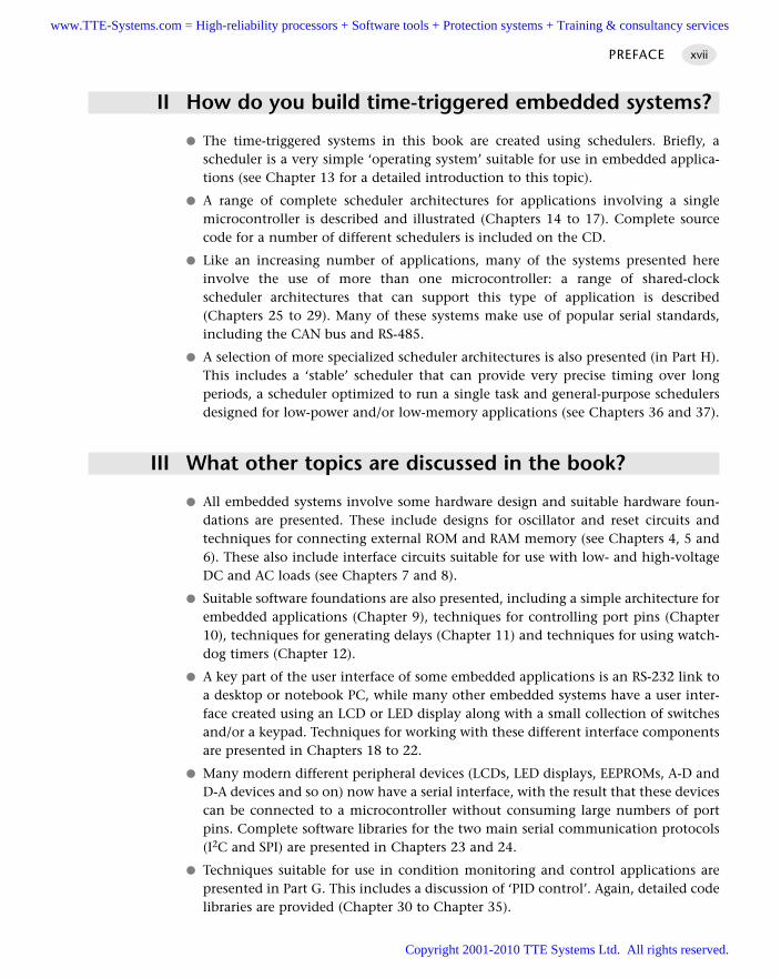
II How do you build time-triggered embedded systems?
The time-triggered systems in this book are created using schedulers. Briefly, ascheduler is a very simple ‘operating system’ suitable for use in embedded applica-tions (see Chapter 13 for a detailed introduction to this topic).
A range of complete scheduler architectures for applications involving a singlemicrocontroller is described and illustrated (Chapters 14 to 17). Complete sourcecode for a number of different schedulers is included on the CD.
Like an increasing number of applications, many of the systems presented hereinvolve the use of more than one microcontroller: a range of shared-clockscheduler architectures that can support this type of application is described(Chapters 25 to 29). Many of these systems make use of popular serial standards,including the CAN bus and RS-485.
A selection of more specialized scheduler architectures is also presented (in Part H).This includes a ‘stable’ scheduler that can provide very precise timing over longperiods, a scheduler optimized to run a single task and general-purpose schedulersdesigned for low-power and/or low-memory applications (see Chapters 36 and 37).
III What other topics are discussed in the book?
All embedded systems involve some hardware design and suitable hardware foun-dations are presented. These include designs for oscillator and reset circuits andtechniques for connecting external ROM and RAM memory (see Chapters 4, 5 and6). These also include interface circuits suitable for use with low- and high-voltageDC and AC loads (see Chapters 7 and 8).
Suitable software foundations are also presented, including a simple architecture forembedded applications (Chapter 9), techniques for controlling port pins (Chapter10), techniques for generating delays (Chapter 11) and techniques for using watch-dog timers (Chapter 12).
A key part of the user interface of some embedded applications is an RS-232 link toa desktop or notebook PC, while many other embedded systems have a user inter-face created using an LCD or LED display along with a small collection of switchesand/or a keypad. Techniques for working with these different interface componentsare presented in Chapters 18 to 22.
Many modern different peripheral devices (LCDs, LED displays, EEPROMs, A-D andD-A devices and so on) now have a serial interface, with the result that these devicescan be connected to a microcontroller without consuming large numbers of portpins. Complete software libraries for the two main serial communication protocols(I2C and SPI) are presented in Chapters 23 and 24.
Techniques suitable for use in condition monitoring and control applications arepresented in Part G. This includes a discussion of ‘PID control’. Again, detailed codelibraries are provided (Chapter 30 to Chapter 35).
www.TTE-Systems.com = High-reliability processors + Software tools + Protection systems + Training & consultancy services
Copyright 2001-2010 TTE Systems Ltd. All rights reserved.
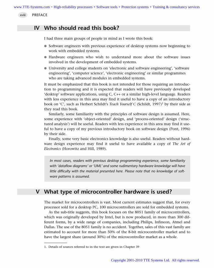
IV Who should read this book?
I had three main groups of people in mind as I wrote this book:
Software engineers with previous experience of desktop systems now beginning towork with embedded systems.
Hardware engineers who wish to understand more about the software issuesinvolved in the development of embedded systems.
University and college students on ‘electronic and software engineering’, ‘softwareengineering’, ‘computer science’, ‘electronic engineering’ or similar programmeswho are taking advanced modules in embedded systems.
It must be emphasized that this book is not intended for those requiring an introduc-tion to programming and it is expected that readers will have previously developed‘desktop’ software applications, using C, C++ or a similar high-level language. Readerswith less experience in this area may find it useful to have a copy of an introductorybook on ‘C’, such as Herbert Schildt’s Teach Yourself C (Schildt, 1997)1 by their side asthey read this book.
Similarly, some familiarity with the principles of software design is assumed. Here,some experience with ‘object-oriented’ design, and ‘process-oriented’ design (‘struc-tured analysis’) will be useful. Readers with less experience in this area may find it use-ful to have a copy of my previous introductory book on software design (Pont, 1996)by their side.
Finally, some very basic electronics knowledge is also useful. Readers without hard-ware design experience may find it useful to have available a copy of The Art ofElectronics (Horowitz and Hill, 1989).
V What type of microcontroller hardware is used?
The market for microcontrollers is vast. Most current estimates suggest that, for everyprocessor sold for a desktop PC, 100 microcontrollers are sold for embedded systems.
As the sub-title suggests, this book focuses on the 8051 family of microcontrollers,which was originally developed by Intel, but is now produced, in more than 300 dif-ferent forms, by a wide range of companies, including Philips, Infineon, Atmel andDallas. The use of the 8051 family is no accident. Together, sales of this vast family areestimated to account for more than 50% of the 8-bit microcontroller market and tohave the largest share (around 30%) of the microcontroller market as a whole.
PREFACExviii
In most cases, readers with previous desktop programming experience, some familiaritywith ‘dataflow diagrams’ or ‘UML’ and some rudimentary hardware knowledge will havelittle difficulty with the material presented here. Please note that no knowledge of soft-ware patterns is assumed.
1. Details of sources referred to in the text are given in Chapter 39
www.TTE-Systems.com = High-reliability processors + Software tools + Protection systems + Training & consultancy services
Copyright 2001-2010 TTE Systems Ltd. All rights reserved.
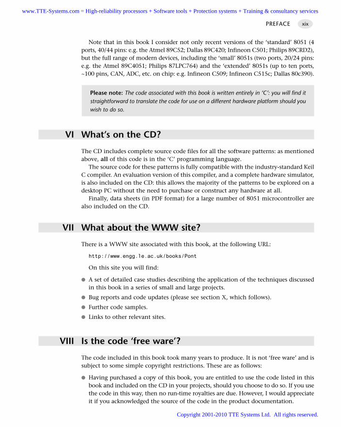
Note that in this book I consider not only recent versions of the ‘standard’ 8051 (4ports, 40/44 pins: e.g. the Atmel 89C52; Dallas 89C420; Infineon C501; Philips 89CRD2),but the full range of modern devices, including the ‘small’ 8051s (two ports, 20/24 pins:e.g. the Atmel 89C4051; Philips 87LPC764) and the ‘extended’ 8051s (up to ten ports,~100 pins, CAN, ADC, etc. on chip: e.g. Infineon C509; Infineon C515c; Dallas 80c390).
VI What’s on the CD?
The CD includes complete source code files for all the software patterns: as mentionedabove, all of this code is in the ‘C’ programming language.
The source code for these patterns is fully compatible with the industry-standard KeilC compiler. An evaluation version of this compiler, and a complete hardware simulator,is also included on the CD: this allows the majority of the patterns to be explored on adesktop PC without the need to purchase or construct any hardware at all.
Finally, data sheets (in PDF format) for a large number of 8051 microcontroller arealso included on the CD.
VII What about the WWW site?
There is a WWW site associated with this book, at the following URL:
http://www.engg.le.ac.uk/books/Pont
On this site you will find:
A set of detailed case studies describing the application of the techniques discussedin this book in a series of small and large projects.
Bug reports and code updates (please see section X, which follows).
Further code samples.
Links to other relevant sites.
VIII Is the code ‘free ware’?
The code included in this book took many years to produce. It is not ‘free ware’ and issubject to some simple copyright restrictions. These are as follows:
Having purchased a copy of this book, you are entitled to use the code listed in thisbook and included on the CD in your projects, should you choose to do so. If you usethe code in this way, then no run-time royalties are due. However, I would appreciateit if you acknowledged the source of the code in the product documentation.
PREFACE xix
Please note: The code associated with this book is written entirely in ‘C’: you will find itstraightforward to translate the code for use on a different hardware platform should youwish to do so.
www.TTE-Systems.com = High-reliability processors + Software tools + Protection systems + Training & consultancy services
Copyright 2001-2010 TTE Systems Ltd. All rights reserved.
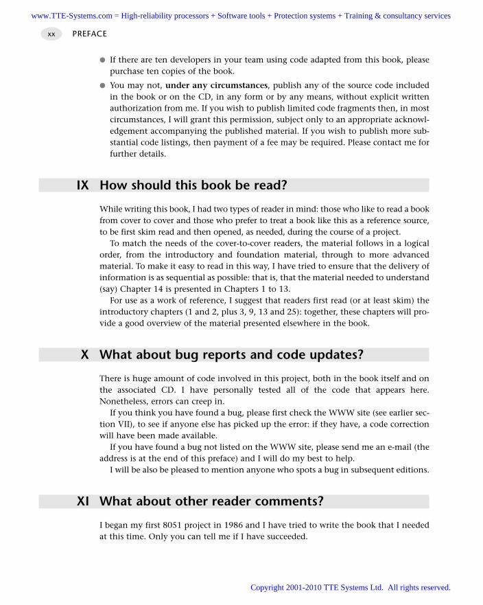
If there are ten developers in your team using code adapted from this book, pleasepurchase ten copies of the book.
You may not, under any circumstances, publish any of the source code includedin the book or on the CD, in any form or by any means, without explicit writtenauthorization from me. If you wish to publish limited code fragments then, in mostcircumstances, I will grant this permission, subject only to an appropriate acknowl-edgement accompanying the published material. If you wish to publish more sub-stantial code listings, then payment of a fee may be required. Please contact me forfurther details.
IX How should this book be read?
While writing this book, I had two types of reader in mind: those who like to read a bookfrom cover to cover and those who prefer to treat a book like this as a reference source,to be first skim read and then opened, as needed, during the course of a project.
To match the needs of the cover-to-cover readers, the material follows in a logicalorder, from the introductory and foundation material, through to more advancedmaterial. To make it easy to read in this way, I have tried to ensure that the delivery ofinformation is as sequential as possible: that is, that the material needed to understand(say) Chapter 14 is presented in Chapters 1 to 13.
For use as a work of reference, I suggest that readers first read (or at least skim) theintroductory chapters (1 and 2, plus 3, 9, 13 and 25): together, these chapters will pro-vide a good overview of the material presented elsewhere in the book.
X What about bug reports and code updates?
There is huge amount of code involved in this project, both in the book itself and onthe associated CD. I have personally tested all of the code that appears here.Nonetheless, errors can creep in.
If you think you have found a bug, please first check the WWW site (see earlier sec-tion VII), to see if anyone else has picked up the error: if they have, a code correctionwill have been made available.
If you have found a bug not listed on the WWW site, please send me an e-mail (theaddress is at the end of this preface) and I will do my best to help.
I will be also be pleased to mention anyone who spots a bug in subsequent editions.
XI What about other reader comments?
I began my first 8051 project in 1986 and I have tried to write the book that I neededat this time. Only you can tell me if I have succeeded.
PREFACExx
www.TTE-Systems.com = High-reliability processors + Software tools + Protection systems + Training & consultancy services
Copyright 2001-2010 TTE Systems Ltd. All rights reserved.
I would appreciate your comments and feedback. For example, should the book belonger? Shorter? What other areas should I cover? What should I miss out? Would youlike to see a future edition focusing on a different family of microcontrollers? If so,which one?
To ensure that any future editions continue to provide the information you need, Iwould be delighted to hear of your experiences (good or bad) using the book. I can becontacted either by post (via the publishers, please), or much more efficiently bye-mail at the address given at the end of this Preface.
I’ll do my best to respond personally and promptly to every communication.
XII Credit where credit is due
The material presented here has evolved substantially in the three years since I beganwork on this project. The creation and subsequent development of this material wouldnot have been possible without the help and support of a great many people.
In particular, I would like to thank:
Kent Beck (Three Rivers Institute) for providing the Foreword and introducing meto Ray.
The Engineering and Physical Sciences Research Council (EPSRC) and the (then)Science and Engineering Research Council (SERC), which have funded most of myresearch in this area.
Staff at a range of UK and European organizations who have employed me as a con-sultant and / or attended my training courses in software development over the lastdecade and from whom I – in turn – have learned an enormous amount aboutembedded systems, software design and programming.
Various people associated with the EuroPlop (1999) conference:
– Fiona Kinnear (then at Addison-Wesley) for suggesting that I should attend. – My ‘shepherd’, Ward Cunningham, for making me revise my submission to take
into account more of the ideas and philosophy of this book: as Ward predicted,the revised version provoked much useful debate.
– All the people who took the time to comment on my draft patterns: of these peo-ple, Kent Beck deserves a particular mention as he provided numerous construc-tive comments and general support.
The members of the Midlands Patterns Group for numerous helpful suggestionsand ideas.
Various people who have acted as reviewers during the evolution of this text:
– Michael Jackson (University of Wolverhampton) for invaluable comments on myearly ideas for the first version of this book.
– Chris Hills (Keil Software), Niall Murphy (PanelSoft) and David Ward (The MotorIndustry Research Association), who provided many useful comments on the firstcomplete draft of this book.
PREFACE xxi
www.TTE-Systems.com = High-reliability processors + Software tools + Protection systems + Training & consultancy services
Copyright 2001-2010 TTE Systems Ltd. All rights reserved.
– Mark Banner (University of Leicester) for providing useful comments on severalof the final draft chapters.
Various people at the University of Leicester:
– Members of the ‘Frankenstein’ group for inviting me to give my first talk onpatterns and, through their enthusiasm and feedback, first convincing me thatthe ideas presented here had some validity.
– Royan Ong, who has taught me a great deal about hardware design over the lasttwo years.
– Dave Dryden and Andy Willby for feedback on my hardware designs.– Andrew Norman, for creating the first version of the SPI library in Chapter 24
and – more generally – for finding numerous ‘features’ in my designs and codesince 1992.
– James Andrew, Adrian Banks, Mark Banner, Mathew Hubbard, Andrei Lesiapeto,Hitesh Mistry, Alastair Moir, Royan Ong, Chinmay Parikh, Keiron Skillett, RobertSmith, Thomas Sorrel, and Neil Whitworth, for destructive testing of many of thecode examples.
– The people who ‘saved my life’ when my computer went up in smoke in March2000, when the first draft of this book was (over)due at the publishers, in partic-ular Andy Willby and Jason Palmer.
– Other members of staff for help and advice during the course of this project,including Declan Bates, Dave Dryden, Chris Edwards, Ian Jarvis, FernandoSchlindwein and Maureen Strange.
– Ian Postlethwaite, for allowing me time to complete this large project.
Bob Damper (University of Southampton) who introduced me to the challenges ofspeech recognition using the 8051 family in the mid-1980s.
People at Keil Software:
– Reinhard Keil, for his support and for providing an updated CD at the last minute.– Chris Hills, for much useful advice.
The members of various e-mail pattern and microcontroller lists for numerous help-ful comments and suggestions.
Various people at Addison-Wesley Longman and Pearson Education:
– Sally Mortimore (then of AWL) for letting me constantly change my mind aboutthe contents of this book.
– Alison Birtwell for stepping courageously into Sally’s shoes when Sally could takeit no longer.
– Katherin Ekstrom for answering all my e-mails.– Penelope Allport, for smooth management of the final production process.– Helen Baxter, for careful copy editing.– George Moore, for proof reading the final, vast, document.– Isobel McLean, for the index.– Everyone at Pantek, for the typesetting.
PREFACExxii
www.TTE-Systems.com = High-reliability processors + Software tools + Protection systems + Training & consultancy services
Copyright 2001-2010 TTE Systems Ltd. All rights reserved.
Gordon Pont and Andrew Pont for proof reading.
Last, but not least:
– Sarah, for supporting me throughout the last three years.– Fiona, Mark, Siobhan and Clare, for teaching me how to fly kites.– Anna, Nick and Ella, for numerous Friday nights.– Lisa and Mike, for Tuscany.– Cass and Kynall Washington, for always being there.– Radiohead, for keeping me sane.
Michael J. PontGreat Dalby, May [email protected]
PREFACE xxiii
www.TTE-Systems.com = High-reliability processors + Software tools + Protection systems + Training & consultancy services
Copyright 2001-2010 TTE Systems Ltd. All rights reserved.

www.TTE-Systems.com = High-reliability processors + Software tools + Protection systems + Training & consultancy services
Copyright 2001-2010 TTE Systems Ltd. All rights reserved.
Introduction
The chapters in this introductory section are intended to answer the following questions:
What is an embedded system?
What is a time-triggered system and what are the alternatives?
Why are time-triggered systems generally considered to be more reliable than
systems based on different architectures?
What is a software pattern?
How can patterns assist in the creation of reliable embedded applications?
www.TTE-Systems.com = High-reliability processors + Software tools + Protection systems + Training & consultancy services
Copyright 2001-2010 TTE Systems Ltd. All rights reserved.

www.TTE-Systems.com = High-reliability processors + Software tools + Protection systems + Training & consultancy services
Copyright 2001-2010 TTE Systems Ltd. All rights reserved.
What is a time-triggered
embedded system?
In this introductory chapter, we consider what is meant by the phrases ‘embedded
system’ and ‘time-triggered system’ and we examine how these important areas overlap.
1.1 Introduction
Current software applications are often given one of a bewildering range of labels:
Information system
Desktop application
Real-time system
Embedded system
Event-triggered system
Time-triggered system
There is considerable overlap between the various areas. We will therefore briefly con-sider all six types of application in this chapter, to put our discussions of time-triggeredembedded systems in the remainder of this book in context.
1.2 Information systems
Information systems (ISs), and particularly ‘business information systems’, represent ahuge number of applications. Although many of the challenges of information systemdevelopment are rather different from those we will be concerned with in this book, a
chapter1www.TTE-Systems.com = High-reliability processors + Software tools + Protection systems + Training & consultancy services
Copyright 2001-2010 TTE Systems Ltd. All rights reserved.
basic understanding of such systems is useful, not least because most of the existingtechniques for real-time and embedded development have been adapted from thoseoriginally developed to support the IS field.
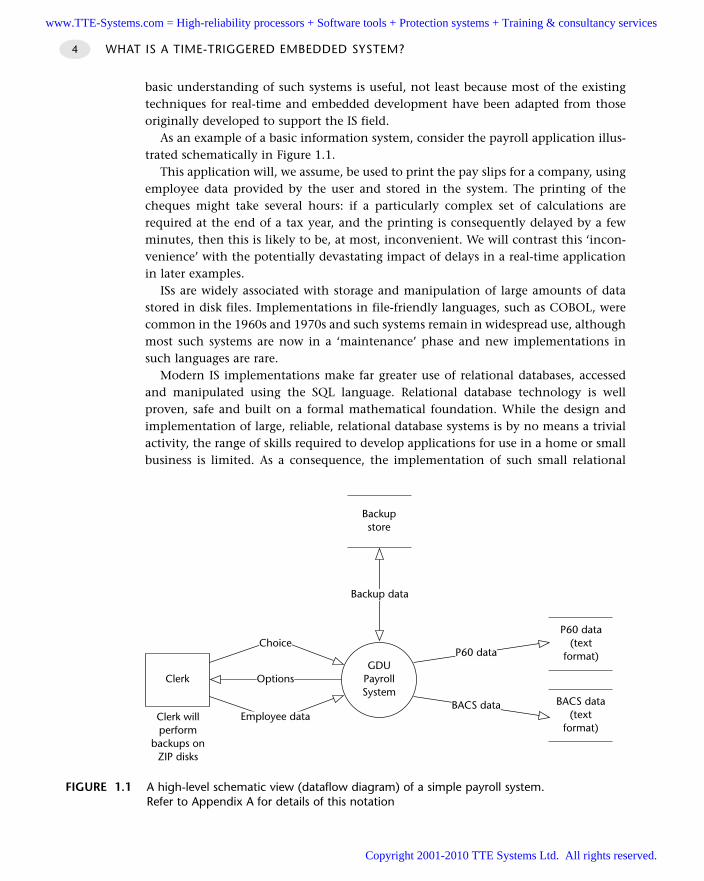
As an example of a basic information system, consider the payroll application illus-trated schematically in Figure 1.1.
This application will, we assume, be used to print the pay slips for a company, usingemployee data provided by the user and stored in the system. The printing of thecheques might take several hours: if a particularly complex set of calculations arerequired at the end of a tax year, and the printing is consequently delayed by a fewminutes, then this is likely to be, at most, inconvenient. We will contrast this ‘incon-venience’ with the potentially devastating impact of delays in a real-time applicationin later examples.
ISs are widely associated with storage and manipulation of large amounts of datastored in disk files. Implementations in file-friendly languages, such as COBOL, werecommon in the 1960s and 1970s and such systems remain in widespread use, althoughmost such systems are now in a ‘maintenance’ phase and new implementations insuch languages are rare.
Modern IS implementations make far greater use of relational databases, accessedand manipulated using the SQL language. Relational database technology is wellproven, safe and built on a formal mathematical foundation. While the design andimplementation of large, reliable, relational database systems is by no means a trivialactivity, the range of skills required to develop applications for use in a home or smallbusiness is limited. As a consequence, the implementation of such small relational
WHAT IS A TIME-TRIGGERED EMBEDDED SYSTEM?4
FIGURE 1.1 A high-level schematic view (dataflow diagram) of a simple payroll system.Refer to Appendix A for details of this notation
Backupstore
P60 data(text
format)
Backup data
GDUPayrollSystem
Clerk Options
Choice
Employee dataBACS data
(textformat)
P60 data
BACS dataClerk willperform
backups onZIP disks
www.TTE-Systems.com = High-reliability processors + Software tools + Protection systems + Training & consultancy services
Copyright 2001-2010 TTE Systems Ltd. All rights reserved.
database systems has ceased to be a specialized process and relational database designtools are now available to, and used by, many desktop computer users as part of stan-dard ‘office’ packages.
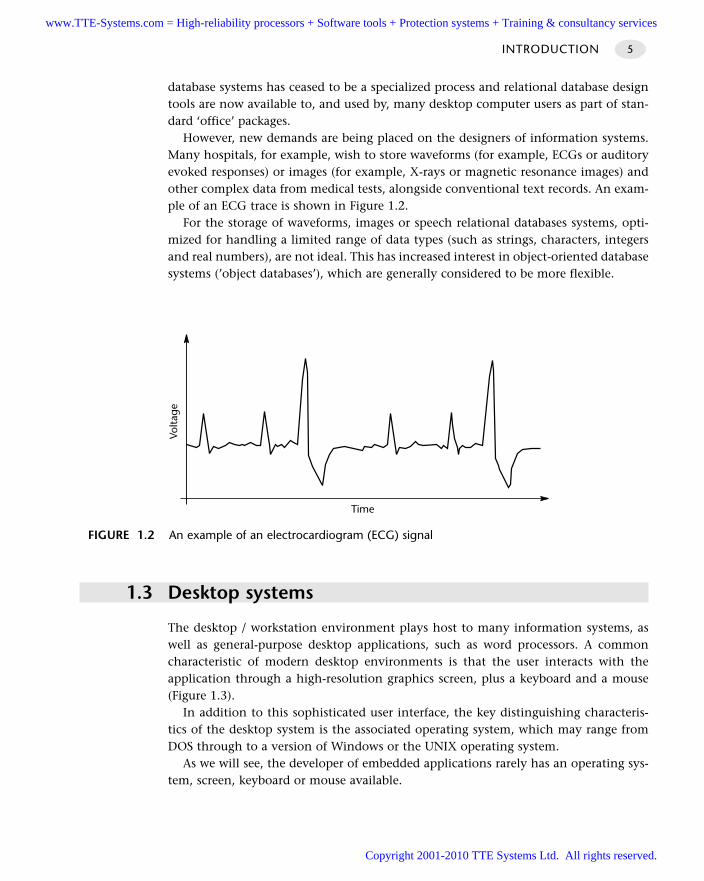
However, new demands are being placed on the designers of information systems.Many hospitals, for example, wish to store waveforms (for example, ECGs or auditoryevoked responses) or images (for example, X-rays or magnetic resonance images) andother complex data from medical tests, alongside conventional text records. An exam-ple of an ECG trace is shown in Figure 1.2.
For the storage of waveforms, images or speech relational databases systems, opti-mized for handling a limited range of data types (such as strings, characters, integersand real numbers), are not ideal. This has increased interest in object-oriented databasesystems (’object databases’), which are generally considered to be more flexible.
1.3 Desktop systems
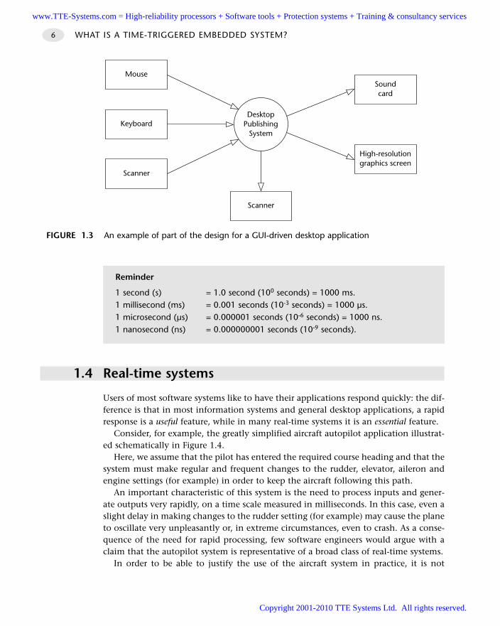
The desktop / workstation environment plays host to many information systems, aswell as general-purpose desktop applications, such as word processors. A commoncharacteristic of modern desktop environments is that the user interacts with theapplication through a high-resolution graphics screen, plus a keyboard and a mouse(Figure 1.3).
In addition to this sophisticated user interface, the key distinguishing characteris-tics of the desktop system is the associated operating system, which may range fromDOS through to a version of Windows or the UNIX operating system.
As we will see, the developer of embedded applications rarely has an operating sys-tem, screen, keyboard or mouse available.
INTRODUCTION 5
FIGURE 1.2 An example of an electrocardiogram (ECG) signal
Time
Volta
ge
www.TTE-Systems.com = High-reliability processors + Software tools + Protection systems + Training & consultancy services
Copyright 2001-2010 TTE Systems Ltd. All rights reserved.
1.4 Real-time systems
Users of most software systems like to have their applications respond quickly: the dif-ference is that in most information systems and general desktop applications, a rapidresponse is a useful feature, while in many real-time systems it is an essential feature.
Consider, for example, the greatly simplified aircraft autopilot application illustrat-ed schematically in Figure 1.4.
Here, we assume that the pilot has entered the required course heading and that thesystem must make regular and frequent changes to the rudder, elevator, aileron andengine settings (for example) in order to keep the aircraft following this path.
An important characteristic of this system is the need to process inputs and gener-ate outputs very rapidly, on a time scale measured in milliseconds. In this case, even aslight delay in making changes to the rudder setting (for example) may cause the planeto oscillate very unpleasantly or, in extreme circumstances, even to crash. As a conse-quence of the need for rapid processing, few software engineers would argue with aclaim that the autopilot system is representative of a broad class of real-time systems.
In order to be able to justify the use of the aircraft system in practice, it is not
WHAT IS A TIME-TRIGGERED EMBEDDED SYSTEM?6
FIGURE 1.3 An example of part of the design for a GUI-driven desktop application
DesktopPublishing
System
Soundcard
Keyboard
Mouse
Scanner
High-resolutiongraphics screen
Scanner
Reminder
1 second (s) = 1.0 second (100 seconds) = 1000 ms.1 millisecond (ms) = 0.001 seconds (10-3 seconds) = 1000 µs.1 microsecond (µs) = 0.000001 seconds (10-6 seconds) = 1000 ns.1 nanosecond (ns) = 0.000000001 seconds (10-9 seconds).
www.TTE-Systems.com = High-reliability processors + Software tools + Protection systems + Training & consultancy services
Copyright 2001-2010 TTE Systems Ltd. All rights reserved.
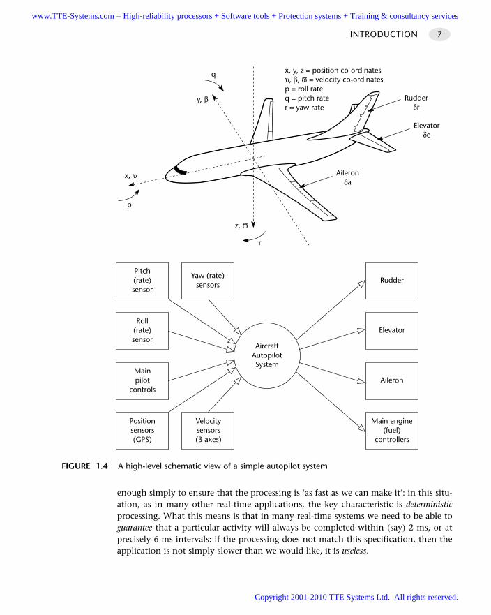
enough simply to ensure that the processing is ‘as fast as we can make it’: in this situ-ation, as in many other real-time applications, the key characteristic is deterministicprocessing. What this means is that in many real-time systems we need to be able toguarantee that a particular activity will always be completed within (say) 2 ms, or atprecisely 6 ms intervals: if the processing does not match this specification, then theapplication is not simply slower than we would like, it is useless.
INTRODUCTION 7
x, y, z = position co-ordinatesυ, β, ϖ = velocity co-ordinatesp = roll rateq = pitch rater = yaw rate
x, υ
p
y, β
q
z, ϖ
r
Aileronδa
Elevatorδe
Rudderδr
FIGURE 1.4 A high-level schematic view of a simple autopilot system
Roll(rate)sensor
AircraftAutopilotSystem
Mainpilot
controls
Pitch(rate)sensor
Positionsensors(GPS)
Velocitysensors(3 axes)
Yaw (rate)sensors
Elevator
Aileron
Rudder
Main engine(fuel)
controllers
www.TTE-Systems.com = High-reliability processors + Software tools + Protection systems + Training & consultancy services
Copyright 2001-2010 TTE Systems Ltd. All rights reserved.
Tom De Marco has provided a graphic description of this form of hard real-timerequirement in practice, quoting the words of a manager on a software project:
‘We build systems that reside in a small telemetry computer, equipped with all kinds of sensors tomeasure electromagnetic fields and changes in temperature, sound and physical disturbance. Weanalyze these signals and transmit the results back to a remote computer over a wide-band chan-nel. Our computer is at one end of a one-meter long bar and at the other end is a nuclear device.We drop them together down a big hole in the ground and when the device detonates, our com-puter collects data on the leading edge of the blast. The first two-and-a-quarter milliseconds afterdetonation are the most interesting. Of course, long before millisecond three, things have gonedown hill badly for our little computer. We think of that as a real-time constraint.
(De Marco, writing in the foreword to Hatley and Pirbhai, 1987)
In this case, it is clear that this real-time system must complete its recording ontime: it has no opportunity for a ‘second try’. This is an extreme example of what issometimes referred to as a ‘hard’ real-time system.
Note that, unlike this military example, many applications (like the aircraft systemoutlined earlier), involve repeated sampling of data from the real world (via a trans-ducer and analog-to-digital converter) and, after some (digital) processing, creating anappropriate analog output signal (via a digital-to-analog converter and an actuator).Assuming that we sample the inputs at 1000 Hz then, to qualify as a real-time system,we must be able to process this input and generate the corresponding output, beforewe are due to take the next sample (0.001 seconds later).
To summarize, consider the following ‘dictionary’ definition of a real-time system:
‘[A] program that responds to events in the world as they happen. For example, an automatic-pilotprogram in an aircraft must respond instantly in order to correct deviations from its course. Processcontrol, robotics, games, and many military applications are examples of real-time systems.’
(Hutchinson New Century Encyclopedia (CD ROM edition, 1996))
It is important to emphasize that a desire for rapid processing, either on the part ofthe designer or on the part of the client for whom the system is being developed, isnot enough, on its own, to justify the description ‘real time’. This is often misunder-stood, even by developers within the software industry. For example, Waites and Knotthave stated:
‘Some business information systems also require real-time control … Typical examples includeairline booking and some stock control systems where rapid turnover is the norm.’
(Waites and Knott, 1996, p.194)
In fact, neither of these systems can sensibly be described as a real-time application.
1.5 Embedded systems
Although it is widely associated with real-time applications, the category ‘embeddedsystems’, like that of desktop systems includes, for example, both real-time and, less
WHAT IS A TIME-TRIGGERED EMBEDDED SYSTEM?8
www.TTE-Systems.com = High-reliability processors + Software tools + Protection systems + Training & consultancy services
Copyright 2001-2010 TTE Systems Ltd. All rights reserved.
commonly, information systems. The distinguishing characteristic of an embeddedapplication is loosely summarized in the box:
Typical examples of such embedded applications include common domestic appli-ances, such as video recorders, microwave ovens and fridges. Other examples rangefrom cars through combine harvesters to aircraft and numerous defence systems.Please note that this definition excludes applications such as ‘palm computers’ which– from a developer’s perspective – are best viewed as a cut-down version of a desktopcomputer system.
While the desktop market is driven by a need to provide ever more performance,in order to support sophisticated operating systems and applications, the embeddedmarket has rather different needs. For example, recent economic, legislative and tech-nological developments in the automotive sector mean that an increasing number ofroad vehicles contain embedded systems. In some cases, such systems have beenintroduced primarily as a means of reducing production costs: for example, in mod-ern vehicles, expensive (~£600.00) multi-wire looms have now been replaced by atwo-wire controller area network (CAN) computer bus at a fraction of the cost (Perierand Coen, 1998). In other situations, such as the introduction of active suspensionsystems, the embedded systems have been introduced to improve ride quality andhandling (Sharp, 1998).
Consider a very simple example which may help to illustrate some of the require-ments of the embedded market: the indicator light circuit for a passenger car. In thisapplication we need to be able to control six or more indicator lights from a switchbehind the steering wheel, allowing the driver to tell other road users that he or sheintends to turn a corner, change lane or park. For the US (and some other) markets, weexpect the indicator circuit to interact with the rear lights (so that one light flashes toindicate the direction of a turn); in Europe, we expect indicator and rear lights to oper-ate separately. Furthermore, in some countries, we wish to use the indicator lights as‘parking lights’, to avoid having people run into our (parked) car at night.
The Volvo 131 (‘Amazon’) demonstrates the traditional solution to this problem.This classic European car from the 1960s uses a considerable amount of wire and somemechanical switches to provide indicator and braking behaviour: if we wanted toadjust this car to operate in the US style, we would have make substantial changes tothe wiring loom. To avoid this type of expensive, labour-intensive conversion, moremodern cars use a microcontroller to provide the required behaviour. Not only doesthe microcontroller solution result in a simpler, and cheaper, collection of wires, it canalso be converted between US and European indicator standards by flicking a switchor changing a memory chip.
INTRODUCTION 9
An embedded system is an application that contains at least one programmablecomputer (typically in the form of a microcontroller, a microprocessor or digital signalprocessor chip) and which is used by individuals who are, in the main, unaware that thesystem is computer-based.
www.TTE-Systems.com = High-reliability processors + Software tools + Protection systems + Training & consultancy services
Copyright 2001-2010 TTE Systems Ltd. All rights reserved.
This simple application highlights four important features of many embeddedapplications.
Like this indicator system, many applications employ microcontrollers not becausethe processing is complex, but because the microcontroller is flexible and, crucially,because it results in a cost-effective solution. As a result, many products haveembedded microcontrollers sitting almost idle for much of their operational life.The fact that many commonly used microcontrollers are, by comparison with mod-ern desktop microprocessors, often rather slow, is seldom of great concern.
Unlike most microprocessors, microcontrollers are required to interact with the out-side world, not via keyboards and graphical user interfaces, but via switches, smallkeypads, LEDs and so on. The provision of extensive I/O facilities is a key drivingforce for many microcontroller manufacturers.
Like the indicator system, most embedded applications are required to execute par-ticular tasks at precise time intervals or at particular instants of time. In this case,for example, the indicators lights must flash on at a precise frequency and dutycycle in order to satisfy legal requirements. This type of application is considered ingreater detail in Chapter 2.
Unlike many desktop applications (for example) many embedded applications havesafety implications. For example, if the indicator lights fail while the car is in use,this could result in an accident. As a result, reliability is a crucial requirement inmany embedded applications.
1.6 Event-triggered systems
Many applications are now described as ‘event triggered’ or ‘event driven’. For exam-ple, in the case of modern desktop applications, the various running applications mustrespond to events such as mouse clicks or mouse movements. A key expectation ofusers is that such events will invoke an ‘immediate’ response.
In embedded systems, event-triggered behaviour is often achieved through the useof interrupts (see following box). To support these, event-triggered system architecturesoften provide multiple interrupt service routines.
What is an interrupt?
From a low-level perspective, an interrupt is a hardware mechanism used to notify aprocessor that an ‘event’ has taken place: such events may be ‘internal’ events (such asthe overflow of a timer) or ‘external’ events (such as the arrival of a character through aserial interface).
Viewed from a high-level perspective, interrupts provide a mechanism for creatingmultitasking applications: that is applications which, apparently, perform more than one
WHAT IS A TIME-TRIGGERED EMBEDDED SYSTEM?10
www.TTE-Systems.com = High-reliability processors + Software tools + Protection systems + Training & consultancy services
Copyright 2001-2010 TTE Systems Ltd. All rights reserved.
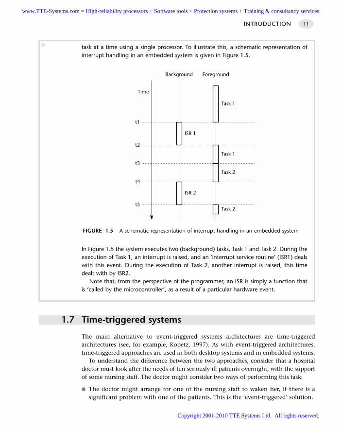
INTRODUCTION 11
task at a time using a single processor. To illustrate this, a schematic representation ofinterrupt handling in an embedded system is given in Figure 1.5.
In Figure 1.5 the system executes two (background) tasks, Task 1 and Task 2. During theexecution of Task 1, an interrupt is raised, and an ‘interrupt service routine’ (ISR1) dealswith this event. During the execution of Task 2, another interrupt is raised, this timedealt with by ISR2.
Note that, from the perspective of the programmer, an ISR is simply a function thatis ‘called by the microcontroller’, as a result of a particular hardware event.
1.7 Time-triggered systems
The main alternative to event-triggered systems architectures are time-triggeredarchitectures (see, for example, Kopetz, 1997). As with event-triggered architectures,time-triggered approaches are used in both desktop systems and in embedded systems.
To understand the difference between the two approaches, consider that a hospitaldoctor must look after the needs of ten seriously ill patients overnight, with the supportof some nursing staff. The doctor might consider two ways of performing this task:
The doctor might arrange for one of the nursing staff to waken her, if there is asignificant problem with one of the patients. This is the ‘event-triggered’ solution.
t1
t2
t3
t4
t5
ISR 1
Task 1
Task 2
Background Foreground
Time
Task 1
Task 2
ISR 2
FIGURE 1.5 A schematic representation of interrupt handling in an embedded system
www.TTE-Systems.com = High-reliability processors + Software tools + Protection systems + Training & consultancy services
Copyright 2001-2010 TTE Systems Ltd. All rights reserved.
WHAT IS A TIME-TRIGGERED EMBEDDED SYSTEM?12
The doctor might set her alarm clock to ring every hour. When the alarm goes off,she will get up and visit each of the patients, in turn, to check that they are welland, if necessary, prescribe treatment. This is the ‘time-triggered’ solution.
For most doctors, the event-triggered approach will seem the more attractive, becausethey are likely to get a few hours of sleep during the course of the night. By contrast,with the time-triggered approach, the doctor will inevitably suffer sleep deprivation.
However, in the case of many embedded systems – which do not need sleep – thetime-triggered approach has many advantages. Indeed, within industrial sectors wheresafety is an obvious concern, such as the aerospace industry and, increasingly, theautomotive industry, time-triggered techniques are widely used because it is accepted,both by the system developers and their certification authorities, that they helpimprove reliability and safety (see, for example, Allworth, 1981; MISRA, 1994; Storey,1996; Nissanke, 1997; Bates, 2000 for discussion of these issues).
The main reason that time-triggered approaches are preferred in safety-related appli-cations is that they result in systems which have very predictable behaviour. If we revis-it the hospital analogy, we can begin to see why this is so.
Suppose, for example, that our ‘event-triggered’ doctor is sleeping peacefully. Anapparently minor problem develops with one of the patients and the nursing staffdecide not to awaken the doctor but to deal with the problem themselves. After anoth-er two hours, when four patients have ‘minor’ problems, the nurses decide that theywill have to wake the doctor after all. As soon as the doctor sees the patients, she rec-ognizes that two of them have a severe complications, and she has to begin surgery.Before she can complete the surgery on the first patient, the second patient is veryclose to death.
Consider the same example with the ‘time-triggered’ doctor. In this case, becausethe patient visits take place at hourly intervals, the doctor sees each patient before seri-ous complications arise and arranges appropriate treatment. Another way of viewingthis is that the workload is spread out evenly throughout the night. As a result, all thepatients survive the night without difficulty.
In embedded applications, the (rather macabre) hospital situation is mirrored in theevent-driven application by the occurrence of several events (that is, several interrupts)at the same time. This might indicate, for example, that two different faults had beendetected simultaneously in an aircraft or simply that two switches had been pressed atthe same time on a keypad.
To see why the simultaneous occurrence of two interrupts causes a problem, con-sider what happens in the 8051 architecture in these circumstances. Like many micro-controllers, the original 8051 architecture supports two different interrupt priority lev-els: low and high. If two interrupts (we will call them Interrupt 1 and Interrupt 2) occurin rapid succession, the system will behave as follows:
If Interrupt 1 is a low-priority interrupt and Interrupt 2 is a high-priority interrupt: The interrupt service routine (ISR) invoked by a low-priority interrupt can be interrupted
by a high-priority interrupt. In this case, the low-priority ISR will be paused, to allow thehigh-priority ISR to be executed, after which the operation of the low-priority ISR will be
www.TTE-Systems.com = High-reliability processors + Software tools + Protection systems + Training & consultancy services
Copyright 2001-2010 TTE Systems Ltd. All rights reserved.
completed. In most cases, the system will operate correctly (provided that the two ISRs donot interfere with one another).
If Interrupt 1 is a low-priority interrupt and Interrupt 2 is also a low-priority interrupt:
The ISR invoked by a low-priority interrupt cannot be interrupted by another low-priority interrupt. As a result, the response to the second interrupt will be at the very leastdelayed; under some circumstances it will be ignored altogether.
If Interrupt 1 is a high-priority interrupt and Interrupt 2 is a low-priority interrupt:
The interrupt service routine (ISR) invoked by a high-priority interrupt cannot beinterrupted by a low-priority interrupt. As a result, the response to the second interrupt willbe at the very least delayed; under some circumstances it will be ignored altogether.
If Interrupt 1 is a high-priority interrupt and Interrupt 2 is also a high-priorityinterrupt:
The interrupt service routine (ISR) invoked by a high-priority interrupt cannot be inter-rupted by another high-priority interrupt. As a result, the response to the second interruptwill be at the very least delayed; under some circumstances it will be ignored altogether.
It is the need to deal with the simultaneous occurrence of more than one event thatboth adds to the system complexity and reduces the ability to predict the behaviour ofan event-triggered system under all circumstances. By contrast, in a time-triggeredembedded application, the designer is able to ensure that only single events must behandled at a time, in a carefully controlled sequence.
As already mentioned, the predictable nature of time-triggered applications makesthis approach the usual choice in safety-related applications, where reliability is a cru-cial design requirement. However, the need for reliability is not restricted to systemssuch as fly-by-wire aircraft and drive-by-wire passenger cars: even at the lowest level,an alarm clock that fails to sound on time or a video recorder that operates intermit-tently, or a data monitoring system that – once a year – loses a few bytes of data maynot have safety implications but, equally, will not have high sales figures.
In addition to increasing reliability, the use of time-triggered techniques can help toreduce both CPU loads and memory usage: as a result, as we demonstrate throughoutthis book, even the smallest of embedded applications can benefit from the use of thisform of system architecture.
INTRODUCTION 13
Note carefully what this means! There is a common misconception among the devel-opers of embedded applications that interrupt events will never be lost. This simplyis not true. If you have multiple sources of interrupts that may appear at ‘random’time intervals, interrupt responses can be missed: indeed, where there are severalactive interrupt sources, it is practically impossible to create code that will deal cor-rectly with all possible combinations of interrupts.
www.TTE-Systems.com = High-reliability processors + Software tools + Protection systems + Training & consultancy services
Copyright 2001-2010 TTE Systems Ltd. All rights reserved.
1.8 Conclusions
The various characteristics of time-triggered embedded systems introduced in thischapter will be explored in greater depth throughout this book.
In the next chapter, we consider why ‘traditional’ software design techniques pro-vide only limited support for the developers of this type of application and argue thatsoftware patterns can provide a useful adjunct to existing approaches.
WHAT IS A TIME-TRIGGERED EMBEDDED SYSTEM?14
www.TTE-Systems.com = High-reliability processors + Software tools + Protection systems + Training & consultancy services
Copyright 2001-2010 TTE Systems Ltd. All rights reserved.
Designing embedded systems
using patterns
In this second introductory chapter, we consider why ‘traditional’ software design tech-
niques provide only limited support for the developers of embedded applications and
argue that software patterns can provide a useful adjunct to such techniques.
2.1 Introduction
Most branches of engineering have a long history. Work in the area of control systems,for example, might be said to have begun with the seminal studies by James Watt on theflywheel governor in the 1760s, while work in electrical engineering can be dated backto the work of Michael Faraday, who is generally credited with the invention of the elec-tric motor in 1821. It can be argued that the practice of civil engineering has the longesthistory of all, originating, perhaps, with the building of the Egyptian pyramids, or toGreek or Roman times: certainly the Institution of Civil Engineers was founded inEngland (UK) in 1818 and is the oldest professional engineering institution in the world.
For the software engineer, a different situation applies. The first mass-producedminicomputer, the PDP-8, was launched only in 1965 and the first microprocessoronly in 1971. As a result of the comparatively late introduction, and subsequent rapidevolution, of small programmable computer systems, the field of software engineeringhas had little opportunity to mature. In the limited time available, much work on soft-ware engineering has focused on the design process and, in particular, on the devel-opment and use of various graphical notations, including process-oriented notations,such as dataflow diagrams (Yourdon, 1989: see Figure 2.1), and object-oriented nota-tions, such as the ‘Unified Modelling Language’ (Fowler and Scott, 2000). The use ofsuch notations is supported by ‘methodologies’: these are collections of ‘recipes’ for
chapter 2www.TTE-Systems.com = High-reliability processors + Software tools + Protection systems + Training & consultancy services
Copyright 2001-2010 TTE Systems Ltd. All rights reserved.
INTRODUCTION16
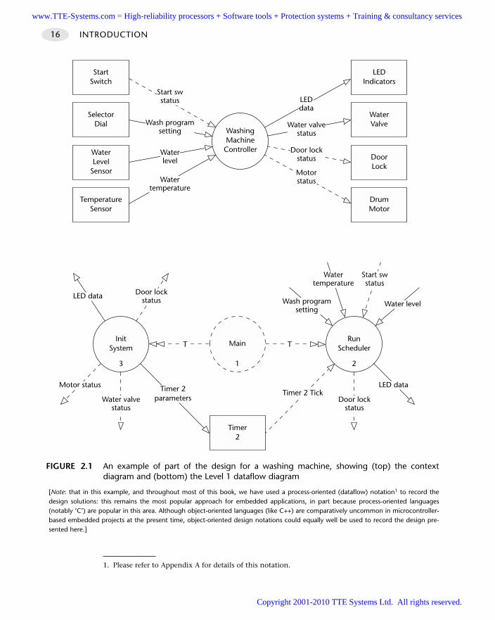
FIGURE 2.1 An example of part of the design for a washing machine, showing (top) the contextdiagram and (bottom) the Level 1 dataflow diagram
[Note: that in this example, and throughout most of this book, we have used a process-oriented (dataflow) notation1 to record thedesign solutions: this remains the most popular approach for embedded applications, in part because process-oriented languages(notably ‘C’) are popular in this area. Although object-oriented languages (like C++) are comparatively uncommon in microcontroller-based embedded projects at the present time, object-oriented design notations could equally well be used to record the design pre-sented here.]
MainRun
SchedulerInit
System
Timer2
23 1
TT
Watertemperature
Start swstatus
Water levelWash programsetting
LED dataTimer 2 Tick
Door lockstatus
Timer 2parametersWater valve
status
Motor status
LED data Door lockstatus
DoorLock
WaterValve
LEDIndicators
DrumMotor
WashingMachine
ControllerWaterLevel
Sensor
SelectorDial
StartSwitch
TemperatureSensor
Door lockstatus
Water valvestatus
LEDdata
Motorstatus
Waterlevel
Wash programsetting
Start swstatus
Watertemperature
1. Please refer to Appendix A for details of this notation.
www.TTE-Systems.com = High-reliability processors + Software tools + Protection systems + Training & consultancy services
Copyright 2001-2010 TTE Systems Ltd. All rights reserved.
software design, detailing how and when particular notations should be used in a proj-ect (see, for example, Pont, 1996). The designs that result from the application of thesetechniques consist of a set of linked diagrams, each following a standard notation, andaccompanied by appropriate supporting documentation (Yourdon, 1989; Booch, 1994;Pont, 1996; Fowler and Scott, 2000).
As the title suggests, we are concerned in this book with the development of soft-ware for embedded systems. In the past, despite the ubiquitous nature of embeddedapplications, the design of such systems has not been a major focus of attention with-in the software field. Indeed, in almost all cases, software design techniques have beendeveloped first to meet the needs of the developers of desktop business systems(DeMarco, 1978; Rumbaugh et al., 1991; Coleman et al., 1994), and then subsequent-ly ‘adapted’ in an attempt to meet the needs of developers of real-time and / or embed-ded applications (Hatley and Pirbhai, 1987; Selic et al., 1994; Awad et al., 1996;Douglass, 1998). We will argue (in Section 2.2) that the resulting software design tech-niques, although not without merit, cannot presently meet the needs of the designersof embedded systems. We then go on to propose (Sections 2.2 and 2.4) that the use ofsoftware patterns as an adjunct to existing techniques represents a promising way toalleviate some of the current problems.
2.2 Limitations of existing software design techniques
We begin the main part of this chapter by considering two examples whichillustrate the limitations of standard design techniques when used for embeddedsystem development.
Cruise-control system
As a first example, we will consider a cruise-control system (CCS) for a road vehicle. ACCS is often used to demonstrate the effectiveness of real-time software designmethodologies (for example, see Hatley and Pirbhai, 1987; Awad et al., 1996). Such asystem is usually assumed to be required to take over the task of maintaining the vehi-cle at a constant speed even while negotiating a varying terrain, involving, for exam-ple, hills or corners in the road. Subject to certain conditions (typically that the vehi-cle is in top gear and exceeding a preset minimum speed), the cruise control is furtherassumed to be engaged by the driver via a push switch on the dashboard and disen-gaged by touching the brake pedal.
As an example, an outline process-oriented (‘structured’) design for such a system isillustrated in Figure 2.2 to Figure 2.5. This design is adapted from that suggested byHatley and Pirbhai (1987) in a standard text on real-time software design. Starting at thehighest level of abstraction, Figure 2.2 shows the ‘context diagram’ for the system. Figure2.3 shows the corresponding Level 1 dataflow diagram, which describes in more detailthe processing carried by the process ‘simple cruise control’ in Figure 2.2. Figure 2.4in turn shows the state-transition diagram associated with ‘main control process’in Figure 2.3.
DESIGNING EMBEDDED SYSTEMS USING PATTERNS 17
www.TTE-Systems.com = High-reliability processors + Software tools + Protection systems + Training & consultancy services
Copyright 2001-2010 TTE Systems Ltd. All rights reserved.
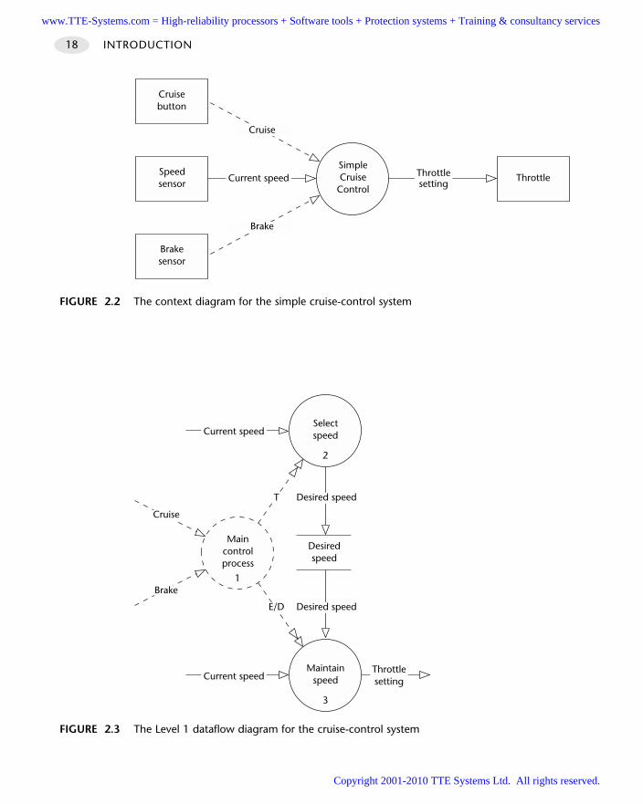
INTRODUCTION18
FIGURE 2.2 The context diagram for the simple cruise-control system
SimpleCruise
Control
Speedsensor Current speed
Cruisebutton
Brakesensor
Cruise
Brake
ThrottleThrottlesetting
FIGURE 2.3 The Level 1 dataflow diagram for the cruise-control system
Maincontrolprocess
1
Desiredspeed
Maintainspeed
3
Selectspeed
2
T Desired speed
E/D Desired speed
Current speed
Current speed
Throttlesetting
Cruise
Brake
www.TTE-Systems.com = High-reliability processors + Software tools + Protection systems + Training & consultancy services
Copyright 2001-2010 TTE Systems Ltd. All rights reserved.
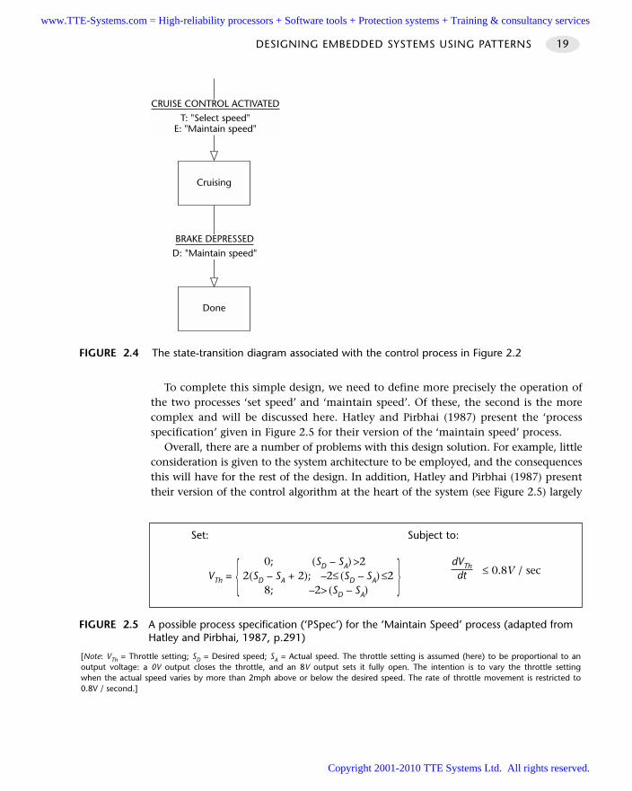
To complete this simple design, we need to define more precisely the operation ofthe two processes ‘set speed’ and ‘maintain speed’. Of these, the second is the morecomplex and will be discussed here. Hatley and Pirbhai (1987) present the ‘processspecification’ given in Figure 2.5 for their version of the ‘maintain speed’ process.
Overall, there are a number of problems with this design solution. For example, littleconsideration is given to the system architecture to be employed, and the consequencesthis will have for the rest of the design. In addition, Hatley and Pirbhai (1987) presenttheir version of the control algorithm at the heart of the system (see Figure 2.5) largely
DESIGNING EMBEDDED SYSTEMS USING PATTERNS 19
FIGURE 2.4 The state-transition diagram associated with the control process in Figure 2.2
Cruising
BRAKE DEPRESSED
D: "Maintain speed"
Done
CRUISE CONTROL ACTIVATED
T: "Select speed"E: "Maintain speed"
FIGURE 2.5 A possible process specification (‘PSpec’) for the ‘Maintain Speed’ process (adapted fromHatley and Pirbhai, 1987, p.291)
[Note: VTh = Throttle setting; SD = Desired speed; SA = Actual speed. The throttle setting is assumed (here) to be proportional to anoutput voltage: a 0V output closes the throttle, and an 8V output sets it fully open. The intention is to vary the throttle settingwhen the actual speed varies by more than 2mph above or below the desired speed. The rate of throttle movement is restricted to0.8V / second.]
Set: Subject to:
0; (SD – SA) >2 dVThVTh = 2(SD – SA + 2); –2≤ (SD – SA) ≤2 ≤ 0.8V / sec
8; –2> (SD – SA)dt
www.TTE-Systems.com = High-reliability processors + Software tools + Protection systems + Training & consultancy services
Copyright 2001-2010 TTE Systems Ltd. All rights reserved.
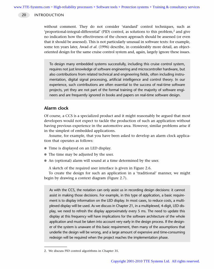
without comment. They do not consider ‘standard’ control techniques, such as‘proportional-integral-differential’ (PID) control, as solutions to this problem,2 and giveno indication how the effectiveness of the chosen approach should be assessed (or eventhat it should be assessed). This is not particularly unusual in software texts: for example,some ten years later, Awad et al. (1996) describe, in considerably more detail, an object-oriented design for the same cruise control system and, again, largely ignore these issues.
Alarm clock
Of course, a CCS is a specialized product and it might reasonably be argued that mostdevelopers would not expect to tackle the production of such an application withouthaving previous experience in the automotive area. However, similar problems arise ifin the simplest of embedded applications.
Assume, for example, that you have been asked to develop an alarm clock applica-tion that operates as follows:
Time is displayed on an LED display.
The time may be adjusted by the user.
An (optional) alarm will sound at a time determined by the user.
A sketch of the required user interface is given in Figure 2.6.To create the design for such an application in a ‘traditional’ manner, we might
begin by drawing a context diagram (Figure 2.7).
INTRODUCTION20
To design many embedded systems successfully, including this cruise control system,requires not just knowledge of software engineering and microcontroller hardware, butalso contributions from related technical and engineering fields, often including instru-mentation, digital signal processing, artificial intelligence and control theory. In ourexperience, such contributions are often essential to the success of real-time softwareprojects, yet they are not part of the formal training of the majority of software engi-neers and are frequently ignored in books and papers on real-time software design.
As with the CCS, the notation can only assist us in recording design decisions: it cannotassist in making those decisions. For example, in this type of application, a basic require-ment is to display information on the LED display. In most cases, to reduce costs, a multi-plexed display will be used. As we discuss in Chapter 21, in a multiplexed, 4-digit, LED dis-play, we need to refresh the display approximately every 5 ms. The need to update thisdisplay at this frequency will have implications for the software architecture of the wholeapplication and must be taken into account very early in the design process. If the design-er of the system is unaware of this basic requirement, then many of the assumptions thatunderlie the design will be wrong, and a large amount of expensive and time-consumingredesign will be required when the project reaches the implementation phase.
2. We discuss PID control algorithms in Chapter 35.
www.TTE-Systems.com = High-reliability processors + Software tools + Protection systems + Training & consultancy services
Copyright 2001-2010 TTE Systems Ltd. All rights reserved.
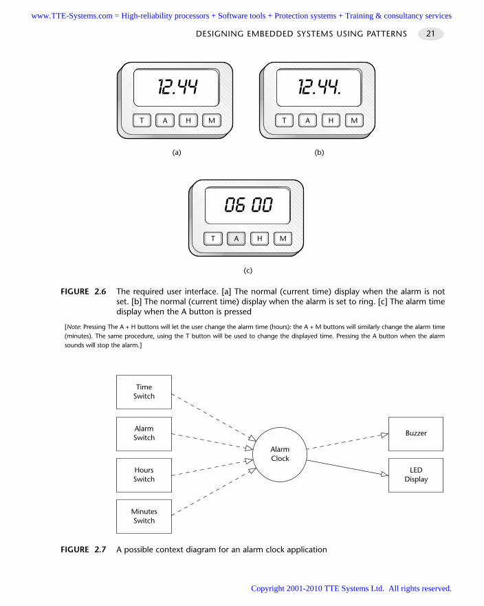
DESIGNING EMBEDDED SYSTEMS USING PATTERNS 21
FIGURE 2.6 The required user interface. [a] The normal (current time) display when the alarm is notset. [b] The normal (current time) display when the alarm is set to ring. [c] The alarm timedisplay when the A button is pressed
[Note: Pressing The A + H buttons will let the user change the alarm time (hours): the A + M buttons will similarly change the alarm time(minutes). The same procedure, using the T button will be used to change the displayed time. Pressing the A button when the alarmsounds will stop the alarm.]
T H M
(c)
A
T H M
(a)
A T H M
(b)
A
FIGURE 2.7 A possible context diagram for an alarm clock application
LEDDisplay
Buzzer
AlarmClock
HoursSwitch
AlarmSwitch
TimeSwitch
MinutesSwitch
www.TTE-Systems.com = High-reliability processors + Software tools + Protection systems + Training & consultancy services
Copyright 2001-2010 TTE Systems Ltd. All rights reserved.
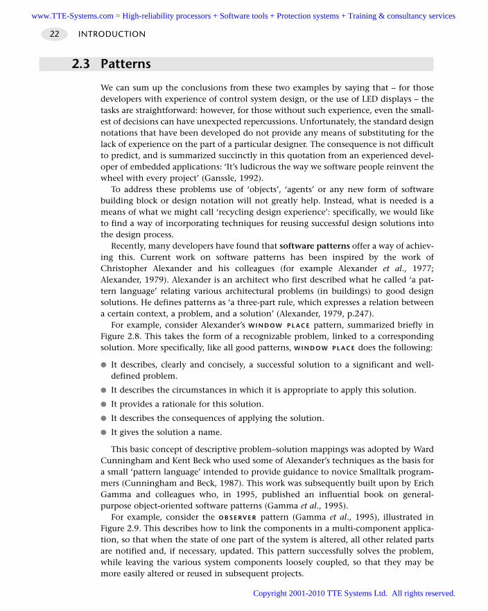
2.3 Patterns
We can sum up the conclusions from these two examples by saying that – for thosedevelopers with experience of control system design, or the use of LED displays – thetasks are straightforward: however, for those without such experience, even the small-est of decisions can have unexpected repercussions. Unfortunately, the standard designnotations that have been developed do not provide any means of substituting for thelack of experience on the part of a particular designer. The consequence is not difficultto predict, and is summarized succinctly in this quotation from an experienced devel-oper of embedded applications: ‘It’s ludicrous the way we software people reinvent thewheel with every project’ (Ganssle, 1992).
To address these problems use of ‘objects’, ‘agents’ or any new form of softwarebuilding block or design notation will not greatly help. Instead, what is needed is ameans of what we might call ‘recycling design experience’: specifically, we would liketo find a way of incorporating techniques for reusing successful design solutions intothe design process.
Recently, many developers have found that software patterns offer a way of achiev-ing this. Current work on software patterns has been inspired by the work ofChristopher Alexander and his colleagues (for example Alexander et al., 1977;Alexander, 1979). Alexander is an architect who first described what he called ‘a pat-tern language’ relating various architectural problems (in buildings) to good designsolutions. He defines patterns as ‘a three-part rule, which expresses a relation betweena certain context, a problem, and a solution’ (Alexander, 1979, p.247).
For example, consider Alexander’s W I N D O W P L A C E pattern, summarized briefly inFigure 2.8. This takes the form of a recognizable problem, linked to a correspondingsolution. More specifically, like all good patterns, W I N D O W P L A C E does the following:
It describes, clearly and concisely, a successful solution to a significant and well-defined problem.
It describes the circumstances in which it is appropriate to apply this solution.
It provides a rationale for this solution.
It describes the consequences of applying the solution.
It gives the solution a name.
This basic concept of descriptive problem–solution mappings was adopted by WardCunningham and Kent Beck who used some of Alexander’s techniques as the basis fora small ‘pattern language’ intended to provide guidance to novice Smalltalk program-mers (Cunningham and Beck, 1987). This work was subsequently built upon by ErichGamma and colleagues who, in 1995, published an influential book on general-purpose object-oriented software patterns (Gamma et al., 1995).
For example, consider the O B S E RV E R pattern (Gamma et al., 1995), illustrated inFigure 2.9. This describes how to link the components in a multi-component applica-tion, so that when the state of one part of the system is altered, all other related partsare notified and, if necessary, updated. This pattern successfully solves the problem,while leaving the various system components loosely coupled, so that they may bemore easily altered or reused in subsequent projects.
INTRODUCTION22
www.TTE-Systems.com = High-reliability processors + Software tools + Protection systems + Training & consultancy services
Copyright 2001-2010 TTE Systems Ltd. All rights reserved.
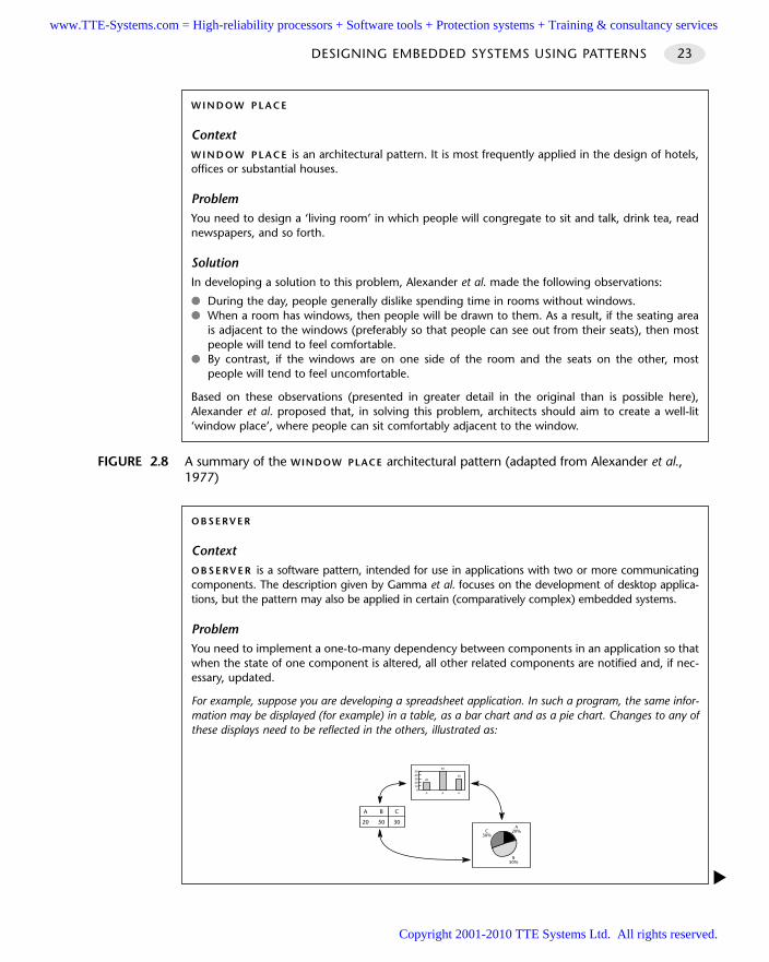
DESIGNING EMBEDDED SYSTEMS USING PATTERNS 23
FIGURE 2.8 A summary of the WINDOW PLACE architectural pattern (adapted from Alexander et al.,1977)
W I N D O W P L A C E
ContextW I N D O W P L A C E is an architectural pattern. It is most frequently applied in the design of hotels,offices or substantial houses.
ProblemYou need to design a ‘living room’ in which people will congregate to sit and talk, drink tea, readnewspapers, and so forth.
SolutionIn developing a solution to this problem, Alexander et al. made the following observations:
During the day, people generally dislike spending time in rooms without windows. When a room has windows, then people will be drawn to them. As a result, if the seating area
is adjacent to the windows (preferably so that people can see out from their seats), then mostpeople will tend to feel comfortable.
By contrast, if the windows are on one side of the room and the seats on the other, mostpeople will tend to feel uncomfortable.
Based on these observations (presented in greater detail in the original than is possible here),Alexander et al. proposed that, in solving this problem, architects should aim to create a well-lit‘window place’, where people can sit comfortably adjacent to the window.
O B S E RV E R
ContextO B S E RV E R is a software pattern, intended for use in applications with two or more communicatingcomponents. The description given by Gamma et al. focuses on the development of desktop applica-tions, but the pattern may also be applied in certain (comparatively complex) embedded systems.
ProblemYou need to implement a one-to-many dependency between components in an application so thatwhen the state of one component is altered, all other related components are notified and, if nec-essary, updated.
For example, suppose you are developing a spreadsheet application. In such a program, the same infor-mation may be displayed (for example) in a table, as a bar chart and as a pie chart. Changes to any ofthese displays need to be reflected in the others, illustrated as:
01020304050
20
A
50
A
30
A
305020
CBA
A20%C
30%
B50%
www.TTE-Systems.com = High-reliability processors + Software tools + Protection systems + Training & consultancy services
Copyright 2001-2010 TTE Systems Ltd. All rights reserved.
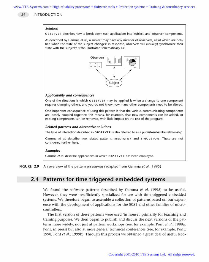
2.4 Patterns for time-triggered embedded systems
We found the software patterns described by Gamma et al. (1995) to be useful.However, they were insufficiently specialized for use with time-triggered embeddedsystems. We therefore began to assemble a collection of patterns based on our experi-ence with the development of applications for the 8051 and other families of micro-controllers.
The first version of these patterns were used ‘in house’, primarily for teaching andtraining purposes. We then began to publish and discuss the next versions of the pat-terns more widely, not just at pattern workshops (see, for example, Pont et al., 1999a;Pont, in press) but also at more general technical conferences (see, for example, Pont,1998; Pont et al., 1999b). Through this process we obtained a great deal of useful feed-
INTRODUCTION24
FIGURE 2.9 An overview of the pattern O B S E RV E R (adapted from Gamma et al., 1995)
SolutionO B S E RV E R describes how to break down such applications into ‘subject’ and ‘observer’ components.
As described by Gamma et al., a subject may have any number of observers, all of which are noti-fied when the state of the subject changes: in response, observers will (usually) synchronize theirstate with the subject’s state, illustrated schematically as:
Applicability and consequencesOne of the situations is which O B S E RV E R may be applied is when a change to one componentrequires changing others, and you do not know how many other components need to be altered.
One important consequence of using this pattern is that the various communicating componentsare loosely coupled together: this means, for example, that new components can be added, orexisting components can be removed, with little impact on the rest of the program.
Related patterns and alternative solutionsThe type of interaction described in O B S E RV E R is also referred to as a publish-subscribe relationship.
Gamma et al. describe two related patterns: M E D I AT O R and S I N G L E T O N . These are notconsidered further here.
ExamplesGamma et al. describe applications in which O B S E RV E R has been employed.
A20%C
30%
B50%305020
CBA0
1020304050
20
A
50
A
30
A
Observers
Subject
www.TTE-Systems.com = High-reliability processors + Software tools + Protection systems + Training & consultancy services
Copyright 2001-2010 TTE Systems Ltd. All rights reserved.
back on the project, and refined the collection again. The end result was the set of pat-terns described in detail throughout this book.
The structure of the final version of the patterns is illustrated in Figure 2.10. Thepatterns are grouped by chapter, and the book is further divided into sections. Thisarrangement is intended to make it easy for you to find the information you require.
2.5 Conclusions
In this second brief introductory chapter, we have argued that developers of embed-ded applications can benefit from pattern-driven design techniques not least becausemany embedded projects require the developer to have both knowledge of softwaredesign and from a range of related technical and engineering fields.
Four points should be made as we conclude this chapter:
Software patterns should not be seen as an attempt to produce a panacea or whatBrooks (1986) calls a ‘silver bullet’ for the problems of embedded software designor implementation. Software development is a multifaceted activity, requiringintelligence and creativity: the solutions to such problems come from intelligentand creative individuals, and there are no ‘miracle cures’ or ‘silver bullets’ waitingto be uncovered.
For similar reasons, use of the patterns in this book does not guarantee that yoursystem will be reliable. Thus, for example, the first time you get on a plane and thepilot announces, reassuringly, that the flight control software was designed by engi-neers who used the latest set of ‘time-triggered software patterns’, this may meanthat the software is more reliable than it would have been if the designers and pro-grammers had not been exposed to a set of patterns like those presented in thisbook. However, it can never mean that the flight software is fault free.
At best, ‘the pattern solution’ will be a partial one. For example, it is not feasible toprovide all software engineers or their managers, irrespective of background ortraining, with sufficient knowledge of relevant fields to ensure that they can, forexample, create appropriate designs for aircraft flight control systems or faultdiagnosis systems based on sliding-mode observers. However, what we may be ableto achieve is to make software managers, and the teams they manage, better able torecognize projects in which it would be advisable to appoint (say) an artificial intel-ligence, signal processing or control expert from within the company on theproject team or to employ an outside consultant to fulfil such a rôle.
No useful pattern collection is ever ‘finished’: further patterns will gradually beadded and existing patterns can always be improved. This collection is certainly noexception. As discussed in the preface, your comments and feedback on this collec-tion would be very much appreciated.
DESIGNING EMBEDDED SYSTEMS USING PATTERNS 25
www.TTE-Systems.com = High-reliability processors + Software tools + Protection systems + Training & consultancy services
Copyright 2001-2010 TTE Systems Ltd. All rights reserved.
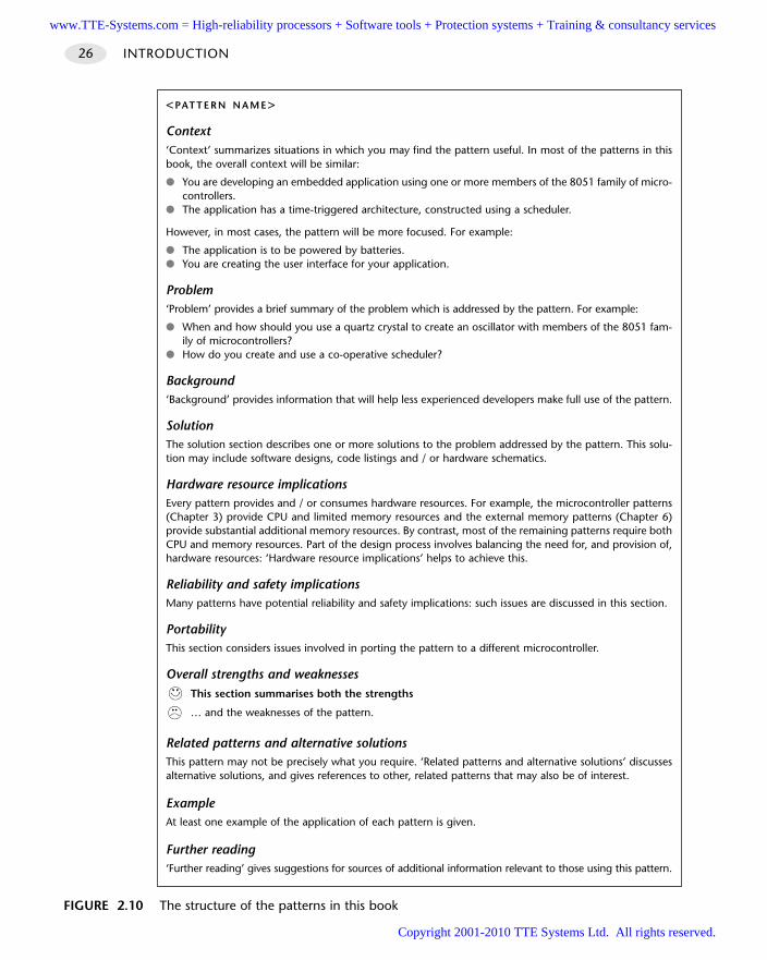
INTRODUCTION26
<PAT T E R N N A M E>
Context‘Context’ summarizes situations in which you may find the pattern useful. In most of the patterns in thisbook, the overall context will be similar:
You are developing an embedded application using one or more members of the 8051 family of micro-controllers.
The application has a time-triggered architecture, constructed using a scheduler.
However, in most cases, the pattern will be more focused. For example:
The application is to be powered by batteries. You are creating the user interface for your application.
Problem‘Problem’ provides a brief summary of the problem which is addressed by the pattern. For example:
When and how should you use a quartz crystal to create an oscillator with members of the 8051 fam-ily of microcontrollers?
How do you create and use a co-operative scheduler?
Background‘Background’ provides information that will help less experienced developers make full use of the pattern.
SolutionThe solution section describes one or more solutions to the problem addressed by the pattern. This solu-tion may include software designs, code listings and / or hardware schematics.
Hardware resource implicationsEvery pattern provides and / or consumes hardware resources. For example, the microcontroller patterns(Chapter 3) provide CPU and limited memory resources and the external memory patterns (Chapter 6)provide substantial additional memory resources. By contrast, most of the remaining patterns require bothCPU and memory resources. Part of the design process involves balancing the need for, and provision of,hardware resources: ‘Hardware resource implications’ helps to achieve this.
Reliability and safety implicationsMany patterns have potential reliability and safety implications: such issues are discussed in this section.
PortabilityThis section considers issues involved in porting the pattern to a different microcontroller.
Overall strengths and weaknessesThis section summarises both the strengths
… and the weaknesses of the pattern.
Related patterns and alternative solutionsThis pattern may not be precisely what you require. ‘Related patterns and alternative solutions’ discussesalternative solutions, and gives references to other, related patterns that may also be of interest.
ExampleAt least one example of the application of each pattern is given.
Further reading‘Further reading’ gives suggestions for sources of additional information relevant to those using this pattern.
FIGURE 2.10 The structure of the patterns in this book
www.TTE-Systems.com = High-reliability processors + Software tools + Protection systems + Training & consultancy services
Copyright 2001-2010 TTE Systems Ltd. All rights reserved.
Hardware foundations
The patterns in Part A are concerned with the creation of the basic hardware foundation
that is required in all microcontroller-based embedded applications.
We begin by considering the microcontroller itself. Often the initial choice of processor
must be made early in the project life-cycle; this choice will have a substantial impact on
many later software and hardware design decisions and development costs can be
substantially reduced if subsequent changes can be avoided. In Chapter 3, a small set of
patterns are presented to help you decide whether a member of the 8051 family is appro-
priate for your application and, if so, which one you should use.
We then turn our attention to oscillator circuits. All digital computer systems are driven
by some form of oscillator. This circuit is the ‘heartbeat’ of the system and is crucial to cor-
rect operation. For example, if the oscillator fails, the system will not function at all; if the
oscillator runs irregularly, any timing calculations performed by the system will be inaccu-
rate. In Chapter 4, two key forms of oscillator circuit are discussed and compared.
We next consider the non-trivial process required to start the microcontroller when
power is applied. Because of the system complexity, a small, manufacturer-defined ‘reset
routine’ must be run to place this hardware into an appropriate state before it can begin
executing the user program. Running this reset routine takes time and requires that the
microcontroller’s oscillator is operating. In Chapter 5, we consider different ways of creat-
ing a suitable reset circuit.
Memory is the next important issue we need to consider. Specifically, in Chapter 6, we
explore techniques for making effective use of the internal memory in the 8051 family
and, where necessary, of adding external (code and / or data) memory to the system.
Finally, we consider how you can create the hardware needed to drive DC loads (in
Chapter 7) and AC loads (in Chapter 8).
part awww.TTE-Systems.com = High-reliability processors + Software tools + Protection systems + Training & consultancy services
Copyright 2001-2010 TTE Systems Ltd. All rights reserved.

www.TTE-Systems.com = High-reliability processors + Software tools + Protection systems + Training & consultancy services
Copyright 2001-2010 TTE Systems Ltd. All rights reserved.
The 8051 microcontroller family
Introduction
Early in the life-cycle of most embedded projects, an initial choice of microcontrollermust be made. While it may become necessary to change the microcontroller as theproject develops, the particular hardware platform that is used will have a substantialimpact on many later software and hardware design decisions and development costscan be substantially reduced if subsequent changes can be avoided.
In this chapter, three patterns are presented to support this selection process:
S TA N D A R D 8051 [page 30]
S M A L L 8051 [page 41]
E X T E N D E D 8051 [page 46]
chapter3
Note that using any processor family requires a considerable investment in hard-ware, software and staff training: few firms can afford to select devices on aper-project basis: instead, they tend to specialize in a single family or a smallnumber of families. As we will see, the huge – and growing – range of 8051 devicesavailable can make it an excellent choice for a wide range of projects and, as aresult, can frequently justify this investment.
www.TTE-Systems.com = High-reliability processors + Software tools + Protection systems + Training & consultancy services
Copyright 2001-2010 TTE Systems Ltd. All rights reserved.
STANDARD 8051
ContextYou are developing a microcontroller-based embedded application and have someflexibility in the choice of hardware platform to be used.
ProblemShould you base your application on a standard 8051-family microcontroller?
BackgroundTaken as a whole, the 8051 family has what is, in the semiconductor world, a verylong history. The underlying architecture is derived from that of the Intel 8048 micro-controller (introduced in 1976): the first 8051 was introduced in 1980 (Intel, 1985).
The original 8051 architecture had the following features:
Up to 12 MHz operating frequency.
Thirty-two digital input / output pins (arranged as four 8-bit ports).
Internal data (RAM) memory – 128 bytes.
Three versions with different program memory options:
– No program memory: all programs needed to be stored in external memory (8031)
– 4K × 8 bits internal mask-programmed ROM (8051)
– 4K × 8 bits UV-eraseable EPROM (8751)
Two 16-bit timer / counters (Timer 0 and Timer 1).
Five interrupt sources were provided (two external) with two priority levels.
One programmable, full-duplex, serial port.
The external interface to the 8051 is illustrated in Figure 3.1.Shortly after the launch of the 8051, the 8052 was launched (again by Intel). The
8052 differed in several important respects from the earlier device. The 8052 had thefollowing features:
Internal data (RAM) memory was increased to 256 bytes.
Two 8052 versions were available with different program memory options:
– No program memory: all programs needed to be stored in external memory (8032)
– 8K × 8 bits internal mask-programmed ROM (8052)
Three 16-bit timer / counters (Timer 0, Timer 1 and Timer 2).
Six interrupt sources were provided (two external) with two priority levels.
HARDWARE FOUNDATIONS30
www.TTE-Systems.com = High-reliability processors + Software tools + Protection systems + Training & consultancy services
Copyright 2001-2010 TTE Systems Ltd. All rights reserved.
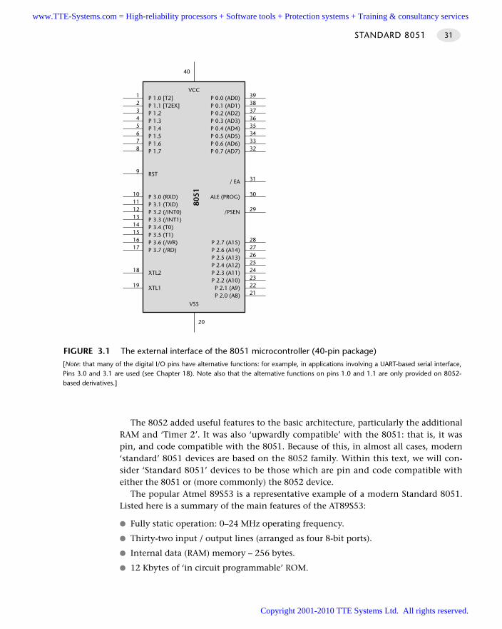
The 8052 added useful features to the basic architecture, particularly the additionalRAM and ‘Timer 2’. It was also ‘upwardly compatible’ with the 8051: that is, it waspin, and code compatible with the 8051. Because of this, in almost all cases, modern‘standard’ 8051 devices are based on the 8052 family. Within this text, we will con-sider ‘Standard 8051’ devices to be those which are pin and code compatible witheither the 8051 or (more commonly) the 8052 device.
The popular Atmel 89S53 is a representative example of a modern Standard 8051.Listed here is a summary of the main features of the AT89S53:
Fully static operation: 0–24 MHz operating frequency.
Thirty-two input / output lines (arranged as four 8-bit ports).
Internal data (RAM) memory – 256 bytes.
12 Kbytes of ‘in circuit programmable’ ROM.
STANDARD 8051 31
FIGURE 3.1 The external interface of the 8051 microcontroller (40-pin package)[Note: that many of the digital I/O pins have alternative functions: for example, in applications involving a UART-based serial interface,Pins 3.0 and 3.1 are used (see Chapter 18). Note also that the alternative functions on pins 1.0 and 1.1 are only provided on 8052-based derivatives.]
P 1.0 [T2]P 1.1 [T2EX]P 1.2P 1.3P 1.4P 1.5P 1.6P 1.7
RST
P 3.0 (RXD)P 3.1 (TXD)P 3.2 (/INT0)P 3.3 (/INT1)P 3.4 (T0)P 3.5 (T1)P 3.6 (/WR)P 3.7 (/RD)
XTL2
XTL1
P 0.0 (AD0)P 0.1 (AD1)P 0.2 (AD2)P 0.3 (AD3)P 0.4 (AD4)P 0.5 (AD5)P 0.6 (AD6)P 0.7 (AD7)
/ EA
ALE (PROG)
/PSEN
P 2.7 (A15)P 2.6 (A14)P 2.5 (A13)P 2.4 (A12)P 2.3 (A11)P 2.2 (A10)
P 2.1 (A9)P 2.0 (A8)
VCC
8051
VSS
3938373635343332
31
30
29
2827262524232221
12345678
9
1011121314151617
18
19
20
40
www.TTE-Systems.com = High-reliability processors + Software tools + Protection systems + Training & consultancy services
Copyright 2001-2010 TTE Systems Ltd. All rights reserved.
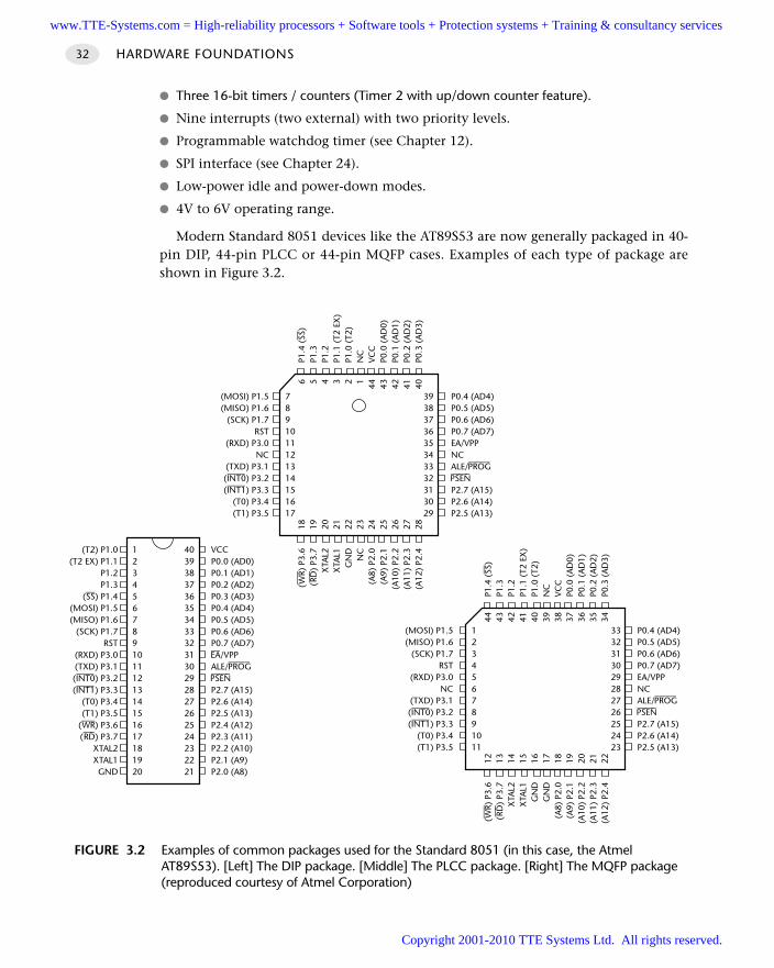
Three 16-bit timers / counters (Timer 2 with up/down counter feature).
Nine interrupts (two external) with two priority levels.
Programmable watchdog timer (see Chapter 12).
SPI interface (see Chapter 24).
Low-power idle and power-down modes.
4V to 6V operating range.
Modern Standard 8051 devices like the AT89S53 are now generally packaged in 40-pin DIP, 44-pin PLCC or 44-pin MQFP cases. Examples of each type of package areshown in Figure 3.2.
HARDWARE FOUNDATIONS32
FIGURE 3.2 Examples of common packages used for the Standard 8051 (in this case, the AtmelAT89S53). [Left] The DIP package. [Middle] The PLCC package. [Right] The MQFP package(reproduced courtesy of Atmel Corporation)
(T2) P1.0(T2 EX) P1.1
P1.2P1.3
(—SS) P1.4(MOSI) P1.5(MISO) P1.6
(SCK) P1.7RST
(RXD) P3.0(TXD) P3.1(—IN—T0) P3.2(—IN—T1) P3.3
(T0) P3.4(T1) P3.5
(—–WR) P3.6(—–RD) P3.7
XTAL2XTAL1GND
1234567891011121314151617181920
VCCP0.0 (AD0)P0.1 (AD1)P0.2 (AD2)P0.3 (AD3)P0.4 (AD4)P0.5 (AD5)P0.6 (AD6)P0.7 (AD7)—EA/VPPALE/—PR—OG–—PS—EN–
P2.7 (A15)P2.6 (A14)P2.5 (A13)P2.4 (A12)P2.3 (A11)P2.2 (A10)P2.1 (A9)P2.0 (A8)
4039383736353433323130292827262524232221
(MOSI) P1.5(MISO) P1.6
(SCK) P1.7RST
(RXD) P3.0NC
(TXD) P3.1(—IN—T0) P3.2(—IN—T1) P3.3
(T0) P3.4(T1) P3.5
7891011121314151617
(—–
WR)
P3.
6(—
–RD
) P3
.7X
TAL2
XTA
L1G
ND
NC
(A8)
P2.
0(A
9) P
2.1
(A10
) P2
.2(A
11)
P2.3
(A12
) P2
.4
18 19 20 21 22 23 24 25 26 27 28
P0.4 (AD4)P0.5 (AD5)P0.6 (AD6)P0.7 (AD7)EA/VPPNCALE/—PR—OG–—PS—EN–
P2.7 (A15)P2.6 (A14)P2.5 (A13)
3938373635343332313029
6 5 4 3 2 1 44 43 42 41 40
P1.4
(— SS
)P1
.3P1
.2P1
.1 (
T2 E
X)
P1.0
(T2
)N
CVC
CP0
.0 (
AD
0)P0
.1 (
AD
1)P0
.2 (
AD
2)P0
.3 (
AD
3)
(MOSI) P1.5(MISO) P1.6
(SCK) P1.7RST
(RXD) P3.0NC
(TXD) P3.1(—IN—T0) P3.2(—IN—T1) P3.3
(T0) P3.4(T1) P3.5
1234567891011
(—–
WR)
P3.
6(—
–RD
) P3
.7X
TAL2
XTA
L1G
ND
GN
D(A
8) P
2.0
(A9)
P2.
1(A
10)
P2.2
(A11
) P2
.3(A
12)
P2.4
12 13 14 15 16 17 18 19 20 21 22
P0.4 (AD4)P0.5 (AD5)P0.6 (AD6)P0.7 (AD7)EA/VPPNCALE/—PR—OG–—PS—EN–
P2.7 (A15)P2.6 (A14)P2.5 (A13)
3332313029282726252423
44 43 42 41 40 39 38 37 36 35 34
P1.4
(— SS
)P1
.3P1
.2P1
.1 (
T2 E
X)
P1.0
(T2
)N
CVC
CP0
.0 (
AD
0)P0
.1 (
AD
1)P0
.2 (
AD
2)P0
.3 (
AD
3)
www.TTE-Systems.com = High-reliability processors + Software tools + Protection systems + Training & consultancy services
Copyright 2001-2010 TTE Systems Ltd. All rights reserved.
STANDARD 8051 33
SolutionThe aim of this pattern is to help you decide whether you should use a Standard 8051in your application. When making such a decision, some or all of the following ques-tions need to be addressed:
1 Is the microcontroller powerful enough to perform the required tasks?
2 Does the microcontroller have sufficient memory ‘on chip’ to store the requiredcode and data? If not, then does the microcontroller allow the use of appropriateexternal memory?
3 Does the microcontroller have appropriate on-chip hardware components (forexample, CAN interface, PWM interface) to support the required tasks?
4 Does the microcontroller have sufficient port pins (or a suitable serial interface) toallow any required external components (such as switches, keypads, LCD displays)to be connected?
5 Is the power consumption of the chosen microcontroller appropriate (a particularconcern with battery powered applications)?
We will consider each of these points in turn here.
Performance issues
One of the first question to be asked when considering a microcontroller for a projectis whether it has the required level of performance. There are various ways in whichsuch performance may be described: one measure is the number of machine instruc-tions that may be executed in one second, usually expressed in MIPS (millioninstructions per second).
For example, in an original Intel 8051 microcontroller (and most current members ofthe 8051 family), a minimum of 12 oscillator cycles are required to execute a machineinstruction. As a result, at best, a 12 MHz 8051 has a performance of approximately 1 MIP.
What’s in a name?
It should be noted that the naming of various members of the ‘8051’ family is asource of considerable confusion to new developers. For example, the 8031, 8751,8052, 8032, C505c, C515, C509, 80C517, 83C452, ADµC812, and the 80C390 areall members of the 8051 family. The names of the devices provide little or no indica-tion of the family connections.
Originally, there were some basic conventions used to identify the features of differ-ent variants of a particular 8051 device. For example, the standard 8051 had maskROM, the 8031 had no ROM and the 8751 had UV-erasable ROM memory. This basicconvention is now rarely observed. In the case of the Infineon C501, for example, dif-ferent suffixes are used to distinguish different C501 versions: C501-1R, C501-1E, andso on.
www.TTE-Systems.com = High-reliability processors + Software tools + Protection systems + Training & consultancy services
Copyright 2001-2010 TTE Systems Ltd. All rights reserved.
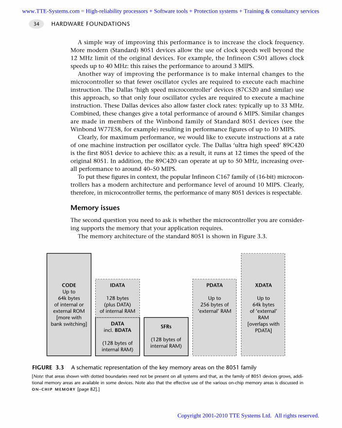
A simple way of improving this performance is to increase the clock frequency.More modern (Standard) 8051 devices allow the use of clock speeds well beyond the12 MHz limit of the original devices. For example, the Infineon C501 allows clockspeeds up to 40 MHz: this raises the performance to around 3 MIPS.
Another way of improving the performance is to make internal changes to themicrocontroller so that fewer oscillator cycles are required to execute each machineinstruction. The Dallas ‘high speed microcontroller’ devices (87C520 and similar) usethis approach, so that only four oscillator cycles are required to execute a machineinstruction. These Dallas devices also allow faster clock rates: typically up to 33 MHz.Combined, these changes give a total performance of around 6 MIPS. Similar changesare made in members of the Winbond family of Standard 8051 devices (see theWinbond W77E58, for example) resulting in performance figures of up to 10 MIPS.
Clearly, for maximum performance, we would like to execute instructions at a rateof one machine instruction per oscillator cycle. The Dallas ‘ultra high speed’ 89C420is the first 8051 device to achieve this: as a result, it runs at 12 times the speed of theoriginal 8051. In addition, the 89C420 can operate at up to 50 MHz, increasing over-all performance to around 40–50 MIPS.
To put these figures in context, the popular Infineon C167 family of (16-bit) microcon-trollers has a modern architecture and performance level of around 10 MIPS. Clearly,therefore, in microcontroller terms, the performance of many 8051 devices is respectable.
Memory issues
The second question you need to ask is whether the microcontroller you are consider-ing supports the memory that your application requires.
The memory architecture of the standard 8051 is shown in Figure 3.3.
HARDWARE FOUNDATIONS34
FIGURE 3.3 A schematic representation of the key memory areas on the 8051 family[Note: that areas shown with dotted boundaries need not be present on all systems and that, as the family of 8051 devices grows, addi-tional memory areas are available in some devices. Note also that the effective use of the various on-chip memory areas is discussed inO N-C H I P M E M O RY [page 82].]
CODEUp to
64k bytesof internal orexternal ROM
[more withbank switching] DATA
incl. BDATA
(128 bytes ofinternal RAM)
SFRs
(128 bytes ofinternal RAM)
IDATA
128 bytes(plus DATA)
of internal RAM
PDATA
Up to256 bytes of
‘external’ RAM
XDATA
Up to64k bytes
of ‘external’RAM
[overlaps withPDATA]
www.TTE-Systems.com = High-reliability processors + Software tools + Protection systems + Training & consultancy services
Copyright 2001-2010 TTE Systems Ltd. All rights reserved.
STANDARD 8051 35
The first thing to note is that, for the Standard 8051, a maximum program size of64 kbytes is directly supported. While it is possible to use larger programs by ‘bankswitching’ the memory (a techniques considered in O F F - C H I P C O D E M E M O R Y [page100]) this technique is complex, less efficient than a linear address space, and can beerror prone. Similarly, the memory available for data is restricted to 64 kbytes. In situ-ations where code or data memory in excess of 64 kbytes is required, use of anE X T E N D E D 8051 [page 46] is often a better alternative.
The second thing to note is that Figure 3.3 shows the total memory (both internaland external) available on all Standard 8051 devices. Where possible, it is better to usea device with all the required memory on the chip, since this can improve reliability,reduce costs, reduce the application size and reduce power consumption. As discussedin ‘Background’, the original 8051 family had up to 128 bytes of RAM and 4 kbytes ofROM available, from data and code (respectively). More modern Standard 8051srarely provide more than around 1 kbyte of RAM (usually 256 bytes), but may provideup to 64 kbytes of flash, OTP or mask ROM (see Chapter 6 for further details).
Availability of on-chip hardware components
One of the main reasons for choosing to use a microcontroller is that it integratesmost or all of the hardware features you require in your application on a single chip.The 8051 family is particularly impressive in this area. There are numerous variantsavailable which between them meet the needs of a huge number of projects, withouthaving to resort to using large numbers of external components.
Some of the on-chip hardware components available on Standard 8051s areas follows:
All Standard 8051s have at least one serial port available, supporting RS-232 serialprotocols. This makes it easy, for example, to download data to a desktop PC. Wediscuss the linking of embedded and desktop systems in Chapter 18.
All Standard 8051s have two or three timers.
Many Standard 8051s have on-chip ‘watchdog timers’. Use of such components isdiscussed in Chapter 12.
Some Standard 8051s have on-chip support for the SPI bus. We discuss this impor-tant serial bus protocol in Chapter 23.
Some Standard 8051s have on-chip support for the I2C bus. We discuss this impor-tant serial bus protocol in Chapter 24.
Note that many more features are available in the E X T E N D E D 8051 [page 46] devices.Despite this variation, the core architecture remains the same and software for one
variant can generally be used without major alteration on another.
Pin count
All Standard 8051s have four 8-bit ports available, allowing a number of externaldevices to be added.
www.TTE-Systems.com = High-reliability processors + Software tools + Protection systems + Training & consultancy services
Copyright 2001-2010 TTE Systems Ltd. All rights reserved.
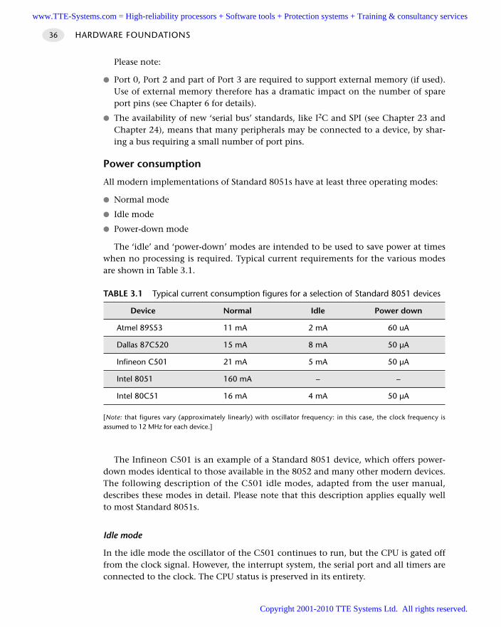
HARDWARE FOUNDATIONS36
Please note:
Port 0, Port 2 and part of Port 3 are required to support external memory (if used).Use of external memory therefore has a dramatic impact on the number of spareport pins (see Chapter 6 for details).
The availability of new ‘serial bus’ standards, like I2C and SPI (see Chapter 23 andChapter 24), means that many peripherals may be connected to a device, by shar-ing a bus requiring a small number of port pins.
Power consumption
All modern implementations of Standard 8051s have at least three operating modes:
Normal mode
Idle mode
Power-down mode
The ‘idle’ and ‘power-down’ modes are intended to be used to save power at timeswhen no processing is required. Typical current requirements for the various modesare shown in Table 3.1.
The Infineon C501 is an example of a Standard 8051 device, which offers power-down modes identical to those available in the 8052 and many other modern devices.The following description of the C501 idle modes, adapted from the user manual,describes these modes in detail. Please note that this description applies equally wellto most Standard 8051s.
Idle mode
In the idle mode the oscillator of the C501 continues to run, but the CPU is gated offfrom the clock signal. However, the interrupt system, the serial port and all timers areconnected to the clock. The CPU status is preserved in its entirety.
TABLE 3.1 Typical current consumption figures for a selection of Standard 8051 devices
Device Normal Idle Power down
Atmel 89S53 11 mA 2 mA 60 uA
Dallas 87C520 15 mA 8 mA 50 µA
Infineon C501 21 mA 5 mA 50 µA
Intel 8051 160 mA – –
Intel 80C51 16 mA 4 mA 50 µA
[Note: that figures vary (approximately linearly) with oscillator frequency: in this case, the clock frequency isassumed to 12 MHz for each device.]
www.TTE-Systems.com = High-reliability processors + Software tools + Protection systems + Training & consultancy services
Copyright 2001-2010 TTE Systems Ltd. All rights reserved.
STANDARD 8051 37
The reduction of power consumption which can be achieved by this featuredepends on the number of peripherals running. If all timers are stopped and the serialinterfaces are not running, the maximum power reduction can be achieved: the devel-oper has to determine which peripheral must continue to run and which may bestopped.
The idle mode is entered by setting the flag bit IDLE (PCON.0). Because PCON isnot a bit-addressable register, the easiest way to set the IDLE bit is with the following‘C’ statement:
PCON |= 0x01; // Enter idle mode
The instruction that sets bit IDLE is the last instruction executed before going intoidle mode.
There are two ways to terminate idle mode:
Activate any enabled interrupt. This interrupt will be serviced and the programwill continue by executing the instruction following the instruction that sets theIDLE bit.
Perform a hardware reset.
Power-down mode
In the power-down mode, the on-chip oscillator is stopped. Therefore all functionsare stopped; only the contents of the on-chip RAM are maintained.
The power-down mode is entered by setting the flag bit PDE (PCON.1). This ismost easily done in ‘C’ as follows:
PCON |= 0x02; // Enter power down mode
The instruction that sets bit PDE is the last instruction executed before going intopower down mode. The only exit from power-down mode is a hardware reset.
Hardware resource implicationsTo summarize, the Standard 8051 provides the following hardware resources:
A CPU performance of between 1 MIPS and 50 MIPS (approximately).
Available on-chip memory of up to 64 kbytes for code and (typically) at least256 bytes for data.
One ‘RS-232’ serial port.
Two or three hardware timers.
Current consumption of around 20 mA in normal operating mode, 5 mA in idlemode, and 50 µA in power-down mode.
Reliability and safety implicationsThere are no available figures to suggest that the Standard 8051 is any more (or less)reliable than any other microcontroller family. Nonetheless, there are differences
www.TTE-Systems.com = High-reliability processors + Software tools + Protection systems + Training & consultancy services
Copyright 2001-2010 TTE Systems Ltd. All rights reserved.
between the facilities provided by the various 8051 family members and the choice ofan inappropriate microcontroller can have a detrimental impact on the safety and /or reliability of your application.
These differences arise simply due to the availability of on-chip resources: as wehave mentioned, these include – for example – different amounts of memory (RAMand ROM), serial interfaces (SPI and I2C) and analog-to-digital converters. Where pos-sible, the use of on-chip components generally increases application reliability, for thefollowing reasons:
With external components, each of the soldered joints has a risk of failure, particu-larly in the presence of vibration and / or high humidity: reducing the number ofjoints reduces this risk.
External wires act as miniature aerials and increase vulnerability to electromagneticinterference (EMI): as a consequence reduction in external wiring tends to makethe application more robust in the presence EMI.
Without external components, the complexity of the hardware design is reduced,which means there are fewer opportunities for wiring and / or hardware design errors,
As (in almost all cases) the ‘on-chip’ solution will also be both cheaper to produceand physically smaller, the message is clear: you should generally use a microcon-troller with all the on-chip resources you require if at all possible. Note, however,that use of less common on-chip resources will make your design less portable (seenext section).
PortabilityBecause of the huge range of different 8051 devices available, design based on theStandard 8051 are inherently portable. However, if you assume the availability ofnon-standard components (extra RAM, extra serial interfaces etc.), your design willnot be as portable.
Overall strengths and weaknessesTo summarize, the Standard 8051 has the following strengths and weaknesses:
It is a flexible, general-purpose microcontroller suitable for use in many projects.
It is a low-cost device.
It has an architecture with which many developers are familiar.
It is supported by many development tools.
The family as a whole is available in more than 300 different forms.
It is available from a very wide range of different manufacturers: if one com-pany fails, there will be an alternative source.
Its CPU performance (in some versions) is equal to or greater than many16-bit devices.
HARDWARE FOUNDATIONS38
www.TTE-Systems.com = High-reliability processors + Software tools + Protection systems + Training & consultancy services
Copyright 2001-2010 TTE Systems Ltd. All rights reserved.
STANDARD 8051 39
It has limited memory available (compared with 16-bit or 32-bit microcon-trollers).
Its memory architecture is comparatively complex.
Related patterns and alternative solutionsIn this section, we consider some alternatives to the Standard 8051 microcontroller.
Smaller alternatives
If your application does not require external memory and you do not require morethan (approximately) 15 port pins for input and output, you may find that the Small8051s are a good option: see S M A L L 8051 [page 41].
Extended 8051 alternatives
The Extended 8051s can generally do everything that the Standard 8051 can do. Inaddition, they usually have a larger number of available port pins and a wider range ofon-chip hardware components such as digital-to-analog converters, CAN interfaces, SPIinterfaces, I2C interfaces and so on. The Extended 8051s also, in some cases, providesupport for large amounts of external memory: up to 16 Mbytes in some cases.
We discuss such devices in E X T E N D E D 8051 [page 46].
The Intel 80251 family
The Intel MCS-251 is both software and hardware compatible with the Standard 8051family. This means that, in most cases, you can load your existing code into a 251and place this (40-pin or 44-pin) device into your existing 8051-based circuit board.
It is claimed that performance can be improved by a factor of 5–15 times bythis approach (compared with the original 1-MIP 8051) and that further improve-ments are possible by recompiling and / or rewriting code to take advantage of thenew architecture.
To summarize, the key features of the 251 are:
Software and hardware compatibility with the Standard 8051.
5–15 × the performance of the original 8051.
Large (up to 16 Mbyte) linear address space.
Additional on-chip RAM compared with the Standard 8051 (up to 1 kbyte).
Other additional components, such as a watchdog timer and a PWM unit.
Two serial ports in some versions.
Overall, the main advantage of the 251 family is that can provide a more powerful,drop-in replacement for the original 8051 and that it may be used without purchasingadditional tools (such as compilers). However, the 251 family has not proved nearlyas popular as the 8051 and it offers little that Standard and Extended 8051 devicescannot now provide.
If you wish to find out more about the 251 family, then Ayala (2000) may be of interest.
www.TTE-Systems.com = High-reliability processors + Software tools + Protection systems + Training & consultancy services
Copyright 2001-2010 TTE Systems Ltd. All rights reserved.
Example: Using the Standard 8051We give many examples of the use of Standard 8051 devices throughout this book.
Further readingA collection of data books for a range of Standard 8051 devices is included on theCD-ROM.
HARDWARE FOUNDATIONS40
www.TTE-Systems.com = High-reliability processors + Software tools + Protection systems + Training & consultancy services
Copyright 2001-2010 TTE Systems Ltd. All rights reserved.
SMALL 8051
ContextYou are developing a microcontroller-based embedded application and have someflexibility in the choice of hardware platform to be used.
ProblemShould you base your application on a Small 8051-family microcontroller?
BackgroundThe desktop microprocessor market is characterized by constant demands forincreased power. As a result, processors become obsolete after two or three years inproduction. By contrast, the 8051 architecture is more than 20 years old, yet thefamily is growing in both size and popularity.
This only makes sense because, as we saw in Chapter 1, the driving forces behindthe embedded market are rather different from those of the desktop. In the embeddedmarket, the trend is to exploit the flexibility of low-cost microcontrollers in an everwider range of applications: indeed, as prices fall, these devices are finding their wayinto applications that would have involved a small number of discrete components(transistors, diodes, resistors, capacitors) a few years ago, but which are now imple-mented with microcontrollers.
To emphasize the very different nature of the embedded market, some of the morerecent 8051 devices – far from being more powerful and having more features thanthe original – generally have fewer features.
Most immediately obvious is the fact that these Small 8051 devices typically have20 or 24 pins and only some 15 I/O pins. In addition to their small physical size, theother common feature linking the Small 8051s is that they do not support externalmemory. For example, in the case of the popular AT89C1051, AT89C2051 andAT89C4051, Port 0 and Port 21 from the original device are omitted entirely (alongwith the ALE and PSEN pins, and some pins on Port 3), allowing the number of exter-nal pins to be reduced, in these cases to 20 pins. Similar changes are made in thePhilips 87LPC764 and Philips 80c751 devices (see Figure 3.4).
SolutionShould you use a Small 8051 in your application?
SMALL 8051 41
1. As was noted in S TA N D A R D 8051 [page 32], Port 0 and Port 2 are used to support the address anddata buses when external memory is used. See Chapter 6 for further details.
www.TTE-Systems.com = High-reliability processors + Software tools + Protection systems + Training & consultancy services
Copyright 2001-2010 TTE Systems Ltd. All rights reserved.
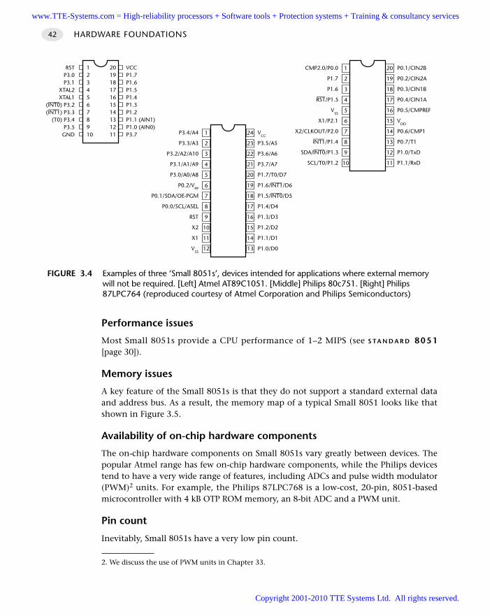
Performance issues
Most Small 8051s provide a CPU performance of 1–2 MIPS (see S TA N D A R D 8051[page 30]).
Memory issues
A key feature of the Small 8051s is that they do not support a standard external dataand address bus. As a result, the memory map of a typical Small 8051 looks like thatshown in Figure 3.5.
Availability of on-chip hardware components
The on-chip hardware components on Small 8051s vary greatly between devices. Thepopular Atmel range has few on-chip hardware components, while the Philips devicestend to have a very wide range of features, including ADCs and pulse width modulator(PWM)2 units. For example, the Philips 87LPC768 is a low-cost, 20-pin, 8051-basedmicrocontroller with 4 kB OTP ROM memory, an 8-bit ADC and a PWM unit.
Pin count
Inevitably, Small 8051s have a very low pin count.
HARDWARE FOUNDATIONS42
FIGURE 3.4 Examples of three ‘Small 8051s’, devices intended for applications where external memorywill not be required. [Left] Atmel AT89C1051. [Middle] Philips 80c751. [Right] Philips87LPC764 (reproduced courtesy of Atmel Corporation and Philips Semiconductors)
P3.4/A4
P3.3/A3
P3.2/A2/A10
P3.1/A1/A9
P3.0/A0/A8
P0.2/VPP
P0.1/SDA/OE-PGM
P0.0/SCL/ASEL
RST
X2
X1
VSS
12
11
10
9
8
7
6
5
4
3
2
1
13
14
15
16
17
18
19
20
21
22
23
24 VCC
P3.5/A5
P3.6/A6
P3.7/A7
P1.7/T0/D7
P1.6/—IN—T1/D6
P1.5/—IN—T0/D5
P1.4/D4
P1.3/D3
P1.2/D2
P1.1/D1
P1.0/D0
CMP2.0/P0.0
P1.7
P1.6—–RST/P1.5
VSS
X1/P2.1
X2/CLKOUT/P2.0—IN—T1/P1.4
SDA/—IN—T0/P1.3
SCL/T0/P1.2 10
9
8
7
6
5
4
3
2
1
15
16
17
18
19
20 P0.1/CIN2B
P0.2/CIN2A
P0.3/CIN1B
P0.4/CIN1A
P0.5/CMPREF
VDD
P0.6/CMP1
P0.7/T1
P1.0/TxD
P1.1/RxD
14
13
12
11
RSTP3.0P3.1
XTAL2XTAL1
(—IN—T0) P3.2(—IN—T1) P3.3
(T0) P3.4P3.5GND
12345678910
VCCP1.7P1.6P1.5P1.4P1.3P1.2P1.1 (AIN1)P1.0 (AIN0)P3.7
20191817161514131211
2. We discuss the use of PWM units in Chapter 33.
www.TTE-Systems.com = High-reliability processors + Software tools + Protection systems + Training & consultancy services
Copyright 2001-2010 TTE Systems Ltd. All rights reserved.
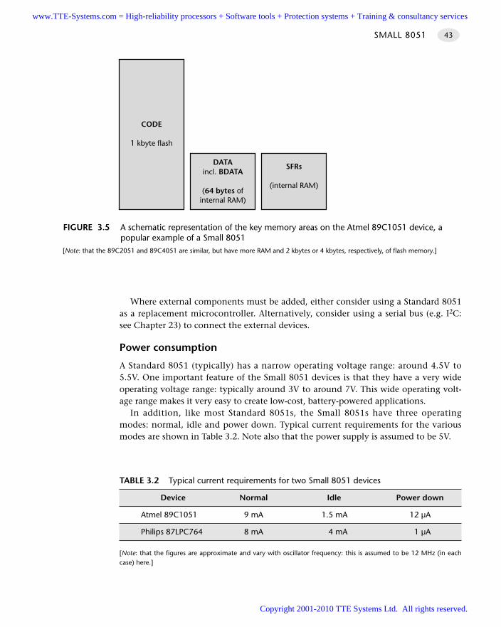
Where external components must be added, either consider using a Standard 8051as a replacement microcontroller. Alternatively, consider using a serial bus (e.g. I2C:see Chapter 23) to connect the external devices.
Power consumption
A Standard 8051 (typically) has a narrow operating voltage range: around 4.5V to5.5V. One important feature of the Small 8051 devices is that they have a very wideoperating voltage range: typically around 3V to around 7V. This wide operating volt-age range makes it very easy to create low-cost, battery-powered applications.
In addition, like most Standard 8051s, the Small 8051s have three operatingmodes: normal, idle and power down. Typical current requirements for the variousmodes are shown in Table 3.2. Note also that the power supply is assumed to be 5V.
SMALL 8051 43
FIGURE 3.5 A schematic representation of the key memory areas on the Atmel 89C1051 device, apopular example of a Small 8051
[Note: that the 89C2051 and 89C4051 are similar, but have more RAM and 2 kbytes or 4 kbytes, respectively, of flash memory.]
CODE
1 kbyte flash
DATAincl. BDATA
(64 bytes ofinternal RAM)
SFRs
(internal RAM)
TABLE 3.2 Typical current requirements for two Small 8051 devices
Device Normal Idle Power down
Atmel 89C1051 9 mA 1.5 mA 12 µA
Philips 87LPC764 8 mA 4 mA 1 µA
[Note: that the figures are approximate and vary with oscillator frequency: this is assumed to be 12 MHz (in eachcase) here.]
www.TTE-Systems.com = High-reliability processors + Software tools + Protection systems + Training & consultancy services
Copyright 2001-2010 TTE Systems Ltd. All rights reserved.
Hardware resource implicationsThe Small 8051 provides the following hardware resources:
A CPU performance of between 1 MIPS and 3 MIPS (approximately).
Available internal memory (typical) of up to 4 kbytes for code and 256 bytes fordata. No support for external memory.
Usually one, full duplex (‘RS-232’) serial port.
Two or three hardware timers.
Current consumption of around 10 mA in normal operating mode, 5 mA in idlemode, and 10 µA in power-down mode.
Additional features are also available on some devices.
Reliability and safety implicationsThere are no available figures to suggest that the Small 8051 is any more (or less)reliable than any other microcontroller family.
PortabilityPlease note that the Small 8051s have a core architecture based on the 8051 family.However, as is apparent from Figure 3.4, the various Small 8051s are in no sense pincompatible and vary greatly in features and functionality. As a result, code written fora particular Small 8051 is less portable than code written for a Standard 8051.
Overall strengths and weaknessesTo summarize, the Standard 8051 has the following strengths and weaknesses:
It is based on the core 8051 architecture and thus has many of the strengthsof the Standard 8051.
It has a small physical size.
It is a low-cost device.
It has limited on-chip RAM and ROM memory and no support for external memory.
Designs based on Small 8051s are less easy to port than designs based on Standard8051s, due to the diverse nature of this branch of the microcontroller family
Related patterns and alternative solutionsThe main alternative to a Small 8051 (considered in this text) is the S TA N D A R D 8051[page 30].
Alternatively, consider one of the microchip family of PIC devices, such as the(8-pin) PIC12CE673; these have similar capabilities to the Small 8051 devices, albeitwith a completely different architecture.
HARDWARE FOUNDATIONS44
www.TTE-Systems.com = High-reliability processors + Software tools + Protection systems + Training & consultancy services
Copyright 2001-2010 TTE Systems Ltd. All rights reserved.
Example: Using the Small 8051We give many examples of the use of Small 8051 devices throughout this book.
Further readingA collection of data books for a range of Small 8051 devices is included on theCD-ROM.
SMALL 8051 45
www.TTE-Systems.com = High-reliability processors + Software tools + Protection systems + Training & consultancy services
Copyright 2001-2010 TTE Systems Ltd. All rights reserved.
EXTENDED 8051
ContextYou are developing a microcontroller-based embedded application and have someflexibility in the choice of hardware platform to be used.
ProblemShould you base your application on an Extended 8051-family microcontroller?
BackgroundAs we have seen in connection with S TA N D A R D 8051 [page 30] and S M A L L 8051[page 41], this long-lived microcontroller family continues to thrive partly because itoffers a huge variety of ‘standard devices’ (covering the territory of traditional 8-bitmicrocontrollers) and a range of ‘small devices’ (overlapping with the range of 4-bitcontrollers, and challenging devices such as the small PIC range).
Both the Standard and Small 8051s are aimed, largely, at low-cost, low-performanceapplication areas where limited memory is required and the three most important con-siderations are ‘cost, cost and cost’. Of course, not all projects take this form.
To develop applications requiring specialized hardware or larger amounts ofmemory, we can opt to switch to a 16-bit (or 32-bit) microcontroller environment.However, such a move can require a major investment in staff, staff training anddevelopment tools. An alternative is to use one of the Extended 8051 devices intro-duced in recent years by a range of manufacturers. Such devices preserve theinvestment in the 8051 range and, at the same time, open up new application areasto this microcontroller family.
In general, the extended 8051s offer the widest range of features available in 8051devices. For example, the Infineon C505C and C515C include a useful range of on-chip hardware components (including in this case support for the CAN3 bus) thathave led to these devices being used in the vast automotive market.
The C505C and C515C both retain the memory limitations of the Standard 8051.By contrast, other Extended 8051s, such as the Dallas 80C390 (Figure 3.6) and theAnalog Devices ADµC812 (Figure 3.7) can access much larger amounts of memory, ina linear address space.
Compared to many 16-bit microcontrollers, the Extended 8051s are, usually, com-paratively inexpensive: however, they are inevitably more expensive than either theStandard 8051 or Small 8051 alternatives.
HARDWARE FOUNDATIONS46
3. We discuss the use of the CAN bus in Chapter 28.
www.TTE-Systems.com = High-reliability processors + Software tools + Protection systems + Training & consultancy services
Copyright 2001-2010 TTE Systems Ltd. All rights reserved.
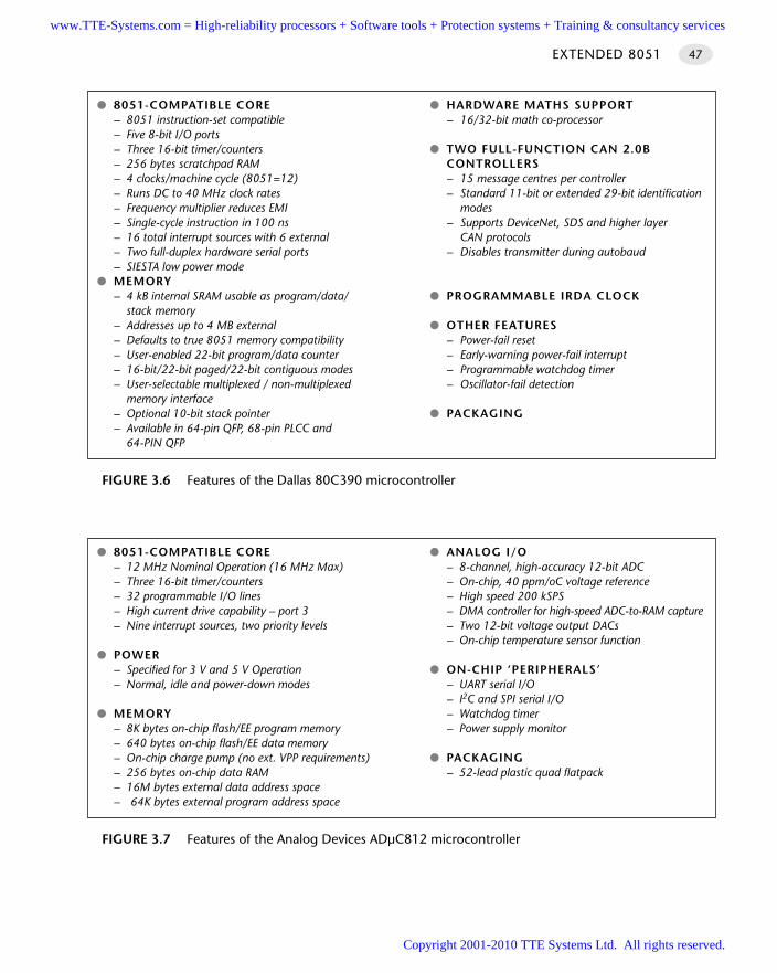
EXTENDED 8051 47
FIGURE 3.6 Features of the Dallas 80C390 microcontroller
8051-COMPATIBLE CORE HARDWARE MATHS SUPPORT– 8051 instruction-set compatible – 16/32-bit math co-processor– Five 8-bit I/O ports– Three 16-bit timer/counters TWO FULL-FUNCTION CAN 2.0B– 256 bytes scratchpad RAM CONTROLLERS– 4 clocks/machine cycle (8051=12) – 15 message centres per controller– Runs DC to 40 MHz clock rates – Standard 11-bit or extended 29-bit identification – Frequency multiplier reduces EMI modes– Single-cycle instruction in 100 ns – Supports DeviceNet, SDS and higher layer– 16 total interrupt sources with 6 external CAN protocols– Two full-duplex hardware serial ports – Disables transmitter during autobaud– SIESTA low power mode
MEMORY– 4 kB internal SRAM usable as program/data/ PROGRAMMABLE IRDA CLOCK
stack memory– Addresses up to 4 MB external OTHER FEATURES– Defaults to true 8051 memory compatibility – Power-fail reset– User-enabled 22-bit program/data counter – Early-warning power-fail interrupt– 16-bit/22-bit paged/22-bit contiguous modes – Programmable watchdog timer– User-selectable multiplexed / non-multiplexed – Oscillator-fail detection
memory interface– Optional 10-bit stack pointer PACKAGING– Available in 64-pin QFP, 68-pin PLCC and
64-PIN QFP
FIGURE 3.7 Features of the Analog Devices ADµC812 microcontroller
8051-COMPATIBLE CORE ANALOG I/O– 12 MHz Nominal Operation (16 MHz Max) – 8-channel, high-accuracy 12-bit ADC– Three 16-bit timer/counters – On-chip, 40 ppm/oC voltage reference– 32 programmable I/O lines – High speed 200 kSPS– High current drive capability – port 3 – DMA controller for high-speed ADC-to-RAM capture– Nine interrupt sources, two priority levels – Two 12-bit voltage output DACs
– On-chip temperature sensor function POWER
– Specified for 3 V and 5 V Operation ON-CHIP ‘PERIPHERALS ’– Normal, idle and power-down modes – UART serial I/O
– I2C and SPI serial I/O MEMORY – Watchdog timer
– 8K bytes on-chip flash/EE program memory – Power supply monitor– 640 bytes on-chip flash/EE data memory– On-chip charge pump (no ext. VPP requirements) PACKAGING– 256 bytes on-chip data RAM – 52-lead plastic quad flatpack– 16M bytes external data address space– 64K bytes external program address space
www.TTE-Systems.com = High-reliability processors + Software tools + Protection systems + Training & consultancy services
Copyright 2001-2010 TTE Systems Ltd. All rights reserved.
SolutionShould you use an Extended 8051 microcontroller in your application?
Performance issues
The Extended 8051s have good levels of performance. For example, as we have previ-ously noted, the performance of the Dallas 80C390 is up to 10x higher than theoriginal 8051. In addition, the presence of hardware maths units in several Extended8051s can significantly improve the speed of maths-intensive programs. Nonetheless,the Dallas 89C420 (a Standard 8051) is more powerful than any of the currentExtended 8051 devices.
Memory issues
Some of the Extended 8051s support the use of large amounts of external memory. Ofparticular note here is the Dallas 80C390, the Analog Devices 80µC812 and thePhilips 80C51MX. (See Chapter 6 for details.)
Availability of on-chip hardware components
Some of the on-chip hardware components available on Extended 8051s areas follows:
Several Extended 8051s have on-chip analog-to-digital converters (typically upto eight channels, 10-bit resolution). We discuss the use of such converters inChapter 32.
Several Extended 8051s have hardware support for mathematical operations, ensur-ing that (for example) floating-point maths operations are carried outcomparatively rapidly. See, for example, the data sheets for the Infineon C517,C537 and C509 and the Dallas 80C390 (included on the CD).
Some Extended 8051s have support for the Inter-Integrated Circuit (I2C) bus. Wediscuss this important serial protocol in Chapter 23.
Some Extended 8051s have on-chip support for the SPI bus. We discuss this impor-tant serial bus protocol in Chapter 24.
Some Extended 8051s have support for the Controller Area Network (CAN) bus. Wediscuss the CAN bus in Chapter 28.
Some Extended 8051s have on-chip digital-to-analog (D-A) converters. We discusssuch converters in Chapter 34.
Pin count
Many Extended 8051s have a very large number of available port pins. For example,the C509 has nine 8-bit ports. Even where external memory is used, six complete 8-bit ports are available.
HARDWARE FOUNDATIONS48
www.TTE-Systems.com = High-reliability processors + Software tools + Protection systems + Training & consultancy services
Copyright 2001-2010 TTE Systems Ltd. All rights reserved.
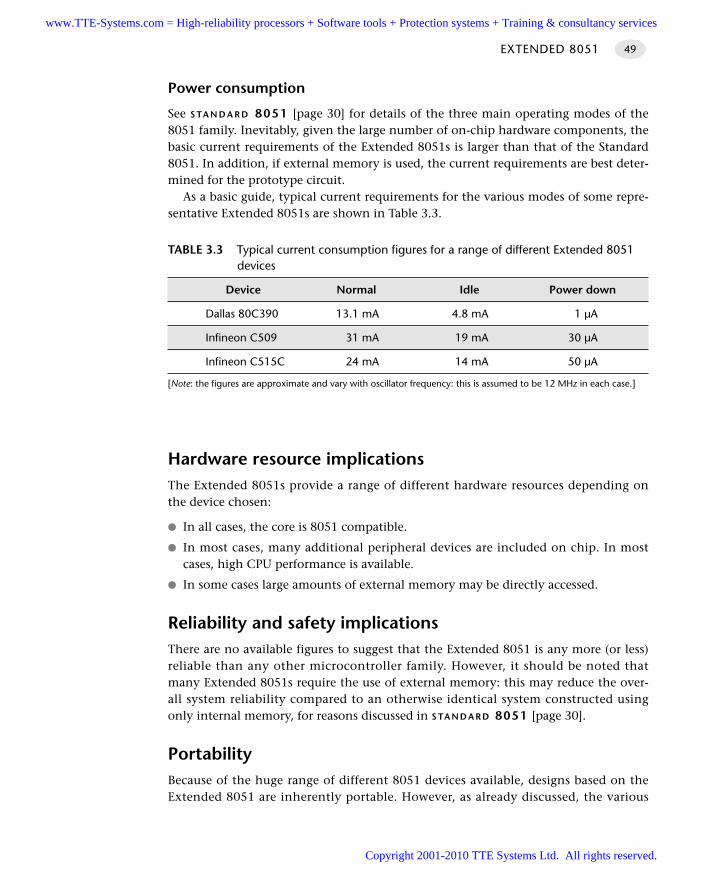
Power consumption
See S TA N D A R D 8051 [page 30] for details of the three main operating modes of the8051 family. Inevitably, given the large number of on-chip hardware components, thebasic current requirements of the Extended 8051s is larger than that of the Standard8051. In addition, if external memory is used, the current requirements are best deter-mined for the prototype circuit.
As a basic guide, typical current requirements for the various modes of some repre-sentative Extended 8051s are shown in Table 3.3.
Hardware resource implicationsThe Extended 8051s provide a range of different hardware resources depending onthe device chosen:
In all cases, the core is 8051 compatible.
In most cases, many additional peripheral devices are included on chip. In mostcases, high CPU performance is available.
In some cases large amounts of external memory may be directly accessed.
Reliability and safety implicationsThere are no available figures to suggest that the Extended 8051 is any more (or less)reliable than any other microcontroller family. However, it should be noted thatmany Extended 8051s require the use of external memory: this may reduce the over-all system reliability compared to an otherwise identical system constructed usingonly internal memory, for reasons discussed in S TA N D A R D 8051 [page 30].
PortabilityBecause of the huge range of different 8051 devices available, designs based on theExtended 8051 are inherently portable. However, as already discussed, the various
EXTENDED 8051 49
TABLE 3.3 Typical current consumption figures for a range of different Extended 8051 devices
Device Normal Idle Power down
Dallas 80C390 13.1 mA 4.8 mA 1 µA
Infineon C509 31 mA 19 mA 30 µA
Infineon C515C 24 mA 14 mA 50 µA
[Note: the figures are approximate and vary with oscillator frequency: this is assumed to be 12 MHz in each case.]
www.TTE-Systems.com = High-reliability processors + Software tools + Protection systems + Training & consultancy services
Copyright 2001-2010 TTE Systems Ltd. All rights reserved.
‘extended’ 8051s share only the common core and are not pin compatible (by anymeans). This means that core routines (like schedulers, for example) may be easilyported, but other components will need to be adapted to suit a particular device.
Overall strengths and weaknessesTo summarize, the Extended 8051 has the following strengths and weaknesses:
It is based on the 8051 architecture and thus has many of the strengths of theStandard 8051.
It has – in most cases – a large number of external port pins available.
It has – in most cases – a number of additional on-chip hardware compo-nents available.
It has – in many cases – an ability to access large amounts of ROM and RAMmemory.
Still, essentially, an 8-bit device: for higher levels of performance, a 32-bit devicemay be a better option.
Related patterns and alternative solutionsWe consider three alternative solutions in this section.
Use two (or more) Standard 8051s
Suppose we require a microcontroller with the following specification:
60+ port pins
Six timers
Two USARTS
128 kbytes of ROM
512 bytes of RAM
A cost of around $2.00 (US)
We can meet many of these requirements with an E X T E N D E D 8051 : however, thiswill typically cost five to ten times the $2.00 price we require. By contrast, the ‘micro-controller’ in Figure 3.8 matches these requirements very closely.
Figure 3.8 shows two standard 8051 microcontrollers linked together by means of asingle port pin: as we demonstrate in S C I S C H E D U L E R (T I C K) [page 554], linking thetwo processors can be done with a minimal software and hardware load. The result isa flexible environment with 62 free port pins, five free timers, two USARTs and so on.Note that further microcontrollers may be added without difficulty and the commu-nication over a single wire (plus ground) will ensure that the tasks on all processorsare perfectly synchronized.
HARDWARE FOUNDATIONS50
www.TTE-Systems.com = High-reliability processors + Software tools + Protection systems + Training & consultancy services
Copyright 2001-2010 TTE Systems Ltd. All rights reserved.
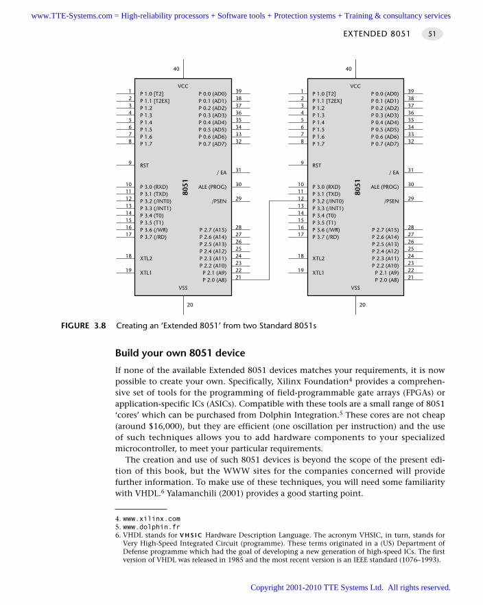
Build your own 8051 device
If none of the available Extended 8051 devices matches your requirements, it is nowpossible to create your own. Specifically, Xilinx Foundation4 provides a comprehen-sive set of tools for the programming of field-programmable gate arrays (FPGAs) orapplication-specific ICs (ASICs). Compatible with these tools are a small range of 8051‘cores’ which can be purchased from Dolphin Integration.5 These cores are not cheap(around $16,000), but they are efficient (one oscillation per instruction) and the useof such techniques allows you to add hardware components to your specializedmicrocontroller, to meet your particular requirements.
The creation and use of such 8051 devices is beyond the scope of the present edi-tion of this book, but the WWW sites for the companies concerned will providefurther information. To make use of these techniques, you will need some familiaritywith VHDL.6 Yalamanchili (2001) provides a good starting point.
EXTENDED 8051 51
FIGURE 3.8 Creating an ‘Extended 8051’ from two Standard 8051s
P 1.0 [T2]P 1.1 [T2EX]P 1.2P 1.3P 1.4P 1.5P 1.6P 1.7
RST
P 3.0 (RXD)P 3.1 (TXD)P 3.2 (/INT0)P 3.3 (/INT1)P 3.4 (T0)P 3.5 (T1)P 3.6 (/WR)P 3.7 (/RD)
XTL2
XTL1
P 0.0 (AD0)P 0.1 (AD1)P 0.2 (AD2)P 0.3 (AD3)P 0.4 (AD4)P 0.5 (AD5)P 0.6 (AD6)P 0.7 (AD7)
/ EA
ALE (PROG)
/PSEN
P 2.7 (A15)P 2.6 (A14)P 2.5 (A13)P 2.4 (A12)P 2.3 (A11)P 2.2 (A10)
P 2.1 (A9)P 2.0 (A8)
VCC
8051
VSS
3938373635343332
31
30
29
2827262524232221
12345678
9
1011121314151617
18
19
20
40
P 1.0 [T2]P 1.1 [T2EX]P 1.2P 1.3P 1.4P 1.5P 1.6P 1.7
RST
P 3.0 (RXD)P 3.1 (TXD)P 3.2 (/INT0)P 3.3 (/INT1)P 3.4 (T0)P 3.5 (T1)P 3.6 (/WR)P 3.7 (/RD)
XTL2
XTL1
P 0.0 (AD0)P 0.1 (AD1)P 0.2 (AD2)P 0.3 (AD3)P 0.4 (AD4)P 0.5 (AD5)P 0.6 (AD6)P 0.7 (AD7)
/ EA
ALE (PROG)
/PSEN
P 2.7 (A15)P 2.6 (A14)P 2.5 (A13)P 2.4 (A12)P 2.3 (A11)P 2.2 (A10)P 2.1 (A9)P 2.0 (A8)
VCC
8051
VSS
3938373635343332
31
30
29
2827262524232221
12345678
9
1011121314151617
18
19
20
40
4. www.xilinx.com5. www.dolphin.fr6. VHDL stands for V H S I C Hardware Description Language. The acronym VHSIC, in turn, stands for
Very High-Speed Integrated Circuit (programme). These terms originated in a (US) Department ofDefense programme which had the goal of developing a new generation of high-speed ICs. The firstversion of VHDL was released in 1985 and the most recent version is an IEEE standard (1076–1993).
www.TTE-Systems.com = High-reliability processors + Software tools + Protection systems + Training & consultancy services
Copyright 2001-2010 TTE Systems Ltd. All rights reserved.
It is worth noting that the availability of the 8051 core in this form is another, veryuseful consequence of the fact that this microcontroller architecture is very mature.
Use an XA-family device
The final alternative to the Extended 8051 which we will consider here is the so-called ‘8051XA’ family, from Philips.
When developing the 251 family (discussed in S TA N D A R D 8051 [page 30]), Intelchose to produce a range of devices that was, to a large extent, both (executable) codeand hardware compatible with the original 8051. When developing the XA family,Philips opted to follow a different route. The aim was to develop a new, 16-bit ‘8051’device which preserved source code compatibility with the 8051, but little else.
The XA family has features including dual 16 Mbyte address spaces (code and data)and fast (hardware) multiply and divide facilities. It also includes dual USARTs, an on-chip ADC and hardware support for the I2C bus.
It should be noted that very similar facilities are provided by recent Extended 8051devices and that – unlike the Extended 8051 – the XA family requires that the devel-opers purchase different software tools (compilers etc). In addition, the XA family hasnot proved particularly popular, with the result that tools, and development boards,are not very widely available.
Please refer to the Philips WWW site7 for further details of the XA family.
Example: Using the Extended 8051We give many examples of the use of Extended 8051 devices throughout this book.
Further readingA collection of data books for a range of Extended 8051 devices is included on theCD-ROM.
HARDWARE FOUNDATIONS52
7. www.philips.com
www.TTE-Systems.com = High-reliability processors + Software tools + Protection systems + Training & consultancy services
Copyright 2001-2010 TTE Systems Ltd. All rights reserved.
Oscillator hardware
Introduction
All digital computer systems are driven by some form of oscillator circuit. This circuitis the ‘heartbeat’ of the system and is crucial to correct operation. For example, if theoscillator fails, the system will not function at all; if the oscillator runs irregularly, anytiming calculations performed by the system will be inaccurate.
As a consequence, choice of an appropriate oscillator circuit is an important part ofany hardware design. For most microcontroller-based systems, there are two mainoscillator options, each of which is represented by a pattern in this chapter:
C RY S TA L O S C I L L AT O R [page 54]
C E R A M I C R E S O N AT O R [page 64]
chapter4www.TTE-Systems.com = High-reliability processors + Software tools + Protection systems + Training & consultancy services
Copyright 2001-2010 TTE Systems Ltd. All rights reserved.
CRYSTAL OSCILLATOR
Context You are developing an embedded application using one or more members of the
8051 family of microcontrollers.
You are designing an appropriate hardware foundation for your application.
ProblemWhen and how should you use a quartz crystal to create an oscillator for use withmembers of the 8051 family of microcontrollers?
BackgroundQuartz is a common mineral and is the main component of most sand grains. It hasthe useful quality that it is piezoelectric in nature, which means that if we apply pres-sure to a piece of quartz, it will generate an electric current at a particular frequency.In some materials, the converse is also true: application of an electric field will cause amechanical deflection in the material.
We can use this behaviour as the basis of a useful oscillator by using an electric field(generated by plating some contacts on the surface of the mineral and applying a cur-rent) to set up mechanical oscillations in the crystal which are, in turn, converted intomeasurable voltage fluctuations at the surface of the crystal. We can precisely control thefrequency of these fluctuations by cutting the quartz to a particular size and shape: a par-ticular form of cut, known as the ‘AT’ cut, is reasonably inexpensive to produce and cancreate high-frequency crystals with good temperature stability at reasonable cost.
To create a complete oscillator, some further components are required. Figure 4.1shows how crystals may be used to generate a popular form of oscillator circuitknown as a Pierce oscillator.
A variant of the Pierce oscillator is common in the 8051 family. To create such anoscillator, most of the components are included on the microcontroller itself: thesecomponents are, together, sometimes referred to as the oscillator inverter. The user ofthis device must generally only supply the crystal and two small capacitors to com-plete the oscillator implementation. We discuss this further in the solution section ofthis pattern.
Note that, in some circumstances, it may be preferable to use a complete, self-contained external crystal oscillator module (based on a circuit like that illustrated inFigure 4.1) and use this to drive the microcontroller. We discuss this possibilityin ‘Reliability and safety implications’.
HARDWARE FOUNDATIONS54
www.TTE-Systems.com = High-reliability processors + Software tools + Protection systems + Training & consultancy services
Copyright 2001-2010 TTE Systems Ltd. All rights reserved.
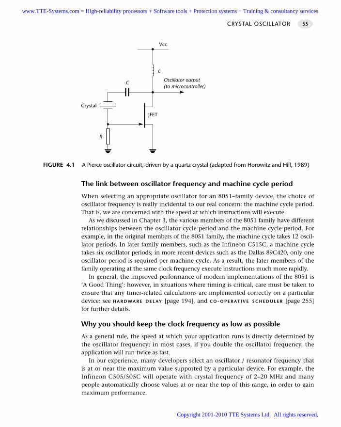
The link between oscillator frequency and machine cycle period
When selecting an appropriate oscillator for an 8051–family device, the choice ofoscillator frequency is really incidental to our real concern: the machine cycle period.That is, we are concerned with the speed at which instructions will execute.
As we discussed in Chapter 3, the various members of the 8051 family have differentrelationships between the oscillator cycle period and the machine cycle period. Forexample, in the original members of the 8051 family, the machine cycle takes 12 oscil-lator periods. In later family members, such as the Infineon C515C, a machine cycletakes six oscillator periods; in more recent devices such as the Dallas 89C420, only oneoscillator period is required per machine cycle. As a result, the later members of thefamily operating at the same clock frequency execute instructions much more rapidly.
In general, the improved performance of modern implementations of the 8051 is‘A Good Thing’: however, in situations where timing is critical, care must be taken toensure that any timer-related calculations are implemented correctly on a particulardevice: see H A R D WA R E D E L AY [page 194], and C O-O P E R AT I V E S C H E D U L E R [page 255]for further details.
Why you should keep the clock frequency as low as possible
As a general rule, the speed at which your application runs is directly determined bythe oscillator frequency: in most cases, if you double the oscillator frequency, theapplication will run twice as fast.
In our experience, many developers select an oscillator / resonator frequency thatis at or near the maximum value supported by a particular device. For example, theInfineon C505/505C will operate with crystal frequency of 2–20 MHz and manypeople automatically choose values at or near the top of this range, in order to gainmaximum performance.
CRYSTAL OSCILLATOR 55
FIGURE 4.1 A Pierce oscillator circuit, driven by a quartz crystal (adapted from Horowitz and Hill, 1989)
JFET
C
R
Crystal
L
Oscillator output(to microcontroller)
Vcc
www.TTE-Systems.com = High-reliability processors + Software tools + Protection systems + Training & consultancy services
Copyright 2001-2010 TTE Systems Ltd. All rights reserved.
This can be a mistake, for the following reasons:
Many applications do not require the levels of performance that a modern 8051device can provide.
In most modern (CMOS-based) 8051s, there is an almost linear relationshipbetween the oscillator frequency and the power supply current. As a result, byusing the lowest frequency necessary it is possible to reduce the power require-ment: this can be useful in many applications.
When accessing low-speed peripherals (such as slow memory or LCD displays),programming and hardware design can be greatly simplified – and the cost ofperipheral components, such as memory latches, can be reduced – if the chip isoperating more slowly.
The electromagnetic interference (EMI) generated by a circuit increases with clockfrequency.
0 MHz operating frequencies?
Several modern 8051 family members can be operated at speeds down to 0 Hz: forexample, the Atmel 89C52 device has an operating range from 0 to 24 MHz. Thisfacility can allow significant power savings, through operating the system at very lowfrequencies (in kiloHertz or even Hertz, rather than in megaHertz). We make use ofthese features in O N E-Y E A R S C H E D U L E R [page 919].
In some applications, even 0 Hz can be useful. At first glance, this may not makesense: at 0 Hz, the device is not operating and no code will execute. However, indevices designed for low-frequency operation, the system state will be maintained evenif the clock frequency is reduced. This means that the clock frequency can be reducedto 0 to save power. In addition it means that, if the clock temporarily fails (for what-ever reason) and then recovers, your system has a better chance of recovering, too.
SolutionThe aim of this pattern is to help you decide if you should use a quartz crystal withyour 8051 microcontroller and, if so, how to connect such a device. This sectiondirectly addresses these issues.
Stability issues
A key factor in selecting an oscillator for your system is the issue of oscillator stability.In most cases, oscillator stability is expressed in figures such as ‘±20 ppm’: ‘20 partsper million’.
HARDWARE FOUNDATIONS56
In general, you should operate at the lowest possible oscillator frequency compatiblewith the performance needs of your application.
www.TTE-Systems.com = High-reliability processors + Software tools + Protection systems + Training & consultancy services
Copyright 2001-2010 TTE Systems Ltd. All rights reserved.
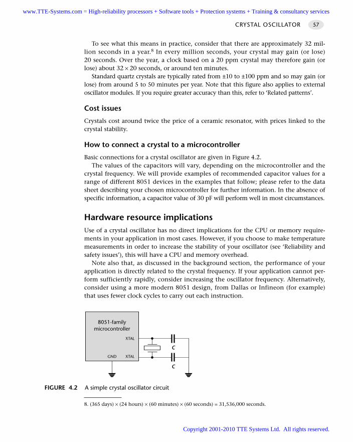
To see what this means in practice, consider that there are approximately 32 mil-lion seconds in a year.8 In every million seconds, your crystal may gain (or lose)20 seconds. Over the year, a clock based on a 20 ppm crystal may therefore gain (orlose) about 32 × 20 seconds, or around ten minutes.
Standard quartz crystals are typically rated from ±10 to ±100 ppm and so may gain (orlose) from around 5 to 50 minutes per year. Note that this figure also applies to externaloscillator modules. If you require greater accuracy than this, refer to ‘Related patterns’.
Cost issues
Crystals cost around twice the price of a ceramic resonator, with prices linked to thecrystal stability.
How to connect a crystal to a microcontroller
Basic connections for a crystal oscillator are given in Figure 4.2. The values of the capacitors will vary, depending on the microcontroller and the
crystal frequency. We will provide examples of recommended capacitor values for arange of different 8051 devices in the examples that follow; please refer to the datasheet describing your chosen microcontroller for further information. In the absence ofspecific information, a capacitor value of 30 pF will perform well in most circumstances.
Hardware resource implicationsUse of a crystal oscillator has no direct implications for the CPU or memory require-ments in your application in most cases. However, if you choose to make temperaturemeasurements in order to increase the stability of your oscillator (see ‘Reliability andsafety issues’), this will have a CPU and memory overhead.
Note also that, as discussed in the background section, the performance of yourapplication is directly related to the crystal frequency. If your application cannot per-form sufficiently rapidly, consider increasing the oscillator frequency. Alternatively,consider using a more modern 8051 design, from Dallas or Infineon (for example)that uses fewer clock cycles to carry out each instruction.
CRYSTAL OSCILLATOR 57
FIGURE 4.2 A simple crystal oscillator circuit
8051-familymicrocontroller
GND XTAL
XTAL
C
C
8. (365 days) × (24 hours) × (60 minutes) × (60 seconds) = 31,536,000 seconds.
www.TTE-Systems.com = High-reliability processors + Software tools + Protection systems + Training & consultancy services
Copyright 2001-2010 TTE Systems Ltd. All rights reserved.
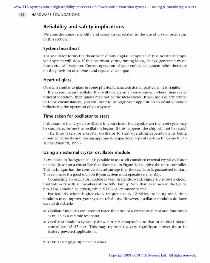
Reliability and safety implicationsWe consider some reliability and safety issues related to the use of crystal oscillatorsin this section.
System heartbeat
The oscillator forms the ‘heartbeat’ of any digital computer. If this heartbeat stops,your system will stop. If this heartbeat varies, timing loops, delays, generated wave-forms etc. will vary too. Correct operation of your embedded system relies thereforeon the provision of a robust and regular clock input.
Heart of glass
Quartz is similar to glass in some physical characteristics: in particular, it is fragile. If you require an oscillator that will operate in an environment where there is sig-
nificant vibration, then quartz may not be the ideal choice. If you use a quartz crystalin these circumstances, you will need to package your application to avoid vibrationinfluencing the operation of your system.
Time taken for oscillator to start
If the start of the (crystal) oscillator in your circuit is delayed, then the reset cycle maybe completed before the oscillation begins. If this happens, the chip will not be reset.9
The time taken for a crystal oscillator to start operating depends on its beingmounted correctly and having appropriate capacitors. Typical start-up times are 0.1 to10 ms (Mariutti, 1999).
Using an external crystal oscillator module
As we noted in ‘Background’, it is possible to use a self-contained external crystal oscillatormodule (based on a circuit like that illustrated in Figure 4.1) to drive the microcontroller.This technique has the considerable advantage that the oscillator is guaranteed to start.This can make it a good solution if your system must operate very reliably.
Connecting an oscillator module is very straightforward. Figure 4.3 shows a circuitthat will work with all members of the 8051 family. Note that, as shown in the figure,pin XTAL1 should be driven, while XTAL2 is left unconnected.
Particularly where higher clock frequencies (> 12 MHz) are being used, thenmodules may improve your system reliability. However, oscillator modules do haveseveral drawbacks:
Oscillator modules cost around twice the price of a crystal oscillator and four timesas much as a ceramic resonator.
Oscillator modules typically draw currents comparable to that of an 8051 micro-controller: 15–35 mA. This may represent a very significant power drain inbattery-powered applications.
HARDWARE FOUNDATIONS58
9. See R C R E S E T [page 68] for further details.
www.TTE-Systems.com = High-reliability processors + Software tools + Protection systems + Training & consultancy services
Copyright 2001-2010 TTE Systems Ltd. All rights reserved.
Oscillator modules are not always easy to obtain in ‘odd’ frequencies, such as11.059 MHz. This frequency is very useful in 8051-based designs involving a serialinterface, as discussed in ‘Related patterns and alternative solutions’.
Improving the stability of a crystal oscillator
As we have discussed, typical crystal oscillators have a stability of around ±20–100ppm. If we use this device to control a real-time clock we may gain or lose up to 50mins per year: that is, up to ~1 minute / week. This result is not specific to the 8051family: the result of this behaviour is evident even in expensive servers for desktopcomputer networks. By contrast, most ‘quartz’ wristwatches use crystal oscillators,cost very little and keep very good time. This is because they have a sophisticatedtemperature control system attached, which keeps them operating at a temperature of35°C for about 16 hours every day. The temperature control system is your wrist (andattached biological mechanisms).
If you want a general crystal-controlled embedded system to keep accurate time,you can choose to keep the device in an oven (or fridge) at a fixed temperature andfine-tune the software to keep accurate time. This is, however, rarely practical.Instead, ‘temperature compensated crystal oscillators’ (TCXOs) are available that pro-vide – in an easy-to-use package – a crystal oscillator and circuitry that compensatesfor changes in temperature. Such devices provide stability levels of up to ±0.1 ppm (ormore): in a clock circuit, this should gain or lose no more than around 1 minuteevery 20 years. Such levels of accuracy are adequate for all but the most demanding ofapplications. However, there is a catch. TCXOs can cost in excess of $100.00 per unitand may even cost several times this amount. This price puts them well out of reachof most embedded projects.
One practical alternative is to determine the temperature-frequency characteristicsfor your chosen crystal and include this information in your application. For the costof a small temperature sensor (around $2.00), you can keep track of the temperatureand adjust the timing as required. This is the basis of S TA B L E S C H E D U L E R [page 932].
CRYSTAL OSCILLATOR 59
FIGURE 4.3 Using an external oscillator module
8051-familymember
XTAL 2
XTAL 1Ocillatormodule
Vcc
www.TTE-Systems.com = High-reliability processors + Software tools + Protection systems + Training & consultancy services
Copyright 2001-2010 TTE Systems Ltd. All rights reserved.
Another alternative is to use an atomic clock. For example, a caesium beam clockuses atomic transitions as the reference for a crystal oscillator and can provide accu-racy at a level of a few parts per million million (that is, around 1 in 1012). Thistranslates into an accuracy of around 1 minute every million years. Use of such adevice may sound like an outlandishly expensive solution, but you can now accessthe atomic clocks in various satellites using global positioning system (GPS) receiversor GPS chip sets. This is the approach increasingly used by the mobile phone (cellphone) companies that include such technology on their base stations.
PortabilityThese techniques can be, and are, used with a wide range of microcontrollers andmicroprocessors.
Note that, as discussed in the ‘Solution’ section, the value of capacitors to be useddepends on both the crystal frequency and the microcontroller used. The manufac-turer’s data sheet for the microcontroller will provide recommended values.
Overall strengths and weaknessesCrystal oscillators are stable. Typically ±20–100 ppm = ±50 mins per year (upto ~1 minute / week).
The great majority of 8051-based designs use a variant of the simple crystal-based oscillator circuit presented here: developers are therefore familiar withcrystal-based designs.
Quartz crystals are available at reasonable cost for most common frequencies.The only additional components required are usually two small capacitors.Overall, crystal oscillators are more expensive than ceramic resonators.
Crystal oscillators are susceptible to vibration.
The stability falls with age.
Related patterns and alternative solutionsAn alternative solution
The main alternative to an external crystal oscillator is an external ceramic resonator:see C E R A M I C R E S O N AT O R [page 64].
Using an on-chip oscillator
As we saw in Chapter 3, Small 8051 devices, such as the popular Atmel 89C4051, aredesigned as flexible, cost-effective replacements to discrete circuits (assembled fromtransistors, resistors, capacitors etc.). However, these devices still require externaloscillator (and reset) circuits. As the oscillator and reset components can, together,cost as much as these small microcontrollers and greatly increase the board size, it
HARDWARE FOUNDATIONS60
www.TTE-Systems.com = High-reliability processors + Software tools + Protection systems + Training & consultancy services
Copyright 2001-2010 TTE Systems Ltd. All rights reserved.
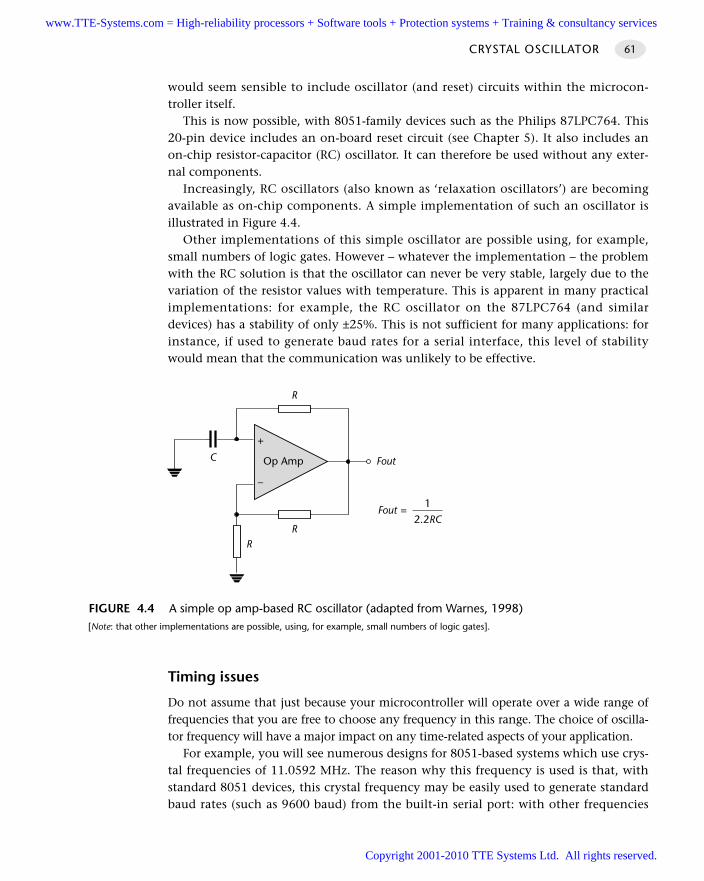
would seem sensible to include oscillator (and reset) circuits within the microcon-troller itself.
This is now possible, with 8051-family devices such as the Philips 87LPC764. This20-pin device includes an on-board reset circuit (see Chapter 5). It also includes anon-chip resistor-capacitor (RC) oscillator. It can therefore be used without any exter-nal components.
Increasingly, RC oscillators (also known as ‘relaxation oscillators’) are becomingavailable as on-chip components. A simple implementation of such an oscillator isillustrated in Figure 4.4.
Other implementations of this simple oscillator are possible using, for example,small numbers of logic gates. However – whatever the implementation – the problemwith the RC solution is that the oscillator can never be very stable, largely due to thevariation of the resistor values with temperature. This is apparent in many practicalimplementations: for example, the RC oscillator on the 87LPC764 (and similardevices) has a stability of only ±25%. This is not sufficient for many applications: forinstance, if used to generate baud rates for a serial interface, this level of stabilitywould mean that the communication was unlikely to be effective.
Timing issues
Do not assume that just because your microcontroller will operate over a wide range offrequencies that you are free to choose any frequency in this range. The choice of oscilla-tor frequency will have a major impact on any time-related aspects of your application.
For example, you will see numerous designs for 8051-based systems which use crys-tal frequencies of 11.0592 MHz. The reason why this frequency is used is that, withstandard 8051 devices, this crystal frequency may be easily used to generate standardbaud rates (such as 9600 baud) from the built-in serial port: with other frequencies
CRYSTAL OSCILLATOR 61
FIGURE 4.4 A simple op amp-based RC oscillator (adapted from Warnes, 1998) [Note: that other implementations are possible, using, for example, small numbers of logic gates].
Op Amp
+
–
Fout
R
RR
C
Fout =1
2.2RC
www.TTE-Systems.com = High-reliability processors + Software tools + Protection systems + Training & consultancy services
Copyright 2001-2010 TTE Systems Ltd. All rights reserved.
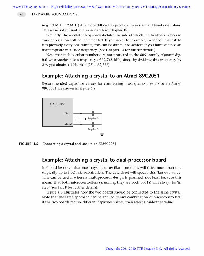
(e.g. 10 MHz, 12 MHz) it is more difficult to produce these standard baud rate values.This issue is discussed in greater depth in Chapter 18.
Similarly, the oscillator frequency dictates the rate at which the hardware timers inyour application will be incremented. If you need, for example, to schedule a task torun precisely every one minute, this can be difficult to achieve if you have selected aninappropriate oscillator frequency. (See Chapter 14 for further details.)
Note that such peculiar numbers are not restricted to the 8051 family. ‘Quartz’ dig-ital wristwatches use a frequency of 32.768 kHz, since, by dividing this frequency by215, you obtain a 1 Hz ‘tick’ (215 = 32,768).
Example: Attaching a crystal to an Atmel 89C2051Recommended capacitor values for connecting most quartz crystals to an Atmel89C2051 are shown in Figure 4.5.
Example: Attaching a crystal to dual-processor boardIt should be noted that most crystals or oscillator modules will drive more than one(typically up to five) microcontrollers. The data sheet will specify this ‘fan out’ value.This can be useful where a multiprocesor design is planned, not least because thismeans that both microcontrollers (assuming they are both 8051s) will always be ‘instep’ (see Part F for further details).
Figure 4.6 illustrates how the two boards should be connected to the same crystal.Note that the same approach can be applied to any combination of microcontrollers:if the two boards require different capacitor values, then select a mid-range value.
HARDWARE FOUNDATIONS62
FIGURE 4.5 Connecting a crystal oscillator to an AT89C2051
AT89C2051
XTAL 2
XTAL 1
30 pF ±10
30 pF ±10
www.TTE-Systems.com = High-reliability processors + Software tools + Protection systems + Training & consultancy services
Copyright 2001-2010 TTE Systems Ltd. All rights reserved.
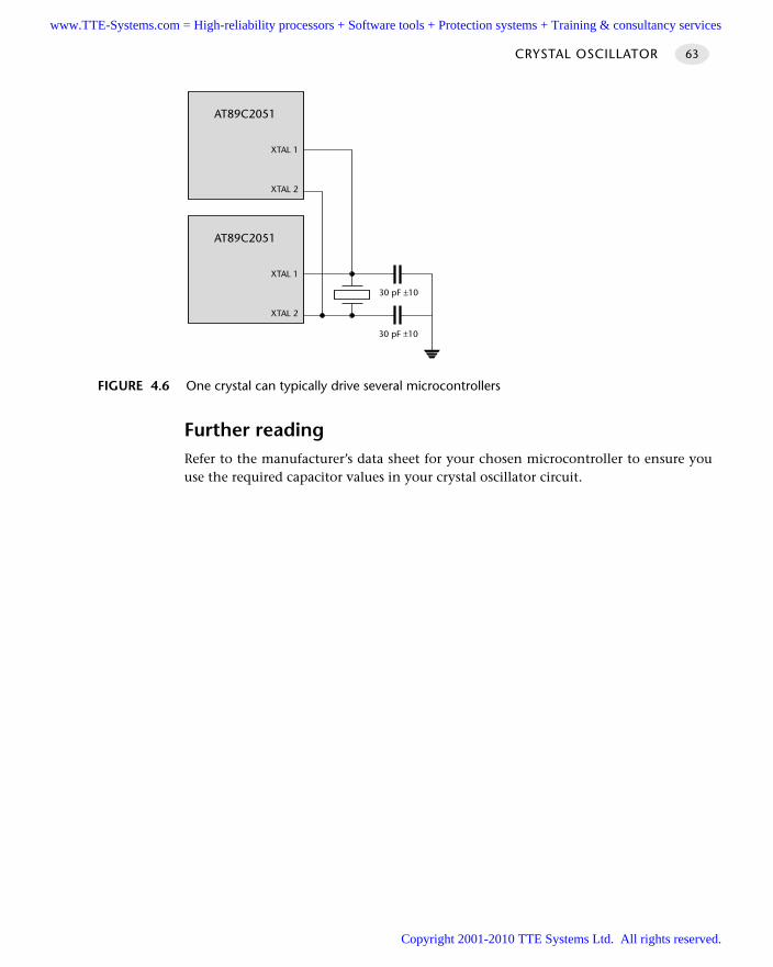
Further readingRefer to the manufacturer’s data sheet for your chosen microcontroller to ensure youuse the required capacitor values in your crystal oscillator circuit.
CRYSTAL OSCILLATOR 63
FIGURE 4.6 One crystal can typically drive several microcontrollers
AT89C2051
XTAL 2
XTAL 1
30 pF ±10
30 pF ±10
AT89C2051
XTAL 2
XTAL 1
www.TTE-Systems.com = High-reliability processors + Software tools + Protection systems + Training & consultancy services
Copyright 2001-2010 TTE Systems Ltd. All rights reserved.
CERAMIC RESONATOR
Context You are developing an embedded application using one or more members of the
8051 family of microcontrollers.
You are designing an appropriate hardware foundation for your application.
ProblemWhen and how should you use a ceramic resonator with members of the 8051–familymicrocontrollers?
BackgroundA ceramic resonator is, like a quartz oscillator, based on a piezoelectric material. Inthis case, the material is (as the name suggests) a form of piezoelectric ceramic.
See C RY S TA L O S C I L L AT O R [page 54] for additional background material.
SolutionThe aim of this pattern is to help you decide if you should use a ceramic resonatorwith your 8051 microcontroller and, if so, how to connect such a device. This sectiondirectly addresses these issues.
Stability issues
As discussed in C RY S TA L O S C I L L AT O R [page 54], a key factor in selecting an oscillatorfor your system is the issue of oscillator stability. Unlike crystal oscillators, which usu-ally have stability measured expressed in parts per million, ceramic resonator stabilityis usually stated in percentage terms. A figure of 1% stability is common. There are1,440 minutes in a day and a clock based on a 1% ceramic resonator could expect togain (or lose) around 14 minutes every day. Clearly, such devices are not suitable foroperations requiring accurate timing over a long period. Note, however, that if werequire the resonator to form the basis of a 30-second delay, the likely gain or loss is0.3 seconds: this may not be a problem.
Cost issues
Ceramic resonators cost half the price of a crystal oscillator.
HARDWARE FOUNDATIONS64
www.TTE-Systems.com = High-reliability processors + Software tools + Protection systems + Training & consultancy services
Copyright 2001-2010 TTE Systems Ltd. All rights reserved.
External capacitors
Most ceramic resonators include internal capacitors. They may therefore be directlyaccessed to the microcontroller without the need for external capacitors. This makesthem easy to use and can further reduce costs and the required board size.
Hardware resource implicationsUse of a ceramic resonator has no direct implications for the memory requirements inyour application.
Note also that the performance of your application is directly related to the res-onator frequency. If your application cannot perform sufficiently rapidly, considerincreasing this frequency. Alternatively, consider using a more modern 8051 design,from Dallas or Infineon (for example) that requires fewer clock cycles to carry outeach instruction.
Reliability and safety implicationsSee C R Y S TA L O S C I L L AT O R [page 54] for a general discussion of reliability and safetyissues associated with oscillators.
Overall, the ceramic resonator is the most physically robust form of oscillatorwe consider.
PortabilityThese techniques can be, and are, used with a wide range of microcontrollers andmicroprocessors.
Please note that ceramic resonators should not, generally, be used as plug-inreplacements for crystal oscillators: different capacitors (if any) are required for eachsolution.
Overall strengths and weaknessesCheaper than crystal oscillators.
Physically robust: less easily damage by physical vibration (or droppedequipment etc.) than crystal oscillator.
Many resonators contain in-built capacitors and can be used without anyexternal components.
Small size. About half the size of crystal oscillator.
Comparatively low stability: not general appropriate for use where accuratetiming (over an extended period) is required. Typically ±5000 ppm = ±2500 minper year (up to ~50 minutes / week).
CERAMIC RESONATOR 65
www.TTE-Systems.com = High-reliability processors + Software tools + Protection systems + Training & consultancy services
Copyright 2001-2010 TTE Systems Ltd. All rights reserved.
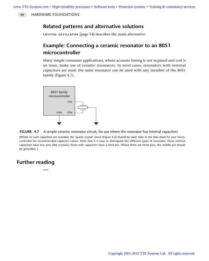
Related patterns and alternative solutionsC RY S TA L O S C I L L AT O R [page 54] describes the main alternative.
Example: Connecting a ceramic resonator to an 8051microcontrollerMany simple consumer applications, where accurate timing is not required and cost isan issue, make use of ceramic resonators. In most cases, resonators with internalcapacitors are used: the same resonator can be used with any member of the 8051family (Figure 4.7).
Further reading—
HARDWARE FOUNDATIONS66
FIGURE 4.7 A simple ceramic resonator circuit, for use where the resonator has internal capacitors [Where no such capacitors are included, the ‘quartz crystal’ circuit (Figure 4.2) should be used: refer to the data sheet for your micro-controller for recommended capacitor values. Note that it is easy to distinguish the different types of resonator: those withoutcapacitors have two pins (like crystals); those with capacitors have a third pin. Where there are three pins, the middle pin shouldbe grounded. ]
8051-familymicrocontroller
GND XTAL
XTAL
www.TTE-Systems.com = High-reliability processors + Software tools + Protection systems + Training & consultancy services
Copyright 2001-2010 TTE Systems Ltd. All rights reserved.
Reset hardware
Introduction
The process of starting any microcontroller is a non-trivial one. The underlying hard-ware is complex and a small, manufacturer-defined ‘reset routine’ must be run toplace this hardware into an appropriate state before it can begin executing the userprogram. Running this reset routine takes time and requires that the microcontroller’soscillator is operating.
Where your system is supplied by a robust power supply, which rapidly reaches itsspecified output voltage when switched on, rapidly decreases to 0V when switchedoff, and – while switched on – cannot ‘brown out’ (drop in voltage), then you cansafely use low-cost reset hardware based on a capacitor and a resistor: this form ofreset circuit is addressed in R C R E S E T [page 68].
Where your power supply is less than perfect, and / or your application is safetyrelated, the simple RC solution will not be suitable. R O B U S T R E S E T [page 77] discussesa more reliable alternative.
chapter 5www.TTE-Systems.com = High-reliability processors + Software tools + Protection systems + Training & consultancy services
Copyright 2001-2010 TTE Systems Ltd. All rights reserved.
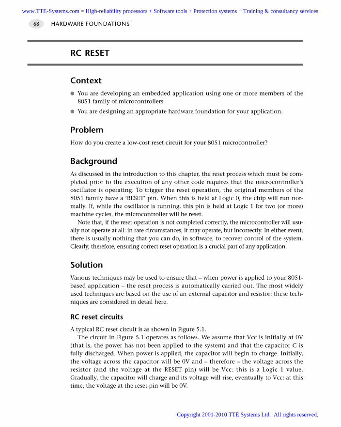
RC RESET
Context You are developing an embedded application using one or more members of the
8051 family of microcontrollers.
You are designing an appropriate hardware foundation for your application.
ProblemHow do you create a low-cost reset circuit for your 8051 microcontroller?
BackgroundAs discussed in the introduction to this chapter, the reset process which must be com-pleted prior to the execution of any other code requires that the microcontroller’soscillator is operating. To trigger the reset operation, the original members of the8051 family have a ‘RESET’ pin. When this is held at Logic 0, the chip will run nor-mally. If, while the oscillator is running, this pin is held at Logic 1 for two (or more)machine cycles, the microcontroller will be reset.
Note that, if the reset operation is not completed correctly, the microcontroller will usu-ally not operate at all: in rare circumstances, it may operate, but incorrectly. In either event,there is usually nothing that you can do, in software, to recover control of the system.Clearly, therefore, ensuring correct reset operation is a crucial part of any application.
SolutionVarious techniques may be used to ensure that – when power is applied to your 8051-based application – the reset process is automatically carried out. The most widelyused techniques are based on the use of an external capacitor and resistor: these tech-niques are considered in detail here.
RC reset circuits
A typical RC reset circuit is as shown in Figure 5.1.The circuit in Figure 5.1 operates as follows. We assume that Vcc is initially at 0V
(that is, the power has not been applied to the system) and that the capacitor C isfully discharged. When power is applied, the capacitor will begin to charge. Initially,the voltage across the capacitor will be 0V and – therefore – the voltage across theresistor (and the voltage at the RESET pin) will be Vcc: this is a Logic 1 value.Gradually, the capacitor will charge and its voltage will rise, eventually to Vcc: at thistime, the voltage at the reset pin will be 0V.
HARDWARE FOUNDATIONS68
www.TTE-Systems.com = High-reliability processors + Software tools + Protection systems + Training & consultancy services
Copyright 2001-2010 TTE Systems Ltd. All rights reserved.
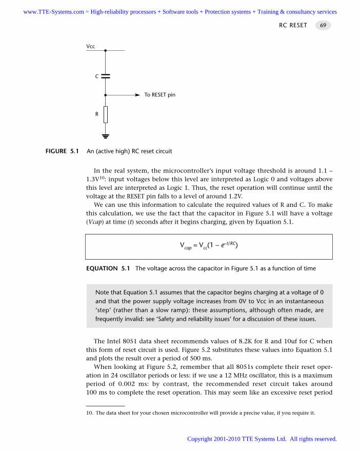
In the real system, the microcontroller’s input voltage threshold is around 1.1 –1.3V10: input voltages below this level are interpreted as Logic 0 and voltages abovethis level are interpreted as Logic 1. Thus, the reset operation will continue until thevoltage at the RESET pin falls to a level of around 1.2V.
We can use this information to calculate the required values of R and C. To makethis calculation, we use the fact that the capacitor in Figure 5.1 will have a voltage(Vcap) at time (t) seconds after it begins charging, given by Equation 5.1.
The Intel 8051 data sheet recommends values of 8.2K for R and 10uf for C whenthis form of reset circuit is used. Figure 5.2 substitutes these values into Equation 5.1and plots the result over a period of 500 ms.
When looking at Figure 5.2, remember that all 8051s complete their reset oper-ation in 24 oscillator periods or less: if we use a 12 MHz oscillator, this is a maximumperiod of 0.002 ms: by contrast, the recommended reset circuit takes around100 ms to complete the reset operation. This may seem like an excessive reset period
RC RESET 69
FIGURE 5.1 An (active high) RC reset circuit
C
R
Vcc
To RESET pin
EQUATION 5.1 The voltage across the capacitor in Figure 5.1 as a function of time
Vcap = Vcc(1 – e–t/RC)
Note that Equation 5.1 assumes that the capacitor begins charging at a voltage of 0and that the power supply voltage increases from 0V to Vcc in an instantaneous‘step’ (rather than a slow ramp): these assumptions, although often made, arefrequently invalid: see ‘Safety and reliability issues’ for a discussion of these issues.
10. The data sheet for your chosen microcontroller will provide a precise value, if you require it.
www.TTE-Systems.com = High-reliability processors + Software tools + Protection systems + Training & consultancy services
Copyright 2001-2010 TTE Systems Ltd. All rights reserved.
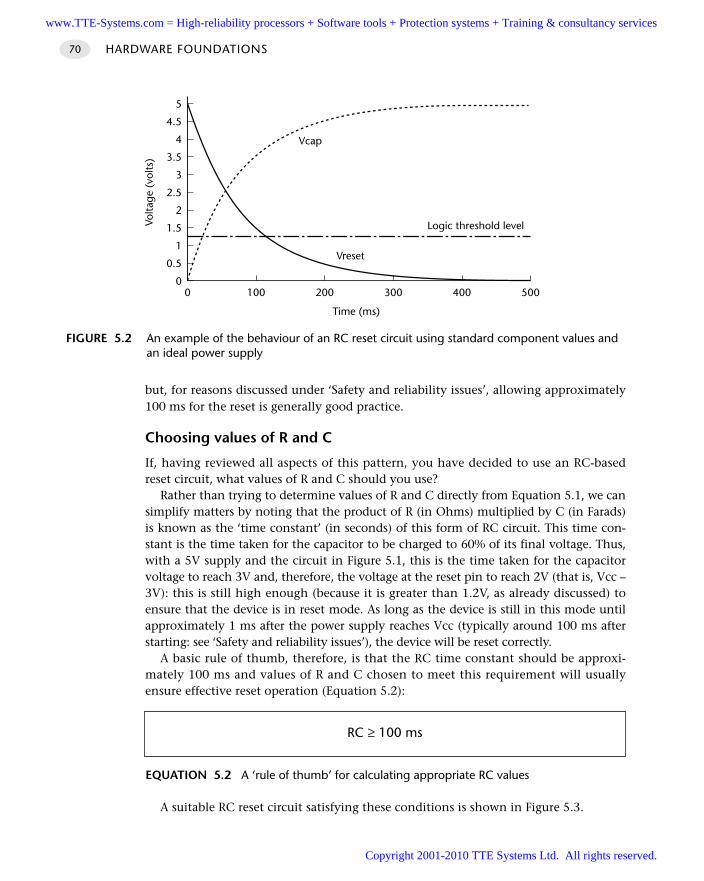
but, for reasons discussed under ‘Safety and reliability issues’, allowing approximately100 ms for the reset is generally good practice.
Choosing values of R and C
If, having reviewed all aspects of this pattern, you have decided to use an RC-basedreset circuit, what values of R and C should you use?
Rather than trying to determine values of R and C directly from Equation 5.1, we cansimplify matters by noting that the product of R (in Ohms) multiplied by C (in Farads)is known as the ‘time constant’ (in seconds) of this form of RC circuit. This time con-stant is the time taken for the capacitor to be charged to 60% of its final voltage. Thus,with a 5V supply and the circuit in Figure 5.1, this is the time taken for the capacitorvoltage to reach 3V and, therefore, the voltage at the reset pin to reach 2V (that is, Vcc –3V): this is still high enough (because it is greater than 1.2V, as already discussed) toensure that the device is in reset mode. As long as the device is still in this mode untilapproximately 1 ms after the power supply reaches Vcc (typically around 100 ms afterstarting: see ‘Safety and reliability issues’), the device will be reset correctly.
A basic rule of thumb, therefore, is that the RC time constant should be approxi-mately 100 ms and values of R and C chosen to meet this requirement will usuallyensure effective reset operation (Equation 5.2):
A suitable RC reset circuit satisfying these conditions is shown in Figure 5.3.
HARDWARE FOUNDATIONS70
FIGURE 5.2 An example of the behaviour of an RC reset circuit using standard component values andan ideal power supply
00
0.5
1
1.5
2
2.5
3
3.5
4
4.5
5
100 200 300 400 500
Time (ms)
Volta
ge (
volts
)Vcap
Vreset
Logic threshold level
EQUATION 5.2 A ‘rule of thumb’ for calculating appropriate RC values
RC ≥ 100 ms
www.TTE-Systems.com = High-reliability processors + Software tools + Protection systems + Training & consultancy services
Copyright 2001-2010 TTE Systems Ltd. All rights reserved.
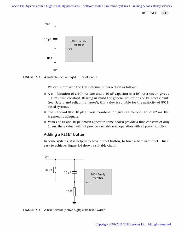
We can summarize the key material in this section as follows:
A combination of a 10K resistor and a 10 µF capacitor in a RC reset circuit gives a100 ms time constant. Bearing in mind the general limitations of RC reset circuits(see ‘Safety and reliability issues’), this value is suitable for the majority of 8051-based systems.
The standard 8K2, 10 µF RC reset combination gives a time constant of 82 ms: thisis generally adequate.
Values of 1K and 10 µF (which appear in some books) provide a time constant of only10 ms: these values will not provide a reliable reset operation with all power supplies.
Adding a RESET button
In some systems, it is helpful to have a reset button, to force a hardware reset. This iseasy to achieve. Figure 5.4 shows a suitable circuit.
RC RESET 71
FIGURE 5.3 A suitable (active high) RC reset circuit
8051 familymember
10 µF
10 K
Vcc
RESET
FIGURE 5.4 A reset circuit (active high) with reset switch
8051 familymember
10 µF
10 K
Vcc
RESET
Reset
www.TTE-Systems.com = High-reliability processors + Software tools + Protection systems + Training & consultancy services
Copyright 2001-2010 TTE Systems Ltd. All rights reserved.
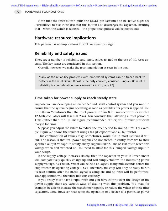
Note that the reset button pulls the RESET pin (assumed to be active high: see‘Portability’) to Vcc. Note also that this button also discharges the capacitor, ensuringthat – when the switch is released – the proper reset process will be carried out.
Hardware resource implicationsThis pattern has no implications for CPU or memory usage.
Reliability and safety issuesThere are a number of reliability and safety issues related to the use of RC reset cir-cuits. The key issues are considered in this section.
Overall, however, we make the recommendation as seen in the box.
Time taken for power supply to reach steady state
Suppose you are developing an embedded industrial control system and you want toensure that the system begins operating as soon as possible after power is applied. Younote (from ‘Solution’) that the reset process on an 8051 microcontroller (with a12 MHz oscillator) will take 0.002 ms. You conclude that, allowing a reset period of1 ms (rather than the 100 ms figure recommended earlier) will provide sufficientmargin for error.
Suppose you adjust the values to reduce the reset period to around 1 ms. For exam-ple, Figure 5.5 shows the result of using a 0.1 µF capacitor and a 6K7 resistor.
This combination of values may, sometimes, work: but in most systems it willfail. The reason is that real power supplies do not switch instantly from 0V to theirspecified output voltage: in reality, many supplies take 50 ms or 100 ms to reach thisvoltage when first switched on. You need to allow for this ‘ramped’ voltage input inyour design.
If the supply voltage increases slowly, then the capacitor in your RC reset circuitwill comparatively quickly charge up and will simply ‘follow’ the increasing powersupply voltage. As a result, Vreset will be held at Logic 0 many milliseconds before thechip reaches its operating voltage (~5V). Therefore, the chip will only be ready to runits reset routine after the RESET signal is complete and no reset will be performed.Your application will therefore not start correctly.
If you really must have a rapid reset and you have control over the design of thepower supply there are various ways of dealing with this problem. You may, forexample, be able to increase the transformer capacity or reduce the values of these filtercapacitors. Note, however, that tying the operation of a device to a particular power
HARDWARE FOUNDATIONS72
Many of the reliability problems with embedded systems can be traced back todefects in the reset circuit. If cost is the only concern, consider using an RC reset: ifreliability is a consideration, use a R O B U S T R E S E T [page 77].
www.TTE-Systems.com = High-reliability processors + Software tools + Protection systems + Training & consultancy services
Copyright 2001-2010 TTE Systems Ltd. All rights reserved.
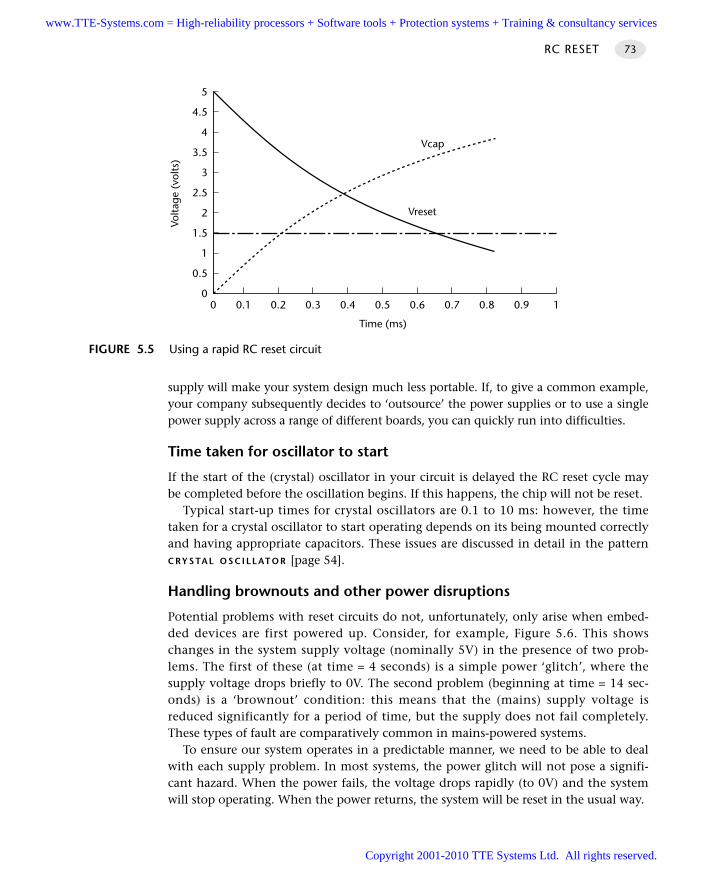
supply will make your system design much less portable. If, to give a common example,your company subsequently decides to ‘outsource’ the power supplies or to use a singlepower supply across a range of different boards, you can quickly run into difficulties.
Time taken for oscillator to start
If the start of the (crystal) oscillator in your circuit is delayed the RC reset cycle maybe completed before the oscillation begins. If this happens, the chip will not be reset.
Typical start-up times for crystal oscillators are 0.1 to 10 ms: however, the timetaken for a crystal oscillator to start operating depends on its being mounted correctlyand having appropriate capacitors. These issues are discussed in detail in the patternC RY S TA L O S C I L L AT O R [page 54].
Handling brownouts and other power disruptions
Potential problems with reset circuits do not, unfortunately, only arise when embed-ded devices are first powered up. Consider, for example, Figure 5.6. This showschanges in the system supply voltage (nominally 5V) in the presence of two prob-lems. The first of these (at time = 4 seconds) is a simple power ‘glitch’, where thesupply voltage drops briefly to 0V. The second problem (beginning at time = 14 sec-onds) is a ‘brownout’ condition: this means that the (mains) supply voltage isreduced significantly for a period of time, but the supply does not fail completely.These types of fault are comparatively common in mains-powered systems.
To ensure our system operates in a predictable manner, we need to be able to dealwith each supply problem. In most systems, the power glitch will not pose a signifi-cant hazard. When the power fails, the voltage drops rapidly (to 0V) and the systemwill stop operating. When the power returns, the system will be reset in the usual way.
RC RESET 73
FIGURE 5.5 Using a rapid RC reset circuit
00
0.5
1
1.5
2
2.5
3
3.5
4
4.5
5
0.1 0.2 0.3 0.4 1
Time (ms)
Volta
ge (
volts
)
Vcap
Vreset
0.5 0.6 0.7 0.8 0.9
www.TTE-Systems.com = High-reliability processors + Software tools + Protection systems + Training & consultancy services
Copyright 2001-2010 TTE Systems Ltd. All rights reserved.
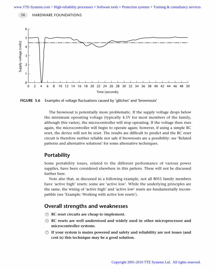
The brownout is potentially more problematic. If the supply voltage drops belowthe minimum operating voltage (typically 4.5V for most members of the family,although this varies), the microcontroller will stop operating. If the voltage then risesagain, the microcontroller will begin to operate again; however, if using a simple RCreset, the device will not be reset. The results are difficult to predict and the RC resetcircuit is therefore neither reliable nor safe if brownouts are a possibility: see ‘Relatedpatterns and alternative solutions’ for some alternative techniques.
PortabilitySome portability issues, related to the different performance of various powersupplies, have been considered elsewhere in this pattern. These will not be discussedfurther here.
Note also that, as discussed in a following example, not all 8051 family membershave ‘active high’ resets: some are ‘active low’. While the underlying principles arethe same, the wiring of ‘active high’ and ‘active low’ resets are fundamentally incom-patible (see ‘Example: Working with active low resets’).
Overall strengths and weaknessesRC reset circuits are cheap to implement.
RC resets are well understood and widely used in other microprocessor andmicrocontroller systems.
If your system is mains powered and safety and reliability are not issues (andcost is) this technique may be a good solution.
HARDWARE FOUNDATIONS74
FIGURE 5.6 Examples of voltage fluctuations caused by ‘glitches’ and ‘brownouts’
0 2 4 6 8 10 12 14 16 18 20 22 24 26 28 30 32 34 36 38 40 42 44 46 48 500
1
2
3
4
5
6
Time (seconds)
Sup
ply
vol
tage
(vo
lts)
www.TTE-Systems.com = High-reliability processors + Software tools + Protection systems + Training & consultancy services
Copyright 2001-2010 TTE Systems Ltd. All rights reserved.
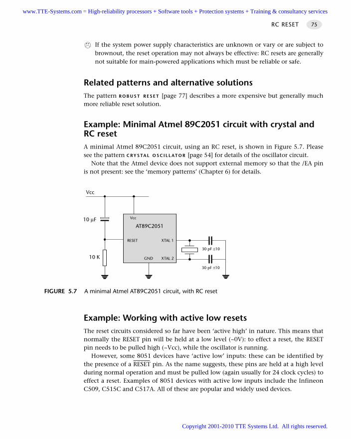
If the system power supply characteristics are unknown or vary or are subject tobrownout, the reset operation may not always be effective: RC resets are generallynot suitable for main-powered applications which must be reliable or safe.
Related patterns and alternative solutionsThe pattern R O B U S T R E S E T [page 77] describes a more expensive but generally muchmore reliable reset solution.
Example: Minimal Atmel 89C2051 circuit with crystal andRC resetA minimal Atmel 89C2051 circuit, using an RC reset, is shown in Figure 5.7. Pleasesee the pattern C RY S TA L O S C I L L AT O R [page 54] for details of the oscillator circuit.
Note that the Atmel device does not support external memory so that the /EA pinis not present: see the ‘memory patterns’ (Chapter 6) for details.
Example: Working with active low resetsThe reset circuits considered so far have been ‘active high’ in nature. This means thatnormally the RESET pin will be held at a low level (~0V): to effect a reset, the RESETpin needs to be pulled high (~Vcc), while the oscillator is running.
However, some 8051 devices have ‘active low’ inputs: these can be identified bythe presence of a RESET pin. As the name suggests, these pins are held at a high levelduring normal operation and must be pulled low (again usually for 24 clock cycles) toeffect a reset. Examples of 8051 devices with active low inputs include the InfineonC509, C515C and C517A. All of these are popular and widely used devices.
RC RESET 75
FIGURE 5.7 A minimal Atmel AT89C2051 circuit, with RC reset
AT89C2051
XTAL 2
XTAL 1
30 pF ±10
30 pF ±10
10 µF
10 K
Vcc
RESET
Vcc
GND
www.TTE-Systems.com = High-reliability processors + Software tools + Protection systems + Training & consultancy services
Copyright 2001-2010 TTE Systems Ltd. All rights reserved.
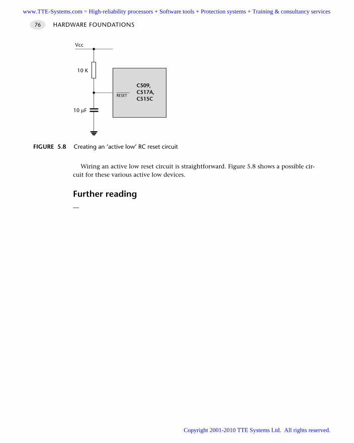
Wiring an active low reset circuit is straightforward. Figure 5.8 shows a possible cir-cuit for these various active low devices.
Further reading—
HARDWARE FOUNDATIONS76
FIGURE 5.8 Creating an ‘active low’ RC reset circuit
C509,C517A,C515C
10 K
10 µF
Vcc
RESET
www.TTE-Systems.com = High-reliability processors + Software tools + Protection systems + Training & consultancy services
Copyright 2001-2010 TTE Systems Ltd. All rights reserved.
ROBUST RESET
Context You are developing an embedded application using one or more members of the
8051 family of microcontrollers.
You are designing an appropriate hardware foundation for your application.
ProblemHow do you create a very reliable reset circuit for your 8051 microcontroller?
BackgroundSee R C R E S E T [page 68] for some background material on reset circuits.
SolutionAs discussed in R C R E S E T [page 68], a key problem for the designers of reliable embed-ded systems is that power supplies are seldom ideal. For example, mains powersupplies can take around 100 ms to reach their normal operating voltage when firstswitched on and may subsequently suffer from voltage variations, includingbrownouts, in part due to variations in the network load caused by other users of themains supply. On the other hand, ‘1.5V’ primary cells (‘batteries’) often begin lifewith a voltage of up to 1.7V and decline to 0.9V or less as they are used.
Although careful design of your power supply can reduce these problems, it isoften desirable to reduce the risks of system failure by maximizing the chances thatyour system will be reset correctly in the event of power supply problems. The robustreset circuits, notably from Dallas and Maxim, directly address this problem.
These useful devices perform two basic operations:
When power is applied to a ‘cold’ system, they apply an appropriate (active high oractive low) reset signal to the microcontroller for at least 100 ms to allow the oscil-lator (if used) and power supply to reach their operational state.
If the supply voltage falls below a preset value during normal operation, thereset cycle will begin and will only end ~100 ms after the supply is restored to thenormal value. This behaviour deals with both total power failures (long or short)and brownouts.
Overall, these devices are very effective and are cheap. Except where cost is theonly concern, they are highly recommended.
ROBUST RESET 77
www.TTE-Systems.com = High-reliability processors + Software tools + Protection systems + Training & consultancy services
Copyright 2001-2010 TTE Systems Ltd. All rights reserved.
Hardware resource implicationsThis pattern has no implications for CPU or memory usage.
Reliability and safety issuesThis form of reset circuit is, as a general rule, much safer than any RC-based equivalent.
PortabilityThe various robust reset chips are generally insensitive to power supply variationsover a wide range: use of such devices therefore tends to make your design moreportable and less dependent on a particular power supply. Most devices are availablewith both ‘active high’ and ‘active low’ versions and are therefore compatible with awide range of 8051 chips.
Overall strengths and weaknessesRobust reset provides reliable performance even with ‘slow’ power suppliesand in the event of brownout.
More expensive than RC reset alternatives.
Related patterns and alternative solutionsR C R E S E T [page 68] offers a cheaper alternative where safety and reliability are muchless important than product cost.
In addition, two further ways of obtaining reliable reset behaviour are now discussed.
On-chip reset circuits
Reset circuits are always a challenge with microcontroller-based systems and – nowthat small reset ICs are available – it seems surprising that this circuitry is not simplyincluded in the microcontroller itself.
In fact, in more recent 8051s, such circuitry is included: see, for example, theDallas DS87C520 / DS83C520 and the Philips 87LPC764. An example of a Dallas87C520 circuit using internal reset components is given in the following section.
Microcontroller / microprocessor supervisor ICs
The robust reset circuits discussed here are simple, economical reset options. However,in some applications, we require other external facilities too. Maxim, in particular, havedeveloped a range of different ‘microcontroller supervisor’ ICs that include not only theequivalent of ‘robust reset’ circuits, but also have various combinations of additionalfacilities, such as watchdog timers and even RS-232 transceivers. Three examples of suchdevices are summarized here: consult the Maxim WWW site11 for further details.
HARDWARE FOUNDATIONS78
11. www.maxim-ic.com
www.TTE-Systems.com = High-reliability processors + Software tools + Protection systems + Training & consultancy services
Copyright 2001-2010 TTE Systems Ltd. All rights reserved.
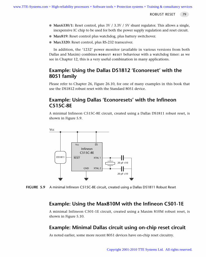
Max6330/1: Reset control, plus 3V / 3.3V / 5V shunt regulator. This allows a single,inexpensive IC chip to be used for both the power supply regulation and reset circuit.
Max819: Reset control plus watchdog, plus battery switchover.
Max3320: Reset control, plus RS-232 transceiver.
In addition, the ‘1232’ power monitor (available in various versions from bothDallas and Maxim) combines R O B U S T R E S E T behaviour with a watchdog timer: as wesee in Chapter 12, this is a very useful combination in many applications.
Example: Using the Dallas DS1812 ‘Econoreset’ with the 8051 familyPlease refer to Chapter 26, Figure 26.10, for one of many examples in this book thatuse the DS1812 robust reset with the Standard 8051 device.
Example: Using Dallas ‘Econoresets’ with the InfineonC515C-8EA minimal Infineon C515C-8E circuit, created using a Dallas DS1811 robust reset, isshown in Figure 5.9.
Example: Using the Max810M with the Infineon C501-1EA minimal Infineon C501-1E circuit, created using a Maxim 810M robust reset, isshown in Figure 5.10.
Example: Minimal Dallas circuit using on-chip reset circuitAs noted earlier, some more recent 8051 devices have on-chip reset circuitry.
ROBUST RESET 79
FIGURE 5.9 A minimal Infineon C515C-8E circuit, created using a Dallas DS1811 Robust Reset
InfineonC515C-8E
XTAL 2
XTAL 1
20 pF ±10
20 pF ±10
Vcc
RESET
Vcc
GND
EA
DS1811
www.TTE-Systems.com = High-reliability processors + Software tools + Protection systems + Training & consultancy services
Copyright 2001-2010 TTE Systems Ltd. All rights reserved.
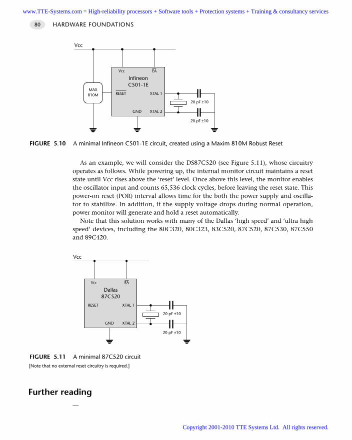
As an example, we will consider the DS87C520 (see Figure 5.11), whose circuitryoperates as follows. While powering up, the internal monitor circuit maintains a resetstate until Vcc rises above the ‘reset’ level. Once above this level, the monitor enablesthe oscillator input and counts 65,536 clock cycles, before leaving the reset state. Thispower-on reset (POR) interval allows time for the both the power supply and oscilla-tor to stabilize. In addition, if the supply voltage drops during normal operation,power monitor will generate and hold a reset automatically.
Note that this solution works with many of the Dallas ‘high speed’ and ‘ultra highspeed’ devices, including the 80C320, 80C323, 83C520, 87C520, 87C530, 87C550and 89C420.
Further reading—
HARDWARE FOUNDATIONS80
FIGURE 5.10 A minimal Infineon C501-1E circuit, created using a Maxim 810M Robust Reset
InfineonC501-1E
XTAL 2
XTAL 1
20 pF ±10
20 pF ±10
Vcc
RESET
Vcc
GND
EA
MAX810M
FIGURE 5.11 A minimal 87C520 circuit [Note that no external reset circuitry is required.]
Dallas87C520
XTAL 2
XTAL 1
20 pF ±10
20 pF ±10
Vcc
RESET
Vcc
GND
EA
www.TTE-Systems.com = High-reliability processors + Software tools + Protection systems + Training & consultancy services
Copyright 2001-2010 TTE Systems Ltd. All rights reserved.
Memory issues
Introduction
All practical microcontroller-based systems require some form of non-volatile codememory (to store the program code) and some form of volatile memory (to store dataand the stack).
In many cases, it is possible to create useful applications without adding externalmemory devices. The first pattern in this chapter (O N-C H I P M E M O R Y [page 82]) dis-cusses how to do this by making effective use of the various memory areas availablein members of the 8051 family.
In some applications, it is necessary to add external memory: the remaining patternsin this chapter (O F F-C H I P D ATA M E M O RY [page 94] and O F F-C H I P C O D E M E M O RY [page100]) consider how best to add additional memory to your 8051-based application.
Please note that the material in this chapter is concerned primarily with devicesusing the Standard 8051 memory architecture. Some of the more recent 8051 devices,such as the Dallas 80C390, Analog Devices ADµC812 and Philips 80C51MX, providesupport for much larger amounts of external memory than was possible in the origi-nal 8051 device: we briefly consider such extended memory devices in this chapter,but – as each manufacturer has an individual solution – we do not attempt to coverthem in detail.
chapter 6www.TTE-Systems.com = High-reliability processors + Software tools + Protection systems + Training & consultancy services
Copyright 2001-2010 TTE Systems Ltd. All rights reserved.
ON-CHIP MEMORY
Context You are developing an embedded application using one or more members of the
8051 family of microcontrollers.
You are designing an appropriate hardware foundation for your application.
ProblemHow do you create an 8051-based circuit that uses only internal memory?
BackgroundSome general background material on memory is presented in this section.
Direct vs. indirect addressing
You will often see the terms ‘indirect addressing’ and ‘direct addressing’ used in dis-cussions about microcontroller memory. Although these terms often cause confusion,they are not difficult to understand.
You will recall that whatever language you write in (for example, C or assembly),your code must ultimately be translated into machine code instructions that can beexecuted by your chosen microcontroller. This set of possible machine instructions isdefined by the hardware manufacturer. Through this process, even complex state-ments in a high-level language are eventually broken down into basic operations,such as ‘Copy this piece of data from one memory location to another’. These, inturn, are implemented by machine instructions that take the form ‘Move the con-tents of memory address X to register Y’.
There are essentially two ways in which such fundamental ‘Move’ instructions maybe implemented in microcontrollers and microprocessors:
Using direct addressing, the address of the memory location (that is, memoryaddress X in the last example) is specifically given as part of the instruction.
Using indirect addressing, the address of the memory location is not explicitlyincluded as part of the instruction: instead the address (of another memory locationor another register) that contains memory address X is included in the instruction.
Since the use of indirect addressing means that two steps are required to find theaddress of the required memory location it may appear to be slower than directaddressing. However, universal use of direct addressing in an 8-bit architecture (with a16-bit address space) would mean that all ‘Move’ instructions would need to includetwo bytes of address information, and would therefore take more time to fetch from
HARDWARE FOUNDATIONS82
www.TTE-Systems.com = High-reliability processors + Software tools + Protection systems + Training & consultancy services
Copyright 2001-2010 TTE Systems Ltd. All rights reserved.
memory. A compromise is thus often made in devices (including the 8051) where asmall area of memory can be directly addressed and most other memory areas mustbe indirectly addressed.
Note that the distinction between direct and indirect addressing also has otheruses. For example, within members of the 8051 family, there is an area of ‘specialfunction register’ memory and another area of general purpose memory. Both blocksof memory are the same size (128 bytes) and both blocks share the same addressrange. On the surface, having two areas of memory with the same address makes nosense; however, in this case, there is no problem. One block of memory can only beaccessed indirectly, the other block can only be accessed directly. As a result, whenour compiler translates a particular ‘C’ statement, appropriate machine-level instruc-tions are selected to ensure that the correct memory area is accessed: in mostcircumstances, this process is completely hidden from the programmer.
Types of memory
On the desktop, most designers and programmers can safely ignore the type ofmemory they are using. This is seldom the case in embedded environments and wetherefore briefly review some of the different types of memory.
First, a short history lesson, to explain the roots of an important acronym. On earlymainframe and desktop computer systems, long-term data storage was carried outusing computer tapes. Reading or writing to the tape took varying amounts of time,depending whether it involved, for example, rewinding the entire tape or simplyrewinding a couple of centimetres. In this context, new memory devices appeared thatcould be used to store data while the computer was running, but which lost these datawhen the power was removed. These read-write memory devices were referred to as‘random access memory’ (RAM) devices, because – unlike tape-based systems – access-ing any element of memory ‘chosen at random’ took the same amount of time.
Tapes have now largely disappeared, but the acronym RAM has not and is still usedto refer to memory devices that can be both read from and written to. However, sinceRAM was first introduced, new forms of memory devices have appeared, includingvarious forms of ROM (read-only memory). Since these ROM devices are also ‘randomaccess’ in nature, the acronym RAM is now best translated as ‘read-write memory’.
Dynamic RAM (DRAM)
Dynamic RAM is a read-write memory technology that uses a small capacitor to storeinformation. As the capacitor will discharge quite rapidly, it must be frequentlyrefreshed to maintain the required information: circuitry on the chip takes care ofthis refresh activity. Like most current forms of RAM, the information is lost whenpower is removed from the chip.
In general, dynamic RAM is simple and comparatively cheap.
ON-CHIP MEMORY 83
www.TTE-Systems.com = High-reliability processors + Software tools + Protection systems + Training & consultancy services
Copyright 2001-2010 TTE Systems Ltd. All rights reserved.
Static RAM (SRAM)
Static RAM is a read-write memory technology that uses a form of electronic flip-flopto store the information. No refreshing is required, but the circuitry is more complexand costs can be several times that of the corresponding size of DRAM. However,access times may be a third those of DRAM.
Mask read-only memory (ROM)
A true read-only memory (ROM) would be useless. The most basic kind of practical ROMis, from the designer’s perspective, read only: however, the manufacturer is able to writeto the memory, at the time the chip is manufactured, according to a ‘mask’ provided bythe company for which the chips are being produced. Such devices are therefore some-times referred to as ‘factory-programmed ROM’ or ‘mask ROM’. Factory or maskprogramming is not cheap and is not a low-volume option: as a result, mistakes can bevery expensive and providing code for your first mask can be a character-building process.Access times are often slower than RAM: roughly 1.5 times that of DRAM.
It should be noted that mask ROMs retain their contents even in environmentswith high levels of electromagnetic activity. This behaviour is in contrast to some ofthe erasable devices in which there is a risk that data corruption may occur due, forexample, to high UV levels (UV–EPROMs: see later in this section) or strong electricalfields (EEPROMs: see later in this section).
Many members of the 8051 family are available with on-board mask-programmableROM.
Programmable read-only memory (PROM)
The name PROM sounds like a contradiction and it is. This is, in fact, a form of write-once, read-many (WORM) or ‘one-time programmable’ (OTP) memory. Basically, weuse a PROM programmer to blow tiny ‘fuses’ in the device. Once blown, these fusescannot be repaired; however, the devices themselves are cheap.
Many modern members of the 8051 family are available with OTP ROM.
UV-erasable programmable read-only memory (UV-EPROM)
Like PROMs, UV-EPROMs are programmed electrically. Unlike PROMs, they also havea quartz window which allows the memory to be erased by exposing the internals ofthe device to UV light. The erasure process can take several minutes and, after erasure,the quartz window will be covered with a UV-opaque label. This form of EPROM canwithstand thousands of program / erase cycles.
More flexible than PROMs and once very common, UV-EPROMs now seem ratherprimitive compared with EEPROMs. They can be useful for prototyping but are pro-hibitively expensive for use in production.
Many older members of the 8051 family are available with on-board UV-EPROM.
HARDWARE FOUNDATIONS84
www.TTE-Systems.com = High-reliability processors + Software tools + Protection systems + Training & consultancy services
Copyright 2001-2010 TTE Systems Ltd. All rights reserved.
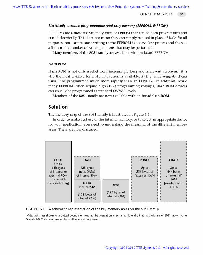
Electrically erasable programmable read-only memory (EEPROM, E2PROM)
EEPROMs are a more user-friendly form of EPROM that can be both programmed anderased electrically. This does not mean they can simply be used in place of RAM for allpurposes, not least because writing to the EEPROM is a very slow process and there isa limit to the number of write operations that may be performed.
Many members of the 8051 family are available with on-board EEPROM.
Flash ROM
Flash ROM is not only a relief from increasingly long and irrelevent acronyms, it isalso the most civilized form of ROM currently available. As the name suggests, it canusually be programmed much more rapidly than an EEPROM. In addition, whilemany EEPROMs often require high (12V) programming voltages, Flash ROM devicescan usually be programmed at standard (3V/5V) levels.
Members of the 8051 family are now available with on-board flash ROM.
SolutionThe memory map of the 8051 family is illustrated in Figure 6.1.
In order to make best use of the internal memory, or to select an appropriate devicefor your application, you need to understand the meaning of the different memoryareas. These are now discussed.
ON-CHIP MEMORY 85
FIGURE 6.1 A schematic representation of the key memory areas on the 8051 family
[Note: that areas shown with dotted boundaries need not be present on all systems. Note also that, as the family of 8051 grows, someExtended 8051 devices have added additional memory areas.]
CODEUp to
64k bytesof internal orexternal ROM
[more withbank switching] DATA
incl. BDATA
(128 bytes ofinternal RAM)
SFRs
(128 bytes ofinternal RAM)
IDATA
128 bytes(plus DATA)
of internal RAM
PDATA
Up to256 bytes of
‘external’ RAM
XDATA
Up to64k bytes
of ‘external’RAM
[overlaps withPDATA]
www.TTE-Systems.com = High-reliability processors + Software tools + Protection systems + Training & consultancy services
Copyright 2001-2010 TTE Systems Ltd. All rights reserved.
The CODE area
As the name suggests, the main rôle that CODE memory plays in your 8051 applica-tion is to store the program (executable) code. This happens automatically with all Ccompilers. Note that the code is executed ‘in place’ in ROM: it is not copied to RAMfor execution.
In addition to code, it can be useful to store (read-only) data, such as lookup tables,in the CODE area. This is often an excellent idea: many 8051 devices have compara-tively large amounts of ROM available (64 kbytes is no longer uncommon), but onlysmall amounts of available RAM (usually no more than 4 kbytes; frequently no morethan 256 bytes). Placing read-only data in ROM when possible usually makes goodsense.
Using ROM for data tables can also make sense on performance grounds. For exam-ple, if your code requires calculation of sines or cosines, this can require a largenumber of CPU operations on most systems (typically more than 3000 CPU oper-ations). If you are able to include the relevant results in an array (lookup table), thiscan reduce the CPU load by a factor of around 1,000.
Placing data in ROM is easy to do. For example, using the Keil C51 compiler andthe code keyword, we can store a large array in ROM as follows:
int code CRC16_table[256] =
0×0000, 0×1021, 0×2042, 0×3063, 0×4084, 0×50a5, 0×60c6, 0×70e7, 0×8108,0×9129, 0×a14a, 0×b16b, 0×c18c, 0×d1ad, 0×e1ce, 0×f1ef, 0×1231, 0×0210,
// etc...
The DATA, BDATA and IDATA areas
Up to 256 bytes of internal data memory are available depending on the particular8051 device that is used. Access to internal data memory is generally very fast becauseit can be carried out using an 8-bit address.
The internal data area is split into three overlapping areas: DATA, IDATA andBDATA. We now discuss each of these areas.
Using the DATA area
The DATA area refers to the first 128 bytes of internal data memory. Variables storedhere are accessed very quickly using direct addressing.
Using the DATA area is the default with the C51 compiler, if – as recommended byKeil – the small memory model is used. Alternatively, the data keyword may be usedto explicitly specify that a variable should be stored in the DATA area. For example:
char data Input1;
unsigned int data Loop_Control;
HARDWARE FOUNDATIONS86
www.TTE-Systems.com = High-reliability processors + Software tools + Protection systems + Training & consultancy services
Copyright 2001-2010 TTE Systems Ltd. All rights reserved.
Using the IDATA area
The IDATA area refers to all 256 bytes of internal data memory (including the 128bytes of the data area, with which it overlaps). Variables stored here are accessed lessrapidly than DATA variables, using indirect addressing. The idata keyword may beused to explicitly state that variables are to be stored in the IDATA area, as follows:
char idata Input2;
unsigned int idata Loop_Control2;
Note, however, that the IDATA area is usually most useful as a stack area: ingeneral, it is better to leave this area free for use by the compiler.
Using the BDATA area
The BDATA area overlaps with the DATA area. Specifically, it refers to 16 bytes of bit-addressable memory in the internal DATA area (addresses 0x0020 to 0x002F).
Use of the bit, bdata and sbit keywords allows you to make use of this areaand to declare data types that can be accessed at the bit level. Consider the followingexamples:
// The definition of the unsigned character variable Bit_addressable
// – this can take values 0 to 255
unsigned char bdata Bit_addressable;
// The definition of the bit variable Flag
// – this can take values of 0 or 1
bit Flag;
// The declaration of the bit areas in the variable bit_addressable
// – Note use of the sbit keyword (*NOT* bit)
// – Note that this declaration does not use any memory
sbit Bit0 = Bit_addressable^0;
Special function register (SFR) memory
As shown in Figure 6.1, all 8051s provide up to 128 bytes of memory for special func-tion registers (SFRs). SFRs are bit, byte or word-size (2-byte) registers that are used tocontrol timers, counters, serial I/O, port I/O and various peripherals. The port SFRs arediscussed in the pattern P O R T I/O [page 162].
Note that – as briefly mentioned in ‘Background’ – the IDATA locations 128 to255 and the SFR area share the same address space. However, memory locations in thesetwo areas are accessed using different addressing modes. IDATA locations 128 to 255are only indirectly addressable and the special function registers are only directlyaddressable.
ON-CHIP MEMORY 87
www.TTE-Systems.com = High-reliability processors + Software tools + Protection systems + Training & consultancy services
Copyright 2001-2010 TTE Systems Ltd. All rights reserved.
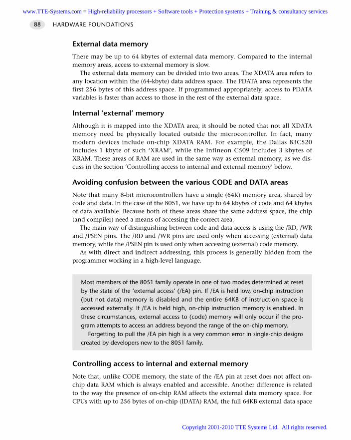
External data memory
There may be up to 64 kbytes of external data memory. Compared to the internalmemory areas, access to external memory is slow.
The external data memory can be divided into two areas. The XDATA area refers toany location within the (64-kbyte) data address space. The PDATA area represents thefirst 256 bytes of this address space. If programmed appropriately, access to PDATAvariables is faster than access to those in the rest of the external data space.
Internal ‘external’ memory
Although it is mapped into the XDATA area, it should be noted that not all XDATAmemory need be physically located outside the microcontroller. In fact, manymodern devices include on-chip XDATA RAM. For example, the Dallas 83C520includes 1 kbyte of such ‘XRAM’, while the Infineon C509 includes 3 kbytes ofXRAM. These areas of RAM are used in the same way as external memory, as we dis-cuss in the section ‘Controlling access to internal and external memory’ below.
Avoiding confusion between the various CODE and DATA areas
Note that many 8-bit microcontrollers have a single (64K) memory area, shared bycode and data. In the case of the 8051, we have up to 64 kbytes of code and 64 kbytesof data available. Because both of these areas share the same address space, the chip(and compiler) need a means of accessing the correct area.
The main way of distinguishing between code and data access is using the /RD, /WRand /PSEN pins. The /RD and /WR pins are used only when accessing (external) datamemory, while the /PSEN pin is used only when accessing (external) code memory.
As with direct and indirect addressing, this process is generally hidden from theprogrammer working in a high-level language.
Controlling access to internal and external memory
Note that, unlike CODE memory, the state of the /EA pin at reset does not affect on-chip data RAM which is always enabled and accessible. Another difference is relatedto the way the presence of on-chip RAM affects the external data memory space. ForCPUs with up to 256 bytes of on-chip (IDATA) RAM, the full 64KB external data space
HARDWARE FOUNDATIONS88
Most members of the 8051 family operate in one of two modes determined at resetby the state of the ‘external access’ (/EA) pin. If /EA is held low, on-chip instruction(but not data) memory is disabled and the entire 64KB of instruction space isaccessed externally. If /EA is held high, on-chip instruction memory is enabled. Inthese circumstances, external access to (code) memory will only occur if the pro-gram attempts to access an address beyond the range of the on-chip memory.
Forgetting to pull the /EA pin high is a very common error in single-chip designscreated by developers new to the 8051 family.
www.TTE-Systems.com = High-reliability processors + Software tools + Protection systems + Training & consultancy services
Copyright 2001-2010 TTE Systems Ltd. All rights reserved.
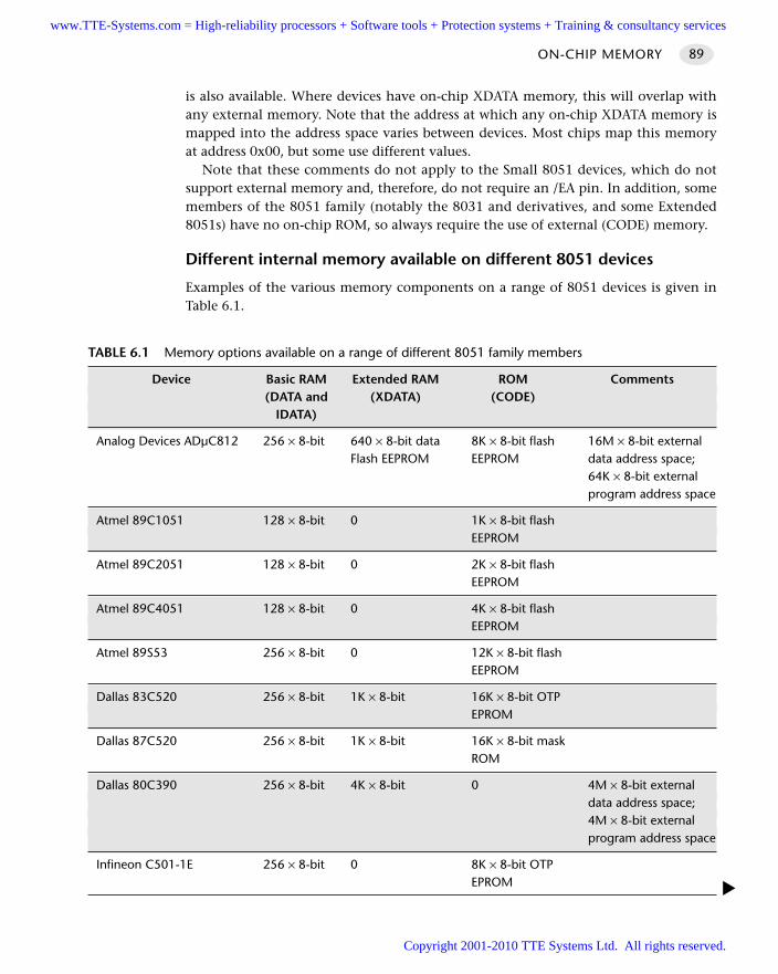
is also available. Where devices have on-chip XDATA memory, this will overlap withany external memory. Note that the address at which any on-chip XDATA memory ismapped into the address space varies between devices. Most chips map this memoryat address 0x00, but some use different values.
Note that these comments do not apply to the Small 8051 devices, which do notsupport external memory and, therefore, do not require an /EA pin. In addition, somemembers of the 8051 family (notably the 8031 and derivatives, and some Extended8051s) have no on-chip ROM, so always require the use of external (CODE) memory.
Different internal memory available on different 8051 devices
Examples of the various memory components on a range of 8051 devices is given inTable 6.1.
ON-CHIP MEMORY 89
TABLE 6.1 Memory options available on a range of different 8051 family members
Device Basic RAM Extended RAM ROM Comments(DATA and (XDATA) (CODE)
IDATA)
Analog Devices ADµC812 256 × 8-bit 640 × 8-bit data 8K × 8-bit flash 16M × 8-bit externalFlash EEPROM EEPROM data address space;
64K × 8-bit externalprogram address space
Atmel 89C1051 128 × 8-bit 0 1K × 8-bit flashEEPROM
Atmel 89C2051 128 × 8-bit 0 2K × 8-bit flashEEPROM
Atmel 89C4051 128 × 8-bit 0 4K × 8-bit flash EEPROM
Atmel 89S53 256 × 8-bit 0 12K × 8-bit flash EEPROM
Dallas 83C520 256 × 8-bit 1K × 8-bit 16K × 8-bit OTP EPROM
Dallas 87C520 256 × 8-bit 1K × 8-bit 16K × 8-bit mask ROM
Dallas 80C390 256 × 8-bit 4K × 8-bit 0 4M × 8-bit external data address space; 4M × 8-bit external program address space
Infineon C501-1E 256 × 8-bit 0 8K × 8-bit OTP EPROM
www.TTE-Systems.com = High-reliability processors + Software tools + Protection systems + Training & consultancy services
Copyright 2001-2010 TTE Systems Ltd. All rights reserved.
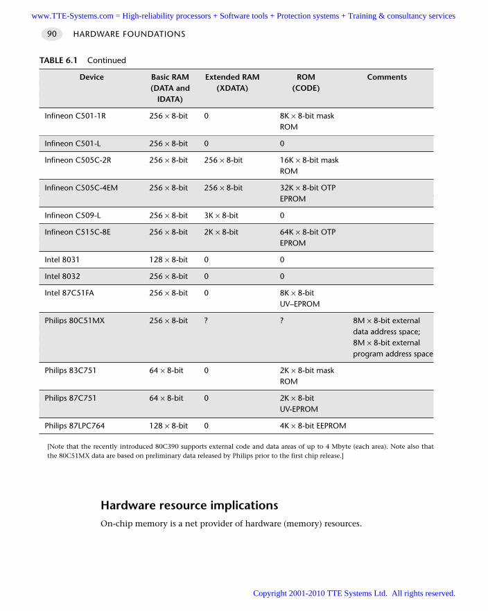
Hardware resource implicationsOn-chip memory is a net provider of hardware (memory) resources.
HARDWARE FOUNDATIONS90
TABLE 6.1 Continued
Device Basic RAM Extended RAM ROM Comments(DATA and (XDATA) (CODE)
IDATA)
Infineon C501-1R 256 × 8-bit 0 8K × 8-bit mask ROM
Infineon C501-L 256 × 8-bit 0 0
Infineon C505C-2R 256 × 8-bit 256 × 8-bit 16K × 8-bit mask ROM
Infineon C505C-4EM 256 × 8-bit 256 × 8-bit 32K × 8-bit OTPEPROM
Infineon C509-L 256 × 8-bit 3K × 8-bit 0
Infineon C515C-8E 256 × 8-bit 2K × 8-bit 64K × 8-bit OTP EPROM
Intel 8031 128 × 8-bit 0 0
Intel 8032 256 × 8-bit 0 0
Intel 87C51FA 256 × 8-bit 0 8K × 8-bit UV–EPROM
Philips 80C51MX 256 × 8-bit ? ? 8M × 8-bit externaldata address space; 8M × 8-bit externalprogram address space
Philips 83C751 64 × 8-bit 0 2K × 8-bit mask ROM
Philips 87C751 64 × 8-bit 0 2K × 8-bit UV-EPROM
Philips 87LPC764 128 × 8-bit 0 4K × 8-bit EEPROM
[Note that the recently introduced 80C390 supports external code and data areas of up to 4 Mbyte (each area). Note also thatthe 80C51MX data are based on preliminary data released by Philips prior to the first chip release.]
www.TTE-Systems.com = High-reliability processors + Software tools + Protection systems + Training & consultancy services
Copyright 2001-2010 TTE Systems Ltd. All rights reserved.
Reliability and safety implicationsSuppose that we have two identical applications, using (almost) identical software,but one using internal memory (only), and one using external memory (for codeand/or data). Everything else being equal, it is likely that the ‘internal’ applicationwill prove more reliable. This is partly because the use of internal memory reduces theopportunities for wiring or design errors, partly because of the reduction in externalwires (‘aerials’) makes the system less vulnerable to EMI, and partly because (in theexternal version) each of the soldered joints has a risk of failure in the presence ofvibration and/or high humidity.
In addition, the ALE pin can be a source of EMI. This pin is required for externalmemory access but its operation can (in some devices) be disabled, if internalmemory is being used. This can reduce the likelihood that your application willinduce an error in some other part of the application.
As (in almost all cases) the ‘internal’ solution will also be both cheaper to produceand physically smaller, the message is clear: use internal memory if at all possible.
PortabilityIn general, the most portable 8051 code assumes only the presence of a small amountof CODE memory (some kind of ROM, say 4 kbytes) and 128 bytes of RAM. Thiscombination is available even in most of the smallest 8051s.
Further memory (typically 256 bytes of RAM) will be available in many modern8051s. Some modern devices also have on-chip XRAM. However, the more of thesefacilities you use, the less easy it will be to port your code to another microcontrollerin the 8051 family.
Overall strengths and weaknessesUse of internal memory (in place of external memory) can have the followingimplications:
Lower application cost.
Increased hardware reliability.
Reduced EM emissions (where you are able to disable ALE activity).
In most cases, the available data memory will be restricted.
Related patterns and alternative solutionsSee O F F-C H I P D ATA M E M O RY [page 94] and O F F-C H I P C O D E M E M O RY [page 100].
Example: Internal memory on the Philips 8XC552As an example of the memory options available, we will consider the Philips 8XC552.
ON-CHIP MEMORY 91
www.TTE-Systems.com = High-reliability processors + Software tools + Protection systems + Training & consultancy services
Copyright 2001-2010 TTE Systems Ltd. All rights reserved.
The 8XC552 contains 8 kbytes of on-chip program memory which can beextended to 64 kbytes through the use of external memory. When the EA pin is heldhigh, the 8XC552 fetches instructions from internal ROM unless the address exceeds1FFFH. Locations 2000H to FFFFH are fetched from external program memory. Whenthe EA pin is held low, all instruction fetches are from external memory. ROM loca-tions 0003H to 0073H are used by interrupt service routines.
The internal data memory is divided into three sections: the lower 128 bytes ofRAM, the upper 128 bytes of RAM and the 128-byte special function register areas.The lower 128 bytes of RAM are directly and indirectly addressable. While RAM loca-tions 128 to 255 and the special function register area share the same address space,they are accessed through different addressing modes. RAM locations 128 to 255 areonly indirectly addressable and the special function registers are only directly address-able. All other aspects of the internal RAM are identical to the 8051. The stack may belocated anywhere in the internal RAM by loading the 8-bit stack pointer. Stack depthis 256 bytes maximum.
The special function registers (directly addressable only) contain all the 8XC552registers except the program counter and the four register banks. Most of the 56 spe-cial function registers are used to control the on-chip peripheral hardware. Otherregisters include arithmetic registers (ACC, B, PSW), stack pointer (SP) anddata pointer registers (DHP, DPL). Sixteen of the SFRs contain 128 directly addressablebit locations.
Example: Comparing speed of access to different memory areasTypical access times for data stored in the various memory areas (measured in instruc-tion cycles) are as follows:
Access to DATA area takes one cycle [direct access]
Access to IDATA area takes two cycles [8-bit copy of address to register (1 cycle), then 1-cycle move]
Access to PDATA area takes three cycles [8-bit copy of address to register (1 cycle), then 2-cycle move instruction]
Access to XDATA area takes four cycles [16-bit copy of address to register (2 cycles), 2-cycle move instruction]
Access to CODE area takes four cycles [16-bit copy of address to register (2 cycles), 2-cycle move instruction]
Although these figures are typical, it is difficult to predict precisely how accesstimes to variables in different memory areas will compare, partly because the resultsvary depending on different compiler options used.
HARDWARE FOUNDATIONS92
www.TTE-Systems.com = High-reliability processors + Software tools + Protection systems + Training & consultancy services
Copyright 2001-2010 TTE Systems Ltd. All rights reserved.
Example: Making use of internal XRAM memory on theInfineon C515CThe Infineon C515C is a powerful (extended) 8051 device that we have used in arange of different applications, particularly because of its good performance and on-chip CAN component.
In addition to the standard (256 bytes) of IDATA RAM, the C515C has 2 kbytes ofon-chip XRAM.
To use this memory, you need to be aware that (unlike the Dallas 520, for exam-ple), this memory is not mapped from address 0×0000. Instead, the starting address ofthis memory is 0xF800.
If you are using the Keil compiler, you need to provide this information to the linker,via the ‘Size / Location’ menu item. You should enter the address (start of XDATA) as‘0F800’: omitting the initial ‘0’ causes problems with current versions of the compiler.
Further reading—
ON-CHIP MEMORY 93
www.TTE-Systems.com = High-reliability processors + Software tools + Protection systems + Training & consultancy services
Copyright 2001-2010 TTE Systems Ltd. All rights reserved.
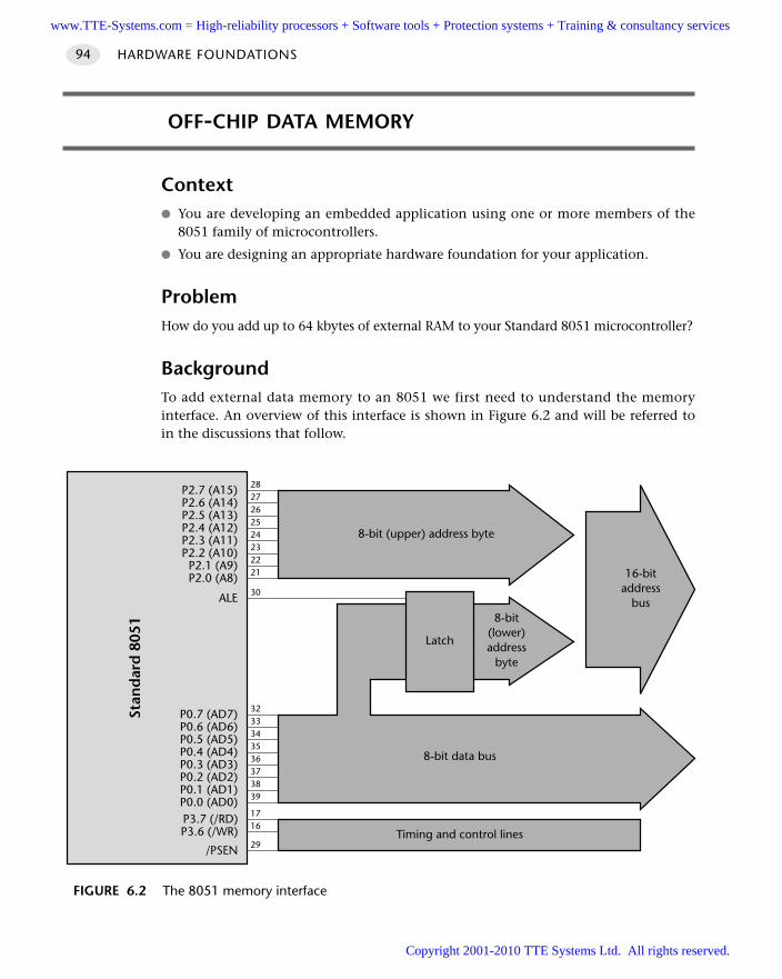
OFF-CHIP DATA MEMORY
Context You are developing an embedded application using one or more members of the
8051 family of microcontrollers.
You are designing an appropriate hardware foundation for your application.
ProblemHow do you add up to 64 kbytes of external RAM to your Standard 8051 microcontroller?
BackgroundTo add external data memory to an 8051 we first need to understand the memoryinterface. An overview of this interface is shown in Figure 6.2 and will be referred toin the discussions that follow.
HARDWARE FOUNDATIONS94
FIGURE 6.2 The 8051 memory interface
P2.7 (A15) 28
P2.6 (A14) 27
P2.5 (A13) 26
P2.4 (A12) 25
P2.3 (A11) 24
P2.2 (A10) 23
P2.1 (A9) 22
P2.0 (A8) 21
P0.7 (AD7) 32
P0.6 (AD6) 33
P0.5 (AD5) 34
P0.4 (AD4) 35
P0.3 (AD3) 36
P0.2 (AD2) 37
P0.1 (AD1) 38
P0.0 (AD0) 39
P3.7 (/RD) 17
P3.6 (/WR) 16
/PSEN 29Timing and control lines
8-bit data bus
16-bitaddress
bus
Latch
8-bit(lower)address
byte
8-bit (upper) address byte
ALE 30
Stan
dar
d 8
051
www.TTE-Systems.com = High-reliability processors + Software tools + Protection systems + Training & consultancy services
Copyright 2001-2010 TTE Systems Ltd. All rights reserved.
The address bus (P0.0–P0.7)
For both program and data access, Port 0 is used as a multiplexed address/data busthat outputs the low-order address bits (A0–A7) and inputs/outputs the 8-bit data(D0–D7).
The data bus (P2.0–P2.7)
For all external program accesses, P2 outputs the high-order address bits (A8–A15).The same is true for external data accesses with 16-bit addresses.
Note one special case: Systems that use on-chip code memory and only 256 bytesof external data memory are free to use P2 for general purpose I/O.
ALE (address latch enable)
ALE is used to demultiplex the AD0–7 bus. At the beginning of the external cycleALE is high and the CPU emits A0–A7 which should be externally latched when ALEgoes low.
Note that on most 8051-based systems, ALE is always active, even during internalprogram and data accesses: however, on some more modern 8051 designs, it is possi-ble to disable ALE activity if external memory access is not required: this can help toreduce EM emissions.
Note also that, where external memory access is not required, ALE may be treatedas a continuous clock that runs at one-sixth the oscillator frequency. This output canbe used, for example, to control timing in external circuits.
PSEN (program store enable)
PSEN is the read strobe for external instruction (code memory) access. Unlike ALE,PSEN is not asserted during internal accesses. We consider the use of PSEN in thepattern O F F-C H I P C O D E M E M O RY [page 100].
RD (data read)
RD is the read strobe for external data access and (like PSEN) is not asserted duringinternal accesses.
WR (data write)
WR is the write strobe for external data access and (like PSEN and RD) is not assertedduring internal accesses.
SolutionWith a basic understanding of the memory interface (see ‘Background’), adding exter-nal data memory to an 8051 microcontroller is easy to do, provided some care istaken in the choice of components (see Figure 6.3).
OFF-CHIP DATA MEMORY 95
www.TTE-Systems.com = High-reliability processors + Software tools + Protection systems + Training & consultancy services
Copyright 2001-2010 TTE Systems Ltd. All rights reserved.
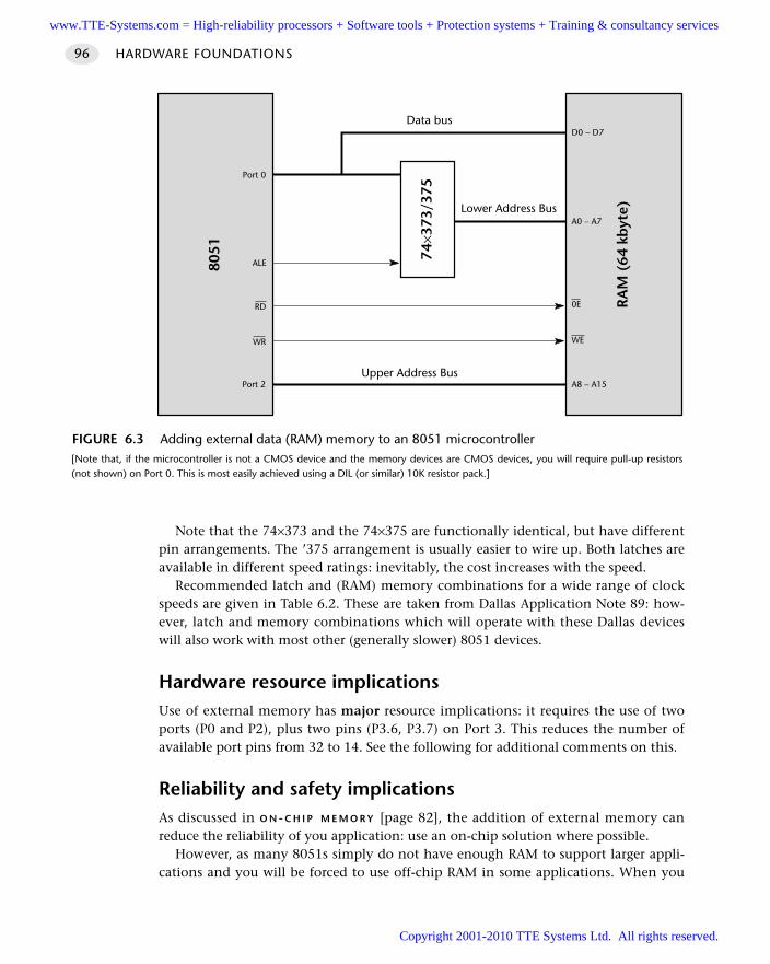
Note that the 74×373 and the 74×375 are functionally identical, but have differentpin arrangements. The ’375 arrangement is usually easier to wire up. Both latches areavailable in different speed ratings: inevitably, the cost increases with the speed.
Recommended latch and (RAM) memory combinations for a wide range of clockspeeds are given in Table 6.2. These are taken from Dallas Application Note 89: how-ever, latch and memory combinations which will operate with these Dallas deviceswill also work with most other (generally slower) 8051 devices.
Hardware resource implicationsUse of external memory has major resource implications: it requires the use of twoports (P0 and P2), plus two pins (P3.6, P3.7) on Port 3. This reduces the number ofavailable port pins from 32 to 14. See the following for additional comments on this.
Reliability and safety implicationsAs discussed in O N - C H I P M E M O R Y [page 82], the addition of external memory canreduce the reliability of you application: use an on-chip solution where possible.
However, as many 8051s simply do not have enough RAM to support larger appli-cations and you will be forced to use off-chip RAM in some applications. When you
HARDWARE FOUNDATIONS96
FIGURE 6.3 Adding external data (RAM) memory to an 8051 microcontroller [Note that, if the microcontroller is not a CMOS device and the memory devices are CMOS devices, you will require pull-up resistors(not shown) on Port 0. This is most easily achieved using a DIL (or similar) 10K resistor pack.]
Lower Address Bus
Data bus
Upper Address Bus
RA
M (
64 k
byt
e)
8051
Port 2
WR
RD
ALE
Port 0
D0 – D7
A0 – A7
0E
WE
A8 – A15
74×3
73/3
75
www.TTE-Systems.com = High-reliability processors + Software tools + Protection systems + Training & consultancy services
Copyright 2001-2010 TTE Systems Ltd. All rights reserved.
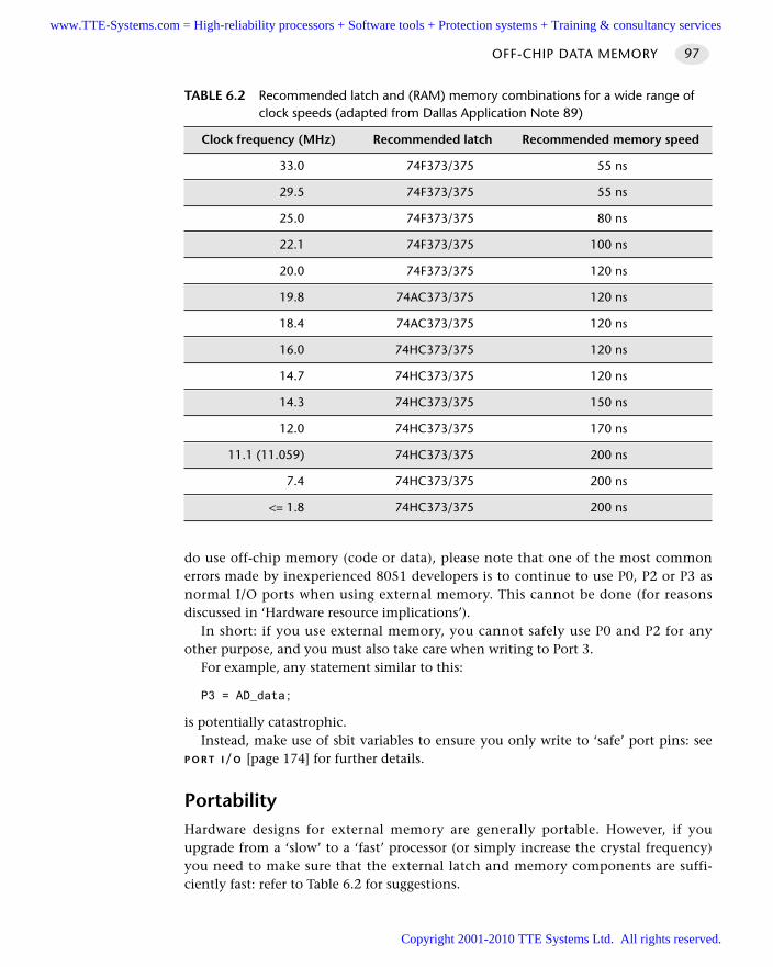
do use off-chip memory (code or data), please note that one of the most commonerrors made by inexperienced 8051 developers is to continue to use P0, P2 or P3 asnormal I/O ports when using external memory. This cannot be done (for reasonsdiscussed in ‘Hardware resource implications’).
In short: if you use external memory, you cannot safely use P0 and P2 for anyother purpose, and you must also take care when writing to Port 3.
For example, any statement similar to this:
P3 = AD_data;
is potentially catastrophic. Instead, make use of sbit variables to ensure you only write to ‘safe’ port pins: see
P O R T I/O [page 174] for further details.
PortabilityHardware designs for external memory are generally portable. However, if youupgrade from a ‘slow’ to a ‘fast’ processor (or simply increase the crystal frequency)you need to make sure that the external latch and memory components are suffi-ciently fast: refer to Table 6.2 for suggestions.
OFF-CHIP DATA MEMORY 97
TABLE 6.2 Recommended latch and (RAM) memory combinations for a wide range of clock speeds (adapted from Dallas Application Note 89)
Clock frequency (MHz) Recommended latch Recommended memory speed
33.0 74F373/375 55 ns
29.5 74F373/375 55 ns
25.0 74F373/375 80 ns
22.1 74F373/375 100 ns
20.0 74F373/375 120 ns
19.8 74AC373/375 120 ns
18.4 74AC373/375 120 ns
16.0 74HC373/375 120 ns
14.7 74HC373/375 120 ns
14.3 74HC373/375 150 ns
12.0 74HC373/375 170 ns
11.1 (11.059) 74HC373/375 200 ns
7.4 74HC373/375 200 ns
<= 1.8 74HC373/375 200 ns
www.TTE-Systems.com = High-reliability processors + Software tools + Protection systems + Training & consultancy services
Copyright 2001-2010 TTE Systems Ltd. All rights reserved.
The only way to make your external access design as portable as possible is alwaysto use the fastest external components available. This approach has cost implications,but, if you are able to produce 100,000 copies of one, generic (fast) board rather thansmaller numbers of ‘slow’, ‘medium’ and ‘fast’ versions, you may find the ‘one sizefits all’ solution to be both a reliable and cost-effective solution.
Overall strengths and weaknessesMany 8051s simply do not have enough RAM to support larger applications:this pattern solves that problem.
As discussed in ON-CHIP MEMORY [page 82], the addition of external memory canreduce the reliability of your application: use an on-chip solution where possible.
Related patterns and alternative solutionsSee O N-C H I P M E M O RY [page 82] for a discussion on the use of on-chip memory.
Example: Using external RAM and internal XRAM on the C509The Infineon C509 microcontrollers have 3 kbytes of internal XRAM. By default,XRAM is disabled when the device is reset and the full 64 kbytes of external datamemory are accessible.
However, if XRAM is enabled, then the internal XRAM and external RAM memoryareas overlap: specifically, in the case of the C509, the XRAM is mapped to the upper3 kbytes of data memory, as illustrated in Figure 6.4.
The internal XRAM is enabled via the SYSCON1 SFR. Specifically, the PRGEN bitmust be set to 0 and the SWAP bit must be set to 1.
Example: Using external RAM and internal SRAM on theDallas 8XC520The Dallas 8XC520 microcontrollers have 1 kbyte of internal ‘SRAM’. By default, thisSRAM is disabled when the device is reset and the full 64 kbytes of external datamemory are accessible. However, if SRAM is enabled, then the internal XRAM andexternal RAM memory areas overlap: specifically, in the case of the 8XC520, theSRAM is mapped to the lowest 1 kbyte of data memory, as illustrated in Figure 6.5.
Further reading—
HARDWARE FOUNDATIONS98
www.TTE-Systems.com = High-reliability processors + Software tools + Protection systems + Training & consultancy services
Copyright 2001-2010 TTE Systems Ltd. All rights reserved.
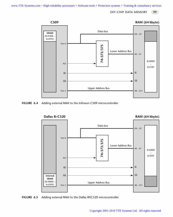
OFF-CHIP DATA MEMORY 99
FIGURE 6.4 Adding external RAM to the Infineon C509 microcontroller
Lower Address Bus
Data bus
Upper Address Bus
RAM (64 kbyte)C509
Port 2
WR
RD
ALE
Port 0
D0 – D7
A0 – A7
0E
WE
A8 – A15
74×3
73/3
75
XRAM(0×F400 –0×FFFF)
0×0000–
0×F3FF
FIGURE 6.5 Adding external RAM to the Dallas 8XC520 microcontroller
Lower Address Bus
Data bus
Upper Address Bus
RAM (64 kbyte)Dallas 8×C520
Port 2
WR
RD
ALE
Port 0
D0 – D7
A0 – A7
0E
WE
A8 – A15
74×3
73/3
75
InternalSRAM
(0×0000 –0×03FF)
0×0400–
0×FFFF
www.TTE-Systems.com = High-reliability processors + Software tools + Protection systems + Training & consultancy services
Copyright 2001-2010 TTE Systems Ltd. All rights reserved.
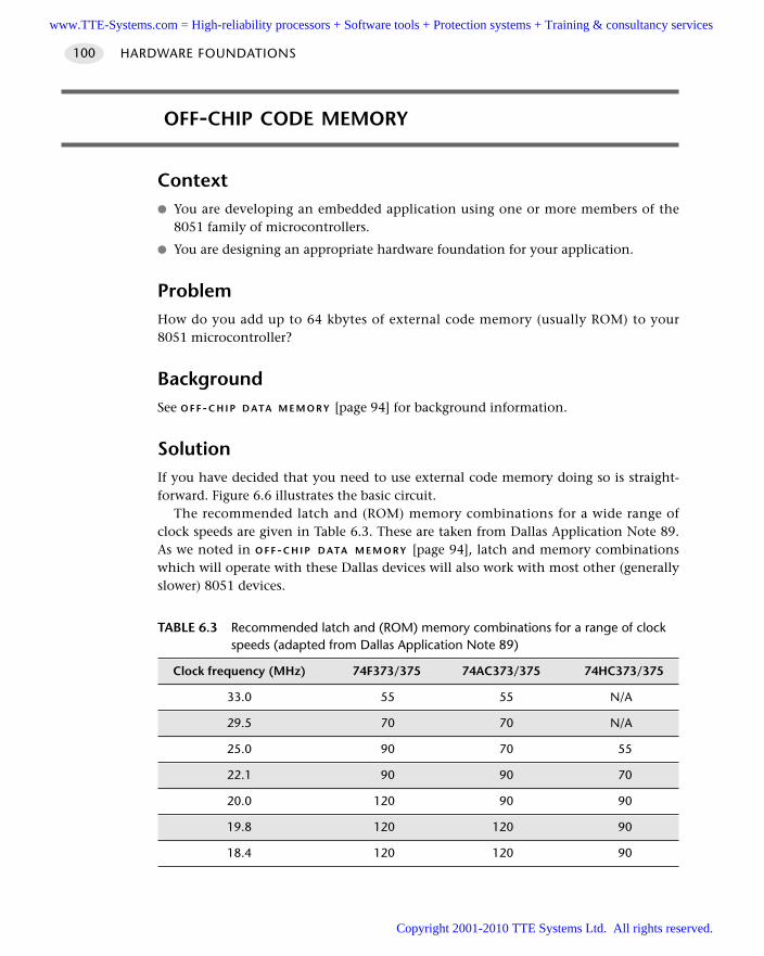
OFF-CHIP CODE MEMORY
Context You are developing an embedded application using one or more members of the
8051 family of microcontrollers.
You are designing an appropriate hardware foundation for your application.
ProblemHow do you add up to 64 kbytes of external code memory (usually ROM) to your8051 microcontroller?
BackgroundSee O F F-C H I P D ATA M E M O RY [page 94] for background information.
SolutionIf you have decided that you need to use external code memory doing so is straight-forward. Figure 6.6 illustrates the basic circuit.
The recommended latch and (ROM) memory combinations for a wide range ofclock speeds are given in Table 6.3. These are taken from Dallas Application Note 89.As we noted in O F F -C H I P D ATA M E M O RY [page 94], latch and memory combinationswhich will operate with these Dallas devices will also work with most other (generallyslower) 8051 devices.
HARDWARE FOUNDATIONS100
TABLE 6.3 Recommended latch and (ROM) memory combinations for a range of clock speeds (adapted from Dallas Application Note 89)
Clock frequency (MHz) 74F373/375 74AC373/375 74HC373/375
33.0 55 55 N/A
29.5 70 70 N/A
25.0 90 70 55
22.1 90 90 70
20.0 120 90 90
19.8 120 120 90
18.4 120 120 90
www.TTE-Systems.com = High-reliability processors + Software tools + Protection systems + Training & consultancy services
Copyright 2001-2010 TTE Systems Ltd. All rights reserved.
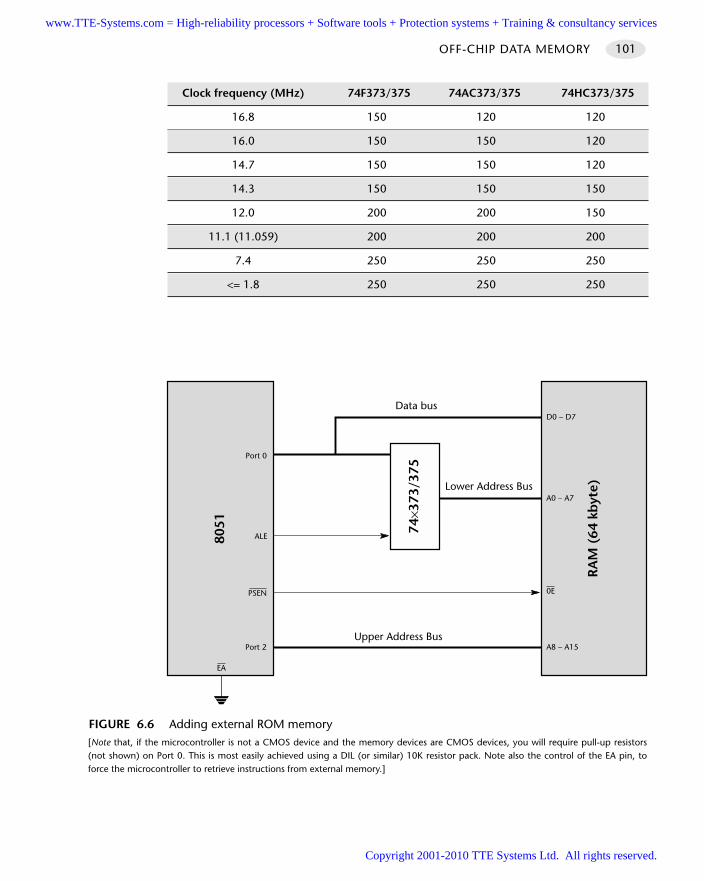
OFF-CHIP DATA MEMORY 101
FIGURE 6.6 Adding external ROM memory [Note that, if the microcontroller is not a CMOS device and the memory devices are CMOS devices, you will require pull-up resistors(not shown) on Port 0. This is most easily achieved using a DIL (or similar) 10K resistor pack. Note also the control of the EA pin, toforce the microcontroller to retrieve instructions from external memory.]
Lower Address Bus
Data bus
Upper Address Bus
RA
M (
64 k
byt
e)
8051
Port 2
PSEN
ALE
Port 0
D0 – D7
A0 – A7
0E
A8 – A15
74×3
73/3
75
EA
Clock frequency (MHz) 74F373/375 74AC373/375 74HC373/375
16.8 150 120 120
16.0 150 150 120
14.7 150 150 120
14.3 150 150 150
12.0 200 200 150
11.1 (11.059) 200 200 200
7.4 250 250 250
<= 1.8 250 250 250
www.TTE-Systems.com = High-reliability processors + Software tools + Protection systems + Training & consultancy services
Copyright 2001-2010 TTE Systems Ltd. All rights reserved.
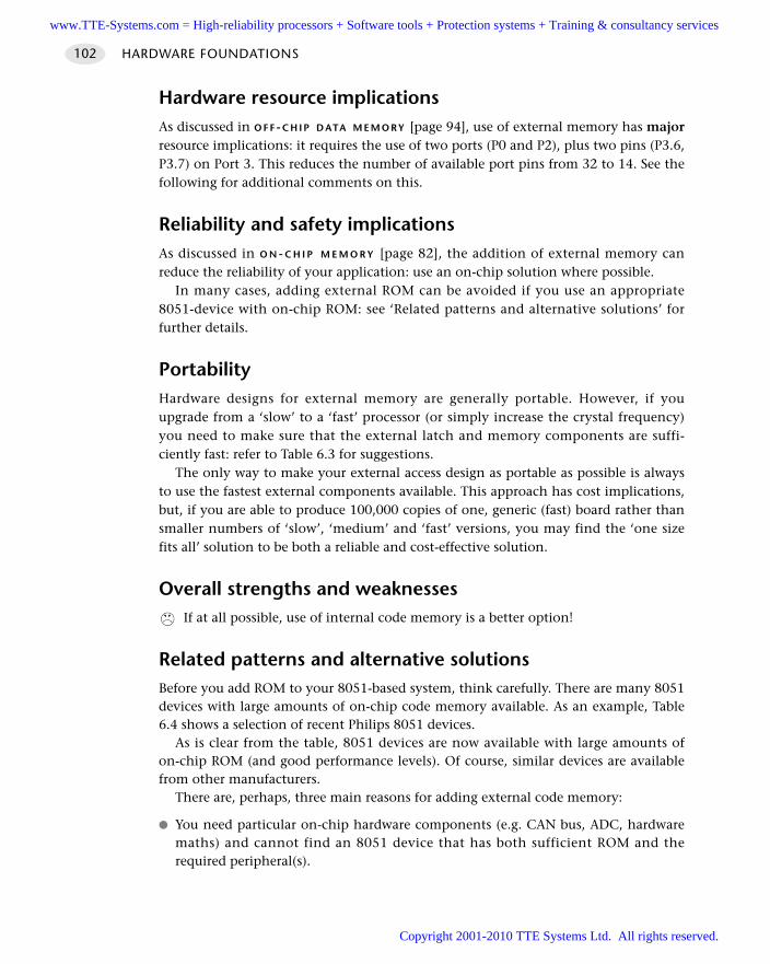
Hardware resource implicationsAs discussed in O F F-C H I P D ATA M E M O RY [page 94], use of external memory has majorresource implications: it requires the use of two ports (P0 and P2), plus two pins (P3.6,P3.7) on Port 3. This reduces the number of available port pins from 32 to 14. See thefollowing for additional comments on this.
Reliability and safety implicationsAs discussed in O N - C H I P M E M O R Y [page 82], the addition of external memory canreduce the reliability of your application: use an on-chip solution where possible.
In many cases, adding external ROM can be avoided if you use an appropriate8051-device with on-chip ROM: see ‘Related patterns and alternative solutions’ forfurther details.
PortabilityHardware designs for external memory are generally portable. However, if youupgrade from a ‘slow’ to a ‘fast’ processor (or simply increase the crystal frequency)you need to make sure that the external latch and memory components are suffi-ciently fast: refer to Table 6.3 for suggestions.
The only way to make your external access design as portable as possible is alwaysto use the fastest external components available. This approach has cost implications,but, if you are able to produce 100,000 copies of one, generic (fast) board rather thansmaller numbers of ‘slow’, ‘medium’ and ‘fast’ versions, you may find the ‘one sizefits all’ solution to be both a reliable and cost-effective solution.
Overall strengths and weaknessesIf at all possible, use of internal code memory is a better option!
Related patterns and alternative solutionsBefore you add ROM to your 8051-based system, think carefully. There are many 8051devices with large amounts of on-chip code memory available. As an example, Table6.4 shows a selection of recent Philips 8051 devices.
As is clear from the table, 8051 devices are now available with large amounts ofon-chip ROM (and good performance levels). Of course, similar devices are availablefrom other manufacturers.
There are, perhaps, three main reasons for adding external code memory:
You need particular on-chip hardware components (e.g. CAN bus, ADC, hardwaremaths) and cannot find an 8051 device that has both sufficient ROM and therequired peripheral(s).
HARDWARE FOUNDATIONS102
www.TTE-Systems.com = High-reliability processors + Software tools + Protection systems + Training & consultancy services
Copyright 2001-2010 TTE Systems Ltd. All rights reserved.
You require external RAM. Having therefore already created much of the requiredexternal memory interface, you have decided that it makes good economic sense toadd external ROM too, rather than using a device with on-chip ROM.
You need to be able to update the code that your system will execute. For example,if your system is running on a comparatively expensive (Extended) 8051 device,you may decide that it will be more cost effective to replace a small ROM chipwhen code updates are required, rather than to replace the microcontroller itself.
Example: Adding ROM and RAM memoryFigure 6.7 illustrates how you can add both code and data memory to your system.
Example: Reducing the component countIf space is very tight and / or you are seeking to improve the reliability of your 8051-based system by keeping the number of connections to a minimum, you have twobasic choices:
Use a microcontroller with on-chip code memory.
Use a memory (ROM) chip that does not require a latch.
Option 1 is not always available. For example, the powerful C509 microcontrolleris very fast and has several useful features (including a hardware maths unit compati-ble with that in the 80C517). It does not, however, have on-chip ROM of any kind.
OFF-CHIP DATA MEMORY 103
TABLE 6.4 An example of the available (internal) ROM on various recent Philips 8051 devices
Part# Flash size Comment
89C51 4K Standard 12-clock machine cycle
89C52 8K Standard 12-clock machine cycle
89C54 16K Standard 12-clock machine cycle
89C58 32K Standard 12-clock machine cycle
89CRC+ 32K Standard 12-clock machine cycle
89CRD+ 64K Standard 12-clock machine cycle
89CRB2 16K 6-clock machine cycle (12 clock optional)
89CRC2 32K 6-clock machine cycle (12 clock optional)
89CRD2 64K 6-clock machine cycle (12 clock optional)
[Note that similar devices are available from other manufacturers, but the Philips range is particularly comprehensive.]
www.TTE-Systems.com = High-reliability processors + Software tools + Protection systems + Training & consultancy services
Copyright 2001-2010 TTE Systems Ltd. All rights reserved.
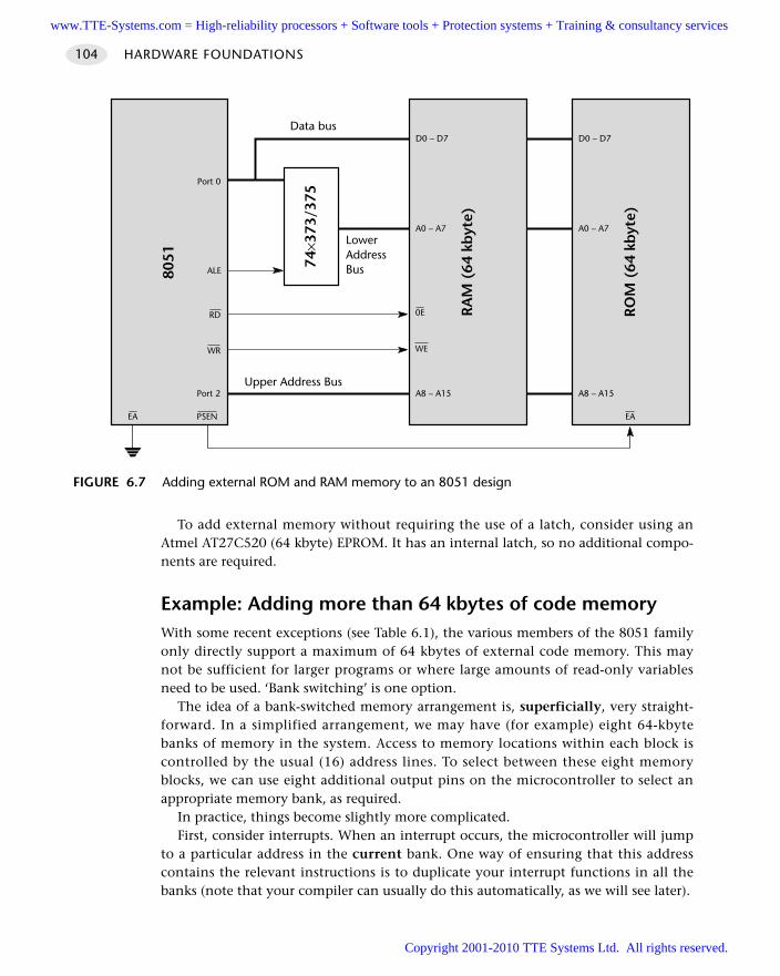
To add external memory without requiring the use of a latch, consider using anAtmel AT27C520 (64 kbyte) EPROM. It has an internal latch, so no additional compo-nents are required.
Example: Adding more than 64 kbytes of code memoryWith some recent exceptions (see Table 6.1), the various members of the 8051 familyonly directly support a maximum of 64 kbytes of external code memory. This maynot be sufficient for larger programs or where large amounts of read-only variablesneed to be used. ‘Bank switching’ is one option.
The idea of a bank-switched memory arrangement is, superficially, very straight-forward. In a simplified arrangement, we may have (for example) eight 64-kbytebanks of memory in the system. Access to memory locations within each block iscontrolled by the usual (16) address lines. To select between these eight memoryblocks, we can use eight additional output pins on the microcontroller to select anappropriate memory bank, as required.
In practice, things become slightly more complicated.First, consider interrupts. When an interrupt occurs, the microcontroller will jump
to a particular address in the current bank. One way of ensuring that this addresscontains the relevant instructions is to duplicate your interrupt functions in all thebanks (note that your compiler can usually do this automatically, as we will see later).
HARDWARE FOUNDATIONS104
FIGURE 6.7 Adding external ROM and RAM memory to an 8051 design
LowerAddressBus
Data bus
Upper Address Bus
RA
M (
64 k
byt
e)
8051
Port 2
ALE
Port 0
D0 – D7
A0 – A7
A8 – A15
74×3
73/3
75
EA
WR
RD 0E
WE
PSEN
RO
M (
64 k
byt
e)
D0 – D7
A0 – A7
A8 – A15
EA
www.TTE-Systems.com = High-reliability processors + Software tools + Protection systems + Training & consultancy services
Copyright 2001-2010 TTE Systems Ltd. All rights reserved.
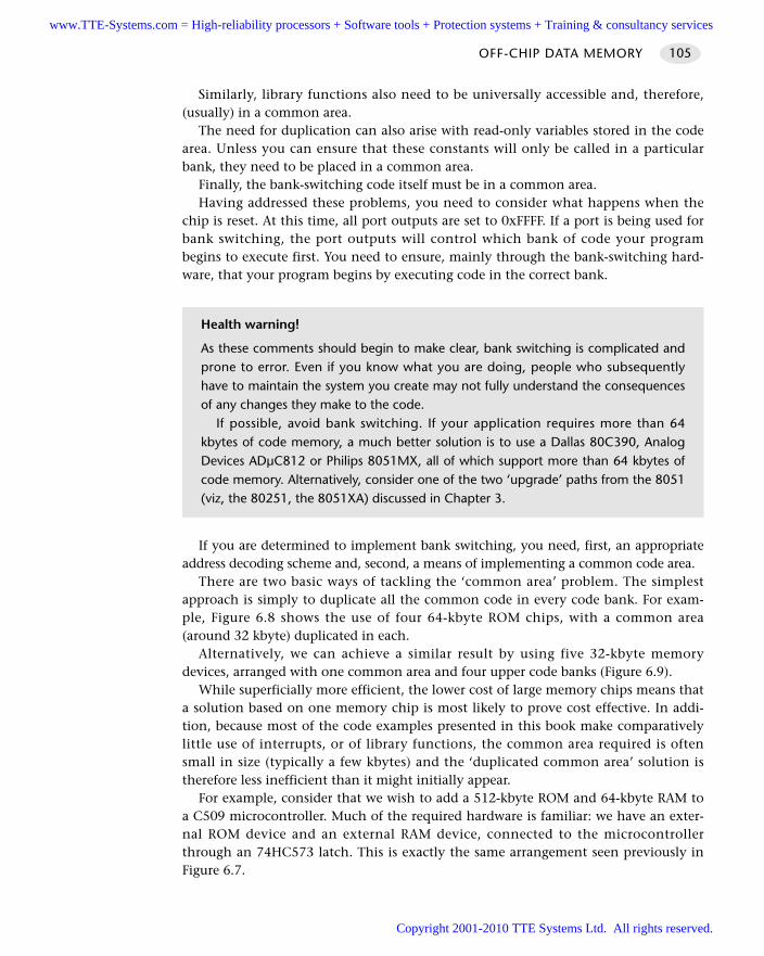
Similarly, library functions also need to be universally accessible and, therefore,(usually) in a common area.
The need for duplication can also arise with read-only variables stored in the codearea. Unless you can ensure that these constants will only be called in a particularbank, they need to be placed in a common area.
Finally, the bank-switching code itself must be in a common area.Having addressed these problems, you need to consider what happens when the
chip is reset. At this time, all port outputs are set to 0xFFFF. If a port is being used forbank switching, the port outputs will control which bank of code your programbegins to execute first. You need to ensure, mainly through the bank-switching hard-ware, that your program begins by executing code in the correct bank.
If you are determined to implement bank switching, you need, first, an appropriateaddress decoding scheme and, second, a means of implementing a common code area.
There are two basic ways of tackling the ‘common area’ problem. The simplestapproach is simply to duplicate all the common code in every code bank. For exam-ple, Figure 6.8 shows the use of four 64-kbyte ROM chips, with a common area(around 32 kbyte) duplicated in each.
Alternatively, we can achieve a similar result by using five 32-kbyte memorydevices, arranged with one common area and four upper code banks (Figure 6.9).
While superficially more efficient, the lower cost of large memory chips means thata solution based on one memory chip is most likely to prove cost effective. In addi-tion, because most of the code examples presented in this book make comparativelylittle use of interrupts, or of library functions, the common area required is oftensmall in size (typically a few kbytes) and the ‘duplicated common area’ solution istherefore less inefficient than it might initially appear.
For example, consider that we wish to add a 512-kbyte ROM and 64-kbyte RAM toa C509 microcontroller. Much of the required hardware is familiar: we have an exter-nal ROM device and an external RAM device, connected to the microcontrollerthrough an 74HC573 latch. This is exactly the same arrangement seen previously inFigure 6.7.
OFF-CHIP DATA MEMORY 105
Health warning!
As these comments should begin to make clear, bank switching is complicated andprone to error. Even if you know what you are doing, people who subsequentlyhave to maintain the system you create may not fully understand the consequencesof any changes they make to the code.
If possible, avoid bank switching. If your application requires more than 64kbytes of code memory, a much better solution is to use a Dallas 80C390, AnalogDevices ADµC812 or Philips 8051MX, all of which support more than 64 kbytes ofcode memory. Alternatively, consider one of the two ‘upgrade’ paths from the 8051(viz, the 80251, the 8051XA) discussed in Chapter 3.
www.TTE-Systems.com = High-reliability processors + Software tools + Protection systems + Training & consultancy services
Copyright 2001-2010 TTE Systems Ltd. All rights reserved.
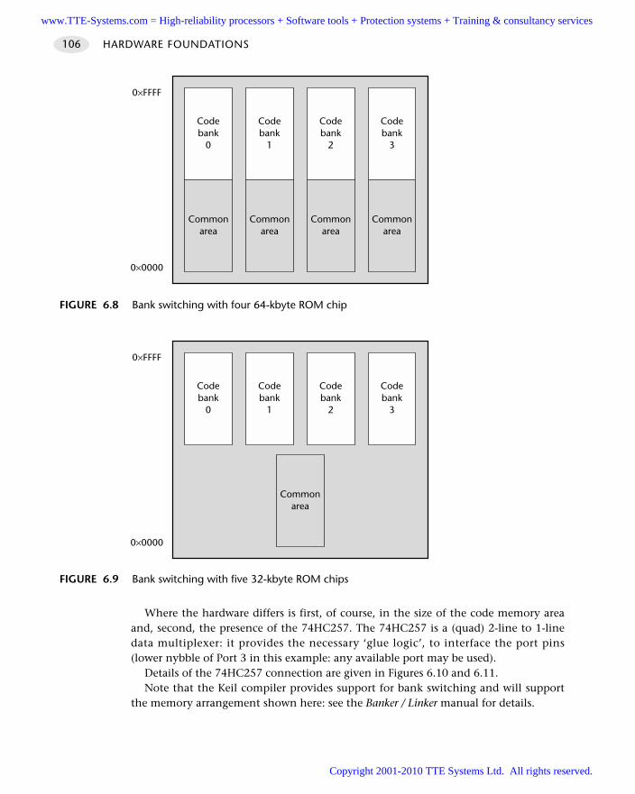
Where the hardware differs is first, of course, in the size of the code memory areaand, second, the presence of the 74HC257. The 74HC257 is a (quad) 2-line to 1-linedata multiplexer: it provides the necessary ‘glue logic’, to interface the port pins(lower nybble of Port 3 in this example: any available port may be used).
Details of the 74HC257 connection are given in Figures 6.10 and 6.11.Note that the Keil compiler provides support for bank switching and will support
the memory arrangement shown here: see the Banker / Linker manual for details.
HARDWARE FOUNDATIONS106
FIGURE 6.8 Bank switching with four 64-kbyte ROM chip
Codebank
1
Commonarea
Codebank
0
Commonarea
Codebank
2
Commonarea
Codebank
3
Commonarea
0×FFFF
0×0000
FIGURE 6.9 Bank switching with five 32-kbyte ROM chips
Codebank
1
Codebank
0
Codebank
2
Commonarea
Codebank
3
0×FFFF
0×0000
www.TTE-Systems.com = High-reliability processors + Software tools + Protection systems + Training & consultancy services
Copyright 2001-2010 TTE Systems Ltd. All rights reserved.
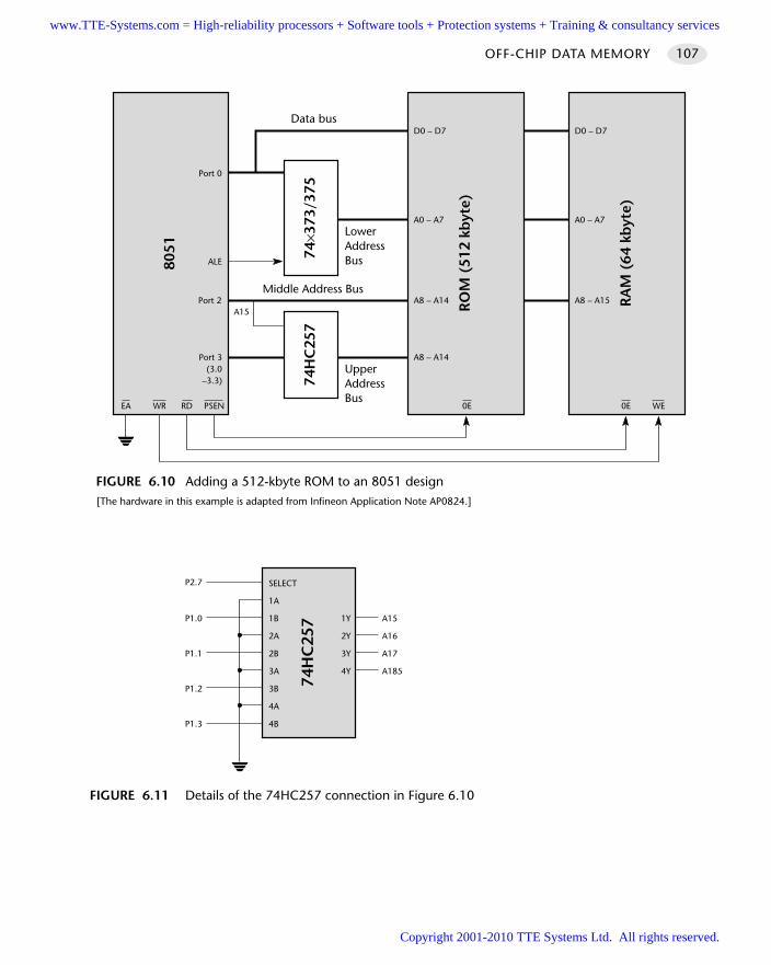
OFF-CHIP DATA MEMORY 107
FIGURE 6.10 Adding a 512-kbyte ROM to an 8051 design[The hardware in this example is adapted from Infineon Application Note AP0824.]
LowerAddressBus
Data bus
Middle Address Bus
RO
M (
512
kbyt
e)
8051
Port 2
ALE
Port 0
D0 – D7
A0 – A7
A8 – A1474
×373
/375
EA PSEN
RA
M (
64 k
byt
e)
D0 – D7
A0 – A7
A8 – A15
0E
Port 3(3.0
–3.3)
A8 – A14
74H
C25
7A15
UpperAddressBus
0E WERDWR
FIGURE 6.11 Details of the 74HC257 connection in Figure 6.10
74H
C25
7 A151Y
A162Y
A173Y
A1854Y
1B
2A
2B
3A
3B
4A
4B
P1.0
P1.1
P1.2
P1.3
1A
SELECTP2.7
www.TTE-Systems.com = High-reliability processors + Software tools + Protection systems + Training & consultancy services
Copyright 2001-2010 TTE Systems Ltd. All rights reserved.
Further reading—
HARDWARE FOUNDATIONS108
www.TTE-Systems.com = High-reliability processors + Software tools + Protection systems + Training & consultancy services
Copyright 2001-2010 TTE Systems Ltd. All rights reserved.
Driving DC Loads
Introduction
The port pins on a typical microcontroller can be set at values of either 0V or 5V (or,in a 3V system, 0V and 3V) under software control. Each pin can typically sink (orsource) a current of around 10 mA. In this chapter, we are concerned with hardwaredesigns that will allow us to control a range of low- and high-power, direct current(DC) loads via these pins.
With care, the port may be used directly to drive low-power DC loads, such as LEDs(see N A K E D L E D [page 110]) or, for example, small warning buzzers (see N A K E D L O A D
[page 115]). However, while a limited number of such loads may be connecteddirectly to the port, connecting, say, eight LEDs will generally exceed the total port ormicrocontroller capacity. In these circumstances, use of an IC-based buffer circuit canbe a cost-effective solution: see I C B U F F E R [page 118]. Indeed, even with small loads,the reliability of the application may be improved through the use of such a buffer.
Of course, many output devices require a higher voltage and a far greater poweroutput than the naked ports can provide. For example, to drive even a small DC motormay require up to 1A of current at 12V. To control such devices, we need to provideappropriate driver (or interface) circuit to convert the microcontroller output to anappropriate level. We will consider three ways of driving such loads in this chapter:
Using bipolar-junction transistors (see B J T D R I V E R [page 124])
Using a driver IC (see I C D R I V E R [page 134])
Using ‘metal oxide silicon field effect transistors’ (see M O S F E T D R I V E R [page 139])
chapter 7
Please note that in this chapter our concern will be with hardware details of theinterface only. In P O R T I/O [page 174] we consider software suitable for controllingsuch hardware.
www.TTE-Systems.com = High-reliability processors + Software tools + Protection systems + Training & consultancy services
Copyright 2001-2010 TTE Systems Ltd. All rights reserved.
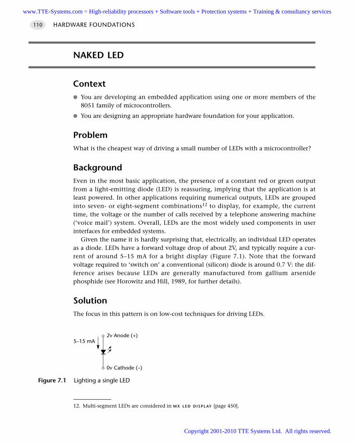
NAKED LED
Context You are developing an embedded application using one or more members of the
8051 family of microcontrollers.
You are designing an appropriate hardware foundation for your application.
ProblemWhat is the cheapest way of driving a small number of LEDs with a microcontroller?
BackgroundEven in the most basic application, the presence of a constant red or green outputfrom a light-emitting diode (LED) is reassuring, implying that the application is atleast powered. In other applications requiring numerical outputs, LEDs are groupedinto seven- or eight-segment combinations12 to display, for example, the currenttime, the voltage or the number of calls received by a telephone answering machine(‘voice mail’) system. Overall, LEDs are the most widely used components in userinterfaces for embedded systems.
Given the name it is hardly surprising that, electrically, an individual LED operatesas a diode. LEDs have a forward voltage drop of about 2V, and typically require a cur-rent of around 5–15 mA for a bright display (Figure 7.1). Note that the forwardvoltage required to ‘switch on’ a conventional (silicon) diode is around 0.7 V: the dif-ference arises because LEDs are generally manufactured from gallium arsenidephosphide (see Horowitz and Hill, 1989, for further details).
SolutionThe focus in this pattern is on low-cost techniques for driving LEDs.
HARDWARE FOUNDATIONS110
Figure 7.1 Lighting a single LED
2v Anode (+)
0v Cathode (–)
5–15 mA
12. Multi-segment LEDs are considered in M X L E D D I S P L AY [page 450].
www.TTE-Systems.com = High-reliability processors + Software tools + Protection systems + Training & consultancy services
Copyright 2001-2010 TTE Systems Ltd. All rights reserved.
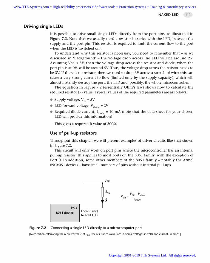
Driving single LEDs
It is possible to drive small single LEDs directly from the port pins, as illustrated inFigure 7.2. Note that we usually need a resistor in series with the LED, between thesupply and the port pin. This resistor is required to limit the current flow to the portwhen the LED is ‘switched on’.
To understand why this resistor is necessary, you need to remember that – as wediscussed in ‘Background’ – the voltage drop across the LED will be around 2V.Assuming Vcc is 5V, then the voltage drop across the resistor and diode, when theport pin is at 0V, will be around 5V. Thus, the voltage drop across the resistor needs tobe 3V. If there is no resistor, then we need to drop 3V across a stretch of wire: this cancause a very strong current to flow (limited only by the supply capacity), which willalmost instantly destroy the port, the LED and, possibly, the whole microcontroller.
The equation in Figure 7.2 (essentially Ohm’s law) shows how to calculate therequired resistor (R) value. Typical values of the required parameters are as follows:
Supply voltage, Vcc = 5V
LED forward voltage, Vdiode = 2V
Required diode current, Idiode = 10 mA (note that the data sheet for your chosenLED will provide this information)
This gives a required R value of 300Ω.
Use of pull-up resistors
Throughout this chapter, we will present examples of driver circuits like that shownin Figure 7.2.
This circuit will only work on port pins where the microcontroller has an internalpull-up resistor: this applies to most ports on the 8051 family, with the exception ofPort 0. In addition, some other members of the 8051 family – notably the Atmel89Cx051 devices – have small numbers of pins without internal pull-ups.
NAKED LED 111
Figure 7.2 Connecting a single LED directly to a microcomputer port
[Note: When calculating the required value of Rled, the resistance values are in ohms, voltages in volts and current in amps.]
Rled
Vcc
8051 device
PX.YLogic 0 (0v)to light LED
Rled =VCC – Vdiode
Idiode
www.TTE-Systems.com = High-reliability processors + Software tools + Protection systems + Training & consultancy services
Copyright 2001-2010 TTE Systems Ltd. All rights reserved.
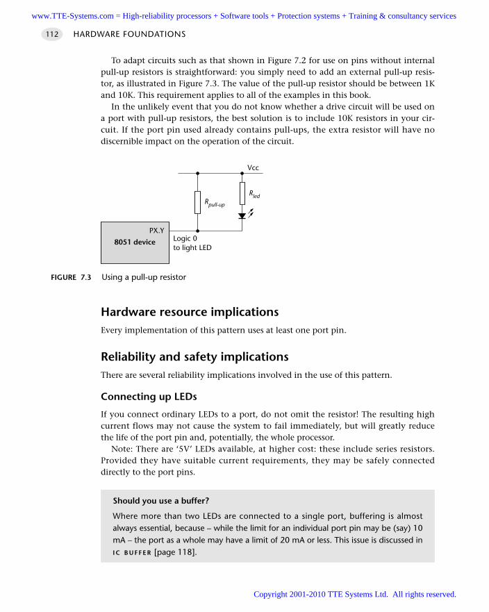
To adapt circuits such as that shown in Figure 7.2 for use on pins without internalpull-up resistors is straightforward: you simply need to add an external pull-up resis-tor, as illustrated in Figure 7.3. The value of the pull-up resistor should be between 1Kand 10K. This requirement applies to all of the examples in this book.
In the unlikely event that you do not know whether a drive circuit will be used ona port with pull-up resistors, the best solution is to include 10K resistors in your cir-cuit. If the port pin used already contains pull-ups, the extra resistor will have nodiscernible impact on the operation of the circuit.
Hardware resource implicationsEvery implementation of this pattern uses at least one port pin.
Reliability and safety implicationsThere are several reliability implications involved in the use of this pattern.
Connecting up LEDs
If you connect ordinary LEDs to a port, do not omit the resistor! The resulting highcurrent flows may not cause the system to fail immediately, but will greatly reducethe life of the port pin and, potentially, the whole processor.
Note: There are ‘5V’ LEDs available, at higher cost: these include series resistors.Provided they have suitable current requirements, they may be safely connecteddirectly to the port pins.
HARDWARE FOUNDATIONS112
FIGURE 7.3 Using a pull-up resistor
Rled
Vcc
8051 device
PX.YLogic 0to light LED
Rpull-up
Should you use a buffer?
Where more than two LEDs are connected to a single port, buffering is almostalways essential, because – while the limit for an individual port pin may be (say) 10mA – the port as a whole may have a limit of 20 mA or less. This issue is discussed inI C B U F F E R [page 118].
www.TTE-Systems.com = High-reliability processors + Software tools + Protection systems + Training & consultancy services
Copyright 2001-2010 TTE Systems Ltd. All rights reserved.
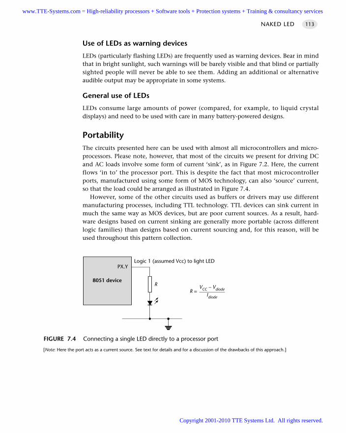
NAKED LED 113
Use of LEDs as warning devices
LEDs (particularly flashing LEDs) are frequently used as warning devices. Bear in mindthat in bright sunlight, such warnings will be barely visible and that blind or partiallysighted people will never be able to see them. Adding an additional or alternativeaudible output may be appropriate in some systems.
General use of LEDs
LEDs consume large amounts of power (compared, for example, to liquid crystaldisplays) and need to be used with care in many battery-powered designs.
PortabilityThe circuits presented here can be used with almost all microcontrollers and micro-processors. Please note, however, that most of the circuits we present for driving DCand AC loads involve some form of current ‘sink’, as in Figure 7.2. Here, the currentflows ‘in to’ the processor port. This is despite the fact that most microcontrollerports, manufactured using some form of MOS technology, can also ‘source’ current,so that the load could be arranged as illustrated in Figure 7.4.
However, some of the other circuits used as buffers or drivers may use differentmanufacturing processes, including TTL technology. TTL devices can sink current inmuch the same way as MOS devices, but are poor current sources. As a result, hard-ware designs based on current sinking are generally more portable (across differentlogic families) than designs based on current sourcing and, for this reason, will beused throughout this pattern collection.
FIGURE 7.4 Connecting a single LED directly to a processor port
[Note: Here the port acts as a current source. See text for details and for a discussion of the drawbacks of this approach.]
8051 device
PX.YLogic 1 (assumed Vcc) to light LED
RR =
VCC – Vdiode
Idiode
www.TTE-Systems.com = High-reliability processors + Software tools + Protection systems + Training & consultancy services
Copyright 2001-2010 TTE Systems Ltd. All rights reserved.
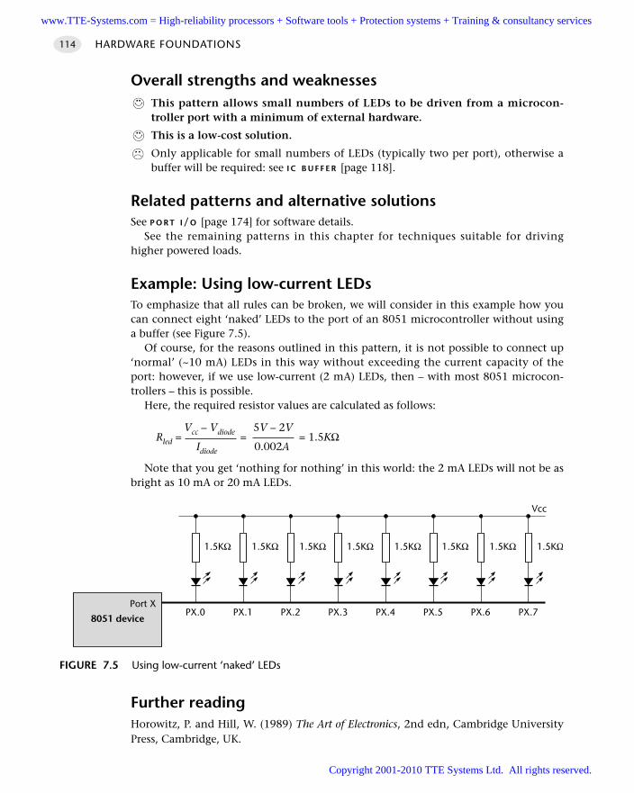
Overall strengths and weaknessesThis pattern allows small numbers of LEDs to be driven from a microcon-troller port with a minimum of external hardware.
This is a low-cost solution.
Only applicable for small numbers of LEDs (typically two per port), otherwise abuffer will be required: see I C B U F F E R [page 118].
Related patterns and alternative solutionsSee P O R T I/O [page 174] for software details.
See the remaining patterns in this chapter for techniques suitable for drivinghigher powered loads.
Example: Using low-current LEDsTo emphasize that all rules can be broken, we will consider in this example how youcan connect eight ‘naked’ LEDs to the port of an 8051 microcontroller without usinga buffer (see Figure 7.5).
Of course, for the reasons outlined in this pattern, it is not possible to connect up‘normal’ (~10 mA) LEDs in this way without exceeding the current capacity of theport: however, if we use low-current (2 mA) LEDs, then – with most 8051 microcon-trollers – this is possible.
Here, the required resistor values are calculated as follows:
Vcc – Vdiode 5V – 2VRled = = = 1.5KΩ
Idiode 0.002A
Note that you get ‘nothing for nothing’ in this world: the 2 mA LEDs will not be asbright as 10 mA or 20 mA LEDs.
Further readingHorowitz, P. and Hill, W. (1989) The Art of Electronics, 2nd edn, Cambridge UniversityPress, Cambridge, UK.
HARDWARE FOUNDATIONS114
FIGURE 7.5 Using low-current ‘naked’ LEDs
1.5KΩ 1.5KΩ 1.5KΩ 1.5KΩ 1.5KΩ 1.5KΩ 1.5KΩ 1.5KΩ
8051 device
Port XPX.0 PX.1 PX.2 PX.3 PX.4 PX.5 PX.6 PX.7
Vcc
www.TTE-Systems.com = High-reliability processors + Software tools + Protection systems + Training & consultancy services
Copyright 2001-2010 TTE Systems Ltd. All rights reserved.
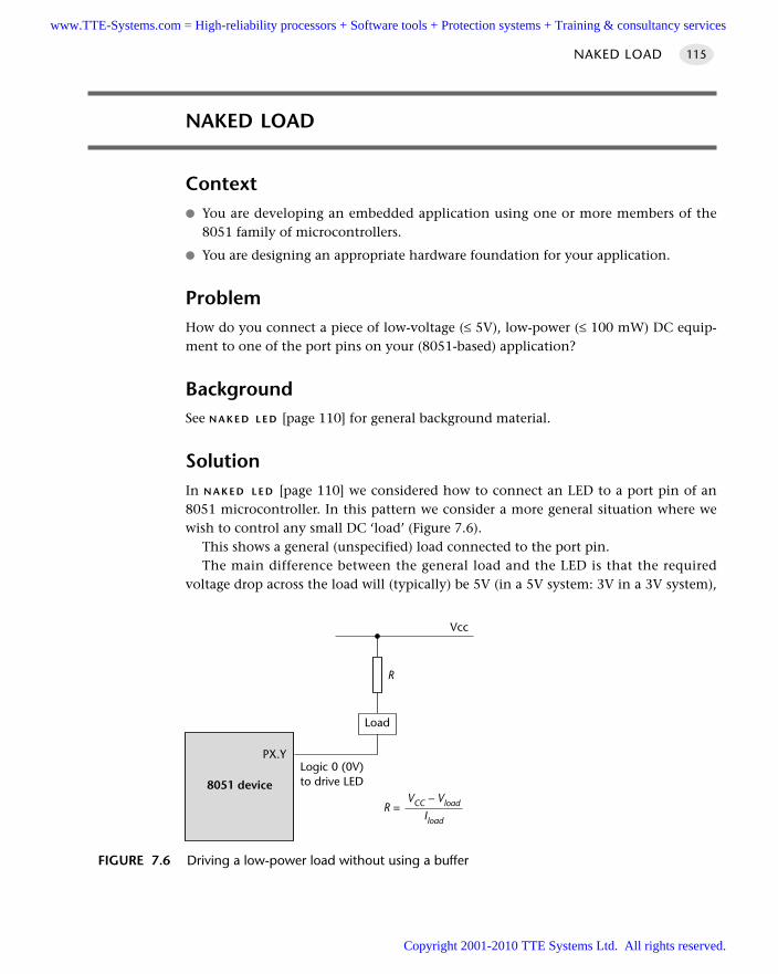
NAKED LOAD
Context You are developing an embedded application using one or more members of the
8051 family of microcontrollers.
You are designing an appropriate hardware foundation for your application.
ProblemHow do you connect a piece of low-voltage (≤ 5V), low-power (≤ 100 mW) DC equip-ment to one of the port pins on your (8051-based) application?
BackgroundSee N A K E D L E D [page 110] for general background material.
SolutionIn N A K E D L E D [page 110] we considered how to connect an LED to a port pin of an8051 microcontroller. In this pattern we consider a more general situation where wewish to control any small DC ‘load’ (Figure 7.6).
This shows a general (unspecified) load connected to the port pin. The main difference between the general load and the LED is that the required
voltage drop across the load will (typically) be 5V (in a 5V system: 3V in a 3V system),
NAKED LOAD 115
FIGURE 7.6 Driving a low-power load without using a buffer
8051 device
PX.YLogic 0 (0V)to drive LED
R
R =VCC – Vload
Iload
Load
Vcc
www.TTE-Systems.com = High-reliability processors + Software tools + Protection systems + Training & consultancy services
Copyright 2001-2010 TTE Systems Ltd. All rights reserved.
HARDWARE FOUNDATIONS116
rather than the 2V seen in the case of LEDs. In these circumstances, the resistor maybe omitted, since the required resistance value will be:
5.0V – 5.0VR = [ ] = 0Ω
Iload
Hardware resource implicationsEvery implementation of this pattern uses at least one port pin.
Reliability and safety implicationsI C B U F F E R [page 107] discusses techniques for buffering LEDs and other small loads.This can increase the reliability of some applications.
PortabilityAll microcontrollers can control small loads in this way.
Overall strengths and weaknessesThe techniques discussed in this pattern allow small loads to be driven froma microcontroller port with a minimum of external hardware.
This is a low-cost solution.
Only applicable for small loads (and small numbers of very small loads), other-wise a buffer will be required: see I C B U F F E R [page 118].
Related patterns and alternative solutionsSee P O R T I/O [page 174] for software details.
See the pattern I C B U F F E R [page 118] for techniques suitable for driving two ormore small loads from a single microcontroller.
See the patterns B J T D R I V E R [page 124], I C D R I V E R [page 134] and M O S F E T D R I V E R
[page 139] for techniques suitable for driving higher powered DC loads.
Example: BuzzerA range of piezoelectric buzzers are available that generate very loud (~70 dB) tones atmicrocontroller port voltages (they will operate from 3V to 12V) and currents (theyrequire around 3 mA). These make excellent warning devices, even in battery-powered applications (see Figure 7.7).
As we discussed in ‘Solution’, this 5V load requires no series resistor.
www.TTE-Systems.com = High-reliability processors + Software tools + Protection systems + Training & consultancy services
Copyright 2001-2010 TTE Systems Ltd. All rights reserved.
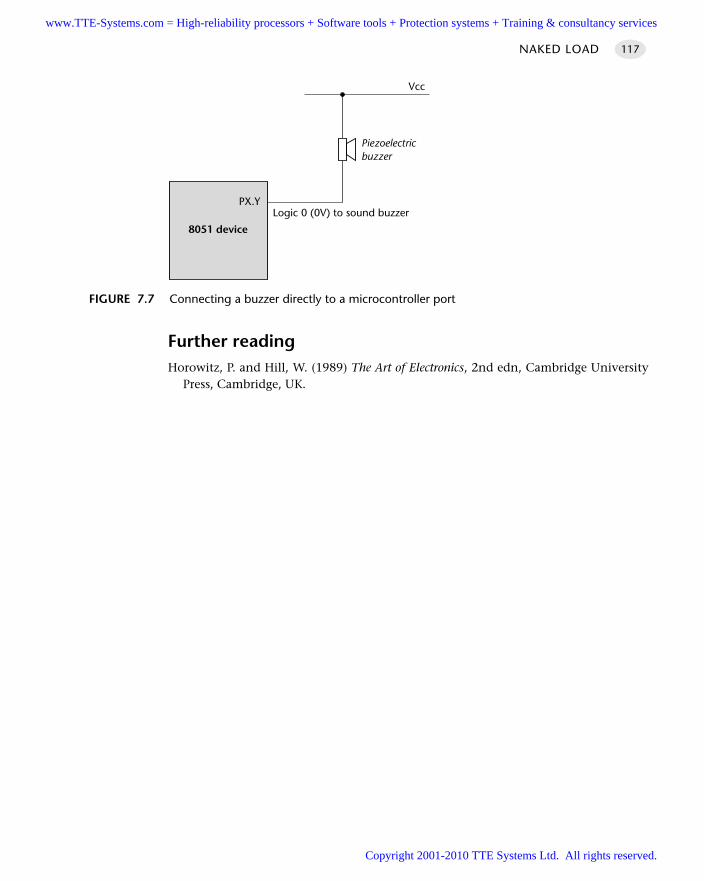
Further readingHorowitz, P. and Hill, W. (1989) The Art of Electronics, 2nd edn, Cambridge University
Press, Cambridge, UK.
NAKED LOAD 117
FIGURE 7.7 Connecting a buzzer directly to a microcontroller port
8051 device
PX.YLogic 0 (0V) to sound buzzer
Vcc
Piezoelectricbuzzer
www.TTE-Systems.com = High-reliability processors + Software tools + Protection systems + Training & consultancy services
Copyright 2001-2010 TTE Systems Ltd. All rights reserved.
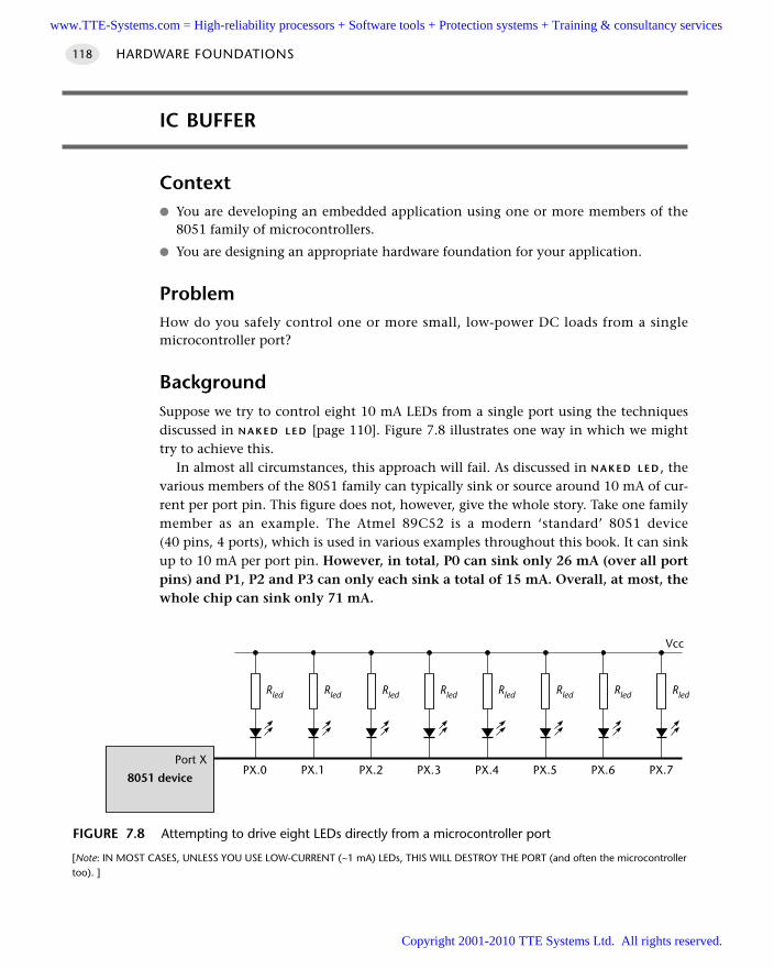
IC BUFFER
Context You are developing an embedded application using one or more members of the
8051 family of microcontrollers.
You are designing an appropriate hardware foundation for your application.
ProblemHow do you safely control one or more small, low-power DC loads from a singlemicrocontroller port?
BackgroundSuppose we try to control eight 10 mA LEDs from a single port using the techniquesdiscussed in N A K E D L E D [page 110]. Figure 7.8 illustrates one way in which we mighttry to achieve this.
In almost all circumstances, this approach will fail. As discussed in N A K E D L E D , thevarious members of the 8051 family can typically sink or source around 10 mA of cur-rent per port pin. This figure does not, however, give the whole story. Take one familymember as an example. The Atmel 89C52 is a modern ‘standard’ 8051 device(40 pins, 4 ports), which is used in various examples throughout this book. It can sinkup to 10 mA per port pin. However, in total, P0 can sink only 26 mA (over all portpins) and P1, P2 and P3 can only each sink a total of 15 mA. Overall, at most, thewhole chip can sink only 71 mA.
HARDWARE FOUNDATIONS118
FIGURE 7.8 Attempting to drive eight LEDs directly from a microcontroller port
[Note: IN MOST CASES, UNLESS YOU USE LOW-CURRENT (~1 mA) LEDs, THIS WILL DESTROY THE PORT (and often the microcontrollertoo). ]
Rled Rled Rled Rled Rled Rled Rled Rled
8051 device
Port XPX.0 PX.1 PX.2 PX.3 PX.4 PX.5 PX.6 PX.7
Vcc
www.TTE-Systems.com = High-reliability processors + Software tools + Protection systems + Training & consultancy services
Copyright 2001-2010 TTE Systems Ltd. All rights reserved.
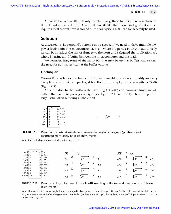
Although the various 8051 family members vary, these figures are representative ofthose found in many devices. As a result, circuits like that shown in Figure 7.8 – whichrequire a total current flow of around 80 mA for typical LEDs – cannot generally be used.
SolutionAs discussed in ‘Background’, buffers can be needed if we need to drive multiple low-power loads from one microcontroller. Even where the ports can drive loads directly,we can both reduce the risk of damage to the ports and safeguard the application as awhole by using an IC buffer between the microcomputer and the load.
We consider, first, some of the many ICs that may be used as buffers and, second,the need for pull-up resistors at the buffer outputs.
Finding an IC
Various ICs can be used as buffers in this way. Suitable inverters are readily and verycheaply available: six are packaged together, for example, in the ubiquitous 74×04(Figure 7.9).
An alternative to the 74×04 is the inverting (74×240) and non-inverting (74×241)buffers that come in packages of eight (see Figures 7.10 and 7.11). These are particu-larly useful when buffering a whole port.
IC BUFFER 119
FIGURE 7.9 Pinout of the 74x04 inverter and corresponding logic diagram (positive logic). (Reproduced courtesy of Texas Instruments)
[Note: that each chip contains six independent inverters.]
A Y
1A1Y2A2Y3A3Y
GND
1234567
VCC
6A6Y5A5Y4A4Y
1413121110
98
FIGURE 7.10 Pinout and logic diagram of the 74x240 inverting buffer (reproduced courtesy of TexasInstruments)
[Note: that each chip contains eight buffers, arranged in two groups of four (Group 1, Group 2). The buffers are all tri-state devicesand, for use as a simple buffer, the gates must be enabled (in the case of Group 1) by applying a low (~0V) input to Gate 1 or (in thecase of Group 2) Gate 2. ]
19
11
13
15
17
2OE–—
2A1
2A2
2A3
2A4
8
7
5
3
2Y1
2Y2
1Y3
2Y4
1
2
4
6
8
1OE–—
1A1
1A2
1A3
1A4
18
16
14
12
1Y1
1Y2
1Y3
1Y4
1OE1A12Y41A22Y31A32Y21A42Y1
GND
12345678910
VCC2OE1Y12A41Y22A31Y32A21Y42A1
20191817161514131211
www.TTE-Systems.com = High-reliability processors + Software tools + Protection systems + Training & consultancy services
Copyright 2001-2010 TTE Systems Ltd. All rights reserved.
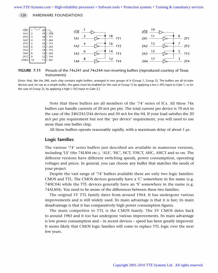
HARDWARE FOUNDATIONS120
Note that these buffers are all members of the ‘74’ series of ICs. All these 74xbuffers can handle currents of 20 mA per pin. The total current per device is 70 mA inthe case of the 240/241/244 devices and 50 mA for the 04. If your load satisfies the 20mA per pin requirement but not the ‘per device’ requirement, you will need to usemore than one buffer chip.
All these buffers operate reasonably rapidly, with a maximum delay of about 1 µs.
Logic families
The various ‘74’ series buffers just described are available in numerous versions,including ‘LS’ (the 74LS04 etc.), ‘ALS’, ‘HC’, HCT, VHCT, AHC, AHCT and so on. Thedifferent versions have different switching speeds, power consumption, operatingvoltages and prices. In general, you can choose any buffer that matches the needs ofyour project.
Despite the vast range of ‘74’ buffers available there are only two logic families:CMOS and TTL. The CMOS devices generally have a ‘C’ somewhere in the name (e.g.74HC04) while the TTL devices generally have an ‘S’ somewhere in the name (e.g.74ALS04). You need to be aware of the differences between these two families.
The original 5V TTL family dates from around 1964. It has undergone variousimprovements and is still widely used. Its main advantage is that it is fast; its maindisadvantage is that it has comparatively high power consumption figures.
The main competitor to TTL is the CMOS family. The 5V CMOS dates backto around 1983 and it too has undergone various improvements. Its main advantageis low power consumption and – in recent devices – speed has been greatly improved.It seems likely that CMOS logic families will come to replace TTL logic over the nextfew years.
FIGURE 7.11 Pinouts of the 74x241 and 74x244 non-inverting buffers (reproduced courtesy of TexasInstruments)
[Note: that, like the 240, each chip contains eight buffers, arranged in two groups of 4 (Group 1, Group 2). The buffers are all tri-statedevices and, for use as a simple buffer, the gates must be enabled (in the case of Group 1) by applying a low (~0V) input to Gate 1, or (inthe case of Group 2), by applying a high (~5V) input to Gate 2.]
19
11
13
15
17
2OE–—
2A1
2A2
2A3
2A4
8
7
5
3
2Y1
2Y2
1Y3
2Y4
1
2
4
6
8
1OE–—
1A1
1A2
1A3
1A4
18
16
14
12
1Y1
1Y2
1Y3
1Y4
1–––OE1A12Y41A22Y31A32Y21A42Y1
GND
12345678910
VCC
2OE1Y12A41Y22A31Y32A21Y42A1
20191817161514131211
www.TTE-Systems.com = High-reliability processors + Software tools + Protection systems + Training & consultancy services
Copyright 2001-2010 TTE Systems Ltd. All rights reserved.
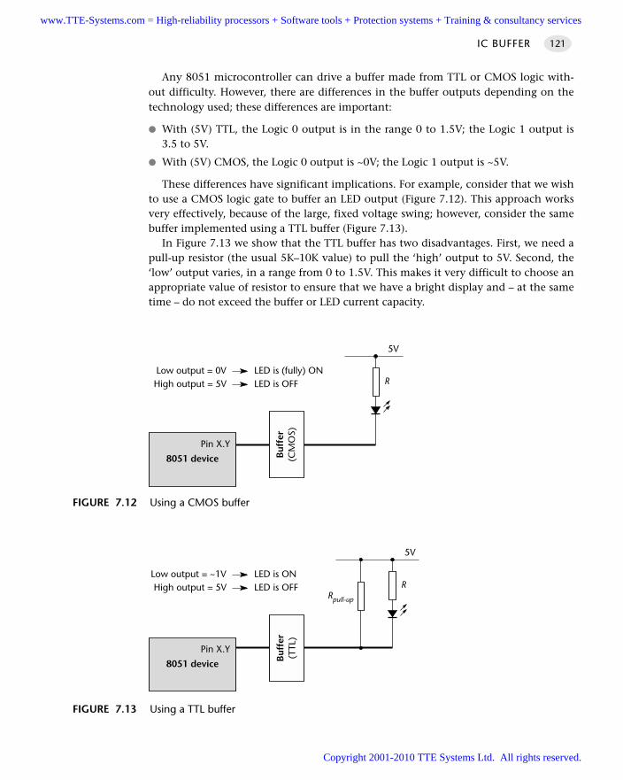
Any 8051 microcontroller can drive a buffer made from TTL or CMOS logic with-out difficulty. However, there are differences in the buffer outputs depending on thetechnology used; these differences are important:
With (5V) TTL, the Logic 0 output is in the range 0 to 1.5V; the Logic 1 output is3.5 to 5V.
With (5V) CMOS, the Logic 0 output is ~0V; the Logic 1 output is ~5V.
These differences have significant implications. For example, consider that we wishto use a CMOS logic gate to buffer an LED output (Figure 7.12). This approach worksvery effectively, because of the large, fixed voltage swing; however, consider the samebuffer implemented using a TTL buffer (Figure 7.13).
In Figure 7.13 we show that the TTL buffer has two disadvantages. First, we need apull-up resistor (the usual 5K–10K value) to pull the ‘high’ output to 5V. Second, the‘low’ output varies, in a range from 0 to 1.5V. This makes it very difficult to choose anappropriate value of resistor to ensure that we have a bright display and – at the sametime – do not exceed the buffer or LED current capacity.
IC BUFFER 121
FIGURE 7.12 Using a CMOS buffer
R
5V
8051 device
Pin X.Y
Buf
fer
(CM
OS)
Low output = 0V LED is (fully) ONHigh output = 5V LED is OFF
FIGURE 7.13 Using a TTL buffer
R
5V
8051 device
Pin X.Y
Rpull-up
Buf
fer
(TTL
)
Low output = ~1V LED is ONHigh output = 5V LED is OFF
www.TTE-Systems.com = High-reliability processors + Software tools + Protection systems + Training & consultancy services
Copyright 2001-2010 TTE Systems Ltd. All rights reserved.
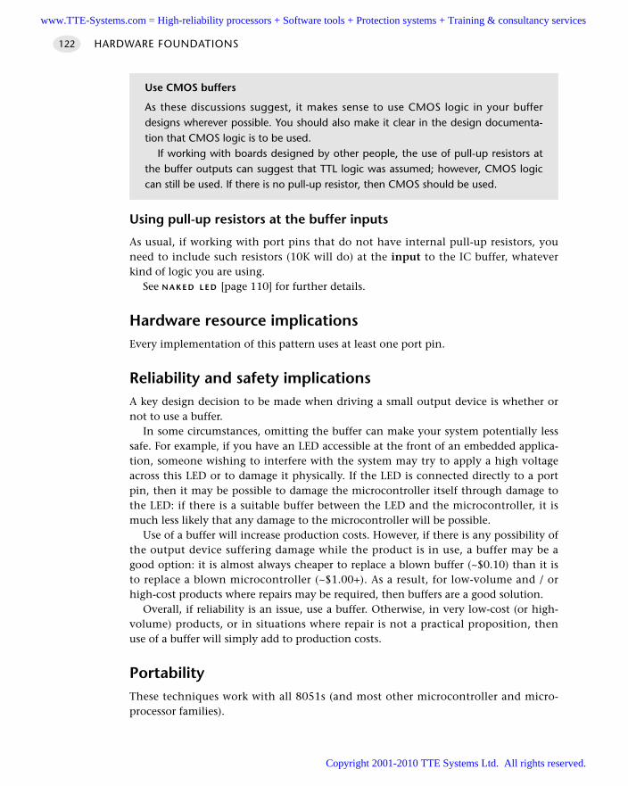
Using pull-up resistors at the buffer inputs
As usual, if working with port pins that do not have internal pull-up resistors, youneed to include such resistors (10K will do) at the input to the IC buffer, whateverkind of logic you are using.
See N A K E D L E D [page 110] for further details.
Hardware resource implicationsEvery implementation of this pattern uses at least one port pin.
Reliability and safety implicationsA key design decision to be made when driving a small output device is whether ornot to use a buffer.
In some circumstances, omitting the buffer can make your system potentially lesssafe. For example, if you have an LED accessible at the front of an embedded applica-tion, someone wishing to interfere with the system may try to apply a high voltageacross this LED or to damage it physically. If the LED is connected directly to a portpin, then it may be possible to damage the microcontroller itself through damage tothe LED: if there is a suitable buffer between the LED and the microcontroller, it ismuch less likely that any damage to the microcontroller will be possible.
Use of a buffer will increase production costs. However, if there is any possibility ofthe output device suffering damage while the product is in use, a buffer may be agood option: it is almost always cheaper to replace a blown buffer (~$0.10) than it isto replace a blown microcontroller (~$1.00+). As a result, for low-volume and / orhigh-cost products where repairs may be required, then buffers are a good solution.
Overall, if reliability is an issue, use a buffer. Otherwise, in very low-cost (or high-volume) products, or in situations where repair is not a practical proposition, thenuse of a buffer will simply add to production costs.
PortabilityThese techniques work with all 8051s (and most other microcontroller and micro-processor families).
HARDWARE FOUNDATIONS122
Use CMOS buffers
As these discussions suggest, it makes sense to use CMOS logic in your bufferdesigns wherever possible. You should also make it clear in the design documenta-tion that CMOS logic is to be used.
If working with boards designed by other people, the use of pull-up resistors atthe buffer outputs can suggest that TTL logic was assumed; however, CMOS logiccan still be used. If there is no pull-up resistor, then CMOS should be used.
www.TTE-Systems.com = High-reliability processors + Software tools + Protection systems + Training & consultancy services
Copyright 2001-2010 TTE Systems Ltd. All rights reserved.
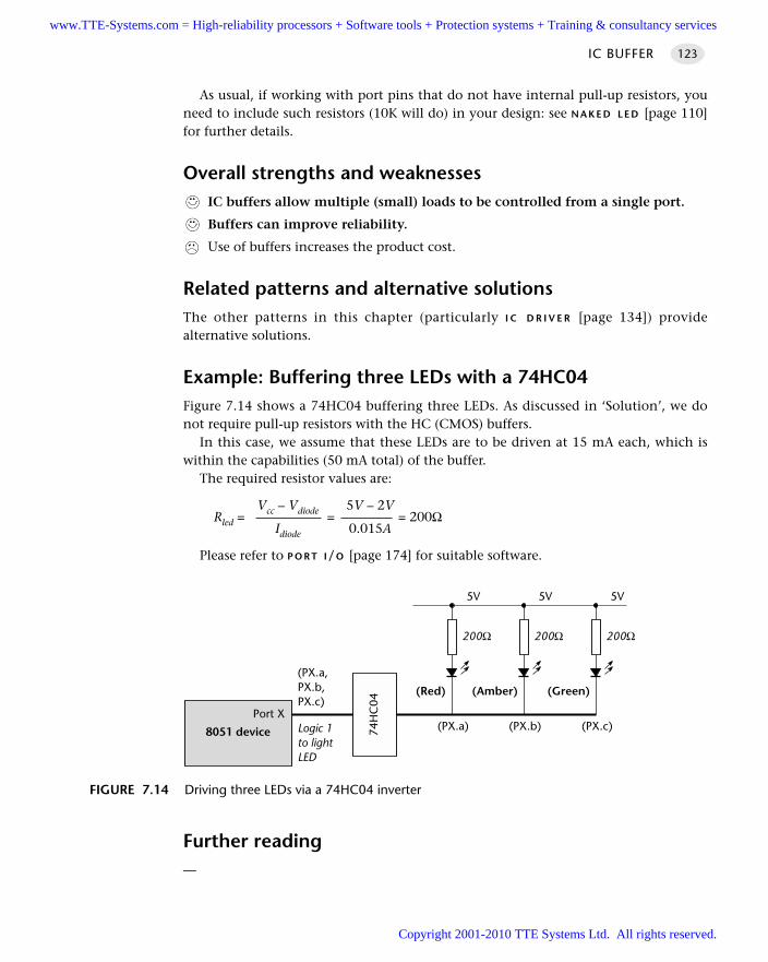
As usual, if working with port pins that do not have internal pull-up resistors, youneed to include such resistors (10K will do) in your design: see N A K E D L E D [page 110]for further details.
Overall strengths and weaknessesIC buffers allow multiple (small) loads to be controlled from a single port.
Buffers can improve reliability.
Use of buffers increases the product cost.
Related patterns and alternative solutionsThe other patterns in this chapter (particularly I C D R I V E R [page 134]) providealternative solutions.
Example: Buffering three LEDs with a 74HC04Figure 7.14 shows a 74HC04 buffering three LEDs. As discussed in ‘Solution’, we donot require pull-up resistors with the HC (CMOS) buffers.
In this case, we assume that these LEDs are to be driven at 15 mA each, which iswithin the capabilities (50 mA total) of the buffer.
The required resistor values are:
Vcc – Vdiode 5V – 2VRled = = = 200Ω
Idiode 0.015A
Please refer to P O R T I/O [page 174] for suitable software.
Further reading—
IC BUFFER 123
FIGURE 7.14 Driving three LEDs via a 74HC04 inverter
200Ω
5V
8051 device
Port X
74H
C04
(Red)
200Ω
5V
(Amber)
200Ω
5V
(Green)
(PX.a,PX.b,PX.c)
Logic 1to lightLED
(PX.a) (PX.b) (PX.c)
www.TTE-Systems.com = High-reliability processors + Software tools + Protection systems + Training & consultancy services
Copyright 2001-2010 TTE Systems Ltd. All rights reserved.
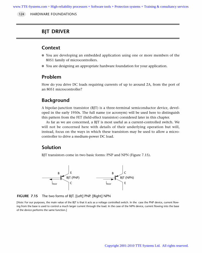
HARDWARE FOUNDATIONS124
BJT DRIVER
Context You are developing an embedded application using one or more members of the
8051 family of microcontrollers.
You are designing an appropriate hardware foundation for your application.
ProblemHow do you drive DC loads requiring currents of up to around 2A, from the port ofan 8051 microcontroller?
BackgroundA bipolar-junction transistor (BJT) is a three-terminal semiconductor device, devel-oped in the early 1950s. The full name (or acronym) will be used here to distinguishthis pattern from the FET (field-effect transistor) considered later in this chapter.
As far as we are concerned, a BJT is most useful as a current-controlled switch. Wewill not be concerned here with details of their underlying operation but will,instead, focus on the ways in which these transistors may be used to allow a micro-controller to drive a medium-power DC load.
SolutionBJT transistors come in two basic forms: PNP and NPN (Figure 7.15).
FIGURE 7.15 The two forms of BJT. [Left] PNP. [Right] NPN
[Note: For our purposes, the main value of the BJT is that it acts as a voltage controlled switch. In the case the PNP device, current flow-ing from the base is used to control a much larger current through the load. In the case of the NPN device, current flowing into the baseof the device performs the same function.]
B
|base
E
C
BJT (PNP)B
|base
C
E
BJT (NPN)
www.TTE-Systems.com = High-reliability processors + Software tools + Protection systems + Training & consultancy services
Copyright 2001-2010 TTE Systems Ltd. All rights reserved.
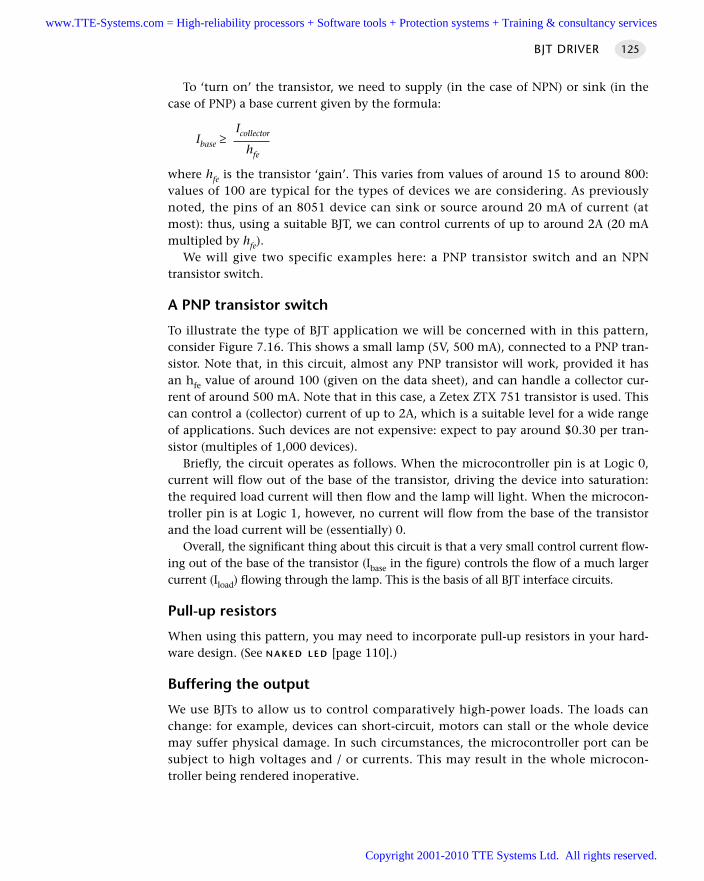
BJT DRIVER 125
To ‘turn on’ the transistor, we need to supply (in the case of NPN) or sink (in thecase of PNP) a base current given by the formula:
IcollectorIbase ≥hfe
where hfe is the transistor ‘gain’. This varies from values of around 15 to around 800:values of 100 are typical for the types of devices we are considering. As previouslynoted, the pins of an 8051 device can sink or source around 20 mA of current (atmost): thus, using a suitable BJT, we can control currents of up to around 2A (20 mAmultipled by hfe).
We will give two specific examples here: a PNP transistor switch and an NPNtransistor switch.
A PNP transistor switch
To illustrate the type of BJT application we will be concerned with in this pattern,consider Figure 7.16. This shows a small lamp (5V, 500 mA), connected to a PNP tran-sistor. Note that, in this circuit, almost any PNP transistor will work, provided it hasan hfe value of around 100 (given on the data sheet), and can handle a collector cur-rent of around 500 mA. Note that in this case, a Zetex ZTX 751 transistor is used. Thiscan control a (collector) current of up to 2A, which is a suitable level for a wide rangeof applications. Such devices are not expensive: expect to pay around $0.30 per tran-sistor (multiples of 1,000 devices).
Briefly, the circuit operates as follows. When the microcontroller pin is at Logic 0,current will flow out of the base of the transistor, driving the device into saturation:the required load current will then flow and the lamp will light. When the microcon-troller pin is at Logic 1, however, no current will flow from the base of the transistorand the load current will be (essentially) 0.
Overall, the significant thing about this circuit is that a very small control current flow-ing out of the base of the transistor (Ibase in the figure) controls the flow of a much largercurrent (Iload) flowing through the lamp. This is the basis of all BJT interface circuits.
Pull-up resistors
When using this pattern, you may need to incorporate pull-up resistors in your hard-ware design. (See N A K E D L E D [page 110].)
Buffering the output
We use BJTs to allow us to control comparatively high-power loads. The loads canchange: for example, devices can short-circuit, motors can stall or the whole devicemay suffer physical damage. In such circumstances, the microcontroller port can besubject to high voltages and / or currents. This may result in the whole microcon-troller being rendered inoperative.
www.TTE-Systems.com = High-reliability processors + Software tools + Protection systems + Training & consultancy services
Copyright 2001-2010 TTE Systems Ltd. All rights reserved.
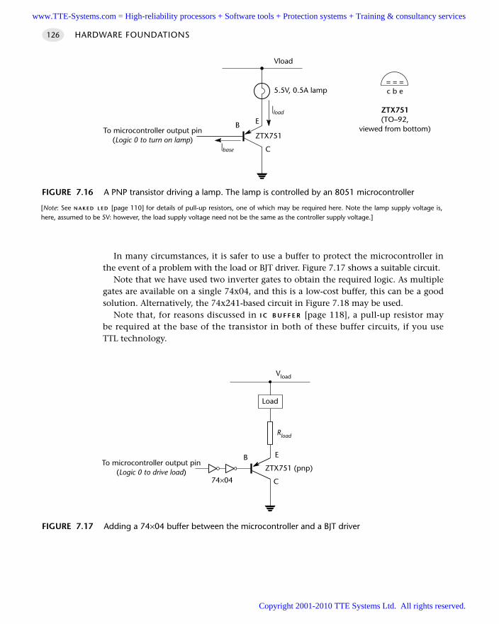
HARDWARE FOUNDATIONS126
In many circumstances, it is safer to use a buffer to protect the microcontroller inthe event of a problem with the load or BJT driver. Figure 7.17 shows a suitable circuit.
Note that we have used two inverter gates to obtain the required logic. As multiplegates are available on a single 74x04, and this is a low-cost buffer, this can be a goodsolution. Alternatively, the 74x241-based circuit in Figure 7.18 may be used.
Note that, for reasons discussed in I C B U F F E R [page 118], a pull-up resistor maybe required at the base of the transistor in both of these buffer circuits, if you useTTL technology.
FIGURE 7.16 A PNP transistor driving a lamp. The lamp is controlled by an 8051 microcontroller
[Note: See N A K E D L E D [page 110] for details of pull-up resistors, one of which may be required here. Note the lamp supply voltage is,here, assumed to be 5V: however, the load supply voltage need not be the same as the controller supply voltage.]
B
|base
E
C
|load
5.5V, 0.5A lamp
To microcontroller output pin(Logic 0 to turn on lamp)
Vload
ZTX751
= = =c b e
ZTX751(TO–92,
viewed from bottom)
FIGURE 7.17 Adding a 74×04 buffer between the microcontroller and a BJT driver
B E
C
To microcontroller output pin(Logic 0 to drive load)
Vload
ZTX751 (pnp)
Rload
Load
74×04
www.TTE-Systems.com = High-reliability processors + Software tools + Protection systems + Training & consultancy services
Copyright 2001-2010 TTE Systems Ltd. All rights reserved.
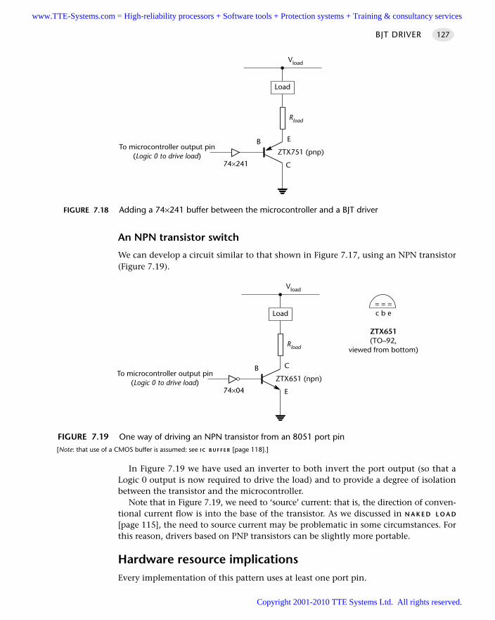
An NPN transistor switch
We can develop a circuit similar to that shown in Figure 7.17, using an NPN transistor(Figure 7.19).
In Figure 7.19 we have used an inverter to both invert the port output (so that aLogic 0 output is now required to drive the load) and to provide a degree of isolationbetween the transistor and the microcontroller.
Note that in Figure 7.19, we need to ‘source’ current: that is, the direction of conven-tional current flow is into the base of the transistor. As we discussed in N A K E D L O A D
[page 115], the need to source current may be problematic in some circumstances. Forthis reason, drivers based on PNP transistors can be slightly more portable.
Hardware resource implicationsEvery implementation of this pattern uses at least one port pin.
BJT DRIVER 127
FIGURE 7.18 Adding a 74×241 buffer between the microcontroller and a BJT driver
B E
C
To microcontroller output pin(Logic 0 to drive load)
Vload
ZTX751 (pnp)
Rload
Load
74×241
FIGURE 7.19 One way of driving an NPN transistor from an 8051 port pin[Note: that use of a CMOS buffer is assumed: see I C B U F F E R [page 118].]
B C
E
To microcontroller output pin(Logic 0 to drive load)
Vload
ZTX651 (npn)
Rload
Load
74×04
= = =c b e
ZTX651(TO–92,
viewed from bottom)
www.TTE-Systems.com = High-reliability processors + Software tools + Protection systems + Training & consultancy services
Copyright 2001-2010 TTE Systems Ltd. All rights reserved.
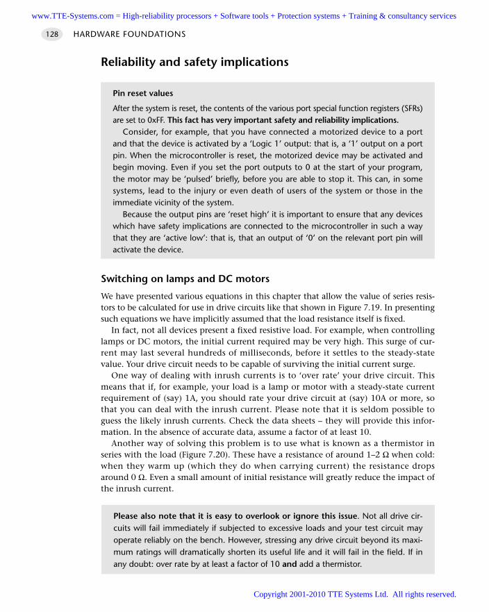
Reliability and safety implications
Switching on lamps and DC motors
We have presented various equations in this chapter that allow the value of series resis-tors to be calculated for use in drive circuits like that shown in Figure 7.19. In presentingsuch equations we have implicitly assumed that the load resistance itself is fixed.
In fact, not all devices present a fixed resistive load. For example, when controllinglamps or DC motors, the initial current required may be very high. This surge of cur-rent may last several hundreds of milliseconds, before it settles to the steady-statevalue. Your drive circuit needs to be capable of surviving the initial current surge.
One way of dealing with inrush currents is to ‘over rate’ your drive circuit. Thismeans that if, for example, your load is a lamp or motor with a steady-state currentrequirement of (say) 1A, you should rate your drive circuit at (say) 10A or more, sothat you can deal with the inrush current. Please note that it is seldom possible toguess the likely inrush currents. Check the data sheets – they will provide this infor-mation. In the absence of accurate data, assume a factor of at least 10.
Another way of solving this problem is to use what is known as a thermistor inseries with the load (Figure 7.20). These have a resistance of around 1–2 Ω when cold:when they warm up (which they do when carrying current) the resistance dropsaround 0 Ω. Even a small amount of initial resistance will greatly reduce the impact ofthe inrush current.
HARDWARE FOUNDATIONS128
Please also note that it is easy to overlook or ignore this issue. Not all drive cir-cuits will fail immediately if subjected to excessive loads and your test circuit mayoperate reliably on the bench. However, stressing any drive circuit beyond its maxi-mum ratings will dramatically shorten its useful life and it will fail in the field. If inany doubt: over rate by at least a factor of 10 and add a thermistor.
Pin reset values
After the system is reset, the contents of the various port special function registers (SFRs)are set to 0xFF. This fact has very important safety and reliability implications.
Consider, for example, that you have connected a motorized device to a portand that the device is activated by a ‘Logic 1’ output: that is, a ‘1’ output on a portpin. When the microcontroller is reset, the motorized device may be activated andbegin moving. Even if you set the port outputs to 0 at the start of your program,the motor may be ‘pulsed’ briefly, before you are able to stop it. This can, in somesystems, lead to the injury or even death of users of the system or those in theimmediate vicinity of the system.
Because the output pins are ‘reset high’ it is important to ensure that any deviceswhich have safety implications are connected to the microcontroller in such a waythat they are ‘active low’: that is, that an output of ‘0’ on the relevant port pin willactivate the device.
www.TTE-Systems.com = High-reliability processors + Software tools + Protection systems + Training & consultancy services
Copyright 2001-2010 TTE Systems Ltd. All rights reserved.
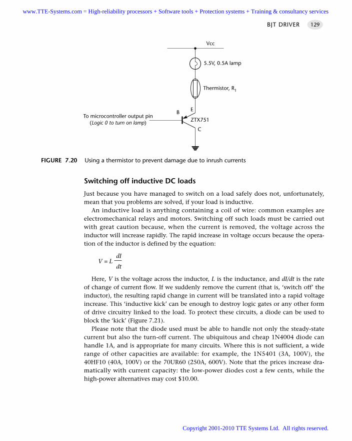
Switching off inductive DC loads
Just because you have managed to switch on a load safely does not, unfortunately,mean that you problems are solved, if your load is inductive.
An inductive load is anything containing a coil of wire: common examples areelectromechanical relays and motors. Switching off such loads must be carried outwith great caution because, when the current is removed, the voltage across theinductor will increase rapidly. The rapid increase in voltage occurs because the opera-tion of the inductor is defined by the equation:
dIV = L
dt
Here, V is the voltage across the inductor, L is the inductance, and dI/dt is the rateof change of current flow. If we suddenly remove the current (that is, ‘switch off’ theinductor), the resulting rapid change in current will be translated into a rapid voltageincrease. This ‘inductive kick’ can be enough to destroy logic gates or any other formof drive circuitry linked to the load. To protect these circuits, a diode can be used toblock the ‘kick’ (Figure 7.21).
Please note that the diode used must be able to handle not only the steady-statecurrent but also the turn-off current. The ubiquitous and cheap 1N4004 diode canhandle 1A, and is appropriate for many circuits. Where this is not sufficient, a widerange of other capacities are available: for example, the 1N5401 (3A, 100V), the40HF10 (40A, 100V) or the 70UR60 (250A, 600V). Note that the prices increase dra-matically with current capacity: the low-power diodes cost a few cents, while thehigh-power alternatives may cost $10.00.
BJT DRIVER 129
FIGURE 7.20 Using a thermistor to prevent damage due to inrush currents
B E
C
5.5V, 0.5A lamp
To microcontroller output pin(Logic 0 to turn on lamp)
Vcc
ZTX751
Thermistor, R1
www.TTE-Systems.com = High-reliability processors + Software tools + Protection systems + Training & consultancy services
Copyright 2001-2010 TTE Systems Ltd. All rights reserved.
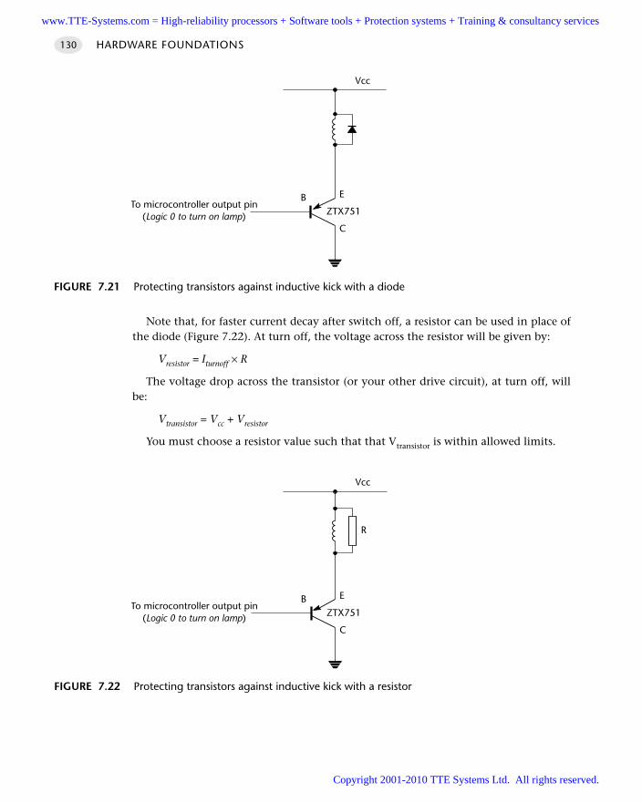
Note that, for faster current decay after switch off, a resistor can be used in place ofthe diode (Figure 7.22). At turn off, the voltage across the resistor will be given by:
Vresistor = Iturnoff × R
The voltage drop across the transistor (or your other drive circuit), at turn off, willbe:
Vtransistor = Vcc + Vresistor
You must choose a resistor value such that that Vtransistor is within allowed limits.
HARDWARE FOUNDATIONS130
FIGURE 7.21 Protecting transistors against inductive kick with a diode
B E
C
To microcontroller output pin(Logic 0 to turn on lamp)
Vcc
ZTX751
FIGURE 7.22 Protecting transistors against inductive kick with a resistor
B E
C
To microcontroller output pin(Logic 0 to turn on lamp)
Vcc
ZTX751
R
www.TTE-Systems.com = High-reliability processors + Software tools + Protection systems + Training & consultancy services
Copyright 2001-2010 TTE Systems Ltd. All rights reserved.
Protecting again load faults
The use of thermistors, diodes and inrush resistors is designed to protect the switch-ing circuit under normal conditions. When working with high-power loads, you alsoneed to deal with the problems caused by damage to the load. In particular, we needto consider the possibility that the load will be short-circuited.
A particular problem arises with semiconductor switching devices such as BJTs. Thethermal mass of such semiconductor devices is very low: this means that an excessivecurrent flow – caused, for example, by a short or a stalled motor – will very rapidly takethe device out of the safe operating region (see Lander, 1993; or Rashid, 1993, fordetails). To protect against this, it is essential that you use a fuse in series with the load.
Note that an ‘ordinary’ fuse will not be adequate: the fuse must blow very rapidlyto avoid damage to the semiconductor device: such devices are usually labelled ‘highspeed’ and will be described as being suitable for semiconductor protection.
PortabilityThese techniques work with all 8051s (and most other microcontroller and micro-processor families).
As usual, if working with port pins that do not have internal pull-up resistors, youneed to include such resistors (10K will do) in your design.
Overall strengths and weaknessesSoftware developers sometimes seem to hold the view that discrete transis-tors are ‘old fashioned’ and have now been replaced by IC equivalents. Thisis not the case. In many applications, particularly where a small number ofrelatively low- and medium-power drivers are required, discrete transistorsare widely used, not least because they are available for under $0.10 each(around half the price of ICs), even in small quantities: as such they can rep-resent a very cost-effective solution.
BJTs can operate at very low voltages, compatible with low-voltage micro-controllers.
The maximum BJT gain of around 100 means that, in most circumstances, we arerestricted to current flows of around 1A–2A, if we use a single transistor. SingleMOSFETs, by comparison, can readily switch loads of 100A.
BJT DRIVER 131
Please note (again) that it is easy to overlook or ignore this issue. Not all drivecircuits will fail immediately if subjected to excessive loads and your test circuit mayoperate reliably on the bench. However, stressing any drive circuit beyond its maxi-mum ratings will dramatically shorten its useful life and it will fail in the field. If inany doubt, use a suitable diode or resistor.
www.TTE-Systems.com = High-reliability processors + Software tools + Protection systems + Training & consultancy services
Copyright 2001-2010 TTE Systems Ltd. All rights reserved.
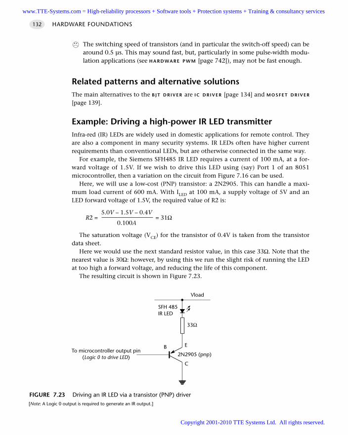
The switching speed of transistors (and in particular the switch-off speed) can bearound 0.5 µs. This may sound fast, but, particularly in some pulse-width modu-lation applications (see H A R D WA R E P W M [page 742]), may not be fast enough.
Related patterns and alternative solutionsThe main alternatives to the B J T D R I V E R are I C D R I V E R [page 134] and M O S F E T D R I V E R
[page 139].
Example: Driving a high-power IR LED transmitterInfra-red (IR) LEDs are widely used in domestic applications for remote control. Theyare also a component in many security systems. IR LEDs often have higher currentrequirements than conventional LEDs, but are otherwise connected in the same way.
For example, the Siemens SFH485 IR LED requires a current of 100 mA, at a for-ward voltage of 1.5V. If we wish to drive this LED using (say) Port 1 of an 8051microcontroller, then a variation on the circuit from Figure 7.16 can be used.
Here, we will use a low-cost (PNP) transistor: a 2N2905. This can handle a maxi-mum load current of 600 mA. With ILED at 100 mA, a supply voltage of 5V and anLED forward voltage of 1.5V, the required value of R2 is:
5.0V – 1.5V – 0.4VR2 = = 31Ω
0.100A
The saturation voltage (VCE) for the transistor of 0.4V is taken from the transistordata sheet.
Here we would use the next standard resistor value, in this case 33Ω. Note that thenearest value is 30Ω: however, by using this we run the slight risk of running the LEDat too high a forward voltage, and reducing the life of this component.
The resulting circuit is shown in Figure 7.23.
HARDWARE FOUNDATIONS132
FIGURE 7.23 Driving an IR LED via a transistor (PNP) driver[Note: A Logic 0 output is required to generate an IR output.]
B E
C
To microcontroller output pin(Logic 0 to drive LED)
Vload
2N2905 (pnp)
33Ω
SFH 485IR LED
www.TTE-Systems.com = High-reliability processors + Software tools + Protection systems + Training & consultancy services
Copyright 2001-2010 TTE Systems Ltd. All rights reserved.
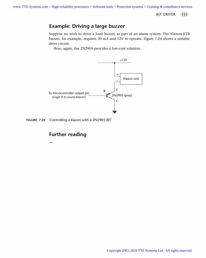
Example: Driving a large buzzerSuppose we wish to drive a loud buzzer, as part of an alarm system. The Klaxon KTBbuzzer, for example, requires 30 mA and 12V to operate. Figure 7.24 shows a suitabledrive circuit.
Here, again, the 2N2905 provides a low-cost solution.
Further reading—
BJT DRIVER 133
FIGURE 7.24 Controlling a klaxon with a 2N2905 BJT
B E
C
To microcontroller output pin(Logic 0 to sound klaxon)
+12V
2N2905 (pnp)
Klaxon unit–
+
www.TTE-Systems.com = High-reliability processors + Software tools + Protection systems + Training & consultancy services
Copyright 2001-2010 TTE Systems Ltd. All rights reserved.
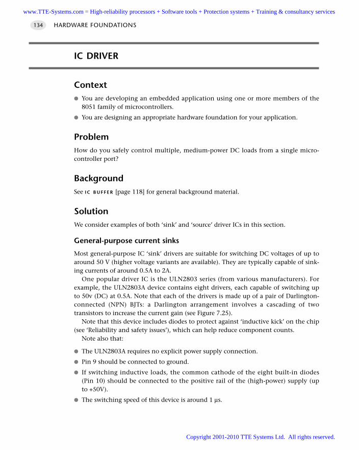
IC DRIVER
Context You are developing an embedded application using one or more members of the
8051 family of microcontrollers.
You are designing an appropriate hardware foundation for your application.
ProblemHow do you safely control multiple, medium-power DC loads from a single micro-controller port?
BackgroundSee I C B U F F E R [page 118] for general background material.
SolutionWe consider examples of both ‘sink’ and ‘source’ driver ICs in this section.
General-purpose current sinks
Most general-purpose IC ‘sink’ drivers are suitable for switching DC voltages of up toaround 50 V (higher voltage variants are available). They are typically capable of sink-ing currents of around 0.5A to 2A.
One popular driver IC is the ULN2803 series (from various manufacturers). Forexample, the ULN2803A device contains eight drivers, each capable of switching upto 50v (DC) at 0.5A. Note that each of the drivers is made up of a pair of Darlington-connected (NPN) BJTs: a Darlington arrangement involves a cascading of twotransistors to increase the current gain (see Figure 7.25).
Note that this device includes diodes to protect against ‘inductive kick’ on the chip(see ‘Reliability and safety issues’), which can help reduce component counts.
Note also that:
The ULN2803A requires no explicit power supply connection.
Pin 9 should be connected to ground.
If switching inductive loads, the common cathode of the eight built-in diodes(Pin 10) should be connected to the positive rail of the (high-power) supply (upto +50V).
The switching speed of this device is around 1 µs.
HARDWARE FOUNDATIONS134
www.TTE-Systems.com = High-reliability processors + Software tools + Protection systems + Training & consultancy services
Copyright 2001-2010 TTE Systems Ltd. All rights reserved.
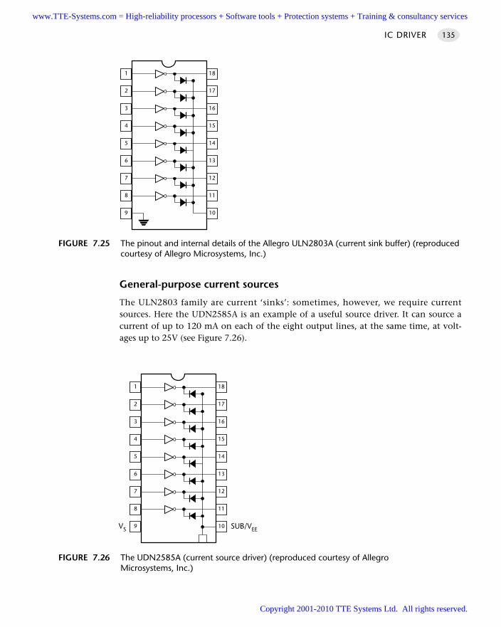
General-purpose current sources
The ULN2803 family are current ‘sinks’: sometimes, however, we require currentsources. Here the UDN2585A is an example of a useful source driver. It can source acurrent of up to 120 mA on each of the eight output lines, at the same time, at volt-ages up to 25V (see Figure 7.26).
IC DRIVER 135
FIGURE 7.25 The pinout and internal details of the Allegro ULN2803A (current sink buffer) (reproducedcourtesy of Allegro Microsystems, Inc.)
1
2
3
4
5
6
7
8
18
17
16
15
14
13
12
11
109
FIGURE 7.26 The UDN2585A (current source driver) (reproduced courtesy of Allegro Microsystems, Inc.)
1
2
3
4
5
6
7
8
18
17
16
15
14
13
12
11
109 SUB/VEEVS
www.TTE-Systems.com = High-reliability processors + Software tools + Protection systems + Training & consultancy services
Copyright 2001-2010 TTE Systems Ltd. All rights reserved.
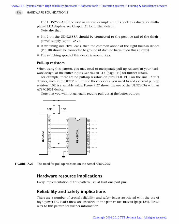
The UDN2585A will be used in various examples in this book as a driver for multi-plexed LED displays: see Chapter 21 for further details.
Note also that:
Pin 9 on the UDN2585A should be connected to the positive rail of the (high-power) supply (up to +25V).
If switching inductive loads, then the common anode of the eight built-in diodes(Pin 10) should be connected to ground (it does no harm to do this anyway).
The switching speed of this device is around 5 µs.
Pull-up resistors
When using this pattern, you may need to incorporate pull-up resistors in your hard-ware design, at the buffer inputs. See N A K E D L E D [page 110] for further details.
For example, there are no pull-up resistors on pins P1.0, P1.1 on the small Atmeldevices, such as the 89C2051. To use these devices, you need to add external pull-upresistors. 10K is a suitable value. Figure 7.27 shows the use of the ULN2803A with anAT89C2051 device.
Note that you will not generally require pull-ups at the buffer outputs.
Hardware resource implicationsEvery implementation of this pattern uses at least one port pin.
Reliability and safety implicationsThere are a number of crucial reliability and safety issues associated with the use ofhigh-power DC loads: these are discussed in the pattern B J T D R I V E R [page 124]. Pleaserefer to this pattern for further information.
HARDWARE FOUNDATIONS136
FIGURE 7.27 The need for pull-up resistors on the Atmel AT89C2051
9
8
7
6
5
4
3
2
1
ULN
2803
A
10
11
12
13
14
15
16
17
18
11
12
13
14
15
16
17
19
89C
2051
10K 10K
20
18
www.TTE-Systems.com = High-reliability processors + Software tools + Protection systems + Training & consultancy services
Copyright 2001-2010 TTE Systems Ltd. All rights reserved.
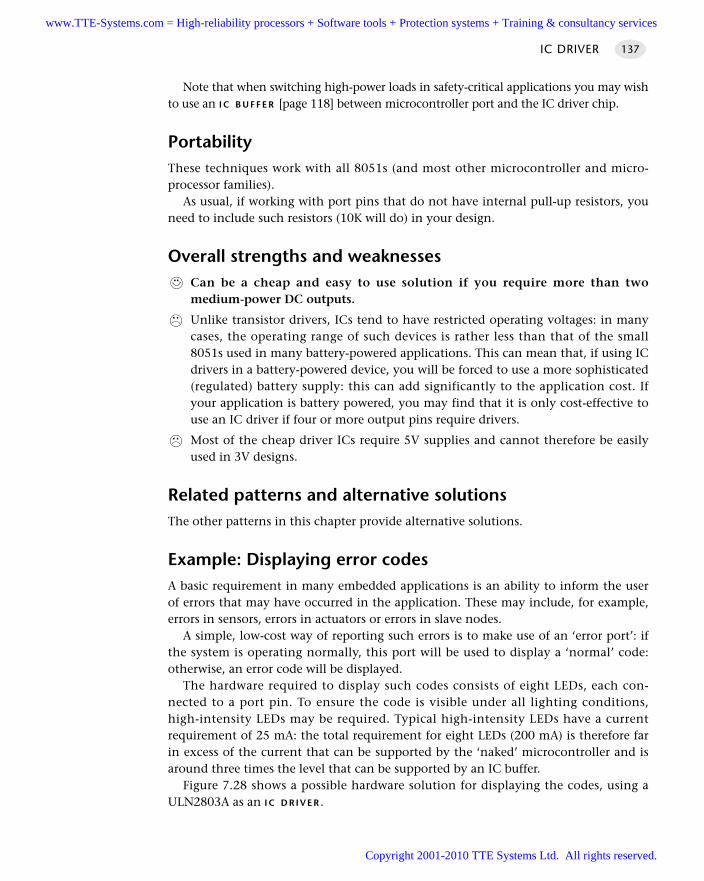
Note that when switching high-power loads in safety-critical applications you may wishto use an I C B U F F E R [page 118] between microcontroller port and the IC driver chip.
PortabilityThese techniques work with all 8051s (and most other microcontroller and micro-processor families).
As usual, if working with port pins that do not have internal pull-up resistors, youneed to include such resistors (10K will do) in your design.
Overall strengths and weaknessesCan be a cheap and easy to use solution if you require more than twomedium-power DC outputs.
Unlike transistor drivers, ICs tend to have restricted operating voltages: in manycases, the operating range of such devices is rather less than that of the small8051s used in many battery-powered applications. This can mean that, if using ICdrivers in a battery-powered device, you will be forced to use a more sophisticated(regulated) battery supply: this can add significantly to the application cost. Ifyour application is battery powered, you may find that it is only cost-effective touse an IC driver if four or more output pins require drivers.
Most of the cheap driver ICs require 5V supplies and cannot therefore be easilyused in 3V designs.
Related patterns and alternative solutionsThe other patterns in this chapter provide alternative solutions.
Example: Displaying error codesA basic requirement in many embedded applications is an ability to inform the userof errors that may have occurred in the application. These may include, for example,errors in sensors, errors in actuators or errors in slave nodes.
A simple, low-cost way of reporting such errors is to make use of an ‘error port’: ifthe system is operating normally, this port will be used to display a ‘normal’ code:otherwise, an error code will be displayed.
The hardware required to display such codes consists of eight LEDs, each con-nected to a port pin. To ensure the code is visible under all lighting conditions,high-intensity LEDs may be required. Typical high-intensity LEDs have a currentrequirement of 25 mA: the total requirement for eight LEDs (200 mA) is therefore farin excess of the current that can be supported by the ‘naked’ microcontroller and isaround three times the level that can be supported by an IC buffer.
Figure 7.28 shows a possible hardware solution for displaying the codes, using aULN2803A as an I C D R I V E R .
IC DRIVER 137
www.TTE-Systems.com = High-reliability processors + Software tools + Protection systems + Training & consultancy services
Copyright 2001-2010 TTE Systems Ltd. All rights reserved.
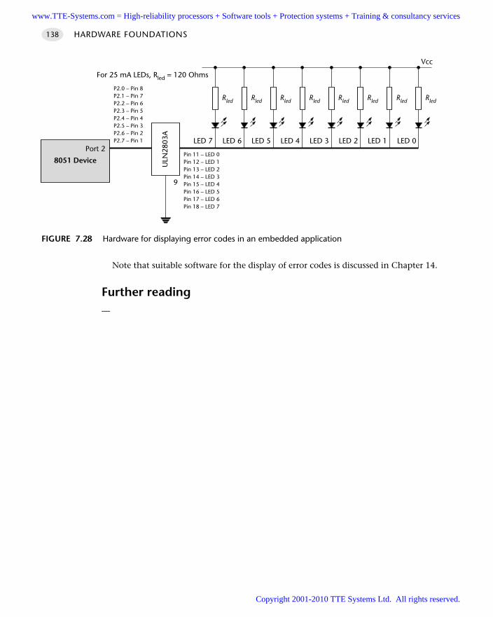
Note that suitable software for the display of error codes is discussed in Chapter 14.
Further reading—
HARDWARE FOUNDATIONS138
FIGURE 7.28 Hardware for displaying error codes in an embedded application
Rled Rled Rled Rled Rled Rled Rled Rled
8051 Device
Port 2LED 7
Vcc
ULN
2803
A
P2.0 – Pin 8P2.1 – Pin 7P2.2 – Pin 6P2.3 – Pin 5P2.4 – Pin 4P2.5 – Pin 3P2.6 – Pin 2P2.7 – Pin 1
Pin 11 – LED 0Pin 12 – LED 1Pin 13 – LED 2Pin 14 – LED 3Pin 15 – LED 4Pin 16 – LED 5Pin 17 – LED 6Pin 18 – LED 7
LED 6 LED 5 LED 4 LED 3 LED 2 LED 1 LED 0
For 25 mA LEDs, Rled = 120 Ohms
9
www.TTE-Systems.com = High-reliability processors + Software tools + Protection systems + Training & consultancy services
Copyright 2001-2010 TTE Systems Ltd. All rights reserved.
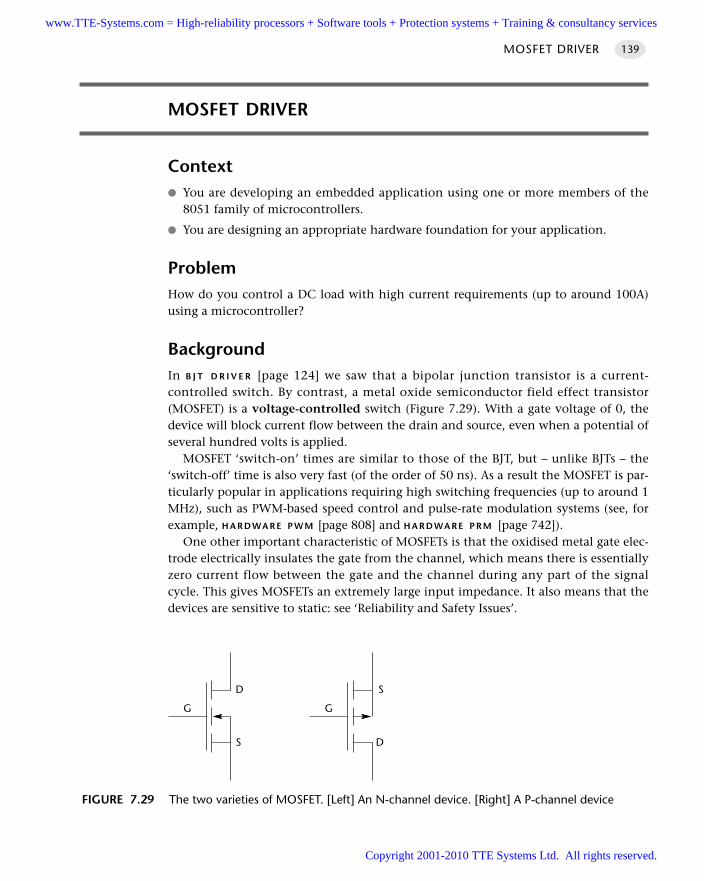
MOSFET DRIVER
Context You are developing an embedded application using one or more members of the
8051 family of microcontrollers.
You are designing an appropriate hardware foundation for your application.
ProblemHow do you control a DC load with high current requirements (up to around 100A)using a microcontroller?
BackgroundIn B J T D R I V E R [page 124] we saw that a bipolar junction transistor is a current-controlled switch. By contrast, a metal oxide semiconductor field effect transistor(MOSFET) is a voltage-controlled switch (Figure 7.29). With a gate voltage of 0, thedevice will block current flow between the drain and source, even when a potential ofseveral hundred volts is applied.
MOSFET ‘switch-on’ times are similar to those of the BJT, but – unlike BJTs – the‘switch-off’ time is also very fast (of the order of 50 ns). As a result the MOSFET is par-ticularly popular in applications requiring high switching frequencies (up to around 1MHz), such as PWM-based speed control and pulse-rate modulation systems (see, forexample, H A R D WA R E P W M [page 808] and H A R D WA R E P R M [page 742]).
One other important characteristic of MOSFETs is that the oxidised metal gate elec-trode electrically insulates the gate from the channel, which means there is essentiallyzero current flow between the gate and the channel during any part of the signalcycle. This gives MOSFETs an extremely large input impedance. It also means that thedevices are sensitive to static: see ‘Reliability and Safety Issues’.
MOSFET DRIVER 139
FIGURE 7.29 The two varieties of MOSFET. [Left] An N-channel device. [Right] A P-channel device
G
D
S
G
S
D
www.TTE-Systems.com = High-reliability processors + Software tools + Protection systems + Training & consultancy services
Copyright 2001-2010 TTE Systems Ltd. All rights reserved.
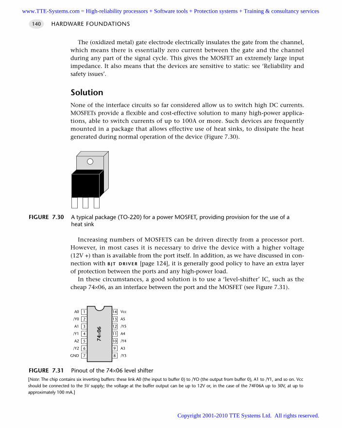
HARDWARE FOUNDATIONS140
The (oxidized metal) gate electrode electrically insulates the gate from the channel,which means there is essentially zero current between the gate and the channelduring any part of the signal cycle. This gives the MOSFET an extremely large inputimpedance. It also means that the devices are sensitive to static: see ‘Reliability andsafety issues’.
SolutionNone of the interface circuits so far considered allow us to switch high DC currents.MOSFETs provide a flexible and cost-effective solution to many high-power applica-tions, able to switch currents of up to 100A or more. Such devices are frequentlymounted in a package that allows effective use of heat sinks, to dissipate the heatgenerated during normal operation of the device (Figure 7.30).
Increasing numbers of MOSFETS can be driven directly from a processor port.However, in most cases it is necessary to drive the device with a higher voltage(12V +) than is available from the port itself. In addition, as we have discussed in con-nection with B J T D R I V E R [page 124], it is generally good policy to have an extra layerof protection between the ports and any high-power load.
In these circumstances, a good solution is to use a ‘level-shifter’ IC, such as thecheap 74×06, as an interface between the port and the MOSFET (see Figure 7.31).
FIGURE 7.30 A typical package (TO-220) for a power MOSFET, providing provision for the use of a heat sink
FIGURE 7.31 Pinout of the 74×06 level shifter[Note: The chip contains six inverting buffers: these link A0 (the input to buffer 0) to /YO (the output from buffer 0), A1 to /Y1, and so on. Vccshould be connected to the 5V supply; the voltage at the buffer output can be up to 12V or, in the case of the 74F06A up to 30V, at up toapproximately 100 mA.]
A0
/Y0
A1
/Y1
A2
/Y2
GND 7
6
5
4
3
2
1
8
9
10
11
12
13
14 Vcc
A5
/Y5
A4
/Y4
A3
/Y3
74×0
6
www.TTE-Systems.com = High-reliability processors + Software tools + Protection systems + Training & consultancy services
Copyright 2001-2010 TTE Systems Ltd. All rights reserved.
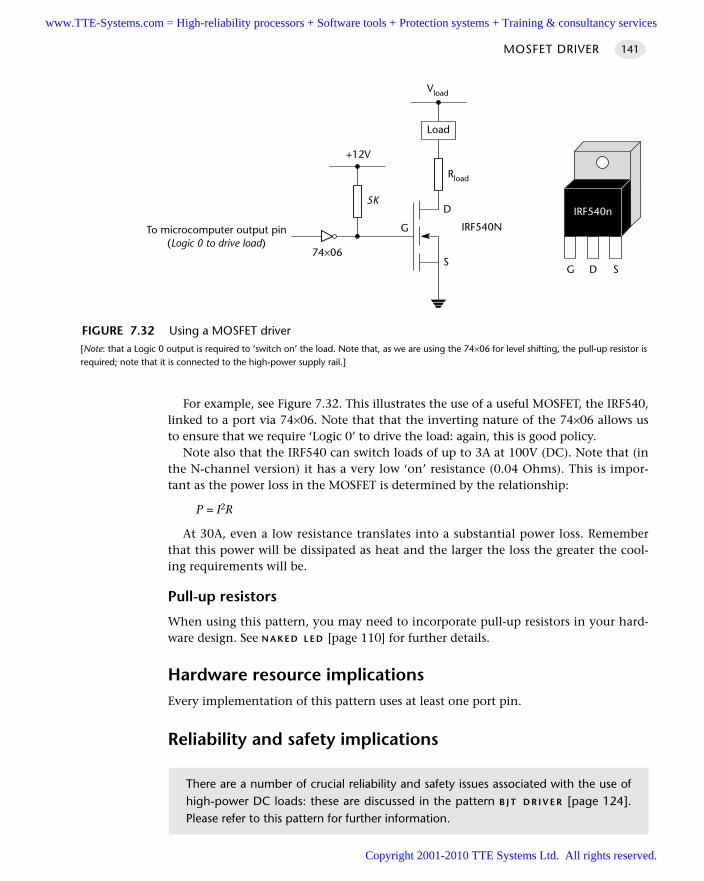
For example, see Figure 7.32. This illustrates the use of a useful MOSFET, the IRF540,linked to a port via 74×06. Note that that the inverting nature of the 74×06 allows usto ensure that we require ‘Logic 0’ to drive the load: again, this is good policy.
Note also that the IRF540 can switch loads of up to 3A at 100V (DC). Note that (inthe N-channel version) it has a very low ‘on’ resistance (0.04 Ohms). This is impor-tant as the power loss in the MOSFET is determined by the relationship:
P = I2R
At 30A, even a low resistance translates into a substantial power loss. Rememberthat this power will be dissipated as heat and the larger the loss the greater the cool-ing requirements will be.
Pull-up resistors
When using this pattern, you may need to incorporate pull-up resistors in your hard-ware design. See N A K E D L E D [page 110] for further details.
Hardware resource implicationsEvery implementation of this pattern uses at least one port pin.
Reliability and safety implications
MOSFET DRIVER 141
FIGURE 7.32 Using a MOSFET driver[Note: that a Logic 0 output is required to ‘switch on’ the load. Note that, as we are using the 74×06 for level shifting, the pull-up resistor isrequired; note that it is connected to the high-power supply rail.]
G
D
S
To microcomputer output pin(Logic 0 to drive load)
+12V
Load
Rload
Vload
5K
G D S
IRF540n
74×06
IRF540N
There are a number of crucial reliability and safety issues associated with the use ofhigh-power DC loads: these are discussed in the pattern B J T D R I V E R [page 124].Please refer to this pattern for further information.
www.TTE-Systems.com = High-reliability processors + Software tools + Protection systems + Training & consultancy services
Copyright 2001-2010 TTE Systems Ltd. All rights reserved.
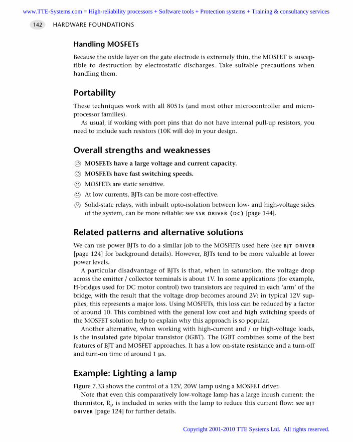
HARDWARE FOUNDATIONS142
Handling MOSFETs
Because the oxide layer on the gate electrode is extremely thin, the MOSFET is suscep-tible to destruction by electrostatic discharges. Take suitable precautions whenhandling them.
PortabilityThese techniques work with all 8051s (and most other microcontroller and micro-processor families).
As usual, if working with port pins that do not have internal pull-up resistors, youneed to include such resistors (10K will do) in your design.
Overall strengths and weaknessesMOSFETs have a large voltage and current capacity.
MOSFETs have fast switching speeds.
MOSFETs are static sensitive.
At low currents, BJTs can be more cost-effective.
Solid-state relays, with inbuilt opto-isolation between low- and high-voltage sidesof the system, can be more reliable: see S S R D R I V E R (D C) [page 144].
Related patterns and alternative solutionsWe can use power BJTs to do a similar job to the MOSFETs used here (see B J T D R I V E R
[page 124] for background details). However, BJTs tend to be more valuable at lowerpower levels.
A particular disadvantage of BJTs is that, when in saturation, the voltage dropacross the emitter / collector terminals is about 1V. In some applications (for example,H-bridges used for DC motor control) two transistors are required in each ‘arm’ of thebridge, with the result that the voltage drop becomes around 2V: in typical 12V sup-plies, this represents a major loss. Using MOSFETs, this loss can be reduced by a factorof around 10. This combined with the general low cost and high switching speeds ofthe MOSFET solution help to explain why this approach is so popular.
Another alternative, when working with high-current and / or high-voltage loads,is the insulated gate bipolar transistor (IGBT). The IGBT combines some of the bestfeatures of BJT and MOSFET approaches. It has a low on-state resistance and a turn-offand turn-on time of around 1 µs.
Example: Lighting a lampFigure 7.33 shows the control of a 12V, 20W lamp using a MOSFET driver.
Note that even this comparatively low-voltage lamp has a large inrush current: thethermistor, Rt, is included in series with the lamp to reduce this current flow: see B J T
D R I V E R [page 124] for further details.
www.TTE-Systems.com = High-reliability processors + Software tools + Protection systems + Training & consultancy services
Copyright 2001-2010 TTE Systems Ltd. All rights reserved.
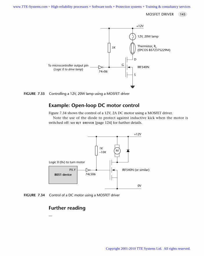
Example: Open-loop DC motor controlFigure 7.34 shows the control of a 12V, 2A DC motor using a MOSFET driver.
Note the use of the diode to protect against inductive kick when the motor isswitched off: see B J T D R I V E R [page 124] for further details.
Further reading—
MOSFET DRIVER 143
FIGURE 7.33 Controlling a 12V, 20W lamp using a MOSFET driver
G
D
S
To microcontroller output pin(Logic 0 to drive lamp)
5K
12V, 20W lamp
Thermistor, Rt(EPCOS B57237S229M)
+12V
74×06IRF540N
FIGURE 7.34 Control of a DC motor using a MOSFET driver
1K–10K
+12V
74LS06IRF540N (or similar)
M
0V
8051 device
PX.Y
Logic 0 (0v) to turn motor
www.TTE-Systems.com = High-reliability processors + Software tools + Protection systems + Training & consultancy services
Copyright 2001-2010 TTE Systems Ltd. All rights reserved.
HARDWARE FOUNDATIONS144
SSR DRIVER (DC)
Context You are developing an embedded application using one or more members of the
8051 family of microcontrollers.
You are designing an appropriate hardware foundation for your application.
ProblemHow do you ‘switch on’ or ‘switch off’ a piece of high-voltage (DC) electrical equip-ment using a microcontroller?
BackgroundA solid-state relay is a semiconductor device that was designed to take the place of aconventional electromagnetic (EM) relay. We do not recommend the use of EM relaysfor switching DC loads and therefore do not consider EM relays until we discuss theswitching of AC loads in Chapter 8. If you are unfamiliar with EM relays, you mayfind it useful to refer to Chapter 8 (and specifically to E M R D R I V E R [page 149]) forbackground information on EM relays before considering this pattern.
SolutionUnlike EM relays, solid-state relays (SSRs) are purely electronic in nature: they haveno moving (mechanical) switch contacts. Both DC and AC solid-state relays are avail-able: note that, unlike EM relays, a DC relay will not switch AC supplies and a DCrelay will not switch AC supplies: we explain why this is the case later in the pattern.
SSRs provide very high levels of isolation between the ‘control’ and ‘switching’ cir-cuits by optical techniques. The ‘control’ inputs will be connected to one (or more)LEDs. These will then, without any electrical link, control a phototransistor or photo-diode array, which will, in turn, connect to further switching circuitry. In the case of aDC SSR, the switching circuit will typically be based on a MOSFET, and the current-and voltage-switching capabilities will generally be similar to MOSFETs.
Use of SSRs is generally straightforward: the inputs are directly compatible withmicrocontroller port voltages, and – because of the built-in opto-isolation – there isgenerally no need to add additional gates between the microcontroller and the SSR.
The examples below will illustrate the use of these devices.
www.TTE-Systems.com = High-reliability processors + Software tools + Protection systems + Training & consultancy services
Copyright 2001-2010 TTE Systems Ltd. All rights reserved.
SSR DRIVER (DC) 145
Pull-up resistors
When using this pattern, you may need to incorporate pull-up resistors in your hard-ware design, at the input to the SSR. See N A K E D L E D [page 110] for further details.
Hardware resource implicationsEvery implementation of this pattern uses at least one port pin.
Reliability and safety issues
How robust are SSRs?
SSRs are less electrically robust than EM relays: in the presence of excessive voltages(due to back EMF from inductive loads, for example) or where the SSR is subjected tolarger currents (possibly due to ‘inrush’), the device will fail. If in doubt, over rate thedevice: that is, use a 300 V device where a 200 V device would probably do.
One other issue: we have seen people try to use more than one SSR in parallel inorder to increase the current rating. This will only rarely work and is never reliable.The problem is that you have no way of ensuring that both relays switch on atexactly the same time. When one relay has turned on, the supply voltage drop willusually mean that the second (and subsequent) SSRs do not turn on – until the firstrelay fails. Thus, the likely result is that, within around a millisecond, all the relayswill blow, in rapid succession.
What’s in a name?
Despite the name, there are important differences between ‘solid-state’ and ‘electro-mechanical’ relays, particularly when it comes to circuit testing. If you are using an EMrelay, you can check to make sure that the contacts are closing by using a multimeterto measure the resistance of the switch contacts: this resistance will be essentially zerowhen the contacts are closed and essentially infinite when they are open. This behav-iour will be observed without connecting up the high-voltage side of the application.
You cannot test an SSR-based circuit in the same manner: most SSRs will always showan infinite resistance when measured with a multimeter. To test an SSR, you need tooperate close to the specified operating voltage. Initial tests are therefore best performed(carefully) using a high-voltage load (we usually use an ordinary household lightbulb).
What happens when it goes wrong?
The typical failure mode of an SSR is an output short circuit: this can be dangerous.
There are a number of general reliability and safety issues associated with the use ofhigh-power DC loads: these are discussed in the pattern B J T D R I V E R [page 124].Please refer to this pattern for further information.
www.TTE-Systems.com = High-reliability processors + Software tools + Protection systems + Training & consultancy services
Copyright 2001-2010 TTE Systems Ltd. All rights reserved.
HARDWARE FOUNDATIONS146
PortabilitySSRs can be used with any processor type. However, there are other portability issuesto consider.
The most important (already briefly mentioned) is that an AC SSR cannot be usedto switch DC. The reason for this is that the AC SSR contains zero-crossing detectioncircuits (see Chapter 8 for details). Because the DC supply never crosses zero, the SSRwill never switch on.
Similarly, most DC SSRs are based on MOSFETs. Using a MOSFET to switch ACis ineffective: at best, the device will act as a form of rectifier for a short period, untilit overheats.
Overall strengths and weaknessesSSRs do not wear out (in normal use).
SSRs are resistant to shock and vibration.
SSRs have a high switching speed.
SSRs have high levels of isolation between the ‘control’ and ‘switching’ circuits.
SSRs generate only very low levels of electrical noise and generate noacoustic noise.
SSRs do not exhibit switch bounce.
SSRs can be instantly and irrevocably damaged by excessive voltage and /or current.
The typical failure mode of an SSR is an output short circuit: this can bedangerous.
The ‘switched’ side has a minimum operating voltage and current: these may bequite high, complicating initial testing.
EM relays can usually switch higher voltages and currents.
Unlike an EM relay, the ‘switched’ side exhibits some leakage current in theoff-state.
The ‘on’ resistance is typically much larger than that of an EM relays: this trans-lates directly into wasted heat and, hence, the need for heatsinks.
Related patterns and alternative solutionsSee the other patterns in this chapter and Chapter 8, for alternative approaches.
Example: SSRs in telecommunication applicationsSmall DC semiconductor relays are commonly used in telecommunications equip-ment, such as modems, in place of larger EM relays. Indeed, the telecoms market is soimportant that special-purpose SSRs, intended to be used for telephone current linesensing, are also available (see, for example, products from Erg components).
www.TTE-Systems.com = High-reliability processors + Software tools + Protection systems + Training & consultancy services
Copyright 2001-2010 TTE Systems Ltd. All rights reserved.
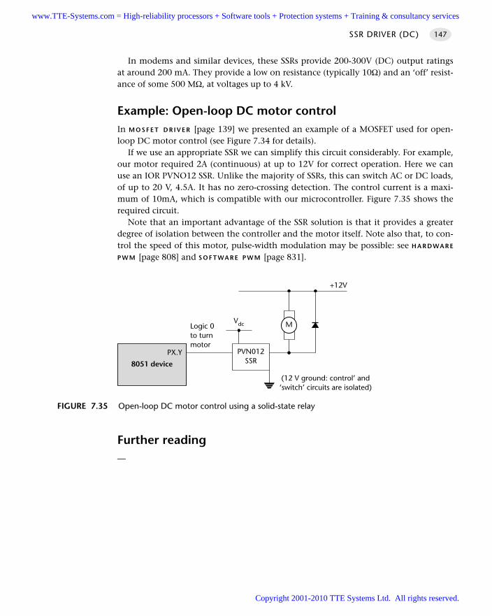
In modems and similar devices, these SSRs provide 200-300V (DC) output ratingsat around 200 mA. They provide a low on resistance (typically 10Ω) and an ‘off’ resist-ance of some 500 MΩ, at voltages up to 4 kV.
Example: Open-loop DC motor controlIn M O S F E T D R I V E R [page 139] we presented an example of a MOSFET used for open-loop DC motor control (see Figure 7.34 for details).
If we use an appropriate SSR we can simplify this circuit considerably. For example,our motor required 2A (continuous) at up to 12V for correct operation. Here we canuse an IOR PVNO12 SSR. Unlike the majority of SSRs, this can switch AC or DC loads,of up to 20 V, 4.5A. It has no zero-crossing detection. The control current is a maxi-mum of 10mA, which is compatible with our microcontroller. Figure 7.35 shows therequired circuit.
Note that an important advantage of the SSR solution is that it provides a greaterdegree of isolation between the controller and the motor itself. Note also that, to con-trol the speed of this motor, pulse-width modulation may be possible: see H A R D WA R E
P W M [page 808] and S O F T WA R E P W M [page 831].
Further reading—
SSR DRIVER (DC) 147
FIGURE 7.35 Open-loop DC motor control using a solid-state relay
+12V
M
8051 device
PX.Y
Logic 0to turnmotor
PVN012SSR
Vdc
(12 V ground: control’ and‘switch’ circuits are isolated)
www.TTE-Systems.com = High-reliability processors + Software tools + Protection systems + Training & consultancy services
Copyright 2001-2010 TTE Systems Ltd. All rights reserved.
Driving AC loads
Introduction
Consider some problems:
A pump in a domestic or industrial heating system must be switched on and off atpreset times.
A series of high-intensity lights around the perimeter of a factory complex are to beactivated in the event of a security incident.
An electrical heater in a brewery must be used to maintain a precise temperature.
The motor in a washing machine must go through a pre-programmed series ofmovements.
In these – and many other applications – we need safely and reliably to controlcomparatively high-level AC supplies. In this chapter we will consider two popularapproaches to this problem
E M R D R I V E R [page 149]
S S R D R I V E R (A C) [page 156]
chapter 8www.TTE-Systems.com = High-reliability processors + Software tools + Protection systems + Training & consultancy services
Copyright 2001-2010 TTE Systems Ltd. All rights reserved.
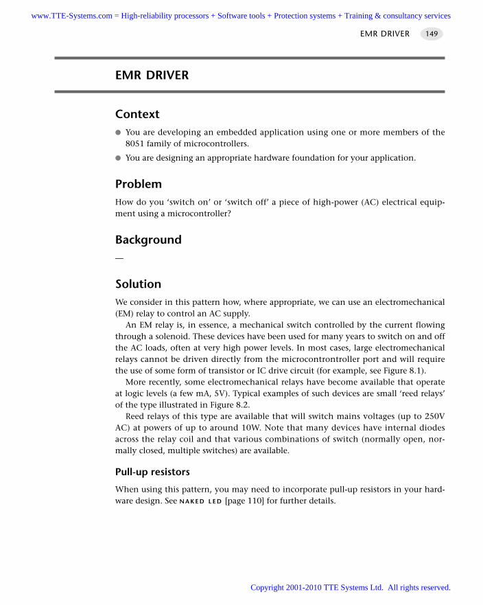
EMR DRIVER 149
EMR DRIVER
Context You are developing an embedded application using one or more members of the
8051 family of microcontrollers.
You are designing an appropriate hardware foundation for your application.
ProblemHow do you ‘switch on’ or ‘switch off’ a piece of high-power (AC) electrical equip-ment using a microcontroller?
Background—
SolutionWe consider in this pattern how, where appropriate, we can use an electromechanical(EM) relay to control an AC supply.
An EM relay is, in essence, a mechanical switch controlled by the current flowingthrough a solenoid. These devices have been used for many years to switch on and offthe AC loads, often at very high power levels. In most cases, large electromechanicalrelays cannot be driven directly from the microcontrontroller port and will requirethe use of some form of transistor or IC drive circuit (for example, see Figure 8.1).
More recently, some electromechanical relays have become available that operateat logic levels (a few mA, 5V). Typical examples of such devices are small ‘reed relays’of the type illustrated in Figure 8.2.
Reed relays of this type are available that will switch mains voltages (up to 250VAC) at powers of up to around 10W. Note that many devices have internal diodesacross the relay coil and that various combinations of switch (normally open, nor-mally closed, multiple switches) are available.
Pull-up resistors
When using this pattern, you may need to incorporate pull-up resistors in your hard-ware design. See N A K E D L E D [page 110] for further details.
www.TTE-Systems.com = High-reliability processors + Software tools + Protection systems + Training & consultancy services
Copyright 2001-2010 TTE Systems Ltd. All rights reserved.
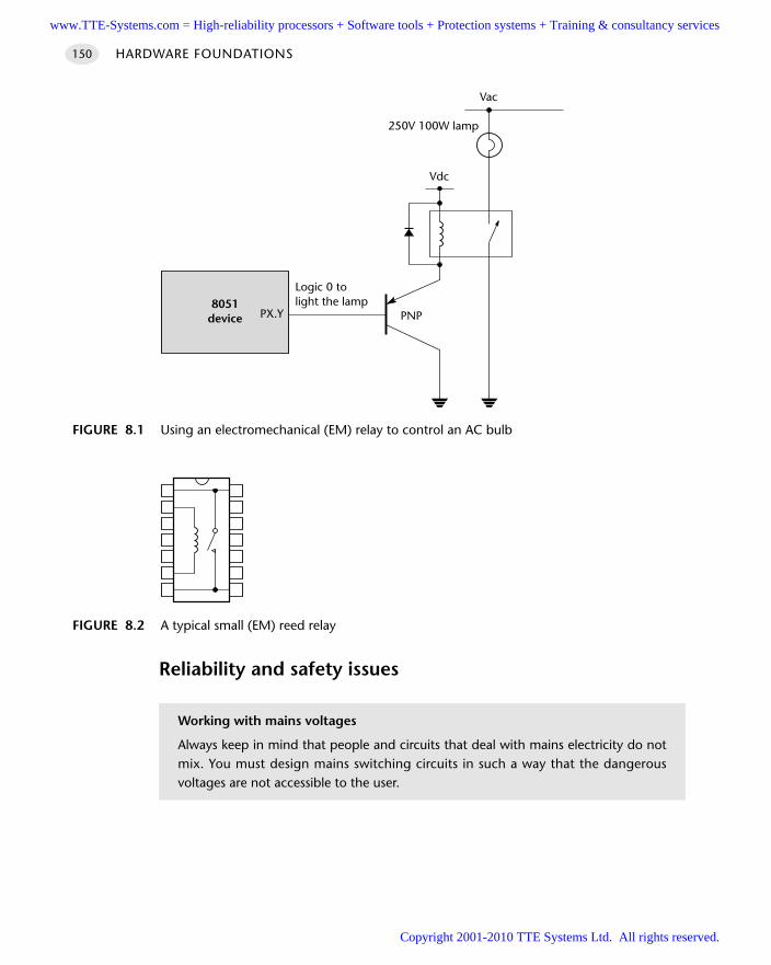
HARDWARE FOUNDATIONS150
Reliability and safety issues
FIGURE 8.1 Using an electromechanical (EM) relay to control an AC bulb
Logic 0 tolight the lamp8051
device PX.Y
Vdc
PNP
Vac
250V 100W lamp
FIGURE 8.2 A typical small (EM) reed relay
Working with mains voltages
Always keep in mind that people and circuits that deal with mains electricity do notmix. You must design mains switching circuits in such a way that the dangerousvoltages are not accessible to the user.
www.TTE-Systems.com = High-reliability processors + Software tools + Protection systems + Training & consultancy services
Copyright 2001-2010 TTE Systems Ltd. All rights reserved.
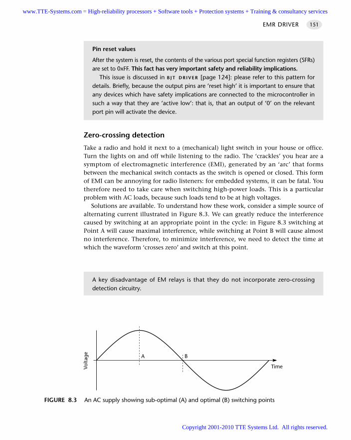
EMR DRIVER 151
Zero-crossing detection
Take a radio and hold it next to a (mechanical) light switch in your house or office.Turn the lights on and off while listening to the radio. The ‘crackles’ you hear are asymptom of electromagnetic interference (EMI), generated by an ‘arc’ that formsbetween the mechanical switch contacts as the switch is opened or closed. This formof EMI can be annoying for radio listeners: for embedded systems, it can be fatal. Youtherefore need to take care when switching high-power loads. This is a particularproblem with AC loads, because such loads tend to be at high voltages.
Solutions are available. To understand how these work, consider a simple source ofalternating current illustrated in Figure 8.3. We can greatly reduce the interferencecaused by switching at an appropriate point in the cycle: in Figure 8.3 switching atPoint A will cause maximal interference, while switching at Point B will cause almostno interference. Therefore, to minimize interference, we need to detect the time atwhich the waveform ‘crosses zero’ and switch at this point.
Pin reset values
After the system is reset, the contents of the various port special function registers (SFRs)are set to 0xFF. This fact has very important safety and reliability implications.
This issue is discussed in B J T D R I V E R [page 124]: please refer to this pattern fordetails. Briefly, because the output pins are ‘reset high’ it is important to ensure thatany devices which have safety implications are connected to the microcontroller insuch a way that they are ‘active low’: that is, that an output of ‘0’ on the relevantport pin will activate the device.
FIGURE 8.3 An AC supply showing sub-optimal (A) and optimal (B) switching points
BA
Volta
ge
Time
A key disadvantage of EM relays is that they do not incorporate zero-crossing detection circuitry.
www.TTE-Systems.com = High-reliability processors + Software tools + Protection systems + Training & consultancy services
Copyright 2001-2010 TTE Systems Ltd. All rights reserved.
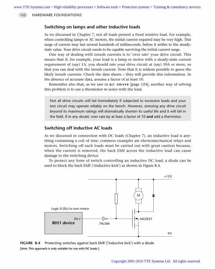
Switching on lamps and other inductive loads
As we discussed in Chapter 7, not all loads present a fixed resistive load. For example,when controlling lamps or AC motors, the initial current required may be very high. Thissurge of current may last several hundreds of milliseconds, before it settles to the steady-state value. Your drive circuit needs to be capable surviving the initial current surge.
One way of dealing with inrush currents is to ‘over rate’ your drive circuit. Thismeans that if, for example, your load is a lamp or motor with a steady-state currentrequirement of (say) 1A, you should rate your drive circuit at (say) 10A or more, sothat you can deal with the inrush current. Note that it is seldom possible to guess thelikely inrush currents. Check the data sheets – they will provide this information. Inthe absence of accurate data, assume a factor of at least 10.
Remember also that, as we saw in B J T D R I V E R [page 124], another way of solvingthis problem is to use a thermistor in series with the load.
Switching off inductive AC loads
As we discussed in connection with DC loads (Chapter 7), an inductive load is any-thing containing a coil of wire: common examples are electromechanical relays andmotors. Switching off such loads must be carried out with great caution because,when the current is removed, the back EMF across the inductive load can causedamage to the switching device.
To protect any form of switch controlling an inductive DC load, a diode can beused to block the back EMF (‘inductive kick’) as shown in Figure 8.4.
HARDWARE FOUNDATIONS152
Not all drive circuits will fail immediately if subjected to excessive loads and yourtest circuit may operate reliably on the bench. However, stressing any drive circuitbeyond its maximum ratings will dramatically shorten its useful life and it will fail inthe field. If in any doubt: over rate by at least a factor of 10 and add a thermistor.
FIGURE 8.4 Protecting switches against back EMF (‘inductive kick’) with a diode[Note: This approach is only suitable for use with DC loads.]
8051 device
Logic 0 (0v) to turn motor
PX.Y
M
+12V
MOSFET74LS06
0V
www.TTE-Systems.com = High-reliability processors + Software tools + Protection systems + Training & consultancy services
Copyright 2001-2010 TTE Systems Ltd. All rights reserved.
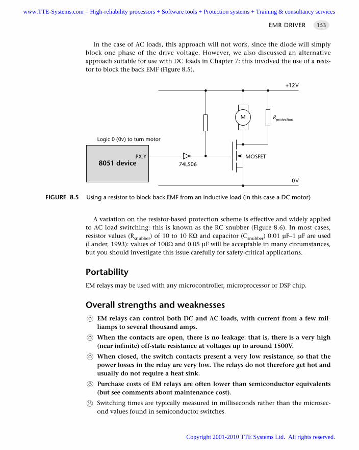
In the case of AC loads, this approach will not work, since the diode will simplyblock one phase of the drive voltage. However, we also discussed an alternativeapproach suitable for use with DC loads in Chapter 7: this involved the use of a resis-tor to block the back EMF (Figure 8.5).
A variation on the resistor-based protection scheme is effective and widely appliedto AC load switching: this is known as the RC snubber (Figure 8.6). In most cases,resistor values (Rsnubber) of 10 to 10 KΩ and capacitor (Csnubber) 0.01 µF–1 µF are used(Lander, 1993): values of 100Ω and 0.05 µF will be acceptable in many circumstances,but you should investigate this issue carefully for safety-critical applications.
PortabilityEM relays may be used with any microcontroller, microprocessor or DSP chip.
Overall strengths and weaknessesEM relays can control both DC and AC loads, with current from a few mil-liamps to several thousand amps.
When the contacts are open, there is no leakage: that is, there is a very high(near infinite) off-state resistance at voltages up to around 1500V.
When closed, the switch contacts present a very low resistance, so that thepower losses in the relay are very low. The relays do not therefore get hot andusually do not require a heat sink.
Purchase costs of EM relays are often lower than semiconductor equivalents(but see comments about maintenance cost).
Switching times are typically measured in milliseconds rather than the microsec-ond values found in semiconductor switches.
EMR DRIVER 153
FIGURE 8.5 Using a resistor to block back EMF from an inductive load (in this case a DC motor)
8051 device
Logic 0 (0v) to turn motor
PX.Y
M
+12V
MOSFET74LS06
0V
Rprotection
www.TTE-Systems.com = High-reliability processors + Software tools + Protection systems + Training & consultancy services
Copyright 2001-2010 TTE Systems Ltd. All rights reserved.
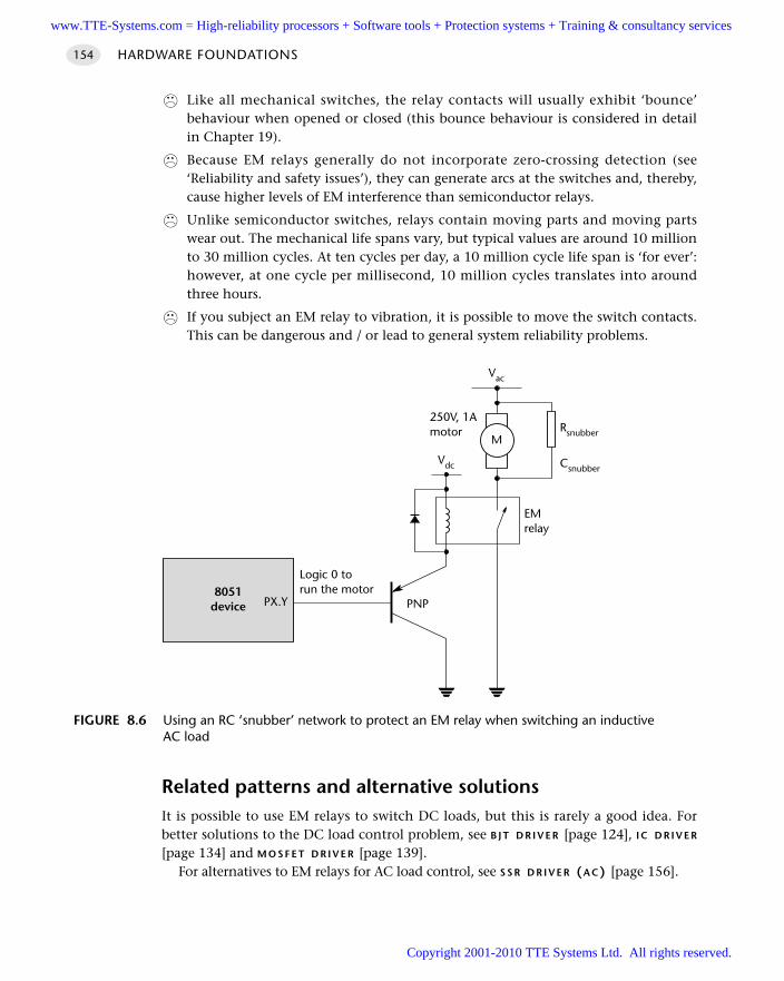
Like all mechanical switches, the relay contacts will usually exhibit ‘bounce’behaviour when opened or closed (this bounce behaviour is considered in detailin Chapter 19).
Because EM relays generally do not incorporate zero-crossing detection (see‘Reliability and safety issues’), they can generate arcs at the switches and, thereby,cause higher levels of EM interference than semiconductor relays.
Unlike semiconductor switches, relays contain moving parts and moving partswear out. The mechanical life spans vary, but typical values are around 10 millionto 30 million cycles. At ten cycles per day, a 10 million cycle life span is ‘for ever’:however, at one cycle per millisecond, 10 million cycles translates into aroundthree hours.
If you subject an EM relay to vibration, it is possible to move the switch contacts.This can be dangerous and / or lead to general system reliability problems.
Related patterns and alternative solutionsIt is possible to use EM relays to switch DC loads, but this is rarely a good idea. Forbetter solutions to the DC load control problem, see B J T D R I V E R [page 124], I C D R I V E R
[page 134] and M O S F E T D R I V E R [page 139].For alternatives to EM relays for AC load control, see S S R D R I V E R (A C) [page 156].
HARDWARE FOUNDATIONS154
FIGURE 8.6 Using an RC ‘snubber’ network to protect an EM relay when switching an inductiveAC load
Logic 0 torun the motor8051
device PX.Y
Vdc
PNP
Vac
250V, 1Amotor
EMrelay
MRsnubber
Csnubber
www.TTE-Systems.com = High-reliability processors + Software tools + Protection systems + Training & consultancy services
Copyright 2001-2010 TTE Systems Ltd. All rights reserved.
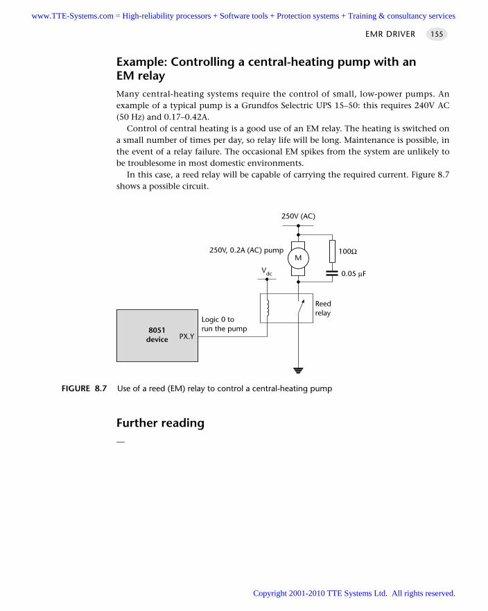
Example: Controlling a central-heating pump with an EM relayMany central-heating systems require the control of small, low-power pumps. Anexample of a typical pump is a Grundfos Selectric UPS 15–50: this requires 240V AC(50 Hz) and 0.17–0.42A.
Control of central heating is a good use of an EM relay. The heating is switched ona small number of times per day, so relay life will be long. Maintenance is possible, inthe event of a relay failure. The occasional EM spikes from the system are unlikely tobe troublesome in most domestic environments.
In this case, a reed relay will be capable of carrying the required current. Figure 8.7shows a possible circuit.
Further reading—
EMR DRIVER 155
FIGURE 8.7 Use of a reed (EM) relay to control a central-heating pump
Logic 0 torun the pump8051
device PX.Y
Vdc
250V (AC)
250V, 0.2A (AC) pump
Reedrelay
M100Ω
0.05 µF
www.TTE-Systems.com = High-reliability processors + Software tools + Protection systems + Training & consultancy services
Copyright 2001-2010 TTE Systems Ltd. All rights reserved.
HARDWARE FOUNDATIONS156
SSR DRIVER (AC)
Context You are developing an embedded application using one or more members of the
8051 family of microcontrollers.
You are designing an appropriate hardware foundation for your application.
ProblemHow do you ‘switch on’ or ‘switch off’ a piece of mains-powered (AC) electrical equip-ment using a microcontroller?
BackgroundWe introduce DC SSRs in S S R D R I V E R ( D C ) [page 144]. Please refer to the previouspattern for general background information on SSRs.
The main differences between the two devices is that, while in DC SSRs, the outputstage typically consists of a MOSFET, in AC SSRs, the output stage is usually a TRIAC.Very briefly, a TRIAC is a semiconductor switch that allows current to flow in bothdirections: this is, of course, precisely what we require with AC loads.
SolutionUse of SSRs is generally straightforward: the inputs are directly compatible withmicrocontroller port values, and – because of the built-in opto-isolation – there is gen-erally no need to add additional gates between the microcontroller and the SSR. Theexamples that follow will illustrate the use of these devices.
Pull-up resistors
When using this pattern, you may need to incorporate pull-up resistors in your hard-ware design. See N A K E D L E D [page 110] for further details.
Reliability and safety issuesSee the start of this chapter for general reliability and safety issues.
See also S S R D R I V E R (D C) [page 144] for basic SSR guidelines.A key difference between AC and DC SSRs is that, while MOSFETs have very low
losses, the TRIAC output stages used in AC SSRs typically have a voltage drop of up to1.5V when they conduct: this translates directly into a power loss of up to 1.5W perAmpere of current. If using a high-power device (greater than around 4A), you willrequire a heat sink.
www.TTE-Systems.com = High-reliability processors + Software tools + Protection systems + Training & consultancy services
Copyright 2001-2010 TTE Systems Ltd. All rights reserved.
PortabilitySSRs can be used with any processor type. However, there are other portability issuesto consider.
The most important (already briefly mentioned) is that an AC SSR cannot be usedto switch DC. The reason for this is that the AC SSR contains zero-crossing detectioncircuits. Because the DC supply never crosses zero, the SSR will never switch on.
Similarly, most DC SSRs are based on MOSFETs. Using a MOSFET to switch ACis ineffective: at best, the device will act as a form of rectifier for a short period, untilit overheats.
Overall strengths and weaknessesSSRs do not exhibit switch bounce.
SSRs do not wear out (in normal use).
SSRs do not generate acoustic noise.
Many (AC) SSRs incorporate ‘zero-crossing detection’ circuits. This helps togreatly reduce EM emissions.
SSRs are resistant to shock and vibration.
SSRs have a high switching speed.
SSRs have high levels of isolation between the ‘control’ and ‘switching’ circuits.
EM relays can usually switch higher voltages and currents.
The on-resistance of AC SSRs is much larger than EM relays. This means extraheat is generated and you must plan for a heat sink or other forms of cooling.
Unlike an EM relay, the ‘switch’ in the AC SSR (usually a TRIAC) exhibits someleakage current in the off-state.
Most AC SSRs will not switch DC, partly because of the zero-crossing detection.
SSRs can be irrevocably damaged almost instantly by excessive voltage and / orcurrent: EM relays are more forgiving.
The typical failure mode of an SSR is an output short circuit: this can bedangerous.
The ‘switched’ side has a minimum operating voltage and current: these maybe quite high, which can make it more difficult to perform initial tests onsmall-scale prototypes.
SSR DRIVER (AC) 157
When you fit a heat sink, keep it isolated from the case of your application. Neverbolt it to the chassis: this can have deadly consequences.
www.TTE-Systems.com = High-reliability processors + Software tools + Protection systems + Training & consultancy services
Copyright 2001-2010 TTE Systems Ltd. All rights reserved.
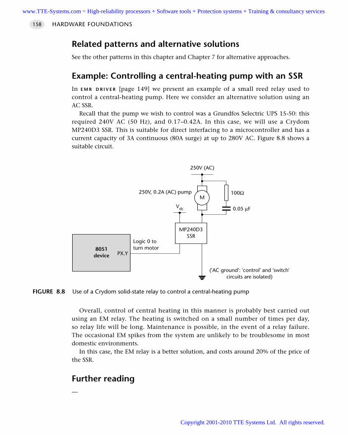
Related patterns and alternative solutionsSee the other patterns in this chapter and Chapter 7 for alternative approaches.
Example: Controlling a central-heating pump with an SSRIn E M R D R I V E R [page 149] we present an example of a small reed relay used tocontrol a central-heating pump. Here we consider an alternative solution using anAC SSR.
Recall that the pump we wish to control was a Grundfos Selectric UPS 15-50: thisrequired 240V AC (50 Hz), and 0.17–0.42A. In this case, we will use a CrydomMP240D3 SSR. This is suitable for direct interfacing to a microcontroller and has acurrent capacity of 3A continuous (80A surge) at up to 280V AC. Figure 8.8 shows asuitable circuit.
Overall, control of central heating in this manner is probably best carried outusing an EM relay. The heating is switched on a small number of times per day,so relay life will be long. Maintenance is possible, in the event of a relay failure.The occasional EM spikes from the system are unlikely to be troublesome in mostdomestic environments.
In this case, the EM relay is a better solution, and costs around 20% of the price ofthe SSR.
Further reading—
HARDWARE FOUNDATIONS158
FIGURE 8.8 Use of a Crydom solid-state relay to control a central-heating pump
Logic 0 toturn motor8051
device PX.Y
Vdc
250V (AC)
250V, 0.2A (AC) pumpM
100Ω
0.05 µF
MP240D3SSR
('AC ground': 'control' and 'switch'circuits are isolated)
www.TTE-Systems.com = High-reliability processors + Software tools + Protection systems + Training & consultancy services
Copyright 2001-2010 TTE Systems Ltd. All rights reserved.
Software foundations
The chapters in Part A focused on the development of an appropriate hardware
environment to meet the needs of your embedded application. In Part B, we consider the
corresponding software foundation.
In Chapter 9, we describe the minimum software environment required to create an
embedded application.
In Chapter 10, we consider software techniques suitable for use with the AC and DC
driver hardware discussed in Chapters 7 and 8.
In Chapter 11, we explore software- and hardware-based techniques for producing delays.
In Chapter 12, we look at the topic of watchdogs timers and consider how these may be
used to improve the reliability of your application.
part bwww.TTE-Systems.com = High-reliability processors + Software tools + Protection systems + Training & consultancy services
Copyright 2001-2010 TTE Systems Ltd. All rights reserved.

www.TTE-Systems.com = High-reliability processors + Software tools + Protection systems + Training & consultancy services
Copyright 2001-2010 TTE Systems Ltd. All rights reserved.
A rudimentary software
architecture
Introduction
In the first pattern in this chapter we consider the minimum software environmentrequired to create a typical embedded application: this environment is called S U P E R
L O O P [page 162].
The second pattern (P R O J E C T H E A D E R [page 169) is a practical implementation of astandard software design guideline: ‘Do not duplicate information in numerous files;place the common information in a single file and refer to it where necessary.’Specifically, P R O J E C T H E A D E R pulls together the information connected with the par-ticular microcontroller used in your application, along with other key pieces ofinformation that are required by many of the files in your project.
chapter9
Please note that we will use Super Loop in this book primarily to allow us to illus-trate some introductory software patterns in Chapters 10, 11 and 12. In Chapter 13we will demonstrate that a co-operative scheduler provides a more appropriateenvironment than a S U P E R L O O P for the great majority of embedded applications.
www.TTE-Systems.com = High-reliability processors + Software tools + Protection systems + Training & consultancy services
Copyright 2001-2010 TTE Systems Ltd. All rights reserved.
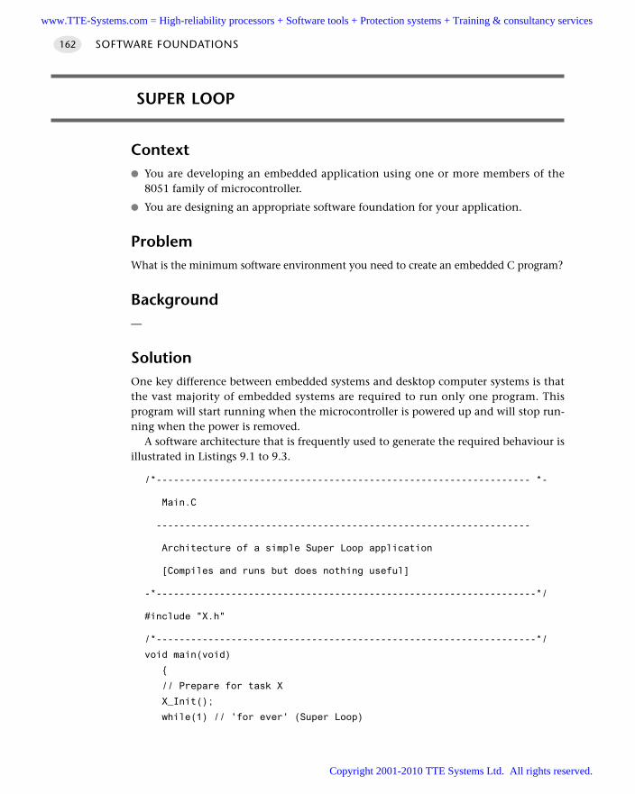
SUPER LOOP
Context You are developing an embedded application using one or more members of the
8051 family of microcontroller.
You are designing an appropriate software foundation for your application.
ProblemWhat is the minimum software environment you need to create an embedded C program?
Background—
SolutionOne key difference between embedded systems and desktop computer systems is thatthe vast majority of embedded systems are required to run only one program. Thisprogram will start running when the microcontroller is powered up and will stop run-ning when the power is removed.
A software architecture that is frequently used to generate the required behaviour isillustrated in Listings 9.1 to 9.3.
/*----------------------------------------------------------------- *-
Main.C
-----------------------------------------------------------------
Architecture of a simple Super Loop application
[Compiles and runs but does nothing useful]
-*------------------------------------------------------------------*/
#include "X.h"
/*------------------------------------------------------------------*/
void main(void)
// Prepare for task X
X_Init();
while(1) // 'for ever' (Super Loop)
SOFTWARE FOUNDATIONS162
www.TTE-Systems.com = High-reliability processors + Software tools + Protection systems + Training & consultancy services
Copyright 2001-2010 TTE Systems Ltd. All rights reserved.

X(); // Perform the task
/* -----------------------------------------------------------------*-
-------END OF FILE ---------------------------------------------
-*------------------------------------------------------------------*/
Listing 9.1 Part of a simple Super Loop demonstration
/*------------------------------------------------------------------*-
X.H
------------------------------------------------------------------
- see X.C for details.
-*------------------------------------------------------------------*/
// Function prototypes
void X_Init(void);
void X(void);
/*------------------------------------------------------------------*-
----- END OF FILE -----------------------------------------------
-*---------------------------------------------------------------*/
Listing 9.2 Part of a simple Super Loop demonstration
/*------------------------------------------------------------------*-
X.C
------------------------------------------------------------------
'Task' for a demonstration Super Loop application
[Compiles and runs but does nothing useful]
-*------------------------------------------------------------------*/
/*------------------------------------------------------------------*/
void X_Init(void)
// Prepare for task X
// User code here ...
/*------------------------------------------------------------------*/
SUPER LOOP 163
www.TTE-Systems.com = High-reliability processors + Software tools + Protection systems + Training & consultancy services
Copyright 2001-2010 TTE Systems Ltd. All rights reserved.
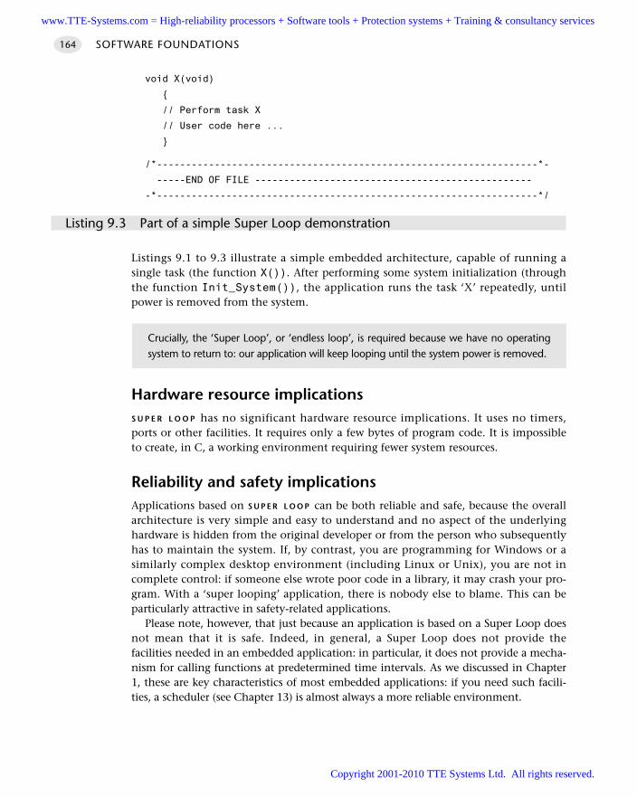
SOFTWARE FOUNDATIONS164
void X(void)
// Perform task X
// User code here ...
/*------------------------------------------------------------------*-
-----END OF FILE ------------------------------------------------
-*------------------------------------------------------------------*/
Listing 9.3 Part of a simple Super Loop demonstration
Listings 9.1 to 9.3 illustrate a simple embedded architecture, capable of running asingle task (the function X()). After performing some system initialization (throughthe function Init_System()), the application runs the task ‘X’ repeatedly, untilpower is removed from the system.
Hardware resource implicationsS U P E R L O O P has no significant hardware resource implications. It uses no timers,ports or other facilities. It requires only a few bytes of program code. It is impossibleto create, in C, a working environment requiring fewer system resources.
Reliability and safety implicationsApplications based on S U P E R L O O P can be both reliable and safe, because the overallarchitecture is very simple and easy to understand and no aspect of the underlyinghardware is hidden from the original developer or from the person who subsequentlyhas to maintain the system. If, by contrast, you are programming for Windows or asimilarly complex desktop environment (including Linux or Unix), you are not incomplete control: if someone else wrote poor code in a library, it may crash your pro-gram. With a ‘super looping’ application, there is nobody else to blame. This can beparticularly attractive in safety-related applications.
Please note, however, that just because an application is based on a Super Loop doesnot mean that it is safe. Indeed, in general, a Super Loop does not provide thefacilities needed in an embedded application: in particular, it does not provide a mecha-nism for calling functions at predetermined time intervals. As we discussed in Chapter1, these are key characteristics of most embedded applications: if you need such facili-ties, a scheduler (see Chapter 13) is almost always a more reliable environment.
Crucially, the ‘Super Loop’, or ‘endless loop’, is required because we have no operatingsystem to return to: our application will keep looping until the system power is removed.
www.TTE-Systems.com = High-reliability processors + Software tools + Protection systems + Training & consultancy services
Copyright 2001-2010 TTE Systems Ltd. All rights reserved.
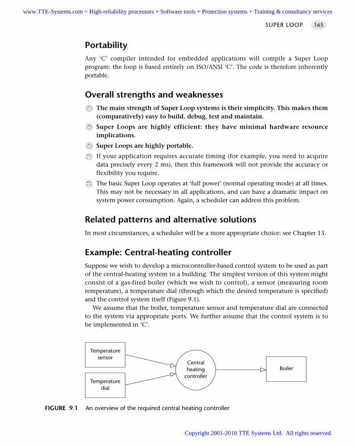
SUPER LOOP 165
PortabilityAny ‘C’ compiler intended for embedded applications will compile a Super Loopprogram: the loop is based entirely on ISO/ANSI ‘C’. The code is therefore inherentlyportable.
Overall strengths and weaknessesThe main strength of Super Loop systems is their simplicity. This makes them(comparatively) easy to build, debug, test and maintain.
Super Loops are highly efficient: they have minimal hardware resourceimplications.
Super Loops are highly portable.
If your application requires accurate timing (for example, you need to acquiredata precisely every 2 ms), then this framework will not provide the accuracy orflexibility you require.
The basic Super Loop operates at ‘full power’ (normal operating mode) at all times.This may not be necessary in all applications, and can have a dramatic impact onsystem power consumption. Again, a scheduler can address this problem.
Related patterns and alternative solutionsIn most circumstances, a scheduler will be a more appropriate choice: see Chapter 13.
Example: Central-heating controllerSuppose we wish to develop a microcontroller-based control system to be used as partof the central-heating system in a building. The simplest version of this system mightconsist of a gas-fired boiler (which we wish to control), a sensor (measuring roomtemperature), a temperature dial (through which the desired temperature is specified)and the control system itself (Figure 9.1).
We assume that the boiler, temperature sensor and temperature dial are connectedto the system via appropriate ports. We further assume that the control system is tobe implemented in ‘C’.
FIGURE 9.1 An overview of the required central heating controller
BoilerCentralheating
controllerTemperature
dial
Temperaturesensor
www.TTE-Systems.com = High-reliability processors + Software tools + Protection systems + Training & consultancy services
Copyright 2001-2010 TTE Systems Ltd. All rights reserved.
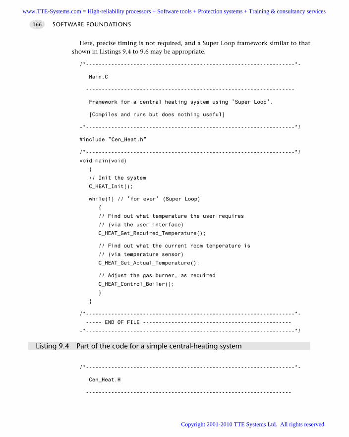
SOFTWARE FOUNDATIONS166
Here, precise timing is not required, and a Super Loop framework similar to thatshown in Listings 9.4 to 9.6 may be appropriate.
/*------------------------------------------------------------------*-
Main.C
------------------------------------------------------------------
Framework for a central heating system using 'Super Loop'.
[Compiles and runs but does nothing useful]
-*------------------------------------------------------------------*/
#include "Cen_Heat.h"
/*------------------------------------------------------------------*/
void main(void)
// Init the system
C_HEAT_Init();
while(1) // 'for ever' (Super Loop)
// Find out what temperature the user requires
// (via the user interface)
C_HEAT_Get_Required_Temperature();
// Find out what the current room temperature is
// (via temperature sensor)
C_HEAT_Get_Actual_Temperature();
// Adjust the gas burner, as required
C_HEAT_Control_Boiler();
/*------------------------------------------------------------------*-
----- END OF FILE -----------------------------------------------
-*------------------------------------------------------------------*/
Listing 9.4 Part of the code for a simple central-heating system
/*------------------------------------------------------------------*-
Cen_Heat.H
-----------------------------------------------------------------
www.TTE-Systems.com = High-reliability processors + Software tools + Protection systems + Training & consultancy services
Copyright 2001-2010 TTE Systems Ltd. All rights reserved.
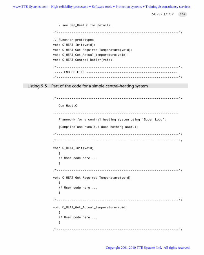
- see Cen_Heat.C for details.
-*------------------------------------------------------------------*/
// Function prototypes
void C_HEAT_Init(void);
void C_HEAT_Get_Required_Temperature(void);
void C_HEAT_Get_Actual_temperature(void);
void C_HEAT_Control_Boiler(void);
/*------------------------------------------------------------------*-
---- END OF FILE -------------------------------------------------
-*------------------------------------------------------------------*/
Listing 9.5 Part of the code for a simple central-heating system
/*------------------------------------------------------------------*-
Cen_Heat.C
--------------------------------------------------------------------
Framework for a central heating system using 'Super Loop'.
[Compiles and runs but does nothing useful]
-*------------------------------------------------------------------*/
/*------------------------------------------------------------------*/
void C_HEAT_Init(void)
// User code here ...
/*------------------------------------------------------------------*/
void C_HEAT_Get_Required_Temperature(void)
// User code here ...
/*------------------------------------------------------------------*/
void C_HEAT_Get_Actual_temperature(void)
// User code here ...
/*------------------------------------------------------------------*/
SUPER LOOP 167
www.TTE-Systems.com = High-reliability processors + Software tools + Protection systems + Training & consultancy services
Copyright 2001-2010 TTE Systems Ltd. All rights reserved.
void C_HEAT_Control_Boiler(void)
// User code here ...
/*------------------------------------------------------------------*-
-------- END OF FILE --------------------------------------------
-*------------------------------------------------------------------*/
Listing 9.6 Part of the code for a simple central-heating system
Further reading—
SOFTWARE FOUNDATIONS168
www.TTE-Systems.com = High-reliability processors + Software tools + Protection systems + Training & consultancy services
Copyright 2001-2010 TTE Systems Ltd. All rights reserved.
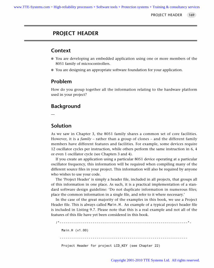
PROJECT HEADER 169
PROJECT HEADER
Context You are developing an embedded application using one or more members of the
8051 family of microcontrollers.
You are designing an appropriate software foundation for your application.
ProblemHow do you group together all the information relating to the hardware platformused in your project?
Background—
SolutionAs we saw in Chapter 3, the 8051 family shares a common set of core facilities.However, it is a family – rather than a group of clones – and the different familymembers have different features and facilities. For example, some devices require12 oscillator cycles per instruction, while others perform the same instruction in 6, 4or even 1 oscillator cycle (see Chapters 3 and 4).
If you create an application using a particular 8051 device operating at a particularoscillator frequency, this information will be required when compiling many of thedifferent source files in your project. This information will also be required by anyonewho wishes to use your code.
The ‘Project Header’ is simply a header file, included in all projects, that groups allof this information in one place. As such, it is a practical implementation of a stan-dard software design guideline: ‘Do not duplicate information in numerous files;place the common information in a single file, and refer to it where necessary.’
In the case of the great majority of the examples in this book, we use a ProjectHeader file. This is always called Main.H. An example of a typical project header fileis included in Listing 9.7. Please note that this is a real example and not all of thefeatures of this file have yet been considered in this book.
/*------------------------------------------------------------------*-
Main.H (v1.00)
------------------------------------------------------------------
Project Header for project LCD_KEY (see Chapter 22)
www.TTE-Systems.com = High-reliability processors + Software tools + Protection systems + Training & consultancy services
Copyright 2001-2010 TTE Systems Ltd. All rights reserved.
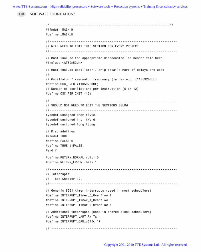
-*------------------------------------------------------------------*/
#ifndef _MAIN_H
#define _MAIN_H
//----------------------------------------------------------------------
// WILL NEED TO EDIT THIS SECTION FOR EVERY PROJECT
//----------------------------------------------------------------------
// Must include the appropriate microcontroller header file here
#include <AT89×52.h>
// Must include oscillator / chip details here if delays are used
// -
// Oscillator / resonator frequency (in Hz) e.g. (11059200UL)
#define OSC_FREQ (11059200UL)
// Number of oscillations per instruction (6 or 12)
#define OSC_PER_INST (12)
//----------------------------------------------------------------------
// SHOULD NOT NEED TO EDIT THE SECTIONS BELOW
//----------------------------------------------------------------------
typedef unsigned char tByte;
typedef unsigned int tWord;
typedef unsigned long tLong;
// Misc #defines
#ifndef TRUE
#define FALSE 0
#define TRUE (!FALSE)
#endif
#define RETURN_NORMAL (bit) 0
#define RETURN_ERROR (bit) 1
//----------------------------------------------------------------------
// Interrupts
// – see Chapter 12.
//----------------------------------------------------------------------
// Generic 8051 timer interrupts (used in most schedulers)
#define INTERRUPT_Timer_0_Overflow 1
#define INTERRUPT_Timer_1_Overflow 3
#define INTERRUPT_Timer_2_Overflow 5
// Additional interrupts (used in shared-clock schedulers)
#define INTERRUPT_UART Rx_Tx 4
#define INTERRUPT_CAN_c515c 17
// ---------------------------------------------------------------------
SOFTWARE FOUNDATIONS170
www.TTE-Systems.com = High-reliability processors + Software tools + Protection systems + Training & consultancy services
Copyright 2001-2010 TTE Systems Ltd. All rights reserved.
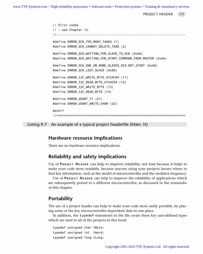
PROJECT HEADER 171
// Error codes
// – see Chapter 13.
//----------------------------------------------------------------------
#define ERROR_SCH_TOO_MANY_TASKS (1)
#define ERROR_SCH_CANNOT_DELETE_TASK (2)
#define ERROR_SCH_WAITING_FOR_SLAVE_TO_ACK (0xAA)
#define ERROR_SCH_WAITING_FOR_START_COMMAND_FROM_MASTER (0xAA)
#define ERROR_SCH_ONE_OR_MORE_SLAVES_DID_NOT_START (0xA0)
#define ERROR_SCH_LOST_SLAVE (0x80)
#define ERROR_I2C_WRITE_BYTE_AT24C64 (11)
#define ERROR_I2C_READ_BYTE_AT24C64 (12)
#define ERROR_I2C_WRITE_BYTE (13)
#define ERROR_I2C_READ_BYTE (14)
#define ERROR_USART_TI (21)
#define ERROR_USART_WRITE_CHAR (22)
#endif
//======================================================================
Listing 9.7 An example of a typical project headerfile (Main. H)
Hardware resource implicationsThere are no hardware resource implications.
Reliability and safety implicationsUse of PR O J E C T HE A D E R can help to improve reliability, not least because it helps tomake your code more readable, because anyone using your projects knows where tofind key information, such as the model of microcontroller and the oscillator frequency.
Use of PR O J E C T HE A D E R can help to improve the reliability of applications whichare subsequently ported to a different microcontroller, as discussed in the remainderof this chapter.
PortabilityThe use of a project header can help to make your code more easily portable, by plac-ing some of the key rnicrocontroller-dependent data in one place.
In addition, the typedef statements in the file create three key user-defined typeswhich are used in all of the projects in this book:
typedef unsigned char tByte;
typedef unsigned int tWord;
typedef unsigned long tLong;
www.TTE-Systems.com = High-reliability processors + Software tools + Protection systems + Training & consultancy services
Copyright 2001-2010 TTE Systems Ltd. All rights reserved.
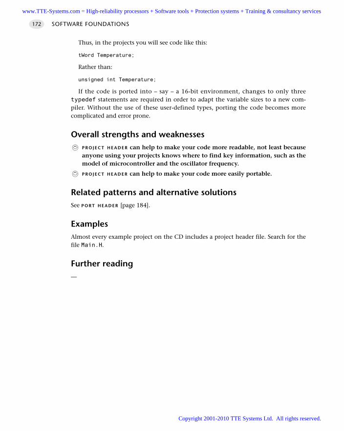
Thus, in the projects you will see code like this:
tWord Temperature;
Rather than:
unsigned int Temperature;
If the code is ported into – say – a 16-bit environment, changes to only threetypedef statements are required in order to adapt the variable sizes to a new com-piler. Without the use of these user-defined types, porting the code becomes morecomplicated and error prone.
Overall strengths and weaknessesP R O J E C T H E A D E R can help to make your code more readable, not least becauseanyone using your projects knows where to find key information, such as themodel of microcontroller and the oscillator frequency.
P R O J E C T H E A D E R can help to make your code more easily portable.
Related patterns and alternative solutionsSee P O R T H E A D E R [page 184].
ExamplesAlmost every example project on the CD includes a project header file. Search for thefile Main.H.
Further reading—
SOFTWARE FOUNDATIONS172
www.TTE-Systems.com = High-reliability processors + Software tools + Protection systems + Training & consultancy services
Copyright 2001-2010 TTE Systems Ltd. All rights reserved.
Using the ports
Introduction
The first pattern in this chapter (P O R T I /O [page 174]) is concerned with basic soft-ware techniques for interacting with the digital ports on an 8051 microcontroller.
The second pattern (P O R T H E A D E R [page 184]) encapsulates a design guideline thathelps you cope with the fact that many different components in a larger project willeach require port access: specifically, P O R T H E A D E R demonstrates how the port accessfor the whole project can be integrated into a single file. Use of these techniques canease project development, maintenance and porting.
The following points should also be noted:
This chapter does not consider the hardware that will be connected to the port: seeChapters 7 and 8 for relevant hardware details.
This chapter does not consider analog input and output: for this, see Part G.
chapter 10www.TTE-Systems.com = High-reliability processors + Software tools + Protection systems + Training & consultancy services
Copyright 2001-2010 TTE Systems Ltd. All rights reserved.
SOFTWARE FOUNDATIONS174
PORT I/O
Context You are developing an embedded application using one or more members of the
8051 family of microcontrollers.
You are designing an appropriate software foundation for your application.
ProblemHow do you write software to read from and /or write to the ports on an (8051)microcontroller?
BackgroundThe Standard 8051s have four 8-bit ports. All of the ports are bidirectional: that is,they may be used for both input and output.
To limit the size of the device, some of the port pins have alternative functions. Forexample, as we saw in Chapter 6, Ports 0, 2 (and part of Port 3) together provide theaddress and data bus used to support access to external memory. Similarly, two fur-ther pins on Port 3 (pins 0 and 1) also provide access to the on-chip USART (seeChapter 18). When in their ‘alternative roles’, these pins cannot be used for ordinaryinput or output. As a result, on the original members of the 8051 family, where exter-nal memory is used, only Port 1 is available for general-purpose I/O operations.
These comments all refer to the Standard 8051: the number of available ports on8051 microcontrollers varies enormously: the Small 8051s have the equivalent ofapproximately two ports and the Extended 8051s have up to ten ports (see Chapter3). Despite these differences, the control of ports on all members of the 8051 family iscarried out in the same way.
SolutionControl of the 8051 ports through software is carried out using what are known as‘special function registers’ (SFRs). The SFRs are 8-bit latches: in practical terms, thismeans that the values written to the port are held there until a new value is written orthe device is reset.
Each of the four basic ports on the Standard 8051 family, as well as any additionalports, is represented by an SFR: these are named, appropriately, P0, P1, P2, P3 and soon. Physically, the SFR is a area of memory in the upper areas of internal RAM: P0 isat address 0x80, P1 at address 0x90, P2 at address 0xA0 and P3 at address 0xB0.
If we want to read from the ports, we need to read from these addresses. Assumingthat we are using a C compiler, the process of writing to an address is usually by
www.TTE-Systems.com = High-reliability processors + Software tools + Protection systems + Training & consultancy services
Copyright 2001-2010 TTE Systems Ltd. All rights reserved.
means of a SFR variable ‘declaration’, hidden in a header file. Thus, a typical SFRheader file for an 8051 family device will contain the lines:
sfr P0 = 0x80;
sfr P1 = 0x90;
sfr P2 = 0xA0;
sfr P3 = 0xB0;
Having declared the SFR variables, we can write to the ports in a straightforwardmanner. For example, we can send some data to Port 1 as follows:
unsigned char Port_data:
Port_data = 0x0F;
P1 = Port_data; // Write 00001111 to Port 1
Similarly, we can read from (for example) Port 1 as follows:
unsigned char Port_data;
P1 = 0xFF; // Set the port to 'read mode'
Port_data = P1; // Read from the port
Note that, in order to read from a pin, we need to ensure that the last thing writtento the pin was a ‘1’. Because the reset value of the ports is 0xFF (see ‘Port reset values’,page 178), it is tempting to assume that writing this value is unnecessary and that wecan get away with the following version:
unsigned char Port_data;
// Assume nothing written to port since reset
// - DANGEROUS!!!
Port_data = P1;
The problem with this code is that, in simple test programs it works: this can lullthe developer into a false sense of security. If, at a later date, someone modifies theprogram to include a routine for writing to all or part of the same port, this code willnot generally work as required:
unsigned char Port-data:
P1 = 0x00;
...
// Assumes nothing written to port since reset
// - WON'T ALWAYS WORK
Port_data = P1;
In general, we use initialization functions to set the ports to a known state at thestart of the program. Where this is not possible, it is safer to always write ‘1’ to anyport pin before reading from it, as was illustrated in the first example.
PORT I/O 175
www.TTE-Systems.com = High-reliability processors + Software tools + Protection systems + Training & consultancy services
Copyright 2001-2010 TTE Systems Ltd. All rights reserved.
Note that, in the last example, we assume that we wished to read from or write to anentire port. More commonly, we might wish (for example) to control an LED isconnected to a single output pin. For example, assuming that the LED is connected toPin 0 on Port 3 of an 8051-family microcontroller, we can flash the diode by control-ling the whole port, as follows:
P3 = 0xFF:
... // delay
P3 = 0x00;
... // delay
P3 = 0xFF ;
... // etc
Alternatively, we can make use of an sbit variable in the C51 compiler to providea finer level of control. At the same time, we consider the fact that – depending onthe hardware (see Chapter 7) – the LED may be lit using a logic 1 or a logic 0 outputon the port pin and we make the software flexible enough to deal easily with subse-quent hardware changes:
#define LED_PORT P3
#define LED_ON 0 // Easy to change the logic here
#define LED_OFF 1
sbit Warning_led = LED_PORT^0; // LED is connected to 4.0
...
Warning_led = LED_ON;
... // delay
Warning_led = LED_OFF;
... // delay
Warning_led = LED_ON:
... // etc
Reliability and safety implicationsPort reset values
After the system is reset, the contents of the various port special function registers(SFRs) are set to 0xFF. This fact has very important safety and reliability implications.
Consider, for example, that you have connected a motorized device to a port andthat the device is activated by a ‘logic 1’ output. When the microcontroller is reset, themotorized device will be activated. Even if you change the port outputs to 0 at the startof your program, the motor will be ‘pulsed’ briefly. This can, in some systems, lead tothe injury or even death of users of the system or those in the immediate vicinity.
Because the output pins are ‘reset high’ it is important to ensure that any deviceswhich have safety implications are connected to the microcontroller in such a way
SOFTWARE FOUNDATIONS176
www.TTE-Systems.com = High-reliability processors + Software tools + Protection systems + Training & consultancy services
Copyright 2001-2010 TTE Systems Ltd. All rights reserved.
PORT I/O 177
that they are ‘active low’: that is, that an output of ‘0’ on the relevant port pin willactivate the device.
Port I/O and memory access
One of the most common errors made by inexperienced 8051 developers is to con-tinue to use P0, P2 or P3 as normal I/O ports when using external memory (seeChapter 8 for details of memory usage).
If you use external memory, you cannot safely use P0 and P2 for any other purposeand you must also take care when writing to Port 3.
For example, any statement similar to this:
P3 = AD_data;
is potentially catastrophic if external memory is being used.Instead, make use of sbit variables to ensure you only write to ‘safe’ port pins (see
‘Example: Reading and writing bits’ for details).
Hardware resource implicationsAll port I/O involves the use of port pins. As we discussed earlier, if these pins areused for I/O, then they are not generally available for other purposes.
Note that all Extended 8051s provide additional ports. On the 80C515C, for exam-ple, there are eight 8-bit ports: these include the ‘standard’ ports (0–3), plus one 8-bitport with alternate A/D conversion functions and three further ports.
PortabilityPort access in general and the keywords bit and sbit in particular are not part of theISO / ANSI C language: therefore, by definition, this code is not totally portable.
That said, this code can be used (with the standard Keil compiler) across the wholeof the 8051 range. With minor modifications it can be used with other 8051 compil-ers, all of which provide similar facilities.
Overall strengths and weaknessesThis pattern allows flexible and efficient access to the 8051 ports, makingfull use of the internal BDATA memory area (discussed in Chapter 6).
As noted earlier, port access in general and the keywords bit and sbit in partic-ular are not part of the ISO / ANSI C language: therefore, by definition, this codeis not totally portable. Note that, while perhaps less than ideal, this problemcannot be avoided.
www.TTE-Systems.com = High-reliability processors + Software tools + Protection systems + Training & consultancy services
Copyright 2001-2010 TTE Systems Ltd. All rights reserved.
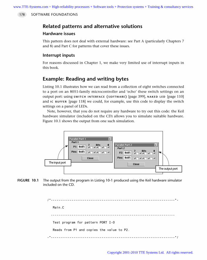
SOFTWARE FOUNDATIONS178
Related patterns and alternative solutionsHardware issues
This pattern does not deal with external hardware: see Part A (particularly Chapters 7and 8) and Part C for patterns that cover these issues.
Interrupt inputs
For reasons discussed in Chapter 1, we make very limited use of interrupt inputs inthis book.
Example: Reading and writing bytesListing 10.1 illustrates how we can read from a collection of eight switches connectedto a port on an 8051-family microcontroller and ‘echo’ these switch settings on anoutput port: using S W I T C H I N T E R FA C E (S O F T WA R E) [page 399], N A K E D L E D [page 110]and I C B U F F E R [page 118] we could, for example, use this code to display the switchsettings on a panel of LEDs.
Note, however, that you do not require any hardware to try out this code: the Keilhardware simulator (included on the CD) allows you to simulate suitable hardware.Figure 10.1 shows the output from one such simulation.
/*------------------------------------------------------------------*-
Main.C
------------------------------------------------------------------
Test program for pattern PORT I-O
Reads from P1 and copies the value to P2.
-*------------------------------------------------------------------*/
FIGURE 10.1 The output from the program in Listing 10-1 produced using the Keil hardware simulatorincluded on the CD.
The output port
The input port
www.TTE-Systems.com = High-reliability processors + Software tools + Protection systems + Training & consultancy services
Copyright 2001-2010 TTE Systems Ltd. All rights reserved.

PORT I/O 179
// File Main.H is detailed in Chapter 9
#include <Main.H>
/*..................................................................*/
void main (void)
unsigned char Port1_value;
// Must set up P1 for reading
P1 = 0xFF;
while(l)
// Read the value of P1
Port1_value = P1;
// Copy the value to P2
P2 = Port1_value;
/*------------------------------------------------------------------*-
--------- END OF FILE -------------------------------------------
--*-----------------------------------------------------------------*/
Listing 10.1 A simple Super Loop application which copies the values from P1 to P2
Example: Reading and writing bitsListing 10.1 demonstrated how to read from or write to an entire port. Consideranother common problem: reading and writing individual pins on a port. This prob-lem arises because often the various parts of a port will be serving different purposes.
Suppose, for example, that we have a switch connected to Port 1 (pin 3) and anLED connected to Port 1 (pin 4) and also have other input and output devices con-nected to the other pins on this port. How do we read from pin 3 and write to pin 4without disrupting anything else?
We can do this by making use of the bitwise AND, OR and ‘complement’ operators.These, and other, bitwise operators are not widely used by desktop developers. Thevarious bitwise operators allow a number of data manipulations that are invaluable inembedded applications. Some examples of the use of these operators are given inListing 10.2. Note that this file is written in ISO ‘C’ (’Desktop C’): it cannot be run onthe Keil compiler.
/*------------------------------------------------------------------*-
Main.C
www.TTE-Systems.com = High-reliability processors + Software tools + Protection systems + Training & consultancy services
Copyright 2001-2010 TTE Systems Ltd. All rights reserved.
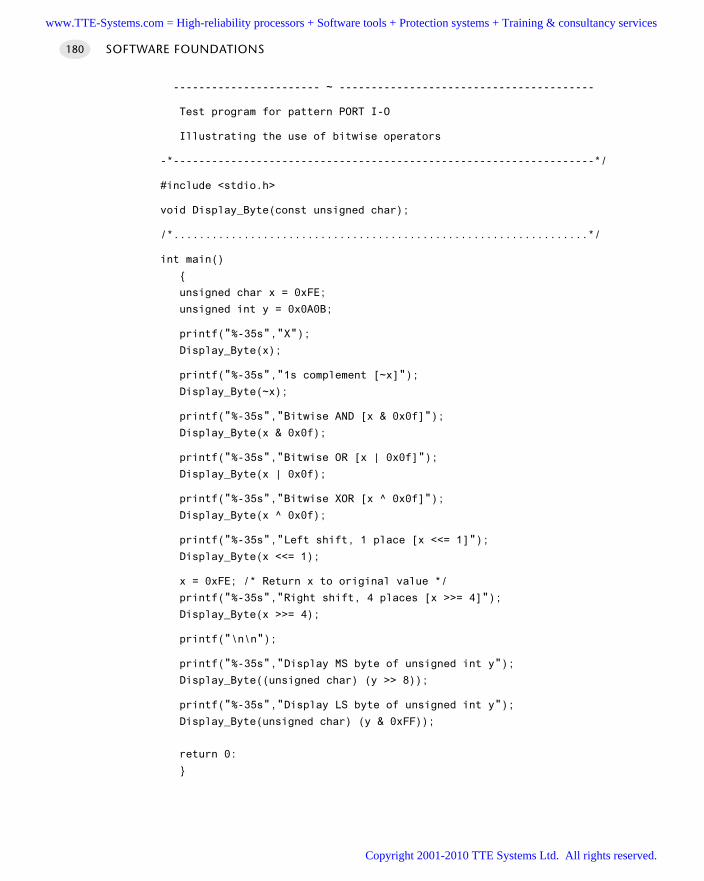
SOFTWARE FOUNDATIONS180
----------------------- ~ ----------------------------------------
Test program for pattern PORT I-O
Illustrating the use of bitwise operators
-*------------------------------------------------------------------*/
#include <stdio.h>
void Display_Byte(const unsigned char);
/*.................................................................*/
int main()
unsigned char x = 0xFE;
unsigned int y = 0x0A0B;
printf("%-35s","X");Display_Byte(x);
printf("%-35s","1s complement [~x]");Display_Byte(~x);
printf("%-35s","Bitwise AND [x & 0x0f]"); Display_Byte(x & 0x0f);
printf("%-35s","Bitwise OR [x | 0x0f]"); Display_Byte(x | 0x0f);
printf("%-35s","Bitwise XOR [x ^ 0x0f]"); Display_Byte(x ^ 0x0f);
printf("%-35s","Left shift, 1 place [x <<= 1]");Display_Byte(x <<= 1);
x = 0xFE; /* Return x to original value */
printf("%-35s","Right shift, 4 places [x >>= 4]"); Display_Byte(x >>= 4);
printf("\n\n");
printf("%-35s","Display MS byte of unsigned int y");Display_Byte((unsigned char) (y >> 8));
printf("%-35s","Display LS byte of unsigned int y");Display_Byte(unsigned char) (y & 0xFF));
return 0:
www.TTE-Systems.com = High-reliability processors + Software tools + Protection systems + Training & consultancy services
Copyright 2001-2010 TTE Systems Ltd. All rights reserved.
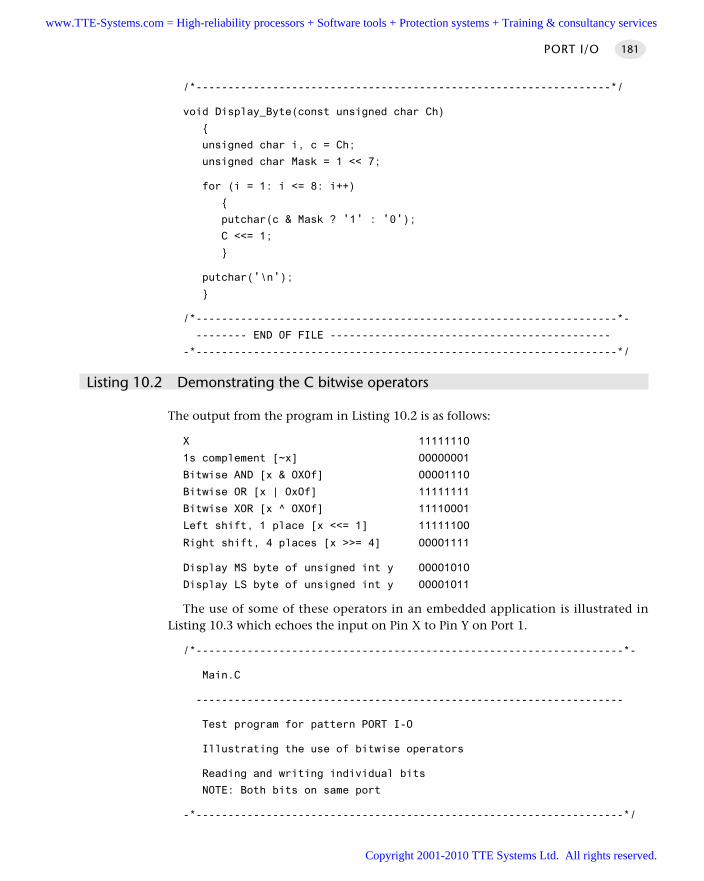
PORT I/O 181
/*-----------------------------------------------------------------*/
void Display_Byte(const unsigned char Ch)
unsigned char i, c = Ch;
unsigned char Mask = 1 << 7;
for (i = 1: i <= 8: i++)
putchar(c & Mask ? '1' : '0'); C <<= 1;
putchar('\n');
/*------------------------------------------------------------------*-
-------- END OF FILE --------------------------------------------
-*------------------------------------------------------------------*/
Listing 10.2 Demonstrating the C bitwise operators
The output from the program in Listing 10.2 is as follows:
X 1111111O
1s complement [~x] OOOOOOO1
Bitwise AND [x & OXOf] OOOO111O
Bitwise OR [x | OxOf] 11111111
Bitwise XOR [x ^ OXOf] 1111OOO1
Left shift, 1 place [x <<= 1] 111111OO
Right shift, 4 places [x >>= 4] OOOO1111
Display MS byte of unsigned int y OOOO1O1O
Display LS byte of unsigned int y OOOO1O11
The use of some of these operators in an embedded application is illustrated inListing 10.3 which echoes the input on Pin X to Pin Y on Port 1.
/*-------------------------------------------------------------------*-
Main.C
-------------------------------------------------------------------
Test program for pattern PORT I-O
Illustrating the use of bitwise operators
Reading and writing individual bits
NOTE: Both bits on same port
-*-------------------------------------------------------------------*/
www.TTE-Systems.com = High-reliability processors + Software tools + Protection systems + Training & consultancy services
Copyright 2001-2010 TTE Systems Ltd. All rights reserved.
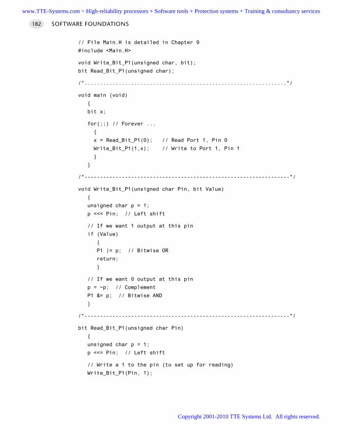
// File Main.H is detailed in Chapter 9
#include <Main.H>
void Write_Bit_P1(unsigned char, bit);
bit Read_Bit_P1(unsigned char);
/*.................................................................*/
void main (void)
bit x;
for(;;) // Forever ...
x = Read_Bit_P1(0); // Read Port 1, Pin 0
Write_Bit_P1(1,x); // Write to Port 1, Pin 1
/*------------------------------------------------------------------*/
void Write_Bit_P1(unsigned char Pin, bit Value)
unsigned char p = 1;
p <<= Pin; // Left shift
// If we want 1 output at this pin
if (Value)
P1 |= p; // Bitwise OR
return;
// If we want 0 output at this pin
p = ~p; // Complement
P1 &= p; // Bitwise AND
/*------------------------------------------------------------------*/
bit Read_Bit_P1(unsigned char Pin)
unsigned char p = 1;
p <<= Pin; // Left shift
// Write a 1 to the pin (to set up for reading)
Write_Bit_P1(Pin, 1);
SOFTWARE FOUNDATIONS182
www.TTE-Systems.com = High-reliability processors + Software tools + Protection systems + Training & consultancy services
Copyright 2001-2010 TTE Systems Ltd. All rights reserved.
return (P1 & p); // Read the pin
/*------------------------------------------------------------------*-
--------- END OF FILE -------------------------------------------
-*------------------------------------------------------------------*/
Listing 10.3 Reading and writing bits
Example: Displaying error codes in a schedulerSee C O-O P E R AT I V E S C H E D U L E R [page 255], where error codes are displayed on a bankof LEDs connected to a port.
Example: Controlling an LCDSee L C D C H A R A C T E R PA N E L [page 467], where control of individual port pins is usedto send data to an LCD panel.
Further readingFurther information about the use of the ‘C’ bitwise operators will be found in anystandard textbook on C programming.
PORT I/O 183
www.TTE-Systems.com = High-reliability processors + Software tools + Protection systems + Training & consultancy services
Copyright 2001-2010 TTE Systems Ltd. All rights reserved.
SOFTWARE FOUNDATIONS184
PORT HEADER
Context You are developing an embedded application using one or more members of the
8051 family of microcontrollers.
ProblemHow do you manage port access allocations in a larger project?
BackgroundIn a typical embedded project, you may have a user interface created using an LCD, akeypad and one or more single LEDs. There may be a serial (RS-485) link to anothermicrocontroller board. There may be one or more high-power devices (say three-phase industrial motors) controlled by your application.
Each of these (software) components in your application will require exclusiveaccess to one or more port pins. The project may include 10–20 different source files.How do you ensure that changes to port access in one component do not impact onanother? How do you ensure that it is easy to port the application to an environmentwhere different port pins must be used?
These issues are addressed through the simple P O R T H E A D E R design pattern.
SolutionPO R T HE A D E R encapsulates a simple but effective design guideline that can help youcope with the fact that many different components in a larger project will eachrequire port access: specifically, using PO R T HE A D E R , you will pull together the differ-ent port access features for the whole project into a single (header) file. Use of thistechnique can ease project development, maintenance and porting.
Port Header is simple to understand and simple to apply.Consider, for example, that we have three C files in a project (A, B, C), each of
which requires access to one or more port pins, or to a complete port.File A may include the following:
// File A
sbit Pin_A = P3^2;
...
File B may include the following:
// File B
#define Port_B = P0;
...
www.TTE-Systems.com = High-reliability processors + Software tools + Protection systems + Training & consultancy services
Copyright 2001-2010 TTE Systems Ltd. All rights reserved.
PORT HEADER 185
File C may include the following:
// File C
sbit Pin_C = P2^7;
...
In this version of the code, all of the port access requirements are spread over mul-tiple files. Instead of this, there are many advantages obtained by integrating all portaccess in a single Port.H header file:
//----- Port.H -----
// Port access for File B
#define Port_B = P0;
// Port access for File A
sbit Pin_A = P3^2;
// Port access for File C
sbit Pin_C = P2^7;
...
Each of the remaining project files will then #include Port.H.Listing 10.4 shows a complete example of a Port.H file from a real application.
/*------------------------------------------------------------------*-
Port.H (vl.00)
------------------------------------------------------------------
’Port Header’ for the project LCD_KEY (see Chapter 22)
-*------------------------------------------------------------------*/
//------ Sch51.C ----------------------------------------
// Comment this line out if error reporting is NOT required
//#define SCH_REPORT_ERRORS
#ifdef SCH_REPORT_ERRORS
// The port on which error codes will be displayed
// ONLY USED IF ERRORS ARE REPORTED
#define Error_port P1
#endif
// ------ Keypad.C ------------------------------------------------
#define KEYPAD_PORT P0
sbit C1 = KEYPAD_PORT^0;
sbit C2 = KEYPAD_PORT^1;
www.TTE-Systems.com = High-reliability processors + Software tools + Protection systems + Training & consultancy services
Copyright 2001-2010 TTE Systems Ltd. All rights reserved.
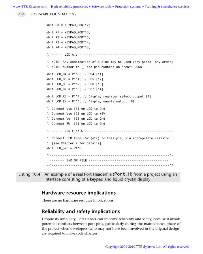
sbit C3 = KEYPAD_PORT^2;
sbit R1 = KEYPAD_PORT^6;
sbit R2 = KEYPAD_PORT^5;
sbit R3 = KEYPAD_PORT^4;
sbit R4 = KEYPAD_PORT^3;
// ------ LCD_A.c ---------------------------------------------------
// NOTE: Any combination of 6 pins may be used (any ports, any order)
// NOTE: Number in [] are pin numbers on *MANY* LCDs
sbit LCD_D4 = P1^0; // DB4 [11]
sbit LCD_D5 = P1^1; // DB5 [12]
sbit LCD_D6 = P1^2; // DB6 [13]
sbit LCD_D7 = P1^3; // DB7 [14]
sbit LCD_RS = P1^4; // Display register select output [4]
sbit LCD_EN = P1^5; // Display enable output [6]
// Connect Vss [1] on LCD to Gnd
// Connect Vcc [2] on LCD to +5V
// Connect Vo [3] on LCD to Gnd
// Connect RW [5] on LCD to Gnd
// ------ LED_Flas.C ------------------------------------------------
// Connect LED from +5V (etc) to this pin, via appropriate resistor
// [see Chapter 7 for details]
sbit LED_pin = P1^5;
/*-----------------------------------------------------------------*-
-------- END OF FILE -------------------------------------------
--*----------------------------------------------------------------*/
Listing 10.4 An example of a real Port Headerfile (Port.H) from a project using an interface consisting of a keypad and liquid crystal display
Hardware resource implicationsThere are no hardware resource implications.
Reliability and safety implicationsDespite its simplicity, Port Header can improve reliability and safety, because it avoidspotential conflicts between port pins, particularly during the maintenance phase ofthe project when developers (who may not have been involved in the original design)are required to make code changes.
SOFTWARE FOUNDATIONS186
www.TTE-Systems.com = High-reliability processors + Software tools + Protection systems + Training & consultancy services
Copyright 2001-2010 TTE Systems Ltd. All rights reserved.
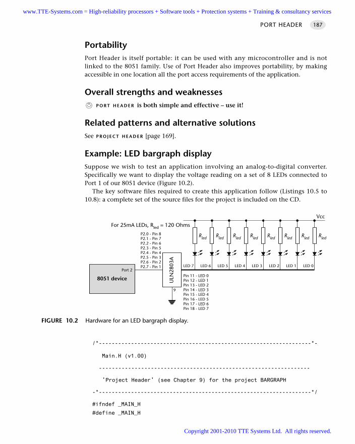
PORT HEADER 187
PortabilityPort Header is itself portable: it can be used with any microcontroller and is notlinked to the 8051 family. Use of Port Header also improves portability, by makingaccessible in one location all the port access requirements of the application.
Overall strengths and weaknessesP O R T H E A D E R is both simple and effective – use it!
Related patterns and alternative solutionsSee P R O J E C T H E A D E R [page 169].
Example: LED bargraph displaySuppose we wish to test an application involving an analog-to-digital converter.Specifically we want to display the voltage reading on a set of 8 LEDs connected toPort 1 of our 8051 device (Figure 10.2).
The key software files required to create this application follow (Listings 10.5 to10.8): a complete set of the source files for the project is included on the CD.
/*------------------------------------------------------------------*-
Main.H (v1.00)
-----------------------------------------------------------------
'Project Header' (see Chapter 9) for the project BARGRAPH
-*------------------------------------------------------------------*/
#ifndef _MAIN_H
#define _MAIN_H
FIGURE 10.2 Hardware for an LED bargraph display.
8051 device
Port 2
ULN
2803
A
P2.0 - Pin 8P2.1 - Pin 7P2.2 - Pin 6P2.3 - Pin 5P2.4 - Pin 4P2.5 - Pin 3P2.6 - Pin 2P2.7 - Pin 1
Pin 11 - LED 0Pin 12 - LED 1Pin 13 - LED 2Pin 14 - LED 3Pin 15 - LED 4Pin 16 - LED 5Pin 17 - LED 6Pin 18 - LED 7
9
LED 7 LED 6 LED 5 LED 4 LED 3 LED 2 LED 1 LED 0
Vcc
RledRledRledRledRledRledRledRled
For 25mA LEDs, Rled = 120 Ohms
www.TTE-Systems.com = High-reliability processors + Software tools + Protection systems + Training & consultancy services
Copyright 2001-2010 TTE Systems Ltd. All rights reserved.
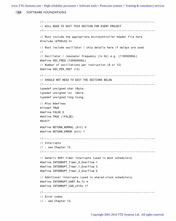
SOFTWARE FOUNDATIONS188
//----------------------------------------------------------------------
// WILL NEED TO EDIT THIS SECTION FOR EVERY PROJECT
//----------------------------------------------------------------------
// Must include the appropriate microcontroller header file here
#include <AT89x52.h>
// Must include oscillator / chip details here if delays are used
//
// Oscillator / resonator frequency (in Hz) e.g. (11059200UL)
#define OSC_FREQ (12000000UL)
// Number of oscillations per instruction (6 or 12)
#define OSC_PER_INST (12)
//----------------------------------------------------------------------
// SHOULD NOT NEED TO EDIT THE SECTIONS BELOW
//----------------------------------------------------------------------
typedef unsigned char tByte;
typedef unsigned int tWord;
typedef unsigned long tLong;
// Misc #defines
#ifndef TRUE
#define FALSE 0
#define TRUE (!FALSE)
#endif
#define RETURN_NORMAL (bit) 0
#define RETURN_ERROR (bit) 1
//----------------------------------------------------------------------
// Interrupts
// - see Chapter 12.
//----------------------------------------------------------------------
// Generic 8051 timer interrupts (used in most schedulers)
#define INTERRUPT_Timer_0_Overflow 1
#define INTERRUPT_Timer_1_Overflow 3
#define INTERRUPT_Timer_2_Overflow 5
// Additional interrupts (used in shared-clock schedulers)
#define INTERRUPT_UART Rx_Tx 4
#define INTERRUPT_CAN_c515c 17
//----------------------------------------------------------------------
// Error codes
// - see Chapter 13.
www.TTE-Systems.com = High-reliability processors + Software tools + Protection systems + Training & consultancy services
Copyright 2001-2010 TTE Systems Ltd. All rights reserved.
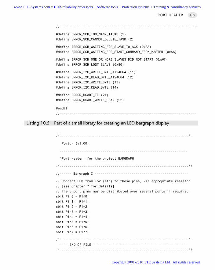
PORT HEADER 189
//----------------------------------------------------------------------
#define ERROR_SCH_TOO_MANY_TASKS (1)
#define ERROR_SCH_CANNOT_DELETE_TASK (2)
#define ERROR_SCH_WAITING_FOR_SLAVE_TO_ACK (0xAA)
#define ERROR_SCH_WAITING_FOR_START_COMMAND_FROM_MASTER (0xAA)
#define ERROR_SCH_ONE_OR_MORE_SLAVES_DID_NOT_START (0xA0)
#define ERROR_SCH_LOST_SLAVE (0x80)
#define ERROR_I2C_WRITE_BYTE_AT24C64 (11)
#define ERROR_I2C_READ_BYTE_AT24C64 (12)
#define ERROR_I2C_WRITE_BYTE (13)
#define ERROR_I2C_READ_BYTE (14)
#define ERROR_USART_TI (21)
#define ERROR_USART_WRITE_CHAR (22)
#endif
//======================================================================
Listing 10.5 Part of a small library for creating an LED bargraph display
/*------------------------------------------------------------------*-
Port.H (v1.00)
------------------------------------------------------------------
'Port Header' for the project BARGRAPH
-*------------------------------------------------------------------*/
//------ Bargraph.C ------------------------------------------------
// Connect LED from +5V (etc) to these pins, via appropriate resistor
// [see Chapter 7 for details]
// The 8 port pins may be distributed over several ports if required
sbit Pin0 = P1^0;
sbit Pin1 = P1^1;
sbit Pin2 = P1^2;
sbit Pin3 = P1^3;
sbit Pin4 = P1^4;
sbit PinS = P1^5;
sbit Pin6 = P1^6;
sbit Pin7 = P1^7;
/*------------------------------------------------------------------*-
---- END OF FILE ------------------------------------------------
-*------------------------------------------------------------------*/
www.TTE-Systems.com = High-reliability processors + Software tools + Protection systems + Training & consultancy services
Copyright 2001-2010 TTE Systems Ltd. All rights reserved.
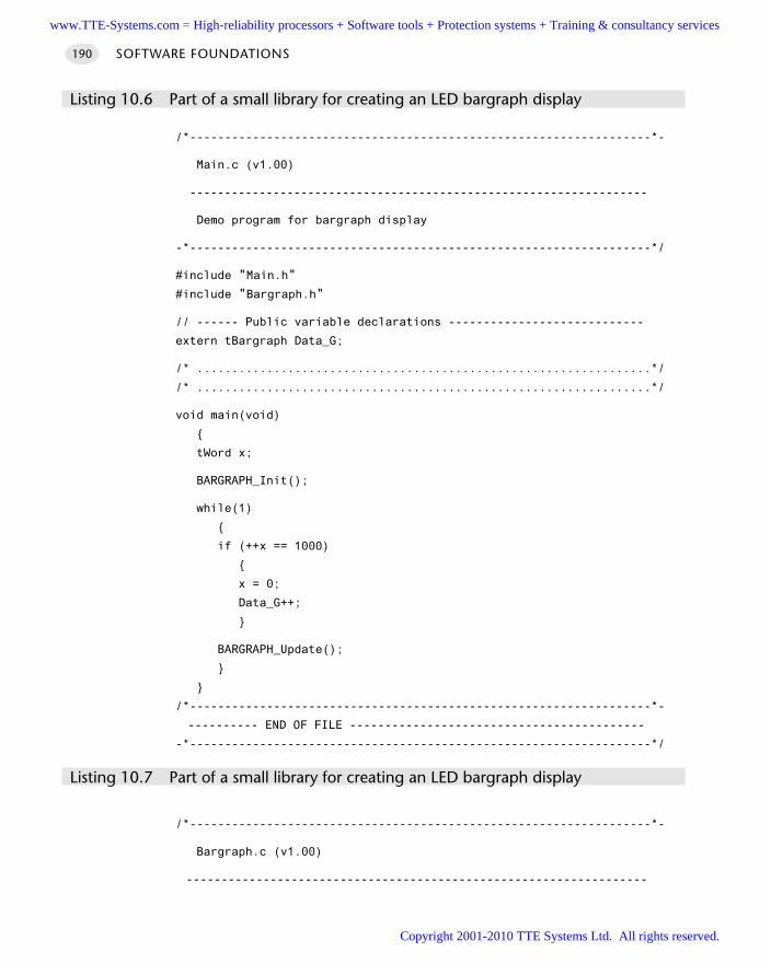
SOFTWARE FOUNDATIONS190
Listing 10.6 Part of a small library for creating an LED bargraph display
/*------------------------------------------------------------------*-
Main.c (v1.00)
------------------------------------------------------------------
Demo program for bargraph display
-*------------------------------------------------------------------*/
#include "Main.h"
#include "Bargraph.h"
// ------ Public variable declarations ----------------------------
extern tBargraph Data_G;
/* .................................................................*/
/* .................................................................*/
void main(void)
tWord x;
BARGRAPH_Init();
while(1)
if (++x == 1000)
x = 0;
Data_G++;
BARGRAPH_Update();
/*------------------------------------------------------------------*-
---------- END OF FILE ------------------------------------------
-*------------------------------------------------------------------*/
Listing 10.7 Part of a small library for creating an LED bargraph display
/*------------------------------------------------------------------*-
Bargraph.c (v1.00)
------------------------------------------------------------------
www.TTE-Systems.com = High-reliability processors + Software tools + Protection systems + Training & consultancy services
Copyright 2001-2010 TTE Systems Ltd. All rights reserved.
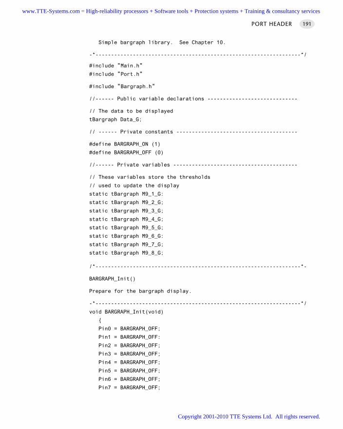
Simple bargraph library. See Chapter 10.
-*------------------------------------------------------------------*/
#include "Main.h"
#include "Port.h"
#include "Bargraph.h"
//------ Public variable declarations -----------------------------
// The data to be displayed
tBargraph Data_G;
// ------ Private constants ---------------------------------------
#define BARGRAPH_ON (1)
#define BARGRAPH_OFF (0)
//------ Private variables ----------------------------------------
// These variables store the thresholds
// used to update the display
static tBargraph M9_1_G:
static tBargraph M9_2_G;
static tBargraph M9_3_G;
static tBargraph M9_4_G;
static tBargraph M9_5_G;
static tBargraph M9_6_G:
static tBargraph M9_7_G;
static tBargraph M9_8_G;
/*------------------------------------------------------------------*-
BARGRAPH_Init()
Prepare for the bargraph display.
-*------------------------------------------------------------------*/
void BARGRAPH_Init(void)
Pin0 = BARGRAPH_OFF;
Pin1 = BARGRAPH_OFF:
Pin2 = BARGRAPH_OFF;
Pin3 = BARGRAPH_OFF;
Pin4 = BARGRAPH_OFF;
Pin5 = BARGRAPH_OFF;
Pin6 = BARGRAPH_OFF;
Pin7 = BARGRAPH_OFF;
PORT HEADER 191
www.TTE-Systems.com = High-reliability processors + Software tools + Protection systems + Training & consultancy services
Copyright 2001-2010 TTE Systems Ltd. All rights reserved.
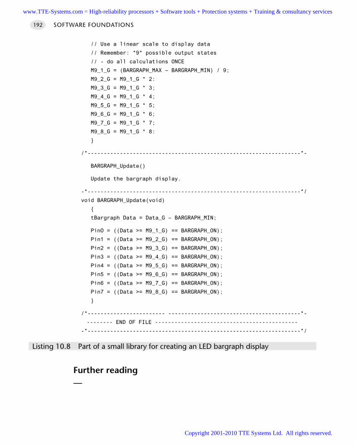
// Use a linear scale to display data
// Remember: *9* possible output states
// - do all calculations ONCE
M9_1_G = (BARGRAPH_MAX – BARGRAPH_MIN) / 9;
M9_2_G = M9_1_G * 2:
M9_3_G = M9_1_G * 3;
M9_4_G = M9_1_G * 4;
M9_5_G = M9_1_G * 5;
M9_6_G = M9_1_G * 6;
M9_7_G = M9_1_G * 7;
M9_8_G = M9_1_G * 8:
/*------------------------------------------------------------------*-
BARGRAPH_Update()
Update the bargraph display.
-*------------------------------------------------------------------*/
void BARGRAPH_Update(void)
tBargraph Data = Data_G – BARGRAPH_MIN;
PinO = ((Data >= M9_1_G) == BARGRAPH_ON);
Pin1 = ((Data >= M9_2_G) == BARGRAPH_ON);
Pin2 = ((Data >= M9_3_G) == BARGRAPH_ON);
Pin3 = ((Data >= M9_4_G) == BARGRAPH_ON);
Pin4 = ((Data >= M9_5_G) == BARGRAPH_ON);
Pin5 = ((Data >= M9_6_G) == BARGRAPH_ON);
Pin6 = ((Data >= M9_7_G) == BARGRAPH_ON);
Pin7 = ((Data >= M9_8_G) == BARGRAPH_ON);
/*------------------------ -----------------------------------------*-
-------- END OF FILE --------------------------------------------
-*------------------------------------------------------------------*/
Listing 10.8 Part of a small library for creating an LED bargraph display
Further reading—
SOFTWARE FOUNDATIONS192
www.TTE-Systems.com = High-reliability processors + Software tools + Protection systems + Training & consultancy services
Copyright 2001-2010 TTE Systems Ltd. All rights reserved.
Delays
Introduction
The creation of accurate delays are key requirements in many embedded applications.In this chapter we will consider two different techniques that may be used to pro-
vide such facilities:
H A R D WA R E D E L AY [page 194] which is capable of producing precise delays throughthe use of one of the on-chip timers. Particularly suitable for generating delays ofaround 0.1 ms or more.
S O F T WA R E D E L AY [page 206] which is a simple technique that requires no hardwareresources. The most flexible form of delay mechanism that is particularly suitablefor generating short delays (measured in microseconds) or where timer resourcesare not available.
chapter 11www.TTE-Systems.com = High-reliability processors + Software tools + Protection systems + Training & consultancy services
Copyright 2001-2010 TTE Systems Ltd. All rights reserved.
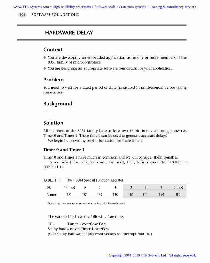
HARDWARE DELAY
Context You are developing an embedded application using one or more members of the
8051 family of microcontrollers.
You are designing an appropriate software foundation for your application.
ProblemYou need to wait for a fixed period of time (measured in milliseconds) before takingsome action.
Background—
SolutionAll members of the 8051 family have at least two 16-bit timer / counters, known asTimer 0 and Timer 1. These timers can be used to generate accurate delays.
We begin by providing brief information on these timers.
Timer 0 and Timer 1
Timer 0 and Timer 1 have much in common and we will consider them together.To see how these timers operate, we need, first, to introduce the TCON SFR
(Table 11.1).
The various bits have the following functions:
TF1 Timer 1 overflow flagSet by hardware on Timer 1 overflow.(Cleared by hardware if processor vectors to interrupt routine.)
SOFTWARE FOUNDATIONS194
TABLE 11.1 The TCON Special Function Register
Bit 7 (msb) 6 5 4 3 2 1 0 (Isb)
Name TF1 TR1 TF0 TR0 1E1 IT1 1E0 IT0
[Note: that the grey areas are not connected with these timers.]
www.TTE-Systems.com = High-reliability processors + Software tools + Protection systems + Training & consultancy services
Copyright 2001-2010 TTE Systems Ltd. All rights reserved.
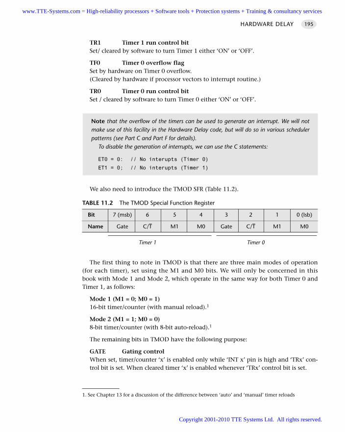
TR1 Timer 1 run control bitSet/ cleared by software to turn Timer 1 either ‘ON’ or ‘OFF’.
TF0 Timer 0 overflow flagSet by hardware on Timer 0 overflow.(Cleared by hardware if processor vectors to interrupt routine.)
TR0 Timer 0 run control bitSet / cleared by software to turn Timer 0 either ‘ON’ or ‘OFF’.
We also need to introduce the TMOD SFR (Table 11.2).
The first thing to note in TMOD is that there are three main modes of operation(for each timer), set using the M1 and M0 bits. We will only be concerned in thisbook with Mode 1 and Mode 2, which operate in the same way for both Timer 0 andTimer 1, as follows:
Mode 1 (M1 = 0; M0 = 1)16-bit timer/counter (with manual reload).1
Mode 2 (M1 = 1; M0 = 0)8-bit timer/counter (with 8-bit auto-reload).1
The remaining bits in TMOD have the following purpose:
GATE Gating controlWhen set, timer/counter ‘x’ is enabled only while ‘INT x’ pin is high and ‘TRx’ con-trol bit is set. When cleared timer ‘x’ is enabled whenever ‘TRx’ control bit is set.
HARDWARE DELAY 195
TABLE 11.2 The TMOD Special Function Register
Bit 7 (msb) 6 5 4 3 2 1 0 (Isb)
Name Gate C/T– M1 M0 Gate C/T– M1 M0
Timer 1 Timer 0
Note that the overflow of the timers can be used to generate an interrupt. We will notmake use of this facility in the Hardware Delay code, but will do so in various schedulerpatterns (see Part C and Part F for details).
To disable the generation of interrupts, we can use the C statements:
ET0 = 0: // No interupts (Timer 0)
ET1 = 0; // No interupts (Timer 1)
1. See Chapter 13 for a discussion of the difference between ‘auto’ and ‘manual’ timer reloads
www.TTE-Systems.com = High-reliability processors + Software tools + Protection systems + Training & consultancy services
Copyright 2001-2010 TTE Systems Ltd. All rights reserved.
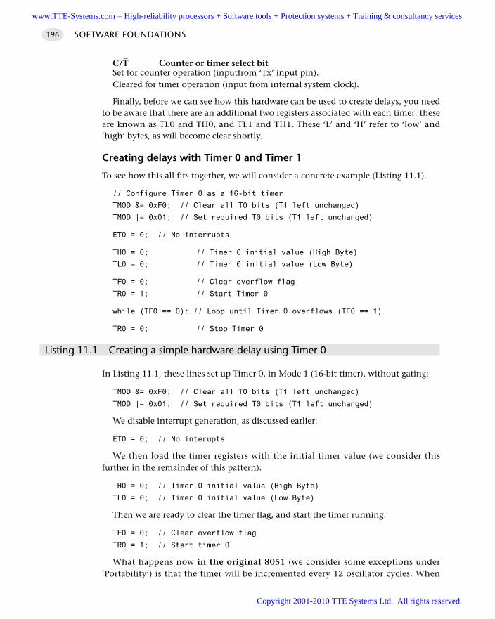
C/T–
Counter or timer select bitSet for counter operation (inputfrom ‘Tx’ input pin). Cleared for timer operation (input from internal system clock).
Finally, before we can see how this hardware can be used to create delays, you needto be aware that there are an additional two registers associated with each timer: theseare known as TL0 and TH0, and TL1 and TH1. These ‘L’ and ‘H’ refer to ‘low’ and‘high’ bytes, as will become clear shortly.
Creating delays with Timer 0 and Timer 1
To see how this all fits together, we will consider a concrete example (Listing 11.1).
// Configure Timer 0 as a 16-bit timer
TMOD &= 0xF0; // Clear all T0 bits (T1 left unchanged)
TMOD |= 0x01; // Set required T0 bits (T1 left unchanged)
ET0 = 0; // No interrupts
TH0 = 0; // Timer 0 initial value (High Byte)
TL0 = 0; // Timer 0 initial value (Low Byte)
TF0 = 0; // Clear overflow flag
TR0 = 1; // Start Timer 0
while (TF0 == 0): // Loop until Timer 0 overflows (TF0 == 1)
TR0 = 0; // Stop Timer 0
Listing 11.1 Creating a simple hardware delay using Timer 0
In Listing 11.1, these lines set up Timer 0, in Mode 1 (16-bit timer), without gating:
TMOD &= 0xF0; // Clear all T0 bits (T1 left unchanged)
TMOD |= 0x01; // Set required T0 bits (T1 left unchanged)
We disable interrupt generation, as discussed earlier:
ET0 = 0; // No interupts
We then load the timer registers with the initial timer value (we consider thisfurther in the remainder of this pattern):
TH0 = 0; // Timer 0 initial value (High Byte)
TL0 = 0; // Timer 0 initial value (Low Byte)
Then we are ready to clear the timer flag, and start the timer running:
TF0 = 0; // Clear overflow flag
TR0 = 1; // Start timer 0
What happens now in the original 8051 (we consider some exceptions under‘Portability’) is that the timer will be incremented every 12 oscillator cycles. When
SOFTWARE FOUNDATIONS196
www.TTE-Systems.com = High-reliability processors + Software tools + Protection systems + Training & consultancy services
Copyright 2001-2010 TTE Systems Ltd. All rights reserved.
this (16-bit) timer overflows – that is, it is incremented from a value of 65535 – thetimer flag (TF1) will be set. In addition, as we have already noted, this overflow canbe used to generate an interrupt; we do not use this option here.
This is very useful behaviour. Simply by varying the initial value stored in thetimer, we specify the number of oscillations that occur before an overflow takes placeand can generate shorter delays.
Building on the material discussed under ‘Background’, H A R D WA R E D E L AY calcula-tions generally take the following form:
We calculate the required starting value for the timer.
We load this value into Timer 0 or Timer 1.
We start the timer.
The timer will be incremented, without software intervention, at a rate determinedby the oscillator frequency; we wait for the timer to reach its maximum value and‘roll over’.
The rolling over of the timer signals the end of the delay by changing the value ofa flag variable.
With a 12-oscillator per instruction 8051, running at 12 MHz, the longest delaythat can be produced with a 16-bit timer is ~65 ms. If we need longer delays, wecan repeat the process.
Overall, this is a powerful and reliable technique and can be used to generaterepeatable delays with good levels of accuracy. A detailed code example is presentedlater in this pattern.
Why not use Timer 2?
In many cases, as we saw in Chapter 3, modern 8051 family devices are based on theslightly later 8052 architecture: such devices include an extra, more powerful timer(called, logically, Timer 2).
While Timer 2 can be used to generate delays (in a manner nearly identical to thatused with Timer 0 and Timer 1 in this pattern), this is generally an inappropriate usefor this resource. This is because Timer 2 is a 16-bit auto-reload timer. This auto-reloadfeature has no value in the generation of delays, but makes it ideally suited as a sourceof ‘ticks’ for the schedulers we use throughout most of this book.2
Hardware resource implicationsHA R D WA R E DE L AY requires non-exclusive use of a timer. There are often competingdemands for such resources, since they are essential for driving a scheduler and areoften used, for example, to generate timeouts (see H A R D WA R E T I M E O U T [page 305]),for pulse-width modulation (see 3-L E V E L P W M [page 822]), for pulse-rate modulation
HARDWARE DELAY 197
2. See Chapter 13 and C O-O P E R AT I V E S C H E D U L E R [page 255] for further information on this topic.
www.TTE-Systems.com = High-reliability processors + Software tools + Protection systems + Training & consultancy services
Copyright 2001-2010 TTE Systems Ltd. All rights reserved.
(see H A R D WA R E P R M [page 742]) and for pulse counting (see H A R D WA R E P U L S E -C O U N T
[page 728].
Reliability and safety implicationsThe techniques discussed in H A R D WA R E D E L AY are generally more portable and moreaccurate than software-based delays, but they are still not suitable for generating pre-cisely timed delays without careful hand-tuning to take into account factors such asthe time taken to call the delay function and the time taken to load the timer withthe initial count value.
Delays generated through multiple calls to a delay function will increase theimpact of these factors; long delays generated using this technique are likely to beparticularly inaccurate.
PortabilityWe consider two main portability issues here.
Differences in timer increment rates
In the original 8051 (and in most current 8051s), Timer 0 and Timer 1 are incre-mented every 12 oscillator cycles: that is, at 1 MHz in a device using a 12 MHz crystaloscillator. In more recent 8051 devices, factors of 6, 4 or 1 are also used. You mustcheck the data sheet to ensure that your calculations of the initial reload values takethese differences into account.
Note that the library code (listed later) is itself highly portable, because it makesuse of information provided in the P R O J E C T H E A D E R [page 169] file.
Porting within the 8051 family
There are limited timers available in the 8051 family. Careful use of particular timerscan help make your code easier to port.
For example, in many applications presented in this book, we will use Timer 2 (whereavailable) to drive a scheduler (see, for example, Chapter 13). In addition, in some appli-cations, Timer 1 will be required to generate baud rates, for a serial network. As a result,your delay code will be particularly portable if you base it on Timer 0.
Note that, where you will use a scheduler and a serial link and your chosen micro-controller does not have Timer 2 available, you may need to use both the availabletimers for the scheduler (T0) and baud rate generation (T1). You will then be forced touse an implementation of S O F T WA R E D E L AY [page 179] for any necessary delay gener-ation. Note also that, in many cases, the use of a scheduler can remove the need formost delay calculations.
Finally, note that, in addition to Timer 2, some extended 8051s have an additionalinternal timer, intended for use as an internal baud rate generator: this can free Timer1 for other purposes, such as delay generation. (See Chapter 3 for details.)
SOFTWARE FOUNDATIONS198
www.TTE-Systems.com = High-reliability processors + Software tools + Protection systems + Training & consultancy services
Copyright 2001-2010 TTE Systems Ltd. All rights reserved.
Porting beyond the 8051 family
Like the 8051 family, most microcontrollers have on-board timers: where such timersare available, this pattern may be adapted without great difficulty. If your chosenmicrocontroller does not have an on-board timer, the pattern S O F T WA R E D E L AY [page206] offers an alternative solution.
Overall strengths and weaknessesThese basic time delay techniques have the great advantage that they arevery simple and can be implemented in a few lines of code. As a result, theyare widely applicable and are frequently used in applications where veryaccurate timing is not of great concern.
They are not suitable for generating very short delays; see ‘Related patterns andalternative solutions’ for alternative suggestions.
Because of the need to manually reload the initial timer value, the delaysobtained may not be precisely as expected. This is of particular concern where, forexample, an attempt is made to delay for (say) a second by invoking a 50 msdelay 20 times: this will not be accurate. Do not attempt to use H A R D WA R E D E L AY
to implement a real-time clock!
They require access to an important hardware resource (a timer).
The timings are not very portable: even different members of the 8051 familyhave different relationships between crystal frequency and instruction cycle fre-quency (note, however, that the code that follows addresses this problem for awide range of delays).
As implemented here, the processor is tied up waiting for the timer to overflow.Where processor power is limited, this may not be an acceptable solution: use ofa scheduler (see Chapter 13) can often reduce the need to waste CPU time inthis way.
Related patterns and alternative solutionsThe code we present in this pattern is designed to generate delays on N millisecondduration, which is a key requirement in many applications. If this is not what yourequire, then some alternatives are as follows:
To generate delays from ~10 µs to about ~10+ ms, H A R D WA R E T I M E O U T [page 305]can be used very effectively.
For generating delays less than ~10 µs, neither H A R D WA R E D E L AY nor H A R D WA R E
T I M E O U T – both of which use Timer 0 / Timer 1 – is suitable. For example, in anoriginal 12 MHz 8051, the minimum timer increment is, in theory, 1 µs: that is theoscillator frequency / 12. However, this delay will often be less than the time takento call the delay function, set up and start the timer. In general, delays less than
HARDWARE DELAY 199
www.TTE-Systems.com = High-reliability processors + Software tools + Protection systems + Training & consultancy services
Copyright 2001-2010 TTE Systems Ltd. All rights reserved.
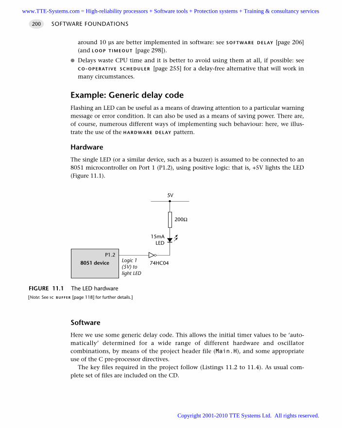
around 10 µs are better implemented in software: see S O F T WA R E D E L AY [page 206](and L O O P T I M E O U T [page 298]).
Delays waste CPU time and it is better to avoid using them at all, if possible: seeC O-O P E R AT I V E S C H E D U L E R [page 255] for a delay-free alternative that will work inmany circumstances.
Example: Generic delay codeFlashing an LED can be useful as a means of drawing attention to a particular warningmessage or error condition. It can also be used as a means of saving power. There are,of course, numerous different ways of implementing such behaviour: here, we illus-trate the use of the H A R D WA R E D E L AY pattern.
Hardware
The single LED (or a similar device, such as a buzzer) is assumed to be connected to an8051 microcontroller on Port 1 (P1.2), using positive logic: that is, +5V lights the LED(Figure 11.1).
Software
Here we use some generic delay code. This allows the initial timer values to be ‘auto-matically’ determined for a wide range of different hardware and oscillatorcombinations, by means of the project header file (Main.H), and some appropriateuse of the C pre-processor directives.
The key files required in the project follow (Listings 11.2 to 11.4). As usual com-plete set of files are included on the CD.
SOFTWARE FOUNDATIONS200
FIGURE 11.1 The LED hardware [Note: See I C B U F F E R [page 118] for further details.]
5V
8051 device
P1.2Logic 1(5V) tolight LED
15mALED
200Ω
74HC04
www.TTE-Systems.com = High-reliability processors + Software tools + Protection systems + Training & consultancy services
Copyright 2001-2010 TTE Systems Ltd. All rights reserved.
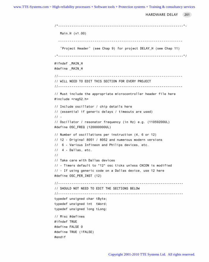
/*------------------------------------------------------------------*-
Main.H (v1.00)
-----------------------------------------------------------------
'Project Header' (see Chap 9) for project DELAY_H (see Chap 11)
-*------------------------------------------------------------------*/
#ifndef _MAIN_H
#define _MAIN_H
//-----------------------------------------------------------------
// WILL NEED TO EDIT THIS SECTION FOR EVERY PROJECT
//-----------------------------------------------------------------
// Must include the appropriate microcontroller header file here
#include <reg52.h>
// Include oscillator / chip details here
// (essential if generic delays / timeouts are used)
// -
// Oscillator / resonator frequency (in Hz) e.g. (11059200UL)
#define OSC_FREQ (120000000UL)
// Number of oscillations per instruction (4, 6 or 12)
// 12 - Original 8051 / 8052 and numerous modern versions
// 6 - Various Infineon and Philips devices, etc.
// 4 - Dallas, etc.
//
// Take care with Dallas devices
// - Timers default to *12* osc ticks unless CKCON is modified
// - If using generic code on a Dallas device, use 12 here
#define OSC_PER_INST (12)
//------------------------------------------------------------------
// SHOULD NOT NEED TO EDIT THE SECTIONS BELOW
//------------------------------------------------------------------
typedef unsigned char tByte;
typedef unsigned int tWord;
typedef unsigned long tLong:
// Misc #defines
#ifndef TRUE
#define FALSE 0
#define TRUE (!FALSE)
#endif
HARDWARE DELAY 201
www.TTE-Systems.com = High-reliability processors + Software tools + Protection systems + Training & consultancy services
Copyright 2001-2010 TTE Systems Ltd. All rights reserved.
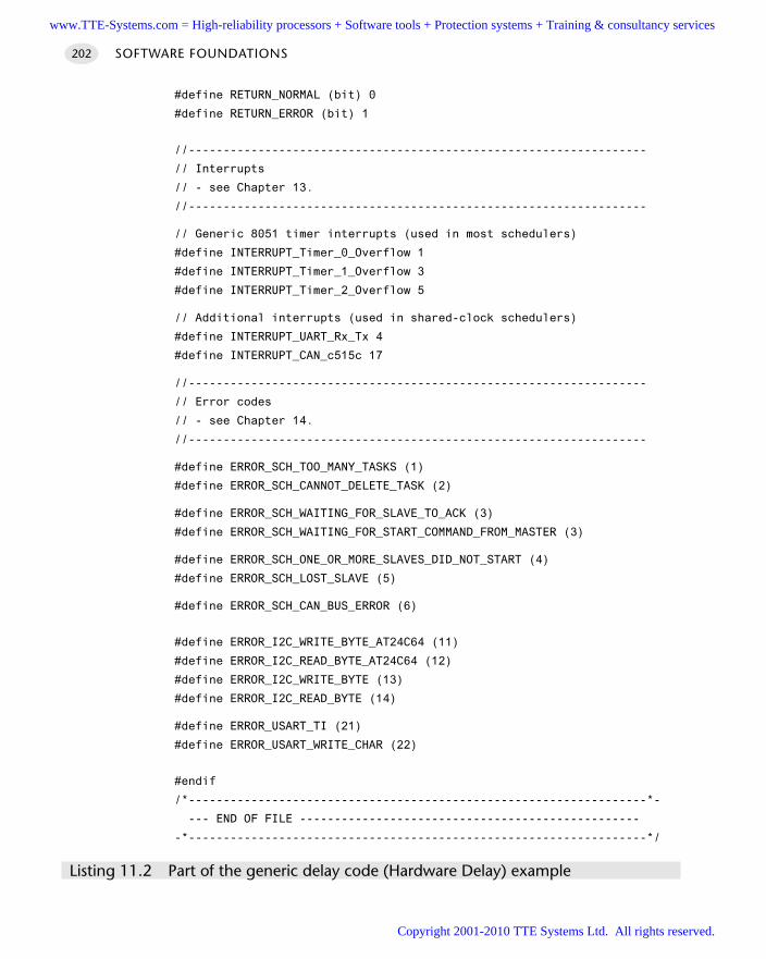
#define RETURN_NORMAL (bit) 0
#define RETURN_ERROR (bit) 1
//------------------------------------------------------------------
// Interrupts
// - see Chapter 13.
//------------------------------------------------------------------
// Generic 8051 timer interrupts (used in most schedulers)
#define INTERRUPT_Timer_0_Overflow 1
#define INTERRUPT_Timer_1_Overflow 3
#define INTERRUPT_Timer_2_Overflow 5
// Additional interrupts (used in shared-clock schedulers)
#define INTERRUPT_UART_Rx_Tx 4
#define INTERRUPT_CAN_c515c 17
//------------------------------------------------------------------
// Error codes
// - see Chapter 14.
//------------------------------------------------------------------
#define ERROR_SCH_TOO_MANY_TASKS (1)
#define ERROR_SCH_CANNOT_DELETE_TASK (2)
#define ERROR_SCH_WAITING_FOR_SLAVE_TO_ACK (3)
#define ERROR_SCH_WAITING_FOR_START_COMMAND_FROM_MASTER (3)
#define ERROR_SCH_ONE_OR_MORE_SLAVES_DID_NOT_START (4)
#define ERROR_SCH_LOST_SLAVE (5)
#define ERROR_SCH_CAN_BUS_ERROR (6)
#define ERROR_I2C_WRITE_BYTE_AT24C64 (11)
#define ERROR_I2C_READ_BYTE_AT24C64 (12)
#define ERROR_I2C_WRITE_BYTE (13)
#define ERROR_I2C_READ_BYTE (14)
#define ERROR_USART_TI (21)
#define ERROR_USART_WRITE_CHAR (22)
#endif
/*------------------------------------------------------------------*-
--- END OF FILE -------------------------------------------------
-*------------------------------------------------------------------*/
Listing 11.2 Part of the generic delay code (Hardware Delay) example
SOFTWARE FOUNDATIONS202
www.TTE-Systems.com = High-reliability processors + Software tools + Protection systems + Training & consultancy services
Copyright 2001-2010 TTE Systems Ltd. All rights reserved.
/*------------------------------------------------------------------*-
Main.C (v1.00)
------------------------------------------------------------------
Simple test program for hardware delay library.
-*------------------------------------------------------------------*/
#include "Main.h"
#include "Delay.h"
#include "LED_Flas.h"
void main(void)
LED_Flash_Init();
while (1)
LED_Flash_Update();
Hardware_Delay_T0(1000);
/*--------------------------------- --------------------------------*-
---- END OF FILE ------------------------------------------------
-*------------------------------------------------------------------*/
Listing 11.3 Part of the generic delay code (Hardware Delay) example
/*------------------------------------------------------------------*-
Delay_T0.C (vl.00)
------------------------------------------------------------------
Simple hardware delays based on T0.
-*------------------------------------------------------------------*/
#include "Main.H"
// ------ Private constants ----------------------------------------
// Timer preload values for use in simple (hardware) delays
// - Timers are 16-bit, manual reload ('one shot').
// NOTE: These values are portable but timings are *approximate*
// and *must* be checked by hand if accurate timing is required.
//
HARDWARE DELAY 203
www.TTE-Systems.com = High-reliability processors + Software tools + Protection systems + Training & consultancy services
Copyright 2001-2010 TTE Systems Ltd. All rights reserved.
// Define Timer 0 / Timer 1 reload values for ~1 msec delay
// NOTE: Adjustment made to allow for function call overheard etc.
#define PRELOAD01 (65536 - (tWord)(OSC_FREQ / (OSC_PER_INST * 1063)))
#define PRELOAD01H (PRELOAD01 / 256)
#define PRELOADO1L (PRELOAD01 % 256)
/*------------------------------------------------------------------*-
Hardware_Delay_T0()
Function to generate N millisecond delay (approx).
Uses Timer 0 (easily adapted to Timer 1).
-*------------------------------------------------------------------*/
void Hardware_Delay_T0(const tWord N)
tWord ms;
// Configure Timer 0 as a 16-bit timer
TMOD &= 0xF0: // Clear all T0 bits (T1 left unchanged)
TMOD |= 0x0l; // Set required T0 bits (T1 left unchanged)
ETO = 0; // No interupts
// Delay value is *approximately* 1 ms per loop
for (ms 0; ms < N; ms++)
TH0 = PRELOAD01H;
TL0 = PRELOAD01L;
TF0 = 0; // clear overflow flag
TR0 = 1; // start timer 0
while (TF0 == 0); // Loop until Timer 0 overflows (TF0 == 1)
TR0 = 0; // Stop Timer 0
/*------------------------------------------------------------------*-
------------ END OF FILE ----------------------------------------
-*------------------------------------------------------------------*/
Listing 11.4 Part of the generic delay code (Hardware Delay) example
The output from this project is shown running in the Keil hardware simulator inFigure 11.2. Note that the delay value obtained is within 0.001% of the requiredvalue.
SOFTWARE FOUNDATIONS204
www.TTE-Systems.com = High-reliability processors + Software tools + Protection systems + Training & consultancy services
Copyright 2001-2010 TTE Systems Ltd. All rights reserved.
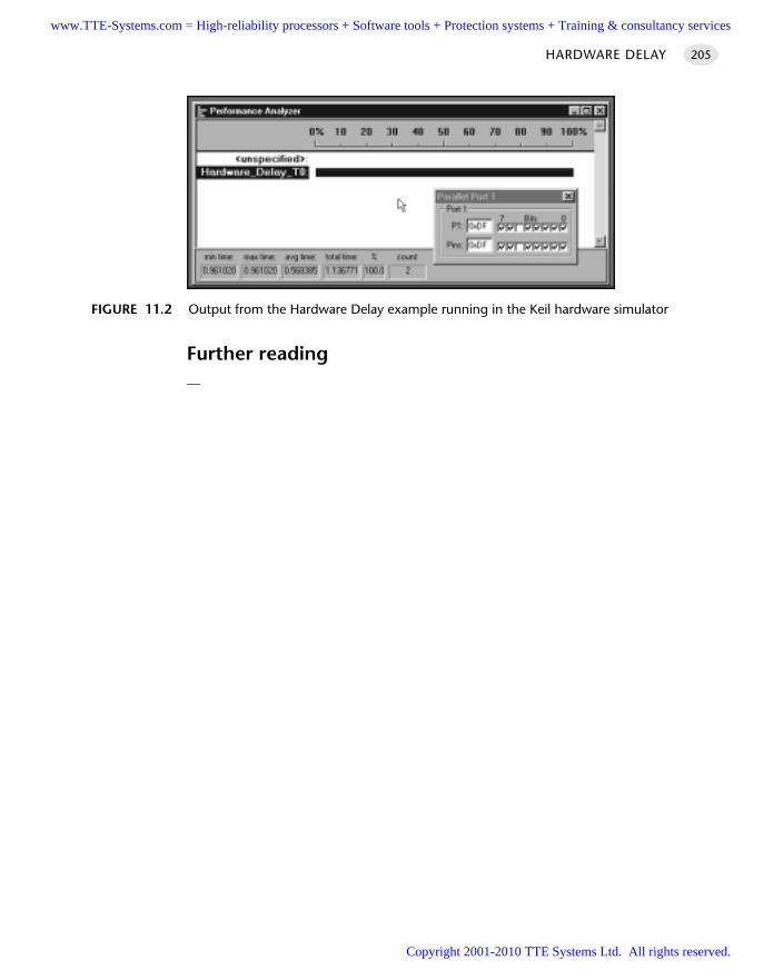
Further reading—
HARDWARE DELAY 205
FIGURE 11.2 Output from the Hardware Delay example running in the Keil hardware simulator
www.TTE-Systems.com = High-reliability processors + Software tools + Protection systems + Training & consultancy services
Copyright 2001-2010 TTE Systems Ltd. All rights reserved.
SOFTWARE DELAY
Context You are developing an embedded application using one or more members of the
8051 family of microcontrollers.
You are designing an appropriate software foundation for your application.
ProblemHow do you create a simple delay without using any hardware (timer) resources?
BackgroundSee H A R D WA R E D E L AY [page 194] for background information.
SolutionSuppose we want to flash the LEDs connected to Port 1 on an 8051 microcontrollerwith a two second cycle time (so that they are on for 1 second then off for 1 second,ad infinitum). The basic program structure we require could be based on a S U P E R L O O P
[page 162] as follows:
...
while (1)
P1 = 0xFF;
// Delay one second
P1 = 0x00;
// Delay one second
If we wish to implement these delays and have no available timers (see H A R D WA R E
D E L AY [page 194]), we could use a ‘Software Delay’, implemented as follows:
Loop_Delay()
unsigned int x;
for (x=0; x <= 65535; x++);
We could then measure the pulse frequency we obtained, using an oscilloscope ora software simulator. If we found that these delays were not long enough, we couldeasily extend them by adding additional layers, as shown in Longer_Loop_Delay()
SOFTWARE FOUNDATIONS206
www.TTE-Systems.com = High-reliability processors + Software tools + Protection systems + Training & consultancy services
Copyright 2001-2010 TTE Systems Ltd. All rights reserved.
Longer_Loop_Delay()
unsigned int x;
unsigned int y;
for (x=0; x<=65535; x++)
for (y=0; y<=65535; y++);
Hardware resource implicationsUnlike H A R D WA R E D E L AY [page 194], S O F T WA R E D E L AY uses no timer resources. Note,however, that the CPU time spent in the delay calculation is wasted: using a sched-uler (see Chapter 13) can, in many circumstances, avoid the waste of CPU time.
Reliability and safety implicationsSoftware delays are not suitable for use in applications where precise timing is required.
PortabilitySoftware delays can be used even on a microcontroller / microprocessor without abuilt-in timer. However, the precise delay duration obtained varies (enormously) withdifferences in hardware and software.
Overall strengths and weaknessesS O F T WA R E D E L AY can be used to produce very short delays.
S O F T WA R E D E L AY requires no hardware timers.
S O F T WA R E D E L AY will work on any microcontroller.
It is very difficult to produce precisely timed delays.
The loops must be returned if you decide to use a different processor, change theclock frequency or even change the compiler optimization settings.
Related patterns and alternative solutionsIn most circumstances, it is better to avoid using delays at all: see C O-O P E R AT I V E S C H E D-U L E R [page 255] for a delay-free alternative that will work in many circumstances.
If you do require delays then H A R D W A R E D E L AY [page 194] is often a betteralternative.
SOFTWARE DELAY 207
www.TTE-Systems.com = High-reliability processors + Software tools + Protection systems + Training & consultancy services
Copyright 2001-2010 TTE Systems Ltd. All rights reserved.
Example: Creating a 5 µs delay in an I2C libraryAs we discuss in Chapter 23, software implementation of the I2C serial protocol canrequire small delays. In Listing 11.5 we illustrate how a delay of around 5 µs can becreated in software for use in such a library.
/*------------------------------------------------------------------*-
_I2C_Delay()
A short software delay.
Adjust this for a minimum of 5.425 µs to work with 'standard' I2C devices. Any delay longer than this will also work.
With modern devices shorter delays may also be used.
NOTE: Cannot do this with a Hardware Delay!!!
-*------------------------------------------------------------------*/
void _I2C_Delay(void)
int x;
x++;
x++;
Listing 11.5 Creating a very short delay
Example: Flashing an LEDWe will repeat the ‘flashing LED’ example used in H A R D W A R E D E L AY [Page 194] toillustrate the S O F T WA R E D E L AY pattern.
To control the flashing of the LED, we will use an endless loop involving one S O F T-WA R E D E L AY and a ‘flash LED’ function.
We assume that we are using a Standard 8051 device with 12 oscillations perinstruction cycle and an oscillator frequency of 12 MHz. (see Chapter 4 for furtherdetails.)
The key files required in the project follow (Listings 11.6 to 11.11). As usualcomplete set of files are included on the CD.
/*------------------------------------------------------------------*-
Main.C (v1.00)
------------------------------------------------------------------
Simple test program for SOFTWARE DELAY pattern.
-*------------------------------------------------------------------*/
SOFTWARE FOUNDATIONS208
www.TTE-Systems.com = High-reliability processors + Software tools + Protection systems + Training & consultancy services
Copyright 2001-2010 TTE Systems Ltd. All rights reserved.
#include "Main.h"
#include "Loop_Del.h"
#include "LED_Flas.h"
void main(void)
LED_Flash_Init();
while (1)
LED_Flash_Update();
Loop_delay(1000);
/*------------------------------------------------------------------*-
---- END OF FILE ------------------------------------------------
-*------------------------------------------------------------------*/
Listing 11.6 Part of the Software Delay (flashing LED) example
/*------------------------------------------------------------------*-
Loop_Del.H (v1.00)
------------------------------------------------------------------
- See Loop_Del.C for details.
-*------------------------------------------------------------------*/
void Loop_delay(const unsigned int);
/*------------------------------------------------------------------*-
---------- END OF FILE ------------------------------------------
-*------------------------------------------------------------------*/
Listing 11.7 Part of the Software Delay (flashing LED) example
/*------------------------------------------------------------------*-
Loop_Del.c (v1.00)
------------------------------------------------------------------
Implementation of the pattern SOFTWARE DELAY.
-*------------------------------------------------------------------*/
void Loop_Delay(const unsigned int);
SOFTWARE DELAY 209
www.TTE-Systems.com = High-reliability processors + Software tools + Protection systems + Training & consultancy services
Copyright 2001-2010 TTE Systems Ltd. All rights reserved.
/*------------------------------------------------------------------*-
Loop_Delay()
Delay duration varies with parameter.
Parameter is, *ROUGHLY*, the delay, in milliseconds,
on 12MHz 8051 (12 osc cycles).
You need to adjust the timing for your application!
-*------------------------------------------------------------------*/
void Loop_Delay(const unsigned int DELAY)
unsigned int x, y:
for (x = 0; x <= DELAY; x++)
for (y = 0; y <= 120; y++);
/*------------------------------------------------------------------*-
------- END OF FILE ---------------------------------------------
-*------------------------------------------------------------------*/
Listing 11.8 Part of the Software Delay (flashing LED) example
/*------------------------------------------------------------------*-
LED_flas.H (v1.00)
------------------------------------------------------------------
- See LED_flas.C for details.
-*------------------------------------------------------------------*/
//------ Public function prototypes -------------------------------
void LED_Flash_Init(void);
void LED_Flash_Update(void);
/*------------------------------------------------------------------*-
---------- END OF FILE -------------------------------------------
-*------------------------------------------------------------------*/
Listing 11.9 Part of the Software Delay (flashing LED) example
SOFTWARE FOUNDATIONS210
www.TTE-Systems.com = High-reliability processors + Software tools + Protection systems + Training & consultancy services
Copyright 2001-2010 TTE Systems Ltd. All rights reserved.

/*------------------------------------------------------------------*-
LED_flas.C (v1.00)
------------------------------------------------------------------
Simple ‘Flash LED’ test function.
-*------------------------------------------------------------------*/
#include "Main.h"
#include "LED_flas.h"
// ------ Port pins -----------------------------------------------
// Connect LED from +5V (etc) to this pin, via appropriate resistor
// [see Chapter 7 for details]
sbit LED_Pin = P1^2;
// ------ Public variable definitions -----------------------------
static bit LED_state_G;
/*------------------------------------------------------------------*-
LED_Flash_Init()
- See below.
-*------------------------------------------------------------------*/
void LED_Flash_Init(void)
LED_state_G = 0;
/*------------------------------------------------------------------*-
LED_Flash_Update()
Flashes an LED (or pulses a buzzer, etc) on a specified port pin.
Must schedule at twice the required flash rate: thus, for 1 Hz
flash (on for 0.5 seconds, off for 0.5 seconds) must schedule
at 2 Hz.
-*------------------------------------------------------------------*/
void LED_Flash_Update(void)
// Change the LED from OFF to ON (or vice versa)
if (LED_state_G == 1)
SOFTWARE DELAY 211
www.TTE-Systems.com = High-reliability processors + Software tools + Protection systems + Training & consultancy services
Copyright 2001-2010 TTE Systems Ltd. All rights reserved.
LED_state_G 0;
LED_pin = 0;
else
LED_state_G = 1;
LED_pin = 1;
/*------------------------------------------------------------------*-
----------- END OF FILE -----------------------------------------
-*------------------------------------------------------------------*/
Listing 11.10 Part of the Software Delay (flashing LED) example
/*------------------------------------------------------------------*-
Main.H (v1.00)
------------------------------------------------------------------
‘Project Header’ (see Chap 9) for project S_Delay
-*------------------------------------------------------------------*/
#ifndef _MAIN_H
#define _MAIN_H
//------------------------------------------------------------------
// WILL NEED TO EDIT THIS SECTION FOR EVERY PROJECT
//------------------------------------------------------------------
// Must include the appropriate microcontroller header file here
#include <reg52.h>
// Include oscillator / chip details here
// (essential if generic delays / timeouts are used)
// -
// Oscillator / resonator frequency (in Hz) e.g. (11059200UL)
#define OSC_FREQ (12000000UL)
// Number of oscillations per instruction (e.g. 1, 4, 6 or 12)
// 12 - Original 8051 / 8052 and numerous modern versions
// 6 - Various Infineon and Philips devices, etc.
// 4 - Dallas, etc.
//
// Take care with Dallas devices
SOFTWARE FOUNDATIONS212
www.TTE-Systems.com = High-reliability processors + Software tools + Protection systems + Training & consultancy services
Copyright 2001-2010 TTE Systems Ltd. All rights reserved.
// - Timers default to *12* osc ticks unless CKCON is modified
// - If using generic code on a Dallas device, use 12 here
#define OSC_PER_INST (12)
//------------------------------------------------------------------
// SHOULD NOT NEED TO EDIT THE SECTIONS BELOW
//------------------------------------------------------------------
typedef unsigned char tByte;
typedef unsigned int tWord;
typedef unsigned long tLong;
// Misc #defines
#ifndef TRUE
#define FALSE 0
#define TRUE (!FALSE)
#endif
#define RETURN_NORMAL (bit) 0
#define RETURN_ERROR (bit) 1
//--------------------------------------------------------------------
// Interrupts
// - see Chapter 12.
//--------------------------------------------------------------------
// Generic 8051 timer interrupts (used in most schedulers)
#define INTERRUPT_Timer_0_Overflow 1
#define INTERRUPT_Timer_1_Overflow 3
#define INTERRUPT_Timer_2_Overflow 5
// Additional interrupts (used in shared-clock schedulers)
#define INTERRUPT_UART_Rx_Tx 4
#define INTERRUPT_CAN_c515c 17
//--------------------------------------------------------------------
// Error codes
// - see Chapter 13.
//--------------------------------------------------------------------
#define ERROR_SCH_TOO_MANY_TASKS (1)
#define ERROR_SCH_CANNOT_DELETE_TASK (2)
#define ERROR_SCH_WAITING_FOR_SLAVE_TO_ACK (3)
#define ERROR_SCH_WAITING_FOR_START_COMMAND_FROM_MASTER (3)
#define ERROR_SCH_ONE_OR_MORE_SLAVES_DID_NOT_START (4)
#define ERROR_SCH_LOST_SLAVE (5)
SOFTWARE DELAY 213
www.TTE-Systems.com = High-reliability processors + Software tools + Protection systems + Training & consultancy services
Copyright 2001-2010 TTE Systems Ltd. All rights reserved.
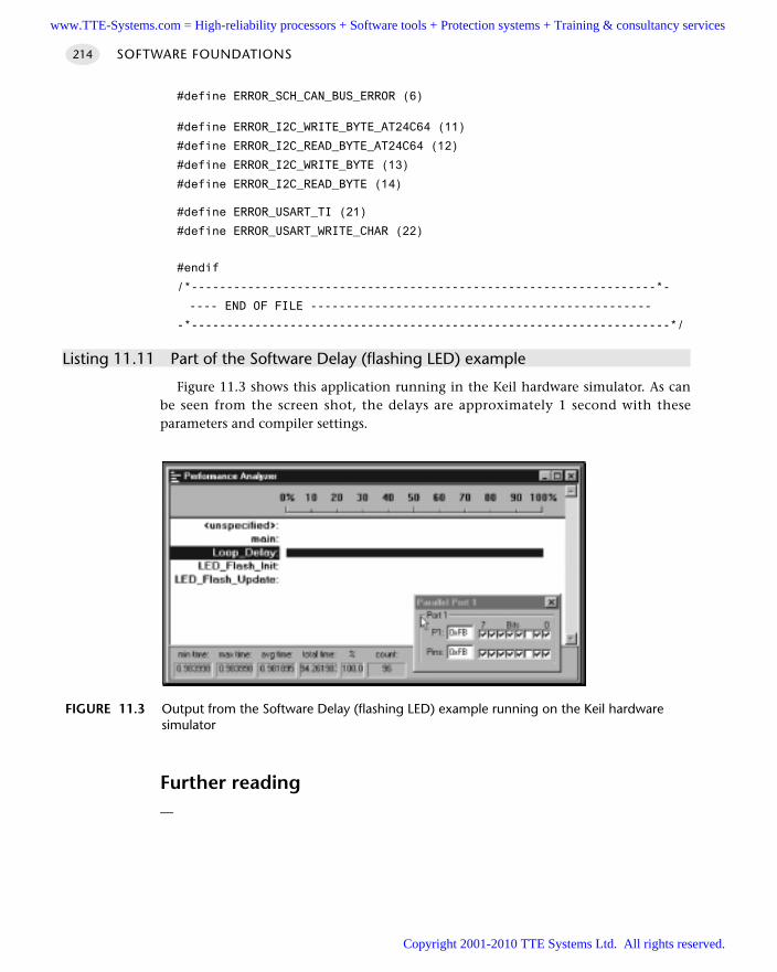
#define ERROR_SCH_CAN_BUS_ERROR (6)
#define ERROR_I2C_WRITE_BYTE_AT24C64 (11)
#define ERROR_I2C_READ_BYTE_AT24C64 (12)
#define ERROR_I2C_WRITE_BYTE (13)
#define ERROR_I2C_READ_BYTE (14)
#define ERROR_USART_TI (21)
#define ERROR_USART_WRITE_CHAR (22)
#endif
/*------------------------------------------------------------------*-
---- END OF FILE ------------------------------------------------
-*--------------------------------------------------------------------*/
Listing 11.11 Part of the Software Delay (flashing LED) example
Figure 11.3 shows this application running in the Keil hardware simulator. As canbe seen from the screen shot, the delays are approximately 1 second with theseparameters and compiler settings.
Further reading—
SOFTWARE FOUNDATIONS214
FIGURE 11.3 Output from the Software Delay (flashing LED) example running on the Keil hardwaresimulator
www.TTE-Systems.com = High-reliability processors + Software tools + Protection systems + Training & consultancy services
Copyright 2001-2010 TTE Systems Ltd. All rights reserved.
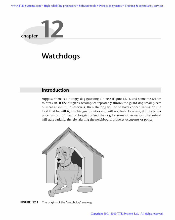
Watchdogs
Introduction
Suppose there is a hungry dog guarding a house (Figure 12.1), and someone wishesto break in. If the burglar’s accomplice repeatedly throws the guard dog small piecesof meat at 2-minute intervals, then the dog will be so busy concentrating on thefood that he will ignore his guard duties and will not bark. However, if the accom-plice run out of meat or forgets to feed the dog for some other reason, the animalwill start barking, thereby alerting the neighbours, property occupants or police.
chapter 12
FIGURE 12.1 The origins of the ‘watchdog’ analogy
www.TTE-Systems.com = High-reliability processors + Software tools + Protection systems + Training & consultancy services
Copyright 2001-2010 TTE Systems Ltd. All rights reserved.
This same basic approach is followed in computerized ‘watchdog timers’. Verysimply, these are timers which, if not refreshed at regular intervals, will overflow. Inmost cases, overflow of the timer will reset the system. Such watchdogs are intendedto deal with the fact that, even with meticulous planning and careful design, embed-ded systems can ‘hang’ due to unexpected problems. The use of a watchdog can beused to recover from this situation, in certain circumstances.
The pattern H A R D WA R E WAT C H D O G [page 217] considers how to apply these tech-niques to good effect in your embedded application.
SOFTWARE FOUNDATIONS216
www.TTE-Systems.com = High-reliability processors + Software tools + Protection systems + Training & consultancy services
Copyright 2001-2010 TTE Systems Ltd. All rights reserved.
HARDWARE WATCHDOG
Context You are developing an embedded application using one or more members of the
8051 family of microcontrollers.
You are designing an appropriate software foundation for your application.
ProblemHow can you ensure that – if your application ‘hangs’ due to an unexpected softwareor hardware error – the system will automatically reset itself?
BackgroundSee the introduction to this chapter for an explanation of the watchdog analogy.
SolutionWorking with H A R D WA R E WAT C H D O G means using either an internal or external (hard-ware) timer.
We have seen in many previous cases that, where available, the use of on-chipcomponents is to be preferred to the use of equivalent off-chip components.Specifically, on-chip components generally offer the following benefits:
Reduced hardware complexity, which tends to result in increased system reliability.
Reduced application cost.
Reduced application size.
In the case of watchdog timers, the situation is more complex, because externalwatchdog chips typically provide some useful facilities that are not available in moston-chip versions.
For example, the popular ‘1232’ watchdogs (available, in various versions, fromDallas Semiconductors, Maxim, Linear Technology and Analog Devices) are low-cost,low-power devices. In addition to functioning as a watchdog timer, they also providepower system monitoring capabilities (see R O B U S T R E S E T [page 77] for details of this).If, as in many designs, you intend to use an external ‘robust reset’ circuit anyway,then the 1232 chips allow you to incorporate an external watchdog facility for mini-mal addition cost and only a very minor increase in hardware complexity.
Another beneficial feature of external watchdogs is that they are inherentlyportable: you can generally use the same external watchdog with any member of the8051 family. By contrast, code written to work with an internal watchdog will gener-ally have to be rewritten for use with a different hardware.
HARDWARE WATCHDOG 217
www.TTE-Systems.com = High-reliability processors + Software tools + Protection systems + Training & consultancy services
Copyright 2001-2010 TTE Systems Ltd. All rights reserved.
SOFTWARE FOUNDATIONS218
One situation in which on-chip watchdogs (such as those in the Infineon c515xdevices) can be beneficial is where they allow you to determine whether the systemhas undergone a normal reset or a reset caused by a watchdog overflow. This mayallow you to modify the system behaviour to match these circumstances. Withoutthis information (which is not generally available through external watchdogs with-out some complex coding) your system may be continually reset by the watchdogtimer overflow.
We can summarize by saying that, if you require watchdog facilities, you need toconsider both internal and external solutions carefully. There is no single ‘ideal’ solu-tion and – considering the issues mentioned earlier – you need to find the best matchto your requirements.
Reliability and safety implicationsBefore using either an internal or external watchdog, you need to be sure that the useof such a timer will increase (rather than decrease) the reliability of your application.
The first thing to bear in mind is that watchdog behaviour should be for disasterrecovery. In a well-designed system the occurrence of a watchdog reset should be anoteworthy event that occurs rarely. If you think of the use of watchdogs in terms of‘if all else falls, then we will have to let the watchdog reset the system’, then you aretaking a realistic view of the capabilities of this approach.
Used without due care at the design phase and/or adequate testing, watchdogs canreduce the system reliability dramatically. A particular problem with a badly designedwatchdog can occur in the presence of sustained hardware faults. In these circum-stances, a badly implemented watchdog can mean that your system constantly resetsitself. This can be extremely dangerous.
You also need to appreciate that watchdogs are unsuitable for many applications,because the time taken to react to an error is too long. Suppose, for example, the brakingsystem in an automotive application uses a 500 ms watchdog and the vehicle encountersa problem when it is travelling at 70 miles per hour (110 km per hour). In these circum-stances, the vehicle and its passengers will have travelled some 16 yards / 15 metres –right into the car in front – before the vehicle even begins to reset the braking system. Inshort, where fast recovery is required, watchdogs are rarely the best solution.
PortabilityAs already noted, internal watchdogs are based on hardware that is not part of the8051/52 core. As a result, different forms of watchdog now exist on the various differ-ent 8051 derivatives and code written for one on-chip watchdog will generally needto be adapted for use with a different device. By contrast, software written for externalwatchdogs can be more portable.
www.TTE-Systems.com = High-reliability processors + Software tools + Protection systems + Training & consultancy services
Copyright 2001-2010 TTE Systems Ltd. All rights reserved.
HARDWARE WATCHDOG 219
Overall strengths and weaknessesWatchdogs can provide a ‘last resort’ form of error recovery. If you think ofthe use of watchdogs in terms of ‘if all else fails, then reset the system’, thenyou are taking a realistic view of the capabilities of this approach.
In the presence of intermittent faults, e.g. rare bursts of EMI, watchdogs canbe very effective.
Watchdogs with long timeout periods are unsuitable for many applications.
Used without due care at the design phase and / or adequate testing, watchdogscan reduce the system reliability dramatically.
In the presence of sustained hardware faults, badly implemented watchdogs canmean that your system constantly resets itself. This can be very dangerous.
Related patterns and alternative solutionsIn certain restricted circumstances, a software watchdog may also be useful.
This can be created from two components:
A timer ISR
A refresh function
Essentially, we set a timer to overflow in (say) 60 ms. Under normal circumstances,this timer will never overflow, because we will call the refresh function regularly andthereby restart the timer. If, however, the program is ‘jammed’, the refresh functionwill not be called. When the timer overflows, the ISR will be called: this will imple-ment an ‘appropriate’ error recovery strategy.
We have used software watchdogs in several applications. The main problem withthis approach is that some software errors (for example, those induced by EMI) candisrupt the watchdog timer as well as the main application code: this rarely happenswith hardware watchdogs, which tend to be more robust.
The main advantage with software watchdogs is that different forms of error recov-ery (not just a complete chip reset) are possible. However, use of an on-chip hardwarewatchdog can provide flexible reset behaviour and is, in many circumstances, a morereliable solution.
Example: Using the ‘1232’ external watchdog timerIn this example we assume that we will be developing a simple central-heating con-trol system and will be using an external ‘1232’ watchdog chip to improve thereliability of the application.
The use of the 1232 is very straightforward:
We wire up the watchdog to the microcontroller reset pin, as illustrated in Figure 12.2.
www.TTE-Systems.com = High-reliability processors + Software tools + Protection systems + Training & consultancy services
Copyright 2001-2010 TTE Systems Ltd. All rights reserved.
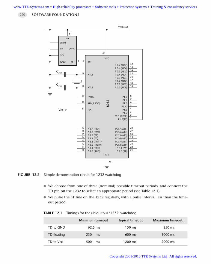
We choose from one of three (nominal) possible timeout periods, and connect theTD pin on the 1232 to select an appropriate period (see Table 12.1).
We pulse the ST line on the 1232 regularly, with a pulse interval less than the time-out period.
SOFTWARE FOUNDATIONS220
FIGURE 12.2 Simple demonstration circuit for 1232 watchdog
RST
XTL1
XTL2
/PSEN
ALE(/PROG)
/EA
P 3.7 (/RD)P 3.6 (/WR)P 3.5 (T1)P 3.4 (T0)P 3.3 (/INT1)P 3.2 (/INT0)P 3.1 (TXD)P 3.0 (RXD)
P 0.7 (AD7)P 0.6 (AD6)P 0.5 (AD5)P 0.4 (AD4)P 0.3 (AD3)P 0.2 (AD2)P 0.1 (AD1)P 0.0 (AD0)
P1.7P1.6P1.5
P1.4)P1.3P1.2
P1.1 (T2EX)P1.0(T2)
P 2.7 (A15)P 2.6 (A14)P 2.5 (A13)P 2.4 (A12)P 2.3 (A11)P 2.2 (A10)P 2.1 (A9)P 2.0 (A8)
VCC
8052
VSS
3233343536373839
87654321
2827262524232221
9
19
18
29
30
31
1716151413121110
20
40
Vcc
Cxtal
Cxtal
/PBRST
TD
TOL
GND
/STO
RST
Vcc
Vcc(+5V)
8
5
TABLE 12.1 Timings for the ubiquitous ‘1232’ watchdog
Minimum timeout Typical timeout Maximum timeout
TD to GND 62.5 ms 150 ms 250 ms
TD floating 250 ms 600 ms 1000 ms
TD to Vcc 500 ms 1200 ms 2000 ms
www.TTE-Systems.com = High-reliability processors + Software tools + Protection systems + Training & consultancy services
Copyright 2001-2010 TTE Systems Ltd. All rights reserved.
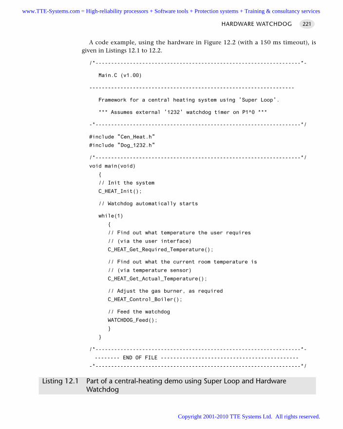
HARDWARE WATCHDOG 221
A code example, using the hardware in Figure 12.2 (with a 150 ms timeout), isgiven in Listings 12.1 to 12.2.
/*------------------------------------------------------------------*-
Main.C (v1.00)
------------------------------------------------------------------
Framework for a central heating system using 'Super Loop'.
*** Assumes external '1232' watchdog timer on P1^0 ***
-*------------------------------------------------------------------*/
#include "Cen_Heat.h"
#include "Dog_1232.h"
/*------------------------------------------------------------------*/
void main(void)
// Init the system
C_HEAT_Init();
// Watchdog automatically starts
while(1)
// Find out what temperature the user requires
// (via the user interface)
C_HEAT_Get_Required_Temperature();
// Find out what the current room temperature is
// (via temperature sensor)
C_HEAT_Get_Actual_Temperature();
// Adjust the gas burner, as required
C_HEAT_Control_Boiler();
// Feed the watchdog
WATCHDOG_Feed();
/*------------------------------------------------------------------*-
-------- END OF FILE --------------------------------------------
-*------------------------------------------------------------------*/
Listing 12.1 Part of a central-heating demo using Super Loop and Hardware Watchdog
www.TTE-Systems.com = High-reliability processors + Software tools + Protection systems + Training & consultancy services
Copyright 2001-2010 TTE Systems Ltd. All rights reserved.
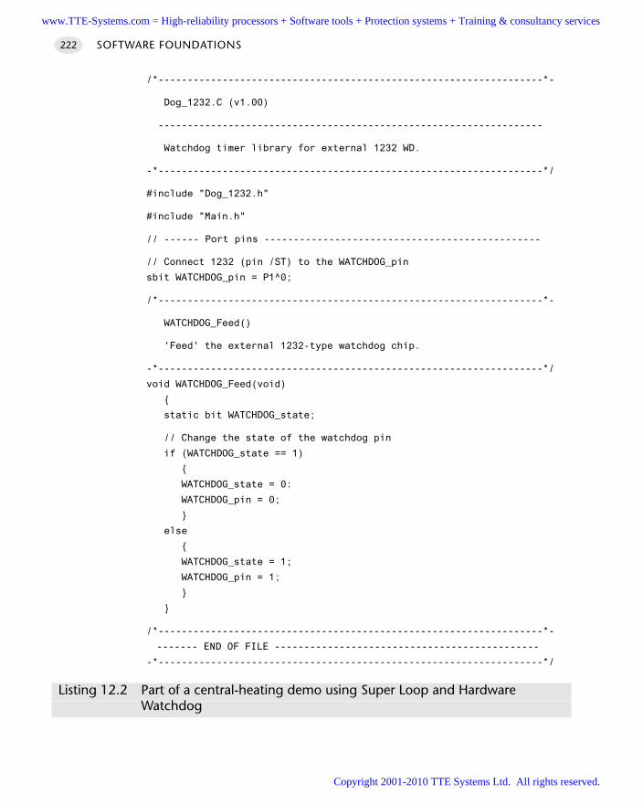
SOFTWARE FOUNDATIONS222
/*------------------------------------------------------------------*-
Dog_1232.C (v1.00)
------------------------------------------------------------------
Watchdog timer library for external 1232 WD.
-*------------------------------------------------------------------*/
#include "Dog_1232.h"
#include "Main.h"
// ------ Port pins -----------------------------------------------
// Connect 1232 (pin /ST) to the WATCHDOG_pin
sbit WATCHDOG_pin = P1^0;
/*------------------------------------------------------------------*-
WATCHDOG_Feed()
'Feed' the external 1232-type watchdog chip.
-*------------------------------------------------------------------*/
void WATCHDOG_Feed(void)
static bit WATCHDOG_state;
// Change the state of the watchdog pin
if (WATCHDOG_state == 1)
WATCHDOG_state = 0:
WATCHDOG_pin = 0;
else
WATCHDOG_state = 1;
WATCHDOG_pin = 1;
/*------------------------------------------------------------------*-
------- END OF FILE ---------------------------------------------
-*------------------------------------------------------------------*/
Listing 12.2 Part of a central-heating demo using Super Loop and HardwareWatchdog
www.TTE-Systems.com = High-reliability processors + Software tools + Protection systems + Training & consultancy services
Copyright 2001-2010 TTE Systems Ltd. All rights reserved.
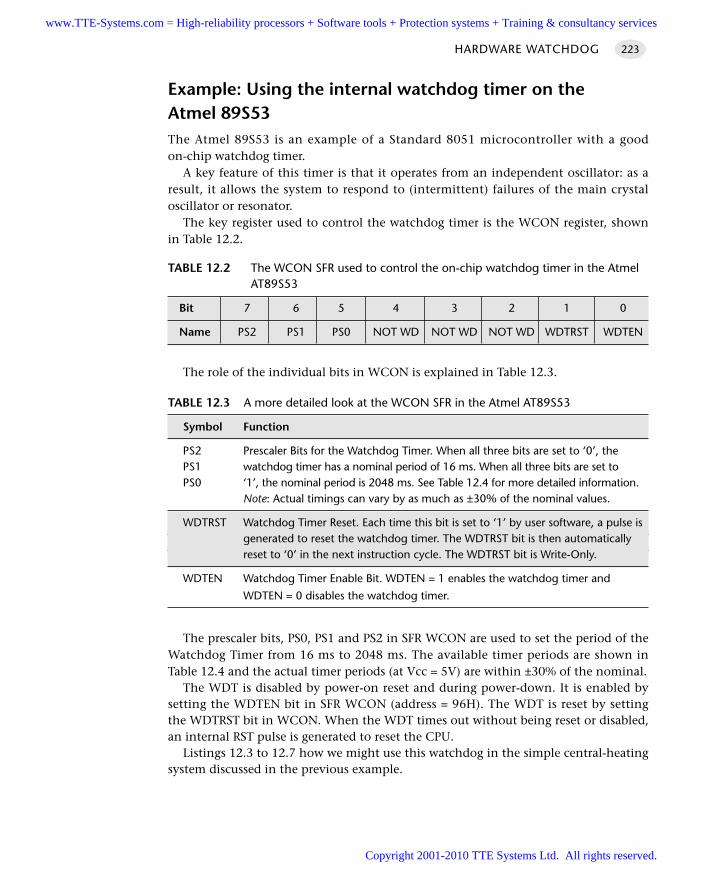
Example: Using the internal watchdog timer on the Atmel 89S53The Atmel 89S53 is an example of a Standard 8051 microcontroller with a goodon-chip watchdog timer.
A key feature of this timer is that it operates from an independent oscillator: as aresult, it allows the system to respond to (intermittent) failures of the main crystaloscillator or resonator.
The key register used to control the watchdog timer is the WCON register, shownin Table 12.2.
The role of the individual bits in WCON is explained in Table 12.3.
The prescaler bits, PS0, PS1 and PS2 in SFR WCON are used to set the period of theWatchdog Timer from 16 ms to 2048 ms. The available timer periods are shown inTable 12.4 and the actual timer periods (at Vcc = 5V) are within ±30% of the nominal.
The WDT is disabled by power-on reset and during power-down. It is enabled bysetting the WDTEN bit in SFR WCON (address = 96H). The WDT is reset by settingthe WDTRST bit in WCON. When the WDT times out without being reset or disabled,an internal RST pulse is generated to reset the CPU.
Listings 12.3 to 12.7 how we might use this watchdog in the simple central-heatingsystem discussed in the previous example.
HARDWARE WATCHDOG 223
TABLE 12.2 The WCON SFR used to control the on-chip watchdog timer in the AtmelAT89S53
Bit 7 6 5 4 3 2 1 0
Name PS2 PS1 PS0 NOT WD NOT WD NOT WD WDTRST WDTEN
TABLE 12.3 A more detailed look at the WCON SFR in the Atmel AT89S53
Symbol Function
PS2 Prescaler Bits for the Watchdog Timer. When all three bits are set to ‘0’, the PS1 watchdog timer has a nominal period of 16 ms. When all three bits are set to PS0 ‘1’, the nominal period is 2048 ms. See Table 12.4 for more detailed information.
Note: Actual timings can vary by as much as ±30% of the nominal values.
WDTRST Watchdog Timer Reset. Each time this bit is set to ‘1’ by user software, a pulse isgenerated to reset the watchdog timer. The WDTRST bit is then automatically reset to ‘0’ in the next instruction cycle. The WDTRST bit is Write-Only.
WDTEN Watchdog Timer Enable Bit. WDTEN = 1 enables the watchdog timer and
WDTEN = 0 disables the watchdog timer.
www.TTE-Systems.com = High-reliability processors + Software tools + Protection systems + Training & consultancy services
Copyright 2001-2010 TTE Systems Ltd. All rights reserved.
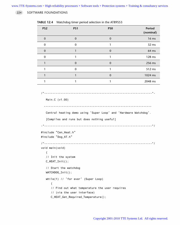
SOFTWARE FOUNDATIONS224
/*------------------------------------------------------------------*-
Main.C (v1.00)
------------------------------------------------------------------
Central heating demo using 'Super Loop' and 'Hardware Watchdog'.
[Compiles and runs but does nothing useful]
-*------------------------------------------------------------------*/
#include "Cen_Heat.h"
#include "Dog_AT.h"
/*------------------------------------------------------------------*/
void main(void)
// Init the system
C_HEAT_Init();
// Start the watchdog
WATCHDOG_Init();
while(1) // 'for ever' (Super Loop)
// Find out what temperature the user requires
// (via the user interface)
C_HEAT_Get_Required_Temperature();
TABLE 12.4 Watchdog timer period selection in the AT89S53
PS2 PS1 PS0 Period(nominal)
0 0 0 16 ms
0 0 1 32 ms
0 1 0 64 ms
0 1 1 128 ms
1 0 0 256 ms
1 0 1 512 ms
1 1 0 1024 ms
1 1 1 2048 ms
www.TTE-Systems.com = High-reliability processors + Software tools + Protection systems + Training & consultancy services
Copyright 2001-2010 TTE Systems Ltd. All rights reserved.
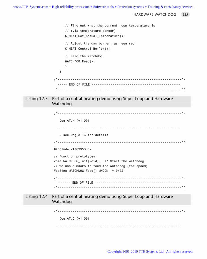
// Find out what the current room temperature is
// (via temperature sensor)
C_HEAT_Get_Actual_Temperature();
// Adjust the gas burner, as required
C_HEAT_Control_Boiler();
// Feed the watchdog
WATCHDOG_Feed();
/*------------------------------------------------------------------*-
----- END OF FILE -----------------------------------------------
-*------------------------------------------------------------------*/
Listing 12.3 Part of a central-heating demo using Super Loop and HardwareWatchdog
/*------------------------------------------------------------------*-
Dog_AT.H (v1.00)
------------------------------------------------------------------
- see Dog_AT.C for details
-*------------------------------------------------------------------*/
#include <At89S53.h>
// Function prototypes
void WATCHDOG_Init(void); // Start the watchdog
// We use a macro to feed the watchdog (for speed)
#define WATCHDOG_Feed() WMCON |= 0x02
/*------------------------------------------------------------------*-
------- END OF FILE ---------------------------------------------
-*------------------------------------------------------------------*/
Listing 12.4 Part of a central-heating demo using Super Loop and HardwareWatchdog
-*------------------------------------------------------------------*-
Dog_AT.C (v1.00)
------------------------------------------------------------------
HARDWARE WATCHDOG 225
www.TTE-Systems.com = High-reliability processors + Software tools + Protection systems + Training & consultancy services
Copyright 2001-2010 TTE Systems Ltd. All rights reserved.
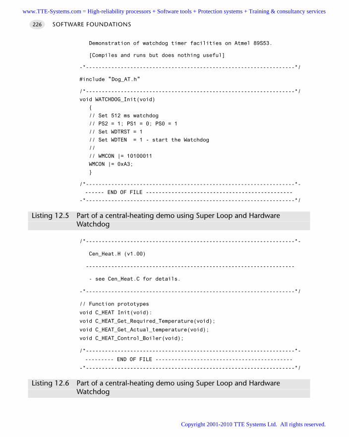
Demonstration of watchdog timer facilities on Atmel 89S53.
[Compiles and runs but does nothing useful]
-*------------------------------------------------------------------*/
#include "Dog_AT.h"
/*------------------------------------------------------------------*/
void WATCHDOG_Init(void)
// Set 512 ms watchdog
// PS2 = 1; PS1 = 0; PS0 = 1
// Set WDTRST = 1
// Set WDTEN = 1 - start the Watchdog
//
// WMCON |= 10100011
WMCON |= 0xA3;
/*------------------------------------------------------------------*-
------ END OF FILE ----------------------------------------------
-*------------------------------------------------------------------*/
Listing 12.5 Part of a central-heating demo using Super Loop and HardwareWatchdog
/*------------------------------------------------------------------*-
Cen_Heat.H (v1.00)
------------------------------------------------------------------
- see Cen_Heat.C for details.
-*------------------------------------------------------------------*/
// Function prototypes
void C_HEAT Init(void):
void C_HEAT_Get_Required_Temperature(void);
void C_HEAT_Get_Actual_temperature(void);
void C_HEAT_Control_Boiler(void);
/*------------------------------------------------------------------*-
--------- END OF FILE -------------------------------------------
-*------------------------------------------------------------------*/
Listing 12.6 Part of a central-heating demo using Super Loop and HardwareWatchdog
SOFTWARE FOUNDATIONS226
www.TTE-Systems.com = High-reliability processors + Software tools + Protection systems + Training & consultancy services
Copyright 2001-2010 TTE Systems Ltd. All rights reserved.
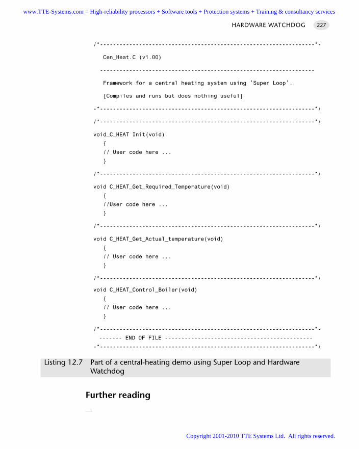
/*------------------------------------------------------------------*-
Cen_Heat.C (v1.00)
------------------------------------------------------------------
Framework for a central heating system using 'Super Loop'.
[Compiles and runs but does nothing useful]
-*------------------------------------------------------------------*/
/*------------------------------------------------------------------*/
void_C_HEAT Init(void)
// User code here ...
/*------------------------------------------------------------------*/
void C_HEAT_Get_Required_Temperature(void)
//User code here ...
/*------------------------------------------------------------------*/
void C_HEAT_Get_Actual_temperature(void)
// User code here ...
/*------------------------------------------------------------------*/
void C_HEAT_Control_Boiler(void)
// User code here ...
/*------------------------------------------------------------------*-
------- END OF FILE ---------------------------------------------
-*------------------------------------------------------------------*/
Listing 12.7 Part of a central-heating demo using Super Loop and HardwareWatchdog
Further reading
—
HARDWARE WATCHDOG 227
www.TTE-Systems.com = High-reliability processors + Software tools + Protection systems + Training & consultancy services
Copyright 2001-2010 TTE Systems Ltd. All rights reserved.

www.TTE-Systems.com = High-reliability processors + Software tools + Protection systems + Training & consultancy services
Copyright 2001-2010 TTE Systems Ltd. All rights reserved.
Time-triggered architectures for single-processor systems
This book is primarily concerned with the creation of time-triggered embedded systems.
Having laid the foundations, we are now in a position to consider in detail the ways in
which time-triggered software architectures may be created, in ‘C’, for the 8051 family.
In Chapter 13, we introduce schedulers and explain how they may be used to create effi-
cient time-triggered applications.
In Chapter 14, we describe, in detail, the construction of C O - O P E R AT I V E S C H E D U L E R
[page 255]. This simple but flexible environment is suitable for use with a very wide range
of embedded applications.
Using a co-operative scheduler in your application has a number of benefits, one of
which being that the development process is simiplified. However, to get the maximum
benefit from the scheduler you need to approach the design in a slightly different (‘task
oriented’) way. We discuss how to do this in Chapter 15 and Chapter 16.
Finally, in Chapter 17, we present H Y B R I D S C H E D U L E R [page 333]. Like all of the sched-
uler patterns in this book, H Y B R I D S C H E D U L E R is based on a co-operative scheduler;
however, this version is also able to support a single pre-emptive task.
part cwww.TTE-Systems.com = High-reliability processors + Software tools + Protection systems + Training & consultancy services
Copyright 2001-2010 TTE Systems Ltd. All rights reserved.

www.TTE-Systems.com = High-reliability processors + Software tools + Protection systems + Training & consultancy services
Copyright 2001-2010 TTE Systems Ltd. All rights reserved.
An introduction to schedulers
In this chapter, we see that schedulers can play a similar role in embedded systems to that
played by ‘Windows’ (or other operating systems) in many modern desktop applications.
13.1 Introduction
Having laid the foundations in Parts A and B, we are now in a position to look indetail at the ways in which time-triggered applications may be created with the 8051family of microcontrollers.
To produce such applications, we will use a scheduler: this is a very simple operatingenvironment for embedded applications. In this introductory chapter, we explain whata scheduler is and the differences between co-operative and pre-emptive scheduling.We will also explain why the use of a co-operative scheduler can help to make even thesmallest of embedded applications easier to develop and more reliable in operation.
To place the discussions in the rest of the chapter in context, we begin by brieflyreviewing the reasons why desktop systems employ an operating system and explain-ing why such an OS is not appropriate for use with the type of embedded systemsconsidered in this book.
13.2 The desktop OS
As stated in the preface, it is assumed in this book that readers will have had previousexperience of software development for desktop computer systems. As we discussed inChapter 1, the desktop / workstation environment plays host to many information sys-tems, as well as general-purpose desktop applications, such as word processors. A
chapter 13www.TTE-Systems.com = High-reliability processors + Software tools + Protection systems + Training & consultancy services
Copyright 2001-2010 TTE Systems Ltd. All rights reserved.
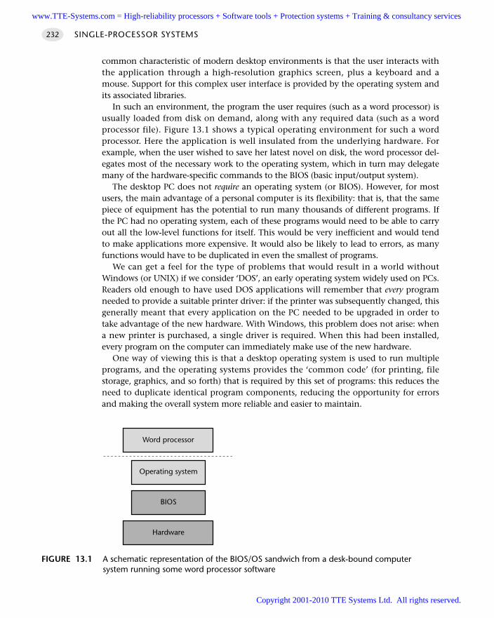
common characteristic of modern desktop environments is that the user interacts withthe application through a high-resolution graphics screen, plus a keyboard and amouse. Support for this complex user interface is provided by the operating system andits associated libraries.
In such an environment, the program the user requires (such as a word processor) isusually loaded from disk on demand, along with any required data (such as a wordprocessor file). Figure 13.1 shows a typical operating environment for such a wordprocessor. Here the application is well insulated from the underlying hardware. Forexample, when the user wished to save her latest novel on disk, the word processor del-egates most of the necessary work to the operating system, which in turn may delegatemany of the hardware-specific commands to the BIOS (basic input/output system).
The desktop PC does not require an operating system (or BIOS). However, for mostusers, the main advantage of a personal computer is its flexibility: that is, that the samepiece of equipment has the potential to run many thousands of different programs. Ifthe PC had no operating system, each of these programs would need to be able to carryout all the low-level functions for itself. This would be very inefficient and would tendto make applications more expensive. It would also be likely to lead to errors, as manyfunctions would have to be duplicated in even the smallest of programs.
We can get a feel for the type of problems that would result in a world withoutWindows (or UNIX) if we consider ‘DOS’, an early operating system widely used on PCs.Readers old enough to have used DOS applications will remember that every programneeded to provide a suitable printer driver: if the printer was subsequently changed, thisgenerally meant that every application on the PC needed to be upgraded in order totake advantage of the new hardware. With Windows, this problem does not arise: whena new printer is purchased, a single driver is required. When this had been installed,every program on the computer can immediately make use of the new hardware.
One way of viewing this is that a desktop operating system is used to run multipleprograms, and the operating systems provides the ‘common code’ (for printing, filestorage, graphics, and so forth) that is required by this set of programs: this reduces theneed to duplicate identical program components, reducing the opportunity for errorsand making the overall system more reliable and easier to maintain.
SINGLE-PROCESSOR SYSTEMS232
FIGURE 13.1 A schematic representation of the BIOS/OS sandwich from a desk-bound computersystem running some word processor software
Word processor
Operating system
BIOS
Hardware
www.TTE-Systems.com = High-reliability processors + Software tools + Protection systems + Training & consultancy services
Copyright 2001-2010 TTE Systems Ltd. All rights reserved.
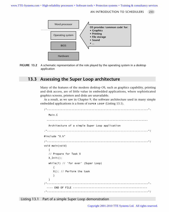
13.3 Assessing the Super Loop architecture
Many of the features of the modern desktop OS, such as graphics capability, printingand disk access, are of little value in embedded applications, where sophisticatedgraphics screens, printers and disks are unavailable.
As a result, as we saw in Chapter 9, the software architecture used in many simpleembedded applications is a form of S U P E R L O O P (Listing 13.1).
/*------------------------------------------------------------------*-
Main.C
------------------------------------------------------------------
Architecture of a simple Super Loop application
-*------------------------------------------------------------------*/
#include "X.h"
/*------------------------------------------------------------------*/
void main(void)
// Prepare for Task X
X_Init();
while(1) // 'for ever' (Super Loop)
X(); // Perform the task
/*------------------------------------------------------------------*-
---- END OF FILE ------------------------------------------------
-*------------------------------------------------------------------*/
Listing 13.1 Part of a simple Super Loop demonstration
AN INTRODUCTION TO SCHEDULERS 233
FIGURE 13.2 A schematic representation of the role played by the operating system in a desktopapplication
Word processor
Operating system
BIOS
Hardware
OS provides 'common code' for:• Graphics• Printing• File storage• Sound• ...
www.TTE-Systems.com = High-reliability processors + Software tools + Protection systems + Training & consultancy services
Copyright 2001-2010 TTE Systems Ltd. All rights reserved.
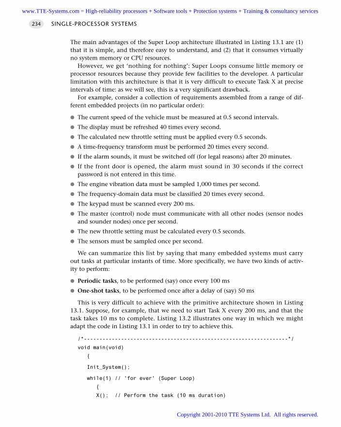
The main advantages of the Super Loop architecture illustrated in Listing 13.1 are (1)that it is simple, and therefore easy to understand, and (2) that it consumes virtuallyno system memory or CPU resources.
However, we get ‘nothing for nothing’: Super Loops consume little memory orprocessor resources because they provide few facilities to the developer. A particularlimitation with this architecture is that it is very difficult to execute Task X at preciseintervals of time: as we will see, this is a very significant drawback.
For example, consider a collection of requirements assembled from a range of dif-ferent embedded projects (in no particular order):
The current speed of the vehicle must be measured at 0.5 second intervals.
The display must be refreshed 40 times every second.
The calculated new throttle setting must be applied every 0.5 seconds.
A time-frequency transform must be performed 20 times every second.
If the alarm sounds, it must be switched off (for legal reasons) after 20 minutes.
If the front door is opened, the alarm must sound in 30 seconds if the correctpassword is not entered in this time.
The engine vibration data must be sampled 1,000 times per second.
The frequency-domain data must be classified 20 times every second.
The keypad must be scanned every 200 ms.
The master (control) node must communicate with all other nodes (sensor nodesand sounder nodes) once per second.
The new throttle setting must be calculated every 0.5 seconds.
The sensors must be sampled once per second.
We can summarize this list by saying that many embedded systems must carryout tasks at particular instants of time. More specifically, we have two kinds of activ-ity to perform:
Periodic tasks, to be performed (say) once every 100 ms
One-shot tasks, to be performed once after a delay of (say) 50 ms
This is very difficult to achieve with the primitive architecture shown in Listing13.1. Suppose, for example, that we need to start Task X every 200 ms, and that thetask takes 10 ms to complete. Listing 13.2 illustrates one way in which we mightadapt the code in Listing 13.1 in order to try to achieve this.
/*------------------------------------------------------------------*/
void main(void)
Init_System();
while(1) // 'for ever' (Super Loop)
X(); // Perform the task (10 ms duration)
SINGLE-PROCESSOR SYSTEMS234
www.TTE-Systems.com = High-reliability processors + Software tools + Protection systems + Training & consultancy services
Copyright 2001-2010 TTE Systems Ltd. All rights reserved.
Delay_190ms(); // Delay for 190 ms
Listing 13.2 Trying to use the Super Loop architecture to execute tasks at regular intervals
The approach illustrated in Listing 13.2 is not generally adequate, because it will onlywork if the following conditions are satisfied:
1 We know the precise duration of Task X
2 This duration never varies
In practical applications, determining the precise task duration is rarely straightfor-ward. Suppose we have a very simple task that does not interact with the outsideworld but, instead, performs some internal calculations. Even under these ratherrestricted circumstances, changes to compiler optimization settings – even changes toan apparently unrelated part of the program – can alter the speed at which the taskexecutes. This can make fine-tuning the timing very tedious and error prone.
The second condition is even more problematic. Often in an embedded system thetask will be required to interact with the outside world in a complex way. In these cir-cumstances the task duration will vary according to outside activities in a mannerover which the programmer has very little control.
13.4 A better solution
A better solution to the problems outlined is to use timer-based interrupts as a meansof invoking functions at particular times.
Timer-based interrupts and interrupt service routines
As we saw in Chapter 1, an interrupt is a hardware mechanism used to notify a proces-sor that an ‘event’ has taken place: such events may be internal events or externalevents. Altogether the core 8051 / 8052 architecture supports seven interrupt sources:
Three timer/counter interrupts (related to Timer 0, Timer 1 and – where available –Timer 2)
Two UART-related interrupts (note: these share the same interrupt vector, and canbe viewed as a single interrupt source)
Two external interrupts
In addition, there is one addition interrupt source over which the programmer hasminimal control:
The ‘power-on reset’ (POR) interrupt
AN INTRODUCTION TO SCHEDULERS 235
www.TTE-Systems.com = High-reliability processors + Software tools + Protection systems + Training & consultancy services
Copyright 2001-2010 TTE Systems Ltd. All rights reserved.
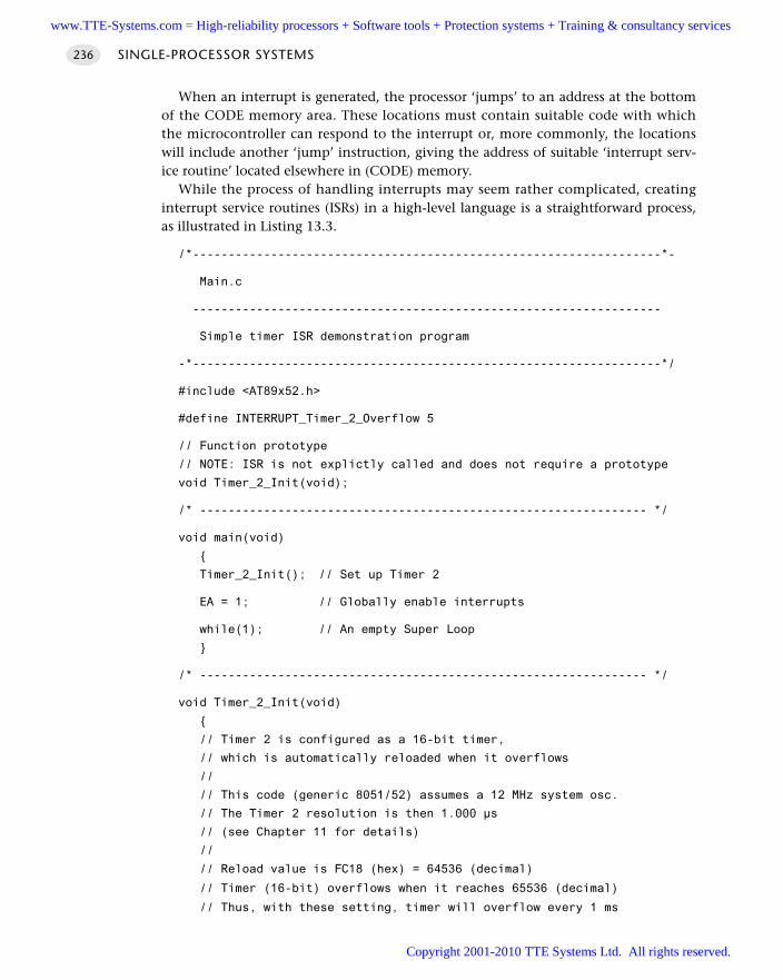
When an interrupt is generated, the processor ‘jumps’ to an address at the bottomof the CODE memory area. These locations must contain suitable code with whichthe microcontroller can respond to the interrupt or, more commonly, the locationswill include another ‘jump’ instruction, giving the address of suitable ‘interrupt serv-ice routine’ located elsewhere in (CODE) memory.
While the process of handling interrupts may seem rather complicated, creatinginterrupt service routines (ISRs) in a high-level language is a straightforward process,as illustrated in Listing 13.3.
/*------------------------------------------------------------------*-
Main.c
------------------------------------------------------------------
Simple timer ISR demonstration program
-*------------------------------------------------------------------*/
#include <AT89x52.h>
#define INTERRUPT_Timer_2_Overflow 5
// Function prototype
// NOTE: ISR is not explictly called and does not require a prototype
void Timer_2_Init(void);
/* --------------------------------------------------------------- */
void main(void)
Timer_2_Init(); // Set up Timer 2
EA = 1; // Globally enable interrupts
while(1); // An empty Super Loop
/* --------------------------------------------------------------- */
void Timer_2_Init(void)
// Timer 2 is configured as a 16-bit timer,
// which is automatically reloaded when it overflows
//
// This code (generic 8051/52) assumes a 12 MHz system osc.
// The Timer 2 resolution is then 1.000 µs
// (see Chapter 11 for details)
//
// Reload value is FC18 (hex) = 64536 (decimal)
// Timer (16-bit) overflows when it reaches 65536 (decimal)
// Thus, with these setting, timer will overflow every 1 ms
SINGLE-PROCESSOR SYSTEMS236
www.TTE-Systems.com = High-reliability processors + Software tools + Protection systems + Training & consultancy services
Copyright 2001-2010 TTE Systems Ltd. All rights reserved.
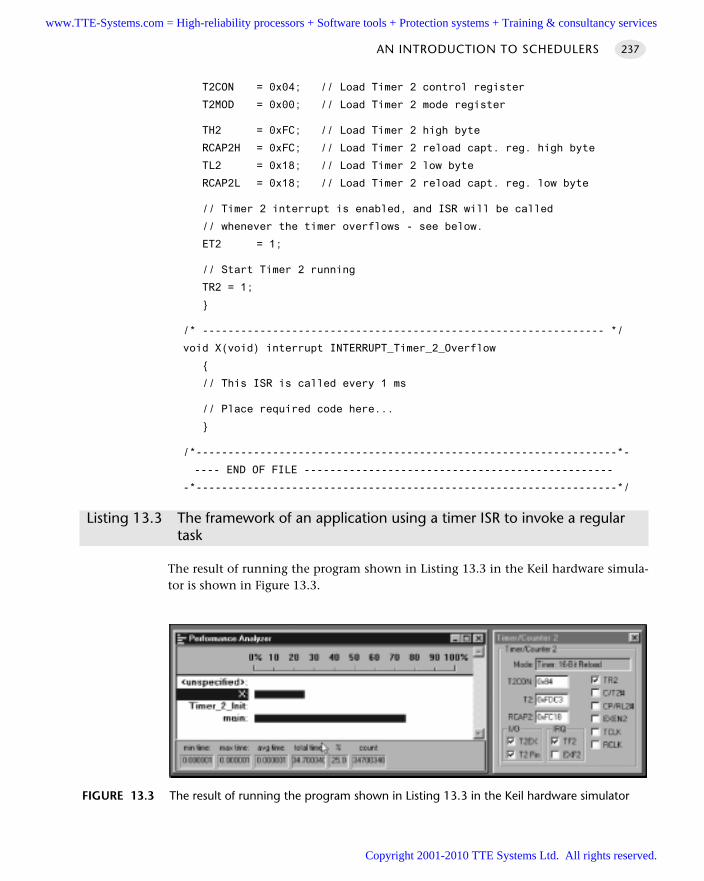
T2CON = 0x04; // Load Timer 2 control register
T2MOD = 0x00; // Load Timer 2 mode register
TH2 = 0xFC; // Load Timer 2 high byte
RCAP2H = 0xFC; // Load Timer 2 reload capt. reg. high byte
TL2 = 0x18; // Load Timer 2 low byte
RCAP2L = 0x18; // Load Timer 2 reload capt. reg. low byte
// Timer 2 interrupt is enabled, and ISR will be called
// whenever the timer overflows - see below.
ET2 = 1;
// Start Timer 2 running
TR2 = 1;
/* --------------------------------------------------------------- */
void X(void) interrupt INTERRUPT_Timer_2_Overflow
// This ISR is called every 1 ms
// Place required code here...
/*------------------------------------------------------------------*-
---- END OF FILE ------------------------------------------------
-*------------------------------------------------------------------*/
Listing 13.3 The framework of an application using a timer ISR to invoke a regular task
The result of running the program shown in Listing 13.3 in the Keil hardware simula-tor is shown in Figure 13.3.
AN INTRODUCTION TO SCHEDULERS 237
FIGURE 13.3 The result of running the program shown in Listing 13.3 in the Keil hardware simulator
www.TTE-Systems.com = High-reliability processors + Software tools + Protection systems + Training & consultancy services
Copyright 2001-2010 TTE Systems Ltd. All rights reserved.
Much of Listing 13.3 should be familiar. The code to set up Timer 2 in the functionTimer_2_Init() is the same as the delay code discussed in Chapter 11, the twomain differences being that, in this case:
1 The timer will generate an interrupt when it overflows
2 The timer will be automatically reloaded, and will immediately begin counting again
We discuss both of these differences in the following subsections.
The interrupt service routine (ISR)
The interrupt generated by the overflow of Timer 2, invokes the ISR called, here, X().
/* --------------------------------------------------------------- */
void X(void) interrupt INTERRUPT_Timer_2_Overflow
// This ISR is called every 1 ms
// Place required code here...
The link between this function and the timer overflow is made using the Keil key-word interrupt (included after the function header in the function definition):
void X(void) interrupt INTERRUPT_Timer_2_Overflow
plus the following #define directive:
#define INTERRUPT_Timer_2_Overflow 5
To understand where the ‘5’ comes from, note that the interrupt numbers used inISRs directly correspond to the enable bit index of the interrupt source in the 8051 IESFR. That is, bit 0 of the IE register will be linked to a function using ‘interrupt 0’.Table 13.1 shows the link between the interrupt sources and the required interruptnumbers for the original 8051/8052.
Overall, the use of interrupts linked to timer overflows is a safe and powerful tech-nique which will be applied throughout this book.
Automatic timer reloads
As noted earlier, when Timer 2 overflows, it is automatically reloaded and immedi-ately begins counting again. In this case, the timer is reloaded using the contents ofthe ‘capture’ registers (note that the names of these registers vary slightly betweenchip manufacturers):
RCAP2H = 0xFC; // Load Timer 2 reload capt. reg. high byte
RCAP2L = 0x18; // Load Timer 2 reload capt. reg. low byte
SINGLE-PROCESSOR SYSTEMS238
www.TTE-Systems.com = High-reliability processors + Software tools + Protection systems + Training & consultancy services
Copyright 2001-2010 TTE Systems Ltd. All rights reserved.
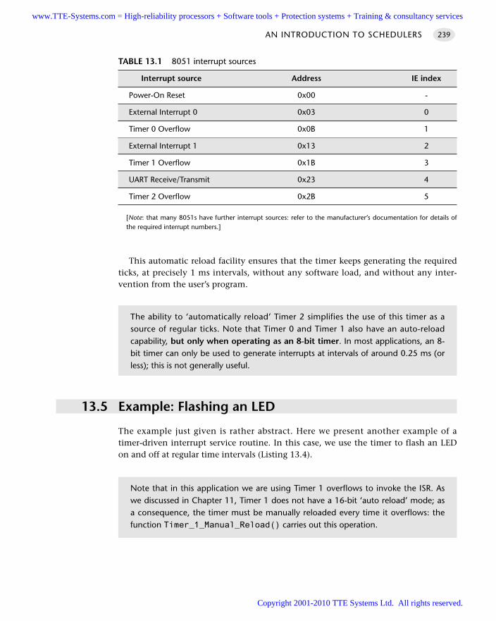
This automatic reload facility ensures that the timer keeps generating the requiredticks, at precisely 1 ms intervals, without any software load, and without any inter-vention from the user’s program.
13.5 Example: Flashing an LED
The example just given is rather abstract. Here we present another example of atimer-driven interrupt service routine. In this case, we use the timer to flash an LEDon and off at regular time intervals (Listing 13.4).
AN INTRODUCTION TO SCHEDULERS 239
TABLE 13.1 8051 interrupt sources
Interrupt source Address IE index
Power-On Reset 0x00 -
External Interrupt 0 0x03 0
Timer 0 Overflow 0x0B 1
External Interrupt 1 0x13 2
Timer 1 Overflow 0x1B 3
UART Receive/Transmit 0x23 4
Timer 2 Overflow 0x2B 5
[Note: that many 8051s have further interrupt sources: refer to the manufacturer’s documentation for details ofthe required interrupt numbers.]
The ability to ‘automatically reload’ Timer 2 simplifies the use of this timer as asource of regular ticks. Note that Timer 0 and Timer 1 also have an auto-reloadcapability, but only when operating as an 8-bit timer. In most applications, an 8-bit timer can only be used to generate interrupts at intervals of around 0.25 ms (orless); this is not generally useful.
Note that in this application we are using Timer 1 overflows to invoke the ISR. Aswe discussed in Chapter 11, Timer 1 does not have a 16-bit ‘auto reload’ mode; asa consequence, the timer must be manually reloaded every time it overflows: thefunction Timer_1_Manual_Reload() carries out this operation.
www.TTE-Systems.com = High-reliability processors + Software tools + Protection systems + Training & consultancy services
Copyright 2001-2010 TTE Systems Ltd. All rights reserved.
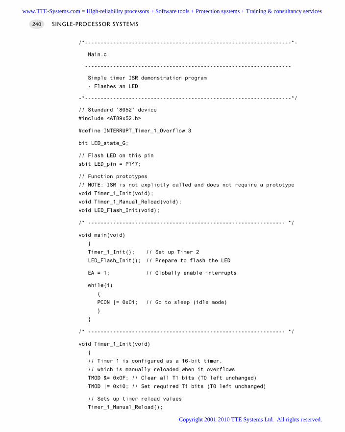
/*------------------------------------------------------------------*-
Main.c
------------------------------------------------------------------
Simple timer ISR demonstration program
- Flashes an LED
-*------------------------------------------------------------------*/
// Standard '8052' device
#include <AT89x52.h>
#define INTERRUPT_Timer_1_Overflow 3
bit LED_state_G;
// Flash LED on this pin
sbit LED_pin = P1^7;
// Function prototypes
// NOTE: ISR is not explictly called and does not require a prototype
void Timer_1_Init(void);
void Timer_1_Manual_Reload(void);
void LED_Flash_Init(void);
/* --------------------------------------------------------------- */
void main(void)
Timer_1_Init(); // Set up Timer 2
LED_Flash_Init(); // Prepare to flash the LED
EA = 1; // Globally enable interrupts
while(1)
PCON |= 0x01; // Go to sleep (idle mode)
/* --------------------------------------------------------------- */
void Timer_1_Init(void)
// Timer 1 is configured as a 16-bit timer,
// which is manually reloaded when it overflows
TMOD &= 0x0F; // Clear all T1 bits (T0 left unchanged)
TMOD |= 0x10; // Set required T1 bits (T0 left unchanged)
// Sets up timer reload values
Timer_1_Manual_Reload();
SINGLE-PROCESSOR SYSTEMS240
www.TTE-Systems.com = High-reliability processors + Software tools + Protection systems + Training & consultancy services
Copyright 2001-2010 TTE Systems Ltd. All rights reserved.
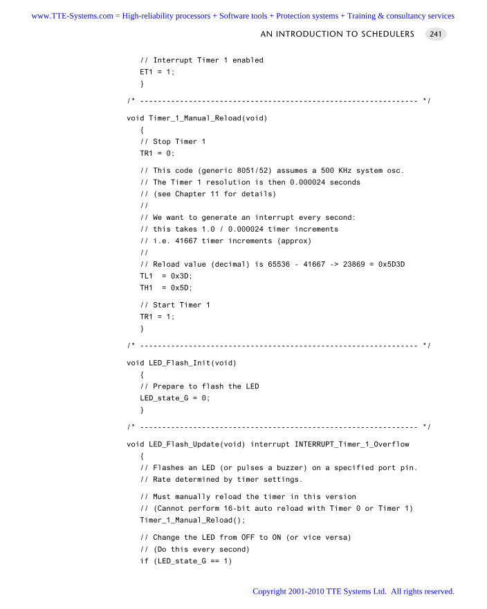
// Interrupt Timer 1 enabled
ET1 = 1;
/* --------------------------------------------------------------- */
void Timer_1_Manual_Reload(void)
// Stop Timer 1
TR1 = 0;
// This code (generic 8051/52) assumes a 500 KHz system osc.
// The Timer 1 resolution is then 0.000024 seconds
// (see Chapter 11 for details)
//
// We want to generate an interrupt every second:
// this takes 1.0 / 0.000024 timer increments
// i.e. 41667 timer increments (approx)
//
// Reload value (decimal) is 65536 - 41667 -> 23869 = 0x5D3D
TL1 = 0x3D;
TH1 = 0x5D;
// Start Timer 1
TR1 = 1;
/* --------------------------------------------------------------- */
void LED_Flash_Init(void)
// Prepare to flash the LED
LED_state_G = 0;
/* --------------------------------------------------------------- */
void LED_Flash_Update(void) interrupt INTERRUPT_Timer_1_Overflow
// Flashes an LED (or pulses a buzzer) on a specified port pin.
// Rate determined by timer settings.
// Must manually reload the timer in this version
// (Cannot perform 16-bit auto reload with Timer 0 or Timer 1)
Timer_1_Manual_Reload();
// Change the LED from OFF to ON (or vice versa)
// (Do this every second)
if (LED_state_G == 1)
AN INTRODUCTION TO SCHEDULERS 241
www.TTE-Systems.com = High-reliability processors + Software tools + Protection systems + Training & consultancy services
Copyright 2001-2010 TTE Systems Ltd. All rights reserved.
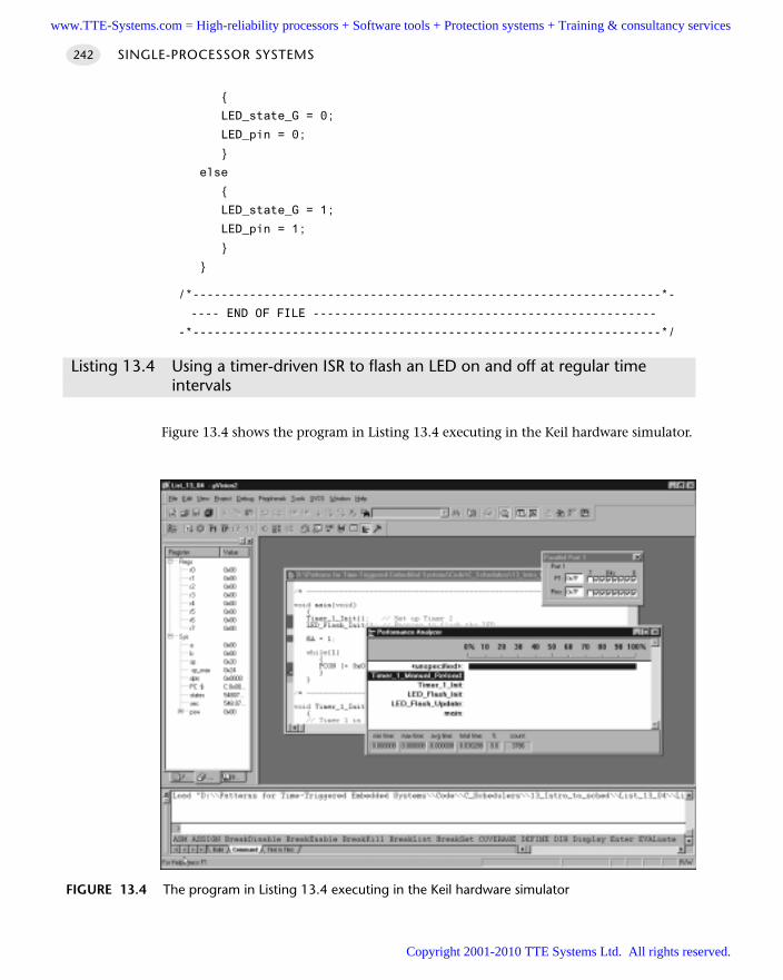
LED_state_G = 0;
LED_pin = 0;
else
LED_state_G = 1;
LED_pin = 1;
/*------------------------------------------------------------------*-
---- END OF FILE ------------------------------------------------
-*------------------------------------------------------------------*/
Listing 13.4 Using a timer-driven ISR to flash an LED on and off at regular time intervals
Figure 13.4 shows the program in Listing 13.4 executing in the Keil hardware simulator.
SINGLE-PROCESSOR SYSTEMS242
FIGURE 13.4 The program in Listing 13.4 executing in the Keil hardware simulator
www.TTE-Systems.com = High-reliability processors + Software tools + Protection systems + Training & consultancy services
Copyright 2001-2010 TTE Systems Ltd. All rights reserved.
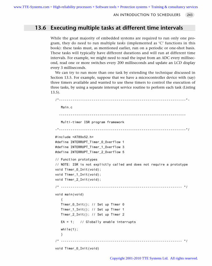
13.6 Executing multiple tasks at different time intervals
While the great majority of embedded systems are required to run only one pro-gram, they do need to run multiple tasks (implemented as ‘C’ functions in thisbook): these tasks must, as mentioned earlier, run on a periodic or one-shot basis.These tasks will typically have different durations and will run at different timeintervals. For example, we might need to read the input from an ADC every millisec-ond, read one or more switches every 200 milliseconds and update an LCD displayevery 3 milliseconds.
We can try to run more than one task by extending the technique discussed inSection 13.5. For example, suppose that we have a microcontroller device with (say)three timers available and wanted to use these timers to control the execution ofthree tasks, by using a separate interrupt service routine to perform each task (Listing13.5).
/*------------------------------------------------------------------*-
Main.c
------------------------------------------------------------------
Multi-timer ISR program framework
-*------------------------------------------------------------------*/
#include <AT89x52.h>
#define INTERRUPT_Timer_0_Overflow 1
#define INTERRUPT_Timer_1_Overflow 3
#define INTERRUPT_Timer_2_Overflow 5
// Function prototypes
// NOTE: ISR is not explictly called and does not require a prototype
void Timer_0_Init(void);
void Timer_1_Init(void);
void Timer_2_Init(void);
/* --------------------------------------------------------------- */
void main(void)
Timer_0_Init(); // Set up Timer 0
Timer_1_Init(); // Set up Timer 1
Timer_2_Init(); // Set up Timer 2
EA = 1; // Globally enable interrupts
while(1);
/* --------------------------------------------------------------- */
void Timer_0_Init(void)
AN INTRODUCTION TO SCHEDULERS 243
www.TTE-Systems.com = High-reliability processors + Software tools + Protection systems + Training & consultancy services
Copyright 2001-2010 TTE Systems Ltd. All rights reserved.
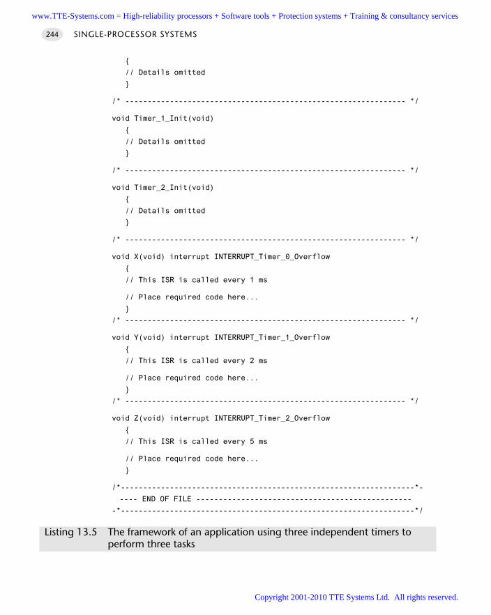
// Details omitted
/* --------------------------------------------------------------- */
void Timer_1_Init(void)
// Details omitted
/* --------------------------------------------------------------- */
void Timer_2_Init(void)
// Details omitted
/* --------------------------------------------------------------- */
void X(void) interrupt INTERRUPT_Timer_0_Overflow
// This ISR is called every 1 ms
// Place required code here...
/* --------------------------------------------------------------- */
void Y(void) interrupt INTERRUPT_Timer_1_Overflow
// This ISR is called every 2 ms
// Place required code here...
/* --------------------------------------------------------------- */
void Z(void) interrupt INTERRUPT_Timer_2_Overflow
// This ISR is called every 5 ms
// Place required code here...
/*------------------------------------------------------------------*-
---- END OF FILE ------------------------------------------------
-*------------------------------------------------------------------*/
Listing 13.5 The framework of an application using three independent timers to perform three tasks
SINGLE-PROCESSOR SYSTEMS244
www.TTE-Systems.com = High-reliability processors + Software tools + Protection systems + Training & consultancy services
Copyright 2001-2010 TTE Systems Ltd. All rights reserved.
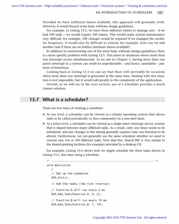
Provided we have sufficient timers available, this approach will generally work.However, it would breach some basic software design guidelines.
For example, in Listing 13.5, we have three different timers to manage and – if wehad 100 tasks – we would require 100 timers. This would make system maintenancevery difficult; for example, 100 changes would be required if we changed the oscilla-tor frequency. It would also be difficult to extend; for example, how can we addanother task if there are no further hardware timers available?
In addition to contravening one of the most basic software design guidelines, thereis a more specific problem with Listing 13.5. This arises in situations where more thanone interrupt occurs simultaneously. As we saw in Chapter 1, having more than oneactive interrupt in a system can result in unpredictable – and hence, unreliable – pat-terns of behaviour.
Looking back at Listing 13.5 we can see that there will inevitably be occasionswhen more than one interrupt is generated at the same time. Dealing with this situa-tion is not impossible, but it would add greatly to the complexity of the application.
Overall, as we will see in the next section, use of a scheduler provides a muchcleaner solution.
13.7 What is a scheduler?
There are two ways of viewing a scheduler:
At one level, a scheduler can be viewed as a simple operating system that allowstasks to be called periodically or (less commonly) on a one-shot basis.
At a lower level, a scheduler can be viewed as a single timer interrupt service routinethat is shared between many different tasks. As a result, only one timer needs to beinitialized, and any changes to the timing generally requires only one function to bealtered. Furthermore, we can generally use the same scheduler whether we need toexecute one, ten or 100 different tasks. Note that this ‘shared ISR’ is very similar tothe shared printing facilities (for example) provided by a desktop OS.
For example, Listing 13.6 shows how we might schedule the three tasks shown inListing 13.5, this time using a scheduler.
/* --------------------------------------------------------------- */
void main(void)
// Set up the scheduler
SCH_Init();
// Add the tasks (1ms tick interval)
// Function_A will run every 2 ms
SCH_Add_Task(Function_A, 0, 2);
// Function_B will run every 10 ms
SCH_Add_Task(Function_B, 1, 10);
AN INTRODUCTION TO SCHEDULERS 245
www.TTE-Systems.com = High-reliability processors + Software tools + Protection systems + Training & consultancy services
Copyright 2001-2010 TTE Systems Ltd. All rights reserved.
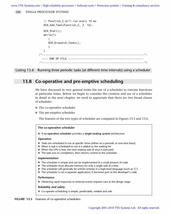
// Function_C will run every 15 ms
SCH_Add_Task(Function_C, 3, 15);
SCH_Start();
while(1)
SCH_Dispatch_Tasks();
/*------------------------------------------------------------------*-
---- END OF FILE ------------------------------------------------
-*------------------------------------------------------------------*/
Listing 13.6 Running three periodic tasks (at different time intervals) using a scheduler
13.8 Co-operative and pre-emptive scheduling
We have discussed in very general terms the use of a scheduler to execute functionsat particular times. Before we begin to consider the creation and use of a schedulerin detail in the next chapter, we need to appreciate that there are two broad classesof scheduler:
The co-operative scheduler
The pre-emptive scheduler
The features of the two types of scheduler are compared in Figures 13.5 and 13.6.
SINGLE-PROCESSOR SYSTEMS246
The co-operative scheduler
A co-operative scheduler provides a single-tasking system architecture
Operation: Tasks are scheduled to run at specific times (either on a periodic or one-shot basis) When a task is scheduled to run it is added to the waiting list When the CPU is free, the next waiting task (if any) is executed The task runs to completion, then returns control to the scheduler
Implementation: The scheduler is simple and can be implemented in a small amount of code The scheduler must allocate memory for only a single task at a time The scheduler will generally be written entirely in a high-level language (such as ‘C’) The scheduler is not a separate application; it becomes part of the developer’s code
Performance: Obtaining rapid responses to external events requires care at the design stage
Reliability and safety: Co-operate scheduling is simple, predictable, reliable and safe
FIGURE 13.5 Features of co-operative schedulers
www.TTE-Systems.com = High-reliability processors + Software tools + Protection systems + Training & consultancy services
Copyright 2001-2010 TTE Systems Ltd. All rights reserved.
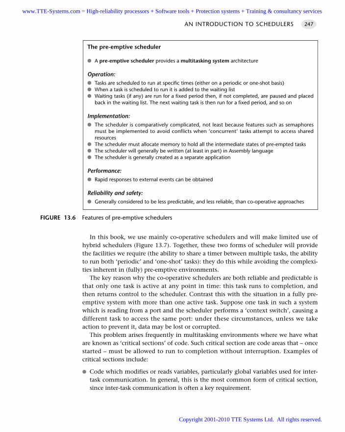
In this book, we use mainly co-operative schedulers and will make limited use ofhybrid schedulers (Figure 13.7). Together, these two forms of scheduler will providethe facilities we require (the ability to share a timer between multiple tasks, the abilityto run both ‘periodic’ and ‘one-shot’ tasks): they do this while avoiding the complexi-ties inherent in (fully) pre-emptive environments.
The key reason why the co-operative schedulers are both reliable and predictable isthat only one task is active at any point in time: this task runs to completion, andthen returns control to the scheduler. Contrast this with the situation in a fully pre-emptive system with more than one active task. Suppose one task in such a systemwhich is reading from a port and the scheduler performs a ‘context switch’, causing adifferent task to access the same port: under these circumstances, unless we takeaction to prevent it, data may be lost or corrupted.
This problem arises frequently in multitasking environments where we have whatare known as ‘critical sections’ of code. Such critical section are code areas that – oncestarted – must be allowed to run to completion without interruption. Examples ofcritical sections include:
Code which modifies or reads variables, particularly global variables used for inter-task communication. In general, this is the most common form of critical section,since inter-task communication is often a key requirement.
AN INTRODUCTION TO SCHEDULERS 247
FIGURE 13.6 Features of pre-emptive schedulers
The pre-emptive scheduler
A pre-emptive scheduler provides a multitasking system architecture
Operation: Tasks are scheduled to run at specific times (either on a periodic or one-shot basis) When a task is scheduled to run it is added to the waiting list Waiting tasks (if any) are run for a fixed period then, if not completed, are paused and placed
back in the waiting list. The next waiting task is then run for a fixed period, and so on
Implementation: The scheduler is comparatively complicated, not least because features such as semaphores
must be implemented to avoid conflicts when ‘concurrent’ tasks attempt to access sharedresources
The scheduler must allocate memory to hold all the intermediate states of pre-empted tasks The scheduler will generally be written (at least in part) in Assembly language The scheduler is generally created as a separate application
Performance: Rapid responses to external events can be obtained
Reliability and safety: Generally considered to be less predictable, and less reliable, than co-operative approaches
www.TTE-Systems.com = High-reliability processors + Software tools + Protection systems + Training & consultancy services
Copyright 2001-2010 TTE Systems Ltd. All rights reserved.
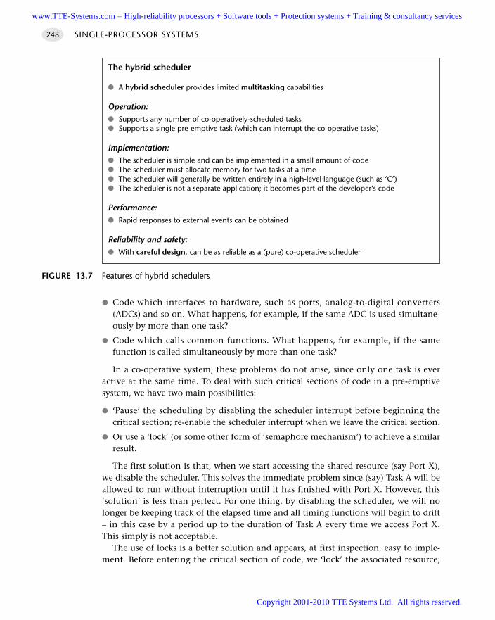
Code which interfaces to hardware, such as ports, analog-to-digital converters(ADCs) and so on. What happens, for example, if the same ADC is used simultane-ously by more than one task?
Code which calls common functions. What happens, for example, if the samefunction is called simultaneously by more than one task?
In a co-operative system, these problems do not arise, since only one task is everactive at the same time. To deal with such critical sections of code in a pre-emptivesystem, we have two main possibilities:
‘Pause’ the scheduling by disabling the scheduler interrupt before beginning thecritical section; re-enable the scheduler interrupt when we leave the critical section.
Or use a ‘lock’ (or some other form of ‘semaphore mechanism’) to achieve a similarresult.
The first solution is that, when we start accessing the shared resource (say Port X),we disable the scheduler. This solves the immediate problem since (say) Task A will beallowed to run without interruption until it has finished with Port X. However, this‘solution’ is less than perfect. For one thing, by disabling the scheduler, we will nolonger be keeping track of the elapsed time and all timing functions will begin to drift– in this case by a period up to the duration of Task A every time we access Port X.This simply is not acceptable.
The use of locks is a better solution and appears, at first inspection, easy to imple-ment. Before entering the critical section of code, we ‘lock’ the associated resource;
SINGLE-PROCESSOR SYSTEMS248
FIGURE 13.7 Features of hybrid schedulers
The hybrid scheduler
A hybrid scheduler provides limited multitasking capabilities
Operation: Supports any number of co-operatively-scheduled tasks Supports a single pre-emptive task (which can interrupt the co-operative tasks)
Implementation: The scheduler is simple and can be implemented in a small amount of code The scheduler must allocate memory for two tasks at a time The scheduler will generally be written entirely in a high-level language (such as ‘C’) The scheduler is not a separate application; it becomes part of the developer’s code
Performance: Rapid responses to external events can be obtained
Reliability and safety: With careful design, can be as reliable as a (pure) co-operative scheduler
www.TTE-Systems.com = High-reliability processors + Software tools + Protection systems + Training & consultancy services
Copyright 2001-2010 TTE Systems Ltd. All rights reserved.
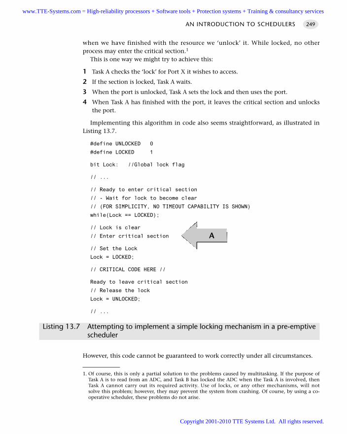
when we have finished with the resource we ‘unlock’ it. While locked, no otherprocess may enter the critical section.1
This is one way we might try to achieve this:
1 Task A checks the ‘lock’ for Port X it wishes to access.
2 If the section is locked, Task A waits.
3 When the port is unlocked, Task A sets the lock and then uses the port.
4 When Task A has finished with the port, it leaves the critical section and unlocksthe port.
Implementing this algorithm in code also seems straightforward, as illustrated inListing 13.7.
#define UNLOCKED 0
#define LOCKED 1
bit Lock: //Global lock flag
// ...
// Ready to enter critical section
// - Wait for lock to become clear
// (FOR SIMPLICITY, NO TIMEOUT CAPABILITY IS SHOWN)
while(Lock == LOCKED);
// Lock is clear
// Enter critical section
// Set the Lock
Lock = LOCKED;
// CRITICAL CODE HERE //
Ready to leave critical section
// Release the lock
Lock = UNLOCKED;
// ...
Listing 13.7 Attempting to implement a simple locking mechanism in a pre-emptive scheduler
However, this code cannot be guaranteed to work correctly under all circumstances.
AN INTRODUCTION TO SCHEDULERS 249
A
1. Of course, this is only a partial solution to the problems caused by multitasking. If the purpose ofTask A is to read from an ADC, and Task B has locked the ADC when the Task A is involved, thenTask A cannot carry out its required activity. Use of locks, or any other mechanisms, will notsolve this problem; however, they may prevent the system from crashing. Of course, by using a co-operative scheduler, these problems do not arise.
www.TTE-Systems.com = High-reliability processors + Software tools + Protection systems + Training & consultancy services
Copyright 2001-2010 TTE Systems Ltd. All rights reserved.
Consider the part of the code labelled ‘A’ in Listing 13.7. If our system is fully pre-emptive, then our task can reach this point at the same time as the schedulerperforms a context switch and allows (say) Task B access to the CPU. If Task Y alsowants to access the Port X
We can then have a situation as follows:
Task A has checked the lock for Port X and found that the port is not locked; TaskA has, however, not yet changed the lock flag.
Task B is then ‘switched in’. Task B checks the lock flag and it is still clear. Task Bsets the lock flag and begins to use Port X.
Task A is ‘switched in’ again. As far as Task A is concerned, the port is not locked;this task therefore sets the flag and starts to use the port, unaware that Task B isalready doing so.
…
As we can see, this simple lock code violates the principal of mutual exclusion:that is, it allows more than one task to access a critical code section. The problemarises because it is possible for the context switch to occur after a task has checkedthe lock flag but before the task changes the lock flag. In other words, the lock‘check and set code’ (designed to control access to a critical section of code), isitself a critical section.
This problem can be solved. For example, because it takes little time to ‘check andset’ the lock code, we can disable interrupts for this period. However, this is not initself a complete solution: because there is a chance that an interrupt may haveoccurred even in the short period of ‘check and set’, we may then need to check therelevant interrupt flag(s) and, if necessary, call the relevant ISR(s). This can be done,but it adds to the complexity of the operating environment.
13.9 A closer look at pre-emptive schedulers
Various research studies have demonstrated that, compared to pre-emptive sched-ulers, co-operative schedulers have a number of desirable features. For example,Nissanke (1997, p. 237) notes:
[Pre-emptive] schedules carry greater runtime overheads because of the need for contextswitching – storage and retrieval of partially computed results. [Co-operative] algorithms do notincur such overheads. Other advantages of [co-operative] algorithms include their better under-standability, greater predictability, ease of testing and their inherent capability for guaranteeingexclusive access to any shared resource or data.
SINGLE-PROCESSOR SYSTEMS250
The discussion in this section is more technical than the previous sections in thischapter and may be omitted on a first reading of the book.
www.TTE-Systems.com = High-reliability processors + Software tools + Protection systems + Training & consultancy services
Copyright 2001-2010 TTE Systems Ltd. All rights reserved.
Similarly, Allworth (1981, pp. 53–4) notes:
Significant advantages are obtained when using this [co-operative] technique. Since theprocesses are not interruptable, poor synchronisation does not give rise to the problem ofshared data. Shared subroutines can be implemented without producing re-entrant code orimplementing lock and unlock mechanisms.
Also, in a recent presentation, Bates (2000) identified the following four advantages ofco-operative scheduling, compared to pre-emptive alternatives:
1 The scheduler is simpler
2 The overheads are reduced
3 Testing is easier
4 Certification authorities tend to support this form of scheduling
Despite these observations, all the authors cited and the vast majority of otherworkers in this area focus on the use of pre-emptive schedulers. At least part of thereason why pre-emptive approaches are more widely discussed is because of confu-sion over the options available. For example, Bennett (1994, p. 205) states:
If we consider the scheduling of time allocation on a single CPU there are two basic alternatives:[1] cyclic, [2] pre-emptive.
In fact, contrary to Bennett’s assertion, what he refers to as cyclic scheduling isessentially a form of S U P E R L O O P [page 162]. As we saw in Chapter 9, this type ofarchitecture is suitable only for use in a restricted range of very simple applications, inparticular those where accurate timing is not a key requirement and limited memoryand CPU resources are available: S U P E R L O O P is not representative of the broad rangeof co-operative scheduling architectures that are available.
Bennett is, however, not alone: other researchers make similar assumptions(see Barnett, 1995). For example, Locke (1992, p. 37) – in a widely cited publication –suggests that:
Traditionally, there have been two basic approaches to the overall design of applicationsystems exhibiting hard real-time deadlines: the cyclic executive … and the fixed priority [pre-emptive] architecture.
Similarly, Cooling (1991, pp. 292–3) compares co-operative and pre-emptive schedul-ing approaches. Again, however, his discussion of co-operative schedulers is restrictedto a consideration of the special case of cyclic scheduling: as a result, his conclusionthat a pre-emptive approach is more effective is unsurprising.
Where the different characteristics of pre-emptive and co-operative scheduling arecompared equitably, the main concern expressed is often that long tasks will have animpact on the responsiveness of a co-operative scheduler. This concern is succinctlysummarized by Allworth (1981):
[The] main drawback with this [co-operative] approach is that while the current process is run-ning, the system is not responsive to changes in the environment. Therefore, system processesmust be extremely brief if the real-time response [of the] system is not to be impaired.
AN INTRODUCTION TO SCHEDULERS 251
www.TTE-Systems.com = High-reliability processors + Software tools + Protection systems + Training & consultancy services
Copyright 2001-2010 TTE Systems Ltd. All rights reserved.
There are four main technical reasons why such concerns are, generally, misplaced:
In many embedded applications, the task duration is extremely brief. For example,consider one of the more complex algorithms considered in this book: proportionalintegral differential (PID) control. Even the most basic 8051 microcontroller cancarry out a PID calculation in around 0.4 ms (see p. 872): even in flight control –where PID algorithms remain in widespread use – sample rates of around 10 ms arecommon, and a 0.4 ms calculation does not impose a significant processor load.
Where the system does have long tasks, this is often because the developer isunaware of some simple techniques that can be used to break down these tasks inan appropriate way and – in effect – convert ‘long tasks called infrequently’ into‘short tasks called frequently’. Such techniques are used throughout this book; theyare introduced and explained in Chapter 16.
In many cases, the increased power of microcontrollers has more than kept upwith performance demands in many embedded systems. For example, the PID per-formance figures just given assumed an original 8051 microcontroller, with a 1MIPS performance level. As we saw in Chapter 3, numerous low-cost members ofthis family now have performance levels between 5 and 50 MIPS. Often a simple,cost-effective, way of addressing performance concerns is not to use a more com-plex software architecture, but, instead, to update the hardware.
If upgrades to the task design or microcontroller do not provide sufficient perform-ance improvements, then more than one microcontroller can be used. This is nowvery common. For example, a typical automotive environment containing morethan 40 embedded processors (Leen et al., 1999). With the increased availability ofsuch processing elements, long tasks may be readily ‘migrated’ to another proces-sor, leaving the main CPU free to respond rapidly, if necessary, to other events. (SeePart F of this book for numerous examples of this process.)
Finally, it should be noted that the reasons why pre-emptive schedulers have beenmore widely discussed and used may not be for technical reasons at all: in fact, theuse of pre-emptive environments can be seen to have clear commercial advantages forsome companies. For example, a co-operative scheduler may be easily constructed,entirely in a high-level programming language, in around 300 lines of ‘C’ code, as wedemonstrate in Chapter 9. The code is highly portable, easy to understand and to useand is, in effect, freely available. By contrast, the increased complexity of a pre-emptive operating environment results in a much larger code framework (some tentimes the size, even in a simple implementation: Labrosse, 1998). The size and com-plexity of this code makes it unsuitable for ‘in-house’ construction in most situationsand therefore provides the basis for a commercial ‘RTOS’ products to be sold, gener-ally at high prices and often with expensive run-time royalties to be paid. Thecontinued promotion and sale of such environments has, in turn, prompted furtheracademic interest in this area. For example, according to Liu and Ha, (1995):
[An] objective of reengineering is the adoption of commercial off-the-shelf and standard operat-ing systems. Because they do not support cyclic scheduling, the adoption of these operatingsystems makes it necessary for us to abandon this traditional approach to scheduling.
SINGLE-PROCESSOR SYSTEMS252
www.TTE-Systems.com = High-reliability processors + Software tools + Protection systems + Training & consultancy services
Copyright 2001-2010 TTE Systems Ltd. All rights reserved.
13.10 Conclusions
In this chapter, we have explained what a scheduler is and outlined the differencesbetween co-operative and pre-emptive scheduling. We have argued that a co-operativescheduler provides a simple and reliable operating environment that matches pre-cisely the needs of most embedded applications.
Over recent years we have used versions of the co-operative schedulers presented inthis book in numerous ‘real’ applications. We have also helped many student groupsuse this architecture in their first embedded systems. We have no doubt that the cor-rect use of these schedulers not only results in simple, transparent and reliabledesigns, but also make it easier for ‘desktop’ developers to adapt rapidly to the chal-lenges of embedded system development.
13.11 Further reading
Allworth, S.T. (1981) An Introduction to Real-Time Software Design, Macmillan, London.
Bates, I. (2000) “Introduction to scheduling and timing analysis”, in The Use of Ada inReal-Time System (6 April, 2000). IEE Conference Publication 00/034.
Burns, A. and Wellings, A. (1997) Real-Time Systems and Programming Languages,Addison-Wesley, London.
Cooling, J.E. (1991) Software Design for Real-Time Systems, Chapman and Hall, London.
Kopetz, H. (1997) Real-Time Systems: Design Principles for Distributed EmbeddedApplications, Kluwer Academic, New York.
Leen, G., Heffernan, D. and Dunne, A. (1999) ‘Digital networks in the automotivevehicle’, Computing and Control, 10 (6): 257–266.
Leveson, N.G. (1995) Safeware: System Safety and Computers, Addison-Wesley, Reading,MA.
Liu, J.W.S. and Ha, R. (1995) ‘Methods for validating real-time constraints’ Journal ofSystems and Software, 30 (1–2), 85–98.
Locke, C.D. (1992) ‘Software architecture for hard real-time applications: Cyclic exec-utives vs. Fixed priority executives’, The Journal of Real-Time Systems, 4: 37–53.
Nissanke, N. (1997) Realtime Systems, Prentice Hall, London.
Shaw, A.C. (2001) Real-Time Systems and Software, Wiley, New York.
Storey, N. (1996) Safety-Critical Computer Systems, Addison-Wesley, London.
Ward, N.J. (1991) ‘The static analysis of a safety-critical avionics control system’, inD.E. Corbyn, and N.P. Bray (eds) Air Transport Safety: Proceedings of the Safety andReliability Society Spring Conference, 1991, SaRS.
AN INTRODUCTION TO SCHEDULERS 253
www.TTE-Systems.com = High-reliability processors + Software tools + Protection systems + Training & consultancy services
Copyright 2001-2010 TTE Systems Ltd. All rights reserved.
Co-operative schedulers
Introduction
In this chapter, we discuss techniques for creating co-operative schedulers suitable foruse in single-processor environments. These provide a very flexible and predictablesoftware platform for a wide range of embedded applications, from the simplest con-sumer gadget up to and including aircraft control systems.
The following pattern is presented in this chapter:
C O-O P E R AT I V E S C H E D U L E R [page 255]
A co-operative scheduler provides a simple, highly predictable environment. Thescheduler is written entirely in ‘C’ and becomes part of the application: this tends tomake the operation of the whole system more transparent and eases development,maintenance and porting to different environments. Memory overheads are sevenbytes per task and CPU requirements (which vary with tick interval) are low.
chapter14www.TTE-Systems.com = High-reliability processors + Software tools + Protection systems + Training & consultancy services
Copyright 2001-2010 TTE Systems Ltd. All rights reserved.
CO-OPERATIVE SCHEDULER
Context You are developing an embedded application using one or more members of the
8051 family of microcontrollers.
The application is to have a time-triggered architecture, constructed using a scheduler.
ProblemHow do you create and use a co-operative scheduler?
BackgroundWe present some links to relevant background material in this section.
What is a co-operative scheduler?
See Chapter 13 for an introduction to co-operative schedulers.
Function pointers
One area of the language with which many ‘C’ programmers are unfamiliar is thefunction pointer. While comparatively rarely used in desktop programs, this languagefeature is crucial in the creation of schedulers: we therefore provide a brief introduc-tory example here.
The key point to note is that – just as we can, for example, determine the startingaddress of an array of data in memory – we can also find the address in memory atwhich the executable code for a particular function begins. This address can be usedas a ‘pointer’ to the function; most importantly, it can be used to call the function.
Used with care, function pointers can make it easier to design and implement com-plex programs. For example, suppose we are developing a large, safety-critical,application, controlling an industrial plant. If we detect a critical situation, we maywish to shut down the system as rapidly as possible. However, the appropriate way toshut down the system will vary, depending on the system state. What we can do iscreate a number of different recovery functions and a function pointer. Every timethe system state changes, we can alter the function pointer so that it is always point-ing to the most appropriate recovery function. In this way, we know that – if there isever an emergency situation – we can rapidly call the most appropriate function, bymeans of the function pointer.
The example in Listings 14.1 and 14.2 illustrates some of the basic features offunction pointers.
CO-OPERATIVE SCHEDULER 255
www.TTE-Systems.com = High-reliability processors + Software tools + Protection systems + Training & consultancy services
Copyright 2001-2010 TTE Systems Ltd. All rights reserved.
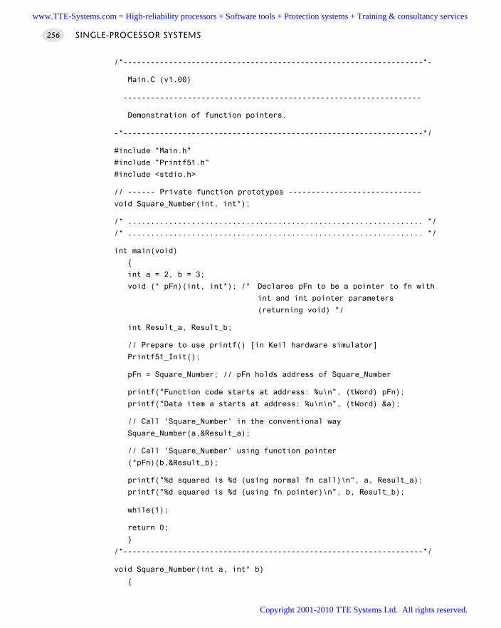
/*------------------------------------------------------------------*-
Main.C (v1.00)
-----------------------------------------------------------------
Demonstration of function pointers.
-*------------------------------------------------------------------*/
#include "Main.h"
#include "Printf51.h"
#include <stdio.h>
// ------ Private function prototypes -----------------------------
void Square_Number(int, int*);
/* ................................................................. */
/* ................................................................. */
int main(void)
int a = 2, b = 3;
void (* pFn)(int, int*); /* Declares pFn to be a pointer to fn with
int and int pointer parameters
(returning void) */
int Result_a, Result_b;
// Prepare to use printf() [in Keil hardware simulator]
Printf51_Init();
pFn = Square_Number; // pFn holds address of Square_Number
printf("Function code starts at address: %u\n", (tWord) pFn);
printf("Data item a starts at address: %u\n\n", (tWord) &a);
// Call 'Square_Number' in the conventional way
Square_Number(a,&Result_a);
// Call 'Square_Number' using function pointer
(*pFn)(b,&Result_b);
printf("%d squared is %d (using normal fn call)\n", a, Result_a);
printf("%d squared is %d (using fn pointer)\n", b, Result_b);
while(1);
return 0;
/*------------------------------------------------------------------*/
void Square_Number(int a, int* b)
SINGLE-PROCESSOR SYSTEMS256
www.TTE-Systems.com = High-reliability processors + Software tools + Protection systems + Training & consultancy services
Copyright 2001-2010 TTE Systems Ltd. All rights reserved.
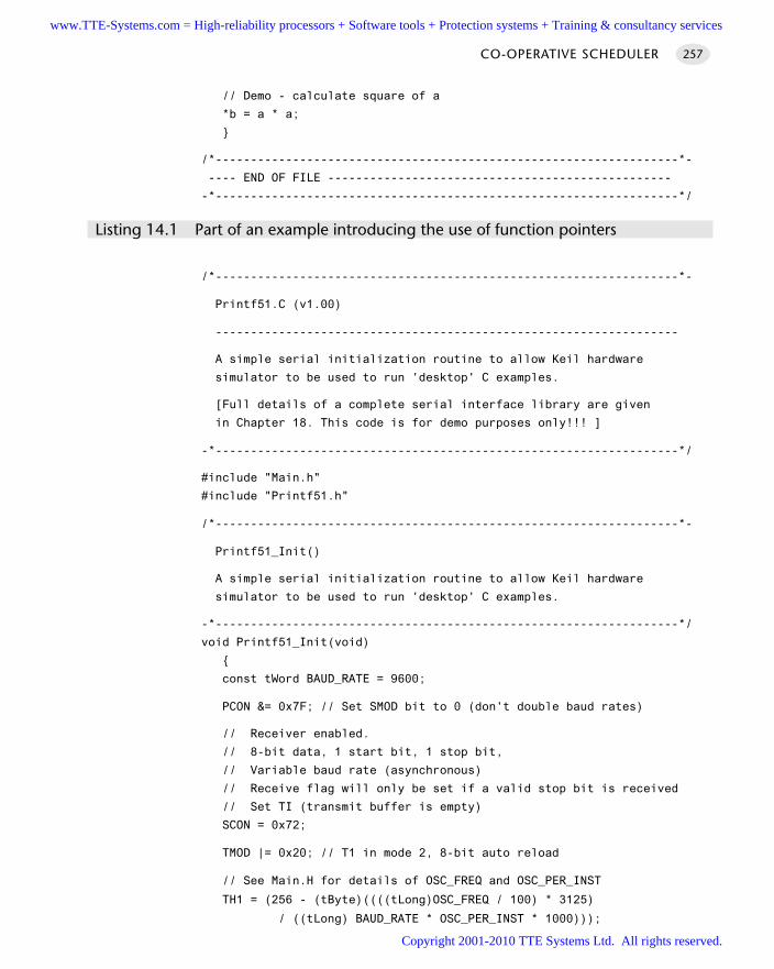
// Demo - calculate square of a
*b = a * a;
/*------------------------------------------------------------------*-
---- END OF FILE -------------------------------------------------
-*------------------------------------------------------------------*/
Listing 14.1 Part of an example introducing the use of function pointers
/*------------------------------------------------------------------*-
Printf51.C (v1.00)
------------------------------------------------------------------
A simple serial initialization routine to allow Keil hardware
simulator to be used to run 'desktop' C examples.
[Full details of a complete serial interface library are given
in Chapter 18. This code is for demo purposes only!!! ]
-*------------------------------------------------------------------*/
#include "Main.h"
#include "Printf51.h"
/*------------------------------------------------------------------*-
Printf51_Init()
A simple serial initialization routine to allow Keil hardware
simulator to be used to run 'desktop' C examples.
-*------------------------------------------------------------------*/
void Printf51_Init(void)
const tWord BAUD_RATE = 9600;
PCON &= 0x7F; // Set SMOD bit to 0 (don't double baud rates)
// Receiver enabled.
// 8-bit data, 1 start bit, 1 stop bit,
// Variable baud rate (asynchronous)
// Receive flag will only be set if a valid stop bit is received
// Set TI (transmit buffer is empty)
SCON = 0x72;
TMOD |= 0x20; // T1 in mode 2, 8-bit auto reload
// See Main.H for details of OSC_FREQ and OSC_PER_INST
TH1 = (256 - (tByte)((((tLong)OSC_FREQ / 100) * 3125)
/ ((tLong) BAUD_RATE * OSC_PER_INST * 1000)));
CO-OPERATIVE SCHEDULER 257
www.TTE-Systems.com = High-reliability processors + Software tools + Protection systems + Training & consultancy services
Copyright 2001-2010 TTE Systems Ltd. All rights reserved.
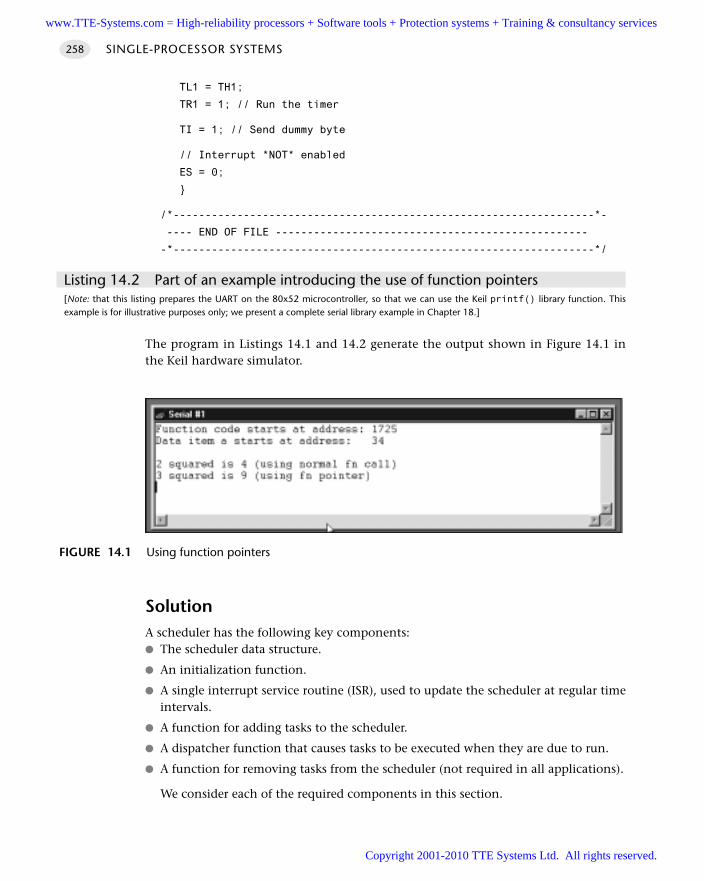
TL1 = TH1;
TR1 = 1; // Run the timer
TI = 1; // Send dummy byte
// Interrupt *NOT* enabled
ES = 0;
/*------------------------------------------------------------------*-
---- END OF FILE -------------------------------------------------
-*------------------------------------------------------------------*/
Listing 14.2 Part of an example introducing the use of function pointers [Note: that this listing prepares the UART on the 80x52 microcontroller, so that we can use the Keil printf() library function. Thisexample is for illustrative purposes only; we present a complete serial library example in Chapter 18.]
The program in Listings 14.1 and 14.2 generate the output shown in Figure 14.1 inthe Keil hardware simulator.
SolutionA scheduler has the following key components: The scheduler data structure.
An initialization function.
A single interrupt service routine (ISR), used to update the scheduler at regular timeintervals.
A function for adding tasks to the scheduler.
A dispatcher function that causes tasks to be executed when they are due to run.
A function for removing tasks from the scheduler (not required in all applications).
We consider each of the required components in this section.
SINGLE-PROCESSOR SYSTEMS258
FIGURE 14.1 Using function pointers
www.TTE-Systems.com = High-reliability processors + Software tools + Protection systems + Training & consultancy services
Copyright 2001-2010 TTE Systems Ltd. All rights reserved.
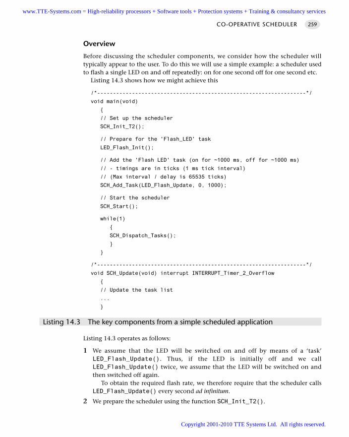
Overview
Before discussing the scheduler components, we consider how the scheduler willtypically appear to the user. To do this we will use a simple example: a scheduler usedto flash a single LED on and off repeatedly: on for one second off for one second etc.
Listing 14.3 shows how we might achieve this
/*------------------------------------------------------------------*/
void main(void)
// Set up the scheduler
SCH_Init_T2();
// Prepare for the 'Flash_LED' task
LED_Flash_Init();
// Add the 'Flash LED' task (on for ~1000 ms, off for ~1000 ms)
// - timings are in ticks (1 ms tick interval)
// (Max interval / delay is 65535 ticks)
SCH_Add_Task(LED_Flash_Update, 0, 1000);
// Start the scheduler
SCH_Start();
while(1)
SCH_Dispatch_Tasks();
/*------------------------------------------------------------------*/
void SCH_Update(void) interrupt INTERRUPT_Timer_2_Overflow
// Update the task list
...
Listing 14.3 The key components from a simple scheduled application
Listing 14.3 operates as follows:
1 We assume that the LED will be switched on and off by means of a ‘task’LED_Flash_Update(). Thus, if the LED is initially off and we callLED_Flash_Update() twice, we assume that the LED will be switched on andthen switched off again.
To obtain the required flash rate, we therefore require that the scheduler callsLED_Flash_Update() every second ad infinitum.
2 We prepare the scheduler using the function SCH_Init_T2().
CO-OPERATIVE SCHEDULER 259
www.TTE-Systems.com = High-reliability processors + Software tools + Protection systems + Training & consultancy services
Copyright 2001-2010 TTE Systems Ltd. All rights reserved.
3 After preparing the scheduler, we add the function LED_Flash_Update() to thescheduler task list using the SCH_Add_Task() function. At the same time we spec-ify that the LED will be turned on and off at the required rate as follows:
// Add the 'Flash LED' task (on for ~1000 ms, off for ~1000 ms)
// - timings are in ticks (1 ms tick interval)
// (Max interval / delay is 65535 ticks)
SCH_Add_Task(LED_Flash_Update, 0, 1000);
(We will shortly consider all the parameters of SCH_Add_Task(), and examine itsinternal structure).
4 The timing of the LED_Flash_Update() function will be controlled by the functionSCH_Update(), an interrupt service routine triggered by the overflow of Timer 2:
void SCH_Update(void) interrupt INTERRUPT_Timer_2_Overflow
// Update the task list
...
5 The ‘Update’ ISR does not execute the task: it calculates when a task is due to runand sets a flag. The job of executing LED_Flash_Update() falls to the dispatcherfunction (SCH_Dispatch_Tasks()), which runs in the main (‘super’) loop:
while(1)
SCH_Dispatch_Tasks();
Before considering these components in detail, we should acknowledge that this is,undoubtedly, a complicated way of flashing an LED: if our intention were to developan LED flasher application that required minimal memory and minimal code size,this would not be a good solution. However, the key point is that we will be able touse the same scheduler architecture in all our subsequent examples, including anumber of substantial and complex applications and the effort required to under-stand the operation of this environment will be rapidly repaid.
It should also be emphasized that the scheduler is a ‘low-cost’ option: it consumesa small percentage of the CPU resources (we will consider precise percentages shortly).In addition, the scheduler itself requires no more than 7 bytes of memory for eachtask. Since a typical application will require no more than four to six tasks, the task –memory budget (around 40 bytes) is not excessive, even on an 8-bit microcontroller.
The scheduler data structure and task array
At the heart of the scheduler is the scheduler data structure: this is a user-defined datatype which collects together the information required about each task.
SINGLE-PROCESSOR SYSTEMS260
www.TTE-Systems.com = High-reliability processors + Software tools + Protection systems + Training & consultancy services
Copyright 2001-2010 TTE Systems Ltd. All rights reserved.
The data structure is reproduced (from file Sch51.H) here:
// Store in DATA area, if possible, for rapid access
// Total memory per task is 7 bytes
typedef data struct
// Pointer to the task (must be a 'void (void)' function)
void (code * pTask)(void);
// Delay (ticks) until the function will (next) be run
// - see SCH_Add_Task() for further details
tWord Delay;
// Interval (ticks) between subsequent runs.
// - see SCH_Add_Task() for further details
tWord Period;
// Incremented (by scheduler) when task is due to execute
tByte RunMe;
sTask;
File Sch51.H also includes the constant SCH_MAX_TASKS:
// The maximum number of tasks required at any one time
// during the execution of the program
//
// MUST BE ADJUSTED FOR EACH NEW PROJECT
#define SCH_MAX_TASKS (1)
Both the sTask data type and the SCH_MAX_TASKS constant are used to create – inthe file Sch51.C – the array of tasks that is referred to throughout the scheduler:
// The array of tasks
sTask SCH_tasks_G[SCH_MAX_TASKS];
CO-OPERATIVE SCHEDULER 261
The size of the task array
You must ensure that the task array is sufficiently large to store the tasks required inyour application, by adjusting the value of SCH_MAX_TASKS.
For example, if you schedule three tasks as follows:
SCH_Add_Task(Function_A, 0, 2);
SCH_Add_Task(Function_B, 1, 10);
SCH_Add_Task(Function_C, 3, 15);
then SCH_MAX_TASKS must have a value of three (or more) for correct operation ofthe scheduler.
Note also that, if this condition is not satisfied, the scheduler will generate anerror code (see page 274).
www.TTE-Systems.com = High-reliability processors + Software tools + Protection systems + Training & consultancy services
Copyright 2001-2010 TTE Systems Ltd. All rights reserved.
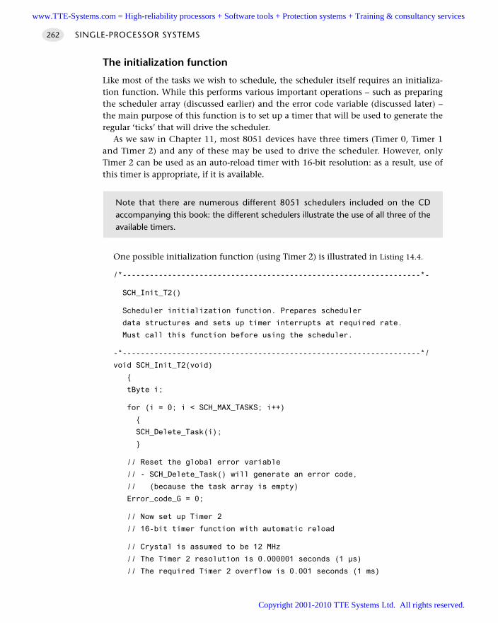
The initialization function
Like most of the tasks we wish to schedule, the scheduler itself requires an initializa-tion function. While this performs various important operations – such as preparingthe scheduler array (discussed earlier) and the error code variable (discussed later) –the main purpose of this function is to set up a timer that will be used to generate theregular ‘ticks’ that will drive the scheduler.
As we saw in Chapter 11, most 8051 devices have three timers (Timer 0, Timer 1and Timer 2) and any of these may be used to drive the scheduler. However, onlyTimer 2 can be used as an auto-reload timer with 16-bit resolution: as a result, use ofthis timer is appropriate, if it is available.
One possible initialization function (using Timer 2) is illustrated in Listing 14.4.
/*------------------------------------------------------------------*-
SCH_Init_T2()
Scheduler initialization function. Prepares scheduler
data structures and sets up timer interrupts at required rate.
Must call this function before using the scheduler.
-*------------------------------------------------------------------*/
void SCH_Init_T2(void)
tByte i;
for (i = 0; i < SCH_MAX_TASKS; i++)
SCH_Delete_Task(i);
// Reset the global error variable
// - SCH_Delete_Task() will generate an error code,
// (because the task array is empty)
Error_code_G = 0;
// Now set up Timer 2
// 16-bit timer function with automatic reload
// Crystal is assumed to be 12 MHz
// The Timer 2 resolution is 0.000001 seconds (1 µs)
// The required Timer 2 overflow is 0.001 seconds (1 ms)
SINGLE-PROCESSOR SYSTEMS262
Note that there are numerous different 8051 schedulers included on the CDaccompanying this book: the different schedulers illustrate the use of all three of theavailable timers.
www.TTE-Systems.com = High-reliability processors + Software tools + Protection systems + Training & consultancy services
Copyright 2001-2010 TTE Systems Ltd. All rights reserved.
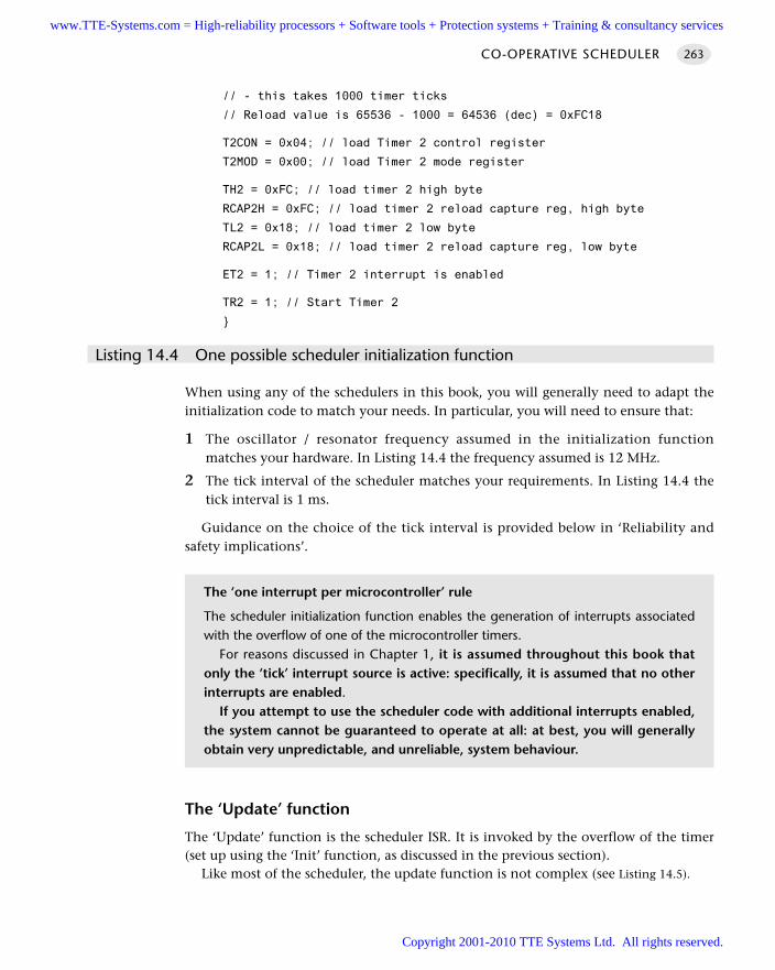
// - this takes 1000 timer ticks
// Reload value is 65536 - 1000 = 64536 (dec) = 0xFC18
T2CON = 0x04; // load Timer 2 control register
T2MOD = 0x00; // load Timer 2 mode register
TH2 = 0xFC; // load timer 2 high byte
RCAP2H = 0xFC; // load timer 2 reload capture reg, high byte
TL2 = 0x18; // load timer 2 low byte
RCAP2L = 0x18; // load timer 2 reload capture reg, low byte
ET2 = 1; // Timer 2 interrupt is enabled
TR2 = 1; // Start Timer 2
Listing 14.4 One possible scheduler initialization function
When using any of the schedulers in this book, you will generally need to adapt theinitialization code to match your needs. In particular, you will need to ensure that:
1 The oscillator / resonator frequency assumed in the initialization functionmatches your hardware. In Listing 14.4 the frequency assumed is 12 MHz.
2 The tick interval of the scheduler matches your requirements. In Listing 14.4 thetick interval is 1 ms.
Guidance on the choice of the tick interval is provided below in ‘Reliability andsafety implications’.
The ‘Update’ function
The ‘Update’ function is the scheduler ISR. It is invoked by the overflow of the timer(set up using the ‘Init’ function, as discussed in the previous section).
Like most of the scheduler, the update function is not complex (see Listing 14.5).
CO-OPERATIVE SCHEDULER 263
The ‘one interrupt per microcontroller’ rule
The scheduler initialization function enables the generation of interrupts associatedwith the overflow of one of the microcontroller timers.
For reasons discussed in Chapter 1, it is assumed throughout this book thatonly the ‘tick’ interrupt source is active: specifically, it is assumed that no otherinterrupts are enabled.
If you attempt to use the scheduler code with additional interrupts enabled,the system cannot be guaranteed to operate at all: at best, you will generallyobtain very unpredictable, and unreliable, system behaviour.
www.TTE-Systems.com = High-reliability processors + Software tools + Protection systems + Training & consultancy services
Copyright 2001-2010 TTE Systems Ltd. All rights reserved.
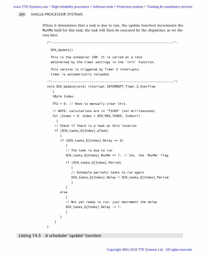
When it determines that a task is due to run, the update function increments theRunMe field for this task: the task will then be executed by the dispatcher, as we dis-cuss later.
/*------------------------------------------------------------------*-
SCH_Update()
This is the scheduler ISR. It is called at a rate
determined by the timer settings in the 'init' function.
This version is triggered by Timer 2 interrupts:
timer is automatically reloaded.
-*------------------------------------------------------------------*/
void SCH_Update(void) interrupt INTERRUPT_Timer_2_Overflow
tByte Index;
TF2 = 0; // Have to manually clear this.
// NOTE: calculations are in *TICKS* (not milliseconds)
for (Index = 0; Index < SCH_MAX_TASKS; Index++)
// Check if there is a task at this location
if (SCH_tasks_G[Index].pTask)
if (SCH_tasks_G[Index].Delay == 0)
// The task is due to run
SCH_tasks_G[Index].RunMe += 1; // Inc. the 'RunMe' flag
if (SCH_tasks_G[Index].Period)
// Schedule periodic tasks to run again
SCH_tasks_G[Index].Delay = SCH_tasks_G[Index].Period;
else
// Not yet ready to run: just decrement the delay
SCH_tasks_G[Index].Delay -= 1;
Listing 14.5 A scheduler ‘update’ function
SINGLE-PROCESSOR SYSTEMS264
www.TTE-Systems.com = High-reliability processors + Software tools + Protection systems + Training & consultancy services
Copyright 2001-2010 TTE Systems Ltd. All rights reserved.
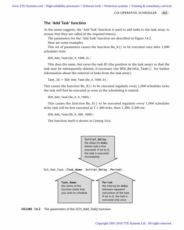
The ‘Add Task’ function
As the name suggests, the ‘Add Task’ function is used to add tasks to the task array, toensure that they are called at the required time(s).
The parameters for the ‘Add Task’ function are described in Figure 14.2.Here are some examples.This set of parameters causes the function Do_X() to be executed once after 1,000
scheduler ticks:
SCH_Add_Task(Do_X,1000,0);
This does the same, but saves the task ID (the position in the task array) so that thetask may be subsequently deleted, if necessary (see SCH_Delete_Task() for furtherinformation about the removal of tasks from the task array):
Task_ID = SCH_Add_Task(Do_X,1000,0);
This causes the function Do_X() to be executed regularly every 1,000 scheduler ticks;the task will first be executed as soon as the scheduling is started:
SCH_Add_Task(Do_X,0,1000);
This causes the function Do_X() to be executed regularly every 1,000 schedulerticks; task will be first executed at T = 300 ticks, then 1,300, 2,300 etc:
SCH_Add_Task(Do_X,300,1000);
The function itself is shown in Listing 14.6.
CO-OPERATIVE SCHEDULER 265
FIGURE 14.2 The parameters of the SCH_Add_Task() function
Periodthe interval (in ticks)between repeatedexecutions of the task.If set to 0, the task isexecuted only once
Task_Namethe name of thefunction (task) thatyou wish to schedule
Initial_Delaythe delay (in ticks)before task is firstexecuted. If set to 0,the task is executedimmediately
Sch_Add_Task (Task_Name, Initial_Delay, Period);
www.TTE-Systems.com = High-reliability processors + Software tools + Protection systems + Training & consultancy services
Copyright 2001-2010 TTE Systems Ltd. All rights reserved.
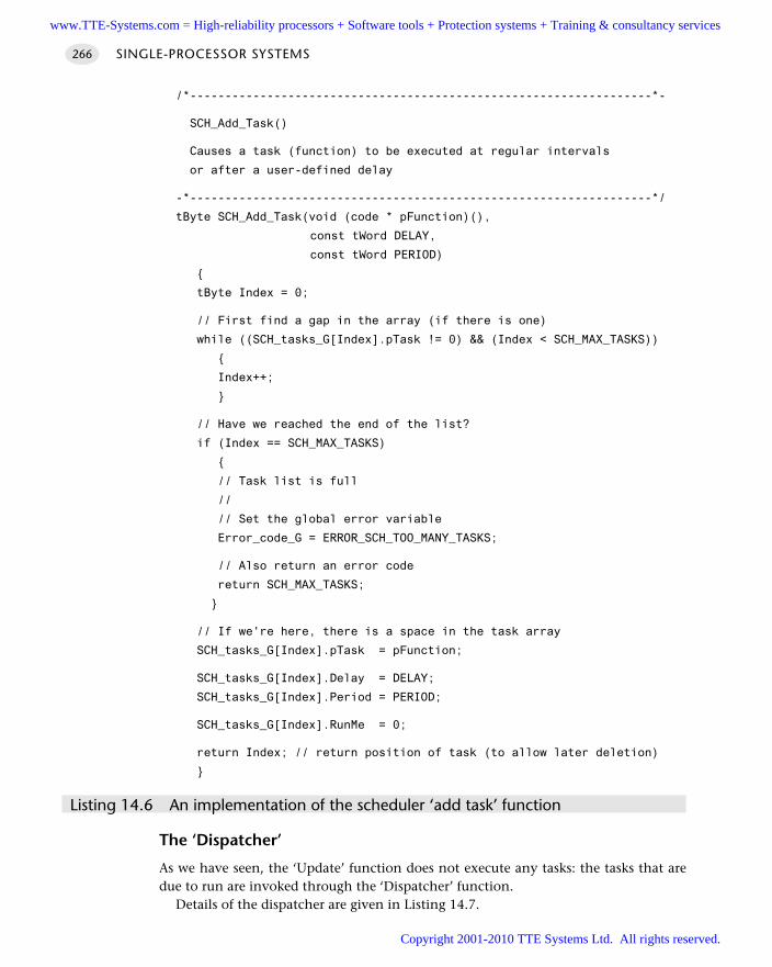
/*------------------------------------------------------------------*-
SCH_Add_Task()
Causes a task (function) to be executed at regular intervals
or after a user-defined delay
-*------------------------------------------------------------------*/
tByte SCH_Add_Task(void (code * pFunction)(),
const tWord DELAY,
const tWord PERIOD)
tByte Index = 0;
// First find a gap in the array (if there is one)
while ((SCH_tasks_G[Index].pTask != 0) && (Index < SCH_MAX_TASKS))
Index++;
// Have we reached the end of the list?
if (Index == SCH_MAX_TASKS)
// Task list is full
//
// Set the global error variable
Error_code_G = ERROR_SCH_TOO_MANY_TASKS;
// Also return an error code
return SCH_MAX_TASKS;
// If we're here, there is a space in the task array
SCH_tasks_G[Index].pTask = pFunction;
SCH_tasks_G[Index].Delay = DELAY;
SCH_tasks_G[Index].Period = PERIOD;
SCH_tasks_G[Index].RunMe = 0;
return Index; // return position of task (to allow later deletion)
Listing 14.6 An implementation of the scheduler ‘add task’ function
The ‘Dispatcher’
As we have seen, the ‘Update’ function does not execute any tasks: the tasks that aredue to run are invoked through the ‘Dispatcher’ function.
Details of the dispatcher are given in Listing 14.7.
SINGLE-PROCESSOR SYSTEMS266
www.TTE-Systems.com = High-reliability processors + Software tools + Protection systems + Training & consultancy services
Copyright 2001-2010 TTE Systems Ltd. All rights reserved.
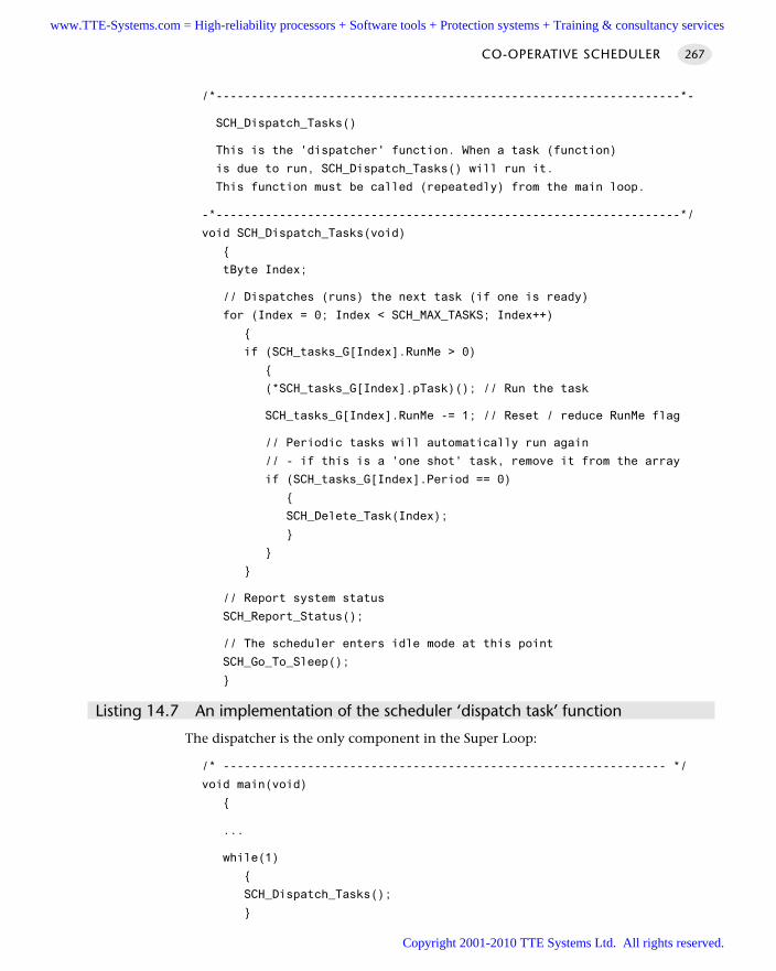
/*------------------------------------------------------------------*-
SCH_Dispatch_Tasks()
This is the 'dispatcher' function. When a task (function)
is due to run, SCH_Dispatch_Tasks() will run it.
This function must be called (repeatedly) from the main loop.
-*------------------------------------------------------------------*/
void SCH_Dispatch_Tasks(void)
tByte Index;
// Dispatches (runs) the next task (if one is ready)
for (Index = 0; Index < SCH_MAX_TASKS; Index++)
if (SCH_tasks_G[Index].RunMe > 0)
(*SCH_tasks_G[Index].pTask)(); // Run the task
SCH_tasks_G[Index].RunMe -= 1; // Reset / reduce RunMe flag
// Periodic tasks will automatically run again
// - if this is a 'one shot' task, remove it from the array
if (SCH_tasks_G[Index].Period == 0)
SCH_Delete_Task(Index);
// Report system status
SCH_Report_Status();
// The scheduler enters idle mode at this point
SCH_Go_To_Sleep();
Listing 14.7 An implementation of the scheduler ‘dispatch task’ function
The dispatcher is the only component in the Super Loop:
/* --------------------------------------------------------------- */
void main(void)
...
while(1)
SCH_Dispatch_Tasks();
CO-OPERATIVE SCHEDULER 267
www.TTE-Systems.com = High-reliability processors + Software tools + Protection systems + Training & consultancy services
Copyright 2001-2010 TTE Systems Ltd. All rights reserved.
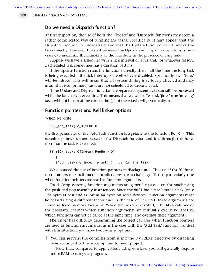
Do we need a Dispatch function?
At first inspection, the use of both the ‘Update’ and ‘Dispatch’ functions may seem arather complicated way of running the tasks. Specifically, it may appear that theDispatch function in unnecessary and that the Update function could invoke thetasks directly. However, the split between the Update and Dispatch operations is nec-essary, to maximize the reliability of the scheduler in the presence of long tasks.
Suppose we have a scheduler with a tick interval of 1 ms and, for whatever reason,a scheduled task sometimes has a duration of 3 ms.
If the Update function runs the functions directly then – all the time the long taskis being executed – the tick interrupts are effectively disabled. Specifically, two ‘ticks’will be missed. This will mean that all system timing is seriously affected and maymean that two (or more) tasks are not scheduled to execute at all.
If the Update and Dispatch function are separated, system ticks can still be processedwhile the long task is executing. This means that we will suffer task ‘jitter’ (the ‘missing’tasks will not be run at the correct time), but these tasks will, eventually, run.
Function pointers and Keil linker options
When we write:
SCH_Add_Task(Do_X,1000,0);
the first parameter of the ‘Add Task’ function is a pointer to the function Do_X(). Thisfunction pointer is then passed to the Dispatch function and it is through this func-tion that the task is executed:
if (SCH_tasks_G[Index].RunMe > 0)
(*SCH_tasks_G[Index].pTask)(); // Run the task
We discussed the use of function pointers in ‘Background’. The use of the ‘C’ func-tion pointers on small microcontrollers presents a challenge. This is particularly truewhen function pointers are used as function arguments.
On desktop systems, function arguments are generally passed on the stack usingthe push and pop assembly instructions. Since the 8051 has a size limited stack (only128 bytes at best and as low as 64 bytes on some devices), function arguments mustbe passed using a different technique: in the case of Keil C51, these arguments arestored in fixed memory locations. When the linker is invoked, it builds a call tree ofthe program, decides which function arguments are mutually exclusive (that is,which functions cannot be called at the same time) and overlays these arguments.
The linker has difficulty determining the correct call tree when function pointersare used as function arguments, as is the case with the ‘Add Task’ function. To dealwith this situation, you have two realistic options:
1 You can prevent the compiler from using the OVERLAY directive by disablingoverlays as part of the linker options for your project.
Note that, compared to applications using overlays, you will generally requiremore RAM to run your program.
SINGLE-PROCESSOR SYSTEMS268
www.TTE-Systems.com = High-reliability processors + Software tools + Protection systems + Training & consultancy services
Copyright 2001-2010 TTE Systems Ltd. All rights reserved.
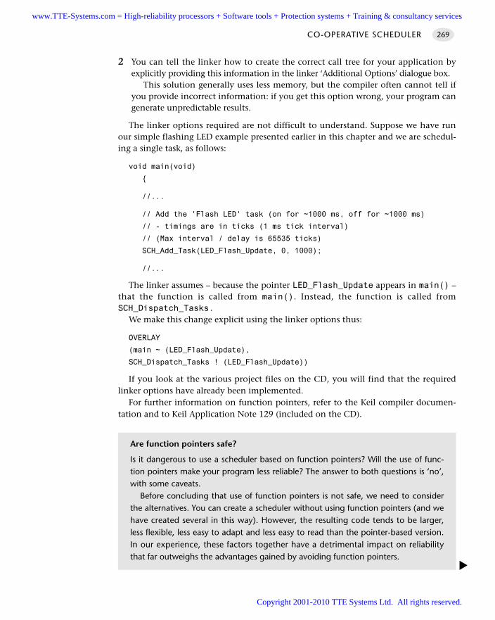
2 You can tell the linker how to create the correct call tree for your application byexplicitly providing this information in the linker ‘Additional Options’ dialogue box.
This solution generally uses less memory, but the compiler often cannot tell ifyou provide incorrect information: if you get this option wrong, your program cangenerate unpredictable results.
The linker options required are not difficult to understand. Suppose we have runour simple flashing LED example presented earlier in this chapter and we are schedul-ing a single task, as follows:
void main(void)
//...
// Add the 'Flash LED' task (on for ~1000 ms, off for ~1000 ms)
// - timings are in ticks (1 ms tick interval)
// (Max interval / delay is 65535 ticks)
SCH_Add_Task(LED_Flash_Update, 0, 1000);
//...
The linker assumes – because the pointer LED_Flash_Update appears in main() –that the function is called from main(). Instead, the function is called fromSCH_Dispatch_Tasks.
We make this change explicit using the linker options thus:
OVERLAY
(main ~ (LED_Flash_Update),
SCH_Dispatch_Tasks ! (LED_Flash_Update))
If you look at the various project files on the CD, you will find that the requiredlinker options have already been implemented.
For further information on function pointers, refer to the Keil compiler documen-tation and to Keil Application Note 129 (included on the CD).
CO-OPERATIVE SCHEDULER 269
Are function pointers safe?
Is it dangerous to use a scheduler based on function pointers? Will the use of func-tion pointers make your program less reliable? The answer to both questions is ‘no’,with some caveats.
Before concluding that use of function pointers is not safe, we need to considerthe alternatives. You can create a scheduler without using function pointers (and wehave created several in this way). However, the resulting code tends to be larger,less flexible, less easy to adapt and less easy to read than the pointer-based version.In our experience, these factors together have a detrimental impact on reliabilitythat far outweighs the advantages gained by avoiding function pointers.
www.TTE-Systems.com = High-reliability processors + Software tools + Protection systems + Training & consultancy services
Copyright 2001-2010 TTE Systems Ltd. All rights reserved.
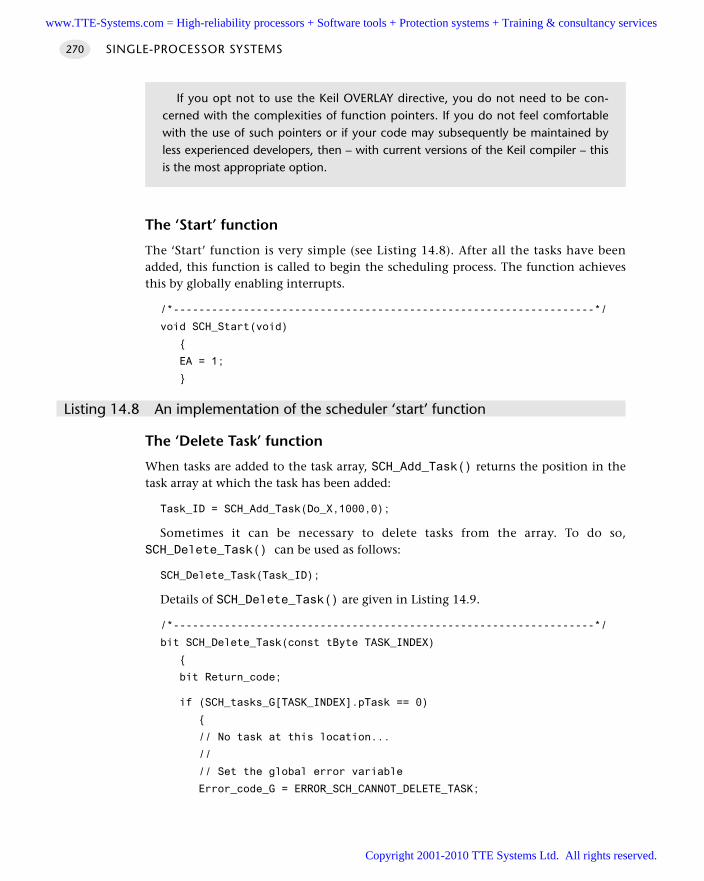
The ‘Start’ function
The ‘Start’ function is very simple (see Listing 14.8). After all the tasks have beenadded, this function is called to begin the scheduling process. The function achievesthis by globally enabling interrupts.
/*------------------------------------------------------------------*/
void SCH_Start(void)
EA = 1;
Listing 14.8 An implementation of the scheduler ‘start’ function
The ‘Delete Task’ function
When tasks are added to the task array, SCH_Add_Task() returns the position in thetask array at which the task has been added:
Task_ID = SCH_Add_Task(Do_X,1000,0);
Sometimes it can be necessary to delete tasks from the array. To do so,SCH_Delete_Task() can be used as follows:
SCH_Delete_Task(Task_ID);
Details of SCH_Delete_Task() are given in Listing 14.9.
/*------------------------------------------------------------------*/
bit SCH_Delete_Task(const tByte TASK_INDEX)
bit Return_code;
if (SCH_tasks_G[TASK_INDEX].pTask == 0)
// No task at this location...
//
// Set the global error variable
Error_code_G = ERROR_SCH_CANNOT_DELETE_TASK;
SINGLE-PROCESSOR SYSTEMS270
If you opt not to use the Keil OVERLAY directive, you do not need to be con-cerned with the complexities of function pointers. If you do not feel comfortablewith the use of such pointers or if your code may subsequently be maintained byless experienced developers, then – with current versions of the Keil compiler – thisis the most appropriate option.
www.TTE-Systems.com = High-reliability processors + Software tools + Protection systems + Training & consultancy services
Copyright 2001-2010 TTE Systems Ltd. All rights reserved.
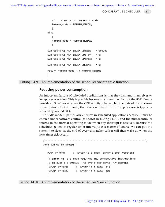
// ...also return an error code
Return_code = RETURN_ERROR;
else
Return_code = RETURN_NORMAL;
SCH_tasks_G[TASK_INDEX].pTask = 0x0000;
SCH_tasks_G[TASK_INDEX].Delay = 0;
SCH_tasks_G[TASK_INDEX].Period = 0;
SCH_tasks_G[TASK_INDEX].RunMe = 0;
return Return_code; // return status
Listing 14.9 An implementation of the scheduler ‘delete task’ function
Reducing power consumption
An important feature of scheduled applications is that they can lend themselves tolow-power operation. This is possible because all current members of the 8051 familyprovide an ‘idle’ mode, where the CPU activity is halted, but the state of the processoris maintained. In this mode, the power required to run the processor is typicallyreduced by around 50%.
This idle mode is particularly effective in scheduled applications because it may beentered under software control (as shown in Listing 14.10), and the microcontrollerreturns to the normal operating mode when any interrupt is received. Because thescheduler generates regular timer interrupts as a matter of course, we can put thesystem ‘ to sleep’ at the end of every dispatcher call: it will then wake up when thenext timer tick occurs.
/*------------------------------------------------------------------*/
void SCH_Go_To_Sleep()
PCON |= 0x01; // Enter idle mode (generic 8051 version)
// Entering idle mode requires TWO consecutive instructions
// on 80c515 / 80c505 - to avoid accidental triggering
//PCON |= 0x01; // Enter idle mode (#1)
//PCON |= 0x20; // Enter idle mode (#2)
Listing 14.10 An implementation of the scheduler ‘sleep’ function
CO-OPERATIVE SCHEDULER 271
www.TTE-Systems.com = High-reliability processors + Software tools + Protection systems + Training & consultancy services
Copyright 2001-2010 TTE Systems Ltd. All rights reserved.
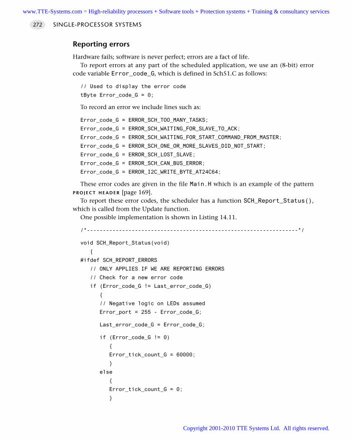
Reporting errors
Hardware fails; software is never perfect; errors are a fact of life. To report errors at any part of the scheduled application, we use an (8-bit) error
code variable Error_code_G, which is defined in Sch51.C as follows:
// Used to display the error code
tByte Error_code_G = 0;
To record an error we include lines such as:
Error_code_G = ERROR_SCH_TOO_MANY_TASKS;
Error_code_G = ERROR_SCH_WAITING_FOR_SLAVE_TO_ACK;
Error_code_G = ERROR_SCH_WAITING_FOR_START_COMMAND_FROM_MASTER;
Error_code_G = ERROR_SCH_ONE_OR_MORE_SLAVES_DID_NOT_START;
Error_code_G = ERROR_SCH_LOST_SLAVE;
Error_code_G = ERROR_SCH_CAN_BUS_ERROR;
Error_code_G = ERROR_I2C_WRITE_BYTE_AT24C64;
These error codes are given in the file Main.H which is an example of the patternP R O J E C T H E A D E R [page 169].
To report these error codes, the scheduler has a function SCH_Report_Status(),which is called from the Update function.
One possible implementation is shown in Listing 14.11.
/*------------------------------------------------------------------*/
void SCH_Report_Status(void)
#ifdef SCH_REPORT_ERRORS
// ONLY APPLIES IF WE ARE REPORTING ERRORS
// Check for a new error code
if (Error_code_G != Last_error_code_G)
// Negative logic on LEDs assumed
Error_port = 255 - Error_code_G;
Last_error_code_G = Error_code_G;
if (Error_code_G != 0)
Error_tick_count_G = 60000;
else
Error_tick_count_G = 0;
SINGLE-PROCESSOR SYSTEMS272
www.TTE-Systems.com = High-reliability processors + Software tools + Protection systems + Training & consultancy services
Copyright 2001-2010 TTE Systems Ltd. All rights reserved.
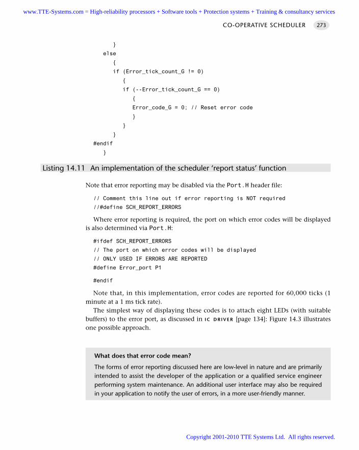
else
if (Error_tick_count_G != 0)
if (--Error_tick_count_G == 0)
Error_code_G = 0; // Reset error code
#endif
Listing 14.11 An implementation of the scheduler ‘report status’ function
Note that error reporting may be disabled via the Port.H header file:
// Comment this line out if error reporting is NOT required
//#define SCH_REPORT_ERRORS
Where error reporting is required, the port on which error codes will be displayedis also determined via Port.H:
#ifdef SCH_REPORT_ERRORS
// The port on which error codes will be displayed
// ONLY USED IF ERRORS ARE REPORTED
#define Error_port P1
#endif
Note that, in this implementation, error codes are reported for 60,000 ticks (1minute at a 1 ms tick rate).
The simplest way of displaying these codes is to attach eight LEDs (with suitablebuffers) to the error port, as discussed in I C D R I V E R [page 134]: Figure 14.3 illustratesone possible approach.
CO-OPERATIVE SCHEDULER 273
What does that error code mean?
The forms of error reporting discussed here are low-level in nature and are primarilyintended to assist the developer of the application or a qualified service engineerperforming system maintenance. An additional user interface may also be requiredin your application to notify the user of errors, in a more user-friendly manner.
www.TTE-Systems.com = High-reliability processors + Software tools + Protection systems + Training & consultancy services
Copyright 2001-2010 TTE Systems Ltd. All rights reserved.
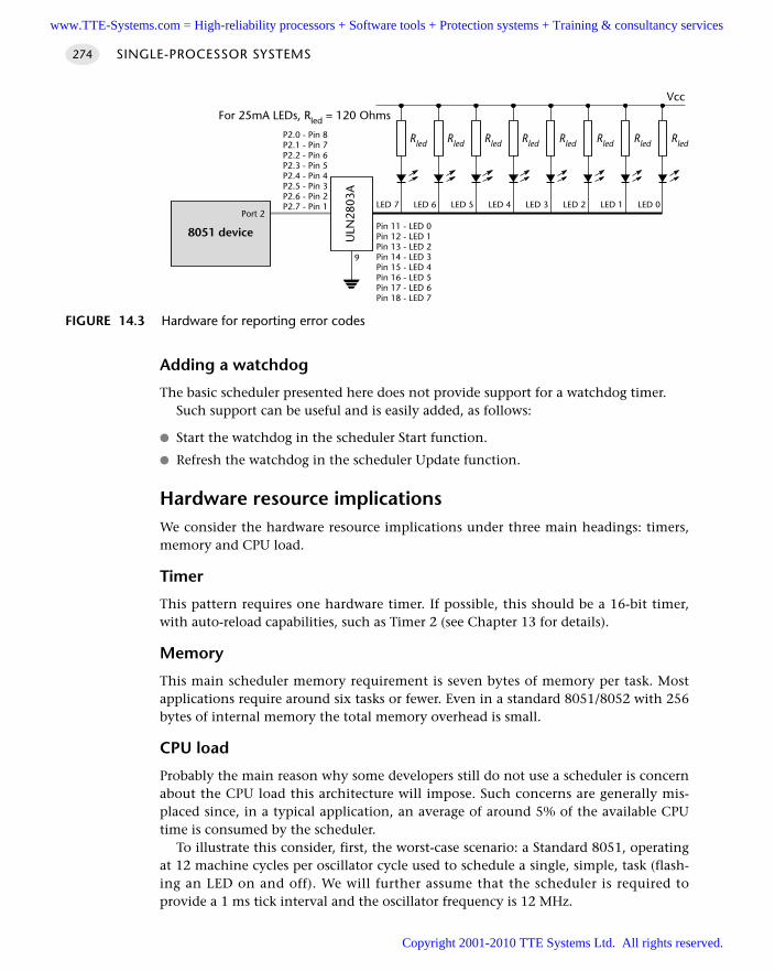
Adding a watchdog
The basic scheduler presented here does not provide support for a watchdog timer.Such support can be useful and is easily added, as follows:
Start the watchdog in the scheduler Start function.
Refresh the watchdog in the scheduler Update function.
Hardware resource implicationsWe consider the hardware resource implications under three main headings: timers,memory and CPU load.
Timer
This pattern requires one hardware timer. If possible, this should be a 16-bit timer,with auto-reload capabilities, such as Timer 2 (see Chapter 13 for details).
Memory
This main scheduler memory requirement is seven bytes of memory per task. Mostapplications require around six tasks or fewer. Even in a standard 8051/8052 with 256bytes of internal memory the total memory overhead is small.
CPU load
Probably the main reason why some developers still do not use a scheduler is concernabout the CPU load this architecture will impose. Such concerns are generally mis-placed since, in a typical application, an average of around 5% of the available CPUtime is consumed by the scheduler.
To illustrate this consider, first, the worst-case scenario: a Standard 8051, operatingat 12 machine cycles per oscillator cycle used to schedule a single, simple, task (flash-ing an LED on and off). We will further assume that the scheduler is required toprovide a 1 ms tick interval and the oscillator frequency is 12 MHz.
SINGLE-PROCESSOR SYSTEMS274
FIGURE 14.3 Hardware for reporting error codes
8051 device
Port 2
ULN
2803
A
P2.0 - Pin 8P2.1 - Pin 7P2.2 - Pin 6P2.3 - Pin 5P2.4 - Pin 4P2.5 - Pin 3P2.6 - Pin 2P2.7 - Pin 1
Pin 11 - LED 0Pin 12 - LED 1Pin 13 - LED 2Pin 14 - LED 3Pin 15 - LED 4Pin 16 - LED 5Pin 17 - LED 6Pin 18 - LED 7
9
LED 7 LED 6 LED 5 LED 4 LED 3 LED 2 LED 1 LED 0
Vcc
RledRledRledRledRledRledRledRled
For 25mA LEDs, Rled = 120 Ohms
www.TTE-Systems.com = High-reliability processors + Software tools + Protection systems + Training & consultancy services
Copyright 2001-2010 TTE Systems Ltd. All rights reserved.
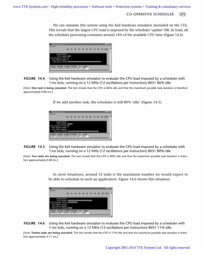
We can simulate this system using the Keil hardware simulator (included on the CD).This reveals that the largest CPU load is imposed by the scheduler ‘update’ ISR. In total, allthe scheduler processing consumes around 14% of the available CPU time (Figure 14.4).
If we add another task, the scheduler is still 80% ‘idle’ (Figure 14.5).
In most situations, around 12 tasks is the maximum number we would expect tobe able to schedule in such an application. Figure 14.6 shows this situation.
CO-OPERATIVE SCHEDULER 275
FIGURE 14.4 Using the Keil hardware simulator to evaluate the CPU load imposed by a scheduler with1ms ticks, running on a 12 MHz (12 oscillations per instruction) 8051 86% idle
[Note: One task is being executed. The test reveals that the CPU is 86% idle and that the maximum possible task duration is thereforeapproximately 0.86 ms.]
FIGURE 14.5 Using the Keil hardware simulator to evaluate the CPU load imposed by a scheduler with1ms ticks, running on a 12 MHz (12 oscillations per instruction) 8051 80% idle
[Note: Two tasks are being executed. The test reveals that the CPU is 80% idle and that the maximum possible task duration is there-fore approximately 0.80 ms.]
FIGURE 14.6 Using the Keil hardware simulator to evaluate the CPU load imposed by a scheduler with1 ms ticks, running on a 12 MHz (12 oscillations per instruction) 8051 11% idle.
[Note: Twelve tasks are being executed. The test reveals that the CPU is 11% idle and that the maximum possible task duration is there-fore approximately 0.11 ms.]
www.TTE-Systems.com = High-reliability processors + Software tools + Protection systems + Training & consultancy services
Copyright 2001-2010 TTE Systems Ltd. All rights reserved.
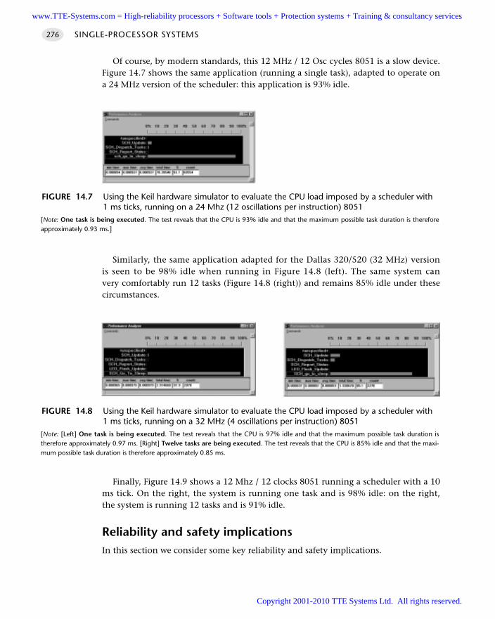
Of course, by modern standards, this 12 MHz / 12 Osc cycles 8051 is a slow device.Figure 14.7 shows the same application (running a single task), adapted to operate ona 24 MHz version of the scheduler: this application is 93% idle.
Similarly, the same application adapted for the Dallas 320/520 (32 MHz) versionis seen to be 98% idle when running in Figure 14.8 (left). The same system canvery comfortably run 12 tasks (Figure 14.8 (right)) and remains 85% idle under thesecircumstances.
Finally, Figure 14.9 shows a 12 Mhz / 12 clocks 8051 running a scheduler with a 10ms tick. On the right, the system is running one task and is 98% idle: on the right,the system is running 12 tasks and is 91% idle.
Reliability and safety implicationsIn this section we consider some key reliability and safety implications.
SINGLE-PROCESSOR SYSTEMS276
FIGURE 14.7 Using the Keil hardware simulator to evaluate the CPU load imposed by a scheduler with1 ms ticks, running on a 24 Mhz (12 oscillations per instruction) 8051
[Note: One task is being executed. The test reveals that the CPU is 93% idle and that the maximum possible task duration is thereforeapproximately 0.93 ms.]
FIGURE 14.8 Using the Keil hardware simulator to evaluate the CPU load imposed by a scheduler with1 ms ticks, running on a 32 MHz (4 oscillations per instruction) 8051
[Note: [Left] One task is being executed. The test reveals that the CPU is 97% idle and that the maximum possible task duration istherefore approximately 0.97 ms. [Right] Twelve tasks are being executed. The test reveals that the CPU is 85% idle and that the maxi-mum possible task duration is therefore approximately 0.85 ms.
www.TTE-Systems.com = High-reliability processors + Software tools + Protection systems + Training & consultancy services
Copyright 2001-2010 TTE Systems Ltd. All rights reserved.
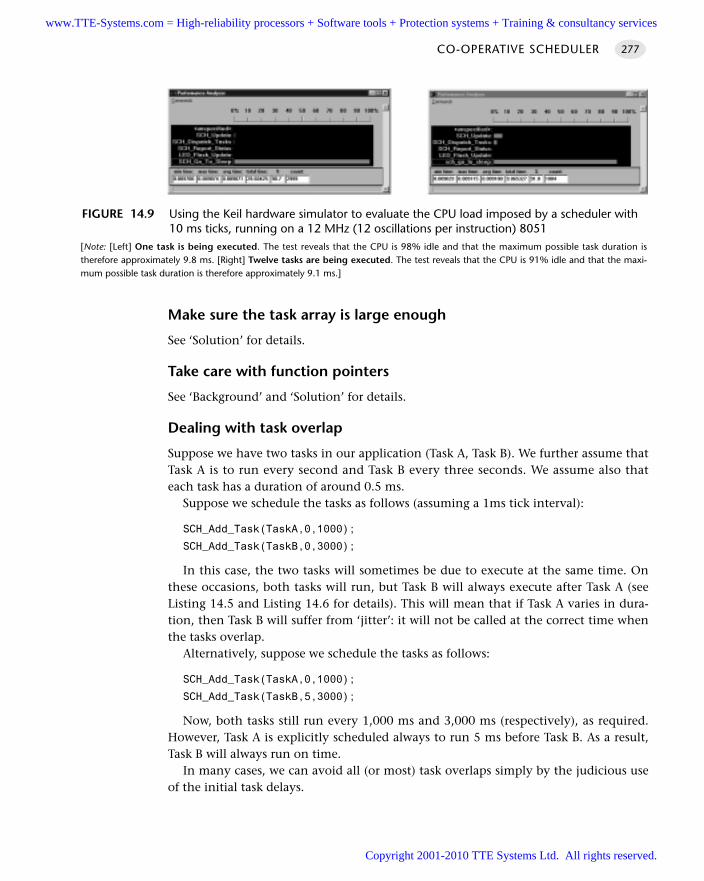
Make sure the task array is large enough
See ‘Solution’ for details.
Take care with function pointers
See ‘Background’ and ‘Solution’ for details.
Dealing with task overlap
Suppose we have two tasks in our application (Task A, Task B). We further assume thatTask A is to run every second and Task B every three seconds. We assume also thateach task has a duration of around 0.5 ms.
Suppose we schedule the tasks as follows (assuming a 1ms tick interval):
SCH_Add_Task(TaskA,0,1000);
SCH_Add_Task(TaskB,0,3000);
In this case, the two tasks will sometimes be due to execute at the same time. Onthese occasions, both tasks will run, but Task B will always execute after Task A (seeListing 14.5 and Listing 14.6 for details). This will mean that if Task A varies in dura-tion, then Task B will suffer from ‘jitter’: it will not be called at the correct time whenthe tasks overlap.
Alternatively, suppose we schedule the tasks as follows:
SCH_Add_Task(TaskA,0,1000);
SCH_Add_Task(TaskB,5,3000);
Now, both tasks still run every 1,000 ms and 3,000 ms (respectively), as required.However, Task A is explicitly scheduled always to run 5 ms before Task B. As a result,Task B will always run on time.
In many cases, we can avoid all (or most) task overlaps simply by the judicious useof the initial task delays.
CO-OPERATIVE SCHEDULER 277
FIGURE 14.9 Using the Keil hardware simulator to evaluate the CPU load imposed by a scheduler with10 ms ticks, running on a 12 MHz (12 oscillations per instruction) 8051
[Note: [Left] One task is being executed. The test reveals that the CPU is 98% idle and that the maximum possible task duration istherefore approximately 9.8 ms. [Right] Twelve tasks are being executed. The test reveals that the CPU is 91% idle and that the maxi-mum possible task duration is therefore approximately 9.1 ms.]
www.TTE-Systems.com = High-reliability processors + Software tools + Protection systems + Training & consultancy services
Copyright 2001-2010 TTE Systems Ltd. All rights reserved.
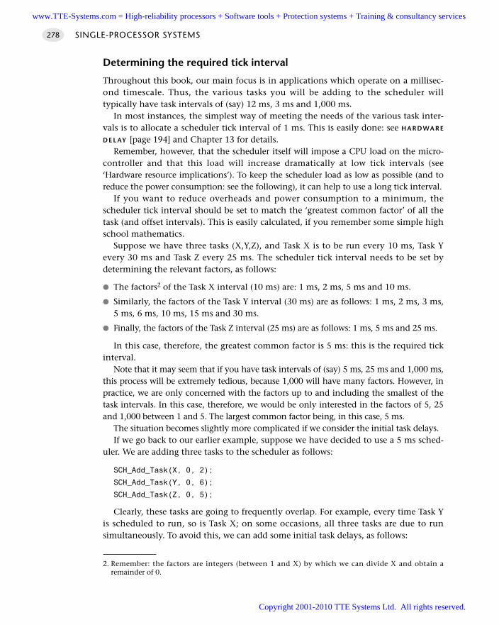
Determining the required tick interval
Throughout this book, our main focus is in applications which operate on a millisec-ond timescale. Thus, the various tasks you will be adding to the scheduler willtypically have task intervals of (say) 12 ms, 3 ms and 1,000 ms.
In most instances, the simplest way of meeting the needs of the various task inter-vals is to allocate a scheduler tick interval of 1 ms. This is easily done: see H A R D WA R E
D E L AY [page 194] and Chapter 13 for details.Remember, however, that the scheduler itself will impose a CPU load on the micro-
controller and that this load will increase dramatically at low tick intervals (see‘Hardware resource implications’). To keep the scheduler load as low as possible (and toreduce the power consumption: see the following), it can help to use a long tick interval.
If you want to reduce overheads and power consumption to a minimum, thescheduler tick interval should be set to match the ‘greatest common factor’ of all thetask (and offset intervals). This is easily calculated, if you remember some simple highschool mathematics.
Suppose we have three tasks (X,Y,Z), and Task X is to be run every 10 ms, Task Yevery 30 ms and Task Z every 25 ms. The scheduler tick interval needs to be set bydetermining the relevant factors, as follows:
The factors2 of the Task X interval (10 ms) are: 1 ms, 2 ms, 5 ms and 10 ms.
Similarly, the factors of the Task Y interval (30 ms) are as follows: 1 ms, 2 ms, 3 ms,5 ms, 6 ms, 10 ms, 15 ms and 30 ms.
Finally, the factors of the Task Z interval (25 ms) are as follows: 1 ms, 5 ms and 25 ms.
In this case, therefore, the greatest common factor is 5 ms: this is the required tickinterval.
Note that it may seem that if you have task intervals of (say) 5 ms, 25 ms and 1,000 ms,this process will be extremely tedious, because 1,000 will have many factors. However, inpractice, we are only concerned with the factors up to and including the smallest of thetask intervals. In this case, therefore, we would be only interested in the factors of 5, 25and 1,000 between 1 and 5. The largest common factor being, in this case, 5 ms.
The situation becomes slightly more complicated if we consider the initial task delays. If we go back to our earlier example, suppose we have decided to use a 5 ms sched-
uler. We are adding three tasks to the scheduler as follows:
SCH_Add_Task(X, 0, 2);
SCH_Add_Task(Y, 0, 6);
SCH_Add_Task(Z, 0, 5);
Clearly, these tasks are going to frequently overlap. For example, every time Task Yis scheduled to run, so is Task X; on some occasions, all three tasks are due to runsimultaneously. To avoid this, we can add some initial task delays, as follows:
SINGLE-PROCESSOR SYSTEMS278
2. Remember: the factors are integers (between 1 and X) by which we can divide X and obtain aremainder of 0.
www.TTE-Systems.com = High-reliability processors + Software tools + Protection systems + Training & consultancy services
Copyright 2001-2010 TTE Systems Ltd. All rights reserved.
Task X is to be run every 10 ms: we start this task immediately.
Task Z is to be run every 25 ms: we start this task after 2 ms.
Task Y is to be run every 30 ms; we start this task after 1 ms.
When determining the required scheduler interval, we must now take into accountboth the task intervals and the initial delays. This, in this case, we now need to findthe greatest common factor of 10, 25, 30, 1 and 2: this suggests that a scheduler inter-val of 1 ms is now required.
Guidelines for predictable and reliable scheduling
1 For precise scheduling, the scheduler tick interval should be set to match the‘greatest common factor’ of all the task intervals (see earlier).
2 All tasks should have a duration less than the schedule tick interval, to ensure thatthe dispatcher is always free to call any task that is due to execute. Software simu-lation can often be used to measure the task duration.
3 In order to meet Condition 2, all tasks must ‘timeout’ so that they cannot blockthe scheduler under any circumstances. Note that this condition can often be metby incorporating, where necessary, a LOOP TIMEOUT [page 298] or a HARDWARE TIME-OUT [page 305] in scheduled tasks.
Please remember that this condition also applies to any functions called fromwithin a scheduled task, including any library code provided by your compilermanufacturer. In many cases, standard functions (like printf()) do not includetimeout features. They must not be used in situations where predictability isrequired.
4 The total time required to execute all the scheduled tasks must be less than theavailable processor time. Of course, the total processor time must include boththis ‘task time’ and the ‘scheduler time’ required to execute the scheduler updateand dispatcher operations.
5 Tasks should be scheduled so that they are never required to execute simultane-ously: that is, task overlaps should be minimized. Note that where all tasks are of aduration much less than the scheduler tick interval, and that some task jitter canbe tolerated, this problem may not be significant.
PortabilityA co-operative scheduler, like that described in this pattern, can be written entirely in‘C’ and need use only core 8051 hardware features. A scheduler created for one 8051family member may therefore be readily ported for use on any other 8051 device.
The techniques described here may also be used without difficulty on other micro-controllers.
CO-OPERATIVE SCHEDULER 279
www.TTE-Systems.com = High-reliability processors + Software tools + Protection systems + Training & consultancy services
Copyright 2001-2010 TTE Systems Ltd. All rights reserved.
Overall strengths and weaknessesThe overall strengths and weaknesses of a co-operative scheduler may be summarizedas follows:
The scheduler is simple and can be implemented in a small amount ofcode.
The applications based on the scheduler are inherently predictable, safeand reliable.
The scheduler is written entirely in ‘C’: it is not a separate application, butbecomes part of the developer’s code.
The scheduler supports team working, since individual tasks can often bedeveloped largely independently and then assembled into the final system.
Obtain rapid responses to external events requires care at the design stage.
The tasks cannot safely use interrupts: the only interrupt that should be activein the application is the timer-related interrupt that drives the scheduler itself.
Related patterns and alternative solutionsFor alternative solutions see:
HYBRID SCHEDULER [page 333]
ONE-TASK SCHEDULER [page 911]
ONE-YEAR SCHEDULER [page 919]
STABLE SCHEDULER [page 932]
Chapter 13, for details of pre-emptive schedulers
Example: The core scheduler library (generic)The schedulers in this book are all constructed using a library of core files, presentedhere. Specified schedulers (designed for different hardware, clock frequencies and / ortick intervals) then add a small number of additional files on top of this core.
Most of the material in the core library has already been described earlier in thischapter. The complete library is presented in Listings 14.12 and 14.13 to illustratehow the various components fit together.
/*------------------------------------------------------------------*-
SCH51.h (v1.00)
------------------------------------------------------------------
- see SCH51.C for details
-*------------------------------------------------------------------*/
SINGLE-PROCESSOR SYSTEMS280
www.TTE-Systems.com = High-reliability processors + Software tools + Protection systems + Training & consultancy services
Copyright 2001-2010 TTE Systems Ltd. All rights reserved.
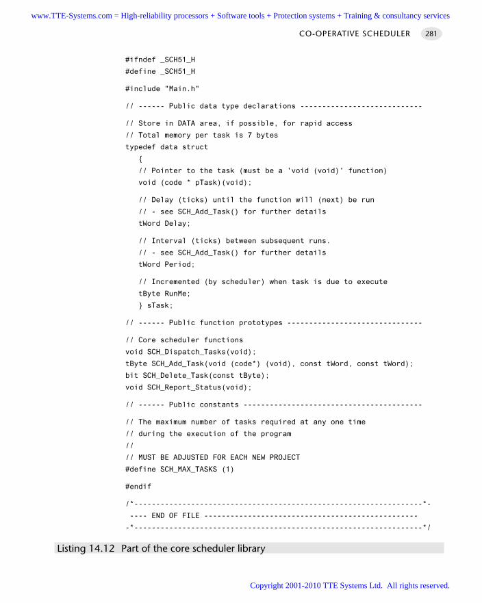
#ifndef _SCH51_H
#define _SCH51_H
#include "Main.h"
// ------ Public data type declarations ----------------------------
// Store in DATA area, if possible, for rapid access
// Total memory per task is 7 bytes
typedef data struct
// Pointer to the task (must be a 'void (void)' function)
void (code * pTask)(void);
// Delay (ticks) until the function will (next) be run
// - see SCH_Add_Task() for further details
tWord Delay;
// Interval (ticks) between subsequent runs.
// - see SCH_Add_Task() for further details
tWord Period;
// Incremented (by scheduler) when task is due to execute
tByte RunMe;
sTask;
// ------ Public function prototypes -------------------------------
// Core scheduler functions
void SCH_Dispatch_Tasks(void);
tByte SCH_Add_Task(void (code*) (void), const tWord, const tWord);
bit SCH_Delete_Task(const tByte);
void SCH_Report_Status(void);
// ------ Public constants -----------------------------------------
// The maximum number of tasks required at any one time
// during the execution of the program
//
// MUST BE ADJUSTED FOR EACH NEW PROJECT
#define SCH_MAX_TASKS (1)
#endif
/*------------------------------------------------------------------*-
---- END OF FILE -------------------------------------------------
-*------------------------------------------------------------------*/
Listing 14.12 Part of the core scheduler library
CO-OPERATIVE SCHEDULER 281
www.TTE-Systems.com = High-reliability processors + Software tools + Protection systems + Training & consultancy services
Copyright 2001-2010 TTE Systems Ltd. All rights reserved.
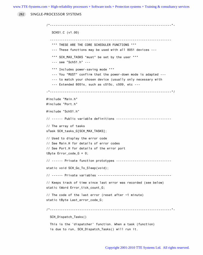
/*------------------------------------------------------------------*-
SCH51.C (v1.00)
------------------------------------------------------------------
*** THESE ARE THE CORE SCHEDULER FUNCTIONS ***
--- These functions may be used with all 8051 devices ---
*** SCH_MAX_TASKS *must* be set by the user ***
--- see "Sch51.h" ---
*** Includes power-saving mode ***
--- You *MUST* confirm that the power-down mode is adapted ---
--- to match your chosen device (usually only necessary with
--- Extended 8051s, such as c515c, c509, etc ---
-*------------------------------------------------------------------*/
#include "Main.h"
#include "Port.h"
#include "Sch51.h"
// ------ Public variable definitions ------------------------------
// The array of tasks
sTask SCH_tasks_G[SCH_MAX_TASKS];
// Used to display the error code
// See Main.H for details of error codes
// See Port.H for details of the error port
tByte Error_code_G = 0;
// ------ Private function prototypes ------------------------------
static void SCH_Go_To_Sleep(void);
// ------ Private variables ----------------------------------------
// Keeps track of time since last error was recorded (see below)
static tWord Error_tick_count_G;
// The code of the last error (reset after ~1 minute)
static tByte Last_error_code_G;
/*------------------------------------------------------------------*-
SCH_Dispatch_Tasks()
This is the 'dispatcher' function. When a task (function)
is due to run, SCH_Dispatch_Tasks() will run it.
SINGLE-PROCESSOR SYSTEMS282
www.TTE-Systems.com = High-reliability processors + Software tools + Protection systems + Training & consultancy services
Copyright 2001-2010 TTE Systems Ltd. All rights reserved.
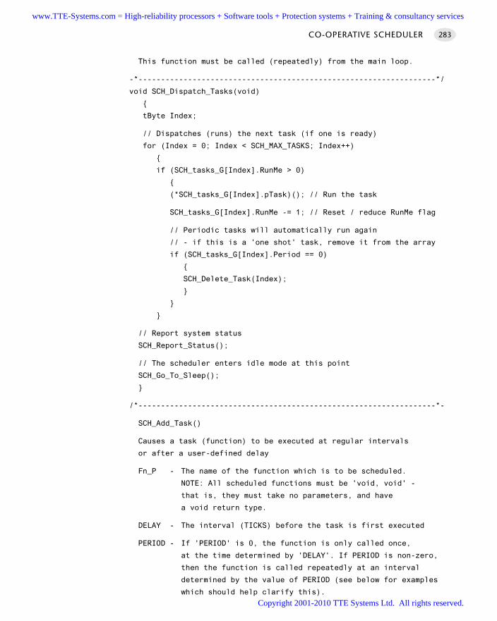
This function must be called (repeatedly) from the main loop.
-*------------------------------------------------------------------*/
void SCH_Dispatch_Tasks(void)
tByte Index;
// Dispatches (runs) the next task (if one is ready)
for (Index = 0; Index < SCH_MAX_TASKS; Index++)
if (SCH_tasks_G[Index].RunMe > 0)
(*SCH_tasks_G[Index].pTask)(); // Run the task
SCH_tasks_G[Index].RunMe -= 1; // Reset / reduce RunMe flag
// Periodic tasks will automatically run again
// - if this is a 'one shot' task, remove it from the array
if (SCH_tasks_G[Index].Period == 0)
SCH_Delete_Task(Index);
// Report system status
SCH_Report_Status();
// The scheduler enters idle mode at this point
SCH_Go_To_Sleep();
/*------------------------------------------------------------------*-
SCH_Add_Task()
Causes a task (function) to be executed at regular intervals
or after a user-defined delay
Fn_P - The name of the function which is to be scheduled.
NOTE: All scheduled functions must be 'void, void' -
that is, they must take no parameters, and have
a void return type.
DELAY - The interval (TICKS) before the task is first executed
PERIOD - If 'PERIOD' is 0, the function is only called once,
at the time determined by 'DELAY'. If PERIOD is non-zero,
then the function is called repeatedly at an interval
determined by the value of PERIOD (see below for examples
which should help clarify this).
CO-OPERATIVE SCHEDULER 283
www.TTE-Systems.com = High-reliability processors + Software tools + Protection systems + Training & consultancy services
Copyright 2001-2010 TTE Systems Ltd. All rights reserved.
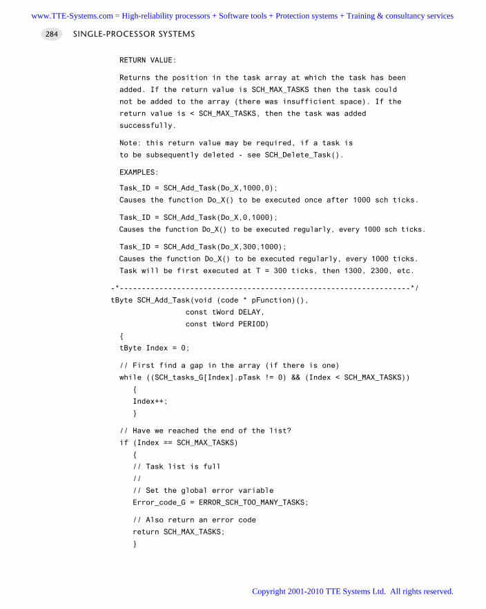
RETURN VALUE:
Returns the position in the task array at which the task has been
added. If the return value is SCH_MAX_TASKS then the task could
not be added to the array (there was insufficient space). If the
return value is < SCH_MAX_TASKS, then the task was added
successfully.
Note: this return value may be required, if a task is
to be subsequently deleted - see SCH_Delete_Task().
EXAMPLES:
Task_ID = SCH_Add_Task(Do_X,1000,0);
Causes the function Do_X() to be executed once after 1000 sch ticks.
Task_ID = SCH_Add_Task(Do_X,0,1000);
Causes the function Do_X() to be executed regularly, every 1000 sch ticks.
Task_ID = SCH_Add_Task(Do_X,300,1000);
Causes the function Do_X() to be executed regularly, every 1000 ticks.
Task will be first executed at T = 300 ticks, then 1300, 2300, etc.
-*------------------------------------------------------------------*/
tByte SCH_Add_Task(void (code * pFunction)(),
const tWord DELAY,
const tWord PERIOD)
tByte Index = 0;
// First find a gap in the array (if there is one)
while ((SCH_tasks_G[Index].pTask != 0) && (Index < SCH_MAX_TASKS))
Index++;
// Have we reached the end of the list?
if (Index == SCH_MAX_TASKS)
// Task list is full
//
// Set the global error variable
Error_code_G = ERROR_SCH_TOO_MANY_TASKS;
// Also return an error code
return SCH_MAX_TASKS;
SINGLE-PROCESSOR SYSTEMS284
www.TTE-Systems.com = High-reliability processors + Software tools + Protection systems + Training & consultancy services
Copyright 2001-2010 TTE Systems Ltd. All rights reserved.
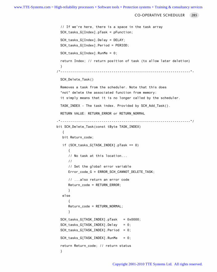
// If we're here, there is a space in the task array
SCH_tasks_G[Index].pTask = pFunction;
SCH_tasks_G[Index].Delay = DELAY;
SCH_tasks_G[Index].Period = PERIOD;
SCH_tasks_G[Index].RunMe = 0;
return Index; // return position of task (to allow later deletion)
/*------------------------------------------------------------------*-
SCH_Delete_Task()
Removes a task from the scheduler. Note that this does
*not* delete the associated function from memory:
it simply means that it is no longer called by the scheduler.
TASK_INDEX - The task index. Provided by SCH_Add_Task().
RETURN VALUE: RETURN_ERROR or RETURN_NORMAL
-*------------------------------------------------------------------*/
bit SCH_Delete_Task(const tByte TASK_INDEX)
bit Return_code;
if (SCH_tasks_G[TASK_INDEX].pTask == 0)
// No task at this location...
//
// Set the global error variable
Error_code_G = ERROR_SCH_CANNOT_DELETE_TASK;
// ...also return an error code
Return_code = RETURN_ERROR;
else
Return_code = RETURN_NORMAL;
SCH_tasks_G[TASK_INDEX].pTask = 0x0000;
SCH_tasks_G[TASK_INDEX].Delay = 0;
SCH_tasks_G[TASK_INDEX].Period = 0;
SCH_tasks_G[TASK_INDEX].RunMe = 0;
return Return_code; // return status
CO-OPERATIVE SCHEDULER 285
www.TTE-Systems.com = High-reliability processors + Software tools + Protection systems + Training & consultancy services
Copyright 2001-2010 TTE Systems Ltd. All rights reserved.
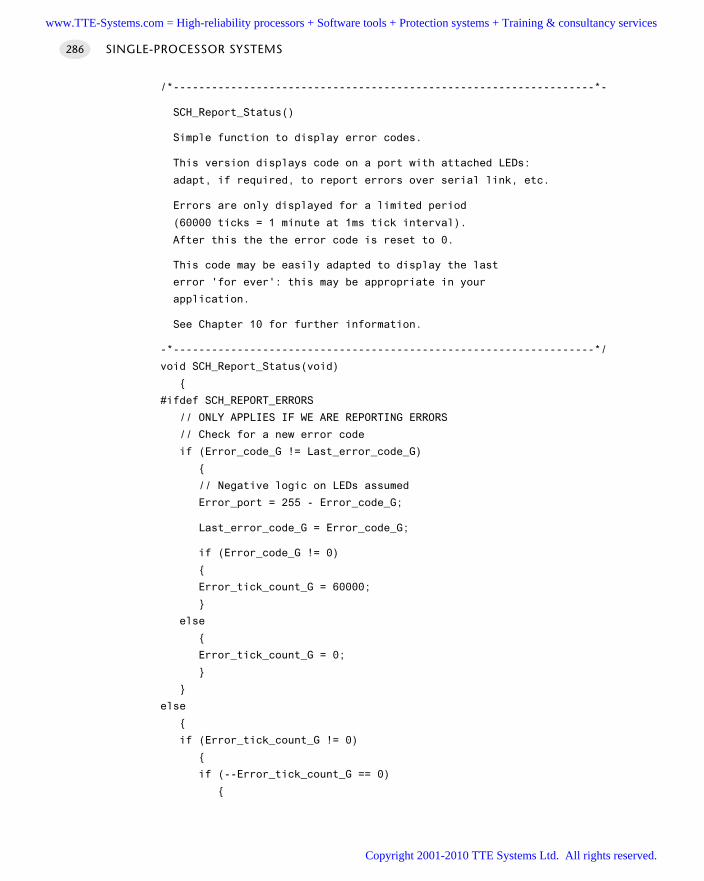
/*------------------------------------------------------------------*-
SCH_Report_Status()
Simple function to display error codes.
This version displays code on a port with attached LEDs:
adapt, if required, to report errors over serial link, etc.
Errors are only displayed for a limited period
(60000 ticks = 1 minute at 1ms tick interval).
After this the the error code is reset to 0.
This code may be easily adapted to display the last
error 'for ever': this may be appropriate in your
application.
See Chapter 10 for further information.
-*------------------------------------------------------------------*/
void SCH_Report_Status(void)
#ifdef SCH_REPORT_ERRORS
// ONLY APPLIES IF WE ARE REPORTING ERRORS
// Check for a new error code
if (Error_code_G != Last_error_code_G)
// Negative logic on LEDs assumed
Error_port = 255 - Error_code_G;
Last_error_code_G = Error_code_G;
if (Error_code_G != 0)
Error_tick_count_G = 60000;
else
Error_tick_count_G = 0;
else
if (Error_tick_count_G != 0)
if (--Error_tick_count_G == 0)
SINGLE-PROCESSOR SYSTEMS286
www.TTE-Systems.com = High-reliability processors + Software tools + Protection systems + Training & consultancy services
Copyright 2001-2010 TTE Systems Ltd. All rights reserved.
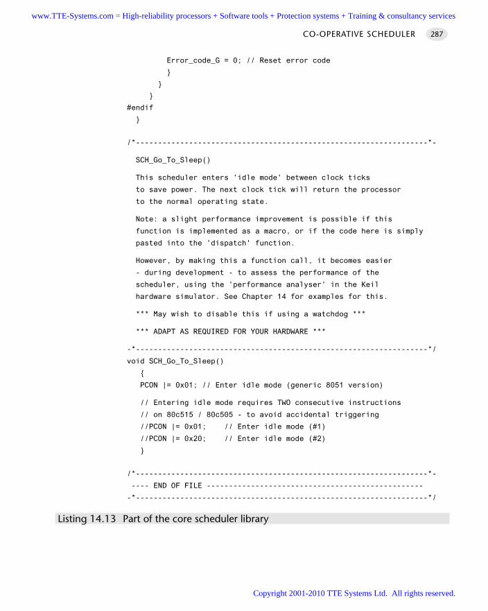
Error_code_G = 0; // Reset error code
#endif
/*------------------------------------------------------------------*-
SCH_Go_To_Sleep()
This scheduler enters 'idle mode' between clock ticks
to save power. The next clock tick will return the processor
to the normal operating state.
Note: a slight performance improvement is possible if this
function is implemented as a macro, or if the code here is simply
pasted into the 'dispatch' function.
However, by making this a function call, it becomes easier
- during development - to assess the performance of the
scheduler, using the 'performance analyser' in the Keil
hardware simulator. See Chapter 14 for examples for this.
*** May wish to disable this if using a watchdog ***
*** ADAPT AS REQUIRED FOR YOUR HARDWARE ***
-*------------------------------------------------------------------*/
void SCH_Go_To_Sleep()
PCON |= 0x01; // Enter idle mode (generic 8051 version)
// Entering idle mode requires TWO consecutive instructions
// on 80c515 / 80c505 - to avoid accidental triggering
//PCON |= 0x01; // Enter idle mode (#1)
//PCON |= 0x20; // Enter idle mode (#2)
/*------------------------------------------------------------------*-
---- END OF FILE -------------------------------------------------
-*------------------------------------------------------------------*/
Listing 14.13 Part of the core scheduler library
CO-OPERATIVE SCHEDULER 287
www.TTE-Systems.com = High-reliability processors + Software tools + Protection systems + Training & consultancy services
Copyright 2001-2010 TTE Systems Ltd. All rights reserved.
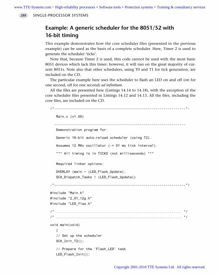
Example: A generic scheduler for the 8051/52 with 16-bit timingThis example demonstrates how the core scheduler files (presented in the previousexample) can be used as the basis of a complete scheduler. Here, Timer 2 is used togenerate the scheduler ‘ticks’.
Note that, because Timer 2 is used, this code cannot be used with the most basic8051 devices which lack this timer: however, it will run on the great majority of cur-rent 8051s. Note also that other schedulers, using T0 and T1 for tick generation, areincluded on the CD.
The particular example here uses the scheduler to flash an LED on and off (on forone second, off for one second) ad infinitum.
All the files are presented here (Listings 14.14 to 14.18), with the exception of thecore scheduler files presented in Listings 14.12 and 14.13. All the files, including thecore files, are included on the CD.
/*------------------------------------------------------------------*-
Main.c (v1.00)
------------------------------------------------------------------
Demonstration program for:
Generic 16-bit auto-reload scheduler (using T2).
Assumes 12 MHz oscillator (-> 01 ms tick interval).
*** All timing is in TICKS (not milliseconds) ***
Required linker options:
OVERLAY (main ~ (LED_Flash_Update),
SCH_Dispatch_Tasks ! (LED_Flash_Update))
-*------------------------------------------------------------------*/
#include "Main.h"
#include "2_01_12g.h"
#include "LED_flas.h"
/* ............................................................... */
/* ............................................................... */
void main(void)
// Set up the scheduler
SCH_Init_T2();
// Prepare for the 'Flash_LED' task
LED_Flash_Init();
SINGLE-PROCESSOR SYSTEMS288
www.TTE-Systems.com = High-reliability processors + Software tools + Protection systems + Training & consultancy services
Copyright 2001-2010 TTE Systems Ltd. All rights reserved.
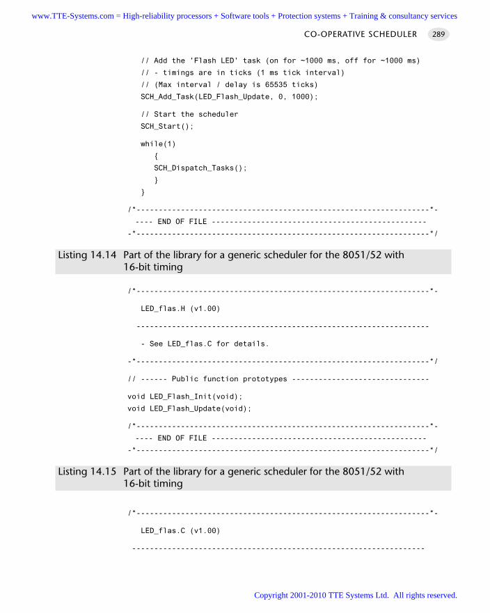
// Add the 'Flash LED' task (on for ~1000 ms, off for ~1000 ms)
// - timings are in ticks (1 ms tick interval)
// (Max interval / delay is 65535 ticks)
SCH_Add_Task(LED_Flash_Update, 0, 1000);
// Start the scheduler
SCH_Start();
while(1)
SCH_Dispatch_Tasks();
/*------------------------------------------------------------------*-
---- END OF FILE ------------------------------------------------
-*------------------------------------------------------------------*/
Listing 14.14 Part of the library for a generic scheduler for the 8051/52 with 16-bit timing
/*------------------------------------------------------------------*-
LED_flas.H (v1.00)
------------------------------------------------------------------
- See LED_flas.C for details.
-*------------------------------------------------------------------*/
// ------ Public function prototypes -------------------------------
void LED_Flash_Init(void);
void LED_Flash_Update(void);
/*------------------------------------------------------------------*-
---- END OF FILE ------------------------------------------------
-*------------------------------------------------------------------*/
Listing 14.15 Part of the library for a generic scheduler for the 8051/52 with16-bit timing
/*------------------------------------------------------------------*-
LED_flas.C (v1.00)
------------------------------------------------------------------
CO-OPERATIVE SCHEDULER 289
www.TTE-Systems.com = High-reliability processors + Software tools + Protection systems + Training & consultancy services
Copyright 2001-2010 TTE Systems Ltd. All rights reserved.
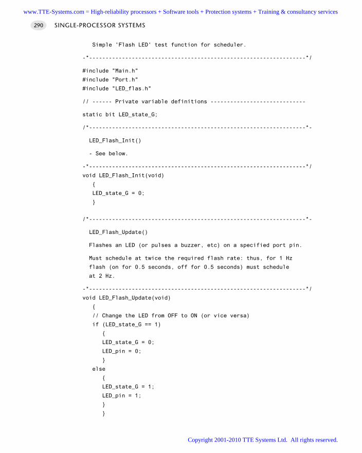
Simple 'Flash LED' test function for scheduler.
-*------------------------------------------------------------------*/
#include "Main.h"
#include "Port.h"
#include "LED_flas.h"
// ------ Private variable definitions -----------------------------
static bit LED_state_G;
/*------------------------------------------------------------------*-
LED_Flash_Init()
- See below.
-*------------------------------------------------------------------*/
void LED_Flash_Init(void)
LED_state_G = 0;
/*------------------------------------------------------------------*-
LED_Flash_Update()
Flashes an LED (or pulses a buzzer, etc) on a specified port pin.
Must schedule at twice the required flash rate: thus, for 1 Hz
flash (on for 0.5 seconds, off for 0.5 seconds) must schedule
at 2 Hz.
-*------------------------------------------------------------------*/
void LED_Flash_Update(void)
// Change the LED from OFF to ON (or vice versa)
if (LED_state_G == 1)
LED_state_G = 0;
LED_pin = 0;
else
LED_state_G = 1;
LED_pin = 1;
SINGLE-PROCESSOR SYSTEMS290
www.TTE-Systems.com = High-reliability processors + Software tools + Protection systems + Training & consultancy services
Copyright 2001-2010 TTE Systems Ltd. All rights reserved.
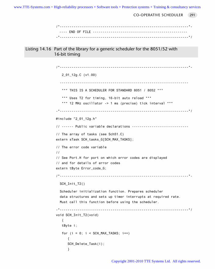
/*------------------------------------------------------------------*-
---- END OF FILE ------------------------------------------------
-*------------------------------------------------------------------*/
Listing 14.16 Part of the library for a generic scheduler for the 8051/52 with 16-bit timing
/*------------------------------------------------------------------*-
2_01_12g.C (v1.00)
------------------------------------------------------------------
*** THIS IS A SCHEDULER FOR STANDARD 8051 / 8052 ***
*** Uses T2 for timing, 16-bit auto reload ***
*** 12 MHz oscillator -> 1 ms (precise) tick interval ***
-*------------------------------------------------------------------*/
#include "2_01_12g.h"
// ------ Public variable declarations -----------------------------
// The array of tasks (see Sch51.C)
extern sTask SCH_tasks_G[SCH_MAX_TASKS];
// The error code variable
//
// See Port.H for port on which error codes are displayed
// and for details of error codes
extern tByte Error_code_G;
/*------------------------------------------------------------------*-
SCH_Init_T2()
Scheduler initialization function. Prepares scheduler
data structures and sets up timer interrupts at required rate.
Must call this function before using the scheduler.
-*------------------------------------------------------------------*/
void SCH_Init_T2(void)
tByte i;
for (i = 0; i < SCH_MAX_TASKS; i++)
SCH_Delete_Task(i);
CO-OPERATIVE SCHEDULER 291
www.TTE-Systems.com = High-reliability processors + Software tools + Protection systems + Training & consultancy services
Copyright 2001-2010 TTE Systems Ltd. All rights reserved.
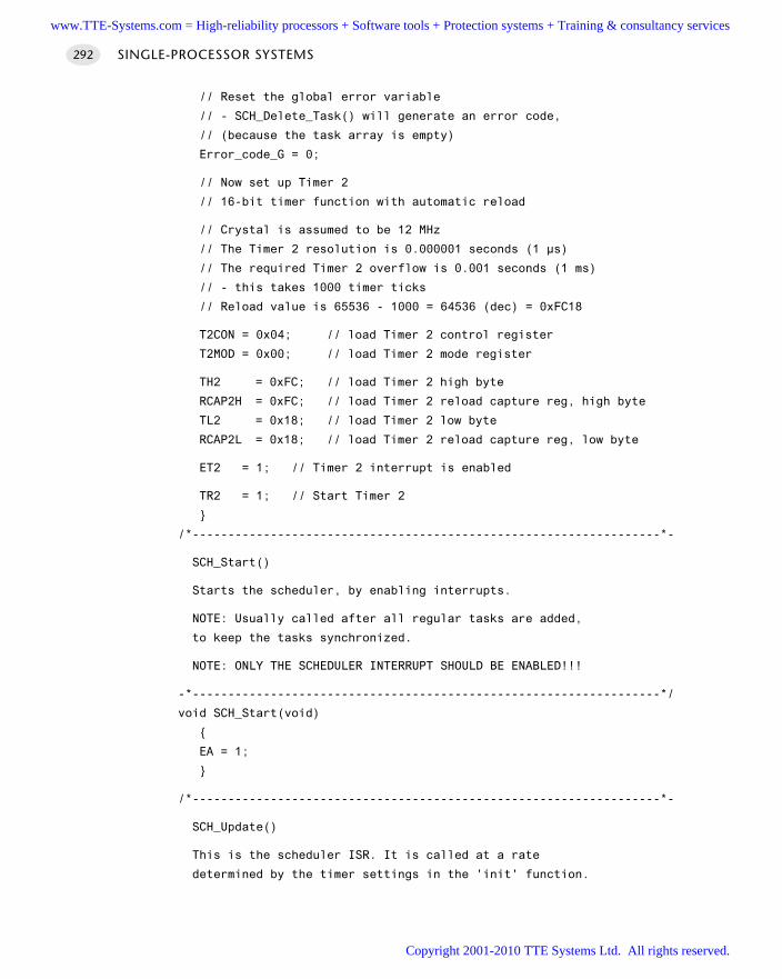
// Reset the global error variable
// - SCH_Delete_Task() will generate an error code,
// (because the task array is empty)
Error_code_G = 0;
// Now set up Timer 2
// 16-bit timer function with automatic reload
// Crystal is assumed to be 12 MHz
// The Timer 2 resolution is 0.000001 seconds (1 µs)
// The required Timer 2 overflow is 0.001 seconds (1 ms)
// - this takes 1000 timer ticks
// Reload value is 65536 - 1000 = 64536 (dec) = 0xFC18
T2CON = 0x04; // load Timer 2 control register
T2MOD = 0x00; // load Timer 2 mode register
TH2 = 0xFC; // load Timer 2 high byte
RCAP2H = 0xFC; // load Timer 2 reload capture reg, high byte
TL2 = 0x18; // load Timer 2 low byte
RCAP2L = 0x18; // load Timer 2 reload capture reg, low byte
ET2 = 1; // Timer 2 interrupt is enabled
TR2 = 1; // Start Timer 2
/*------------------------------------------------------------------*-
SCH_Start()
Starts the scheduler, by enabling interrupts.
NOTE: Usually called after all regular tasks are added,
to keep the tasks synchronized.
NOTE: ONLY THE SCHEDULER INTERRUPT SHOULD BE ENABLED!!!
-*------------------------------------------------------------------*/
void SCH_Start(void)
EA = 1;
/*------------------------------------------------------------------*-
SCH_Update()
This is the scheduler ISR. It is called at a rate
determined by the timer settings in the 'init' function.
SINGLE-PROCESSOR SYSTEMS292
www.TTE-Systems.com = High-reliability processors + Software tools + Protection systems + Training & consultancy services
Copyright 2001-2010 TTE Systems Ltd. All rights reserved.
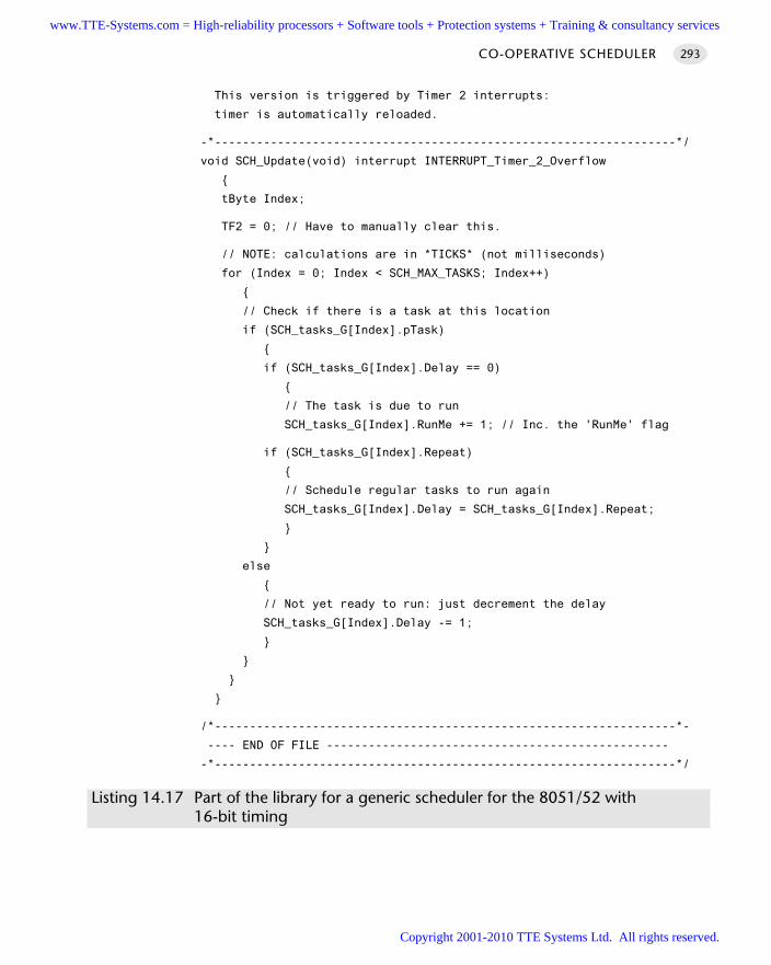
This version is triggered by Timer 2 interrupts:
timer is automatically reloaded.
-*------------------------------------------------------------------*/
void SCH_Update(void) interrupt INTERRUPT_Timer_2_Overflow
tByte Index;
TF2 = 0; // Have to manually clear this.
// NOTE: calculations are in *TICKS* (not milliseconds)
for (Index = 0; Index < SCH_MAX_TASKS; Index++)
// Check if there is a task at this location
if (SCH_tasks_G[Index].pTask)
if (SCH_tasks_G[Index].Delay == 0)
// The task is due to run
SCH_tasks_G[Index].RunMe += 1; // Inc. the 'RunMe' flag
if (SCH_tasks_G[Index].Repeat)
// Schedule regular tasks to run again
SCH_tasks_G[Index].Delay = SCH_tasks_G[Index].Repeat;
else
// Not yet ready to run: just decrement the delay
SCH_tasks_G[Index].Delay -= 1;
/*------------------------------------------------------------------*-
---- END OF FILE -------------------------------------------------
-*------------------------------------------------------------------*/
Listing 14.17 Part of the library for a generic scheduler for the 8051/52 with 16-bit timing
CO-OPERATIVE SCHEDULER 293
www.TTE-Systems.com = High-reliability processors + Software tools + Protection systems + Training & consultancy services
Copyright 2001-2010 TTE Systems Ltd. All rights reserved.
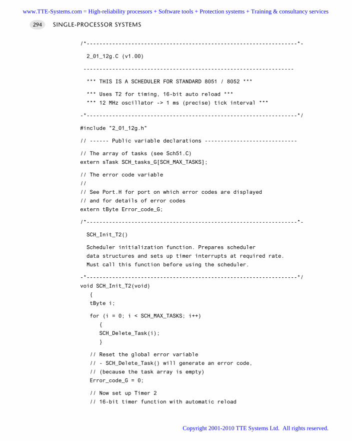
/*------------------------------------------------------------------*-
2_01_12g.C (v1.00)
------------------------------------------------------------------
*** THIS IS A SCHEDULER FOR STANDARD 8051 / 8052 ***
*** Uses T2 for timing, 16-bit auto reload ***
*** 12 MHz oscillator -> 1 ms (precise) tick interval ***
-*------------------------------------------------------------------*/
#include "2_01_12g.h"
// ------ Public variable declarations -----------------------------
// The array of tasks (see Sch51.C)
extern sTask SCH_tasks_G[SCH_MAX_TASKS];
// The error code variable
//
// See Port.H for port on which error codes are displayed
// and for details of error codes
extern tByte Error_code_G;
/*------------------------------------------------------------------*-
SCH_Init_T2()
Scheduler initialization function. Prepares scheduler
data structures and sets up timer interrupts at required rate.
Must call this function before using the scheduler.
-*------------------------------------------------------------------*/
void SCH_Init_T2(void)
tByte i;
for (i = 0; i < SCH_MAX_TASKS; i++)
SCH_Delete_Task(i);
// Reset the global error variable
// - SCH_Delete_Task() will generate an error code,
// (because the task array is empty)
Error_code_G = 0;
// Now set up Timer 2
// 16-bit timer function with automatic reload
SINGLE-PROCESSOR SYSTEMS294
www.TTE-Systems.com = High-reliability processors + Software tools + Protection systems + Training & consultancy services
Copyright 2001-2010 TTE Systems Ltd. All rights reserved.
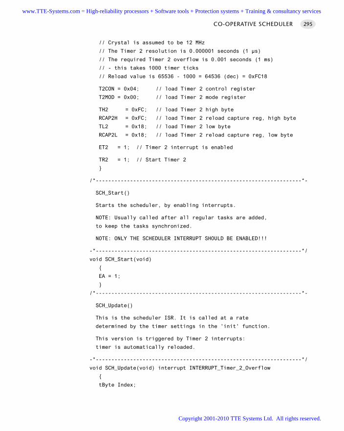
// Crystal is assumed to be 12 MHz
// The Timer 2 resolution is 0.000001 seconds (1 µs)
// The required Timer 2 overflow is 0.001 seconds (1 ms)
// - this takes 1000 timer ticks
// Reload value is 65536 - 1000 = 64536 (dec) = 0xFC18
T2CON = 0x04; // load Timer 2 control register
T2MOD = 0x00; // load Timer 2 mode register
TH2 = 0xFC; // load Timer 2 high byte
RCAP2H = 0xFC; // load Timer 2 reload capture reg, high byte
TL2 = 0x18; // load Timer 2 low byte
RCAP2L = 0x18; // load Timer 2 reload capture reg, low byte
ET2 = 1; // Timer 2 interrupt is enabled
TR2 = 1; // Start Timer 2
/*------------------------------------------------------------------*-
SCH_Start()
Starts the scheduler, by enabling interrupts.
NOTE: Usually called after all regular tasks are added,
to keep the tasks synchronized.
NOTE: ONLY THE SCHEDULER INTERRUPT SHOULD BE ENABLED!!!
-*------------------------------------------------------------------*/
void SCH_Start(void)
EA = 1;
/*------------------------------------------------------------------*-
SCH_Update()
This is the scheduler ISR. It is called at a rate
determined by the timer settings in the 'init' function.
This version is triggered by Timer 2 interrupts:
timer is automatically reloaded.
-*------------------------------------------------------------------*/
void SCH_Update(void) interrupt INTERRUPT_Timer_2_Overflow
tByte Index;
CO-OPERATIVE SCHEDULER 295
www.TTE-Systems.com = High-reliability processors + Software tools + Protection systems + Training & consultancy services
Copyright 2001-2010 TTE Systems Ltd. All rights reserved.
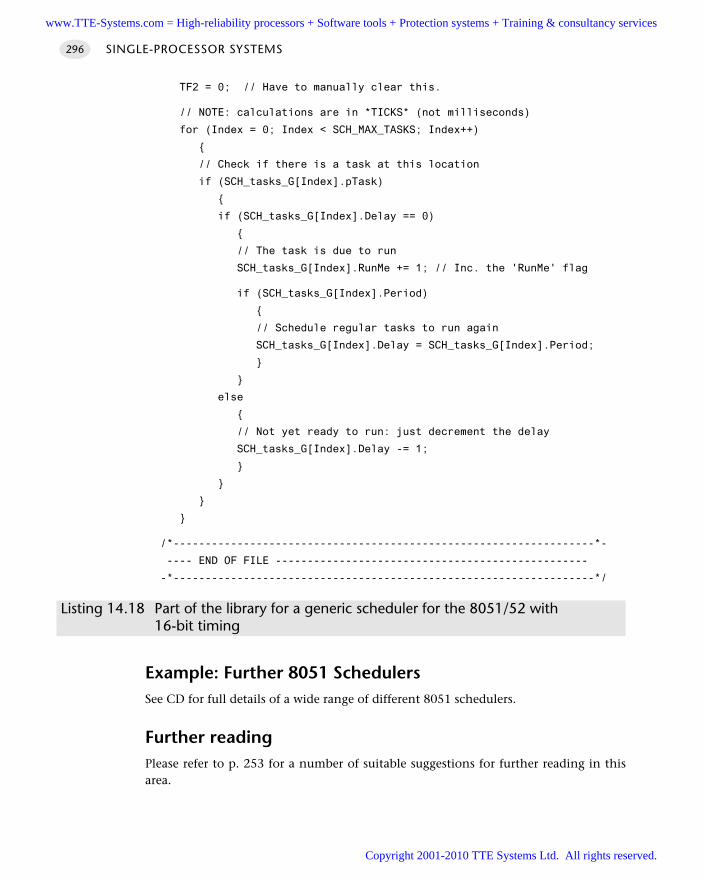
TF2 = 0; // Have to manually clear this.
// NOTE: calculations are in *TICKS* (not milliseconds)
for (Index = 0; Index < SCH_MAX_TASKS; Index++)
// Check if there is a task at this location
if (SCH_tasks_G[Index].pTask)
if (SCH_tasks_G[Index].Delay == 0)
// The task is due to run
SCH_tasks_G[Index].RunMe += 1; // Inc. the 'RunMe' flag
if (SCH_tasks_G[Index].Period)
// Schedule regular tasks to run again
SCH_tasks_G[Index].Delay = SCH_tasks_G[Index].Period;
else
// Not yet ready to run: just decrement the delay
SCH_tasks_G[Index].Delay -= 1;
/*------------------------------------------------------------------*-
---- END OF FILE -------------------------------------------------
-*------------------------------------------------------------------*/
Listing 14.18 Part of the library for a generic scheduler for the 8051/52 with 16-bit timing
Example: Further 8051 SchedulersSee CD for full details of a wide range of different 8051 schedulers.
Further readingPlease refer to p. 253 for a number of suitable suggestions for further reading in thisarea.
SINGLE-PROCESSOR SYSTEMS296
www.TTE-Systems.com = High-reliability processors + Software tools + Protection systems + Training & consultancy services
Copyright 2001-2010 TTE Systems Ltd. All rights reserved.
Learning to think co-operatively
Introduction
Using a co-operative scheduler in your application has a number of benefits, one ofwhich being that the development process is simplified. However, to get the maxi-mum benefit from the scheduler you need to learn to think ‘co-operatively’.
For example, one key difference between scheduled and desktop applications is theneed to think carefully about issues of timing and task duration. More specifically, aswe saw in Chapter 14, a key requirement in applications using a co-operative sched-uler is that – for all tasks, under all circumstances – the task duration, DurationTask,must satisfy the following condition:
DurationTask < Tick Interval
The patterns in this chapter are intended to help you meet this condition by ensur-ing that tasks will abort if they cannot complete within a specified period of time.Specifically, two timeout patterns are presented here:
L O O P T I M E O U T [page 298]
H A R D WA R E T I M E O U T [page 305]
chapter 15www.TTE-Systems.com = High-reliability processors + Software tools + Protection systems + Training & consultancy services
Copyright 2001-2010 TTE Systems Ltd. All rights reserved.
SINGLE-PROCESSOR SYSTEMS298
LOOP TIMEOUT
Context You are developing an embedded application using one or more members of the
8051 family of microcontrollers.
The application has a time-triggered architecture, constructed using a scheduler.
ProblemHow do you ensure that your system will not ‘hang’ while waiting for a hardwareoperation (such as an AD conversion or serial data transfer) to complete?
BackgroundThe Philips 8XC552 is an Extended 8051 device with a number of on-chip peripher-als, including an 8-channel, 10-bit ADC. Philips provide an application note(AN93017) that describes how to use this microcontroller. This application noteincludes the following code:
// Wait until AD conversion finishes (checking ADCI)
while ((ADCON & ADCI) == 0);
Such code is potentially unreliable, because there are circumstances under whichour application may ‘hang’. This might occur for one or more of the following reasons:
If the ADC has been incorrectly initialized, we cannot be sure that a data conver-sion will be carried out.
If the ADC has been subjected to an excessive input voltage, then it may notoperate at all.
If the variables ADCON or ADCI were not correctly initialized, they may not oper-ate as required.
Such problems are not, of course, unique to this particular microcontroller or evento ADCs. Such code is common in embedded applications.
If your application is to be reliable, you need to be able to guarantee that no func-tion will hang in this way. Loop timeouts offer a simple but effective means ofproviding such a guarantee.
www.TTE-Systems.com = High-reliability processors + Software tools + Protection systems + Training & consultancy services
Copyright 2001-2010 TTE Systems Ltd. All rights reserved.
LOOP TIMEOUT 299
SolutionA loop timeout may be easily created. The basis of the code structure is a softwaredelay, created as follows:
unsigned integer Timeout_loop = 0;
...
while (++Timeout_loop);
This loop will keep running until the variable Timeout_loop reaches its maxi-mum value (assuming 16-bit integers) of 65,535 and then overflows. When thishappens, the program will continue. Note that, without some simulation studies orprototyping, we cannot easily determine how long this delay will be. However, we doknow that the loop will, eventually, time out.
Such a loop is not terribly useful. However, if we consider again the ADC examplegiven in ‘Background’, we can easily extend this idea. Recall that the original codewas as follows:
// Wait until AD conversion finishes (checking ADCI)
while ((ADCON & ADCI) == 0);
Here is a modified version of this code, this time incorporating a loop timeout:
tWord Timeout_loop = 0;
// Take sample from ADC
// Wait until conversion finishes (checking ADCI)
// - simple loop timeout
while (((ADCON & ADCI) == 0) && (++Timeout_loop != 0));
Note that this alternative implementation is also useful:
tWord Timeout_loop = 1;
// Take sample from ADC
// Wait until conversion finishes (checking ADCI)
// - simple loop timeout
while (((ADCON & ADCI) == 0) && (Timeout_loop != 0))
Timeout_loop++; // Disable for use in hardware simulator...
The advantage of this second technique is that the loop timeout may be easilycommented out, if required, when executing the code on a hardware simulator.
In both cases, we now know that the loop cannot go on ‘for ever’.Note that we can vary the duration of the loop timeout by changing the initial
value loaded into loop variable. The file TimeoutL.H, reproduced in Listing 15.1 andincluded on the CD in the directory associated with this chapter, includes a set ofconstants that give, very approximately, the specified timeout values.
www.TTE-Systems.com = High-reliability processors + Software tools + Protection systems + Training & consultancy services
Copyright 2001-2010 TTE Systems Ltd. All rights reserved.
/*------------------------------------------------------------------*-
TimeoutL.H (v1.00)
------------------------------------------------------------------
Simple loop timeout delays for the 8051 family based.
* THESE VALUES ARE NOT PRECISE - YOU MUST ADAPT TO YOUR SYSTEM *
-*------------------------------------------------------------------*/
// ------ Public constants -----------------------------------------
// Vary this value to change the loop duration
// THESE ARE APPROX VALUES FOR VARIOUS TIMEOUT DELAYS
// ON 8051, 12 MHz, 12 Osc / cycle
// *** MUST BE FINE TUNED FOR YOUR APPLICATION ***
// *** Timings vary with compiler optimization settings ***
#define LOOP_TIMEOUT_INIT_001ms 65435
#define LOOP_TIMEOUT_INIT_010ms 64535
#define LOOP_TIMEOUT_INIT_500ms 14535
/*------------------------------------------------------------------*-
---- END OF FILE ------------------------------------------------
-*------------------------------------------------------------------*/
Listing 15.1 The file TimeoutL.H.
We give an example of how to use this file in the following sections.
Hardware resource implicationsL O O P T I M E O U T does not use a timer and imposes an almost negligible CPU andmemory load.
Reliability and safety implicationsUsing a L O O P T I M E O U T can result in a huge reliability and safety improvement atminimal cost. However, if practical, H A R D WA R E T I M E O U T [page 305] is usually an evenbetter solution.
PortabilityLoop timeouts will work in any environment. However, the timings obtained willvary dramatically between microcontrollers and compilers.
SINGLE-PROCESSOR SYSTEMS300
www.TTE-Systems.com = High-reliability processors + Software tools + Protection systems + Training & consultancy services
Copyright 2001-2010 TTE Systems Ltd. All rights reserved.
Overall strengths and weaknessesMuch better than executing code without any form of timeout protection.
Many applications use a timer for RS232 baud rate generation, and anothertimer to run the scheduler. In many 8051 devices, this leaves no furthertimers available to implement a H A R D WA R E T I M E O U T [page 305]. In thesecircumstances, use of a loop is the only practical way of implementingeffective timeout behaviour.
Timings are difficult to calculate and timer values are not portable. H A R D WA R E
T I M E O U T is always a better solution, if you have a spare timer available.
Related patterns and alternative solutionsAs mentioned under ‘Reliability and safety implications’, H A R D WA R E T I M E O U T [page305] is often a better alternative to L O O P T I M E O U T .
In addition, H A R D WA R E WAT C H D O G [page 217] provides an alternative; however,it is rather crude by comparison and detects errors at the application (rather thantask) level.
Example: Test program for loop timeout codeAs noted, loop timeouts must be carefully hand-tuned to give accurate delay values.
The program in Listing 15.2 can be used to test such timeout code.
/*------------------------------------------------------------------*-
Main.C
------------------------------------------------------------------
Testing timeout loops.
-*------------------------------------------------------------------*/
#include "Main.H"
#include "TimeoutL.H"
// Function prototypes
void Test_1ms(void);
void Test_10ms(void);
void Test_500ms(void);
/*------------------------------------------------------------------*/
void main(void)
while(1)
Test_1ms();
LOOP TIMEOUT 301
www.TTE-Systems.com = High-reliability processors + Software tools + Protection systems + Training & consultancy services
Copyright 2001-2010 TTE Systems Ltd. All rights reserved.
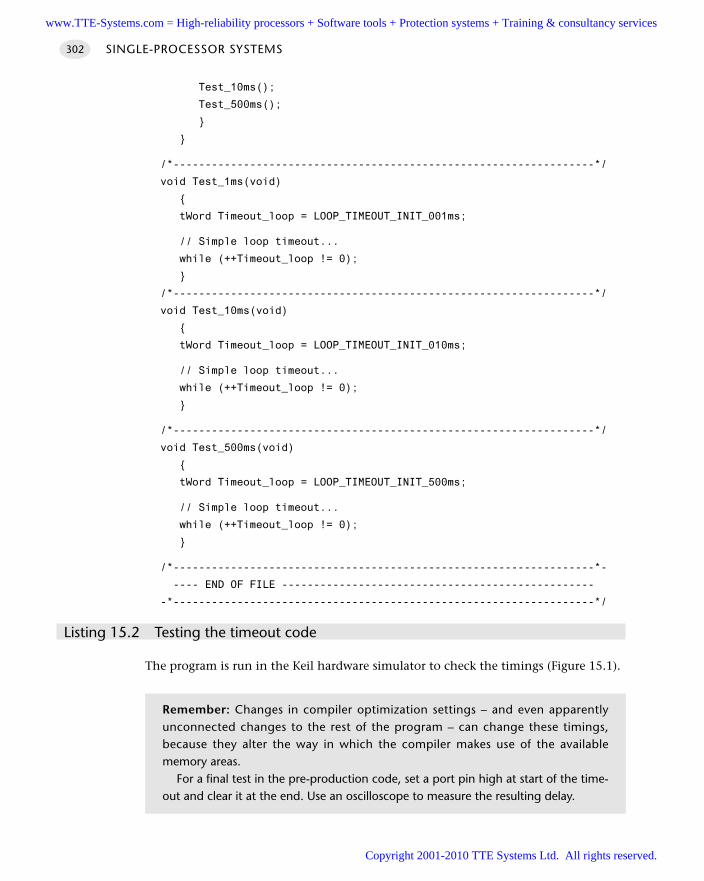
Test_10ms();
Test_500ms();
/*------------------------------------------------------------------*/
void Test_1ms(void)
tWord Timeout_loop = LOOP_TIMEOUT_INIT_001ms;
// Simple loop timeout...
while (++Timeout_loop != 0);
/*------------------------------------------------------------------*/
void Test_10ms(void)
tWord Timeout_loop = LOOP_TIMEOUT_INIT_010ms;
// Simple loop timeout...
while (++Timeout_loop != 0);
/*------------------------------------------------------------------*/
void Test_500ms(void)
tWord Timeout_loop = LOOP_TIMEOUT_INIT_500ms;
// Simple loop timeout...
while (++Timeout_loop != 0);
/*------------------------------------------------------------------*-
---- END OF FILE -------------------------------------------------
-*------------------------------------------------------------------*/
Listing 15.2 Testing the timeout code
The program is run in the Keil hardware simulator to check the timings (Figure 15.1).
SINGLE-PROCESSOR SYSTEMS302
Remember: Changes in compiler optimization settings – and even apparentlyunconnected changes to the rest of the program – can change these timings,because they alter the way in which the compiler makes use of the availablememory areas.
For a final test in the pre-production code, set a port pin high at start of the time-out and clear it at the end. Use an oscilloscope to measure the resulting delay.
www.TTE-Systems.com = High-reliability processors + Software tools + Protection systems + Training & consultancy services
Copyright 2001-2010 TTE Systems Ltd. All rights reserved.
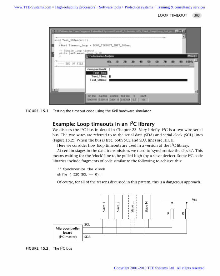
Example: Loop timeouts in an I2C libraryWe discuss the I2C bus in detail in Chapter 23. Very briefly, I2C is a two-wire serialbus. The two wires are referred to as the serial data (SDA) and serial clock (SCL) lines(Figure 15.2). When the bus is free, both SCL and SDA lines are HIGH.
Here we consider how loop timeouts are used in a version of the I2C library.At certain stages in the data transmission, we need to ‘synchronize the clocks’. This
means waiting for the ‘clock’ line to be pulled high (by a slave device). Some I2C codelibraries include fragments of code similar to the following to achieve this:
// Synchronize the clock
while (_I2C_SCL == 0);
Of course, for all of the reasons discussed in this pattern, this is a dangerous approach.
LOOP TIMEOUT 303
FIGURE 15.1 Testing the timeout code using the Keil hardware simulator
FIGURE 15.2 The I2C bus
Microcontrollerboard
(l2C master)
Slav
e 1
SCL
SDA
Slav
e 2
Slav
e ...
Slav
e N
R R
Vcc
www.TTE-Systems.com = High-reliability processors + Software tools + Protection systems + Training & consultancy services
Copyright 2001-2010 TTE Systems Ltd. All rights reserved.
The following code fragment uses a loop timeout to improve this code with a 1 mstimeout:
#define LOOP_TIMEOUT_INIT_001ms 65435
...
tLong Timeout_loop = LOOP_TIMEOUT_INIT_001ms;
...
// Try to synchronize the clock
while ((_I2C_SCL == 0) && (++Timeout_loop));
if (!Timeout_loop)
return 1; // Error - Timeout condition failed
Please refer to Chapter 23 for further details of the I2C bus and this library.
Further reading—
SINGLE-PROCESSOR SYSTEMS304
www.TTE-Systems.com = High-reliability processors + Software tools + Protection systems + Training & consultancy services
Copyright 2001-2010 TTE Systems Ltd. All rights reserved.
HARDWARE TIMEOUT
Context You are developing an embedded application using one or more members of the
8051 family of microcontrollers.
The application has a time-triggered architecture, constructed using a scheduler.
ProblemHow do you produce well-defined timeout behaviour so that, for example, you canrespond within exactly 0.5 ms if an expected event does not occur?
BackgroundSee L O O P T I M E O U T [page 298] for relevant background material.
SolutionAs we saw in H A R D W A R E D E L AY [page 194], we can create portable and easy to usedelay code for the 8051 family as follows:
// Define Timer 0 / Timer 1 reload values for ~1 msec delay
#define PRELOAD_01ms (65536 - (tWord)(OSC_FREQ / (OSC_PER_INST * 1000)))
#define PRELOAD_01ms_H (PRELOAD_01ms / 256)
#define PRELOAD_01ms_L (PRELOAD_01ms % 256)
//
...
void Hardware_Delay_T0(const tLong MS)
tLong ms;
// Configure Timer 0 as a 16-bit timer
TMOD &= 0xF0; // Clear all T0 bits (T1 left unchanged)
TMOD |= 0x01; // Set required T0 bits (T1 left unchanged)
ET0 = 0; // No interrupts
for(ms = 0; ms < MS; ms++)
// Note - delay value is *approximately* 1 ms per loop
// - see Delay_T0.H for details of PRELOAD_values.
HARDWARE TIMEOUT 305
www.TTE-Systems.com = High-reliability processors + Software tools + Protection systems + Training & consultancy services
Copyright 2001-2010 TTE Systems Ltd. All rights reserved.
SINGLE-PROCESSOR SYSTEMS306
TH0 = PRELOAD_01ms_H;
TL0 = PRELOAD_01ms_L;
TF0 = 0; // clear overflow flag
TR0 = 1; // start timer 0
while (TF0 == 0); // Loop until Timer 0 overflows (TF0 == 1)
TR0 = 0; // Stop Timer 0
H A R D W A R E T I M E O U T involves a simple variation on this technique and allowsprecise timeout delays to be easily generated.
For example, in L O O P T I M E O U T [page 298] we considered the process of readingfrom an ADC in a Philips 8XC552 microcontroller.
This was the original, potentially dangerous, code:
// Wait until AD conversion finishes (checking ADCI)
while ((ADCON & ADCI) == 0);
This was a possible application of L O O P T I M E O U T to this problem:
tWord Timeout_loop = 0;
// Take sample from A-D
// Wait until AD conversion finishes (checking ADCI)
// - simple loop timeout
while (((ADCON & ADCI) == 0) && (++Timeout_loop));
Applying L O O P T I M E O U T can result in a significant improvement in the reliabilityof this code, but determining the duration of the timeout is not a trivial process.
Here is an alternative solution, providing a delay of 10 ms which will, with reason-able accuracy, apply across the whole 8051 family (without code modifications):
// Configure Timer 0 as a 16-bit timer
TMOD &= 0xF0; // Clear all T0 bits (T1 left unchanged)
TMOD |= 0x01; // Set required T0 bits (T1 left unchanged)
ET0 = 0; // No interrupts
// Simple timeout feature - approx 10 ms
TH0 = PRELOAD_10ms_H; // See Timeout.H for PRELOAD details
TL0 = PRELOAD_10ms_L;
TF0 = 0; // Clear flag
TR0 = 1; // Start timer
while (((ADCON & ADCI) == 0) && !TF0);
Various portable PRELOAD_ macros are given in the file Timeout.H reproduced inListing 15.3 and included on the CD.
www.TTE-Systems.com = High-reliability processors + Software tools + Protection systems + Training & consultancy services
Copyright 2001-2010 TTE Systems Ltd. All rights reserved.
Note that the same PRELOAD_ values may be used with either Timer 0 or Timer 1,as required.
/*------------------------------------------------------------------*-
Timeout.H (v1.00)
------------------------------------------------------------------
Simple timeout delays for the 8051 family based on T0/T1.
Timer must be correctly configured to use these values:
See Chapter 11 for details.
-*------------------------------------------------------------------*/
// ------ Public constants -----------------------------------------
// Timer T_ values for use in simple (hardware) timeouts
// - Timers are 16-bit, manual reload ('one shot').
//
// NOTE: These macros are portable but timings are *approximate*
// and *must* be checked by hand if accurate timing is required.
//
// Define initial Timer 0 / Timer 1 values for ~50 µs delay
#define T_50micros (65536 - (tWord)((OSC_FREQ / 26000)/(OSC_PER_INST)))
#define T_50micros_H (T_50micros / 256)
#define T_50micros_L (T_50micros % 256)
// Define initial Timer 0 / Timer 1 values for ~500 µs delay
#define T_500micros (65536 - (tWord)(OSC_FREQ / (OSC_PER_INST * 2000)))
#define T_500micros_H (T_500micros / 256)
#define T_500micros_L (T_500micros % 256)
// Define initial Timer 0 / Timer 1 values for ~1 msec delay
#define T_01ms (65536 - (tWord)(OSC_FREQ / (OSC_PER_INST * 1000)))
#define T_01ms_H (T_01ms / 256)
#define T_01ms_L (T_01ms % 256)
//
// Define initial Timer 0 / Timer 1 values for ~10 msec delay
#define T_10ms (65536 - (tWord)(OSC_FREQ / (OSC_PER_INST * 100)))
#define T_10ms_H (T_10ms / 256)
#define T_10ms_L (T_10ms % 256)
//
// Define initial Timer 0 / Timer 1 values for ~30 msec delay
#define T_30ms (65536 - (tWord)(OSC_FREQ / (OSC_PER_INST * 33)))
#define T_30ms_H (T_30ms / 256)
#define T_30ms_L (T_30ms % 256)
HARDWARE TIMEOUT 307
www.TTE-Systems.com = High-reliability processors + Software tools + Protection systems + Training & consultancy services
Copyright 2001-2010 TTE Systems Ltd. All rights reserved.
SINGLE-PROCESSOR SYSTEMS308
/*------------------------------------------------------------------*-
---- END OF FILE -------------------------------------------------
-*------------------------------------------------------------------*/
Listing 15.3 The file Timeout.H
Hardware resource implicationsH A R D WA R E T I M E O U T requires the use of a timer.
Reliability and safety implicationsH A R D W A R E T I M E O U T is the most reliable form of timeout structure we consider inthe book.
PortabilityLike all timer-based patterns, this code may be easily ported to other members of the8051 family. It may also be ported to other microcontrollers.
Overall strengths and weaknessesAccurate timeout delays may be obtained using H A R D WA R E T I M E O U T .
The number of timers available is very limited: however, when using a co-operative scheduler, the tasks are running co-operatively and the same timermay be used in several tasks at the same time.
Related patterns and alternative solutionsSee L O O P T I M E O U T [page 298] for an alternative that does not require the use of anytimer hardware.
In addition, H A R D WA R E WAT C H D O G [page 217] provides an alternative; however,it is rather crude by comparison and detects errors at the application (rather thantask) level.
Example: Testing hardware timeoutsListing 15.4 illustrates the delays obtained with some hardware timeouts using theKeil hardware simulator (see also Figure 15.3).
/*------------------------------------------------------------------*-
Main.C
------------------------------------------------------------------
www.TTE-Systems.com = High-reliability processors + Software tools + Protection systems + Training & consultancy services
Copyright 2001-2010 TTE Systems Ltd. All rights reserved.
HARDWARE TIMEOUT 309
Testing timeout loops.
-*------------------------------------------------------------------*/
#include "Main.H"
#include "TimeoutH.H"
// Function prototypes
void Test_50micros(void);
void Test_500micros(void);
void Test_1ms(void);
void Test_5ms(void);
void Test_10ms(void);
void Test_15ms(void);
void Test_20ms(void);
void Test_50ms(void);
// TIMEOUT code variable & TIMEOUT code (dummy here)
#define TIMEOUT 0xFF
tByte Error_code_G;
/*------------------------------------------------------------------*/
void main(void)
while(1)
Test_50micros();
Test_500micros();
Test_1ms();
Test_5ms();
Test_10ms();
Test_15ms();
Test_20ms();
Test_50ms();
/*------------------------------------------------------------------*/
void Test_50micros(void)
// Configure Timer 0 as a 16-bit timer
TMOD &= 0xF0; // Clear all T0 bits (T1 left unchanged)
TMOD |= 0x01; // Set required T0 bits (T1 left unchanged)
ET0 = 0; // No interrupts
www.TTE-Systems.com = High-reliability processors + Software tools + Protection systems + Training & consultancy services
Copyright 2001-2010 TTE Systems Ltd. All rights reserved.
SINGLE-PROCESSOR SYSTEMS310
// Simple timeout feature - approx 50 µs
TH0 = T_50micros_H; // See TimeoutH.H for T_ details
TL0 = T_50micros_L;
TF0 = 0; // Clear flag
TR0 = 1; // Start timer
while (!TF0);
TR0 = 0;
// Normally need to report timeout TIMEOUTs
// (this test is for demo purposes here)
if (TF0 == 1)
// Operation timed out
Error_code_G = TIMEOUT;
/*------------------------------------------------------------------*/
void Test_500micros(void)
// Configure Timer 0 as a 16-bit timer
TMOD &= 0xF0; // Clear all T0 bits (T1 left unchanged)
TMOD |= 0x01; // Set required T0 bits (T1 left unchanged)
ET0 = 0; // No interrupts
// Simple timeout feature - approx 500 µs
TH0 = T_500micros_H; // See TimeoutH.H for T_ details
TL0 = T_500micros_L;
TF0 = 0; // Clear flag
TR0 = 1; // Start timer
while (!TF0);
TR0 = 0;
// Normally need to report timeout TIMEOUTs
// (this test is for demo purposes here)
if (TF0 == 1)
// Operation timed out
Error_code_G = TIMEOUT;
www.TTE-Systems.com = High-reliability processors + Software tools + Protection systems + Training & consultancy services
Copyright 2001-2010 TTE Systems Ltd. All rights reserved.
/*------------------------------------------------------------------*/
void Test_1ms(void)
// Configure Timer 0 as a 16-bit timer
TMOD &= 0xF0; // Clear all T0 bits (T1 left unchanged)
TMOD |= 0x01; // Set required T0 bits (T1 left unchanged)
ET0 = 0; // No interrupts
// Simple timeout feature - approx 1 ms
TH0 = T_01ms_H; // See TimeoutH.H for T_ details
TL0 = T_01ms_L;
TF0 = 0; // Clear flag
TR0 = 1; // Start timer
while (!TF0);
TR0 = 0;
// Normally need to report timeout TIMEOUTs
// (this test is for demo purposes here)
if (TF0 == 1)
// Operation timed out
Error_code_G = TIMEOUT;
/*------------------------------------------------------------------*/
void Test_5ms(void)
// Configure Timer 0 as a 16-bit timer
TMOD &= 0xF0; // Clear all T0 bits (T1 left unchanged)
TMOD |= 0x01; // Set required T0 bits (T1 left unchanged)
ET0 = 0; // No interrupts
// Simple timeout feature - approx 10 ms
TH0 = T_05ms_H; // See TimeoutH.H for T_ details
TL0 = T_05ms_L;
TF0 = 0; // Clear flag
TR0 = 1; // Start timer
while (!TF0);
TR0 = 0;
// Normally need to report timeout TIMEOUTs
HARDWARE TIMEOUT 311
www.TTE-Systems.com = High-reliability processors + Software tools + Protection systems + Training & consultancy services
Copyright 2001-2010 TTE Systems Ltd. All rights reserved.
// (this test is for demo purposes here)
if (TF0 == 1)
// Operation timed out
Error_code_G = TIMEOUT;
/*------------------------------------------------------------------*/
void Test_10ms(void)
// Configure Timer 0 as a 16-bit timer
TMOD &= 0xF0; // Clear all T0 bits (T1 left unchanged)
TMOD |= 0x01; // Set required T0 bits (T1 left unchanged)
ET0 = 0; // No interrupts
// Simple timeout feature - approx 10 ms
TH0 = T_10ms_H; // See TimeoutH.H for T_ details
TL0 = T_10ms_L;
TF0 = 0; // Clear flag
TR0 = 1; // Start timer
while (!TF0);
TR0 = 0;
// Normally need to report timeout TIMEOUTs
// (this test is for demo purposes here)
if (TF0 == 1)
// Operation timed out
Error_code_G = TIMEOUT;
/*------------------------------------------------------------------*/
void Test_15ms(void)
// Configure Timer 0 as a 16-bit timer
TMOD &= 0xF0; // Clear all T0 bits (T1 left unchanged)
TMOD |= 0x01; // Set required T0 bits (T1 left unchanged)
ET0 = 0; // No interrupts
// Simple timeout feature - approx 10 ms
TH0 = T_15ms_H; // See TimeoutH.H for T_ details
SINGLE-PROCESSOR SYSTEMS312
www.TTE-Systems.com = High-reliability processors + Software tools + Protection systems + Training & consultancy services
Copyright 2001-2010 TTE Systems Ltd. All rights reserved.
TL0 = T_15ms_L;
TF0 = 0; // Clear flag
TR0 = 1; // Start timer
while (!TF0);
TR0 = 0;
// Normally need to report timeout TIMEOUTs
// (this test is for demo purposes here)
if (TF0 == 1)
// Operation timed out
Error_code_G = TIMEOUT;
/*------------------------------------------------------------------*/
void Test_20ms(void)
// Configure Timer 0 as a 16-bit timer
TMOD &= 0xF0; // Clear all T0 bits (T1 left unchanged)
TMOD |= 0x01; // Set required T0 bits (T1 left unchanged)
ET0 = 0; // No interrupts
// Simple timeout feature - approx 10 ms
TH0 = T_20ms_H; // See TimeoutH.H for T_ details
TL0 = T_20ms_L;
TF0 = 0; // Clear flag
TR0 = 1; // Start timer
while (!TF0);
TR0 = 0;
// Normally need to report timeout TIMEOUTs
// (this test is for demo purposes here)
if (TF0 == 1)
// Operation timed out
Error_code_G = TIMEOUT;
/*------------------------------------------------------------------*/
void Test_50ms(void)
HARDWARE TIMEOUT 313
www.TTE-Systems.com = High-reliability processors + Software tools + Protection systems + Training & consultancy services
Copyright 2001-2010 TTE Systems Ltd. All rights reserved.
// Configure Timer 0 as a 16-bit timer
TMOD &= 0xF0; // Clear all T0 bits (T1 left unchanged)
TMOD |= 0x01; // Set required T0 bits (T1 left unchanged)
ET0 = 0; // No interrupts
// Simple timeout feature - approx 10 ms
TH0 = T_50ms_H; // See TimeoutH.H for T_ details
TL0 = T_50ms_L;
TF0 = 0; // Clear flag
TR0 = 1; // Start timer
while (!TF0);
TR0 = 0;
// Normally need to report timeout TIMEOUTs
// (this test is for demo purposes here)
if (TF0 == 1)
// Operation timed out
Error_code_G = TIMEOUT;
/*------------------------------------------------------------------*-
---- END OF FILE -------------------------------------------------
-*------------------------------------------------------------------*/
Listing 15.4 Testing the hardware timeouts
Example: Generating timeout-based delaysThe ‘timeout’ technique may be readily extended to create an alternative implemen-tation of H A R D WA R E D E L AY [page 194]: see Listing 15.5.
void Delay_50micros(void)
// Configure Timer 0 as a 16-bit timer
TMOD &= 0xF0; // Clear all T0 bits (T1 left unchanged)
TMOD |= 0x01; // Set required T0 bits (T1 left unchanged)
ET0 = 0; // No interrupts
// Simple timeout feature - approx 50 µs
TH0 = T_50micros_H; // See TimeoutH.H for T_ details
SINGLE-PROCESSOR SYSTEMS314
www.TTE-Systems.com = High-reliability processors + Software tools + Protection systems + Training & consultancy services
Copyright 2001-2010 TTE Systems Ltd. All rights reserved.
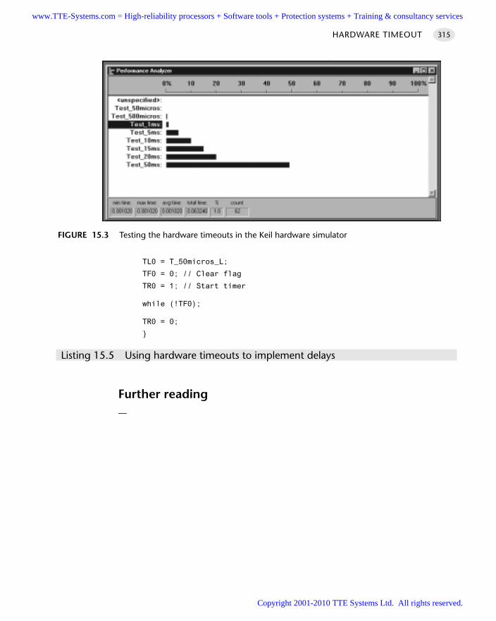
TL0 = T_50micros_L;
TF0 = 0; // Clear flag
TR0 = 1; // Start timer
while (!TF0);
TR0 = 0;
Listing 15.5 Using hardware timeouts to implement delays
Further reading—
HARDWARE TIMEOUT 315
FIGURE 15.3 Testing the hardware timeouts in the Keil hardware simulator
www.TTE-Systems.com = High-reliability processors + Software tools + Protection systems + Training & consultancy services
Copyright 2001-2010 TTE Systems Ltd. All rights reserved.
Task-oriented design
Introduction
Two patterns in this chapter encapsulate key design characteristics that underliemany successful co-operatively scheduled applications:
M U LT I - S TA G E TA S K [page 317] considers techniques that may be used to convertlong tasks (scheduled at infrequent intervals) into much shorter tasks (scheduled atfrequent intervals)
M U LT I - S TAT E TA S K [Page 322] considers techniques that may be used to replacemultiple tasks with a single task that performs different activities depending on thecurrent state of the system.
chapter 16www.TTE-Systems.com = High-reliability processors + Software tools + Protection systems + Training & consultancy services
Copyright 2001-2010 TTE Systems Ltd. All rights reserved.
MULTI-STAGE TASK
Context You are developing an embedded application using one or more members of the
8051 family of microcontrollers.
The application has a time-triggered architecture, constructed using a scheduler.
ProblemHow do you make sure that a long task does not interfere with the normal operationof the scheduler?
BackgroundSee C O-O P E R AT I V E S C H E D U L E R [page 255] for relevant background information.
SolutionAs we have seen, co-operative schedulers have many advantages when compared topre-emptive or even hybrid schedulers and we generally wish to use a co-operativeapproach when it is feasible to do so. However, a key design challenge when usingthis approach is to ensure that each task is completed before the next scheduler tickoccurs. One approach that can help us to achieve this goal is to make use of timeouts(see Chapter 15).
Another approach is to use of multi-stage tasks. To understand the need for multi-stage tasks, consider an example (adapted from Pont 1996,Chapter 13). Suppose thatas part of a ‘backup’ temperature monitoring system for a metal furnace we arerequired to send temperature samples at regular, 5-second, intervals to a desktop PC(Figure 16.1).
The required PC output takes the form shown in Figure 16.2.At first inspection, the obvious way of sending this information to the PC at the
required 5-second interval is to create a function (we will call it Send_Temp_Data()),which will be run by the scheduler every five seconds.
However, this is probably a rather bad solution. The problem is that we need tosend at least 43 characters to the PC using Send_Temp_Data(). At a common baudrate of 9,600 (see Chapter 18 for details), each of the characters will take approxi-mately 1 millisecond to send: as a result, the task duration will be around 40 ms. Ifwe use this (long) task, we will need to set the system tick interval at a value greaterthan 40 ms, which may have a detrimental impact on the overall responsiveness ofthe application.
MULTI-STAGE TASK 317
www.TTE-Systems.com = High-reliability processors + Software tools + Protection systems + Training & consultancy services
Copyright 2001-2010 TTE Systems Ltd. All rights reserved.
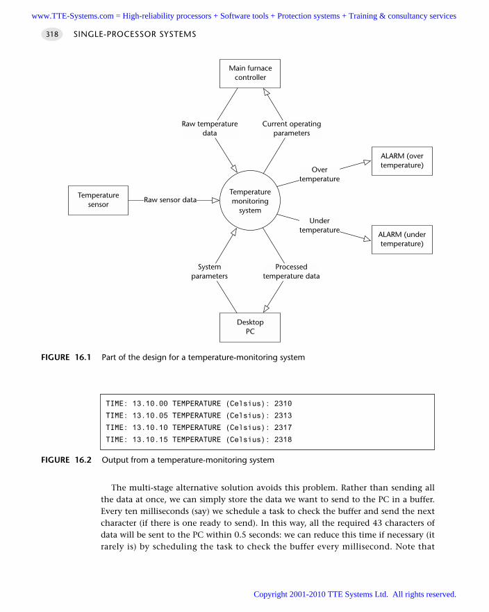
The multi-stage alternative solution avoids this problem. Rather than sending allthe data at once, we can simply store the data we want to send to the PC in a buffer.Every ten milliseconds (say) we schedule a task to check the buffer and send the nextcharacter (if there is one ready to send). In this way, all the required 43 characters ofdata will be sent to the PC within 0.5 seconds: we can reduce this time if necessary (itrarely is) by scheduling the task to check the buffer every millisecond. Note that
SINGLE-PROCESSOR SYSTEMS318
FIGURE 16.1 Part of the design for a temperature-monitoring system
Temperaturemonitoring
system
DesktopPC
ALARM (overtemperature)
Systemparameters
Processedtemperature data
Raw temperaturedata
Current operatingparameters
Main furnacecontroller
Temperaturesensor
Raw sensor data
ALARM (undertemperature)
Overtemperature
Undertemperature
FIGURE 16.2 Output from a temperature-monitoring system
TIME: 13.10.00 TEMPERATURE (Celsius): 2310
TIME: 13.10.05 TEMPERATURE (Celsius): 2313
TIME: 13.10.10 TEMPERATURE (Celsius): 2317
TIME: 13.10.15 TEMPERATURE (Celsius): 2318
www.TTE-Systems.com = High-reliability processors + Software tools + Protection systems + Training & consultancy services
Copyright 2001-2010 TTE Systems Ltd. All rights reserved.
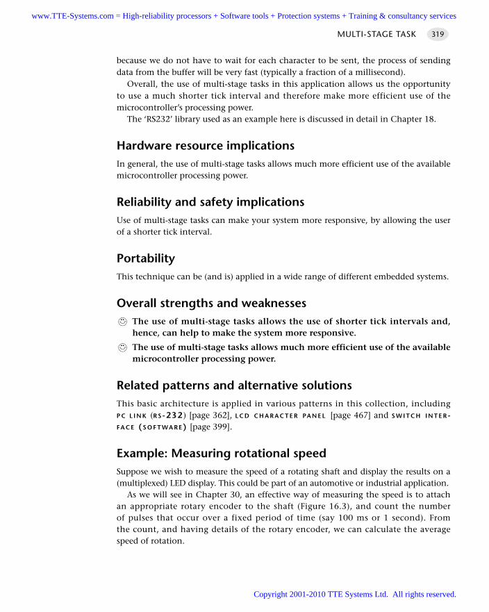
because we do not have to wait for each character to be sent, the process of sendingdata from the buffer will be very fast (typically a fraction of a millisecond).
Overall, the use of multi-stage tasks in this application allows us the opportunityto use a much shorter tick interval and therefore make more efficient use of themicrocontroller’s processing power.
The ‘RS232’ library used as an example here is discussed in detail in Chapter 18.
Hardware resource implicationsIn general, the use of multi-stage tasks allows much more efficient use of the availablemicrocontroller processing power.
Reliability and safety implicationsUse of multi-stage tasks can make your system more responsive, by allowing the userof a shorter tick interval.
PortabilityThis technique can be (and is) applied in a wide range of different embedded systems.
Overall strengths and weaknessesThe use of multi-stage tasks allows the use of shorter tick intervals and,hence, can help to make the system more responsive.
The use of multi-stage tasks allows much more efficient use of the availablemicrocontroller processing power.
Related patterns and alternative solutionsThis basic architecture is applied in various patterns in this collection, includingP C L I N K (R S-232 ) [page 362], L C D C H A R A C T E R PA N E L [page 467] and S W I T C H I N T E R-FA C E (S O F T WA R E) [page 399].
Example: Measuring rotational speedSuppose we wish to measure the speed of a rotating shaft and display the results on a(multiplexed) LED display. This could be part of an automotive or industrial application.
As we will see in Chapter 30, an effective way of measuring the speed is to attachan appropriate rotary encoder to the shaft (Figure 16.3), and count the numberof pulses that occur over a fixed period of time (say 100 ms or 1 second). Fromthe count, and having details of the rotary encoder, we can calculate the averagespeed of rotation.
MULTI-STAGE TASK 319
www.TTE-Systems.com = High-reliability processors + Software tools + Protection systems + Training & consultancy services
Copyright 2001-2010 TTE Systems Ltd. All rights reserved.
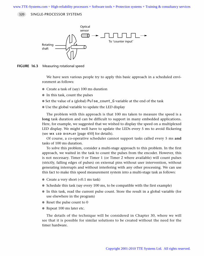
We have seen various people try to apply this basic approach in a scheduled envi-ronment as follows:
Create a task of (say) 100 ms duration
In this task, count the pulses
Set the value of a (global) Pulse_count_G variable at the end of the task
Use the global variable to update the LED display
The problem with this approach is that 100 ms taken to measure the speed is along task duration and can be difficult to support in many embedded applications.Here, for example, we suggested that we wished to display the speed on a multiplexedLED display. We might well have to update the LEDs every 5 ms to avoid flickering(see M X L E D D I S P L AY [page 450] for details).
Of course, a co-operative scheduler cannot support tasks called every 5 ms andtasks of 100 ms duration.
To solve this problem, consider a multi-stage approach to this problem. In the firstapproach, we waited in the task to count the pulses from the encoder. However, thisis not necessary. Timer 0 or Timer 1 (or Timer 2 where available) will count pulses(strictly, falling edges of pulses) on external pins without user intervention, withoutgenerating interrupts and without interfering with any other processing. We can usethis fact to make this speed measurement system into a multi-stage task as follows:
Create a very short (<0.1 ms task)
Schedule this task (say every 100 ms, to be compatible with the first example)
In this task, read the current pulse count. Store the result in a global variable (foruse elsewhere in the program)
Reset the pulse count to 0
Repeat 100 ms later etc.
The details of the technique will be considered in Chapter 30, where we willsee that it is possible for similar solutions to be created without the need for thetimer hardware.
SINGLE-PROCESSOR SYSTEMS320
FIGURE 16.3 Measuring rotational speed
Rotatingshaft
To ‘counter input’
Opticalsensor
www.TTE-Systems.com = High-reliability processors + Software tools + Protection systems + Training & consultancy services
Copyright 2001-2010 TTE Systems Ltd. All rights reserved.
Example: LCD librarySuppose we wish to update an LCD display. As we will see in L C D C H A R A C T E R PA N E L
[page 467], updating each character in a typical LCD display can take around 0.5 ms:to update the whole of a 40-character display can therefore take around 20 ms. This isoften prohibitively long.
However, suppose we schedule a LCD_Update() function every 20 ms and, eachtime, update only a single display position. At worst, it will take us a total of 800 msto update the whole display – and we will be able to complete numerous other tasksat the same time. In addition, in most circumstances, only some of the display willhave changed: if we keep track of characters that need to be updated, we can usuallykeep the display fully up to date with a multi-stage task of 0.5 ms duration calledevery 100 ms. Overall, the multi-stage approach to this single task can make a majordifference to the architecture of the whole application.
Full details of the multi-stage LCD library are given in L C D C H A R A C T E R PA N E L
[page 467].
Further reading—
MULTI-STAGE TASK 321
www.TTE-Systems.com = High-reliability processors + Software tools + Protection systems + Training & consultancy services
Copyright 2001-2010 TTE Systems Ltd. All rights reserved.
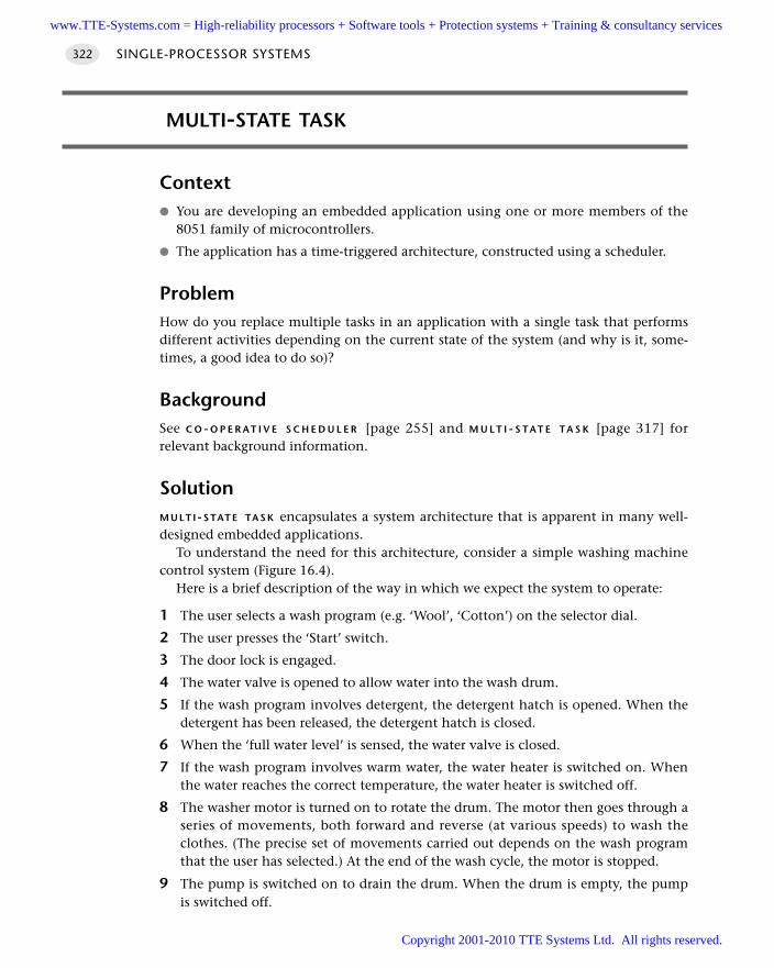
MULTI-STATE TASK
Context You are developing an embedded application using one or more members of the
8051 family of microcontrollers.
The application has a time-triggered architecture, constructed using a scheduler.
ProblemHow do you replace multiple tasks in an application with a single task that performsdifferent activities depending on the current state of the system (and why is it, some-times, a good idea to do so)?
BackgroundSee C O - O P E R AT I V E S C H E D U L E R [page 255] and M U L T I - S TAT E TA S K [page 317] forrelevant background information.
SolutionM U LT I - S TAT E TA S K encapsulates a system architecture that is apparent in many well-designed embedded applications.
To understand the need for this architecture, consider a simple washing machinecontrol system (Figure 16.4).
Here is a brief description of the way in which we expect the system to operate:
1 The user selects a wash program (e.g. ‘Wool’, ‘Cotton’) on the selector dial.
2 The user presses the ‘Start’ switch.
3 The door lock is engaged.
4 The water valve is opened to allow water into the wash drum.
5 If the wash program involves detergent, the detergent hatch is opened. When thedetergent has been released, the detergent hatch is closed.
6 When the ‘full water level’ is sensed, the water valve is closed.
7 If the wash program involves warm water, the water heater is switched on. Whenthe water reaches the correct temperature, the water heater is switched off.
8 The washer motor is turned on to rotate the drum. The motor then goes through aseries of movements, both forward and reverse (at various speeds) to wash theclothes. (The precise set of movements carried out depends on the wash programthat the user has selected.) At the end of the wash cycle, the motor is stopped.
9 The pump is switched on to drain the drum. When the drum is empty, the pumpis switched off.
SINGLE-PROCESSOR SYSTEMS322
www.TTE-Systems.com = High-reliability processors + Software tools + Protection systems + Training & consultancy services
Copyright 2001-2010 TTE Systems Ltd. All rights reserved.
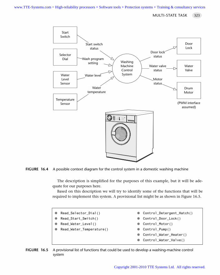
The description is simplified for the purposes of this example, but it will be ade-quate for our purposes here.
Based on this description we will try to identify some of the functions that will berequired to implement this system. A provisional list might be as shown in Figure 16.5.
MULTI-STATE TASK 323
FIGURE 16.4 A possible context diagram for the control system in a domestic washing machine
SelectorDial
WashingMachineControlSystemWater
LevelSensor
StartSwitch
TemperatureSensor
WaterValve
DoorLock
DrumMotor
Start switchstatus
Watertemperature
Wash programsetting
Water level
(PWM interfaceassumed)
Door lockstatus
Water valvestatus
Water valvestatus
Motorstatus
FIGURE 16.5 A provisional list of functions that could be used to develop a washing-machine control system
Read_Selector_Dial() Control_Detergent_Hatch()
Read_Start_Switch() Control_Door_Lock()
Read_Water_Level() Control_Motor()
Read_Water_Temperature() Control_Pump()
Control_Water_Heater()
Control_Water_Valve()
www.TTE-Systems.com = High-reliability processors + Software tools + Protection systems + Training & consultancy services
Copyright 2001-2010 TTE Systems Ltd. All rights reserved.
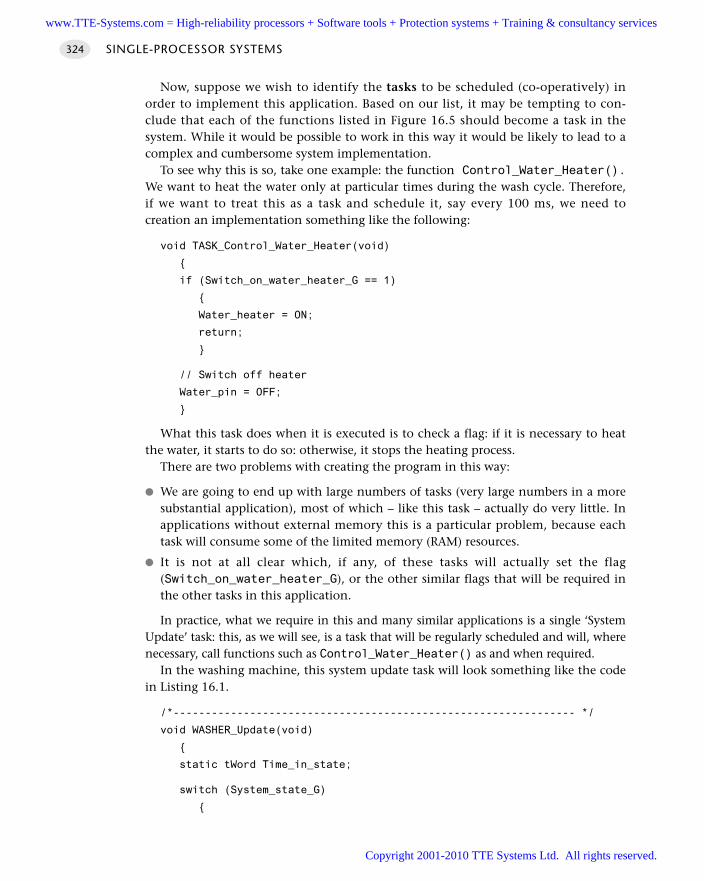
Now, suppose we wish to identify the tasks to be scheduled (co-operatively) inorder to implement this application. Based on our list, it may be tempting to con-clude that each of the functions listed in Figure 16.5 should become a task in thesystem. While it would be possible to work in this way it would be likely to lead to acomplex and cumbersome system implementation.
To see why this is so, take one example: the function Control_Water_Heater().We want to heat the water only at particular times during the wash cycle. Therefore,if we want to treat this as a task and schedule it, say every 100 ms, we need tocreation an implementation something like the following:
void TASK_Control_Water_Heater(void)
if (Switch_on_water_heater_G == 1)
Water_heater = ON;
return;
// Switch off heater
Water_pin = OFF;
What this task does when it is executed is to check a flag: if it is necessary to heatthe water, it starts to do so: otherwise, it stops the heating process.
There are two problems with creating the program in this way:
We are going to end up with large numbers of tasks (very large numbers in a moresubstantial application), most of which – like this task – actually do very little. Inapplications without external memory this is a particular problem, because eachtask will consume some of the limited memory (RAM) resources.
It is not at all clear which, if any, of these tasks will actually set the flag(Switch_on_water_heater_G), or the other similar flags that will be required inthe other tasks in this application.
In practice, what we require in this and many similar applications is a single ‘SystemUpdate’ task: this, as we will see, is a task that will be regularly scheduled and will, wherenecessary, call functions such as Control_Water_Heater() as and when required.
In the washing machine, this system update task will look something like the codein Listing 16.1.
/*--------------------------------------------------------------- */
void WASHER_Update(void)
static tWord Time_in_state;
switch (System_state_G)
SINGLE-PROCESSOR SYSTEMS324
www.TTE-Systems.com = High-reliability processors + Software tools + Protection systems + Training & consultancy services
Copyright 2001-2010 TTE Systems Ltd. All rights reserved.
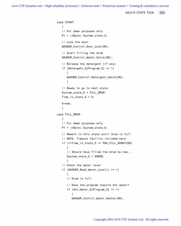
case START:
// For demo purposes only
P1 = (tByte) System_state_G;
// Lock the door
WASHER_Control_Door_Lock(ON);
// Start filling the drum
WASHER_Control_Water_Valve(ON);
// Release the detergent (if any)
if (Detergent_G[Program_G] == 1)
WASHER_Control_Detergent_Hatch(ON);
// Ready to go to next state
System_state_G = FILL_DRUM;
Time_in_state_G = 0;
break;
case FILL_DRUM:
// For demo purposes only
P1 = (tByte) System_state_G;
// Remain in this state until drum is full
// NOTE: Timeout facility included here
if (++Time_in_state_G >= MAX_FILL_DURATION)
// Should have filled the drum by now...
System_state_G = ERROR;
// Check the water level
if (WASHER_Read_Water_Level() == 1)
// Drum is full
// Does the program require hot water?
if (Hot_Water_G[Program_G] == 1)
WASHER_Control_Water_Heater(ON);
MULTI-STATE TASK 325
www.TTE-Systems.com = High-reliability processors + Software tools + Protection systems + Training & consultancy services
Copyright 2001-2010 TTE Systems Ltd. All rights reserved.
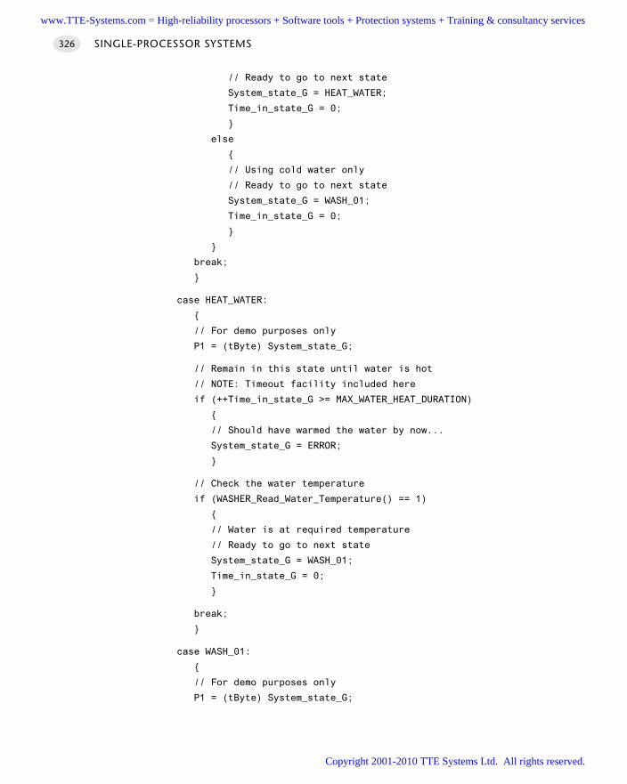
// Ready to go to next state
System_state_G = HEAT_WATER;
Time_in_state_G = 0;
else
// Using cold water only
// Ready to go to next state
System_state_G = WASH_01;
Time_in_state_G = 0;
break;
case HEAT_WATER:
// For demo purposes only
P1 = (tByte) System_state_G;
// Remain in this state until water is hot
// NOTE: Timeout facility included here
if (++Time_in_state_G >= MAX_WATER_HEAT_DURATION)
// Should have warmed the water by now...
System_state_G = ERROR;
// Check the water temperature
if (WASHER_Read_Water_Temperature() == 1)
// Water is at required temperature
// Ready to go to next state
System_state_G = WASH_01;
Time_in_state_G = 0;
break;
case WASH_01:
// For demo purposes only
P1 = (tByte) System_state_G;
SINGLE-PROCESSOR SYSTEMS326
www.TTE-Systems.com = High-reliability processors + Software tools + Protection systems + Training & consultancy services
Copyright 2001-2010 TTE Systems Ltd. All rights reserved.
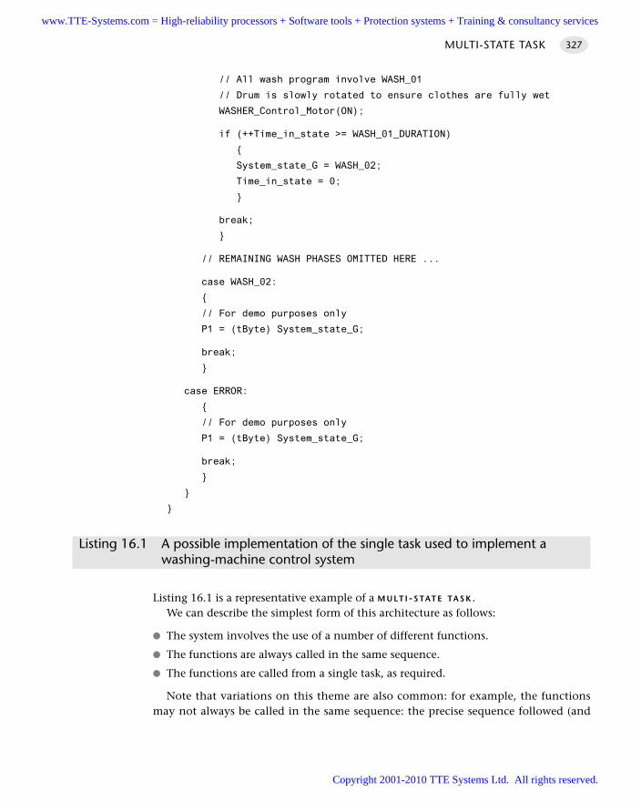
// All wash program involve WASH_01
// Drum is slowly rotated to ensure clothes are fully wet
WASHER_Control_Motor(ON);
if (++Time_in_state >= WASH_01_DURATION)
System_state_G = WASH_02;
Time_in_state = 0;
break;
// REMAINING WASH PHASES OMITTED HERE ...
case WASH_02:
// For demo purposes only
P1 = (tByte) System_state_G;
break;
case ERROR:
// For demo purposes only
P1 = (tByte) System_state_G;
break;
Listing 16.1 A possible implementation of the single task used to implement a washing-machine control system
Listing 16.1 is a representative example of a M U LT I - S TAT E TA S K . We can describe the simplest form of this architecture as follows:
The system involves the use of a number of different functions.
The functions are always called in the same sequence.
The functions are called from a single task, as required.
Note that variations on this theme are also common: for example, the functionsmay not always be called in the same sequence: the precise sequence followed (and
MULTI-STATE TASK 327
www.TTE-Systems.com = High-reliability processors + Software tools + Protection systems + Training & consultancy services
Copyright 2001-2010 TTE Systems Ltd. All rights reserved.
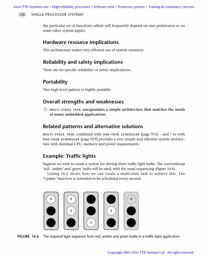
the particular set of functions called) will frequently depend on user preferences or onsome other system inputs.
Hardware resource implicationsThis architecture makes very efficient use of system resources.
Reliability and safety implicationsThere are no specific reliability or safety implications.
PortabilityThis high-level pattern is highly portable.
Overall strengths and weaknessesM U LT I - S TA G E TA S K encapsulates a simple architecture that matches the needsof many embedded applications
Related patterns and alternative solutionsM U LT I - S TA G E TA S K combined with O N E-TA S K S C H E D U L E R [page 911] – and / or withO N E-Y E A R S C H E D U L E R [page 919] provides a very simple and efficient system architec-ture with minimal CPU, memory and power requirements.
Example: Traffic lightsSuppose we wish to create a system for driving three traffic light bulbs. The conventional‘red’, ‘amber’ and ‘green’ bulbs will be used, with the usual sequencing (Figure 16.6).
Listing 16.2 shows how we can create a multi-state task to achieve this. The‘Update’ function is intended to be scheduled every second.
SINGLE-PROCESSOR SYSTEMS328
FIGURE 16.6 The required light sequence from red, amber and green bulbs in a traffic-light application
R
A
G
R
A
G
R
A
G
R
A
G
R
A
G
www.TTE-Systems.com = High-reliability processors + Software tools + Protection systems + Training & consultancy services
Copyright 2001-2010 TTE Systems Ltd. All rights reserved.
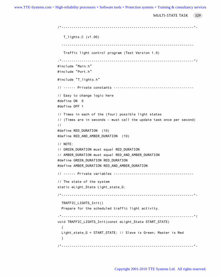
/*------------------------------------------------------------------*-
T_lights.C (v1.00)
------------------------------------------------------------------
Traffic light control program (Test Version 1.0)
-*------------------------------------------------------------------*/
#include "Main.h"
#include "Port.h"
#include "T_lights.h"
// ------ Private constants ----------------------------------------
// Easy to change logic here
#define ON 0
#define OFF 1
// Times in each of the (four) possible light states
// (Times are in seconds – must call the update task once per second)
//
#define RED_DURATION (10)
#define RED_AND_AMBER_DURATION (10)
// NOTE:
// GREEN_DURATION must equal RED_DURATION
// AMBER_DURATION must equal RED_AND_AMBER_DURATION
#define GREEN_DURATION RED_DURATION
#define AMBER_DURATION RED_AND_AMBER_DURATION
// ------ Private variables ----------------------------------------
// The state of the system
static eLight_State Light_state_G;
/*------------------------------------------------------------------*-
TRAFFIC_LIGHTS_Init()
Prepare for the scheduled traffic light activity.
-*------------------------------------------------------------------*/
void TRAFFIC_LIGHTS_Init(const eLight_State START_STATE)
Light_state_G = START_STATE; // Slave is Green; Master is Red
/*------------------------------------------------------------------*-
MULTI-STATE TASK 329
www.TTE-Systems.com = High-reliability processors + Software tools + Protection systems + Training & consultancy services
Copyright 2001-2010 TTE Systems Ltd. All rights reserved.
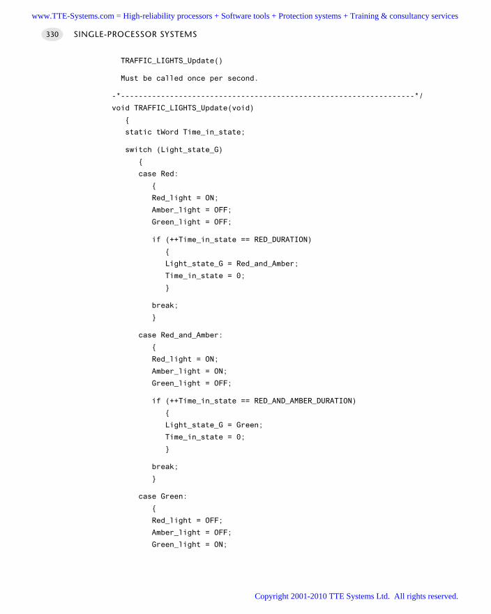
TRAFFIC_LIGHTS_Update()
Must be called once per second.
-*------------------------------------------------------------------*/
void TRAFFIC_LIGHTS_Update(void)
static tWord Time_in_state;
switch (Light_state_G)
case Red:
Red_light = ON;
Amber_light = OFF;
Green_light = OFF;
if (++Time_in_state == RED_DURATION)
Light_state_G = Red_and_Amber;
Time_in_state = 0;
break;
case Red_and_Amber:
Red_light = ON;
Amber_light = ON;
Green_light = OFF;
if (++Time_in_state == RED_AND_AMBER_DURATION)
Light_state_G = Green;
Time_in_state = 0;
break;
case Green:
Red_light = OFF;
Amber_light = OFF;
Green_light = ON;
SINGLE-PROCESSOR SYSTEMS330
www.TTE-Systems.com = High-reliability processors + Software tools + Protection systems + Training & consultancy services
Copyright 2001-2010 TTE Systems Ltd. All rights reserved.
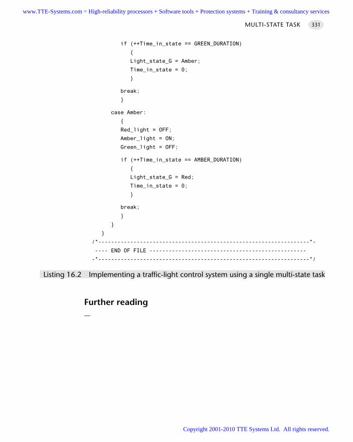
if (++Time_in_state == GREEN_DURATION)
Light_state_G = Amber;
Time_in_state = 0;
break;
case Amber:
Red_light = OFF;
Amber_light = ON;
Green_light = OFF;
if (++Time_in_state == AMBER_DURATION)
Light_state_G = Red;
Time_in_state = 0;
break;
/*------------------------------------------------------------------*-
---- END OF FILE -------------------------------------------------
-*------------------------------------------------------------------*/
Listing 16.2 Implementing a traffic-light control system using a single multi-state task
Further reading—
MULTI-STATE TASK 331
www.TTE-Systems.com = High-reliability processors + Software tools + Protection systems + Training & consultancy services
Copyright 2001-2010 TTE Systems Ltd. All rights reserved.
Hybrid schedulers
Introduction
As we discussed in Chapter 13, co-operative schedulers provide a predictable platformfor a wide range of embedded applications.
On some occasions, it can be necessary to incorporate some of the features of pre-emptive schedulers into a co-operative scheduler framework, in a carefully controlledmanner. A hybrid scheduler seeks to achieve this.
chapter 17www.TTE-Systems.com = High-reliability processors + Software tools + Protection systems + Training & consultancy services
Copyright 2001-2010 TTE Systems Ltd. All rights reserved.
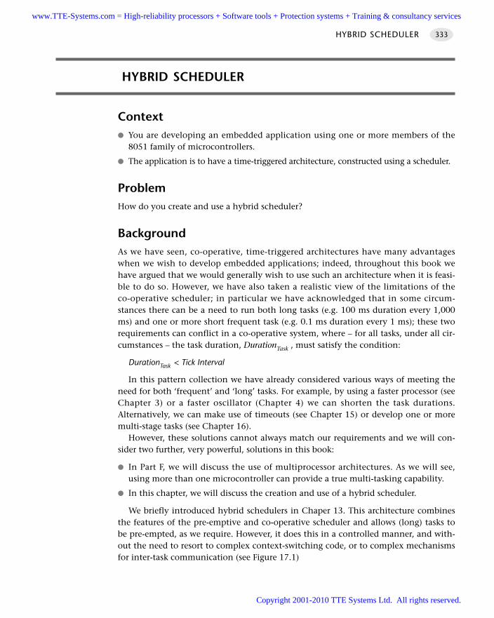
HYBRID SCHEDULER
Context You are developing an embedded application using one or more members of the
8051 family of microcontrollers.
The application is to have a time-triggered architecture, constructed using a scheduler.
ProblemHow do you create and use a hybrid scheduler?
BackgroundAs we have seen, co-operative, time-triggered architectures have many advantageswhen we wish to develop embedded applications; indeed, throughout this book wehave argued that we would generally wish to use such an architecture when it is feasi-ble to do so. However, we have also taken a realistic view of the limitations of theco-operative scheduler; in particular we have acknowledged that in some circum-stances there can be a need to run both long tasks (e.g. 100 ms duration every 1,000ms) and one or more short frequent task (e.g. 0.1 ms duration every 1 ms); these tworequirements can conflict in a co-operative system, where – for all tasks, under all cir-cumstances – the task duration, DurationTask , must satisfy the condition:
DurationTask < Tick Interval
In this pattern collection we have already considered various ways of meeting theneed for both ‘frequent’ and ‘long’ tasks. For example, by using a faster processor (seeChapter 3) or a faster oscillator (Chapter 4) we can shorten the task durations.Alternatively, we can make use of timeouts (see Chapter 15) or develop one or moremulti-stage tasks (see Chapter 16).
However, these solutions cannot always match our requirements and we will con-sider two further, very powerful, solutions in this book:
In Part F, we will discuss the use of multiprocessor architectures. As we will see,using more than one microcontroller can provide a true multi-tasking capability.
In this chapter, we will discuss the creation and use of a hybrid scheduler.
We briefly introduced hybrid schedulers in Chaper 13. This architecture combinesthe features of the pre-emptive and co-operative scheduler and allows (long) tasks tobe pre-empted, as we require. However, it does this in a controlled manner, and with-out the need to resort to complex context-switching code, or to complex mechanismsfor inter-task communication (see Figure 17.1)
HYBRID SCHEDULER 333
www.TTE-Systems.com = High-reliability processors + Software tools + Protection systems + Training & consultancy services
Copyright 2001-2010 TTE Systems Ltd. All rights reserved.
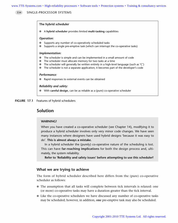
Solution
What we are trying to achieve
The form of hybrid scheduler described here differs from the (pure) co-operativescheduler as follows:
The assumption that all tasks will complete between tick intervals is relaxed: one(or more) co-operative tasks may have a duration greater than the tick interval.
Like the co-operative schedulers we have discussed any number of co-operative tasksmay be scheduled; however, in addition, one pre-emptive task may also be scheduled.
SINGLE-PROCESSOR SYSTEMS334
FIGURE 17.1 Features of hybrid schedulers
The hybrid scheduler
A hybrid scheduler provides limited multi-tasking capabilities
Operation: Supports any number of co-operatively scheduled tasks Supports a single pre-emptive task (which can interrupt the co-operative tasks)
Implementation: The scheduler is simple and can be implemented in a small amount of code The scheduler must allocate memory for two tasks at a time The scheduler will generally be written entirely in a high-level language (such as ‘C’) The scheduler is not a separate application; it becomes part of the developer’s code
Performance: Rapid responses to external events can be obtained
Reliability and safety: With careful design, can be as reliable as a (pure) co-operative scheduler
WARNING!
When you have created a co-operative scheduler (see Chapter 14), modifying it toproduce a hybrid scheduler involves only very minor code changes. We have seenmany instances where designers have used hybrid designs ‘because it was easy todo’. This is almost always a mistake.
In a hybrid scheduler the (purely) co-operative nature of the scheduling is lost.This can have far-reaching implications for both the design process and, ulti-mately, the system reliability.
Refer to ‘Reliability and safety issues’ before attempting to use this scheduler!
www.TTE-Systems.com = High-reliability processors + Software tools + Protection systems + Training & consultancy services
Copyright 2001-2010 TTE Systems Ltd. All rights reserved.
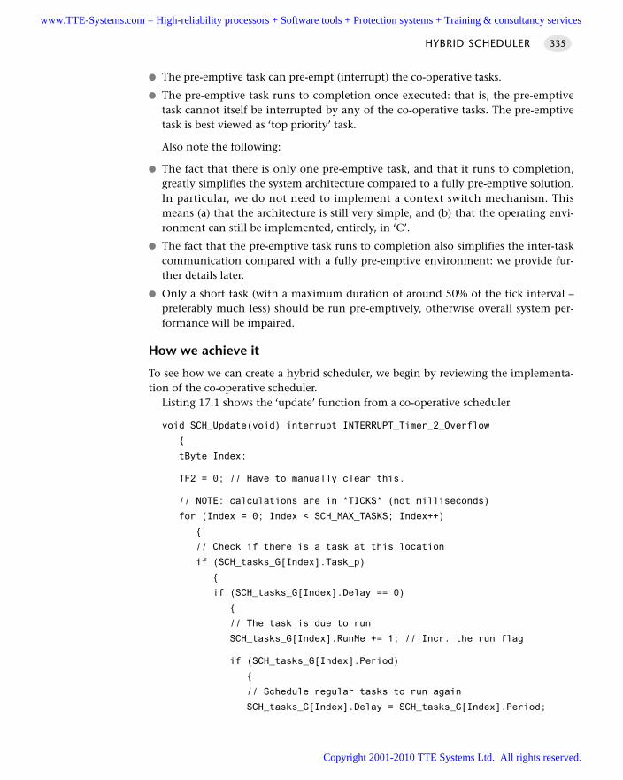
The pre-emptive task can pre-empt (interrupt) the co-operative tasks.
The pre-emptive task runs to completion once executed: that is, the pre-emptivetask cannot itself be interrupted by any of the co-operative tasks. The pre-emptivetask is best viewed as ‘top priority’ task.
Also note the following:
The fact that there is only one pre-emptive task, and that it runs to completion,greatly simplifies the system architecture compared to a fully pre-emptive solution.In particular, we do not need to implement a context switch mechanism. Thismeans (a) that the architecture is still very simple, and (b) that the operating envi-ronment can still be implemented, entirely, in ‘C’.
The fact that the pre-emptive task runs to completion also simplifies the inter-taskcommunication compared with a fully pre-emptive environment: we provide fur-ther details later.
Only a short task (with a maximum duration of around 50% of the tick interval –preferably much less) should be run pre-emptively, otherwise overall system per-formance will be impaired.
How we achieve it
To see how we can create a hybrid scheduler, we begin by reviewing the implementa-tion of the co-operative scheduler.
Listing 17.1 shows the ‘update’ function from a co-operative scheduler.
void SCH_Update(void) interrupt INTERRUPT_Timer_2_Overflow
tByte Index;
TF2 = 0; // Have to manually clear this.
// NOTE: calculations are in *TICKS* (not milliseconds)
for (Index = 0; Index < SCH_MAX_TASKS; Index++)
// Check if there is a task at this location
if (SCH_tasks_G[Index].Task_p)
if (SCH_tasks_G[Index].Delay == 0)
// The task is due to run
SCH_tasks_G[Index].RunMe += 1; // Incr. the run flag
if (SCH_tasks_G[Index].Period)
// Schedule regular tasks to run again
SCH_tasks_G[Index].Delay = SCH_tasks_G[Index].Period;
HYBRID SCHEDULER 335
www.TTE-Systems.com = High-reliability processors + Software tools + Protection systems + Training & consultancy services
Copyright 2001-2010 TTE Systems Ltd. All rights reserved.
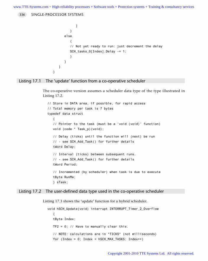
else
// Not yet ready to run: just decrement the delay
SCH_tasks_G[Index].Delay -= 1;
Listing 17.1 The ‘update’ function from a co-operative scheduler
The co-operative version assumes a scheduler data type of the type illustrated inListing 17.2.
// Store in DATA area, if possible, for rapid access
// Total memory per task is 7 bytes
typedef data struct
// Pointer to the task (must be a ‘void (void)’ function)
void (code * Task_p)(void);
// Delay (ticks) until the function will (next) be run
// - see SCH_Add_Task() for further details
tWord Delay;
// Interval (ticks) between subsequent runs.
// - see SCH_Add_Task() for further details
tWord Period;
// Incremented (by scheduler) when task is due to execute
tByte RunMe;
sTask;
Listing 17.2 The user-defined data type used in the co-operative scheduler
Listing 17.3 shows the ‘update’ function for a hybrid scheduler.
void hSCH_Update(void) interrupt INTERRUPT_Timer_2_Overflow
tByte Index;
TF2 = 0; // Have to manually clear this.
// NOTE: calculations are in *TICKS* (not milliseconds)
for (Index = 0; Index < hSCH_MAX_TASKS; Index++)
SINGLE-PROCESSOR SYSTEMS336
www.TTE-Systems.com = High-reliability processors + Software tools + Protection systems + Training & consultancy services
Copyright 2001-2010 TTE Systems Ltd. All rights reserved.
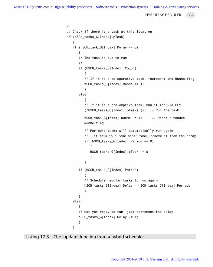
// Check if there is a task at this location
if (hSCH_tasks_G[Index].pTask)
if (hSCH_task_G[Index].Delay == 0)
// The task is due to run
//
if (hSCH_tasks_G[Index].Co_op)
// If it is a co-operative task, increment the RunMe flag
hSCH_tasks_G[Index].RunMe += 1;
else
// If it is a pre-emptive task, run it IMMEDIATELY
(*hSCH_tasks_G[Index].pTask) (); // Run the task
hSCH_task_G[Index].RunMe -= 1; // Reset / reduce
RunMe flag
// Periodic tasks will automatically run again
// - if this is a 'one shot' task, remove it from the array
if (hSCH_tasks_G[Index].Period == 0)
hSCH_tasks_G[Index].pTask = 0;
if (hSCH_tasks_G[Index].Period)
// Schedule regular tasks to run again
hSCH_tasks_G[Index].Delay = hSCH_tasks_G[Index].Period;
else
// Not yet ready to run: just decrement the delay
hSCH_tasks_G[Index].Delay -= 1;
Listing 17.3 The ‘update’ function from a hybrid scheduler
HYBRID SCHEDULER 337
www.TTE-Systems.com = High-reliability processors + Software tools + Protection systems + Training & consultancy services
Copyright 2001-2010 TTE Systems Ltd. All rights reserved.
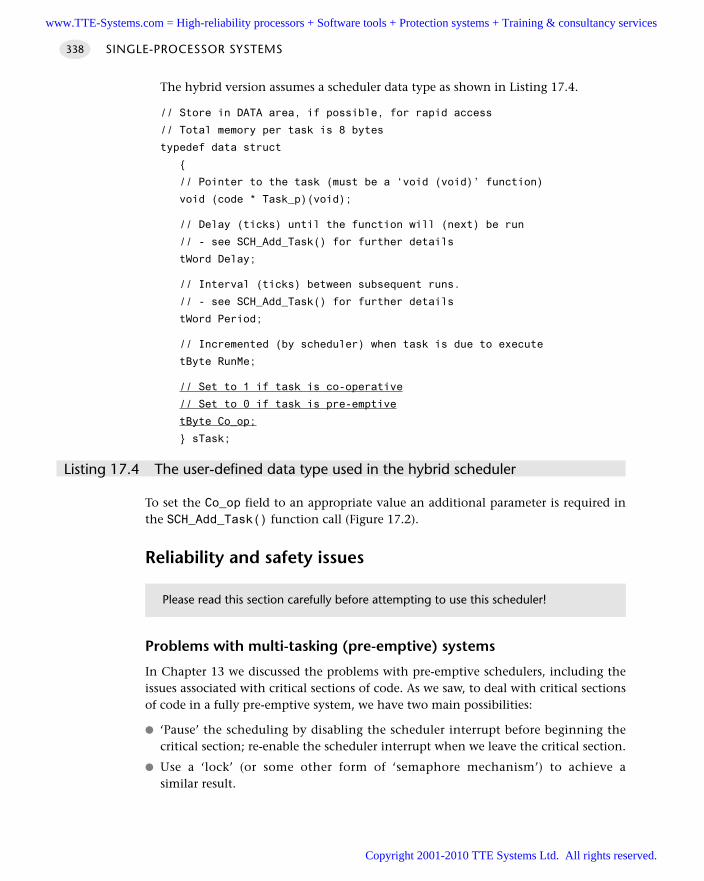
The hybrid version assumes a scheduler data type as shown in Listing 17.4.
// Store in DATA area, if possible, for rapid access
// Total memory per task is 8 bytes
typedef data struct
// Pointer to the task (must be a ‘void (void)’ function)
void (code * Task_p)(void);
// Delay (ticks) until the function will (next) be run
// - see SCH_Add_Task() for further details
tWord Delay;
// Interval (ticks) between subsequent runs.
// - see SCH_Add_Task() for further details
tWord Period;
// Incremented (by scheduler) when task is due to execute
tByte RunMe;
// Set to 1 if task is co-operative
// Set to 0 if task is pre-emptive
tByte Co_op;
sTask;
Listing 17.4 The user-defined data type used in the hybrid scheduler
To set the Co_op field to an appropriate value an additional parameter is required inthe SCH_Add_Task() function call (Figure 17.2).
Reliability and safety issues
Problems with multi-tasking (pre-emptive) systems
In Chapter 13 we discussed the problems with pre-emptive schedulers, including theissues associated with critical sections of code. As we saw, to deal with critical sectionsof code in a fully pre-emptive system, we have two main possibilities:
‘Pause’ the scheduling by disabling the scheduler interrupt before beginning thecritical section; re-enable the scheduler interrupt when we leave the critical section.
Use a ‘lock’ (or some other form of ‘semaphore mechanism’) to achieve asimilar result.
SINGLE-PROCESSOR SYSTEMS338
Please read this section carefully before attempting to use this scheduler!
www.TTE-Systems.com = High-reliability processors + Software tools + Protection systems + Training & consultancy services
Copyright 2001-2010 TTE Systems Ltd. All rights reserved.
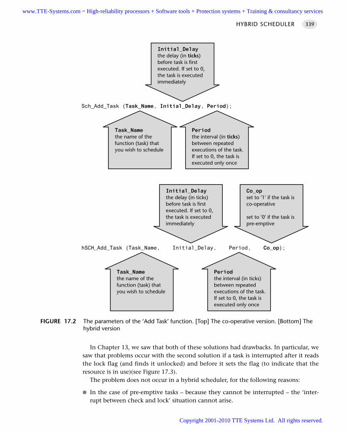
In Chapter 13, we saw that both of these solutions had drawbacks. In particular, wesaw that problems occur with the second solution if a task is interrupted after it readsthe lock flag (and finds it unlocked) and before it sets the flag (to indicate that theresource is in use)(see Figure 17.3).
The problem does not occur in a hybrid scheduler, for the following reasons:
In the case of pre-emptive tasks – because they cannot be interrupted – the ‘inter-rupt between check and lock’ situation cannot arise.
HYBRID SCHEDULER 339
FIGURE 17.2 The parameters of the ‘Add Task’ function. [Top] The co-operative version. [Bottom] Thehybrid version
Periodthe interval (in ticks)between repeatedexecutions of the task.If set to 0, the task isexecuted only once
Task_Namethe name of thefunction (task) thatyou wish to schedule
Initial_Delaythe delay (in ticks)before task is firstexecuted. If set to 0,the task is executedimmediately
Sch_Add_Task (Task_Name, Initial_Delay, Period);
Periodthe interval (in ticks)between repeatedexecutions of the task.If set to 0, the task isexecuted only once
Task_Namethe name of thefunction (task) thatyou wish to schedule
Initial_Delaythe delay (in ticks)before task is firstexecuted. If set to 0,the task is executedimmediately
hSCH_Add_Task (Task_Name, Initial_Delay, Period, Co_op);
Co_opset to '1' if the task isco-operative
set to '0' if the task ispre-emptive
www.TTE-Systems.com = High-reliability processors + Software tools + Protection systems + Training & consultancy services
Copyright 2001-2010 TTE Systems Ltd. All rights reserved.
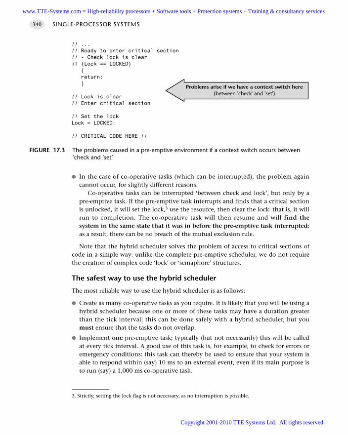
In the case of co-operative tasks (which can be interrupted), the problem againcannot occur, for slightly different reasons.
Co-operative tasks can be interrupted ‘between check and lock’, but only by apre-emptive task. If the pre-emptive task interrupts and finds that a critical sectionis unlocked, it will set the lock,3 use the resource, then clear the lock: that is, it willrun to completion. The co-operative task will then resume and will find thesystem in the same state that it was in before the pre-emptive task interrupted:as a result, there can be no breach of the mutual exclusion rule.
Note that the hybrid scheduler solves the problem of access to critical sections ofcode in a simple way: unlike the complete pre-emptive scheduler, we do not requirethe creation of complex code ‘lock’ or ‘semaphore’ structures.
The safest way to use the hybrid scheduler
The most reliable way to use the hybrid scheduler is as follows:
Create as many co-operative tasks as you require. It is likely that you will be using ahybrid scheduler because one or more of these tasks may have a duration greaterthan the tick interval; this can be done safely with a hybrid scheduler, but youmust ensure that the tasks do not overlap.
Implement one pre-emptive task; typically (but not necessarily) this will be calledat every tick interval. A good use of this task is, for example, to check for errors oremergency conditions: this task can thereby be used to ensure that your system isable to respond within (say) 10 ms to an external event, even if its main purpose isto run (say) a 1,000 ms co-operative task.
SINGLE-PROCESSOR SYSTEMS340
FIGURE 17.3 The problems caused in a pre-emptive environment if a context switch occurs between‘check and ‘set’
Problems arise if we have a context switch here(between 'check' and 'set')
// ...// Ready to enter critical section// - Check lock is clearif (Lock == LOCKED) return:
// Lock is clear// Enter critical section
// Set the lockLock = LOCKED:
// CRITICAL CODE HERE //
3. Strictly, setting the lock flag is not necessary, as no interruption is possible.
www.TTE-Systems.com = High-reliability processors + Software tools + Protection systems + Training & consultancy services
Copyright 2001-2010 TTE Systems Ltd. All rights reserved.
Remember that the pre-emptive task(s) can interrupt the co-operative tasks. If thereare critical code sections, you need to implement a simple lock mechanism (thefollowing example will illustrate this in detail).
The pre-emptive task must be short (with a maximum duration of around 50% ofthe tick interval – preferably much less), otherwise overall system performance willbe greatly impaired.
Test the application carefully, under a full range of operating conditions, andmonitor for errors.
PortabilityThe H Y B R I D S C H E D U L E R is as portable as the C O-O P E R AT I V E S C H E D U L E R [page 255]. Itdoes not require the use of assembly code or other non-standard language features.
Overall strengths and weaknessesThe overall strengths and weaknesses of H Y B R I D S C H E D U L E R may be summarizedas follows:
Has the ability to deal with both ‘long infrequent tasks’ and a single ‘shortfrequent task’ that cannot be provided by a pure C O - O P E R AT I V E S C H E D U L E R
[page 255].
Is safe and predictable, if used according to the guidelines.
It must be handled with caution.
Related patterns and alternative solutions See C O-O P E R AT I V E S C H E D U L E R [page 255]
See S C U S C H E D U L E R (L O C A L) [page 609]
See S C C S C H E D U L E R [page 677]
Example: Hybrid scheduler using T2 (1 ms ticks)A complete example of a hybrid scheduler is given in this section (Listings 17.5to 17.12).
Note the use of a simple locking mechanism to ensure that only one task accessesthe LED port at any particular time.
/*------------------------------------------------------------------*-
Port.H (v1.00)
------------------------------------------------------------------
'Port Header' (see Chapter 10) for the project 2_01_12h
HYBRID SCHEDULER 341
www.TTE-Systems.com = High-reliability processors + Software tools + Protection systems + Training & consultancy services
Copyright 2001-2010 TTE Systems Ltd. All rights reserved.
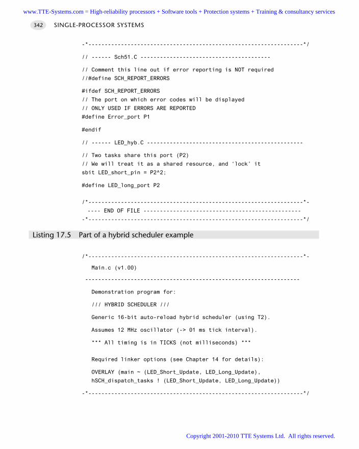
-*------------------------------------------------------------------*/
// ------ Sch51.C ----------------------------------------
// Comment this line out if error reporting is NOT required
//#define SCH_REPORT_ERRORS
#ifdef SCH_REPORT_ERRORS
// The port on which error codes will be displayed
// ONLY USED IF ERRORS ARE REPORTED
#define Error_port P1
#endif
// ------ LED_hyb.C ------------------------------------------------
// Two tasks share this port (P2)
// We will treat it as a shared resource, and ‘lock’ it
sbit LED_short_pin = P2^2;
#define LED_long_port P2
/*------------------------------------------------------------------*-
---- END OF FILE ------------------------------------------------
-*------------------------------------------------------------------*/
Listing 17.5 Part of a hybrid scheduler example
/*------------------------------------------------------------------*-
Main.c (v1.00)
------------------------------------------------------------------
Demonstration program for:
/// HYBRID SCHEDULER ///
Generic 16-bit auto-reload hybrid scheduler (using T2).
Assumes 12 MHz oscillator (-> 01 ms tick interval).
*** All timing is in TICKS (not milliseconds) ***
Required linker options (see Chapter 14 for details):
OVERLAY (main ~ (LED_Short_Update, LED_Long_Update),
hSCH_dispatch_tasks ! (LED_Short_Update, LED_Long_Update))
-*------------------------------------------------------------------*/
SINGLE-PROCESSOR SYSTEMS342
www.TTE-Systems.com = High-reliability processors + Software tools + Protection systems + Training & consultancy services
Copyright 2001-2010 TTE Systems Ltd. All rights reserved.
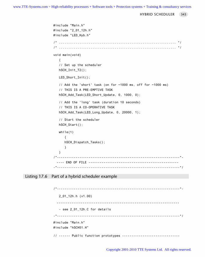
#include "Main.h"
#include "2_01_12h.h"
#include "LED_Hyb.h"
/* ............................................................... */
/* ............................................................... */
void main(void)
// Set up the scheduler
hSCH_Init_T2();
LED_Short_Init();
// Add the 'short' task (on for ~1000 ms, off for ~1000 ms)
// THIS IS A PRE-EMPTIVE TASK
hSCH_Add_Task(LED_Short_Update, 0, 1000, 0);
// Add the 'long' task (duration 10 seconds)
// THIS IS A CO-OPERATIVE TASK
hSCH_Add_Task(LED_Long_Update, 0, 20000, 1);
// Start the scheduler
hSCH_Start();
while(1)
hSCH_Dispatch_Tasks();
/*------------------------------------------------------------------*-
---- END OF FILE ------------------------------------------------
-*------------------------------------------------------------------*/
Listing 17.6 Part of a hybrid scheduler example
/*------------------------------------------------------------------*-
2_01_12h.h (v1.00)
------------------------------------------------------------------
- see 2_01_12h.C for details
-*------------------------------------------------------------------*/
#include "Main.h"
#include "hSCH51.H"
// ------ Public function prototypes -------------------------------
HYBRID SCHEDULER 343
www.TTE-Systems.com = High-reliability processors + Software tools + Protection systems + Training & consultancy services
Copyright 2001-2010 TTE Systems Ltd. All rights reserved.
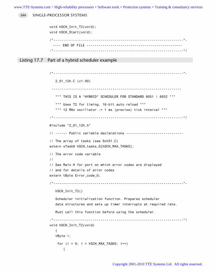
void hSCH_Init_T2(void);
void hSCH_Start(void);
/*------------------------------------------------------------------*-
---- END OF FILE ------------------------------------------------
-*------------------------------------------------------------------*/
Listing 17.7 Part of a hybrid scheduler example
/*------------------------------------------------------------------*-
2_01_12h.C (v1.00)
------------------------------------------------------------------
*** THIS IS A *HYBRID* SCHEDULER FOR STANDARD 8051 / 8052 ***
*** Uses T2 for timing, 16-bit auto reload ***
*** 12 MHz oscillator -> 1 ms (precise) tick interval ***
-*------------------------------------------------------------------*/
#include "2_01_12h.h"
// ------ Public variable declarations -----------------------------
// The array of tasks (see Sch51.C)
extern sTaskH hSCH_tasks_G[hSCH_MAX_TASKS];
// The error code variable
//
// See Main.H for port on which error codes are displayed
// and for details of error codes
extern tByte Error_code_G;
/*------------------------------------------------------------------*-
hSCH_Init_T2()
Scheduler initialization function. Prepares scheduler
data structures and sets up timer interrupts at required rate.
Must call this function before using the scheduler.
-*------------------------------------------------------------------*/
void hSCH_Init_T2(void)
tByte i;
for (i = 0; i < hSCH_MAX_TASKS; i++)
SINGLE-PROCESSOR SYSTEMS344
www.TTE-Systems.com = High-reliability processors + Software tools + Protection systems + Training & consultancy services
Copyright 2001-2010 TTE Systems Ltd. All rights reserved.
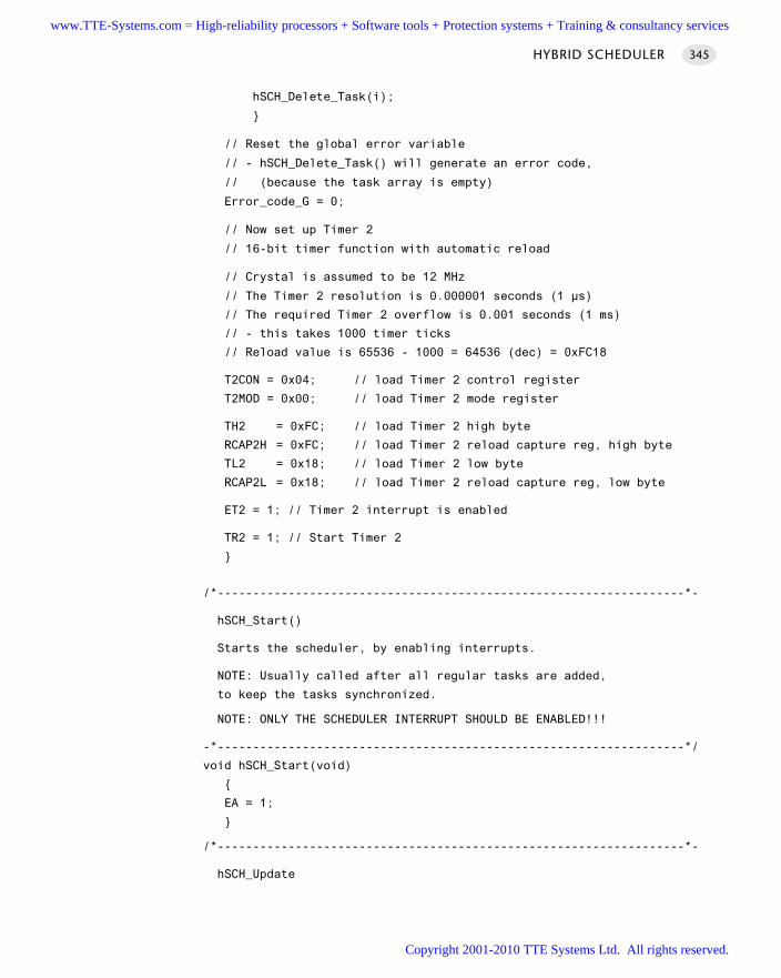
hSCH_Delete_Task(i);
// Reset the global error variable
// - hSCH_Delete_Task() will generate an error code,
// (because the task array is empty)
Error_code_G = 0;
// Now set up Timer 2
// 16-bit timer function with automatic reload
// Crystal is assumed to be 12 MHz
// The Timer 2 resolution is 0.000001 seconds (1 µs)
// The required Timer 2 overflow is 0.001 seconds (1 ms)
// - this takes 1000 timer ticks
// Reload value is 65536 - 1000 = 64536 (dec) = 0xFC18
T2CON = 0x04; // load Timer 2 control register
T2MOD = 0x00; // load Timer 2 mode register
TH2 = 0xFC; // load Timer 2 high byte
RCAP2H = 0xFC; // load Timer 2 reload capture reg, high byte
TL2 = 0x18; // load Timer 2 low byte
RCAP2L = 0x18; // load Timer 2 reload capture reg, low byte
ET2 = 1; // Timer 2 interrupt is enabled
TR2 = 1; // Start Timer 2
/*------------------------------------------------------------------*-
hSCH_Start()
Starts the scheduler, by enabling interrupts.
NOTE: Usually called after all regular tasks are added,
to keep the tasks synchronized.
NOTE: ONLY THE SCHEDULER INTERRUPT SHOULD BE ENABLED!!!
-*------------------------------------------------------------------*/
void hSCH_Start(void)
EA = 1;
/*------------------------------------------------------------------*-
hSCH_Update
HYBRID SCHEDULER 345
www.TTE-Systems.com = High-reliability processors + Software tools + Protection systems + Training & consultancy services
Copyright 2001-2010 TTE Systems Ltd. All rights reserved.
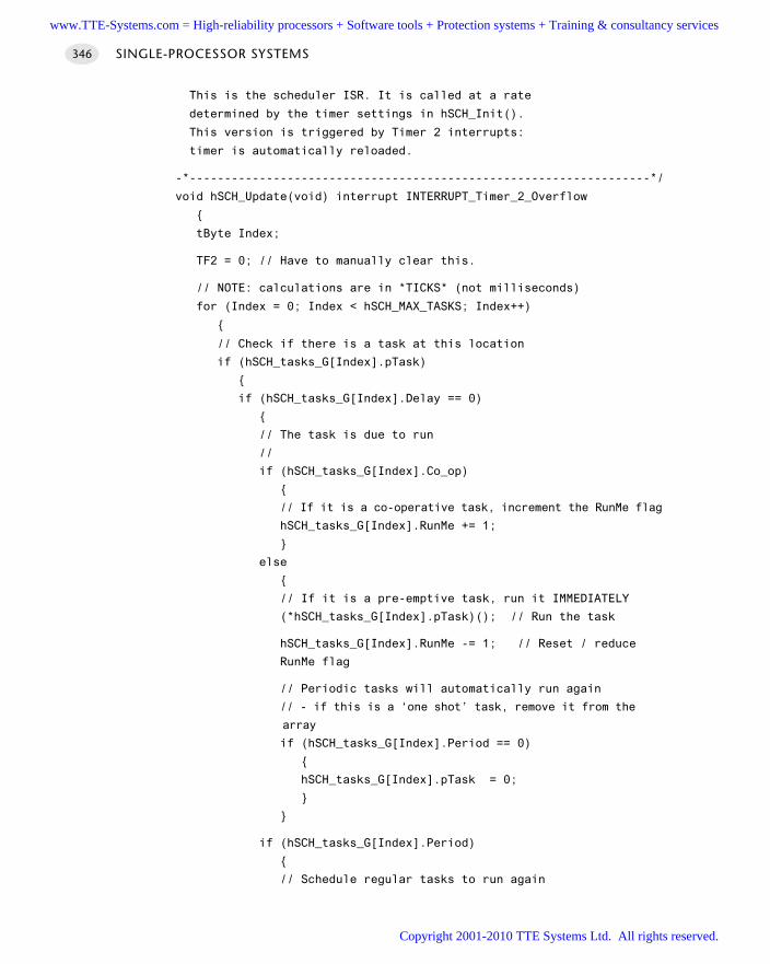
This is the scheduler ISR. It is called at a rate
determined by the timer settings in hSCH_Init().
This version is triggered by Timer 2 interrupts:
timer is automatically reloaded.
-*------------------------------------------------------------------*/
void hSCH_Update(void) interrupt INTERRUPT_Timer_2_Overflow
tByte Index;
TF2 = 0; // Have to manually clear this.
// NOTE: calculations are in *TICKS* (not milliseconds)
for (Index = 0; Index < hSCH_MAX_TASKS; Index++)
// Check if there is a task at this location
if (hSCH_tasks_G[Index].pTask)
if (hSCH_tasks_G[Index].Delay == 0)
// The task is due to run
//
if (hSCH_tasks_G[Index].Co_op)
// If it is a co-operative task, increment the RunMe flag
hSCH_tasks_G[Index].RunMe += 1;
else
// If it is a pre-emptive task, run it IMMEDIATELY
(*hSCH_tasks_G[Index].pTask)(); // Run the task
hSCH_tasks_G[Index].RunMe -= 1; // Reset / reduce
RunMe flag
// Periodic tasks will automatically run again
// - if this is a ‘one shot’ task, remove it from the
array
if (hSCH_tasks_G[Index].Period == 0)
hSCH_tasks_G[Index].pTask = 0;
if (hSCH_tasks_G[Index].Period)
// Schedule regular tasks to run again
SINGLE-PROCESSOR SYSTEMS346
www.TTE-Systems.com = High-reliability processors + Software tools + Protection systems + Training & consultancy services
Copyright 2001-2010 TTE Systems Ltd. All rights reserved.
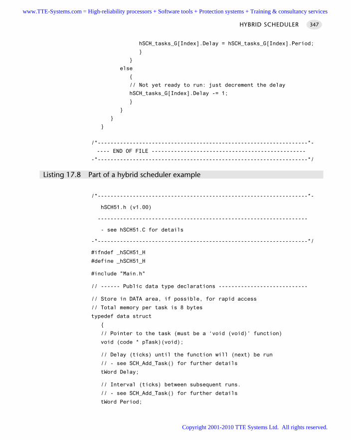
hSCH_tasks_G[Index].Delay = hSCH_tasks_G[Index].Period;
else
// Not yet ready to run: just decrement the delay
hSCH_tasks_G[Index].Delay -= 1;
/*------------------------------------------------------------------*-
---- END OF FILE ------------------------------------------------
-*------------------------------------------------------------------*/
Listing 17.8 Part of a hybrid scheduler example
/*------------------------------------------------------------------*-
hSCH51.h (v1.00)
------------------------------------------------------------------
- see hSCH51.C for details
-*------------------------------------------------------------------*/
#ifndef _hSCH51_H
#define _hSCH51_H
#include "Main.h"
// ------ Public data type declarations ----------------------------
// Store in DATA area, if possible, for rapid access
// Total memory per task is 8 bytes
typedef data struct
// Pointer to the task (must be a ‘void (void)’ function)
void (code * pTask)(void);
// Delay (ticks) until the function will (next) be run
// - see SCH_Add_Task() for further details
tWord Delay;
// Interval (ticks) between subsequent runs.
// - see SCH_Add_Task() for further details
tWord Period;
HYBRID SCHEDULER 347
www.TTE-Systems.com = High-reliability processors + Software tools + Protection systems + Training & consultancy services
Copyright 2001-2010 TTE Systems Ltd. All rights reserved.
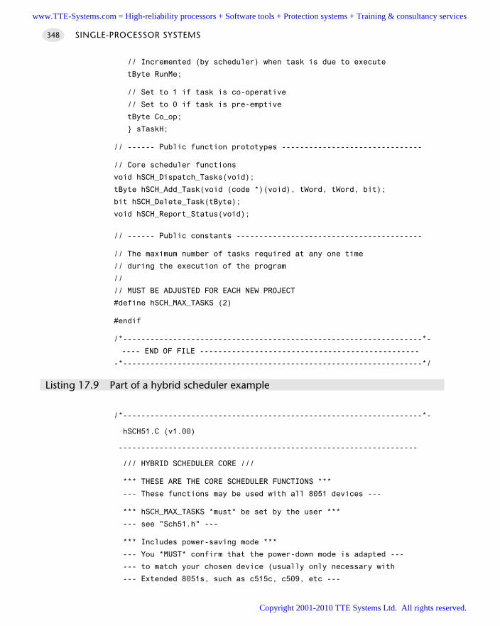
// Incremented (by scheduler) when task is due to execute
tByte RunMe;
// Set to 1 if task is co-operative
// Set to 0 if task is pre-emptive
tByte Co_op;
sTaskH;
// ------ Public function prototypes -------------------------------
// Core scheduler functions
void hSCH_Dispatch_Tasks(void);
tByte hSCH_Add_Task(void (code *)(void), tWord, tWord, bit);
bit hSCH_Delete_Task(tByte);
void hSCH_Report_Status(void);
// ------ Public constants -----------------------------------------
// The maximum number of tasks required at any one time
// during the execution of the program
//
// MUST BE ADJUSTED FOR EACH NEW PROJECT
#define hSCH_MAX_TASKS (2)
#endif
/*------------------------------------------------------------------*-
---- END OF FILE ------------------------------------------------
-*------------------------------------------------------------------*/
Listing 17.9 Part of a hybrid scheduler example
/*------------------------------------------------------------------*-
hSCH51.C (v1.00)
------------------------------------------------------------------
/// HYBRID SCHEDULER CORE ///
*** THESE ARE THE CORE SCHEDULER FUNCTIONS ***
--- These functions may be used with all 8051 devices ---
*** hSCH_MAX_TASKS *must* be set by the user ***
--- see "Sch51.h" ---
*** Includes power-saving mode ***
--- You *MUST* confirm that the power-down mode is adapted ---
--- to match your chosen device (usually only necessary with
--- Extended 8051s, such as c515c, c509, etc ---
SINGLE-PROCESSOR SYSTEMS348
www.TTE-Systems.com = High-reliability processors + Software tools + Protection systems + Training & consultancy services
Copyright 2001-2010 TTE Systems Ltd. All rights reserved.
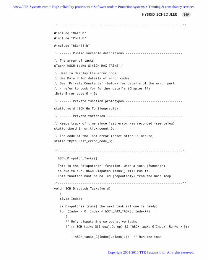
-*------------------------------------------------------------------*/
#include "Main.h"
#include "Port.h"
#include "hSch51.h"
// ------ Public variable definitions ------------------------------
// The array of tasks
sTaskH hSCH_tasks_G[hSCH_MAX_TASKS];
// Used to display the error code
// See Main.H for details of error codes
// See ‘Private Constants’ (below) for details of the error port
// - refer to book for further details (Chapter 14)
tByte Error_code_G = 0;
// ------ Private function prototypes ------------------------------
static void hSCH_Go_To_Sleep(void);
// ------ Private variables ----------------------------------------
// Keeps track of time since last error was recorded (see below)
static tWord Error_tick_count_G;
// The code of the last error (reset after ~1 minute)
static tByte Last_error_code_G;
/*------------------------------------------------------------------*-
hSCH_Dispatch_Tasks()
This is the ‘dispatcher’ function. When a task (function)
is due to run, hSCH_Dispatch_Tasks() will run it.
This function must be called (repeatedly) from the main loop.
-*------------------------------------------------------------------*/
void hSCH_Dispatch_Tasks(void)
tByte Index;
// Dispatches (runs) the next task (if one is ready)
for (Index = 0; Index < hSCH_MAX_TASKS; Index++)
// Only dispatching co-operative tasks
if ((hSCH_tasks_G[Index].Co_op) && (hSCH_tasks_G[Index].RunMe > 0))
(*hSCH_tasks_G[Index].pTask)(); // Run the task
HYBRID SCHEDULER 349
www.TTE-Systems.com = High-reliability processors + Software tools + Protection systems + Training & consultancy services
Copyright 2001-2010 TTE Systems Ltd. All rights reserved.
hSCH_tasks_G[Index].RunMe -= 1; // Reset / reduce RunMe flag
// Periodic tasks will automatically run again
// - if this is a ‘one shot’ task, remove it from the array
if (hSCH_tasks_G[Index].Period == 0)
// Faster than call to delete task
hSCH_tasks_G[Index].pTask = 0;
// Report system status
hSCH_Report_Status();
// The scheduler enters idle mode at this point
hSCH_Go_To_Sleep();
/*------------------------------------------------------------------*-
hSCH_Add_Task()
Causes a task (function) to be executed at regular intervals
or after a user-defined delay
Fn_P - The name of the function which is to be scheduled.
NOTE: All scheduled functions must be 'void, void' -
that is, they must take no parameters, and have
a void return type.
Del - The interval (TICKS) before the task is first executed
Per - If 'Per' is 0, the function is only called once,
at the time determined by 'Del'. If Per is non-zero,
then the function is called repeatedly at an interval
determined by the value of Per (see below for examples
that should help clarify this).
Co-op - Set to 1 if it a co-op task; 0 if pre-emptive
RETN: The position in the task array at which the task has been added.
If the return value is hSCH_MAX_TASKS then the task could not be
added to the array (there was insufficient space). If the
return value is < hSCH_MAX_TASKS, then the task was added
successfully.
Note: this return value may be required, if a task is
to be subsequently deleted - see hSCH_Delete_Task().
SINGLE-PROCESSOR SYSTEMS350
www.TTE-Systems.com = High-reliability processors + Software tools + Protection systems + Training & consultancy services
Copyright 2001-2010 TTE Systems Ltd. All rights reserved.
EXAMPLES:
Task_ID = hSCH_Add_Task(Do_X,1000,0,0);
Causes the function Do_X() to be executed once after 1000 ticks.
(Pre-emptive task)
Task_ID = hSCH_Add_Task(Do_X,0,1000,1);
Causes the function Do_X() to be executed regularly, every 1000 ticks.
(co-operative task)
Task_ID = hSCH_Add_Task(Do_X,300,1000,0);
Causes the function Do_X() to be executed regularly, every 1000 ticks.
Task will be first executed at T = 300 ticks, then 1300, 2300, etc.
(Pre-emptive task)
-*------------------------------------------------------------------*/
tByte hSCH_Add_Task(void (code* Fn_p)(), // Task function pointer
tWord Del, // Num ticks 'til task first runs
tWord Per, // Num ticks between repeat runs
bit Co_op) // Co_op / pre_emp
tByte Index = 0;
// First find a gap in the array (if there is one)
while ((hSCH_tasks_G[Index].pTask != 0) && (Index < hSCH_MAX_TASKS))
Index++;
// Have we reached the end of the list?
if (Index == hSCH_MAX_TASKS)
// Task list is full
//
// Set the global error variable
Error_code_G = ERROR_SCH_TOO_MANY_TASKS;
// Also return an error code
return hSCH_MAX_TASKS;
// If we’re here, there is a space in the task array
hSCH_tasks_G[Index].pTask = Fn_p;
hSCH_tasks_G[Index].Delay = Del;
hSCH_tasks_G[Index].Period = Per;
hSCH_tasks_G[Index].Co_op = Co_op;
HYBRID SCHEDULER 351
www.TTE-Systems.com = High-reliability processors + Software tools + Protection systems + Training & consultancy services
Copyright 2001-2010 TTE Systems Ltd. All rights reserved.
hSCH_tasks_G[Index].RunMe = 0;
return Index; // return position of task (to allow later deletion)
/*------------------------------------------------------------------*-
hSCH_Delete_Task()
Removes a task from the scheduler. Note that this does
*not* delete the associated function from memory:
it simply means that it is no longer called by the scheduler.
PARAMS: Task_index - The task index. Provided by hSCH_Add_Task().
RETURNS: RETURN_ERROR or RETURN_NORMAL
-*------------------------------------------------------------------*/
bit hSCH_Delete_Task(tByte Task_index)
bit Return_code;
if (hSCH_tasks_G[Task_index].pTask == 0)
// No task at this location...
//
// Set the global error variable
Error_code_G = ERROR_SCH_CANNOT_DELETE_TASK;
// ...also return an error code
Return_code = RETURN_ERROR;
else
Return_code = RETURN_NORMAL;
hSCH_tasks_G[Task_index].pTask = 0;
hSCH_tasks_G[Task_index].Delay = 0;
hSCH_tasks_G[Task_index].Period = 0;
hSCH_tasks_G[Task_index].RunMe = 0;
return Return_code; // return status
/*------------------------------------------------------------------*-
hSCH_Report_Status()
Simple function to display error codes.
SINGLE-PROCESSOR SYSTEMS352
www.TTE-Systems.com = High-reliability processors + Software tools + Protection systems + Training & consultancy services
Copyright 2001-2010 TTE Systems Ltd. All rights reserved.
This version displays code on a port with attached LEDs:
adapt, if required, to report errors over serial link, etc.
Errors are only displayed for a limited period
(60000 ticks = 1 minute at 1 ms tick interval).
After this the the error code is reset to 0.
This code may be easily adapted to display the last
error 'for ever': this may be appropriate in your
application.
See Chapter 14 for further information.
-*------------------------------------------------------------------*/
void hSCH_Report_Status(void)
#ifdef SCH_REPORT_ERRORS
// ONLY APPLIES IF WE ARE REPORTING ERRORS
// Check for a new error code
if (Error_code_G != Last_error_code_G)
// Negative logic on LEDs assumed
Error_port = 255 - Error_code_G;
Last_error_code_G = Error_code_G;
if (Error_code_G != 0)
Error_tick_count_G = 60000;
else
Error_tick_count_G = 0;
else
if (Error_tick_count_G != 0)
if (--Error_tick_count_G == 0)
Error_code_G = 0; // Reset error code
HYBRID SCHEDULER 353
www.TTE-Systems.com = High-reliability processors + Software tools + Protection systems + Training & consultancy services
Copyright 2001-2010 TTE Systems Ltd. All rights reserved.
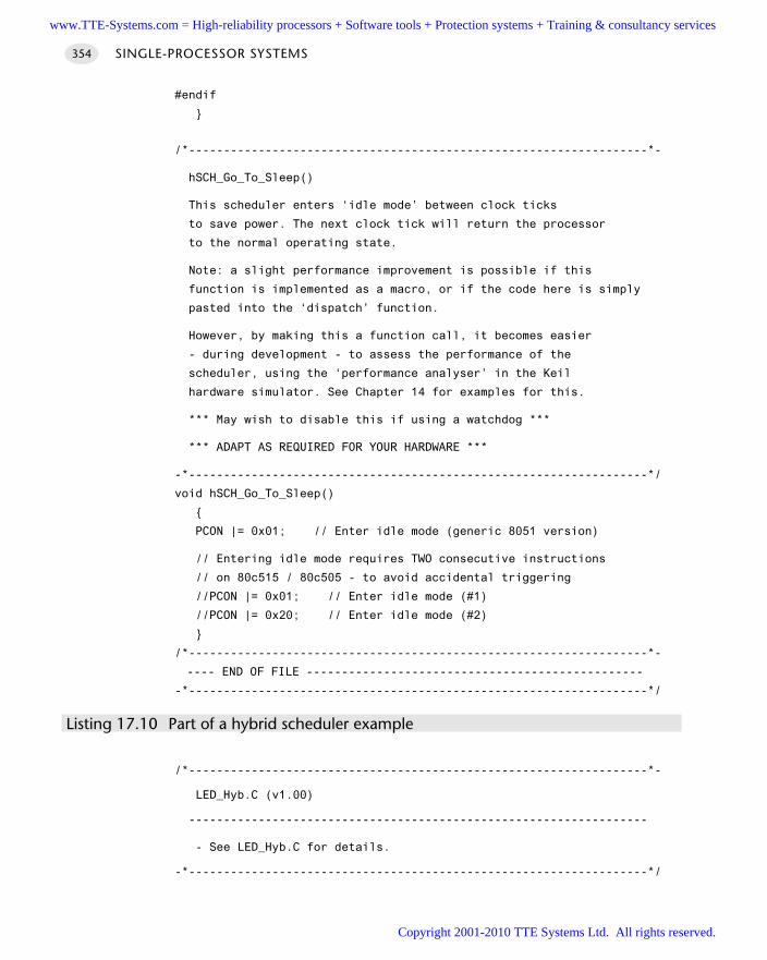
#endif
/*------------------------------------------------------------------*-
hSCH_Go_To_Sleep()
This scheduler enters ‘idle mode’ between clock ticks
to save power. The next clock tick will return the processor
to the normal operating state.
Note: a slight performance improvement is possible if this
function is implemented as a macro, or if the code here is simply
pasted into the ‘dispatch’ function.
However, by making this a function call, it becomes easier
- during development - to assess the performance of the
scheduler, using the ‘performance analyser’ in the Keil
hardware simulator. See Chapter 14 for examples for this.
*** May wish to disable this if using a watchdog ***
*** ADAPT AS REQUIRED FOR YOUR HARDWARE ***
-*------------------------------------------------------------------*/
void hSCH_Go_To_Sleep()
PCON |= 0x01; // Enter idle mode (generic 8051 version)
// Entering idle mode requires TWO consecutive instructions
// on 80c515 / 80c505 - to avoid accidental triggering
//PCON |= 0x01; // Enter idle mode (#1)
//PCON |= 0x20; // Enter idle mode (#2)
/*------------------------------------------------------------------*-
---- END OF FILE ------------------------------------------------
-*------------------------------------------------------------------*/
Listing 17.10 Part of a hybrid scheduler example
/*------------------------------------------------------------------*-
LED_Hyb.C (v1.00)
------------------------------------------------------------------
- See LED_Hyb.C for details.
-*------------------------------------------------------------------*/
SINGLE-PROCESSOR SYSTEMS354
www.TTE-Systems.com = High-reliability processors + Software tools + Protection systems + Training & consultancy services
Copyright 2001-2010 TTE Systems Ltd. All rights reserved.
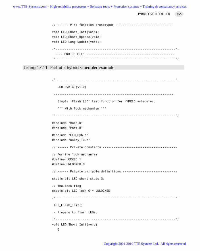
// ------ P ic function prototypes -------------------------------
void LED_Short_Init(void);
void LED_Short_Update(void);
void LED_Long_Update(void);
/*------------------------------------------------------------------*-
---- END OF FILE ------------------------------------------------
-*------------------------------------------------------------------*/
Listing 17.11 Part of a hybrid scheduler example
/*------------------------------------------------------------------*-
LED_Hyb.C (v1.0)
------------------------------------------------------------------
Simple ‘Flash LED’ test function for HYBRID scheduler.
*** With lock mechanism ***
-*------------------------------------------------------------------*/
#include "Main.h"
#include "Port.H"
#include "LED_Hyb.h"
#include "Delay_T0.h"
// ------ Private constants -----------------------------------------
// For the lock mechanism
#define LOCKED 1
#define UNLOCKED 0
// ------ Private variable definitions ------------------------------
static bit LED_short_state_G;
// The lock flag
static bit LED_lock_G = UNLOCKED;
/*------------------------------------------------------------------*-
LED_Flash_Init()
- Prepare to flash LEDs.
-*------------------------------------------------------------------*/
void LED_Short_Init(void)
HYBRID SCHEDULER 355
www.TTE-Systems.com = High-reliability processors + Software tools + Protection systems + Training & consultancy services
Copyright 2001-2010 TTE Systems Ltd. All rights reserved.
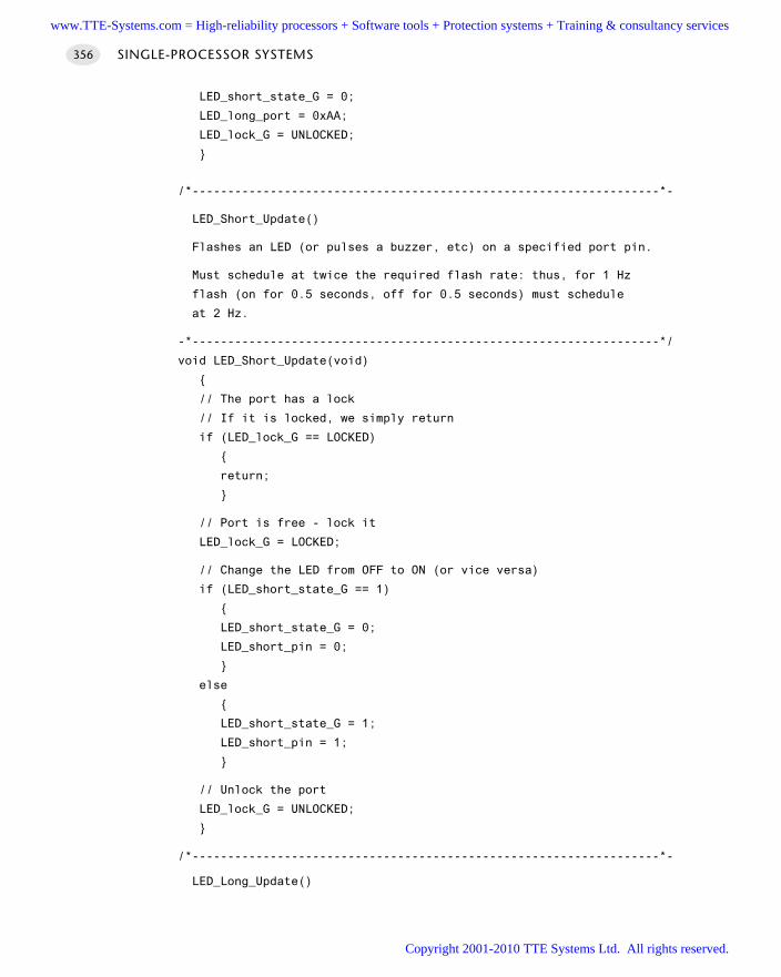
LED_short_state_G = 0;
LED_long_port = 0xAA;
LED_lock_G = UNLOCKED;
/*------------------------------------------------------------------*-
LED_Short_Update()
Flashes an LED (or pulses a buzzer, etc) on a specified port pin.
Must schedule at twice the required flash rate: thus, for 1 Hz
flash (on for 0.5 seconds, off for 0.5 seconds) must schedule
at 2 Hz.
-*------------------------------------------------------------------*/
void LED_Short_Update(void)
// The port has a lock
// If it is locked, we simply return
if (LED_lock_G == LOCKED)
return;
// Port is free - lock it
LED_lock_G = LOCKED;
// Change the LED from OFF to ON (or vice versa)
if (LED_short_state_G == 1)
LED_short_state_G = 0;
LED_short_pin = 0;
else
LED_short_state_G = 1;
LED_short_pin = 1;
// Unlock the port
LED_lock_G = UNLOCKED;
/*------------------------------------------------------------------*-
LED_Long_Update()
SINGLE-PROCESSOR SYSTEMS356
www.TTE-Systems.com = High-reliability processors + Software tools + Protection systems + Training & consultancy services
Copyright 2001-2010 TTE Systems Ltd. All rights reserved.
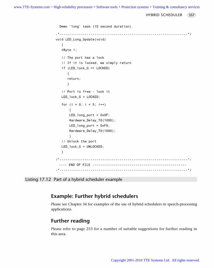
Demo 'long' task (10 second duration).
-*------------------------------------------------------------------*/
void LED_Long_Update(void)
tByte i;
// The port has a lock
// If it is locked, we simply return
if (LED_lock_G == LOCKED)
return;
// Port is free - lock it
LED_lock_G = LOCKED;
for (i = 0; i < 5; i++)
LED_long_port = 0x0F;
Hardware_Delay_T0(1000);
LED_long_port = 0xF0;
Hardware_Delay_T0(1000);
// Unlock the port
LED_lock_G = UNLOCKED;
/*------------------------------------------------------------------*-
---- END OF FILE ------------------------------------------------
-*------------------------------------------------------------------*/
Listing 17.12 Part of a hybrid scheduler example
Example: Further hybrid schedulersPlease see Chapter 34 for examples of the use of hybrid schedulers in speech-processingapplications.
Further readingPlease refer to page 253 for a number of suitable suggestions for further reading inthis area.
HYBRID SCHEDULER 357
www.TTE-Systems.com = High-reliability processors + Software tools + Protection systems + Training & consultancy services
Copyright 2001-2010 TTE Systems Ltd. All rights reserved.

www.TTE-Systems.com = High-reliability processors + Software tools + Protection systems + Training & consultancy services
Copyright 2001-2010 TTE Systems Ltd. All rights reserved.
The user interface
In this part, we will consider some key patterns suitable for assisting in the creation of user
interfaces for a wide range of embedded applications.
In Chapter 18, we present P C L I N K (R S -232) [page 364]. This pattern considers how,
using the universal ‘RS-232’ standard, we can transfer data between an embedded device
and a desktop, notebook or similar PC. In addition to being a useful pattern in its own
right, this pattern illustrates many of the features required in software developed for a co-
operatively scheduled environment.
In Chapter 19, we will explore techniques for reading inputs from switches: here we will
be concerned with both software-only and hardware-based interfaces. In Chapter 20, we
will see how the same basic techniques may be extended to work efficiently with keypads.
In Chapter 21, we turn our attention to the creation of LED displays. In particular, we will
be concerned with multiplexed LED interfaces, which are the only cost-effective solution in
most applications.
Finally, in Chapter 22, we will consider how to control LCD (text) displays. In this chapter
we will be specifically concerned with the interaction with displays based on the ubiqui-
tous Hitachi HD44780 LCD controller chip.
part dwww.TTE-Systems.com = High-reliability processors + Software tools + Protection systems + Training & consultancy services
Copyright 2001-2010 TTE Systems Ltd. All rights reserved.
www.TTE-Systems.com = High-reliability processors + Software tools + Protection systems + Training & consultancy services
Copyright 2001-2010 TTE Systems Ltd. All rights reserved.
Communicating with PCs via RS-232
Introduction
In this chapter we present P C L I N K (R S -232) . This pattern describes how, using theuniversal ‘RS-232’ standard, we can transfer data between an embedded device and adesktop, notebook or similar PC.
chapter 18
Note: We are not concerned here with the process of transferring data betweentwo (or more) microcontrollers: this is discussed in Part F.
www.TTE-Systems.com = High-reliability processors + Software tools + Protection systems + Training & consultancy services
Copyright 2001-2010 TTE Systems Ltd. All rights reserved.
PC LINK (RS-232)
Context You are developing an embedded application using one or more members of the
8051 family of microcontrollers.
The application has a time-triggered architecture, constructed using a scheduler.
You are creating the user interface for your application.
ProblemHow do you link your embedded application to a desktop (or notebook or hand-held)PC using ‘RS-232’?
BackgroundThis pattern is concerned with the use of what is commonly referred to as the RS-232communication protocol, to transfer data between an 8051 microcontroller and someform of personal computer (PC, notebook or similar).
We provide some important background information on RS-232 in this section. Webegin, however, by considering some important terminology used in the communica-tions area.
What are ‘simplex’, ‘half-duplex’ and ‘duplex’ serial communications?
In a simplex serial communication system, we typically require at least two wires(’signal’ and ‘ground’). Data transfer is only in one direction: for example, we mighttransfer data from a simple data-monitoring system to a PC using simplex data transfer.
In a half-duplex serial communication system we again (typically) require at leasttwo wires. Here, data transfer can be in both directions. However, transmission canonly be in one direction at a time. In a variation of the data-monitoring example, wemight use a half-duplex communication strategy to allow us to send information tothe embedded module (to set parameters, such as sampling rate). We might also, atother times, use the same link to download the data from the embedded board to a PC.
In a full-duplex serial communication system, we typically require at least threewires (Signal A, Signal B, Ground). The line Signal A will carry data in one direction atthe same time that Signal B carries data in the other direction.
What is ‘RS-232’?
In 1997 the Telecommunications Industry Association released what is formallyknown as TIA-232 Version F, a serial communication protocol which has been
THE USER INTERFACE362
www.TTE-Systems.com = High-reliability processors + Software tools + Protection systems + Training & consultancy services
Copyright 2001-2010 TTE Systems Ltd. All rights reserved.
universally referred to as ‘RS-232’ since its first ‘Recommended Standard’ appeared in the1960s. Similar standards (V.28) are published by the International TelecommunicationsUnion (ITU) and by CCITT (Consultative Committee International Telegraphand Telephone).
The ‘RS-232’ standard includes details of:
The protocol to be used for data transmission.
The voltages to be used on the signal lines.
The connectors to be used to link equipment together.
Overall, the standard is comprehensive and widely used, at data transfer rates ofup to around 115 or 330 kbits / second (115 / 330 k baud). Data transfer can be overdistances of 15 metres or more.
Note that RS-232 is a peer-to-peer communication standard. Unlike the multi-dropRS-485 standard (which we consider in Chapter 27), RS-232 is intended to link onlytwo devices together.
Basic RS-232 protocol
RS-232 is a character-oriented protocol. That is, it is intended to be used to sendsingle 8-bit blocks of data. To transmit a byte of data over an RS-232 link, we gener-ally encode the information as follows:
We send a ‘Start’ bit.
We send the data (8 bits).
We send a ‘Stop’ bit (or bits).
We consider each of these stages here.
Quiescent state
When no data are being sent on an RS-232 ‘transmit’ line, the line is held at aLogic 1 level.
Start bit
To indicate the start of a data transmission we pull the ‘transmit’ line low.
Data
Data are often encoded in ASCII (American Standard Code for InformationInterchange), in 7-bit form. The bits are sent least significant bit first. If we are send-ing 7-bit data, the eighth data bit is often used as a simple parity check bit and istransmitted in order to provide a rudimentary error detection facility on a character-by-character basis.
Note that none of the code presented here uses parity bits: we use all 8 bits fordata transfer.
PC LINK (RS–232) 363
www.TTE-Systems.com = High-reliability processors + Software tools + Protection systems + Training & consultancy services
Copyright 2001-2010 TTE Systems Ltd. All rights reserved.
Stop bit(s)
The stop bits consist of a Logic 1 output. These can be 1 or, less commonly, 1G or 2pulses wide.
Note that we will use a single stop bit in all code example.
Asynchronous data transmission and baud rates
RS-232 uses an asynchronous protocol. This means that no clock signal is sent withthe data. Instead, both ends of the communication link have an internal clock, run-ning at the same rate. The data (in the case of RS-232, the ‘Start’ bit) is then used tosynchronize the clocks, if necessary, to ensure successful data transfer.
RS-232 generally operates at one of a (restricted) range of baud rates. Typicallythese are: 75, 110, 300, 1,200, 2,400, 4,800, 9,600, 14,400, 19,200, 28,800, 33,600,56,000, 115,000 and (rarely) 330,000 baud. Of these, 9,600 baud is a very ‘safe’choice, as it is very widely supported.
RS-232 voltage levels
The threshold levels used by the receiver are +3V and -3V and the lines are inverted.The maximum voltage allowed is +/- 15V.
Note that these voltages cannot be obtained directly from the naked microcon-troller port pins: some form of interface hardware is required. For example, theMaxim Max232 and Max233 are popular and widely used line driver chips; we con-sider how to use such chips in ‘Solution’.
Flow control
RS-232 is often used with some form of flow control. This is a protocol, implementedthrough software or hardware, that allows a receiver of data to tell the transmitter topause the dataflow. This might be necessary, for example, if we were sending data to aPC and the PC had filled a RAM buffer: the PC would then tell our embedded applica-tion to pause the data transfer until the buffer contents had been stored on disk.
Although hardware handshaking can be used, this requires extra signal lines. Themost common flow control technique is ‘Xon / Xoff’ control. This requires a half- orfull-duplex communication link, and can operate as follows:
1 Transmitter sends a byte of data.
2 The receiver is able to receive more data: it does nothing.
3 The transmitter sends another byte of data.
4 Steps 1–3 continue until the receiver cannot accept any more data: it then sends a‘Control s’ (Xoff) character back to the transmitter.
5 The transmitter receives the ‘Xoff’ command and pauses the data transmission.
THE USER INTERFACE364
www.TTE-Systems.com = High-reliability processors + Software tools + Protection systems + Training & consultancy services
Copyright 2001-2010 TTE Systems Ltd. All rights reserved.
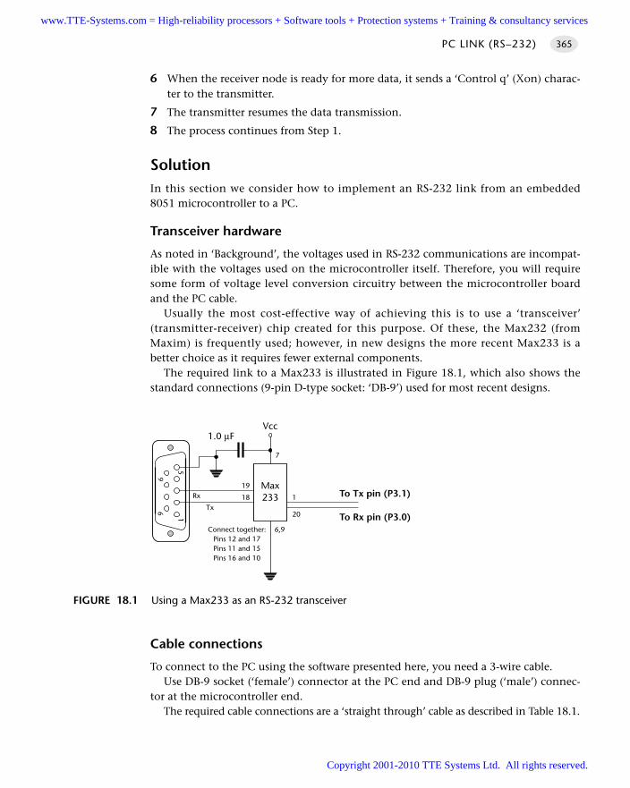
6 When the receiver node is ready for more data, it sends a ‘Control q’ (Xon) charac-ter to the transmitter.
7 The transmitter resumes the data transmission.
8 The process continues from Step 1.
SolutionIn this section we consider how to implement an RS-232 link from an embedded8051 microcontroller to a PC.
Transceiver hardware
As noted in ‘Background’, the voltages used in RS-232 communications are incompat-ible with the voltages used on the microcontroller itself. Therefore, you will requiresome form of voltage level conversion circuitry between the microcontroller boardand the PC cable.
Usually the most cost-effective way of achieving this is to use a ‘transceiver’(transmitter-receiver) chip created for this purpose. Of these, the Max232 (fromMaxim) is frequently used; however, in new designs the more recent Max233 is abetter choice as it requires fewer external components.
The required link to a Max233 is illustrated in Figure 18.1, which also shows thestandard connections (9-pin D-type socket: ‘DB-9’) used for most recent designs.
Cable connections
To connect to the PC using the software presented here, you need a 3-wire cable. Use DB-9 socket (‘female’) connector at the PC end and DB-9 plug (‘male’) connec-
tor at the microcontroller end.The required cable connections are a ‘straight through’ cable as described in Table 18.1.
PC LINK (RS–232) 365
FIGURE 18.1 Using a Max233 as an RS-232 transceiver
1
69
5
Max233
Vcc1.0 µF
To Tx pin (P3.1)
To Rx pin (P3.0)
19
18 1
20
6,9
7
Tx
Rx
Connect together:Pins 12 and 17Pins 11 and 15Pins 16 and 10
www.TTE-Systems.com = High-reliability processors + Software tools + Protection systems + Training & consultancy services
Copyright 2001-2010 TTE Systems Ltd. All rights reserved.
The software architecture
Suppose we wish to transfer data to a PC at a standard 9,600 baud rate; that is, 9,600bits per second. As we discussed in ‘Background’, transmitting each byte of data, plusstop and start bits, involves the transmission of ten bits of information (assuming asingle stop bit is used). As a result, each byte takes approximately 1 ms to transmit.
This has important implications in all applications, not least those using a sched-uler. If, for example, we wish to send this information to the PC:
Current core temperature is 36.678 degrees
then the task sending these 42 characters will take more than 40 milliseconds tocomplete. This will frequently be an unacceptably long duration.
The most obvious way of solving this problem is to increase the baud rate; how-ever, this is not always possible and it does not solve the underlying problem.
A better solution is to write all data to a buffer in the microcontroller. The contentsof this buffer will then be sent – usually one byte at a time – to the PC, using a regu-lar, scheduled task.
This solution is used in the code libraries presented in the following sections andincluded on the accompanying CD. The architecture is a good example of a M U LT I -S TA G E TA S K [page 317], and is frequently used in user-interface libraries: L C D
C H A R A C T E R PA N E L [page 467], for example, uses a very similar architecture.
Using the on-chip U(S)ART for RS-232 communications
Having decided on the basic architecture for the RS-232 library, we need to considerin more detail how the on-chip serial port is used.
This port is full duplex, meaning it can transmit and receive simultaneously. It isalso receive buffered, meaning it can commence reception of a second byte before apreviously received byte has been read from the receive register. (However, if the firstbyte still has not been read by the time reception of the second byte is complete, oneof the bytes will be lost.)
The serial port can operate in four modes (one synchronous mode, three asynchro-nous modes). In this pattern, we are primarily interested in Mode 1. In this mode, 10bits are transmitted (through TxD) or received (through RxD): a start bit (0), 8 databits (lsb first), and a stop bit (1).
THE USER INTERFACE366
TABLE 18.1 Connections required for a ‘straight through’ cable needed to link the microcontroller to the desktop PC (or similar terminal)
PC (COM1, COM2) MicrocontrollerDB-9 connector DB-9 connector
RxD – Pin 2 to TxD – Pin 2
TxD – Pin 3 to RxD – Pin 3
Ground – Pin 5 to Ground – Pin 5
www.TTE-Systems.com = High-reliability processors + Software tools + Protection systems + Training & consultancy services
Copyright 2001-2010 TTE Systems Ltd. All rights reserved.
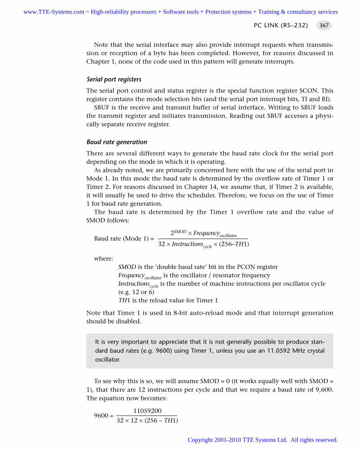
Note that the serial interface may also provide interrupt requests when transmis-sion or reception of a byte has been completed. However, for reasons discussed inChapter 1, none of the code used in this pattern will generate interrupts.
Serial port registers
The serial port control and status register is the special function register SCON. Thisregister contains the mode selection bits (and the serial port interrupt bits, TI and RI).
SBUF is the receive and transmit buffer of serial interface. Writing to SBUF loadsthe transmit register and initiates transmission. Reading out SBUF accesses a physi-cally separate receive register.
Baud rate generation
There are several different ways to generate the baud rate clock for the serial portdepending on the mode in which it is operating.
As already noted, we are primarily concerned here with the use of the serial port inMode 1. In this mode the baud rate is determined by the overflow rate of Timer 1 orTimer 2. For reasons discussed in Chapter 14, we assume that, if Timer 2 is available,it will usually be used to drive the scheduler. Therefore, we focus on the use of Timer1 for baud rate generation.
The baud rate is determined by the Timer 1 overflow rate and the value ofSMOD follows:
2SMOD × FrequencyoscillatorBaud rate (Mode 1) = 32 × Instructionscycle × (256–TH1)
where:SMOD is the ‘double baud rate’ bit in the PCON registerFrequencyoscillator is the oscillator / resonator frequencyInstructionscycle is the number of machine instructions per oscillator cycle(e.g. 12 or 6)TH1 is the reload value for Timer 1
Note that Timer 1 is used in 8-bit auto-reload mode and that interrupt generationshould be disabled.
To see why this is so, we will assume SMOD = 0 (it works equally well with SMOD =1), that there are 12 instructions per cycle and that we require a baud rate of 9,600.The equation now becomes:
110592009600 =
32 × 12 × (256 – TH1)
PC LINK (RS–232) 367
It is very important to appreciate that it is not generally possible to produce stan-dard baud rates (e.g. 9600) using Timer 1, unless you use an 11.0592 MHz crystaloscillator.
www.TTE-Systems.com = High-reliability processors + Software tools + Protection systems + Training & consultancy services
Copyright 2001-2010 TTE Systems Ltd. All rights reserved.
This becomes:
11059200= 256 – TH1
9600 × 384
Or:
256 – TH1 = 3
Thus, if we set TH1 to 253 (0xFD) we get a precise 9,600 baud rate.If, for example, we repeat this with a 12 MHz oscillator, we get:
12000000= 256 – TH1
9600 × 384
Or:
256 – TH1 = 3.255208333333
Thus, the required value of TH1 is 252.7447916667.The nearest integer value is 253. This means that our actual baud rate will be
approximately 10,417 baud – more than 8% higher than the required (9,600) rate.
Dealing with the 11.0592 MHz problem
In a scheduled application, using an 11.0592 MHz crystal oscillator is not ideal.11.0592 MHz may translate into precise baud rates, but it is not ideal as a source of‘ticks’ in the scheduler: in particular, it is impossible to produce precise 1 ms ticksfrom an 8051 device driven by an 11.0592 MHz crystal.
THE USER INTERFACE368
Remember: This is an asynchronous protocol and relies for correct operation onthe fact that both ends of the connection are working at the same baud rate.In practice, you can generally work with a difference in baud rates at both ends ofthe connection by up to 5%, but no more.
Despite the possible 5% margin, it is always good policy to get the baud rate asclose as possible to the standard value because, in the field, there may be signifi-cant temperature variations between the oscillator in the PC and that in theembedded system. This will lead to a ‘drift’ in baud rates on PC and microcontroller,even if they were precisely the same to start with: as a result, if the baud rates wereinitially mismatched, then communication with the PC may fail completely duringnormal use. This type of ‘inexplicable fault’ has caused many developers sleeplessnights (’I don’t understand it! It works fine in all the tests in the lab!’).
Note also that it is generally essential to use some form of crystal oscillator(rather than a ceramic resonator) when working with asynchronous serial links (such asRS-232, RS-485 or CAN): the ceramic resonator is not sufficiently stable for this purpose:see C R Y S TA L O S C I L L AT O R [page 54] and C E R A M I C R E S O N AT O R [page 64]for details.
www.TTE-Systems.com = High-reliability processors + Software tools + Protection systems + Training & consultancy services
Copyright 2001-2010 TTE Systems Ltd. All rights reserved.
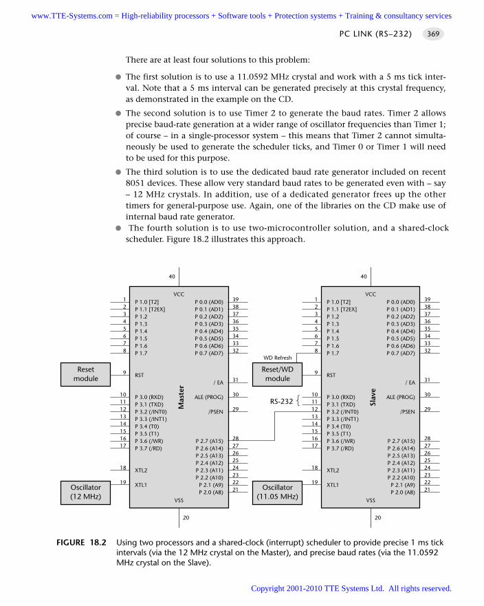
There are at least four solutions to this problem:
The first solution is to use a 11.0592 MHz crystal and work with a 5 ms tick inter-val. Note that a 5 ms interval can be generated precisely at this crystal frequency,as demonstrated in the example on the CD.
The second solution is to use Timer 2 to generate the baud rates. Timer 2 allowsprecise baud-rate generation at a wider range of oscillator frequencies than Timer 1;of course – in a single-processor system – this means that Timer 2 cannot simulta-neously be used to generate the scheduler ticks, and Timer 0 or Timer 1 will needto be used for this purpose.
The third solution is to use the dedicated baud rate generator included on recent8051 devices. These allow very standard baud rates to be generated even with – say– 12 MHz crystals. In addition, use of a dedicated generator frees up the othertimers for general-purpose use. Again, one of the libraries on the CD make use ofinternal baud rate generator.
The fourth solution is to use two-microcontroller solution, and a shared-clockscheduler. Figure 18.2 illustrates this approach.
PC LINK (RS–232) 369
FIGURE 18.2 Using two processors and a shared-clock (interrupt) scheduler to provide precise 1 ms tickintervals (via the 12 MHz crystal on the Master), and precise baud rates (via the 11.0592MHz crystal on the Slave).
P 1.0 [T2]P 1.1 [T2EX]P 1.2P 1.3P 1.4P 1.5P 1.6P 1.7
RST
P 3.0 (RXD)P 3.1 (TXD)P 3.2 (/INT0)P 3.3 (/INT1)P 3.4 (T0)P 3.5 (T1)P 3.6 (/WR)P 3.7 (/RD)
XTL2
XTL1
P 0.0 (AD0)P 0.1 (AD1)P 0.2 (AD2)P 0.3 (AD3)P 0.4 (AD4)P 0.5 (AD5)P 0.6 (AD6)P 0.7 (AD7)
/ EA
ALE (PROG)
/PSEN
P 2.7 (A15)P 2.6 (A14)P 2.5 (A13)P 2.4 (A12)P 2.3 (A11)P 2.2 (A10)
P 2.1 (A9)P 2.0 (A8)
VCC
Mas
ter
VSS
3938373635343332
31
30
29
2827262524232221
12345678
9
1011121314151617
18
19
20
40
P 1.0 [T2]P 1.1 [T2EX]P 1.2P 1.3P 1.4P 1.5P 1.6P 1.7
RST
P 3.0 (RXD)P 3.1 (TXD)P 3.2 (/INT0)P 3.3 (/INT1)P 3.4 (T0)P 3.5 (T1)P 3.6 (/WR)P 3.7 (/RD)
XTL2
XTL1
P 0.0 (AD0)P 0.1 (AD1)P 0.2 (AD2)P 0.3 (AD3)P 0.4 (AD4)P 0.5 (AD5)P 0.6 (AD6)P 0.7 (AD7)
/ EA
ALE (PROG)
/PSEN
P 2.7 (A15)P 2.6 (A14)P 2.5 (A13)P 2.4 (A12)P 2.3 (A11)P 2.2 (A10)
P 2.1 (A9)P 2.0 (A8)
VCC
Slav
e
VSS
3938373635343332
31
30
29
2827262524232221
12345678
9
1011121314151617
18
19
20
40
Oscillator(11.05 MHz)
Reset/WDmodule
WD Refresh
RS-232
Oscillator(12 MHz)
Resetmodule
www.TTE-Systems.com = High-reliability processors + Software tools + Protection systems + Training & consultancy services
Copyright 2001-2010 TTE Systems Ltd. All rights reserved.
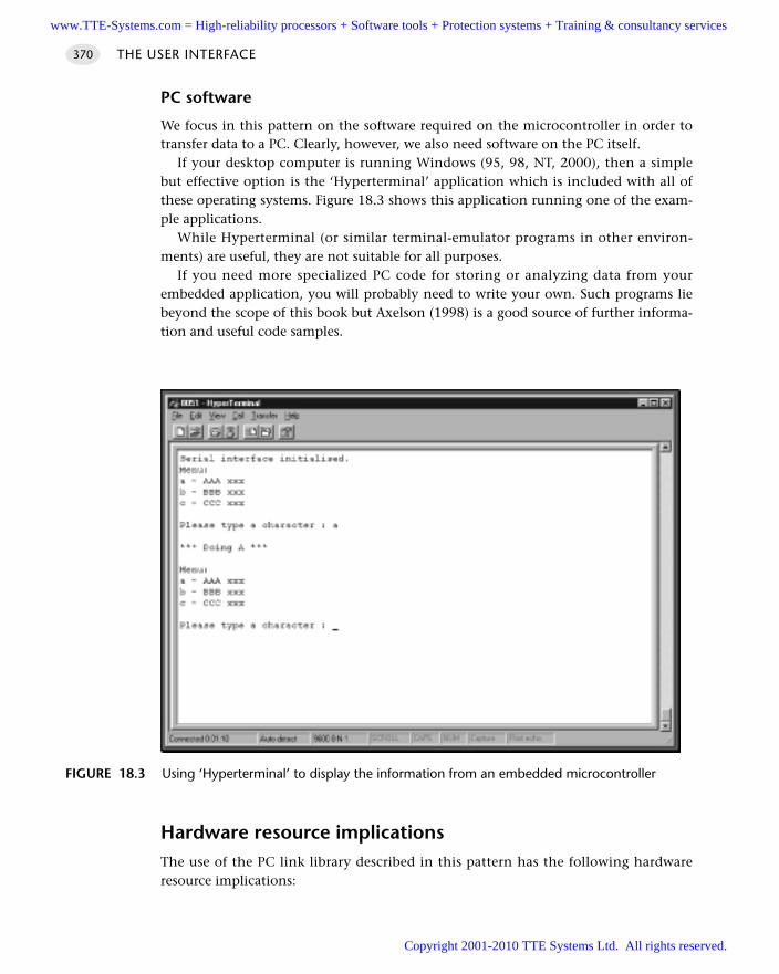
PC software
We focus in this pattern on the software required on the microcontroller in order totransfer data to a PC. Clearly, however, we also need software on the PC itself.
If your desktop computer is running Windows (95, 98, NT, 2000), then a simplebut effective option is the ‘Hyperterminal’ application which is included with all ofthese operating systems. Figure 18.3 shows this application running one of the exam-ple applications.
While Hyperterminal (or similar terminal-emulator programs in other environ-ments) are useful, they are not suitable for all purposes.
If you need more specialized PC code for storing or analyzing data from yourembedded application, you will probably need to write your own. Such programs liebeyond the scope of this book but Axelson (1998) is a good source of further informa-tion and useful code samples.
Hardware resource implicationsThe use of the PC link library described in this pattern has the following hardwareresource implications:
THE USER INTERFACE370
FIGURE 18.3 Using ‘Hyperterminal’ to display the information from an embedded microcontroller
www.TTE-Systems.com = High-reliability processors + Software tools + Protection systems + Training & consultancy services
Copyright 2001-2010 TTE Systems Ltd. All rights reserved.
It uses the UART.
It uses two port pins (P3.0, P3.1).
It uses either a general-purpose timer or a specialized baud rate generator circuit.
Overall, however, it is the memory load that causes greatest difficulty, particularlyin situations where only internal memory is available. The root of this difficulty isthat fact that, as we discussed in ‘Solution’, the architecture used (to transmit data tothe PC) is based on the use of a buffer to which the user writes as required; this bufferis then emptied, one character at a time, by a scheduled task.1
The buffer itself is very simple:
// The transmit buffer length
#define PC_LINK_TRAN_BUFFER_LENGTH 100
static tByte Tran_buffer[PC_LINK_TRAN_BUFFER_LENGTH];
If you run out of memory, there are several options:
You can reduce the buffer size. This may mean that tasks in your applications mustbreak down the data they send into smaller blocks. Typically, the main implicationis that shorter strings must be used.
You can increase the baud rate and adapt the code so that the scheduler sendsmore than one byte of data in every time the ‘update’ function is run.
If using on-chip memory only, you can choose an 8051 device with additional on-chip RAM: for example, Dallas and Infineon produce a number of such devices. Wediscuss how to make use of this memory in O F F-C H I P D ATA M E M O RY [page 94].
Reliability and safety issuesWe consider the reliability and safety implications of RS-232 communications in thissection.
What about printf()?
We do not generally recommend the use of standard library functions, such asprintf(), because:
This function sends data immediately to the UART. As a result, the duration of thetransmission is usually too long to be safely handled in a co-operatively scheduledapplication.
Most implementations of printf() do not incorporate timeouts, making it possi-ble that use of this functions can ‘hang’ the whole application if errors occur.
PC LINK (RS–232) 371
1. Note that while both the ‘transmit’ and (where available) ‘receive’ channels have associated buffers,the transmit buffer is usually larger than the recieve buffer, since – in most cases – the direction ofdataflow is from the microcontroller to the PC. As a result, we focus on the transmit buffer here.However, similar concerns – and solutions – apply to the receive buffer in circumstances where themain direction of information flow is from the PC to the microcontroller.
www.TTE-Systems.com = High-reliability processors + Software tools + Protection systems + Training & consultancy services
Copyright 2001-2010 TTE Systems Ltd. All rights reserved.
If you are determined to use printf(), refer to Chapter 10 where a simple libraryusing this function is presented.
General comments
The RS-232 protocol does not provide any adequate form of error checking: you needto carry this out manually. A simple approach is to send important data to the PC two(or more) times and compare the two (or more) versions: if there is a mismatch, havethe data sent again. Clearly, this approach greatly increases the required communica-tion bandwidth.
PortabilityThe UART is part of the 8051 core: therefore if your application has a UART-based RS-232 interface it will generally be portable. However, use of non-core features (likededicated baud rate generators or more than one serial port) will dramatically reducethe porting opportunities.
Overall strengths and weaknessesRS-232 support is part of the 8051 core: applications based on RS-232 arevery portable.
At the PC end too, RS-232 is ubiquitous: every PC has one or more RS-232ports.
Links can – with modern transceiver chips – be up to 30 m (100 ft) inlength.
Because of the hardware support, RS-232 generally imposes a low softwareload.
RS-232 is a peer-to-peer protocol (unlike, for example, RS-485: see Chapter 27):you can only connect one microcontroller directly (simultaneously) to each PC.
RS-232 has little or no error checking at the hardware level (unlike, for exam-ple, CAN: see Chapter 28): if you want to be sure that the data you received atthe PC are valid, you need to carry out checks in software.
Related patterns and alternative solutionsThere are several related patterns and some alternative solutions. We discuss these here.
Selecting an oscillator or resonator
As already noted, it is generally essential to use some form of crystal oscillator (ratherthan a ceramic resonator) when working with asynchronous serial links: the ceramicresonator is not sufficiently stable for this purpose: see C RY S TA L O S C I L L AT O R [page 54]and C E R A M I C R E S O N AT O R [page 64] for details.
THE USER INTERFACE372
www.TTE-Systems.com = High-reliability processors + Software tools + Protection systems + Training & consultancy services
Copyright 2001-2010 TTE Systems Ltd. All rights reserved.
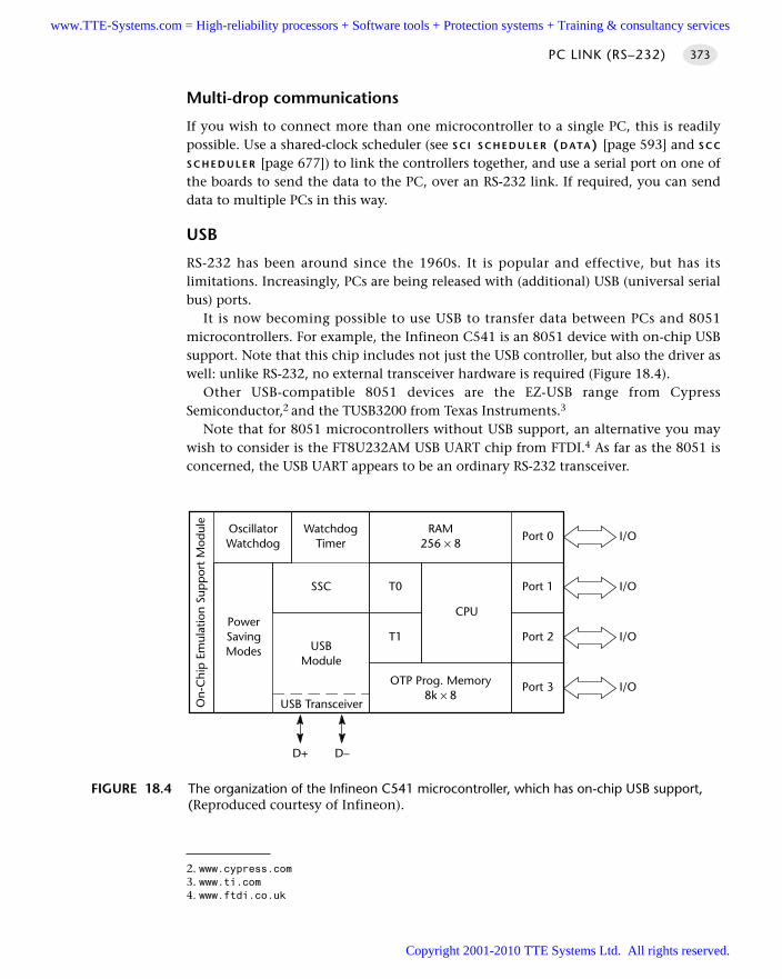
Multi-drop communications
If you wish to connect more than one microcontroller to a single PC, this is readilypossible. Use a shared-clock scheduler (see S C I S C H E D U L E R (D ATA) [page 593] and S C C
S C H E D U L E R [page 677]) to link the controllers together, and use a serial port on one ofthe boards to send the data to the PC, over an RS-232 link. If required, you can senddata to multiple PCs in this way.
USB
RS-232 has been around since the 1960s. It is popular and effective, but has itslimitations. Increasingly, PCs are being released with (additional) USB (universal serialbus) ports.
It is now becoming possible to use USB to transfer data between PCs and 8051microcontrollers. For example, the Infineon C541 is an 8051 device with on-chip USBsupport. Note that this chip includes not just the USB controller, but also the driver aswell: unlike RS-232, no external transceiver hardware is required (Figure 18.4).
Other USB-compatible 8051 devices are the EZ-USB range from CypressSemiconductor,2 and the TUSB3200 from Texas Instruments.3
Note that for 8051 microcontrollers without USB support, an alternative you maywish to consider is the FT8U232AM USB UART chip from FTDI.4 As far as the 8051 isconcerned, the USB UART appears to be an ordinary RS-232 transceiver.
PC LINK (RS–232) 373
FIGURE 18.4 The organization of the Infineon C541 microcontroller, which has on-chip USB support,(Reproduced courtesy of Infineon).
On-
Chi
p E
mul
atio
n Su
pp
ort
Mod
ule
OscillatorWatchdog
WatchdogTimer
RAM256 × 8
Port 0
Port 1T0SSC
T1USB
Module
PowerSavingModes
USB Transceiver
Port 2
Port 3OTP Prog. Memory8k × 8
CPU
D–D+
I/O
I/O
I/O
I/O
2. www.cypress.com3. www.ti.com4. www.ftdi.co.uk
www.TTE-Systems.com = High-reliability processors + Software tools + Protection systems + Training & consultancy services
Copyright 2001-2010 TTE Systems Ltd. All rights reserved.
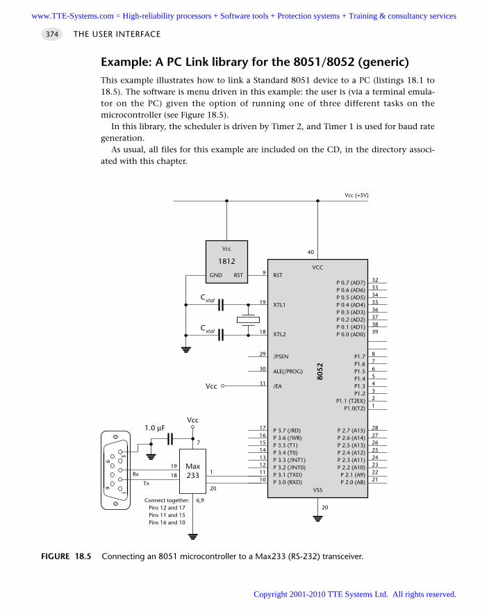
Example: A PC Link library for the 8051/8052 (generic)This example illustrates how to link a Standard 8051 device to a PC (listings 18.1 to18.5). The software is menu driven in this example: the user is (via a terminal emula-tor on the PC) given the option of running one of three different tasks on themicrocontroller (see Figure 18.5).
In this library, the scheduler is driven by Timer 2, and Timer 1 is used for baud rategeneration.
As usual, all files for this example are included on the CD, in the directory associ-ated with this chapter.
THE USER INTERFACE374
FIGURE 18.5 Connecting an 8051 microcontroller to a Max233 (RS-232) transceiver.
1
69
5
Max233
Vcc1.0 µF
19
181
20
6,9
7
Tx
Rx
Connect together:Pins 12 and 17Pins 11 and 15Pins 16 and 10
RST
XTL1
XTL2
/PSEN
ALE(/PROG)
/EA
P 3.7 (/RD)P 3.6 (/WR)P 3.5 (T1)P 3.4 (T0)P 3.3 (/INT1)P 3.2 (/INT0)P 3.1 (TXD)P 3.0 (RXD)
P 0.7 (AD7)P 0.6 (AD6)P 0.5 (AD5)P 0.4 (AD4)P 0.3 (AD3)P 0.2 (AD2)P 0.1 (AD1)P 0.0 (AD0)
P1.7P1.6P1.5P1.4P1.3P1.2
P1.1 (T2EX)P1.0(T2)
P 2.7 (A15)P 2.6 (A14)P 2.5 (A13)P 2.4 (A12)P 2.3 (A11)P 2.2 (A10)
P 2.1 (A9)P 2.0 (A8)
VCC
8052
VSS
3233343536373839
87654321
2827262524232221
9
19
18
29
30
31
1716151413121110
20
40
Vcc
Cxtal
Cxtal
Vcc (+5V)
GND RST
Vcc
1812
www.TTE-Systems.com = High-reliability processors + Software tools + Protection systems + Training & consultancy services
Copyright 2001-2010 TTE Systems Ltd. All rights reserved.
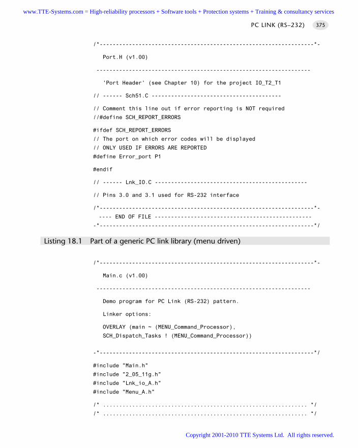
/*------------------------------------------------------------------*-
Port.H (v1.00)
------------------------------------------------------------------
'Port Header' (see Chapter 10) for the project IO_T2_T1
// ------ Sch51.C ----------------------------------------
// Comment this line out if error reporting is NOT required
//#define SCH_REPORT_ERRORS
#ifdef SCH_REPORT_ERRORS
// The port on which error codes will be displayed
// ONLY USED IF ERRORS ARE REPORTED
#define Error_port P1
#endif
// ------ Lnk_IO.C -----------------------------------------------
// Pins 3.0 and 3.1 used for RS-232 interface
/*------------------------------------------------------------------*-
---- END OF FILE ------------------------------------------------
-*------------------------------------------------------------------*/
Listing 18.1 Part of a generic PC link library (menu driven)
/*------------------------------------------------------------------*-
Main.c (v1.00)
------------------------------------------------------------------
Demo program for PC Link (RS-232) pattern.
Linker options:
OVERLAY (main ~ (MENU_Command_Processor),
SCH_Dispatch_Tasks ! (MENU_Command_Processor))
-*------------------------------------------------------------------*/
#include "Main.h"
#include "2_05_11g.h"
#include "Lnk_io_A.h"
#include "Menu_A.h"
/* ............................................................... */
/* ............................................................... */
PC LINK (RS–232) 375
www.TTE-Systems.com = High-reliability processors + Software tools + Protection systems + Training & consultancy services
Copyright 2001-2010 TTE Systems Ltd. All rights reserved.
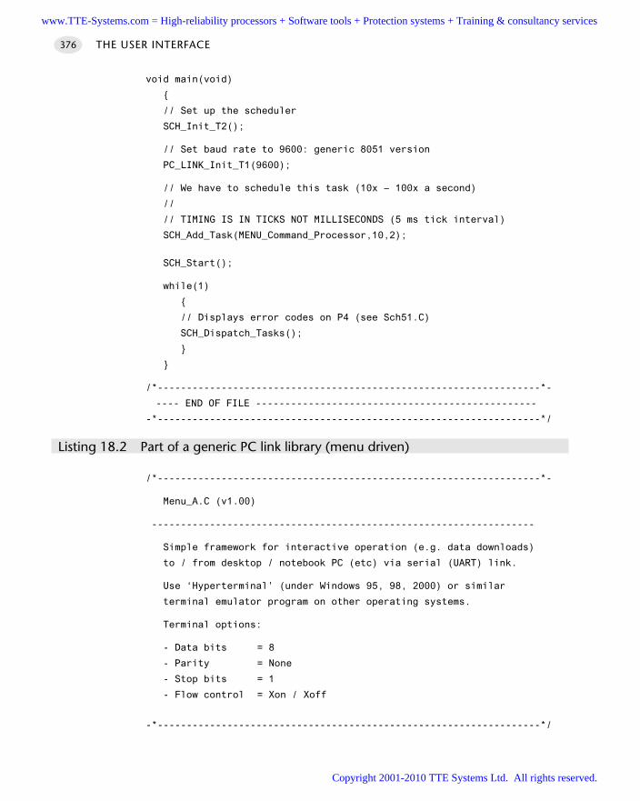
void main(void)
// Set up the scheduler
SCH_Init_T2();
// Set baud rate to 9600: generic 8051 version
PC_LINK_Init_T1(9600);
// We have to schedule this task (10x – 100x a second)
//
// TIMING IS IN TICKS NOT MILLISECONDS (5 ms tick interval)
SCH_Add_Task(MENU_Command_Processor,10,2);
SCH_Start();
while(1)
// Displays error codes on P4 (see Sch51.C)
SCH_Dispatch_Tasks();
/*------------------------------------------------------------------*-
---- END OF FILE ------------------------------------------------
-*------------------------------------------------------------------*/
Listing 18.2 Part of a generic PC link library (menu driven)
/*------------------------------------------------------------------*-
Menu_A.C (v1.00)
------------------------------------------------------------------
Simple framework for interactive operation (e.g. data downloads)
to / from desktop / notebook PC (etc) via serial (UART) link.
Use ‘Hyperterminal’ (under Windows 95, 98, 2000) or similar
terminal emulator program on other operating systems.
Terminal options:
- Data bits = 8
- Parity = None
- Stop bits = 1
- Flow control = Xon / Xoff
-*------------------------------------------------------------------*/
THE USER INTERFACE376
www.TTE-Systems.com = High-reliability processors + Software tools + Protection systems + Training & consultancy services
Copyright 2001-2010 TTE Systems Ltd. All rights reserved.
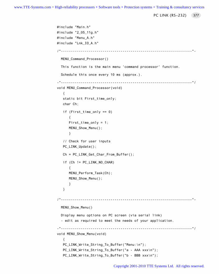
#include "Main.h"
#include "2_05_11g.h"
#include "Menu_A.h"
#include "Lnk_IO_A.h"
/*------------------------------------------------------------------*-
MENU_Command_Processor()
This function is the main menu 'command processor' function.
Schedule this once every 10 ms (approx.).
-*------------------------------------------------------------------*/
void MENU_Command_Processor(void)
static bit First_time_only;
char Ch;
if (First_time_only == 0)
First_time_only = 1;
MENU_Show_Menu();
// Check for user inputs
PC_LINK_Update();
Ch = PC_LINK_Get_Char_From_Buffer();
if (Ch != PC_LINK_NO_CHAR)
MENU_Perform_Task(Ch);
MENU_Show_Menu();
/*------------------------------------------------------------------*-
MENU_Show_Menu()
Display menu options on PC screen (via serial link)
- edit as required to meet the needs of your application.
-*------------------------------------------------------------------*/
void MENU_Show_Menu(void)
PC_LINK_Write_String_To_Buffer("Menu:\n");
PC_LINK_Write_String_To_Buffer("a - AAA xxx\n");
PC_LINK_Write_String_To_Buffer("b - BBB xxx\n");
PC LINK (RS–232) 377
www.TTE-Systems.com = High-reliability processors + Software tools + Protection systems + Training & consultancy services
Copyright 2001-2010 TTE Systems Ltd. All rights reserved.
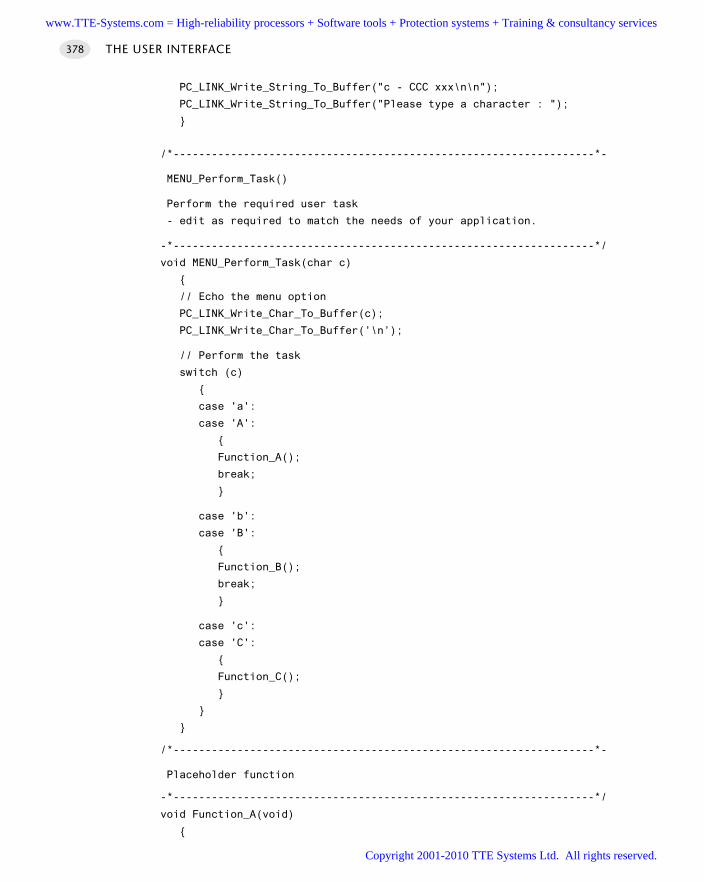
PC_LINK_Write_String_To_Buffer("c - CCC xxx\n\n");
PC_LINK_Write_String_To_Buffer("Please type a character : ");
/*------------------------------------------------------------------*-
MENU_Perform_Task()
Perform the required user task
- edit as required to match the needs of your application.
-*------------------------------------------------------------------*/
void MENU_Perform_Task(char c)
// Echo the menu option
PC_LINK_Write_Char_To_Buffer(c);
PC_LINK_Write_Char_To_Buffer(’\n’);
// Perform the task
switch (c)
case 'a':
case 'A':
Function_A();
break;
case 'b':
case 'B':
Function_B();
break;
case 'c':
case 'C':
Function_C();
/*------------------------------------------------------------------*-
Placeholder function
-*------------------------------------------------------------------*/
void Function_A(void)
THE USER INTERFACE378
www.TTE-Systems.com = High-reliability processors + Software tools + Protection systems + Training & consultancy services
Copyright 2001-2010 TTE Systems Ltd. All rights reserved.
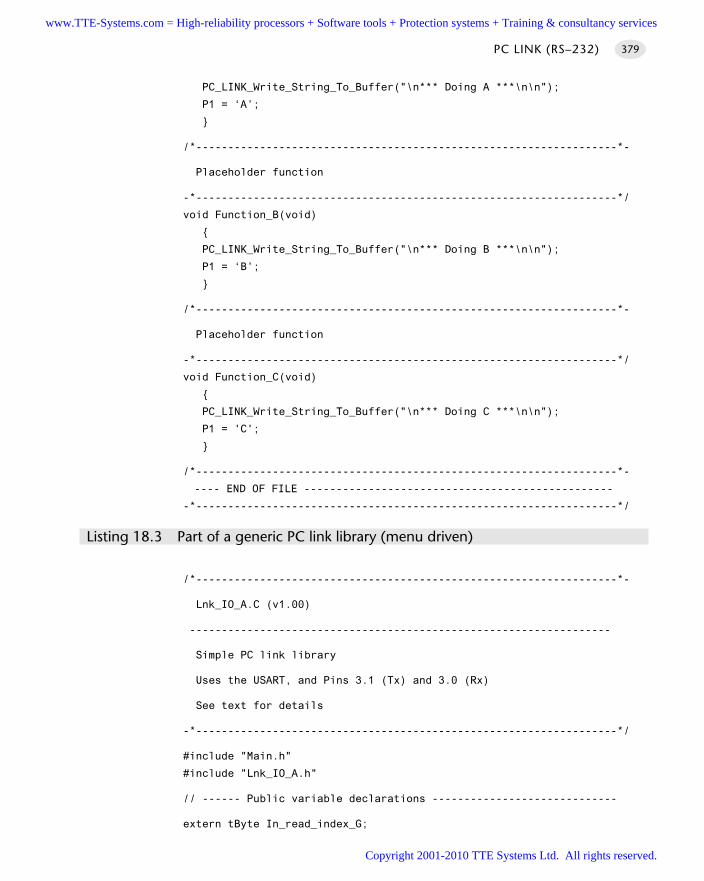
PC_LINK_Write_String_To_Buffer("\n*** Doing A ***\n\n");
P1 = ‘A’;
/*------------------------------------------------------------------*-
Placeholder function
-*------------------------------------------------------------------*/
void Function_B(void)
PC_LINK_Write_String_To_Buffer("\n*** Doing B ***\n\n");
P1 = ‘B’;
/*------------------------------------------------------------------*-
Placeholder function
-*------------------------------------------------------------------*/
void Function_C(void)
PC_LINK_Write_String_To_Buffer("\n*** Doing C ***\n\n");
P1 = 'C';
/*------------------------------------------------------------------*-
---- END OF FILE ------------------------------------------------
-*------------------------------------------------------------------*/
Listing 18.3 Part of a generic PC link library (menu driven)
/*------------------------------------------------------------------*-
Lnk_IO_A.C (v1.00)
------------------------------------------------------------------
Simple PC link library
Uses the USART, and Pins 3.1 (Tx) and 3.0 (Rx)
See text for details
-*------------------------------------------------------------------*/
#include "Main.h"
#include "Lnk_IO_A.h"
// ------ Public variable declarations -----------------------------
extern tByte In_read_index_G;
PC LINK (RS–232) 379
www.TTE-Systems.com = High-reliability processors + Software tools + Protection systems + Training & consultancy services
Copyright 2001-2010 TTE Systems Ltd. All rights reserved.
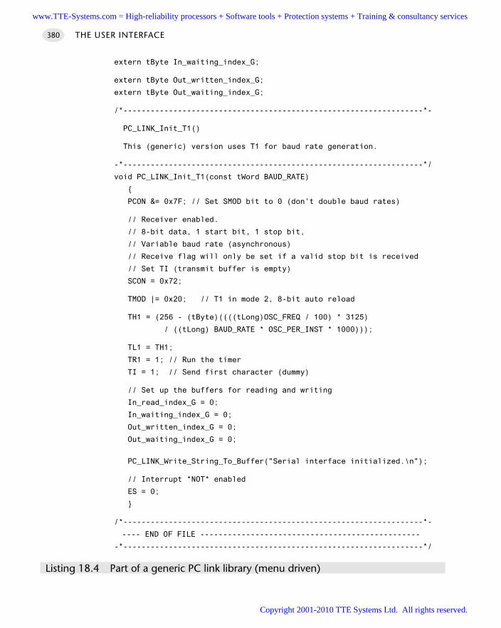
extern tByte In_waiting_index_G;
extern tByte Out_written_index_G;
extern tByte Out_waiting_index_G;
/*------------------------------------------------------------------*-
PC_LINK_Init_T1()
This (generic) version uses T1 for baud rate generation.
-*------------------------------------------------------------------*/
void PC_LINK_Init_T1(const tWord BAUD_RATE)
PCON &= 0x7F; // Set SMOD bit to 0 (don’t double baud rates)
// Receiver enabled.
// 8-bit data, 1 start bit, 1 stop bit,
// Variable baud rate (asynchronous)
// Receive flag will only be set if a valid stop bit is received
// Set TI (transmit buffer is empty)
SCON = 0x72;
TMOD |= 0x20; // T1 in mode 2, 8-bit auto reload
TH1 = (256 - (tByte)((((tLong)OSC_FREQ / 100) * 3125)
/ ((tLong) BAUD_RATE * OSC_PER_INST * 1000)));
TL1 = TH1;
TR1 = 1; // Run the timer
TI = 1; // Send first character (dummy)
// Set up the buffers for reading and writing
In_read_index_G = 0;
In_waiting_index_G = 0;
Out_written_index_G = 0;
Out_waiting_index_G = 0;
PC_LINK_Write_String_To_Buffer("Serial interface initialized.\n");
// Interrupt *NOT* enabled
ES = 0;
/*------------------------------------------------------------------*-
---- END OF FILE ------------------------------------------------
-*------------------------------------------------------------------*/
Listing 18.4 Part of a generic PC link library (menu driven)
THE USER INTERFACE380
www.TTE-Systems.com = High-reliability processors + Software tools + Protection systems + Training & consultancy services
Copyright 2001-2010 TTE Systems Ltd. All rights reserved.
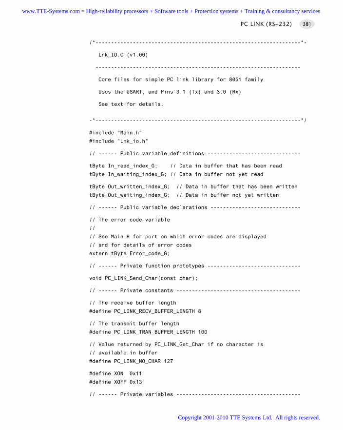
/*------------------------------------------------------------------*-
Lnk_IO.C (v1.00)
------------------------------------------------------------------
Core files for simple PC link library for 8051 family
Uses the USART, and Pins 3.1 (Tx) and 3.0 (Rx)
See text for details.
-*------------------------------------------------------------------*/
#include "Main.h"
#include "Lnk_io.h"
// ------ Public variable definitions ------------------------------
tByte In_read_index_G; // Data in buffer that has been read
tByte In_waiting_index_G; // Data in buffer not yet read
tByte Out_written_index_G; // Data in buffer that has been written
tByte Out_waiting_index_G; // Data in buffer not yet written
// ------ Public variable declarations -----------------------------
// The error code variable
//
// See Main.H for port on which error codes are displayed
// and for details of error codes
extern tByte Error_code_G;
// ------ Private function prototypes ------------------------------
void PC_LINK_Send_Char(const char);
// ------ Private constants ----------------------------------------
// The receive buffer length
#define PC_LINK_RECV_BUFFER_LENGTH 8
// The transmit buffer length
#define PC_LINK_TRAN_BUFFER_LENGTH 100
// Value returned by PC_LINK_Get_Char if no character is
// available in buffer
#define PC_LINK_NO_CHAR 127
#define XON 0x11
#define XOFF 0x13
// ------ Private variables ----------------------------------------
PC LINK (RS–232) 381
www.TTE-Systems.com = High-reliability processors + Software tools + Protection systems + Training & consultancy services
Copyright 2001-2010 TTE Systems Ltd. All rights reserved.
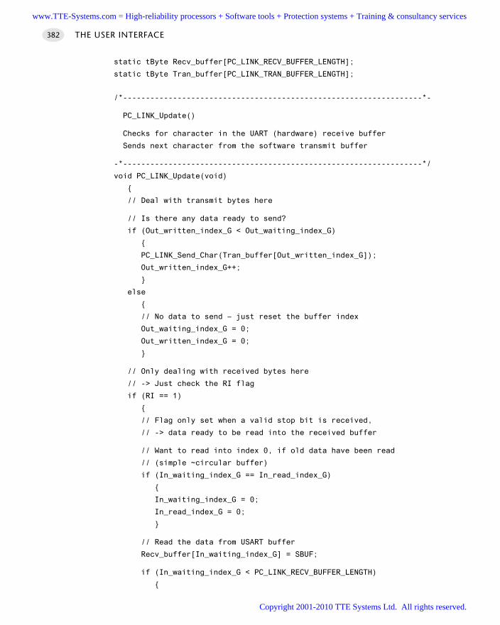
static tByte Recv_buffer[PC_LINK_RECV_BUFFER_LENGTH];
static tByte Tran_buffer[PC_LINK_TRAN_BUFFER_LENGTH];
/*------------------------------------------------------------------*-
PC_LINK_Update()
Checks for character in the UART (hardware) receive buffer
Sends next character from the software transmit buffer
-*------------------------------------------------------------------*/
void PC_LINK_Update(void)
// Deal with transmit bytes here
// Is there any data ready to send?
if (Out_written_index_G < Out_waiting_index_G)
PC_LINK_Send_Char(Tran_buffer[Out_written_index_G]);
Out_written_index_G++;
else
// No data to send – just reset the buffer index
Out_waiting_index_G = 0;
Out_written_index_G = 0;
// Only dealing with received bytes here
// -> Just check the RI flag
if (RI == 1)
// Flag only set when a valid stop bit is received,
// -> data ready to be read into the received buffer
// Want to read into index 0, if old data have been read
// (simple ~circular buffer)
if (In_waiting_index_G == In_read_index_G)
In_waiting_index_G = 0;
In_read_index_G = 0;
// Read the data from USART buffer
Recv_buffer[In_waiting_index_G] = SBUF;
if (In_waiting_index_G < PC_LINK_RECV_BUFFER_LENGTH)
THE USER INTERFACE382
www.TTE-Systems.com = High-reliability processors + Software tools + Protection systems + Training & consultancy services
Copyright 2001-2010 TTE Systems Ltd. All rights reserved.
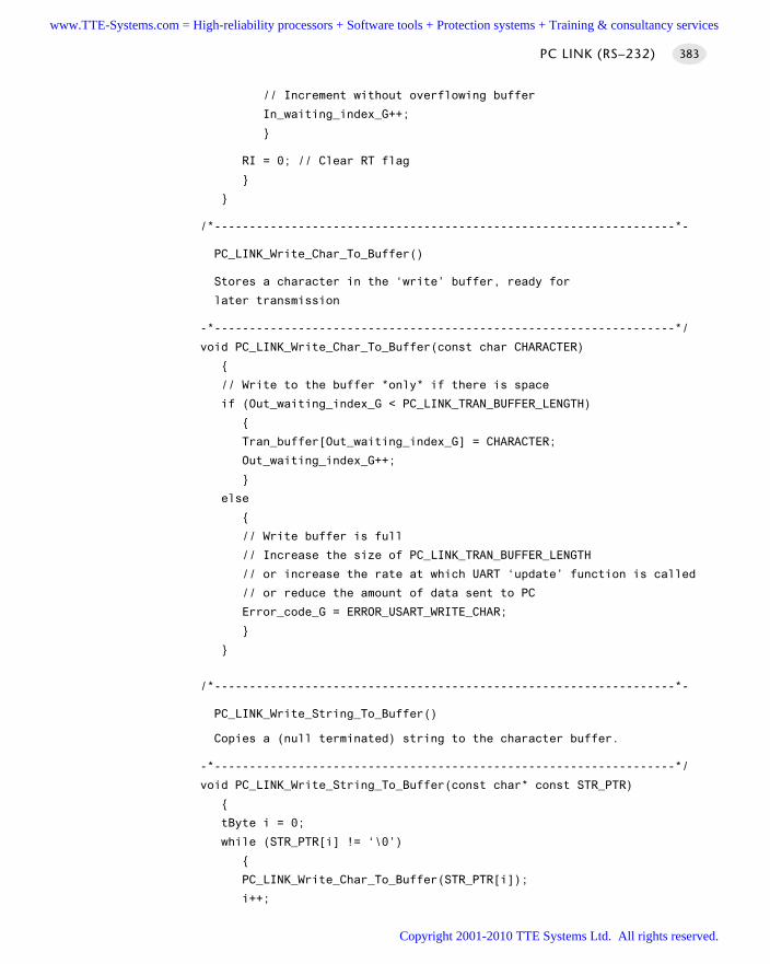
// Increment without overflowing buffer
In_waiting_index_G++;
RI = 0; // Clear RT flag
/*------------------------------------------------------------------*-
PC_LINK_Write_Char_To_Buffer()
Stores a character in the ‘write’ buffer, ready for
later transmission
-*------------------------------------------------------------------*/
void PC_LINK_Write_Char_To_Buffer(const char CHARACTER)
// Write to the buffer *only* if there is space
if (Out_waiting_index_G < PC_LINK_TRAN_BUFFER_LENGTH)
Tran_buffer[Out_waiting_index_G] = CHARACTER;
Out_waiting_index_G++;
else
// Write buffer is full
// Increase the size of PC_LINK_TRAN_BUFFER_LENGTH
// or increase the rate at which UART ‘update’ function is called
// or reduce the amount of data sent to PC
Error_code_G = ERROR_USART_WRITE_CHAR;
/*------------------------------------------------------------------*-
PC_LINK_Write_String_To_Buffer()
Copies a (null terminated) string to the character buffer.
-*------------------------------------------------------------------*/
void PC_LINK_Write_String_To_Buffer(const char* const STR_PTR)
tByte i = 0;
while (STR_PTR[i] != ‘\0’)
PC_LINK_Write_Char_To_Buffer(STR_PTR[i]);
i++;
PC LINK (RS–232) 383
www.TTE-Systems.com = High-reliability processors + Software tools + Protection systems + Training & consultancy services
Copyright 2001-2010 TTE Systems Ltd. All rights reserved.
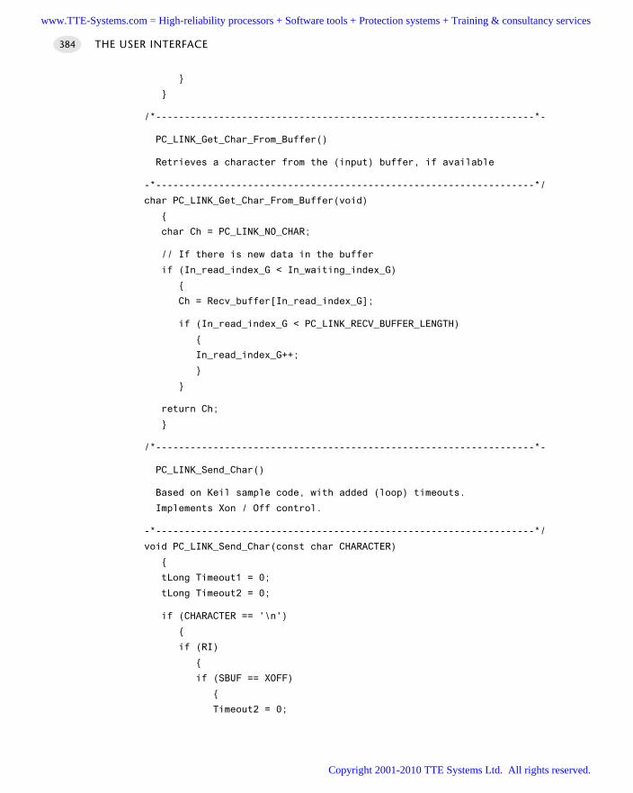
/*------------------------------------------------------------------*-
PC_LINK_Get_Char_From_Buffer()
Retrieves a character from the (input) buffer, if available
-*------------------------------------------------------------------*/
char PC_LINK_Get_Char_From_Buffer(void)
char Ch = PC_LINK_NO_CHAR;
// If there is new data in the buffer
if (In_read_index_G < In_waiting_index_G)
Ch = Recv_buffer[In_read_index_G];
if (In_read_index_G < PC_LINK_RECV_BUFFER_LENGTH)
In_read_index_G++;
return Ch;
/*------------------------------------------------------------------*-
PC_LINK_Send_Char()
Based on Keil sample code, with added (loop) timeouts.
Implements Xon / Off control.
-*------------------------------------------------------------------*/
void PC_LINK_Send_Char(const char CHARACTER)
tLong Timeout1 = 0;
tLong Timeout2 = 0;
if (CHARACTER == '\n')
if (RI)
if (SBUF == XOFF)
Timeout2 = 0;
THE USER INTERFACE384
www.TTE-Systems.com = High-reliability processors + Software tools + Protection systems + Training & consultancy services
Copyright 2001-2010 TTE Systems Ltd. All rights reserved.
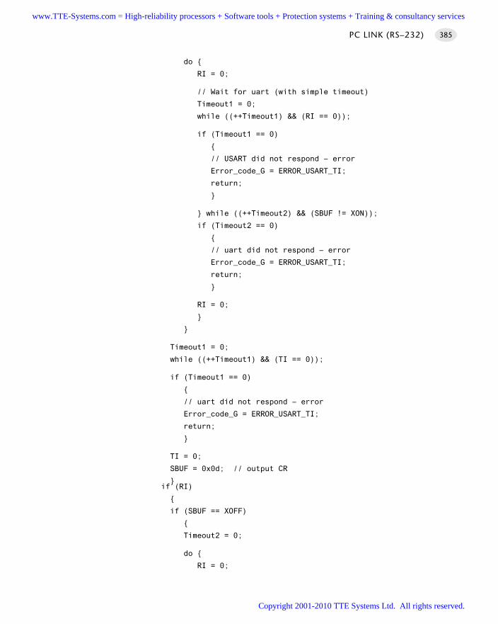
do
RI = 0;
// Wait for uart (with simple timeout)
Timeout1 = 0;
while ((++Timeout1) && (RI == 0));
if (Timeout1 == 0)
// USART did not respond – error
Error_code_G = ERROR_USART_TI;
return;
while ((++Timeout2) && (SBUF != XON));
if (Timeout2 == 0)
// uart did not respond – error
Error_code_G = ERROR_USART_TI;
return;
RI = 0;
Timeout1 = 0;
while ((++Timeout1) && (TI == 0));
if (Timeout1 == 0)
// uart did not respond – error
Error_code_G = ERROR_USART_TI;
return;
TI = 0;
SBUF = 0x0d; // output CR
if (RI)
if (SBUF == XOFF)
Timeout2 = 0;
do
RI = 0;
PC LINK (RS–232) 385
www.TTE-Systems.com = High-reliability processors + Software tools + Protection systems + Training & consultancy services
Copyright 2001-2010 TTE Systems Ltd. All rights reserved.
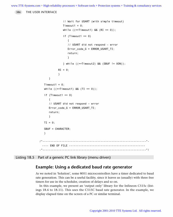
// Wait for USART (with simple timeout)
Timeout1 = 0;
while ((++Timeout1) && (RI == 0));
if (Timeout1 == 0)
// USART did not respond – error
Error_code_G = ERROR_USART_TI;
return;
while ((++Timeout2) && (SBUF != XON));
RI = 0;
Timeout1 = 0;
while ((++Timeout1) && (TI == 0));
if (Timeout1 == 0)
// USART did not respond – error
Error_code_G = ERROR_USART_TI;
return;
TI = 0;
SBUF = CHARACTER;
/*------------------------------------------------------------------*-
---- END OF FILE ------------------------------------------------
-*------------------------------------------------------------------*/
Listing 18.5 Part of a generic PC link library (menu driven)
Example: Using a dedicated baud rate generatorAs we noted in ‘Solution’, some 8051 microcontrollers have a timer dedicated to baudrate generation. This can be a useful facility, since it leaves us (usually) with three freetimers for use in the scheduler, creation of delays and so on.
In this example, we present an ‘output only’ library for the Infineon C515c (list-ings 18.6 to 18.11). This uses the C515C baud rate generator. In the example, wedisplay elapsed time on the screen of a PC or similar terminal.
THE USER INTERFACE386
www.TTE-Systems.com = High-reliability processors + Software tools + Protection systems + Training & consultancy services
Copyright 2001-2010 TTE Systems Ltd. All rights reserved.
There are two main points to note in this example:
The library is considerably smaller and simpler than the ‘duplex’ library presentedearlier.
The microcontroller is running at 10 MHz; despite this, the internal baud rate gen-erator allows us to create a very accurate baud rate for the serial link. This is a veryuseful feature.
/*------------------------------------------------------------------*-
Port.H (v1.00)
------------------------------------------------------------------
'Port Header' (see Chapter 10) for the project O_T2_IN
-*------------------------------------------------------------------*/
// ------ Sch51.C ----------------------------------------
// Comment this line out if error reporting is NOT required
//#define SCH_REPORT_ERRORS
#ifdef SCH_REPORT_ERRORS
// The port on which error codes will be displayed
// ONLY USED IF ERRORS ARE REPORTED
#define Error_port P1
#endif
// ------ Lnk_IO.C -----------------------------------------------
// Pins 3.0 and 3.1 used for RS-232 interface
/*------------------------------------------------------------------*-
---- END OF FILE ------------------------------------------------
-*------------------------------------------------------------------*/
Listing 18.6 Part of an example using a dedicated timer for baud rate generation on the Infineon c515c
/*------------------------------------------------------------------*-
Main.c (v1.00)
------------------------------------------------------------------
Test program for output-only PC link library, based on c515c.
Linker options:
PC LINK (RS–232) 387
www.TTE-Systems.com = High-reliability processors + Software tools + Protection systems + Training & consultancy services
Copyright 2001-2010 TTE Systems Ltd. All rights reserved.
OVERLAY (main ~ (PC_LINK_Update,Elapsed_Time_RS232_Update),
SCH_Dispatch_Tasks ! (PC_LINK_Update,Elapsed_Time_LCD_Update))
-*------------------------------------------------------------------*/
#include "Main.h"
#include "2_01_10i.h"
#include "Lnk_O_B.h"
#include "Elap_232.h"
/* ............................................................... */
/* ............................................................... */
void main(void)
// Set up the scheduler
SCH_Init_T2();
// Set baud rate to 9600, using internal baud rate generator
PC_LINK_Init_Internal(9600);
// Prepare the elapsed time library
Elapsed_Time_RS232_Init();
// We have to schedule this task (~100x a second is enough here)
// - this writes data to PC
//
// TIMING IS IN TICKS (1 ms tick interval)
SCH_Add_Task(PC_LINK_Update, 10, 10);
// Update the time once per second
SCH_Add_Task(Elapsed_Time_RS232_Update, 1000, 1000);
SCH_Start();
while(1)
// Displays error codes on P4 (see Sch51.C)
SCH_Dispatch_Tasks();
/*------------------------------------------------------------------*-
---- END OF FILE ------------------------------------------------
-*------------------------------------------------------------------*/
Listing 18.7 Part of an example using a dedicated timer for baud rate generation on the Infineon c515c
THE USER INTERFACE388
www.TTE-Systems.com = High-reliability processors + Software tools + Protection systems + Training & consultancy services
Copyright 2001-2010 TTE Systems Ltd. All rights reserved.
/*------------------------------------------------------------------*-
Elap_232.C (v1.00)
------------------------------------------------------------------
Simple library function for keeping track of elapsed time
Demo version to display time on PC screen via RS232 link.
-*------------------------------------------------------------------*/
#include "Main.h"
#include "Elap_232.h"
#include "Lnk_O.h"
// ------ Public variable definitions ------------------------------
tByte Hou_G = 0;
tByte Min_G = 0;
tByte Sec_G = 0;
// ------ Public variable declarations -----------------------------
// See Char_Map.c
extern const char code CHAR_MAP_G[10];
/*------------------------------------------------------------------*-
Elapsed_Time_RS232_Init()
Init function for simple library displaying elapsed time on PC
screen.
-*------------------------------------------------------------------*/
void Elapsed_Time_RS232_Init(void)
char Time_Str[] = ‘Elapsed time’;
PC_LINK_Write_String_To_Buffer(Time_Str);
/*------------------------------------------------------------------*-
Elapsed_Time_RS232_Update()
Function for displaying elapsed time on PC Screen.
*** Must be scheduled once per second ***
-*------------------------------------------------------------------*/
void Elapsed_Time_RS232_Update(void)
char Time_Str[30] = ‘\rElapsed time: ‘;
PC LINK (RS–232) 389
www.TTE-Systems.com = High-reliability processors + Software tools + Protection systems + Training & consultancy services
Copyright 2001-2010 TTE Systems Ltd. All rights reserved.
if (++Sec_G == 60)
Sec_G = 0;
if (++Min_G == 60)
Min_G = 0;
if (++Hou_G == 24)
Hou_G = 0;
Time_Str[15] = CHAR_MAP_G[Hou_G / 10];
Time_Str[16] = CHAR_MAP_G[Hou_G % 10];
Time_Str[18] = CHAR_MAP_G[Min_G / 10];
Time_Str[19] = CHAR_MAP_G[Min_G % 10];
Time_Str[21] = CHAR_MAP_G[Sec_G / 10];
Time_Str[22] = CHAR_MAP_G[Sec_G % 10];
// We don’t display seconds in this version.
// We simply use the seconds data to turn on and off the colon
// (between hours and minutes)
if ((Sec_G % 2) == 0)
Time_Str[17] = ':';
Time_Str[20] = ':';
else
Time_Str[17] = ' ';
Time_Str[20] = ' ';
PC_LINK_Write_String_To_Buffer(Time_Str);
/*------------------------------------------------------------------*-
---- END OF FILE ------------------------------------------------
-*------------------------------------------------------------------*/
Listing 18.8 Part of an example using a dedicated timer for baud rate generation on the Infineon c515c
THE USER INTERFACE390
www.TTE-Systems.com = High-reliability processors + Software tools + Protection systems + Training & consultancy services
Copyright 2001-2010 TTE Systems Ltd. All rights reserved.
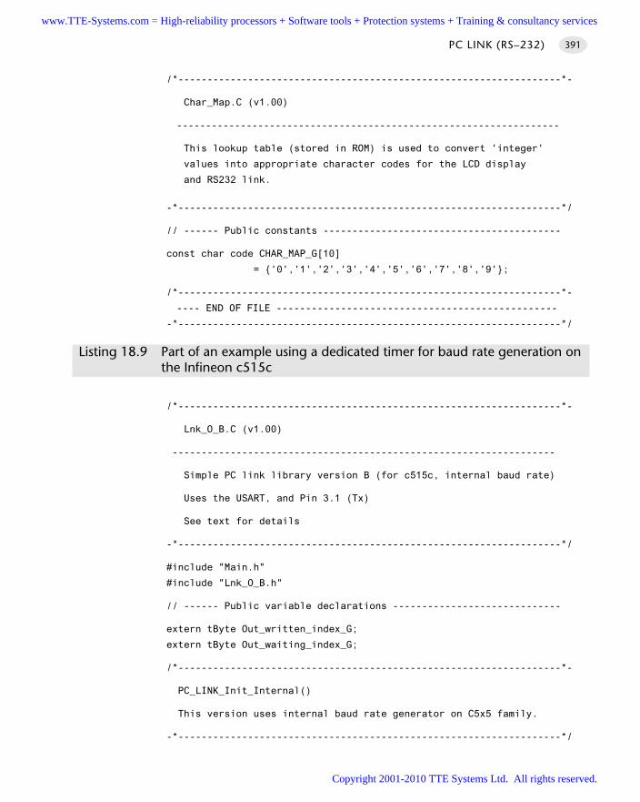
/*------------------------------------------------------------------*-
Char_Map.C (v1.00)
------------------------------------------------------------------
This lookup table (stored in ROM) is used to convert 'integer'
values into appropriate character codes for the LCD display
and RS232 link.
-*------------------------------------------------------------------*/
// ------ Public constants -----------------------------------------
const char code CHAR_MAP_G[10]
= '0','1','2','3','4','5','6','7','8','9';
/*------------------------------------------------------------------*-
---- END OF FILE ------------------------------------------------
-*------------------------------------------------------------------*/
Listing 18.9 Part of an example using a dedicated timer for baud rate generation on the Infineon c515c
/*------------------------------------------------------------------*-
Lnk_O_B.C (v1.00)
------------------------------------------------------------------
Simple PC link library version B (for c515c, internal baud rate)
Uses the USART, and Pin 3.1 (Tx)
See text for details
-*------------------------------------------------------------------*/
#include "Main.h"
#include "Lnk_O_B.h"
// ------ Public variable declarations -----------------------------
extern tByte Out_written_index_G;
extern tByte Out_waiting_index_G;
/*------------------------------------------------------------------*-
PC_LINK_Init_Internal()
This version uses internal baud rate generator on C5x5 family.
-*------------------------------------------------------------------*/
PC LINK (RS–232) 391
www.TTE-Systems.com = High-reliability processors + Software tools + Protection systems + Training & consultancy services
Copyright 2001-2010 TTE Systems Ltd. All rights reserved.
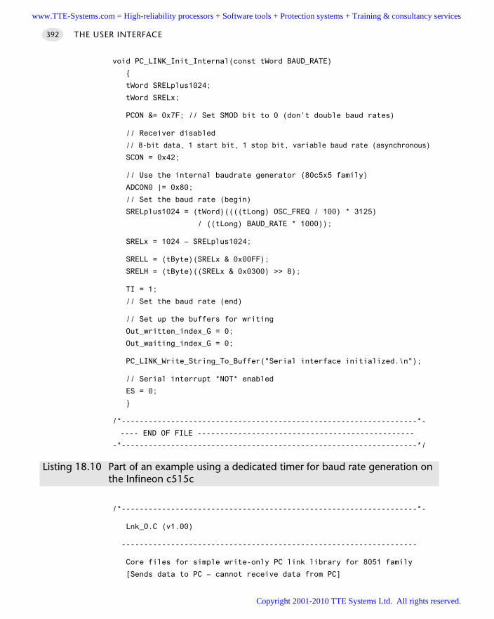
void PC_LINK_Init_Internal(const tWord BAUD_RATE)
tWord SRELplus1024;
tWord SRELx;
PCON &= 0x7F; // Set SMOD bit to 0 (don’t double baud rates)
// Receiver disabled
// 8-bit data, 1 start bit, 1 stop bit, variable baud rate (asynchronous)
SCON = 0x42;
// Use the internal baudrate generator (80c5x5 family)
ADCON0 |= 0x80;
// Set the baud rate (begin)
SRELplus1024 = (tWord)((((tLong) OSC_FREQ / 100) * 3125)
/ ((tLong) BAUD_RATE * 1000));
SRELx = 1024 – SRELplus1024;
SRELL = (tByte)(SRELx & 0x00FF);
SRELH = (tByte)((SRELx & 0x0300) >> 8);
TI = 1;
// Set the baud rate (end)
// Set up the buffers for writing
Out_written_index_G = 0;
Out_waiting_index_G = 0;
PC_LINK_Write_String_To_Buffer("Serial interface initialized.\n");
// Serial interrupt *NOT* enabled
ES = 0;
/*------------------------------------------------------------------*-
---- END OF FILE ------------------------------------------------
-*------------------------------------------------------------------*/
Listing 18.10 Part of an example using a dedicated timer for baud rate generation on the Infineon c515c
/*------------------------------------------------------------------*-
Lnk_O.C (v1.00)
------------------------------------------------------------------
Core files for simple write-only PC link library for 8051 family
[Sends data to PC – cannot receive data from PC]
THE USER INTERFACE392
www.TTE-Systems.com = High-reliability processors + Software tools + Protection systems + Training & consultancy services
Copyright 2001-2010 TTE Systems Ltd. All rights reserved.
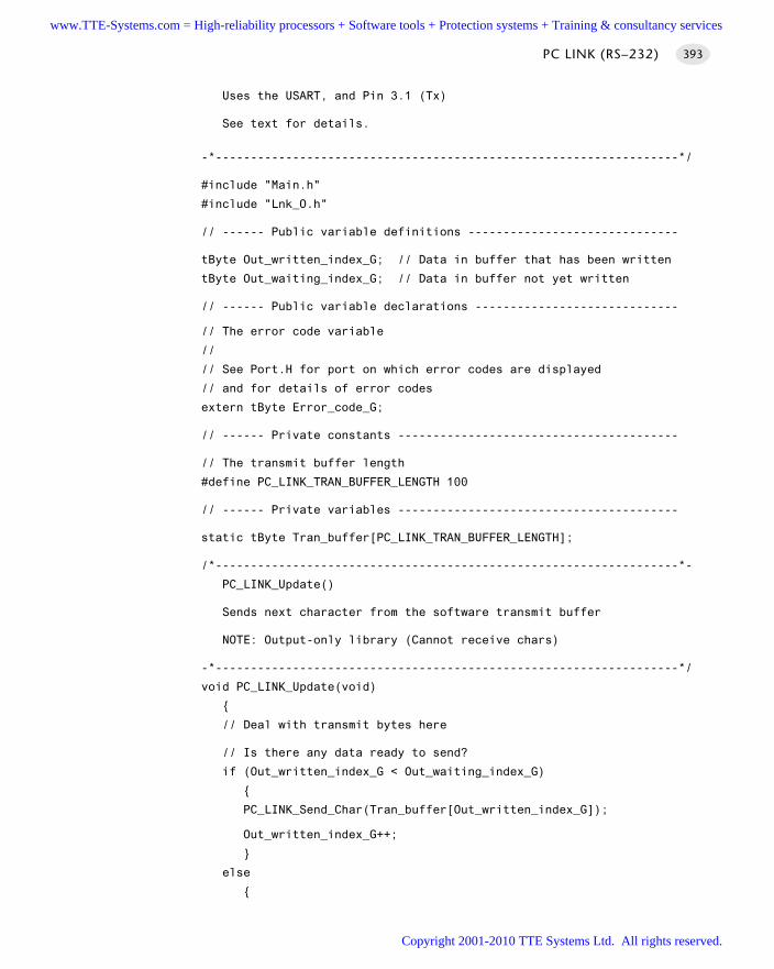
Uses the USART, and Pin 3.1 (Tx)
See text for details.
-*------------------------------------------------------------------*/
#include "Main.h"
#include "Lnk_O.h"
// ------ Public variable definitions ------------------------------
tByte Out_written_index_G; // Data in buffer that has been written
tByte Out_waiting_index_G; // Data in buffer not yet written
// ------ Public variable declarations -----------------------------
// The error code variable
//
// See Port.H for port on which error codes are displayed
// and for details of error codes
extern tByte Error_code_G;
// ------ Private constants ----------------------------------------
// The transmit buffer length
#define PC_LINK_TRAN_BUFFER_LENGTH 100
// ------ Private variables ----------------------------------------
static tByte Tran_buffer[PC_LINK_TRAN_BUFFER_LENGTH];
/*------------------------------------------------------------------*-
PC_LINK_Update()
Sends next character from the software transmit buffer
NOTE: Output-only library (Cannot receive chars)
-*------------------------------------------------------------------*/
void PC_LINK_Update(void)
// Deal with transmit bytes here
// Is there any data ready to send?
if (Out_written_index_G < Out_waiting_index_G)
PC_LINK_Send_Char(Tran_buffer[Out_written_index_G]);
Out_written_index_G++;
else
PC LINK (RS–232) 393
www.TTE-Systems.com = High-reliability processors + Software tools + Protection systems + Training & consultancy services
Copyright 2001-2010 TTE Systems Ltd. All rights reserved.
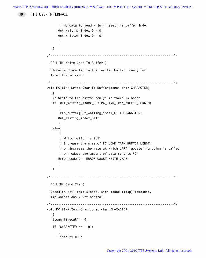
// No data to send – just reset the buffer index
Out_waiting_index_G = 0;
Out_written_index_G = 0;
/*------------------------------------------------------------------*-
PC_LINK_Write_Char_To_Buffer()
Stores a character in the 'write' buffer, ready for
later transmission
-*------------------------------------------------------------------*/
void PC_LINK_Write_Char_To_Buffer(const char CHARACTER)
// Write to the buffer *only* if there is space
if (Out_waiting_index_G < PC_LINK_TRAN_BUFFER_LENGTH)
Tran_buffer[Out_waiting_index_G] = CHARACTER;
Out_waiting_index_G++;
else
// Write buffer is full
// Increase the size of PC_LINK_TRAN_BUFFER_LENGTH
// or increase the rate at which UART 'update' function is called
// or reduce the amount of data sent to PC
Error_code_G = ERROR_USART_WRITE_CHAR;
/*------------------------------------------------------------------*-
PC_LINK_Send_Char()
Based on Keil sample code, with added (loop) timeouts.
Implements Xon / Off control.
-*------------------------------------------------------------------*/
void PC_LINK_Send_Char(const char CHARACTER)
tLong Timeout1 = 0;
if (CHARACTER == ‘\n’)
Timeout1 = 0;
THE USER INTERFACE394
www.TTE-Systems.com = High-reliability processors + Software tools + Protection systems + Training & consultancy services
Copyright 2001-2010 TTE Systems Ltd. All rights reserved.
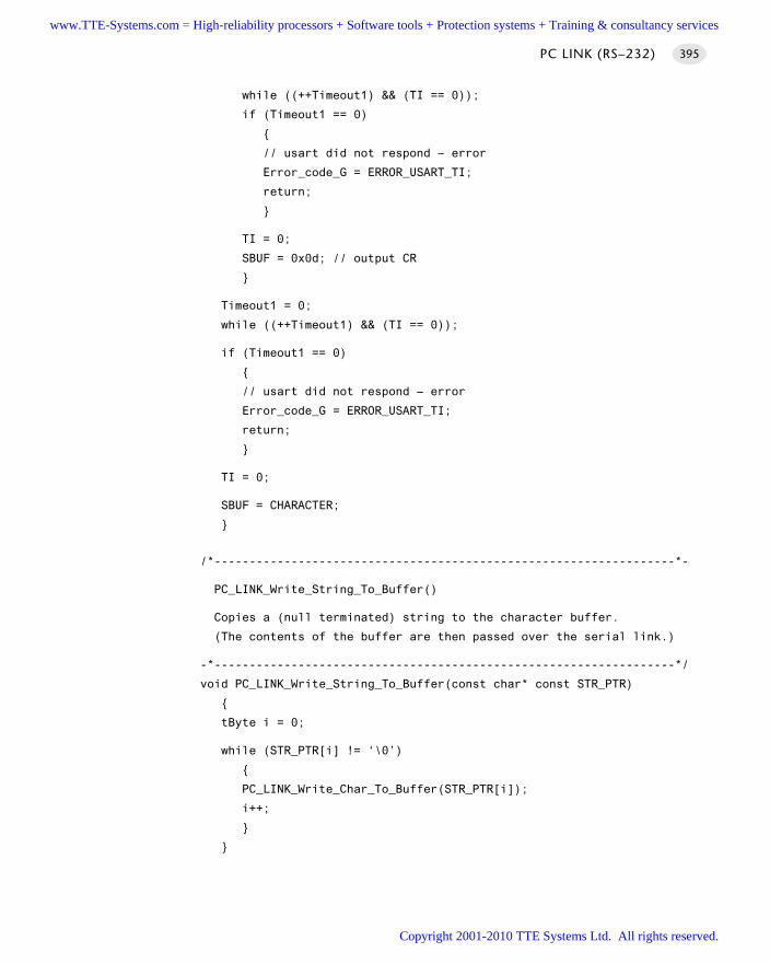
while ((++Timeout1) && (TI == 0));
if (Timeout1 == 0)
// usart did not respond – error
Error_code_G = ERROR_USART_TI;
return;
TI = 0;
SBUF = 0x0d; // output CR
Timeout1 = 0;
while ((++Timeout1) && (TI == 0));
if (Timeout1 == 0)
// usart did not respond – error
Error_code_G = ERROR_USART_TI;
return;
TI = 0;
SBUF = CHARACTER;
/*------------------------------------------------------------------*-
PC_LINK_Write_String_To_Buffer()
Copies a (null terminated) string to the character buffer.
(The contents of the buffer are then passed over the serial link.)
-*------------------------------------------------------------------*/
void PC_LINK_Write_String_To_Buffer(const char* const STR_PTR)
tByte i = 0;
while (STR_PTR[i] != ‘\0’)
PC_LINK_Write_Char_To_Buffer(STR_PTR[i]);
i++;
PC LINK (RS–232) 395
www.TTE-Systems.com = High-reliability processors + Software tools + Protection systems + Training & consultancy services
Copyright 2001-2010 TTE Systems Ltd. All rights reserved.
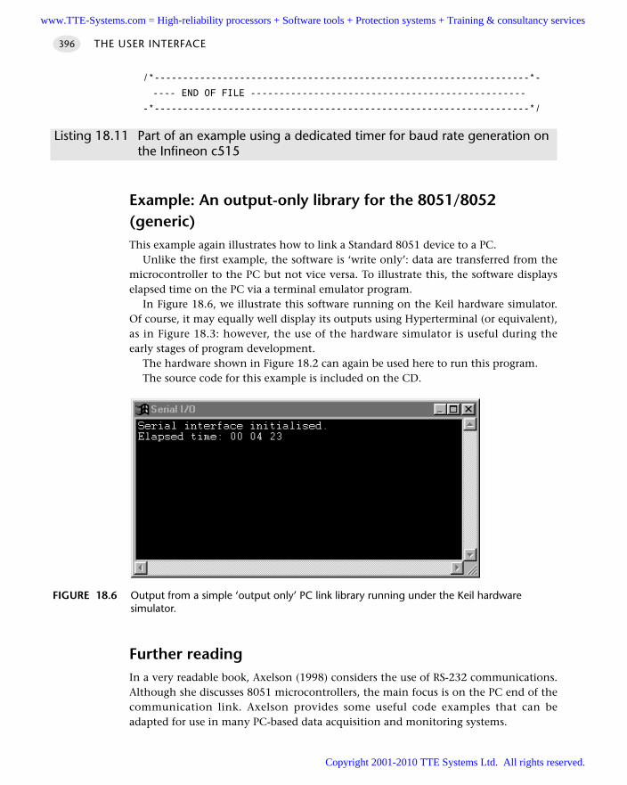
/*------------------------------------------------------------------*-
---- END OF FILE ------------------------------------------------
-*------------------------------------------------------------------*/
Listing 18.11 Part of an example using a dedicated timer for baud rate generation on the Infineon c515
Example: An output-only library for the 8051/8052 (generic)This example again illustrates how to link a Standard 8051 device to a PC.
Unlike the first example, the software is ‘write only’: data are transferred from themicrocontroller to the PC but not vice versa. To illustrate this, the software displayselapsed time on the PC via a terminal emulator program.
In Figure 18.6, we illustrate this software running on the Keil hardware simulator.Of course, it may equally well display its outputs using Hyperterminal (or equivalent),as in Figure 18.3: however, the use of the hardware simulator is useful during theearly stages of program development.
The hardware shown in Figure 18.2 can again be used here to run this program.The source code for this example is included on the CD.
Further readingIn a very readable book, Axelson (1998) considers the use of RS-232 communications.Although she discusses 8051 microcontrollers, the main focus is on the PC end of thecommunication link. Axelson provides some useful code examples that can beadapted for use in many PC-based data acquisition and monitoring systems.
THE USER INTERFACE396
FIGURE 18.6 Output from a simple ‘output only’ PC link library running under the Keil hardwaresimulator.
www.TTE-Systems.com = High-reliability processors + Software tools + Protection systems + Training & consultancy services
Copyright 2001-2010 TTE Systems Ltd. All rights reserved.
Switch interfaces
Introduction
Reading the status of one or more push-button switches is a very common require-ment in embedded applications. The four patterns in this chapter describe differentsolutions to this problem.
The patterns are as follows:
S W I T C H I N T E R FA C E (S O F T WA R E) [page 399]Uses a minimum of external hardware. Reads a single switch, debounces it and
reports its status
S W I T C H I N T E R FA C E (H A R D WA R E) [page 410]Use external hardware to perform switch debouncing. Increased cost (compared
with S W I T C H I N T E R FA C E (S O F T WA R E) ), but much higher level of protection againstESD, malicious damage etc.
O N-O F F S W I T C H [page 414]Building on S W I T C H I N T E R F A C E ( S O F T W A R E ) or S W I T C H I N T E R F A C E ( H A R D -
WA R E) this pattern provides, through software, the following behaviour:Assume that the switch is in the OFF state. It remains in this state until it is pressed.
When pressed, the state changes to ON. It remains in this state until it is pressed. Whenpressed, the state changes to OFF.
This type of behaviour can be used, for example, to allow a single (non-latching)switch to control a piece of machinery.
M U LT I - S TAT E S W I T C H [page 423]Building on S W I T C H I N T E R F A C E ( S O F T W A R E ) or S W I T C H I N T E R F A C E ( H A R D -
WA R E) this pattern provides, through software, the following behaviour:Assume that the switch state is in the OFF state. The switch is pressed and briefly held.
The switch state changes to ‘ON STATE 1’. The user continues to depress the switch. Theswitch state becomes ‘ON STATE 2’, etc. Releasing the switch (at any time) puts theswitch back in the OFF state.
chapter 19www.TTE-Systems.com = High-reliability processors + Software tools + Protection systems + Training & consultancy services
Copyright 2001-2010 TTE Systems Ltd. All rights reserved.
That is, the switch state depends on the duration of the switch press. Anynumber of ‘ON’ states may be supported (although having more than around threeis generally very confusing for the user).
This type of behaviour can be useful when, for example, setting time on a clock.Pressing the set switch will initially cause the displayed time to change slowly; sus-tained depressions will cause the displayed time to increase more rapidly.
THE USER INTERFACE398
Note: For reasons discussed in S W I T C H I N T E R F A C E ( S O F T W A R E ) , in ‘Safety andreliability’, we are only concerned with push-button switches in these patterns:‘toggle’ or ‘latching’ switches are not considered (and the use of such switches isnot recommended).
www.TTE-Systems.com = High-reliability processors + Software tools + Protection systems + Training & consultancy services
Copyright 2001-2010 TTE Systems Ltd. All rights reserved.
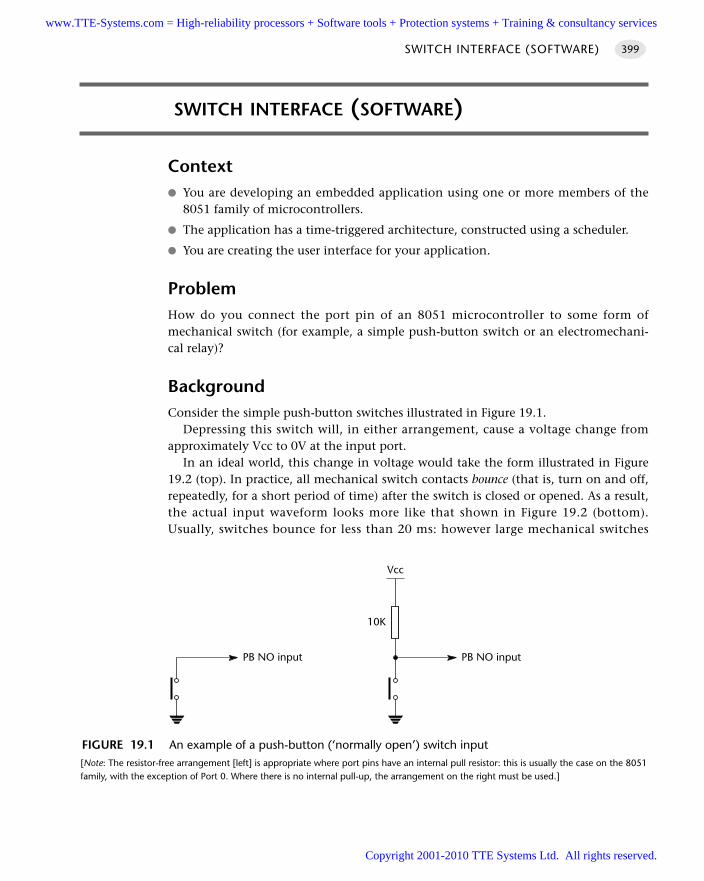
SWITCH INTERFACE (SOFTWARE)
Context You are developing an embedded application using one or more members of the
8051 family of microcontrollers.
The application has a time-triggered architecture, constructed using a scheduler.
You are creating the user interface for your application.
ProblemHow do you connect the port pin of an 8051 microcontroller to some form ofmechanical switch (for example, a simple push-button switch or an electromechani-cal relay)?
BackgroundConsider the simple push-button switches illustrated in Figure 19.1.
Depressing this switch will, in either arrangement, cause a voltage change fromapproximately Vcc to 0V at the input port.
In an ideal world, this change in voltage would take the form illustrated in Figure19.2 (top). In practice, all mechanical switch contacts bounce (that is, turn on and off,repeatedly, for a short period of time) after the switch is closed or opened. As a result,the actual input waveform looks more like that shown in Figure 19.2 (bottom).Usually, switches bounce for less than 20 ms: however large mechanical switches
SWITCH INTERFACE (SOFTWARE) 399
FIGURE 19.1 An example of a push-button (‘normally open’) switch input[Note: The resistor-free arrangement [left] is appropriate where port pins have an internal pull resistor: this is usually the case on the 8051family, with the exception of Port 0. Where there is no internal pull-up, the arrangement on the right must be used.]
Vcc
10K
PB NO inputPB NO input
www.TTE-Systems.com = High-reliability processors + Software tools + Protection systems + Training & consultancy services
Copyright 2001-2010 TTE Systems Ltd. All rights reserved.
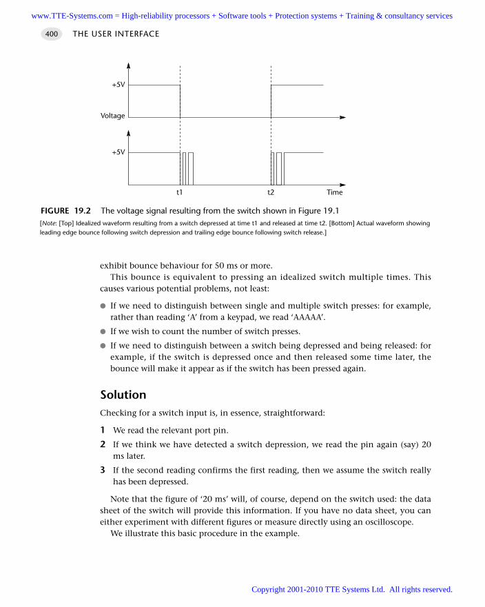
exhibit bounce behaviour for 50 ms or more.This bounce is equivalent to pressing an idealized switch multiple times. This
causes various potential problems, not least:
If we need to distinguish between single and multiple switch presses: for example,rather than reading ‘A’ from a keypad, we read ‘AAAAA’.
If we wish to count the number of switch presses.
If we need to distinguish between a switch being depressed and being released: forexample, if the switch is depressed once and then released some time later, thebounce will make it appear as if the switch has been pressed again.
SolutionChecking for a switch input is, in essence, straightforward:
1 We read the relevant port pin.
2 If we think we have detected a switch depression, we read the pin again (say) 20ms later.
3 If the second reading confirms the first reading, then we assume the switch reallyhas been depressed.
Note that the figure of ‘20 ms’ will, of course, depend on the switch used: the datasheet of the switch will provide this information. If you have no data sheet, you caneither experiment with different figures or measure directly using an oscilloscope.
We illustrate this basic procedure in the example.
THE USER INTERFACE400
FIGURE 19.2 The voltage signal resulting from the switch shown in Figure 19.1[Note: [Top] Idealized waveform resulting from a switch depressed at time t1 and released at time t2. [Bottom] Actual waveform showingleading edge bounce following switch depression and trailing edge bounce following switch release.]
+5V
+5V
t1 t2 Time
Voltage
www.TTE-Systems.com = High-reliability processors + Software tools + Protection systems + Training & consultancy services
Copyright 2001-2010 TTE Systems Ltd. All rights reserved.
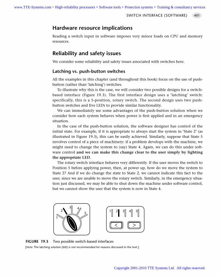
Hardware resource implicationsReading a switch input in software imposes very minor loads on CPU and memoryresources.
Reliability and safety issuesWe consider some reliability and safety issues associated with switches here.
Latching vs. push-button switches
All the examples in this chapter (and throughout this book) focus on the use of push-button (rather than ‘latching’) switches.
To illustrate why this is the case, we will consider two possible designs for a switch-based interface (Figure 19.3). The first interface design uses a ‘latching’ switch:specifically, this is a 5-position, rotary switch. The second design uses two push-button switches and five LEDs to provide similar functionality.
We can immediately see some advantages of the push-button solution when weconsider how each system behaves when power is first applied and in an emergencysituation.
In the case of the push-button solution, the software designer has control of theinitial state. For example, if it is appropriate to always start the system in ‘State 2’ (asillustrated in Figure 19.3), this can be easily achieved. Similarly, suppose that State 5involves control of a piece of machinery: if a problem develops with the machine, wemight need to change the system to (say) State 4. Again, we can do this under soft-ware control and we can make this change clear to the user simply by lightingthe appropriate LED.
The rotary switch interface behaves very differently. If the user moves the switch toPosition 5 before applying power, then, at power up, how do we move the system toState 2? And if we do change the state to State 2, we cannot indicate this fact to theuser, since we are unable to move the rotary switch. Similarly, in the emergency situa-tion just discussed, we may be able to shut down the machine under software control,but we cannot show the user that the system is now in State 4.
SWITCH INTERFACE (SOFTWARE) 401
FIGURE 19.3 Two possible switch-based interfaces[Note: The latching solution (left) is not recommended for reasons discussed in the text.]
54
1
23
1 2 3 4 5
www.TTE-Systems.com = High-reliability processors + Software tools + Protection systems + Training & consultancy services
Copyright 2001-2010 TTE Systems Ltd. All rights reserved.
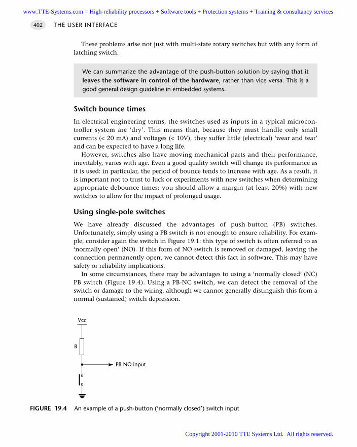
These problems arise not just with multi-state rotary switches but with any form oflatching switch.
Switch bounce times
In electrical engineering terms, the switches used as inputs in a typical microcon-troller system are ‘dry’. This means that, because they must handle only smallcurrents (< 20 mA) and voltages (< 10V), they suffer little (electrical) ‘wear and tear’and can be expected to have a long life.
However, switches also have moving mechanical parts and their performance,inevitably, varies with age. Even a good quality switch will change its performance asit is used: in particular, the period of bounce tends to increase with age. As a result, itis important not to trust to luck or experiments with new switches when determiningappropriate debounce times: you should allow a margin (at least 20%) with newswitches to allow for the impact of prolonged usage.
Using single-pole switches
We have already discussed the advantages of push-button (PB) switches.Unfortunately, simply using a PB switch is not enough to ensure reliability. For exam-ple, consider again the switch in Figure 19.1: this type of switch is often referred to as‘normally open’ (NO). If this form of NO switch is removed or damaged, leaving theconnection permanently open, we cannot detect this fact in software. This may havesafety or reliability implications.
In some circumstances, there may be advantages to using a ‘normally closed’ (NC)PB switch (Figure 19.4). Using a PB-NC switch, we can detect the removal of theswitch or damage to the wiring, although we cannot generally distinguish this from anormal (sustained) switch depression.
THE USER INTERFACE402
We can summarize the advantage of the push-button solution by saying that itleaves the software in control of the hardware, rather than vice versa. This is agood general design guideline in embedded systems.
FIGURE 19.4 An example of a push-button (‘normally closed’) switch input
Vcc
R
PB NO input
www.TTE-Systems.com = High-reliability processors + Software tools + Protection systems + Training & consultancy services
Copyright 2001-2010 TTE Systems Ltd. All rights reserved.
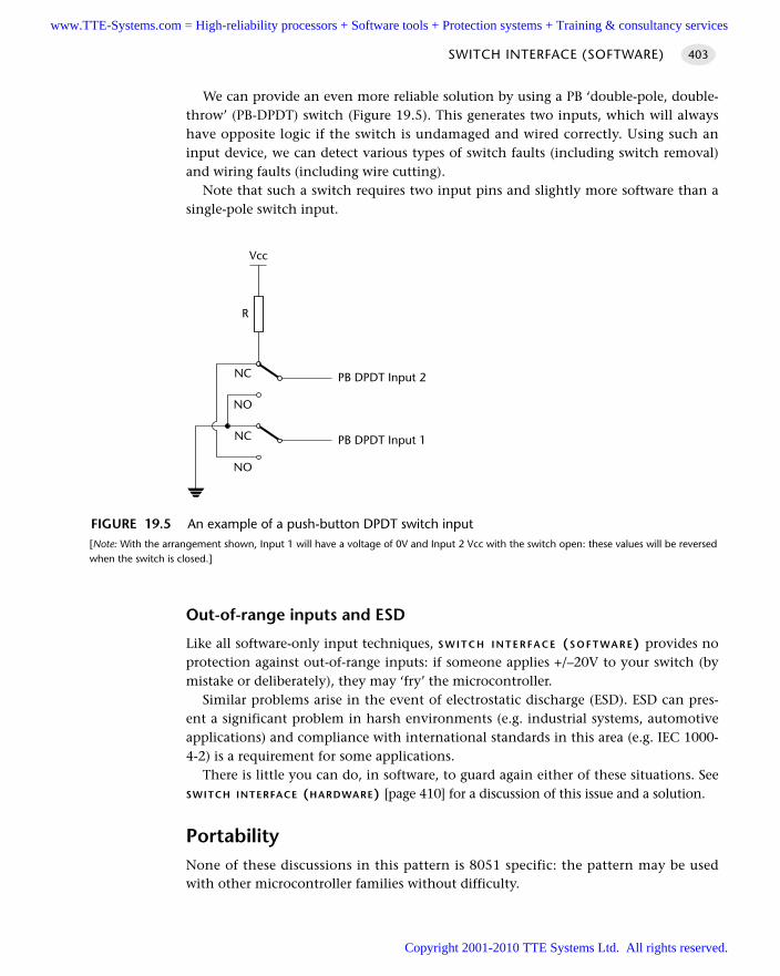
We can provide an even more reliable solution by using a PB ‘double-pole, double-throw’ (PB-DPDT) switch (Figure 19.5). This generates two inputs, which will alwayshave opposite logic if the switch is undamaged and wired correctly. Using such aninput device, we can detect various types of switch faults (including switch removal)and wiring faults (including wire cutting).
Note that such a switch requires two input pins and slightly more software than asingle-pole switch input.
Out-of-range inputs and ESD
Like all software-only input techniques, S W I T C H I N T E R FA C E (S O F T WA R E) provides noprotection against out-of-range inputs: if someone applies +/–20V to your switch (bymistake or deliberately), they may ‘fry’ the microcontroller.
Similar problems arise in the event of electrostatic discharge (ESD). ESD can pres-ent a significant problem in harsh environments (e.g. industrial systems, automotiveapplications) and compliance with international standards in this area (e.g. IEC 1000-4-2) is a requirement for some applications.
There is little you can do, in software, to guard again either of these situations. SeeSWITCH INTERFACE (HARDWARE) [page 410] for a discussion of this issue and a solution.
PortabilityNone of these discussions in this pattern is 8051 specific: the pattern may be usedwith other microcontroller families without difficulty.
SWITCH INTERFACE (SOFTWARE) 403
FIGURE 19.5 An example of a push-button DPDT switch input[Note: With the arrangement shown, Input 1 will have a voltage of 0V and Input 2 Vcc with the switch open: these values will be reversedwhen the switch is closed.]
NO
NC
NO
NC
Vcc
R
PB DPDT Input 2
PB DPDT Input 1
www.TTE-Systems.com = High-reliability processors + Software tools + Protection systems + Training & consultancy services
Copyright 2001-2010 TTE Systems Ltd. All rights reserved.
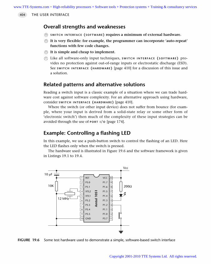
Overall strengths and weaknessesS W I T C H I N T E R FA C E (S O F T WA R E) requires a minimum of external hardware.
It is very flexible: for example, the programmer can incorporate ‘auto-repeat’functions with few code changes.
It is simple and cheap to implement.
Like all software-only input techniques, S W I T C H I N T E R F A C E ( S O F T W A R E ) pro-vides no protection against out-of-range inputs or electrostatic discharge (ESD).See S W I T C H I N T E R FA C E (H A R D WA R E) [page 410] for a discussion of this issue anda solution.
Related patterns and alternative solutionsReading a switch input is a classic example of a situation where we can trade hard-ware cost against software complexity. For an alternative approach using hardware,consider S W I T C H I N T E R FA C E (H A R D WA R E) [page 410].
Where the switch (or other input device) does not suffer from bounce (for exam-ple, where your input is derived from a solid-state relay or some other form of‘electronic switch’) then much of the complexity of these input strategies can beavoided through the use of P O R T I/O [page 174].
Example: Controlling a flashing LEDIn this example, we use a push-button switch to control the flashing of an LED. Herethe LED flashes only when the switch is pressed.
The hardware used is illustrated in Figure 19.6 and the software framework is givenin Listings 19.1 to 19.4.
THE USER INTERFACE404
FIGURE 19.6 Some test hardware used to demonstrate a simple, software-based switch interface
RST
P3.0
P3.1
XTL2
XTL1
P3.2
P3.3
P3.4
P3.5
GND10
9
8
7
6
5
4
3
2
1
11
12
13
14
15
16
17
18
19
20VCC
P1.7
P1.6
P1.5
P1.4
P1.3
P1.2
P1.1
P1.0
P3.7
Am
tel 1
051
12 MHz
10K 200Ω
Vcc
10 µF
www.TTE-Systems.com = High-reliability processors + Software tools + Protection systems + Training & consultancy services
Copyright 2001-2010 TTE Systems Ltd. All rights reserved.
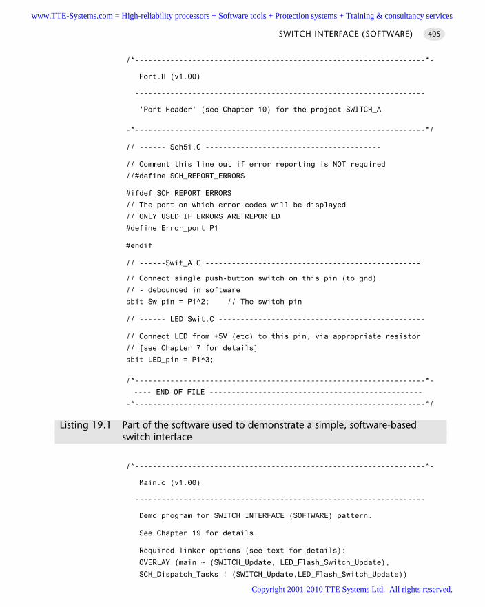
/*------------------------------------------------------------------*-
Port.H (v1.00)
------------------------------------------------------------------
'Port Header' (see Chapter 10) for the project SWITCH_A
-*------------------------------------------------------------------*/
// ------ Sch51.C ----------------------------------------
// Comment this line out if error reporting is NOT required
//#define SCH_REPORT_ERRORS
#ifdef SCH_REPORT_ERRORS
// The port on which error codes will be displayed
// ONLY USED IF ERRORS ARE REPORTED
#define Error_port P1
#endif
// ------Swit_A.C -------------------------------------------------
// Connect single push-button switch on this pin (to gnd)
// - debounced in software
sbit Sw_pin = P1^2; // The switch pin
// ------ LED_Swit.C -----------------------------------------------
// Connect LED from +5V (etc) to this pin, via appropriate resistor
// [see Chapter 7 for details]
sbit LED_pin = P1^3;
/*------------------------------------------------------------------*-
---- END OF FILE ------------------------------------------------
-*------------------------------------------------------------------*/
Listing 19.1 Part of the software used to demonstrate a simple, software-based switch interface
/*------------------------------------------------------------------*-
Main.c (v1.00)
------------------------------------------------------------------
Demo program for SWITCH INTERFACE (SOFTWARE) pattern.
See Chapter 19 for details.
Required linker options (see text for details):
OVERLAY (main ~ (SWITCH_Update, LED_Flash_Switch_Update),
SCH_Dispatch_Tasks ! (SWITCH_Update,LED_Flash_Switch_Update))
SWITCH INTERFACE (SOFTWARE) 405
www.TTE-Systems.com = High-reliability processors + Software tools + Protection systems + Training & consultancy services
Copyright 2001-2010 TTE Systems Ltd. All rights reserved.
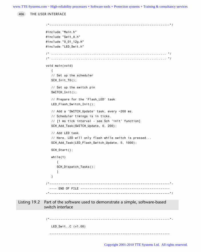
-*------------------------------------------------------------------*/
#include "Main.h"
#include "Swit_A.h"
#include "0_01_12g.H"
#include "LED_Swit.h"
/* ............................................................... */
/* ............................................................... */
void main(void)
// Set up the scheduler
SCH_Init_T0();
// Set up the switch pin
SWITCH_Init();
// Prepare for the 'Flash_LED' task
LED_Flash_Switch_Init();
// Add a 'SWITCH_Update' task, every ~200 ms.
// Scheduler timings is in ticks.
// [1 ms tick interval - see Sch 'init' function]
SCH_Add_Task(SWITCH_Update, 0, 200);
// Add LED task
// Here, LED will only flash while switch is pressed...
SCH_Add_Task(LED_Flash_Switch_Update, 5, 1000);
SCH_Start();
while(1)
SCH_Dispatch_Tasks();
/*------------------------------------------------------------------*-
---- END OF FILE -------------------------------------------------
-*------------------------------------------------------------------*/
Listing 19.2 Part of the software used to demonstrate a simple, software-based switch interface
/*------------------------------------------------------------------*-
LED_Swit..C (v1.00)
------------------------------------------------------------------
THE USER INTERFACE406
www.TTE-Systems.com = High-reliability processors + Software tools + Protection systems + Training & consultancy services
Copyright 2001-2010 TTE Systems Ltd. All rights reserved.
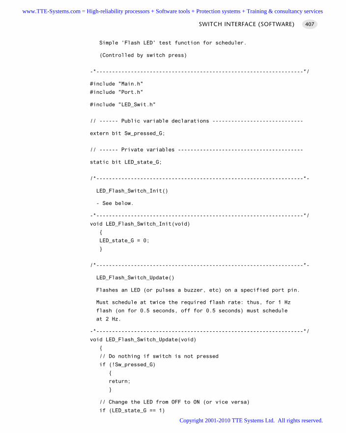
Simple 'Flash LED' test function for scheduler.
(Controlled by switch press)
-*------------------------------------------------------------------*/
#include "Main.h"
#include "Port.h"
#include "LED_Swit.h"
// ------ Public variable declarations -----------------------------
extern bit Sw_pressed_G;
// ------ Private variables ----------------------------------------
static bit LED_state_G;
/*------------------------------------------------------------------*-
LED_Flash_Switch_Init()
- See below.
-*------------------------------------------------------------------*/
void LED_Flash_Switch_Init(void)
LED_state_G = 0;
/*------------------------------------------------------------------*-
LED_Flash_Switch_Update()
Flashes an LED (or pulses a buzzer, etc) on a specified port pin.
Must schedule at twice the required flash rate: thus, for 1 Hz
flash (on for 0.5 seconds, off for 0.5 seconds) must schedule
at 2 Hz.
-*------------------------------------------------------------------*/
void LED_Flash_Switch_Update(void)
// Do nothing if switch is not pressed
if (!Sw_pressed_G)
return;
// Change the LED from OFF to ON (or vice versa)
if (LED_state_G == 1)
SWITCH INTERFACE (SOFTWARE) 407
www.TTE-Systems.com = High-reliability processors + Software tools + Protection systems + Training & consultancy services
Copyright 2001-2010 TTE Systems Ltd. All rights reserved.
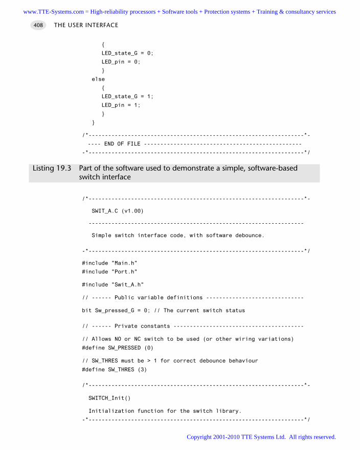
LED_state_G = 0;
LED_pin = 0;
else
LED_state_G = 1;
LED_pin = 1;
/*------------------------------------------------------------------*-
---- END OF FILE ------------------------------------------------
-*------------------------------------------------------------------*/
Listing 19.3 Part of the software used to demonstrate a simple, software-based switch interface
/*------------------------------------------------------------------*-
SWIT_A.C (v1.00)
------------------------------------------------------------------
Simple switch interface code, with software debounce.
-*------------------------------------------------------------------*/
#include "Main.h"
#include "Port.h"
#include "Swit_A.h"
// ------ Public variable definitions ------------------------------
bit Sw_pressed_G = 0; // The current switch status
// ------ Private constants ----------------------------------------
// Allows NO or NC switch to be used (or other wiring variations)
#define SW_PRESSED (0)
// SW_THRES must be > 1 for correct debounce behaviour
#define SW_THRES (3)
/*------------------------------------------------------------------*-
SWITCH_Init()
Initialization function for the switch library.
-*------------------------------------------------------------------*/
THE USER INTERFACE408
www.TTE-Systems.com = High-reliability processors + Software tools + Protection systems + Training & consultancy services
Copyright 2001-2010 TTE Systems Ltd. All rights reserved.
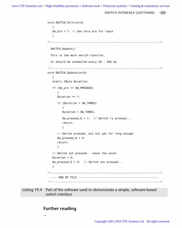
void SWITCH_Init(void)
Sw_pin = 1; // Use this pin for input
/*------------------------------------------------------------------*-
SWITCH_Update()
This is the main switch function.
It should be scheduled every 50 - 500 ms.
-*------------------------------------------------------------------*/
void SWITCH_Update(void)
static tByte Duration;
if (Sw_pin == SW_PRESSED)
Duration += 1;
if (Duration > SW_THRES)
Duration = SW_THRES;
Sw_pressed_G = 1; // Switch is pressed...
return;
// Switch pressed, but not yet for long enough
Sw_pressed_G = 0;
return;
// Switch not pressed - reset the count
Duration = 0;
Sw_pressed_G = 0; // Switch not pressed...
/*------------------------------------------------------------------*-
---- END OF FILE ------------------------------------------------
-*------------------------------------------------------------------*/
Listing 19.4 Part of the software used to demonstrate a simple, software-based switch interface
Further reading—
SWITCH INTERFACE (SOFTWARE) 409
www.TTE-Systems.com = High-reliability processors + Software tools + Protection systems + Training & consultancy services
Copyright 2001-2010 TTE Systems Ltd. All rights reserved.
SWITCH INTERFACE (HARDWARE)
Context You are developing an embedded application using one or more members of the
8051 family of microcontrollers.
The application has a time-triggered architecture, constructed using a scheduler.
You are creating the user interface for your application.
ProblemHow do you create a very robust switch interface for use in a hostile (e.g. industrial,automotive) environment?
BackgroundConsider the following scenarios:
Your embedded application is used in an industrial environment where high levelsof electrostatic discharge are likely. How can you ensure that your device remainsfully operational?
Your automotive security application may be the subject of deliberate vandalism ordamage. Specifically, reports on the WWW have revealed that thieves have found itpossible to disable a similar security system by applying 12V from a car batterydirectly to one of the system switches. How can you ensure that your system is morerobust?
In general, S W I T C H I N T E R FA C E (S O F T WA R E) [page 399] describes techniques thatare only suitable in ‘safe’ applications: in hostile environments, you need a morerobust solution. This must be hardware based.
SolutionAs noted in ‘Background’, creating a robust switch interface requires the use of off-chip hardware.
Traditionally, techniques involving J-K flip-flops, high-impedence CMOS gates orR-C integrators have all been used for switch debouncing: Huang (2000), for example,provides details of these techniques. In general, these approaches – while performingthe debounce operation – provide only very limited protection, at best, again ESD andsimilar hazards. Because, as we saw in S W I T C H I N T E R FA C E ( S O F T WA R E ) [page 399],the process of switch debouncing is almost trivial in a scheduled application, the costof external hardware for switch debouncing alone cannot generally be justified.
THE USER INTERFACE410
www.TTE-Systems.com = High-reliability processors + Software tools + Protection systems + Training & consultancy services
Copyright 2001-2010 TTE Systems Ltd. All rights reserved.
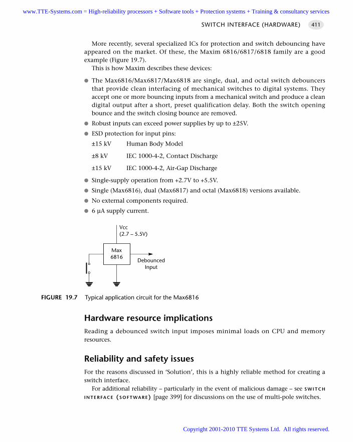
More recently, several specialized ICs for protection and switch debouncing haveappeared on the market. Of these, the Maxim 6816/6817/6818 family are a goodexample (Figure 19.7).
This is how Maxim describes these devices:
The Max6816/Max6817/Max6818 are single, dual, and octal switch debouncersthat provide clean interfacing of mechanical switches to digital systems. Theyaccept one or more bouncing inputs from a mechanical switch and produce a cleandigital output after a short, preset qualification delay. Both the switch openingbounce and the switch closing bounce are removed.
Robust inputs can exceed power supplies by up to ±25V.
ESD protection for input pins:
±15 kV Human Body Model
±8 kV IEC 1000-4-2, Contact Discharge
±15 kV IEC 1000-4-2, Air-Gap Discharge
Single-supply operation from +2.7V to +5.5V.
Single (Max6816), dual (Max6817) and octal (Max6818) versions available.
No external components required.
6 µA supply current.
Hardware resource implicationsReading a debounced switch input imposes minimal loads on CPU and memoryresources.
Reliability and safety issuesFor the reasons discussed in ‘Solution’, this is a highly reliable method for creating aswitch interface.
For additional reliability – particularly in the event of malicious damage – see S W I T C H
I N T E R FA C E (S O F T WA R E) [page 399] for discussions on the use of multi-pole switches.
SWITCH INTERFACE (HARDWARE) 411
FIGURE 19.7 Typical application circuit for the Max6816
Max6816
Vcc(2.7 – 5.5V)
DebouncedInput
www.TTE-Systems.com = High-reliability processors + Software tools + Protection systems + Training & consultancy services
Copyright 2001-2010 TTE Systems Ltd. All rights reserved.
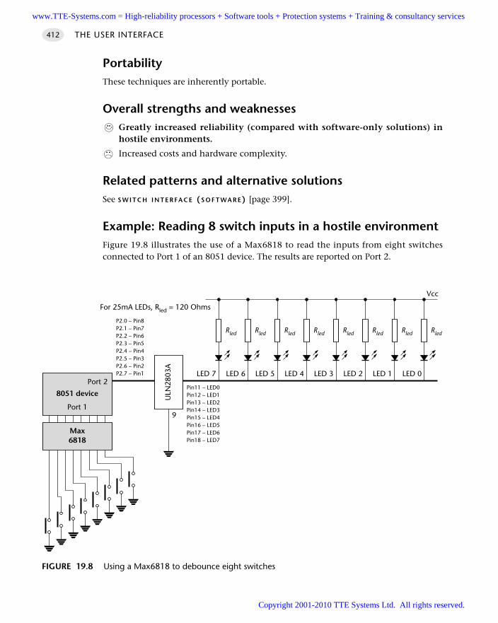
PortabilityThese techniques are inherently portable.
Overall strengths and weaknessesGreatly increased reliability (compared with software-only solutions) inhostile environments.
Increased costs and hardware complexity.
Related patterns and alternative solutionsSee S W I T C H I N T E R FA C E (S O F T WA R E) [page 399].
Example: Reading 8 switch inputs in a hostile environmentFigure 19.8 illustrates the use of a Max6818 to read the inputs from eight switchesconnected to Port 1 of an 8051 device. The results are reported on Port 2.
THE USER INTERFACE412
FIGURE 19.8 Using a Max6818 to debounce eight switches
Rled Rled Rled Rled Rled Rled Rled Rled
8051 device
Port 2LED 7
Vcc
ULN
2803
A
P2.0 – Pin8P2.1 – Pin7P2.2 – Pin6P2.3 – Pin5P2.4 – Pin4P2.5 – Pin3P2.6 – Pin2P2.7 – Pin1
Pin11 – LED0Pin12 – LED1Pin13 – LED2Pin14 – LED3Pin15 – LED4Pin16 – LED5Pin17 – LED6Pin18 – LED7
LED 6 LED 5 LED 4 LED 3 LED 2 LED 1 LED 0
For 25mA LEDs, Rled = 120 Ohms
9
Max6818
Port 1
www.TTE-Systems.com = High-reliability processors + Software tools + Protection systems + Training & consultancy services
Copyright 2001-2010 TTE Systems Ltd. All rights reserved.
The software requirements can be most easily met using a S U P E R L O O P [page 162],as shown in Listing 19.5.
void main(void)
while(1)
P2 = P1;
Listing 19.5 A trivial Super Loop switch interface
Further reading—
SWITCH INTERFACE (HARDWARE) 413
www.TTE-Systems.com = High-reliability processors + Software tools + Protection systems + Training & consultancy services
Copyright 2001-2010 TTE Systems Ltd. All rights reserved.
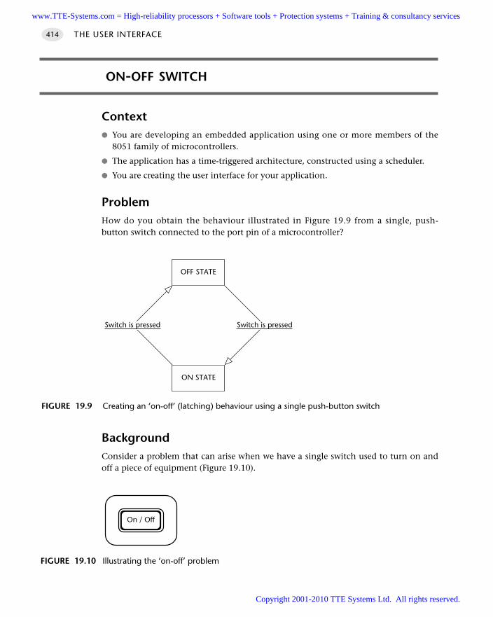
ON-OFF SWITCH
Context You are developing an embedded application using one or more members of the
8051 family of microcontrollers.
The application has a time-triggered architecture, constructed using a scheduler.
You are creating the user interface for your application.
ProblemHow do you obtain the behaviour illustrated in Figure 19.9 from a single, push-button switch connected to the port pin of a microcontroller?
BackgroundConsider a problem that can arise when we have a single switch used to turn on andoff a piece of equipment (Figure 19.10).
THE USER INTERFACE414
FIGURE 19.9 Creating an ‘on-off’ (latching) behaviour using a single push-button switch
OFF STATE
ON STATE
Switch is pressedSwitch is pressed
FIGURE 19.10 Illustrating the ‘on-off’ problem
On / Off
www.TTE-Systems.com = High-reliability processors + Software tools + Protection systems + Training & consultancy services
Copyright 2001-2010 TTE Systems Ltd. All rights reserved.
The switch is intended to operate as follows:
The user presses the switch to turn on a piece of equipment.
The equipment operates as required.
The user presses the switch again to turn off the equipment.
This seems very straightforward. However, suppose we are applying the basicapproach to switch reading presented in S W I T C H I N T E R FA C E (S O F T WA R E) [page 399],or S W I T C H I N T E R FA C E (H A R D WA R E) [page 410]. This can be summarized as follows:
1 We read the relevant port pin.
2 If we think we have detected a switch depression, we read the pin again 100 mslater.
3 If the second reading confirms the first reading, we assume the switch really hasbeen depressed.
This is what can happen:
The user presses the switch to turn on the piece of equipment.
The switch is checked. It is depressed.
The switch is checked (say) 100 ms later: the second check confirms the first. Theequipment is turned on.
The switch is checked 100 ms later. It is still depressed.
The switch is checked 100 ms later: the second check confirms the first. The equip-ment is turned off again.
And so on.
This behaviour arises because the user will generally wait until the equipmentbegins to work and will then remove their finger from the switch. In the best case sce-nario, a switch depression is likely to last about 500 ms. Unless we take action toprevent it, the equipment will ‘flicker’ on and off.
SolutionWe can most simply create an on-off switch by adding a ‘switch block’ counter to theexisting interface code. This works as follows:
1 Every time we find the switch has been pressed, we ‘block’ it for – say – 1 second.
2 While the switch is blocked, any changes in switch status are ignored: thus,for example, if the user keeps the switch depressed for half a second, this fact willbe ignored.
The ‘on-off’ example that follows illustrates how this is achieved in practice.
ON-OFF SWITCH 415
www.TTE-Systems.com = High-reliability processors + Software tools + Protection systems + Training & consultancy services
Copyright 2001-2010 TTE Systems Ltd. All rights reserved.
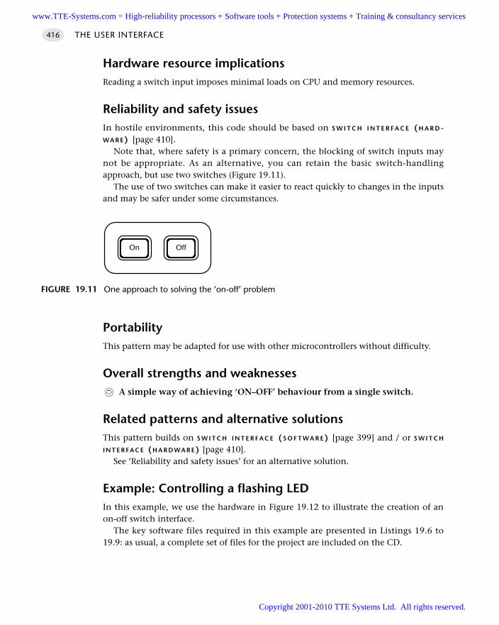
Hardware resource implicationsReading a switch input imposes minimal loads on CPU and memory resources.
Reliability and safety issuesIn hostile environments, this code should be based on S W I T C H I N T E R F A C E ( H A R D -WA R E) [page 410].
Note that, where safety is a primary concern, the blocking of switch inputs maynot be appropriate. As an alternative, you can retain the basic switch-handlingapproach, but use two switches (Figure 19.11).
The use of two switches can make it easier to react quickly to changes in the inputsand may be safer under some circumstances.
PortabilityThis pattern may be adapted for use with other microcontrollers without difficulty.
Overall strengths and weaknessesA simple way of achieving ‘ON–OFF’ behaviour from a single switch.
Related patterns and alternative solutionsThis pattern builds on S W I T C H I N T E R FA C E (S O F T WA R E) [page 399] and / or S W I T C H
I N T E R FA C E (H A R D WA R E) [page 410].See ‘Reliability and safety issues’ for an alternative solution.
Example: Controlling a flashing LEDIn this example, we use the hardware in Figure 19.12 to illustrate the creation of anon-off switch interface.
The key software files required in this example are presented in Listings 19.6 to19.9: as usual, a complete set of files for the project are included on the CD.
THE USER INTERFACE416
FIGURE 19.11 One approach to solving the ‘on-off’ problem
On Off
www.TTE-Systems.com = High-reliability processors + Software tools + Protection systems + Training & consultancy services
Copyright 2001-2010 TTE Systems Ltd. All rights reserved.
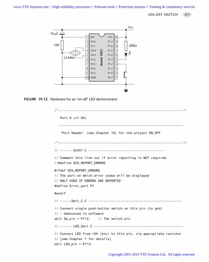
/*------------------------------------------------------------------*-
Port.H (v1.00)
------------------------------------------------------------------
'Port Header' (see Chapter 10) for the project ON_OFF
-*------------------------------------------------------------------*/
// ------ Sch51.C ----------------------------------------
// Comment this line out if error reporting is NOT required
//#define SCH_REPORT_ERRORS
#ifdef SCH_REPORT_ERRORS
// The port on which error codes will be displayed
// ONLY USED IF ERRORS ARE REPORTED
#define Error_port P1
#endif
// ------Swit_C.C -------------------------------------------------
// Connect single push-button switch on this pin (to gnd)
// - debounced in software
sbit Sw_pin = P1^2; // The switch pin
// ------ LED_Swit.C -----------------------------------------------
// Connect LED from +5V (etc) to this pin, via appropriate resistor
// [see Chapter 7 for details]
sbit LED_pin = P1^3;
ON-OFF SWITCH 417
FIGURE 19.12 Hardware for an ‘on-off’ LED demonstrator
RST
P3.0
P3.1
XTL2
XTL1
P3.2
P3.3
P3.4
P3.5
GND10
9
8
7
6
5
4
3
2
1
11
12
13
14
15
16
17
18
19
20VCC
P1.7
P1.6
P1.5
P1.4
P1.3
P1.2
P1.1
P1.0
P3.7
Am
tel 1
051
12 MHz
10K 200Ω
Vcc
10 µF
www.TTE-Systems.com = High-reliability processors + Software tools + Protection systems + Training & consultancy services
Copyright 2001-2010 TTE Systems Ltd. All rights reserved.
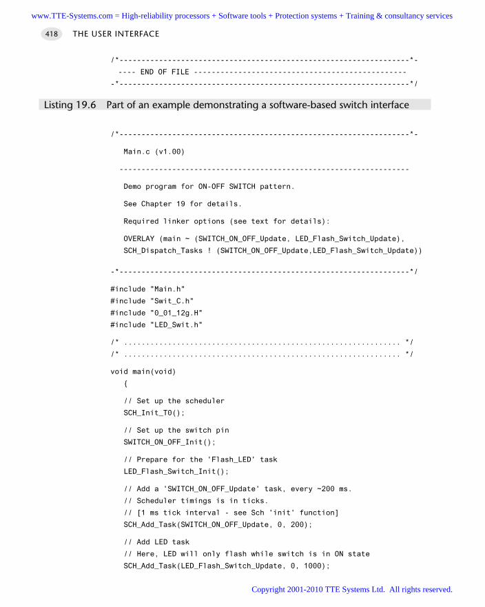
/*------------------------------------------------------------------*-
---- END OF FILE ------------------------------------------------
-*------------------------------------------------------------------*/
Listing 19.6 Part of an example demonstrating a software-based switch interface
/*------------------------------------------------------------------*-
Main.c (v1.00)
------------------------------------------------------------------
Demo program for ON-OFF SWITCH pattern.
See Chapter 19 for details.
Required linker options (see text for details):
OVERLAY (main ~ (SWITCH_ON_OFF_Update, LED_Flash_Switch_Update),
SCH_Dispatch_Tasks ! (SWITCH_ON_OFF_Update,LED_Flash_Switch_Update))
-*------------------------------------------------------------------*/
#include "Main.h"
#include "Swit_C.h"
#include "0_01_12g.H"
#include "LED_Swit.h"
/* ............................................................... */
/* ............................................................... */
void main(void)
// Set up the scheduler
SCH_Init_T0();
// Set up the switch pin
SWITCH_ON_OFF_Init();
// Prepare for the 'Flash_LED' task
LED_Flash_Switch_Init();
// Add a 'SWITCH_ON_OFF_Update' task, every ~200 ms.
// Scheduler timings is in ticks.
// [1 ms tick interval - see Sch 'init' function]
SCH_Add_Task(SWITCH_ON_OFF_Update, 0, 200);
// Add LED task
// Here, LED will only flash while switch is in ON state
SCH_Add_Task(LED_Flash_Switch_Update, 0, 1000);
THE USER INTERFACE418
www.TTE-Systems.com = High-reliability processors + Software tools + Protection systems + Training & consultancy services
Copyright 2001-2010 TTE Systems Ltd. All rights reserved.
SCH_Start();
while(1)
SCH_Dispatch_Tasks();
/*------------------------------------------------------------------*-
---- END OF FILE ------------------------------------------------
-*------------------------------------------------------------------*/
Listing 19.7 Part of an example demonstrating a software-based switch interface
/*------------------------------------------------------------------*-
LED_Swit.C (v1.00)
------------------------------------------------------------------
Simple 'Flash LED' test function for scheduler.
(Controlled by switch press)
-*------------------------------------------------------------------*/
#include "Main.h"
#include "Port.h"
#include "LED_Swit.h"
// ------ Public variable declarations -----------------------------
extern bit Sw_pressed_G;
// ------ Private variables ----------------------------------------
static bit LED_state_G;
/*------------------------------------------------------------------*-
LED_Flash_Switch_Init()
- See below.
-*------------------------------------------------------------------*/
void LED_Flash_Switch_Init(void)
LED_state_G = 0;
ON-OFF SWITCH 419
www.TTE-Systems.com = High-reliability processors + Software tools + Protection systems + Training & consultancy services
Copyright 2001-2010 TTE Systems Ltd. All rights reserved.
/*------------------------------------------------------------------*-
LED_Flash_Switch_Update()
Flashes an LED (or pulses a buzzer, etc) on a specified port pin.
Must schedule at twice the required flash rate: thus, for 1 Hz
flash (on for 0.5 seconds, off for 0.5 seconds) must schedule
at 2 Hz.
-*------------------------------------------------------------------*/
void LED_Flash_Switch_Update(void)
// Do nothing if switch is not pressed
if (!Sw_pressed_G)
return;
// Change the LED from OFF to ON (or vice versa)
if (LED_state_G == 1)
LED_state_G = 0;
LED_pin = 0;
else
LED_state_G = 1;
LED_pin = 1;
/*------------------------------------------------------------------*-
---- END OF FILE -------------------------------------------------
-*------------------------------------------------------------------*/
Listing 19.8 Part of an example demonstrating a software-based switch interface
/*------------------------------------------------------------------*-
SWIT_C.C (v1.00)
------------------------------------------------------------------
On-Off Switch code, with software debounce.
-*------------------------------------------------------------------*/
THE USER INTERFACE420
www.TTE-Systems.com = High-reliability processors + Software tools + Protection systems + Training & consultancy services
Copyright 2001-2010 TTE Systems Ltd. All rights reserved.
#include "Main.h"
#include "Port.h"
#include "Swit_C.h"
// ------ Public variable definitions ------------------------------
bit Sw_pressed_G = 0; // The current switch status
// ------ Private constants ----------------------------------------
// Allows NO or NC switch to be used (or other wiring variations)
#define SW_PRESSED (0)
// SW_THRES must be > 1 for correct debounce behaviour
#define SW_THRES (3)
// ------ Private variables ----------------------------------------
static tByte Sw_press_duration_G = 0;
static tByte Sw_blocked_G = 0;
/*------------------------------------------------------------------*-
FUNCTION: SWITCH_ON_OFF_Init()
Initialization function for the switch library.
-*------------------------------------------------------------------*/
void SWITCH_ON_OFF_Init(void)
Sw_pin = 1; // Use this pin for input
Sw_pressed_G = 0; // Switch is initially OFF
Sw_press_duration_G = 0;
Sw_blocked_G = 0;
/*------------------------------------------------------------------*-
FUNCTION: SWITCH_ON_OFF_Update()
This is the main on-off switch function.
It should be scheduled every 50 - 500 ms.
-*------------------------------------------------------------------*/
void SWITCH_ON_OFF_Update(void)
// If the switch is blocked, decrement the count and return
// without checking the switch pin status.
// This is done to give the user time to remove their finger
ON-OFF SWITCH 421
www.TTE-Systems.com = High-reliability processors + Software tools + Protection systems + Training & consultancy services
Copyright 2001-2010 TTE Systems Ltd. All rights reserved.
// from the switch - otherwise if they keep their finger on
// the switch for more than 0.4s the light will switch off again.
if (Sw_blocked_G)
Sw_blocked_G--;
return;
if (Sw_pin == SW_PRESSED)
Sw_press_duration_G += 1;
if (Sw_press_duration_G > SW_THRES)
Sw_press_duration_G = SW_THRES;
// Change switch state
if (Sw_pressed_G == 1)
Sw_pressed_G = 0; // Switch state changed to OFF
else
Sw_pressed_G = 1; // Switch state changed to ON
// Allow no other changes for ~1 second
Sw_blocked_G = 5;
return;
// Switch pressed, but not yet for long enough
return;
// Switch not pressed - reset the count
Sw_press_duration_G = 0;
/*------------------------------------------------------------------*-
---- END OF FILE ------------------------------------------------
-*------------------------------------------------------------------*/
Listing 19.9 Part of an example demonstrating a software-based switch interface
Further reading—
THE USER INTERFACE422
www.TTE-Systems.com = High-reliability processors + Software tools + Protection systems + Training & consultancy services
Copyright 2001-2010 TTE Systems Ltd. All rights reserved.
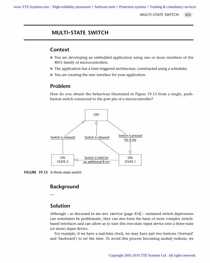
MULTI-STATE SWITCH
Context You are developing an embedded application using one or more members of the
8051 family of microcontrollers.
The application has a time-triggered architecture, constructed using a scheduler.
You are creating the user interface for your application.
ProblemHow do you obtain the behaviour illustrated in Figure 19.13 from a single, push-button switch connected to the port pin of a microcontroller?
Background—
SolutionAlthough – as discussed in O N-O F F S W I T C H [page 414] – sustained switch depressionscan sometimes be problematic, they can also form the basis of more complex switch-based interfaces and can allow us to turn this two-state input device into a three-state(or more) input device.
For example, if we have a real-time clock, we may have just two buttons (‘forward’and ‘backward’) to set the time. To avoid this process becoming unduly tedious, we
MULTI-STATE SWITCH 423
FIGURE 19.13 A three-state switch
OFF
ONSTATE 2
Switch is pressedfor A ms
Switch is released Switch is released
Switch is held foran additional B ms
ONSTATE 1
www.TTE-Systems.com = High-reliability processors + Software tools + Protection systems + Training & consultancy services
Copyright 2001-2010 TTE Systems Ltd. All rights reserved.
might decide that a brief depression of the ‘Forward’ button should slowly incrementthe displayed time, while a sustained depression (longer than, say, five seconds),should advance the display more rapidly.
To implement this type of behaviour, we might operate as follows:
We keep track of the period of time over which the switch has been continuallydepressed.
When the depression exceeds a threshold (call it Duration A), we treat this like anormal switch depression.
When the depression exceeds a larger threshold (call it Duration B), we treat this asa sustained switch depression.
Note that further ‘levels’ can be added, but more than two (sometimes three) canbe confusing to the user.
See the example that follows for complete implementation details.
Hardware resource implicationsCreating a multi-state switch imposes very minor loads on CPU and memory resources.
Reliability and safety issuesThe use of multi-state switches does not generally have reliability or safety implications.
Refer to S W I T C H I N T E R F A C E ( S O F T W A R E ) [page 399] and S W I T C H I N T E R F A C E
(H A R D WA R E) [page 410] for general discussions about the safety of switch interfaces.
PortabilityThis pattern may be adapted for use with other microcontrollers without difficulty.
Overall strengths and weaknessesA cost-effective way of improving the usability of many applications.
Related patterns and alternative solutionsSee O N-O F F S W I T C H [page 414].
Example: CounterIn this example, we demonstrate the key features of a multi-state switch by means ofa counter that is incremented at a rate which depends on the switch-press duration(Listings 19.10 to 19.14).
The required hardware is illustrated in Figure 19.14.
THE USER INTERFACE424
www.TTE-Systems.com = High-reliability processors + Software tools + Protection systems + Training & consultancy services
Copyright 2001-2010 TTE Systems Ltd. All rights reserved.
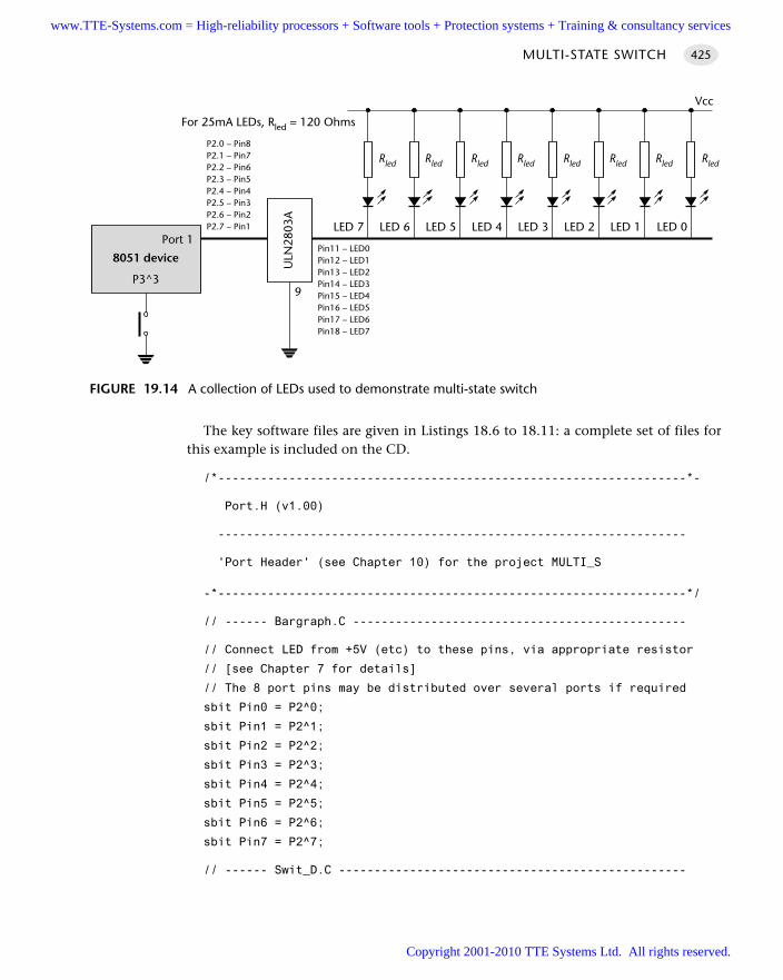
The key software files are given in Listings 18.6 to 18.11: a complete set of files forthis example is included on the CD.
/*------------------------------------------------------------------*-
Port.H (v1.00)
------------------------------------------------------------------
'Port Header' (see Chapter 10) for the project MULTI_S
-*------------------------------------------------------------------*/
// ------ Bargraph.C -----------------------------------------------
// Connect LED from +5V (etc) to these pins, via appropriate resistor
// [see Chapter 7 for details]
// The 8 port pins may be distributed over several ports if required
sbit Pin0 = P2^0;
sbit Pin1 = P2^1;
sbit Pin2 = P2^2;
sbit Pin3 = P2^3;
sbit Pin4 = P2^4;
sbit Pin5 = P2^5;
sbit Pin6 = P2^6;
sbit Pin7 = P2^7;
// ------ Swit_D.C -------------------------------------------------
MULTI-STATE SWITCH 425
FIGURE 19.14 A collection of LEDs used to demonstrate multi-state switch
Rled Rled Rled Rled Rled Rled Rled Rled
8051 device
Port 1LED 7
Vcc
ULN
2803
A
P2.0 – Pin8P2.1 – Pin7P2.2 – Pin6P2.3 – Pin5P2.4 – Pin4P2.5 – Pin3P2.6 – Pin2P2.7 – Pin1
Pin11 – LED0Pin12 – LED1Pin13 – LED2Pin14 – LED3Pin15 – LED4Pin16 – LED5Pin17 – LED6Pin18 – LED7
LED 6 LED 5 LED 4 LED 3 LED 2 LED 1 LED 0
For 25mA LEDs, Rled = 120 Ohms
9P3^3
www.TTE-Systems.com = High-reliability processors + Software tools + Protection systems + Training & consultancy services
Copyright 2001-2010 TTE Systems Ltd. All rights reserved.
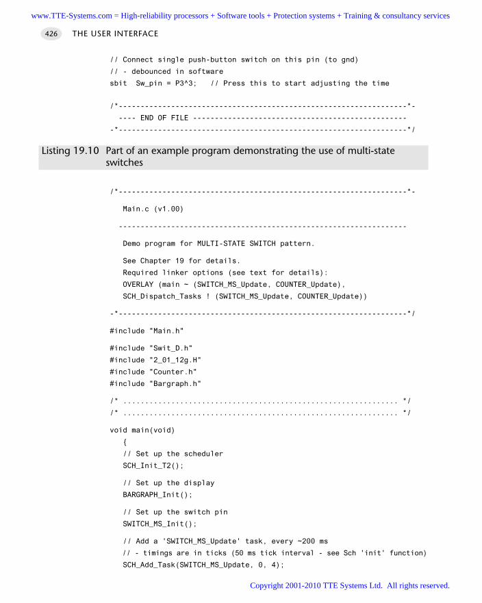
// Connect single push-button switch on this pin (to gnd)
// - debounced in software
sbit Sw_pin = P3^3; // Press this to start adjusting the time
/*------------------------------------------------------------------*-
---- END OF FILE -------------------------------------------------
-*------------------------------------------------------------------*/
Listing 19.10 Part of an example program demonstrating the use of multi-state switches
/*------------------------------------------------------------------*-
Main.c (v1.00)
------------------------------------------------------------------
Demo program for MULTI-STATE SWITCH pattern.
See Chapter 19 for details.
Required linker options (see text for details):
OVERLAY (main ~ (SWITCH_MS_Update, COUNTER_Update),
SCH_Dispatch_Tasks ! (SWITCH_MS_Update, COUNTER_Update))
-*------------------------------------------------------------------*/
#include "Main.h"
#include "Swit_D.h"
#include "2_01_12g.H"
#include "Counter.h"
#include "Bargraph.h"
/* ............................................................... */
/* ............................................................... */
void main(void)
// Set up the scheduler
SCH_Init_T2();
// Set up the display
BARGRAPH_Init();
// Set up the switch pin
SWITCH_MS_Init();
// Add a 'SWITCH_MS_Update' task, every ~200 ms
// - timings are in ticks (50 ms tick interval - see Sch 'init' function)
SCH_Add_Task(SWITCH_MS_Update, 0, 4);
THE USER INTERFACE426
www.TTE-Systems.com = High-reliability processors + Software tools + Protection systems + Training & consultancy services
Copyright 2001-2010 TTE Systems Ltd. All rights reserved.
// Add a 'COUNTER_Update' task every ~1000 ms
SCH_Add_Task(COUNTER_Update, 0, 20);
SCH_Start();
while(1)
SCH_Dispatch_Tasks();
/*------------------------------------------------------------------*-
---- END OF FILE ------------------------------------------------
-*------------------------------------------------------------------*/
Listing 19.11 Part of an example program demonstrating the use of multi-state switches
/*------------------------------------------------------------------*-
Bargraph.c (v1.00)
------------------------------------------------------------------
Simple bargraph library. See Chapter 10.
-*------------------------------------------------------------------*/
#include "Main.h"
#include "Port.h"
#include "Bargraph.h"
// ------ Public variable declarations -----------------------------
// The data to be displayed
extern tByte Data_G;
// ------ Private constants ----------------------------------------
#define BARGRAPH_ON (1)
#define BARGRAPH_OFF (0)
// ------ Private variables ----------------------------------------
// These variables store the thresholds
// used to update the display
static tBargraph M9_1_G;
static tBargraph M9_2_G;
static tBargraph M9_3_G;
MULTI-STATE SWITCH 427
www.TTE-Systems.com = High-reliability processors + Software tools + Protection systems + Training & consultancy services
Copyright 2001-2010 TTE Systems Ltd. All rights reserved.
static tBargraph M9_4_G;
static tBargraph M9_5_G;
static tBargraph M9_6_G;
static tBargraph M9_7_G;
static tBargraph M9_8_G;
/*------------------------------------------------------------------*-
BARGRAPH_Init()
Prepare for the bargraph display.
-*------------------------------------------------------------------*/
void BARGRAPH_Init(void)
Pin0 = BARGRAPH_OFF;
Pin1 = BARGRAPH_OFF;
Pin2 = BARGRAPH_OFF;
Pin3 = BARGRAPH_OFF;
Pin4 = BARGRAPH_OFF;
Pin5 = BARGRAPH_OFF;
Pin6 = BARGRAPH_OFF;
Pin7 = BARGRAPH_OFF;
// Use a linear scale to display data
// Remember: *9* possible output states
// - do all calculations ONCE
M9_1_G = (BARGRAPH_MAX - BARGRAPH_MIN) / 9;
M9_2_G = M9_1_G * 2;
M9_3_G = M9_1_G * 3;
M9_4_G = M9_1_G * 4;
M9_5_G = M9_1_G * 5;
M9_6_G = M9_1_G * 6;
M9_7_G = M9_1_G * 7;
M9_8_G = M9_1_G * 8;
/*------------------------------------------------------------------*-
BARGRAPH_Update()
Update the bargraph display.
-*------------------------------------------------------------------*/
void BARGRAPH_Update(void)
tBargraph Data = Data_G - BARGRAPH_MIN;
THE USER INTERFACE428
www.TTE-Systems.com = High-reliability processors + Software tools + Protection systems + Training & consultancy services
Copyright 2001-2010 TTE Systems Ltd. All rights reserved.
Pin0 = ((Data >= M9_1_G) == BARGRAPH_ON);
Pin1 = ((Data >= M9_2_G) == BARGRAPH_ON);
Pin2 = ((Data >= M9_3_G) == BARGRAPH_ON);
Pin3 = ((Data >= M9_4_G) == BARGRAPH_ON);
Pin4 = ((Data >= M9_5_G) == BARGRAPH_ON);
Pin5 = ((Data >= M9_6_G) == BARGRAPH_ON);
Pin6 = ((Data >= M9_7_G) == BARGRAPH_ON);
Pin7 = ((Data >= M9_8_G) == BARGRAPH_ON);
/*------------------------------------------------------------------*-
---- END OF FILE ------------------------------------------------
-*------------------------------------------------------------------*/
Listing 19.12 Part of an example program demonstrating the use of multi-state switches
/*------------------------------------------------------------------*-
Counter.C (v1.00)
------------------------------------------------------------------
Simple 'counter' function, to illustrate use of multi-state
switches.
-*------------------------------------------------------------------*/
#include "Main.h"
#include "Counter.h"
#include "Bargraph.h"
// ------ Public variable definitions ------------------------------
tBargraph Data_G;
// ------ Public variable declarations -----------------------------
extern tByte Sw_status_G;
/*------------------------------------------------------------------*-
COUNTER_Update()
Simple counter function (demo purposes).
-*------------------------------------------------------------------*/
void COUNTER_Update(void)
Data_G += Sw_status_G;
MULTI-STATE SWITCH 429
www.TTE-Systems.com = High-reliability processors + Software tools + Protection systems + Training & consultancy services
Copyright 2001-2010 TTE Systems Ltd. All rights reserved.
if (Data_G > BARGRAPH_MAX)
Data_G = 0;
BARGRAPH_Update();
/*------------------------------------------------------------------*-
---- END OF FILE ------------------------------------------------
-*------------------------------------------------------------------*/
Listing 19.13 Part of an example program demonstrating the use of multi-state switches
/*------------------------------------------------------------------*-
SWIT_D.C (v1.00)
------------------------------------------------------------------
4-state switch interface code, with software debounce.
-*------------------------------------------------------------------*/
#include "Main.h"
#include "Port.h"
#include "Swit_D.h"
// ------ Public variables -----------------------------------------
tByte Sw_status_G; // The current switch status
// ------ Private constants ----------------------------------------
// SW_THRES must be > 1 for correct debounce behaviour
#define SW_THRES (1)
#define SW_THRES_X2 (SW_THRES + SW_THRES + SW_THRES + SW_THRES)
#define SW_THRES_X3 (SW_THRES_X2 + SW_THRES_X2)
// Allows NO or NC switch to be used (or other wiring variations)
#define SW_PRESSED (0)
// ------ Private variables ----------------------------------------
static tByte Sw_press_duration_G = 0;
/*------------------------------------------------------------------*-
SWITCH_MS_Init()
THE USER INTERFACE430
www.TTE-Systems.com = High-reliability processors + Software tools + Protection systems + Training & consultancy services
Copyright 2001-2010 TTE Systems Ltd. All rights reserved.
Initialization function for the switch library.
-*------------------------------------------------------------------*/
void SWITCH_MS_Init(void)
Sw_pin = 1; // Use this pin for input
Sw_status_G = 0; // Switch is initially OFF
Sw_press_duration_G = 0;
/*------------------------------------------------------------------*-
SWITCH_MS_Update()
This is the main switch function. It should be scheduled every
50 - 500 ms.
Alters Sw_press_duration_G depending on duration of switch press.
-*------------------------------------------------------------------*/
void SWITCH_MS_Update(void)
if (Sw_pin == SW_PRESSED)
Sw_press_duration_G += 1;
if (Sw_press_duration_G > (SW_THRES_X3))
Sw_press_duration_G = SW_THRES_X3;
Sw_status_G = 3; // Switch has been pressed for a long time...
return;
if (Sw_press_duration_G > (SW_THRES_X2))
Sw_status_G = 2; // Switch has been pressed for a medium time...
return;
// SW_THRES must be > 1 for software debounce
if (Sw_press_duration_G > SW_THRES)
Sw_status_G = 1; // Switch has been pressed for a short time...
return;
MULTI-STATE SWITCH 431
www.TTE-Systems.com = High-reliability processors + Software tools + Protection systems + Training & consultancy services
Copyright 2001-2010 TTE Systems Ltd. All rights reserved.
// switch pressed, but not yet for long enough
Sw_status_G = 0;
return;
// Switch not pressed - reset the count
Sw_press_duration_G = 0;
Sw_status_G = 0; // Switch not pressed...
/*------------------------------------------------------------------*-
---- END OF FILE -------------------------------------------------
-*------------------------------------------------------------------*/
Listing 19.14 Part of an example program demonstrating the use of multi-state switches
Further reading—
THE USER INTERFACE432
www.TTE-Systems.com = High-reliability processors + Software tools + Protection systems + Training & consultancy services
Copyright 2001-2010 TTE Systems Ltd. All rights reserved.
Keypad interfaces
Introduction
Keypads are a common component in embedded applications. In this chapter, we consider how you can create reliable keypad-based user interfaces.
chapter 20www.TTE-Systems.com = High-reliability processors + Software tools + Protection systems + Training & consultancy services
Copyright 2001-2010 TTE Systems Ltd. All rights reserved.
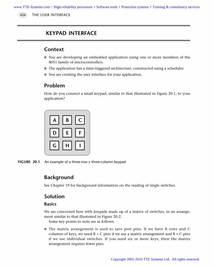
KEYPAD INTERFACE
Context You are developing an embedded application using one or more members of the
8051 family of microcontrollers.
The application has a time-triggered architecture, constructed using a scheduler.
You are creating the user interface for your application.
ProblemHow do you connect a small keypad, similar to that illustrated in Figure 20.1, to yourapplication?
BackgroundSee Chapter 19 for background information on the reading of single switches.
SolutionBasics
We are concerned here with keypads made up of a matrix of switches, in an arrange-ment similar to that illustrated in Figure 20.2.
Some key points to note are as follows:
The matrix arrangement is used to save port pins. If we have R rows and Ccolumns of keys, we need R + C pins if we use a matrix arrangement and R × C pinsif we use individual switches. If you need six or more keys, then the matrixarrangement requires fewer pins.
THE USER INTERFACE434
FIGURE 20.1 An example of a three-row x three-column keypad
B CA
E FD
H IG
www.TTE-Systems.com = High-reliability processors + Software tools + Protection systems + Training & consultancy services
Copyright 2001-2010 TTE Systems Ltd. All rights reserved.
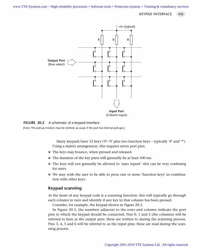
Many keypads have 12 keys (‘0’–‘9’ plus two function keys – typically ‘#’ and ‘*’).Using a matrix arrangement, this requires seven port pins.
The keys may bounce, when pressed and released.
The duration of the key press will generally be at least 500 ms.
The keys will not generally be allowed to ‘auto repeat’: this can be very confusingfor users.
We may wish the user to be able to press one or more ‘function keys’ in combina-tion with other keys.
Keypad scanning
At the heart of any keypad code is a scanning function: this will typically go througheach column in turn and identify if any key in that column has been pressed.
Consider, for example, the keypad shown in Figure 20.3.In Figure 20.3, the numbers adjacent to the rows and column indicate the port
pins to which the keypad should be connected. Pins 0, 1 and 2 (the columns) will bereferred to here as the output pins: these are written to during the scanning process.Pins 3, 4, 5 and 6 will be referred to as the input pins: these are read during the scan-ning process.
KEYPAD INTERFACE 435
FIGURE 20.2 A schematic of a keypad interface[Note: The pull-up resistors may be omitted, as usual, if the port has internal pull-ups.]
R R R
+5v (typical)
Input Port(Column input)
Output Port(Row select)
www.TTE-Systems.com = High-reliability processors + Software tools + Protection systems + Training & consultancy services
Copyright 2001-2010 TTE Systems Ltd. All rights reserved.
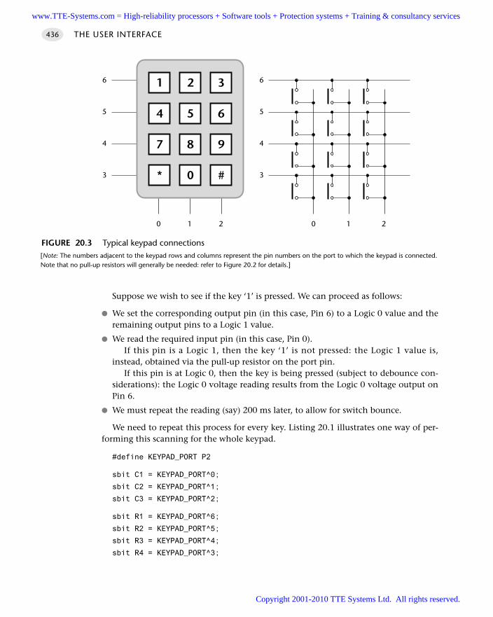
Suppose we wish to see if the key ‘1’ is pressed. We can proceed as follows:
We set the corresponding output pin (in this case, Pin 6) to a Logic 0 value and theremaining output pins to a Logic 1 value.
We read the required input pin (in this case, Pin 0). If this pin is a Logic 1, then the key ‘1’ is not pressed: the Logic 1 value is,
instead, obtained via the pull-up resistor on the port pin. If this pin is at Logic 0, then the key is being pressed (subject to debounce con-
siderations): the Logic 0 voltage reading results from the Logic 0 voltage output onPin 6.
We must repeat the reading (say) 200 ms later, to allow for switch bounce.
We need to repeat this process for every key. Listing 20.1 illustrates one way of per-forming this scanning for the whole keypad.
#define KEYPAD_PORT P2
sbit C1 = KEYPAD_PORT^0;
sbit C2 = KEYPAD_PORT^1;
sbit C3 = KEYPAD_PORT^2;
sbit R1 = KEYPAD_PORT^6;
sbit R2 = KEYPAD_PORT^5;
sbit R3 = KEYPAD_PORT^4;
sbit R4 = KEYPAD_PORT^3;
THE USER INTERFACE436
FIGURE 20.3 Typical keypad connections[Note: The numbers adjacent to the keypad rows and columns represent the pin numbers on the port to which the keypad is connected.Note that no pull-up resistors will generally be needed: refer to Figure 20.2 for details.]
0 1 2 0 1 2
4
5
6
3
2 31
5 64
8 97
0 #*
4
5
6
3
www.TTE-Systems.com = High-reliability processors + Software tools + Protection systems + Training & consultancy services
Copyright 2001-2010 TTE Systems Ltd. All rights reserved.
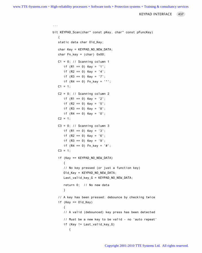
...
bit KEYPAD_Scan(char* const pKey, char* const pFuncKey)
static data char Old_Key;
char Key = KEYPAD_NO_NEW_DATA;
char Fn_key = (char) 0x00;
C1 = 0; // Scanning column 1
if (R1 == 0) Key = '1';
if (R2 == 0) Key = '4';
if (R3 == 0) Key = '7';
if (R4 == 0) Fn_key = '*';
C1 = 1;
C2 = 0; // Scanning column 2
if (R1 == 0) Key = '2';
if (R2 == 0) Key = '5';
if (R3 == 0) Key = '8';
if (R4 == 0) Key = '0';
C2 = 1;
C3 = 0; // Scanning column 3
if (R1 == 0) Key = '3';
if (R2 == 0) Key = '6';
if (R3 == 0) Key = '9';
if (R4 == 0) Fn_key = '#';
C3 = 1;
if (Key == KEYPAD_NO_NEW_DATA)
// No key pressed (or just a function key)
Old_Key = KEYPAD_NO_NEW_DATA;
Last_valid_key_G = KEYPAD_NO_NEW_DATA;
return 0; // No new data
// A key has been pressed: debounce by checking twice
if (Key == Old_Key)
// A valid (debounced) key press has been detected
// Must be a new key to be valid - no 'auto repeat'
if (Key != Last_valid_key_G)
KEYPAD INTERFACE 437
www.TTE-Systems.com = High-reliability processors + Software tools + Protection systems + Training & consultancy services
Copyright 2001-2010 TTE Systems Ltd. All rights reserved.
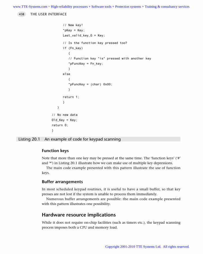
// New key!
*pKey = Key;
Last_valid_key_G = Key;
// Is the function key pressed too?
if (Fn_key)
// Function key *is* pressed with another key
*pFuncKey = Fn_key;
else
*pFuncKey = (char) 0x00;
return 1;
// No new data
Old_Key = Key;
return 0;
Listing 20.1 An example of code for keypad scanning
Function keys
Note that more than one key may be pressed at the same time. The ‘function keys’ (‘#’and ‘*’) in Listing 20.1 illustrate how we can make use of multiple key depressions.
The main code example presented with this pattern illustrate the use of functionkeys.
Buffer arrangements
In most scheduled keypad routines, it is useful to have a small buffer, so that keypresses are not lost if the system is unable to process them immediately.
Numerous buffer arrangements are possible: the main code example presentedwith this pattern illustrates one possibility.
Hardware resource implicationsWhile it does not require on-chip facilities (such as timers etc.), the keypad scanningprocess imposes both a CPU and memory load.
THE USER INTERFACE438
www.TTE-Systems.com = High-reliability processors + Software tools + Protection systems + Training & consultancy services
Copyright 2001-2010 TTE Systems Ltd. All rights reserved.
Reliability and safety issuesKeypad scanning is a software-based technique, closely related to S W I T C H I N T E R FA C E
(S O F T WA R E) [page 399]. In a hostile environment, use of a keypad may provide a lessreliable solution than use of a number of individual switches with a hardware inter-face (see S W I T C H I N T E R FA C E (H A R D WA R E) [page 410]).
However, particularly where a large keypad – such as a QWERTY keypad witharound 30 keys – is required, use of separate switches may be impractical. The safestthing to do in such circumstances may be to use a shared-clock scheduler (see Part F),and have a second microcontroller link to the keypad. This ‘keypad microcontroller’should then have a separate power supply, and should be opto-isolated from the mainsystem board.
PortabilityThis code is highly portable and this approach to keypad scanning is very widely used.
Overall strengths and weaknessesMultiplexed keypads are easy to use and inexpensive.
Because the pattern is software based, minimal protection against ESD and mali-cious damage (for example) is provided: use of a separate, isolated, keypadprocessor may be necessary if the reliability of the main processor is essential.
In harsh environments, it may be safer to avoid multiplexed keypads and useindividual switches.
Related patterns and alternative solutionsSee S W I T C H I N T E R FA C E (S O F T WA R E) [page 399] and S W I T C H I N T E R FA C E (H A R D WA R E)[page 410].
Example: Keypad library with buffer and fn key supportWe present here a complete keypad library for the 8051 family. The library has supportfor function keys (two) and has a buffer facility. The library is intended to work with key-pads as shown in Figure 20.3, but is easily adapted to different keypad layouts and sizes.
The demonstration program runs on an Infineon c515c microcontroller. However,none of the keypad code is 515 specific: using appropriate versions of the scheduler andthe PC link libraries (included on the CD) it can be used with any 8051 family member.
Figure 20.4 shows a typical program output.The key library files are given in Listings 20.2 to 20.5. Refer to the CD for the com-
plete set of files for this example.
KEYPAD INTERFACE 439
www.TTE-Systems.com = High-reliability processors + Software tools + Protection systems + Training & consultancy services
Copyright 2001-2010 TTE Systems Ltd. All rights reserved.
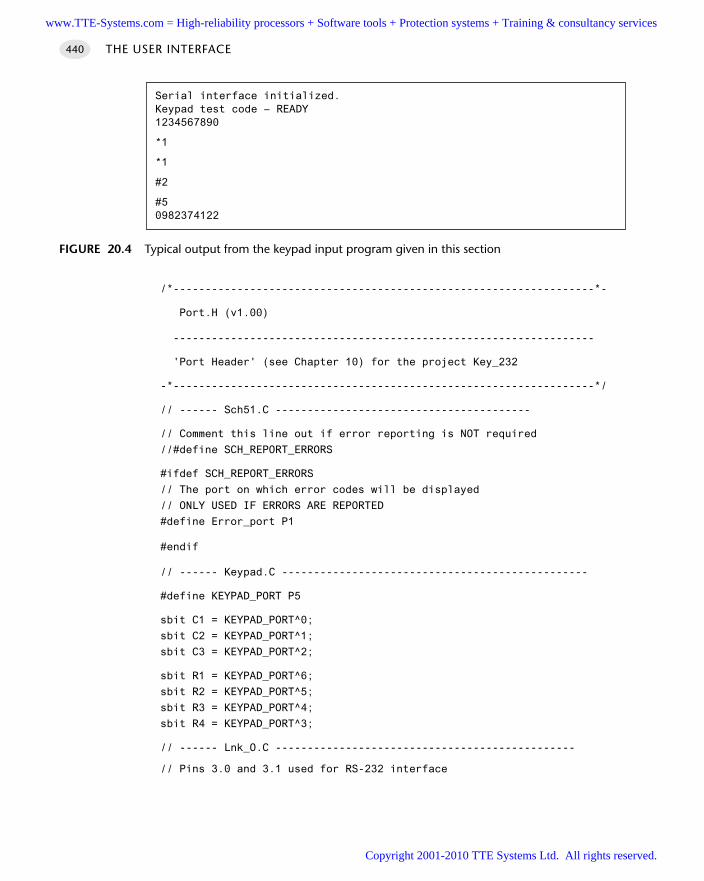
/*------------------------------------------------------------------*-
Port.H (v1.00)
------------------------------------------------------------------
'Port Header' (see Chapter 10) for the project Key_232
-*------------------------------------------------------------------*/
// ------ Sch51.C ----------------------------------------
// Comment this line out if error reporting is NOT required
//#define SCH_REPORT_ERRORS
#ifdef SCH_REPORT_ERRORS
// The port on which error codes will be displayed
// ONLY USED IF ERRORS ARE REPORTED
#define Error_port P1
#endif
// ------ Keypad.C ------------------------------------------------
#define KEYPAD_PORT P5
sbit C1 = KEYPAD_PORT^0;
sbit C2 = KEYPAD_PORT^1;
sbit C3 = KEYPAD_PORT^2;
sbit R1 = KEYPAD_PORT^6;
sbit R2 = KEYPAD_PORT^5;
sbit R3 = KEYPAD_PORT^4;
sbit R4 = KEYPAD_PORT^3;
// ------ Lnk_O.C -----------------------------------------------
// Pins 3.0 and 3.1 used for RS-232 interface
THE USER INTERFACE440
FIGURE 20.4 Typical output from the keypad input program given in this section
Serial interface initialized.Keypad test code – READY1234567890
*1
*1
#2
#50982374122
www.TTE-Systems.com = High-reliability processors + Software tools + Protection systems + Training & consultancy services
Copyright 2001-2010 TTE Systems Ltd. All rights reserved.
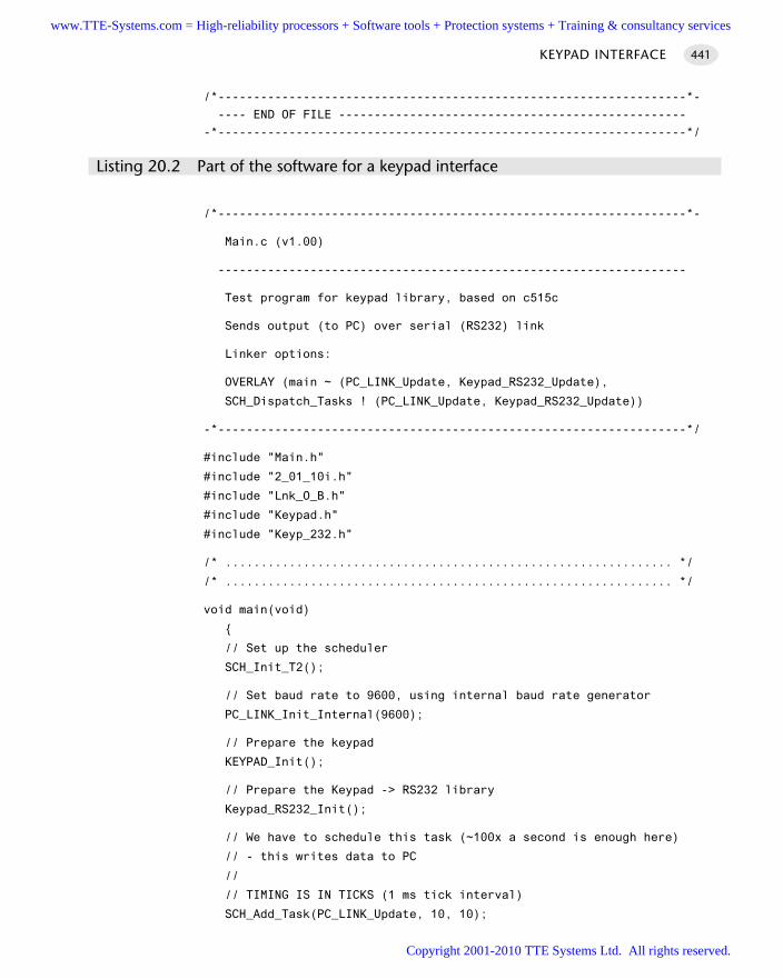
/*------------------------------------------------------------------*-
---- END OF FILE -------------------------------------------------
-*------------------------------------------------------------------*/
Listing 20.2 Part of the software for a keypad interface
/*------------------------------------------------------------------*-
Main.c (v1.00)
------------------------------------------------------------------
Test program for keypad library, based on c515c
Sends output (to PC) over serial (RS232) link
Linker options:
OVERLAY (main ~ (PC_LINK_Update, Keypad_RS232_Update),
SCH_Dispatch_Tasks ! (PC_LINK_Update, Keypad_RS232_Update))
-*------------------------------------------------------------------*/
#include "Main.h"
#include "2_01_10i.h"
#include "Lnk_O_B.h"
#include "Keypad.h"
#include "Keyp_232.h"
/* ............................................................... */
/* ............................................................... */
void main(void)
// Set up the scheduler
SCH_Init_T2();
// Set baud rate to 9600, using internal baud rate generator
PC_LINK_Init_Internal(9600);
// Prepare the keypad
KEYPAD_Init();
// Prepare the Keypad -> RS232 library
Keypad_RS232_Init();
// We have to schedule this task (~100x a second is enough here)
// - this writes data to PC
//
// TIMING IS IN TICKS (1 ms tick interval)
SCH_Add_Task(PC_LINK_Update, 10, 10);
KEYPAD INTERFACE 441
www.TTE-Systems.com = High-reliability processors + Software tools + Protection systems + Training & consultancy services
Copyright 2001-2010 TTE Systems Ltd. All rights reserved.
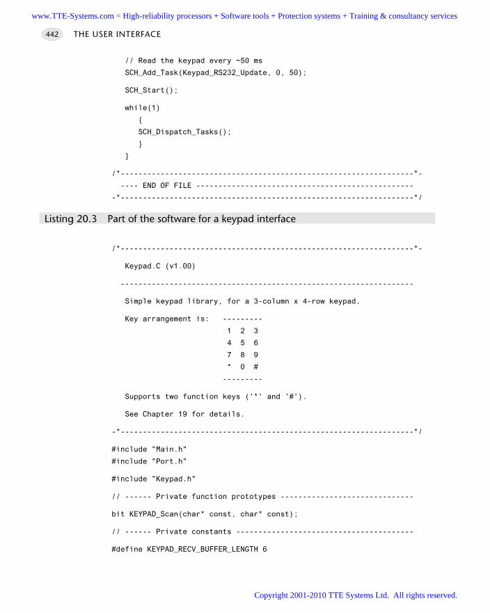
// Read the keypad every ~50 ms
SCH_Add_Task(Keypad_RS232_Update, 0, 50);
SCH_Start();
while(1)
SCH_Dispatch_Tasks();
/*------------------------------------------------------------------*-
---- END OF FILE -------------------------------------------------
-*------------------------------------------------------------------*/
Listing 20.3 Part of the software for a keypad interface
/*------------------------------------------------------------------*-
Keypad.C (v1.00)
------------------------------------------------------------------
Simple keypad library, for a 3-column x 4-row keypad.
Key arrangement is: ---------
1 2 3
4 5 6
7 8 9
* 0 #
---------
Supports two function keys ('*' and '#').
See Chapter 19 for details.
-*------------------------------------------------------------------*/
#include "Main.h"
#include "Port.h"
#include "Keypad.h"
// ------ Private function prototypes ------------------------------
bit KEYPAD_Scan(char* const, char* const);
// ------ Private constants ----------------------------------------
#define KEYPAD_RECV_BUFFER_LENGTH 6
THE USER INTERFACE442
www.TTE-Systems.com = High-reliability processors + Software tools + Protection systems + Training & consultancy services
Copyright 2001-2010 TTE Systems Ltd. All rights reserved.
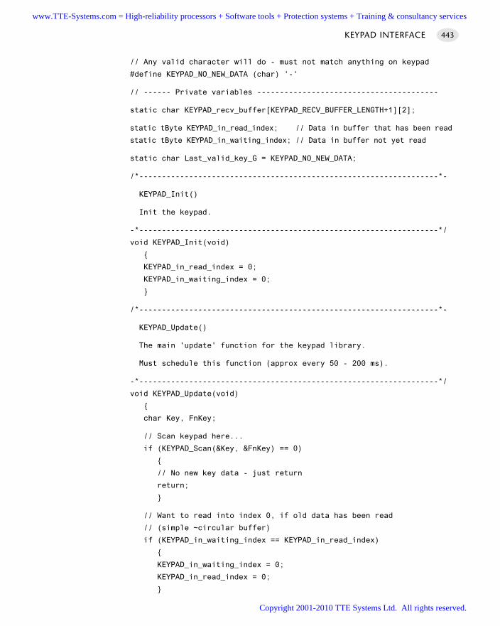
// Any valid character will do - must not match anything on keypad
#define KEYPAD_NO_NEW_DATA (char) '-'
// ------ Private variables ----------------------------------------
static char KEYPAD_recv_buffer[KEYPAD_RECV_BUFFER_LENGTH+1][2];
static tByte KEYPAD_in_read_index; // Data in buffer that has been read
static tByte KEYPAD_in_waiting_index; // Data in buffer not yet read
static char Last_valid_key_G = KEYPAD_NO_NEW_DATA;
/*------------------------------------------------------------------*-
KEYPAD_Init()
Init the keypad.
-*------------------------------------------------------------------*/
void KEYPAD_Init(void)
KEYPAD_in_read_index = 0;
KEYPAD_in_waiting_index = 0;
/*------------------------------------------------------------------*-
KEYPAD_Update()
The main 'update' function for the keypad library.
Must schedule this function (approx every 50 - 200 ms).
-*------------------------------------------------------------------*/
void KEYPAD_Update(void)
char Key, FnKey;
// Scan keypad here...
if (KEYPAD_Scan(&Key, &FnKey) == 0)
// No new key data - just return
return;
// Want to read into index 0, if old data has been read
// (simple ~circular buffer)
if (KEYPAD_in_waiting_index == KEYPAD_in_read_index)
KEYPAD_in_waiting_index = 0;
KEYPAD_in_read_index = 0;
KEYPAD INTERFACE 443
www.TTE-Systems.com = High-reliability processors + Software tools + Protection systems + Training & consultancy services
Copyright 2001-2010 TTE Systems Ltd. All rights reserved.
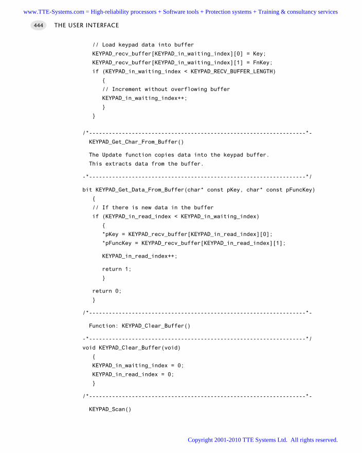
// Load keypad data into buffer
KEYPAD_recv_buffer[KEYPAD_in_waiting_index][0] = Key;
KEYPAD_recv_buffer[KEYPAD_in_waiting_index][1] = FnKey;
if (KEYPAD_in_waiting_index < KEYPAD_RECV_BUFFER_LENGTH)
// Increment without overflowing buffer
KEYPAD_in_waiting_index++;
/*------------------------------------------------------------------*-
KEYPAD_Get_Char_From_Buffer()
The Update function copies data into the keypad buffer.
This extracts data from the buffer.
-*------------------------------------------------------------------*/
bit KEYPAD_Get_Data_From_Buffer(char* const pKey, char* const pFuncKey)
// If there is new data in the buffer
if (KEYPAD_in_read_index < KEYPAD_in_waiting_index)
*pKey = KEYPAD_recv_buffer[KEYPAD_in_read_index][0];
*pFuncKey = KEYPAD_recv_buffer[KEYPAD_in_read_index][1];
KEYPAD_in_read_index++;
return 1;
return 0;
/*------------------------------------------------------------------*-
Function: KEYPAD_Clear_Buffer()
-*------------------------------------------------------------------*/
void KEYPAD_Clear_Buffer(void)
KEYPAD_in_waiting_index = 0;
KEYPAD_in_read_index = 0;
/*------------------------------------------------------------------*-
KEYPAD_Scan()
THE USER INTERFACE444
www.TTE-Systems.com = High-reliability processors + Software tools + Protection systems + Training & consultancy services
Copyright 2001-2010 TTE Systems Ltd. All rights reserved.
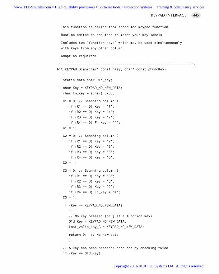
This function is called from scheduled keypad function.
Must be edited as required to match your key labels.
Includes two 'function keys' which may be used simultaneously
with keys from any other column.
Adapt as required!
-*------------------------------------------------------------------*/
bit KEYPAD_Scan(char* const pKey, char* const pFuncKey)
static data char Old_Key;
char Key = KEYPAD_NO_NEW_DATA;
char Fn_key = (char) 0x00;
C1 = 0; // Scanning column 1
if (R1 == 0) Key = '1';
if (R2 == 0) Key = '4';
if (R3 == 0) Key = '7';
if (R4 == 0) Fn_key = '*';
C1 = 1;
C2 = 0; // Scanning column 2
if (R1 == 0) Key = '2';
if (R2 == 0) Key = '5';
if (R3 == 0) Key = '8';
if (R4 == 0) Key = '0';
C2 = 1;
C3 = 0; // Scanning column 3
if (R1 == 0) Key = '3';
if (R2 == 0) Key = '6';
if (R3 == 0) Key = '9';
if (R4 == 0) Fn_key = '#';
C3 = 1;
if (Key == KEYPAD_NO_NEW_DATA)
// No key pressed (or just a function key)
Old_Key = KEYPAD_NO_NEW_DATA;
Last_valid_key_G = KEYPAD_NO_NEW_DATA;
return 0; // No new data
// A key has been pressed: debounce by checking twice
if (Key == Old_Key)
KEYPAD INTERFACE 445
www.TTE-Systems.com = High-reliability processors + Software tools + Protection systems + Training & consultancy services
Copyright 2001-2010 TTE Systems Ltd. All rights reserved.
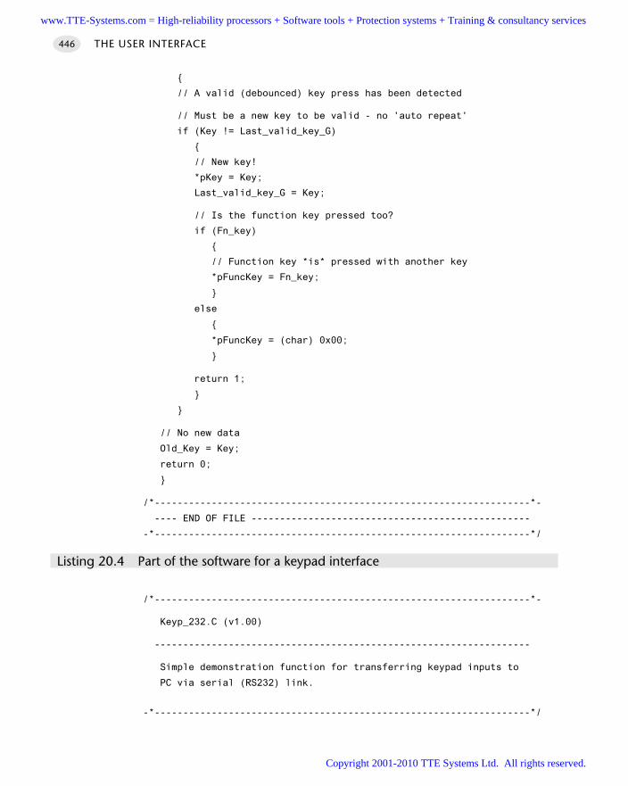
// A valid (debounced) key press has been detected
// Must be a new key to be valid - no 'auto repeat'
if (Key != Last_valid_key_G)
// New key!
*pKey = Key;
Last_valid_key_G = Key;
// Is the function key pressed too?
if (Fn_key)
// Function key *is* pressed with another key
*pFuncKey = Fn_key;
else
*pFuncKey = (char) 0x00;
return 1;
// No new data
Old_Key = Key;
return 0;
/*------------------------------------------------------------------*-
---- END OF FILE -------------------------------------------------
-*------------------------------------------------------------------*/
Listing 20.4 Part of the software for a keypad interface
/*------------------------------------------------------------------*-
Keyp_232.C (v1.00)
------------------------------------------------------------------
Simple demonstration function for transferring keypad inputs to
PC via serial (RS232) link.
-*------------------------------------------------------------------*/
THE USER INTERFACE446
www.TTE-Systems.com = High-reliability processors + Software tools + Protection systems + Training & consultancy services
Copyright 2001-2010 TTE Systems Ltd. All rights reserved.
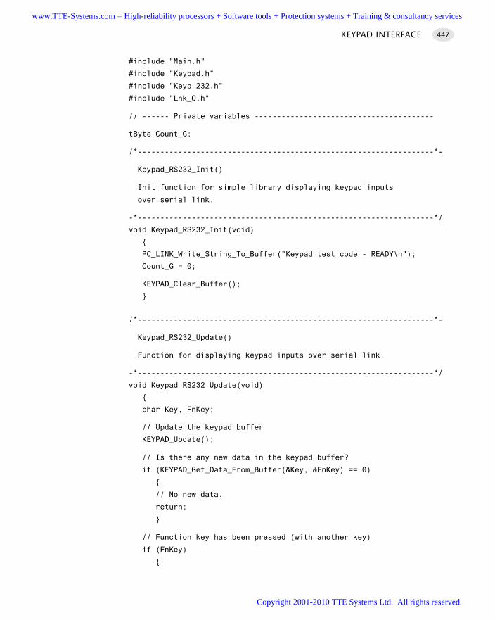
#include "Main.h"
#include "Keypad.h"
#include "Keyp_232.h"
#include "Lnk_O.h"
// ------ Private variables ----------------------------------------
tByte Count_G;
/*------------------------------------------------------------------*-
Keypad_RS232_Init()
Init function for simple library displaying keypad inputs
over serial link.
-*------------------------------------------------------------------*/
void Keypad_RS232_Init(void)
PC_LINK_Write_String_To_Buffer("Keypad test code - READY\n");
Count_G = 0;
KEYPAD_Clear_Buffer();
/*------------------------------------------------------------------*-
Keypad_RS232_Update()
Function for displaying keypad inputs over serial link.
-*------------------------------------------------------------------*/
void Keypad_RS232_Update(void)
char Key, FnKey;
// Update the keypad buffer
KEYPAD_Update();
// Is there any new data in the keypad buffer?
if (KEYPAD_Get_Data_From_Buffer(&Key, &FnKey) == 0)
// No new data.
return;
// Function key has been pressed (with another key)
if (FnKey)
KEYPAD INTERFACE 447
www.TTE-Systems.com = High-reliability processors + Software tools + Protection systems + Training & consultancy services
Copyright 2001-2010 TTE Systems Ltd. All rights reserved.
PC_LINK_Write_Char_To_Buffer('\n');
PC_LINK_Write_Char_To_Buffer(FnKey);
PC_LINK_Write_Char_To_Buffer(Key);
PC_LINK_Write_Char_To_Buffer('\n');
Count_G = 0;
else
// An ordinary key (no function key) has been pressed
PC_LINK_Write_Char_To_Buffer(Key);
if (++Count_G == 10)
PC_LINK_Write_Char_To_Buffer('\n');
Count_G = 0;
/*------------------------------------------------------------------*-
---- END OF FILE -------------------------------------------------
-*------------------------------------------------------------------*/
Listing 20.5 Part of the software for a keypad interface
Example: Keypad and LCDSee Chapter 22 for a complete example of a keypad and LCD interface design.
Further reading—
THE USER INTERFACE448
www.TTE-Systems.com = High-reliability processors + Software tools + Protection systems + Training & consultancy services
Copyright 2001-2010 TTE Systems Ltd. All rights reserved.
Multiplexed LED displays
Introduction
Many embedded applications contain user interfaces assembled from multi-segmentLED displays.
In this chapter, we consider how such displays may be interfaced to the 8051family of microcontrollers.
chapter 21www.TTE-Systems.com = High-reliability processors + Software tools + Protection systems + Training & consultancy services
Copyright 2001-2010 TTE Systems Ltd. All rights reserved.
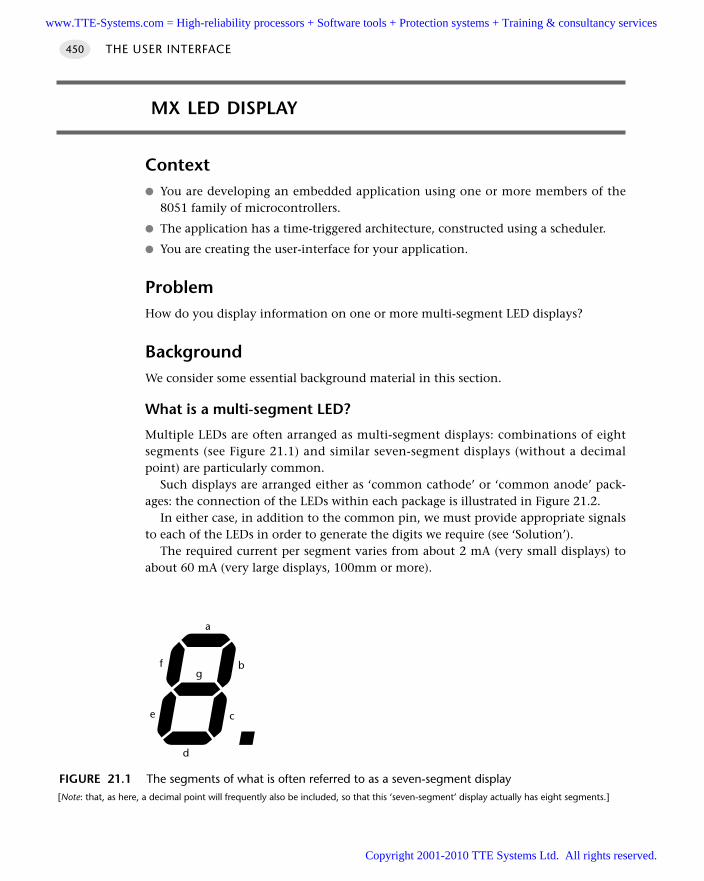
THE USER INTERFACE450
MX LED DISPLAY
Context You are developing an embedded application using one or more members of the
8051 family of microcontrollers.
The application has a time-triggered architecture, constructed using a scheduler.
You are creating the user-interface for your application.
ProblemHow do you display information on one or more multi-segment LED displays?
BackgroundWe consider some essential background material in this section.
What is a multi-segment LED?
Multiple LEDs are often arranged as multi-segment displays: combinations of eightsegments (see Figure 21.1) and similar seven-segment displays (without a decimalpoint) are particularly common.
Such displays are arranged either as ‘common cathode’ or ‘common anode’ pack-ages: the connection of the LEDs within each package is illustrated in Figure 21.2.
In either case, in addition to the common pin, we must provide appropriate signalsto each of the LEDs in order to generate the digits we require (see ‘Solution’).
The required current per segment varies from about 2 mA (very small displays) toabout 60 mA (very large displays, 100mm or more).
FIGURE 21.1 The segments of what is often referred to as a seven-segment display[Note: that, as here, a decimal point will frequently also be included, so that this ‘seven-segment’ display actually has eight segments.]
a
d
e
f
c
bg
www.TTE-Systems.com = High-reliability processors + Software tools + Protection systems + Training & consultancy services
Copyright 2001-2010 TTE Systems Ltd. All rights reserved.
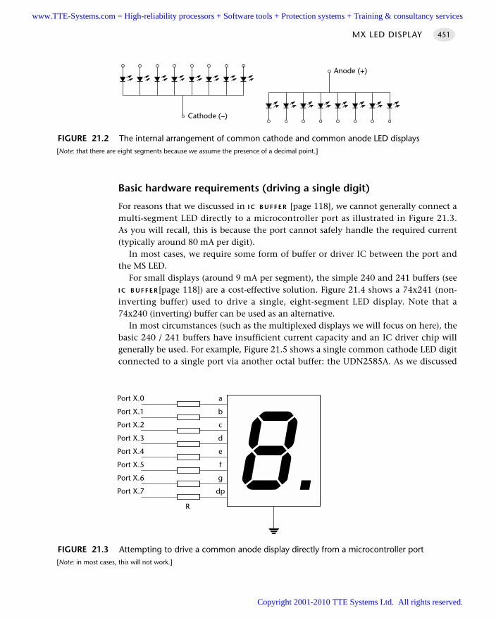
Basic hardware requirements (driving a single digit)
For reasons that we discussed in I C B U F F E R [page 118], we cannot generally connect amulti-segment LED directly to a microcontroller port as illustrated in Figure 21.3.As you will recall, this is because the port cannot safely handle the required current(typically around 80 mA per digit).
In most cases, we require some form of buffer or driver IC between the port andthe MS LED.
For small displays (around 9 mA per segment), the simple 240 and 241 buffers (seeI C B U F F E R [page 118]) are a cost-effective solution. Figure 21.4 shows a 74x241 (non-inverting buffer) used to drive a single, eight-segment LED display. Note that a74x240 (inverting) buffer can be used as an alternative.
In most circumstances (such as the multiplexed displays we will focus on here), thebasic 240 / 241 buffers have insufficient current capacity and an IC driver chip willgenerally be used. For example, Figure 21.5 shows a single common cathode LED digitconnected to a single port via another octal buffer: the UDN2585A. As we discussed
MX LED DISPLAY 451
FIGURE 21.2 The internal arrangement of common cathode and common anode LED displays[Note: that there are eight segments because we assume the presence of a decimal point.]
Cathode (–)
Anode (+)
FIGURE 21.3 Attempting to drive a common anode display directly from a microcontroller port[Note: in most cases, this will not work.]
ePort X.4
dPort X.3
cPort X.2
bPort X.1
aPort X.0
fPort X.5
gPort X.6
dpPort X.7
R
www.TTE-Systems.com = High-reliability processors + Software tools + Protection systems + Training & consultancy services
Copyright 2001-2010 TTE Systems Ltd. All rights reserved.
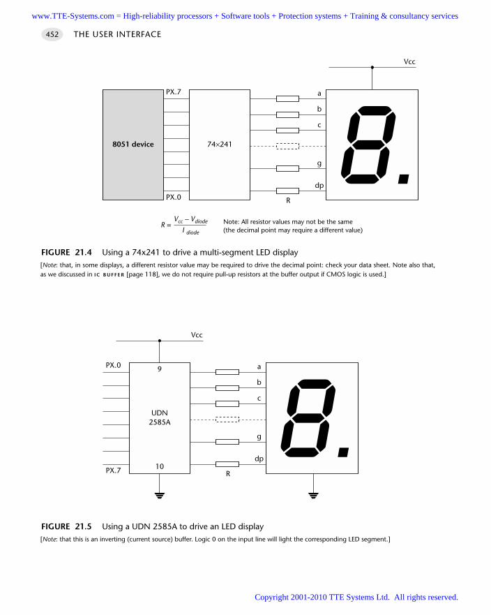
THE USER INTERFACE452
FIGURE 21.4 Using a 74x241 to drive a multi-segment LED display[Note: that, in some displays, a different resistor value may be required to drive the decimal point: check your data sheet. Note also that,as we discussed in I C B U F F E R [page 118], we do not require pull-up resistors at the buffer output if CMOS logic is used.]
b
a
g
dp
R
Vcc
c
74×2418051 device
PX.7
PX.0
R =Vcc – Vdiode
I diode
Note: All resistor values may not be the same(the decimal point may require a different value)
FIGURE 21.5 Using a UDN 2585A to drive an LED display[Note: that this is an inverting (current source) buffer. Logic 0 on the input line will light the corresponding LED segment.]
b
a
g
dp
R
Vcc
c
UDN2585A
PX.0
PX.7
9
10
www.TTE-Systems.com = High-reliability processors + Software tools + Protection systems + Training & consultancy services
Copyright 2001-2010 TTE Systems Ltd. All rights reserved.
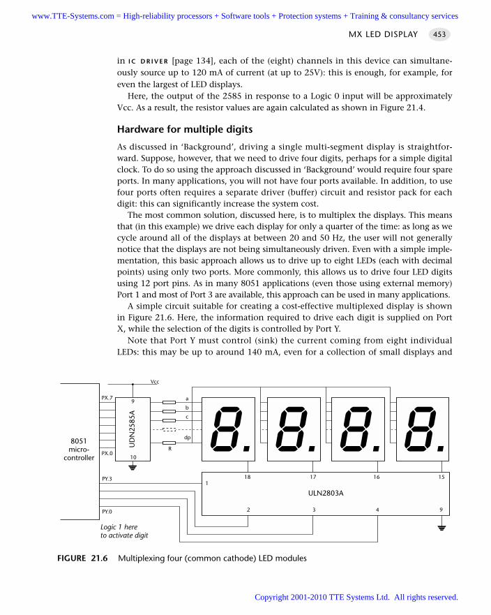
in I C D R I V E R [page 134], each of the (eight) channels in this device can simultane-ously source up to 120 mA of current (at up to 25V): this is enough, for example, foreven the largest of LED displays.
Here, the output of the 2585 in response to a Logic 0 input will be approximatelyVcc. As a result, the resistor values are again calculated as shown in Figure 21.4.
Hardware for multiple digits
As discussed in ‘Background’, driving a single multi-segment display is straightfor-ward. Suppose, however, that we need to drive four digits, perhaps for a simple digitalclock. To do so using the approach discussed in ‘Background’ would require four spareports. In many applications, you will not have four ports available. In addition, to usefour ports often requires a separate driver (buffer) circuit and resistor pack for eachdigit: this can significantly increase the system cost.
The most common solution, discussed here, is to multiplex the displays. This meansthat (in this example) we drive each display for only a quarter of the time: as long as wecycle around all of the displays at between 20 and 50 Hz, the user will not generallynotice that the displays are not being simultaneously driven. Even with a simple imple-mentation, this basic approach allows us to drive up to eight LEDs (each with decimalpoints) using only two ports. More commonly, this allows us to drive four LED digitsusing 12 port pins. As in many 8051 applications (even those using external memory)Port 1 and most of Port 3 are available, this approach can be used in many applications.
A simple circuit suitable for creating a cost-effective multiplexed display is shownin Figure 21.6. Here, the information required to drive each digit is supplied on PortX, while the selection of the digits is controlled by Port Y.
Note that Port Y must control (sink) the current coming from eight individualLEDs: this may be up to around 140 mA, even for a collection of small displays and
MX LED DISPLAY 453
FIGURE 21.6 Multiplexing four (common cathode) LED modules
b
a
dp
R
Vcc
c
UD
N25
85A
PX.7
PX.0
9
10
ULN2803A
18 17 16 15
2 3 4 9
8051micro-
controller
PY.0
1PY.3
Logic 1 hereto activate digit
www.TTE-Systems.com = High-reliability processors + Software tools + Protection systems + Training & consultancy services
Copyright 2001-2010 TTE Systems Ltd. All rights reserved.
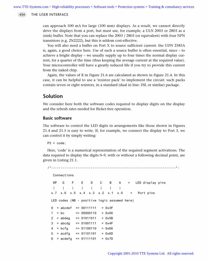
can approach 500 mA for large (100 mm) displays. As a result, we cannot directlydrive the displays from a port, but must use, for example, a ULN 2003 or 2803 as a(sink) buffer. Note that you can replace the 2003 / 2803 (or equivalent) with four NPNtransistors (e.g. 2N2222), but this is seldom cost-effective.
You will also need a buffer on Port X to source sufficient current: the UDN 2585Ais, again, a good choice here. Use of such a source buffer is often essential, since – toachieve a bright display – we usually supply up to four times the normal display cur-rent, for a quarter of the time (thus keeping the average current at the required value).Your microcontroller will have a greatly reduced life if you try to provide this currentfrom the naked chip.
Again, the values of R in Figure 21.6 are calculated as shown in Figure 21.4. In thiscase, it can be helpful to use a ‘resistor pack’ to implement the circuit: such packscontain seven or eight resistors, in a standard (dual in line: DIL or similar) package.
SolutionWe consider here both the software codes required to display digits on the displayand the refresh rates needed for flicker-free operation.
Basic software
The software to control the LED digits in arrangements like those shown in Figures21.4 and 21.5 is easy to write. If, for example, we connect the display to Port 3, wecan control it by simply writing:
P3 = code;
Here, ‘code’ is a numerical representation of the required segment activations. Thedata required to display the digits 0–9, with or without a following decimal point, aregiven in Listing 21.1.
/*------------------------------------------------------------------*-
Connections
DP G F E D C B A = LED display pins
| | | | | | | |
x.7 x.6 x.5 x.4 x.3 x.2 x.1 x.0 = Port pins
LED codes (NB - positive logic assumed here)
0 = abcdef => 00111111 = 0x3F
1 = bc => 00000110 = 0x06
2 = abdeg => 01011011 = 0x5B
3 = abcdg => 01001111 = 0x4F
4 = bcfg => 01100110 = 0x66
5 = acdfg => 01101101 = 0x6D
6 = acdefg => 01111101 = 0x7D
THE USER INTERFACE454
www.TTE-Systems.com = High-reliability processors + Software tools + Protection systems + Training & consultancy services
Copyright 2001-2010 TTE Systems Ltd. All rights reserved.
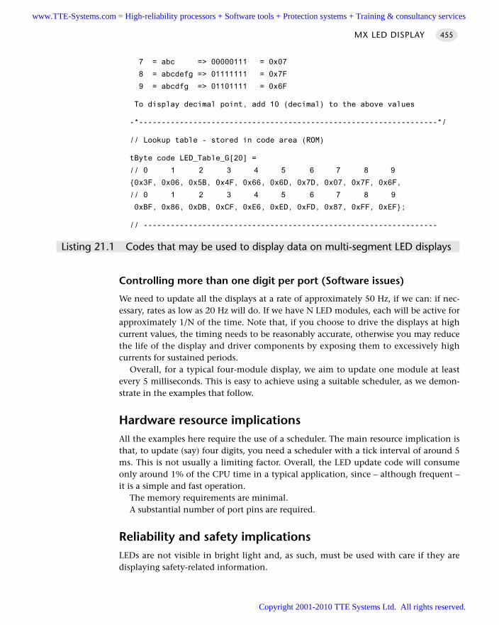
MX LED DISPLAY 455
7 = abc => 00000111 = 0x07
8 = abcdefg => 01111111 = 0x7F
9 = abcdfg => 01101111 = 0x6F
To display decimal point, add 10 (decimal) to the above values
-*------------------------------------------------------------------*/
// Lookup table - stored in code area (ROM)
tByte code LED_Table_G[20] =
// 0 1 2 3 4 5 6 7 8 9
0x3F, 0x06, 0x5B, 0x4F, 0x66, 0x6D, 0x7D, 0x07, 0x7F, 0x6F,
// 0 1 2 3 4 5 6 7 8 9
0xBF, 0x86, 0xDB, 0xCF, 0xE6, 0xED, 0xFD, 0x87, 0xFF, 0xEF;
// -----------------------------------------------------------------
Listing 21.1 Codes that may be used to display data on multi-segment LED displays
Controlling more than one digit per port (Software issues)
We need to update all the displays at a rate of approximately 50 Hz, if we can: if nec-essary, rates as low as 20 Hz will do. If we have N LED modules, each will be active forapproximately 1/N of the time. Note that, if you choose to drive the displays at highcurrent values, the timing needs to be reasonably accurate, otherwise you may reducethe life of the display and driver components by exposing them to excessively highcurrents for sustained periods.
Overall, for a typical four-module display, we aim to update one module at leastevery 5 milliseconds. This is easy to achieve using a suitable scheduler, as we demon-strate in the examples that follow.
Hardware resource implicationsAll the examples here require the use of a scheduler. The main resource implication isthat, to update (say) four digits, you need a scheduler with a tick interval of around 5ms. This is not usually a limiting factor. Overall, the LED update code will consumeonly around 1% of the CPU time in a typical application, since – although frequent –it is a simple and fast operation.
The memory requirements are minimal.A substantial number of port pins are required.
Reliability and safety implicationsLEDs are not visible in bright light and, as such, must be used with care if they aredisplaying safety-related information.
www.TTE-Systems.com = High-reliability processors + Software tools + Protection systems + Training & consultancy services
Copyright 2001-2010 TTE Systems Ltd. All rights reserved.
THE USER INTERFACE456
For multiplexed displays, you must ensure that the application (or scheduler)cannot become locked: if it does, the display will very quickly be destroyed by highcurrent values. Thus, if a poorly designed task blocks the scheduler, even for a few sec-onds, and delays a display update (usually scheduled around 20 to 50 Hz), you willprobably destroy the display. Whatever happens, you need to ensure that such anevent will not impact on the general operation of the microcontroller and, therefore,completely destroy the application.
PortabilityThese techniques are easily ported across members of the 8051 family and to anyother processor family. No features unique to the 8051 are employed.
Overall strengths and weaknessesMulti-segment LED displays are reliable and cheap.
The techniques discussed in this pattern are easy to apply and highly portable.
A typical interface requires a substantial number of port pins: up to 12 pins for amultiplexed 4-digit display.
Displays are not visible in bright sunlight. Provide an additional audible warningif necessary.
Multiplexed displays can suffer from reliability problems if the scheduling is nothandled correctly.
Related patterns and alternative solutionsThere are numerous ‘intelligent’ LED drivers, such as the Maxim 7219, that can dealwith the task of driving and multiplexing LED displays for you. These usually have aserial interface and, as a result, require few port pins. This can be a useful solution ifport availability is limited.
Another way of reducing port requirements is to use a version of the 74x247, BCD-to-7-segment decoder IC as an interface to your displays, as illustrated in Figure 21.7.The main problem with this approach is that the 74x247 is no longer widely avail-able. If you can find a good supply and are assured of future supplies, this device iseasy to use: consult the data sheet for details.
Another alternative, if lack of ports is a problem, is to use an additional Small 8051in your design. This chip will then be responsible for the display multiplexing andupdates: data can be easily transferred to such a device using a serial interface and ashared-clock scheduler (Figure 21.8). Shared-clock schedulers are discussed in Part F.
www.TTE-Systems.com = High-reliability processors + Software tools + Protection systems + Training & consultancy services
Copyright 2001-2010 TTE Systems Ltd. All rights reserved.
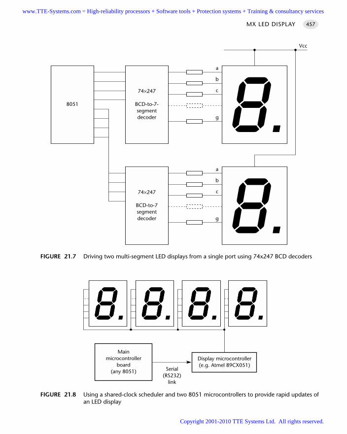
MX LED DISPLAY 457
FIGURE 21.7 Driving two multi-segment LED displays from a single port using 74x247 BCD decoders
b
a
g
Vcc
c74×247
BCD-to-7-segmentdecoder
b
a
g
c74×247
BCD-to-7segmentdecoder
8051
FIGURE 21.8 Using a shared-clock scheduler and two 8051 microcontrollers to provide rapid updates ofan LED display
Display microcontroller(e.g. Atmel 89CX051)
Mainmicrocontroller
board(any 8051) Serial
(RS232)link
www.TTE-Systems.com = High-reliability processors + Software tools + Protection systems + Training & consultancy services
Copyright 2001-2010 TTE Systems Ltd. All rights reserved.
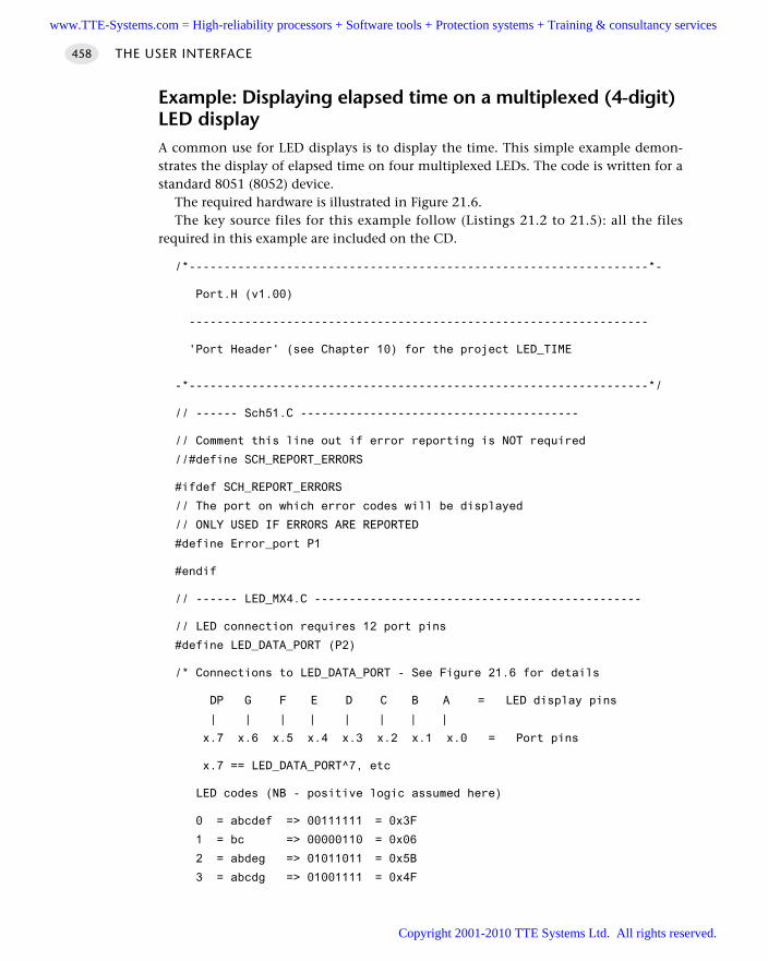
Example: Displaying elapsed time on a multiplexed (4-digit)LED display A common use for LED displays is to display the time. This simple example demon-strates the display of elapsed time on four multiplexed LEDs. The code is written for astandard 8051 (8052) device.
The required hardware is illustrated in Figure 21.6.The key source files for this example follow (Listings 21.2 to 21.5): all the files
required in this example are included on the CD.
/*------------------------------------------------------------------*-
Port.H (v1.00)
------------------------------------------------------------------
'Port Header' (see Chapter 10) for the project LED_TIME
-*------------------------------------------------------------------*/
// ------ Sch51.C ----------------------------------------
// Comment this line out if error reporting is NOT required
//#define SCH_REPORT_ERRORS
#ifdef SCH_REPORT_ERRORS
// The port on which error codes will be displayed
// ONLY USED IF ERRORS ARE REPORTED
#define Error_port P1
#endif
// ------ LED_MX4.C -----------------------------------------------
// LED connection requires 12 port pins
#define LED_DATA_PORT (P2)
/* Connections to LED_DATA_PORT - See Figure 21.6 for details
DP G F E D C B A = LED display pins
| | | | | | | |
x.7 x.6 x.5 x.4 x.3 x.2 x.1 x.0 = Port pins
x.7 == LED_DATA_PORT^7, etc
LED codes (NB - positive logic assumed here)
0 = abcdef => 00111111 = 0x3F
1 = bc => 00000110 = 0x06
2 = abdeg => 01011011 = 0x5B
3 = abcdg => 01001111 = 0x4F
THE USER INTERFACE458
www.TTE-Systems.com = High-reliability processors + Software tools + Protection systems + Training & consultancy services
Copyright 2001-2010 TTE Systems Ltd. All rights reserved.
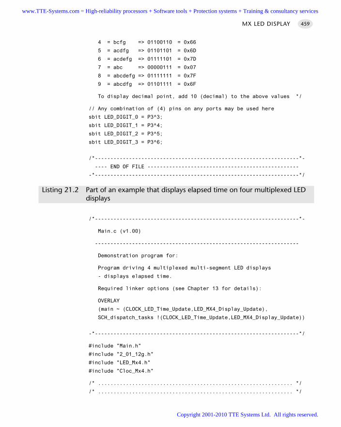
4 = bcfg => 01100110 = 0x66
5 = acdfg => 01101101 = 0x6D
6 = acdefg => 01111101 = 0x7D
7 = abc => 00000111 = 0x07
8 = abcdefg => 01111111 = 0x7F
9 = abcdfg => 01101111 = 0x6F
To display decimal point, add 10 (decimal) to the above values */
// Any combination of (4) pins on any ports may be used here
sbit LED_DIGIT_0 = P3^3;
sbit LED_DIGIT_1 = P3^4;
sbit LED_DIGIT_2 = P3^5;
sbit LED_DIGIT_3 = P3^6;
/*------------------------------------------------------------------*-
---- END OF FILE -------------------------------------------------
-*------------------------------------------------------------------*/
Listing 21.2 Part of an example that displays elapsed time on four multiplexed LED displays
/*------------------------------------------------------------------*-
Main.c (v1.00)
------------------------------------------------------------------
Demonstration program for:
Program driving 4 multiplexed multi-segment LED displays
- displays elapsed time.
Required linker options (see Chapter 13 for details):
OVERLAY
(main ~ (CLOCK_LED_Time_Update,LED_MX4_Display_Update),
SCH_dispatch_tasks !(CLOCK_LED_Time_Update,LED_MX4_Display_Update))
-*------------------------------------------------------------------*/
#include "Main.h"
#include "2_01_12g.h"
#include "LED_Mx4.h"
#include "Cloc_Mx4.h"
/* ............................................................... */
/* ............................................................... */
MX LED DISPLAY 459
www.TTE-Systems.com = High-reliability processors + Software tools + Protection systems + Training & consultancy services
Copyright 2001-2010 TTE Systems Ltd. All rights reserved.
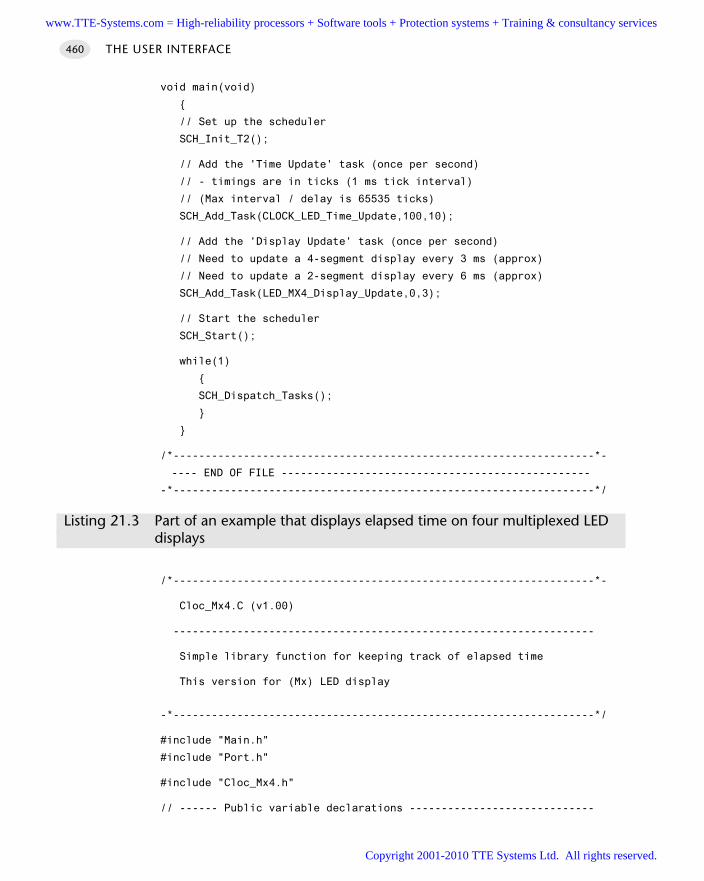
void main(void)
// Set up the scheduler
SCH_Init_T2();
// Add the 'Time Update' task (once per second)
// - timings are in ticks (1 ms tick interval)
// (Max interval / delay is 65535 ticks)
SCH_Add_Task(CLOCK_LED_Time_Update,100,10);
// Add the 'Display Update' task (once per second)
// Need to update a 4-segment display every 3 ms (approx)
// Need to update a 2-segment display every 6 ms (approx)
SCH_Add_Task(LED_MX4_Display_Update,0,3);
// Start the scheduler
SCH_Start();
while(1)
SCH_Dispatch_Tasks();
/*------------------------------------------------------------------*-
---- END OF FILE ------------------------------------------------
-*------------------------------------------------------------------*/
Listing 21.3 Part of an example that displays elapsed time on four multiplexed LED displays
/*------------------------------------------------------------------*-
Cloc_Mx4.C (v1.00)
------------------------------------------------------------------
Simple library function for keeping track of elapsed time
This version for (Mx) LED display
-*------------------------------------------------------------------*/
#include "Main.h"
#include "Port.h"
#include "Cloc_Mx4.h"
// ------ Public variable declarations -----------------------------
THE USER INTERFACE460
www.TTE-Systems.com = High-reliability processors + Software tools + Protection systems + Training & consultancy services
Copyright 2001-2010 TTE Systems Ltd. All rights reserved.
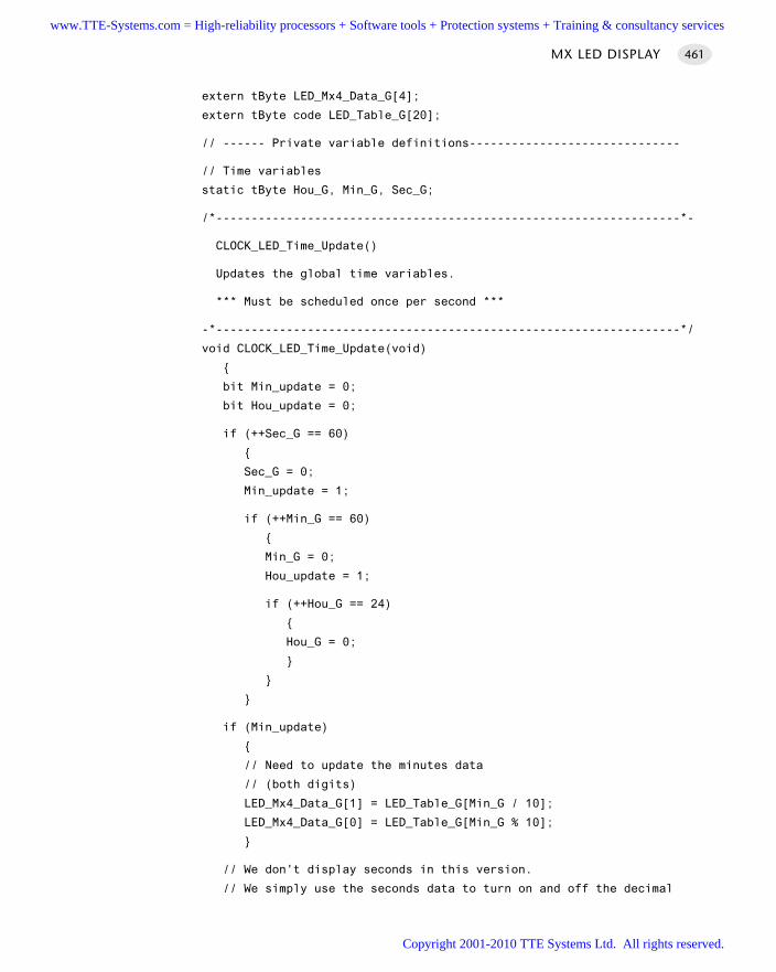
extern tByte LED_Mx4_Data_G[4];
extern tByte code LED_Table_G[20];
// ------ Private variable definitions------------------------------
// Time variables
static tByte Hou_G, Min_G, Sec_G;
/*------------------------------------------------------------------*-
CLOCK_LED_Time_Update()
Updates the global time variables.
*** Must be scheduled once per second ***
-*------------------------------------------------------------------*/
void CLOCK_LED_Time_Update(void)
bit Min_update = 0;
bit Hou_update = 0;
if (++Sec_G == 60)
Sec_G = 0;
Min_update = 1;
if (++Min_G == 60)
Min_G = 0;
Hou_update = 1;
if (++Hou_G == 24)
Hou_G = 0;
if (Min_update)
// Need to update the minutes data
// (both digits)
LED_Mx4_Data_G[1] = LED_Table_G[Min_G / 10];
LED_Mx4_Data_G[0] = LED_Table_G[Min_G % 10];
// We don't display seconds in this version.
// We simply use the seconds data to turn on and off the decimal
MX LED DISPLAY 461
www.TTE-Systems.com = High-reliability processors + Software tools + Protection systems + Training & consultancy services
Copyright 2001-2010 TTE Systems Ltd. All rights reserved.
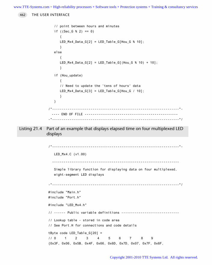
// point between hours and minutes
if ((Sec_G % 2) == 0)
LED_Mx4_Data_G[2] = LED_Table_G[Hou_G % 10];
else
LED_Mx4_Data_G[2] = LED_Table_G[(Hou_G % 10) + 10];
if (Hou_update)
// Need to update the 'tens of hours' data
LED_Mx4_Data_G[3] = LED_Table_G[Hou_G / 10];
/*------------------------------------------------------------------*-
---- END OF FILE ------------------------------------------------
-*------------------------------------------------------------------*/
Listing 21.4 Part of an example that displays elapsed time on four multiplexed LED displays
/*------------------------------------------------------------------*-
LED_Mx4.C (v1.00)
------------------------------------------------------------------
Simple library function for displaying data on four multiplexed,
eight-segment LED displays
-*------------------------------------------------------------------*/
#include "Main.h"
#include "Port.h"
#include "LED_Mx4.h"
// ------ Public variable definitions ------------------------------
// Lookup table - stored in code area
// See Port.H for connections and code details
tByte code LED_Table_G[20] =
// 0 1 2 3 4 5 6 7 8 9
0x3F, 0x06, 0x5B, 0x4F, 0x66, 0x6D, 0x7D, 0x07, 0x7F, 0x6F,
THE USER INTERFACE462
www.TTE-Systems.com = High-reliability processors + Software tools + Protection systems + Training & consultancy services
Copyright 2001-2010 TTE Systems Ltd. All rights reserved.
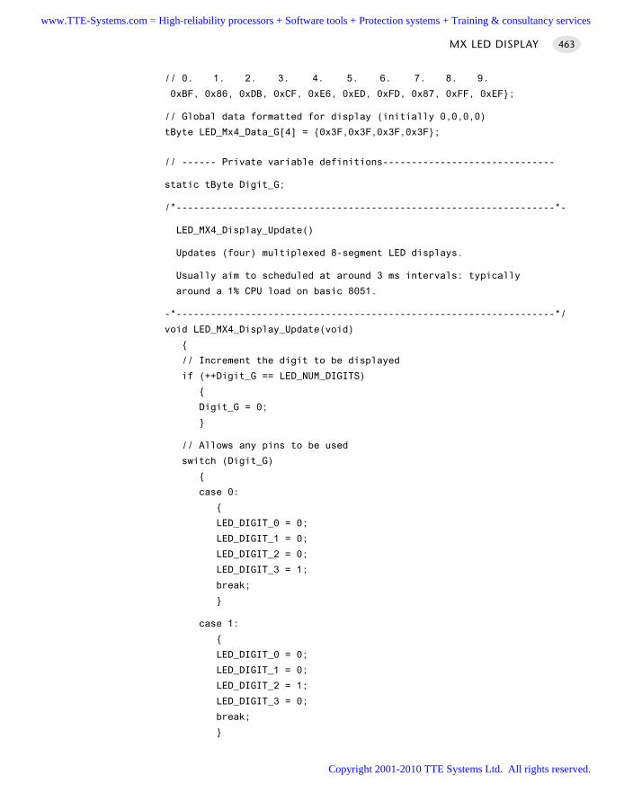
// 0. 1. 2. 3. 4. 5. 6. 7. 8. 9.
0xBF, 0x86, 0xDB, 0xCF, 0xE6, 0xED, 0xFD, 0x87, 0xFF, 0xEF;
// Global data formatted for display (initially 0,0,0,0)
tByte LED_Mx4_Data_G[4] = 0x3F,0x3F,0x3F,0x3F;
// ------ Private variable definitions------------------------------
static tByte Digit_G;
/*------------------------------------------------------------------*-
LED_MX4_Display_Update()
Updates (four) multiplexed 8-segment LED displays.
Usually aim to scheduled at around 3 ms intervals: typically
around a 1% CPU load on basic 8051.
-*------------------------------------------------------------------*/
void LED_MX4_Display_Update(void)
// Increment the digit to be displayed
if (++Digit_G == LED_NUM_DIGITS)
Digit_G = 0;
// Allows any pins to be used
switch (Digit_G)
case 0:
LED_DIGIT_0 = 0;
LED_DIGIT_1 = 0;
LED_DIGIT_2 = 0;
LED_DIGIT_3 = 1;
break;
case 1:
LED_DIGIT_0 = 0;
LED_DIGIT_1 = 0;
LED_DIGIT_2 = 1;
LED_DIGIT_3 = 0;
break;
MX LED DISPLAY 463
www.TTE-Systems.com = High-reliability processors + Software tools + Protection systems + Training & consultancy services
Copyright 2001-2010 TTE Systems Ltd. All rights reserved.
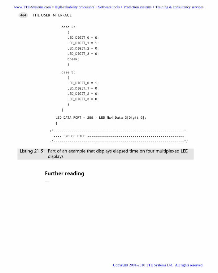
case 2:
LED_DIGIT_0 = 0;
LED_DIGIT_1 = 1;
LED_DIGIT_2 = 0;
LED_DIGIT_3 = 0;
break;
case 3:
LED_DIGIT_0 = 1;
LED_DIGIT_1 = 0;
LED_DIGIT_2 = 0;
LED_DIGIT_3 = 0;
LED_DATA_PORT = 255 - LED_Mx4_Data_G[Digit_G];
/*------------------------------------------------------------------*-
---- END OF FILE -------------------------------------------------
-*------------------------------------------------------------------*/
Listing 21.5 Part of an example that displays elapsed time on four multiplexed LED displays
Further reading—
THE USER INTERFACE464
www.TTE-Systems.com = High-reliability processors + Software tools + Protection systems + Training & consultancy services
Copyright 2001-2010 TTE Systems Ltd. All rights reserved.
Controlling LCD panels
Introduction
We considered the creation of LED-based user interfaces in Chapter 21. Here we areconcerned with the use of liquid crystal displays (LCDs) in such interfaces.
Unlike LEDs, LCDs are based on passive display technology: this means that LCDscontrol the passage of light rather than emitting light. This fact directly contributes tothe low power consumption of these devices: large (5V) panels require up to 5 mA: atotal power consumption of up to 25 mW, excluding any backlight. Small panels con-sume around half this power. Since a single LED has a very similar power consumption,use of LCD displays in battery-powered embedded systems is particularly popular.
While various types of LCD display are available, they can be divided into twobasic groups: graphics displays and text displays. Notebook (and increasingly desktop)PCs use sophisticated graphics displays, made up of many thousands of individual‘picture elements’ (pixels). Such displays are expensive in their own right and gener-ally require large amounts of memory (typically several megabytes) and powerfulprocessors for efficient operation. As we have seen, the type of embedded devices weare concerned with in this book do not usually justify this level of expense. Instead,we will be concerned here with small displays intended primarily to display text.
Various types of LCD-based character displays are available. These are typicallyarranged as one, two or four lines of between 16 and 40 characters. Inevitably, thelarger displays are more expensive and consume more power. Each LCD character isusually a 5x8 matrix of dots: less commonly, a 5x11 matrix is also used: note that, ineach case, the characters themselves are 5x7 and 5x10 pixels in size, with the bottomline being reserved for the cursor. To generate characters on such displays would tendto consume a large percentage of the available CPU time (and most of the ports oraddress space) on most embedded processors. As a result, most LCD panels include anon-board controller to deal with this: this is generally a variant on the Hitachi
chapter 22www.TTE-Systems.com = High-reliability processors + Software tools + Protection systems + Training & consultancy services
Copyright 2001-2010 TTE Systems Ltd. All rights reserved.
HD44780. Displays based on this popular controller all have very similar hardwareinterfaces and will display the same mixture of English (or Japanese) characters.
We focus on LCD panels based on this ‘standard’ controller in the pattern L C D
C H A R A C T E R PA N E L presented in this chapter. Please note that much of the background material presented here is adapted from
the Hitachi HD44780 data sheet.
THE USER INTERFACE466
www.TTE-Systems.com = High-reliability processors + Software tools + Protection systems + Training & consultancy services
Copyright 2001-2010 TTE Systems Ltd. All rights reserved.
LCD CHARACTER PANEL
Context You are developing an embedded application using one or more members of the
8051 family of microcontrollers.
The application has a time-triggered architecture, constructed using a scheduler.
You are creating the user interface for your application.
ProblemHow do you connect an LCD-based ‘character panel’ display to your embeddedprocessor and control it efficiently using a high-level programming language?
BackgroundAs outlined at the start of this chapter, we are concerned here with LCD characterpanels based on the HD44780 microcontroller.
Key HD44780 components
The HD44780 contains its own reset circuitry, memory and so forth: it contains sev-eral important components (Figure 22.1), which may be accessed and controlled froman attached microcontroller or microprocessor. We will discuss some of the key com-ponents in the sections that follow.
As shown in Figure 22.1, the interface between the microcontroller and theHD44780 consists of five sets of signals. A summary of each of these signals is givenin Table 22.1.
DD RAM
At the heart of the HD44780 is the DD RAM: the ‘Display Data’ RAM. This stores dis-play data represented in 8-bit character codes. Its capacity is 80 characters; as a resultthe maximum display sizes are 20 charactersx4 lines or 40 charactersx2 lines.
Use of the HD44780 involves transferring data (via the 4-bit or 8-bit data bus) intothe DD RAM. The HD44780 will then refresh the display as required using these data.
Characters that can be stored and displayed via DD RAM include most of the core(displayable) characters from the ASCII table, with only minor changes (Table 22.2):this means that, in general, you can simply send character data to the display andobtain the expected outputs.
Note that none of these characters uses the bottom line of the display (the cursorline): as a result, low-case characters with ‘tails’ (g, j, p, q, y) will appear higher thannormal on the display.
LCD CHARACTER PANEL 467
www.TTE-Systems.com = High-reliability processors + Software tools + Protection systems + Training & consultancy services
Copyright 2001-2010 TTE Systems Ltd. All rights reserved.
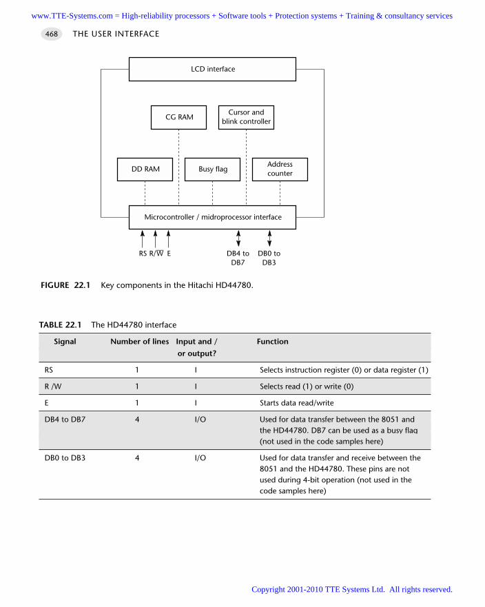
THE USER INTERFACE468
FIGURE 22.1 Key components in the Hitachi HD44780.
Microcontroller / midroprocessor interface
Busy flag
CG RAM
DD RAM
Cursor andblink controller
Addresscounter
RS R/––W E DB0 toDB3
DB4 toDB7
LCD interface
TABLE 22.1 The HD44780 interface
Signal Number of lines Input and / Function
or output?
RS 1 I Selects instruction register (0) or data register (1)
R /W 1 I Selects read (1) or write (0)
E 1 I Starts data read/write
DB4 to DB7 4 I/O Used for data transfer between the 8051 and the HD44780. DB7 can be used as a busy flag(not used in the code samples here)
DB0 to DB3 4 I/O Used for data transfer and receive between the8051 and the HD44780. These pins are notused during 4-bit operation (not used in the code samples here)
www.TTE-Systems.com = High-reliability processors + Software tools + Protection systems + Training & consultancy services
Copyright 2001-2010 TTE Systems Ltd. All rights reserved.
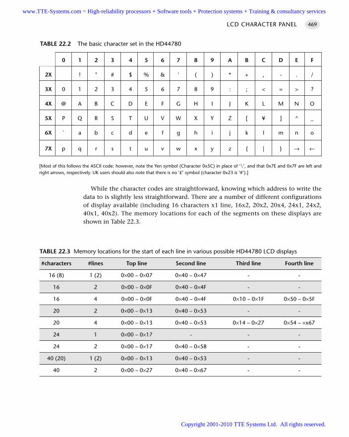
[Most of this follows the ASCII code: however, note the Yen symbol (Character 0x5C) in place of ‘\’, and that 0x7E and 0x7F are left andright arrows, respectively. UK users should also note that there is no ‘£’ symbol (character 0x23 is ‘#’).]
While the character codes are straightforward, knowing which address to write thedata to is slightly less straightforward. There are a number of different configurationsof display available (including 16 characters x1 line, 16x2, 20x2, 20x4, 24x1, 24x2,40x1, 40x2). The memory locations for each of the segments on these displays areshown in Table 22.3.
LCD CHARACTER PANEL 469
0 1 2 3 4 5 6 7 8 9 A B C D E F
2X ! " # $ % & ' ( ) * + , - . /
3X 0 1 2 3 4 5 6 7 8 9 : ; < = > ?
4X @ A B C D E F G H I J K L M N O
5X P Q R S T U V W X Y Z [ ¥ ] ^ _
6X ` a b c d e f g h i j k l m n o
7X p q r s t u v w x y z | → ←
TABLE 22.2 The basic character set in the HD44780
TABLE 22.3 Memory locations for the start of each line in various possible HD44780 LCD displays
#characters #lines Top line Second line Third line Fourth line
16 (8) 1 (2) 0×00 – 0×07 0×40 – 0×47 - -
16 2 0×00 – 0×0F 0×40 – 0×4F - -
16 4 0×00 – 0×0F 0×40 – 0×4F 0×10 – 0×1F 0×50 – 0×5F
20 2 0×00 – 0×13 0×40 – 0×53 - -
20 4 0×00 – 0×13 0×40 – 0×53 0×14 – 0×27 0×54 – ×x67
24 1 0×00 – 0×17 - - -
24 2 0×00 – 0×17 0×40 – 0×58 - -
40 (20) 1 (2) 0×00 – 0×13 0×40 – 0×53 - -
40 2 0×00 – 0×27 0×40 – 0×67 - -
www.TTE-Systems.com = High-reliability processors + Software tools + Protection systems + Training & consultancy services
Copyright 2001-2010 TTE Systems Ltd. All rights reserved.
CG RAM
The CG RAM is the ‘Character Generator’ RAM: this can be used to allow the creationand display of user-defined characters. This facility is helpful if you wish to displaycharacters outside the ‘standard’ range, such as a ‘£’ sign.
We demonstrate how to use CG RAM in an example that follows.
Registers
The HD44780 has two 8-bit registers, an instruction register (IR) and a data register (DR):
The IR stores instruction codes, such as display clear and cursor shift and addressinformation for DDRAM and character generator CGRAM.
The DR temporarily stores data to be written into DDRAM or CGRAM. Data writteninto the DR from the 8051 are automatically written into DDRAM or CGRAM byan internal operation.
Busy flag (BF)
When the busy flag is 1, the HD44780 is performing an internal operation and fur-ther instructions or data will not be accepted. When RS = 0 and R/W = 1 (Table 22.4),the busy flag is output to DB7.
Cursor/blink control circuit
As the name suggests, the cursor/blink control circuit generates the cursor or characterblinking. The cursor or the blinking will appear with the digit located at the displaydata RAM (DDRAM) address set in the address counter (AC). For example, when theaddress counter is 0x08, the cursor position is displayed at DDRAM address 0x08.
Address counter (AC)
The address counter (AC) assigns addresses to both DDRAM and CGRAM. When anaddress of an instruction is written into the IR, the address information is sent fromthe IR to the AC.
Selection of either DDRAM or CGRAM is also determined concurrently by theinstruction.
THE USER INTERFACE470
TABLE 22.4 Register selection
RS R/W Operation
0 0 IR write as an internal operation (display clear etc.)
0 1 Read busy flag (DB7) and address counter (DB0 to DB6)
1 0 DR write as an internal operation (DR to DDRAM or CGRAM)
1 1 DR read as an internal operation (DDRAM or CGRAM to DR)
www.TTE-Systems.com = High-reliability processors + Software tools + Protection systems + Training & consultancy services
Copyright 2001-2010 TTE Systems Ltd. All rights reserved.
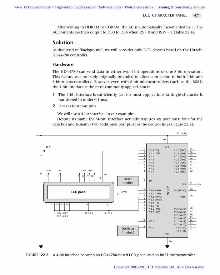
After writing to DDRAM or CGRAM, the AC is automatically incremented by 1. TheAC contents are then output to DB0 to DB6 when RS = 0 and R/W = 1 (Table 22.4).
SolutionAs discussed in ‘Background’, we will consider only LCD devices based on the HitachiHD44780 controller.
Hardware
The HD44780 can send data in either two 4-bit operations or one 8-bit operation.This feature was probably originally intended to allow connection to both 4-bit and8-bit microcontrollers. However, even with 8-bit microcontrollers (such as the 8051)the 4-bit interface is the most commonly applied, since:
1 The 4-bit interface is sufficiently fast for most applications (a single character istransferred in under 0.1 ms).
2 It saves four port pins.
We will use a 4-bit interface in our examples.Despite its name the ‘4-bit’ interface actually requires six port pins: four for the
data bus and (usually) two additional port pins for the control lines (Figure 22.2).
LCD CHARACTER PANEL 471
FIGURE 22.2 A 4-bit interface between an HD44780-based LCD panel and an 8051 microcontroller
P 1.0 [T2]P 1.1 [T2EX]P 1.2P 1.3P 1.4P 1.5P 1.6P 1.7
RST
P 3.0 (RXD)P 3.1 (TXD)P 3.2 (/INT0)P 3.3 (/INT1)P 3.4 (T0)P 3.5 (T1)P 3.6 (/WR)P 3.7 (/RD)
XTL2
XTL1
P 0.0 (AD0)P 0.1 (AD1)P 0.2 (AD2)P 0.3 (AD3)P 0.4 (AD4)P 0.5 (AD5)P 0.6 (AD6)P 0.7 (AD7)
/ EA
ALE (PROG)
/PSEN
P 2.7 (A15)P 2.6 (A14)P 2.5 (A13)P 2.4 (A12)P 2.3 (A11)P 2.2 (A10)P 2.1 (A9)P 2.0 (A8)
VCC
‘805
1’
VSS
3938373635343332
31
30
29
2827262524232221
12345678
9
1011121314151617
18
19
20
40
Oscillator(module)
Resetmodule
Vcc (+5V)
6414131211
5 1 7 8 9 10
R/W Vss DB0 - DB3
DB4 - DB7P3.2 - P3.5
RS P3.6 E P3.7
10 K
LCD panel
Vcc
3
Vo
Vcc2
www.TTE-Systems.com = High-reliability processors + Software tools + Protection systems + Training & consultancy services
Copyright 2001-2010 TTE Systems Ltd. All rights reserved.
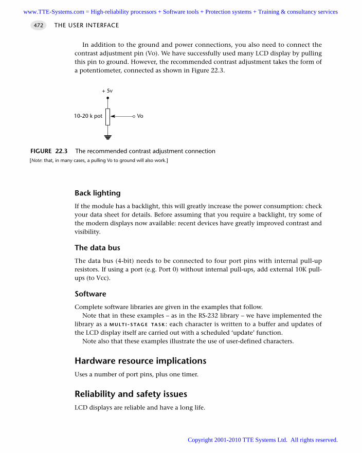
In addition to the ground and power connections, you also need to connect thecontrast adjustment pin (Vo). We have successfully used many LCD display by pullingthis pin to ground. However, the recommended contrast adjustment takes the form ofa potentiometer, connected as shown in Figure 22.3.
Back lighting
If the module has a backlight, this will greatly increase the power consumption: checkyour data sheet for details. Before assuming that you require a backlight, try some ofthe modern displays now available: recent devices have greatly improved contrast andvisibility.
The data bus
The data bus (4-bit) needs to be connected to four port pins with internal pull-upresistors. If using a port (e.g. Port 0) without internal pull-ups, add external 10K pull-ups (to Vcc).
Software
Complete software libraries are given in the examples that follow.Note that in these examples – as in the RS-232 library – we have implemented the
library as a M U LT I - S TA G E TA S K : each character is written to a buffer and updates ofthe LCD display itself are carried out with a scheduled ‘update’ function.
Note also that these examples illustrate the use of user-defined characters.
Hardware resource implicationsUses a number of port pins, plus one timer.
Reliability and safety issuesLCD displays are reliable and have a long life.
THE USER INTERFACE472
FIGURE 22.3 The recommended contrast adjustment connection[Note: that, in many cases, a pulling Vo to ground will also work.]
Vo
+ 5v
10-20 k pot
www.TTE-Systems.com = High-reliability processors + Software tools + Protection systems + Training & consultancy services
Copyright 2001-2010 TTE Systems Ltd. All rights reserved.
PortabilityThis pattern can be applied to any microcontroller family.
Overall strengths and weaknessesLCDs provide the basis of a professional and flexible user interface.
The panels are not cheap.
Even a ‘4-bit’ interface requires six pins.
Related patterns and alternative solutions See M X L E D D I S P L AY [page 450]
See P C L I N K (R S-232) [page 362]
Example: Displaying elapsed time on an LCDThis example displays elapsed time on an LCD character panel (Listings 22.1 to 22.3).
Hardware
The required hardware is shown in Figure 22.2.
Software
/*------------------------------------------------------------------*-
Port.H (v1.00)
------------------------------------------------------------------
'Port Header' (see Chapter 10) for the project LCD_TIME
-*------------------------------------------------------------------*/
// ------ Sch51.C ----------------------------------------
// Comment this line out if error reporting is NOT required
//#define SCH_REPORT_ERRORS
#ifdef SCH_REPORT_ERRORS
// The port on which error codes will be displayed
// ONLY USED IF ERRORS ARE REPORTED
#define Error_port P1
#endif
// ------ LCD_A.c --------------------------------------------------
// NOTE: Any combination of 6 pins may be used (any ports, any order)
// NOTE: Number in [] are pin numbers on *MANY* LCDs
LCD CHARACTER PANEL 473
www.TTE-Systems.com = High-reliability processors + Software tools + Protection systems + Training & consultancy services
Copyright 2001-2010 TTE Systems Ltd. All rights reserved.
sbit LCD_D4 = P3^2; // DB4 [11]
sbit LCD_D5 = P3^3; // DB5 [12]
sbit LCD_D6 = P3^4; // DB6 [13]
sbit LCD_D7 = P3^5; // DB7 [14]
sbit LCD_RS = P3^6; // Display register select output [4]
sbit LCD_EN = P3^7; // Display enable output [6]
// Connect Vss [1] on LCD to Gnd
// Connect Vcc [2] on LCD to +5V
// Connect Vo [3] on LCD to Gnd
// Connect RW [5] on LCD to Gnd
/*------------------------------------------------------------------*-
---- END OF FILE ------------------------------------------------
-*------------------------------------------------------------------*/
Listing 22.1 Part of a demonstration program that displays elapsed time on an LCD character panel
/*------------------------------------------------------------------*-
Elap_LCD.C (v1.00)
------------------------------------------------------------------
Simple library function for keeping track of elapsed time
This version for LCD display.
-*------------------------------------------------------------------*/
#include "Main.h"
#include "Port.h"
#include "Elap_LCD.h"
#include "LCD_A.h"
// ------ Public variable definitions ------------------------------
tByte Hou_G = 0;
tByte Min_G = 0;
tByte Sec_G = 0;
// ------ Public variable declarations -----------------------------
extern char LCD_data_G[LCD_LINES][LCD_CHARACTERS+1];
extern char code CHAR_MAP_G[10];
extern tByte Hou_G, Min_G;
/*------------------------------------------------------------------*-
Elapsed_Time_LCD_Init()
THE USER INTERFACE474
www.TTE-Systems.com = High-reliability processors + Software tools + Protection systems + Training & consultancy services
Copyright 2001-2010 TTE Systems Ltd. All rights reserved.
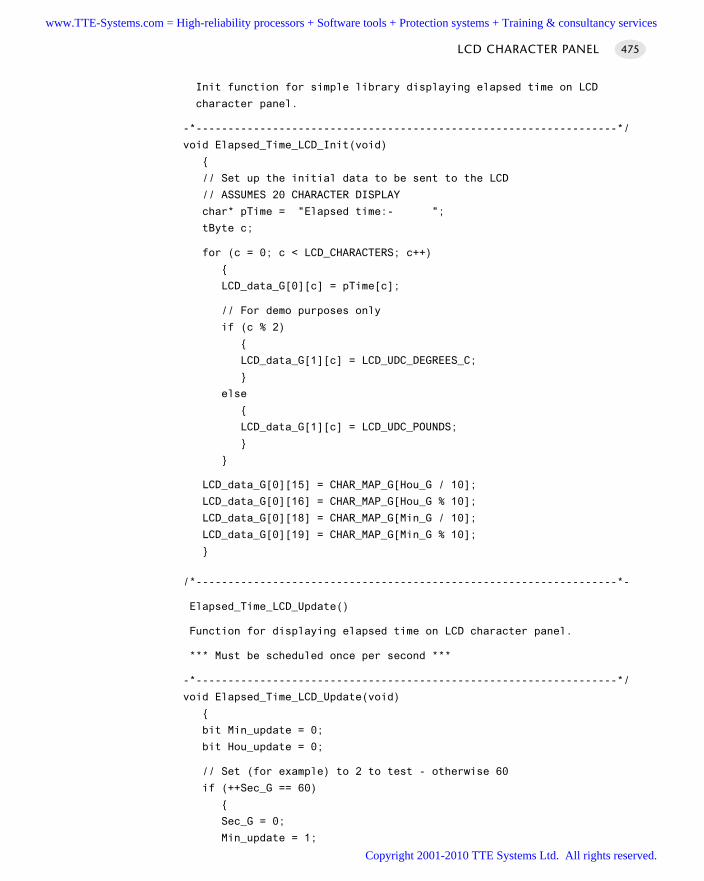
Init function for simple library displaying elapsed time on LCD
character panel.
-*------------------------------------------------------------------*/
void Elapsed_Time_LCD_Init(void)
// Set up the initial data to be sent to the LCD
// ASSUMES 20 CHARACTER DISPLAY
char* pTime = "Elapsed time:- ";
tByte c;
for (c = 0; c < LCD_CHARACTERS; c++)
LCD_data_G[0][c] = pTime[c];
// For demo purposes only
if (c % 2)
LCD_data_G[1][c] = LCD_UDC_DEGREES_C;
else
LCD_data_G[1][c] = LCD_UDC_POUNDS;
LCD_data_G[0][15] = CHAR_MAP_G[Hou_G / 10];
LCD_data_G[0][16] = CHAR_MAP_G[Hou_G % 10];
LCD_data_G[0][18] = CHAR_MAP_G[Min_G / 10];
LCD_data_G[0][19] = CHAR_MAP_G[Min_G % 10];
/*------------------------------------------------------------------*-
Elapsed_Time_LCD_Update()
Function for displaying elapsed time on LCD character panel.
*** Must be scheduled once per second ***
-*------------------------------------------------------------------*/
void Elapsed_Time_LCD_Update(void)
bit Min_update = 0;
bit Hou_update = 0;
// Set (for example) to 2 to test - otherwise 60
if (++Sec_G == 60)
Sec_G = 0;
Min_update = 1;
LCD CHARACTER PANEL 475
www.TTE-Systems.com = High-reliability processors + Software tools + Protection systems + Training & consultancy services
Copyright 2001-2010 TTE Systems Ltd. All rights reserved.
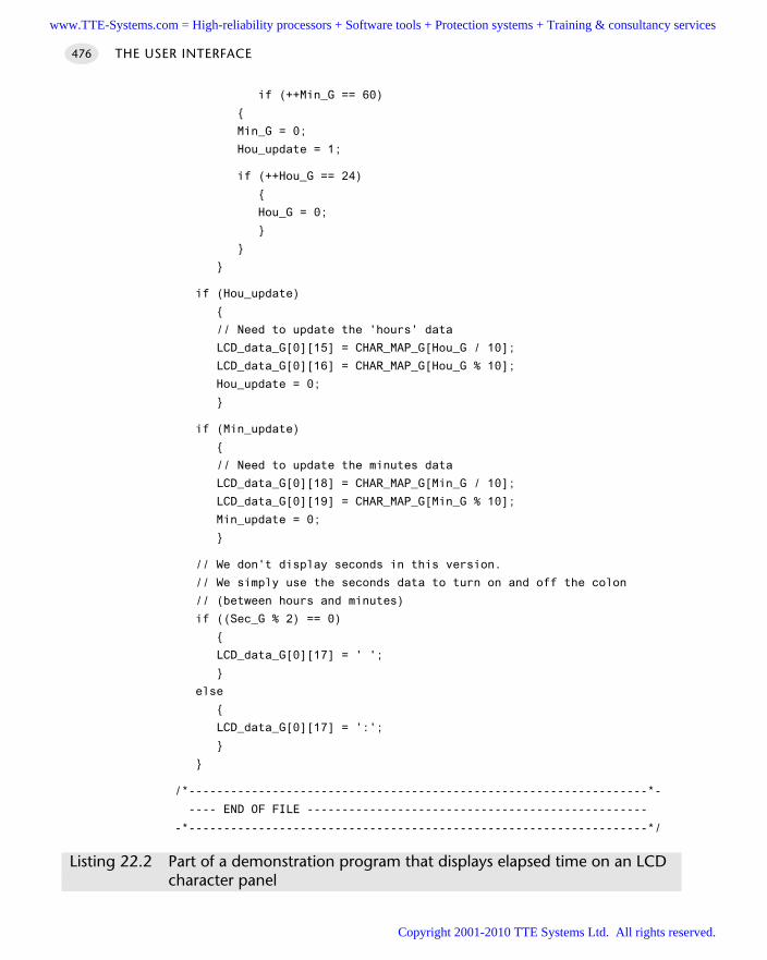
if (++Min_G == 60)
Min_G = 0;
Hou_update = 1;
if (++Hou_G == 24)
Hou_G = 0;
if (Hou_update)
// Need to update the 'hours' data
LCD_data_G[0][15] = CHAR_MAP_G[Hou_G / 10];
LCD_data_G[0][16] = CHAR_MAP_G[Hou_G % 10];
Hou_update = 0;
if (Min_update)
// Need to update the minutes data
LCD_data_G[0][18] = CHAR_MAP_G[Min_G / 10];
LCD_data_G[0][19] = CHAR_MAP_G[Min_G % 10];
Min_update = 0;
// We don't display seconds in this version.
// We simply use the seconds data to turn on and off the colon
// (between hours and minutes)
if ((Sec_G % 2) == 0)
LCD_data_G[0][17] = ' ';
else
LCD_data_G[0][17] = ':';
/*------------------------------------------------------------------*-
---- END OF FILE -------------------------------------------------
-*------------------------------------------------------------------*/
Listing 22.2 Part of a demonstration program that displays elapsed time on an LCD character panel
THE USER INTERFACE476
www.TTE-Systems.com = High-reliability processors + Software tools + Protection systems + Training & consultancy services
Copyright 2001-2010 TTE Systems Ltd. All rights reserved.
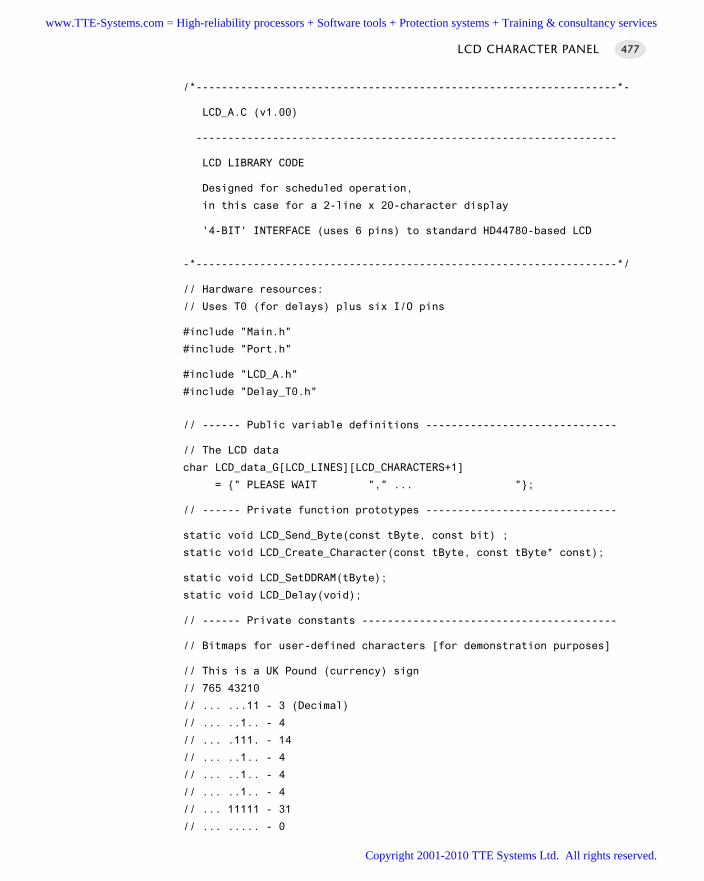
/*------------------------------------------------------------------*-
LCD_A.C (v1.00)
------------------------------------------------------------------
LCD LIBRARY CODE
Designed for scheduled operation,
in this case for a 2-line x 20-character display
'4-BIT' INTERFACE (uses 6 pins) to standard HD44780-based LCD
-*------------------------------------------------------------------*/
// Hardware resources:
// Uses T0 (for delays) plus six I/O pins
#include "Main.h"
#include "Port.h"
#include "LCD_A.h"
#include "Delay_T0.h"
// ------ Public variable definitions ------------------------------
// The LCD data
char LCD_data_G[LCD_LINES][LCD_CHARACTERS+1]
= " PLEASE WAIT "," ... ";
// ------ Private function prototypes ------------------------------
static void LCD_Send_Byte(const tByte, const bit) ;
static void LCD_Create_Character(const tByte, const tByte* const);
static void LCD_SetDDRAM(tByte);
static void LCD_Delay(void);
// ------ Private constants ----------------------------------------
// Bitmaps for user-defined characters [for demonstration purposes]
// This is a UK Pound (currency) sign
// 765 43210
// ... ...11 - 3 (Decimal)
// ... ..1.. - 4
// ... .111. - 14
// ... ..1.. - 4
// ... ..1.. - 4
// ... ..1.. - 4
// ... 11111 - 31
// ... ..... - 0
LCD CHARACTER PANEL 477
www.TTE-Systems.com = High-reliability processors + Software tools + Protection systems + Training & consultancy services
Copyright 2001-2010 TTE Systems Ltd. All rights reserved.
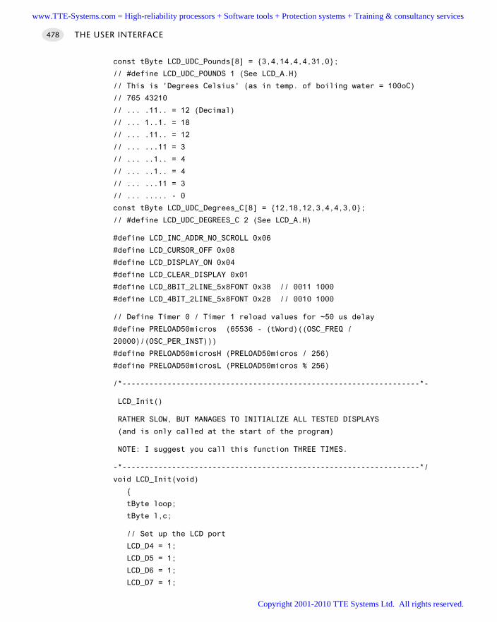
const tByte LCD_UDC_Pounds[8] = 3,4,14,4,4,31,0;
// #define LCD_UDC_POUNDS 1 (See LCD_A.H)
// This is 'Degrees Celsius' (as in temp. of boiling water = 100oC)
// 765 43210
// ... .11.. = 12 (Decimal)
// ... 1..1. = 18
// ... .11.. = 12
// ... ...11 = 3
// ... ..1.. = 4
// ... ..1.. = 4
// ... ...11 = 3
// ... ..... - 0
const tByte LCD_UDC_Degrees_C[8] = 12,18,12,3,4,4,3,0;
// #define LCD_UDC_DEGREES_C 2 (See LCD_A.H)
#define LCD_INC_ADDR_NO_SCROLL 0x06
#define LCD_CURSOR_OFF 0x08
#define LCD_DISPLAY_ON 0x04
#define LCD_CLEAR_DISPLAY 0x01
#define LCD_8BIT_2LINE_5x8FONT 0x38 // 0011 1000
#define LCD_4BIT_2LINE_5x8FONT 0x28 // 0010 1000
// Define Timer 0 / Timer 1 reload values for ~50 us delay
#define PRELOAD50micros (65536 - (tWord)((OSC_FREQ /
20000)/(OSC_PER_INST)))
#define PRELOAD50microsH (PRELOAD50micros / 256)
#define PRELOAD50microsL (PRELOAD50micros % 256)
/*------------------------------------------------------------------*-
LCD_Init()
RATHER SLOW, BUT MANAGES TO INITIALIZE ALL TESTED DISPLAYS
(and is only called at the start of the program)
NOTE: I suggest you call this function THREE TIMES.
-*------------------------------------------------------------------*/
void LCD_Init(void)
tByte loop;
tByte l,c;
// Set up the LCD port
LCD_D4 = 1;
LCD_D5 = 1;
LCD_D6 = 1;
LCD_D7 = 1;
THE USER INTERFACE478
www.TTE-Systems.com = High-reliability processors + Software tools + Protection systems + Training & consultancy services
Copyright 2001-2010 TTE Systems Ltd. All rights reserved.
LCD_RS = 1;
LCD_EN = 1;
Hardware_Delay_T0(500);
LCD_RS = 0;
LCD_EN = 0;
// Now wait for the display to initialize
// - data sheet says at least 40 ms
Hardware_Delay_T0(400);
// Data sheet says send this instruction 3 times...
for (loop = 0; loop < 3; loop++)
// Using a 4-bit bus, 2 display lines and a 5x7 dot font
LCD_Send_Byte(LCD_4BIT_2LINE_5x8FONT,0);
Hardware_Delay_T0(100);
// Increment display address for each character but do not scroll
LCD_Send_Byte(LCD_INC_ADDR_NO_SCROLL,0);
Hardware_Delay_T0(50);
// Turn the display on and the cursor off
LCD_Send_Byte((LCD_CURSOR_OFF | LCD_DISPLAY_ON),0);
Hardware_Delay_T0(50);
// Clear the display
LCD_Send_Byte(LCD_CLEAR_DISPLAY,0);
Hardware_Delay_T0(50);
// Invisible cursor (dummy function call to avoid library error)
LCD_Control_Cursor(0,0,0);
Hardware_Delay_T0(200);
// Set up user-defined character(s) - if required
LCD_Create_Character(LCD_UDC_DEGREES_C, LCD_UDC_Degrees_C);
Hardware_Delay_T0(200);
LCD_Create_Character(LCD_UDC_POUNDS, LCD_UDC_Pounds);
Hardware_Delay_T0(200);
// Update all characters in the display
for (l = 0; l < LCD_LINES; l++)
for (c = 0; c < LCD_CHARACTERS; c++)
LCD_data_G[l][c] = '*';
LCD_Update();
LCD CHARACTER PANEL 479
www.TTE-Systems.com = High-reliability processors + Software tools + Protection systems + Training & consultancy services
Copyright 2001-2010 TTE Systems Ltd. All rights reserved.
Hardware_Delay_T0(10);
/*------------------------------------------------------------------*-
LCD_Update()
This function updates one character in the LCD panel
(if it requires updating).
Duration: ~0.1 ms.
Schedule roughly every 25 ms (2-line x 20-char display) to
force one complete display update every second.
-*------------------------------------------------------------------*/
void LCD_Update(void)
static tByte Line;
static tByte Character;
tByte Tests, Data;
bit Update_required;
// Find next character to be updated
Tests = LCD_CHARACTERS * LCD_LINES;
do
if (++Character == LCD_CHARACTERS)
Character = 0;
if (++Line == LCD_LINES)
Line = 0;
// Array contents set to \0 after data are written to LCD
Update_required = (LCD_data_G[Line][Character] != '\0');
while ((Tests-- > 0) && (!Update_required));
if (!Update_required)
return; // No data in LCD requires updating
// Set DDRAM address which character is to be written to
// - Assumes 2 line by 20 character display
THE USER INTERFACE480
www.TTE-Systems.com = High-reliability processors + Software tools + Protection systems + Training & consultancy services
Copyright 2001-2010 TTE Systems Ltd. All rights reserved.
// - See Table 22-3 for adjustments needed for other display sizes
if (Line == 0)
LCD_SetDDRAM(0x00 + Character); // First line
else
LCD_SetDDRAM(0xC0 + Character); // Second line
// This is the data for updating
Data = LCD_data_G[Line][Character];
// Send single data byte
LCD_Send_Byte(Data,1);
// Once data has been written to LCD
LCD_data_G[Line][Character] = '\0';
/*------------------------------------------------------------------*-
LCD_Send_Byte()
This function writes a byte to the LCD panel.
Duration < 0.1 ms .
Parameters: DATA
The byte to be written to the display.
DATA_FLAG:
If DATA_FLAG == 1, a data byte is sent
If DATA_FLAG == 0, a command byte is sent
-*------------------------------------------------------------------*/
void LCD_Send_Byte(const tByte DATA, const bit DATA_FLAG)
// Delays *are* needed
// [you may find it possible to reduce them on
// on some displays]
LCD_D4 = 0;
LCD_D5 = 0;
LCD_D6 = 0;
LCD_D7 = 0;
LCD_RS = DATA_FLAG; // Data register
LCD_EN = 0;
LCD_Delay();
LCD CHARACTER PANEL 481
www.TTE-Systems.com = High-reliability processors + Software tools + Protection systems + Training & consultancy services
Copyright 2001-2010 TTE Systems Ltd. All rights reserved.
// Write the data (high nybble)
LCD_D4 = ((DATA & 0x10) == 0x10);
LCD_D5 = ((DATA & 0x20) == 0x20);
LCD_D6 = ((DATA & 0x40) == 0x40);
LCD_D7 = ((DATA & 0x80) == 0x80);
LCD_Delay();
LCD_EN = 1; // Latch the high nybble
LCD_Delay();
LCD_EN = 0;
LCD_Delay();
LCD_D4 = 0;
LCD_D5 = 0;
LCD_D6 = 0;
LCD_D7 = 0;
LCD_RS = DATA_FLAG;
LCD_EN = 0;
LCD_Delay();
// Write the data (low nybble)
LCD_D4 = ((DATA & 0x01) == 0x01);
LCD_D5 = ((DATA & 0x02) == 0x02);
LCD_D6 = ((DATA & 0x04) == 0x04);
LCD_D7 = ((DATA & 0x08) == 0x08);
LCD_Delay();
LCD_EN = 1; // Latch the low nybble
LCD_Delay();
LCD_EN = 0;
LCD_Delay();
/*------------------------------------------------------------------*-
LCD_Control_Cursor()
This function enables or clears the cursor and moves
it to a specified point.
Params: Visible - Set if the cursor should be visible.
Blinking - Set if character should be blinking
Address - Address (DDRAM) we want to adjust.
-*------------------------------------------------------------------*/
void LCD_Control_Cursor(const bit VISIBLE, const bit BLINKING,
const tByte ADDRESS)
// Cursor / blinking appears at current DDRAM address
THE USER INTERFACE482
www.TTE-Systems.com = High-reliability processors + Software tools + Protection systems + Training & consultancy services
Copyright 2001-2010 TTE Systems Ltd. All rights reserved.
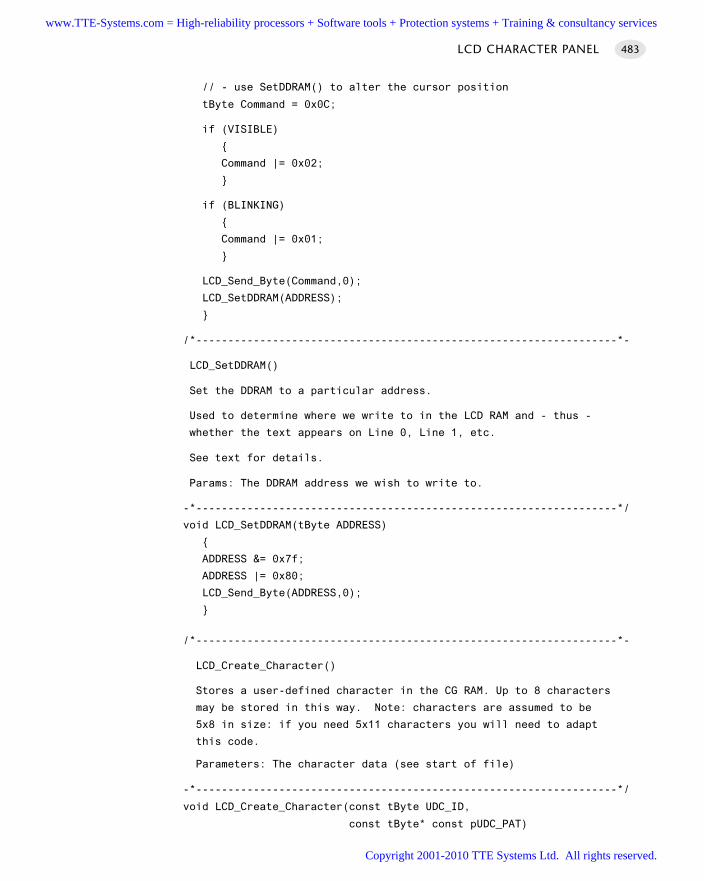
// - use SetDDRAM() to alter the cursor position
tByte Command = 0x0C;
if (VISIBLE)
Command |= 0x02;
if (BLINKING)
Command |= 0x01;
LCD_Send_Byte(Command,0);
LCD_SetDDRAM(ADDRESS);
/*------------------------------------------------------------------*-
LCD_SetDDRAM()
Set the DDRAM to a particular address.
Used to determine where we write to in the LCD RAM and - thus -
whether the text appears on Line 0, Line 1, etc.
See text for details.
Params: The DDRAM address we wish to write to.
-*------------------------------------------------------------------*/
void LCD_SetDDRAM(tByte ADDRESS)
ADDRESS &= 0x7f;
ADDRESS |= 0x80;
LCD_Send_Byte(ADDRESS,0);
/*------------------------------------------------------------------*-
LCD_Create_Character()
Stores a user-defined character in the CG RAM. Up to 8 characters
may be stored in this way. Note: characters are assumed to be
5x8 in size: if you need 5x11 characters you will need to adapt
this code.
Parameters: The character data (see start of file)
-*------------------------------------------------------------------*/
void LCD_Create_Character(const tByte UDC_ID,
const tByte* const pUDC_PAT)
LCD CHARACTER PANEL 483
www.TTE-Systems.com = High-reliability processors + Software tools + Protection systems + Training & consultancy services
Copyright 2001-2010 TTE Systems Ltd. All rights reserved.
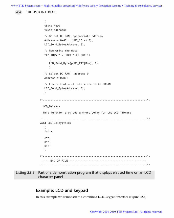
tByte Row;
tByte Address;
// Select CG RAM, appropriate address
Address = 0x40 + (UDC_ID << 3);
LCD_Send_Byte(Address, 0);
// Now write the data
for (Row = 0; Row < 8; Row++)
LCD_Send_Byte(pUDC_PAT[Row], 1);
// Select DD RAM - address 0
Address = 0x80;
// Ensure that next data write is to DDRAM
LCD_Send_Byte(Address, 0);
/*------------------------------------------------------------------*-
LCD_Delay()
This function provides a short delay for the LCD library.
-*------------------------------------------------------------------*/
void LCD_Delay(void)
int x;
x++;
x++;
x++;
/*------------------------------------------------------------------*-
---- END OF FILE ------------------------------------------------
-*------------------------------------------------------------------*/
Listing 22.3 Part of a demonstration program that displays elapsed time on an LCD character panel
Example: LCD and keypadIn this example we demonstrate a combined LCD–keypad interface (Figure 22.4).
THE USER INTERFACE484
www.TTE-Systems.com = High-reliability processors + Software tools + Protection systems + Training & consultancy services
Copyright 2001-2010 TTE Systems Ltd. All rights reserved.
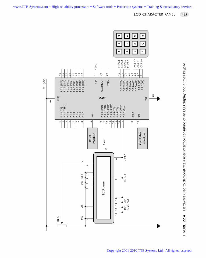
LCD CHARACTER PANEL 485
FIG
UR
E 2
2.4
Har
dwar
e us
ed t
o de
mon
stra
te a
use
r in
terf
ace
cons
istin
g of
an
LCD
dis
pla
y an
d a
smal
l key
pad
Vcc
P 1.
0 [T
2]P
1.1
[T2E
X]
P 1.
2P
1.3
P 1.
4P
1.5
P 1.
6P
1.7
RST
P 3.
0 (R
XD
)P
3.1
(TX
D)
P 3.
2 (/
INT0
)P
3.3
(/IN
T1)
P 3.
4 (T
0)P
3.5
(T1)
P 3.
6 (/
WR)
P 3.
7 (/
RD)
XTL
2
XTL
1
P 0.
0 (A
D0)
P 0.
1 (A
D1)
P 0.
2 (A
D2)
P 0.
3 (A
D3)
P 0.
4 (A
D4)
P 0.
5 (A
D5)
P 0.
6 (A
D6)
P 0.
7 (A
D7)
/ EA
ALE
(PR
OG
)
/PSE
N
P 2.
7 (A
15)
P 2.
6 (A
14)
P 2.
5 (A
13)
P 2.
4 (A
12)
P 2.
3 (A
11)
P 2.
2 (A
10)
P 2.
1 (A
9)P
2.0
(A8)
VCC 8051
VSS
39 38 37 36 35 34 33 32 31 30 29 28 27 26 25 24 23 22 21
1 2 3 4 5 6 7 8 9 10 11 12 13 14 15 16 17 18 19
20
40
Osc
illat
orm
odul
e
Rese
tm
odul
e
Vcc
(+5V
)
64
1413
1211
51
78
910
R/W
Vss
DB0
- D
B3
DB4
- D
B7P3
.2 -
P3.
5RS
P3.
6E
P3.
7
10 K
LCD
pan
el
Vcc
23
1
56
4
89
7
0#
*
R4-P
2.3
R3-P
2.4
R2-P
2.5
R1-P
2.6
C3-
P2.2
C2-
P2.1
C1-
P2.0
Vo
3
2
www.TTE-Systems.com = High-reliability processors + Software tools + Protection systems + Training & consultancy services
Copyright 2001-2010 TTE Systems Ltd. All rights reserved.
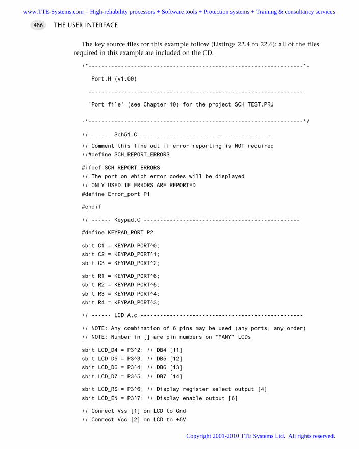
The key source files for this example follow (Listings 22.4 to 22.6): all of the filesrequired in this example are included on the CD.
/*------------------------------------------------------------------*-
Port.H (v1.00)
------------------------------------------------------------------
'Port file' (see Chapter 10) for the project SCH_TEST.PRJ
-*------------------------------------------------------------------*/
// ------ Sch51.C ----------------------------------------
// Comment this line out if error reporting is NOT required
//#define SCH_REPORT_ERRORS
#ifdef SCH_REPORT_ERRORS
// The port on which error codes will be displayed
// ONLY USED IF ERRORS ARE REPORTED
#define Error_port P1
#endif
// ------ Keypad.C ------------------------------------------------
#define KEYPAD_PORT P2
sbit C1 = KEYPAD_PORT^0;
sbit C2 = KEYPAD_PORT^1;
sbit C3 = KEYPAD_PORT^2;
sbit R1 = KEYPAD_PORT^6;
sbit R2 = KEYPAD_PORT^5;
sbit R3 = KEYPAD_PORT^4;
sbit R4 = KEYPAD_PORT^3;
// ------ LCD_A.c --------------------------------------------------
// NOTE: Any combination of 6 pins may be used (any ports, any order)
// NOTE: Number in [] are pin numbers on *MANY* LCDs
sbit LCD_D4 = P3^2; // DB4 [11]
sbit LCD_D5 = P3^3; // DB5 [12]
sbit LCD_D6 = P3^4; // DB6 [13]
sbit LCD_D7 = P3^5; // DB7 [14]
sbit LCD_RS = P3^6; // Display register select output [4]
sbit LCD_EN = P3^7; // Display enable output [6]
// Connect Vss [1] on LCD to Gnd
// Connect Vcc [2] on LCD to +5V
THE USER INTERFACE486
www.TTE-Systems.com = High-reliability processors + Software tools + Protection systems + Training & consultancy services
Copyright 2001-2010 TTE Systems Ltd. All rights reserved.
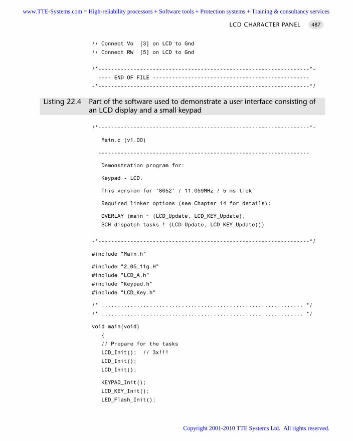
// Connect Vo [3] on LCD to Gnd
// Connect RW [5] on LCD to Gnd
/*------------------------------------------------------------------*-
---- END OF FILE -------------------------------------------------
-*------------------------------------------------------------------*/
Listing 22.4 Part of the software used to demonstrate a user interface consisting of an LCD display and a small keypad
/*------------------------------------------------------------------*-
Main.c (v1.00)
------------------------------------------------------------------
Demonstration program for:
Keypad - LCD.
This version for '8052' / 11.059MHz / 5 ms tick
Required linker options (see Chapter 14 for details):
OVERLAY (main ~ (LCD_Update, LCD_KEY_Update),
SCH_dispatch_tasks ! (LCD_Update, LCD_KEY_Update)))
-*------------------------------------------------------------------*/
#include "Main.h"
#include "2_05_11g.H"
#include "LCD_A.h"
#include "Keypad.h"
#include "LCD_Key.h"
/* ............................................................... */
/* ............................................................... */
void main(void)
// Prepare for the tasks
LCD_Init(); // 3x!!!
LCD_Init();
LCD_Init();
KEYPAD_Init();
LCD_KEY_Init();
LED_Flash_Init();
LCD CHARACTER PANEL 487
www.TTE-Systems.com = High-reliability processors + Software tools + Protection systems + Training & consultancy services
Copyright 2001-2010 TTE Systems Ltd. All rights reserved.
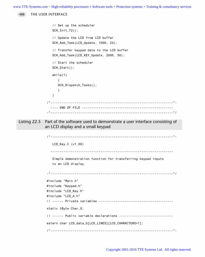
// Set up the scheduler
SCH_Init_T2();
// Update the LCD from LCD buffer
SCH_Add_Task(LCD_Update, 1000, 24);
// Transfer keypad data to the LCD buffer
SCH_Add_Task(LCD_KEY_Update, 2000, 50);
// Start the scheduler
SCH_Start();
while(1)
SCH_Dispatch_Tasks();
/*------------------------------------------------------------------*-
---- END OF FILE -------------------------------------------------
-*------------------------------------------------------------------*/
Listing 22.5 Part of the software used to demonstrate a user interface consisting of an LCD display and a small keypad
/*------------------------------------------------------------------*-
LCD_Key.C (v1.00)
------------------------------------------------------------------
Simple demonstration function for transferring keypad inputs
to an LCD display.
-*------------------------------------------------------------------*/
#include "Main.h"
#include "Keypad.h"
#include "LCD_Key.h"
#include "LCD_A.h"
// ------ Private variables ----------------------------------------
static tByte Char_G;
// ------ Public variable declarations -----------------------------
extern char LCD_data_G[LCD_LINES][LCD_CHARACTERS+1];
/*------------------------------------------------------------------*-
THE USER INTERFACE488
www.TTE-Systems.com = High-reliability processors + Software tools + Protection systems + Training & consultancy services
Copyright 2001-2010 TTE Systems Ltd. All rights reserved.
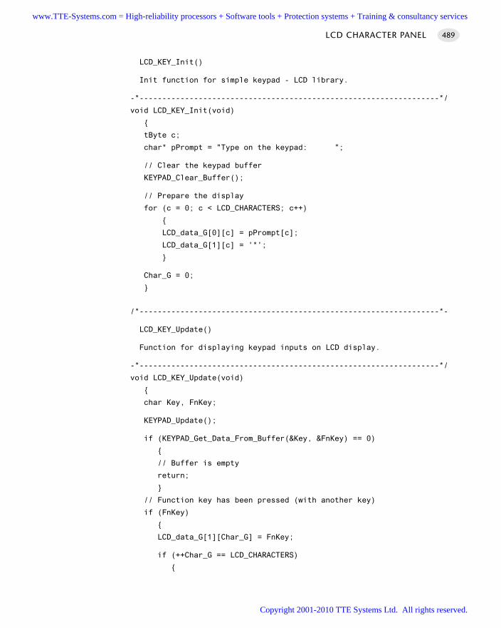
LCD_KEY_Init()
Init function for simple keypad - LCD library.
-*------------------------------------------------------------------*/
void LCD_KEY_Init(void)
tByte c;
char* pPrompt = "Type on the keypad: ";
// Clear the keypad buffer
KEYPAD_Clear_Buffer();
// Prepare the display
for (c = 0; c < LCD_CHARACTERS; c++)
LCD_data_G[0][c] = pPrompt[c];
LCD_data_G[1][c] = '*';
Char_G = 0;
/*------------------------------------------------------------------*-
LCD_KEY_Update()
Function for displaying keypad inputs on LCD display.
-*------------------------------------------------------------------*/
void LCD_KEY_Update(void)
char Key, FnKey;
KEYPAD_Update();
if (KEYPAD_Get_Data_From_Buffer(&Key, &FnKey) == 0)
// Buffer is empty
return;
// Function key has been pressed (with another key)
if (FnKey)
LCD_data_G[1][Char_G] = FnKey;
if (++Char_G == LCD_CHARACTERS)
LCD CHARACTER PANEL 489
www.TTE-Systems.com = High-reliability processors + Software tools + Protection systems + Training & consultancy services
Copyright 2001-2010 TTE Systems Ltd. All rights reserved.
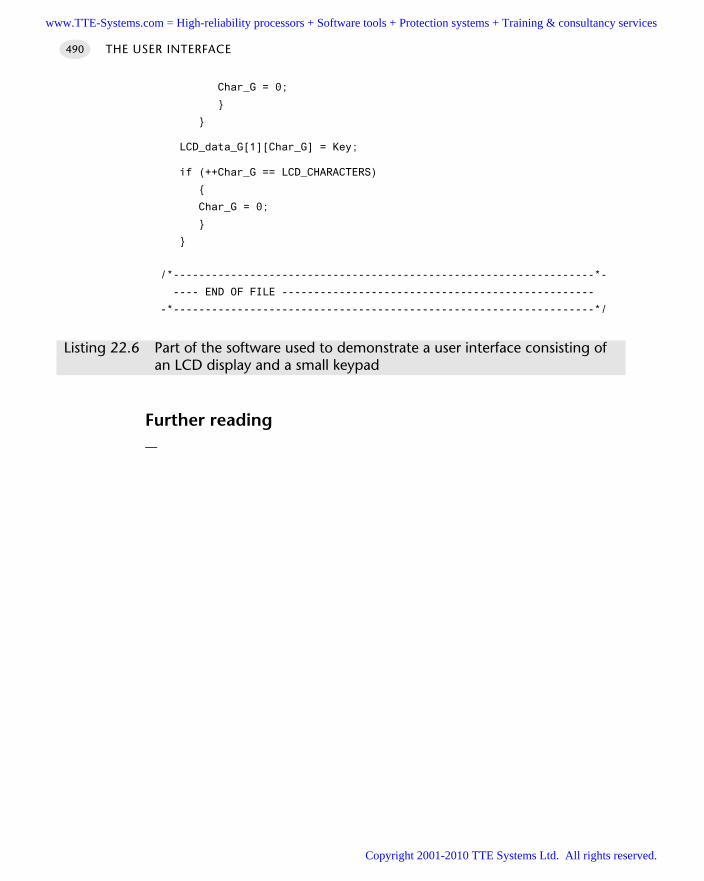
Char_G = 0;
LCD_data_G[1][Char_G] = Key;
if (++Char_G == LCD_CHARACTERS)
Char_G = 0;
/*------------------------------------------------------------------*-
---- END OF FILE -------------------------------------------------
-*------------------------------------------------------------------*/
Listing 22.6 Part of the software used to demonstrate a user interface consisting of an LCD display and a small keypad
Further reading—
THE USER INTERFACE490
www.TTE-Systems.com = High-reliability processors + Software tools + Protection systems + Training & consultancy services
Copyright 2001-2010 TTE Systems Ltd. All rights reserved.
Using serial peripherals
In Part E we consider how two powerful and influential serial communication protocols
(‘I2C’ and ‘SPI’) may be utilized in applications with a time-triggered architecture.
Use of these protocols has two main advantages:
They are designed to allow microcontrollers to be linked to a wide range of different
peripherals – memory, displays, ADCs and similar devices – without requiring the use
of large numbers of port pins.
A common set of software code may be used with all SPI peripherals (for example),
reducing the development effort required.
In Chapter 23, we consider the I2C bus, developed by Philips. I2C is a simple protocol,
and may be easily generated in software. This allows the full range of 8051 devices
(including Small 8051s, with very few spare port pins) to communicate with a wide range
of peripheral devices.
In Chapter 24, we consider the SPI bus, developed by Motorola. Increasing numbers of
‘Standard’ and ‘Extended’ 8051 devices have hardware support for SPI and we will make
use of these facilities in Chapter 24.
part ewww.TTE-Systems.com = High-reliability processors + Software tools + Protection systems + Training & consultancy services
Copyright 2001-2010 TTE Systems Ltd. All rights reserved.

www.TTE-Systems.com = High-reliability processors + Software tools + Protection systems + Training & consultancy services
Copyright 2001-2010 TTE Systems Ltd. All rights reserved.
Using ‘I2C’ peripherals
Introduction
The I2C bus is a two-wire serial communication bus, originally introduced by Philipsin 1992. I2C is now supported by a wide range of semiconductor manufacturers, withthe result that many different peripheral devices (LCDs, LED displays, EEPROMs, ADCand DAC devices and so on) can be connected to a microcontroller without usinglarge numbers of port pins.
The pattern in this chapter addresses the following problem:
Should you use the I2C protocol to link your microcontroller to peripheral devicesand, if so, how do you do so?
chapter 23www.TTE-Systems.com = High-reliability processors + Software tools + Protection systems + Training & consultancy services
Copyright 2001-2010 TTE Systems Ltd. All rights reserved.
I2C PERIPHERAL
Context You are developing an embedded application using one or more members of the
8051 family of microcontrollers.
The application has a time-triggered architecture, based on a scheduler.
The microcontroller in your application will be interfaced to one or more peripher-als, such as a keypad, EEPROM, digital-to-analog converter, or similar device.
ProblemShould you use the I2C protocol to link your microcontroller to peripheral devicesand, if so, how do you do so?
BackgroundThere are five key features of I2C as far as the developer of embedded applications isconcerned:
I2C is a protocol designed to allow microcontrollers to be linked to a wide range ofdifferent peripherals – memory, displays, ADCs and similar devices – and requiresonly two port pins to connect to (typically) up to 20 peripherals.
There are many I2C peripherals available for purchase ‘off the shelf’.
I2C is a simple protocol and may be easily generated in software. This allows all8051 devices to communicate with a wide range of peripheral devices.
A common set of software code may be used with all I2C peripherals.
I2C is fast enough (even when generated in software) to be compatible with time-triggered architectures. Typical data transfer rates will be up to 1,000 bytes / second(with a 1 ms scheduler tick).
We provide some background necessary for understanding and using the I2C bus inthis section. Please note that much of the material here is adapted from the Philips(1998) I2C specification. For further details, the reader is referred to this document, acopy of which can be obtained from the Philips WWW site.1
Hardware
We begin by considering essential I2C hardware features.
USING SERIAL PERIPHERALS494
1. www.philips.com
www.TTE-Systems.com = High-reliability processors + Software tools + Protection systems + Training & consultancy services
Copyright 2001-2010 TTE Systems Ltd. All rights reserved.
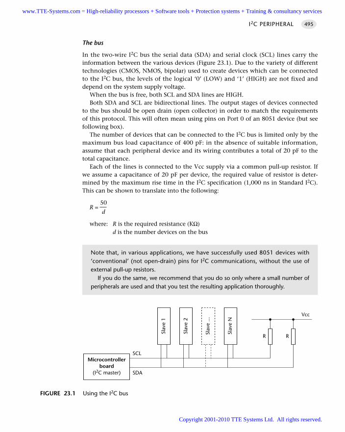
The bus
In the two-wire I2C bus the serial data (SDA) and serial clock (SCL) lines carry theinformation between the various devices (Figure 23.1). Due to the variety of differenttechnologies (CMOS, NMOS, bipolar) used to create devices which can be connectedto the I2C bus, the levels of the logical ‘0’ (LOW) and ‘1’ (HIGH) are not fixed anddepend on the system supply voltage.
When the bus is free, both SCL and SDA lines are HIGH. Both SDA and SCL are bidirectional lines. The output stages of devices connected
to the bus should be open drain (open collector) in order to match the requirementsof this protocol. This will often mean using pins on Port 0 of an 8051 device (but seefollowing box).
The number of devices that can be connected to the I2C bus is limited only by themaximum bus load capacitance of 400 pF: in the absence of suitable information,assume that each peripheral device and its wiring contributes a total of 20 pF to thetotal capacitance.
Each of the lines is connected to the Vcc supply via a common pull-up resistor. Ifwe assume a capacitance of 20 pF per device, the required value of resistor is deter-mined by the maximum rise time in the I2C specification (1,000 ns in Standard I2C).This can be shown to translate into the following:
50R =
d
where: R is the required resistance (KΩ)d is the number devices on the bus
I2C PERIPHERAL 495
FIGURE 23.1 Using the I2C bus
Microcontrollerboard
(I2C master)
Slav
e 1
SCL
SDA
Slav
e 2
Slav
e ...
Slav
e N
R R
Vcc
Note that, in various applications, we have successfully used 8051 devices with‘conventional’ (not open-drain) pins for I2C communications, without the use ofexternal pull-up resistors.
If you do the same, we recommend that you do so only where a small number ofperipherals are used and that you test the resulting application thoroughly.
www.TTE-Systems.com = High-reliability processors + Software tools + Protection systems + Training & consultancy services
Copyright 2001-2010 TTE Systems Ltd. All rights reserved.
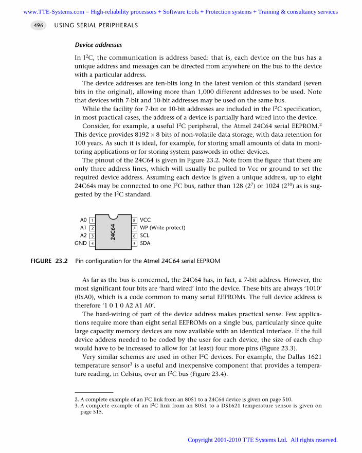
Device addresses
In I2C, the communication is address based: that is, each device on the bus has aunique address and messages can be directed from anywhere on the bus to the devicewith a particular address.
The device addresses are ten-bits long in the latest version of this standard (sevenbits in the original), allowing more than 1,000 different addresses to be used. Notethat devices with 7-bit and 10-bit addresses may be used on the same bus.
While the facility for 7-bit or 10-bit addresses are included in the I2C specification,in most practical cases, the address of a device is partially hard wired into the device.
Consider, for example, a useful I2C peripheral, the Atmel 24C64 serial EEPROM.2
This device provides 8192 × 8 bits of non-volatile data storage, with data retention for100 years. As such it is ideal, for example, for storing small amounts of data in moni-toring applications or for storing system passwords in other devices.
The pinout of the 24C64 is given in Figure 23.2. Note from the figure that there areonly three address lines, which will usually be pulled to Vcc or ground to set therequired device address. Assuming each device is given a unique address, up to eight24C64s may be connected to one I2C bus, rather than 128 (27) or 1024 (210) as is sug-gested by the I2C standard.
As far as the bus is concerned, the 24C64 has, in fact, a 7-bit address. However, themost significant four bits are ‘hard wired’ into the device. These bits are always ‘1010’(0xA0), which is a code common to many serial EEPROMs. The full device address istherefore ‘1 0 1 0 A2 A1 A0’.
The hard-wiring of part of the device address makes practical sense. Few applica-tions require more than eight serial EEPROMs on a single bus, particularly since quitelarge capacity memory devices are now available with an identical interface. If the fulldevice address needed to be coded by the user for each device, the size of each chipwould have to be increased to allow for (at least) four more pins (Figure 23.3).
Very similar schemes are used in other I2C devices. For example, the Dallas 1621temperature sensor3 is a useful and inexpensive component that provides a tempera-ture reading, in Celsius, over an I2C bus (Figure 23.4).
USING SERIAL PERIPHERALS496
FIGURE 23.2 Pin configuration for the Atmel 24C64 serial EEPROM
4
3
2
1
24C
64
5
6
7
8A0A1A2
GND
VCCWP (Write protect)SCLSDA
2. A complete example of an I2C link from an 8051 to a 24C64 device is given on page 510.3. A complete example of an I2C link from an 8051 to a DS1621 temperature sensor is given on
page 515.
www.TTE-Systems.com = High-reliability processors + Software tools + Protection systems + Training & consultancy services
Copyright 2001-2010 TTE Systems Ltd. All rights reserved.
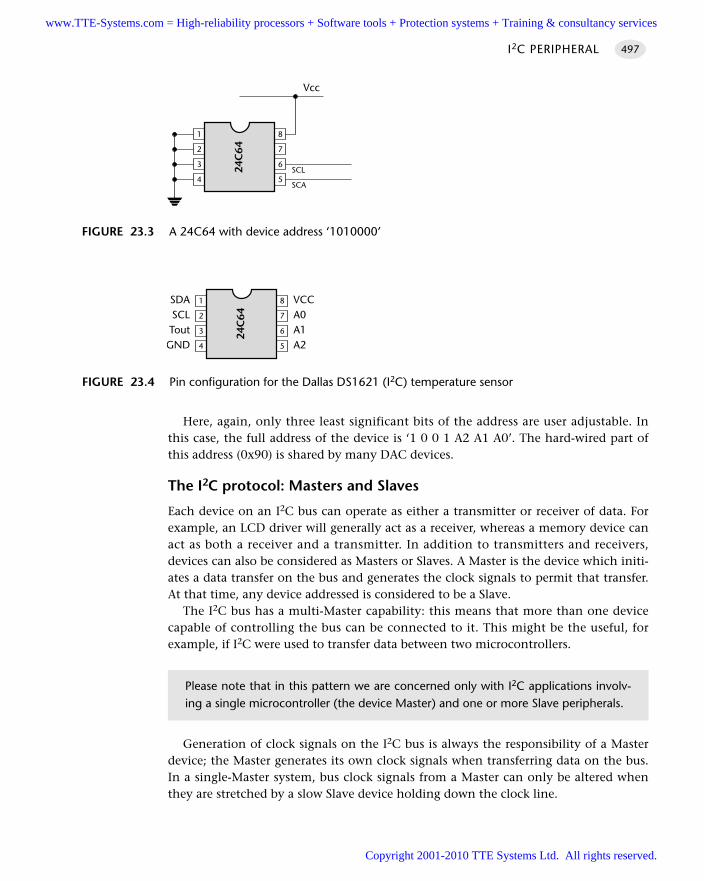
Here, again, only three least significant bits of the address are user adjustable. Inthis case, the full address of the device is ‘1 0 0 1 A2 A1 A0’. The hard-wired part ofthis address (0x90) is shared by many DAC devices.
The I2C protocol: Masters and Slaves
Each device on an I2C bus can operate as either a transmitter or receiver of data. Forexample, an LCD driver will generally act as a receiver, whereas a memory device canact as both a receiver and a transmitter. In addition to transmitters and receivers,devices can also be considered as Masters or Slaves. A Master is the device which initi-ates a data transfer on the bus and generates the clock signals to permit that transfer.At that time, any device addressed is considered to be a Slave.
The I2C bus has a multi-Master capability: this means that more than one devicecapable of controlling the bus can be connected to it. This might be the useful, forexample, if I2C were used to transfer data between two microcontrollers.
Generation of clock signals on the I2C bus is always the responsibility of a Masterdevice; the Master generates its own clock signals when transferring data on the bus.In a single-Master system, bus clock signals from a Master can only be altered whenthey are stretched by a slow Slave device holding down the clock line.
I2C PERIPHERAL 497
FIGURE 23.3 A 24C64 with device address ‘1010000’
4
3
2
1
24C
64
5
6
7
8
Vcc
SCL
SCA
FIGURE 23.4 Pin configuration for the Dallas DS1621 (I2C) temperature sensor
4
3
2
1
24C
64
5
6
7
8SDASCLTout
GND
VCCA0A1A2
Please note that in this pattern we are concerned only with I2C applications involv-ing a single microcontroller (the device Master) and one or more Slave peripherals.
www.TTE-Systems.com = High-reliability processors + Software tools + Protection systems + Training & consultancy services
Copyright 2001-2010 TTE Systems Ltd. All rights reserved.

Performing data transfers
We now consider how data are transferred between devices. Consider, for example,that we wish to read a temperature value from a DS1621 temperature sensor discussedearlier: we would do so as follows:
1 Generate a START condition
2 Send DS1621 device address (with WRITE access request)
3 Make sure that the Slave (DS1621) generates an ACKNOWLEDGE bit
4 Send the command ‘Read Temperature’ (0xAA)
5 Make sure that the Slave (DS1621) generates an ACKNOWLEDGE bit
6 Generate another START condition
7 Send DS1621 device address (with READ access request this time)
8 Make sure that the Slave (DS1621) generates an ACKNOWLEDGE bit.
9 Receive the first (most significant) byte of temperature data from the I2C bus
10 Perform a MASTER – ACKNOWLEDGE
11 Receive the second byte of temperature data from the I2C bus
12 Perform a MASTER – NOT ACKNOWLEDGE
13 Generate a STOP condition
Although this process appears at first glance rather complex, it contains all the coreI2C routines that are required for communication with any I2C peripheral. As a result,when we have considered this process, you will be in a position to develop I2C inter-faces for a very wide range of devices.
To understand the discussions that follow, it will be helpful to refer to Figure 23.5.We begin by considering the START and STOP conditions.
USING SERIAL PERIPHERALS498
FIGURE 23.5 The basic format of I2C communications[Note: that one clock pulse is generated for each data bit transferred. Note also that the data on the SDA line must be stable during theHIGH period of the clock. The HIGH or LOW state of the data line can only change when the clock signal on the SCL line is LOW.]
SCL
SDA
Start StopX
ACK ACK
Time
1 2 8 9 1 9
www.TTE-Systems.com = High-reliability processors + Software tools + Protection systems + Training & consultancy services
Copyright 2001-2010 TTE Systems Ltd. All rights reserved.
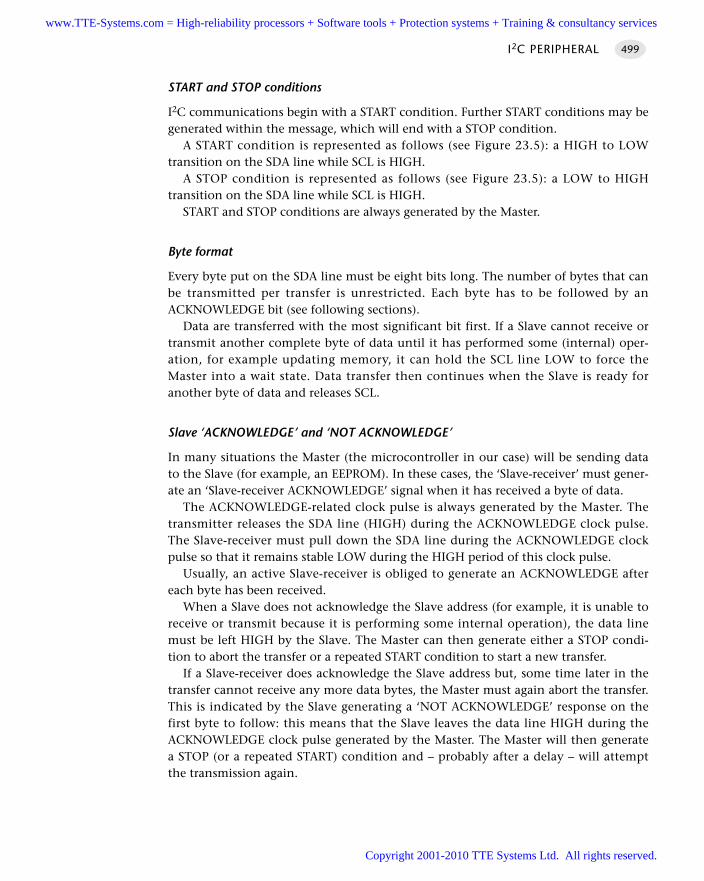
START and STOP conditions
I2C communications begin with a START condition. Further START conditions may begenerated within the message, which will end with a STOP condition.
A START condition is represented as follows (see Figure 23.5): a HIGH to LOWtransition on the SDA line while SCL is HIGH.
A STOP condition is represented as follows (see Figure 23.5): a LOW to HIGHtransition on the SDA line while SCL is HIGH.
START and STOP conditions are always generated by the Master.
Byte format
Every byte put on the SDA line must be eight bits long. The number of bytes that canbe transmitted per transfer is unrestricted. Each byte has to be followed by anACKNOWLEDGE bit (see following sections).
Data are transferred with the most significant bit first. If a Slave cannot receive ortransmit another complete byte of data until it has performed some (internal) oper-ation, for example updating memory, it can hold the SCL line LOW to force theMaster into a wait state. Data transfer then continues when the Slave is ready foranother byte of data and releases SCL.
Slave ‘ACKNOWLEDGE’ and ‘NOT ACKNOWLEDGE’
In many situations the Master (the microcontroller in our case) will be sending datato the Slave (for example, an EEPROM). In these cases, the ‘Slave-receiver’ must gener-ate an ‘Slave-receiver ACKNOWLEDGE’ signal when it has received a byte of data.
The ACKNOWLEDGE-related clock pulse is always generated by the Master. Thetransmitter releases the SDA line (HIGH) during the ACKNOWLEDGE clock pulse.The Slave-receiver must pull down the SDA line during the ACKNOWLEDGE clockpulse so that it remains stable LOW during the HIGH period of this clock pulse.
Usually, an active Slave-receiver is obliged to generate an ACKNOWLEDGE aftereach byte has been received.
When a Slave does not acknowledge the Slave address (for example, it is unable toreceive or transmit because it is performing some internal operation), the data linemust be left HIGH by the Slave. The Master can then generate either a STOP condi-tion to abort the transfer or a repeated START condition to start a new transfer.
If a Slave-receiver does acknowledge the Slave address but, some time later in thetransfer cannot receive any more data bytes, the Master must again abort the transfer.This is indicated by the Slave generating a ‘NOT ACKNOWLEDGE’ response on thefirst byte to follow: this means that the Slave leaves the data line HIGH during theACKNOWLEDGE clock pulse generated by the Master. The Master will then generatea STOP (or a repeated START) condition and – probably after a delay – will attemptthe transmission again.
I2C PERIPHERAL 499
www.TTE-Systems.com = High-reliability processors + Software tools + Protection systems + Training & consultancy services
Copyright 2001-2010 TTE Systems Ltd. All rights reserved.
Master-receiver ‘ACKNOWLEDGE’ and ‘NOT ACKNOWLEDGE’
In some situations the Master (the microcontroller in our case) will be receiving datafrom the Slave (for example, the temperature sensor). In some cases, the ‘Master-receiver’ must generate a ‘Master-receiver ACKNOWLEDGE’ signal when it hasreceived a byte of data. However, at the end of the data transfer (when the Master-receiver has received the last byte of data it requires), it must signal the end of data tothe Slave-transmitter by not generating an ACKNOWLEDGE on the last byte that wasclocked out of the Slave. The Slave-transmitter must release the data line to allow theMaster to generate a STOP or repeated START condition.
Synchronization
All Masters generate their own clock on the SCL line to transfer messages on the I2Cbus. Data are only valid during the HIGH period of the clock. A defined clock is there-fore needed for the bit-by-bit arbitration procedure to take place.
Clock synchronization is performed using the wired AND connection of I2C inter-faces to the SCL line. This means that a HIGH to LOW transition on the SCL line willcause the devices concerned to start counting off their LOW period and, once a deviceclock has gone LOW, it will hold the SCL line in that state until the clock HIGH stateis reached. However, the LOW to HIGH transition of this clock may not change thestate of the SCL line if another clock is still within its LOW period. The SCL line willtherefore be held LOW by the device with the longest LOW period. Devices withshorter LOW periods enter a HIGH wait-state during this time.
When all devices concerned have counted off their LOW period, the clock line willbe released and go HIGH. There will then be no difference between the device clocksand the state of the SCL line and all the devices will start counting their HIGH peri-ods. The first device to complete its HIGH period will again pull the SCL line LOW. Inthis way, a synchronized SCL clock is generated with its LOW period determined bythe device with the longest clock LOW period and its HIGH period determined by theone with the shortest clock HIGH period.
Further details
A complete technical specification for the I2C bus will be found on the PhilipsWWW site.
Solution
Should you use I2C?
In order to determine whether use of an I2C bus is appropriate in your time-triggeredapplication, we consider some key questions that should be asked when consideringthe use of any communications protocol or related technique.
USING SERIAL PERIPHERALS500
www.TTE-Systems.com = High-reliability processors + Software tools + Protection systems + Training & consultancy services
Copyright 2001-2010 TTE Systems Ltd. All rights reserved.
Main application areas
The I2C bus was designed mainly to allow the interconnection of components withina single application. Although the bus may be used, for example, to connect proces-sors (usually microcontrollers) to one another or to other computer systems, its mainapplication area is in the connection of standard peripheral devices, such as LCDpanels or EEPROMs, or ‘smart’ components in consumer applications (e.g. TV tuners,PLL synthesizers, video processors) to microcontrollers.
Ease of development
I2C can be used to communicate with a large number and range of peripherals. By usingthe same protocol to talk to a range of devices, development efforts may be reduced.
Scalability
The maximum size of an I2C bus is limited by the maximum capacitance of 400 pF. Toestimate the maximum network size, we can add up the input capacitance of all thedevices we wish to connect to the bus.
For example, the SGS-Thomson ST24C16 16K I2C-compatible EEPROM has aninput capacitance of around 8 pF, and we could attach some 50 of these devicestogether on the same bus. Note that this rough calculation ignores any effects of straycapacitance due to the cabling itself. If we assume a ‘standard’ capacitance per deviceof 20 pF (including stray capacitance), we can still hope to connect around 20 periph-erals to the microcontroller over a single bus.
Overall, the bus supports large enough collections of peripherals to meet the needsof its main application area.
Flexibility
I2C is flexible. Networks of one Master and multiple Slaves and networks withmultiple Masters can both be implemented. Note: we consider only single-Masterapplications in this pattern.
Speed of execution and size of code
As we have mentioned, I2C can operate over a wide speed range: from 100 kbits/s inthe ‘standard’ version (1992), to 400 kbits/s in the ‘fast’ version, and now 3.4 Mbit/sin the latest ‘high-speed’ version introduced in 1998.
However, in this pattern we are concerned with I2C interfaces created entirely insoftware. Such interfaces are only practical at the low end of the speed range.
Generation of the I2C protocol inevitably adds to the code size: see the core I2Clibrary (in the following example) for details.
I2C PERIPHERAL 501
www.TTE-Systems.com = High-reliability processors + Software tools + Protection systems + Training & consultancy services
Copyright 2001-2010 TTE Systems Ltd. All rights reserved.
Cost
The cost of licence fees for use of the bus is included in the cost of the peripheralcomponents which you purchase: in most circumstances, there are no additional feesto pay.
Note that this may not be the case if, for example, you are implementing a I2Cperipheral (to be sold for connection to an I2C bus). If in doubt, please contact Philipsfor further details.
Choice of implementations and vendors
The I2C library presented here may be used with any 8051 device.
Suitability for use in time-triggered applications
As we saw in Chapter 18, the RS-232 communication protocol is appropriate for use intime-triggered applications. This suitability arises because the task duration associatedwith transmission (and reception) of data on an RS-232 network is very short. Notethat this transmission time is not directly linked to the baud rate of the network,largely because almost all of the 8051 family have on-chip hardware support for RS-232, with the result that messages are transmitted and received ‘in the background’.
The situation with I2C is rather different. Specifically, in this pattern, we are con-cerned with software-based I2C protocols; this undoubtedly adds to the software load.For example, if we consider the process of sending one byte of data to an I2C-basedROM chip (an example of this is presented in full later), then the total task duration isapproximately 0.5 ms.
This task duration can be supported on a time-triggered application, even with 1ms timer ticks, if the maximum data rate (1000 bytes / second) matches the needs ofthe application.
How do you use I2C in a time-triggered application?
The examples that follow include a complete I2C library which may be used with anymember of the 8051 family.
Hardware resource implicationsI2C requires the use of two port pins. This is considerably fewer than would berequired to create a parallel interface to most peripheral devices.
There is, however, a significant CPU load: see ‘Solution’ for details.
Reliability and safety implicationsThe I2C protocol incorporates only minimal error-checking mechanisms: detection ofdata corruption (for example) during the transfer of information to or from a periph-
USING SERIAL PERIPHERALS502
www.TTE-Systems.com = High-reliability processors + Software tools + Protection systems + Training & consultancy services
Copyright 2001-2010 TTE Systems Ltd. All rights reserved.
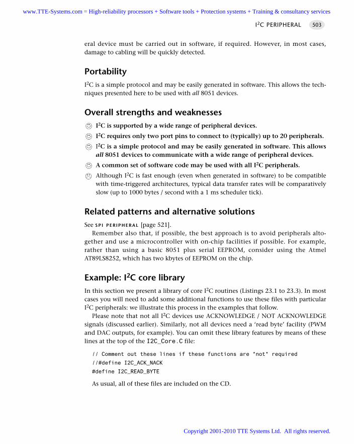
eral device must be carried out in software, if required. However, in most cases,damage to cabling will be quickly detected.
PortabilityI2C is a simple protocol and may be easily generated in software. This allows the tech-niques presented here to be used with all 8051 devices.
Overall strengths and weaknessesI2C is supported by a wide range of peripheral devices.
I2C requires only two port pins to connect to (typically) up to 20 peripherals.
I2C is a simple protocol and may be easily generated in software. This allowsall 8051 devices to communicate with a wide range of peripheral devices.
A common set of software code may be used with all I2C peripherals.
Although I2C is fast enough (even when generated in software) to be compatiblewith time-triggered architectures, typical data transfer rates will be comparativelyslow (up to 1000 bytes / second with a 1 ms scheduler tick).
Related patterns and alternative solutionsSee S P I P E R I P H E R A L [page 521].
Remember also that, if possible, the best approach is to avoid peripherals alto-gether and use a microcontroller with on-chip facilities if possible. For example,rather than using a basic 8051 plus serial EEPROM, consider using the AtmelAT89LS8252, which has two kbytes of EEPROM on the chip.
Example: I2C core libraryIn this section we present a library of core I2C routines (Listings 23.1 to 23.3). In mostcases you will need to add some additional functions to use these files with particularI2C peripherals: we illustrate this process in the examples that follow.
Please note that not all I2C devices use ACKNOWLEDGE / NOT ACKNOWLEDGEsignals (discussed earlier). Similarly, not all devices need a ‘read byte’ facility (PWMand DAC outputs, for example). You can omit these library features by means of theselines at the top of the I2C_Core.C file:
// Comment out these lines if these functions are *not* required
//#define I2C_ACK_NACK
#define I2C_READ_BYTE
As usual, all of these files are included on the CD.
I2C PERIPHERAL 503
www.TTE-Systems.com = High-reliability processors + Software tools + Protection systems + Training & consultancy services
Copyright 2001-2010 TTE Systems Ltd. All rights reserved.
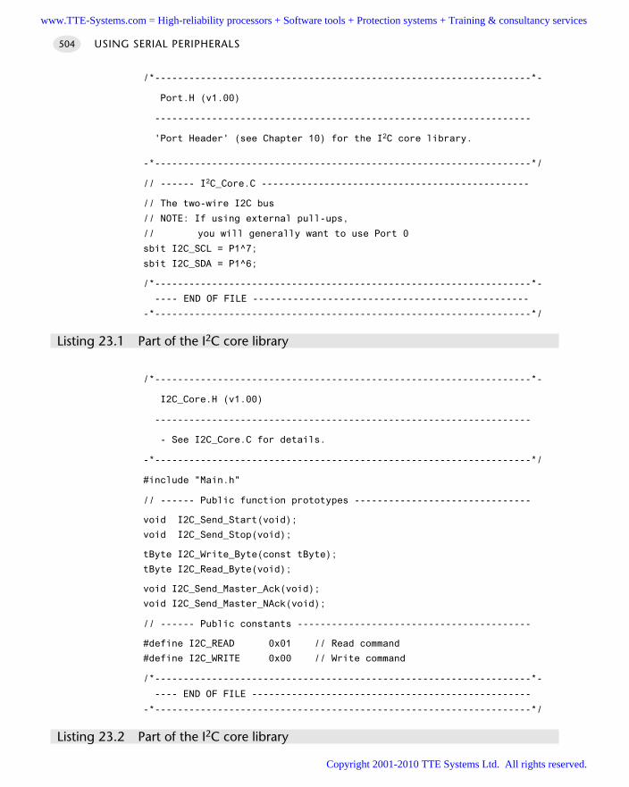
/*------------------------------------------------------------------*-
Port.H (v1.00)
------------------------------------------------------------------
'Port Header' (see Chapter 10) for the I2C core library.
-*------------------------------------------------------------------*/
// ------ I2C_Core.C -----------------------------------------------
// The two-wire I2C bus
// NOTE: If using external pull-ups,
// you will generally want to use Port 0
sbit I2C_SCL = P1^7;
sbit I2C_SDA = P1^6;
/*------------------------------------------------------------------*-
---- END OF FILE ------------------------------------------------
-*------------------------------------------------------------------*/
Listing 23.1 Part of the I2C core library
/*------------------------------------------------------------------*-
I2C_Core.H (v1.00)
------------------------------------------------------------------
- See I2C_Core.C for details.
-*------------------------------------------------------------------*/
#include "Main.h"
// ------ Public function prototypes -------------------------------
void I2C_Send_Start(void);
void I2C_Send_Stop(void);
tByte I2C_Write_Byte(const tByte);
tByte I2C_Read_Byte(void);
void I2C_Send_Master_Ack(void);
void I2C_Send_Master_NAck(void);
// ------ Public constants -----------------------------------------
#define I2C_READ 0x01 // Read command
#define I2C_WRITE 0x00 // Write command
/*------------------------------------------------------------------*-
---- END OF FILE -------------------------------------------------
-*------------------------------------------------------------------*/
Listing 23.2 Part of the I2C core library
USING SERIAL PERIPHERALS504
www.TTE-Systems.com = High-reliability processors + Software tools + Protection systems + Training & consultancy services
Copyright 2001-2010 TTE Systems Ltd. All rights reserved.

/*------------------------------------------------------------------*-
I2C_CORE.C (v1.00)
------------------------------------------------------------------
Core of the I2C library.
You will typically need other components
(see, for example, I2C_ROM.C) to create a complete library.
-*------------------------------------------------------------------*/
#include "Main.h"
#include "Port.h"
#include "I2C_Core.h"
#include "TimeoutH.H"
// ------ Private function prototypes ------------------------------
static tByte I2C_Get_Ack_From_Slave(void);
static bit I2C_Sync_The_Clock_T0(void);
static void I2C_Delay(void);
// Comment out this line if these functions are *not* required
//#define I2C_ACK_NACK
/*------------------------------------------------------------------*-
I2C_Send_Start()
Generates a 'start' condition.
-*------------------------------------------------------------------*/
void I2C_Send_Start(void)
// Prepare the bus
I2C_SCL = 1;
I2C_SDA = 1;
I2C_Delay();
// Generate the START condition
I2C_SDA = 0;
I2C_Delay();
I2C_SCL = 0;
/*------------------------------------------------------------------*-
I2C_Send_Stop()
Generates a 'stop'condition.
-*------------------------------------------------------------------*/
I2C PERIPHERAL 505
www.TTE-Systems.com = High-reliability processors + Software tools + Protection systems + Training & consultancy services
Copyright 2001-2010 TTE Systems Ltd. All rights reserved.
void I2C_Send_Stop(void)
I2C_SDA = 0;
I2C_Delay();
I2C_SCL = 1;
I2C_Delay();
I2C_SDA = 1;
/*------------------------------------------------------------------*-
I2C_Get_Ack_From_Slave()
We are implementing a 'Master-Slave' communication protocol
here, with the microcontroller as the Master. This function
waits (with timeout) for an acknowledgement from the Slave device.
-*------------------------------------------------------------------*/
tByte I2C_Get_Ack_From_Slave(void)
// Prepare the bus
I2C_SDA = 1;
I2C_SCL = 1;
if(I2C_Sync_The_Clock_T0())
return 1; // Error - failed to sync
// Managed to synchronize the clock
I2C_Delay();
if (I2C_SDA)
// Generate a clock cycle
I2C_SCL = 0;
return 1; // Error - No ack from Slave
I2C_SCL = 0; // Generate a clock cycle
return 0; // OK - Slave issued ack
/*------------------------------------------------------------------*-
I2C_Write_Byte()
Send a byte of data to the Slave.
Supports slow Slaves by allowing 'clock stretching'.
USING SERIAL PERIPHERALS506
www.TTE-Systems.com = High-reliability processors + Software tools + Protection systems + Training & consultancy services
Copyright 2001-2010 TTE Systems Ltd. All rights reserved.
Duration ~100 µs (except in the event of bus error).
-*------------------------------------------------------------------*/
tByte I2C_Write_Byte(tByte Data)
tByte Bit = 0;
// Sending data one bit at a time (MS bit first)
for (Bit = 0; Bit < 8; Bit++ )
I2C_SDA = (bit)((Data & 0x80) >> 7);
I2C_SCL = 1;
if (I2C_Sync_The_Clock_T0())
return 1; // Error - failed to sync
I2C_Delay();
// Generate a clock cycle
I2C_SCL = 0;
// Prepare to send next bit
Data <<= 1;
// Make sure the Slave acknowledges
return(I2C_Get_Ack_From_Slave());
/*------------------------------------------------------------------*-
I2C_Read_Byte()
Read a byte of data from the Slave.
Supports slow Slaves by allowing 'clock stretching'.
-*------------------------------------------------------------------*/
tByte I2C_Read_Byte(void)
tByte result = 0; // Return value with read I2C byte
tByte Bit = 0; // Bitcounter
for (Bit = 0; Bit < 8; Bit++ )
I2C_SDA = 1; // Release SDA
I2C_SCL = 1; // Release SCL
if (I2C_Sync_The_Clock_T0())
I2C PERIPHERAL 507
www.TTE-Systems.com = High-reliability processors + Software tools + Protection systems + Training & consultancy services
Copyright 2001-2010 TTE Systems Ltd. All rights reserved.
return 1; // Error - failed to sync
I2C_Delay();
result <<= 1; // Shift left the result
if (I2C_SDA)
result |= 0x01; // Set actual SDA state to LSB
I2C_SCL = 0; // Force a clock cycle
I2C_Delay();
return(result);
/*------------------------------------------------------------------*-
I2C_Sync_The_Clock_T0()
Low-level function used during I2C data transfers.
*** With 1ms hardware (Timer 0) timeout ***
RETURNS: 1 - Error (not synchronized)
0 - OK (clock synchronized)
-*------------------------------------------------------------------*/
bit I2C_Sync_The_Clock_T0(void)
// Configure Timer 0 as a 16-bit timer
TMOD &= 0xF0; // Clear all T0 bits (T1 left unchanged)
TMOD |= 0x01; // Set required T0 bits (T1 left unchanged)
ET0 = 0; // No interrupts
// Simple timeout feature - approx 1ms
TH0 = T_01ms_H; // See TimeoutH.H for T_ details
TL0 = T_01ms_L;
TF0 = 0; // Clear flag
TR0 = 1; // Start timer
// Try to synchronize the clock
while ((I2C_SCL == 0) && (TF0 != 1));
TR0 = 0; // Stop the timer
if (TF0 == 1)
return 1; // Error - Timeout condition failed
USING SERIAL PERIPHERALS508
www.TTE-Systems.com = High-reliability processors + Software tools + Protection systems + Training & consultancy services
Copyright 2001-2010 TTE Systems Ltd. All rights reserved.
return 0; // OK - Clock synchronized
/*------------------------------------------------------------------*-
I2C_Delay()
A short software delay (around 10 µs).
Adjust this for a minimum of 5.425 µs to work with
'standard' I2C devices. Any delay longer than this will also work.
With modern devices shorter delays may also be used.
NOTE: Cannot generally do this with a Hardware Delay.
-*------------------------------------------------------------------*/
void I2C_Delay(void)
int x;
x++;
x++;
#ifdef I2C_ACK_NACK
/*------------------------------------------------------------------*-
I2C_Send_Master_Ack()
Generates an 'ACKNOWLEDGE' condition.
-*------------------------------------------------------------------*/
void I2C_Send_Master_Ack(void)
I2C_SDA = 0;
I2C_SCL = 1;
I2C_Sync_The_Clock_T0();
I2C_Delay();
I2C_SCL = 0;
/*------------------------------------------------------------------*-
I2C_Send_Master_NAck()
Generates a 'NOT ACKNOWLEDGE' condition.
-*------------------------------------------------------------------*/
void I2C_Send_Master_NAck(void)
I2C_SDA = 1; I2C_SCL = 1;
I2C PERIPHERAL 509
www.TTE-Systems.com = High-reliability processors + Software tools + Protection systems + Training & consultancy services
Copyright 2001-2010 TTE Systems Ltd. All rights reserved.
I2C_Sync_The_Clock_T0();
I2C_Delay();
I2C_SCL = 0;
#endif
/*------------------------------------------------------------------*-
---- END OF FILE -------------------------------------------------
-*------------------------------------------------------------------*/
Listing 23.3 Part of the I2C core library
Example: I2C EEPROM interfaceIn this example we consider how to link an 8051 microcontroller to a serial EEPROMusing an I2C bus. Note that use of such EEPROMs is a common way of retainingsystem settings after power is removed: the storage is non-volatile, for a period ofaround 100 years.
Hardware
The required hardware is illustrated in Figure 23.6. Note that, in this case, we are not using an open-collector port and do not require
pull-up resistors. If you are using more than one I2C device, it is recommended thatyou adapt the code to work with Port 0 (a trivial change) and use pull-up resistorvalues calculated as described in ‘Background’.
Software
The required software is contained in Listings 23.4 to 23.6. Note that you will alsorequire the core I2C library from the ‘Solution’ section.
USING SERIAL PERIPHERALS510
FIGURE 23.6 A 24C64 with device address ‘1010000’
4
3
2
1
24C
64
5
6
7
8
Vcc
SCL
SCA
www.TTE-Systems.com = High-reliability processors + Software tools + Protection systems + Training & consultancy services
Copyright 2001-2010 TTE Systems Ltd. All rights reserved.
/*------------------------------------------------------------------*-
Main.C (v1.00)
------------------------------------------------------------------
Simple test program for I2C (24C64) library.
Connect a 24C64 to the SDA and SCL pins described
in the library file (I2C_Core.C).
Terminating resistors not generally required on the bus.
Pull all three address lines (on the EEPROM) to ground.
-*------------------------------------------------------------------*/
#include "Main.h"
#include "I2C_ROM.h"
#include "Delay_T0.h"
// In this test program, we define the error code variable here
// (usually in the scheduler library)
tByte Error_code_G = 0;
void main( void )
tByte data1 = 0;
tByte data2 = 0;
tWord Data_address = 0;
while (1)
Data_address = data1;
// Write to eeprom
I2C_Write_Byte_AT24C64(Data_address, data1);
// Read back from eeprom
data2 = I2C_Read_Byte_AT24C64(Data_address);
// Display value from eeprom
P1 = 255 - data2;
// Display error code
P2 = 255 - Error_code_G;
if (++data1 == 255)
data1 = 0;
I2C PERIPHERAL 511
www.TTE-Systems.com = High-reliability processors + Software tools + Protection systems + Training & consultancy services
Copyright 2001-2010 TTE Systems Ltd. All rights reserved.
Hardware_Delay_T0(1000);
/*------------------------------------------------------------------*-
---- END OF FILE ------------------------------------------------
-*------------------------------------------------------------------*/
Listing 23.4 Part of an I2C EEPROM library
/*------------------------------------------------------------------*-
I2C_ROM.H (v1.00)
------------------------------------------------------------------
- See I2C_ROM.C for details.
-*------------------------------------------------------------------*/
#include "Main.h"
// ------ Public function prototypes -------------------------------
// Read byte from EEPROM
tByte I2C_Read_Byte_AT24C64(tWord);
// Write byte to EEPROM
void I2C_Write_Byte_AT24C64(tWord,tByte);
/*------------------------------------------------------------------*-
---- END OF FILE ------------------------------------------------
-*------------------------------------------------------------------*/
Listing 23.5 Part of an I2C EEPROM library
/*------------------------------------------------------------------*-
I2C_ROM.C (v1.00)
------------------------------------------------------------------
I2C library functions which are intended to allow
use of 2-wire serial EEPROMs (specifically, AT24C64).
Easily extended / adapted to work with other 2-wire EEPROMs.
-*------------------------------------------------------------------*/
#include "Main.h"
#include "Delay_T0.h"
#include "I2C_Core.h"
#include "I2C_ROM.h"
USING SERIAL PERIPHERALS512
www.TTE-Systems.com = High-reliability processors + Software tools + Protection systems + Training & consultancy services
Copyright 2001-2010 TTE Systems Ltd. All rights reserved.
// ------ Public variable declarations -----------------------------
extern tByte Error_code_G;
// ------ Private constants ----------------------------------------
// Device identifier of the EEPROM used in this example
// - see text / Philips documentation for IDs used by other devices
#define I2C_EEPROM_ID 0xA0
/*------------------------------------------------------------------*-
I2C_Write_Byte_AT24C64()
Send a byte of data to the EEPROM.
-*------------------------------------------------------------------*/
void I2C_Write_Byte_AT24C64(const tWord address, tByte content)
tByte MSByte; // Most significant byte of data address
tByte LSByte; // Least significant byte of data address
I2C_Send_Start(); // Generate START condition
// Send SLAVE address with write request
if (I2C_Write_Byte(I2C_EEPROM_ID | I2C_WRITE))
Error_code_G = ERROR_I2C_WRITE_BYTE_AT24C64;
return;
// MSByte of address
MSByte = (address >> 8) & 0x00FF;
// LSByte of Address
LSByte = address & 0x00FF;
// Send memory address
if (I2C_Write_Byte(MSByte))
Error_code_G = ERROR_I2C_WRITE_BYTE_AT24C64;
return;
// Send memory address
if (I2C_Write_Byte(LSByte))
Error_code_G = ERROR_I2C_WRITE_BYTE_AT24C64;
return;
// Send content to memory address
I2C PERIPHERAL 513
www.TTE-Systems.com = High-reliability processors + Software tools + Protection systems + Training & consultancy services
Copyright 2001-2010 TTE Systems Ltd. All rights reserved.
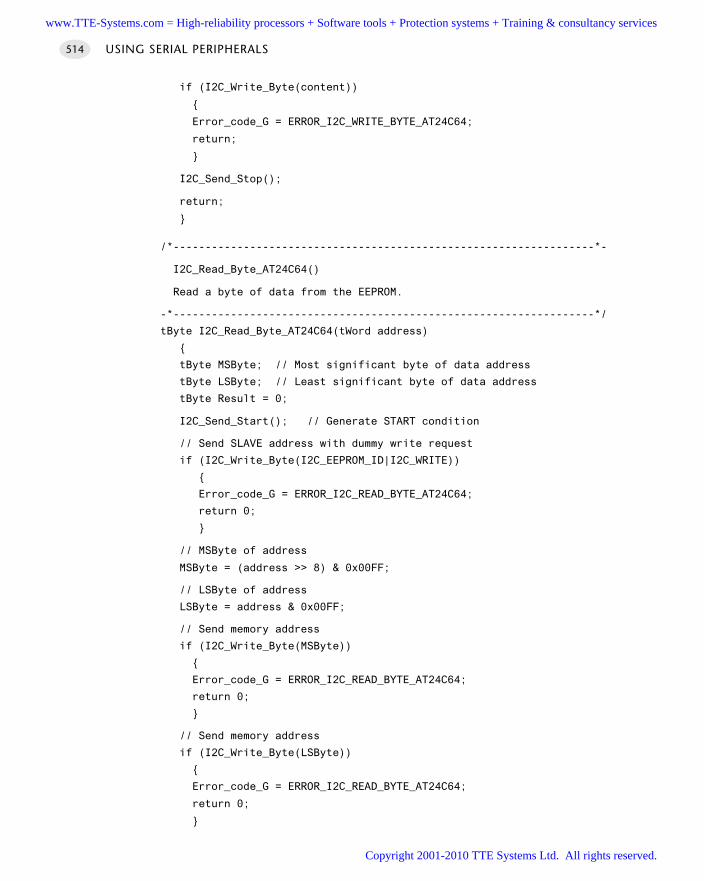
if (I2C_Write_Byte(content))
Error_code_G = ERROR_I2C_WRITE_BYTE_AT24C64;
return;
I2C_Send_Stop();
return;
/*------------------------------------------------------------------*-
I2C_Read_Byte_AT24C64()
Read a byte of data from the EEPROM.
-*------------------------------------------------------------------*/
tByte I2C_Read_Byte_AT24C64(tWord address)
tByte MSByte; // Most significant byte of data address
tByte LSByte; // Least significant byte of data address
tByte Result = 0;
I2C_Send_Start(); // Generate START condition
// Send SLAVE address with dummy write request
if (I2C_Write_Byte(I2C_EEPROM_ID|I2C_WRITE))
Error_code_G = ERROR_I2C_READ_BYTE_AT24C64;
return 0;
// MSByte of address
MSByte = (address >> 8) & 0x00FF;
// LSByte of address
LSByte = address & 0x00FF;
// Send memory address
if (I2C_Write_Byte(MSByte))
Error_code_G = ERROR_I2C_READ_BYTE_AT24C64;
return 0;
// Send memory address
if (I2C_Write_Byte(LSByte))
Error_code_G = ERROR_I2C_READ_BYTE_AT24C64;
return 0;
USING SERIAL PERIPHERALS514
www.TTE-Systems.com = High-reliability processors + Software tools + Protection systems + Training & consultancy services
Copyright 2001-2010 TTE Systems Ltd. All rights reserved.
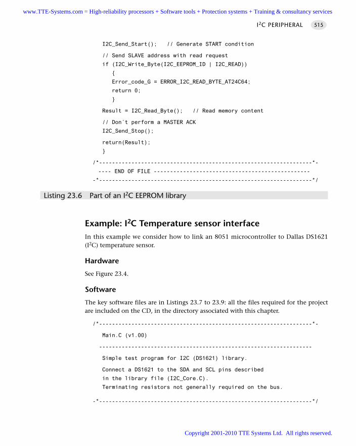
I2C_Send_Start(); // Generate START condition
// Send SLAVE address with read request
if (I2C_Write_Byte(I2C_EEPROM_ID | I2C_READ))
Error_code_G = ERROR_I2C_READ_BYTE_AT24C64;
return 0;
Result = I2C_Read_Byte(); // Read memory content
// Don´t perform a MASTER ACK
I2C_Send_Stop();
return(Result);
/*------------------------------------------------------------------*-
---- END OF FILE ------------------------------------------------
-*------------------------------------------------------------------*/
Listing 23.6 Part of an I2C EEPROM library
Example: I2C Temperature sensor interfaceIn this example we consider how to link an 8051 microcontroller to Dallas DS1621(I2C) temperature sensor.
Hardware
See Figure 23.4.
Software
The key software files are in Listings 23.7 to 23.9: all the files required for the projectare included on the CD, in the directory associated with this chapter.
/*------------------------------------------------------------------*-
Main.C (v1.00)
------------------------------------------------------------------
Simple test program for I2C (DS1621) library.
Connect a DS1621 to the SDA and SCL pins described
in the library file (I2C_Core.C).
Terminating resistors not generally required on the bus.
-*------------------------------------------------------------------*/
I2C PERIPHERAL 515
www.TTE-Systems.com = High-reliability processors + Software tools + Protection systems + Training & consultancy services
Copyright 2001-2010 TTE Systems Ltd. All rights reserved.
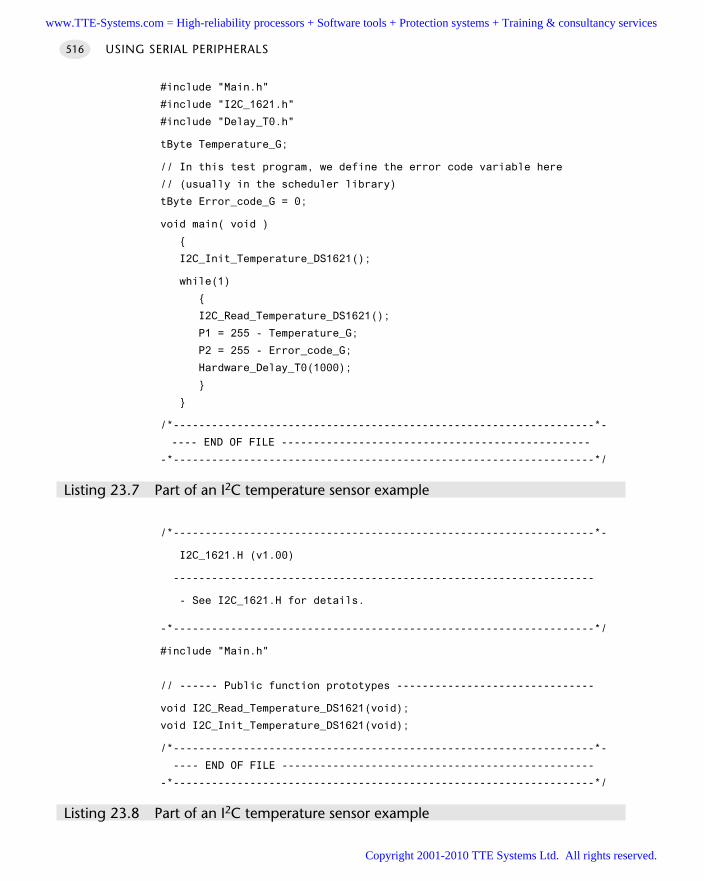
#include "Main.h"
#include "I2C_1621.h"
#include "Delay_T0.h"
tByte Temperature_G;
// In this test program, we define the error code variable here
// (usually in the scheduler library)
tByte Error_code_G = 0;
void main( void )
I2C_Init_Temperature_DS1621();
while(1)
I2C_Read_Temperature_DS1621();
P1 = 255 - Temperature_G;
P2 = 255 - Error_code_G;
Hardware_Delay_T0(1000);
/*------------------------------------------------------------------*-
---- END OF FILE ------------------------------------------------
-*------------------------------------------------------------------*/
Listing 23.7 Part of an I2C temperature sensor example
/*------------------------------------------------------------------*-
I2C_1621.H (v1.00)
------------------------------------------------------------------
- See I2C_1621.H for details.
-*------------------------------------------------------------------*/
#include "Main.h"
// ------ Public function prototypes -------------------------------
void I2C_Read_Temperature_DS1621(void);
void I2C_Init_Temperature_DS1621(void);
/*------------------------------------------------------------------*-
---- END OF FILE -------------------------------------------------
-*------------------------------------------------------------------*/
Listing 23.8 Part of an I2C temperature sensor example
USING SERIAL PERIPHERALS516
www.TTE-Systems.com = High-reliability processors + Software tools + Protection systems + Training & consultancy services
Copyright 2001-2010 TTE Systems Ltd. All rights reserved.
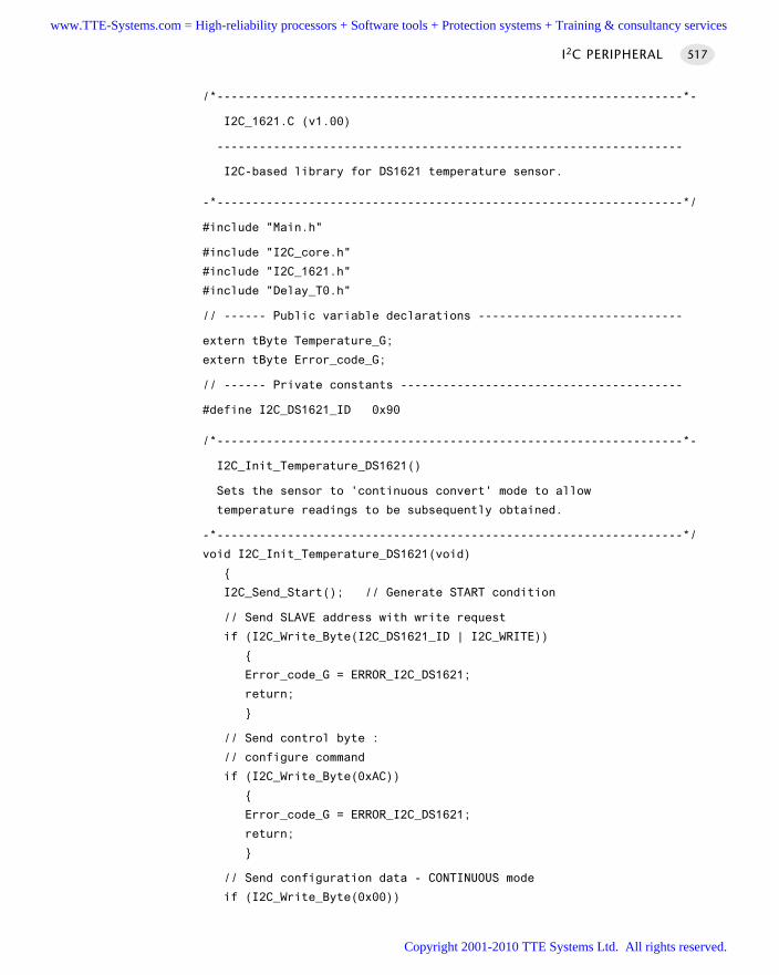
/*------------------------------------------------------------------*-
I2C_1621.C (v1.00)
------------------------------------------------------------------
I2C-based library for DS1621 temperature sensor.
-*------------------------------------------------------------------*/
#include "Main.h"
#include "I2C_core.h"
#include "I2C_1621.h"
#include "Delay_T0.h"
// ------ Public variable declarations -----------------------------
extern tByte Temperature_G;
extern tByte Error_code_G;
// ------ Private constants ----------------------------------------
#define I2C_DS1621_ID 0x90
/*------------------------------------------------------------------*-
I2C_Init_Temperature_DS1621()
Sets the sensor to 'continuous convert' mode to allow
temperature readings to be subsequently obtained.
-*------------------------------------------------------------------*/
void I2C_Init_Temperature_DS1621(void)
I2C_Send_Start(); // Generate START condition
// Send SLAVE address with write request
if (I2C_Write_Byte(I2C_DS1621_ID | I2C_WRITE))
Error_code_G = ERROR_I2C_DS1621;
return;
// Send control byte :
// configure command
if (I2C_Write_Byte(0xAC))
Error_code_G = ERROR_I2C_DS1621;
return;
// Send configuration data - CONTINUOUS mode
if (I2C_Write_Byte(0x00))
I2C PERIPHERAL 517
www.TTE-Systems.com = High-reliability processors + Software tools + Protection systems + Training & consultancy services
Copyright 2001-2010 TTE Systems Ltd. All rights reserved.
Error_code_G = ERROR_I2C_DS1621;
return;
I2C_Send_Stop(); // Generate STOP condition
// Must delay here to allow EEPROM (in sensor)
// to store these data. Sheet says 10ms.
Hardware_Delay_T0(100);
// Now start temperature conversions
I2C_Send_Start(); // Generate START condition
// Send SLAVE address with write request
if (I2C_Write_Byte(I2C_DS1621_ID | I2C_WRITE))
Error_code_G = ERROR_I2C_DS1621;
return;
// Send command data - start converting
if (I2C_Write_Byte(0xEE))
Error_code_G = ERROR_I2C_DS1621;
return;
I2C_Send_Stop(); // Generate STOP condition
/*------------------------------------------------------------------*-
I2C_Read_Temperature_DS1621()
The sensor samples continuously (around 1 new value per second).
We obtain the latest value.
-*------------------------------------------------------------------*/
void I2C_Read_Temperature_DS1621(void)
tByte result = 0;
I2C_Send_Start(); // Generate START condition
// Send DS1621 device address (with write access request)
if (I2C_Write_Byte(I2C_DS1621_ID | I2C_WRITE))
Error_code_G = ERROR_I2C_DS1621;
return;
USING SERIAL PERIPHERALS518
www.TTE-Systems.com = High-reliability processors + Software tools + Protection systems + Training & consultancy services
Copyright 2001-2010 TTE Systems Ltd. All rights reserved.
// Send command - Read Temperature (0xAA)
if (I2C_Write_Byte(0xAA))
Error_code_G = ERROR_I2C_DS1621;
return;
I2C_Send_Start(); // Generate START condition (again)
// Send DS1621 device address (with READ access request this time)
if (I2C_Write_Byte(I2C_DS1621_ID | I2C_READ))
Error_code_G = ERROR_I2C_DS1621;
return;
// Receive first (MS) byte from I2C bus
Temperature_G = I2C_Read_Byte();
I2C_Send_Master_Ack(); // Perform a MASTER ACK
// Here we require temperature only accurate to 1 degree C
// - we discard LS byte (perform a dummy read)
I2C_Read_Byte();
I2C_Send_Master_NAck(); // Perform a MASTER NACK
I2C_Send_Stop(); // Generate STOP condition
/*------------------------------------------------------------------*-
---- END OF FILE ------------------------------------------------
-*------------------------------------------------------------------*/
Listing 23.9 Part of an I2C temperature sensor example
Example: I2C ADCSee Chapter 32 for an example of an I2C interface to an analogue-to-digital converter.
Further readingSee the Philips I2C specification (see www.philips.com) for further details.
I2C PERIPHERAL 519
www.TTE-Systems.com = High-reliability processors + Software tools + Protection systems + Training & consultancy services
Copyright 2001-2010 TTE Systems Ltd. All rights reserved.
Using ‘SPI’ peripherals
Introduction
When using asynchronous serial protocols, such as ‘RS-232’, the two devices that arecommunicating must agree on a communication frequency (the baud rate) and eachdevice then uses (say) an independent crystal-based clock to ensure that it operates atthe required rate. One consequence of this approach is that, if the clocks in the trans-mitter and receiver devices vary by more than a few per cent, the receiving device willbe unable to decode the incoming data correctly.
By contrast, the serial peripheral interface (SPI) uses a synchronous communicationprotocol: this means that both the transmitter and receiver devices share a commonclock. The transitions of this common clock determine when to send and receive thevarious bits. For example, in a simple synchronous protocol, the transmitter devicemay write a bit on the rising edge of the clock and the receiving device will then readthis bit when it detects the falling clock edge. Note that the clock frequency does notneed to be held constant.
Such synchronous interfaces are primarily intended for use over distances meas-ured in centimetres rather than in metres and we will restrict our discussions here tothe use of SPI to link the 8051 with compatible peripherals.
chapter 24www.TTE-Systems.com = High-reliability processors + Software tools + Protection systems + Training & consultancy services
Copyright 2001-2010 TTE Systems Ltd. All rights reserved.
SPI PERIPHERAL
Context You are developing an embedded application using one or more members of the
8051 family of microcontrollers.
The application has a time-triggered architecture, based on a scheduler.
The microcontroller in your application will be interfaced to one or more peripher-als, such as a keypad, EEPROM, digital-to-analogue converter or similar device.
Your microcontroller has hardware support for the SPI protocol.
ProblemShould you use the SPI bus to link your microcontroller to peripheral devices and, ifso, how do you do so?
BackgroundThere are five key features of SPI as far as the developer of embedded applicationsis concerned:
SPI is a protocol designed to allow microcontrollers to be linked to a wide range ofdifferent peripherals – memory, displays, ADCs and similar devices – and requires(typically) three port pins for the bus, plus one chip-select pin per peripheral.
There are many SPI-compatible peripherals available for purchase ‘off the shelf’.
Increasing numbers of ‘Standard’ and ‘Extended’ 8051 devices have hardware sup-port for SPI and we will make use of such facilities in this pattern.
A common set of software code may be used with all SPI peripherals.
SPI is compatible with time-triggered architectures and, as implemented in this book,is faster than I2C (largely due to the use of on-chip hardware support). Typical datatransfer rates will be up to 5,000–10,000 bytes / second (with a 1 ms scheduler tick).
We provide some background to SPI in this section.
History
Serial peripheral interface (SPI) was developed by Motorola and included on the68HC11 and other microcontrollers. Recently, this interface standard has beenadopted by manufacturers of other microcontrollers. Increasing numbers of‘Standard’ and ‘Extended’ 8051 devices (see Chapter 3) have hardware support for SPIand we will make use of such facilities in this pattern.
SPI PERIPHERAL 521
www.TTE-Systems.com = High-reliability processors + Software tools + Protection systems + Training & consultancy services
Copyright 2001-2010 TTE Systems Ltd. All rights reserved.
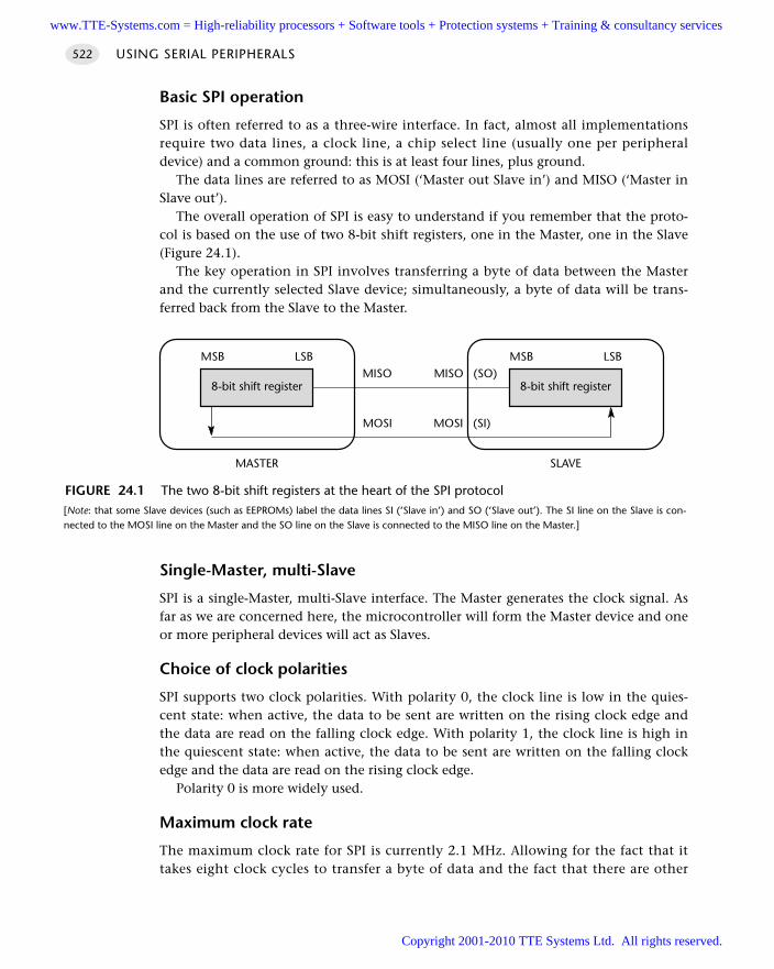
Basic SPI operation
SPI is often referred to as a three-wire interface. In fact, almost all implementationsrequire two data lines, a clock line, a chip select line (usually one per peripheraldevice) and a common ground: this is at least four lines, plus ground.
The data lines are referred to as MOSI (‘Master out Slave in’) and MISO (‘Master inSlave out’).
The overall operation of SPI is easy to understand if you remember that the proto-col is based on the use of two 8-bit shift registers, one in the Master, one in the Slave(Figure 24.1).
The key operation in SPI involves transferring a byte of data between the Masterand the currently selected Slave device; simultaneously, a byte of data will be trans-ferred back from the Slave to the Master.
Single-Master, multi-Slave
SPI is a single-Master, multi-Slave interface. The Master generates the clock signal. Asfar as we are concerned here, the microcontroller will form the Master device and oneor more peripheral devices will act as Slaves.
Choice of clock polarities
SPI supports two clock polarities. With polarity 0, the clock line is low in the quies-cent state: when active, the data to be sent are written on the rising clock edge andthe data are read on the falling clock edge. With polarity 1, the clock line is high inthe quiescent state: when active, the data to be sent are written on the falling clockedge and the data are read on the rising clock edge.
Polarity 0 is more widely used.
Maximum clock rate
The maximum clock rate for SPI is currently 2.1 MHz. Allowing for the fact that ittakes eight clock cycles to transfer a byte of data and the fact that there are other
USING SERIAL PERIPHERALS522
FIGURE 24.1 The two 8-bit shift registers at the heart of the SPI protocol[Note: that some Slave devices (such as EEPROMs) label the data lines SI (‘Slave in’) and SO (‘Slave out’). The SI line on the Slave is con-nected to the MOSI line on the Master and the SO line on the Slave is connected to the MISO line on the Master.]
8-bit shift register
MSB LSB
8-bit shift register
MSB LSBMISO MISO (SO)
MOSI (SI)MOSI
MASTER SLAVE
www.TTE-Systems.com = High-reliability processors + Software tools + Protection systems + Training & consultancy services
Copyright 2001-2010 TTE Systems Ltd. All rights reserved.
overheads too (instructions and addresses, for example), the maximum data transferrates will be around 130,000 bytes per second.
Microwire
Note that the Microwire interface standard (developed by National Semiconductor) issimilar to SPI, although the connection names, polarities and other details vary:Microwire is not discussed further in this book.
SolutionShould you use SPI?
In order to determine whether use of an SPI bus is appropriate in your time-triggeredapplication, we consider some key questions that should be asked when consideringthe use of any communications protocol or related technique.
Main application areas
Although the SPI bus may be used, for example, to connect processors (usually micro-controllers) to one another or to other computer systems, its main application areais – like I2C – in the connection of standard peripheral devices, such as LCD panels orEEPROMs to microcontrollers.
Ease of development
SPI can be used to communicate with a large number and range of peripherals. By usingthe same protocol to talk to a range of devices, development efforts may be reduced.
Scalability
Each SPI Slave device requires a separate /CS (chip select) line from the Master node.This increases the number of pins required on the microcontroller if large numbers ofperipherals are used.
Flexibility
Individual SPI-compatible microcontrollers may act as Master or Slave nodes. We con-sider only the use of the microcontroller as the Master node in this pattern.
Speed of execution and size of code
The maximum clock rate for SPI is currently 2.1 MHz. As we will be using hardware-based SPI in this pattern, the code overhead will
be small.
SPI PERIPHERAL 523
www.TTE-Systems.com = High-reliability processors + Software tools + Protection systems + Training & consultancy services
Copyright 2001-2010 TTE Systems Ltd. All rights reserved.
Cost
The cost of licence fees for use of the bus is included in the cost of the peripheralcomponents which you purchase: in most circumstances, there are no additional feesto pay.
Note that this may not be the case if, for example, you are implementing an SPIperipheral (to be sold for connection to an SPI bus). If in doubt, contact Motorola forfurther details.
Choice of implementations and vendors
The SPI library presented here may be used only with 8051 devices that have hard-ware support for SPI.
Suitability for use in time-triggered applications
As we saw in Chapter 18, the RS-232 communication protocol is appropriate for use intime-triggered applications. This suitability arises because the task duration associatedwith transmission (and reception) of data on an RS-232 network is very short. Note thatthis transmission time is not directly linked to the baud rate of the network, largelybecause almost all members of the 8051 family have on-chip hardware support for RS-232, with the result that messages are transmitted and received ‘in the background’.
The situation with SPI is similar. Specifically, in this pattern, we are concerned withhardware-based SPI protocols. These typically impose a low software load and allow ashort task duration. For example, if we consider the process of sending one byte ofdata to an SPI-based ROM chip (an example of this is presented in full later), then thetotal task duration is approximately 0.1 ms; note that this is considerably shorterthan the equivalent operation using the I2C library presented in this book.
This task duration can be easily supported in a time-triggered application, evenwith 1 ms timer ticks.
How do you use SPI in a time-triggered application?
The discussions will centre around the Atmel AT89S53, a Standard 8051 device withon-chip SPI support. Note that hardware support provided by other manufacturers isvery similar.
The AT89S53 SPI features include the following:
Full-duplex, three-wire synchronous data transfer
Master or Slave operation
1.5 MHz bit frequency (max.)
LSB first or MSB first data transfer
Four programmable bit rates
End of transmission interrupt flag
USING SERIAL PERIPHERALS524
www.TTE-Systems.com = High-reliability processors + Software tools + Protection systems + Training & consultancy services
Copyright 2001-2010 TTE Systems Ltd. All rights reserved.
Write collision flag protection
Wakeup from idle mode (Slave mode only)
The interconnection between Master and Slave CPUs with SPI is as shown inFigure 24.1.
The SCK pin is the clock output in the Master mode (the only mode we will usehere). Writing to the SPI data register of the Master CPU starts the SPI clock genera-tor and the data written shifts out of the MOSI pin and into the MOSI pin of theSlave CPU. After shifting one byte, the SPI clock generator stops, setting the end oftransmission flag (SPIF). If both the SPI interrupt enable bit (SPIE) and the serial portinterrupt enable bit (ES) are set, an interrupt is requested. We will not use theseinterrupt facilities.
The Slave Select input, SS/P1.4, is set low to select an individual SPI device as aSlave. When SS/P1.4 is set high, the SPI port is deactivated and the MOSI/P1.5 pin canbe used as an input.
There are four combinations of SCK phase and polarity with respect to serial data,which are determined by control bits CPHA and CPOL (see Table 24.1).
Most of the features of the SPI interface in the AT89S53 are illustrated in theexample that follows.
Hardware resource implicationsWith on-chip hardware support, S P I P E R I P H E R A L imposes a minimal software load.
Reliability and safety issuesThe SPI protocol incorporates only minimal error-checking mechanisms: detection ofdata corruption (for example) during the transfer of information to or from a periph-eral device must be carried out in software, if required.
PortabilityThis pattern requires hardware support for SPI: it cannot be used with microcon-trollers without such support.
The discussions here are based on the Atmel 89S53. Use with other 8051 microcon-trollers – including many Infineon 8051s – is straightforward.
Overall strengths and weaknessesSPI is supported by a wide range of peripheral devices.
SPI requires (typically) three port pins for the bus, plus one chip-select pinper peripheral.
Use of hardware-based SPI (as discussed here) facilitates the design of taskswith short durations; as a consequence the protocol is well matched to the
SPI PERIPHERAL 525
www.TTE-Systems.com = High-reliability processors + Software tools + Protection systems + Training & consultancy services
Copyright 2001-2010 TTE Systems Ltd. All rights reserved.
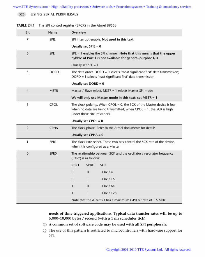
needs of time-triggered applications. Typical data transfer rates will be up to5,000–10,000 bytes / second (with a 1 ms scheduler tick).
A common set of software code may be used with all SPI peripherals.
The use of this pattern is restricted to microcontrollers with hardware support forSPI.
USING SERIAL PERIPHERALS526
TABLE 24.1 The SPI control register (SPCR) in the Atmel 89S53
Bit Name Overview
7 SPIE SPI interrupt enable. Not used in this text
Usually set SPIE = 0
6 SPE SPE = 1 enables the SPI channel. Note that this means that the uppernybble of Port 1 is not available for general-purpose I/O
Usually set SPE = 1
5 DORD The data order. DORD = 0 selects ‘most significant first’ data transmission;DORD = 1 selects ‘least significant first’ data transmission
Usually set DORD = 0
4 MSTR Master / Slave select. MSTR = 1 selects Master SPI mode
We will only use Master mode in this text: set MSTR = 1
3 CPOL The clock polarity. When CPOL = 0, the SCK of the Master device is low when no data are being transmitted; when CPOL = 1, the SCK is highunder these circumstances
Usually set CPOL = 0
2 CPHA The clock phase. Refer to the Atmel documents for details
Usually set CPHA = 0
1 SPR1 The clock-rate select. These two bits control the SCK rate of the device, when it is configured as a Master
0 SPR0 The relationship between SCK and the oscillator / resonator frequency (‘Osc’) is as follows:
SPR1 SPR0 SCK
0 0 Osc / 4
0 1 Osc / 16
1 0 Osc / 64
1 1 Osc / 128
Note that the AT89S53 has a maximum (SPI) bit rate of 1.5 MHz
www.TTE-Systems.com = High-reliability processors + Software tools + Protection systems + Training & consultancy services
Copyright 2001-2010 TTE Systems Ltd. All rights reserved.
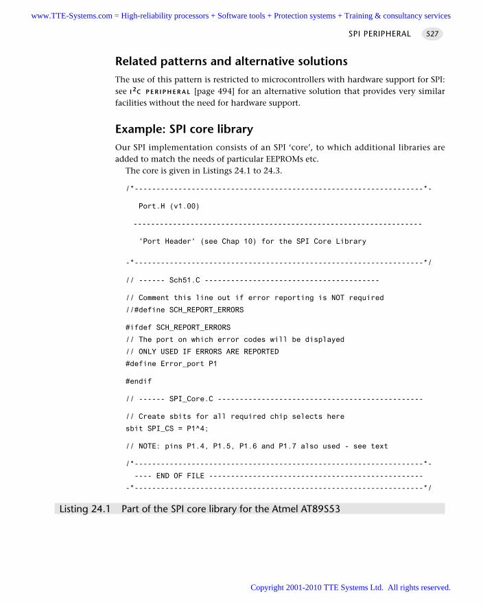
Related patterns and alternative solutionsThe use of this pattern is restricted to microcontrollers with hardware support for SPI:see I 2C P E R I P H E R A L [page 494] for an alternative solution that provides very similarfacilities without the need for hardware support.
Example: SPI core libraryOur SPI implementation consists of an SPI ‘core’, to which additional libraries areadded to match the needs of particular EEPROMs etc.
The core is given in Listings 24.1 to 24.3.
/*------------------------------------------------------------------*-
Port.H (v1.00)
------------------------------------------------------------------
'Port Header' (see Chap 10) for the SPI Core Library
-*------------------------------------------------------------------*/
// ------ Sch51.C ----------------------------------------
// Comment this line out if error reporting is NOT required
//#define SCH_REPORT_ERRORS
#ifdef SCH_REPORT_ERRORS
// The port on which error codes will be displayed
// ONLY USED IF ERRORS ARE REPORTED
#define Error_port P1
#endif
// ------ SPI_Core.C -----------------------------------------------
// Create sbits for all required chip selects here
sbit SPI_CS = P1^4;
// NOTE: pins P1.4, P1.5, P1.6 and P1.7 also used - see text
/*------------------------------------------------------------------*-
---- END OF FILE -------------------------------------------------
-*------------------------------------------------------------------*/
Listing 24.1 Part of the SPI core library for the Atmel AT89S53
SPI PERIPHERAL 527
www.TTE-Systems.com = High-reliability processors + Software tools + Protection systems + Training & consultancy services
Copyright 2001-2010 TTE Systems Ltd. All rights reserved.
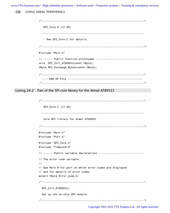
/*------------------------------------------------------------------*-
SPI_Core.H (v1.00)
------------------------------------------------------------------
- See SPI_Core.C for details.
-*------------------------------------------------------------------*/
#include "Main.h"
// ------ Public function prototypes -------------------------------
void SPI_Init_AT89S53(const tByte);
tByte SPI_Exchange_Bytes(const tByte);
/*------------------------------------------------------------------*-
---- END OF FILE ------------------------------------------------
-*------------------------------------------------------------------*/
Listing 24.2 Part of the SPI core library for the Atmel AT89S53
/*------------------------------------------------------------------*-
SPI_Core.C (v1.00)
------------------------------------------------------------------
Core SPI library for Atmel AT89S53.
-*------------------------------------------------------------------*/
#include "Main.h"
#include "Port.h"
#include "SPI_Core.h"
#include "TimeoutH.H"
// ------ Public variable declarations -----------------------------
// The error code variable
//
// See Main.H for port on which error codes are displayed
// and for details of error codes
extern tByte Error_code_G;
/*------------------------------------------------------------------*-
SPI_Init_AT89S53()
Set up the on-chip SPI module.
-*------------------------------------------------------------------*/
USING SERIAL PERIPHERALS528
www.TTE-Systems.com = High-reliability processors + Software tools + Protection systems + Training & consultancy services
Copyright 2001-2010 TTE Systems Ltd. All rights reserved.
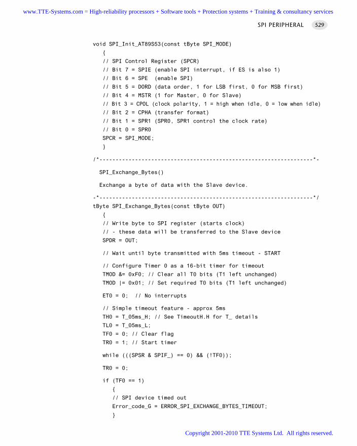
void SPI_Init_AT89S53(const tByte SPI_MODE)
// SPI Control Register (SPCR)
// Bit 7 = SPIE (enable SPI interrupt, if ES is also 1)
// Bit 6 = SPE (enable SPI)
// Bit 5 = DORD (data order, 1 for LSB first, 0 for MSB first)
// Bit 4 = MSTR (1 for Master, 0 for Slave)
// Bit 3 = CPOL (clock polarity, 1 = high when idle, 0 = low when idle)
// Bit 2 = CPHA (transfer format)
// Bit 1 = SPR1 (SPR0, SPR1 control the clock rate)
// Bit 0 = SPR0
SPCR = SPI_MODE;
/*------------------------------------------------------------------*-
SPI_Exchange_Bytes()
Exchange a byte of data with the Slave device.
-*------------------------------------------------------------------*/
tByte SPI_Exchange_Bytes(const tByte OUT)
// Write byte to SPI register (starts clock)
// - these data will be transferred to the Slave device
SPDR = OUT;
// Wait until byte transmitted with 5ms timeout - START
// Configure Timer 0 as a 16-bit timer for timeout
TMOD &= 0xF0; // Clear all T0 bits (T1 left unchanged)
TMOD |= 0x01; // Set required T0 bits (T1 left unchanged)
ET0 = 0; // No interrupts
// Simple timeout feature - approx 5ms
TH0 = T_05ms_H; // See TimeoutH.H for T_ details
TL0 = T_05ms_L;
TF0 = 0; // Clear flag
TR0 = 1; // Start timer
while (((SPSR & SPIF_) == 0) && (!TF0));
TR0 = 0;
if (TF0 == 1)
// SPI device timed out
Error_code_G = ERROR_SPI_EXCHANGE_BYTES_TIMEOUT;
SPI PERIPHERAL 529
www.TTE-Systems.com = High-reliability processors + Software tools + Protection systems + Training & consultancy services
Copyright 2001-2010 TTE Systems Ltd. All rights reserved.
// Clear SPIF and WCOL
SPSR &= 0x3F;
// Return contents of SPI register
// - these are the data from the Slave device
return SPDR;
/*------------------------------------------------------------------*-
---- END OF FILE ------------------------------------------------
-*------------------------------------------------------------------*/
Listing 24.3 Part of the SPI core library for the Atmel AT89S53
Example: Using an SPI EEPROM (X25320 or similar)In this example we present an SPI library allowing communication with an externalEEPROM. In this case we have used a X25320 (4k × 8-bit) device, but any similar SPIEEPROM can be used without difficulty. Such devices are very useful as a means ofstoring non-volatile information such as passwords and similar information.
The hardware is based on the Atmel 89S53 (see Figure 24.2). Note that in main() we do the following:
SPI_Init_AT89S53(0x51);
In this case, with a 12 MHz crystal on the board, this sets the SPI clock rate to750,000 bits/second: this is roughly 100 bytes / millisecond, meaning that the dura-tion of the basic data transfer tasks is approximately 0.01 ms.
The key files are given in Listings 24.4 to 24.6. You will also need the core SPI filespresented earlier. As usual, all the files for this project are included on the CD.
/*------------------------------------------------------------------*-
Main.C (v1.00)
------------------------------------------------------------------
Simple test program for SPI code library.
Writes and reads Xicor X25320 (4k x 8-bit) EEPROM
-*------------------------------------------------------------------*/
#include "Main.h"
#include "SPI_Core.h"
#include "SPI_X25.h"
#include "Delay_T0.h"
// In this test program, we define the error code variable here.
tByte Error_code_G = 0;
USING SERIAL PERIPHERALS530
www.TTE-Systems.com = High-reliability processors + Software tools + Protection systems + Training & consultancy services
Copyright 2001-2010 TTE Systems Ltd. All rights reserved.
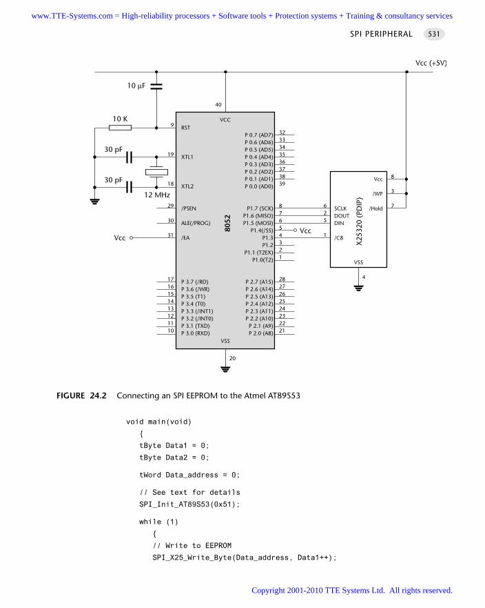
void main(void)
tByte Data1 = 0;
tByte Data2 = 0;
tWord Data_address = 0;
// See text for details
SPI_Init_AT89S53(0x51);
while (1)
// Write to EEPROM
SPI_X25_Write_Byte(Data_address, Data1++);
SPI PERIPHERAL 531
FIGURE 24.2 Connecting an SPI EEPROM to the Atmel AT89S53
30 pF
30 pF
RST
XTL1
XTL2
/PSEN
ALE(/PROG)
/EA
P 3.7 (/RD)P 3.6 (/WR)P 3.5 (T1)P 3.4 (T0)P 3.3 (/INT1)P 3.2 (/INT0)P 3.1 (TXD)P 3.0 (RXD)
P 0.7 (AD7)P 0.6 (AD6)P 0.5 (AD5)P 0.4 (AD4)P 0.3 (AD3)P 0.2 (AD2)P 0.1 (AD1)P 0.0 (AD0)
P1.7 (SCK)P1.6 (MISO)P1.5 (MOSI)
P1.4(/SS)P1.3P1.2
P1.1 (T2EX)P1.0(T2)
P 2.7 (A15)P 2.6 (A14)P 2.5 (A13)P 2.4 (A12)P 2.3 (A11)P 2.2 (A10)
P 2.1 (A9)P 2.0 (A8)
VCC
8052
VSS
3233343536373839
87654321
2827262524232221
9
19
18
29
30
31
1716151413121110
20
40
Vcc
SCLKDOUTDIN
/C8
12 MHz
10 µF
625
1
Vcc (+5V)
10 K
Vcc
X25
320
(PD
IP)
Vcc
/WP
/Hold
VSS
4
8
3
7
www.TTE-Systems.com = High-reliability processors + Software tools + Protection systems + Training & consultancy services
Copyright 2001-2010 TTE Systems Ltd. All rights reserved.
// Read back from EEPROM
Data2 = SPI_X25_Read_Byte(Data_address);
// Display value from EEPROM
P2 = 255 - Data2;
// Display error codes (if any)
P3 = 255 - Error_code_G;
if (++Data_address == 4095)
Data_address = 0;
Hardware_Delay_T0(1000);
/*------------------------------------------------------------------*-
---- END OF FILE ------------------------------------------------
-*------------------------------------------------------------------*/
Listing 24.4 Part of an example linking an SPI EEPROM to the Atmel AT89S53
/*------------------------------------------------------------------*-
SPI_x25.H (v1.00)
------------------------------------------------------------------
- See SPI_x25.C for details.
-*------------------------------------------------------------------*/
#include "Main.h"
// ------ Public function prototypes -------------------------------
void SPI_X25_Write_Byte(const tWord, const tByte);
tByte SPI_X25_Read_Byte(const tWord);
/*------------------------------------------------------------------*-
---- END OF FILE ------------------------------------------------
-*------------------------------------------------------------------*/
Listing 24.5 Part of an example linking an SPI EEPROM to the Atmel AT89S53
USING SERIAL PERIPHERALS532
www.TTE-Systems.com = High-reliability processors + Software tools + Protection systems + Training & consultancy services
Copyright 2001-2010 TTE Systems Ltd. All rights reserved.
/*------------------------------------------------------------------*-
SPI_X25.C (v1.00)
------------------------------------------------------------------
Simple SPI library for Atmel AT89S53
- allows data storage on Xicor X25138 EEPROM (or similar)
-*------------------------------------------------------------------*/
#include "Main.H"
#include "Port.h"
#include "SPI_Core.h"
#include "SPI_X25.h"
#include "TimeoutH.h"
// ------ Public variable declarations -----------------------------
// The error code variable
//
// See Main.H for port on which error codes are displayed
// and for details of error codes
extern tByte Error_code_G;
// ------ Private function prototypes ------------------------------
void SPI_Delay_T0(void);
void SPI_X25_Read_Status_Register(void);
/*------------------------------------------------------------------*-
SPI_X25_Write_Byte()
Store a byte of data on the EEPROM.
-*------------------------------------------------------------------*/
void SPI_X25_Write_Byte(const tWord ADDRESS, const tByte DATA)
// 0. We check the status register
SPI_X25_Read_Status_Register();
// 1. Pin /CS is pulled low to select the device
SPI_CS = 0;
// 2. The 'Write Enable' instruction is sent (0x06)
SPI_Exchange_Bytes(0x06);
// 3. The /CS must now be pulled high
SPI_CS = 1;
// 4. Wait (briefly)
SPI_Delay_T0();
SPI PERIPHERAL 533
www.TTE-Systems.com = High-reliability processors + Software tools + Protection systems + Training & consultancy services
Copyright 2001-2010 TTE Systems Ltd. All rights reserved.
// 5. Pin /CS is pulled low to select the device
SPI_CS = 0;
// 6. The 'Write' instruction is sent (0x02)
SPI_Exchange_Bytes(0x02);
// 7. The address we wish to read from is sent.
// NOTE: we send a 16-bit address:
// - depending on the size of the device, some bits may be ignored.
SPI_Exchange_Bytes((ADDRESS >> 8) & 0x00FF); // Send MSB
SPI_Exchange_Bytes(ADDRESS & 0x00FF); // Send LSB
// 8. The data to be written is shifted out on MOSI
SPI_Exchange_Bytes(DATA);
// 9. Pull the /CS pin high to complete the operation
SPI_CS = 1;
/*------------------------------------------------------------------*-
SPI_X25_Read_Byte()
Read a byte of data from the EEPROM.
-*------------------------------------------------------------------*/
tByte SPI_X25_Read_Byte(const tWord ADDRESS)
tByte Data;
// 0. We check the status register
SPI_X25_Read_Status_Register();
// 1. Pin /CS is pulled low to select the device
SPI_CS = 0;
// 2. The 'Read' instruction is sent (0x03)
SPI_Exchange_Bytes(0x03);
// 3. The address we wish to read from is sent.
// NOTE: we send a 16-bit address:
// depending on the size of the device, some bits may be ignored.
SPI_Exchange_Bytes((ADDRESS >> 8) & 0x00FF);
SPI_Exchange_Bytes(ADDRESS & 0x00FF);
// 4. The data requested is shifted out on SO by sending a dummy byte
Data = SPI_Exchange_Bytes(0x00);
// 5. We pull the /CS pin high to complete the operation
SPI_CS = 1;
USING SERIAL PERIPHERALS534
www.TTE-Systems.com = High-reliability processors + Software tools + Protection systems + Training & consultancy services
Copyright 2001-2010 TTE Systems Ltd. All rights reserved.
return Data; // Return SPI data byte
/*------------------------------------------------------------------*-
SPI_X25_Read_Status_Register()
We read the status register only to make sure that previous
'Write' operations (if any) are now complete.
To do this, we check the WIP ('Write In Progress') flag.
*** NB: THE INTERNAL EEPROM WRITE OPERATION TAKES UP 10ms ***
*** Schedule writes (and reads after writes) at sensible ***
*** intervals - or you will get task jitter ***
We timeout after ~15ms.
Uses T0 for (hardware) timeout - see Chapter 15.
-*------------------------------------------------------------------*/
void SPI_X25_Read_Status_Register()
tByte Data;
bit Wip;
// Configure Timer 0 as a 16-bit timer
TMOD &= 0xF0; // Clear all T0 bits (T1 left unchanged)
TMOD |= 0x01; // Set required T0 bits (T1 left unchanged)
ET0 = 0; // No interrupts
// Simple timeout feature - approx 15ms
TH0 = T_15ms_H; // See TimeoutH.H for T_ details
TL0 = T_15ms_L;
TF0 = 0; // Clear flag
TR0 = 1; // Start timer
do
// 0. Pin /CS is pulled low to select the device
SPI_CS = 0;
// 1. The 'RDSR' instruction is sent (0x05)
SPI_Exchange_Bytes(0x05);
// 2. The contents of the ROM status register are read
Data = SPI_Exchange_Bytes(0x00);
// 3. Pull the /CS pin high to complete the operation
SPI_CS = 1;
// Check the WIP flag
Wip = (Data & 0x01);
while ((Wip != 0) && (TF0 != 1));
SPI PERIPHERAL 535
www.TTE-Systems.com = High-reliability processors + Software tools + Protection systems + Training & consultancy services
Copyright 2001-2010 TTE Systems Ltd. All rights reserved.
TR0 = 0;
if (TF0 == 1)
// ROM timed out
Error_code_G = ERROR_SPI_X25_TIMEOUT;
/*------------------------------------------------------------------*-
SPI_Delay_T0()
A delay of approx 50 µs using 'timeout' code.
-*------------------------------------------------------------------*/
void SPI_Delay_T0(void)
// Configure Timer 0 as a 16-bit timer
TMOD &= 0xF0; // Clear all T0 bits (T1 left unchanged)
TMOD |= 0x01; // Set required T0 bits (T1 left unchanged)
ET0 = 0; // No interrupts
// Simple timeout feature - approx 50 µs
TH0 = T_50micros_H; // See TimeoutH.H for T_ details
TL0 = T_50micros_L;
TF0 = 0; // Clear flag
TR0 = 1; // Start timer
while (!TF0);
TR0 = 0;
/*------------------------------------------------------------------*-
---- END OF FILE ------------------------------------------------
-*------------------------------------------------------------------*/
Listing 24.6 Part of an example linking an SPI EEPROM to the Atmel AT89S53
Example: Using an SPI ADCSee Chapter 32, where an SPI-based analogue-to-digital converter is used.
Further reading—
USING SERIAL PERIPHERALS536
www.TTE-Systems.com = High-reliability processors + Software tools + Protection systems + Training & consultancy services
Copyright 2001-2010 TTE Systems Ltd. All rights reserved.
Time-triggered architectures for multiprocessor systems
In Part F, we turn our attention to multiprocessor applications. As we will see, an important
advantage of the time-triggered (co-operative) scheduling architecture is that it is inher-
ently scaleable and that its use extends naturally to multiprocessor environments.
In Chapter 25, we consider some of the advantages – and disadvantages – that can result
from the use of multiple processors. We then go on to introduce the shared-clock sched-
uler and illustrate how this operating environment may be used to create efficient
time-triggered applications involving two or more microcontrollers.
In Chapter 26, we consider shared-clock schedulers that are kept synchronized through
the use of external interrupts on the Slave microcontrollers. These simple schedulers
impose little memory, CPU or hardware overhead. However, they are generally suitable
only for use for system prototyping or where the Master and Slave microcontrollers are on
the same circuit board.
In Chapter 27, we describe in detail techniques for creating shared-clock schedulers that can
link multiple controllers over large distances, using the ubiquitous RS-232 and RS-485 proto-
cols and suitable transceiver hardware. In addition, we demonstrate that the same techniques
may be applied at short distances without the need for any transceiver components.
Finally, in Chapter 28, we consider shared-clock schedulers that communicate via the
powerful ‘controller area network’ (CAN) bus. The CAN bus is now very widely used in
automotive, industrial and other sectors: it forms an excellent platform for reliable, multi-
processor applications, particularly where there is a need to move comparatively large
amounts of data around the network. Like UART-based techniques, the CAN protocol is
suitable for use in both local and distributed systems.
part fwww.TTE-Systems.com = High-reliability processors + Software tools + Protection systems + Training & consultancy services
Copyright 2001-2010 TTE Systems Ltd. All rights reserved.

www.TTE-Systems.com = High-reliability processors + Software tools + Protection systems + Training & consultancy services
Copyright 2001-2010 TTE Systems Ltd. All rights reserved.
An introduction to shared-clock
schedulers
In this chapter, we consider one additional important characteristic of embedded applica-
tions: the use of multiple processors. As we will see, the scheduler architecture introduced in
previous chapters may be extended without difficulty in order to support such applications.
25.1 Introduction
Despite the diverse nature of the embedded applications we have discussed in previ-ous chapters, each of these has involved only a single microcontroller. By contrast,many modern embedded systems contain more than one processor. For example, amodern passenger car might contain some 40 such devices (Leen et al., 1999), con-trolling brakes, door windows and mirrors, steering, air bags and so forth. Similarly,an industrial fire detection system might typically have 200 or more processors, asso-ciated, for example, with a range of different sensors and actuators.
We begin this chapter by considering two key advantages of multiprocessor sys-tems and then go on to introduce a form of co-operative scheduler – the shared-clockscheduler – that can help the developer get the most from such a design.
We conclude by discussing some of the reliability implications of multiprocessorimplementations.
25.2 Additional CPU performance and hardware facilities
Suppose we require a microcontroller with the following specification:
60+ port pins
Six timers
chapter 25www.TTE-Systems.com = High-reliability processors + Software tools + Protection systems + Training & consultancy services
Copyright 2001-2010 TTE Systems Ltd. All rights reserved.
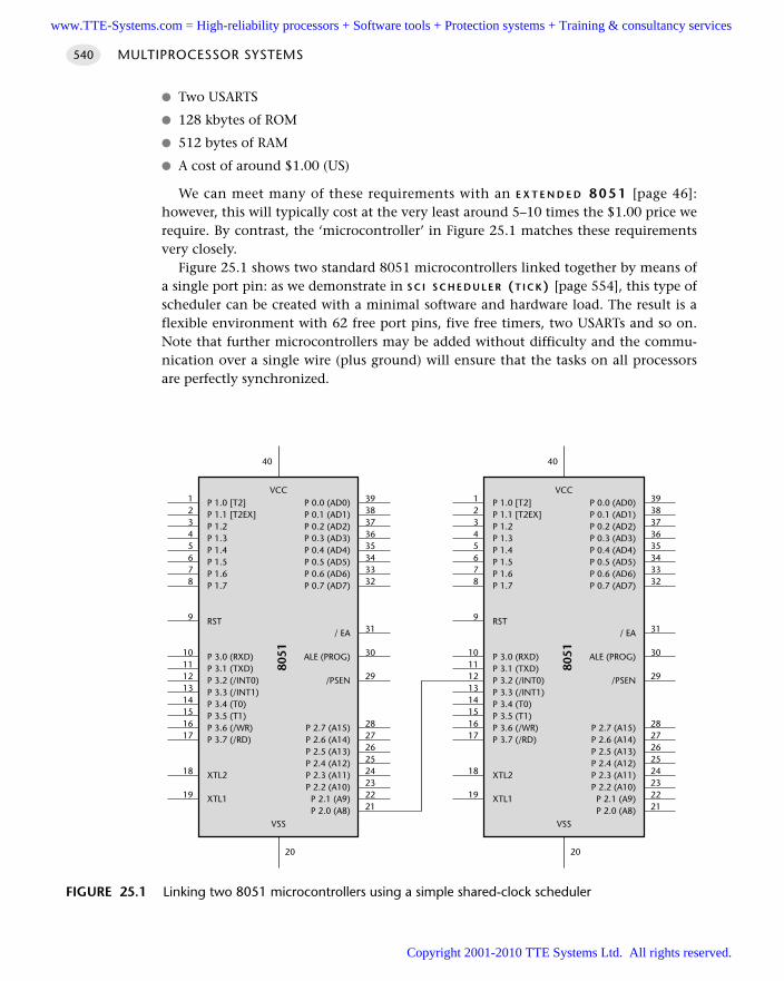
Two USARTS
128 kbytes of ROM
512 bytes of RAM
A cost of around $1.00 (US)
We can meet many of these requirements with an E X T E N D E D 8051 [page 46]:however, this will typically cost at the very least around 5–10 times the $1.00 price werequire. By contrast, the ‘microcontroller’ in Figure 25.1 matches these requirementsvery closely.
Figure 25.1 shows two standard 8051 microcontrollers linked together by means ofa single port pin: as we demonstrate in S C I S C H E D U L E R (T I C K) [page 554], this type ofscheduler can be created with a minimal software and hardware load. The result is aflexible environment with 62 free port pins, five free timers, two USARTs and so on.Note that further microcontrollers may be added without difficulty and the commu-nication over a single wire (plus ground) will ensure that the tasks on all processorsare perfectly synchronized.
MULTIPROCESSOR SYSTEMS540
FIGURE 25.1 Linking two 8051 microcontrollers using a simple shared-clock scheduler
P 1.0 [T2]P 1.1 [T2EX]P 1.2P 1.3P 1.4P 1.5P 1.6P 1.7
RST
P 3.0 (RXD)P 3.1 (TXD)P 3.2 (/INT0)P 3.3 (/INT1)P 3.4 (T0)P 3.5 (T1)P 3.6 (/WR)P 3.7 (/RD)
XTL2
XTL1
P 0.0 (AD0)P 0.1 (AD1)P 0.2 (AD2)P 0.3 (AD3)P 0.4 (AD4)P 0.5 (AD5)P 0.6 (AD6)P 0.7 (AD7)
/ EA
ALE (PROG)
/PSEN
P 2.7 (A15)P 2.6 (A14)P 2.5 (A13)P 2.4 (A12)P 2.3 (A11)P 2.2 (A10)
P 2.1 (A9)P 2.0 (A8)
VCC
8051
VSS
3938373635343332
31
30
29
2827262524232221
12345678
9
1011121314151617
18
19
20
40
www.TTE-Systems.com = High-reliability processors + Software tools + Protection systems + Training & consultancy services
Copyright 2001-2010 TTE Systems Ltd. All rights reserved.
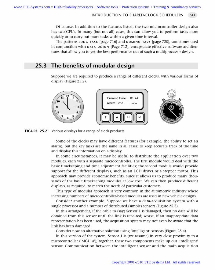
Of course, in addition to the features listed, the two-microcontroller design alsohas two CPUs. In many (but not all) cases, this can allow you to perform tasks morequickly or to carry out more tasks within a given time interval.
The patterns L O N G TA S K [page 716] and D O M I N O TA S K [page 720], sometimes usedin conjunction with D ATA U N I O N [Page 712], encapsulate effective software architec-tures that allow you to get the best performance out of such a multiprocessor design.
25.3 The benefits of modular design
Suppose we are required to produce a range of different clocks, with various forms ofdisplay (Figure 25.2).
Some of the clocks may have different features (for example, the ability to set analarm), but the key tasks are the same in all cases: to keep accurate track of the timeand display this information on a display.
In some circumstances, it may be useful to distribute the application over twomodules, each with a separate microcontroller. The first module would deal with thebasic timekeeping and time adjustment facilities; the second module would providesupport for the different displays, such as an LCD driver or a stepper motor. Thisapproach may provide economic benefits, since it allows us to produce many thou-sands of the basic timekeeping modules at low cost. We can then produce differentdisplays, as required, to match the needs of particular customers.
This type of modular approach is very common in the automotive industry whereincreasing numbers of microcontroller-based modules are used in new vehicle designs.
Consider another example. Suppose we have a data-acquisition system with asingle processor and a number of distributed (simple) sensors (Figure 25.3).
In this arrangement, if the cable to (say) Sensor 1 is damaged, then no data will beobtained from this sensor until the link is repaired; worse, if an inappropriate datarepresentation has been used, the acquisition system may not even be aware that thelink has been damaged.
Consider now an alternative solution using ‘intelligent’ sensors (Figure 25.4).In this version of the system, Sensor 1 is (we assume) in very close proximity to a
microcontroller (‘MCU A’); together, these two components make up our ‘intelligent’sensor. Communication between the intelligent sensor and the main acquisition
INTRODUCTION TO SHARED-CLOCK SCHEDULERS 541
FIGURE 25.2 Various displays for a range of clock products
T A H M
Current Time : 01:44
Alarm Time : --:--
www.TTE-Systems.com = High-reliability processors + Software tools + Protection systems + Training & consultancy services
Copyright 2001-2010 TTE Systems Ltd. All rights reserved.
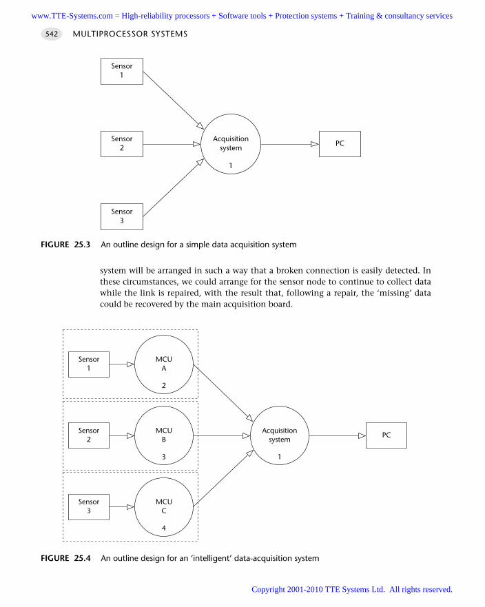
system will be arranged in such a way that a broken connection is easily detected. Inthese circumstances, we could arrange for the sensor node to continue to collect datawhile the link is repaired, with the result that, following a repair, the ‘missing’ datacould be recovered by the main acquisition board.
MULTIPROCESSOR SYSTEMS542
FIGURE 25.3 An outline design for a simple data acquisition system
Acquisitionsystem
1
Sensor2
PC
Sensor1
Sensor3
FIGURE 25.4 An outline design for an ‘intelligent’ data-acquisition system
Acquisitionsystem
1
Sensor2
PC
Sensor1
Sensor3
MCUA
2
MCUC
4
MCUB
3
www.TTE-Systems.com = High-reliability processors + Software tools + Protection systems + Training & consultancy services
Copyright 2001-2010 TTE Systems Ltd. All rights reserved.
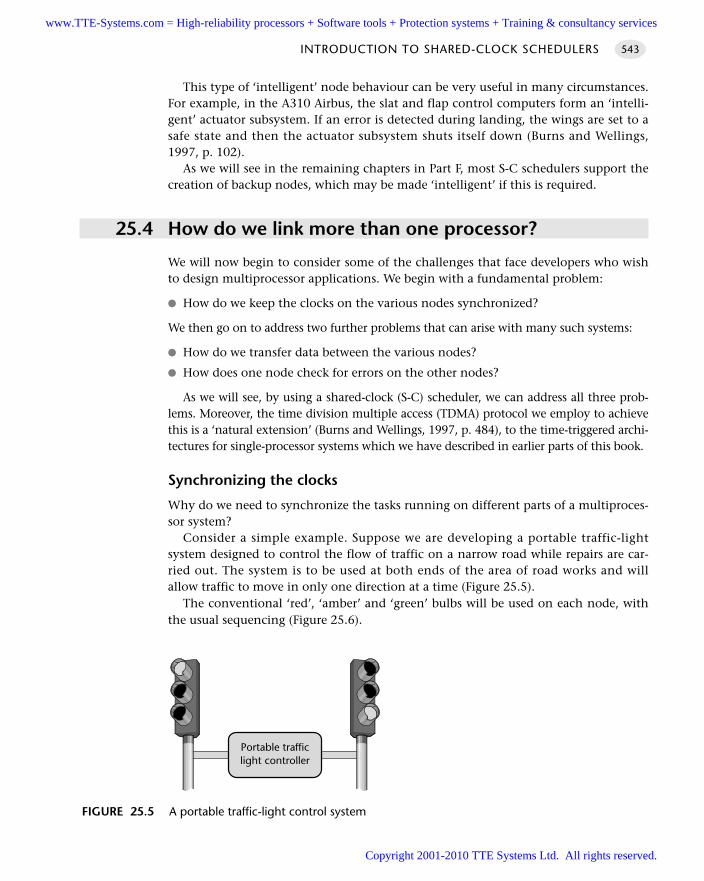
This type of ‘intelligent’ node behaviour can be very useful in many circumstances.For example, in the A310 Airbus, the slat and flap control computers form an ‘intelli-gent’ actuator subsystem. If an error is detected during landing, the wings are set to asafe state and then the actuator subsystem shuts itself down (Burns and Wellings,1997, p. 102).
As we will see in the remaining chapters in Part F, most S-C schedulers support thecreation of backup nodes, which may be made ‘intelligent’ if this is required.
25.4 How do we link more than one processor?
We will now begin to consider some of the challenges that face developers who wishto design multiprocessor applications. We begin with a fundamental problem:
How do we keep the clocks on the various nodes synchronized?
We then go on to address two further problems that can arise with many such systems:
How do we transfer data between the various nodes?
How does one node check for errors on the other nodes?
As we will see, by using a shared-clock (S-C) scheduler, we can address all three prob-lems. Moreover, the time division multiple access (TDMA) protocol we employ to achievethis is a ‘natural extension’ (Burns and Wellings, 1997, p. 484), to the time-triggered archi-tectures for single-processor systems which we have described in earlier parts of this book.
Synchronizing the clocks
Why do we need to synchronize the tasks running on different parts of a multiproces-sor system?
Consider a simple example. Suppose we are developing a portable traffic-lightsystem designed to control the flow of traffic on a narrow road while repairs are car-ried out. The system is to be used at both ends of the area of road works and willallow traffic to move in only one direction at a time (Figure 25.5).
The conventional ‘red’, ‘amber’ and ‘green’ bulbs will be used on each node, withthe usual sequencing (Figure 25.6).
INTRODUCTION TO SHARED-CLOCK SCHEDULERS 543
FIGURE 25.5 A portable traffic-light control system
Portable trafficlight controller
www.TTE-Systems.com = High-reliability processors + Software tools + Protection systems + Training & consultancy services
Copyright 2001-2010 TTE Systems Ltd. All rights reserved.
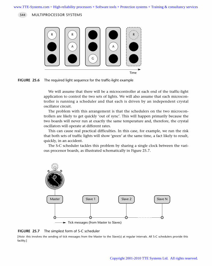
We will assume that there will be a microcontroller at each end of the traffic-lightapplication to control the two sets of lights. We will also assume that each microcon-troller is running a scheduler and that each is driven by an independent crystaloscillator circuit.
The problem with this arrangement is that the schedulers on the two microcon-trollers are likely to get quickly ‘out of sync’. This will happen primarily because thetwo boards will never run at exactly the same temperature and, therefore, the crystaloscillators will operate at different rates.
This can cause real practical difficulties. In this case, for example, we run the riskthat both sets of traffic lights will show ‘green’ at the same time, a fact likely to result,quickly, in an accident.
The S-C scheduler tackles this problem by sharing a single clock between the vari-ous processor boards, as illustrated schematically in Figure 25.7.
MULTIPROCESSOR SYSTEMS544
FIGURE 25.6 The required light sequence for the traffic-light example
R
A
G
R
A
G
R
A
G
R
A
G
R
A
G
Time
FIGURE 25.7 The simplest form of S-C scheduler [Note: this involves the sending of tick messages from the Master to the Slave(s) at regular intervals. All S-C schedulers provide thisfacility.]
Master Slave 1 Slave 2 Slave N
Tick messages (from Master to Slaves)
www.TTE-Systems.com = High-reliability processors + Software tools + Protection systems + Training & consultancy services
Copyright 2001-2010 TTE Systems Ltd. All rights reserved.
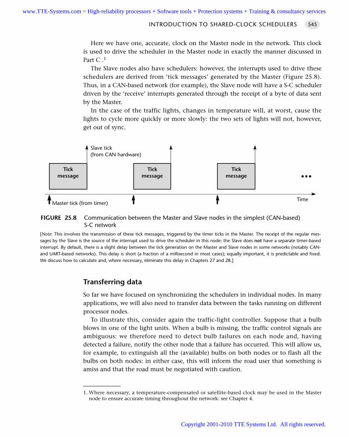
Here we have one, accurate, clock on the Master node in the network. This clockis used to drive the scheduler in the Master node in exactly the manner discussed inPart C .1
The Slave nodes also have schedulers: however, the interrupts used to drive theseschedulers are derived from ‘tick messages’ generated by the Master (Figure 25.8).Thus, in a CAN-based network (for example), the Slave node will have a S-C schedulerdriven by the ‘receive’ interrupts generated through the receipt of a byte of data sentby the Master.
In the case of the traffic lights, changes in temperature will, at worst, cause thelights to cycle more quickly or more slowly: the two sets of lights will not, however,get out of sync.
Transferring data
So far we have focused on synchronizing the schedulers in individual nodes. In manyapplications, we will also need to transfer data between the tasks running on differentprocessor nodes.
To illustrate this, consider again the traffic-light controller. Suppose that a bulbblows in one of the light units. When a bulb is missing, the traffic control signals areambiguous: we therefore need to detect bulb failures on each node and, havingdetected a failure, notify the other node that a failure has occurred. This will allow us,for example, to extinguish all the (available) bulbs on both nodes or to flash all thebulbs on both nodes: in either case, this will inform the road user that something isamiss and that the road must be negotiated with caution.
INTRODUCTION TO SHARED-CLOCK SCHEDULERS 545
FIGURE 25.8 Communication between the Master and Slave nodes in the simplest (CAN-based)S-C network
[Note: This involves the transmission of these tick messages, triggered by the timer ticks in the Master. The receipt of the regular mes-sages by the Slave is the source of the interrupt used to drive the scheduler in this node: the Slave does not have a separate timer-basedinterrupt. By default, there is a slight delay between the tick generation on the Master and Slave nodes in some networks (notably CAN-and UART-based networks). This delay is short (a fraction of a millisecond in most cases); equally important, it is predictable and fixed.We discuss how to calculate and, where necessary, eliminate this delay in Chapters 27 and 28.]
Tickmessage
Tickmessage
Tickmessage
Slave tick(from CAN hardware)
Master tick (from timer)Time
1. Where necessary, a temperature-compensated or satellite-based clock may be used in the Masternode to ensure accurate timing throughout the network: see Chapter 4.
www.TTE-Systems.com = High-reliability processors + Software tools + Protection systems + Training & consultancy services
Copyright 2001-2010 TTE Systems Ltd. All rights reserved.
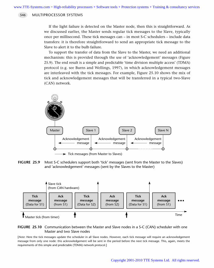
If the light failure is detected on the Master node, then this is straightforward. Aswe discussed earlier, the Master sends regular tick messages to the Slave, typicallyonce per millisecond. These tick messages can – in most S-C schedulers – include datatransfers: it is therefore straightforward to send an appropriate tick message to theSlave to alert it to the bulb failure.
To support the transfer of data from the Slave to the Master, we need an additionalmechanism: this is provided through the use of ‘acknowledgement’ messages (Figure25.9). The end result is a simple and predictable ‘time division multiple access’ (TDMA)protocol (e.g. see Burns and Wellings, 1997), in which acknowledgement messagesare interleaved with the tick messages. For example, Figure 25.10 shows the mix oftick and acknowledgement messages that will be transferred in a typical two-Slave(CAN) network.
MULTIPROCESSOR SYSTEMS546
FIGURE 25.9 Most S-C schedulers support both ‘tick’ messages (sent from the Master to the Slaves)and ‘acknowledgement’ messages (sent by the Slaves to the Master)
Master Slave 1 Slave 2 Slave N
Tick messages (from Master to Slaves)
Acknowledgementmessage
Acknowledgementmessage
Acknowledgementmessage
FIGURE 25.10 Communication between the Master and Slave nodes in a S-C (CAN) scheduler with oneMaster and two Slave nodes
[Note: Here the tick messages update the scheduler in all Slave nodes. However, each tick message will require an acknowledgementmessage from only one node: this acknowledgement will be sent in the period before the next tick message. This, again, meets therequirements of this simple and predictable (TDMA) network protocol.]
Tickmessage
(Data for S1)
Ackmessage(from S1)
Tickmessage
(Data for S2)
Ackmessage(from S2)
Tickmessage
(Data for S1)
Ackmessage(from S1)
Slave tick(from CAN hardware)
Master tick (from timer)Time
www.TTE-Systems.com = High-reliability processors + Software tools + Protection systems + Training & consultancy services
Copyright 2001-2010 TTE Systems Ltd. All rights reserved.
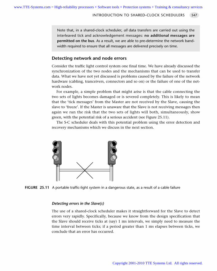
Detecting network and node errors
Consider the traffic light control system one final time. We have already discussed thesynchronization of the two nodes and the mechanisms that can be used to transferdata. What we have not yet discussed is problems caused by the failure of the networkhardware (cabling, tranceivers, connectors and so on) or the failure of one of the net-work nodes.
For example, a simple problem that might arise is that the cable connecting thetwo sets of lights becomes damaged or is severed completely. This is likely to meanthat the ‘tick messages’ from the Master are not received by the Slave, causing theslave to ‘freeze’. If the Master is unaware that the Slave is not receiving messages thenagain we run the risk that the two sets of lights will both, simultaneously, showgreen, with the potential risk of a serious accident (see Figure 25.11).
The S-C scheduler deals with this potential problem using the error detection andrecovery mechanisms which we discuss in the next section.
Detecting errors in the Slave(s)
The use of a shared-clock scheduler makes it straightforward for the Slave to detecterrors very rapidly. Specifically, because we know from the design specification thatthe Slave should receive ticks at (say) 1 ms intervals, we simply need to measure thetime interval between ticks; if a period greater than 1 ms elapses between ticks, weconclude that an error has occurred.
INTRODUCTION TO SHARED-CLOCK SCHEDULERS 547
Note that, in a shared-clock scheduler, all data transfers are carried out using theinterleaved tick and acknowledgement messages: no additional messages arepermitted on the bus. As a result, we are able to pre-determine the network band-width required to ensure that all messages are delivered precisely on time.
FIGURE 25.11 A portable traffic-light system in a dangerous state, as a result of a cable failure
www.TTE-Systems.com = High-reliability processors + Software tools + Protection systems + Training & consultancy services
Copyright 2001-2010 TTE Systems Ltd. All rights reserved.
In many circumstances an effective way of achieving this is to set a watchdog timer2 inthe Slave to overflow at a period slightly longer than the tick interval. Under normal cir-cumstances, the ‘update’ function in the Slave will be invoked by the arrival of each tickand this update function will, in turn, refresh the watchdog timer. If a tick is not received,the timer will overflow and we can invoke an appropriate error-handling routine.
We discuss the required error-handling functions further next.
Detecting errors in the Master
Detecting errors in the Master node requires that each Slave sends appropriateacknowledgement messages to the Master at regular intervals (see Figure 25.10). Asimple way of achieving this may be illustrated by considering the operation of aparticular one-Master, ten-Slave network:
The Master node sends tick messages to all nodes, simultaneously, every millisec-ond; these messages are used to invoke the update function in all Slaves everymillisecond.
Each tick message will, in most schedulers, be accompanied by data for a particularnode. In this case, we will assume that the Master sends tick messages to each ofthe Slaves in turn; thus, each Slave receives data in every tenth tick message (every10 milliseconds in this case).
Each Slave sends an acknowledgement message to the Master only when it receivesa tick message with its ID; it does not send an acknowledgement to any othertick messages.
As mentioned previously, this arrangement provides the predictable bus loadingthat we require and a means of communicating with each Slave individually. It alsomeans that the Master is able to detect whether or not a particular Slave hasresponded to its tick message.
Handling errors detected by the Slave
We will assume that errors in the Slave are detected with a watchdog timer. To deal withsuch errors, the shared-clock schedulers presented in this book all operate as follows:
Whenever the Slave node is reset (either having been powered up or reset as aresult of a watchdog overflow), the node enters a ‘safe state’.
The node remains in this state until it receives an appropriate series of ‘start’ com-mands from the Master.
This form of error handling is easily produced and is effective in most circumstances. One important alternative form of behaviour involves converting a Slave into a
Master node in the event that failure of the Master is detected. This behaviour can be
MULTIPROCESSOR SYSTEMS548
2. See H A R D WA R E WAT C H D O G [page 217]
www.TTE-Systems.com = High-reliability processors + Software tools + Protection systems + Training & consultancy services
Copyright 2001-2010 TTE Systems Ltd. All rights reserved.
very effective, particularly on networks (such as CAN networks) which allow thetransmission of messages with a range of priority levels. We will not consider this pos-sibility in detail in the present edition of this book.
Handling errors detected by the Master
Handling errors detected by the Slave node(s) is straightforward in a shared-clock net-work. Handling errors detected by the Master is more complicated. We consider andillustrate three main options in this book:
The ‘Enter safe state then shut down’ option
The ‘Restart the network’ option
The ‘Engage backup Slave’ option
We consider each of these options now.
Enter a safe state and shut down the network
Shutting down the network following the detection of errors by the Master node iseasily achieved. We simply stop the transmission of tick messages by the Master. Bystopping the tick messages, we cause the Slave(s) to be reset too; the Slaves will thenwait (in a safe state). The whole network will therefore stop, until the Master is reset.
This behaviour is the most appropriate behaviour in many systems in the event ofa network error, if a ‘safe state’ can be identified. This will, of course, be highlyapplication dependent.
For example, we have already mentioned the A310 Airbus’ slat and flap controlcomputers which, on detecting an error during landing, restore the wing system to asafe state and then shut down. In this situation, a ‘safe state’ involves having bothwings with the same settings; only asymmetric settings are hazardous during landing(Burns and Wellings, 1997, p.102).
The strengths and weaknesses of this approach are as follows:
It is very easy to implement.
It is effective in many systems.
It can often be a ‘last line of defence’ if more advanced recovery schemeshave failed.
It does not attempt to recover normal network operation or to engage backupnodes.
This approach may be used with any of the networks we discuss in this book(interrupt based, UART based or CAN based). We illustrate the approach in detail inChapter 26.
INTRODUCTION TO SHARED-CLOCK SCHEDULERS 549
www.TTE-Systems.com = High-reliability processors + Software tools + Protection systems + Training & consultancy services
Copyright 2001-2010 TTE Systems Ltd. All rights reserved.
Reset the network
Another simple way of dealing with errors is to reset the Master and, hence, thewhole network. When it is reset, the Master will attempt to re-establish communica-tion with each Slave in turn; if it fails to establish contact with a particular Slave, itwill attempt to connect to the backup device for that Slave.
This approach is easy to implement and can be effective. For example, manydesigns use ‘N-version’ programming to create backup versions of key components.3
By performing a reset, we keep all the nodes in the network synchronized and weengage a backup Slave (if one is available).
The strengths and weaknesses of this approach are as follows:
It allows full use to be made of backup nodes.
It may take time (possibly half a second or more) to restart the network; even ifthe network becomes fully operational, the delay involved may be too long (forexample, in automotive braking or aerospace flight-control applications).
With poor design or implementation, errors can cause the network to be continu-ally reset. This may be rather less safe than the simple ‘enter safe state and shutdown’ option.
This approach may be used with any of the UART- or CAN-based networks wediscuss in this book. We illustrate the approach in detail in Chapter 27.
Engage a backup Slave
The third and final recovery technique we discuss in the present edition of this bookis as follows. If a Slave fails, then – rather than restarting the whole network – we startthe corresponding backup unit.
The strengths and weaknesses of this approach are as follows:
It allows full use to be made of backup nodes.
In most circumstances it takes comparatively little time to engage the backup unit.
The underlying coding is more complicated than the other alternatives discussedin this book.
This approach may be used with any of the UART- or CAN-based networks wediscuss in this book. We illustrate the approach in detail in Chapter 28.
25.5 Why additional processors may not always improvereliability
It is very important to appreciate that – without due care – increasing the numbers ofprocessors in a network can have a detrimental impact on overall system reliability.
MULTIPROCESSOR SYSTEMS550
3. See Leveson, 1995, for detailed discussion of the strengths and weaknesses of N-version program-ming techniques.
www.TTE-Systems.com = High-reliability processors + Software tools + Protection systems + Training & consultancy services
Copyright 2001-2010 TTE Systems Ltd. All rights reserved.
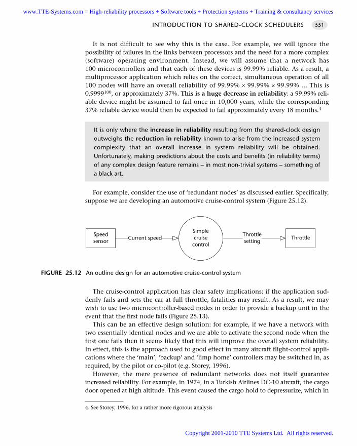
It is not difficult to see why this is the case. For example, we will ignore thepossibility of failures in the links between processors and the need for a more complex(software) operating environment. Instead, we will assume that a network has100 microcontrollers and that each of these devices is 99.99% reliable. As a result, amultiprocessor application which relies on the correct, simultaneous operation of all100 nodes will have an overall reliability of 99.99% × 99.99% × 99.99% … This is0.9999100, or approximately 37%. This is a huge decrease in reliability: a 99.99% reli-able device might be assumed to fail once in 10,000 years, while the corresponding37% reliable device would then be expected to fail approximately every 18 months.4
For example, consider the use of ‘redundant nodes’ as discussed earlier. Specifically,suppose we are developing an automotive cruise-control system (Figure 25.12).
The cruise-control application has clear safety implications: if the application sud-denly fails and sets the car at full throttle, fatalities may result. As a result, we maywish to use two microcontroller-based nodes in order to provide a backup unit in theevent that the first node fails (Figure 25.13).
This can be an effective design solution: for example, if we have a network withtwo essentially identical nodes and we are able to activate the second node when thefirst one fails then it seems likely that this will improve the overall system reliability.In effect, this is the approach used to good effect in many aircraft flight-control appli-cations where the ‘main’, ‘backup’ and ‘limp home’ controllers may be switched in, asrequired, by the pilot or co-pilot (e.g. Storey, 1996).
However, the mere presence of redundant networks does not itself guaranteeincreased reliability. For example, in 1974, in a Turkish Airlines DC-10 aircraft, the cargodoor opened at high altitude. This event caused the cargo hold to depressurize, which in
INTRODUCTION TO SHARED-CLOCK SCHEDULERS 551
It is only where the increase in reliability resulting from the shared-clock designoutweighs the reduction in reliability known to arise from the increased systemcomplexity that an overall increase in system reliability will be obtained.Unfortunately, making predictions about the costs and benefits (in reliability terms)of any complex design feature remains – in most non-trivial systems – something ofa black art.
FIGURE 25.12 An outline design for an automotive cruise-control system
Simplecruise
control
Speedsensor Current speed
Throttlesetting
Throttle
4. See Storey, 1996, for a rather more rigorous analysis
www.TTE-Systems.com = High-reliability processors + Software tools + Protection systems + Training & consultancy services
Copyright 2001-2010 TTE Systems Ltd. All rights reserved.
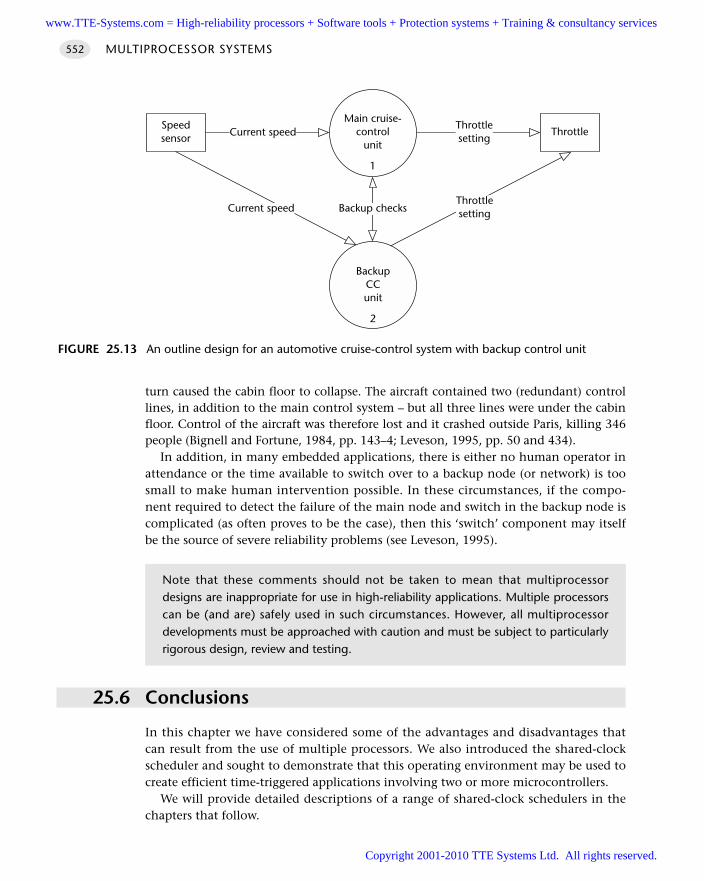
turn caused the cabin floor to collapse. The aircraft contained two (redundant) controllines, in addition to the main control system – but all three lines were under the cabinfloor. Control of the aircraft was therefore lost and it crashed outside Paris, killing 346people (Bignell and Fortune, 1984, pp. 143–4; Leveson, 1995, pp. 50 and 434).
In addition, in many embedded applications, there is either no human operator inattendance or the time available to switch over to a backup node (or network) is toosmall to make human intervention possible. In these circumstances, if the compo-nent required to detect the failure of the main node and switch in the backup node iscomplicated (as often proves to be the case), then this ‘switch’ component may itselfbe the source of severe reliability problems (see Leveson, 1995).
25.6 Conclusions
In this chapter we have considered some of the advantages and disadvantages thatcan result from the use of multiple processors. We also introduced the shared-clockscheduler and sought to demonstrate that this operating environment may be used tocreate efficient time-triggered applications involving two or more microcontrollers.
We will provide detailed descriptions of a range of shared-clock schedulers in thechapters that follow.
MULTIPROCESSOR SYSTEMS552
FIGURE 25.13 An outline design for an automotive cruise-control system with backup control unit
Main cruise-control
unit
Speedsensor Current speed
Throttlesetting
Throttle
1
Backup checks
BackupCCunit
2
Current speedThrottlesetting
Note that these comments should not be taken to mean that multiprocessordesigns are inappropriate for use in high-reliability applications. Multiple processorscan be (and are) safely used in such circumstances. However, all multiprocessordevelopments must be approached with caution and must be subject to particularlyrigorous design, review and testing.
www.TTE-Systems.com = High-reliability processors + Software tools + Protection systems + Training & consultancy services
Copyright 2001-2010 TTE Systems Ltd. All rights reserved.
Shared-clock schedulers using
external interrupts
Introduction
In this chapter we present two simple implementations of the shared-clock schedulerarchitecture. In each case the Master and Slave devices are kept in synchronyby means of pulses (generated by the Master) that invoke interrupts on the Slavemicrocontrollers: these interrupts, in turn, drive the ‘update’ functions in theSlave schedulers.
These simple schedulers are very powerful and impose little memory, CPU or hard-ware overhead.
chapter 26
Note that the use of external interrupts to convey tick messages means that theresulting applications are at particular risk from sources of electromagnetic interfer-ence (EMI). As a result, these schedulers are only suitable for ‘local’ networks: thatis, for applications containing multiple microcontrollers which are displaced by nomore than (at most) a few centimetres; in most cases, the microcontrollers will becontained in the same, shielded system box and mounted on the same PCB.
www.TTE-Systems.com = High-reliability processors + Software tools + Protection systems + Training & consultancy services
Copyright 2001-2010 TTE Systems Ltd. All rights reserved.
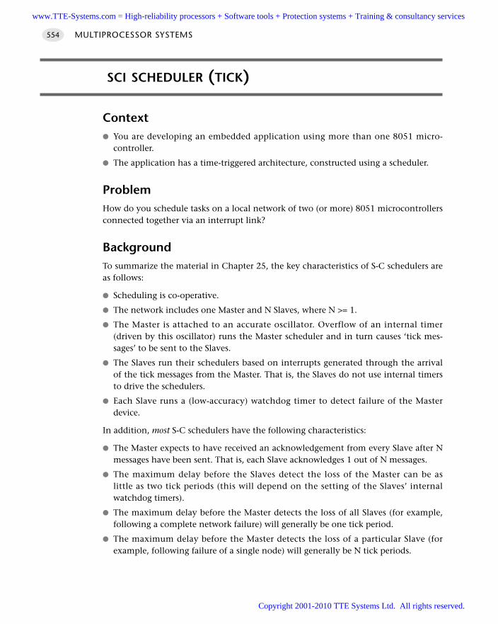
SCI SCHEDULER (TICK)
Context You are developing an embedded application using more than one 8051 micro-
controller.
The application has a time-triggered architecture, constructed using a scheduler.
ProblemHow do you schedule tasks on a local network of two (or more) 8051 microcontrollersconnected together via an interrupt link?
BackgroundTo summarize the material in Chapter 25, the key characteristics of S-C schedulers areas follows:
Scheduling is co-operative.
The network includes one Master and N Slaves, where N >= 1.
The Master is attached to an accurate oscillator. Overflow of an internal timer(driven by this oscillator) runs the Master scheduler and in turn causes ‘tick mes-sages’ to be sent to the Slaves.
The Slaves run their schedulers based on interrupts generated through the arrivalof the tick messages from the Master. That is, the Slaves do not use internal timersto drive the schedulers.
Each Slave runs a (low-accuracy) watchdog timer to detect failure of the Masterdevice.
In addition, most S-C schedulers have the following characteristics:
The Master expects to have received an acknowledgement from every Slave after Nmessages have been sent. That is, each Slave acknowledges 1 out of N messages.
The maximum delay before the Slaves detect the loss of the Master can be aslittle as two tick periods (this will depend on the setting of the Slaves’ internalwatchdog timers).
The maximum delay before the Master detects the loss of all Slaves (for example,following a complete network failure) will generally be one tick period.
The maximum delay before the Master detects the loss of a particular Slave (forexample, following failure of a single node) will generally be N tick periods.
MULTIPROCESSOR SYSTEMS554
www.TTE-Systems.com = High-reliability processors + Software tools + Protection systems + Training & consultancy services
Copyright 2001-2010 TTE Systems Ltd. All rights reserved.
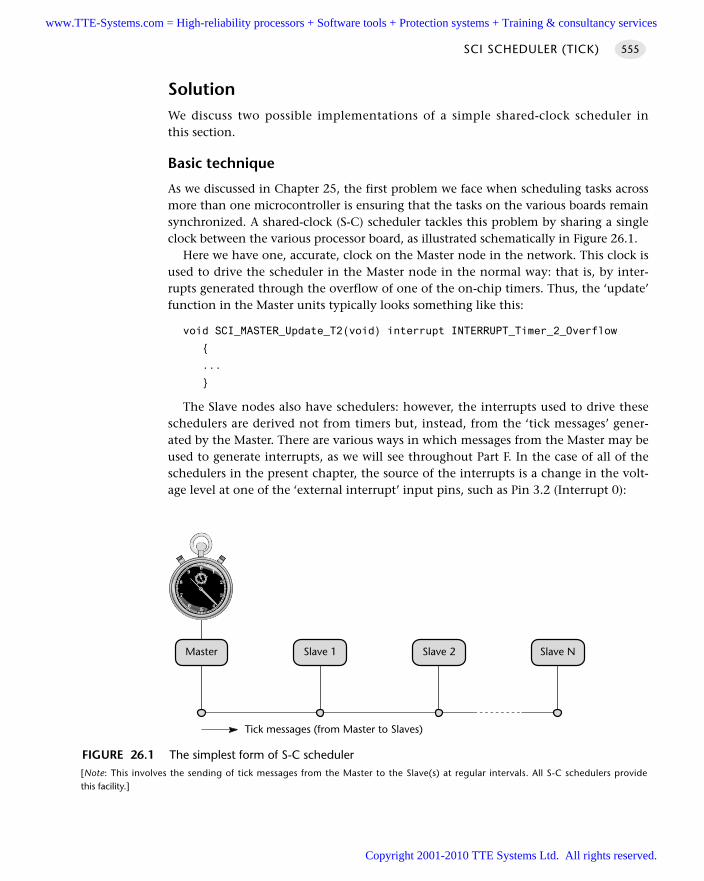
SolutionWe discuss two possible implementations of a simple shared-clock scheduler inthis section.
Basic technique
As we discussed in Chapter 25, the first problem we face when scheduling tasks acrossmore than one microcontroller is ensuring that the tasks on the various boards remainsynchronized. A shared-clock (S-C) scheduler tackles this problem by sharing a singleclock between the various processor board, as illustrated schematically in Figure 26.1.
Here we have one, accurate, clock on the Master node in the network. This clock isused to drive the scheduler in the Master node in the normal way: that is, by inter-rupts generated through the overflow of one of the on-chip timers. Thus, the ‘update’function in the Master units typically looks something like this:
void SCI_MASTER_Update_T2(void) interrupt INTERRUPT_Timer_2_Overflow
...
The Slave nodes also have schedulers: however, the interrupts used to drive theseschedulers are derived not from timers but, instead, from the ‘tick messages’ gener-ated by the Master. There are various ways in which messages from the Master may beused to generate interrupts, as we will see throughout Part F. In the case of all of theschedulers in the present chapter, the source of the interrupts is a change in the volt-age level at one of the ‘external interrupt’ input pins, such as Pin 3.2 (Interrupt 0):
SCI SCHEDULER (TICK) 555
FIGURE 26.1 The simplest form of S-C scheduler [Note: This involves the sending of tick messages from the Master to the Slave(s) at regular intervals. All S-C schedulers providethis facility.]
Master Slave 1 Slave 2 Slave N
Tick messages (from Master to Slaves)
www.TTE-Systems.com = High-reliability processors + Software tools + Protection systems + Training & consultancy services
Copyright 2001-2010 TTE Systems Ltd. All rights reserved.
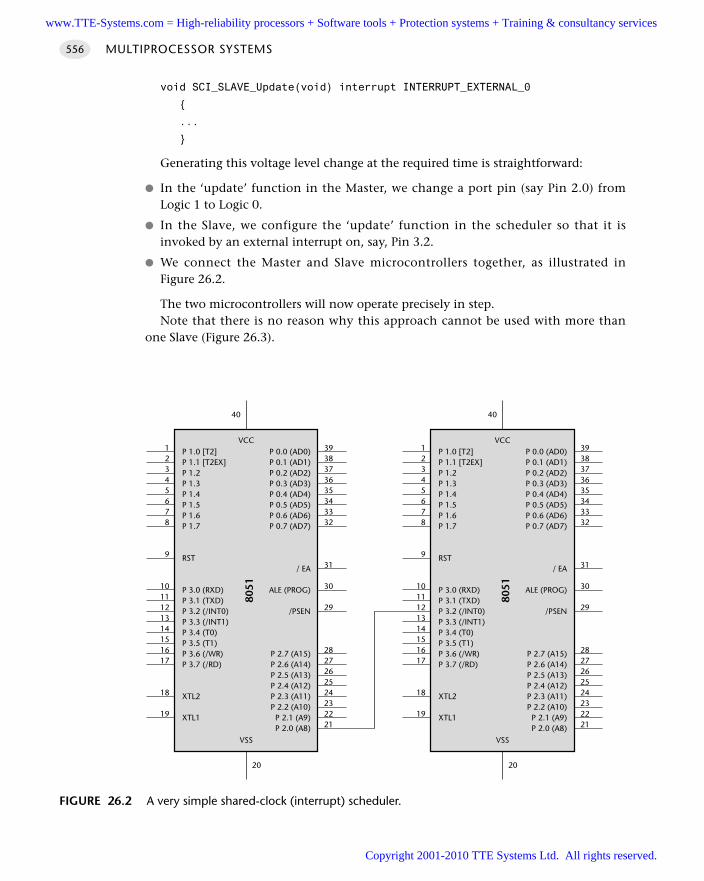
void SCI_SLAVE_Update(void) interrupt INTERRUPT_EXTERNAL_0
...
Generating this voltage level change at the required time is straightforward:
In the ‘update’ function in the Master, we change a port pin (say Pin 2.0) fromLogic 1 to Logic 0.
In the Slave, we configure the ‘update’ function in the scheduler so that it isinvoked by an external interrupt on, say, Pin 3.2.
We connect the Master and Slave microcontrollers together, as illustrated inFigure 26.2.
The two microcontrollers will now operate precisely in step.Note that there is no reason why this approach cannot be used with more than
one Slave (Figure 26.3).
MULTIPROCESSOR SYSTEMS556
FIGURE 26.2 A very simple shared-clock (interrupt) scheduler.
P 1.0 [T2]P 1.1 [T2EX]P 1.2P 1.3P 1.4P 1.5P 1.6P 1.7
RST
P 3.0 (RXD)P 3.1 (TXD)P 3.2 (/INT0)P 3.3 (/INT1)P 3.4 (T0)P 3.5 (T1)P 3.6 (/WR)P 3.7 (/RD)
XTL2
XTL1
P 0.0 (AD0)P 0.1 (AD1)P 0.2 (AD2)P 0.3 (AD3)P 0.4 (AD4)P 0.5 (AD5)P 0.6 (AD6)P 0.7 (AD7)
/ EA
ALE (PROG)
/PSEN
P 2.7 (A15)P 2.6 (A14)P 2.5 (A13)P 2.4 (A12)P 2.3 (A11)P 2.2 (A10)
P 2.1 (A9)P 2.0 (A8)
VCC
8051
VSS
3938373635343332
31
30
29
2827262524232221
12345678
9
1011121314151617
18
19
20
40
www.TTE-Systems.com = High-reliability processors + Software tools + Protection systems + Training & consultancy services
Copyright 2001-2010 TTE Systems Ltd. All rights reserved.
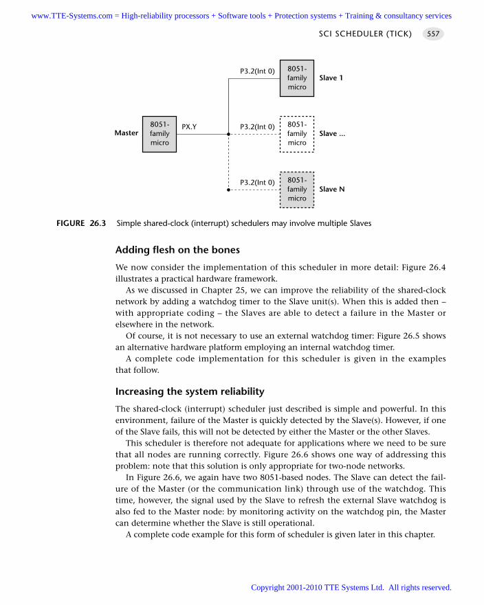
Adding flesh on the bones
We now consider the implementation of this scheduler in more detail: Figure 26.4illustrates a practical hardware framework.
As we discussed in Chapter 25, we can improve the reliability of the shared-clocknetwork by adding a watchdog timer to the Slave unit(s). When this is added then –with appropriate coding – the Slaves are able to detect a failure in the Master orelsewhere in the network.
Of course, it is not necessary to use an external watchdog timer: Figure 26.5 showsan alternative hardware platform employing an internal watchdog timer.
A complete code implementation for this scheduler is given in the examplesthat follow.
Increasing the system reliability
The shared-clock (interrupt) scheduler just described is simple and powerful. In thisenvironment, failure of the Master is quickly detected by the Slave(s). However, if oneof the Slave fails, this will not be detected by either the Master or the other Slaves.
This scheduler is therefore not adequate for applications where we need to be surethat all nodes are running correctly. Figure 26.6 shows one way of addressing thisproblem: note that this solution is only appropriate for two-node networks.
In Figure 26.6, we again have two 8051-based nodes. The Slave can detect the fail-ure of the Master (or the communication link) through use of the watchdog. Thistime, however, the signal used by the Slave to refresh the external Slave watchdog isalso fed to the Master node: by monitoring activity on the watchdog pin, the Mastercan determine whether the Slave is still operational.
A complete code example for this form of scheduler is given later in this chapter.
SCI SCHEDULER (TICK) 557
FIGURE 26.3 Simple shared-clock (interrupt) schedulers may involve multiple Slaves
8051-familymicro
8051-familymicro
MasterPX.Y
8051-familymicro
P3.2(Int 0)
P3.2(Int 0)
8051-familymicro
P3.2(Int 0)
Slave ...
Slave 1
Slave N
www.TTE-Systems.com = High-reliability processors + Software tools + Protection systems + Training & consultancy services
Copyright 2001-2010 TTE Systems Ltd. All rights reserved.
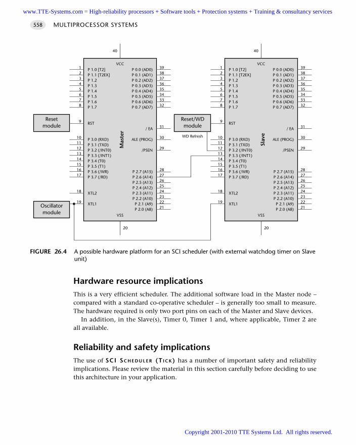
Hardware resource implicationsThis is a very efficient scheduler. The additional software load in the Master node –compared with a standard co-operative scheduler – is generally too small to measure.The hardware required is only two port pins on each of the Master and Slave devices.
In addition, in the Slave(s), Timer 0, Timer 1 and, where applicable, Timer 2 areall available.
Reliability and safety implicationsThe use of SCI SC H E D U L E R (T I C K) has a number of important safety and reliabilityimplications. Please review the material in this section carefully before deciding to usethis architecture in your application.
MULTIPROCESSOR SYSTEMS558
FIGURE 26.4 A possible hardware platform for an SCI scheduler (with external watchdog timer on Slaveunit)
P 1.0 [T2]P 1.1 [T2EX]P 1.2P 1.3P 1.4P 1.5P 1.6P 1.7
RST
P 3.0 (RXD)P 3.1 (TXD)P 3.2 (/INT0)P 3.3 (/INT1)P 3.4 (T0)P 3.5 (T1)P 3.6 (/WR)P 3.7 (/RD)
XTL2
XTL1
P 0.0 (AD0)P 0.1 (AD1)P 0.2 (AD2)P 0.3 (AD3)P 0.4 (AD4)P 0.5 (AD5)P 0.6 (AD6)P 0.7 (AD7)
/ EA
ALE (PROG)
/PSEN
P 2.7 (A15)P 2.6 (A14)P 2.5 (A13)P 2.4 (A12)P 2.3 (A11)P 2.2 (A10)
P 2.1 (A9)P 2.0 (A8)
VCC
Mas
ter
VSS
3938373635343332
31
30
29
2827262524232221
12345678
9
1011121314151617
18
19
20
40
P 1.0 [T2]P 1.1 [T2EX]P 1.2P 1.3P 1.4P 1.5P 1.6P 1.7
RST
P 3.0 (RXD)P 3.1 (TXD)P 3.2 (/INT0)P 3.3 (/INT1)P 3.4 (T0)P 3.5 (T1)P 3.6 (/WR)P 3.7 (/RD)
XTL2
XTL1
P 0.0 (AD0)P 0.1 (AD1)P 0.2 (AD2)P 0.3 (AD3)P 0.4 (AD4)P 0.5 (AD5)P 0.6 (AD6)P 0.7 (AD7)
/ EA
ALE (PROG)
/PSEN
P 2.7 (A15)P 2.6 (A14)P 2.5 (A13)P 2.4 (A12)P 2.3 (A11)P 2.2 (A10)
P 2.1 (A9)P 2.0 (A8)
VCC
Slav
e
VSS
3938373635343332
31
30
29
2827262524232221
12345678
9
1011121314151617
18
19
20
40
Reset/WDmodule
WD Refresh
Oscillatormodule
Resetmodule
www.TTE-Systems.com = High-reliability processors + Software tools + Protection systems + Training & consultancy services
Copyright 2001-2010 TTE Systems Ltd. All rights reserved.
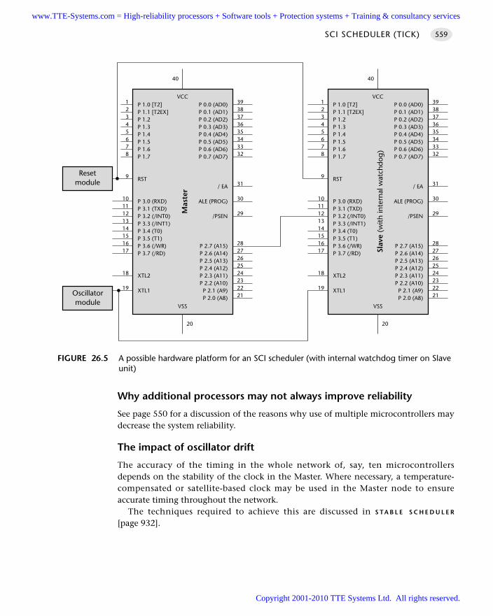
Why additional processors may not always improve reliability
See page 550 for a discussion of the reasons why use of multiple microcontrollers maydecrease the system reliability.
The impact of oscillator drift
The accuracy of the timing in the whole network of, say, ten microcontrollersdepends on the stability of the clock in the Master. Where necessary, a temperature-compensated or satellite-based clock may be used in the Master node to ensureaccurate timing throughout the network.
The techniques required to achieve this are discussed in S TA B L E S C H E D U L E R
[page 932].
SCI SCHEDULER (TICK) 559
FIGURE 26.5 A possible hardware platform for an SCI scheduler (with internal watchdog timer on Slaveunit)
P 1.0 [T2]P 1.1 [T2EX]P 1.2P 1.3P 1.4P 1.5P 1.6P 1.7
RST
P 3.0 (RXD)P 3.1 (TXD)P 3.2 (/INT0)P 3.3 (/INT1)P 3.4 (T0)P 3.5 (T1)P 3.6 (/WR)P 3.7 (/RD)
XTL2
XTL1
P 0.0 (AD0)P 0.1 (AD1)P 0.2 (AD2)P 0.3 (AD3)P 0.4 (AD4)P 0.5 (AD5)P 0.6 (AD6)P 0.7 (AD7)
/ EA
ALE (PROG)
/PSEN
P 2.7 (A15)P 2.6 (A14)P 2.5 (A13)P 2.4 (A12)P 2.3 (A11)P 2.2 (A10)
P 2.1 (A9)P 2.0 (A8)
VCC
Mas
ter
VSS
3938373635343332
31
30
29
2827262524232221
12345678
9
1011121314151617
18
19
20
40
P 1.0 [T2]P 1.1 [T2EX]P 1.2P 1.3P 1.4P 1.5P 1.6P 1.7
RST
P 3.0 (RXD)P 3.1 (TXD)P 3.2 (/INT0)P 3.3 (/INT1)P 3.4 (T0)P 3.5 (T1)P 3.6 (/WR)P 3.7 (/RD)
XTL2
XTL1
P 0.0 (AD0)P 0.1 (AD1)P 0.2 (AD2)P 0.3 (AD3)P 0.4 (AD4)P 0.5 (AD5)P 0.6 (AD6)P 0.7 (AD7)
/ EA
ALE (PROG)
/PSEN
P 2.7 (A15)P 2.6 (A14)P 2.5 (A13)P 2.4 (A12)P 2.3 (A11)P 2.2 (A10)
P 2.1 (A9)P 2.0 (A8)
VCC
Slav
e (w
ith in
tern
al w
atch
dog)
VSS
3938373635343332
31
30
29
2827262524232221
12345678
9
1011121314151617
18
19
20
40
Oscillatormodule
Resetmodule
www.TTE-Systems.com = High-reliability processors + Software tools + Protection systems + Training & consultancy services
Copyright 2001-2010 TTE Systems Ltd. All rights reserved.
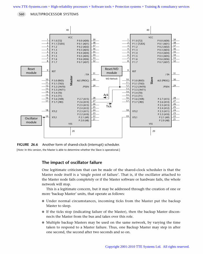
The impact of oscillator failure
One legitimate criticism that can be made of the shared-clock scheduler is that theMaster node itself is a ‘single point of failure’. That is, if the oscillator attached tothe Master node fails completely or if the Master software or hardware fails, the wholenetwork will stop.
This is a legitimate concern, but it may be addressed through the creation of one ormore ‘backup Master’ units, that operate as follows:
Under normal circumstances, incoming ticks from the Master put the backupMaster to sleep.
If the ticks stop (indicating failure of the Master), then the backup Master discon-nects the Master from the bus and takes over this role.
Multiple backup Masters may be used on the same network, by varying the timetaken to respond to a Master failure. Thus, one Backup Master may step in afterone second, the second after two seconds and so on.
MULTIPROCESSOR SYSTEMS560
FIGURE 26.6 Another form of shared-clock (interrupt) scheduler. [Note: In this version, the Master is able to determine whether the Slave is operational.]
P 1.0 [T2]P 1.1 [T2EX]P 1.2P 1.3P 1.4P 1.5P 1.6P 1.7
RST
P 3.0 (RXD)P 3.1 (TXD)P 3.2 (/INT0)P 3.3 (/INT1)P 3.4 (T0)P 3.5 (T1)P 3.6 (/WR)P 3.7 (/RD)
XTL2
XTL1
P 0.0 (AD0)P 0.1 (AD1)P 0.2 (AD2)P 0.3 (AD3)P 0.4 (AD4)P 0.5 (AD5)P 0.6 (AD6)P 0.7 (AD7)
/ EA
ALE (PROG)
/PSEN
P 2.7 (A15)P 2.6 (A14)P 2.5 (A13)P 2.4 (A12)P 2.3 (A11)P 2.2 (A10)
P 2.1 (A9)P 2.0 (A8)
VCC
Mas
ter
VSS
3938373635343332
31
30
29
2827262524232221
12345678
9
1011121314151617
18
19
20
40
P 1.0 [T2]P 1.1 [T2EX]P 1.2P 1.3P 1.4P 1.5P 1.6P 1.7
RST
P 3.0 (RXD)P 3.1 (TXD)P 3.2 (/INT0)P 3.3 (/INT1)P 3.4 (T0)P 3.5 (T1)P 3.6 (/WR)P 3.7 (/RD)
XTL2
XTL1
P 0.0 (AD0)P 0.1 (AD1)P 0.2 (AD2)P 0.3 (AD3)P 0.4 (AD4)P 0.5 (AD5)P 0.6 (AD6)P 0.7 (AD7)
/ EA
ALE (PROG)
/PSEN
P 2.7 (A15)P 2.6 (A14)P 2.5 (A13)P 2.4 (A12)P 2.3 (A11)P 2.2 (A10)
P 2.1 (A9)P 2.0 (A8)
VCC
Slav
e
VSS
3938373635343332
31
30
29
2827262524232221
12345678
9
1011121314151617
18
19
20
40
Reset/WDmodule
WD Refresh
Oscillatormodule
Resetmodule
Ack
Tick
www.TTE-Systems.com = High-reliability processors + Software tools + Protection systems + Training & consultancy services
Copyright 2001-2010 TTE Systems Ltd. All rights reserved.
The dangers of external interrupts
The use of external interrupts to convey tick messages means that the resulting appli-cations are at particular risk from sources of electromagnetic interference (EMI),unless sensible precautions are taken.
This sensitivity of the microcontroller to EMI is greatly increased if long leads(that is, aerials) are connected to the interrupt pins. As a result, these schedulers areonly suitable for ‘local’ networks: that is, for applications containing multiple micro-controllers which are displaced by no more than (at most) a few centimetres; in mostcases, the microcontrollers should be mounted on the same PCB and housed in ashielded box.
Detecting and handling errors
We discussed three techniques for detecting and handling errors in a shared-clocknetwork in Chapter 25. In this chapter we assume that ‘enter safe state then shutdown’ error handling is used: see Chapter 25 for further details.
PortabilityAlmost all microcontroller families have at least one external interrupt pin. As aresult, these patterns may be adapted without difficulty for use with these families.
Overall strength and weaknessSimple, effective and with very low overheads.
Provides one-way communication between Master and Slave(s): Master cannotdetect errors on the Slave node(s).
There is no mechanism for transferring data between the Master and Slave (orvice versa).
The system may be vulnerable to EMI unless sensible precautions are taken.
Related patterns and alternative solutionsThe other patterns in this chapter and throughout Part F provide alternative tech-niques for linking together more than one microcontroller.
In addition, there is a further alternative, illustrated in Figure 26.7. In Figure 26.7,the only link between the Master and the Slave is the reset and clock circuits; eachdevice has its own timer-driven scheduler. This approach is not generally recom-mended, for the following reasons:
We have to use an important hardware resource (a timer) on each of the nodes.
The tasks on the two (or more) nodes will not, generally, be synchronized, sincethe start of scheduling on each node will depend on the time taken to perform ini-tialization functions (if any) on each node.
SCI SCHEDULER (TICK) 561
www.TTE-Systems.com = High-reliability processors + Software tools + Protection systems + Training & consultancy services
Copyright 2001-2010 TTE Systems Ltd. All rights reserved.
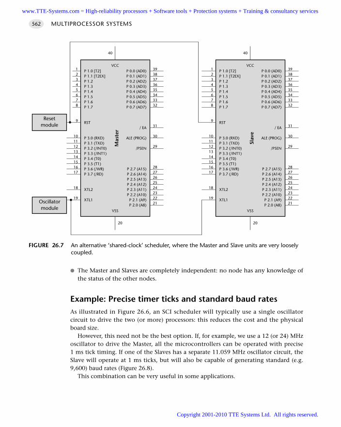
The Master and Slaves are completely independent: no node has any knowledge ofthe status of the other nodes.
Example: Precise timer ticks and standard baud ratesAs illustrated in Figure 26.6, an SCI scheduler will typically use a single oscillatorcircuit to drive the two (or more) processors: this reduces the cost and the physicalboard size.
However, this need not be the best option. If, for example, we use a 12 (or 24) MHzoscillator to drive the Master, all the microcontrollers can be operated with precise1 ms tick timing. If one of the Slaves has a separate 11.059 MHz oscillator circuit, theSlave will operate at 1 ms ticks, but will also be capable of generating standard (e.g.9,600) baud rates (Figure 26.8).
This combination can be very useful in some applications.
MULTIPROCESSOR SYSTEMS562
FIGURE 26.7 An alternative ‘shared-clock’ scheduler, where the Master and Slave units are very looselycoupled.
P 1.0 [T2]P 1.1 [T2EX]P 1.2P 1.3P 1.4P 1.5P 1.6P 1.7
RST
P 3.0 (RXD)P 3.1 (TXD)P 3.2 (/INT0)P 3.3 (/INT1)P 3.4 (T0)P 3.5 (T1)P 3.6 (/WR)P 3.7 (/RD)
XTL2
XTL1
P 0.0 (AD0)P 0.1 (AD1)P 0.2 (AD2)P 0.3 (AD3)P 0.4 (AD4)P 0.5 (AD5)P 0.6 (AD6)P 0.7 (AD7)
/ EA
ALE (PROG)
/PSEN
P 2.7 (A15)P 2.6 (A14)P 2.5 (A13)P 2.4 (A12)P 2.3 (A11)P 2.2 (A10)
P 2.1 (A9)P 2.0 (A8)
VCC
Mas
ter
VSS
3938373635343332
31
30
29
2827262524232221
12345678
9
1011121314151617
18
19
20
40
P 1.0 [T2]P 1.1 [T2EX]P 1.2P 1.3P 1.4P 1.5P 1.6P 1.7
RST
P 3.0 (RXD)P 3.1 (TXD)P 3.2 (/INT0)P 3.3 (/INT1)P 3.4 (T0)P 3.5 (T1)P 3.6 (/WR)P 3.7 (/RD)
XTL2
XTL1
P 0.0 (AD0)P 0.1 (AD1)P 0.2 (AD2)P 0.3 (AD3)P 0.4 (AD4)P 0.5 (AD5)P 0.6 (AD6)P 0.7 (AD7)
/ EA
ALE (PROG)
/PSEN
P 2.7 (A15)P 2.6 (A14)P 2.5 (A13)P 2.4 (A12)P 2.3 (A11)P 2.2 (A10)
P 2.1 (A9)P 2.0 (A8)
VCC
Slav
e
VSS
3938373635343332
31
30
29
2827262524232221
12345678
9
1011121314151617
18
19
20
40
Oscillatormodule
Resetmodule
www.TTE-Systems.com = High-reliability processors + Software tools + Protection systems + Training & consultancy services
Copyright 2001-2010 TTE Systems Ltd. All rights reserved.
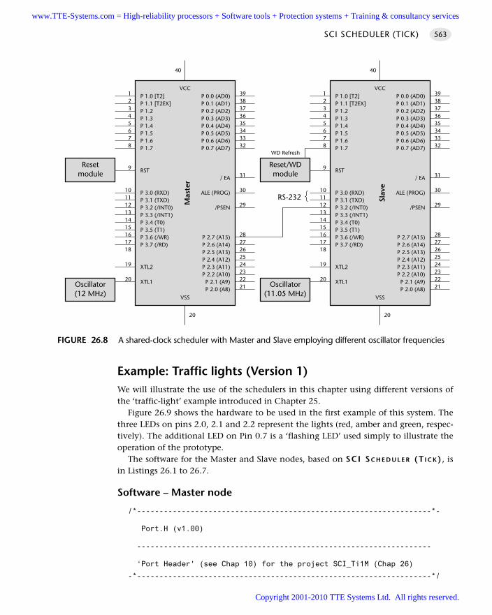
Example: Traffic lights (Version 1)We will illustrate the use of the schedulers in this chapter using different versions ofthe ‘traffic-light’ example introduced in Chapter 25.
Figure 26.9 shows the hardware to be used in the first example of this system. Thethree LEDs on pins 2.0, 2.1 and 2.2 represent the lights (red, amber and green, respec-tively). The additional LED on Pin 0.7 is a ‘flashing LED’ used simply to illustrate theoperation of the prototype.
The software for the Master and Slave nodes, based on SCI SC H E D U L E R (T I C K) , isin Listings 26.1 to 26.7.
Software – Master node
/*------------------------------------------------------------------*-
Port.H (v1.00)
------------------------------------------------------------------
‘Port Header' (see Chap 10) for the project SCI_Ti1M (Chap 26)
-*------------------------------------------------------------------*/
SCI SCHEDULER (TICK) 563
FIGURE 26.8 A shared-clock scheduler with Master and Slave employing different oscillator frequencies
P 1.0 [T2]P 1.1 [T2EX]P 1.2P 1.3P 1.4P 1.5P 1.6P 1.7
RST
P 3.0 (RXD)P 3.1 (TXD)P 3.2 (/INT0)P 3.3 (/INT1)P 3.4 (T0)P 3.5 (T1)P 3.6 (/WR)P 3.7 (/RD)
XTL2
XTL1
P 0.0 (AD0)P 0.1 (AD1)P 0.2 (AD2)P 0.3 (AD3)P 0.4 (AD4)P 0.5 (AD5)P 0.6 (AD6)P 0.7 (AD7)
/ EA
ALE (PROG)
/PSEN
P 2.7 (A15)P 2.6 (A14)P 2.5 (A13)P 2.4 (A12)P 2.3 (A11)P 2.2 (A10)
P 2.1 (A9)P 2.0 (A8)
VCC
Mas
ter
VSS
3938373635343332
31
30
29
2827262524232221
12345678
9
101112131415161718
19
20
20
40
P 1.0 [T2]P 1.1 [T2EX]P 1.2P 1.3P 1.4P 1.5P 1.6P 1.7
RST
P 3.0 (RXD)P 3.1 (TXD)P 3.2 (/INT0)P 3.3 (/INT1)P 3.4 (T0)P 3.5 (T1)P 3.6 (/WR)P 3.7 (/RD)
XTL2
XTL1
P 0.0 (AD0)P 0.1 (AD1)P 0.2 (AD2)P 0.3 (AD3)P 0.4 (AD4)P 0.5 (AD5)P 0.6 (AD6)P 0.7 (AD7)
/ EA
ALE (PROG)
/PSEN
P 2.7 (A15)P 2.6 (A14)P 2.5 (A13)P 2.4 (A12)P 2.3 (A11)P 2.2 (A10)
P 2.1 (A9)P 2.0 (A8)
VCC
Slav
e
VSS
3938373635343332
31
30
29
2827262524232221
12345678
9
101112131415161718
19
20
20
40
Oscillator(11.05 MHz)
Reset/WDmodule
WD Refresh
RS-232
Oscillator(12 MHz)
Resetmodule
www.TTE-Systems.com = High-reliability processors + Software tools + Protection systems + Training & consultancy services
Copyright 2001-2010 TTE Systems Ltd. All rights reserved.
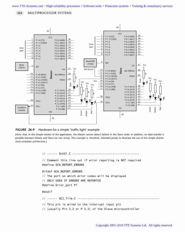
// ------ Sch51.C ----------------------------------------
// Comment this line out if error reporting is NOT required
#define SCH_REPORT_ERRORS
#ifdef SCH_REPORT_ERRORS
// The port on which error codes will be displayed
// ONLY USED IF ERRORS ARE REPORTED
#define Error_port P1
#endif
// ------ SCI_Ti1m.C -------------------------------------------------
// This pin is wired to the interrupt input pin
// (usually Pin 3.2 or P 3.3) of the Slave microcontroller
MULTIPROCESSOR SYSTEMS564
FIGURE 26.9 Hardware for a simple ‘traffic light’ example[Note: that, in this simple version of the application, the Master cannot detect failures in the Slave node. In addition, no data transfer ispossible between Master and Slave (or vice versa). This example is, therefore, intended purely to illustrate the use of this simple shared-clock scheduler architecture.]
VccVcc
Vcc
P 1.0 [T2]P 1.1 [T2EX]P 1.2P 1.3P 1.4P 1.5P 1.6P 1.7
RST
P 3.0 (RXD)P 3.1 (TXD)P 3.2 (/INT0)P 3.3 (/INT1)P 3.4 (T0)P 3.5 (T1)P 3.6 (/WR)P 3.7 (/RD)
XTL2
XTL1
P 0.0 (AD0)P 0.1 (AD1)P 0.2 (AD2)P 0.3 (AD3)P 0.4 (AD4)P 0.5 (AD5)P 0.6 (AD6)P 0.7 (AD7)
/ EA
ALE (PROG)
/PSEN
P 2.7 (A15)P 2.6 (A14)P 2.5 (A13)P 2.4 (A12)P 2.3 (A11)P 2.2 (A10)P 2.1 (A9)P 2.0 (A8)
VCC
Mas
ter
VSS
3938373635343332
31
30
29
2827262524232221
12345678
9
1011121314151617
18
19
20
40
P 1.0 [T2]P 1.1 [T2EX]P 1.2P 1.3P 1.4P 1.5P 1.6P 1.7
RST
P 3.0 (RXD)P 3.1 (TXD)P 3.2 (/INT0)P 3.3 (/INT1)P 3.4 (T0)P 3.5 (T1)P 3.6 (/WR)P 3.7 (/RD)
XTL2
XTL1
P 0.0 (AD0)P 0.1 (AD1)P 0.2 (AD2)P 0.3 (AD3)P 0.4 (AD4)P 0.5 (AD5)P 0.6 (AD6)P 0.7 (AD7)
/ EA
ALE (PROG)
/PSEN
P 2.7 (A15)P 2.6 (A14)P 2.5 (A13)P 2.4 (A12)P 2.3 (A11)P 2.2 (A10)P 2.1 (A9)P 2.0 (A8)
VCC
Slav
e
VSS
3938373635343332
31
30
29
2827262524232221
12345678
9
1011121314151617
18
19
20
40
Reset/WD(1232)
WD Refresh
Oscillatormodule
Reset(1812)
VccVcc
Vcc
Errorport
RR
RRe
d
Am
ber
Gre
en
Vcc
R
Tick
Flas
h
Errorport
Red
Am
ber
Gre
en
Vcc
R
Flas
h
www.TTE-Systems.com = High-reliability processors + Software tools + Protection systems + Training & consultancy services
Copyright 2001-2010 TTE Systems Ltd. All rights reserved.
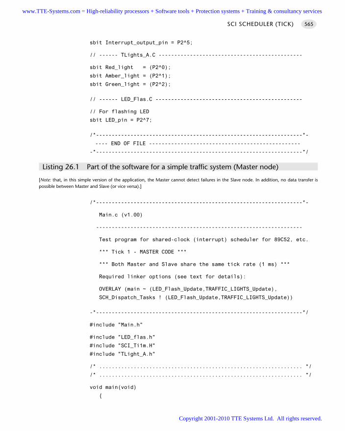
sbit Interrupt_output_pin = P2^5;
// ------ TLights_A.C ----------------------------------------------
sbit Red_light = (P2^0);
sbit Amber_light = (P2^1);
sbit Green_light = (P2^2);
// ------ LED_Flas.C -----------------------------------------------
// For flashing LED
sbit LED_pin = P2^7;
/*------------------------------------------------------------------*-
---- END OF FILE ------------------------------------------------
-*------------------------------------------------------------------*/
Listing 26.1 Part of the software for a simple traffic system (Master node)
[Note: that, in this simple version of the application, the Master cannot detect failures in the Slave node. In addition, no data transfer ispossible between Master and Slave (or vice versa).]
/*------------------------------------------------------------------*-
Main.c (v1.00)
------------------------------------------------------------------
Test program for shared-clock (interrupt) scheduler for 89C52, etc.
*** Tick 1 - MASTER CODE ***
*** Both Master and Slave share the same tick rate (1 ms) ***
Required linker options (see text for details):
OVERLAY (main ~ (LED_Flash_Update,TRAFFIC_LIGHTS_Update),
SCH_Dispatch_Tasks ! (LED_Flash_Update,TRAFFIC_LIGHTS_Update))
-*------------------------------------------------------------------*/
#include "Main.h"
#include "LED_flas.h"
#include "SCI_Ti1m.H"
#include "TLight_A.h"
/* ................................................................. */
/* ................................................................. */
void main(void)
SCI SCHEDULER (TICK) 565
www.TTE-Systems.com = High-reliability processors + Software tools + Protection systems + Training & consultancy services
Copyright 2001-2010 TTE Systems Ltd. All rights reserved.
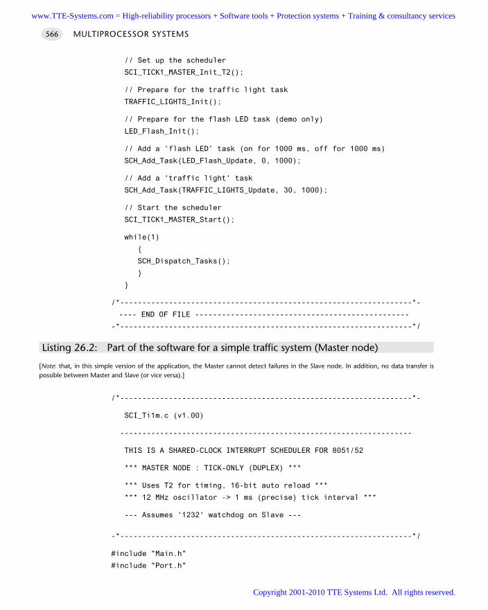
// Set up the scheduler
SCI_TICK1_MASTER_Init_T2();
// Prepare for the traffic light task
TRAFFIC_LIGHTS_Init();
// Prepare for the flash LED task (demo only)
LED_Flash_Init();
// Add a 'flash LED' task (on for 1000 ms, off for 1000 ms)
SCH_Add_Task(LED_Flash_Update, 0, 1000);
// Add a 'traffic light' task
SCH_Add_Task(TRAFFIC_LIGHTS_Update, 30, 1000);
// Start the scheduler
SCI_TICK1_MASTER_Start();
while(1)
SCH_Dispatch_Tasks();
/*------------------------------------------------------------------*-
---- END OF FILE ------------------------------------------------
-*------------------------------------------------------------------*/
Listing 26.2: Part of the software for a simple traffic system (Master node)
[Note: that, in this simple version of the application, the Master cannot detect failures in the Slave node. In addition, no data transfer ispossible between Master and Slave (or vice versa).]
/*------------------------------------------------------------------*-
SCI_Ti1m.c (v1.00)
------------------------------------------------------------------
THIS IS A SHARED-CLOCK INTERRUPT SCHEDULER FOR 8051/52
*** MASTER NODE : TICK-ONLY (DUPLEX) ***
*** Uses T2 for timing, 16-bit auto reload ***
*** 12 MHz oscillator -> 1 ms (precise) tick interval ***
--- Assumes '1232' watchdog on Slave ---
-*------------------------------------------------------------------*/
#include "Main.h"
#include "Port.h"
MULTIPROCESSOR SYSTEMS566
www.TTE-Systems.com = High-reliability processors + Software tools + Protection systems + Training & consultancy services
Copyright 2001-2010 TTE Systems Ltd. All rights reserved.
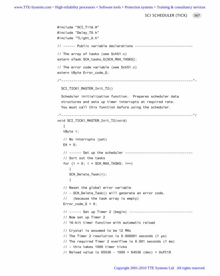
#include "SCI_Ti1m.H"
#include "Delay_T0.h"
#include "TLight_A.h"
// ------ Public variable declarations -----------------------------
// The array of tasks (see Sch51.c)
extern sTask SCH_tasks_G[SCH_MAX_TASKS];
// The error code variable (see Sch51.c)
extern tByte Error_code_G;
/*------------------------------------------------------------------*-
SCI_TICK1_MASTER_Init_T2()
Scheduler initialization function. Prepares scheduler data
structures and sets up timer interrupts at required rate.
You must call this function before using the scheduler.
-*------------------------------------------------------------------*/
void SCI_TICK1_MASTER_Init_T2(void)
tByte i;
// No interrupts (yet)
EA = 0;
// ------ Set up the scheduler ----------------------------------
// Sort out the tasks
for (i = 0; i < SCH_MAX_TASKS; i++)
SCH_Delete_Task(i);
// Reset the global error variable
// - SCH_Delete_Task() will generate an error code,
// (because the task array is empty)
Error_code_G = 0;
// ------ Set up Timer 2 (begin) --------------------------------
// Now set up Timer 2
// 16-bit timer function with automatic reload
// Crystal is assumed to be 12 MHz
// The Timer 2 resolution is 0.000001 seconds (1 µs)
// The required Timer 2 overflow is 0.001 seconds (1 ms)
// - this takes 1000 timer ticks
// Reload value is 65536 - 1000 = 64536 (dec) = 0xFC18
SCI SCHEDULER (TICK) 567
www.TTE-Systems.com = High-reliability processors + Software tools + Protection systems + Training & consultancy services
Copyright 2001-2010 TTE Systems Ltd. All rights reserved.
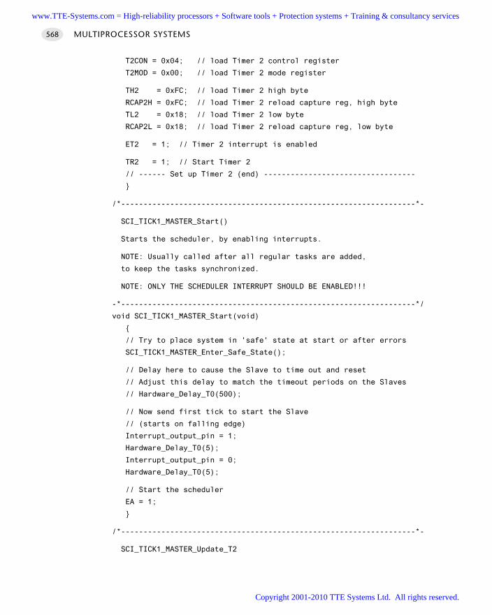
T2CON = 0x04; // load Timer 2 control register
T2MOD = 0x00; // load Timer 2 mode register
TH2 = 0xFC; // load Timer 2 high byte
RCAP2H = 0xFC; // load Timer 2 reload capture reg, high byte
TL2 = 0x18; // load Timer 2 low byte
RCAP2L = 0x18; // load Timer 2 reload capture reg, low byte
ET2 = 1; // Timer 2 interrupt is enabled
TR2 = 1; // Start Timer 2
// ------ Set up Timer 2 (end) ----------------------------------
/*------------------------------------------------------------------*-
SCI_TICK1_MASTER_Start()
Starts the scheduler, by enabling interrupts.
NOTE: Usually called after all regular tasks are added,
to keep the tasks synchronized.
NOTE: ONLY THE SCHEDULER INTERRUPT SHOULD BE ENABLED!!!
-*------------------------------------------------------------------*/
void SCI_TICK1_MASTER_Start(void)
// Try to place system in 'safe' state at start or after errors
SCI_TICK1_MASTER_Enter_Safe_State();
// Delay here to cause the Slave to time out and reset
// Adjust this delay to match the timeout periods on the Slaves
// Hardware_Delay_T0(500);
// Now send first tick to start the Slave
// (starts on falling edge)
Interrupt_output_pin = 1;
Hardware_Delay_T0(5);
Interrupt_output_pin = 0;
Hardware_Delay_T0(5);
// Start the scheduler
EA = 1;
/*------------------------------------------------------------------*-
SCI_TICK1_MASTER_Update_T2
MULTIPROCESSOR SYSTEMS568
www.TTE-Systems.com = High-reliability processors + Software tools + Protection systems + Training & consultancy services
Copyright 2001-2010 TTE Systems Ltd. All rights reserved.
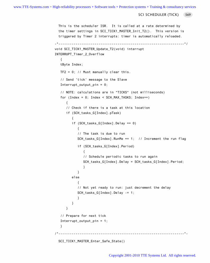
This is the scheduler ISR. It is called at a rate determined by
the timer settings in SCI_TICK1_MASTER_Init_T2(). This version is
triggered by Timer 2 interrupts: timer is automatically reloaded.
-*------------------------------------------------------------------*/
void SCI_TICK1_MASTER_Update_T2(void) interrupt
INTERRUPT_Timer_2_Overflow
tByte Index;
TF2 = 0; // Must manually clear this.
// Send 'tick' message to the Slave
Interrupt_output_pin = 0;
// NOTE: calculations are in *TICKS* (not milliseconds)
for (Index = 0; Index < SCH_MAX_TASKS; Index++)
// Check if there is a task at this location
if (SCH_tasks_G[Index].pTask)
if (SCH_tasks_G[Index].Delay == 0)
// The task is due to run
SCH_tasks_G[Index].RunMe += 1; // Increment the run flag
if (SCH_tasks_G[Index].Period)
// Schedule periodic tasks to run again
SCH_tasks_G[Index].Delay = SCH_tasks_G[Index].Period;
else
// Not yet ready to run: just decrement the delay
SCH_tasks_G[Index].Delay -= 1;
// Prepare for next tick
Interrupt_output_pin = 1;
/*------------------------------------------------------------------*-
SCI_TICK1_MASTER_Enter_Safe_State()
SCI SCHEDULER (TICK) 569
www.TTE-Systems.com = High-reliability processors + Software tools + Protection systems + Training & consultancy services
Copyright 2001-2010 TTE Systems Ltd. All rights reserved.
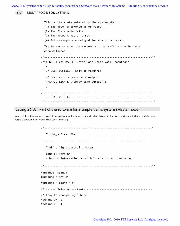
This is the state entered by the system when:
(1) The node is powered up or reset
(2) The Slave node fails
(3) The network has an error
(4) Ack messages are delayed for any other reason
Try to ensure that the system is in a 'safe' state in these
circumstances.
-*------------------------------------------------------------------*/
void SCI_TICK1_MASTER_Enter_Safe_State(void) reentrant
// USER DEFINED - Edit as required
// Here we display a safe output
TRAFFIC_LIGHTS_Display_Safe_Output();
/*------------------------------------------------------------------*-
---- END OF FILE -------------------------------------------------
-*------------------------------------------------------------------*/
Listing 26.3: Part of the software for a simple traffic system (Master node)
[Note: that, in this simple version of the application, the Master cannot detect failures in the Slave node. In addition, no data transfer ispossible between Master and Slave (or vice versa).]
/*------------------------------------------------------------------*-
TLight_A.C (v1.00)
------------------------------------------------------------------
Traffic light control program
Simplex version
- has no information about bulb status on other node.
-*------------------------------------------------------------------*/
#include "Main.h"
#include "Port.h"
#include "TLight_A.h"
// ------ Private constants ----------------------------------------
// Easy to change logic here
#define ON 0
#define OFF 1
MULTIPROCESSOR SYSTEMS570
www.TTE-Systems.com = High-reliability processors + Software tools + Protection systems + Training & consultancy services
Copyright 2001-2010 TTE Systems Ltd. All rights reserved.
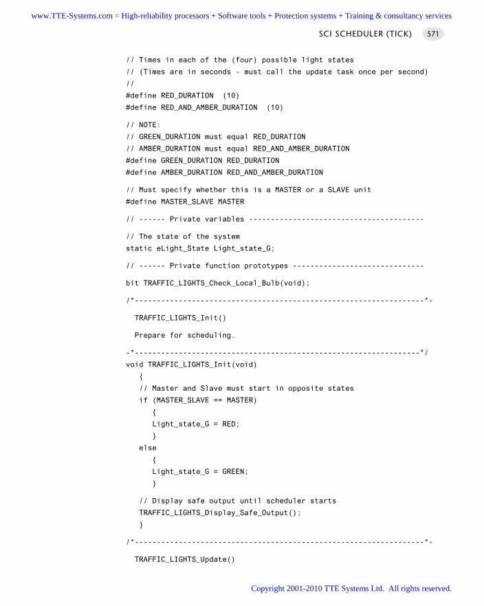
// Times in each of the (four) possible light states
// (Times are in seconds - must call the update task once per second)
//
#define RED_DURATION (10)
#define RED_AND_AMBER_DURATION (10)
// NOTE:
// GREEN_DURATION must equal RED_DURATION
// AMBER_DURATION must equal RED_AND_AMBER_DURATION
#define GREEN_DURATION RED_DURATION
#define AMBER_DURATION RED_AND_AMBER_DURATION
// Must specify whether this is a MASTER or a SLAVE unit
#define MASTER_SLAVE MASTER
// ------ Private variables ----------------------------------------
// The state of the system
static eLight_State Light_state_G;
// ------ Private function prototypes ------------------------------
bit TRAFFIC_LIGHTS_Check_Local_Bulb(void);
/*------------------------------------------------------------------*-
TRAFFIC_LIGHTS_Init()
Prepare for scheduling.
-*-----------------------------------------------------------------*/
void TRAFFIC_LIGHTS_Init(void)
// Master and Slave must start in opposite states
if (MASTER_SLAVE == MASTER)
Light_state_G = RED;
else
Light_state_G = GREEN;
// Display safe output until scheduler starts
TRAFFIC_LIGHTS_Display_Safe_Output();
/*------------------------------------------------------------------*-
TRAFFIC_LIGHTS_Update()
SCI SCHEDULER (TICK) 571
www.TTE-Systems.com = High-reliability processors + Software tools + Protection systems + Training & consultancy services
Copyright 2001-2010 TTE Systems Ltd. All rights reserved.
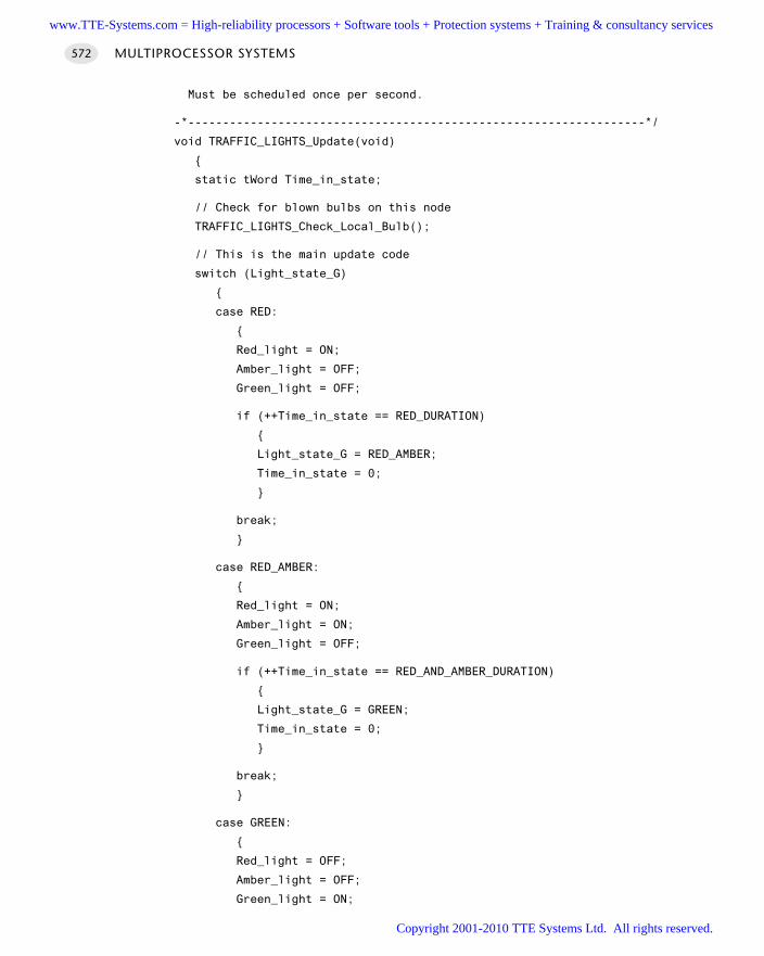
Must be scheduled once per second.
-*------------------------------------------------------------------*/
void TRAFFIC_LIGHTS_Update(void)
static tWord Time_in_state;
// Check for blown bulbs on this node
TRAFFIC_LIGHTS_Check_Local_Bulb();
// This is the main update code
switch (Light_state_G)
case RED:
Red_light = ON;
Amber_light = OFF;
Green_light = OFF;
if (++Time_in_state == RED_DURATION)
Light_state_G = RED_AMBER;
Time_in_state = 0;
break;
case RED_AMBER:
Red_light = ON;
Amber_light = ON;
Green_light = OFF;
if (++Time_in_state == RED_AND_AMBER_DURATION)
Light_state_G = GREEN;
Time_in_state = 0;
break;
case GREEN:
Red_light = OFF;
Amber_light = OFF;
Green_light = ON;
MULTIPROCESSOR SYSTEMS572
www.TTE-Systems.com = High-reliability processors + Software tools + Protection systems + Training & consultancy services
Copyright 2001-2010 TTE Systems Ltd. All rights reserved.
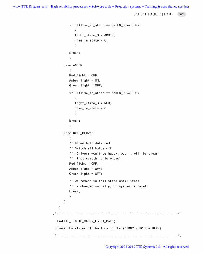
if (++Time_in_state == GREEN_DURATION)
Light_state_G = AMBER;
Time_in_state = 0;
break;
case AMBER:
Red_light = OFF;
Amber_light = ON;
Green_light = OFF;
if (++Time_in_state == AMBER_DURATION)
Light_state_G = RED;
Time_in_state = 0;
break;
case BULB_BLOWN:
// Blown bulb detected
// Switch all bulbs off
// (Drivers won't be happy, but it will be clear
// that something is wrong)
Red_light = OFF;
Amber_light = OFF;
Green_light = OFF;
// We remain in this state until state
// is changed manually, or system is reset
break;
/*------------------------------------------------------------------*-
TRAFFIC_LIGHTS_Check_Local_Bulb()
Check the status of the local bulbs (DUMMY FUNCTION HERE)
-*------------------------------------------------------------------*/
SCI SCHEDULER (TICK) 573
www.TTE-Systems.com = High-reliability processors + Software tools + Protection systems + Training & consultancy services
Copyright 2001-2010 TTE Systems Ltd. All rights reserved.
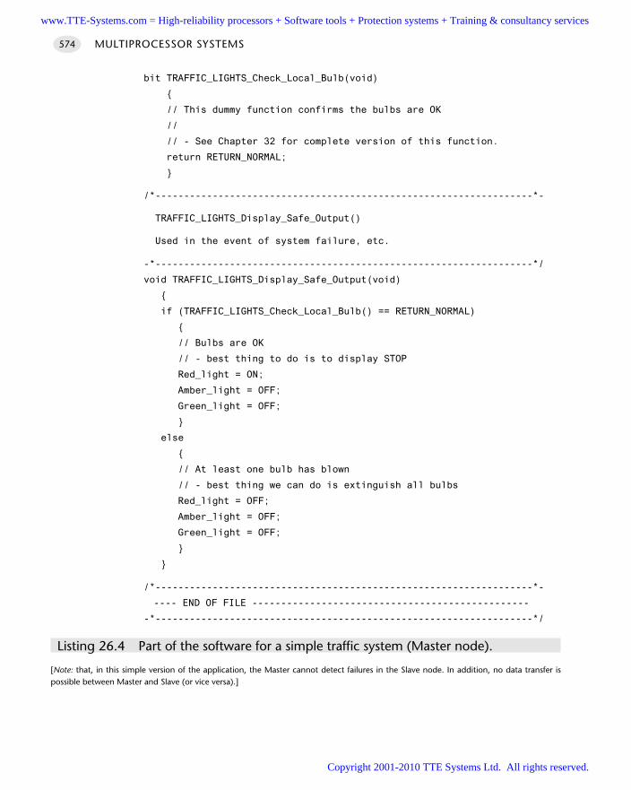
bit TRAFFIC_LIGHTS_Check_Local_Bulb(void)
// This dummy function confirms the bulbs are OK
//
// - See Chapter 32 for complete version of this function.
return RETURN_NORMAL;
/*------------------------------------------------------------------*-
TRAFFIC_LIGHTS_Display_Safe_Output()
Used in the event of system failure, etc.
-*------------------------------------------------------------------*/
void TRAFFIC_LIGHTS_Display_Safe_Output(void)
if (TRAFFIC_LIGHTS_Check_Local_Bulb() == RETURN_NORMAL)
// Bulbs are OK
// - best thing to do is to display STOP
Red_light = ON;
Amber_light = OFF;
Green_light = OFF;
else
// At least one bulb has blown
// - best thing we can do is extinguish all bulbs
Red_light = OFF;
Amber_light = OFF;
Green_light = OFF;
/*------------------------------------------------------------------*-
---- END OF FILE ------------------------------------------------
-*------------------------------------------------------------------*/
Listing 26.4 Part of the software for a simple traffic system (Master node).
[Note: that, in this simple version of the application, the Master cannot detect failures in the Slave node. In addition, no data transfer ispossible between Master and Slave (or vice versa).]
MULTIPROCESSOR SYSTEMS574
www.TTE-Systems.com = High-reliability processors + Software tools + Protection systems + Training & consultancy services
Copyright 2001-2010 TTE Systems Ltd. All rights reserved.
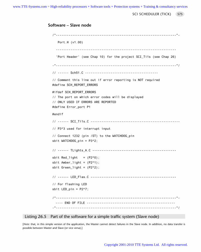
Software – Slave node
/*------------------------------------------------------------------*-
Port.H (v1.00)
------------------------------------------------------------------
'Port Header' (see Chap 10) for the project SCI_Ti1s (see Chap 26)
-*------------------------------------------------------------------*/
// ------ Sch51.C ----------------------------------------
// Comment this line out if error reporting is NOT required
#define SCH_REPORT_ERRORS
#ifdef SCH_REPORT_ERRORS
// The port on which error codes will be displayed
// ONLY USED IF ERRORS ARE REPORTED
#define Error_port P1
#endif
// ------ SCI_Ti1s.C -------------------------------------------------
// P3^3 used for interrupt input
// Connect 1232 (pin /ST) to the WATCHDOG_pin
sbit WATCHDOG_pin = P3^2;
// ------ TLights_A.C ----------------------------------------------
sbit Red_light = (P2^0);
sbit Amber_light = (P2^1);
sbit Green_light = (P2^2);
// ------ LED_Flas.C -----------------------------------------------
// For flashing LED
sbit LED_pin = P2^7;
/*------------------------------------------------------------------*-
---- END OF FILE ------------------------------------------------
-*------------------------------------------------------------------*/
Listing 26.5 Part of the software for a simple traffic system (Slave node)
[Note: that, in this simple version of the application, the Master cannot detect failures in the Slave node. In addition, no data transfer ispossible between Master and Slave (or vice versa).]
SCI SCHEDULER (TICK) 575
www.TTE-Systems.com = High-reliability processors + Software tools + Protection systems + Training & consultancy services
Copyright 2001-2010 TTE Systems Ltd. All rights reserved.
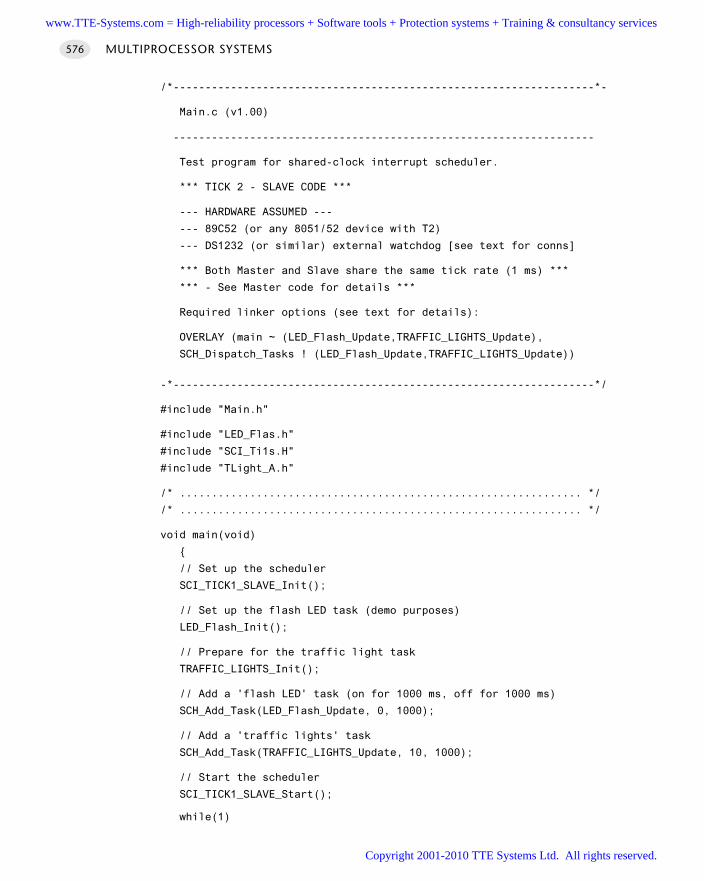
/*------------------------------------------------------------------*-
Main.c (v1.00)
------------------------------------------------------------------
Test program for shared-clock interrupt scheduler.
*** TICK 2 - SLAVE CODE ***
--- HARDWARE ASSUMED ---
--- 89C52 (or any 8051/52 device with T2)
--- DS1232 (or similar) external watchdog [see text for conns]
*** Both Master and Slave share the same tick rate (1 ms) ***
*** - See Master code for details ***
Required linker options (see text for details):
OVERLAY (main ~ (LED_Flash_Update,TRAFFIC_LIGHTS_Update),
SCH_Dispatch_Tasks ! (LED_Flash_Update,TRAFFIC_LIGHTS_Update))
-*------------------------------------------------------------------*/
#include "Main.h"
#include "LED_Flas.h"
#include "SCI_Ti1s.H"
#include "TLight_A.h"
/* ............................................................... */
/* ............................................................... */
void main(void)
// Set up the scheduler
SCI_TICK1_SLAVE_Init();
// Set up the flash LED task (demo purposes)
LED_Flash_Init();
// Prepare for the traffic light task
TRAFFIC_LIGHTS_Init();
// Add a 'flash LED' task (on for 1000 ms, off for 1000 ms)
SCH_Add_Task(LED_Flash_Update, 0, 1000);
// Add a 'traffic lights' task
SCH_Add_Task(TRAFFIC_LIGHTS_Update, 10, 1000);
// Start the scheduler
SCI_TICK1_SLAVE_Start();
while(1)
MULTIPROCESSOR SYSTEMS576
www.TTE-Systems.com = High-reliability processors + Software tools + Protection systems + Training & consultancy services
Copyright 2001-2010 TTE Systems Ltd. All rights reserved.
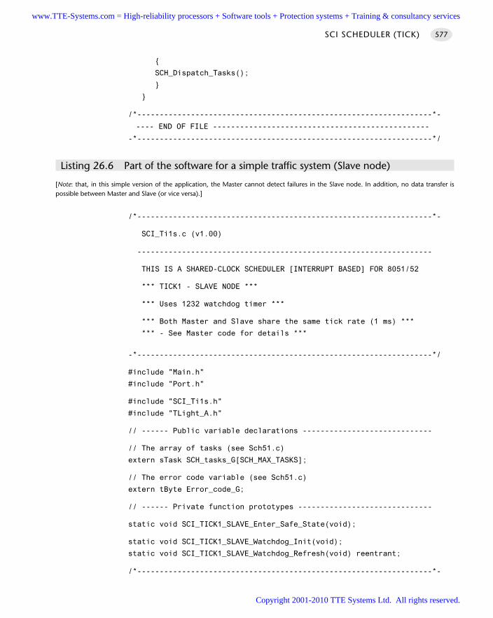
SCH_Dispatch_Tasks();
/*------------------------------------------------------------------*-
---- END OF FILE ------------------------------------------------
-*------------------------------------------------------------------*/
Listing 26.6 Part of the software for a simple traffic system (Slave node)
[Note: that, in this simple version of the application, the Master cannot detect failures in the Slave node. In addition, no data transfer ispossible between Master and Slave (or vice versa).]
/*------------------------------------------------------------------*-
SCI_Ti1s.c (v1.00)
------------------------------------------------------------------
THIS IS A SHARED-CLOCK SCHEDULER [INTERRUPT BASED] FOR 8051/52
*** TICK1 - SLAVE NODE ***
*** Uses 1232 watchdog timer ***
*** Both Master and Slave share the same tick rate (1 ms) ***
*** - See Master code for details ***
-*------------------------------------------------------------------*/
#include "Main.h"
#include "Port.h"
#include "SCI_Ti1s.h"
#include "TLight_A.h"
// ------ Public variable declarations -----------------------------
// The array of tasks (see Sch51.c)
extern sTask SCH_tasks_G[SCH_MAX_TASKS];
// The error code variable (see Sch51.c)
extern tByte Error_code_G;
// ------ Private function prototypes ------------------------------
static void SCI_TICK1_SLAVE_Enter_Safe_State(void);
static void SCI_TICK1_SLAVE_Watchdog_Init(void);
static void SCI_TICK1_SLAVE_Watchdog_Refresh(void) reentrant;
/*------------------------------------------------------------------*-
SCI SCHEDULER (TICK) 577
www.TTE-Systems.com = High-reliability processors + Software tools + Protection systems + Training & consultancy services
Copyright 2001-2010 TTE Systems Ltd. All rights reserved.
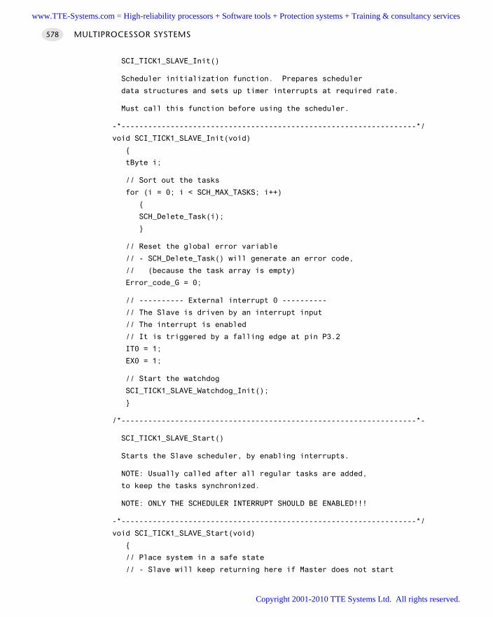
SCI_TICK1_SLAVE_Init()
Scheduler initialization function. Prepares scheduler
data structures and sets up timer interrupts at required rate.
Must call this function before using the scheduler.
-*------------------------------------------------------------------*/
void SCI_TICK1_SLAVE_Init(void)
tByte i;
// Sort out the tasks
for (i = 0; i < SCH_MAX_TASKS; i++)
SCH_Delete_Task(i);
// Reset the global error variable
// - SCH_Delete_Task() will generate an error code,
// (because the task array is empty)
Error_code_G = 0;
// ---------- External interrupt 0 ----------
// The Slave is driven by an interrupt input
// The interrupt is enabled
// It is triggered by a falling edge at pin P3.2
IT0 = 1;
EX0 = 1;
// Start the watchdog
SCI_TICK1_SLAVE_Watchdog_Init();
/*------------------------------------------------------------------*-
SCI_TICK1_SLAVE_Start()
Starts the Slave scheduler, by enabling interrupts.
NOTE: Usually called after all regular tasks are added,
to keep the tasks synchronized.
NOTE: ONLY THE SCHEDULER INTERRUPT SHOULD BE ENABLED!!!
-*------------------------------------------------------------------*/
void SCI_TICK1_SLAVE_Start(void)
// Place system in a safe state
// - Slave will keep returning here if Master does not start
MULTIPROCESSOR SYSTEMS578
www.TTE-Systems.com = High-reliability processors + Software tools + Protection systems + Training & consultancy services
Copyright 2001-2010 TTE Systems Ltd. All rights reserved.
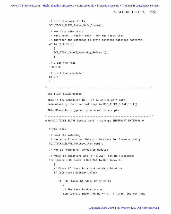
// - or otherwise fails.
SCI_TICK1_SLAVE_Enter_Safe_State();
// Now in a safe state
// Wait here - indefinitely - for the first tick
// (Refresh the watchdog to avoid constant watchdog restarts)
while (IE0 == 0)
SCI_TICK1_SLAVE_Watchdog_Refresh();
// Clear the flag
IE0 = 0;
// Start the scheduler
EA = 1;
/*------------------------------------------------------------------*-
SCI_TICK1_SLAVE_Update
This is the scheduler ISR. It is called at a rate
determined by the timer settings in SCI_TICK1_SLAVE_Init().
This Slave is triggered by external interrupts.
-*------------------------------------------------------------------*/
void SCI_TICK1_SLAVE_Update(void) interrupt INTERRUPT_EXTERNAL_0
tByte Index;
// Feed the watchdog
// Master will monitor this pin to check for Slave activity
SCI_TICK1_SLAVE_Watchdog_Refresh();
// Now do 'standard' scheduler updates
// NOTE: calculations are in *TICKS* (not milliseconds)
for (Index = 0; Index < SCH_MAX_TASKS; Index++)
// Check if there is a task at this location
if (SCH_tasks_G[Index].pTask)
if (SCH_tasks_G[Index].Delay == 0)
// The task is due to run
SCH_tasks_G[Index].RunMe += 1; // Incr. the run flag
SCI SCHEDULER (TICK) 579
www.TTE-Systems.com = High-reliability processors + Software tools + Protection systems + Training & consultancy services
Copyright 2001-2010 TTE Systems Ltd. All rights reserved.
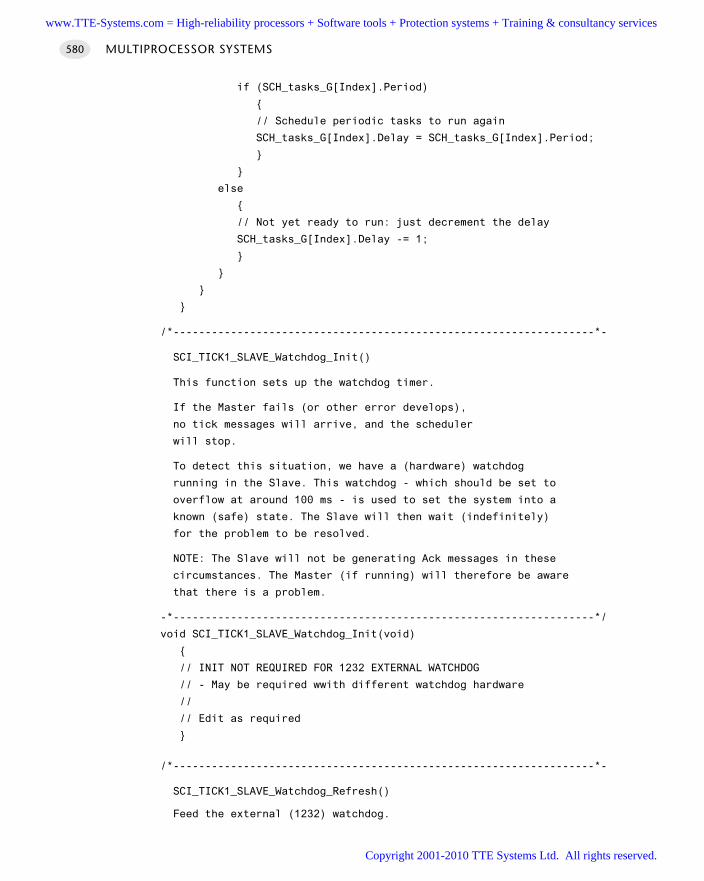
if (SCH_tasks_G[Index].Period)
// Schedule periodic tasks to run again
SCH_tasks_G[Index].Delay = SCH_tasks_G[Index].Period;
else
// Not yet ready to run: just decrement the delay
SCH_tasks_G[Index].Delay -= 1;
/*------------------------------------------------------------------*-
SCI_TICK1_SLAVE_Watchdog_Init()
This function sets up the watchdog timer.
If the Master fails (or other error develops),
no tick messages will arrive, and the scheduler
will stop.
To detect this situation, we have a (hardware) watchdog
running in the Slave. This watchdog - which should be set to
overflow at around 100 ms - is used to set the system into a
known (safe) state. The Slave will then wait (indefinitely)
for the problem to be resolved.
NOTE: The Slave will not be generating Ack messages in these
circumstances. The Master (if running) will therefore be aware
that there is a problem.
-*------------------------------------------------------------------*/
void SCI_TICK1_SLAVE_Watchdog_Init(void)
// INIT NOT REQUIRED FOR 1232 EXTERNAL WATCHDOG
// - May be required wwith different watchdog hardware
//
// Edit as required
/*------------------------------------------------------------------*-
SCI_TICK1_SLAVE_Watchdog_Refresh()
Feed the external (1232) watchdog.
MULTIPROCESSOR SYSTEMS580
www.TTE-Systems.com = High-reliability processors + Software tools + Protection systems + Training & consultancy services
Copyright 2001-2010 TTE Systems Ltd. All rights reserved.
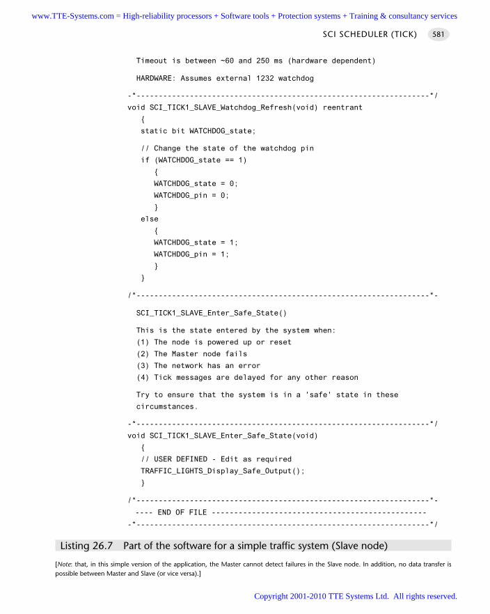
Timeout is between ~60 and 250 ms (hardware dependent)
HARDWARE: Assumes external 1232 watchdog
-*------------------------------------------------------------------*/
void SCI_TICK1_SLAVE_Watchdog_Refresh(void) reentrant
static bit WATCHDOG_state;
// Change the state of the watchdog pin
if (WATCHDOG_state == 1)
WATCHDOG_state = 0;
WATCHDOG_pin = 0;
else
WATCHDOG_state = 1;
WATCHDOG_pin = 1;
/*------------------------------------------------------------------*-
SCI_TICK1_SLAVE_Enter_Safe_State()
This is the state entered by the system when:
(1) The node is powered up or reset
(2) The Master node fails
(3) The network has an error
(4) Tick messages are delayed for any other reason
Try to ensure that the system is in a 'safe' state in these
circumstances.
-*------------------------------------------------------------------*/
void SCI_TICK1_SLAVE_Enter_Safe_State(void)
// USER DEFINED - Edit as required
TRAFFIC_LIGHTS_Display_Safe_Output();
/*------------------------------------------------------------------*-
---- END OF FILE ------------------------------------------------
-*------------------------------------------------------------------*/
Listing 26.7 Part of the software for a simple traffic system (Slave node)
[Note: that, in this simple version of the application, the Master cannot detect failures in the Slave node. In addition, no data transfer ispossible between Master and Slave (or vice versa).]
SCI SCHEDULER (TICK) 581
www.TTE-Systems.com = High-reliability processors + Software tools + Protection systems + Training & consultancy services
Copyright 2001-2010 TTE Systems Ltd. All rights reserved.
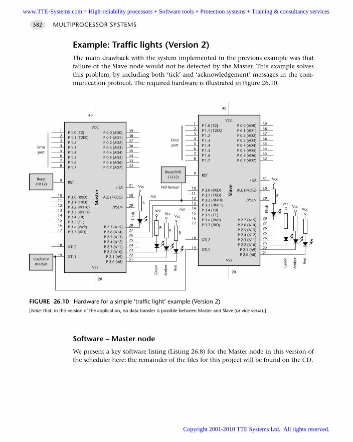
Example: Traffic lights (Version 2)The main drawback with the system implemented in the previous example was thatfailure of the Slave node would not be detected by the Master. This example solvesthis problem, by including both ‘tick’ and ‘acknowledgement’ messages in the com-munication protocol. The required hardware is illustrated in Figure 26.10.
Software – Master node
We present a key software listing (Listing 26.8) for the Master node in this version ofthe scheduler here: the remainder of the files for this project will be found on the CD.
MULTIPROCESSOR SYSTEMS582
FIGURE 26.10 Hardware for a simple ‘traffic light’ example (Version 2)[Note: that, in this version of the application, no data transfer is possible between Master and Slave (or vice versa).]
VccVcc
Vcc
P 1.0 [T2]P 1.1 [T2EX]P 1.2P 1.3P 1.4P 1.5P 1.6P 1.7
RST
P 3.0 (RXD)P 3.1 (TXD)P 3.2 (/INT0)P 3.3 (/INT1)P 3.4 (T0)P 3.5 (T1)P 3.6 (/WR)P 3.7 (/RD)
XTL2
XTL1
P 0.0 (AD0)P 0.1 (AD1)P 0.2 (AD2)P 0.3 (AD3)P 0.4 (AD4)P 0.5 (AD5)P 0.6 (AD6)P 0.7 (AD7)
/ EA
ALE (PROG)
/PSEN
P 2.7 (A15)P 2.6 (A14)P 2.5 (A13)P 2.4 (A12)P 2.3 (A11)P 2.2 (A10)P 2.1 (A9)P 2.0 (A8)
VCC
Mas
ter
VSS
3938373635343332
31
30
29
2827262524232221
12345678
9
1011121314151617
18
19
20
40
P 1.0 [T2]P 1.1 [T2EX]P 1.2P 1.3P 1.4P 1.5P 1.6P 1.7
RST
P 3.0 (RXD)P 3.1 (TXD)P 3.2 (/INT0)P 3.3 (/INT1)P 3.4 (T0)P 3.5 (T1)P 3.6 (/WR)P 3.7 (/RD)
XTL2
XTL1
P 0.0 (AD0)P 0.1 (AD1)P 0.2 (AD2)P 0.3 (AD3)P 0.4 (AD4)P 0.5 (AD5)P 0.6 (AD6)P 0.7 (AD7)
/ EA
ALE (PROG)
/PSEN
P 2.7 (A15)P 2.6 (A14)P 2.5 (A13)P 2.4 (A12)P 2.3 (A11)P 2.2 (A10)
P 2.1 (A9)P 2.0 (A8)
VCC
Slav
e
VSS
3938373635343332
31
30
29
2827262524232221
12345678
9
1011121314151617
18
19
20
40
Reset/WD(1232)
WD Refresh
Oscillatormodule
Reset(1812)
VccVcc
Vcc
Errorport
RR
R
Red
Am
ber
Gre
en
Vcc
R
Tick
Flas
h
Errorport
Red
Am
ber
Gre
en
Vcc
R
Flas
h
Ack
www.TTE-Systems.com = High-reliability processors + Software tools + Protection systems + Training & consultancy services
Copyright 2001-2010 TTE Systems Ltd. All rights reserved.
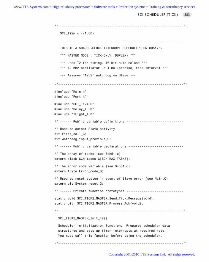
/*------------------------------------------------------------------*-
SCI_Ti2m.c (v1.00)
------------------------------------------------------------------
THIS IS A SHARED-CLOCK INTERRUPT SCHEDULER FOR 8051/52
*** MASTER NODE : TICK-ONLY (DUPLEX) ***
*** Uses T2 for timing, 16-bit auto reload ***
*** 12 MHz oscillator -> 1 ms (precise) tick interval ***
--- Assumes '1232' watchdog on Slave ---
-*------------------------------------------------------------------*/
#include "Main.h"
#include "Port.h"
#include "SCI_Ti2m.H"
#include "Delay_T0.h"
#include "TLight_A.h"
// ------ Public variable definitions ------------------------------
// Used to detect Slave activity
bit First_call_G;
bit Watchdog_input_previous_G;
// ------ Public variable declarations -----------------------------
// The array of tasks (see Sch51.c)
extern sTask SCH_tasks_G[SCH_MAX_TASKS];
// The error code variable (see Sch51.c)
extern tByte Error_code_G;
// Used to reset system in event of Slave error (see Main.C)
extern bit System_reset_G;
// ------ Private function prototypes ------------------------------
static void SCI_TICK2_MASTER_Send_Tick_Message(void);
static bit SCI_TICK2_MASTER_Process_Ack(void);
/*------------------------------------------------------------------*-
SCI_TICK2_MASTER_Init_T2()
Scheduler initialization function. Prepares scheduler data
structures and sets up timer interrupts at required rate.
You must call this function before using the scheduler.
-*------------------------------------------------------------------*/
SCI SCHEDULER (TICK) 583
www.TTE-Systems.com = High-reliability processors + Software tools + Protection systems + Training & consultancy services
Copyright 2001-2010 TTE Systems Ltd. All rights reserved.
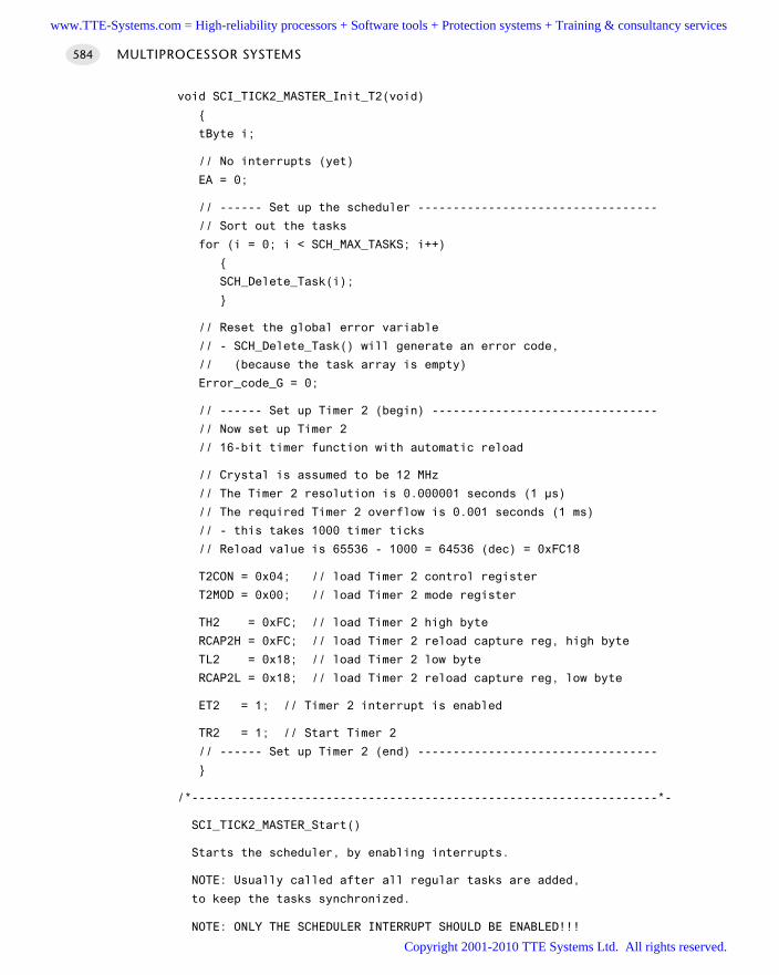
void SCI_TICK2_MASTER_Init_T2(void)
tByte i;
// No interrupts (yet)
EA = 0;
// ------ Set up the scheduler ----------------------------------
// Sort out the tasks
for (i = 0; i < SCH_MAX_TASKS; i++)
SCH_Delete_Task(i);
// Reset the global error variable
// - SCH_Delete_Task() will generate an error code,
// (because the task array is empty)
Error_code_G = 0;
// ------ Set up Timer 2 (begin) --------------------------------
// Now set up Timer 2
// 16-bit timer function with automatic reload
// Crystal is assumed to be 12 MHz
// The Timer 2 resolution is 0.000001 seconds (1 µs)
// The required Timer 2 overflow is 0.001 seconds (1 ms)
// - this takes 1000 timer ticks
// Reload value is 65536 - 1000 = 64536 (dec) = 0xFC18
T2CON = 0x04; // load Timer 2 control register
T2MOD = 0x00; // load Timer 2 mode register
TH2 = 0xFC; // load Timer 2 high byte
RCAP2H = 0xFC; // load Timer 2 reload capture reg, high byte
TL2 = 0x18; // load Timer 2 low byte
RCAP2L = 0x18; // load Timer 2 reload capture reg, low byte
ET2 = 1; // Timer 2 interrupt is enabled
TR2 = 1; // Start Timer 2
// ------ Set up Timer 2 (end) ----------------------------------
/*------------------------------------------------------------------*-
SCI_TICK2_MASTER_Start()
Starts the scheduler, by enabling interrupts.
NOTE: Usually called after all regular tasks are added,
to keep the tasks synchronized.
NOTE: ONLY THE SCHEDULER INTERRUPT SHOULD BE ENABLED!!!
MULTIPROCESSOR SYSTEMS584
www.TTE-Systems.com = High-reliability processors + Software tools + Protection systems + Training & consultancy services
Copyright 2001-2010 TTE Systems Ltd. All rights reserved.
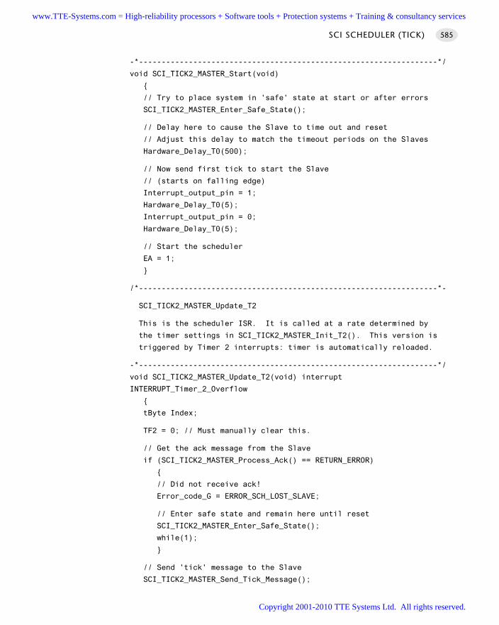
-*------------------------------------------------------------------*/
void SCI_TICK2_MASTER_Start(void)
// Try to place system in 'safe' state at start or after errors
SCI_TICK2_MASTER_Enter_Safe_State();
// Delay here to cause the Slave to time out and reset
// Adjust this delay to match the timeout periods on the Slaves
Hardware_Delay_T0(500);
// Now send first tick to start the Slave
// (starts on falling edge)
Interrupt_output_pin = 1;
Hardware_Delay_T0(5);
Interrupt_output_pin = 0;
Hardware_Delay_T0(5);
// Start the scheduler
EA = 1;
/*------------------------------------------------------------------*-
SCI_TICK2_MASTER_Update_T2
This is the scheduler ISR. It is called at a rate determined by
the timer settings in SCI_TICK2_MASTER_Init_T2(). This version is
triggered by Timer 2 interrupts: timer is automatically reloaded.
-*------------------------------------------------------------------*/
void SCI_TICK2_MASTER_Update_T2(void) interrupt
INTERRUPT_Timer_2_Overflow
tByte Index;
TF2 = 0; // Must manually clear this.
// Get the ack message from the Slave
if (SCI_TICK2_MASTER_Process_Ack() == RETURN_ERROR)
// Did not receive ack!
Error_code_G = ERROR_SCH_LOST_SLAVE;
// Enter safe state and remain here until reset
SCI_TICK2_MASTER_Enter_Safe_State();
while(1);
// Send 'tick' message to the Slave
SCI_TICK2_MASTER_Send_Tick_Message();
SCI SCHEDULER (TICK) 585
www.TTE-Systems.com = High-reliability processors + Software tools + Protection systems + Training & consultancy services
Copyright 2001-2010 TTE Systems Ltd. All rights reserved.
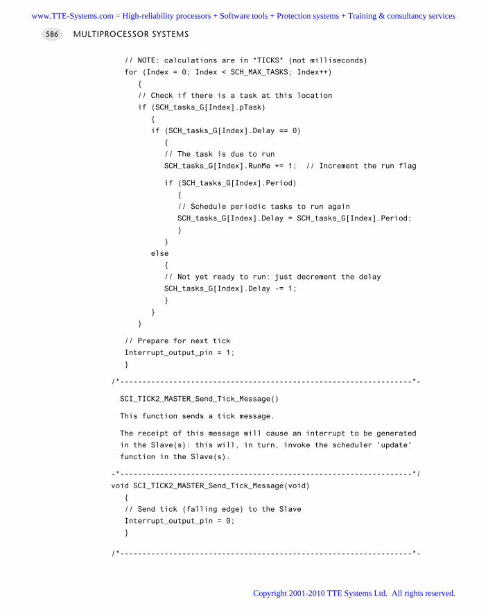
// NOTE: calculations are in *TICKS* (not milliseconds)
for (Index = 0; Index < SCH_MAX_TASKS; Index++)
// Check if there is a task at this location
if (SCH_tasks_G[Index].pTask)
if (SCH_tasks_G[Index].Delay == 0)
// The task is due to run
SCH_tasks_G[Index].RunMe += 1; // Increment the run flag
if (SCH_tasks_G[Index].Period)
// Schedule periodic tasks to run again
SCH_tasks_G[Index].Delay = SCH_tasks_G[Index].Period;
else
// Not yet ready to run: just decrement the delay
SCH_tasks_G[Index].Delay -= 1;
// Prepare for next tick
Interrupt_output_pin = 1;
/*------------------------------------------------------------------*-
SCI_TICK2_MASTER_Send_Tick_Message()
This function sends a tick message.
The receipt of this message will cause an interrupt to be generated
in the Slave(s): this will, in turn, invoke the scheduler 'update'
function in the Slave(s).
-*------------------------------------------------------------------*/
void SCI_TICK2_MASTER_Send_Tick_Message(void)
// Send tick (falling edge) to the Slave
Interrupt_output_pin = 0;
/*------------------------------------------------------------------*-
MULTIPROCESSOR SYSTEMS586
www.TTE-Systems.com = High-reliability processors + Software tools + Protection systems + Training & consultancy services
Copyright 2001-2010 TTE Systems Ltd. All rights reserved.
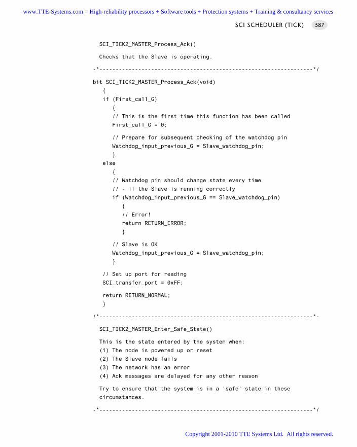
SCI_TICK2_MASTER_Process_Ack()
Checks that the Slave is operating.
-*------------------------------------------------------------------*/
bit SCI_TICK2_MASTER_Process_Ack(void)
if (First_call_G)
// This is the first time this function has been called
First_call_G = 0;
// Prepare for subsequent checking of the watchdog pin
Watchdog_input_previous_G = Slave_watchdog_pin;
else
// Watchdog pin should change state every time
// - if the Slave is running correctly
if (Watchdog_input_previous_G == Slave_watchdog_pin)
// Error!
return RETURN_ERROR;
// Slave is OK
Watchdog_input_previous_G = Slave_watchdog_pin;
// Set up port for reading
SCI_transfer_port = 0xFF;
return RETURN_NORMAL;
/*------------------------------------------------------------------*-
SCI_TICK2_MASTER_Enter_Safe_State()
This is the state entered by the system when:
(1) The node is powered up or reset
(2) The Slave node fails
(3) The network has an error
(4) Ack messages are delayed for any other reason
Try to ensure that the system is in a 'safe' state in these
circumstances.
-*------------------------------------------------------------------*/
SCI SCHEDULER (TICK) 587
www.TTE-Systems.com = High-reliability processors + Software tools + Protection systems + Training & consultancy services
Copyright 2001-2010 TTE Systems Ltd. All rights reserved.
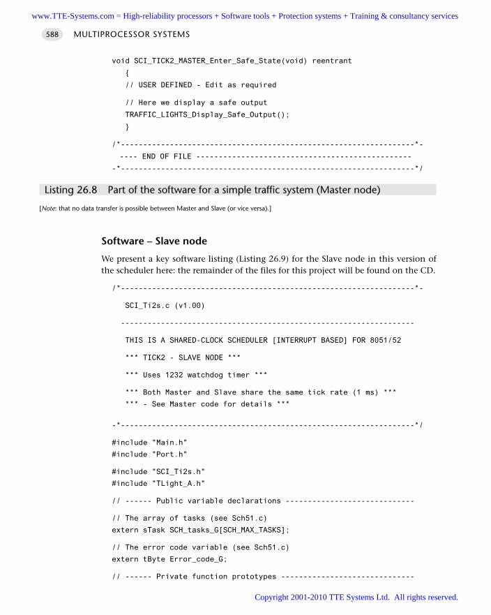
void SCI_TICK2_MASTER_Enter_Safe_State(void) reentrant
// USER DEFINED - Edit as required
// Here we display a safe output
TRAFFIC_LIGHTS_Display_Safe_Output();
/*------------------------------------------------------------------*-
---- END OF FILE ------------------------------------------------
-*------------------------------------------------------------------*/
Listing 26.8 Part of the software for a simple traffic system (Master node)
[Note: that no data transfer is possible between Master and Slave (or vice versa).]
Software – Slave node
We present a key software listing (Listing 26.9) for the Slave node in this version ofthe scheduler here: the remainder of the files for this project will be found on the CD.
/*------------------------------------------------------------------*-
SCI_Ti2s.c (v1.00)
------------------------------------------------------------------
THIS IS A SHARED-CLOCK SCHEDULER [INTERRUPT BASED] FOR 8051/52
*** TICK2 - SLAVE NODE ***
*** Uses 1232 watchdog timer ***
*** Both Master and Slave share the same tick rate (1 ms) ***
*** - See Master code for details ***
-*------------------------------------------------------------------*/
#include "Main.h"
#include "Port.h"
#include "SCI_Ti2s.h"
#include "TLight_A.h"
// ------ Public variable declarations -----------------------------
// The array of tasks (see Sch51.c)
extern sTask SCH_tasks_G[SCH_MAX_TASKS];
// The error code variable (see Sch51.c)
extern tByte Error_code_G;
// ------ Private function prototypes ------------------------------
MULTIPROCESSOR SYSTEMS588
www.TTE-Systems.com = High-reliability processors + Software tools + Protection systems + Training & consultancy services
Copyright 2001-2010 TTE Systems Ltd. All rights reserved.
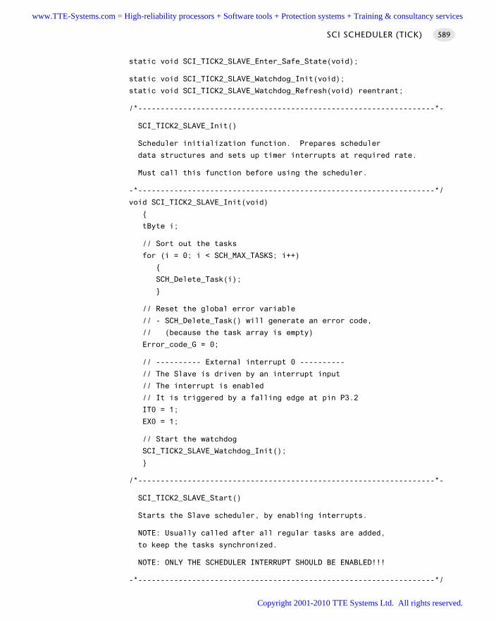
static void SCI_TICK2_SLAVE_Enter_Safe_State(void);
static void SCI_TICK2_SLAVE_Watchdog_Init(void);
static void SCI_TICK2_SLAVE_Watchdog_Refresh(void) reentrant;
/*------------------------------------------------------------------*-
SCI_TICK2_SLAVE_Init()
Scheduler initialization function. Prepares scheduler
data structures and sets up timer interrupts at required rate.
Must call this function before using the scheduler.
-*------------------------------------------------------------------*/
void SCI_TICK2_SLAVE_Init(void)
tByte i;
// Sort out the tasks
for (i = 0; i < SCH_MAX_TASKS; i++)
SCH_Delete_Task(i);
// Reset the global error variable
// - SCH_Delete_Task() will generate an error code,
// (because the task array is empty)
Error_code_G = 0;
// ---------- External interrupt 0 ----------
// The Slave is driven by an interrupt input
// The interrupt is enabled
// It is triggered by a falling edge at pin P3.2
IT0 = 1;
EX0 = 1;
// Start the watchdog
SCI_TICK2_SLAVE_Watchdog_Init();
/*------------------------------------------------------------------*-
SCI_TICK2_SLAVE_Start()
Starts the Slave scheduler, by enabling interrupts.
NOTE: Usually called after all regular tasks are added,
to keep the tasks synchronized.
NOTE: ONLY THE SCHEDULER INTERRUPT SHOULD BE ENABLED!!!
-*------------------------------------------------------------------*/
SCI SCHEDULER (TICK) 589
www.TTE-Systems.com = High-reliability processors + Software tools + Protection systems + Training & consultancy services
Copyright 2001-2010 TTE Systems Ltd. All rights reserved.
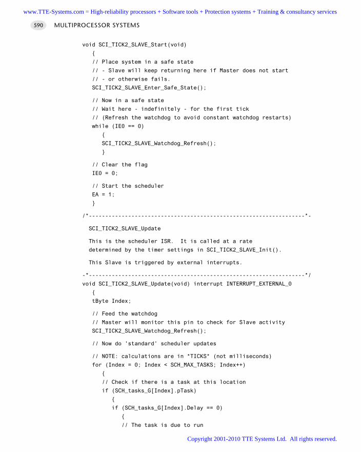
void SCI_TICK2_SLAVE_Start(void)
// Place system in a safe state
// - Slave will keep returning here if Master does not start
// - or otherwise fails.
SCI_TICK2_SLAVE_Enter_Safe_State();
// Now in a safe state
// Wait here - indefinitely - for the first tick
// (Refresh the watchdog to avoid constant watchdog restarts)
while (IE0 == 0)
SCI_TICK2_SLAVE_Watchdog_Refresh();
// Clear the flag
IE0 = 0;
// Start the scheduler
EA = 1;
/*------------------------------------------------------------------*-
SCI_TICK2_SLAVE_Update
This is the scheduler ISR. It is called at a rate
determined by the timer settings in SCI_TICK2_SLAVE_Init().
This Slave is triggered by external interrupts.
-*------------------------------------------------------------------*/
void SCI_TICK2_SLAVE_Update(void) interrupt INTERRUPT_EXTERNAL_0
tByte Index;
// Feed the watchdog
// Master will monitor this pin to check for Slave activity
SCI_TICK2_SLAVE_Watchdog_Refresh();
// Now do 'standard' scheduler updates
// NOTE: calculations are in *TICKS* (not milliseconds)
for (Index = 0; Index < SCH_MAX_TASKS; Index++)
// Check if there is a task at this location
if (SCH_tasks_G[Index].pTask)
if (SCH_tasks_G[Index].Delay == 0)
// The task is due to run
MULTIPROCESSOR SYSTEMS590
www.TTE-Systems.com = High-reliability processors + Software tools + Protection systems + Training & consultancy services
Copyright 2001-2010 TTE Systems Ltd. All rights reserved.
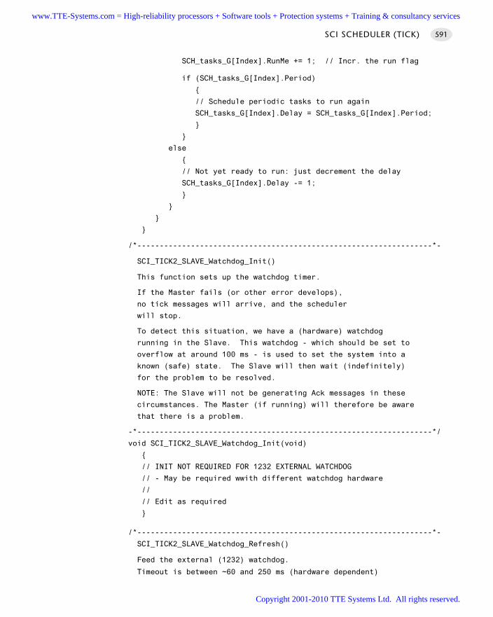
SCH_tasks_G[Index].RunMe += 1; // Incr. the run flag
if (SCH_tasks_G[Index].Period)
// Schedule periodic tasks to run again
SCH_tasks_G[Index].Delay = SCH_tasks_G[Index].Period;
else
// Not yet ready to run: just decrement the delay
SCH_tasks_G[Index].Delay -= 1;
/*------------------------------------------------------------------*-
SCI_TICK2_SLAVE_Watchdog_Init()
This function sets up the watchdog timer.
If the Master fails (or other error develops),
no tick messages will arrive, and the scheduler
will stop.
To detect this situation, we have a (hardware) watchdog
running in the Slave. This watchdog - which should be set to
overflow at around 100 ms - is used to set the system into a
known (safe) state. The Slave will then wait (indefinitely)
for the problem to be resolved.
NOTE: The Slave will not be generating Ack messages in these
circumstances. The Master (if running) will therefore be aware
that there is a problem.
-*------------------------------------------------------------------*/
void SCI_TICK2_SLAVE_Watchdog_Init(void)
// INIT NOT REQUIRED FOR 1232 EXTERNAL WATCHDOG
// - May be required wwith different watchdog hardware
//
// Edit as required
/*------------------------------------------------------------------*-
SCI_TICK2_SLAVE_Watchdog_Refresh()
Feed the external (1232) watchdog.
Timeout is between ~60 and 250 ms (hardware dependent)
SCI SCHEDULER (TICK) 591
www.TTE-Systems.com = High-reliability processors + Software tools + Protection systems + Training & consultancy services
Copyright 2001-2010 TTE Systems Ltd. All rights reserved.
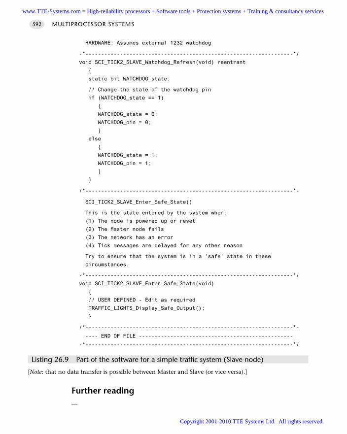
HARDWARE: Assumes external 1232 watchdog
-*------------------------------------------------------------------*/
void SCI_TICK2_SLAVE_Watchdog_Refresh(void) reentrant
static bit WATCHDOG_state;
// Change the state of the watchdog pin
if (WATCHDOG_state == 1)
WATCHDOG_state = 0;
WATCHDOG_pin = 0;
else
WATCHDOG_state = 1;
WATCHDOG_pin = 1;
/*------------------------------------------------------------------*-
SCI_TICK2_SLAVE_Enter_Safe_State()
This is the state entered by the system when:
(1) The node is powered up or reset
(2) The Master node fails
(3) The network has an error
(4) Tick messages are delayed for any other reason
Try to ensure that the system is in a 'safe' state in these
circumstances.
-*------------------------------------------------------------------*/
void SCI_TICK2_SLAVE_Enter_Safe_State(void)
// USER DEFINED - Edit as required
TRAFFIC_LIGHTS_Display_Safe_Output();
/*------------------------------------------------------------------*-
---- END OF FILE -------------------------------------------------
-*------------------------------------------------------------------*/
Listing 26.9 Part of the software for a simple traffic system (Slave node)
[Note: that no data transfer is possible between Master and Slave (or vice versa).]
Further reading—
MULTIPROCESSOR SYSTEMS592
www.TTE-Systems.com = High-reliability processors + Software tools + Protection systems + Training & consultancy services
Copyright 2001-2010 TTE Systems Ltd. All rights reserved.
SCI SCHEDULER (DATA)
Context You are developing an embedded application using more than one 8051 micro-
controller.
The application has a time-triggered architecture, constructed using a scheduler.
ProblemHow do you schedule tasks on (and transfer data over) a local network of two 8051microcontrollers connected together via an interrupt link?
BackgroundRefer to Chapter 25 for an introduction to shared-clock schedulers.
SolutionS C I S C H E D U L E R ( T I C K ) [page 554] is a simple, flexible and reliable scheduler.However, use of such a scheduler means that the system must be partitioned so thatthe tasks running on the Master and Slave nodes do not need to communicate, sincethis simple scheduler does not support data transfer between nodes.
S C I S C H E D U L E R (D ATA) builds on S C I S C H E D U L E R (T I C K) and provides a facility fortransferring data between nodes. The basic hardware framework used to provide thisbehaviour is illustrated in Figure 26.11.
Like S C I S C H E D U L E R (T I C K) , this scheduler keeps the tasks on the two controllerssynchronized and allows both the Master and Slave nodes to detect when the othernode, or the communication channel, has failed.
However, in addition, this scheduler allows one byte of information to be trans-ferred between the Master and the Slave with each ‘tick’ message; similarly, one byteof data is transferred between the Slave and the Master with each ‘ack’ message.
A complete code listing is given later, to illustrate how the data are transferred.
Hardware resource implicationsLike S C I S C H E D U L E R ( T I C K ) , this is an efficient scheduler. The additional softwareload in the Master node – compared with a standard co-operative scheduler – is toosmall to measure.
However, this scheduler requires use of two ports (one on the Master, one on theSlave) to support the data transfers, in addition to the two port pins (on each micro-controller) used for the ‘tick’ and ‘ack’ signals.
SCI SCHEDULER (DATA) 593
www.TTE-Systems.com = High-reliability processors + Software tools + Protection systems + Training & consultancy services
Copyright 2001-2010 TTE Systems Ltd. All rights reserved.
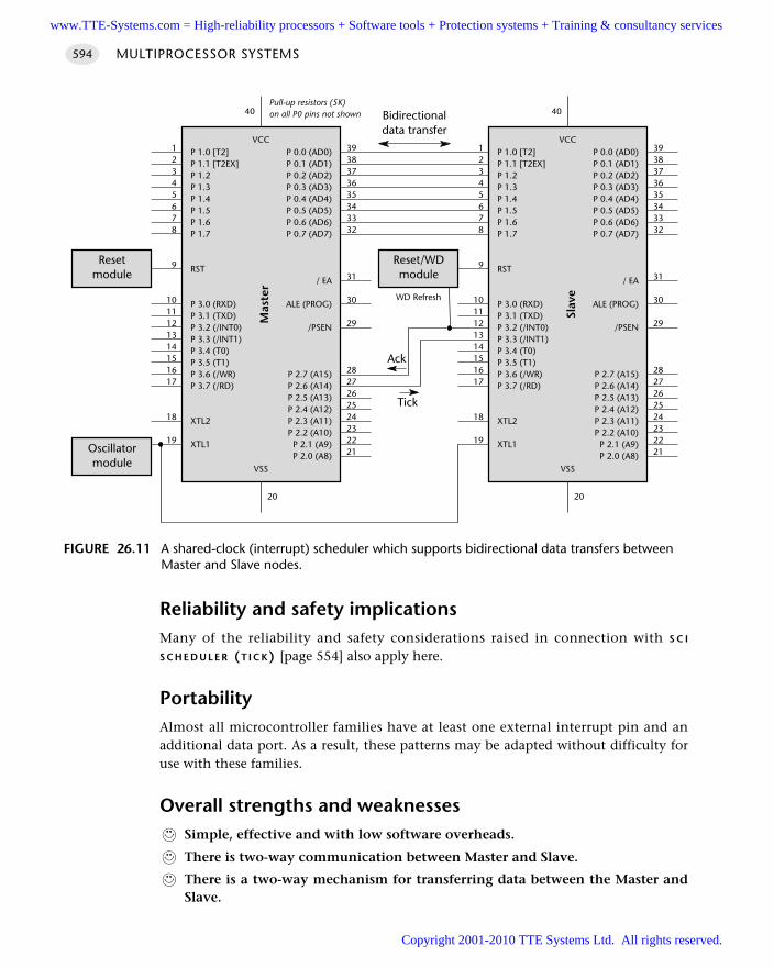
Reliability and safety implicationsMany of the reliability and safety considerations raised in connection with S C I
S C H E D U L E R (T I C K) [page 554] also apply here.
PortabilityAlmost all microcontroller families have at least one external interrupt pin and anadditional data port. As a result, these patterns may be adapted without difficulty foruse with these families.
Overall strengths and weaknessesSimple, effective and with low software overheads.
There is two-way communication between Master and Slave.
There is a two-way mechanism for transferring data between the Master andSlave.
MULTIPROCESSOR SYSTEMS594
FIGURE 26.11 A shared-clock (interrupt) scheduler which supports bidirectional data transfers betweenMaster and Slave nodes.
P 1.0 [T2]P 1.1 [T2EX]P 1.2P 1.3P 1.4P 1.5P 1.6P 1.7
RST
P 3.0 (RXD)P 3.1 (TXD)P 3.2 (/INT0)P 3.3 (/INT1)P 3.4 (T0)P 3.5 (T1)P 3.6 (/WR)P 3.7 (/RD)
XTL2
XTL1
P 0.0 (AD0)P 0.1 (AD1)P 0.2 (AD2)P 0.3 (AD3)P 0.4 (AD4)P 0.5 (AD5)P 0.6 (AD6)P 0.7 (AD7)
/ EA
ALE (PROG)
/PSEN
P 2.7 (A15)P 2.6 (A14)P 2.5 (A13)P 2.4 (A12)P 2.3 (A11)P 2.2 (A10)
P 2.1 (A9)P 2.0 (A8)
VCC
Mas
ter
VSS
3938373635343332
31
30
29
2827262524232221
12345678
9
1011121314151617
18
19
20
40
P 1.0 [T2]P 1.1 [T2EX]P 1.2P 1.3P 1.4P 1.5P 1.6P 1.7
RST
P 3.0 (RXD)P 3.1 (TXD)P 3.2 (/INT0)P 3.3 (/INT1)P 3.4 (T0)P 3.5 (T1)P 3.6 (/WR)P 3.7 (/RD)
XTL2
XTL1
P 0.0 (AD0)P 0.1 (AD1)P 0.2 (AD2)P 0.3 (AD3)P 0.4 (AD4)P 0.5 (AD5)P 0.6 (AD6)P 0.7 (AD7)
/ EA
ALE (PROG)
/PSEN
P 2.7 (A15)P 2.6 (A14)P 2.5 (A13)P 2.4 (A12)P 2.3 (A11)P 2.2 (A10)
P 2.1 (A9)P 2.0 (A8)
VCC
Slav
e
VSS
3938373635343332
31
30
29
2827262524232221
12345678
9
1011121314151617
18
19
20
40
Reset/WDmodule
WD Refresh
Oscillatormodule
Resetmodule
Ack
Tick
Pull-up resistors (5K)on all P0 pins not shown Bidirectional
data transfer
www.TTE-Systems.com = High-reliability processors + Software tools + Protection systems + Training & consultancy services
Copyright 2001-2010 TTE Systems Ltd. All rights reserved.
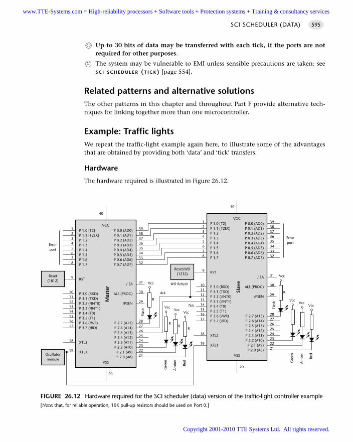
Up to 30 bits of data may be transferred with each tick, if the ports are notrequired for other purposes.
The system may be vulnerable to EMI unless sensible precautions are taken: seeS C I S C H E D U L E R (T I C K) [page 554].
Related patterns and alternative solutionsThe other patterns in this chapter and throughout Part F provide alternative tech-niques for linking together more than one microcontroller.
Example: Traffic lightsWe repeat the traffic-light example again here, to illustrate some of the advantagesthat are obtained by providing both ‘data’ and ‘tick’ transfers.
Hardware
The hardware required is illustrated in Figure 26.12.
SCI SCHEDULER (DATA) 595
FIGURE 26.12 Hardware required for the SCI scheduler (data) version of the traffic-light controller example[Note: that, for reliable operation, 10K pull-up resistors should be used on Port 0.]
VccVcc
Vcc
P 1.0 [T2]P 1.1 [T2EX]P 1.2P 1.3P 1.4P 1.5P 1.6P 1.7
RST
P 3.0 (RXD)P 3.1 (TXD)P 3.2 (/INT0)P 3.3 (/INT1)P 3.4 (T0)P 3.5 (T1)P 3.6 (/WR)P 3.7 (/RD)
XTL2
XTL1
P 0.0 (AD0)P 0.1 (AD1)P 0.2 (AD2)P 0.3 (AD3)P 0.4 (AD4)P 0.5 (AD5)P 0.6 (AD6)P 0.7 (AD7)
/ EA
ALE (PROG)
/PSEN
P 2.7 (A15)P 2.6 (A14)P 2.5 (A13)P 2.4 (A12)P 2.3 (A11)P 2.2 (A10)P 2.1 (A9)P 2.0 (A8)
VCC
Mas
ter
VSS
3938373635343332
31
30
29
2827262524232221
12345678
9
1011121314151617
18
19
20
40
P 1.0 [T2]P 1.1 [T2EX]P 1.2P 1.3P 1.4P 1.5P 1.6P 1.7
RST
P 3.0 (RXD)P 3.1 (TXD)P 3.2 (/INT0)P 3.3 (/INT1)P 3.4 (T0)P 3.5 (T1)P 3.6 (/WR)P 3.7 (/RD)
XTL2
XTL1
P 0.0 (AD0)P 0.1 (AD1)P 0.2 (AD2)P 0.3 (AD3)P 0.4 (AD4)P 0.5 (AD5)P 0.6 (AD6)P 0.7 (AD7)
/ EA
ALE (PROG)
/PSEN
P 2.7 (A15)P 2.6 (A14)P 2.5 (A13)P 2.4 (A12)P 2.3 (A11)P 2.2 (A10)P 2.1 (A9)P 2.0 (A8)
VCC
Slav
e
VSS
3938373635343332
31
30
29
2827262524232221
12345678
9
1011121314151617
18
19
20
40
Reset/WD(1232)
WD Refresh
Oscillatormodule
Reset(1812)
VccVcc
Vcc
Errorport
RR
R
Red
Am
ber
Gre
en
Vcc
R
Tick
Flas
h
Errorport
Red
Am
ber
Gre
en
Vcc
R
Flas
h
Ack
www.TTE-Systems.com = High-reliability processors + Software tools + Protection systems + Training & consultancy services
Copyright 2001-2010 TTE Systems Ltd. All rights reserved.
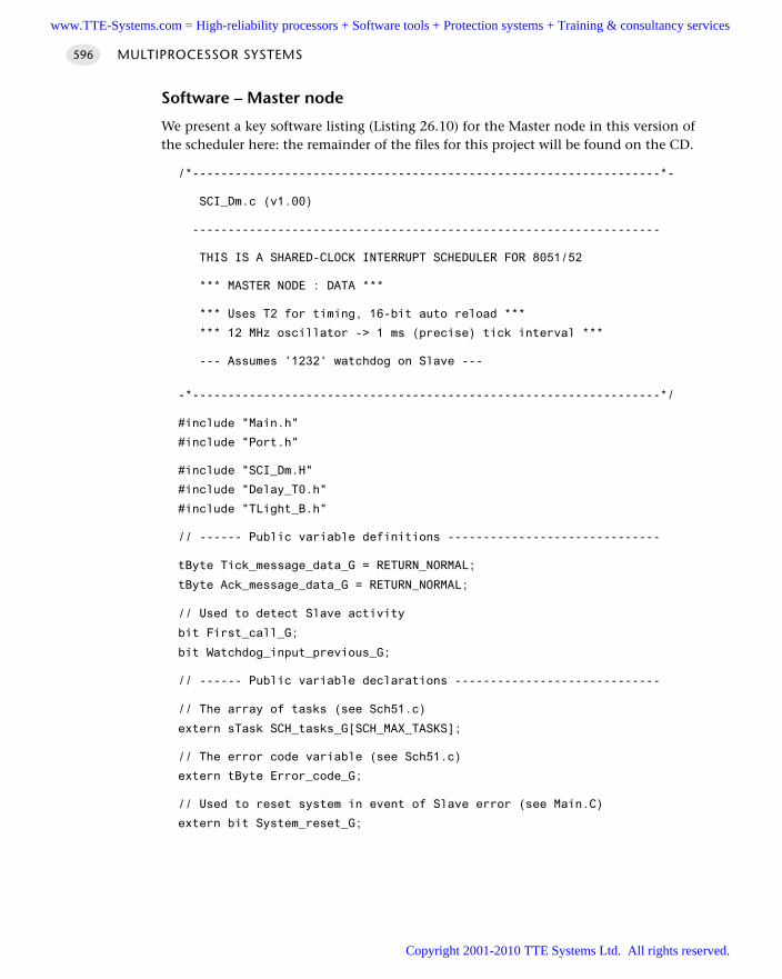
Software – Master node
We present a key software listing (Listing 26.10) for the Master node in this version ofthe scheduler here: the remainder of the files for this project will be found on the CD.
/*------------------------------------------------------------------*-
SCI_Dm.c (v1.00)
------------------------------------------------------------------
THIS IS A SHARED-CLOCK INTERRUPT SCHEDULER FOR 8051/52
*** MASTER NODE : DATA ***
*** Uses T2 for timing, 16-bit auto reload ***
*** 12 MHz oscillator -> 1 ms (precise) tick interval ***
--- Assumes '1232' watchdog on Slave ---
-*------------------------------------------------------------------*/
#include "Main.h"
#include "Port.h"
#include "SCI_Dm.H"
#include "Delay_T0.h"
#include "TLight_B.h"
// ------ Public variable definitions ------------------------------
tByte Tick_message_data_G = RETURN_NORMAL;
tByte Ack_message_data_G = RETURN_NORMAL;
// Used to detect Slave activity
bit First_call_G;
bit Watchdog_input_previous_G;
// ------ Public variable declarations -----------------------------
// The array of tasks (see Sch51.c)
extern sTask SCH_tasks_G[SCH_MAX_TASKS];
// The error code variable (see Sch51.c)
extern tByte Error_code_G;
// Used to reset system in event of Slave error (see Main.C)
extern bit System_reset_G;
MULTIPROCESSOR SYSTEMS596
www.TTE-Systems.com = High-reliability processors + Software tools + Protection systems + Training & consultancy services
Copyright 2001-2010 TTE Systems Ltd. All rights reserved.
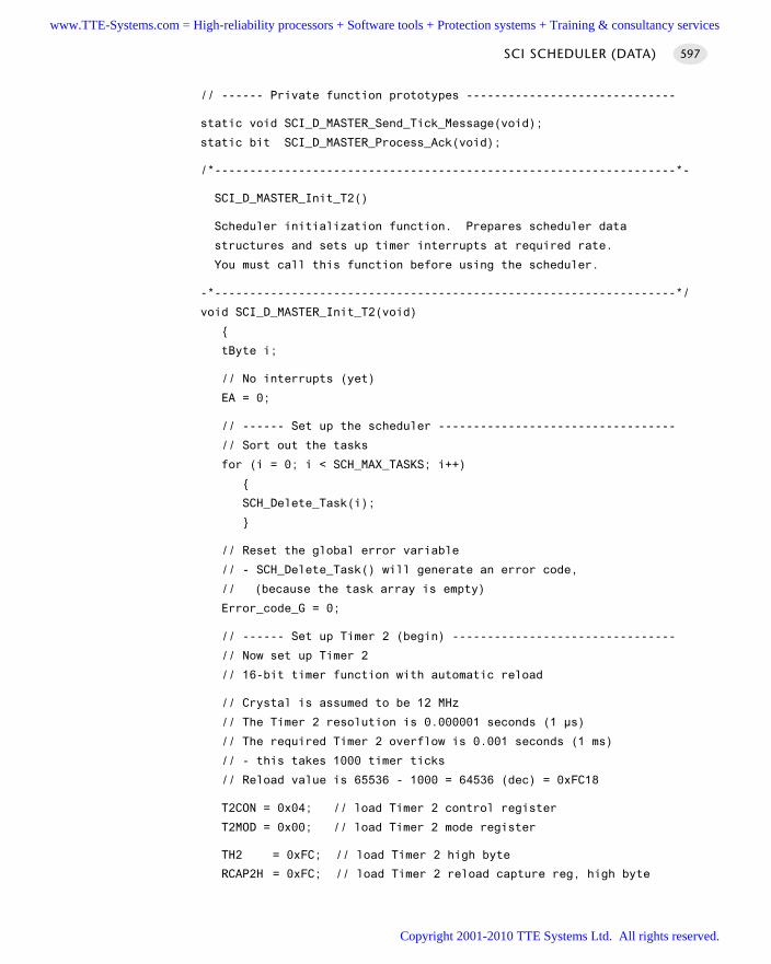
// ------ Private function prototypes ------------------------------
static void SCI_D_MASTER_Send_Tick_Message(void);
static bit SCI_D_MASTER_Process_Ack(void);
/*------------------------------------------------------------------*-
SCI_D_MASTER_Init_T2()
Scheduler initialization function. Prepares scheduler data
structures and sets up timer interrupts at required rate.
You must call this function before using the scheduler.
-*------------------------------------------------------------------*/
void SCI_D_MASTER_Init_T2(void)
tByte i;
// No interrupts (yet)
EA = 0;
// ------ Set up the scheduler ----------------------------------
// Sort out the tasks
for (i = 0; i < SCH_MAX_TASKS; i++)
SCH_Delete_Task(i);
// Reset the global error variable
// - SCH_Delete_Task() will generate an error code,
// (because the task array is empty)
Error_code_G = 0;
// ------ Set up Timer 2 (begin) --------------------------------
// Now set up Timer 2
// 16-bit timer function with automatic reload
// Crystal is assumed to be 12 MHz
// The Timer 2 resolution is 0.000001 seconds (1 µs)
// The required Timer 2 overflow is 0.001 seconds (1 ms)
// - this takes 1000 timer ticks
// Reload value is 65536 - 1000 = 64536 (dec) = 0xFC18
T2CON = 0x04; // load Timer 2 control register
T2MOD = 0x00; // load Timer 2 mode register
TH2 = 0xFC; // load Timer 2 high byte
RCAP2H = 0xFC; // load Timer 2 reload capture reg, high byte
SCI SCHEDULER (DATA) 597
www.TTE-Systems.com = High-reliability processors + Software tools + Protection systems + Training & consultancy services
Copyright 2001-2010 TTE Systems Ltd. All rights reserved.
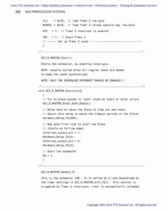
TL2 = 0x18; // load Timer 2 low byte
RCAP2L = 0x18; // load Timer 2 reload capture reg, low byte
ET2 = 1; // Timer 2 interrupt is enabled
TR2 = 1; // Start Timer 2
// ------ Set up Timer 2 (end) ----------------------------------
/*------------------------------------------------------------------*-
SCI_D_MASTER_Start()
Starts the scheduler, by enabling interrupts.
NOTE: Usually called after all regular tasks are added,
to keep the tasks synchronized.
NOTE: ONLY THE SCHEDULER INTERRUPT SHOULD BE ENABLED!!!
-*------------------------------------------------------------------*/
void SCI_D_MASTER_Start(void)
// Try to place system in 'safe' state at start or after errors
SCI_D_MASTER_Enter_Safe_State();
// Delay here to cause the Slave to time out and reset
// Adjust this delay to match the timeout periods on the Slaves
Hardware_Delay_T0(500);
// Now send first tick to start the Slave
// (starts on falling edge)
Interrupt_output_pin = 1;
Hardware_Delay_T0(5);
Interrupt_output_pin = 0;
Hardware_Delay_T0(5);
// Start the scheduler
EA = 1;
/*------------------------------------------------------------------*-
SCI_D_MASTER_Update_T2
This is the scheduler ISR. It is called at a rate determined by
the timer settings in SCI_D_MASTER_Init_T2(). This version is
triggered by Timer 2 interrupts: timer is automatically reloaded.
MULTIPROCESSOR SYSTEMS598
www.TTE-Systems.com = High-reliability processors + Software tools + Protection systems + Training & consultancy services
Copyright 2001-2010 TTE Systems Ltd. All rights reserved.
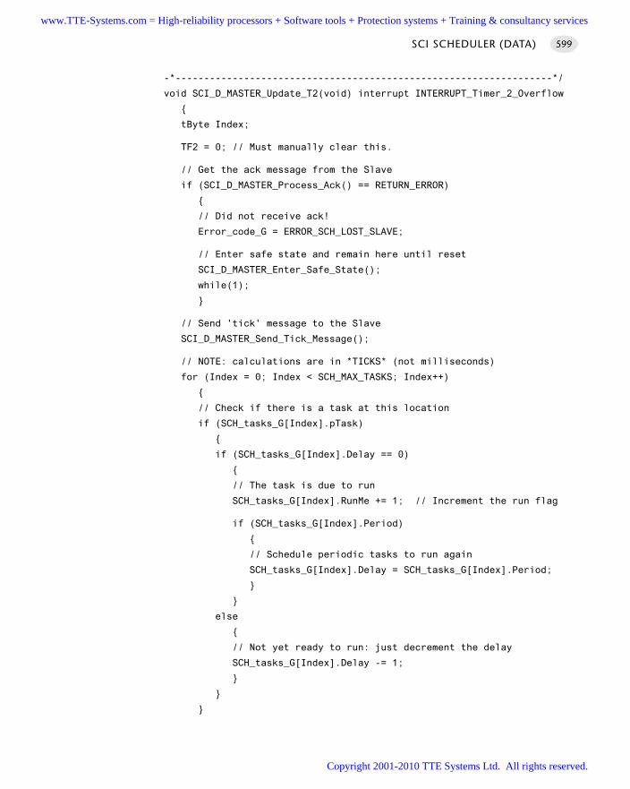
-*------------------------------------------------------------------*/
void SCI_D_MASTER_Update_T2(void) interrupt INTERRUPT_Timer_2_Overflow
tByte Index;
TF2 = 0; // Must manually clear this.
// Get the ack message from the Slave
if (SCI_D_MASTER_Process_Ack() == RETURN_ERROR)
// Did not receive ack!
Error_code_G = ERROR_SCH_LOST_SLAVE;
// Enter safe state and remain here until reset
SCI_D_MASTER_Enter_Safe_State();
while(1);
// Send 'tick' message to the Slave
SCI_D_MASTER_Send_Tick_Message();
// NOTE: calculations are in *TICKS* (not milliseconds)
for (Index = 0; Index < SCH_MAX_TASKS; Index++)
// Check if there is a task at this location
if (SCH_tasks_G[Index].pTask)
if (SCH_tasks_G[Index].Delay == 0)
// The task is due to run
SCH_tasks_G[Index].RunMe += 1; // Increment the run flag
if (SCH_tasks_G[Index].Period)
// Schedule periodic tasks to run again
SCH_tasks_G[Index].Delay = SCH_tasks_G[Index].Period;
else
// Not yet ready to run: just decrement the delay
SCH_tasks_G[Index].Delay -= 1;
SCI SCHEDULER (DATA) 599
www.TTE-Systems.com = High-reliability processors + Software tools + Protection systems + Training & consultancy services
Copyright 2001-2010 TTE Systems Ltd. All rights reserved.
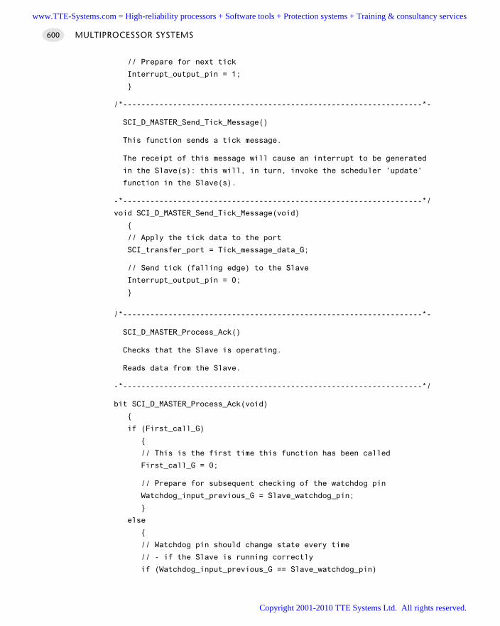
// Prepare for next tick
Interrupt_output_pin = 1;
/*------------------------------------------------------------------*-
SCI_D_MASTER_Send_Tick_Message()
This function sends a tick message.
The receipt of this message will cause an interrupt to be generated
in the Slave(s): this will, in turn, invoke the scheduler 'update'
function in the Slave(s).
-*------------------------------------------------------------------*/
void SCI_D_MASTER_Send_Tick_Message(void)
// Apply the tick data to the port
SCI_transfer_port = Tick_message_data_G;
// Send tick (falling edge) to the Slave
Interrupt_output_pin = 0;
/*------------------------------------------------------------------*-
SCI_D_MASTER_Process_Ack()
Checks that the Slave is operating.
Reads data from the Slave.
-*------------------------------------------------------------------*/
bit SCI_D_MASTER_Process_Ack(void)
if (First_call_G)
// This is the first time this function has been called
First_call_G = 0;
// Prepare for subsequent checking of the watchdog pin
Watchdog_input_previous_G = Slave_watchdog_pin;
else
// Watchdog pin should change state every time
// - if the Slave is running correctly
if (Watchdog_input_previous_G == Slave_watchdog_pin)
MULTIPROCESSOR SYSTEMS600
www.TTE-Systems.com = High-reliability processors + Software tools + Protection systems + Training & consultancy services
Copyright 2001-2010 TTE Systems Ltd. All rights reserved.
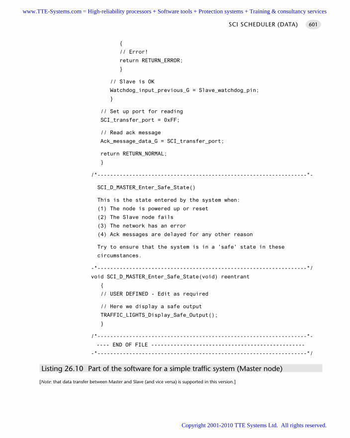
// Error!
return RETURN_ERROR;
// Slave is OK
Watchdog_input_previous_G = Slave_watchdog_pin;
// Set up port for reading
SCI_transfer_port = 0xFF;
// Read ack message
Ack_message_data_G = SCI_transfer_port;
return RETURN_NORMAL;
/*------------------------------------------------------------------*-
SCI_D_MASTER_Enter_Safe_State()
This is the state entered by the system when:
(1) The node is powered up or reset
(2) The Slave node fails
(3) The network has an error
(4) Ack messages are delayed for any other reason
Try to ensure that the system is in a 'safe' state in these
circumstances.
-*------------------------------------------------------------------*/
void SCI_D_MASTER_Enter_Safe_State(void) reentrant
// USER DEFINED - Edit as required
// Here we display a safe output
TRAFFIC_LIGHTS_Display_Safe_Output();
/*------------------------------------------------------------------*-
---- END OF FILE ------------------------------------------------
-*------------------------------------------------------------------*/
Listing 26.10 Part of the software for a simple traffic system (Master node)
[Note: that data transfer between Master and Slave (and vice versa) is supported in this version.]
SCI SCHEDULER (DATA) 601
www.TTE-Systems.com = High-reliability processors + Software tools + Protection systems + Training & consultancy services
Copyright 2001-2010 TTE Systems Ltd. All rights reserved.
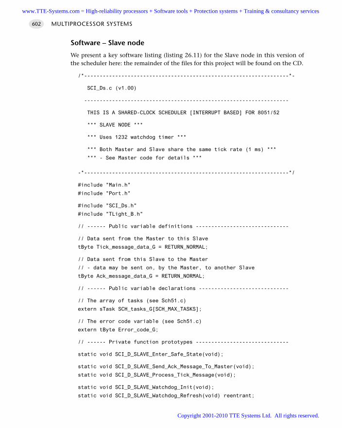
Software – Slave node
We present a key software listing (listing 26.11) for the Slave node in this version ofthe scheduler here: the remainder of the files for this project will be found on the CD.
/*------------------------------------------------------------------*-
SCI_Ds.c (v1.00)
------------------------------------------------------------------
THIS IS A SHARED-CLOCK SCHEDULER [INTERRUPT BASED] FOR 8051/52
*** SLAVE NODE ***
*** Uses 1232 watchdog timer ***
*** Both Master and Slave share the same tick rate (1 ms) ***
*** - See Master code for details ***
-*------------------------------------------------------------------*/
#include "Main.h"
#include "Port.h"
#include "SCI_Ds.h"
#include "TLight_B.h"
// ------ Public variable definitions ------------------------------
// Data sent from the Master to this Slave
tByte Tick_message_data_G = RETURN_NORMAL;
// Data sent from this Slave to the Master
// - data may be sent on, by the Master, to another Slave
tByte Ack_message_data_G = RETURN_NORMAL;
// ------ Public variable declarations -----------------------------
// The array of tasks (see Sch51.c)
extern sTask SCH_tasks_G[SCH_MAX_TASKS];
// The error code variable (see Sch51.c)
extern tByte Error_code_G;
// ------ Private function prototypes ------------------------------
static void SCI_D_SLAVE_Enter_Safe_State(void);
static void SCI_D_SLAVE_Send_Ack_Message_To_Master(void);
static void SCI_D_SLAVE_Process_Tick_Message(void);
static void SCI_D_SLAVE_Watchdog_Init(void);
static void SCI_D_SLAVE_Watchdog_Refresh(void) reentrant;
MULTIPROCESSOR SYSTEMS602
www.TTE-Systems.com = High-reliability processors + Software tools + Protection systems + Training & consultancy services
Copyright 2001-2010 TTE Systems Ltd. All rights reserved.
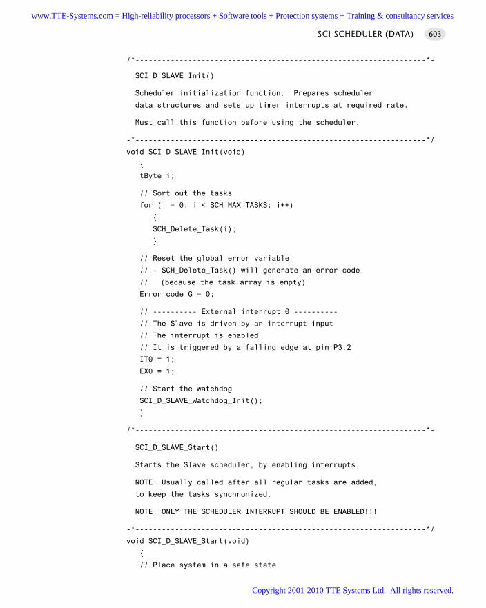
/*------------------------------------------------------------------*-
SCI_D_SLAVE_Init()
Scheduler initialization function. Prepares scheduler
data structures and sets up timer interrupts at required rate.
Must call this function before using the scheduler.
-*------------------------------------------------------------------*/
void SCI_D_SLAVE_Init(void)
tByte i;
// Sort out the tasks
for (i = 0; i < SCH_MAX_TASKS; i++)
SCH_Delete_Task(i);
// Reset the global error variable
// - SCH_Delete_Task() will generate an error code,
// (because the task array is empty)
Error_code_G = 0;
// ---------- External interrupt 0 ----------
// The Slave is driven by an interrupt input
// The interrupt is enabled
// It is triggered by a falling edge at pin P3.2
IT0 = 1;
EX0 = 1;
// Start the watchdog
SCI_D_SLAVE_Watchdog_Init();
/*------------------------------------------------------------------*-
SCI_D_SLAVE_Start()
Starts the Slave scheduler, by enabling interrupts.
NOTE: Usually called after all regular tasks are added,
to keep the tasks synchronized.
NOTE: ONLY THE SCHEDULER INTERRUPT SHOULD BE ENABLED!!!
-*------------------------------------------------------------------*/
void SCI_D_SLAVE_Start(void)
// Place system in a safe state
SCI SCHEDULER (DATA) 603
www.TTE-Systems.com = High-reliability processors + Software tools + Protection systems + Training & consultancy services
Copyright 2001-2010 TTE Systems Ltd. All rights reserved.
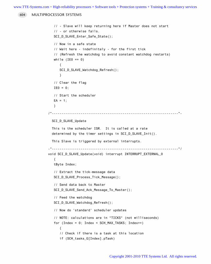
// - Slave will keep returning here if Master does not start
// - or otherwise fails.
SCI_D_SLAVE_Enter_Safe_State();
// Now in a safe state
// Wait here - indefinitely - for the first tick
// (Refresh the watchdog to avoid constant watchdog restarts)
while (IE0 == 0)
SCI_D_SLAVE_Watchdog_Refresh();
// Clear the flag
IE0 = 0;
// Start the scheduler
EA = 1;
/*------------------------------------------------------------------*-
SCI_D_SLAVE_Update
This is the scheduler ISR. It is called at a rate
determined by the timer settings in SCI_D_SLAVE_Init().
This Slave is triggered by external interrupts.
-*------------------------------------------------------------------*/
void SCI_D_SLAVE_Update(void) interrupt INTERRUPT_EXTERNAL_0
tByte Index;
// Extract the tick-message data
SCI_D_SLAVE_Process_Tick_Message();
// Send data back to Master
SCI_D_SLAVE_Send_Ack_Message_To_Master();
// Feed the watchdog
SCI_D_SLAVE_Watchdog_Refresh();
// Now do 'standard' scheduler updates
// NOTE: calculations are in *TICKS* (not milliseconds)
for (Index = 0; Index < SCH_MAX_TASKS; Index++)
// Check if there is a task at this location
if (SCH_tasks_G[Index].pTask)
MULTIPROCESSOR SYSTEMS604
www.TTE-Systems.com = High-reliability processors + Software tools + Protection systems + Training & consultancy services
Copyright 2001-2010 TTE Systems Ltd. All rights reserved.
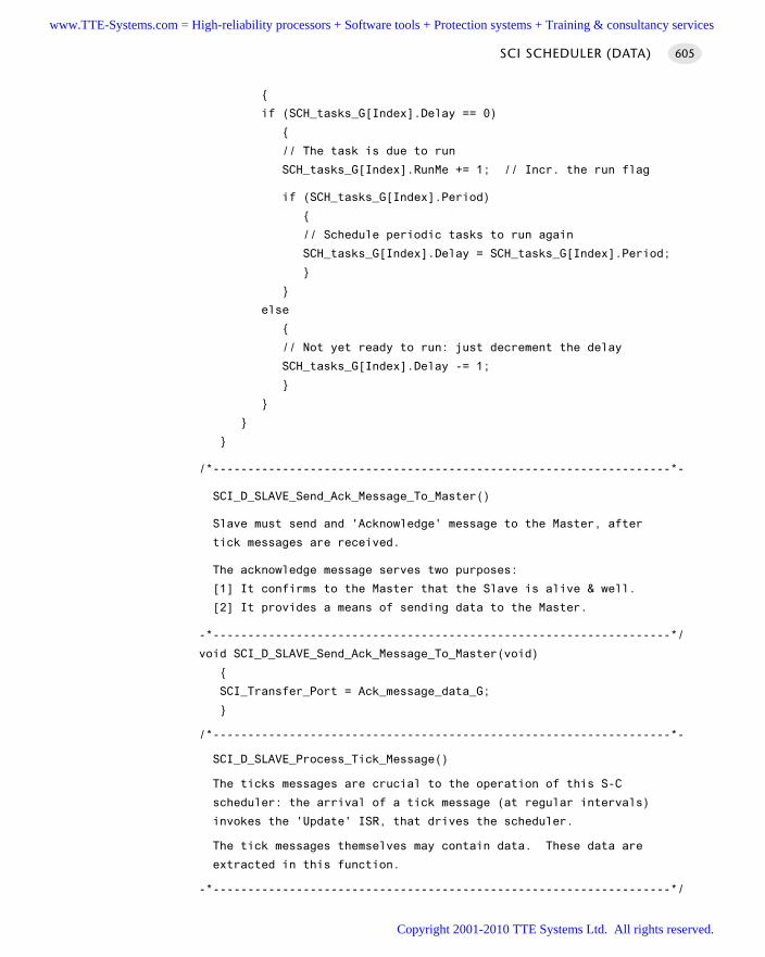
if (SCH_tasks_G[Index].Delay == 0)
// The task is due to run
SCH_tasks_G[Index].RunMe += 1; // Incr. the run flag
if (SCH_tasks_G[Index].Period)
// Schedule periodic tasks to run again
SCH_tasks_G[Index].Delay = SCH_tasks_G[Index].Period;
else
// Not yet ready to run: just decrement the delay
SCH_tasks_G[Index].Delay -= 1;
/*------------------------------------------------------------------*-
SCI_D_SLAVE_Send_Ack_Message_To_Master()
Slave must send and 'Acknowledge' message to the Master, after
tick messages are received.
The acknowledge message serves two purposes:
[1] It confirms to the Master that the Slave is alive & well.
[2] It provides a means of sending data to the Master.
-*------------------------------------------------------------------*/
void SCI_D_SLAVE_Send_Ack_Message_To_Master(void)
SCI_Transfer_Port = Ack_message_data_G;
/*------------------------------------------------------------------*-
SCI_D_SLAVE_Process_Tick_Message()
The ticks messages are crucial to the operation of this S-C
scheduler: the arrival of a tick message (at regular intervals)
invokes the 'Update' ISR, that drives the scheduler.
The tick messages themselves may contain data. These data are
extracted in this function.
-*------------------------------------------------------------------*/
SCI SCHEDULER (DATA) 605
www.TTE-Systems.com = High-reliability processors + Software tools + Protection systems + Training & consultancy services
Copyright 2001-2010 TTE Systems Ltd. All rights reserved.
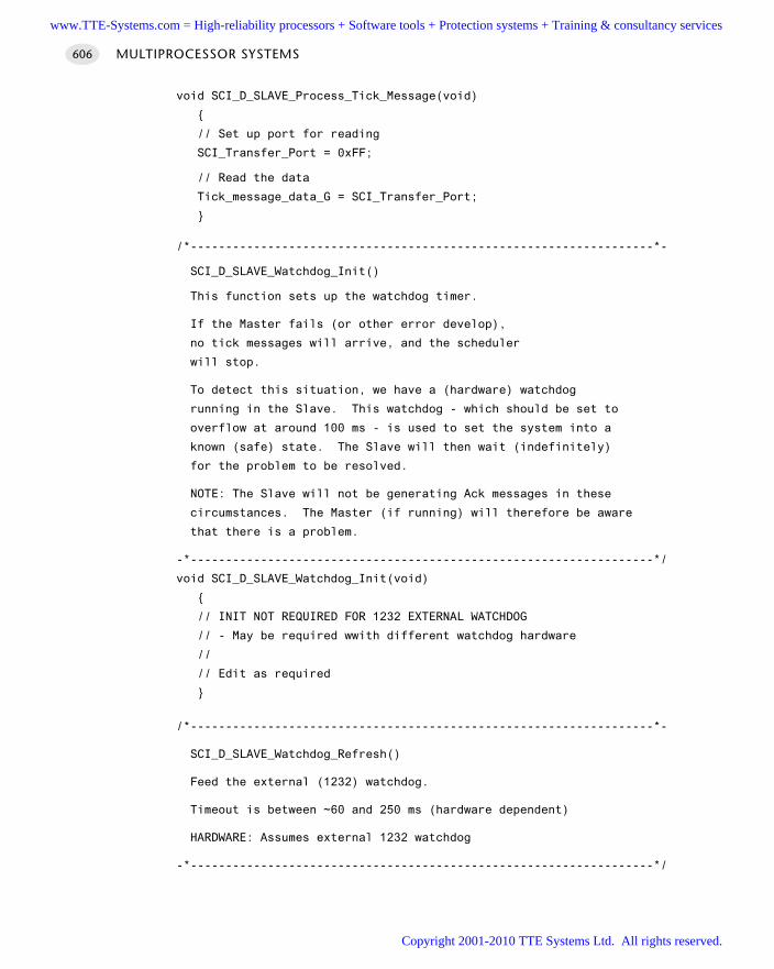
void SCI_D_SLAVE_Process_Tick_Message(void)
// Set up port for reading
SCI_Transfer_Port = 0xFF;
// Read the data
Tick_message_data_G = SCI_Transfer_Port;
/*------------------------------------------------------------------*-
SCI_D_SLAVE_Watchdog_Init()
This function sets up the watchdog timer.
If the Master fails (or other error develop),
no tick messages will arrive, and the scheduler
will stop.
To detect this situation, we have a (hardware) watchdog
running in the Slave. This watchdog - which should be set to
overflow at around 100 ms - is used to set the system into a
known (safe) state. The Slave will then wait (indefinitely)
for the problem to be resolved.
NOTE: The Slave will not be generating Ack messages in these
circumstances. The Master (if running) will therefore be aware
that there is a problem.
-*------------------------------------------------------------------*/
void SCI_D_SLAVE_Watchdog_Init(void)
// INIT NOT REQUIRED FOR 1232 EXTERNAL WATCHDOG
// - May be required wwith different watchdog hardware
//
// Edit as required
/*------------------------------------------------------------------*-
SCI_D_SLAVE_Watchdog_Refresh()
Feed the external (1232) watchdog.
Timeout is between ~60 and 250 ms (hardware dependent)
HARDWARE: Assumes external 1232 watchdog
-*------------------------------------------------------------------*/
MULTIPROCESSOR SYSTEMS606
www.TTE-Systems.com = High-reliability processors + Software tools + Protection systems + Training & consultancy services
Copyright 2001-2010 TTE Systems Ltd. All rights reserved.
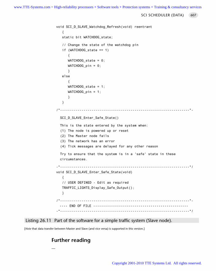
void SCI_D_SLAVE_Watchdog_Refresh(void) reentrant
static bit WATCHDOG_state;
// Change the state of the watchdog pin
if (WATCHDOG_state == 1)
WATCHDOG_state = 0;
WATCHDOG_pin = 0;
else
WATCHDOG_state = 1;
WATCHDOG_pin = 1;
/*------------------------------------------------------------------*-
SCI_D_SLAVE_Enter_Safe_State()
This is the state entered by the system when:
(1) The node is powered up or reset
(2) The Master node fails
(3) The network has an error
(4) Tick messages are delayed for any other reason
Try to ensure that the system is in a 'safe' state in these
circumstances.
-*------------------------------------------------------------------*/
void SCI_D_SLAVE_Enter_Safe_State(void)
// USER DEFINED - Edit as required
TRAFFIC_LIGHTS_Display_Safe_Output();
/*------------------------------------------------------------------*-
---- END OF FILE ------------------------------------------------
-*------------------------------------------------------------------*/
Listing 26.11 Part of the software for a simple traffic system (Slave node).
[Note that data transfer between Master and Slave (and vice versa) is supported in this version.]
Further reading—
SCI SCHEDULER (DATA) 607
www.TTE-Systems.com = High-reliability processors + Software tools + Protection systems + Training & consultancy services
Copyright 2001-2010 TTE Systems Ltd. All rights reserved.
Shared-clock schedulers
using the UART
Introduction
As we discussed in Chapter 18, UART-based data transfer is a straightforward proposi-tion with the 8051 family, allowing information to be transferred to an embeddedapplication from a desktop PC and vice versa. In this chapter we demonstrate that theUART may also be used as the hardware foundation in a simple, low-cost techniquefor linking two or more microcontrollers together.
Note that these patterns are suitable for both ‘local’ and ‘distributed’ networks. Bylocal networks, we mean applications containing multiple microcontrollers which aredisplaced by no more than a few centimetres; in most cases, the microcontrollers willbe contained in the same system box; indeed, they will usually be mounted on thesame PCB. In distributed networks, the microcontrollers may be displaced by consid-erable distances; in the case of RS-485 networks, for example, displacements of up to akilometre are possible and even longer distances can be achieved if ‘repeater’ boardsare added at kilometre intervals (e.g. see Sivasothy, 1998).
chapter 27www.TTE-Systems.com = High-reliability processors + Software tools + Protection systems + Training & consultancy services
Copyright 2001-2010 TTE Systems Ltd. All rights reserved.
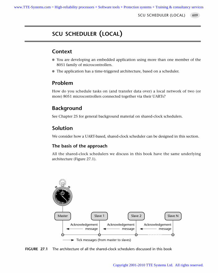
SCU SCHEDULER (LOCAL)
Context You are developing an embedded application using more than one member of the
8051 family of microcontrollers.
The application has a time-triggered architecture, based on a scheduler.
ProblemHow do you schedule tasks on (and transfer data over) a local network of two (ormore) 8051 microcontrollers connected together via their UARTs?
BackgroundSee Chapter 25 for general background material on shared-clock schedulers.
SolutionWe consider how a UART-based, shared-clock scheduler can be designed in this section.
The basis of the approach
All the shared-clock schedulers we discuss in this book have the same underlyingarchitecture (Figure 27.1).
SCU SCHEDULER (LOCAL) 609
FIGURE 27.1 The architecture of all the shared-clock schedulers discussed in this book
Master Slave 1 Slave 2 Slave N
Tick messages (from master to slaves)
Acknowledgementmessage
Acknowledgementmessage
Acknowledgementmessage
www.TTE-Systems.com = High-reliability processors + Software tools + Protection systems + Training & consultancy services
Copyright 2001-2010 TTE Systems Ltd. All rights reserved.
Here we have one, accurate clock on the Master node in the network. This clock isused to drive the scheduler in the Master node in exactly the manner discussed in Part C.
The Slave nodes also have schedulers: however, the interrupts used to drive theseschedulers are derived from ‘tick messages’ generated by the Master. Thus, in theUART-based network we are concerned with in this pattern, the Slave node(s) willhave a S-C scheduler driven by the ‘receive’ interrupts generated through the receiptof a byte of data sent by the Master.
Note that the ability to generate an interrupt (in a Slave) on receipt of a data byteby the UART makes the underlying scheduler operation an extremely simple two-stage process:
1 Timer overflow in the Master causes the scheduler ‘Update’ function to be invoked.This, in turn, causes a byte of data to be sent (via the UART) to all Slaves:
void MASTER_Update_T2(void) interrupt INTERRUPT_Timer_2_Overflow
...
MASTER_Send_Tick_Message(...);
...
2 When these data have been received all Slaves generate an interrupt; this invokesthe ‘Update’ function in the Slave schedulers. This, in turn, causes one Slave tosend an ‘Acknowledge’ message back to the Master (again via the UART).
void SLAVE_Update(void) interrupt INTERRUPT_UART_Rx_Tx
...
SLAVE_Send_Ack_Message_To_Master();
...
The message structure
The design of the message structure to be used in a UART-based network requiressome care.
For example, consider Figure 27.2. Here we will assume that we wish to control andmonitor three hydraulic actuators to control the operation of a mechanical excavator.
Suppose we wish to adjust the angle of Actuator A to 90º; how do we do this?Immediately the 8-bit nature of the UART becomes a limitation, because we need tosend a message that identifies both the node to be adjusted and the angle itself.
MULTIPROCESSOR SYSTEMS610
www.TTE-Systems.com = High-reliability processors + Software tools + Protection systems + Training & consultancy services
Copyright 2001-2010 TTE Systems Ltd. All rights reserved.
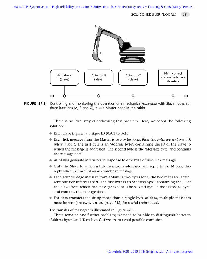
There is no ideal way of addressing this problem. Here, we adopt the followingsolution:
Each Slave is given a unique ID (0x01 to 0xFF).
Each tick message from the Master is two bytes long; these two bytes are sent one tickinterval apart. The first byte is an ‘Address byte’, containing the ID of the Slave towhich the message is addressed. The second byte is the ‘Message byte’ and containsthe message data.
All Slaves generate interrupts in response to each byte of every tick message.
Only the Slave to which a tick message is addressed will reply to the Master; thisreply takes the form of an acknowledge message.
Each acknowledge message from a Slave is two bytes long; the two bytes are, again,sent one tick interval apart. The first byte is an ‘Address byte’, containing the ID ofthe Slave from which the message is sent. The second byte is the ‘Message byte’and contains the message data.
For data transfers requiring more than a single byte of data, multiple messagesmust be sent (see D ATA U N I O N [page 712] for useful techniques).
The transfer of messages is illustrated in Figure 27.3.There remains one further problem; we need to be able to distinguish between
‘Address bytes’ and ‘Data bytes’, if we are to avoid possible confusion.
SCU SCHEDULER (LOCAL) 611
FIGURE 27.2 Controlling and monitoring the operation of a mechanical excavator with Slave nodes atthree locations (A, B and C), plus a Master node in the cabin
A
B
C
Main controland user interface
(Master)
Actuator A(Slave)
Actuator B(Slave)
Actuator C(Slave)
www.TTE-Systems.com = High-reliability processors + Software tools + Protection systems + Training & consultancy services
Copyright 2001-2010 TTE Systems Ltd. All rights reserved.
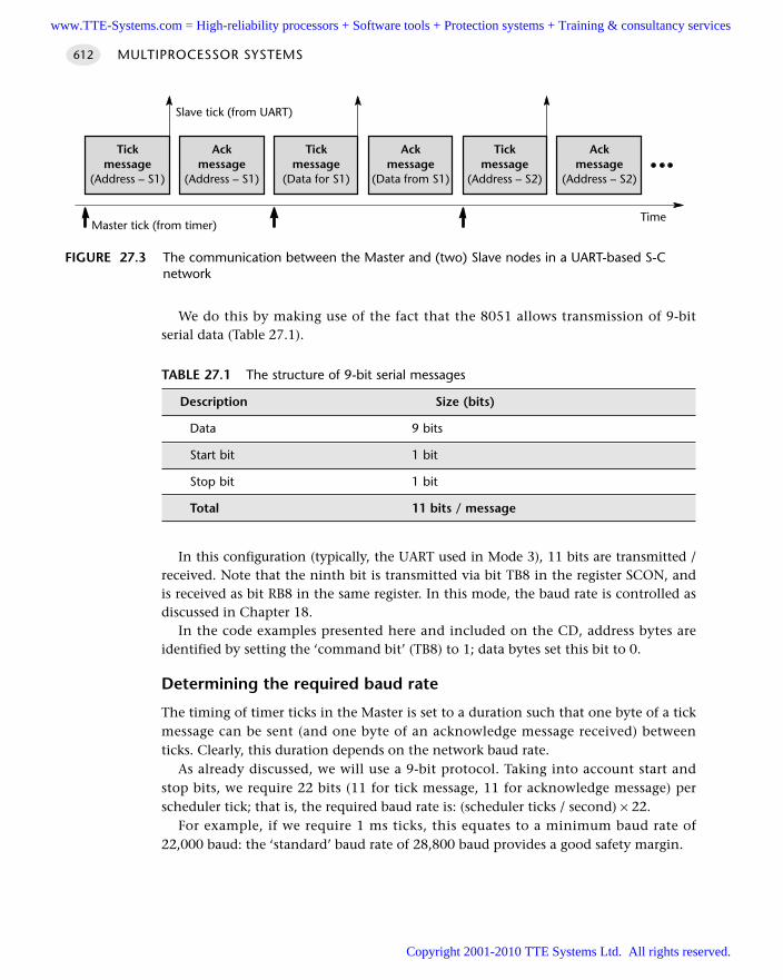
We do this by making use of the fact that the 8051 allows transmission of 9-bitserial data (Table 27.1).
In this configuration (typically, the UART used in Mode 3), 11 bits are transmitted /received. Note that the ninth bit is transmitted via bit TB8 in the register SCON, andis received as bit RB8 in the same register. In this mode, the baud rate is controlled asdiscussed in Chapter 18.
In the code examples presented here and included on the CD, address bytes areidentified by setting the ‘command bit’ (TB8) to 1; data bytes set this bit to 0.
Determining the required baud rate
The timing of timer ticks in the Master is set to a duration such that one byte of a tickmessage can be sent (and one byte of an acknowledge message received) betweenticks. Clearly, this duration depends on the network baud rate.
As already discussed, we will use a 9-bit protocol. Taking into account start andstop bits, we require 22 bits (11 for tick message, 11 for acknowledge message) perscheduler tick; that is, the required baud rate is: (scheduler ticks / second) × 22.
For example, if we require 1 ms ticks, this equates to a minimum baud rate of22,000 baud: the ‘standard’ baud rate of 28,800 baud provides a good safety margin.
MULTIPROCESSOR SYSTEMS612
FIGURE 27.3 The communication between the Master and (two) Slave nodes in a UART-based S-Cnetwork
Tickmessage
(Address – S1)
Ackmessage
(Address – S1)
Tickmessage
(Data for S1)
Ackmessage
(Data from S1)
Tickmessage
(Address – S2)
Ackmessage
(Address – S2)
Master tick (from timer)Time
Slave tick (from UART)
TABLE 27.1 The structure of 9-bit serial messages
Description Size (bits)
Data 9 bits
Start bit 1 bit
Stop bit 1 bit
Total 11 bits / message
www.TTE-Systems.com = High-reliability processors + Software tools + Protection systems + Training & consultancy services
Copyright 2001-2010 TTE Systems Ltd. All rights reserved.
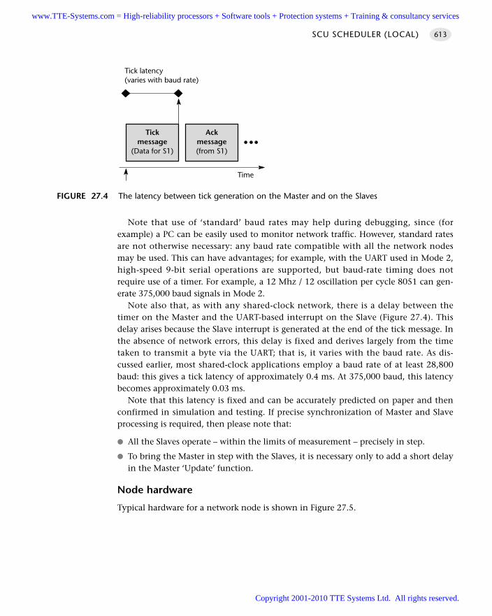
Note that use of ‘standard’ baud rates may help during debugging, since (forexample) a PC can be easily used to monitor network traffic. However, standard ratesare not otherwise necessary: any baud rate compatible with all the network nodesmay be used. This can have advantages; for example, with the UART used in Mode 2,high-speed 9-bit serial operations are supported, but baud-rate timing does notrequire use of a timer. For example, a 12 Mhz / 12 oscillation per cycle 8051 can gen-erate 375,000 baud signals in Mode 2.
Note also that, as with any shared-clock network, there is a delay between thetimer on the Master and the UART-based interrupt on the Slave (Figure 27.4). Thisdelay arises because the Slave interrupt is generated at the end of the tick message. Inthe absence of network errors, this delay is fixed and derives largely from the timetaken to transmit a byte via the UART; that is, it varies with the baud rate. As dis-cussed earlier, most shared-clock applications employ a baud rate of at least 28,800baud: this gives a tick latency of approximately 0.4 ms. At 375,000 baud, this latencybecomes approximately 0.03 ms.
Note that this latency is fixed and can be accurately predicted on paper and thenconfirmed in simulation and testing. If precise synchronization of Master and Slaveprocessing is required, then please note that:
All the Slaves operate – within the limits of measurement – precisely in step.
To bring the Master in step with the Slaves, it is necessary only to add a short delayin the Master ‘Update’ function.
Node hardware
Typical hardware for a network node is shown in Figure 27.5.
SCU SCHEDULER (LOCAL) 613
FIGURE 27.4 The latency between tick generation on the Master and on the Slaves
Tickmessage
(Data for S1)
Ackmessage(from S1)
Time
Tick latency(varies with baud rate)
www.TTE-Systems.com = High-reliability processors + Software tools + Protection systems + Training & consultancy services
Copyright 2001-2010 TTE Systems Ltd. All rights reserved.
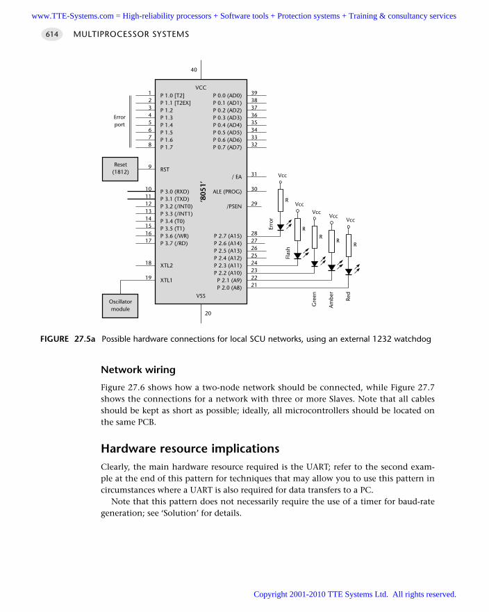
Network wiring
Figure 27.6 shows how a two-node network should be connected, while Figure 27.7shows the connections for a network with three or more Slaves. Note that all cablesshould be kept as short as possible; ideally, all microcontrollers should be located onthe same PCB.
Hardware resource implicationsClearly, the main hardware resource required is the UART; refer to the second exam-ple at the end of this pattern for techniques that may allow you to use this pattern incircumstances where a UART is also required for data transfers to a PC.
Note that this pattern does not necessarily require the use of a timer for baud-rategeneration; see ‘Solution’ for details.
MULTIPROCESSOR SYSTEMS614
FIGURE 27.5a Possible hardware connections for local SCU networks, using an external 1232 watchdog
P 1.0 [T2]P 1.1 [T2EX]P 1.2P 1.3P 1.4P 1.5P 1.6P 1.7
RST
P 3.0 (RXD)P 3.1 (TXD)P 3.2 (/INT0)P 3.3 (/INT1)P 3.4 (T0)P 3.5 (T1)P 3.6 (/WR)P 3.7 (/RD)
XTL2
XTL1
P 0.0 (AD0)P 0.1 (AD1)P 0.2 (AD2)P 0.3 (AD3)P 0.4 (AD4)P 0.5 (AD5)P 0.6 (AD6)P 0.7 (AD7)
/ EA
ALE (PROG)
/PSEN
P 2.7 (A15)P 2.6 (A14)P 2.5 (A13)P 2.4 (A12)P 2.3 (A11)P 2.2 (A10)P 2.1 (A9)P 2.0 (A8)
VCC
‘805
1’
VSS
3938373635343332
31
30
29
2827262524232221
12345678
9
1011121314151617
18
19
20
40
Oscillatormodule
Reset(1812)
VccVcc
Vcc
Red
RR
R
Am
ber
Gre
en
Vcc
R
Vcc
R
Flas
h
Erro
r
Errorport
www.TTE-Systems.com = High-reliability processors + Software tools + Protection systems + Training & consultancy services
Copyright 2001-2010 TTE Systems Ltd. All rights reserved.
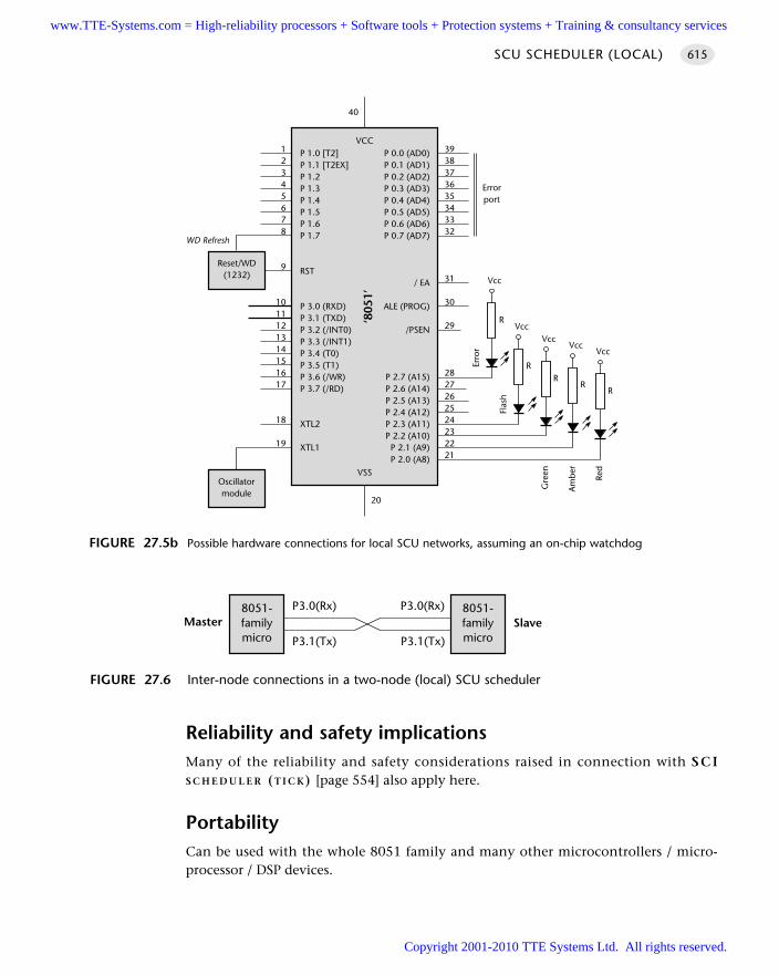
Reliability and safety implicationsMany of the reliability and safety considerations raised in connection with SCIS C H E D U L E R (T I C K) [page 554] also apply here.
PortabilityCan be used with the whole 8051 family and many other microcontrollers / micro-processor / DSP devices.
SCU SCHEDULER (LOCAL) 615
FIGURE 27.5b Possible hardware connections for local SCU networks, assuming an on-chip watchdog
P 1.0 [T2]P 1.1 [T2EX]P 1.2P 1.3P 1.4P 1.5P 1.6P 1.7
RST
P 3.0 (RXD)P 3.1 (TXD)P 3.2 (/INT0)P 3.3 (/INT1)P 3.4 (T0)P 3.5 (T1)P 3.6 (/WR)P 3.7 (/RD)
XTL2
XTL1
P 0.0 (AD0)P 0.1 (AD1)P 0.2 (AD2)P 0.3 (AD3)P 0.4 (AD4)P 0.5 (AD5)P 0.6 (AD6)P 0.7 (AD7)
/ EA
ALE (PROG)
/PSEN
P 2.7 (A15)P 2.6 (A14)P 2.5 (A13)P 2.4 (A12)P 2.3 (A11)P 2.2 (A10)
P 2.1 (A9)P 2.0 (A8)
VCC
‘805
1’
VSS
3938373635343332
31
30
29
2827262524232221
12345678
9
1011121314151617
18
19
20
40
Oscillatormodule
Reset/WD(1232)
VccVcc
Vcc
Red
Errorport
RR
R
Am
ber
Gre
en
Vcc
R
Vcc
R
Flas
h
Erro
r
WD Refresh
FIGURE 27.6 Inter-node connections in a two-node (local) SCU scheduler
8051-familymicro
8051-familymicro
MasterP3.0(Rx)
Slave
P3.1(Tx)
P3.0(Rx)
P3.1(Tx)
www.TTE-Systems.com = High-reliability processors + Software tools + Protection systems + Training & consultancy services
Copyright 2001-2010 TTE Systems Ltd. All rights reserved.
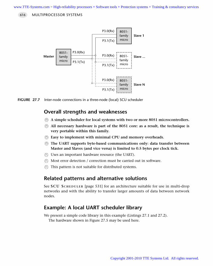
Overall strengths and weaknessesA simple scheduler for local systems with two or more 8051 microcontrollers.
All necessary hardware is part of the 8051 core: as a result, the technique isvery portable within this family.
Easy to implement with minimal CPU and memory overheads.
The UART supports byte-based communications only: data transfer betweenMaster and Slaves (and vice versa) is limited to 0.5 bytes per clock tick.
Uses an important hardware resource (the UART).
Most error detection / correction must be carried out in software.
This pattern is not suitable for distributed systems.
Related patterns and alternative solutionsSee SCU S C H E D U L E R [page 531] for an architecture suitable for use in multi-dropnetworks and with the ability to transfer larger amounts of data between networknodes.
Example: A local UART scheduler libraryWe present a simple code library in this example (Listings 27.1 and 27.2).
The hardware shown in Figure 27.5 may be used here.
MULTIPROCESSOR SYSTEMS616
FIGURE 27.7 Inter-node connections in a three-node (local) SCU scheduler
8051-familymicro
8051-familymicro
Master
8051-familymicro
P3.0(Rx)
8051-familymicro
Slave ...
Slave 1
Slave N
P3.1(Tx)
P3.0(Rx)
P3.1(Tx)
P3.0(Rx)
P3.1(Tx)
P3.0(Rx)
P3.1(Tx)
www.TTE-Systems.com = High-reliability processors + Software tools + Protection systems + Training & consultancy services
Copyright 2001-2010 TTE Systems Ltd. All rights reserved.
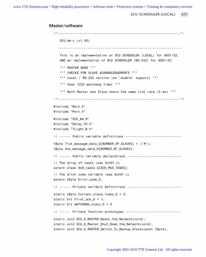
Master/software
/*------------------------------------------------------------------*-
SCU_Am.c (v1.00)
------------------------------------------------------------------
This is an implementation of SCU SCHEDULER (LOCAL) for 8051/52.
AND an implementation of SCU SCHEDULER (RS-232) for 8051/52.
*** MASTER NODE ***
*** CHECKS FOR SLAVE ACKNOWLEDGEMENTS ***
*** Local / RS-232 version (no 'enable' support) ***
*** Uses 1232 watchdog timer ***
*** Both Master and Slave share the same tick rate (5 ms) ***
-*------------------------------------------------------------------*/
#include "Main.h"
#include "Port.h"
#include "SCU_Am.H"
#include "Delay_T0.h"
#include "TLight_B.h"
// ------ Public variable definitions ------------------------------
tByte Tick_message_data_G[NUMBER_OF_SLAVES] = 'M';
tByte Ack_message_data_G[NUMBER_OF_SLAVES];
// ------ Public variable declarations -----------------------------
// The array of tasks (see Sch51.c)
extern sTask SCH_tasks_G[SCH_MAX_TASKS];
// The error code variable (see Sch51.c)
extern tByte Error_code_G;
// ------ Private variable definitions -----------------------------
static tByte Current_slave_index_G = 0;
static bit First_ack_G = 1;
static bit WATCHDOG_state_G = 0
// ------ Private function prototypes ------------------------------
static void SCU_A_MASTER_Reset_the_Network(void);
static void SCU_A_Master_Shut_Down_the_Network(void);
static void SCU_A_MASTER_Switch_To_Backup_Slave(const tByte);
SCU SCHEDULER (LOCAL) 617
www.TTE-Systems.com = High-reliability processors + Software tools + Protection systems + Training & consultancy services
Copyright 2001-2010 TTE Systems Ltd. All rights reserved.
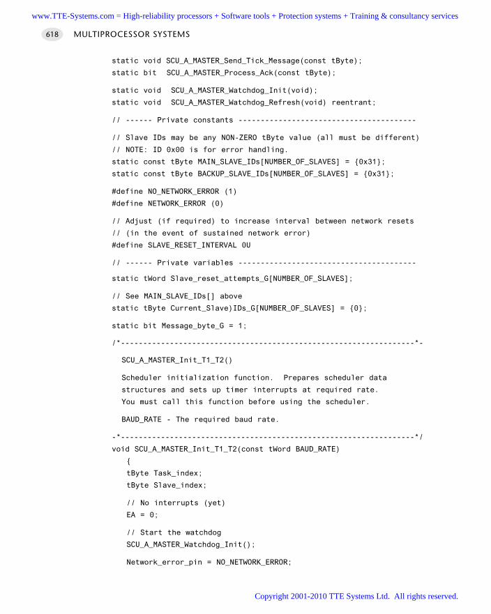
static void SCU_A_MASTER_Send_Tick_Message(const tByte);
static bit SCU_A_MASTER_Process_Ack(const tByte);
static void SCU_A_MASTER_Watchdog_Init(void);
static void SCU_A_MASTER_Watchdog_Refresh(void) reentrant;
// ------ Private constants ----------------------------------------
// Slave IDs may be any NON-ZERO tByte value (all must be different)
// NOTE: ID 0x00 is for error handling.
static const tByte MAIN_SLAVE_IDs[NUMBER_OF_SLAVES] = 0x31;
static const tByte BACKUP_SLAVE_IDs[NUMBER_OF_SLAVES] = 0x31;
#define NO_NETWORK_ERROR (1)
#define NETWORK_ERROR (0)
// Adjust (if required) to increase interval between network resets
// (in the event of sustained network error)
#define SLAVE_RESET_INTERVAL 0U
// ------ Private variables ----------------------------------------
static tWord Slave_reset_attempts_G[NUMBER_OF_SLAVES];
// See MAIN_SLAVE_IDs[] above
static tByte Current_Slave)IDs_G[NUMBER_OF_SLAVES] = 0;
static bit Message_byte_G = 1;
/*------------------------------------------------------------------*-
SCU_A_MASTER_Init_T1_T2()
Scheduler initialization function. Prepares scheduler data
structures and sets up timer interrupts at required rate.
You must call this function before using the scheduler.
BAUD_RATE - The required baud rate.
-*------------------------------------------------------------------*/
void SCU_A_MASTER_Init_T1_T2(const tWord BAUD_RATE)
tByte Task_index;
tByte Slave_index;
// No interrupts (yet)
EA = 0;
// Start the watchdog
SCU_A_MASTER_Watchdog_Init();
Network_error_pin = NO_NETWORK_ERROR;
MULTIPROCESSOR SYSTEMS618
www.TTE-Systems.com = High-reliability processors + Software tools + Protection systems + Training & consultancy services
Copyright 2001-2010 TTE Systems Ltd. All rights reserved.
// ------ Set up the scheduler ----------------------------------
// Sort out the tasks
for (Task_index = 0; Task_index < SCH_MAX_TASKS; Task_index++)
SCH_Delete_Task(Task_index);
// Reset the global error variable
// - SCH_Delete_Task() will generate an error code,
// (because the task array is empty)
Error_code_G = 0;
// We allow any combination of ID numbers in slaves
// - but reserve ID 0x00
for (Slave_index = 0; Slave_index < NUMBER_OF_SLAVES; Slave_index++)
Slave_reset_attempts_G[Slave_index] = 0;
Current_Slave_IDs_G[Slave_index] = MAIN_SLAVE_IDs[Slave_index];
// ------ Set the baud rate (begin) -----------------------------
PCON &= 0x7F; // Set SMOD bit to 0 (don't double baud rates)
// Receiver enabled
// *9-bit data*, 1 start bit, 1 stop bit, variable baud rate
(asynchronous)
SCON = 0xD2;
TMOD |= 0x20; // T1 in mode 2, 8-bit auto reload
TH1 = (256 - (tByte)((((tLong)OSC_FREQ / 100) * 3125)
/ ((tLong) BAUD_RATE * OSC_PER_INST * 1000)));
TL1 = TH1;
TR1 = 1; // Run the timer
TI = 1; // Send first character (dummy)
// ------ Set the baud rate (end) -------------------------------
// Serial interrupt *NOT* enabled
ES = 0;
// ------ Set up the serial link (end) --------------------------
// ------ Set up Timer 2 (begin) --------------------------------
// Crystal is assumed to be 12 MHz, 12 osc/increment
//
// The Timer 2 resolution is 0.000001 seconds (1 µs)// The required Timer 2 overflow is 0.005 seconds (5 ms)
SCU SCHEDULER (LOCAL) 619
www.TTE-Systems.com = High-reliability processors + Software tools + Protection systems + Training & consultancy services
Copyright 2001-2010 TTE Systems Ltd. All rights reserved.
// - this takes 5000 timer ticks
// Reload value is 65536 - 5000 = 60536 (dec) = 0xEC78
T2CON = 0x04; // load Timer 2 control register
T2MOD = 0x00; // load Timer 2 mode register
TH2 = 0xEC; // load timer 2 high byte
RCAP2H = 0xEC; // load timer 2 reload capture reg, high byte
TL2 = 0x78; // load timer 2 low byte
RCAP2L = 0x78; // load timer 2 reload capture reg, low byte
ET2 = 1; // Timer 2 interrupt is enabled
TR2 = 1; // Start Timer 2
// ------ Set up Timer 2 (end) ----------------------------------
/*------------------------------------------------------------------*-
SCU_A_MASTER_Start()
Starts the scheduler, by enabling interrupts.
NOTE: Usually called after all tasks are added,
to keep the tasks synchronized.
NOTE: ONLY THE SCHEDULER INTERRUPT SHOULD BE ENABLED!!!
NOTE: Delays here (2 ms) assume a baud rate of at least 9600 baud.
You will need to fine-tune this code if you opt for a lower baud
rate.
-*------------------------------------------------------------------*/
void SCU_A_MASTER_Start(void)
tByte Slave_ID;
tByte Num_active_slaves;
tByte Id, i;
bit First_byte = 0;
bit Slave_replied_correctly;
tByte Slave_index;
// Refresh the watchdog
SCU_A_MASTER_Watchdog_Refresh();
// Place system in 'safe state’
SCU_A_MASTER_Enter_Safe_State();
// Report error as we wait to start
Network_error_pin = NETWORK_ERROR;
MULTIPROCESSOR SYSTEMS620
www.TTE-Systems.com = High-reliability processors + Software tools + Protection systems + Training & consultancy services
Copyright 2001-2010 TTE Systems Ltd. All rights reserved.
Error_code_G = ERROR_SCH_WAITING_FOR_SLAVE_TO_ACK;
SCH_Report_Status(); // Sch not yet running - do this manually
// Pause here (300 ms), to time-out all the slaves
// (This is the means by which we synchronize the network)
for (i = 0; i < 100; i++)
Hardware_Delay_T0(30);
SCU_A_MASTER_Watchdog_Refresh();
// Currently disconnected from all slaves
Num_active_slaves = 0;
// After the initial (long) delay, all (operational) slaves will
have timed out.
// All operational slaves will now be in the 'READY TO START' state
// Send them a (single-byte) message to get them started
// DO THIS TWICE IN A ROW, WITH COMMAND BIT
// This cannot happen under normal circumstances
Slave_index = 0;
do
// Refresh the watchdog
SCU_A_MASTER_Watchdog_Refresh();
// Clear 'first byte' flag
First_byte = 0;
// Find the slave ID for this slave
Slave_ID = (tByte) Current_Slave_IDs_G[Slave_index];
// Send a 'Slave ID' message
TI = 0;
TB8 = 1; // Set command bit
SBUF = Slave_ID;
// Wait to give slave time to reply
Hardware_Delay_T0(5);
// Check we had a reply
if (RI == 1)
// Get the reply data
Id = (tByte) SBUF;
RI = 0;
// Check reply - with command bit
if ((Id == Slave_ID) && (RB8 == 1))
SCU SCHEDULER (LOCAL) 621
www.TTE-Systems.com = High-reliability processors + Software tools + Protection systems + Training & consultancy services
Copyright 2001-2010 TTE Systems Ltd. All rights reserved.
First_byte = 1;
// Send second byte
TI = 0;
TB8 = 1;
SBUF = Slave_ID;
// Wait to give slave time to reply
Hardware_Delay_T0(5);
// Check we had a reply
Slave_replied_correctly = 0;
if (RI != 0)
// Get the reply data
Id = (tByte) SBUF;
RI = 0;
if ((Id == Slave_ID) && (RB8 == 1) && (First_byte == 1))
Slave_replied_correctly = 1;
if (Slave_replied_correctly)
// Slave responded correctly
Num_active_slaves++;
Slave_index++;
else
// Slave did not reply correctly
// - try to switch to backup device (if available)
if (Current_Slave_IDs_G[Slave_index] !=
BACKUP_SLAVE_IDs[Slave_index])
// There is a backup available: switch to backup and try
// again
Current_Slave_IDs_G[Slave_index] =
BACKUP_SLAVE_IDs[Slave_index];
MULTIPROCESSOR SYSTEMS622
www.TTE-Systems.com = High-reliability processors + Software tools + Protection systems + Training & consultancy services
Copyright 2001-2010 TTE Systems Ltd. All rights reserved.
else
// No backup available (or backup failed too) - have to
// continue
// NOTE: we don't abort the loop, to allow for more
flexible
// error handling (below).
Slave_index++;
while (Slave_index < NUMBER_OF_SLAVES);
// DEAL WITH CASE OF MISSING SLAVE(S) HERE ...
if (Num_active_slaves < NUMBER_OF_SLAVES)
// User-defined error handling here...
// 1 or more slaves have not replied
// NOTE: In some circumstances you may wish to abort if slaves
// are missing
// - or reconfigure the network.
// Here we display error and shut down the network
Error_code_G = ERROR_SCH_ONE_OR_MORE_SLAVES_DID_NOT_START;
SCU_A_MASTER_Shut_Down_the_Network();
else
Error_code_G = 0;
Network_error_pin = NO_NETWORK_ERROR;
// Get ready to send first tick message
Message_byte_G = 1;
First_ack_G = 1;
Current_slave_index_G = 0;
// Start the scheduler
EA = 1;
/*------------------------------------------------------------------*-
SCU_A_MASTER_Update_T2
This is the scheduler ISR. It is called at a rate determined by
the timer settings in SCU_A_MASTER_Init_T2(). This version is
triggered by Timer 2 interrupts: timer is automatically reloaded.
-*------------------------------------------------------------------*/
SCU SCHEDULER (LOCAL) 623
www.TTE-Systems.com = High-reliability processors + Software tools + Protection systems + Training & consultancy services
Copyright 2001-2010 TTE Systems Ltd. All rights reserved.
void SCU_A_MASTER_Update_T2(void) interrupt INTERRUPT_Timer_2_Overflow
tByte Task_index;
tByte Previous_slave_index;
TF2 = 0; // Must manually clear this.
// Refresh the watchdog
SCU_A_MASTER_Watchdog_Refresh();
// Default
Network_error_pin = NO_NETWORK_ERROR;
// Keep track of the current slave
// FIRST VALUE IS 0
Previous_slave_index = Current_slave_index_G;
// Assume 2-byte messages sent and received
// - it takes two ticks to deliver each message
if (Message_byte_G == 0)
Message_byte_G = 1;
else
Message_byte_G = 0;
if (++Current_slave_index_G >= NUMBER_OF_SLAVES)
Current_slave_index_G = 0;
// Check that the appropriate slave responded to the previous message:
// (if it did, store the data sent by this slave)
if (SCU_A_MASTER_Process_Ack(Previous_slave_index) == RETURN_ERROR)
Network_error_pin = NETWORK_ERROR;
Error_code_G = ERROR_SCH_LOST_SLAVE;
// If we have lost contact with a slave, we attempt to
// switch to a backup device (if one is available) as we reset
// the network
//
// NOTE: We don't do this every tick (or the the net will be
constantly reset)
//
// Choose a value of SLAVE_RESET_INTERVAL to allow resets (say)
// every 5 seconds
MULTIPROCESSOR SYSTEMS624
www.TTE-Systems.com = High-reliability processors + Software tools + Protection systems + Training & consultancy services
Copyright 2001-2010 TTE Systems Ltd. All rights reserved.
if (++Slave_reset_attempts_G[Previous_slave_index] >=
SLAVE_RESET_INTERVAL)
SCU_A_MASTER_Reset_the_Network();
else
// Reset this counter
Slave_reset_attempts_G[Previous_slave_index] = 0
// Send 'tick' message to all connected slaves
// (sends one data byte to the current slave)
SCU_A_MASTER_Send_Tick_Message(Current_slave_index_G);
// NOTE: calculations are in *TICKS* (not milliseconds)
for (Task_index = 0; Task_index < SCH_MAX_TASKS; Task_index++)
// Check if there is a task at this location
if (SCH_tasks_G[Task_index].pTask)
if (SCH_tasks_G[Task_index].Delay == 0)
// The task is due to run
SCH_tasks_G[Task_index].RunMe += 1; // Increment the RunMe
flag
if (SCH_tasks_G[Task_index].Period)
// Schedule periodic tasks to run again
SCH_tasks_G[Task_index].Delay =
SCH_tasks_G[Task_index].Period;
else
// Not yet ready to run: just decrement the delay
SCH_tasks_G[Task_index].Delay -= 1;
/*------------------------------------------------------------------*-
SCU_A_MASTER_Send_Tick_Message()
SCU SCHEDULER (LOCAL) 625
www.TTE-Systems.com = High-reliability processors + Software tools + Protection systems + Training & consultancy services
Copyright 2001-2010 TTE Systems Ltd. All rights reserved.
This function sends a tick message, over the USART network.
The receipt of this message will cause an interrupt to be generated
in the slave(s): this invoke the scheduler 'update' function
in the slave(s).
-*------------------------------------------------------------------*/
void SCU_A_MASTER_Send_Tick_Message(const tByte SLAVE_INDEX)
tLong Timeout;
// Find the slave ID for this slave
tByte Slave_ID = (tByte) Current_Slave_IDs_G[SLAVE_INDEX];
// Sending one byte of data at a time, depending on index value
// If Message_byte_G is 0, send first byte (the slave ID)
if (Message_byte_G == 0)
Timeout = 0;
while ((++Timeout) && (TI == 0));
if (Timeout == 0)
// UART did not respond - error
Error_code_G = ERROR_USART_TI;
return;
TI = 0;
TB8 = 1; // Set 'Command' bit
SBUF = Slave_ID;
else
// Message_byte_G is 1, send the data byte
Timeout = 0;
while ((++Timeout) && (TI == 0));
if (Timeout == 0)
// usart did not respond - error
Error_code_G = ERROR_USART_TI;
return;
TI = 0;
TB8 = 0;
SBUF = Tick_message_data_G[SLAVE_INDEX];
MULTIPROCESSOR SYSTEMS626
www.TTE-Systems.com = High-reliability processors + Software tools + Protection systems + Training & consultancy services
Copyright 2001-2010 TTE Systems Ltd. All rights reserved.
// Data sent - return
/*------------------------------------------------------------------*-
SCU_A_MASTER_Process_Ack()
Make sure the slave (SLAVE_ID) has acknowledged the previous
message that was sent. If it has, extract the message data
from the USART hardware: if not, call the appropriate error
handler.
Slave_index - The index of the slave.
RETURNS: RETURN_NORMAL - Ack received (data in Ack_message_data_G)
RETURN_ERROR - No ack received (-> no data)
-*------------------------------------------------------------------*/
bit SCU_A_MASTER_Process_Ack(const tByte Slave_index)
tByte Message_contents;
tByte Slave_ID;
// First time this is called there is no ack tick to check
// - we simply return 'OK'
if (First_ack_G)
First_ack_G = 0;
return RETURN_NORMAL;
// Find the slave ID for this slave
Slave_ID = (tByte) Current_Slave_IDs_G[Slave_index];
// Data should already be in the buffer
if (RI == 0)
// Slave has not replied to last tick message
// Set error LED
Network_error_pin = NETWORK_ERROR;
return RETURN_ERROR;
// There is data - get it
Message_contents = (tByte) SBUF;
RI = 0;
// This is the reply to the last message
// - reverse the message byte interpretation
SCU SCHEDULER (LOCAL) 627
www.TTE-Systems.com = High-reliability processors + Software tools + Protection systems + Training & consultancy services
Copyright 2001-2010 TTE Systems Ltd. All rights reserved.
if (Message_byte_G == 1)
// Check the 'command bit' is set
if (RB8 == 1)
// Check that the ID is correct
if (Slave_ID == (tByte) Message_contents)
// Required Ack message was received
return RETURN_NORMAL;
// Something is wrong...
// Set error LED
Network_error_pin = NETWORK_ERROR;
return RETURN_ERROR;
else
// There *ARE* data available
// Extract the data from the slave message
//
// NOTE: We *assume* these data are OK
// - you may wish to send crucial data twice, etc.
Ack_message_data_G[Slave_index] = Message_contents;
return RETURN_NORMAL; // return the slave data
/*------------------------------------------------------------------*-
SCU_A_MASTER_Reset_the_Network()
This function resets (that ism restarts) the whole network.
-*------------------------------------------------------------------*/
void SCU_A_MASTER_Reset_the_Network(void)
EA = 0; // Disable interrupts
while(1); // Watchdog will time out
/*------------------------------------------------------------------*-
SCU_A_MASTER_Shut_Down_the_Network()
This function shuts down the whole network.
MULTIPROCESSOR SYSTEMS628
www.TTE-Systems.com = High-reliability processors + Software tools + Protection systems + Training & consultancy services
Copyright 2001-2010 TTE Systems Ltd. All rights reserved.
-*------------------------------------------------------------------*/
void SCU_A_MASTER_Shut_Down_the_Network(void)
EA = 0; // Disable interrupts
Network_error_pin = NETWORK_ERROR;
SCH_Report_Status(); // Sch not running - do this manually
while(1)
SCU_A_MASTER_Watchdog_Refresh();
-*------------------------------------------------------------------*/
SCU_A_MASTER_Enter_Safe_State()
This is the state entered by the system when:
(1) The node is powered up or reset
(2) The Master node cannot detect a slave
(3) The network has an error
Try to ensure that the system is in a 'safe’ state in these
circumstances.
-*------------------------------------------------------------------*/
void SCU_A_MASTER_Enter_Safe_State(void)
// USER DEFINED - Edit as required
TRAFFIC_LIGHTS_Display_Safe_Output();
/*------------------------------------------------------------------*-
SCU_A_MASTER_Watchdog_Init()
This function sets up the watchdog timer.
If the Master fails (or other error develop),
no tick messages will arrive, and the scheduler
will stop.
To detect this situation, we have a (hardware) watchdog
running in the slave. This watchdog - which should be set to
overflow at around 100 ms - is used to set the system into a
known (safe) state. The slave will then wait (indefinitely)
for the problem to be resolved.
NOTE: The slave will not be generating Ack messages in these
circumstances. The Master (if running) will therefore be aware
that there is a problem.
SCU SCHEDULER (LOCAL) 629
www.TTE-Systems.com = High-reliability processors + Software tools + Protection systems + Training & consultancy services
Copyright 2001-2010 TTE Systems Ltd. All rights reserved.
-*------------------------------------------------------------------*/
void SCU_A_MASTER_Watchdog_Init(void)
// INIT NOT REQUIRED FOR 1232 EXTERNAL WATCHDOG
// - May be required wwith different watchdog hardware
// Edit as required
/*------------------------------------------------------------------*-
SCU_A_MASTER_Watchdog_Refresh()
Feed the external (1232) watchdog.
Timeout is between ~60 and 250 ms (hardware dependent)
Assumes external 1232 watchdog
-*------------------------------------------------------------------*/
void SCU_A_MASTER_Watchdog_Refresh(void) reentrant
// Change the state of the watchdog pin
if (WATCHDOG_state_G == 1)
WATCHDOG_state_G = 0;
WATCHDOG_pin = 0;
else
WATCHDOG_state_G = 1;
WATCHDOG_pin = 1;
/*------------------------------------------------------------------*-
---- END OF FILE ------------------------------------------------
-*------------------------------------------------------------------*/
Listing 27.1 Part of a local UART scheduler library (Master node)
Slave software
/*------------------------------------------------------------------*-
SCU_As.c (v1.00)
------------------------------------------------------------------
This is an implementation of SCU SCHEDULER (LOCAL) for 8051/52.
AND an implementation of SCU SCHEDULER (RS-232) for 8051/52.
MULTIPROCESSOR SYSTEMS630
www.TTE-Systems.com = High-reliability processors + Software tools + Protection systems + Training & consultancy services
Copyright 2001-2010 TTE Systems Ltd. All rights reserved.
*** SLAVE NODE ***
***Local / RS-232 version (no 'enable' support) ***
*** Uses 1232 watchdog timer ***
*** Assumes 12 MHz osc (same as Master) ***
*** Both Master and Slave share the same tick rate (5 ms) ***
*** - See Master code for details ***
-*------------------------------------------------------------------*/
#include "Main.h"
#include "Port.h"
#include "SCU_As.h"
#include "TLight_B.h"
// ------ Public variable definitions ------------------------------
// Data sent from the master to this slave
tByte Tick_message_data_G;
// Data sent from this slave to the master
// - data may be sent on, by the master, to another slave
tByte Ack_message_data_G = 'S';
// ------ Public variable declarations -----------------------------
// The array of tasks (see Sch51.c)
extern sTask SCH_tasks_G[SCH_MAX_TASKS];
// The error code variable (see Sch51.c)
extern tByte Error_code_G;
// ------ Private function prototypes ------------------------------
static void SCU_A_SLAVE_Enter_Safe_State(void);
static void SCU_A_SLAVE_Send_Ack_Message_To_Master(void);
static tByte SCU_A_SLAVE_Process_Tick_Message(void);
static void SCU_A_SLAVE_Watchdog_Init(void);
static void SCU_A_SLAVE_Watchdog_Refresh(void) reentrant;
// ------ Private constants ----------------------------------------
// Each slave must have a unique (non-zero) ID
#define SLAVE_ID 0x31
#define NO_NETWORK_ERROR (1)
#define NETWORK_ERROR (0)
// ------ Private variables ----------------------------------------
SCU SCHEDULER (LOCAL) 631
www.TTE-Systems.com = High-reliability processors + Software tools + Protection systems + Training & consultancy services
Copyright 2001-2010 TTE Systems Ltd. All rights reserved.
static bit Message_byte_G;
static bit WATCHDOG_state_G = 0
static tByte Message_ID_G = 0
/*------------------------------------------------------------------*-
SCU_A_SLAVE_Init_T1()
Scheduler initialization function. Prepares scheduler
data structures and sets up timer interrupts at required rate.
Must call this function before using the scheduler.
BAUD_RATE - The required baud rate
-*------------------------------------------------------------------*/
void SCU_A_SLAVE_Init_T1(const tWord BAUD_RATE)
tByte i;
// Sort out the tasks
for (i = 0; i < SCH_MAX_TASKS; i++)
SCH_Delete_Task(i);
// Reset the global error variable
// - SCH_Delete_Task() will generate an error code,
// (because the task array is empty)
Error_code_G = 0;
// Set the network error pin (reset when tick message received)
Network_error_pin = NETWORK_ERROR;
// Ready for first tick message
Message_byte_G = 1;
// ------ Set the baud rate (begin) -----------------------------
PCON &= 0x7F; // Set SMOD bit to 0 (don’t double baud rates)
// receiver enabled
// 9-bit data, 1 start bit, 1 stop bit, variable baud rate
// (asynchronous)
SCON = 0xD2;
TMOD |= 0x20; // T1 in mode 2, 8-bit auto reload
TH1 = (256 - (tByte)((((tLong)OSC_FREQ / 100) * 3125)
/ ((tLong) BAUD_RATE * OSC_PER_INST * 1000)));
TL1 = TH1;
TR1 = 1; // Run the timer
TI = 1; // Send first character (dummy)
MULTIPROCESSOR SYSTEMS632
www.TTE-Systems.com = High-reliability processors + Software tools + Protection systems + Training & consultancy services
Copyright 2001-2010 TTE Systems Ltd. All rights reserved.
// ------ Set the baud rate (end) -------------------------------
// Interrupt enabled
// (Both receiving and SENDING a byte will generate a serial interrupt)
// Global interrupts not yet enabled.
ES = 1;
// Start the watchdog
SCU_A_SLAVE_Watchdog_Init();
/*------------------------------------------------------------------*-
SCU_A_SLAVE_Start()
Starts the slave scheduler, by enabling interrupts.
NOTE: Usually called after all regular tasks are added,
to keep the tasks synchronized.
NOTE: ONLY THE SCHEDULER INTERRUPT SHOULD BE ENABLED!!!
-*------------------------------------------------------------------*/
void SCU_A_SLAVE_Start(void)
tByte Command = 0;
tByte Message_byte;
tByte Count = 0;
bit Slave_started = 0;
// Disable interrupts
EA = 0;
// We can be at this point because:
// 1. The network has just been powered up
// 2. An error has occurred in the Master, and it is not generating
// ticks
// 3. The network has been damaged and no ticks are being received
// by this slave
//
// Try to make sure the system is in a safe state...
SCU_A_SLAVE_Enter_Safe_State();
// NOTE: Interrupts are disabled here
Count = 0;
Error_code_G = ERROR_SCH_WAITING_FOR_START_COMMAND_FROM_MASTER;
SCH_Report_Status(); // Sch not yet running - do this manually
// Now wait (indefinitely) for appropriate signals from the master
do
// Wait for tick messages (byte 1), all bits set to 0, to be
// received
SCU SCHEDULER (LOCAL) 633
www.TTE-Systems.com = High-reliability processors + Software tools + Protection systems + Training & consultancy services
Copyright 2001-2010 TTE Systems Ltd. All rights reserved.
do
SCU_A_SLAVE_Watchdog_Refresh(); // Must keep feeding the
watchdog
while (RI == 0);
Message_byte = (tByte) SBUF;
RI = 0;
// Must get two ID messages in a row...
// (with command bit)
// Ack each one
if ((Message_byte == (tByte) SLAVE_ID) && (RB8 == 1))
Count++;
// Received message for this slave - send ack
TI = 0;
TB8 = 1; // Set command bit
SBUF = (tByte) SLAVE_ID;
else
Count = 0;
while (Count < 2);
// Start the scheduler
EA = 1;
/*------------------------------------------------------------------*-
SCU_A_SLAVE_Update
This is the scheduler ISR. It is called at a rate
determined by the timer settings in SCU_A_SLAVE_Init().
This Slave is triggered by USART interrupts.
-*------------------------------------------------------------------*/
void SCU_A_SLAVE_Update(void) interrupt INTERRUPT_UART_Rx_Tx
tByte Index;
if (RI == 1) // Must check this.
// Default
Network_error_pin = NO_NETWORK_ERROR;
// Two-byte messages are sent (Ack) and received (Tick)
// - it takes two sched ticks to process each message
MULTIPROCESSOR SYSTEMS634
www.TTE-Systems.com = High-reliability processors + Software tools + Protection systems + Training & consultancy services
Copyright 2001-2010 TTE Systems Ltd. All rights reserved.
//
// Keep track of the current byte
if (Message_byte_G == 0)
Message_byte_G = 1;
else
Message_byte_G = 0;
// Check tick data - send ack if necessary
// NOTE: 'START' message will only be sent after a 'time out'
if (SCU_A_SLAVE_Process_Tick_Message() == SLAVE_ID)
SCU_A_SLAVE_Send_Ack_Message_To_Master();
// Feed the watchdog ONLY when a *relevant* message is
// received
// (noise on the bus, etc, will not stop the watchdog...)
//
// START messages will NOT refresh the slave
// - Must talk to every slave at regular intervals
SCU_A_SLAVE_Watchdog_Refresh();
// NOTE: calculations are in *TICKS* (not milliseconds)
for (Index = 0; Index < SCH_MAX_TASKS; Index++)
// Check if there is a task at this location
if (SCH_tasks_G[Index].pTask)
if (SCH_tasks_G[Index].Delay == 0)
// The task is due to run
SCH_tasks_G[Index].RunMe = 1; // Set the run flag
if (SCH_tasks_G[Index].Period)
// Schedule periodic tasks to run again
SCH_tasks_G[Index].Delay = SCH_tasks_G[Index].Period;
else
// Not yet ready to run: just decrement the delay
SCU SCHEDULER (LOCAL) 635
www.TTE-Systems.com = High-reliability processors + Software tools + Protection systems + Training & consultancy services
Copyright 2001-2010 TTE Systems Ltd. All rights reserved.
SCH_tasks_G[Index].Delay -= 1;
RI = 0; // Reset the RI flag
else
// ISR call was triggered by TI flag, after last character was sent
// Must clear the TI flag
TI = 0;
/*------------------------------------------------------------------*-
SCU_A_SLAVE_Send_Ack_Message_To_Master()
Slave must send and 'Acknowledge' message to the master, after
tick messages are received. NOTE: Only tick messages specifically
addressed to this slave should be acknowledged.
The acknowledge message serves two purposes:
[1] It confirms to the master that this slave is alive & well.
[2] It provides a means of sending data to the master and - hence
- to other slaves.
NOTE: Direct data transfer between slaves is NOT possible.
-*------------------------------------------------------------------*/
void SCU_A_SLAVE_Send_Ack_Message_To_Master(void)
// Sending one byte of data at a time, depending on index value
// If Message_byte_G is 0, send first byte (the slave ID)
if (Message_byte_G == 0)
TI = 0;
TB8 = 1; // Set 'Command' bit
SBUF = SLAVE_ID;
else
// Message_byte_G is 1, send the data byte
TI = 0;
TB8 = 0;
SBUF = Ack_message_data_G;
MULTIPROCESSOR SYSTEMS636
www.TTE-Systems.com = High-reliability processors + Software tools + Protection systems + Training & consultancy services
Copyright 2001-2010 TTE Systems Ltd. All rights reserved.
// Data sent - return
/*------------------------------------------------------------------*-
SCU_A_SLAVE_Process_Tick_Message()
The ticks messages are crucial to the operation of this shared-clock
scheduler: the arrival of a tick message (at regular intervals)
invokes the 'Update' ISR, that drives the scheduler.
The tick messages themselves may contain data. These data are
extracted in this function.
-*------------------------------------------------------------------*/
tByte SCU_A_SLAVE_Process_Tick_Message(void)
tByte Data;
// Try to get data byte
if (RI == 0)
// No data - something is wrong
// Set the error flag bit
Network_error_pin = NETWORK_ERROR;
// Return slave ID 0
return 0x00;
// There *ARE* data available
Data = (tByte) SBUF;
RI = 0; // Clear RI flag
// What we do with this message depends if it is a first or second
byte
if (Message_byte_G == 0)
// This is (should be) an ID byte
Message_ID_G = Data;
if (RB8 == 0)
Message_ID_G = 0; // Command bit should be set
else
// This is (should be) a data byte
// - Command bit should not be set
SCU SCHEDULER (LOCAL) 637
www.TTE-Systems.com = High-reliability processors + Software tools + Protection systems + Training & consultancy services
Copyright 2001-2010 TTE Systems Ltd. All rights reserved.
if ((Message_ID_G == SLAVE_ID) && (RB8 == 0))
Tick_message_data_G = Data;
else
// Something is wrong - set Message_ID to 0
Message_ID_G = 0;
// Set the error flag bit
Network_error_pin = NETWORK_ERROR;
return Message_ID_G;
/*------------------------------------------------------------------*-
SCU_A_SLAVE_Watchdog_Init()
This function sets up the watchdog timer.
If the Master fails (or other error develop),
no tick messages will arrive, and the scheduler
will stop.
To detect this situation, we have a (hardware) watchdog
running in the slave. This watchdog - which should be set to
overflow at around 100 ms - is used to set the system into a
known (safe) state. The slave will then wait (indefinitely)
for the problem to be resolved.
NOTE: The slave will not be generating Ack messages in these
circumstances. The Master (if running) will therefore be aware
that there is a problem.
-*------------------------------------------------------------------*/
void SCU_A_SLAVE_Watchdog_Init(void)
// INIT NOT REQUIRED FOR 1232 EXTERNAL WATCHDOG
// - May be required with different watchdog hardware
//
// Edit as required
/*------------------------------------------------------------------*-
SCU_A_SLAVE_Watchdog_Refresh()
MULTIPROCESSOR SYSTEMS638
www.TTE-Systems.com = High-reliability processors + Software tools + Protection systems + Training & consultancy services
Copyright 2001-2010 TTE Systems Ltd. All rights reserved.
Feed the external (1232) watchdog.
Timeout is between ~60 and 250 ms (hardware dependent)
Assumes external 1232 watchdog
-*------------------------------------------------------------------*/
void SCU_A_SLAVE_Watchdog_Refresh(void) reentrant
// Change the state of the watchdog pin
if (WATCHDOG_state_G == 1)
WATCHDOG_state_G = 0;
WATCHDOG_pin = 0;
else
WATCHDOG_state_G = 1;
WATCHDOG_pin = 1;
/*------------------------------------------------------------------*-
SCU_A_SLAVE_Enter_Safe_State()
This is the state entered by the system when:
(1) The node is powered up or reset
(2) The Master node fails, and no working backup is available
(3) The network has an error
(4) Tick messages are delayed for any other reason
Try to ensure that the system is in a 'safe’ state in these
circumstances.
-*------------------------------------------------------------------*/
void SCU_A_SLAVE_Enter_Safe_State(void)
// USER DEFINED - Edit as required
TRAFFIC_LIGHTS_Display_Safe_Output();
/*------------------------------------------------------------------*-
---- END OF FILE ------------------------------------------------
-*------------------------------------------------------------------*/
Listing 27.2 Part of a local UART scheduler library (Slave node)
SCU SCHEDULER (LOCAL) 639
www.TTE-Systems.com = High-reliability processors + Software tools + Protection systems + Training & consultancy services
Copyright 2001-2010 TTE Systems Ltd. All rights reserved.
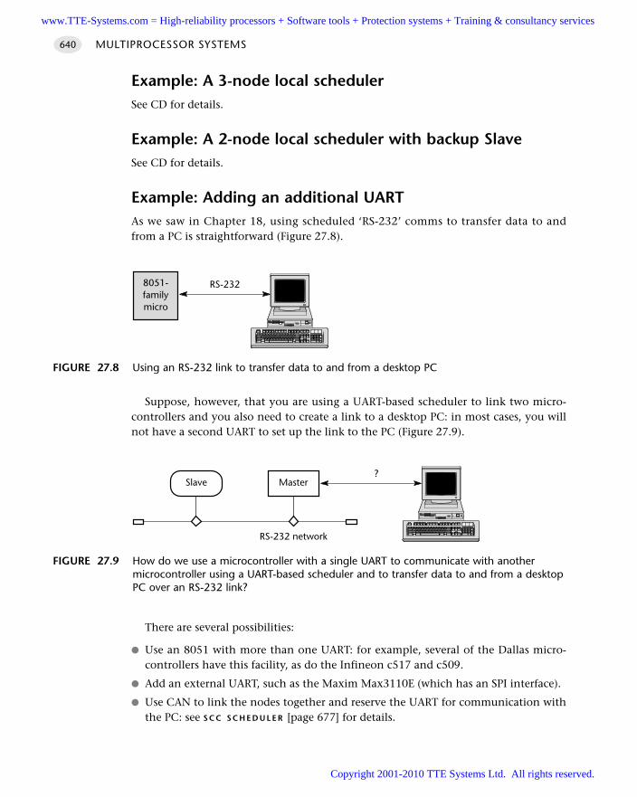
Example: A 3-node local schedulerSee CD for details.
Example: A 2-node local scheduler with backup SlaveSee CD for details.
Example: Adding an additional UARTAs we saw in Chapter 18, using scheduled ‘RS-232’ comms to transfer data to andfrom a PC is straightforward (Figure 27.8).
Suppose, however, that you are using a UART-based scheduler to link two micro-controllers and you also need to create a link to a desktop PC: in most cases, you willnot have a second UART to set up the link to the PC (Figure 27.9).
There are several possibilities:
Use an 8051 with more than one UART: for example, several of the Dallas micro-controllers have this facility, as do the Infineon c517 and c509.
Add an external UART, such as the Maxim Max3110E (which has an SPI interface).
Use CAN to link the nodes together and reserve the UART for communication withthe PC: see S C C S C H E D U L E R [page 677] for details.
MULTIPROCESSOR SYSTEMS640
FIGURE 27.8 Using an RS-232 link to transfer data to and from a desktop PC
8051-familymicro
RS-232
FIGURE 27.9 How do we use a microcontroller with a single UART to communicate with anothermicrocontroller using a UART-based scheduler and to transfer data to and from a desktopPC over an RS-232 link?
MasterSlave?
RS-232 network
www.TTE-Systems.com = High-reliability processors + Software tools + Protection systems + Training & consultancy services
Copyright 2001-2010 TTE Systems Ltd. All rights reserved.
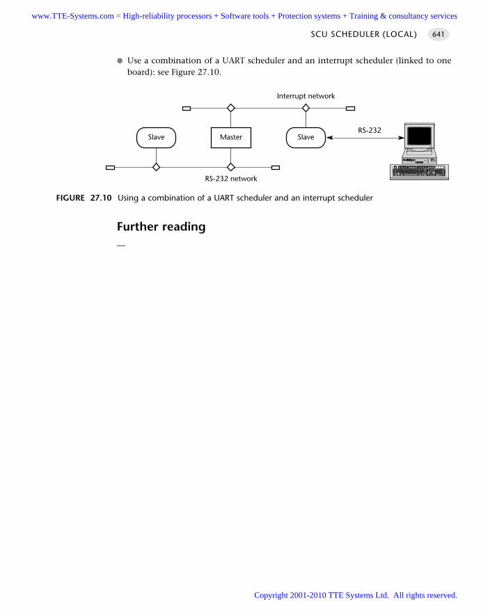
Use a combination of a UART scheduler and an interrupt scheduler (linked to oneboard): see Figure 27.10.
Further reading—
SCU SCHEDULER (LOCAL) 641
FIGURE 27.10 Using a combination of a UART scheduler and an interrupt scheduler
MasterSlaveRS-232
RS-232 network
Slave
Interrupt network
www.TTE-Systems.com = High-reliability processors + Software tools + Protection systems + Training & consultancy services
Copyright 2001-2010 TTE Systems Ltd. All rights reserved.
SCU SCHEDULER (RS-232)
Context You are developing an embedded application using more than one member of the
8051 family of microcontrollers.
The application has a time-triggered architecture, based on a scheduler.
ProblemHow do you schedule tasks on (and transfer data over) a distributed network of two8051 microcontrollers communicating using the RS-232 protocol?
BackgroundSee Chapter 18 for background information on the RS-232 protocol.
See S C U S C H E D U L E R (L O C A L) [page 609] for details of the required software.
SolutionThis pattern extends S C U S C H E D U L E R (L O C A L) [page 609]; the key difference betweenthe two patterns is that S C U S C H E D U L E R (R S -232) allows the creation of two-node,distributed networks, by making use of RS-232-compatible transceiver hardware.Figure 27.11 shows one possible node configuration, where an external 1232 watch-dog timer is employed.
Figure 27.12 shows a suitable node configuration where you have an on-boardwatchdog timer.
Hardware resource implicationsClearly, the main (microcontroller) hardware resource required is the UART; refer tothe second example at the end of S C U S C H E D U L E R (L O C A L) [page 609] for techniquesthat may allow you to use this pattern in circumstances where a UART is also requiredfor data transfers to a PC.
Note that this pattern does not necessarily require the use of a timer for baud-rategeneration; see the ‘Solution’ section in S C U S C H E D U L E R (L O C A L) for details.
Reliability and safety implicationsMany of the reliability and safety considerations raised in connection with S C I
S C H E D U L E R (T I C K) [page 554] also apply here.
MULTIPROCESSOR SYSTEMS642
www.TTE-Systems.com = High-reliability processors + Software tools + Protection systems + Training & consultancy services
Copyright 2001-2010 TTE Systems Ltd. All rights reserved.
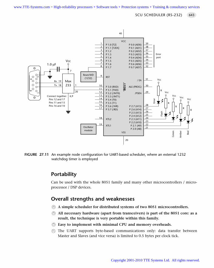
PortabilityCan be used with the whole 8051 family and many other microcontrollers / micro-processor / DSP devices.
Overall strengths and weaknessesA simple scheduler for distributed systems of two 8051 microcontrollers.
All necessary hardware (apart from transceivers) is part of the 8051 core: as aresult, the technique is very portable within this family.
Easy to implement with minimal CPU and memory overheads.
The UART supports byte-based communications only: data transfer betweenMaster and Slaves (and vice versa) is limited to 0.5 bytes per clock tick.
SCU SCHEDULER (RS-232) 643
FIGURE 27.11 An example node configuration for UART-based scheduler, where an external 1232watchdog timer is employed
1
69
5
Max233
Vcc1.0 µF
19
18 1
20
6,9
7
Tx
Rx
Connect together:Pins 12 and 17Pins 11 and 15Pins 16 and 10
P 1.0 [T2]P 1.1 [T2EX]P 1.2P 1.3P 1.4P 1.5P 1.6P 1.7
RST
P 3.0 (RXD)P 3.1 (TXD)P 3.2 (/INT0)P 3.3 (/INT1)P 3.4 (T0)P 3.5 (T1)P 3.6 (/WR)P 3.7 (/RD)
XTL2
XTL1
P 0.0 (AD0)P 0.1 (AD1)P 0.2 (AD2)P 0.3 (AD3)P 0.4 (AD4)P 0.5 (AD5)P 0.6 (AD6)P 0.7 (AD7)
/ EA
ALE (PROG)
/PSEN
P 2.7 (A15)P 2.6 (A14)P 2.5 (A13)P 2.4 (A12)P 2.3 (A11)P 2.2 (A10)
P 2.1 (A9)P 2.0 (A8)
VCC
‘805
1’
VSS
3938373635343332
31
30
29
2827262524232221
12345678
9
1011121314151617
18
19
20
40
Oscillatormodule
Reset/WD(1232)
VccVcc
Vcc
Red
Errorport
RR
R
Am
ber
Gre
en
Vcc
R
Vcc
R
Flas
h
Erro
r
www.TTE-Systems.com = High-reliability processors + Software tools + Protection systems + Training & consultancy services
Copyright 2001-2010 TTE Systems Ltd. All rights reserved.
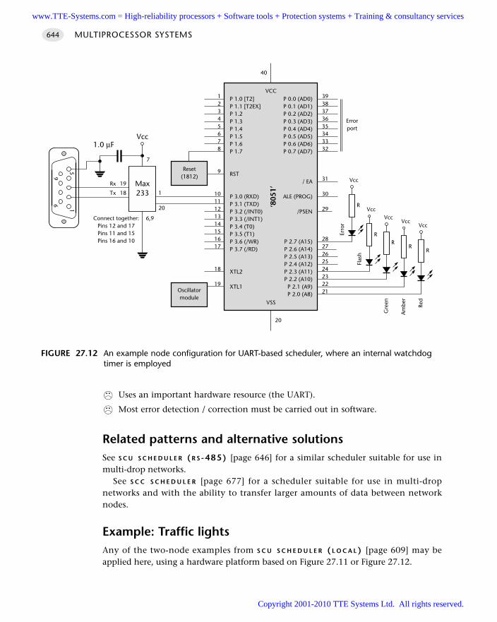
Uses an important hardware resource (the UART).
Most error detection / correction must be carried out in software.
Related patterns and alternative solutionsSee S C U S C H E D U L E R (R S -485) [page 646] for a similar scheduler suitable for use inmulti-drop networks.
See S C C S C H E D U L E R [page 677] for a scheduler suitable for use in multi-dropnetworks and with the ability to transfer larger amounts of data between networknodes.
Example: Traffic lights Any of the two-node examples from S C U S C H E D U L E R ( L O C A L ) [page 609] may beapplied here, using a hardware platform based on Figure 27.11 or Figure 27.12.
MULTIPROCESSOR SYSTEMS644
FIGURE 27.12 An example node configuration for UART-based scheduler, where an internal watchdogtimer is employed
1
69
5
Max233
Vcc1.0 µF
19
18 1
20
6,9
7
Tx
Rx
Connect together:Pins 12 and 17Pins 11 and 15Pins 16 and 10
P 1.0 [T2]P 1.1 [T2EX]P 1.2P 1.3P 1.4P 1.5P 1.6P 1.7
RST
P 3.0 (RXD)P 3.1 (TXD)P 3.2 (/INT0)P 3.3 (/INT1)P 3.4 (T0)P 3.5 (T1)P 3.6 (/WR)P 3.7 (/RD)
XTL2
XTL1
P 0.0 (AD0)P 0.1 (AD1)P 0.2 (AD2)P 0.3 (AD3)P 0.4 (AD4)P 0.5 (AD5)P 0.6 (AD6)P 0.7 (AD7)
/ EA
ALE (PROG)
/PSEN
P 2.7 (A15)P 2.6 (A14)P 2.5 (A13)P 2.4 (A12)P 2.3 (A11)P 2.2 (A10)
P 2.1 (A9)P 2.0 (A8)
VCC
‘805
1’
VSS
3938373635343332
31
30
29
2827262524232221
12345678
9
1011121314151617
18
19
20
40
Oscillatormodule
Reset(1812)
VccVcc
Vcc
Red
Errorport
RR
R
Am
ber
Gre
en
Vcc
R
Vcc
R
Flas
h
Erro
r
www.TTE-Systems.com = High-reliability processors + Software tools + Protection systems + Training & consultancy services
Copyright 2001-2010 TTE Systems Ltd. All rights reserved.
Further readingAxelson, J. (1998) Serial Port Complete, Lakeview Research.
SCU SCHEDULER (RS-232) 645
www.TTE-Systems.com = High-reliability processors + Software tools + Protection systems + Training & consultancy services
Copyright 2001-2010 TTE Systems Ltd. All rights reserved.
SCU SCHEDULER (RS-485)
Context You are developing an embedded application using more than one member of
the 8051 family of microcontrollers.
The application has a time-triggered architecture, based on a scheduler.
ProblemHow do you schedule tasks on (and transfer data over) a distributed network of two(or more) 8051 microcontrollers communicating using the RS-485 protocol?
BackgroundThe key characteristics of a shared-clock scheduler were discussed in Chapter 25.
SolutionThe communications standard generally referred to as ‘RS-485’ is an electrical specifi-cation for what are often referred to as ‘multi-point’ or ‘multi-drop’ communicationsystems; for our purposes, this means applications that involve at least three nodes,each containing a microcontroller.
Note that the specification document (EIA/TIA-485-A) defines the electricalcharacteristics of the line and its drivers and receivers: this is the limit of the standard.Thus, unlike ‘RS-232’, there is no discussion of software protocols or of connectors.
We discussed the RS-232 protocol in connection with S C U S C H E D U L E R (R S -232)[page 642] and P C L I N K ( R S -232) [page 362]. There are many similarities betweenRS-232 and RS-485 communication protocols:
Both are serial standards.
Both are in widespread use.
Both involve – for our purposes – the use of an appropriate transceiver chipconnected to a UART.
Both involve very similar software libraries.
There are also some key differences:
RS-232 is a single-wire standard (one signal line, per channel, plus ground).Electrical noise in the environment can lead to data corruption. This restricts thecommunication range to a maximum of around 30 metres and the data rate toaround 115 kbaud (with recent drivers).
MULTIPROCESSOR SYSTEMS646
www.TTE-Systems.com = High-reliability processors + Software tools + Protection systems + Training & consultancy services
Copyright 2001-2010 TTE Systems Ltd. All rights reserved.
RS-485 is a two-wire or differential communication standard. This means that, foreach channel, two lines carry (1) the required signal and (2) the inverse of thesignal. The receiver then detects the voltage difference between the two lines.Electrical noise will impact on both lines, and will cancel out when the differenceis calculated at the receiver. As a result, an RS-485 network can extend as far as1 km, at a data rate of 90 kbaud. Faster data rates (up to 10 Mbaud) are possible atshorter distances (up to 15 metres).
RS-232 is a peer-to-peer communications standard. For our purposes, this meansthat it is suitable for applications that involve two nodes, each containing a micro-controller (or, as we saw in Chapter 18, for applications where one node is adesktop, or similar, PC).
RS-485 is a ‘multi-point’ or ‘multi-drop’ communications standard. Larger RS-485networks can have up to 32 ‘unit loads’: by using high-impedance receivers, youcan have as many as 256 nodes on the network.
RS-232 requires low-cost ‘straight’ cables, with three wires for fully duplex commu-nications (Tx, Rx, ground).
For full performance, RS-485 requires twisted-pair cables, with two twisted pairs,plus ground (and usually a screen). This cabling is more bulky and more expensivethan the RS-232 equivalent.
RS-232 cables do not require terminating resistors.
RS-485 cables are usually used with 120Ω terminating resistors (assuming 24-AWGtwisted pair cables) connected in parallel, at or just beyond the final node at bothends of the network (Figure 27.13). The terminations reduce voltage reflectionsthat can otherwise cause the receiver to misread logic levels.
RS-232 transceivers are simple and standard.
Choice of RS-485 transceivers depends on the application. A common choicefor basic systems is the Maxim5 Max489 family (see Figures 27.13 and 27.14).For increased reliability, the Linear Technology6 LTC1482, NationalSemiconductors7 DS36276 and the Maxim Max3080–89 series all have internalcircuitry to protect against cable short-circuits. Also, the Maxim Max MAX1480contains its own transformer-isolated supply and opto-isolated signal path: thiscan help avoid interaction between power lines and network cables destroyingyour microcontroller.
SCU SCHEDULER (RS-485) 647
5. www.maxim-ic.com6. www.national.com7. www.linear-tech.com
www.TTE-Systems.com = High-reliability processors + Software tools + Protection systems + Training & consultancy services
Copyright 2001-2010 TTE Systems Ltd. All rights reserved.
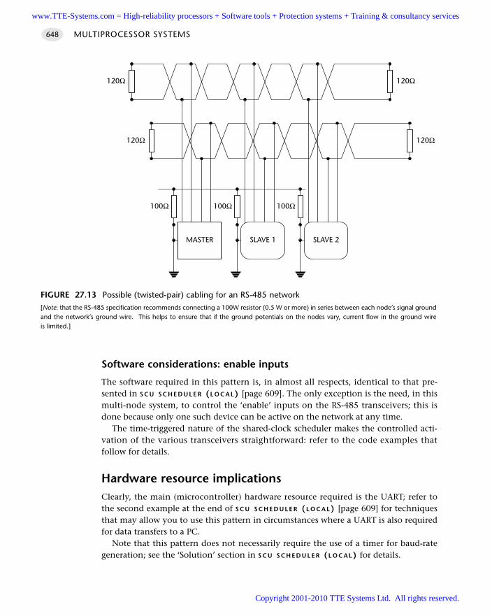
Software considerations: enable inputs
The software required in this pattern is, in almost all respects, identical to that pre-sented in S C U S C H E D U L E R (L O C A L) [page 609]. The only exception is the need, in thismulti-node system, to control the ‘enable’ inputs on the RS-485 transceivers; this isdone because only one such device can be active on the network at any time.
The time-triggered nature of the shared-clock scheduler makes the controlled acti-vation of the various transceivers straightforward: refer to the code examples thatfollow for details.
Hardware resource implicationsClearly, the main (microcontroller) hardware resource required is the UART; refer tothe second example at the end of S C U S C H E D U L E R (L O C A L) [page 609] for techniquesthat may allow you to use this pattern in circumstances where a UART is also requiredfor data transfers to a PC.
Note that this pattern does not necessarily require the use of a timer for baud-rategeneration; see the ‘Solution’ section in S C U S C H E D U L E R (L O C A L) for details.
MULTIPROCESSOR SYSTEMS648
FIGURE 27.13 Possible (twisted-pair) cabling for an RS-485 network[Note: that the RS-485 specification recommends connecting a 100W resistor (0.5 W or more) in series between each node’s signal groundand the network’s ground wire. This helps to ensure that if the ground potentials on the nodes vary, current flow in the ground wireis limited.]
120Ω120Ω
120Ω 120Ω
MASTER SLAVE 1 SLAVE 2
100Ω 100Ω 100Ω
www.TTE-Systems.com = High-reliability processors + Software tools + Protection systems + Training & consultancy services
Copyright 2001-2010 TTE Systems Ltd. All rights reserved.
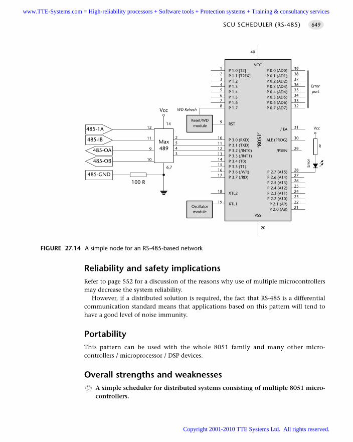
Reliability and safety implicationsRefer to page 552 for a discussion of the reasons why use of multiple microcontrollersmay decrease the system reliability.
However, if a distributed solution is required, the fact that RS-485 is a differentialcommunication standard means that applications based on this pattern will tend tohave a good level of noise immunity.
PortabilityThis pattern can be used with the whole 8051 family and many other micro-controllers / microprocessor / DSP devices.
Overall strengths and weaknessesA simple scheduler for distributed systems consisting of multiple 8051 micro-controllers.
SCU SCHEDULER (RS-485) 649
FIGURE 27.14 A simple node for an RS-485-based network
485-OA
Max489
Vcc
2543
6,7
1412
11
9
10
485-1A
485-IB
485-OB
485-GND100 R
P 1.0 [T2]P 1.1 [T2EX]P 1.2P 1.3P 1.4P 1.5P 1.6P 1.7
RST
P 3.0 (RXD)P 3.1 (TXD)P 3.2 (/INT0)P 3.3 (/INT1)P 3.4 (T0)P 3.5 (T1)P 3.6 (/WR)P 3.7 (/RD)
XTL2
XTL1
P 0.0 (AD0)P 0.1 (AD1)P 0.2 (AD2)P 0.3 (AD3)P 0.4 (AD4)P 0.5 (AD5)P 0.6 (AD6)P 0.7 (AD7)
/ EA
ALE (PROG)
/PSEN
P 2.7 (A15)P 2.6 (A14)P 2.5 (A13)P 2.4 (A12)P 2.3 (A11)P 2.2 (A10)
P 2.1 (A9)P 2.0 (A8)
VCC
‘805
1’
VSS
3938373635343332
31
30
29
2827262524232221
12345678
9
1011121314151617
18
19
20
40
Oscillatormodule
Reset/WDmodule
Errorport
Vcc
R
Erro
r
WD Refresh
www.TTE-Systems.com = High-reliability processors + Software tools + Protection systems + Training & consultancy services
Copyright 2001-2010 TTE Systems Ltd. All rights reserved.
Easy to implement with low CPU and memory overheads.
Twisted-pair cabling and differential signals make this more robust thanRS-232-based alternatives.
UART supports byte-based communications only: data transfer between Masterand Slaves (and vice versa) is limited to 0.5 bytes per clock tick.
Uses an important hardware resource (the UART).
The hardware still has a very limited ability to detect errors: most error detection/ correction must be carried out in software.
Related patterns and alternative solutionsSee S C C S C H E D U L E R [page 677] for an alternative scheduler suitable for use inmulti-drop networks and with the ability to transfer larger amounts of data betweennetwork nodes.
Example: Network with Max489 transceiversIn this example, we present a code framework for an S C U S C H E D U L E R ( R S - 485)suitable for use with network nodes like that illustrated in Figure 27.15 (Listings 27.3and 27.4).
Master software
/*------------------------------------------------------------------*-
SCU_Bm.c (v1.00)
------------------------------------------------------------------
This is an implementation of SCU Scheduler (RS-485) for 8051/52.
*** MASTER NODE ***
*** CHECKS FOR SLAVE ACKNOWLEDGEMENTS ***
*** Includes support for transceiver enables ***
--- Assumes 12.00 MHz crystal -> 5ms tick rate ---
--- Master and slave(s) share same tick rate ---
--- Assumes '1232' watchdog on Master and Slave ---
*------------------------------------------------------------------*/
#include "Main.h"
#include "Port.h"
#include "SCU_Bm.H"
#include "Delay_T0.h"
#include "TLight_B.h"
MULTIPROCESSOR SYSTEMS650
www.TTE-Systems.com = High-reliability processors + Software tools + Protection systems + Training & consultancy services
Copyright 2001-2010 TTE Systems Ltd. All rights reserved.
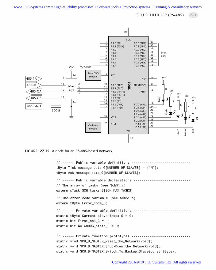
// ------ Public variable definitions ------------------------------
tByte Tick_message_data_G[NUMBER_OF_SLAVES] = 'M';
tByte Ack_message_data_G[NUMBER_OF_SLAVES];
// ------ Public variable declarations -----------------------------
// The array of tasks (see Sch51.c)
extern sTask SCH_tasks_G[SCH_MAX_TASKS];
// The error code variable (see Sch51.c)
extern tByte Error_code_G;
// ------ Private variable definitions -----------------------------
static tByte Current_slave_index_G = 0;
static bit First_ack_G = 1;
static bit WATCHDOG_state_G = 0;
// ------ Private function prototypes ------------------------------
static viod SCU_B_MASTER_Reset_the_Network(void);
static void SCU_B_MASTER_Shut-Down_the Network(void);
static void SCU_B-MASTER_Switch_To_Backup_Slave(const tByte);
SCU SCHEDULER (RS-485) 651
FIGURE 27.15 A node for an RS-485-based network
485-OA
Max489
Vcc
2543
6,7
1412
11
9
10
485-1A
485-IB
485-OB
485-GND100 R
P 1.0 [T2]P 1.1 [T2EX]P 1.2P 1.3P 1.4P 1.5P 1.6P 1.7
RST
P 3.0 (RXD)P 3.1 (TXD)P 3.2 (/INT0)P 3.3 (/INT1)P 3.4 (T0)P 3.5 (T1)P 3.6 (/WR)P 3.7 (/RD)
XTL2
XTL1
P 0.0 (AD0)P 0.1 (AD1)P 0.2 (AD2)P 0.3 (AD3)P 0.4 (AD4)P 0.5 (AD5)P 0.6 (AD6)P 0.7 (AD7)
/ EA
ALE (PROG)
/PSEN
P 2.7 (A15)P 2.6 (A14)P 2.5 (A13)P 2.4 (A12)P 2.3 (A11)P 2.2 (A10)P 2.1 (A9)P 2.0 (A8)
VCC
‘805
1’VSS
3938373635343332
31
30
29
2827262524232221
12345678
9
1011121314151617
18
19
20
40
Oscillatormodule
Reset/WDmodule
Errorport
Vcc
R
Erro
r
WD Refresh
VccVcc
Vcc
Red
RR
R
Am
ber
Gre
en
Vcc
R
Flas
h
www.TTE-Systems.com = High-reliability processors + Software tools + Protection systems + Training & consultancy services
Copyright 2001-2010 TTE Systems Ltd. All rights reserved.
static void SCU_B-MASTER_Send_Tick_Message(const tByte);
static bit SCU_B-MASTER_Process_Ack(const tByte);
static void SCU_B_MASTER_Watchdog_Init(void);
static void SCU_B_MASTER_Watchdog_Refresh(void) reentrant;
// ----- Private constants -----------------------------------------
// Slave IDs may be any NON-ZERO tByte value (all must be different)
// NOTE: ID 0x00 is for error handling.
static const tByte MAIN_SLAVE_IDs[NUMBER_OF_SLAVES] = 0x31;
static const tByte BACKUP_SLAVE_IDs[NUMBER_OF_SLAVES] = 0x31;
#define NO_NETWORK_ERROR (1)
#define NETWORK_ERROR (0)
// Adjust (if required) to increase interval between network resets
// (in the event of sustained network error)
#define SLAVE_RESET_INTERVAL 0U
// ------ Private variables ----------------------------------------
static tWord Slave_reset_attempts_G[NUMBER_OF_SLAVES];
// See MAIN_SLAVE_IDs[] above
static tByte Current_Slave_IDs_G[NUMBER_OF_SLAVES] = 0;
static bit Message_byte_G = 1;
/*------------------------------------------------------------------*-
SCU_B_MASTER_Init_T1_T2()
Scheduler initialisation function. Prepares scheduler data
structures and sets up timer interrupts at required rate.
You must call this function before using the scheduler.
BAUD_RATE - The required baud rate.
-*------------------------------------------------------------------*/
void SCU_B_MASTER_Init_T1_T2(const tWord BAUD_RATE)
tByte Task_index;
tByte Slave_index;
// No interrupts (yet)
EA = 0;
// Start the watchdog
SCU_B_MASTER_Watchdog_Init();
Network_error_pin = NO_NETWORK_ERROR;
// Set up RS-485 transceiver
RS485_Rx_NOT_Enable = 0; // Master Rec is constantly enabled
RS485_Tx_Enable = 1; // Master Tran is constantly enabled
MULTIPROCESSOR SYSTEMS652
www.TTE-Systems.com = High-reliability processors + Software tools + Protection systems + Training & consultancy services
Copyright 2001-2010 TTE Systems Ltd. All rights reserved.
// ------ Set up the scheduler ----------------------------------
// Sort out the tasks
for (Task_index = 0; Task_index < SCH_MAX_TASKS; Task_index++)
SCH_Delete_Task(Task_index);
// Reset the global error variable
// - SCH_Delete_Task() will generate an error code,
// (because the task array is empty)
Error_code_G = 0;
// We allow any combination of ID numbers in slaves
// - but reserve ID 0x00
for (Slave_index = 0; Slave_index < NUMBER_OF_SLAVES; Slave_index++)
Slave_reset_attempts_G[Slave_index] = 0;
Current_Slave_IDs_G[Slave_index] = MAIN_SLAVE_IDs[Slave_index];
// ------ Set the baud rate (begin) -----------------------------
PCON &= 0x7F; // Set SMOD bit to 0 (don’t double baud rates)
// Receiver enabled
// *9-bit data*, 1 start bit, 1 stop bit, variable baud rate
(asynchronous)
SCON = 0xD2;
TMOD |= 0x20; // T1 in mode 2, 8-bit auto reload
TH1 = (256 - (tByte)((((tLong)OSC_FREQ / 100) * 3125)
/ ((tLong) BAUD_RATE * OSC_PER_INST * 1000)));
TL1 = TH1;
TR1 = 1; // Run the timer
TI = 1; // Send first character (dummy)
// ------ Set the baud rate (end) -------------------------------
// Serial interrupt *NOT* enabled
ES = 0;
// ------ Set up the serial link (end) --------------------------
// ------ Set up Timer 2 (begin) --------------------------------
// Crystal is assumed to be 12 MHz, 12 osc/increment
//
// The Timer 2 resolution is 0.000001 seconds (1 µs)
// The required Timer 2 overflow is 0.005 seconds (5 ms)
// - this takes 5000 timer ticks
// Reload value is 65536 - 5000 = 60536 (dec) = 0xEC78
SCU SCHEDULER (RS-485) 653
www.TTE-Systems.com = High-reliability processors + Software tools + Protection systems + Training & consultancy services
Copyright 2001-2010 TTE Systems Ltd. All rights reserved.
T2CON = 0x04; // load Timer 2 control register
T2MOD = 0x00; // load Timer 2 mode register
TH2 = 0xEC; // load timer 2 high byte
RCAP2H = 0xEC; // load timer 2 reload capture reg, high byte
TL2 = 0x00; // load timer 2 low byte
RCAP2L = 0x00; // load timer 2 reload capture reg, low byte
ET2 = 1; // Timer 2 interrupt is enabled
TR2 = 1; // Start Timer 2
// ------ Set up Timer 2 (end) ----------------------------------
/*------------------------------------------------------------------*-
SCU_B_MASTER_Start()
Starts the scheduler, by enabling interrupts.
NOTE: Usually called after all regular tasks are added,
to keep the tasks synchronized.
NOTE: ONLY THE SCHEDULER INTERRUPT SHOULD BE ENABLED!!!
NOTE: Delays here (2 ms) assume a baud rate of at leadt 9600 baud.
You will need to fine-tune this code if you opt for a lower baud
rate.
-*------------------------------------------------------------------*/
void SCU_B_MASTER_Start(void)
tByte Slave_ID;
tByte Num_active_slaves;
tByte Id, i;
bit First_byte = 0;
bit Slave_replied_correctly;
tByte Slave_index;
// Refresh the watchdog
SCU_B_MASTER_Watchdog_Refresh();
// Place system in ‘safe state’
SCU_B_MASTER_Enter_Safe_State();
// Report error as we wait to start
Network_error_pin = NETWORK_ERROR;
Error_code_G = ERROR_SCH_WAITING_FOR_SLAVE_TO_ACK;
SCH_Report_Status(); // Sch not yet running - do this manually
// Pause here (3000 ms), to time-out all the slaves
// (This is the means by which we synchronize the network)
for (i = 0; i < 100; i++)
MULTIPROCESSOR SYSTEMS654
www.TTE-Systems.com = High-reliability processors + Software tools + Protection systems + Training & consultancy services
Copyright 2001-2010 TTE Systems Ltd. All rights reserved.
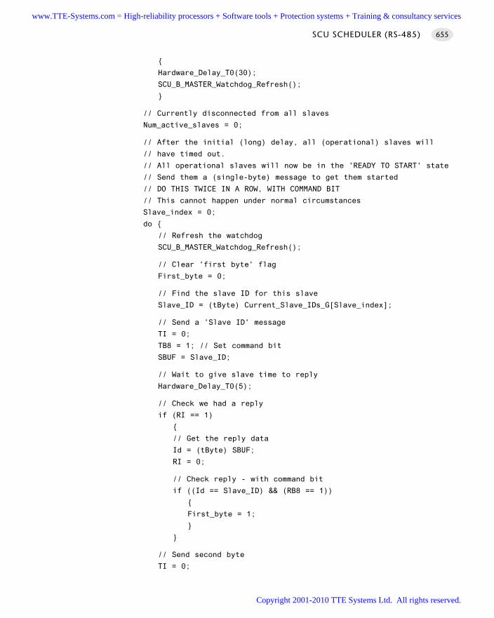
Hardware_Delay_T0(30);
SCU_B_MASTER_Watchdog_Refresh();
// Currently disconnected from all slaves
Num_active_slaves = 0;
// After the initial (long) delay, all (operational) slaves will
// have timed out.
// All operational slaves will now be in the 'READY TO START' state
// Send them a (single-byte) message to get them started
// DO THIS TWICE IN A ROW, WITH COMMAND BIT
// This cannot happen under normal circumstances
Slave_index = 0;
do
// Refresh the watchdog
SCU_B_MASTER_Watchdog_Refresh();
// Clear 'first byte' flag
First_byte = 0;
// Find the slave ID for this slave
Slave_ID = (tByte) Current_Slave_IDs_G[Slave_index];
// Send a 'Slave ID' message
TI = 0;
TB8 = 1; // Set command bit
SBUF = Slave_ID;
// Wait to give slave time to reply
Hardware_Delay_T0(5);
// Check we had a reply
if (RI == 1)
// Get the reply data
Id = (tByte) SBUF;
RI = 0;
// Check reply - with command bit
if ((Id == Slave_ID) && (RB8 == 1))
First_byte = 1;
// Send second byte
TI = 0;
SCU SCHEDULER (RS-485) 655
www.TTE-Systems.com = High-reliability processors + Software tools + Protection systems + Training & consultancy services
Copyright 2001-2010 TTE Systems Ltd. All rights reserved.
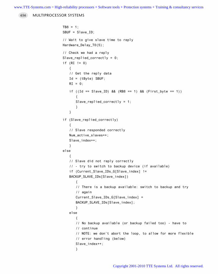
TB8 = 1;
SBUF = Slave_ID;
// Wait to give slave time to reply
Hardware_Delay_T0(5);
// Check we had a reply
Slave_replied_correctly = 0;
if (RI != 0)
// Get the reply data
Id = (tByte) SBUF;
RI = 0;
if ((Id == Slave_ID) && (RB8 == 1) && (First_byte == 1))
Slave_replied_correctly = 1;
if (Slave_replied_correctly)
// Slave responded correctly
Num_active_slaves++;
Slave_index++;
else
// Slave did not reply correctly
// - try to switch to backup device (if available)
if (Current_Slave_IDs_G[Slave_index] !=
BACKUP_SLAVE_IDs[Slave_index])
// There is a backup available: switch to backup and try
// again
Current_Slave_IDs_G[Slave_index] =
BACKUP_SLAVE_IDs[Slave_index];
else
// No backup available (or backup failed too) - have to
// continue
// NOTE: we don’t abort the loop, to allow for more flexible
// error handling (below)
Slave_index++;
MULTIPROCESSOR SYSTEMS656
www.TTE-Systems.com = High-reliability processors + Software tools + Protection systems + Training & consultancy services
Copyright 2001-2010 TTE Systems Ltd. All rights reserved.
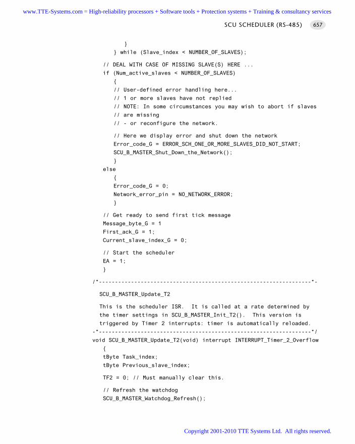
while (Slave_index < NUMBER_OF_SLAVES);
// DEAL WITH CASE OF MISSING SLAVE(S) HERE ...
if (Num_active_slaves < NUMBER_OF_SLAVES)
// User-defined error handling here...
// 1 or more slaves have not replied
// NOTE: In some circumstances you may wish to abort if slaves
// are missing
// - or reconfigure the network.
// Here we display error and shut down the network
Error_code_G = ERROR_SCH_ONE_OR_MORE_SLAVES_DID_NOT_START;
SCU_B_MASTER_Shut_Down_the_Network();
else
Error_code_G = 0;
Network_error_pin = NO_NETWORK_ERROR;
// Get ready to send first tick message
Message_byte_G = 1
First_ack_G = 1;
Current_slave_index_G = 0;
// Start the scheduler
EA = 1;
/*------------------------------------------------------------------*-
SCU_B_MASTER_Update_T2
This is the scheduler ISR. It is called at a rate determined by
the timer settings in SCU_B_MASTER_Init_T2(). This version is
triggered by Timer 2 interrupts: timer is automatically reloaded.
-*------------------------------------------------------------------*/
void SCU_B_MASTER_Update_T2(void) interrupt INTERRUPT_Timer_2_Overflow
tByte Task_index;
tByte Previous_slave_index;
TF2 = 0; // Must manually clear this.
// Refresh the watchdog
SCU_B_MASTER_Watchdog_Refresh();
SCU SCHEDULER (RS-485) 657
www.TTE-Systems.com = High-reliability processors + Software tools + Protection systems + Training & consultancy services
Copyright 2001-2010 TTE Systems Ltd. All rights reserved.
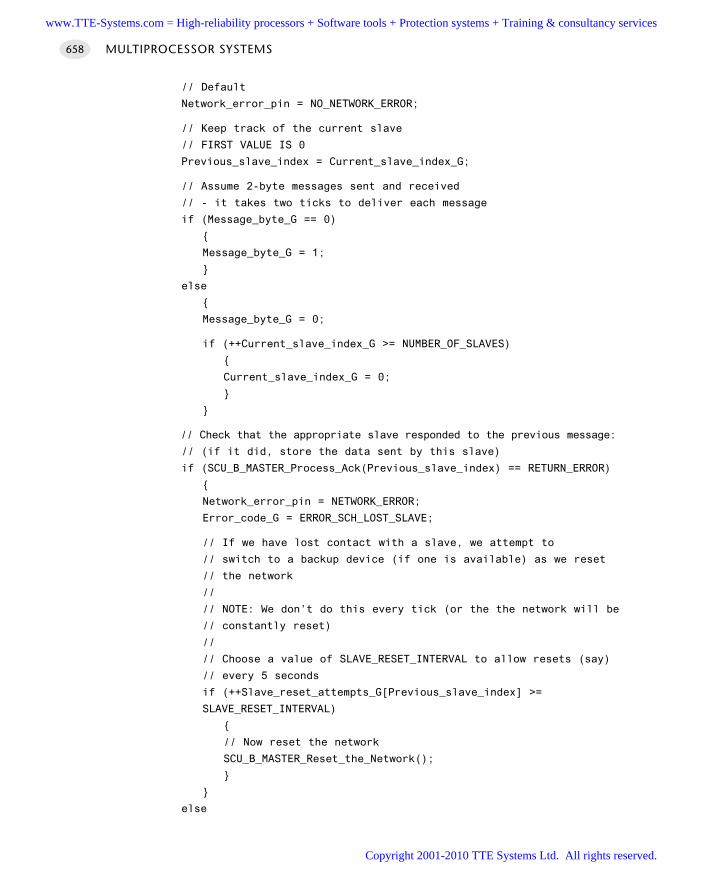
// Default
Network_error_pin = NO_NETWORK_ERROR;
// Keep track of the current slave
// FIRST VALUE IS 0
Previous_slave_index = Current_slave_index_G;
// Assume 2-byte messages sent and received
// - it takes two ticks to deliver each message
if (Message_byte_G == 0)
Message_byte_G = 1;
else
Message_byte_G = 0;
if (++Current_slave_index_G >= NUMBER_OF_SLAVES)
Current_slave_index_G = 0;
// Check that the appropriate slave responded to the previous message:
// (if it did, store the data sent by this slave)
if (SCU_B_MASTER_Process_Ack(Previous_slave_index) == RETURN_ERROR)
Network_error_pin = NETWORK_ERROR;
Error_code_G = ERROR_SCH_LOST_SLAVE;
// If we have lost contact with a slave, we attempt to
// switch to a backup device (if one is available) as we reset
// the network
//
// NOTE: We don’t do this every tick (or the the network will be
// constantly reset)
//
// Choose a value of SLAVE_RESET_INTERVAL to allow resets (say)
// every 5 seconds
if (++Slave_reset_attempts_G[Previous_slave_index] >=
SLAVE_RESET_INTERVAL)
// Now reset the network
SCU_B_MASTER_Reset_the_Network();
else
MULTIPROCESSOR SYSTEMS658
www.TTE-Systems.com = High-reliability processors + Software tools + Protection systems + Training & consultancy services
Copyright 2001-2010 TTE Systems Ltd. All rights reserved.
// Reset this counter
Slave_reset_attempts_G[Previous_slave_index] = 0
// Send 'tick' message to all connected slaves
// (sends one data byte to the current slave)
SCU_B_MASTER_Send_Tick_Message(Current_slave_index_G);
// NOTE: calculations are in *TICKS* (not milliseconds)
for (Task_index = 0; Task_index < SCH_MAX_TASKS; Task_index++)
// Check if there is a task at this location
if (SCH_tasks_G[Task_index].pTask)
if (SCH_tasks_G[Task_index].Delay == 0)
// The task is due to run
SCH_tasks_G[Task_index].RunMe += 1; // Increment the run
// flag
if (SCH_tasks_G[Task_index].Period)
// Schedule periodic tasks to run again
SCH_tasks_G[Task_index].Delay =
SCH_tasks_G[Task_index].Period;
else
// Not yet ready to run: just decrement the delay
SCH_tasks_G[Task_index].Delay -= 1;
/*------------------------------------------------------------------*-
SCU_B_MASTER_Send_Tick_Message()
This function sends a tick message, over the USART network.
The receipt of this message will cause an interrupt to be generated
in the slave(s): this invokes the scheduler 'update' function
in the slave(s).
-*------------------------------------------------------------------*/
SCU SCHEDULER (RS-485) 659
www.TTE-Systems.com = High-reliability processors + Software tools + Protection systems + Training & consultancy services
Copyright 2001-2010 TTE Systems Ltd. All rights reserved.
void SCU_B_MASTER_Send_Tick_Message(const tByte SLAVE_INDEX)
tLong Timeout;
// Find the slave ID for this slave
tByte Slave_ID = (tByte) Current_Slave_IDs_G[SLAVE_INDEX];
// Sending one byte of data at a time, depending on index value
// If Message_byte_G is 0, send first byte (the slave ID)
if (Message_byte_G == 0)
Timeout = 0;
while ((++Timeout) && (TI == 0));
if (Timeout == 0)
// UART did not respond - error
Error_code_G = ERROR_USART_TI;
return;
TI = 0;
TB8 = 1; // Set 'Command' bit
SBUF = Slave_ID;
else
// Message_byte_G is 1, send the data byte
Timeout = 0;
while ((++Timeout) && (TI == 0));
if (Timeout == 0)
// usart did not respond - error
Error_code_G = ERROR_USART_TI;
return;
TI = 0;
TB8 = 0;
SBUF = Tick_message_data_G[SLAVE_INDEX];
// Data sent - return
/*------------------------------------------------------------------*-
MULTIPROCESSOR SYSTEMS660
www.TTE-Systems.com = High-reliability processors + Software tools + Protection systems + Training & consultancy services
Copyright 2001-2010 TTE Systems Ltd. All rights reserved.
SCU_B_MASTER_Process_Ack()
Make sure the slave (SLAVE_ID) has acknowledged the previous
message that was sent. If it has, extract the message data
from the USART hardware: if not, call the appropriate error
handler.
Slave_index - The index of the slave.
RETURNS: RETURN_NORMAL - Ack received (data in Ack_message_data_G)
RETURN_ERROR - No ack received (-> no data)
-*------------------------------------------------------------------*/
bit SCU_B_MASTER_Process_Ack(const tByte Slave_index)
tByte Message_contents;
tByte Slave_ID;
// First time this is called there is no ack tick to check
// - we simply return ‘OK’
if (First_ack_G)
First_ack_G = 0;
return RETURN_NORMAL;
// Find the slave ID for this slave
Slave_ID = (tByte) Current_Slave_IDs_G[Slave_index];
// Data should already be in the buffer
if (RI == 0)
// Slave has not replied to last tick message
// Set error LED
Network_error_pin = NETWORK_ERROR;
return RETURN_ERROR;
// There is data - get it
Message_contents = (tByte) SBUF;
RI = 0;
// This is the reply to the last message
// - reverse the message byte interpretation
if (Message_byte_G == 1)
// Check the ‘command bit’ is set
if (RB8 == 1)
SCU SCHEDULER (RS-485) 661
www.TTE-Systems.com = High-reliability processors + Software tools + Protection systems + Training & consultancy services
Copyright 2001-2010 TTE Systems Ltd. All rights reserved.
// Check that the ID is correct
if (Slave_ID == (tByte) Message_contents)
// Required Ack message was received
return RETURN_NORMAL;
// Something is wrong...
// Set error LED
Network_error_pin = NETWORK_ERROR;
return RETURN_ERROR;
else
// There *ARE* data available
// Extract the data from the slave message
//
// NOTE: We *assume* these data are OK
// - you may wish to send crucial data twice, etc.
Ack_message_data_G[Slave_index] = Message_contents;
return RETURN_NORMAL; // return the slave data
/*------------------------------------------------------------------*-
SCU_B_MASTER_Reset_the_Network()
This function resets (that is, restarts) the whole network.
-*------------------------------------------------------------------*/
void SCU_B_MASTER_Reset_the_Network(void)
EA = 0;
while(1); // Watchdog will time out
/*------------------------------------------------------------------*-
SCU_B_MASTER_Shut_Down_the_Network()
This function shuts down the whole network.
*------------------------------------------------------------------*-/
void SCU_B_MASTER_Shut_Down_the_Network(void)
EA = 0; // Disable interrupts
MULTIPROCESSOR SYSTEMS662
www.TTE-Systems.com = High-reliability processors + Software tools + Protection systems + Training & consultancy services
Copyright 2001-2010 TTE Systems Ltd. All rights reserved.
Network_error_pin = NETWORK_ERROR;
SCH_Report_Status(); // Sch not running - do this manually
while(1)
SCU_B_MASTER_Watchdog_Refresh();
/*------------------------------------------------------------------*-
SCU_B_MASTER_Enter_Safe_State()
This is the state entered by the system when:
(1) The node is powered up or reset
(2) The Master node cannot detect a slave
(3) The network has an error
Try to ensure that the system is in a 'safe' state in these
circumstances.
-*------------------------------------------------------------------*/
void SCU_B_MASTER_Enter_Safe_State(void)
// USER DEFINED - Edit as required
TRAFFIC_LIGHTS_Display_Safe_Output();
/*------------------------------------------------------------------*-
SCU_B_MASTER_Watchdog_Init()
This function sets up the watchdog timer.
If the Master fails (or other error develops),
no tick messages will arrive, and the scheduler
will stop.
To detect this situation, we have a (hardware) watchdog
running in the slave. This watchdog - which should be set to
overflow at around 100 ms - is used to set the system into a
known (safe) state. The slave will then wait (indefinitely)
for the problem to be resolved.
NOTE: The slave will not be generating Ack messages in these
circumstances. The Master (if running) will therefore be aware
that there is a problem.
-*------------------------------------------------------------------*/
void SCU_B_MASTER_Watchdog_Init(void)
SCU SCHEDULER (RS-485) 663
www.TTE-Systems.com = High-reliability processors + Software tools + Protection systems + Training & consultancy services
Copyright 2001-2010 TTE Systems Ltd. All rights reserved.
// INIT NOT REQUIRED FOR 1232 EXTERNAL WATCHDOG
// - May be required with different watchdog hardware
// Edit as required
/*------------------------------------------------------------------*-
SCU_B_MASTER_Watchdog_Refresh()
Feed the external (1232) watchdog.
Timeout is between ~60 and 250 ms (hardware dependent)
Assumes external 1232 watchdog
-*------------------------------------------------------------------*/
void SCU_B_MASTER_Watchdog_Refresh(void) reentrant
// Change the state of the watchdog pin
if (WATCHDOG_state == 1)
WATCHDOG_state_G = 0;
WATCHDOG_pin = 0;
else
WATCHDOG_state_G = 1;
WATCHDOG_pin = 1;
/*------------------------------------------------------------------*-
---- END OF FILE ------------------------------------------------
-*------------------------------------------------------------------*/
Listing 27.3 Part of the software for shared-clock (UART) scheduler demonstrationsystem (Master node)
[Note: Network supports Max489 transceivers and uses the RS-485 protocol.]
Slave software
/*------------------------------------------------------------------*-
SCU_Bs.c (v1.00)
------------------------------------------------------------------
This is an implementation of SCU SCHEDULER (RS-485) for 8051/52.
MULTIPROCESSOR SYSTEMS664
www.TTE-Systems.com = High-reliability processors + Software tools + Protection systems + Training & consultancy services
Copyright 2001-2010 TTE Systems Ltd. All rights reserved.
*** SLAVE / BACKUP NODE ***
*** MASTER CHECKS FOR SLAVE ACKNOWLEDGEMENTS ***
*** Includes support for transceiver enables ***
*** Uses 1232 watchdog timer ***
*** Assumes 12 MHz osc (same as Master) ***
*** Both Master and Slave share the same tick rate (5 ms) ***
*** - See Master code for details ***
-*------------------------------------------------------------------*/
#include "Main.h"
#include "Port.h"
#include "SCU_Bs.h"
#include "TLight_B.h"
// ------ Public variable definitions ------------------------------
// Data sent from the master to this slave
tByte Tick_message_data_G;
// Data sent from this slave to the master
// - data may be sent on, by the master, to another slave
tByte Ack_message_data_G = 'S';
// ------ Public variable declarations -----------------------------
// The array of tasks (see Sch51.c)
extern sTask SCH_tasks_G[SCH_MAX_TASKS];
// The error code variable (see Sch51.c)
extern tByte Error_code_G;
// ------ Private function prototypes ------------------------------
static void SCU_B_SLAVE_Enter_Safe_State(void);
static void SCU_B_SLAVE_Send_Ack_Message_To_Master(void);
static tByte SCU_B_SLAVE_Process_Tick_Message(void);
static void SCU_B_SLAVE_Watchdog_Init(void);
static void SCU_B_SLAVE_Watchdog_Refresh(void) reentrant;
// ------ Private constants ----------------------------------------
// Each slave must have a unique ID
#define SLAVE_ID 0x31
#define NO_NETWORK_ERROR (1)
#define NETWORK_ERROR (0)
SCU SCHEDULER (RS-485) 665
www.TTE-Systems.com = High-reliability processors + Software tools + Protection systems + Training & consultancy services
Copyright 2001-2010 TTE Systems Ltd. All rights reserved.
// ------ Private variables ----------------------------------------
static bit Message–byte_G;
static bit WATCHDOG_state_G = 0
static tByte Message_ID_G = 0
/*------------------------------------------------------------------*-
SCU_B_SLAVE_Init_T1()
Scheduler initialisation function. Prepares scheduler
data structures and sets up timer interrupts at required rate.
Must call this function before using the scheduler.
BAUD_RATE - The required baud rate
-*------------------------------------------------------------------*/
void SCU_B_SLAVE_Init_T1(const tWord BAUD_RATE)
tByte i;
// Sort out the tasks
for (i = 0; i < SCH_MAX_TASKS; i++)
SCH_Delete_Task(i);
// Reset the global error variable
// - SCH_Delete_Task() will generate an error code,
// (because the task array is empty)
Error_code_G = 0;
// Set the network error pin (reset when tick message received)
Network_error_pin = NETWORK_ERROR;
// Set up RS-485 transceiver
RS485_Rx_NOT_Enable = 0; // Receiver is (here) constantly enabled
// (NOTE - negative logic!)
RS485_Tx_Enable = 0; // Transmitter (in slave) is enabled
// only when data are to be transmitted
// by this slave
// Ready for first tick message
Message_byte_G = 1;
// ------ Set the baud rate (begin) -----------------------------
PCON &= 0x7F; // Set SMOD bit to 0 (don't double baud rates)
// receiver enabled
// 9-bit data, 1 start bit, 1 stop bit, variable baud rate
// (asynchronous)
SCON = 0xD2;
MULTIPROCESSOR SYSTEMS666
www.TTE-Systems.com = High-reliability processors + Software tools + Protection systems + Training & consultancy services
Copyright 2001-2010 TTE Systems Ltd. All rights reserved.
TMOD |= 0x20; // T1 in mode 2, 8-bit auto reload
TH1 = (256 - (tByte)((((tLong)OSC_FREQ / 100) * 3125)
/ ((tLong) BAUD_RATE * OSC_PER_INST * 1000)));
TL1 = TH1;
TR1 = 1; // Run the timer
TI = 1; // Send first character (dummy)
// ------ Set the baud rate (end) -------------------------------
// Interrupt enabled
// (Both receiving and SENDING a byte will generate a serial interrupt)
// Global interrupts not yet enabled.
ES = 1;
// Start the watchdog
SCU_B_SLAVE_Watchdog_Init();
/*------------------------------------------------------------------*-
SCU_B_SLAVE_Start()
Starts the slave scheduler, by enabling interrupts.
NOTE: Usually called after all regular tasks are added,
to keep the tasks synchronized.
NOTE: ONLY THE SCHEDULER INTERRUPT SHOULD BE ENABLED!!!
-*------------------------------------------------------------------*/
void SCU_B_SLAVE_Start(void)
tByte Command = 0;
tByte Message_byte;
tByte Count = 0;
bit Slave_started = 0;
// Disable interrupts
EA = 0;
// We can be at this point because:
// 1. The network has just been powered up
// 2. An error has occurred in the Master, and it is not generating
// ticks
// 3. The network has been damaged and no ticks are being received
// by this slave
//
// Try to make sure the system is in a safe state...
SCU_B_SLAVE_Enter_Safe_State();
SCU SCHEDULER (RS-485) 667
www.TTE-Systems.com = High-reliability processors + Software tools + Protection systems + Training & consultancy services
Copyright 2001-2010 TTE Systems Ltd. All rights reserved.
// NOTE: Interrupts are disabled here
Count = 0;
Error_code_G = ERROR_SCH_WAITING_FOR_START_COMMAND_FROM_MASTER;
SCH_Report_Status(); // Sch not yet running - do this manually
// Now wait (indefinitely) for appropriate signals from the master
do
// Wait for tick messages (byte 1), all bits set to 0, to be
// received
do
SCU_B_SLAVE_Watchdog_Refresh(); // Must keep feeding the
// watchdog
while (RI == 0);
Message_byte = (tByte) SBUF;
RI = 0;
// Must get two ID messages in a row...
// (with command bit)
// Ack each one
if ((Message_byte == (tByte) SLAVE_ID) && (RB8 == 1))
Count++;
// Received message for this slave - send ack
// Must enable the slave RS-485 (Max489) hardware (Tx)
RS485_Tx_Enable = 1;
TI = 0;
TB8 = 1; // Set command bit
SBUF = (tByte) SLAVE_ID;
// Wait while data are sent
// (watchdog will trap UART failure...)
while (TI ==0)
// Now clear Tx enable pin
RS485_Tx_Enable = 0;
else
Count = 0;
while (Count < 2);
// Start the scheduler
EA = 1;
MULTIPROCESSOR SYSTEMS668
www.TTE-Systems.com = High-reliability processors + Software tools + Protection systems + Training & consultancy services
Copyright 2001-2010 TTE Systems Ltd. All rights reserved.
/*------------------------------------------------------------------*-
SCU_B_SLAVE_Update
This is the scheduler ISR. It is called at a rate
determined by the timer settings in SCU_B_SLAVE_Init().
This Slave is triggered by USART interrupts.
-*------------------------------------------------------------------*/
void SCU_B_SLAVE_Update(void) interrupt INTERRUPT_UART_Rx_Tx
tByte Index;
if (RI == 1) // Must check this.
// Default
Network_error_pin = NO_NETWORK_ERROR;
// Two-byte messages are sent (Ack) and received (Tick)
// - it takes two sched ticks to process each message
//
// Keep track of the current byte
if (Message_byte_G == 0)
Message_byte_G = 1;
else
Message_byte_G = 0;
// Check tick data - send ack if necessary
// NOTE: 'START' message will only be sent after a 'time out'
if (SCU_B_SLAVE_Process_Tick_Message() == SLAVE_ID)
SCU_B_SLAVE_Send_Ack_Message_To_Master();
// Feed the watchdog ONLY when a *relevant* message is
// received
// (noise on the bus, etc, will not stop the watchdog...)
//
// START messages will NOT refresh the slave
// - Must talk to every slave at regular intervals
SCU_B_SLAVE_Watchdog_Refresh();
// NOTE: calculations are in *TICKS* (not milliseconds)
for (Index = 0; Index < SCH_MAX_TASKS; Index++)
SCU SCHEDULER (RS-485) 669
www.TTE-Systems.com = High-reliability processors + Software tools + Protection systems + Training & consultancy services
Copyright 2001-2010 TTE Systems Ltd. All rights reserved.
// Check if there is a task at this location
if (SCH_tasks_G[Index].pTask)
if (SCH_tasks_G[Index].Delay == 0)
// The task is due to run
SCH_tasks_G[Index].RunMe = 1; // Set the run flag
if (SCH_tasks_G[Index].Period)
// Schedule periodic tasks to run again
SCH_tasks_G[Index].Delay =
SCH_tasks_G[Index].Period;
else
// Not yet ready to run: just decrement the delay
SCH_tasks_G[Index].Delay -= 1;
RI = 0; // Reset the RI flag
else
// ISR call was triggered by TI flag, after last character was sent
// RS485_Tx_Enable flag is reset here
RS485_Tx_Enable = 0;
// Must clear the TI flag
TI = 0;
/*------------------------------------------------------------------*-
SCU_B_SLAVE_Send_Ack_Message_To_Master()
Slave must send and 'Acknowledge' message to the master, after
tick messages are received. NOTE: Only tick messages specifically
addressed to this slave should be acknowledged.
The acknowledge message serves two purposes:
[1] It confirms to the master that this slave is alive & well.
[2] It provides a means of sending data to the master and - hence
- to other slaves.
MULTIPROCESSOR SYSTEMS670
www.TTE-Systems.com = High-reliability processors + Software tools + Protection systems + Training & consultancy services
Copyright 2001-2010 TTE Systems Ltd. All rights reserved.
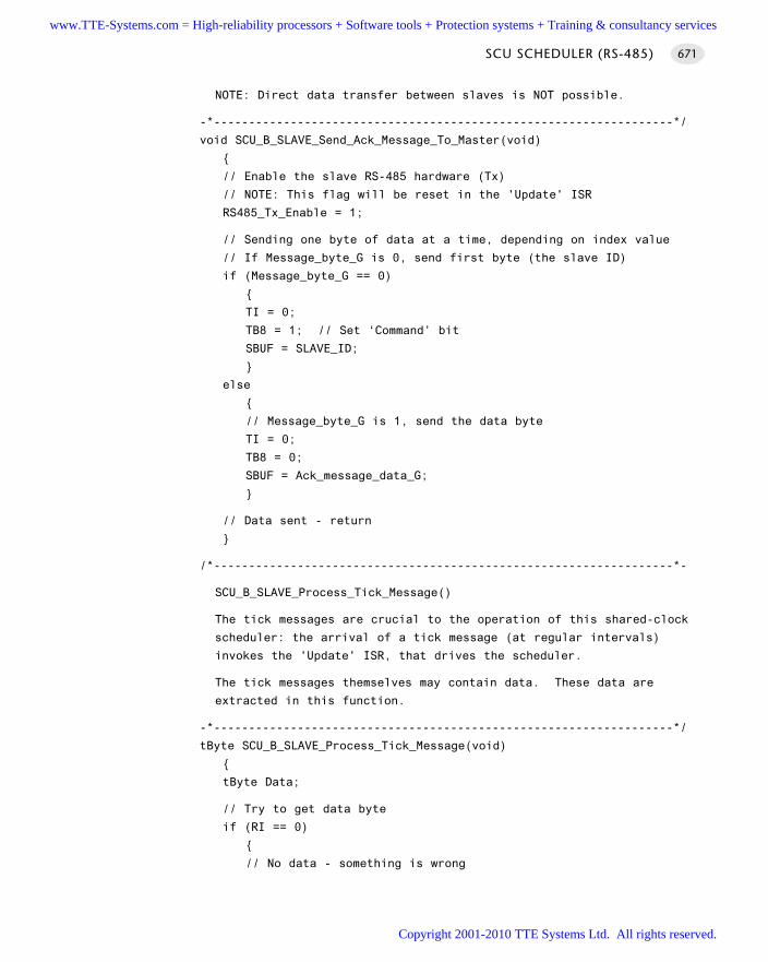
NOTE: Direct data transfer between slaves is NOT possible.
-*------------------------------------------------------------------*/
void SCU_B_SLAVE_Send_Ack_Message_To_Master(void)
// Enable the slave RS-485 hardware (Tx)
// NOTE: This flag will be reset in the 'Update' ISR
RS485_Tx_Enable = 1;
// Sending one byte of data at a time, depending on index value
// If Message_byte_G is 0, send first byte (the slave ID)
if (Message_byte_G == 0)
TI = 0;
TB8 = 1; // Set ‘Command’ bit
SBUF = SLAVE_ID;
else
// Message_byte_G is 1, send the data byte
TI = 0;
TB8 = 0;
SBUF = Ack_message_data_G;
// Data sent - return
/*------------------------------------------------------------------*-
SCU_B_SLAVE_Process_Tick_Message()
The tick messages are crucial to the operation of this shared-clock
scheduler: the arrival of a tick message (at regular intervals)
invokes the 'Update' ISR, that drives the scheduler.
The tick messages themselves may contain data. These data are
extracted in this function.
-*------------------------------------------------------------------*/
tByte SCU_B_SLAVE_Process_Tick_Message(void)
tByte Data;
// Try to get data byte
if (RI == 0)
// No data - something is wrong
SCU SCHEDULER (RS-485) 671
www.TTE-Systems.com = High-reliability processors + Software tools + Protection systems + Training & consultancy services
Copyright 2001-2010 TTE Systems Ltd. All rights reserved.
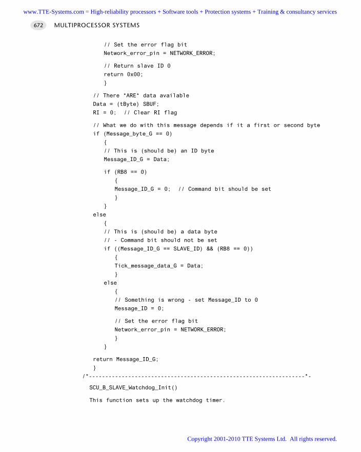
// Set the error flag bit
Network_error_pin = NETWORK_ERROR;
// Return slave ID 0
return 0x00;
// There *ARE* data available
Data = (tByte) SBUF;
RI = 0; // Clear RI flag
// What we do with this message depends if it a first or second byte
if (Message_byte_G == 0)
// This is (should be) an ID byte
Message_ID_G = Data;
if (RB8 == 0)
Message_ID_G = 0; // Command bit should be set
else
// This is (should be) a data byte
// - Command bit should not be set
if ((Message_ID_G == SLAVE_ID) && (RB8 == 0))
Tick_message_data_G = Data;
else
// Something is wrong - set Message_ID to 0
Message_ID = 0;
// Set the error flag bit
Network_error_pin = NETWORK_ERROR;
return Message_ID_G;
/*------------------------------------------------------------------*-
SCU_B_SLAVE_Watchdog_Init()
This function sets up the watchdog timer.
MULTIPROCESSOR SYSTEMS672
www.TTE-Systems.com = High-reliability processors + Software tools + Protection systems + Training & consultancy services
Copyright 2001-2010 TTE Systems Ltd. All rights reserved.
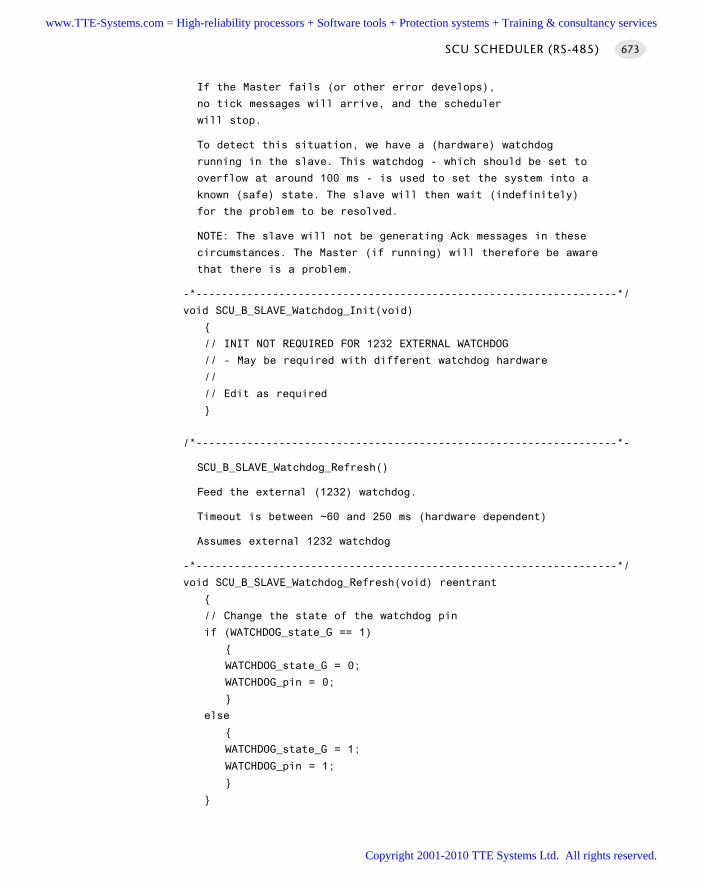
If the Master fails (or other error develops),
no tick messages will arrive, and the scheduler
will stop.
To detect this situation, we have a (hardware) watchdog
running in the slave. This watchdog - which should be set to
overflow at around 100 ms - is used to set the system into a
known (safe) state. The slave will then wait (indefinitely)
for the problem to be resolved.
NOTE: The slave will not be generating Ack messages in these
circumstances. The Master (if running) will therefore be aware
that there is a problem.
-*------------------------------------------------------------------*/
void SCU_B_SLAVE_Watchdog_Init(void)
// INIT NOT REQUIRED FOR 1232 EXTERNAL WATCHDOG
// - May be required with different watchdog hardware
//
// Edit as required
/*------------------------------------------------------------------*-
SCU_B_SLAVE_Watchdog_Refresh()
Feed the external (1232) watchdog.
Timeout is between ~60 and 250 ms (hardware dependent)
Assumes external 1232 watchdog
-*------------------------------------------------------------------*/
void SCU_B_SLAVE_Watchdog_Refresh(void) reentrant
// Change the state of the watchdog pin
if (WATCHDOG_state_G == 1)
WATCHDOG_state_G = 0;
WATCHDOG_pin = 0;
else
WATCHDOG_state_G = 1;
WATCHDOG_pin = 1;
SCU SCHEDULER (RS-485) 673
www.TTE-Systems.com = High-reliability processors + Software tools + Protection systems + Training & consultancy services
Copyright 2001-2010 TTE Systems Ltd. All rights reserved.
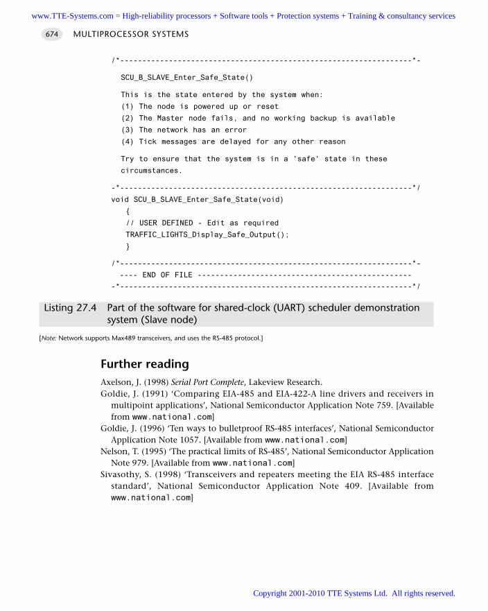
/*------------------------------------------------------------------*-
SCU_B_SLAVE_Enter_Safe_State()
This is the state entered by the system when:
(1) The node is powered up or reset
(2) The Master node fails, and no working backup is available
(3) The network has an error
(4) Tick messages are delayed for any other reason
Try to ensure that the system is in a 'safe' state in these
circumstances.
-*------------------------------------------------------------------*/
void SCU_B_SLAVE_Enter_Safe_State(void)
// USER DEFINED - Edit as required
TRAFFIC_LIGHTS_Display_Safe_Output();
/*------------------------------------------------------------------*-
---- END OF FILE ------------------------------------------------
-*------------------------------------------------------------------*/
Listing 27.4 Part of the software for shared-clock (UART) scheduler demonstrationsystem (Slave node)
[Note: Network supports Max489 transceivers, and uses the RS-485 protocol.]
Further readingAxelson, J. (1998) Serial Port Complete, Lakeview Research.Goldie, J. (1991) ‘Comparing EIA-485 and EIA-422-A line drivers and receivers in
multipoint applications’, National Semiconductor Application Note 759. [Availablefrom www.national.com]
Goldie, J. (1996) ‘Ten ways to bulletproof RS-485 interfaces’, National SemiconductorApplication Note 1057. [Available from www.national.com]
Nelson, T. (1995) ‘The practical limits of RS-485’, National Semiconductor ApplicationNote 979. [Available from www.national.com]
Sivasothy, S. (1998) ‘Transceivers and repeaters meeting the EIA RS-485 interfacestandard’, National Semiconductor Application Note 409. [Available fromwww.national.com]
MULTIPROCESSOR SYSTEMS674
www.TTE-Systems.com = High-reliability processors + Software tools + Protection systems + Training & consultancy services
Copyright 2001-2010 TTE Systems Ltd. All rights reserved.
Shared-clock schedulers using CAN
Introduction
In the previous chapter we introduced methods, based on ‘RS-232’ and ‘RS-485’ com-munication protocols, to allow us to extend the co-operative scheduler discussed inPart C for use in a distributed, multiprocessor environment.
One key advantage of using such environments is that the essential (UART) hard-ware is available in all members of the 8051 family, as well as the great majority ofother microcontroller devices (8-bit, 16-bit, 32-bit or greater). As a result, creatingpoint-to-point and multiprocessor distributed (and local) systems in this way is a cost-effective solution that may be widely applied.
However, UART-based communication protocols suffer from two significant weak-nesses in a shared-clock environment:
The UART supports byte-based communications only: data transfer betweenMaster and Slaves (and vice versa) is limited to 0.5 bytes per clock tick.
The hardware has a very limited ability to detect errors: most error detection /correction must be carried out in software.
In the late 1970s the automotive industry began to tackle very similar problems.The motivation was largely that the wiring looms in passenger cars were becominglarger, heavier and more expensive. The industry was looking for a form of cheap,multi-drop serial bus to which numerous different system components could be con-nected (see Lawrenz, 1997, for further details).
From this need arose the ‘controller area network’ (CAN). CAN is now becomingcommonplace in vehicles produced by most major automotive manufacturers. It isalso widely used in process control and other industrial areas.
chapter 28www.TTE-Systems.com = High-reliability processors + Software tools + Protection systems + Training & consultancy services
Copyright 2001-2010 TTE Systems Ltd. All rights reserved.
We can summarize some of the features of CAN as follows:
CAN is message based and messages can be up to eight bytes in length. Usedin a shared-clock scheduler, the data transfer between Master and Slaves(and vice versa) is up to seven bytes per clock tick. This is adequate formost applications.
A number of 8051 devices have on-chip support for CAN, allowing the proto-col to be used with minimal overheads.
The hardware has advanced error-detection (and correction) facilities builtin, further reducing the software load.
CAN may be used for both ‘local’ and ‘distributed’ systems.
In this chapter, we will consider how we can use the CAN bus as an efficient meansof creating reliable, shared-clock, multiprocessor systems.
MULTIPROCESSOR SYSTEMS676
www.TTE-Systems.com = High-reliability processors + Software tools + Protection systems + Training & consultancy services
Copyright 2001-2010 TTE Systems Ltd. All rights reserved.
SCC SCHEDULER
Context You are developing an embedded application using more than one member of the
8051 family of microcontrollers.
The application has a time-triggered architecture, based on a scheduler.
ProblemHow do you schedule tasks on (and transfer data over) a network of two (or more)8051 microcontrollers communicating using the CAN protocol?
BackgroundWe consider some relevant background material in this section
What is a shared-clock scheduler?
See Chapter 25 for general background material on shared-clock schedulers.
What is CAN?
We begin our discussion of the controller area network (CAN) protocol by highlight-ing some important features of this standard:
CAN supports high-speed (1 Mbits/s) data transmission over short distances (40 m)and low-speed (5 kbits/s) transmissions at lengths of up to 10,000 m.
CAN is message based. The data in each message may vary in length between 0 andeight bytes. This data length is ideal for many embedded applications.
The receipt of a message can be used to generate an interrupt. The interrupt will begenerated only when a complete message (up to eight bytes of data) has beenreceived: this is unlike a UART (for example) which will respond to every character.
CAN is a shared broadcast bus: all messages are sent to all nodes. However, eachmessage has an identifier: this can be used to ‘filter’ messages. This means that – byusing a ‘Full CAN’ controller (see later) – we can ensure that a particular node willonly respond to ‘relevant’ messages: that is, messages with a particular ID.
This is very powerful. What it means in practice is, for example, that a Slavenode can be set to ignore all messages directed from a different Slave to the Master.
CAN is usually implemented on a simple, low-cost, two-wire differential serial bussystem. Other physical media may be used, such as fibre optics (but this is compar-atively rare).
SCC SCHEDULER 677
www.TTE-Systems.com = High-reliability processors + Software tools + Protection systems + Training & consultancy services
Copyright 2001-2010 TTE Systems Ltd. All rights reserved.
The maximum number of nodes on a CAN bus is 32.
Messages can be given an individual priority. This means, for example, that ‘Tickmessages’ can be given a higher priority than ‘Acknowledge messages’.
CAN is highly fault tolerant, with powerful error-detection and handling mecha-nisms built into the controller.
Last, but not least, microcontrollers with built-in CAN controllers are available froma range of companies. For example, 8051 devices with CAN controllers are availablefrom Infineon (c505c, c515c), Philips (8xC592, 8xC598) and Dallas (80C390).
Overall, as we will see in the course of this chapter, the CAN bus provides an excel-lent foundation for reliable distributed scheduled applications.
We now consider some of the important features of CAN in more detail.
CAN 1.0 vs. CAN 2.0
The CAN protocol comes in two versions: CAN 1.0 and CAN 2.0. CAN 2.0 is back-wardly compatible with CAN 1.0 and most new controllers are CAN 2.0.
In addition, there are two parts to the CAN 2.0 standard: Part A and Part B. WithCAN 1.0 and CAN 2.0A, identifiers must be 11 bits long. With CAN 2.0B identifierscan be 11 bits (a ‘standard’ identifier) or 29 bits (an ‘extended’ identifier).
The following basic compatibility rules apply:
CAN 2.0B active controllers are able to send and receive both standard andextended messages.
CAN 2.0B passive controllers are able to send and receive standard messages. Inaddition, they will discard (and ignore) extended frames. They will not generate anerror when they ‘see’ extended messages.
CAN 1.0 controllers generate bus errors when they see extended frames: theycannot be used on networks where extended identifiers are used.
Basic CAN vs. Full CAN
There are two main classes of CAN controller available. Note that these classes are notcovered by the standard, so there is some variation. As noted already, the difference isthat Full CAN controllers provide an acceptance filter that allows a node to ignoreirrelevant messages.
Which microcontrollers have support for CAN?
At the time of writing, the following 8051 devices provide on-chip CAN support:
Dallas 80c390. Two on-chip CAN modules, each supporting CAN 2.0B.
Infineon C505C. Supports CAN2.0B.
Infineon C515C. Supports CAN2.0B.
MULTIPROCESSOR SYSTEMS678
www.TTE-Systems.com = High-reliability processors + Software tools + Protection systems + Training & consultancy services
Copyright 2001-2010 TTE Systems Ltd. All rights reserved.
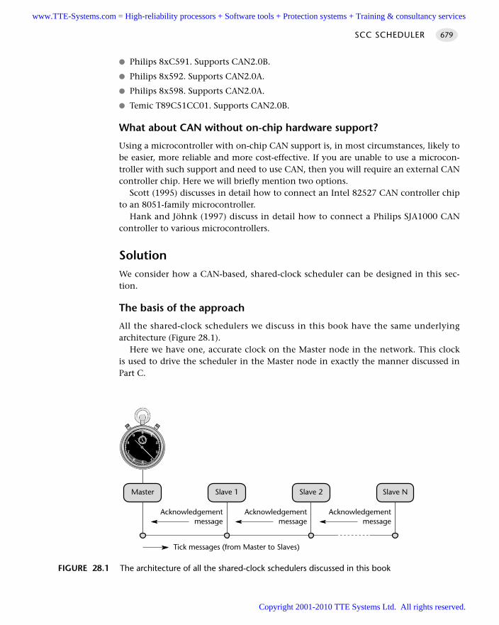
Philips 8xC591. Supports CAN2.0B.
Philips 8x592. Supports CAN2.0A.
Philips 8x598. Supports CAN2.0A.
Temic T89C51CC01. Supports CAN2.0B.
What about CAN without on-chip hardware support?
Using a microcontroller with on-chip CAN support is, in most circumstances, likely tobe easier, more reliable and more cost-effective. If you are unable to use a microcon-troller with such support and need to use CAN, then you will require an external CANcontroller chip. Here we will briefly mention two options.
Scott (1995) discusses in detail how to connect an Intel 82527 CAN controller chipto an 8051-family microcontroller.
Hank and Jöhnk (1997) discuss in detail how to connect a Philips SJA1000 CANcontroller to various microcontrollers.
SolutionWe consider how a CAN-based, shared-clock scheduler can be designed in this sec-tion.
The basis of the approach
All the shared-clock schedulers we discuss in this book have the same underlyingarchitecture (Figure 28.1).
Here we have one, accurate clock on the Master node in the network. This clockis used to drive the scheduler in the Master node in exactly the manner discussed inPart C.
SCC SCHEDULER 679
FIGURE 28.1 The architecture of all the shared-clock schedulers discussed in this book
Master Slave 1 Slave 2 Slave N
Tick messages (from Master to Slaves)
Acknowledgementmessage
Acknowledgementmessage
Acknowledgementmessage
www.TTE-Systems.com = High-reliability processors + Software tools + Protection systems + Training & consultancy services
Copyright 2001-2010 TTE Systems Ltd. All rights reserved.
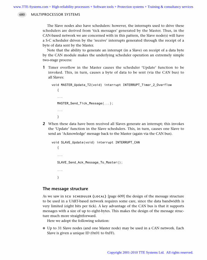
The Slave nodes also have schedulers: however, the interrupts used to drive theseschedulers are derived from ‘tick messages’ generated by the Master. Thus, in theCAN-based network we are concerned with in this pattern, the Slave node(s) will havea S-C scheduler driven by the ‘receive’ interrupts generated through the receipt of abyte of data sent by the Master.
Note that the ability to generate an interrupt (in a Slave) on receipt of a data byteby the CAN module makes the underlying scheduler operation an extremely simpletwo-stage process:
1 Timer overflow in the Master causes the scheduler ‘Update’ function to beinvoked. This, in turn, causes a byte of data to be sent (via the CAN bus) toall Slaves:
void MASTER_Update_T2(void) interrupt INTERRUPT_Timer_2_Overflow
...
MASTER_Send_Tick_Message(...);
...
2 When these data have been received all Slaves generate an interrupt; this invokesthe ‘Update’ function in the Slave schedulers. This, in turn, causes one Slave tosend an ‘Acknowledge’ message back to the Master (again via the CAN bus).
void SLAVE_Update(void) interrupt INTERRUPT_CAN
...
SLAVE_Send_Ack_Message_To_Master();
...
The message structure
As we saw in S C U S C H E D U L E R (L O C A L) [page 609] the design of the message structureto be used in a UART-based network requires some care, since the data bandwidth isvery limited (eight bits per tick). A key advantage of the CAN bus is that it supportsmessages with a size of up to eight-bytes. This makes the design of the message struc-ture much more straightforward.
Here we adopt the following solution:
Up to 31 Slave nodes (and one Master node) may be used in a CAN network. EachSlave is given a unique ID (0x01 to 0xFF).
MULTIPROCESSOR SYSTEMS680
www.TTE-Systems.com = High-reliability processors + Software tools + Protection systems + Training & consultancy services
Copyright 2001-2010 TTE Systems Ltd. All rights reserved.
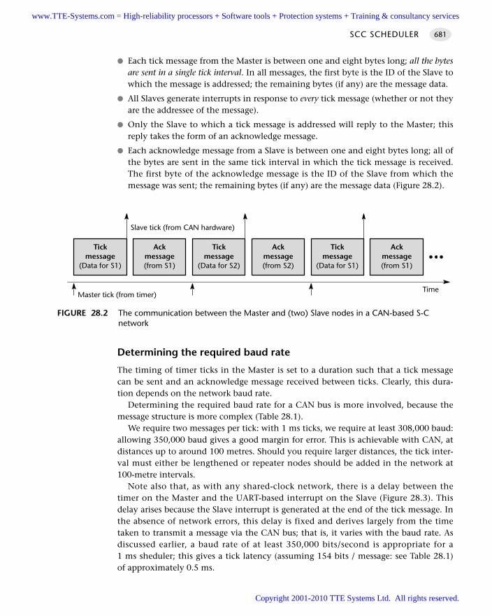
Each tick message from the Master is between one and eight bytes long; all the bytesare sent in a single tick interval. In all messages, the first byte is the ID of the Slave towhich the message is addressed; the remaining bytes (if any) are the message data.
All Slaves generate interrupts in response to every tick message (whether or not theyare the addressee of the message).
Only the Slave to which a tick message is addressed will reply to the Master; thisreply takes the form of an acknowledge message.
Each acknowledge message from a Slave is between one and eight bytes long; all ofthe bytes are sent in the same tick interval in which the tick message is received.The first byte of the acknowledge message is the ID of the Slave from which themessage was sent; the remaining bytes (if any) are the message data (Figure 28.2).
Determining the required baud rate
The timing of timer ticks in the Master is set to a duration such that a tick messagecan be sent and an acknowledge message received between ticks. Clearly, this dura-tion depends on the network baud rate.
Determining the required baud rate for a CAN bus is more involved, because themessage structure is more complex (Table 28.1).
We require two messages per tick: with 1 ms ticks, we require at least 308,000 baud:allowing 350,000 baud gives a good margin for error. This is achievable with CAN, atdistances up to around 100 metres. Should you require larger distances, the tick inter-val must either be lengthened or repeater nodes should be added in the network at100-metre intervals.
Note also that, as with any shared-clock network, there is a delay between thetimer on the Master and the UART-based interrupt on the Slave (Figure 28.3). Thisdelay arises because the Slave interrupt is generated at the end of the tick message. Inthe absence of network errors, this delay is fixed and derives largely from the timetaken to transmit a message via the CAN bus; that is, it varies with the baud rate. Asdiscussed earlier, a baud rate of at least 350,000 bits/second is appropriate for a1 ms sheduler; this gives a tick latency (assuming 154 bits / message: see Table 28.1)of approximately 0.5 ms.
SCC SCHEDULER 681
FIGURE 28.2 The communication between the Master and (two) Slave nodes in a CAN-based S-Cnetwork
Tickmessage
(Data for S1)
Ackmessage(from S1)
Tickmessage
(Data for S2)
Ackmessage(from S2)
Tickmessage
(Data for S1)
Ackmessage(from S1)
Slave tick (from CAN hardware)
Master tick (from timer)Time
www.TTE-Systems.com = High-reliability processors + Software tools + Protection systems + Training & consultancy services
Copyright 2001-2010 TTE Systems Ltd. All rights reserved.
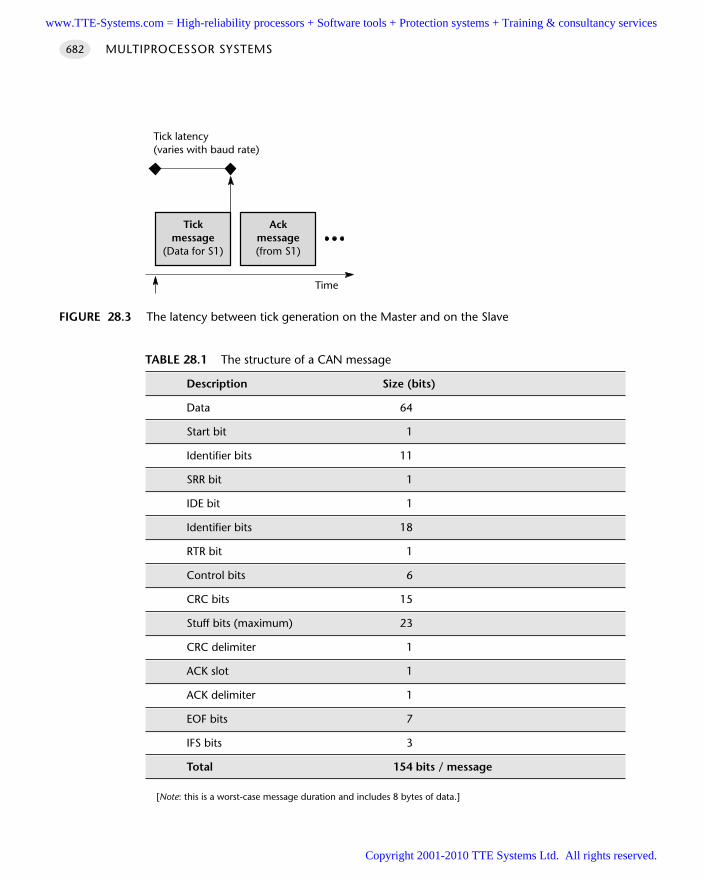
MULTIPROCESSOR SYSTEMS682
TABLE 28.1 The structure of a CAN message
Description Size (bits)
Data 64
Start bit 1
Identifier bits 11
SRR bit 1
IDE bit 1
Identifier bits 18
RTR bit 1
Control bits 6
CRC bits 15
Stuff bits (maximum) 23
CRC delimiter 1
ACK slot 1
ACK delimiter 1
EOF bits 7
IFS bits 3
Total 154 bits / message
[Note: this is a worst-case message duration and includes 8 bytes of data.]
FIGURE 28.3 The latency between tick generation on the Master and on the Slave
Tickmessage
(Data for S1)
Ackmessage(from S1)
Time
Tick latency(varies with baud rate)
www.TTE-Systems.com = High-reliability processors + Software tools + Protection systems + Training & consultancy services
Copyright 2001-2010 TTE Systems Ltd. All rights reserved.
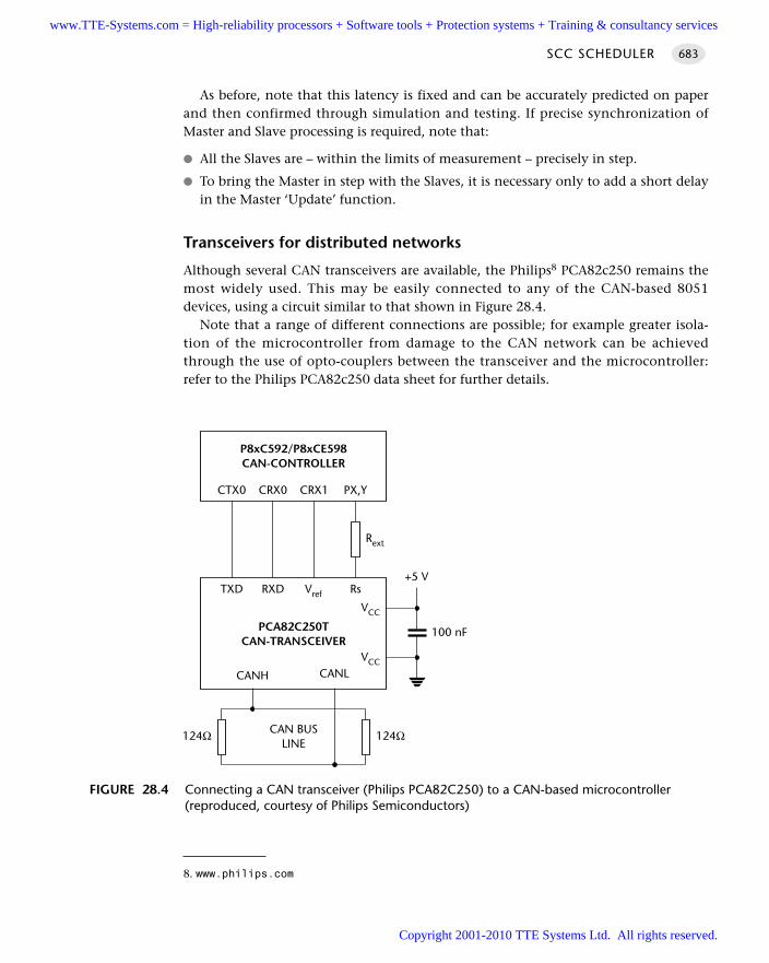
As before, note that this latency is fixed and can be accurately predicted on paperand then confirmed through simulation and testing. If precise synchronization ofMaster and Slave processing is required, note that:
All the Slaves are – within the limits of measurement – precisely in step.
To bring the Master in step with the Slaves, it is necessary only to add a short delayin the Master ‘Update’ function.
Transceivers for distributed networks
Although several CAN transceivers are available, the Philips8 PCA82c250 remains themost widely used. This may be easily connected to any of the CAN-based 8051devices, using a circuit similar to that shown in Figure 28.4.
Note that a range of different connections are possible; for example greater isola-tion of the microcontroller from damage to the CAN network can be achievedthrough the use of opto-couplers between the transceiver and the microcontroller:refer to the Philips PCA82c250 data sheet for further details.
SCC SCHEDULER 683
FIGURE 28.4 Connecting a CAN transceiver (Philips PCA82C250) to a CAN-based microcontroller(reproduced, courtesy of Philips Semiconductors)
P8xC592/P8xCE598CAN-CONTROLLER
CTX0 CRX0 CRX1 PX,Y
Rext
PCA82C250TCAN-TRANSCEIVER
TXD RXD Vref Rs
VCC
CANH CANLVCC
100 nF
124Ω CAN BUSLINE
+5 V
124Ω
8. www.philips.com
www.TTE-Systems.com = High-reliability processors + Software tools + Protection systems + Training & consultancy services
Copyright 2001-2010 TTE Systems Ltd. All rights reserved.
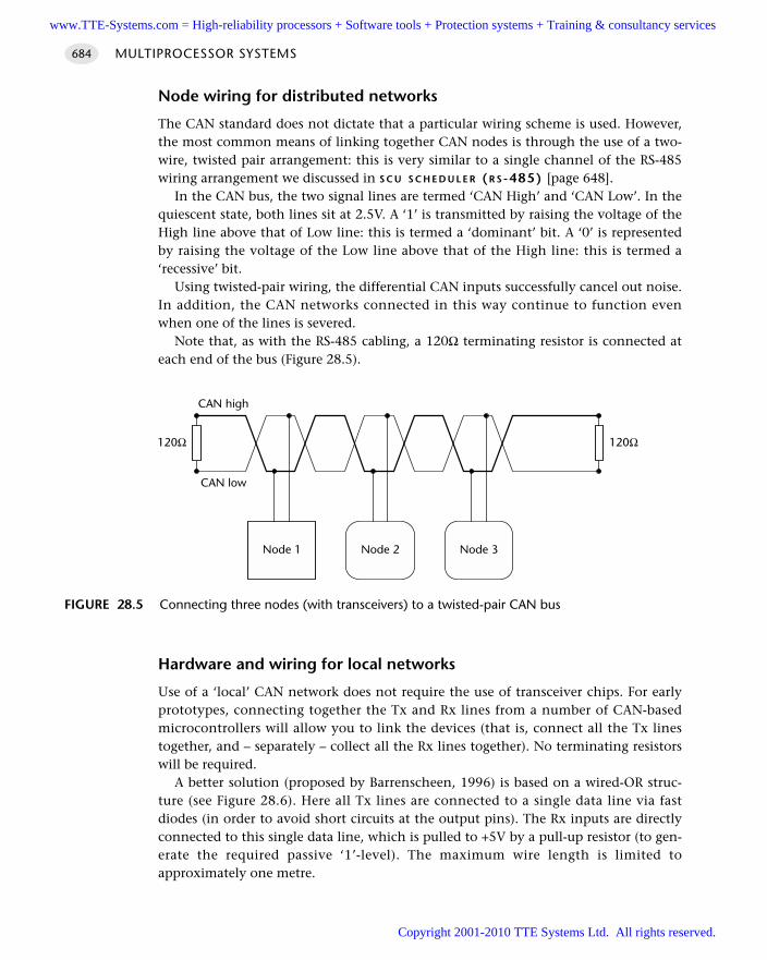
Node wiring for distributed networks
The CAN standard does not dictate that a particular wiring scheme is used. However,the most common means of linking together CAN nodes is through the use of a two-wire, twisted pair arrangement: this is very similar to a single channel of the RS-485wiring arrangement we discussed in S C U S C H E D U L E R (R S -485) [page 648].
In the CAN bus, the two signal lines are termed ‘CAN High’ and ‘CAN Low’. In thequiescent state, both lines sit at 2.5V. A ‘1’ is transmitted by raising the voltage of theHigh line above that of Low line: this is termed a ‘dominant’ bit. A ‘0’ is representedby raising the voltage of the Low line above that of the High line: this is termed a‘recessive’ bit.
Using twisted-pair wiring, the differential CAN inputs successfully cancel out noise.In addition, the CAN networks connected in this way continue to function evenwhen one of the lines is severed.
Note that, as with the RS-485 cabling, a 120Ω terminating resistor is connected ateach end of the bus (Figure 28.5).
Hardware and wiring for local networks
Use of a ‘local’ CAN network does not require the use of transceiver chips. For earlyprototypes, connecting together the Tx and Rx lines from a number of CAN-basedmicrocontrollers will allow you to link the devices (that is, connect all the Tx linestogether, and – separately – collect all the Rx lines together). No terminating resistorswill be required.
A better solution (proposed by Barrenscheen, 1996) is based on a wired-OR struc-ture (see Figure 28.6). Here all Tx lines are connected to a single data line via fastdiodes (in order to avoid short circuits at the output pins). The Rx inputs are directlyconnected to this single data line, which is pulled to +5V by a pull-up resistor (to gen-erate the required passive ‘1’-level). The maximum wire length is limited toapproximately one metre.
MULTIPROCESSOR SYSTEMS684
FIGURE 28.5 Connecting three nodes (with transceivers) to a twisted-pair CAN bus
120Ω120Ω
Node 1 Node 2 Node 3
CAN high
CAN low
www.TTE-Systems.com = High-reliability processors + Software tools + Protection systems + Training & consultancy services
Copyright 2001-2010 TTE Systems Ltd. All rights reserved.
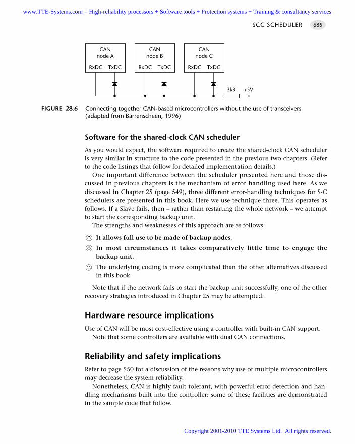
Software for the shared-clock CAN scheduler
As you would expect, the software required to create the shared-clock CAN scheduleris very similar in structure to the code presented in the previous two chapters. (Referto the code listings that follow for detailed implementation details.)
One important difference between the scheduler presented here and those dis-cussed in previous chapters is the mechanism of error handling used here. As wediscussed in Chapter 25 (page 549), three different error-handling techniques for S-Cschedulers are presented in this book. Here we use technique three. This operates asfollows. If a Slave fails, then – rather than restarting the whole network – we attemptto start the corresponding backup unit.
The strengths and weaknesses of this approach are as follows:
It allows full use to be made of backup nodes.
In most circumstances it takes comparatively little time to engage thebackup unit.
The underlying coding is more complicated than the other alternatives discussedin this book.
Note that if the network fails to start the backup unit successfully, one of the otherrecovery strategies introduced in Chapter 25 may be attempted.
Hardware resource implicationsUse of CAN will be most cost-effective using a controller with built-in CAN support.
Note that some controllers are available with dual CAN connections.
Reliability and safety implicationsRefer to page 550 for a discussion of the reasons why use of multiple microcontrollersmay decrease the system reliability.
Nonetheless, CAN is highly fault tolerant, with powerful error-detection and han-dling mechanisms built into the controller: some of these facilities are demonstratedin the sample code that follow.
SCC SCHEDULER 685
FIGURE 28.6 Connecting together CAN-based microcontrollers without the use of transceivers(adapted from Barrenscheen, 1996)
CANnode A
RxDC TxDC
CANnode B
RxDC TxDC
CANnode C
RxDC TxDC
3k3 +5V
www.TTE-Systems.com = High-reliability processors + Software tools + Protection systems + Training & consultancy services
Copyright 2001-2010 TTE Systems Ltd. All rights reserved.
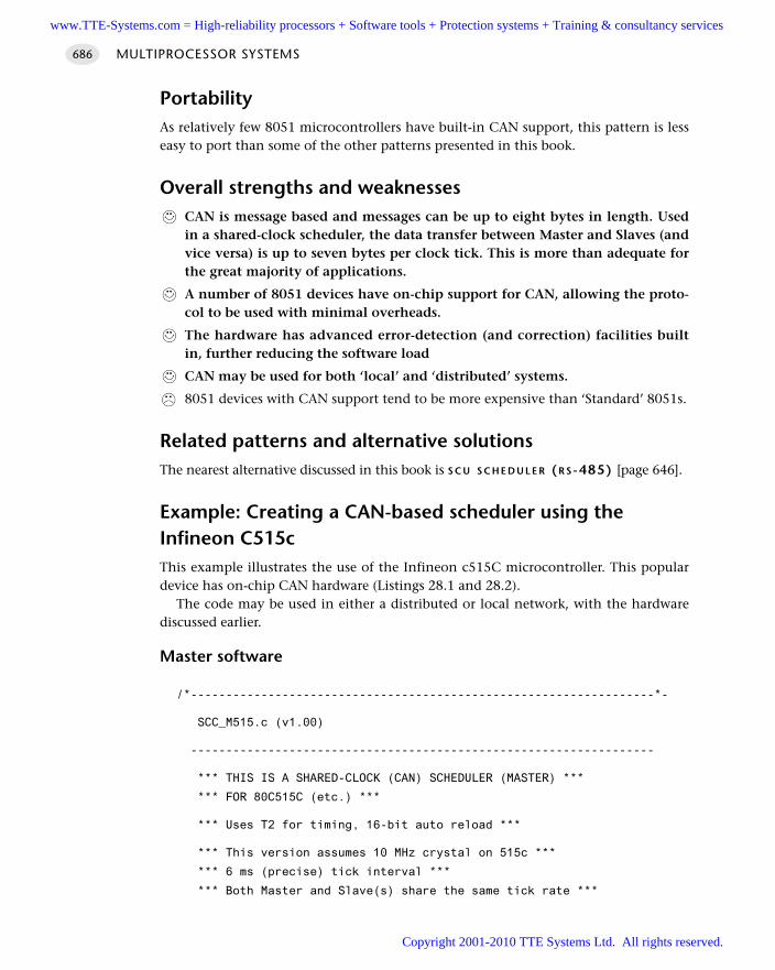
PortabilityAs relatively few 8051 microcontrollers have built-in CAN support, this pattern is lesseasy to port than some of the other patterns presented in this book.
Overall strengths and weaknessesCAN is message based and messages can be up to eight bytes in length. Usedin a shared-clock scheduler, the data transfer between Master and Slaves (andvice versa) is up to seven bytes per clock tick. This is more than adequate forthe great majority of applications.
A number of 8051 devices have on-chip support for CAN, allowing the proto-col to be used with minimal overheads.
The hardware has advanced error-detection (and correction) facilities builtin, further reducing the software load
CAN may be used for both ‘local’ and ‘distributed’ systems.
8051 devices with CAN support tend to be more expensive than ‘Standard’ 8051s.
Related patterns and alternative solutionsThe nearest alternative discussed in this book is S C U S C H E D U L E R (R S -485) [page 646].
Example: Creating a CAN-based scheduler using theInfineon C515cThis example illustrates the use of the Infineon c515C microcontroller. This populardevice has on-chip CAN hardware (Listings 28.1 and 28.2).
The code may be used in either a distributed or local network, with the hardwarediscussed earlier.
Master software
/*------------------------------------------------------------------*-
SCC_M515.c (v1.00)
------------------------------------------------------------------
*** THIS IS A SHARED-CLOCK (CAN) SCHEDULER (MASTER) ***
*** FOR 80C515C (etc.) ***
*** Uses T2 for timing, 16-bit auto reload ***
*** This version assumes 10 MHz crystal on 515c ***
*** 6 ms (precise) tick interval ***
*** Both Master and Slave(s) share the same tick rate ***
MULTIPROCESSOR SYSTEMS686
www.TTE-Systems.com = High-reliability processors + Software tools + Protection systems + Training & consultancy services
Copyright 2001-2010 TTE Systems Ltd. All rights reserved.
-*------------------------------------------------------------------*/
#include "Main.h"
#include "Port.h"
#include "Delay_T0.h"
#include "TLight_B.h"
#include "SCC_M515.h"
// ------ Public variable definitions ------------------------------
// Four bytes of data (plus ID information) are sent
tByte Tick_message_data_G[NUMBER_OF_SLAVES][4] = 'M';
tByte Ack_message_data_G[NUMBER_OF_SLAVES][4];
// ------ Public variable declarations -----------------------------
// The array of tasks (see Sch51.c)
extern sTask SCH_tasks_G[SCH_MAX_TASKS];
// The error code variable (see Sch51.c)
extern tByte Error_code_G;
// ------ Private variable definitions -----------------------------
static tByte Slave_index_G = 0;
static bit First_ack_G = 1;
// ------ Private function prototypes ------------------------------
static void SCC_A_MASTER_Send_Tick_Message(const tByte);
static bit SCC_A_MASTER_Process_Ack(const tByte);
static void SCC_A_MASTER_Shut_Down_the_Network(void);
static void SCC_A_MASTER_Enter_Safe_State(void);
static void SCC_A_MASTER_Watchdog_Init(void);
static void SCC_A_MASTER_Watchdog_Refresh(void) reentrant;
static tByte SCC_A_MASTER_Start_Slave(const tByte) reentrant;
// ------ Private constants ----------------------------------------
// Do not use ID 0x00 (used to start slaves)
static const tByte MAIN_SLAVE_IDs[NUMBER_OF_SLAVES] = 0x01;
static const tByte BACKUP_SLAVE_IDs[NUMBER_OF_SLAVES] = 0x02;
// Number of ticks between reset attempts
#define SLAVE_RESET_INTERVAL 0U
#define NO_NETWORK_ERROR (1)
SCC SCHEDULER 687
www.TTE-Systems.com = High-reliability processors + Software tools + Protection systems + Training & consultancy services
Copyright 2001-2010 TTE Systems Ltd. All rights reserved.
#define NETWORK_ERROR (0)
// ------ Private variables ----------------------------------------
static tWord Slave_reset_attempts_G[NUMBER_OF_SLAVES];
// Slave IDs may be any non-zero tByte value (but all must be different)
static tByte Current_Slave_IDs_G[NUMBER_OF_SLAVES] = 0;
/*------------------------------------------------------------------*-
SCC_A_MASTER_Init_T2_CAN()
Scheduler initialization function. Prepares scheduler data
structures and sets up timer interrupts at required rate.
Must call this function before using the scheduler.
-*------------------------------------------------------------------*/
void SCC_A_MASTER_Init_T2_CAN(void)
tByte i;
tByte Message;
tByte Slave_index;
// No interrupts (yet)
EA = 0;
// Start the watchdog
SCC_A_MASTER_Watchdog_Init();
Network_error_pin = NO_NETWORK_ERROR;
// ------ Set up the scheduler ----------------------------------
// Sort out the tasks
for (i = 0; i < SCH_MAX_TASKS; i++)
SCH_Delete_Task(i);
// Reset the global error variable
// - SCH_Delete_Task() will generate an error code,
// (because the task array is empty)
Error_code_G = 0;
// We allow any combination of ID numbers in slaves
for (Slave_index = 0; Slave_index < NUMBER_OF_SLAVES; Slave_index++)
Slave_reset_attempts_G[Slave_index] = 0;
Current_Slave_IDs_G[Slave_index] = MAIN_SLAVE_IDs[Slave_index];
MULTIPROCESSOR SYSTEMS688
www.TTE-Systems.com = High-reliability processors + Software tools + Protection systems + Training & consultancy services
Copyright 2001-2010 TTE Systems Ltd. All rights reserved.
// Get ready to send first tick message
First_ack_G = 1;
Slave_index_G = 0;
// ------ Set up the CAN link (begin) ------------------------
// ---------------- SYSCON Register --------------
// The access to XRAM and CAN controller is enabled.
// The signals !RD and !WR are not activated during accesses
// to the XRAM/CAN controller.
// ALE generation is enabled.
SYSCON = 0x20;
// ------------ CAN Control/Status Register --------------
// Start to init the CAN module
CAN_cr = 0x41; // INIT and CCE
// ------------ Bit Timing Register ---------------------
// Baudrate = 333.333 kbaud
// - Need 308+ kbaud plus for 1 ms ticks, 8 data bytes
// - See text for details
//
// There are 5 time quanta before sample point
// There are 4 time quanta after sample point
// The (re)synchronization jump width is 2 time quanta
CAN_btr1 = 0x34; // Bit Timing Register
CAN_btr0 = 0x42;
CAN_gms1 = 0xFF; // Global Mask Short Register 1
CAN_gms0 = 0xFF; // Global Mask Short Register 0
CAN_ugml1 = 0xFF; // Upper Global Mask Long Register 1
CAN_ugml0 = 0xFF; // Upper Global Mask Long Register 0
CAN_lgml1 = 0xF8; // Lower Global Mask Long Register 1
CAN_lgml0 = 0xFF; // Lower Global Mask Long Register 0
// --- Configure the 'Tick' Message Object ---
// 'Message Object 1' is valid
CAN_messages[0].MCR1 = 0x55; // Message Control Register 1
CAN_messages[0].MCR0 = 0x95; // Message Control Register 0
// Message direction is transmit
// Extended 29-bit identifier
// These have ID 0x000000 and 5 valid data bytes
SCC SCHEDULER 689
www.TTE-Systems.com = High-reliability processors + Software tools + Protection systems + Training & consultancy services
Copyright 2001-2010 TTE Systems Ltd. All rights reserved.
CAN_messages[0].MCFG = 0x5C; // Message Configuration Register
CAN_messages[0].UAR1 = 0x00; // Upper Arbit. Reg. 1
CAN_messages[0].UAR0 = 0x00; // Upper Arbit. Reg. 0
CAN_messages[0].LAR1 = 0x00; // Lower Arbit. Reg. 1
CAN_messages[0].LAR0 = 0x00; // Lower Arbit. Reg. 0
CAN_messages[0].Data[0] = 0x00; // data byte 0
CAN_messages[0].Data[1] = 0x00; // data byte 1
CAN_messages[0].Data[2] = 0x00; // data byte 2
CAN_messages[0].Data[3] = 0x00; // data byte 3
CAN_messages[0].Data[4] = 0x00; // data byte 4
// --- Configure the 'Ack' Message Object ---
// 'Message Object 2' is valid
// NOTE: Object 2 receives *ALL* ack messages
CAN_messages[1].MCR1 = 0x55; // Message Control Register 1
CAN_messages[1].MCR0 = 0x95; // Message Control Register 0
// Message direction is receive
// Extended 29-bit identifier
// These all have ID: 0x000000FF (5 valid data bytes)
CAN_messages[1].MCFG = 0x04; // Message Configuration Register
CAN_messages[1].UAR1 = 0x00; // Upper Arbit. Reg. 1
CAN_messages[1].UAR0 = 0x00; // Upper Arbit. Reg. 0
CAN_messages[1].LAR1 = 0xF8; // Lower Arbit. Reg. 1
CAN_messages[1].LAR0 = 0x07; // Lower Arbit. Reg. 0
// Configure remaining message objects - none are valid
for (Message = 2; Message <= 14; ++Message)
CAN_messages[Message].MCR1 = 0x55; // Message Control Register 1
CAN_messages[Message].MCR0 = 0x55; // Message Control Register 0
// ------------ CAN Control Register ---------------------
// reset CCE and INIT
CAN_cr = 0x00;
// ------ Set up the CAN link (end) --------------------------
// ------ Set up Timer 2 (begin) --------------------------------
// 80c515c, 10 MHz
// Timer 2 is set to overflow every 6 ms - see text
// Mode 1 = Timerfunction
// Prescaler: Fcpu/12
MULTIPROCESSOR SYSTEMS690
www.TTE-Systems.com = High-reliability processors + Software tools + Protection systems + Training & consultancy services
Copyright 2001-2010 TTE Systems Ltd. All rights reserved.
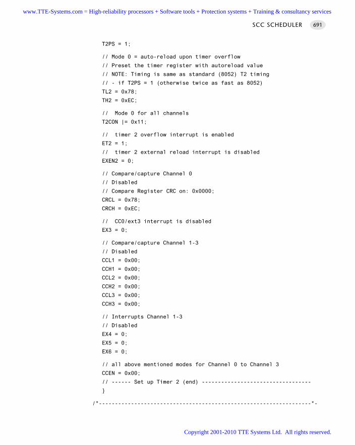
T2PS = 1;
// Mode 0 = auto-reload upon timer overflow
// Preset the timer register with autoreload value
// NOTE: Timing is same as standard (8052) T2 timing
// - if T2PS = 1 (otherwise twice as fast as 8052)
TL2 = 0x78;
TH2 = 0xEC;
// Mode 0 for all channels
T2CON |= 0x11;
// timer 2 overflow interrupt is enabled
ET2 = 1;
// timer 2 external reload interrupt is disabled
EXEN2 = 0;
// Compare/capture Channel 0
// Disabled
// Compare Register CRC on: 0x0000;
CRCL = 0x78;
CRCH = 0xEC;
// CC0/ext3 interrupt is disabled
EX3 = 0;
// Compare/capture Channel 1-3
// Disabled
CCL1 = 0x00;
CCH1 = 0x00;
CCL2 = 0x00;
CCH2 = 0x00;
CCL3 = 0x00;
CCH3 = 0x00;
// Interrupts Channel 1-3
// Disabled
EX4 = 0;
EX5 = 0;
EX6 = 0;
// all above mentioned modes for Channel 0 to Channel 3
CCEN = 0x00;
// ------ Set up Timer 2 (end) ----------------------------------
/*------------------------------------------------------------------*-
SCC SCHEDULER 691
www.TTE-Systems.com = High-reliability processors + Software tools + Protection systems + Training & consultancy services
Copyright 2001-2010 TTE Systems Ltd. All rights reserved.
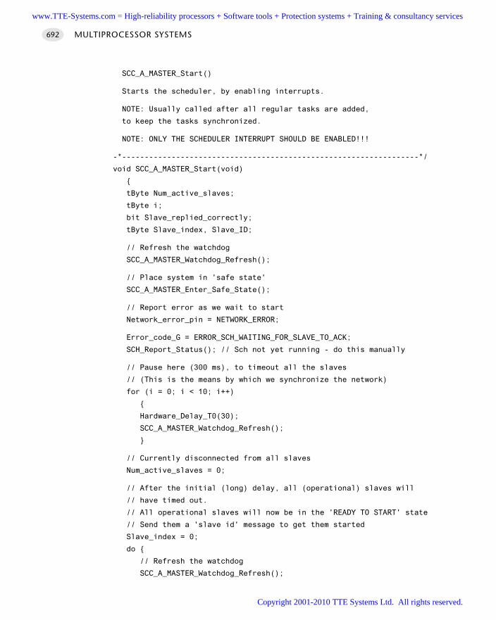
SCC_A_MASTER_Start()
Starts the scheduler, by enabling interrupts.
NOTE: Usually called after all regular tasks are added,
to keep the tasks synchronized.
NOTE: ONLY THE SCHEDULER INTERRUPT SHOULD BE ENABLED!!!
-*------------------------------------------------------------------*/
void SCC_A_MASTER_Start(void)
tByte Num_active_slaves;
tByte i;
bit Slave_replied_correctly;
tByte Slave_index, Slave_ID;
// Refresh the watchdog
SCC_A_MASTER_Watchdog_Refresh();
// Place system in 'safe state'
SCC_A_MASTER_Enter_Safe_State();
// Report error as we wait to start
Network_error_pin = NETWORK_ERROR;
Error_code_G = ERROR_SCH_WAITING_FOR_SLAVE_TO_ACK;
SCH_Report_Status(); // Sch not yet running - do this manually
// Pause here (300 ms), to timeout all the slaves
// (This is the means by which we synchronize the network)
for (i = 0; i < 10; i++)
Hardware_Delay_T0(30);
SCC_A_MASTER_Watchdog_Refresh();
// Currently disconnected from all slaves
Num_active_slaves = 0;
// After the initial (long) delay, all (operational) slaves will
// have timed out.
// All operational slaves will now be in the 'READY TO START' state
// Send them a 'slave id' message to get them started
Slave_index = 0;
do
// Refresh the watchdog
SCC_A_MASTER_Watchdog_Refresh();
MULTIPROCESSOR SYSTEMS692
www.TTE-Systems.com = High-reliability processors + Software tools + Protection systems + Training & consultancy services
Copyright 2001-2010 TTE Systems Ltd. All rights reserved.
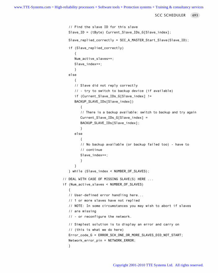
// Find the slave ID for this slave
Slave_ID = (tByte) Current_Slave_IDs_G[Slave_index];
Slave_replied_correctly = SCC_A_MASTER_Start_Slave(Slave_ID);
if (Slave_replied_correctly)
Num_active_slaves++;
Slave_index++;
else
// Slave did not reply correctly
// - try to switch to backup device (if available)
if (Current_Slave_IDs_G[Slave_index] !=
BACKUP_SLAVE_IDs[Slave_index])
// There is a backup available: switch to backup and try again
Current_Slave_IDs_G[Slave_index] =
BACKUP_SLAVE_IDs[Slave_index];
else
// No backup available (or backup failed too) - have to
// continue
Slave_index++;
while (Slave_index < NUMBER_OF_SLAVES);
// DEAL WITH CASE OF MISSING SLAVE(S) HERE ...
if (Num_active_slaves < NUMBER_OF_SLAVES)
// User-defined error handling here...
// 1 or more slaves have not replied
// NOTE: In some circumstances you may wish to abort if slaves
// are missing
// - or reconfigure the network.
// Simplest solution is to display an error and carry on
// (this is what we do here)
Error_code_G = ERROR_SCH_ONE_OR_MORE_SLAVES_DID_NOT_START;
Network_error_pin = NETWORK_ERROR;
SCC SCHEDULER 693
www.TTE-Systems.com = High-reliability processors + Software tools + Protection systems + Training & consultancy services
Copyright 2001-2010 TTE Systems Ltd. All rights reserved.
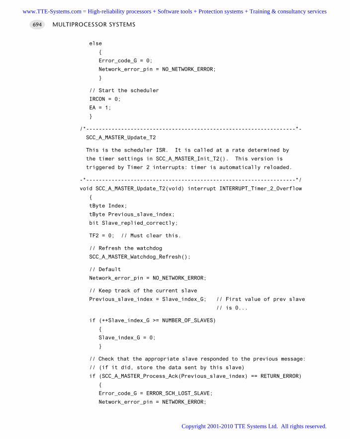
else
Error_code_G = 0;
Network_error_pin = NO_NETWORK_ERROR;
// Start the scheduler
IRCON = 0;
EA = 1;
/*------------------------------------------------------------------*-
SCC_A_MASTER_Update_T2
This is the scheduler ISR. It is called at a rate determined by
the timer settings in SCC_A_MASTER_Init_T2(). This version is
triggered by Timer 2 interrupts: timer is automatically reloaded.
-*------------------------------------------------------------------*/
void SCC_A_MASTER_Update_T2(void) interrupt INTERRUPT_Timer_2_Overflow
tByte Index;
tByte Previous_slave_index;
bit Slave_replied_correctly;
TF2 = 0; // Must clear this.
// Refresh the watchdog
SCC_A_MASTER_Watchdog_Refresh();
// Default
Network_error_pin = NO_NETWORK_ERROR;
// Keep track of the current slave
Previous_slave_index = Slave_index_G; // First value of prev slave
// is 0...
if (++Slave_index_G >= NUMBER_OF_SLAVES)
Slave_index_G = 0;
// Check that the appropriate slave responded to the previous message:
// (if it did, store the data sent by this slave)
if (SCC_A_MASTER_Process_Ack(Previous_slave_index) == RETURN_ERROR)
Error_code_G = ERROR_SCH_LOST_SLAVE;
Network_error_pin = NETWORK_ERROR;
MULTIPROCESSOR SYSTEMS694
www.TTE-Systems.com = High-reliability processors + Software tools + Protection systems + Training & consultancy services
Copyright 2001-2010 TTE Systems Ltd. All rights reserved.
// If we have lost contact with a slave, we attempt to
// switch to a backup device (if one is available)
if (Current_Slave_IDs_G[Slave_index_G] !=
BACKUP_SLAVE_IDs[Slave_index_G])
// There is a backup available: switch to backup and try again
Current_Slave_IDs_G[Slave_index_G] =
BACKUP_SLAVE_IDs[Slave_index_G];
else
// There is no backup available (or we are already using it)
// Try main device.
Current_Slave_IDs_G[Slave_index_G] =
MAIN_SLAVE_IDs[Slave_index_G];
// Try to connect to the slave
Slave_replied_correctly =
SCC_A_MASTER_Start_Slave(Current_Slave_IDs_G[Slave_index_G]);
if (!Slave_replied_correctly)
// No backup available (or backup failed too) - we shut down
// OTHER BEHAVIOUR MAY BE MORE APPROPRIATE IN YOUR APPLICATION
SCC_A_MASTER_Shut_Down_the_Network();
// Send 'tick' message to all connected slaves
// (sends one data byte to the current slave)
SCC_A_MASTER_Send_Tick_Message(Slave_index_G);
// Check the last error codes on the CAN bus via the status register
if ((CAN_sr & 0x07) != 0)
Error_code_G = ERROR_SCH_CAN_BUS_ERROR;
Network_error_pin = NETWORK_ERROR;
// See Infineon c515c manual for error code details
CAN_error_pin0 = ((CAN_sr & 0x01) == 0);
CAN_error_pin1 = ((CAN_sr & 0x02) == 0);
CAN_error_pin2 = ((CAN_sr & 0x04) == 0);
else
SCC SCHEDULER 695
www.TTE-Systems.com = High-reliability processors + Software tools + Protection systems + Training & consultancy services
Copyright 2001-2010 TTE Systems Ltd. All rights reserved.
CAN_error_pin0 = 1;
CAN_error_pin1 = 1;
CAN_error_pin2 = 1;
// NOTE: calculations are in *TICKS* (not milliseconds)
for (Index = 0; Index < SCH_MAX_TASKS; Index++)
// Check if there is a task at this location
if (SCH_tasks_G[Index].pTask)
if (SCH_tasks_G[Index].Delay == 0)
// The task is due to run
SCH_tasks_G[Index].RunMe += 1; // Incr. the 'Run Me' flag
if (SCH_tasks_G[Index].Period)
// Schedule periodic tasks to run again
SCH_tasks_G[Index].Delay = SCH_tasks_G[Index].Period;
else
// Not yet ready to run: just decrement the delay
SCH_tasks_G[Index].Delay -= 1;
/*------------------------------------------------------------------*-
SCC_A_MASTER_Send_Tick_Message()
This function sends a tick message, over the CAN network.
The receipt of this message will cause an interrupt to be generated
in the slave(s): this invoke the scheduler 'update' function
in the slave(s).
-*------------------------------------------------------------------*/
void SCC_A_MASTER_Send_Tick_Message(const tByte SLAVE_INDEX)
// Find the slave ID for this slave
// ALL SLAVES MUST HAVE A UNIQUE (non-zero) ID
MULTIPROCESSOR SYSTEMS696
www.TTE-Systems.com = High-reliability processors + Software tools + Protection systems + Training & consultancy services
Copyright 2001-2010 TTE Systems Ltd. All rights reserved.
tByte Slave_ID = (tByte) Current_Slave_IDs_G[SLAVE_INDEX];
CAN_messages[0].Data[0] = Slave_ID;
// Fill the data fields
CAN_messages[0].Data[1] = Tick_message_data_G[SLAVE_INDEX][0];
CAN_messages[0].Data[2] = Tick_message_data_G[SLAVE_INDEX][1];
CAN_messages[0].Data[3] = Tick_message_data_G[SLAVE_INDEX][2];
CAN_messages[0].Data[4] = Tick_message_data_G[SLAVE_INDEX][3];
// Send the message on the CAN bus
CAN_messages[0].MCR1 = 0xE7; // TXRQ, reset CPUUPD
/*------------------------------------------------------------------*-
SCC_A_MASTER_Process_Ack()
Make sure the slave (SLAVE_ID) has acknowledged the previous
message that was sent. If it has, extract the message data
from the USART hardware: if not, call the appropriate error
handler.
PARAMS: The index of the slave.
RETURNS: RETURN_NORMAL - Ack received (data in Ack_message_data_G)
RETURN_ERROR - No ack received (-> no data)
-*------------------------------------------------------------------*/
bit SCC_A_MASTER_Process_Ack(const tByte SLAVE_INDEX)
tByte Ack_ID, Slave_ID;
// First time this is called there is no ack tick to check
// - we simply return 'OK'
if (First_ack_G)
First_ack_G = 0;
return RETURN_NORMAL;
if ((CAN_messages[1].MCR1 & 0x03) == 0x02) // if NEWDAT
// An ack message was received
//
// Extract the data
Ack_ID = CAN_messages[1].Data[0]; // Get data byte 0
Ack_message_data_G[SLAVE_INDEX][0] = CAN_messages[1].Data[1];
Ack_message_data_G[SLAVE_INDEX][1] = CAN_messages[1].Data[2];
SCC SCHEDULER 697
www.TTE-Systems.com = High-reliability processors + Software tools + Protection systems + Training & consultancy services
Copyright 2001-2010 TTE Systems Ltd. All rights reserved.
Ack_message_data_G[SLAVE_INDEX][2] = CAN_messages[1].Data[3];
Ack_message_data_G[SLAVE_INDEX][3] = CAN_messages[1].Data[4];
CAN_messages[1].MCR0 = 0xfd; // reset NEWDAT, INTPND
CAN_messages[1].MCR1 = 0xfd;
// Find the slave ID for this slave
Slave_ID = (tByte) Current_Slave_IDs_G[SLAVE_INDEX];
if (Ack_ID == Slave_ID)
return RETURN_NORMAL;
// No message, or ID incorrect
return RETURN_ERROR;
/*------------------------------------------------------------------*-
SCC_A_MASTER_Shut_Down_the_Network()
This function will be called when a slave fails to
acknowledge a tick message.
-*------------------------------------------------------------------*/
void SCC_A_MASTER_Shut_Down_the_Network(void)
EA = 0;
while(1)
SCC_A_MASTER_Watchdog_Refresh();
/*------------------------------------------------------------------*-
SCC_A_MASTER_Enter_Safe_State()
This is the state entered by the system when:
(1) The node is powered up or reset
(2) The Master node cannot detect a slave
(3) The network has an error
Try to ensure that the system is in a 'safe' state in these
circumstances.
-*------------------------------------------------------------------*/
MULTIPROCESSOR SYSTEMS698
www.TTE-Systems.com = High-reliability processors + Software tools + Protection systems + Training & consultancy services
Copyright 2001-2010 TTE Systems Ltd. All rights reserved.
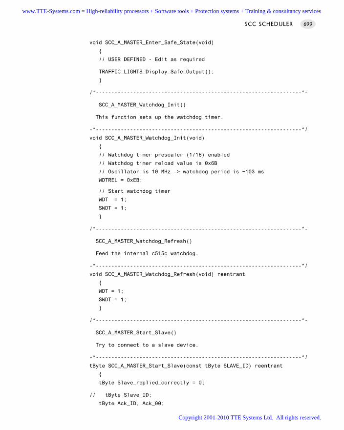
void SCC_A_MASTER_Enter_Safe_State(void)
// USER DEFINED - Edit as required
TRAFFIC_LIGHTS_Display_Safe_Output();
/*------------------------------------------------------------------*-
SCC_A_MASTER_Watchdog_Init()
This function sets up the watchdog timer.
-*------------------------------------------------------------------*/
void SCC_A_MASTER_Watchdog_Init(void)
// Watchdog timer prescaler (1/16) enabled
// Watchdog timer reload value is 0x6B
// Oscillator is 10 MHz -> watchdog period is ~103 ms
WDTREL = 0xEB;
// Start watchdog timer
WDT = 1;
SWDT = 1;
/*------------------------------------------------------------------*-
SCC_A_MASTER_Watchdog_Refresh()
Feed the internal c515c watchdog.
-*------------------------------------------------------------------*/
void SCC_A_MASTER_Watchdog_Refresh(void) reentrant
WDT = 1;
SWDT = 1;
/*------------------------------------------------------------------*-
SCC_A_MASTER_Start_Slave()
Try to connect to a slave device.
-*------------------------------------------------------------------*/
tByte SCC_A_MASTER_Start_Slave(const tByte SLAVE_ID) reentrant
tByte Slave_replied_correctly = 0;
// tByte Slave_ID;
tByte Ack_ID, Ack_00;
SCC SCHEDULER 699
www.TTE-Systems.com = High-reliability processors + Software tools + Protection systems + Training & consultancy services
Copyright 2001-2010 TTE Systems Ltd. All rights reserved.
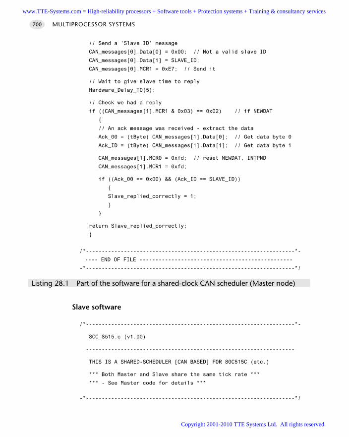
// Send a 'Slave ID' message
CAN_messages[0].Data[0] = 0x00; // Not a valid slave ID
CAN_messages[0].Data[1] = SLAVE_ID;
CAN_messages[0].MCR1 = 0xE7; // Send it
// Wait to give slave time to reply
Hardware_Delay_T0(5);
// Check we had a reply
if ((CAN_messages[1].MCR1 & 0x03) == 0x02) // if NEWDAT
// An ack message was received - extract the data
Ack_00 = (tByte) CAN_messages[1].Data[0]; // Get data byte 0
Ack_ID = (tByte) CAN_messages[1].Data[1]; // Get data byte 1
CAN_messages[1].MCR0 = 0xfd; // reset NEWDAT, INTPND
CAN_messages[1].MCR1 = 0xfd;
if ((Ack_00 == 0x00) && (Ack_ID == SLAVE_ID))
Slave_replied_correctly = 1;
return Slave_replied_correctly;
/*------------------------------------------------------------------*-
---- END OF FILE ------------------------------------------------
-*------------------------------------------------------------------*/
Listing 28.1 Part of the software for a shared-clock CAN scheduler (Master node)
Slave software
/*------------------------------------------------------------------*-
SCC_S515.c (v1.00)
------------------------------------------------------------------
THIS IS A SHARED-SCHEDULER [CAN BASED] FOR 80C515C (etc.)
*** Both Master and Slave share the same tick rate ***
*** - See Master code for details ***
-*------------------------------------------------------------------*/
MULTIPROCESSOR SYSTEMS700
www.TTE-Systems.com = High-reliability processors + Software tools + Protection systems + Training & consultancy services
Copyright 2001-2010 TTE Systems Ltd. All rights reserved.
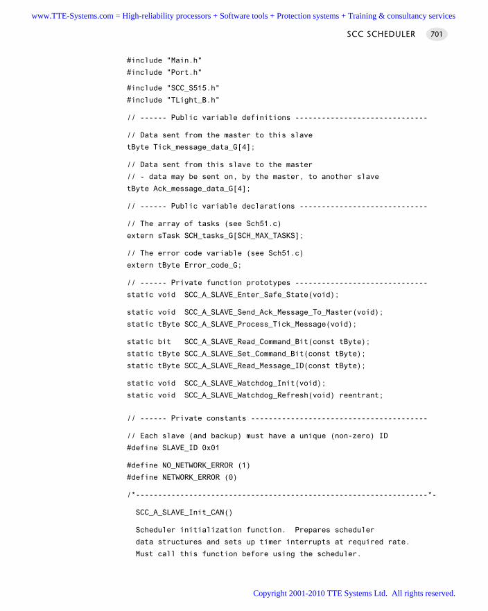
#include "Main.h"
#include "Port.h"
#include "SCC_S515.h"
#include "TLight_B.h"
// ------ Public variable definitions ------------------------------
// Data sent from the master to this slave
tByte Tick_message_data_G[4];
// Data sent from this slave to the master
// - data may be sent on, by the master, to another slave
tByte Ack_message_data_G[4];
// ------ Public variable declarations -----------------------------
// The array of tasks (see Sch51.c)
extern sTask SCH_tasks_G[SCH_MAX_TASKS];
// The error code variable (see Sch51.c)
extern tByte Error_code_G;
// ------ Private function prototypes ------------------------------
static void SCC_A_SLAVE_Enter_Safe_State(void);
static void SCC_A_SLAVE_Send_Ack_Message_To_Master(void);
static tByte SCC_A_SLAVE_Process_Tick_Message(void);
static bit SCC_A_SLAVE_Read_Command_Bit(const tByte);
static tByte SCC_A_SLAVE_Set_Command_Bit(const tByte);
static tByte SCC_A_SLAVE_Read_Message_ID(const tByte);
static void SCC_A_SLAVE_Watchdog_Init(void);
static void SCC_A_SLAVE_Watchdog_Refresh(void) reentrant;
// ------ Private constants ----------------------------------------
// Each slave (and backup) must have a unique (non-zero) ID
#define SLAVE_ID 0x01
#define NO_NETWORK_ERROR (1)
#define NETWORK_ERROR (0)
/*------------------------------------------------------------------*-
SCC_A_SLAVE_Init_CAN()
Scheduler initialization function. Prepares scheduler
data structures and sets up timer interrupts at required rate.
Must call this function before using the scheduler.
SCC SCHEDULER 701
www.TTE-Systems.com = High-reliability processors + Software tools + Protection systems + Training & consultancy services
Copyright 2001-2010 TTE Systems Ltd. All rights reserved.
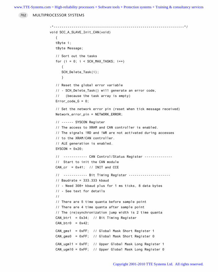
-*------------------------------------------------------------------*/
void SCC_A_SLAVE_Init_CAN(void)
tByte i;
tByte Message;
// Sort out the tasks
for (i = 0; i < SCH_MAX_TASKS; i++)
SCH_Delete_Task(i);
// Reset the global error variable
// - SCH_Delete_Task() will generate an error code,
// (because the task array is empty)
Error_code_G = 0;
// Set the network error pin (reset when tick message received)
Network_error_pin = NETWORK_ERROR;
// ------ SYSCON Register
// The access to XRAM and CAN controller is enabled.
// The signals !RD and !WR are not activated during accesses
// to the XRAM/CAN controller.
// ALE generation is enabled.
SYSCON = 0x20;
// ------------ CAN Control/Status Register --------------
// Start to init the CAN module
CAN_cr = 0x41; // INIT and CCE
// ------------ Bit Timing Register ---------------------
// Baudrate = 333.333 kbaud
// - Need 308+ kbaud plus for 1 ms ticks, 8 data bytes
// - See text for details
//
// There are 5 time quanta before sample point
// There are 4 time quanta after sample point
// The (re)synchronization jump width is 2 time quanta
CAN_btr1 = 0x34; // Bit Timing Register
CAN_btr0 = 0x42;
CAN_gms1 = 0xFF; // Global Mask Short Register 1
CAN_gms0 = 0xFF; // Global Mask Short Register 0
CAN_ugml1 = 0xFF; // Upper Global Mask Long Register 1
CAN_ugml0 = 0xFF; // Upper Global Mask Long Register 0
MULTIPROCESSOR SYSTEMS702
www.TTE-Systems.com = High-reliability processors + Software tools + Protection systems + Training & consultancy services
Copyright 2001-2010 TTE Systems Ltd. All rights reserved.
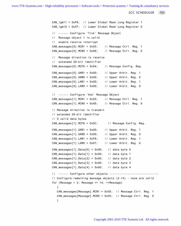
CAN_lgml1 = 0xF8; // Lower Global Mask Long Register 1
CAN_lgml0 = 0xFF; // Lower Global Mask Long Register 0
// ------ Configure 'Tick' Message Object
// Message object 1 is valid
// enable receive interrupt
CAN_messages[0].MCR1 = 0x55; // Message Ctrl. Reg. 1
CAN_messages[0].MCR0 = 0x99; // Message Ctrl. Reg. 0
// Message direction is receive
// extended 29-bit identifier
CAN_messages[0].MCFG = 0x04; // Message Config. Reg.
CAN_messages[0].UAR1 = 0x00; // Upper Arbit. Reg. 1
CAN_messages[0].UAR0 = 0x00; // Upper Arbit. Reg. 0
CAN_messages[0].LAR1 = 0x00; // Lower Arbit. Reg. 1
CAN_messages[0].LAR0 = 0x00; // Lower Arbit. Reg. 0
// ------ Configure 'Ack' Message Object
CAN_messages[1].MCR1 = 0x55; // Message Ctrl. Reg. 1
CAN_messages[1].MCR0 = 0x95; // Message Ctrl. Reg. 0
// Message direction is transmit
// extended 29-bit identifier
// 5 valid data bytes
CAN_messages[1].MCFG = 0x5C; // Message Config. Reg.
CAN_messages[1].UAR1 = 0x00; // Upper Arbit. Reg. 1
CAN_messages[1].UAR0 = 0x00; // Upper Arbit. Reg. 0
CAN_messages[1].LAR1 = 0xF8; // Lower Arbit. Reg. 1
CAN_messages[1].LAR0 = 0x07; // Lower Arbit. Reg. 0
CAN_messages[1].Data[0] = 0x00; // data byte 0
CAN_messages[1].Data[1] = 0x00; // data byte 1
CAN_messages[1].Data[2] = 0x00; // data byte 2
CAN_messages[1].Data[3] = 0x00; // data byte 3
CAN_messages[1].Data[4] = 0x00; // data byte 4
// ------ Configure other objects ------------------------------
// Configure remaining message objects (2-14) - none are valid
for (Message = 2; Message <= 14; ++Message)
CAN_messages[Message].MCR1 = 0x55; // Message Ctrl. Reg. 1
CAN_messages[Message].MCR0 = 0x55; // Message Ctrl. Reg. 0
SCC SCHEDULER 703
www.TTE-Systems.com = High-reliability processors + Software tools + Protection systems + Training & consultancy services
Copyright 2001-2010 TTE Systems Ltd. All rights reserved.
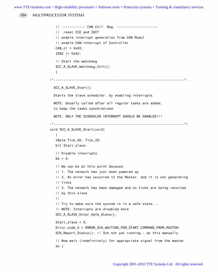
// ------------ CAN Ctrl. Reg. ---------------------
// reset CCE and INIT
// enable interrupt generation from CAN Modul
// enable CAN-interrupt of Controller
CAN_cr = 0x02;
IEN2 |= 0x02;
// Start the watchdog
SCC_A_SLAVE_Watchdog_Init();
/*------------------------------------------------------------------*-
SCC_A_SLAVE_Start()
Starts the slave scheduler, by enabling interrupts.
NOTE: Usually called after all regular tasks are added,
to keep the tasks synchronized.
NOTE: ONLY THE SCHEDULER INTERRUPT SHOULD BE ENABLED!!!
-*------------------------------------------------------------------*/
void SCC_A_SLAVE_Start(void)
tByte Tick_00, Tick_ID;
bit Start_slave;
// Disable interrupts
EA = 0;
// We can be at this point because:
// 1. The network has just been powered up
// 2. An error has occurred in the Master, and it is not generating
// ticks
// 3. The network has been damaged and no ticks are being received
// by this slave
//
// Try to make sure the system is in a safe state...
// NOTE: Interrupts are disabled here
SCC_A_SLAVE_Enter_Safe_State();
Start_slave = 0;
Error_code_G = ERROR_SCH_WAITING_FOR_START_COMMAND_FROM_MASTER;
SCH_Report_Status(); // Sch not yet running - do this manually
// Now wait (indefinitely) for appropriate signal from the master
do
MULTIPROCESSOR SYSTEMS704
www.TTE-Systems.com = High-reliability processors + Software tools + Protection systems + Training & consultancy services
Copyright 2001-2010 TTE Systems Ltd. All rights reserved.
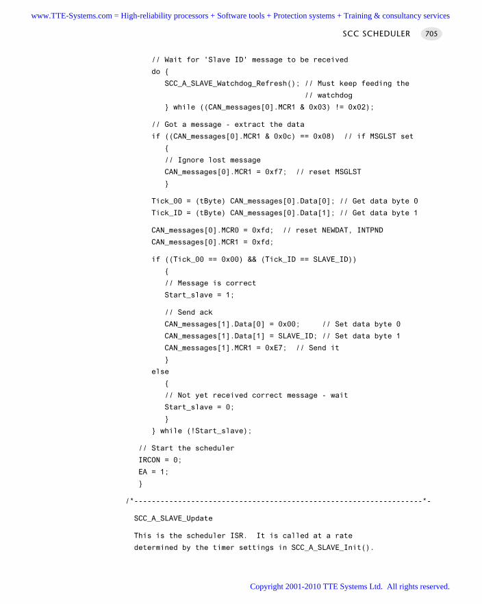
// Wait for 'Slave ID' message to be received
do
SCC_A_SLAVE_Watchdog_Refresh(); // Must keep feeding the
// watchdog
while ((CAN_messages[0].MCR1 & 0x03) != 0x02);
// Got a message - extract the data
if ((CAN_messages[0].MCR1 & 0x0c) == 0x08) // if MSGLST set
// Ignore lost message
CAN_messages[0].MCR1 = 0xf7; // reset MSGLST
Tick_00 = (tByte) CAN_messages[0].Data[0]; // Get data byte 0
Tick_ID = (tByte) CAN_messages[0].Data[1]; // Get data byte 1
CAN_messages[0].MCR0 = 0xfd; // reset NEWDAT, INTPND
CAN_messages[0].MCR1 = 0xfd;
if ((Tick_00 == 0x00) && (Tick_ID == SLAVE_ID))
// Message is correct
Start_slave = 1;
// Send ack
CAN_messages[1].Data[0] = 0x00; // Set data byte 0
CAN_messages[1].Data[1] = SLAVE_ID; // Set data byte 1
CAN_messages[1].MCR1 = 0xE7; // Send it
else
// Not yet received correct message - wait
Start_slave = 0;
while (!Start_slave);
// Start the scheduler
IRCON = 0;
EA = 1;
/*------------------------------------------------------------------*-
SCC_A_SLAVE_Update
This is the scheduler ISR. It is called at a rate
determined by the timer settings in SCC_A_SLAVE_Init().
SCC SCHEDULER 705
www.TTE-Systems.com = High-reliability processors + Software tools + Protection systems + Training & consultancy services
Copyright 2001-2010 TTE Systems Ltd. All rights reserved.
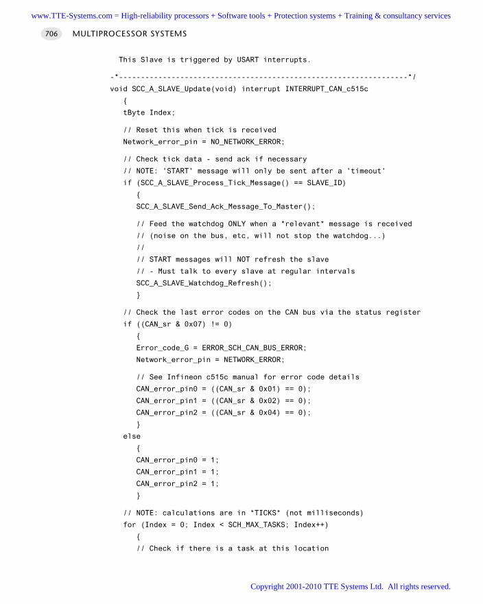
This Slave is triggered by USART interrupts.
-*------------------------------------------------------------------*/
void SCC_A_SLAVE_Update(void) interrupt INTERRUPT_CAN_c515c
tByte Index;
// Reset this when tick is received
Network_error_pin = NO_NETWORK_ERROR;
// Check tick data - send ack if necessary
// NOTE: 'START' message will only be sent after a 'timeout'
if (SCC_A_SLAVE_Process_Tick_Message() == SLAVE_ID)
SCC_A_SLAVE_Send_Ack_Message_To_Master();
// Feed the watchdog ONLY when a *relevant* message is received
// (noise on the bus, etc, will not stop the watchdog...)
//
// START messages will NOT refresh the slave
// - Must talk to every slave at regular intervals
SCC_A_SLAVE_Watchdog_Refresh();
// Check the last error codes on the CAN bus via the status register
if ((CAN_sr & 0x07) != 0)
Error_code_G = ERROR_SCH_CAN_BUS_ERROR;
Network_error_pin = NETWORK_ERROR;
// See Infineon c515c manual for error code details
CAN_error_pin0 = ((CAN_sr & 0x01) == 0);
CAN_error_pin1 = ((CAN_sr & 0x02) == 0);
CAN_error_pin2 = ((CAN_sr & 0x04) == 0);
else
CAN_error_pin0 = 1;
CAN_error_pin1 = 1;
CAN_error_pin2 = 1;
// NOTE: calculations are in *TICKS* (not milliseconds)
for (Index = 0; Index < SCH_MAX_TASKS; Index++)
// Check if there is a task at this location
MULTIPROCESSOR SYSTEMS706
www.TTE-Systems.com = High-reliability processors + Software tools + Protection systems + Training & consultancy services
Copyright 2001-2010 TTE Systems Ltd. All rights reserved.
if (SCH_tasks_G[Index].pTask)
if (SCH_tasks_G[Index].Delay == 0)
// The task is due to run
SCH_tasks_G[Index].RunMe = 1; // Increment the RunMe flag
if (SCH_tasks_G[Index].Period)
// Schedule periodic tasks to run again
SCH_tasks_G[Index].Delay = SCH_tasks_G[Index].Period;
else
// Not yet ready to run: just decrement the delay
SCH_tasks_G[Index].Delay -= 1;
/*------------------------------------------------------------------*-
SCC_A_SLAVE_Process_Tick_Message()
The ticks messages are crucial to the operation of this shared-clock
scheduler: the arrival of a tick message (at regular intervals)
invokes the 'Update' ISR, that drives the scheduler.
The tick messages themselves may contain data. These data are
extracted in this function.
-*------------------------------------------------------------------*/
tByte SCC_A_SLAVE_Process_Tick_Message(void)
tByte Tick_ID;
if ((CAN_messages[0].MCR1 & 0x0c) == 0x08) // if MSGLST set
// Indicates that the CAN controller has stored a new
// message into this object, while NEWDAT was still set,
// i.e. the previously stored message is lost.
// We simply IGNORE this here and reset the flag
CAN_messages[0].MCR1 = 0xf7; // reset MSGLST
SCC SCHEDULER 707
www.TTE-Systems.com = High-reliability processors + Software tools + Protection systems + Training & consultancy services
Copyright 2001-2010 TTE Systems Ltd. All rights reserved.
// The first byte is the ID of the slave for which the data are
// intended
Tick_ID = CAN_messages[0].Data[0]; // Get data byte 0 (Slave ID)
if (Tick_ID == SLAVE_ID)
// Only if there is a match do we need to copy these fields
Tick_message_data_G[0] = CAN_messages[0].Data[1];
Tick_message_data_G[1] = CAN_messages[0].Data[2];
Tick_message_data_G[2] = CAN_messages[0].Data[3];
Tick_message_data_G[3] = CAN_messages[0].Data[4];
CAN_messages[0].MCR0 = 0xfd; // reset NEWDAT, INTPND
CAN_messages[0].MCR1 = 0xfd;
return Tick_ID;
/*------------------------------------------------------------------*-
SCC_A_SLAVE_Send_Ack_Message_To_Master()
Slave must send and 'Acknowledge' message to the master, after
tick messages are received. NOTE: Only tick messages specifically
addressed to this slave should be acknowledged.
The acknowledge message serves two purposes:
[1] It confirms to the master that this slave is alive & well.
[2] It provides a means of sending data to the master and - hence
- to other slaves.
NOTE: Data transfer between slaves is NOT permitted!
-*------------------------------------------------------------------*/
void SCC_A_SLAVE_Send_Ack_Message_To_Master(void)
// First byte of message must be slave ID
CAN_messages[1].Data[0] = SLAVE_ID; // data byte 0
CAN_messages[1].Data[1] = Ack_message_data_G[0];
CAN_messages[1].Data[2] = Ack_message_data_G[1];
CAN_messages[1].Data[3] = Ack_message_data_G[2];
CAN_messages[1].Data[4] = Ack_message_data_G[3];
// Send the message on the CAN bus
CAN_messages[1].MCR1 = 0xE7; // TXRQ, reset CPUUPD
MULTIPROCESSOR SYSTEMS708
www.TTE-Systems.com = High-reliability processors + Software tools + Protection systems + Training & consultancy services
Copyright 2001-2010 TTE Systems Ltd. All rights reserved.
/*------------------------------------------------------------------*-
SCC_A_SLAVE_Watchdog_Init()
This function sets up the watchdog timer.
If the Master fails (or other error develop),
no tick messages will arrive, and the scheduler
will stop.
To detect this situation, we have a (hardware) watchdog
running in the slave. This watchdog - which should be set to
overflow at around 100 ms - is used to set the system into a
known (safe) state. The slave will then wait (indefinitely)
for the problem to be resolved.
NOTE: The slave will not be generating Ack messages in these
circumstances. The Master (if running) will therefore be aware
that there is a problem.
-*------------------------------------------------------------------*/
void SCC_A_SLAVE_Watchdog_Init(void)
// Watchdog timer prescaler (1/16) enabled
// Watchdog timer reload value is 0x6B
// Watchdog period is 103.2 ms (10.0 MHz xtal, c515c)
WDTREL = 0xEB;
// Start watchdog timer
WDT = 1;
SWDT = 1;
/*------------------------------------------------------------------*-
SCC_A_SLAVE_Watchdog_Refresh()
Feed the watchdog.
-*------------------------------------------------------------------*/
void SCC_A_SLAVE_Watchdog_Refresh(void) reentrant
WDT = 1;
SWDT = 1;
/*------------------------------------------------------------------*-
SCC_A_SLAVE_Enter_Safe_State()
SCC SCHEDULER 709
www.TTE-Systems.com = High-reliability processors + Software tools + Protection systems + Training & consultancy services
Copyright 2001-2010 TTE Systems Ltd. All rights reserved.
This is the state entered by the system when:
(1) The node is powered up or reset
(2) The Master node fails, and no working backup is available
(3) The network has an error
(4) Tick messages are delayed for any other reason
Try to ensure that the system is in a 'safe' state in these
circumstances.
-*------------------------------------------------------------------*/
void SCC_A_SLAVE_Enter_Safe_State(void)
// USER DEFINED
TRAFFIC_LIGHTS_Display_Safe_Output();
/*------------------------------------------------------------------*-
---- END OF FILE ------------------------------------------------
-*------------------------------------------------------------------*/
Listing 28.2 Part of the software for a shared-clock CAN scheduler (Slave node)
Backup slave software
See the CD for details of the code for the backup Slave.
Further readingBarrenscheen, J. (1996) ‘On-board communication via CAN without transceiver’,
Infineon (Siemens) Application Note AP2921. [Available from the Infineon WWWsite].
Gergeleit, M. and Streich, H. (1994) ‘Implementing a distributed high-resolutionreal-time clock using the CAN-bus’, Proceedings 1st International CAN Conference,Mainz, Germany, September 1994.
Hank, P. and Jöhnk, E. (1997) ‘SJA1000 stand-alone CAN controller’, PhilipsApplication Note AN97076. [Available from the Philips WWW site].
Lawrenz, W. (1997) CAN System Engineering, Springer.Scott, G. (1995) ‘Interfacing an MCS 51 microcontroller to an 82527 CAN controller’,
Intel Application Note AP-724. [Available from the Intel WWW site]
MULTIPROCESSOR SYSTEMS710
www.TTE-Systems.com = High-reliability processors + Software tools + Protection systems + Training & consultancy services
Copyright 2001-2010 TTE Systems Ltd. All rights reserved.
Designing multiprocessor
applications
Introduction
There are a number of important design problems which must be addressed whenusing shared-clock schedulers. We address some of the key problems in this chapter.Specifically, we consider the following:
In D ATA U N I O N [page 712], we consider the problem of transferring (possibly largeamounts of) data between Master and Slave nodes, using a communicationchannel of limited bandwidth.
In L O N G TA S K [page 716], we consider a perennial problem in scheduled systems;the need to handle both long, infrequently invoked tasks and short, frequentlyinvoked tasks. In this case, we consider techniques for migrating one or more longtask(s) onto a Slave, thereby freeing up the Master node to handle shorter tasks.
In D O M I N O TA S K [page 720], we consider the problem of distributing processingbetween tasks operating on two or more network nodes; specifically, we consider thesituation where the tasks are of similar duration and must be invoked in sequence.
chapter 29www.TTE-Systems.com = High-reliability processors + Software tools + Protection systems + Training & consultancy services
Copyright 2001-2010 TTE Systems Ltd. All rights reserved.
DATA UNION
Context You are developing an embedded application using more than one member of the
8051 family of microcontrollers.
The application has a time-triggered architecture, based on a shared-clock scheduler.
ProblemHow do you transfer data between Master and Slave nodes, using a communicationchannel of limited bandwidth?
BackgroundSuppose we are using a shared-clock, UART-based scheduler. The communicationchannel is eight bits wide; that is, we can send only eight bits of data between Masterand a Slave (or vice versa) in any network message. How do we transfer, say, integer orfloating-point data over this limited bandwidth channel? This is the type of problemwe are seeking to address in the present pattern.
SolutionTo implement DATA UN I O N , we will use the C union keyword. In C, a union-basedvariable can hold, at different times, values of different types and sizes, with the com-piler ensuring that size and alignment are maintained. Different types of data cantherefore be accommodated in a single area of storage.
To create a variable using a union we use the same syntax as the widely usedstruct, but whereas a struct-based variable might hold an int, a double and achar, a union can hold an int or a double or a char.
For example, consider the code in Listing 29.1.
// An example using the C/C++ union keyword
#include <stdio.h>
// A user-defined data type based on a union
typedef union
int Integer;
float Float;
uNumber;
MULTIPROCESSOR SYSTEMS712
www.TTE-Systems.com = High-reliability processors + Software tools + Protection systems + Training & consultancy services
Copyright 2001-2010 TTE Systems Ltd. All rights reserved.
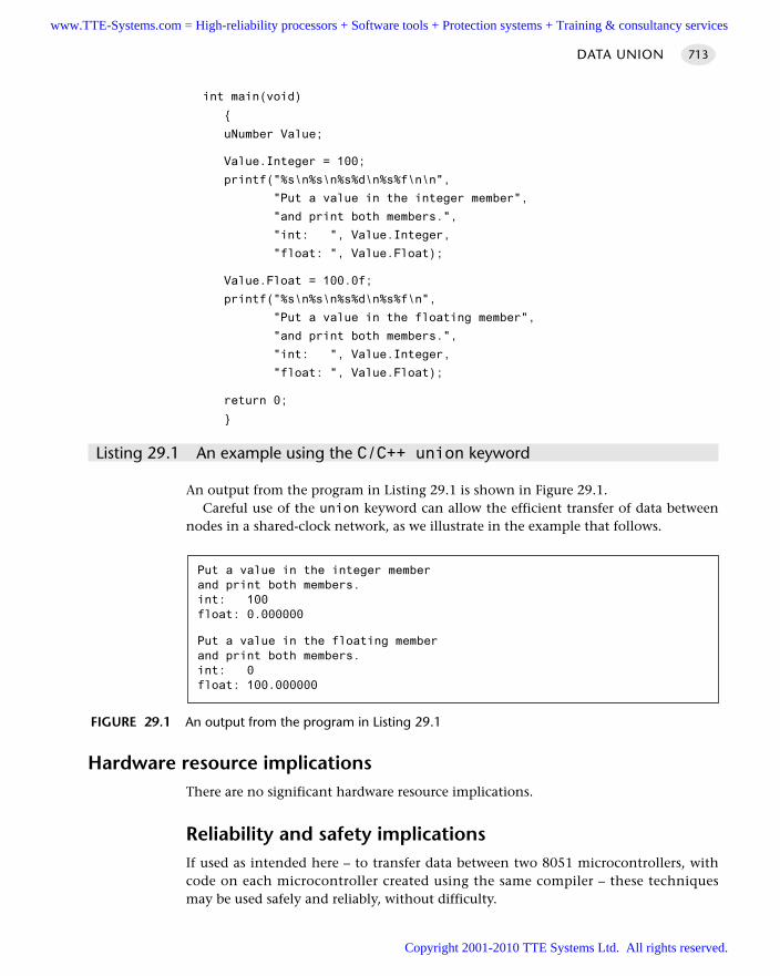
int main(void)
uNumber Value;
Value.Integer = 100;
printf("%s\n%s\n%s%d\n%s%f\n\n",
"Put a value in the integer member",
"and print both members.",
"int: ", Value.Integer,
"float: ", Value.Float);
Value.Float = 100.0f;
printf("%s\n%s\n%s%d\n%s%f\n",
"Put a value in the floating member",
"and print both members.",
"int: ", Value.Integer,
"float: ", Value.Float);
return 0;
Listing 29.1 An example using the C/C++ union keyword
An output from the program in Listing 29.1 is shown in Figure 29.1.Careful use of the union keyword can allow the efficient transfer of data between
nodes in a shared-clock network, as we illustrate in the example that follows.
Hardware resource implicationsThere are no significant hardware resource implications.
Reliability and safety implicationsIf used as intended here – to transfer data between two 8051 microcontrollers, withcode on each microcontroller created using the same compiler – these techniquesmay be used safely and reliably, without difficulty.
DATA UNION 713
FIGURE 29.1 An output from the program in Listing 29.1
Put a value in the integer memberand print both members.int: 100float: 0.000000
Put a value in the floating memberand print both members.int: 0float: 100.000000
www.TTE-Systems.com = High-reliability processors + Software tools + Protection systems + Training & consultancy services
Copyright 2001-2010 TTE Systems Ltd. All rights reserved.
However, if you attempt to use this technique to transfer data to a different micro-controller or microprocessor family, then problems can arise: see ‘Portability’ forfurther details.
PortabilityThis technique is portable, in that it can be applied to any microcontroller or micro-processor.
That said, the data themselves may not be portable. For example, if you attempt touse this approach to transfer data between an 8-bit and 16-bit microcontroller or an8-bit microcontroller and a (32-bit) PC, then care must be taken, since the codeassumes that the data (particularly the floating-point data) are of a particular size andstored in a particular byte order; in fact, the size and order of the data varies betweencompilers and operating environments.
For example, while a float may be represented in four bytes on an 8051 device, an8-byte or 16-byte representation may be used in other environments. If you attemptto directly interpret an encoded 4-byte float in an 8-byte environment, the results willbe meaningless.
Overall strengths and weaknessesSimple and effective as a way of sending data between 8051 microcon-trollers over a byte-wide communication channel.
Care must be taken if the technique is used to transfer data between 8- and 16-or 32-bit environments.
Related patterns and alternative solutionsD ATA U N I O N is a form of M U LT I - S TA G E TA S K [page 317].
Example: Transferring floats between microcontrollersWe provide a simple example illustrating the transfer of (32-bit) floats across an 8-bitcommunication network here.
// Breaking up floats (etc) for transfer over a serial link
// or via one or more parallel ports
// Assume float is 4 bytes
typedef union
MULTIPROCESSOR SYSTEMS714
Care must therefore be taken if this approach is used to transfer data betweendifferent environments.
www.TTE-Systems.com = High-reliability processors + Software tools + Protection systems + Training & consultancy services
Copyright 2001-2010 TTE Systems Ltd. All rights reserved.
float Float;
unsigned char Bytes[4];
uTransfer;
void main()
uTransfer X,Y;
X.Float = 3.1415f;
printf("Original data is %f\n", X.Float);
// Simulate transfer of floats over byte-wide communication link
for (byte = 0; byte < 4; byte++)
Y.Bytes[byte] = X.Bytes[byte];
// Now display ‘transferred data’
printf("Original data is %f\n", X.Float);
Further readingSchildt, H. (1997) Teach Yourself C, 3rd edn, McGraw-Hill, Maidenhead.
DATA UNION 715
www.TTE-Systems.com = High-reliability processors + Software tools + Protection systems + Training & consultancy services
Copyright 2001-2010 TTE Systems Ltd. All rights reserved.
LONG TASK
Context You are developing an embedded application using more than one member of the
8051 family of microcontrollers.
The application has a time-triggered architecture, based on a shared-clock scheduler.
ProblemHow can you handle both long (infrequent) tasks and short (frequent) tasks in a multi-processor application?
BackgroundAs we have seen, co-operative, time-triggered architectures have many advantageswhen we wish to develop embedded applications; indeed, throughout this book wehave argued that we would generally wish to use such an architecture when it is feasi-ble to do so. However, we have also taken a realistic view of the limitations of theco-operative scheduler; in particular we have acknowledged that in some circum-stances there can be a need to run both long, infrequent tasks (e.g. 100 ms durationevery 1,000 ms) and one or more short, frequent task (e.g. 0.1 ms duration every 1ms); these two requirements can conflict in a co-operative system, where – for alltasks, under all circumstances – the worst case execution time (WCET) for a task, thatis, the maximum task duration, must satisfy the condition:
WCETTask < tick interval
In this pattern collection we have already considered various ways of meeting theneed for both ‘frequent’ and ‘long’ tasks. For example, by using a faster processor (seeChapter 3) or a faster oscillator (Chapter 4) we can shorten the task execution times.Alternatively, we can make use of timeouts (see Chapter 15), develop one or moremulti-stage tasks (see Chapter 16) or use a hybrid scheduler (see Chapter 17).
In this pattern, we consider a multiprocessor solution to this problem.
SolutionIn this pattern, we discuss the design and use of a system architecture which is basedon a shared-clock scheduler and which – at its simplest – takes the following form (seeFigures 29.2 and 29.3):
A single short task (e.g. WCET 0.1 ms) runs frequently (e.g. every millisecond) onthe Master node. This task may, for example, be used to check for errors or handlesome other activity that requires a rapid response.
MULTIPROCESSOR SYSTEMS716
www.TTE-Systems.com = High-reliability processors + Software tools + Protection systems + Training & consultancy services
Copyright 2001-2010 TTE Systems Ltd. All rights reserved.
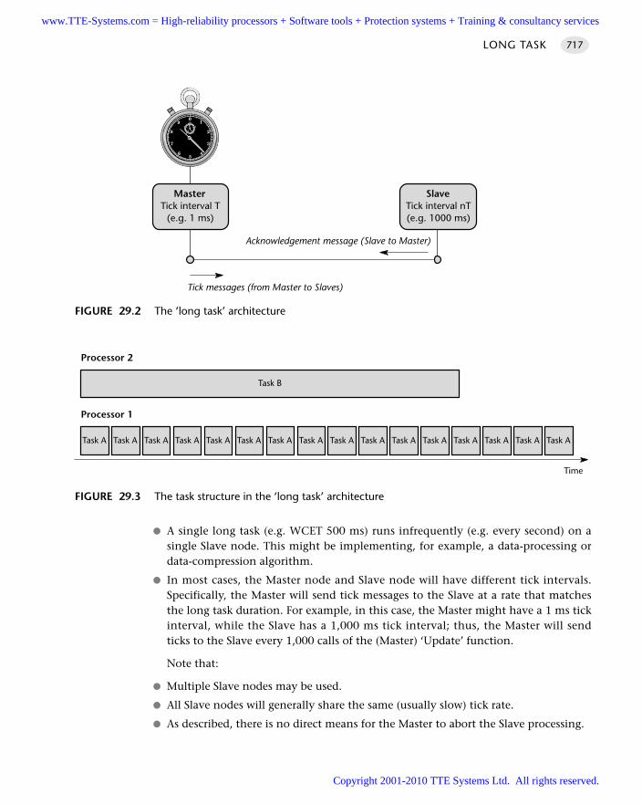
A single long task (e.g. WCET 500 ms) runs infrequently (e.g. every second) on asingle Slave node. This might be implementing, for example, a data-processing ordata-compression algorithm.
In most cases, the Master node and Slave node will have different tick intervals.Specifically, the Master will send tick messages to the Slave at a rate that matchesthe long task duration. For example, in this case, the Master might have a 1 ms tickinterval, while the Slave has a 1,000 ms tick interval; thus, the Master will sendticks to the Slave every 1,000 calls of the (Master) ‘Update’ function.
Note that:
Multiple Slave nodes may be used.
All Slave nodes will generally share the same (usually slow) tick rate.
As described, there is no direct means for the Master to abort the Slave processing.
LONG TASK 717
FIGURE 29.2 The ‘long task’ architecture
MasterTick interval T
(e.g. 1 ms)
Tick messages (from Master to Slaves)
Acknowledgement message (Slave to Master)
SlaveTick interval nT(e.g. 1000 ms)
FIGURE 29.3 The task structure in the ‘long task’ architecture
Task A Task A Task A Task A Task A Task A Task A Task A Task A Task A Task A Task A Task A Task A Task A Task A
Processor 1
Task B
Processor 2
Time
www.TTE-Systems.com = High-reliability processors + Software tools + Protection systems + Training & consultancy services
Copyright 2001-2010 TTE Systems Ltd. All rights reserved.
Hardware resource implicationsThis pattern requires the use of at least two microcontrollers and associated hardware(for example, reset, oscillator, memory and power supplies).
Reliability and safety implicationsThe correct operation of L O N G TA S K depends on all the microcontrollers involvedoperating normally. This requirement can, under some circumstances, reduce theoverall reliability of your system: see page 550 for a discussion of this issue.
PortabilityThis general design pattern may be applied with any microcontroller or microproces-sor family.
Overall strengths and weaknessesAn effective way of supporting the execution of both long, infrequent tasksand short, frequent tasks.
Like any multiprocessor design, it must be used with care if overall systemreliability is not to be compromised.
Related patterns and alternative solutions
See H Y B R I D S C H E D U L E R [page 333].
See D ATA U N I O N [page 712].
See D O M I N O TA S K [page 720].
Example: Data acquisition and FFTIn many condition-monitoring applications, we need to:
Acquire data, via an ADC
Perform a fast Fourier transform (FFT) on these data, prior to subsequent processing
The data-acquisition process will be very short, typically requiring a fraction of amillisecond to complete. By contrast, the FFT operation may be carried out every timewe have amassed, say, 256 data samples. It is a computationally intense process (e.g.see Press et al., 1992; Lynn and Fuerst, 1998; Smith, 1999) and must usually be com-pleted before the next set of 256 samples has been acquired.
Use of the L O N G TA S K architecture is ideal in these circumstances.
MULTIPROCESSOR SYSTEMS718
www.TTE-Systems.com = High-reliability processors + Software tools + Protection systems + Training & consultancy services
Copyright 2001-2010 TTE Systems Ltd. All rights reserved.
Further readingLynn, P. and Fuerst, W. (1998) Introductory Digital Signal Processing with Computer
Applications, Wiley, Chichester.Press, W.H., Teulolsky, S.A., Vettering, W.T. and Flannery, B.P. (1992) Numerical Recipes
in C: The Art of Scientific Computing, Cambridge University Press, Cambridge.Smith, S.W. (1999) The Scientist and Engineer’s Guide to Digital Signal Processing, 2nd
edn, California Technical Publishing. [Available electronically atwww.DSPguide.com]
LONG TASK 719
www.TTE-Systems.com = High-reliability processors + Software tools + Protection systems + Training & consultancy services
Copyright 2001-2010 TTE Systems Ltd. All rights reserved.
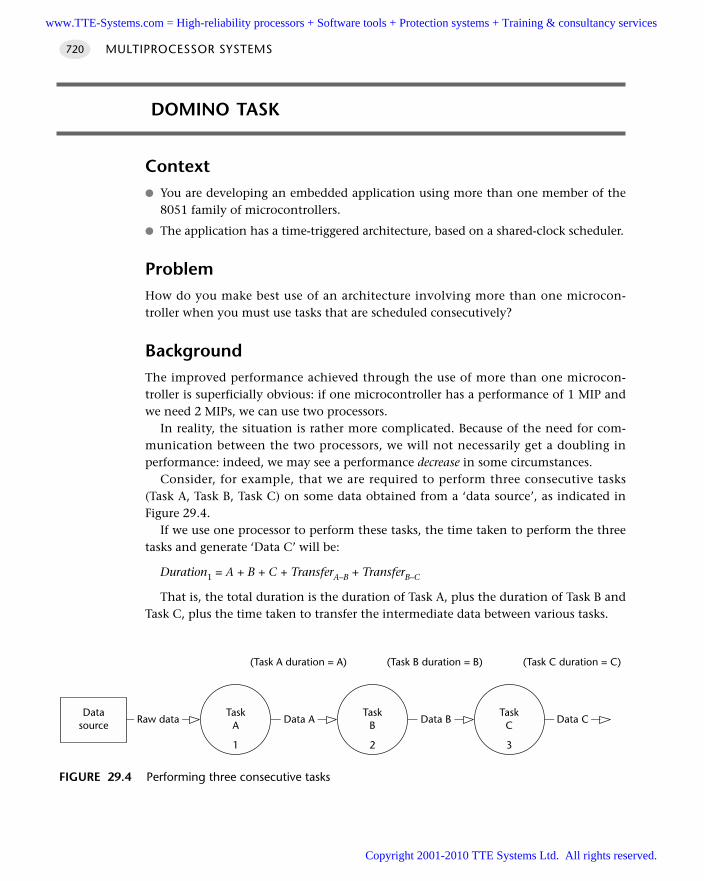
DOMINO TASK
Context You are developing an embedded application using more than one member of the
8051 family of microcontrollers.
The application has a time-triggered architecture, based on a shared-clock scheduler.
ProblemHow do you make best use of an architecture involving more than one microcon-troller when you must use tasks that are scheduled consecutively?
BackgroundThe improved performance achieved through the use of more than one microcon-troller is superficially obvious: if one microcontroller has a performance of 1 MIP andwe need 2 MIPs, we can use two processors.
In reality, the situation is rather more complicated. Because of the need for com-munication between the two processors, we will not necessarily get a doubling inperformance: indeed, we may see a performance decrease in some circumstances.
Consider, for example, that we are required to perform three consecutive tasks(Task A, Task B, Task C) on some data obtained from a ‘data source’, as indicated inFigure 29.4.
If we use one processor to perform these tasks, the time taken to perform the threetasks and generate ‘Data C’ will be:
Duration1 = A + B + C + TransferA–B + TransferB–C
That is, the total duration is the duration of Task A, plus the duration of Task B andTask C, plus the time taken to transfer the intermediate data between various tasks.
MULTIPROCESSOR SYSTEMS720
FIGURE 29.4 Performing three consecutive tasks
TaskC
3
TaskB
2
Datasource
TaskA
1
Raw data Data CData BData A
(Task C duration = C)(Task B duration = B)(Task A duration = A)
www.TTE-Systems.com = High-reliability processors + Software tools + Protection systems + Training & consultancy services
Copyright 2001-2010 TTE Systems Ltd. All rights reserved.
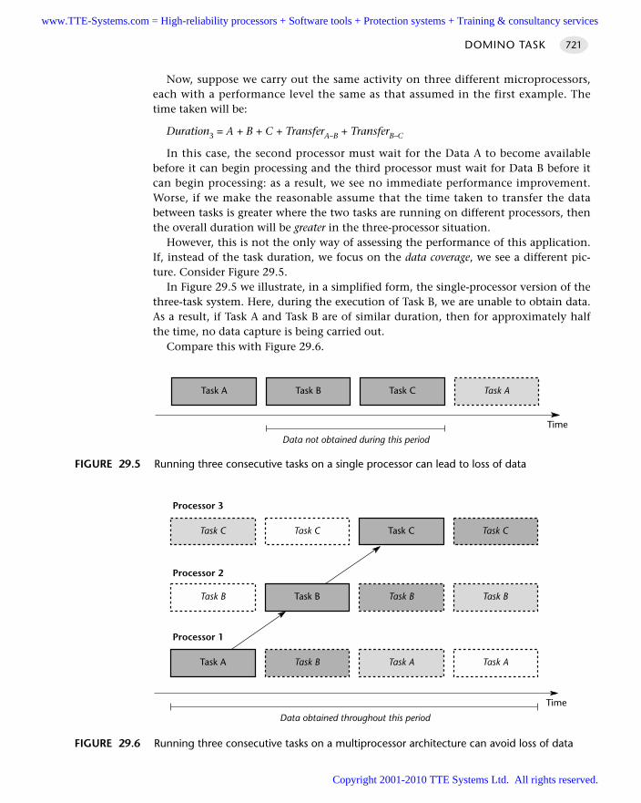
Now, suppose we carry out the same activity on three different microprocessors,each with a performance level the same as that assumed in the first example. Thetime taken will be:
Duration3 = A + B + C + TransferA–B + TransferB–C
In this case, the second processor must wait for the Data A to become availablebefore it can begin processing and the third processor must wait for Data B before itcan begin processing: as a result, we see no immediate performance improvement.Worse, if we make the reasonable assume that the time taken to transfer the databetween tasks is greater where the two tasks are running on different processors, thenthe overall duration will be greater in the three-processor situation.
However, this is not the only way of assessing the performance of this application.If, instead of the task duration, we focus on the data coverage, we see a different pic-ture. Consider Figure 29.5.
In Figure 29.5 we illustrate, in a simplified form, the single-processor version of thethree-task system. Here, during the execution of Task B, we are unable to obtain data.As a result, if Task A and Task B are of similar duration, then for approximately halfthe time, no data capture is being carried out.
Compare this with Figure 29.6.
DOMINO TASK 721
FIGURE 29.5 Running three consecutive tasks on a single processor can lead to loss of data
Task BTask A Task C Task A
Time
Data not obtained during this period
FIGURE 29.6 Running three consecutive tasks on a multiprocessor architecture can avoid loss of data
Task CTask C Task C Task C
Time
Data obtained throughout this period
Processor 3
Task BTask B Task B Task B
Processor 2
Task BTask A Task A Task A
Processor 1
www.TTE-Systems.com = High-reliability processors + Software tools + Protection systems + Training & consultancy services
Copyright 2001-2010 TTE Systems Ltd. All rights reserved.
In Figure 29.6, we ‘domino schedule’ (or pipeline) Task A, Task B and Task C. Ateach interval of time, Task A processes new data and Task B processes the results ofthe previous Task A run.
In this case, we refer to Task B and Task C as domino tasks.
SolutionThe key factor involved in determining whether a domino task architecture is appro-priate for your application is the worst case execution time for the various tasks.
For example, consider Figure 29.6. For maximum efficiency, Task A, Task B andTask C must be of similar duration. Where this condition is not satisfied the ‘domino’architecture is inappropriate and the gains in performance obtained through the useof the additional processor will be greatly reduced.
Where we have tasks of different duration, we can still obtain benefits from the useof multiple processors, but we need to use a different software architecture: see L O N G
TA S K [page 716] for details.Note that, if we require complete data coverage, Task A must have a duration
greater than or equal to the duration of Task B and Task B must have a durationgreater than or equal to that of Task C. If these conditions are not met, we have threemain options:
1 Use a faster processor to reduce the execution time of Task B and / or Task C.
2 Split one or more of the tasks in such a way that they run as two successive(shorter) tasks; for example, split Task B into Task B1 and Task B2 and run each,successively, on two processors.
3 Split one or more of the tasks in such a way that they run as two parallel (shorter)tasks; for example, split Task B into Task B1 and Task B2 and run each, consecu-tively, on two processors.
Hardware resource implicationsThis pattern requires the use of at least two microcontrollers and associated hardware(for example, reset, oscillator, memory and power supplies).
Reliability and safety implicationsThe correct operation of D O M I N O TA S K depends on all the microcontrollers involvedoperating normally. This requirement can, under some circumstances, reduce theoverall reliability of your system: see page 550 for a discussion of this issue.
PortabilityThis general design pattern may be applied with any microcontroller or microproces-sor family.
MULTIPROCESSOR SYSTEMS722
www.TTE-Systems.com = High-reliability processors + Software tools + Protection systems + Training & consultancy services
Copyright 2001-2010 TTE Systems Ltd. All rights reserved.
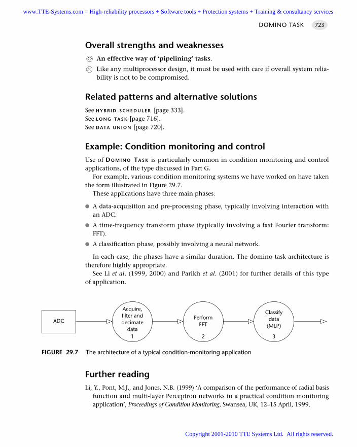
Overall strengths and weaknessesAn effective way of ‘pipelining’ tasks.
Like any multiprocessor design, it must be used with care if overall system relia-bility is not to be compromised.
Related patterns and alternative solutionsSee H Y B R I D S C H E D U L E R [page 333].See L O N G TA S K [page 716].See D ATA U N I O N [page 720].
Example: Condition monitoring and controlUse of DO M I N O TA S K is particularly common in condition monitoring and controlapplications, of the type discussed in Part G.
For example, various condition monitoring systems we have worked on have takenthe form illustrated in Figure 29.7.
These applications have three main phases:
A data-acquisition and pre-processing phase, typically involving interaction withan ADC.
A time-frequency transform phase (typically involving a fast Fourier transform:FFT).
A classification phase, possibly involving a neural network.
In each case, the phases have a similar duration. The domino task architecture istherefore highly appropriate.
See Li et al. (1999, 2000) and Parikh et al. (2001) for further details of this typeof application.
Further readingLi, Y., Pont, M.J., and Jones, N.B. (1999) ‘A comparison of the performance of radial basis
function and multi-layer Perceptron networks in a practical condition monitoringapplication’, Proceedings of Condition Monitoring, Swansea, UK, 12–15 April, 1999.
DOMINO TASK 723
FIGURE 29.7 The architecture of a typical condition-monitoring application
ADC
Classifydata
(MLP)
3
PerformFFT
2
Acquire,filter anddecimate
data1
www.TTE-Systems.com = High-reliability processors + Software tools + Protection systems + Training & consultancy services
Copyright 2001-2010 TTE Systems Ltd. All rights reserved.
Li, Y., Pont, M.J., Parikh, C.R. and Jones, N.B. (2000) ‘Using a combination of RBFN,MLP and kNN classifiers for engine misfire detection’, R. John, and R. Birkenhead(eds) Advances in Soft Computing: Soft Computing Techniques and Applications,Springer-Verlag, Berlin.
Parikh, C.R., Pont, M.J., Li, Y. and Jones, N.B. (1999) ‘Improving the performance ofmulti-layer Perceptrons where limited training data are available for some classes’,Proceedings of the IEE International Conference on Neural Networks, Edinburgh,September 1999.
Parikh C.R., M.J. Pont and N.B. Jones (2001) ‘Application of Dempster-Shafertheory in condition monitoring applications – a case study’, Pattern RecognitionLetters, 22 (6–7): 777–85.
MULTIPROCESSOR SYSTEMS724
www.TTE-Systems.com = High-reliability processors + Software tools + Protection systems + Training & consultancy services
Copyright 2001-2010 TTE Systems Ltd. All rights reserved.
Monitoring and control components
The penultimate group of patterns presented in this book are intended for use in data
acquisition, condition monitoring and control systems. As in previous parts, we are con-
cerned with techniques which are appropriate for use in systems employing a
time-triggered software architecture.
We begin in Chapter 30 by considering the counting of pulses. These techniques are in
widespread use in many industrial applications and throughout the automotive industry.
H A R D WA R E P U L S E C O U N T [page 728] and S O F T WA R E P U L S E C O U N T [page 736] present,
respectively, hardware-based and software-only techniques for pulse counting.
In Chapter 31, we address pulse-rate modulation: that is, the generation of square-wave
signals of a specified frequency. Again, two patterns are presented: H A R D WA R E P R M [page
742] and S O F T WA R E P R M [page 748].
In Chapter 32 we consider how we can use an 8051 microcontroller to measure ana-
logue voltage or current signals. These may, for example, represent the battery voltage in
a charger application: more generally, such signals can come from an enormous range of
sensors, such as potentiometers or temperature probes. The patterns O N E - S H O T A D C
[page 757] and S E Q U E N T I A L A D C [page 782s] discuss how to make effective use of
on-chip and off-chip analogue-to-digital converters (ADCs). Also in this chapter, the
patterns A D C P R E -A M P [page 777] and A-A F I LT E R [page 794] consider important pre-
processing stages that may be required before an analogue signal is measured. Finally, the
pattern C U R R E N T S E N S O R [page 802] considers how we can use analogue measurements
for current-sensing applications, such as detecting blown bulbs or stalled DC motors.
In Chapter 33 we explore how analogue outputs from the microcontroller – generated
in the form of pulse-width modulated signals – can be used in applications such as set-
ting the speed of motors or controlling the brightness of bulbs. Again, both hardware-
part gwww.TTE-Systems.com = High-reliability processors + Software tools + Protection systems + Training & consultancy services
Copyright 2001-2010 TTE Systems Ltd. All rights reserved.
and software-based techniques are considered, in the patterns H A R D W A R E P W M [page
808] and S O F T WA R E P W M [page 831]. We also consider the post-processing that may be
required to filter PWM-based signals, through the pattern P W M S M O O T H E R [page 818]
and the creation of a high-frequency PWM output without using specialized hardware in
the pattern 3-L E V E L P W M [page 822].
In Chapter 34 we consider how analogue outputs from the microcontroller may be gen-
erated using digital-to-analogue converter (DAC) hardware (see D A C O U T P U T [page
841]). We consider the post-processing that may be required to filter and / or amplify
DAC-derived signals, through the patterns D A C S M O O T H E R [page 853] and D A C D R I V E R
[page 857].
Finally, in Chapter 35, we turn our attention to proportional-integral-differential (PID)
control. PID is both simple and effective: as a consequence it is the most widely used con-
trol algorithm. The focus in this chapter is on techniques for designing and implementing
PID controllers for use in embedded, time-triggered applications.
MONITORING AND CONTROL COMPONENTS726
www.TTE-Systems.com = High-reliability processors + Software tools + Protection systems + Training & consultancy services
Copyright 2001-2010 TTE Systems Ltd. All rights reserved.
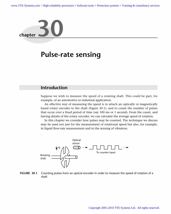
Pulse-rate sensing
Introduction
Suppose we wish to measure the speed of a rotating shaft. This could be part, forexample, of an automotive or industrial application.
An effective way of measuring the speed is to attach an optically or magneticallybased rotary encoder to the shaft (Figure 30.1), and to count the number of pulsesthat occur over a fixed period of time (say 100 ms or 1 second). From the count, andhaving details of the rotary encoder, we can calculate the average speed of rotation.
In this chapter we consider how pulses may be counted. The technique we discussmay be used not just for the measurement of rotational speed but also, for example,in liquid flow-rate measurement and in the sensing of vibration.
chapter 30
FIGURE 30.1 Counting pulses from an optical encoder in order to measure the speed of rotation of ashaft
Rotatingshaft
To counter input
Opticalsensor
www.TTE-Systems.com = High-reliability processors + Software tools + Protection systems + Training & consultancy services
Copyright 2001-2010 TTE Systems Ltd. All rights reserved.
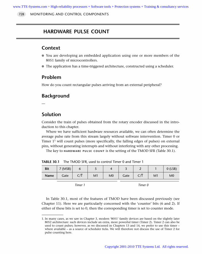
HARDWARE PULSE COUNT
Context You are developing an embedded application using one or more members of the
8051 family of microcontrollers.
The application has a time-triggered architecture, constructed using a scheduler.
ProblemHow do you count rectangular pulses arriving from an external peripheral?
Background—
SolutionConsider the train of pulses obtained from the rotary encoder discussed in the intro-duction to this chapter.
Where we have sufficient hardware resources available, we can often determine theaverage pulse rate from this stream largely without software intervention. Timer 0 orTimer 11 will count pulses (more specifically, the falling edges of pulses) on externalpins, without generating interrupts and without interfering with any other processing.
The key to H A R D WA R E P U L S E C O U N T is the setting of the TMOD SFR (Table 30.1).
In Table 30.1, most of the features of TMOD have been discussed previously (seeChapter 11). Here we are particularly concerned with the ‘counter’ bits (6 and 2). Ifeither of these bits is set to 0, then the corresponding timer is set to counter mode.
MONITORING AND CONTROL COMPONENTS728
TABLE 30.1 The TMOD SFR, used to control Timer 0 and Timer 1
Bit 7 (MSB) 6 5 4 3 2 1 0 (LSB)
Name Gate C/T– M1 M0 Gate C/T– M1 M0
Timer 1 Timer 0
1. In many cases, as we saw in Chapter 3, modern ‘8051’ family devices are based on the slightly later8052 architecture: such devices include an extra, more powerful timer (Timer 2). Timer 2 can also beused to count pulses; however, as we discussed in Chapters 13 and 14, we prefer to use this timer –where available – as a source of scheduler ticks. We will therefore not discuss the use of Timer 2 forpulse counting here.
www.TTE-Systems.com = High-reliability processors + Software tools + Protection systems + Training & consultancy services
Copyright 2001-2010 TTE Systems Ltd. All rights reserved.
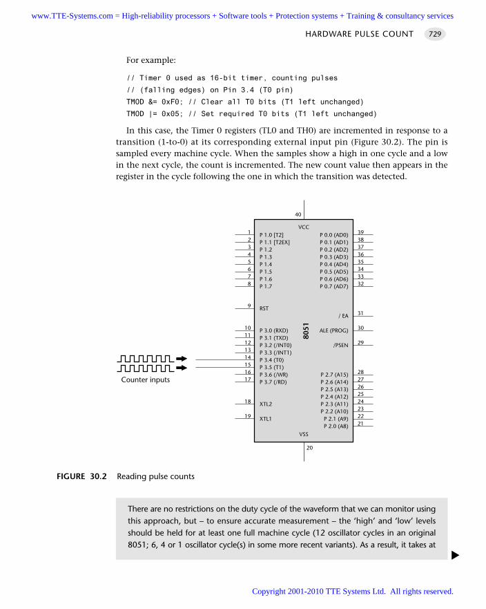
For example:
// Timer 0 used as 16-bit timer, counting pulses
// (falling edges) on Pin 3.4 (T0 pin)
TMOD &= 0xF0; // Clear all T0 bits (T1 left unchanged)
TMOD |= 0x05; // Set required T0 bits (T1 left unchanged)
In this case, the Timer 0 registers (TL0 and TH0) are incremented in response to atransition (1-to-0) at its corresponding external input pin (Figure 30.2). The pin issampled every machine cycle. When the samples show a high in one cycle and a lowin the next cycle, the count is incremented. The new count value then appears in theregister in the cycle following the one in which the transition was detected.
HARDWARE PULSE COUNT 729
FIGURE 30.2 Reading pulse counts
P 1.0 [T2]P 1.1 [T2EX]P 1.2P 1.3P 1.4P 1.5P 1.6P 1.7
RST
P 3.0 (RXD)P 3.1 (TXD)P 3.2 (/INT0)P 3.3 (/INT1)P 3.4 (T0)P 3.5 (T1)P 3.6 (/WR)P 3.7 (/RD)
XTL2
XTL1
P 0.0 (AD0)P 0.1 (AD1)P 0.2 (AD2)P 0.3 (AD3)P 0.4 (AD4)P 0.5 (AD5)P 0.6 (AD6)P 0.7 (AD7)
/ EA
ALE (PROG)
/PSEN
P 2.7 (A15)P 2.6 (A14)P 2.5 (A13)P 2.4 (A12)P 2.3 (A11)P 2.2 (A10)
P 2.1 (A9)P 2.0 (A8)
VCC
8051
VSS
3938373635343332
31
30
29
2827262524232221
12345678
9
1011121314151617
18
19
20
40
Counter inputs
There are no restrictions on the duty cycle of the waveform that we can monitor usingthis approach, but – to ensure accurate measurement – the ‘high’ and ‘low’ levelsshould be held for at least one full machine cycle (12 oscillator cycles in an original8051; 6, 4 or 1 oscillator cycle(s) in some more recent variants). As a result, it takes at
www.TTE-Systems.com = High-reliability processors + Software tools + Protection systems + Training & consultancy services
Copyright 2001-2010 TTE Systems Ltd. All rights reserved.
We can use this information efficiently to measure the rotational speed in the pre-vious example by creating a task that operates as follows:
1 Read the current hardware pulse count.
2 Store the result in a global variable.
3 Reset the count to 0.
We need to schedule this task for repeated execution (say every 100 ms). We give a code example that illustrates this approach in a following example.
Hardware resource implicationsH A R D WA R E P U L S E C O U N T requires exclusive access to a timer. In many cases, Timer 2will be used for the scheduler and Timer 1 may be used for baud-rate generation. Thiswill only leave Timer 0 for this purpose. Where this is not available (or you need tomeasure multiple pulse trains) you will need to consider software-based techniques:see S O F T W A R E P U L S E C O U N T [page 736] or the use of an additional microcontroller(see Part F).
Reliability and safety implicationsThere are no specific reliability and safety implications, provided you do not attemptto count pulses beyond the limits of your hardware (see ‘Solution’ for details).
PortabilityThis pattern uses only core 8051 features: there are no specific portability implications.
Overall strengths and weaknessesH A R D WA R E P U L S E C O U N T imposes a minimal software overhead.
H A R D W A R E P U L S E C O U N T requires exclusive access to a timer for each pulsetrain you wish to count.
Related patterns and alternative solutionsThere are two main alternatives to H A R D WA R E P U L S E C O U N T .
MONITORING AND CONTROL COMPONENTS730
least two machine cycles (24, 12, 8 or 2 oscillator cycles) to detect a 1-to-0 transition.This determines the maximum pulse rate that you can measure: for example, on abasic 12 Mhz / 12 oscillator cycle 8051, the maximum pulse rate (square wave) thatwe can measure has a period of 24 oscillator cycles (2 µs), and a frequency of 500 kHz.
www.TTE-Systems.com = High-reliability processors + Software tools + Protection systems + Training & consultancy services
Copyright 2001-2010 TTE Systems Ltd. All rights reserved.
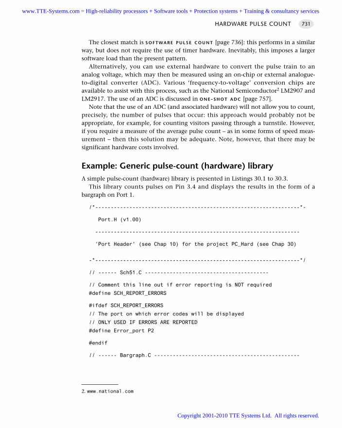
The closest match is S O F T WA R E P U L S E C O U N T [page 736]: this performs in a similarway, but does not require the use of timer hardware. Inevitably, this imposes a largersoftware load than the present pattern.
Alternatively, you can use external hardware to convert the pulse train to ananalog voltage, which may then be measured using an on-chip or external analogue-to-digital converter (ADC). Various ‘frequency-to-voltage’ conversion chips areavailable to assist with this process, such as the National Semiconductor2 LM2907 andLM2917. The use of an ADC is discussed in O N E-S H O T A D C [page 757].
Note that the use of an ADC (and associated hardware) will not allow you to count,precisely, the number of pulses that occur: this approach would probably not beappropriate, for example, for counting visitors passing through a turnstile. However,if you require a measure of the average pulse count – as in some forms of speed meas-urement – then this solution may be adequate. Note, however, that there may besignificant hardware costs involved.
Example: Generic pulse-count (hardware) libraryA simple pulse-count (hardware) library is presented in Listings 30.1 to 30.3.
This library counts pulses on Pin 3.4 and displays the results in the form of abargraph on Port 1.
/*------------------------------------------------------------------*-
Port.H (v1.00)
------------------------------------------------------------------
'Port Header' (see Chap 10) for the project PC_Hard (see Chap 30)
-*------------------------------------------------------------------*/
// ------ Sch51.C ----------------------------------------
// Comment this line out if error reporting is NOT required
#define SCH_REPORT_ERRORS
#ifdef SCH_REPORT_ERRORS
// The port on which error codes will be displayed
// ONLY USED IF ERRORS ARE REPORTED
#define Error_port P2
#endif
// ------ Bargraph.C -----------------------------------------------
HARDWARE PULSE COUNT 731
2. www.national.com
www.TTE-Systems.com = High-reliability processors + Software tools + Protection systems + Training & consultancy services
Copyright 2001-2010 TTE Systems Ltd. All rights reserved.
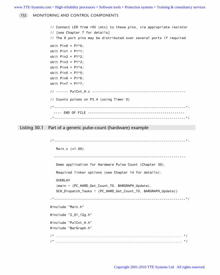
// Connect LED from +5V (etc) to these pins, via appropriate resistor
// [see Chapter 7 for details]
// The 8 port pins may be distributed over several ports if required
sbit Pin0 = P1^0;
sbit Pin1 = P1^1;
sbit Pin2 = P1^2;
sbit Pin3 = P1^3;
sbit Pin4 = P1^4;
sbit Pin5 = P1^5;
sbit Pin6 = P1^6;
sbit Pin7 = P1^7;
// ------ PulCnt_H.c -----------------------------------------------
// Counts pulses on P3.4 (using Timer 0)
/*------------------------------------------------------------------*-
---- END OF FILE ------------------------------------------------
-*------------------------------------------------------------------*/
Listing 30.1 Part of a generic pulse-count (hardware) example
/*------------------------------------------------------------------*-
Main.c (v1.00)
------------------------------------------------------------------
Demo application for Hardware Pulse Count (Chapter 30).
Required linker options (see Chapter 14 for details):
OVERLAY
(main ~ (PC_HARD_Get_Count_T0, BARGRAPH_Update),
SCH_Dispatch_Tasks ! (PC_HARD_Get_Count_T0, BARGRAPH_Update))
-*------------------------------------------------------------------*/
#include "Main.h"
#include "2_01_12g.h"
#include "PulCnt_H.h"
#include "BarGraph.h"
/* ............................................................... */
/* ............................................................... */
MONITORING AND CONTROL COMPONENTS732
www.TTE-Systems.com = High-reliability processors + Software tools + Protection systems + Training & consultancy services
Copyright 2001-2010 TTE Systems Ltd. All rights reserved.
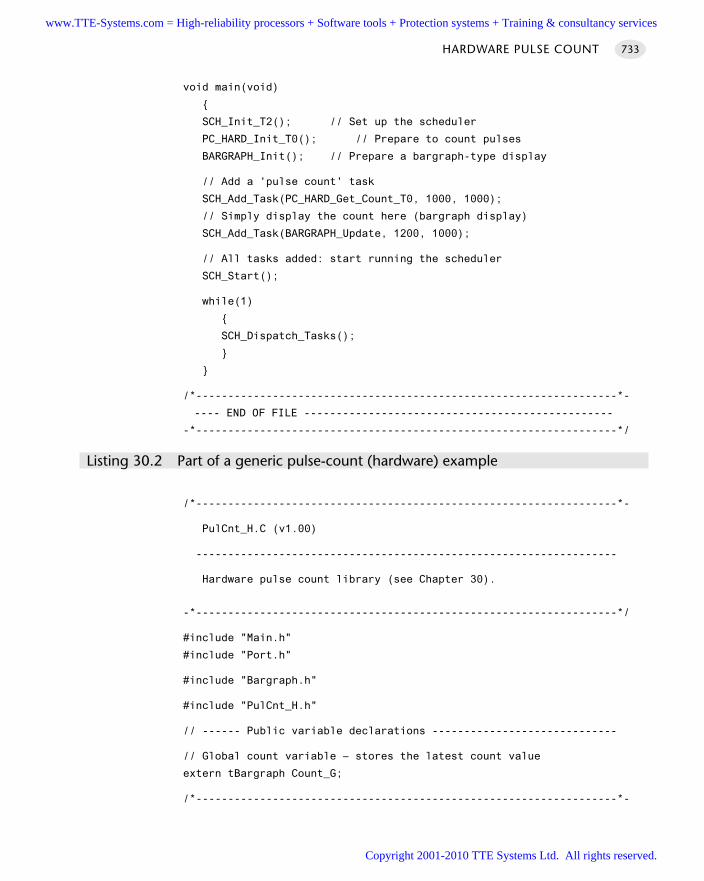
HARDWARE PULSE COUNT 733
void main(void)
SCH_Init_T2(); // Set up the scheduler
PC_HARD_Init_T0(); // Prepare to count pulses
BARGRAPH_Init(); // Prepare a bargraph-type display
// Add a 'pulse count' task
SCH_Add_Task(PC_HARD_Get_Count_T0, 1000, 1000);
// Simply display the count here (bargraph display)
SCH_Add_Task(BARGRAPH_Update, 1200, 1000);
// All tasks added: start running the scheduler
SCH_Start();
while(1)
SCH_Dispatch_Tasks();
/*------------------------------------------------------------------*-
---- END OF FILE ------------------------------------------------
-*------------------------------------------------------------------*/
Listing 30.2 Part of a generic pulse-count (hardware) example
/*------------------------------------------------------------------*-
PulCnt_H.C (v1.00)
------------------------------------------------------------------
Hardware pulse count library (see Chapter 30).
-*------------------------------------------------------------------*/
#include "Main.h"
#include "Port.h"
#include "Bargraph.h"
#include "PulCnt_H.h"
// ------ Public variable declarations -----------------------------
// Global count variable – stores the latest count value
extern tBargraph Count_G;
/*------------------------------------------------------------------*-
www.TTE-Systems.com = High-reliability processors + Software tools + Protection systems + Training & consultancy services
Copyright 2001-2010 TTE Systems Ltd. All rights reserved.
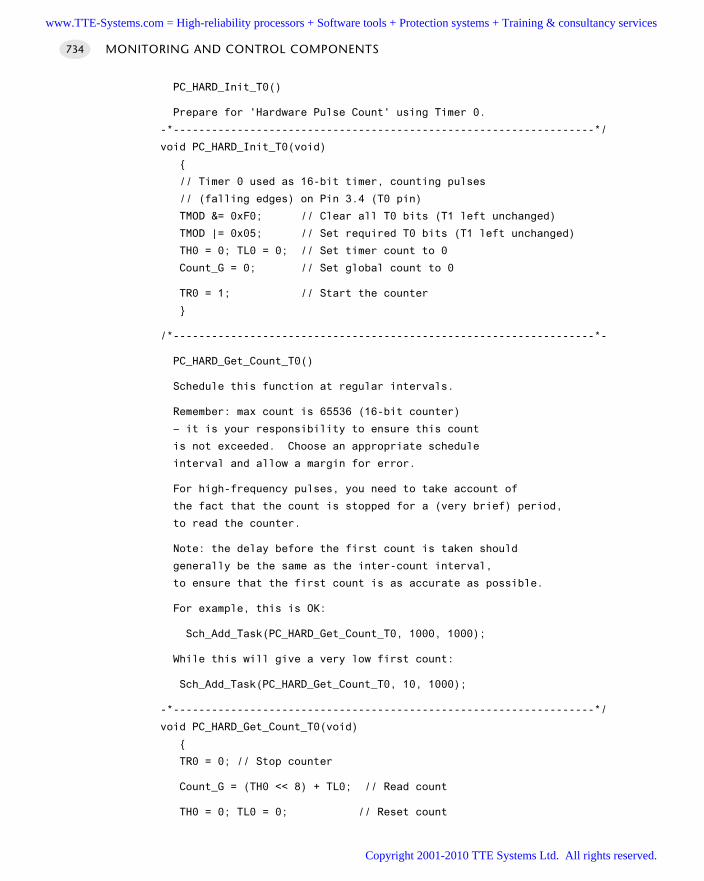
PC_HARD_Init_T0()
Prepare for 'Hardware Pulse Count' using Timer 0.
-*------------------------------------------------------------------*/
void PC_HARD_Init_T0(void)
// Timer 0 used as 16-bit timer, counting pulses
// (falling edges) on Pin 3.4 (T0 pin)
TMOD &= 0xF0; // Clear all T0 bits (T1 left unchanged)
TMOD |= 0x05; // Set required T0 bits (T1 left unchanged)
TH0 = 0; TL0 = 0; // Set timer count to 0
Count_G = 0; // Set global count to 0
TR0 = 1; // Start the counter
/*------------------------------------------------------------------*-
PC_HARD_Get_Count_T0()
Schedule this function at regular intervals.
Remember: max count is 65536 (16-bit counter)
– it is your responsibility to ensure this count
is not exceeded. Choose an appropriate schedule
interval and allow a margin for error.
For high-frequency pulses, you need to take account of
the fact that the count is stopped for a (very brief) period,
to read the counter.
Note: the delay before the first count is taken should
generally be the same as the inter-count interval,
to ensure that the first count is as accurate as possible.
For example, this is OK:
Sch_Add_Task(PC_HARD_Get_Count_T0, 1000, 1000);
While this will give a very low first count:
Sch_Add_Task(PC_HARD_Get_Count_T0, 10, 1000);
-*------------------------------------------------------------------*/
void PC_HARD_Get_Count_T0(void)
TR0 = 0; // Stop counter
Count_G = (TH0 << 8) + TL0; // Read count
TH0 = 0; TL0 = 0; // Reset count
MONITORING AND CONTROL COMPONENTS734
www.TTE-Systems.com = High-reliability processors + Software tools + Protection systems + Training & consultancy services
Copyright 2001-2010 TTE Systems Ltd. All rights reserved.
if (TF0 == 1)
// Timer has overflowed
// – pulse frequency too high
// – or schedule rate too low
// We code this error as a 'max count'
// – could also set a global error flag, if required
Count_G = 65536;
TF0 = 0;
TR0 = 1; // Restart counter
/*------------------------------------------------------------------*-
---- END OF FILE ------------------------------------------------
-*------------------------------------------------------------------*/
Listing 30.3 Part of a generic pulse-count (hardware) example
Further reading—
HARDWARE PULSE COUNT 735
www.TTE-Systems.com = High-reliability processors + Software tools + Protection systems + Training & consultancy services
Copyright 2001-2010 TTE Systems Ltd. All rights reserved.
SOFTWARE PULSE COUNT
Context You are developing an embedded application using one or more members of the
8051 family of microcontrollers. The application has a time-triggered architecture, constructed using a scheduler.
ProblemHow do you count pulses arriving from an external peripheral?
BackgroundSee H A R D WA R E P U L S E C O U N T [page 582] for background details.
SolutionH A R D WA R E P U L S E C O U N T requires exclusive access to a timer.
Where this timer is not available and comparatively low pulse rates are to be meas-ured, software-only pulse counting is possible.
Software-based pulse counting involves a periodic task that keeps track of the stateof one or more input pins. When a pin changes state in the interval between taskinvocations, we increment the corresponding count by 1. The main drawback is themaximum pulse rate: with a 1 ms scheduler, the maximum pulse rate we can measureis 500 Hz: this is around 1,000 times less than can be measured using H A R D W A R E
P U L S E C O U N T [page 730].
Hardware resource implicationsThis pattern uses no on-chip hardware components.
Reliability and safety implicationsThere are no specific reliability and safety implications.
PortabilityThis code has no hardware requirements and may be readily ported to a differentmicrocontroller environment, provided that the new environment also uses a sched-uler operating at the same tick rate.
Overall strengths and weaknessesS O F T WA R E P U L S E C O U N T does not require a timer.
MONITORING AND CONTROL COMPONENTS736
www.TTE-Systems.com = High-reliability processors + Software tools + Protection systems + Training & consultancy services
Copyright 2001-2010 TTE Systems Ltd. All rights reserved.
The main drawback is the maximum pulse rate. With a 1 ms scheduler, themaximum pulse rate we can measure is 500 Hz: this is around 1,000 times lessthan can be measured using hardware.
Related patterns and alternative solutionsThe main alternative to S O F T W A R E P U L S E C O U N T is H A R D W A R E P U L S E C O U N T
[page 728].
Example: Generic pulse-count (software) libraryA simple pulse-count (software) library is presented in Listings 30.4 to 30.6.
This library counts pulses on Pin 3.0 and displays the results in the form of a bar-graph on Port 1.
/*------------------------------------------------------------------*-
Port.H (v1.00)
------------------------------------------------------------------
'Port Header' (see Chap 10) for the project PC_Soft
-*------------------------------------------------------------------*/
// ------ Sch51.C ----------------------------------------
// Comment this line out if error reporting is NOT required
#define SCH_REPORT_ERRORS
#ifdef SCH_REPORT_ERRORS
// The port on which error codes will be displayed
// ONLY USED IF ERRORS ARE REPORTED
#define Error_port P2
#endif
// ------ Bargraph.C -----------------------------------------------
// Connect LED from +5V (etc) to these pins, via appropriate resistor
// [see Chapter 7 for details]
// The 8 port pins may be distributed over several ports if required
sbit Pin0 = P1^0;
sbit Pin1 = P1^1;
sbit Pin2 = P1^2;
sbit Pin3 = P1^3;
sbit Pin4 = P1^4;
sbit Pin5 = P1^5;
sbit Pin6 = P1^6;
sbit Pin7 = P1^7;
// ------ PulCnt_S.c -----------------------------------------------
SOFTWARE PULSE COUNT 737
www.TTE-Systems.com = High-reliability processors + Software tools + Protection systems + Training & consultancy services
Copyright 2001-2010 TTE Systems Ltd. All rights reserved.
MONITORING AND CONTROL COMPONENTS738
sbit Count_pin = P3^0;
/*------------------------------------------------------------------*-
---- END OF FILE ------------------------------------------------
-*------------------------------------------------------------------*/
Listing 30.4 Part of a generic pulse-count (software) example
/*------------------------------------------------------------------*-
Main.c (v1.00)
------------------------------------------------------------------
Demo application for Software Pulse Count
Required linker options (see Chapter 14 for details):
OVERLAY
(main ~ (PC_SOFT_Poll_Count, PC_SOFT_Get_Count, BARGRAPH_Update),
SCH_Dispatch_Tasks ! (PC_SOFT_Poll_Count, PC_SOFT_Get_Count,
BARGRAPH_Update))
-*------------------------------------------------------------------*/
#include "Main.h"
#include "2_01_12g.h"
#include "PulCnt_S.h"
#include "BarGraph.h"
/* ............................................................... */
/* ............................................................... */
void main(void)
SCH_Init_T2(); // Set up the scheduler
PC_SOFT_Init(); // Prepare to count pulses
BARGRAPH_Init(); // Prepare a bargraph-type display (P4)
// TIMING IS IN TICKS (1 ms interval)
// Add a 'pulse count poll' task
// Every 40 milliseconds
SCH_Add_Task(PC_SOFT_Poll_Count, 0, 20);
// Add a 'pulse get count' task
// Every 20 seconds
SCH_Add_Task(PC_SOFT_Get_Count, 0, 20000);
// Simply display the count here (bargraph display)
// Max count is ~250
SCH_Add_Task(BARGRAPH_Update, 50, 10000);
www.TTE-Systems.com = High-reliability processors + Software tools + Protection systems + Training & consultancy services
Copyright 2001-2010 TTE Systems Ltd. All rights reserved.
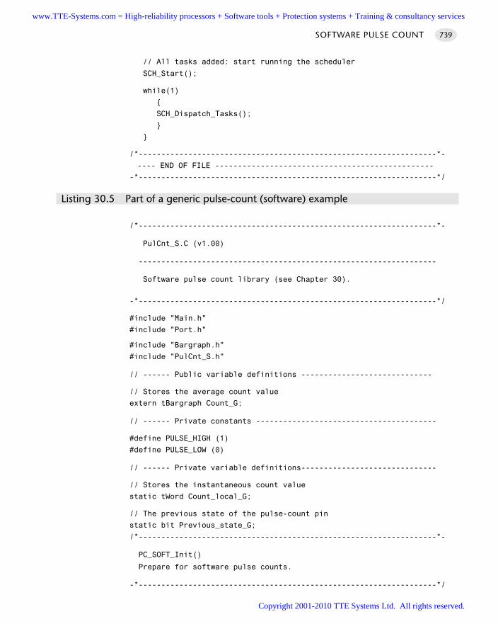
SOFTWARE PULSE COUNT 739
// All tasks added: start running the scheduler
SCH_Start();
while(1)
SCH_Dispatch_Tasks();
/*------------------------------------------------------------------*-
---- END OF FILE ------------------------------------------------
-*------------------------------------------------------------------*/
Listing 30.5 Part of a generic pulse-count (software) example
/*------------------------------------------------------------------*-
PulCnt_S.C (v1.00)
------------------------------------------------------------------
Software pulse count library (see Chapter 30).
-*------------------------------------------------------------------*/
#include "Main.h"
#include "Port.h"
#include "Bargraph.h"
#include "PulCnt_S.h"
// ------ Public variable definitions -----------------------------
// Stores the average count value
extern tBargraph Count_G;
// ------ Private constants ----------------------------------------
#define PULSE_HIGH (1)
#define PULSE_LOW (0)
// ------ Private variable definitions------------------------------
// Stores the instantaneous count value
static tWord Count_local_G;
// The previous state of the pulse-count pin
static bit Previous_state_G;
/*------------------------------------------------------------------*-
PC_SOFT_Init()
Prepare for software pulse counts.
-*------------------------------------------------------------------*/
www.TTE-Systems.com = High-reliability processors + Software tools + Protection systems + Training & consultancy services
Copyright 2001-2010 TTE Systems Ltd. All rights reserved.
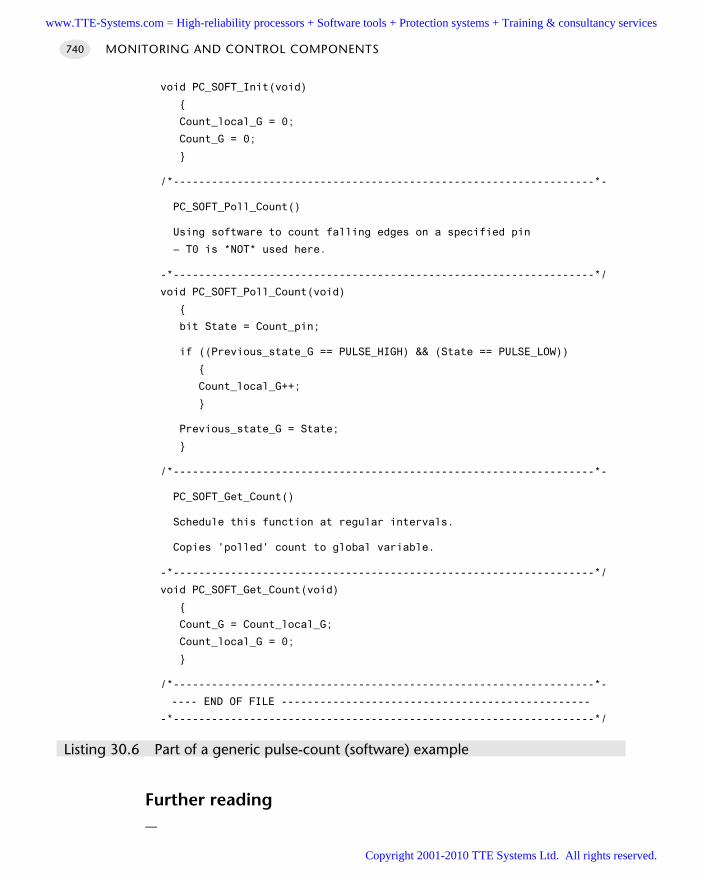
MONITORING AND CONTROL COMPONENTS740
void PC_SOFT_Init(void)
Count_local_G = 0;
Count_G = 0;
/*------------------------------------------------------------------*-
PC_SOFT_Poll_Count()
Using software to count falling edges on a specified pin
– T0 is *NOT* used here.
-*------------------------------------------------------------------*/
void PC_SOFT_Poll_Count(void)
bit State = Count_pin;
if ((Previous_state_G == PULSE_HIGH) && (State == PULSE_LOW))
Count_local_G++;
Previous_state_G = State;
/*------------------------------------------------------------------*-
PC_SOFT_Get_Count()
Schedule this function at regular intervals.
Copies 'polled' count to global variable.
-*------------------------------------------------------------------*/
void PC_SOFT_Get_Count(void)
Count_G = Count_local_G;
Count_local_G = 0;
/*------------------------------------------------------------------*-
---- END OF FILE ------------------------------------------------
-*------------------------------------------------------------------*/
Listing 30.6 Part of a generic pulse-count (software) example
Further reading—
www.TTE-Systems.com = High-reliability processors + Software tools + Protection systems + Training & consultancy services
Copyright 2001-2010 TTE Systems Ltd. All rights reserved.
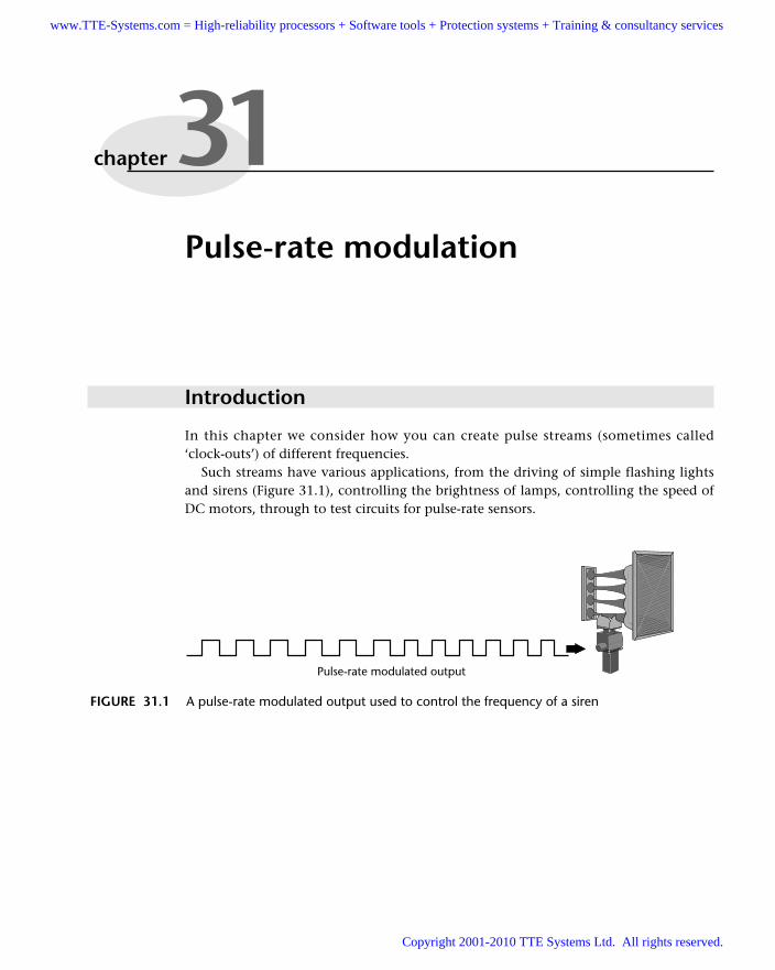
Pulse-rate modulation
Introduction
In this chapter we consider how you can create pulse streams (sometimes called‘clock-outs’) of different frequencies.
Such streams have various applications, from the driving of simple flashing lightsand sirens (Figure 31.1), controlling the brightness of lamps, controlling the speed ofDC motors, through to test circuits for pulse-rate sensors.
chapter 31
FIGURE 31.1 A pulse-rate modulated output used to control the frequency of a siren
Pulse-rate modulated output
www.TTE-Systems.com = High-reliability processors + Software tools + Protection systems + Training & consultancy services
Copyright 2001-2010 TTE Systems Ltd. All rights reserved.
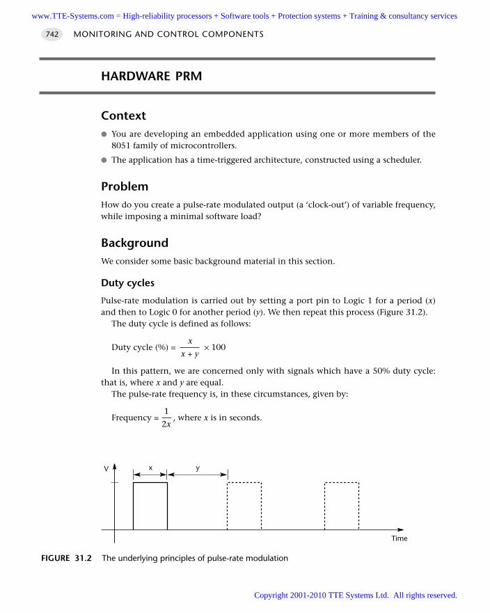
HARDWARE PRM
Context You are developing an embedded application using one or more members of the
8051 family of microcontrollers.
The application has a time-triggered architecture, constructed using a scheduler.
ProblemHow do you create a pulse-rate modulated output (a ‘clock-out’) of variable frequency,while imposing a minimal software load?
BackgroundWe consider some basic background material in this section.
Duty cycles
Pulse-rate modulation is carried out by setting a port pin to Logic 1 for a period (x)and then to Logic 0 for another period (y). We then repeat this process (Figure 31.2).
The duty cycle is defined as follows:
xDuty cycle (%) = × 100
x + y
In this pattern, we are concerned only with signals which have a 50% duty cycle:that is, where x and y are equal.
The pulse-rate frequency is, in these circumstances, given by:
1Frequency = , where x is in seconds.
2x
MONITORING AND CONTROL COMPONENTS742
FIGURE 31.2 The underlying principles of pulse-rate modulation
V
Time
yx
www.TTE-Systems.com = High-reliability processors + Software tools + Protection systems + Training & consultancy services
Copyright 2001-2010 TTE Systems Ltd. All rights reserved.
Timer 2
As we saw in Chapter 3, the original 8052 and most modern ‘8051’ devices contain anadditional timer, known as Timer 2. This pattern requires the use of Timer 2.
Refer to Chapter 3 for basic background on Timer 2 and to Chapter 11 for basicinformation on timers.
SolutionUsing Timer 2 (see ‘Background’), Pin 1.0 can be programmed to output a 50% dutycycle clock.
To configure this timer3 as a clock generator, bit C/T2 (T2CON.1) must be clearedand bit T2OE (T2MOD.1) must be set. Bit TR2 (T2CON.2) starts and stops the timer.The clock-out frequency depends on the oscillator frequency and the reload value ofTimer 2 capture registers (RCAP2H, RCAP2L), as shown in the following equation.
FrequencyOscillatorFrequencypulse = 4 × (65536 – RCAP2H, RCAP2L)
For example, the minimum frequency with a 12 MHz crystal is:
12000000Frequencymin = = 45.78 Hz
4 × (65536)
Similarly, the maximum frequency is:
12000000Frequencymax = = 3.0 MHz
4
In the clock-out mode, Timer 2 rollovers will not generate an interrupt. This behaviour is similar to when Timer 2 is used as a baud-rate generator and it is
possible to use Timer 2 as a baud-rate generator and a clock generator simultaneously.Note, however, that the baud rate and clock-out frequencies cannot be determinedindependently from one another since they both use RCAP2H and RCAP2L.
Hardware resource implicationsThis pattern requires the use of Timer 2. In single-processor applications, Timer 2 isoften the most suitable timer to use to drive the scheduler itself; as a result, use of thistechnique may have an impact on other parts of the application.
Note that, if a two-processor solution is possible (using a UART- or interrupt-basedscheduler, for example), then Timer 2 can be used to drive the scheduler in the Master
HARDWARE PRM 743
3. As we discussed in Chapters 3 and 11, different implementations of Timer 2 are used in various 8051family members; the names of some of the registers can therefore vary. This description appliesspecifically to the Atmel 89x52 / 89x53 devices but may be applied with minor modifications toother family members.
www.TTE-Systems.com = High-reliability processors + Software tools + Protection systems + Training & consultancy services
Copyright 2001-2010 TTE Systems Ltd. All rights reserved.
node, leaving Timer 2 in the Slave node free for use as a PRM generator: see Part F fordetails of various multiprocessor solutions that may be appropriate here.
Reliability and safety implicationsThis technique is very reliable.
PortabilityThis technique may only be used with 8052-based devices: that is, those with animplementation of Timer 2 available. While most modern ‘8051s’ have such a timer,some popular devices, such as the Atmel Small 8051s, do not.
Overall strengths and weaknessesA simple, effective technique for creating PRM signals over a very wide fre-quency range.
Imposes no measurable software or CPU load.
Requires exclusive use of Timer 2.
Related patterns and alternative solutionsThe most directly comparable pattern is S O F T WA R E P R M [page 748]. In addition, S O F T-WA R E P W M [page 831], H A R D WA R E P W M [page 808] and particularly 3- L L E V E L P W M
[page 822] can form the basis of alternative solutions under some circumstances.As we noted in ‘Hardware resource implications’, it may be appropriate to use this
technique in a Slave node in a multiprocessor application. Refer to the various pat-terns in Part F for further information on this topic.
Example: Hardware PRM on the ‘8052’An example of software to control hardware-based pulse-rate modulation is given inthis section.
In Listings 31.1 and 31.2, we use a 16-bit (unsigned) integer variable(PRM_reload_G) to control the pulse frequency. The resulting frequency, as discussedearlier, is as follows:
FrequencyOscillatorFrequencypulse =4 × (65536 – RCAP2H,RCAP2L)
Thus, with a 12 MHz oscillator, the pulse rate will increase slowly from 45Hz to3MHz (approximately), repeatedly.
MONITORING AND CONTROL COMPONENTS744
www.TTE-Systems.com = High-reliability processors + Software tools + Protection systems + Training & consultancy services
Copyright 2001-2010 TTE Systems Ltd. All rights reserved.
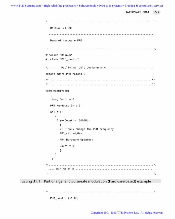
/*------------------------------------------------------------------*-
Main.c (v1.00)
------------------------------------------------------------------
Demo of hardware PRM.
-*------------------------------------------------------------------*/
#include "Main.h"
#include "PRM_Hard.h"
// ------ Public variable declarations -----------------------------
extern tWord PRM_reload_G;
/* ............................................................... */
/* ............................................................... */
void main(void)
tLong Count = 0;
PRM_Hardware_Init();
while(1)
if (++Count > 10000UL)
// Slowly change the PRM frequency
PRM_reload_G++;
PRM_Hardware_Update();
Count = 0;
/*------------------------------------------------------------------*-
---- END OF FILE ------------------------------------------------
-*------------------------------------------------------------------*/
Listing 31.1 Part of a generic pulse-rate modulation (hardware-based) example
/*------------------------------------------------------------------*-
PRM_Hard.C (v1.00)
HARDWARE PRM 745
www.TTE-Systems.com = High-reliability processors + Software tools + Protection systems + Training & consultancy services
Copyright 2001-2010 TTE Systems Ltd. All rights reserved.
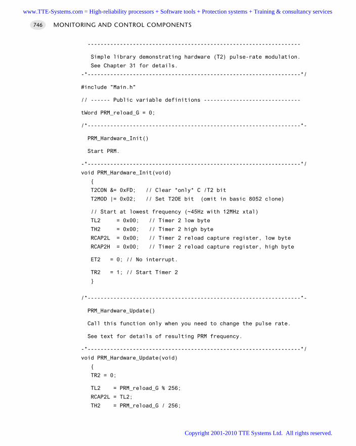
------------------------------------------------------------------
Simple library demonstrating hardware (T2) pulse-rate modulation.
See Chapter 31 for details.
-*------------------------------------------------------------------*/
#include "Main.h"
// ------ Public variable definitions ------------------------------
tWord PRM_reload_G = 0;
/*------------------------------------------------------------------*-
PRM_Hardware_Init()
Start PRM.
-*------------------------------------------------------------------*/
void PRM_Hardware_Init(void)
T2CON &= 0xFD; // Clear *only* C /T2 bit
T2MOD |= 0x02; // Set T2OE bit (omit in basic 8052 clone)
// Start at lowest frequency (~45Hz with 12MHz xtal)
TL2 = 0x00; // Timer 2 low byte
TH2 = 0x00; // Timer 2 high byte
RCAP2L = 0x00; // Timer 2 reload capture register, low byte
RCAP2H = 0x00; // Timer 2 reload capture register, high byte
ET2 = 0; // No interrupt.
TR2 = 1; // Start Timer 2
/*------------------------------------------------------------------*-
PRM_Hardware_Update()
Call this function only when you need to change the pulse rate.
See text for details of resulting PRM frequency.
-*------------------------------------------------------------------*/
void PRM_Hardware_Update(void)
TR2 = 0;
TL2 = PRM_reload_G % 256;
RCAP2L = TL2;
TH2 = PRM_reload_G / 256;
MONITORING AND CONTROL COMPONENTS746
www.TTE-Systems.com = High-reliability processors + Software tools + Protection systems + Training & consultancy services
Copyright 2001-2010 TTE Systems Ltd. All rights reserved.
RCAP2H = TH2;
TR2 = 1;
/*------------------------------------------------------------------*-
---- END OF FILE -------------------------------------------------
-*------------------------------------------------------------------*/
Listing 31.2 Part of a generic pulse-rate modulation (hardware-based) example
Further reading—
HARDWARE PRM 747
www.TTE-Systems.com = High-reliability processors + Software tools + Protection systems + Training & consultancy services
Copyright 2001-2010 TTE Systems Ltd. All rights reserved.
SOFTWARE PRM
Context You are developing an embedded application using one or more members of the
8051 family of microcontrollers.
The application has a time-triggered architecture, constructed using a scheduler.
ProblemHow do you create a square- or rectangular-wave output pulse with particular pulse-width and frequency characteristics without using on-chip hardware?
BackgroundRefer to H A R D W A R E P R M [page 742] for basic background information on pulse-rate modulation.
SolutionCreating an output that is pulse-rate modulated using a scheduler is easy to do: infact, all our introductory examples did just this. For example, consider Listing 31.3,first presented in Chapter 14.
void main(void)
// Set up the scheduler
SCH_Init_T2();
// Prepare for the 'Flash_LED' task
LED_Flash_Init();
// Add the 'Flash LED' task (on for ~1000 ms, off for ~1000 ms)
// – timings are in ticks (1 ms tick interval)
// (Max interval / delay is 65535 ticks)
SCH_Add_Task(LED_Flash_Update, 0, 1000);
// Start the scheduler
SCH_Start();
while(1)
MONITORING AND CONTROL COMPONENTS748
www.TTE-Systems.com = High-reliability processors + Software tools + Protection systems + Training & consultancy services
Copyright 2001-2010 TTE Systems Ltd. All rights reserved.
SCH_Dispatch_Tasks();
Listing 31.3 A simple form of pulse-rate modulation (software based)
The ‘flash LED’ task itself may be implemented as shown in Listing 31.4.
void LED_Flash_Update(void)
// Change the LED from OFF to ON (or vice versa)
if (LED_state_G == 1)
LED_state_G = 0;
LED_pin = 0;
else
LED_state_G = 1;
LED_pin = 1;
Listing 31.4 A ‘flash LED’ task
This code flashes an LED at a 0.5Hz rate: it could, of course, drive various otherdevices, if we use an appropriate hardware interface.
The same technique may be readily adapted to allow us to perform low-frequencysoftware PRM, at variable frequencies: Listing 31.5 illustrates this.
void PRM_Soft_Update(void)
// Increment the 'position' variable
if (++PRM_position_G >= PRM_period_G)
PRM_position_G = 0;
PRM_period_G = PRM_period_new_G;
PRM_pin = 0;
return;
// Generate the PRM output
if (PRM_position_G < (PRM_period_G / 2))
SOFTWARE PRM 749
www.TTE-Systems.com = High-reliability processors + Software tools + Protection systems + Training & consultancy services
Copyright 2001-2010 TTE Systems Ltd. All rights reserved.
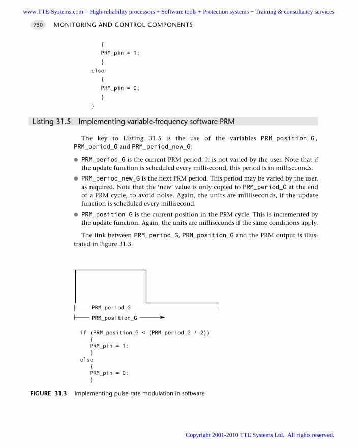
PRM_pin = 1;
else
PRM_pin = 0;
Listing 31.5 Implementing variable-frequency software PRM
The key to Listing 31.5 is the use of the variables PRM_position_G,PRM_period_G and PRM_period_new_G:
PRM_period_G is the current PRM period. It is not varied by the user. Note that ifthe update function is scheduled every millisecond, this period is in milliseconds.
PRM_period_new_G is the next PRM period. This period may be varied by the user,as required. Note that the ‘new’ value is only copied to PRM_period_G at the endof a PRM cycle, to avoid noise. Again, the units are milliseconds, if the updatefunction is scheduled every millisecond.
PRM_position_G is the current position in the PRM cycle. This is incremented bythe update function. Again, the units are milliseconds if the same conditions apply.
The link between PRM_period_G, PRM_position_G and the PRM output is illus-trated in Figure 31.3.
MONITORING AND CONTROL COMPONENTS750
FIGURE 31.3 Implementing pulse-rate modulation in software
if (PRM_position_G < (PRM_period_G / 2)) PRM_pin = 1: else PRM_pin = 0:
PRM_period_G
PRM_position_G
www.TTE-Systems.com = High-reliability processors + Software tools + Protection systems + Training & consultancy services
Copyright 2001-2010 TTE Systems Ltd. All rights reserved.
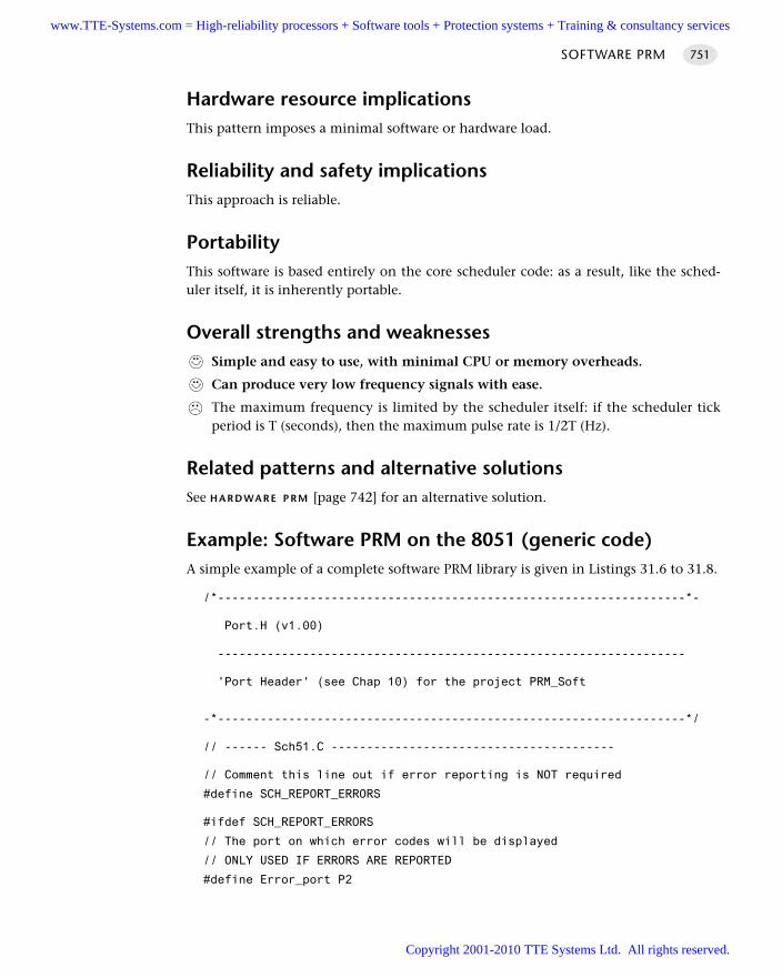
Hardware resource implicationsThis pattern imposes a minimal software or hardware load.
Reliability and safety implicationsThis approach is reliable.
PortabilityThis software is based entirely on the core scheduler code: as a result, like the sched-uler itself, it is inherently portable.
Overall strengths and weaknessesSimple and easy to use, with minimal CPU or memory overheads.
Can produce very low frequency signals with ease.
The maximum frequency is limited by the scheduler itself: if the scheduler tickperiod is T (seconds), then the maximum pulse rate is 1/2T (Hz).
Related patterns and alternative solutionsSee H A R D WA R E P R M [page 742] for an alternative solution.
Example: Software PRM on the 8051 (generic code)A simple example of a complete software PRM library is given in Listings 31.6 to 31.8.
/*------------------------------------------------------------------*-
Port.H (v1.00)
------------------------------------------------------------------
'Port Header' (see Chap 10) for the project PRM_Soft
-*------------------------------------------------------------------*/
// ------ Sch51.C ----------------------------------------
// Comment this line out if error reporting is NOT required
#define SCH_REPORT_ERRORS
#ifdef SCH_REPORT_ERRORS
// The port on which error codes will be displayed
// ONLY USED IF ERRORS ARE REPORTED
#define Error_port P2
SOFTWARE PRM 751
www.TTE-Systems.com = High-reliability processors + Software tools + Protection systems + Training & consultancy services
Copyright 2001-2010 TTE Systems Ltd. All rights reserved.
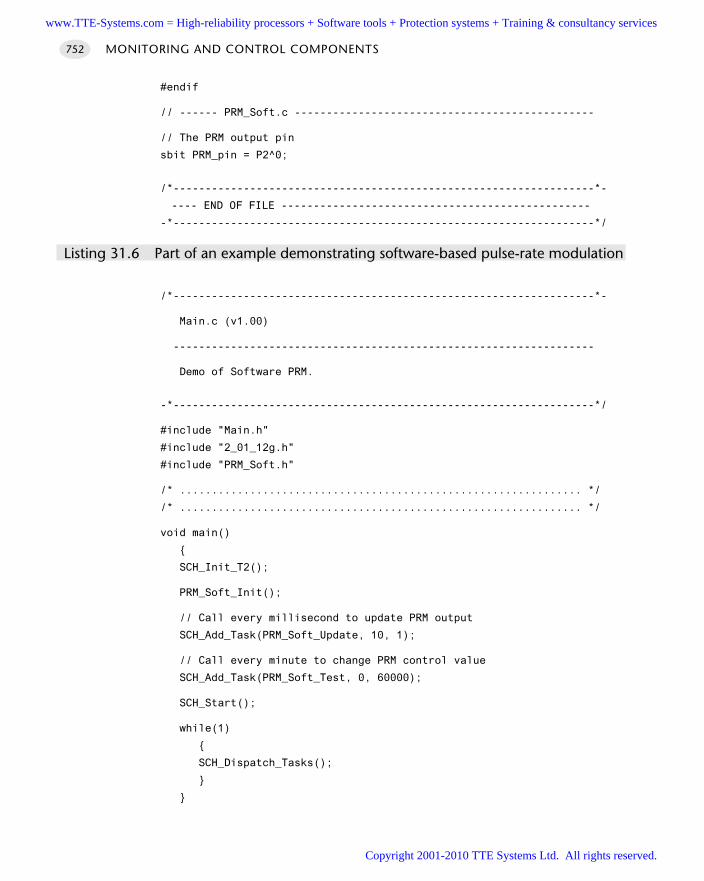
#endif
// ------ PRM_Soft.c -----------------------------------------------
// The PRM output pin
sbit PRM_pin = P2^0;
/*------------------------------------------------------------------*-
---- END OF FILE ------------------------------------------------
-*------------------------------------------------------------------*/
Listing 31.6 Part of an example demonstrating software-based pulse-rate modulation
/*------------------------------------------------------------------*-
Main.c (v1.00)
------------------------------------------------------------------
Demo of Software PRM.
-*------------------------------------------------------------------*/
#include "Main.h"
#include "2_01_12g.h"
#include "PRM_Soft.h"
/* ............................................................... */
/* ............................................................... */
void main()
SCH_Init_T2();
PRM_Soft_Init();
// Call every millisecond to update PRM output
SCH_Add_Task(PRM_Soft_Update, 10, 1);
// Call every minute to change PRM control value
SCH_Add_Task(PRM_Soft_Test, 0, 60000);
SCH_Start();
while(1)
SCH_Dispatch_Tasks();
MONITORING AND CONTROL COMPONENTS752
www.TTE-Systems.com = High-reliability processors + Software tools + Protection systems + Training & consultancy services
Copyright 2001-2010 TTE Systems Ltd. All rights reserved.
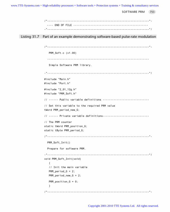
/*------------------------------------------------------------------*-
---- END OF FILE ------------------------------------------------
-*------------------------------------------------------------------*/
Listing 31.7 Part of an example demonstrating software-based pulse-rate modulation
/*------------------------------------------------------------------*-
PRM_Soft.c (v1.00)
------------------------------------------------------------------
Simple Software PRM library.
-*------------------------------------------------------------------*/
#include "Main.h"
#include "Port.h"
#include "2_01_12g.h"
#include "PRM_Soft.h"
// ------ Public variable definitions ------------------------------
// Set this variable to the required PRM value
tWord PRM_period_new_G;
// ------ Private variable definitions------------------------------
// The PRM counter
static tWord PRM_position_G;
static tByte PRM_period_G;
/*------------------------------------------------------------------*-
PRM_Soft_Init()
Prepare for software PRM.
-*------------------------------------------------------------------*/
void PRM_Soft_Init(void)
// Init the main variable
PRM_period_G = 2;
PRM_period_new_G = 2;
PRM_position_G = 0;
/*------------------------------------------------------------------*-
SOFTWARE PRM 753
www.TTE-Systems.com = High-reliability processors + Software tools + Protection systems + Training & consultancy services
Copyright 2001-2010 TTE Systems Ltd. All rights reserved.
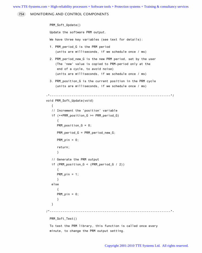
PRM_Soft_Update()
Update the software PRM output.
We have three key variables (see text for details):
1. PRM_period_G is the PRM period
(units are milliseconds, if we schedule once / ms)
2. PRM_period_new_G is the new PRM period, set by the user
(The 'new' value is copied to PRM-period only at the
end of a cycle, to avoid noise)
(units are milliseconds, if we schedule once / ms)
3. PRM_position_G is the current position in the PRM cycle
(units are milliseconds, if we schedule once / ms)
-*------------------------------------------------------------------*/
void PRM_Soft_Update(void)
// Increment the 'position' variable
if (++PRM_position_G >= PRM_period_G)
PRM_position_G = 0;
PRM_period_G = PRM_period_new_G;
PRM_pin = 0;
return;
// Generate the PRM output
if (PRM_position_G < (PRM_period_G / 2))
PRM_pin = 1;
else
PRM_pin = 0;
/*------------------------------------------------------------------*-
PRM_Soft_Test()
To test the PRM library, this function is called once every
minute, to change the PRM output setting.
MONITORING AND CONTROL COMPONENTS754
www.TTE-Systems.com = High-reliability processors + Software tools + Protection systems + Training & consultancy services
Copyright 2001-2010 TTE Systems Ltd. All rights reserved.
-*------------------------------------------------------------------*/
void PRM_Soft_Test(void)
PRM_period_new_G += 2;
if (PRM_period_new_G >= 60000)
PRM_period_new_G = 2;
/*------------------------------------------------------------------*-
---- END OF FILE ------------------------------------------------
-*------------------------------------------------------------------*/
Listing 31.8 Part of an example demonstrating software-based pulse-rate modulation
Further reading—
SOFTWARE PRM 755
www.TTE-Systems.com = High-reliability processors + Software tools + Protection systems + Training & consultancy services
Copyright 2001-2010 TTE Systems Ltd. All rights reserved.
Using analogue-to-digital
converters (ADCs)
Introduction
The recording of analog signals is an important part of many condition monitoring,data acquisition and control applications.
We will consider how to read analog values using an 8051 microcontroller in thischapter. In doing so, we will present the following patterns:
O N E-S H O T A D C [page 757] addresses the problem of measuring an analogue voltagesignal at irregular (or infrequent) intervals, using a microcontroller
A D C P R E-A M P [page 777] addresses the problem of amplifying an analogue signal, inorder to convert it to a range suitable for subsequent analogue-to-digital conversion.
S E Q U E N T I A L A D C [page 782] addresses the problem of recording a sequence of ana-logue samples using a microcontroller.
A - A F I L T E R [page 794] addresses the problem of filtering an analogue signal toremove high-frequency components.
C U R R E N T S E N S O R [page 802] addresses the problem of monitoring the currentflowing through a DC load.
chapter 32www.TTE-Systems.com = High-reliability processors + Software tools + Protection systems + Training & consultancy services
Copyright 2001-2010 TTE Systems Ltd. All rights reserved.
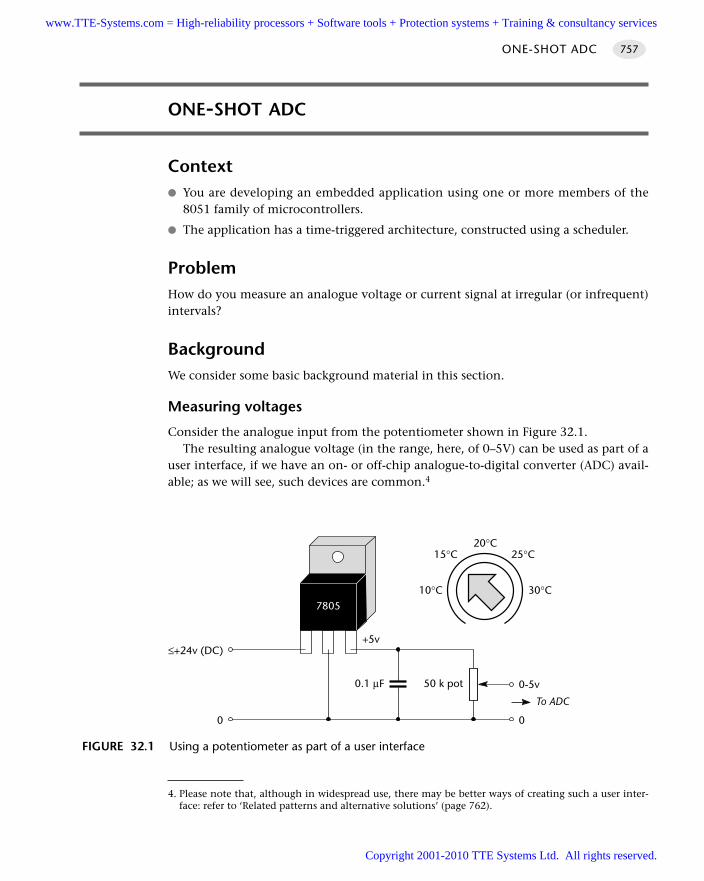
ONE-SHOT ADC
Context You are developing an embedded application using one or more members of the
8051 family of microcontrollers.
The application has a time-triggered architecture, constructed using a scheduler.
ProblemHow do you measure an analogue voltage or current signal at irregular (or infrequent)intervals?
BackgroundWe consider some basic background material in this section.
Measuring voltages
Consider the analogue input from the potentiometer shown in Figure 32.1.The resulting analogue voltage (in the range, here, of 0–5V) can be used as part of a
user interface, if we have an on- or off-chip analogue-to-digital converter (ADC) avail-able; as we will see, such devices are common.4
ONE-SHOT ADC 757
FIGURE 32.1 Using a potentiometer as part of a user interface
50 k pot0.1 µF
0
0-5v
To ADC
+5v
7805
0
≤+24v (DC)
20°C15°C 25°C
10°C 30°C
4. Please note that, although in widespread use, there may be better ways of creating such a user inter-face: refer to ‘Related patterns and alternative solutions’ (page 762).
www.TTE-Systems.com = High-reliability processors + Software tools + Protection systems + Training & consultancy services
Copyright 2001-2010 TTE Systems Ltd. All rights reserved.
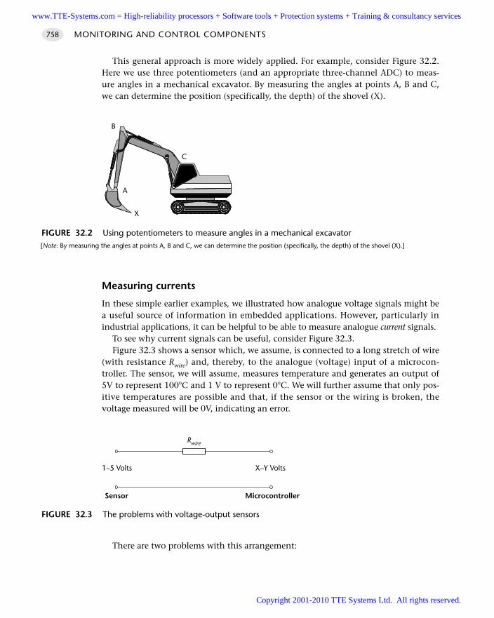
This general approach is more widely applied. For example, consider Figure 32.2.Here we use three potentiometers (and an appropriate three-channel ADC) to meas-ure angles in a mechanical excavator. By measuring the angles at points A, B and C,we can determine the position (specifically, the depth) of the shovel (X).
Measuring currents
In these simple earlier examples, we illustrated how analogue voltage signals might bea useful source of information in embedded applications. However, particularly inindustrial applications, it can be helpful to be able to measure analogue current signals.
To see why current signals can be useful, consider Figure 32.3.Figure 32.3 shows a sensor which, we assume, is connected to a long stretch of wire
(with resistance Rwire) and, thereby, to the analogue (voltage) input of a microcon-troller. The sensor, we will assume, measures temperature and generates an output of5V to represent 100°C and 1 V to represent 0°C. We will further assume that only pos-itive temperatures are possible and that, if the sensor or the wiring is broken, thevoltage measured will be 0V, indicating an error.
There are two problems with this arrangement:
MONITORING AND CONTROL COMPONENTS758
FIGURE 32.2 Using potentiometers to measure angles in a mechanical excavator[Note: By measuring the angles at points A, B and C, we can determine the position (specifically, the depth) of the shovel (X).]
A
B
C
X
FIGURE 32.3 The problems with voltage-output sensors
Rwire
1–5 Volts X–Y Volts
Sensor Microcontroller
www.TTE-Systems.com = High-reliability processors + Software tools + Protection systems + Training & consultancy services
Copyright 2001-2010 TTE Systems Ltd. All rights reserved.
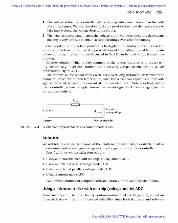
1 The voltage at the microcontroller will be less – possibly much less – than the volt-age at the sensor. We will therefore probably need to fine-tune the sensor code totake into account the voltage drop in the wiring.
2 The wire resistance (and, hence, the voltage drop) will be temperature dependent,making it very difficult to obtain accurate readings even after fine-tuning.
One good solution to this problem is to digitize the analogue readings in thesensor and to transmit a digital representation of the voltage signal to the mainmicrocontroller; the techniques discussed in Part F can be used to implement thissolution.
Another solution, which is very common in the process industry, is to use a vary-ing current (e.g. 4–20 mA) rather than a varying voltage to encode the sensorinformation (Figure 32.4).
The current-source sensor works well, even over long distances, even where thewiring resistance varies with temperature, since the sensor can adjust its output volt-age, as required, to keep the current at the specified level. Note also that, at themicrocontroller, we may simply convert the current signal back to a voltage signal byusing a fixed resistor.
SolutionWe will briefly consider here some of the hardware options that are available to allowthe measurement of analogue voltage or current signals using a microcontroller.
Specifically, we will consider four options:
Using a microcontroller with on-chip (voltage-mode) ADC
Using an external serial (voltage-mode) ADC
Using an external parallel (voltage-mode) ADC
Using a current-mode ADC
We present a number of complete software libraries in the examples that follow.
Using a microcontroller with on-chip (voltage-mode) ADC
Many members of the 8051 family contain on-board ADCs. In general, use of aninternal device will result in increased reliability, since both hardware and software
ONE-SHOT ADC 759
FIGURE 32.4 A schematic representation of a current-mode sensor
Rwire
4–20 mA 1–5 Voltvoltage drop
Sensor Microcontroller
Rsensor
www.TTE-Systems.com = High-reliability processors + Software tools + Protection systems + Training & consultancy services
Copyright 2001-2010 TTE Systems Ltd. All rights reserved.
complexity will often be lower. In addition, the ‘internal’ solution will usually bephysically smaller and have a lower system cost.
Here are some examples of the available ADC components provided on two8051 devices.
Infineon c515c
From the Infineon5 c515c data sheet:
The c515c includes a high performance / high speed 10-bit A/D-converter (ADC) with 8 chan-nels. It operates with a successive approximation technique and uses self calibrationmechanisms for reduction and compensation of offset and linearity errors.
The A/D converter provides the following features:
8 multiplexed input channels (port 6), which can also be used as digital inputs 10-bit resolution Single or continuous conversion mode Internal or external start-of-conversion trigger capability Uses successive approximation conversion technique via a capacitor array Built-in hidden calibration of offset and linearity errors
Analog Devices ADµC812
From the Analog Devices6 ADµC812 data sheet:
The ADC conversion block incorporates a fast, multi-channel, 12-bit, single supply A/D con-verter. This block provides the user with multi-channel mux, track/hold, on-chip reference,calibration features and A/D converter. All components in this block are easily configured via theSFR interface from the core MCU.
The A/D converter section in this block consists of a conventional successive-approximationconverter based around a capacitor DAC. The converter accepts an analogue input range of 0to +VREF. A high precision, low drift 2.5V reference is provided on-chip. The internal referencemay be overdriven via the external VREF pin. This external reference can be in the range 2.3Vto AVDD.
Single step or continuous conversion modes can be initiated in software or alternatively byapplying a convert signal to the an external pin. Timer 2 can also be configured to generate arepetitive trigger for ADC conversions. The ADC may also be configured to operate in a DMAMode whereby the ADC block continuously converts and captures samples without any interac-tion from the MCU core.
The ADC core contains self-calibration and system calibration options to ensure accurateoperation over time and temperature. A voltage output from an On-Chip bandgap referenceproportional to absolute temperature can also be routed through the front-end ADC multi-plexor facilitating a temperature sensor implementation.
MONITORING AND CONTROL COMPONENTS760
5. www.infineon.com6. www.analog.com
www.TTE-Systems.com = High-reliability processors + Software tools + Protection systems + Training & consultancy services
Copyright 2001-2010 TTE Systems Ltd. All rights reserved.
Using an external parallel (voltage-mode) ADC
The ‘traditional’ alternative to an on-chip ADC is a parallel ADC. In general, parallelADCs have the following strengths and weaknesses:
They can provide fast data transfers.
They tend to be inexpensive.
They require a very simple software framework.
They tend to require a large number of port pins. In the case of a 16-bit conver-sion, the external ADC will require 16 pins for the data transfer, plus between oneand three pins to control the data transfers.
The wiring complexity can be a source of reliability problems in some environ-ments.
Examples of the use of a parallel ADC follow.
Using an external serial (voltage-mode) ADC
Many more recent ADCs have a serial interface. In general, serial ADCs have thefollowing strengths and weaknesses:
They require a small number of port pins (between two and four), regardlessof the ADC resolution.
They require on-chip support for the serial protocol or the use of a suitablesoftware library.
The data transfer may be slower than a parallel alternative.
They can be comparatively expensive.
Two examples of the use of serial ADCs follow.
Using a current-mode ADC
As we discussed in ‘Background’, use of current-based data transmission can be usefulin some circumstances.
A number of current-mode sensor components (e.g. the Burr-Brown7 XTR105) andADCs (e.g. the Burr-Brown RCV420) are now available.
In addition, C U R R E N T S E N S O R [page 802] discusses current sensing using voltage-mode ADCs.
Hardware resource implicationsUse of the internal ADC will generally mean that at least one input pin is unavailablefor other purposes; use of an external ADC will require the use of larger numbers ofport pins.
ONE-SHOT ADC 761
7. www.burr-brown.com
www.TTE-Systems.com = High-reliability processors + Software tools + Protection systems + Training & consultancy services
Copyright 2001-2010 TTE Systems Ltd. All rights reserved.
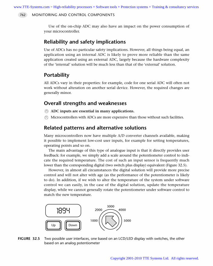
Use of the on-chip ADC may also have an impact on the power consumption ofyour microcontroller.
Reliability and safety implicationsUse of ADCs has no particular safety implications. However, all things being equal, anapplication using an internal ADC is likely to prove more reliable than the sameapplication created using an external ADC, largely because the hardware complexityof the ‘internal’ solution will be much less than that of the ‘external’ solution.
PortabilityAll ADCs vary in their properties: for example, code for one serial ADC will often notwork without alteration on another serial device. However, the required changes aregenerally minor.
Overall strengths and weaknessesADC inputs are essential in many applications.
Microcontrollers with ADCs are more expensive than those without such facilities.
Related patterns and alternative solutionsMany microcontrollers now have multiple A/D converter channels available, makingit possible to implement low-cost user inputs, for example for setting temperatures,operating points and so on.
The main advantage of this type of analogue input is that it directly provides userfeedback: for example, we simply add a scale around the potentiometer control to indi-cate the required temperature. The cost of such an input sensor is frequently muchlower than the corresponding digital (two switch plus display) equivalent (Figure 32.5).
However, in almost all circumstances the digital solution will provide more precisecontrol and will not alter with age (as the performance of the potentiometer is likelyto do). In addition, if we wish to alter the temperature of the system under softwarecontrol we can easily, in the case of the digital solution, update the temperaturedisplay, while we cannot generally rotate the potentiometer under software control tomatch the new temperature.
MONITORING AND CONTROL COMPONENTS762
FIGURE 32.5 Two possible user interfaces, one based on an LCD/LED display with switches, the otherbased on an analog potentiometer
DownUp
30002000 4000
1000 5000
1894
www.TTE-Systems.com = High-reliability processors + Software tools + Protection systems + Training & consultancy services
Copyright 2001-2010 TTE Systems Ltd. All rights reserved.
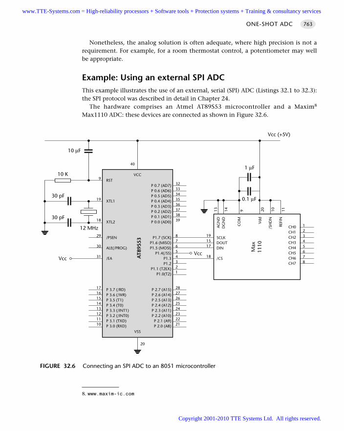
Nonetheless, the analog solution is often adequate, where high precision is not arequirement. For example, for a room thermostat control, a potentiometer may wellbe appropriate.
Example: Using an external SPI ADCThis example illustrates the use of an external, serial (SPI) ADC (Listings 32.1 to 32.3):the SPI protocol was described in detail in Chapter 24.
The hardware comprises an Atmel AT89S53 microcontroller and a Maxim8
Max1110 ADC: these devices are connected as shown in Figure 32.6.
ONE-SHOT ADC 763
FIGURE 32.6 Connecting an SPI ADC to an 8051 microcontroller
30 pF
30 pF
RST
XTL1
XTL2
/PSEN
ALE(/PROG)
/EA
P 3.7 (/RD)P 3.6 (/WR)P 3.5 (T1)P 3.4 (T0)P 3.3 (/INT1)P 3.2 (/INT0)P 3.1 (TXD)P 3.0 (RXD)
P 0.7 (AD7)P 0.6 (AD6)P 0.5 (AD5)P 0.4 (AD4)P 0.3 (AD3)P 0.2 (AD2)P 0.1 (AD1)P 0.0 (AD0)
P1.7 (SCK)P1.6 (MISO)P1.5 (MOSI)
P1.4(/SS)P1.3P1.2
P1.1 (T2EX)P1.0(T2)
P 2.7 (A15)P 2.6 (A14)P 2.5 (A13)P 2.4 (A12)P 2.3 (A11)P 2.2 (A10)
P 2.1 (A9)P 2.0 (A8)
VCC
AT8
9553
VSS
3233343536373839
87654321
2827262524232221
9
19
18
29
30
31
1716151413121110
20
40
Vcc
SCLKDOUTDIN
/CS
CH0CH1CH2CH3CH4CH5CH6CH7
12 MHz
10 µF
191517
18
Vcc (+5V)
10 K
Vcc
AG
ND
DG
ND
CO
M
Vdd
/SH
DN
REFI
N
0.1 µF
1 µF
12345678
13 14 9 20 10 11
Max
1110
8. www.maxim-ic.com
www.TTE-Systems.com = High-reliability processors + Software tools + Protection systems + Training & consultancy services
Copyright 2001-2010 TTE Systems Ltd. All rights reserved.
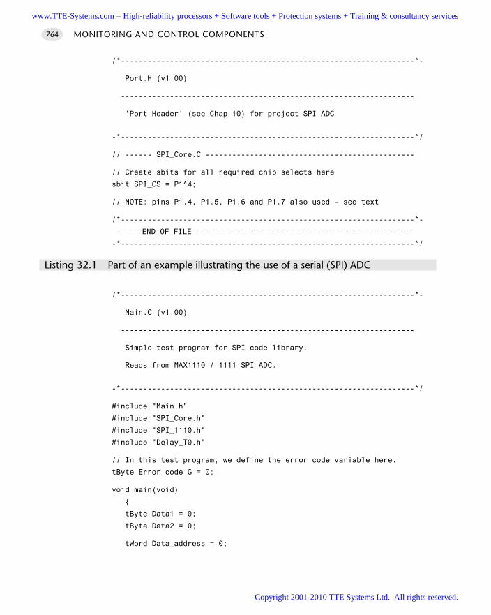
/*------------------------------------------------------------------*-
Port.H (v1.00)
------------------------------------------------------------------
'Port Header' (see Chap 10) for project SPI_ADC
-*------------------------------------------------------------------*/
// ------ SPI_Core.C -----------------------------------------------
// Create sbits for all required chip selects here
sbit SPI_CS = P1^4;
// NOTE: pins P1.4, P1.5, P1.6 and P1.7 also used - see text
/*------------------------------------------------------------------*-
---- END OF FILE ------------------------------------------------
-*------------------------------------------------------------------*/
Listing 32.1 Part of an example illustrating the use of a serial (SPI) ADC
/*------------------------------------------------------------------*-
Main.C (v1.00)
------------------------------------------------------------------
Simple test program for SPI code library.
Reads from MAX1110 / 1111 SPI ADC.
-*------------------------------------------------------------------*/
#include "Main.h"
#include "SPI_Core.h"
#include "SPI_1110.h"
#include "Delay_T0.h"
// In this test program, we define the error code variable here.
tByte Error_code_G = 0;
void main(void)
tByte Data1 = 0;
tByte Data2 = 0;
tWord Data_address = 0;
MONITORING AND CONTROL COMPONENTS764
www.TTE-Systems.com = High-reliability processors + Software tools + Protection systems + Training & consultancy services
Copyright 2001-2010 TTE Systems Ltd. All rights reserved.
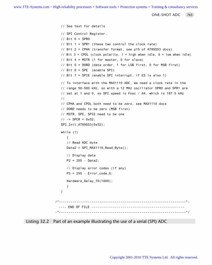
// See text for details
// SPI Control Register.
// Bit 0 = SPR0
// Bit 1 = SPR1 (these two control the clock rate)
// Bit 2 = CPHA (transfer format, see p15 of AT89S53 docs)
// Bit 3 = CPOL (clock polarity, 1 = high when idle, 0 = low when idle)
// Bit 4 = MSTR (1 for master, 0 for slave)
// Bit 5 = DORD (data order, 1 for LSB first, 0 for MSB first)
// Bit 6 = SPE (enable SPI)
// Bit 7 = SPIE (enable SPI interrupt, if ES is also 1)
// To interface with the MAX1110 ADC, we need a clock rate in the
// range 50-500 kHz, so with a 12 MHz oscillator SPR0 and SPR1 are
// set at 1 and 0, so SPI speed is Fosc / 64, which is 187.5 kHz
//
// CPHA and CPOL both need to be zero, see MAX1110 docs
// DORD needs to be zero (MSB first)
// MSTR, SPE, SPIE need to be one
// -> SPCR = 0x52;
SPI_Init_AT89S53(0x52);
while (1)
// Read ADC byte
Data2 = SPI_MAX1110_Read_Byte();
// Display data
P2 = 255 - Data2;
// Display error codes (if any)
P3 = 255 - Error_code_G;
Hardware_Delay_T0(1000);
/*------------------------------------------------------------------*-
---- END OF FILE ------------------------------------------------
-*------------------------------------------------------------------*/
Listing 32.2 Part of an example illustrating the use of a serial (SPI) ADC
ONE-SHOT ADC 765
www.TTE-Systems.com = High-reliability processors + Software tools + Protection systems + Training & consultancy services
Copyright 2001-2010 TTE Systems Ltd. All rights reserved.
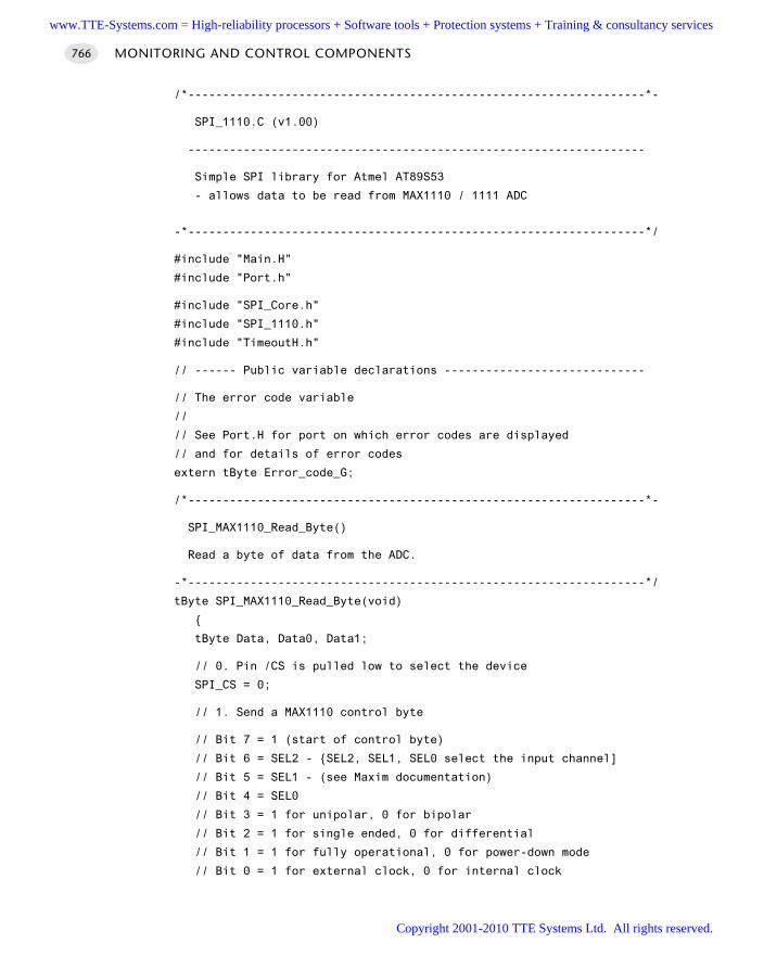
/*------------------------------------------------------------------*-
SPI_1110.C (v1.00)
------------------------------------------------------------------
Simple SPI library for Atmel AT89S53
- allows data to be read from MAX1110 / 1111 ADC
-*------------------------------------------------------------------*/
#include "Main.H"
#include "Port.h"
#include "SPI_Core.h"
#include "SPI_1110.h"
#include "TimeoutH.h"
// ------ Public variable declarations -----------------------------
// The error code variable
//
// See Port.H for port on which error codes are displayed
// and for details of error codes
extern tByte Error_code_G;
/*------------------------------------------------------------------*-
SPI_MAX1110_Read_Byte()
Read a byte of data from the ADC.
-*------------------------------------------------------------------*/
tByte SPI_MAX1110_Read_Byte(void)
tByte Data, Data0, Data1;
// 0. Pin /CS is pulled low to select the device
SPI_CS = 0;
// 1. Send a MAX1110 control byte
// Bit 7 = 1 (start of control byte)
// Bit 6 = SEL2 - SEL2, SEL1, SEL0 select the input channel]
// Bit 5 = SEL1 - (see Maxim documentation)
// Bit 4 = SEL0
// Bit 3 = 1 for unipolar, 0 for bipolar
// Bit 2 = 1 for single ended, 0 for differential
// Bit 1 = 1 for fully operational, 0 for power-down mode
// Bit 0 = 1 for external clock, 0 for internal clock
MONITORING AND CONTROL COMPONENTS766
www.TTE-Systems.com = High-reliability processors + Software tools + Protection systems + Training & consultancy services
Copyright 2001-2010 TTE Systems Ltd. All rights reserved.
//
// Control byte 0x8F sets single-ended unipolar mode,
// input channel 0 (pin 1)
// 0 (pin 1)
SPI_Exchange_Bytes(0x8F);
// 2. The data requested is shifted out on SO by sending two dummy
// bytes
Data0 = SPI_Exchange_Bytes(0x00);
Data1 = SPI_Exchange_Bytes(0x00);
// The data are contained in bits 5-0 of Data0
// and 7-6 of Data1 - shift these bytes to give a combined byte,
Data0 <<= 2;
Data1 >>= 6;
Data = (Data0 | Data1);
// 3. We pull the /CS pin high to complete the operation
SPI_CS = 1;
// 4. We return the required data
return Data; // Return SPI data byte
/*------------------------------------------------------------------*-
---- END OF FILE ------------------------------------------------
-*------------------------------------------------------------------*/
Listing 32.3 Part of an example illustrating the use of a serial (SPI) ADC
Example: Using an external I2C ADCThis example illustrates the use of an external, serial (I2C) ADC (Listings 32.4 to 32.6):the I2C protocol was described in detail in Chapter 23.
The ADC hardware comprises a Maxim9 Max127 ADC: this device is connected tothe microcontroller as shown in Figure 32.7.
/*------------------------------------------------------------------*-
Port.H (v1.00)
------------------------------------------------------------------
'Port Header' (see Chap 10) for project ADC_M127 (see Chap 32)
ONE-SHOT ADC 767
9. www.maxim-ic.com
www.TTE-Systems.com = High-reliability processors + Software tools + Protection systems + Training & consultancy services
Copyright 2001-2010 TTE Systems Ltd. All rights reserved.
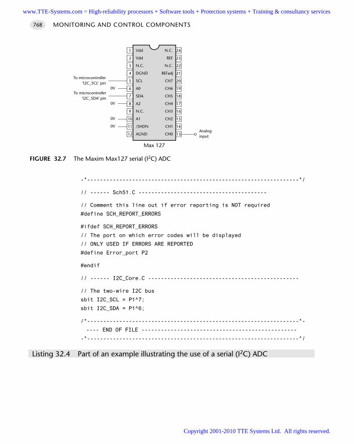
-*------------------------------------------------------------------*/
// ------ Sch51.C ----------------------------------------
// Comment this line out if error reporting is NOT required
#define SCH_REPORT_ERRORS
#ifdef SCH_REPORT_ERRORS
// The port on which error codes will be displayed
// ONLY USED IF ERRORS ARE REPORTED
#define Error_port P2
#endif
// ------ I2C_Core.C -----------------------------------------------
// The two-wire I2C bus
sbit I2C_SCL = P1^7;
sbit I2C_SDA = P1^6;
/*------------------------------------------------------------------*-
---- END OF FILE ------------------------------------------------
-*------------------------------------------------------------------*/
Listing 32.4 Part of an example illustrating the use of a serial (I2C) ADC
MONITORING AND CONTROL COMPONENTS768
FIGURE 32.7 The Maxim Max127 serial (I2C) ADC
Vdd
Vdd
N.C.
DGND
SCL
A0
SDA
A2
N.C.
A110
9
8
7
6
5
4
3
2
1
15
16
17
18
19
20
21
22
23
24N.C.
REF
N.C.
REFadj
CH7
CH6
CH5
CH4
CH3
CH2
11
12
14
13
/SHDN
AGND
CH1
CH0
0V
To microcontroller‘l2C_SCL’ pin
0V
0V
0V
To microcontroller‘l2C_SDA’ pin
Max 127
Analoginput
www.TTE-Systems.com = High-reliability processors + Software tools + Protection systems + Training & consultancy services
Copyright 2001-2010 TTE Systems Ltd. All rights reserved.
/*------------------------------------------------------------------*-
Main.C (v1.00)
------------------------------------------------------------------
Simple test program for I2C (MAX127 ADC) library.
Connect a MAX127 to the SDA and SCL pins described
in the library file (I2C_Core.C).
Terminating resistors not generally required on the bus.
-*------------------------------------------------------------------*/
#include "Main.h"
#include "I2C_m127.h"
#include "Delay_T0.h"
extern tByte ADC_G;
// In this test program, we define the error code variable here
// (Usually in the scheduler library)
tByte Error_code_G = 0;
void main( void )
while(1)
I2C_ADC_MAX127_Read();
P1 = ADC_G;
P2 = Error_code_G;
Hardware_Delay_T0(1000);
/*------------------------------------------------------------------*-
---- END OF FILE ------------------------------------------------
-*------------------------------------------------------------------*/
Listing 32.5 Part of an example illustrating the use of a serial (I2C) ADC
ONE-SHOT ADC 769
www.TTE-Systems.com = High-reliability processors + Software tools + Protection systems + Training & consultancy services
Copyright 2001-2010 TTE Systems Ltd. All rights reserved.
/*------------------------------------------------------------------*-
I2C_m127.C (v1.00)
------------------------------------------------------------------
Code library for MAX127 (I2C) ADC.
-*------------------------------------------------------------------*/
#include "Main.H"
#include "Port.h"
#include "I2C_Core.h"
#include "I2C_m127.h"
#include "Delay_t0.h"
// ------ Public variable definitions ------------------------------
// The ADC value
tByte ADC_G;
// ------ Public variable declarations -----------------------------
// The error codes - see scheduler
extern tByte Error_code_G;
// ------ Private constants ----------------------------------------
// Chip address = 0101xxxW
#define I2C_MAX127_ADDRESS (80)
// Start bit set
// Normal power mode (not in power-down mode)
// Range 0 - 5V
#define I2C_MAX127_MODE (0x80)
// ------ Private variable definitions------------------------------
// The ADC channel (0 - 7)
// *** Value here is required channel value << 4 ***
// *** We are using Channel 2 ***
static tByte I2C_MAX127_Channel_G = 0x20;
/*------------------------------------------------------------------*-
MONITORING AND CONTROL COMPONENTS770
www.TTE-Systems.com = High-reliability processors + Software tools + Protection systems + Training & consultancy services
Copyright 2001-2010 TTE Systems Ltd. All rights reserved.
I2C_ADC_MAX127_Read()
Reads from the I2C 12-bit ADC
The channel used is given by ADC_Channel_G
This version reads only 8-bits (most sig) data
-*-------------------------------------------------------------------*/
void I2C_ADC_MAX127_Read(void)
I2C_Send_Start(); // Generate I2C START condition
// Send DAC device address (with write access request)
if (I2C_Write_Byte(I2C_MAX127_ADDRESS | I2C_WRITE))
Error_code_G = ERROR_I2C_ADC_MAX127;
return;
// Set the ADC mode and channel - see above
if (I2C_Write_Byte(I2C_MAX127_MODE | I2C_MAX127_Channel_G))
Error_code_G = ERROR_I2C_ADC_MAX127;
return;
I2C_Send_Stop(); // Generate STOP condition
I2C_Send_Start(); // Generate START condition (again)
// Send MAX127 device address (with READ access request)
if (I2C_Write_Byte(I2C_MAX127_ADDRESS | I2C_READ))
Error_code_G = ERROR_I2C_ADC_MAX127;
return;
// Receive first (MS) byte from I2C bus
ADC_G = I2C_Read_Byte();
I2C_Send_Master_Ack(); // Perform a MASTER ACK
ONE-SHOT ADC 771
www.TTE-Systems.com = High-reliability processors + Software tools + Protection systems + Training & consultancy services
Copyright 2001-2010 TTE Systems Ltd. All rights reserved.
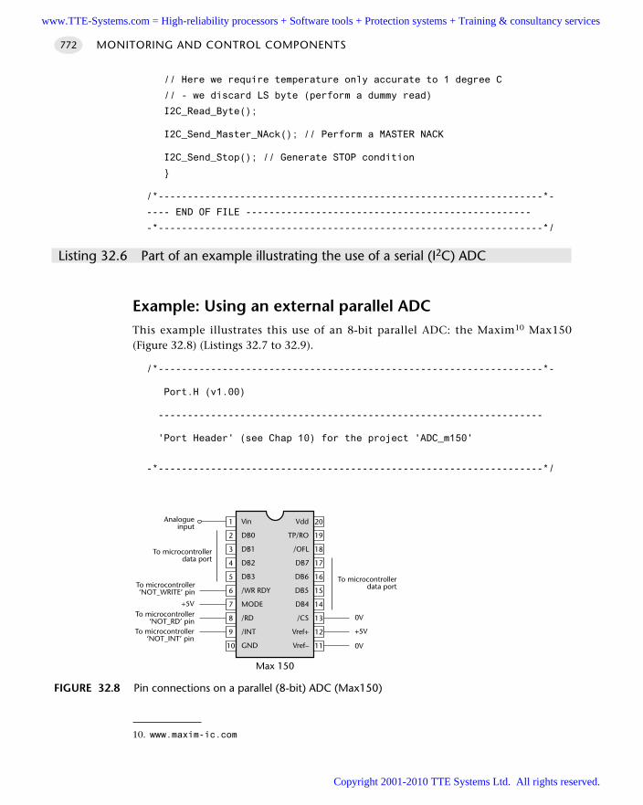
// Here we require temperature only accurate to 1 degree C
// - we discard LS byte (perform a dummy read)
I2C_Read_Byte();
I2C_Send_Master_NAck(); // Perform a MASTER NACK
I2C_Send_Stop(); // Generate STOP condition
/*------------------------------------------------------------------*-
---- END OF FILE -------------------------------------------------
-*------------------------------------------------------------------*/
Listing 32.6 Part of an example illustrating the use of a serial (I2C) ADC
Example: Using an external parallel ADCThis example illustrates this use of an 8-bit parallel ADC: the Maxim10 Max150(Figure 32.8) (Listings 32.7 to 32.9).
/*------------------------------------------------------------------*-
Port.H (v1.00)
------------------------------------------------------------------
'Port Header' (see Chap 10) for the project 'ADC_m150'
-*------------------------------------------------------------------*/
MONITORING AND CONTROL COMPONENTS772
FIGURE 32.8 Pin connections on a parallel (8-bit) ADC (Max150)
Vin
DB0
DB1
DB2
DB3
/WR RDY
MODE
/RD
/INT
GND10
9
8
7
6
5
4
3
2
1
11
12
13
14
15
16
17
18
19
20Vdd
TP/RO
/OFL
DB7
DB6
DB5
DB4
/CS
Vref+
Vref–
To microcontroller‘NOT_WRITE’ pin
+5V
Max 150
To microcontroller‘NOT_INT’ pin
To microcontrollerdata port
To microcontroller‘NOT_RD’ pin
Analogueinput
+5V
0V
0V
To microcontrollerdata port
10. www.maxim-ic.com
www.TTE-Systems.com = High-reliability processors + Software tools + Protection systems + Training & consultancy services
Copyright 2001-2010 TTE Systems Ltd. All rights reserved.
// ------ ADC_M150.C ----------------------------------------
// Interface to the MAX150 parallel ADC
sbit ADC_MAX150_NOT_Read_pin = P1^0;
sbit ADC_MAX150_NOT_Write_pin = P1^1;
sbit ADC_MAX150_NOT_Int_pin = P1^2;
#define ADC_MAX150_port P2
// ------ Bargraph.C -----------------------------------------------
// Connect LED from +5V (etc) to these pins, via appropriate resistor
// [see Chapter 7 for details]
// The 8 port pins may be distributed over several ports if required
sbit Pin0 = P2^0;
sbit Pin1 = P2^1;
sbit Pin2 = P2^2;
sbit Pin3 = P2^3;
sbit Pin4 = P2^4;
sbit Pin5 = P2^5;
sbit Pin6 = P2^6;
sbit Pin7 = P2^7;
/*------------------------------------------------------------------*-
---- END OF FILE ------------------------------------------------
-*------------------------------------------------------------------*/
Listing 32.7 Part of an example illustrating the use of a parallel (8-bit) ADC
/*------------------------------------------------------------------*-
Main.c (v1.00)
------------------------------------------------------------------
Demo program for ADC -> Bargraph display
Required linker options (see text for details):
OVERLAY
(main ~ (AD_Get_Sample,Bargraph_Update),
sch_dispatch_tasks ! (AD_Get_Sample,Bargraph_Update))
-*------------------------------------------------------------------*/
#include "Main.h"
#include "2_01_12g.h"
#include "ADC_m150.h"
#include "BarGraph.h"
ONE-SHOT ADC 773
www.TTE-Systems.com = High-reliability processors + Software tools + Protection systems + Training & consultancy services
Copyright 2001-2010 TTE Systems Ltd. All rights reserved.
/* ............................................................... */
/* ............................................................... */
void main(void)
SCH_Init_T2(); // Set up the scheduler
ADC_MAX150_Init(); // Prepare the ADC
BARGRAPH_Init(); // Prepare a bargraph-type display (P4)
// Read the ADC regularly
SCH_Add_Task(ADC_MAX150_Get_Sample, 10, 1000);
// Simply display the count here (bargraph display)
SCH_Add_Task(BARGRAPH_Update, 12, 1000);
// All tasks added: start running the scheduler
SCH_Start();
while(1)
SCH_Dispatch_Tasks();
/*------------------------------------------------------------------*-
---- END OF FILE ------------------------------------------------
-*------------------------------------------------------------------*/
Listing 32.8 Part of an example illustrating the use of a parallel (8-bit) ADC
/*------------------------------------------------------------------*-
ADC_m150.c (v1.00)
------------------------------------------------------------------
Simple, single-channel, 8-bit A-D (input) library for 8051 family
- uses MAX150 8-bit parallel ADC.
See Chapter 32 for details.
-*------------------------------------------------------------------*/
#include "Main.H"
#include "Port.h"
#include "Bargraph.h"
// ------ Public variable definitions ------------------------------
MONITORING AND CONTROL COMPONENTS774
www.TTE-Systems.com = High-reliability processors + Software tools + Protection systems + Training & consultancy services
Copyright 2001-2010 TTE Systems Ltd. All rights reserved.
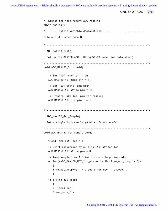
// Stores the most recent ADC reading
tByte Analog_G;
// ------ Public variable declarations -----------------------------
extern tByte Error_code_G;
/*------------------------------------------------------------------*-
ADC_MAX150_Init()
Set up the MAX150 ADC. Using WR-RD mode (see data sheet)
-*------------------------------------------------------------------*/
void ADC_MAX150_Init(void)
// Set 'NOT read' pin high
ADC_MAX150_NOT_Read_pin = 1;
// Set 'NOT write' pin high
ADC_MAX150_NOT_Write_pin = 1;
// Prepare 'NOT Int' pin for reading
ADC_MAX150_NOT_Int_pin = 1;
/*------------------------------------------------------------------*-
ADC_MAX150_Get_Sample()
Get a single data sample (8 bits) from the ADC.
-*------------------------------------------------------------------*/
void ADC_MAX150_Get_Sample(void)
tWord Time_out_loop = 1;
// Start conversion by pulling 'NOT Write' low
ADC_MAX150_NOT_Write_pin = 0;
// Take sample from A-D (with simple loop time-out)
while ((ADC_MAX150_NOT_Int_pin == 1) && (Time_out_loop != 0));
Time_out_loop++; // Disable for use in dScope...
if (!Time_out_loop)
// Timed out
Error_code_G =
ONE-SHOT ADC 775
www.TTE-Systems.com = High-reliability processors + Software tools + Protection systems + Training & consultancy services
Copyright 2001-2010 TTE Systems Ltd. All rights reserved.
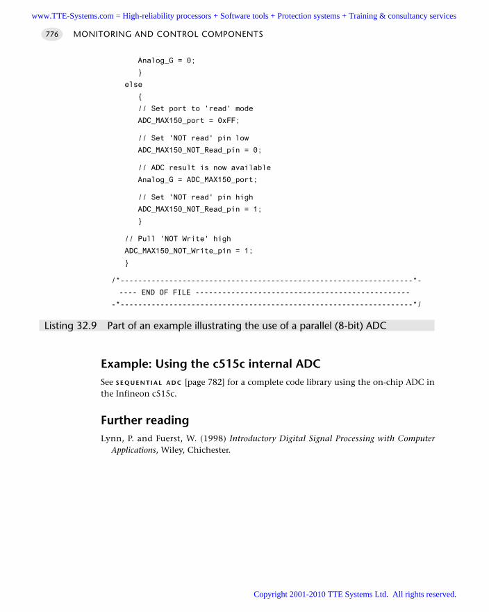
Analog_G = 0;
else
// Set port to 'read' mode
ADC_MAX150_port = 0xFF;
// Set 'NOT read' pin low
ADC_MAX150_NOT_Read_pin = 0;
// ADC result is now available
Analog_G = ADC_MAX150_port;
// Set 'NOT read' pin high
ADC_MAX150_NOT_Read_pin = 1;
// Pull 'NOT Write' high
ADC_MAX150_NOT_Write_pin = 1;
/*------------------------------------------------------------------*-
---- END OF FILE ------------------------------------------------
-*------------------------------------------------------------------*/
Listing 32.9 Part of an example illustrating the use of a parallel (8-bit) ADC
Example: Using the c515c internal ADC See S E Q U E N T I A L A D C [page 782] for a complete code library using the on-chip ADC inthe Infineon c515c.
Further readingLynn, P. and Fuerst, W. (1998) Introductory Digital Signal Processing with Computer
Applications, Wiley, Chichester.
MONITORING AND CONTROL COMPONENTS776
www.TTE-Systems.com = High-reliability processors + Software tools + Protection systems + Training & consultancy services
Copyright 2001-2010 TTE Systems Ltd. All rights reserved.
ADC PRE-AMP
Context You are developing an embedded application using one or more members of the
8051 family of microcontrollers.
The application has a time-triggered architecture, constructed using a scheduler.
ProblemHow do you convert an analogue voltage signal into a range suitable for subsequentanalogue-to-digital conversion?
BackgroundIn a 5V system, an ADC will typically encode a range of analogue signals, from 0V toapproximately 5V. If we have an analogue signal in the range 0–5 mV, we need toamplify this voltage prior to use of the ADC or the digital signal will be a very poorrepresentation of the analogue original.
This pattern describes some suitable circuits. Note that this pattern is hardwarebased; no software is required.
SolutionAn operational amplifier provides the basis of a widely used solution to the problemof scaling analogue signals and will be used here.
A wide range of operational amplifiers are available, including the ‘classic’ 741 or411 chips and more recent devices such as the Microchip11 MCP601.
We consider two basic operations: amplification and level shifting
Voltage amplification
All operational amplifiers are used in the same way when implementing a simplevoltage amplifier. Figure 32.9 illustrates the approach.
The gain of this circuit, G, is given by:
Vout R1 + R2 R2G = = = 1 +
Vin R1 R1
This is very simply applied, as we illustrate in the following example.Note that for precise gains, you need to use good-quality resistors, with a precision
of 1%: a precision of 5% will not generally be adequate.
ADC PRE-AMP 777
11. www.microchip.com
www.TTE-Systems.com = High-reliability processors + Software tools + Protection systems + Training & consultancy services
Copyright 2001-2010 TTE Systems Ltd. All rights reserved.
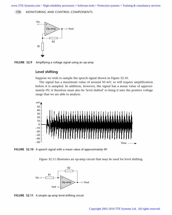
Level shifting
Suppose we wish to sample the speech signal shown in Figure 32.10.The signal has a maximum value of around 50 mV, so will require amplification
before it is sampled. In addition, however, the signal has a mean value of approxi-mately 0V; it therefore must also be ‘level shifted’ to bring it into the positive voltagerange that we are able to analyze.
Figure 32.11 illustrates an op-amp circuit that may be used for level shifting.
MONITORING AND CONTROL COMPONENTS778
FIGURE 32.9 Amplifying a voltage signal using an op-amp
+
–
Op-amp
R1
R2
Vin
Vout
FIGURE 32.10 A speech signal with a mean value of approximately 0V
50403020100
–10–20–30–40–50
mV
Time
FIGURE 32.11 A simple op-amp level-shifting circuit
+
–
Op-amp
R2
Vin
Vout
Vref
R1
www.TTE-Systems.com = High-reliability processors + Software tools + Protection systems + Training & consultancy services
Copyright 2001-2010 TTE Systems Ltd. All rights reserved.
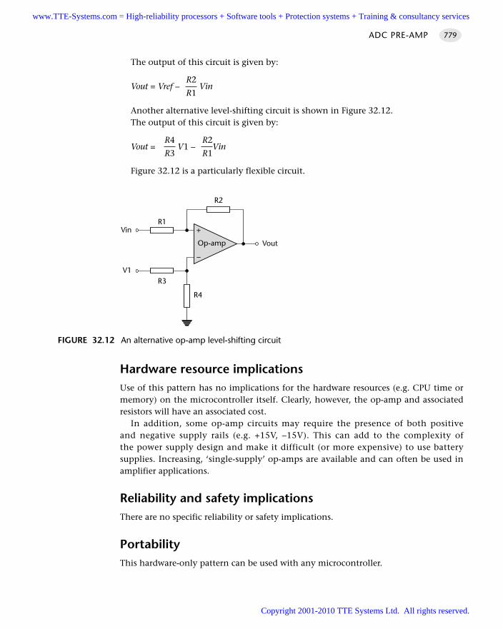
The output of this circuit is given by:
R2Vout = Vref – Vin
R1
Another alternative level-shifting circuit is shown in Figure 32.12.The output of this circuit is given by:
R4 R2Vout = V1 – Vin
R3 R1
Figure 32.12 is a particularly flexible circuit.
Hardware resource implicationsUse of this pattern has no implications for the hardware resources (e.g. CPU time ormemory) on the microcontroller itself. Clearly, however, the op-amp and associatedresistors will have an associated cost.
In addition, some op-amp circuits may require the presence of both positiveand negative supply rails (e.g. +15V, –15V). This can add to the complexity ofthe power supply design and make it difficult (or more expensive) to use batterysupplies. Increasing, ‘single-supply’ op-amps are available and can often be used inamplifier applications.
Reliability and safety implicationsThere are no specific reliability or safety implications.
PortabilityThis hardware-only pattern can be used with any microcontroller.
ADC PRE-AMP 779
FIGURE 32.12 An alternative op-amp level-shifting circuit
+
–
Op-amp
R4
R3
Vin
Vout
R2
R1
V1
www.TTE-Systems.com = High-reliability processors + Software tools + Protection systems + Training & consultancy services
Copyright 2001-2010 TTE Systems Ltd. All rights reserved.
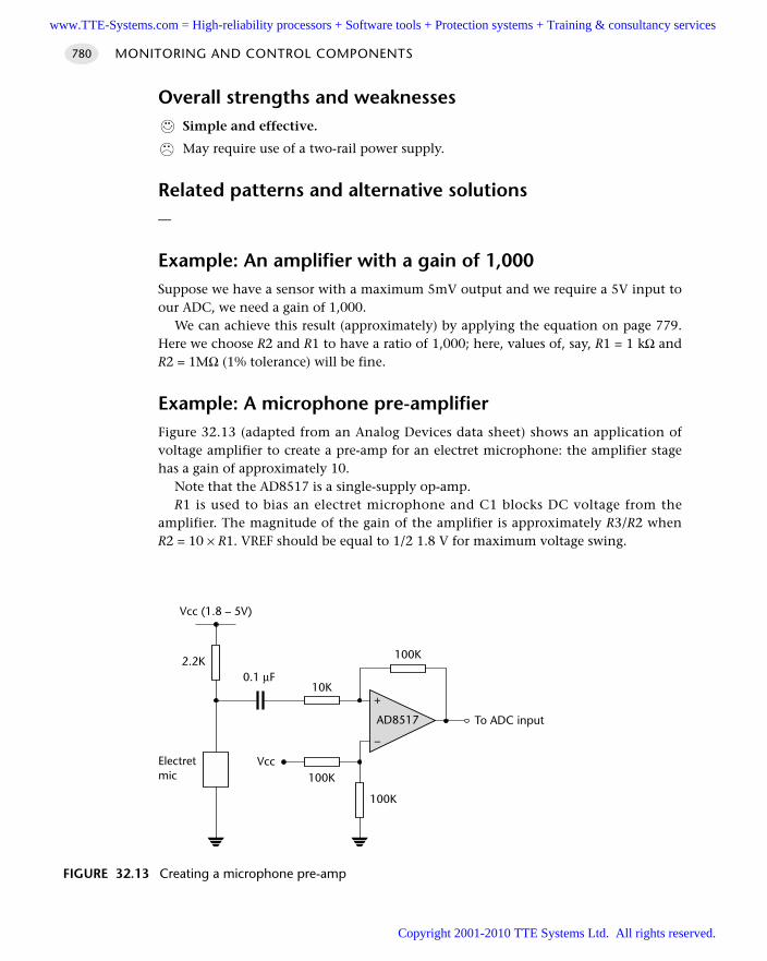
Overall strengths and weaknessesSimple and effective.
May require use of a two-rail power supply.
Related patterns and alternative solutions—
Example: An amplifier with a gain of 1,000Suppose we have a sensor with a maximum 5mV output and we require a 5V input toour ADC, we need a gain of 1,000.
We can achieve this result (approximately) by applying the equation on page 779.Here we choose R2 and R1 to have a ratio of 1,000; here, values of, say, R1 = 1 kΩ andR2 = 1MΩ (1% tolerance) will be fine.
Example: A microphone pre-amplifierFigure 32.13 (adapted from an Analog Devices data sheet) shows an application ofvoltage amplifier to create a pre-amp for an electret microphone: the amplifier stagehas a gain of approximately 10.
Note that the AD8517 is a single-supply op-amp.R1 is used to bias an electret microphone and C1 blocks DC voltage from the
amplifier. The magnitude of the gain of the amplifier is approximately R3/R2 whenR2 = 10 × R1. VREF should be equal to 1/2 1.8 V for maximum voltage swing.
MONITORING AND CONTROL COMPONENTS780
FIGURE 32.13 Creating a microphone pre-amp
+
–
AD8517
100K
100K
To ADC input
100K
10K
Vcc
Vcc (1.8 – 5V)
2.2K0.1 µF
Electretmic
www.TTE-Systems.com = High-reliability processors + Software tools + Protection systems + Training & consultancy services
Copyright 2001-2010 TTE Systems Ltd. All rights reserved.
Further readingElgar, P. (1998) Sensors for Measurement and Control, Longman, London.Franco, S. (1998) Design with Operational Amplifiers and Analog Integrated Circuits, 2nd
edn, McGraw-Hill, Boston, MA.
ADC PRE-AMP 781
www.TTE-Systems.com = High-reliability processors + Software tools + Protection systems + Training & consultancy services
Copyright 2001-2010 TTE Systems Ltd. All rights reserved.
SEQUENTIAL ADC
Context You are developing an embedded application using one or more members of the
8051 family of microcontrollers.
The application has a time-triggered architecture, constructed using a scheduler.
ProblemHow do you record a sequence of analog samples?
BackgroundIn the pattern O N E - S H O T A D C [page 757], we were concerned with the use of ana-logue signals to address questions such as:
What central-heating temperature does the user require?
What is the current angle of the crane?
What is the humidity level in Greenhouse 3?
In the present pattern, we are concerned with the recording of sequences of ana-logue samples, in order to address questions such as:
How quickly is the car accelerating?
How fast is the plane turning?
What is the frequency of this sound?
For example, suppose that we are required to design a system to be used by anenvironmental organization to record and automatically classify the songs of whalesrecorded (underwater) in the Antarctic. Our embedded system will be encased inplastic and attached to a floating buoy. It will run on batteries for a two-year periodand will be required to send a radio broadcast to base every time it detects a whale inthe vicinity.
In this case we will need an underwater pressure transducer (hydrophone) to con-vert the fluctuations in water pressure produced by the whale song into a voltagevalue that can be processed by an ADC.
The output of the ADC will be a sequence of numbers (Figure 32.14). Individually,these numbers (e.g. ‘0.89’) have no meaning; it is the sequence of numbers thatallows us to determine, for example, the frequency components that make up thewhale song.
In this pattern, we are concerned with the recording of sequences of analogue sig-nals, at a fixed sampling frequency: for example, the whale song might be sampled at
MONITORING AND CONTROL COMPONENTS782
www.TTE-Systems.com = High-reliability processors + Software tools + Protection systems + Training & consultancy services
Copyright 2001-2010 TTE Systems Ltd. All rights reserved.
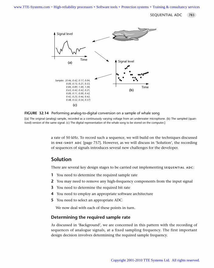
a rate of 50 kHz. To record such a sequence, we will build on the techniques discussedin O N E-S H O T A D C [page 757]. However, as we will discuss in ‘Solution’, the recordingof sequences of signals introduces several new challenges for the developer.
SolutionThere are several key design stages to be carried out implementing S E Q U E N T I A L A D C :
1 You need to determine the required sample rate
2 You may need to remove any high-frequency components from the input signal
3 You need to determine the required bit rate
4 You need to employ an appropriate software architecture
5 You need to select an appropriate ADC
We now deal with each of these points in turn.
Determining the required sample rate
As discussed in ‘Background’, we are concerned in this pattern with the recording ofsequences of analogue signals, at a fixed sampling frequency. The first importantdesign decision involves determining the required sample frequency.
SEQUENTIAL ADC 783
FIGURE 32.14 Performing analog-to-digital conversion on a sample of whale song[(a) The original (analog) sample, recorded as a continuously varying voltage from an underwater microphone. (b) The sampled (quan-tized) version of the same signal. (c) The digital representation of the whale song to be stored on the computer.]
Signal level
Time(a) Signal level
Time(b)
Samples 0.46, 0.42, 0.17, 0.04,0.00, 0.13, 0.21, 0.53,0.84, 0.89, 1.00, 1.00,0.63, 0.42, 0.42, 0.21,0.00, 0.11, 0.00, 0.42,0.42, 0.23, 0.46, 0.42,0.48, 0.52, 0.54, 0.57
(c)
www.TTE-Systems.com = High-reliability processors + Software tools + Protection systems + Training & consultancy services
Copyright 2001-2010 TTE Systems Ltd. All rights reserved.
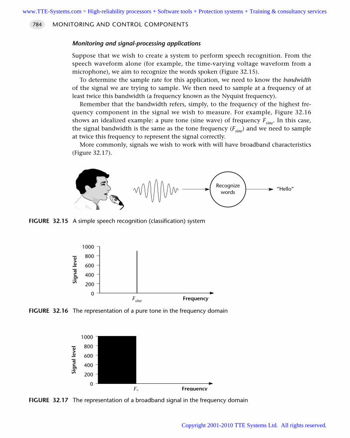
Monitoring and signal-processing applications
Suppose that we wish to create a system to perform speech recognition. From thespeech waveform alone (for example, the time-varying voltage waveform from amicrophone), we aim to recognize the words spoken (Figure 32.15).
To determine the sample rate for this application, we need to know the bandwidthof the signal we are trying to sample. We then need to sample at a frequency of atleast twice this bandwidth (a frequency known as the Nyquist frequency).
Remember that the bandwidth refers, simply, to the frequency of the highest fre-quency component in the signal we wish to measure. For example, Figure 32.16shows an idealized example: a pure tone (sine wave) of frequency Fsine. In this case,the signal bandwidth is the same as the tone frequency (Fsine) and we need to sampleat twice this frequency to represent the signal correctly.
More commonly, signals we wish to work with will have broadband characteristics(Figure 32.17).
MONITORING AND CONTROL COMPONENTS784
FIGURE 32.15 A simple speech recognition (classification) system
Recognizewords
“Hello”
FIGURE 32.16 The representation of a pure tone in the frequency domain
0
200
400
600
800
1000
Sig
nal
leve
l
Fsine Frequency
FIGURE 32.17 The representation of a broadband signal in the frequency domain
0
200
400
600
800
1000
Sig
nal
leve
l
Fb Frequency
www.TTE-Systems.com = High-reliability processors + Software tools + Protection systems + Training & consultancy services
Copyright 2001-2010 TTE Systems Ltd. All rights reserved.
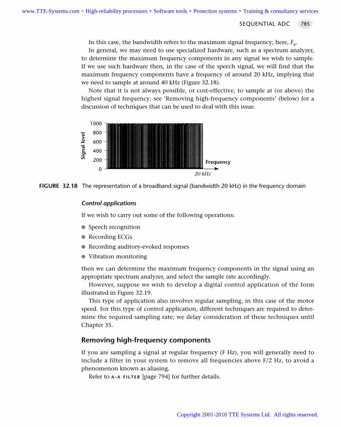
In this case, the bandwidth refers to the maximum signal frequency; here, Fb.In general, we may need to use specialized hardware, such as a spectrum analyzer,
to determine the maximum frequency components in any signal we wish to sample.If we use such hardware then, in the case of the speech signal, we will find that themaximum frequency components have a frequency of around 20 kHz, implying thatwe need to sample at around 40 kHz (Figure 32.18).
Note that it is not always possible, or cost-effective, to sample at (or above) thehighest signal frequency: see ‘Removing high-frequency components’ (below) for adiscussion of techniques that can be used to deal with this issue.
Control applications
If we wish to carry out some of the following operations:
Speech recognition
Recording ECGs
Recording auditory-evoked responses
Vibration monitoring
then we can determine the maximum frequency components in the signal using anappropriate spectrum analyzer, and select the sample rate accordingly.
However, suppose we wish to develop a digital control application of the formillustrated in Figure 32.19.
This type of application also involves regular sampling, in this case of the motorspeed. For this type of control application, different techniques are required to deter-mine the required sampling rate; we delay consideration of these techniques untilChapter 35.
Removing high-frequency components
If you are sampling a signal at regular frequency (F Hz), you will generally need toinclude a filter in your system to remove all frequencies above F/2 Hz, to avoid aphenomenon known as aliasing.
Refer to A-A F I LT E R [page 794] for further details.
SEQUENTIAL ADC 785
FIGURE 32.18 The representation of a broadband signal (bandwidth 20 kHz) in the frequency domain
0
200
400
600
800
1000
Sig
nal
leve
l
20 kHz
Frequency
www.TTE-Systems.com = High-reliability processors + Software tools + Protection systems + Training & consultancy services
Copyright 2001-2010 TTE Systems Ltd. All rights reserved.
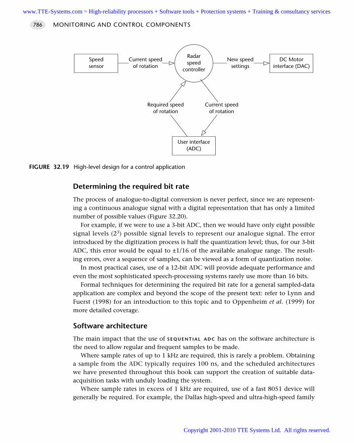
Determining the required bit rate
The process of analogue-to-digital conversion is never perfect, since we are represent-ing a continuous analogue signal with a digital representation that has only a limitednumber of possible values (Figure 32.20).
For example, if we were to use a 3-bit ADC, then we would have only eight possiblesignal levels (23) possible signal levels to represent our analogue signal. The errorintroduced by the digitization process is half the quantization level; thus, for our 3-bitADC, this error would be equal to ±1/16 of the available analogue range. The result-ing errors, over a sequence of samples, can be viewed as a form of quantization noise.
In most practical cases, use of a 12-bit ADC will provide adequate performance andeven the most sophisticated speech-processing systems rarely use more than 16 bits.
Formal techniques for determining the required bit rate for a general sampled-dataapplication are complex and beyond the scope of the present text: refer to Lynn andFuerst (1998) for an introduction to this topic and to Oppenheim et al. (1999) formore detailed coverage.
Software architecture
The main impact that the use of S E Q U E N T I A L A D C has on the software architecture isthe need to allow regular and frequent samples to be made.
Where sample rates of up to 1 kHz are required, this is rarely a problem. Obtaininga sample from the ADC typically requires 100 ns, and the scheduled architectureswe have presented throughout this book can support the creation of suitable data-acquisition tasks with unduly loading the system.
Where sample rates in excess of 1 kHz are required, use of a fast 8051 device willgenerally be required. For example, the Dallas high-speed and ultra-high-speed family
MONITORING AND CONTROL COMPONENTS786
FIGURE 32.19 High-level design for a control application
Radarspeed
controller
DC Motorinterface (DAC)
New speedsettings
Speedsensor
Current speedof rotation
User interface(ADC)
Required speedof rotation
Current speedof rotation
www.TTE-Systems.com = High-reliability processors + Software tools + Protection systems + Training & consultancy services
Copyright 2001-2010 TTE Systems Ltd. All rights reserved.
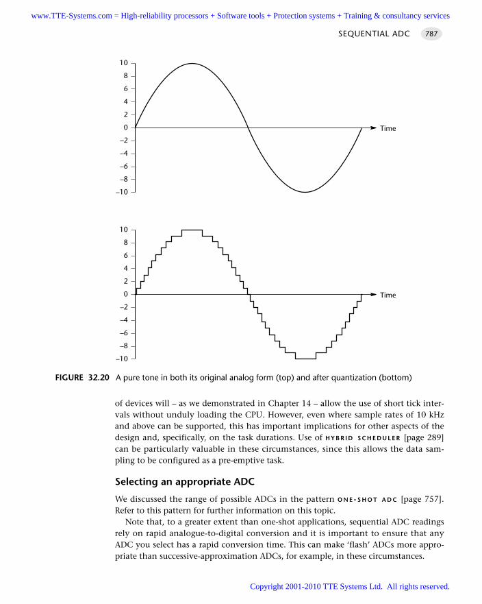
of devices will – as we demonstrated in Chapter 14 – allow the use of short tick inter-vals without unduly loading the CPU. However, even where sample rates of 10 kHzand above can be supported, this has important implications for other aspects of thedesign and, specifically, on the task durations. Use of H Y B R I D S C H E D U L E R [page 289]can be particularly valuable in these circumstances, since this allows the data sam-pling to be configured as a pre-emptive task.
Selecting an appropriate ADC
We discussed the range of possible ADCs in the pattern O N E - S H O T A D C [page 757].Refer to this pattern for further information on this topic.
Note that, to a greater extent than one-shot applications, sequential ADC readingsrely on rapid analogue-to-digital conversion and it is important to ensure that anyADC you select has a rapid conversion time. This can make ‘flash’ ADCs more appro-priate than successive-approximation ADCs, for example, in these circumstances.
SEQUENTIAL ADC 787
FIGURE 32.20 A pure tone in both its original analog form (top) and after quantization (bottom)
10
8
6
4
2
0
–2
–4
–6
–8
–10
Time
10
8
6
4
2
0
–2
–4
–6
–8
–10
Time
www.TTE-Systems.com = High-reliability processors + Software tools + Protection systems + Training & consultancy services
Copyright 2001-2010 TTE Systems Ltd. All rights reserved.
Hardware resource implicationsUse of the internal ADC will generally mean that at least one input pin is unavailablefor other purposes.
Use of the ADC may also have an impact on the power consumption of yourmicrocontroller.
Reliability and safety implicationsAll things being equal, an application using an internal ADC is likely to prove morereliable than the same application created using an external ADC, largely becausethe hardware complexity of the ‘internal’ solution will be much less than that of the‘external’ solution.
More specifically, use of an ADC with a long conversion time may introduce delaysthat will impact on the general performance of signal-processing applications andwhich may impact on the stability of control applications. Make sure the speed of theADC is an appropriate match for your intended application.
PortabilityAll ADCs vary in their properties: for example, code for one serial ADC will not gener-ally work without alteration on another serial device. However, the required changesare generally minor.
Overall strengths and weaknessesUse of sequential ADC inputs is essential in many applications.
The need to sample data frequently will have an significant impact on the systemarchitecture.
Related patterns and alternative solutionsSee the rest of this chapter for related patterns and alternative solutions.
Example: Using the c515c internal ADC This small library illustrates how we an make analogue readings, as required, usingthe on-chip ADC in an Infineon c515c microcontroller (Listings 32.10 to 32.12 (Seealso Figure 32.21)).
The ADC is initialized. Each time a reading is required, we start the ADC conver-sion and wait (with timeout, of course) for the conversion to complete.
The duration of the individual ADC tasks depends on the speed of the internalADC.
MONITORING AND CONTROL COMPONENTS788
www.TTE-Systems.com = High-reliability processors + Software tools + Protection systems + Training & consultancy services
Copyright 2001-2010 TTE Systems Ltd. All rights reserved.
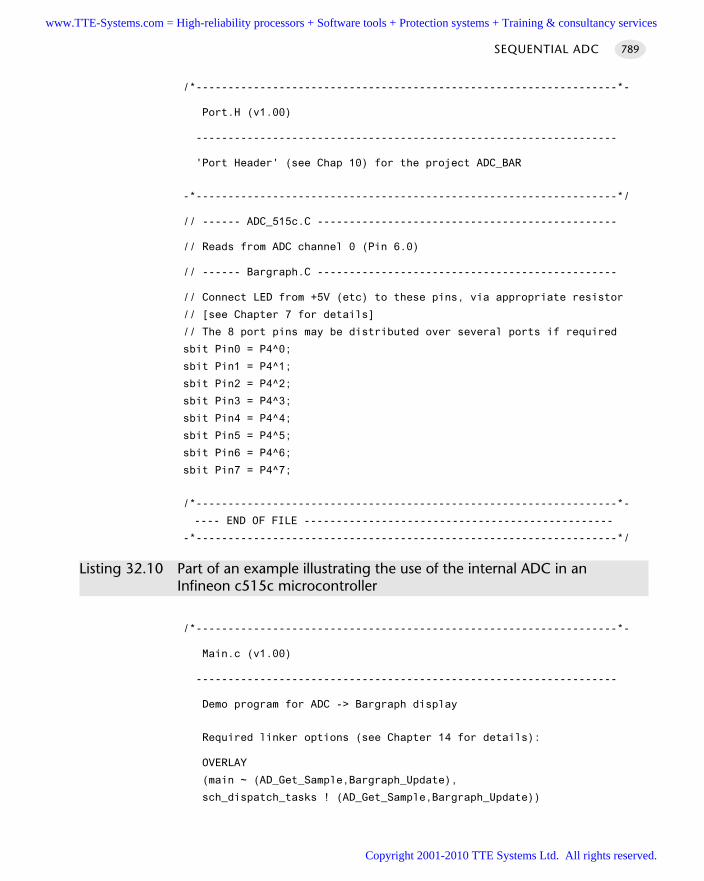
/*------------------------------------------------------------------*-
Port.H (v1.00)
------------------------------------------------------------------
'Port Header' (see Chap 10) for the project ADC_BAR
-*------------------------------------------------------------------*/
// ------ ADC_515c.C -----------------------------------------------
// Reads from ADC channel 0 (Pin 6.0)
// ------ Bargraph.C -----------------------------------------------
// Connect LED from +5V (etc) to these pins, via appropriate resistor
// [see Chapter 7 for details]
// The 8 port pins may be distributed over several ports if required
sbit Pin0 = P4^0;
sbit Pin1 = P4^1;
sbit Pin2 = P4^2;
sbit Pin3 = P4^3;
sbit Pin4 = P4^4;
sbit Pin5 = P4^5;
sbit Pin6 = P4^6;
sbit Pin7 = P4^7;
/*------------------------------------------------------------------*-
---- END OF FILE ------------------------------------------------
-*------------------------------------------------------------------*/
Listing 32.10 Part of an example illustrating the use of the internal ADC in an Infineon c515c microcontroller
/*------------------------------------------------------------------*-
Main.c (v1.00)
------------------------------------------------------------------
Demo program for ADC -> Bargraph display
Required linker options (see Chapter 14 for details):
OVERLAY
(main ~ (AD_Get_Sample,Bargraph_Update),
sch_dispatch_tasks ! (AD_Get_Sample,Bargraph_Update))
SEQUENTIAL ADC 789
www.TTE-Systems.com = High-reliability processors + Software tools + Protection systems + Training & consultancy services
Copyright 2001-2010 TTE Systems Ltd. All rights reserved.
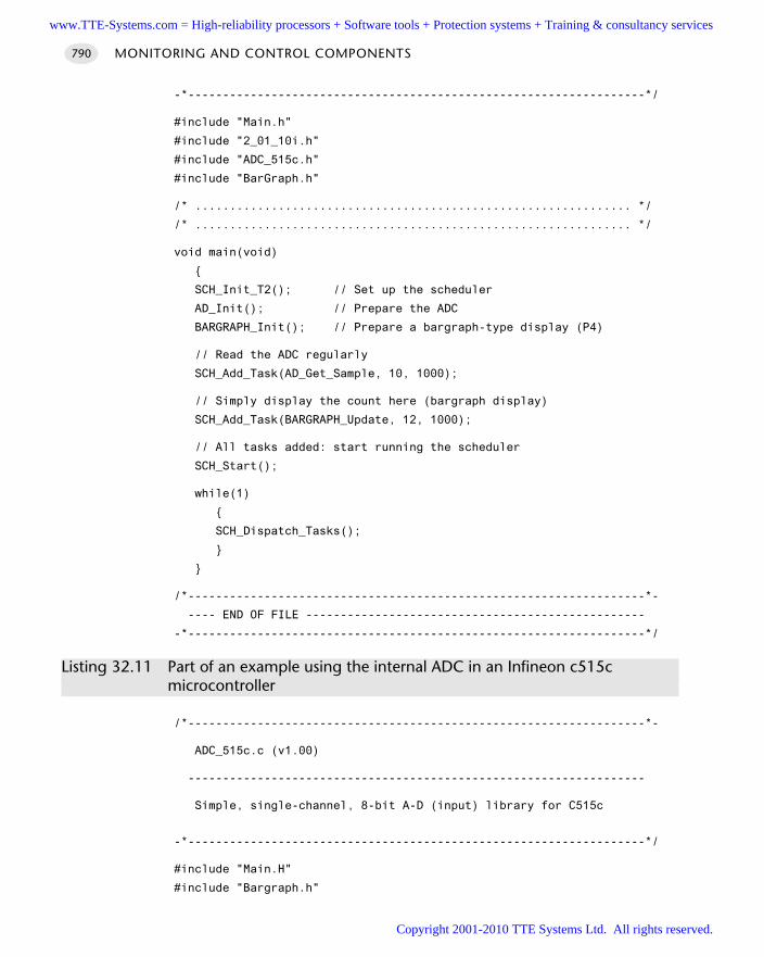
-*------------------------------------------------------------------*/
#include "Main.h"
#include "2_01_10i.h"
#include "ADC_515c.h"
#include "BarGraph.h"
/* ............................................................... */
/* ............................................................... */
void main(void)
SCH_Init_T2(); // Set up the scheduler
AD_Init(); // Prepare the ADC
BARGRAPH_Init(); // Prepare a bargraph-type display (P4)
// Read the ADC regularly
SCH_Add_Task(AD_Get_Sample, 10, 1000);
// Simply display the count here (bargraph display)
SCH_Add_Task(BARGRAPH_Update, 12, 1000);
// All tasks added: start running the scheduler
SCH_Start();
while(1)
SCH_Dispatch_Tasks();
/*------------------------------------------------------------------*-
---- END OF FILE -------------------------------------------------
-*------------------------------------------------------------------*/
Listing 32.11 Part of an example using the internal ADC in an Infineon c515cmicrocontroller
/*------------------------------------------------------------------*-
ADC_515c.c (v1.00)
------------------------------------------------------------------
Simple, single-channel, 8-bit A-D (input) library for C515c
-*------------------------------------------------------------------*/
#include "Main.H"
#include "Bargraph.h"
MONITORING AND CONTROL COMPONENTS790
www.TTE-Systems.com = High-reliability processors + Software tools + Protection systems + Training & consultancy services
Copyright 2001-2010 TTE Systems Ltd. All rights reserved.
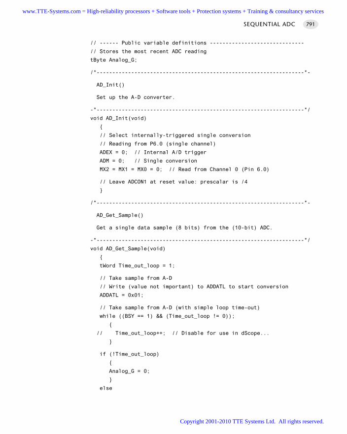
// ------ Public variable definitions ------------------------------
// Stores the most recent ADC reading
tByte Analog_G;
/*------------------------------------------------------------------*-
AD_Init()
Set up the A-D converter.
-*------------------------------------------------------------------*/
void AD_Init(void)
// Select internally-triggered single conversion
// Reading from P6.0 (single channel)
ADEX = 0; // Internal A/D trigger
ADM = 0; // Single conversion
MX2 = MX1 = MX0 = 0; // Read from Channel 0 (Pin 6.0)
// Leave ADCON1 at reset value: prescalar is /4
/*------------------------------------------------------------------*-
AD_Get_Sample()
Get a single data sample (8 bits) from the (10-bit) ADC.
-*------------------------------------------------------------------*/
void AD_Get_Sample(void)
tWord Time_out_loop = 1;
// Take sample from A-D
// Write (value not important) to ADDATL to start conversion
ADDATL = 0x01;
// Take sample from A-D (with simple loop time-out)
while ((BSY == 1) && (Time_out_loop != 0));
// Time_out_loop++; // Disable for use in dScope...
if (!Time_out_loop)
Analog_G = 0;
else
SEQUENTIAL ADC 791
www.TTE-Systems.com = High-reliability processors + Software tools + Protection systems + Training & consultancy services
Copyright 2001-2010 TTE Systems Ltd. All rights reserved.
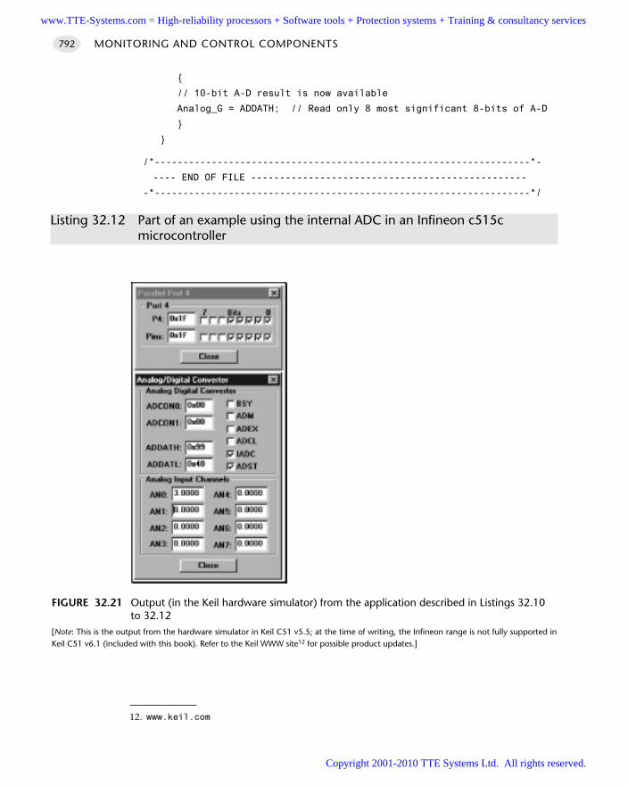
// 10-bit A-D result is now available
Analog_G = ADDATH; // Read only 8 most significant 8-bits of A-D
/*------------------------------------------------------------------*-
---- END OF FILE ------------------------------------------------
-*------------------------------------------------------------------*/
Listing 32.12 Part of an example using the internal ADC in an Infineon c515cmicrocontroller
MONITORING AND CONTROL COMPONENTS792
FIGURE 32.21 Output (in the Keil hardware simulator) from the application described in Listings 32.10to 32.12
[Note: This is the output from the hardware simulator in Keil C51 v5.5; at the time of writing, the Infineon range is not fully supported inKeil C51 v6.1 (included with this book). Refer to the Keil WWW site12 for possible product updates.]
12. www.keil.com
www.TTE-Systems.com = High-reliability processors + Software tools + Protection systems + Training & consultancy services
Copyright 2001-2010 TTE Systems Ltd. All rights reserved.
Further readingLynn, P. and Fuerst, W. (1998) Introductory Digital Signal Processing with Computer
Applications, Wiley, Chichester.Oppenheim, A.V., Schafer, R.W. and Buck, J.R. (1999) Discrete-time Signal Processing,
Prentice Hall, New Jersey.Smith, S.W. (1999) The Scientist and Engineer’s Guide to Digital Signal Processing, 2nd
edn, California Technical Publishing. [Available electronically at www.DSPguide.com]
SEQUENTIAL ADC 793
www.TTE-Systems.com = High-reliability processors + Software tools + Protection systems + Training & consultancy services
Copyright 2001-2010 TTE Systems Ltd. All rights reserved.
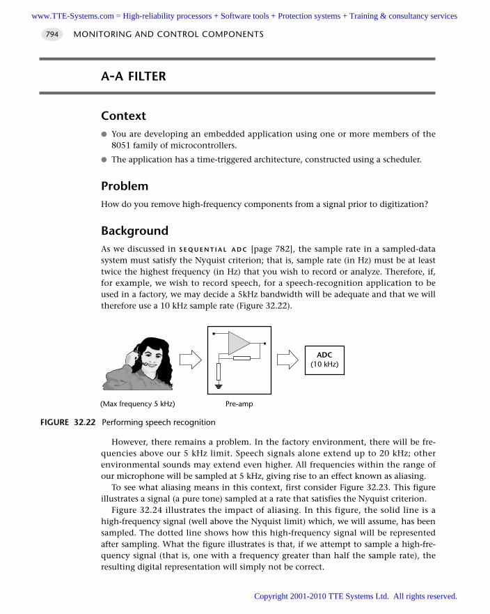
A-A FILTER
Context You are developing an embedded application using one or more members of the
8051 family of microcontrollers.
The application has a time-triggered architecture, constructed using a scheduler.
ProblemHow do you remove high-frequency components from a signal prior to digitization?
BackgroundAs we discussed in S E Q U E N T I A L A D C [page 782], the sample rate in a sampled-datasystem must satisfy the Nyquist criterion; that is, sample rate (in Hz) must be at leasttwice the highest frequency (in Hz) that you wish to record or analyze. Therefore, if,for example, we wish to record speech, for a speech-recognition application to beused in a factory, we may decide a 5kHz bandwidth will be adequate and that we willtherefore use a 10 kHz sample rate (Figure 32.22).
However, there remains a problem. In the factory environment, there will be fre-quencies above our 5 kHz limit. Speech signals alone extend up to 20 kHz; otherenvironmental sounds may extend even higher. All frequencies within the range ofour microphone will be sampled at 5 kHz, giving rise to an effect known as aliasing.
To see what aliasing means in this context, first consider Figure 32.23. This figureillustrates a signal (a pure tone) sampled at a rate that satisfies the Nyquist criterion.
Figure 32.24 illustrates the impact of aliasing. In this figure, the solid line is ahigh-frequency signal (well above the Nyquist limit) which, we will assume, has beensampled. The dotted line shows how this high-frequency signal will be representedafter sampling. What the figure illustrates is that, if we attempt to sample a high-fre-quency signal (that is, one with a frequency greater than half the sample rate), theresulting digital representation will simply not be correct.
MONITORING AND CONTROL COMPONENTS794
FIGURE 32.22 Performing speech recognition
ADC(10 kHz)
Pre-amp(Max frequency 5 kHz)
www.TTE-Systems.com = High-reliability processors + Software tools + Protection systems + Training & consultancy services
Copyright 2001-2010 TTE Systems Ltd. All rights reserved.
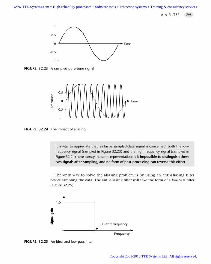
The only way to solve the aliasing problem is by using an anti-aliasing filterbefore sampling the data. The anti-aliasing filter will take the form of a low-pass filter(Figure 32.25).
A-A FILTER 795
FIGURE 32.23 A sampled pure-tone signal
1
0.5
0
–0.5
–1
Time
FIGURE 32.24 The impact of aliasing
1
0.5
0
–0.5
–1
Time
Am
plit
ude
It is vital to appreciate that, as far as sampled-data signal is concerned, both the low-frequency signal (sampled in Figure 32.23) and the high-frequency signal (sampled inFigure 32.24) have exactly the same representation; it is impossible to distinguish thesetwo signals after sampling, and no form of post-processing can reverse this effect.
FIGURE 32.25 An idealized low-pass filter
1.0
Sig
nal
gai
n
Frequency
Cutoff frequency
www.TTE-Systems.com = High-reliability processors + Software tools + Protection systems + Training & consultancy services
Copyright 2001-2010 TTE Systems Ltd. All rights reserved.
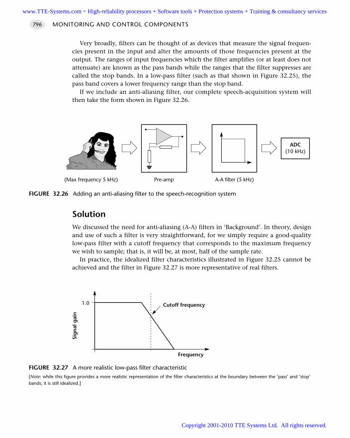
Very broadly, filters can be thought of as devices that measure the signal frequen-cies present in the input and alter the amounts of those frequencies present at theoutput. The ranges of input frequencies which the filter amplifies (or at least does notattenuate) are known as the pass bands while the ranges that the filter suppresses arecalled the stop bands. In a low-pass filter (such as that shown in Figure 32.25), thepass band covers a lower frequency range than the stop band.
If we include an anti-aliasing filter, our complete speech-acquisition system willthen take the form shown in Figure 32.26.
SolutionWe discussed the need for anti-aliasing (A-A) filters in ‘Background’. In theory, designand use of such a filter is very straightforward, for we simply require a good-qualitylow-pass filter with a cutoff frequency that corresponds to the maximum frequencywe wish to sample; that is, it will be, at most, half of the sample rate.
In practice, the idealized filter characteristics illustrated in Figure 32.25 cannot beachieved and the filter in Figure 32.27 is more representative of real filters.
MONITORING AND CONTROL COMPONENTS796
FIGURE 32.26 Adding an anti-aliasing filter to the speech-recognition system
ADC(10 kHz)
Pre-amp(Max frequency 5 kHz) A-A filter (5 kHz)
FIGURE 32.27 A more realistic low-pass filter characteristic[Note: while this figure provides a more realistic representation of the filter characteristics at the boundary between the ‘pass’ and ‘stop’bands, it is still idealized.]
1.0
Sig
nal
gai
n
Frequency
Cutoff frequency
www.TTE-Systems.com = High-reliability processors + Software tools + Protection systems + Training & consultancy services
Copyright 2001-2010 TTE Systems Ltd. All rights reserved.
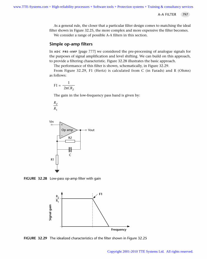
As a general rule, the closer that a particular filter design comes to matching the idealfilter shown in Figure 32.25, the more complex and more expensive the filter becomes.
We consider a range of possible A-A filters in this section.
Simple op-amp filters
In A D C P R E -A M P [page 777] we considered the pre-processing of analogue signals forthe purposes of signal amplification and level shifting. We can build on this approach,to provide a filtering characteristic. Figure 32.28 illustrates the basic approach.
The performance of this filter is shown, schematically, in Figure 32.29.From Figure 32.29, F1 (Hertz) is calculated from C (in Farads) and R (Ohms)
as follows:
1F1 =
2πCR2
The gain in the low-frequency pass band is given by:
R2
R1
A-A FILTER 797
FIGURE 32.28 Low-pass op-amp filter with gain
+
–
Op amp
R1
R2
Vin
Vout
C
FIGURE 32.29 The idealized characteristics of the filter shown in Figure 32.25
Sig
nal
gai
n
Frequency
F1R2R1
www.TTE-Systems.com = High-reliability processors + Software tools + Protection systems + Training & consultancy services
Copyright 2001-2010 TTE Systems Ltd. All rights reserved.
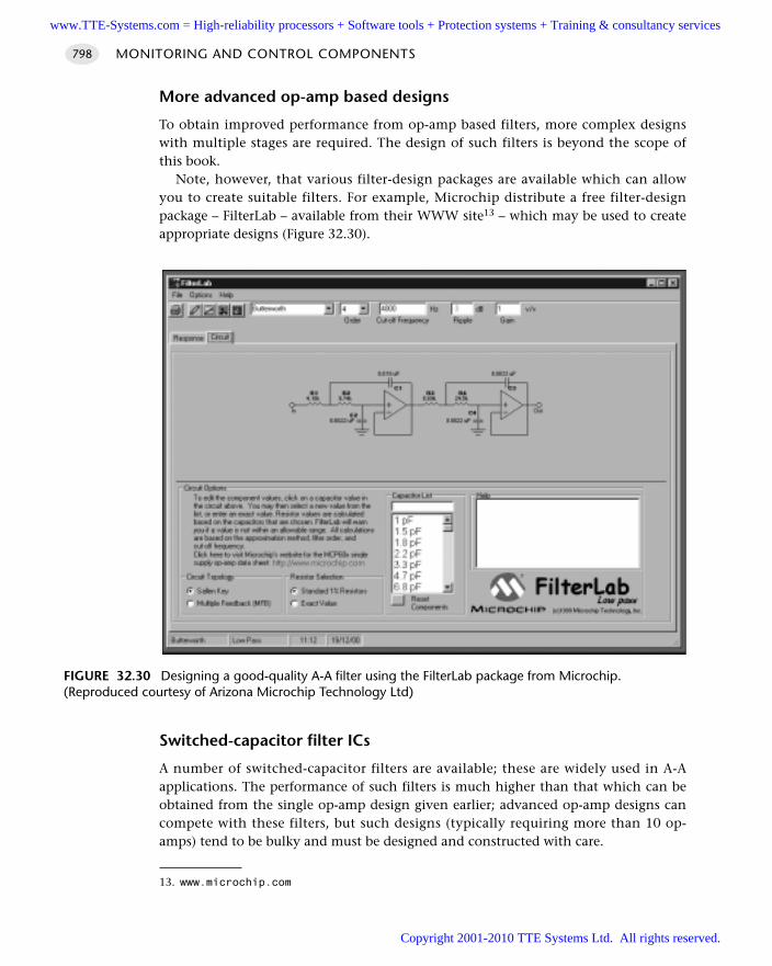
More advanced op-amp based designs
To obtain improved performance from op-amp based filters, more complex designswith multiple stages are required. The design of such filters is beyond the scope ofthis book.
Note, however, that various filter-design packages are available which can allowyou to create suitable filters. For example, Microchip distribute a free filter-designpackage – FilterLab – available from their WWW site13 – which may be used to createappropriate designs (Figure 32.30).
Switched-capacitor filter ICs
A number of switched-capacitor filters are available; these are widely used in A-Aapplications. The performance of such filters is much higher than that which can beobtained from the single op-amp design given earlier; advanced op-amp designs cancompete with these filters, but such designs (typically requiring more than 10 op-amps) tend to be bulky and must be designed and constructed with care.
MONITORING AND CONTROL COMPONENTS798
FIGURE 32.30 Designing a good-quality A-A filter using the FilterLab package from Microchip.(Reproduced courtesy of Arizona Microchip Technology Ltd)
13. www.microchip.com
www.TTE-Systems.com = High-reliability processors + Software tools + Protection systems + Training & consultancy services
Copyright 2001-2010 TTE Systems Ltd. All rights reserved.
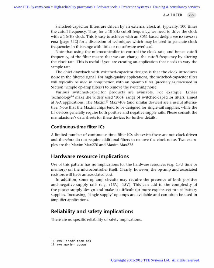
Switched-capacitor filters are driven by an external clock at, typically, 100 timesthe cutoff frequency. Thus, for a 10 kHz cutoff frequency, we need to drive the clockwith a 1 MHz clock. This is easy to achieve with an 8051-based design: see H A R D WA R E
P R M [page 742] for a discussion of techniques which may be used to generate clockfrequencies in this range with little or no software overhead.
Note that using the microcontroller to control the clock rate, and hence cutofffrequency, of the filter means that we can change the cutoff frequency by alteringthe clock rate. This is useful if you are creating an application that needs to vary thesample rate.
The chief drawback with switched-capacitor designs is that the clock introducesnoise in the filtered signal. For high-quality applications, the switched-capacitor filterwill typically be used in conjunction with an op-amp filter (precisely as discussed inSection ‘Simple op-amp filters’) to remove the switching noise.
Various switched-capacitor products are available. For example, LinearTechnology14 make the widely used ‘1064’ range of switched-capacitor filters, aimedat A-A applications. The Maxim15 Max7408 (and similar devices) are a useful alterna-tive. Note that the Maxim chips tend to be designed for single-rail supplies, while theLT devices generally require both positive and negative supply rails. Please consult themanufacturer’s data sheets for these devices for further details.
Continuous-time filter ICs
A limited number of continuous-time filter ICs also exist; these are not clock drivenand therefore do not require additional filters to remove the clock noise. Two exam-ples are the Maxim Max270 and Maxim Max275.
Hardware resource implicationsUse of this pattern has no implications for the hardware resources (e.g. CPU time ormemory) on the microcontroller itself. Clearly, however, the op-amp and associatedresistors will have an associated cost.
In addition, some op-amp circuits may require the presence of both positiveand negative supply rails (e.g. +15V, –15V). This can add to the complexity ofthe power supply design and make it difficult (or more expensive) to use batterysupplies. Increasing, ‘single-supply’ op-amps are available and can often be used inamplifier applications.
Reliability and safety implicationsThere are no specific reliability or safety implications.
A-A FILTER 799
14. www.linear-tech.com15. www.maxim-ic.com
www.TTE-Systems.com = High-reliability processors + Software tools + Protection systems + Training & consultancy services
Copyright 2001-2010 TTE Systems Ltd. All rights reserved.
PortabilityThis hardware-only pattern can be used with any microcontroller.
Overall strengths and weaknessesUse of A-A F I LT E R can greatly improve the performance of many systems.
Adding such a filter increases the product cost.
Related patterns and alternative solutionsGood-quality A-A filters can add significantly to the cost of an embedded application.Sometimes it is possible to reduce the need for A-A filters altogether or at least tomanage with simple op-amp filters, without reducing the signal quality. This is possi-ble if we over-sample the signal.
Consider our speech-recognition system (introduced in ‘Background’) again. Thissystem required data at 10 kHz sample rate, in order to analyze speech sounds at upto 5 kHz. However, we assumed that other sounds in the vicinity would extend up toa frequency of at least 20 kHz and that the frequencies above 5 kHz would need to beremoved by a good-quality A-A filter.
Suppose, however, that we carry out the following:
Filter the signal using a low-quality, 5 kHz, analogue A-A filter
Sample at 40 kHz (thereby correctly sampling all frequencies up to 20 kHz)
Digitally low-pass filter the 40 kHz signal, in software, to remove frequenciesabove 5 kHz
Discard three out of every four samples (a process referred to as decimation), toprovide the 10 kHz data that we require
This process results in a high-quality signal, without the need to invest in anexpensive analogue A-A filter: it is for these reasons that almost all manufacturers ofCD players use over-sampling (typically 4x) to reduce the cost of their products with-out sacrificing quality.
Performing the required digital filtering operating is straightforward (e.g. see Lynnand Fuerst, 1998). The main drawback with this approach is that we require highsample rates; this may, in turn, necessitate the use of a H Y B R I D S C H E D U L E R [page 333].
Example: Applying an A-A filter in a speech-recognition systemConsider the speech-recognition example discussed earlier in this pattern and sum-marized in Figure 32.31.
Figure 32.32 shows a possible design for a suitable A-A filter, created using theMicrochip FilterLab software.
MONITORING AND CONTROL COMPONENTS800
www.TTE-Systems.com = High-reliability processors + Software tools + Protection systems + Training & consultancy services
Copyright 2001-2010 TTE Systems Ltd. All rights reserved.
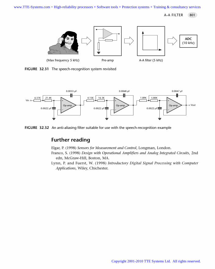
Further readingElgar, P. (1998) Sensors for Measurement and Control, Longman, London.Franco, S. (1998) Design with Operational Amplifiers and Analog Integrated Circuits, 2nd
edn, McGraw-Hill, Boston, MA.Lynn, P. and Fuerst, W. (1998) Introductory Digital Signal Processing with Computer
Applications, Wiley, Chichester.
A-A FILTER 801
FIGURE 32.31 The speech-recognition system revisited
ADC(10 kHz)
Pre-amp(Max frequency 5 kHz) A-A filter (5 kHz)
FIGURE 32.32 An anti-aliasing filter suitable for use with the speech-recognition example
+
–
Op-amp
21.4K
0.0022 µF
6.51K
0.0033 µF
Vin +
–
Op-amp
16.3K
0.0022 µF
4.15K
0.0068 µF
+
–
Op-amp
5.80K
0.0022 µF
1.89K
0.0047 µF
Vout
www.TTE-Systems.com = High-reliability processors + Software tools + Protection systems + Training & consultancy services
Copyright 2001-2010 TTE Systems Ltd. All rights reserved.
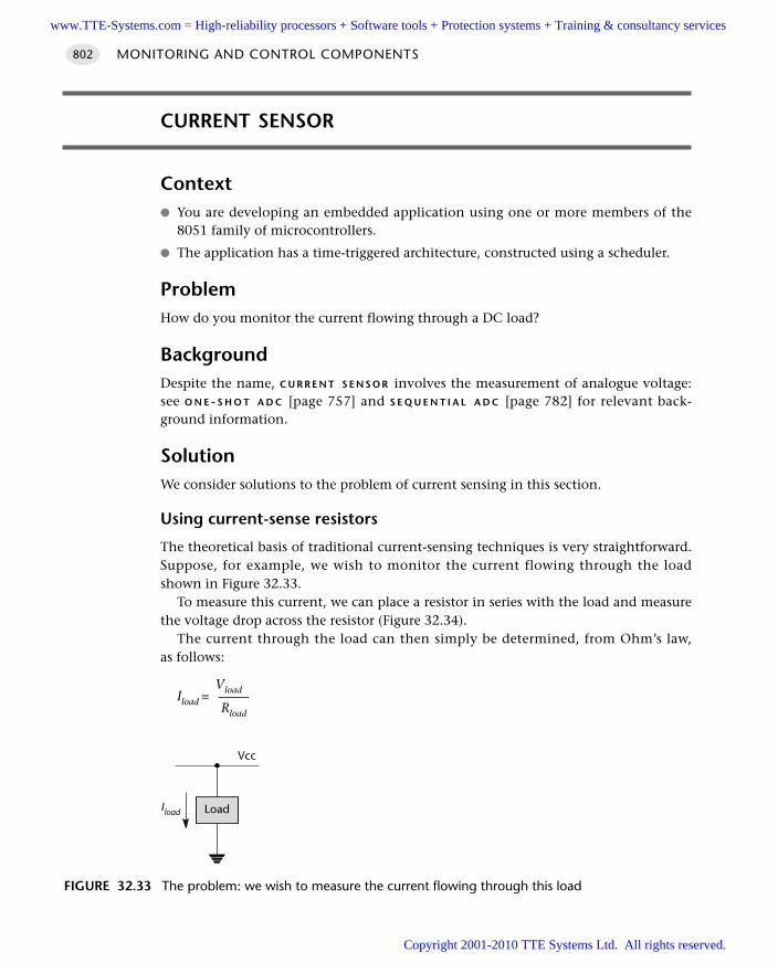
CURRENT SENSOR
Context You are developing an embedded application using one or more members of the
8051 family of microcontrollers.
The application has a time-triggered architecture, constructed using a scheduler.
ProblemHow do you monitor the current flowing through a DC load?
BackgroundDespite the name, C U R R E N T S E N S O R involves the measurement of analogue voltage:see O N E - S H O T A D C [page 757] and S E Q U E N T I A L A D C [page 782] for relevant back-ground information.
SolutionWe consider solutions to the problem of current sensing in this section.
Using current-sense resistors
The theoretical basis of traditional current-sensing techniques is very straightforward.Suppose, for example, we wish to monitor the current flowing through the loadshown in Figure 32.33.
To measure this current, we can place a resistor in series with the load and measurethe voltage drop across the resistor (Figure 32.34).
The current through the load can then simply be determined, from Ohm’s law,as follows:
VloadIload = Rload
MONITORING AND CONTROL COMPONENTS802
FIGURE 32.33 The problem: we wish to measure the current flowing through this load
LoadIload
Vcc
www.TTE-Systems.com = High-reliability processors + Software tools + Protection systems + Training & consultancy services
Copyright 2001-2010 TTE Systems Ltd. All rights reserved.
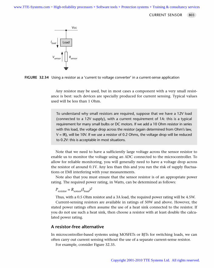
Any resistor may be used, but in most cases a component with a very small resist-ance is best: such devices are specially produced for current sensing. Typical valuesused will be less than 1 Ohm.
Note that we need to have a sufficiently large voltage across the sensor resistor toenable us to monitor the voltage using an ADC connected to the microcontroller. Toallow for reliable monitoring, you will generally need to have a voltage drop acrossthe resistor of around 0.1V. Any less than this and you run the risk of supply fluctua-tions or EMI interfering with your measurements.
Note also that you must ensure that the sensor resistor is of an appropriate powerrating. The required power rating, in Watts, can be determined as follows:
Presistor = Rsensor(Iload)2
Thus, with a 0.5 Ohm resistor and a 3A load, the required power rating will be 4.5W.Current-sensing resistors are available in ratings of 50W and above. However, the
stated power ratings often assume the use of a heat sink connected to the resistor. Ifyou do not use such a heat sink, then choose a resistor with at least double the calcu-lated power rating.
A resistor-free alternative
In microcontroller-based systems using MOSFETs or BJTs for switching loads, we canoften carry out current sensing without the use of a separate current-sense resistor.
For example, consider Figure 32.35.
CURRENT SENSOR 803
FIGURE 32.34 Using a resistor as a ‘current to voltage converter’ in a current-sense application
LoadIload
Vcc
Vsensor Rsensor
To understand why small resistors are required, suppose that we have a 12V load(connected to a 12V supply), with a current requirement of 1A: this is a typicalrequirement for many small bulbs or DC motors. If we add a 10 Ohm resistor in serieswith this load, the voltage drop across the resistor (again determined from Ohm’s law,V = IR), will be 10V. If we use a resistor of 0.2 Ohms, the voltage drop will be reducedto 0.2V: this is acceptable in most situations.
www.TTE-Systems.com = High-reliability processors + Software tools + Protection systems + Training & consultancy services
Copyright 2001-2010 TTE Systems Ltd. All rights reserved.
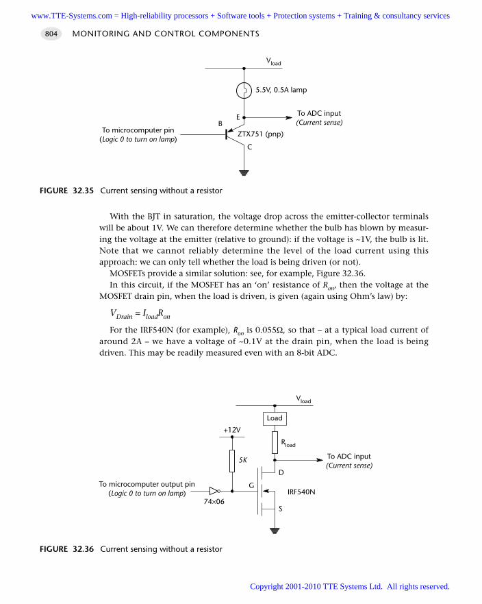
With the BJT in saturation, the voltage drop across the emitter-collector terminalswill be about 1V. We can therefore determine whether the bulb has blown by measur-ing the voltage at the emitter (relative to ground): if the voltage is ~1V, the bulb is lit.Note that we cannot reliably determine the level of the load current using thisapproach: we can only tell whether the load is being driven (or not).
MOSFETs provide a similar solution: see, for example, Figure 32.36.In this circuit, if the MOSFET has an ‘on’ resistance of Ron, then the voltage at the
MOSFET drain pin, when the load is driven, is given (again using Ohm’s law) by:
VDrain = IloadRon
For the IRF540N (for example), Ron is 0.055Ω, so that – at a typical load current ofaround 2A – we have a voltage of ~0.1V at the drain pin, when the load is beingdriven. This may be readily measured even with an 8-bit ADC.
MONITORING AND CONTROL COMPONENTS804
FIGURE 32.35 Current sensing without a resistor
BE
C
5.5V, 0.5A lamp
To microcomputer pin(Logic 0 to turn on lamp)
Vload
ZTX751 (pnp)
To ADC input(Current sense)
FIGURE 32.36 Current sensing without a resistor
Load
D
S
GTo microcomputer output pin(Logic 0 to turn on lamp)
Vload
To ADC input(Current sense)
Rload
IRF540N
+12V
5K
74×06
www.TTE-Systems.com = High-reliability processors + Software tools + Protection systems + Training & consultancy services
Copyright 2001-2010 TTE Systems Ltd. All rights reserved.
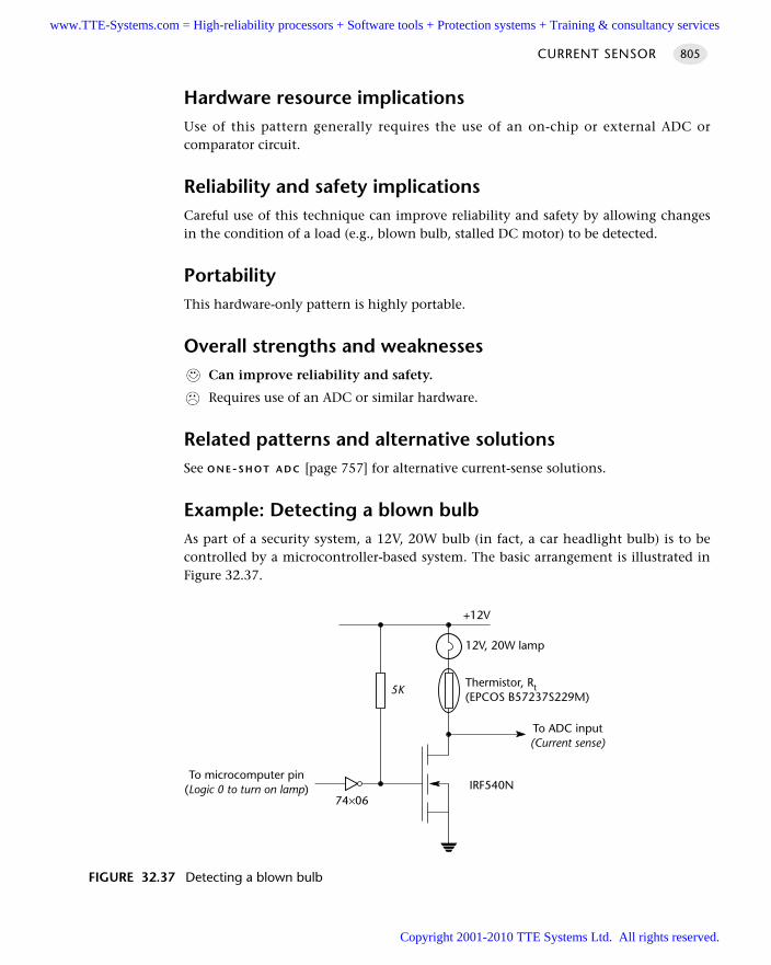
Hardware resource implicationsUse of this pattern generally requires the use of an on-chip or external ADC orcomparator circuit.
Reliability and safety implicationsCareful use of this technique can improve reliability and safety by allowing changesin the condition of a load (e.g., blown bulb, stalled DC motor) to be detected.
PortabilityThis hardware-only pattern is highly portable.
Overall strengths and weaknessesCan improve reliability and safety.
Requires use of an ADC or similar hardware.
Related patterns and alternative solutionsSee O N E-S H O T A D C [page 757] for alternative current-sense solutions.
Example: Detecting a blown bulbAs part of a security system, a 12V, 20W bulb (in fact, a car headlight bulb) is to becontrolled by a microcontroller-based system. The basic arrangement is illustrated inFigure 32.37.
CURRENT SENSOR 805
FIGURE 32.37 Detecting a blown bulb
To microcomputer pin(Logic 0 to turn on lamp)
To ADC input(Current sense)
IRF540N
5K
74×06
+12V
12V, 20W lamp
Thermistor, Rt(EPCOS B57237S229M)
www.TTE-Systems.com = High-reliability processors + Software tools + Protection systems + Training & consultancy services
Copyright 2001-2010 TTE Systems Ltd. All rights reserved.
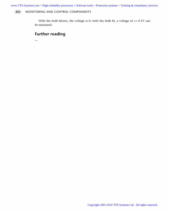
With the bulb blown, the voltage is 0; with the bulb lit, a voltage of >= 0.1V canbe measured.
Further reading—
MONITORING AND CONTROL COMPONENTS806
www.TTE-Systems.com = High-reliability processors + Software tools + Protection systems + Training & consultancy services
Copyright 2001-2010 TTE Systems Ltd. All rights reserved.
Pulse-width modulation
Introduction
Wait until it gets dark. Go to a room in your office or home where there is an ordi-nary (filament) light bulb. Switch the light on and off as rapidly as you can. The roomwill be dimly lit, with a flickering light. Pulse-width modulation (PWM) does exactlythe same thing, at a much higher frequency. More specifically, PWM allows us to con-trol (for example) the brightness of the light – without visible flickering – byswitching the light on and off at a particular duty cycle.
PWM is an efficient basis for the control of high-power loads and is particularlywidely used in applications such as DC (and AC) motor speed control.
There are two practical approaches to PWM signal generation in a time-triggeredapplication:
Several 8051-family microcontrollers provide hardware support for PWM on chip.This is generally easy to use. Where on-chip support is not available, specialistexternal hardware can provide cost-effective, high-frequency PWM switching.
PWM outputs can be generated easily, at low frequencies, using software-onlytechniques.
These approaches are considered in the patterns H A R D WA R E P W M [page 808] andS O F T W A R E P W M [page 831]. We also consider the post-processing that may berequired to filter PWM-based signals, through the pattern P W M S M O O T H E R [page 818]and creation of a high-frequency PWM output without using specialized hardware inthe pattern 3-L E V E L P W M [page 822].
chapter 33www.TTE-Systems.com = High-reliability processors + Software tools + Protection systems + Training & consultancy services
Copyright 2001-2010 TTE Systems Ltd. All rights reserved.
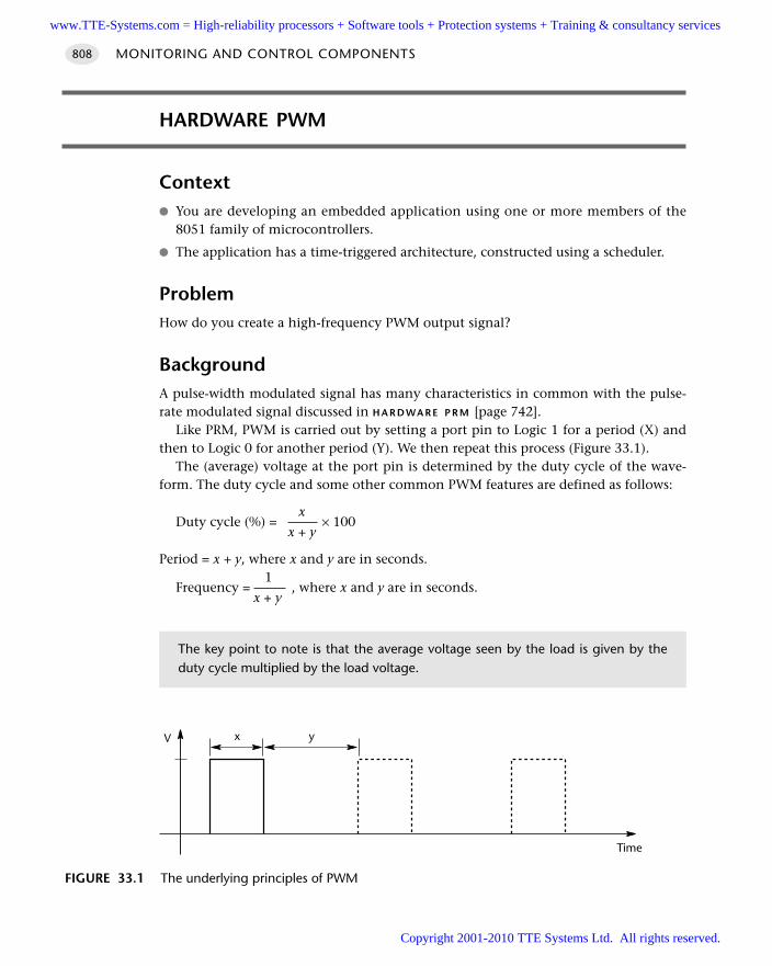
HARDWARE PWM
Context You are developing an embedded application using one or more members of the
8051 family of microcontrollers.
The application has a time-triggered architecture, constructed using a scheduler.
ProblemHow do you create a high-frequency PWM output signal?
BackgroundA pulse-width modulated signal has many characteristics in common with the pulse-rate modulated signal discussed in H A R D WA R E P R M [page 742].
Like PRM, PWM is carried out by setting a port pin to Logic 1 for a period (X) andthen to Logic 0 for another period (Y). We then repeat this process (Figure 33.1).
The (average) voltage at the port pin is determined by the duty cycle of the wave-form. The duty cycle and some other common PWM features are defined as follows:
xDuty cycle (%) = × 100
x + y
Period = x + y, where x and y are in seconds.1
Frequency = , where x and y are in seconds.x + y
MONITORING AND CONTROL COMPONENTS808
FIGURE 33.1 The underlying principles of PWM
V
Time
yx
The key point to note is that the average voltage seen by the load is given by theduty cycle multiplied by the load voltage.
www.TTE-Systems.com = High-reliability processors + Software tools + Protection systems + Training & consultancy services
Copyright 2001-2010 TTE Systems Ltd. All rights reserved.
SolutionWe consider the following issues in this section:
Creating PWM signals using on-chip hardware
Creating PWM signals using external hardware
Determining the required switching frequency
Buffer and driver limitations
Smoothing the PWM outputs
Creating PWM signals using on-chip hardware
We consider two specific examples of the generation of PWM signals using on-chiphardware in this section.
The Infineon c515c
In the Infineon c515c the PWM timer (which is based on Timer 2) is incrementedwith the machine clock, at one-sixth of the oscillator frequency. To generate a 16-bitPWM signal at the maximum (10 MHz) operational frequency, the timer is incre-mented every 300 ns (0.3 µs). The total period is 216 x 0.3 µs, which is 19,660.8 µs or19.7 ms. The frequency is therefore approximately 50 Hz.
The Dallas 87C550
The Dallas 87C550 incorporates a high-speed, 4-channel, PWM hardware interface.The maximum PWM frequency (8-bit PWM, 12 MHz oscillator) is approximately46 kHz.
Creating PWM signals using external hardware
If your microcontroller does not have hardware PWM support, external PWM chipsare available: see, for example, the low-cost Dallas DS1050 family,16 which has a (5-bit) PWM output operating at up to 100 kHz.
Determining the required switching frequency: general guidelines
Determining, on paper, the PWM frequency you need to use for your application isgenerally not easy: it depends on a number of factors associated with the load anddriver and it is generally necessary to perform some practical tests to determine therequired frequencies: we discuss such tests later.
HARDWARE PWM 809
16. www.dalsemi.com
www.TTE-Systems.com = High-reliability processors + Software tools + Protection systems + Training & consultancy services
Copyright 2001-2010 TTE Systems Ltd. All rights reserved.
However, some basic guidelines can be given:
The human eye can detect ‘flicker’ at rates of up to around 50 Hz. If your PWMhardware is controlling something like a bulb, the user may be able to see theflicker if the switching frequency is below this.
The human auditory system has a range, at birth, of around 20 Hz to 20 kHz. Ifyou switch high-power loads within this range, it is likely that the results will beaudible to users, typically as a very annoying whine.
Determining the required switching frequency: practical studies
The only way of determining the required switching frequency in a practical applica-tion is to try a range of different frequencies.
One flexible way of doing this is to use a signal generator to drive the hardwareand observe the results.
An effective alternative, that can often be carried out using your prototype system,is to apply the pattern H A R D W A R E P R M [page 742]. This allows the generation ofsquare waves with a fixed (50%) duty cycle but variable period, at frequencies fromless than 100 Hz to 3 MHz or more.
Buffer and driver limitations
The speed of the PWM hardware is, of course, not the only consideration in develop-ing a PWM interface. For example, Figure 33.2 shows a circuit which attempts toperform PWM-based speed control of an AC motor.
This approach is doomed to failure, since the switch time of the EM relay will, typi-cally, be of the order of 10 milliseconds; this restricts the PWM switching frequencyto around 100 Hz. In many applications, this will not be adequate.
Smoothing the PWM outputs
It is sometimes necessary to smooth PWM outputs, in order to remove high-frequency harmonics: see P W M S M O O T H E R [page 818] for details.
Hardware resource implicationsThe main hardware resource implication is that, if you use the on-chip PWM, this isoften based on Timer 2. As we have discussed, this timer is often used to drive thesystem scheduler (in a single-processor system).
MONITORING AND CONTROL COMPONENTS810
It is essential that you check the switching times of both switch hardware and anyassociated buffer circuitry when developing a PWM application.
www.TTE-Systems.com = High-reliability processors + Software tools + Protection systems + Training & consultancy services
Copyright 2001-2010 TTE Systems Ltd. All rights reserved.
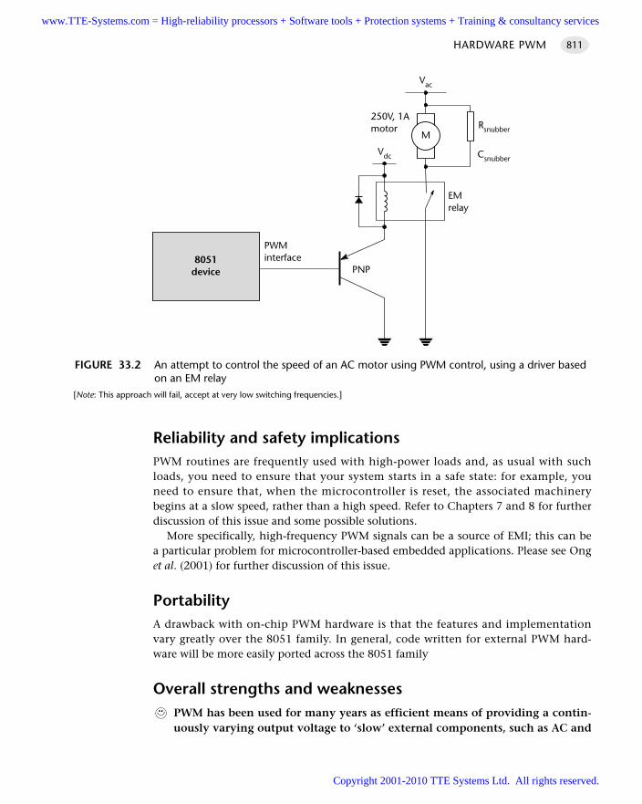
Reliability and safety implicationsPWM routines are frequently used with high-power loads and, as usual with suchloads, you need to ensure that your system starts in a safe state: for example, youneed to ensure that, when the microcontroller is reset, the associated machinerybegins at a slow speed, rather than a high speed. Refer to Chapters 7 and 8 for furtherdiscussion of this issue and some possible solutions.
More specifically, high-frequency PWM signals can be a source of EMI; this can bea particular problem for microcontroller-based embedded applications. Please see Onget al. (2001) for further discussion of this issue.
PortabilityA drawback with on-chip PWM hardware is that the features and implementationvary greatly over the 8051 family. In general, code written for external PWM hard-ware will be more easily ported across the 8051 family
Overall strengths and weaknessesPWM has been used for many years as efficient means of providing a contin-uously varying output voltage to ‘slow’ external components, such as AC and
HARDWARE PWM 811
FIGURE 33.2 An attempt to control the speed of an AC motor using PWM control, using a driver basedon an EM relay
[Note: This approach will fail, accept at very low switching frequencies.]
PWMinterface8051
device
Vdc
PNP
Vac
250V, 1Amotor
EMrelay
MRsnubber
Csnubber
www.TTE-Systems.com = High-reliability processors + Software tools + Protection systems + Training & consultancy services
Copyright 2001-2010 TTE Systems Ltd. All rights reserved.
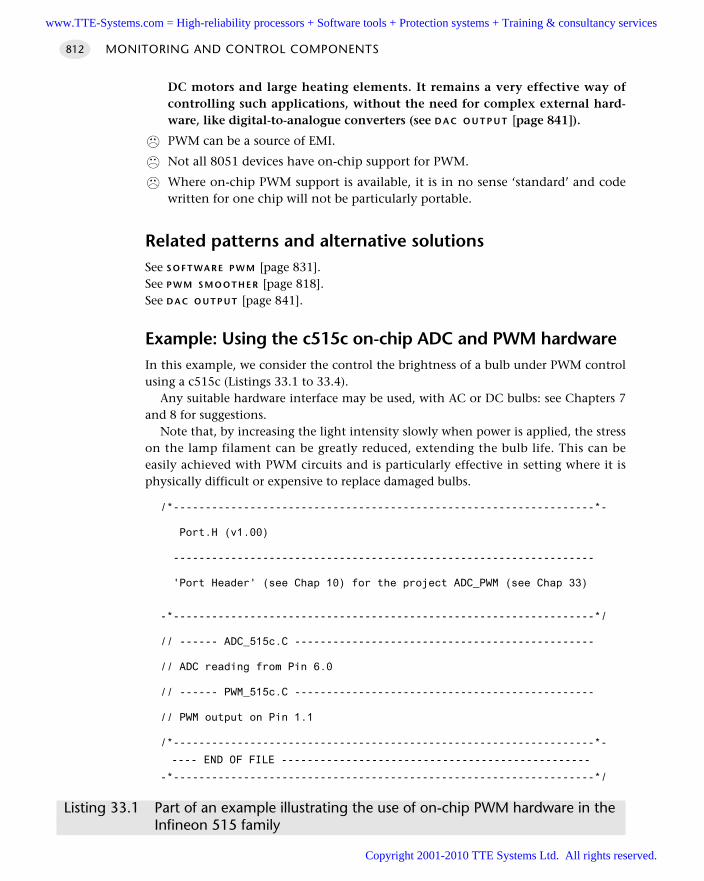
DC motors and large heating elements. It remains a very effective way ofcontrolling such applications, without the need for complex external hard-ware, like digital-to-analogue converters (see D A C O U T P U T [page 841]).
PWM can be a source of EMI.
Not all 8051 devices have on-chip support for PWM.
Where on-chip PWM support is available, it is in no sense ‘standard’ and codewritten for one chip will not be particularly portable.
Related patterns and alternative solutionsSee S O F T WA R E P W M [page 831]. See P W M S M O O T H E R [page 818].See D A C O U T P U T [page 841].
Example: Using the c515c on-chip ADC and PWM hardwareIn this example, we consider the control the brightness of a bulb under PWM controlusing a c515c (Listings 33.1 to 33.4).
Any suitable hardware interface may be used, with AC or DC bulbs: see Chapters 7and 8 for suggestions.
Note that, by increasing the light intensity slowly when power is applied, the stresson the lamp filament can be greatly reduced, extending the bulb life. This can beeasily achieved with PWM circuits and is particularly effective in setting where it isphysically difficult or expensive to replace damaged bulbs.
/*------------------------------------------------------------------*-
Port.H (v1.00)
------------------------------------------------------------------
'Port Header' (see Chap 10) for the project ADC_PWM (see Chap 33)
-*------------------------------------------------------------------*/
// ------ ADC_515c.C -----------------------------------------------
// ADC reading from Pin 6.0
// ------ PWM_515c.C -----------------------------------------------
// PWM output on Pin 1.1
/*------------------------------------------------------------------*-
---- END OF FILE ------------------------------------------------
-*------------------------------------------------------------------*/
Listing 33.1 Part of an example illustrating the use of on-chip PWM hardware in theInfineon 515 family
MONITORING AND CONTROL COMPONENTS812
www.TTE-Systems.com = High-reliability processors + Software tools + Protection systems + Training & consultancy services
Copyright 2001-2010 TTE Systems Ltd. All rights reserved.
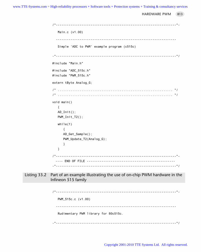
/*------------------------------------------------------------------*-
Main.c (v1.00)
------------------------------------------------------------------
Simple 'ADC to PWM' example program (c515c)
-*------------------------------------------------------------------*/
#include "Main.h"
#include "ADC_515c.h"
#include "PWM_515c.h"
extern tByte Analog_G;
/* ............................................................... */
/* ............................................................... */
void main()
AD_Init();
PWM_Init_T2();
while(1)
AD_Get_Sample();
PWM_Update_T2(Analog_G);
/*------------------------------------------------------------------*-
---- END OF FILE ------------------------------------------------
-*------------------------------------------------------------------*/
Listing 33.2 Part of an example illustrating the use of on-chip PWM hardware in theInfineon 515 family
/*------------------------------------------------------------------*-
PWM_515c.c (v1.00)
------------------------------------------------------------------
Rudimentary PWM library for 80c515c.
-*------------------------------------------------------------------*/
HARDWARE PWM 813
www.TTE-Systems.com = High-reliability processors + Software tools + Protection systems + Training & consultancy services
Copyright 2001-2010 TTE Systems Ltd. All rights reserved.
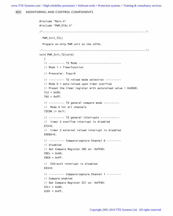
#include "Main.h"
#include "PWM_515c.h"
/*------------------------------------------------------------------*-
PWM_Init_T2()
Prepare on-chip PWM unit on the c515c.
-*------------------------------------------------------------------*/
void PWM_Init_T2(void)
// ---------- T2 Mode ---------------------------
// Mode 1 = Timerfunction
// Prescaler: Fcpu/6
// ---------- T2 reload mode selection ----------
// Mode 0 = auto-reload upon timer overflow
// Preset the timer register with autoreload value ! 0x0000;
TL2 = 0x00;
TH2 = 0xFF;
// ---------- T2 general compare mode ----------
// Mode 0 for all channels
T2CON |= 0x11;
// ---------- T2 general interrupts ------------
// timer 2 overflow interrupt is disabled
ET2=0;
// timer 2 external reload interrupt is disabled
EXEN2=0;
// ---------- Compare/capture Channel 0 ---------
// disabled
// Set Compare Register CRC on: 0xFF00;
CRCL = 0x00;
CRCH = 0xFF;
// CC0/ext3 interrupt is disabled
EX3=0;
// ---------- Compare/capture Channel 1 ---------
// Compare enabled
// Set Compare Register CC1 on: 0xFF80;
CCL1 = 0x80;
CCH1 = 0xFF;
MONITORING AND CONTROL COMPONENTS814
www.TTE-Systems.com = High-reliability processors + Software tools + Protection systems + Training & consultancy services
Copyright 2001-2010 TTE Systems Ltd. All rights reserved.
// CC1/ext4 interrupt is disabled
EX4=0;
// ---------- Compare/capture Channel 2 ---------
// disabled
// Set Compare Register CC2 on: 0x0000;
CCL2 = 0x00;
CCH2 = 0x00;
// CC2/ext5 interrupt is disabled
EX5=0;
// ---------- Compare/capture Channel 3 ---------
// disabled
// Set Compare Register CC3 on: 0x0000;
CCL3 = 0x000;
CCH3 = 0x000;
// CC3/ext6 interrupt is disabled
EX6=0;
// Set all above mentioned modes for channel 0-3
CCEN = 0x08;
/*------------------------------------------------------------------*-
PWM_Update_T2()
Update the PWM output value (capture/compare Channel 1)
Output is on Pin 1.1.
NOTE: Hardware will continue to produce this value (indefinitely),
without software intervention, until the next update.
-*------------------------------------------------------------------*/
void PWM_Update_T2(const tByte New_PWM_value)
CCL1 = New_PWM_value;
/*------------------------------------------------------------------*-
---- END OF FILE ------------------------------------------------
-*------------------------------------------------------------------*/
Listing 33.3 Part of an example illustrating the use of on-chip PWM hardware in theInfineon 515 family
HARDWARE PWM 815
www.TTE-Systems.com = High-reliability processors + Software tools + Protection systems + Training & consultancy services
Copyright 2001-2010 TTE Systems Ltd. All rights reserved.
/*------------------------------------------------------------------*-
ADC_515c.c (v1.00)
------------------------------------------------------------------
Simple, single-channel, 8-bit A-D (input) library for C515c
-*------------------------------------------------------------------*/
#include "Main.H"
//#include "Bargraph.h"
// ------ Public variable definitions ------------------------------
// Stores the most recent ADC reading
tByte Analog_G;
/*------------------------------------------------------------------*-
AD_Init()
Set up the A-D converter.
-*------------------------------------------------------------------*/
void AD_Init(void)
// Select internally-triggered single conversion
// Reading from P6.0 (single channel)
ADEX = 0; // Internal A/D trigger
ADM = 0; // Single conversion
MX2 = MX1 = MX0 = 0; // Read from Channel 0 (Pin 6.0)
// Leave ADCON1 at reset value: prescalar is /4
/*------------------------------------------------------------------*-
AD_Get_Sample()
Get a single data sample (8 bits) from the (10-bit) ADC.
-*------------------------------------------------------------------*/
void AD_Get_Sample(void)
tWord Time_out_loop = 1;
// Take sample from A-D
// Write (value not important) to ADDATL to start conversion
ADDATL = 0x01;
// Take sample from A-D (with simple loop time-out)
MONITORING AND CONTROL COMPONENTS816
www.TTE-Systems.com = High-reliability processors + Software tools + Protection systems + Training & consultancy services
Copyright 2001-2010 TTE Systems Ltd. All rights reserved.
while ((BSY == 1) && (Time_out_loop != 0));
// Time_out_loop++; // Disable for use in dScope...
if (!Time_out_loop)
Analog_G = 0;
else
// 10-bit A-D result is now available
Analog_G = ADDATH; // Read only 8 most significant 8-bits of A-D
/*------------------------------------------------------------------*-
---- END OF FILE ------------------------------------------------
-*------------------------------------------------------------------*/
Listing 33.4 Part of an example illustrating the use of on-chip PWM hardware in theInfineon 515 family
Further readingOng, H.L.R, Pont, M.J. and Peasgood, W. (2001) ‘Do software-based techniques
increase the reliability of embedded applications in the presence of EMI?’,Microprocessors and Microsystems, 24 (10): 481–91.
HARDWARE PWM 817
www.TTE-Systems.com = High-reliability processors + Software tools + Protection systems + Training & consultancy services
Copyright 2001-2010 TTE Systems Ltd. All rights reserved.
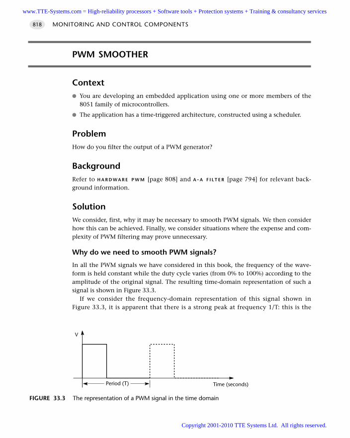
PWM SMOOTHER
Context You are developing an embedded application using one or more members of the
8051 family of microcontrollers.
The application has a time-triggered architecture, constructed using a scheduler.
ProblemHow do you filter the output of a PWM generator?
BackgroundRefer to H A R D W A R E P W M [page 808] and A - A F I L T E R [page 794] for relevant back-ground information.
SolutionWe consider, first, why it may be necessary to smooth PWM signals. We then considerhow this can be achieved. Finally, we consider situations where the expense and com-plexity of PWM filtering may prove unnecessary.
Why do we need to smooth PWM signals?
In all the PWM signals we have considered in this book, the frequency of the wave-form is held constant while the duty cycle varies (from 0% to 100%) according to theamplitude of the original signal. The resulting time-domain representation of such asignal is shown in Figure 33.3.
If we consider the frequency-domain representation of this signal shown inFigure 33.3, it is apparent that there is a strong peak at frequency 1/T: this is the
MONITORING AND CONTROL COMPONENTS818
FIGURE 33.3 The representation of a PWM signal in the time domain
V
Time (seconds)Period (T)
www.TTE-Systems.com = High-reliability processors + Software tools + Protection systems + Training & consultancy services
Copyright 2001-2010 TTE Systems Ltd. All rights reserved.
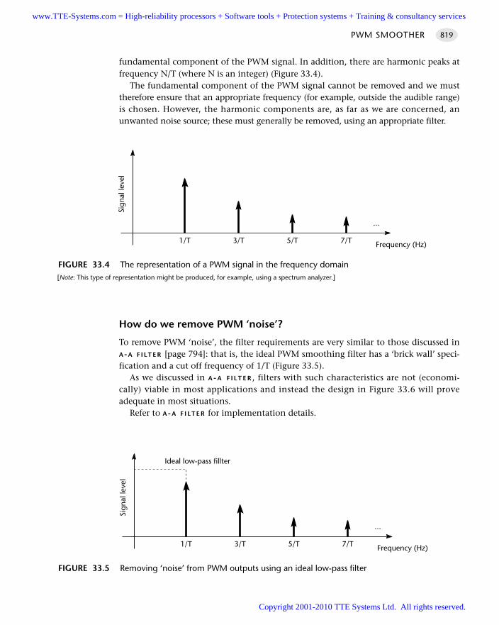
fundamental component of the PWM signal. In addition, there are harmonic peaks atfrequency N/T (where N is an integer) (Figure 33.4).
The fundamental component of the PWM signal cannot be removed and we musttherefore ensure that an appropriate frequency (for example, outside the audible range)is chosen. However, the harmonic components are, as far as we are concerned, anunwanted noise source; these must generally be removed, using an appropriate filter.
How do we remove PWM ‘noise’?
To remove PWM ‘noise’, the filter requirements are very similar to those discussed inA-A F I LT E R [page 794]: that is, the ideal PWM smoothing filter has a ‘brick wall’ speci-fication and a cut off frequency of 1/T (Figure 33.5).
As we discussed in A-A F I LT E R , filters with such characteristics are not (economi-cally) viable in most applications and instead the design in Figure 33.6 will proveadequate in most situations.
Refer to A-A F I LT E R for implementation details.
PWM SMOOTHER 819
FIGURE 33.4 The representation of a PWM signal in the frequency domain[Note: This type of representation might be produced, for example, using a spectrum analyzer.]
1/T 3/T 5/T 7/T Frequency (Hz)
...
Sign
al le
vel
FIGURE 33.5 Removing ‘noise’ from PWM outputs using an ideal low-pass filter
1/T 3/T 5/T 7/T
Ideal low-pass fillter
Frequency (Hz)
...
Sign
al le
vel
www.TTE-Systems.com = High-reliability processors + Software tools + Protection systems + Training & consultancy services
Copyright 2001-2010 TTE Systems Ltd. All rights reserved.
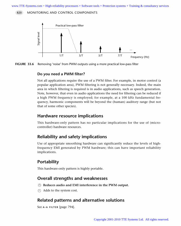
Do you need a PWM filter?
Not all applications require the use of a PWM filter. For example, in motor control (apopular application area), PWM filtering is not generally necessary. Indeed, the mainarea in which filtering is required is in audio applications, such as speech generation.Note, however, that even in audio applications the need for filtering can be reduced ifa high PWM frequency is employed; for example, at a 100 kHz fundamental fre-quency, harmonic components will be beyond the (human) auditory range (but notthat of some other species).
Hardware resource implicationsThis hardware-only pattern has no particular implications for the use of (micro-controller) hardware resources.
Reliability and safety implicationsUse of appropriate smoothing hardware can significantly reduce the levels of high-frequency EMI generated by PWM hardware; this can have important reliabilityimplications.
PortabilityThis hardware-only pattern is highly portable.
Overall strengths and weaknessesReduces audio and EMI interference in the PWM output.
Adds to the system cost.
Related patterns and alternative solutionsSee A-A F I LT E R [page 794].
MONITORING AND CONTROL COMPONENTS820
FIGURE 33.6 Removing ‘noise’ from PWM outputs using a more practical low-pass filter
1/T 3/T 5/T 7/T
Practical low-pass fillter
Frequency (Hz)
...
Sign
al le
vel
www.TTE-Systems.com = High-reliability processors + Software tools + Protection systems + Training & consultancy services
Copyright 2001-2010 TTE Systems Ltd. All rights reserved.
Example: Creating a 5 kHz PWM smoothing filterRefer to the ‘speech-recognition’ example in A-A F I LT E R [page 794] for implementa-tion details of a suitable filter.
Further readingLynn, P. and Fuerst, W. (1998) Introductory Digital Signal Processing with Computer
Applications, Wiley, Chichester.Oppenheim, A.V., Schafer, R.W. and Buck, J.R. (1999) Discrete-time Signal Processing,
Prentice-Hall NJ.Palacheria, A. (1997) ‘Using PWM to generate analog output’, Microchip Application
Note AN538.
PWM SMOOTHER 821
www.TTE-Systems.com = High-reliability processors + Software tools + Protection systems + Training & consultancy services
Copyright 2001-2010 TTE Systems Ltd. All rights reserved.
3-LEVEL PWM
Context You are developing an embedded application using one or more members of the
8051 family of microcontrollers.
The application has a time-triggered architecture, constructed using a scheduler.
ProblemHow do you create a high-frequency PWM output without using specialized hardware?
BackgroundSee H A R D WA R E P R M [page 742] for discussions of pulse-rate modulation.
SolutionSuppose we wish to control the speed of a DC motor. If we switch the motor on andoff at a slow rate via a single output pin on a microcontroller, we can view this as‘1-bit PWM’, or ‘2-level PWM’. That is, we are controlling the motor with a pulsewidth of zero, or an infinite pulse width.
We can take this one significant stage further. As we saw in H A R D WA R E P R M [page742], the majority of modern 8051 devices contain Timer 2; this timer can be pro-grammed to generate a 50% duty cycle output at very high frequencies (up to 3 MHz,even with a 12 MHz / 12 oscillator cycle device).
Using this option, plus the ‘on’ or ‘off’ capabilities just mentioned, we can do thefollowing with a minimal software load:
Run the motor at full speed.
Run the motor at half-speed, with a high-frequency PWM output.
Stop the motor.
This behaviour is adequate for many applications and is very low cost. Of course, itmay be applied equally well to other external devices, such as AC or DC lighting.
Hardware resource implicationsThis pattern requires the use of Timer 2. In single-processor applications, Timer 2 isoften the most suitable means of driving the scheduler itself; as a result, use of thistechnique may have an impact on other parts of the application.
Note that, if a two-processor solution is possible (using a UART- or interrupt-basedscheduler), then Timer 2 can be used to drive the scheduler in the Master node, leav-ing Timer 2 in the Slave node free for use as a PWM generator: see Part F for details ofvarious multiprocessor solutions that may be appropriate here.
MONITORING AND CONTROL COMPONENTS822
www.TTE-Systems.com = High-reliability processors + Software tools + Protection systems + Training & consultancy services
Copyright 2001-2010 TTE Systems Ltd. All rights reserved.
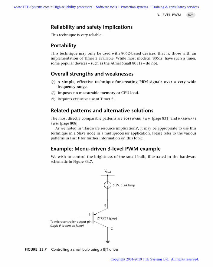
Reliability and safety implicationsThis technique is very reliable.
PortabilityThis technique may only be used with 8052-based devices: that is, those with animplementation of Timer 2 available. While most modern ‘8051s’ have such a timer,some popular devices – such as the Atmel Small 8051s – do not.
Overall strengths and weaknessesA simple, effective technique for creating PRM signals over a very widefrequency range.
Imposes no measurable memory or CPU load.
Requires exclusive use of Timer 2.
Related patterns and alternative solutionsThe most directly comparable patterns are S O F T WA R E P W M [page 831] and H A R D WA R E
P W M [page 808].As we noted in ‘Hardware resource implications’, it may be appropriate to use this
technique in a Slave node in a multiprocessor application. Please refer to the variouspatterns in Part F for further information on this topic.
Example: Menu-driven 3-level PWM exampleWe wish to control the brightness of the small bulb, illustrated in the hardwareschematic in Figure 33.7.
3-LEVEL PWM 823
FIGURE 33.7 Controlling a small bulb using a BJT driver
ZTX751 (pnp)
Vload
5.5V, 0.5A lamp
E
B
C
To microcontroller output pin(Logic 0 to turn on lamp)
www.TTE-Systems.com = High-reliability processors + Software tools + Protection systems + Training & consultancy services
Copyright 2001-2010 TTE Systems Ltd. All rights reserved.
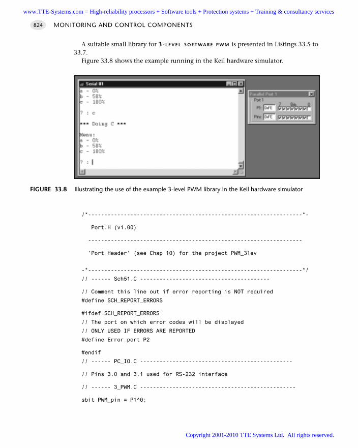
A suitable small library for 3-L E V E L S O F T WA R E P W M is presented in Listings 33.5 to33.7.
Figure 33.8 shows the example running in the Keil hardware simulator.
/*------------------------------------------------------------------*-
Port.H (v1.00)
------------------------------------------------------------------
'Port Header' (see Chap 10) for the project PWM_3lev
-*------------------------------------------------------------------*/
// ------ Sch51.C ----------------------------------------
// Comment this line out if error reporting is NOT required
#define SCH_REPORT_ERRORS
#ifdef SCH_REPORT_ERRORS
// The port on which error codes will be displayed
// ONLY USED IF ERRORS ARE REPORTED
#define Error_port P2
#endif
// ------ PC_IO.C -----------------------------------------------
// Pins 3.0 and 3.1 used for RS-232 interface
// ------ 3_PWM.C ------------------------------------------------
sbit PWM_pin = P1^0;
MONITORING AND CONTROL COMPONENTS824
FIGURE 33.8 Illustrating the use of the example 3-level PWM library in the Keil hardware simulator
www.TTE-Systems.com = High-reliability processors + Software tools + Protection systems + Training & consultancy services
Copyright 2001-2010 TTE Systems Ltd. All rights reserved.
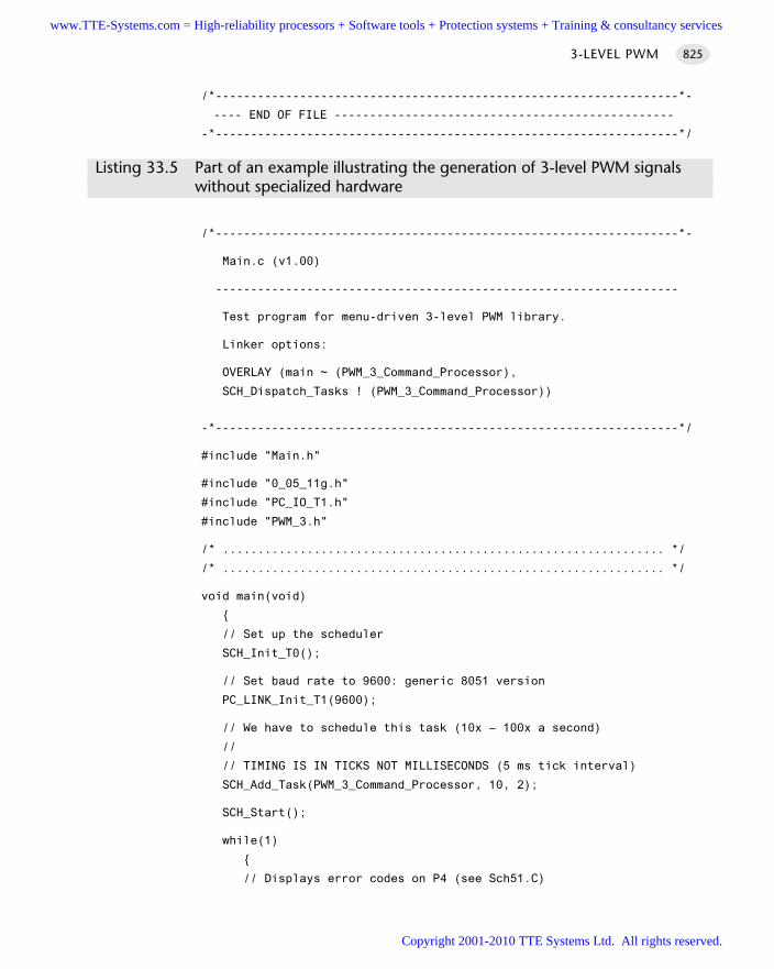
/*------------------------------------------------------------------*-
---- END OF FILE ------------------------------------------------
-*------------------------------------------------------------------*/
Listing 33.5 Part of an example illustrating the generation of 3-level PWM signalswithout specialized hardware
/*------------------------------------------------------------------*-
Main.c (v1.00)
------------------------------------------------------------------
Test program for menu-driven 3-level PWM library.
Linker options:
OVERLAY (main ~ (PWM_3_Command_Processor),
SCH_Dispatch_Tasks ! (PWM_3_Command_Processor))
-*------------------------------------------------------------------*/
#include "Main.h"
#include "0_05_11g.h"
#include "PC_IO_T1.h"
#include "PWM_3.h"
/* ............................................................... */
/* ............................................................... */
void main(void)
// Set up the scheduler
SCH_Init_T0();
// Set baud rate to 9600: generic 8051 version
PC_LINK_Init_T1(9600);
// We have to schedule this task (10x – 100x a second)
//
// TIMING IS IN TICKS NOT MILLISECONDS (5 ms tick interval)
SCH_Add_Task(PWM_3_Command_Processor, 10, 2);
SCH_Start();
while(1)
// Displays error codes on P4 (see Sch51.C)
3-LEVEL PWM 825
www.TTE-Systems.com = High-reliability processors + Software tools + Protection systems + Training & consultancy services
Copyright 2001-2010 TTE Systems Ltd. All rights reserved.
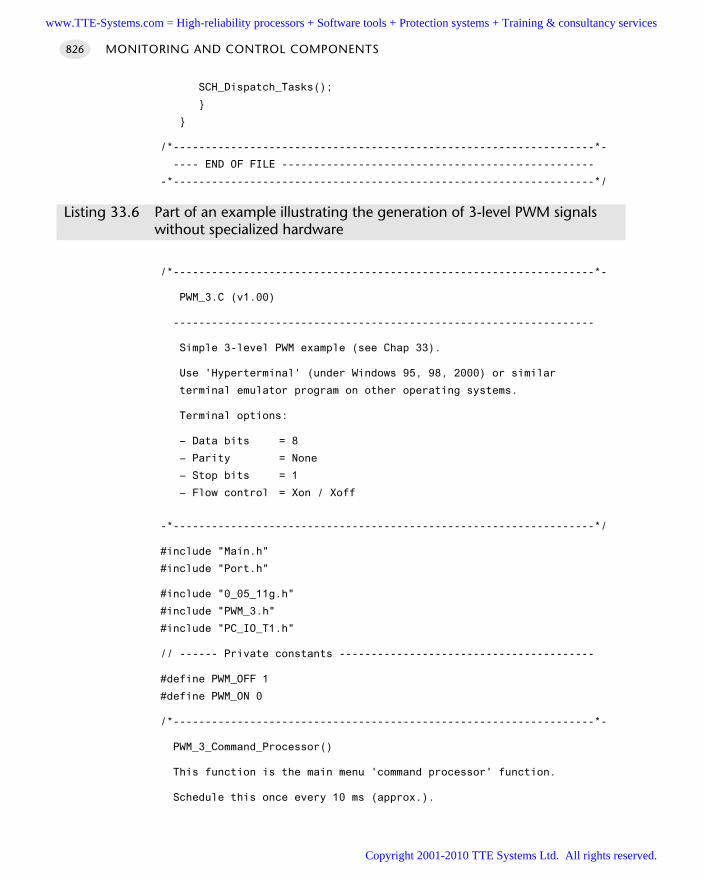
SCH_Dispatch_Tasks();
/*------------------------------------------------------------------*-
---- END OF FILE -------------------------------------------------
-*------------------------------------------------------------------*/
Listing 33.6 Part of an example illustrating the generation of 3-level PWM signalswithout specialized hardware
/*------------------------------------------------------------------*-
PWM_3.C (v1.00)
------------------------------------------------------------------
Simple 3-level PWM example (see Chap 33).
Use 'Hyperterminal' (under Windows 95, 98, 2000) or similar
terminal emulator program on other operating systems.
Terminal options:
– Data bits = 8
– Parity = None
– Stop bits = 1
– Flow control = Xon / Xoff
-*------------------------------------------------------------------*/
#include "Main.h"
#include "Port.h"
#include "0_05_11g.h"
#include "PWM_3.h"
#include "PC_IO_T1.h"
// ------ Private constants ----------------------------------------
#define PWM_OFF 1
#define PWM_ON 0
/*------------------------------------------------------------------*-
PWM_3_Command_Processor()
This function is the main menu 'command processor' function.
Schedule this once every 10 ms (approx.).
MONITORING AND CONTROL COMPONENTS826
www.TTE-Systems.com = High-reliability processors + Software tools + Protection systems + Training & consultancy services
Copyright 2001-2010 TTE Systems Ltd. All rights reserved.
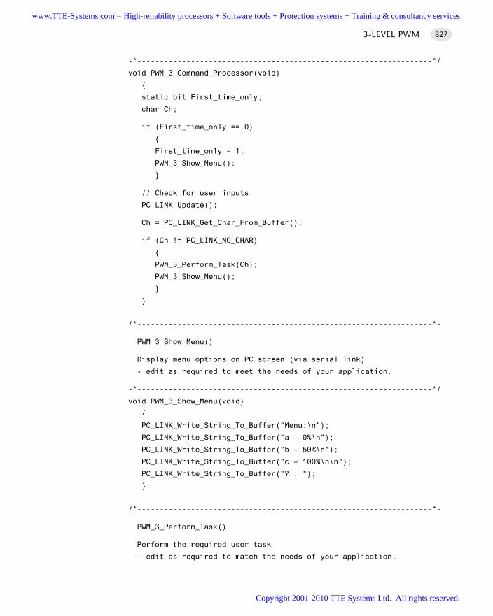
-*------------------------------------------------------------------*/
void PWM_3_Command_Processor(void)
static bit First_time_only;
char Ch;
if (First_time_only == 0)
First_time_only = 1;
PWM_3_Show_Menu();
// Check for user inputs
PC_LINK_Update();
Ch = PC_LINK_Get_Char_From_Buffer();
if (Ch != PC_LINK_NO_CHAR)
PWM_3_Perform_Task(Ch);
PWM_3_Show_Menu();
/*------------------------------------------------------------------*-
PWM_3_Show_Menu()
Display menu options on PC screen (via serial link)
- edit as required to meet the needs of your application.
-*------------------------------------------------------------------*/
void PWM_3_Show_Menu(void)
PC_LINK_Write_String_To_Buffer("Menu:\n");
PC_LINK_Write_String_To_Buffer("a – 0%\n");
PC_LINK_Write_String_To_Buffer("b – 50%\n");
PC_LINK_Write_String_To_Buffer("c – 100%\n\n");
PC_LINK_Write_String_To_Buffer("? : ");
/*------------------------------------------------------------------*-
PWM_3_Perform_Task()
Perform the required user task
– edit as required to match the needs of your application.
3-LEVEL PWM 827
www.TTE-Systems.com = High-reliability processors + Software tools + Protection systems + Training & consultancy services
Copyright 2001-2010 TTE Systems Ltd. All rights reserved.
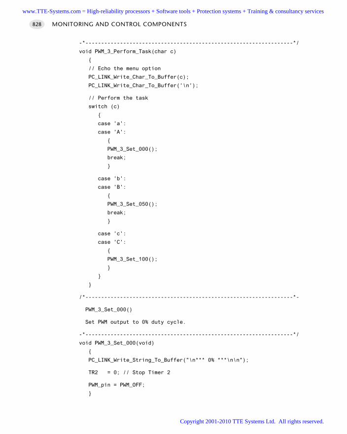
-*------------------------------------------------------------------*/
void PWM_3_Perform_Task(char c)
// Echo the menu option
PC_LINK_Write_Char_To_Buffer(c);
PC_LINK_Write_Char_To_Buffer('\n');
// Perform the task
switch (c)
case 'a':
case 'A':
PWM_3_Set_000();
break;
case 'b':
case 'B':
PWM_3_Set_050();
break;
case 'c':
case 'C':
PWM_3_Set_100();
/*------------------------------------------------------------------*-
PWM_3_Set_000()
Set PWM output to 0% duty cycle.
-*------------------------------------------------------------------*/
void PWM_3_Set_000(void)
PC_LINK_Write_String_To_Buffer("\n*** 0% ***\n\n");
TR2 = 0; // Stop Timer 2
PWM_pin = PWM_OFF;
MONITORING AND CONTROL COMPONENTS828
www.TTE-Systems.com = High-reliability processors + Software tools + Protection systems + Training & consultancy services
Copyright 2001-2010 TTE Systems Ltd. All rights reserved.
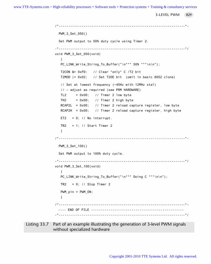
/*------------------------------------------------------------------*-
PWM_3_Set_050()
Set PWM output to 50% duty cycle using Timer 2.
-*------------------------------------------------------------------*/
void PWM_3_Set_050(void)
PC_LINK_Write_String_To_Buffer("\n*** 50% ***\n\n");
T2CON &= 0xFD; // Clear *only* C /T2 bit
T2MOD |= 0x02; // Set T2OE bit (omit in basic 8052 clone)
// Set at lowest frequency (~45Hz with 12MHz xtal)
// – adjust as required (see PRM HARDWARE)
TL2 = 0x00; // Timer 2 low byte
TH2 = 0x00; // Timer 2 high byte
RCAP2L = 0x00; // Timer 2 reload capture register, low byte
RCAP2H = 0x00; // Timer 2 reload capture register, high byte
ET2 = 0; // No interrupt.
TR2 = 1; // Start Timer 2
/*------------------------------------------------------------------*-
PWM_3_Set_100()
Set PWM output to 100% duty cycle.
-*------------------------------------------------------------------*/
void PWM_3_Set_100(void)
PC_LINK_Write_String_To_Buffer("\n*** Doing C ***\n\n");
TR2 = 0; // Stop Timer 2
PWM_pin = PWM_ON;
/*------------------------------------------------------------------*-
---- END OF FILE ------------------------------------------------
-*------------------------------------------------------------------*/
Listing 33.7 Part of an example illustrating the generation of 3-level PWM signalswithout specialized hardware
3-LEVEL PWM 829
www.TTE-Systems.com = High-reliability processors + Software tools + Protection systems + Training & consultancy services
Copyright 2001-2010 TTE Systems Ltd. All rights reserved.
Further readingHuang, H-W (2000) Using the MCS-51 Microcontroller, Oxford University Press, New
York.
MONITORING AND CONTROL COMPONENTS830
www.TTE-Systems.com = High-reliability processors + Software tools + Protection systems + Training & consultancy services
Copyright 2001-2010 TTE Systems Ltd. All rights reserved.
SOFTWARE PWM
Context You are developing an embedded application using one or more members of the
8051 family of microcontrollers.
The application has a time-triggered architecture, constructed using a scheduler.
ProblemHow do you create a low-frequency PWM output signal without using specializedPWM hardware?
BackgroundSee H A R D WA R E P W M [page 808] for general background material on PWM.
See S O F T WA R E P R M [page 748] for a similar solution.
SolutionThe techniques discussed in S O F T W A R E P R M [page 748] may be readily adapted toallow us to generate low-frequency pulse-width modulated signals. Listing 33.8 illus-trates this.
void PWM_Soft_Update(void)
// Have we reached the end of the current PWM cycle?
if (++PWM_position_G >= PWM_PERIOD)
// Reset the PWM position counter
PWM_position_G = 0;
// Update the PWM control value
PWM_G = PWM_new_G;
// Set the PWM output to OFF
PWM_pin = PWM_OFF;
return;
// We are in a PWM cycle
if (PWM_position_G < PWM_G)
SOFTWARE PWM 831
www.TTE-Systems.com = High-reliability processors + Software tools + Protection systems + Training & consultancy services
Copyright 2001-2010 TTE Systems Ltd. All rights reserved.

PWM_pin = PWM_ON;
else
PWM_pin = PWM_OFF;
Listing 33.8 Implementing software PWM
The key to Listing 33.8 is the use of the variables PWM_position_G, PWM_period_Gand PWM_period_new_G:
PWM_period_G is the current PRM period. Note that if the update function isscheduled every millisecond, this period is in milliseconds. PWM_period_G is fixedduring the program execution.
PWM_G represents the current PWM duty cycle (see Figure 33.9).
PWM_new_G is the next PWM duty cycle. This period may be varied by the user, asrequired. Note that the ‘new’ value is only copied to PWM_G at the end of a PWMcycle, to avoid noise.
PWM_position_G is the current position in the PWM cycle. This is incremented bythe update function. Again, the units are milliseconds if these conditions apply.
The link between these various variables and constants is illustrated in Figure 33.9.
MONITORING AND CONTROL COMPONENTS832
FIGURE 33.9 Implementing pulse-rate modulation in software
if (PRM_position_G < PWM_G) PRM_pin = PWM_ON: else PRM_pin = PWM_OFF:
PRM_period_G
PRM_position_G
PRM_G
www.TTE-Systems.com = High-reliability processors + Software tools + Protection systems + Training & consultancy services
Copyright 2001-2010 TTE Systems Ltd. All rights reserved.
Using a 1 ms scheduler, the PWM frequency (Hz) and PWM resolution (%) weobtain are given by:
1000FrequencyPWM =
2N
and:
1ResolutionPWM = × 100%
2N
where N is the number of PWM bits you use.For example, 5-bit PWM allows you to control the output to a resolution of
approximately 3%, at a frequency of approximately 31 Hz.
Hardware resource implicationsSO F T WA R E PWM has no significant hardware resource implications.
Reliability and safety implicationsWhen working with PWM, you may be switching high-power loads and / or mainsvoltages. You need to take care with start-up states, to ensure that any equipment youare controlling is not going to cause damage or injury when the application starts.
PortabilityS O F T WA R E P W M uses only core 8051 features: it may be easily used throughout the8051 family.
Overall strengths and weaknessesPWM has been used for many years as efficient means of providing a continu-ously varying output voltage to ‘slow’ external components, such as AC and DCmotors and large heating elements. It remains a very effective way of control-ling such applications, without the need for digital-to-analogue converters.
S O F T WA R E P W M does not impose a heavy CPU load.
S O F T WA R E P W M can only operate at comparatively low frequencies. For example,at a 1 ms tick rate and 8-bit PWM, the PWM frequency is 1000 / 256: that is, lessthan 4 Hz. Typical hardware PWM units operate at up to 100 kHz. For manyapplications, high-speed PWM is an important consideration: please see H A R D -WA R E P W M [page 808] for further information on this issue.
Related patterns and alternative solutionsSee H A R D WA R E P W M [page 808] for one alternative.
SOFTWARE PWM 833
www.TTE-Systems.com = High-reliability processors + Software tools + Protection systems + Training & consultancy services
Copyright 2001-2010 TTE Systems Ltd. All rights reserved.
An alternative implementation of the present pattern is also worth highlighting.Consider the code shown in Listing 33.9.
void Fast_Software_PWM_Update(void)
tWord PWM_position;
for (PWM_position = 0; PWM_position < PWM_INCREMENTS; PWM_position++)
if (PWM_position < PWM_G)
PWM_pin = PWM_ON;
else
PWM_pin = PWM_OFF;
// Appropriate delay here
PWM_Delay();
Listing 33.9 Attempting to increase the frequency of software-only PWM signals
In this solution, we assume that we are generating an entire PWM cycle every time wecall the task: this seems to offer the possibility of generating faster PWM signals. Forexample, at a 0.25 ms tick intervals, we can generate a 4 kHz PWM frequency, whichwill be adequate for many applications. Moreover, we can generate any number of‘PWM_INCREMENTS’: that is, any required bit rate.
However, this solution has two problems. The first is that the CPU is tied up, com-pletely, in the PWM signal generation. This is not insurmountable but might mean,for example, that the solution could only be implemented on a Slave node in a multi-processor system.
The second problem is more serious and relates to the delays required within theloop. For example, at a 1 ms tick interval, the generation of 5-bit PWM outputsrequires the generation of delays of precisely 3.125 µs. This is very difficult to achieve,as we discussed in Chapter 11. At higher bit rates and tick frequencies, the requireddelays are very much shorter and cannot be obtained in most implementations.
Example: Controlling the brightness of a bulbWe again wish to control the brightness of the small bulb, illustrated in the hardwareschematic in Figure 33.10.
MONITORING AND CONTROL COMPONENTS834
www.TTE-Systems.com = High-reliability processors + Software tools + Protection systems + Training & consultancy services
Copyright 2001-2010 TTE Systems Ltd. All rights reserved.
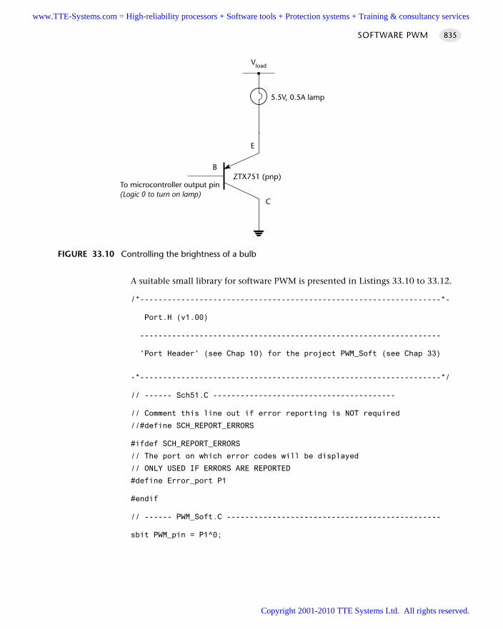
A suitable small library for software PWM is presented in Listings 33.10 to 33.12.
/*------------------------------------------------------------------*-
Port.H (v1.00)
------------------------------------------------------------------
'Port Header' (see Chap 10) for the project PWM_Soft (see Chap 33)
-*------------------------------------------------------------------*/
// ------ Sch51.C ----------------------------------------
// Comment this line out if error reporting is NOT required
//#define SCH_REPORT_ERRORS
#ifdef SCH_REPORT_ERRORS
// The port on which error codes will be displayed
// ONLY USED IF ERRORS ARE REPORTED
#define Error_port P1
#endif
// ------ PWM_Soft.C -----------------------------------------------
sbit PWM_pin = P1^0;
SOFTWARE PWM 835
FIGURE 33.10 Controlling the brightness of a bulb
ZTX751 (pnp)
Vload
5.5V, 0.5A lamp
E
B
C
To microcontroller output pin(Logic 0 to turn on lamp)
www.TTE-Systems.com = High-reliability processors + Software tools + Protection systems + Training & consultancy services
Copyright 2001-2010 TTE Systems Ltd. All rights reserved.
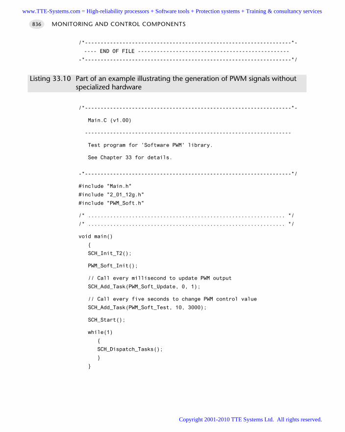
/*------------------------------------------------------------------*-
---- END OF FILE ------------------------------------------------
-*------------------------------------------------------------------*/
Listing 33.10 Part of an example illustrating the generation of PWM signals withoutspecialized hardware
/*------------------------------------------------------------------*-
Main.C (v1.00)
------------------------------------------------------------------
Test program for 'Software PWM' library.
See Chapter 33 for details.
-*------------------------------------------------------------------*/
#include "Main.h"
#include "2_01_12g.h"
#include "PWM_Soft.h"
/* ............................................................... */
/* ............................................................... */
void main()
SCH_Init_T2();
PWM_Soft_Init();
// Call every millisecond to update PWM output
SCH_Add_Task(PWM_Soft_Update, 0, 1);
// Call every five seconds to change PWM control value
SCH_Add_Task(PWM_Soft_Test, 10, 3000);
SCH_Start();
while(1)
SCH_Dispatch_Tasks();
MONITORING AND CONTROL COMPONENTS836
www.TTE-Systems.com = High-reliability processors + Software tools + Protection systems + Training & consultancy services
Copyright 2001-2010 TTE Systems Ltd. All rights reserved.
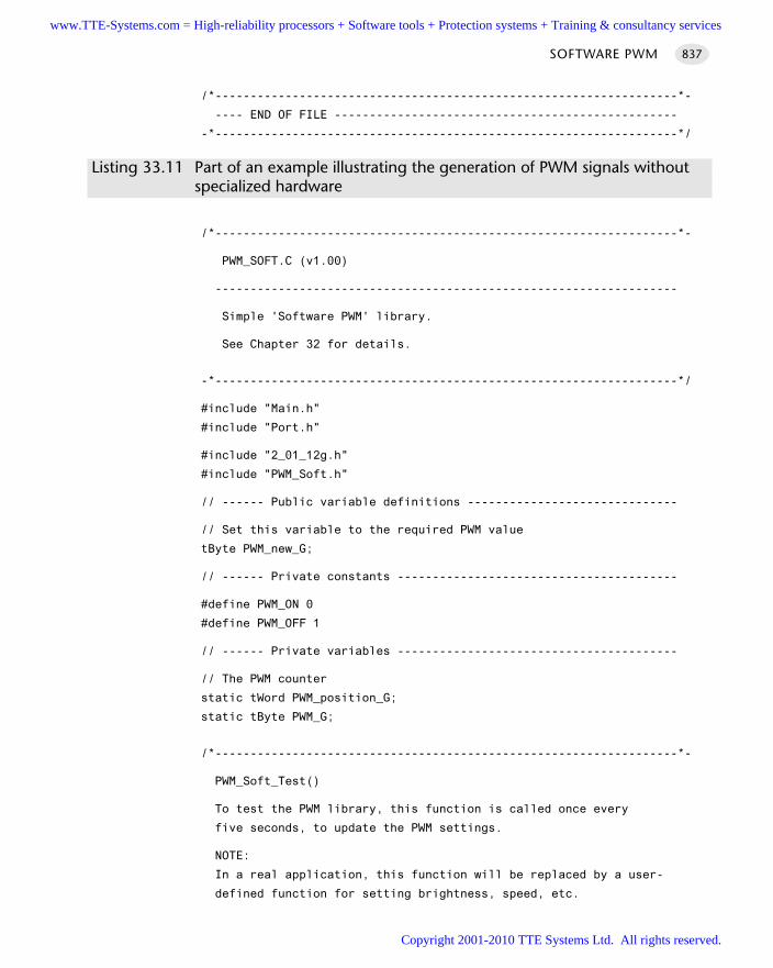
/*------------------------------------------------------------------*-
---- END OF FILE -------------------------------------------------
-*------------------------------------------------------------------*/
Listing 33.11 Part of an example illustrating the generation of PWM signals withoutspecialized hardware
/*------------------------------------------------------------------*-
PWM_SOFT.C (v1.00)
------------------------------------------------------------------
Simple 'Software PWM' library.
See Chapter 32 for details.
-*------------------------------------------------------------------*/
#include "Main.h"
#include "Port.h"
#include "2_01_12g.h"
#include "PWM_Soft.h"
// ------ Public variable definitions ------------------------------
// Set this variable to the required PWM value
tByte PWM_new_G;
// ------ Private constants ----------------------------------------
#define PWM_ON 0
#define PWM_OFF 1
// ------ Private variables ----------------------------------------
// The PWM counter
static tWord PWM_position_G;
static tByte PWM_G;
/*------------------------------------------------------------------*-
PWM_Soft_Test()
To test the PWM library, this function is called once every
five seconds, to update the PWM settings.
NOTE:
In a real application, this function will be replaced by a user-
defined function for setting brightness, speed, etc.
SOFTWARE PWM 837
www.TTE-Systems.com = High-reliability processors + Software tools + Protection systems + Training & consultancy services
Copyright 2001-2010 TTE Systems Ltd. All rights reserved.
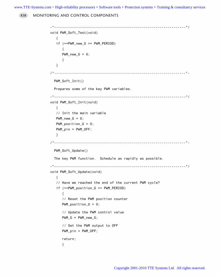
-*------------------------------------------------------------------*/
void PWM_Soft_Test(void)
if (++PWM_new_G >= PWM_PERIOD)
PWM_new_G = 0;
/*------------------------------------------------------------------*-
PWM_Soft_Init()
Prepares some of the key PWM variables.
-*------------------------------------------------------------------*/
void PWM_Soft_Init(void)
// Init the main variable
PWM_new_G = 0;
PWM_position_G = 0;
PWM_pin = PWM_OFF;
/*------------------------------------------------------------------*-
PWM_Soft_Update()
The key PWM function. Schedule as rapidly as possible.
-*------------------------------------------------------------------*/
void PWM_Soft_Update(void)
// Have we reached the end of the current PWM cycle?
if (++PWM_position_G >= PWM_PERIOD)
// Reset the PWM position counter
PWM_position_G = 0;
// Update the PWM control value
PWM_G = PWM_new_G;
// Set the PWM output to OFF
PWM_pin = PWM_OFF;
return;
MONITORING AND CONTROL COMPONENTS838
www.TTE-Systems.com = High-reliability processors + Software tools + Protection systems + Training & consultancy services
Copyright 2001-2010 TTE Systems Ltd. All rights reserved.
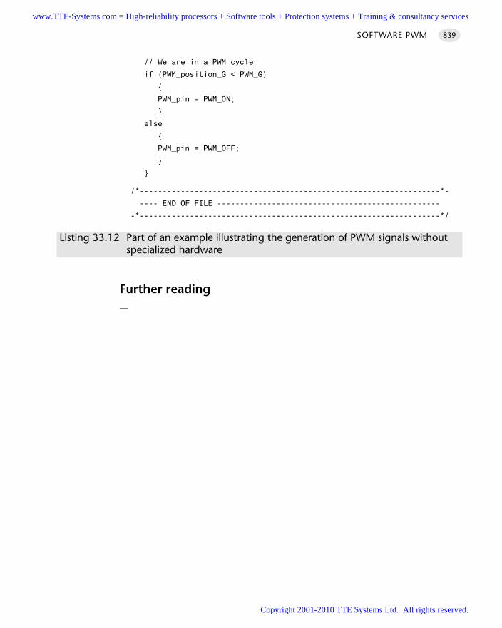
// We are in a PWM cycle
if (PWM_position_G < PWM_G)
PWM_pin = PWM_ON;
else
PWM_pin = PWM_OFF;
/*------------------------------------------------------------------*-
---- END OF FILE -------------------------------------------------
-*------------------------------------------------------------------*/
Listing 33.12 Part of an example illustrating the generation of PWM signals withoutspecialized hardware
Further reading—
SOFTWARE PWM 839
www.TTE-Systems.com = High-reliability processors + Software tools + Protection systems + Training & consultancy services
Copyright 2001-2010 TTE Systems Ltd. All rights reserved.
Using digital-to-analog
converters (DACs)
Introduction
In the 1980s, if you wanted to create an analog signal from a microcontroller, youwould probably have used a ‘digital-to-analog converter’ (DAC). More recently, as theoperating frequencies for digital hardware have grown, pulse-width modulation(PWM) has become a more cost-effective means of creating an analog signal in manycircumstances. As a result, use of DACs in areas such as motor control and roboticshas become much less common.
However, there are two main sets of circumstances in which use of a DAC is stillcost-effective: in high-frequency / high bit-rate applications (particularly audio appli-cations) and in process control.
We consider how to use a DAC to generate analog outputs in this chapter. In doingso we present the following patterns:
D A C O U T P U T [page 841]
D A C S M O O T H E R [page 853]
D A C D R I V E R [page 857]
chapter 34www.TTE-Systems.com = High-reliability processors + Software tools + Protection systems + Training & consultancy services
Copyright 2001-2010 TTE Systems Ltd. All rights reserved.
DAC OUTPUT
ContextYou are developing a ‘hard’ or ‘soft’ real-time application, for either a desktop orembedded environment (see Chapter 1 for definitions of these various terms).
ProblemHow do you use a digital-to-analog converter (DAC) to generate analog signals?
BackgroundSuppose you are developing an intruder alarm system for a home environment. In theevent of a break-in, we generally expect simply to sound an alarm (ring a bell) tonotify the neighbours. This is adequate: the intruder alarm is only intended to detectone kind of problem.
However, suppose you are developing a safety monitoring system for an industrialplant. Various problems may arise: different forms of gas leak, nuclear materials leak,fire, intruder and so forth. In some situations, those in the plant need to take differ-ent action (for example, donning different kinds of protective clothing), dependingon the type of threat they face.
How do we tell those in the plant what kind of problem has occurred?One appropriate solution might be to use digitized messages that describe the
problem and tell users what to do. For example: ‘Warning, a leak of Contaminant 356has been detected at a level of 345 parts per million. Please use your respirator nowand leave the building via your designated escape route.’
To play back this type of message, we will generally require a digital-to-analog con-verter (DAC).
DACs have an important role, not only in the playback of digitized warnings, butalso in other control applications. We consider how to use DACs in this pattern.
SolutionThere are several key design decisions that must be made when generating an analogoutput:
1 You need to determine the required sample rate.
2 You need to determine the required bit rate (DAC resolution).
3 You need to select an 8051 family member with an appropriate DAC or, if neces-sary, add an external DAC.
DAC OUTPUT 841
www.TTE-Systems.com = High-reliability processors + Software tools + Protection systems + Training & consultancy services
Copyright 2001-2010 TTE Systems Ltd. All rights reserved.
4 You may need to shape the frequency response of the output signal.
5 You need to use an appropriate software architecture.
We now deal with each of these points in turn.
Determining the required sample rate
Refer to S E Q U E N T I A L A D C [page 782] for discussions on sample rates.
Determining the required bit rate
Refer to O N E-S H O T A D C [page 757] for discussions on bit rates.
8051 microcontrollers with on-chip DACs
While, as we saw in O N E-S H O T A D C [page 757], many 8051 microcontrollers containon-chip ADCs, the number of devices with on-chip DACs is very limited.
Some examples of the available DAC components provided on two recent 8051devices follow.
Analog Devices ADµC812
Adapted from the Analog Devices17 data sheet:
The ADµC812 incorporates two 12-bit voltage-mode DACs On-Chip. DAC operation is controlled via three special function registers. In normal mode of oper-
ation, each DAC is updated when the low DAC byte (DACxL) SFR is written. Both DACs canbe updated simultaneously using the SYNC bit in the DACCON SFR. The DAC's can operate in12 or 8-bit modes and have programmable output ranges of 0 -> 2.5V or 0 ->VDD.
Cygnal C8051F000
Adapted from the Cygnal18 C8051F000 data sheet:
The C8051F000 MCU family has two 12-bit voltage-mode DACs (DAC0, DAC1). Each DAC has an output swing of 0V to VREF-1LSB for a corresponding input code range of
0x000 to 0xFFF. Using DAC0 as an example, the 12-bit data word is written to the low byte(DAC0L) and high byte (DAC0H) data registers. Data is latched into DAC0 after a write to thecorresponding DAC0H register, so the write sequence should be DAC0L followed by DAC0H ifthe full 12-bit resolution is required. The DAC can be used in 8-bit mode by initializing DAC0Lto the desired value (typically 0x00), and writing data to only DAC0H. DAC0 Control Register(DAC0CN) provides a means to enable/disable DAC0 and to modify its input data formatting.
The DAC0 enable/disable function is controlled by the DAC0EN bit (DAC0CN.7). Writing a 1to DAC0EN enables DAC0 while writing a 0 to DAC0EN disables DAC0. While disabled, the
MONITORING AND CONTROL COMPONENTS842
17. www.analog.com18. www.cygnal.com
www.TTE-Systems.com = High-reliability processors + Software tools + Protection systems + Training & consultancy services
Copyright 2001-2010 TTE Systems Ltd. All rights reserved.
output of DAC0 is maintained in a high-impedance state, and the DAC0 supply current falls to1uA or less.
In some instances, input data should be shifted prior to a DAC0 write operation to properlyjustify data within the DAC input registers. This action would typically require one or more loadand shift operations, adding software overhead and slowing DAC throughput. To alleviate thisproblem, the data-formatting feature provides a means for the user to program the orientationof the DAC0 data word within data registers DAC0H and DAC0L. The three DAC0DF bits(DAC0CN.[2:0]) allow the user to specify one of five data word orientations.
DAC1 is functionally the same as DAC0 described above.
Using an external voltage-mode DAC
In general, while the use of an internal DAC will result in increased reliability, smallersystem size and lower system cost, this is not always possible.
As with ADCs, both parallel and serial (voltage-mode) DACs are available. Forexample, in terms of parallel components, Analog Devices19 produce the parallelAD7245a (12-bit), AD7248a (12-bit) and AD7801 (8-bit), while Maxim20 produce theMax5480 (8-bit). In serial devices, Maxim (again) produce, for example, the Max517with an I2C interface and the Max541 with an SPI interface: refer to Part E for discus-sion of the use of these interfaces in a time-triggered environment.
Because we will generally be using DACs in circumstances where a high bit-rate andsample frequency is required, the parallel solution will often be the most practical solution.
Using an external current-mode DAC or a transconductance amplifier
As we discussed in O N E-S H O T A D C [page 757], there are circumstances, particularly inmonitoring or process control, when the use of current-mode components (sensors oractuators) may be more appropriate than the use of voltage-mode devices.
To generate analog current signals from a microcontroller, we have two main options:
Use a current-mode DAC
Use a voltage-mode DAC and a voltage-to-current converter (often referred to as atransconductance amplifier)
The second option may be particularly attractive if your microcontroller has an on-chip DAC.
An example of a suitable DAC component is the Analog Devices21 AD421, aDAC designed specifically for 4 to 20mA current loops and which is powered by theloop itself.
An example of a transconductance amplifier is the XTR 110 from Burr Brown.22 Thiscan be used, for example, to convert a 1–5V analog voltage (from, say, a microcontroller
DAC OUTPUT 843
19. www.analog.com20. www.maxim-ic.com21. www.analog.com22. www.burr-brown.com
www.TTE-Systems.com = High-reliability processors + Software tools + Protection systems + Training & consultancy services
Copyright 2001-2010 TTE Systems Ltd. All rights reserved.
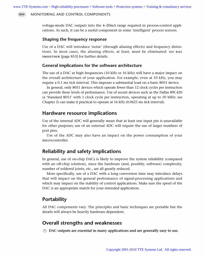
voltage-mode DAC output) into the 4–20mA range required in process-control appli-cations. As such, it can be a useful component in some ‘intelligent’ process sensors.
Shaping the frequency response
Use of a DAC will introduce ‘noise’ (through aliasing effects) and frequency distor-tions. In most cases, the aliasing effects, at least, must be eliminated: see D A C
S M O O T H E R [page 853] for further details.
General implications for the software architecture
The use of a DAC at high frequencies (10 kHz or 16 kHz) will have a major impact onthe overall architecture of your application. For example, even at 10 kHz, you mayrequire a 0.1 ms tick interval. This imposes a substantial load on a basic 8051 device.
In general, only 8051 devices which operate fewer than 12 clock cycles per instructioncan provide these levels of performance. Use of recent devices such as the Dallas 89C420(a ‘Standard 8051’ with 1 clock cycle per instruction, operating at up to 50 MHz: seeChapter 3) can make it practical to operate at 16 kHz (0.0625 ms tick interval).
Hardware resource implicationsUse of the internal ADC will generally mean that at least one input pin is unavailablefor other purposes; use of an external ADC will require the use of larger numbers ofport pins.
Use of the ADC may also have an impact on the power consumption of yourmicrocontroller.
Reliability and safety implicationsIn general, use of on-chip DACs is likely to improve the system reliability (comparedwith an off-chip solution), since the hardware (and, possibly, software) complexity,number of soldered joints, etc., are all greatly reduced.
More specifically, use of a DAC with a long conversion time may introduce delaysthat will impact on the general performance of signal-processing applications andwhich may impact on the stability of control applications. Make sure the speed of theDAC is an appropriate match for your intended application.
PortabilityAll DAC components vary. The principles and basic techniques are portable but thedetails will always be heavily hardware dependent.
Overall strengths and weaknessesDAC outputs are essential in many applications and are generally easy to use.
MONITORING AND CONTROL COMPONENTS844
www.TTE-Systems.com = High-reliability processors + Software tools + Protection systems + Training & consultancy services
Copyright 2001-2010 TTE Systems Ltd. All rights reserved.
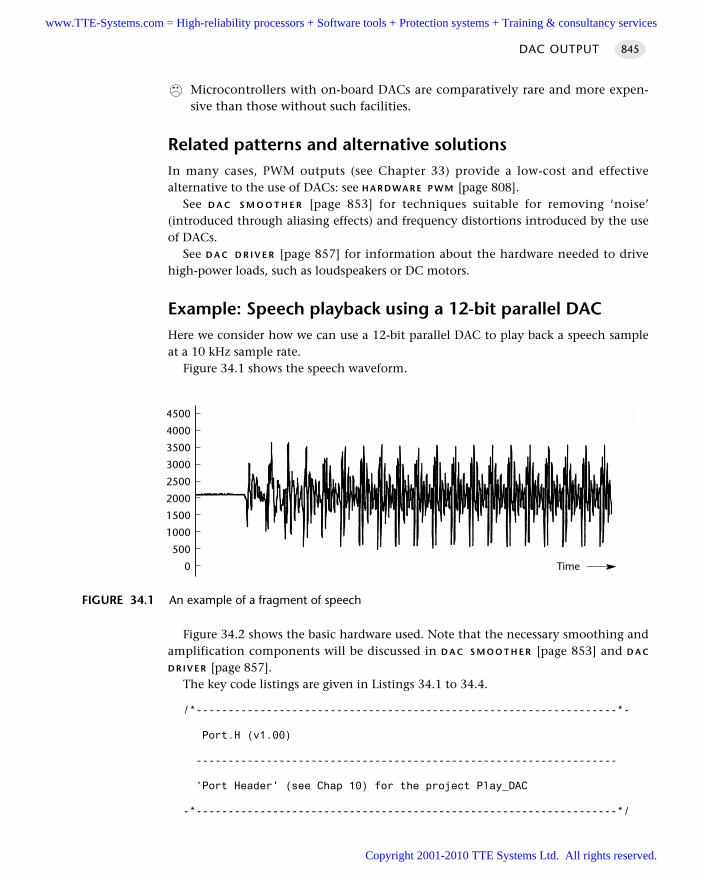
Microcontrollers with on-board DACs are comparatively rare and more expen-sive than those without such facilities.
Related patterns and alternative solutionsIn many cases, PWM outputs (see Chapter 33) provide a low-cost and effectivealternative to the use of DACs: see H A R D WA R E P W M [page 808].
See D A C S M O O T H E R [page 853] for techniques suitable for removing ‘noise’(introduced through aliasing effects) and frequency distortions introduced by the useof DACs.
See D A C D R I V E R [page 857] for information about the hardware needed to drivehigh-power loads, such as loudspeakers or DC motors.
Example: Speech playback using a 12-bit parallel DACHere we consider how we can use a 12-bit parallel DAC to play back a speech sampleat a 10 kHz sample rate.
Figure 34.1 shows the speech waveform.
Figure 34.2 shows the basic hardware used. Note that the necessary smoothing andamplification components will be discussed in D A C S M O O T H E R [page 853] and D A C
D R I V E R [page 857].The key code listings are given in Listings 34.1 to 34.4.
/*------------------------------------------------------------------*-
Port.H (v1.00)
------------------------------------------------------------------
'Port Header' (see Chap 10) for the project Play_DAC
-*------------------------------------------------------------------*/
DAC OUTPUT 845
FIGURE 34.1 An example of a fragment of speech
0
500
1000
1500
2000
2500
3000
3500
4000
4500
Time
www.TTE-Systems.com = High-reliability processors + Software tools + Protection systems + Training & consultancy services
Copyright 2001-2010 TTE Systems Ltd. All rights reserved.
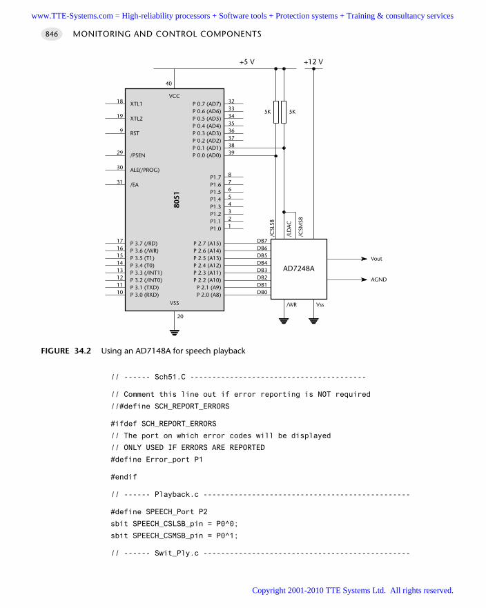
// ------ Sch51.C ----------------------------------------
// Comment this line out if error reporting is NOT required
//#define SCH_REPORT_ERRORS
#ifdef SCH_REPORT_ERRORS
// The port on which error codes will be displayed
// ONLY USED IF ERRORS ARE REPORTED
#define Error_port P1
#endif
// ------ Playback.c -----------------------------------------------
#define SPEECH_Port P2
sbit SPEECH_CSLSB_pin = P0^0;
sbit SPEECH_CSMSB_pin = P0^1;
// ------ Swit_Ply.c -----------------------------------------------
MONITORING AND CONTROL COMPONENTS846
FIGURE 34.2 Using an AD7148A for speech playback
VCC
8051
VSS
3233343536373839
87654321
18
19
9
29
30
31
1716151413121110
20
40
DB7DB6DB5DB4DB3DB2DB1DB0
/WR Vss
AD7248AAGND
Vout
/CSM
S8
/LD
AC
/CSL
SB
5K 5K
+5 V +12 V
XTL1
XTL2
RST
/PSEN
ALE(/PROG)
/EA
P 3.7 (/RD)P 3.6 (/WR)P 3.5 (T1)P 3.4 (T0)P 3.3 (/INT1)P 3.2 (/INT0)P 3.1 (TXD)P 3.0 (RXD)
P 0.7 (AD7)P 0.6 (AD6)P 0.5 (AD5)P 0.4 (AD4)P 0.3 (AD3)P 0.2 (AD2)P 0.1 (AD1)P 0.0 (AD0)
P1.7P1.6P1.5P1.4P1.3P1.2P1.1P1.0
P 2.7 (A15)P 2.6 (A14)P 2.5 (A13)P 2.4 (A12)P 2.3 (A11)P 2.2 (A10)
P 2.1 (A9)P 2.0 (A8)
www.TTE-Systems.com = High-reliability processors + Software tools + Protection systems + Training & consultancy services
Copyright 2001-2010 TTE Systems Ltd. All rights reserved.
// Connect single push-button switch on this pin (to gnd)
// - debounced in software
sbit Sw_pin = P3^3; // The switch pin
/*------------------------------------------------------------------*-
---- END OF FILE ------------------------------------------------
-*------------------------------------------------------------------*/
Listing 34.1 Part of an example illustrating the control of an external 12-bit(parallel) DAC
/*------------------------------------------------------------------*-
Main.c (v1.00)
------------------------------------------------------------------
Speech playback example, uses hybrid scheduler.
Required linker options (see Chapter 13 for details):
OVERLAY
(main ~ (SWITCH_Update),
SWITCH_Update ~ (SPEECH_PLAYBACK_Update),
hSCH_dispatch_tasks ! (SWITCH_Update, SPEECH_PLAYBACK_Update))
-*------------------------------------------------------------------*/
#include "Main.h"
#include "2_01_12h.h"
#include "Swit_Ply.h"
#include "Playback.h"
/* ............................................................... */
/* ............................................................... */
void main(void)
// Set up the scheduler
hSCH_Init_T2();
// Set up the switch pin
SWITCH_Init();
// Add the 'switch' task (check every 200 ms)
// THIS IS A PRE-EMPTIVE TASK
hSCH_Add_Task(SWITCH_Update, 0, 200, 0);
DAC OUTPUT 847
www.TTE-Systems.com = High-reliability processors + Software tools + Protection systems + Training & consultancy services
Copyright 2001-2010 TTE Systems Ltd. All rights reserved.
// NOTE:
// 'Playback' task is added by the SWITCH_Update task
// (as requested by user)
// 'Playback' is CO-OPERATIVE
// *** NOTE REQUIRED LINKER OPTIONS (see above) ***
// Start the scheduler
hSCH_Start();
while(1)
hSCH_Dispatch_Tasks();
/*------------------------------------------------------------------*-
---- END OF FILE ------------------------------------------------
-*------------------------------------------------------------------*/
Listing 34.2 Part of an example illustrating the control of an external 12-bit(parallel) DAC
/*------------------------------------------------------------------*-
Playback.C (v1.00)
------------------------------------------------------------------
Library of functions to allow playback of stored speech sample
from on-chip ROM.
Assumes presence of AD7248A DAC: see text for hardware connections.
Play back continuously while switch is depressed.
Data are replayed at 10 kHz, 12-bit resolution.
-*------------------------------------------------------------------*/
#include "Main.h"
#include "Port.h"
#include "Playback.h"
// ------ Public constants -----------------------------------------
// The speech data we are going to play
extern const tWord code BA_12_BIT_10KHZ_G[3500];
// ------ Public variable declarations -----------------------------
MONITORING AND CONTROL COMPONENTS848
www.TTE-Systems.com = High-reliability processors + Software tools + Protection systems + Training & consultancy services
Copyright 2001-2010 TTE Systems Ltd. All rights reserved.
extern bit Sw_pressed_G;
// ------ Public variable definitions ------------------------------
bit SPEECH_PLAYBACK_Playing_G = 0;
// ------ Private variables ----------------------------------------
static bit LED_state_G;
// ------ Private constants ----------------------------------------
#define T_100micros (65536 - (tWord)((OSC_FREQ / 13000)/(OSC_PER_INST)))
#define T_100micros_H (T_100micros / 256)
#define T_100micros_L (T_100micros % 256)
/*------------------------------------------------------------------*-
SPEECH_PLAYBACK_Update()
The main update function for the playback software.
This will usually be scheduled, as required, as a one-shot
(co-operative) task.
Task duration is approximately 350 milliseconds.
User can abort at any time by releasing the switch.
-*------------------------------------------------------------------*/
void SPEECH_PLAYBACK_Update(void)
int Sample;
SPEECH_PLAYBACK_Playing_G = 0;
// Configure Timer 0 as a 16-bit timer
TMOD &= 0xF0; // Clear all T0 bits (T1 left unchanged)
TMOD |= 0x01; // Set required T0 bits (T1 left unchanged)
ET0 = 0; // No interrupts
// Playback at ~ 10 kHz
for (Sample = 0; Sample < 3500; Sample++)
// Avoid multiple calls to this function
SPEECH_PLAYBACK_Playing_G = 1;
// Play a sample
SPEECH_PLAYBACK_Play_Sample(BA_12_BIT_10KHZ_G[Sample]);
// Delay ~0.1 ms (to give 10 kHz sample rate)
TR0 = 0;
TH0 = T_100micros_H;
DAC OUTPUT 849
www.TTE-Systems.com = High-reliability processors + Software tools + Protection systems + Training & consultancy services
Copyright 2001-2010 TTE Systems Ltd. All rights reserved.
TL0 = T_100micros_L;
TF0 = 0; // Clear flag
TR0 = 1; // Start timer
while (!TF0);
TR0 = 0;
if (!Sw_pressed_G)
break; // Abort loop if user releases switch
// Set flag to 0 as we leave this function
SPEECH_PLAYBACK_Playing_G = 0;
/*------------------------------------------------------------------*-
SPEECH_PLAYBACK_Play_Sample()
Send 12-bit data sample to AD7248A ADC.
-*------------------------------------------------------------------*/
void SPEECH_PLAYBACK_Play_Sample(const tWord SAMPLE)
// Samples are 12-bits, in 16-bit (tWord) value
// Send lower 8 bits first
tByte Data_8bit = (tByte) (SAMPLE & 0x00FF);
SPEECH_Port = Data_8bit;
SPEECH_CSLSB_pin = 0;
SPEECH_CSMSB_pin = 1;
// Now the upper 4 bits
Data_8bit = (tByte) ((SAMPLE >> 8) & (0x0F));
SPEECH_Port = Data_8bit;
SPEECH_CSLSB_pin = 1;
SPEECH_CSMSB_pin = 0;
/*------------------------------------------------------------------*-
---- END OF FILE ------------------------------------------------
-*------------------------------------------------------------------*/
Listing 34.3 Part of an example illustrating the control of an external 12-bit(parallel) DAC
MONITORING AND CONTROL COMPONENTS850
www.TTE-Systems.com = High-reliability processors + Software tools + Protection systems + Training & consultancy services
Copyright 2001-2010 TTE Systems Ltd. All rights reserved.
/*------------------------------------------------------------------*-
SWIT_PLY.C (v1.00)
------------------------------------------------------------------
Simple switch interface code, with software debounce.
Controls DAC speech playback.
-*------------------------------------------------------------------*/
#include "Main.h"
#include "Port.h"
#include "Swit_Ply.h"
#include "Playback.h"
#include "2_01_12h.h"
// ------ Public variable definitions ------------------------------
bit Sw_pressed_G = 0; // The current switch status
// ------ Public variable declarations -----------------------------
extern bit SPEECH_PLAYBACK_Playing_G; // Current playback status
// ------ Private constants ----------------------------------------
// Allows NO or NC switch to be used (or other wiring variations)
#define SW_PRESSED (0)
// SW_THRES must be > 1 for correct debounce behaviour
#define SW_THRES (3)
/*------------------------------------------------------------------*-
SWITCH_Init()
Initialization function for the switch library.
-*------------------------------------------------------------------*/
void SWITCH_Init(void)
Sw_pin = 1; // Use this pin for input
/*------------------------------------------------------------------*-
SWITCH_Update()
This is the main switch function.
It should be scheduled every 50 - 500 ms.
DAC OUTPUT 851
www.TTE-Systems.com = High-reliability processors + Software tools + Protection systems + Training & consultancy services
Copyright 2001-2010 TTE Systems Ltd. All rights reserved.
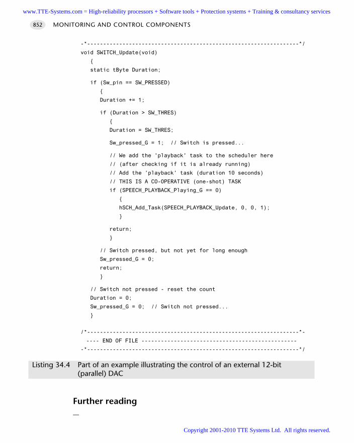
-*------------------------------------------------------------------*/
void SWITCH_Update(void)
static tByte Duration;
if (Sw_pin == SW_PRESSED)
Duration += 1;
if (Duration > SW_THRES)
Duration = SW_THRES;
Sw_pressed_G = 1; // Switch is pressed...
// We add the 'playback' task to the scheduler here
// (after checking if it is already running)
// Add the 'playback' task (duration 10 seconds)
// THIS IS A CO-OPERATIVE (one-shot) TASK
if (SPEECH_PLAYBACK_Playing_G == 0)
hSCH_Add_Task(SPEECH_PLAYBACK_Update, 0, 0, 1);
return;
// Switch pressed, but not yet for long enough
Sw_pressed_G = 0;
return;
// Switch not pressed - reset the count
Duration = 0;
Sw_pressed_G = 0; // Switch not pressed...
/*------------------------------------------------------------------*-
---- END OF FILE ------------------------------------------------
-*------------------------------------------------------------------*/
Listing 34.4 Part of an example illustrating the control of an external 12-bit(parallel) DAC
Further reading—
MONITORING AND CONTROL COMPONENTS852
www.TTE-Systems.com = High-reliability processors + Software tools + Protection systems + Training & consultancy services
Copyright 2001-2010 TTE Systems Ltd. All rights reserved.
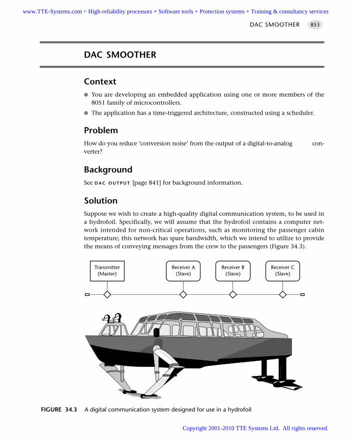
DAC SMOOTHER
Context You are developing an embedded application using one or more members of the
8051 family of microcontrollers.
The application has a time-triggered architecture, constructed using a scheduler.
ProblemHow do you reduce ‘conversion noise’ from the output of a digital-to-analog con-verter?
BackgroundSee D A C O U T P U T [page 841] for background information.
SolutionSuppose we wish to create a high-quality digital communication system, to be used ina hydrofoil. Specifically, we will assume that the hydrofoil contains a computer net-work intended for non-critical operations, such as monitoring the passenger cabintemperature; this network has spare bandwidth, which we intend to utilize to providethe means of conveying messages from the crew to the passengers (Figure 34.3).
DAC SMOOTHER 853
FIGURE 34.3 A digital communication system designed for use in a hydrofoil
Transmitter(Master)
Receiver A(Slave)
Receiver B(Slave)
Receiver C(Slave)
www.TTE-Systems.com = High-reliability processors + Software tools + Protection systems + Training & consultancy services
Copyright 2001-2010 TTE Systems Ltd. All rights reserved.
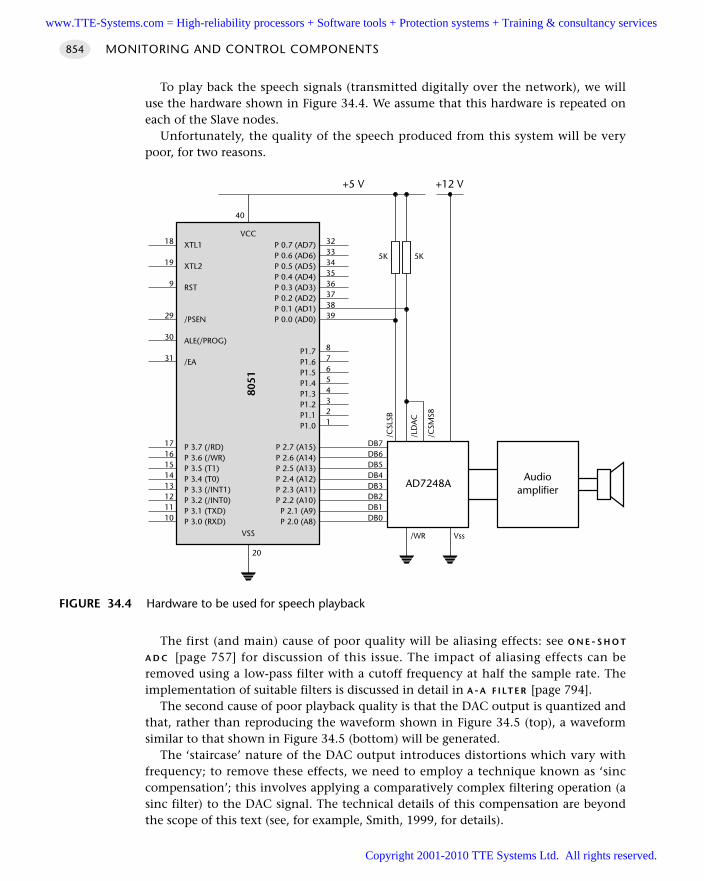
To play back the speech signals (transmitted digitally over the network), we willuse the hardware shown in Figure 34.4. We assume that this hardware is repeated oneach of the Slave nodes.
Unfortunately, the quality of the speech produced from this system will be verypoor, for two reasons.
The first (and main) cause of poor quality will be aliasing effects: see O N E - S H O T
A D C [page 757] for discussion of this issue. The impact of aliasing effects can beremoved using a low-pass filter with a cutoff frequency at half the sample rate. Theimplementation of suitable filters is discussed in detail in A-A F I LT E R [page 794].
The second cause of poor playback quality is that the DAC output is quantized andthat, rather than reproducing the waveform shown in Figure 34.5 (top), a waveformsimilar to that shown in Figure 34.5 (bottom) will be generated.
The ‘staircase’ nature of the DAC output introduces distortions which vary withfrequency; to remove these effects, we need to employ a technique known as ‘sinccompensation’; this involves applying a comparatively complex filtering operation (asinc filter) to the DAC signal. The technical details of this compensation are beyondthe scope of this text (see, for example, Smith, 1999, for details).
MONITORING AND CONTROL COMPONENTS854
FIGURE 34.4 Hardware to be used for speech playback
Audioamplifier
VCC
8051
VSS
3233343536373839
87654321
18
19
9
29
30
31
1716151413121110
20
40
DB7DB6DB5DB4DB3DB2DB1DB0
/WR Vss
AD7248A
/CSM
S8
/LD
AC
/CSL
SB
5K 5K
+5 V +12 V
XTL1
XTL2
RST
/PSEN
ALE(/PROG)
/EA
P 3.7 (/RD)P 3.6 (/WR)P 3.5 (T1)P 3.4 (T0)P 3.3 (/INT1)P 3.2 (/INT0)P 3.1 (TXD)P 3.0 (RXD)
P 0.7 (AD7)P 0.6 (AD6)P 0.5 (AD5)P 0.4 (AD4)P 0.3 (AD3)P 0.2 (AD2)P 0.1 (AD1)P 0.0 (AD0)
P1.7P1.6P1.5P1.4P1.3P1.2P1.1P1.0
P 2.7 (A15)P 2.6 (A14)P 2.5 (A13)P 2.4 (A12)P 2.3 (A11)P 2.2 (A10)
P 2.1 (A9)P 2.0 (A8)
www.TTE-Systems.com = High-reliability processors + Software tools + Protection systems + Training & consultancy services
Copyright 2001-2010 TTE Systems Ltd. All rights reserved.
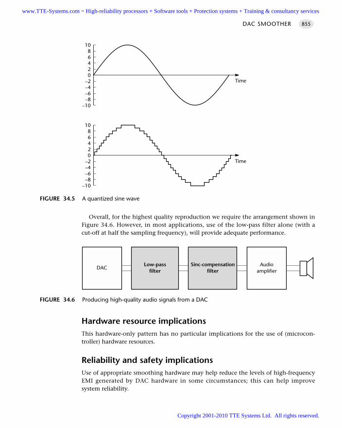
Overall, for the highest quality reproduction we require the arrangement shown inFigure 34.6. However, in most applications, use of the low-pass filter alone (with acut-off at half the sampling frequency), will provide adequate performance.
Hardware resource implicationsThis hardware-only pattern has no particular implications for the use of (microcon-troller) hardware resources.
Reliability and safety implicationsUse of appropriate smoothing hardware may help reduce the levels of high-frequencyEMI generated by DAC hardware in some circumstances; this can help improvesystem reliability.
DAC SMOOTHER 855
FIGURE 34.5 A quantized sine wave
02468
10
–2–4–6–8
–10
02468
10
–2–4–6–8
–10
Time
Time
FIGURE 34.6 Producing high-quality audio signals from a DAC
Audioamplifier
Sinc-compensationfilter
Low-passfilter
DAC
www.TTE-Systems.com = High-reliability processors + Software tools + Protection systems + Training & consultancy services
Copyright 2001-2010 TTE Systems Ltd. All rights reserved.
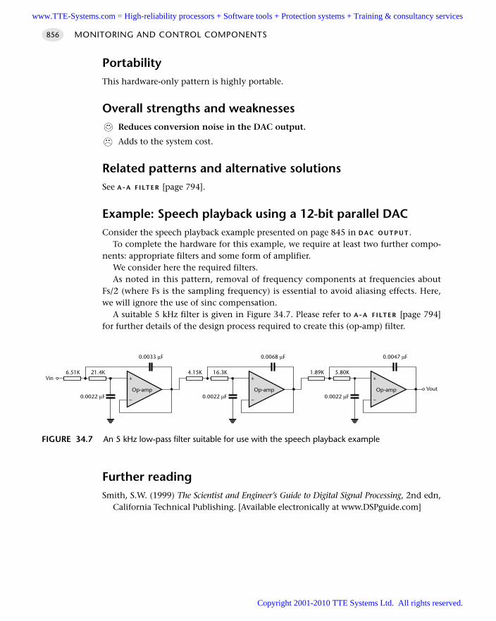
PortabilityThis hardware-only pattern is highly portable.
Overall strengths and weaknessesReduces conversion noise in the DAC output.
Adds to the system cost.
Related patterns and alternative solutionsSee A-A F I LT E R [page 794].
Example: Speech playback using a 12-bit parallel DACConsider the speech playback example presented on page 845 in D A C O U T P U T .
To complete the hardware for this example, we require at least two further compo-nents: appropriate filters and some form of amplifier.
We consider here the required filters.As noted in this pattern, removal of frequency components at frequencies about
Fs/2 (where Fs is the sampling frequency) is essential to avoid aliasing effects. Here,we will ignore the use of sinc compensation.
A suitable 5 kHz filter is given in Figure 34.7. Please refer to A-A F I LT E R [page 794]for further details of the design process required to create this (op-amp) filter.
Further readingSmith, S.W. (1999) The Scientist and Engineer’s Guide to Digital Signal Processing, 2nd edn,
California Technical Publishing. [Available electronically at www.DSPguide.com]
MONITORING AND CONTROL COMPONENTS856
FIGURE 34.7 An 5 kHz low-pass filter suitable for use with the speech playback example
+
–
Op-amp
21.4K
0.0022 µF
6.51K
0.0033 µF
Vin +
–
Op-amp
16.3K
0.0022 µF
4.15K
0.0068 µF
+
–
Op-amp
5.80K
0.0022 µF
1.89K
0.0047 µF
Vout
www.TTE-Systems.com = High-reliability processors + Software tools + Protection systems + Training & consultancy services
Copyright 2001-2010 TTE Systems Ltd. All rights reserved.
DAC DRIVER
Context You are developing an embedded application using one or more members of the
8051 family of microcontrollers.
The application has a time-triggered architecture, constructed using a scheduler.
ProblemHow do you convert the output from a voltage-mode ADC into a form suitable fordriving high-power loads?
BackgroundSee D A C O U T P U T [page 841] for background details on DACs.
SolutionVoltage-mode DACs are low-power devices; for example, the Maxim Max541 is a16-bit DAC with an ability to handle a maximum (analog) current of the 50 mA.23
Clearly if we wish to use such a device to drive, say, a DC motor, we require someform of buffer circuit.
As we saw in Chapter 7, when we considered the switching of DC loads, there aretwo main alternatives when driving high-power loads: use a solution based on dis-crete components (which generally means BJTs) or an IC-based solution (whichgenerally means a power op-amp).
We illustrate these solutions in the examples that follow.
Hardware resource implicationsUse of this pattern has no implications for the hardware resources (e.g. CPU time ormemory) on the microcontroller itself.
Reliability and safety implicationsThere are no specific reliability or safety implications.
PortabilityThis hardware-only pattern can be used with any microcontroller.
DAC DRIVER 857
23. This figure is higher than many common DAC chips
www.TTE-Systems.com = High-reliability processors + Software tools + Protection systems + Training & consultancy services
Copyright 2001-2010 TTE Systems Ltd. All rights reserved.
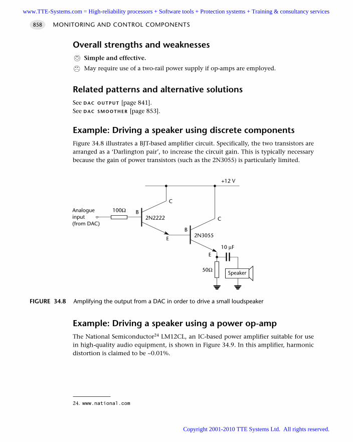
Overall strengths and weaknessesSimple and effective.
May require use of a two-rail power supply if op-amps are employed.
Related patterns and alternative solutionsSee D A C O U T P U T [page 841].See D A C S M O O T H E R [page 853].
Example: Driving a speaker using discrete componentsFigure 34.8 illustrates a BJT-based amplifier circuit. Specifically, the two transistors arearranged as a ‘Darlington pair’, to increase the circuit gain. This is typically necessarybecause the gain of power transistors (such as the 2N3055) is particularly limited.
Example: Driving a speaker using a power op-ampThe National Semiconductor24 LM12CL, an IC-based power amplifier suitable for usein high-quality audio equipment, is shown in Figure 34.9. In this amplifier, harmonicdistortion is claimed to be ~0.01%.
MONITORING AND CONTROL COMPONENTS858
FIGURE 34.8 Amplifying the output from a DAC in order to drive a small loudspeaker
2N2222
C
E
B
2N3055
C
E
B
50Ω
+12 V
Analogueinput(from DAC)
10 µF
Speaker
100Ω
24. www.national.com
www.TTE-Systems.com = High-reliability processors + Software tools + Protection systems + Training & consultancy services
Copyright 2001-2010 TTE Systems Ltd. All rights reserved.
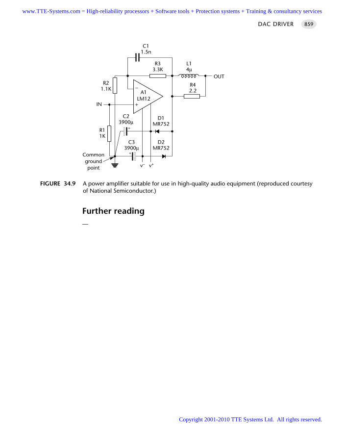
Further reading—
DAC DRIVER 859
FIGURE 34.9 A power amplifier suitable for use in high-quality audio equipment (reproduced courtesyof National Semiconductor.)
A1LM12
–
+
C11.5n
R33.3K
L14µ
R42.2
OUT
D1MR752
D2MR752
C33900µ
C23900µ
R11K
IN
R21.1K
Commongroundpoint
+
+
v– v+
www.TTE-Systems.com = High-reliability processors + Software tools + Protection systems + Training & consultancy services
Copyright 2001-2010 TTE Systems Ltd. All rights reserved.
Taking control
Introduction
The focus of the chapter is on proportional-integral-differential (PID) control. PID isboth simple and effective: as a consequence it is the most widely used control algo-rithm. The focus here will be on techniques for designing and implementing PIDcontrollers for use in embedded applications.
chapter 35www.TTE-Systems.com = High-reliability processors + Software tools + Protection systems + Training & consultancy services
Copyright 2001-2010 TTE Systems Ltd. All rights reserved.
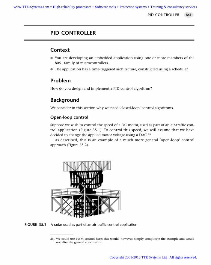
PID CONTROLLER
Context You are developing an embedded application using one or more members of the
8051 family of microcontrollers.
The application has a time-triggered architecture, constructed using a scheduler.
ProblemHow do you design and implement a PID control algorithm?
BackgroundWe consider in this section why we need ‘closed-loop’ control algorithms.
Open-loop control
Suppose we wish to control the speed of a DC motor, used as part of an air-traffic con-trol application (Figure 35.1). To control this speed, we will assume that we havedecided to change the applied motor voltage using a DAC.25
As described, this is an example of a much more general ‘open-loop’ controlapproach (Figure 35.2).
PID CONTROLLER 861
FIGURE 35.1 A radar used as part of an air-traffic control application
25. We could use PWM control here: this would, however, simply complicate the example and wouldnot alter the general conculsions
www.TTE-Systems.com = High-reliability processors + Software tools + Protection systems + Training & consultancy services
Copyright 2001-2010 TTE Systems Ltd. All rights reserved.
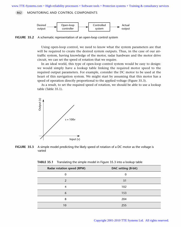
Using open-loop control, we need to know what the system parameters are thatwill be required to create the desired system outputs. Thus, in the case of our air-traffic system, having knowledge of the motor, radar hardware and the motor drivecircuit, we can set the speed of rotation that we require.
In an ideal world, this type of open-loop control system would be easy to design:we would simply have a lookup table linking the required motor speed to therequired output parameters. For example, consider the DC motor to be used at theheart of this navigation system. We might start by assuming that this motor has aspeed of operation directly proportional to the applied voltage (Figure 35.3).
As a result, to set the required speed of rotation, we should be able to use a lookuptable (Table 35.1).
MONITORING AND CONTROL COMPONENTS862
FIGURE 35.2 A schematic representation of an open-loop control system
Open-loopcontroller
Controlledsystem
Actualoutput
Desiredoutput
FIGURE 35.3 A simple model predicting the likely speed of rotation of a DC motor as the voltage isvaried
Input (v)
Out
put
(s)
s = 100v
TABLE 35.1 Translating the simple model in Figure 35.3 into a lookup table
Radar rotation speed (RPM) DAC setting (8-bit)
0 0
2 51
4 102
6 153
8 204
10 255
www.TTE-Systems.com = High-reliability processors + Software tools + Protection systems + Training & consultancy services
Copyright 2001-2010 TTE Systems Ltd. All rights reserved.
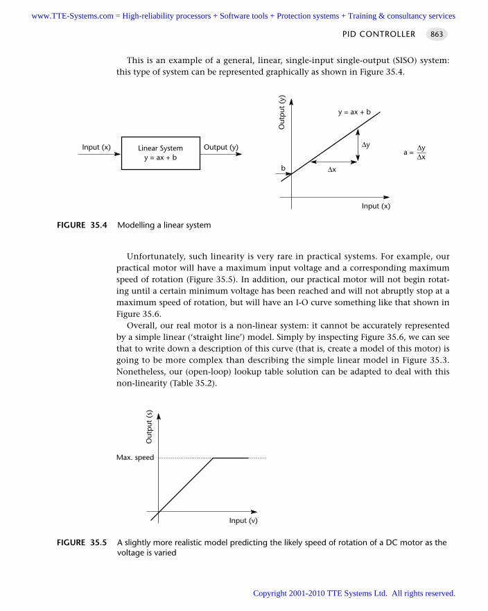
This is an example of a general, linear, single-input single-output (SISO) system:this type of system can be represented graphically as shown in Figure 35.4.
Unfortunately, such linearity is very rare in practical systems. For example, ourpractical motor will have a maximum input voltage and a corresponding maximumspeed of rotation (Figure 35.5). In addition, our practical motor will not begin rotat-ing until a certain minimum voltage has been reached and will not abruptly stop at amaximum speed of rotation, but will have an I-O curve something like that shown inFigure 35.6.
Overall, our real motor is a non-linear system: it cannot be accurately representedby a simple linear (‘straight line’) model. Simply by inspecting Figure 35.6, we can seethat to write down a description of this curve (that is, create a model of this motor) isgoing to be more complex than describing the simple linear model in Figure 35.3.Nonetheless, our (open-loop) lookup table solution can be adapted to deal with thisnon-linearity (Table 35.2).
PID CONTROLLER 863
FIGURE 35.4 Modelling a linear system
Input (x)
Out
put
(y)
y = ax + b
∆y
∆xb
Output (y)Input (x) Linear Systemy = ax + b
a =∆y∆x
FIGURE 35.5 A slightly more realistic model predicting the likely speed of rotation of a DC motor as thevoltage is varied
Input (v)
Out
put
(s)
Max. speed
www.TTE-Systems.com = High-reliability processors + Software tools + Protection systems + Training & consultancy services
Copyright 2001-2010 TTE Systems Ltd. All rights reserved.
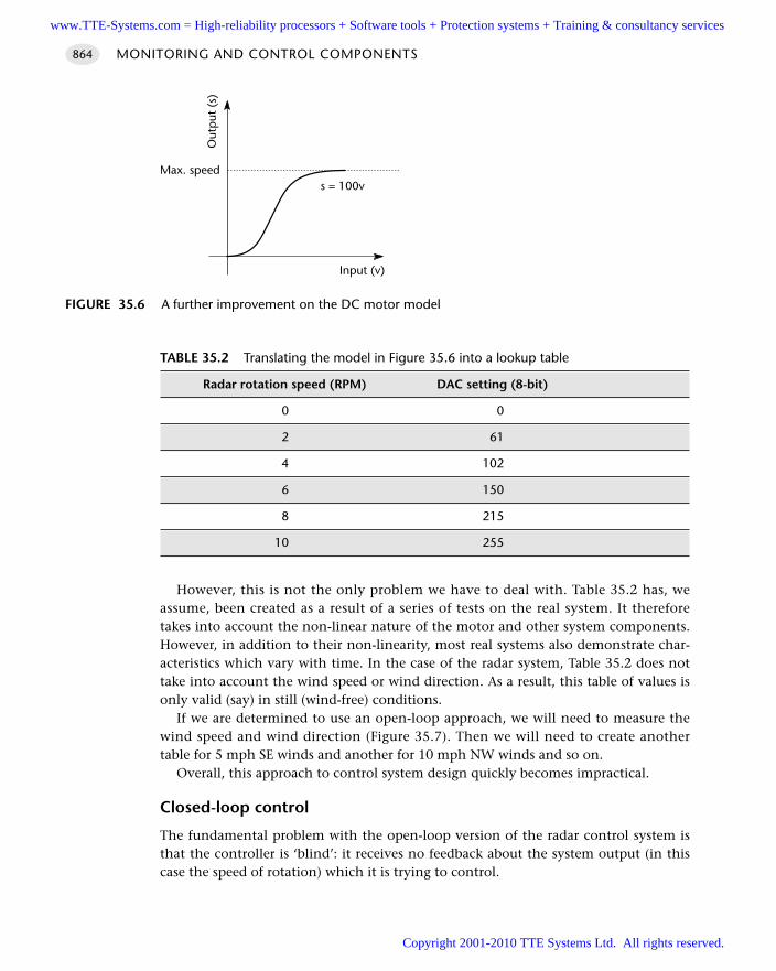
However, this is not the only problem we have to deal with. Table 35.2 has, weassume, been created as a result of a series of tests on the real system. It thereforetakes into account the non-linear nature of the motor and other system components.However, in addition to their non-linearity, most real systems also demonstrate char-acteristics which vary with time. In the case of the radar system, Table 35.2 does nottake into account the wind speed or wind direction. As a result, this table of values isonly valid (say) in still (wind-free) conditions.
If we are determined to use an open-loop approach, we will need to measure thewind speed and wind direction (Figure 35.7). Then we will need to create anothertable for 5 mph SE winds and another for 10 mph NW winds and so on.
Overall, this approach to control system design quickly becomes impractical.
Closed-loop control
The fundamental problem with the open-loop version of the radar control system isthat the controller is ‘blind’: it receives no feedback about the system output (in thiscase the speed of rotation) which it is trying to control.
MONITORING AND CONTROL COMPONENTS864
FIGURE 35.6 A further improvement on the DC motor model
Input (v)
Out
put
(s)
s = 100vMax. speed
TABLE 35.2 Translating the model in Figure 35.6 into a lookup table
Radar rotation speed (RPM) DAC setting (8-bit)
0 0
2 61
4 102
6 150
8 215
10 255
www.TTE-Systems.com = High-reliability processors + Software tools + Protection systems + Training & consultancy services
Copyright 2001-2010 TTE Systems Ltd. All rights reserved.
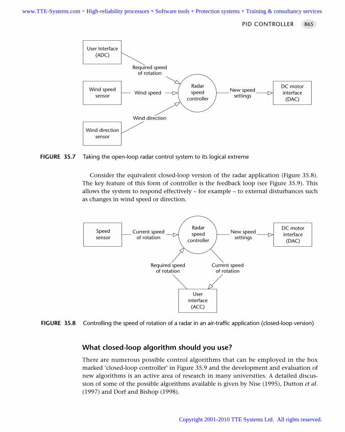
Consider the equivalent closed-loop version of the radar application (Figure 35.8).The key feature of this form of controller is the feedback loop (see Figure 35.9). Thisallows the system to respond effectively – for example – to external disturbances suchas changes in wind speed or direction.
What closed-loop algorithm should you use?
There are numerous possible control algorithms that can be employed in the boxmarked ‘closed-loop controller’ in Figure 35.9 and the development and evaluation ofnew algorithms is an active area of research in many universities. A detailed discus-sion of some of the possible algorithms available is given by Nise (1995), Dutton et al.(1997) and Dorf and Bishop (1998).
PID CONTROLLER 865
FIGURE 35.7 Taking the open-loop radar control system to its logical extreme
Radarspeed
controller
Wind speedsensor Wind speed
User Interface(ADC)
Wind directionsensor
Required speedof rotation
Wind direction
DC motorinterface(DAC)
New speedsettings
FIGURE 35.8 Controlling the speed of rotation of a radar in an air-traffic application (closed-loop version)
Radarspeed
controller
Speedsensor
Current speedof rotation
Userinterface(ACC)
DC motorinterface(DAC)
New speedsettings
Required speedof rotation
Current speedof rotation
www.TTE-Systems.com = High-reliability processors + Software tools + Protection systems + Training & consultancy services
Copyright 2001-2010 TTE Systems Ltd. All rights reserved.
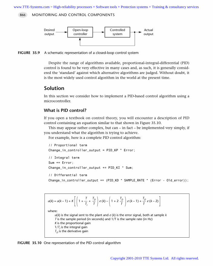
Despite the range of algorithms available, proportional-integral-differential (PID)control is found to be very effective in many cases and, as such, it is generally consid-ered the ‘standard’ against which alternative algorithms are judged. Without doubt, itis the most widely used control algorithm in the world at the present time.
SolutionIn this section we consider how to implement a PID-based control algorithm using amicrocontroller.
What is PID control?
If you open a textbook on control theory, you will encounter a description of PIDcontrol containing an equation similar to that shown in Figure 35.10.
This may appear rather complex, but can – in fact – be implemented very simply, ifyou understand what the algorithm is trying to achieve.
For example, here is a complete PID control algorithm:
// Proportional term
Change_in_controller_output = PID_KP * Error;
// Integral term
Sum += Error;
Change_in_controller_output += PID_KI * Sum;
// Differential term
Change_in_controller_output += (PID_KD * SAMPLE_RATE * (Error - Old_error));
MONITORING AND CONTROL COMPONENTS866
FIGURE 35.9 A schematic representation of a closed-loop control system
Open-loopcontroller
Controlledsystem
Actualoutput
Desiredoutput
FIGURE 35.10 One representation of the PID control algorithm
T TD TD TDu(k) = u(k – 1) + K [ ( 1 + + ) e (k) – ( 1 + 2 ) e (k – 1) + e (k – 2) ]TI T T T
where:u(k) is the signal sent to the plant and e (k) is the error signal, both at sample kT is the sample period (in seconds) and 1/T is the sample rate (in Hz)K is the proportional gain1/TI is the integral gainTD is the derivative gain
www.TTE-Systems.com = High-reliability processors + Software tools + Protection systems + Training & consultancy services
Copyright 2001-2010 TTE Systems Ltd. All rights reserved.
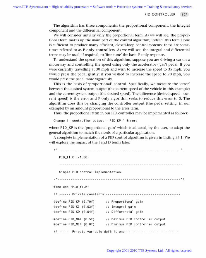
The algorithm has three components: the proportional component, the integralcomponent and the differential component.
We will consider initially only the proportional term. As we will see, the propor-tional term makes up the main part of the control algorithm; indeed, this term aloneis sufficient to produce many efficient, closed-loop control systems: these are some-times referred to as P-only controllers. As we will see, the integral and differentialterms may be used, if required, to ‘fine-tune’ the basic P-only response.
To understand the operation of this algorithm, suppose you are driving a car on amotorway and controlling the speed using only the accelerator (‘gas’) pedal. If youwere currently travelling at 30 mph and wish to increase the speed to 35 mph, youwould press the pedal gently; if you wished to increase the speed to 70 mph, youwould press the pedal more vigorously.
This is the basis of ‘proportional’ control. Specifically, we measure the ‘error’between the desired system output (the current speed of the vehicle in this example)and the current system output (the desired speed). The difference (desired speed – cur-rent speed) is the error and P-only algorithm seeks to reduce this error to 0. Thealgorithm does this by changing the controller output (the pedal setting, in ourexample) by an amount proportional to the error term.
Thus, the proportional term in our PID controller may be implemented as follows:
Change_in_controller_output = PID_KP * Error;
where PID_KP is the ‘proportional gain’ which is adjusted, by the user, to adapt thegeneral algorithm to match the needs of a particular application.
A complete implementation of a PID control algorithm is given in Listing 35.1. Wewill explore the impact of the I and D terms later.
/*------------------------------------------------------------------*-
PID_f1.C (v1.00)
------------------------------------------------------------------
Simple PID control implementation.
-*------------------------------------------------------------------*/
#include "PID_f1.h"
// ------ Private constants ----------------------------------------
#define PID_KP (0.70f) // Proportional gain
#define PID_KI (0.03f) // Integral gain
#define PID_KD (0.04f) // Differential gain
#define PID_MAX (0.5f) // Maximum PID controller output
#define PID_MIN (0.0f) // Minimum PID controller output
// ------ Private variable definitions------------------------------
PID CONTROLLER 867
www.TTE-Systems.com = High-reliability processors + Software tools + Protection systems + Training & consultancy services
Copyright 2001-2010 TTE Systems Ltd. All rights reserved.
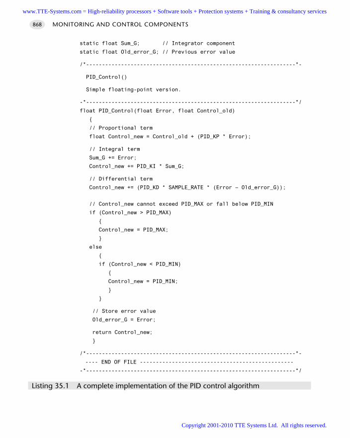
static float Sum_G; // Integrator component
static float Old_error_G; // Previous error value
/*------------------------------------------------------------------*-
PID_Control()
Simple floating-point version.
-*------------------------------------------------------------------*/
float PID_Control(float Error, float Control_old)
// Proportional term
float Control_new = Control_old + (PID_KP * Error);
// Integral term
Sum_G += Error;
Control_new += PID_KI * Sum_G;
// Differential term
Control_new += (PID_KD * SAMPLE_RATE * (Error – Old_error_G));
// Control_new cannot exceed PID_MAX or fall below PID_MIN
if (Control_new > PID_MAX)
Control_new = PID_MAX;
else
if (Control_new < PID_MIN)
Control_new = PID_MIN;
// Store error value
Old_error_G = Error;
return Control_new;
/*------------------------------------------------------------------*-
---- END OF FILE ------------------------------------------------
-*------------------------------------------------------------------*/
Listing 35.1 A complete implementation of the PID control algorithm
MONITORING AND CONTROL COMPONENTS868
www.TTE-Systems.com = High-reliability processors + Software tools + Protection systems + Training & consultancy services
Copyright 2001-2010 TTE Systems Ltd. All rights reserved.
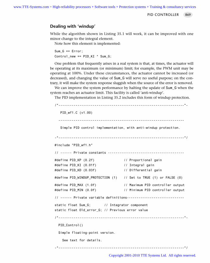
Dealing with ‘windup’
While the algorithm shown in Listing 35.1 will work, it can be improved with oneminor change to the integral element.
Note how this element is implemented:
Sum_G += Error;
Control_new += PID_KI * Sum_G;
One problem that frequently arises in a real system is that, at times, the actuator willbe operating at its maximum (or minimum) limit; for example, the PWM unit may beoperating at 100%. Under these circumstances, the actuator cannot be increased (ordecreased), and changing the value of Sum_G will serve no useful purpose; on the con-trary, it will make the system response sluggish when the source of the error is removed.
We can improve the system performance by halting the update of Sum_G when thesystem reaches an actuator limit. This facility is called ‘anti-windup’.
The PID implementation in Listing 35.2 includes this form of windup protection.
/*------------------------------------------------------------------*-
PID_wf1.C (v1.00)
------------------------------------------------------------------
Simple PID control implementation, with anti-windup protection.
-*------------------------------------------------------------------*/
#include "PID_wf1.h"
// ------ Private constants ----------------------------------------
#define PID_KP (0.2f) // Proportional gain
#define PID_KI (0.01f) // Integral gain
#define PID_KD (0.03f) // Differential gain
#define PID_WINDUP_PROTECTION (1) // Set to TRUE (1) or FALSE (0)
#define PID_MAX (1.0f) // Maximum PID controller output
#define PID_MIN (0.0f) // Minimum PID controller output
// ------ Private variable definitions------------------------------
static float Sum_G; // Integrator component
static float Old_error_G; // Previous error value
/*------------------------------------------------------------------*-
PID_Control()
Simple floating-point version.
See text for details.
-*------------------------------------------------------------------*/
PID CONTROLLER 869
www.TTE-Systems.com = High-reliability processors + Software tools + Protection systems + Training & consultancy services
Copyright 2001-2010 TTE Systems Ltd. All rights reserved.
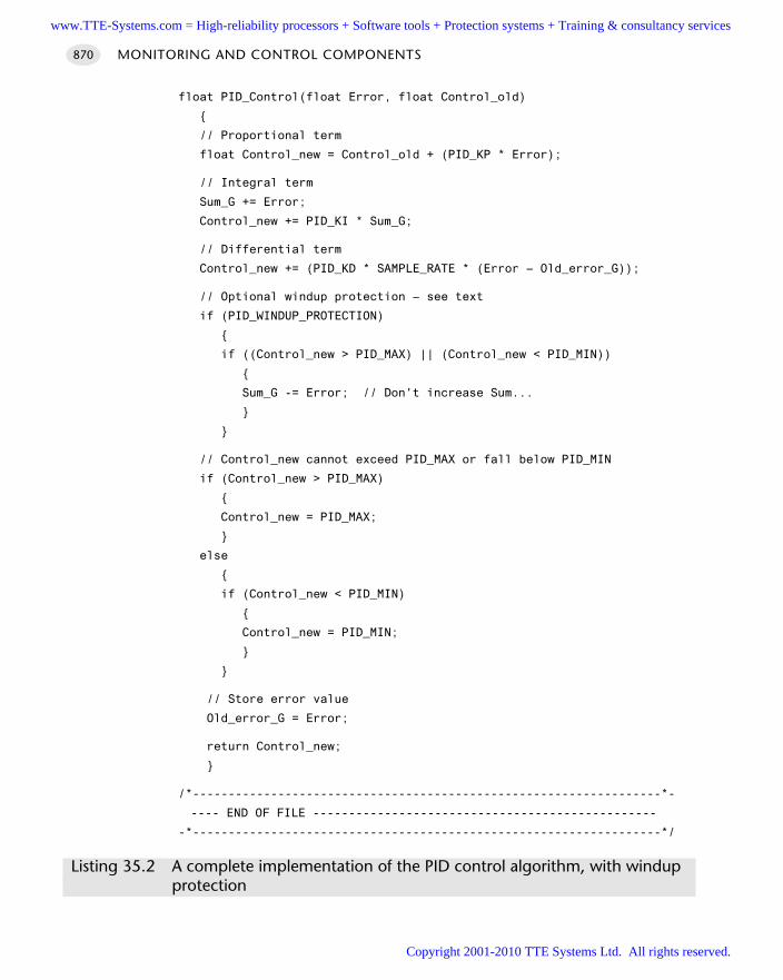
float PID_Control(float Error, float Control_old)
// Proportional term
float Control_new = Control_old + (PID_KP * Error);
// Integral term
Sum_G += Error;
Control_new += PID_KI * Sum_G;
// Differential term
Control_new += (PID_KD * SAMPLE_RATE * (Error – Old_error_G));
// Optional windup protection – see text
if (PID_WINDUP_PROTECTION)
if ((Control_new > PID_MAX) || (Control_new < PID_MIN))
Sum_G -= Error; // Don't increase Sum...
// Control_new cannot exceed PID_MAX or fall below PID_MIN
if (Control_new > PID_MAX)
Control_new = PID_MAX;
else
if (Control_new < PID_MIN)
Control_new = PID_MIN;
// Store error value
Old_error_G = Error;
return Control_new;
/*------------------------------------------------------------------*-
---- END OF FILE ------------------------------------------------
-*------------------------------------------------------------------*/
Listing 35.2 A complete implementation of the PID control algorithm, with windupprotection
MONITORING AND CONTROL COMPONENTS870
www.TTE-Systems.com = High-reliability processors + Software tools + Protection systems + Training & consultancy services
Copyright 2001-2010 TTE Systems Ltd. All rights reserved.
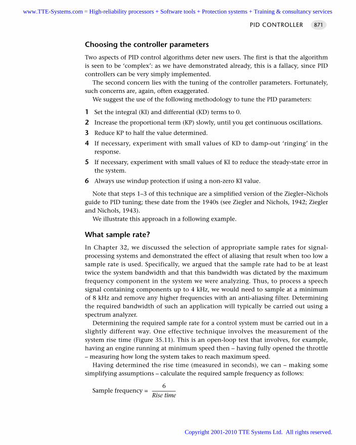
Choosing the controller parameters
Two aspects of PID control algorithms deter new users. The first is that the algorithmis seen to be ‘complex’: as we have demonstrated already, this is a fallacy, since PIDcontrollers can be very simply implemented.
The second concern lies with the tuning of the controller parameters. Fortunately,such concerns are, again, often exaggerated.
We suggest the use of the following methodology to tune the PID parameters:
1 Set the integral (KI) and differential (KD) terms to 0.
2 Increase the proportional term (KP) slowly, until you get continuous oscillations.
3 Reduce KP to half the value determined.
4 If necessary, experiment with small values of KD to damp-out ‘ringing’ in theresponse.
5 If necessary, experiment with small values of KI to reduce the steady-state error inthe system.
6 Always use windup protection if using a non-zero KI value.
Note that steps 1–3 of this technique are a simplified version of the Ziegler–Nicholsguide to PID tuning; these date from the 1940s (see Ziegler and Nichols, 1942; Zieglerand Nichols, 1943).
We illustrate this approach in a following example.
What sample rate?
In Chapter 32, we discussed the selection of appropriate sample rates for signal-processing systems and demonstrated the effect of aliasing that result when too low asample rate is used. Specifically, we argued that the sample rate had to be at leasttwice the system bandwidth and that this bandwidth was dictated by the maximumfrequency component in the system we were analyzing. Thus, to process a speechsignal containing components up to 4 kHz, we would need to sample at a minimumof 8 kHz and remove any higher frequencies with an anti-aliasing filter. Determiningthe required bandwidth of such an application will typically be carried out using aspectrum analyzer.
Determining the required sample rate for a control system must be carried out in aslightly different way. One effective technique involves the measurement of thesystem rise time (Figure 35.11). This is an open-loop test that involves, for example,having an engine running at minimum speed then – having fully opened the throttle– measuring how long the system takes to reach maximum speed.
Having determined the rise time (measured in seconds), we can – making somesimplifying assumptions – calculate the required sample frequency as follows:
6Sample frequency =
Rise time
PID CONTROLLER 871
www.TTE-Systems.com = High-reliability processors + Software tools + Protection systems + Training & consultancy services
Copyright 2001-2010 TTE Systems Ltd. All rights reserved.
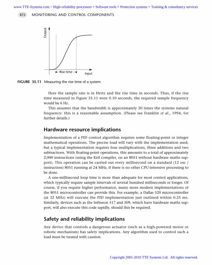
Here the sample rate is in Hertz and the rise time in seconds. Thus, if the risetime measured in Figure 35.11 were 0.10 seconds, the required sample frequencywould be 6 Hz.
This assumes that the bandwidth is approximately 20 times the systems naturalfrequency: this is a reasonable assumption. (Please see Franklin et al., 1994, forfurther details.)
Hardware resource implicationsImplementation of a PID control algorithm requires some floating-point or integermathematical operations. The precise load will vary with the implementation used,but a typical implementation requires four multiplications, three additions and twosubtractions. With floating-point operations, this amounts to a total of approximately2,000 instructions (using the Keil compiler, on an 8051 without hardware maths sup-port). This operation can be carried out every millisecond on a standard (12 osc /instruction) 8051 running at 24 MHz, if there is no other CPU-intensive processing tobe done.
A one-millisecond loop time is more than adequate for most control applications,which typically require sample intervals of several hundred milliseconds or longer. Ofcourse, if you require higher performance, many more modern implementations ofthe 8051 microcontroller can provide this. For example, a Dallas 520 microcontroller(at 32 MHz) will execute the PID implementation just outlined within 0.25 ms.Similarly, devices such as the Infineon 517 and 509, which have hardware maths sup-port, will also execute this code rapidly, should this be required.
Safety and reliability implicationsAny device that controls a dangerous actuator (such as a high-powered motor orrobotic mechanism) has safety implications. Any algorithm used to control such aload must be treated with caution.
MONITORING AND CONTROL COMPONENTS872
FIGURE 35.11 Measuring the rise time of a system
Input
Out
put
Rise time
www.TTE-Systems.com = High-reliability processors + Software tools + Protection systems + Training & consultancy services
Copyright 2001-2010 TTE Systems Ltd. All rights reserved.
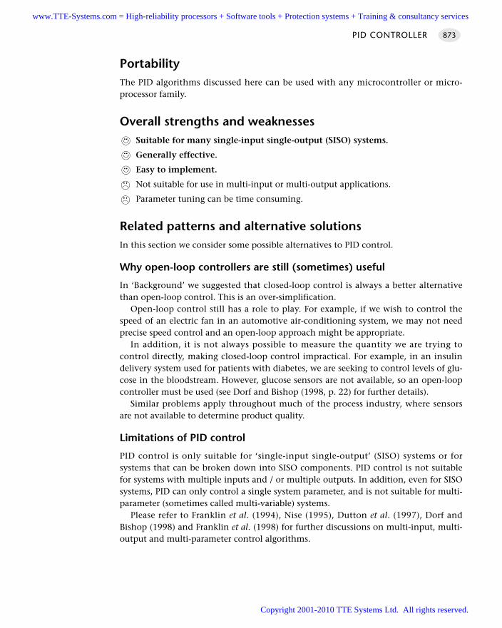
PortabilityThe PID algorithms discussed here can be used with any microcontroller or micro-processor family.
Overall strengths and weaknessesSuitable for many single-input single-output (SISO) systems.
Generally effective.
Easy to implement.
Not suitable for use in multi-input or multi-output applications.
Parameter tuning can be time consuming.
Related patterns and alternative solutionsIn this section we consider some possible alternatives to PID control.
Why open-loop controllers are still (sometimes) useful
In ‘Background’ we suggested that closed-loop control is always a better alternativethan open-loop control. This is an over-simplification.
Open-loop control still has a role to play. For example, if we wish to control thespeed of an electric fan in an automotive air-conditioning system, we may not needprecise speed control and an open-loop approach might be appropriate.
In addition, it is not always possible to measure the quantity we are trying tocontrol directly, making closed-loop control impractical. For example, in an insulindelivery system used for patients with diabetes, we are seeking to control levels of glu-cose in the bloodstream. However, glucose sensors are not available, so an open-loopcontroller must be used (see Dorf and Bishop (1998, p. 22) for further details).
Similar problems apply throughout much of the process industry, where sensorsare not available to determine product quality.
Limitations of PID control
PID control is only suitable for ‘single-input single-output’ (SISO) systems or forsystems that can be broken down into SISO components. PID control is not suitablefor systems with multiple inputs and / or multiple outputs. In addition, even for SISOsystems, PID can only control a single system parameter, and is not suitable for multi-parameter (sometimes called multi-variable) systems.
Please refer to Franklin et al. (1994), Nise (1995), Dutton et al. (1997), Dorf andBishop (1998) and Franklin et al. (1998) for further discussions on multi-input, multi-output and multi-parameter control algorithms.
PID CONTROLLER 873
www.TTE-Systems.com = High-reliability processors + Software tools + Protection systems + Training & consultancy services
Copyright 2001-2010 TTE Systems Ltd. All rights reserved.
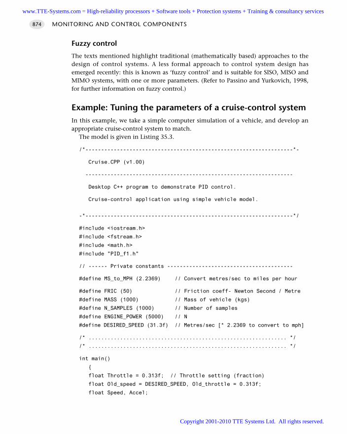
Fuzzy control
The texts mentioned highlight traditional (mathematically based) approaches to thedesign of control systems. A less formal approach to control system design hasemerged recently: this is known as ‘fuzzy control’ and is suitable for SISO, MISO andMIMO systems, with one or more parameters. (Refer to Passino and Yurkovich, 1998,for further information on fuzzy control.)
Example: Tuning the parameters of a cruise-control systemIn this example, we take a simple computer simulation of a vehicle, and develop anappropriate cruise-control system to match.
The model is given in Listing 35.3.
/*------------------------------------------------------------------*-
Cruise.CPP (v1.00)
------------------------------------------------------------------
Desktop C++ program to demonstrate PID control.
Cruise-control application using simple vehicle model.
-*------------------------------------------------------------------*/
#include <iostream.h>
#include <fstream.h>
#include <math.h>
#include "PID_f1.h"
// ------ Private constants ----------------------------------------
#define MS_to_MPH (2.2369) // Convert metres/sec to miles per hour
#define FRIC (50) // Friction coeff- Newton Second / Metre
#define MASS (1000) // Mass of vehicle (kgs)
#define N_SAMPLES (1000) // Number of samples
#define ENGINE_POWER (5000) // N
#define DESIRED_SPEED (31.3f) // Metres/sec [* 2.2369 to convert to mph]
/* ............................................................... */
/* ............................................................... */
int main()
float Throttle = 0.313f; // Throttle setting (fraction)
float Old_speed = DESIRED_SPEED, Old_throttle = 0.313f;
float Speed, Accel;
MONITORING AND CONTROL COMPONENTS874
www.TTE-Systems.com = High-reliability processors + Software tools + Protection systems + Training & consultancy services
Copyright 2001-2010 TTE Systems Ltd. All rights reserved.
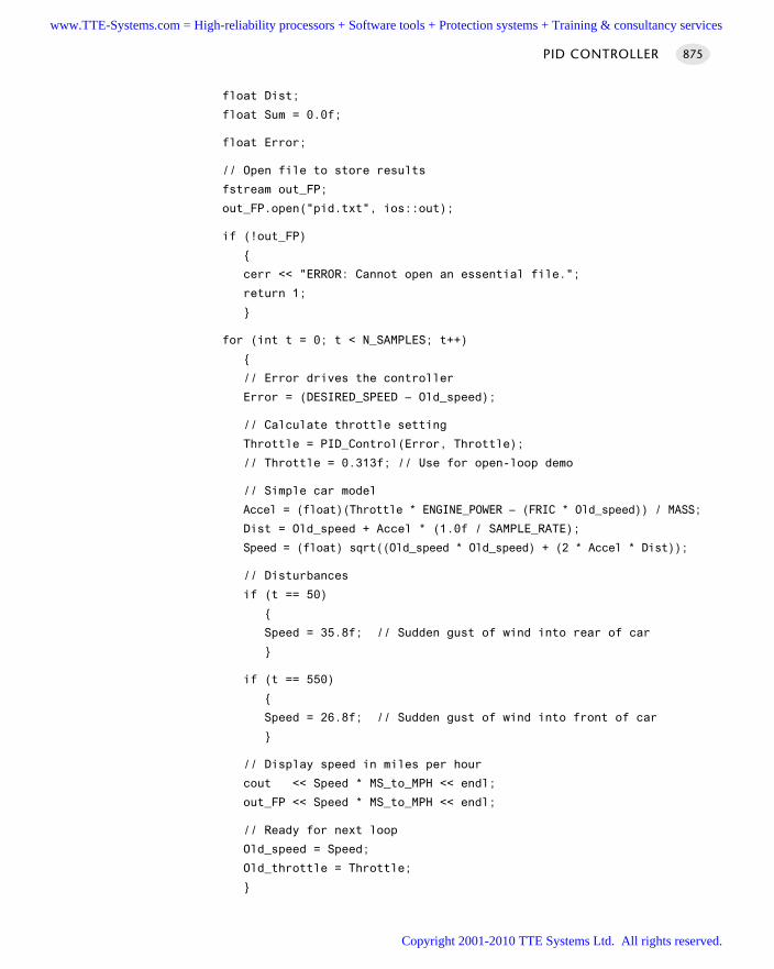
float Dist;
float Sum = 0.0f;
float Error;
// Open file to store results
fstream out_FP;
out_FP.open("pid.txt", ios::out);
if (!out_FP)
cerr << "ERROR: Cannot open an essential file.";
return 1;
for (int t = 0; t < N_SAMPLES; t++)
// Error drives the controller
Error = (DESIRED_SPEED – Old_speed);
// Calculate throttle setting
Throttle = PID_Control(Error, Throttle);
// Throttle = 0.313f; // Use for open-loop demo
// Simple car model
Accel = (float)(Throttle * ENGINE_POWER – (FRIC * Old_speed)) / MASS;
Dist = Old_speed + Accel * (1.0f / SAMPLE_RATE);
Speed = (float) sqrt((Old_speed * Old_speed) + (2 * Accel * Dist));
// Disturbances
if (t == 50)
Speed = 35.8f; // Sudden gust of wind into rear of car
if (t == 550)
Speed = 26.8f; // Sudden gust of wind into front of car
// Display speed in miles per hour
cout << Speed * MS_to_MPH << endl;
out_FP << Speed * MS_to_MPH << endl;
// Ready for next loop
Old_speed = Speed;
Old_throttle = Throttle;
PID CONTROLLER 875
www.TTE-Systems.com = High-reliability processors + Software tools + Protection systems + Training & consultancy services
Copyright 2001-2010 TTE Systems Ltd. All rights reserved.
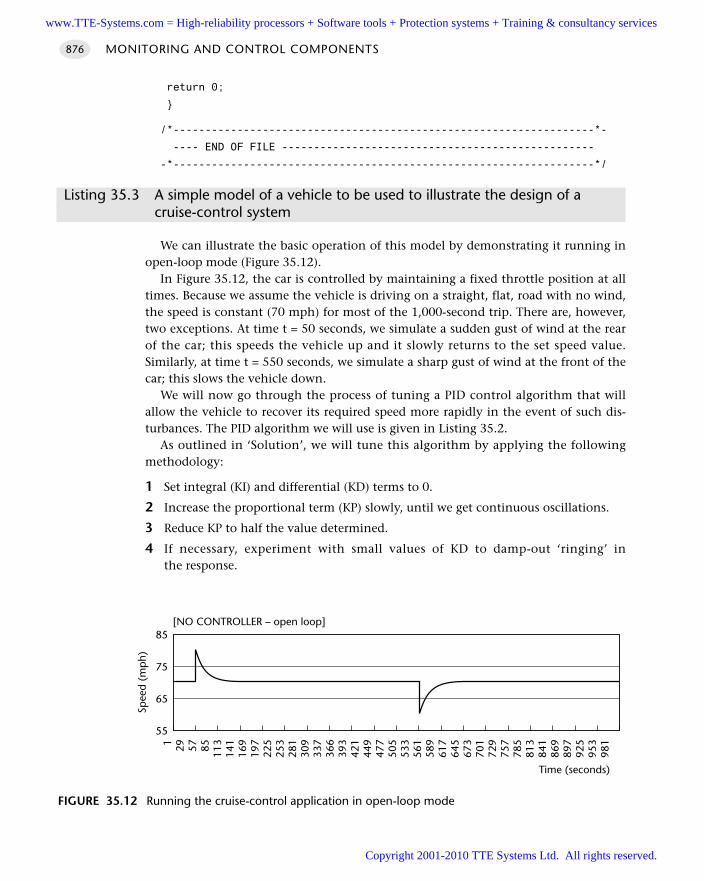
return 0;
/*------------------------------------------------------------------*-
---- END OF FILE -------------------------------------------------
-*------------------------------------------------------------------*/
Listing 35.3 A simple model of a vehicle to be used to illustrate the design of a cruise-control system
We can illustrate the basic operation of this model by demonstrating it running inopen-loop mode (Figure 35.12).
In Figure 35.12, the car is controlled by maintaining a fixed throttle position at alltimes. Because we assume the vehicle is driving on a straight, flat, road with no wind,the speed is constant (70 mph) for most of the 1,000-second trip. There are, however,two exceptions. At time t = 50 seconds, we simulate a sudden gust of wind at the rearof the car; this speeds the vehicle up and it slowly returns to the set speed value.Similarly, at time t = 550 seconds, we simulate a sharp gust of wind at the front of thecar; this slows the vehicle down.
We will now go through the process of tuning a PID control algorithm that willallow the vehicle to recover its required speed more rapidly in the event of such dis-turbances. The PID algorithm we will use is given in Listing 35.2.
As outlined in ‘Solution’, we will tune this algorithm by applying the followingmethodology:
1 Set integral (KI) and differential (KD) terms to 0.
2 Increase the proportional term (KP) slowly, until we get continuous oscillations.
3 Reduce KP to half the value determined.
4 If necessary, experiment with small values of KD to damp-out ‘ringing’ inthe response.
MONITORING AND CONTROL COMPONENTS876
FIGURE 35.12 Running the cruise-control application in open-loop mode
55
65
75
85
1 29 57 85 113
141
169
197
225
253
281
309
337
366
393
421
449
477
505
533
561
589
617
645
673
701
729
757
785
813
841
869
897
925
953
981
Spee
d (m
ph)
Time (seconds)
[NO CONTROLLER – open loop]
www.TTE-Systems.com = High-reliability processors + Software tools + Protection systems + Training & consultancy services
Copyright 2001-2010 TTE Systems Ltd. All rights reserved.
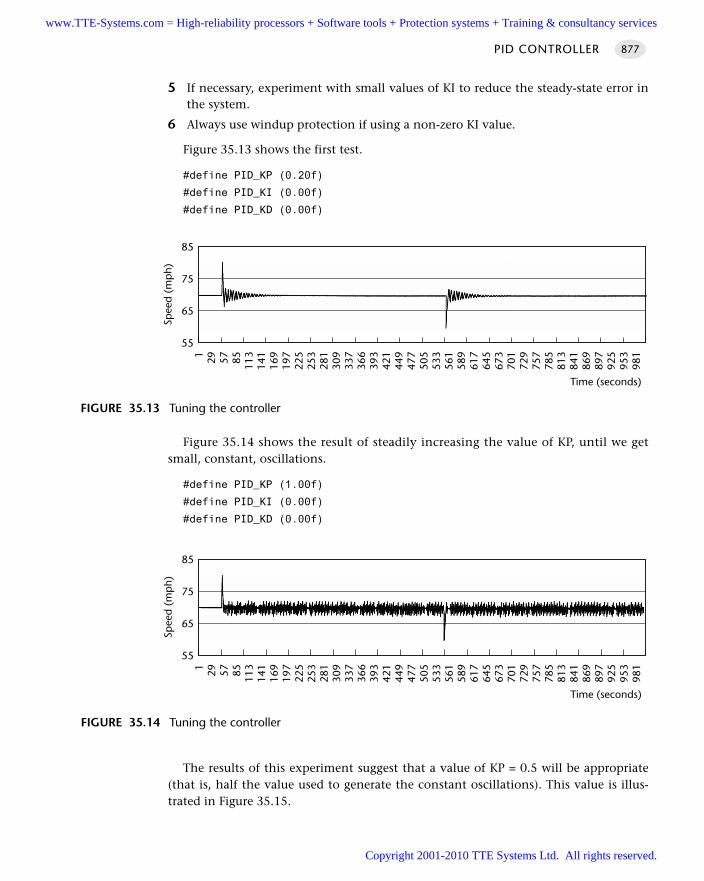
5 If necessary, experiment with small values of KI to reduce the steady-state error inthe system.
6 Always use windup protection if using a non-zero KI value.
Figure 35.13 shows the first test.
#define PID_KP (0.20f)
#define PID_KI (0.00f)
#define PID_KD (0.00f)
Figure 35.14 shows the result of steadily increasing the value of KP, until we getsmall, constant, oscillations.
#define PID_KP (1.00f)
#define PID_KI (0.00f)
#define PID_KD (0.00f)
The results of this experiment suggest that a value of KP = 0.5 will be appropriate(that is, half the value used to generate the constant oscillations). This value is illus-trated in Figure 35.15.
PID CONTROLLER 877
FIGURE 35.13 Tuning the controller
55
65
75
85
1 29 57 85 113
141
169
197
225
253
281
309
337
366
393
421
449
477
505
533
561
589
617
645
673
701
729
757
785
813
841
869
897
925
953
981
Spee
d (m
ph)
Time (seconds)
FIGURE 35.14 Tuning the controller
55
65
75
85
1 29 57 85 113
141
169
197
225
253
281
309
337
366
393
421
449
477
505
533
561
589
617
645
673
701
729
757
785
813
841
869
897
925
953
981
Spee
d (m
ph)
Time (seconds)
www.TTE-Systems.com = High-reliability processors + Software tools + Protection systems + Training & consultancy services
Copyright 2001-2010 TTE Systems Ltd. All rights reserved.
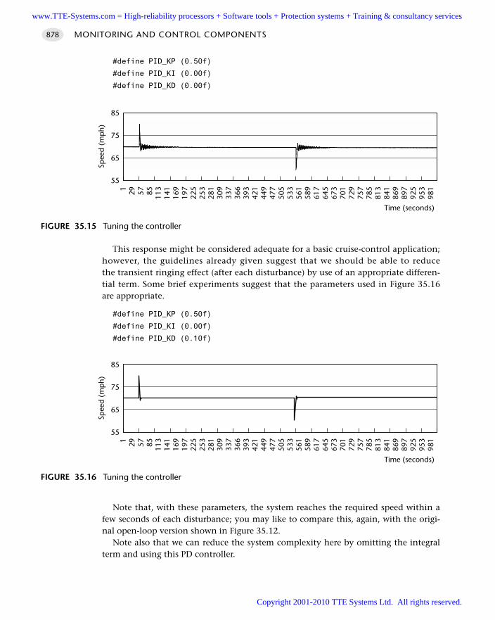
#define PID_KP (0.50f)
#define PID_KI (0.00f)
#define PID_KD (0.00f)
This response might be considered adequate for a basic cruise-control application;however, the guidelines already given suggest that we should be able to reducethe transient ringing effect (after each disturbance) by use of an appropriate differen-tial term. Some brief experiments suggest that the parameters used in Figure 35.16are appropriate.
#define PID_KP (0.50f)
#define PID_KI (0.00f)
#define PID_KD (0.10f)
Note that, with these parameters, the system reaches the required speed within afew seconds of each disturbance; you may like to compare this, again, with the origi-nal open-loop version shown in Figure 35.12.
Note also that we can reduce the system complexity here by omitting the integralterm and using this PD controller.
MONITORING AND CONTROL COMPONENTS878
FIGURE 35.15 Tuning the controller
55
65
75
851 29 57 85 113
141
169
197
225
253
281
309
337
366
393
421
449
477
505
533
561
589
617
645
673
701
729
757
785
813
841
869
897
925
953
981
Spee
d (m
ph)
Time (seconds)
FIGURE 35.16 Tuning the controller
55
65
75
85
1 29 57 85 113
141
169
197
225
253
281
309
337
366
393
421
449
477
505
533
561
589
617
645
673
701
729
757
785
813
841
869
897
925
953
981
Spee
d (m
ph)
Time (seconds)
www.TTE-Systems.com = High-reliability processors + Software tools + Protection systems + Training & consultancy services
Copyright 2001-2010 TTE Systems Ltd. All rights reserved.
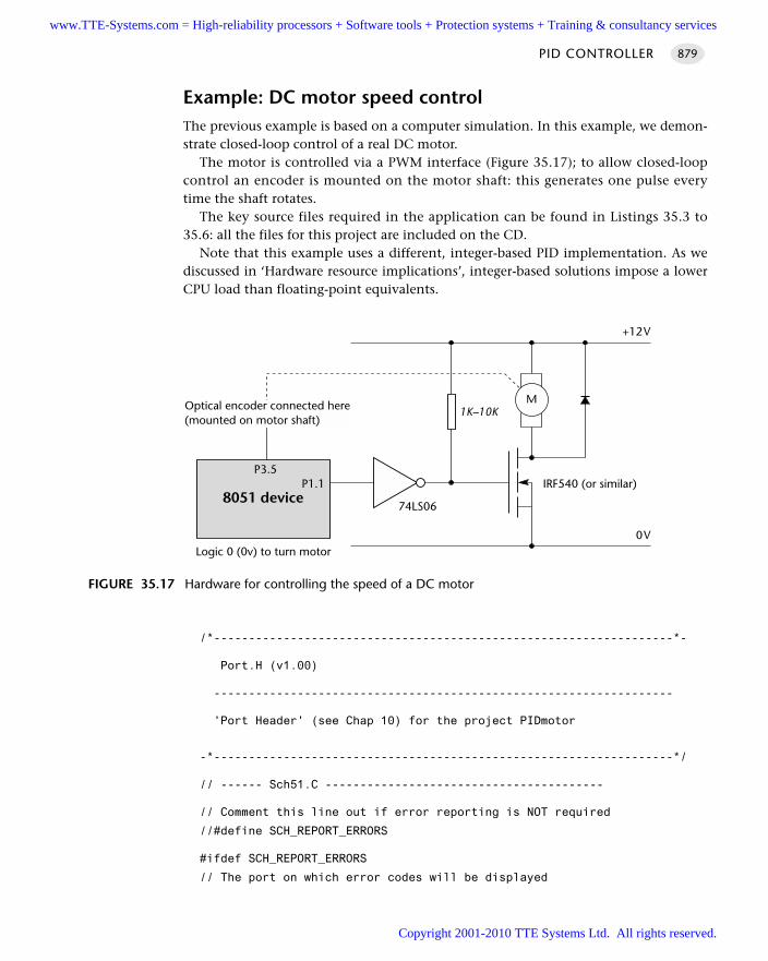
Example: DC motor speed controlThe previous example is based on a computer simulation. In this example, we demon-strate closed-loop control of a real DC motor.
The motor is controlled via a PWM interface (Figure 35.17); to allow closed-loopcontrol an encoder is mounted on the motor shaft: this generates one pulse everytime the shaft rotates.
The key source files required in the application can be found in Listings 35.3 to35.6: all the files for this project are included on the CD.
Note that this example uses a different, integer-based PID implementation. As wediscussed in ‘Hardware resource implications’, integer-based solutions impose a lowerCPU load than floating-point equivalents.
/*------------------------------------------------------------------*-
Port.H (v1.00)
------------------------------------------------------------------
'Port Header' (see Chap 10) for the project PIDmotor
-*------------------------------------------------------------------*/
// ------ Sch51.C ----------------------------------------
// Comment this line out if error reporting is NOT required
//#define SCH_REPORT_ERRORS
#ifdef SCH_REPORT_ERRORS
// The port on which error codes will be displayed
PID CONTROLLER 879
FIGURE 35.17 Hardware for controlling the speed of a DC motor
8051 device
Optical encoder connected here(mounted on motor shaft)
P1.1
M
+12V
IRF540 (or similar)
74LS06
0V
P3.5
1K–10K
Logic 0 (0v) to turn motor
www.TTE-Systems.com = High-reliability processors + Software tools + Protection systems + Training & consultancy services
Copyright 2001-2010 TTE Systems Ltd. All rights reserved.
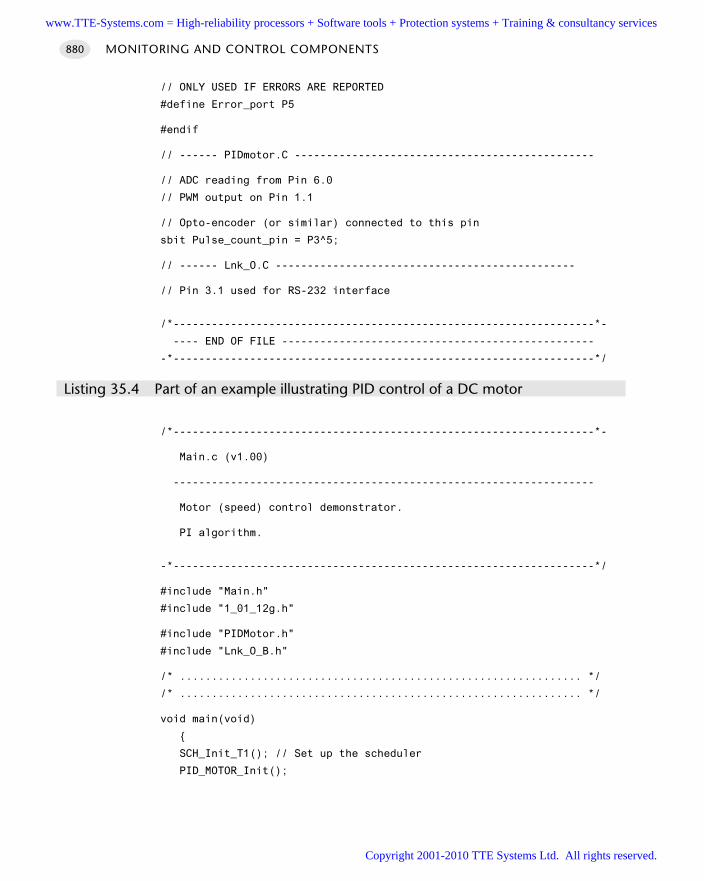
// ONLY USED IF ERRORS ARE REPORTED
#define Error_port P5
#endif
// ------ PIDmotor.C -----------------------------------------------
// ADC reading from Pin 6.0
// PWM output on Pin 1.1
// Opto-encoder (or similar) connected to this pin
sbit Pulse_count_pin = P3^5;
// ------ Lnk_O.C -----------------------------------------------
// Pin 3.1 used for RS-232 interface
/*------------------------------------------------------------------*-
---- END OF FILE -------------------------------------------------
-*------------------------------------------------------------------*/
Listing 35.4 Part of an example illustrating PID control of a DC motor
/*------------------------------------------------------------------*-
Main.c (v1.00)
------------------------------------------------------------------
Motor (speed) control demonstrator.
PI algorithm.
-*------------------------------------------------------------------*/
#include "Main.h"
#include "1_01_12g.h"
#include "PIDMotor.h"
#include "Lnk_O_B.h"
/* ............................................................... */
/* ............................................................... */
void main(void)
SCH_Init_T1(); // Set up the scheduler
PID_MOTOR_Init();
MONITORING AND CONTROL COMPONENTS880
www.TTE-Systems.com = High-reliability processors + Software tools + Protection systems + Training & consultancy services
Copyright 2001-2010 TTE Systems Ltd. All rights reserved.
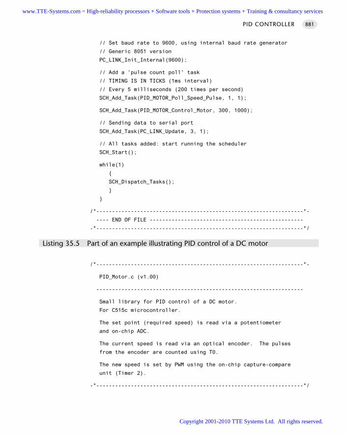
// Set baud rate to 9600, using internal baud rate generator
// Generic 8051 version
PC_LINK_Init_Internal(9600);
// Add a 'pulse count poll' task
// TIMING IS IN TICKS (1ms interval)
// Every 5 milliseconds (200 times per second)
SCH_Add_Task(PID_MOTOR_Poll_Speed_Pulse, 1, 1);
SCH_Add_Task(PID_MOTOR_Control_Motor, 300, 1000);
// Sending data to serial port
SCH_Add_Task(PC_LINK_Update, 3, 1);
// All tasks added: start running the scheduler
SCH_Start();
while(1)
SCH_Dispatch_Tasks();
/*------------------------------------------------------------------*-
---- END OF FILE -------------------------------------------------
-*------------------------------------------------------------------*/
Listing 35.5 Part of an example illustrating PID control of a DC motor
/*------------------------------------------------------------------*-
PID_Motor.c (v1.00)
------------------------------------------------------------------
Small library for PID control of a DC motor.
For C515c microcontroller.
The set point (required speed) is read via a potentiometer
and on-chip ADC.
The current speed is read via an optical encoder. The pulses
from the encoder are counted using T0.
The new speed is set by PWM using the on-chip capture-compare
unit (Timer 2).
-*------------------------------------------------------------------*/
PID CONTROLLER 881
www.TTE-Systems.com = High-reliability processors + Software tools + Protection systems + Training & consultancy services
Copyright 2001-2010 TTE Systems Ltd. All rights reserved.
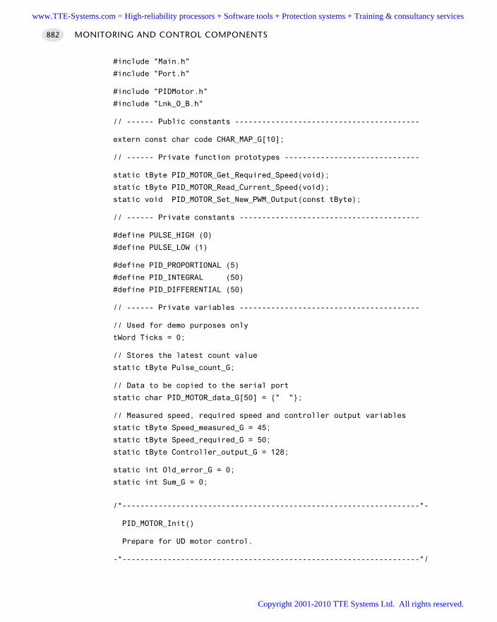
#include "Main.h"
#include "Port.h"
#include "PIDMotor.h"
#include "Lnk_O_B.h"
// ------ Public constants -----------------------------------------
extern const char code CHAR_MAP_G[10];
// ------ Private function prototypes ------------------------------
static tByte PID_MOTOR_Get_Required_Speed(void);
static tByte PID_MOTOR_Read_Current_Speed(void);
static void PID_MOTOR_Set_New_PWM_Output(const tByte);
// ------ Private constants ----------------------------------------
#define PULSE_HIGH (0)
#define PULSE_LOW (1)
#define PID_PROPORTIONAL (5)
#define PID_INTEGRAL (50)
#define PID_DIFFERENTIAL (50)
// ------ Private variables ----------------------------------------
// Used for demo purposes only
tWord Ticks = 0;
// Stores the latest count value
static tByte Pulse_count_G;
// Data to be copied to the serial port
static char PID_MOTOR_data_G[50] = " ";
// Measured speed, required speed and controller output variables
static tByte Speed_measured_G = 45;
static tByte Speed_required_G = 50;
static tByte Controller_output_G = 128;
static int Old_error_G = 0;
static int Sum_G = 0;
/*------------------------------------------------------------------*-
PID_MOTOR_Init()
Prepare for UD motor control.
-*------------------------------------------------------------------*/
MONITORING AND CONTROL COMPONENTS882
www.TTE-Systems.com = High-reliability processors + Software tools + Protection systems + Training & consultancy services
Copyright 2001-2010 TTE Systems Ltd. All rights reserved.
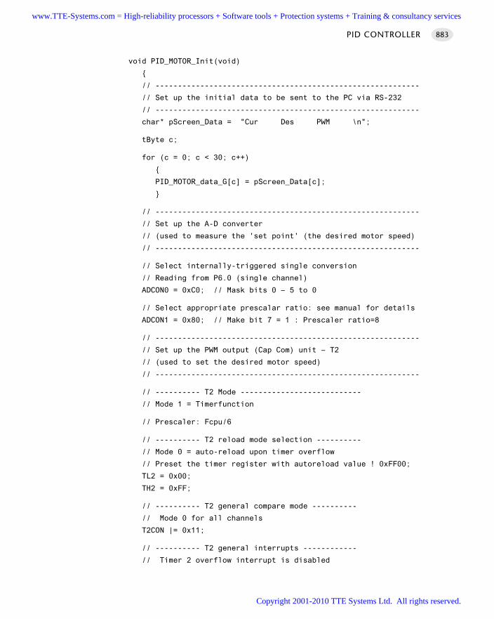
void PID_MOTOR_Init(void)
// -----------------------------------------------------------
// Set up the initial data to be sent to the PC via RS-232
// -----------------------------------------------------------
char* pScreen_Data = "Cur Des PWM \n";
tByte c;
for (c = 0; c < 30; c++)
PID_MOTOR_data_G[c] = pScreen_Data[c];
// -----------------------------------------------------------
// Set up the A-D converter
// (used to measure the 'set point' (the desired motor speed)
// -----------------------------------------------------------
// Select internally-triggered single conversion
// Reading from P6.0 (single channel)
ADCON0 = 0xC0; // Mask bits 0 – 5 to 0
// Select appropriate prescalar ratio: see manual for details
ADCON1 = 0x80; // Make bit 7 = 1 : Prescaler ratio=8
// -----------------------------------------------------------
// Set up the PWM output (Cap Com) unit – T2
// (used to set the desired motor speed)
// -----------------------------------------------------------
// ---------- T2 Mode ---------------------------
// Mode 1 = Timerfunction
// Prescaler: Fcpu/6
// ---------- T2 reload mode selection ----------
// Mode 0 = auto-reload upon timer overflow
// Preset the timer register with autoreload value ! 0xFF00;
TL2 = 0x00;
TH2 = 0xFF;
// ---------- T2 general compare mode ----------
// Mode 0 for all channels
T2CON |= 0x11;
// ---------- T2 general interrupts ------------
// Timer 2 overflow interrupt is disabled
PID CONTROLLER 883
www.TTE-Systems.com = High-reliability processors + Software tools + Protection systems + Training & consultancy services
Copyright 2001-2010 TTE Systems Ltd. All rights reserved.
ET2=0;
// Timer 2 external reload interrupt is disabled
EXEN2=0;
// ---------- Compare/capture Channel 0 ---------
// Disabled??
// Set Compare Register CRC on: 0xFF00;
CRCL = 0x00;
CRCH = 0xFF;
// CC0/ext3 interrupt is disabled
EX3=0;
// ---------- Compare/capture Channel 1 ---------
// Compare enabled
// Set Compare Register CC1 on: 0xFF80;
CCL1 = 0x80;
CCH1 = 0xFF;
// CC1/ext4 interrupt is disabled
EX4=0;
// ---------- Compare/capture Channel 2 ---------
// Disabled
// Set Compare Register CC2 on: 0x0000;
CCL2 = 0x00;
CCH2 = 0x00;
// CC2/ext5 interrupt is disabled
EX5=0;
// ---------- Compare/capture Channel 3 ---------
// Disabled
// Set Compare Register CC3 on: 0x0000;
CCL3 = 0x00;
CCH3 = 0x00;
// CC3/ext6 interrupt is disabled
EX6=0;
// Set all above mentioned modes for channel 0-3
CCEN = 0x08;
// -----------------------------------------------------------
// Count pulses on Pin 3.5 [software only]
// (used to measure the current motor speed)
// -----------------------------------------------------------
Pulse_count_pin = 1;
MONITORING AND CONTROL COMPONENTS884
www.TTE-Systems.com = High-reliability processors + Software tools + Protection systems + Training & consultancy services
Copyright 2001-2010 TTE Systems Ltd. All rights reserved.
Pulse_count_G = 0;
/*------------------------------------------------------------------*-
PID_MOTOR_Control_Motor()
The main motor control function.
-*------------------------------------------------------------------*/
void PID_MOTOR_Control_Motor(void)
int Error;
int Control_new;
// Get the current speed value (0-255)
Speed_measured_G = PID_MOTOR_Read_Current_Speed();
// Get the desired speed value (0-255)
Speed_required_G =
PID_MOTOR_Get_Required_Speed();
if (++Ticks == 100)
Speed_required_G = 200;
// Difference between required and actual speed (0-255)
Error = Speed_required_G – Speed_measured_G;
// Proportional term
Control_new = Controller_output_G + (Error / PID_PROPORTIONAL);
// Integral term [SET TO 0 IF NOT REQUIRED]
if (PID_INTEGRAL)
Sum_G += Error;
Control_new += (Sum_G / (1 + PID_INTEGRAL));
// Differential term [SET TO 0 IF NOT REQUIRED]
if (PID_DIFFERENTIAL)
Control_new += (Error – Old_error_G) / (1 + PID_DIFFERENTIAL);
// Store error value
Old_error_G = Error;
PID CONTROLLER 885
www.TTE-Systems.com = High-reliability processors + Software tools + Protection systems + Training & consultancy services
Copyright 2001-2010 TTE Systems Ltd. All rights reserved.
// Adjust to 8-bit range
if (Control_new > 255)
Control_new = 255;
Sum_G -= Error; // Windup protection
if (Control_new < 0)
Control_new = 0;
Sum_G -= Error; // Windup protection
// Convert to required 8-bit format
Controller_output_G = (tByte) Control_new;
// Update the PWM setting
PID_MOTOR_Set_New_PWM_Output(Controller_output_G);
// Update display
PID_MOTOR_data_G[4] = CHAR_MAP_G[Speed_measured_G / 100];
PID_MOTOR_data_G[5] = CHAR_MAP_G[(Speed_measured_G % 100) / 10];
PID_MOTOR_data_G[6] = CHAR_MAP_G[Speed_measured_G % 10];
PID_MOTOR_data_G[12] = CHAR_MAP_G[Speed_required_G / 100];
PID_MOTOR_data_G[13] = CHAR_MAP_G[(Speed_required_G % 100) / 10];
PID_MOTOR_data_G[14] = CHAR_MAP_G[Speed_required_G % 10];
PID_MOTOR_data_G[20] = CHAR_MAP_G[Controller_output_G / 100];
PID_MOTOR_data_G[21] = CHAR_MAP_G[(Controller_output_G % 100) / 10];
PID_MOTOR_data_G[22] = CHAR_MAP_G[Controller_output_G % 10];
PC_LINK_Write_String_To_Buffer(PID_MOTOR_data_G);
/*------------------------------------------------------------------*-
PID_MOTOR_Get_Required_Speed()
Get the required speed via the Pot and ADC.
-*------------------------------------------------------------------*/
tByte PID_MOTOR_Get_Required_Speed(void)
// Take sample from A-D
// Write (value not important) to ADDATL to start conversion
ADDATL = 0x01;
MONITORING AND CONTROL COMPONENTS886
www.TTE-Systems.com = High-reliability processors + Software tools + Protection systems + Training & consultancy services
Copyright 2001-2010 TTE Systems Ltd. All rights reserved.
// Wait for conversion to complete
// NOTE: This demo software has no timeout...
while (BSY == 1);
// 10-bit A-D result is now available
// return 8-bit result
return ADDATH;
/*------------------------------------------------------------------*-
PID_MOTOR_Set_New_PWM_Output()
Adjust the PWM output value.
-*------------------------------------------------------------------*/
void PID_MOTOR_Set_New_PWM_Output(const tByte Controller_output_G)
// Changing value in CCL1 to generate appropriate PWM duty cycle
CCL1 = Controller_output_G;
/*------------------------------------------------------------------*-
PID_MOTOR_Read_Current_Speed()
Schedule this function at regular intervals.
Remember: max count is 65536 (16-bit counter)
– it is your responsibility to ensure this count
is not exceeded. Choose an appropriate schedule
interval and allow a margin for error.
For high-frequency pulses, you need to take account of
the fact that the count is stop for a (very brief) period,
to read the counter.
Note: the delay before the first count is taken should
generally be the same as the inter-count interval,
to ensure that the first count is as accurate as possible.
For example, this is OK:
Sch_Add_Task(PID_MOTOR_Read_Current_Speed, 1000, 1000);
While this will give a very low first count:
Sch_Add_Task(PID_MOTOR_Read_Current_Speed, 0, 1000);
-*------------------------------------------------------------------*/
PID CONTROLLER 887
www.TTE-Systems.com = High-reliability processors + Software tools + Protection systems + Training & consultancy services
Copyright 2001-2010 TTE Systems Ltd. All rights reserved.
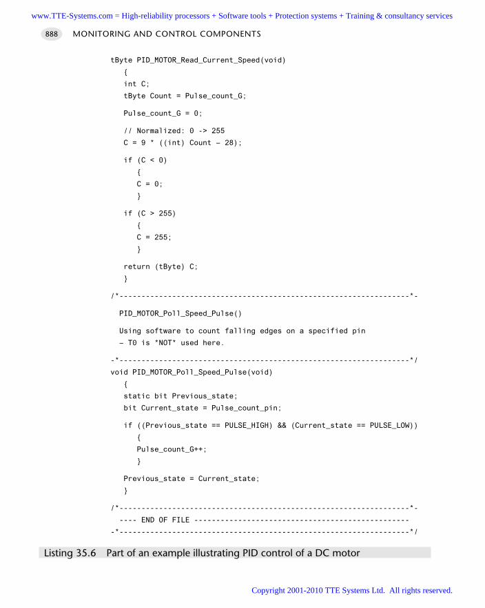
tByte PID_MOTOR_Read_Current_Speed(void)
int C;
tByte Count = Pulse_count_G;
Pulse_count_G = 0;
// Normalized: 0 -> 255
C = 9 * ((int) Count – 28);
if (C < 0)
C = 0;
if (C > 255)
C = 255;
return (tByte) C;
/*------------------------------------------------------------------*-
PID_MOTOR_Poll_Speed_Pulse()
Using software to count falling edges on a specified pin
– T0 is *NOT* used here.
-*------------------------------------------------------------------*/
void PID_MOTOR_Poll_Speed_Pulse(void)
static bit Previous_state;
bit Current_state = Pulse_count_pin;
if ((Previous_state == PULSE_HIGH) && (Current_state == PULSE_LOW))
Pulse_count_G++;
Previous_state = Current_state;
/*------------------------------------------------------------------*-
---- END OF FILE -------------------------------------------------
-*------------------------------------------------------------------*/
Listing 35.6 Part of an example illustrating PID control of a DC motor
MONITORING AND CONTROL COMPONENTS888
www.TTE-Systems.com = High-reliability processors + Software tools + Protection systems + Training & consultancy services
Copyright 2001-2010 TTE Systems Ltd. All rights reserved.
Further readingAtherton, D.P. (1999) ‘PID controller tuning’, IEE Computing & Control Engineering
Journal, 10 (2): 44–50.Bennett, S. (1994) Real-time Computer Control, 2nd edn, Prentice Hall, New Jersey.Daley, S. and Liu, G.P. (1999) ‘Optimal PID tuning using direct search algorithms’, IEE
Computing & Control Engineering Journal, 10 (2): 51–6.Dorf, R.C. and Bishop, R.H. (1998) Modern Control Systems, 8th edn, Addison-Wesley,
CA.Doyle, F.J., Gatzke, E.P. and Parker, R.S. (1999) Process Control Modules: A Software
Laboratory for Control Design: The MATLAB-based Process Control Guide for ChemicalEngineering Professionals, Prentice-Hall, New Jersey.
Dutton, K., Thompson, S. and Barraclough, B. (1997) The Art of Control Engineering,Addison-Wesley Reading, MA.
Franklin, G.F., Powell, J.D., and Emami-Naeini, A. (1994) Feedback Control of DynamicSystems, 3rd edn, Addison-Wesley, Reading, MA.
Franklin, G.F., Powell, J.D., and Workman, M. (1998) Digital Control of DynamicSystems, 3rd edn, Addison-Wesley, CA.
Nise, N.S. (1995) Control Systems Engineering, 2nd edn, Addison-Wesley, CA.Passino, K.M. and Yurkovich, S. (1998) Fuzzy Control, Addison-Wesley, CA.Ziegler, J.G. and Nichols, N.B. (1942) ‘Optimal setting for automatic controllers’,
Trans. ASME, 64 (11), 759–68.Ziegler, J.G. and Nichols, N.B. (1943) ‘Process lags in automatic control circuits’,
Trans. ASME, 65 (5), 433–44.
PID CONTROLLER 889
www.TTE-Systems.com = High-reliability processors + Software tools + Protection systems + Training & consultancy services
Copyright 2001-2010 TTE Systems Ltd. All rights reserved.

www.TTE-Systems.com = High-reliability processors + Software tools + Protection systems + Training & consultancy services
Copyright 2001-2010 TTE Systems Ltd. All rights reserved.
Specialized time-triggeredarchitectures
We conclude the collection of patterns in this book by considering four specialized sched-
ulers. These are all co-operative in nature, but are adapted to meet the needs of particular
applications where, for example, low power consumption or very accurate scheduler
timing are required.
More specifically:
In Chapter 36, we consider ways of maintaining the advantages of the scheduled
architecture while reducing the CPU and / or memory load it imposes.
In Chapter 37, we discuss simple and cost-effective techniques for improving the
stability of the scheduler timing in the face of inevitable fluctuations in ambient
temperature.
part hwww.TTE-Systems.com = High-reliability processors + Software tools + Protection systems + Training & consultancy services
Copyright 2001-2010 TTE Systems Ltd. All rights reserved.

www.TTE-Systems.com = High-reliability processors + Software tools + Protection systems + Training & consultancy services
Copyright 2001-2010 TTE Systems Ltd. All rights reserved.
Reducing the system overheads
Introduction
In this chapter, we consider some of the ways in which the flexible nature of the gen-eral-purpose schedulers presented in this book may be exploited, in order to createspecial-purpose schedulers adapted for the needs of particular applications.
The following patterns are presented in this chapter:
255-T I C K S C H E D U L E R [page 894]
A scheduler designed to run multiple tasks, but with reduced memory (and CPU)overheads. This scheduler operates in the same way as the standard co-operativeschedulers, but all information is stored in byte-sized (rather than word-sized) vari-ables: this reduces the required memory for each task by around 30%.
O N E-TA S K S C H E D U L E R [page 911]
A stripped-down, co-operative scheduler able to manage a single task. This verysimple scheduler makes very efficient use of hardware resources, with the bare min-imum of CPU and memory overheads.
O N E-Y E A R S C H E D U L E R [page 919]
A scheduler designed for very low-power operation: specifically, it is designed toform the basis of battery-powered applications capable of operating for a year ormore from a small, low-cost battery supply.
chapter 36www.TTE-Systems.com = High-reliability processors + Software tools + Protection systems + Training & consultancy services
Copyright 2001-2010 TTE Systems Ltd. All rights reserved.
255-TICK SCHEDULER
Context You are developing an embedded application using one or more members of the
8051 family of microcontrollers.
The application has a time-triggered architecture, constructed using a scheduler.
ProblemHow do you reduce the scheduler memory requirements?
Background—
SolutionAs we discussed in Chapter 14, the majority of the schedulers in this book are basedon the following data structure:
// Store in DATA area, if possible, for rapid access
// Total memory per task is 7 bytes
typedef data struct
// Pointer to the task (must be a 'void (void)' function)
void (code * pTask)(void);
// Delay (ticks) until the function will (next) be run
// - see SCH_Add_Task() for further details
tWord Delay;
// Interval (ticks) between subsequent runs.
// - see SCH_Add_Task() for further details
tWord Period;
// Incremented (by scheduler) when task is due to execute
tByte RunMe;
sTask;
This data structure allows initial task delays and task intervals of up to 65,535 ticks.In doing so, it requires a total of seven bytes of memory per task.
SPECIALIZED ARCHITECTURES894
www.TTE-Systems.com = High-reliability processors + Software tools + Protection systems + Training & consultancy services
Copyright 2001-2010 TTE Systems Ltd. All rights reserved.
The 255-tick scheduler data structure is slightly modified:
// Store in DATA area, if possible, for rapid access
// Total memory per task is 5 bytes
typedef data struct
// Pointer to the task (must be a 'void (void)' function)
void (code * pTask)(void);
// Delay (ticks) until the function will (next) be run
// - see SCH_Add_Task() for further details
tByte Delay;
// Interval (ticks) between subsequent runs.
// - see SCH_Add_Task() for further details
tByte Period;
// Incremented (by scheduler) when task is due to execute
tByte RunMe;
sTask;
This data structure allows initial task delays and task intervals of up to 255 ticks. Indoing so, it requires a total of five bytes of memory per task.
Hardware resource implicationsIn addition to the significant memory savings, use of this scheduler also provides aslight performance improvement, since the processor can manipulate the 8-bit vari-ables in the 255-tick scheduler more rapidly than the 16-bit variables in theconventional version.
Reliability and safety implicationsThis scheduler has all the reliability and safety features of the co-operative schedulerswe have discussed throughout this book.
PortabilityThis scheduler is as portable as the other co-operative schedulers discussed through-out this book.
Overall strengths and weaknessesProvides a co-operative scheduling environment.
Reduced memory requirements (compared with C O - O P E R AT I V E S C H E D U L E R
[page 255]).
255-TICK SCHEDULER 895
www.TTE-Systems.com = High-reliability processors + Software tools + Protection systems + Training & consultancy services
Copyright 2001-2010 TTE Systems Ltd. All rights reserved.
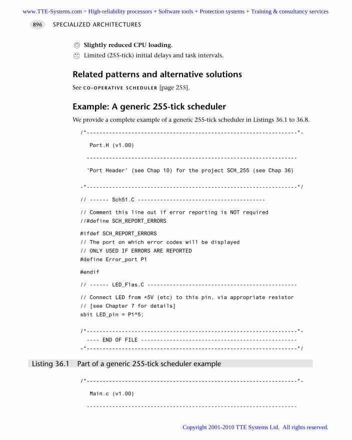
Slightly reduced CPU loading.
Limited (255-tick) initial delays and task intervals.
Related patterns and alternative solutionsSee C O-O P E R AT I V E S C H E D U L E R [page 255].
Example: A generic 255-tick schedulerWe provide a complete example of a generic 255-tick scheduler in Listings 36.1 to 36.8.
/*------------------------------------------------------------------*-
Port.H (v1.00)
------------------------------------------------------------------
'Port Header' (see Chap 10) for the project SCH_255 (see Chap 36)
-*------------------------------------------------------------------*/
// ------ Sch51.C ----------------------------------------
// Comment this line out if error reporting is NOT required
//#define SCH_REPORT_ERRORS
#ifdef SCH_REPORT_ERRORS
// The port on which error codes will be displayed
// ONLY USED IF ERRORS ARE REPORTED
#define Error_port P1
#endif
// ------ LED_Flas.C -----------------------------------------------
// Connect LED from +5V (etc) to this pin, via appropriate resistor
// [see Chapter 7 for details]
sbit LED_pin = P1^5;
/*------------------------------------------------------------------*-
---- END OF FILE -------------------------------------------------
-*------------------------------------------------------------------*/
Listing 36.1 Part of a generic 255-tick scheduler example
/*------------------------------------------------------------------*-
Main.c (v1.00)
------------------------------------------------------------------
SPECIALIZED ARCHITECTURES896
www.TTE-Systems.com = High-reliability processors + Software tools + Protection systems + Training & consultancy services
Copyright 2001-2010 TTE Systems Ltd. All rights reserved.
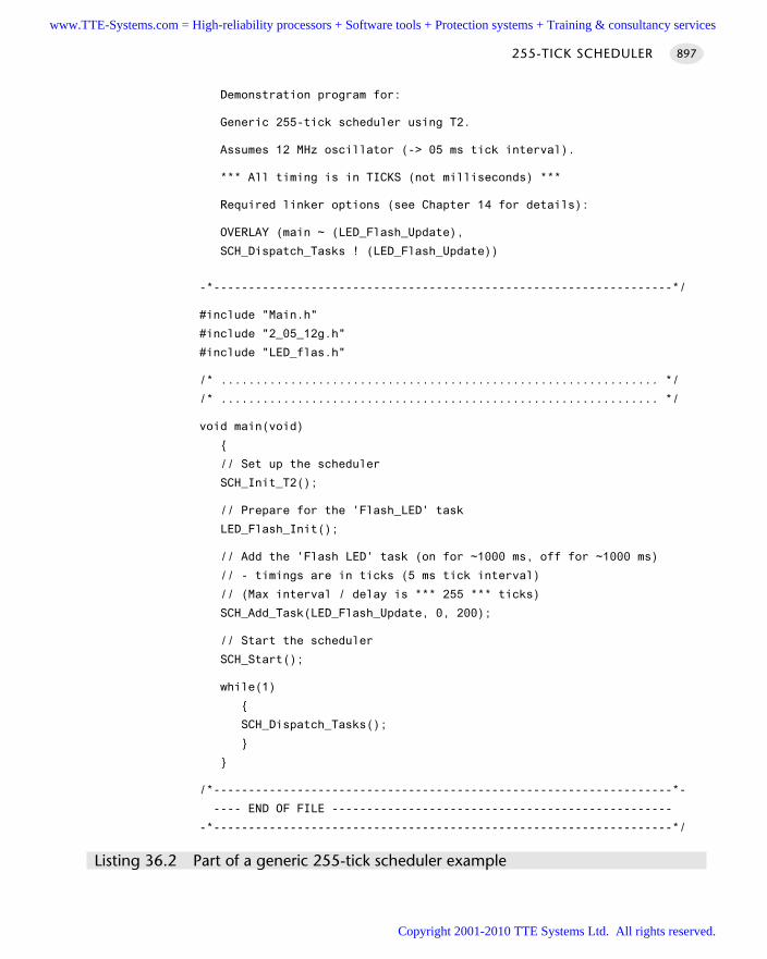
Demonstration program for:
Generic 255-tick scheduler using T2.
Assumes 12 MHz oscillator (-> 05 ms tick interval).
*** All timing is in TICKS (not milliseconds) ***
Required linker options (see Chapter 14 for details):
OVERLAY (main ~ (LED_Flash_Update),
SCH_Dispatch_Tasks ! (LED_Flash_Update))
-*------------------------------------------------------------------*/
#include "Main.h"
#include "2_05_12g.h"
#include "LED_flas.h"
/* ............................................................... */
/* ............................................................... */
void main(void)
// Set up the scheduler
SCH_Init_T2();
// Prepare for the 'Flash_LED' task
LED_Flash_Init();
// Add the 'Flash LED' task (on for ~1000 ms, off for ~1000 ms)
// - timings are in ticks (5 ms tick interval)
// (Max interval / delay is *** 255 *** ticks)
SCH_Add_Task(LED_Flash_Update, 0, 200);
// Start the scheduler
SCH_Start();
while(1)
SCH_Dispatch_Tasks();
/*------------------------------------------------------------------*-
---- END OF FILE -------------------------------------------------
-*------------------------------------------------------------------*/
Listing 36.2 Part of a generic 255-tick scheduler example
255-TICK SCHEDULER 897
www.TTE-Systems.com = High-reliability processors + Software tools + Protection systems + Training & consultancy services
Copyright 2001-2010 TTE Systems Ltd. All rights reserved.
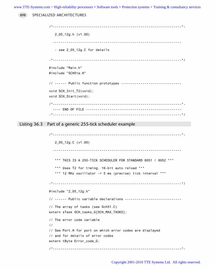
/*------------------------------------------------------------------*-
2_05_12g.h (v1.00)
------------------------------------------------------------------
- see 2_05_12g.C for details
-*------------------------------------------------------------------*/
#include "Main.h"
#include "SCH51a.H"
// ------ Public function prototypes -------------------------------
void SCH_Init_T2(void);
void SCH_Start(void);
/*------------------------------------------------------------------*-
---- END OF FILE -------------------------------------------------
-*------------------------------------------------------------------*/
Listing 36.3 Part of a generic 255-tick scheduler example
/*------------------------------------------------------------------*-
2_05_12g.C (v1.00)
------------------------------------------------------------------
*** THIS IS A 255-TICK SCHEDULER FOR STANDARD 8051 / 8052 ***
*** Uses T2 for timing, 16-bit auto reload ***
*** 12 MHz oscillator -> 5 ms (precise) tick interval ***
-*------------------------------------------------------------------*/
#include "2_05_12g.h"
// ------ Public variable declarations -----------------------------
// The array of tasks (see Sch51.C)
extern sTask SCH_tasks_G[SCH_MAX_TASKS];
// The error code variable
//
// See Port.H for port on which error codes are displayed
// and for details of error codes
extern tByte Error_code_G;
/*------------------------------------------------------------------*-
SPECIALIZED ARCHITECTURES898
www.TTE-Systems.com = High-reliability processors + Software tools + Protection systems + Training & consultancy services
Copyright 2001-2010 TTE Systems Ltd. All rights reserved.
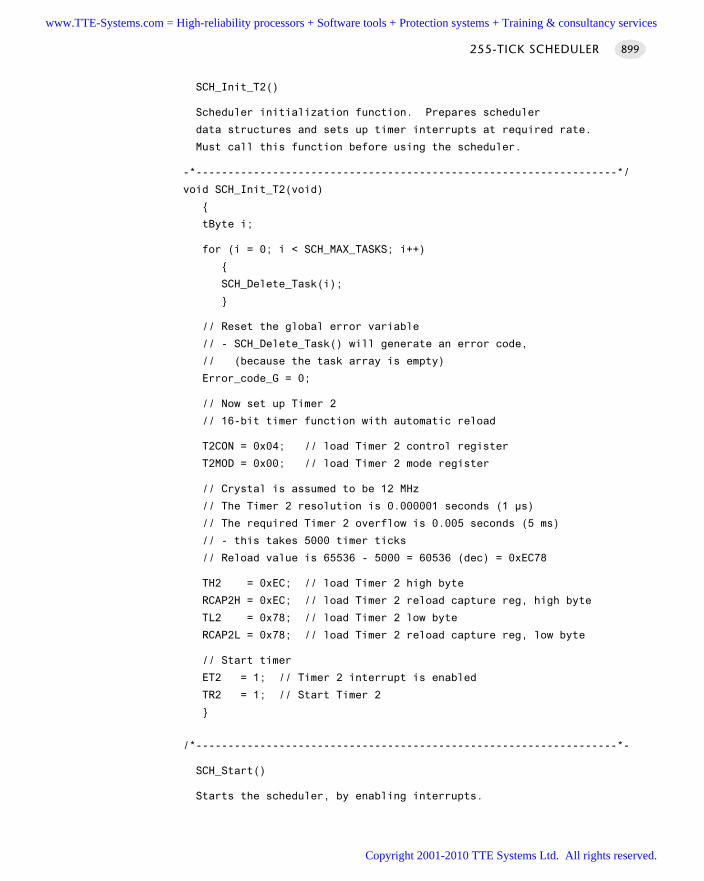
SCH_Init_T2()
Scheduler initialization function. Prepares scheduler
data structures and sets up timer interrupts at required rate.
Must call this function before using the scheduler.
-*------------------------------------------------------------------*/
void SCH_Init_T2(void)
tByte i;
for (i = 0; i < SCH_MAX_TASKS; i++)
SCH_Delete_Task(i);
// Reset the global error variable
// - SCH_Delete_Task() will generate an error code,
// (because the task array is empty)
Error_code_G = 0;
// Now set up Timer 2
// 16-bit timer function with automatic reload
T2CON = 0x04; // load Timer 2 control register
T2MOD = 0x00; // load Timer 2 mode register
// Crystal is assumed to be 12 MHz
// The Timer 2 resolution is 0.000001 seconds (1 µs)
// The required Timer 2 overflow is 0.005 seconds (5 ms)
// - this takes 5000 timer ticks
// Reload value is 65536 - 5000 = 60536 (dec) = 0xEC78
TH2 = 0xEC; // load Timer 2 high byte
RCAP2H = 0xEC; // load Timer 2 reload capture reg, high byte
TL2 = 0x78; // load Timer 2 low byte
RCAP2L = 0x78; // load Timer 2 reload capture reg, low byte
// Start timer
ET2 = 1; // Timer 2 interrupt is enabled
TR2 = 1; // Start Timer 2
/*------------------------------------------------------------------*-
SCH_Start()
Starts the scheduler, by enabling interrupts.
255-TICK SCHEDULER 899
www.TTE-Systems.com = High-reliability processors + Software tools + Protection systems + Training & consultancy services
Copyright 2001-2010 TTE Systems Ltd. All rights reserved.
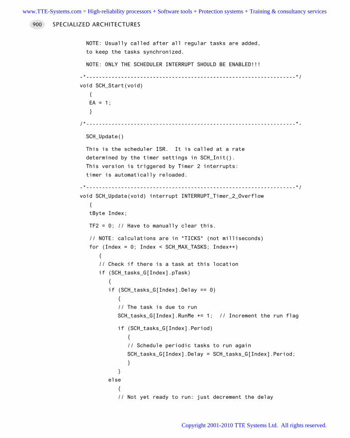
NOTE: Usually called after all regular tasks are added,
to keep the tasks synchronized.
NOTE: ONLY THE SCHEDULER INTERRUPT SHOULD BE ENABLED!!!
-*------------------------------------------------------------------*/
void SCH_Start(void)
EA = 1;
/*------------------------------------------------------------------*-
SCH_Update()
This is the scheduler ISR. It is called at a rate
determined by the timer settings in SCH_Init().
This version is triggered by Timer 2 interrupts:
timer is automatically reloaded.
-*------------------------------------------------------------------*/
void SCH_Update(void) interrupt INTERRUPT_Timer_2_Overflow
tByte Index;
TF2 = 0; // Have to manually clear this.
// NOTE: calculations are in *TICKS* (not milliseconds)
for (Index = 0; Index < SCH_MAX_TASKS; Index++)
// Check if there is a task at this location
if (SCH_tasks_G[Index].pTask)
if (SCH_tasks_G[Index].Delay == 0)
// The task is due to run
SCH_tasks_G[Index].RunMe += 1; // Increment the run flag
if (SCH_tasks_G[Index].Period)
// Schedule periodic tasks to run again
SCH_tasks_G[Index].Delay = SCH_tasks_G[Index].Period;
else
// Not yet ready to run: just decrement the delay
SPECIALIZED ARCHITECTURES900
www.TTE-Systems.com = High-reliability processors + Software tools + Protection systems + Training & consultancy services
Copyright 2001-2010 TTE Systems Ltd. All rights reserved.
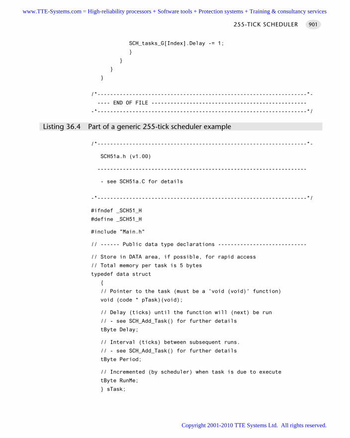
SCH_tasks_G[Index].Delay -= 1;
/*------------------------------------------------------------------*-
---- END OF FILE -------------------------------------------------
-*------------------------------------------------------------------*/
Listing 36.4 Part of a generic 255-tick scheduler example
/*------------------------------------------------------------------*-
SCH51a.h (v1.00)
------------------------------------------------------------------
- see SCH51a.C for details
-*------------------------------------------------------------------*/
#ifndef _SCH51_H
#define _SCH51_H
#include "Main.h"
// ------ Public data type declarations ----------------------------
// Store in DATA area, if possible, for rapid access
// Total memory per task is 5 bytes
typedef data struct
// Pointer to the task (must be a 'void (void)' function)
void (code * pTask)(void);
// Delay (ticks) until the function will (next) be run
// - see SCH_Add_Task() for further details
tByte Delay;
// Interval (ticks) between subsequent runs.
// - see SCH_Add_Task() for further details
tByte Period;
// Incremented (by scheduler) when task is due to execute
tByte RunMe;
sTask;
255-TICK SCHEDULER 901
www.TTE-Systems.com = High-reliability processors + Software tools + Protection systems + Training & consultancy services
Copyright 2001-2010 TTE Systems Ltd. All rights reserved.
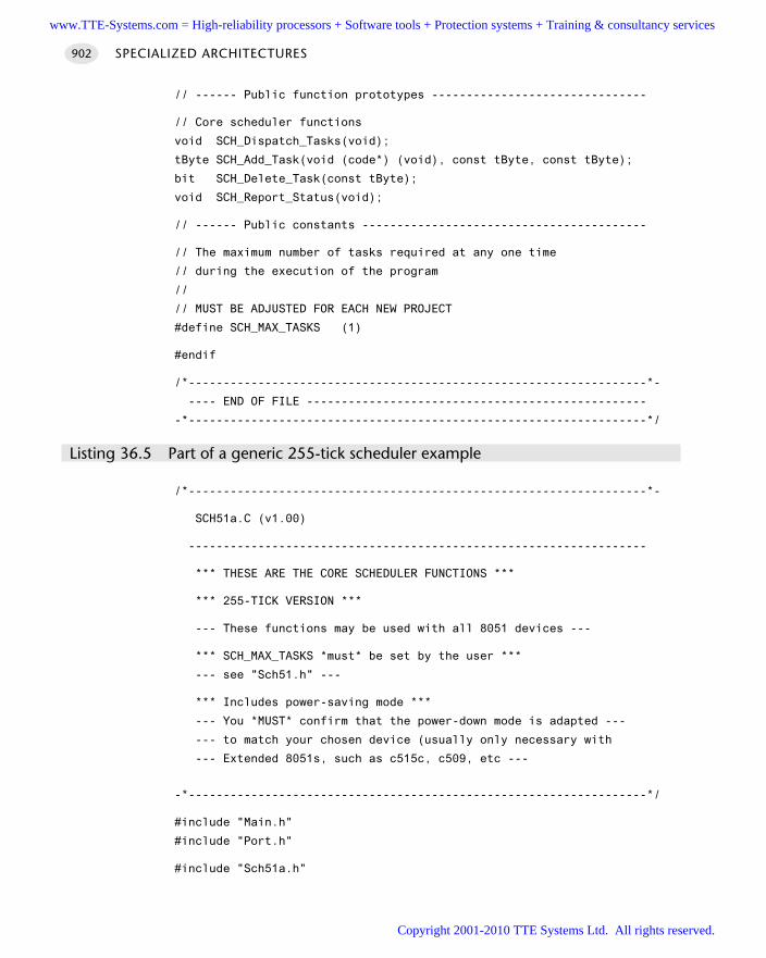
// ------ Public function prototypes -------------------------------
// Core scheduler functions
void SCH_Dispatch_Tasks(void);
tByte SCH_Add_Task(void (code*) (void), const tByte, const tByte);
bit SCH_Delete_Task(const tByte);
void SCH_Report_Status(void);
// ------ Public constants -----------------------------------------
// The maximum number of tasks required at any one time
// during the execution of the program
//
// MUST BE ADJUSTED FOR EACH NEW PROJECT
#define SCH_MAX_TASKS (1)
#endif
/*------------------------------------------------------------------*-
---- END OF FILE -------------------------------------------------
-*------------------------------------------------------------------*/
Listing 36.5 Part of a generic 255-tick scheduler example
/*------------------------------------------------------------------*-
SCH51a.C (v1.00)
------------------------------------------------------------------
*** THESE ARE THE CORE SCHEDULER FUNCTIONS ***
*** 255-TICK VERSION ***
--- These functions may be used with all 8051 devices ---
*** SCH_MAX_TASKS *must* be set by the user ***
--- see "Sch51.h" ---
*** Includes power-saving mode ***
--- You *MUST* confirm that the power-down mode is adapted ---
--- to match your chosen device (usually only necessary with
--- Extended 8051s, such as c515c, c509, etc ---
-*------------------------------------------------------------------*/
#include "Main.h"
#include "Port.h"
#include "Sch51a.h"
SPECIALIZED ARCHITECTURES902
www.TTE-Systems.com = High-reliability processors + Software tools + Protection systems + Training & consultancy services
Copyright 2001-2010 TTE Systems Ltd. All rights reserved.
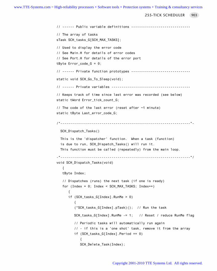
// ------ Public variable definitions ------------------------------
// The array of tasks
sTask SCH_tasks_G[SCH_MAX_TASKS];
// Used to display the error code
// See Main.H for details of error codes
// See Port.H for details of the error port
tByte Error_code_G = 0;
// ------ Private function prototypes ------------------------------
static void SCH_Go_To_Sleep(void);
// ------ Private variables ----------------------------------------
// Keeps track of time since last error was recorded (see below)
static tWord Error_tick_count_G;
// The code of the last error (reset after ~1 minute)
static tByte Last_error_code_G;
/*------------------------------------------------------------------*-
SCH_Dispatch_Tasks()
This is the 'dispatcher' function. When a task (function)
is due to run, SCH_Dispatch_Tasks() will run it.
This function must be called (repeatedly) from the main loop.
-*------------------------------------------------------------------*/
void SCH_Dispatch_Tasks(void)
tByte Index;
// Dispatches (runs) the next task (if one is ready)
for (Index = 0; Index < SCH_MAX_TASKS; Index++)
if (SCH_tasks_G[Index].RunMe > 0)
(*SCH_tasks_G[Index].pTask)(); // Run the task
SCH_tasks_G[Index].RunMe -= 1; // Reset / reduce RunMe flag
// Periodic tasks will automatically run again
// - if this is a 'one shot' task, remove it from the array
if (SCH_tasks_G[Index].Period == 0)
SCH_Delete_Task(Index);
255-TICK SCHEDULER 903
www.TTE-Systems.com = High-reliability processors + Software tools + Protection systems + Training & consultancy services
Copyright 2001-2010 TTE Systems Ltd. All rights reserved.
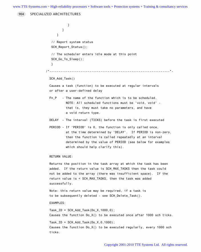
// Report system status
SCH_Report_Status();
// The scheduler enters idle mode at this point
SCH_Go_To_Sleep();
/*------------------------------------------------------------------*-
SCH_Add_Task()
Causes a task (function) to be executed at regular intervals
or after a user-defined delay
Fn_P - The name of the function which is to be scheduled.
NOTE: All scheduled functions must be 'void, void' -
that is, they must take no parameters, and have
a void return type.
DELAY - The interval (TICKS) before the task is first executed
PERIOD - If 'PERIOD' is 0, the function is only called once,
at the time determined by 'DELAY'. If PERIOD is non-zero,
then the function is called repeatedly at an interval
determined by the value of PERIOD (see below for examples
which should help clarify this).
RETURN VALUE:
Returns the position in the task array at which the task has been
added. If the return value is SCH_MAX_TASKS then the task could
not be added to the array (there was insufficient space). If the
return value is < SCH_MAX_TASKS, then the task was added
successfully.
Note: this return value may be required, if a task is
to be subsequently deleted - see SCH_Delete_Task().
EXAMPLES:
Task_ID = SCH_Add_Task(Do_X,1000,0);
Causes the function Do_X() to be executed once after 1000 sch ticks.
Task_ID = SCH_Add_Task(Do_X,0,1000);
Causes the function Do_X() to be executed regularly, every 1000 sch
ticks.
SPECIALIZED ARCHITECTURES904
www.TTE-Systems.com = High-reliability processors + Software tools + Protection systems + Training & consultancy services
Copyright 2001-2010 TTE Systems Ltd. All rights reserved.
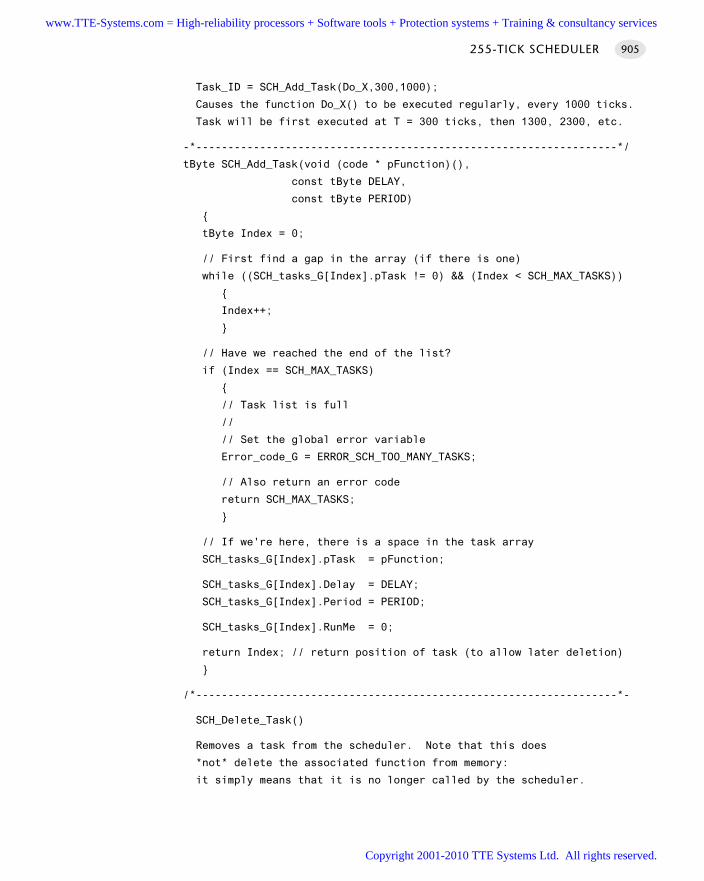
Task_ID = SCH_Add_Task(Do_X,300,1000);
Causes the function Do_X() to be executed regularly, every 1000 ticks.
Task will be first executed at T = 300 ticks, then 1300, 2300, etc.
-*------------------------------------------------------------------*/
tByte SCH_Add_Task(void (code * pFunction)(),
const tByte DELAY,
const tByte PERIOD)
tByte Index = 0;
// First find a gap in the array (if there is one)
while ((SCH_tasks_G[Index].pTask != 0) && (Index < SCH_MAX_TASKS))
Index++;
// Have we reached the end of the list?
if (Index == SCH_MAX_TASKS)
// Task list is full
//
// Set the global error variable
Error_code_G = ERROR_SCH_TOO_MANY_TASKS;
// Also return an error code
return SCH_MAX_TASKS;
// If we're here, there is a space in the task array
SCH_tasks_G[Index].pTask = pFunction;
SCH_tasks_G[Index].Delay = DELAY;
SCH_tasks_G[Index].Period = PERIOD;
SCH_tasks_G[Index].RunMe = 0;
return Index; // return position of task (to allow later deletion)
/*------------------------------------------------------------------*-
SCH_Delete_Task()
Removes a task from the scheduler. Note that this does
*not* delete the associated function from memory:
it simply means that it is no longer called by the scheduler.
255-TICK SCHEDULER 905
www.TTE-Systems.com = High-reliability processors + Software tools + Protection systems + Training & consultancy services
Copyright 2001-2010 TTE Systems Ltd. All rights reserved.
TASK_INDEX - The task index. Provided by SCH_Add_Task().
RETURN VALUE: RETURN_ERROR or RETURN_NORMAL
-*------------------------------------------------------------------*/
bit SCH_Delete_Task(const tByte TASK_INDEX)
bit Return_code;
if (SCH_tasks_G[TASK_INDEX].pTask == 0)
// No task at this location...
//
// Set the global error variable
Error_code_G = ERROR_SCH_CANNOT_DELETE_TASK;
// ...also return an error code
Return_code = RETURN_ERROR;
else
Return_code = RETURN_NORMAL;
SCH_tasks_G[TASK_INDEX].pTask = 0x0000;
SCH_tasks_G[TASK_INDEX].Delay = 0;
SCH_tasks_G[TASK_INDEX].Period = 0;
SCH_tasks_G[TASK_INDEX].RunMe = 0;
return Return_code; // return status
/*------------------------------------------------------------------*-
SCH_Report_Status()
Simple function to display error codes.
This version displays code on a port with attached LEDs:
adapt, if required, to report errors over serial link, etc.
Errors are only displayed for a limited period
(60000 ticks = 1 minute at 1ms tick interval).
After this the the error code is reset to 0.
This code may be easily adapted to display the last
error 'for ever': this may be appropriate in your
application.
SPECIALIZED ARCHITECTURES906
www.TTE-Systems.com = High-reliability processors + Software tools + Protection systems + Training & consultancy services
Copyright 2001-2010 TTE Systems Ltd. All rights reserved.
See Chapter 10 for further information.
-*------------------------------------------------------------------*/
void SCH_Report_Status(void)
#ifdef SCH_REPORT_ERRORS
// ONLY APPLIES IF WE ARE REPORTING ERRORS
// Check for a new error code
if (Error_code_G != Last_error_code_G)
// Negative logic on LEDs assumed
Error_port = 255 - Error_code_G;
Last_error_code_G = Error_code_G;
if (Error_code_G != 0)
Error_tick_count_G = 60000;
else
Error_tick_count_G = 0;
else
if (Error_tick_count_G != 0)
if (--Error_tick_count_G == 0)
Error_code_G = 0; // Reset error code
#endif
/*------------------------------------------------------------------*-
SCH_Go_To_Sleep()
This scheduler enters 'idle mode' between clock ticks
to save power. The next clock tick will return the processor
to the normal operating state.
255-TICK SCHEDULER 907
www.TTE-Systems.com = High-reliability processors + Software tools + Protection systems + Training & consultancy services
Copyright 2001-2010 TTE Systems Ltd. All rights reserved.
Note: a slight performance improvement is possible if this
function is implemented as a macro, or if the code here is simply
pasted into the 'dispatch' function.
However, by making this a function call, it becomes easier
- during development - to assess the performance of the
scheduler, using the 'performance analyser' in the Keil
hardware simulator. See Chapter 14 for examples of this.
*** May wish to disable this if using a watchdog ***
*** ADAPT AS REQUIRED FOR YOUR HARDWARE ***
-*------------------------------------------------------------------*/
void SCH_Go_To_Sleep()
PCON |= 0x01; // Enter idle mode (generic 8051 version)
// Entering idle mode requires TWO consecutive instructions
// on 80c515 / 80c505 - to avoid accidental triggering
//PCON |= 0x01; // Enter idle mode (#1)
//PCON |= 0x20; // Enter idle mode (#2)
/*------------------------------------------------------------------*-
---- END OF FILE -------------------------------------------------
-*------------------------------------------------------------------*/
Listing 36.6 Part of a generic 255-tick scheduler example
/*------------------------------------------------------------------*-
LED_flas.H (v1.00)
------------------------------------------------------------------
- See LED_flas.C for details.
-*------------------------------------------------------------------*/
// ------ Public function prototypes -------------------------------
void LED_Flash_Init(void);
void LED_Flash_Update(void);
/*------------------------------------------------------------------*-
---- END OF FILE -------------------------------------------------
-*------------------------------------------------------------------*/
Listing 36.7 Part of a generic 255-tick scheduler example
SPECIALIZED ARCHITECTURES908
www.TTE-Systems.com = High-reliability processors + Software tools + Protection systems + Training & consultancy services
Copyright 2001-2010 TTE Systems Ltd. All rights reserved.
/*------------------------------------------------------------------*-
LED_flas.C (v1.00)
------------------------------------------------------------------
Simple 'Flash LED' test function for scheduler.
-*------------------------------------------------------------------*/
#include "Main.h"
#include "Port.h"
#include "LED_flas.h"
// ------ Private variable definitions -----------------------------
static bit LED_state_G;
/*------------------------------------------------------------------*-
LED_Flash_Init()
- See below.
-*------------------------------------------------------------------*/
void LED_Flash_Init(void)
LED_state_G = 0;
/*------------------------------------------------------------------*-
LED_Flash_Update()
Flashes an LED (or pulses a buzzer, etc) on a specified port pin.
Must schedule at twice the required flash rate: thus, for 1 Hz
flash (on for 0.5 seconds, off for 0.5 seconds) must schedule
at 2 Hz.
-*------------------------------------------------------------------*/
void LED_Flash_Update(void)
// Change the LED from OFF to ON (or vice versa)
if (LED_state_G == 1)
LED_state_G = 0;
LED_pin = 0;
else
255-TICK SCHEDULER 909
www.TTE-Systems.com = High-reliability processors + Software tools + Protection systems + Training & consultancy services
Copyright 2001-2010 TTE Systems Ltd. All rights reserved.
LED_state_G = 1;
LED_pin = 1;
/*------------------------------------------------------------------*-
---- END OF FILE -------------------------------------------------
-*------------------------------------------------------------------*/
Listing 36.8 Part of a generic 255-tick scheduler example
Further reading—
SPECIALIZED ARCHITECTURES910
www.TTE-Systems.com = High-reliability processors + Software tools + Protection systems + Training & consultancy services
Copyright 2001-2010 TTE Systems Ltd. All rights reserved.
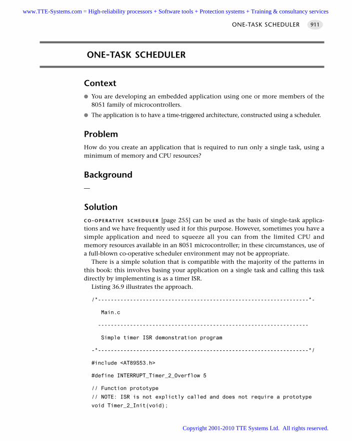
ONE-TASK SCHEDULER
Context You are developing an embedded application using one or more members of the
8051 family of microcontrollers.
The application is to have a time-triggered architecture, constructed using a scheduler.
ProblemHow do you create an application that is required to run only a single task, using aminimum of memory and CPU resources?
Background—
SolutionC O-O P E R AT I V E S C H E D U L E R [page 255] can be used as the basis of single-task applica-tions and we have frequently used it for this purpose. However, sometimes you have asimple application and need to squeeze all you can from the limited CPU andmemory resources available in an 8051 microcontroller; in these circumstances, use ofa full-blown co-operative scheduler environment may not be appropriate.
There is a simple solution that is compatible with the majority of the patterns inthis book: this involves basing your application on a single task and calling this taskdirectly by implementing is as a timer ISR.
Listing 36.9 illustrates the approach.
/*------------------------------------------------------------------*-
Main.c
------------------------------------------------------------------
Simple timer ISR demonstration program
-*------------------------------------------------------------------*/
#include <AT89S53.h>
#define INTERRUPT_Timer_2_Overflow 5
// Function prototype
// NOTE: ISR is not explictly called and does not require a prototype
void Timer_2_Init(void);
ONE-TASK SCHEDULER 911
www.TTE-Systems.com = High-reliability processors + Software tools + Protection systems + Training & consultancy services
Copyright 2001-2010 TTE Systems Ltd. All rights reserved.
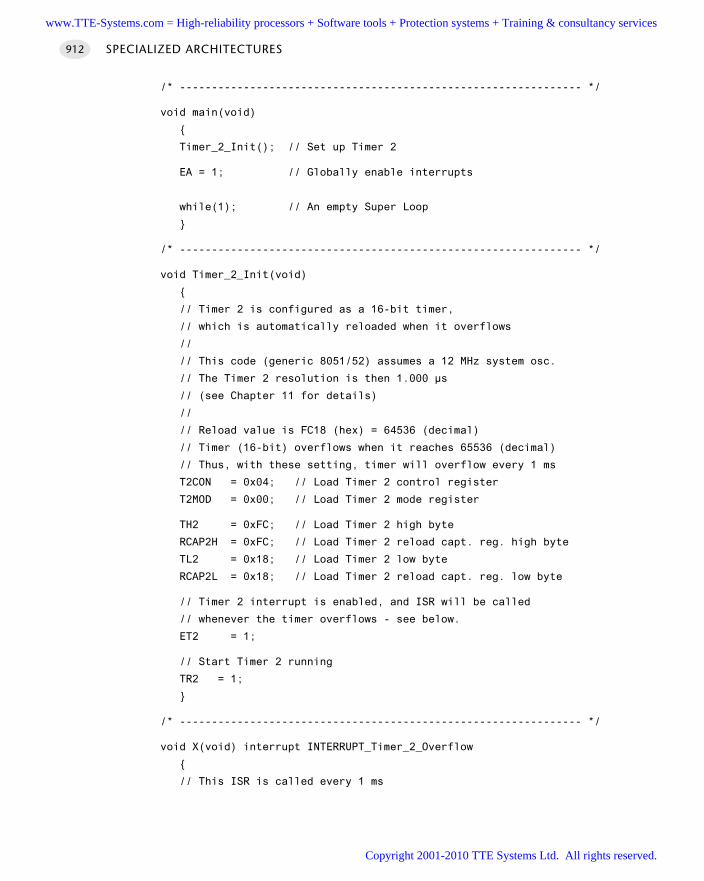
/* --------------------------------------------------------------- */
void main(void)
Timer_2_Init(); // Set up Timer 2
EA = 1; // Globally enable interrupts
while(1); // An empty Super Loop
/* --------------------------------------------------------------- */
void Timer_2_Init(void)
// Timer 2 is configured as a 16-bit timer,
// which is automatically reloaded when it overflows
//
// This code (generic 8051/52) assumes a 12 MHz system osc.
// The Timer 2 resolution is then 1.000 µs
// (see Chapter 11 for details)
//
// Reload value is FC18 (hex) = 64536 (decimal)
// Timer (16-bit) overflows when it reaches 65536 (decimal)
// Thus, with these setting, timer will overflow every 1 ms
T2CON = 0x04; // Load Timer 2 control register
T2MOD = 0x00; // Load Timer 2 mode register
TH2 = 0xFC; // Load Timer 2 high byte
RCAP2H = 0xFC; // Load Timer 2 reload capt. reg. high byte
TL2 = 0x18; // Load Timer 2 low byte
RCAP2L = 0x18; // Load Timer 2 reload capt. reg. low byte
// Timer 2 interrupt is enabled, and ISR will be called
// whenever the timer overflows - see below.
ET2 = 1;
// Start Timer 2 running
TR2 = 1;
/* --------------------------------------------------------------- */
void X(void) interrupt INTERRUPT_Timer_2_Overflow
// This ISR is called every 1 ms
SPECIALIZED ARCHITECTURES912
www.TTE-Systems.com = High-reliability processors + Software tools + Protection systems + Training & consultancy services
Copyright 2001-2010 TTE Systems Ltd. All rights reserved.
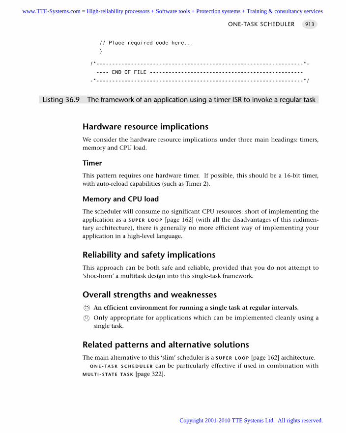
// Place required code here...
/*------------------------------------------------------------------*-
---- END OF FILE -------------------------------------------------
-*------------------------------------------------------------------*/
Listing 36.9 The framework of an application using a timer ISR to invoke a regular task
Hardware resource implicationsWe consider the hardware resource implications under three main headings: timers,memory and CPU load.
Timer
This pattern requires one hardware timer. If possible, this should be a 16-bit timer,with auto-reload capabilities (such as Timer 2).
Memory and CPU load
The scheduler will consume no significant CPU resources: short of implementing theapplication as a S U P E R L O O P [page 162] (with all the disadvantages of this rudimen-tary architecture), there is generally no more efficient way of implementing yourapplication in a high-level language.
Reliability and safety implicationsThis approach can be both safe and reliable, provided that you do not attempt to‘shoe-horn’ a multitask design into this single-task framework.
Overall strengths and weaknessesAn efficient environment for running a single task at regular intervals.
Only appropriate for applications which can be implemented cleanly using asingle task.
Related patterns and alternative solutionsThe main alternative to this ‘slim’ scheduler is a S U P E R L O O P [page 162] architecture.
O N E - TA S K S C H E D U L E R can be particularly effective if used in combination withM U LT I - S TAT E TA S K [page 322].
ONE-TASK SCHEDULER 913
www.TTE-Systems.com = High-reliability processors + Software tools + Protection systems + Training & consultancy services
Copyright 2001-2010 TTE Systems Ltd. All rights reserved.
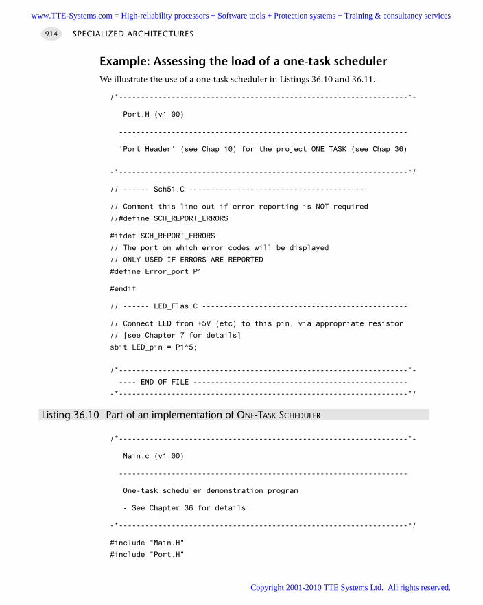
Example: Assessing the load of a one-task schedulerWe illustrate the use of a one-task scheduler in Listings 36.10 and 36.11.
/*------------------------------------------------------------------*-
Port.H (v1.00)
------------------------------------------------------------------
'Port Header' (see Chap 10) for the project ONE_TASK (see Chap 36)
-*------------------------------------------------------------------*/
// ------ Sch51.C ----------------------------------------
// Comment this line out if error reporting is NOT required
//#define SCH_REPORT_ERRORS
#ifdef SCH_REPORT_ERRORS
// The port on which error codes will be displayed
// ONLY USED IF ERRORS ARE REPORTED
#define Error_port P1
#endif
// ------ LED_Flas.C -----------------------------------------------
// Connect LED from +5V (etc) to this pin, via appropriate resistor
// [see Chapter 7 for details]
sbit LED_pin = P1^5;
/*------------------------------------------------------------------*-
---- END OF FILE -------------------------------------------------
-*------------------------------------------------------------------*/
Listing 36.10 Part of an implementation of ONE-TASK SCHEDULER
/*------------------------------------------------------------------*-
Main.c (v1.00)
------------------------------------------------------------------
One-task scheduler demonstration program
- See Chapter 36 for details.
-*------------------------------------------------------------------*/
#include "Main.H"
#include "Port.H"
SPECIALIZED ARCHITECTURES914
www.TTE-Systems.com = High-reliability processors + Software tools + Protection systems + Training & consultancy services
Copyright 2001-2010 TTE Systems Ltd. All rights reserved.
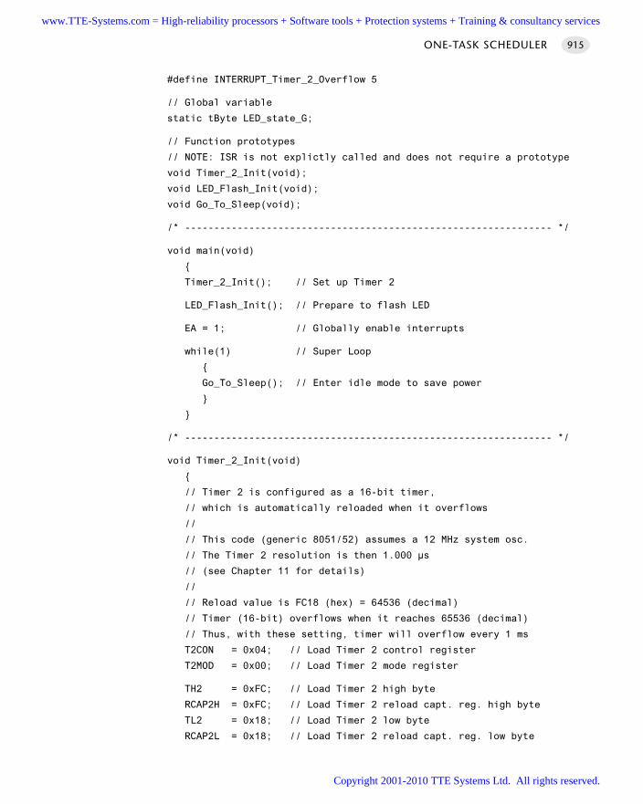
#define INTERRUPT_Timer_2_Overflow 5
// Global variable
static tByte LED_state_G;
// Function prototypes
// NOTE: ISR is not explictly called and does not require a prototype
void Timer_2_Init(void);
void LED_Flash_Init(void);
void Go_To_Sleep(void);
/* --------------------------------------------------------------- */
void main(void)
Timer_2_Init(); // Set up Timer 2
LED_Flash_Init(); // Prepare to flash LED
EA = 1; // Globally enable interrupts
while(1) // Super Loop
Go_To_Sleep(); // Enter idle mode to save power
/* --------------------------------------------------------------- */
void Timer_2_Init(void)
// Timer 2 is configured as a 16-bit timer,
// which is automatically reloaded when it overflows
//
// This code (generic 8051/52) assumes a 12 MHz system osc.
// The Timer 2 resolution is then 1.000 µs
// (see Chapter 11 for details)
//
// Reload value is FC18 (hex) = 64536 (decimal)
// Timer (16-bit) overflows when it reaches 65536 (decimal)
// Thus, with these setting, timer will overflow every 1 ms
T2CON = 0x04; // Load Timer 2 control register
T2MOD = 0x00; // Load Timer 2 mode register
TH2 = 0xFC; // Load Timer 2 high byte
RCAP2H = 0xFC; // Load Timer 2 reload capt. reg. high byte
TL2 = 0x18; // Load Timer 2 low byte
RCAP2L = 0x18; // Load Timer 2 reload capt. reg. low byte
ONE-TASK SCHEDULER 915
www.TTE-Systems.com = High-reliability processors + Software tools + Protection systems + Training & consultancy services
Copyright 2001-2010 TTE Systems Ltd. All rights reserved.
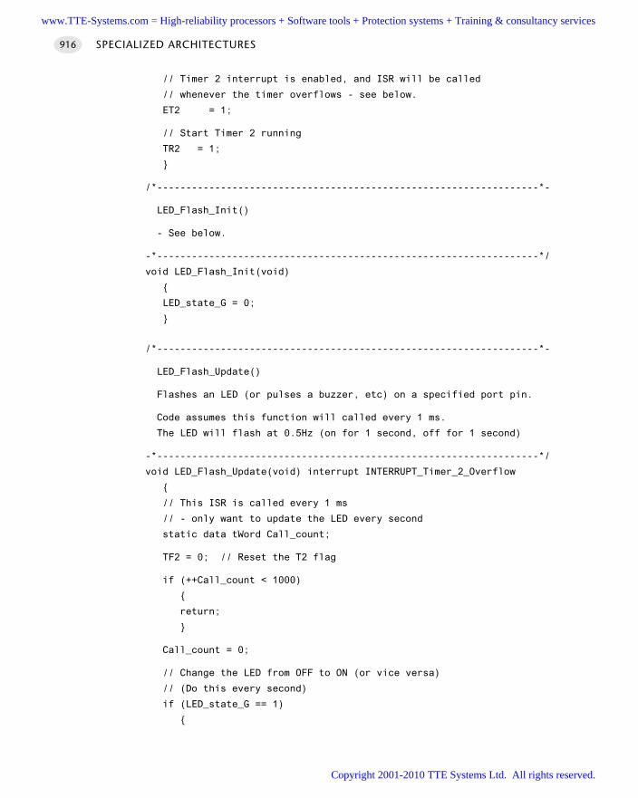
// Timer 2 interrupt is enabled, and ISR will be called
// whenever the timer overflows - see below.
ET2 = 1;
// Start Timer 2 running
TR2 = 1;
/*------------------------------------------------------------------*-
LED_Flash_Init()
- See below.
-*------------------------------------------------------------------*/
void LED_Flash_Init(void)
LED_state_G = 0;
/*------------------------------------------------------------------*-
LED_Flash_Update()
Flashes an LED (or pulses a buzzer, etc) on a specified port pin.
Code assumes this function will called every 1 ms.
The LED will flash at 0.5Hz (on for 1 second, off for 1 second)
-*------------------------------------------------------------------*/
void LED_Flash_Update(void) interrupt INTERRUPT_Timer_2_Overflow
// This ISR is called every 1 ms
// - only want to update the LED every second
static data tWord Call_count;
TF2 = 0; // Reset the T2 flag
if (++Call_count < 1000)
return;
Call_count = 0;
// Change the LED from OFF to ON (or vice versa)
// (Do this every second)
if (LED_state_G == 1)
SPECIALIZED ARCHITECTURES916
www.TTE-Systems.com = High-reliability processors + Software tools + Protection systems + Training & consultancy services
Copyright 2001-2010 TTE Systems Ltd. All rights reserved.
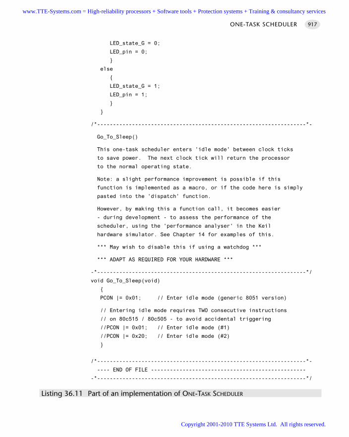
LED_state_G = 0;
LED_pin = 0;
else
LED_state_G = 1;
LED_pin = 1;
/*------------------------------------------------------------------*-
Go_To_Sleep()
This one-task scheduler enters 'idle mode' between clock ticks
to save power. The next clock tick will return the processor
to the normal operating state.
Note: a slight performance improvement is possible if this
function is implemented as a macro, or if the code here is simply
pasted into the 'dispatch' function.
However, by making this a function call, it becomes easier
- during development - to assess the performance of the
scheduler, using the 'performance analyser' in the Keil
hardware simulator. See Chapter 14 for examples of this.
*** May wish to disable this if using a watchdog ***
*** ADAPT AS REQUIRED FOR YOUR HARDWARE ***
-*------------------------------------------------------------------*/
void Go_To_Sleep(void)
PCON |= 0x01; // Enter idle mode (generic 8051 version)
// Entering idle mode requires TWO consecutive instructions
// on 80c515 / 80c505 - to avoid accidental triggering
//PCON |= 0x01; // Enter idle mode (#1)
//PCON |= 0x20; // Enter idle mode (#2)
/*------------------------------------------------------------------*-
---- END OF FILE -------------------------------------------------
-*------------------------------------------------------------------*/
Listing 36.11 Part of an implementation of ONE-TASK SCHEDULER
ONE-TASK SCHEDULER 917
www.TTE-Systems.com = High-reliability processors + Software tools + Protection systems + Training & consultancy services
Copyright 2001-2010 TTE Systems Ltd. All rights reserved.
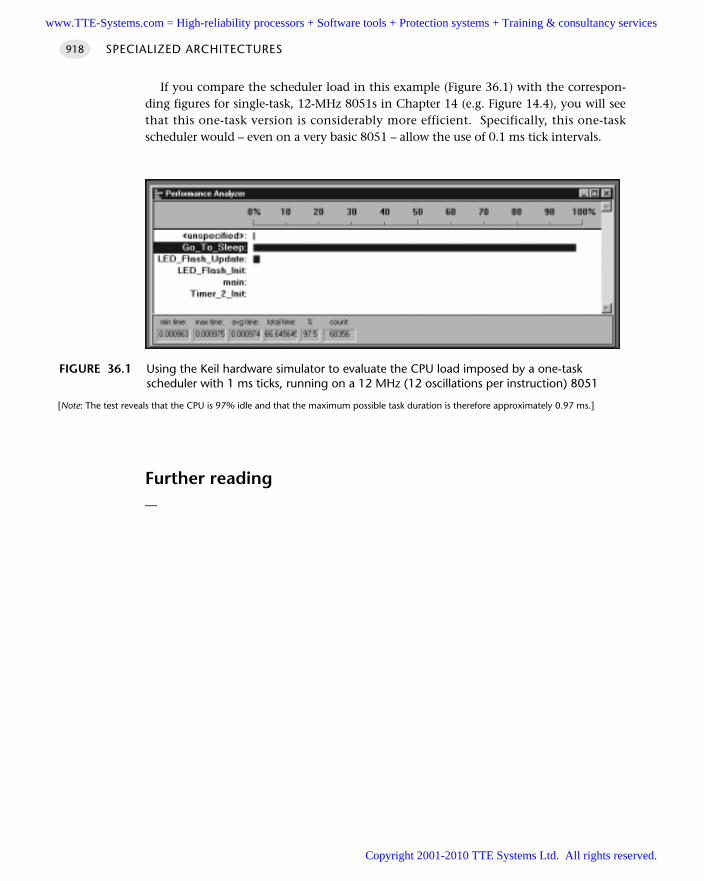
If you compare the scheduler load in this example (Figure 36.1) with the correspon-ding figures for single-task, 12-MHz 8051s in Chapter 14 (e.g. Figure 14.4), you will seethat this one-task version is considerably more efficient. Specifically, this one-taskscheduler would – even on a very basic 8051 – allow the use of 0.1 ms tick intervals.
Further reading—
SPECIALIZED ARCHITECTURES918
FIGURE 36.1 Using the Keil hardware simulator to evaluate the CPU load imposed by a one-taskscheduler with 1 ms ticks, running on a 12 MHz (12 oscillations per instruction) 8051
[Note: The test reveals that the CPU is 97% idle and that the maximum possible task duration is therefore approximately 0.97 ms.]
www.TTE-Systems.com = High-reliability processors + Software tools + Protection systems + Training & consultancy services
Copyright 2001-2010 TTE Systems Ltd. All rights reserved.
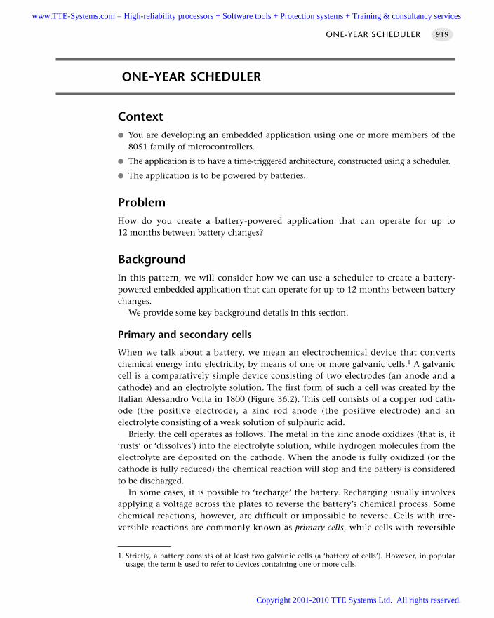
ONE-YEAR SCHEDULER
Context You are developing an embedded application using one or more members of the
8051 family of microcontrollers.
The application is to have a time-triggered architecture, constructed using a scheduler.
The application is to be powered by batteries.
ProblemHow do you create a battery-powered application that can operate for up to12 months between battery changes?
BackgroundIn this pattern, we will consider how we can use a scheduler to create a battery-powered embedded application that can operate for up to 12 months between batterychanges.
We provide some key background details in this section.
Primary and secondary cells
When we talk about a battery, we mean an electrochemical device that convertschemical energy into electricity, by means of one or more galvanic cells.1 A galvaniccell is a comparatively simple device consisting of two electrodes (an anode and acathode) and an electrolyte solution. The first form of such a cell was created by theItalian Alessandro Volta in 1800 (Figure 36.2). This cell consists of a copper rod cath-ode (the positive electrode), a zinc rod anode (the positive electrode) and anelectrolyte consisting of a weak solution of sulphuric acid.
Briefly, the cell operates as follows. The metal in the zinc anode oxidizes (that is, it‘rusts’ or ‘dissolves’) into the electrolyte solution, while hydrogen molecules from theelectrolyte are deposited on the cathode. When the anode is fully oxidized (or thecathode is fully reduced) the chemical reaction will stop and the battery is consideredto be discharged.
In some cases, it is possible to ‘recharge’ the battery. Recharging usually involvesapplying a voltage across the plates to reverse the battery’s chemical process. Somechemical reactions, however, are difficult or impossible to reverse. Cells with irre-versible reactions are commonly known as primary cells, while cells with reversible
ONE-YEAR SCHEDULER 919
1. Strictly, a battery consists of at least two galvanic cells (a ‘battery of cells’). However, in popularusage, the term is used to refer to devices containing one or more cells.
www.TTE-Systems.com = High-reliability processors + Software tools + Protection systems + Training & consultancy services
Copyright 2001-2010 TTE Systems Ltd. All rights reserved.
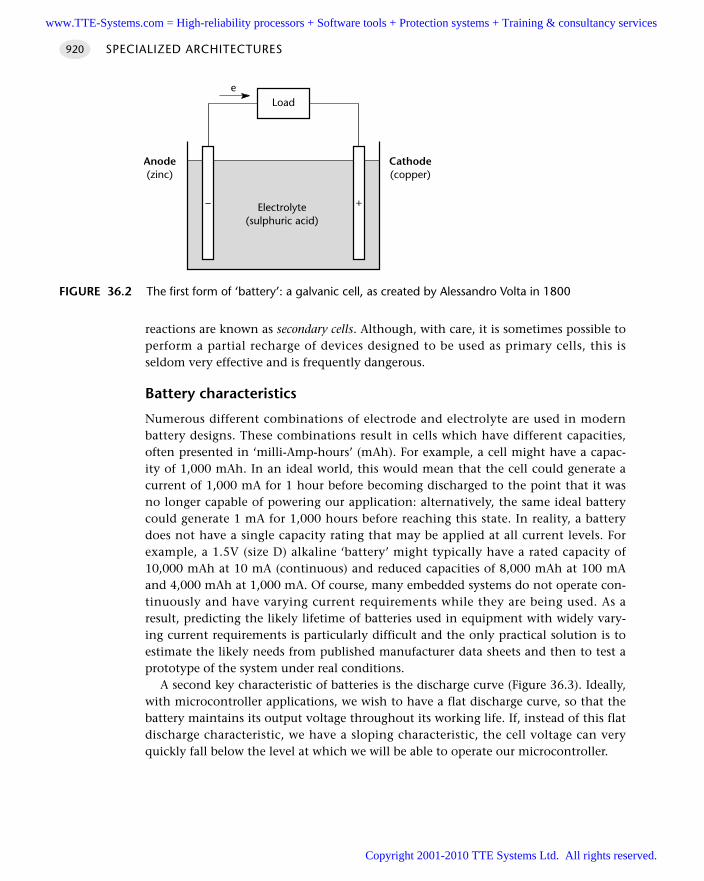
reactions are known as secondary cells. Although, with care, it is sometimes possible toperform a partial recharge of devices designed to be used as primary cells, this isseldom very effective and is frequently dangerous.
Battery characteristics
Numerous different combinations of electrode and electrolyte are used in modernbattery designs. These combinations result in cells which have different capacities,often presented in ‘milli-Amp-hours’ (mAh). For example, a cell might have a capac-ity of 1,000 mAh. In an ideal world, this would mean that the cell could generate acurrent of 1,000 mA for 1 hour before becoming discharged to the point that it wasno longer capable of powering our application: alternatively, the same ideal batterycould generate 1 mA for 1,000 hours before reaching this state. In reality, a batterydoes not have a single capacity rating that may be applied at all current levels. Forexample, a 1.5V (size D) alkaline ‘battery’ might typically have a rated capacity of10,000 mAh at 10 mA (continuous) and reduced capacities of 8,000 mAh at 100 mAand 4,000 mAh at 1,000 mA. Of course, many embedded systems do not operate con-tinuously and have varying current requirements while they are being used. As aresult, predicting the likely lifetime of batteries used in equipment with widely vary-ing current requirements is particularly difficult and the only practical solution is toestimate the likely needs from published manufacturer data sheets and then to test aprototype of the system under real conditions.
A second key characteristic of batteries is the discharge curve (Figure 36.3). Ideally,with microcontroller applications, we wish to have a flat discharge curve, so that thebattery maintains its output voltage throughout its working life. If, instead of this flatdischarge characteristic, we have a sloping characteristic, the cell voltage can veryquickly fall below the level at which we will be able to operate our microcontroller.
SPECIALIZED ARCHITECTURES920
FIGURE 36.2 The first form of ‘battery’: a galvanic cell, as created by Alessandro Volta in 1800
Electrolyte(sulphuric acid)
Load
+–
e
Cathode(copper)
Anode(zinc)
www.TTE-Systems.com = High-reliability processors + Software tools + Protection systems + Training & consultancy services
Copyright 2001-2010 TTE Systems Ltd. All rights reserved.
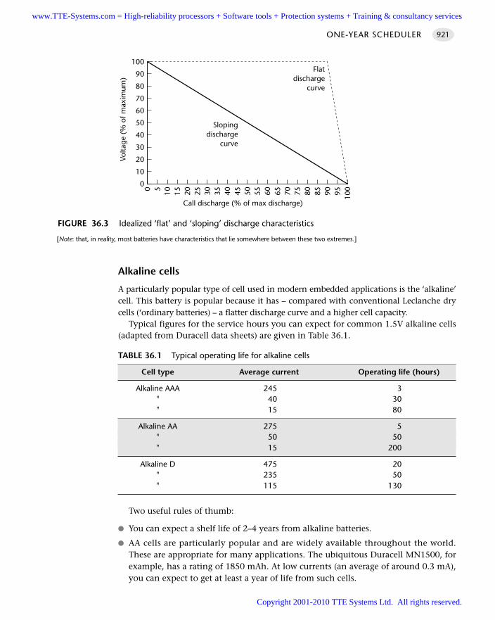
Alkaline cells
A particularly popular type of cell used in modern embedded applications is the ‘alkaline’cell. This battery is popular because it has – compared with conventional Leclanche drycells (‘ordinary batteries) – a flatter discharge curve and a higher cell capacity.
Typical figures for the service hours you can expect for common 1.5V alkaline cells(adapted from Duracell data sheets) are given in Table 36.1.
Two useful rules of thumb:
You can expect a shelf life of 2–4 years from alkaline batteries.
AA cells are particularly popular and are widely available throughout the world.These are appropriate for many applications. The ubiquitous Duracell MN1500, forexample, has a rating of 1850 mAh. At low currents (an average of around 0.3 mA),you can expect to get at least a year of life from such cells.
ONE-YEAR SCHEDULER 921
FIGURE 36.3 Idealized ‘flat’ and ‘sloping’ discharge characteristics
[Note: that, in reality, most batteries have characteristics that lie somewhere between these two extremes.]
0
0
10
20
30
40
50
60
70
80
90
100
5 10 15 20 25 30 35 40 45 50 55 60 65 70 75 80 90 95 10085
Call discharge (% of max discharge)
Volta
ge (
% o
f max
imum
)
Flatdischarge
curve
Slopingdischarge
curve
TABLE 36.1 Typical operating life for alkaline cells
Cell type Average current Operating life (hours)
Alkaline AAA 245 3" 40 30" 15 80
Alkaline AA 275 5" 50 50" 15 200
Alkaline D 475 20" 235 50" 115 130
www.TTE-Systems.com = High-reliability processors + Software tools + Protection systems + Training & consultancy services
Copyright 2001-2010 TTE Systems Ltd. All rights reserved.
Obtaining the required voltage
Each cell gives 1.5V (nominal): four cells will therefore give you 6V. Note that thisdoes not alter the current rating: 1 MN1500 AA cell has a rating of 1.5V, 1,850 mAh,while four have a rating of 6V, 1,850 mAh.
SolutionWe will particularly focus on the use of AA-sized alkaline cells as the power source, asthis is a popular and effective option. To do this then – for the reasons outlined in‘Background’ – we need to reduce the average current consumption to 0.3 mA.
As we noted in Chapter 3 (see Table 3.1, page 36), the typical current consumptionfor a Standard 8051 microcontroller (operating normally) is around 15 mA. At thiscurrent level, our batteries will last for around 200 hours – around 8 days. Even if theapplication spends most of its time in idle mode, the current consumption will stillbe around 5 mA: with luck, our application may operate for almost a month.
However, these figures do not tell the full story. In particular, they hide the factthat current consumption is heavily dependent on the oscillator frequency, and oper-ating voltage. For example, if you consider the datasheet for the Atmel 89S53(included on the CD), it will be apparent that the current consumption varies withvoltage and oscillator frequency. More specifically, by considering the datasheets forthe 89S53 or a wide range of other 8051 devices, it becomes apparent that, to obtainour average of 0.3mA current consumption, we must run at a voltage of around 3V,and at a very low oscillator frequency (around 1 MHz, preferably less). In addition, wemust keep the application in idle mode most of the time.
A cost-effective way of obtaining the required oscillator frequency is to use awatch crystal. These are cheap, small and widely available: they have frequencies of32.768 kHz. Note that to use this frequency you must work with an 8051 that canoperate in this frequency range: check your data sheet.
Working with AAA cells
The AA cells considered in detail in this pattern have a weight of 23.6 g or 0.83 oz.(Duracell MN1500 data sheet). To reduce the weight (and size) of your application,you way wish to consider using AAA cells, which have a weight of 11.0 g. or 0.39 oz.(Duracell MN2400 data sheet). These cells have a capacity of 1,150 mAh (DuracellMN2400 data sheet).
1,150 mAh translates into an average current of around 0.13 mA over a year. It isnow possible to obtain this level of current consumption from an 8051 device usingthe Small 8051s and particularly the modern Philips devices. For example, the Philips87LPC764 has very low current consumption in both active and idle states, particu-larly at low frequencies, as the data sheet (included on the CD ROM) makes clear.
From the data sheet, it is apparent that even in active mode (again assuming use ofa 32 kHz watch crystal), the 87LPC768 draws only around 0.1 mA, while in idle modethis figure falls to around 0.05 mA. Provided we do not need to drive high-powerexternal components, then these devices are ideal as the basis of lightweight embed-ded applications.
SPECIALIZED ARCHITECTURES922
www.TTE-Systems.com = High-reliability processors + Software tools + Protection systems + Training & consultancy services
Copyright 2001-2010 TTE Systems Ltd. All rights reserved.
Working with 9V batteries
Another popular lightweight battery is the 9V ‘radio’ battery, with useful push-onconnector terminals. These have a capacity of around 500 mAh (Duracell MN1604data sheet), which translates into 0.06 mA average current over a year. The recentSmall 8051s (described earlier) can, almost match these requirements. However, inmost 8051-based applications, you will be unlikely to obtain more than around sixmonths of life from such a battery.
Working with D cells
If you require a longer operating life and / or higher current than AA cells can pro-vide, D cells may be an alternative. These comparatively large cells have a capacity ofaround 15,000 mAh (Duracell MN1300 data sheet). Over one year, this translates intoan average current of 1.7 mA: over two years, this becomes 0.8 mA.
You can reliably obtain two years of life from D cells in embedded applications andmay even manage 3 years if your current requirements are very limited. For applicationswhere the user is not expect to carry the product around this can be a good solution.
D cells are particularly attractive in applications such as long-term, unattendeddata logging. Although the D cells are large and heavy, the alternative may be a lead-acid secondary cell and a solar-powered battery charger, which will be even heavier,more complex and considerably more expensive.
Working with lithium cells
Lithium cells have been introduced comparatively recently and have many character-istics that make them very attractive for use as primary cells in many battery-poweredembedded systems.
Key characteristics of this type of cell or battery:
Lithium cells have very low self-discharge rates: this means they can last formany years (a decade is not uncommon) ‘on the shelf’.
When being used, lithium batteries can last around three times longer thanalkaline batteries of the same size. This makes them ideal as, for example,CMOS backup batteries in desktop computers.
Lithium cells weigh around 30% less than equivalent alkaline cells.
Unlike most other battery technology, lithium cells operate effectively over awide temperature range. Alkaline cells operate at around 50–60% of theirnormal level at 0°C, whereas lithium cells operate normally at this tempera-ture. Lithium cells continue to provide an output around 80% of their normallevel even at temperatures below –20°C, whereas alkaline cells are unusable atsuch temperatures.
Lithium primary cells are available in standard (AA) sizes, 1.5V.
Lithium reacts violently when exposed to water and there were initial safety con-cerns about batteries based on this metal. Recent designs have greatly reducedsuch problems, but you need to be aware of this potential safety concern.
ONE-YEAR SCHEDULER 923
www.TTE-Systems.com = High-reliability processors + Software tools + Protection systems + Training & consultancy services
Copyright 2001-2010 TTE Systems Ltd. All rights reserved.
Lithium cells are not suitable for high-current applications (for example, drivingmotors, or other such loads).
Lithium batteries cost around twice as much as alkaline batteries of the same size,so may not always prove cost effective.
Lithium batteries are, currently, not as widely available as alkaline equivalents.
Overall, given these characteristics, it seems inevitable that, as prices fall, lithiumcells will become increasingly common in embedded applications.
Working with secondary cells
Rechargeable batteries are useful in many embedded applications, such as mobilephones, but cannot retain their charge for long enough to match the needs of thepresent pattern.
Hardware resource implicationsThis pattern is only suitable for use in applications which require limited CPU activityand are able to spend most of their operational life in idle mode.
Reliability and safety implicationsTypical one-year applications will be awakened from idle mode every 200 ms (say) tocheck a switch or perform some other processing. While in idle mode, they will notbe able to respond to external events.
This type of architecture is common, for example, in TV remote-control applica-tions and is appropriate for this purpose. This architecture may not be appropriate forsafety-related applications where very rapid responses are required.
PortabilityThis is a form of C O - O P E R AT I V E S C H E D U L E R [page 255] and is as portable as theoriginal pattern.
Overall strengths and weaknessesReduces battery consumption to a low level.
Limited processing ability as a result of low clock frequencies.
May not be appropriate for safety-related applications.
Related patterns and alternative solutionsThis pattern can often be combined with 255 - T I C K S C H E D U L E R [page 894] orO N E-TA S K S C H E D U L E R [page 911] to reduce the resource requirements further.
SPECIALIZED ARCHITECTURES924
www.TTE-Systems.com = High-reliability processors + Software tools + Protection systems + Training & consultancy services
Copyright 2001-2010 TTE Systems Ltd. All rights reserved.
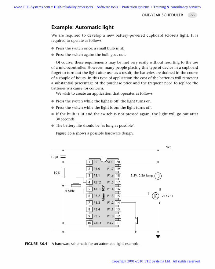
Example: Automatic lightWe are required to develop a new battery-powered cupboard (closet) light. It isrequired to operate as follows:
Press the switch once: a small bulb is lit.
Press the switch again: the bulb goes out.
Of course, these requirements may be met very easily without resorting to the useof a microcontroller. However, many people placing this type of device in a cupboardforget to turn out the light after use: as a result, the batteries are drained in the courseof a couple of hours. In this type of application the cost of the batteries will representa substantial percentage of the purchase price and the frequent need to replace thebatteries is a cause for concern.
We wish to create an application that operates as follows:
Press the switch while the light is off: the light turns on.
Press the switch while the light is on: the light turns off.
If the bulb is lit and the switch is not pressed again, the light will go out after30 seconds.
The battery life should be ‘as long as possible’.
Figure 36.4 shows a possible hardware design.
ONE-YEAR SCHEDULER 925
FIGURE 36.4 A hardware schematic for an automatic-light example.
201 VCCRST
192 P1.7P3.0
183 P1.6P3.1
174 P1.5XLT2
165 P1.4XTL1
156 P1.3P3.2
147 P1.2P3.3
138 P1.1P3.4
129 P1.0P3.5
1110 P3.7GND
EB
C
ZTX751
5.5V, 0.3A lamp
Vcc
10 µF
10 K
4 MHz
Atm
el 1
051
www.TTE-Systems.com = High-reliability processors + Software tools + Protection systems + Training & consultancy services
Copyright 2001-2010 TTE Systems Ltd. All rights reserved.
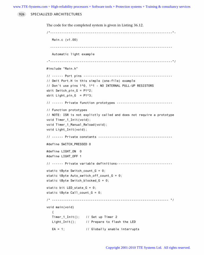
The code for the completed system is given in Listing 36.12.
/*------------------------------------------------------------------*-
Main.c (v1.00)
------------------------------------------------------------------
Automatic light example
-*------------------------------------------------------------------*/
#include "Main.h"
// ------ Port pins ------------------------------------------------
// Omit Port.H in this simple (one-file) example
// Don’t use pins 1^0, 1^1 - NO INTERNAL PULL-UP RESISTORS
sbit Switch_pin_G = P1^2;
sbit Light_pin_G = P1^3;
// ------ Private function prototypes ------------------------------
// Function prototypes
// NOTE: ISR is not explictly called and does not require a prototype
void Timer_1_Init(void);
void Timer_1_Manual_Reload(void);
void Light_Init(void);
// ------ Private constants ----------------------------------------
#define SWITCH_PRESSED 0
#define LIGHT_ON 0
#define LIGHT_OFF 1
// ------ Private variable definitions------------------------------
static tByte Switch_count_G = 0;
static tByte Auto_switch_off_count_G = 0;
static tByte Switch_blocked_G = 0;
static bit LED_state_G = 0;
static tByte Call_count_G = 0;
/* --------------------------------------------------------------- */
void main(void)
Timer_1_Init(); // Set up Timer 2
Light_Init(); // Prepare to flash the LED
EA = 1; // Globally enable interrupts
SPECIALIZED ARCHITECTURES926
www.TTE-Systems.com = High-reliability processors + Software tools + Protection systems + Training & consultancy services
Copyright 2001-2010 TTE Systems Ltd. All rights reserved.
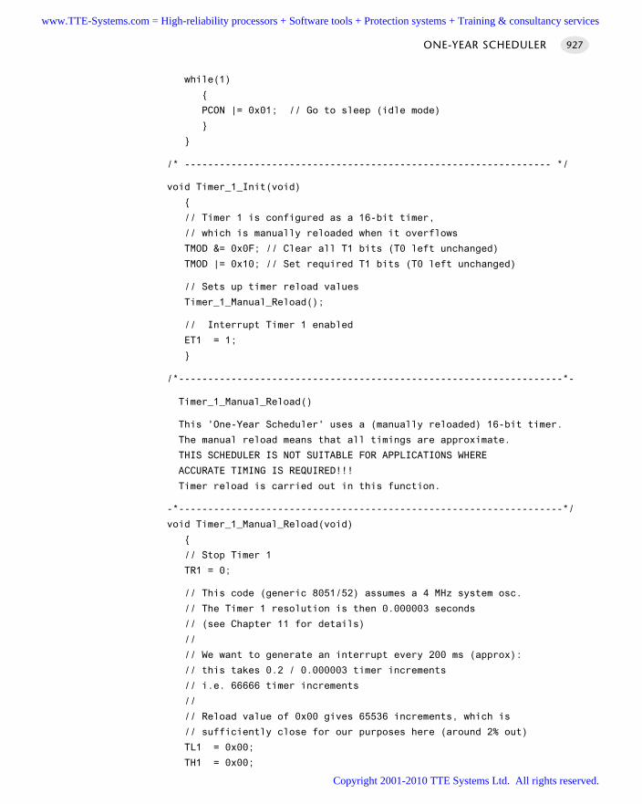
while(1)
PCON |= 0x01; // Go to sleep (idle mode)
/* --------------------------------------------------------------- */
void Timer_1_Init(void)
// Timer 1 is configured as a 16-bit timer,
// which is manually reloaded when it overflows
TMOD &= 0x0F; // Clear all T1 bits (T0 left unchanged)
TMOD |= 0x10; // Set required T1 bits (T0 left unchanged)
// Sets up timer reload values
Timer_1_Manual_Reload();
// Interrupt Timer 1 enabled
ET1 = 1;
/*------------------------------------------------------------------*-
Timer_1_Manual_Reload()
This 'One-Year Scheduler' uses a (manually reloaded) 16-bit timer.
The manual reload means that all timings are approximate.
THIS SCHEDULER IS NOT SUITABLE FOR APPLICATIONS WHERE
ACCURATE TIMING IS REQUIRED!!!
Timer reload is carried out in this function.
-*------------------------------------------------------------------*/
void Timer_1_Manual_Reload(void)
// Stop Timer 1
TR1 = 0;
// This code (generic 8051/52) assumes a 4 MHz system osc.
// The Timer 1 resolution is then 0.000003 seconds
// (see Chapter 11 for details)
//
// We want to generate an interrupt every 200 ms (approx):
// this takes 0.2 / 0.000003 timer increments
// i.e. 66666 timer increments
//
// Reload value of 0x00 gives 65536 increments, which is
// sufficiently close for our purposes here (around 2% out)
TL1 = 0x00;
TH1 = 0x00;
ONE-YEAR SCHEDULER 927
www.TTE-Systems.com = High-reliability processors + Software tools + Protection systems + Training & consultancy services
Copyright 2001-2010 TTE Systems Ltd. All rights reserved.
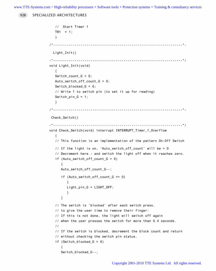
// Start Timer 1
TR1 = 1;
/*------------------------------------------------------------------*-
Light_Init()
-*------------------------------------------------------------------*/
void Light_Init(void)
Switch_count_G = 0;
Auto_switch_off_count_G = 0;
Switch_blocked_G = 0;
// Write 1 to switch pin (to set it up for reading)
Switch_pin_G = 1;
/*------------------------------------------------------------------*-
Check_Switch()
-*------------------------------------------------------------------*/
void Check_Switch(void) interrupt INTERRUPT_Timer_1_Overflow
// This function is an implementation of the pattern On-Off Switch
// If the light is on, 'Auto_switch_off_count' will be > 0
// Decrement here - and switch the light off when it reaches zero.
if (Auto_switch_off_count_G > 0)
Auto_switch_off_count_G--;
if (Auto_switch_off_count_G == 0)
Light_pin_G = LIGHT_OFF;
// The switch is 'blocked' after each switch press,
// to give the user time to remove their finger:
// If this is not done, the light will switch off again
// when the user presses the switch for more than 0.4 seconds.
//
// If the switch is blocked, decrement the block count and return
// without checking the switch pin status.
if (Switch_blocked_G > 0)
Switch_blocked_G--;
SPECIALIZED ARCHITECTURES928
www.TTE-Systems.com = High-reliability processors + Software tools + Protection systems + Training & consultancy services
Copyright 2001-2010 TTE Systems Ltd. All rights reserved.
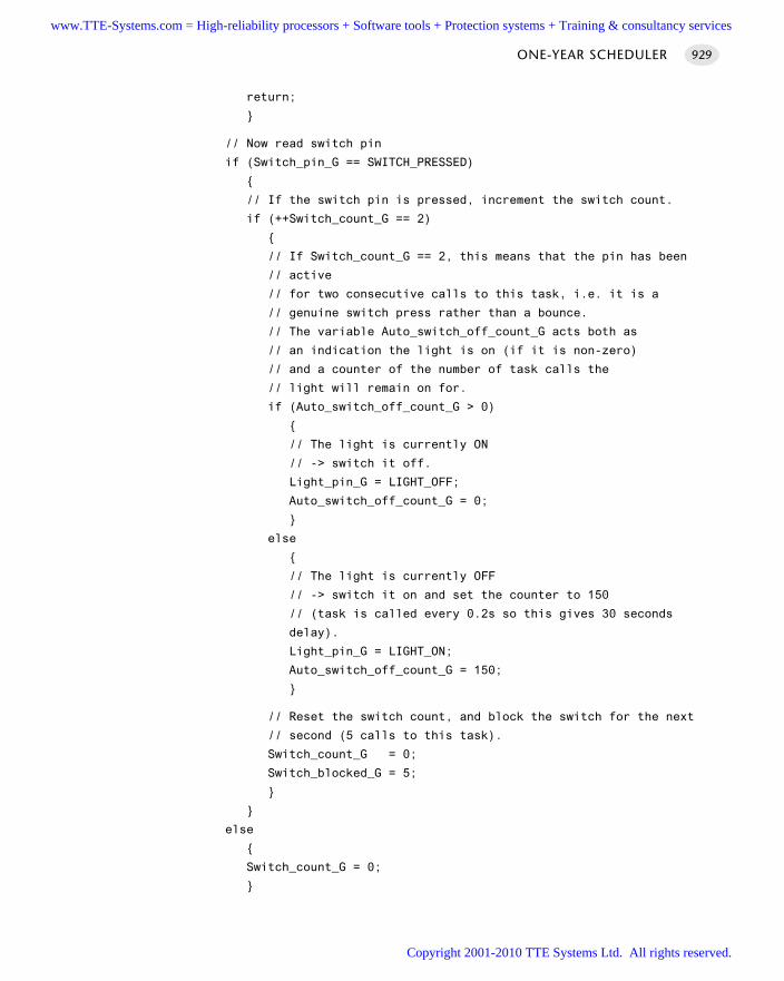
return;
// Now read switch pin
if (Switch_pin_G == SWITCH_PRESSED)
// If the switch pin is pressed, increment the switch count.
if (++Switch_count_G == 2)
// If Switch_count_G == 2, this means that the pin has been
// active
// for two consecutive calls to this task, i.e. it is a
// genuine switch press rather than a bounce.
// The variable Auto_switch_off_count_G acts both as
// an indication the light is on (if it is non-zero)
// and a counter of the number of task calls the
// light will remain on for.
if (Auto_switch_off_count_G > 0)
// The light is currently ON
// -> switch it off.
Light_pin_G = LIGHT_OFF;
Auto_switch_off_count_G = 0;
else
// The light is currently OFF
// -> switch it on and set the counter to 150
// (task is called every 0.2s so this gives 30 seconds
delay).
Light_pin_G = LIGHT_ON;
Auto_switch_off_count_G = 150;
// Reset the switch count, and block the switch for the next
// second (5 calls to this task).
Switch_count_G = 0;
Switch_blocked_G = 5;
else
Switch_count_G = 0;
ONE-YEAR SCHEDULER 929
www.TTE-Systems.com = High-reliability processors + Software tools + Protection systems + Training & consultancy services
Copyright 2001-2010 TTE Systems Ltd. All rights reserved.
/*------------------------------------------------------------------*-
---- END OF FILE -------------------------------------------------
-*------------------------------------------------------------------*/
Listing 36.12 Code for controlling an automatic light
Further reading—
SPECIALIZED ARCHITECTURES930
www.TTE-Systems.com = High-reliability processors + Software tools + Protection systems + Training & consultancy services
Copyright 2001-2010 TTE Systems Ltd. All rights reserved.
Increasing the stability of the
scheduling
Introduction
All crystal oscillators and ceramic resonators have frequency outputs which varywith temperature. As a result, schedulers driven by such clock sources also varytheir timing behaviour with temperature. S TA B L E S C H E D U L E R is a temperature-compensated scheduler that adjusts its behaviour to take into account changes inambient temperature.
chapter 37www.TTE-Systems.com = High-reliability processors + Software tools + Protection systems + Training & consultancy services
Copyright 2001-2010 TTE Systems Ltd. All rights reserved.
STABLE SCHEDULER
Context You are developing an embedded application using one or more members of the
8051 family of microcontrollers.
The application has a time-triggered architecture, constructed using a scheduler.
ProblemHow do you ensure that your scheduled application continues to operate with correcttiming even if the ambient temperature varies?
BackgroundSee C RY S TA L O S C I L L AT O R [page 54] for a discussion of the impact of temperature onthe performance of crystal oscillator circuits.
SolutionIn most practical applications where accurate timing is required, the system willderive its oscillator from some form of crystal oscillator. Unfortunately, the stability ofthese oscillators varies with temperature. To obtain stable scheduling, we have twomain options:
Maintain the system at a constant, known temperature and adapt all timer settingsto match this. This might be achieved by placing the application in some formof industrial oven or in an ice bath. For most applications, this type of approachis impractical.
Measure the ambient temperature and adjust the system timing to take intoaccount any temperature changes.
STA B L E SC H E D U L E R adopts this second approach.
Hardware resource implicationsThe main hardware implication is that we require some form of temperature sensor.In most situations, a digital sensor (such as one of the Dallas Semiconductor 1620family) is a cost-effective choice, since it is itself cheap and requires at most threemicrocontroller pins.
SPECIALIZED ARCHITECTURES932
www.TTE-Systems.com = High-reliability processors + Software tools + Protection systems + Training & consultancy services
Copyright 2001-2010 TTE Systems Ltd. All rights reserved.
A particularly good alternative is an on-chip temperature sensor: some of theCygnal2 and Analog Devices3 ranges of 8051 microcontrollers include such a sensor,making them ideal for this application.
The load imposed by the scheduling software is very small, with one temperaturemeasurement made at infrequent (typically 1-minute) intervals.
Reliability and safety implicationsUse of a stable scheduler can improve the reliability of your application if accuratetiming over long periods is required.
PortabilityMost microcontrollers can be linked to some form of external temperature sensorand, therefore, can apply this pattern.
Overall strengths and weaknessesImproves the scheduler stability.
Usually increases costs.
Related patterns and alternative solutions—
Example: Using a external Dallas DS1621 I2C temperaturesensorIn this example, we present a simple stable scheduler, using an external (DS1621)temperature sensor (Listings 37.1 and 37.2).
The demonstration program displays time on an LED display; refer to Chapter 21for suitable display hardware and the CD for a complete set of code listings.
/*------------------------------------------------------------------*-
Main.c (v1.00)
------------------------------------------------------------------
Demonstration program for:
Stable Scheduler
Drives 4 multiplexed multi-segment LED displays
- displays elapsed time.
STABLE SCHEDULER 933
2. www.cygnal.com3. www.analog.com
www.TTE-Systems.com = High-reliability processors + Software tools + Protection systems + Training & consultancy services
Copyright 2001-2010 TTE Systems Ltd. All rights reserved.
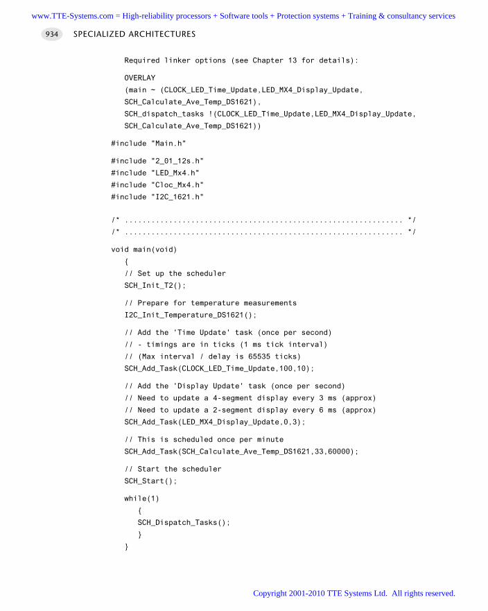
Required linker options (see Chapter 13 for details):
OVERLAY
(main ~ (CLOCK_LED_Time_Update,LED_MX4_Display_Update,
SCH_Calculate_Ave_Temp_DS1621),
SCH_dispatch_tasks !(CLOCK_LED_Time_Update,LED_MX4_Display_Update,
SCH_Calculate_Ave_Temp_DS1621))
#include "Main.h"
#include "2_01_12s.h"
#include "LED_Mx4.h"
#include "Cloc_Mx4.h"
#include "I2C_1621.h"
/* ............................................................... */
/* ............................................................... */
void main(void)
// Set up the scheduler
SCH_Init_T2();
// Prepare for temperature measurements
I2C_Init_Temperature_DS1621();
// Add the 'Time Update' task (once per second)
// - timings are in ticks (1 ms tick interval)
// (Max interval / delay is 65535 ticks)
SCH_Add_Task(CLOCK_LED_Time_Update,100,10);
// Add the 'Display Update' task (once per second)
// Need to update a 4-segment display every 3 ms (approx)
// Need to update a 2-segment display every 6 ms (approx)
SCH_Add_Task(LED_MX4_Display_Update,0,3);
// This is scheduled once per minute
SCH_Add_Task(SCH_Calculate_Ave_Temp_DS1621,33,60000);
// Start the scheduler
SCH_Start();
while(1)
SCH_Dispatch_Tasks();
SPECIALIZED ARCHITECTURES934
www.TTE-Systems.com = High-reliability processors + Software tools + Protection systems + Training & consultancy services
Copyright 2001-2010 TTE Systems Ltd. All rights reserved.
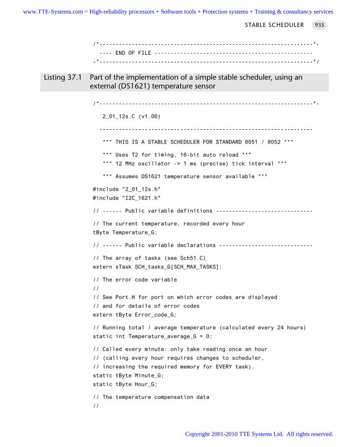
/*------------------------------------------------------------------*-
---- END OF FILE -------------------------------------------------
-*------------------------------------------------------------------*/
Listing 37.1 Part of the implementation of a simple stable scheduler, using an external (DS1621) temperature sensor
/*------------------------------------------------------------------*-
2_01_12s.C (v1.00)
------------------------------------------------------------------
*** THIS IS A STABLE SCHEDULER FOR STANDARD 8051 / 8052 ***
*** Uses T2 for timing, 16-bit auto reload ***
*** 12 MHz oscillator -> 1 ms (precise) tick interval ***
*** Assumes DS1621 temperature sensor available ***
#include "2_01_12s.h"
#include "I2C_1621.h"
// ------ Public variable definitions ------------------------------
// The current temperature, recorded every hour
tByte Temperature_G;
// ------ Public variable declarations -----------------------------
// The array of tasks (see Sch51.C)
extern sTask SCH_tasks_G[SCH_MAX_TASKS];
// The error code variable
//
// See Port.H for port on which error codes are displayed
// and for details of error codes
extern tByte Error_code_G;
// Running total / average temperature (calculated every 24 hours)
static int Temperature_average_G = 0;
// Called every minute: only take reading once an hour
// (calling every hour requires changes to scheduler,
// increasing the required memory for EVERY task).
static tByte Minute_G;
static tByte Hour_G;
// The temperature compensation data
//
STABLE SCHEDULER 935
www.TTE-Systems.com = High-reliability processors + Software tools + Protection systems + Training & consultancy services
Copyright 2001-2010 TTE Systems Ltd. All rights reserved.
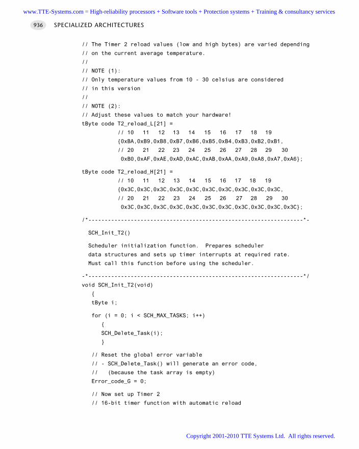
// The Timer 2 reload values (low and high bytes) are varied depending
// on the current average temperature.
//
// NOTE (1):
// Only temperature values from 10 - 30 celsius are considered
// in this version
//
// NOTE (2):
// Adjust these values to match your hardware!
tByte code T2_reload_L[21] =
// 10 11 12 13 14 15 16 17 18 19
0xBA,0xB9,0xB8,0xB7,0xB6,0xB5,0xB4,0xB3,0xB2,0xB1,
// 20 21 22 23 24 25 26 27 28 29 30
0xB0,0xAF,0xAE,0xAD,0xAC,0xAB,0xAA,0xA9,0xA8,0xA7,0xA6;
tByte code T2_reload_H[21] =
// 10 11 12 13 14 15 16 17 18 19
0x3C,0x3C,0x3C,0x3C,0x3C,0x3C,0x3C,0x3C,0x3C,0x3C,
// 20 21 22 23 24 25 26 27 28 29 30
0x3C,0x3C,0x3C,0x3C,0x3C,0x3C,0x3C,0x3C,0x3C,0x3C,0x3C;
/*------------------------------------------------------------------*-
SCH_Init_T2()
Scheduler initialization function. Prepares scheduler
data structures and sets up timer interrupts at required rate.
Must call this function before using the scheduler.
-*------------------------------------------------------------------*/
void SCH_Init_T2(void)
tByte i;
for (i = 0; i < SCH_MAX_TASKS; i++)
SCH_Delete_Task(i);
// Reset the global error variable
// - SCH_Delete_Task() will generate an error code,
// (because the task array is empty)
Error_code_G = 0;
// Now set up Timer 2
// 16-bit timer function with automatic reload
SPECIALIZED ARCHITECTURES936
www.TTE-Systems.com = High-reliability processors + Software tools + Protection systems + Training & consultancy services
Copyright 2001-2010 TTE Systems Ltd. All rights reserved.
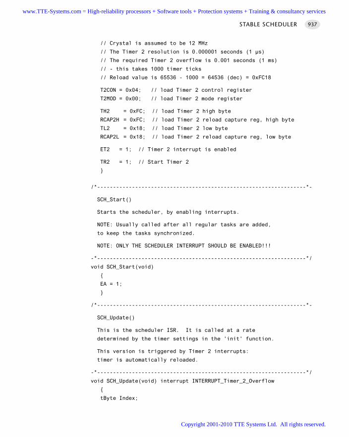
// Crystal is assumed to be 12 MHz
// The Timer 2 resolution is 0.000001 seconds (1 µs)
// The required Timer 2 overflow is 0.001 seconds (1 ms)
// - this takes 1000 timer ticks
// Reload value is 65536 - 1000 = 64536 (dec) = 0xFC18
T2CON = 0x04; // load Timer 2 control register
T2MOD = 0x00; // load Timer 2 mode register
TH2 = 0xFC; // load Timer 2 high byte
RCAP2H = 0xFC; // load Timer 2 reload capture reg, high byte
TL2 = 0x18; // load Timer 2 low byte
RCAP2L = 0x18; // load Timer 2 reload capture reg, low byte
ET2 = 1; // Timer 2 interrupt is enabled
TR2 = 1; // Start Timer 2
/*------------------------------------------------------------------*-
SCH_Start()
Starts the scheduler, by enabling interrupts.
NOTE: Usually called after all regular tasks are added,
to keep the tasks synchronized.
NOTE: ONLY THE SCHEDULER INTERRUPT SHOULD BE ENABLED!!!
-*------------------------------------------------------------------*/
void SCH_Start(void)
EA = 1;
/*------------------------------------------------------------------*-
SCH_Update()
This is the scheduler ISR. It is called at a rate
determined by the timer settings in the 'init' function.
This version is triggered by Timer 2 interrupts:
timer is automatically reloaded.
-*------------------------------------------------------------------*/
void SCH_Update(void) interrupt INTERRUPT_Timer_2_Overflow
tByte Index;
STABLE SCHEDULER 937
www.TTE-Systems.com = High-reliability processors + Software tools + Protection systems + Training & consultancy services
Copyright 2001-2010 TTE Systems Ltd. All rights reserved.
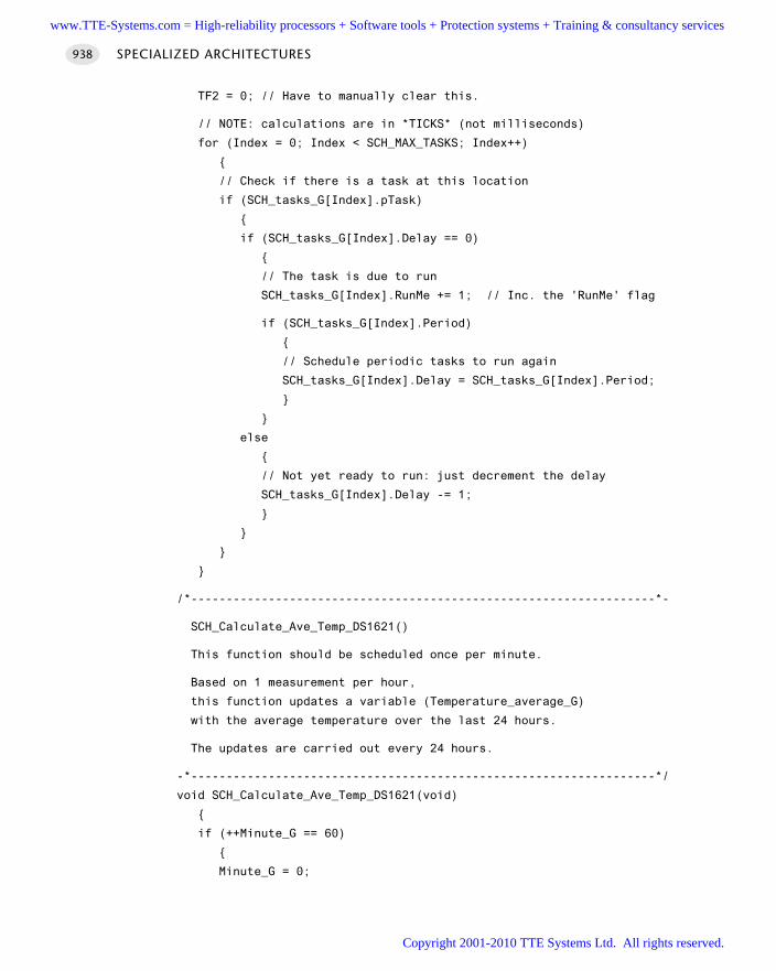
TF2 = 0; // Have to manually clear this.
// NOTE: calculations are in *TICKS* (not milliseconds)
for (Index = 0; Index < SCH_MAX_TASKS; Index++)
// Check if there is a task at this location
if (SCH_tasks_G[Index].pTask)
if (SCH_tasks_G[Index].Delay == 0)
// The task is due to run
SCH_tasks_G[Index].RunMe += 1; // Inc. the 'RunMe' flag
if (SCH_tasks_G[Index].Period)
// Schedule periodic tasks to run again
SCH_tasks_G[Index].Delay = SCH_tasks_G[Index].Period;
else
// Not yet ready to run: just decrement the delay
SCH_tasks_G[Index].Delay -= 1;
/*------------------------------------------------------------------*-
SCH_Calculate_Ave_Temp_DS1621()
This function should be scheduled once per minute.
Based on 1 measurement per hour,
this function updates a variable (Temperature_average_G)
with the average temperature over the last 24 hours.
The updates are carried out every 24 hours.
-*------------------------------------------------------------------*/
void SCH_Calculate_Ave_Temp_DS1621(void)
if (++Minute_G == 60)
Minute_G = 0;
SPECIALIZED ARCHITECTURES938
www.TTE-Systems.com = High-reliability processors + Software tools + Protection systems + Training & consultancy services
Copyright 2001-2010 TTE Systems Ltd. All rights reserved.
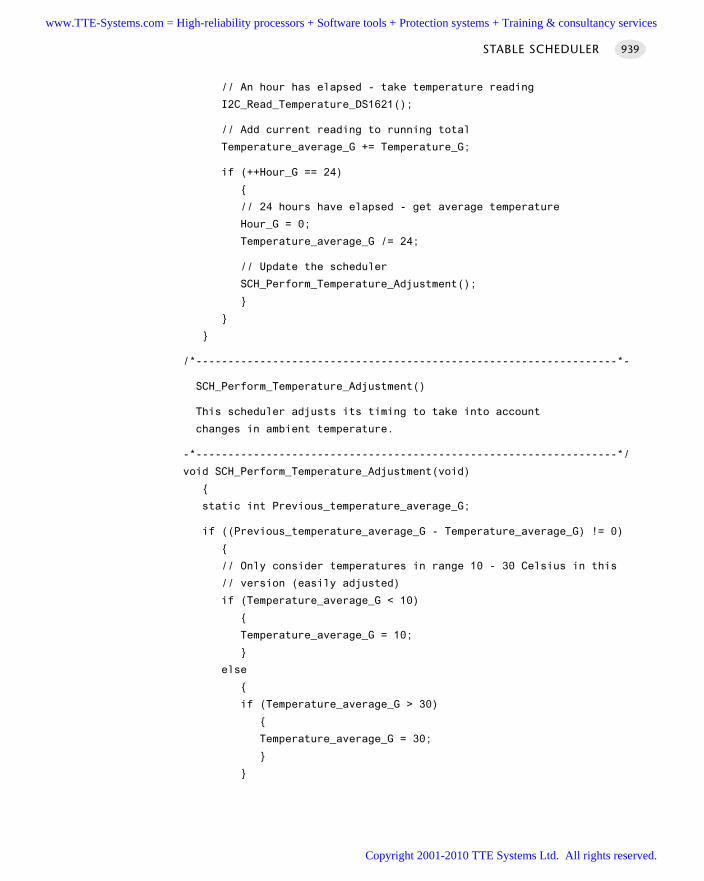
// An hour has elapsed - take temperature reading
I2C_Read_Temperature_DS1621();
// Add current reading to running total
Temperature_average_G += Temperature_G;
if (++Hour_G == 24)
// 24 hours have elapsed - get average temperature
Hour_G = 0;
Temperature_average_G /= 24;
// Update the scheduler
SCH_Perform_Temperature_Adjustment();
/*------------------------------------------------------------------*-
SCH_Perform_Temperature_Adjustment()
This scheduler adjusts its timing to take into account
changes in ambient temperature.
-*------------------------------------------------------------------*/
void SCH_Perform_Temperature_Adjustment(void)
static int Previous_temperature_average_G;
if ((Previous_temperature_average_G - Temperature_average_G) != 0)
// Only consider temperatures in range 10 - 30 Celsius in this
// version (easily adjusted)
if (Temperature_average_G < 10)
Temperature_average_G = 10;
else
if (Temperature_average_G > 30)
Temperature_average_G = 30;
STABLE SCHEDULER 939
www.TTE-Systems.com = High-reliability processors + Software tools + Protection systems + Training & consultancy services
Copyright 2001-2010 TTE Systems Ltd. All rights reserved.
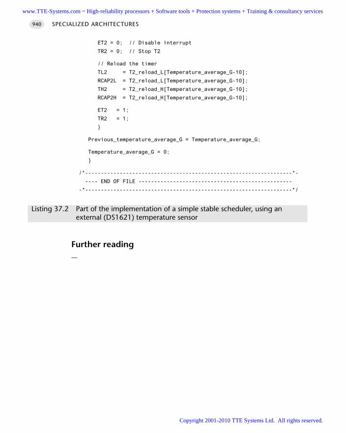
ET2 = 0; // Disable interrupt
TR2 = 0; // Stop T2
// Reload the timer
TL2 = T2_reload_L[Temperature_average_G-10];
RCAP2L = T2_reload_L[Temperature_average_G-10];
TH2 = T2_reload_H[Temperature_average_G-10];
RCAP2H = T2_reload_H[Temperature_average_G-10];
ET2 = 1;
TR2 = 1;
Previous_temperature_average_G = Temperature_average_G;
Temperature_average_G = 0;
/*------------------------------------------------------------------*-
---- END OF FILE -------------------------------------------------
-*------------------------------------------------------------------*/
Listing 37.2 Part of the implementation of a simple stable scheduler, using an external (DS1621) temperature sensor
Further reading—
SPECIALIZED ARCHITECTURES940
www.TTE-Systems.com = High-reliability processors + Software tools + Protection systems + Training & consultancy services
Copyright 2001-2010 TTE Systems Ltd. All rights reserved.
Conclusions
We draw the book to a close with two final chapters.
In Chapter 38, we review what we have tried to achieve through presentation of this
pattern collection.
In Chapter 39, we present a collected list of books and papers either directly
referenced in the text or of related interest.
www.TTE-Systems.com = High-reliability processors + Software tools + Protection systems + Training & consultancy services
Copyright 2001-2010 TTE Systems Ltd. All rights reserved.

www.TTE-Systems.com = High-reliability processors + Software tools + Protection systems + Training & consultancy services
Copyright 2001-2010 TTE Systems Ltd. All rights reserved.
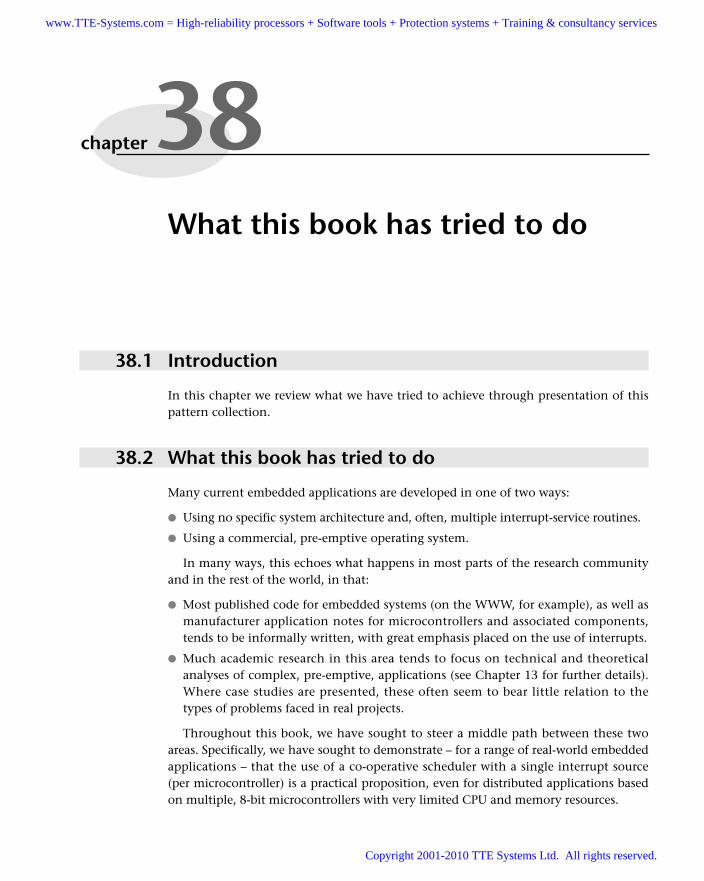
What this book has tried to do
38.1 Introduction
In this chapter we review what we have tried to achieve through presentation of thispattern collection.
38.2 What this book has tried to do
Many current embedded applications are developed in one of two ways:
Using no specific system architecture and, often, multiple interrupt-service routines.
Using a commercial, pre-emptive operating system.
In many ways, this echoes what happens in most parts of the research communityand in the rest of the world, in that:
Most published code for embedded systems (on the WWW, for example), as well asmanufacturer application notes for microcontrollers and associated components,tends to be informally written, with great emphasis placed on the use of interrupts.
Much academic research in this area tends to focus on technical and theoreticalanalyses of complex, pre-emptive, applications (see Chapter 13 for further details).Where case studies are presented, these often seem to bear little relation to thetypes of problems faced in real projects.
Throughout this book, we have sought to steer a middle path between these twoareas. Specifically, we have sought to demonstrate – for a range of real-world embeddedapplications – that the use of a co-operative scheduler with a single interrupt source(per microcontroller) is a practical proposition, even for distributed applications basedon multiple, 8-bit microcontrollers with very limited CPU and memory resources.
chapter 38www.TTE-Systems.com = High-reliability processors + Software tools + Protection systems + Training & consultancy services
Copyright 2001-2010 TTE Systems Ltd. All rights reserved.
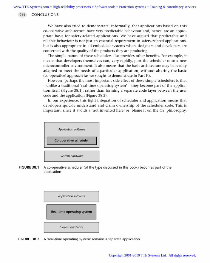
We have also tried to demonstrate, informally, that applications based on thisco-operative architecture have very predictable behaviour and, hence, are an appro-priate basis for safety-related applications. We have argued that predictable andreliable behaviour is not just an essential requirement in safety-related applications,but is also appropriate in all embedded systems where designers and developers areconcerned with the quality of the products they are producing.
The simple nature of these schedulers also provides other benefits. For example, itmeans that developers themselves can, very rapidly, port the scheduler onto a newmicrocontroller environment. It also means that the basic architecture may be readilyadapted to meet the needs of a particular application, without altering the basic(co-operative) approach (as we sought to demonstrate in Part H).
However, perhaps the most important side-effect of these simple schedulers is that– unlike a traditional ‘real-time operating system’ – they become part of the applica-tion itself (Figure 38.1), rather than forming a separate code layer between the usercode and the application (Figure 38.2).
In our experience, this tight integration of scheduler and application means thatdevelopers quickly understand and claim ownership of the scheduler code. This isimportant, since it avoids a ‘not invented here’ or ‘blame it on the OS’ philosophy,
CONCLUSIONS944
FIGURE 38.1 A co-operative scheduler (of the type discussed in this book) becomes part of theapplication
Co-operative scheduler
Application software
System hardware
FIGURE 38.2 A ‘real-time operating system’ remains a separate application
Real-time operating system
System hardware
Application software
www.TTE-Systems.com = High-reliability processors + Software tools + Protection systems + Training & consultancy services
Copyright 2001-2010 TTE Systems Ltd. All rights reserved.
which can arise when developers must interface their code to a large and complexreal-time operating system, the features and behaviour of which they may never fullyunderstand.
38.3 Conclusions
In this chapter we have briefly reviewed what we have tried to achieve through pres-entation of this pattern collection.
This brings us to the end of the book. To explore further the topics discussedin this chapter and in earlier chapters, refer to the sources of information listed inChapter 39.
WHAT THIS BOOK HAS TRIED TO DO 945
www.TTE-Systems.com = High-reliability processors + Software tools + Protection systems + Training & consultancy services
Copyright 2001-2010 TTE Systems Ltd. All rights reserved.
Collected references
and bibliography
In this chapter we present a collected list of books and papers which are either directly
referenced in the text, or of related interest.
39.1 Complete list of publications
Acarnley, P.P. (1984) Stepping Motors: A Guide to Modern Theory and Practice, PeterPeregrinus Ltd, UK.
Ackermann, J. (1998) ‘Active steering for better safety, handling and comfort’, Proceedingsof Advances in Vehicle Control and Safety, Amiens, France, 1–3 July.
Alexander, C. (1979) The Timeless Way of Building, Oxford University Press, New York.
Alexander, C., Ishikawa, S., Silverstein, M. with Jacobson, M., Fisksdahl-King, I. andAngel, S. (1977) A Pattern Language, Oxford University Press, New York.
Allworth, S.T. (1981) An Introduction to Real-Time Software Design, Macmillan, London.
Atherton, D.P. (1999) ‘PID controller tuning’, IEE Computing & Control EngineeringJournal, 10 (2): 44–50.
Awad, M., Kuusela, J. and Ziegler, J. (1996) Object-oriented Technology for Real-timeSystems, Prentice-Hall, New Jersey.
Axelson, J. (1998) Serial Port Complete, Lakeview Research.
Axelson, J. (1999) USB Complete, Lakeview Research.
Ayala, K. (2000) The 80251 Microcontroller, Prentice Hall, New Jersey.
Barnett, R.H. (1995) The 8051 Family of Microcontrollers, Prentice Hall, New Jersey.
Barrenscheen, J. (1996) ‘On-board communication via CAN without Transceiver’,Infineon (Siemens) Application Note AP2921. [Available from www.infineon.com]
chapter 39www.TTE-Systems.com = High-reliability processors + Software tools + Protection systems + Training & consultancy services
Copyright 2001-2010 TTE Systems Ltd. All rights reserved.
Bates, I. (2000) ‘Introduction to scheduling and timing analysis’, in The Use of Ada inReal-Time System, IEE Conference Publication 00/034.
Bennett, S. (1994) Real-Time Computer Control, 2nd edn, Prentice Hall, New Jersey.
Bignell, V. and Fortune, J. (1984) Understanding System Failures, Manchester UniversityPress, Manchester.
Bishop, C.M (1995) Neural Networks for Pattern Recognition, Oxford University PressOxford.
Boehm, B.W. (1981) Software Engineering Economics, Prentice Hall, New Jersey.
Booch, G. (1994) Object-Oriented Analysis and Design, Benjamin Cummings.
Bowerman, B.L. and O'Connell, R.T. (1987) Time Series Forecasting: Unified Conceptsand Computer Implementation, Duxbury Press, Boston, MA.
Brooks, F.P. (1975) The Mythical Man-Month: Essays on Software Engineering, Addison-Wesley, Reading, MA.
Brooks, F.P. (1986) ‘No silver bullet – essence and accidents of software engineering’,in H.J. Kugler (ed.) Information Processing 86, Elsevier Science, Amsterdam.
Broughton, J. (1994) ‘Assessing the safety of new vehicle control systems’, Proceedingsof the First World Congress on Applications of Transport Telematics and IntelligentVehicle-Highway Systems, Paris, November 1994.
BS IEC 61508 (1999) ‘Functional safety of electrical / electronic / programmableelectronic safety-related systems’. [Available from BSI, London]
Burns, A. and Wellings, A. (1997) Real-time Systems and Programming Languages,Addison-Wesley, Reading, MA.
Buschmann, F., Meunier, R., Rohnert, H., Sommerlad, P., and Stal, M. (1996) Pattern-Oriented Software Architecture: A System of Patterns, Wiley, Chichester.
Cahill, S.J. (1994) C for the Microprocessor Engineer, Prentice Hall, New Jersey.
Coleman, D., Arnold, P., Bodoff, S., Dollin, C., Gilchrist, H., Hayes, F. and Jeremes, P.(1994) Object-oriented Development: The Fusion Method, Prentice Hall, New Jersey.
Cooling, J.E. (1991) Software Design for Real-time Systems, Chapman & Hall, London.
Cunningham, W. and Beck, K. (1987) ‘Using pattern languages for object-orientedprograms’, Proceedings of OOPSLA’87, Orlando, FL.
Daley, S. and Liu, G.P. (1999) ‘Optimal PID tuning using direct search algorithms’, IEEComputing & Control Engineering Journal, 10 (2): 51–56.
DeMarco, T. (1978) Structured Analysis and System Specification, Prentice-Hall, NewJersey.
Dorf, R.C. and Bishop, R.H. (1998) Modern Control Systems, 8th edn, Addison-Wesley,Reading, MA.
Douglass, B.P. (1998) Real-time UML, Addison-Wesley, Reading, MA.
Doyle, F.J., Gatzke, E.P. and Parker, R.S. (1999) Process Control Modules: A SoftwareLaboratory for Control Design: The MATLAB-based Process Control Guide for ChemicalEngineering Professionals, Prentice Hall, New Jersey.
COLLECTED REFERENCES AND BIBLIOGRAPHY 947
www.TTE-Systems.com = High-reliability processors + Software tools + Protection systems + Training & consultancy services
Copyright 2001-2010 TTE Systems Ltd. All rights reserved.
Dutton, K., Thompson, S. and Barraclough, B. (1997) The Art of Control Engineering,Addison-Wesley, Reading, MA.
Ebinger, B., Sienel, W. and Sporl, T. (1998) ‘A hardware-in-the-loop test environmentfor interconnected ECUs for passenger cars and commercial vehicles’, Proceedings ofAdvances in Vehicle Control and Safety, Amiens, France, 1–3 July.
Elgar, P. (1998) Sensors for Measurement and Control, Longman, London.
Falla, M. (1997) Advances in Safety-Critical Systems, University of Lancaster Press,Lancaster.
Fenton, N. and Pfleeger, S.L. (1996) Software Metrics, Thomson, London.
Fowler, M. and Scott, K. (2000) UML Distilled, 2nd edn, Addison-Wesley, Reading, MA.
Franco, S. (1998) Design with Operational Amplifiers and Analog Integrated Circuits, 2ndedn, McGraw-Hill, Boston, MA.
Franklin, G.F., Powell, J.D. and Emami-Naeini, A. (1994) Feedback Control of DynamicSystems, 3rd edn, Addison-Wesley, Reading, MA.
Franklin, G.F., Powell, J.D. and Workman, M. (1998) Digital Control of DynamicSystems, 3rd edn, Addison-Wesley, Reading, MA.
Gamma, E., Helm, R., Johnson, R. and Vlissides, J. (1995) Design Patterns: Elements ofReusable Object-oriented Software, Addison-Wesley, Reading, MA.
Gannsle, J. (1992) The Art of Programming Embedded Systems, Academic Press, San Diego.
Gergeleit, M. and Streich, H. (1994) ‘Implementing a distributed high-resolution real-time clock using the CAN-bus’, Proceedings 1st International CAN Conference, Mainz,Germany, September 1994.
Goldie, J. (1991) ‘Comparing EIA-485 and EIA-422-A line drivers and receivers in mul-tipoint applications’, National Semiconductor Application Note 759. [Availablefrom www.national.com]
Goldie, J. (1996) ‘Ten ways to bulletproof RS-485 interfaces’, National SemiconductorApplication Note 1057. [Available from www.national.com]
Goldsmith, S. (1993) A Practical Guide to Real-Time Systems Development, Prentice Hall,New Jersey.
Graham, I. (1994) Object-Oriented Methods, 2nd edn, Addison-Wesley, Reading, MA.
Haney, P.R., Richardson, M.J., Clarke, N.J. and Barber, P.A. (1998) ‘Development ofadaptive cruise control systems for motor vehicles’, Proceedings of Control ’98,Swansea (Mini Symposium on Mechatronics).
Hank, P. and Jöhnk, E. (1997) ‘SJA1000 stand-alone CAN controller’, PhilipsApplication Note AN97076. [Available from www.philips.com]
Hatley, D.J. and Pirbhai, I.A. (1987) Strategies for Real-time System Specification, DorsetHouse.
Hatton, L. (1994) Safer C: Developing Software for High-integrity and Safety-criticalSystems’, McGraw-Hill, Maidenhead.
Haykin, S. (1994) Neural networks: A Comprehensive Foundation, Macmillan CollegePublishing Company, New York.
CONCLUSIONS948
www.TTE-Systems.com = High-reliability processors + Software tools + Protection systems + Training & consultancy services
Copyright 2001-2010 TTE Systems Ltd. All rights reserved.
Horowitz, P. and Hill, W. (1989) The Art of Electronics, 2nd edn, Cambridge UniversityPress, Cambridge.
Huang, H-W (2000) Using the MCS-51 Microcontroller, Oxford University Press, New York.
Intel (1985) Microcontroller Handbook 1986, Intel Corporation.
Jacobson, I., Christerson, M., Jonsson, P. and Övergaard, G. (1993) Object-OrientedSoftware Engineering, revised edn, Addison-Wesley, Reading, MA.
Kenjo, T. (1984) Stepping Motors and their Microprocessor Circuits, Clarendon Press,Oxford.
Kopetz, H. (1997) Real-time Systems: Design Principles for Distributed EmbeddedApplications, Kluwer Academic, New York.
Labrosse, J.J. (1998) uC/OS II: The Real-Time Kernel, R&D Books.
Lander, C.W. (1993) Power Electronics, 3rd edn, McGraw-Hill, Maidenhead.
Lawrence, P.D. and Mauch, K. (1988) Real-Time Microcomputer System Design: AnIntroduction, McGraw-Hill, Maidenhead.
Lawrenz, W. (1997) CAN System Engineering, Springer-Verlag, Heidelberg.
Leen, G., Heffernan, D. and Dunne, A. (1999) ‘Digital networks in the automotivevehicle’, Computing and Control, 10 (6): 257–66.
Leveson, N.G. (1995) Safeware: System Safety and Computers, Addison-Wesley, Reading,MA.
Li, Y., Pont, M.J. and Jones, N.B. (1999) ‘A comparison of the performance of radialbasis function and multi-layer Perceptron networks in a practical condition moni-toring application’, Proceedings of Condition Monitoring, Swansea, UK, April 12–15,1999.
Li, Y., Pont, M.J., Parikh, C.R. and Jones, N.B. (2000) ‘Using a combination of RBFN,MLP and kNN classifiers for engine misfire detection’, in R. John andR. Birkenhead (eds) Advances in Soft Computing: Soft Computing Techniques andApplications, Springer-Verlag, Heidelberg.
Lippmann, P. (1987) ‘An introduction to computing with neural networks’, Instituteof Electrical and Electronic Engineers (USA), Acoustics, Speech and Signal Processing,April, 1987.
Liu, J.W.S. and Ha, R. (1995) ‘Methods for validating real-time constraints’, Journal ofSystems and Software, 30 (1–2): 85–98.
Locke, C.D. (1992) ‘Software architecture for hard real-time applications: Cyclic exec-utives vs. fixed priority executives’, Journal of Real-Time Systems, 4: 37–53.
Lynn, P. and Fuerst, W. (1998) Introductory Digital Signal Processing with ComputerApplications, Wiley, Chichester.
Mariutti, P. (1999) ‘Crystal oscillator of the C500 and C166 microcontroller families’,Infineon (Siemens) Application Note AP242005. [Available from www.infineon.com]
MISRA (1994) ‘Development guidelines for vehicle-based software’, Motor IndustrySoftware Reliability Report, November, 1994. [These guidelines, plus nine supportingreports, are available from MIRA]
COLLECTED REFERENCES AND BIBLIOGRAPHY 949
www.TTE-Systems.com = High-reliability processors + Software tools + Protection systems + Training & consultancy services
Copyright 2001-2010 TTE Systems Ltd. All rights reserved.
MISRA (1998) Guidelines for the use of the C language in vehicle-based software’,Motor Industry Software Reliability Report. [Available from MIRA]
Nelson, T. (1995) ‘The practical limits of RS-485’, National Semiconductor ApplicationNote 979. [Available from www.national.com]
NHTSA (1996) ‘Effectiveness of occupant safety systems and their use’. National HighwayTraffic Safety Administration (US) Third Report to Congress, December 1996.
NHTSA (1999) ‘NHTSA light vehicle antilock brake system research program task 4’,National Highway Traffic Safety Administration (US) Report, January 1999.
Nise, N.S. (1995) Control Systems Engineering, 2nd edn, Addison-Wesley, Reading, MA.
Nissanke, N. (1997) Realtime Systems, Prentice Hall, New Jersey.
Ong, H.L.R, Pont, M.J. and Peasgood, W. (2001) ‘Do software-based techniquesincrease the reliability of embedded applications in the presence of EMI?’,Microprocessors and Microsystems, 24 (10), 481–91.
Oppenheim, A.V., Schafer, R.W. and Buck, J.R. (1999) Discrete-time Signal Processing,Prentice Hall, New Jersey.
Palacheria, A. (1997) ‘Using PWM to generate analog output’, Microchip ApplicationNote AN538.
Parikh, C.R., Pont, M.J., Li, Y. and Jones, N.B. (1999) ‘Improving the performance ofmulti-layer Perceptrons where limited training data are available for some classes’,Proceedings of the IEE International Conference on Neural Networks, Edinburgh,September 1999.
Parikh C.R., M.J. Pont and N.B. Jones (2001) ‘Application of Dempster-Shafertheory in condition monitoring applications – a case study’, Pattern RecognitionLetters, 22 (6–7), 777–85.
Passino, K.M. and Yurkovich, S. (1998) Fuzzy Control, Addison-Wesley, Reading, MA.
Perier, L. and Coen, A. (1998) ‘CAN-do solutions for car multiplexing’, Proceedings ofthe 5th International CAN Conference, San Jose, California, November 1998.
Plauger, P.J. (1992) The Standard C Library, Prentice Hall, New Jersey.
Pont, M.J. (1996) Software Engineering with C++ and CASE Tools, Addison-Wesley,Reading, MA.
Pont, M.J. (1998) ‘Control system design using real-time design patterns’, Proceedingsof Control ’98, Swansea, UK, September.
Pont, M.J. (in press) ‘Designing and implementing reliable embedded systemsusing patterns’, in P. Dyson (ed.) Proceedings of the 4th European Conference onPattern Languages of Programming and Computing, 1999, to be published by Springer-Verlag.
Pont, M.J., Ong, H.L.R., Parikh, C.R., Kureemun, R., Wong, C.P., Peasgood, W. and Li,Y. (1999a) ‘A selection of patterns for reliable embedded systems’, original paperpresented at EuroPlop ’99, Kloster Irsee, Germany.
Pont, M.J., Li, Y., Parikh, C.R. and Wong, C.P. (1999b) ‘The design of embeddedsystems using software patterns’, Proceedings of Condition Monitoring 1999, Swansea,UK, 12–15 April.
CONCLUSIONS950
www.TTE-Systems.com = High-reliability processors + Software tools + Protection systems + Training & consultancy services
Copyright 2001-2010 TTE Systems Ltd. All rights reserved.
Press, W.H., Teulolsky, S.A., Vettering, W.T. and Flannery, B.P. (1992) Numerical Recipesin C: The Art of Scientific Computing, Cambridge University Press, Cambridge.
Pressman, R. (1992) Software Engineering: A Practitioner’s Approach, 3rd edn. McGraw-Hill, Maidenhead.
Ralston, A. and Meek, C.L. (1976) Encyclopaedia of Computer Science, Petrocelli/Charter.
Rashid, M.H. (1993) Power Electronics: Circuits, Devices and Applications, 2nd edn,Prentice Hall, New Jersey.
Rumbaugh, J., Blaha, M., Premerlani, W., Eddy, F. and Lorensen, W. (1991) Object-Oriented Modeling and Design, Prentice Hall, New Jersey.
Schildt, H. (1997) Teach Yourself C, 3rd edn, McGraw-Hill, Maidenhead.
Scott, G. (1995) ‘Interfacing an MCS 51 Microcontroller to an 82527 CAN Controller’,Intel Application Note AP-724. [Available from www.intel.com]
Selic, B., Gullekson, G. and Ward, P.T. (1994) Real-time Object-oriented Modeling, Wiley,New York.
Sharp, R.S. (1998) ‘Variable geometry active suspension for cars’, IEE Computing andControl Engineering Journal, 9 (5): 217–22.
Shaw, A.C. (2001) Real-Time Systems and Software, Wiley, New York.
Sivasothy, S. (1998) ‘Transceivers and repeaters meeting the EIA RS-485 interfacestandard’, National Semiconductor Application Note 409. [Available fromwww.national.com]
Smith, S.W. (1999) The Scientist and Engineer’s Guide to Digital Signal Processing, 2ndedn, California Technical Publishing. [Available from www.DSPguide.com]
Somerville, I. (1996) Software Engineering, 5th edn, Addison-Wesley, Reading, MA.
Storey, N. (1996) Safety-critical Computer Systems, Addison-Wesley, Reading, MA.
Tindell, K. (1998) ‘Embedded systems in the automotive industry’, Proceedings of the1998 Embedded Systems Conference, San José, CA.
Waites, N. and Knott, G. (1996) Computing, 2nd edn, Business Education Publishers,Sunderland.
Ward, N.J. (1991) ‘The static analysis of a safety-critical avionics control system’, inD.E. Corbyn and N.P. Bray (eds) Air Transport Safety: Proceedings of the Safety andReliability Society Spring Conference, 1991, SaRS.
Ward, P.T. and Mellor, S.J. (1985) Structured Development for Real-Time Systems, PrenticeHall, New Jersey.
Warnes, L. (1998) Electronic and Electrical Engineering: Principles and Practice,Macmillan, London.
Wong, C. P. and Pont, M. J. (2000) ‘An overview of an evolutionary algorithm patternlanguage’, in R. John and R. Birkenhead (eds) Advances in Soft Computing: SoftComputing Techniques and Applications, Springer-Verlag, Heidelberg.
Yalamanchili, S. (2001) Introductory VHDL: From Simulation to Synthesis, Prentice Hall,New Jersey.
COLLECTED REFERENCES AND BIBLIOGRAPHY 951
www.TTE-Systems.com = High-reliability processors + Software tools + Protection systems + Training & consultancy services
Copyright 2001-2010 TTE Systems Ltd. All rights reserved.
Yourdon, E.N. (1989) Modern Structured Analysis, Prentice Hall, New Jersey.
Ziegler, J.G. and Nichols, N.B. (1942) ‘Optimal setting for automatic controllers’,Trans. ASME, 64(11), 759–68.
Ziegler, J.G. and Nichols, N.B. (1943) ‘Process lags in automatic control circuits’,Trans. ASME, 65(5), 433–44.
39.2 Other pattern collections
Alexander, C. (1979) The Timeless Way of Building, Oxford University Press, New York.
Alexander, C., Ishikawa, S., Silverstein, M. with Jacobson, M. Fisksdahl-King, I., andAngel, S. (1977) A Pattern Language, Oxford University Press, New York.
Buschmann, F., Meunier, R., Rohnert, H., Sommerlad, P., and Stal, M. (1996) Pattern-oriented Software Architecture: A System of Patterns, Wiley, Chichester.
Cunningham, W. and Beck, K. (1987) ‘Using pattern languages for object-orientedprograms’, Proceedings of OOPSLA’87, Orlando, FL.
Douglass, B.P. (1998) Real-time UML, Addison-Wesley, Reading, MA.
Gamma, E., Helm, R., Johnson, R. and Vlissides, J. (1995) Design Patterns: Elements ofReusable Object-oriented Software, Addison-Wesley, Reading, MA.
Wong, C. P. and Pont, M. J. (2000) ‘An overview of an evolutionary algorithm patternlanguage’, in R. John, and R. Birkenhead (eds) Advances in Soft Computing: SoftComputing Techniques and Applications, Springer-Verlag, Heidelberg.
Ziegler, J.G. and Nichols, N.B. (1942) ‘Optimal setting for automatic controllers’,Trans. ASME, 64 (11), 759–68.
Ziegler, J.G. and Nichols, N.B. (1943) ‘Process lags in automatic control circuits’,Trans. ASME, 65 (5), 433–44.
39.3 Design techniques for real-time / embedded systems
Allworth, S.T. (1981) An Introduction to Real-Time Software Design, Macmillan, London.
Awad, M., Kuusela, J. and Ziegler, J. (1996) Object-oriented Technology for Real-timeSystems, Prentice Hall, New Jersey.
Cooling, J.E. (1991) Software Design for Real-time Systems, Chapman & Hall, London.
Douglass, B.P. (1998) Real-time UML, Addison-Wesley, Reading, MA.
Goldsmith, S. (1993) A Practical Guide to Real-Time Systems Development, Prentice Hall,New Jersey.
Hatley, D.J. and Pirbhai, I.A. (1987) Strategies for Real-time System Specification, DorsetHouse.
CONCLUSIONS952
www.TTE-Systems.com = High-reliability processors + Software tools + Protection systems + Training & consultancy services
Copyright 2001-2010 TTE Systems Ltd. All rights reserved.
Kopetz, H. (1997) Real-time Systems: Design Principles for Distributed EmbeddedApplications, Kluwer Academic, New York.
Lawrence, P.D. and Mauch, K. (1988) Real-Time Micrcomputer System Design: AnIntroduction, McGraw-Hill, Maidenhead.
Nissanke, N. (1997) Realtime Systems, Prentice Hall, New Jersey.
Selic, B., Gullekson, G. and Ward, P.T. (1994) Real-time Object-oriented Modeling, Wiley,New York.
Shaw, A.C. (2001) Real-Time Systems and Software, Wiley, New York.
Ward, P.T. and Mellor, S.J. (1985) Structured Development for Real-Time Systems, PrenticeHall, New Jersey.
Ward, N.J. (1991) ‘The static analysis of a safety-critical avionics control system’, inD.E. Corbyn and N.P. Bray (eds) Air Transport Safety: Proceedings of the Safety andReliability Society Spring Conference, 1991, SaRS.
39.4 Design techniques for high-reliability systems
Bignell, V. and Fortune, J. (1984) Understanding System Failures, Manchester UniversityPress, Manchester.
Broughton, J. (1994) ‘Assessing the safety of new vehicle control systems’, Proceedingsof the First World Congress on Applications of Transport Telematics and IntelligentVehicle-Highway Systems, Paris, November.
BS IEC 61508 (1999) ‘Functional safety of electrical/electronic/programmableelectronic safety-related systems’. [Available from BSI, London]
Falla, M. (1997) Advances in Safety-Critical Systems, University of Lancaster Press,Lancaster.
Hatton, L. (1994) Safer C: Developing Software for High-integrity and Safety-criticalSystems, McGraw-Hill, Maidenhead.
Leveson, N.G. (1995) Safeware: System Safety and Computers, Addison-Wesley,Reading, MA.
MISRA (1994) ‘Development guidelines for vehicle-based software’, Motor IndustrySoftware Reliability Report, November, 1994. [These guidelines, plus nine supportingreports, are available from MIRA.]
MISRA (1998) ‘Guidelines for the use of the C language in vehicle-based software’,Motor Industry Software Reliability Report. [Available from MIRA.]
Ong, H.L.R, Pont, M.J. and Peasgood, W. (2001) ‘Do software-based techniquesincrease the reliability of embedded applications in the presence of EMI?’,Microprocessors and Microsystems, 24 (10), 481–91.
Storey, N. (1996) Safety-critical Computer Systems, Addison-Wesley, Reading, MA.
COLLECTED REFERENCES AND BIBLIOGRAPHY 953
www.TTE-Systems.com = High-reliability processors + Software tools + Protection systems + Training & consultancy services
Copyright 2001-2010 TTE Systems Ltd. All rights reserved.
39.5 The 8051 microcontroller
Barnett, R.H. (1995) The 8051 Family of Microcontrollers, Prentice Hall, New Jersey.
Huang, H-W (2000) Using the MCS-51 Microcontroller, Oxford University Press,New York.
39.6 Related publications by the author
Li, Y., Pont, M.J., and Jones, N.B. (1999) ‘A comparison of the performance of radialbasis function and multi-layer Perceptron networks in a practical condition moni-toring application’, Proceedings of Condition Monitoring 1999, Swansea, UK, April12–15.
Li, Y., Pont, M.J., Parikh, C.R. and Jones, N.B. (2000) ‘Using a combination of RBFN,MLP and kNN classifiers for engine misfire detection’, in R. John, and R.Birkenhead (eds) Advances in Soft Computing: Soft Computing Techniques andApplications, Springer-Verlag, Heidelberg.
Ong, H.L.R, Pont, M.J. and Peasgood, W. (2001) ‘Do software-based techniquesincrease the reliability of embedded applications in the presence of EMI?’,Microprocessors and Microsystems, 24 (10), 481–91.
Parikh, C.R., Pont, M.J., Li, Y. and Jones, N.B. (1999) ‘Improving the performance ofmulti-layer Perceptrons where limited training data are available for some classes’,Proceedings of the IEE International Conference on Neural Networks, Edinburgh,September.
Parikh C.R., M.J. Pont and N.B. Jones (2001) ‘Application of Dempster-Shafertheory in condition monitoring systems’, Pattern Recognition Letters, 22 (6–7)777–85.
Pont, M.J. (1996) Software Engineering with C++ and CASE Tools, Addison-Wesley,Reading, MA.
Pont, M.J. (1998) ‘Control system design using real-time design patterns’, Proceedingsof Control ’98, Swansea, UK, September 1998.
Pont, M.J., Ong, H.L.R., Parikh, C.R., Kureemun, R., Wong, C.P., Peasgood, W. and Li,Y. (1999a) ‘A selection of patterns for reliable embedded systems’, original paperpresented at EuroPlop ’99, Kloster Irsee, Germany.
Pont, M.J., Li, Y., Parikh, C.R. and Wong, C.P. (1999b) ‘The design of embedded sys-tems using software patterns’, Proceedings of Condition Monitoring 1999, Swansea,UK, 12–15 April.
Pont, M.J. (in press) ‘Designing and implementing reliable embedded systemsusing patterns’, in Dyson, P. (Ed.) Proceedings of the 4th European Conference onPattern Languages of Programming and Computing, 1999, to be published by Springer-Verlag.
Wong, C. P. and Pont, M. J. (2000) ‘An overview of an evolutionary algorithm patternlanguage’, in: R. John, and R. Birkenhead, (eds) Advances in Soft Computing: SoftComputing Techniques and Applications, Springer-Verlag, Heidelberg.
CONCLUSIONS954
www.TTE-Systems.com = High-reliability processors + Software tools + Protection systems + Training & consultancy services
Copyright 2001-2010 TTE Systems Ltd. All rights reserved.
Appendices
There are three appendices:
Appendix A provides details of the design notation used throughout this book.
Appendix B provides information about the contents of the CD.
Appendix C provides information about the WWW site associated with the book.
www.TTE-Systems.com = High-reliability processors + Software tools + Protection systems + Training & consultancy services
Copyright 2001-2010 TTE Systems Ltd. All rights reserved.

www.TTE-Systems.com = High-reliability processors + Software tools + Protection systems + Training & consultancy services
Copyright 2001-2010 TTE Systems Ltd. All rights reserved.
The design notation and CASE tool
Overview
This appendix will provide a brief description of the design notation used throughoutthe book and the CASE tool used to produce the associated figures.
The CASE tool
The diagrams throughout this book were created using the Select ‘Yourdon’ CASEtool. This product is now distributed by Aonix Corporation.1
Note that a copy of this CASE tool is included with the book Software Engineeringwith C++ and CASE Tools (Pont, 1996). This is a full copy of the product, but has aneducational licence and may not be used for commercial purposes.
The notation
The notation used in this book is fully described elsewhere (Pont, 1996). Briefly, thedesign is described in a series of layers, starting from an initial high-level design (inthe form of a context diagram) and ending with some form of process specification(which will, typically, be implemented as a C function).
The design process also covers aspects such as the creation of the user interface andtesting of the components; these issues are not considered here.
The following series of figures (Figures A1.1–A1.6), taken from Pont (1996) illus-trate some of the key documents for the design of a bank auto-teller machine (FigureA1.1), culminating in a code framework (in desktop C++ in this case: Listing A1.1).
appendixa
1. www.aonix.com
www.TTE-Systems.com = High-reliability processors + Software tools + Protection systems + Training & consultancy services
Copyright 2001-2010 TTE Systems Ltd. All rights reserved.
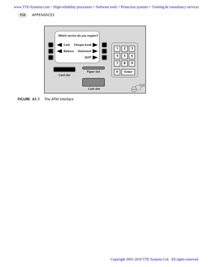
APPENDICES958
FIGURE A1.1 The ATM interface
5 64
2 31
8 97
Enter0
Which service do you require?
Cheque book
Statement
QUIT
Cash
Balance
Card slotPaper slot
Cash slotLSE
SADIE
www.TTE-Systems.com = High-reliability processors + Software tools + Protection systems + Training & consultancy services
Copyright 2001-2010 TTE Systems Ltd. All rights reserved.
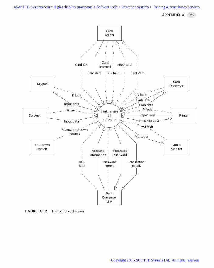
APPENDIX A 959
FIGURE A1.2 The context diagram
Bank servicetill
software
BankComputer
Link
Passwordcorrect
BCLfault
Transactiondetails
Accountinformation
Processedpassword
CardReader
Card OKCard
insertedKeep card
Eject cardCR faultCard data
Softkeys
Keypad
Shutdownswitch
Printer
CashDispenser
VideoMonitor
CD fault
Cash dataCash level
P fault
Paper level
Printed slip data
VM fault
Messages
Manual shutdownrequest
Input data
Sk fault
Input data
K fault
www.TTE-Systems.com = High-reliability processors + Software tools + Protection systems + Training & consultancy services
Copyright 2001-2010 TTE Systems Ltd. All rights reserved.
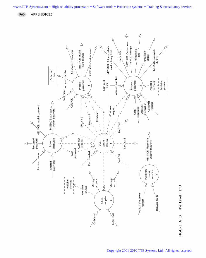
APPENDICES960
FIG
UR
E A
1.3
The
Lev
el 1
DfD
Mai
nco
ntro
lp
roce
ss
Ejec
t ca
rd
Keep
car
dC
ard
OK
Che
cksu
pp
lies
17
Avai
labl
ese
rvic
es
Avai
labl
ese
rvic
es Mes
sage
no p
aper
Mes
sage
no c
ash
T
Cas
h le
vel
Pap
er le
vel
Car
d in
sert
ed
Proc
ess
pas
swor
d
2
Valid
pas
swor
dT
Cus
tom
erre
que
stPr
oces
sp
assw
ord
4
T
Read
car
d
Keep
car
d
Ejec
t ca
rd
MES
SAG
E: T
hank
you
MES
SAG
E: C
ard
reta
ined
MES
SAG
E: In
valid
card
inse
rted
Cas
h ca
rdda
ta
Car
d da
ta
Car
d O
K
Acc
ount
num
ber
Proc
esse
dp
assw
ord
Pass
wor
d co
rrec
t
Ente
red
pas
swor
ds
MES
SAG
E: In
valid
pas
swor
d
MES
SAG
E: A
sk u
ser
toty
pe
in p
assw
ord
Har
dwar
est
atus
mon
itor
5
MES
SAG
E: P
leas
e us
ean
othe
r m
achi
ne
Man
ual s
hutd
own
req
uest
Har
war
e fa
ults
Proc
ess
pas
swor
d
4
Cas
h ca
rdda
ta
Avai
labl
ese
rvic
es
Avai
labl
ese
rvic
es
Acc
ount
num
ber
MES
SAG
E: A
sk u
ser
whi
chse
rvic
e is
req
uire
d
Cas
h da
ta
MES
SAG
E: C
usto
mer
serv
ice
mes
sage
s
Prin
ted
slip
data
Tran
sact
ion
deta
ils
MES
SAG
E: a
vaila
ble
choi
ces
Cas
hre
que
sted
Acc
ount
info
rmat
ion
Cus
tom
erre
que
st
Cus
tom
erre
que
st
T
www.TTE-Systems.com = High-reliability processors + Software tools + Protection systems + Training & consultancy services
Copyright 2001-2010 TTE Systems Ltd. All rights reserved.
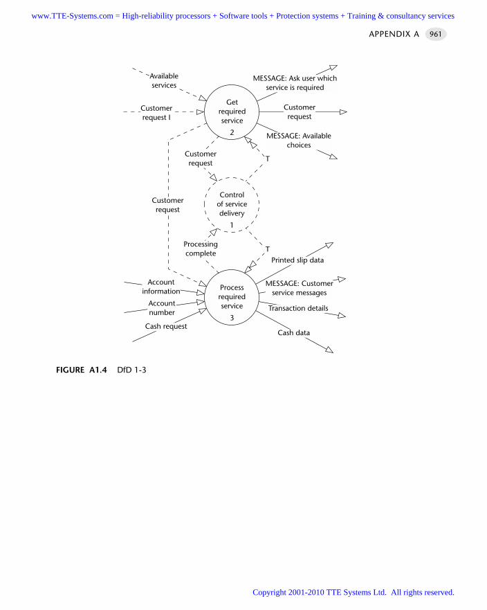
APPENDIX A 961
FIGURE A1.4 DfD 1-3
Controlof servicedelivery
1
Getrequiredservice
2
Processrequiredservice
3
T
T
Customerrequest
Processingcomplete
Printed slip data
MESSAGE: Customerservice messages
Transaction details
Cash dataCash request
Accountinformation
Accountnumber
Customerrequest
Customerrequest I
Availableservices
MESSAGE: Ask user whichservice is required
MESSAGE: Availablechoices
Customerrequest
www.TTE-Systems.com = High-reliability processors + Software tools + Protection systems + Training & consultancy services
Copyright 2001-2010 TTE Systems Ltd. All rights reserved.
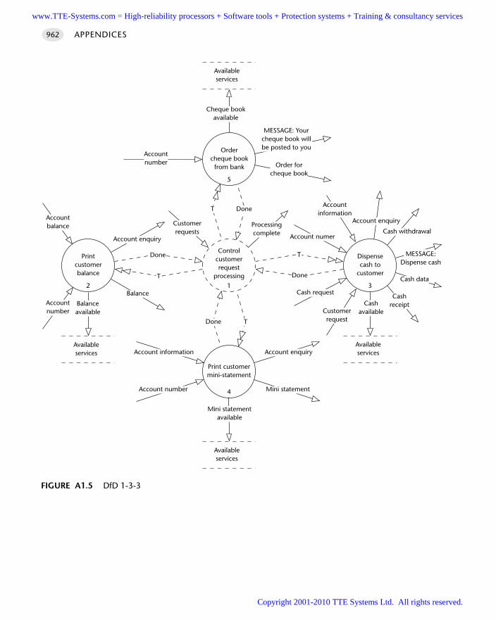
APPENDICES962
FIGURE A1.5 DfD 1-3-3
Cashavailable
Availableservices
Done
Order forcheque book
Ordercheque book
from bank
5
Printcustomerbalance
2
Dispensecash to
customer
3
Cheque bookavailable
Availableservices
Accountnumber
MESSAGE: Yourcheque book willbe posted to you
Balance
Account enquiry
Accountnumber
Balanceavailable
Availableservices
Accountbalance
T Done
T
DoneT
Print customermini-statement
4 Mini statement
Account enquiry
Account number
Account information
Mini statementavailable
Availableservices
Done T
Controlcustomerrequest
processing1
Customerrequests
Processingcomplete
Cashreceipt
Cash data
Cash withdrawal
Account enquiry
MESSAGE:Dispense cash
Cash request
Customerrequest
Account numer
Accountinformation
www.TTE-Systems.com = High-reliability processors + Software tools + Protection systems + Training & consultancy services
Copyright 2001-2010 TTE Systems Ltd. All rights reserved.
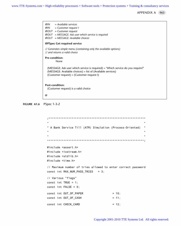
/***********************************************************
* *
* A Bank Service Till (ATM) Simulation (Process-Oriented) *
* *
* *
***********************************************************/
#include <assert.h>
#include <iostream.h>
#include <stdlib.h>
#include <time.h>
// Maximum number of tries allowed to enter correct password
const int MAX_NUM_PASS_TRIES = 3;
// Various "flags"
const int TRUE = 1;
const int FALSE = 0;
const int OUT_OF_PAPER = 10;
const int OUT_OF_CASH = 11;
const int CHECK_CARD = 12;
APPENDIX A 963
FIGURE A1.6 PSpec 1-3-2
@IN = Available services@IN = Customer request I@OUT = Customer request@OUT = MESSAGE: Ask user which service is required@OUT = MESSAGE: Available choices
@PSpec Get required service
// Generates simple menu (containing only the available options) // and returns a valid choice
Pre-condition:None
(MESSAGE: Ask user which service is required) = ‘Which service do you require?’ (MESSAGE: Available choices) = list of (Available services)(Customer request) = (Customer request I)
Post-condition:(Customer request) is a valid choice
@
www.TTE-Systems.com = High-reliability processors + Software tools + Protection systems + Training & consultancy services
Copyright 2001-2010 TTE Systems Ltd. All rights reserved.

const int KEEP_CARD = 13;
const int EJECT_CARD = 14;
const int ORDER_CHEQUE_BOOK = 15;
const int PRINT_BALANCE = 16;
const int PRINT_MINI_STATEMENT = 17;
const int DISPENSE_CASH = 18;
const int QUIT = 19;
// Function prototypes
void Check_cash_reserves(int&);
void Check_paper_reserves(int&);
void Check_supplies(int&, int&, int&, int&);
void Deliver_services(int&, int& ,int&, int&);
void Dispense_cash_to_customer(int&);
void Get_password(int&,int&,int&);
void Get_required_service(int&, int, int, int, int);
int Hardware_fault_detected();
void Order_cheque_book_from_bank(int&);
void Print_customer_balance(int&);
void Print_customer_mini_statement(int&);
void Process_cash_card(int, int* = 0);
void Process_required_service(int, int&, int&, int&, int&);
void Shutdown(void);
/***********************************************************
* *
* FUNCTION: main() *
* *
***********************************************************/
int main(void)
int cheque_OK,
balance_OK,
statement_OK,
cash_OK;
int valid_password_entered, valid_card_entered;
int user_wants_to_quit, tries;
// Set up non-repeatable random numbers for simulation
srand((unsigned)time(NULL));
// Simulate (up to) five customers in queue then
// manual shut down
APPENDICES964
www.TTE-Systems.com = High-reliability processors + Software tools + Protection systems + Training & consultancy services
Copyright 2001-2010 TTE Systems Ltd. All rights reserved.
for (int customer = 1; customer <= 5; customer++)
// Welcome banner
cout << "----------------------------------\n";
cout << "PROTOTYPE BANK AUTO TELLER MACHINE\n";
cout << "----------------------------------\n\n";
Check_supplies(cash_OK, balance_OK,
statement_OK, cheque_OK);
Process_cash_card(CHECK_CARD, &valid_card_entered);
if (valid_card_entered)
tries = 0;
user_wants_to_quit = FALSE;
Get_password(valid_password_entered,
user_wants_to_quit, tries);
if ((valid_password_entered)
&& (!user_wants_to_quit))
// Keep delivering services till user says quit
// (or hardware fault)
Deliver_services(cheque_OK, balance_OK,
statement_OK, cash_OK);
Process_cash_card(EJECT_CARD);
else
// No valid password
if (user_wants_to_quit)
// Polite ejection
Process_cash_card(EJECT_CARD);
// Simulate manual shutdown
Shutdown();
return 0;
APPENDIX A 965
www.TTE-Systems.com = High-reliability processors + Software tools + Protection systems + Training & consultancy services
Copyright 2001-2010 TTE Systems Ltd. All rights reserved.
/***********************************************************
* *
* FUNCTION: Shutdown() *
* *
* OVERVIEW: Exit message, and exit program. *
* *
* PRE: None. *
* POST: None. *
* *
* RETURNS: void. *
* *
***********************************************************/
void Shutdown(void)
// Pre - none
cout << "Please use another machine.\n";
cerr << "*** SIMULATING MACHINE SHUTDOWN ***\n";
exit(1);
// Post - none(!)
/***********************************************************
* *
* FUNCTION: Check_supplies() *
* *
* OVERVIEW: Check cash and paper reserves &c. *
* *
* PRE: No hardware faults. *
* POST: Got valid data. *
* *
* RETURNS: void. *
* *
***********************************************************/
void Check_supplies(int& cash_OK_REF,
int& balance_OK_REF,
int& statement_OK_REF,
int& cheque_OK_REF)
// Pre - no hardware faults
if (Hardware_fault_detected()) Shutdown();
int paper_level_OK; // Is paper level okay? (flag)
APPENDICES966
www.TTE-Systems.com = High-reliability processors + Software tools + Protection systems + Training & consultancy services
Copyright 2001-2010 TTE Systems Ltd. All rights reserved.
cout << "Next customer please wait...\n\n";
Check_cash_reserves(cash_OK_REF);
Check_paper_reserves(paper_level_OK);
if (!paper_level_OK)
balance_OK_REF = FALSE;
statement_OK_REF = FALSE;
else
// Reset these for new customer
balance_OK_REF = TRUE;
statement_OK_REF = TRUE;
// Reset flag for new customer (always available)
cheque_OK_REF = TRUE;
// Post - got valid data
assert((cash_OK_REF == FALSE)
|| (cash_OK_REF == TRUE));
assert((balance_OK_REF == FALSE)
|| (balance_OK_REF == TRUE));
assert((statement_OK_REF == FALSE)
|| (statement_OK_REF == TRUE));
assert((cheque_OK_REF == FALSE)
|| (cheque_OK_REF == TRUE));
/***********************************************************
* *
* FUNCTION: Hardware_fault_detected() *
* *
* OVERVIEW: Make sure hardware is not damaged. *
* *
* PRE: None. *
* POST: None. *
* *
* RETURNS: TRUE (1) if fault, FALSE (0) otherwise. *
* *
***********************************************************/
APPENDIX A 967
www.TTE-Systems.com = High-reliability processors + Software tools + Protection systems + Training & consultancy services
Copyright 2001-2010 TTE Systems Ltd. All rights reserved.
int Hardware_fault_detected()
// Pre - none
// Simulating a hardware fault with a prob. of 1/100
if ((rand() % 100) == 0)
cerr << "*** SIMULATING HARDWARE FAULT ***\n";
return 1;
else
return 0;
// Post - none
/***********************************************************
* *
* FUNCTION: Check_cash_reserves() *
* *
* OVERVIEW: Check cash level. *
* *
* PRE: No hardware faults. *
* POST: Got valid data. *
* *
* RETURNS: void. *
* *
***********************************************************/
void Check_cash_reserves(int& cash_OK_REF)
// Pre - no hardware faults
if (Hardware_fault_detected()) Shutdown();
// Simulating a 1/6 chance of a cash shortage
if ((rand() % 6)==0)
cash_OK_REF = FALSE;
cerr << "*** SIMULATING LOW CASH LEVEL ***\n";
else
cash_OK_REF = TRUE;
APPENDICES968
www.TTE-Systems.com = High-reliability processors + Software tools + Protection systems + Training & consultancy services
Copyright 2001-2010 TTE Systems Ltd. All rights reserved.
// Post - got valid data
assert((cash_OK_REF == FALSE)
|| (cash_OK_REF == TRUE));
/***********************************************************
* *
* FUNCTION: Check_paper_reserves() *
* *
* OVERVIEW: Check that there is paper to print on. *
* *
* PRE: No hardware faults. *
* POST: Got valid data. *
* *
* RETURNS: void. *
* *
***********************************************************/
void Check_paper_reserves(int& paper_level_OK_REF)
// Pre - no hardware faults
if (Hardware_fault_detected()) Shutdown();
// Simulating a 1/6 chance of a paper shortage
if ((rand() % 6)==0)
paper_level_OK_REF = FALSE;
cerr << "*** SIMULATING LOW PAPER LEVEL ***\n";
else
paper_level_OK_REF = TRUE;
// Post - got valid data
assert((paper_level_OK_REF == FALSE)
|| (paper_level_OK_REF == TRUE));
/***********************************************************
* *
* FUNCTION: Process_cash_card() *
* *
* OVERVIEW: Validate, eject or retain cash card. *
APPENDIX A 969
www.TTE-Systems.com = High-reliability processors + Software tools + Protection systems + Training & consultancy services
Copyright 2001-2010 TTE Systems Ltd. All rights reserved.
* *
* PRE: No hardware faults. *
* Valid operation requested. *
* POST: None. *
* *
* RETURNS: void. *
* *
***********************************************************/
void Process_cash_card(int required_op, int* card_OK_PTR)
// Pre - no hardware faults
if (Hardware_fault_detected()) Shutdown();
// Pre - valid operation requested
assert((required_op == CHECK_CARD) ||
(required_op == KEEP_CARD) ||
(required_op == EJECT_CARD));
/* NOTE: Process_cash_card() is a function with a
default argument. Can call as:
Process_cash_card(CHECK_CARD, card_OK);
or
Process_cash_card(KEEP_CARD);
Process_cash_card(EJECT_CARD); */
switch (required_op)
case CHECK_CARD:
// Using "extra" argument
cout << "Please insert your card.\n";
// Validate user's card
*card_OK_PTR = (((rand() % 6) != 0)
? (TRUE) : (FALSE));
if (*card_OK_PTR)
cerr <<
"*** SIMULATING CORRECT CARD INSERTED ***\n";
cout << "Thank you.\n\n";
else
cerr <<
"*** SIMULATING *INCORRECT* CARD INSERTED ***\n";
APPENDICES970
www.TTE-Systems.com = High-reliability processors + Software tools + Protection systems + Training & consultancy services
Copyright 2001-2010 TTE Systems Ltd. All rights reserved.
cout << "Incorrect card.\n";
Process_cash_card(EJECT_CARD);
break;
case KEEP_CARD:
cout << "Password incorrect. Card retained.\n";
cout << "Please contact your branch.\n";
cerr << "*** SIMULATING SWALLOWING CARD ***\n\n";
break;
case EJECT_CARD:
cout << "Thank you for using this machine.\n";
cerr << "*** SIMULATING EJECTING CARD ***\n\n";
break;
// Post - none
/***********************************************************
* *
* FUNCTION: Get_password() *
* *
* OVERVIEW: Get and validate user's password *
* *
* PRE: No hardware faults. *
* POST: Got valid data. *
* *
* RETURNS: void. *
* *
***********************************************************/
void Get_password(int& password_OK_REF,
int& want_to_quit_REF,
int& tries_REF)
// Pre - no hardware faults
if (Hardware_fault_detected()) Shutdown();
int password;
tries_REF++;
cout << "Please enter your password"
APPENDIX A 971
www.TTE-Systems.com = High-reliability processors + Software tools + Protection systems + Training & consultancy services
Copyright 2001-2010 TTE Systems Ltd. All rights reserved.
<< "\n(or 9999 to simulate QUIT button): ";
cin >> password;
if (!(password == 9999))
// User did not ask to quit
// Simulate call to bank computer
cerr << "*** SIMULATING CALL TO BANK COMPUTER ***\n";
// Simulating one single valid password...
// In reality, send account number and password
// to bank computer
// Computer returns “YES” or “NO”.
if (password == 1234)
password_OK_REF = TRUE;
else
password_OK_REF = FALSE;
if (!(password_OK_REF))
if (tries_REF < MAX_NUM_PASS_TRIES)
cout << "Password incorrect.\n";
// Recursive call to Get_password()
Get_password(password_OK_REF, want_to_quit_REF, tries_REF);
else
// Too many tries - could be a stolen card?
Process_cash_card(KEEP_CARD);
else
cout << "Thank you.\n\n";
else
APPENDICES972
www.TTE-Systems.com = High-reliability processors + Software tools + Protection systems + Training & consultancy services
Copyright 2001-2010 TTE Systems Ltd. All rights reserved.
// User wants to quit
want_to_quit_REF = TRUE;
// Post - got valid data
assert((password_OK_REF == FALSE)
|| (password_OK_REF == TRUE));
assert((want_to_quit_REF == FALSE)
|| (want_to_quit_REF == TRUE));
assert(tries_REF <= MAX_NUM_PASS_TRIES);
/***********************************************************
* *
* FUNCTION: Deliver_services() *
* *
* OVERVIEW: Ask user for reqd. service and deliver it. *
* *
* PRE: No hardware faults. *
* Got valid data. *
* POST: None. *
* *
* RETURNS: void. *
* *
***********************************************************/
void Deliver_services(int& cheque_OK_REF,
int& balance_OK_REF,
int& statement_OK_REF,
int& cash_OK_REF)
// Pre - no hardware faults
if (Hardware_fault_detected()) Shutdown();
// Pre - got valid data
assert((cash_OK_REF == FALSE)
|| (cash_OK_REF == TRUE));
assert((cheque_OK_REF == FALSE)
|| (cheque_OK_REF == TRUE));
assert((balance_OK_REF == FALSE)
|| (balance_OK_REF == TRUE));
assert((statement_OK_REF == FALSE)
|| (statement_OK_REF == TRUE));
int user_choice;
APPENDIX A 973
www.TTE-Systems.com = High-reliability processors + Software tools + Protection systems + Training & consultancy services
Copyright 2001-2010 TTE Systems Ltd. All rights reserved.
Get_required_service(user_choice, cheque_OK_REF,
balance_OK_REF, statement_OK_REF, cash_OK_REF);
while (user_choice != QUIT)
Process_required_service(user_choice, cheque_OK_REF,
balance_OK_REF, statement_OK_REF, cash_OK_REF);
Get_required_service(user_choice, cheque_OK_REF,
balance_OK_REF, statement_OK_REF, cash_OK_REF);
// Post - none
/***********************************************************
* *
* FUNCTION: Get_required_service() *
* *
* OVERVIEW: Find out what service user requires. *
* *
* PRE: No hardware faults. *
* POST: Got valid choice. *
* *
* RETURNS: void. *
* *
***********************************************************/
void Get_required_service(int& service_REF,
int cheque_OK,
int balance_OK,
int statement_OK,
int cash_OK)
// Pre - no hardware faults
if (Hardware_fault_detected()) Shutdown();
int service;
cout << "Which service do you require: \n";
cout << "Quit - Type 1\n";
if (cheque_OK) cout << "Order cheque book - Type 2\n";
if (balance_OK) cout << "Print balance - Type 3\n";
if (statement_OK) cout << "Print statement - Type 4\n";
if (cash_OK) cout << "Cash - Type 5\n";
APPENDICES974
www.TTE-Systems.com = High-reliability processors + Software tools + Protection systems + Training & consultancy services
Copyright 2001-2010 TTE Systems Ltd. All rights reserved.
do
cout << "Please enter the appropriate number : ";
cin >> service;
while ((service > 5)
|| (service < 1)
|| ((service == 2) && (!cheque_OK))
|| ((service == 3) && (!balance_OK))
|| ((service == 4) && (!statement_OK))
|| ((service == 5) && (!cash_OK)));
cout << "Thank you.\n\n";
switch (service)
case 1: service_REF = QUIT; break;
case 2: service_REF = ORDER_CHEQUE_BOOK; break;
case 3: service_REF = PRINT_BALANCE; break;
case 4: service_REF = PRINT_MINI_STATEMENT; break;
case 5: service_REF = DISPENSE_CASH; break;
// Post - got valid choice
assert((service_REF == QUIT) ||
(service_REF == ORDER_CHEQUE_BOOK) ||
(service_REF == PRINT_BALANCE) ||
(service_REF == PRINT_MINI_STATEMENT) ||
(service_REF == DISPENSE_CASH));
/***********************************************************
* *
* FUNCTION: Process_required_service() *
* *
* OVERVIEW: Perform user's requested service. *
* *
* PRE: No hardware faults. *
* Got valid choice of service. *
* POST: None. *
* *
* RETURNS: void. *
* *
***********************************************************/
APPENDIX A 975
www.TTE-Systems.com = High-reliability processors + Software tools + Protection systems + Training & consultancy services
Copyright 2001-2010 TTE Systems Ltd. All rights reserved.
void Process_required_service(int user_choice,
int& cheque_OK_REF,
int& balance_OK_REF,
int& statement_OK_REF,
int& cash_OK_REF)
// Pre - no hardware faults
if (Hardware_fault_detected()) Shutdown();
// Pre - got valid choice
assert((user_choice == QUIT) ||
(user_choice == ORDER_CHEQUE_BOOK) ||
(user_choice == PRINT_BALANCE) ||
(user_choice == PRINT_MINI_STATEMENT) ||
(user_choice == DISPENSE_CASH));
switch (user_choice)
case ORDER_CHEQUE_BOOK:
Order_cheque_book_from_bank(cheque_OK_REF);
break;
case PRINT_BALANCE:
Print_customer_balance(balance_OK_REF);
break;
case PRINT_MINI_STATEMENT:
Print_customer_mini_statement(statement_OK_REF);
break;
case DISPENSE_CASH:
Dispense_cash_to_customer(cash_OK_REF);
break;
// Post - none
/***********************************************************
* *
* FUNCTION: Order_cheque_book_from_bank() *
* *
* OVERVIEW: Order cheque book. *
* *
APPENDICES976
www.TTE-Systems.com = High-reliability processors + Software tools + Protection systems + Training & consultancy services
Copyright 2001-2010 TTE Systems Ltd. All rights reserved.
* PRE: No hardware faults. *
* Got valid data. *
* POST: Returning valid data. *
* *
* RETURNS: void. *
* *
***********************************************************/
void Order_cheque_book_from_bank(int& cheque_OK_REF)
// Pre - no hardware faults
if (Hardware_fault_detected()) Shutdown();
// Pre - got valid data
assert((cheque_OK_REF == TRUE));
cerr << "*** SIMULATING ORDER FOR CHEQUE BOOK ***\n";
cout << "Your cheque book will be posted to you.\n\n";
cheque_OK_REF = FALSE;
// Post - returning valid data
assert((cheque_OK_REF == FALSE));
/***********************************************************
* *
* FUNCTION: Print_customer_balance() *
* *
* OVERVIEW: Print customer's balance. *
* *
* PRE: No hardware faults. *
* Got valid data. *
* POST: Returning valid data. *
* *
* RETURNS: void. *
* *
***********************************************************/
void Print_customer_balance(int& balance_OK_REF)
// Pre - no hardware faults
if (Hardware_fault_detected()) Shutdown();
// Pre - got valid data
assert((balance_OK_REF == TRUE));
cout << "Your balance is: 99.99 (*** SIMULATED ***)\n\n";
APPENDIX A 977
www.TTE-Systems.com = High-reliability processors + Software tools + Protection systems + Training & consultancy services
Copyright 2001-2010 TTE Systems Ltd. All rights reserved.
balance_OK_REF = FALSE;
// Post - returning valid data
assert((balance_OK_REF == FALSE));
/***********************************************************
* *
* FUNCTION: Print_customer_mini_statement() *
* *
* OVERVIEW: Print mini statement. *
* *
* PRE: No hardware faults. *
* Got valid data. *
* POST: Returning valid data. *
* *
* RETURNS: void. *
* *
***********************************************************/
void Print_customer_mini_statement(int& statement_OK_REF)
// Pre - no hardware faults
if (Hardware_fault_detected()) Shutdown();
// Pre - got valid data
assert((statement_OK_REF == TRUE));
cerr << "*** SIMULATING PRINTING OF MINI STATEMENT ***";
cout << "\nPlease take your mini statement.\n\n";
statement_OK_REF = FALSE;
// Post - returning valid data
assert((statement_OK_REF == FALSE));
/***********************************************************
* *
* FUNCTION: Dispense_cash_to_customer() *
* *
* OVERVIEW: Deliver cash. *
* *
* PRE: No hardware faults. *
* Got valid data. *
* POST: Returning valid data. *
* *
APPENDICES978
www.TTE-Systems.com = High-reliability processors + Software tools + Protection systems + Training & consultancy services
Copyright 2001-2010 TTE Systems Ltd. All rights reserved.
* RETURNS: void. *
* *
***********************************************************/
void Dispense_cash_to_customer(int& cash_OK_REF)
// Pre - no hardware faults
if (Hardware_fault_detected()) Shutdown();
// Pre - got valid data
assert((cash_OK_REF == TRUE));
cerr << "*** SIMULATING CASH DELIVERY ***\n";
cout << "Please take your cash.\n\n";
cash_OK_REF = FALSE;
// Post - returning valid data
assert((cash_OK_REF == FALSE));
/***********************************************************
* *** END OF PROGRAM *** *
***********************************************************/
Listing A1.1 The prototype ATM system software
APPENDIX A 979
www.TTE-Systems.com = High-reliability processors + Software tools + Protection systems + Training & consultancy services
Copyright 2001-2010 TTE Systems Ltd. All rights reserved.
Guide to the CD
Overview
This short appendix provides a guide to the contents of the CD.
The basis of the CD
The CD is based on information kindly provided by Keil Software; this includesthe evaluation version of all the Keil compilers, plus numerous data sheets on 8051microcontrollers.
The CD has a menu which will guide you through the installation process.
The source code for this book
The source code for this book is NOT automatically installed with the Keil compiler.The source files are included on the CD in the directory \Pont. For example, if
your CD–ROM drive is mapped to D: you will find the source files in the directoryD:\Pont.
Use ‘ Windows Explorer’ (or equivalent) to copy these files from the CD to yourhard drive.
appendixbwww.TTE-Systems.com = High-reliability processors + Software tools + Protection systems + Training & consultancy services
Copyright 2001-2010 TTE Systems Ltd. All rights reserved.
APPENDIX B 981
Copyright Restrictions
The code included in this book took many years to produce. It is not ‘ free ware’and is subject to some simple copyright restrictions. These are as follows:
Having purchased a copy of this book, you are entitled to use the code listed inthis book and included on the CD in your projects, should you choose to do so. Ifyou use the code in this way, then no run-time royalties are due. However, theauthor would appreciate it if you acknowledged the source of the code in theproduct documentation.
If there are ten developers in your team using code adapted from this book,please purchase ten copies of the book.
You may not, under any circumstances, publish or otherwise distribute any ofthe source code included in the book or on the CD, in any form or by anymeans, without explicit written authorization from the author. If you wish topublish limited code fragments then, in most circumstances, this permission willbe granted, subject only to an appropriate acknowledgement accompanying thepublished material. If you wish to publish more substantial code listings, paymentof a fee may be required. Please contact the author for further details.
www.TTE-Systems.com = High-reliability processors + Software tools + Protection systems + Training & consultancy services
Copyright 2001-2010 TTE Systems Ltd. All rights reserved.
Guide to the WWW site
Overview
This brief appendix provides information about the WWW site associated withthis book.
The URL
There is a WWW site associated with this book, at the following URL:
http://www.engg.le.ac.uk/books/Pont
Contents of the WWW site
On this WWW site you will find:
A set of detailed case studies describing the application of the techniques discussedin this book in a series of small and large projects
Bug reports and code updates
Further code samples
Links to other relevant sites
Bug reports and code updates
There is huge amount of code involved in this project, both in the book itself and onthe associated CD. The author has personally tested all the code that appears here.Nonetheless, errors can creep in.
appendixcwww.TTE-Systems.com = High-reliability processors + Software tools + Protection systems + Training & consultancy services
Copyright 2001-2010 TTE Systems Ltd. All rights reserved.
If you think you have found a bug, please first check the WWW site to see ifanyone else has picked up the error: if they have, a code correction will have beenmade available.
If you have found a bug not listed on the WWW site, please send an e-mail to theauthor explaining the bug ([email protected]) and he will do his best to help.
Anyone who spots a bug will be acknowledged (if they wish) in subsequenteditions of the book.
APPENDIX C 983
www.TTE-Systems.com = High-reliability processors + Software tools + Protection systems + Training & consultancy services
Copyright 2001-2010 TTE Systems Ltd. All rights reserved.

www.TTE-Systems.com = High-reliability processors + Software tools + Protection systems + Training & consultancy services
Copyright 2001-2010 TTE Systems Ltd. All rights reserved.
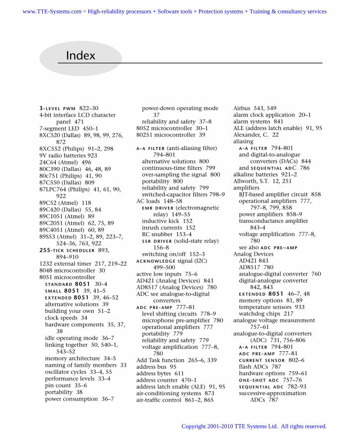
3-L E V E L P W M 822–304-bit interface LCD character
panel 4717-segment LED 450–18XC520 (Dallas) 89, 98, 99, 276,
8728XC552 (Philips) 91–2, 2989V radio batteries 92324C64 (Atmel) 49680C390 (Dallas) 46, 48, 8980c751 (Philips) 41, 9087C550 (Dallas) 80987LPC764 (Philips) 41, 61, 90,
92289C52 (Atmel) 11889C420 (Dallas) 55, 8489C1051 (Atmel) 8989C2051 (Atmel) 62, 75, 8989C4051 (Atmel) 60, 8989S53 (Atmel) 31–2, 89, 223–7,
524–36, 763, 922255-TICK SCHEDULER 893,
894–9101232 external timer 217, 219–228048 microcontroller 308051 microcontroller
S TA N D A R D 8051 30–4S M A L L 8051 39, 41–5E X T E N D E D 8051 39, 46–52alternative solutions 39building your own 51–2clock speeds 34hardware components 35, 37,
38idle operating mode 36–7linking together 50, 540–1,
543–52memory architecture 34–5naming of family members 33oscillator cycles 33–4, 55performance levels 33–4pin count 35–6portability 38power consumption 36–7
power-down operating mode37
reliability and safety 37–88052 microcontroller 30–180251 microcontroller 39
A-A F I LT E R (anti-aliasing filter)794–801
alternative solutions 800continuous-time filters 799over-sampling the signal 800portability 800reliability and safety 799switched-capacitor filters 798–9
AC loads 148–58E M R D R I V E R (electromagnetic
relay) 149–55inductive kick 152inrush currents 152RC snubber 153–4S S R D R I V E R (solid-state relay)
156–8switching on/off 152–3
A C K N O W L E D G E signal (I2C)499–500
active low inputs 75–6AD421 (Analog Devices) 843AD8517 (Analog Devices) 780ADC see analogue-to-digital
convertersA D C P R E-A M P 777–81
level shifting circuits 778–9microphone pre-amplifier 780operational amplifiers 777portability 779reliability and safety 779voltage amplification 777–8,
780Add Task function 265–6, 339address bus 95address bytes 611address counter 470–1address latch enable (ALE) 91, 95air-conditioning systems 873air-traffic control 861–2, 865
Airbus 543, 549alarm clock application 20–1alarm systems 841ALE (address latch enable) 91, 95Alexander, C. 22aliasing
A-A F I LT E R 794–801and digital-to-analogue
converters (DACs) 844and S E Q U E N T I A L A DC 786
alkaline batteries 921–2Allworth, S.T. 12, 251amplifiers
BJT-based amplifier circuit 858operational amplifiers 777,
797–8, 799, 858power amplifiers 858–9transconductance amplifier
843–4voltage amplification 777–8,
780see also A D C P R E–A M P
Analog DevicesAD421 843AD8517 780analogue-digital converter 760digital-analogue converter
842, 843E X T E N D E D 8051 46–7, 48memory options 81, 89temperature sensors 933watchdog chips 217
analogue voltage measurement757–61
analogue-to-digital converters(ADC) 731, 756–806
A-A F I LT E R 794–801A D C P R E-A M P 777–81C U R R E N T S E N S O R 802–6flash ADCs 787hardware options 759–61O N E-S H O T A D C 757–76S E Q U E N T I A L A D C 782–93successive-approximation
ADCs 787
Index
www.TTE-Systems.com = High-reliability processors + Software tools + Protection systems + Training & consultancy services
Copyright 2001-2010 TTE Systems Ltd. All rights reserved.
anti-windup protection 869–70asynchronous data transmission
364, 368, 520AT cut 54Atmel
24C64 49689C542 11889C1051 8989C2051 62, 75, 8989C4051 60, 8989S53 31–2, 89, 223–7,
524–36, 763, 922memory options 89S M A L L 8051 41, 42watchdog timers 223–7
atomic clocks 60audio equipment 858–9auditory-evoked responses 785auto-reload timers 197, 238–9automatic light 925–30autopilot applications 6–7Awad, M. 16, 17, 20Axelson, J. 370, 396Ayala, K. 39
back lighting LCD characterpanels 472
bandwidthand data transfer 712–15and P I D C O N T R O L L E R 871–2and S E Q U E N T I A L A D C 784–5
bank-switched memoryarrangements 104–7
bargraph display 187–92Barnett, R.H. 251Barrenscheen, J. 684, 685Basic CAN 678basic input/output system (BIOS)
232Bates, I. 12, 251batteries
alkaline 921–2D cell 923discharge curve 920–1galvanic cells 919, 920lithium cell 923–49V 923predicting lifetime of 920primary cells 919recharging 919–20, 924secondary cells 920, 924voltage of 922
baud ratesP C L I N K (R S-232) 364, 366,
367–8, 386–96, 520
S C C S C H E D U L E R 681S C I S C H E D U L E R (T I C K) 562S C U S C H E D U L E R (L O C A L)
612–13and timer 2 743
BDATA memory 86Beck, K. 22Bennett, S. 251Bignell, V. 552BIOS (basic input/output system)
232bipolar-junction transistor (BJT)
see BJTBishop, R.H. 866, 873bit rate
D A C O U T P U T 842S E Q U E N T I A L A D C 786
bitwise operators 179–83BJT (bipolar-junction transistor),
amplifier circuit 858BJT (bipolar-junction transistor),
and current-sense resistors803–4
B J T D R I V E R 124–33, 142buffering output 125–7inrush currents 128load faults 131portability 131reliability and safety 128–31switching off inductive DC
loads 129–31blink control circuit 470Booch, G. 16bounce behaviour of switches
399–400, 402, 410–11brightness control 823–30,
834–9broadband signals 784–5Brooks, F.P. 25brownouts 73–4buffers
and B J T D R I V E R 125–7and connecting up LEDs 112and H A R D WA R E P W M 810I C B U F F E R 118–2and K E Y PA D I N T E R FA C E 438,
439logic families 120–2and multi-segment LED
displays 451, 454UDN2585A 451–3, 454
bug reports 982–3Burns, A. 543, 546Burr-Brown
RCV420 761
transconductance amplifier843–4
XTR105 761XTR110 843–4
business information systems(BISs) 3–5
busy flag (BF) 470buzzers 116–17, 133bytes
address bytes 611format in I2C protocol 499message bytes 611reading and writing 178–9
C167 (Infineon) 34C501 (Infineon) 33, 34, 36,
89–90C505C (Infineon) 46, 90C509 (Infineon) 90, 98, 872C515C (Infineon) 46, 90, 93,
386–96, 686–710, 760,776, 788–92, 809, 812–17
C517 (Infineon) 872C541 (Infineon) 373C8051F000 (Cygnal) 842–3cable connections (RS-232)
365–6caesium beam clock 60CAN (controller area networks)
545–7, 675–710capacitors 57, 65CASE tool 957central-heating systems 155,
158, 165–8H A R D WA R E WAT C H D O G 221–2,
224–7C E R A M I C R E S O N AT O R 64–6
connecting 66cost 64frequency variation and
temperature 931portability 65reliability and safety 65stability 64
Character Generator (CG) RAM470
character set of LCD panels 469clock frequency/speed
latch and memorycombinations 97, 100–1
and oscillator frequency 55–6S P I P E R I P H E R A L 522–3S TA N D A R D 8051 34
clock synchronizationand I2C protocol 497, 500
INDEX986
www.TTE-Systems.com = High-reliability processors + Software tools + Protection systems + Training & consultancy services
Copyright 2001-2010 TTE Systems Ltd. All rights reserved.
and shared-clock schedulers543–5
clock-outs 741closed-loop control systems
864–5CMOS logic family 120–2C O-O P E R AT I V E S C H E D U L E R
246–53, 255–96, 716compared to pre-emptive
scheduler 250–2core scheduler library 280–96CPU load 274–6data structure 260–1error reporting 272–4function pointers 255–8,
268–70, 277functions
add task 265–6, 339delete task 270–1dispatch task 266–8initialization 262–3report status 272–4sleep 271start 270update 263–4, 268, 336–7
integration of scheduler andapplication 944–5
interrupt generation 263Keil linker options 268–70key components 258and memory 274oscillator frequency 274–6portability 279power consumption 271reliability and safety 246,
276–9resource consumption 260,
274–6task array 261, 277task jitter 268task overlap 277, 278tick intervals 263, 278–9watchdog support 274
co-operative thinking 297CODE memory 86, 88
and interrupts 236O F F-C H I P C O D E M E M O RY
100–8speed of access 92
code sizeI2C communication protocol
501S P I P E R I P H E R A L 523
code updates 982–3Coen, A. 9
Coleman, D. 16common anode packages 450common cathode packages 450communication systems for
hydrofoils 853–5condition-monitoring
applications 718, 723consecutively scheduled tasks
720–4context switch 247, 340continuous-time filters 799contrast adjustments 472control algorithms 865–72, 876control parameters 871controller area networks (CAN)
545–7, 675–710Cooling, J.E. 251copyright restrictions 981cost of licences
I2C protocol 502S P I P E R I P H E R A L 524
countersaddress counter 470–1incrementing 424–32switch block counter 415see also timers
critical sections of code 247–50,338
cruise-control system 17–20,551, 874–8
Crydom MP240D3 SSR 158C RY S TA L O S C I L L AT O R 54–63
connecting 57, 58to dual-processor boards 62,
63cost 57external modules 54, 58–9on-chip 60–1oscillator frequency 55–6, 57,
61–2and P C L I N K (RS-232) 368–9,
372portability 60and R C R E S E T 73reliability and safety 58–60and RS-232 communication
368–9stability 56–7, 59–60start-up times 58temperature-compensated
(TCXOs) 59, 931, 932Cunningham, W. 22current measurement 758–61C U R R E N T S E N S O R 802–6
portability 805
reliability and safety 805current sinks 134–6current-mode DACs 843–4current-mode sensor components
761current-sense resistors 802–3cursor/blink control circuit 470cyclic scheduling 251Cygnal
C8051F000 842–3on-chip DACs 842–3temperature sensors 933
Cypress Semiconductor 373
D cell batteries 923D A C D R I V E R (digital-to-analogue
converter driver) 857–9portability 857reliability and safety 857
D A C O U T P U T (digital-to-analogueconverter output) 841–52
aliasing 844alternative solutions 845bit rate 842external current-mode DAC
843–4external voltage-mode DAC
843frequency distortion 844on-chip DACs 842–3port pins and 844portability 844reliability and safety 844sample rate 842sinc compensation 854software architecture 844speech playback 845–52transconductance amplifier
843–4D A C S M O O T H E R (digital-to-
analogue convertersmoother) 853–6
portability 856reliability and safety 855
Dallas Semiconductor8XC520 98, 99, 276, 87280C390 46, 4887C550 80989C420 55, 844CAN support 678DS1050 809DS1620 932, 933–40DS1621 515Econoreset 77, 78, 79E X T E N D E D 8051 46, 48
INDEX 987
www.TTE-Systems.com = High-reliability processors + Software tools + Protection systems + Training & consultancy services
Copyright 2001-2010 TTE Systems Ltd. All rights reserved.
Dallas Semiconductor continuedfast 8051 devices 786–7high speed devices 34memory options 81, 89, 98–9pulse-width modulation
devices 809S TA N D A R D 8051 34temperature sensors 515, 932,
933–40watchdog chips 217
Darlington arrangement 134,858
data acquisition 541–3, 718data bus 95, 472Data bytes 611–12data lines 522DATA memory 86–7, 88
O F F-C H I P D ATA M E M O RY 94–9speed of access 92
data registers 470data structure
C O-O P E R AT I V E S C H E D U L E R
260–1255-T I C K S C H E D U L E R 894–5see also message structure
data transferI2C protocol 498–500limited bandwidth 712–15shared-clock schedulers 545–6S P I P E R I P H E R A L 522UART data transfer 235, 608,
675see also message structure
D ATA U N I O N 712–15portability 714reliability and safety 713–14
DC loads 109–47B J T D R I V E R 124–33, 142I C B U F F E R 118–23I C D R I V E R 134–8inductive kick 129inrush currents 128M O S F E T D R I V E R 139–43N A K E D L E D 110–14N A K E D L O A D 115–17SSR driver 144–7switching on/off 128–31
DC motor control 128, 143, 147,822, 861–4, 879–88
DD (Display Data) RAM 467De Marco, T. 8, 16debouncing switches 399–400,
402, 410–11delays
generic delay code 200–5
H A R D WA R E D E L AY 194–205S O F T WA R E D E L AY 206–14
Delete Task function 270–1design notation 957desktop systems 5–6, 162, 231–2
see also P C L I N K (R S-232)device addresses 496–7digital-to-analogue converters
(DACs) 840–59conversion noise 853D A C D R I V E R 857–9D A C O U T P U T 841–52D A C S M O O T H E R 853–6voltage mode DACs 843, 857
diodes 129–30, 153direct addressing 82–3disaster recovery 218discharge curve of batteries
920–1Dispatch task function 266–8Display Data (DD) RAM 467distributed networks 608, 646
node wiring 684transceivers 683
Dolphin Integration 51DOMINO TASK 720–4
portability 722reliability and safety 722
Dorf, R.C. 866, 873Douglass, B.P. 16DRAM (dynamic RAM) 83DS1050 (Dallas) 809DS1620 (Dallas) 932, 933–40DS1621 (Dallas) 515Duracell 921Dutton, K. 866, 873duty cycles
H A R D WA R E P R M 742H A R D WA R E P W M 808–9
dynamic RAM (DRAM) 83
EEPROM (electrically erasableprogrammable read-onlymemory) 85, 496, 503,510–15, 530–6
electromagnetic interference(EMI) 151, 811, 820
electromagnetic relays 144, 145electromechanical relays 149,
152, 155electrostatic discharge (ESD) 403embedded systems 8–10, 162E M R D R I V E R 149–55
portability 153reliability and safety 150–3
switching on/off inductiveloads 152–3
zero-crossing detection 151enable inputs 648encoding data 363error checking/handling
I2C protocol 502–3network and node errors
547–50RS-232 protocol 372S C I S C H E D U L E R (T I C K ) 561
error code displays 137–8, 183,272–4
event-triggered systems 10–11examples
255-T I C K S C H E D U L E R
896–9101232 external watchdog timer
219–22A-A FILTER 800–1active low resets 75–6amplifiers 780automatic lights 925–30baud rate generator 386–96brightness of light bulbs 834–9buzzers 116–17, 133CAN-based scheduler 686–710central-heating pump control
with an EM relay 155with an SSR 158with S U P E R L O O P 165–8
C E R A M I C R E S O N AT O R
connections 66condition monitoring and
control 723counter 424–32cruise-control system 874–8C RY S TA L O S C I L L AT O R
attaching to an Atmel89C2051 62
attaching to a dual-processorboard 62
data acquisition and FFT 718DC motor control
M O S F E T D R I V E R 143P I D C O N T R O L L E R 879–88S S R D R I V E R 147
delaysin an I2C library 208generic code 200–5
detecting a blown bulb 805–6Econoresets 79error code displays 137–8
in a scheduler 183external I2C ADC 767–72
INDEX988
www.TTE-Systems.com = High-reliability processors + Software tools + Protection systems + Training & consultancy services
Copyright 2001-2010 TTE Systems Ltd. All rights reserved.
external parallel ADC 772–6external SPI ADC 763–7H A R D WA R E P R M on the 8052
744–7H A R D WA R E P U L S E -C O U N T
library 731–5H Y B R I D S C H E D U L E R 341–57I2C P E R I P H E R A L
with ADC converters 519,767–72
core library 503–10delays in an I2C library 208EEPROM interface 510–15temperature sensors 515–19,
933–40internal ADC 776, 788–92K E Y PA D I N T E R FA C E 439–48large buzzers 133LCDs
controlling an LCD 183and K E Y PA D I N T E R FA C E
484–90time displays on an LCD
473–84updating displays 321
LEDsbargraph display 187–92buffering three LEDs with a
74HC04 123driving a high-power IR LED
transmitter 132flashing with H A R D WA R E
D E L AY 200–5flashing with O N-O F F
S W I T C H 416–22flashing with S O F T WA R E
D E L AY 208–14flashing with S W I T C H
I N T E R FA C E S O F T WA R E
404–9flashing with Timer 1
239–42low-current LEDs 114time displays on an M X L E D
D I S P L AY 458–64light bulbs
automatic lights 925–30controlling brightness of
834–9detecting a blown bulb
805–6lighting with M O S F E T D R I V E R
142–3Max489 transceivers 650–74Max810M 79
memoryadding more than 64 kbytes
of code memory 104–7adding ROM and RAM
memory 103external RAM and internal
SRAM on the Dallas8XC520 98–9
external RAM and internalXRAM on the C509 98
internal XRAM memory onC515C 93
Philips 8XC552 internalmemory 91–2
speed of access to memoryareas 92
microphone pre-amplifier 780minimal Atmel 89C2051 75minimal Dallas circuit 79–80menu-driven 3-L E V E L P W M
823–9network with Max489
transceivers 650–74on-chip ADC and PWM
hardware 812–17O N E-TA S K S C H E D U L E R 914–18open-loop DC motor control
(M O S F E T D R I V E R) 143open-loop DC motor control
(S S R D R I V E R) 147output-only library 396P C L I N K (R S-232) library
374–86P R O J E C T H E A D E R 172PWM smoothing filter 821reading 8 switch inputs in a
hostile environment412–13
reading and writing bits179–83
reading and writing bytes178–9
reducing the component count103–4
rotational speed measurement319–20
schedulers255-T I C K S C H E D U L E R
896–910CAN-based scheduler
686–710core scheduler library 280–7generic C O-O P E R AT I V E
S C H E D U L E R with 16–bittiming 288–96
H Y B R I D S C H E D U L E R 341–57O N E-TA S K S C H E D U L E R
914–18S C C S C H E D U L E R 686–710S C I S C H E D U L E R (D ATA)
595–604S C I S C H E D U L E R (T I C K)
precise timer ticks andstandard baud rates 562–3traffic lights 563–92
S C U S C H E D U L E R (R S -232)644
S O F T WA R E P R M on the 8051751–5
S O F T WA R E P U L S E -C O U N T
library 737–40speaker drivers 858–9speech playback 845–52, 856speech-recognition system
800–1S P I P E R I P H E R A L
core library 527–30SPI-based ADC 536, 763–7using an EEPROM 530–6
SSRs in telecommunicationapplications 146–7
temperature sensors 515–19,933–40
timeoutsgenerating timeout-based
delays 314–15H A R D WA R E T I M E O U T 308–14L O O P T I M E O U T 301–4
traffic lights 328–31using S C I S C H E D U L E R (D ATA)
595–604using S C I S C H E D U L E R (T I C K)
563–62using S C U S C H E D U L E R
(R S -232) 644using S C U S C H E D U L E R
(R S -485) 650–74using S C C S C H E D U L E R
686–710transferring floats between
microcontrollers 714–15UART
adding an additional UART640–1
scheduler library 616–39watchdogs
1232 external watchdogtimer 219–22
internal watchdog timer onthe Atmel 89S53 223–7
INDEX 989
www.TTE-Systems.com = High-reliability processors + Software tools + Protection systems + Training & consultancy services
Copyright 2001-2010 TTE Systems Ltd. All rights reserved.
E X T E N D E D 8051 39, 46–52alternative solutions 50hardware components 48, 49memory 48performance levels 48pin count 48portability 49–50ports 174power consumption 49reliability and safety 49
external code memory 100–8external crystal oscillator mod-
ules 54, 58–9external DACs 843–4external data memory 88external parallel ADC 761, 772–6external serial ADC 761, 763–7,
767–72external watchdog chips 217–18EZ-USB range 373
FFT (Fourier transform) 718FilterLab 798filters
continuous-time 799design packages 798high-frequency 786low-pass 795–6, 797op-amp 777, 797–8, 799, 858pulse-width modulation
819–20sinc filter 854switched-capacitor 798–9see also A-A (anti-aliasing) filter
flash ADCs 787flash ROM 85flashing an LED
C O-O P E R AT I V E S C H E D U L E R
259–60, 269, 288–96H A R D WA R E D E L AY 200O N-O F F S W I T C H interface
416–22S O F T WA R E D E L AY 206–7,
208–14S O F T WA R E P R M 748–50S W I T C H I N T E R FA C E (S O F T WA R E)
404–9timer-driven routine 239–42
flow control in RS-232communication protocol364–5
Fortune, J. 552Fourier transform (FFT) 718Fowler, M. 15, 16
Franklin, G.F. 873, 874frequency distortion 844frequency-domain signal
representation 818–19Fuerst, W. 786, 800Full CAN 678full-duplex serial communication
system 362function keys 438, 439function pointers 255–8,
268–70, 277reliability and safety 269–70
fuses 131fuzzy control 874
galvanic cells 919, 920Gamma, E. 22, 24Ganssle, J. 22global positioning system (GPS)
receivers 60glucose sensors 873graphic displays 465
Ha, R. 252half-duplex serial communication
system 362‘hanging’ applications 217, 298H A R D WA R E D E L AY 194–205,
314–15portability 198–9reliability and safety 198timers/counters 194–7, 198–9
H A R D WA R E P R M (pulse-ratemodulation) 742–7
alternative solutions 744duty cycles 742portability 744reliability and safety 744
H A R D WA R E P U L S E -C O U N T
728–35alternative solutions 730–1generic library 731–5portability 730reliability and safety 730
H A R D WA R E P W M (pulse-widthmodulation) 808–17
buffer limitations 810driver limitations 810duty cycle 808–9external hardware 809on-chip hardware 809portability 811reliability and safety 811
smoothing outputs 810switching frequency 809–10
H A R D WA R E T I M E O U T 305–15portability 308reliability and safety 308testing 308–14
H A R D WA R E WAT C H D O G 215–27external watchdog chips
217–181232 external timer 217,
219–22portability 218reliability and safety 218
Hatley, D.J. 16, 17, 19HD44780 (LCD) components
465–6, 467–72header files
P O R T H E A D E R 184–92P R O J E C T H E A D E R 161, 169–72
heat sink 156–7high-frequency filters 786
see also A-A (anti-aliasing) filterHill, W. 110Hitachi LCD panel controller
(HD44780) 465–6, 467–72Horowitz, P. 110Huang, H-W 410H Y B R I D S C H E D U L E R 247, 248,
332–57portability 341reliability and safety 248, 334,
338–41hydrofoil communication
systems 853–5hydrophones 782Hyperterminal application 370
I2C bus 494–502ACKNOWLEDGE signal
499–500byte format 499clock signal generation/
synchronization 497, 500code size 501data transfers 498–500device addresses 496–7error-checking mechanisms
502–3execution speed 501external serial (I2C) ADC
767–72flexibility 501licence fees 502load capacitance 495, 501
INDEX990
www.TTE-Systems.com = High-reliability processors + Software tools + Protection systems + Training & consultancy services
Copyright 2001-2010 TTE Systems Ltd. All rights reserved.
main application areas 501Masters and Slaves 497,
499–500NOT ACKNOWLEDGE signal
499–500scalability 501serial clock (SCL) lines 495,
499serial data (SDA) lines 495,
499START condition 499STOP condition 499suitability of 502temperature sensor 933–40
I2C librariescore library 503–10EEPROM interface 496, 503,
510–15L O O P T I M E O U T 303–4temperature sensor interface
498, 515–19I2C P E R I P H E R A L 303–4, 491,
493–519hardware features 494–502portability 503reliability and safety 502–3
I C B U F F E R 118–23finding an IC 119–20logic families 120–2portability 122–3reliability and safety 122
I C D R I V E R 134–8current sinks 134–6error code displays 137–8portability 137reliability and safety 136–7
IDATA memory 86, 92idle operating mode 36–7, 271indicator light circuits 9–10indirect addressing 82–3inductive AC loads 152–3inductive DC loads 129–31inductive kick 129, 152Infineon
analogue/digital converter 760C167 34C501 33, 34, 36C505C 46C509 98, 872C515C 46, 93, 386–96,
686–710, 760, 776,788–92, 809, 812–17
C517 872C541 373
CAN support 678E X T E N D E D 8051 46internal ADC 788–92memory options 89–90, 93,
98–9on-chip ADC 812–17pulse-width modulation signal
generation 809PWM hardware 812–17watchdog chips 218
information systems (ISs) 3–5infra-red (IR) LEDs 132initialization function 262–3inrush currents 128, 152instruction registers 470insulin delivery systems 873Intel
8048 microcontroller 308052 microcontroller 30–180251 microcontroller 39memory options 90
intelligent data-acquisition541–3
intelligent sensors 541–3internal ‘external’ memory 88interrupt inputs and P O R T I/O
178interrupts
and CODE memory 236definition 10–11external interrupts 561one interrupt per
microcontroller rule 263priority levels 12–13S C C S C H E D U L E R 680S C I S C H E D U L E R (T I C K) 555shared-clock schedulers
(UART–based) 610timer-based 235–9UART-related 235
Keil hardware simulator 275–7K E Y PA D I N T E R FA C E 433–48
buffer arrangements 438, 439code library 439–48function keys 438, 439and L C D C H A R A C T E R PA N E L
484–90matrix of switches 434–5and memory 438portability 439QWERTY keypad 439reliability and safety 439scanning function 435–8
shared-clock scheduler 439keypad scanning 435–8Knott, G. 8Kopetz, H. 11
Labrosse, J.J. 252lamps see light bulbsLander, C.W. 131latch combinations and clock
frequency/speed 97, 100–1latching switches 401–2latency 613, 681–3Lawrenz, W. 675L C D C H A R A C T E R PA N E L (liquid
crystal display) 321,465–90
address counter 470–1back lighting 472busy flag (BF) 470Character Generator (CG) RAM
(in HD44780) 470character set 469contrast adjustment
connection 472cursor/blink control circuit 470data bus 472Display Data (DD) RAM (in
HD44780) 4674-bit interface 471HD44780 components 465–6,
467–72and K E Y PA D I N T E R FA C E
484–90memory locations 469on-board controller 465–6portability 473power consumption 465registers 470reliability and safety 472software library 472time displays 473–84updating 321
LCD (liquid crystal displays)graphic displays 321, 465
LED (light-emitting diodes)bargraph display 187–92buffers and connecting up
LEDs 112driving multiple LEDs 118–19,
123error code displays 137–8infra-red (IR) LEDs 132multi-segment LED displays
450–1
INDEX 991
www.TTE-Systems.com = High-reliability processors + Software tools + Protection systems + Training & consultancy services
Copyright 2001-2010 TTE Systems Ltd. All rights reserved.
LED (light-emitting diodes) continued
M X L E D D I S P L AY 449–64N A K E D L E D 110–14and ports 453, 456see also flashing an LED
Leen, G. 252, 539level shifting circuits 778–9level-shifter IC 140Leveson, N.G. 552Li, Y. 723licence fees 502, 524light bulbs
automatic light 925-30brightness control 823–30,
834–9detecting a blown bulb 805–6pulse-width modulation 807switching on 128, 142–3, 152
light-emitting diodes see LEDLinear Technology
switched-capacitor filters 799watchdog chips 217
linear/non-linear control systems863–4
liquid crystal displays see LCDlithium cell batteries 923–4Liu, J.W.S. 252load capacitance in I2C protocol
495, 501local networks 608
hardware and wiring 684Locke, C.D. 251locking mechanisms 248–50,
338–9, 341logic families 120–2L O N G TA S K 716–19
portability 718reliability and safety 718
loop time in P I D C O N T R O L L E R
872L O O P T I M E O U T 299–304
I2C library 303–4portability 300reliability and safety 300test program for 301–3
low-pass filter 795–6, 797Lynn, P. 786, 800
machine cycle periods seeperformance levels
Mariutti, P. 58mask read-only memory 84Master node 610, 611–13, 679–81
matrix arrangements of switches434–5
Maximcontinuous-time filters 799LED drivers 456Max127 ADC 767Max150 772Max232 365Max270 799Max275 799Max541 857Max1110 ADC 763Max7408 799R O B U S T R E S E T 77, 78, 79switch debouncing 411switched-capacitor filters 799voltage-mode DACs 857watchdog chips 217
measuring speed see speedmeasurement
memory 81–108areas of memory 85–90bank-switched arrangements
104–7Character Generator (CG) RAM
(in HD44780) 470and clock frequency/speed 97,
100–1and co-operative scheduling
274Display Data (DD) RAM (in
HD44780) 467EEPROM 85, 496, 503, 510–15,
530–6and E X T E N D E D 8051 48and K E Y PA D I N T E R FA C E 438locations in L C D C H A R A C T E R
PA N E L 469O F F-C H I P C O D E M E M O RY
100–8O F F-C H I P D ATA M E M O RY 94–9O N-C H I P M E M O RY 82–93and O N E-TA S K S C H E D U L E R
913in P C L I N K (R S-232) 371reducing requirements 894S M A L L 8051 42speed of access 92S TA N D A R D 8051 34–5types of memory 83–5
memory access and P O R T I/O
177message bytes 611
message structureS C C S C H E D U L E R 680–1shared-clock schedulers
(UART-based) 610–12Microchip
filter-design packages 798MCP601 777PIC 12CE673 as alternative to
S M A L L 8051 44microphone pre-amplifier 780Microwire interface 523MISO (Master in Slave out) data
line (SPI) 522MISRA 12modems 146–7M O S F E T D R I V E R 139–43, 803–4
portability 142reliability and safety 141–2
MOSI (Master out Slave in) dataline (SPI) 522
Motorola 521MP240D3 SSR (Crydon) 158multi–drop communication 373,
646multi-point communication 373,
646multi-segment LED displays
450–1M U LT I - S TA G E TA S K 317–21
LCD library 321portability 319reliability and safety 319rotational speed measurement
319–20temperature monitoring system
317–19M U LT I - S TAT E S W I T C H 397,
423–32incrementing a counter
424–32portability 424reliability and safety 424
M U LT I - S TAT E TA S K 322–31portability 328reliability and safety 328System Update task 324traffic light system 328–31
multiplexed LED displays seeM X L E D D I S P L AY
multiprocessor applications711–24
D ATA U N I O N 712–15D O M I N O TA S K 720–4L O N G TA S K 716–19
INDEX992
www.TTE-Systems.com = High-reliability processors + Software tools + Protection systems + Training & consultancy services
Copyright 2001-2010 TTE Systems Ltd. All rights reserved.
multitasking 243–5, 247–8,338–40
see also multiprocessor applications; M U LT I - S TA G E
TA S K ; M U LT I - S TAT E TA S K
M X L E D D I S P L AY 449–64hardware requirements 451–4multi-segment LED displays
450, 451, 454portability 456reliability and safety 455–6software code 454–5time displays 455–64updating modules 455, 456
N A K E D L E D 110–14connecting up LEDs 112portability 113pull-up resistors 111–12reliability and safety 112
N A K E D L O A D 115–17portability 116reliability and safety 116
National Semiconductor 523analogue-to-digital converters
(ADC) 731LM12CL 858-9power amplifiers 858–9
networksCAN (controller area networks)
545–7, 675–710distributed networks 608, 646,
683, 684local networks 608, 684Max489 transceivers 650–74node errors 547–50resetting networks 550shutting down 549wiring 614, 684
Nichols, N.B. 871nine volt radio batteries 923Nise, N.S. 866, 873Nissanke, N. 12, 250nodes
errors 547–50hardware 613–14Master node 610, 611–13,
679–81redundant nodes 551Slave node 610, 611, 613,
680–1wiring 684
non-linear control systems863–4
normally closed (NC) switches402
normally open (NO) switches402
NOT ACKNOWLEDGE signal(I2C) 499–500
NPN transistor switches 124–5,127
Nyquist frequency 784, 794
object databases 5O B S E RV E R 22, 23–4O F F-C H I P C O D E M E M O RY 100–8
bank-switched memoryarrangements 104–7
portability 102reliability and safety 102
O F F-C H I P D ATA M E M O RY 94–9portability 97–8reliability and safety 96–7
on-chip DACs 842–3O N-C H I P M E M O RY 82–93
areas of memory 85–90controlling access to 88–9direct addressing 82–3indirect addressing 82–3portability 91reliability and safety 91speed of access 92types of memory 83–5
on-chip oscillators 60–1on-chip reset circuits 78, 79–80on-chip (voltage-mode) ADC
759–60O N-O F F S W I T C H 397, 414–22
for AC loads 152–3for DC loads 128–31portability 416reliability and safety 416switch block counter 415
O N E-S H O T A D C (analogue-to-digital converter) 757–76
alternative solutions 762–3analogue voltage measurement
757–61current measurement 758–61current-mode sensor
components 761external parallel ADC 772–6external parallel (voltage-mode)
ADC 761external serial (I2C) ADC
767–72external serial (SPI) ADC 763–7
external serial (voltage-mode)ADC 761
on-chip (voltage-mode) ADC759–60
port pins and 761portability 762potentiometers 757–8, 762–3and power consumption 762reliability and safety 762
one-shot tasks 234, 243O N E-TA S K S C H E D U L E R 893,
911–18alternative solutions 913and CPU load 913load assessment 914–18and memory 913reliability and safety 913and timers 913
O N E-Y E A R S C H E D U L E R 893,919–30
alternative solutions 924automatic light 925–30portability 924reliability and safety 924see also batteries
Ong, H.L.R. 811open-loop control systems
861–4, 873, 876operating systems 5, 231–2, 944operational amplifiers 777,
797–8, 799, 858Oppenheim, A.V. 786oscillator cycles 33–4, 55oscillator drift 559oscillator failure 560oscillator frequency 55–6, 57,
274–60 MHz 56battery-powered applications
922choosing 61–2
oscillator hardwareC E R A M I C R E S O N AT O R 64–6C RY S TA L O S C I L L AT O R 54–63on-chip oscillators 60–1RC oscillators (relaxation
oscillators) 61R C R E S E T 73
over-sampling signals 800OVERLAY directive 268
P-only controllers 867parallel ADC 772–6parallel (voltage-mode) ADC 761
INDEX 993
www.TTE-Systems.com = High-reliability processors + Software tools + Protection systems + Training & consultancy services
Copyright 2001-2010 TTE Systems Ltd. All rights reserved.
Parikh, C.R. 723payroll systems 4P C L I N K (R S-232) 361–96
baud rate generation 366,367–8, 386–96, 520
cable connections 365–6C RY S TA L O S C I L L AT O R 368–9,
372error checking 372link library 374–86memory problems 371multi-drop communications
373output-only library 396PC software 370portability 372reliability and safety 371–2SCON special function register
367serial port control 366–7software architecture 366transceiver chip 365USB (universal serial bus) ports
373voltage level conversion 365see also RS-232 protocol
PCA82c250 (Philips) 683PDATA memory 88, 92performance levels
E X T E N D E D 8051 48and oscillator frequency 55S M A L L 8051 42S TA N D A R D 8051 33–4
Perier, L. 9periodic tasks 234, 243personal computers see desktop
systemsPhilips
8XC552 1–2, 29880c751 4187LPC764 41, 61, 922CAN support 679, 683E X T E N D E D 8051 48extended memory devices 81memory options 90, 91–2, 103PCA82c250 683S M A L L 8051 41, 42XA-family 52
P I D C O N T R O L L E R 252, 860–89bandwidth 871–2closed-loop control systems
864–5control algorithms 865–72,
876
control parameters 871cruise-control system 874–8DC motor speed control
879–88fuzzy control 874limitations of 873linear/non-linear control
systems 863–4loop time 872open-loop control systems
861–4, 873, 876P-only controllers 867portability 873reliability and safety 872sample rate for control systems
871–2tuning the controller 877–8windup protection 869–70
Pierce oscillator 54piezoelectric buzzers 116–17pins see port pinsPirbhai, I.A. 16, 17, 19PNP transistor switch 124–5pointers see function pointersPont, M.J. 16, 24, 37, 957P O R T H E A D E R 184–92
portability 187reliability and safety 186
P O R T I/O 174–83bitwise operators 179–83interrupt inputs 178and memory access 177portability 177reading and writing from ports
174–6bits 179–83bytes 178–9
reliability and safety 176–7reset values 176–7sbit variables 176special function registers (SFR)
174–5port pins/ports
ALE pin 91, 95and D A C O U T P U T 844driving DC loads 109E X T E N D E D 8051 48header files 184–92and LED displays 453, 456and matrix of switches 434–5and O N E-S H O T A D C 761RESET pin 68SCK pin 525and S E Q U E N T I A L A D C 788
serial port control 366–7S M A L L 8051 42–3, 174S TA N D A R D 8051 35–6USB (universal serial bus) ports
373portability
3-L E V E L P W M 823255-T I C K S C H E D U L E R 895A-A F I LT E R 800A D C P R E-A M P 779B J T D R I V E R 131C E R A M I C R E S O N AT O R 65C O-O P E R AT I V E S C H E D U L E R 279C RY S TA L O S C I L L AT O R 60C U R R E N T S E N S O R 805D A C D R I V E R 857D A C O U T P U T 844D A C S M O O T H E R 856D ATA U N I O N 714D O M I N O TA S K 722E M R D R I V E R 153E X T E N D E D 805 1 49–50H A R D WA R E D E L AY 198–9H A R D WA R E P R M 744H A R D WA R E P U L S E–C O U N T 730H A R D WA R E P W M 811H A R D WA R E T I M E O U T 308H A R D WA R E WAT C H D O G 218H Y B R I D S C H E D U L E R 341I2C P E R I P H E R A L 503I C B U F F E R 122–3I C D R I V E R 137K E Y PA D I N T E R FA C E 439L C D C H A R A C T E R PA N E L 473L O N G TA S K 718L O O P T I M E O U T 300M O S F E T D R I V E R 142M U LT I - S TA G E TA S K 319M U LT I - S TAT E S W I T C H 424M U LT I - S TAT E TA S K 328M X L E D D I S P L AY 456N A K E D L E D 113N A K E D L O A D 116O F F-C H I P C O D E M E M O RY 102O F F-C H I P D ATA M E M O RY 97–8O N-C H I P M E M O RY 91O N-O F F S W I T C H 416O N E-S H O T A D C 762O N E-Y E A R S C H E D U L E R 924P C L I N K (R S-232) 372P I D C O N T R O L L E R 873P O R T H E A D E R 187P O R T I/O 177P R O J E C T H E A D E R 171–2
INDEX994
www.TTE-Systems.com = High-reliability processors + Software tools + Protection systems + Training & consultancy services
Copyright 2001-2010 TTE Systems Ltd. All rights reserved.
P W M S M O O T H E R 820R C R E S E T 74R O B U S T R E S E T 78S C C S C H E D U L ER 686S C I S C H E D U L E R (D ATA) 594S C I S C H E D U L E R (T I C K) 561S C U S C H E D U L E R (L O C A L) 615S C U S C H E D U L E R (R S -232)
643S C U S C H E D U L E R (R S -485)
649S E Q U E N T I A L A D C 788S M A L L 8051 44S O F T WA R E D E L AY 207S O F T WA R E P R M 751S O F T WA R E P U L S E -C O U N T 736S O F T WA R E P W M 833S P I P E R I P H E R A L 525S S R D R I V E R (A C) 157S S R D R I V E R (D C) 146S TA B L E S C H E D U L E R 933S TA N D A R D 8051 38S U P E R L O O P 165S W I T C H I N T E R FA C E
(H A R D WA R E) 412S W I T C H I N T E R FA C E
(S O F T WA R E) 403potentiometers 757–8, 762–3power amplifiers 858–9power consumption
and C O-O P E R AT I V E S C H E D U L E R
271E X T E N D E D 8051 49L C D C H A R A C T E R PA N E L 465O N E-S H O T A D C 762S E Q U E N T I A L A D C 788S M A L L 8051 43S TA N D A R D 8051 36–7
power supply design/disruption72–3, 73–4, 77
power-down operating mode 37pre-emptive scheduler 246–53,
338–40code complexity 252compared to C O-O P E R AT I V E
S C H E D U L E R 250–2pre-emptive tasks 334–5, 340–1printf() function 371–2programmable read-only (PROM)
memory 84P R O J E C T H E A D E R 161, 169–72
portability 171–2reliability and safety 171typedef statements 171–2
proportional-integral-differential(PID) control see P I D
C O N T R O L L E R
PSEN (program store enable) 95pull-up resistors 111–12, 122, 125,
136, 141, 145, 149, 156pulse counting 728–30pulse stream 741pulse-rate modulated output
748–50pulse-rate modulation 741–55
H A R D WA R E P R M 742–7S O F T WA R E P R M 748–55
pulse-rate sensing 727–40H A R D WA R E P U L S E -C O U N T
728–35S O F T WA R E P U L S E -C O U N T 731,
736–40pulse-width modulation 807–39
filters 819–20frequency-domain signal
representation 818–19H A R D WA R E P W M 808–17noise removal 819P W M S M O O T H E R 818–21S O F T WA R E P W M 831–93-L E V E L P W M 822–30time-domain signal
representation 818push-button double-pole,
double-throw (PB-DPDT)switch 403
push-button switch 401–3PWM (pulse-width modulation)
filters 819–20P W M S M O O T H E R 818–21
portability 820reliability and safety 820
quantized sine wave 854–5quartz crystal oscillator see
C RY S TA L O S C I L L AT O R
quiescent state 363QWERTY keypad 439
radar control system 861–2, 865radio battery 923RAM (random access memory)
83–5Rashid, M.H. 131RC oscillator (relaxation
oscillator) 61R C R E S E T 68–76
active low inputs 75–6
brownouts 73–4and oscillation 73portability 74power supply design/
disruption 72–3, 73–4, 77reliability and safety 72RESET buttons 71–2reset cycle 73values of R and C 69–71
RC snubber 153–4RCV420 (Burr-Brown) 761RD (data read) 95read-write memory 83–5reading and writing from ports
174–6real-time system 6–8recharging batteries 919–20, 924rectangular-wave output 748redundant networks/nodes
551–2reed relay 149refresh function 219register
and L C D C H A R A C T E R PA N E L 470SPI control register 525–6see also special function
register (SFR)relational database system 4–5relaxation oscillator 61relay
electromagnetic 144, 145electromechanical 149, 152,
155reed relays 149S S R D R I V E R (A C) 156–8S S R D R I V E R (D C) 144–7
reliability and safetyfunction pointers 269–70shared-clock schedulers 550–23-L E V E L P W M 823255-T I C K S C H E D U L E R 895A-A F I LT E R 799A D C P R E-A M P 779B J T D R I V E R 128–31C E R A M I C R E S O N AT O R 65C O-O P E R AT I V E S C H E D U L E R 246,
276–9C RY S TA L O S C I L L AT O R 58–60C U R R E N T S E N S O R 805D A C D R I V E R 857D A C O U T P U T 844D A C S M O O T H E R 855D ATA U N I O N 713–14D O M I N O TA S K 722
INDEX 995
www.TTE-Systems.com = High-reliability processors + Software tools + Protection systems + Training & consultancy services
Copyright 2001-2010 TTE Systems Ltd. All rights reserved.
reliability and safety continuedE M R D R I V E R 150–3E X T E N D E D 8051 49H A R D WA R E D E L AY 198H A R D WA R E P R M 744H A R D WA R E P U L S E -C O U N T 730H A R D WA R E P W M 811H A R D WA R E T I M E O U T 308H A R D WA R E WAT C H D O G 218H Y B R I D S C H E D U L E R 248, 334,
338–41I2C P E R I P H E R A L 502–3I C B U F F E R 122I C D R I V E R 136–7K E Y PA D I N T E R FA C E 439L C D C H A R A C T E R PA N E L 472L O N G TA S K 718L O O P T I M E O U T 300M O S F E T D R I V E R 141–2M U LT I - S TA G E TA S K 319M U LT I - S TAT E S W I T C H 424M U LT I - S TAT E TA S K 328M X L E D D I S P L AY 455–6N A K E D L E D 112N A K E D L O A D 116O F F-C H I P C O D E M E M O RY 102O F F-C H I P D ATA M E M O RY 96–7O N-C H I P M E M O RY 91O N-O F F S W I T C H 416O N E-S H O T A D C 762O N E-TA S K S C H E D U L E R 913O N E-Y E A R S C H E D U L E R 924P C L I N K (R S-232) 371–2P C L I N K (R S-232) 872P O R T H E A D E R 186P O R T I/O 176–7P R O J E C T H E A D E R 171P W M S M O O T H E R 820R C R E S E T 72R O B U S T R E S E T 78S C C S C H E D U L E R 685S C I S C H E D U L E R (D ATA) 594S C I S C H E D U L E R (T I C K) 557–61S C U S C H E D U L E R (L O C A L) 615S C U S C H E D U L E R (R S–232) 642S C U S C H E D U L E R (R S -485) 649S E Q U E N T I A L A D C 788S M A L L 8051 44S O F T WA R E D E L AY 207S O F T WA R E P R M 751S O F T WA R E P U L S E -C O U N T 736S O F T WA R E P W M 833S P I P E R I P H E R A L 525S S R D R I V E R (A C) 156–7
S S R D R I V E R (D C ) 145S TA B L E S C H E D U L E R 933S TA N D A R D 8051 37–8S U P E R L O O P 164S W I T C H I N T E R FA C E (H A R D WA R E)
411S W I T C H I N T E R FA C E
(S O F T WA R E) 401–3repeater boards (repeaters) 608report status function 272–4RESET buttons 71–2reset cycle 73reset hardware 67–80
R C R E S E T 68–76R O B U S T R E S E T 77–80
RESET pin 68reset values 176–7resistors
current-sense resistors 802–3pull-up resistors 111–12, 122,
125, 136, 141, 145, 149,156
resonators see CERAMIC RESONATOR
R O B U S T R E S E T 77–80on-chip reset circuits 78, 79–80portability 78reliability and safety 78
ROM (read-only memory) 83–5rotary encoders 319
see also pulse-rate sensingrotary switch interface 401–2rotational speed measurement
319–20, 727H A R D WA R E P U L S E -C O U N T
728–35S O F T WA R E P U L S E -C O U N T 731,
736–40see also DC motor control
RS-232 protocol 362–5, 524asynchronous data transmission
364, 368, 520baud rates 364, 520compared to RS-485 646–8C RY S TA L O S C I L L AT O R 368–9definition 362–3encoding data 363error checking 372flow control 364–5quiescent state 363start bit 363stop bit 364voltage levels 364, 365see also P C L I N K (R S-232) ;
S C U S C H E D U L E R (R S -232)
RS-485 protocol 608, 646–8see also S C U S C H E D U L E R
(R S -485)Rumbaugh, J. 16
safety see reliability and safetysafety monitoring systems 841sample frequency
for control systems 871–2DAC OUTPUT 842Nyquist criterion 784, 794over-sampling signals 800S E Q U E N T I A L A D C 783–5
sbit variables 176SBUF 367scalability
of I2C protocol 501of S P I P E R I P H E R A L 523
scanning keypads 435–8S C C S C H E D U L E R 677–710
architecture 679baud rate 681Infineon C515c 686–710interrupt generation 680Master node 679–81message structure 680–1node wiring 684portability 686reliability and safety 685Slave node 680–1software for 685tick latency 681–3timer overflow 680transceivers 683Update function 680
schedulers 231–53255-T I C K S C H E D U L E R 893,
894–910C O-O P E R AT I V E S C H E D U L E R
246–53, 255–96, 716core scheduler library 280–96cyclic scheduling 251definition 245error code displays 183, 272–4H Y B R I D S C H E D U L E R 247, 248,
332–57integration of scheduler and
application 944–5memory requirements 894and M X L E D D I S P L AY 455–6O N E-TA S K S C H E D U L E R 893,
911–18O N E-Y E A R S C H E D U L E R 893,
919–30
INDEX996
www.TTE-Systems.com = High-reliability processors + Software tools + Protection systems + Training & consultancy services
Copyright 2001-2010 TTE Systems Ltd. All rights reserved.
pre-emptive scheduler 246–53,338–40
pulse-rate modulated output748–50
S TA B L E S C H E D U L E R 932–40temperature-compensated
schedulers 931–40see also shared-clock schedulers
S C I S C H E D U L E R (D ATA) 593–607hardware requirements 593portability 594reliability and safety 594traffic light control system
595–607Master node 595–601Slave node 602–7
S C I S C H E D U L E R (T I C K) 554–92alternative solutions 561–2baud rates 562error handling 561hardware requirements 558interrupt generation 555
external interrupts 561oscillator drift 559oscillator failure 560portability 561reliability and safety 557–61tick messages 555, 562traffic light control system
563–92Master node 582–8Slave node 588–92tick and acknowledgement
messages 582–92update function 555voltage level change 556
SCK pin 525SCON special function register
367Scott, K. 15, 16S C U S C H E D U L E R (L O C A L)
609–41adding an additional UART
640–1Address bytes 611–12architecture 609–10baud rate 612–13Data bytes 611–12interrupt generation 610Master node 610, 611–13message structure 610–12network wiring 614node hardware 613–14portability 615
reliability and safety 615Slave node 610, 611, 613tick latency 613tick rate 612–13timer overflow 610UART scheduler library 616–41
Master software 617–30Slave software 630–40
Update function 610S C U S C H E D U L E R (R S–232) 642–5
portability 643reliability and safety 642
S C U S C H E D U L E R (R S -485)646–74
enable inputs 648network with Max489
transceivers 650–74Master software 650–64Slave software 664–74
portability 649reliability and safety 649
Selic, B. 16semaphore mechanisms 248,
338sensors
C U R R E N T S E N S O R 802–6current-mode sensor
components 761glucose sensors 873intelligent sensors 541–3temperature sensors 59, 498,
515–19, 932–3, 933–40S E Q U E N T I A L A D C 782–93
bandwidth of signals 784–5bit rate 786conversion times 787high-frequency filters 786library code 788–92port pins and 788portability 788power consumption 788reliability and safety 788sample frequency 783–5, 794software architecture 786–7
serial clock (SCL) lines 495, 499serial data (SDA) lines 495, 499serial (I2C) ADC 767–72serial peripheral interface see SPIserial port control 366–7serial (SPI) ADC 763–7serial (voltage-mode) ADC 761shared-clock schedulers 539–52
backup slave 550CAN-based 675–710
clock synchronization 543–5data transfer 545–6K E Y PA D I N T E R FA C E 439modular design benefits 541–3network and node errors
547–50reliability and safety 550–2resetting networks 550S C C S C H E D U L E R 677–710S C I S C H E D U L E R (D ATA)
593–607S C I S C H E D U L E R (T I C K) 554–92S C U S C H E D U L E R (L O C A L)
609–41S C U S C H E D U L E R (R S -232)
642–5S C U S C H E D U L E R (R S -485)
646–74shutting down networks 549task structure 716–17watchdog timers 548
Sharp, R.S. 9short task handling 716–19simplex serial communication
system 362sinc compensation 854sinc filter 854single-pole switches 402–3sink drivers 134–6SISO (single-input single-output)
systems 863, 873Sivasothy, S. 608Slave node 610, 611, 613, 680–1Sleep function 271S M A L L 8051 39, 41–5
alternative solutions 44hardware components 42, 44memory 42performance levels 42pin count 42–3portability 44ports 174power consumption 43reliability and safety 44
Smith, S.W. 854smoothing signals
D A C S M O O T H E R 853–6P W M S M O O T H E R 818–21
software application labels 3S O F T WA R E D E L AY 206–14
portability 207reliability and safety 207
software design limitations16–21
INDEX 997
www.TTE-Systems.com = High-reliability processors + Software tools + Protection systems + Training & consultancy services
Copyright 2001-2010 TTE Systems Ltd. All rights reserved.
software patterns 22–6S O F T WA R E P R M (pulse-rate
modulation) 748–55flashing an LED 748–50generic code 751–5portability 751reliability and safety 751variable-frequency software
PRM 750S O F T WA R E P U L S E -C O U N T 731,
736–40generic library 737–40maximum pulse rate 736portability 736reliability and safety 736
S O F T WA R E P W M (pulse-widthmodulation) 831–9
frequency increases 834portability 833reliability and safety 833
software watchdogs 219solid-state relay see S S R D R I V E R
(A C) ; S S R D R I V E R (D C)speakers 858–9special function registers (SFR)
174–5memory 87SCON 367TCON 194TMOD 194WCON 223
spectrum analyzer 785speech recognition systems
784–5, 794, 800–1speech signals
digitally transmitted 854level shifting 778playback using 12-bit parallel
DAC 845–52, 856speed measurement 319–20, 727
see also DC motor control;pulse-rate sensing
S P I P E R I P H E R A L 521–36clock polarities 522clock rate 522–3clock signal generation 522code size 523control register 525–6data lines 522data transfer 522execution speed 523flexibility 523history of 521
librariescore library 527–30external EEPROM 530–6
licence fees 524main application areas 523Microwire interface 523portability 525reliability and safety 525scalability 523SCK pin 525serial (SPI) ADC 763–7stability of 524
square-wave output 748S S R D R I V E R (A C) 156–8
heat sink 156–7portability 157reliability and safety 156–7
S S R D R I V E R (D C) 144–7portability 146reliability and safety 145in telecommunications
equipment 146–7S TA B L E S C H E D U L E R 932–40
portability 933reliability and safety 933
S TA N D A R D 8051 30–4alternative solutions 39clock speeds 34hardware components 35, 37,
38idle operating mode 36–7linking together 50, 540–1,
543–52memory architecture 34–5oscillator cycles 33–4, 55performance levels 33–4pin count 35–6portability 38power consumption 36–7power-down operating mode
37reliability and safety 37–8
start bit 363Start function 270static RAM (SRAM) 84stop bit 364Storey, N. 12, 551successive-approximation ADCs
787S U P E R L O O P 161–8, 233–5
portability 165reliability and safety 164switch interface 412–13
switch block counter 415
switch interface 412–13debouncing 399–400, 402,
410–11in industrial environments
397, 410–13latching switches 401–2matrix of switches 434–5M U LT I - S TAT E S W I T C H 397,
423–32push-button switches 401–3rotary switch interface 401–2single-pole switches 402–3see also O N-O F F S W I T C H
S W I T C H I N T E R FA C E (H A R D WA R E)397, 410–13
portability 412reliability and safety 411
S W I T C H I N T E R FA C E (S O F T WA R E)397, 399–409
electrostatic discharge (ESD)403
flashing an LED 404–9normally closed (NC) switches
402normally open (NO) switches
402out-of-range inputs 403portability 403push-button double-pole,
double-throw (PB-DPDT)switch 403
reliability and safety 401–3switched-capacitor filters 798–9switching frequency 809–10synchronization see clock
synchronizationsynchronous communication
protocol 520System Update task 324
task array 261, 277task duration 234–5, 243–5, 252,
297, 333and multiprocessor systems
720–1task jitter 268task overlap 277, 278task structure 716–17
consecutively scheduled tasks720–4
long and short task handling716–19
worst case execution time(WCET) 716
INDEX998
www.TTE-Systems.com = High-reliability processors + Software tools + Protection systems + Training & consultancy services
Copyright 2001-2010 TTE Systems Ltd. All rights reserved.
task-oriented design 316–31M U LT I - S TA G E TA S K 317–21M U LT I - S TAT E TA S K 322–31
TCON special function register194
TDMA (time division multipleaccess) protocol 543, 546
Temic CAN support 679temperature monitoring system
317–19, 762temperature sensors 59, 498,
515–19, 932–3, 933–40temperature-compensated crystal
oscillator (TCXOs) 59,931, 932
temperature-compensatedschedulers 931–40
Texas Instruments, TUSB3200373
text displays see LCD (liquidcrystal displays) characterpanel
thermistors 128, 1523-LEVEL PWM (pulse-width
modulation) 822–30menu-driven example 823–30portability 823reliability and safety 823Timer 2 and 822
tick intervals 263, 278–9tick latency 613, 681–3tick messages 555, 562tick rate 612–13time displays 455–64, 473–84time division multiple access
(TDMA) protocol 543, 546time–domain signal
representation 818time-triggered systems 11–13timeout patterns
H A R D WA R E T I M E O U T 305–15L O O P T I M E O U T 299–304
timer ISR 219timer overflow
S C C S C H E D U L E R 680S C U S C H E D U L E R (L O C A L) 610
timer-based interrupts 235–9timers
auto-reload timers 197, 238–9and co-operative scheduling
274and H A R D WA R E D E L AY 194–7,
198–9increment rates 198
1232 external timer 217,219–22
and O N E-TA S K S C H E D U L E R 913and speed measurement
systems 320timer 0 194–7, 198, 728–30timer 1 194–7, 198, 367,
728–30timer 2 197, 198, 238–9
as a baud-rate generator 743clock-out mode 743and H A R D WA R E P W M 810and 3-L E V E L P W M 822
see also counters; H A R D WA R E
WAT C H D O G
TMOD special function register(SFR) 194
traffic light control system328–31, 543–7, 563–92,595–607
Master node 582–8, 595–601Slave node 588–92, 602–7tick and acknowledgement
messages 582–92transceiver chip 365transceivers 683transconductance amplifier
843–4transistors
Darlington pair 858NPN transistor switch 124–5,
127PNP transistor switch 124–5see also BJT DRIVER
(bipolar-junctiontransistor); M O S F E T D R I V E R
TRIAC switch 156TTL logic family 120–2Turkish Airlines 551–2255-T I C K S C H E D U L E R 893,
894–910data structure 894–5generic code 896–910portability 895reliability and safety 895
typedef statements 171–2
UART-based shared-clockschedulers
adding an additional UART640–1
data transfer 608, 675interrupts 235scheduler library 616–41
S C U S C H E D U L E R (L O C A L)609–41
S C U S C H E D U L E R (R S -232)642–5
S C U S C H E D U L E R (R S -485)646–74
UDN2585A buffer 451–3, 454UDN2585A driver series 135–6ULN2803 driver series 134–5UML 15underwater pressure transducer
782Unified Modelling Language
(UML) 15union (C/C++) keyword see D ATA
U N I O N
Update function 263–4, 268,336–7, 555, 610, 680
USB (universal serial bus) ports373
user interfaces 359UV-erasable programmable read-
only (UV-EPROM) 84
variable-frequency software PRM750
vibration monitoring 785Volta, Alessandro 919voltage
amplification 777–8, 780of batteries 922measurement of 757–61in RS-232 protocol 364, 365in S C I S C H E D U L E R (T I C K) 556
voltage-mode ADC 761voltage-mode DAC 843, 857
Waites, N. 8warning devices 113washing machine control system
322–8watchdog support 274watchdog timers 548watchdogs
H A R D WA R E WAT C H D O G 215–27software watchdogs 219
waveform storage 5WCON special function registers
(SFR) 223web site 982Wellings, A. 543, 546whale song 782–3Winbond microcontrollers 34W I N D O W P L A C E 22, 23
INDEX 999
www.TTE-Systems.com = High-reliability processors + Software tools + Protection systems + Training & consultancy services
Copyright 2001-2010 TTE Systems Ltd. All rights reserved.
windup protection 869–70worst case execution time
(WCET) 716WR (data write) 95writing from ports 174–6
XA-family (Philips) 52XDATA memory 88, 89, 92Xilinx Foundation 51XTR105 (Burr-Brown) 761XTR110 (Burr-Brown) 843–4
Yalamanchili, S. 51Yourdon, E.N. 1 5, 16
zero-crossing detection 151Ziegler, J.G. 871
INDEX1000
www.TTE-Systems.com = High-reliability processors + Software tools + Protection systems + Training & consultancy services
Copyright 2001-2010 TTE Systems Ltd. All rights reserved.
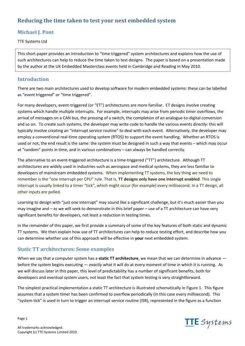
Page 1 All trademarks acknowledged. Copyright (c) TTE Systems Limited 2010.
Reducing the time taken to test your next embedded system
Michael J. Pont
TTE Systems Ltd
This short paper provides an introduction to “time triggered” system architectures and explains how the use of
such architectures can help to reduce the time taken to test designs. The paper is based on a presentation made
by the author at the UK Embedded Masterclass events held in Cambridge and Reading in May 2010.
Introduction
There are two main architectures used to develop software for modern embedded systems: these can be labelled
as “event triggered” or “time triggered”.
For many developers, event-triggered (or “ET”) architectures are more familiar. ET designs involve creating
systems which handle multiple interrupts. For example, interrupts may arise from periodic timer overflows, the
arrival of messages on a CAN bus, the pressing of a switch, the completion of an analogue-to-digital conversion
and so on. To create such systems, the developer may write code to handle the various events directly: this will
typically involve creating an “interrupt service routine” to deal with each event. Alternatively, the developer may
employ a conventional real-time operating system (RTOS) to support the event handling. Whether an RTOS is
used or not, the end result is the same: the system must be designed in such a way that events – which may occur
at “random” points in time, and in various combinations – can always be handled correctly.
The alternative to an event-triggered architecture is a time-triggered (“TT”) architecture. Although TT
architectures are widely used in industries such as aerospace and medical systems, they are less familiar to
developers of mainstream embedded systems. When implementing TT systems, the key thing we need to
remember is the “one interrupt per CPU” rule. That is, TT designs only have one interrupt enabled. This single
interrupt is usually linked to a timer “tick”, which might occur (for example) every millisecond. In a TT design, all
other inputs are polled.
Learning to design with “just one interrupt” may sound like a significant challenge, but it’s much easier than you
may imagine and – as we will seek to demonstrate in this brief paper – use of a TT architecture can have very
significant benefits for developers, not least a reduction in testing times.
In the remainder of this paper, we first provide a summary of some of the key features of both static and dynamic
TT systems. We then explain how use of TT architectures can help to reduce testing effort, and describe how you
can determine whether use of this approach will be effective in your next embedded system.
Static TT architectures: Some examples
When we say that a computer system has a static TT architecture, we mean that we can determine in advance —
before the system begins executing — exactly what it will do at every moment of time in which it is running. As
we will discuss later in this paper, this level of predictability has a number of significant benefits, both for
developers and eventual system users, not least the fact that system testing is very straightforward.
The simplest practical implementation a static TT architecture is illustrated schematically in Figure 1. This figure
assumes that a system timer has been confirmed to overflow periodically (in this case every millisecond). This
“system tick” is used in turn to trigger an interrupt service routine (ISR), represented in the figure as a function
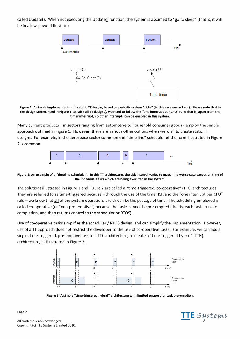
Page 2 All trademarks acknowledged. Copyright (c) TTE Systems Limited 2010.
called Update(). When not executing the Update() function, the system is assumed to “go to sleep” (that is, it will
be in a low-power idle state).
Figure 1: A simple implementation of a static TT design, based on periodic system “ticks” (in this case every 1 ms). Please note that in the design summarised in Figure 1 (as with all TT designs), we need to follow the “one interrupt per CPU” rule: that is, apart from the
timer interrupt, no other interrupts can be enabled in this system.
Many current products – in sectors ranging from automotive to household consumer goods - employ the simple
approach outlined in Figure 1. However, there are various other options when we wish to create static TT
designs. For example, in the aerospace sector some form of “time line” scheduler of the form illustrated in Figure
2 is common.
Figure 2: An example of a “timeline scheduler”. In this TT architecture, the tick interval varies to match the worst-case execution time of the individual tasks which are being executed in the system.
The solutions illustrated in Figure 1 and Figure 2 are called a “time-triggered, co-operative” (TTC) architectures.
They are referred to as time-triggered because – through the use of the timer ISR and the “one interrupt per CPU”
rule – we know that all of the system operations are driven by the passage of time. The scheduling employed is
called co-operative (or “non-pre-emptive”) because the tasks cannot be pre-empted (that is, each tasks runs to
completion, and then returns control to the scheduler or RTOS).
Use of co-operative tasks simplifies the scheduler / RTOS design, and can simplify the implementation. However,
use of a TT approach does not restrict the developer to the use of co-operative tasks. For example, we can add a
single, time-triggered, pre-emptive task to a TTC architecture, to create a “time-triggered hybrid” (TTH)
architecture, as illustrated in Figure 3.
Figure 3: A simple “time-triggered hybrid” architecture with limited support for task pre-emption.
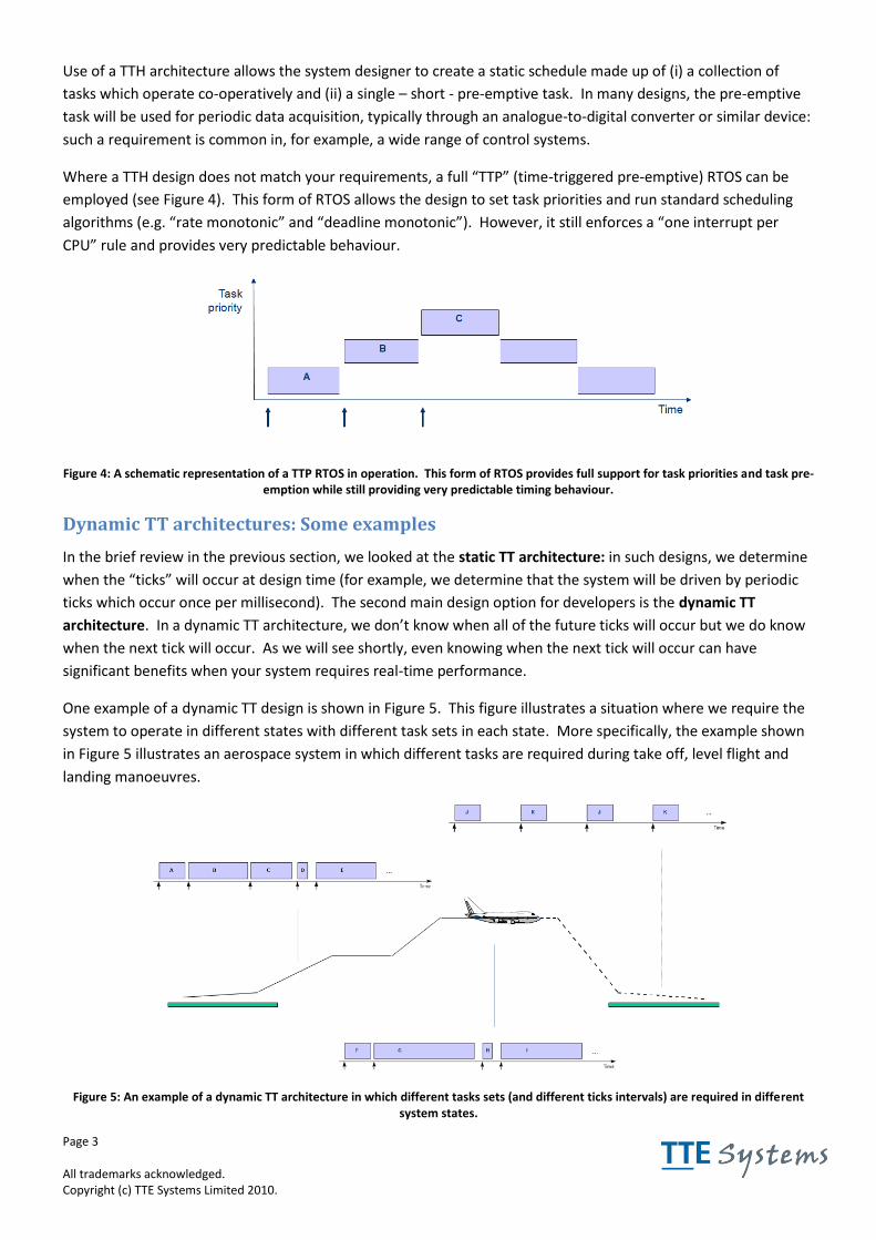
Page 3 All trademarks acknowledged. Copyright (c) TTE Systems Limited 2010.
Use of a TTH architecture allows the system designer to create a static schedule made up of (i) a collection of
tasks which operate co-operatively and (ii) a single – short - pre-emptive task. In many designs, the pre-emptive
task will be used for periodic data acquisition, typically through an analogue-to-digital converter or similar device:
such a requirement is common in, for example, a wide range of control systems.
Where a TTH design does not match your requirements, a full “TTP” (time-triggered pre-emptive) RTOS can be
employed (see Figure 4). This form of RTOS allows the design to set task priorities and run standard scheduling
algorithms (e.g. “rate monotonic” and “deadline monotonic”). However, it still enforces a “one interrupt per
CPU” rule and provides very predictable behaviour.
Figure 4: A schematic representation of a TTP RTOS in operation. This form of RTOS provides full support for task priorities and task pre-emption while still providing very predictable timing behaviour.
Dynamic TT architectures: Some examples
In the brief review in the previous section, we looked at the static TT architecture: in such designs, we determine
when the “ticks” will occur at design time (for example, we determine that the system will be driven by periodic
ticks which occur once per millisecond). The second main design option for developers is the dynamic TT
architecture. In a dynamic TT architecture, we don’t know when all of the future ticks will occur but we do know
when the next tick will occur. As we will see shortly, even knowing when the next tick will occur can have
significant benefits when your system requires real-time performance.
One example of a dynamic TT design is shown in Figure 5. This figure illustrates a situation where we require the
system to operate in different states with different task sets in each state. More specifically, the example shown
in Figure 5 illustrates an aerospace system in which different tasks are required during take off, level flight and
landing manoeuvres.
Figure 5: An example of a dynamic TT architecture in which different tasks sets (and different ticks intervals) are required in different system states.
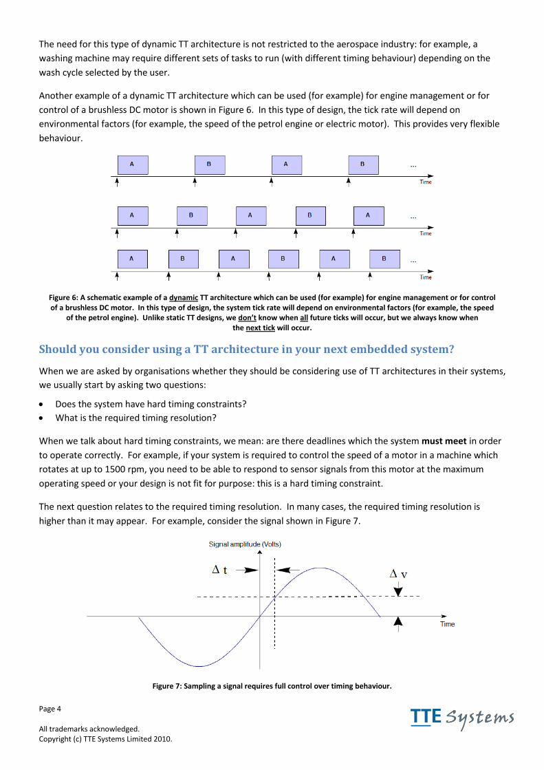
Page 4 All trademarks acknowledged. Copyright (c) TTE Systems Limited 2010.
The need for this type of dynamic TT architecture is not restricted to the aerospace industry: for example, a
washing machine may require different sets of tasks to run (with different timing behaviour) depending on the
wash cycle selected by the user.
Another example of a dynamic TT architecture which can be used (for example) for engine management or for
control of a brushless DC motor is shown in Figure 6. In this type of design, the tick rate will depend on
environmental factors (for example, the speed of the petrol engine or electric motor). This provides very flexible
behaviour.
Figure 6: A schematic example of a dynamic TT architecture which can be used (for example) for engine management or for control of a brushless DC motor. In this type of design, the system tick rate will depend on environmental factors (for example, the speed
of the petrol engine). Unlike static TT designs, we don’t know when all future ticks will occur, but we always know when the next tick will occur.
Should you consider using a TT architecture in your next embedded system?
When we are asked by organisations whether they should be considering use of TT architectures in their systems,
we usually start by asking two questions:
Does the system have hard timing constraints?
What is the required timing resolution?
When we talk about hard timing constraints, we mean: are there deadlines which the system must meet in order
to operate correctly. For example, if your system is required to control the speed of a motor in a machine which
rotates at up to 1500 rpm, you need to be able to respond to sensor signals from this motor at the maximum
operating speed or your design is not fit for purpose: this is a hard timing constraint.
The next question relates to the required timing resolution. In many cases, the required timing resolution is
higher than it may appear. For example, consider the signal shown in Figure 7.
Figure 7: Sampling a signal requires full control over timing behaviour.
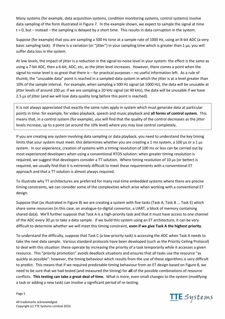
Page 5 All trademarks acknowledged. Copyright (c) TTE Systems Limited 2010.
Many systems (for example, data acquisition systems, condition monitoring systems, control systems) involve
data sampling of the form illustrated in Figure 7. In the example shown, we expect to sample the signal at time
t = 0, but – instead – the sampling is delayed by a short time. This results in data corruption in the system.
Suppose (for example) that you are sampling a 500 Hz tone at a sample rate of 1000 Hz, using an 8-bit ADC (a very
basic sampling task). If there is a variation (or “jitter”) in your sampling time which is greater than 1 µs, you will
suffer data loss in the system.
At low levels, the impact of jitter is a reduction in the signal-to-noise level in your system: the effect is the same as
using a 7-bit ADC, then a 6-bit, ADC, etc, as the jitter level increases. However, there comes a point when the
signal-to-noise level is so great that there is – for practical purposes – no useful information left. As a rule of
thumb, the “unusable data” point is reached in a sampled-data system in which the jitter is at a level greater than
10% of the sample interval. For example, when sampling a 500 Hz signal (at 1000 Hz), the data will be unusable at
jitter levels of around 100 µs: if we are sampling a 20 kHz signal (at 40 kHz), the data will be unusable if we have
2.5 µs of jitter (and we will lose data quality long before this point is reached).
It is not always appreciated that exactly the same rules apply in system which must generate data at particular
points in time: for example, for video playback, speech and music playback and all forms of control system. This
means that, in a control system (for example), you will find that the quality of the control decreases as the jitter
levels increase, up to a point (at around the 10% level) where you may lose control completely.
If you are creating any system involving data sampling or data playback, you need to understand the key timing
limits that your system must meet: this determines whether you are creating a 1 ms system, a 100 µs or a 1 µs
system. In our experience, creation of systems with a timing resolution of 100 ms or less can be carried out by
most experienced developers when using a conventional RTOS solution: when greater timing resolution is
required, we suggest that developers consider a TT solution. Where timing resolution of 10 µs (or better) is
required, we usually find that it is extremely difficult to meet these requirements with a conventional ET
approach and that a TT solution is almost always required.
To illustrate why TT architectures are preferred for many real-time embedded systems where there are precise
timing constraints, we can consider some of the complexities which arise when working with a conventional ET
design.
Suppose that (as illustrated in Figure 8) we are creating a system with five tasks (Task A, Task B ... Task E) which
share some resources (in this case, an analogue-to-digital convertor, a UART, a block of memory containing
shared data). We’ll further suppose that Task A is a high-priority task and that it must have access to one channel
of the ADC every 30 µs to take a data sample. If we build this system using an ET architecture, it can be very
difficult to determine whether we will meet this timing constraint, even if we give Task A the highest priority.
To understand the difficulty, suppose that Task C (a low-priority task) is accessing the ADC when Task A needs to
take the next data sample. Various standard protocols have been developed (such as the Priority Ceiling Protocol)
to deal with this situation: these operate by increasing the priority of a task temporarily while it accesses a given
resource. This “priority promotion” avoids deadlock situations and ensures that all tasks use the resource “as
quickly as possible”: however, the timing behaviour which results from the use of these algorithms is very difficult
to predict. This means that if we required predictable timing behaviour from an ET design based on Figure 8, we
need to be sure that we had tested (and measured the timing) for all of the possible combinations of resource
conflicts. This testing can take a great deal of time. What is more, even small changes to the system (modifying
a task or adding a new task) can involve a significant period of re-testing.
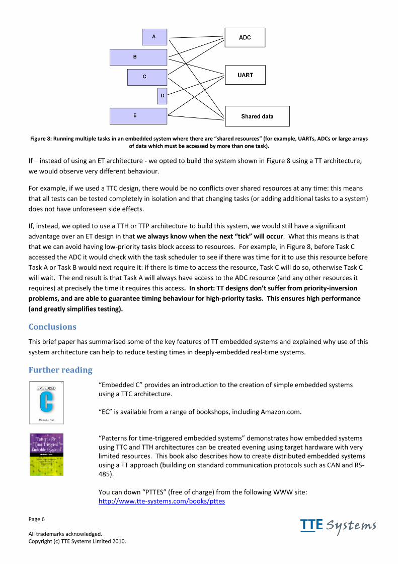
Page 6 All trademarks acknowledged. Copyright (c) TTE Systems Limited 2010.
Figure 8: Running multiple tasks in an embedded system where there are “shared resources” (for example, UARTs, ADCs or large arrays of data which must be accessed by more than one task).
If – instead of using an ET architecture - we opted to build the system shown in Figure 8 using a TT architecture,
we would observe very different behaviour.
For example, if we used a TTC design, there would be no conflicts over shared resources at any time: this means
that all tests can be tested completely in isolation and that changing tasks (or adding additional tasks to a system)
does not have unforeseen side effects.
If, instead, we opted to use a TTH or TTP architecture to build this system, we would still have a significant
advantage over an ET design in that we always know when the next “tick” will occur. What this means is that
that we can avoid having low-priority tasks block access to resources. For example, in Figure 8, before Task C
accessed the ADC it would check with the task scheduler to see if there was time for it to use this resource before
Task A or Task B would next require it: if there is time to access the resource, Task C will do so, otherwise Task C
will wait. The end result is that Task A will always have access to the ADC resource (and any other resources it
requires) at precisely the time it requires this access. In short: TT designs don’t suffer from priority-inversion
problems, and are able to guarantee timing behaviour for high-priority tasks. This ensures high performance
(and greatly simplifies testing).
Conclusions
This brief paper has summarised some of the key features of TT embedded systems and explained why use of this
system architecture can help to reduce testing times in deeply-embedded real-time systems.
Further reading
“Embedded C” provides an introduction to the creation of simple embedded systems using a TTC architecture. “EC” is available from a range of bookshops, including Amazon.com.
“Patterns for time-triggered embedded systems” demonstrates how embedded systems using TTC and TTH architectures can be created evening using target hardware with very limited resources. This book also describes how to create distributed embedded systems using a TT approach (building on standard communication protocols such as CAN and RS-485). You can down “PTTES” (free of charge) from the following WWW site: http://www.tte-systems.com/books/pttes
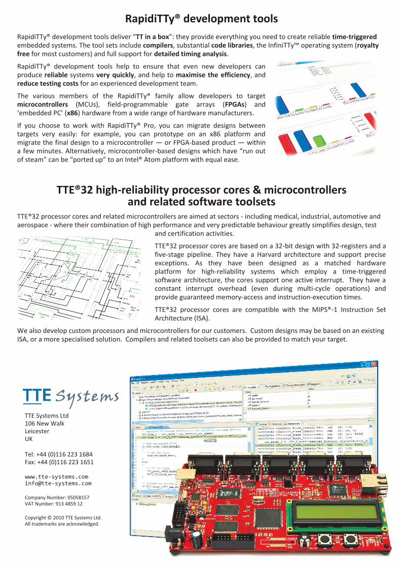
TTE Systems Ltd 106 New Walk Leicester UK Tel: +44 (0)116 223 1684 Fax: +44 (0)116 223 1651 www.tte-systems.com [email protected] Company Number: 05058157 VAT Number: 913 4859 12 Copyright © 2010 TTE Systems Ltd. All trademarks are acknowledged.
RapidiTTy® development tools
RapidiTTy® development tools deliver “TT in a box”: they provide everything you need to create reliable time-triggered embedded systems. The tool sets include compilers, substantial code libraries, the InfiniTTy™ operating system (royalty free for most customers) and full support for detailed timing analysis.
RapidiTTy® development tools help to ensure that even new developers can produce reliable systems very quickly, and help to maximise the efficiency, and reduce testing costs for an experienced development team.
The various members of the RapidiTTy® family allow developers to target microcontrollers (MCUs), field-programmable gate arrays (FPGAs) and ‘embedded PC’ (x86) hardware from a wide range of hardware manufacturers.
If you choose to work with RapidiTTy® Pro, you can migrate designs between targets very easily: for example, you can prototype on an x86 platform and migrate the final design to a microcontroller — or FPGA-based product — within a few minutes. Alternatively, microcontroller-based designs which have “run out of steam” can be “ported up” to an Intel® Atom platform with equal ease.
TTE®32 high-reliability processor cores & microcontrollers and related software toolsets
TTE®32 processor cores and related microcontrollers are aimed at sectors - including medical, industrial, automotive and aerospace - where their combination of high performance and very predictable behaviour greatly simplifies design, test
and certification activities.
TTE®32 processor cores are based on a 32-bit design with 32-registers and a five-stage pipeline. They have a Harvard architecture and support precise exceptions. As they have been designed as a matched hardware platform for high-reliability systems which employ a time-triggered software architecture, the cores support one active interrupt. They have a constant interrupt overhead (even during multi-cycle operations) and provide guaranteed memory-access and instruction-execution times.
TTE®32 processor cores are compatible with the MIPS®-1 Instruction Set Architecture (ISA).
We also develop custom processors and microcontrollers for our customers. Custom designs may be based on an existing ISA, or a more specialised solution. Compilers and related toolsets can also be provided to match your target.

Copyright © 2010 TTE Systems Ltd. All rights reserved.
MIPS and MIPS I are trademarks and / or registered trademarks of MIPS Technologies, Inc. TTE Systems Ltd is not associated with MIPS Technologies, Inc. in any way. TTE32 and RapidiTTy are registered trademarks of TTE Systems Ltd. InfiniTTy and SafeTTy are trademarks of TTE Systems Ltd. All other trademarks are acknowledged.
www.tte-systems.com
TTE® Systems Ltd 106 New Walk, Leicester,
United Kingdom
Tel: +44 (0)116 223 1684 Fax: +44 (0)116 223 1651
TTE®32 high-reliability processor cores and microcontrollers TTE32 processor cores and related microcontrollers are intended for use in aircraft (both manned and UAVs), medical equipment, industrial control, automotive designs, space systems and other high-reliability applications. They offer a combination very predictable behaviour, high performance and future-proof design features which greatly simplifies design, test and certification activities.
TTE32 processor cores are based on a 32-bit design with 32-registers and a five-stage pipeline. They have a Harvard architecture and support precise exceptions. They have a constant interrupt overhead (even during multi-cycle operations) and provide guaranteed memory-access and instruction-execution times.
TTE32 cores provide highly-predictable behaviour
Provide an ideal platform for designs which require precise "worst-case execution time" (WCET) determination and / or low task jitter. Typical measurement resolution is at the microsecond level or better (dependent on chosen implementation platform).
Can be provided with full validation and verification data for use in DO-254 / DO-178b, IEC 61508, ISO 26262 or other high-reliability projects.
Can be provided with full support for triple-modular redundancy (TMR), in both single-chip and multi-chips implementations, allowing use in aerospace (and space) designs in which single-event effects (SEEs) - including single-event upsets (SEUs) - must be addressed.
TTE32 cores provide future-proof performance
To support a wide range of performance requirements and "future proof" your system design, TTE32 processor cores can be provided in both single-core and advanced multi-core implementations.
Adding cores in a TTE32 design allows developers to support additional system functionality without sacrificing timing predictability in existing task sets. Full software toolsets to support the development of multi-core designs are available.
Single- and multi-core designs can be provided with full processor design information (including complete VHDL source), ensuring that your investment is protected for many decades into the future, even in the face of inevitable developments in implementation technology.
TTE32 cores have full software support
TTE32 processors execute code which conforms to the MIPS I™ instruction set architecture, allowing use of a wide range of standard compilers and related development tools.
TTE32 processors are fully compatible with RapidiTTy® software development tools. RapidiTTy provides precise WCET measurements with no software load. RapidiTTy facilitates the migration from single-core to multi-core designs. Compilers for C and Ada programming languages are available, fully integrated in the toolchain.
TTE32 processors support both co-operative and pre-emptive task scheduling (including the InfiniTTy™ operating system family).
TTE32 processors are an ideal platform for time-triggered (TT) software architectures.
TTE32 cores have a low-cost evaluation process
We offer a very straightforward evaluation process, which is free of charge for many of our customers.
Bespoke CPU and microcontroller designs
We can provide a custom processor core or custom microcontroller for you, to match your precise requirements. Matching software toolsets (e.g. for code development or WCET prediction) can also be provided.

Copyright © 2010 TTE Systems Ltd. All rights reserved.
MIPS and MIPS I are trademarks and / or registered trademarks of MIPS Technologies, Inc. TTE Systems Ltd is not associated with MIPS Technologies, Inc. in any way. TTE32 and RapidiTTy are registered trademarks of TTE Systems Ltd. InfiniTTy and SafeTTy are trademarks of TTE Systems Ltd. All other trademarks are acknowledged.
www.tte-systems.com
TTE® Systems Ltd 106 New Walk, Leicester,
United Kingdom
Tel: +44 (0)116 223 1684 Fax: +44 (0)116 223 1651
SafeTTy™ Technology
When the products you build are based on embedded processors, unexpected failures can occur due to software errors (in your code or in the operating system you use), the impact of electromagnetic interference (EMI) or “single-event effects” (SEEs), or from various forms of hardware damage.
In automotive, medical, industrial, aerospace and similar systems, the impact of such failures can be serious injury or even loss of life.
SafeTTy™ technology from TTE Systems can help you to avoid such serious system failures.
SafeTTy technology provides an extremely robust, flexible and cost-effective solu-tion for fault monitoring and recovery in a wide range of embedded systems.
Use of SafeTTy technology can simplify the creation of a high-reliability systems and help you to comply with international safety standards and guidelines.
Two SafeTTy protection mechanisms are available (each with full design support):
SafeTTy Wrappers (usually used with designs based on Linux or other standard operating systems);
SafeTTy Agents (usually used with “time-triggered” designs). A cost-effective evaluation process is available for all SafeTTy protection systems.
Support for DO-178b, IEC 61508 and related projects Many of our products are available in forms which are suitable for use in high-reliability and safety-critical products which are developed according to international guidelines (including DO-254, DO-178b, ISO 26262, ISO 13485, IEC 61131, IEC 61508).
For example, we can provide both our TTE32 processors and custom processors with full design and verification documentation (including PHAC documents, Hardware Verification Procedures, and Verification Reports). We can also provide precisely-matched software toolsets, supporting a full range of software development and test activities, including precise worst-case execution time (WCET) prediction and measurement.
Bespoke consultancy and training services
We offer a range of consultancy and bespoke training services to support customers who wish to develop safety-related and safety-critical embedded systems.
For example, if your organisation is aiming to develop future products according to DO-178b / ED-12b / DO-254 / ED-80 guidelines, we can assess your existing development processes, provide you with a report and — where necessary — assist you with training in appropriate areas. These services can be provided on your site, on a worldwide basis, on dates of your choosing, and we can provide an initial assessment and customised proposal for you at low cost and without obligation.


