Embed Size (px)
Citation preview
OmniTurn - Trouble shooting guide
OmniTurn Operator and Maintenance Manual 6.1 www.OmniTurn.com (541)332-7004
Description ....................................................... Page
Trouble Shooting Guide .............................................. 6.2Ctrl-S Spindle Encoder Counts .................................... 6.4Alt-I Input Monitor Function ........................................ 6.5Positioning Problems ................................................... 6.6Ctrl-H Diagnostic Mode ............................................... 6.6Servo Motor Replacement ........................................... 6.8CNC Control Disassembly ........................................... 6.10Top Chassis Components ............................................ 6.11Connect Card .............................................................. 6.12Front Panel Connect Card ........................................... 6.12Computer Chassis ....................................................... 6.13Setting Servo Amps ..................................................... 6.14Ctrl-E Diagnostic ......................................................... 6.15OmniTurn Block Diagram (Inverter Drive) ................... 6.17CNC Control Block Diagram ....................................... 6.18Front Panel Interface ................................................... 6.19Misc Cable & Operator’s Station (Inverter Drive) ......... 6.20Servo Drive Interface ................................................... 6.21Spindle Panel, Inverter Drive ....................................... 6.22Spindle Cabinet TB1 Wiring, Inverter .......................... 6.23Spindle Drive Wiring, Inverter ..................................... 6.24Inverter Drive Illustration ............................................. 6.25GT Air Pack ................................................................. 6.26OmniTurn Block Diagram (C-Axis) .............................. 6.27Misc Cable & Operator’s Station (C-Axis CCA)............ 6.28Spindle Circuit Card Assembly (C-Axis) ....................... 6.29Spindle Drive Control Logic (C-Axis CCA) .................. 6.30Spindle Drive Wiring (C-Axis CCA) ............................. 6.31Collet Closer Installation and Maintenance .................. 6.32Lubricator Operation & Service ................................... 6.36Lubrication & Maintenance Schedule .......................... 6.37
Table of Contents
OmniTurn - Trouble shooting guide
OmniTurn Operator and Maintenance Manual 6.2 www.OmniTurn.com (541)332-7004
The Yellow power light won’t come onThe yellow power light indicates that the computer and auxiliary power supplies are working. The 12V should come on when the system is turned on and the computer is working. If the monitor displays the start-up information but the yellow power light is off, replace the bulb (#53 miniature bayonet).
• Be sure there is power to the machine.• Check that disconnect on spindle cabinet is ON.• Check that the CNC Control is plugged into socket on back of machine.• Check the fuse on the back of the CNC Control.• Check fuses on step-down transformer in spindle cabinet.• Check fuse on auxiliary power supply in CNC Control.
The Blue servo light won’t come onThe Blue servo light indicates that the servos have been turned on. If this won’t illuminate that means that the E-Stop string is open, or there is a problem with the drives or their control system.If you hear the servos engage when the button is pressed, but the blue light is off, replace the bulb (#53 miniature bayonet).
• Check the that the E-stops on CNC and Operator’s Station (palm box) are released.• Check that the Operator’s Station is plugged into the CNC.• Check the 1CR relay on the connect card in the control, be sure it is plugged in.• Check voltage at CRDY test-point on Connect Card (see page 6-12). At “Please
turn servos on” prompt, CRDY should stay near zero volts when Servos On button is pressed. If voltage at CRDY goes up to 12V ribbon cable to motion card could be bad, or problem could be on motion card. If CRDY stays low, the E-Stop string could be open (see schematic on page 6.18) or ribbon cable to front panel connect card could be bad or Servos On switch could be bad.
The Monitor won’t come on• If the rest of the system works (the yellow light comes on and, after 1 minute, you
can turn on Caps Lock Light on keyboard) but you do not get an image on the screen there could be a problem with the monitor. Make sure 12V cable from CRT, is at-tached to CN10 on connect card.
• If the Caps Lock Light won’t light, the computer is probably not booting up.
The Red Motion Stop light come on every time you try to move the slide• Check that the Spindle Drive is not faulted; press the reset button on the the spindle
drive cabinet located at the left side of GT-75 and GT-Jr.• Check the hatch on GT-Jr, or any interlocked doors on your system. To jog the ma-
chine with door open during setup, get the interlock bypass key from your supervisor.• If you have a barfeeder, check that the end of bar circuit is not activated
“Servo Axis Error” when you try to jog the slide:Most common cause is from over-travelling the slide and hitting a “hard stop”.
• Press ”ESC”, this will reset the control. If the control shuts down again when you try to jog the axis go to the next step.
• Check the two thermal overloads. These are located on the rear panel of the CNC. It can take a few minutes for the overload to cool enough to be reset. Press “Esc” and try to jog again.
• Turn the control off, wait 15 seconds, turn the control on again. This will reset the Servo driver card. If the control shuts down again when you try to jog, go to the next step.
• Check for loose motor cable; set power off, then disconnect and reconnect.

OmniTurn - Trouble shooting guide
OmniTurn Operator and Maintenance Manual 6.3 www.OmniTurn.com (541)332-7004
If only one axis is giving you problems, do the following:• Turn the control off and swap the cables to the motors, Z to X and X to Z. When
you try to jog in Z, the X motor should move; when you try to jog in X, the Z motor should move.
• Turn the control back on and try to jog in the good axis; if the “bad” motor moves, the motor is probably ok and the motion control card is bad; if the motor doesn’t move, it’s probably bad. Try the other axis and verify your conclusions.
• If you have questions about this procedure, call the factory (541-332-7004)
The slide crashes whenever a program is run
Problem • The HOME position has been improperly set• Either the tool offsets have not been set or have been lost• Your program is incorrect• Check the XnZn statements after a tool change, be sure you have one for each and
they are correct.
Solutions • Reset HOME • Check your tool offset table• Check your program• Reset the tool• Reload the tool offset table, see F10 in the automatic mode
Spindle won’t come on
• Check that both E-stops are released, on CNC control and operator’s station• Turn the ”spindle override” pot on the CNC control full CW• Turn the spindle switch on the CNC control to ”AUTO”• Check that the spindle lock pin is pulled out• Check that MISC cable from the OmniTum CNC to Spindle Cabinet is connected• Check that Operator Station Cable is connected to Spindle Cabinet• Spindle drive box must be turned on (attachments only)• Cables to the spindle drive box must be plugged in
• Spindle drive may be in ‘fault’ condition. Push the red reset button on the spindle drive box to reset the spindle drive. This could be tripped for a number of reasons:
• Too low or too high line voltage• The duty cycle is too much; cycle time is too short and too often.• Noise from coolant pump or other contacts• Acceleration or deacceleration are to short (standard 5hp drive). Parameters can
be set to change these: see “AC Spindle Drive” pg 6.18
OmniTurn - Trouble shooting guide
OmniTurn Operator and Maintenance Manual 6.4 www.OmniTurn.com (541)332-7004
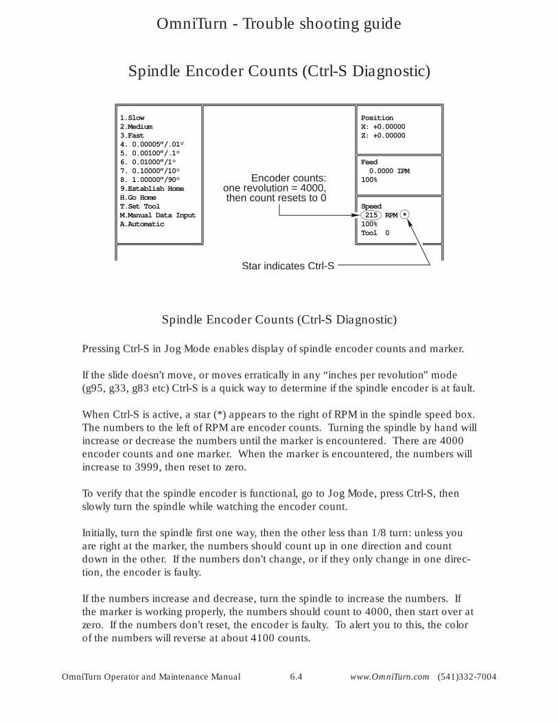
1.Slow2.Medium3.Fast4. 0.00005”/.01°5. 0.00100”/.1°6. 0.01000”/1°7. 0.10000”/10°8. 1.00000”/90°9.Establish HomeH.Go HomeT.Set ToolM.Manual Data InputA.Automatic
PositionX: +0.00000Z: +0.00000
Feed 0.0000 IPM100%
Speed 215 RPM *100%Tool 0
Star indicates Ctrl-S
Encoder counts: one revolution = 4000,
then count resets to 0
Spindle Encoder Counts (Ctrl-S Diagnostic)
Spindle Encoder Counts (Ctrl-S Diagnostic)
Pressing Ctrl-S in Jog Mode enables display of spindle encoder counts and marker.
If the slide doesn’t move, or moves erratically in any “inches per revolution” mode (g95, g33, g83 etc) Ctrl-S is a quick way to determine if the spindle encoder is at fault.
When Ctrl-S is active, a star (*) appears to the right of RPM in the spindle speed box. The numbers to the left of RPM are encoder counts. Turning the spindle by hand will increase or decrease the numbers until the marker is encountered. There are 4000 encoder counts and one marker. When the marker is encountered, the numbers will increase to 3999, then reset to zero.
To verify that the spindle encoder is functional, go to Jog Mode, press Ctrl-S, then slowly turn the spindle while watching the encoder count.
Initially, turn the spindle first one way, then the other less than 1/8 turn: unless you are right at the marker, the numbers should count up in one direction and count down in the other. If the numbers don’t change, or if they only change in one direc-tion, the encoder is faulty.
If the numbers increase and decrease, turn the spindle to increase the numbers. If the marker is working properly, the numbers should count to 4000, then start over at zero. If the numbers don’t reset, the encoder is faulty. To alert you to this, the color of the numbers will reverse at about 4100 counts.
OmniTurn - Trouble shooting guide
OmniTurn Operator and Maintenance Manual 6.5 www.OmniTurn.com (541)332-7004
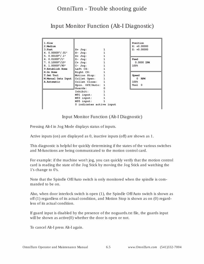
1.Slow2.Medium3.Fast4. 0.00005”/.01°5. 0.00100”/.1°6. 0.01000”/1°7. 0.10000”/10°8. 1.00000”/90°9.Establish HomeH.Go HomeT.Set ToolM.Manual Data InputA.Automatic
X+ Jog: 1X- Jog: 1Z+ Jog: 1Z- Jog: 1C+ Jog: 1C- Jog: 1Left CS: 1Right CS: 1Motion Stop: 1Collet Open: 1Collet Close: 1Spin. Off/Auto: 1Guards: 0Inhibit: 1M91 input: 1M93 input: 1M95 input: 10 indicates active input
PositionX: +0.00000Z: +0.00000
Feed 0.0000 IPM100%
Speed 0 RPM100%Tool 0
Input Monitor Function (Alt-I Diagnostic)
Pressing Alt-I in Jog Mode displays status of inputs.
Active inputs (on) are displayed as 0, inactive inputs (off) are shown as 1.
This diagnostic is helpful for quickly determining if the states of the various switches and M-functions are being communicated to the motion control card.
For example: if the machine won’t jog, you can quickly verify that the motion control card is reading the state of the Jog Stick by moving the Jog Stick and watching the 1's change to 0's.
Note that the Spindle Off/Auto switch is only monitored when the spindle is com-manded to be on.
Also, when door interlock switch is open (1), the Spindle Off/Auto switch is shown as off (1) regardless of its actual condition, and Motion Stop is shown as on (0) regard-less of its actual condition.
If guard input is disabled by the presence of the noguards.txt file, the guards input will be shown as active(0) whether the door is open or not.
To cancel Alt-I press Alt-I again.
Input Monitor Function (Alt-I Diagnostic)
OmniTurn - Trouble shooting guide
OmniTurn Operator and Maintenance Manual 6.6 www.OmniTurn.com (541)332-7004
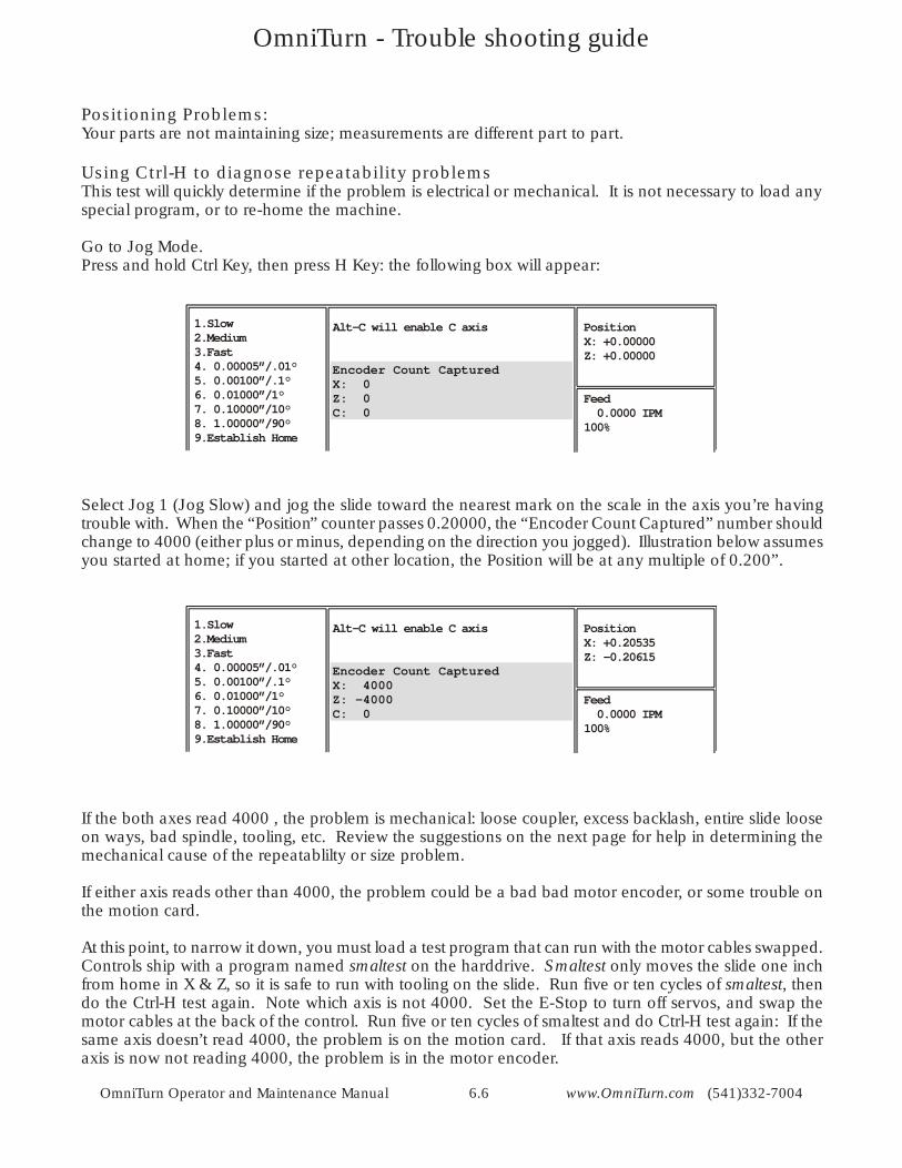
Positioning Problems:Your parts are not maintaining size; measurements are different part to part.
Using Ctrl-H to diagnose repeatability problems This test will quickly determine if the problem is electrical or mechanical. It is not necessary to load any special program, or to re-home the machine.
Go to Jog Mode.Press and hold Ctrl Key, then press H Key: the following box will appear:
Select Jog 1 (Jog Slow) and jog the slide toward the nearest mark on the scale in the axis you’re having trouble with. When the “Position” counter passes 0.20000, the “Encoder Count Captured” number should change to 4000 (either plus or minus, depending on the direction you jogged). Illustration below assumes you started at home; if you started at other location, the Position will be at any multiple of 0.200”.
If the both axes read 4000 , the problem is mechanical: loose coupler, excess backlash, entire slide loose on ways, bad spindle, tooling, etc. Review the suggestions on the next page for help in determining the mechanical cause of the repeatablilty or size problem.
If either axis reads other than 4000, the problem could be a bad bad motor encoder, or some trouble on the motion card.
At this point, to narrow it down, you must load a test program that can run with the motor cables swapped. Controls ship with a program named smaltest on the harddrive. Smaltest only moves the slide one inch from home in X & Z, so it is safe to run with tooling on the slide. Run five or ten cycles of smaltest, then do the Ctrl-H test again. Note which axis is not 4000. Set the E-Stop to turn off servos, and swap the motor cables at the back of the control. Run five or ten cycles of smaltest and do Ctrl-H test again: If the same axis doesn’t read 4000, the problem is on the motion card. If that axis reads 4000, but the other axis is now not reading 4000, the problem is in the motor encoder.
1.Slow2.Medium3.Fast4. 0.00005”/.01°5. 0.00100”/.1°6. 0.01000”/1°7. 0.10000”/10°8. 1.00000”/90°9.Establish Home
Alt-C will enable C axis PositionX: +0.00000Z: +0.00000
Feed 0.0000 IPM100%
Encoder Count CapturedX: 0Z: 0C: 0
1.Slow2.Medium3.Fast4. 0.00005”/.01°5. 0.00100”/.1°6. 0.01000”/1°7. 0.10000”/10°8. 1.00000”/90°9.Establish Home
Alt-C will enable C axis PositionX: +0.20535Z: -0.20615
Feed 0.0000 IPM100%
Encoder Count CapturedX: 4000Z: -4000C: 0
OmniTurn - Trouble shooting guide
OmniTurn Operator and Maintenance Manual 6.7 www.OmniTurn.com (541)332-7004
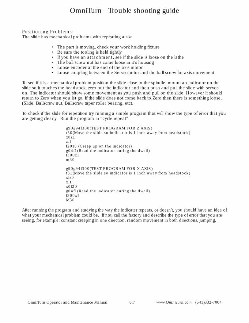
Positioning Problems: The slide has mechanical problems with repeating a size
• The part is moving, check your work holding fixture• Be sure the tooling is held tightly• If you have an attachment, see if the slide is loose on the lathe• The ball screw nut has come loose in it’s housing• Loose encoder at the end of the axis motor• Loose coupling between the Servo motor and the ball screw for axis movement
To see if it is a mechanical problem position the slide close to the spindle, mount an indicator on the slide so it touches the headstock, zero out the indicator and then push and pull the slide with servos on. The indicator should show some movement as you push and pull on the slide. However it should return to Zero when you let go. If the slide does not come back to Zero then there is something loose, (Slide, Ballscrew nut, Ballscrew taper roller bearing, etc).
To check if the slide for repetition try running a simple program that will show the type of error that you are getting clearly. Run the program in “cycle repeat”:
g90g94f300(TEST PROGRAM FOR Z AXIS) t30(Move the slide so indicator is 1 inch away from headstock) x0z1z.1f20z0 (Creep up on the indicator)g04f1(Read the indicator during the dwell) f300z1m30
g90g94f300(TEST PROGRAM FOR X AXIS)t31(Move the slide so indicator is 1 inch away from headstock)xlz0x.1x0f20g04f1(Read the indicator during the dwell)f300x1M30
After running the program and studying the way the indicater repeats, or doesn’t, you should have an idea of what your mechanical problem could be. If not, call the factory and describe the type of error that you are seeing, for example: constant creeping in one direction, random movement in both directions, jumping.
OmniTurn - Trouble shooting guide
OmniTurn Operator and Maintenance Manual 6.8 www.OmniTurn.com (541)332-7004
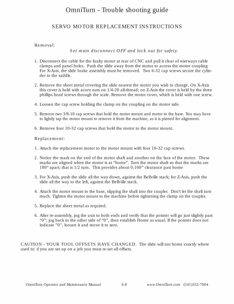
SERVO MOTOR REPLACEMENT INSTRUCTIONS
Removal: Set main disconnect OFF and lock out for safety.
1. Disconnect the cable for the faulty motor at rear of CNC and pull it clear of wireways cable clamps and panel holes. Push the slide away from the motor to access the motor coupling For X-Axis, the slide brake assembly must be removed. Two 6-32 cap screws secure the cylin-der to the saddle.
2. Remove the sheet metal covering the slide nearest the motor you wish to change. On X-Axis this cover is held with acorn nuts on 1/4-20 all-thread; on Z-Axis the cover is held by the three phillips head screws through the scale. Remove the motor cover, which is held with one screw.
4. Loosen the cap screw holding the clamp on the coupling on the motor side.
5. Remove two 3/8-18 cap screws that hold the motor mount and motor to the base. You may have to lightly tap the motor mount to remove it from the machine, as it is pinned for alignment.
6. Remove four 10-32 cap screws that hold the motor to the motor mount.
Replacement:
1. Attach the replacement motor to the motor mount with four 10-32 cap screws.
2. Notice the mark on the end of the motor shaft and another on the face of the motor. These marks are aligned when the motor is at “home”. Turn the motor shaft so that the marks are 180° apart; that is 1/2 turn. This provides about 0.100” clearance past home
3. For X-Axis, push the slide all the way down, against the Bellville stack; for Z-Axis, push the slide all the way to the left, against the Bellville stack.
4. Attach the motor mount to the base, slipping the shaft into the coupler. Don’t let the shaft turn much. Tighten the motor mount to the machine before tightening the clamp on the coupler.
5. Replace the sheet metal as required.
6. After re-assembly, jog the axis to both ends and verify that the pointer will go just slightly past “0”; jog back to the other side of “0”, then establish Home as usual. If the pointer does not indicate ”0”, loosen it and move it to zero.
CAUTION - YOUR TOOL OFFSETS HAVE CHANGED. The slide will not home exactly where used to: If you are set up on a job you must re-set all offsets.
OmniTurn - Trouble shooting guide
OmniTurn Operator and Maintenance Manual 6.9 www.OmniTurn.com (541)332-7004
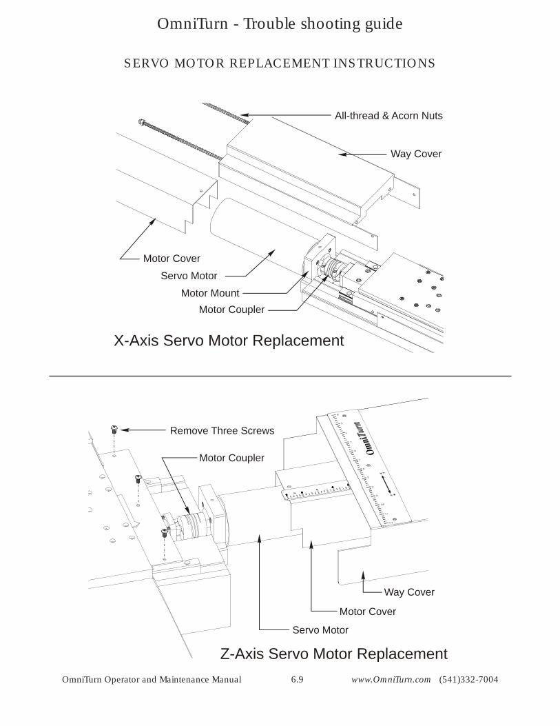
X-Axis Servo Motor Replacement
Motor CouplerMotor Mount
Motor Cover
All-thread & Acorn Nuts
Way Cover
Servo Motor
SERVO MOTOR REPLACEMENT INSTRUCTIONS
Z-Axis Servo Motor Replacement
Motor Coupler
Motor Cover
Way Cover
Servo Motor
Remove Three Screws
OmniTurn - Trouble shooting guide
OmniTurn Operator and Maintenance Manual 6.10 www.OmniTurn.com (541)332-7004
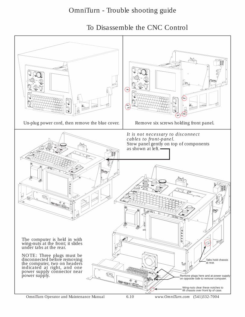
To Disassemble the CNC Control
It is not necessary to disconnect cables to front-panel.Stow panel gently on top of components as shown at left.
Remove six screws holding front panel.Un-plug power cord, then remove the blue cover.
The computer is held in with wing-nuts at the front; it slides under tabs at the rear.
NOTE: Three plugs must be disconnected before removing the computer, two on headers indicated at right, and one power supply connector near power supply. Remove plugs here and at power supply
on opposite side to remove computer.
Wing-nuts clear these notches to lift chassis over front lip of case.
Tabs hold chassis at rear.
OmniTurn - Trouble shooting guide
OmniTurn Operator and Maintenance Manual 6.11 www.OmniTurn.com (541)332-7004
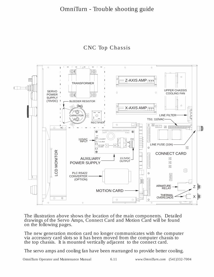
CNC Top Chassis
X-Axis
Z-Axis
Spindle
SERVOPOWERSUPPLY (70VDC)
AUXILIARYPOWER SUPPLY
+{-{
CN2CN1
AC FUSE1A 250V
2:L=BLK
1:N=WHT123456
ARMATURERELAY
THERMALOVERLOADS
CONNECT CARD
TRANSFORMER
CAPACITOR
RECTIFIER
BLEEDER RESISTOR
Z-AXIS AMP
X-AXIS AMP
TS1: 110VACLINE FILTER
LINE FUSE (10A)
UPPER CHASSISCOOLING FAN
Z
X
LCD
MO
NIT
OR
MOTION CARD
PLC RS422CONVERTER
(OPTION)
110VACINPUT
13.2VDCOUTPUT
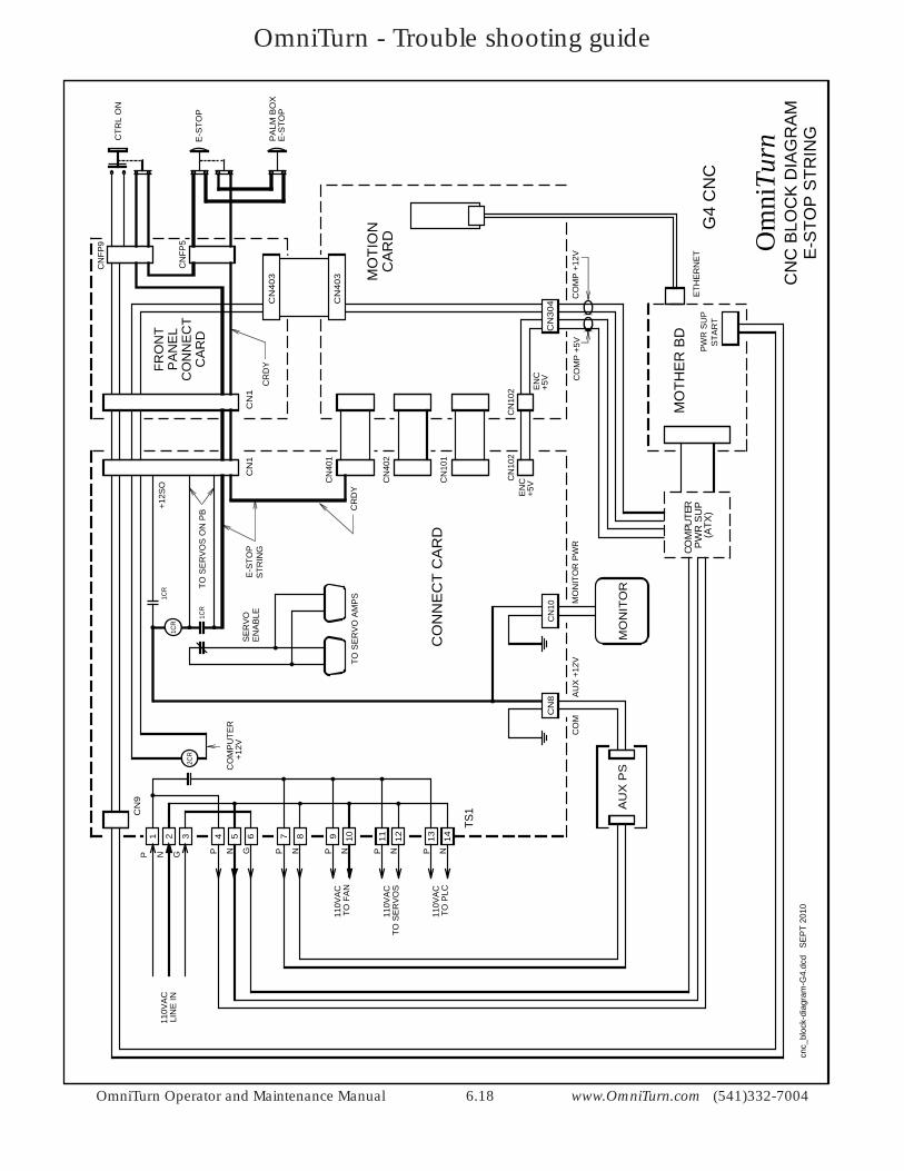
The illustration above shows the location of the main components. Detailed drawings of the Servo Amps, Connect Card and Motion Card will be found on the following pages.
The new generation motion card no longer communicates with the computer via accessory card slots so it has been moved from the computer chassis to the top chassis. It is mounted vertically adjacent to the connect card.
The servo amps and cooling fan have been rearranged to provide better cooling.
OmniTurn - Trouble shooting guide
OmniTurn Operator and Maintenance Manual 6.12 www.OmniTurn.com (541)332-7004
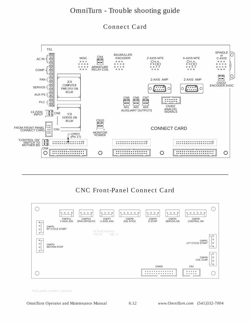
CNC Front-Panel Connect Card
13.2VDCINPUT
“CONTROL ON”SWITCH TO
MOTHER BD
FROM FRONT PANELCONNECT CARD
ANALOGSIGNALS
ENCODER 5VDC
CONNECT CARD
MISCBAUMULLERENCODER Z-AXIS MTE X-AXIS MTE
1CRSERVOS ON
RELAY
2CRCOMPUTER
PWR SPLY ONRELAY
CN4
CN10
CN5 CN6 CN7
CN302
Z-AXIS AMP Z-AXIS AMPCN102
CN9
CN1
CN8
TS1
AC IN
COMP
FAN
SERVOS
AUX PS
PLC
A01 A02 A03AUXILIARY OUTPUTS-
+
+-MONITORPOWER
ARMATURERELAY COIL
SPINDLEor
C-AXIS
CRDY(Pin 17)
CNFP9CONTROL ON
CNFP4SERVOS ON
CNFP5E-STOP
CNFP8JOG STICK
CNFP7C-AXIS JOG
CNFP10SPIN OFF/AUTO
CNFP11Y-AXIS JOG
CNFP1LFT CYCLE START
CNFP6COL CLSR
CNFP1RT CYCLE START
CNFP3MOTION STOP
CN403 CN1
Connect Card
OmniTurn - Trouble shooting guide
OmniTurn Operator and Maintenance Manual 6.13 www.OmniTurn.com (541)332-7004
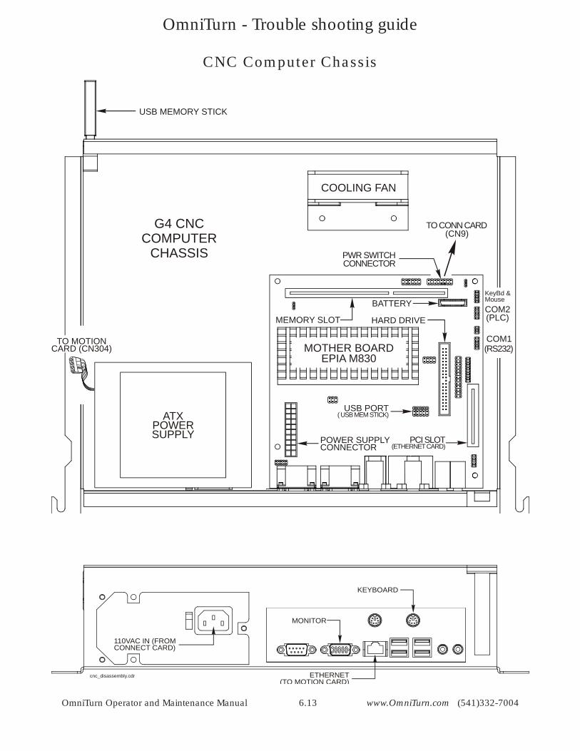
CNC Computer Chassis
MOTHER BOARDEPIA M830
POWER SUPPLYCONNECTOR
USB PORT( USB MEM STICK)
BATTERY
PCI SLOT(ETHERNET CARD)
MEMORY SLOT HARD DRIVE
PWR SWITCHCONNECTOR
ATXPOWERSUPPLY
COOLING FAN
COM2(PLC)
COM1(RS232)
KeyBd &Mouse
TO MOTIONCARD (CN304)
USB MEMORY STICK
TO CONN CARD(CN9)
di bl d
G4 CNCCOMPUTER
CHASSIS
110VAC IN (FROMCONNECT CARD)
KEYBOARD
MONITOR
ETHERNET(TO MOTION CARD)
cnc_disassembly.cdr
OmniTurn - Trouble shooting guide
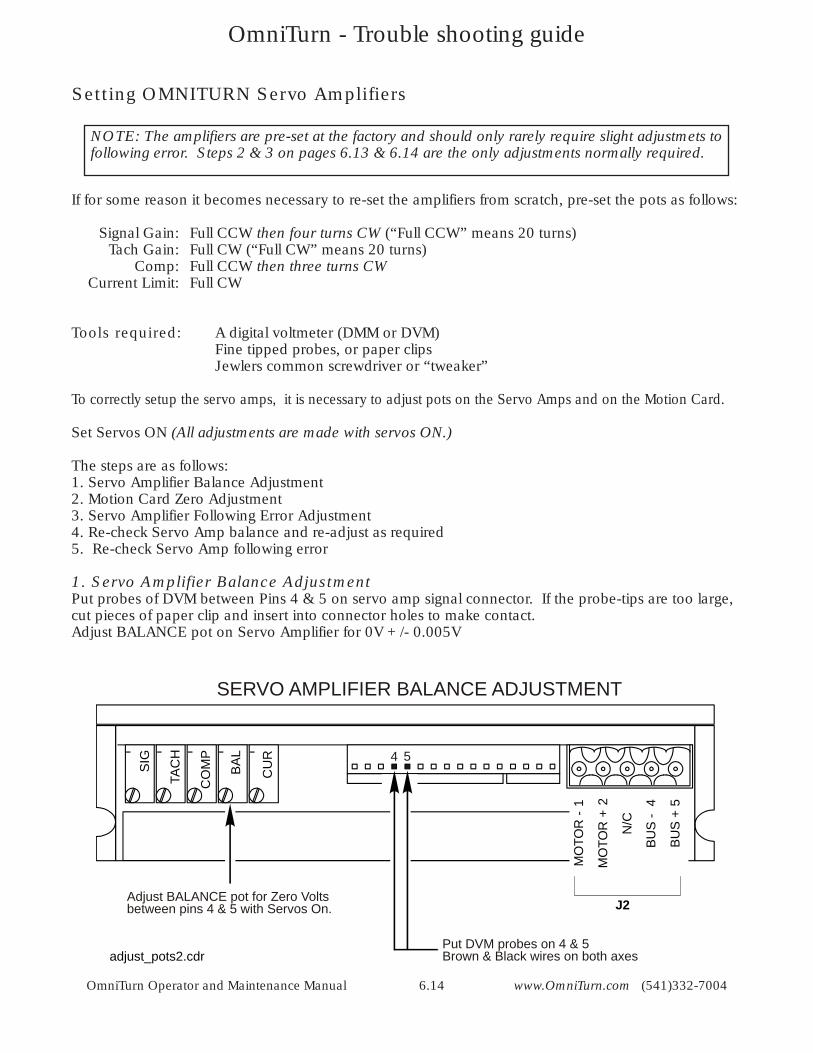
OmniTurn Operator and Maintenance Manual 6.14 www.OmniTurn.com (541)332-7004
If for some reason it becomes necessary to re-set the amplifiers from scratch, pre-set the pots as follows:
Signal Gain: Full CCW then four turns CW (“Full CCW” means 20 turns) Tach Gain: Full CW (“Full CW” means 20 turns) Comp: Full CCW then three turns CW Current Limit: Full CW
Tools required: A digital voltmeter (DMM or DVM) Fine tipped probes, or paper clips Jewlers common screwdriver or “tweaker”
To correctly setup the servo amps, it is necessary to adjust pots on the Servo Amps and on the Motion Card.
Set Servos ON (All adjustments are made with servos ON.)
The steps are as follows:1. Servo Amplifier Balance Adjustment2. Motion Card Zero Adjustment3. Servo Amplifier Following Error Adjustment4. Re-check Servo Amp balance and re-adjust as required5. Re-check Servo Amp following error
1. Servo Amplifier Balance AdjustmentPut probes of DVM between Pins 4 & 5 on servo amp signal connector. If the probe-tips are too large, cut pieces of paper clip and insert into connector holes to make contact.Adjust BALANCE pot on Servo Amplifier for 0V +/- 0.005V
Adjust BALANCE pot for Zero Voltsbetween pins 4 & 5 with Servos On.
Put DVM probes on 4 & 5Brown & Black wires on both axes
4 5
SERVO AMPLIFIER BALANCE ADJUSTMENT
MO
TOR
-1
MO
TOR
+2
N/C
BUS
-4
BUS
+5
J2
adjust_pots2.cdr
SIG
TAC
H
CO
MP
BA
L
CU
R
NOTE: The amplifiers are pre-set at the factory and should only rarely require slight adjustmets to following error. Steps 2 & 3 on pages 6.13 & 6.14 are the only adjustments normally required.
Setting OMNITURN Servo Amplifiers
OmniTurn - Trouble shooting guide
OmniTurn Operator and Maintenance Manual 6.15 www.OmniTurn.com (541)332-7004
Adjust for Zero Following Error (Ctrl-E in Jog)X-AxisZ-Axis
MOTION CARD ZERO ADJUSTMENT
}
Z X
adjust_pots2.cdr
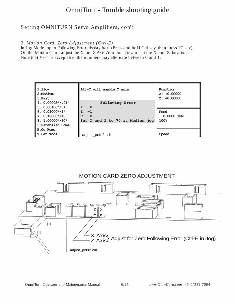
1.Slow2.Medium3.Fast4. 0.00005”/.01°5. 0.00100”/.1°6. 0.01000”/1°7. 0.10000”/10°8. 1.00000”/90°9.Establish HomeH.Go HomeT.Set Tool
Alt-C will enable C axis PositionX: +0.00000Z: +0.00000
Feed 0.0000 IPM100%
Speed
Following ErrorX: 0Z: -1C: 0Set X and Z to 70 at Medium jog
adjust_pots2.cdr
2. Motion Card Zero Adjustment (Ctrl-E)In Jog Mode, open Following Error display box. (Press and hold Ctrl key, then press ‘E’ key).On the Motion Card, adjust the X and Z Axis Zero pots for zeros at the X: and Z: locations.Note that +/- 1 is acceptable; the numbers may alternate between 0 and 1.
Setting OMNITURN Servo Amplifiers, con’t
OmniTurn - Trouble shooting guide
OmniTurn Operator and Maintenance Manual 6.16 www.OmniTurn.com (541)332-7004
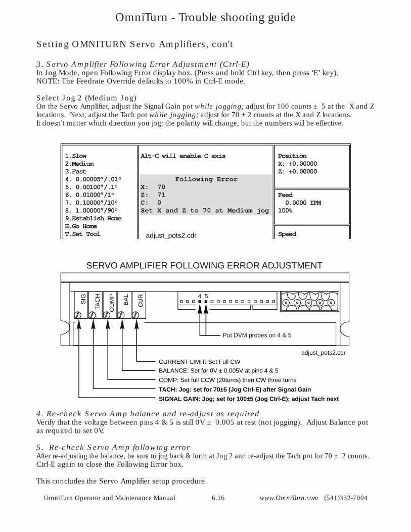
Setting OMNITURN Servo Amplifiers, con’t
3. Servo Amplifier Following Error Adjustment (Ctrl-E)In Jog Mode, open Following Error display box. (Press and hold Ctrl key, then press ‘E’ key).NOTE: The Feedrate Override defaults to 100% in Ctrl-E mode.
Select Jog 2 (Medium Jog)On the Servo Amplifier, adjust the Signal Gain pot while jogging; adjust for 100 counts ± 5 at the X and Z locations. Next, adjust the Tach pot while jogging; adjust for 70 ±2 counts at the X and Z locations.It doesn’t matter which direction you jog; the polarity will change, but the numbers will be effective.
1.Slow2.Medium3.Fast4. 0.00005”/.01°5. 0.00100”/.1°6. 0.01000”/1°7. 0.10000”/10°8. 1.00000”/90°9.Establish HomeH.Go HomeT.Set Tool
Alt-C will enable C axis PositionX: +0.00000Z: +0.00000
Feed 0.0000 IPM100%
Speed
Following ErrorX: 70Z: 71C: 0Set X and Z to 70 at Medium jog
adjust_pots2.cdr
CURRENT LIMIT: Set Full CWBALANCE: Set for 0V ± 0.005V at pins 4 & 5COMP: Set full CCW (20turns) then CW three turnsTACH: Jog: set for 70±5 (Jog Ctrl-E) after Signal GainSIGNAL GAIN: Jog; set for 100±5 ; adjust Tach next (Jog Ctrl-E)
SERVO AMPLIFIER FOLLOWING ERROR ADJUSTMENT
Put DVM probes on 4 & 5
4 5
SIG
TAC
H
CO
MP
BA
L
CU
R
adjust_pots2.cdr
4. Re-check Servo Amp balance and re-adjust as requiredVerify that the voltage between pins 4 & 5 is still 0V ± 0.005 at rest (not jogging). Adjust Balance pot as required to set 0V.
5. Re-check Servo Amp following errorAfter re-adjusting the balance, be sure to jog back & forth at Jog 2 and re-adjust the Tach pot for 70 ± 2 counts.Ctrl-E again to close the Following Error box.
This concludes the Servo Amplifier setup procedure.
OmniTurn - Trouble shooting guide
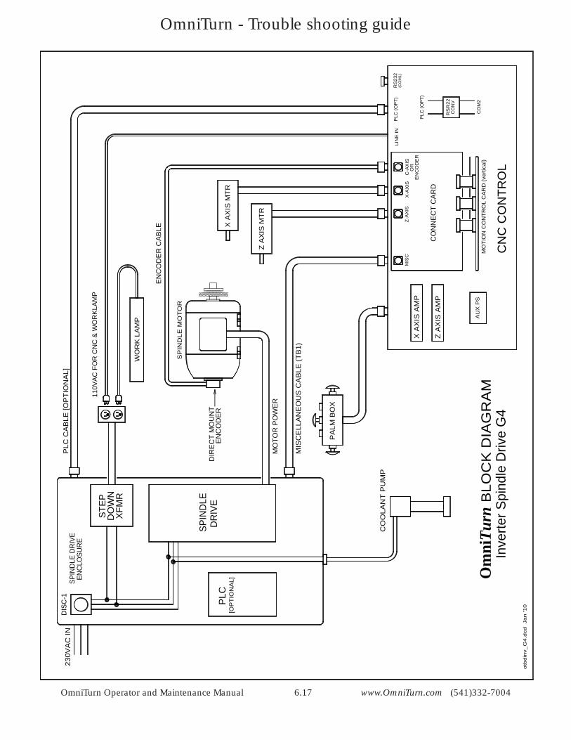
OmniTurn Operator and Maintenance Manual 6.17 www.OmniTurn.com (541)332-7004
otb
din
v_G
4.d
cd Ja
n '1
0
MIS
CE
LLA
NE
OU
S C
AB
LE (T
B1)
PLC
CA
BLE
[OP
TIO
NA
L]
[OP
TIO
NA
L]
DIS
C-1
230V
AC
IN
PA
LM B
OX
CO
OLA
NT
PU
MP
DIR
EC
T M
OU
NT
MO
TOR
PO
WE
R
SPIN
DLE
DR
IVE
PLC
BLO
CK
DIA
GR
AM
Om
niTu
rnIn
verte
r Spi
ndle
Driv
e G
4
Z A
XIS
MTR
X A
XIS
MTR
XFM
R
STE
PD
OW
N
110V
AC F
OR
CN
C &
WO
RKL
AMP
MO
TIO
N C
ON
TRO
L C
AR
D (v
ertic
al)
RS
R22
CO
NV
CO
M2
CO
NN
EC
T C
AR
D
CN
C C
ON
TRO
L
X A
XIS
AM
P
Z A
XIS
AM
P
MIS
C
RS
232
(CO
M1)
PLC
(OP
T)
Z-A
XIS
X-A
XIS
C-A
XIS
SPIN
DLE
DR
IVE
ENC
LOSU
RE
WO
RK
LA
MP
PLC
(OP
T)
AU
X P
S
EN
CO
DE
R C
AB
LE
EN
CO
DE
RO
R
EN
CO
DE
R
LIN
E IN
SP
IND
LE M
OT
OR
OmniTurn - Trouble shooting guide
OmniTurn Operator and Maintenance Manual 6.18 www.OmniTurn.com (541)332-7004
TS1
1 87632 4 5 1411109 12 13
CN
304
MO
TIO
N
CO
NN
EC
T C
AR
D
AU
X P
S
CN
9
CN
403
CN
403
CN
1
CO
MP
+12
VC
OM
P +
5V
110V
AC
LIN
E IN
2CR
1CR
1CR
1CR
SE
RV
OE
NA
BLE
TO S
ER
VO
AM
PS
CR
DY
CN
102 E
NC
+5V
CN
401
CN
402
CN
101
110V
AC
TO F
AN
110V
AC
TO S
ER
VO
S
110V
AC
TO P
LC
AU
X +
12V
CA
RD
CO
M
+12S
O
CO
MP
UTE
R
TO S
ER
VO
S O
N P
BE
-STO
P
CTR
L O
N
E-S
TOP
PA
LM B
OX
E-S
TOP
STR
ING
FRO
NT
PA
NE
LC
ON
NE
CT
CA
RD
CR
DY
CN
1
G4
CN
C
Om
niTu
rnC
NC
BLO
CK
DIA
GR
AM
E-S
TOP
STR
ING
P N G P N G P N P N P N P N
CN
102
EN
C+5
V
CN
FP9
CN
FP5
cnc_
bloc
k-di
agra
m-G
4.dc
d S
EP
T 20
10
PWR
SU
P
MO
THE
R B
D
STA
RT
CO
MPU
TER
PW
R S
UP
(ATX
)
CN
8
+12V
CN
10
MO
NIT
OR
MO
NIT
OR
PW
R
ETH
ER
NE
T
OmniTurn - Trouble shooting guide
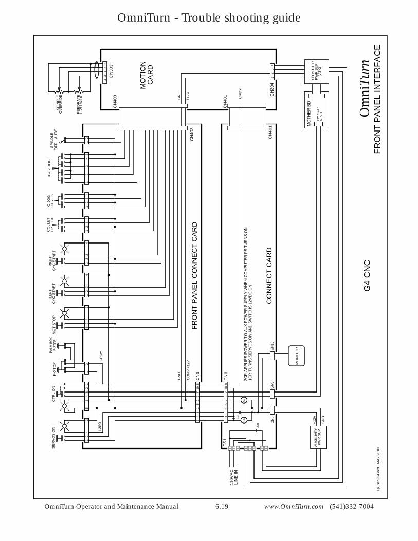
OmniTurn Operator and Maintenance Manual 6.19 www.OmniTurn.com (541)332-7004
E-S
TOP
CTR
L O
NE-
STOP
PALM
BO
X
56
43
21
12
+12V
GN
D
1 87632 4 5
G4
CN
CO
mni
Turn
FRO
NT
PA
NE
L IN
TER
FAC
E
SE
RV
OS
ON
34
21
32
97
108
15
64
34
21
43
21
MO
T S
TOP
CY
C S
TAR
TLE
FT
43
21
CY
C S
TAR
TR
IGH
T
32
1CO
LLE
T 4
OP
C
L
32
1C-J
OG
4
C+
C
-
15
X &
Z J
OG
21
SP
IND
LEO
FF
AU
TOS
PIN
DLE
OV
ER
RID
E
FEE
DR
ATE
OV
ER
RID
E4
32
31
5
CN
3032
4 PW
R S
UP
CO
MPU
TER
(ATX
)
MO
THE
R B
D
STA
RT
PW
R S
UP
PW
R S
UP
AU
XIL
LIA
RY
32
14
CN
403
CN
403
CN
1
CN
1
CN
304
32
97
108
15
64
1CR
+12V
GN
D1CR
CO
MP
+12
V
GN
D
TS1
2CR
CN
401
CN
401
CR
DY
Fp_s
ch-G
4.dc
d M
AY
201
0
CN
8C
N9
CR
DY
12S
O
MO
TIO
N
CO
NN
EC
T C
AR
D
FRO
NT
PA
NE
L C
ON
NE
CT
CA
RD
CA
RD
110V
AC
LIN
E IN
2CR
MO
NIT
ORCN
10
2CR
APP
LIES
PO
WER
TO
AU
X PO
WER
SU
PPLY
WH
EN C
OM
PUTE
R P
S TU
RN
S O
N1C
R T
UR
NS
SER
VOS
ON
AN
D S
WIT
CH
S 12
VDC
ON
OmniTurn - Trouble shooting guide
OmniTurn Operator and Maintenance Manual 6.20 www.OmniTurn.com (541)332-7004
VIO
GR
N
BLU
Cla
mp
Un
cla
mp
WH
T
YEL
1067
43
34
83
OP
ER
ATO
RS
STA
TIO
N
SP
IND
LE D
RIV
EE
NC
LOS
UR
E
12
E-S
TOP
INV
ER
TER
DR
IVE
OR
G
4 5B
RN
34
43
34
43
Du
al P
alm
Bu
tto
ns
RE
D1
(PA
LM B
OX
)
YEL
OR
G
RE
D
BR
N
BLK
GR
N
BLU
106783 4 5 1
262021 2 4
EX
TEN
SIO
N C
AB
LE T
O C
NC
OP
STA
CO
NN
EC
TOR
AT
RE
AR
PA
NE
L O
F C
NC
CO
NN
EC
TOR
S A
T LE
FT-H
AN
DM
OTI
ON
CA
RD
BR
AC
KE
T
1 2TO
TO
P O
F E
-STO
PS
WIT
CH
ON
CN
C
TO C
OL
CLS
SW
ON
CN
C
TO C
OL
OP
EN
SW
ON
CN
C
TO C
OM
ON
CO
L O
P/C
LS S
W
TO L
EFT
CY
.ST
SW
ON
CN
C
TO R
IGH
T C
Y.S
T S
W O
N C
YC
NO
TE: T
HE
SE
WIR
ES
ALS
O G
OTO
CN
403
ON
MO
TIO
N C
AR
D
TB1
MIS
C C
AB
LE T
O C
NC
3025IN
HIB
IT8
8G
UA
RD
S (D
OO
R IN
TLK
)13
13
22
12V
CO
MM
ON
19121110 15
M08
5M
251
M12
77
M13
33
75M
036
6M
044
45
1 210
10S
PIN
DLE
AN
ALO
G
1111
SP
.AN
ALO
G C
OM
MO
N
99
+12V
SO
924A
UX
E-S
TOP
B14
1412
12A
UX
E-S
TOP
A3 23
BLK
OR
G
GR
N
BLU
RE
D
GR
Y
WHT
BR
N
PN
K
BRN
VIO
YE
L
BLK
CLR
26 29303108C
N1
CN
302
CN
401
CN
402
CN
403B
CN
ES
T
6 5
1
6 4 3 2 1 5
26 29306 5 6 4 3 2 1 5
CO
NN
EC
T C
AR
D
MO
TIO
N C
AR
D
CO
NN
EC
T C
AR
DFR
ON
T P
AN
EL
3108
CN
403
CN
403
CN
1
CN
403B
G4
CN
C
mis
c_cb
-inv-
G4.
dcd
1/10
CN
C C
ON
TRO
L
Om
niTu
rnM
ISC
ELL
AN
EO
US
CA
BLE
AN
D O
PE
RA
TOR
S S
TATI
ON
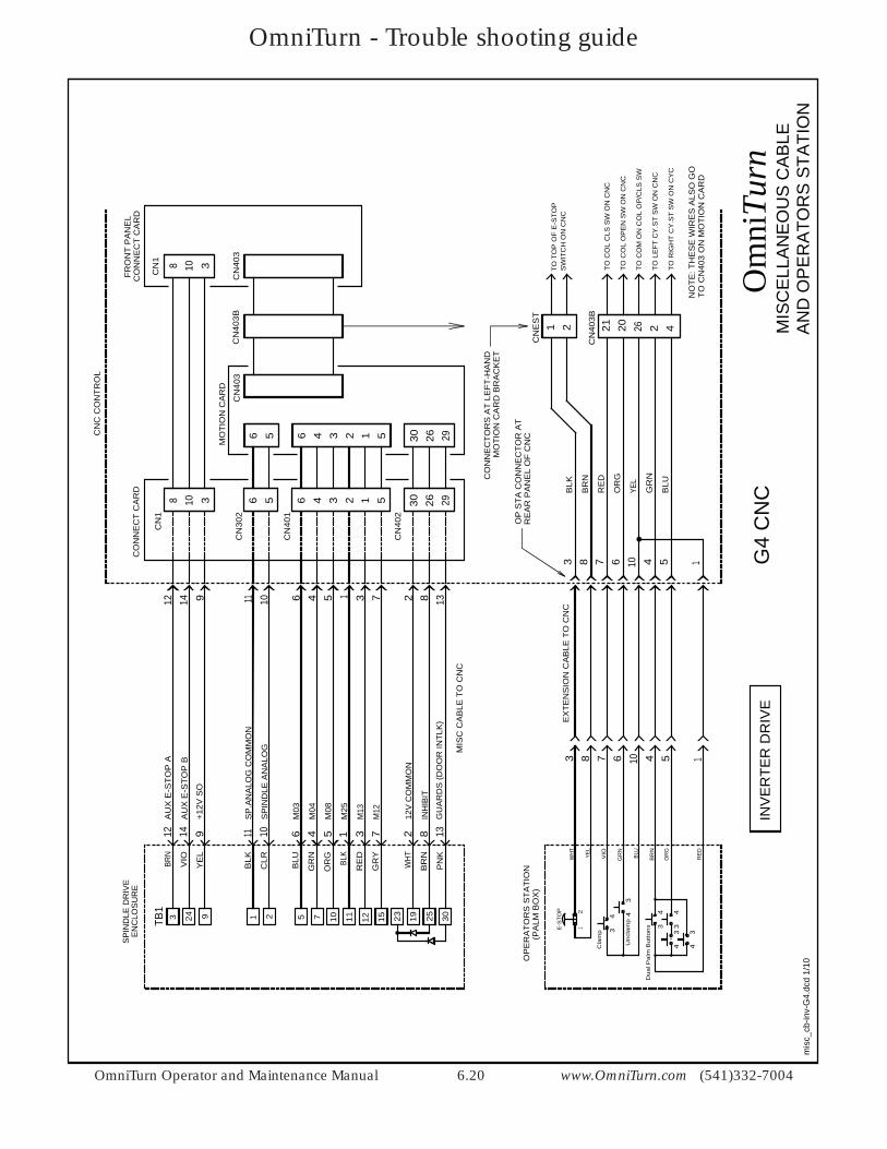
OmniTurn - Trouble shooting guide
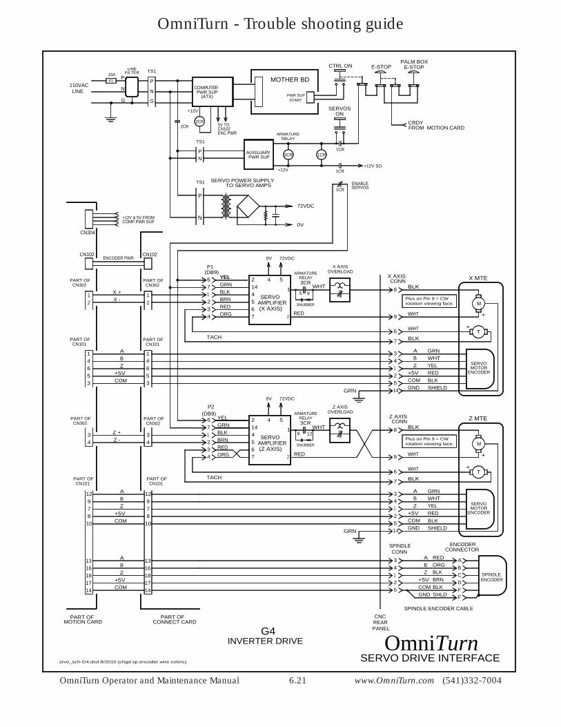
OmniTurn Operator and Maintenance Manual 6.21 www.OmniTurn.com (541)332-7004
4 5
72VDC0V
72VDC0V
+
REDBLKSHIELD
71234
GRNBLKBRNREDORG
4567 2
1SERVO
AMPLIFIER(X AXIS)
3CR
95
M
T
8
9
6
7
34125
X MTEX AXISCONN
ABZ
+5VCOM
71234
4567 2
1SERVO
AMPLIFIER(Z AXIS)
M
T
8
9
6
7
Z MTEZ AXISCONN
REARPANEL
CNC
ENCODER
SERVOMOTOR
34125
ABZ
+5VCOM
34125
SPINDLECONN
SPINDLE ENCODER CABLE
SERVO DRIVE INTERFACE
CONNECT CARDPART OF
12X -
ABZ
146
34
PART OFMOTION CARD
X +
ABZ
ABZ
131618
X AXISOVERLOAD
TACH
TACH
RELAYARMATURE
RELAYARMATURE
BLK
BLK
WHT
WHT
BLK
BLK
WHT
WHT
14 GND
14 GND
ENCODERSPINDLE
ABCDF
ENCODERCONNECTOR
ENCODER
SERVOMOTOR
REDORGBLKBRNBLKSHLD
ABZ
+5VCOMGND F
WHT
3CR
128
RELAYARMATURE
RED
GRNWHTYEL
Z AXISOVERLOAD
WHT
RED
GRN
SNUBBER
OmniTurn
4 5
+
Plus on Pin 9 = CWrotation viewing face.
GRNWHTYELREDBLKSHIELD
SNUBBER
+
+
GRN
(DB9)
(DB9)
6 YELYEL
6
P1
P2
214
214
GRNBLKBRNREDORG
YEL
Plus on Pin 9 = CWrotation viewing face.
G4INVERTER DRIVE
PART OFCN101
E-STOPCTRL ON E-STOPPALM BOX
PWR SUPAUXILLIARY
+12V+12V SO
1CR3CR1CR
1CR
ENABLE
ONSERVOS
F110A
LINEFILTER
P
N
2CR
G
110VACLINE
TS1
P
N
G
2CR
PWR SUPCOMPUTER
(ATX)
PN
+12V
TS1
TO SERVO AMPS
P
N
SERVO POWER SUPPLY
72VDC
0V
TS1
MOTHER BD
STARTPWR SUP
CRDY
1CR SERVOS
5V TOCN102ENC PWR
CN304
+12V & 5V FROMCOMP PWR SUP
FROM MOTION CARD
PART OFCN302
PART OFCN302
PART OFCN101
PART OFCN101
PART OFCN302
PART OFCN302
PART OFCN101
+5VCOM
+5VCOM
+5VCOM
Z -Z +
53
12978
10
1714
131618
12978
10
1714
34
12
14653
CN102 CN102ENCODER PWR
srvo_sch-G4.dcd 8/2010 (chgd sp.encoder wire colors)
OmniTurn - Trouble shooting guide
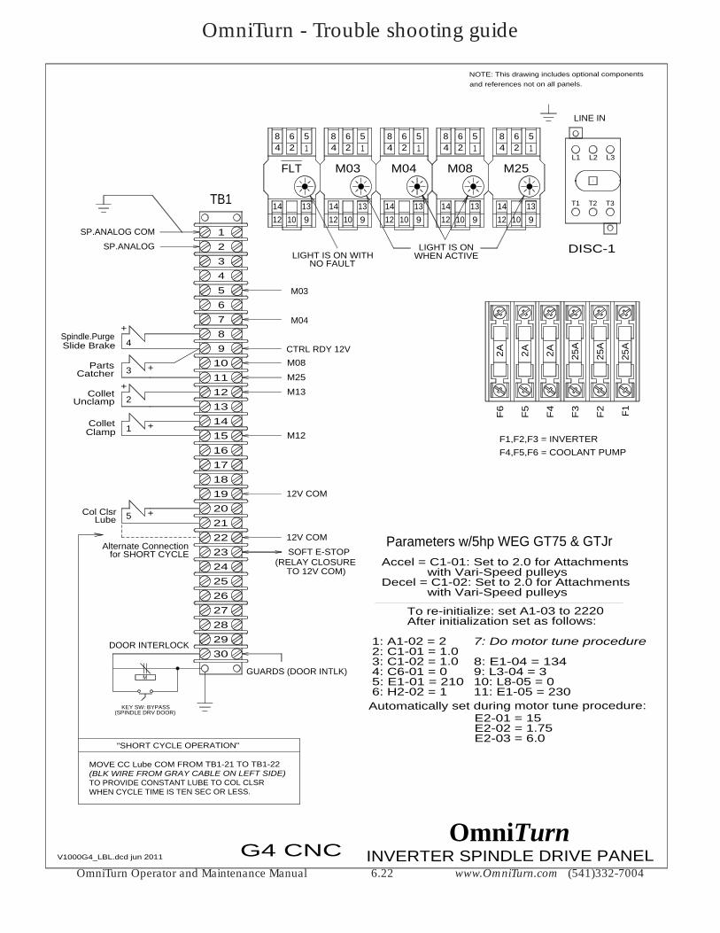
OmniTurn Operator and Maintenance Manual 6.22 www.OmniTurn.com (541)332-7004
MOVE CC Lube COM FROM TB1-21 TO TB1-22
TO PROVIDE CONSTANT LUBE TO COL CLSRWHEN CYCLE TIME IS TEN SEC OR LESS.
"SHORT CYCLE OPERATION"
(BLK WIRE FROM GRAY CABLE ON LEFT SIDE)
TB1
1
3456789
101112131415161718192021222324252627282930
2
2
1Collet
Collet
5Col Clsr
+
+
+
3
4
Parts
Slide Brake
+
Alternate Connection
+
DOOR INTERLOCK
M
KEY SW: BYPASS(SPINDLE DRV DOOR)
for SHORT CYCLE
M03
CTRL RDY 12VM08
M25M13
M12
12V COM
GUARDS (DOOR INTLK)
12V COM
Catcher
Unclamp
Clamp
Lube
SP.ANALOG COM
SP.ANALOG
FLT M03 M04 M08 M25
DISC-1
LINE IN
10 91214 13
8 6 54 2 1
10 91214 13
8 6 54 2 1
10 91214 13
8 6 54 2 1
10 91214 13
8 6 54 2 1
10 91214 13
8 6 54 2 1
NOTE: This drawing includes optional componentsand references not on all panels.
F5
F4
F3
F2 F1
25A
25A
25A
2A2A
F6
2A
INVERTER SPINDLE DRIVE PANELV1000G4_LBL.dcd jun 2011 G4 CNC
F1,F2,F3 = INVERTERF4,F5,F6 = COOLANT PUMP
M04
LIGHT IS ON WITHNO FAULT
LIGHT IS ONWHEN ACTIVE
L1 L2 L3
T1 T2 T3
OmniTurn
SOFT E-STOP(RELAY CLOSURE
TO 12V COM)
Spindle.Purge
Accel = C1-01: Set to 2.0 for Attachments
Decel = C1-02: Set to 2.0 for Attachments
To re-initialize: set A1-03 to 2220
2: C1-01 = 1.03: C1-02 = 1.04: C6-01 = 05: E1-01 = 2106: H2-02 = 1
7: Do motor tune procedure
8: E1-04 = 1349: L3-04 = 3
11: E1-05 = 230
1: A1-02 = 2
Parameters w/5hp WEG GT75 & GTJr
10: L8-05 = 0
After initialization set as follows:
with Vari-Speed pulleys
with Vari-Speed pulleys
Automatically set during motor tune procedure:
E2-02 = 1.75E2-03 = 6.0
E2-01 = 15
OmniTurn - Trouble shooting guide
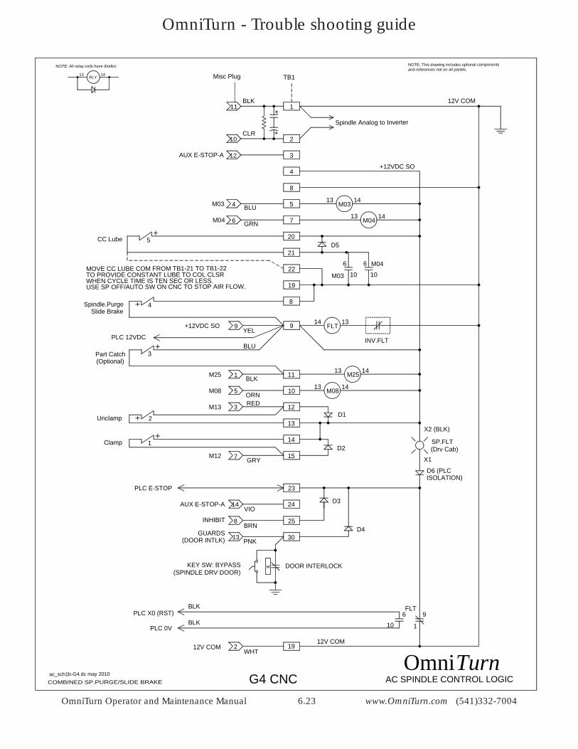
OmniTurn Operator and Maintenance Manual 6.23 www.OmniTurn.com (541)332-7004
AC SPINDLE CONTROL LOGICac_sch1b-G4.dc may 2010
NOTE: All relay coils have diodes:
RLY13 14
NOTE: This drawing includes optional componentsand references not on all panels.
M
G4 CNCOmni
COMBINED SP.PURGE/SLIDE BRAKE
9+12VDC SO
AUX E-STOP-A
4
M08M08 5
M25M25 1
M13 3
Clamp
Unclamp
M12 7
D1
D2
3
8
5
7
13 14M03M03 BLU
YEL9
13 14
13 14
10
11
ORN
BLK
RED 12
13
14
15GRY
WHT2
23
GUARDS 13
FLT9
1
19
21
8
20
Slide Brake
CC Lube
4
Spindle.Purge
INHIBIT 8
PLC 12VDCBLU
D5
Part Catch
5
4
3
2
1 SP.FLT
FLT14 13
INV.FLT
PNK
BRN
VIO
(Drv Cab)
D3
6M04 GRN
12V COM
12V COM
12V COM
DOOR INTERLOCK
210CLR
22MOVE CC LUBE COM FROM TB1-21 TO TB1-22TO PROVIDE CONSTANT LUBE TO COL CLSRWHEN CYCLE TIME IS TEN SEC OR LESS.USE SP OFF/AUTO SW ON CNC TO STOP AIR FLOW.
M0413 14
19
10
6 M04
10
6
M03
Spindle Analog to Inverter
6
10
BLK
BLKPLC X0 (RST)
PLC 0V
X2 (BLK)
D6 (PLC
KEY SW: BYPASS(SPINDLE DRV DOOR)
TB1Misc Plug
111BLK
12
X1
14
D4
ISOLATION)
(Optional)
AUX E-STOP-A
PLC E-STOP
24
25
30(DOOR INTLK)
+12VDC SO
Turn
OmniTurn - Trouble shooting guide
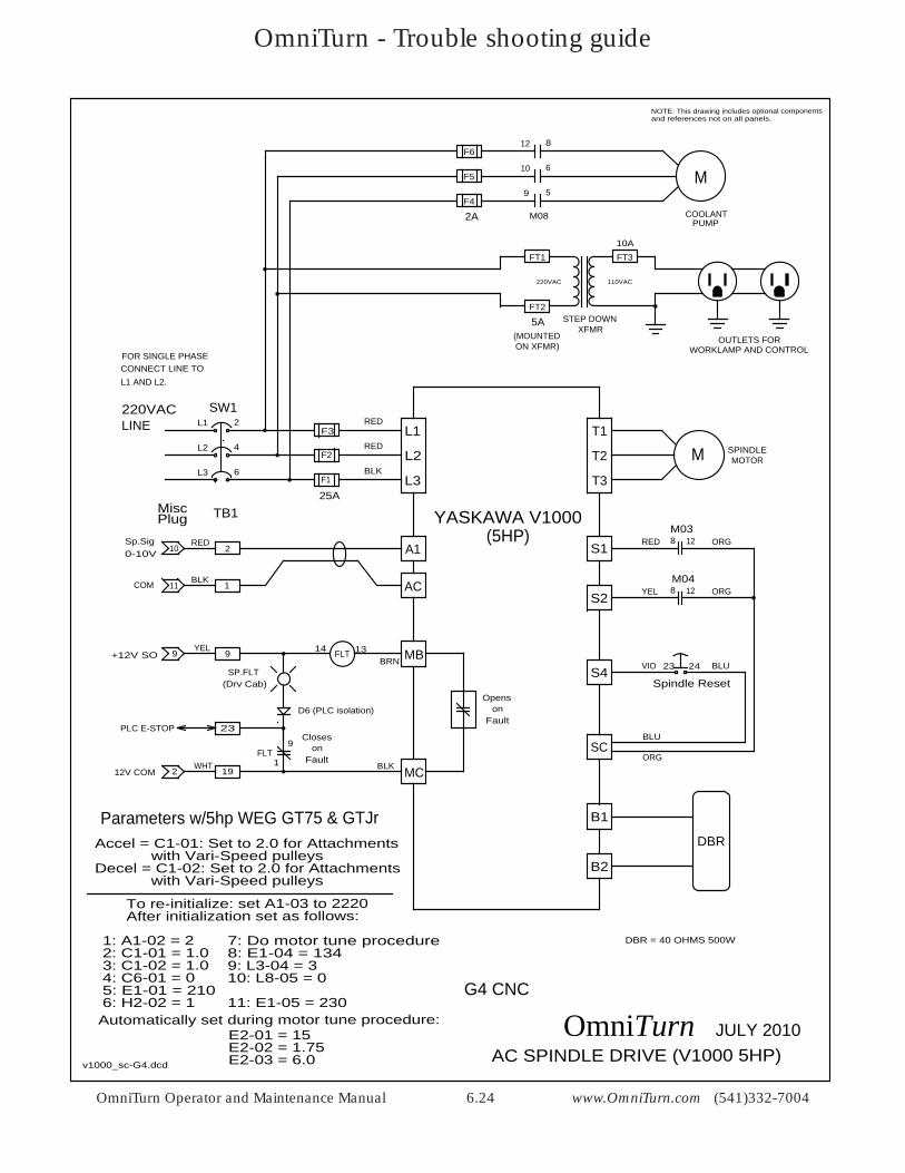
OmniTurn Operator and Maintenance Manual 6.24 www.OmniTurn.com (541)332-7004
NOTE: This drawing includes optional componentsand references not on all panels.
MT1
T2
T3
SPINDLE
S1 RED
YEL
MOTOR
AC SPINDLE DRIVE (V1000 5HP)v1000_sc-G4.dcd
M
COOLANT
L1
L3
L2
SW1
F3
F2
10 6
8
2L1
4L2
6L3
12
F1
F5
F4
M08PUMP
220VAC
BLK
RED
RED
F6
9 5
LINE
M0412
M03
8S2
S4 VIO
ORG
ORG
23 24
Spindle Reset
BLU
AC
A1
9+12V SO
19
YEL9 FLT14 13
23
9
1
SP.FLT(Drv Cab)
212V COMWHT
FLT
MB
MC
B1
B2
1
2RED
COM 11BLK
0-10VSp.Sig
Openson
Fault
TB1MiscPlug
DBR
DBR = 40 OHMS 500W
2A
25A
YASKAWA V1000
FOR SINGLE PHASECONNECT LINE TOL1 AND L2.
Closeson
Fault
BLUSC
(5HP) 12810
BLK
BRN
Accel = C1-01: Set to 2.0 for Attachments
Decel = C1-02: Set to 2.0 for Attachments
To re-initialize: set A1-03 to 2220
2: C1-01 = 1.03: C1-02 = 1.04: C6-01 = 05: E1-01 = 2106: H2-02 = 1
7: Do motor tune procedure8: E1-04 = 1349: L3-04 = 3
11: E1-05 = 230
1: A1-02 = 2
220VAC 110VAC
STEP DOWNXFMR
OUTLETS FORWORKLAMP AND CONTROL
FT310A
FT1
FT2
5A(MOUNTEDON XFMR)
Parameters w/5hp WEG GT75 & GTJr
ORG
D6 (PLC isolation)
JULY 2010OmniTurn
10: L8-05 = 0
PLC E-STOP
After initialization set as follows:
with Vari-Speed pulleys
with Vari-Speed pulleys
G4 CNC
Automatically set during motor tune procedure:
E2-02 = 1.75E2-03 = 6.0
E2-01 = 15
OmniTurn - Trouble shooting guide
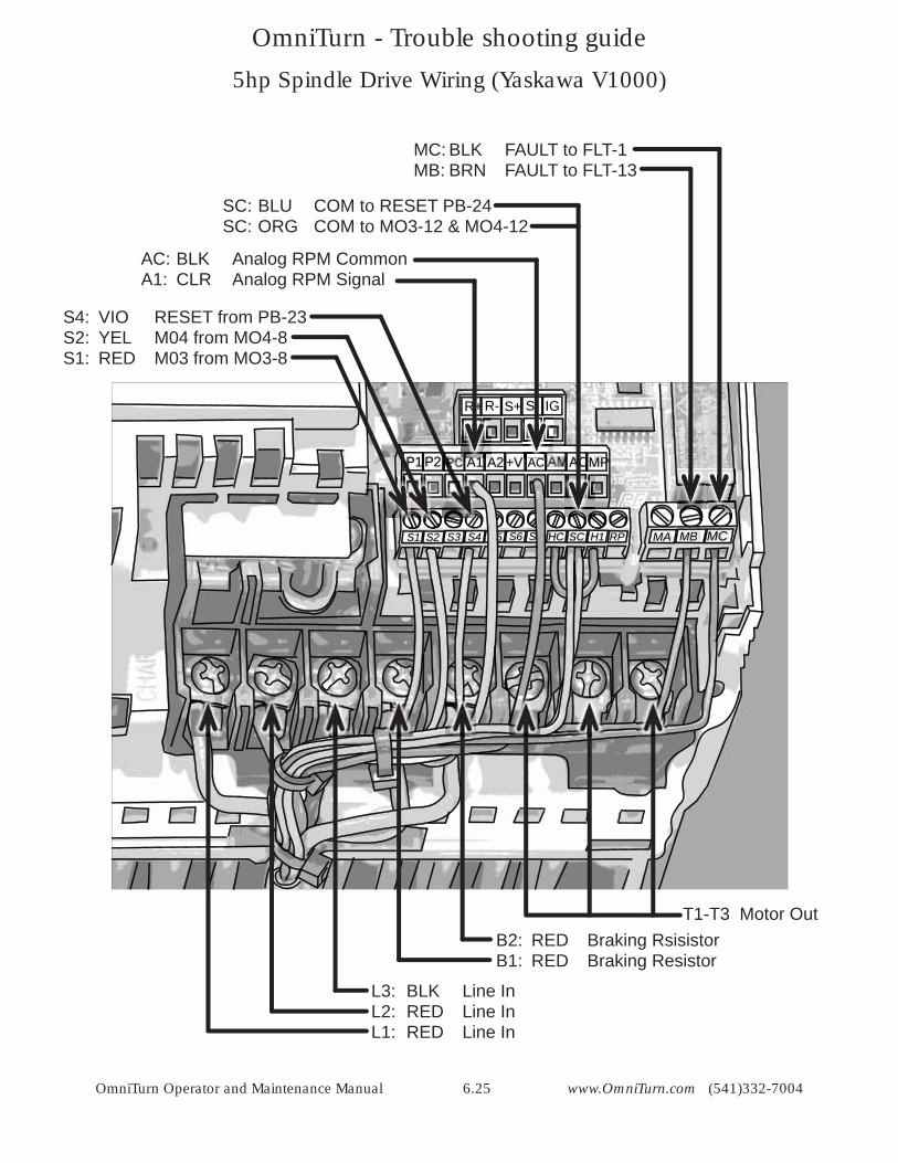
OmniTurn Operator and Maintenance Manual 6.25 www.OmniTurn.com (541)332-7004
HC SC H1SS65S4S3S2S1 RP MA MB MC
P1P2 A1 A2+V AC ACMP
R+ R- S+ S- IG
5hp Spindle Drive Wiring (Yaskawa V1000)
L3: BLK Line InL2: RED Line In L1: RED Line In
B2: RED Braking RsisistorB1: RED Braking Resistor
T1-T3 Motor Out
S4: VIO RESET from PB-23S2: YEL M04 from MO4-8 S1: RED M03 from MO3-8
AC: BLK Analog RPM CommonA1: CLR Analog RPM Signal
SC: BLU COM to RESET PB-24SC: ORG COM to MO3-12 & MO4-12
MC: BLK FAULT to FLT-1MB: BRN FAULT to FLT-13
ACA1A1 A
OmniTurn - Trouble shooting guide
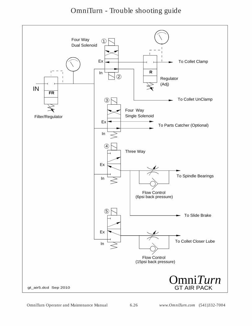
OmniTurn Operator and Maintenance Manual 6.26 www.OmniTurn.com (541)332-7004
FR
To Parts Catcher (Optional)
In
Ex
In
Ex
In
Ex
To Spindle Bearings
To Slide Brake
IN
Filter/RegulatorFour WaySingle Solenoid
Three Way
To Collet Clamp
To Collet UnClamp
Four WayDual Solenoid
In
Ex
RRegulator(Adj)
GT AIR PACKOmniTurn
Flow Control(6psi back pressure)
To Collet Closer Lube
Flow Control(15psi back pressure)
gt_air5.dcd Sep 2010
4
3
1
2
5
OmniTurn - Trouble shooting guide
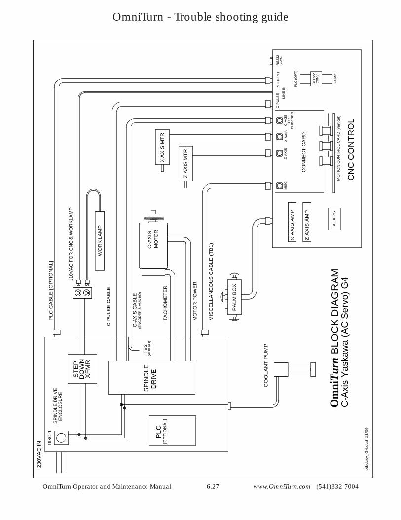
OmniTurn Operator and Maintenance Manual 6.27 www.OmniTurn.com (541)332-7004
otb
dcx
y_G
4.d
cd
11
/09
MO
TOR
MIS
CE
LLA
NE
OU
S C
AB
LE (T
B1)
PLC
CA
BLE
[OP
TIO
NA
L]
[OP
TIO
NA
L]
DIS
C-1
230V
AC
IN
PA
LM B
OX
CO
OLA
NT
PU
MP
TAC
HO
ME
TER
MO
TOR
PO
WE
R
SPIN
DLE
DR
IVE
PLC
C-A
XIS
BLO
CK
DIA
GR
AM
Om
niTu
rnC
-Axi
s Ya
skaw
a (A
C S
ervo
) G4
Z A
XIS
MTR
X A
XIS
MTR
XFM
R
STE
PD
OW
N
110V
AC F
OR
CN
C &
WO
RKL
AMP
RS
R22
CO
NV
CO
M2
CO
NN
EC
T C
AR
D
CN
C C
ON
TRO
L
X A
XIS
AM
P
Z A
XIS
AM
P
MIS
C
RS
232
(CO
M1)
PLC
(OP
T)
Z-A
XIS
X-A
XIS
SPIN
DLE
DR
IVE
ENC
LOSU
RE
WO
RK
LA
MP
C-P
ULS
E
PLC
(OP
T)
AU
X P
S
C-A
XIS
CA
BLE
C-P
ULS
E C
AB
LE
(EN
CO
DE
R &
AU
X I/
O)
C-A
XIS
EN
CO
DE
RO
RLI
NE
IN
MO
TIO
N C
ON
TRO
L C
AR
D (v
ertic
al)
TB2
(AU
X I/
O)
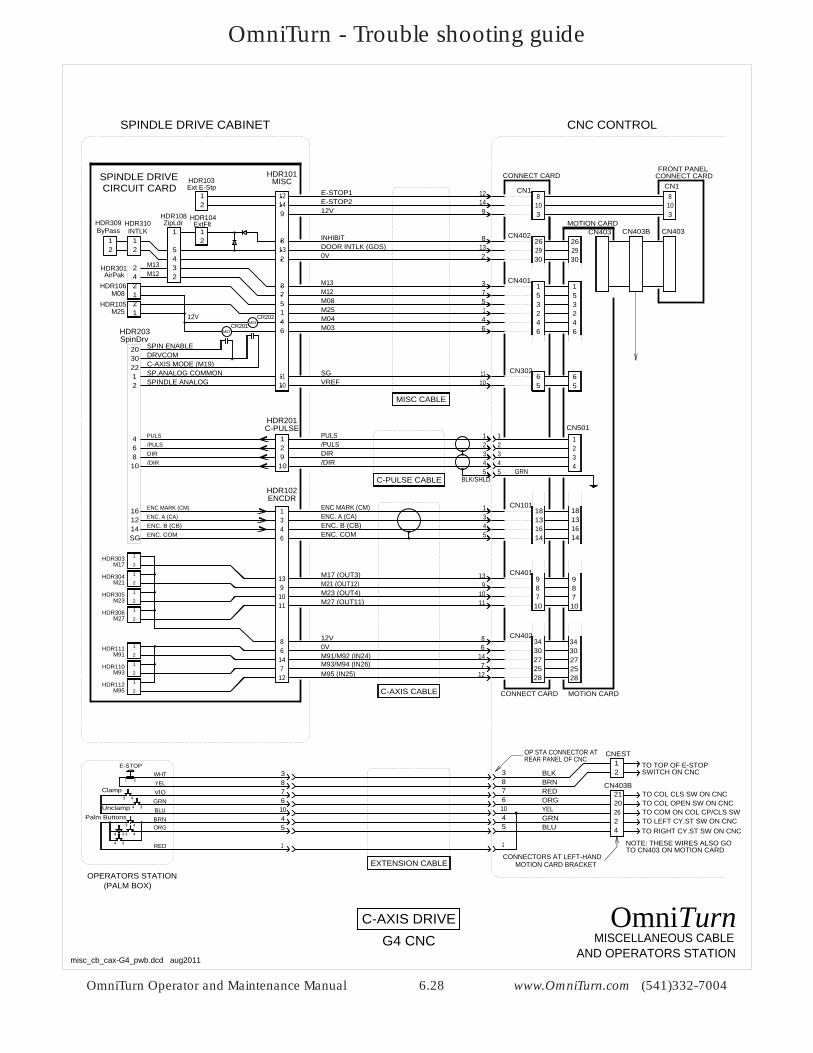
OmniTurn - Trouble shooting guide
OmniTurn Operator and Maintenance Manual 6.28 www.OmniTurn.com (541)332-7004
CN501
C-PULSE CABLE
4
1
3
5
2
4
1
3
5
2
/DIR
/PULSDIR
PULS
4
1
32
GRNBLK/SHLD
ENCDRHDR102
54
13
ENC. COM
ENC. A (CA)ENC. B (CB)
ENC MARK (CM)
1216
SG14
C-PULSE
21
HDR201
109
64
108
1346
C-AXIS CABLE
CN101
M27 (OUT11)
M21 (OUT12)M23 (OUT4)
M17 (OUT3) 13 9 989 8
10 7 711 10 10
CN401139
1011
12V
M95 (IN25)
M91/M92 (IN24)M93/M94 (IN26)
0V34 348
6 30 3014 27 277 25 25
12 28 28
CN402
CONNECT CARD MOTION CARD
86
147
12
/DIR
/PULSDIR
PULS
ENC. COM
MISCELLANEOUS CABLE
106783
OPERATORS STATION
AND OPERATORS STATION
C-AXIS DRIVE
45
1
(PALM BOX)
YELORGREDBRNBLK
GRNBLU
106783
45
1
EXTENSION CABLE
OP STA CONNECTOR ATREAR PANEL OF CNC
misc_cb_cax-G4_pwb.dcd aug2011
CONNECTORS AT LEFT-HANDMOTION CARD BRACKET
OmniTurnG4 CNC
18131614
18131614
ENC. A (CA)ENC. B (CB)
ENC MARK (CM)
91412
3108
CN1
CONNECT CARD
9 12VE-STOP214
12 E-STOP1MISC
HDR101Ext E-Stp
21
HDR103
262930
CN402262930
8132
ZipLdrHDR108
21
ByPass
21
INTLK 1
54
21
ExtFltHDR104
INHIBIT
0V
8132
DOOR INTLK (GDS)
5
CN401
32
321
73 1
515
M085M251
M12M13
73
M08
M25
AirPakHDR301
HDR105
HDR106
M04CR202
M03CR201
12V M044M036
46
46
46
1011 6
56510 VREF
11 SG
21
CN302
203022
SPIN ENABLEDRVCOMC-AXIS MODE (M19)
32
MOTION CARD
CONNECT CARDFRONT PANEL
3108
CN403 CN403
CN1
CN403B
CNC CONTROL
MISC CABLE
12
12
42
HDR309 HDR310
M12M13
SPINDLE ANALOGSP.ANALOG COMMON
SPINDLE DRIVE CABINET
SPINDLE DRIVECIRCUIT CARD
SpinDrvHDR203
2
1
2
1
2
1
2
1
M17HDR303
M21HDR304
M23HDR305
M27HDR306
2
1
2
1
2
1
M91HDR111
M93HDR110
M95HDR112
262021
24
12
TO TOP OF E-STOPSWITCH ON CNC
TO COL CLS SW ON CNCTO COL OPEN SW ON CNC
CN403B
CNEST
TO COM ON COL CP/CLS SWTO LEFT CY.ST SW ON CNCTO RIGHT CY.ST SW ON CNC
NOTE: THESE WIRES ALSO GOTO CN403 ON MOTION CARD
VIOGRNBLU
Clamp
Unclamp
WHTYEL
4 3
3 4
1 2
E-STOP
ORGBRN
3 4
4 3
3 44 3
Palm Buttons
RED
OmniTurn - Trouble shooting guide
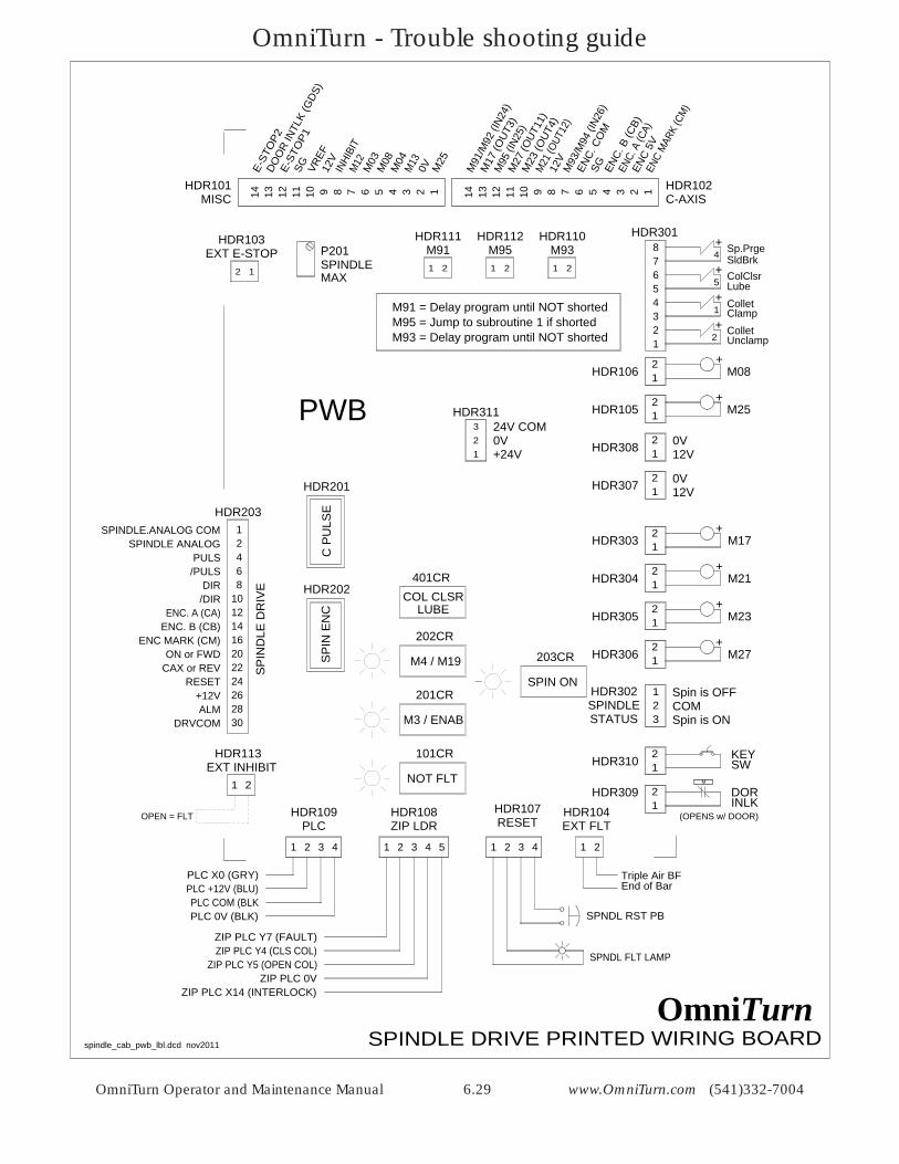
OmniTurn Operator and Maintenance Manual 6.29 www.OmniTurn.com (541)332-7004
spindle_cab_pwb_lbl.dcd nov2011
M91 M95 M93
M25
M08
M27
M23
M21
M17
C P
ULS
ES
PIN
EN
C
PLC ZIP LDR RESET
SPIN ON
SPINDLEEXT E-STOP
NOT FLT
12V
12V
SP
IND
LE D
RIV
E
EXT INHIBIT
HDR106
KEYSW
DORINLK
HDR105
HDR308
HDR307
HDR303
HDR310
HDR309
HDR304
HDR305
HDR306
HDR302
HDR201
HDR202
HDR311
HDR113
HDR109 HDR108 HDR107
HDR203
HDR103
HDR104
P201HDR111 HDR112 HDR110
MISC C-AXIS
101CR
203CR
HDR101 HDR102
+24V
EXT FLT
COL CLSRLUBE
M3 / ENAB
M4 / M19
201CR
202CR
401CR
HDR301
1
/DIR
/PULSDIR
PULSSPINDLE ANALOG
SPINDLE.ANALOG COM
ENC. A (CA)ENC. B (CB)
ENC MARK (CM)ON or FWD
CAX or REV
DRVCOMALM
RESET+12V
2468
10121416202224262830
M
SPINDLE123
Spin is OFFCOMSpin is ONSTATUS
12 +
+
+
+
+
+
(OPENS w/ DOOR)
0V
0V
21
OPEN = FLT
1 2 3 41 2 3 4 1 2 3 4 5
2 1
PLC +12V (BLU)PLC X0 (GRY)
PLC COM (BLKPLC 0V (BLK)
SPNDL FLT LAMP
SPNDL RST PB
End of BarTriple Air BF
ZIP PLC Y4 (CLS COL)ZIP PLC Y7 (FAULT)
ZIP PLC Y5 (OPEN COL)ZIP PLC 0V
ZIP PLC X14 (INTERLOCK)
SPINDLE DRIVE PRINTED WIRING BOARDOmniTurn
321
0V24V COM
1 2
M25
0VM13
M04
M08
M03
M12
INHI
BIT
12V
VREF
SGE-ST
OP1
DOO
R IN
TLK
(GDS
)
E-ST
OP2
14 13 12 11 10 9 8 7 6 5 4 3 2 1EN
C M
ARK
(CM
)
ENC
5V
ENC.
A (C
A)
ENC.
B (C
B)
SGENC.
CO
M
M93
/M94
(IN2
6)
12V
M21
(OUT
12)
M23
(OUT
4)
M27
(OUT
11)
M95
(IN2
5)
M17
(OUT
3)
M91
/M92
(IN2
4)
14 13 12 11 10 9 8 7 6 5 4 3 2 1
+
+
+
+
87654321
2
1
4
5
UnclampCollet
ColletClamp
Sp.PrgeSldBrkColClsrLube
12
12
12
12
12
12
12
12
12
MAX1 2 1 2 1 2
M95 = Jump to subroutine 1 if shortedM93 = Delay program until NOT shorted
M91 = Delay program until NOT shorted
PWB
OmniTurn - Trouble shooting guide
OmniTurn Operator and Maintenance Manual 6.30 www.OmniTurn.com (541)332-7004
CR202
CR201
2
1
203022
ON or FWDDRVCOM
CAX or REVSPINDLE ANALOG
SP.ANALOG COMMON (SG*)CR203
12V
0V
46
LUBE
0V12V
AirPakHDR301
ByPassHDR309
INTLKHDR310
ZipLdrHDR108
ExtFltHDR104
0V TIMER
SpinDrvHDR203
SpinStatHDR302
123
73
132
8
9
1412
1011
Ext E-StpHDR103
21
21
0V
1/Flt
/DIR
/PULSDIR
PULS
HDR102
ENC. COM
ENC. A (CA)ENC. B (CB)
ENC MARK (CM)1216
SG14
C-PULSE
21
HDR201
109
64
108
1346
/DIR
/PULSDIR
PULS
ENC. COM
ENC. A (CA)ENC. B (CB)
ENC MARK (CM)
ENCDR
SP.ENCHDR202
SG ENC. COM
ENC 5V
ENC.AENC MARK
ENC. B21
3
4 0V
5
6
2
12V26
ENC 5V
SPIN
M03M0412V
M27 (OUT11)
M21 (OUT12)M23 (OUT4)
M17 (OUT3)
2
1
2
1
2
1
2
1
M17HDR303
M21HDR304
M23HDR305
M27HDR306
139
1011
12V
M95 (IN25)
M91/M92 (IN24)M93/M94 (IN26)
0V2
1
2
1
2
1
M91HDR111
M93HDR110
M95HDR112
86
147
12
3024
28
DRVCOM
ALM
RESET
Ext InhibitHDR113
HDR107SpinRst
CR101
12V
/FLT
0V
/FLT
HDR109PLC
321
4
12V0V
2
43
1
12V12
MISCHDR101
54
32
21
21
12V
E-STOP2E-STOP1
INHIBIT
0VDOOR INTLK (GDS)
KEY SW: BYPASS(SPINDLE DRV DOOR)
M
M25HDR105
121 12V
M08HDR106
21 12V
5
Collet
ColletUnclamp
Clamp
Door Intlk
1
2 +
+
M08
M25
M12M13
M04M03
2
4
1
3
56
Sp.PrgeSldBrk 4 +
ColClsrLube 5 +
87
21
HDR307
21
HDR30812V0V
VREFSG
*SG = ODD#s HDR201 1-17
1
1
1616
9
9
13
13
16 1
4
4
8
8
PLC +12V (BLU)PLC X0 (GRY)
PLC COM (BLKPLC 0V (BLK)
SPNDL FLT LAMP
SPNDL RST PB
OPEN = FLT
SHORT = FLT
+12V
SIG GND
+12V
0V
FROM INVERTERMOTOR ENCODER
}TO MOTION CARD
}
FROM CAXSERVO DRIVE
}
TO CAXSERVO DRIVE }TO MOTION CARD
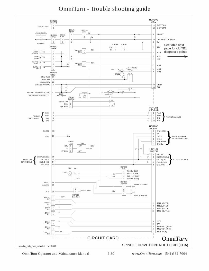
SPINDLE DRIVE CONTROL LOGIC (CCA)spindle_cab_pwb_sch.dcd nov 2011
OmniTurn
}
Spin is OFFCOM
Spin is ON
24VHDR311
123
+24V0V
24V COM
+12V0V
-12V
PS1+12V
+
+
P201Max Signal
48
9 13
11 13
CIRCUIT CARD
See table next page for old TB1 diagnostic points
OmniTurn - Trouble shooting guide
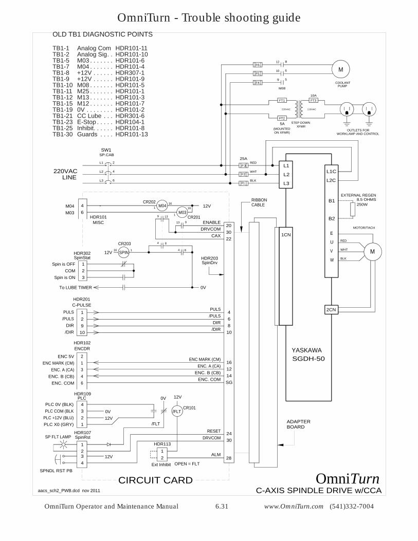
OmniTurn Operator and Maintenance Manual 6.31 www.OmniTurn.com (541)332-7004
MU
V
W
MOTOR/TACH
M
COOLANT
SW1
F3
F2
10 6
8
2L1
4L2
6L3
12
F1
F5
F4PUMP
BLK
WHT
RED
F6
9 5
25A
YASKAWASGDH-50
RED
WHT
BLK
220VAC 110VAC
STEP DOWNXFMR
OUTLETS FORWORKLAMP AND CONTROL
FT310A
FT1
FT2
5A(MOUNTEDON XFMR)
2CN
L2C
L1CL1
L3
L2
B1
B2
8.5 OHMS250W
EXTERNAL REGEN
E
C-AXIS SPINDLE DRIVE w/CCA
220VAC
SP.CAB
LINE
M08
aacs_sch2_PWB.dcd nov 2011
OmniTurnCIRCUIT CARD
ADAPTER
CR202
CR201
203022
ENABLEDRVCOM
CAX
46
SpinDrvHDR203
/DIR
/PULSDIR
PULS
ENC. COM
ENC. A (CA)ENC. B (CB)
ENC MARK (CM)1216
SG14
C-PULSE
21
HDR201
109
64
108
1346
/DIR
/PULSDIR
PULS
ENC. COM
ENC. A (CA)ENC. B (CB)
ENC MARK (CM)2ENC 5V
M03M04 12V
3024
28
DRVCOM
ALM
RESET
Ext Inhibit
HDR113
HDR107SpinRst
CR101
12V
/FLT
0V
/FLT
HDR109PLC
321
4
12V0V
2
43
1
12V12
M04M03
1
1
1616
9
9
13
13
PLC +12V (BLU)PLC X0 (GRY)
PLC COM (BLKPLC 0V (BLK)
SP FLT LAMP
SPNDL RST PBOPEN = FLT
HDR102ENCDR
CR203
12V
0V
SPIN 116
4
4
8
8
SpinStatHDR302
123
Spin is OFFCOM
Spin is ON
To LUBE TIMER
MISCHDR101
1CN
RIBBONCABLE
BOARD
OLD TB1 DIAGNOSTIC POINTS TB1-1 Analog Com HDR101-11 TB1-2 Analog Sig . . HDR101-10 TB1-5 M03 . . . . . . . HDR101-6TB1-7 M04 . . . . . . . HDR101-4TB1-8 +12V . . . . . . HDR307-1TB1-9 +12V . . . . . . HDR101-9TB1-10 M08 . . . . . . . HDR101-5 TB1-11 M25 . . . . . . . HDR101-1 TB1-12 M13 . . . . . . . HDR101-3TB1-15 M12 . . . . . . . HDR101-7TB1-19 0V . . . . . . . . HDR101-2TB1-21 CC Lube . . . HDR301-6TB1-23 E-Stop . . . . . HDR104-1TB1-25 Inhibit. . . . . . HDR101-8TB1-30 Guards . . . . HDR101-13
OmniTurn - Trouble shooting guide
OmniTurn Operator and Maintenance Manual 6.32 www.OmniTurn.com (541)332-7004
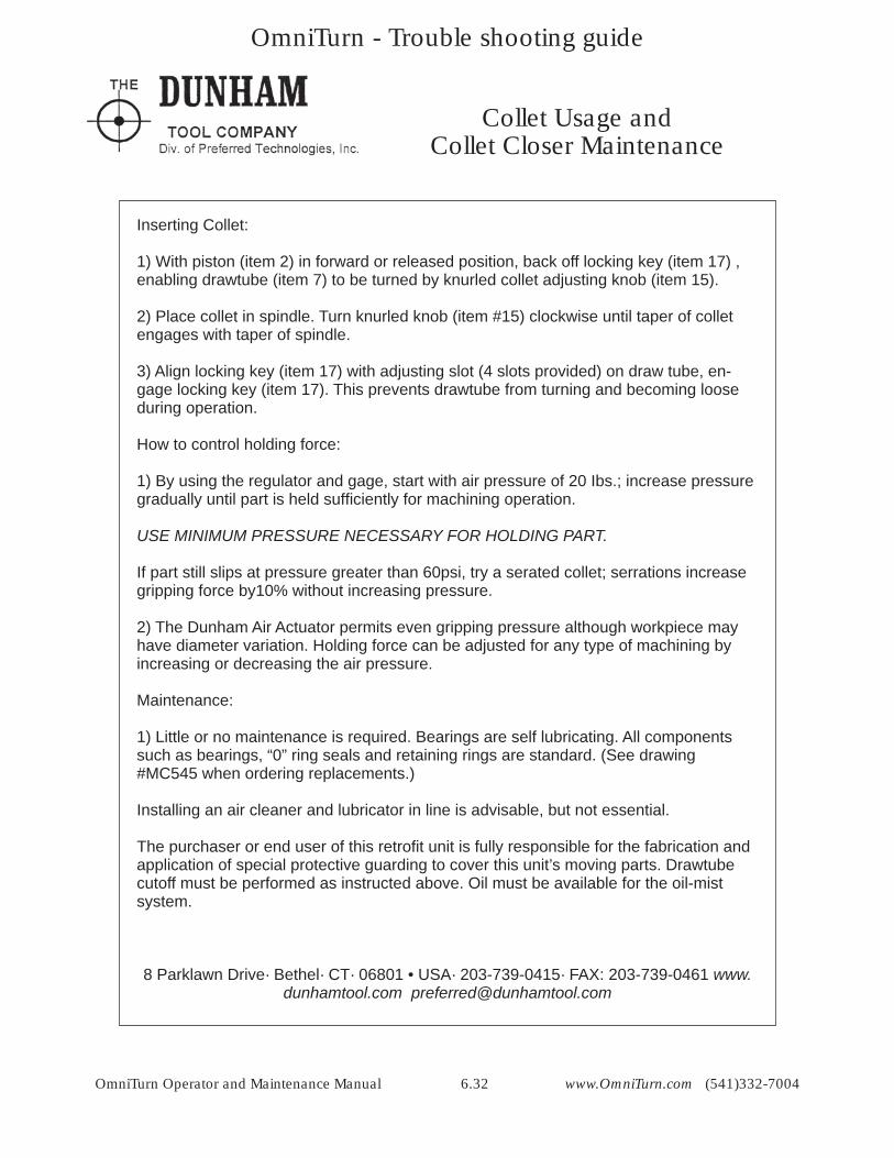
Collet Usage andCollet Closer Maintenance
Inserting Collet:
1) With piston (item 2) in forward or released position, back off locking key (item 17) , enabling drawtube (item 7) to be turned by knurled collet adjusting knob (item 15).
2) Place collet in spindle. Turn knurled knob (item #15) clockwise until taper of collet engages with taper of spindle.
3) Align locking key (item 17) with adjusting slot (4 slots provided) on draw tube, en-gage locking key (item 17). This prevents drawtube from turning and becoming loose during operation.
How to control holding force:
1) By using the regulator and gage, start with air pressure of 20 Ibs.; increase pressure gradually until part is held suffi ciently for machining operation.
USE MINIMUM PRESSURE NECESSARY FOR HOLDING PART.
If part still slips at pressure greater than 60psi, try a serated collet; serrations increase gripping force by10% without increasing pressure.
2) The Dunham Air Actuator permits even gripping pressure although workpiece may have diameter variation. Holding force can be adjusted for any type of machining by increasing or decreasing the air pressure.
Maintenance:
1) Little or no maintenance is required. Bearings are self lubricating. All components such as bearings, “0” ring seals and retaining rings are standard. (See drawing #MC545 when ordering replacements.)
Installing an air cleaner and lubricator in line is advisable, but not essential.
The purchaser or end user of this retrofi t unit is fully responsible for the fabrication and application of special protective guarding to cover this unit’s moving parts. Drawtube cutoff must be performed as instructed above. Oil must be available for the oil-mist system.
8 Parklawn Drive· Bethel· CT· 06801 • USA· 203-739-0415· FAX: 203-739-0461 www.dunhamtool.com [email protected]
OmniTurn - Trouble shooting guide
OmniTurn Operator and Maintenance Manual 6.33 www.OmniTurn.com (541)332-7004
OmniTurn - Trouble shooting guide
OmniTurn Operator and Maintenance Manual 6.34 www.OmniTurn.com (541)332-7004
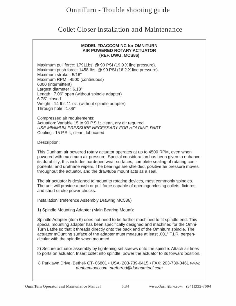
MODEL #DACCOM-NC for OMNITURNAIR POWERED ROTARY ACTUATOR
(REF. DWG. MCS86)
Maximum pull force: 17911bs. @ 90 PSI (19.9 X line pressure).Maximum push force: 1458 Ibs. @ 90 PSI (16.2 X line pressure).Maximum stroke : 5/16”Maximum RPM : 4500 (continuous)6000 (intermittent)Largest diameter : 6.18” Length : 7.06” open (without spindle adapter) 6.7S” closed Weight : 14 Ibs 11 oz. (without spindle adapter) Through hole : 1.06”
Compressed air requirements: Actuation: Variable 15 to 90 P.S.!.; clean, dry air required.USE MINIMUM PRESSURE NECESSARY FOR HOLDING PARTCooling : 15 P.S.!.; clean, lubricated
Description:
This Dunham air powered rotary actuator operates at up to 4500 RPM, even when powered with maximum air pressure. Special consideration has been given to enhanceits durability; this includes hardened wear surfaces, complete sealing of rotating com-ponents, and urethane wipers. The bearings are shielded, positive air pressure moves throughout the actuator, and the drawtube mount acts as a seal.
The air actuator is designed to mount to rotating devices, most commonly spindles. The unit will provide a push or pull force capable of openingorclosing collets, fi xtures, and short stroke power chucks.
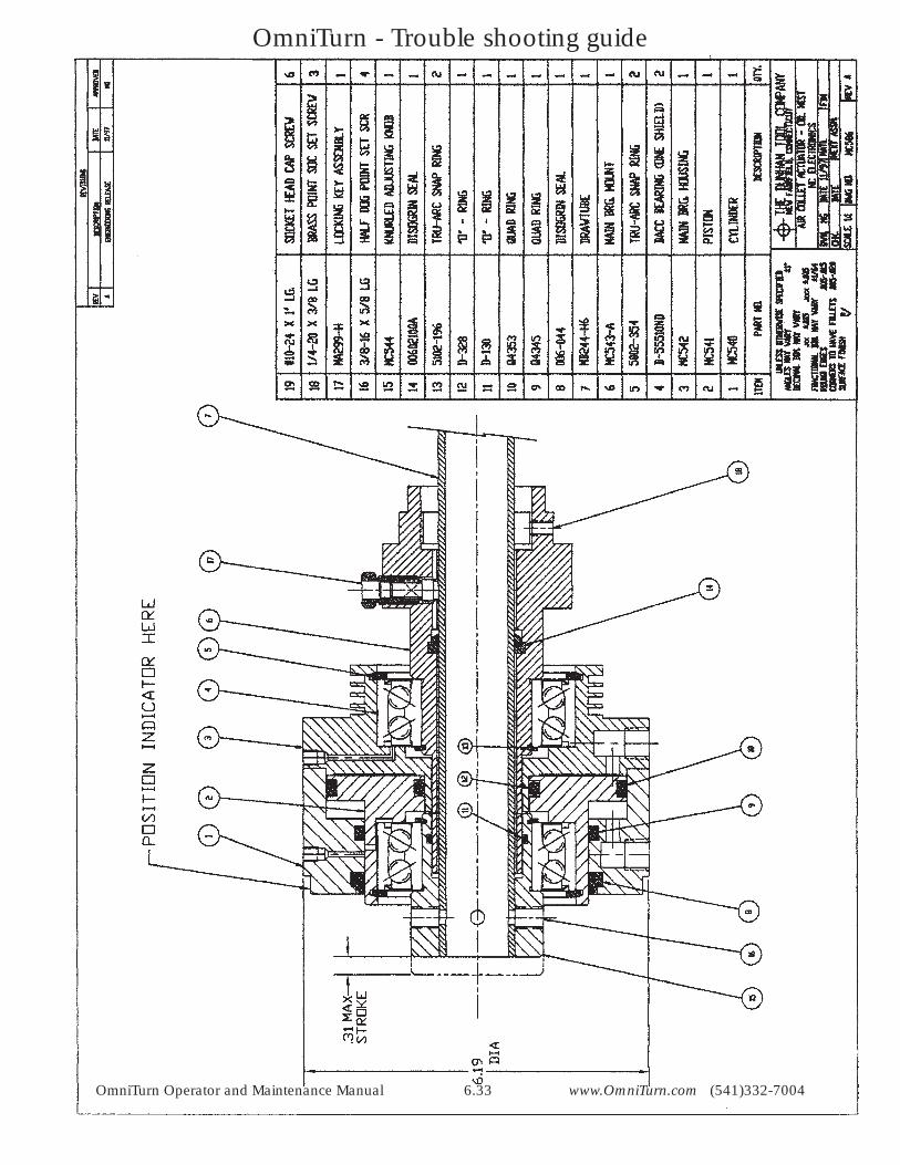
Installation: (reference Assembly Drawing MC586)
1) Spindle Mounting Adapter (Main Bearing Mount):
Spindle Adapter (item 6) does not need to be further machined to fi t spindle end. This special mounting adapter has been specifi cally designed and machined for the Omni-Turn Lathe so that it threads directly onto the back end of the Omniturn spindle. The actuator mOunting surface of the adapter must measure at least .001” T.I.R. perpen-dicular with the spindle when mounted.
2) Secure actuator assembly by tightening set screws onto the spindle. Attach air lines to ports on actuator. Insert collet into spindle; power the actuator to its forward position.
8 Parklawn Drive· Bethel· CT· 06801 • USA· 203-739-0415 • FAX: 203-739-0461 www.dunhamtool.com [email protected]
Collet Closer Installation and Maintenance
OmniTurn - Trouble shooting guide
OmniTurn Operator and Maintenance Manual 6.35 www.OmniTurn.com (541)332-7004
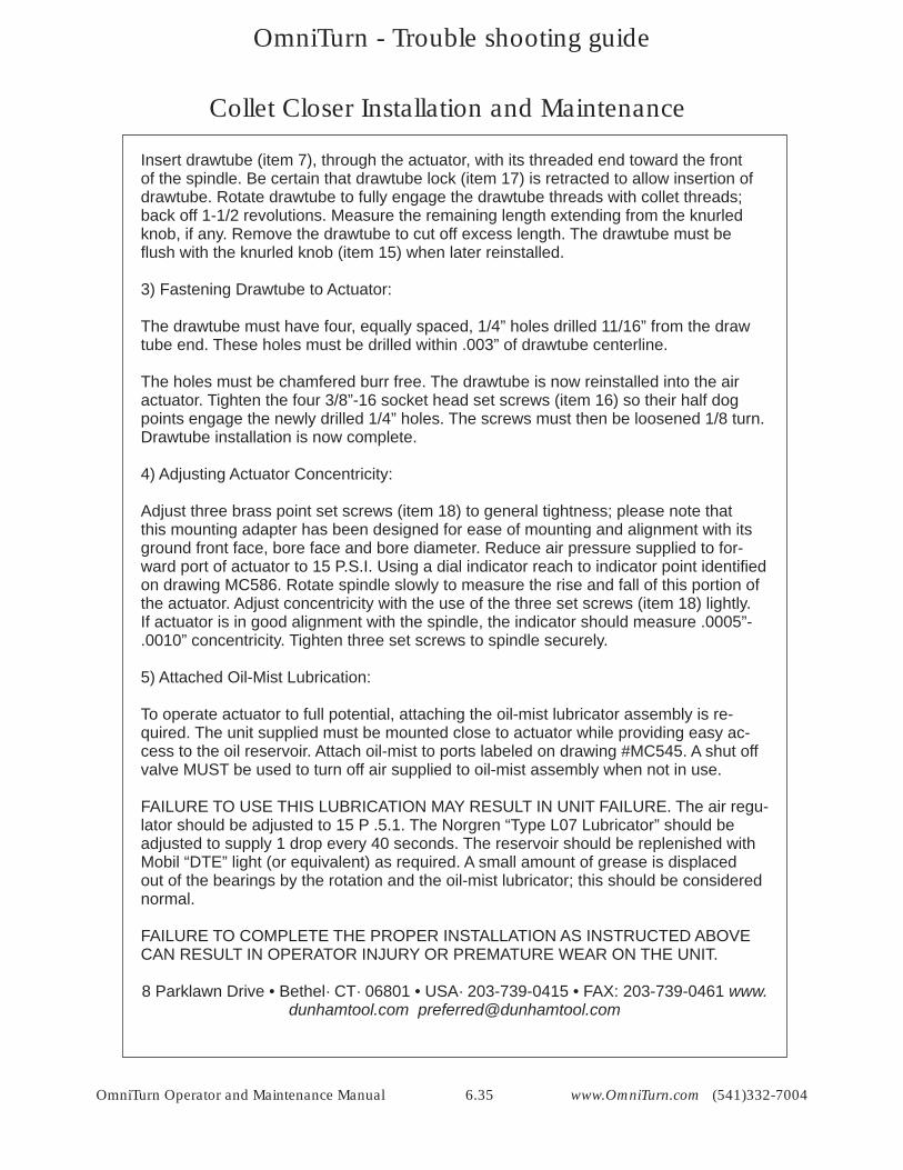
Collet Closer Installation and Maintenance
Insert drawtube (item 7), through the actuator, with its threaded end toward the front of the spindle. Be certain that drawtube lock (item 17) is retracted to allow insertion of drawtube. Rotate drawtube to fully engage the drawtube threads with collet threads; back off 1-1/2 revolutions. Measure the remaining length extending from the knurled knob, if any. Remove the drawtube to cut off excess length. The drawtube must be fl ush with the knurled knob (item 15) when later reinstalled.
3) Fastening Drawtube to Actuator:
The drawtube must have four, equally spaced, 1/4” holes drilled 11/16” from the draw tube end. These holes must be drilled within .003” of drawtube centerline.
The holes must be chamfered burr free. The drawtube is now reinstalled into the air actuator. Tighten the four 3/8”-16 socket head set screws (item 16) so their half dog points engage the newly drilled 1/4” holes. The screws must then be loosened 1/8 turn. Drawtube installation is now complete.
4) Adjusting Actuator Concentricity:
Adjust three brass point set screws (item 18) to general tightness; please note that this mounting adapter has been designed for ease of mounting and alignment with its ground front face, bore face and bore diameter. Reduce air pressure supplied to for-ward port of actuator to 15 P.S.I. Using a dial indicator reach to indicator point identifi ed on drawing MC586. Rotate spindle slowly to measure the rise and fall of this portion of the actuator. Adjust concentricity with the use of the three set screws (item 18) lightly. If actuator is in good alignment with the spindle, the indicator should measure .0005”-.0010” concentricity. Tighten three set screws to spindle securely.
5) Attached Oil-Mist Lubrication:
To operate actuator to full potential, attaching the oil-mist lubricator assembly is re-quired. The unit supplied must be mounted close to actuator while providing easy ac-cess to the oil reservoir. Attach oil-mist to ports labeled on drawing #MC545. A shut off valve MUST be used to turn off air supplied to oil-mist assembly when not in use.
FAILURE TO USE THIS LUBRICATION MAY RESULT IN UNIT FAILURE. The air regu-lator should be adjusted to 15 P .5.1. The Norgren “Type L07 Lubricator” should be adjusted to supply 1 drop every 40 seconds. The reservoir should be replenished with Mobil “DTE” light (or equivalent) as required. A small amount of grease is displaced out of the bearings by the rotation and the oil-mist lubricator; this should be considered normal.
FAILURE TO COMPLETE THE PROPER INSTALLATION AS INSTRUCTED ABOVE CAN RESULT IN OPERATOR INJURY OR PREMATURE WEAR ON THE UNIT.
8 Parklawn Drive • Bethel· CT· 06801 • USA· 203-739-0415 • FAX: 203-739-0461 www.dunhamtool.com [email protected]
OmniTurn - Trouble shooting guide
OmniTurn Operator and Maintenance Manual 6.36 www.OmniTurn.com (541)332-7004
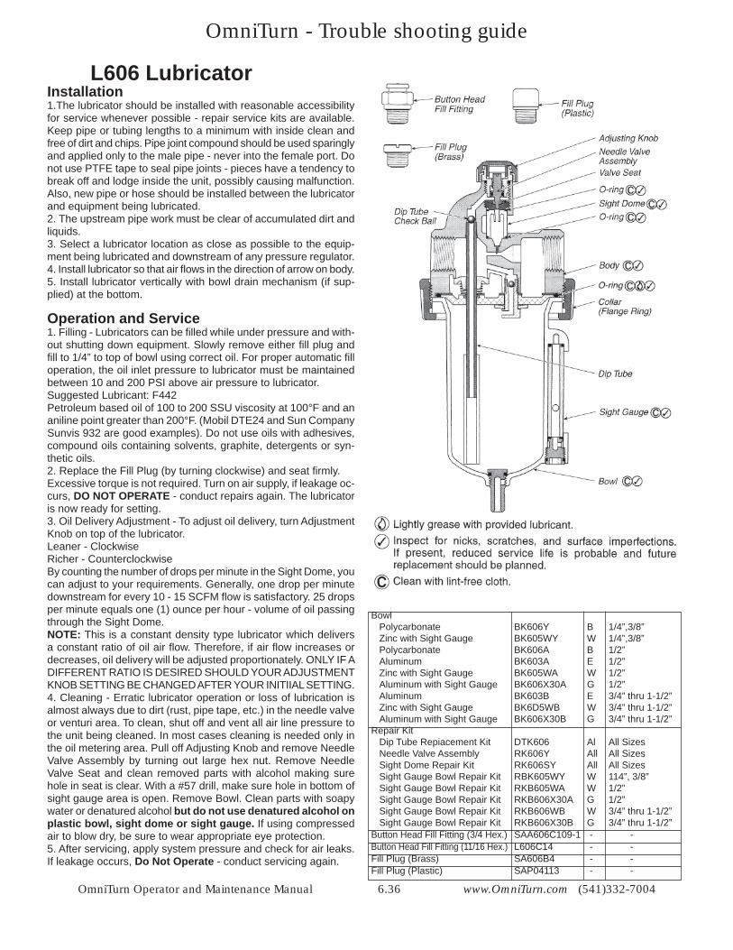
Bowl Polycarbonate BK606Y B 1/4”,3/8” Zinc with Sight Gauge BK605WY W 1/4”,3/8” Polycarbonate BK606A B 1/2” Aluminum BK603A E 1/2” Zinc with Sight Gauge BK605WA W 1/2” Aluminum with Sight Gauge BK606X30A G 1/2” Aluminum BK603B E 3/4” thru 1-1/2” Zinc with Sight Gauge BK6D5WB W 3/4” thru 1-1/2” Aluminum with Sight Gauge BK606X30B G 3/4” thru 1-1/2”Repair Kit Dip Tube Repiacement Kit DTK606 Al All Sizes Needle Valve Assembly RK606Y All All Sizes Sight Dome Repair Kit RK606SY All All Sizes Sight Gauge Bowl Repair Kit RBK605WY W 114”, 3/8” Sight Gauge Bowl Repair Kit RKB605WA W 1/2” Sight Gauge Bowl Repair Kit RKB606X30A G 1/2” Sight Gauge Bowl Repair Kit RKB606WB W 3/4” thru 1-1/2” Sight Gauge Bowl Repair Kit RKB606X30B G 3/4” thru 1-1/2”Button Head Fill Fitting (3/4 Hex.) SAA606C109-1 - -Button Head Fill Fitting (11/16 Hex.) L606C14 - -Fill Plug (Brass) SA606B4 - -Fill Plug (Plastic) SAP04113 - -
L606 LubricatorInstallation 1.The lubricator should be installed with reasonable accessibility for service whenever possible - repair service kits are available. Keep pipe or tubing lengths to a minimum with inside clean and free of dirt and chips. Pipe joint compound should be used sparingly and applied only to the male pipe - never into the female port. Do not use PTFE tape to seal pipe joints - pieces have a tendency to break off and lodge inside the unit, possibly causing malfunction. Also, new pipe or hose should be installed between the lubricator and equipment being lubricated. 2. The upstream pipe work must be clear of accumulated dirt and liquids. 3. Select a lubricator location as close as possible to the equip-ment being lubricated and downstream of any pressure regulator. 4. Install lubricator so that air fl ows in the direction of arrow on body. 5. Install lubricator vertically with bowl drain mechanism (if sup-plied) at the bottom.
Operation and Service 1. Filling - Lubricators can be fi lled while under pressure and with-out shutting down equipment. Slowly remove either fi ll plug and fi ll to 1/4” to top of bowl using correct oil. For proper automatic fi ll operation, the oil inlet pressure to lubricator must be maintained between 10 and 200 PSI above air pressure to lubricator. Suggested Lubricant: F442 Petroleum based oil of 100 to 200 SSU viscosity at 100°F and an aniline point greater than 200°F. (Mobil DTE24 and Sun Company Sunvis 932 are good examples). Do not use oils with adhesives, compound oils containing solvents, graphite, detergents or syn-thetic oils. 2. Replace the Fill Plug (by turning clockwise) and seat fi rmly. Excessive torque is not required. Turn on air supply, if leakage oc-curs, DO NOT OPERATE - conduct repairs again. The lubricator is now ready for setting. 3. Oil Delivery Adjustment - To adjust oil delivery, turn Adjustment Knob on top of the lubricator. Leaner - Clockwise Richer - Counterclockwise By counting the number of drops per minute in the Sight Dome, you can adjust to your requirements. Generally, one drop per minute downstream for every 10 - 15 SCFM fl ow is satisfactory. 25 drops per minute equals one (1) ounce per hour - volume of oil passing through the Sight Dome. NOTE: This is a constant density type lubricator which delivers a constant ratio of oil air fl ow. Therefore, if air fl ow increases or decreases, oil delivery will be adjusted proportionately. ONLY IF A DIFFERENT RATIO IS DESIRED SHOULD YOUR ADJUSTMENT KNOB SETTING BE CHANGED AFTER YOUR INITIIAL SETTING.4. Cleaning - Erratic lubricator operation or loss of lubrication is almost always due to dirt (rust, pipe tape, etc.) in the needle valve or venturi area. To clean, shut off and vent all air line pressure to the unit being cleaned. In most cases cleaning is needed only in the oil metering area. Pull off Adjusting Knob and remove Needle Valve Assembly by turning out large hex nut. Remove Needle Valve Seat and clean removed parts with alcohol making sure hole in seat is clear. With a #57 drill, make sure hole in bottom of sight gauge area is open. Remove Bowl. Clean parts with soapy water or denatured alcohol but do not use denatured alcohol on plastic bowl, sight dome or sight gauge. If using compressed air to blow dry, be sure to wear appropriate eye protection. 5. After servicing, apply system pressure and check for air leaks. If leakage occurs, Do Not Operate - conduct servicing again.
OmniTurn - Trouble shooting guide
OmniTurn Operator and Maintenance Manual 6.37 www.OmniTurn.com (541)332-7004
OmniTurn GT75 & GTJr
MAINTENANCE & LUBRICATION SCHEDULE
NOTE: Preventative maintenance reminders will periodically appear on the control monitor to prompt the operator of various lubrication requirements. The schedule below lists these require-ments in greater detail.
DAILY1. Check main air pressure: 30psi minimum for stand-alone GT, depending on collet pressure re-quirement. If any OmniTurn loader is installed, then 90psi.2. Check collet closer lubricator (mounted on bulkhead in spindle motor compartment). With spindle running observe the sight glass for oil flow. If necessary, adjust oil flow to one drop per 30 seconds. Use Mobile Light DTE oil or equivalent.3. Remove any heavy chip build up from guards and way covers.
WEEKLY1. Check air regulator/filter • Drain main regulator bowl (loosen plug CW)
• Drain coalescing filter bowl (loosen plug CW)
MONTHLY1. Examine main regulator element; replace with Watts EKF31if it shows serious contamination.2. Examine coalescing filter element; replace with Watts EK504VY if it looks oil-coated.
EVERY FOUR TO SIX MONTHS (Water-Based Coolant)Lubricate the ways and ball screws.
NOTE: If CUTTING OIL is used, no lubrication is necessary, ever.
The linear guide manufacturer recommends charging the bearing blocks with lithium grease every 4,000,000 inches of travel. On the Z-axis, this is about 96,000 parts with two inches of thread done in 8 passes.
LUBRICATING the WAYS and BALL SCREWS
There is a fitting on each of the eight bearing blocks. Three pieces of sheet metal and the accordion bellows must be removed to access the fittings and ball screws. The accordion bellows is removed by lifting each end off its holder, exposing the spindle-end Z-axis fittings. The other Z-axis fittings are exposed by removing the wide piece of sheet metal with the X-axis scale affixed. Three screws through the X-axis scale hold this in place. The X-axis covers are held in place by four long all-thread rods and acorn nuts, two on each end of the tooling plate. See page 6.7 for illustration.
With the sheet metal removed, thoroughly grease each bearing block with lithium grease.A “needle tip” is required to fit the fitting on the blocks. Tips are available from Napa (pn 715-1215) or MSC (pn 48527378).
The ball screws should be lubricated with a drizzle of Slick-50 over the entire exposed length.

OmniTurn - Trouble shooting guide
OmniTurn Operator and Maintenance Manual 6.38 www.OmniTurn.com (541)332-7004
This page intentionally blank