Embed Size (px)
Citation preview

Procedia Engineering 32 (2012) 315 – 322
1877-7058 © 2012 Published by Elsevier Ltd.doi:10.1016/j.proeng.2012.01.1273
Available online at www.sciencedirect.comAvailable online at www.sciencedirect.com
Procedia Engineering 00 (2012) 000–000
ProcediaEngineering
www.elsevier.com/locate/procedia
I-SEEC2011
Transition Characteristics of Longitudinal Heat-Assisted Magnetic Recording Systems
A. Kaewpukdeea, N. Chirdchoob, P. Kovintavewatb,*
aDepartment of Electrical Engineering, Faculty of Engineering, King Mongkut’s University of Technology North Bangkok, Bangkok, 10800, Thailand
bData Storage Technology Research Center, Nakhon Pathom Rajabhat University, Nakhon Pathom, 73000, Thailand
Elsevier use only: Received 30 September 2011; Revised 10 November 2011; Accepted 25 November 2011.
Abstract
The current magnetic recording technology is approaching its theoretical boundary known as a super-paramagnetic limit. Heat-assisted magnetic recording (HAMR) is one of the promissing technologies enabling higher recording capacity beyond this limit. In HAMR, the heat is applied in a medium during writing process resulting unique transition characteristics if compared to a conventional scheme. In this paper, we investigate the effect of different parameters, including the peak temperature, medium coercivity, a write head gap, a deep gap field, and a distance from pole to medium (or a fly height), on the transition characteristics of the longitudinal HAMR system. Numerical results indicate that there exists an optimal parameter setting which minimizes the transition center and the transition parameter so as to provide high storage capacity.
© 2010 Published by Elsevier Ltd. Selection and/or peer-review under responsibility of I-SEEC2011
Keywords: HAMR; Transition center; Transition parameter
1. Introduction
The recording capacity based on the perpendicular recording technology will soon reach its maximum storage capacity, which is often referred to as the super-paramagnetic limit, at 1 Tb/in2 [1]. This raises the awareness among researchers on finding new technologies that are capable of increasing a recording capacity beyond this limit. To achieve higher areal density of hard disk drives, it is typically achieved by reducing a volume of a grain size (V) that is required to store a single bit in magnetic medium. A magnetic grain is characterized by its uniaxial anisotropy coefficient (Ku) such that the higher the Ku, the
* Corresponding author. Tel.: (+66) 089-456-5050; fax: (+66) 034-261-065 E-mail address: [email protected]

316 A. Kaewpukdee et al. / Procedia Engineering 32 (2012) 315 – 3222 A. Kaewpukdee et al. / Procedia Engineering 00 (2012) 000–000
harder the magnetization of the media to be changed. In practice, the magnetic energy (KuV) is a factor used to determine the thermal stability of a magnetic grain. Specifically, the magnetic grain is said to be stable only if the magnetic energy is much greater than the thermal energy (kBT) according to
,u
B
K VB
k T (1)
where kB = 1.3810-23 is a Boltzmann’s constant, T is a temperature in Kelvin, and B is any large positive integer, e.g., 60 [2]. Generally, (1) can also be used to indicate a maximum areal density that magnetic medium can support. For example, if we reduce V so as to increase an areal density, Ku must also be increased such that KuV is kept constant. Unfortunately, the medium coercivity (Hc) is proportional to Ku.Therefore, increasing Ku results in the higher magnetic field density needed to change the direction of medium magnetization.
Recently, there exist various technologies that can be used to overcome the super-paramagnetic limit. These include heat-assisted magnetic recording (HAMR), bit-patterned magnetic recording (BPMR), microwave-assisted magnetic recording (MAMR), and two-dimensional magnetic recording (TDMR) [1]. Among all these technologies, we are particularly interested in HAMR, due to its feasibility to cooperate with the current hard disk drive technology.
Due to the fact that Hc is inversely proportional to the temperature [2], the medium in HAMR is then heated during the writing process so that Hc can be reduced. This consequently leads to the lower magnetic field required in writing a data bit into a medium. Once the data bit has been written, the medium is rapidly cooled down until it reached the ambient temperature at which Hc returns to its typical high value. By doing do, it is possible to write a data bit into the medium with high Ku by using only a small amount of magnetic field. Furthermore, this method can guarantee the thermal stability of the data bit stored in the medium as well.
Williams and Comstock [3] has proposed the so-called Williams-Comstock model to study the transition characteristics of longitudinal recording systems. However, Rausch et al. [2] had extended this model to include the effect of temperature, resulting in the thermal Williams-Comstock model (TWCM), for predicting the transition length in a longitudinal HAMR system. The behavior of the transition location and the transition parameter in a longitudinal HAMR system has been extensively investigated in [4]. Finally, Radhakrishan et al. [5] have studied the transition characteristics of a perpendicular HAMR system.
Although the transition characteristics of a longitudinal HAMR system have previously been studied in [3 – 5], these studies focus only on the effect of peak temperature on the readback signal response for given parameters, including medium coercivity, a write head gap, a deep gap field, and a distance from pole to medium (or a fly height). Nevertheless, we are interested in how the transition characteristics behave when these parameters vary. To do so, we employ the TWCM and a microtrack model [3] for the longitudinal HAMR system to investigate the effect of these parameters on the transition center, the transition length, and the PW50. This study will serve as a guideline for a system designer to optimize some parameters so as to obtain the best system performance.
The rest of this paper is organized as follows. Section 2 and Section 3 briefly explain the TWCM and the microtrack model, respectively. Next, the simulation settings and results are presented and discussed in Section 4. Finally, Section 5 concludes this paper.
2. Thermal Williams-Comstock Model
The Williams-Comstock model was proposed in [3], which is an analytical expression used to study the transition characteristics of longitudinal magnetic recording systems. Later, Rausch et al. [2] include
317A. Kaewpukdee et al. / Procedia Engineering 32 (2012) 315 – 322 A. Kaewpukdee et al. / Procedia Engineering 00 (2012) 000–000 3
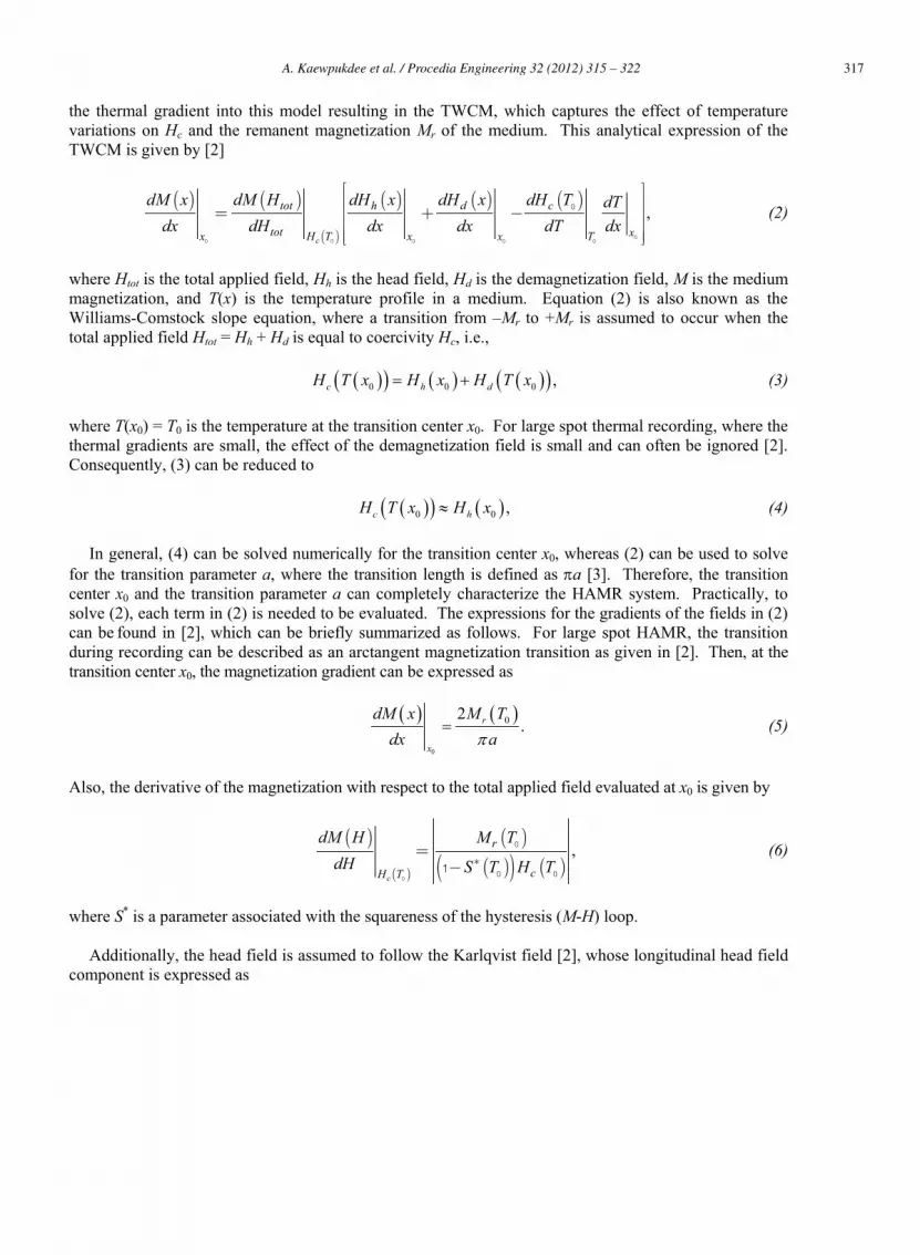
the thermal gradient into this model resulting in the TWCM, which captures the effect of temperature variations on Hc and the remanent magnetization Mr of the medium. This analytical expression of the TWCM is given by [2]
( ) ( )
( )
( ) ( ) ( ),
c
h dtot c
tot xH T Tx x x
dM x dH x dH xdM H dH T dTdx dH dx dx dT dx
é ùê ú
= + -ê úê ú
úê ûë 00 00 0 0
0 (2)
where Htot is the total applied field, Hh is the head field, Hd is the demagnetization field, M is the medium magnetization, and T(x) is the temperature profile in a medium. Equation (2) is also known as the Williams-Comstock slope equation, where a transition from –Mr to +Mr is assumed to occur when the total applied field Htot = Hh + Hd is equal to coercivity Hc, i.e.,
0 0 0 ,c h dH T x H x H T x (3)
where T(x0) = T0 is the temperature at the transition center x0. For large spot thermal recording, where the thermal gradients are small, the effect of the demagnetization field is small and can often be ignored [2]. Consequently, (3) can be reduced to
0 0 ,c hH T x H x (4)
In general, (4) can be solved numerically for the transition center x0, whereas (2) can be used to solve for the transition parameter a, where the transition length is defined as a [3]. Therefore, the transition center x0 and the transition parameter a can completely characterize the HAMR system. Practically, to solve (2), each term in (2) is needed to be evaluated. The expressions for the gradients of the fields in (2) can be found in [2], which can be briefly summarized as follows. For large spot HAMR, the transition during recording can be described as an arctangent magnetization transition as given in [2]. Then, at the transition center x0, the magnetization gradient can be expressed as
0
02.r
x
dM x M Tdx a
(5)
Also, the derivative of the magnetization with respect to the total applied field evaluated at x0 is given by
( )
( )
( )( )( ) ( )
,*
=-
c
r
cH T
dM H M TdH S T H T
0
0
0 01 (6)
where S* is a parameter associated with the squareness of the hysteresis (M-H) loop.
Additionally, the head field is assumed to follow the Karlqvist field [2], whose longitudinal head field component is expressed as

318 A. Kaewpukdee et al. / Procedia Engineering 32 (2012) 315 – 3224 A. Kaewpukdee et al. / Procedia Engineering 00 (2012) 000–000
Fig. 1. A microtrack model
( ) 1 10 / 2 / 2tan tan ,hH x g x gH x
y y- -
é ùæ ö æ ö+ -÷ ÷ç çê ú÷ ÷= -ç ç÷ ÷ê úç ç÷ ÷ç çp è ø è øê úë û (7)
where H0 is the deep gap field, g is the shield-to-shield spacing in the write gap, y = d + t/2 is the distance between the bottom of the pole and the center of the medium, d is the fly height, and t is the medium thickness. Similarly, for the large spot HAMR region, the demagnetization field gradient at the transition center can be approximated by
( )
( )0
02/ 2
rd
x
M T tdHdx a a t
=-p +
(8)
Finally, the coercivity gradient and the thermal gradient in (2) are easily obtained once the medium coercivity and the thermal profile [2] are known.
3. Microtrack Model
Generally, the TWCM is a one-dimensional model because it ignores the cross-track variations in the transition. In fact, this TWCM is inadequate for describing the HAMR process where the medium is heated with a laser. Because the thermal profile is approximately Gaussian, there is not only an along-track variation in Hc, but also a cross-track variation. To account for this behavior, the microtrack model was proposed in [6] to approximate transition curvature.
Specifically, a magnetic track is divided into N subtracks with equal width. Then, the TWCM is applied for each subtrack to determine a transition parameter and a transition center as shown in Fig. 1. The transition responses of each subtrack are sufficient to determine the characteristics of HAMR system. If the system response of an individual subtrack is ,h a t , the total response for the entire track will be given by [3]
1
1 , ,N
i ii
p t h a tN
(9)

319A. Kaewpukdee et al. / Procedia Engineering 32 (2012) 315 – 322 A. Kaewpukdee et al. / Procedia Engineering 00 (2012) 000–000 5
Table 1. Setup parameters [2]
Coercivity (Hc) -2000 T(x) + 16×105 A/m Remanant magnetization (Mr) -1200 T(x) + 12×105 A/m
Coercive squareness (S*) 0.7
Peak temperature 400 oC
Write head gap (g) 100 nm Deep gap field (Hg) 19×105 A/m
Fly height (d) 20 nm Peak temperature position (c) 0 nm
Read head gap 5 nm
Width of the track 120 nm
Number of subtracks (N) 17
-60 -40 -20 0 20 40 60-70
-65
-60
-55
Tra
nsiti
on c
ente
r (n
m)
-60 -40 -20 0 20 40 605.2
5.4
5.6
5.8
6
6.2
Tra
nsiti
on p
aram
eter
(nm
)
Cross-track location (nm)
320C (-20%)
360C (-20%)
400C (0%)
440C (+10%)
480C (+20%)
Fig. 2. Effect of peak temperature on (Top) the transition center and (Bottom) the transition parameter
where h(t) is the subtrack response given in [3], ai is the transition parameter, and it is the relative location of the transition center for each subtrack.
4. Simulation Results
To investigate the transition characteristics of the longitudinal HAMR system, the parameter setting used in simulations is shown in Table 1 (if not specified otherwise). Note that the boldface letters in Table 1 indicate the parameters studied in this paper. Fig. 2 shows the effect of the peak temperature on (Top) the transition center x0 and (Bottom) the transition parameter a at each subtrack. The peak temperatures used in this study include the default value (400 oC)and its 10% and 20% variations. The transition center represents the location of magnetic transition occurred in a medium when applying a temperature profile, where the negative value means the position to the left of the head gap center. As illustrated in Fig. 2, increasing the peak temperature results in the

320 A. Kaewpukdee et al. / Procedia Engineering 32 (2012) 315 – 3226 A. Kaewpukdee et al. / Procedia Engineering 00 (2012) 000–000
variation of both x0 and a. To be more specific, in Fig. 2 (Top), increasing the peak temperature will push the transition center further away from the center head gap. However, when the peak temperature is high, it leads to a smaller transition parameter as depicted in Fig. 2 (Bottom), and thus a smaller transition parameter, which is highly preferable [7]. Since higher temperature is desirable for improving the transition parameters, while at the same time it leads to undesirable effect on the transition center, we need to trade-off between the transition center and the transition parameter when choosing the peak temperature employed in HAMR systems.
Table 2. The averaged transition center and transition parameter
Peak temperature -20% -10% 0% 10% 20%
x0 (nm) -58.46 -60.18 -61.92 -63.69 -65.49 a (nm) 5.79 5.67 5.56 5.46 5.37 PW50 (nm) 51 50 50 50 49
Write head gap (g)-20% -10% 0% 10% 20%
x0 (nm) -53.34 -57.67 -61.92 -66.13 -70.32 a (nm) 5.52 5.54 5.56 5.59 5.62 PW50 (nm) 50 50 50 50 50
Fly height (d)-20% -10% 0% 10% 20%
x0 (nm) -60.96 -61.62 -61.92 -62.70 -63.14 a (nm) 5.10 5.41 5.56 5.98 6.25 PW50 (nm) 42 47 50 57 61
Coercivity Hc(x)-20% -10% 0% 10% 20%
x0 (nm) -54.57 -58.13 -61.92 -66.06 -70.65 a (nm) 5.69 5.55 5.56 5.67 5.84 PW50 (nm) 51 50 50 50 50
Deep gap field (Hg)-20% -10% 0% 10% 20%
x0 (nm) -57.72 -59.94 -61.92 -63.73 -65.40 a (nm) 5.59 5.55 5.56 5.59 5.64 PW50 (nm) 50 50 50 50 50
Furthermore, we also show the averaged transition center x0 and the averaged transition parameter a(averaged from 17 subtracks) in Table 2, when the peak temperature varies, so as to easily understand the behavior of x0 and a. Again, we can clearly see that increasing the peak temperature will move the transition center further away from the head gap center and will also reduce the transition parameter. Moreover, we also list the PW50 of the total response in (9) in Table 2, which is the width at half of its maximum. It is apparent that increasing the peak temperature can help reduce the PW50, which is preferable. This is because the smaller the PW50, the higher the achievable storage capacity.
Similarly, Fig. 3 demonstrates the effect of write head gap g on (Top) the transition center x0 and (Bottom) the transition parameter a at each subtrack, where the write head gaps used in this study include the default value (100 nm) and its 10% and 20% variations. It is apparent that increasing the write head gap will greatly push the transition center away from the head gap center and will slightly increase the transition parameter. This result is similar to the case when investigating the effect of fly height d as

321A. Kaewpukdee et al. / Procedia Engineering 32 (2012) 315 – 322 A. Kaewpukdee et al. / Procedia Engineering 00 (2012) 000–000 7
illustrated in Fig. 4. However, we found that when d increases, the transition center slightly moves away from the head gap center whereas the transition parameter largely increases.
-60 -40 -20 0 20 40 60-75
-70
-65
-60
-55
-50
-45
Tra
nsiti
on c
ente
r (n
m)
80 nm (-20%)
90 nm (-10%)
100 nm (0%)110 nm (+10%)
120 nm (+20%)
-60 -40 -20 0 20 40 605.3
5.4
5.5
5.6
5.7
5.8
Cross-track location (nm)
Tra
nsiti
on p
aram
eter
(nm
)
Fig. 3. Effect of write head gap g on (Top) the transition center and (Bottom) the transition parameter
-60 -40 -20 0 20 40 60
-66
-64
-62
-60
-58
Tra
nsiti
on c
ente
r (n
m)
16 nm (-20%)
18 nm (-10%)
20 nm (0%)22 nm (+10%)
24 nm (+20%)
-60 -40 -20 0 20 40 605
5.5
6
6.5
Cross-track location (nm)
Tra
nsiti
on p
aram
eter
(nm
)
Fig. 4. Effect of fly height d on (Top) the transition center and (Bottom) the transition parameter
Next, we illustrate the averaged transition center x0 and the averaged transition parameter a in Table 2, when the write head gap g and the fly height d vary. It is evident that increasing g or d will push the transition center away from the head gap center and will increase the transition parameter. In addition, it can be seen that changing the write head gap does not affect the PW50, while the PW50 largely depends on the fly height. Specifically, decreasing the fly height can considerably reduce the PW50. Also, it seems that the PW50 is proportional to the transition parameter a.
Finally, Table 2 also lists the averaged transition center x0, the averaged transition parameter a, and the PW50 when the coercivity Hc and the deep gap field Hg change from their default values by 10% and 20%. Clearly, increasing Hc or Hg will move the transition center further away from the head gap center, and will only slightly change the transition parameter. Furthermore, we found that the PW50 is likely independent of Hc and Hg because changing Hc or Hg has no effect on the PW50.

322 A. Kaewpukdee et al. / Procedia Engineering 32 (2012) 315 – 3228 A. Kaewpukdee et al. / Procedia Engineering 00 (2012) 000–000
As demonstrated here, all parameters in this study have an impact on the transition center x0 and the transition parameter a, as well as the PW50. However, it should be noted that the small a and PW50 are preferable in the HAMR system to achieve high areal densities. Accordingly, we should utilize some optimization technique to obtain the suitable parameters for the HAMR system so as to achieve good performance.
5. Conclusion
In this paper, we investigated the impact of several parameters, including the peak temperature, the medium coercivity, the write head gap, the deep gap field, and the fly height, on the transition characteristics (e.g., the transition center x0, the transition parameter a, and the PW50) of the longitudinal HAMR system, based on the TWCM and the microtrack model. From our study, it is shown that there exist certain parameter settings that can minimize the transition parameter, the transition center, and the PW50.Specifically, among all parameters studied, the fly height has the most impact on the a and PW50, followed by the peak temperature. Accordingly, the fly height and the peak temperature are of importance in optimizing the HAMR system, rather than the medium coercivity, the write head gap and the deep gap field.
As for our future research, although HAMR is very promising in increasing the areal density of hard disk drives, there are still many challenges to be overcame a studied before a real implementation can be achieved. These include the development of an efficient light delivery system, thermo-magnetic write head, head-disk interface, cooling system, and so on [2].
References
[1] Shiroishi Y., Fukuda K., Tagawa I., Iwasaki H., Takenoiri S., Tanaka H., Mutoh H., and Yoshikawa N., Future options for HDD storage, IEEE Trans. Magn., 2009, p. 3816-3822.
[2] Rausch T., Bain J. A., Stancil D. D., and Schelesinger T. E., Thermal Williams-Comstock model for predicting transition length in a heat-assisted magnetic recording system, IEEE Trans. Magn., 2004, p. 137-147.
[3] Williams M. L. and Comstock R. L., An analytic model of the write process in digital magnetic recording, in Proc. 17th Annu. AIP Conf., 1971, p. 724-738
[4] Erden F. M., Rausch T., and Challener W. A., Cross-track transition location and transition parameter effects in heat-assisted magnetic recording, IEEE Trans. Magn., 2005, p. 2189-2194.
[5] Radhakrishan R., Fatih Erden M., He C. and Vasic B., Transition response characteristics of heat-assisted magnetic recording and their performance with MTR codes, IEEE Trans. Magn., 2007, p. 2298-2300.
[6] Caroselli J. and Wolf J. K., A new model for media noise in thin film media, in Proc. of SPIE – Coding and Information Theory, 1995, p. 29–38.
[7] Wang S. X. and Taratorin A. M., Magnetic Information Storage Technology. San Diego, CA: Academic, 1999.


