Embed Size (px)
Citation preview
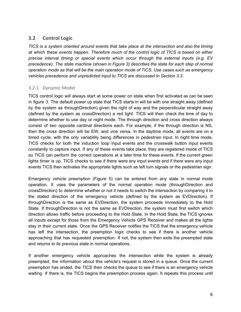
Traffic Intersection Control System Software Requirements Specification SRS Version 2.0
Team #1 February 29, 2020 CS 460 Software Engineering
0
Table of Contents 1 Introduction 2
2 General Description 2
2.1 Product Perspective 2
2.2 Product Functions 4
3 Specific Requirements 5
3.1 External Interfaces 5
3.1.1 Vehicle Interface - Induction Loop Sensor 6
3.1.2 Pedestrian Interface - Crosswalk Button 6
3.1.3 EV Interface - GPS system 6
3.1.4 Technician Interface - Controller Cabinet 7
3.1.5 Environmental Interfaces 7
3.2 Control Logic 8
3.2.1 Object Model 8
3.3 Use Cases 11
4 Design Constraints 15
4.1 Functional Constraints 15
4.2 Operational Constraints 15
5 Definition of Terms 16
6 References 18
1
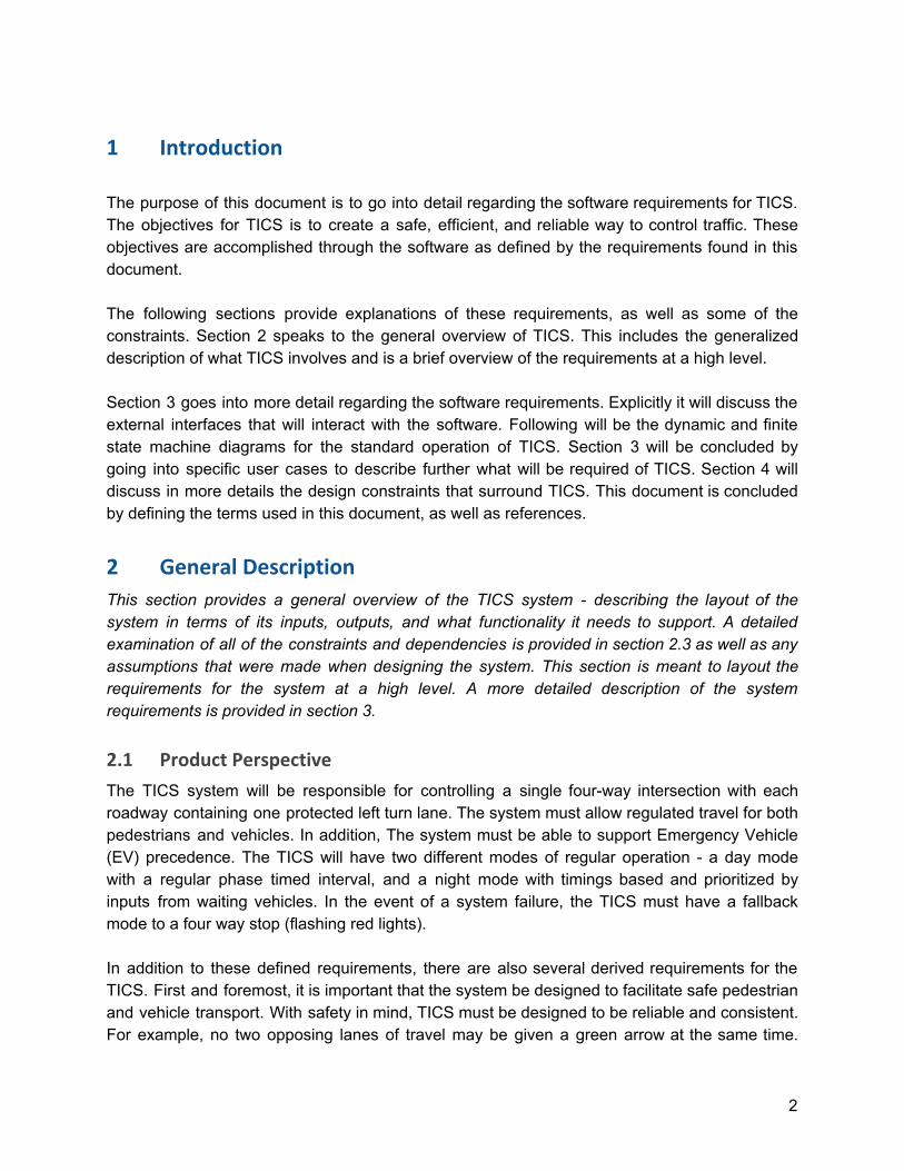
1 Introduction
The purpose of this document is to go into detail regarding the software requirements for TICS. The objectives for TICS is to create a safe, efficient, and reliable way to control traffic. These objectives are accomplished through the software as defined by the requirements found in this document. The following sections provide explanations of these requirements, as well as some of the constraints. Section 2 speaks to the general overview of TICS. This includes the generalized description of what TICS involves and is a brief overview of the requirements at a high level. Section 3 goes into more detail regarding the software requirements. Explicitly it will discuss the external interfaces that will interact with the software. Following will be the dynamic and finite state machine diagrams for the standard operation of TICS. Section 3 will be concluded by going into specific user cases to describe further what will be required of TICS. Section 4 will discuss in more details the design constraints that surround TICS. This document is concluded by defining the terms used in this document, as well as references.
2 General Description
This section provides a general overview of the TICS system - describing the layout of the system in terms of its inputs, outputs, and what functionality it needs to support. A detailed examination of all of the constraints and dependencies is provided in section 2.3 as well as any assumptions that were made when designing the system. This section is meant to layout the requirements for the system at a high level. A more detailed description of the system requirements is provided in section 3.
2.1 Product Perspective
The TICS system will be responsible for controlling a single four-way intersection with each roadway containing one protected left turn lane. The system must allow regulated travel for both pedestrians and vehicles. In addition, The system must be able to support Emergency Vehicle (EV) precedence. The TICS will have two different modes of regular operation - a day mode with a regular phase timed interval, and a night mode with timings based and prioritized by inputs from waiting vehicles. In the event of a system failure, the TICS must have a fallback mode to a four way stop (flashing red lights). In addition to these defined requirements, there are also several derived requirements for the TICS. First and foremost, it is important that the system be designed to facilitate safe pedestrian and vehicle transport. With safety in mind, TICS must be designed to be reliable and consistent. For example, no two opposing lanes of travel may be given a green arrow at the same time.
2
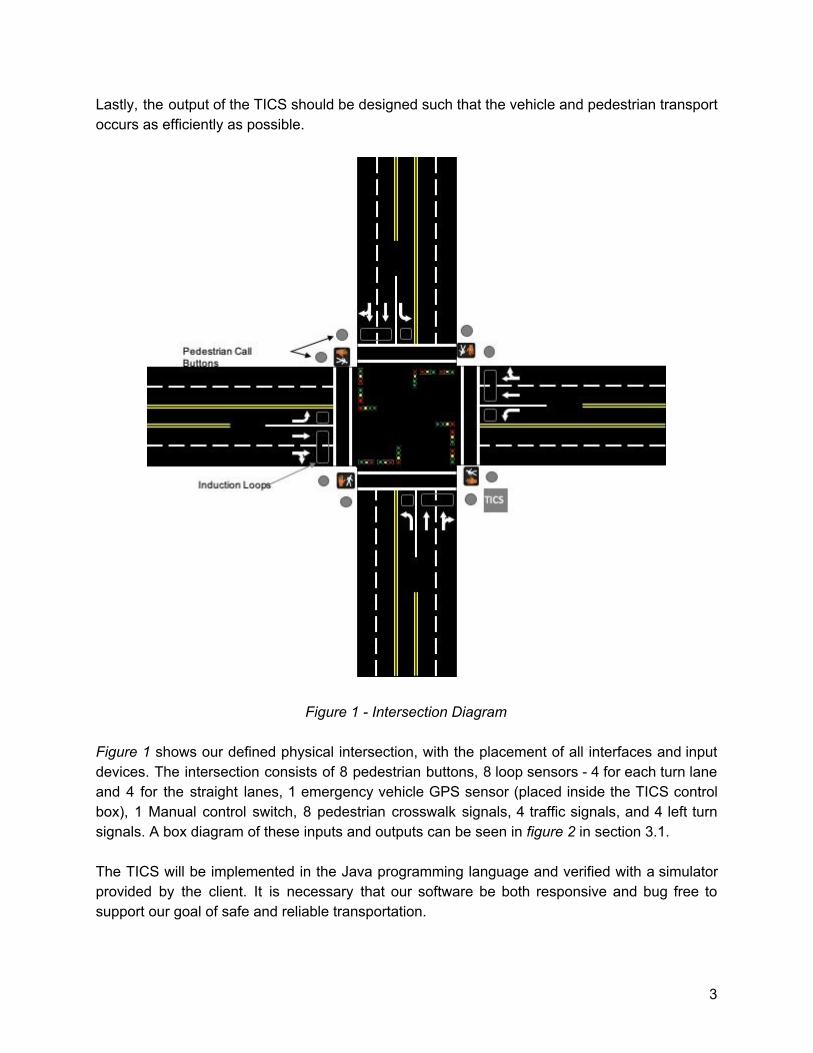
Lastly, the output of the TICS should be designed such that the vehicle and pedestrian transport occurs as efficiently as possible.
Figure 1 - Intersection Diagram Figure 1 shows our defined physical intersection, with the placement of all interfaces and input devices. The intersection consists of 8 pedestrian buttons, 8 loop sensors - 4 for each turn lane and 4 for the straight lanes, 1 emergency vehicle GPS sensor (placed inside the TICS control box), 1 Manual control switch, 8 pedestrian crosswalk signals, 4 traffic signals, and 4 left turn signals. A box diagram of these inputs and outputs can be seen in figure 2 in section 3.1. The TICS will be implemented in the Java programming language and verified with a simulator provided by the client. It is necessary that our software be both responsive and bug free to support our goal of safe and reliable transportation.
3
2.2 Product Functions
The primary function of the TICS system is to control the timing of lights and indicators in the Intersection. To fulfill this function, TICS must respond accordingly to inputs received from sensors around the intersection. These include 1 daylight sensor, 1 EV sensor, 8 Induction Loop sensors, and 8 pedestrian crosswalk buttons. It is the job of the TICS to take the inputs from these sensors and provide correct and safe outputs using a combination of pedestrian indicators, traffic lights, and left turn signals.
4
3 Specific Requirements
This section will provide a detailed review of the specific requirements; expanding on requirements mentioned in section 2 as well as exploring specific use cases and conditions in which the TICS must have special behavior. Section 3.1 will cover inputs to the TICS system in the form of external interfaces. Section 3.2 will provide state diagrams which give a high-level overview of the TICS behavior and logic. Section 3.3 will then provide specific examples in which these state diagrams are used.
3.1 External Interfaces
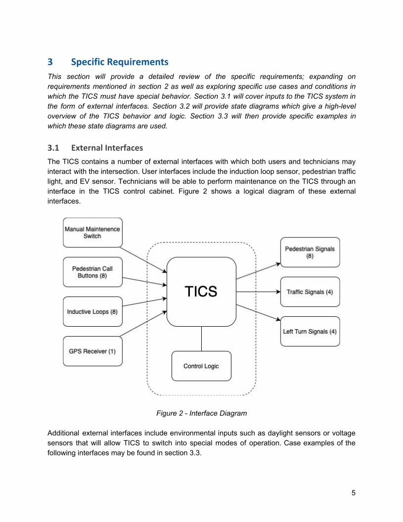
The TICS contains a number of external interfaces with which both users and technicians may interact with the intersection. User interfaces include the induction loop sensor, pedestrian traffic light, and EV sensor. Technicians will be able to perform maintenance on the TICS through an interface in the TICS control cabinet. Figure 2 shows a logical diagram of these external interfaces.
Figure 2 - Interface Diagram Additional external interfaces include environmental inputs such as daylight sensors or voltage sensors that will allow TICS to switch into special modes of operation. Case examples of the following interfaces may be found in section 3.3.
5
3.1.1 Vehicle Interface - Induction Loop Sensor
All vehicles traveling through the intersection will interact with TICS through an induction loop sensor. The intersection contains 8 induction loop sensors - 4 sensors for traffic lanes traveling straight forward and 4 for each left turn lane. These sensors are placed at the head of each lane and are only capable of detecting one vehicle per lane. When a vehicle is detected by the Induction Loop Sensor, a signal is sent to TICS indicating the presence of a vehicle at the specified lane of traffic. This signal is processed by TICS in the form of a signal change request. If the light for the given lane of traffic is already green, then the change request is discarded, otherwise TICS will process the change request in a manner indicated by figure 1 in section 3.2.1.
3.1.2 Pedestrian Interface - Crosswalk Button
Pedestrians can interface with the TICS through a crosswalk button. The intersection will contain 8 crosswalk buttons, 2 for each corresponding side of the crosswalk spanning each roadway in the intersection. Each pair of crosswalk buttons will largely be treated the same, as will the set of two pairs corresponding to the NS and EW crosswalks. When a crosswalk button is pressed, TICS will receive a crosswalk request signal containing the direction of the crosswalk. Similarly to the behavior described in section 3.1.1, if the crosswalk light is already on WALK then the signal is discarded and the state of the system remains the same. Otherwise, TICS will respond to the request by recording the crosswalk request. TICS will send the WALK output at the next available opportunity defined by the sequence of lights in the intersection (see figure 1 and figure 2 in section 3.2.1). A WALK indicator must not be given if an opposing lane of traffic is currently set to GREEN.
3.1.3 EV Interface - GPS system
Emergency Vehicles will be able to interface with the TICS through a GPS sensor. The GPS sensor will detect nearby emergency vehicles and process their presence in the form of a preemption request. Upon receiving a preemption request, TICS will respond in one of two ways. If the Emergency vehicle is traveling in a lane that is already green, TICS will maintain the green light (stopping any cycles) until the EV has passed through the intersection. If the EV is in a lane of traffic opposing the current green light, the preemption request will be processed by shortening the current green light cycle as much as possible within regulations defined by NMDOT. For a detailed diagram of control during EV preemption, see figure 3 in section 3.2.1.
6
3.1.4 Technician Interface - Controller Cabinet
During operation of the TICS, it may be necessary for maintenance to be performed by a traffic technician. The need for this might arise If TICS has detected an invalid state and reverts to backup mode or becomes non-operational. If this occurs, the TICS must be manually reset by the technician. Additionally, the timing and intervals, and thresholds for the TICS during day mode operation may need to be adjusted. The Traffic Controller Cabinet will include an interface (hardware provided by the client) through which the traffic technician can both reset the TICS to normal operating behavior, or change the interval timings for the light. The Controller Cabinet will also contain a control allowing the technician to set TICS into a backup mode turning it into a four-way stop. Although much of this interface lies in the hardware, the TICS must be able to respond to all of these inputs by either adjusting the interval timings, or processing a change mode or reset request. Changes to interval timing will be recorded and processed by the TICS after the next manual reset. TICS will process a change mode request at the next time that the sequence of traffic lights is in an all RED state. A reset request will be processed immediately if the TICS is in backup mode or non-operational and at the next available all RED state otherwise.
3.1.5 Environmental Interfaces
Although not a user in the conventional sense, the environment of the intersection must be considered to facilitate the safe operation of the TICS. Therefore there are several interfaces through which the environment may interface with the TICS such as daylight sensors and voltage sensors. Daylight sensors can interface with the TICS by sending information about the current light level. TICS will respond to this light information by comparing it against a daylight threshold (set by the technician). If TICS is in day mode and the light level is below the threshold TICS will switch to night mode at the next resting state (all RED) and vice versa. Voltage sensors will detect abnormalities in the operation of all of the inputs and outputs to the TICS. If an abnormality is detected, the voltage sensor will send a signal to TICS indicating both the severity and the relevant sensor. TICS will process this signal according to the severity of the abnormality. If the signal is in response to loss of operation of a traffic signal, TICS will immediately revert to a backup mode, transforming the intersection into a four-way stop. If voltage signal is in response to a secondary device such as a crosswalk button, EV sensor, or Induction Loop, the TICS may choose to either revert to backup mode or change to a default timing sequence depending on the behavior specified by settings in the traffic controller cabinet.
7
3.2 Control Logic
TICS is a system oriented around events that take place at the intersection and also the timing at which these events happen. Therefore much of the control logic of TICS is based on either precise interval timing or special events which occur through the external inputs (e.g. EV precedence). The state machine (shown in Figure 3) describes the state for each step of normal operation mode as that will be the main operation mode of TICS. Use cases such as emergency vehicles precedence and unpredicted input to TICS are discussed In Section 3.3.
3.2.1 Dynamic Model
TICS control logic will always start at some power on state when first activated as can be seen in figure 3. The default power up state that TICS starts in will be with one straight away (defined by the system as throughDirection) given the right of way and the perpendicular straight away (defined by the system as crossDirection) a red light. TICS will then check the time of day to determine whether to use day or night mode. The through direction and cross direction always consist of two opposite cardinal directions each. For example, if the through direction is NS, then the cross direction will be EW, and vice versa. In the daytime mode, all events are on a timed cycle, with the only variability being differences in pedestrian input. In night time mode, TICS checks for both the induction loop input events and the crosswalk button input events constantly to capture input. If any of these events take place, they are registered inside of TICS so TICS can perform the correct operations at a later time for these events. If the current green lights timer is up, TICS checks to see if there were any input events and if there were any input events TICS then activates the appropriate lights such as left turn signals or the pedestrian sign. Emergency vehicle preemption (Figure 5) can be entered from any state in normal mode operation. It uses the parameters of the normal operation mode (throughDirection and crossDirection) to determine whether or not it needs to switch the intersection by comparing it to the stated direction of the emergency vehicle (defined by the system as EVDirection). If throughDirection is the same as EVDirection, the system proceeds immediately to the Hold State. If throughDirection is not the same as EVDirection, the system must first switch which direction allows traffic before proceeding to the Hold State. In the Hold State, the TICS ignores all inputs except for those from the Emergency Vehicle GPS Receiver and makes all the lights stay in their current state. Once the GPS Receiver notifies the TICS that the emergency vehicle has left the intersection, the preemption logic checks to see if there is another vehicle approaching that has requested preemption. If not, the system then exits the preempted state and returns to its previous state in normal operations. If another emergency vehicle approaches the intersection while the system is already preempted, the information about this vehicle’s request is stored in a queue. Once the current preemption has ended, the TICS then checks the queue to see if there is an emergency vehicle waiting. If there is, the TICS begins the preemption process again. It repeats this process until
8
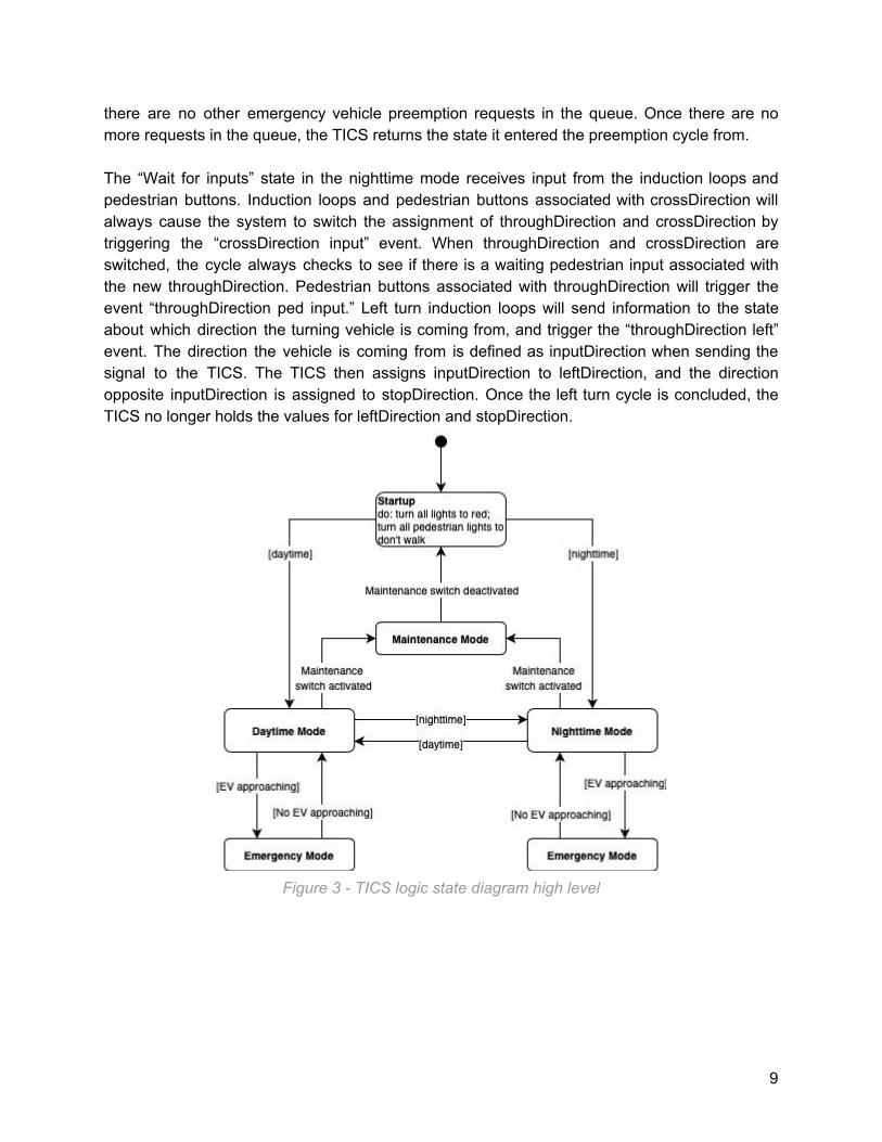
there are no other emergency vehicle preemption requests in the queue. Once there are no more requests in the queue, the TICS returns the state it entered the preemption cycle from. The “Wait for inputs” state in the nighttime mode receives input from the induction loops and pedestrian buttons. Induction loops and pedestrian buttons associated with crossDirection will always cause the system to switch the assignment of throughDirection and crossDirection by triggering the “crossDirection input” event. When throughDirection and crossDirection are switched, the cycle always checks to see if there is a waiting pedestrian input associated with the new throughDirection. Pedestrian buttons associated with throughDirection will trigger the event “throughDirection ped input.” Left turn induction loops will send information to the state about which direction the turning vehicle is coming from, and trigger the “throughDirection left” event. The direction the vehicle is coming from is defined as inputDirection when sending the signal to the TICS. The TICS then assigns inputDirection to leftDirection, and the direction opposite inputDirection is assigned to stopDirection. Once the left turn cycle is concluded, the TICS no longer holds the values for leftDirection and stopDirection.
Figure 3 - TICS logic state diagram high level
9
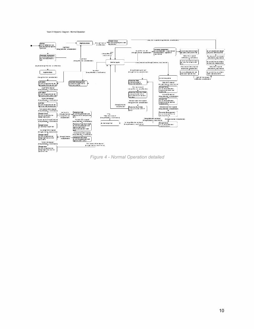
Figure 4 - Normal Operation detailed
10
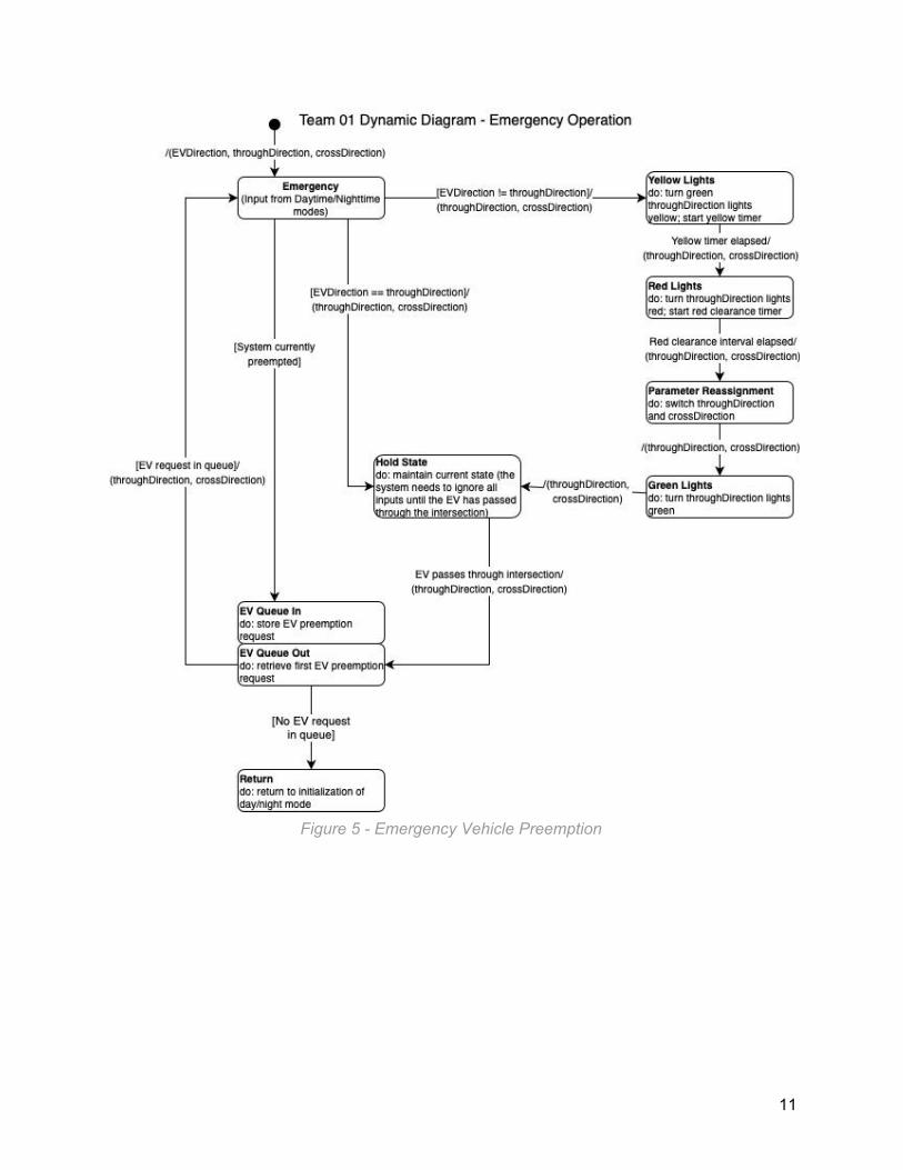
Figure 5 - Emergency Vehicle Preemption
11
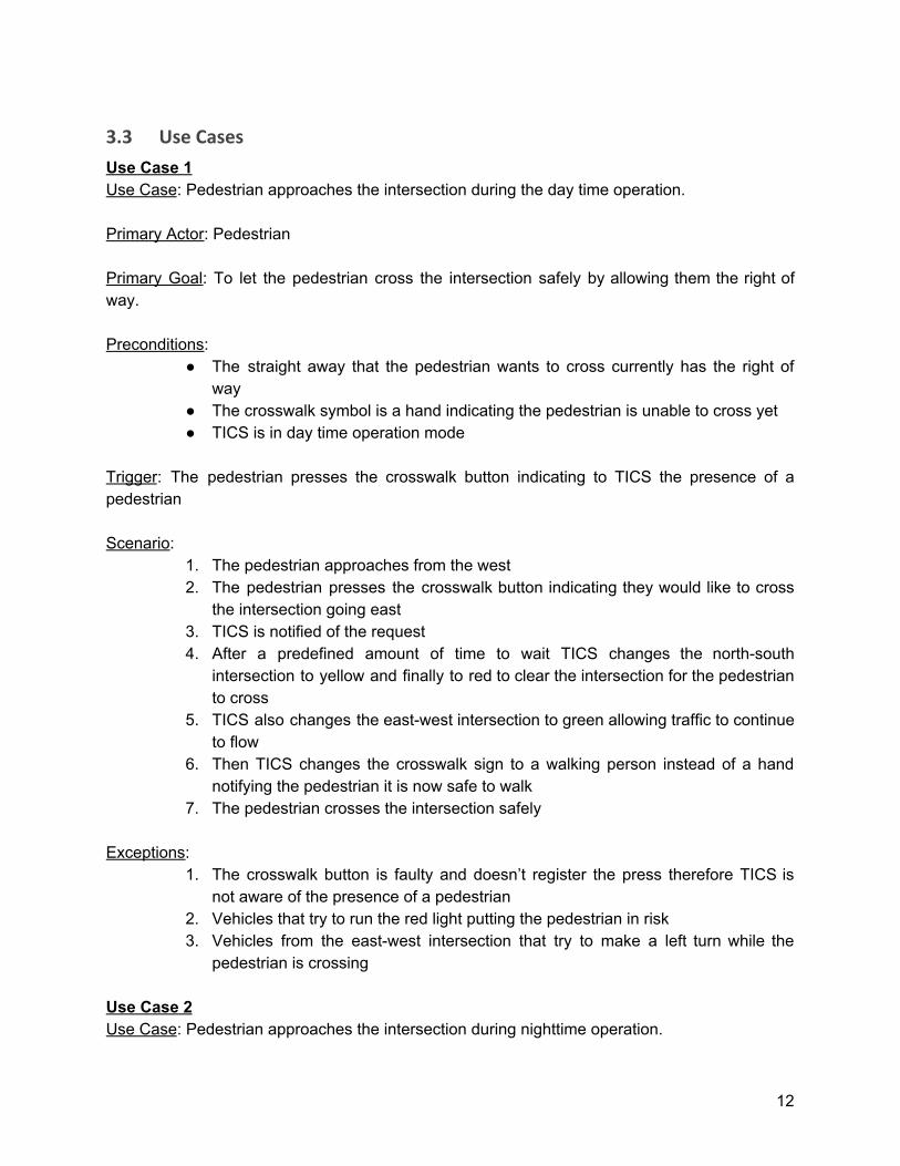
3.3 Use Cases
Use Case 1 Use Case: Pedestrian approaches the intersection during the day time operation. Primary Actor: Pedestrian Primary Goal: To let the pedestrian cross the intersection safely by allowing them the right of way. Preconditions:
● The straight away that the pedestrian wants to cross currently has the right of way
● The crosswalk symbol is a hand indicating the pedestrian is unable to cross yet ● TICS is in day time operation mode
Trigger: The pedestrian presses the crosswalk button indicating to TICS the presence of a pedestrian Scenario:
1. The pedestrian approaches from the west 2. The pedestrian presses the crosswalk button indicating they would like to cross
the intersection going east 3. TICS is notified of the request 4. After a predefined amount of time to wait TICS changes the north-south
intersection to yellow and finally to red to clear the intersection for the pedestrian to cross
5. TICS also changes the east-west intersection to green allowing traffic to continue to flow
6. Then TICS changes the crosswalk sign to a walking person instead of a hand notifying the pedestrian it is now safe to walk
7. The pedestrian crosses the intersection safely Exceptions:
1. The crosswalk button is faulty and doesn’t register the press therefore TICS is not aware of the presence of a pedestrian
2. Vehicles that try to run the red light putting the pedestrian in risk 3. Vehicles from the east-west intersection that try to make a left turn while the
pedestrian is crossing Use Case 2 Use Case: Pedestrian approaches the intersection during nighttime operation.
12
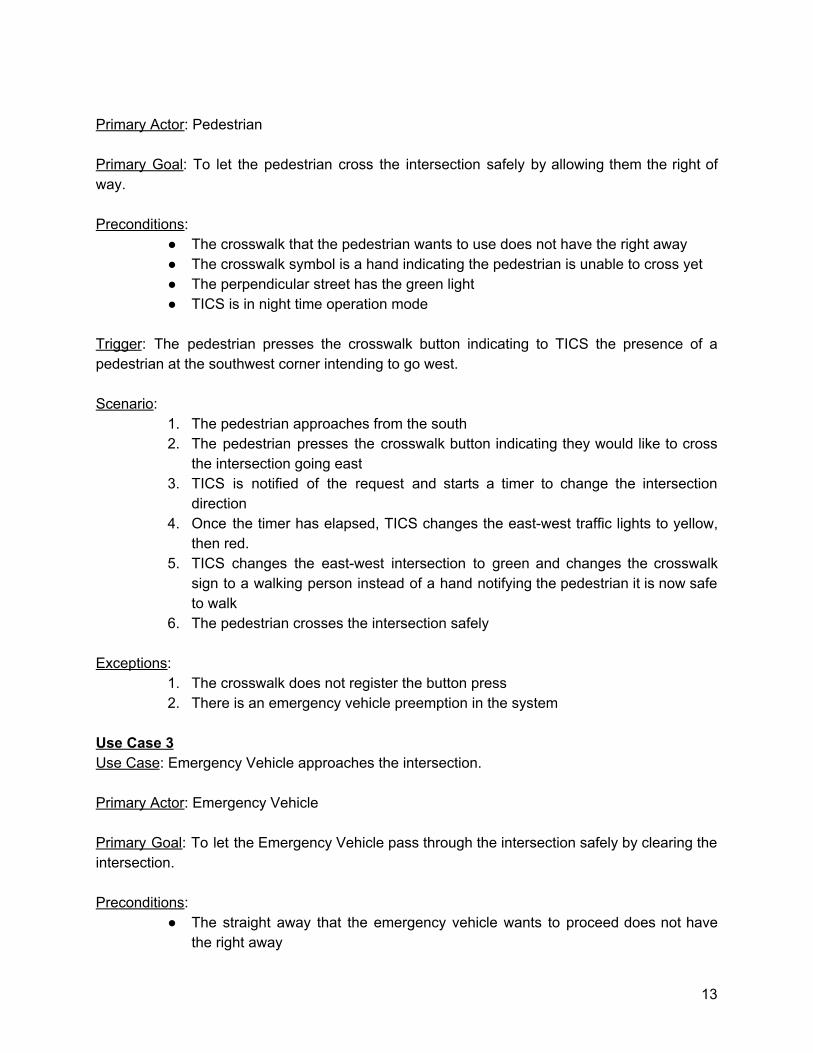
Primary Actor: Pedestrian Primary Goal: To let the pedestrian cross the intersection safely by allowing them the right of way. Preconditions:
● The crosswalk that the pedestrian wants to use does not have the right away ● The crosswalk symbol is a hand indicating the pedestrian is unable to cross yet ● The perpendicular street has the green light ● TICS is in night time operation mode
Trigger: The pedestrian presses the crosswalk button indicating to TICS the presence of a pedestrian at the southwest corner intending to go west. Scenario:
1. The pedestrian approaches from the south 2. The pedestrian presses the crosswalk button indicating they would like to cross
the intersection going east 3. TICS is notified of the request and starts a timer to change the intersection
direction 4. Once the timer has elapsed, TICS changes the east-west traffic lights to yellow,
then red. 5. TICS changes the east-west intersection to green and changes the crosswalk
sign to a walking person instead of a hand notifying the pedestrian it is now safe to walk
6. The pedestrian crosses the intersection safely Exceptions:
1. The crosswalk does not register the button press 2. There is an emergency vehicle preemption in the system
Use Case 3 Use Case: Emergency Vehicle approaches the intersection. Primary Actor: Emergency Vehicle Primary Goal: To let the Emergency Vehicle pass through the intersection safely by clearing the intersection. Preconditions:
● The straight away that the emergency vehicle wants to proceed does not have the right away
13
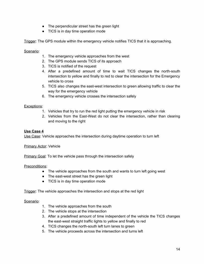
● The perpendicular street has the green light ● TICS is in day time operation mode
Trigger: The GPS module within the emergency vehicle notifies TICS that it is approaching. Scenario:
1. The emergency vehicle approaches from the west 2. The GPS module sends TICS of its approach 3. TICS is notified of the request 4. After a predefined amount of time to wait TICS changes the north-south
intersection to yellow and finally to red to clear the intersection for the Emergency vehicle to cross
5. TICS also changes the east-west intersection to green allowing traffic to clear the way for the emergency vehicle
6. The emergency vehicle crosses the intersection safely Exceptions:
1. Vehicles that try to run the red light putting the emergency vehicle in risk 2. Vehicles from the East-West do not clear the intersection, rather than clearing
and moving to the right Use Case 4 Use Case: Vehicle approaches the intersection during daytime operation to turn left Primary Actor: Vehicle Primary Goal: To let the vehicle pass through the intersection safely Preconditions:
● The vehicle approaches from the south and wants to turn left going west ● The east-west street has the green light ● TICS is in day time operation mode
Trigger: The vehicle approaches the intersection and stops at the red light Scenario:
1. The vehicle approaches from the south 2. The vehicle stops at the intersection 3. After a predefined amount of time independent of the vehicle the TICS changes
the east-west straight traffic lights to yellow and finally to red 4. TICS changes the north-south left turn lanes to green 5. The vehicle proceeds across the intersection and turns left
14
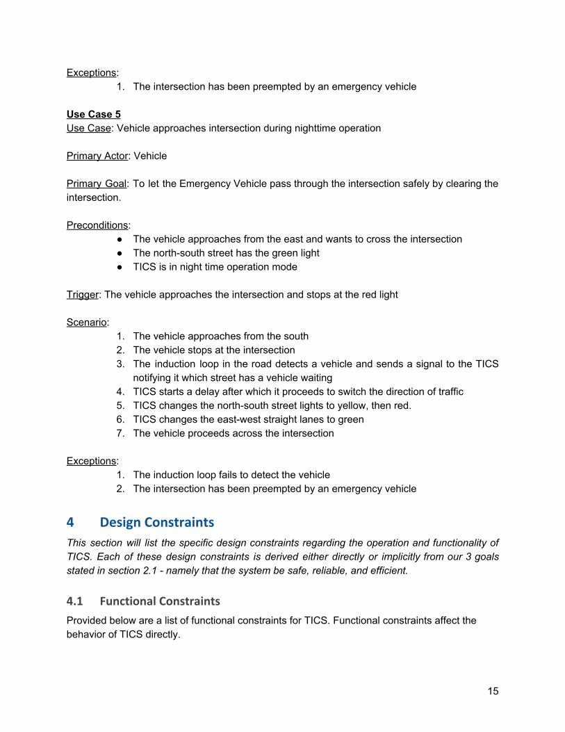
Exceptions: 1. The intersection has been preempted by an emergency vehicle
Use Case 5 Use Case: Vehicle approaches intersection during nighttime operation Primary Actor: Vehicle Primary Goal: To let the Emergency Vehicle pass through the intersection safely by clearing the intersection. Preconditions:
● The vehicle approaches from the east and wants to cross the intersection ● The north-south street has the green light ● TICS is in night time operation mode
Trigger: The vehicle approaches the intersection and stops at the red light Scenario:
1. The vehicle approaches from the south 2. The vehicle stops at the intersection 3. The induction loop in the road detects a vehicle and sends a signal to the TICS
notifying it which street has a vehicle waiting 4. TICS starts a delay after which it proceeds to switch the direction of traffic 5. TICS changes the north-south street lights to yellow, then red. 6. TICS changes the east-west straight lanes to green 7. The vehicle proceeds across the intersection
Exceptions:
1. The induction loop fails to detect the vehicle 2. The intersection has been preempted by an emergency vehicle
4 Design Constraints
This section will list the specific design constraints regarding the operation and functionality of TICS. Each of these design constraints is derived either directly or implicitly from our 3 goals stated in section 2.1 - namely that the system be safe, reliable, and efficient.
4.1 Functional Constraints
Provided below are a list of functional constraints for TICS. Functional constraints affect the behavior of TICS directly.
15
The functional constraints for the system are defined as follows: ● TICS will always start up in a ALL-RED state (all indicators on red) ● The end state of any cycle is an ALL-RED state ● Any transition between states or modes (e.g. Day Mode -> Night Mode) must be
preceded by an ALL-RED state. ● TICS will immediately switch to Emergency Mode following the detection of an invalid
state, hardware failure, or loss of power. ● TICS may not transition out of Emergency Mode until reset manually by a technician. ● TICS may not make any alterations to timings or settings performed by a technician until
after a full reset. ● TICS must allow transportation through the intersection of all lanes of traffic during a full
cycle (no lane may be omitted)
4.2 Operational Constraints
Operational constraints define limits on what actions TICS may perform given the current state and inputs. These constraints are designed to prevent accidents or collisions during operations. Some of the design constraints are
● A green signal must not be given to any lane of traffic if any opposing lane of traffic or crosswalk is already in a GREEN YELLOW or WALK state.
● Traffic lights may not change while an EV is crossing an intersection during EV precedence.
● At no point may a Green light be directly preceded with a Red light without the intervening Yellow light.
● TICS must not change interval timings mid-operation (at any point while running) ● TICS must use the specified interval timings during Day Mode operation ● Adjacent crosswalk indicators must always be turned on together (e.g north and south
facing indicators along the same crosswalk)
5 Definition of Terms
The following terms will be used throughout the document to describe different components of the TICS and are defined as follows:
● All-RED - A state in which all the traffic lights and indicators for the intersection are either RED, DONT-WALK, or off.
● Cross Direction - The cardinal directions perpendicular to the through direction.
● EV - Emergency Vehicle
16
● Interval - A discrete portion of the signal cycle during which the signal indications remain unchanged[1].
● Minimum Viable Product (MVP) - The absolute bare minimum requirements that must be satisfied in order to fulfill the goals of the project.
● Right of Way - The legal right presented to the vehicles or pedestrians to cross the intersection, determined by the given
● Road User - any vehicle or person that travels through the intersection including motor vehicles, transit riders, pedestrians, bicyclists, and other non-motorized modes of travel[1].
● Sensor - an electronic device for monitoring road users, vehicles, and the flow of traffic. May include audio detectors, cameras, and loop detectors.
● Signal - An electronic indicator that is electronically that communicates a prescribed action to road users[1].
● Straight Away - also known as throughDirection. The roads in which the drivers go straight without turning.
● Through Direction - The direction of the traffic currently allowed through the intersection with a green light. Always two opposing cardinal directions, i.e. NS.
● Through Traffic - Traffic from one roadway that is continuing on to the directly adjacent roadway (e.g. traffic from the north roadway traveling south)
● Traffic Intersection Control System (TICS) - The system in charge of the regulation and control of traffic intervals as well as other indicators and components of a Traffic Intersection.
● Traffic Signal - The complete integrated set of all electronic signals and indicators that operate in a traffic intersection regarding vehicles[1].
● Traffic Signal Controller - An electrical device controlling the sequence as well as the timings of the interval for indications displayed by traffic signals[1].
● Vehicle - any motorized transportation device that is used to facilitate the transportation of people or objects as defined by the US Department of Transportation[3].
17
6 References
[1] NMDOT. Traffic Signals 101. Retrieved February 8, 2020, from
http://www.dot.state.mn.us/trafficeng/publ/signals101/Traffic-Signals-101Manual-2020.pdf
[2] Abad-Mota, S. (2020, February 8). Project 1: Traffic Intersection Controller. Retrieved February 8, 2020, from https://www.cs.unm.edu/~bmatthews1/hosted/cs460/Project1-TICS-description.pdf
[3] Introduction To Vehicle Classification. (n.d.). Retrieved February 8, 2020, from https://www.fhwa.dot.gov/publications/research/infrastructure/pavements/ltpp/13091/002.cfm
[4] Team #1 TICS Technical Feasibility Study. Retrieved February 13, 2020, from https://www.cs.unm.edu/~bmatthews1/hosted/cs460/T01-TFS.pdf
18


