Embed Size (px)
Citation preview
TOPIC: -
FOLDING AND FAULTING
Dr. SATYAPRIYA MAHATO
PAPER NAME: - ADVANCED GEOMORPHOLOGY
SUBJECT: - GEOGRAPHY
SEMESTER: - B.A. HONS. –II
PAPER CODE: - (CCT-101)
UNIVERSITY DEPARTMENT OF GEOGRAPHY,
DR. SHYMA PRASAD MUKHERJEE UNIVERSITY, RANCHI.

Folding and Faulting
Introduction
In the past geologists used to think that fold mountains were formed due to shrinking of
earth’s material i.e., when molten crust solidified it created wrinkles in the form of fold mountain.
Now we know this is not the valid reason for the formation of fold mountains. Suppose initial
notion about the formation fold mountain had been a reality then, they would have been arranged
evenly over the surface of the earth. Therefore, question can be raised, why mountains are
confined to specific places on the earth?
If you observe the upper part of the crust closely you will notice that it is characterized by
complicated structures. This complication has been created by different types of stress resulting
into folding, faulting, volcanic activity, igneous intrusion and metamorphism.
1. Stress and Strain
The understanding of concept of stress and strain is mandatory to comprehend different types of
crustal deformations. For a layman stress may denote an activity related with pushing and
pulling. Similarly, strain is considered as deformation in form of bending, breaking, stretching. But
technically both terms have deeper meaning. Let us understand the meaning of stress and strain
in context to geomorphology.
We know that force is a clearly definable vector quantity that changes or tends to
produce a change in the motion of body (Billings, 2016). Since the force is defined by its
magnitude and direction (vector quantity) therefore it may be expressed by an arrow. In

structural geology a force applied to material that tends to change the material’s dimension is
called stress.
The Figure is showing that in mathematics the Stress is represented by the symbol σ
meaning sigma, which is defined as the force (F) per unit area (A), or σ = F/A. Therefore, we
can consider stress as the intensity of force, or a measure of how intense a force is. Effect of stress
on rocks or any other material is called strain. Therefore, the strain represents deformation
caused by stress. The deformation can be in form of dilation and distortion:
(i) Dilation: The figure is showing that the Strain resulted in form of change in volume is called
dilation.
(ii) Distortion: On the hand the figure is showing that the distortion denotes change in form or
volume or both.
There are three types of stress i.e., Tensional, Compressional, and Shear.

Tensional Stress: It is clear from the module number 10 on plate tectonics that along
the divergent plate boundary tensional stress is produced. It can be shown by following diagram.
The diagram showing that a rectangular rock body is said to be under tension when it is
subjected to external forces that tend to pull it apart. It is actually a stretching stress which has
potential to increase the volume of a material.
Compressional Stress: The Plate tectonic theory reveals that, convergent boundaries create
compressional stress. The figure shows that rectangular rock body is said to be under
compression when it is subjected to external forces that tend to compress it. Therefore,
compression tends to decrease the volume of the material but under certain condition or upto a
certain limit.
Shear stress: In case of transform plate boundaries shear stress is produced. The figures
are showing that shear stress produces change in shape of the rock material
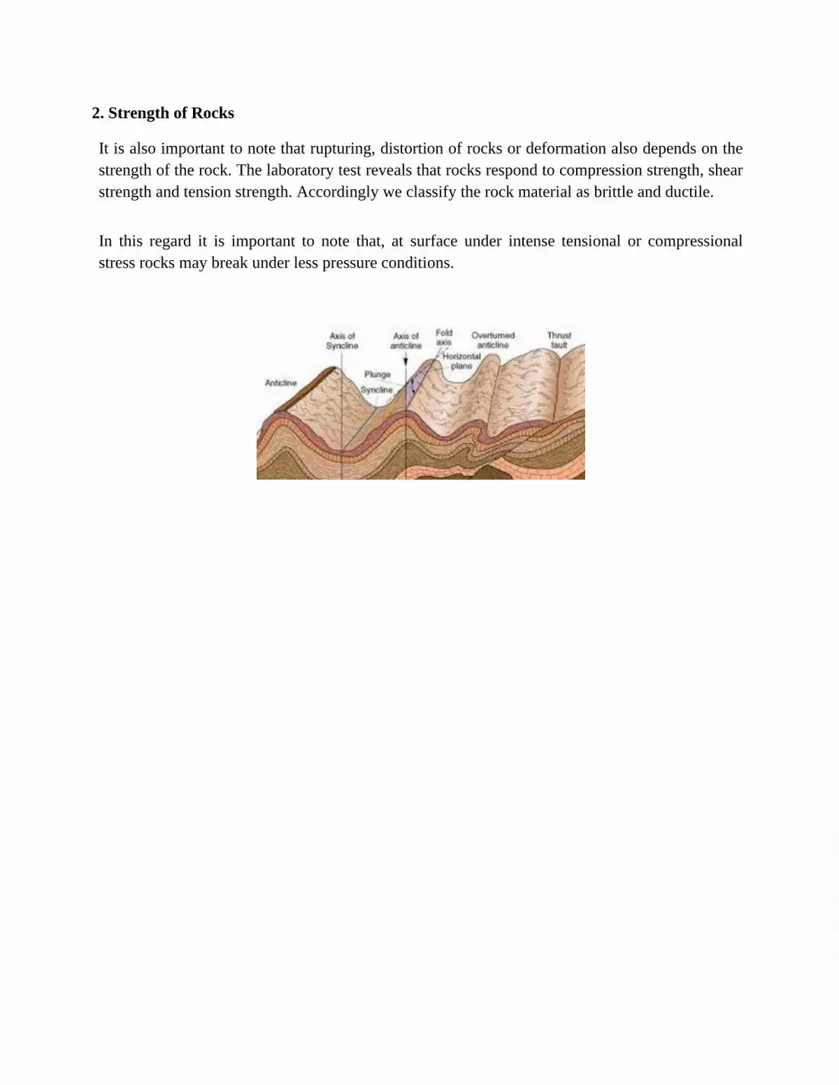
2. Strength of Rocks It is also important to note that rupturing, distortion of rocks or deformation also depends on the
strength of the rock. The laboratory test reveals that rocks respond to compression strength, shear
strength and tension strength. Accordingly we classify the rock material as brittle and ductile.
In this regard it is important to note that, at surface under intense tensional or compressional
stress rocks may break under less pressure conditions.

On the other hand the figure is exhibiting at depths under pressure and increasing temperature
rocks may take time to break. Therefore in real world pressure and temperatures are important
component of strength of the rocks.
3. Folds and Basic Fold Geometry
Folds are manifestation of compressional stress representing undulated rock deformation.
A fold can be considered as a structural feature that is formed when planar surfaces are bent or
curved and rocks are deformed. The term deformation refers to changes in shape, position, or
orientation of a body resulting from the application of a differential stress. In fold rocks are
deformed by compressional stress which forms wavy undulations on the surface of the earth. In
style and intensity they differ from place to place, and from rock to rock. For example, their size
may range from minute wrinkle in a small piece of metamorphic rock to huge fold mountains like
Himalayas. In terms of their inter-limb angle they may very gentle to very tight category. The
types of folding depend on the strength of the rock, magnitude and direction of stress
under the specific condition of pressure and temperature.
Generally folds are recognized by rock outcrop patterns, direct field observations, photo-
geological methods and by structural studies. Nowadays satellite imageries are gaining
importance to identify the fold patterns accorss the surface of the earth. For example above
satellite imagery (Google Earth) is showing the beautiful pattern of folds along the Fink River in
Australia.
Basic Fold Geometry
The basic fold geometry includes: Hinge, Limb, Hinge Line, Axial Plane, Interlimb Angle, and
Wavelength of the Fold, Crest, Trough and Fold Profile Plane.
(i). Hinge: It represents the zone of maximum curvature of the surface. The figure shows that
the hinge separates the two limbs.
(ii). Limb: It is the area between two hinges. A point in a limb where the sense of curvature
changes is recognized as inflection point. It is clear from the above diagram that in a fold there
are two limbs and one hinge.
(iii). Hinge Line: It is a line of intersection with a bedding plane. It denotes the line of
the greatest curvature in a folded surface. It is important to note from the figure (below) that hinge
line may be straight which is designated as ‘Straight Line Hinge’ or cylindrical fold. The
adjacent figure also exhibits that hinge line may be curved. In this case it is designated
as
‘Curved Line Hinge’ which recognizes non-cylindrical fold

iv) Axial Plane: The plane which bisects the angle between the two limbs is called an axial plane.
The yellow colour in above diagram is showing the axial plane. It should be noted that axial surface
does not necessarily divide the fold into equal halves.
(v) Interlimb Angle: The angle made by the limbs of the fold (profile plane) is designated as fold
angle or interlimb angle.
It is also important to note that the smaller the interlimb angle, the greater the intensity
of folding.
(vi) Wavelength: The distance between the two hinges or zone of maximum curvature is called
wavelength of the fold. From the diagram (below) it is clear that the amplitude of the fold is half
the height of the structure measured from crest to trough.
(vii) Crest and Trough: the uppermost and lowest points of a fold are called the crest
and trough, respectively.
(vii) Fold profile plane: It signifies the shape of the fold with reference to a plane
which is perpendicular to hinge line.
4. Classification of Folds
Fold can be classified into several ways. (A) Based on Interlimb angle: We already know that the angle made by the limbs of the fold is
designated as interlimb angle. The classification of folds on the basis of interlimb angle
signifies the tightness and openness of the fold. In this way geologists can also infer amount of
deformation through the present classification. In general we can identify four types of fold on the
basis of interlimb angle. They are as follows:
(i) Gentle Fold: In this case the interlimb angle remains between 120° to 180° (ii) Open Fold: In this case in general the interlimb angle ranges beteeen 60° to 120°
(iii) Tight Fold: in this case the interlimb angle ranges between 10° to 60°
(iv) Isoclinal fold: It denotes the special fold where the interlimb angle is nearly 0°
(B) On the Basis of Symmetry of the Fold:
(i) Symmetrical Fold: When the axial plane bisects the fold at a right angle or perfectly vertical
in an ideal situation then it is regarded as Symmetrical Fold.
(ii) Asymmetrical Fold: The diagram shows that the inclination or presence of dip in a fold
makes the fold asymmetrical.
(iii) Recumbent Fold: The diagram shows that when we find axial plane of the fold in a
horizontal position we classify that type of fold as ‘Recumbent Fold’. It is actually an
overturned fold. They are well exposed in the Alps (Billings, 2016). The figure shows that
naturally under the immense pressure of overlying rock in recumbent Fold the strata in
the inverted limb region are much thinner than the beds in the normal limb which is thicker than
the inverted limb. The sub-features of this fold are as follow
Arch-bend: The figure shows that the curved part of the recumbent fold between the normal and
inverted limb is known as arch-bend.
Shell and Core: The outer part of the fold is called shell and the inner part is recognized as core of
the recumbent fold. It is noteworthy that generally core is composed of crystalline rocks surrounded
by shell of sedimentary rocks.
Digitations: The figure shows that the fingers like subsidiary fold attached to the recumbent fold
are called digitations.
(iv) Isoclinal fold: We already know that isoclinal fold denotes a fold where the interlimb angle is
nearly 0°. Isoclinal is a Greek word which means “equally inclined”. The figure shows that in this
fold two limbs dip at equal angles and in the same direction. It should be noted that many
recumbent folds are also considered as isoclinal.
(v) Overturned Fold: In this fold the axial plane is inclined and limbs of the fold dip in the same
direction but at different angle.
(C) On the Basis of Appearance in Cross Section:
(i) Anticline: The figure shows that convex shaped upfolded rock beds are designated as
anticlines i.e., a type of fold which is convex upward. The figure also exhibits that they may be
symmetrical and asymmetrical in nature. Accordingly they are also named as symmetrical
anticline and asymmetrical anticline. Likewise on the basis of interlimb angle they may be
in form of gentle anticline and steep anticline.
(ii) Syncline: The digram shows that it is a fold which is concave upward and generally dips
towards the axial plane.
(iii) Anticlinorium: It is a large anticline containing subsidiary folds of smaller size. In

Scotland mountainous area one can find example of this category of fold.
(iv) Synclinorium: It denotes a large syncline containing subsidiary folds of smaller size. They
are found in the central part of Aravali Ranges.
(v) Geosyncline: it means “earth syncline” but the note of caution is that, this term should not be
used for large synclines. Geosyncline is considered as huge elongated basin containing huge
stock of sediments.
(D) Special Types of Folds
(i) Chevron: The digram shows that they are angular folds in which hinges are very sharp. They
are also known as zig zag.
(ii) Box Fold: The picture shows that it is a type of fold in which the crest is broad and flat. They
are also known as Coffer Fold.
(iii) Fanfold: When the upper shell of the Anticlinorium is eroded due to exogenic forces the
remnant outer shell is regarded as fanfold. They are found in Chota Nagpur Plateau region of our
country.
(iv) Kink Bands: they are the narrow bands of beds ranging from few inches to a few feet wide.
The beds acquire a dip which is either steeper or gentler than the adjacent bed.
Similarly there are many other types of folds such as: Drag fold, monocline, Homocline,
Diapir Folds, Plunging Fold and Dome.
5. Fault and Basic Geometry
Faults reflect ruptures or crakes in the earth along which one side is relatively displaced
with reference to the other side. Sometimes they are also known as disjunctive dislocation. In size
and total displacement they may range from a few inches to hundreds of kilometers long.
Above picture shows that since are formed due to great stresses therefore they reflects
brittle deformation. The brittle deformation results in fracturing and faulting. You can
also notice brittle deformation if you drop a glass (but by mistake!) on a hard floor you will notice
that it breaks into several pieces. Similarity crakes in building formed due to earthquake,
gravitational effect, subsidence also denotes brittle deformation. Geomorphologists and
geologists recognize the fault by indentifying omission of strata, dislocation of structure or the
discontinuity, geometry of fault plane, sudden changes in topography.
Basic Fault Geometry
Wall: Rock adjacent to a fault surface is the wall of the fault Fault block: the body of rock that moved as a consequence of slip on the fault is a fault block
Hanging-Wall Block: It is a fault block or rock body above the fault plane. Foot-Wall Block: The fault block below the fault plane is recognized as foot-wall block.
Strike: It denotes the trend of horizontal line in the plane of the fault.
Dip: generally we recognize fault as steep or vertical to tell about image of a fault, which in turn
reflects the dip of the fault. The dip represents the angle between a horizontal surface and fault
plane. It makes right angle to the strike of the fault.
Hade: is the complement angle of the dip i.e., Hade = 90° - Dip Throw: Normally under the gravitational pull during the faulting vertical displacement of rock
occurs. The figure (below) shows that this vertical displacement is recognized as Throw.
In nutshell it denotes the vertical component of dip separation.
Heave: The above figure shows that apparent horizontal displacement of fault block is known as
heave. It denotes the horizontal component of dip separation
6. Classification of Faults
Like folds faults can also be classified into several ways. (A) Classification on the Basis of Apparent Movement
There are three types i.e., Normal Fault, Thrust or Reverse Fault and Strike Slip Fault.
1. Normal Fault: The normal fault is also known as gravity fault, tensional fault or extensional
fault. They occur when the vertical stress is greater than the horizontal stress. The picture shows
that in normal fault primarily displacement or movement is vertical. In this case the downthrown
block is the hanging-wall block which is influenced by the gravity that is why normal fault is also
recognized as gravity or tensional fault. On a global level normal fault system leads to
lengthening the earth’s crust. This process occurs along the rift valleys and either side of mid-
ocean ridges. Normal faults are also visible along the edge of mountain ranges in California. The
cliff formed by faulting is commonly called a fault scarp, or escarpment. Process of Normal
Faulting can give rise to following geomorphic features:
(i) Horst: An upstanding fault block bounded by two normal faults is regarded as horst.
The figure (below) shows that in appearance it looks like block plateau or mountain generally flat
on top but with steep sides. Horst may be formed by upliftment of block between two normal faults
or may be left upstanding due to subsidence of either sides of the middle block. The Shillong
Plateau is an example of horst. (ii) Graben: Graben is from the German word for “trough”. The
figure shows that graben is a valley like depression or trough representing a sloped fault block
bounded by normal faults. It is like a trench with straight parallel walls created by tensional
force on the contrary the horst represents a narrow elevated block between two normal faults.
(iii) Half Graben: The figure (below) shows that in the Half Graben the upper part of
the hanging-wall block is tilted towards the fault due to rotation of displaced block along the normal
fault line. This type of displaced rotational movement creates half graben depression. Half
graben are common in the Basin and Range Province of the Western United States.
(iv) Fault Scarp: From the figure it is apparent that the steep straight cliff-like topography
created along the normal fault plane is called fault scarps. In length they may go up to
300 kilometers. The height of fault scarp may range between a few meters to a few hundred meters.
(iv) Block Mountain: The long and ridge like horst is called block mountain.. Vosges
Black
Forest in Germany is also well known example of Block Mountain. (v) Rift Valley: A long narrow fault trough created along the divergent plate boundary (due to
tectonic activity) is called rift valley. The East African Rift Valley is the well know example of
rifting. The map shows the areal extent of East African Rift Valley along the divergent plate
boundary. This belt extends from Ethiopia to Tanzania. This rift valley is also the sites of
volcanic activity. The volcano Kilimanjaro in Tanzania is a well known example of this belt. As
rift valleys open, water flows into the new lowlands. The Red Sea and the Gulf of California are
examples of this process they are actually confined in larger rift valleys.
Similarly the rifting due to tensional stress can also occur at local level. For example Narmada
and Tapti river India flow throw rift valleys.
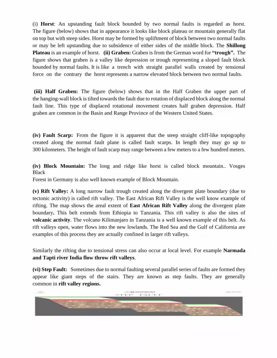
(vi) Step Fault: Sometimes due to normal faulting several parallel series of faults are formed they
appear like giant steps of the stairs. They are known as step faults. They are generally
common in rift valley regions.

2. Thrust or Reverse Fault
Unlike normal fault the thrust faults are created by compressional stress. From the figure
(Below) it is apparent that, they are formed when hanging wall block has overridden the
footwall block generally at a very shallow angle. That is why they are also known as
“contractional faults”. It should be noted that in the thrust fault maximum stress is horizontal
and minimum stress is vertical which leads to shortening of the earth crust. There is a minor
difference between thrust and reverse fault. In former the dip angle is less than 45° and in later it
is more than 45°. The subduction zones along the convergent plate boundaries are characterized
by thrust fault. In such tectonic settings, thrusting occurs in combination with formation of folds.
In the Alps and Himalayas , several such over thrusts result from compressional stresses of the
ongoing collision between different plates. For detail kindly refer module number 10 on Plate
Tectonics.
(i) Ramp Valley: A valley like depression formed by commprssional stress may create ramp
valley. The figure shows that in this category of thrust fault the two hanging blocks move
upward side and one foot wall block appears to remain stationary. The Brahmaputra valley
between Himalaya and Shillong Plateau is an example of ramp valley.
3. Strike Slip Fault: As the name suggests in this category of fault the relative displacement of
fault blocks remains mainly parallel to the strike of the fault. They are formed when rocks are
torn by lateral-shearing stress. On the basis standing position of the observer they are divided into
two categories which are as follows:
(i) Right Lateral Strike Slip Fault: From the above diagram it is clear that in this type of fault
the displacement appears to the right side of the observer.
(ii) Left lateral Strike Slip Fault: If a person is standing at the fault and looks across to see that a
block or a portion of land has been displaced to the left hand direction, it is designated as a left-
lateral strike-slip fault.
(iii) Transform Fault:
Transform faults are associated with plate tectonics. The Transform Fault represents plate
boundary at which lithosphere is neither created nor destroyed. Therefore, they are devoid of
stunning landform features in comparison to convergent and divergent boundaries. San Adreas
fault in California is best known example of this category. One can also identify the trace of the
transform fault through offset roads, fences. It is also noteworthy that any relative sudden
displacement of rocks along the transform fault may cause immense loss of life property. For
detail kindly refer module number 12 on Earthquakes and module number 10 on Plate
Tectonics.
7. Folding-Faulting and the Society
The study of folding and faulting is useful for academic purpose to create awareness about
associated hazards and benefits of folding and faulting. It is equally useful for exploration
geologists to explore natural gas, oil in anticlinal areas and to discover occurrence minerals along

the fault line. The construction of mega-structures such as dams, skyscrapers, nuclear power
plants and town planning requires deeper understanding of the fold and fault settings.


