Embed Size (px)
Citation preview

THIS RECORD WAS DISTRIBUTED ON 09/30/04 - DOCUMENT CONTROLRECEIVED IT ON 10/21/04 FOR RELEASE - THE DOCUMENT OWNER DID NOTWANT TO GO TO THE EXPENSE OF MODIFYING THE EFFECTIVE DATE ANDHAVING FORM 431.02 COMPLETED BY DOCUMENT CONTROL, THEREFORE,THE NATIVE FILE AND RECORD COPY HAVE BEEN LOADED TO EDMS ASTHEY WERE DISTRIBUTED.
Document ID:EDF-5153Revision ID:O
Effective Date:09/30/04
Engineering Design File
PROJECT NO. 23833
OU 7-13/14 In Situ Grouting ProjectHydraulic Excavator and Drill-Injection Rig
‘'rkftvi EEIdaho National Engineednoaiid Environmental Laboratory
Form 412.1410/9/2003Rev. 05
Engineering DesignFile(form 431.02, Rev. 11)
EDF No.: 5153
OU 7-13/14 In Situ Grouting Project Identifier: EDF-5153Revision: 0Hydraulic Excavator and Drill-Injection Rig Page 1 of 123
EDF Rev. No.: 0 Project File No.: 23833
1. Title: OU 7-13/14 In Situ Grouting Project Hydraulic Excavator and Drill-Injection Rig2. Index Codes:
WMF-700 Radioactive WasteBuilding/Type Subsurface Disposal Area SSC ID N/A Site Area Management Complex
3. NPH Performance Category: or N/A
4.Consumer
EDF Safety Category: or N/A SCC Safety Category: Grade or Q N/A
5. Purpose: This engineering design file (EDF) provides conceptual design information for the hydraulicexcavator and drilling/grout injection rig for in situ grouting (ISG) of select areas of the Subsurface DisposalArea (SDA) at the Idaho National Engineering and Environmental Laboratory's Radioactive WasteManagement Complex for the Operable Unit 7-13/14 Phase 2 ISG Project.
Scope: This EDF prepares alternative conceptual designs for a grout injection drill rig and hydraulicexcavator for Phase II ISG of selected areas of the SDA, and selects a baseline conceptual alternative forpurposes of enabling follow-on preparation by others of the following:• A conceptual design cost estimate for project documentation• A hazards analysis for project documentation• An environmental assessment for project documentation• A procurement Performance Statement of Work for inclusion in a future performance-based Request
for Proposal.
Conclusions: The approach for injection grouting of contaminant waste zones for the formation of monolithicgrouted masses using a roto-percussion, rotary sonic drill, or rotary drill with fluted bit and injection groutingrig attached to a sufficiently large hydraulic excavator, as depicted in Alternative 1, is considered a validapproach and commercially practicable. Standards development for hydraulic excavators is mature andcovered under earth moving equipment of the International Standards Organization. The jet grouting industryis considered mature, however, standards and regulatory environment development for jet grouting equipmentis immature and follows the lead of the European standards development community. Vendor knowledge,trade secrets, and expert consultant help appear to be used to a great extent. Potential future procurements forjet grouting equipment should recognize the immature status of the standards and regulatory environment ofthe jet grouting industry and address relevant issues in the procurement.Alternative 2 is also considered technically and commercially practical and may provide benefits of increasedproduction because of reduced number of repetitive operational steps, and reduction in potential ofcontamination spread because of fewer components at the drill pipe soil interface. However, use ofAlternative 2 methods for injection grouting operations would be considered newer technology with a reducedexperience base. This may require some development effort.Alternative 3's use of equipment similar to Phase 1 equipment and methods is considered technically feasibleand may be cost effective for Fiscal Year 2005.
Recommendations: This conceptual design effort recommends that the approach for single fluid injectiongrouting of contaminant waste zones for the formation of monolithic grouted masses, as well as foundationgrouting using a roto-percussion, rotary sonic drill, or rotary drill with fluted bit and injection grouting rigattached to a sufficiently large hydraulic excavator, is a valid approach and commercially practicable.Alternative 1, using the drill rig attached to a linear mast, is the recommended approach and should providesufficient similarities to commercial practices for competitive bidding.This conceptual design recommends the allowance for use of used equipment based on vendor desires. Thisallowance should provide some means for potential bidders to reduce their project risk.This EDF also recommends further study of Alternative 2 of using a mastless drill head and active hydraulicsensing and controls, provided funding is available. This alternative may minimize the complexity ofoperations and minimize the number of personnel required to meet the production schedule.
Engineering DesignFile(form 431.02, Rev. 11)
EDF No.: 5153
OU 7-13114 In Situ Grouting Project Identifier: EDF-5153Revision: 0
Hydraulic Excavator and Drill-Injection Rig Page 2 of 123
EDF Rev. No.: 0 Project File No.: 23833
1. Title: OU 7-13/14 In Situ Grouting Project Hydraulic Excavator and Drill-Injection Rig
2. Index Codes:
Building/TypeWMF-700 Radioactive WasteSubsurface Disposal Area SSC ID N/A Site Area Management Complex
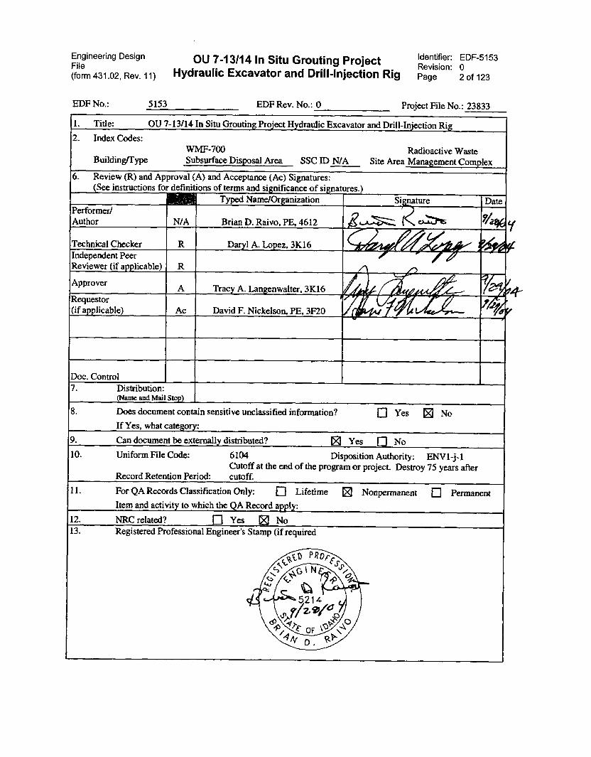
6. Review (R) and Approval (A) and Acceptance (Ac) Signatures:(See instructions for definitions of terms and significance of signatures.)
Typed NamelOrganization Sigture DatePerformer/Author N/A Brian D. Raivo, PE, 4612 ig,..k. K.,-.-ts ..,/a1,6„Technical Checker R Daryl A. Lopez, 3K16 727,14 (100 : 4Independent PeerReviewer (if applicable) R _
AApprover
A Tracy A. Langenwalter, 3K16// , f4 /
'ft'1/1,.•
Requestor(if applicable) Ac David F. Nickelson, PE, 3F20 ti t"
74;4
Doc. Control7. Distribution:
(Name and Mail Stop)
8. Does document contain sensitive unclassified information?
If Yes, what category:
❑ Yes 0 No
9. Can document be externally distributed? S Yes ❑ No
10. Uniform File Code: 6104 DispositionCutoff at the end of the program
Record Retention Period: cutoff.or
Authority: ENV1-j-1project. Destroy 75 years after
11. For QA Records Classification Only: ❑ Lifetime
Item and activity to which the QA Record apply:
Nonpermanent ❑ Permanent)2
12. NRC related? ❑ Yes IE No13. Registered Professional Engineer's Stamp
ir .
(if required
'42
°
t PRoFEss-\c.- c 0 N
\ . N.\(,,, 43
4.8
I 01
5214
4,tt, eViVao<0 l'.
t oF 1.0' ,,4 . RV's
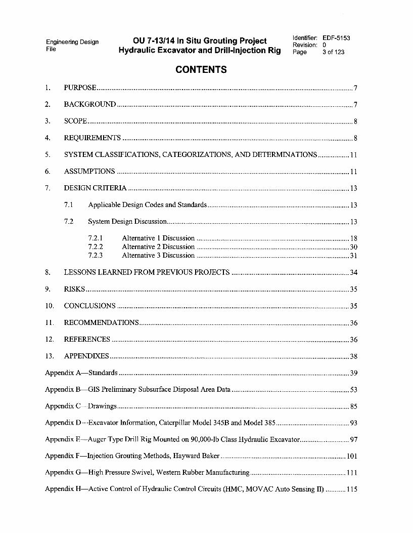
Engineering Design OU 7-13/14 In Situ Grouting Project Identifier: EDF-5153Revision: 0
File Hydraulic Excavator and Drill-Injection Rig Page 3 of 123
CONTENTS
1. PURPOSE 7
2. BACKGROUND 7
3. SCOPE 8
4. REQUIREMENTS 8
5. SYSTEM CLASSIFICATIONS, CATEGORIZATIONS, AND DETERMINATIONS 11
6. ASSUMPTIONS 11
7. DESIGN CRITERIA 13
7.1 Applicable Design Codes and Standards 13
7.2 System Design Discussion 13
7.2.1 Alternative 1 Discussion 187.2.2 Alternative 2 Discussion 307.2.3 Alternative 3 Discussion 31
8. LESSONS LEARNED FROM PREVIOUS PROJECTS 34
9. RISKS 35
10. CONCLUSIONS 35
11. RECOMMENDATIONS 36
12. REFERENCES 36
13. APPENDIXES 38
Appendix A—Standards 39
Appendix B—GIS Preliminary Subsurface Disposal Area Data 53
Appendix C—Drawings 85
Appendix D—Excavator Information, Caterpillar Model 345B and Model 385 93
Appendix E—Auger Type Drill Rig Mounted on 90,000-lb Class Hydraulic Excavator 97
Appendix F—Injection Grouting Methods, Hayward Baker 101
Appendix G—High Pressure Swivel, Western Rubber Manufacturing 111
Appendix H—Active Control of Hydraulic Control Circuits (HMC, MOVAC Auto Sensing II) 115

Engineering Design OU 7-13/14 ln Situ Grouting ProjectFile Hydraulic Excavator and Drill-lnjection Rig
This page is intentionally left blank.
Identifier: EDF-5153Revision: 0Page 4 of 123
Engineering Design OU 7-13/14 In Situ Grouting ProjectFile Hydraulic Excavator and Drill-Injection Rig
ACRONYMS
API American Petroleum Institute
EDF engineering design file
FY fiscal year
GIS geographical information system
INEEL Idaho National Engineering and Environmental Laboratory
ISG in situ grouting
ISO International Standards Organization
MCP management control procedure
OSHA Occupational Safety and Health Act
RWMC Radioactive Waste Management Complex
SDA subsurface disposal area
TFR technical and functional requirement
Identifier: EDF-5153Revision: 0Page 5 of 123

Engineering Design OU 7-13/14 In Situ Grouting ProjectFile Hydraulic Excavator and Drill-Injection Rig
This page is intentionally left blank.
Identifier: EDF-5153Revision: 0Page 6 of 123
Engineering Design OU 7-13/14 In Situ Grouting ProjectFile Hydraulic Excavator and Drill-Injection Rig
Identifier: EDF-5153Revision: 0Page 7 of 123
OU 7-13/14 In Situ Grouting ProjectHydraulic Excavator and Drill-Injection Rig
1. PURPOSE
This engineering and design file (EDF) provides conceptual design information for the hydraulicexcavator and drilling/grout injection rig for in situ grouting (ISG) of select areas of the SubsurfaceDisposal Area (SDA) at the Idaho National Engineering and Environmental Laboratory's (INEEL's)Radioactive Waste Management Complex (RWMC) for the Operable Unit 7-13/14 Phase 2 ISG Project.
2. BACKGROUND
The INEEL is a U.S. Department of Energy National Laboratory located approximately 50 milesfrom Idaho Falls, Idaho. Several discrete disposal locations in soil vault rows, pits, and trenches in theSDA will be remediated by single fluid nondisplacement ISG over a span of several years. Chemicallyand radiologically contaminated soil and debris may be encountered during remedial action activities. TheSDA consists of an approximate 97-acre fenced area containing 20 pits, 58 trenches, and 21 soil vaultrows. The depth of the area from surface to bedrock varies from approximately 15 to 30 ft. Verticalsections of the area contain waste zones consisting of underburden soil, waste burial zones, andoverburden soil, as well as native soil in between the disposal areas.
The current envisioned project is to inject cementitious grout into the subsurface to approximatemaximum depths of 25 ft, forming monolithic columnar blocks or spaced vertical support columns. Pitsand trenches were typically constmcted originally by excavating undisturbed earth to bedrock (15- to25-ft depth) and backfilling the excavation with several feet of clean fill in order to create a disposalvolume. This volume would then be filled with various types of wastes. Typical wastes would includedrummed wastes (55-gal), large wooden boxed waste, and construction and demolition wastes. Othernontypical wastes may also be contained within some waste volumes. After the disposal volumes werefilled, an additional layer of clean fill would be added to close the volume, and some additional soil coverhas been added since the initial closure to fill subsidence areas and provide drainage contouring. Soilvaults are unlined and were normally constmcted using 6-ft augurs. Waste was placed in the vaults, whichwere then closed with a soil cover.
Low-level waste pits and trenches within the SDA at RWMC will be grouted to form a monolithtotally encapsulating the waste. Transuranic pits and selected trench areas will be grouted with a widerspacing of columns sufficient to support a future cap.
The low-level waste under consideration lies beneath an area of about 11.1 acres and occupies avolume of about 1,320,000 ft3. The transuranic pits and trenches are spread over an area of 15.4 acres andoccupy a volume of about 2,330,000 ft3.
Engineering Design OU 7-13/14 In Situ Grouting ProjectFile Hydraulic Excavator and Drill-Injection Rig
3. SCOPE
Identifier: EDF-5153Revision: 0Page 8 of 123
This EDF prepares alternative conceptual designs for a grout injection drill rig and hydraulicexcavator for Phase II ISG of selected areas of the SDA, and selects a baseline conceptual alternative forpurposes of enabling follow-on preparation by others of the following:
• A conceptual design cost estimate for project documentation
• A hazards analysis for project documentation
• An environmental assessment for project documentation
• A procurement Performance Statement of Work for inclusion in a future performance-basedRequest for Proposal.
4. REQUIREMENTS
Requirements for the Phase 2 excavator drill unit are identified by two types of bases. Theseinclude technical and functional requirements (TFRs) as described in TFR-267, "Requirements for theOU 7-13/14 In Situ Grouting Project (Customer, Project, and System)," and additional design criteria asidentified in this EDF.
Technical and functional requirements are developed for a project before the conceptual designprocess by project staff and approved by the project engineer. TFR-267 was developed as high-levelrequirements for ISG. During the conceptual design process, the TFR requirements are reviewed andinvestigated by the conceptual design engineers. The conceptual design approach is then developed fromthe investigation and analysis of these customer requirements and the conceptual design is then created.The engineer then develops and specifies design criteria unique to the individual subsystems forsubsequent detailed design.
Table 1 identifies applicable requirement as defined in TFR-267. Additional design features arelisted as salient features under the system design discussion.
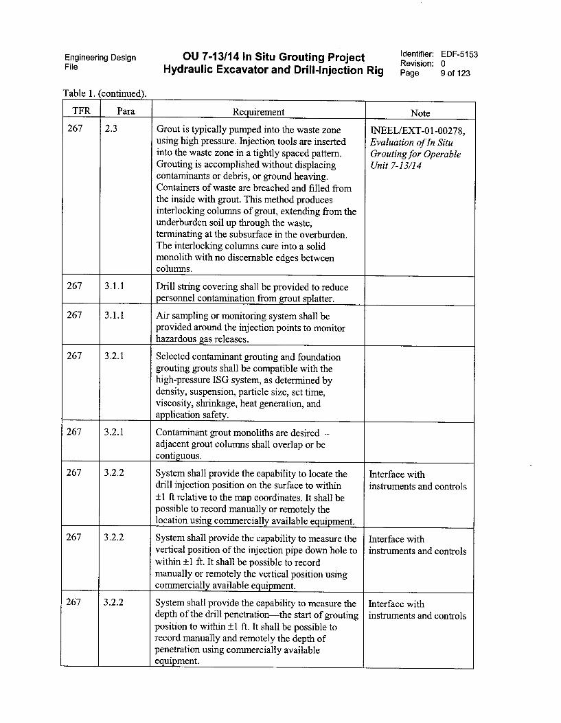
Table 1. Technical and functional requirements defined requirements.
TFR Para Requirement Note
267 2.1 The systems shall be capable of providing groutand injecting it into the ground at specifiedlocations.
267 2.2 The system and components shall be categorizedas consumer grade.
High-pressurecomponents, includingthe swivel may be safetysignificant, (seeEDF-5102, "OU 7-13/14In Situ Grouting ProjectGrout Delivery System")
Engineering Design OU 7-13/14 In Situ Grouting Project Identifier: EDF-5153Revision: 0File Hydraulic Excavator and Drill-Injection Rig Page 9 of 123
Table 1. (continued).
TFR Para Requirement Note
267 2.3 Grout is typically pumped into the waste zoneusing high pressure. Injection tools are insertedinto the waste zone in a tightly spaced pattern.Grouting is accomplished without displacingcontaminants or debris, or ground heaving.Containers of waste are breached and filled fromthe inside with grout. This method producesinterlocking columns of grout, extending from theunderburden soil up through the waste,terminating at the subsurface in the overburden.The interlocking columns cure into a solidmonolith with no discernable edges betweencolumns.
INEEL/EXT-01-00278,Evaluation of In SituGrouting for OperableUnit 7-13/14
267 3.1.1 Drill string covering shall be provided to reducepersonnel contamination from grout splatter.
267 3.1.1 Air sampling or monitoring system shall beprovided around the injection points to monitorhazardous gas releases.
267 3 .2.1 Selected contaminant grouting and foundationgrouting grouts shall be compatible with thehigh-pressure ISG system, as determined bydensity, suspension, particle size, set time,viscosity, shrinkage, heat generation, andapplication safety.
267 3.2.1 Contaminant grout monoliths are desired—adjacent grout columns shall overlap or becontiguous.
267 3.2.2 System shall provide the capability to locate thedrill injection position on the surface to within±1 ft relative to the map coordinates. It shall bepossible to record manually or remotely thelocation using commercially available equipment.
Interface withinstruments and controls
267 3.2.2 System shall provide the capability to measure thevertical position of the injection pipe down hole towithin ±1 ft. It shall be possible to recordmanually or remotely the vertical position usingcommercially available equipment.
Interface withinstruments and controls
267 3.2.2 System shall provide the capability to measure thedepth of the drill penetration—the start of groutingposition to within ±1 ft. It shall be possible torecord manually and remotely the depth ofpenetration using cornmercially availableequipment.
Interface withinstruments and controls
Engineering Design OU 7-13/14 In Situ Grouting ProjectFile Hydraulic Excavator and Drill-Injection Rig
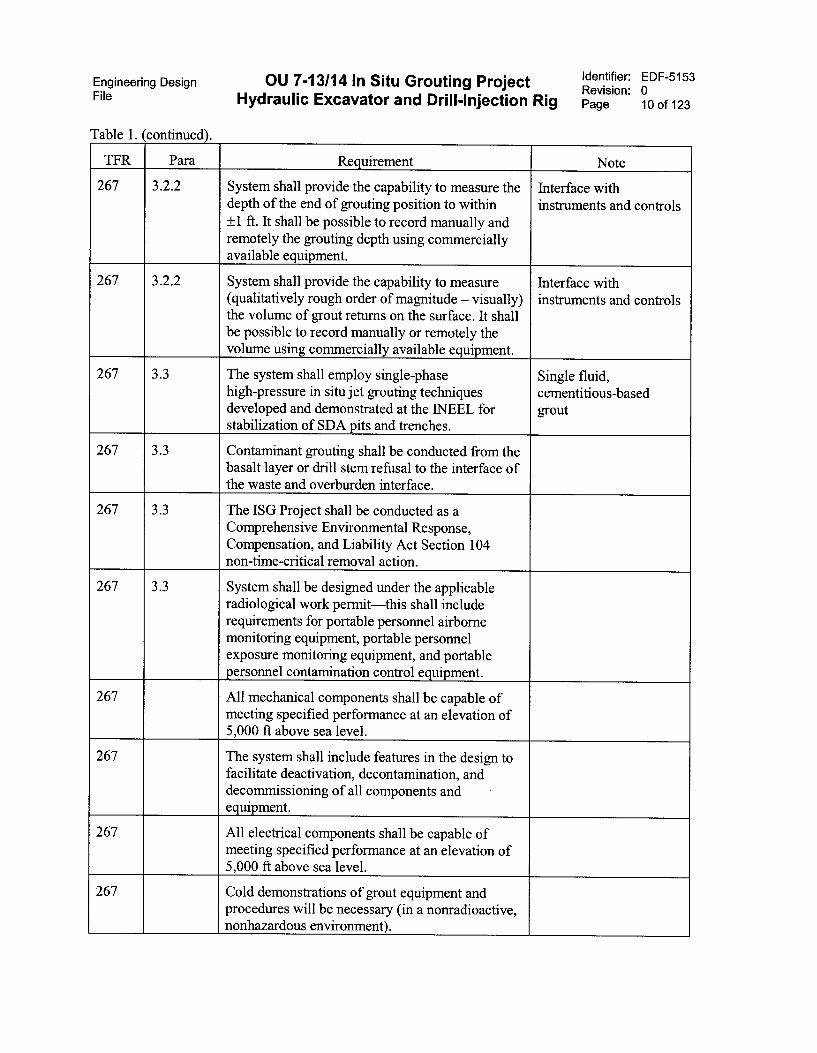
Table 1. continued .
Identifier: EDF-5153Revision: 0Page 10 of 123
TFR Para Requirement Note
267 3.2.2 System shall provide the capability to measure thedepth of the end of grouting position to within±1 ft. It shall be possible to record manually andremotely the grouting depth using commerciallyavailable equipment.
Interface withinstruments and controls
267 3.2.2 System shall provide the capability to measure(qualitatively rough order of magnitude — visually)the volume of grout returns on the surface. It shallbe possible to record manually or remotely thevolume using commercially available equipment.
Interface withinstruments and controls
267 3.3 The system shall employ single-phasehigh-pressure in situ jet grouting techniquesdeveloped and demonstrated at the 1NEEL forstabilization of SDA pits and trenches.
Single fluid,cementitious-basedgrout
267 3.3 Contaminant grouting shall be conducted from thebasalt layer or drill stem refusal to the interface ofthe waste and overburden interface.
267 3.3 The ISG Project shall be conducted as aComprehensive Environmental Response,Compensation, and Liability Act Section 104non-time-critical removal action.
267 3.3 System shall be designed under the applicableincluderadiological work permit—this shall
requirements for portable personnel airbornemonitoring equipment, portable personnelexposure monitoring equipment, and portablepersonnel contamination control equipment.
267 All mechanical components shall be capable ofmeeting specified performance at an elevation of5,000 ft above sea level.
267 The system shall include features in the design tofacilitate deactivation, decontamination, anddecommissioning of all components andequipment.
267 All electrical components shall be capable ofmeeting specified performance at an elevation of5,000 ft above sea level.
267 Cold demonstrations of grout equipment andprocedures will be necessary (in a nonradioactive,nonhazardous environment).

Engineering Design OU 7-13/14 In Situ Grouting ProjectFile Hydraulic Excavator and Drill-Injection Rig
Table 1. (continued).
Identifier: EDF-5153Revision: 0Page 11 of 123
TFR Para Requirement Note
267 System shall be designed and constructed asconsumer grade per Management ControlProcedure (MCP)-540, "Documenting the SafetyCategory of Structures, Systems, andComponents."
267 A11 procured services and materials shall beconsumer grade.
5. SYSTEM CLASSIFICATIONS, CATEGORIZATIONS,AND DETERMINATIONS
All systems and components are consumer grade. However, high-pressure components, includingthe swivel, may be classified as safety significant (see EDF-5102 for additional discussion).
6. ASSUMPTIONS
The following are assumptions for the hydraulic excavator and drill-injection rig for the ISGProject:
1. Uncertainty in the area to be in situ grouted in Phase II is defined in Table 2.
2. Uncertainty in the grouting depth of Phase II is defined in Table 3.
3. The maximum depth of ISG is 30 ft from surface level (EDF-4013, "Feasibility Study Technicaland Functional Requirements for OU 7-13/14 In Situ Grouting Preliminary Documented SafetyAnalysis), 33 ft using 'NEEL spatial analysis map, sda_sedimentthickness_dlv3.mxd.
Table 2. Phase II in situ grouting low-level waste area.
Scenario
Total In SituGrouting Project
Area(ft2)
Estimated TotalGrout Area Less
Than 15 ftInjection Depth
(ft2)
Estimated TotalGrout Area 15 to25 ft InjectionDepth (ft2)
Estimated TotalGrout Area 25 to30 ft InjectionDepth (ft2)
Minimal wastearea groutingscenario
262,664 223,716 34,743 4,205
Nominal wastearea groutingscenario
525,328 447,433 69,484 8,411
Estimatedmaximum wastearea plusfoundation areaproject grouting
1,166,000(26.5 acre)
N/A N/A N/A
Engineering Design OU 7-13/14 In Situ Grouting ProjectFile Hydraulic Excavator and Drill-Injection Rig
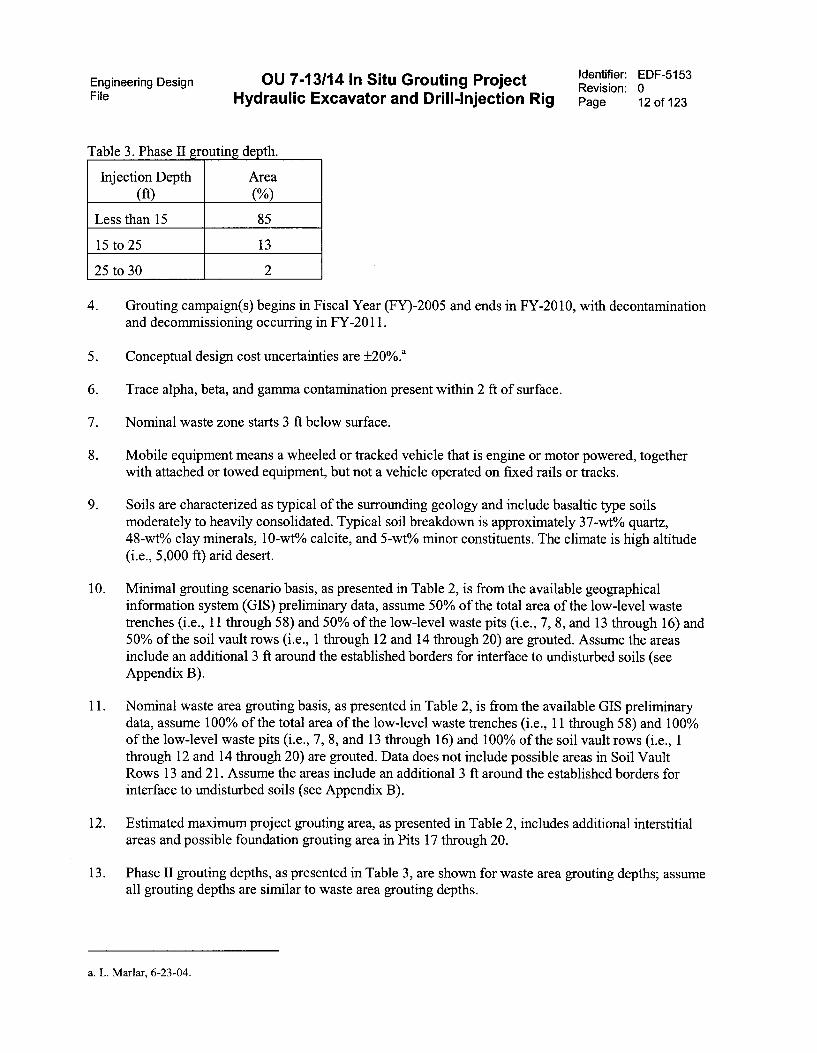
Table 3. Phase II grouting de th.
Injection Depth(ft)
Area
(%)
Less than 15 85
15 to 25 13
25 to 30 2
Identifier: EDF-5153Revision: 0Page 12 of 123
4. Grouting campaign(s) begins in Fiscal Year (FY)-2005 and ends in FY-2010, with decontaminationand decommissioning occurring in FY-2011.
5. Conceptual design cost uncertainties are ±20%.a
6. Trace alpha, beta, and gamma contamination present within 2 ft of surface.
7. Nominal waste zone starts 3 ft below surface.
8. Mobile equipment means a wheeled or tracked vehicle that is engine or motor powered, togetherwith attached or towed equipment, but not a vehicle operated on fixed rails or tracks.
9. Soils are characterized as typical of the surrounding geology and include basaltic type soilsmoderately to heavily consolidated. Typical soil breakdown is approximately 37-wt% quartz,48-wt% clay minerals, 10-wt% calcite, and 5-wt% minor constituents. The climate is high altitude(i.e., 5,000 ft) arid desert.
10. Minimal grouting scenario basis, as presented in Table 2, is from the available geographicalinformation system (GIS) preliminary data, assume 50% of the total area of the low-level wastetrenches (i.e., 11 through 58) and 50% of the low-level waste pits (i.e., 7, 8, and 13 through 16) and50% of the soil vault rows (i.e., 1 through 12 and 14 through 20) are grouted. Assume the areasinclude an additional 3 ft around the established borders for interface to undisturbed soils (seeAppendix B).
11. Nominal waste area grouting basis, as presented in Table 2, is from the available GIS preliminarydata, assume 100% of the total area of the low-level waste trenches (i.e., 11 through 58) and 100%of the low-level waste pits (i.e., 7, 8, and 13 through 16) and 100% of the soil vault rows (i.e., 1through 12 and 14 through 20) are grouted. Data does not include possible areas in Soil VaultRows 13 and 21. Assume the areas include an additional 3 ft around the established borders forinterface to undisturbed soils (see Appendix B).
12. Estimated maximum project grouting area, as presented in Table 2, includes additional interstitialareas and possible foundation grouting area in Pits 17 through 20.
13. Phase II grouting depths, as presented in Table 3, are shown for waste area grouting depths; assumeall grouting depths are similar to waste area grouting depths.
a. L. Marlar, 6-23-04.
OU 7-13/14 In Situ Grouting ProjectEngineering DesignFile Hydraulic Excavator and Drill-Injection Rig
7. DESIGN CRITERIA
7.1 Applicable Design Codes and Standards
Identifier: EDF-5153Revision: 0Page 13 of 123
The following conceptual listing of applicable codes and standards relate to implementation of the
Phase 2 ISG Project using commercial grade equipment. This listing clarifies, or is in addition to,
equipment design codes and standards normally used by a vendor for design and fabrication of
equipment.
• Factory Mutual Datasheet 7-40, "Heavy Duty Mobile Equipment"
• International Standards Organization (ISO) TC 127, "Earth Moving Equipment"
• Occupational Safety and Health Act (OSHA) Regulations
• Safety and hazard warnings: ISO Standard 9244:1995, "Earth-moving machinery—safety signs and
hazard pictorials—General principles."
Equipment procurement specifications will be based on general operational and performance
capabilities of commercial grade equipment, which implies conformance to industrial regulation. A
detailed listing and discussion of design and fabrication codes and standards is beyond the scope of this
EDF. However, standards applicable to hydraulic excavators are covered under ISO standards, under
ISO TC 127, which also covers other earth moving equipment. A draft subset listing of applicable
standards of ISO TC 127 for hydraulic excavators provided by D. Gamble-John Deere Co. is provided in
Appendix A.
Standards for jet grouting equipment and processes are less evolved than for earth moving
equipment. As of 1997, American standards for jet grouting both lagged and referenced the European
Committee for Standardization finalization of standards for the jet grouting industry. Appendix A
provides discussion on standards for the jet grouting industry. The American Petroleum Institute (API)
includes many suggested practices and specifications for high-pressure components primarily used in the
petroleum industry. Some of the API documents, but not all, are cross referenced to ISO standards. Future
procurements should specify, or request as part of a subcontract, sufficient detail to address safety of
design and operation in addition to available standards for the injection grouting equipment.
7.2 System Design Discussion
Three alternatives are presented for the trackhoe and drill rig system conceptual design. These
alternatives include a hydraulic excavator with mast mounted drill-injection rig, a hydraulic excavator
with nonmast drill-injection rig, and an altemative for reuse of the existing Phase 1 drill-injection rig with
or without modifications for cementitious grout. The first alternative is discussed in the most detail. The
latter alternatives are discussed as variances from Alternative 1 or as stand-alone programmatic paths.
Alternative 1—This alternative includes a hydraulic excavator with a mast mounted drill-injection
rig as illustrated in Figure 1. Salient features are itemized as follows:
• Equipment that includes an integrated hydraulic excavator with a roto-percussion, rotary sonic
drill, or rotary drill with fluted bit end effector and a high-pressure pump system integration with
the injection system, including hose management systems, monitoring and control systems, and all
accompanying documentation.
Engineering Design OU 7-13/14 In Situ Grouting Project Identifier: EDF-5153Revision: 0
File Hydraulic Excavator and Drill-Injection Rig Page 14 of 123
• Equipment that must operate on SDA waste area surfaces should have ground pressures of 2,000psf or lower. Mats, platforms, or other means to reduce ground pressure should be provided forequipment with ground pressures exceeding this value. During wet conditions or where overburdendepths are less than 3 ft, ground pressures should be 1,500 psf or lower.
• The system and operations shall meet OSHA standards.
• Fire protection shall be in accordance with Factory Mutual Datasheet 7-40.
• Equipment shall be able to perform contamination stabilization grouting or foundation grouting.
• Foundation support grout injection to provide spaced structural support columns for potential cap.
• System shall be able to monitor actual variation in elevation of the drill string bit, and the locationof the nozzle injection planes during the injection process. The system should control normal
variations in elevation of the injection planes to ±1/4 in. during injection activities.
• Production of up to 3 to 8 holes per hour to nominal depth of 15 ft, capability to inject to 25 ft.
• Contamination grout injection to provide monolithic waste zone solidification through repetitivesoil-crete column production.
• Single fluid cementitious jet grouting, with one or more injection nozzles.
• Contamination grout injection into known characterization of overcover fill, unknowncharacterization of waste matrix, and known characterization of undercover fill areas having beenknown as previously excavated and filled and patched in prior decades.
• Hole spacing for monolithic waste zone solidification 20 in. each leg on triangular pitch.
• Accuracy of surface hole placement ±1 ft (basis: program direction).
• Hole spacing for structural support columns 10 to 12 feet on center. Grout injection operation(s) tominimize radiological or hazardous exposure to operational personnel, and the environment.
• Water system to actuate pipe wiper and supply water spray for pipe and end cleaning (e.g., supplytank, pump, wiper seal, and spray nozzles).
• Contaminant fixative system to spray fixative on grout retums after grouting (e.g., supply tank,pump, and spray nozzle).
• General and local area monitoring for radiological controls, industrial hygiene, and dataacquisition.

TO HIMPRESSUREPUMP
1411.11-11124PMOM SPOOL
FtcATNETAM(
Engineering Design OU 7-13/14 In Situ Grouting ProjectFile Hydraulic Excavator and Drill-Injection Rig
%WEL BABE
WAITIL1.0.014
FIXAME UTE (1WIER UNE II
Einem= LNESE§HORD PPE TO
F
ILT MINTS
FAR.EAD
PUMP PO PIMP
UNE 04 T14145011
HYDRAULJCEECAYATER
p I=1 =II= 0 1..1.1
DUAL SI.EME SPOOLS
IRDRAUULuses OM MEL)
FIX4WAITTE &IEOFLE1
ANGLE
I
S-IFT
NAST
Identifier: EDF-5153Revision: 0Page 15 of 123
ROTARY-PERCUSSIONCaLL HEAD
ar,— EFSTARGETS
INCUNDETERS
isy:■ HEAD
SHROUD
=AGUE REMNANT/
SINGER
5YATER ACTUATED
;fi
csi
2 PLACES
.;\FOOT
FIXATDE SPRAYNOZ2LE
Figure 1. Alternative 1 excavator and drill rig configuration.
OPTIONAL H411 PRESSUREHOSE ROJTNG
SIPPCRT CAGLE
TO HIGH PRESSLVEPUMP
CABLEANCHOR

Engineering Design OU 7-13/14 In Situ Grouting ProjectFile Hydraulic Excavator and Drill-Injection Rig
Excavator salient features:
• 35 to 40 ft reach from cab to drill string
Identifier: EDF-5153Revision: 0Page 16 of 123
Structural rigidity of machinery linkages and pins to maintain accuracy of hole and colunmplacement
• Sufficient hydraulic capacity to power excavator and the drill rig
• Ground pressure less than 2000 lb/ft2 for dry conditions, 1500 lb/ft2 for wet conditions or forshallow overburden
• Kicker support foot, load locks, or means to minimize hydraulic drift
• Nominal excavator size class 90,000 lb or greater
• Vertical reach sufficient to extract drill stem with bit and mast 3 ft above ground
• End motion to enable laying drilling rig horizontal
• Safety systems—cab safety interlocks, flashing lights, audible alert warnings, placarding, andcommunications system(s)
• Automatic lube system
• 110-volt AC power sufficient to power monitors, sensors, cameras, and other extra oversight ordata acquisition equipment (approximately 1 to 5 kW)
• Commercial grade cab pressurized through an air-conditioned filtered air system to maintainoperator comfort; workspace to be periodically assessed and controlled to industrial hygiene andradiological control guidance
• Data acquisition system and secure wireless uplink hardware
• Hose management sheaves and reeving on top of boom and stinger, or alternatively, a hoseattached to the swivel and to ground with safety cable and anchored take up hoist reeving, oralternatively, using an expandable cable tray with a u-bend to track the mast vertical motion
• Visible flashing light (yellow) to indicate operational status
• Fixative spray system interface at the bottom of the drill rig to spray bright colored fixative on topof the grout returns to fix any potential contamination
• Emergency shutdown switch(s)
• Nonflammable or minimal flammable hydraulic fluid
• Dry chemical fire suppression system in engine compai tu ent
• Local fire extinguishers.
Engineering Design OU 7-13/14 In Situ Grouting Project Identifier: EDF-5153Revision: 0
File Hydraulic Excavator and Drill-Injection Rig Page 17 of 123
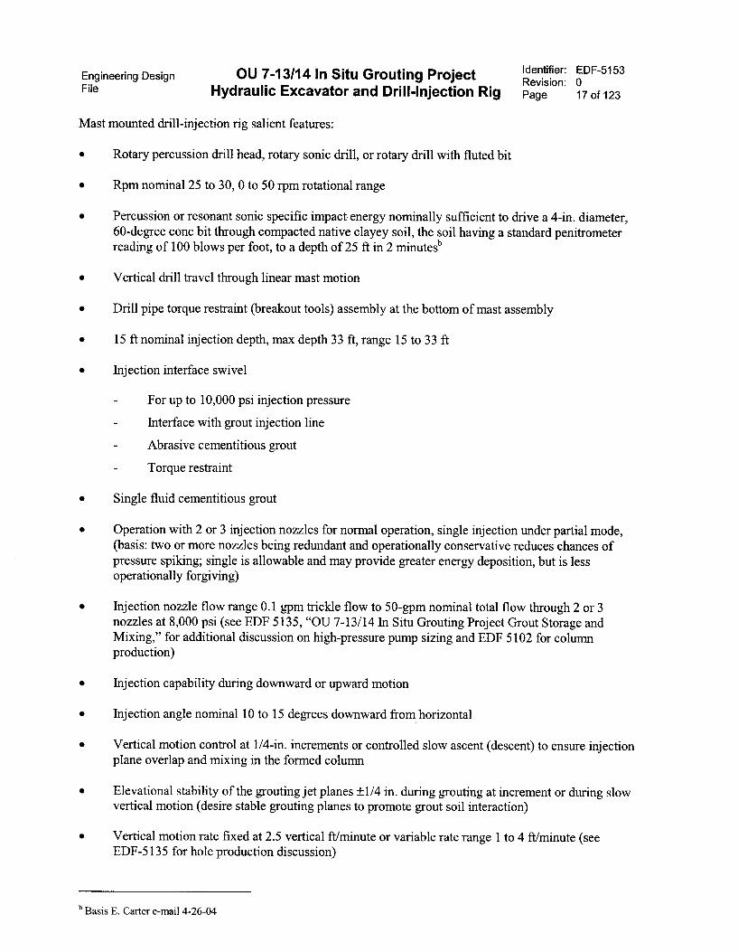
Mast mounted drill-injection rig salient features:
• Rotary percussion drill head, rotary sonic drill, or rotary drill with fluted bit
• Rpm nominal 25 to 30, 0 to 50 rpm rotational range
• Percussion or resonant sonic specific impact energy nominally sufficient to drive a 4-in. diameter,60-degree cone bit through compacted native clayey soil, the soil having a standard penitrometerreading of 100 blows per foot, to a depth of 25 ft in 2 minutesb
• Vertical drill travel through linear mast motion
• Drill pipe torque restraint (breakout tools) assembly at the bottom of mast assembly
• 15 ft nominal injection depth, max depth 33 ft, range 15 to 33 ft
• Injection interface swivel
- For up to 10,000 psi injection pressure
Interface with grout injection line
Abrasive cementitious grout
- Torque restraint
• Single fluid cementitious grout
• Operation with 2 or 3 injection nozzles for normal operation, single injection under partial mode,(basis: two or more nozzles being redundant and operationally conservative reduces chances ofpressure spiking; single is allowable and may provide greater energy deposition, but is lessoperationally forgiving)
• Injection nozzle flow range 0.1 gpm trickle flow to 50-gpm nominal total flow through 2 or 3nozzles at 8,000 psi (see EDF 5135, "OU 7-13/14 In Situ Grouting Project Grout Storage andMixing," for additional discussion on high-pressure pump sizing and EDF 5102 for columnproduction)
• Injection capability during downward or upward motion
• Injection angle nominal 10 to 15 degrees downward from horizontal
• Vertical motion control at 1/4-in. increments or controlled slow ascent (descent) to ensure injectionplane overlap and mixing in the formed column
• Elevational stability of the grouting jet planes ±1/4 in. during grouting at increment or during slowvertical motion (desire stable grouting planes to promote grout soil interaction)
• Vertical motion rate fixed at 2.5 vertical ft/minute or variable rate range 1 to 4 ft/minute (seeEDF-5135 for hole production discussion)
b Basis E. Carter e-mail 4-26-04
Engineering Design OU 7-13/14 In Situ Grouting Project Identifier: EDF-5153Revision: 0
File Hydraulic Excavator and Drill-Injection Rig Page 18 of 123
• Optional load pad/kicker foot to preclude groutlmud buildup, and reduce hydraulic drift
• Drill string shroud and pipe string interface stinger with internal pipe wiper(s) or approvedalternative arrangement using a filled double wiper assembly and no shroud
• Drill stem diameter nominal 3.5 in., range 2.0 to 4.0 in.
• Drill stem interface—quick change remotized
• Normal maintenance to be performed in horizontal position
• Normal routine maintenance (see EDF-5155, for additional discussion)
Swivel—biweekly
Injection nozzles and drill bit—daily through bit box
Grout injection hose—biweekly.
• Operator control in cab, remote data acquisition to data link to control facility
• High-pressure grout injection hose: 20,000 psi rating hydraulic hose, 2 in. OD x 1/2 in. ID atfittings (basis Phase 1 hose), or preferred altemative using a 5 in. OD, 2 in. ID, 10,000 psi ratedcementing hose, See EDF-5102 for more discussion on the high-pressure hose.
7.2.1 Alternative 1 Discussion
Alternative 1 includes a large hydraulic commercial excavator combined with a mast mountedroto-percussion or rotary sonic drill rig configured for impact or rotary drilling and high-pressure groutinjection. The configuration is presented in Figure 1, as well as in Sketch 1 of Appendix C. Theconceptual design uses a commercially available hydraulic excavator to maximize reliability of operation.The excavator would be modified only minimally to incorporate safety or operationally requiredcomponents; these include any additional safety interlocks, monitors, cameras, cleaning systems, andcontaminant fixative special spray systems.
Primary factors in the configuration of the excavator and drill rig are the methods and componentsincluded to minimize the potential for spread of contamination emitted from the grout hole. Minimizationof contamination includes locating the drill pipe safely away from the operator cab, precluding anyoperations or oversight personnel near the grout hole while in operating mode, configuring a systemassembly and operational procedure that minimizes soil and grout retum accumulations, providingcomponent active cleanup and wash systems, and controlling or fixing the grout returns as they evolve atthe surface during grouting operations.
Alternative 1 configuration includes a kicker foot located at the bottom of the drill mast. This footserves two functions. First, it provides a means to stabilize the mast during operations through interfacewith the ground. This stabilization reduces the need for advanced hydraulic controls to maintain rigidity,and may enable the use of lower cost or used financially depreciated excavators. The second function ofthe foot is to provide a kicking action to dislocate soil or potentially contaminated grout accumulated onthe foot during operations.
A torque restraint system (i.e., breakout tools) is located at the bottom of the mast. The restraintsystem includes dual sets of pipe jaws to enable breaking the pipe joints without the use of the drill head.
Engineering Design OU 7-13/14 In Situ Grouting Project Identifier: EDF-5153Revision: 0File Hydraulic Excavator and Drill-Injection Rig Page 19 of 123
The pipe jaws also serve as sets of pipe rams to hold a stinger interface during normal operations. Thestinger interfaces with the pipe shroud as depicted in Figure 1, and houses one or more pipe wipers.
In addition, a contaminant fixative system is configured to the excavator and drill rig bottom tospray a layer of fixative on the grout returns at the end of grouting operations. The fixative would bebrightly colored to aid in visualization of the fixed area. Other monitors, as directed by radiologicalcontrol or industrial hygiene, may be located at the bottom of the mast assembly for oversight monitoringof the local injection site
Location of the drill pipe approximately 30 to 35 ft from the operating cab is considered a safedistance for conceptual design purposes and conforms to the As Low As Reasonable Achievableprinciples of time, distance, or shielding. This distance requires an excavator of sufficient size and rigidityto provide the reach and maintain accuracy of hole and column placement during operations. Based onreview of commercial drill rig products in the general size range to accomplish 20 to 30 ft drilling andinjection, the associated hydraulic excavators needed to handle that size of unit are of the approximate90,000-lb class or greater.
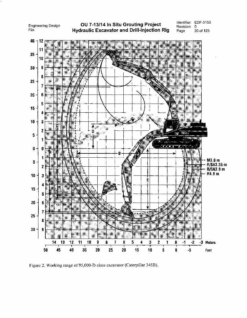
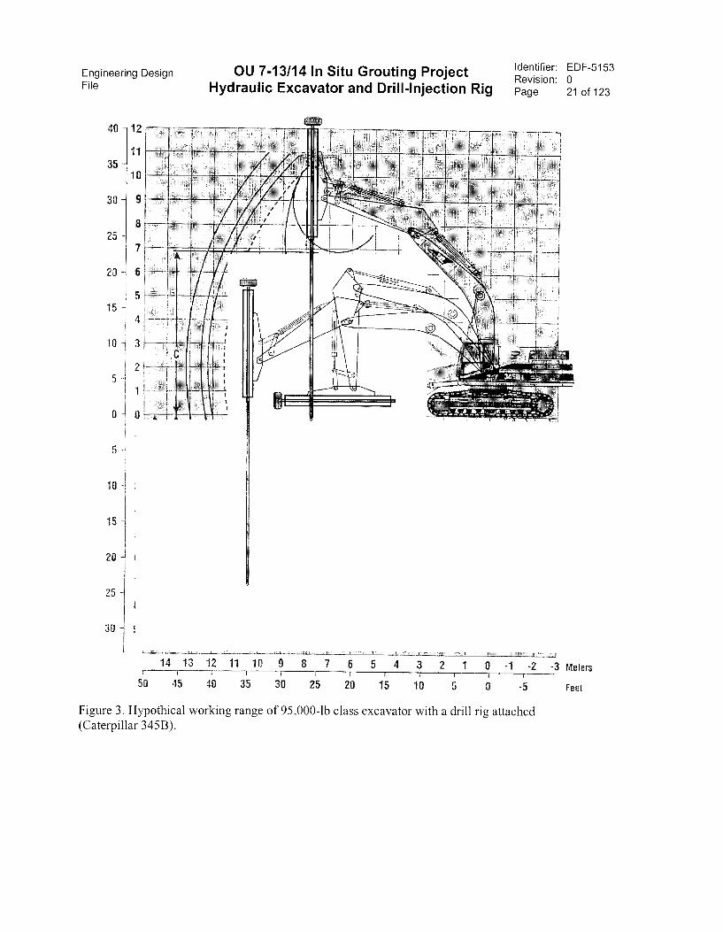
Figures 2 and 3 illustrate the working range of a 95,000+-class excavator with a standard bucketand with a hypothetical drill attached. A Caterpillar Model 345B excavator is used for illustration.Appendix D provides reference information on a Caterpillar Model 345B, and for a larger 180,000-1bClass excavator, a Caterpillar Model 385. The large unit provides a reach of approximately 50 to 55 ft atthe bucket and approximately 30 ft at the end of the main boom. Other makes and models provide similarcharacteristics.
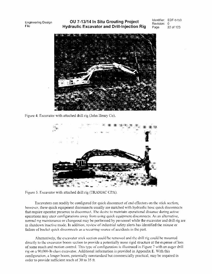
Figures 4 and 5 illustrate typical actual condition reach capabilities of excavators with attacheddrill rigs. Figure 4 illustrates a smaller unit with an approximate 21-ft reach, and Figure 5 illustrates aslightly larger unit with a 21.5-ft single pass rock drilling depth capability.
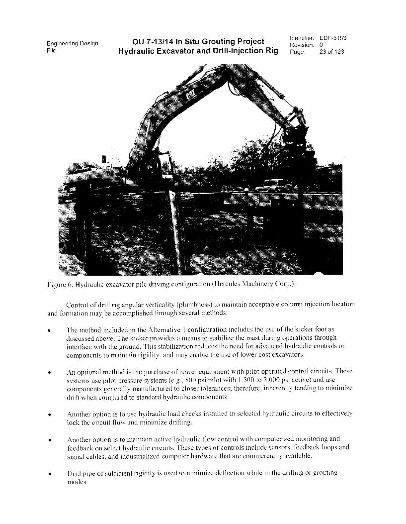
The drill rig would essentially replace the digging bucket on the excavator stick link as an end effector.Alternative 1 for the drill rig includes a mast mount roto-percussion or rotary sonic drill rig configured forimpact and rotary drilling and grout injection. The normal operating scenario would be for the operator tolocate the tip of the drill string at a preselected hole location using the excavator tracks for periodicmovement; using the pivot for angular setup; using the boom, stick, and bucket hydraulic motion controlsfor hole location setup. The drill string would be placed in the vertical position as measured in two planes.The first vertical alignment would be perpendicular to the boom and stick plane using the excavatorcontrols, and the second would be at 90-degree verticality using the mast side angular adjustment control.An accuracy of placement of the drill tip at the preselected location of ±1 ft and vertical angularityaccuracy of the inserted drill pipe of ±1 degree of plumb has been established as adequate for conceptualdesign purposes. In the latter, a 1-degree verticality misalignment would equate to approximately 0.52 ftover a 30 ft depth (30 ft x tan 1° = 0.52 ft). The 1-degree verticality misalignment is considered acommercially practical value based on hydraulic excavator pile driving practices using modern hydrauliccontrols as illustrated in Figure 6, provided the drill pipe has sufficient rigidity to minimize deflectionduring drilling and grouting and the drilling procedure minimizes deflection. Alternative 2 discusses thesecontrols in more detail and vendor information is referenced in Appendix H.
Engineering DesignFile Hydraulic Excavator and Drill-Injection Rig
40
35
30
25
20
15
10
5
5
415
5
20 6
25
30
OU 7-13/14 In Situ Grouting ProjectIdentifier: EDF-5153Revision: 0Page 20 of 123
.0 mR/SA3.35 mR/SA3.9 mR4.8 m
14 13 12 11 10 9 8 7 6 5 4 3 2 1 0 -1 -2 -3 MetersÌ 1 1 l 1 I 4 I 150 45 40 35 30 25 20 15 10 5 0 -5 Feet
Figure 2. Working range of 95,000-lb class excavator (Caterpillar 345B).
Engineering Design OU 7-13/14 In Situ Grouting ProjectFile Hydraulic Excavator and Drill-Injection Rig
4
35
25
20
1
D-
10d
15 -
20 -
25 -
30
Identifier: EDF-5153Revision: 0Page 21 of 123
Meters
30 25 20 15 10 5 0 -5 Feet
Figure 3. Hypothical working range of 95,000-lb class excavator with a drill rig attached(Caterpillar 345B).
Engineering Design OU 7-13/14 In Situ Grouting ProjectFile Hydraulic Excavator and Drill-Injection Rig
Figure 4. Excavator with attached drill rig (John Henry Co).
Figure 5. Excavator with attached drill rig (TRAMAC CPA).
Identifier: EDF-5153Revision: 0Page 22 of 123
Excavators can readily be configured for quick disconnect of end effectors on the stick section;however, these quick equipment disconnects usually are matched with hydraulic hose quick disconnectsthat require operator presence to disconnect. The desire to maintain operational distance during activeoperations may steer configurations away from using quick equipment disconnects. As an alternative,noi inal rig maintenance or changeout may be performed by personnel while the excavator and drill rig arein shutdown inactive mode. In addition, review of industrial safety alerts has identified the misuse orfailure of bucket quick disconnects as a recurring source of accidents in the past.
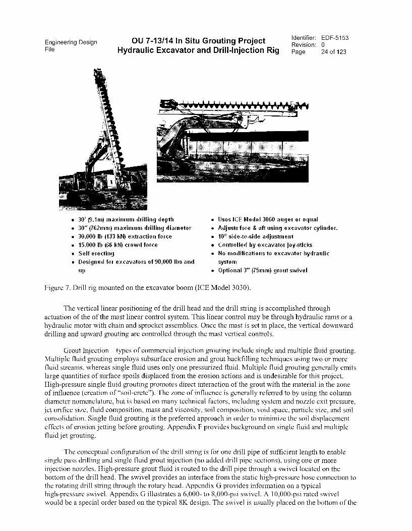
Alternatively, the excavator stick section could be removed and the drill rig could be mounteddirectly to the excavator boom section to provide a potentially more rigid structure at the expense of lossof some reach and motion control. This type of configuration is illustrated in Figure 7 with an auger drillrig on a 90,000-1b class excavator. Additional information is provided in Appendix E. With thisconfiguration, a longer boom, potentially nonstandard but commercially practical, may be required inorder to provide sufficient reach of 30 to 35 ft.
Engineering DesignFile Hydraulic Excavator and Drill-Injection Rig
OU 7-13/14 In Situ Grouting ProjectIdentifier: EDF-5153Revision: 0Page 23 of 123
Figure 6. Hydraulic excavator pile driving configuration (Hercules Machinery Corp.).
Control of drill rig angular verticality (plumbness) to maintain acceptable column injection location
and formation may be accomplished through several methods:
• The method included in the Ahernative 1 configuration includes the use of the kicker foot as
discussed above. The kicker provides a means to stabilize the mast during operations through
interface with the ground. This stabilization reduces the need for advanced hydraulic controls or
cornponents to maintain rigidity, and may enable the use of lower cost excavators.
An optional method is the purchase of newer equipment with pilot-operated control circuits. These
systerns use pilot pressure systems (e.g., 500 psi pilot with 1,500 to 3,000 psi active) and use
components generally manufactured to closer tolerances; therefore, inherently tending to minimize
drift when compared to standard hydraulic components.
• Another option is to use hydraulic load checks installed in selected hydraulic circuits to effectively
lock the circuit flow and minimize drifting.
• Another option is to maintain active hydraulic flow control with computerized monitoring and
fecdback on select hydraulic circuits. Thesc types of controls include sensors, feedback loops and
signal cables, and industrialized computer hardware that are comrnercially available.
• Drill pipe of sufficient rigidity is used to minimize deflection while in the drilling or grouting
modes.
Engineering Design OU 7-13/14 In Situ Grouting ProjectFile Hydraulic Excavator and Drill-Injection Rig
• 30' (9.1m) maximum drilling depth
• 30" V62mm) maximum drilling diameter
• 30,000 lb (133 kN) extraction force
• 15,000 lb (66 kN) crowd force
• Self erecting
• Designed for excavators of 90,000 lbs and
up
Identifier: EDF-5153Revision: 0Page 24 of 123
• Uses ICE Model 3060 auger or equal
• Adjusts fore & aft using excavatoi cylindei.
• 10° side-to-side adjustment
• Controlled by excavator joy-sticks
• No modifications to excavator hydraulic
syste m
• Optional 3" 175mm) grout swivel
Figure 7. Drill rig mounted on the excavator boom (ICE Model 3030).
The vertical linear positioning of the drill head and the drill string is accomplished throughactuation of the of the mast linear control system. This linear control may be through hydraulic rams or ahydraulic motor with chain and sprocket assemblies. Once the mast is set in place, the vertical downwarddrilling and upward grouting are controlled through the mast vertical controls.
Grout Injection types of commercial injection grouting include single and multiple fluid grouting.Multiple fluid grouting employs subsurface erosion and grout backfilling techniques using two or morefluid streams, whereas single fluid uses only one pressurized fluid. Multiple fluid grouting generally emitslarge quantities of surface spoils displaced from the erosion actions and is undesirable for this project.High-pressure single fluid grouting promotes direct interaction of the grout with the material in the zoneof influence (creation of "soil-crete"). The zone of influence is generally referred to by using the columndiameter nomenclature, but is based on many technical factors, including system and nozzle exit pressure,jet orifice size, fluid composition, mass and viscosity, soil composition, void space, particle size, and soilconsolidation. Single fluid grouting is the preferred approach in order to minimize the soil displacementeffects of erosion jetting before grouting. Appendix F provides background on single fluid and multiplefluid jet grouting.
The conceptual configuration of the drill string is for one drill pipe of sufficient length to enablesingle pass drilling and single fluid grout injection (no added drill pipe sections), using one or moreinjection nozzles. High-pressure grout fluid is routed to the drill pipe through a swivel located on thebottom of the drill head. The swivel provides an interface from the static high-pressure hose connection tothe rotating drill string through the rotary head. Appendix G provides information on a typicalhigh-pressure swivel. Appendix G illustrates a 6,000- to 8,000-psi swivel. A 10,000-psi rated swivelwould be a special order based on the typical 8K design. The swivel is usually placed on the bottom of the
Engineering DesignFile Hydraulic Excavator and Drill-Injection Rig
OU 7-13/14 In Situ Grouting Project Identifier: EDF-5153Revision: 0Page 25 of 123
drill head; however, alternate drill head designs may place it at the top. In this case, the drill head woulduse a hollow internal shaft to complete the fluid circuit.
Drill pipe and bit rotary and percussion motions are supplied by the drill head. These motions arehydraulically powered for this alternative, but may be powered by air or electricity. The drill head may beeither a rotary percussion rock drill type of drill head or a rotary resonant sonic type drill head.
The rotary percussion rock drill type drill head is a rotary head that supplies a percussion impactforce to the drill string. These drill heads typically operate in the 10- to 60-hz range for percussion impactevents. The impact forces of the percussion heads provide a shock force through the swivel and drillstring to the bit, which in turn is transferred to the matrix material for enhanced material removal.Figure 8 illustrates a typical rotary percussion type drill head.
Suomeksi Jin Finnish ::::::: Doofor efficient, reliable and fast rock drilling, bolting or mining :::
download
Figure 8. Rotary percussion drill head (Doofer).
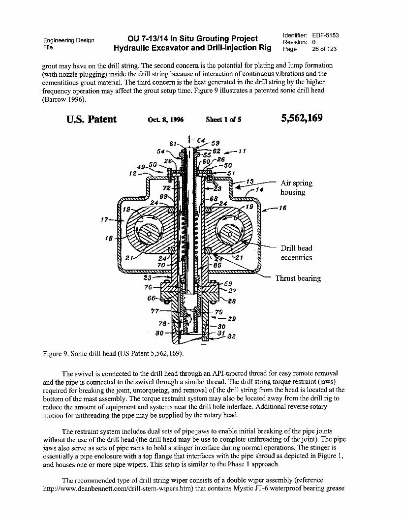
The rotary sonic drill head is a rotary head that supplies excitation vibration forces to the drillstring and the drill bit. These heads typically operate with three modes of excitation. The first mode, thestartup mode, is characterized by low frequency (i.e., less than 2 cps) oscillation with large verticalamplitude (±0.5 to 1.0 in. oscillations). This mode starts the entire drill string mass string in verticalmotion. The second mode is characterized by a higher frequency (i.e., 100 to 150 cps), low amplitude(±1/32 in.) vibrational mode that is intended to excite the drill string into resonance. The third mode isresonance mode. In the resonance mode, the higher frequency low amplitude vertical excitation vibrationsinduce resonance in the string, which induces strong lateral deflections of the drill string. The verticalvibrations and the lateral deflections tend to fluidize the adjacent matrix soil greatly, decreasing drillstring sliding friction because of the fluidized matrix material. However, in practice for short drill strings,the drill pipe material is often too stiff and too short to enable a resonant condition to form, with the resultbeing the drill string just operates in a low amplitude high vertical vibration mode. These types of headsare typically larger and heavier than the rotary percussion drill heads with the drill string being coupled tothe head through a shock absorbing mechanism, such as air springs and bumpers. This type of drill headhas been used successfully for probe insertion into the SDA. Three concerns are recognized for the use ofa sonic drill head for injection grouting. The first concern is the potential damping effect the flowing
Engineering DesignFile Hydraulic Excavator and Drill-Injection Rig
OU 7-13/14 In Situ Grouting Project Identifier: EDF-5153Revision: 0Page 26 of 123
grout may have on the drill string. The second concern is the potential for plating and lump formation
(with nozzle plugging) inside the drill string because of interaction of continuous vibrations and thecementitious grout material. The third concern is the heat generated in the drill string by the higher
frequency operation may affect the grout setup time. Figure 9 illustrates a patented sonic drill head
(Barrow 1996).
U.S. Pa Oct. S, 1996 Sheet 1 et .5 5,562,169
---- Air springf 4 housing
16
Drill headeccentrics
3 Thrust bearing5927
28
7929
3080 31 32
Figure 9. Sonic drill head (US Patent 5,562,169).
The swivel is connected to the drill head through an API-tapered thread for easy remote removaland the pipe is connected to the swivel through a similar thread. The drill string torque restraint (jaws)required for breaking the joint, untorqueing, and removal of the drill string from the head is located at thebottom of the mast assembly. The torque restraint system may also be located away from the drill rig toreduce the amount of equipment and systems near the drill hole interface. Additional reverse rotarymotion for unthreading the pipe may be supplied by the rotary head.
The restraint system includes dual sets of pipe jaws to enable initial breaking of the pipe jointswithout the use of the drill head (the drill head may be use to complete unthreading of the joint). The pipejaws also serve as sets of pipe rams to hold a stinger interface during normal operations. The stinger isessentially a pipe enclosure with a top flange that interfaces with the pipe shroud as depicted in Figure 1,and houses one or more pipe wipers. This setup is similar to the Phase 1 approach.
The recommended type of drill string wiper consists of a double wiper assembly (referencehttp://www.deanbennett.com/drill-stem-wipers.htm) that contains Mystic JT-6 waterproof bearing grease

Engineering DesignFile Hydraulic Excavator and Drill-Injection Rig
OU 7-13/14 In Situ Grouting ProjectIdentifier: EDF-5153Revision: 0Page 27 of 123
or a very soft wax pressurized between the two wipers. This wiper assernbly is held in place at the lower
location using the mast pipe ram clarnps. The wiper assembly enables coating the drill pipe and wiping it
as it passes through the assembly in order to prevent formation of potentially contaminated grout dust on
the drill pipe above the assembly. This method aids in preventing buildup of grout on the drill pipe and
saves cleaning the drill pipe before cleaning the system. This system potentially elirninates the need for a
drill string shroud.
The main drill pipe is allowed to rernain potentially contarninated. The upper 6 ft of drill pipe
remains clean because it never moves downward far enough to pass by the potentially contaminated top
wiper or chuck jaws. Figure 10 illustrates a typical double wiper assembly.
-CECON :EPPAYER.
OLIT T1J CO2 PELLETS ANDTHEN TO MR COMPFS- CiFi
WIPERE
DRILL MAST -
DRILL PIECE
Figure 10. Double wiper assembly.
An alternative wiper assembly uses one or more water-actuated wipers affixed to the stinger at the
lower end of the mast and engaged to wipe the drill pipe as it is withdrawn. This type of wiper systern
may also be used as a localized water spray to aid in cleanup.
In addition, a contaminant fixative system is configured to the excavator and drill rig bottorn to
spray a layer of fixative on the grout returns at the end of grouting operations. The fixative would be
brightly colored to aid in visualization of the fixed area. Other monitors, as directed by radiological
control or industrial hygiene, may be located at the bottorn of the mast assembly for oversight monitoring
of the local injection site.

Engineering Design OU 7-13/14 In Situ Grouting ProjectFile Hydraulic Excavator and Drill-Injection Rig
Identifier: EDF-5153Revision: 0Page 28 of 123
A combination drilling and injection-grouting bit is located at the bottom of the drill pipe. Theconceptual configuration for the bit includes 2 to 3 injection nozzles located above the cutting bit sectionand 120 to 180 degrees apart to balance the injection forces, and provide redundant grout flow capability.A major operations consideration is the plugging of an injection nozzle. The grout flow from the drill pipeis vertical; this flow changes direction to horizontal at the nozzle location. The internals of the bit providea sump reservoir for accumulation of grout clumps as the flow transitions to horizontal, which couldpotentially block a nozzle. This sump provides some backup to minimize nozzle plugging. The use ofmultiple nozzles provides additional backup should a nozzle plug. The nozzles are pointed approximately10 to 15 degrees downward from horizontal to enhance column mixing and minimize potential spray atthe surface. The nozzles are located at different elevations approximately 2 in. apart to also enhancecolunm mixing. A suite of drill bits of various configurations, and sizing are considered necessary toaccommodate unknowns in waste and soil matrix, and operating conditions.
The column formation parameters are conceptually configured as:
• Grout fluid is single phase cementitious.
• Zone consolidation is for monolithic column production using a 24-in. nominal colunm diameterformed from the depth at bit refusal (assumed at the bottom of the underburden) to the interface ofthe waste and overburden interface, or a 13-ft average nominal grout distance, with a range toapproximately 25 ft maximum depth in select areas.
• Column spacing is 20 in. on center in a triangular grid, allowing for overlap and mixing of columnsduring grouting.
• Grout injection theoretical volume is 23.6 gal/vertical ft (100% void space) and nominal averageinjection rate of 13.6 gal/vertical ft (58% void space) intermixed with soil and waste.
• The columns are formed at a nominal vertical rate of 2-1/2 vertical ft/minute, (5 minutes/groutedcolunm 13 ft high) (see EDF 5135 for additional discussion on hole production rate).
• Grout interaction with the soil and waste is configured using 8,000 psi nominal (6,000 to10,000 psi) injection pressure through two or three nozzles,
• Nozzles are sized to optimize energy deposition into the column to promote interaction, andminimize potential for plugging, nominal 2 to 3 mm nozzle orifice diameter.
Priority operational maintenance for the configuration and equipment include:
• High pressure hose replacement
• Bit replacement
• Swivel replacement
• High pressure grout circuit flushing.
The management and configuration of the high-pressure grout hose from the high-pressure pump isconfigured for maintaining operational distance during operations and for ease of replacement. As shownin Figure 1 and Appendix C, hose management is configured through reeving through several sets of largediameter reels mounted to the excavator housing, boom, stick, and end effector. A tension take-up spool islocated at the rear of the unit to allow a nontension connection to the high-pressure pump. An alternativeconfiguration is also illustrated in Figure 1 and includes attachment of one end of the high-pressure hose
Engineering Design OU 7-13/14 In Situ Grouting ProjectFile Hydraulic Excavator and Drill-Injection Rig
Identifier: EDF-5153Revision: 0Page 29 of 123
to the drill head swivel and the other end to the high-pressure pump. The grout hose is long enough toallow some payout of the hose on the ground. A support cable is attached to the hose and routed through aground anchored sheave located at some distance from the drill string. A take-up hoist located at the topof the mast is used to take up slack in the pressure hose. Another alternative is to use an expandable cabletray arrangement similar to the Phase 1 cable tray. This type of cable tray allows a u-bed in the tray so oneend can track the vertical motion of the mast. Either of the latter alternatives may be the preferred optionif the selected high-pressure hose has a sufficiently large minimum bend radius that would dictateexcessively large spools for the first configuration. This would be similar to the Phase 1 approach.
The high-pressure hose is identified as a high maintenance component necessitating replacement inlieu of maintenance. The replacement interval is defined per criteria presented in EDF-5155.
The drill bit and nozzles are also identified as high maintenance components necessitatingoperational changeout and replacement in the drill string. However, once replaced in the string, the bitsand nozzles may be serviced and maintained in a controlled area and reused in the drill string at a latertime. The replacement interval for bit changeout is estimated at several times per day.
The swivel is also identified as a high maintenance component necessitating operational changeoutand replacement in the drill head. As with the bit, once replaced in the head, the swivel may be servicedand maintained in a controlled area and reused in the drill head at a later time. The replacement intervalfor swivel changeout is estimated at once every 2 weeks.
High-pressure grout circuit flushing is also a high maintenance action. Flushing of the circuit isnecessary if the circuit is in an idle mode for a period of time in excess of an established critical thresholdtime. Idle times in excess of or the established allowable idle time may allow the grout to start to set up,form agglomerations within the grout, or worst case, fully cure and solidify. Once small agglomerationsare formed, the circuit may be partially or fully plugged, causing a major shutdown. The critical idle timewill be established based on the variables, such as quantity and kind of additives contained in the grout,and weather conditions. This period of time may range from minutes to days, depending on the groutformulation. Longer times would indicate more additives, or more expensive additives, and potentiallyresult in a costlier grout.
Excavator and drill rig fire protection—The hydraulic excavator will be commercially availableequipment that is used in general industry. The drill mast is commercially available, but will becustomized to support the special requirements for this project. This equipment is specific to the projectperformance and is not readily replaceable. Therefore, it is being protected in accordance with FactoryMutual Datasheet 7-40.
This datasheet specifies the following requirements. A fixed automatically actuated, multipurpose,dry chemical extinguishing system will protect the engine compartment. Where practical, the hydraulicfluid will be a factory mutual-approved less-flammable fluid. If a factory mutual-approvedless-flammable hydraulic fluid is not used, a pre-engineered fixed automatically actuated multipurposedry chemical extinguishing system shall protect areas where ignition of hydraulic fluid is possible. Meansto manually activate the system will be provided in the operator's compartment and at an outside locationthat is accessible from the ground. The system shall be interlocked to shutdown the engine and hydraulicsystem when the suppression system activates. At least one 20-lb multipurpose dry chemical fireextinguisher shall be provided on each vehicle. The incorporation of these requirements needs to beevaluated by the fire hazard analysis.
Equipment condition—The program seeks to maximize performance while minimizing costs. Thecurrent direction for project implementation is to release a performance-based Request for Proposal andissue one or more performance contracts. The period of performance is conceptualized from issue of
Engineering DesignFile Hydraulic Excavator and Drill-Injection Rig
OU 7-13/14 In Situ Grouting Project Identifier: EDF-5153Revision: 0Page 30 of 123
contract through FY-2012 on a nonpriority basis with FY-2005 scoping and remainder year scoping. Inorder to address many of the concerns in a future contract action, a review of some of the issues with thestatus of equipment used is presented. The issue basically involves the use of new equipment and usedequipment. Depending on how the contract is written and what govemment cost guarantees are included,potential bidders may desire to include used equipment in their plans. The following itemize some issuesand assumptions for use of new or used equipment:
• Use of new equipment will require sufficient initial and out year cash flow to support equipmentpurchase.
• New equipment should have more state-of-the-art components and systems and provide longerproject life. New components would include advanced hydraulics and controls as standardequipment.
• The use of used older equipment may provide considerable cost savings to the project or profitpotential to the vendor thereby lessening financial risk. However, used older equipment may beoperationally marginal for 1NEEL standards (e.g., used equipment having minor to significant leaksthat would be acceptable for commercial project may be unacceptable for INEEL work base on thequantities of leaking fluids).
• Used older equipment would generally be considered as less rigid and less stable than comparablenewer equipment of the same class.
• Used newer equipment that has been partially depreciated may provide similar features, such asnewer hydraulics as new equipment for some potential cost savings.
Current project projections are for different scope of efforts for the first year of operation(FY-2005) versus out-year efforts. This difference may add complexities to cash flow projection of thepotential bidders, especially in the early years. Out-year scoping should be of sufficient magnitude toallow sufficient operation. This conceptual design recommends the allowance for use of used or newequipment based on vendor desires. This allowance should provide some means for potential bidders toreduce their project risk.
7.2.2 Alternative 2 Discussion
Alternative 2 includes a conceptual configuration for injection grouting using a hydraulic excavatorand a roto-percussion or rotary sonic drill head as a direct connected end effector. The main differencebetween Alternative 2 and Alternative 1 is that this alternative does not include a mast for vertical controland positioning of the drill head.
Drill bit positioning to pre-selected surface locations and initial drill pipe verticality (plumb) areaccomplished similar to the Alternative 1 configuration. However, vertical linear control of the drill headand attached drill pipe is accomplished through active position sensing, with feedback to active hydrauliccontrol valves for continuous control of the hydraulic circuits. This configuration eliminates the mast, andthe kicker foot in the setup, as well as the need or desire for load checks in the hydraulic circuits, in orderto minimize drift.
In this alternative, hydraulic fluid is constantly flowing in the control circuits with position sensingand controlled in real-time through computerized control. The advantage of this alternative is theelimination of components, and the potential reduction in the number of operational steps required forsetup at each hole location. Reduction in the number of repetitive operational setup steps may transfer toreductions in total time per hole and increased grouted colunm production per day.

Engineering DesignFile Hydraulic Excavator and Drill-lnjection Rig
OU 7-13/14 ln Situ Grouting ProjectIdentifier: EDF-5153Revision: 0Page 31 of 123
This alternative is considered valid only if active hydraulic contTol technology is commercially
available and reliable under construction type activities with an established experience base.
Figure 11 illustrates vibration impact placement of piles up to 50 ft deep, while maintaining
verticality (plumbness) placement contTol to within 1 degree using boorn, stick, and end effector position
sensing, feedback and control technology. Appendix H provides additional vendor infoi illation for this
type of system.
Based on this industry practice as an accepted method of placing piles, the technology is
considered commercially available and reliable under construction type activities; however, the
experience base using this technique for grout injection is unknown. No systems were found for
commercial application of these techniques for the grout injection industry.
Additional review of this alternative may provide improved rnethods to speed production while
minimizing project risk (i.e., contamination) because of the reduction of systern complexity and
component locations near the hole to surface intcrface.
Figure 11. Pile driving using active hydraulic verticality control.
7.2.3 Alternative 3 Discussion
Alternative 3 uses equipment similar to the existing Phase I injection grouting equipment and
procedures to the rnaximum extent possible for Phase II operations. Phase I injection grouting uses a wax-
based grout for stabilizing a very localized waste arca. Use of similar equipment, procedures, and working
plan provides a means for cost savings on Phase II, if feasible and economic to do so.
Engineering Design OU 7-13/14 In Situ Grouting ProjectFile Hydraulic Excavator and Drill-Injection Rig
Identifier: EDF-5153Revision: 0Page 32 of 123
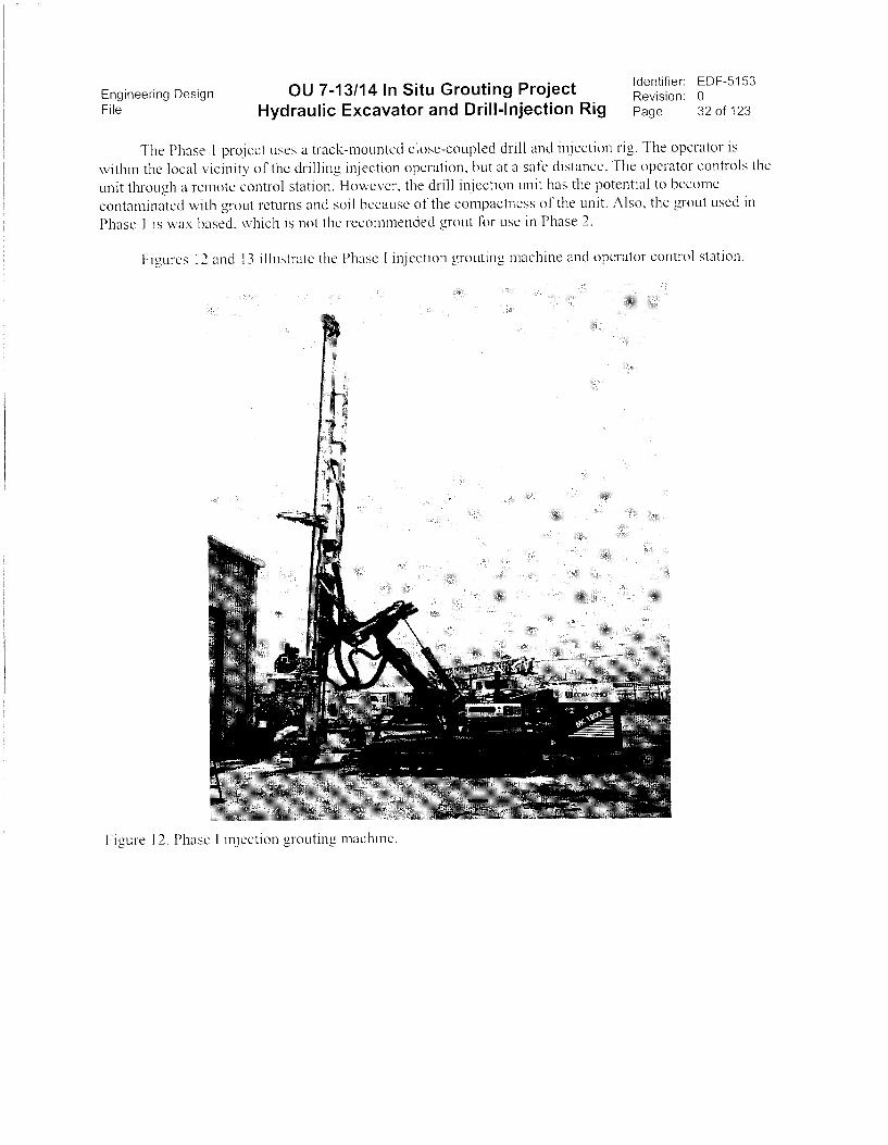
The Phase 1 project uses a track-mounted close-coupled drill and injection rig. The operator is
within the local vicinity of the drilling injection operation, but at a safe distance. The operator controls the
unit through a remote control station. However, the drill injection unit has the potential to becorne
contaminated with grout returns and soil because of the cornpactness of the unit. Also, the grout used in
Phase 1 is wax based, which is not thc recornrnended grout for use in Phase 2.
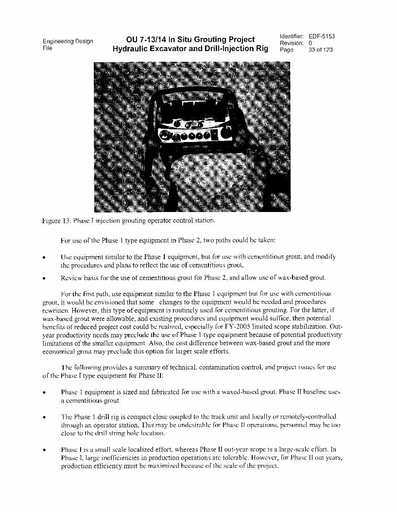
Figures 12 and 13 illustrate the Phase 1 injection grouting machine and operator control station.
Figure 12. Phase 1 injection grouting rnachine.
Engineering DesignFile Hydraulic Excavator and Drill-Injection Rig
OU 7-13/14 In Situ Grouting Project
Figure 1 3. Phase I injection grouting operator control station.
For use of the Phase 1 type equipment in Phase 2, two paths could be taken:
Identifier: EDF-5153Revision: 0Page 33 of 123
• Use equipment similar to the Phase 1 equipment, but for use with cementitious grout, and modify
the procedures and plans to reflect the use of cementitious grout,
• Review basis for the use of cementitious grout for Phase 2, and allow use of wax-based grout.
For the first path, use equipment similar to the Phase 1 equipment but for use with cementitious
grout, it would be envisioned that some changes to the equipment would be needed and procedures
rewritten. However, this type of equipment is routinely used for cementitious grouting. For the latter, if
wax-based grout were allowable, and existing procedures and equipment would suffice, then potentialbenefits of reduced project cost could be realized, especially for FY-2005 limited scope stabilization. Out-
year productivity needs may preclude the use of Phase 1 type equipment because of potential productivity
limitations of the smaller equipment. Also, the cost difference between wax-based grout and the moreeconomical grout may preclude this option for larger scale efforts.
The following provides a summary of technical, contamination control, and project issues for use
of the Phase I type equipment for Phase II:
• Phase 1 equipment is sized and fabricated for use with a waxed-based grout. Phase II baseline uses
a cementitious grout.
• The Phase 1 drill rig is compact close coupled to the track unit and locally or remotely-controlledthrough an operator station. This may be undesirable for Phase II operations, personnel may be tooclose to the drill string hole location.
• Phase I is a small scale localized effort, whereas Phase II out-year scope is a large-scale effort. InPhase I, large inefficiencies in production operations are tolerable. However, for Phase II out years,production efficiency must be maximized because of the scale of the project.
Engineering Design OU 7-13/14 In Situ Grouting Project Identifier: EDF-5153Revision: 0
File Hydraulic Excavator and Drill-Injection Rig Page 34 of 123
8. LESSONS LEARNED FROM PREVIOUS PROJECTS
Lessons learned from early sonic drill rig probe insertion, and Phase 1 beryllium block grouting
projects indicate excessive times to penetrate a compacted soil hardpan layer from approximately 2.5 to 5
ft depth at some locations.
Soils are generally characterized as typical of the surrounding geology and include basaltic type
soils moderately to heavily consolidated. Typical soil breakdown is approximately 37 wt% quartz,
48 wt% clay minerals, 10 wt% calcite, and 5 wt% minor constituents. The climate is high altitude (i.e.,
5,000 ft) arid desert.
Drilling times for this hard layer of 5 to 6 minutes of total drill time of 8 minutes had been
encountered early in the Phase 1 project. This extended drill time combined with the higher flow gearing
of the Phase 1 high pressure pump (no gearing provided for trickle flow) resulted in excessive grout
volumes returning early to the surface. The Phase 1 drill rig used a vibration/hammer with rotation
capability. The probe insertion project used a sonic drill rig with rotation capability.
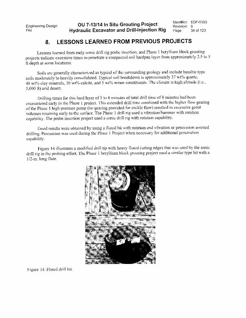
Good results were obtained by using a fluted bit with rotation and vibration or percussion assisted
drilling. Percussion was used during the Phase 1 Project when necessary for additional penetration
capability.
Figure 14 illustrates a modified drill tip with heavy fluted cutting edges that was used by the sonic
drill rig in the probing effort. The Phase 1 beryllium block grouting project used a similar type bit with a
1/2-in. long flute.
Figure 14. Fluted drill bit.
Engineering Design OU 7-13/14 In Situ Grouting Project Identifier: EDF-5153Revision: 0
File Hydraulic Excavator and Drill-Injection Rig Page 35 of 123
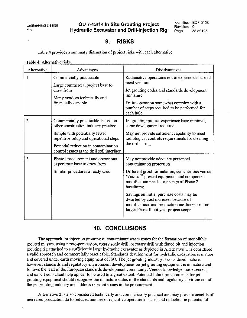
9. RISKS
Table 4 provides a summary discussion of project risks with each alternative.
Table 4. Alternative risks.
Alternative Advantages Disadvantages
1 Commercially practicable
Large commercial project base todraw from
Many vendors technically andfinancially capable
Radioactive operations not in experience base ofmost vendors
Jet grouting codes and standards developmentimmature
Entire operation somewhat complex with anumber of steps required to be performed foreach hole
2 Commercially practicable, based onother construction industry practice
Simple with potentially fewerrepetitive setup and operational steps
Potential reduction in contaminationcontrol issues at the drill soil interface
Jet grouting project experience base minimal,some development required
May not provide sufficient capability to meetradiological controls requirements for cleaningthe drill string
3 Phase I procurement and operationsexperience base to draw from
Similar procedures already used
May not provide adequate personnelcontamination protection
Different grout formulation, cementitious versusWaxfixTm present equipment and componentmodification needs, or change of Phase 2baselining
Savings on initial purchase costs may bedwarfed by cost increases because ofmodifications and production inefficiencies forlarger Phase II out year project scope
10. CONCLUSIONS
The approach for injection grouting of contaminant waste zones for the formation of monolithicgrouted masses, using a roto-percussion, rotary sonic drill, or rotary drill with fluted bit and injectiongrouting rig attached to a sufficiently large hydraulic excavator as depicted in Alternative 1, is considereda valid approach and commercially practicable. Standards development for hydraulic excavators is matureand covered under earth moving equipment of ISO. The jet grouting industry is considered mature;however, standards and regulatory environment development for jet grouting equipment is immature andfollows the lead of the European standards development community. Vendor knowledge, trade secrets,and expert consultant help appear to be used to a great extent. Potential future procurements for jetgrouting equipment should recognize the immature status of the standards and regulatory environment ofthe jet grouting industry and address relevant issues in the procurement.
Alternative 2 is also considered technically and commercially practical and may provide benefits ofincreased production do to reduced number of repetitive operational steps, and reduction in potential of
Engineering DesignFile Hydraulic Excavator and Drill-Injection Rig
OU 7-13/14 In Situ Grouting Project Identifier: EDF-5153Revision: 0Page 36 of 123
contamination spread do to fewer components at the drill pipe soil interface. However, use ofAlternative 2 methods for injection grouting operations would be considered newer technology with areduced experience base, and with perhaps less flexibility in equipment. This alternative may requiresome development effort.
Alternative 3, use of equipment similar to Phase 1 equipment and methods, is consideredtechnically feasible and may be cost effective for FY-2005.
11. RECOMMENDATIONS
This conceptual design effort recommends that the approach for single fluid injection grouting ofcontaminant waste zones for the formation of monolithic grouted masses, as well as foundation groutingusing a roto-percussion, rotary sonic drill, or rotary drill with fluted bit and injection grouting rig attachedto a sufficiently large hydraulic excavator, is a valid approach and commercially practicable. Alternative1, using the drill rig attached to a linear mast, is the recommended approach and should provide sufficientsimilarities to commercial practices for competitive bidding.
This conceptual design recommends the allowance for use of used equipment based on vendordesires. This allowance should provide some means for potential bidders to reduce their financial risk.
This EDF also recommends further study of Alternative 2, using a mastless drill head and activehydraulic sensing and controls, provided funding is available.
12. REFERENCES
Barrow, J., Sonic Drilling Method and Apparatus, US Patent #5,562,169, October 8, 1996
Depth contour map of the Subsurface Disposal Area, INEEL Spatial Analysis map,sda_sediment_thickness_dl_v3.mxd, dated 8/9/2004
EDF-4013, Feasibility Study Technical and Functional Requirements for OU 7-13/14 In Situ GroutingPreliminary Documented Safety Analysis
EDF-5102, OU 7-13-14 In Situ Grouting Project Grout Delivery System
EDF-5135, OU 7-13-14 In Situ Grouting Project Grout Storage and Mixing
EDF-5155, OU 7-13-14 In Situ Grouting Project Operations, Maintenance, and Logistics
E-mail communications with E. Carter, Carter Technologies Company, Project Technical Consultant forInjection Grouting,
E-mail correspondence on reference hydraulic excavator standards, David Gamble, Manager ProductSafety and Compliance, John Deere Dubuque Works, 7/22/2004.
Factory Mutual Data Sheet 7-40, Heavy Duty Mobile Equipment
INEEL/EXT-99-00739, Technical and Functional Requirements for the WAG 7 Drill String Enclosure
INEEL/EXT-01-00278, Evaluation Of In Situ Grouting for Operable Unit 7-13/14
Engineering DesignFile Hydraulic Excavator and Drill-Injection Rig
OU 7-13/14 In Situ Grouting Project Identifier: EDF-5153Revision: 0Page 37 of 123
ISO Standard 9244:1995, Earth-moving machinery—safety signs and hazard pictorials—General
principles
MCP-540, Documenting the Safety Category of Structures, Systems and Components.
OSHA Regulations
Phase 1 ISG status e-mail, D. E. Crisp to D. Abbott, subject: Be ISG PROJECT MODIFICATIONS, soil
hardpan issue and grout returns, 7/22/2004
Raivo, B. et al., Waste Description Information for Transuranically Contaminated Wastes Stored at the
Idaho National Engineering Laboratory, INEL-95/0412, December 1995.
Responses to Expression of Interest, Integrated Hydraulic Excavator and High Pressure Grout Injection
Machine, Federal Business Opportunities, Posted 5/11/04, Closed 5/26/04.
TFR-267, Requirements for the OU 7-13/14 In Situ Grouting Project (Customer, Project, and System)
Vendor Information, Parker Brinkerhoff,http://www.pbworld.comlnews_events/publications/network/issue_40/40_10_PepeF_JetGroutingR
esearch.asp
Vendor Information, Caterpillar, www.cat.com
Vendor Information, Doofer Rock Drills, http://www.doofor.com/products/df751.htm
Vendor Information, Hayward Baker, http://www.haywardbaker.com/services/jet grouting.htm
Vendor Information, Ingersoll Rand, http://www.ircmg.com/rockdri11/4066/gen pl.htm
Vendor Information, International Construction Equipment (ICE), www.iceusa.com
Vendor Information, John Henry Co., http://www.iohnhenryrockdrill.comlindex.html,http:llwww.iohnhenryrockdrill.com/action.html
Vendor Information, M. Meehan, Hercules Machinery Corp., www.hmc-us.com.
Vendor Information, Paul Eberhardt, Western Rubber and Mfg., www.westernrm.com,
Vendor Information, PACO, http://www.pacoequip.com/db catalog.html?parent id=145
Vendor Information, Precision Sampling http://www.precisionsampling.com/print-version.php
Vendor Information, Prosonic Corporation, http://www.prosoniccorp.com/sonicdrilling.html
Vendor Information, TRAMAC, http://www.tramac.com/rockdrills/drills.htm,http://www.tramac.com/whatsnew/article22.htm
Vendor Information, Dean Bennett Company, http://www.deanbennett.com/drill-stem-wipers.htm
Engineering Design OU 7-13/14 ln Situ Grouting Project Identifier: EDF-5153Revision: 0
File Hydraulic Excavator and Drill-lnjection Rig Page 38 of 123
13. APPENDIXES
Appendix A—Standards
Appendix B—GIS Preliminary Subsurface Disposal Area Data
Appendix C—Drawings
Appendix D—Excavator Information, Caterpillar Model 345B and Model 385
Appendix E—Auger Type Drill Rig Mounted On 90,000-lb Class Hydraulic Excavator
Appendix F—Injection Grouting Methods, Hayward Baker
Appendix G—High Pressure Swivel, Western Rubber and Manufacturing
Appendix H—Active Control of Hydraulic Control Circuits (HMC, MOVAC Auto Sensing II)

Engineering Design OU 7-13/14 In Situ Grouting Project Identifier: EDF-5153Revision: 0
File Hydraulic Excavator and Drill-Injection Rig Page 39 of 123
Appendix A
Standards

Engineering Design OU 7-13/14 In Situ Grouting ProjectFile Hydraulic Excavator and Drill-Injection Rig
This page is intentionally left blank.
Identifier: EDF-5153Revision: 0Page 40 of 123
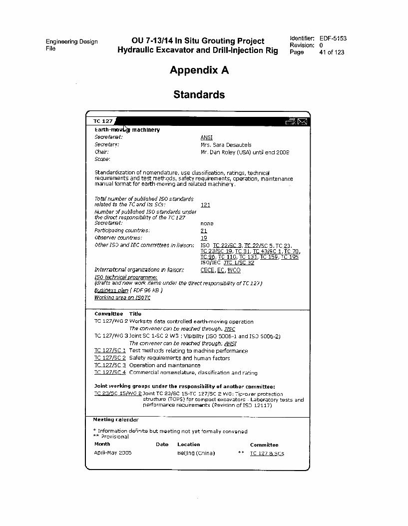
Engineering Design OU 7-13/14 In Situ Grouting ProjectFile Hydraulic Excavator and Drill-Injection Rig
Appendix A
Standards
Identifier:Revision:Page
Earth-mow machinery
Secretariat:
Secretary:
Chair:
Scope:
ANSI
Mrs. Sara DesautelsMr, Dan Roley (USA) until end 2008
Standardization of nomendature, use classification, ratings, technicalrequirements and test rnethods, safety requirements, operation, maintenancernanual format for earth-moving and related machinery.
Total number of buNished ISO standardsrelated to the TC and its SCs:
Number of published ISO standards underthe direct responsibility of the TC 127Secretanat:
Participating countries:
Observer countries:
Other ISO and IEC committees in liaison:
internattnal organizations in liaison:150 tectrical proorarnrne: (drafts and new work items under the direct responsib4ty of TC 127)8usiness plan ( PDF 96 KB )Workina area on ISOTC
121
none
21
19
ISO TC 27IRC a, TC 72/SC S, TC TC 23(SC 19, TC 31, TC LI-31SC 1, TC 70,TC 96, TC 110, TC 131, TC 159, TC 195 ISO/IEC JTC 1/SC 32
CECE, EC, VVCO
Committee Title
TC 127/WG 2 Worksite data controlled earth-moving operationThe convener can be reached through: J/Sc
TC 127/WG 3 Joint SC 1-SC 2 WS Visibility (ISO 5005-1 and ISD 5006-2)The convener can be reached through: ANS/
TC 127/SC 1 Test methods relating to rnachine perfarmanceTC 127/SC 2 Safety requirements and human factorsTC 127/SC„1 Operation and maintenanceTC 127/SC 4 Comrnercial namenclature, classificatian and rating
Joint working groups under tho responsibility of another committee:TC 23/SC 15/WG 2 Joint TC 23/SC 15-TC 127/SC 2 WG: Tip-over protection
structure (TOPS) for compact excavators - Laboratory tests andperformance requirements (Revision of ISO 12117)
Meeting calendar
* Information definite but meeting not yet formally convened** ProvisionalMonth Date Location Committee
April-May 2005 Beijing (China) " TC 127 & scs
EDF-5153041 of 123

Engineering Design OU 7-13/14 In Situ Grouting Project Identifier: EDF-5153Revision: 0
File Hydraulic Excavator and Drill-Injection Rig Page 42 of 123
M2212004 02.51 PM
To
boc
Subject
■ Brian D RairalPAIVIDDICCO1JIMEELLIS@IMEL
Fre inquiry an The applicable stab dardi for l-lydraulic Bon:melon
Bee webehe belaw.
Fon.varded by Lynn E MelariderNELALEICC01IINEEL11)8 on 0712.2.2004 (12 50 F1,4 —
'Gamble David B'taambleDavidf30johndears.co
07122120N 0243 PM
To
ct
rnelale gou
Butnea. FW: Inquily on ihe applicable standarts for 1-tydraulic Excernabm
David Gamble!Tanager Product 2catety 6 ComplianceIlar2dulde Construction t Forestry Div.
John Deere Dubuque Unrka
Mmail: GambleDavidlgJohnDeere.com
Phone: 565/S89-6620FAX! 563/5B9-5464
Original Message From! Gonble David M
Sent; Thursday, July 22, 20DA 5:41 PK
To:Sublect: Inquiry on the applicable atandarda Tor Hydraulic Excavator5
Dear Br. Xelander,
The applicable standards for hydraulic excavators are MO standards under MO TechnicalCommittee 127 Earthmoving Kachinery. Below is o veb site that rill list all the
applicable standarda for earthmoving machinery and tbeae would needed to be eorted to
those standards that apply to excavators as some apply to other machine fOIMB. Belau issorted list I have prepared !ar your raferenae: havever, it may be out or date in terma orthe most recent applicable etandard editiona and it 'ma prepared for the North Linericannerket, Please contact me directly bg phone or email 1/ you need more assistance.
P5 I hope John D ere excavators are being considered ir there 1s a purchase opportunity.
.c-eCEDExc ZarecyHtds,docY›littp://vav.iao.cbt,iachten/CataloqueLierPame.CateilncrneList7ICS1...53rics2200
Regards,David Ganble
&inlayer. Piuduut 8ateLy t Cumplianue
Gorldvide Conatruction i Foreatry Div.
Tobn Deere Dubuque iiorksEmail: [email protected]
Phone: 563/569-6620
FM 5681589-5464
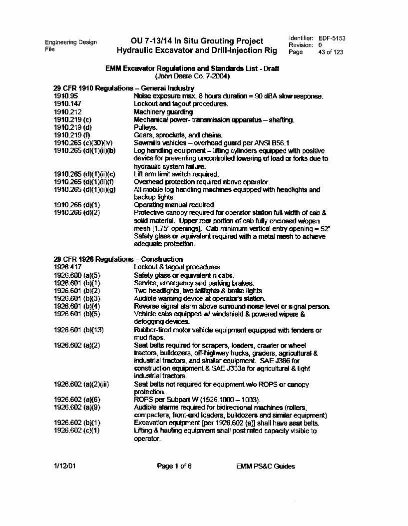
Engineering Design OU 7-13/14 In Situ Grouting ProjectFile Hydraulic Excavator and Drill-Injection Rig
Identifier: EDF-5153Revision: 0Page 43 of 123
EMM Excavrdor Regutitions and Strmdards List - Draft(John Deere Co. 7-2004)
29 CFR 1 0 Regiilitions — General Industry191025 Noise exposure max_ 8 locus duration = 90 ol slow response.1910_147 Lockout and tagout procedures.1910212 Machinery warring1910219 (c) PAecharical poover- transm ion awparatus — shafting.
Pulleys,.Gears, sprockets, rrodSava-ails vehicles — overhead guard per ANSI B56.1Log handl-kg equipment — glinders eqt *iped with posithredevke for preventing uncontrolled lowering of load or forks ckhe tohydresiic system failure.Lift arm lkrit switth required.Overhead protection required above operabr.All moble IN handing "es aTipped with -ghts andbackuP kits.Operatkig manual requieol.Prolective canopy required for operator statkin full wtrth of cab &solid material. Upper rear portion of orb fuiy enclosed wkopenmesh [1.75n cperikogs]. Cab ninimurn verliciA entry opening =Safety glass or eqivalent required wth a rnetiA rnesh to achieveadecpiate protection.
1910219 (d)1910219 (f)1910265 (cX Xiv)1910265 (d)(1)(ii)(b)
1910265 (d)(1 )(ii)(c)1910265 (d)(1)(ii)(f)1910265 (d)(1)(ii)(g)
1910266 (d)(1)1910266 (d)(2)
29 CFR 1926 Regul1926.4171926_600 (a)(5)1926.601 (b)(1)1926.601 (b){2)1926_601 (b)(3)1926.601 (b)(4)1926.601 (b)(5)
1926.64)1 (b){13)
1926.602 (a)(2)
1926.602 (a)(2)(iii)
1926_602 (a)(6)1926_602 (a)(9)
1926_602 (b)(1)1926.602 (c)(1)
01
ions — ConstructionLockout & tagout proceduresSafety glass or equivalent n cabs.Service, emergency and perking brakes.Two headlights, two tailights & brake lights.Audble voixning device at operator's station_Reverse signal alarm above surround noise leve signal person.Vehicle cabs equipped w! wi-odshiekl & powered wipers &defoggtog devices.Rubber-tired rnotor vehicle equipment equipped with fenders ormud flaps.Seat betts required for scrapers, baders, crawler or wheeltractors, bulldozers, off-highway trucks, graders, agriculti.ral &industrial tractors, and skniar equipment. SAE n86 forconstruction equipment & SAE J333a for agricultural & lightindustrial tractors.Seat belts root required for equipment wio ROPS or canopyprotection.ROPS per Subpart W (1926_1000 — 1003).Audible alarms required for bidirectional machines (rollers,compacters, front-end loaders, bulldozers and similar equipment)Excavation eopipment [per 1926.602 (a)] shall have seat belts.Lifting & hauling equipment shall post rated capacity visible tooperator.
Page 1 of 6 EMM PS&C Guides
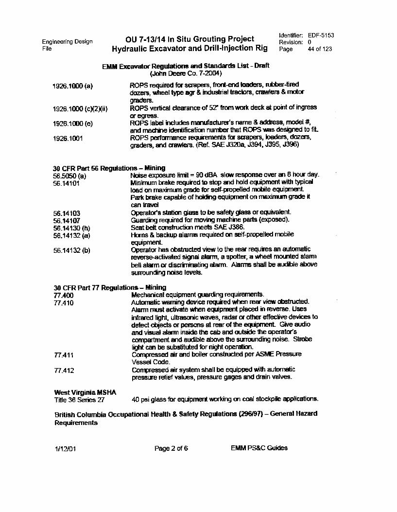
Engineering DesignFile Hydraulic Excavator and Drill-Injection Rig
1926.1000 (a)
1926.1000 (cX2Xii)
1926.1000 (e)
1926.1001
30 CFR Part 56565050 (a)56.14101
56.1410356_1410756_14130 (h)56_14132 (a)
56_14132 (b)
OU 7-13/14 In Situ Grouting Project
EhIM Excavrgor Regdiations and Standards List - Malt(John Deere Co_ 7-Z104)
ROPS required for scrapers, front-end loaders, rubber-tireddozers, wheel type agr & industrial tractors, crawlers & mctorgraders.ROPS vertkal dearance of 52° om vifork deck at point of ingressor egress_ROPS label includes manufacturer's name & address, model It,and =chile idertification number that ROPS was designed to frt_ROPS performance requkermaill for scrapers, loaders, dozers,graders, and cavilers. (Ref. SAE J320a, J394, J395, J396)
Identifier:Revision:Page
EDF-5153044 of 123
ul ns — MiningNoise exposure limit = 90 dBA slow response over an 8 how day_Minimum brake required to stcp and hold equipment with typicalload on maximum grade for self-propelled motile equipment_Park brake capable of hoking equipment on maximum grade itcan travelOperator's station glass to be safety glass or equivalent.Guard-kg required for moving machine paris (=posed).Seat bett construction meets SAE J386.Horns & backup alarms required on self-propelled mobileequipment.Operator has obstructed view to the rear requires an automaticreverse-activated signal alarm, a spotter, a wheel mounted alarm
bell alarm cc discrirrinating alarm_ Alarms shall be aucible abovesurrouncing noise levels.
30 CFR Part 77 Regulations — Mining77_400 Mechimical equipment waging requirements.77_410 Automatic wEkring device required when rear view obstructed_
Alarm must activate when ecgipment pkiced in reverse. Useskifrared f ultrasoric vvaves, radar or dher effective devkesdetect daiects or persons at rear d tte equkment_ Give audioarid visual alEsm inside the cab arid outside the operatofscaripartrnent auxible above the stkroundkig noise. StrobekW owl be substituted for nilit operation_
77.411 Convessed sir arid boiler constructed per AShE PressureVessel Code.
77.412 Compressed sir system shall be equipped with aukinuticpresswe relief values, pressure gages and ckain valves.
West Virginia MSHATitle 36 Series 27 40 psi glass for eqiipment working on stockple applications.
British Cokanbia cupational Health & Safety Regulations (296/97) — General Hazard
Requirements
1/12/01 Page 2 of 6 C

Engineering DesignFile
OU 7-13/14 In Situ Grouting ProjectHydraulic Excavator and Drill-Injection Rig
Identifier: EDF-5153Revision: 0Page 45 of 123
EMM Excavator R dations arid Standards List - Draft(John Deem Co. 7-2004)
Part 7 Noise, Viairabon, Radiation and Temperature72 Exposure limits- 85 dBA Lex (1 Pa2 h) &at( exposure & 135 dBA
peak sound level.7.25 Evaketion of vitiation - whole body according to ISO 2631 Part 1
"Evaivaticii of Human Exposixe lo Whole-body Viirationz726 Equipment saiection & use - ecaipment that meets the "dries
must be used ki preference to eck*ment, wtich produces higherlevels of vixation.
T27 Labels- equipment wiich produces levels ce vibration aboverecomrrencled guithines mist be labeled to ken* the hazard.
Part 16 -le Equi at16.8 Wamkg stria device - mbile equipment in which the operator
cannot drectly or by mirror a- dher effective device seerianeciately behind the machine mist have an adornatic audiblewarning device. The device mist (1) activate whenevereqiiprnent corircds are positioned to rnove the equnTent inreverse, and (2) is aucible above tte arnbient noise level.(Atka natives inckide a *mat person)
16_9 Lights - that meet the reqdrements of SAE J1029 '3Lightkig &Marking of Ccustrucbari and Inckistrial Mecham"
16.10 Rew view mirrors - must have a mirror ar mirrors. Rear viewmirrors are not required if the equiprnent wakes the use of rrirrorskivracticable.
16.11 Window starklards - safety Oalmg meeting ANSI Z26.1-1993'Safety Gazing Materkis for Gla;Jng Motor Veticies & MotorVehicle Exxitxnerit Operatrog on Land High/rays - Safety Code"
16.13 Braking requirements - SAE J1473, J1026, J1178, J1472, ASO1151Z JIISO 11512, and ASME B56.6.
16.14 Supplementary steering - meeting SAE J1511 and ISO 5010.[1616] Safe star"; - eqiipmerit protected from engine starter
engagement when coupled to the *reels or track_[16.17] Escwie from a cab - mottle eqipment mareachred after
January 1, 2000 must have alternate mans of escape that (1) isclearly marked inside & outskle; (2) can be opened from eitherriside or outside without am, use of tools; (3) maxinawn openirgtree of 135 it (30#); and (4) has mkikrium opening sizereckiiremerts [65 cm diwneter, 60 cm square, 47 cm x 65 cm[ectangle].
[16.18] Contrds - hydrauic log fowlers, hydraulic excavaiors and hoechucking rrectines mat meet SAE J1177
[16.21] Guards - must meet tie applicebe standards WCB Standard -G601-609, SAE J231, J1043, 150 3449, J1084, J1356
[1622] Rollover pratective structures - meet the reqiirements of ISO3471 or SAE J1040.
[16.32] Seat belt provisions according to SAE J3
1/12/01 Page 3 of 6 EMM PS&C Guides

Engineering DesignFile Hydraulic Excavator and Drill-Injection Rig
OU 7-13/14 In Situ Grouting Project
EMM Excavator Regtiations and Standards List - Draft(John Deere Co_ 7-2004)
Identifier: EDF-5153Revision: 0Page 46 of 123
ISO StandardsISO 1585 Engine test codeISO 2631 Guide for evaluaticn of humeri e b le-body vitration
ISO 2860 EMM Pifirin11111 access dimensionsISO 2867 EMM - Access SystemsISO 3164 EMM - Lab evakudions of ROPS & FOPS - specific:aim for
dellection-liiitiryg volumeISO 3411-1 EMM - Mthirrern operator spew envelcpeISO 3449 EMM - FOPS - lab tests and pericanance requiernentsISO 3450 EMM-Brsking systems of atter-tired mactines - Systems &
performance rewirements & test ixoceduresISO 3457 EMM Guercls - Defritions & requiementsISO 3461-1 Graphical symbols fix use on equbrnentISO 3471 EMM - ROPS - lab tests & performance reqiirementsISO 3600 Tractors & mactinery fix & fixestry - Operator manuris &
technical publications - presentationSO 3795 Road vehicles, & teems and machinery for al7kaiture & brestry
- Detemikitim of buning behavior of interior materiaks.150 3864-3 Safety colors & safety sicyis prorbet safety labelsISO 4254-1 Forestry - Technical means for ensuring safetyISO 4254- 4 Forestry varichesISO 4510 1-1End tools for m *antenance & adjustrmat workISO 5005 EMM - Method of locality; Center of GravityISO 5006-1 EMM - Cpenstart field of vOew - Part 1: Test method
ISO 5006-2 EMM - Part 2: Eveduation methodISO 5006-3 EMM - Part 3: CriteriaISO 5010 EMM Ribber-tyred machines - Steering requirementsISO 5131 Agriculturri Tractcts & Forestry - Meastzernent of Ncise at
Operator's Position_SO 5353 EMM Seat nelex rbtitISO 5596 AccirmligorsISO 5805 Mecharical vbration. & shock - Human expostre - VocataeryISO 6011 EMM - Vsual display of machine operation fractionsISO 6012 EMM - Service instrumentationISO 6014 EMM Determthation of ground speedISO 6015 EMM Hydratiic excavatcrs -Methods of detem *ring tool forcesISO 6016 EMM - Methods of measuring the masses of whole machines,
their equbmnt and commentsISO 6165 EMM - Basic types - VocabularyISO 6302 EMM - Cvan,1Th & level piugsISO 6385 Ergonomic princbles in the design of work systemISO 6393 EMM - Acoustics - Measurement of exterior nni-sP enitted by
earthmovng ecRipmert -Stalionay test concfflicrisISO 6394 EMM -Acoustics - Meastrement r‘ the operatces position of
noise emitted by ealhmoving mactinery - Stationary testconditions
1/12/01 Page 4 of 6 EWA PS&C Guides
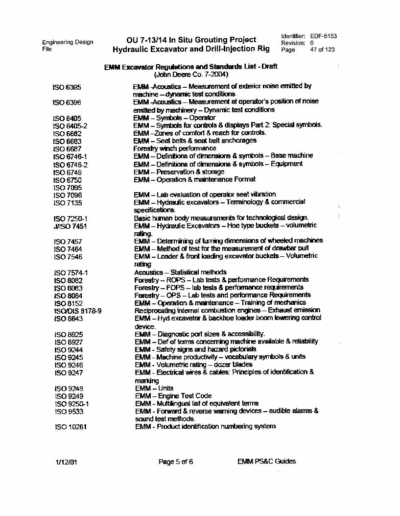
Engineering DesignFile Hydraulic Excavator and Drill-Injection Rig
ISO 6395
ISO 6396
ISO 6405ISO 6405-2ISO 6682ISO 6683ISO 6687ISO 6746-1ISO 6746-2ISO 6749ISO 6750ISO 7095ISO 7096ISO 7135
ISO 7Z0-1ASO 7451
ISO 7457ISO 7464ISO 7546
ISO 7574-1ISO 8082ISO 8083ISO 8084ISO 8152ISO/DIS 8178-9ISO 8643
ISO 8925ISO 8927ISO 9244ISO 9245ISO 9246ISO 9247
ISO 9248ISO 9249ISO 9250-1ISO 9533
SO 10261
1/12101
OU 7-13/14 In Situ Grouting ProjectIdentifier: EDF-5153Revision: 0Page 47 of 123
EMM Excavator Regdations arid Standards List - Draft(John Deere Co_ 7-2004)
EMM -Acousbcs — Measurement of extol noise emitted bymachine —dynamic test conditionsEMM -Acoustics — Measkserrent at operator's pordion of noiseemitted by machinery — Dynamic test conditionsEMM — Symbols — OperabrEMM Symbols for controls & displays Pert Special symbols.EMM —Zones of comfort & reach for controls.EMM — Seal bets & seat belt anchoragesForestry winch performanceEMM — Definkions of dinensicwis & symbols — Base rnachineEMM Definbons of dimensions & symbols &wnedEMM — Preservation & storageEMM — "on & makitenance Format
EMM — Lab evaluation of operatcr seat vbrationEMM Hijklnalic excavators Terrninology & convnercialspecifications.Basic Ivxnan body measixerireits bar technolocical clesigtEMM — Hydrralic Excavators — Hoe type buckets — volumetric
EMM — Detem*kg of turning dimensions of wheeled machkiesEMM — Mehod of test for the measurement of drawbar pullEMM — Loader & front loaclkg excavator buckets — VolurivtricrekigAcoustics — Statistical methodsForestry — ROPS — Lab tests & performance RecarkementsForestry — FOPS — lab basts & performance reqdrementsForestry — OPS — Lab tests and performance RequirernantsEMM OVeration & mantenance —Trainkg af mecharicsReciprocating internal combustim entines — Exhaust eilliSsiCeEMM — Hyd excavator & backhoe loader boorn bwerkig controldevioe.EMM — Diagnostic post sizes & accessibility_EMM Def of terrns concern-kg machine avaistle & reliabilityEMM Safety signs mid hazard pkfixidsEMM - Machine pnoductivity — vocabulary symbols & witsEMM Volumene rating — dozer bladesEMM Electrkal wires & cables: Prkiciples a -"cation &markingEMM — UnitsEMM — Erigkie Test CodeEMM - Mdtffinguri list of equivalent termsEMM Format & reverse warring devices — audible alarms &sound test methods_EMM - Prod-let klerdification numbering system
Page 5 of 6 PS&C Guides
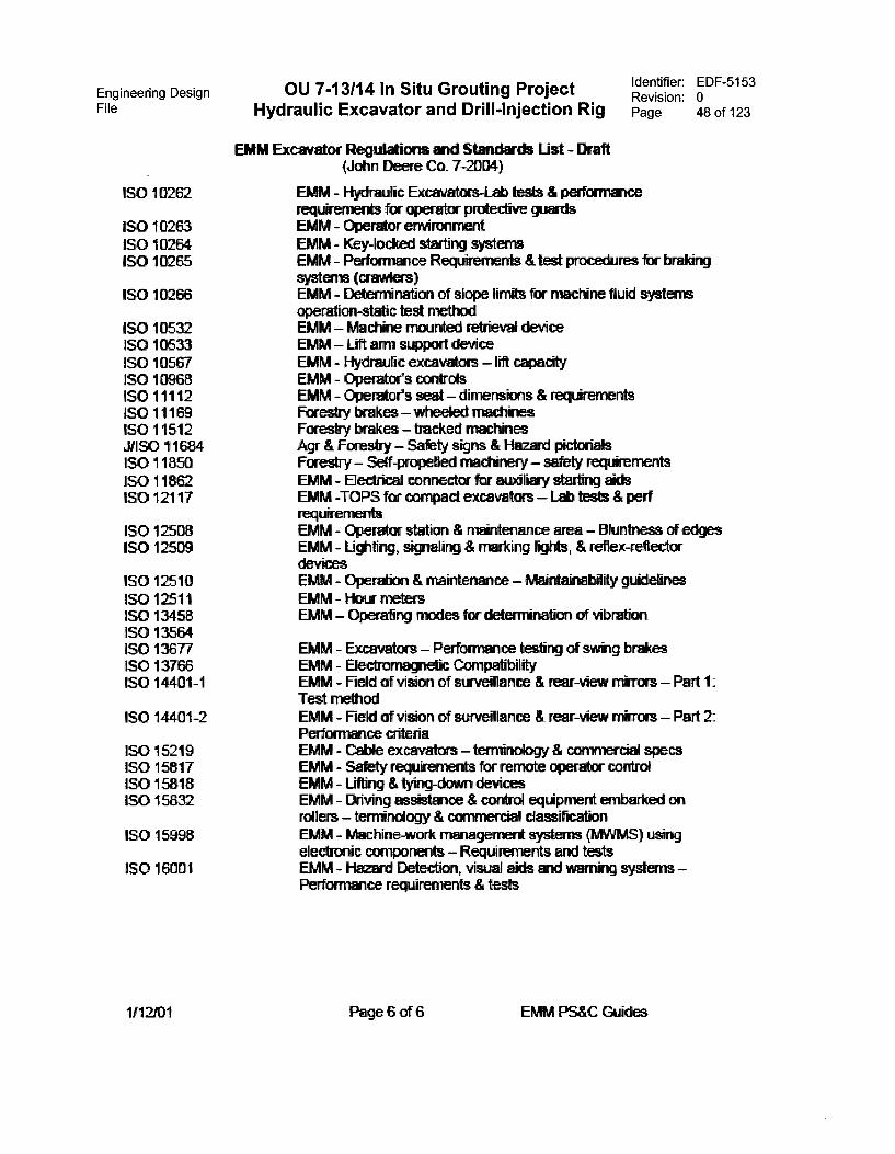
Engineering DesignFile Hydraulic Excavator and Drill-Injection Rig
ISO 10262
ISO 10263SO 10264SO 10265
SO 10266
SO 10532SO 10533SO 10567SO 10968SO 11112SO11169SO 11512XlSO 11684SO 11850ISO 11862ISO 12117
ISO 12508ISO 12509
ISO 12510ISO 12511ISO 13458ISO 13564ISO 13677ISO 13766ISO 14401-1
ISO 14401-2
ISO 15219ISO 15817ISO 15818ISO 15832
SO 15998
ISO 16001
1/12/01
OU 7-13/14 In Situ Grouting Project Identifier: EDF-5153Revision: 0Page 48 of 123
EMM Excavator Regtgations anti Standards List - Draft(John Deere Co. 7-2004)
EMM - Hyrkaulic Excavators-Lab tests & performancerequaernents for operator protective wardsEMM - Dixador environmentEMM - Key-locked Starting systemsEMM Performance Redirements & test procedures fa- twaldngsystems (crawiers)EMM - Deternination of slope kits for mactine fluid systemsoperation-static test methodEMM - Machne ribunted re" dew*EMM - Lift arm sumort deviceEMM - Hytamic excavators lift capacityEMM Opentor's controlsEMM - Orerda's seat - dimensions & red.irementsForestry brakes - wheeled machnesForestry brakes tracked mil:tinesAgr & Forestry - Safety signs & Hazard pictorialsForestry - Setf-propeked machinely - safety rednementsEMM Electricd connector for auxiliay starling aidsEMM -TOPS ftr compact excavators - Lib tests & perfrequaernertsEMM - Opera:or stabon & naintenance area - Bluntness crf edgesEMM Lighting, siwafing & marking lilts, & reflex-reflectordevicesEMM Operaocri & maintenEnce - hitaktanablity guidelinesEMM - Hera metersEMM - Operafing rnodes for deteminaticn ot vibration
EMM - Excavators - Performance testing of swag ImamsEMM Electranawetic CompabbiktyEMM - Field of vision of survediance & rear-view - Part 1:Test methodEMM - Field of vision of stavellance & rear-view manors - Pad 2:Perforrance criteriaEMM Cable excavators - temindogy & commercial specsEMM - Safety requaernents for rernote operator contraEMM Liting & tyavg-down devicesEMM - Diving assistince & codicil equipment embarked onrollers - terminology & cawnercad classificaticnEMM - Machine-work mmagernent systems (MWN1S) usingelectrode componerts - Requirements and testsEMM Hazard Detection, visual aids and wamaig systems -Performence rewirements & tests
Page 6 of 6 PS&C Guides
Engineering Design OU 7-13/14 In Situ Grouting ProjectFile Hydraulic Excavator and Drill-Injection Rig
Identifier: EDF-5153Revision: 0Page 49 of 123
w;;;)1 I I ; I till %II W..
PR seed a svbssie
Recent Advances Are Changing Design And Construction
Jet Grouting Research and Applications
By Frank Pepe, New Ye*, NY 212-465-5215, olld.corn
Go To Other Issues I Contact PB Network
O. of the firre. lessons an enlace learns is dud a key to s continue ce learn sheet sew technolocies. RIK.fulin this het
and the patented benefits of sew technologies. P8 is banding retearck ® jet gram eing—a pewee's] grouted improvement technique e.ThE article discasses some esperts dem research mad jet pectin- applica ties.
Ground enprovement is one of the MOSI interesting and innovative practice alms withingeotechnical engineenng. It includes a wide range of technologies that modify the in situproperties of a soil or rock deposit by in:reasing its strength, reducing its compressibilityca decreasing its permeability so that the deposit is suitable for a design purpose. Onesuch technology, jet grouting, is receiving considerable attention.
Jet growing is a soil graining method that uses a very high pressure of 34.500 kPa to55,0130 kPa (5,000 to 5,000 psi) to injeci a cutting and ground cementing fluid int) a soil&posit_ The high pressure fluid, which can be the cementing agent, cuts end mixes withthe natural sail and forms a cemented soil element (Figure I). The method is basically anerosiovreplacemort proems that romoves a portion of the sail particles and replacesthem -with a minute of soil and cement FMK that lias an increased strength and lowpermeability when hardened. The most common elements produced by the jet grouting,enter cylindrical cohmins or yamols. can be combined to form stabilized blocks andwalls of matenal that can be pait of a construction project.
The use of jet grouting has increased tremendously in much of the world since tbe late1970s and in tbe 1LS. since the Irte 1980s. This growth is due io the increasingawareness of the bereits that jet grouting provides and tbe strong marketing effortsmade by specialty contractors. The system is very flexible and can be used to treat awider range of soils than any other grouting system (Figure 2).
PB ham used jes grouting on the Baltimore Metro in Maryland. the Caito Metro in Egypt.and on the MARTA system in Manta Georgia, and is currently using it on die 63rd .4Street Tunnel Connection in New York City and on the Central ArterpTuonel project in 1,
CI 14MA
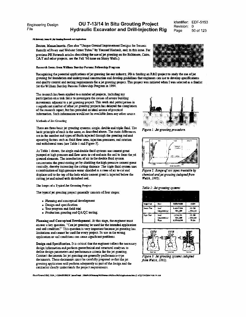
Engineering Design OU 7-13/14 In Situ Grouting ProjectFile Hydraulic Excavator and Drill-Injection Rig
Winn 00=0 Iht Orosig arm* APlikalm
Boston. Massachusetts. (See also "'Unique Ground Improvement Desipis for Seismic
Retrofit of Posey and Weimer Street Tuber by Youssef Hashash, etal, in this issue. For
previous PB Netwrok uncles descnliimg the use of jet grouting cm the Baltimore. Cairo,CAT and other projects. see tbe Fall Vd issue on Shiny Walls.)
Rum& Steals ire= Wilma Barclay Pararas Tollawsbip Prafrata
Identifier: EDF-5153Revision: 0Page 50 of 123
F04-nri7i.E the potential applications of jet pouting for oar industry, PB is fonslin-E an RAD project to study the use of jetgrouting for foundation and underground construction and develop guidelines that engineers csa use to develop specificationsand quality connol and testing requirements for a jet grouting project. This project was initiated when I was uaRrted as a finalist5©r the Wall= Barclay Parsons Fellowship Prop= in 1994.
The research has been applied to a number of projects, including myparticipation on a task force to investigate the causes of severe buildingmovements adjacent t© a jet grouting project This work and participation ina significant number of tuber jet grouting projects has delayed the completionof the research report. bat has provided an ideal source of practicalinformation. Such information would not be available from any other source.
Moho& *flea Gr
There are three basic }et grouting systems: single. double and niple fluid. Thebasic principle of each is the same, as deg:riled above. The main differencesare in the number and types of fluids injected through the grouting tad andcapturing factors such as finid flow rates, injection pressures, rod rotationand withdrawal rates (see Table l and Figure 3).
As Table 1 shows. the sing P and double fluid systems me cement ruoutpumped at high pressure and flow rates to cut and inks the soil to form tbe jetgrouted elements. The introduction of air in the double fluid systemconcentrates the grout cutting jet by shiel' ding the high pressure cement groutconically, theieby increasing the cutting distance_ The triple fluid system usesa combination of hign pressure water shiekled in a cone of air to cut anddisplace soil to the top of the hole while cement grout is injected below thecutting jet and mixed with disunited soil
The Scars of a Typical Jet Grueling Project
The typical jet grouting project generally consists of four stages:
• Planning and conceptual development• Design and specificatione, Test program and fiold trial• Production pouting and QAMC testing.
Pleasing and Conceptual Development At this stage. the engineer muganswer a key question. 'tan jet pouting be used for the intended applicationand soil condition?" This question is very iniportio because jet grouting haulimitations and cannot be used for every project. Its use in the virongapplication or soil conditions can cause significaru problems.
Design and Specification. It is critical that the engineer collect the necessazydesign information and perform geosechnical and structural analyses todefine design parameters and perforrnance criteria for the jet groutingContract documents for jet pouting are generally performance-typedocuments. These documents must be carefully prepared so thin the jetgrouting application will perform adequately as part of the design amd tbecontractor dearly understands the project requirements.
dirAltv.rwacsa_sneo
Figure 2: Range resell opts imitable bychemical aind jet gram* (adapted/taxWelsh, 1992).
Table 1: Jet rowan systems
Figure 3: Jet graraarg syAwn Welsh, 199,2).
tanot5 bat .1110011144tvatimilfiatilamoraliKattaite btoc gely?
Engineering DesignFile Hydraulic Excavator and Drill-Injection Rig
OU 7-13/14 In Situ Grouting Project
Fs mg.:* I *me *KM Ono* Ihrsell AwIlatifir
Identifier: EDF-5153Revision: 0Page 51 of 123
A rrinral element of this stage is the developmene of a complete set of specifications that clearly define the desip. testing andquality control requirements far the jet pouting application. aad the method of payment The developanent of the design, testingand quality control requirements should virally be done by the wines- The jet grouting techniques and detailed proceduredevelopment are best left to the contractnrs who specialize in the technique and have experience and expertise in itsperformance.
Test Program asil Field TriaL At the present time, there is no myriad procedure that can be used to design the jet grouting_Cortelations that define gross properties of jet grouted sods exist, but development of a simple. imiversally accepted desigzapproach is prechuled by the variations in techniques used by contactual. and the variability of the soil. Prior to any productiongrouting, a test program and field trial niust be continued on site using the contractor' s proposed equipment and techniques toestablish the procedures and grouting parameters ka use in die production gloating.
The test program must include cinality control testing and adequate monitoring to validate that the procedures and techniquesused will provide die design requirements and satisfy the assumptions made during design. It k critical that the engineer planand specify the teshng program and acceptance criteria so that the design is verified and performance oldie jet grouting systemis adequate.
Precludes Grouting Rai QA/QC Testing. Quality control and assurance procedures and inspection must be provided toensure dat grouting procedures and parameters developed from the tea program are followed_ This is one of the most criticalphases of the project a®d must be conducted by qualified. experienced representatives from both the contracting and engineeringfirms. Quality control tests must be conducted on production columns to confirm that adequate performwice has been achieve&
Jet ®ain Stssiards
Jet growing can be used in a wide Inge of soils sad the equipment used is easily adaptable to varions site conditions_ Its use fora variety of appliraams, especially in Japan and Europe, has led to the development of European Jet Graining Standards_ Thesestandards, which are es.sential for the successful use and growth of jet grouting technology, address the key issues for theexecution, testing and monitoring diet grouting applicntions. At this tune, die &mean Jet Grouting Standards am beingfinalized by the European Committee for Standardization (CEN) for use by all CEN members.
The development of mRiiar standards in the U.S. has lagged behind the European experience. This delay is due partly to tlxre]atively new acceptance aad use of jet grouting in the U_S. Without reliable and adequate design, specification, testing hidmonitoring standards, however, engineers who want to use the technique are forced to "reinvent the wheer and team the samelessons that other engineers have learned. The lack of standards leads to problems that can result in poor performance of the jestgrouting or worse. Because of the high pressures used in jet grouting. die consequence of mistakes can be severe, especiallywhen the technique is used in urban construction.
Casa:nee.
PB's iesearch on jet grouting is attemplin tv identify the tequilmeents for jet grouting execution and Fermi& guidanceto engineers who develop jet grouting contract documents and monitor of field opemtions. A report that is being prepared willpresent specification guidelines, testing recommendations and inspection quality control cbecktists and pfidelints_ The repentwill be available to PB engineers and our peers and will add, it is hoped. to the knowledge and successful application of jetpouting. R&D
thwArnap.z sati-zowilDimar bmosivit.
Go To Other Issues I Contact PB Network
12N313011 AM

Engineering Design OU 7-13/14 In Situ Grouting ProjectFile Hydraulic Excavator and Drill-Injection Rig
This page is intentionally left blank.
Identifier: EDF-5153Revision: 0Page 52 of 123

Engineering Design OU 7-13/14 In Situ Grouting Project Identifier: EDF-5153Revision: 0
File Hydraulic Excavator and Drill-Injection Rig Page 53 of 123
Appendix B
GIS Preliminary Subsurface Disposal Area Data
Engineering Design OU 7-13/14 In Situ Grouting ProjectFile Hydraulic Excavator and Drill-Injection Rig
This page is intentionally left blank.
Identifier: EDF-5153Revision: 0Page 54 of 123
Engineering Design OU 7-13/14 In Situ Grouting ProjectFile Hydraulic Excavator and Drill-Injection Rig
Appendix B
Identifier: EDF-5153Revision: 0Page 55 of 123
GIS Preliminary Subsurface Disposal Area Data
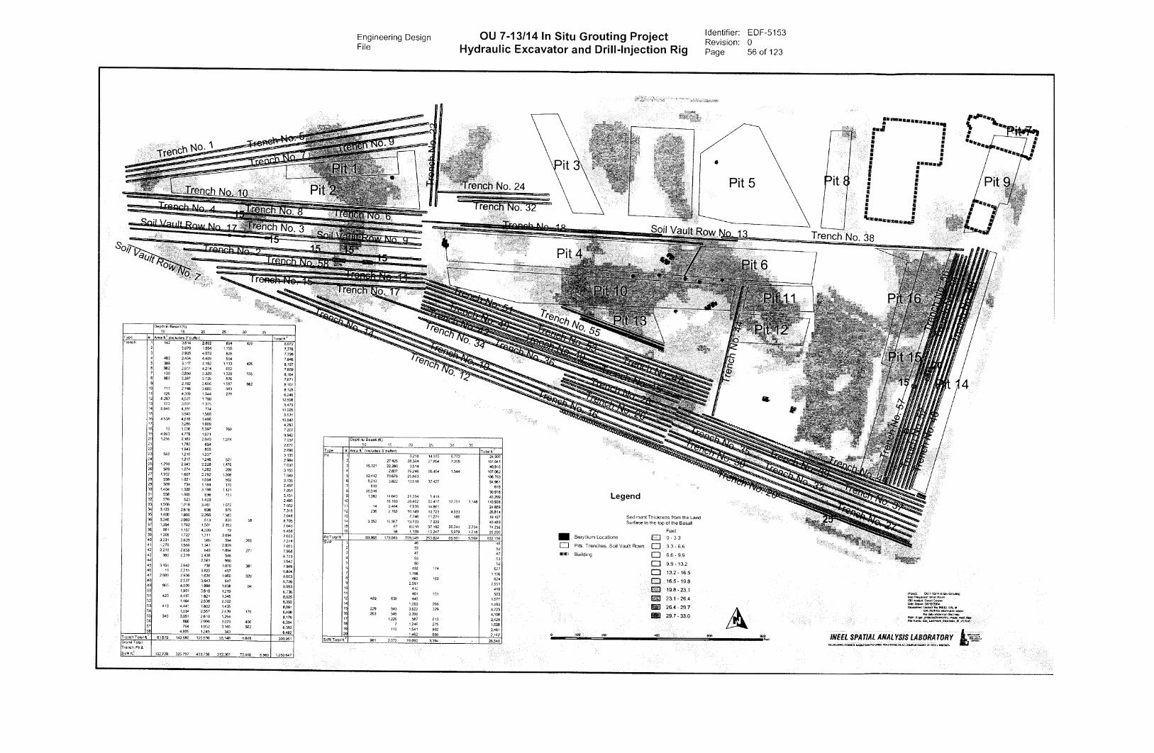
Engineering Design OU 7-13/14 In Situ Grouting Project Identifier: EDF-5153Revision: 0
File Hydraulic Excavator and Drill-Injection Rig Page 56 of 123
CY/tititilt
Depth to Basalt 011.110 15 20 25 30 35
Type p Area tc2 Onctudes 3' burler) Totalft'T tench I 142 3,814 2.802 894 420 6072
2 5,070 1554 1,155 7.7783 2905 4,070 825 07994 483 2,404 4405 554 7,846
389 3.117 1152 1 113 416 8,1976 982 2.011 4214 652 7859
130 2950 3329 1320 535 8,1648 863 2.387 3 720 876 78719 2,192 3656 1597 662 8 10710 711 2 748 3.685 983 8.12811 125 4,309 1544 270 6.24812 6283 4.527 1 788 1259813 173 3931 1 375 547914 6.040 4,191 704 11,00515 3.943 1.588 553116 4538 4816 1.486 10.84017 3285 1,009 4,29318 13 1,036 5 397 769 720719 4093 4,778 1,071 994220 1256 2,163 2045 1.574 7.03721 1,783 894 2.67722 1843 855 2.69823 582 1216 1337 3 13524 1217 1246 521 298425 1290 2043 2228 1.476 7 03716 589 1,074 1282 209 3 15527 1352 1.607 2.782 1,308 7 04928 558 1021 1.054 502 313529 369 734 17 84 170 2 45730 1004 1.328 3.198 1.121 725131 558 1205 836 731 3.13132 570 523 1.403 249533 1,500 1.018 3.461 1 072 7.05234 1123 2.618 698 879 7,31835 1,4120 1 BOO 2268 1.580 7,04836 3245 3089 613 830 28 8,70537 1.354 1.792 1,501 2 393 724038 951 1,157 4330 19 6.45839 1305 1,722 1.311 2,694 7.03340 3,231 2,639 585 594 265 731441 1.270 1.580 1,341 2.1359 7.05042 3219 2.655 649 1.094 371 7,98843 380 2339 3438 546 6.70344 2,561 980 3.54245 3,166 2642 736 1,070 381 798946 11 2,711 3 625 457 980447 2,080 2,906 1,636 1050 320 8,00348 2,537 3,643 547 6,72649 955 4.009 1998 1.038 94 909350 1.901 3016 1,219 6 73651 423 4,437 1 821 1,345 8.02552 1464 2,536 2,392 6,39253 413 4441 1802 1.435 8.09154 1934 2,557 2.639 178 6.40855 346 3951 2810 1264 8,17056 866 2 096 3.023 406 6,39457 704 1352 3,165 562 6.38258 4895 1245 343 6.482
Trench 1'0.1/C 61079 143680 125.596 55,148 4.648 390951Grand T Ola ITrench. Pit 8
SVR ft.' 132.728 325797 403738 312,367 70446 5,569 1,250 647
renCh No. 24
Soil Vault ROW_
Dept to Basalt (P)10 15 20 25 30 35
Type Area ft: Onctudes 3' buPP,1,,
70 111-'Pit 1 3218 14915 6772 24305
2 27.425 313.364 27.854 7,398 10104115,121 22260 3,514 40.916
2.837 76246 26.454 1544 107.08212,412 70678 25,663 108,753
6 5.213 3,822 13518 32,427 54,9817 619 6198 30,918 30.9189 1983 14043 21764 5919 43.20910 16.160 28.462 52.417 12751 1.148 110,938
14 2,484 7500 14.861 2485912 238 2765 10.149 10.729 4233 28,81413 7.746 11271 180 1919714 3,350 16 367 13733 7039 40,48915 87 8,010 37192 26 244 2704 7423616 98 1,159 13,247 5979 1.718 22,200
Pp Total ft 69.868 ma 045 259,049 251824 65801 5.560 833.156SVR 1 46 46
2 52 523 47 474 53 535 50 506 452 174 6277 1.156 1,1568 463 160 6249 2 551 2.55110 410 41011 401 101 50312 489 639 449 1.97714 1203 290 1.49315 229 543 3822 329 4,72316 263 545 3,300 4,10817 1220 587 613 2,42018 7 1246 275 1.52819 119 1,541 802 2,46120 1462 650 2.112
508 Total ft.' 981 3 072 19 092 3394 26.540
Legend
Sediment Thickness from the LandSurface to the top of the Basalt
IIII Beryllium Locations
n Pits. Trenches. Soil Vault Rows
KZ, Building
Feet
0 - 3 3
Ei 3 3 - 6 66 6 - 9 9
Ei 9.9 - 112=I 112 - 1E5
1E5 - 19.8
9.8 -23,1
231- 26Aa3 2E4 - 29 7
MI 2E7 - 310
600
Swwwwwww mmmmmm
aw
we
tit
aa
aa
a a••goteminammta•mi:
•
Trench No. 38
Op
OU
cw+snw
sts/Postailif
1"Pitig.t•****
PIPInlenerni rearcinnTliesfain 1044.4,11,14 -
INEEL SPATIAL ANALYSIS LABORATORYeCakarieternenTs TeacrudeePollnle innenreerin.5.--cuntlhaaen er net r Ma.%

Engineering Design OU 7-13/14 In Situ Grouting Project Identifier: EDF-5153Revision: 0
File Hydraulic Excavator and Drill-Injection Rig Page 57 of 123
Eniity Type Entily113
1SG P-2_Depth kitenials &vied
Burial Depth (ft) AREA (fa) Volume (ft3)
pit 7 35 819 2.1013pit 8 35 30,918 108.212
pit 13 35 3,131 42.205
pit 13 35 4.1315 62.308
pit 13 35 952 17.011pit 13 35 10,319 190003
pit 13 3.5 180 4.224
pit 14 3.5 3,350 11724pit 14 35 1 7pit 14 3.5 3 22pit 14 3.5 1.199 101
pit 14 3.5 4,619 39.259pit 14 35 10,5443 89.028
pit 14 3.5 1 7
pit 14 3.5 1 8
pit 14 3_5 1 9
pit 14 3.5 3 36pit 14 3_5 285 1850pit 14 3.5 3.027 40.870pit 14 3.5 55128 07.8E2pit 14 35 5,388 72.737
pit 14 3.5 7,039 130,217pit 15 35 87 736pit 15 35 52 702pit 15 35 478 6,451
Pit 15 3.5 1,317 17.781pit 15 3.5 1,773 23.931
Pit 15 3.5 4.391 59,275pit 15 35 5,531 102325pit 15 3.5 9,392 173.748pit 15 3.5 22,209 411,972pit 15 35 2 38
pit 15 35 2080 62080pit 15 35 5,268 123,797pit 15 3.5 18295 429.926pit 15 3.5 3 76pit 15 35 343 1,014pit 15 35 B92 25.422pit 15 3.5 1,773 50.542
Pit 16 3,5 1 5
Pit 10 3.5 1 epit 16 3.5 2 19pit 16 3_5 5 39pit 16 3.5 5 39pit 16 3.5 10 85pit 16 3.5 19 158pit 10 3.5 50 479pit 10 3.5 1 9pit 10 3_5 1 11pit 10 3.5 126 1.097
Page 1 BisiaiDeptilyEznity bdr 8-0-04.xis

Engineering Design OU 7-13/14 In Situ Grouting Project Identifier: EDF-5153Revision: 0
File Hydraulic Excavator and Drill-Injection Rig Page 58 of 123
Entity Type Entity ID
ISG P-2_Depth Inlegvals Sanhed
Depth (ft) AREA (raq
Pit 16 5.5 1,0N2
Pit 10 3.5 13,247
Pit 16 35 0 6
Pit 16 3.5 2
Pit 16 3_5 4
Pit 16 3_5 8
Pit 16 3.5 1,060 24.9 4
Pit 16 35 4,904 115.253Pit 16 35 775 22.086
Pit 16 3.5 943 26.865svr 1 35 48 821svr 2 3_5 52 708svr 3 3.5 47 637SVT 4 3.5 53 714svr 5 3_5 50 678svr 6 3.5 101 1.358SVT 6 85 352 4.747StiT 6 8.5 63 1.157sYr 6 8.5 112 2.028svr 7 Els 63 4,893SVT 7 85 1.093 4.893Siff 8 8.5 1 12svr 8 85 99 1.333svr 8 85 364 4.911SVT 8 8_5 52 971SVT 8 8_5 108 1.994SVT 9 8_5 451 4,803SVT 9 8.5 501 4.893svr 9 8.5 051 4.893svr 9 8.5 949 4.893SVT 10 8.5 410 5.541svr 11 8_5 1 14svr 11 8.5 95 1.284svr 11 8.5 305 4,122syr 11 85 101 1.873svr 12 8_5 489 1.711SVT 12 85 0 4SVT 12 85 163 1.382svr 12 8.5 476 4.045Sir 12 8.5 8 110SVT 12 85 207 2793svr 12 85 233 3.152svr 14 8.5 295 3.989sn 14 8_5 987 12.251
14 8.5 290 5.361svr 15 8.5 229 801svr 15 8.5 152 1293sYr 15 8.5 391 3.323
15 8 5 480 6.484SVT 15 8_5 1,255 16.942svr 15 85 1,887 25.468
Page 2 BuiafDepthEyEritity_ B-0-04.xis
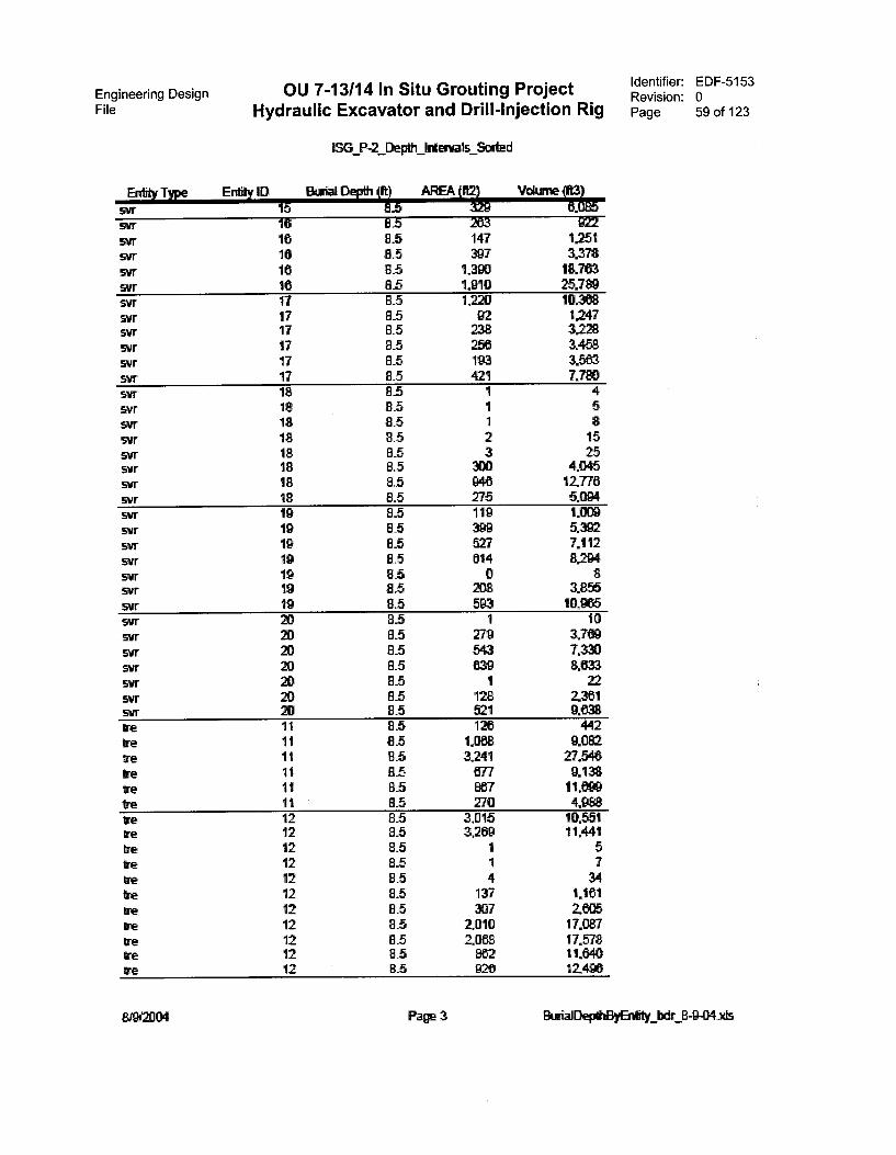
Engineering Design OU 7-13/14 In Situ Grouting Project Identifier: EDF-5153Revision: 0
File Hydraulic Excavator and Drill-Injection Rig Page 59 of 123
P-2_Depth kirmvals Scrted
Entity Type Entity ID Butt Depth (It) AREA (
svr 15 655Vr 16 8.5 263svr 16 8_5 147svr 16 B.5 3975Vr 16 85 1.390svr 16 85 1.910svr 17 85 1.220svr 17 85 92svr 17 8_5 238SVT 17 85 258SVT 17 8.5 193svr 17 8.5 421SVT 18 8.5 1svr 18 8.5 1svr 18 8.5 1SVr 18 85 2svr 18 8.5 3svr 18 8.5 30CISVT 18 85 948svr 18 Bš 275SVT 10 8L 1195Vr 19 8_5 399S'ilr 19 E1.5 52751ff 19 8_5 614SW 19 85 0Sir 19 8.5 208svr 19 8.5 593Siff 20 85 1svr 20 8.5 279svr 20 85 543svr 20 85 639svr 20 85 1svr 20 8_5 128SVT 20 85 521tre 11 8.5 126Ire 11 8.5 1.0681re 11 85 3,241we 11 8_5 677Ire 11 85 887tre 11 8.5 270Ire 12 8.5 3,015tre 12 85 3,269Ire 12 8.5 1tre 12 8.5 1tre 12 85 4tre 12 8_5 137ve 12 8.5 307We 12 8.5 2.010tre 12 8.5 2068ire 12 8.5 862ire 12 B.5 926
T4.5922
12513.37818.76325.78910.3681.24732283.4583.5637.780
4581525
4.045127765.0941.0D95.3927.1128.294
83.85510.955
103.7697.3308.63322
23619.0338442
9.08227.5469.138
4.10.55111.441
5734
1.1612.60517.08717.57811.64012496
8urialDept13yEnkty_bdr 8-9-04 .xis
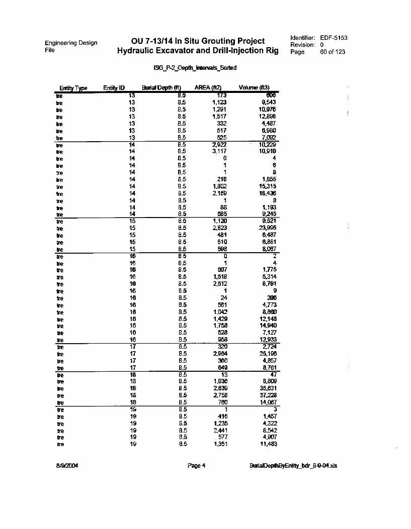
Engineering DesignFile Hydraulic Excavator and Drill-Injection Rig
OU 7-13/14 In Situ Grouting Project
Entity Type
LSG P-2_.Dep#fs Inbarvats acted
Depth (it)
We 13 6.513 85 1,123 9.543
Ire 13 1,291 10.97613 8.5 1,517 12
Ire 13 8.5 332 4.48713 8_5 517 6.980
tne 13 85 525 7.09214 85 2.922 10,229
We 14 8.5 3.117 10.910tre 14 8.5 0 4re 14 8.5 1 6Ire 14 8.5 1 8We 14 8.5 2 8 1.855tre 14 8.5 1,8112 15.315We 14 83 2109 18,436We 14 8_5 1 8Ire 14 8.5 1.193re 14 8.5 635 9.245Ire 15 Bs 1,120 9.521We 15 8.5 2,823 23.995We 15 8_5 481 6,487We 15 8_5 510 6.881re 15 8.5 598 8,067re 16 8.5 0 2tre 16 8.5 1 4tre 16 8.5 1.775re 10 8.5 1,518 5.314
16 8_5 2,512 8,791tre 16 85 1 9tre 16 24 206We 16 8.5 581 4.773Ire 16 8_5 1.042 8,860tne 16 8.5 1,429 12,148re 16 83 1,758 14.940We 16 85 528 7.127re 16 8.5 958 12.933We 17 8_5 320 2724re 17 8.5 2964 25.196We 17 85 360 4,857
17 8_5 649 8.76118 8.5 13 47
We 18 8_5 1.038 8.18 2639 35.631
We 18 8.5 2,758 37.228tre 18 8.5 700 14.067re 19 8_5 3Ire 10 8.5 416 1457We 19 8.5 1,235 4.372Ire 19 8.5 2,441 8.542tre 19 B.5 577 4.9C17We 19 83 1,351 11.483
Identifier: EDF-5153Revision: 0Page 60 of 123
Page 4 BurialDeptiBy bdr
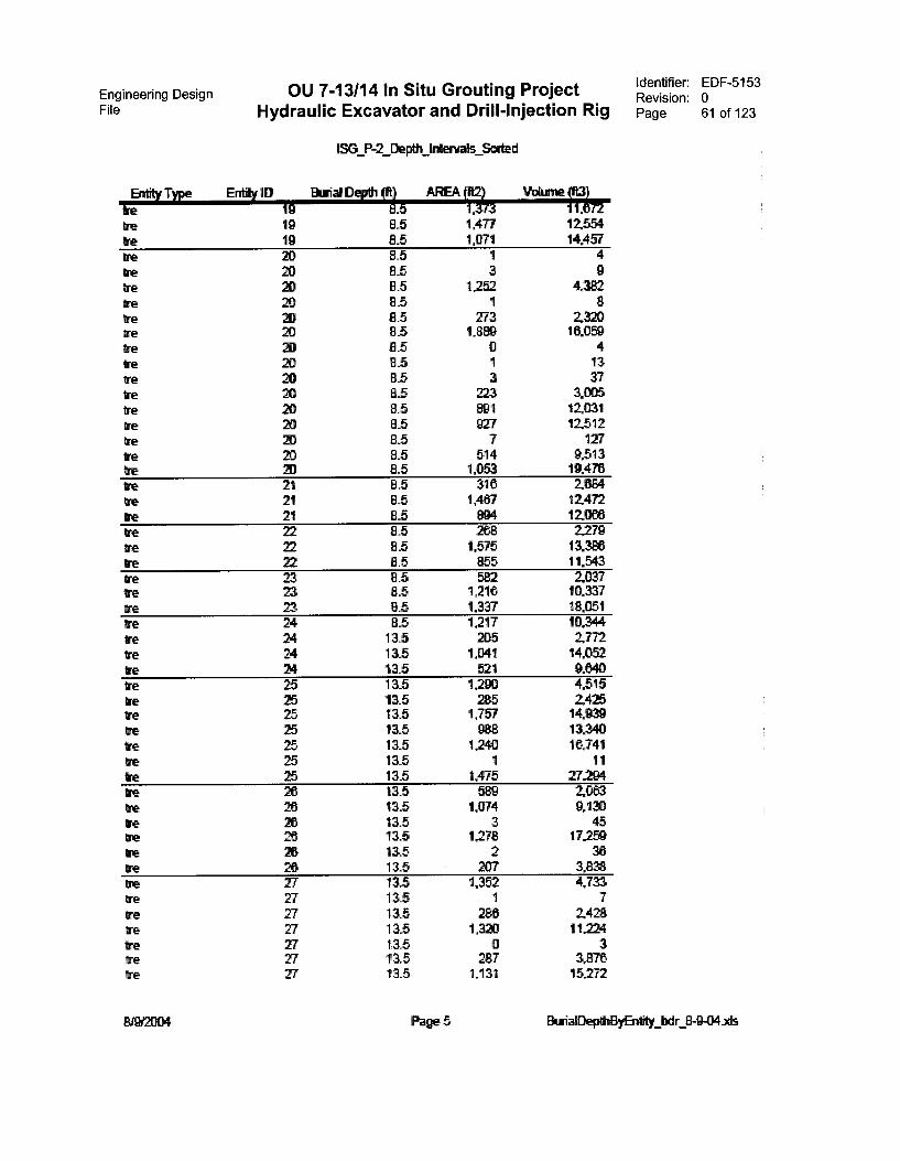
Engineering DesignFile Hydraulic Excavator and Drill-Injection Rig
OU 7-13/14 In Situ Grouting Project
Entity Type Entity 1D
1SG P-2_Depth Intervals Sorted
ift) AREA (VI V
re 19 ii._5 1.373 1„ 72Ire 19 8.5 1,477 12.554re 19 8_5 1,071 14.457re 20 8_5 1 4Ire 20 8.5 3 9re 20 8.5 1.252 4.382We 20 8_5 1 8re Z3 8.5 273 2.320re 20 8_5 1,888 16.059re 20 8_5 0 4re 20 8.5 1 13we 20 115 3 37re 20 8.5 223 1005re 20 8.5 891 12,031we 20 8_5 927 12,512re 20 8.5 7 127re 20 8.5 514 9.513re 20 8.5 1,053 19.470re 21 85 316 2684tre 21 8.5 1,467 12.472re 21 8.5 894 12.008re 22 8.5 268 2.279tre 22 8_5 1,575 13.380re 22 8.5 855 11.543re 23 8.5 582 2037re 23 8.5 1,216 10.337tre 23 8.5 1,337 18,051re 24 85 1,217 10.344ore 24 115 205 2772re 24 13.5 1,041 14.052tre 24 13.5 521 9.640re 26 115 1.290 4.515re 25 115 285 2425re 25 13.5 1,757 14.939re 25 13.5 988 13340re 25 13.5 1,240 16,741tre 25 13.5 1 11re 25 13.5 1,475 27294re 26 133 589 2.0e3re 20 13.5 1,074 9,130tre 26 115 3 45tre 26 115 1,278 17.259re 26 115 2 36tre 26 13_5 207 3,838re 27 115 1,352 4,733we 27 115 1 7re 27 13.5 2 2428re 27 135 1,320 11224tre 27 13.5 3re 27 115 287 3.876we 27 13_5 1,131 15.272
Identifier: EDF-5153Revision: 0Page 61 of 123
Page 5 BurialDeptheyEatity 8-9-04..xts
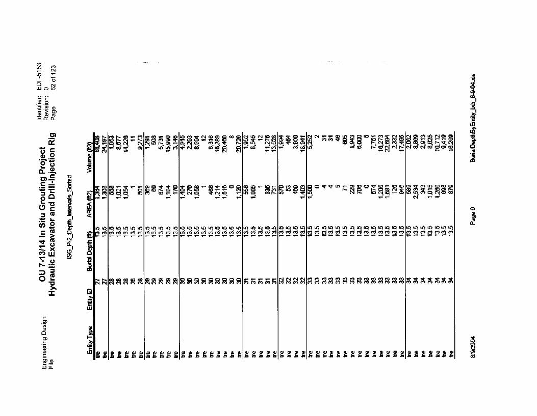
a)
CMc
G)cEn a)c =UJ LL
2
D,"47774 41 u1g". RA
El CD Tr Tr w) Tz 5n oR CP ZtPt N
WI 41 41 41 41 47 WI 41 41 41 41 47 41 410 el 0 0 ei vi 0 000 000TTTTTTTTTTTTTT
2 2 A22222
222222 g ggt

Engineering DesignFile
Entity Type
OU 7-13/14 In Situ Grouting Project Identifier: EDF-5153Revision: 0
Hydraulic Excavator and Drill-Injection Rig Page 63 of 123
ISG_P-2_Depth Iran& Sorted
Edit/ 1D Eltrial Depth
we 35 4.400
ire 35 13.5 1 6
tre 35 115 13 109
we 35 13.5 251 2.137
we 36 135 554 4.705
we 35 115 981 8.342
we 35 13_5 1 10
we 35 13.5 347 4.689
trewe
3535
11513.5
378473
5,6.389
we 35 13.5 1,089 14.426
we 35 135 0 6
we 35 135 1 15
tre 35 13.5 352 6.509
we 35 13.5 1,227 22,602
we 36 13.5 500 1.961
we 36 135 2685 9.397
we 36 135 368 2.1120
we 36 135 UN 9.087
we 36 13.5 Z611 2Z196
we 36 13.5 613 8.276
we 36 13.5 830 15.351
tre 36 115 1 17
we 36 135 27 643
we 37 135 1,354 4.738
we 37 115 32 276
we 37 115 188 1.505
we 37 115 500 4.304
we 37 115 1,065 9.053
Ire 37 115 3 35
we 37 115 3 41
we 37 115 3 47
we 37 135 4 55
tre 37 13.5 5 71
we 37 135 246 3.324
we 37 13.5 328 4.426
tre 37 13.5 444 5
we 37 13.5 485 6.222
tre 37 115 1 11
we 37 13.5 4 83
ye 37 115 424 7.843
we 37 115 1,964 36.328
we 38 135 4 13
we 38 115 947 3.314
ire 38 13.5 4 32
we 38 13.5 24
ire 38 13.5 561 4,770
we 38 13.5 568 4.
we 38 115 1,942 26.216we 38 135 2. 32.242
tre 38 13_5 1 25
Page 7 BtarialDepthil bdr 8-9-04As

Engineering DesignFile
Identifier: EDF-5153OU 7-13/14 In Situ Grouting ProjectRevision: 0
Hydraulic Excavator and Drill-Injection Rig Page 64 of 123
15G P-2_Depth inkrvids Sorted
Entity Type Entftly ID Depth 3 (112) (inkt2tie 38 18tre 39 13.5 1.305 4.567trp 39 135 17 143tre 39 13.5 172 1.463te 39 115 479 4.074tre 39 115 1.054 8.961te 39 115 229 3.ire 39 13.5 335 4.122tre 39 115 315 4247tre 39 13.5 463 8.244tre 39 13_5 482 8.917te 39 13.5 2.212 40.925fre 40 13.5 525 1.838tre 40 13_5 2,706 9.470tre 40 13_5 275 2.341re 40 115 1,111 9.445we 40 13_5 1,252 10.644tre 40 13.5 585 7.897tre 40 13_5 594 10.9c0tre 40 13.5 265 6226tre 41 13_5 1,270 4.443ire 41 115 1$8 1.430ire 41 13,5 468 3.981ire 41 13.5 943 8.018tre 41 13.5 252 3,405te 41 13_5 292 3.944tre 41 13_5 341 4.003tre 41 13.5 456 6.155Ire 41 13,5 532 9.850
41 13.5 2,326 43.040ire 42 13_5 489 1.711tre 42 13.5 2730 9.556te 42 115 270 2294ire 42 13.5 1,131 9.614Wetre
4242
13_513.5
1.25461
10,824
42 115 587 7.931te 42 133 537 9.934tre 42 13_5 557 10.313tre 42 13_5 1 12ire 42 13_5 370 8.705tre 43 13,5 380 1.320ire 43 13.5 1 8tre 43 13,5 1 6tre 43 13,5 5 40tre 43 13_5 453 3.852tre 43 13.5 1.890 15.978
43 115 0 6tre 43 115 1 14tre 43 13.5 617 8.332tre 43 13_5 798 10.748
ButialDeF413yEntity hdr 13-9-04As
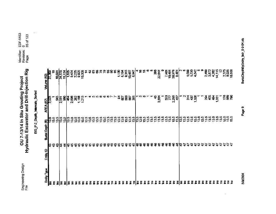
gr~criga
VVVVVVVVMV
04 'sr r•-•
ig Q* c' Eg =2ei c4 ci
v- Q i7411,
41 41 41 41 41 41 41 41 41 41 41 4101 01 05 crf vi coi V, 01 01 00 c4 co, v6
V* "V. w* ** ** v- ** y- v- v-
sr sr1"-. r-
sh sr sr Tr Tr Tr Tr Tr Tr Tr Tr
~bblsbbg
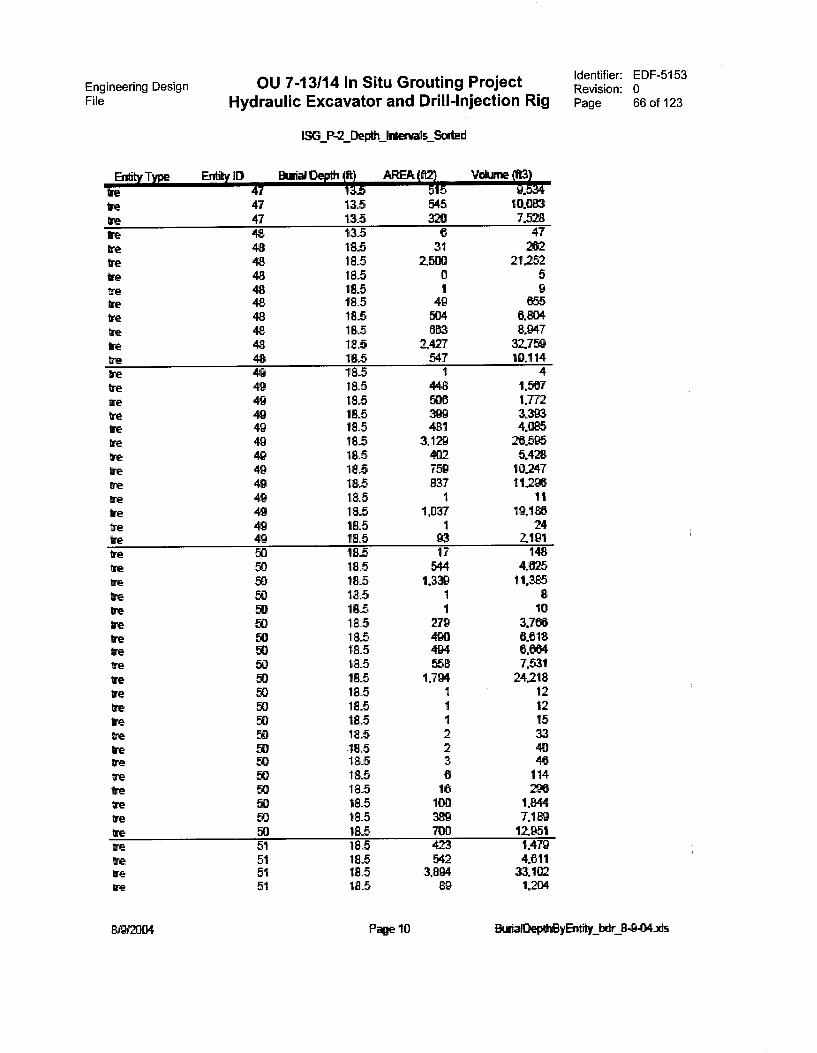
Engineering DesignFile Hydraulic Excavator and Drill-Injection Rig
OU 7-13/14 In Situ Grouting Project
Entity Type En* ID
P,Z_CkIth !demi& Sorted
AREA Whine
re 47 _5 5 5 .re 47 135 545 10.083
re 47 135 320 7,528
te 48 13.5 6 47
re 48 185 31 262
tre 48 18.5 2500 21,252
tre 48 185 0 5
tre 48 185 1 9re 48 185 49 655
we 48 18_5 504 6.804
tre 48 18.5 663 8.947
re 48 18.5 2477 32.759
re 48 18_5 547 10,114
tre 49 185 1 4re 49 185 448 1,567
tre 49 185 5D6 1.772re 49 18_5 399 3.393re 49 185 481 4.085
tre 49 18,5 3,129 26.595ire 49 18.5 402 5.428
re 49 85 759 10.247
ire 49 18.5 837 11296
re 49 185 1 11re 49 185 1,037 19,1
tre 49 185 1 24re 49 18.5 93 2191tre 50 185 17 148
re 50 18.5 544 4.625tre 50 18.5 1,339 11.385re 50 18_5 1 8
ire 50 18_5 1 10
re 50 18,5 279 3.766tre 50 18.5 490 6,618re 50 18.5 494 6664re 50 18.5 558 7.531re 50 185 1,794 24.218ire 93 18.5 1 12re 50 185 1 12re 50 18.5 1 15re 50 18_5 2 33re 50 18.5 2 40tre W 18.5 3 46tre gO 18.5 6 114we 50 18.5 16 2E13tre 50 18.5 100 1.844tine 50 18_5 389 7„1tre 50 18.5 700 12.951re 51 18.5 423 1,479we 51 18_5 542 4,611re 51 18.5 3,894 33.102re 51 18.5 go 1204
Identifier: EDF-5153Revision: 0Page 66 of 123
Page 10 lEturialDepeEtyEnflity bdr 8-9-04its
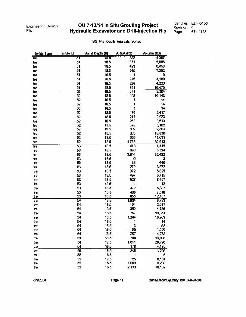
Engineering Design OU 7-13/14 In Situ Grouting ProjectFile Hydraulic Excavator and Drill-Injection Rig
P-2_Derdh laharials &vied
Entity Type Entity ID Burial AREA (It213 Volume (t13)we 51 067tre 51 18_5 371 5,036re 51 18_5 493 0,853we 51 18.5 545 7,3E2re 51 188 1 9Ire 51 18.5 225 4180re 51 18.5 229 4.23ore 51 18_5 891 16,475ire 52 18_5 271 2.304tre 52 18.5 1,193 10.143we 18.5 1 14re 52 18.5 1 14we 52 18.5 1 14ire 52 18.5 179 2,417tre 52 18.5 217 2,923tre 52 18.5 268 3813tre 52 18.5 378 5.102we 52 18.5 689 9,303we 52 18.5 803 10,836we 52 18-5 1329 11831Ire 52 18.5 1.763 32.813tre 53 18.5 413 1.445re 53 18.5 828 5.324tre 53 18.5 3,814 32,4ntre 53 18.5 0 3tre 53 18.5 33 446tre 53 18.5 272 3872re 53 18.5 372 5,025tre 53 18.5 497 6,715tre 53 18.5 627 8.487re 53 18.5 1 12re 53 18.5 372 0.887ire 53 18.5 406 7.518re 53 18_5 658 12,137we 54 18_5 1.034 8,793re 54 18.5 194 2817tre 54 18.5 352 4.758re 54 18.5 787 10,351ye 54 18.5 1244 16.7re 54 18.5 1 14re 54 18_5 3 58tre 54 18.5 80 MODre 54 18.5 257 4.783re 54 1E5 708 13,083tre 54 18.5 1811 29.716re 54 18.5 178 4,175re 55 18.5 345 1203tre 55 18_5 1 6re 55 18.5 725 6.181tre 55 18.5 1,093 9288we 55 18.5 2,133 18.132
Identifier: EDF-5153Revision: 0Page 67 of 123
Page 11 EkrialDeperayEnety bdr
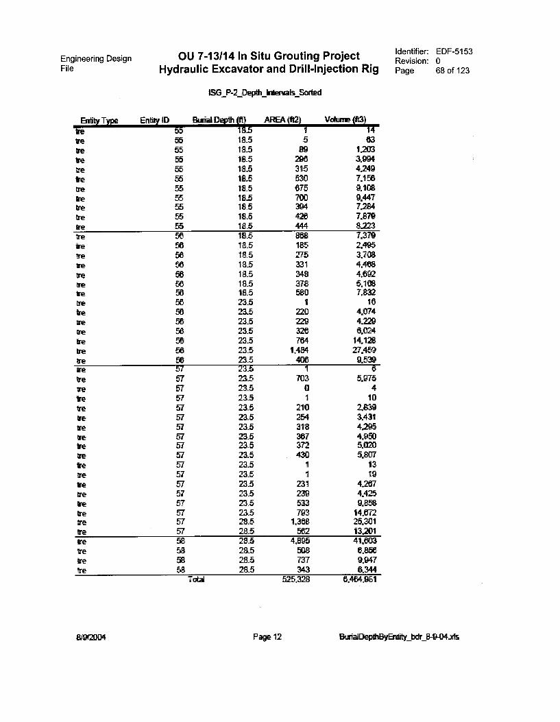
Engineering Design OU 7-13/14 In Situ Grouting Project Identifier: EDF-5153Revision: 0
File Hydraulic Excavator and Drill-Injection Rig Page 68 of 123
ISG P-2_Depth kierwats Sorted
Entity Type E ID Btrial Depthift5 AREA (f12)
ire 55 1 14re 55 18_5 5 63we 55 18.5 1203Ire 55 18.5 296 3.994we 55 18_5 315 4.2419tre 55 18_5 530 7.156me 55 18_5 675 9.108We 55 18_5 700 9.447we 56 18.5 394 7.224tre 55 18.5 426 7.879we 55 18.5 444 8.223tre 56 18_5 808 7.379we 56 18.5 185 2.495we 56 18.5 275 3.708tre 56 18.5 331 4.488tre 56 18_5 348 4,092tre 56 18.5 378 5.1tre 56 18.5 580 7.832We 56 235 1 16we 56 23_5 220 4.074tre 56 23_5 229 4.229tre 56 23.5 326 6.024tre 56 235 704 14.128We 56 235 1.484 27.469tre 56 23.5 4013 9.539we 57 23.5 1 6re 57 23_5 703 5.975tre 57 23.5 0 4we 57 23.5 1 10Ire 57 23.5 210 1839we 57 23_5 254 3.431we 57 235 318 4.295tre 57 23_5 367 4.950We 57 23.5 372 5.020we 57 23.5 430 5.807we 57 23.5 1 13We 57 235 1 19we 57 23_5 231 4.2437we 57 23_5 239 4.425
23.5we 57 533 9.858We 57 23_5 793 14.672we 57 28_5 1,368 25.301We 57 28_5 5te 13.201we as 28_5 4,896 41.603we 58 29_5 508 6.856we 58 28.5 737 9.947We 58 28.5 343 6.344
Total 52 ,328 6.4434.981
Page 12 8-9-04ils
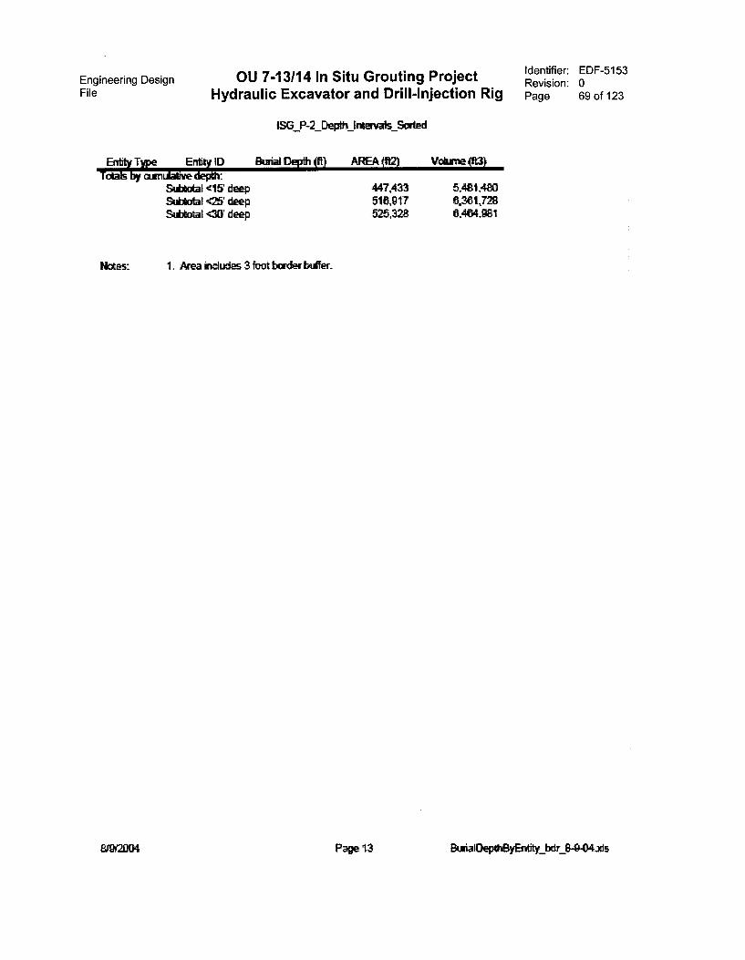
Engineering DesignFile Hydraulic Excavator and Drill-Injection Rig
OU 7-13/14 In Situ Grouting Project
1,3G P-2 pth kftrgais Wed
ype Ent* JD Btriat Depth 0i) AREA fft2) Volume (fa}ToLls 6gr curnutaf3ve depitc
Subldal <15 deep 447,433 5481,480Subtotal <25' deep 510,917 0.361,728Subtotal <31Y deep 525.328 0.404,981
kea includes 3 foot border buffer.
Identifier: EDF-5153Revision: 0Page 69 of 123
Page 13 BuriaDepthByErktity_bdr 8-0-04.xls

Engineering Design OU 7-13/14 ln Situ Grouting ProjectFile Hydraulic Excavator and Drill-lnjection Rig
Entity Type Entity ID
ISG_Phase-2_Depiti
Depth (It) AREA (82)
Pit 7 35 619
pit 8 3.5 30,918
pit 13 115 3,131pit 13 13_5 4,615pit 13 18.5 252pit 13 18,5 10,319pit 13 23.5 1
19,127
pit 14 3.5 3,350pit 14 8.5 1pit 14 8.5 3pit 14 8.5 1,199pit 14 8.5 4,819pit 14 8.5 14546pit 14 135 1pit 14 13.5 1pit 14 135 1pit 14 13.5 3pit 14 115 285pit 14 13.5 3,027pit 14 135 5,028pit 14 13.5 5,388pit 14 18.5 7,039
40A89
Pit 15 8.5 87pit 15 13.5 52pit 15 115 478pit 15 115 1,317pit 15 13_5 1,773pit 15 13.5 4,321pit 15 185 5,531pit 15 8_5 9,392pit 15 18.5 22,262pit 15 235 2pit 15 215 2,680pit 15 23.5 5,288pit 15 23.5 18.295pit 15 28.5 3
Pit 15 28.5 36Pit 15 28.5 BOpit 15 283 1.773
74,236
pit 16 8.5 1pit 16 8_5 1pit 16 8.5 2
Volume XI)
2.108
108212
4226562.30817.611
190.2034224
317.311
11,724722
78936
3.85040.87067.88272.737130.217466.457
736702
6,45117,78123.23159.275102.325171748411,972
3662,280123,797429.226
761.014
25.42250.542
1.4E0,714
5619
Identifier: EDF-5153Revision: 0Page 70 of 123
BurialtepeElyEntity bdr 849-04,ids
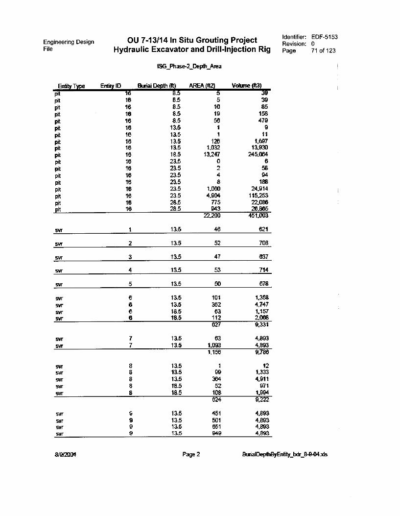
Engineering DesignFile Hydraulic Excavator and Drill-Injection Rig
OU 7-13/14 In Situ Grouting Project
Btity Type Entity ID
LSG Ph
Eluvial Depth (ft)
2_Depth Area
AREA (ft2)
pit 18 a _5 5 39pit 16 8.5 5 39pit 16 8.5 10 85pit 16 8.5 19pit 16 8.5 56 479pit 16 13.5 1 9pit 16 13.5 11pit 16 13.5 126 1,097pit 18 13_5 1,032 13.930pit 16 185 13,247 245.064pit 16 215 0 6
Pit 16 23.5 2 58pit 16 23,5 4pit 16 23.5 8pit 16 23.5 1,000 24,fl14pit 16 215 4.904 115253
Pit 16 28.5 775 22.086pit 16 28.5 943 26.865
22,200 451.0G3
svr 1 13.5 46 621
swr 2 13.5 52
svr 3 13,5 47 637
svr 4 13.5 53 714
Syr 5 13.;5
svr 6 13.5 101 1.358svr 6 135 352 4,747svr 6 11,5 83
svr 6 18.5 112 r:
827 9
svr 7 115 03 4,893SVT 7 115 1.093 4.893
1,156 9.786
SVT 8 13.5 1 12SVT 8 13.5 99 1.333SVT 8 115 364 4.911SVT 8 18.5 52 971svr 8 18.5 108 1.994
024 9 771
svr 9 451 4.893SVT 9 115 501 4.893svr 9 13,5 651 4.893SVT 9 13.5 949 4.893
Identifier: EDF-5153Revision: 0Page 71 of 123
EkviaiDepei3yEritity kir 8-9-04A
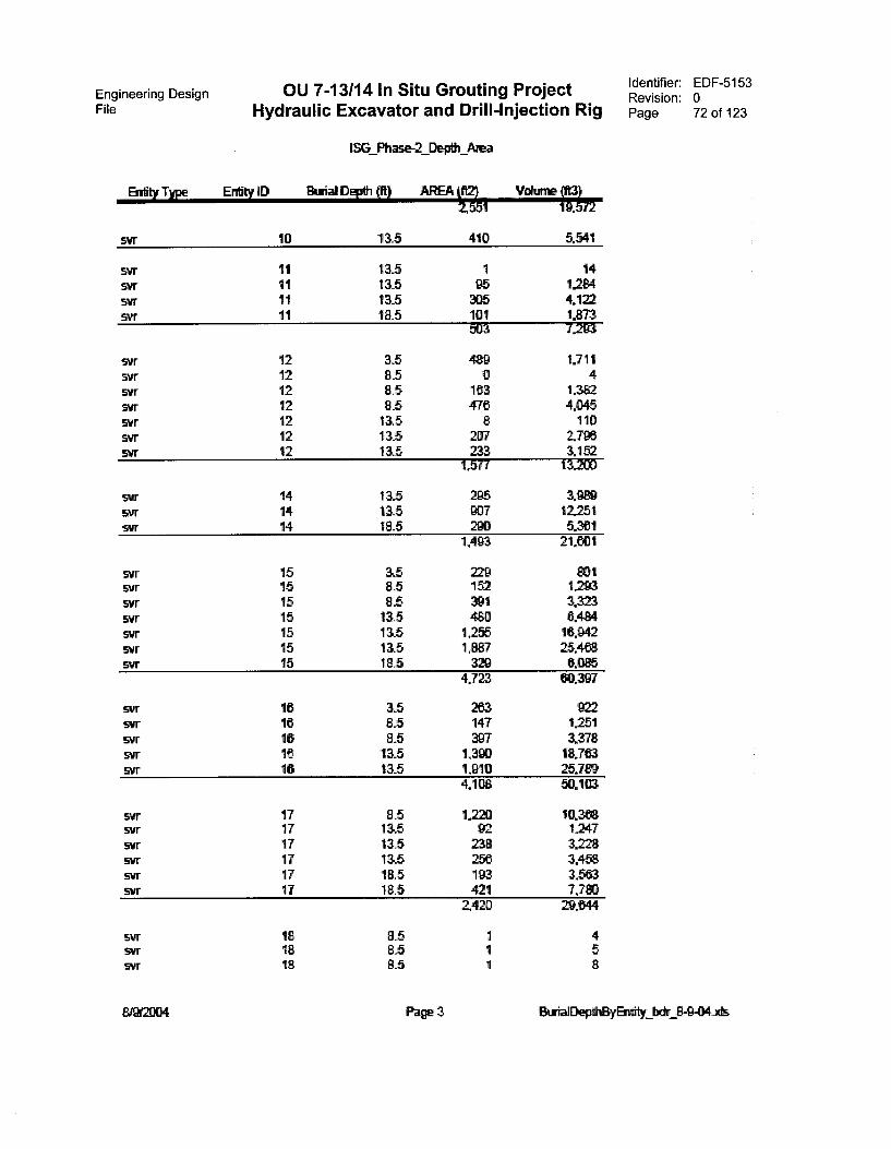
Engineering Design OU 7-13/14 In Situ Grouting Project Identifier: EDF-5153Revision: 0
File Hydraulic Excavator and Drill-Injection Rig Page 72 of 123
ISG_Phase-2_Depth Area
Entity Type Entity ID Burial Depth (ft) AREA T',11
SVT 10 135 410 5.541
svr 11 135 1 14SVT 11 135 95 1284SVT 11 13_5 305 4.122SVT 1 1 18.5 101 1.873
503 7293
svr 12 3.5 489 1.711svr 12 8_5 0 4svr 12 8.5 163 1.382SVT 12 85 476 4.045SVT 12 13.5 8 110SVT 12 13.5 207 2.798svr 12 13_5 233 3.152
1,577 13.200
svr 14 13.5 295 3.989svr 14 13_5 907 12.251svr 14 18.5 280 5.361
1493 21.601
svr 15 33 229 1svr 15 8.5 152svr 15 8_5 391 3.323svr 15 13.5 480 6.484svr 15 13,5 1,255 16.942svr 15 13_5 1,887 25.468svr 15 18.5 329 6.085
4.723 60.397
svr 16 3_5 263 922svr 16 8.5 147 1.251574tr 16 8.5 397 3.378svr 16 13_5 1,390 18.763svr 16 13.5 1.910 25.7
4,108 50.103
svr 17 85 .220 10.368svr 17 13.5 92 1247svr 17 13.5 238 3228svr 17 13_5 256 3.458svr 17 18_5 193 3.563svr 17 18.5 421 7,720
2420 29.644
svr 85 1 4SVT 8.5 1 5svr 18 85 1 8
EitinalDepdElyEntity kir 8-9-04.xis
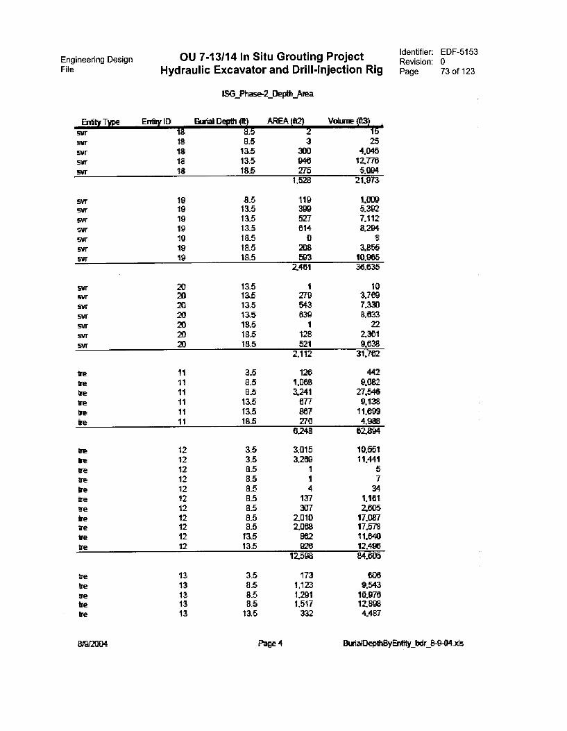
Engineering DesignFile Hydraulic Excavator and Drill-Injection Rig
OU 7-13/14 In Situ Grouting Project
Entity Type Entity lD
1SG Ph 2_Depth_
Vo
svr 18 85 2 15stir 18 8.5 3 25svr 18 13.5 360 4.045svr 18 13.5 940 12776svr 18 18.5 275 5.094
1,528 21,973
svr 19 8.5 119 1.009SVT 19 13.5 398 5.392SVT 19 13.5 527 7.112SVT 19 13.5 614 8294srr 19 18.5 0 8svr 19 18.5 208 3655svr 19 183 593 10.965
2,461 30.635
svr 13.5 1 10SVT 13_5 279 3.709svr 13.5 543 7.330svr 13.5 839 8.633svr 18.5 1 22svr 18.5 128 2361SVT 18.5 521 9638
2112 31.782
te 11 3.5 126 44211 8.5 1,088 9.0Ee
Ire 11 8_5 3,241 27.546Ire 11 13.5 677 9.138Ire 11 13.5 967 1tre 11 18.5 270 4,
6.248
Ire 12 3.5 3,015 10,551We 1/ 3.5 3,269 11,441tne 12 8.5 1 5te 12 8.5 1 7tre 12 8.5 4 34
12 8_5 137 1.181re 1/ 8.5 307 2065Ire 12 8.5 2,010 17.087We 12 8.5 2088 17.578
12 13.5 862 11640Cre 12 13.6 820 124913
12598 84605
13 3.5 173 600We 13 8.5 L123 9.543tne 13 8.5 1,291 10.976
13 8.5 1,517 12.tre 13 13.5 332 4487
Identifier: EDF-5153Revision: 0Page 73 of 123
Dep0a3yErkity_ 8-9-04.3is
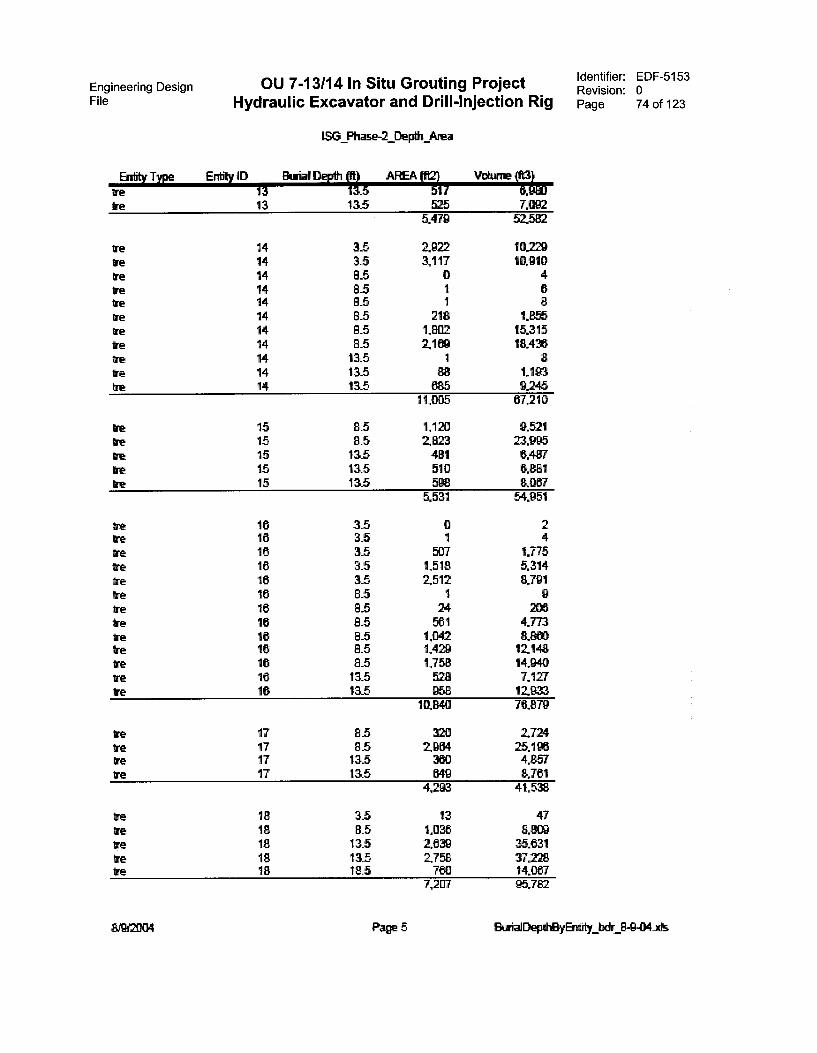
Engineering DesignFile Hydraulic Excavator and Drill-Injection Rig
OU 7-13/14 In Situ Grouting Project
Entity Type D
1SG Phase-2_Depth Area
Depth MI AREA (V)
re 13 115 517re 13 13,5 525
5,479
re 14 3_5 2.922we 14 3.5 3,117Cre 14 8_5 0tre 14 8.5 1
14 8.5 1re 14 8.5 218re 14 8.5 1,802re 14 8.5 2,189re 14 13.5 1re 14 13,5re 14 13.5
1 005
re 15 8.5 1,120re 15 8.5 2823re 15 13,5 481re 15 13.5 510re 15 13.5 598
5,531
16 3.5 0lire 16 3.5 1
16 3.5 507re 16 3.5 1,518tre 16 3_5 2,512tre 16 8.5 1re 16 8_5 24re 16 8.5 561re 16 8.5 1,042re 16 8.5 1,429re 16 8.5 1,758re 16 13.5 528we 16 13..5 858
10.840
Ire 17 8.5 320re 17 8.5 2,964tre 17 13.5 380re 17 13.5 649
4,293
tre 18 3_5 13we 18 8.5 1.036re 18 13.5 2.839re 18 13.5 2,758we 1#f 18.5 760
7,207
%farm Ito
7.09252.582
10.22910.910
468
1.85515.31518,436
81.1939.245
67.210
9.52123.9956.4876.8818.087
54,951
24
1.7755,3148.791
9206
4.7738.88012.14814.9407.12712.93376.879
2.72425.1964.8578.701
41.538
478,809
35.83137.22814,08795.782
Identifier: EDF-5153Revision: 0Page 74 of 123
Page 5 BuirialDe1atii3yEntity_bdr 111-0-04ids
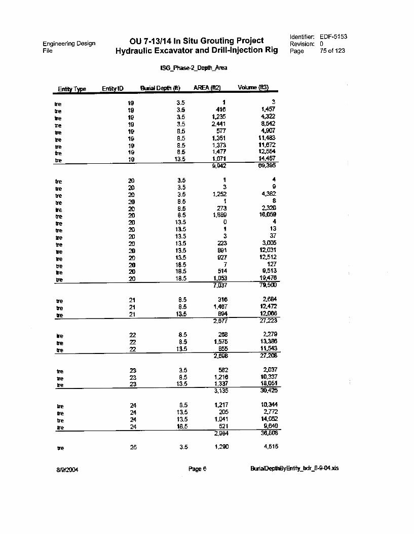
Engineering Design OU 7-13/14 In Situ Grouting ProjectFile Hydraulic Excavator and Drill-Injection Rig
1SG Ph Depth Area
Entity Type Enb D Burial Depth (ft) AREA (V) Vokine (113)
We 19 3.5 1 3
re 19 3.5 416 1,457
re 19 3.5 1.235 4in2
bre 19 35 2,441 8,542
re 19 8.5 577 4.907
tre 19 8.5 1,351 11,483
re 19 8.5 1,373 11.672re 19 85 1,477 12,554
We 19 115 1,071 14.4579.1342 395
vetre
Netreveiretre
trere
irete
2020
8t88638863
3.5 1 43.5 3 935 1,25285 1 88.5 273 2.32085 1,889 16.059115 0 413.5 1 1313 5 3 37115 223 3,005135 891 12.03113.5 B27 12,512185 7 12718.5 514 9.51318.5 1,053 19.470
7,037 79.503
4.382
21 85 316 2.68421 8.5 1,467 12.472
21 135 894 12.006
re
re
2577 27223
22 85 268 2.27922 8.5 1,575 13.38622 13.5 855 11.543
tre
re
rere
232323
24242424
2,098 27.208
3.5 582 / 0378.5 1,218 10,337115 1,337 18.051
3,135 30.425
8_5 1,217 10.34413.5 205 177213.5 1,841 14.052185 521 9.640
2,884 36.
3_5 1,200 4.515
Identifier: EDF-5153Revision: 0Page 75 of 123
BurialDeOl3yEn4ity_bdr 8-9-04ids
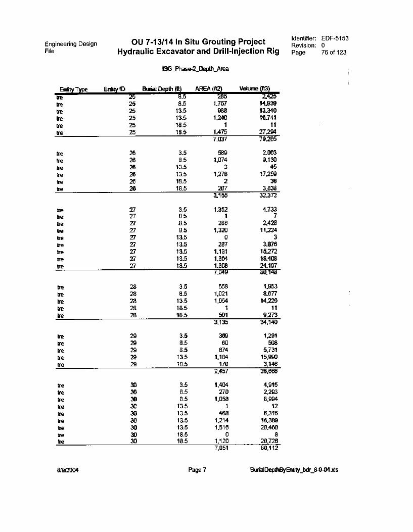
Engineering DesignFile Hydraulic Excavator and Drill-Injection Rig
OU 7-13/14 In Situ Grouting Project
1SG_Phase-2_Depth Area
Entity Type Entity ID &Arial Depth (ft) 1125Ire 25 6.5
We 25 8.5 1,757 14.939We 25 13.5 0138 13.340we 25 13.5 1,240 16,741We 25 18.5 1 11We 25 18.5 1,475 27.204
7,037 79.205
tretreCreweWetre
tretretre
irewetrewetre
we
Iretrete
wetrewetre
weIrewe
yeirewetrewe
26 3.5 589 106326 8.5 1,074 9.13026 13.5 3 4526 13.5 1,278 17,25926 18,5 2 3626 18.5 207 3,838
3,155 32.372
3.5 1.352 4.7338.5 1 78.5 286 2.4288.5 1,320 11,22413.5 0 31345 287 187613.5 1,131 15,272115 1,364 18.40818_5 1,308 24,197
7,049 80.148
28 3_5 558 1.95328 8.5 1.021 8.07728 13.5 1,054 14,22628 18.5 1 1128 185 501 9.273
3,135 34.140
29 3.5 389 1.29129 8,5 80 50829 8.5 674 5.73129 13.5 1,184 15.Ii9D29 18.5 170 3,148
2,457 26.0136
8888388888
33 1,404 4.9158.5 270 2.208.5 1,058 8.994115 1 1213.5 408 6.31613.5 1,214 16.38913.5 1,516 20.4018b 0 818.5 1,120 20,726
7,051 80.112
Identifier: EDF-5153Revision: 0Page 76 of 123
Page 7 BurialDepthByEnlity_bdr 8-9-04..ts
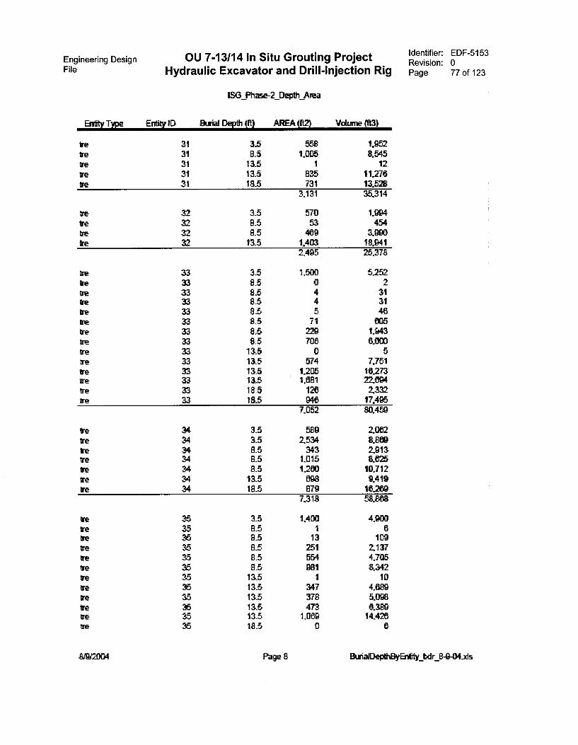
Engineering Design OU 7-13/14 In Situ Grouting ProjectFile Hydraulic Excavator and Drill-Injection Rig
Entity Type
WeWe
Grere
trere
WecreWeWetretrereWeWeWereWeWetre
WeWeheWereWeWe
IreWetre
tretreIreteWetreretre
802004
Entity ID
3131313131
32.323232
3ttE
:3ti
$::I
gE38
EtUf
tSt3
3 $5$t*
t4MOgE!rIbUOli!4
1SG Ph 2_Deptit Area
DEvih (It) AREA (V)
3.5 5588.5 1,00513.5 113.5 83518.5 731
3,131
3.5 5708.5 538.5 40913.5 1,403
2495
3_5 1,50D8.5 08.5 48.5 48.5 58.5 718.5 22Q8.5 708133 013.5 57413.5 120513.5 1,08118.5 12018_5 B46
7,052
3.5 5893.5 25348.5 3438_5 1,0158.5 126013.5 098183 E179
7,318
3.5 1,4008.5 18.5 138.5 2518.5 5548.5 98113.5 113.5 34713.5 37813.5 473135 1,00918.5 0
Page 8
Volisne Cft3)
1.9528.545
121127613.52835.314
1.994454
3.99018,941 25.378
5.2522313146005
1.9436.009
57.75116.273220942.33217,495459
2.0828.8092.9138.62510.7129.4191620958,
4.91X16
1092.1374.7058.342
104,5.0988.32914.426
6
Identifier:Revision:Page
EDF-5153077 of 123
BurialDephEyEnlity bdr 8-9-043ds
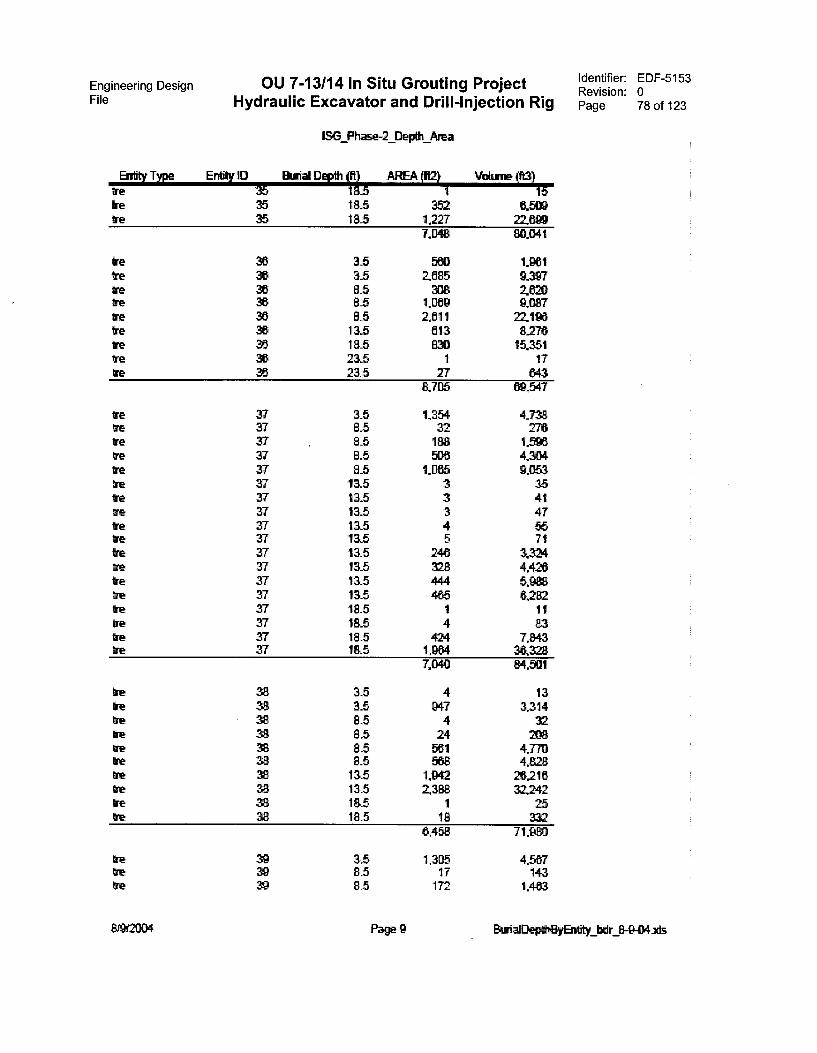
Engineering Design OU 7-13/14 In Situ Grouting ProjectFile Hydraulic Excavator and Drill-Injection Rig
1SG Ph _Depth Area
Entity Type Entity ID Btrial Depth (A) AREA 162) Vokrne (63) re 35 Mb 1 15re 35 18.5 352 6.509re 35 18.5 1,227 22.699
7,048 80.041
WeVe
We
We
We
ire
We
IrereWe
We
rerereretreErere
Iretre
rereWeIre
te
tie
R88888888
3.5 mio 1.96135 2585 9.3978.5 308 262085 1,069 9.0678.5 2511 2219613.5 613 8276185 830 15.35123.5 1 1723.5 27 843
8.705 547
37 3.5 1,354 4.73837 8_5 32 27637 8_5 188 1.59337 8.5 500 4.30437 8_5 1,065 9,05337 13.5 3 3537 13.5 3 4137 13.5 3 4737 133 4 5537 13,5 5 7137 13_5 246 3.32437 13_5 328 4.42637 13.5 414 5.37 13.5 465 6.28237 18,5 1 1137 18_5 4 8337 18.5 424 7.84337 18.5 tem 38.328
7,1340 84.501
8t$:
2480
28gk
Sk88
08
3_5 4 133.5 947 3.3148.5 4 328.5 24 2088.5 561 4.7708.5 588 4.82813.5 1,942 26,216135 2388 32.24218.5 1 2518.5 18 332
6,458 71.980
39 3 5 1,305 456739 8.5 17 14339 85 172 1.463
Identifier: EDF-5153Revision: 0Page 78 of 123
Page 9 BwialDeptigyEnlity_bacir 8 04_xts
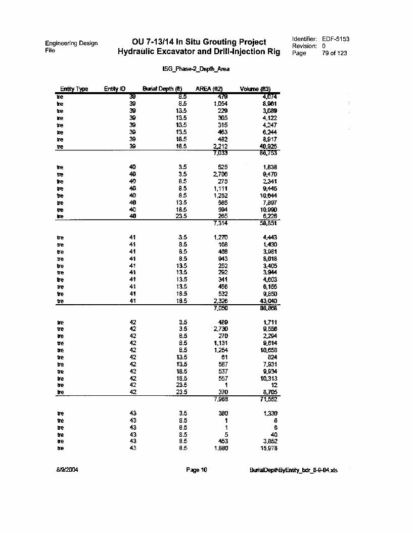
Engineering Design OU 7-13/14 In Situ Grouting Project Identifier: EDF-5153Revision: 0
File HydraUlic Excavator and Drill-Injection Rig Page 79 of 123
Entity Type Entity IDWe
rereweWeWe
re 3s9re
reretrere
prereIre 8
8888t88
re 41re 41ire 41re 41tre 41tre 41re 41re 41Ire 41We 41
re 42re 42We 42re 42Ire 42tre 42Ire 42tre 42We 42tre 42We 42
retreregretrere
434343434343
1.36 Phase-2_Depth Area
atrial Depth (11 AREA (%:4 V9.5 , 48.5 1,054 8,96113,5 229 3.08913.5 305 4,12213.5 315 4,247135 4C3 624418.5 48218.5 2,212 40,925
7,033 :,,8:917753
3.5 525 1.8383.5 2.706 9.4708.5 275 2.3418_5 1,111 9,4458.5 1,252 10.644133 585 7.89718.5 594 10.99323.5 265 6,226
7,314 58.851
3.5 1,270 4.4438.5 168 1.4308.5 488 3.9818.5 943 8,018133 252 3,405133 292 3,94413_5 341 4.6C313.5 456 6.15518.5 532 9.85018.5 2.326 4
7,050
3.5 48D 1,7113.5 2,730 9,5568.5 270 2,2948.5 1,131 9.6148.5 1.254 10.85813.5 61 824115 587 7.93118.5 537 9.193418.5 557 10.31323.5 1 1223.5 370 8,705
7,988 71,552
3.5 380 1,3308.5 1 685 1 68.5 5 408.5 453 3.8528.5 1 15,978
Page 10 BtrialDepftElyEndity_bdr 8-9-04ids
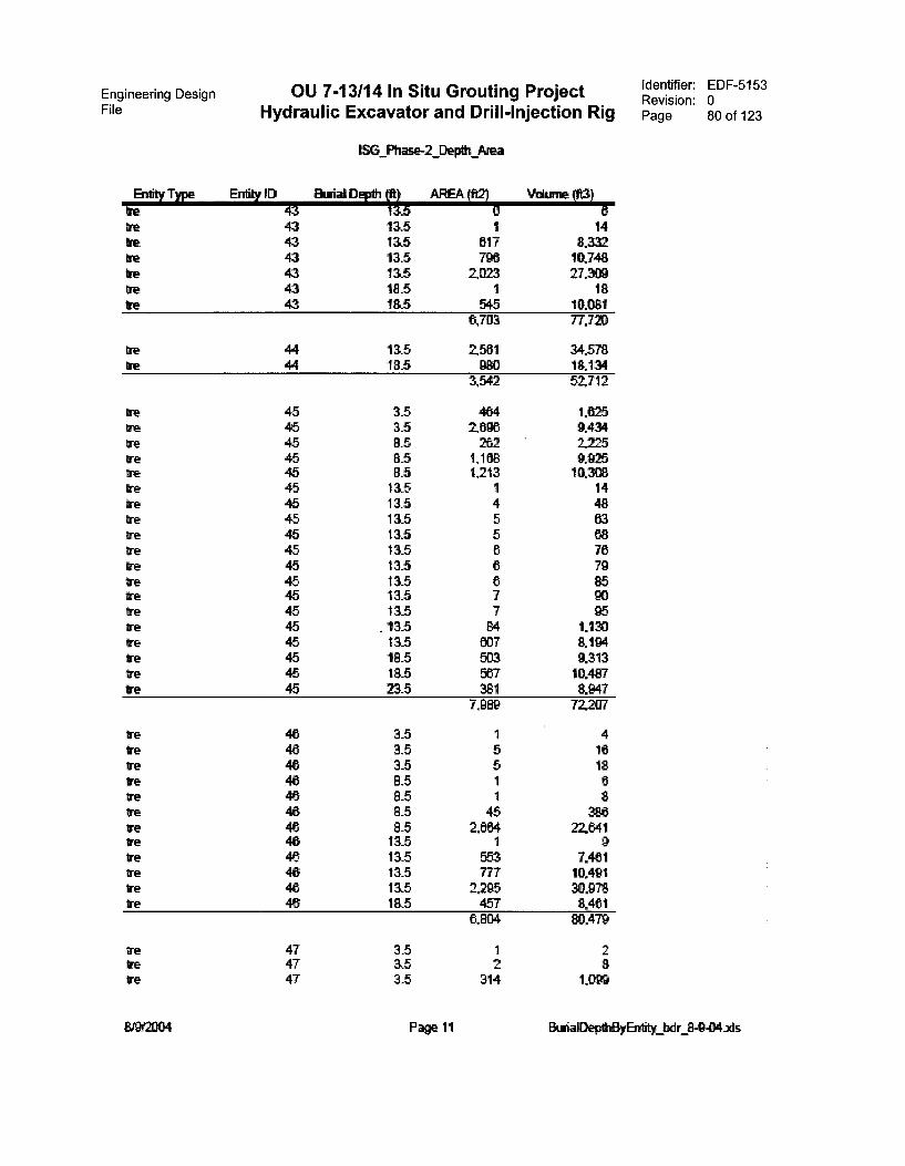
Engineering Design OU 7-13/14 In Situ Grouting ProjectFile Hydraulic Excavator and Drill-Injection Rig
Entity Type Entky IDIre 43re 43Ve 43re 43Ire 43Ire 43re 43
tre 4444
re
re
te
tererereIre
Ire
Ire
Ire
Ire
Iretre
tretre
IreIre
M&V);&&&&&&&&&&itit&
gAM&&8&&g&
474747
8M2004
1SG_Phase-2_Depth Area
13trial Depth It) AREA (ft2) Volume (ft3)11,5 9 613,5 1 14115 817 • XV115 796 10.74813,5 2,023 27.30918.5 1 18185 545 10.081
6,7113 77.720
13.5 2561 34.57818.5 980 18.134
3,542 52.712
3.5 464 1.6253.5 2,696 9.4348.5 262 2.2258.5 1,168 9.9258.5 1,213 10.30813.5 1 1413.5 4 48115 5115 5115 6135 6 7913,5 6 8513.5 7 9013.5 7 95
. 13.5 84 1.130115 007 8.194115 503 9.31318.5 567 10.45723.5 381 8.947
7,989 72.247
3.5 1 43.5 5 1615 5 188.5 1 68_5 1 88.5 45 3888.5 2,664 2E641115 1 913.5 553 7.461115 777 10.49113.5 2.295 30.97818.5 457 8.461
8,804 .479
3_5 13.5 2 83.5 314 1.09D
Identifier: EDF-5153Revision: 0Page 80 of 123
Page 11 BtrialDeptByEnitity_bdr
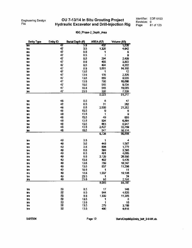
Engineering Design OU 7-13/14 ln Situ Grouting ProjectFile Hydraulic Excavator and Drill-lnjection Rig
Entity Type Entity IDire 47Ire 47we 47we 47We 47We 47tre 47re 47ore 47re 47
47tre 47re 47
47re 47
tre
trereweretreIreIre
re
trereweheWewetrefnetetre
Breweoretrereresre
49494949494949494949494949
'el 8
2_Depth Area
AREA V (7.130
3.5 4,8428_5 1 88.5 1 98.5 2t# 2.4998.5 455 3.8728.5 494 42028.5 1,891 14,115
13..5 1 1213_5 178 2.37513,5 669 9.03513.5 790 10.866185 515 9.534185 545 10.08323.5 320 7,528
8,003 81217
8.5 6 4785 31 2628.5 2,500 2 .252115 0 513.5 1 913.5 49 65513, 5 504 6.80413.5 683 8.94713.5 2427 32.75918.5 547 10.114
6,726 856
3.5 1 43,5 448 1.5873.5 500 1.7728.5 399 13938.5 481 4.0858.5 3,129 26.59513.5 402 5.42813.5 759 10.24713.5 837 11.29618_5 1 1118.5 1,037 19,186235 1 2423,5 93 2.191
8.093 85.797
8.5 17 1488.5 544 4.6258.5 1,339 11,38513,5 1 813.5 1 1013.5 279 3.7e8135 490 6.618
Page 12
Identifier: EDF-5153Revision: 0Page 81 of 123
EkmialDepthBy zds
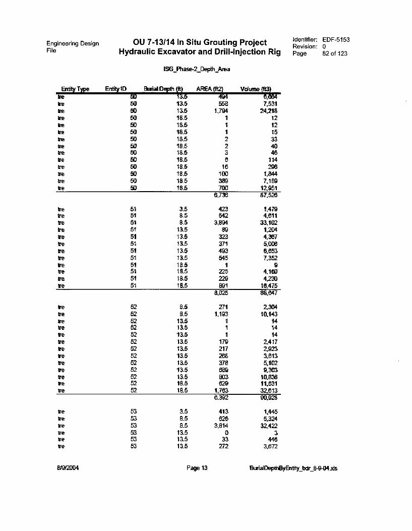
Engineering Design OU 7-13/14 In Situ Grouting Project Identifier: EDF-5153Revision: 0
File Hydraulic Excavator and Drill-Injection Rig Page 82 of 123
Enlity Type Entity IDIneteireWe
ire
betere
re 8888 888888888
re 51we 51re 51we 51we 51re 51re 51re 51tre 51re 51re 51ire 51
re
refneWe
trereretete
re 53we 53re 53we 53re 53we 53
819121:104
1SG_Phase-2_Depth Area
D*111133 AREA 4111V 1'4
135 558 7,53113.5 1,794 24.21818.5 1 1218.5 1 1218.5 1 1518.5 2 3318.5 2 40185 3 4618.5 11418.5 18 29618.5 100 1.84418.5 389 7,1185 12.951
8,736 87.526
3.5 423 t4798.5 542 4.8118_5 3,894 33.10213.5 89 1204115 323 4.367115 371 5.006115 493 6853115 545 7,35218.5 1 918.5 225 4.16318.5 229 4,230185 :4. 1 16.475
8,025 v.: 647
8.5 271 230483 1.193 10.143115 1 1413.5 1 1413,5 1 14115 179 241713.5 217 2923133 288 381313.5 378 5,102115 689 9.30313.5 803 10.83618.5 629 11,83118.5 1,763 32.613
6,302 90.
15 413 1,4458.5 628 5.3248.5 3,814 32.42213.5 0 313.5 33 448115 272 3,872
Page 13 BuriaDeped3yErey 8-9-04..x1s
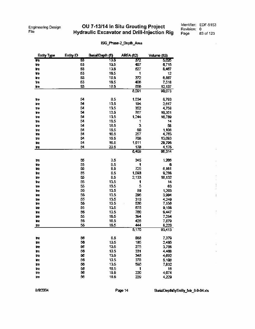
Engineering Design OU 7-13/14 In Situ Grouting ProjectFile Hydraulic Excavator and Drill-Injection Rig
Entity Type Ently IDWe 53We 53We 53we 53We 53we 53Ire 53
WeweIreirebeWewetreIre
Ire 5M5E5MgnM
tretrewetrewe
we
tewetreireWewe S
EPgRgRgSgEgRVgggg
wewetretre
We
tre
WeWeWeWe R
SC388gSSS
1SG Fth
Strial Depth IN
_Depth Area
AREA (I%il511513.518.518.518_518.5
497627
1372406653
6.7158.467
126.8877.51812,137
8,1391 90.1073
8.5 1,034 8,79313.5 194 2,61713.5 352 4.75813.5 767 10.35113.5 1.244 167 :+!185 1 14185 3 5818_5 60 1.106'115 257 4.76318.5 708 13.00318,5 1,611 29.798215 178 4.175
6A08 96.314
3.5 345 1,2068_5 1 685 725 6.16115 1,093 9,2 r.85 2,133 18,13213.5 1 1413.5 5 6313_5 89 1203115 296 3.99413.5 315 4.24913.5 530 7.15613.5 575 9,10813.5 700 9.44718.5 394 7.28418.5 420 7.879185 444 8223
8.170 93.413
8.5 868 7,379115 185 2,495115 275 3,708115 331 4,468115 348 4.69213.5 378 5.108115 580 7.832185 1 1618_5 220 4.07418.5 229 4.229
Identifier: EDF-5153Revision: 0Page 83 of 123
Page 14 DepthElyEntity 8-9-04.2ds
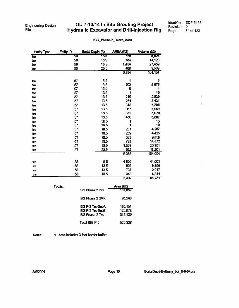
Engineering DesignFile Hydraulic Excavator and Drill-Injection Rig
OU 7-13/14 In Situ Grouting Project
Entity Type Entity 113we 56tre 56tre 50we 56
we
treweWeireWeve
ve
WeweIrewe
ve 4444444444
,444
WeWeiretre
Totals:
1SG Ph
Buda& Depth fft)
_Depth Area
AREA i1,20 Vi .8,518.518.5215
7841,484406
14.12827,4599539
6,304 101.151
85 1 68_5 703 5.975115 0 413.5 1 1013.5 210 Z83913.5 254 3.431115 318 4.28513.5 367 4.95013.5 372 5.02013,5 430 5,80718_5 1 1318.5 1 1918_5 231 4.267185 239 4.42518.5 533 9.8580.5 793 14,67218.5 1,368 25,30123.5 562 13,201
8,383 104.094
8_5 4,895 41,60313.5 508 0,85613.5 737 9.947185 343 6,344
6,482 64,751
ISG Phase 2 Pit 1gN59
ISG Phase 2 SVR 26.540
ISG P-2 Trs-SubA 185.151ISG P-2 Trs-Sub8 125,978ISG Phase 2 Trs 311.129
Total ISG P-2 525,328
1. Area includes 3 foat border buffer.
Page 15
Identifier: EDF-5153Revision: 0Page 84 of 123
Burial 8-9-04.xis
Engineering DesignFile
OU 7-13/14 In Situ Grouting Project Identifier: EDF-5153Revision: 0
Hydraulic Excavator and Drill-Injection Rig Page 85 of 123
Appendix C
Drawings

Engineering Design OU 7-13/14 In Situ Grouting ProjectFile Hydraulic Excavator and Drill-Injection Rig
This page is intentionally left blank.
Identifier: EDF-5153Revision: 0Page 86 of 123
Engineering DesignFile Hydraulic Excavator and Drill-Injection Rig
OU 7-13/14 In Situ Grouting Project
Appendix C
Drawings
Identifier: EDF-5153Revision: 0Page 87 of 123

10-61-atv 1.4 8
Engineering Design OU 7-13/14 In Situ Grouting ProjectFile Hydraulic Excavator and Drill-Injection Rig
7 6 5 4
35.
4
(g)
♦
ti
B
TO HIGHPRESSUREPUMP
LILILD-PHAPTENSOR MOW.
LINE w TENSION
DUAL SHEAVE SPOOLS
-k HYDRABLIC LWES (10HARD PIPWENT:
FwATPC UNE (1WATER UNE (I
• •
11
SWWEL BASE
PIMP PO PUMP
mCwIT(R CPU/DISPLAY
WIZRAULICEXCAVATOR
Ca
HTDRAUUCUNES (10) (FLEX)WATER (1) (ELL!)
(UAW (1) (FLEX)
ANGLESHIFT
MAST
2 PLACES
SMKLHEAD
SHROUD
3
Identifier: EDF-5153Revision: 0Page 88 of 123
ROTARY-PERCUSSIONDRIU. HEAD
TORQUE RESTRAINT/JAWS
5.
STINGER
WATER ACTUATED biWPER
FOOT
FIXATIVE SPRAYNOZZLE
2PENSIONS
0137•101
OPTIONAL RON PRESSUREHOSE ROUTING
SUPPORT CABLE
TO HIGH PRESSUREPUMP •
CABLEANCHOR
8 7 6 5 t 4
Sheet 1. Alternative 1—Hydraulic excavator with mast mounted rotary percussion drill rig.
3
SOORRACI 110.
2
INEEL OU7-13/14
INSITU GROUT PROJECTORIU. RIG PROCESS FLOW SHEET
PREFERRED ALTERNATIVE
,„1,1174M; Dir.-627768 1..1 OF 4
♦
B
A

D
-48
013
at71
1
.
8
Engineering Design OU 7-13/14 In Situ Grouting ProjectFile Hydraulic Excavator and Drill-Injection Rig
8
LARD -41APTENSION SPOIL
7
PuMP
TO HIGHPRESSURE PUMP
P0 PUMP
6
UNE IN IENSION
5 4
DUAL SHEME SPOOLS
4
FIXATIVE SPRAY NOZZLE
3
Identifier: EDF-5153Revision: 0Page 89 of 123
2AMPS
warm orteme cum
LANTIOMW BLOCKS
$10.111ION !NEEL MUM
=ea 8 WO 0U7-13/14awe I GROPE INS1111 GROUT PRO.ECT
DRILL RIG PROCESS FLOW SHEETPREFERRED ALTERNATIVE - LAYDOWN
EIRIVIRVIRIE .16141/1131.11•111 DIonAvi „,j3ifffrq".,,G-62 77681
NONE 2 OF 4
7 6 5 4 3 2
Sheet 2. Alternative 1—Hydraulic excavator with mast mounted rotary percussion drill rig in laydown position for maintenance.
D
c
♦B
A
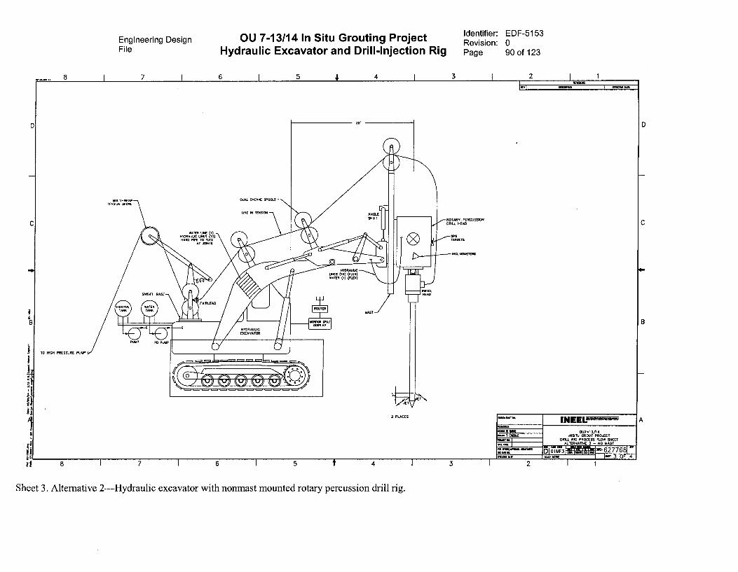
D
B
1
ti
rj 8
8
TO MOH PRESSURE PUMP
Engineering Design OU 7-13/14 In Situ Grouting ProjectFile Hydraulic Excavator and Drill-Injection Rig
11111.1-WRAPTENSoN sPOwL
7 6
DUAL SHEAvE SPEIGLS
5 4 4
JC
o HARD N m) •
•Ww. 1*•
0 ROUTERMAST
71-
/E12 PLACES
ALLEAV
Identifier: EDF-5153Revision: 0Page 90 of 123
3
ROTARY-PERGVSSONMILL HEAD
GPSTARGETS
iNOLINCREL
2
INGOWSPI
•110•111110. 1NEELOU7-10/14
MST) GROUT PROXOTDRILL RIG PROCESS flOW SHEET
ALTERNATIVE 2 - NO OAST
5 1 3;73MEOW MT wAle NONE
on-627768i IE.,' 3 OF 4
7 6 5 4
Sheet 3. Alternative 2—Hydraulic excavator with nonmast mounted rotary percussion drill rig.
3 2
B
A
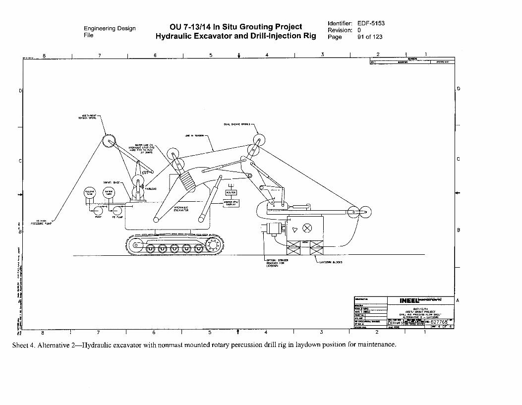
Engineering Design OU 7-13/14 In Situ Grouting ProjectFile Hydraulic Excavator and Drill-Injection Rig
Identifier: EDF-5153Revision: 0Page 91 of 123
-10
TO HIGHPRESSURE PUMP
8
;.1
If
8
MULTI-WOTENS. SP.&
SWIVEL BASE
UNE IN lENSCN
IffOR:U'ITUNES UME
inO),)NAM PiPF TO FLEN
AT JOINTS
FAJRLEAD
-ETPUMP PO PumP
VDRAULICEXCAVATOR
•
/
AZKVelargarla).
DUAL SHEAVE SPOCCS
):,===pA
00
—oPnom STINGERREMOVED FORLATDOVP1
LAYDOWN BLOCKS
111.1:01•1141 'NEEL- •CM PAOmat T CREW
7,Z1 re IlearIAMID. MARS
1011 11114
OUT-17/14ROSIN GROUT PROJECT
DRILL RIG PROCESS FLOW SHEET
sig7,7 N 3rsriE 2 - LATDOWW
T-0.0 W-627768
4 OF 4ORME NIB KNo NONE
7 I 6 I 5 f 4 I 3 i 2 I 1
Sheet 4. Alternative 2—Hydraulic excavator with nonmast mounted rotary percussion drill rig in laydown position for maintenance.

Engineering Design OU 7-13/14 In Situ Grouting ProjectFile Hydraulic Excavator and Drill-Injection Rig
This page is intentionally left blank.
Identifier: EDF-5153Revision: 0Page 92 of 123
Engineering Design OU 7-13/14 In Situ Grouting ProjectFile Hydraulic Excavator and Drill-Injection Rig
Appendix D
Identifier: EDF-5153Revision: 0Page 93 of 123
Excavator Information,Caterpillar Model 345B and Model 385
Engineering DesignFile Hydraulic Excavator and Drill-Injection Rig
OU 7-13/14 In Situ Grouting Project
This page is intentionally left blank.
identifier: EDF-5153Revision: 0Page 94 of 123
Engineering Design OU 7-13/14 In Situ Grouting ProjectFile Hydraulic Excavator and Drill-Injection Rig
Appendix D
Identifier: EDF-5153Revision: 0Page 95 of 123
Excavator Information,Caterpillar Model 345B and Model 385
See separate pdf file (EDF-5153_appendix_D) for Appendix D.
345B LSeries 11Hydraulic Excavator
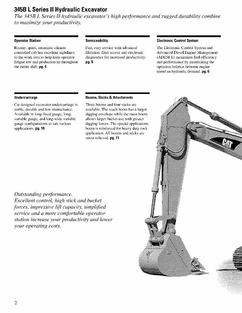
345B L Series II Hydraulic ExcavatorThe 345B L Series II hydraulic excavator's high peiformance and rugged durability combineto maximize your productivity.
Operator Station
Roomy, quiet, automatic climatecontrolled cab has excellent sightlinesto the work area to help keep operatorfatigue low and production up throughoutthe entire shift. pg. 4
Undercarriage
Cat designed excavator undercarriage isstable, durable and low maintenance.Available in long-fixed gauge, long-variable gauge, and long-wide variablegauge configurations to suit variousapplications. pg. 10
Serviceability
Fast, easy service with advancedfiltration, filter access and electronicdiagnostics for increased productivity.pg. 5
Booms, Sticks & Attachments
Three booms and four sticks areavailable. The reach boom has a largerdigging envelope while the mass boomallows larger bucket use with greaterdigging forces. The special applicationsboom is reinforced for heavy duty rockapplication. All booms and sticks arestress relieved. pg. 11
Outstanding performance.Excellent control, high stick and bucketforces, impressive lift capacity, simplifiedservice and a more comfortable operatorstation increase your productivity and loweryour operating costs.
Electronic Control System
The Electronic Control System andAdvanced Diesel Engine Management(ADEM II) maximizes fuel efficiencyand performance by maintaining theoptimum balance between enginespeed an hydraulic demand. pg. 6
2
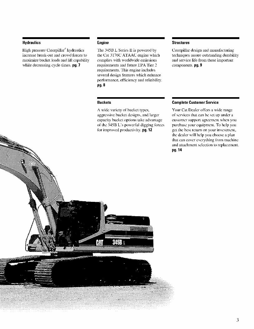
Hydraulics
High pressure Caterpillar° hydraulicsincrease break-out and crowd forces tomaximize bucket loads and lift capabilitywhile decreasing cycle times. pg. 7
Engine
The 345B L Series II is powered bythe Cat 3176C ATAAC engine whichcomplies with worldwide emissionsrequirements and future EPA Tier 2requirements. This engine includesseveral design features which enhanceperformance, efficiency and reliability.pg. 8
Buckets
A wide variety of bucket types,aggressive bucket designs, and largercapacity bucket options take advantageof the 345B L's powerful digging forcesfor improved productivity. pg. 12
Structures
Caterpillar design and manufacturingtechniques assure outstanding durabilityand service life from these importantcomponents. pg. 9
Complete Customer Service
Your Cat Dealer offers a wide rangeof services that can be set up under acustomer support agreement when youpurchase your equipment. To help youget the best return on your investment,the dealer will help you choose a planthat can cover everything from machineand attachment selection to replacement.pg. 14
3
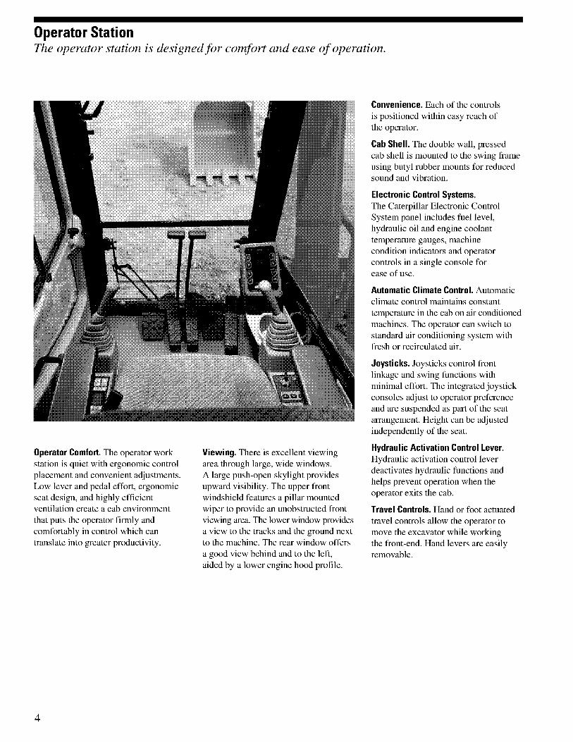
Operator StationThe operator station is designed for comfort and ease of operation.
Operator Comfort. The operator workstation is quiet with ergonomic controlplacement and convenient adjustments.Low lever and pedal effort, ergonomicseat design, and highly efficientventilation create a cab environmentthat puts the operator firmly andcomfortably in control which cantranslate into greater productivity.
Viewing. There is excellent viewingarea through large, wide windows.A large push-open skylight providesupward visibility. The upper frontwindshield features a pillar mountedwiper to provide an unobstructed frontviewing area. The lower window providesa view to the tracks and the ground nextto the machine. The rear window offersa good view behind and to the left,aided by a lower engine hood profile.
Convenience. Each of the controlsis positioned within easy reach ofthe operator.
Cab Shell. The double wall, pressedcab shell is mounted to the swing frameusing butyl rubber mounts for reducedsound and vibration.
Electronic Control Systems.The Caterpillar Electronic ControlSystem panel includes fuel level,hydraulic oil and engine coolanttemperature gauges, machinecondition indicators and operatorcontrols in a single console forease of use.
Automatic Climate Control. Automaticclimate control maintains constanttemperature in the cab on air conditionedmachines. The operator can switch tostandard air conditioning system withfresh or recirculated air.
Joysticks. Joysticks control frontlinkage and swing functions withminimal effort. The integrated joystickconsoles adjust to operator preferenceand are suspended as part of the seatarrangement. Height can be adjustedindependently of the seat.
Hydraulic Activation Control Lever.Hydraulic activation control leverdeactivates hydraulic functions andhelps prevent operation when theoperator exits the cab.
Travel Controls. Hand or foot actuatedtravel controls allow the operator tomove the excavator while workingthe front-end. Hand levers are easilyremovable.
4
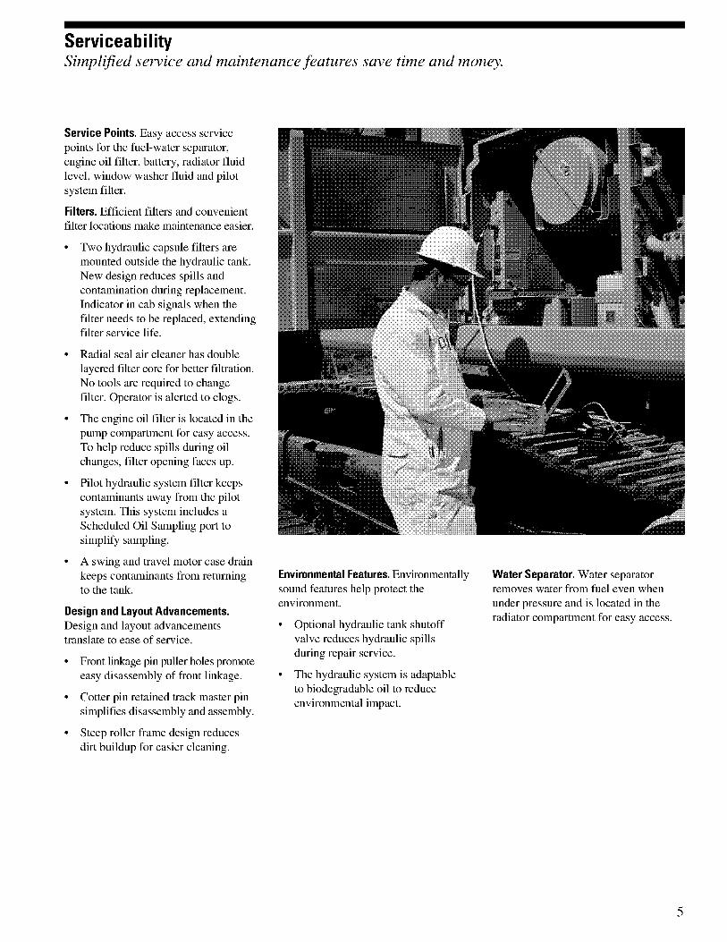
ServiceabilitySimplified service and maintenance features save time and money.
Service Points. Easy access servicepoints for the fuel-water separator,engine oil filter, battery, radiator fluidlevel, window washer fluid and pilotsystem filter.
Filters. Efficient filters and convenientfilter locations make maintenance easier.
• Two hydraulic capsule filters aremounted outside the hydraulic tank.New design reduces spills andcontamination during replacement.Indicator in cab signals when thefilter needs to be replaced, extendingfilter service life.
• Radial seal air cleaner has doublelayered filter core for better filtration.No tools are required to changefilter. Operator is alerted to clogs.
• The engine oil filter is located in thepump compartment for easy access.To help reduce spills during oilchanges, filter opening faces up.
• Pilot hydraulic system filter keepscontaminants away from the pilotsystem. This system includes aScheduled Oil Sampling port tosimplify sampling.
• A swing and travel motor case drainkeeps contaminants from returningto the tank.
Design and Layout Advancements.Design and layout advancementstranslate to ease of service.
• Front linkage pin puller holes promoteeasy disassembly of front linkage
• Cotter pin retained track master pinsiniplifies disassembly and assembly.
• Steep roller frame design reducesdirt buildup for easier cleaning.
Environmental Features. Environmentallysound features help protect theenvironment.
• Optional hydraulic tank shutoffvalve reduces hydraulic spillsduring repair service.
• The hydraulic system is adaptableto biodegradable oil to reduceenvironmental impact.
Water Separator. Water separatorremoves water from fuel even whenunder pressure and is located in theradiator compartment for easy access.
5
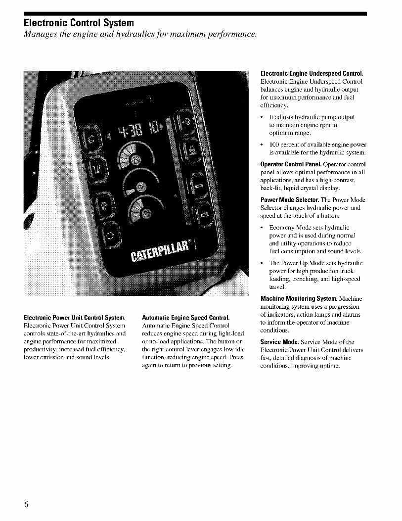
Electronic Control SystemManages the engine and hydraulics for maximum performance.
Electronic Power Unit Control System.Electronic Power Unit Control Systemcontrols state-of-the-art hydraulics andengine performance for maximizedproductivity, increased fuel efficiency,lower emission and sound levels.
Automatic Engine Speed Control.Automatic Engine Speed Controlreduces engine speed during light-loador no-load applications. The button onthe right control lever engages low idlefunction, reducing engine speed. Pressagain to return to previous setting.
Electronic Engine Underspeed Control.Electronic Engine Underspeed Controlbalances engine and hydraulic outputfor maximum performance and fuelefficiency.
• It adjusts hydraulic pump outputto maintain engine rpm inoptimum range.
• 100 percent of available engine poweris available for the hydraulic system.
Operator Control Panel. Operator controlpanel allows optimal performance in allapplications, and has a high-contrast,back-lit, liquid crystal display.
Power Mode Selector. The Power ModeSelector changes hydraulic power andspeed at the touch of a button.
• Economy Mode sets hydraulicpower and is used during normaland utility operations to reducefuel consumption and sound levels.
• The Power Up Mode sets hydraulicpower for high production truckloading, trenching, and high-speedtravel.
Machine Monitoring System. Machinemonitoring system uses a progressionof indicators, action lamps and alarmsto inform the operator of machineconditions.
Service Mode. Service Mode of theElectronic Power Unit Control deliversfast, detailed diagnosis of machineconditions, improving uptime.
6
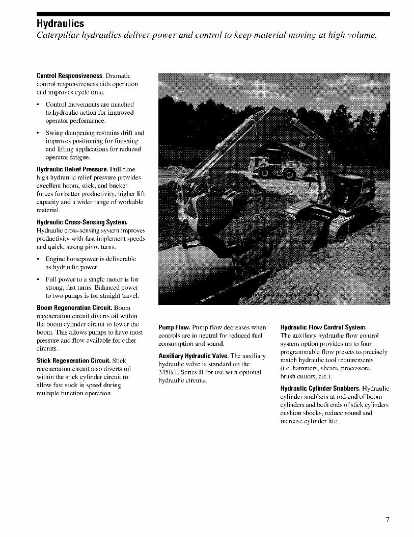
HydraulicsCaterpillar hydraulics deliver power and control to keep material moving at high volume.
Control Responsiveness. Dramaticcontrol responsiveness aids operationand improves cycle time.
• Control movements are matchedto hydraulic action for improvedoperator performance.
• Swing dampening restrains drift andimproves positioning for finishingand lifting applications for reducedoperator fatigue.
Hydraulic Relief Pressure. Full-timehigh hydraulic relief pressure providesexcellent boom, stick, and bucketforces for better productivity, higher liftcapacity and a wider range of workablematerial.
Hydraulic Cross-Sensing System.Hydraulic cross-sensing system improvesproductivity with fast implement speedsand quick, strong pivot turns.
• Engine horsepower is deliverableas hydraulic power.
• Full power to a single motor is forstrong, fast turns. Balanced powerto two pumps is for straight travel.
Boom Regeneration Circuit. Boomregeneration circuit diverts oil withinthe boom cylinder circuit to lower theboom. This allows pumps to have mostpressure and flow available for othercircuits.
Stick Regeneration Circuit. Stickregeneration circuit also diverts oilwithin the stick cylinder circuit toallow fast stick in speed duringmultiple function operation.
Pump Flow. Pump flow decreases whencontrols are in neutral for reduced fuelconsumption and sound.
Auxiliary Hydraulic Valve. The auxiliaryhydraulic valve is standard on the345B L Series II for use with optionalhydraulic circuits.
Hydraulic Flow Control System.The auxiliary hydraulic flow controlsystem option provides up to fourprogrammable flow presets to preciselymatch hydraulic tool requirements(i.e. hammers, shears, processors,brush cutters, etc.).
Hydraulic Cylinder Snubbers. Hydrauliccylinder snubbers at rod-end of boomcylinders and both ends of stick cylinderscushion shocks, reduce sound andincrease cylinder life.
7
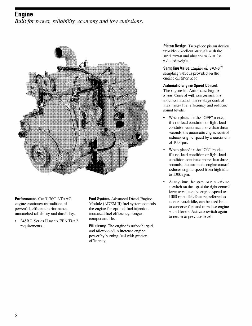
EngineBuilt for power, reliability, economy and low emissions.
Performance. Cat 3176C ATAACengine continues its tradition ofpowerful, efficient performance,unmatched reliability and durability.
• 345B L Series II meets EPA Tier 2requirements.
Fuel System. Advanced Diesel EngineModule (ADEM II) fuel system controlsthe engine for optimal fuel injection,increased fuel efficiency, longercomponent life.
Efficiency. The engine is turbochargedand aftercooled to increase enginepower by burning fuel with greaterefficiency.
Piston Design. Two-piece piston designprovides excellent strength with thesteel crown and aluminum skirt forreduced weight.
Sampling Valve. Engine oil S•O•Ss"`sampling valve is provided on theengine oil filter head.
Automatic Engine Speed Control.The engine has Automatic EngineSpeed Control with convenient one-touch command. Three-stage controlmaximizes fuel efficiency and reducessound levels.
• When placed in the -OFF" mode,if a no-load condition or light-loadcondition continues more than threeseconds, the automatic engine controlreduces engine speed by a maximumof 100 rpm.
• When placed in the -ON" mode,if a no-load condition or light-loadcondition continues more than threeseconds, the automatic engine controlreduces engine speed from high idleto 1300 rpm.
• At any time, the operator can activatea switch on the top of the right controllever to reduce the engine speed to1000 rpm. This feature, referred toas one-touch idle, can be used bothto conserve fuel and to reduce enginesound levels. Activate switch againto retum to previous level.
8

StructuresThe 345B L Series II structural components are the backbone of the machine's durability.
Design. Advanced carbody design forfixed gauge undercarriage stands upin the toughest applications.
• Modified X-shaped, box-sectioncarbody provides excellent resistanceto torsional bending.
• Upper structure weight and stressesare distributed evenly across the fulllength of the track roller frame.
• Smooth transitions and long weldsreduce stresses at the carbody-to-roller frame junctions for excellentdurability.
• Robot welding ensures consistent,high-quality welds throughout themanufacturing process.
• Steep track roller frames are easierto clean.
Variable and Wide Variable GaugeUndercarriage's. Variable Gauge (VG)and Wide Variable Gauge (W VG)undercarriage's have track roller frameswhich are bolted to the carbody and canbe retracted for shipping.
Roller Frames. Robot-welded trackroller frames are press-formed,pentagonal units to deliver exceptionalstrength and service life.
Main Frame. Rugged main frameis designed for maximum durabilityand efficient use of materials.
• Robot welding was used forconsistent, high-quality welds.
• The outer frame utilizes curvedside rails, which are die-formed,for excellent uniformity and strengththroughout the length.
• Box section channels improve upperframe rigidity under the cab.
• Boom tower and one piece mainrails are constructed of solid, hightensile strength steel plates.
• New boom foot design transfers loadmore efficiently with less stress incritical areas.
• Sheet metal supporting structureis strengthened by integrating themounting into the upper framestructure.
• Reinforced lift cylinder and swingdrive mounts increase structuredurability in rock and quarryapplications.
9
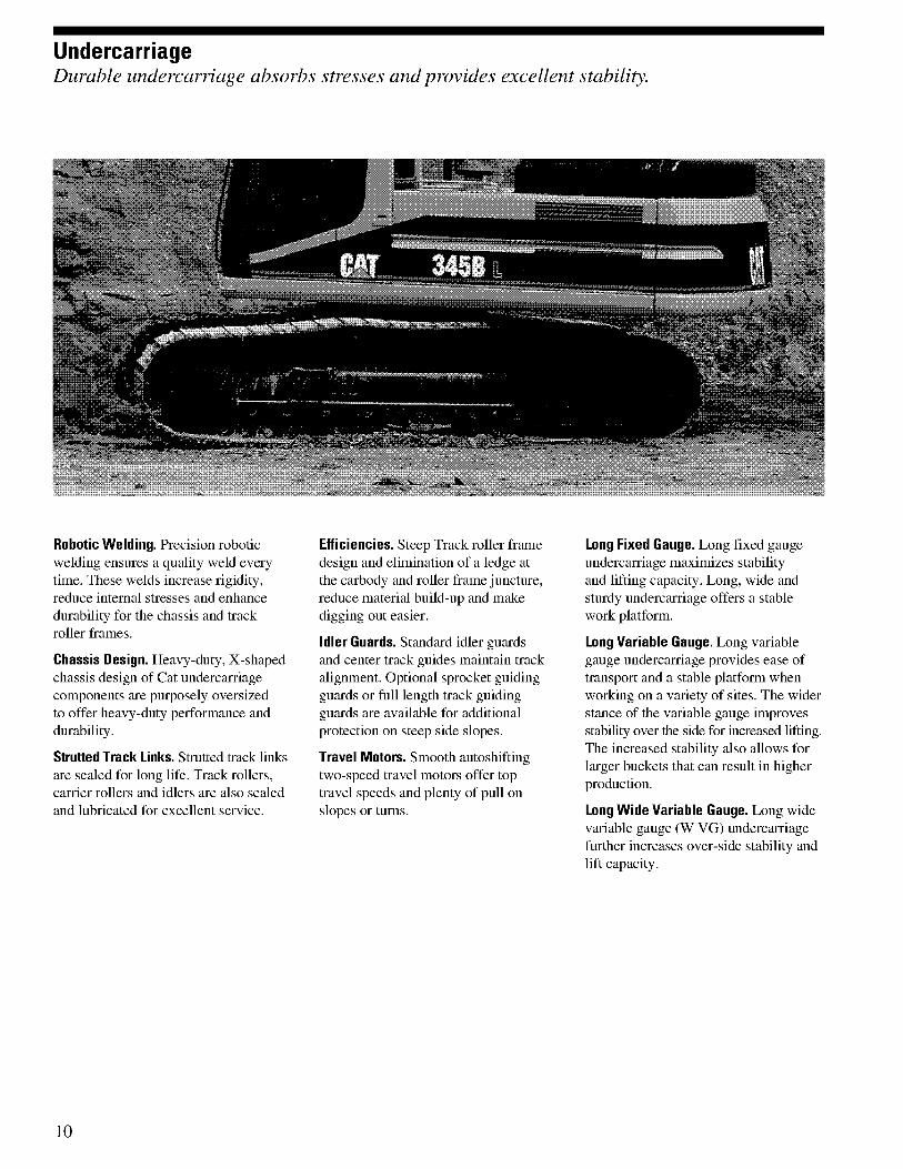
UndercarriageDurable undercarriage absorbs stresses and provides excellent stability.
Robotic Welding. Precision roboticwelding ensures a quality weld everytime. These welds increase rigidity,reduce internal stresses and enhancedurability for the chassis and trackroller frames.
Chassis Design. Heavy-duty, X-shapedchassis design of Cat undercarriagecomponents are purposely oversizedto offer heavy-duty performance anddurability.
Strutted Track Links. Strutted track linksare sealed for long life. Track rollers,carrier rollers and idlers are also sealedand lubricated for excellent service.
Efficiencies. Steep Track roller framedesign and elimination of a ledge atthe carbody and roller frame juncture,reduce material build-up and makedigging out easier.
idler Guards. Standard idler guardsand center track guides maintain trackalignment. Optional sprocket guidingguards or full length track guidingguards are available for additionalprotection on steep side slopes.
Travel Motors. Smooth autoshiftingtwo-speed travel motors offer toptravel speeds and plenty of pull onslopes or turns.
Long Fixed Gauge. Long fixed gaugeundercarriage maximizes stabilityand lifting capacity. Long, wide andsturdy undercarriage offers a stablework platform.
Long Variable Gauge. Long variablegauge undercarriage provides ease oftransport and a stable platform whenworking on a variety of sites. The widerstance of the variable gauge improvesstability over the side for increased lifting.The increased stability also allows forlarger buckets that can result in higherproduction.
Long Wide Variable Gauge. Long widevariable gauge (W VG) undercarriagefurther increases over-side stability andlift capacity.
10
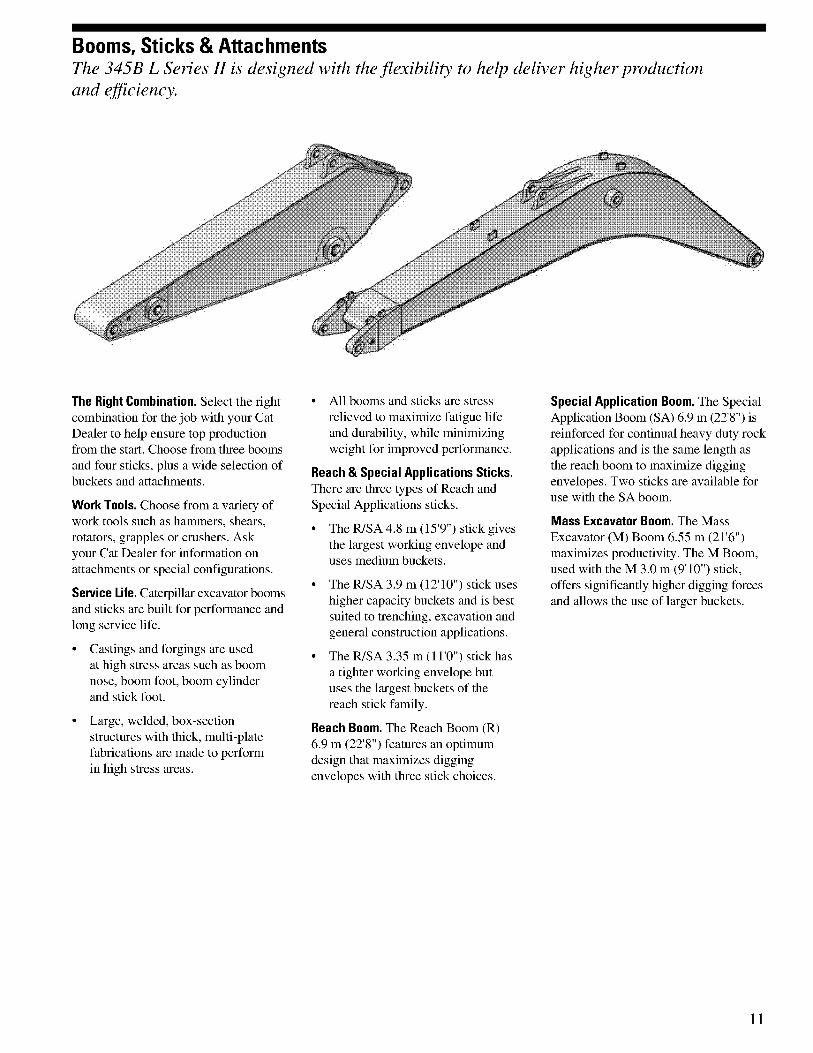
Booms, Sticks & AttachmentsThe 345B L Series II is designed with the flexibility to help deliver higher productionand efficiency.
The Right Combination. Select the rightcombination for the job with your CatDealer to help ensure top productionfrom the start. Choose from three boomsand four sticks, plus a wide selection ofbuckets and attachments.
Work Tools. Choose from a variety ofwork tools such as hammers, shears,rotators, grapples or crushers. Askyour Cat Dealer for information onattachments or special configurations.
Service Life. Caterpillar excavator boomsand sticks are built for performance andlong service life.
• Castings and forgings are usedat high stress areas such as boomnose, boom foot, boom cylinderand stick foot.
• Large, welded, box-sectionstructures with thick, multi-platefabrications are made to performin high stress areas.
• All booms and sticks are stressrelieved to maximize fatigue lifeand durability, while minimizingweight for improved performance.
Reach & Special Applications Sticks.There are three types of Reach andSpecial Applications sticks.
• The R/SA 4.8 m (15'9") stick givesthe largest working envelope anduses medium buckets.
• The R/SA 3.9 m (12'10") stick useshigher capacity buckets and is bestsuited to trenching, excavation andgeneral construction applications.
• The R/SA 3.35 m (11'0") stick hasa tighter working envelope butuses the largest buckets of thereach stick family.
Reach Boom. The Reach Boom (R)6.9 m (22'8") features an optimumdesign that maximizes diggingenvelopes with three stick choices.
Special Application Boom. The SpecialApplication Boom (SA) 6.9 m (22'8") isreinforced for continual heavy duty rockapplications and is the same length asthe reach boom to maximize diggingenvelopes. Two sticks are available foruse with the SA boom.
Mass Excavator Boom. The MassExcavator (M) Boom 6.55 m (21'6")maximizes productivity. The M Boom,used with the M 3.0 m (9'10") stick,offers significantly higher digging forcesand allows the use of larger buckets.
11
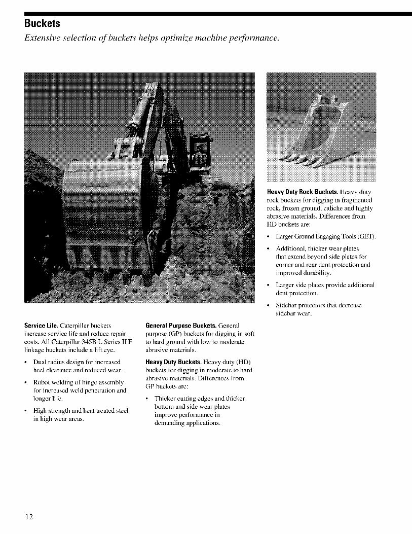
BucketsExtensive selection of buckets helps optimize machine performance.
Service Life. Caterpillar bucketsincrease service life and reduce repaircosts. All Caterpillar 345B L Series II Flinkage buckets include a lift eye.
• Dual radius design for increasedheel clearance and reduced wear.
• Robot welding of hinge assemblyfor increased weld penetration andlonger life.
• High strength and heat treated steelin high wear areas.
General Purpose Buckets. Generalpurpose (GP) buckets for digging in softto hard ground with low to moderateabrasive materials.
Heavy Duty Buckets. Heavy duty (HD)buckets for digging in moderate to hardabrasive materials. Differences fromGP buckets are:
• Thicker cutting edges and thickerbottom and side wear platesimprove performance indemanding applications.
Heavy Duty Rock Buckets. Heavy dutyrock buckets for digging in fragmentedrock, frozen ground, caliche and highlyabrasive materials. Differences fromHD buckets are:
• Larger Ground Engaging Tools (GET).
• Additional, thicker wear platesthat extend beyond side plates forcorner and rear dent protection andimproved durability.
• Larger side plates provide additionaldent protection.
• Sidebar protectors that decreasesidebar wear.
12
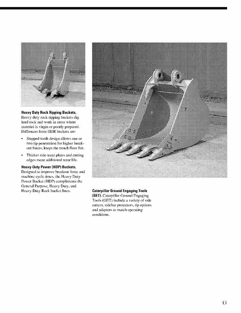
Heavy Duty Rock Ripping Buckets.Heavy duty rock ripping buckets dighard rock and work in areas wherematerial is virgin or poorly prepared.Diffrences from HDR buckets are:
• Stepped tooth design allows one ortwo tip penetration for higher break-out forces, keeps the trench floor flat.
• Thicker side wear plates and cuttingedges mean additional wear life.
Heavy-Duty Power (HDP) Buckets.Designed to improve breakout force andmachine cycle times, the Heavy DutyPower Bucket (HDP) compliments theGeneral Purpose, Heavy Duty, andHeavy Duty Rock bucket lines. Caterpillar Ground Engaging Tools
(GET). Caterpillar Ground EngagingTools (GET) include a variety of sidecutters, sidebar protectors, tip optionsand adapters to match operatingconditions.
13
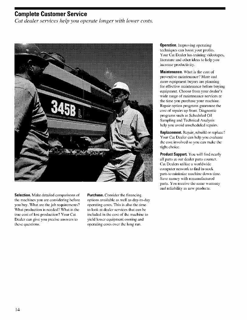
Complete Customer ServiceCat dealer services help you operate longer with lower costs.
Selection. Make detailed comparisons ofthe machines you are considering beforeyou buy. What are the job requirements?What production is needed? What is thetrue cost of lost production? Your CatDealer can give you precise answers tothese questions.
Purchase. Consider the financingoptions available as well as day-to-dayoperating costs. This is also the timeto look at dealer services that can beincluded in the cost of the machine toyield lower equipment owning andoperating costs over the long run.
Operation. Improving operatingtechniques can boost your profits.Your Cat Dealer has training videotapes,literature and other ideas to help youincrease productivity.
Maintenance. What is the cost ofpreventive maintenance? More andmore equipment buyers are planningfor effective maintenance before buyingequipment. Choose from your dealer'swide range of maintenance services atthe time you purchase your machine.Repair option programs guarantee thecost of repairs up front. Diagnosticprograms such as Scheduled OilSampling and Technical Analysishelp you avoid unscheduled repairs.
Replacement. Repair, rebuild or replace?Your Cat Dealer can help you evaluatethe cost involved so you can make theright choice.
Product Support. You will find nearlyall parts at our dealer parts counter.Cat Dealers utilize a worldwidecomputer network to fmd in-stockparts to minirnize machine down time.Save money with remanufacturedparts. You receive the same warrantyand reliability as new products.
14

Engine Hydraulic System
Engine Model CAT 3176C ATAAC Main Implement System -Maximum Flow (2x)
360 L/min 95.1 gal/min
Flywheel Power 239 kW 321 hp
ISO 9249 239 kW 321 hp Maximum pressure - Implements(Full Time)
34 340 kPa 4,980 psi
SAE J1349 239 kW 321 hpMaximum pressure - Travel 34 340 kPa 4,980 psiBore 125 mm 4.92 inMaximum pressure - Swing 28 440 kPa 4,130 psiStroke 140 mm 5.51 inPilot System - Maximum flow 41 L/min 10.8 gal/minDisplacement 10.3 L 630 in3
• no engine derating needed up to 2300 m (7,500 ft)Pilot System - Maximum pressure 4655 kPa 675 psi
Boom Cylinder - Bore 160 mm 6.3 in
Boom Cylinder - Stroke 1575 mm 62 in
Weights Stick Cylinder - Bore 190 mm 7.5 in
Stick Cylinder - Stroke 1758 mm 69.2 in
Operating Weight 44 460 kg 97,940 lb F Family Bucket Cylinder - Bore 160 mm 6.3 in
F Family Bucket Cylinder - Stroke 1575 mm 62 in
G Family Bucket Cylinder - Bore 170 mm 6.7 in
Service Refill Capacities G Family Bucket Cylinder - Stroke 1366 mm 53.8 in
Fuel Tank Capacity 720 L 190 gal
Cooling System 45 L 12 gal DriveEngine Oil 30 L 7.9 gal
Swing Drive 10 L 2.6 gal Maximum Drawbar Pull 331 kN 74,380 lb
Final Drive (each) 15 L 4 gal Maximum Travel Speed 4.4 kph 2.7 mph
Hydraulic System(including tank)
520 L 137 gal
Swing MechanismHydraulic Tank 210 L 55 gal
Sound Performance
Swing Speed 8.6 RPM
Swing Torque 149 kN•m 110,260 Ib•ft
Performance ANSI/SAE J1166 MAY90Meets OSHA and MSHARequirements
Track
Standard w/Long Undercarriage 900 mm 36 in
Optional - Triple Grouser 750 mm 30 inStandards Optional 750 mm 30 in
Ground Clearance - Fixed Gauge 510 mm 20 inBrakes SAE J1026 APR90
Ground Clearance - 740 mm 29 inCab/FOGS SAE J1356 FEB 88 and Variable Gauge
ISO 10262-1998 Ground Clearance - 740 mm 29 inWide Variable Gauge
345B L Series 11 Hydraulic Excavator specifications 15
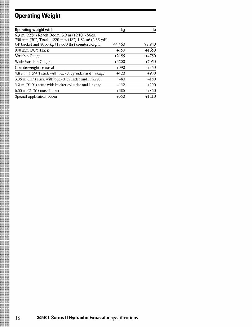
Operating Weight
Operating weight with: kg lb
6.9 m (22'8") Reach Boom, 3.9 m (12'10") Stick,750 mm (30") Track, 1220 mm (48") 1.82 m3 (2.38 yd3)GP bucket and 8000 kg (17,600 lbs) counterweight 44 460 97,940
900 mm (36") Track +750 +1650
Variable Gauge +2155 +4750
Wide Variable Gauge +3200 +7050
Counterweight removal +390 +850
4.8 mm (15'9") stick with bucket cylinder and linkage +420 +930
3.35 m (11") stick with bucket cylinder and linkage —80 —180
3.0 m (9'10") stick with bucket cylinder and linkage —132 +290
6.55 m (21'6") mass boom +386 +850
Special application boom +550 +1210
16 345B L Series II Hydraulic Excavator specifications
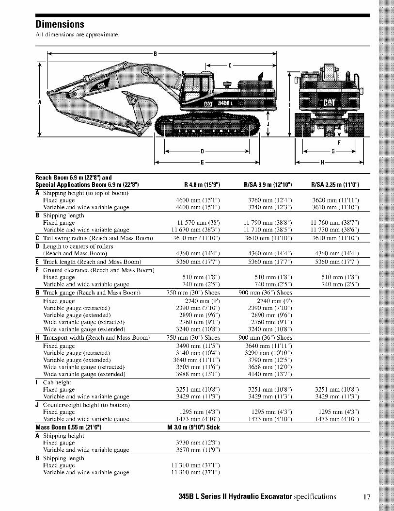
DimensionsAll dimensions are approximate.
Reach Boom 6.9 m (22'r) andSpecial Applications Boom 6.9 m (22'r) R 4.8 m (15T) R/SA 3.9 m (1210") R/SA 3.35 m (WO")
A Shipping height (to top of boom)Fixed gauge 4600 mm (15'1") 3760 mm (12'4") 3620 mm (11'11")Variable and wide variable gauge 4600 mm (15'1") 3740 mm (12'3") 3610 mm (11'10")
B Shipping lengthFixed gauge 11 570 mm (38') 11 790 mm (38'8") 11 760 mm (38'7")Variable and wide variable gauge 11 670 mm (38'3") 11 710 mm (38'5") 11 730 mm (38'6")
C Tail swing radius (Reach and Mass Boom) 3610 mm (11'10") 3610 mm (11'10") 3610 mm (11'10")
D Length to centers of rollers(Reach and Mass Boom) 4360 mm (14'4") 4360 mm (14'4") 4360 mm (14'4")
E Track length (Reach and Mass Boom) 5360 mm (17'7") 5360 mm (17'7") 5360 mm (17'7")
F Ground clearance (Reach and Mass Boom)Fixed gauge 510 mm (1'8") 510 mm (1'8") 510 mm (1'8")Variable and wide variable gauge 740 mm (2'5") 740 mm (2'5") 740 mm (2'5")
G Track gauge (Reach and Mass Boom) 750 mm (30") Shoes 900 mm (36") Shoes
Fixed gauge 2740 mm (9') 2740 mm (9')Variable gauge (retracted) 2390 mm (7'10") 2390 mm (7'10")Variable gauge (extended) 2890 mm (9'6") 2890 mm (9'6")Wide variable gauge (retracted) 2760 mm (9'1") 2760 mm (9'1")Wide variable gauge (extended) 3240 mm (10'8") 3240 mm (10'8")
H Transport width (Reach and Mass Boom) 750 mm (30") Shoes 900 mm (36") Shoes
Fixed gauge 3490 mm (11'5") 3640 mm (11'11")Variable gauge (retracted) 3140 mm (10'4") 3290 mm (10'10")Variable gauge (extended) 3640 mm (11'11") 3790 mm (12'5")Wide variable gauge (retracted) 3505 mm (11'6") 3658 mm (12'0")Wide variable gauge (extended) 3988 mm (13'1") 4140 mm (13'7")
I Cab heightFixed gauge 3251 mm (10'8") 3251 mm (10'8") 3251 mm (10'8")Variable and wide variable gauge 3429 mm (11'3") 3429 mm (11'3") 3429 mm (11'3")
J Counterweight height (to bottom)Fixed gauge 1295 mm (4'3") 1295 mm (4'3") 1295 mm (4'3")Variable and wide variable gauge 1473 mm (4'10") 1473 mm (4'10") 1473 mm (4'10")
Mass Boom 6.55 m (21'6") M 3.0 m (910") Stick
A Shipping heightFixed gauge 3730 mm (12'3")Variable and wide variable gauge 3570 mm (11'9")
B Shipping lengthFixed gaugeVariable and wide variable gauge
11 310 mm (37'1")11 310 mm (37'1")
345B L Series II Hydraulic Excavator specifications 17
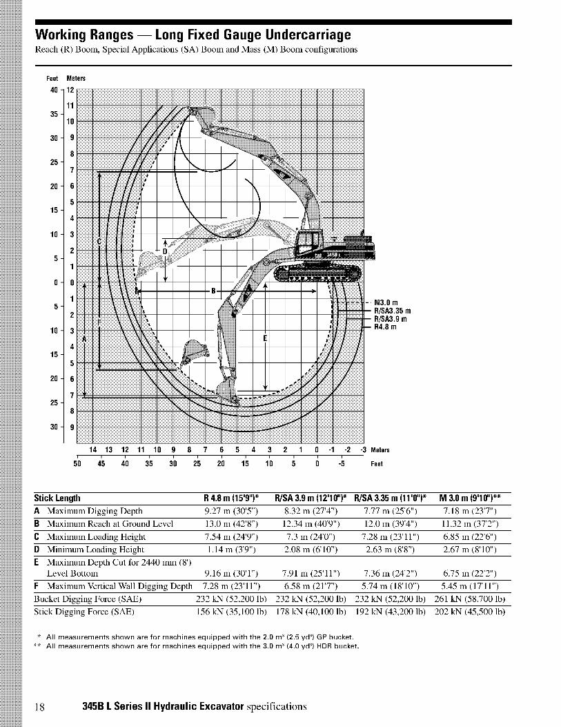
Working Ranges - Long Fixed Gauge UndercarriageReach (R) Boom, Special Applications (SA) Boom and Mass (M) Boom configurations
Feet Meters
40 - 12
1135 -
10
30 - 9
8
7
20 - 6
5
4
10- 3
2
1
0- 0
1
2
10- 3
4
5
20- 6
725 -
8
30 - 9
25 -
15 -
5 -
5 -
15 -
A
-Y
- M3.0 mR/SA3.35 mR/SA3.9 mR4.8 m
►
14 13 12 11 10 9 8 7 6 5 4 3 2 1 0 -1 -2 -3 Meters
50 45 40 35 30 25 20 15 10 5 0 -5 Feet
Stick Length
A Maximum Digging Depth
B Maximum Reach at Ground Level
C Maximum Loading Height
D Minimum Loading Height
E Maximum Depth Cut for 2440 mm (8')Level Bottom
R 4.8 m (15'9")*
9.27 m (30'5")
13.0 m (42'8")
7.54 m (24'9")
1.14 m (3'9")
R/SA 3.9 m (121 0")* R/SA 3.35 m (11'0")* M 3.0 m (91 0")**
8.32 m (27'4") 7.77 m (25'6") 7.18 m (23'7")
12.34 m (40'9") 12.0 m (39'4") 11.32 m (37'2")
7.3 m (24'0") 7.28 m (23'11") 6.85 m (22'6")
2.08 m (610") 2.63 m (8'8") 2.67 m (8'10")
9.16 m (30'1")
F Maximum Vertical Wall Digging Depth 7.28 m (23'11")
Bucket Digging Force (SAE) 232 kN (52,200 lb)
Stick Digging Force (SAE) 156 kN (35,100 lb)
7.91 m (25'11") 7.36 m (24'2") 6.75 m (22'2")
6.58 m (21'7") 5.74 m (18'10") 5.45 m (17'11")
232 kN (52,200 lb) 232 kN (52,200 lb) 261 kN (58,700 lb)
178 kN (40,100 lb) 192 kN (43,200 lb) 202 kN (45,500 lb)
* All measurements shown are for machines equipped with the 2.0 m3 (2.5 yd3) GP bucket.** All measurements shown are for machines equipped with the 3.0 m3 (4.0 yd3) HDR bucket.
18 345B L Series II Hydraulic Excavator specifications
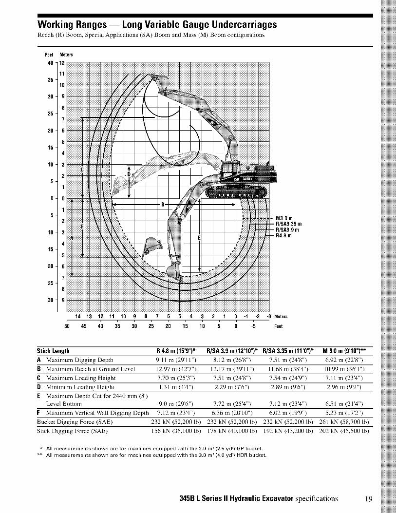
Working Ranges - Long Variable Gauge UndercarriagesReach (R) Boom, Special Applications (SA) Boom and Mass (M) Boom configurations
Feet Meters
40 - 12
1135 -
30 -
10
9
825 -
7
20 - 6
515 -
4
10 3
25 -
1
0 - 0
15 -
2
10 - 3
415 -
5
20 - 6
725 -
8
30 - 9
A
1
- M3.0 m R/SA3.35 m R/SA3.9 m
R4.8 m
14 13 12 11 10 9 8 7 6 5 4 3 2 1 -1 -2 -3 Meters, , , , , , , ,
50 45 40 35 30 25 20 15 10 5 0 -5 Feet
Stick Length
A Maximum Digging Depth
B Maximum Reach at Ground Level
C Maximum Loading Height
D Minimum Loading Height
E Maximum Depth Cut for 2440 mm (8')
Level Bottom 9.0 m (29'6")
F Maximum Vertical Wall Digging Depth 7.12 m (23'4")
Bucket Digging Force (SAE) 232 kN (52,200 lb)
Stick Digging Force (SAE) 156 kN (35,100 lb)
R 4.8 m (15'9")*
9.11 m (29'11")
12.97 m (42'7")
7.70 m (25'3")
1.31 m (4'4")
R/SA 3.9 m (1210")* R/SA 3.35 m (11'0")* M 3.0 m (910")**
8.12 m (26'8")
12.17 m (39'11")
7.51 m (24'8")
2.29 m (7'6")
7.51 m (24'8")
11.68 m (38'4")
7.54 m (24'9")
2.89 m (9'6")
6.92 m (22'8")
10.99 m (36'1")
7.11 m (23'4")
2.96 m (9'9")
7.72 m (25'4")
6.36 m (20'10")
232 kN (52,200 lb)
178 kN (40,100 lb)
7.12 m (23'4")
6.02 m (19'9")
232 kN (52,200 lb)
192 kN (43,200 lb)
* All measurements shown are for machines equipped with the 2.0 m3 (2.5 yd3) GP bucket.** All measurements shown are for machines equipped with the 3.0 m3 (4.0 yd3) HDR bucket.
6.51 m (21'4")
5.23 m (17'2")
261 kN (58,700 lb)
202 kN (45,500 lb)
345B L Series II Hydraulic Excavator specifications 19
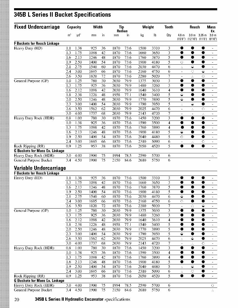
345B L Series 11 Bucket Specifications
Fixed Undercarriage Capacity Width Tip Weight Teeth Reach MassRadius Ex.
m3 yd3 mm in mm in kg lb Gty 4.8 m 3.9 m 3.35 m 3.0 m(15'9") (12'101 (11'0") (9'10")
F Buckets for Reach LinkageHeavy Duty (HD) 1.1 1.38 925 36 1870 73.6 1500 3310 3 • •
1.3 1.75 1098 42 1870 73.6 1660 3650 3 • •1.6 2.13 1246 48 1870 73.6 1760 3870 5 • •1.9 2.50 1400 54 1870 73.6 1900 4180 5 O •2.1 2.75 1540 60 1870 73.6 2030 4470 6 G>2.4 3.00 1695 66 1870 73.6 2160 4750 6 O2.6 3.50 1820 72 1870 73.6 2280 5020 7
General Purpose (GP) 1.0 1.25 780 30 2030 79.9 1375 3030 3 • •1.3 1.75 925 36 2030 79.9 1480 3260 3 • •1.6 2.12 1098 42 2030 79.9 1640 3610 4 • •1.8 2.38 1226 48 1958 77.1 1540 3400 5 Gi> •2.0 2.50 1246 48 2030 79.9 1770 3890 5 G> •2.3 3.00 1400 54 2030 79.9 1790 3950 5 G>2.6 3.50 1562 62 2030 79.9 2025 4470 63.0 4.00 1737 68 2030 79.9 2143 4720 7
Heavy Duty Rock (HDR) 0.8 1.00 780 30 1870 73.6 1450 3200 3 • •1.0 1.38 925 36 1870 73.6 1590 3500 4 • •1.3 1.75 1098 42 1870 73.6 1760 3890 4 • •1.6 2.13 1246 48 1870 73.6 1900 4180 5 G> •1.9 2.50 1400 54 1870 73.6 2040 4480 5 O •2.4 3.00 1695 66 1870 73.6 2310 5090 6
Rock Ripping (RR) 0.9 1.25 953 38 1870 73.6 2050 4520 5 • •G Buckets for Mass Ex. LinkageHeavy Duty Rock (HDR) 3.0 4.00 1900 75 1994 78.5 2590 5700 6General Purpose Bucket
Variable Undercarriage
3.4 4.50 1900 75 2150 84.6 2610 5750 6
F Buckets for Reach LinkageHeavy Duty (HD) 1.1 1.38 925 36 1870 73.6 1500 3310 3 • •
1.3 1.75 1098 42 1870 73.6 1660 3650 3 • •1.6 2.13 1246 48 1870 73.6 1760 3870 5 • •1.9 2.50 1400 54 1870 73.6 1900 4180 5 • •2.1 2.75 1540 60 1870 73.6 2030 4470 6 Gi> •2.4 3.00 1695 66 1870 73.6 2160 4750 6 O •2.6 3.50 1820 72 1870 73.6 2280 5020 7 O
General Purpose (GP) 1.0 1.25 780 30 2030 79.9 1375 3030 3 • •1.3 1.75 925 36 2030 79.9 1480 3260 3 • •1.6 2.12 1098 42 2030 79.9 1640 3610 4 • •1.8 2.38 1226 48 1958 77.1 1540 3400 5 • •2.0 2.50 1246 48 2030 79.9 1770 3890 5 • •2.3 3.00 1400 54 2030 79.9 1790 3950 5 G> •2.6 3.50 1562 62 2030 79.9 2025 4470 6 Gi>3.0 4.00 1737 68 2030 79.9 2143 4720 7
Heavy Duty Rock (HDR) 0.8 1.00 780 30 1870 73.6 1450 3200 3 • •1.0 1.38 925 36 1870 73.6 1590 3500 4 • •1.3 1.75 1098 42 1870 73.6 1760 3890 4 • •1.6 2.13 1246 48 1870 73.6 1900 4180 5 • •1.9 2.50 1400 54 1870 73.6 2040 4480 5 G>2.4 3.00 1695 66 1870 73.6 2310 5090 6 O
Rock Ripping (RR) 0.9 1.25 953 38 1870 73.6 2050 4520 5 • •G Buckets for Mass Ex. LinkageHeavy Duty Rock (HDR) 3.0 4.00 1900 75 1994 78.5 2590 5700 6General Purpose Bucket 3.4 4.50 1900 75 2150 84.6 2610 5750 6
•••••G>O••••••O
icoliceicei•
••••••
Gi>•••••••0•••••••
O
20 345B L Series II Hydraulic Excavator specifications
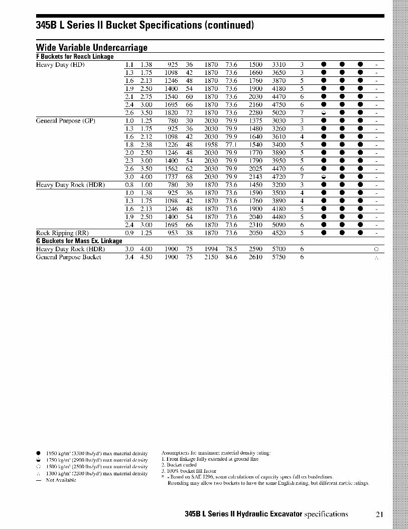
345B L Series 11 Bucket Specifications (continued)
Wide Variable UndercarriageF Buckets for Reach LinkageHeavy Duty (HD) 1.1
1.31.61.92.12.42.6
General Purpose (GP) 1.01.31.61.82.02.32.63.0
Heavy Duty Rock (HDR) 0.81.01.31.61.92.4
Rock Ripping (RR) 0.9
1.381.752.132.502.753.003.501.251.752.122.382.503.003.504.001.001.381.752.132.503.001.25
G Buckets for Mass Ex. LinkageHeavy Duty Rock (HDR) 3.0 4.00General Purpose Bucket 3.4 4.50
• 1950 kg/m' (3300 lbs/yd') max material density
1750 kg/m' (2900 lbs/yd') max material density
0 1500 kg/m' (2500 lbs/yd') max material density
.. 1300 kg/m' (2200 lbs/yd') max material density
- Not Available
925 36 1870 73.6 1500 3310 3 •1098 42 1870 73.6 1660 3650 3 •1246 48 1870 73.6 1760 3870 5 •1400 54 1870 73.6 1900 4180 5 •1540 60 1870 73.6 2030 4470 6 •1695 66 1870 73.6 2160 4750 6 •1820 72 1870 73.6 2280 5020 7780 30 2030 79.9 1375 3030 3 •925 36 2030 79.9 1480 3260 3 •1098 42 2030 79.9 1640 3610 4 •1226 48 1958 77.1 1540 3400 5 •1246 48 2030 79.9 1770 3890 5 •1400 54 2030 79.9 1790 3950 5 •1562 62 2030 79.9 2025 4470 6 •1737 68 2030 79.9 2143 4720 7780 30 1870 73.6 1450 3200 3 •925 36 1870 73.6 1590 3500 4 •1098 42 1870 73.6 1760 3890 4 •1246 48 1870 73.6 1900 4180 5 •1400 54 1870 73.6 2040 4480 5 •1695 66 1870 73.6 2310 5090 6 •953 38 1870 73.6 2050 4520 5 •
1900 75 1994 78.5 2590 5700 61900 75 2150 84.6 2610 5750 6
0101010101010101010101010101010101010101010
0101010101010101010101010101010101010101010
O
Assumptions for maximum material density rating:1. Front linkage fully extended at ground line2. Bucket curled3. 100% bucket fill factor* - Based on SAE J296, some calculations of capacity specs fall on borderlines.
Rounding may allow two buckets to have the same English rating, but different metric ratings.
345B L Series II Hydraulic Excavator specifications 21
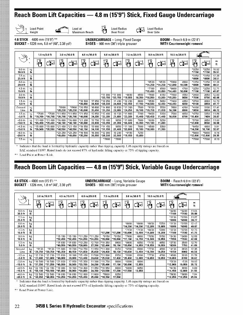
Reach Boom Lift Capacities - 4.8 m (15'9") Stick, Fixed Gauge Undercarriage
j Load Point Height
Load atMaximum Reach
Load RadiusOver Front
Load RadiusOver Side
4.8 STICK - 4800 mm (15'9") ** UNDERCARRIAGE - Long, Fixed GaugeBUCKET - 1226 mm, 1.8 m3(48", 2.38 yd3) SHOES - 900 mm (36") triple grouser
BOOM - Reach 6.9 m (22'8")WITH Counterweight removal
1
1.5 m/5.0 ft 3.0 m/10.0 ft 4.5 m/15.0 ft 6.0 m/20.0 ft 7.5 m/25.0 ft 9.0 m/30.0 ft 10.5 m/35.0 ft4'''k'll
F61 CV CIIPI F6 CIIPI 6 CV CV 6 CV' 6 CV r6 CIIPI ft
9.0 m kg "3250 "3250 10.9230.0 ft lb *7150 *7150 35.51
7.5 m kg "3150 "3150 12.3825.0 ft lb *6900 *6900 38.51
6.0 m kg "6550 "6550 "5900 4900 "3150 "3150 12.3820.0 ft lb *14,250 *14,250 *12,000 10,500 *6900 *6900 40.51
4.5 m kg "7100 6500 "6600 4700 "3250 "3250 12.7115.0 ft lb *15,450 13,850 *14,400 10,000 *7100 *7100 41.67
3.0 m kg "11 000 "11 000 "9050 8550 "7800 6150 "7000 4550 "3400 3050 12.8310.0 ft lb *23,750 *23,750 *19,550 18,350 *16,950 13,200 *15,250 9650 *7500 6750 42.08
1.5 m kg "18 500 17 950 "13 050 11 450 "10 250 8000 "8550 5850 "7400 4350 "3700 3000 12.735.0 ft lb *39,800 38,600 *28,200 24,600 *22,150 17,150 *18,500 12,450 *16,050 9250 *8100 6650 41.77
Ground kg "8900 "8900 "20 850 16 600 "14 600 10 650 "11 200 7500 "9150 5550 7600 4200 "4100 3100 12.41Line lb *20,250 *20,250 *45,000 35,650 *31,350 22,900 *24,250 16,100 *19,750 11,850 16,300 8900 *9050 6850 40.72
-1.5 m kg "7500 "7500 "11 850 "11 850 "21 650 15 950 "15 400 10 150 "11 800 7200 "9450 5350 7500 4050 "4750 3350 11.86-5.0 ft lb *16,700 *16,700 *26,700 *26,700 *46,800 34,200 *33,300 21,800 *25,500 15,400 *20,450 11,400 16,050 8700 *10,450 7400 38.87
-3.0 m kg "11 400 "11 400 "16 000 "16 000 "21 200 15 750 "15 400 9950 "11 800 7000 "9350 5250 "5700 3850 11.03-10.0 ft lb *25,450 *25,450 *36,100 *36,100 *45,800 33,800 *33,250 21,350 *25,500 15,050 *20,100 11,200 *12,600 8550 36.08
-4.5 m kg "15 800 "15 800 "21 450 "21 450 "19 550 15 900 "14 450 9950 "11 100 7000 "8500 5300 "6450 4800 9.84-15.0 ft lb *35,500 *35,500 *48,550 *48,550 *42,150 34,100 *31,150 21,400 *23,800 15,100 *18,000 11,350 *14,200 10,700 32.07
-6.0 m kg "23 250 "23 250 "16 500 16 300 "12 300 10 200 "9150 7250 "5800 "5800 8.16-20.0 ft lb *49,650 *49,650 *35,250 35,050 *26,200 22,000 *19,150 15,600 *12,600 *12,600 26.35
-7.5 m kg "7800 "7800 "7500 "7500 6.13
* Indicates that the load is limited by hydraulic capacity rather than tipping capaci y. Lift capacity ratings are based onSAE standard J1097. Rated loads do not exceed 87% of hydraulic lifting capaci y or 75% of tipping capacity.
** Load Point at Power Link.
Reach Boom Lift Capacities - 4.8 m (151911) Stick, Variable Gauge Undercarriage
4.8 STICK - 4800 mm (15'9") ** UNDERCARRIAGE - Long, Variable GaugeBUCKET - 1226 mm, 1.8 m3(48", 2.38 yd3) SHOES - 900 mm (36") triple grouser
BOOM - Reach 6.9 m (22'8")WITH Counterweight removal
i
3.0 m/10.0 ft 4.5 m/15.0 ft 6.0 m/20.0 ft 7.5 m/25.0 ft 9.0 m/30.0 ft 10.5 m/35.0 ft-'41 1
F6 CV F6 CV CV F6 CV r6 CV CIIVI CV ft
9.0 m kg "3200 "3200 11.0430.0 ft lb *7100 *7100 35.68
7.5 m kg "3150 "3150 11.8725.0 ft lb *6900 *6900 38.77
6.0 m kg "6600 "6600 "6050 5550 "3150 "3150 12.4220.0 ft lb *14,350 *14,350 *12,300 11,600 *6900 *6900 40.67
4.5 m kg "7150 "7150 "6650 5300 "3250 "3250 12.7315.0 ft lb *17,200 *17,200 *15,600 15,450 *14,500 11,350 *7100 *7100 41.75
3.0 m kg "15 150 "15 150 "11 250 "11 250 "9150 "9150 "7900 6900 "7050 5150 "3450 "3450 12.8310.0 ft lb *32,450 *32,450 *24,250 *24,250 *19,800 *19,800 *17,100 14,750 *15,300 10,950 *7550 *7550 42.08
1.5 m kg "18 850 "18 850 "13 250 12 700 "10 350 8900 "8600 6550 "7450 4950 "3750 3500 12.705.0 ft lb *40,550 *40,550 *28,600 27,350 *22,400 19,150 *18,650 14,050 *16,150 10,550 *8200 7750 41.69
Ground kg "9150 "9150 "21 000 18 700 "14 750 11 950 "11 300 8450 "9200 6300 "7750 4800 "4150 3650 12.36Line lb *20,750 *20,750 *45,350 40,150 *31,650 25,650 *24,450 18,150 *19,650 13,450 *16,700 10,250 *9150 8000 40.56
-1.5 m kg "12 250 "12 250 "21 650 18 100 "15 450 11 500 "11 800 8150 "9500 6100 "7750 4700 "4800 3950 11.78-5.0 ft lb *27,600 *27,600 *46,800 38,800 *33,400 24,650 *25,550 17,450 *20,450 13,000 *16,650 10,050 *10,650 8700 38.62
-3.0 m kg "16 500 "16 500 "21 050 17 950 "15 350 11 300 "11,750 8000 "9300 6000 "5850 4550 10.92-10.0 ft lb *37,250 *37,250 *45,550 38,500 *33,150 24,250 *25,400 17,150 *20,000 12,850 *12,900 10,050 35.72
-4.5 m kg "22 150 "22 150 "19 300 18 100 "14 300 11 350 "10 950 8000 "8300 6050 "6450 5850 9.69-15.0 ft lb *50,100 *50,100 *41,600 38,900 *30,800 24,350 *23,500 17,200 *17,550 13,050 *14,150 12,600 31.55
-6.0 m kg "22 500 "22 500 "16 050 "16 050 "12 000 11 600 "8800 8250 "5650 "5650 7.94-20.0 ft lb *48,050 *48,050 *34,250 *34,250 *25,450 25,000 *18,350 17,800 *12,250 *12,250 25.64
* Indicates that the load is limited by hydraulic capacity rather than tipping capac'ty. Lift capacity ratings are based onSAE standard J1097. Rated loads do not exceed 87% of hydraulic lifting capaci y or 75% of tipp'ng capacity.
** Load Point at Power Link.
22 345B L Series II Hydraulic Excavator specifications
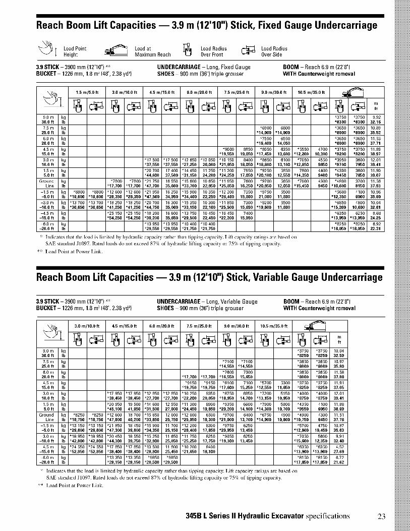
Reach Boom Lift Capacities - 3.9 m (12'10") Stick, Fixed Gauge Undercarriage
I Load Point1 Height
Load atMaximum Reach
Load RadiusOver Front
Load RadiusOver Side
3.9 STICK - 3900 mm (1210r)** UNDERCARRIAGE - Long, Fixed GaugeBUCKET - 1226 mm, 1.8 m' (48", 2.38 ycl3) SHOES - 900 mm (361 triple grouser
BOOM - Reach 6.9 m (22'8")WITH Counterweight removal
1
1.5 m/5.0 ft 3.0 m/10.0 ft 4.5 m/15.0 ft 6.0 m/20.0 ft 7.5 m/25.0 ft 9.0 m/30.0 ft 10.5 m/35.0 ftcir*:1
F6 CV' F6 CP F6 CV F6 CVI r6 CV r6 CIIPI 16 CV CIPI ft
9.0 m kg "3750 "3750 9.9230.0 ft lb *8300 *8300 32.16
7.5 m kg "6900 6800 "3650 "3650 10.8925.0 ft lb *14,000 *14,000 *8000 *8000 35.52
6.0 m kg "7550 6550 "3650 "3650 11.5320.0 ft lb *16,400 14,050 *8000 *8000 37.71
4.5 m kg "9000 8850 "8050 6350 "5550 4700 "3750 "3750 11.8915.0 ft lb *19,550 19,050 *17,450 13,600 *12,200 10,300 *8200 *8200 38.97
3.0 m kg "17 500 "17 500 "12 650 "12 050 "10 150 8400 "8650 6100 "7050 4550 "3950 3600 12.0110.0 ft lb *37,550 *37,550 *27,250 26,000 *21,950 18,050 *18,800 13,100 *12,850 9650 *8700 7950 39.41
1.5 m kg "20 700 17 400 "14 450 11 250 "11 200 7950 "9250 5850 7800 4400 "4300 3600 11.905.0 ft lb *44,600 37,500 *31,150 24,200 *24,250 17,050 *20,100 12,550 *14,350 9400 *9450 7850 39.07
Ground kg "7800 "7800 "21 750 16 550 "15 600 10 650 "11 950 7600 "9700 5650 "7000 4300 "4800 3700 11.56Line lb *17,700 *17,700 *47,700 35,600 *33,700 22,950 *25,850 16,250 *20,950 12,050 *15,450 9450 *10,600 8150 37.93
-1.5 m kg "8800 "8800 "12 600 "12 600 "21 950 16 250 "15 900 10 350 "12 200 7350 "9750 5500 "5600 4100 10.96-5.0 ft lb *19,600 *19,600 *28,350 *28,350 *47,500 34,950 *34,400 22,250 *26,400 15,800 21,000 11,800 *12,350 9000 35.90
-3.0 m kg "13 700 "13 700 "18 250 "18 250 "20 700 16 300 "15 350 10 300 "11 850 7300 "9200 5500 "6850 4800 10.04-10.0 ft lb *30,650 *30,650 *41,250 *41,250 *44,750 35,000 *33,150 22,100 *25,500 15,650 *19,600 11,800 *15,200 10,600 32.81
-4.5 m kg "25 150 "25 150 "18 200 16 600 "13 750 10 450 "10 450 7400 "6350 6250 8.68-15.0 ft lb *54,250 *54,250 *39,200 35,650 *29,500 22,450 *22,200 15,950 *13,950 *13,950 24.25
-6.0 m kg "13 950 "13 950 "10 400 "10 400 "8250 "8250 6.92-20.0 ft lb *29,550 *29,550 *21,750 *21,750 *18,050 *18,050 22.31
* Indicates that the load is limited by hydraulic capacity rather than tipping capacity. Lift capacity atings aie based onSAE standard J1097. Rated loads do not exceed 87% of hydraulic lifting capaci y or 75% of tippmg capacity.
** Load Point at Power Link.
Reach Boom Lift Capacities - 3.9 m (1211V) Stick, Variable Gauge Undercarriage
3.9 STICK - 3900 mm (1210r)** UNDERCARRIAGE - Long, Variable GaugeBUCKET - 1226 mm, 1.8 m3(48", 2.38 ycl3) SHOES - 900 mm (361 triple grouser
BOOM - Reach 6.9 m (22'8")WITH Counterweight removal
1
3.0 m/10.0 ft 4.5 m/15.0 ft 6.0 m/20.0 ft 7.5 m/25.0 ft 9.0 m/30.0 ft 10.5 m/35.0 ft-i‘l l
F6 Cl1P1 F6 CIIPI CV CV CV i) CV CP ft
9.0 m kg "3750 "3750 10.0430.0 ft lb *8250 *8250 32.59
7.5 m kg "7100 "7100 "3650 "3650 10.9725.0 ft lb *14,550 *14,550 *8000 *8000 35.80
6.0 m kg "7600 7300 "3650 "3650 11.5820.0 ft lb *17,700 *17,700 *16,550 15,650 *8000 *8000 37.88
4.5 m kg "9150 "9150 "8100 7100 "5700 5300 "3750 "3750 11.9115.0 ft lb *19,750 *19,750 *17,600 15,250 *12,550 11,650 *8250 *8250 37.05
3.0 m kg "17 950 "17 950 "12 850 "12 850 "10 250 9350 "8750 6850 "7200 5150 "4000 "4000 12.0110.0 ft lb *38,450 *38,450 *27,700 *27,700 *22,200 20,050 *18,950 14,700 *13,150 10,950 *8750 *8750 39.41
1.5 m kg "20 950 19 500 "14 600 12 550 "11 300 8900 "9350 6600 "7900 5000 "4350 4100 11.885.0 ft lb *45,100 41,950 *31,500 27,000 *24,450 19,850 *20,200 14,100 *14,300 10,700 *9550 9050 38.99
Ground kg "8250 "8250 "12 600 18 700 "15 650 12 000 "12 000 6500 "9700 6400 "6750 4900 "4900 4300 11.51Line lb *18,750 *18,750 *47,800 40,200 *33,650 25,750 *25,950 18,300 *21,000 13,700 *14,900 10,800 *10,750 9450 37.76
-1.5 m kg "13 150 "13 150 "21 850 18 450 "15 900 11 700 "12 200 8300 "9750 6250 "5700 4750 10.87-5.0 ft lb *29,600 *29,600 *47,300 39,600 *34,350 25,150 *26,400 17,850 *20,950 13,450 *12,600 10,450 35.63
-3.0 m kg "18 950 "18 950 "20 450 18 550 "15 250 11 650 "11 750 8250 "9050 6250 "7050 5600 9.91-10.0 ft lb *42,800 *42,800 *44,300 39,750 *32,900 25,050 *25,250 17,750 *19,300 13,450 *15,600 12,350 32.40
-4.5 m kg "24 550 "24 550 "17 850 "17 850 "13 500 11 800 "10 200 8400 "6350 "6350 4.52-15.0 ft lb *52,950 *52,950 *38,400 *38,400 *28,900 25,450 *21,650 18,100 *13,900 *13,900 27.69
-6.0 m kg "13 350 "13 350 "9850 "9850 "8150 "8150 6.72-20.0 ft lb *28,150 *28,150 *20,500 *20,500 *17,850 *17,850 21.62
* Indicates that the load is limited by hydraulic capacity rather than tipping capacity. Lift capacity -atings are based onSAE standard J1097. Rated loads do not exceed 87% of hydraulic lifting capacity or 75% of tipping capacity.
** Load Point at Power Link.
345B L Series II Hydraulic Excavator specifications 23

Reach Boom Lift Capacities - 3.9 m (12'10") Stick, Fixed Gauge Undercarriage
Load PointHeight
Load atMaximum Reach
Load RadiusOver Front 6FA Load Radius
Over Side
3.9 STICK - 3900 mm (1210r)** UNDERCARRIAGE - Long, Fixed GaugeBUCKET - 1226 mm, 1.8 m3(48", 2.38 ycl3) SHOES - 750 mm (30r) triple grouser
BOOM - Reach 6.9 m (22'8")WITH Counterweight removal
1
1.5 m/5.0 ft 3.0 m/10.0 ft 4.5 m/15.0 ft 6.0 m/20.0 ft 7.5 m/25.0 ft 9.0 m/30.0 ft 10.5 m/35.0 ft,,=41,....., ..,
.
I6 CV CV F6 CV F6 CV F6 CV F6 CV CIPI 6 CV ft
9.0 m kg "3750 "3750 9.9230.0 ft lb *8300 *8300 32.16
7.5 m kg "6900 6700 "3650 "3650 10.8925.0 ft lb *14,000 *14,000 *8000 *8000 35.52
6.0 m kg "7550 6450 "3650 "3650 11.5320.0 ft lb *16,400 13,850 *8000 *8000 37.71
4.5 m kg "9000 8750 "8050 6250 "5550 4600 "3750 3700 11.8915.0 ft lb *19,550 18,750 *17,450 13,400 *12,200 10,100 *8200 8200 38.97
3.0 m kg "17 500 "17 500 "12 650 11 900 "10 150 8250 "8650 6000 "7050 4450 "3950 3550 12.0110.0 ft lb *37,550 *37,550 *27,250 25,600 *21,950 17,750 *18,800 12,850 *12,850 9450 *8700 7750 39.41
1.5 m kg "20 700 17 150 "14 450 11 050 "11 200 7800 "9250 5750 7700 4300 "4300 3500 11.905.0 ft lb *44,600 36,900 *31,150 23,800 *24,250 16,750 *20,100 12,300 *14,350 9200 *9450 7700 39.07
Ground kg "7800 "7800 "21 750 16 300 "15 600 10 500 "11 950 7450 "9700 5550 "7000 4200 "4800 3650 11.56Line lb *17,700 *17,700 *47,700 35,000 *33,700 22,550 *25,850 15,950 20,950 11,850 *15,450 9250 *10,600 8000 37.93
-1.5 m kg "8800 "8800 "12 600 "12 600 "21 950 16 000 "15 900 10 200 "12 200 7200 9600 5400 "5600 4000 10.96-5.0 ft lb *19,600 *19,600 *28,350 *28,350 *47,500 34,350 *34,400 21,850 *26,400 15,500 20,650 11,550 *12,350 8800 35.90
-3.0 m kg "13 700 "13 700 "18 250 "18 250 "20 700 16 050 "15 350 10 100 "11 850 7150 "9200 5400 "6850 4700 10.04-10.0 ft lb *30,650 *30,650 *41,250 *41,250 *44,750 34,400 *33,150 21,700 *25,500 15,350 *19,600 11,550 *15,200 10,400 32.81
-4.5 m kg "25 150 "25 150 "18 200 16 350 "13 750 10 250 "10 450 7250 "6350 6150 8.68-15.0 ft lb *54,250 *54,250 *39,200 35,050 *29,500 22,050 *22,200 15,650 *13,950 13,700 28.25
-6.0 m kg "13 950 "13 950 "10 400 "10 400 "8250 "8250 6.92-20.0 ft lb *29,550 *29,550 *21,750 *21,750 *18,050 *18,050 22.31
* Indicates that the load is limited by hydraulic capacity rather than tipping capaci y. Lift capacity ratings are based onSAE standard J1097. Rated loads do not exceed 87% of hydraulic lifting capacity or 75% of tipping capacity.
** Load Point at Power Link.
Reach Boom Lift Capacities - 3.9 m (12'10") Stick, Fixed Gauge Undercarriage
3.9 STICK - 3900 mm (1210r)** UNDERCARRIAGE - Long, Fixed GaugeBUCKET - 1226 mm, 1.8 m' (48", 2.38 ycl3) SHOES - 900 mm (361 triple grouser
BOOM - Reach 6.9 m (22'8")WITHOUT Counterweight removal
1.5 m/5.0 ft 3.0 m/10.0 ft 4.5 m/15.0 ft 6.0 m/20.0 ft 7.5 m/25.0 ft 9.0 m/30.0 ft 10.5 m/35.0 ft-1Vr.-..41
1 r6 CV CIPI i) CV i) CV F6 CVLJ CP r6 CV F6 CP ft
9.0 m kg "3750 "3750 9.9230.0 ft lb *8300 *8300 32.16
7.5 m kg "6900 6650 "3650 "3650 10.8925.0 ft lb *14,000 *14,000 *8000 *8000 35.52
6.0 m kg "7550 6400 "3650 "3650 11.5320.0 ft lb *16,400 13,700 *8000 *8000 37.71
4.5 m kg "9000 8650 "8050 6200 "5550 4550 "3750 3700 11.8915.0 ft lb *19,550 18,600 *17,450 13,250 *12,200 10,000 *8200 *8100 38.97
3.0 m kg "17 500 "17 500 "12 650 11 800 "10 150 8200 "8650 5950 "7050 4400 "3950 3500 12.0110.0 ft lb *37,550 *37,550 *27,250 25,400 *21,950 17,600 *18,800 12,700 *12,850 9350 *8700 7650 39.41
1.5 m kg "20 700 17 000 "14 450 10 950 "11 200 7750 "9250 5700 7650 4250 "4300 3450 11.905.0 ft lb *44,600 36,600 *31,150 23,600 *24,250 16,600 *20,100 12,150 *14,350 9100 *9450 7600 39.07
Ground kg "7800 "7800 "21 750 16 150 "15 600 10 400 "11 950 7350 "9700 5450 "7000 4150 "4800 3600 11.56Line lb *17,700 *17,700 *47,700 34,700 *33,700 22,350 *25,850 15,800 20,850 11,700 *15,450 9150 *10,600 7900 37.93
-1.5 m kg "8800 "8800 "12 600 "12 600 "21 950 15 850 "15 900 10 100 "12 200 7150 9600 5350 "5600 3950 10.96-5.0 ft lb *19,600 *19,600 *28,350 *28,350 *47,500 34,050 *34,400 21,650 *26,400 15,350 20,550 11,450 *12,350 8700 35.90
-3.0 m kg "13 700 "13 700 "18 250 "18 250 "20 700 15 900 "15 350 10 000 "11 850 7100 "9200 5350 "6850 4650 10.04-10.0 ft lb *30,650 *30,650 *41,250 *41,250 *44,750 34,100 *33,150 21,500 *25,500 15,200 *19,600 11,450 *15,200 10,300 32.81
-4.5 m kg "25 150 "25 150 "18 200 16 200 "13 750 10 150 "10 450 7200 "6350 6100 8.68-15.0 ft lb *54,250 *54,250 *39,200 34,750 *29,500 21,850 *22,200 15,500 *13,950 *13,600 28.25
-6.0 m kg "13 950 "13 950 "10 400 "10 400 "8250 "8250 6.92-20.0 ft lb *29,550 *29,550 *21,750 *21,750 *18,050 *18,050 22.31
* Indicates that the load is limited by hydraulic capacity rather than tipping capaci y. Lift capacity ratings are based onSAE standard J1097. Rated loads do not exceed 87% of hydraulic lifting capaci y or 75% of tipping capacity.
** Load Point at Power Link.
24 345B L Series II Hydraulic Excavator specifications
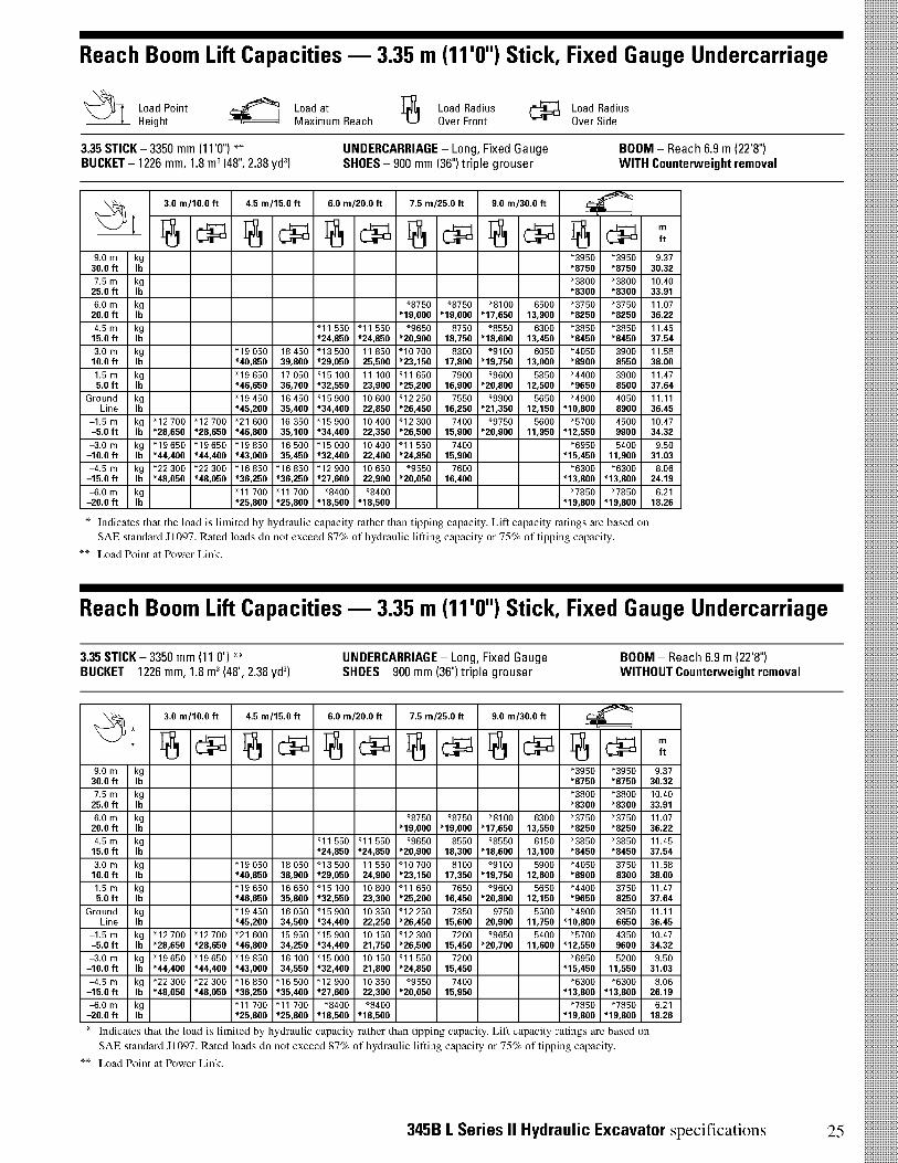
Reach Boom Lift Capacities - 3.35 m (11r) Stick, Fixed Gauge Undercarriage
Load PointHeight
Load atMaximum Reach
Load RadiusOver Front
Load RadiusOver Side
3.35 STICK - 3350 mm (11'01** UNDERCARRIAGE - Long, Fixed GaugeBUCKET - 1226 mm, 1.8 m3(48", 2.38 yd3) SHOES - 900 mm (36") triple grouser
BOOM - Reach 6.9 m (22'8")WITH Counterweight removal
1
3.0 m/10.0 ft 4.5 m/15.0 ft 6.0 m/20.0 ft 7.5 m/25.0 ft 9.0 m/30.0 ft-*(15 1
F6 CIP CV r6 CIIPI F6 CV CVI F6 CV ft
9.0 m kg "3950 "3950 9.3730.0 ft lb *8750 *8750 30.32
7.5 m kg "3800 "3800 10.4025.0 ft lb *8300 *8300 33.91
6.0 m kg "8750 "8750 "8100 6500 "3750 "3750 11.0720.0 ft lb *19,000 *19,000 *17,650 13,900 *8250 *8250 36.22
4.5 m kg "11 550 "11 550 "9650 8750 "8550 6300 "3850 "3850 11.4515.0 ft lb *24,850 *24,850 *20,900 18,750 *18,600 13,450 *8450 *8450 37.54
3.0 m kg "19 050 18 450 "13 500 11 850 "10 700 8300 "9100 6050 "4050 3900 11.5810.0 ft lb *40,850 39,800 *29,050 25,500 *23,150 17,800 *19,750 13,000 *8900 8550 38.00
1.5 m kg "19 650 17 050 "15 100 11 100 "11 650 7900 "9600 5850 "4400 3900 11.475.0 ft lb *46,650 36,700 *32,550 23,900 *25,200 16,900 *20,800 12,500 *9650 8500 37.64
Ground kg "19 450 16 450 "15 900 10 600 "12 250 7550 "9900 5650 "4900 4050 11.11Line lb *45,200 35,400 *34,400 22,850 *26,450 16,250 *21,350 12,150 *10,800 8900 36.45
-1.5 m kg "12 700 "12 700 "21 600 16 350 "15 900 10 400 "12 300 7400 "9750 5600 "5700 4500 10.47-5.0 ft lb *28,650 *28,650 *46,800 35,100 *34,400 22,350 *26,500 15,900 *20,900 11,950 *12,550 9900 34.32
-3.0 m kg "19 650 "19 650 "19 850 16 500 "15 000 10 400 "11 550 7400 "6950 5400 9.50-10.0 ft lb *44,400 *44,400 *43,000 35,450 *32,400 22,400 *24,850 15,900 *15,450 11,900 31.03
-4.5 m kg "22 300 "22 300 "16 850 "16 850 "12 900 10 650 "9550 7600 "6300 "6300 8.06-15.0 ft lb *48,050 *48,050 *36,250 *36,250 *27,600 22,900 *20,050 16,400 *13,800 *13,800 24.19
-6.0 m kg "11 700 "11 700 "8400 "8400 "7850 "7850 6.21-20.0 ft lb *25,800 *25,800 *18,500 *18,500 *19,800 *19,800 18.26
* Indicates that the load is limited by hydraulic capacity rather than tipping capaci y. Lift capacity ratings are based on
SAE standard J1097. Rated loads do not exceed 87% of hydraulic lifting capaci y or 75% of tipping capacity.
** Load Point at Power Link.
Reach Boom Lift Capacities - 3.35 m (11r) Stick, Fixed Gauge Undercarriage
3.35 STICK - 3350 mm (11'0") ** UNDERCARRIAGE - Long, Fixed GaugeBUCKET - 1226 mm, 1.8 m' (48", 2.38 yd3) SHOES - 900 mm (36") triple grouser
BOOM - Reach 6.9 m (22'8")WITHOUT Counterweight removal
I
3.0 m/10.0 ft 4.5 m/15.0 ft 6.0 m/20.0 ft 7.5 m/25.0 ft 9.0 m/30.0 ft-it l
CV C-IIPI F6 C-LPI F61 CV CV F6 CP ft
9.0 m kg "3950 "3950 9.3730.0 ft lb *8750 *8750 30.32
7.5 m kg "3800 "3800 10.4025.0 ft lb *8300 *8300 33.91
6.0 m kg "8750 "8750 "8100 6300 "3750 "3750 11.0720.0 ft lb *19,000 *19,000 *17,650 13,550 *8250 *8250 36.22
4.5 m kg "11 550 "11 550 "9650 8550 "8550 6150 "3850 "3850 11.4515.0 ft lb *24,850 *24,850 *20,900 18,300 *18,600 13,100 *8450 *8450 37.54
3.0 m kg "19 050 18 050 "13 500 11 550 "10 700 8100 "9100 5900 "4050 3750 11.5810.0 ft lb *40,850 38,900 *29,050 24,900 *23,150 17,350 *19,750 12,600 *8900 8300 38.00
1.5 m kg "19 650 16 650 "15 100 10 800 "11 650 7650 "9600 5650 "4400 3750 11.475.0 ft lb *46,650 35,800 *32,550 23,300 *25,200 16,450 *20,800 12,150 *9650 8250 37.64
Ground kg "19 450 16 050 "15 900 10 350 "12 250 7350 9750 5500 "4900 3950 11.11Line lb *45,200 34,500 *34,400 22,250 *26,450 15,600 20,900 11,750 *10,800 6650 36.45
-1.5 m kg "12 700 "12 700 "21 600 15 950 "15 900 10 150 "12 300 7200 "9650 5400 "5700 4350 10.47-5.0 ft lb *28,650 *28,650 *46,800 34,250 *34,400 21,750 *26,500 15,450 *20,700 11,600 *12,550 9600 34.32
-3.0 m kg "19 650 "19 650 "19 850 16 100 "15 000 10 150 "11 550 7200 "6950 5200 9.50-10.0 ft lb *44,400 *44,400 *43,000 34,550 *32,400 21,800 *24,850 15,450 *15,450 11,550 31.03
-4.5 m kg "22 300 "22 300 "16 850 "16 500 "12 900 10 350 "9550 7400 "6300 "6300 8.06-15.0 ft lb *48,050 *48,050 *36,250 *35,400 *27,600 22,300 *20,050 15,950 *13,800 *13,800 26.19
-6.0 m kg "11 700 "11 700 "8400 "8400 "7850 "7850 6.21-20.0 ft lb *25,800 *25,800 *18,500 *18,500 *19,800 *19,800 18.26
* Indicates that the load is limited by hydraulic capacity rather than tipping capac'ty. Lift capacity ratings are based on
SAE standard J1097. Rated loads do not exceed 87% of hydraulic lifting capaci y or 75% of tipping capacity.
** Load Point at Power Link.
345B L Series II Hydraulic Excavator specifications 25
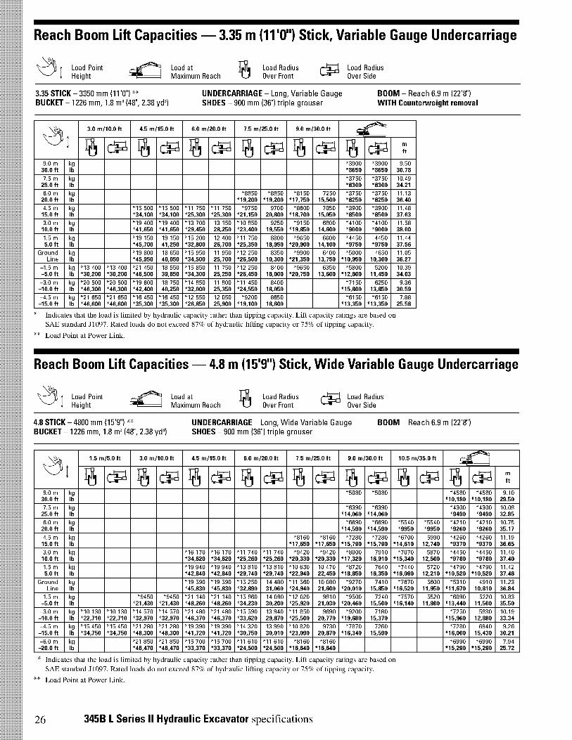
Reach Boom Lift Capacities - 3.35 m (111r) Stick, Variable Gauge Undercarriage
Load PointHeight
Load atMaximum Reach
Load RadiusOver Front
Load RadiusOver Side
3.35 STICK - 3350 mm (11'0") ** UNDERCARRIAGE - Long, Variable Gauge BOOM - Reach 6.9 m (22'8")BUCKET - 1226 mm, 1.8 m3(48", 2.38 ycl3) SHOES - 900 mm (361 triple grouser WITH Counterweight removal
i
3.0 m/10.0 ft 4.5 m/15.0 ft 6.0 m/20.0 ft 7.5 m/25.0 ft 9.0 m/30.0 ft-4641
r6 CP CP i) CP C-VI CV r6 CP ft
9.0 m kg "3900 "3900 9.5030.0 ft lb *8650 *8650 30.78
7.5 m kg "3750 "3750 10.4925.0 ft lb *8300 *8300 34.21
6.0 m kg "8850 "8850 "8150 7250 "3750 "3750 11.1320.0 ft lb *19,200 *19,200 *17,750 15,500 *8250 *8250 36.40
4.5 m kg "15 500 "15 500 "11 750 "11 750 "9750 9700 "8600 7050 "3900 "3900 11.4815.0 ft lb *34,100 *34,100 *25,300 *25,300 *21,150 20,800 *18,700 15,050 *8500 *8500 37.63
3.0 m kg "19 400 "19 400 "13 700 13 150 "10 850 9250 "9150 6800 "4100 "4100 11.5810.0 ft lb *41,650 *41,650 *29,450 28,250 *23,400 19,550 *19,850 14,600 *9000 *9000 38.00
1.5 m kg "19 150 19 150 "15 200 12 400 "11 750 8800 "9650 6600 "4450 4450 11.445.0 ft lb *45,700 41,250 *32,800 26,700 *25,350 18,950 *20,900 14,100 *9750 *9750 37.56
Ground kg "19 800 18 650 "15 950 11 950 "12 250 8350 "9900 6400 "5000 4650 11.05Line lb *45,950 40,050 *34,500 25,700 *26,500 10,300 *21,350 13,750 *10,950 10,300 36.27
-1.5 m kg "13 400 "13 400 "21 450 18 550 "15 850 11 750 "12 250 8400 "9650 6350 "5800 5200 10.39-5.0 ft lb *30,200 *30,200 *46,500 39,850 *34,300 25,250 *26,450 18,000 *20,750 13,600 *12,800 11,450 34.03
-3.0 m kg "20 500 "20 500 "19 600 18 750 "14 850 11 800 "11 450 8400 "7150 6250 9.36-10.0 ft lb *46,300 *46,300 *42,400 40,250 *32,000 25,350 *24,550 18,050 *15,800 13,850 30.59
-4.5 m kg "21 650 "21 650 "16 450 "16 450 "12 550 12 050 "9200 8650 "6150 "6150 7.88-15.0 ft lb *46,600 *46,600 *35,300 *35,300 *26,850 25,900 *19,100 18,600 *13,350 *13,350 25.58
* Indicates that the load is limited by hydraulic capacity rather than tipping capacity. Lift capacity ratings are based onSAE standard J1097. Rated loads do not exceed 87% of hydraulic lifting capaci y or 75% of tipping capacity.
** Load Point at Power Link.
Reach Boom Lift Capacities - 4.8 m (15'9") Stick, Wide Variable Gauge Undercarriage
Load PointHeight
Load atMaximum Reach
Load RadiusOver Front CV Load Radius
Over Side
4.8 STICK - 4800 mm (15'9") ** UNDERCARRIAGE - Long, Wide Variable Gauge BOOM - Reach 6.9 m (22'8")BUCKET - 1226 mm, 1.8 m3(48", 2.38 ycl3) SHOES - 900 mm (361 triple grouser
1.5 m/5.0 ft 3.0 m/10.0 ft 4.5 m/15.0 ft 6.0 m/20.0 ft 7.5 m/25.0 ft 9.0 m/30.0 ft 10.5 m/35.0 ft-,4„..1
-4(
1 i) 1::PI 4) r6 CV r6 CIIPI r6 CV r6 CIIPI r6 CV r6 CIIPI ft
9.0 m kg "5080 "5080 "4580 "4580 9.1030.0 ft lb *10,180 *10,180 29.50
7.5 m kg "6390 "6390 "4300 "4300 10.0825.0 ft lb *14,060 *14,060 *9490 *9490 32.85
6.0 m kg "6690 "6690 "5540 "5540 "4210 "4210 10.7520.0 ft lb *14,590 *14,590 *9950 *9950 *9260 *9260 35.17
4.5 m kg "8160 "8160 "7280 "7280 "6700 5990 "4260 "4260 11.1915.0 ft lb *17,650 *17,650 *15,790 *15,790 *14,610 12,740 *9370 *9370 36.65
3.0 m kg "16 170 "16 170 "11 740 "11 740 "9420 "9420 "8000 7910 "7070 5870 "4450 "4450 11.4010.0 ft lb *34,620 *34,620 *25,260 *25,260 *20,330 *20,330 *17,320 16,910 *15,340 12,500 *9780 *9780 37.40
1.5 m kg "19 940 "19 940 "13 810 "13 810 "10 630 10 470 "8720 7640 "7440 5720 "4790 "4790 11.425.0 ft lb *42,840 *42,840 *29,740 *29,740 *22,940 22,450 *18,850 16,350 *16,090 12,210 *10,520 *10,520 37.46
Ground kg "19 590 "19 590 "15 250 14 480 "11 560 10 080 "9270 7410 "7670 5600 "5310 4910 11.23Line lb *45,830 *45,830 *32,890 31,060 *24,940 21,600 *20,010 15,850 *16,520 11,950 *11,670 10,810 36.84
-1.5 m kg "9450 "9450 "21 140 "21 140 "15 860 14 090 "12 020 9810 "9500 7240 "7570 5520 "6090 5220 10.83-5.0 ft lb *21,430 *21,430 *48,260 *48,260 *34,230 30,200 *25,920 21,030 *20,460 15,500 *16,140 11,800 *13,440 11,500 35.50
-3.0 m kg "10 130 "10 130 "14 570 "14 570 "21 480 "21 480 "15 590 13 940 "11 850 9690 "9200 7180 "7250 5830 10.19-10.0 ft lb *22,710 *22,710 *32,970 *32,970 *46,370 *46,370 *33,620 29,870 *25,500 20,770 *19,680 15,370 *15,960 12,880 33.34
-4.5 m kg "15 450 "15 450 "21 280 "21 280 "19 390 "19 390 "14 320 13 990 "10 820 9730 "7870 7260 "7280 6940 9.26-15.0 ft lb *34,750 *34,750 *48,300 *48,300 *41,720 *41,720 *30,750 30,010 *23,090 20,870 *16,340 15,590 *16,000 15,430 30.21
-6.0 m kg "21 850 "21 850 "15 700 "15 700 "11 610 "11 610 "8160 "8160 "6990 "6990 7.94-20.0 ft lb *46,470 *46,470 *33,370 *33,370 *24,500 *24,500 *16,640 *16,640 *15,290 *15,290 25.72
* Indicates that the load is limited by hydraulic capacity rather than tipping capacity. Lift capacity ratings are based onSAE standard J1097. Rated loads do not exceed 87% of hydraulic lifting capaci y or 75% of tipping capacity.
** Load Point at Power Link.
26 345B L Series II Hydraulic Excavator specifications

Reach Boom Lift Capacities - 3.9 m (12'101 Stick, Wide Variable Gauge Undercarriage
1 Load PointHeight
Load atMaximum Reach
Load RadiusOver Front
Load RadiusOver Side
3.9 STICK - 3900 mm (1210r)** UNDERCARRIAGE - Long, Wide Variable Gauge BOOM - Reach 6.9 m (22'8")BUCKET - 1226 mm, 1.8 m' (48", 2.38 ycl3) SHOES - 900 mm (361 triple grouser
1
3.0 m/10.0 ft 4.5 m/15.0 ft 6.0 m/20.0 ft 7.5 m/25.0 ft 9.0 m/30.0 ft 10.5 m/35.0 ft-‘fl'
i) CV CV r6 CIIPI r6 CV' r6 CIIPI r6 CV' r6 CIPI ft
9.0 m kg "5820 "5820 8.1230.0 ft lb *17,230 *17,230 *12,950 *12,950 26.21
7.5 m kg "6800 "6800 "5380 "5380 9.2025.0 ft lb *11,890 *11,890 29.94
6.0 m kg "8370 "8370 "7750 "7750 "5230 "5230 9.9320.0 ft lb *18,170 *18,170 *16,920 *16,920 *11,510 *11,510 32.46
4.5 m kg "11 250 "11 250 "9370 "9370 "8230 "8130 "5270 "5270 10.4015.0 ft lb *24,200 *24,200 *20,260 *20,260 *17,880 17,390 *11,590 *11,590 34.07
3.0 m kg "18 990 "18 990 "13 360 "13 360 "10 530 "10 530 "8860 7930 "6930 5900 "5490 "5490 10.6310.0 ft lb *40,640 *40,640 *28,730 *28,730 *22,730 *22,730 *19,170 16,970 *12,060 *12,060 34.87
1.5 m kg "16 570 "16 570 "15 120 15 070 "11 570 10 510 "9430 7720 "7680 5820 "5890 5650 10.655.0 ft lb *40,160 *40,160 *32,570 32,340 *24,970 22,540 *20,380 16,530 *12,950 12,440 34.94
Ground kg "16 160 "16 160 "16 120 14 580 "12 240 10 210 "9780 7550 "6540 5800 10.45Line lb *37,810 *37,810 *34,770 31,270 *26,420 21,890 *21,090 16,170 *14,380 12,760 34.27
-1.5 m kg "9620 "9620 "21 130 "21 130 "16 220 14 340 "12 360 10 030 "9700 7450 "7540 6230 10.01-5.0 ft lb *21,860 *21,860 *48,230 *48,230 *35,000 30,740 *26,650 21,510 *20,820 15,960 *16,640 13,720 32.82
-3.0 m kg "16 620 "16 620 "20 650 "20 650 "15 380 14 310 "11 730 9990 "8790 7460 "8060 7070 9.32-10.0 ft lb *37,660 *37,660 *44,610 *44,610 *33,130 30,680 *25,190 21,440 *18,520 16,020 *17,730 15,630 30.48
-4.5 m kg "24 000 "24 000 "17 720 "17 720 "13 360 "13 360 "9870 "9870 "7840 "7840 8.29-15.0 ft lb *51,630 *56,630 *38,050 *38,050 *28,560 *28,560 *20,780 *20,780 *17,210 *17,210 27.00
-6.0 m kg "12 720 "12 720 "9170 "9170 "6900 "6900 6.78-20.0 ft lb *26,670 *26,670 *18,700 *18,700
* Indicates that the load is limited by hydraulic capacity rather than tipping capac'ty. Lit't capacity latings are based onSAE standard J1097. Rated loads do not exceed 87% of hydraulic lifting capaci y or 75% of tipping capacity.
** Load Point at Power Link.
Reach Boom Lift Capacities - 3.35 m (11'01 Stick, Wide Variable Gauge Undercarriage
3.35 STICK - 3350 mm (11'0") ** UNDERCARRIAGE - Long, Wide Variable Gauge BOOM - Reach 6.9 m (22'8")BUCKET - 1226 mm, 1.8 m' (48", 2.38 ycl3) SHOES - 900 mm (361 triple grouser
1
3.0 m/10.0 ft 4.5 m/15.0 ft 6.0 m/20.0 ft 7.5 m/25.0 ft 9.0 m/30.0 ft5ii
CV CV CV i) CV r6 CV r6 CV ft
9.0 m kg "7030 "7030 "6530 "6530 7.5530.0 ft lb *14,570 *14,570 24.31
7.5 m kg "8440 "8440 "5900 "5900 8.7025.0 ft lb *18,480 *18,480 *13,060 *13,060 28.29
6.0 m kg "8970 "8970 "8260 8080 "5650 "5650 9.4820.0 ft lb *19,460 *19,460 *18,090 17,200 *12,450 *12,450 30.96
4.5 m kg "16 270 "16 270 "12 080 "12 080 "9910 "9910 "8640 8000 "5640 "5640 9.9715.0 ft lb *34,730 *34,730 *25,970 *25,970 *21,420 *21,420 *18,760 17,080 *12,400 *12,400 32.64
3.0 m kg "14 070 "14 070 "10 980 10 750 "9170 7830 "5820 "5820 10.2110.0 ft lb *30,260 *30,260 *23,700 23,060 *19,850 16,740 *12,790 *12,790 33.48
1.5 m kg "15 600 14 890 "11 890 10 410 "9640 7650 "6210 6040 10.225.0 ft lb *33,610 31,960 *25,650 22,310 *20,810 16,370 *13,650 13,290 33.55
Ground kg "13 260 "13 260 "16 280 14 490 "12 380 10 150 "9830 7510 "6860 6230 10.01Line lb *31,300 *31,300 *35,140 31,080 *26,710 21,770 *21,160 16,080 *15,909 13,700 32.85
-1.5 m kg "8640 "8640 "20 390 "20 390 "16 050 14 330 "12 260 10 020 "9470 7450 "7900 6740 9.56-5.0 ft lb *19,790 *19,790 *46,890 *46,890 *34,640 30,720 *26,420 21,490 *20,230 15,970 *17,420 14,860 31.33
-3.0 m kg "17 390 "17 390 "19 580 "19 580 "14 840 14 370 "11 280 10 040 "8200 7770 8.83-10.0 ft lb *39,500 *39,500 *42,320 *42,320 *31,950 30,810 *24,130 21,540 *18,030 17,190 28.86
-4.5 m kg "20 820 "20 820 "16 130 "16 130 "12 260 "12 260 "8490 "8490 "7660 "7660 7.73-15.0 ft lb *44,770 *44,770 *34,570 *34,570 *26,090 *26,090 *17,190 *17,190 *16,750 *16,750 25.16
* Indicates that the load is limited by hydraulic capacity rather than tipping capac'ty. Lift capacity latings are based onSAE standard J1097. Rated loads do not exceed 87% of hydraulic lifting capaci y or 75% of tipping capacity.
** Load Point at Power Link.
345B L Series II Hydraulic Excavator specifications 27

Mass Boom Lift Capacities - 3.0 m (9'10") Stick, Fixed Gauge Undercarriage
I Load Point Height
Load atMaximum Reach
Load RadiusOver Front
Load RadiusOver Side
3.0 STICK - 3000 mm (9'11") **BUCKET - 1900 mm, 3.0 m3(75% 4.0 yd3)
UNDERCARRIAGE - Long, Fixed GaugeSHOES - 900 mm (361 triple grouser
BOOM - Mass 6.55 m (21'8")WITH Counterweight removal
1
3.0 m/10.0 ft 4.5 m/15.0 ft 6.0 m/20.0 ft 7.5 m/25.0 ft 9.0 m/30.0 ftl
CP CV CV i) CV F6 C-11PI F6 C-P ft
7.5 m kg "7950 "7950 "4150 "4150 9.6625.0 ft lb *17,300 *17,300 *9200 *9200 31.46
6.0 m kg "8500 8450 "4150 "4150 10.3920.0 ft lb *18,500 18,050 *9050 *9050 33.97
4.5 m kg "11 150 "11 150 "9250 8100 "8200 5550 "4250 3900 14.8015.0 ft lb *24,000 *24,000 *20,100 17,300 *17,800 11,850 *9300 8650 35.58
3.0 m kg "18 300 17 800 "12 900 11 200 "10 200 7850 "8600 5350 "4500 3650 10.9310.0 ft lb *39,250 38,350 *27,800 24,100 *22,050 16,750 *18,650 11,450 *9850 8100 35.85
1.5 m kg "20 650 16 250 "14 350 10 400 "11 000 7200 "8950 5150 "4900 3650 10.805.0 ft lb *44,550 34,950 *30,950 22,350 *23,750 15,450 *19,400 10,950 *10,800 8050 35.43
Ground kg "21 150 15 600 "15 050 9900 "11 450 6900 "9050 5000 "5550 3900 10.39Line lb *45,750 33,450 *32,500 21,200 *24,700 14,750 *19,500 10,650 *12,250 8550 34.10
-1.5 m kg "14 400 "14 400 "20 250 15 450 "14 850 9650 "11 300 6700 "6600 4500 9.58-5.0 ft lb *32,550 *32,550 *43,900 33,150 *32,100 20,750 *24,300 14,400 *14,600 9900 31.73
-3.0 m kg "23 250 "23 250 "18 200 15 700 "13 600 9700 "10 150 6800 "6650 5700 8.62-10.0 ft lb *52,650 *52,650 *39,350 33,650 *29,300 20,850 *21,650 14,550 *14,550 12,650 28.13
-4.5 m kg "19 100 "19 100 "14 550 "14 550 "10 800 10 050 "8350 8050 6.94-15.0 ft lb *40,950 *40,950 *31,100 *31,100 *22,750 21,650 *18,300 18,050 22.52
* Indicates that the load is limited by hydraulic capacity rather than tipping capaci y. Lift capacity ratings are based onSAE standard J1097. Rated loads do not exceed 87% of hydraulic lifting capacity or 75% of tipping capacity.
** Load Point at Power Link.
Mass Boom Lift Capacities - 3.0 m (9'10") Stick, Variable Gauge Undercarriage
3.0 STICK - 3000 mm (9'11") **BUCKET - 1900 mm, 3.0 m3(75% 4.0 yd3)
UNDERCARRIAGE - Long, Variable Gauge BOOM - Mass 6.55 m (21'8")SHOES - 900 mm (361 triple grouser WITH Counterweight removal
1
3.0 m/10.0 ft 4.5 m/15.0 ft 6.0 m/20.0 ft 7.5 m/25.0 ft 9.0 m/30.0 ft5ii
CV CV CV i) CV F6 CV F6 C-P ft
9.0 m kg "4400 "4400 8.66
7.5 m kg "8000 "8000 "4150 "4150 9.7625.0 ft lb *17,400 *17,400 *9150 *9150 31.79
6.0 m kg "8600 "8600 "4150 "4150 10.4520.0 ft lb *18,650 *18,650 *9050 *9050 34.17
4.5 m kg "15 050 "15 050 "11 300 "11 300 "9350 9050 "8250 6300 "4250 "4250 10.8215.0 ft lb *32,150 *32,150 *24,400 *24,400 *20,300 19,400 *17,900 13,450 *9350 *9350 35.47
3.0 m kg "18 650 "18 650 "13 100 12 500 "10 300 8600 "8650 6100 "4500 4250 10.9310.0 ft lb *40,000 *40,000 *28,200 26,900 *22,250 18,400 *18,750 13,050 *9900 9350 35.85
1.5 m kg "20 800 18 350 "14 450 11 700 "11 050 8150 "9000 5900 "4950 4300 10.775.0 ft lb *44,850 39,450 *31,200 25,150 *23,900 17,450 *19,450 12,600 *10,900 9400 35.34
Ground kg "21 100 17 750 "15 050 11 200 "11 450 7050 "9050 5750 "5650 4600 10.33Line lb *45,700 38,100 *32,550 24,050 *24,750 16,000 *19,450 12,250 *12,450 10,050 33.90
-1.5 m kg "15 250 "15 250 "20 100 17 700 "14 750 11 000 "11 200 7700 "6750 5300 9.59-5.0 ft lb *34,500 *34,500 *43,550 37,900 *31,900 23,650 *24,150 16,550 *14,950 11,650 31.40
-3.0 m kg "24 200 "24 200 "17 900 "17 900 "13 400 11 100 "9950 7800 "6550 "6550 8.48-10.0 ft lb *52,450 *52,450 *38,700 38,450 *28,850 23,850 *21,150 16,750 *14,350 *14,350 27.68
-4.5 m kg "18 300 "18 300 "14 000 "14 000 "10 300 "10 300 "8250 "8250 6.77-15.0 ft lb *39,200 *39,200 *29,900 *29,900 *21,650 21,650 *18,100 18,100 21.97
* Indicates that the load is limited by hydraulic capacity rather than tipping capacity. Lift capacity latings are based onSAE standard J1097. Rated loads do not exceed 87% of hydraulic lifting capaci y or 75% of tipping capacity.
** Load Point at Power Link.
28 345B L Series II Hydraulic Excavator specifications

Heavy Duty Special Application (SA) Boom Lift Capacities - 3.35 m (11r) Stick
3.35 STICK - 3350 mm (11'0") ** UNDERCARRIAGE - Long, Fixed GaugeBUCKET - 1226 mm, 1.8 m3(48", 2.38 yd3) SHOES - 750 mm (30") triple grouser
BOOM - SA 6.9 m (22'8")WITH Counterweight removal
I
3.0 m/10.0 ft 4.5 m/15.0 ft 6.0 m/20.0 ft 7.5 m/25.0 ft 9.0 m/30.0 ft-1 C1
F6 CV C-IPI F6 CILVI F61 CV CV F6I CV ft
9.0 m kg "3950 "3950 9.3730.0 ft lb *8750 *8750 30.32
7.5 m kg "3800 "3800 10.4025.0 ft lb *8300 *8300 33.91
6.0 m kg "8700 "8700 "8000 6350 "3750 "3750 11.0720.0 ft lb *18,850 *18,850 *17,450 13,600 *8250 *8250 36.22
4.5 m kg "11 450 "11 450 "9550 8600 "8450 6150 "3850 "3850 11.4515.0 ft lb *24,650 *24,650 *20,700 18,450 *18,350 13,150 *8450 *8450 37.54
3.0 m kg "18 850 18 100 "13 350 11 600 "10 600 8100 "9000 5900 "4050 3750 11.5810.0 ft lb *40,450 39,050 *28,750 25,050 *22,900 17,450 *19,500 12,650 *8900 8250 38.00
1.5 m kg "19 650 16 650 "14 900 10 850 "11 500 7700 "9450 5650 "4400 3750 11.475.0 ft lb *46,100 35,800 *32,150 23,300 *24,900 16,500 *20,500 12,150 *9650 8200 37.64
Ground kg "19 450 16 000 "15 700 10 300 "12 050 7350 9750 5500 "4900 3900 11.11Line lb *45,200 34,400 *33,950 22,200 *26,100 15,750 20,900 11,700 *10,800 6550 36.45
-1.5 m kg "12 700 "12 700 "21 250 15 850 "15 700 10 100 "12 100 7150 "9600 5400 "5700 4350 10.47-5.0 ft lb *28,650 *28,650 *46,100 34,050 *33,950 21,700 *26,100 15,400 *20,600 11,550 *12,550 9550 34.32
-3.0 m kg "19 650 "19 650 "19 550 16 050 "14 750 10 100 "11 400 7150 "6950 5200 9.50-10.0 ft lb *44,400 *44,400 *42,300 34,400 *31,650 21,700 *24,450 15,400 *15,450 11,500 31.03
-4.5 m kg "21 850 "21 850 "16 550 16 400 "12 650 10 300 "9350 7350 "6200 "6200 8.06-15.0 ft lb *47,050 *47,050 *35,600 35,300 *27,100 22,200 *19,650 15,900 *13,450 *13,450 26.19
-6.0 m kg "11 450 "11 450 "8200 "8200 "7600 "7600 6.21-20.0 ft lb *25,200 *25,200 *18,000 *18,000 *19,300 *19,300 18.26
* Indicates that the load is limited by hydraulic capacity rather than tipping capacity. Lit't capacity latings are based on
SAE standard J1097. Rated loads do not exceed 87% of hydraulic lifting capaci y or 75% of tipp'ng capacity.
** Load Point at Power Link.
345B L Series II Hydraulic Excavator specifications 29
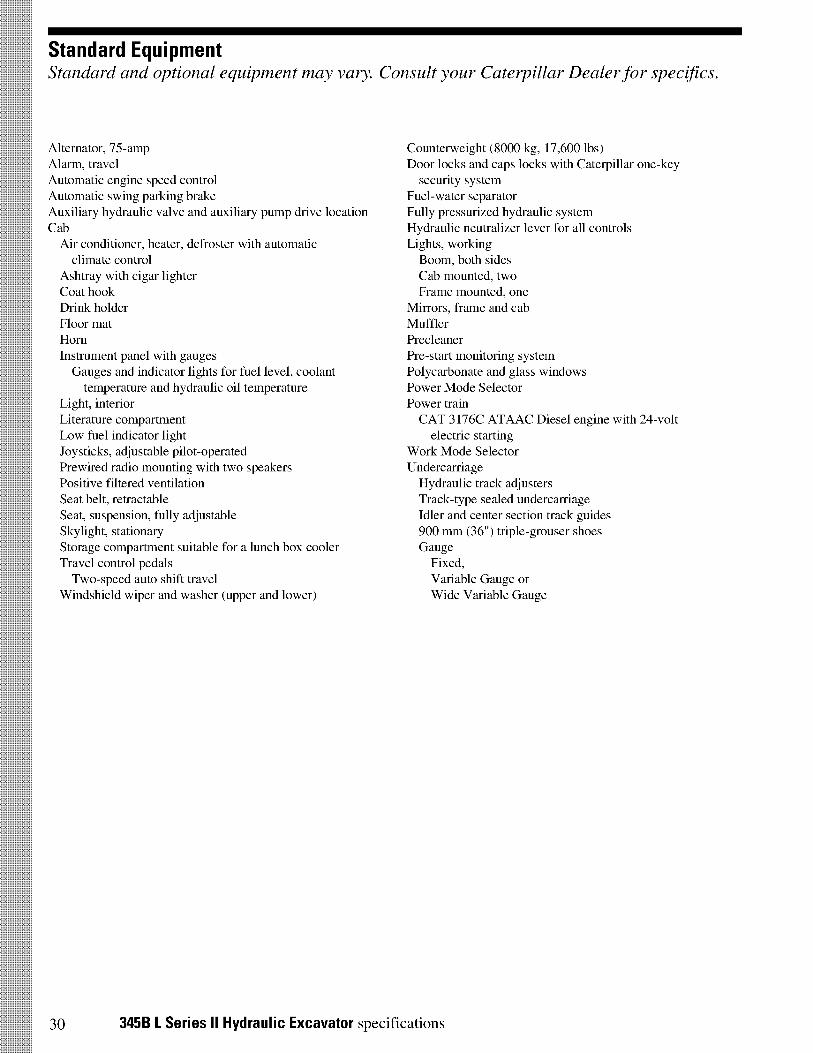
Standard EquipmentStandard and optional equipment may vary. Consult your Caterpillar Dealer for specifics.
Alternator, 75-ampAlarm, travelAutomatic engine speed controlAutomatic swing parking brakeAuxiliary hydraulic valve and auxiliary pump drive locationCab
Air conditioner, heater, defroster with automaticclimate control
Ashtray with cigar lighterCoat hookDrink holderFloor matHornInstrument panel with gaugesGauges and indicator lights for fuel level, coolanttemperature and hydraulic oil temperature
Light, interiorLiterature compartmentLow fuel indicator lightJoysticks, adjustable pilot-operatedPrewired radio mounting with two speakersPositive filtered ventilationSeat belt, retractableSeat, suspension, fully adjustableSkylight, stationaryStorage compartment suitable for a lunch box coolerTravel control pedalsTwo-speed auto shift travel
Windshield wiper and washer (upper and lower)
Counterweight (8000 kg, 17,600 lbs)Door locks and caps locks with Caterpillar one-key
security systemFuel-water separatorFully pressurized hydraulic systemHydraulic neutralizer lever for all controlsLights, workingBoom, both sidesCab mounted, twoFrame mounted, one
Mirrors, frame and cabMufflerPrecleanerPre-start monitoring systemPolycarbonate and glass windowsPower Mode SelectorPower trainCAT 3176C ATAAC Diesel engine with 24-volt
electric startingWork Mode SelectorUndercarriageHydraulic track adjustersTrack-type sealed undercarriageIdler and center section track guides900 mm (36") triple-grouser shoesGaugeFixed,Variable Gauge orWide Variable Gauge
30 345B L Series II Hydraulic Excavator specifications
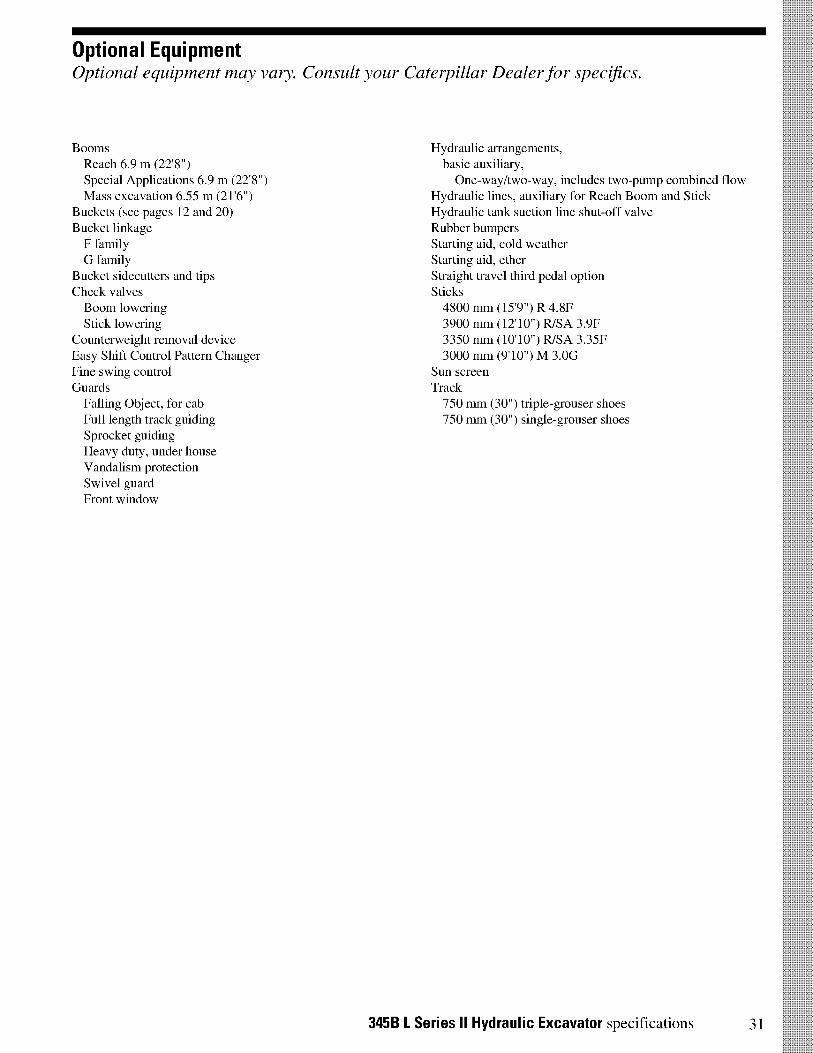
Optional EquipmentOptional equipment may vary. Consult your Caterpillar Dealer for specifics.
BoomsReach 6.9 m (22'8")Special Applications 6.9 m (22'8")Mass excavation 6.55 m (21'6")
Buckets (see pages 12 and 20)Bucket linkageF familyG family
Bucket sidecutters and tipsCheck valvesBoom loweringStick lowering
Counterweight removal deviceEasy Shift Control Pattern ChangerFine swing controlGuards
Falling Object, for cabFull length track guidingSprocket guidingHeavy duty, under houseVandalism protectionSwivel guardFront window
Hydraulic arrangements,basic auxiliary,One-way/two-way, includes two-pump combined flow
Hydraulic lines, auxiliary for Reach Boom and StickHydraulic tank suction line shut-off valveRubber bumpersStarting aid, cold weatherStarting aid, etherStraight travel third pedal optionSticks4800 mm (159") R 4.8F3900 mm (12'10") R/SA 3.9F3350 mm (10'10") R/SA 3.35F3000 mm (9'10") M 3.0G
Sun screenTrack750 mm (30") triple-grouser shoes750 mm (30") single-grouser shoes
345B L Series II Hydraulic Excavator specifications 31
345B L Series II Hydraulic Excavator
AEHQ5385-02 (4-02)
Replaces AEH 0.5385-01
For more complete information on Cat products, dealer services,and industry solutions, visit us on the web at www.CAT.com
© 2002 CaterpillarPrinted in U.S.A.
Materials and specifications are subject to change without notice.Featured machines in photos may include additional equipment.
See your Caterpillar dealer for available options.
CATERPILLAR®
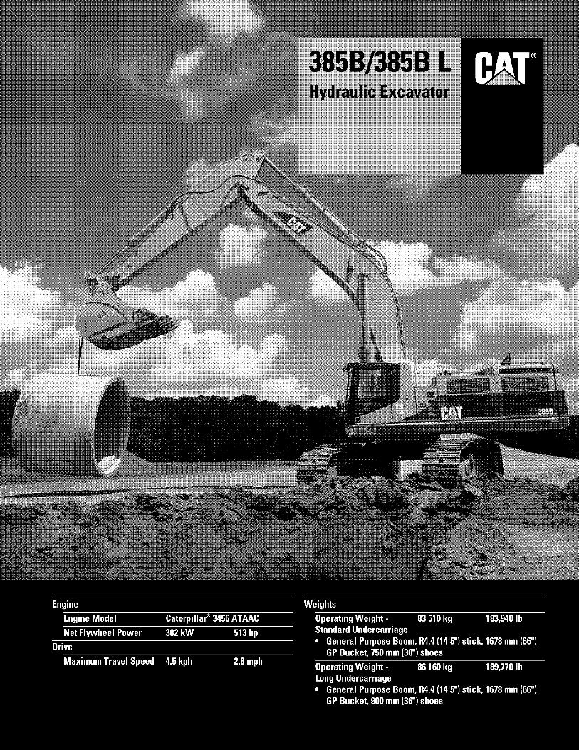
Operating Weight - 83 510 kg 183,940 lbStandard Undercarriage• General Purpose Boom, R4.4 (14'51 stick, 1678 mm (66")
GP Bucket, 750 mm (301 shoes.
Operating Weight -Long Undercarriage• General Purpose Boom, R4.4 (14'5") stick, 1678 mm (66")
GP Bucket, 900 mm (36") shoes.
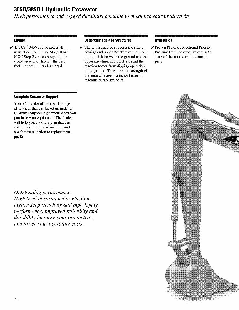
3856/385B L Hydraulic ExcavatorHigh performance and rugged durability combine to maximize your productivity.
Engine
V The Cat° 3456 engine meets allnew EPA Tier 2, Euro Stage II andMOC Step 2 emission regulationsworldwide, and also has the bestfuel economy in its class. pg. 4
Complete Customer Support
Your Cat dealer offers a wide rangeof services that can be set up under aCustomer Support Agreement when youpurchase your equipment. The dealerwill help you choose a plan that cancover everything from machine andattachment selection to replacement.pg. 12
Undercarriage and Structures
V The undercarriage supports the swingbearing and upper structure of the 385B.It is the link between the ground and theupper structure, and must transmit thereaction forces from digging operationto the ground. Therefore, the strength ofthe undercarriage is a major factor inmachine durability. pg. 5
Outstanding performance.High level of sustained production,higher deep trenching and pipe-layingperformance, improved reliability anddurability increase your productivityand lower your operating costs.
Hydraulics
V Proven PPPC (Proportional PriorityPressure Compensated) system withstate-of-the-art electronic control.pg. 6
2
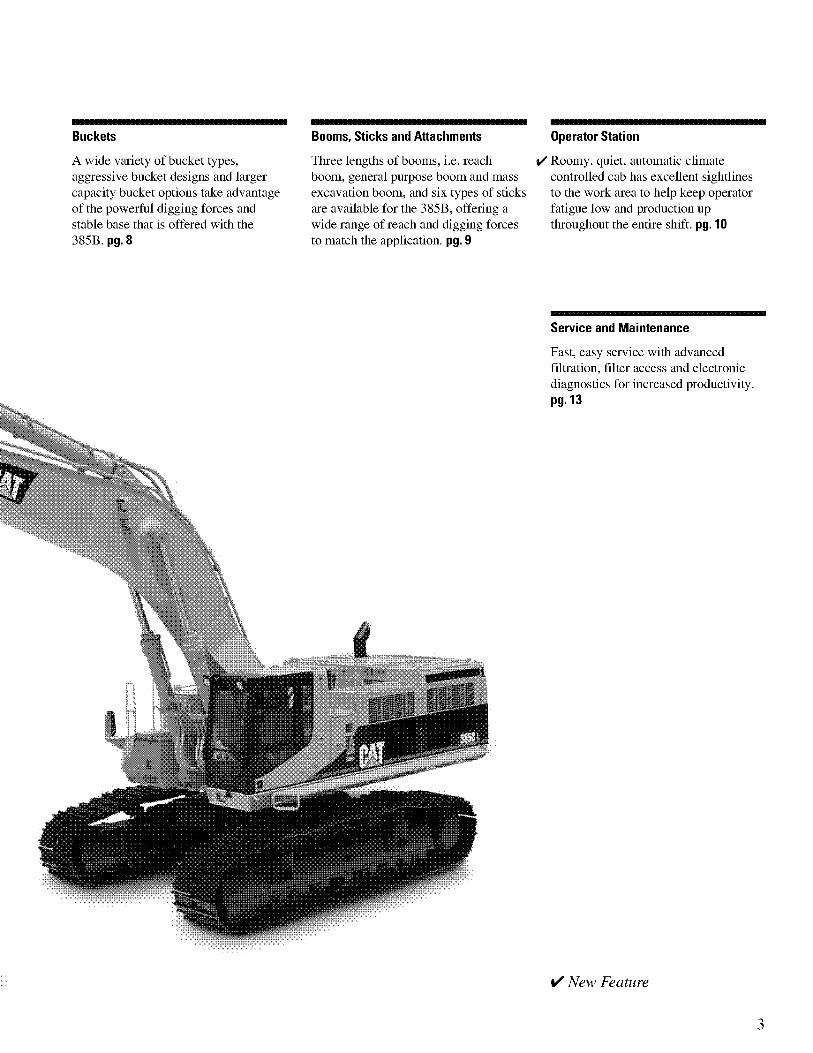
Buckets
A wide variety of bucket types,aggressive bucket designs and largercapacity bucket options take advantageof the powerful digging forces andstable base that is offered with the385B. pg. 8
Booms, Sticks and Attachments
Three lengths of booms, i.e. reachboom, general purpose boom and massexcavation boom, and six types of sticksare available for the 385B, offering awide range of reach and digging forcesto match the application. pg. 9
Operator Station
Roomy, quiet, automatic climatecontrolled cab has excellent sightlinesto the work area to help keep operatorfatigue low and production upthroughout the entire shift. pg. 10
Service and Maintenance
Fast, easy service with advancedfiltration, filter access and electronicdiagnostics for increased productivity.pg. 13
✓ New Feature
3
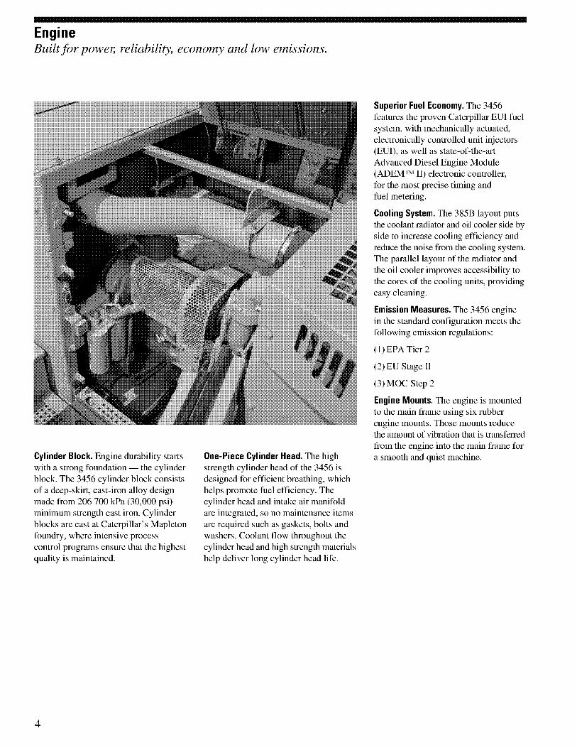
EngineBuilt for power, reliability, economy and low emissions.
Cylinder Block. Engine durability startswith a strong foundation — the cylinderblock. The 3456 cylinder block consistsof a deep-skirt, cast-iron alloy designmade from 206 700 kPa (30,000 psi)minimum strength cast iron. Cylinderblocks are cast at Caterpillar's Mapletonfoundry, where intensive processcontrol programs ensure that the highestquality is maintained.
One-Piece Cylinder Head. The highstrength cylinder head of the 3456 isdesigned for efficient breathing, whichhelps promote fuel efficiency. Thecylinder head and intake air manifoldare integrated, so no maintenance itemsare required such as gaskets, bolts andwashers. Coolant flow throughout thecylinder head and high strength materialshelp deliver long cylinder head life.
Superior Fuel Economy. The 3456features the proven Caterpillar EUI fuelsystem, with mechanically actuated,electronically controlled unit injectors(EUI), as well as state-of-the-artAdvanced Diesel Engine Module(ADEMTM II) electronic controller,for the most precise timing andfuel metering.
Cooling System. The 385B layout putsthe coolant radiator and oil cooler side byside to increase cooling efficiency andreduce the noise from the cooling system.The parallel layout of the radiator andthe oil cooler improves accessibility tothe cores of the cooling units, providingeasy cleaning.
Emission Measures. The 3456 enginein the standard configuration meets thefollowing emission regulations:
(1) EPA Tier 2
(2) EU Stage II
(3) MOC Step 2
Engine Mounts. The engine is mountedto the main frame using six rubberengine mounts. Those mounts reducethe amount of vibration that is transferredfrom the engine into the main frame fora smooth and quiet machine.
4
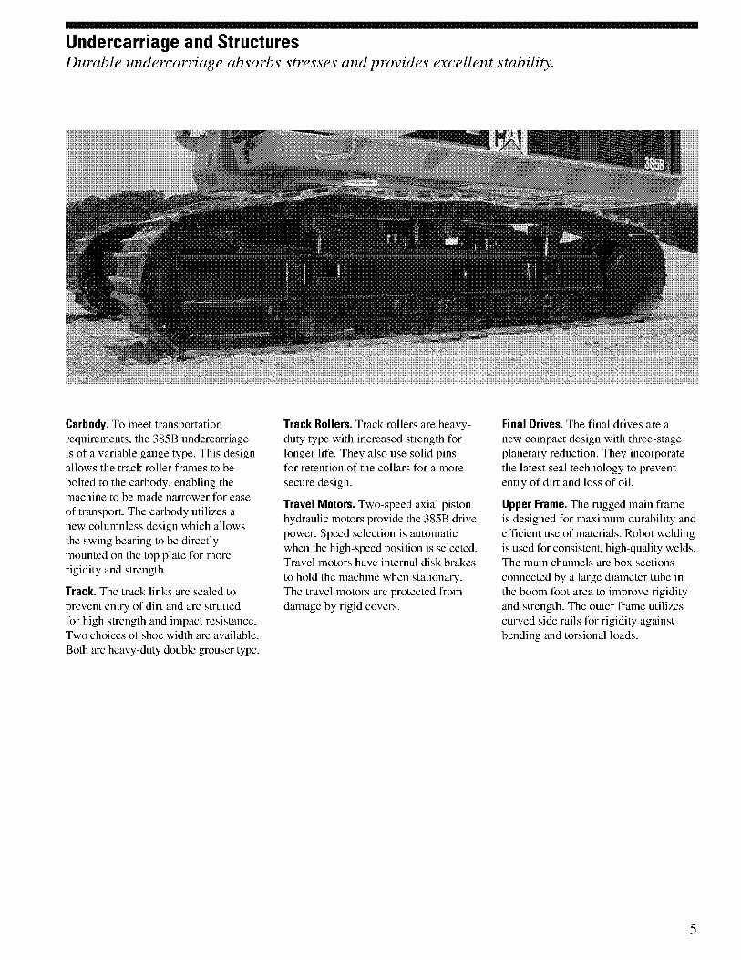
Undercarriage and StructuresDurable undercarriage absorbs stresses and provides excellent stability.
Carbody. To meet transportationrequirements, the 385B undercarriageis of a variable gauge type. This designallows the track roller frames to bebolted to the carbody, enabling themachine to be made narrower for easeof transport. The carbody utilizes anew columnless design which allowsthe swing bearing to be directlymounted on the top plate for morerigidity and strength.
Track. The track links are sealed toprevent entry of dirt and are struttedfor high strength and impact resistance.Two choices of shoe width are available.Both are heavy-duty double grouser type.
Track Rollers. Track rollers are heavy-duty type with increased strength forlonger life. They also use solid pinsfor retention of the collars for a moresecure design.
Travel Motors. Two-speed axial pistonhydraulic motors provide the 385B drivepower. Speed selection is automaticwhen the high-speed position is selected.Travel motors have internal disk brakesto hold the machine when stationary.The travel motors are protected fromdamage by rigid covers.
Final Drives. The final drives are anew compact design with three-stageplanetary reduction. They incorporatethe latest seal technology to prevententry of dirt and loss of oil.
Upper Frame. The rugged main frameis designed for maximum durability andefficient use of materials. Robot weldingis used for consistent, high-quality welds.The main channels are box sectionsconnected by a large diameter tube inthe boom foot area to improve rigidityand strength. The outer frame utilizescurved side rails for rigidity againstbending and torsional loads.
5
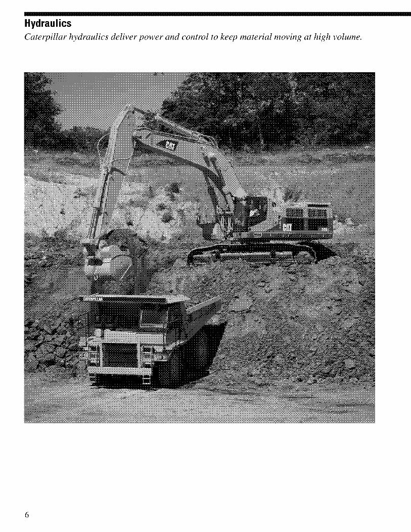
HydraulicsCaterpillar hydraulics deliver power and control to keep material moving at high volume.
6
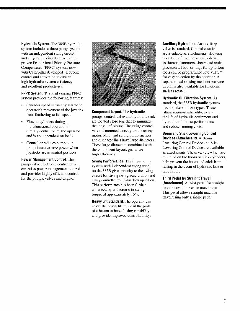
Hydraulic System. The 385B hydraulicsystem includes a three pump systemwith an independent swing circuitand a hydraulic circuit utilizing theproven Proportional Priority PressureCompensated (PPPC) system, nowwith Caterpillar developed electroniccontrol and activation to ensurehigh hydraulic system efficiencyand excellent productivity.
PPPC System. The load sensing PPPCsystem provides the following features:
• Cylinder speed is directly related tooperator's movement of the joystickfrom feathering to full speed
• Flow to cylinders duringmultifunctional operation isdirectly controlled by the operatorand is not dependent on loads
• Controller reduces pump outputto minimum to save power whenjoysticks are in neutral position
Power Management Control. Thepump-valve electronic controller iscentral to power management controland provides highly efficient controlfor the pumps, valves and engine.
Component Layout. The hydraulicpumps, control valve and hydraulic tankare located close together to minimizethe length of piping. The swing controlvalve is mounted directly on the swingmotor. Main and swing pump suctionand discharge lines have large diameters.These large diameters, combined withthe component layout, guaranteehigh efficiency.
Swing Performance. The three-pumpsystem with independent swing usedon the 385B gives priority to the swingcircuit for strong swing acceleration andeasily controlled multi-function operation.This performance has been furtherenhanced by an increase in swingtorque of approximately 16%.
Heavy Lift Standard. The operator canselect the heavy lift mode at the pushof a button to boost lifting capabilityand provide improved controllability.
Auxiliary Hydraulics. An auxiliaryvalve is standard. Control circuitsare available as attachments, allowingoperation of high pressure tools suchas thumbs, hammers, shears and multi-processors. Flow settings for up to fourtools can be programmed into VIDSTMfor easy selection by the operator. Aseparate load sensing medium pressurecircuit is also available for functionssuch as rotate.
Hydraulic Oil Filtration System. Asstandard, the 385B hydraulic systemhas six filters in four types. Thesefilters improve reliability, extendthe life of hydraulic equipment andhydraulic oil, boost performanceand reduce running costs.
Boom and Stick Lowering ControlDevices (Attachment). A BoomLowering Control Device and StickLowering Control Device are availableas attachments. These valves, which aremounted on the boom or stick cylinders,help prevent the boom and stick fromfalling in the event of hydraulic line ortube failure.
Third Pedal for Straight Travel(Attachment). A third pedal for straighttravel is available as an attachment.This pedal allows straight machinetravel using only a single pedal.
7
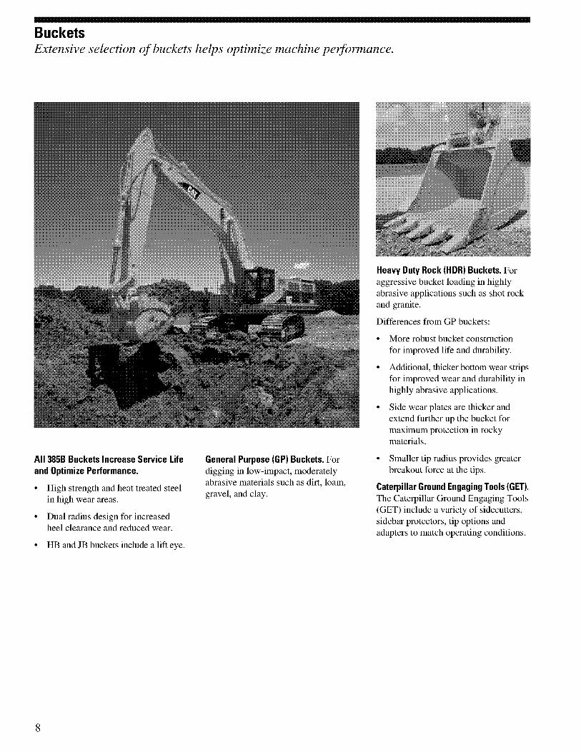
BucketsExtensive selection of buckets helps optimize machine peifonnance.
All 385B Buckets Increase Service Lifeand Optimize Performance.
• High strength and heat treated steelin high wear areas.
• Dual radius design for increasedheel clearance and reduced wear.
• HB and JB buckets include a lift eye.
General Purpose (GP) Buckets. Fordigging in low-impact, moderatelyabrasive materials such as dirt, loam,gravel, and clay.
Heavy Duty Rock (HDR) Buckets. Foraggressive bucket loading in highlyabrasive applications such as shot rockand granite.
Differences from GP buckets:
• More robust bucket constructionfor improved life and durability.
• Additional, thicker bottom wear stripsfor improved wear and durability inhighly abrasive applications.
• Side wear plates are thicker andextend further up the bucket formaximum protection in rockymaterials.
• Smaller tip radius provides greaterbreakout force at the tips.
Caterpillar Ground Engaging Tools (GET).The Caterpillar Ground Engaging Tools(GET) include a variety of sidecutters,sidebar protectors, tip options andadapters to match operating conditions.
8

Booms, Sticks and AttachmentsThe 385B is designed with the flexibility to help deliver higher production and efficiency.
Reach Boom - 10 m (32 ft 10 in) long.For use in deep trenching applicationswhere long reach and depth arenecessary. Two long sticks areavailable for this boom.
General Purpose Boom - 8.4 M (27 ft 7 in)long. The GP boom has been designedto balance the reach, digging force andthe bucket capacity, and offer a widerange of applications such as digging,loading and trenching. Four sticks areavailable for this boom.
Mass Excavation Boom - 725 m (23ft 9 in)long. This is the most suitable boom forhigh production loading where reachand depth are less important. It allowsuse of the largest buckets. Two sticksare available for this boom.
Boom Construction. All 385B boomsfeature large cross-sections, whichare effective in reducing weight andenhancing rigidity. Also, the inside ofthe boom is reinforced by baffle platesto provide higher rigidity and lessstress. All booms are stress relievedfor extended life without added weight.
Stick. There are four lengths in six typesof sticks for the 385B for maximumproductivity in various applications.Each stick is used in a combinationwith a specific boom and bucket family.
Stick Construction. The 385B sticks aremade of high-tensile strength steel usinga large box section design with interiorbaffle plates and an additional bottomplate to protect against rock damage. A11sticks are stress relieved for long life.
Bucket Linkage. Two bucket linkagesare available for the 385B. The HBfamily is used with the longer sticks andtakes HB family buckets; the JB familyis used with the shorter sticks and takesJB family buckets.
Linkage Pin. All pins used in 385Bfront linkages have a thick chromeplating, giving them high wear andcorrosion resistance. The diameter ofeach pin is made as large as possibleto smoothly distribute the shear andbending loads associated with thedigging and lifting forces.
9
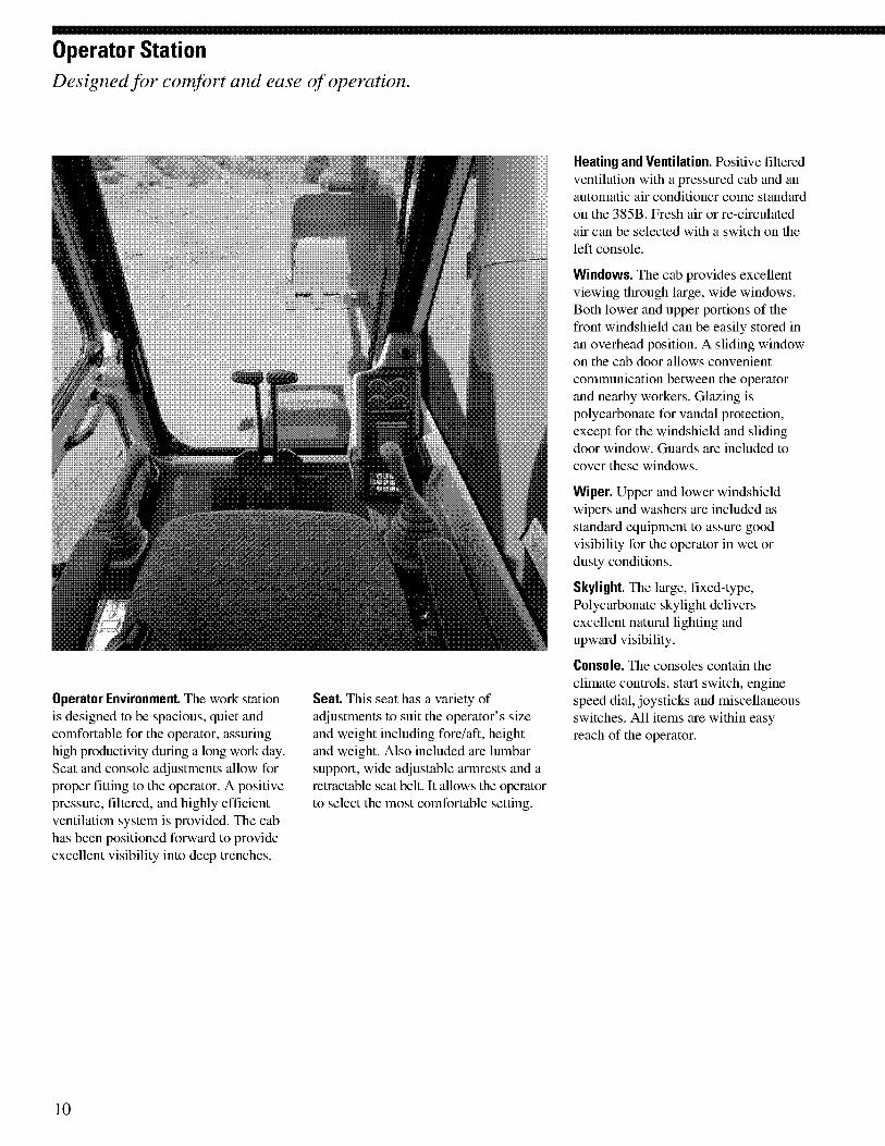
Operator StationDesigned for comfort and ease of operation.
Operator Environment. The work stationis designed to be spacious, quiet andcomfortable for the operator, assuringhigh productivity during a long work day.Seat and console adjustments allow forproper fitting to the operator. A positivepressure, filtered, and highly efficientventilation system is provided. The cabhas been positioned forward to provideexcellent visibility into deep trenches.
Seat. This seat has a variety ofadjustments to suit the operator's sizeand weight including fore/aft, heightand weight. Also included are lumbarsupport, wide adjustable armrests and aretractable seat belt. It allows the operatorto select the most comfortable setting.
Heating and Ventilation. Positive filteredventilation with a pressured cab and anautomatic air conditioner come standardon the 385B. Fresh air or re-circulatedair can be selected with a switch on theleft console.
Windows. The cab provides excellentviewing through large, wide windows.Both lower and upper portions of thefront windshield can be easily stored inan overhead position. A sliding windowon the cab door allows convenientcommunication between the operatorand nearby workers. Glazing ispolycarbonate for vandal protection,except for the windshield and slidingdoor window. Guards are included tocover these windows.
Wiper. Upper and lower windshieldwipers and washers are included asstandard equipment to assure goodvisibility for the operator in wet ordusty conditions.
Skylight. The large, fixed-type,Polycarbonate skylight deliversexcellent natural lighting andupward visibility.
Console. The consoles contain theclimate controls, start switch, enginespeed dial, joysticks and miscellaneousswitches. All items are within easyreach of the operator.
10
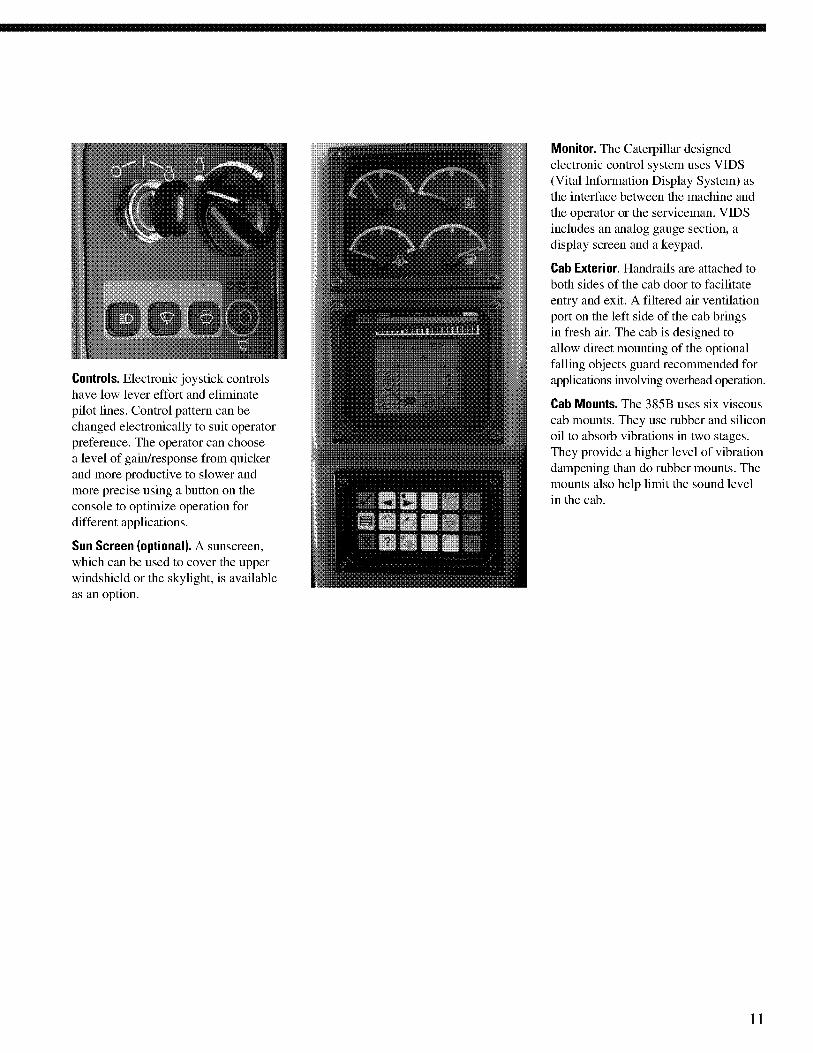
Controls. Electronic joystick controlshave low lever effort and eliminatepilot lines. Control pattern can bechanged electronically to suit operatorpreference. The operator can choosea level of gain/response from quickerand more productive to slower andmore precise using a button on theconsole to optimize operation fordifferent applications.
Sun Screen (optional). A sunscreen,which can be used to cover the upperwindshield or the skylight, is availableas an option.
Monitor. The Caterpillar designedelectronic control system uses VIDS(Vital Information Display System) asthe interface between the machine andthe operator or the serviceman. VIDSincludes an analog gauge section, adisplay screen and a keypad.
Cab Exterior. Handrails are attached toboth sides of the cab door to facilitateentry and exit. A filtered air ventilationport on the left side of the cab bringsin fresh air. The cab is designed toallow direct mounting of the optionalfalling objects guard recommended forapplications involving overhead operation.
Cab Mounts. The 385B uses six viscouscab mounts. They use rubber and siliconoil to absorb vibrations in two stages.They provide a higher level of vibrationdampening than do rubber mounts. Themounts also help limit the sound levelin the cab.
11
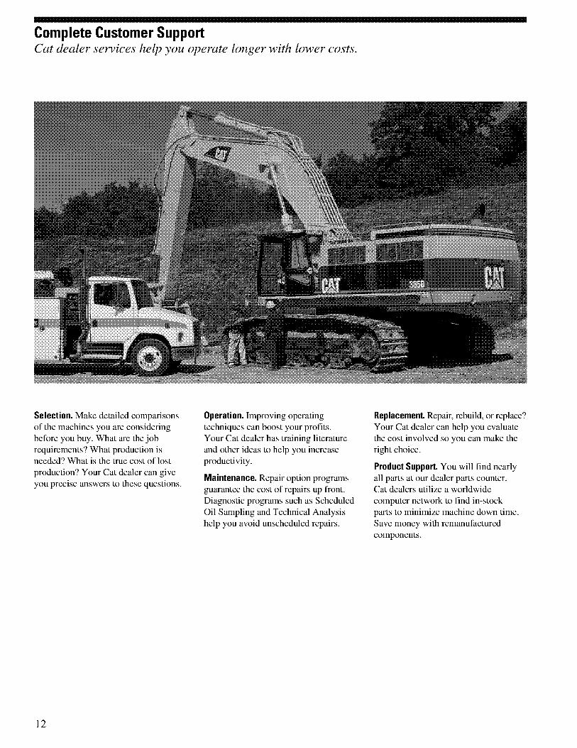
Complete Customer SupportCat dealer services help you operate longer with lower costs.
Selection. Make detailed comparisonsof the machines you are consideringbefore you buy. What are the jobrequirements? What production isneeded? What is the true cost of lostproduction? Your Cat dealer can giveyou precise answers to these questions.
Operation. Improving operatingtechniques can boost your profits.Your Cat dealer has training literatureand other ideas to help you increaseproductivity.
Maintenance. Repair option programsguarantee the cost of repairs up front.Diagnostic programs such as ScheduledOil Sampling and Technical Analysishelp you avoid unscheduled repairs.
Replacement. Repair, rebuild, or replace?Your Cat dealer can help you evaluatethe cost involved so you can make theright choice.
Product Support. You will find nearlyall parts at our dealer parts counter.Cat dealers utilize a worldwidecomputer network to find in-stockparts to minimize machine down time.Save money with remanufacturedcomponents.
12
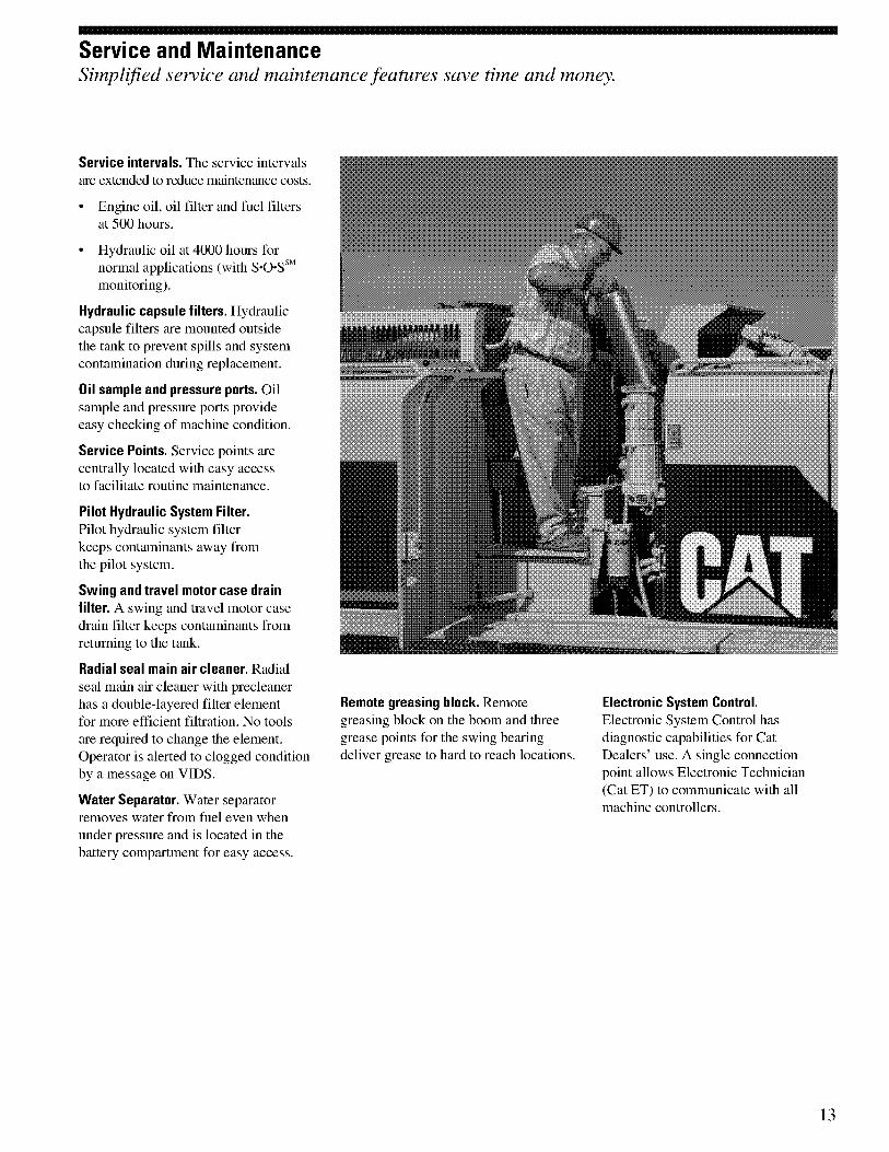
Service and MaintenanceSimplified service and maintenance features save time and money.
Service intervals. The service intervalsare extended to reduce maintenance costs.
• Engine oil, oil filter and fuel filtersat 500 hours.
• Hydraulic oil at 4000 hours fornormal applications (with S-0-Ssmmonitoring).
Hydraulic capsule filters. Hydrauliccapsule filters are mounted outsidethe tank to prevent spills and systemcontamination during replacement.
Oil sample and pressure ports. Oilsample and pressure ports provideeasy checking of machine condition.
Service Points. Service points arecentrally located with easy accessto facilitate routine maintenance.
Pilot Hydraulic System Filter.Pilot hydraulic system filterkeeps contaminants away fromthe pilot system.
Swing and travel motor case drainfilter. A swing and travel motor casedrain filter keeps contaniinants fromreturning to the tank.
Radial seal main air cleaner. Radialseal main air cleaner with precleanerhas a double-layered filter elementfor more efficient filtration. No toolsare required to change the element.Operator is alerted to clogged conditionby a message on VIDS.
Water Separator. Water separatorremoves water from fuel even whenunder pressure and is located in thebattery compartment for easy access.
Remote greasing block. Remotegreasing block on the boom and threegrease points for the swing bearingdeliver grease to hard to reach locations.
Electronic System Control.Electronic System Control hasdiagnostic capabilities for CatDealers' use. A single connectionpoint allows Electronic Technician(Cat ET) to communicate with allmachine controllers.
13
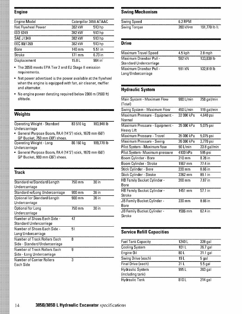
Engine Swing Mechanism
Engine Model Caterpillar 3456 ATAAC Swing Speed
Net Flywheel Power 382 kW 513 hp
ISO 9249 382 kW 513 hp
SAE J1349 382 kW 513 hp
EEC 80/1269 382 kW 513 hp
Bore 140 mm 5.51 in
Stroke 171 mm 6.73 in
Displacement 15.8 L 964 in'
• The 385B meets EPA Tier 2 and EU Stage II emissionrequirements.
• Net power advertised is the power available at the flywheelwhen the engine is equipped with fan, air cleaner, mufflerand alternator.
• No engine power derating required below 2300 m (7500 ft)altitude.
Weights
Operating Weight - Standard 83 510 kg 183,940 lbUndercarriage• General Purpose Boom, R4.4 (14'5") stick, 1678 mm (66")
GP Bucket, 750 mm (301 shoes.Operating Weight - LongUndercarriage• General Purpose Boom, R4.4 (14'5") stick, 1678 mm (66")
GP Bucket, 900 mm (36") shoes.
86 160 kg 189,770 lb
Track
Standard w/Standard Length 750 mm 30 inUndercarriage
Standard w/Long Undercarriage 900 mm 36 in
Optional for Standard Length 900 mm 36 inUndercarriage
Optional for LongUndercarriage
750 mm 30 in
Number of Shoes Each Side - 47Standard Undercarriage
Number of Shoes Each Side - 51Long Undercarriage
Number of Track Rollers Each 8Side - Standard Undercarriage
Number of Track Rollers Each 9Side - Long Undercarriage
Number of Carrier RollersEach Side
3
6.2 RPM
Swing Torque 260 kN•m 191,770 lb ft
Drive
Maximum Travel Speed 4.5 kph 2.8 mph
Maximum Drawbar Pull -Standard Undercarriage
592 kN 133,030 lb
Maximum Drawbar Pull -Long Undercarriage
591 kN 132,810 lb
Hydraulic System
Main System - Maximum Flow 980 L/min 258 gal/min(Total)
Swing System - Maximum Flow 450 L/min 119 gal/min
Maximum Pressure - Equipment - 32 000 kPa 4,640 psiNormal
Maximum Pressure - Equipment - 35 000 kPa 5,075 psiHeavy Lift
Maximum Pressure - Travel 35 000 kPa 5,075 psi
Maximum Pressure - Swing 26 000 kPa 3,770 psi
Pilot System - Maximum flow 90 L/min
Pilot System- Maximum pressure 4100 kPa
23.8 gal/min
595 psi
Boom Cylinder - Bore 210 mm 8.26 in
Boom Cylinder - Stroke 1967 mm 77.4 in
Stick Cylinder - Bore 220 mm 8.66 in
Stick Cylinder - Stroke 2262 mm 89.1 in
HB Family Bucket Cylinder -Bore
200 mm 7.87 in
HB Family Bucket Cylinder -Stroke
1451 mm 57.1 in
JB Family Bucket Cylinder - 220 mm 8.66 inBore
JB Family Bucket Cylinder -Stroke
1586 mm 62.4 in
Service Refill Capacities
Fuel Tank Capacity 1240 L 328 gal
Cooling System 101 L 26.7 gal
Engine Oil 80 L 21.1 gal
Swing Drive (each) 19 L 5 gal
Final Drive (each) 21 L 5.5 gal
Hydraulic System(including tank)
995 L 263 gal
Hydraulic Tank 810 L 214 gal
14 385B/385B L Hydraulic Excavator specifications

Sound Performance Standards
Performance ANSI/SAE J1166 OCT 98 Brakes SAE J1026 APR 90
• When properly installed and maintained, the cab offeredby Caterpillar, when tested with doors and windows closedaccording to ANSI/SAE J1166 OCT 98, meets OSHA andMSHA requirements for operator sound exposure limitsin effect at time of manufacture.
• Hearing protection may be needed when operating withan open operator station and cab (when not properlymaintained or doors/windows open) for extended periodsor in noisy environment.
Cab/FOGS SAE J1356 FEB 88ISO 10262
385B/385B L Hydraulic Excavator specifications 15

DimensionsAll dimensions are approximate.
Reach Boom10.0 m (32'10")
General Purpose Boom8.4 m (2T7")
Mass Boom7.25 m (23'9')
Stick 5.5 m 4.4 m 5.5 m 4.4 m 3.4 m 2.92 m 3.4 m 2.92 m(181") (14'5") (181") (14'5") (117) (9.r) (11. 2") (9T)
A Shipping HeightWith boom, stick
and bucketWithout stick
and bucket
B Shipping Length*With boom, stick
and bucketWithout stick
and bucket
C Tail Swing Radius
5320 mm 4960 mm 5870 mm 5250 mm 5060 mm 4890 mm 4970 mm 4800 mm(17'5") (16'3") (19'3") (17'3") (167") (16'1") (16'4") (159")4020 mm 4020 mm 3760 mm 3760 mm 3760 mm 3760 mm 3870 mm 3870 mm(13'2") (13'2") (12'4") (12'4") (12'4") (12'4") (12'8") (12'8")
16 230 mm 16 290 mm 14 420 mm 14 660 mm 14 220 mm 14 750 mm 13 520 mm 13 510 mm(537) (53'5") (47'4") (48'1") (468") (48'5") (44'4") (44'4")
14 620 mm 14 620 mm 12 950 mm 12 950 mm 12 950 mm 12 950 mm 11 750 mm 11 750 mm(48'0") (48'0") (42'6") (42'6") (42'6") (42'6") (387") (387") 4590 mm 4590 mm 4590 mm 4590 mm 4590 mm 4590 mm 4590 mm 4590 mm(15'1") (15'1") (15'1") (15'1") (15'1") (15'1") (15'1") (15'1")
D Length to Center of RollersStandard Undercarriage 4600 mm 4600 mm 4600 mm 4600 mm 4600 mm 4600 mm 4600 mm 4600 mm
(15'1") (15'1") (15'1") (15'1") (15'1") (15'1") (15'1") (15'1")Long Undercarriage 5120 mm 5120 mm 5120 mm 5120 mm 5120 mm 5120 mm 5120 mm 5120 mm
(1610") (1610") (16'10") (16'10") (16'10") (16'10") (1610") (1610”) E Track Length
Standard Undercarriage 5840 mm 5840 mm 5840 mm 5840 mm 5840 mm 5840 mm 5840 mm 5840 mm(19'2") (19'2") (19'2") (19'2") (19'2") (19'2") (19'2") (19'2")
Long Undercarriage 6360 mm 6360 mm 6360 mm 6360 mm 6360 mm 6360 mm 6360 mm 6360 mm(20'10") (20'10") (20'10") (20'10") (20'10") (20'10") (20'10") (20'10”)
F Ground Clearance 850 mm 850 mm 850 mm 850 mm 850 mm 850 mm 850 mm 850 mm(33.5") (33.5") (33.5") (33.5") (33.5") (33.5") (33.5") (33.5")
G Track Gauge (shipping)**For 750 mm (30") shoes 2750 mm 2750 mm 2750 mm 2750 mm 2750 mm 2750 mm 2750 mm 2750 mm
(9'0") (9'0") (9'0") (9'0") (9'0") (9'0") (9'0") (9'0")For 900 mm (36") shoes 2940 mm 2940 mm 2940 mm 2940 mm 2940 mm 2940 mm 2940 mm 2940 mm
(9'8") (9'8") (9'8") (9'8") (9'8") (9'8") (9'8") (9'8")H Transport Width
For 750 mm (30") shoes 3500 mm 3500 mm 3500 mm 3500 mm 3500 mm 3500 mm 3500 mm 3500 mm(11'6") (11'6") (11'6") (11'6") (11'6") (11'6") (11'6") (11'6")
For 900 mm (36") shoes 3840 mm 3840 mm 3840 mm 3840 mm 3840 mm 3840 mm 3840 mm 3840 mm(12'7") (12'7") (127") (127") (127") (12'7") (12'7") (12'7")
I Cab Height 3660 mm 3660 mm 3660 mm 3660 mm 3660 mm 3660 mm 3660 mm 3660 mm(12'0") (12'0") (12'0") (12'0") (12'0") (12'0") (12'0") (12'0")
* Shipping length with boom removed: 7510 mm (24'8") for standard undercarriage, 7770 mm (25'6") for long undercarriage.Subtract 510 mm (1'8") from all shipping length dimensions if counterweight is removed.
** Track Gauge in extended (working) position: 3510 mm (11'6")
16 385B/385B L Hydraulic Excavator specifications
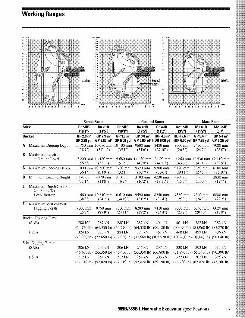
Working Ranges
Feet Mete s
55
50
00
35
30
20
15
10
10
15
20
30
11111111k 1111111111=ENEMA,
116111/4
NOME/IIIMINIMA. lima.EN/NM =MNMIINNWAMENWEMIIEWOMMEMO
IRINNIIIIIIIIVEIMINEENNEMENEEllEMEN MENIN NEN 0/ ••••Ellff • / MuMIEW 4 MNIIIE. MEM
1111 1111 Bilill
II MENNEN l'illimIIIIMELIENNEN I =MINN[IMMUNE= ININEENNEENIMRE\ • 11111111111INIENNEN ENE MIME=ININNEE
•11111 Pr II
11111MENE••••••IN••••
10 17 10
0 55 511 45 40
0 7 fi
311 25 2b
Feet Mete s
55 - 17n
50 - 15
05 -13
00 - 12
30 -
20
10 -
R0 0.110.51R5.5.3
10
b 5 0 -5 -10 F.
20 -
30 -
fi
3
fi
. 10 17 Ifi 15 10 13 12 11 10 9 0 5 0 3
fib fib 55 5 rlb 011 35 30 25 20 15 10
Feet Mete s
551105
14
50
40
35
3205
20
10
G2.92. (Mr) 5G3.0313 MIT)R0.0.3 (10.51 1025.5413 (1OT)
Met.
. Feet
20
25
30
35
3
%NMI
EN IM
=M MISIM
M1
E MEM
M
10 17 Ifi 15 10 13 12 0 9 0 7 fi 5 0 3 2 1 -1 -
M.92.
Meters
b 55 5 rlb 00 35 30 25 20 15 1 0 0 -5 0 Feet
Reach Boom General Boom Mass Boom
Stick R5.5HB R4.4HB R5.5HB R4.4HB G3.4JB G2.92JB M3.4JB M2.92JB(181") (147) (181") (147) (117) (9T) (117) (9T)
Bucket GP 2.9 m3 GP 2.9 m3 GP 3.8 m3 GP 3.8 m3 HDR 4.6 m3 HDR 4.6 m3 GP 5.4 m3 GP 5.4 m3GP 3.88 yd3 GP 3.88 yd3 GP 5.00 yd3 GP 5.00 yd3 HDR 6.00 yd3 HDR 6.00 yd3 GP 725 yd3 GP 725 yd3
A Maximum Digging Depth 11 750 mm 10 650 mm 10 700 mm 9600 mm 8480 mm 8000 mm 7490 mm 7020 mm(38'7") (34'11") (35'1") (31'6") (27'10") (26'3") (24'7") (23'0")
B Maximum Reachat Ground Level 17 200 mm 16 180 mm 15 680 mm 14 630 mm 13 690 mm 13 260 mm 12 530 mm 12 110 mm
(56'5") (53'1") (51'5") (48'0") (44'11") (43'6") (41'1") (3919")C Maximum Loading Height 11 000 mm 10 580 mm 9780 mm 9320 mm 9300 mm 9120 mm 8350 mm 8180 mm
(36'1") (34'9") (32'1") (30'7") (30'6") (29'11") (27'5") (26'10")
D Minimum Loading Height 3370 mm 4470 mm 2000 mm 3100 mm 4230 mm 4700 mm 3350 mm 3830 mm(11'1") (14'8") (6'7") (102") (13'11") (15'5") (11'0") (12'7")
E Maximum Depth Cut for2440 mm (8')Level Bottom 11 660 mm 10 540 mm 10 610 mm 9490 mm 8340 mm 7850 mm 7360 mm 6880 mm
(38'3") (34'7") (34'10") (31'2") (27'4") (25'9") (24'2") (22'7")F Maximum Vertical Wall
Digging Depth 7800 mm 8760 mm 7600 mm 8280 mm 7410 mm 7060 mm 6340 mm 6020 mm(25'7") (28'9") (24'11") (27'2") (24'4") (23'2") (20'10") (19'9")
Bucket Digging Force(SAE) 288 kN 287 kN 288 kN 287 kN 401 kN 401 kN 382 kN 382 kN
(64,770 lb) (64,530 lb) (64,770 lb) (64,530 lb) (90,180 lb) (90,090 lb) (85,960 lb) (85,870 lb)(ISO) 324 kN 323 kN 324 kN 323 kN 461 kN 460 kN 437 kN 436 kN
(72,930 lb) (72,660 lb) (72,930 lb) (72,660 lb) (103,570 lb) (103,460 lb) (98,140 lb) (98,040 lb)
Stick Digging Force(SAE) 206 kN 246 kN 206 kN 246 kN 297 kN 320 kN 292 kN 313 kN
(46,400 lb) (55,350 lb) (46,400 lb) (55,350 lb) (66,800 lb) (71,870 lb) (65,540 lb) (70,390 lb)(ISO) 212 kN 254 kN 212 kN 254 kN 308 kN 332 kN 302 kN 325 kN
(47,610 lb) (57,020 lb) (47,610 lb) (57,020 lb) (69,190 lb) (74,720 lb) (67,870 lb) (73,160 lb)
385B/385B L Hydraulic Excavator specifications 17
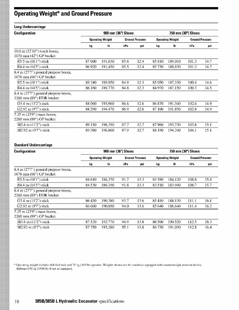
Operating weight* and Ground Pressure
Long Undercarriage
Configuration 900 mm (36') Shoes 750 mm (30") Shoes
Operating Weight Ground Pressure Operating Weight Ground Pressure
kg lb kPa psi kg lb kPa psi
10.0 m (32'10") reach boom,1070 mm (42") GP bucket
R5.5 m (18'1") stick 87 000 191,630 85.6 12.4 85 810 189,010 101.3 14.7
R4.4 m (14'5") stick 86 920 191,450 85.5 12.4 85 730 188,830 101.2 14.7
8.4 m (277") general purpose boom,1678 mm (66") GP bucket
R5.5 m (18'1") stick 89 240 189,950 84.9 12.3 85 050 187,330 100.4 14.6
R4.4 m (14'5") stick 86 160 189,770 84.8 12.3 84 970 187,150 100.3 14.5
8.4 m (277") general purpose boom,2260 mm (89") HDR bucket
G3.4 m (11'2") stick 88 060 193,960 86.6 12.6 86 870 191,340 102.6 14.9
G2.92 m (97") stick 88 290 194,470 86.9 12.6 87 100 191,850 102.8 14.9
7.25 m (239") mass boom,2260 mm (89") GP bucket
M3.4 m (112") stick 89 150 196,350 87.7 12.7 87 960 193,730 103.8 15.1
M2.92 m (97") stick
Standard Undercarriage
89 380 196,860 87.9 12.7 88 190 194,240 104.1 15.1
Configuration 900 mm (36') Shoes 750 mm (30") Shoes
Operating Weight Ground Pressure Operating Weight Ground Pressure
kg lb kPa psi kg lb kPa psi
8.4 m (277") general purpose boom,1678 mm (66") GP bucket
R5.5 m (18'1") stick 84 610 186,370 91.7 13.3 83 590 184,120 108.8 15.8
R4.4 m (14'5") stick 84 530 186,190 91.6 13.3 83 510 183,940 108.7 15.7
8.4 m (27'7") general purpose boom,2260 mm (89") HDR bucket
G3.4 m (112") stick 86 430 190,380 93.7 13.6 85 410 188,130 111.1 16.1
G2.92 m (97") stick 86 660 190,890 94.0 13.6 85 640 188,640 111.4 16.2
7.25 m (23'9") mass boom,2260 mm (89") GP bucket
M3.4 m (11'2") stick 87 520 192,770 94.9 13.8 86 500 190,520 112.5 16.3
M2.92 m (97") stick 87 750 193,280 95.1 13.8 86 730 191,030 112.8 16.4
* Operating weight includes full fuel tank and 75 kg (165 lb) operator. Weights shown are for machines equipped with counterweight removal device.Subtract 670 kg (1500 lb) if not so equipped.
18 385B/385B L Hydraulic Excavator specifications

Major Component Weights
kg lb
Base machine with counterweight, 900 mm (36") shoes (without front linkage)
Standard undercarriage 68 640 151,200
Long undercarriage 69 910 154,700
Counterweight 11 600 25,600
Boom (includes lines, pins and stick cylinder)
Reach boom 10.0 m (32'10") 9520 21,000
General Purpose boom 8.4 m (27'7") 8200 18,100
Mass boom 7.25 m (23'9") 8280 18,250
Stick and Linkage (includes lines, pins, bucket cylinder and bucket linkage)
R5.5HB (18'1") 4820 10,650
R4.4HB (14'5") 4500 9900
G3.4JB (11'2") 4750 10,460
G2.92JB (9'7") 4610 10,150
M3.4JB (11'2") 4920 10,850
M2.92JB (9'7") 4830 10,650
Track roller frame [includes frame, rollers, idler, steps, guards, final drive,900 mm (36") shoes] — each
Standard undercarriage 12 290 27,100
Long undercarriage 13 220 29,100
385B/385B L Hydraulic Excavator specifications 19

385B L Bucket Specifications and Compatibility
Capacity* Widthm3 yd3 mm in
TipRadius
mm in
Weight(w/o tips)kg lb
Reach10 m
R5.5HB R4.4HB(18' 1") (14' 51
GP8.4 m
R5.5HB R4.4HB(18' 1") (14' 51
HB BucketsGeneral Purpose
Heavy Duty Rock
2.12.93.84.62.02.73.54.2
2.753.885.006.002.633.634.635.63
10701374167819821070137416781982
4254667842546678
Capacity* Widthm3 yd3 mm in
23722372237223722288228822882288
93.493.493.493.490.190.190.190.1
TipRadius
mm in
23652760308535002550307533653890
52106080680077105620677074108570
Weight(w/o tips)kg lb
• •
• •
GP8.4 m
G3.4JB G2.9JB(11' 2") (9' T)
•
•
0
•
•
0
•••O•••O
Mass7.25 m
M3.4JB M2.9JB(11' 2") (9' T)
JB BucketsGeneral Purpose 5.4 7.25 2260
5.8 7.75 239089 2350 92.5 5755 12,68094 2350 92.5 5895 12,990
0
0 0
Heavy Duty Rock 4.6 6.00 2260Heavy Duty Rock V-edge 4.8 6.25 2260
89 2240 88.2 5460 12,03089 2377 93.6 5650 12,450
O • •
O • •
385B Bucket Specifications and Compatibility
Capacity* Widthm3 yd3 mm in
TipRadius
mm in
Weight(w/o tips)kg lb
GP8.4 m
R5.5HB R4.4HB(18' 1") (14' 51
HB BucketsGeneral Purpose
Heavy Duty Rock
2.12.93.84.62.02.73.54.2
2.753.885.006.002.633.634.635.63
10701374167819821070137416781982
4254667842546678
Capacity* Widthm3 yd3 mm in
23722372237223722288228822882288
93.493.493.493.490.190.190.190.1
TipRadius
mm in
23652760308535002550307533653890
52106080680077105620677074108570
Weight(w/o tips)kg lb
•
•
0
•
•
0
••
O•••O
GP8.4 m
G3.4JB G2.9JB(11' 2") (9' T)
Mass7.25 m
M3.4JB M2.9JB(11' 2") (9' T)
JB BucketsGeneral Purpose 5.4 7.25 2260 89 2350 92.5 5755 12,680
5.8 7.75 2390 94 2350 92.5 5895 12,990Heavy Duty Rock 4.6 6.00 2260 89 2240 88.2 5460 12,030Heavy Duty Rock V-edge 4.8 6.25 2260 89 2377 93.6 5650 12,450
Assumptions for maximum material density rating:1. Front linkage fully extended at ground line2. Bucket curled3. 100% bucket fill factor
* Capacities based on SAE J296. Some calculations of capacity fall on borderlines. Rounding
may allow two buckets to have the same English rating, but different metric ratings.
O C •
•
• 2100 kg/m' (3500 lb/yd3)
• 1800 kg/m' (3000 lb/yd3)
O 1500 kg/m' (2500 lb/yd3)
O 1200 kg/m' (2000 lb/yd3)
900 kg/m' (1500 lb/yd3)
Not Recommended
20 385B/385B L Hydraulic Excavator specifications
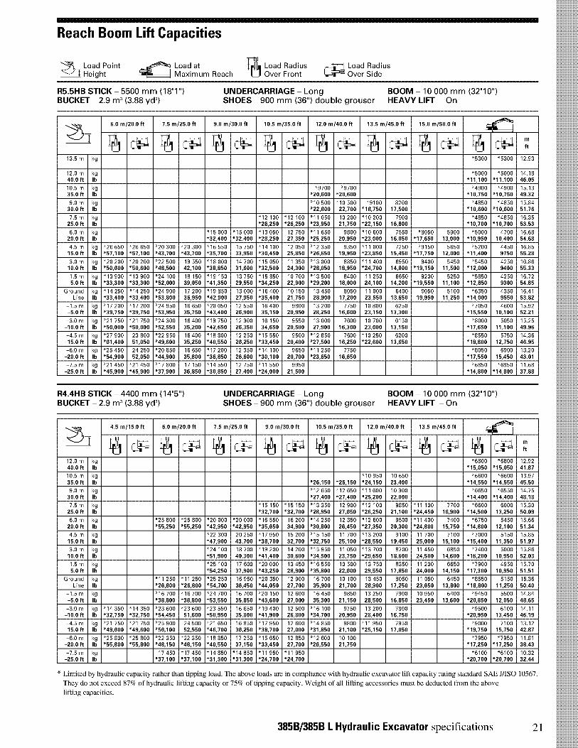
Reach Boom Lift Capacities
Load Point Height
Load atMaximum Reach
Load RadiusOver Front
Load RadiusOver Side
R5.5HB STICK - 5500 mm (18'11BUCKET - 2.9 m3 (3.88 yd3)
UNDERCARRIAGE - Long BOOM - 10 000 mm (32'10")SHOES - 900 mm (36") double grouser HEAVY LIFT - On
Z-1-6.0 m/20.0 ft 7.5 m/25.0 ft 9.0 m/30.0 ft 10.5 m/35.0 ft 12.0 m/40.0 ft 13.5 m/45.0 ft 15.0 m/50.0 ft
54C
Al:t:..ii c-ii cct:..ii ct:-,i ft
13.5 m kg "5300 "5300 12.93
12.0 m kg "5000 "5000 14.1840.0 ft lb *11,100 *11,100 46.05
10.5 m kg "9700 "9700 "4900 "4900 15.1335.0 ft lb *20,600 *20,600 *10,750 *10,750 49.32
9.0 m kg "10 500 "10 500 "9100 8200 "4850 "4850 15.8430.0 ft lb *22,800 22,700 *18,750 17,500 *10,600 *10,600 51.76
7.5 m kg "12 100 "12 100 "11 050 10 200 "10 200 7900 "4850 "4850 16.3525.0 ft lb *26,250 *26,250 *23,950 21,750 *22,150 16,800 *10,700 *10,700 53.53
6.0 m kg "15 000 "15 000 "13 050 12 750 "11 650 9800 "10 600 7550 "8050 5900 "5000 4700 16.6820.0 ft lb *32,400 *32,400 *28,250 27,350 *25,250 20,950 *23,000 16,050 *17,650 13,000 *10,950 10,400 54.68
4.5 m kg "26 650 "26 650 "20 300 "20 300 "16 550 15 750 "14 100 12 050 "12 350 9350 "11 000 7250 "9150 5650 "5200 4450 16.8515.0 ft lb *57,100 *57,100 *43,700 *43,700 *35,700 33,950 *30,450 25,850 *26,650 19,950 *23,850 15,450 *17,750 12,000 *11,400 9750 55.28
3.0 m kg "20 200 "20 200 "22 500 19 550 "18 000 14 700 "15 050 11 350 "13 000 8850 "11 400 6950 9400 5450 "5450 4250 16.8610.0 ft lb *50,600 *50,600 *48,500 42,100 *38,850 31,600 *32,500 24,300 *28,050 18,950 *24,700 14,800 *19,150 11,500 *12,000 9400 55.33
1.5 m kg "13 900 "13 900 "24 100 18 150 "19 150 13 750 "15 850 10 700 "13 500 8400 11 250 6650 9200 5250 "5850 4250 16.725.0 ft lb *33,300 *33,300 *52,000 39,050 *41,350 29,550 *34,250 22,900 *29,200 18,000 24,100 14,200 *19,550 11,100 *12,850 9300 54.85
Ground kg "14 250 "14 250 "24 900 17 200 "19 850 13 000 "16 400 10 150 13 450 8050 11 000 6400 9050 5100 "6350 4350 16.41Line lb *33,400 *33,400 *53,800 36,950 *42,900 27,950 *35,400 21,750 28,900 17,200 23,550 13,650 19,950 11,250 *14,000 9550 53.82
-1.5 m kg "17 200 "17 200 "24 950 16 650 "20 050 12 550 16 400 9800 13 200 7750 10 800 6250 "7050 4600 15.92-5.0 ft lb *39,750 *39,750 *53,950 35,750 *43,400 26,900 35,150 20,950 28,250 16,600 23,150 13,300 *15,550 10,100 52.21
-3.0 m kg "21 750 "21 750 "24 300 16 400 "19 750 12 300 16 150 9550 13 000 7600 10 700 6150 "8000 5050 15.25-10.0 ft lb *50,000 *50,000 *52,550 35,200 *42,650 26,350 34,650 20,500 27,900 16,300 23,000 13,150 *17,650 11,100 49.96
-4.5 m kg "27 900 23 800 "22 950 16 400 "18 800 12 250 "15 550 9500 "12 850 7600 "10 250 6200 "8550 5750 14.36-15.0 ft lb *61,400 51,050 *49,600 35,250 *40,550 26,250 *33,450 20,400 *27,500 16,250 *22,600 13,650 *18,800 12,750 46.95
-6.0 m kg "25 450 24 250 "20 850 16 650 "17 200 12 350 "14 100 9650 "11 250 7750 "8050 6900 13.20-20.0 ft lb *54,900 52,050 *44,900 35,800 *36,850 26,600 *30,100 20,700 *23,650 16,650 *17,550 15,450 43.01
-7.5 m kg "21 450 "21 450 "17 800 17 150 "14 550 12 750 "11 550 9950 "6850 "6850 11.68-25.0 ft lb *45,900 *45,900 *37,900 36,850 *30,850 27,400 *24,000 21,500 *14,800 *14,800 37.88
R4.4HB STICK - 4400 mm (14'5")BUCKET - 2.9 m3 (3.88 yd3)
UNDERCARRIAGE - Long BOOM - 10 000 mm (32'10")SHOES - 900 mm (36") double grouser HEAVY LIFT - On
Z-f4.5 m/15.0 ft 6.0 m/20.0 ft 7.5 m/25.0 ft 9.0 m/30.0 ft 10.5 m/35.0 ft 12.0 m/40.0 ft 13.5 m/45.0 ft
-*C6k1
Abl=.: c-PiAc-Piii cl.iAtli c-Piii c-Pi ii ti, ft
12.0 m kg "6800 "6800 12.9240.0 ft lb *15,050 *15,050 41.87
10.5 m kg "10 950 10 650 "6600 "6600 13.9735.0 ft lb *26,150 *26,150 *24,150 23,400 *14,550 *14,550 45.50
9.0 m kg "12 650 "12 650 "11 600 10 300 "6650 "6550 14.7530.0 ft lb *27,400 *27,400 *25,200 22,000 *14,400 *14,400 48.18
7.5 m kg "15 150 "15 150 "13 350 12 900 "12 100 9850 "11 100 7700 "6600 6000 15.3025.0 ft lb *32,700 *32,700 *28,950 27,650 *26,250 21,100 *24,450 16,900 *14,500 13,250 50.09
6.0 m kg "25 800 "25 800 "20 000 "20 000 "16 550 16 200 "14 250 12 350 "12 600 9500 "11 400 7400 "6750 5450 15.6620.0 ft lb *55,250 *55,250 *42,950 *42,950 *35,650 34,900 *30,800 26,450 *27,350 20,300 *24,800 15,750 *14,800 12,100 51.34
4.5 m kg "22 300 20 250 "17 950 15 200 "15 150 11 700 "13 200 9100 11 700 7100 "7000 5150 15.8515.0 ft lb *47,900 43,700 *38,700 32,700 *32,750 25,100 *28,550 19,450 25,000 15,100 *15,400 11,350 51.97
3.0 m kg "24 100 18 700 "19 200 14 200 "15 950 11 050 "13 700 8700 11 450 6850 "7400 5000 15.8610.0 ft lb *51,900 40,300 *41,400 30,600 *34,500 23,750 *29,650 18,600 24,500 14,600 *16,200 10,950 52.03
1.5 m kg "25 100 17 600 "20 000 13 450 "16 550 10 500 13 750 8350 11 200 6650 "7900 4950 15.705.0 ft lb *54,250 37,900 *43,250 28,900 *35,800 22,600 29,550 17,850 24,000 14,150 *17,300 10,950 51.51
Ground kg "11 250 "11 250 "25 250 16 950 "20 350 12 900 16 700 10 100 13 450 8050 11 050 6450 "8550 5150 15.36Line lb *26,800 *26,800 *54,700 36,450 *44,050 27,700 35,900 21,700 28,900 17,250 23,650 13,800 *18,800 11,250 50.40
-1.5 m kg "16 700 "16 700 "24 700 16 700 "20 150 12 600 16 450 9850 13 250 7900 10 950 6400 "9450 5500 14.84-5.0 ft lb *38,800 *38,800 *53,550 35,850 *43,600 27,000 35,300 21,150 28,500 16,850 23,450 13,600 *20,850 12,050 48.65
-3.0 m kg "14 350 "14 350 "23 600 "23 600 "23 550 16 650 "19 400 12 500 "16 100 9750 13 200 7800 "9500 6100 14.11-10.0 ft lb *32,750 *32,750 *54,450 51,600 *50,950 35,800 *41,900 26,800 *34,700 20,950 28,400 16,750 *20,950 13,450 46.19
-4.5 m kg "21 750 "21 750 "25 900 24 500 "21 650 16 850 "17 950 12 600 "14 850 9800 "11 950 7950 "9000 7100 13.12-15.0 ft lb *49,600 *49,600 *56,100 52,550 *46,700 36,250 *38,700 27,000 *31,850 21,100 *25,150 17,050 *19,750 15,750 42.87
-6.0 m kg "25 800 "25 800 "22 350 "22 350 "18 850 17 250 "15 650 12 850 "12 600 10 100 "7950 "7950 11.81-20.0 ft lb *55,800 *55,800 *48,150 *48,150 *40,550 37,150 *33,450 27,700 *26,550 21,750 *17,250 *17,250 38.43
-7.5 m kg 17 450 "17 450 "14 850 "14 850 "11 950 "11 950 "6100 "6100 10.32-25.0 ft lb *37,100 *37,100 *31,300 *31,300 *24,700 *24,700 *20,700 *20,700 32.44
* Limited by hydraulic capacity -ather than tipping load. The above loads are in compliance with hydraulic excavator lift capacity rating standard SAE HISO 10567.
They do not exceed 87% of hydraulic lifting capacity or 75% of tipping capacity. Weight of all lifting accessories must be deducted from the above
lifting capacities.
385B/385B L Hydraulic Excavator specifications 21
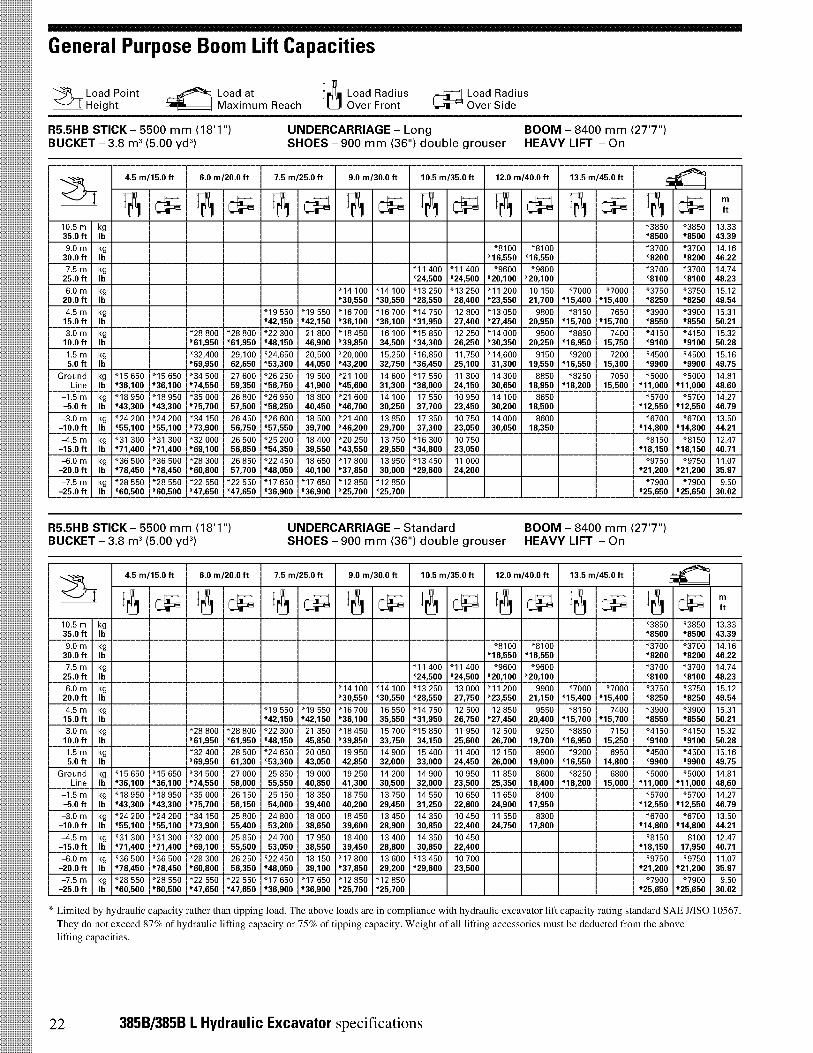
General Purpose Boom Lift Capacities
Load Pointj Height
„„ Load at I) Load RadiusMaximum Reach Over Front
Load RadiusOver Side
R5.5HB STICK - 5500 mm (18'1")BUCKET - 3.8 m3 (5.00 yd3)
UNDERCARRIAGE - LongSHOES - 900 mm (36") double grouser HEAVY LIFT - On
BOOM - 8400 mm (27'7")
Z-1-
4.5 m/15.0 ft 6.0 m/20.0 ft 7.5 m/25.0 ft 9.0 m/30.0 ft 10.5 m/35.0 ft 12.0 m/40.0 ft 13.5 m/45.0 ft-4'111
ii t:_iii c-iii c-piii ,:piAc-piii c-pil c-pii c-pi ft
10.5 m kg "3850 "3850 13.3335.0 ft lb *8500 *8500 43.39
9.0 m kg "8100 "8100 "3700 "3700 14.1630.0 ft lb *16,550 *16,550 *8200 *8200 46.22
7.5 m kg "11 400 "11 400 "9600 "9600 "3700 "3700 14.7425.0 ft lb *24,500 *24,500 *20,100 *20,100 *8100 *8100 48.23
6.0 m kg "14 100 "14 100 "13 250 "13 250 "11 200 10 150 "7000 "7000 "3750 "3750 15.1220.0 ft lb *30,550 *30,550 *28,550 28,400 *23,550 21,700 *15,400 *15,400 *8250 *8250 49.54
4.5 m kg "19 550 "19 550 "16 700 "16 700 "14 750 12 800 "13 050 9800 "8150 7650 "3900 "3900 15.3115.0 ft lb *42,150 *42,150 *36,100 *36,100 *31,950 27,400 *27,450 20,950 *15,700 *15,700 *8550 *8550 50.21
3.0 m kg "28 800 "28 800 "22 300 21 800 "18 450 16 100 "15 850 12 250 "14 000 9500 "8850 7400 "4150 "4150 15.3210.0 ft lb *61,950 *61,950 *48,150 46,900 *39,850 34,500 *34,300 26,250 *30,350 20,250 *16,950 15,750 *9100 *9100 50.28
1.5 m kg "32,400 29,100 "24,650 20,500 "20,000 15,250 "16,850 11,750 "14,600 9150 "9200 7200 "4500 "4500 15.165.0 ft lb *69,950 62,650 *53,300 44,050 *43,200 32,750 *36,450 25,100 31,300 19,550 *16,550 15,300 *9900 *9900 49.75
Ground kg "15 650 "15 650 "34 500 27 600 "26 250 19 500 "21 100 14 600 "17 550 11 300 14 300 8850 "8250 7050 "5000 "5000 14.81Line lb *36,100 *36,100 *74,550 59,350 *56,750 41,900 *45,600 31,300 *38,000 24,150 30,650 18,950 *18,200 15,500 *11,000 *11,000 48.60
-1.5 m kg "18 950 "18 950 "35 000 26 800 "26 950 18 800 "21 600 14 100 17 550 10 950 14 100 8650 "5700 "5700 14.27-5.0 ft lb *43,300 *43,300 *75,700 57,500 *58,250 40,450 *46,700 30,250 37,700 23,450 30,200 18,500 *12,550 *12,550 46.79
-3.0 m kg "24 200 "24 200 "34 150 26 450 "26 600 18 500 "21 400 13 850 17 350 10 750 14 000 8600 "6700 "6700 13.50-10.0 ft lb *55,100 *55,100 *73,900 56,750 *57,550 39,700 *46,200 29,700 37,300 23,050 30,050 18,350 *14,800 *14,800 44.21
-4.5 m kg "31 300 "31 300 "32 000 26 500 "25 200 18 400 "20 250 13 750 "16 300 10 750 "8150 "8150 12.47-15.0 ft lb *71,400 *71,400 *69,100 56,850 *54,350 39,550 *43,550 29,550 *34,800 23,050 *18,150 *18,150 40.71
-6.0 m kg "36 500 "36 500 "28 300 26 850 "22 450 18 650 "17 800 13 950 "13 450 11 000 "9750 "9750 11.07-20.0 ft lb *78,450 *78,450 *60,800 57,700 *48,050 40,100 *37,850 30,000 *29,600 24,200 *21,200 *21,200 35.97
-7.5 m kg "28 550 "28 550 "22 550 "22 550 "17 650 "17 650 "12 850 "12 850 "7900 "7900 9.50-25.0 ft lb *60,500 *60,500 *47,650 *47,650 *36,900 *36,900 *25,700 *25,700 *25,650 *25,650 30.02
R5.5HB STICK - 5500 mm (18'1")BUCKET - 3.8 m3 (5.00 yd3)
UNDERCARRIAGE - Standard BOOM - 8400 mm (27'7")SHOES - 900 mm (36") double grouser HEAVY LIFT - On
Z-I-4.5 m/15.0 ft 6.0 m/20.0 ft 7.5 m/25.0 ft 9.0 m/30.0 ft 10.5 m/35.0 ft 12.0 m/40.0 ft 13.5 m/45.0 ft
Ac-piii c-pi i c-piAc-piAc-piii c-pi i i:-pi ft
10.5 m kg "3850 "3850 13.3335.0 ft lb *8500 *8500 43.39
9.0 m kg "8100 "8100 "3700 "3700 14.1630.0 ft lb *16,550 *16,550 *8200 *8200 46.22
7.5 m kg "11 400 "11 400 "9600 "9600 "3700 "3700 14.7425.0 ft lb *24,500 *24,500 *20,100 *20,100 *8100 *8100 48.23
6.0 m kg "14 100 "14 100 "13 250 13 000 "11 200 9900 "7000 "7000 "3750 "3750 15.1220.0 ft lb *30,550 *30,550 *28,550 27,750 *23,550 21,150 *15,400 *15,400 *8250 *8250 49.54
4.5 m kg "19 550 "19 550 "16 700 16 550 "14 750 12 500 12 850 9550 "8150 7400 "3900 "3900 15.3115.0 ft lb *42,150 *42,150 *36,100 35,550 *31,950 26,750 *27,450 20,400 *15,700 *15,700 *8550 *8550 50.21
3.0 m kg "28 800 "28 800 "22 300 21 350 "18 450 15 700 "15 850 11 950 12 500 9250 "8850 7150 "4150 "4150 15.3210.0 ft lb *61,950 *61,950 *48,150 45,850 *39,850 33,750 34,150 25,600 26,700 19,700 *16,950 15,250 *9100 *9100 50.28
1.5 m kg "32 400 28 500 "24 650 20 050 19 950 14 900 15 400 11 400 12 150 8900 "9200 6950 "4500 "4500 15.165.0 ft lb *69,950 61,300 *53,300 43,050 42,850 32,000 33,000 24,450 26,000 19,000 *16,550 14,800 *9900 *9900 49.75
Ground kg "15 650 "15 650 "34 500 27 000 25 850 19 000 19 250 14 200 14 900 10 950 11 850 8600 "8250 6800 "5000 "5000 14.81Line lb *36,100 *36,100 *74,550 58,000 55,550 40,850 41,300 30,500 32,000 23,500 25,350 18,400 *18,200 15,000 *11,000 *11,000 48,60
-1.5 m kg "18 950 "18 950 "35 000 26 150 25 150 18 350 18 750 13 750 14 550 10 650 11 650 8400 "5700 "5700 14.27-5.0 ft lb *43,300 *43,300 *75,700 56,150 54,000 39,400 40,200 29,450 31,250 22,800 24,900 17,950 *12,550 *12,550 46.79
-3.0 m kg "24 200 "24 200 "34 150 25 800 24 800 18 000 18 450 13 450 14 350 10 450 11 550 8300 "6700 "6700 13.50-10.0 ft lb *55,100 *55,100 *73,900 55,400 53,200 38,650 39,600 28,900 30,850 22,400 24,750 17,800 *14,800 *14,800 44.21
-4.5 m kg "31 300 "31 300 "32 000 25 850 24 700 17 950 18 400 13 400 14 350 10 450 "8150 8100 12.47-15.0 ft lb *71,400 *71,400 *69,100 55,500 53,050 38,550 39,450 28,800 30,850 22,400 *18,150 17,950 40.71
-6.0 m kg "36 500 "36 500 "28 300 26 250 "22 450 18 150 "17 800 13 600 "13 450 10 700 "9750 "9750 11.07-20.0 ft lb *78,450 *78,450 *60,800 56,350 *48,050 39,100 *37,850 29,200 *29,600 23,500 *21,200 *21,200 35.97
-7.5 m kg "28 550 "28 550 "22 550 "22 550 "17 650 "17 650 "12 850 "12 850 "7900 "7900 9.50-25.0 ft lb *60,500 *60,500 *47,650 *47,650 *36,900 *36,900 *25,700 *25,700 *25,650 *25,650 30.02
* Limited by hydraulic capacity -ather than tipping load. The above loads are in compliance with hydraulic excavator lift capacity rating standard SAE J/ISO 10567.They do not exceed 87% of hydraulic lifting capacity or 75% of tipping capacity. Weight of all lifting accessories must be deducted from the abovelifting capacities.
22 385B/385B L Hydraulic Excavator specifications
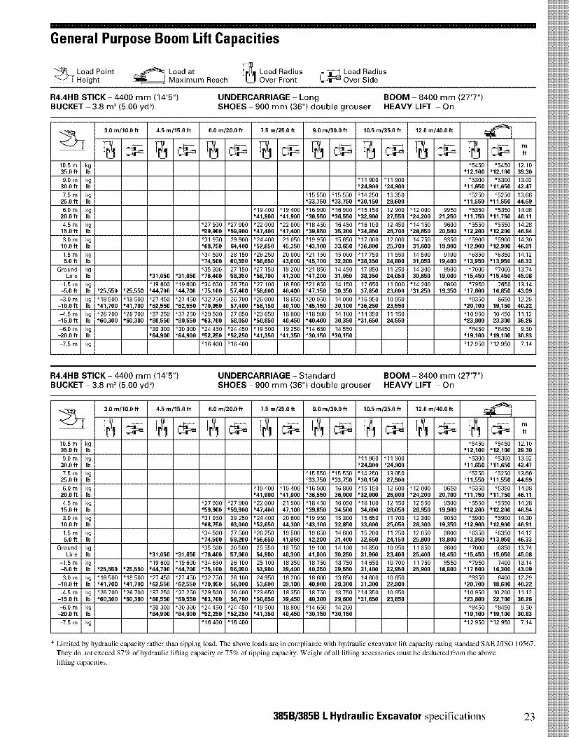
General Purpose Boom Lift Capacities
Load Point1 Height
Load atMaximum Reach
Load RadiusOver
Load RadiusFront Over Side
R4.4HB STICK - 4400 mm (14'5")BUCKET - 3.8 m3 (5.00 yd3)
UNDERCARRIAGE - LongSHOES - 900 mm (36") double grouser HEAVY LIFT - On
BOOM - 8400 mm (27'7")
Z1
3.0 m/10.0 ft 4.5 m/15.0 ft 6.0 m/20.0 ft 7.5 m/25.0 ft 9.0 m/30.0 ft 10.5 m/35.0 ft 12.0 m/40.0 ft _.,_
111 116 A mftC-. 1 -6 - Cl i ,11-j J__,;10.5 m kg "5450 "5450 12.1035.0 ft lb *12,100 *12,100 39.30
9.0 m kg "11 900 "11 900 "5300 "5300 13.0230.0 ft lb *24,900 *24,900 *11,650 *11,650 42.47
7.5 m kg "15 550 "15 550 "14 250 13 350 "5250 "5250 13.6625.0 ft lb *33,750 *33,750 *30,150 28,600 *11,550 *11,550 44.69
6.0 m kg "19 400 "19 400 "16 900 "16 900 "15 150 12 900 "12 000 9950 "5350 "5350 14.0820.0 ft lb *41,900 *41,900 *36,550 *36,550 *32,900 27,550 *24,200 21,250 *11,750 *11,750 46.11
4.5 m kg "27 900 "27 900 "22 000 "22 000 "18 450 16 450 "16 100 12 450 "14 150 9600 "5550 "5550 14.2815.0 ft lb *59,900 *59,900 *47,400 *47,400 *39,850 35,300 *34,850 26,700 *28,650 20,500 *12,200 *12,200 46.84
3.0 m kg "31 950 29 900 "24 400 21 050 "19 950 15 650 "17 000 12 000 14 750 9350 "5900 "5900 14.3010.0 ft lb *68,750 64,400 *52,650 45,350 *43,100 33,650 *36,800 25,700 31,600 19,900 *12,900 *12,900 46.91
1.5 m kg "34 500 28 150 "26 250 20 000 "21 150 15 000 "17 750 11 550 14 500 9100 "6350 "6350 14.125.0 ft lb *74,500 60,550 *56,650 43,000 *45,700 32,200 *38,350 24,800 31,050 19,400 *13,950 *13,950 46.33
Ground kg "35 300 27 150 "27 150 19 200 "21 850 14 450 17 850 11 250 14 300 8900 "7000 "7000 13.74Line lb *31,050 *31,050 *76,400 58,350 *58,700 41,300 *47,200 31,050 38,350 24,050 30,650 19,000 *15,450 *15,450 45.08
-1.5 m kg "19 600 "19 600 "34 650 26 750 "27 100 18 800 "21 850 14 150 17 650 11 000 "14 200 8800 "7950 7650 13.14-5.0 ft lb *25,550 *25,550 *44,700 *44,700 *75,100 57,400 *58,600 40,400 *47,150 30,350 37,850 23,600 *31,250 19,350 *17,600 16,850 43.09
-3.0 m kg "18 500 "18 500 "27 450 "27 450 "32 750 26 700 "26 000 18 650 "20 950 14 000 "16 950 10 950 "9350 8650 12.29-10.0 ft lb *41,700 *41,700 *62,550 *62,550 *70,950 57,400 *56,150 40,100 *45,150 30,100 *36,250 23,550 *20,700 19,150 40.22
-4.5 m kg "26 700 "26 700 "37 250 "37 250 "29 500 27 050 "23 650 18 800 "18 900 14 100 "14 350 11 150 "10 950 10 450 11.12-15.0 ft lb *60,300 *60,300 *80,550 *80,550 *63,700 58,050 *50,850 40,450 *40,400 30,350 *31,650 24,550 *23,800 23,300 36.26
-6.0 m kg "30 300 "30 300 "24 450 "24 450 "19 500 19 250 "14 650 14 550 "8450 "8450 9.50-20.0 ft lb *64,900 *64,900 *52,250 *52,250 *41,350 *41,350 *30,150 *30,150 *19,100 *19,100 30.83
-7.5 m kg "16 400 "16 400 "12 950 "12 950 7.14
R4.4HB STICK - 4400 mm (14'5")BUCKET - 3.8 m3 (5.00 yd3)
UNDERCARRIAGE - Standard BOOM - 8400 mm (27'7")SHOES - 900 mm (36") double grouser HEAVY LIFT - On
ZT3.0 m/10.0 ft 4.5 m/15.0 ft 6.0 m/20.0 ft 7.5 m/25.0 ft 9.0 m/30.0 ft 10.5 m/35.0 ft 12.0 m/40.0 ft
....-- t
A 0 t:,_,:i t:,-, _ cl, A t„T,-, (A,,,, t,:,-, A ft
10.5 m kg "5450 "5450 12.1035.0 ft lb *12,100 *12,100 39.30
9.0 m kg "11900 "11 900 "5300 "5300 13.0230.0 ft lb *24,900 *24,900 *11,650 *11,650 42.47
7.5 m kg "15 550 "15 550 "14 250 13 050 "5250 "5250 13.6625.0 ft lb *33,750 *33,750 *30,150 27,900 *11,550 *11,550 44.69
6.0 m kg "19 400 "19 400 "16 900 16 800 "15 150 12 600 "12 000 9650 "5350 "5350 14.0820.0 ft lb *41,900 *41,900 *36,550 36,000 *32,900 26,900 *24,200 20,700 *11,750 *11,750 46.11
4.5 m kg "27 900 "27 900 "22 000 21 900 "18 450 16 050 "16 100 12 150 12 550 9300 "5550 "5550 14.2815.0 ft lb *59,900 *59,900 *47,400 47,100 *39,850 34,500 34,600 26,050 26,950 19,900 *12,200 *12,200 46.84
3.0 m kg "31 950 29 250 "24 400 20 600 "19 950 15 300 15 650 11 700 12 300 9050 "5900 "5900 14.3010.0 ft lb *68,750 63,000 *52,650 44,300 *43,100 32,850 33,600 25,050 26,300 19,350 *12,900 *12,900 46.91
1.5 m kg "34 500 27 500 "26 250 19 500 19 650 14 600 15 200 11 250 12 050 8800 "6350 "6350 14.125.0 ft lb *74,500 59,200 *56,650 41,950 42,200 31,400 32,650 24,150 25,800 18,800 *13,950 *13,950 46.33
Ground kg "35 300 26 500 25 550 18 750 19 100 14 100 14 850 10 950 11 850 8600 "7000 6850 13.74Line lb *31,050 *31,050 *76,400 57,000 54,900 40,300 41,000 30,250 31,900 23,400 25,400 18,450 *15,450 15,050 45.08
-1.5 m kg "19 600 "19 600 "34 650 26 100 25 100 18 350 18 750 13 750 14 650 10 700 11 750 8550 "7950 7400 13.14-5.0 ft lb *25,550 *25,550 *44,700 *44,700 *75,100 56,050 53,900 39,400 40,250 29,550 31,400 22,950 25,900 18,800 *17 600 16,300 43.09
-3.0 m kg "18 500 "18 500 "27 450 "27 450 "32 750 26 100 24 950 18 200 18 600 13 650 14 600 10 650 "9350 8400 12.29-10.0 ft lb *41,700 *41,700 *62,550 *62,550 *70,950 56,000 53,600 39,100 40,000 29,300 31,300 22,900 *20,700 18,600 40.22
-4.5 m kg "26 700 "26 700 "37 250 "37 250 "29 500 26 400 "23 650 18 350 18 750 13 750 "14 350 10 850 "10 950 10 200 11.12-15.0 ft lb *60,300 *60,300 *80,550 *80,550 *63,700 56,700 *50,850 39,450 40,300 29,600 *31,650 23,850 *23,800 22,700 36.26
-6.0 m kg "30 300 "30 300 "24 450 "24 450 "19 500 18 800 "14 650 14 200 "8450 "8450 9.50-20.0 ft lb *64,900 *64,900 *52,250 *52,250 *41,350 40,450 *30,150 *30,150 *19,100 *19,100 30.83
-7.5 m kg "16 400 "16 400 "12 950 "12 950 7.14
* Limited by hydraulic capacity -ather than tipping load. The above loads are in compliance with hydraulic excavator lift capacity rating standard SAE J/ISO 10567.They do not exceed 87% of hydraulic lifting capacity or 75% of tipping capacity. Weight of all lifting accessories must be deducted from the abovelifting capacities.
385B/385B L Hydraulic Excavator specifications 23
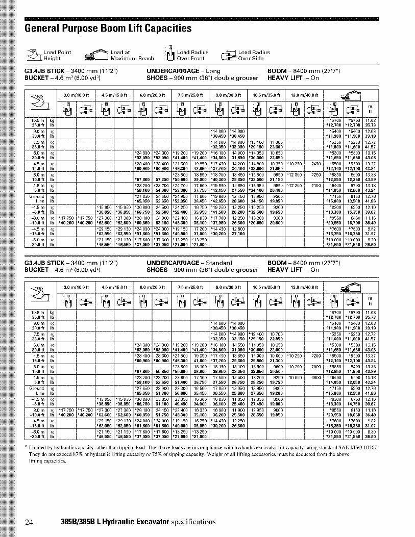
General Purpose Boom Lift Capacities
Load Pointj Height
Load atMaximum Reach
_6 Load RadiusOver Front
Load RadiusOver Side
G3.4JB STICK - 3400 mm (11'2")BUCKET - 4.6 m3 (6.00 yd3)
UNDERCARRIAGE - LongSHOES - 900 mm (36") double grouser HEAVY LIFT - On
BOOM - 8400 mm (27'7")
Z-I-3.0 m/10.0 ft 4.5 m/15.0 ft 6.0 m/20.0 ft 7.5 m/25.0 ft 9.0 m/30.0 ft 10.5 m/35.0 ft 12.0 m/40.0 ft
A 1:-1 A CiPI Ac-, _ Ai:-,A ii t:-4,ii c-pi ft
10.5 m kg "5700 "5700 11.0335.0 ft lb *12,700 *12,700 35.73
9.0 m kg "14 000 "14 000 "5400 "5400 12.0330.0 ft lb *30,450 *30,450 *11,900 *11,900 39.19
7.5 m kg "14 900 "14 900 "13 400 11 000 "5250 "5250 12.7225.0 ft lb *32,350 *32,350 *29,150 23,500 *11,600 *11,600 41.57
6.0 m kg "24 300 "24 300 "19 200 "19 200 "16 100 14 900 "14 050 10 650 "5300 "5300 13.1520.0 ft lb *52,050 *52,050 *41,400 *41,400 *34,800 31,850 *30,500 22,650 *11,650 *11,650 43.08
4.5 m kg "28 400 "28 400 "21 500 19 850 "17 450 14 200 "14 800 10 350 "10 250 7450 "5500 "5500 13.3715.0 ft lb *60,900 *60,900 *46,300 42,650 *37,700 30,400 *32,000 21,950 *12,100 *12,100 43.84
3.0 m kg "23 500 18 550 "18 700 13 450 "15 500 9950 "12 300 7250 "5850 5600 13.3810.0 ft lb *67,800 57,250 *50,600 39,900 *40,300 28,850 *33,500 21,150 *12,850 12,350 43.89
1.5 m kg "23 700 "23 700 "24 700 17 600 "19 550 12 850 "15 950 9550 "12 200 7100 "6400 5700 13.185.0 ft lb *58,100 54,000 *53,300 37,750 *42,150 27,550 *34,400 20,400 *14,050 12,600 43.24
Ground kg "27 350 24 550 "24 950 17 000 "19 800 12 450 15 950 9300 "7150 6150 12.76Line lb *65,050 52,650 *53,950 36,450 *42,650 26,600 34,150 19,850 *15,800 13,500 41.86
-1.5 m kg "15 950 "15 950 "30 800 24 500 "24 250 16 750 "19 250 12 250 "15 250 9200 "8300 6950 12.10-5.0 ft lb *36,850 *36,850 *66,750 52,500 *52,400 35,950 *41,500 26,200 *32,600 19,650 *18,300 15,350 39.67
-3.0 m kg "17 750 "17 750 "27 300 "27 300 "28 100 24 800 "22 400 16 850 "17 700 12 250 "13 200 9300 "9550 8450 11.16-10.0 ft lb *40,200 *40,200 *62,600 *62,600 *60,850 53,150 *48,300 36,100 *37,950 26,300 *29,050 20,500 *20,950 18,700 36.49
-4.5 m kg "29 150 "29 150 "24 000 "24 000 "19 150 17 200 "14 450 12 600 "7600 "7600 9.82-15.0 ft lb *62,950 *62,950 *51,600 *51,600 *40,900 37,000 *30,200 27,100 *16,350 *16,350 31.97
-6.0 m kg "21 150 "21 150 "17 600 "17 600 "13 250 "13 250 "10 000 "10 000 8.30-20.0 ft lb *46,550 *46,550 *37,050 *37,050 *27,000 *27,000 *21,550 *21,550 26.90
G3.4JB STICK - 3400 mm (11'2")BUCKET - 4.6 m3 (6.00 yd3)
UNDERCARRIAGE - Standard BOOM - 8400 mm (27'7")SHOES - 900 mm (36") double grouser HEAVY LIFT - On
Z-1-
3.0 m/10.0 ft 4.5 m/15.0 ft 6.0 m/20.0 ft 7.5 m/25.0 ft 9.0 m/30.0 ft 10.5 m/35.0 ft 12.0 m/40.0 fti;r2K1
il 1:-1 il tt:-1 ii i:-, _ triii c-iii t:_ii t:_ii c-pi ft
10.5 m kg "5700 "5700 11.0335.0 ft lb *12 700 *12 700 35.73
9.0 m kg "14 000 "14 000 "5400 "5400 12.0330.0 ft lb *30,450 *30,450 *11,900 *11,900 39.19
7.5 m kg "14 900 "14 900 "13 400 10 700 "5250 "5250 12.7225.0 ft lb *32,350 32,150 *29,150 22,850 *11,600 *11,600 41.57
6.0 m kg "24 300 "24 300 "19 200 "19 200 "16 100 14 550 "14 050 10 350 "5300 "5300 13.1520.0 ft lb *52,050 *52,050 *41,400 *41,400 *34,800 31,050 *30,500 22,000 *11,650 *11,650 43.08
4.5 m kg "28 400 28 300 "21 500 19 350 "17 450 13 850 14 000 10 000 "10 250 7200 "5500 "5500 13.3715.0 ft lb *60,900 *60,900 *46,300 41,600 *37,700 29,600 29,900 21,300 *12,100 *12,100 43.84
3.0 m kg "23 500 18 100 18 150 13 100 13 600 9600 10 200 7000 "5850 5400 13.3810.0 ft lb *67,800 55,850 *50,600 38,900 38,950 28,050 29,050 20,500 *12,850 11,850 43.89
1.5 m kg "23 700 "23 700 23 950 17 100 17 500 12 500 13 200 9250 10 050 6800 "6400 5500 13.185.0 ft lb *58,100 52,650 51,400 36,750 37,550 26,750 28,250 19,750 *14,050 12,050 43.24
Ground kg "27 350 23 900 23 300 16 500 17 050 12 050 12 950 9000 "7150 5900 12.76Line lb *65,050 51,300 50,000 35,450 36,550 25,800 27,650 19,200 *15,800 12,950 41.86
-1.5 m kg "15 950 "15 950 "30 800 23 850 23 050 16 300 16 850 11 850 12 850 8900 "8300 6700 12.10-5.0 ft lb *36,850 *36,850 *66,750 51,100 49,450 34,900 36,100 25,400 27,450 19,000 *18,300 14,750 39.67
-3.0 m kg "17 750 "17 750 "27 300 "27 300 "28 100 24 150 "22 400 16 350 16 900 11 900 12 950 9000 "9550 8150 11.16-10.0 ft lb *40,200 *40,200 *62,600 *62,600 *60,850 51,750 *48,300 35,100 36,200 25,500 28,550 19,850 *20,950 18,050 36.49
-4.5 m kg "29 150 "29 150 "24 000 "24 000 "19 150 16 750 "14 450 12 250 "7600 "7600 9.82-15.0 ft lb *62,950 *62,950 *51,600 *51,600 *40,900 35,950 *30,200 26,300 *16,350 *16,350 31.97
-6.0 m kg "21 150 "21 150 "17 600 "17 600 "13 250 "13 250 "10 000 "10 000 8.30-20.0 ft lb *46,550 *46,550 *37,050 *37,050 *27,000 *27,000 *21,550 *21,550 26.90
* Limited by hydraulic capacity rather than tipping load. The above loads are in compliance with hydraulic excavator lift capacity rating standard SAE J/ISO 10567.They do not exceed 87% of hydraulic lifting capacity or 75% of tipping capacity. Weight of all lifting accessories must be deducted from the abovelifting capacities.
24 385B/385B L Hydraulic Excavator specifications
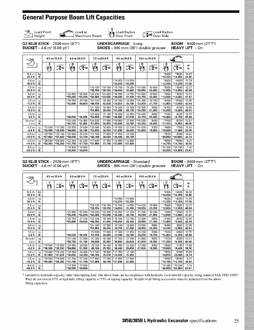
General Purpose Boom Lift Capacities
Load Pointj Height
Load atMaximum Reach
Load RadiusOver Front
Load RadiusOver Side
G2.92JB STICK - 2920 mm (9'7")BUCKET - 4.6 m3 (6.00 yd3)
UNDERCARRIAGE - LongSHOES - 900 mm (36") double grouser HEAVY LIFT - On
BOOM - 8400 mm (27'7")
Z-I-4.5 m/15.0 ft 6.0 m/20.0 ft 7.5 m/25.0 ft 9.0 m/30.0 ft 10.5 m/35.0 ft
54C4bri
1:-1 il CiPI A c, _ A c, A cip, ft
10.5 m kg "6400 "6400 10.4835.0 ft lb *14,250 *14,250 33.92
9.0 m kg "14 850 "14 850 "6050 "6050 11.5430.0 ft lb *32,250 *32,250 *13,350 *13,350 37.59
7.5 m kg "18 150 "18 150 "15 700 15 200 "14 050 10 900 "5900 "5900 12.2725.0 ft lb *39,150 *39,150 *34,050 32,450 *30,950 24,050 *12,950 *12,950 40.09
6.0 m kg "25 800 "25 800 "20 200 "20 200 "16 850 14 750 "14 650 10 500 "5900 "5900 12.7220.0 ft lb *55,250 *55,250 *43,500 *43,500 *36,400 31,500 *31,750 22,300 *13,000 *13,000 41.67
4.5 m kg "29 750 28 200 "22 350 19 550 "18 100 14 050 "15 300 10 250 "6100 "6100 12.9515.0 ft lb *63,800 60,850 *48,150 42,050 *39,050 30,100 *33,050 21,750 *13,450 *13,450 42.46
3.0 m kg "24 100 18 350 "19 200 13 400 "15 900 9900 "6450 6150 12.9510.0 ft lb *51,950 39,450 *41,400 28,700 *34,250 21,050 *14,200 13,500 42.51
1.5 m kg "25 000 17 450 "19 850 12 850 "16 200 9600 "7050 6250 12.755.0 ft lb *46,550 *46,550 *54,050 37,500 *42,800 27,500 34,750 20,400 *15,450 13,750 41.84
Ground kg "25 400 "24 450 "24 950 17 000 "19 850 12 500 "15 950 9400 "7850 6750 12.31Line lb *60,750 52,450 *53,950 36,450 *42,800 26,700 *34,250 20,000 *17,250 14,850 40.40
-1.5 m kg "15 500 "15 500 "29 850 24 600 "23 900 16 850 "19 050 12 350 "14 850 9350 "9000 7700 11.63-5.0 ft lb *36,100 *36,100 *64,800 52,700 *51,650 36,150 *41,000 26,450 *31,450 19,950 *19,900 17,000 38.10
-3.0 m kg "29 400 "29 400 "26 800 25 050 "21 700 17 050 "17 050 12 500 "9550 9500 10.63-10.0 ft lb *67,650 *67,650 *58,050 53,700 *46,700 36,550 *36,400 26,750 *20,850 *20,850 34.74
-4.5 m kg "26 000 "26 000 "22 200 "22 200 "17 800 17 550 "12 650 "12 650 "6800 "6800 9.21-15.0 ft lb *56,300 *56,300 *47,750 *47,750 *37,900 37,700 *27,800 *27,800 *14,700 *14,700 30.02
-6.0 m kg "14 900 "14 900 "10 300 "10 300 7.46-20.0 ft lb *30,950 *30,950 *24,950 *24,950 23.07
G2.92JB STICK - 2920 mm (9'7")BUCKET - 4.6 m3 (6.00 yd3)
UNDERCARRIAGE - Standard BOOM - 8400 mm (27'7")SHOES - 900 mm (36") double grouser HEAVY LIFT - On
Z-1-
4.5 m/15.0 ft 6.0 m/20.0 ft 7.5 m/25.0 ft 9.0 m/30.0 ft 10.5 m/35.0 ft
ii c-, ii t:_,, A--:c, _ tr:_,, A c,
ilf ft
10.5 m kg "6400 "6400 10.4835.0 ft lb *14,250 *14,250 33.92
9.0 m kg "14 850 "14 850 "6050 "6050 11.5430.0 ft lb *32,250 *32,250 *13,350 *13,350 37.59
7.5 m kg "18 150 "18 150 "15 700 14 850 "14 050 10 600 "5900 "5900 12.2725.0 ft lb *39,150 *39,150 *34,050 31,650 *30,950 23,350 *12,950 *12,950 40.09
6.0 m kg "25 800 "25 800 "20 200 "20 200 "16 850 14 350 14 200 10 200 "5900 "5900 12.7220.0 ft lb *55,250 *55,250 *43,500 *43,500 *36,400 30,700 30,250 21,650 *13,000 *13,000 41.67
4.5 m kg "29 750 27 550 "22 350 19 100 "18 100 13 700 13 900 9950 "6100 6050 12.9515.0 ft lb *63,800 59,500 *48,150 41,050 *39,050 29,300 29,650 21,100 *13,450 13,400 42.46
3.0 m kg "24 100 17 900 18 100 13 000 13 550 9600 "6450 5900 12.9510.0 ft lb *51,950 38,450 38,750 27,900 28,950 20,400 *14,200 12,950 42.51
1.5 m kg 23 800 17 000 17 500 12 450 13 200 9300 "7050 6000 12.755.0 ft lb *46,550 *46,550 51,150 36,500 37,500 26,700 28,250 19,750 *15,450 13,250 41.84
Ground kg "25 400 23 800 23 300 16 500 17 100 12 100 13 000 9050 "7850 6500 12.31Line lb *60,750 51,100 50,000 35,450 36,650 25,900 27,800 19,350 *17,250 14,300 40.40
-1.5 m kg "15 500 "15 500 "29 850 23 950 23 150 16 400 16 950 12 000 12 950 9050 "9000 7450 11.63-5.0 ft lb *36,100 *36,100 *64,800 51,350 49,700 35,150 36,400 25,650 27,800 19,300 *19,900 16,400 38.10
-3.0 m kg "29 400 "29 400 "26 800 24 400 "21 700 16 600 "17 050 12 100 "9550 9200 10.63-10.0 ft lb *67,650 *67,650 *58,050 52,300 *46,700 35,550 *36,400 25,950 *20,850 20,400 34.74
-4.5 m kg "26 000 "26 000 "22 200 "22 200 "17 800 17 100 "12 650 12 600 "6800 "6800 9.21-15.0 ft lb *56,300 *56,300 *47,750 *47,750 *37,900 36,700 *27,800 27,800 *14,700 *14,700 30.02
-6.0 m kg "14 900 "14 900 "10 300 "10 300 7.46-20.0 ft lb *30,950 *30,950 *24,950 *24,950 23.07
* Limited by hydraulic capacity rather than tipping load. The above loads are in compliance with hydraulic excavator lift capacity rating standard SAE J/ISO 10567.
They do not exceed 87% of hydraulic lifting capacity or 75% of tipping capacity. Weight of all lifting accessories must be deducted from the above
lifting capacities.
385B/385B L Hydraulic Excavator specifications 25
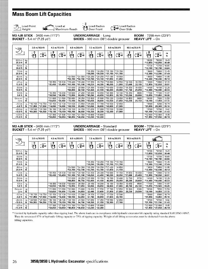
Mass Boom Lift Capacities
Load Pointj Height
Load atMaximum Reach
_6 Load RadiusOver Front
Load RadiusOver Side
M3.4JB STICK - 3400 mm (11'2")BUCKET - 5.4 m3 (7.25 yd3)
UNDERCARRIAGE - LongSHOES - 900 mm (36") double grouser HEAVY LIFT - On
BOOM - 7250 mm (23'9")
Z-I-3.0 m/10.0 ft 4.5 m/15.0 ft 6.0 m/20.0 ft 7.5 m/25.0 ft 9.0 m/30.0 ft 10.5 m/35.0 ft
Cirkll
1:-1 CiPI Ac-, _ Ai:-,A 1 ,:-., ft
10.5 m kg "6200 "6200 9.4535.0 ft lb *13,850 *13,850 30.46
9.0 m kg "5750 "5750 10.6530.0 ft lb *12,700 *12,700 34.64
7.5 m kg "18 350 "18 350 "15 150 "15 150 "5600 "5600 11.4525.0 ft lb *39,200 *39,200 *31,700 *31,700 *12,300 *12,300 37.40
6.0 m kg "24 500 "24 500 "20 250 "20 250 "17 450 15 000 "5650 "5650 11.9520.0 ft lb *52,700 *52,700 *43,700 *43,700 *37,850 31,950 *12,400 *12,400 39.12
4.5 m kg "39 950 "39 950 "28 400 "28 400 "22 350 20 750 "18 600 14 550 "14 100 10 350 "5900 "5900 12.1915.0 ft lb *85,450 *85,450 *61,100 *61,100 *48,250 44,500 *40,200 31,000 *27,600 22,100 *12,950 *12,950 39.97
3.0 m kg "31 850 28 900 "24 300 19 650 "19 650 13 950 "16 350 10 050 "6400 "6400 12.2010.0 ft lb *68,650 62,150 *52,450 42,100 *42,450 29,800 *31,750 21,250 *14,000 *14,000 40.03
1.5 m kg "16 050 "16 050 "33 800 27 200 "25 600 18 650 "20 300 13 400 "16 350 9800 "7100 "7100 11.975.0 ft lb *38,550 *38,550 *72,950 58,450 *55,250 40,050 *43,850 28,700 *33,250 20,800 *15,650 *15,650 39.29
Ground kg "21 800 "21 800 "33 800 26 250 "25 800 18 000 "20 250 13 050 "14 650 9600 "8200 7900 11.50Line lb *50,650 *50,650 *73,100 56,300 *55,650 38,600 *43,550 27,850 *32,250 21,150 *18,100 17,450 37.72
-1.5 m kg "16 750 "16 750 "32 150 "32 150 "31 950 25 950 "24 600 17 700 "18 950 12 850 "9900 9200 10.74-5.0 ft lb *37,950 *37,950 *74,000 *74,000 *69,150 55,600 *53,050 38,000 *40,600 27,500 *21,850 20,300 35.19
-3.0 m kg "28 500 "28 500 "36 100 "36 100 "28 150 26 150 "21 650 17 800 "15 550 13 000 "9700 "9700 9.62-10.0 ft lb *64,550 *64,550 *78,150 *78,150 *60,700 56,050 *46,350 38,200 *32,300 27,900 *21,150 *21,150 31.42
-4.5 m kg "27 500 "27 500 "21 700 "21 700 "15 600 "15 600 "12 800 "12 800 8.05-15.0 ft lb *58,850 *58,850 *46,050 *46,050 *32,200 *32,200 *27,950 *27,950 26.18
M3.4JB STICK - 3400 mm (11'2")BUCKET - 5.4 m3 (7.25 yd3)
UNDERCARRIAGE - Standard BOOM - 7250 mm (23'9")SHOES - 900 mm (36") double grouser HEAVY LIFT - On
Z-I-3.0 m/10.0 ft 4.5 m/15.0 ft 6.0 m/20.0 ft 7.5 m/25.0 ft 9.0 m/30.0 ft 10.5 m/35.0 ft
Ac-iii cipiii c-iii ii c-iii A c-pi ft
10.5 m kg "6200 "6200 9.4535.0 ft lb *13,850 *13,850 30.46
9.0 m kg "5750 "5750 10.6530.0 ft lb *12,700 *12,700 34.64
7.5 m kg "18 350 "18 350 "15 150 "15 150 "5600 "5600 11.4525.0 ft lb *39,200 *39,200 *31,700 *31,700 *12,300 *12,300 37.40
6.0 m kg "24 500 "24 500 "20 250 "20 250 "17 450 14 650 "5650 "5650 11.9520.0 ft lb *52,700 *52,700 *43,700 *43,700 *37,850 31,150 *12,400 *12,400 39.12
4.5 m kg "39 950 "39 950 "28 400 "28 400 "22 350 20 300 "18 600 14 150 14 050 10 050 "5900 "5900 12.1915.0 ft lb *85,450 *85,450 *61,100 *61,100 *48,250 43,450 *40,200 30,250 *27,600 21,450 *12,950 *12,950 39.97
3.0 m kg "31 850 28 250 "24 300 19 150 18 700 13 600 13 700 9750 "6400 "6400 12.2010.0 ft lb *68,650 60,750 *52,450 41,100 40,000 29,050 29,200 20,600 *14,000 *14,000 40.03
1.5 m kg "16 050 "16 050 "33 800 26 550 25 150 18 200 18 150 13 050 13 450 9500 "7100 7050 11.975.0 ft lb *38,550 *38,550 *72,950 57,050 53,950 39,050 38,800 27,900 28,700 20,100 *15,650 *15,500 39.29
Ground kg "21 800 "21 800 "33 800 25 600 24 450 17 550 17 700 12 650 13 300 9300 "8200 7650 11.50Line lb *50,650 *50,650 *73,100 54,950 52,400 37,600 37,950 27,050 29,250 20,500 *18,100 16,850 37.72
-1.5 m kg "16 750 "16 750 "32 150 "32 150 "31 950 25 300 24 150 17 250 17 550 12 500 "9900 8900 10.74-5.0 ft lb *37,950 *37,950 *74,000 *74,000 *69,150 54,250 51,700 36,950 37,600 26,700 *21,850 19,650 35.19
-3.0 m kg "28 500 "28 500 "36 100 "36 100 "28 150 25 500 "21 650 17 350 "15 550 12 650 "9700 "9700 9.62-10.0 ft lb *64,550 *64,550 *78,150 *78,150 *60,700 54,700 *46,350 37,150 *32,300 27,100 *21,150 *21,150 31.42
-4.5 m kg "27 500 "27 500 "21 700 "21 700 "15 600 "15 600 "12 800 "12 800 8.05-15.0 ft lb *58,850 *58,850 *46,050 *46,050 *32,200 *32,200 *27,950 *27,950 26.18
* Limited by hydraulic capacity -ather than tipping load. The above loads are in compliance with hydraulic excavator lift capacity ating standard SAE J/ISO 10567.They do not exceed 87% of hydraulic lifting capacity or 75% of tipping capacity. Weight of all lifting accessories must be deducted from the abovelifting capacities.
26 385B/385B L Hydraulic Excavator specifications
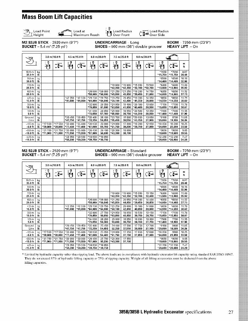
Mass Boom Lift Capacities
Load Pointj Height
Load atMaximum Reach
Load RadiusOver Front
Load RadiusOver Side
M2.92JB STICK - 2920 mm (9'7'')BUCKET - 5.4 m3 (7.25 yd3)
UNDERCARRIAGE - LongSHOES - 900 mm (36") double grouser HEAVY LIFT - On
BOOM - 7250 mm (23'9")
Z-I-3.0 m/10.0 ft 4.5 m/15.0 ft 6.0 m/20.0 ft 7.5 m/25.0 ft 9.0 m/30.0 ft
54C4bri
1:-1 il CiPI A c-, _ A c-, ii c-, ft
10.5 m kg "7050 "7050 8.8735.0 ft lb *15,750 *15,750 28.48
9.0 m kg "6500 "6500 10.1630.0 ft lb *14,400 *14,400 32.99
7.5 m kg "19 600 "19 600 "15 950 15 500 "6300 "6300 11.0025.0 ft lb *42,350 *42,350 *32,700 *32,700 *13,900 *13,900 35.92
6.0 m kg "26 000 "26 000 "21 250 "21 250 "18 200 14 750 "6350 "6350 11.5220.0 ft lb *56,000 *56,000 *45,950 45,850 *39,450 31,600 *14,000 *14,000 37.73
4.5 m kg "42 550 "42 550 "29 750 "29 750 "23 250 20 450 "19 200 14 350 "6650 "6650 11.7815.0 ft lb *91,000 *91,000 *64,000 *64,000 *50,100 43,900 *41,550 30,600 *14,550 *14,550 38.62
3.0 m kg "32 800 28 350 "24 950 19 400 "20 100 13 850 "7150 "7150 11.7810.0 ft lb *70,650 61,000 *53,850 41,650 *43,400 29,550 *15,650 *15,650 38.67
1.5 m kg "34 050 26 850 "25 900 18 550 "20 500 13 350 "7900 "7900 11.555.0 ft lb *73,650 57,700 *55,950 39,750 *44,200 28,550 *17,400 *17,400 37.90
Ground kg "20 450 "20 450 "33 400 26 100 "25 700 18 000 "20 050 13 050 "9100 8700 11.05Line lb *47,750 *47,750 *72,350 56,050 *55,450 38,550 *43,150 27,900 *20,000 19,100 36.26
-1.5 m kg "17 550 "17 550 "33 600 "33 600 "30 950 26 000 "24 000 17 800 "18 200 12 950 "10 850 10 200 10.25-5.0 ft lb *39,800 *39,800 *77,450 *77,450 *67,000 55,750 *51,750 38,200 *38,750 27,800 *24,000 22,550 33.59
-3.0 m kg "31 750 "31 750 "33 000 "33 000 "26 450 26 400 "20 300 18 000 "9050 "9050 9.05-10.0 ft lb *71,900 *71,900 *71,550 *71,550 *57,000 56,600 *43,300 38,700 *19,600 *19,600 29.55
-4.5 m kg "23 550 "23 550 "18 850 "18 850 "12 250 "12 250 7.47-15.0 ft lb *50,200 *50,200 *39,750 *39,750 *26,600 *26,600 24.28
M2.92JB STICK - 2920 mm (9'7'')BUCKET - 5.4 m3 (7.25 yd3)
UNDERCARRIAGE - Standard BOOM - 7250 mm (23'9")SHOES - 900 mm (36") double grouser HEAVY LIFT - On
Z-I-3.0 m/10.0 ft 4.5 m/15.0 ft 6.0 m/20.0 ft 7.5 m/25.0 ft 9.0 m/30.0 ft
A c-, A cip, A c-, _ A c-, A c-, ft
10.5 m kg "7050 "7050 8.8735.0 ft lb *15,750 *15,750 28.48
9.0 m kg "6500 "6500 10.1630.0 ft lb *14,400 *14,400 32.99
7.5 m kg "19 600 "19 600 "15 950 15 150 "6300 "6300 11.0025.0 ft lb *42,350 *42,350 *32,700 32,400 *13,900 *13,900 35.92
6.0 m kg "26 000 "26 000 "21 250 20 950 "18 200 14 400 "6350 "6350 11.5220.0 ft lb *56,000 *56,000 *45,950 44,850 *39,450 30,850 *14,000 *14,000 37.73
4.5 m kg "42 550 "42 550 "29 750 "29 750 "23 250 20 000 19 100 14 000 "6650 "6650 11.7815.0 ft lb *91,000 *91,000 *64,000 *64,000 *50,100 42,850 40,850 29,800 *14,550 *14,550 38.62
3.0 m kg "32 800 27 750 "24 950 18 950 18 550 13 450 "7150 "7150 11.7810.0 ft lb *70,650 59,650 *53,850 40,650 39,750 28,750 *15,650 *15,650 38.67
1.5 m kg "34 050 26 200 25 000 18 050 18 050 13 000 "7900 7700 11.555.0 ft lb *73,650 56,300 53,600 38,750 38,700 27,750 *17,400 16,900 37.90
Ground kg "20 450 "20 450 "33 400 25 450 24 400 17 500 17 750 12 700 "9100 8400 11.05Line lb *47,750 *47,750 *72,350 54,650 52,350 37,550 38,000 27,100 *20,000 18,500 36.26
-1.5 m kg "17 550 "17 550 "33 600 "33 600 "30 950 25 350 "24 000 17 350 17 650 12 600 "10 850 9900 10.25-5.0 ft lb *39,800 *39,800 *77,450 *77,450 *67,000 54,400 *51,750 37,150 37,850 27,000 *24,000 21,850 33.59
-3.0 m kg "31 750 "31 750 "33 000 "33 000 "26 450 25 750 "20 300 17 550 "9050 "9050 9.05-10.0 ft lb *71,900 *71,900 *71,550 *71,550 *57,000 55,200 *43,300 37,700 *19,600 *19,600 29.55
-4.5 m kg "23 550 "23 550 "18 850 "18 850 "12 250 "12 250 7.47-15.0 ft lb *50,200 *50,200 *39,750 *39,750 *26,600 *26,600 24.28
* Limited by hydraulic capacity -ather than tipping load. The above loads are in compliance with hydraulic excavator lift capacity rating standard SAE J/ISO 10567.
They do not exceed 87% of hydraulic lifting capacity or 75% of tipping capacity. Weight of all lifting accessories must be deducted from the above
lifting capacities.
385B/385B L Hydraulic Excavator specifications 27
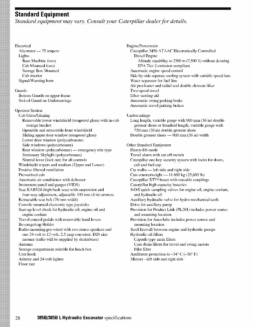
Standard EquipmentStandard equipment may vary. Consult your Caterpillar dealer for details.
ElectricalAlternator — 75 ampereLightsBase Machine (two)Cab Mounted (two)Storage Box MountedCab interior
Signal/Warning horn
GuardsBottom Guards on upper frameSwivel Guard on Undercarriage
Operator StationCab Glass/GlazingRemovable lower windshield (tempered glass) with in-cab
storage bracketOpenable and retractable front windshieldSliding upper door window (tempered glass)Lower door window (polycarbonate)Side windows (polycarbonate)Rear window (polycarbonate) — emergency exit typeStationary Skylight (polycarbonate)Neutral lever (lock out) for all controls
Windshield wipers and washers (Upper and Lower)Positive filtered ventilationPressurized cabAutomatic air conditioner with defrosterInstrument panel and gauges (VIDS)Seat KAB524 (high back seat) with suspension andfour-way adjustment, adjustable 100 mm (4 in) armrest
Retractable seat belt (76 mm width)Console mounted electronic type joysticksStart up level check for hydraulic oil, engine oil andengine coolant
Travel control pedals with removable hand leversBeverage/cup HolderRadio mounting pre-wired with two stereo speakers andone 24-volt to 12-volt, 2.5 amp converter. DIN sizemounts (radio will be supplied by dealer/user)
AntennaStorage compartment suitable for lunch boxCoat hookAshtray and 24-volt lighterFloor mat
Engine/PowertrainCaterpillar 3456 ATAAC Electronically Controlled
Diesel EngineAltitude capability to 2300 m (7,500 ft) without deratingEPA Tier 2 emission compliant
Automatic engine speed controlSide-by-side separate cooling system with variable speed fansWater separator for fuel lineAir precleaner and radial seal double element filterTwo-speed travelEther starting aidAutomatic swing parking brakeAutomatic travel parking brakes
UndercarriageLong length, variable gauge with 900 mm (36 in) double
grouser shoes or Standard length, variable gauge with750 mm (30 in) double grouser shoes
Double grouser shoes — 900 mm (36 in) width
Other Standard EquipmentHeavy-lift modeTravel alarm with cut off switchCaterpillar one key security system with locks for doors,cab and fuel cap
Cat walks — left side and right sideCast counterweight — 11 600 kg (25,600 lb)Caterpillar XTTM hoses with reusable couplingsCaterpillar high-capacity batteriesS•O•S quick sampling valves for engine oil, engine coolant,and hydraulic oil
Auxiliary hydraulic valve for hydro-mechanical toolsDrive for auxiliary pumpProvision for Product Link (PL201) includes power sourceand mounting location
Provision for Auto-lube includes power source andmounting location
Steel firewall between engine and hydraulic pumpsHydraulic oil filtersCapsule type main filtersCase drain filters for travel and swing motorsPilot filter
Antifreeze protection to —34° C (-30° F)Mirrors - left side and right side
28 385B/385B L Hydraulic Excavator specifications
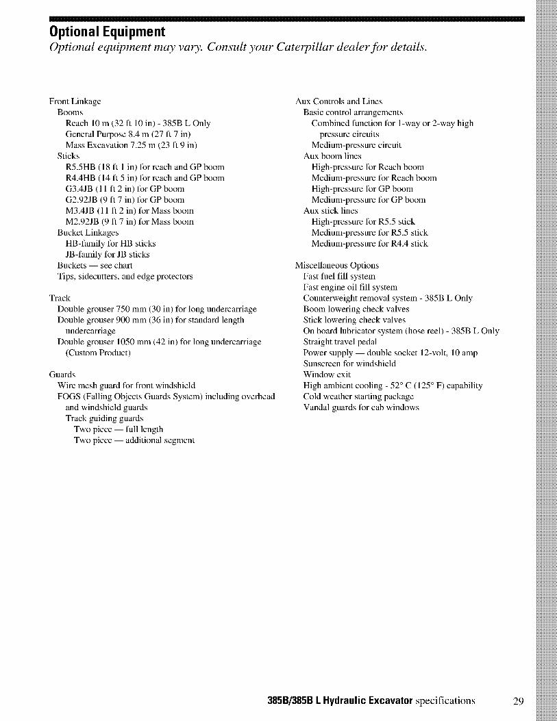
Optional EquipmentOptional equipment may vary. Consult your Caterpillar dealer for details.
Front LinkageBoomsReach 10 m (32 ft 10 in) - 385B L OnlyGeneral Purpose 8.4 m (27 ft 7 in)Mass Excavation 7.25 m (23 ft 9 in)
SticksR5.5HB (18 ft 1 in) for reach and GP boomR4.4HB (14 ft 5 in) for reach and GP boomG3.4JB (11 ft 2 in) for GP boomG2.92JB (9 ft 7 in) for GP boomM3.4JB (11 ft 2 in) for Mass boomM2.92JB (9 ft 7 in) for Mass boom
Bucket LinkagesHB-family for HB sticksJB-family for JB sticks
Buckets — see chartTips, sidecutters, and edge protectors
TrackDouble grouser 750 mm (30 in) for long undercarriageDouble grouser 900 mm (36 in) for standard length
undercarriageDouble grouser 1050 mm (42 in) for long undercarriage(Custom Product)
GuardsWire mesh guard for front windshieldFOGS (Falling Objects Guards System) including overhead
and windshield guardsTrack guiding guardsTwo piece — full lengthTwo piece — additional segment
Aux Controls and LinesBasic control arrangementsCombined function for 1-way or 2-way high
pressure circuitsMedium-pressure circuit
Aux boom linesHigh-pressure for Reach boomMedium-pressure for Reach boomHigh-pressure for GP boomMedium-pressure for GP boom
Aux stick linesHigh-pressure for R5.5 stickMedium-pressure for R5.5 stickMedium-pressure for R4.4 stick
Miscellaneous OptionsFast fuel fill systemFast engine oil fill systemCounterweight removal system - 385B L OnlyBoom lowering check valvesStick lowering check valvesOn board lubricator system (hose reel) - 385B L OnlyStraight travel pedalPower supply — double socket 12-volt, 10 ampSunscreen for windshieldWindow exitHigh ambient cooling - 52° C (125° F) capabilityCold weather starting packageVandal guards for cab windows
385B/385B L Hydraulic Excavator specifications 29

Notes
30 385B/385B L Hydraulic Excavator specifications

Notes
385B/385B L Hydraulic Excavator specifications 31
3856/385B L Hydraulic Excavator
AEHQ5465-03 (3-04)
NACD, CACo
For more complete information on Cat products, dealer services,and industry solutions, visit us on the web at www.CAT.com
© 2004 CaterpillarPrinted in U.S.A.
Materials and specifications are subject to change without notice.Featured machines in photos may include additional equipment.
See your Caterpillar dealer for available options.
CATERPILLAR®

Engineering Design OU 7-13/14 In Situ Grouting Project Identifier: EDF-5153Revision: 0
File Hydraulic Excavator and Drill-Injection Rig Page 96 of 123
This page is intentionally left blank.

Engineering DesignFile Hydraulic Excavator and Drill-Injection Rig
OU 7-13/14 In Situ Grouting Project
Appendix E
Identifier: EDF-5153Revision: 0Page 97 of 123
Auger Type Drill Rig Mounted on 90,000-lbClass Hydraulic Excavator
Engineering Design OU 7-13/14 In Situ Grouting Project Identifier: EDF-5153Revision: 0
File Hydraulic Excavator and Drill-Injection Rig Page 98 of 123
This page is intentionally left blank.
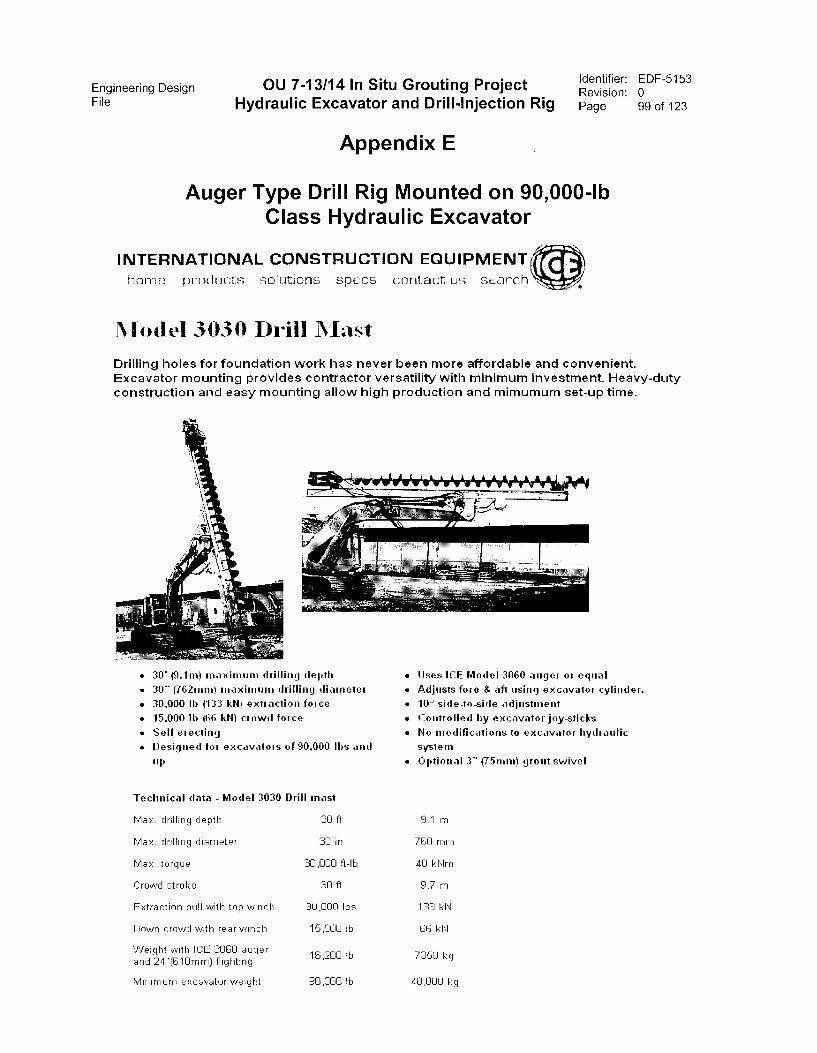
Engineering Design OU 7-13/14 In Situ Grouting Project Identifier: EDF-5153Revision: 0
File Hydraulic Excavator and Drill-Injection Rig Page 99 of 123
Appendix E
Auger Type Drill Rig Mounted on 90,000-lbClass Hydraulic Excavator
INTERNATIONAL CONSTRUCTION EQUIPMENThome products solutions specs contact us scarch
Model 30341 Drill Mast
Drilling holes for foundation work has never been more affordable and convenient.Excavator mounting provides contractor versatility with minimum investment. Heavy-dutyconstruction and easy mounting allow high production and mimumum set-up time.
'441111111111111111111.11111111111111110•
sro.
• 30' (9.1m) maximum drilling depth Uses ICE Model 3060 anger or equal
• 30" (762mm) maximinn drilling diameter • Adjusts fore & aft using excavator cylinder.
• 30,000 lb (133 kN} extraction force • 10° side-to-side adjustment
• 15.000 Ib (66 kN) crowd force • Controlled by excavator joy-sticks
• Self erecting • No modifications to excavator hydraulic
• Designed for excavators of 90,000 lbs and system
rip • Optional 3" (75mm) grout swivel
Technical data - Model 3030 Drill mast
Max. drilling depth 30 ft 9.1 m
Max. drilling diameter 30 in 7E0 rnrn
Max. torque 30,000 ft-lb 40 kNrn
Crowd stroke 30 ft 9.7 m
Extraction pull with top winch 30,000 lbs 133 kN
Down crowd with rear winch 15,000 lb 66 kN
Weight with ICE 3060 auger16,200 lb 7350 kg
and 24"(610mm) flighting
Minimum excavator weight 90,000 lb 40,000 kg
Engineering DesignFile Hydraulic Excavator and Drill-Injection Rig
OU 7-13/14 In Situ Grouting Project
This page is intentionally left blank.
Identifier: EDF-5153Revision: 0Page 100 of 123
Engineering Design OU 7-13/14 In Situ Grouting Project Identifier: EDF-5153Revision: 0
File Hydraulic Excavator and Drill-Injection Rig Page 101 of 123
Appendix F
Injection Grouting Methods,Hayward Baker
Engineering Design OU 7-13/14 In Situ Grouting Project Identifier: EDF-5153Revision: 0
File Hydraulic Excavator and Drill-Injection Rig Page 102 of 123
This page is intentionally left blank.
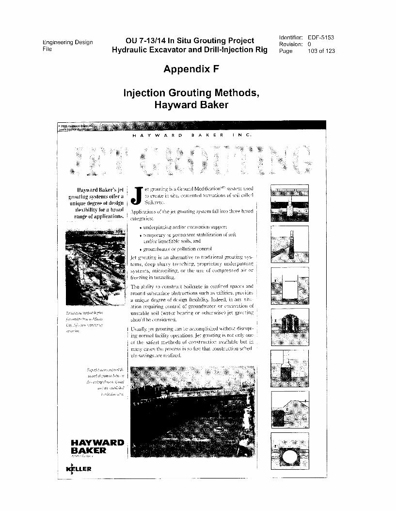
Engineering Design OU 7-13/14 In Situ Grouting ProjectFile Hydraulic Excavator and Drill-Injection Rig
Appendix F
Injection Grouting Methods,Hayward Baker
Identifier:
Revision:
Page
EDF-5153
0
103 of 123
HAYWARD BAKER INC.
Hayward Bakers jet et grouting is a Ground Modificationsm system used
grouting systems offer a to create in situ, cemented formations of soil called
unique degree of design Soilcrete.
fl I f bexibi ity or a roil(
range of applications.
a:(1tY/14W &gals.
Pff COlrstrt Vm,oi.ltlatttdt
czty AT5 um, expn,.;.sway
exfolsfoh,
Syredet slOpori ihr
the ex)slaig Prnm:4! Canal
and a.4 r.stabiishofi
HAYWARDBAKER
KIELLER
FL7triv7pi
Applications of the jet grouting system fall into three broad
categories:
• underpinning andlor excavation support
• temporary or permanent stabilization of soft
and/or liquefiable soils, and
* groundwater or pollution control
Jet grouting is an alternative to traditional grouting sys-
tems, cleep slurry trenching, proprietary underpinning
systems, micropiling, or the use of compressed air or
freezing in tunneling.
The ability to construct Soilcrete in confined spaces and
around subsurface obstructions such as utilities, provides
a unique degree of design flexibility. Indeed, in any situ-
anon requiring control of groundwater or excavation of
unstable soil (water-bearing or otherwise) jet grouting
should be considered,
Usually. jet grouting can be accomplished without disrupt-
ing normal facility operations. Jet grouting is not only one
of the safest methods of construction available but in
many cases the process is so fast that construction sched-
ule savings are realized.
1
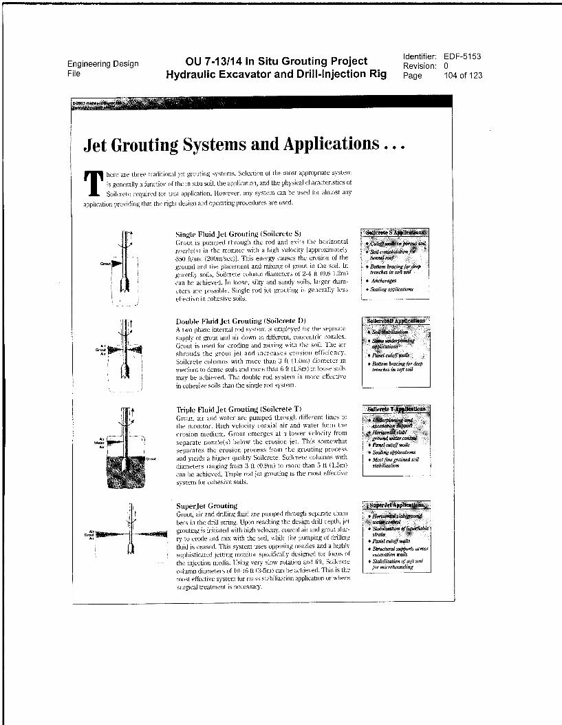
Engineering Design OU 7-13/14 In Situ Grouting ProjectFile Hydraulic Excavator and Drill-Injection Rig
Identifier: EDF-5153Revision: 0Page 104 of 123
Jet Grouting Systems and Applications . . .
There are three traditional jet grouting systems. Selection of the most appropriate system
is generally a function of the in situ soil, the application, and the physical characteristics of
Soilcrete required for that application. However, any system can be used for almost any
application providing that the right clesign and operating procedures arc used.
Grou
AlrGroutAa
AlrWater
Air
Single Fluid Jet Grouting (Soilcrete S)Grout is pumped through the rod and exits the horizontal
nozzles) in the monitor with a high velocity [approximately
650 ftlsec (20(ImIsec)). This energy causes the erosion of the
ground and the placement and mixing of grout in the soil. In
gravelly soils, Soilcrete column diameters of 2-4 ft (0.6-1.2m)
can be achieved. In loose, silty and sandy soils, larger diam-
eters are possible. Single rod jet grouting is generally less
effective in cohesive soils.
Double Fluid Jet Grouting (Soilcrete D)
A two-phase internal rod system is employed for the separate
supply of grout and air down to different, concentric nozzles.
Grout is used for eroding and mixing with the soil. The air
shrouds the grout jet and increases erosion efficiency.
Soilcrete columns with more than 3 ft (1.0m) diameter in
medium to dense soils and more than 6 ft (1.8m) in loose soils
may be achieved. The double rod system is more effective
in cohesive soils than the single rod system.
Triple. Fluid Jet Grouting (Soilerete T)
Grout, air and water are pumped through different lines to
the monitor. High velocity coaxial air and water form the
erosion medium. Grout emerges at a lower velocity from
separate nozzles) below the erosion jet. This somewhat
separates the erosion process from the grouting process
and yields a higher quality Soilcrete. Soilcrete colunms with
diameters ranging from 3 ft (0.9m) to more than 5 ft (1.5m)
can be achieved. Triple rod jet grouting is the most effective
system for cohesive soils.
Superjet GroutingGrout, air and drilling fluid are pumped through separate cham-
bers in the drill string. Upon reaching the design drill depth, jet
tp:outing is initiated with high velocity, coaxial air and grout slur-
ry to erixle and mix with the soil, while the pumping of clrilling
fluid is ceased. This system uses opposing nozzles and a highly
sophisticated jetting monitor specifically designed for focus of
the injection media. Using very slow rotation and lift, Soilcrete
column diameters of 10-16 ft (3-5m) can he achieved. This is the
most effective system for mass stabilization application or where
surgical treatment is necessary.
* Bottom bracing far detrenches in soil soil
• Anchorages
• Sealing applications
ip
a
• Panal
• I3ottom bracing for deePtrenches in soft soil
ater• Panel cutoff walk
• Sealing applications
• Most fine grained sodstabilization
•
• Panel cutoof toalLs
• Structural supports acrossexcavation walls
• Stabilization of soft soilfor microtunneling
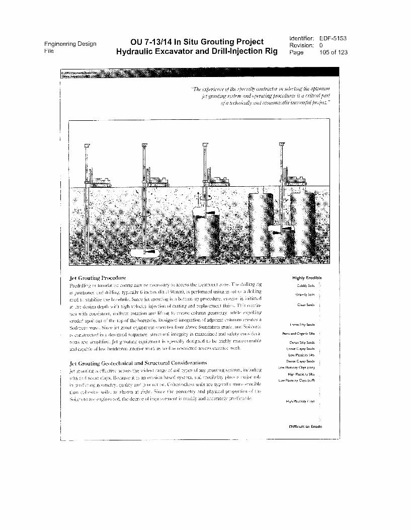
Engineering Design OU 7-13/14 In Situ Grouting ProjectFile Hydraulic Excavator and Drill-Injection Rig
Identifier: EDF-5153Revision: 0Page 105 of 123
"The experience of the specialty (warm:tor in selecting the optimum
jet grouting system and operating procedures is a critical partof a technICally and economically'successful project."
Jet Grouting Procedure
Predrilling or founda6 in coring may be necessary to access the treatment zone. The drilling rig
is positioned and drilling. typically 6 inches dia 1150mm), is performed using grout or a drilling
mud to stabilize the borehole. SMce jet grouting is a bottom-up procedure, erosion is initiated
at the design depth with high vekicity injection of cutting and replacement iluids. This contin-
ues with consistent, uniform rotation and lifting to create column geometry, while expelling
eroded spoil out of the top of the borehole. Designed integration of adjacent columns creates a
Soilcrete mass. Since jet grout equipment operates from above foundation grade, and Soilcrete
is constructed in a designed sequence. structural integrity is maintained ancl safety considera-
tions are simplified. Jet grouting equipment is specially designed to be highly maneuverable
and capable of low-headroom interior work as well as restricted-access exterior work.
Jet Grouting Geotechnical and Structural Considerations
Jet grouting is effective across the widest range of soil types of any grouting system, including
silts and SOIlle clays. Because it is an erosion based system. soil erodibility plays a major riile
in predicting geometry, quality and production. Cohesionless soils are typically more erodible
than cohesive soils, as shown at right. Since the geometry and physical properties of the
Soilcrete arc engineered, the degree of improvement is readily and accurately predictable.
Highly Erodible
Cobbly Soils
Gravelly Soils
Clean Sands
Loose Silty Sands
Peats and Organic Siits
Dense Silty Sands
Loose Ciayey Sands
Low Plasncity Silts
Dense Clayey Sands
Low Plasticity Clays (soft)
High Plastioty Silts
Low Plastidty Clays (sti(f)
High Plasnoty Clays
Difficult to Erode
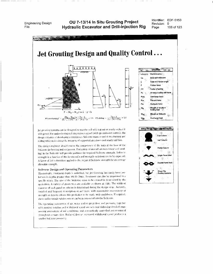
Engineering Design OU 7-13/14 In Situ Grouting ProjectFile Hydraulic Excavator and Drill-Injection Rig
Identifier: EDF-5153Revision: 0Page 106 of 123
Jet Grouting Design and Quality Control .
F = INVB Wsc) tan 5 , g • Ca
(1VB Wsc) a + Pps • 1 5FS overturning* =
(Ps • c) + tPw d) + (Posi. • e)
Pps + F FS slating =
Ps + Pw + Po,a
4*-
1.5
Jet gouting systems can be designed to mix the soil with a grout or nearly replace it
with grout. For underpinning and excavation support (with ptoundwater control). the
design consists of developing a contiguous Soilcrete mass to resist overturning and
sliding while maintaining the integrity of supported structures and nearby utilities.
The design engineer should assess the competency of the soils at the base of the
Soilcrete for bearing ancl settlement. Evaluation of internal stresses (shear and bend-
ing) in the Soilcrete will provide guidance for required Soilerete strength. Soilcrete
strength is a function of the in situ soils and strength variations are to be expected.
A factor of 3.0 is therefore applied to tlie required Soilcrete strength for an average
allowable strength.
Soilcrete Design and Operating Parameters
Theoretically, treatment depth is unlimited, but Jet Grouting has rarely been per-
formed in depths greater than 164 ft (50m). Treatment can also be pinpointed to a
specific strata. The size of the Soilcrete mass to be created is determined by the
application. A variety of geometries are available as shown at right. The width or
diameter of each panel or, column is determined during the design sta,ge. Accurate,
detailed and frequent description of soil type, with reasonable assessment of
strength or density allows this prediction to be made with confidence. lf required,
shear andlor tensile reinforcement can be incorporated int() the Soilcrete.
'Re operating parameters of air, water andlor grout flow, and pressure, together
with nionitor rotation and withdrawal speed are selected (following detailed en),i-
neering assessment of soil conditions) And automatically controlled and monitored
throughout construction. Reduced flow or increased withdrawal speed produces a
smaller Soilcrete geometry.
a,bx,c1.e nt arms
Ca Base soil adhe on
Base 1 angle
F Friction force
FS ctor ot safety
P. At-rest or active
POSL Surcharge force
Pps Pas
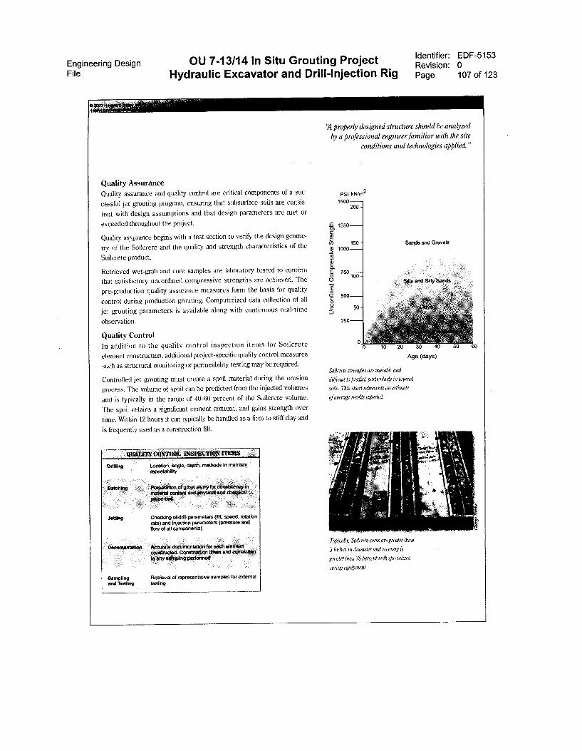
Engineering Design OU 7-13/14 In Situ Grouting ProjectFile Hydraulic Excavator and Drill-Injection Rig
Identifier: EDF-5153
Revision: 0
Page 107 of 123
Quality Assurance
Quality assurance and quality control are critical components of a suc-
cessful jet grouting prograrn, ensuring that subsurface soils are consis-
tent with design assumptions and that design parameters are met or
exceeded throughout the project.
Quality assurance begins with a test section to verify the design geome-
try of the Soilcrete and the quality ancl strength characteristics of the
Soilcrete product.
Retrieved wet-grab and core samples are laboratory tested to confirm
that satisfactory unconfined compressive strengths are achieved. The
pre-production quality assurance measures form the basis for quality
control during production grouting. Computerized data collection of all
jet grouting parameters is available along with contirmous real-time
observation.
Quality Control
ln addition to the quality control inspection items for Soilcrete
element construction, additional project-specific quality control measures
such as structural monitoring or permeability testing rnay be required.
Controlled jet grouting must create a spoil material during the erosion
process. The volume of spoil can be predicted from the injected volumes
and is typically in the range of 40-60 percent of the Soilcrete volume.
The spoil retains a significant cement content, and gains strength over
tirne. Within 12 hours it can typically be handled as a firm to stiff clay and
is frequently used as a construction fill.
L INSPECTION ITEMS
Jetting
Location, angle, depth, methods to maintainrepeatability
Checking of.drill parameters (rift, speed, rotationrate) and injection parameters (pressure andnow of an componeMs)
te documentation forConstruction times and corretatk
y sarnOng fterfOtTned
Sampling Retrieval of representative samples for extemaland Testing testing
`A properly designed structure should be analyzed
by a professional engineer familiar with the site
conditions and technologies applied."
PSI kNirn2
:C. 1250cn
c75 • 150 -Os 1000
.57
if?
E • 750o
sca • 500o
10 20 30 40 50 60
Age (days)
Soikrek strengths are variable and
ditticidt to predict, particularly in layered
soils, This chart represents an estimate
ofaverage results expected.
TYPically, Soikrete cores are greater than
3 inches in diameter and reiovery is
greater than 75 percent with speciahzed
coring eguiPment,
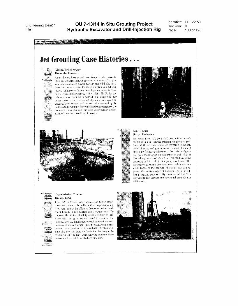
Engineering Design OU 7-13/14 In Situ Grouting ProjectFile Hydraulic Excavator and Drill-Injection Rig
Identifier: EDF-5153Revision: 0Page 108 of 123
Jet Grouting Case Histories ...FT 0
6
22
Nimitz Relief Sewer
llonolulu, Hawaii
As a value-engineered and less disruptive alternative to
open cnt construction, jet groutMg was selected to pro-
vide a homogenized tunnel horizon and minimize post-
constniction settlement tor the installation of a 54 mch
(1.4mi rclief sewer through soft. lagoonal deposits. Two
rows of interconnected, 4 ft (1.2m) dia Soilcrete
columns were installed to bedrock over a 2,800 lf (850
linear meted stretch of Linnet alignment to prepare an
encapsulated tunnel horizon for micro-tunneling. In
;Addition to providing a fully stabilized tunneling face, the
Sodcrete mass ensured that post construction settle-
ment of the sewer would be eliminated.
Transmission Towers
Dallas, Texas
Four. 180 tt (55m) high transmission tower struc-
tures were moving lateralb on the compression leg.
This was due to insufficient diameter and embed-
ment length of the drilled shaft foundations. To
improve the tactor of safety against tailure at ulti-
mate loads. jet grouting was used to stabilize the
compression leg foundation of each tower down to a
competent bearing strata. Prior to production, a test
column was constructed to establish effective col-
umn diameter, forming the basis for the design. An
average of 12, 4 ft dia (1.2n0 Soderete columns were
constructed in each tower to hard limestone.
Kraft Foods
Dover, Delaware
For construdion of a 20 ft Oint) decp railcar unload-
ing pit within an existing huilding, jet grouting per-
formed three functions: excavation support,
underpinning, and groundwater control. To meet
project performance objectives, a 'bathtub' configura-
tion was constructed via a perimeter wall of 20 ft
(tirn) deep, interconnected jet grouted columns
enclosing a 6 ft (1.8n) thick jct grouted base. The
perimeter columns provided excavation support
while those at the corners of the pit also under-
pinned the existing adjacent footings. The jet grout-
ing program successfully prevented building
movement and vertical and horizontal groundwater
infiltration.
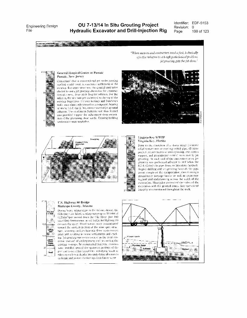
Engineering Design OU 7-13/14 In Situ Grouting ProjectFile Hydraulic Excavator and Drill-Injection Rig
FT 0
20
45
FT 0
13 5
19.5
26
29
961tuif
General Hospital Center at Passaic
Passaic, New Jersey
Concerned that a conventional pit underpinning
method would result in excessive settlement of the
existing, hve-stoiy structure. the general contractor
elected to use a jet grouting alternative tor construc-
tion of a new, three-story hospital addition. For the
addition, the site was pre-excavated to the top 01 the
existing foundation. Column footings and foundation
walls were then underpinned to a competent twaring
strata by :3.5 ft (ha (1.1m), interconnected jet grouted
columns. The continuous Soilcrete wall thus formed
also provided support for subsequent deep excava-
tion of the prevailing clean sands. Existing building
settiements were negligible.
F
U.S. Highway 80 Bridge
Maricopa County, Arizona
During heavy winter rains in the Arizona desert, the
Gillespie Darn tailed. sending water up to 150.000 cf
(4,250m3)per secend CIO \Vil the Gila River. Just 100
yds (92m) downstream, all old bridge Mr Highway 80
crosses the river. Flood waters were concentrated
toward the eastern portion ot the nme-span struc-
ture. scouring cavities beneath three easternmost
piers and resulting in minor settlements and crach-
mg. Jet grouting was recommended as the most eco-
nomic method of underpinning and protecting the
existing footings. Interconnected Sialcretc columns —
were installed around the upstream portions ot the -7,
pier and ,432re either keyed into underlying basalt or
taken to sufficient depths into underlying alluvium to
underpin and protect the footings nom !inure scour.
Identifier: EDF-5153Revision: 0Page 109 of 123
"ft'llen owners and ,waructors need u just, lei:loth:ally
(lbwlire soltriiorr lo a lough geolechnical problem.
jel grinding gels the job dmte."
Virginia Key WWTP
Virginia Key, Florida
Prior to incorporation ot a storm surge pressure
relief system into an existmg outfall pipe, till three
project requirements of underpinning, excavation
support, and groundwater control were met by jet
grouting. At each end of the excavation area, jet
grouting was performed arljacent to and below the
8.5 ft (2.6m) dia pipe down to limestone bedrock)
Angled drilling and jet grouting beneath the pipe
invert completed the encapsulation, thus forming a
groundwater seepage barrier as well as excavation
support and underpinning across the width of the
excavation. Sheetpiles connected the sides of the
excavation wads the grouted zones. Sate Operational
integrity was maintained throughout the work.
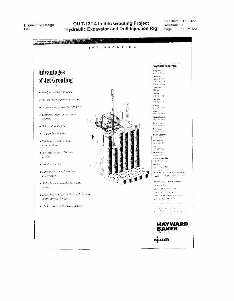
Engineering Design OU 7-13/14 In Situ Grouting ProjectFile Hydraulic Excavator and Drill-Injection Rig
identifier: EDF-5153Revision: 0Page 110 of 123
J E T GROUTING
Advantagesof Jet Grouting
• Nearly all soil types inoutable
• Specipc in situ replaconent possible
• Designable strength and pen ability
• Treahnent to specitic subsi
• Only inert wmrpofterits
• No harmful vibrations
• Gan be performed in liniited
working space
• Any cross-sei tio
possible
• Slaintenance-tree
• Safest metlwil Of underpinning
constniction
• Ability to work around huried active
trtilitics
• Most ii.rtect iithod nJ dir, iinderpainim,
strucluri and utilities
• Much raster than alt,irnatii wthods
Hayward Baker Inc.
Maryland
410-S51-820S
California
55334533-I 351
550 511-2170
c125-FI/5-505e
Colorado
1n3-460-1135,
Florida'13-804-.144 I
Georgia
Illinois
513 631 8580
Iowa
Massachusetts
New Jersey)01-797-lei8E-,
New York115-534-33.801
North Carolina
Tennessee
Texas
Washington
British Columbia
Keller Group — North America
L., In
3 1 8 131E .534,
HAYWARDBAKERA Cd,
4LLER
Engineering Design OU 7-13/14 In Situ Grouting ProjectFile Hydraulic Excavator and Drill-Injection Rig
Appendix G
High Pressure Swivel,Western Rubber Manufacturing
Identifier: EDF-5153Revision: 0Page 111 of 123

Engineering Design OU 7-13/14 In Situ Grouting Project Identifier: EDF-5153Revision: 0
File Hydraulic Excavator and Drill-Injection Rig Page 112 of 123
This page is intentionally left blank.

Engineering DesignFile Hydraulic Excavator and Drill-Injection Rig
STERNRUEI6ER & MFG. ) 590-11135
SIDE INLET SWIVEL
OU 7-13/14 In Situ Grouting Project
Appendix G
High Pressure Swivel,Western Rubber Manufacturing
Identifier: EDF-5153Revision: 0Page 113 of 123
3ORG• Can be used to increase fluid passage, maximum of 2-10' ID• Models for both WATER WELL and MINERAL EXPLORATION drilling• Can be used for both air and mud rotary drilling• Sealed radial ball bearings for smooth rotation• Non adjustable Chevron (V-ring) packing, grease lubricated• Compact design• Can be easily repaired in the field if necessary• Available with numerous thread forms and sizes
TECHNICALOVERALLLENGTH
WIDTH TOP CONK IIZIGECONN_
LOWER' CONN WATERCOURSE WT/LB
3-12' REG BOX l-lir 3-7{C' IF PIN 2-1SR2? 3-u2" REG 190X 2-1IP 3-12° REG POI rire 156
PARTS LISTPARTNUMBER
NAME NUMBERREG
WT/LBSEACH
RECOMMEMEDSPARES FOR (1)
YEAR3ORG-01 SHAFT. ornom 95_00 —3ORG-02 BEARING CAP 1 12.00 —30RG-03 BEARINGS 2 3.50 230RG-04 BEARING RETAINER 1 .10 13ORG-05 GREASE SEAL 1 .30 130RG-06 LANTERN RING 2 .70 —3ORG-07 PACKING SET (HIGH PRES) 2 .70 23ORG-07-416 PACKING SET (LOW PRES) OPrKSN .70 —3ORG-08 PACKOFF HOUSING 1 40.00 —30RG-09 PACKING SEAT RING 2 —3ORG-10 BEARING SPACER 1 1.00 —3ORG-11 PACKING RETAINER 2 .10 2
8K (SPECIAL SWIVEL)
• 6,000 PSI Working Pressure• For High Pressure grouting• Compact design• Sealed Radial Ball Bearings for smooth rotation• Non Adjustable grease lubricated Chevron (V-Ring) packing• 2" Watercourse• Numerous applications in the directional drilling market
*PLEASE STATE SIZE AND TYPE OF THREADS WHEN ORDERING.*OTHER SIZES OF CONNECTIONS AVAILABLE, PLEASE CONSULT FACTORY

Engineering Design OU 7-13/14 In Situ Grouting ProjectFile Hydraulic Excavator and Drill-Injection Rig
This page is intentionally left blank.
Identifier: EDF-5153Revision: 0 -Page 114 of 123
Engineering Design OU 7-13/14 In Situ Grouting Project Identifier: EDF-5153Revision: 0
File Hydraulic Excavator and Drill-Injection Rig Page 115 of 123
Appendix H
Active Control of Hydraulic Control Circuits(HMC, MOVAC Auto Sensing II)

Engineering Design OU 7-13/14 In Situ Grouting ProjectFile Hydraulic Excavator and Drill-Injection Rig
This page is intentionally left blank.
Identifier: EDF-5153Revision: 0Page 116 of 123
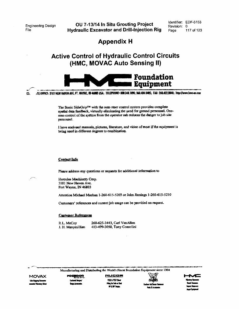
Engineering Design OU 7-13/14 In Situ Grouting ProjectFile Hydraulic Excavator and Drill-Injection Rig
Appendix H
Identifier: EDF-5153Revision: 0Page 117 of 123
Active Control of Hydraulic Control Circuits(HMC, MOVAC Auto Sensing II)
4TE 01 MI1N NAMElI AYf, n.
FoundationEquipment260.42t0/05; FAX: 20142120W 0110://ww
The Sonic SideGripTm with the auto steer control system provides completespatial data feedback, virtually eliminating the neod for ground personnel. One-man control of tbe system from the operator cab reduces the danger to job sitepersonnel.
have enclosed manuals, pictures, literature, and video of most if the equipment isbeing used in different degrees to combination.
Contact Info
Please address any quosti
Hercules Machinery Corp.3101 New Havcn Ave.Fort Wayne, IN 46803
or for additional information to
Attention Michael Meehan 1-260-615-5203 or John Jinnings 1-260-615-5210
Customers' references and current job usage can be provided on request.
Customer References
R.L. McCoy 260-625-3443, Carl VanAllenJ. H. Maxymillian 413-499-3050, Tony Consolini
MOVAX 1'iu=1:41FIwows. homy Pannemoil MIMI Wm
If I Wr hos Pols:Jamas
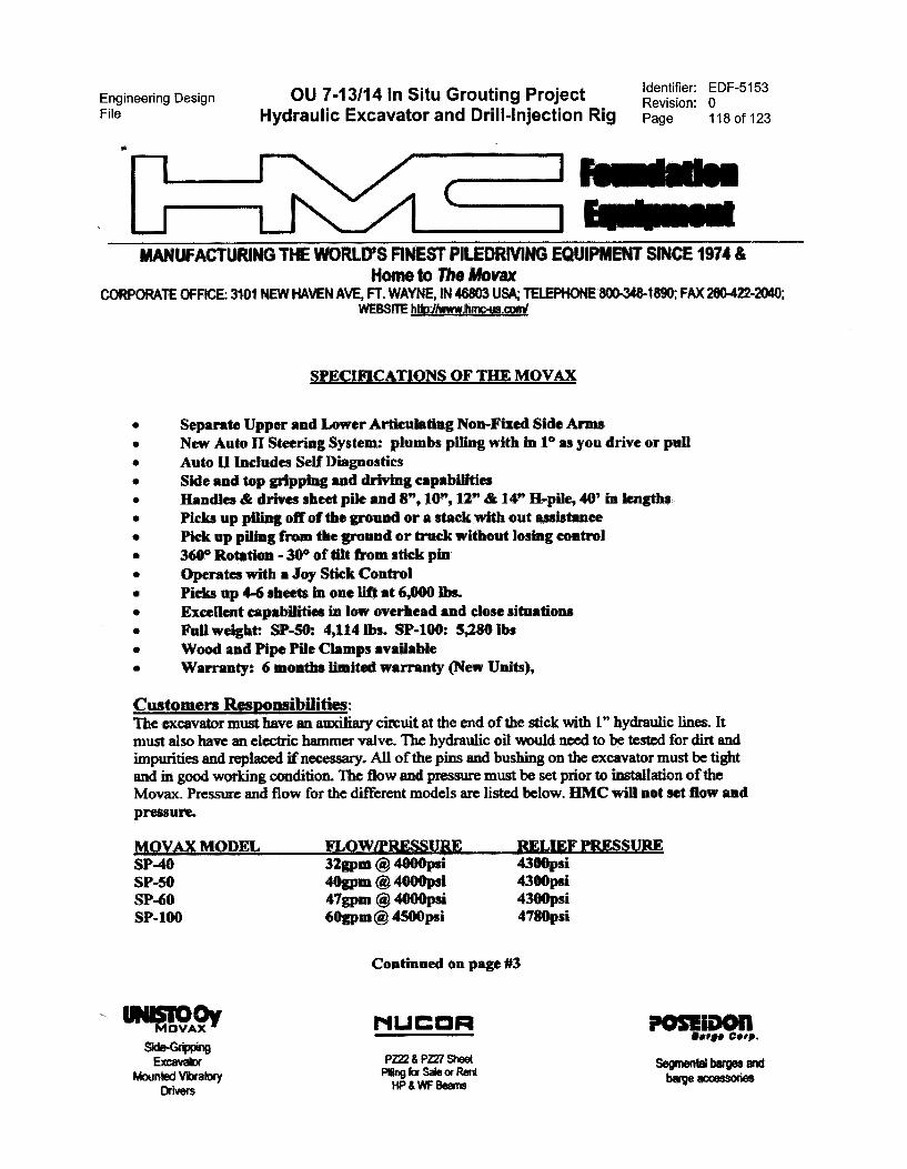
Engineering Design OU 7-13/14 In Situ Grouting Project Identifier: EDF-5153Revision: 0
File Hydraulic Excavator and Drill-Injection Rig Page 118 of 123
1 Faiikaks 1 61111111.1
MANUFACTURING THE WORLD/ FINEST PILEDRIVI EQUIPMENT SINCE 1974 &Homo to The Movax
CORPORATE CFFICE: 3101 NEW HAVEN AVE, FT. WAYtE, IN 46803 USA; TELEPHONE 800448-1890; FAX 260-472-2040;WEBS1TE http://www,hrop-us.corrii
SPECIFICATIONS OF THE MOVAX
• Separate Upper and Lower Articulating Non-Fixed Side Arms• New Auto II Steering System: plumbs piling with in 1° as you drive or pull• Auto II Includes Self Diagnostics• Side and top gripping and driving capabilities• Handles & drives sheet pile and 8", 10", 12" & 14" H-pile, 40' in lengths• Picks up piling off of the ground or a stack with out assistance• Pick up piling from tbe ground or trnck without losing control• 360° Rotation - 30° of tilt from stick pin• Operates with a Joy Stick Control• Picks up 4-6 sbeets in one lift at 6,000 lbs.• Excellent capabilities In low overhead and close situations• Full weight: SP-50: 4,114 lbs. SP-100: 5,280 lbs• Wood and Pipe Pile Clanips available• Warranty: 6 months Ihnited warranty (New Units),
Customers Responsibilities:The excavator must have an auxiliary circuit at the end of the stick with 1" hydraulic lines. Itmust also have an electric hammer valve. The hydraulic oil would need to be testcd for dirt andimpurities and replaced if necessary. All of the pins and bushing on the excavator must be tightand in good working condition. The flow and pressure must be set prior to installation of theMovax. Pressure and flow for the different models are listed below. HMC will not set flow andpressure.
MOVAX MODEL FLOW/PRFSSURE RELIEF P SSP-40 32gpin (4) 4000psi 4300psiSP-50 40gpm ® 4000psi 4300psiSP-60 47gpm Q. 4000psi 4300psiSP-100 60gpm®4500psi 4780psi
VAX
Side-GrippingExcavator
Mounted VbratoryDrivers
Continued on page #3
NUCOR
PZ22 & PZ27 SheetRing for Sale or RentHP & WF Beans
Oar.* Corp.
Segmental barges andbarge accessories
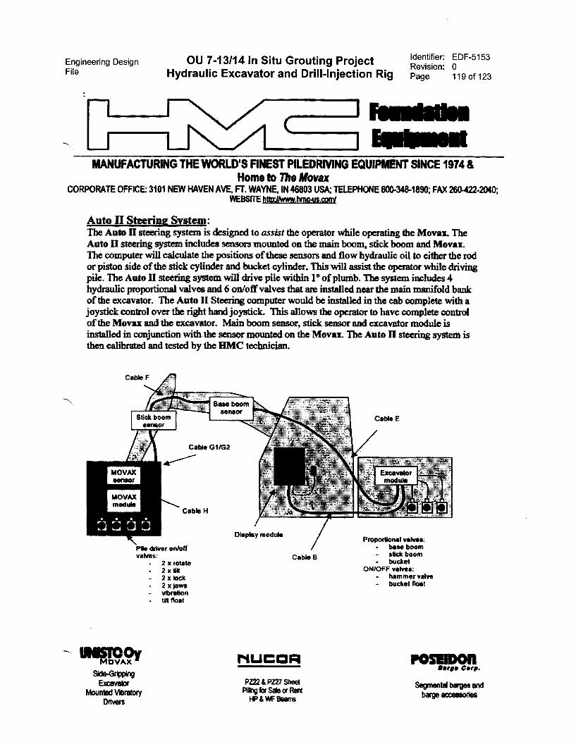
Engineering Design OU 7-13/14 In Situ Grouting ProjectFile Hydraulic Excavator and Drill-Injection Rig
Identifier: EDF-5153Revision: 0Page 119 of 123
MANUFACTURING THE WORLD'S FINEST PILEDRMNG ECHRPMENT SINCE 1974 &Home to The Movax
CORPORATE OFFICE: 3101 NEW HAVEN AVE, FT. WAYNE, IN 46003 USA; TELEPHONE 800448-1890; FAX 260422-2040;WEBSITEM7MAYMBMC-APLCOMI
Auto II Steering System:The Aato 11 steering system is designed to assist the operator while operating the Movai. TheAuto 11 steering system includes sensors mounted on the main boom, stick boom and Movax.The computer will calculate the positions of these sensors and flow hydraulic oil to either the rodor piston side of the stick cylinder and bucket cylinder. This will assist the operator while drivingpile. The Auto 11 steering system will drive pile within 1° of plumb. The system includes 4hydraulic proportional valves and 6 on/off valves that are installed near the main manifold bankof the excavator. The Auto II Steering computer would be installed in the cab complete with ajoystick control over the right hand joystick. This allows the operator to have complete controlof the Movax and the excavator. Main boom sensor, stick sensor and excavator module isinstalled in conjunction with the sensor mounted on the Movax. The Auto 11 steering system isthen calibrated and tested by the HMC technician.
Cable F
.14111/x1t: , Base
Pile driver on/offvalves:
- 2 x rotate- 2 x tlk- 2 x lock- 2 x jaws- vibration- til Boat
VAX
Side-GrimingExcavator
Mounted VibratoryDriven
Cable B
PZ22 & PZ27 SheetPiing for Sale or RentHP & IAiF Beams
Cable E
Proportionel valves:• base boom- Mk* boom- buckel
ON/OFF valves:- hammer valve- bucket float
Pompons.v. Clore.Segmental berges andbarge accessories
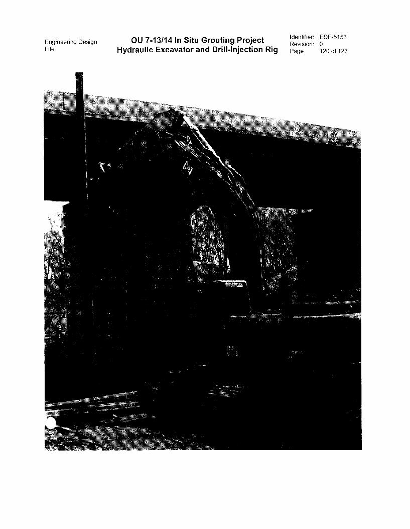
Engineering Design OU 7-13/14 In Situ Grouting ProjectFile Hydraulic Excavator and Drill-Injection Rig
Identifier: EDF-5153Revision: 0Page 120 of 123
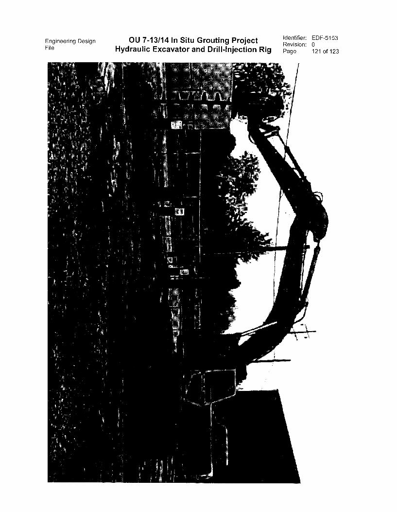
Engineering Design OU 7-13/14 In Situ Grouting ProjectFile Hydraulic Excavator and Drill-Injection Rig
Identifier: EDF-5153Revision: 0Page 121 of 123

Engineering Design OU 7-13/14 In Situ Grouting ProjectFile Hydraulic Excavator and Drill-Injection Rig
Identifier: EDF-5153Revision: 0Page 122 of 123
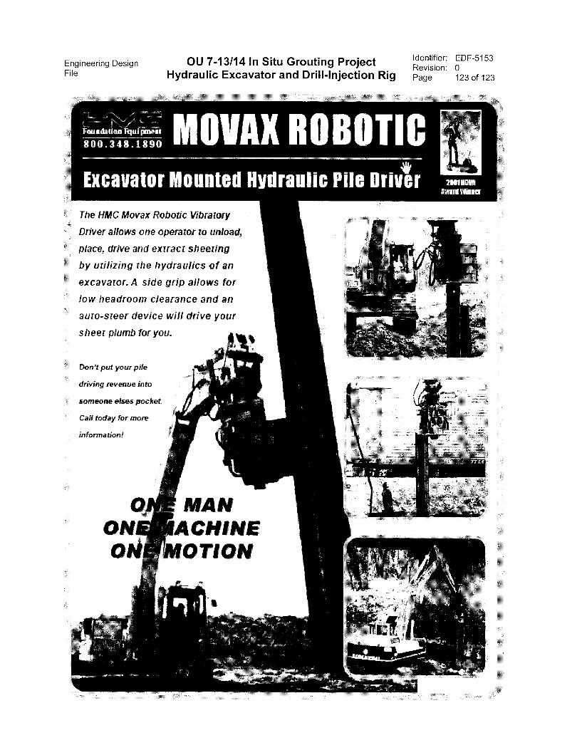
Identifier: EDF-5153Revision: 0Page 123 of 123
Engineering Design OU 7-13/14 In Situ Grouting ProjectFile Hydraulic Excavator and Drill-Injection Rig
The HMC Movax Robotic Vibratory
Driver allows one operator to unload,
place. drive and extract sheeting
by urilizing the hydraulics of an
excavator. A side grip allows for
low headroorn ciearance and an
auto-steer device will drive your
sheer plumb for you.
Don't put your pile
driving revenue into
someone elses pocket
Call today for more
information!


