Embed Size (px)
Citation preview
www.elsevier.com/locate/compfluid
Computers & Fluids 34 (2005) 1115–1151
Review
Thirty years of development and application of CFDat Boeing Commercial Airplanes, Seattle
Forrester T. Johnson *, Edward N. Tinoco, N. Jong Yu
Boeing Commercial Airplanes, The Boeing Company, P.O. Box 3707, MC 67-LH, Seattle, WA 98124-2207, United States
Received 1 June 2004; accepted 18 June 2004
Available online 26 February 2005
Abstract
Over the last 30 years, Boeing has developed, manufactured, sold, and supported hundreds of billions of
dollars worth of commercial airplanes. During this period, it has been absolutely essential that Boeing aero-dynamicists have access to tools that accurately predict and confirm vehicle flight characteristics. Thirty
years ago, these tools consisted almost entirely of analytic approximation methods, wind tunnel tests,
and flight tests. With the development of increasingly powerful computers, numerical simulations of vari-
ous approximations to the Navier–Stokes equations began supplementing these tools. Collectively, these
numerical simulation methods became known as Computational Fluid Dynamics (CFD). This paper
describes the chronology and issues related to the acquisition, development, and use of CFD at Boeing
Commercial Airplanes in Seattle. In particular, it describes the evolution of CFD from a curiosity to a full
partner with established tools in the design of cost-effective and high-performing commercial transports.� 2005 Published by Elsevier Ltd.
Contents
1. Introduction . . . . . . . . . . . . . . . . . . . . . . . . . . . . . . . . . . . . . . . . . . . . . . . . . . . . . . . . . . . . . . . . . . 1116
2. The role and value of CFD . . . . . . . . . . . . . . . . . . . . . . . . . . . . . . . . . . . . . . . . . . . . . . . . . . . . . . . 1117
0045-7930/$ - see front matter � 2005 Published by Elsevier Ltd.
doi:10.1016/j.compfluid.2004.06.005
* Corresponding author. Tel.: +1 425 234 1080.
E-mail address: [email protected] (F.T. Johnson).
1116 F.T. Johnson et al. / Computers & Fluids 34 (2005) 1115–1151
3. The CFD development and application process . . . . . . . . . . . . . . . . . . . . . . . . . . . . . . . . . . . . . . . . . 1120
4. Chronology of CFD capability and use . . . . . . . . . . . . . . . . . . . . . . . . . . . . . . . . . . . . . . . . . . . . . . . 1124
4.1. Linear potential flow. . . . . . . . . . . . . . . . . . . . . . . . . . . . . . . . . . . . . . . . . . . . . . . . . . . . . . . . 1125
4.1.1. First generation methods––early codes . . . . . . . . . . . . . . . . . . . . . . . . . . . . . . . . . . . . 1125
4.1.2. First generation methods––TA230 . . . . . . . . . . . . . . . . . . . . . . . . . . . . . . . . . . . . . . . 1126
4.1.3. Second generation linear potential flow method––PANAIR/A502 . . . . . . . . . . . . . . . . . 1128
4.2. Full potential/coupled boundary layer methods . . . . . . . . . . . . . . . . . . . . . . . . . . . . . . . . . . . . . 1131
4.2.1. A488/A411 . . . . . . . . . . . . . . . . . . . . . . . . . . . . . . . . . . . . . . . . . . . . . . . . . . . . . . . 1131
4.2.2. TRANAIR . . . . . . . . . . . . . . . . . . . . . . . . . . . . . . . . . . . . . . . . . . . . . . . . . . . . . . . 1132
4.2.3. BLWF . . . . . . . . . . . . . . . . . . . . . . . . . . . . . . . . . . . . . . . . . . . . . . . . . . . . . . . . . . 1137
4.3. Euler/coupled boundary layer methods . . . . . . . . . . . . . . . . . . . . . . . . . . . . . . . . . . . . . . . . . . . 1138
4.4. Navier–Stokes methods . . . . . . . . . . . . . . . . . . . . . . . . . . . . . . . . . . . . . . . . . . . . . . . . . . . . . . 1139
4.4.1. Structure grid codes––Zeus TLNS3D/CFL3D, OVERFLOW . . . . . . . . . . . . . . . . . . . . 1139
4.4.2. Unstructured grid codes––Fluent, NSU2D/3D, CFD++ . . . . . . . . . . . . . . . . . . . . . . . . 1142
4.4.3. Other Navier–Stokes codes . . . . . . . . . . . . . . . . . . . . . . . . . . . . . . . . . . . . . . . . . . . . 1143
4.4.4. Next generation Navier–Stokes codes . . . . . . . . . . . . . . . . . . . . . . . . . . . . . . . . . . . . . 1143
4.5. Design and optimization methods. . . . . . . . . . . . . . . . . . . . . . . . . . . . . . . . . . . . . . . . . . . . . . . 1145
4.5.1. A555, A619 inverse design codes . . . . . . . . . . . . . . . . . . . . . . . . . . . . . . . . . . . . . . . . 1145
4.5.2. TRANAIR optimization . . . . . . . . . . . . . . . . . . . . . . . . . . . . . . . . . . . . . . . . . . . . . . 1146
5. Conclusions . . . . . . . . . . . . . . . . . . . . . . . . . . . . . . . . . . . . . . . . . . . . . . . . . . . . . . . . . . . . . . . . . 1148
References. . . . . . . . . . . . . . . . . . . . . . . . . . . . . . . . . . . . . . . . . . . . . . . . . . . . . . . . . . . . . . . . . . . . 1148
1. Introduction
In 1973, an estimated 100–200 computer runs simulating flows about vehicles were made atBoeing Commercial Airplanes, Seattle. In 2002, more than 20,000 CFD cases were run to comple-tion. Moreover, these cases involved physics and geometries of far greater complexity. Many fac-tors were responsible for such a dramatic increase: (1) CFD is now acknowledged to providesubstantial value and has created a paradigm shift in the vehicle design, analysis, and support pro-cesses; (2) the CFD effort at Boeing was led by a strong and capable visionary, Dr. Paul Rubbert,who recruited and was supported by the services of a number of talented managers and technicalpeople; (3) this CFD effort was well diversified, involving algorithm research, code development,application and validation studies, process improvement, and user support; (4) Boeing developeda broad line of products, supported by a number of innovative and demanding project engineers;(5) computing power and affordability improved by three to four orders of magnitude; (6) numer-ous pioneers in academia and the Government continued to make algorithmic breakthroughs; and(7) there were funding managers in Boeing and the Government who were not averse to takingrisks.It would be impossible to adequately address all these factors in this short paper. Consequently,
we will concentrate on issues that were central to the efforts of the authors, who have been mem-bers of the CFD Development and Applications groups at Boeing, Seattle for more than 30 years.In Section 2, we describe the role and value of CFD as it has evolved over the last 30 years and asit may possibly evolve in the future. In Section 3, we describe the CFD development and appli-cation processes. In Section 4, we lay out a brief history of the codes and methods that were most
F.T. Johnson et al. / Computers & Fluids 34 (2005) 1115–1151 1117
heavily used at Boeing, Seattle, as well as some of the issues that lay behind their development. InSection 5, we draw some brief conclusions.Finally, we note that CFD has had a long and distinguished history in many other parts of the
Boeing Enterprise. That history would best be related by those intimately involved.
2. The role and value of CFD
The application of CFD today has revolutionized the process of aerodynamic design. CFDhas joined the wind tunnel and flight test as primary tools of the trade [1–4]. Each has itsstrengths and limitations Because of the tremendous cost involved in flight testing, modern air-craft development must focus instead on the use of CFD and the wind tunnel. The wind tunnelhas the advantage of dealing with a ‘‘real’’ fluid and can produce global data over a far greaterrange of the flight envelope than can CFD. It is best suited for validation and database buildingwithin acceptable limits of a development program�s cost and schedule. Historically, CFD hasbeen considered unsuited for such as task. However, the wind tunnel typically does not producedata at flight Reynolds number, is subject to significant wall and mounting system corrections,and is not well suited to provide flow details. The strength of CFD is its ability to inexpensivelyproduce a small number of simulations leading to understanding necessary for design. Of greatutility in this connection is the fact that CFD can be used in an ‘‘inverse design’’ or optimiza-tion mode, predicting the necessary geometry shape changes to optimize certain flow character-istics or a payoff function (e.g., drag). Beyond this, CFD is heavily used to provide correctionsfor the extrapolation of data acquired experimentally (typically from testing a reduced scalemodel of the vehicle in a wind tunnel) to conditions that characterize the full-scale flight vehicle.Finally, CFD is used to provide understanding and insight as to the source of undesirable flightcharacteristics, whether they are observed in subscale model testing or in the full-scaleconfiguration.Effective use of CFD is a key ingredient in the successful design of modern commercial aircraft.
The combined pressures of market competitiveness, dedication to the highest of safety standards,and desire to remain a profitable business enterprise all contribute to make intelligent, extensive,and careful use of CFD a major strategy for product development at Boeing.Experience to date at Boeing Commercial Airplanes has shown that CFD has had its greatest
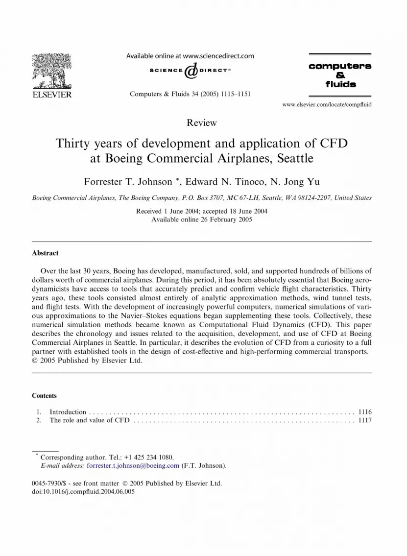
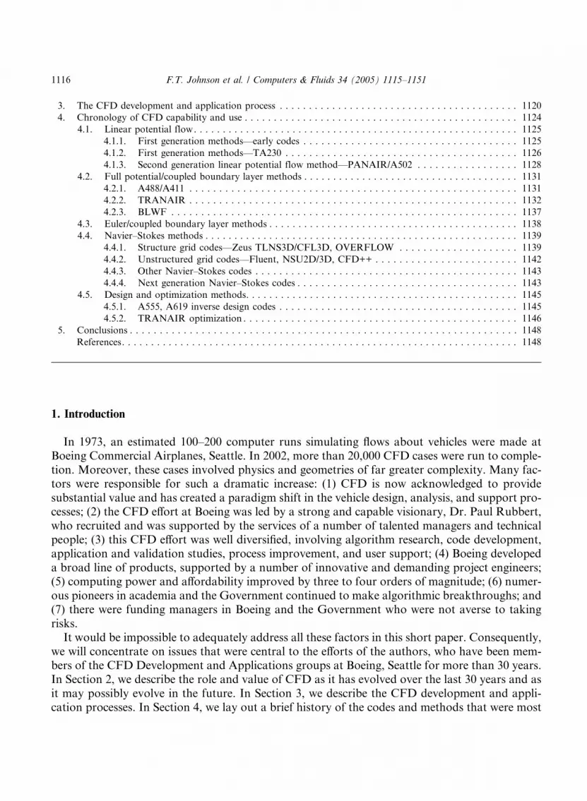
effect in the aerodynamic design of the high-speed cruise configuration of a transport aircraft. Theadvances in computing technology over the years have allowed CFD methods to affect the solu-tion of problems of greater and greater relevance to aircraft design, as illustrated in Figs. 1 and 2.Use of these methods allowed a more thorough aerodynamic design earlier in the developmentprocess, permitting greater concentration on operational and safety-related features.The 777, being a new design, allowed designers substantial freedom to exploit the advances in
CFD and aerodynamics. High-speed cruise wing design and propulsion/airframe integration con-sumed the bulk of the CFD applications. Many other features of the aircraft design were influ-enced by CFD. For example, CFD was instrumental in design of the fuselage. Once the bodydiameter was settled, CFD was used to design the cab. No further changes were necessary as aresult of wind tunnel testing. In fact, the need for wind tunnel testing in future cab design waseliminated. Here, CFD augmented wind tunnel testing for aft body and wing/body fairing shape
Wing DesignTail And Aft
Body Design
Engine / Airframe Integration
Cab Design Wing-bodyFairing
Flap TrackFairings
o Simultaneous Design
o 3 Engine Installationso Including Exhaust Effects
Fig. 1. CFD played a major role in the design of the Boeing 777.
NewTrailing-
Edge FlapDesign
ConstrainedWing Design
Engine/AirframeIntegration
StrutDesign
Wing/Body Stake andFairing Design
Aft BodyModification
Fig. 2. Effect of CFD on the Next Generation 737.
1118 F.T. Johnson et al. / Computers & Fluids 34 (2005) 1115–1151
design. CFD provided insight and guided the design process through the calculation of pressuredistributions and streamlines. In a similar fashion, CFD augmented wind tunnel testing for thedesign of the flap support fairings. The wind tunnel was used to assess the resulting drag charac-teristics. CFD was used to identify prime locations for static source, sideslip ports, and angle-of-attack vanes for the air data system. CFD was used for design of the environmental controlsystem (ECS) inlet and exhaust ports and to plan an unusual wind tunnel evaluation of the inlet.The cabin (pressurization) outflow valves were positioned with CFD. Although still in its infancywith respect to high-lift design, CFD did provide insight to high-lift concepts and was used to as-sess planform effects. The bulk of the high-lift design work, however, was done in the wind tunnel[5]. Another collaboration between the wind tunnel and CFD involved the use of CFD to deter-mine and refine the corrections applied to the experimental data due to the presence of the windtunnel walls and model mounting system.
F.T. Johnson et al. / Computers & Fluids 34 (2005) 1115–1151 1119
The Next Generation 737-700/600/800/900 (illustrated in Fig. 2), being a derivative of earlier737s, presented a much more constrained design problem. Again the bulk of the CFD focusedon cruise wing design and engine/airframe integration. Although the wing was new, its designwas still constrained by the existing wing-body intersection and by the need to maintain manualcontrol of the ailerons in case of a complete hydraulic failure. As with the 777, CFD was used inconjunction with the wind tunnel in the design of the wing-body fairing, modifications to the aftbody, and design of the flap track fairings and the high-lift system.Boeing Commercial Airplanes has leveraged academia- and NASA-developed CFD technol-
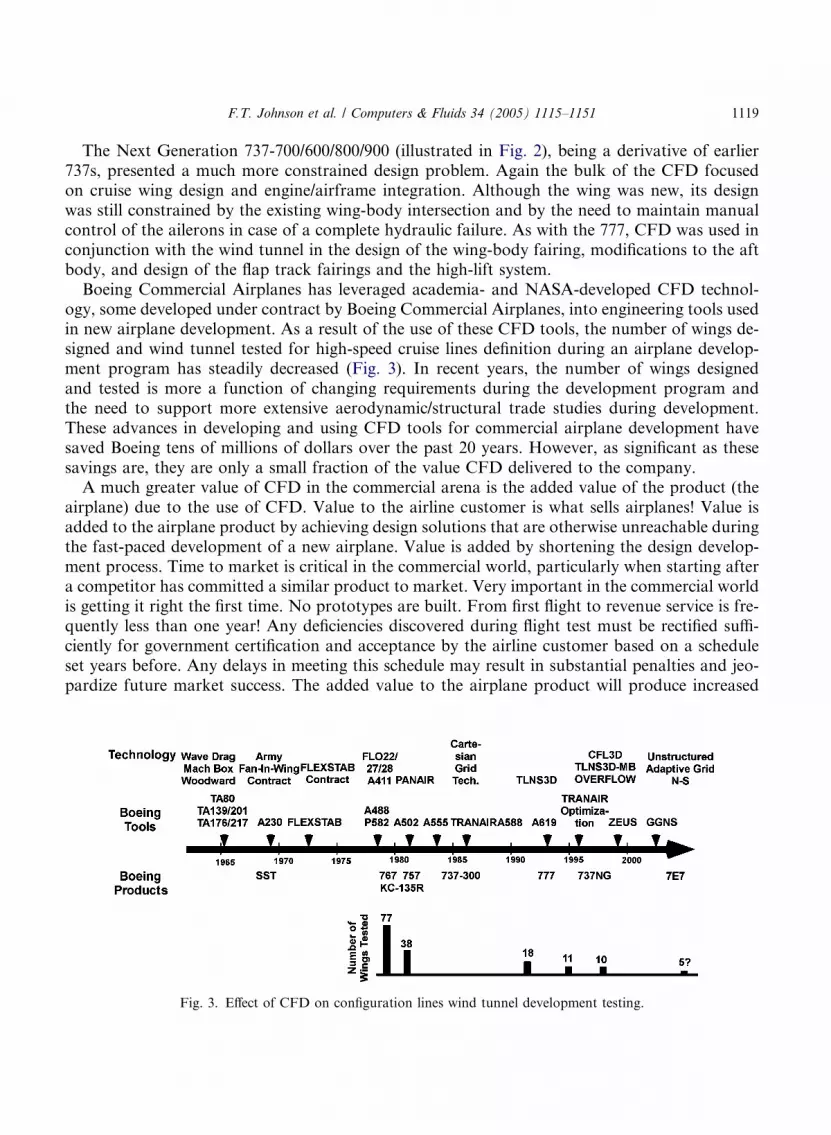
ogy, some developed under contract by Boeing Commercial Airplanes, into engineering tools usedin new airplane development. As a result of the use of these CFD tools, the number of wings de-signed and wind tunnel tested for high-speed cruise lines definition during an airplane develop-ment program has steadily decreased (Fig. 3). In recent years, the number of wings designedand tested is more a function of changing requirements during the development program andthe need to support more extensive aerodynamic/structural trade studies during development.These advances in developing and using CFD tools for commercial airplane development havesaved Boeing tens of millions of dollars over the past 20 years. However, as significant as thesesavings are, they are only a small fraction of the value CFD delivered to the company.A much greater value of CFD in the commercial arena is the added value of the product (the
airplane) due to the use of CFD. Value to the airline customer is what sells airplanes! Value isadded to the airplane product by achieving design solutions that are otherwise unreachable duringthe fast-paced development of a new airplane. Value is added by shortening the design develop-ment process. Time to market is critical in the commercial world, particularly when starting aftera competitor has committed a similar product to market. Very important in the commercial worldis getting it right the first time. No prototypes are built. From first flight to revenue service is fre-quently less than one year! Any deficiencies discovered during flight test must be rectified suffi-ciently for government certification and acceptance by the airline customer based on a scheduleset years before. Any delays in meeting this schedule may result in substantial penalties and jeo-pardize future market success. The added value to the airplane product will produce increased
Fig. 3. Effect of CFD on configuration lines wind tunnel development testing.
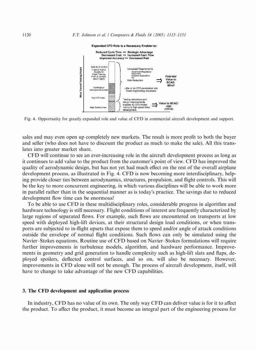
Fig. 4. Opportunity for greatly expanded role and value of CFD in commercial aircraft development and support.
1120 F.T. Johnson et al. / Computers & Fluids 34 (2005) 1115–1151
sales and may even open up completely new markets. The result is more profit to both the buyerand seller (who does not have to discount the product as much to make the sale). All this trans-lates into greater market share.CFD will continue to see an ever-increasing role in the aircraft development process as long as
it continues to add value to the product from the customer�s point of view. CFD has improved thequality of aerodynamic design, but has not yet had much effect on the rest of the overall airplanedevelopment process, as illustrated in Fig. 4. CFD is now becoming more interdisciplinary, help-ing provide closer ties between aerodynamics, structures, propulsion, and flight controls. This willbe the key to more concurrent engineering, in which various disciplines will be able to work morein parallel rather than in the sequential manner as is today�s practice. The savings due to reduceddevelopment flow time can be enormous!To be able to use CFD in these multidisciplinary roles, considerable progress in algorithm and
hardware technology is still necessary. Flight conditions of interest are frequently characterized bylarge regions of separated flows. For example, such flows are encountered on transports at lowspeed with deployed high-lift devices, at their structural design load conditions, or when trans-ports are subjected to in-flight upsets that expose them to speed and/or angle of attack conditionsoutside the envelope of normal flight conditions. Such flows can only be simulated using theNavier–Stokes equations. Routine use of CFD based on Navier–Stokes formulations will requirefurther improvements in turbulence models, algorithm, and hardware performance. Improve-ments in geometry and grid generation to handle complexity such as high-lift slats and flaps, de-ployed spoilers, deflected control surfaces, and so on, will also be necessary. However,improvements in CFD alone will not be enough. The process of aircraft development, itself, willhave to change to take advantage of the new CFD capabilities.
3. The CFD development and application process
In industry, CFD has no value of its own. The only way CFD can deliver value is for it to affectthe product. To affect the product, it must become an integral part of the engineering process for
F.T. Johnson et al. / Computers & Fluids 34 (2005) 1115–1151 1121
the design, manufacture, and support of the product. Otherwise, CFD is just an add-on; it mayhave some value but its effect is limited. To make CFD an integral part of the Product Develop-ment and Support engineering processes, it must get into the hands of the engineers who executethese processes. This is the only way the volume of analysis/design runs necessary to affect theproduct can be made. Moreover, it is in the Product Development and Support organizations thatownership of the CFD/engineering processes resides, and it is these processes that managementrelies on when investing billions of dollars in a new airplane development. The CFD developersand ‘‘expert’’ users can certainly contribute, but are only a part of the engineering process.Getting CFD into ‘‘production’’ use is not trivial––it is frequently a multiyear process. There
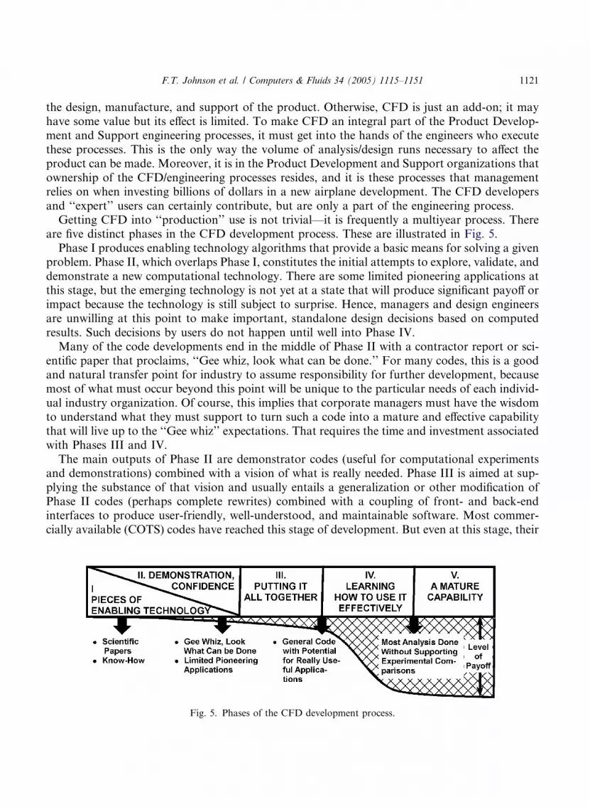
are five distinct phases in the CFD development process. These are illustrated in Fig. 5.Phase I produces enabling technology algorithms that provide a basic means for solving a given
problem. Phase II, which overlaps Phase I, constitutes the initial attempts to explore, validate, anddemonstrate a new computational technology. There are some limited pioneering applications atthis stage, but the emerging technology is not yet at a state that will produce significant payoff orimpact because the technology is still subject to surprise. Hence, managers and design engineersare unwilling at this point to make important, standalone design decisions based on computedresults. Such decisions by users do not happen until well into Phase IV.Many of the code developments end in the middle of Phase II with a contractor report or sci-
entific paper that proclaims, ‘‘Gee whiz, look what can be done.’’ For many codes, this is a goodand natural transfer point for industry to assume responsibility for further development, becausemost of what must occur beyond this point will be unique to the particular needs of each individ-ual industry organization. Of course, this implies that corporate managers must have the wisdomto understand what they must support to turn such a code into a mature and effective capabilitythat will live up to the ‘‘Gee whiz’’ expectations. That requires the time and investment associatedwith Phases III and IV.The main outputs of Phase II are demonstrator codes (useful for computational experiments
and demonstrations) combined with a vision of what is really needed. Phase III is aimed at sup-plying the substance of that vision and usually entails a generalization or other modification ofPhase II codes (perhaps complete rewrites) combined with a coupling of front- and back-endinterfaces to produce user-friendly, well-understood, and maintainable software. Most commer-cially available (COTS) codes have reached this stage of development. But even at this stage, their
Fig. 5. Phases of the CFD development process.

1122 F.T. Johnson et al. / Computers & Fluids 34 (2005) 1115–1151
contribution or effect on the corporate bottom line is still minimal because engineers and manag-ers don�t yet understand how the existence of this new tool will change the engineering process andwhat it will be used for. They have yet to gain enough confidence to make important, standalonedecisions based on the code. That takes time, exposure, and experience.In the fourth phase, the payoff or affect of a code grows rapidly. Phase IV entails ‘‘applications
research,’’ where design engineers, management, and code developers work together to learn howthis new capability will enter into and change the aerodynamic design process. The applicationsresearch endeavor requires people with broad backgrounds who can ask the right questions of thealgorithm researchers, and code developers who can intelligently question experimental data whentest-theory comparisons don�t agree. Both must also be good physicists, for it is not unusual tofind that the short-comings lie neither in the experiment nor in the quality of the computations,but in the fact that the theoretical model assumed in the computations was not an adequatedescription of the real physics. Need for code refinements that were not anticipated invariably sur-face during this phase and these refinements often require more algorithm research, additionalgeometry preprocessors, and so on. Over time, the requests for additions or refinements diminishuntil the code settles down to occupy its proper niche in the toolbox, and design engineers andmanagers have learned the capabilities, limitations, and proper applications of this now-maturecode. Without the investments in Phase IV, the enormous pay-off of having a mature capabilityin Phase V will not happen. An attempt to bypass Phase IV by taking a code developed by algo-rithm researchers and placing it directly in the hands of design engineers, who may not understandthe underlying theoretical models, algorithms, and possible numerical idiosyncrasies, usually re-sults in a prolonged period of frustration and unreliability that leads to abandonment of the code.Product Development engineers must be able to focus on engineering processes and have little
time for manipulating the CFD ‘‘process’’ (i.e., codes must be very user oriented). Stable, pack-aged software solutions enable and promote consistent processes. These not only put CFD intothe hands of the Product Development/Product Support engineers but also allow the ‘‘expert’’user to get fast results with reduced variation. Integrated packaged software solutions combinevarious components to go from ‘‘lofts to plots’’ in the time scale consistent with a fast-paced engi-neering program. These packages include scripted packages for ‘‘standard’’ configurations, geom-etry and grid/paneling generation components, flow solvers, and postprocessing components foranalyzing the results. These are all placed under some form of software version control to main-tain consistency.A key component of CFD and most engineering processes is geometry. CAD systems, such as
CATIA, dominate most geometry engineering needs. However, these systems are designed forcomponent design and definition and are not well suited to CFD use. A key component of manyBoeing Commercial Airplanes CFD processes is AGPS––Aero Grid and Paneling System [6].AGPS is a geometry software tool implemented as a programming language with an interactivegraphical user interface. It can be dynamically configured to create a tailored geometry environ-ment for specific tasks. AGPS is used to create, manipulate, interrogate, or visualize geometry ofany type. Since its first release in 1983, AGPS has been applied with great success within The Boe-ing Company to a wide variety of engineering analysis tasks, such as CFD and structural analysis,in addition to other geometry-related tasks.Computing resources consisting of high-end computing and graphics workstations must also be
integrated. Seamless mass data storage must be available to store the vast amount of information
F.T. Johnson et al. / Computers & Fluids 34 (2005) 1115–1151 1123
that will be generated during the engineering application. These resources require dedicated com-puting system administration. The software control and computing system administration arenecessary to free the engineers to focus their work on the engineering processes and not be con-sumed by the ‘‘computing’’ process.Close customer involvement and acceptance is absolutely essential to deriving value from CFD.
Customers are responsible for implementing the engineering process that will use CFD. They ownthe process, they determine what CFD, if any, they will depend on to carry out their assignedtasks. They are being graded on the engineering tasks they accomplish not on which CFD codesthey use. Their use and trust of CFD is based on a long-term relationship between supplier anduser. This relationship has engaged the customer early on in demonstrations of a new code or newapplication of an existing code. Validation is an on-going process, first of cases of interest to thecustomer, and then of the customer�s ability to implement the new tool. Frequently, parallel appli-cations are undertaken in which the customer continues with the existing tools while the supplier/developer duplicates the process with the new tool. This is especially the case when the new toolmay enable the development of an entirely new process for executing the engineering task.The long-term relationship with the customer is essential from another point of view. Until re-
cently, project engineers, without exception, initially rejected every new CFD development thatlater became the primary CFD analysis and design tool in Boeing Commercial Airplanes ProductDevelopment and Product Support organizations. Every new or proposed CFD capability wasinitially viewed as too difficult to use, too costly to run, not able to produce timely results, notneeded, and so on. ‘‘Just fix what we already have,’’ the customer would tell the developers.The customers had a point. Not until the new CFD technology had been integrated with the cus-tomer�s preprocessing/postprocessing tools and computing system, validated to the customer�sprogram, guaranteed of long-term support, and committed to continuous development andenhancement would the new technology be useful to them.This made it difficult for the developers to propose new Phase I, II and III efforts. In particular,
the initiation and continual defense of Phase I efforts demanded clear and unwavering vision.True vision invariably requires a fundamental understanding of both needs and means. As cus-tomers generally did not have the specialized algorithmic knowledge underlying CFD numerics,it was incumbent on the developers to acquire a thorough understanding of customer needsand concerns. The developers learned they could not just throw a new CFD tool over the fenceand expect the customer to use it no matter how good it might be. The customer was interestedin getting an engineering job done and not in the CFD tool itself! The process of thoroughlyunderstanding customer issues took many years, and early Phase I, II, and III efforts were mostly‘‘technology push’’ efforts, which had to be funded by NASA or other Government agencies. Asthese efforts progressed to Phase IV and V, and the developers established a track record for pro-ducing useful capabilities, the situation gradually changed.Each success allowed the developers a little more leeway. Often they spotted ‘‘niche’’ needs that
could be satisfied by the introduction of their new technology. It was felt that when the users weresatisfied with the usability and utility of the technology in these areas they would then be willing toconsider whether or not replacing their old tools in other areas might offer distinct advantages.Once the users accepted a new capability, they often became very innovative and applied the codesin unanticipated ways, perpetually keeping the developers and validation experts in an anxiousstate. Most of the new applications were, in fact, legitimate, and the developers had to run fast
1124 F.T. Johnson et al. / Computers & Fluids 34 (2005) 1115–1151
to understand the implications involved as well as to try and anticipate future application direc-tions. As time went on, code developers, application experts, and project engineers began under-standing each other�s functions and issues, and a certain amount of trust developed. Gradually,CFD became a ‘‘pull’’ rather than ‘‘push’’ technology. This transformation was greatly facilitatedby the rotation of top engineers between these functions.Today in Boeing Commercial Airplanes, more than 20,000 CFD runs a year are made to sup-
port product development and the various existing product lines. More than 90% of these runs aredone by production engineers outside the research group. The CFD methods in use provide timelyresults in hours or days, not weeks or months. Sufficient experience with the methods has givenmanagement confidence in their results. This means that solutions are believable without furthercomparison of known results with experiment, that the CFD methods contain enough of the rightphysics and resolve the important physical and geometric length scales, that the numerics of themethod are accurate and reliable, and that the CFD tools are already in place––for there is notime to develop and validate new methods. Most of all, management is convinced that the useof CFD makes economic sense. A look at the history of CFD at Boeing Commercial Airplaneswill show how we got to this level of use.
4. Chronology of CFD capability and use
CFD today covers a wide range of capabilities in terms of flow physics and geometric complex-ity. The most general mathematical description of the flow physics relevant to a commercial trans-port is provided by the Navier–Stokes equations. These equations state the laws of conservationof mass, momentum, and energy of a fluid in thermodynamic equilibrium. Unfortunately, directsolutions to these equations for practical aircraft configurations at typical flight conditions arewell beyond the capabilities of today�s computers. Such flows include chaotic, turbulent motionsover a very wide range of length scales. Computations for the simulations of all scales of turbu-lence would require solving for on the order of 1018 degrees of freedom!Fortunately, solutions to simplified (and more tractable) forms of these equations are still of
great engineering value. Turbulent flows may be simulated by the Reynolds equations, in whichstatistical averages are used to describe details of the turbulence. Closure requires the develop-ment of turbulence models, which tend to be adequate for the particular and rather restrictiveclasses of flow for which empirical correlations are available, but which may not be currentlycapable of reliably predicting behavior of the more complex flows that are generally of interestto the aerodynamicist. Use of turbulence models leads to various forms of what are called theReynolds-averaged Navier–Stokes equations.For many aerodynamic design applications, the flow equations are further simplified to make
them more amenable to solution. Neglecting viscosity leads to the Euler equations for the conser-vation of mass, momentum, and energy of an inviscid fluid. Fortunately, under many flight con-ditions the effects of viscosity are small and can be ignored or simulated by the addition of theboundary layer equations, a much simplified form of the Reynolds-averaged Navier–Stokesequations.The introduction of a velocity potential reduces the need to solve five nonlinear partial differ-
ential equations (that make up the Euler equations) to the solution of a single nonlinear partial
F.T. Johnson et al. / Computers & Fluids 34 (2005) 1115–1151 1125
differential equation known as the full potential equation. However, the potential approximationassumes an inviscid, irrotational, isentropic (constant entropy) flow. Potential solutions can ade-quately simulate shock waves as long as they are weak, which is the normal case for commercialtransport configurations.Further simplifications eliminate all the nonlinear terms in the potential equation, resulting in
the Prandtl–Glauert equation for linear compressible flows, or the Laplace equation for incom-pressible flows. The use of these equations is formally justified when the vehicle is relatively slen-der or thin and produces only small disturbances from freestream flow.In the following sections, we describe the CFD capability most heavily used at Boeing Commer-
cial Airplanes in Seattle over the last 30 years. For the purposes of a rough chronological sum-mary, we can say the following. Before 1973, the main codes employed by project engineersinvolved linearized supersonic flows with linearized representations of the geometry or else 2Dincompressible flows. From 1973 to 1983, panel methods, which could model complex geometriesin the presence of linear subsonic and supersonic flows, took center stage. The nonlinear potentialflow/coupled boundary layer codes achieved their prime from 1983 to 1993. Their Euler counter-parts came into use later in that timeframe. From 1993 to 2003, Reynolds averaged Navier–Stokescodes began to be used with increasing frequency. Clearly, much of the development and demon-stration work leading to the widespread use of these codes occurred from five to 10 years earlierthan these dates. It is important to note that a considerable length of time is often required for acode to achieve the Phase V level of maturity. It is also important to realize that once a codeachieves this level of maturity and is in use and accepted by the user community, it tends to remainin use, even though improved capability at the Phase III or IV level may be available.The Boeing panel code, A502, remains in some use today, even though its underlying technol-
ogy was developed almost 30 years ago. The full potential code TRANAIR still receives wide-spread and heavy use.
4.1. Linear potential flow
4.1.1. First generation methods––early codesThe flow physics described by the early linear methods were greatly simplified compared to the
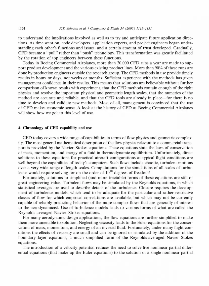
‘‘real’’ flow. Similarly, the geometric fidelity of the actual configuration also had to be greatly sim-plified for the computational analysis to fit within the speed and size constraints of the computersof that era. In spite of such seemingly hopeless limitations, these early CFD methods were success-fully applied during the supersonic transport development programs of the late 1960s––the Anglo-French Concord and the United States/Boeing SST. The need for computational help in theaerodynamic development of these aircraft stemmed from two factors. First, there was the relativelack of experience in designing supersonic cruise aircraft (the first supersonic flight had occurredonly 15 years earlier). Second, there is great sensitivity of supersonic wave drag to details of theaircraft design. Thus, the challenge of developing a viable low-drag design through empirical ‘‘cutand try’’ demanded whatever computational help was available. The opportunity to use simplifiedcomputational methods resulted because the design requirements for low supersonic wave dragled to thin, slender vehicles that minimized ‘‘perturbing’’ the airflow. These characteristics wereconsistent with the limitations of the linearized supersonic theory embedded in the early CFDcodes. These codes included TA80 [7], a Supersonic Area Rule Code based on slender body
Fig. 6. Early Boeing SST test versus CFD comparison—733-290-mach = 2.7.
1126 F.T. Johnson et al. / Computers & Fluids 34 (2005) 1115–1151
theory; TA139/201 [8], a Mach Box Code based on linearized supersonic theory; and TA176/217[9], a Wing-Body Code based on linear potential flow theory with linearized geometry represen-tations. These codes ran on IBM7094 machines. The good agreement with test data predicted bythese linear theory methods for a drag polar of the Boeing SST model 733-290 is shown in Fig. 6.This was a linear theory optimized design of the configuration that allowed Boeing to win the SSTdesign development Government contract. The resulting supersonic transport designs ended uplooking as they did, in part, because the early CFD codes could not handle more geometricallycomplex configurations.The linear aerodynamics of the Wing-Body Code was later combined with linear structural and
dynamic analysis methods in the FLEXSTAB [10] system for the evaluation of static and dynamicstability, trim state, inertial and aerodynamic loading, and elastic deformations of aircraft config-urations at supersonic and subsonic speeds. This system was composed of a group of 14 individualcomputer programs that could be linked by tape or disk data transfer. The system was designed tooperate on CDC-6000 and -7000 series computers and on the IBM 360/370 computers. A very suc-cessful early application of FLEXSTAB was the aeroelastic analysis of the Lockheed YF-12A aspart of the NASA Flight Loads program. Thirty-two flight test conditions ranging from Mach0.80 to 3.0 and involving hot or cold structures and different fuel loading conditions were analyzedat several load factors [11].
4.1.2. First generation methods––TA230By 1973, 3D subsonic panel methods were beginning to affect the design and analysis of aircraft
configurations at Boeing. Subsonic panel methods had their origins with the introduction of theDouglas Neumann program in 1962 [12]. This program was spectacularly successful for its time insolving the 3D incompressible linear potential flow (Laplace) equation about complex configura-tions using solid wall (Neumann) boundary conditions. The numerical method represented theboundary by constant strength source panels with the strengths determined by an influence coef-ficient equation set relating the velocities induced by the source panels to the boundary conditions.The lack of provision for doublet panels limited the class of solutions to those without potential
F.T. Johnson et al. / Computers & Fluids 34 (2005) 1115–1151 1127
jumps and hence without lift. One of the first computer programs for attacking arbitrary potentialflow problems with Neumann boundary conditions [13,14] combined the source panel scheme ofthe Douglas Neumann program with variations of the vortex lattice technique [15]. This programbecame known as the Boeing TA230 program. A very useful feature of this program was the abil-ity to handle, in a logical fashion, any well-posed Neumann boundary value problem. From itsinception, the method employed a building block approach wherein the influence coefficient equa-tion set for a complex problem was constructed by simply assembling networks appropriate to theboundary value problem. A network was viewed as a paneled surface segment on which a sourceor doublet distribution was defined, accompanied by a properly posed set of Neumann boundaryconditions. The surface segment could be oriented arbitrarily in space and the boundary condi-tions could be exact or linearized. Several doublet network types with differing singularity degreesof freedom were available to simulate a variety of physical phenomena producing discontinuitiesin potential. Compressibility effects were handled through scaling. These features combined toallow the analysis of configurations having thin or thick wings, bodies, nacelles, empennage, flaps,wakes, efflux tubes, barriers, free surfaces, interior ducts, fans, and so on.By 1973, Boeing had acquired a CDC 6600 for scientific computing, which allowed the TA230
program to solve problems involving hundreds of panels. This was sufficient to model full config-urations with the fidelity necessary to understand component interactions.One of the most impressive early uses of the TA230 code was in the initial design phase of the
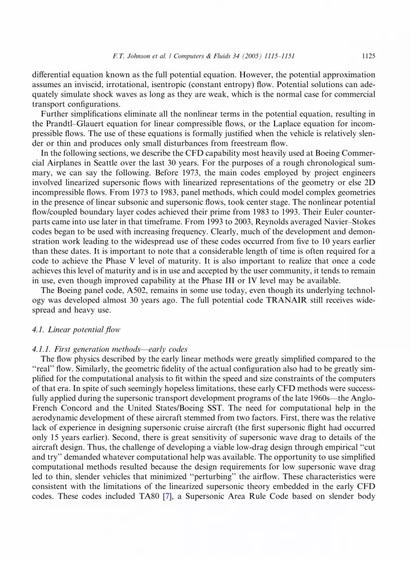
B747 Space Shuttle Carrier Aircraft (SCA). The purpose of the initial design phase was to definethe modifications needed to accomplish the following missions: to ferry the Space Shuttle Orbiter;to air-launch the Orbiter; and to ferry the external fuel tank. To keep the cost of the program to aminimum, CFD was extensively used to investigate the Orbiter attitude during the ferry mission,the Orbiter trajectory and attitude during the launch test, and the external tank location and atti-tude during the ferry mission. At the conclusion of the design phase, the final configurations se-lected were tested in the wind tunnel to verify predictions. A typical example of a paneling schemeof the B747 with the Space Shuttle Orbiter is depicted in Fig. 7. In this example, the Orbiter inci-dence angle was 8 deg with respect to the B747 reference plane. The predicted lift coefficient, CL,as a function of wing angle of attack for this configuration is shown in Fig. 8. The agreement be-tween the analyses and wind tunnel data shown in this figure is excellent.
Fig. 7. B747 with space shuttle orbiter.
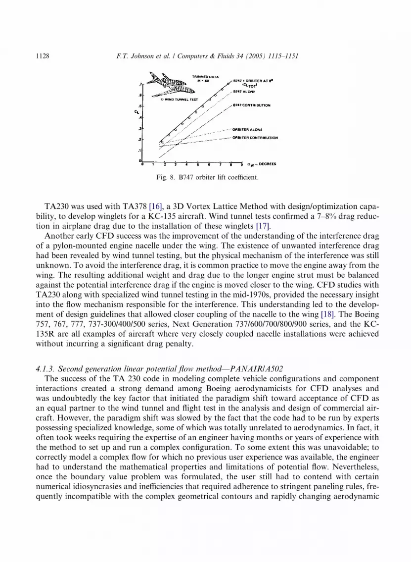
Fig. 8. B747 orbiter lift coefficient.
1128 F.T. Johnson et al. / Computers & Fluids 34 (2005) 1115–1151
TA230 was used with TA378 [16], a 3D Vortex Lattice Method with design/optimization capa-bility, to develop winglets for a KC-135 aircraft. Wind tunnel tests confirmed a 7–8% drag reduc-tion in airplane drag due to the installation of these winglets [17].Another early CFD success was the improvement of the understanding of the interference drag
of a pylon-mounted engine nacelle under the wing. The existence of unwanted interference draghad been revealed by wind tunnel testing, but the physical mechanism of the interference was stillunknown. To avoid the interference drag, it is common practice to move the engine away from thewing. The resulting additional weight and drag due to the longer engine strut must be balancedagainst the potential interference drag if the engine is moved closer to the wing. CFD studies withTA230 along with specialized wind tunnel testing in the mid-1970s, provided the necessary insightinto the flow mechanism responsible for the interference. This understanding led to the develop-ment of design guidelines that allowed closer coupling of the nacelle to the wing [18]. The Boeing757, 767, 777, 737-300/400/500 series, Next Generation 737/600/700/800/900 series, and the KC-135R are all examples of aircraft where very closely coupled nacelle installations were achievedwithout incurring a significant drag penalty.
4.1.3. Second generation linear potential flow method––PANAIR/A502The success of the TA 230 code in modeling complete vehicle configurations and component
interactions created a strong demand among Boeing aerodynamicists for CFD analyses andwas undoubtedly the key factor that initiated the paradigm shift toward acceptance of CFD asan equal partner to the wind tunnel and flight test in the analysis and design of commercial air-craft. However, the paradigm shift was slowed by the fact that the code had to be run by expertspossessing specialized knowledge, some of which was totally unrelated to aerodynamics. In fact, itoften took weeks requiring the expertise of an engineer having months or years of experience withthe method to set up and run a complex configuration. To some extent this was unavoidable; tocorrectly model a complex flow for which no previous user experience was available, the engineerhad to understand the mathematical properties and limitations of potential flow. Nevertheless,once the boundary value problem was formulated, the user still had to contend with certainnumerical idiosyncrasies and inefficiencies that required adherence to stringent paneling rules, fre-quently incompatible with the complex geometrical contours and rapidly changing aerodynamic
F.T. Johnson et al. / Computers & Fluids 34 (2005) 1115–1151 1129
length scales of the vehicle under analysis. Such difficulties were directly related to the use of flatpanels with constant source and doublet strengths. Methods employing these features were quitesensitive to panel layout. Numerical problems arose when panel shapes and sizes varied, and finepaneling in regions of rapid flow variations often forced fine paneling elsewhere. In addition,excessive numbers of panels were often required since numerical accuracy was strongly affectedby local curvature and singularity strength gradient. These problems placed severe limitationson the development of automatic panelers and other complementary aids aimed at relieving theuser of the large amount of handwork and judgments associated with producing accurate numer-ical solutions.Consequently, a method was developed under contract to NASA to enhance practical usability
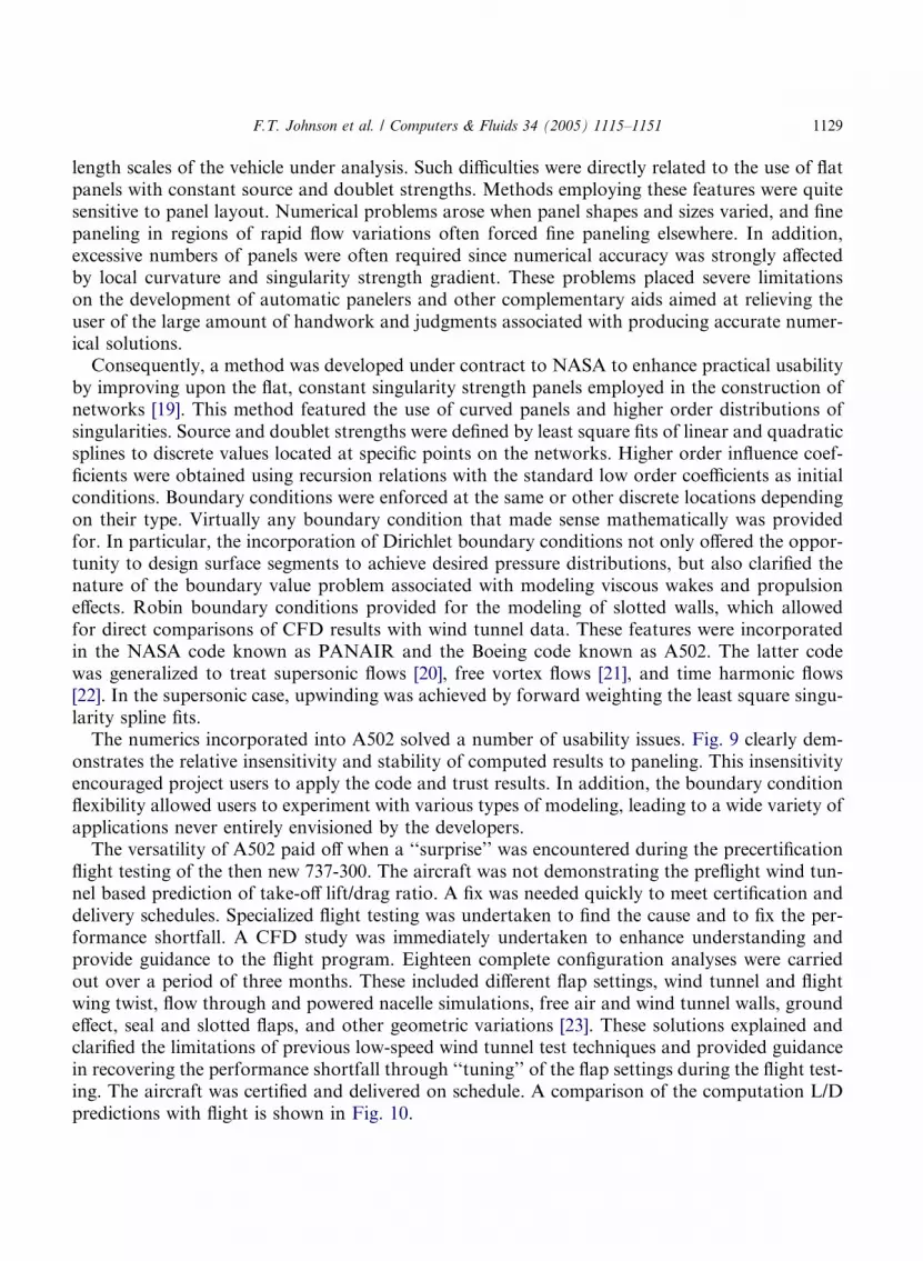
by improving upon the flat, constant singularity strength panels employed in the construction ofnetworks [19]. This method featured the use of curved panels and higher order distributions ofsingularities. Source and doublet strengths were defined by least square fits of linear and quadraticsplines to discrete values located at specific points on the networks. Higher order influence coef-ficients were obtained using recursion relations with the standard low order coefficients as initialconditions. Boundary conditions were enforced at the same or other discrete locations dependingon their type. Virtually any boundary condition that made sense mathematically was providedfor. In particular, the incorporation of Dirichlet boundary conditions not only offered the oppor-tunity to design surface segments to achieve desired pressure distributions, but also clarified thenature of the boundary value problem associated with modeling viscous wakes and propulsioneffects. Robin boundary conditions provided for the modeling of slotted walls, which allowedfor direct comparisons of CFD results with wind tunnel data. These features were incorporatedin the NASA code known as PANAIR and the Boeing code known as A502. The latter codewas generalized to treat supersonic flows [20], free vortex flows [21], and time harmonic flows[22]. In the supersonic case, upwinding was achieved by forward weighting the least square singu-larity spline fits.The numerics incorporated into A502 solved a number of usability issues. Fig. 9 clearly dem-
onstrates the relative insensitivity and stability of computed results to paneling. This insensitivityencouraged project users to apply the code and trust results. In addition, the boundary conditionflexibility allowed users to experiment with various types of modeling, leading to a wide variety ofapplications never entirely envisioned by the developers.The versatility of A502 paid off when a ‘‘surprise’’ was encountered during the precertification
flight testing of the then new 737-300. The aircraft was not demonstrating the preflight wind tun-nel based prediction of take-off lift/drag ratio. A fix was needed quickly to meet certification anddelivery schedules. Specialized flight testing was undertaken to find the cause and to fix the per-formance shortfall. A CFD study was immediately undertaken to enhance understanding andprovide guidance to the flight program. Eighteen complete configuration analyses were carriedout over a period of three months. These included different flap settings, wind tunnel and flightwing twist, flow through and powered nacelle simulations, free air and wind tunnel walls, groundeffect, seal and slotted flaps, and other geometric variations [23]. These solutions explained andclarified the limitations of previous low-speed wind tunnel test techniques and provided guidancein recovering the performance shortfall through ‘‘tuning’’ of the flap settings during the flight test-ing. The aircraft was certified and delivered on schedule. A comparison of the computation L/Dpredictions with flight is shown in Fig. 10.
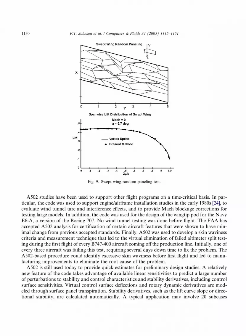
Fig. 9. Swept wing random paneling test.
1130 F.T. Johnson et al. / Computers & Fluids 34 (2005) 1115–1151
A502 studies have been used to support other flight programs on a time-critical basis. In par-ticular, the code was used to support engine/airframe installation studies in the early 1980s [24], toevaluate wind tunnel tare and interference effects, and to provide Mach blockage corrections fortesting large models. In addition, the code was used for the design of the wingtip pod for the NavyE6-A, a version of the Boeing 707. No wind tunnel testing was done before flight. The FAA hasaccepted A502 analysis for certification of certain aircraft features that were shown to have min-imal change from previous accepted standards. Finally, A502 was used to develop a skin wavinesscriteria and measurement technique that led to the virtual elimination of failed altimeter split test-ing during the first flight of every B747-400 aircraft coming off the production line. Initially, one ofevery three aircraft was failing this test, requiring several days down time to fix the problem. TheA502-based procedure could identify excessive skin waviness before first flight and led to manu-facturing improvements to eliminate the root cause of the problem.A502 is still used today to provide quick estimates for preliminary design studies. A relatively
new feature of the code takes advantage of available linear sensitivities to predict a large numberof perturbations to stability and control characteristics and stability derivatives, including controlsurface sensitivities. Virtual control surface deflections and rotary dynamic derivatives are mod-eled through surface panel transpiration. Stability derivatives, such as the lift curve slope or direc-tional stability, are calculated automatically. A typical application may involve 20 subcases
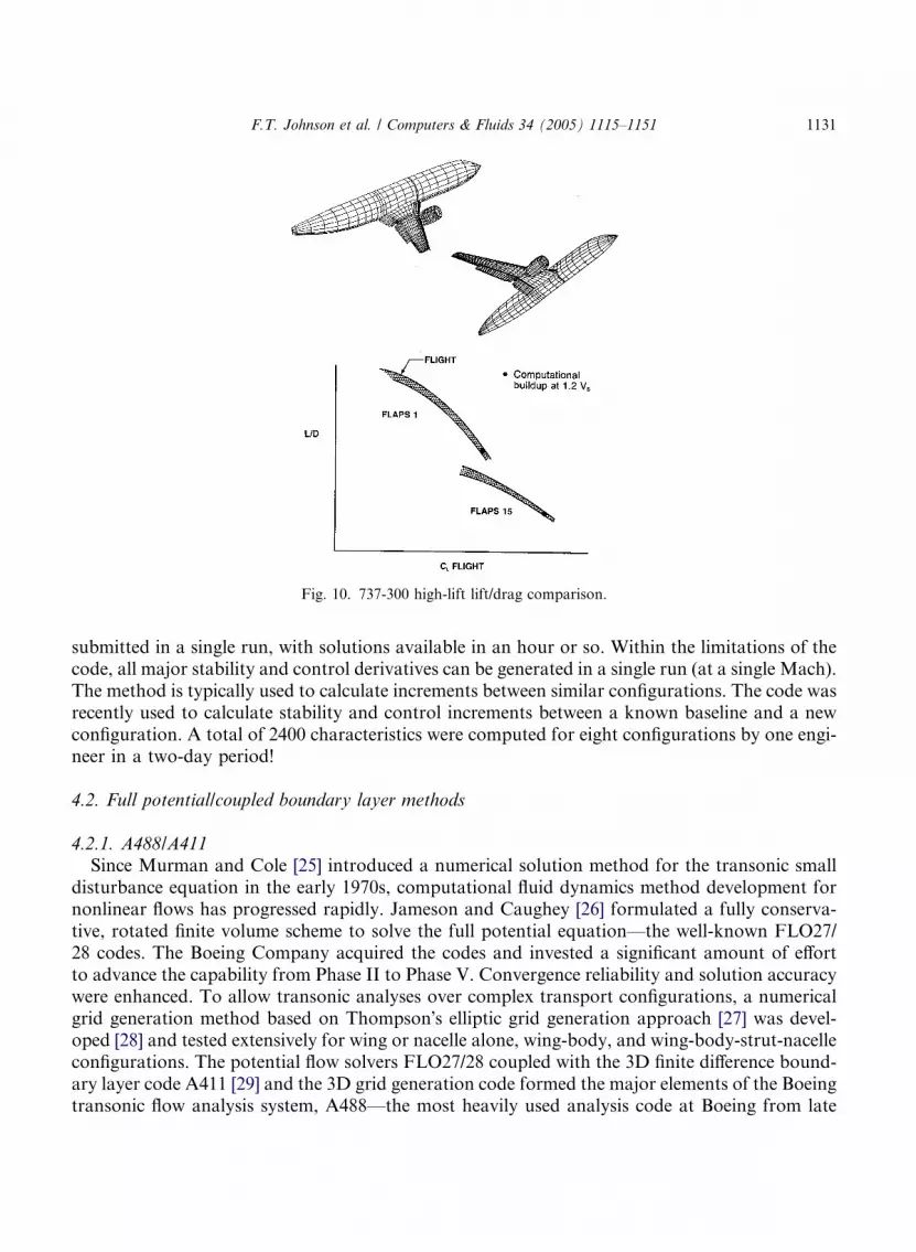
Fig. 10. 737-300 high-lift lift/drag comparison.
F.T. Johnson et al. / Computers & Fluids 34 (2005) 1115–1151 1131
submitted in a single run, with solutions available in an hour or so. Within the limitations of thecode, all major stability and control derivatives can be generated in a single run (at a single Mach).The method is typically used to calculate increments between similar configurations. The code wasrecently used to calculate stability and control increments between a known baseline and a newconfiguration. A total of 2400 characteristics were computed for eight configurations by one engi-neer in a two-day period!
4.2. Full potential/coupled boundary layer methods
4.2.1. A488/A411Since Murman and Cole [25] introduced a numerical solution method for the transonic small
disturbance equation in the early 1970s, computational fluid dynamics method development fornonlinear flows has progressed rapidly. Jameson and Caughey [26] formulated a fully conserva-tive, rotated finite volume scheme to solve the full potential equation––the well-known FLO27/28 codes. The Boeing Company acquired the codes and invested a significant amount of effortto advance the capability from Phase II to Phase V. Convergence reliability and solution accuracywere enhanced. To allow transonic analyses over complex transport configurations, a numericalgrid generation method based on Thompson�s elliptic grid generation approach [27] was devel-oped [28] and tested extensively for wing or nacelle alone, wing-body, and wing-body-strut-nacelleconfigurations. The potential flow solvers FLO27/28 coupled with the 3D finite difference bound-ary layer code A411 [29] and the 3D grid generation code formed the major elements of the Boeingtransonic flow analysis system, A488––the most heavily used analysis code at Boeing from late
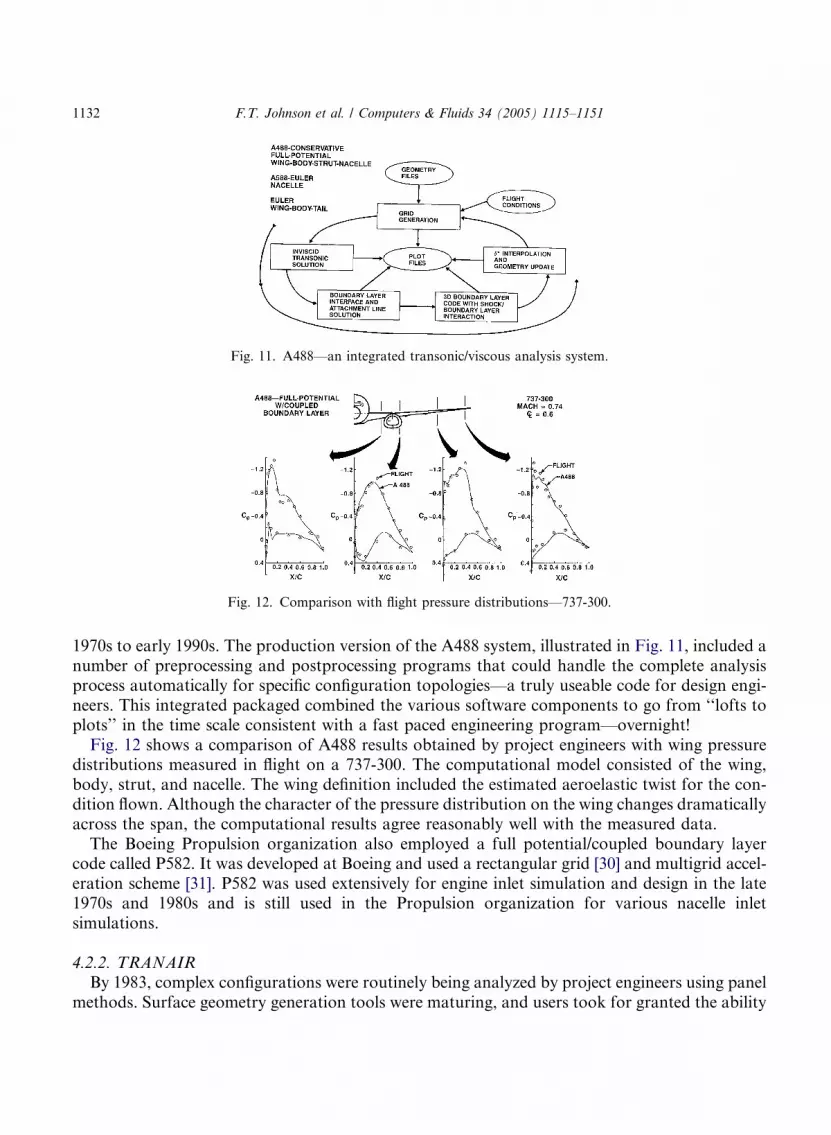
Fig. 12. Comparison with flight pressure distributions––737-300.
Fig. 11. A488––an integrated transonic/viscous analysis system.
1132 F.T. Johnson et al. / Computers & Fluids 34 (2005) 1115–1151
1970s to early 1990s. The production version of the A488 system, illustrated in Fig. 11, included anumber of preprocessing and postprocessing programs that could handle the complete analysisprocess automatically for specific configuration topologies––a truly useable code for design engi-neers. This integrated packaged combined the various software components to go from ‘‘lofts toplots’’ in the time scale consistent with a fast paced engineering program––overnight!Fig. 12 shows a comparison of A488 results obtained by project engineers with wing pressure
distributions measured in flight on a 737-300. The computational model consisted of the wing,body, strut, and nacelle. The wing definition included the estimated aeroelastic twist for the con-dition flown. Although the character of the pressure distribution on the wing changes dramaticallyacross the span, the computational results agree reasonably well with the measured data.The Boeing Propulsion organization also employed a full potential/coupled boundary layer
code called P582. It was developed at Boeing and used a rectangular grid [30] and multigrid accel-eration scheme [31]. P582 was used extensively for engine inlet simulation and design in the late1970s and 1980s and is still used in the Propulsion organization for various nacelle inletsimulations.
4.2.2. TRANAIRBy 1983, complex configurations were routinely being analyzed by project engineers using panel
methods. Surface geometry generation tools were maturing, and users took for granted the ability
F.T. Johnson et al. / Computers & Fluids 34 (2005) 1115–1151 1133
to add, move, or delete components at will; readily change boundary condition types; and obtainnumerically accurate solutions at reasonable cost in a day or two. On the other hand, the nonlin-ear potential flow codes required expert users and considerable flow time to obtain converged andaccurate results on new and nonstandard configurations. Often, geometrical simplifications had tobe made jeopardizing the validity of conclusions regarding component interactions. Clearly, thenonlinear nature of the flow was responsible for numerous difficulties. The development of shocksin the flowfield prolonged convergence, especially if the shocks were strong and prematurely set inthe wrong location. Moreover, weak and double shocks were often not captured accurately, if atall. Boundary layer coupling contributed problems as well, especially as separation was ap-proached. Often, the boundary layer displacement effect had to be fixed after a certain numberof iterations, leading to questionable results. Experts became very good at circumventing manyof these problems; however, the one problem that could not readily be overcome was the necessityto generate a volume grid to capture nonlinear effects.Even today, volume grid generation is one of the main barriers to routine use of nonlinear
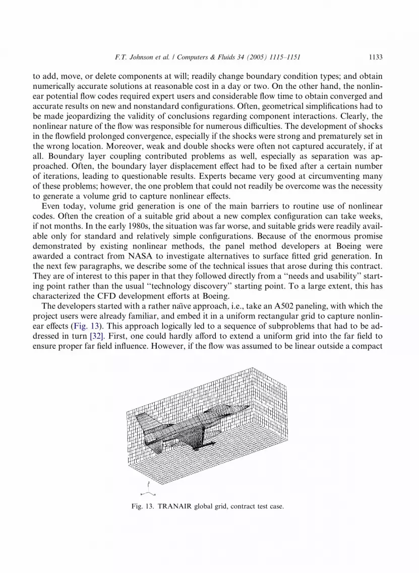
codes. Often the creation of a suitable grid about a new complex configuration can take weeks,if not months. In the early 1980s, the situation was far worse, and suitable grids were readily avail-able only for standard and relatively simple configurations. Because of the enormous promisedemonstrated by existing nonlinear methods, the panel method developers at Boeing wereawarded a contract from NASA to investigate alternatives to surface fitted grid generation. Inthe next few paragraphs, we describe some of the technical issues that arose during this contract.They are of interest to this paper in that they followed directly from a ‘‘needs and usability’’ start-ing point rather than the usual ‘‘technology discovery’’ starting point. To a large extent, this hascharacterized the CFD development efforts at Boeing.The developers started with a rather naı̈ve approach, i.e., take an A502 paneling, with which the
project users were already familiar, and embed it in a uniform rectangular grid to capture nonlin-ear effects (Fig. 13). This approach logically led to a sequence of subproblems that had to be ad-dressed in turn [32]. First, one could hardly afford to extend a uniform grid into the far field toensure proper far field influence. However, if the flow was assumed to be linear outside a compact
Fig. 13. TRANAIR global grid, contract test case.
1134 F.T. Johnson et al. / Computers & Fluids 34 (2005) 1115–1151
region enclosing the configuration, one could use linear methods to obtain the far field influence.A discrete Green�s function for the Prandtl–Glauert equation was constructed, which incorpo-rated the effect of downstream sources and sinks resulting from wakes. This Green�s functionwas applied using FFTs and the doubling algorithm of Hockney [33], a standard technique inastrophysics. The net effect was the same as if the uniform grid extended all the way to infinity,the only approximation being the assumption of linearity outside a compact box. As a byproductof this solution, the user no longer had to estimate a suitable far field stretching ratio.The next problem that had to be addressed was how to handle the intersections of the grid with
the paneling and how to apply boundary conditions. The developers decided to use a finite ele-ment approach based on the Bateman variational principle [34]. Upwinding was achieved by fac-toring the density at the centroid of the elements out of the stiffness integrals and then biasing it inan upwind direction. The elements intersecting the paneled boundary were assumed to have linearbasis functions regardless of their shapes. Stiffness matrix integrals were then evaluated over thesubset of the elements exposed to the flowfield. The integration was performed recursively usingvolume and then surface integration by parts. Additional surface integrals were added to imposethe same variety of boundary conditions as available in A502.The main problem with a uniform rectangular grid is its inability to capture local length scales
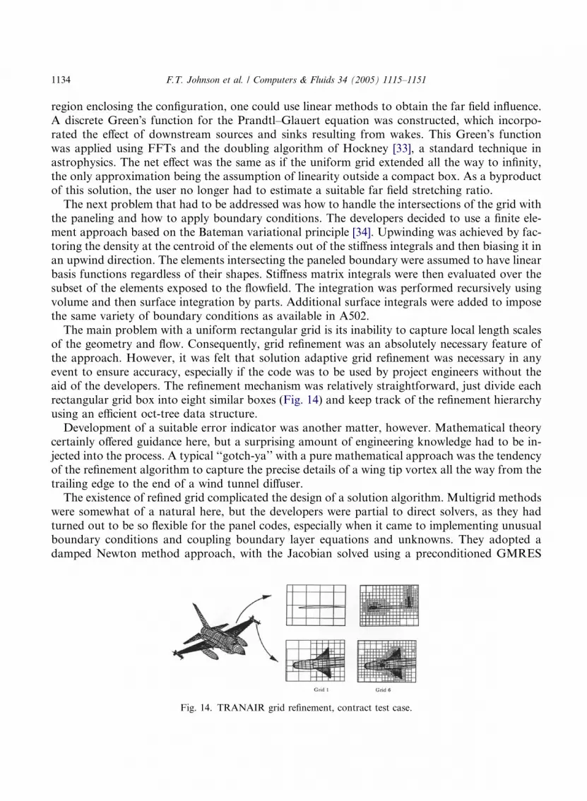
of the geometry and flow. Consequently, grid refinement was an absolutely necessary feature ofthe approach. However, it was felt that solution adaptive grid refinement was necessary in anyevent to ensure accuracy, especially if the code was to be used by project engineers without theaid of the developers. The refinement mechanism was relatively straightforward, just divide eachrectangular grid box into eight similar boxes (Fig. 14) and keep track of the refinement hierarchyusing an efficient oct-tree data structure.Development of a suitable error indicator was another matter, however. Mathematical theory
certainly offered guidance here, but a surprising amount of engineering knowledge had to be in-jected into the process. A typical ‘‘gotch-ya’’ with a pure mathematical approach was the tendencyof the refinement algorithm to capture the precise details of a wing tip vortex all the way from thetrailing edge to the end of a wind tunnel diffuser.The existence of refined grid complicated the design of a solution algorithm. Multigrid methods
were somewhat of a natural here, but the developers were partial to direct solvers, as they hadturned out to be so flexible for the panel codes, especially when it came to implementing unusualboundary conditions and coupling boundary layer equations and unknowns. They adopted adamped Newton method approach, with the Jacobian solved using a preconditioned GMRES
Fig. 14. TRANAIR grid refinement, contract test case.

F.T. Johnson et al. / Computers & Fluids 34 (2005) 1115–1151 1135
iterative algorithm. A sparse direct solver was used as a preconditioner. Even with nested dissec-tion ordering, the cost and storage for a complete factorization was prohibitive, hence they settledon the use of an incomplete factorization employing a dynamic drop tolerance approach, wherebysmall fill-in elements were dropped as they were formed. The method was surprisingly efficient androbust. As a rule, decomposition of the Jacobian resulted in fill-in factors of less than two andconstituted less than 10% of the total run cost, even for grids having more than a million nodes.Early versions of TRANAIR used the A411 boundary layer code in an indirectly coupled mode
in much the same manner as A488. However, the desired convergence reliability was neverachieved, and the shock boundary layer interaction model was occasionally suspect. About thistime, Drela [35] developed an exceedingly accurate 2D integral boundary layer that he directlycoupled with his 2D Euler solver. With Drela�s help, the TRANAIR development team modifiedthis boundary layer to incorporate sweep and taper effects and integrated it into the code. In thisconnection, the use of a direct solver was invaluable. The resultant code turned out to be veryaccurate for transport configurations and agreement with experiment was considered by projectusers to be quite remarkable.As TRANAIR received increasing use, a number of enhancements were added. To model pow-
ered effects, regions of non-freestream but constant total temperature and pressure were simulatedalong with appropriate shear layer effects [36]. Far field drag calculations were added, which laterled to the ability to perform aerodynamic optimization. Time harmonic capability was created forstability and control calculations. Aeroelastic effects were simulated by adding structural un-knowns and equations to the system [37]. Here again the use of a sparse solver was invaluable.Without question, the development of the TRANAIR code strongly benefited from the work
and experiences of CFD pioneers such as Murman [25], Jameson [26], Hafez [38], Cebeci [39],McLean [29], Drela [35], and others. Nevertheless, about 10 major and 30 minor algorithmshad to be developed or adapted. A few were quite far from the mainstream CFD efforts of thetime and required considerable effort. It took almost five years of research and development be-fore a truly useful result could be produced (1989). The TRANAIR code ultimately evolved intothe Boeing workhorse aerodynamic code of the 1990s and up to the current time for analyzingflows about complex configurations. TRANAIR was heavily used in the design of the 777, the737NG, and all subsequent modifications and derivatives to the Boeing Commercial Airplanesfleet. Since 1989, it has been run to completion more than 70,000 times on an enormously widevariety of configurations, some of which were not even vehicles. It has had about 90 users in Boe-ing. An older version of the code was used by NASA, the Air Force, the Navy, and General Avi-ation. In 2002, TRANAIR was run to completion at Boeing more than 15,000 times, which isconsiderable use for a complex geometry CFD code. If we had to choose one single technical fea-ture of TRANAIR that was responsible for such widespread use, we would choose solution adap-tive grid refinement. In retrospect, while this feature was intended to improve accuracy, its mainbenefit was to greatly relieve the user of the burdensome and labor-intensive task of generating avolume grid.Even with substantially simplified gridding requirements, inputting a general geometry CFD
code and processing the outputs are still formidable tasks. An essential enabler for TRANAIRhas been the development of a packaged process for inputting ‘‘standard’’ configurations. By‘‘standard,’’ we mean those configuration types that have been scripted in the various componentsthat make up the process. Configurations not included in the ‘‘standard’’ can still be analyzed but
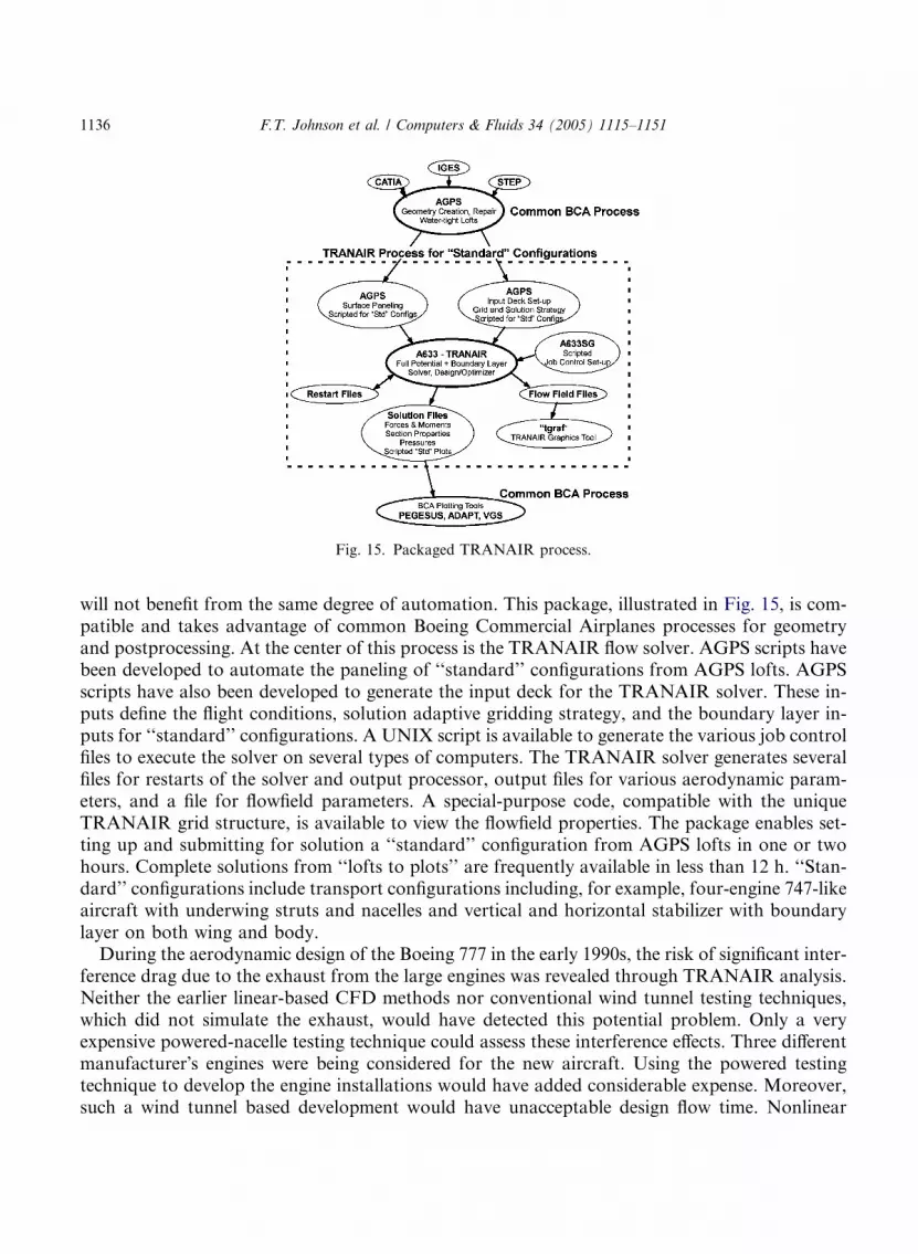
Fig. 15. Packaged TRANAIR process.
1136 F.T. Johnson et al. / Computers & Fluids 34 (2005) 1115–1151
will not benefit from the same degree of automation. This package, illustrated in Fig. 15, is com-patible and takes advantage of common Boeing Commercial Airplanes processes for geometryand postprocessing. At the center of this process is the TRANAIR flow solver. AGPS scripts havebeen developed to automate the paneling of ‘‘standard’’ configurations from AGPS lofts. AGPSscripts have also been developed to generate the input deck for the TRANAIR solver. These in-puts define the flight conditions, solution adaptive gridding strategy, and the boundary layer in-puts for ‘‘standard’’ configurations. A UNIX script is available to generate the various job controlfiles to execute the solver on several types of computers. The TRANAIR solver generates severalfiles for restarts of the solver and output processor, output files for various aerodynamic param-eters, and a file for flowfield parameters. A special-purpose code, compatible with the uniqueTRANAIR grid structure, is available to view the flowfield properties. The package enables set-ting up and submitting for solution a ‘‘standard’’ configuration from AGPS lofts in one or twohours. Complete solutions from ‘‘lofts to plots’’ are frequently available in less than 12 h. ‘‘Stan-dard’’ configurations include transport configurations including, for example, four-engine 747-likeaircraft with underwing struts and nacelles and vertical and horizontal stabilizer with boundarylayer on both wing and body.During the aerodynamic design of the Boeing 777 in the early 1990s, the risk of significant inter-
ference drag due to the exhaust from the large engines was revealed through TRANAIR analysis.Neither the earlier linear-based CFD methods nor conventional wind tunnel testing techniques,which did not simulate the exhaust, would have detected this potential problem. Only a veryexpensive powered-nacelle testing technique could assess these interference effects. Three differentmanufacturer�s engines were being considered for the new aircraft. Using the powered testingtechnique to develop the engine installations would have added considerable expense. Moreover,such a wind tunnel based development would have unacceptable design flow time. Nonlinear
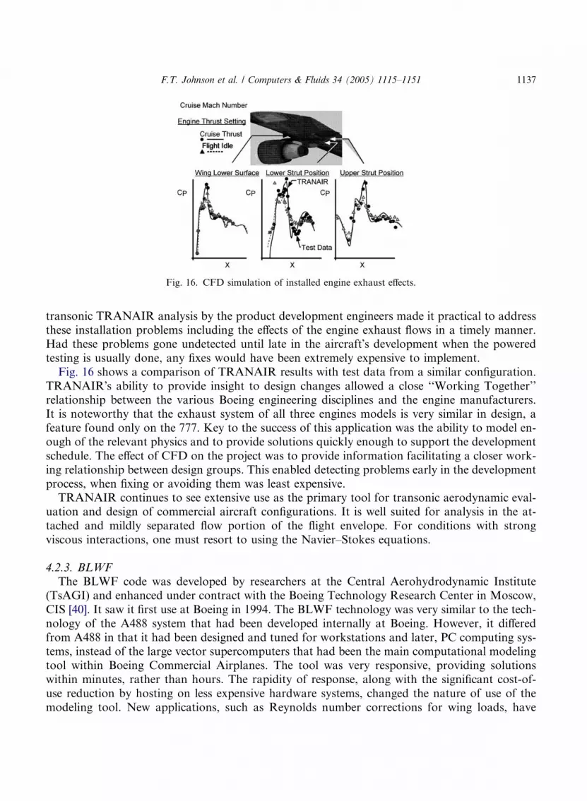
Fig. 16. CFD simulation of installed engine exhaust effects.
F.T. Johnson et al. / Computers & Fluids 34 (2005) 1115–1151 1137
transonic TRANAIR analysis by the product development engineers made it practical to addressthese installation problems including the effects of the engine exhaust flows in a timely manner.Had these problems gone undetected until late in the aircraft�s development when the poweredtesting is usually done, any fixes would have been extremely expensive to implement.Fig. 16 shows a comparison of TRANAIR results with test data from a similar configuration.
TRANAIR�s ability to provide insight to design changes allowed a close ‘‘Working Together’’relationship between the various Boeing engineering disciplines and the engine manufacturers.It is noteworthy that the exhaust system of all three engines models is very similar in design, afeature found only on the 777. Key to the success of this application was the ability to model en-ough of the relevant physics and to provide solutions quickly enough to support the developmentschedule. The effect of CFD on the project was to provide information facilitating a closer work-ing relationship between design groups. This enabled detecting problems early in the developmentprocess, when fixing or avoiding them was least expensive.TRANAIR continues to see extensive use as the primary tool for transonic aerodynamic eval-
uation and design of commercial aircraft configurations. It is well suited for analysis in the at-tached and mildly separated flow portion of the flight envelope. For conditions with strongviscous interactions, one must resort to using the Navier–Stokes equations.
4.2.3. BLWF
The BLWF code was developed by researchers at the Central Aerohydrodynamic Institute(TsAGI) and enhanced under contract with the Boeing Technology Research Center in Moscow,CIS [40]. It saw it first use at Boeing in 1994. The BLWF technology was very similar to the tech-nology of the A488 system that had been developed internally at Boeing. However, it differedfrom A488 in that it had been designed and tuned for workstations and later, PC computing sys-tems, instead of the large vector supercomputers that had been the main computational modelingtool within Boeing Commercial Airplanes. The tool was very responsive, providing solutionswithin minutes, rather than hours. The rapidity of response, along with the significant cost-of-use reduction by hosting on less expensive hardware systems, changed the nature of use of themodeling tool. New applications, such as Reynolds number corrections for wing loads, have

1138 F.T. Johnson et al. / Computers & Fluids 34 (2005) 1115–1151
become feasible with such a tool. This application requires solutions for about a dozen Machnumbers over a range of angles of attack (five to 10). Use of BLWF allows a database of hundredsof solutions to be generated in a matter of a few hours, rather than days or weeks. The code hasalso been used extensively in the preliminary design stage of aircraft definition. At this point in theairplane development cycle, there are typically a large number of significant changes in the aircraftdefinition, along with a need to understand the behavior of the configuration over a large range ofconditions. BLWF allows more realistic modeling of the flight characteristics than other Prelimin-ary Design methods and also provides an ability to obtain the information rapidly, allowing moreeffective cycling of the preliminary design through the evolution of an aircraft.
4.3. Euler/coupled boundary layer methods
The use of full potential/boundary layer coupling code reaches its limit in predicting airplaneperformance at off-design conditions where significant shock induced flow separations or vortexflows generated from sharp edges of the configuration, occur in the flowfield. The boundary layerapproximation breaks down, and the irrotational/isentropic flow assumption is not a goodapproximation for such flow conditions. Moreover, wake locations must be estimated a priori,preventing the accurate analysis of flows where vortex interactions are an important feature.Algorithm research in the early 1980s focused on solution of the Euler equations––the govern-
ing equations for inviscid fluid flows. The Boeing version of an Euler/boundary layer couplingcode––A588 is based on FLO57 [41] coupled with the same boundary layer code A411 used inA488. The code also introduced a capability for simulating engine inlet and exhaust flows withvarious total pressures and total temperatures, as well as propfan engine power effects throughthe use of an actuator disk concept. A588 was the main analysis tool for isolated nacelle develop-ment studies until very recently. It provided accurate predictions of nacelle fan cowl pressure dis-tributions, as well as fan cowl drag rise. The multiblock 3D Euler code was used extensively forthe simulation of the propfan engine on The Boeing 7J7 program during the mid-1980s, as shownin Fig. 17. A key application was the evaluation of propfan engine installation effects on tail sta-bility characteristics––including simulations that could not be accomplished in the wind tunnel.Another Euler/integral boundary layer coupling code––A585, based on Drela and Giles
[42], was developed in mid-1980s for 2D airfoil analysis and design. This code has been used
Fig. 17. Surface grid on an advanced propfan transport.
F.T. Johnson et al. / Computers & Fluids 34 (2005) 1115–1151 1139
extensively for advanced airfoil technology development, an essential capability for airplane prod-uct development engineers.
4.4. Navier–Stokes methods
The limitation of full potential or Euler/boundary layer coupling codes to flow regimes withoutsignificant flow separation leads to the development and application of solutions to Navier–Stokesequations, which are valid over the whole range of flight regime for most commercial airplanes.Finite difference schemes [43] or finite volume schemes with either artificial numerical dissipation[44] or Roe�s upwind scheme [45] were developed and tested extensively during the late 1980s andearly 1990s. At the same time, development of turbulence models for attached and separated flowsimulations progressed rapidly. The simple zero equation Baldwin/Lomax model [46] was usedextensively during the early stage of Navier–Stokes code applications. Later on, the Baldwin/Barth one equation model [47], the Spalart/Allmaras one equation model [48], together with Men-ter�s shear-stress transport k–wmodel [49], were available, and were used for a wide range of flightconditions including massively separated flows.
4.4.1. Structure grid codes––Zeus TLNS3D/CFL3D, OVERFLOW
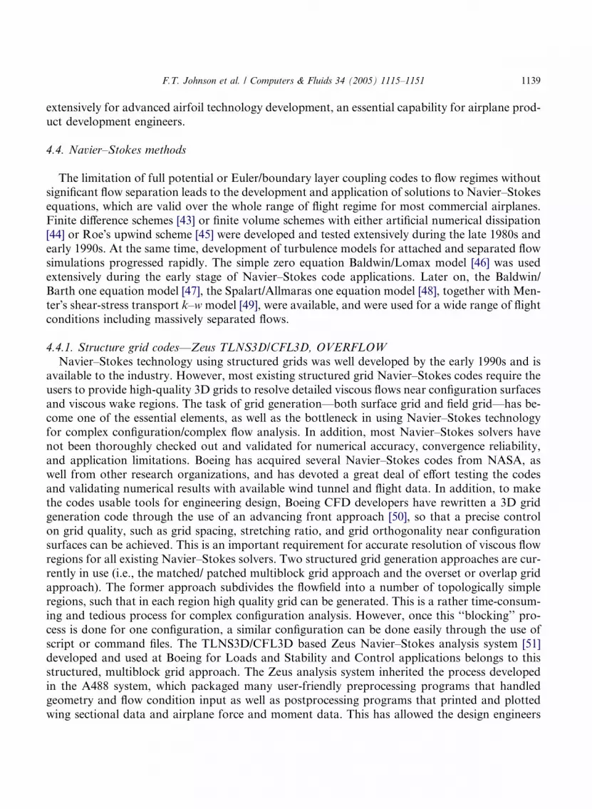
Navier–Stokes technology using structured grids was well developed by the early 1990s and isavailable to the industry. However, most existing structured grid Navier–Stokes codes require theusers to provide high-quality 3D grids to resolve detailed viscous flows near configuration surfacesand viscous wake regions. The task of grid generation––both surface grid and field grid––has be-come one of the essential elements, as well as the bottleneck in using Navier–Stokes technologyfor complex configuration/complex flow analysis. In addition, most Navier–Stokes solvers havenot been thoroughly checked out and validated for numerical accuracy, convergence reliability,and application limitations. Boeing has acquired several Navier–Stokes codes from NASA, aswell from other research organizations, and has devoted a great deal of effort testing the codesand validating numerical results with available wind tunnel and flight data. In addition, to makethe codes usable tools for engineering design, Boeing CFD developers have rewritten a 3D gridgeneration code through the use of an advancing front approach [50], so that a precise controlon grid quality, such as grid spacing, stretching ratio, and grid orthogonality near configurationsurfaces can be achieved. This is an important requirement for accurate resolution of viscous flowregions for all existing Navier–Stokes solvers. Two structured grid generation approaches are cur-rently in use (i.e., the matched/ patched multiblock grid approach and the overset or overlap gridapproach). The former approach subdivides the flowfield into a number of topologically simpleregions, such that in each region high quality grid can be generated. This is a rather time-consum-ing and tedious process for complex configuration analysis. However, once this ‘‘blocking’’ pro-cess is done for one configuration, a similar configuration can be done easily through the use ofscript or command files. The TLNS3D/CFL3D based Zeus Navier–Stokes analysis system [51]developed and used at Boeing for Loads and Stability and Control applications belongs to thisstructured, multiblock grid approach. The Zeus analysis system inherited the process developedin the A488 system, which packaged many user-friendly preprocessing programs that handledgeometry and flow condition input as well as postprocessing programs that printed and plottedwing sectional data and airplane force and moment data. This has allowed the design engineers
Surface grid Generation
Field grid generation
Navier-Stokes analysis
Post-processing
AGPS
Volume grid inputSurface gridsConnectivity file
Field gridsConnectivity file
TLNS3D/CFL3DEnsightGVPlot3dPegasus/TGS
Field solutionGrid files
Flow conditions(User input)
Geometry lofts(User input)
Force/momentsSection char.Detailed flow field info
Fig. 18. Zeus Navier–Stokes analysis system.
1140 F.T. Johnson et al. / Computers & Fluids 34 (2005) 1115–1151
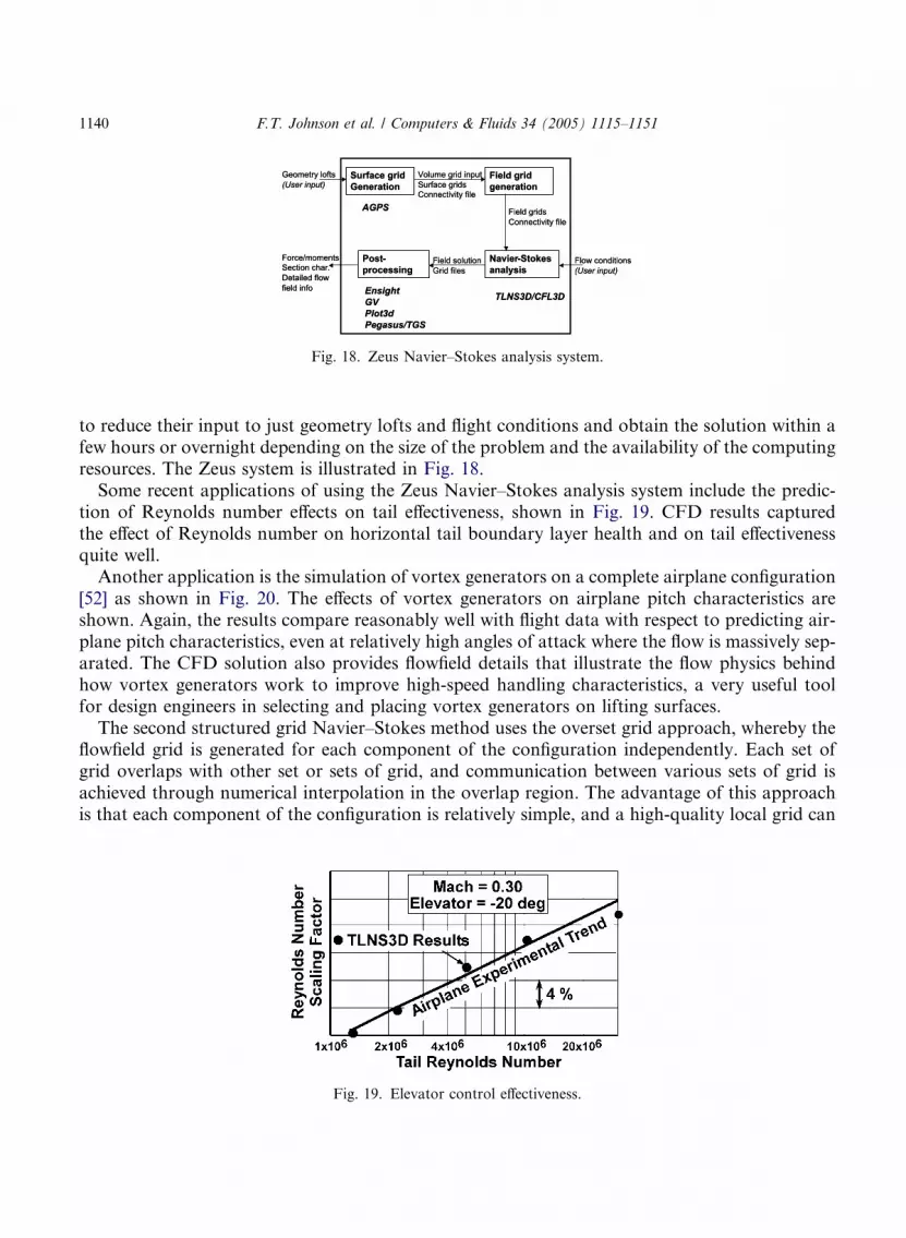
to reduce their input to just geometry lofts and flight conditions and obtain the solution within afew hours or overnight depending on the size of the problem and the availability of the computingresources. The Zeus system is illustrated in Fig. 18.Some recent applications of using the Zeus Navier–Stokes analysis system include the predic-
tion of Reynolds number effects on tail effectiveness, shown in Fig. 19. CFD results capturedthe effect of Reynolds number on horizontal tail boundary layer health and on tail effectivenessquite well.Another application is the simulation of vortex generators on a complete airplane configuration
[52] as shown in Fig. 20. The effects of vortex generators on airplane pitch characteristics areshown. Again, the results compare reasonably well with flight data with respect to predicting air-plane pitch characteristics, even at relatively high angles of attack where the flow is massively sep-arated. The CFD solution also provides flowfield details that illustrate the flow physics behindhow vortex generators work to improve high-speed handling characteristics, a very useful toolfor design engineers in selecting and placing vortex generators on lifting surfaces.The second structured grid Navier–Stokes method uses the overset grid approach, whereby the
flowfield grid is generated for each component of the configuration independently. Each set ofgrid overlaps with other set or sets of grid, and communication between various sets of grid isachieved through numerical interpolation in the overlap region. The advantage of this approachis that each component of the configuration is relatively simple, and a high-quality local grid can
Fig. 19. Elevator control effectiveness.
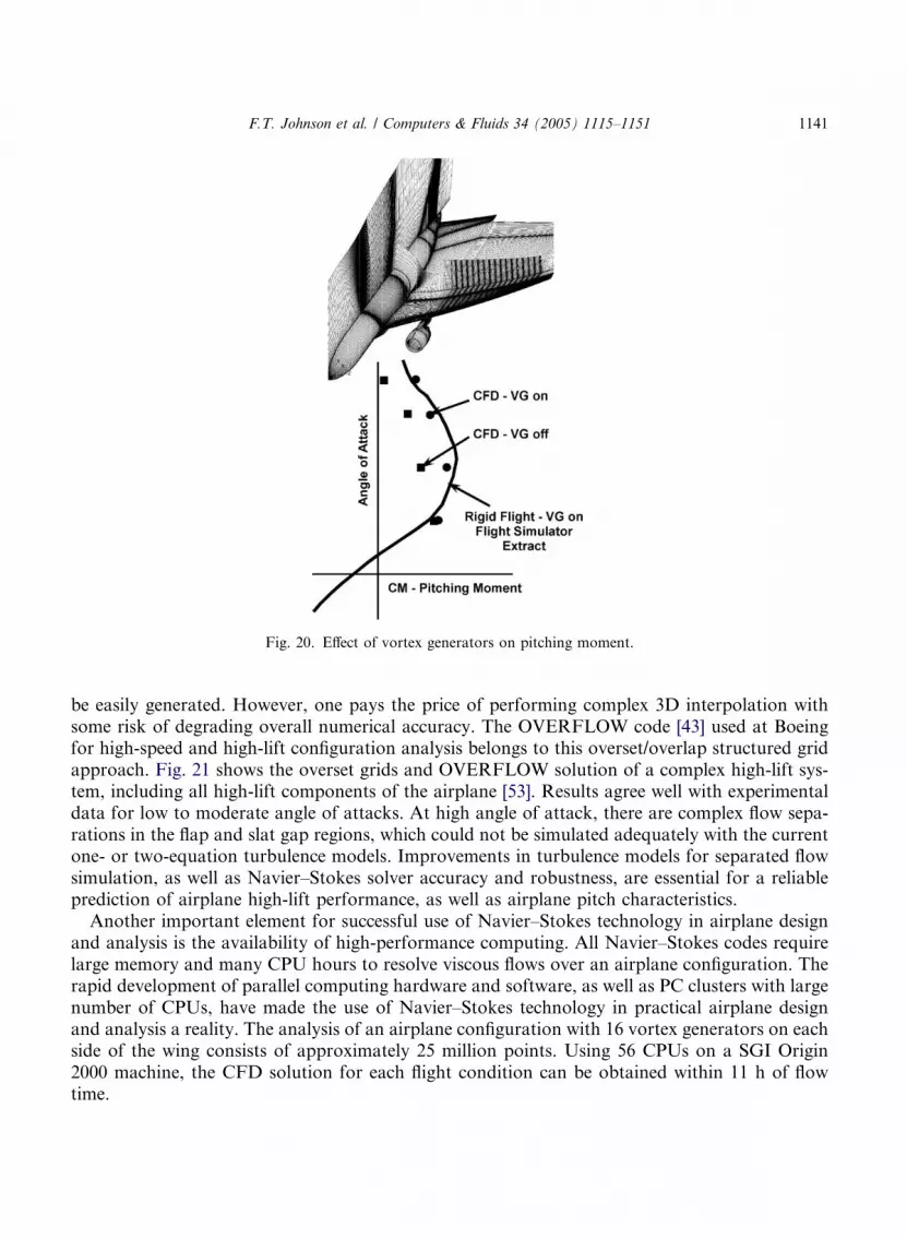
Fig. 20. Effect of vortex generators on pitching moment.
F.T. Johnson et al. / Computers & Fluids 34 (2005) 1115–1151 1141
be easily generated. However, one pays the price of performing complex 3D interpolation withsome risk of degrading overall numerical accuracy. The OVERFLOW code [43] used at Boeingfor high-speed and high-lift configuration analysis belongs to this overset/overlap structured gridapproach. Fig. 21 shows the overset grids and OVERFLOW solution of a complex high-lift sys-tem, including all high-lift components of the airplane [53]. Results agree well with experimentaldata for low to moderate angle of attacks. At high angle of attack, there are complex flow sepa-rations in the flap and slat gap regions, which could not be simulated adequately with the currentone- or two-equation turbulence models. Improvements in turbulence models for separated flowsimulation, as well as Navier–Stokes solver accuracy and robustness, are essential for a reliableprediction of airplane high-lift performance, as well as airplane pitch characteristics.Another important element for successful use of Navier–Stokes technology in airplane design
and analysis is the availability of high-performance computing. All Navier–Stokes codes requirelarge memory and many CPU hours to resolve viscous flows over an airplane configuration. Therapid development of parallel computing hardware and software, as well as PC clusters with largenumber of CPUs, have made the use of Navier–Stokes technology in practical airplane designand analysis a reality. The analysis of an airplane configuration with 16 vortex generators on eachside of the wing consists of approximately 25 million points. Using 56 CPUs on a SGI Origin2000 machine, the CFD solution for each flight condition can be obtained within 11 h of flowtime.
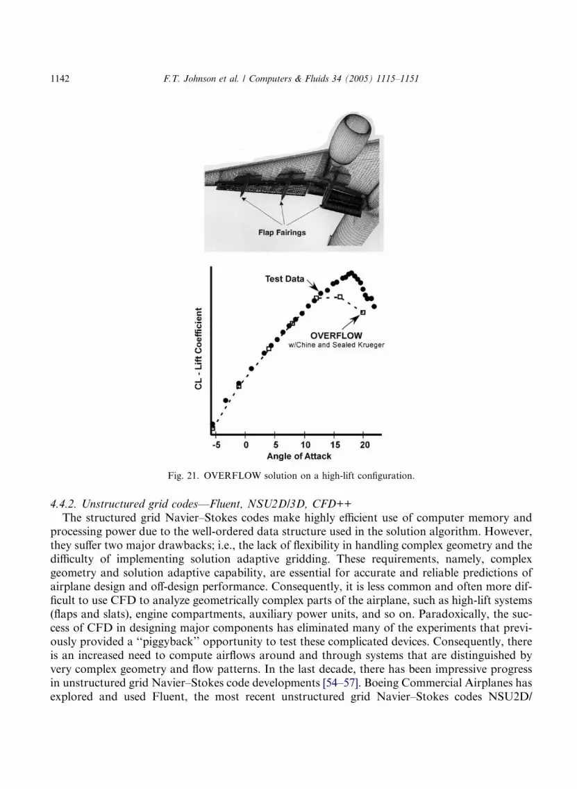
Fig. 21. OVERFLOW solution on a high-lift configuration.
1142 F.T. Johnson et al. / Computers & Fluids 34 (2005) 1115–1151
4.4.2. Unstructured grid codes––Fluent, NSU2D/3D, CFD++
The structured grid Navier–Stokes codes make highly efficient use of computer memory andprocessing power due to the well-ordered data structure used in the solution algorithm. However,they suffer two major drawbacks; i.e., the lack of flexibility in handling complex geometry and thedifficulty of implementing solution adaptive gridding. These requirements, namely, complexgeometry and solution adaptive capability, are essential for accurate and reliable predictions ofairplane design and off-design performance. Consequently, it is less common and often more dif-ficult to use CFD to analyze geometrically complex parts of the airplane, such as high-lift systems(flaps and slats), engine compartments, auxiliary power units, and so on. Paradoxically, the suc-cess of CFD in designing major components has eliminated many of the experiments that previ-ously provided a ‘‘piggyback’’ opportunity to test these complicated devices. Consequently, thereis an increased need to compute airflows around and through systems that are distinguished byvery complex geometry and flow patterns. In the last decade, there has been impressive progressin unstructured grid Navier–Stokes code developments [54–57]. Boeing Commercial Airplanes hasexplored and used Fluent, the most recent unstructured grid Navier–Stokes codes NSU2D/

F.T. Johnson et al. / Computers & Fluids 34 (2005) 1115–1151 1143
NSU3D of Mavriplis [54], and CFD++ of Chakravarthy [57] for 2D and 3D high-lift analysiswith success.A recent application of unstructured grid technology involved the use of Fluent V5 [58] to
investigate the behavior of the efflux from engine thrust reversers [59]. A typical commercial air-plane deploys its thrust reversers briefly after touch down. A piece of engine cowling translates aftand blocker doors drop down, directing the engine airflow into a honeycomb structure called acascade. The cascade directs the flow forward, which acts to slow the aircraft and decrease liftfor more effective braking. There are some critical design considerations in properly directingthe reversed flow. The reverser is used precisely at the time when high-lift devices, wing leadingand trailing edge flaps and slats, are fully deployed. Consequently, the plumes of hot exhaust mustbe directed so as not to impinge on these devices. In addition, the plumes should not hit the fuse-lage or other parts of the aircraft. Moreover, reingestion (in which the reversed plume reenters theengine inlet), engine ingestion of debris blown up from the runway, and plume envelopment of thevertical tail (which affects directional control) must be avoided. To eliminate these effects, it�simportant for designers to know exactly where the exhaust plumes go.The Tetra module of grid generation software from ICEM CFD Engineering [60] has been used
to obtain fully unstructured meshes. Starting from a new airplane geometry (with cleaned uplofts), these meshes can be created in a day or two. The grid generation software contains a replaycapability so that minor changes to the geometry can be remeshed quickly. Because the entireCFD analysis cycle can be completed in about three days, designers can use this tool repeatedlyas a way to optimize the design. In this way, it is possible to map the performance of the reverseragainst the power setting of the reversed engine fan and the airplane forward speed. Tests thatinvolve geometry changes, such as the repositioning of the cascades or the nacelle relative tothe wing or variation of the cascade angles, can be accomplished with minimal remeshing andanalysis. Wind tunnel testing and expense are reduced, but the key benefits are really time andrisk mitigation. If a need to change the design should become apparent after the tooling was builtand aircraft was in test, the delay in entry into service and the expense of retooling would be unac-ceptable. The grid and engine reverser efflux particle traces from one of these cases is illustrated inFig. 22. Fluent is in widespread use at Boeing for other geometrically complex problems, such ascooling flows in engine compartments and dispersion of fire suppression chemicals.
4.4.3. Other Navier–Stokes codes
The Propulsion Analysis group at Boeing Commercial Airplanes has long acquired, supported,and used a number of other Navier–Stokes codes. The present authors are not qualified to de-scribe this activity; however, we do wish to mention some of the codes involved. These includethe Boeing named Mach3 code based on the implicit predictor, corrector methodology of McCor-mack [61], the PARC code [62] of NASA Lewis, the WIND code [63], and BCFD [64], which isscheduled to be the platform for an Enterprise common Navier–Stokes code. These codes havebeen used for nacelle inlet analysis and design and for nacelle fan and core cowl nozzle perfor-mance studies [64,65].
4.4.4. Next generation Navier–Stokes codesThe successful application of Navier–Stokes codes during the last 10 years has raised expecta-
tions among Boeing engineers that CFD can become a routine tool for the loads analysis,
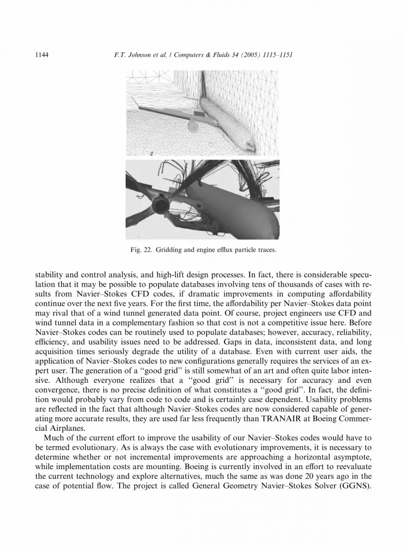
Fig. 22. Gridding and engine efflux particle traces.
1144 F.T. Johnson et al. / Computers & Fluids 34 (2005) 1115–1151
stability and control analysis, and high-lift design processes. In fact, there is considerable specu-lation that it may be possible to populate databases involving tens of thousands of cases with re-sults from Navier–Stokes CFD codes, if dramatic improvements in computing affordabilitycontinue over the next five years. For the first time, the affordability per Navier–Stokes data pointmay rival that of a wind tunnel generated data point. Of course, project engineers use CFD andwind tunnel data in a complementary fashion so that cost is not a competitive issue here. BeforeNavier–Stokes codes can be routinely used to populate databases; however, accuracy, reliability,efficiency, and usability issues need to be addressed. Gaps in data, inconsistent data, and longacquisition times seriously degrade the utility of a database. Even with current user aids, theapplication of Navier–Stokes codes to new configurations generally requires the services of an ex-pert user. The generation of a ‘‘good grid’’ is still somewhat of an art and often quite labor inten-sive. Although everyone realizes that a ‘‘good grid’’ is necessary for accuracy and evenconvergence, there is no precise definition of what constitutes a ‘‘good grid’’. In fact, the defini-tion would probably vary from code to code and is certainly case dependent. Usability problemsare reflected in the fact that although Navier–Stokes codes are now considered capable of gener-ating more accurate results, they are used far less frequently than TRANAIR at Boeing Commer-cial Airplanes.Much of the current effort to improve the usability of our Navier–Stokes codes would have to
be termed evolutionary. As is always the case with evolutionary improvements, it is necessary todetermine whether or not incremental improvements are approaching a horizontal asymptote,while implementation costs are mounting. Boeing is currently involved in an effort to reevaluatethe current technology and explore alternatives, much the same as was done 20 years ago in thecase of potential flow. The project is called General Geometry Navier–Stokes Solver (GGNS).

F.T. Johnson et al. / Computers & Fluids 34 (2005) 1115–1151 1145
From our TRANAIR experience, it seems rather evident that solution adaptive grids must be anessential feature for reliability and usability. This is especially true when computing flows at off-design conditions where our understanding of the flow physics is limited, making it difficult togenerate ‘‘good grids’’. However, these grids must now be anisotropic and, more than likely, quiteirregular. This places a huge burden on improving discretization fidelity, as current discretizationalgorithms do not seem to do well with irregular spacings and cell shapes. Higher order elementsare certainly desirable for efficiency�s sake and for capturing latent features. However, stabiliza-tion and limiter technologies need to be advanced to handle such elements. Current solvers arerelatively weak, and convergence is often incomplete, especially when turbulent transport equa-tions are involved. Some of these issues are addressed in detail elsewhere [66]. It should be notedthat our reevaluation and development work here is a joint effort between the CFD developers atBoeing and their colleagues at the Boeing Technical Research Center in Moscow. We also notethere are related efforts going on elsewhere. We mention in particular the FAAST project atNASA Langley.
4.5. Design and optimization methods
4.5.1. A555, A619 inverse design codes
Most existing CFD codes are analysis tools (i.e., given a configuration, the codes predict aero-dynamic characteristics of the configuration). In airplane design, one would like to have tools thatcan provide design capability (i.e., given airplane aerodynamic characteristics, the codes generaterealistic geometry). The design method used by Henne [67], which prescribes wing surface pres-sures and employs an iterative method to find the corresponding geometry, was one of the veryfirst inverse design methods used in the airplane industry. Boeing Commercial Airplanes devel-oped a similar method for wing design using the A555 code [68], illustrated in Fig. 23. This codewas used extensively on the 7J7, 777, and 737NG programs. The code borrowed heavily from theA488 system to ensure usability in the fast-paced airplane development environment. On the Boe-ing 777 program, CFD contributed to a high degree of confidence in performance with only a
Fig. 23. Iterative/inverse design process.
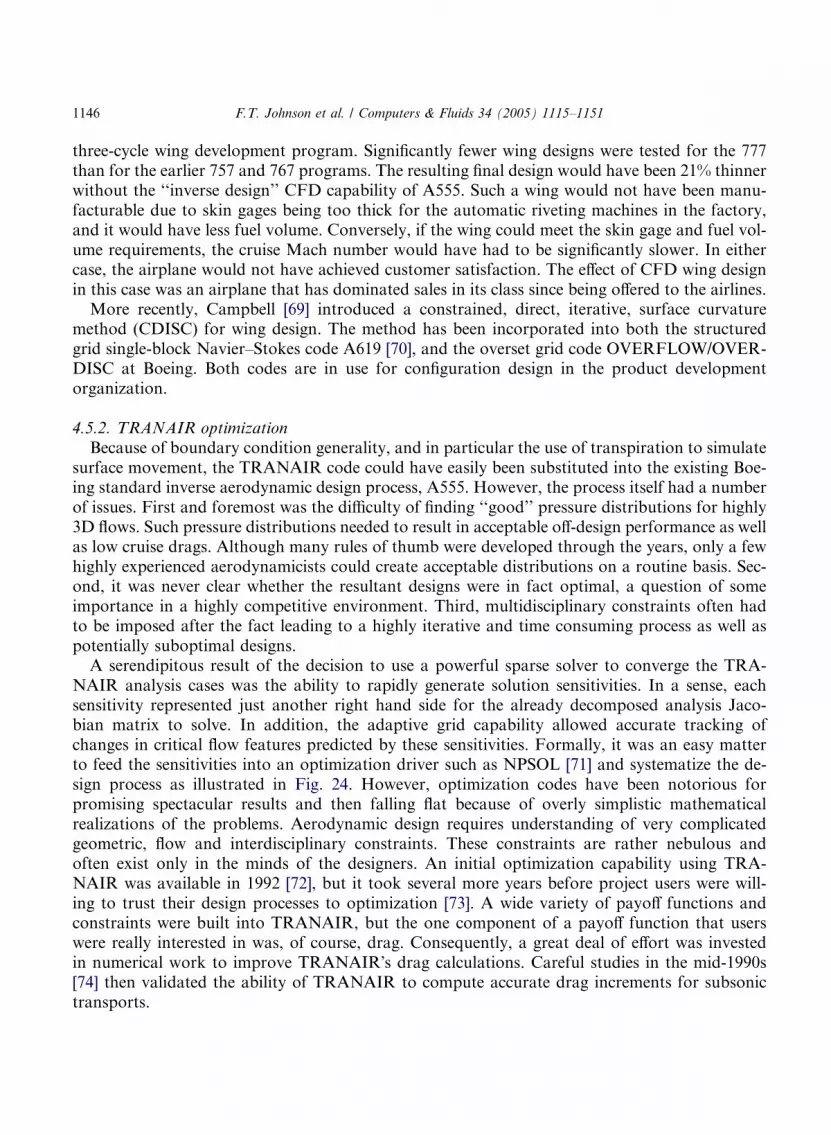
1146 F.T. Johnson et al. / Computers & Fluids 34 (2005) 1115–1151
three-cycle wing development program. Significantly fewer wing designs were tested for the 777than for the earlier 757 and 767 programs. The resulting final design would have been 21% thinnerwithout the ‘‘inverse design’’ CFD capability of A555. Such a wing would not have been manu-facturable due to skin gages being too thick for the automatic riveting machines in the factory,and it would have less fuel volume. Conversely, if the wing could meet the skin gage and fuel vol-ume requirements, the cruise Mach number would have had to be significantly slower. In eithercase, the airplane would not have achieved customer satisfaction. The effect of CFD wing designin this case was an airplane that has dominated sales in its class since being offered to the airlines.More recently, Campbell [69] introduced a constrained, direct, iterative, surface curvature
method (CDISC) for wing design. The method has been incorporated into both the structuredgrid single-block Navier–Stokes code A619 [70], and the overset grid code OVERFLOW/OVER-DISC at Boeing. Both codes are in use for configuration design in the product developmentorganization.
4.5.2. TRANAIR optimizationBecause of boundary condition generality, and in particular the use of transpiration to simulate
surface movement, the TRANAIR code could have easily been substituted into the existing Boe-ing standard inverse aerodynamic design process, A555. However, the process itself had a numberof issues. First and foremost was the difficulty of finding ‘‘good’’ pressure distributions for highly3D flows. Such pressure distributions needed to result in acceptable off-design performance as wellas low cruise drags. Although many rules of thumb were developed through the years, only a fewhighly experienced aerodynamicists could create acceptable distributions on a routine basis. Sec-ond, it was never clear whether the resultant designs were in fact optimal, a question of someimportance in a highly competitive environment. Third, multidisciplinary constraints often hadto be imposed after the fact leading to a highly iterative and time consuming process as well aspotentially suboptimal designs.A serendipitous result of the decision to use a powerful sparse solver to converge the TRA-
NAIR analysis cases was the ability to rapidly generate solution sensitivities. In a sense, eachsensitivity represented just another right hand side for the already decomposed analysis Jaco-bian matrix to solve. In addition, the adaptive grid capability allowed accurate tracking ofchanges in critical flow features predicted by these sensitivities. Formally, it was an easy matterto feed the sensitivities into an optimization driver such as NPSOL [71] and systematize the de-sign process as illustrated in Fig. 24. However, optimization codes have been notorious forpromising spectacular results and then falling flat because of overly simplistic mathematicalrealizations of the problems. Aerodynamic design requires understanding of very complicatedgeometric, flow and interdisciplinary constraints. These constraints are rather nebulous andoften exist only in the minds of the designers. An initial optimization capability using TRA-NAIR was available in 1992 [72], but it took several more years before project users were will-ing to trust their design processes to optimization [73]. A wide variety of payoff functions andconstraints were built into TRANAIR, but the one component of a payoff function that userswere really interested in was, of course, drag. Consequently, a great deal of effort was investedin numerical work to improve TRANAIR�s drag calculations. Careful studies in the mid-1990s[74] then validated the ability of TRANAIR to compute accurate drag increments for subsonictransports.
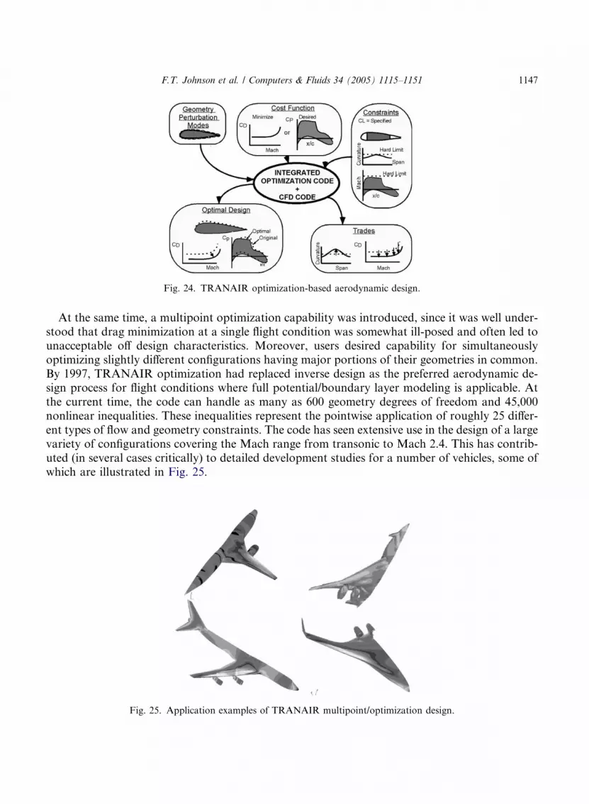
Fig. 24. TRANAIR optimization-based aerodynamic design.
F.T. Johnson et al. / Computers & Fluids 34 (2005) 1115–1151 1147
At the same time, a multipoint optimization capability was introduced, since it was well under-stood that drag minimization at a single flight condition was somewhat ill-posed and often led tounacceptable off design characteristics. Moreover, users desired capability for simultaneouslyoptimizing slightly different configurations having major portions of their geometries in common.By 1997, TRANAIR optimization had replaced inverse design as the preferred aerodynamic de-sign process for flight conditions where full potential/boundary layer modeling is applicable. Atthe current time, the code can handle as many as 600 geometry degrees of freedom and 45,000nonlinear inequalities. These inequalities represent the pointwise application of roughly 25 differ-ent types of flow and geometry constraints. The code has seen extensive use in the design of a largevariety of configurations covering the Mach range from transonic to Mach 2.4. This has contrib-uted (in several cases critically) to detailed development studies for a number of vehicles, some ofwhich are illustrated in Fig. 25.
Fig. 25. Application examples of TRANAIR multipoint/optimization design.
1148 F.T. Johnson et al. / Computers & Fluids 34 (2005) 1115–1151
TRANAIR design/optimization applications that have affected a product include the payloadfairing on the Sea Launch rocket, nacelle fan cowl for the GE90-115B engine, and the processused to determine ‘‘Reduced Vertical Separation Minimums’’ compliance for new and in-serviceaircraft.
5. Conclusions
During the last 30 years at Boeing Commercial Airplanes, Seattle, CFD has evolved into ahighly valued tool for the design, analysis, and support of cost-effective and high-performing com-mercial transports. The application of CFD today has revolutionized the process of aerodynamicdesign, and CFD has joined the wind tunnel and flight test as a critical tool of the trade. This didnot have to be the case; CFD could have easily remained a somewhat interesting tool with modestvalue in the hands of an expert as a means to assess problems arising from time to time. As thereader can gather from the previous sections, there are many reasons that this did not happen.The one we would like to emphasize in this Conclusion section is the fact that Boeing recog-nized the leverage in getting CFD into the hands of the project engineers and was willing to doall the things necessary to make it happen.
References
[1] Rubbert PE, Tinoco EN. Impact of computational methods on aircraft design. AIAA-83-2060, August 1983.
[2] Bengelink RL, Rubbert PE. The Impact of CFD on the airplane design process: Today and tomorrow. SAE
Aerospace Engng 1992(March).
[3] Rubbert PE. AIAA Wright Brothers lecture: CFD and the changing world of airplane design. ICAS-94-0.2,
September 1994.
[4] Tinoco EN. The changing role of computational fluid dynamics in aircraft development. AIAA-98-2512, June
1998.
[5] Nield BN. An overview of the Boeing 777 high lift aerodynamic design. Aeronaut J 1995(November):361–71.
[6] Capron WK, Smit KL. Advanced aerodynamic applications of an interactive geometry and visualization system.
AIAA Paper 91-0800, January 1991.
[7] Carlson HW, Harris Jr RV. A unified system of supersonic aerodynamic analysis. NASA SP-228, 1969;(27):639–
658.
[8] Middleton WD, Carlson HW. Numerical method of estimating and optimizing supersonic aerodynamic
characteristics of arbitrary planform wings. J Aircraft 1965;1(4):261–5.
[9] Woodward FA, Tinoco EN, Larsen JW. Analysis and design of supersonic wing-body combinations, including
flow properties in the near field, part 1––theory and application. NASA CR-73106, 1967.
[10] Tinoco EN, Mercer JE. FLEXSTAB––a summary of the functions and capabilities of the NASA flexible airplane
analysis computer system. NASA CR-2564, December 1975.
[11] Tinoco EN. An aeroelastic analysis of the YF-12A using the FLEXSTAB system. Paper No. 12, NASA YF-12
Flight Loads Program, NASA TMX-3061, June 1974.
[12] Hess JL, Smith AMO. Calculation of non lifting potential flow about arbitrary three-dimensional bodies. ES40622,
Douglas Aircraft Company, 1962.
[13] Rubbert PE et al. A general method for determining the aerodynamic characteristics of fan-in-wing configurations,
Vol. I––Theory and Application, Technical Report 67-61A, USAAVLABS, 1967.
F.T. Johnson et al. / Computers & Fluids 34 (2005) 1115–1151 1149
[14] Rubbert PE, Saaris GR. Review and evaluation of three dimensional lifting potential flow analysis method for
arbitrary configurations. AIAA Paper 72-188, January 1972.
[15] Rubbert PE. Theoretical characteristics of arbitrary wings by a nonplanar vortex lattice method. D6-9244, The
Boeing Company, 1964.
[16] Feifel WM. Optimization and design of three-dimensional aerodynamic configurations of arbitrary shape by a
vortex lattice method. NASA SP-405, May 1976.
[17] Ishimitsu KK. Aerodynamic design and analysis of winglets. AIAA-76-940, September 1976.
[18] Gillette WB. Nacelle installation analysis for subsonic transonic transport aircraft. AIAA-77-102, January 1977.
[19] Johnson FT, Rubbert PE. Advanced panel-type influence coefficient methods applied to subsonic flow. AlAA
Paper 75-50, January 1975.
[20] Tinoco EN, Johnson FT, Freeman LM. Application of a higher order panel method to realistic supersonic
configurations. AIAA J 1980;17(1):38–44.
[21] Johnson FT, Tinoco EN, Lu P, Epton MA. Three-dimensional flow over wings with leading edge vortex
separation. AIAA J 1980;18(4):367–80.
[22] Dusto Arthur R, Epton Michael A. An advanced panel method for analysis of arbitrary configurations in unsteady
subsonic flow. NASA CR-152323, February 1980.
[23] Tinoco EN, Ball DN, Rice II FA. PAN AIR analysis of a transport high-lift configuration. AIAA 86-1811, June
1986, J Aircraft 1987;24(3):181–7.
[24] Chen AW, Tinoco EN. PAN AIR applications to aero-propulsion integration. AIAA 83-1368, June 1983, J
Aircraft 1984;21(3):161–7.
[25] Murman EM, Cole JD. Calculation of plane steady transonic flows. AIAA J 1971;9:114–21.
[26] Jameson A, Caughey DA. A finite volume method for transonic potential flow calculations. In: Proceedings of
AIAA 3rd Computational Fluid Dynamics Conference, 1977. p. 35–54.
[27] Thompson JF, Thames FC, Mastin CM. Automatic numerical generation of body-fitted curvilinear coordinate
system for field containing any number of arbitrary two-dimensional bodies. J Comput Phys 1974;15.
[28] Yu NJ. Grid generation and transonic flow calculations for three-dimensional configurations, AIAA paper 80-
1391, 1980.
[29] McLean JD, Randall JL. Computer program to calculate three-dimensional boundary layer flows over wings with
wall mass transfer. NASA CR-3123, 1978.
[30] Reyhner TA. Transonic potential flow computation about three-dimensional inlets, ducts and bodies. AIAA J
1981;19:1112–21.
[31] McCarthy DR, Reyhner TA. Multigrid code for three-dimensional transonic potential flow about inlets. AIAA J
1982;20:45–50.
[32] Young DP, Melvin RG, Bieterman MB, Johnson FT, Samant SS, Bussoletti JE. A locally refined rectangular grid
finite element method: application to computational fluid dynamics and computational physics. J Comput Phys
1991;92:1–66.
[33] Hockney RW. The Potential Calculation and Some Applications, Methods in Computational Physics, vol. 9, New
York: Academic Press; 1969. p. 135–211.
[34] Bateman H. Irrotational motion of a compresssible inviscid fluid. Proc Nat Acad Sci 1930;16:816–25.
[35] Drela M. Two dimensional transonic aerodynamic design and analysis using the euler equations. Dissertation,
MIT, 1985.
[36] Melvin RG, Johnson FT, Young DP, Foutch DW, Bussoletti JE, Bieterman MB. Using a full potential solver for
propulsion system exhaust simulation. J Propul Power 1993;9(3):412–21.
[37] SenGupta G, Seidel DA, Young DP, Bussoletti JE. Effect of wind tunnel walls on the flutter characteristics of an
airplane model. AIAA Paper 2001-1655, 42nd AIAA/ASME/ASCE/AHS/ASC Structures, Structural Dynamics
and Materials Conference & Exhibit, April 16–19, 2001, Seattle, WA.
[38] Hafez MM, Murman EM, South JC. Artificial compressibility methods for numerical solution of transonic full
potential equations. AIAA Paper 78-1148, 1978.
[39] Cebeci T. Calculation of compressible turbulent boundary layers with heat and mass transfer. AIAA J
1971;9(6):1091–7.
[40] Karas OV, Kovalev VE. BLWF 43 User�s Guide, 2002.

1150 F.T. Johnson et al. / Computers & Fluids 34 (2005) 1115–1151
[41] Jameson A, Schmidt W, Turkel E. Numerical solutions of the euler equations by finite volume methods using
Runge–Kutta time-stepping schemes. AIAA Paper 81-1259, 1981.
[42] Drela M, Giles MB. Viscous-inviscid analysis of transonic and low Reynolds number airfoils. AIAA Paper 86-
1786, June 1986.
[43] Jespersen DC, Pulliam TH, Buning PG. Recent enhancements to OVERFLOW. AIAA paper 97-0644, 1997.
[44] Vatsa VN, Sanetrik MD, Parlette EB. Development of a flexible and efficient multigrid-based multiblock flow
solver. AIAA paper 93-0699, 1993.
[45] Biedron RT, Rumsey CL. CFL3D User�s Manual, NASA/TM-1998-208444, June 1998.[46] Baldwin BS, Lomax HL. Thin layer approximation and algebraic model for separated turbulence flows. AIAA
paper 78-257, 1978.
[47] Baldwin BS, Barth TJ. A one-equation turbulence transport model for high Reynolds number wall-bounded flows.
AIAA 91-0610, 1991.
[48] Spalart PR, Allmaras SR. A one-equation turbulence model for aerodynamic flows. AIAA paper 92-0439, 1992.
[49] Menter FR. Zonal two equation k–w turbulence models for aerodynamic flows. AIAA paper 93-2906, 1993.
[50] Yu NJ, Su TY, Wilkinson WM. Multiblock grid generation process for complex configuration analysis using
Navier–Stokes codes. In: 27th AIAA Fluid Dynamics Conference, 1996, paper 96-1995.
[51] Velazquez MA, Sondles M, Matoi TK. Zeus 4.0 User Guide, March 2002.
[52] Yu NJ, Kao TJ, Bogue DR. Computational simulations of a commercial airplane configuration with vortex
generators. Aerodynamics Conference 2000, Royal Aeronautical Society, London, UK, 2000.
[53] Cao HV, Su TY, Rogers SE. Navier–Stokes analysis of a 747 high lift configuration, AIAA 98-2623, June 1998.
[54] Mavriplis DJ. Three-dimensional high-lift analysis using a parallel unstructured multigrid solver. NASA/CR-1998-
207682, ICASE Report No. 98-20, May 1998.
[55] Anderson WK, Rausch RD, Bonhaus DL. Implicit/multigrid algorithms for incompressible turbulent flows on
unstructured grids. J Comput Phys 1996;128:391–408.
[56] Frink NT, Pirzadeh SZ. Tetrahedral finite-volume solutions to the Navier–Stokes equations on complex
configurations. In: 10th International Conference on Finite Elements in Fluids, Tucson, AZ, USA, 1998.
[57] Chakravarthy S, Palaniswamy S, Goldberg U, Peroomian O, Sekar B. A unified-grid approach for propulsion
applications. AIAA/ASME/SAE/ASEE Joint Propulsion Conference, Cleveland, July 1998.
[58] Fluent, Inc., Fluent Users Manual.
[59] Chuck C. Computational procedures for complex three-dimensional geometries including thrust reverser effluxes
and APUs, AIAA-2001-3747, July 2001.
[60] ANSYS Inc., ICEM CFD User Manual, www.icemcfd.com.
[61] MacCormack RW. A numerical method for solving equations of compressible viscous flow. AIAA J
1982;20(9):1275–81.
[62] Cooper GK, Sirbaugh JR. The PARC distinction: a practical flow simulator. AIAA paper 90-2002, 1990.
[63] NPARC Alliance, WIND: The production flow solver of the NPARC alliance. AIAA Paper 98-0935, 1998.
[64] Hsiao H, Su MW, Colehour JL. Navier–Stokes analysis of a high by-pass engine exhaust system and plume. AIAA
paper 97-2282, 1997.
[65] Brown JJ. A Navier–Stokes nozzle analysis technique. J Propul 1987;3:334–41.
[66] Venkatakrishnan V, Allmaras SR, Kamenetskii D, Johnson FT, Higher order schemes for the compressible
Navier–Stokes equations. AIAA Paper 2003-3987, 16th AIAA Computational Fluid Dynamics Conference, June
23–26, 2003, Orlando, FL.
[67] Henne PA. An inverse transonic wing design method. AIAA paper 80-0330, 1980.
[68] Murray M. Private communication in (approximately) 1986.
[69] Campbell RA, Smith LA. A hybrid algorithm for transonic airfoil and wing design. AIAA paper 87-2552, 1987.
[70] Yu NJ, Campbell RL. Transonic airfoil and wing design using Navier–Stokes codes. AIAA 92-2651, 1992.
[71] Gill PE, Murray W, Saunders MA,Wright MA. Users Guide for NPSOL (version 4.0): a FORTRAN package non-
linear programming, Stanford University Technical Report SOL86-2, Department of Operations Research, 1986.
[72] Huffman WP, Melvin RG, Young DP, Johnson FT, Bussoletti JE, Bieterman MB, et al. Practical design and
optimization in computational fluid dynamics. AIAA Paper 93-3111, AIAA 24th Fluid Dynamics Conference, July
6–9, 1993, Orlando, FL.

F.T. Johnson et al. / Computers & Fluids 34 (2005) 1115–1151 1151
[73] Jou WH, Huffman WP, Young DP, Melvin RG, Bieterman MB, Hilmes CL, et al. Practical Considerations in
Aerodynamic Design Optimization AIAA Paper 95-1730-CP, 12th Computational Fluid Dynamics Conference,
June 19–22, 1995, San Diego, CA.
[74] Tinoco EN. An Assessment of CFD Prediction of Drag and Other Longitudinal Characteristics, AIAA Paper
2001-1002, 39th AIAA Aerospace Sciences Meeting and Exhibit, Reno, NV, January 8–11, 2001.


