Embed Size (px)
Citation preview
Dieses Dokument ist eine Zweitveröffentlichung (Verlagsversion) /
This is a self-archiving document (published version):
Diese Version ist verfügbar / This version is available on:
https://nbn-resolving.org/urn:nbn:de:bsz:14-qucosa2-356375
„Dieser Beitrag ist mit Zustimmung des Rechteinhabers aufgrund einer (DFGgeförderten) Allianz- bzw. Nationallizenz frei zugänglich.“ This publication is openly accessible with the permission of the copyright owner. The permission is granted within a nationwide license, supported by the German Research Foundation (abbr. in German DFG). www.nationallizenzen.de/
Roland Kleicke, Adil Mountasir, Chokri Cherif, Gerald Hoffmann, Christian Franz
Thermoplastic fiber-reinforced composites based on noncrimped and multilayered weaves
Erstveröffentlichung in / First published in:
Journal of Thermoplastic Composite Materials. 2014, 27(10), S. 1370 - 1386 [Zugriff am: 16.08.2019]. SAGE journals. ISSN 1530-7980.
DOI: https://doi.org/10.1177/0892705712473622
Original Article
Thermoplasticfiber-reinforcedcomposites based onnoncrimped andmultilayered weaves
Roland Kleicke1, Adil Mountasir2, Chokri Cherif2,
Gerald Hoffmann2 and Christian Franz2
Abstract
Manufacturing of thermoplastic composite based on textile preforms made from hybridyarns is well suited for the production of fiber-reinforced plastic (FRP) in medium- and
large-scale production runs. Especially, the consolidation of thermoplastic FRP is cur-
rently complicated by the high viscosity of molten material. Woven multilayered and
z-reinforced NCF-preforms are very interesting for FRP supposed to withstand three-
dimensional loading and impact stress. These preforms with z-directional reinforcement
improve the FRP delamination behavior and out-of-plane characteristics. The well-
known composite parameters are essential to ensure the use of these materials in a wide
range of applications.
Keywords
Three-dimensional reinforcement, hybrid, impact behavior, weaving
Introduction
Modern demands for carbon dioxide reduction are the most strongly affecting devel-
opments in mechanical engineering and vehicle construction. These particular industries
have the highest energy requirements. Therefore, it is highly effective and necessary to
1Technische Universitaet Dresden, Spekon GmbH, Institute of Textile Machinery and High Performance
Fibers, Dresden, Seifhennersdorf, Germany2Institute of Textile Machinery and High Performance Material Technology, Dresden, Germany
Corresponding author:
Roland Kleicke, Spekon GmbH, Seifhennersdorf 02782, Germany.
Email: [email protected]
Journal of Thermoplastic Composite
Materials
2014, Vol. 27(10) 1370–1386
ª The Author(s) 2013
Reprints and permissions:
sagepub.co.uk/journalsPermissions.nav
DOI: 10.1177/0892705712473622
jtc.sagepub.com
1370
reduce their energy input. By implementing energy efficiency measures, the industry can
react to rising energy prices, thus minimizing manufacturing costs and fulfilling existing
environmental regulations. Thereby, the continued cost-efficient manufacture of capital
and consumer goods in Europe, and especially in Germany, as well as secure jobs can be
ensured.
Mass reduction in mobile parts in vehicle construction and mechanical engineering
results in reduced energy consumption as well as in increased maximum speed. In
vehicle construction, for instance, the standards are tried to be met by using lightweight
materials and alternative drive systems. This can only be attained by a sustainable
concept, based on interdisciplinary approaches. At today’s state of the art, reliable
alternative drives are significantly heavier than conventional drive systems. Thus, the
use of alternative drives, presupposing unchanged mass of the other components,
would actually increase the energy consumption of vehicle, counteracting the original
aim. Therefore, the structure has to be made significantly lighter in order to reduce the
total vehicle mass, which can only be achieved by implementing a systematic light-
weight construction,1 which has recently seen increasing use within the automobile
industry, caused in part by the suitability of lightweight materials to meet the
requirements of safety and comfort measures, which would usually cause a gain in
vehicle mass.
In vehicle construction and engineering, mass reduction in moving parts reduces the
energy consumption and boosts the maximum cycle times of the machines .2 The mass of
the moving parts thus plays a key role in meeting the existing ecological and economical
demands.
In order to manufacture thick-walled components meeting the requirements and exhi-
biting a high load-bearing capacity, fiber-reinforced composites (FRCs) are convention-
ally constructed from several layers, which are usually done manually and therefore
entail reduced repeatability and substantial expenditure of time. Individual layers of
FRCs produced in this manner show a tendency toward delamination under occurring
loads. In order to avoid such failure behavior, an additional connection of individual
layers with reinforcement threads is necessary. Textile preforms, already manufactured
as multilayered woven fabrics with additional z-directional connection threads, are one
possibility.
Particularly, thermoplastic fiber-reinforced plastics (FRPs) have successfully found
new fields of application during the last years. A crucial advantage over composites with
a thermosetting matrix resides in the base materials’ attainable short processing times of
components. Thermoplastic components can be affordably produced using highly pro-
ductive methods (injection molding, thermoforming and hot pressing). Further advan-
tages are in the thermal ductility, the possibility of unlimited remacerating and
reforming, the better impact resistance and damage tolerance properties as well as an
increased repair-friendliness. To fulfill higher material requirements, the thermoplastic
matrix is reinforced with textile preforms made from high-performance woven fabrics.
The manufacture of thermoplastic composite based on textile preforms made from
hybrid yarns is well suited for the production of FRC inmedium- and large-scale production
runs. Especially, the creation of thermoplastic FRC is currently complicated by the high
Kleicke et al. 1371
1371
viscosity of molten material. A swift and complete impregnation of the reinforcement
filaments is therefore possible only with considerable effort, which necessitates a
minimization of the flow path of molten thermoplastic.
One long-pursued approach is the use of textile preforms made from hybrid yarns.3–7
As the utilized hybrid yarns already consist of the reinforcement and the matrix compo-
nents, the fiber volume content of matrix and reinforcement component required for each
individual construction part can be preadjusted with the hybrid yarn. Furthermore,
hybrid yarns, similar to other high-performance filament yarns, can be processed on tex-
tile machines. This means that relevant textile structures can be produced in diversity
comparable to that of conventional reinforcement preforms.
Textile preforms made of continuous fibers can be adjusted to various, possibly,
layered load cases. Thus, it is possible to create complex-shaped FRC in a single, integral
surface formation step.
Using hybrid yarn-based thermoplastic matrix materials, the manufacturing of light-
weight and complexly formed, high-productivity and high-quality composites becomes
possible.8 To ensure the demanded short cycle times, while simultaneously guaranteeing
highly specific properties of structure components, the most suitable method is hot press-
ing, using continuous fiber-reinforced, near-net-shape thermoplastic preforms. Conven-
tionally, the composition of FRC is performed by stacking several thin-reinforcement
preform layers, which is time intensive and costly and obstructs the application of this
advanced technology.
Multilayered textile preforms, in comparison, are suited for the reinforcement of
higher gauge FRPs due to their use of thicker and preferably denser (¼more compact)
fabrics, as their multilayeredness facilitates the minimization of the usual stacking of
multiple individual reinforcement layers.9
The z-connection within the multilayered fabric leads to a substantially improved
delamination behavior as well as to an increased damage tolerance toward crash and
impact. The result is a new preform, suited for large-area and bowl-shaped FRCs, mak-
ing it ideal for use in vehicle construction and mechanical engineering. A special task is
the attainment of a favorable draping behavior, as draping in particular allows for the
reshaping of planar preforms and the manufacturing of practice-oriented single- or
double-bent FRC components.
Studies have shown that textile structures with an additional z-directional reinfor-
cement exhibit an increased resistance to delamination and impact strains, compared to
conventional stacked fabrics.10–12
By making a qualified choice in binding yarn material aligned in thickness direction,
the delamination and impact behavior can be adjusted adequately.9 The area weight,
depending on yarn material and number of layers, can be set in a wide range. Thus, the
stacking of thin-reinforcement preforms into the tool as well as the manufacturing costs
can be reduced.
Using multilayered textile preforms made from thermoplastic-based hybrid yarns, a
highly productive manufacturing chain can be established. The manufactured FRPs can
be formed with various profiles of properties, individually according to the state of fiber
reinforcement and matrix material.
1372 Journal of Thermoplastic Composite Materials 27(10)
1372
Experimental
Hybrid yarns
Several methods for the manufacture of hybrid yarns have been established in the
market. During production, filaments as well as staple fibers can be processed into
various yarn constructions. This article is based on a special ITM/TU Dresden in-house-
produced commingling hybrid yarn manufactured by air jet texturing, which was used
for the structural tests and property determination.
The advantages of these yarns are their homogenous mixing of the used continuous
filaments as well as their great yarn compaction, which enables further textile techno-
logical processing. Commercially available yarnmaterials can be used inwidely varying
forms, and the individual component percentages can be adjusted to preference on an
extensive range.
By setting the number of forward yarns, the ratio of the components can be adjusted.
The commingling yarns are manufactured on a modified air jet texturing machine RMT-
D (Stahle GmbH, Reutlingen, Germany). The reinforcement and matrix filament yarns
are introduced over separate feed units of an air mixing nozzle, type LD 5.05 (TEMCO
oerlikon, Pfaffikon, Switzerland). Due to this working principle, the structure of the
commingling yarns does not exhibit a completely parallel alignment of the reinforce-
ment and matrix components in relation to the yarn axis.13
The developed and manufactured commingling hybrid yarns from glass fibers (GFs;
300 tex E-glass) and polypropylene (PP; 4 � 32 tex) have a reinforcement fiber count of
73 mass%, which corresponds to 52 vol% in the later composites. The linear mass
density amounts to 410 tex.
Fabric development
The provided hybrid yarns have an experimentally determined substance diameter of
approximately 1 mm. Thus, to result in a cohesive yarn layer, a maximum of 100 yarns
per decimeter can theoretically be integrated into the fabric of each reinforcement layer.
It has to be taken into consideration that in three-dimensional (3D) structures, the
yarns not oriented in the direction of stress can only contribute partially to load transfer.
In turn, the isotropy of the fabrics increases.
The attainable maximum breaking strength of unidirectional composites is highly
direction dependent as Bohm et al. figured out.14
Significantly higher stresses can be conveyed in yarn direction than transversely to it.
Bohm was able to prove the relationship between the achievable breaking strength and
the angle of stress and yarn directions of the used hybrid yarns. A deviation in the stress
direction from the yarn longitudinal axis causes significant losses in tensile strength. An
angle of displacement between load directions a thread axis of approximately 8� causes
approximately 50% of maximum breaking strength.
For further thermopressing process, the following different fabrics made of GF/PP
hybrid yarn were taken into consideration.
Kleicke et al. 1373
1373
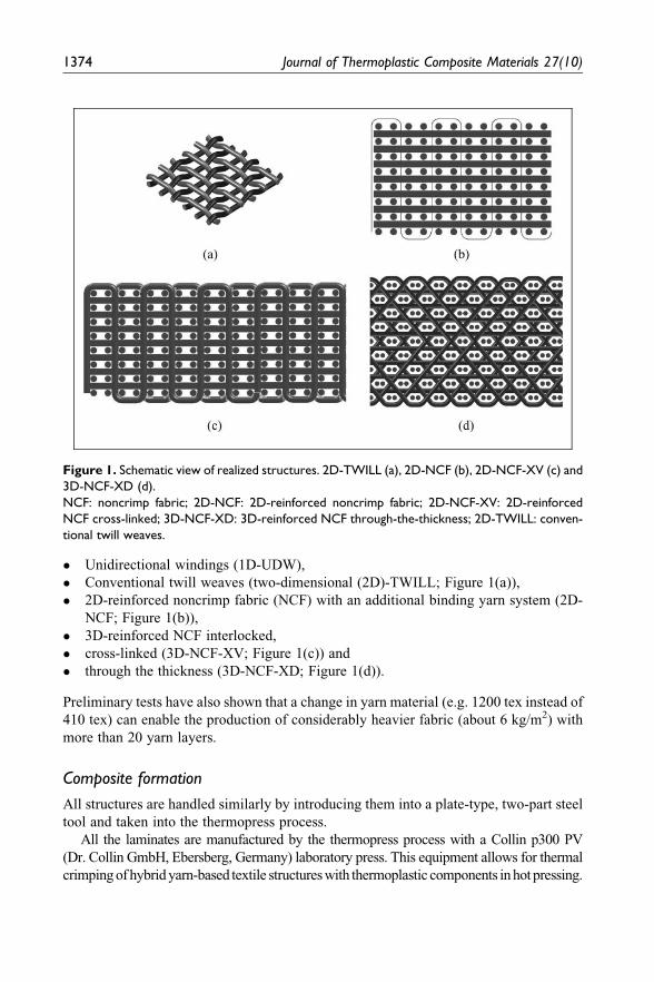
� Unidirectional windings (1D-UDW),
� Conventional twill weaves (two-dimensional (2D)-TWILL; Figure 1(a)),
� 2D-reinforced noncrimp fabric (NCF) with an additional binding yarn system (2D-
NCF; Figure 1(b)),
� 3D-reinforced NCF interlocked,
� cross-linked (3D-NCF-XV; Figure 1(c)) and
� through the thickness (3D-NCF-XD; Figure 1(d)).
Preliminary tests have also shown that a change in yarn material (e.g. 1200 tex instead of
410 tex) can enable the production of considerably heavier fabric (about 6 kg/m2) with
more than 20 yarn layers.
Composite formation
All structures are handled similarly by introducing them into a plate-type, two-part steel
tool and taken into the thermopress process.
All the laminates are manufactured by the thermopress process with a Collin p300 PV
(Dr. Collin GmbH, Ebersberg, Germany) laboratory press. This equipment allows for thermal
crimpingofhybridyarn-based textile structureswith thermoplastic components inhotpressing.
Figure 1. Schematic view of realized structures. 2D-TWILL (a), 2D-NCF (b), 2D-NCF-XV (c) and
3D-NCF-XD (d).
NCF: noncrimp fabric; 2D-NCF: 2D-reinforced noncrimp fabric; 2D-NCF-XV: 2D-reinforced
NCF cross-linked; 3D-NCF-XD: 3D-reinforced NCF through-the-thickness; 2D-TWILL: conven-
tional twill weaves.
1374 Journal of Thermoplastic Composite Materials 27(10)
1374
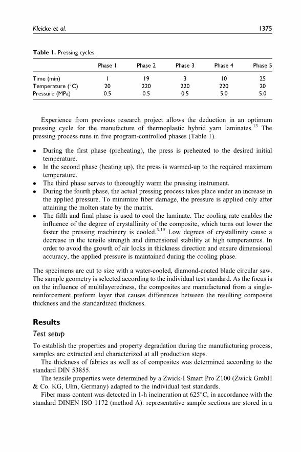
Experience from previous research project allows the deduction in an optimum
pressing cycle for the manufacture of thermoplastic hybrid yarn laminates.13 The
pressing process runs in five program-controlled phases (Table 1).
� During the first phase (preheating), the press is preheated to the desired initial
temperature.
� In the second phase (heating up), the press is warmed-up to the required maximum
temperature.
� The third phase serves to thoroughly warm the pressing instrument.
� During the fourth phase, the actual pressing process takes place under an increase in
the applied pressure. To minimize fiber damage, the pressure is applied only after
attaining the molten state by the matrix.
� The fifth and final phase is used to cool the laminate. The cooling rate enables the
influence of the degree of crystallinity of the composite, which turns out lower the
faster the pressing machinery is cooled.3,15 Low degrees of crystallinity cause a
decrease in the tensile strength and dimensional stability at high temperatures. In
order to avoid the growth of air locks in thickness direction and ensure dimensional
accuracy, the applied pressure is maintained during the cooling phase.
The specimens are cut to size with a water-cooled, diamond-coated blade circular saw.
The sample geometry is selected according to the individual test standard. As the focus is
on the influence of multilayeredness, the composites are manufactured from a single-
reinforcement preform layer that causes differences between the resulting composite
thickness and the standardized thickness.
Results
Test setup
To establish the properties and property degradation during the manufacturing process,
samples are extracted and characterized at all production steps.
The thickness of fabrics as well as of composites was determined according to the
standard DIN 53855.
The tensile properties were determined by a Zwick-I Smart Pro Z100 (Zwick GmbH
& Co. KG, Ulm, Germany) adapted to the individual test standards.
Fiber mass content was detected in 1-h incineration at 625�C, in accordance with the
standard DINEN ISO 1172 (method A): representative sample sections are stored in a
Table 1. Pressing cycles.
Phase 1 Phase 2 Phase 3 Phase 4 Phase 5
Time (min) 1 19 3 10 25
Temperature (�C) 20 220 220 220 20
Pressure (MPa) 0.5 0.5 0.5 5.0 5.0
Kleicke et al. 1375
1375
muffle furnace (Nabertherm-Controller B 170, Naberterm GmbH, Lilienthal, Germany)
until reaching constant mass. The thermoplastic components are completely disinte-
grated. The mass ratios before and after incineration allow for the calculation of fiber
mass content of GFs within the yarn.
Fabrics
The realized fabrics were characterized. Here, the draping and load-elongation proper-
ties are of special interest. To determine drapeability, the handling, the path-
dependent flexural force progression and the shearing behavior are of interest. In this
article, only handling and path-dependent flexural force progressions will be examined
more closely. For a qualitative assessment of drapeability, the bending was recorded by
employing the test procedure BSQ02 (servo motor—driven twist and recording of result-
ing bending moments). The selected testing assembly largely avoids gravitational influ-
ence on the bending force progressions. It becomes apparent that 2D-NCF structures
have a higher level of bending force progressions than 3D-NCF structures. Particularly,
in weft direction, the path-dependent flexural force increases proportionally to the addi-
tion of layers (and thus, an increase in weft density). As stated in the quantitative assess-
ment, it also becomes clear that 3D-NCF-XV structures reach higher bending
progressions than 3D-NCF-XD-9, rendering them less drapeable.
The weft yarns of all structures are virtually stretched incorporated into the fabric.
There is higher incorporation in warp direction, although it is generally 1� lower than in
2D-TWILL fabric.
For detailed information about textile results see Kleicke’s study.16
Composite
Because the developed multilayered fabrics are supposed to be used in reinforced
thermoplastic composites, the establishment of composite parameters is a crucial cri-
terion for the assessment of their quality. Initially, the fiber mass content of the com-
posites is determined. For all 3D-NCF structures, this content amounts between 72.2 and
72.8% by mass, paralleling 51.1% by volume. The reduction in fiber mass content in
comparison to the used source material is mainly caused by the damage loss of thread
substance during the weaving process. Die 2D-NCF structures show a fiber mass content
of 71.8–72.5%, with difference to the source material explicable by a substance loss and
an additional binding yarn (made from matrix material).
The yarns within 1D-UDW are almost elongated located because of the clamping and
the lack of z-oriented yarns, as already published.17 The results show the influence of the
binding thread on the fiber mass content in 2D-NCF to be negligible.
Figure 4 shows the fabric cross section of an embedded 2D-NCF-9 fabricin weft
direction. The nonundulatedly stacked-reinforcement yarn layers as well as the lanes
formed by the binding warp system can be seen clearly.
During composite formation, the fabrics are compressed to approximately 45% of
their initial thickness (Table 2). During the process, the molten PP is pressed between the
1376 Journal of Thermoplastic Composite Materials 27(10)
1376
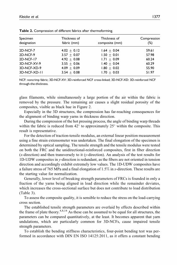
glass filaments, while simultaneously a large portion of the air within the fabric is
removed by the pressure. The remaining air causes a slight residual porosity of the
composites, visible as black hue in Figure 2.
Especially in the 3D structures, the compression has far-reaching consequences for
the alignment of binding warp yarns in thickness direction.
During the compression of the hot pressing process, the angle of binding warp threads
within the fabric is reduced from 42� to approximately 25� within the composite. This
result is representative.
For the detection of traction-tensile modulus, an external linear position measurement
using a fine strain extensometer was undertaken. The final elongation of the specimen is
determined by optical sampling. The tensile strength and the tensile modulus were tested
on both the FRC and the unidirectional-reinforced composites, first in fiber direction
(x-direction) and then transversely to it (y-direction). An analysis of the test results for
1D-UDW composites in y-direction is redundant, as the fibers are not oriented in tension
direction and accordingly exhibit extremely low values. The 1D-UDW composites have
a failure stress of 765MPa and a final elongation of 1.5% in x-direction. These results are
the starting value for normalization.
Generally, lower level of breaking strength parameters of FRCs is founded in only a
fraction of the yarns being aligned in load direction while the remainder deviates,
which increases the cross-sectional surface but does not contribute to load distribution
(Table 3).
To assess the composite quality, it is sensible to reduce the stress on the load-carrying
cross section.
The established tensile strength parameters are overlaid by effects described within
the frame of plate theory.4,8,14 As these can be assumed to be equal for all structures, the
parameters can be compared quantitatively, at the least. It becomes apparent that yarn
undulations, which are particularly common for 3D-NCFs, cause impaired tensile
strength parameters.
To establish the bending stiffness characteristics, four-point bending test was per-
formed in accordance with DIN EN ISO 14125:2011, as it offers a constant bending
Table 2. Compression of different fabrics after thermoforming.
Specimen
designation
Thickness of
fabric (mm)
Thickness of
composite (mm)
Compression
(%)
2D-NCF-7 4.02 + 0.12 1.64 + 0.04 59.61
2D-NCF-9 3.57 + 0.07 1.50 + 0.01 57.98
2D-NCF-17 4.92 + 0.08 1.71 + 0.09 60.24
3D-NCF-XV-9 3.55 + 0.06 1.40 + 0.04 60.29
3D-NCF-XD-9 4.09 + 0.09 1.80 + 0.02 55.90
3D-NCF-XD-11 3.54 + 0.08 1.70 + 0.03 51.97
NCF: noncrimp fabric; 3D-NCF-XV: 3D-reinforced NCF cross-linked; 3D-NCF-XD: 3D-reinforced NCF
through-the-thickness.
Kleicke et al. 1377
1377
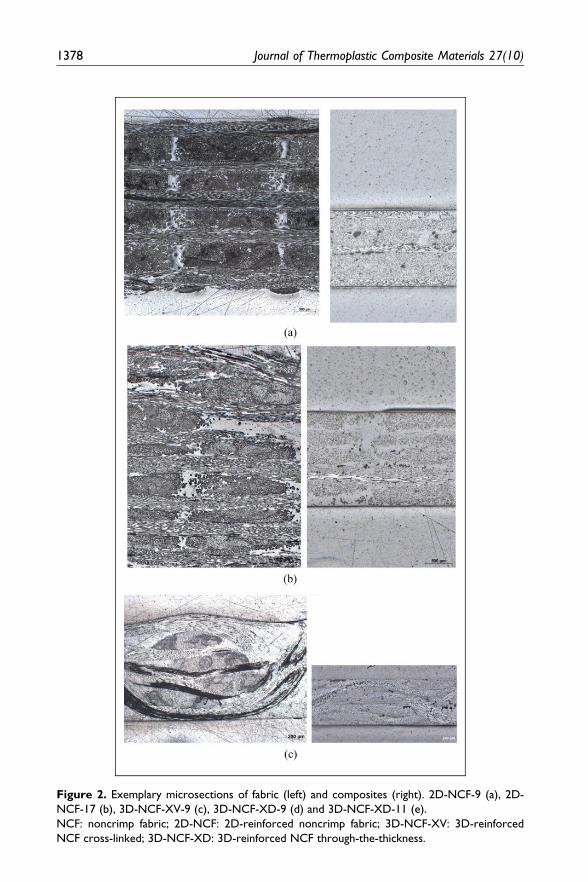
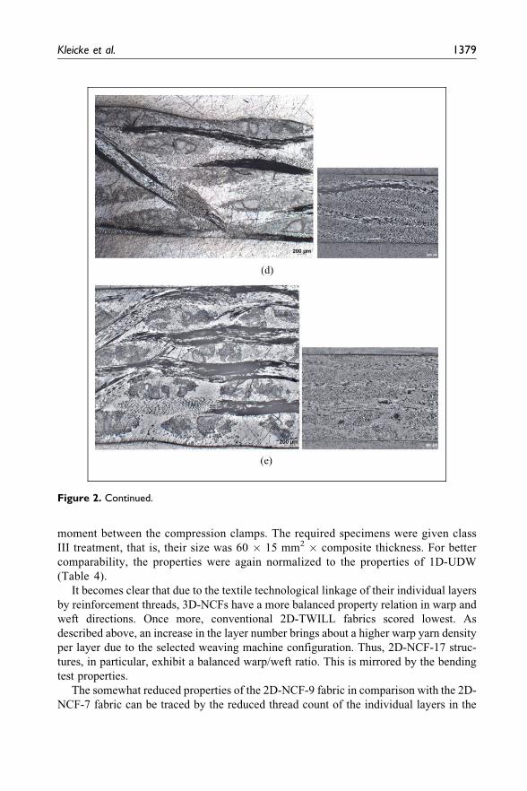
Figure 2. Exemplary microsections of fabric (left) and composites (right). 2D-NCF-9 (a), 2D-
NCF-17 (b), 3D-NCF-XV-9 (c), 3D-NCF-XD-9 (d) and 3D-NCF-XD-11 (e).
NCF: noncrimp fabric; 2D-NCF: 2D-reinforced noncrimp fabric; 3D-NCF-XV: 3D-reinforced
NCF cross-linked; 3D-NCF-XD: 3D-reinforced NCF through-the-thickness.
1378 Journal of Thermoplastic Composite Materials 27(10)
moment between the compression clamps. The required specimens were given class
III treatment, that is, their size was 60 � 15 mm2� composite thickness. For better
comparability, the properties were again normalized to the properties of 1D-UDW
(Table 4).
It becomes clear that due to the textile technological linkage of their individual layers
by reinforcement threads, 3D-NCFs have a more balanced property relation in warp and
weft directions. Once more, conventional 2D-TWILL fabrics scored lowest. As
described above, an increase in the layer number brings about a higher warp yarn density
per layer due to the selected weaving machine configuration. Thus, 2D-NCF-17 struc-
tures, in particular, exhibit a balanced warp/weft ratio. This is mirrored by the bending
test properties.
The somewhat reduced properties of the 2D-NCF-9 fabric in comparison with the 2D-
NCF-7 fabric can be traced by the reduced thread count of the individual layers in the
Figure 2. Continued.
Kleicke et al. 1379
1379
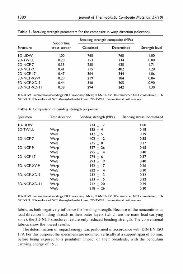
fabric, as both negatively influence the bending strength. Because of the noncontinuous
load-direction binding threads in their outer layers (which are the main load-carrying
zone), the 3D-NCF structures feature only reduced bending strength. The conventional
fabrics show the lowest results.
The determination of impact energy was performed in accordance with DIN EN ISO
179. For this purpose, the specimens are mounted vertically at a support span of 30 mm,
before being exposed to a pendulum impact on their broadside, with the pendulum
carrying energy of 15 J.
Table 3. Breaking strength parameters for the composite in warp direction (selection).
Structure
Supporting
cross section
Breaking strength composite (MPa)
Strength levelCalculated Determined
1D-UDW 1.00 765 765 1.00
2D-TWILL 0.20 153 134 0.88
2D-NCF-7 0.33 255 435 1.71
2D-NCF-9 0.41 315 402 1.28
2D-NCF-17 0.47 364 344 1.06
3D-NCF-XV-9 0.29 219 184 0.84
3D-NCF-XD-9 0.44 340 305 0.90
3D-NCF-XD-11 0.38 294 242 1.30
1D-UDW: unidirectional windings; NCF: noncrimp fabric; 3D-NCF-XV: 3D-reinforced NCF cross-linked; 3D-
NCF-XD: 3D-reinforced NCF through-the-thickness; 2D-TWILL: conventional twill weaves.
Table 4. Comparison of bending strength properties.
Specimen Test direction Bending strength (MPa) Bending stress, normalized
1D-UDW 734 + 17 1.00
2D-TWILL Warp 135 + 4 0.18
Weft 142 + 5 0.19
2D-NCF-7 Warp 402 + 12 0.55
Weft 275 + 8 0.37
2D-NCF-9 Warp 327 + 26 0.45
Weft 295 + 14 0.40
2D-NCF 17 Warp 274 + 6 0.37
Weft 293 + 19 0.40
3D-NCF-XV-9 Warp 192 + 17 0.26
Weft 222 + 14 0.30
3D-NCF-XD-9 Warp 232 + 13 0.32
Weft 233 + 15 0.32
3D-NCF-XD-11 Warp 212 + 20 0.29
Weft 218 + 26 0.30
1D-UDW: unidirectional windings; NCF: noncrimp fabric; 3D-NCF-XV: 3D-reinforced NCF cross-linked; 3D-
NCF-XD: 3D-reinforced NCF through-the-thickness; 2D-TWILL: conventional twill weaves.
1380 Journal of Thermoplastic Composite Materials 27(10)
1380
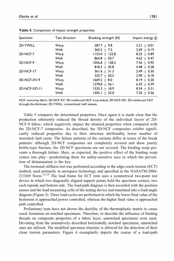
Table 5 compares the determined properties. Once again it is made clear that the
production inherently reduced the thread density of the individual layers of 2D-
NCF-9 fabric, which negatively impact the attained properties when compared with
the 2D-NCF-7 composites. As described, the 3D-NCF composites exhibit signifi-
cantly reduced properties due to their structure attributably lower number of
stretched–laid yarns. The failure patterns of the variants differ in terms of the break
patterns: although 2D-NCF composites are completely severed and show purely
brittle-type fracture, the 3D-NCF specimens are not severed. The binding warp pre-
vents a thorough failure. Here, as expected, the positive effect of the binding warp
comes into play—predestining them for safety-sensitive uses in which the preven-
tion of delamination is the key.
The torsional stiffness test was performed according to the edge-crack-torsion (ECT)
method, used primarily in aerospace technology and specified in the NASATM-2004-
213269 Norm.15,18 The load frame for ECT tests uses a symmetrical two-point test
device in which two diagonally aligned support points hold the specimen corners, two
each topside and bottom side. The load-path diagram is then recorded with the position
sensor and the load measuring cells of the testing device and translated into a load-angle
diagram (Figure 3). Three load cycles are performed in which the lower final value of the
hysteresis is approached power controlled, whereas the higher final value is approached
path controlled.
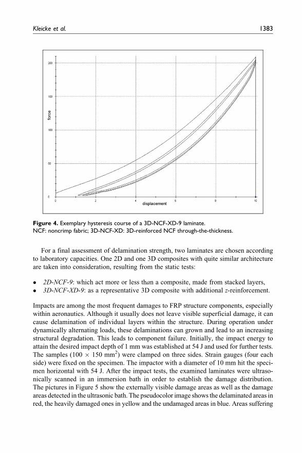
Preliminary tests have not shown the ductility of the thermoplastic matrix to cause
crack formation on notched specimens. Therefore, to describe the influence of binding
threads on composite properties of a fabric layer, unnotched specimens were used.
Deviating from the normatively described horizontally notched specimens, unnotched
ones are utilized. The modified specimen structure is allowed for the detection of their
clean torsion parameters. Figure 4 exemplarily depicts the course of a load-path
Table 5. Comparison of impact strength properties.
Specimen Test direction Breaking strength (N) Impact energy (J)
2D-TWILL Warp 287.7 + 9.8 2.21 + 0.01
Weft 265.5 + 7.2 2.69 + 0.19
2D-NCF-7 Warp 1153.0 + 122.8 8.25 + 0.89
Weft 864.8 + 50.7 4.62 + 0.47
2D-NCF-9 Warp 1056.8 + 128.2 7.56 + 0.95
Weft 818.3 + 45.8 4.48 + 0.28
2D-NCF-17 Warp 361.6 + 31.3 2.49 + 0.30
Weft 325.7 + 20.5 2.90 + 0.18
3D-NCF-XV-9 Warp 1669.2 + 8.0 8.19 + 0.20
Weft 1278.8 + 56.1 6.30 + 0.39
3D-NCF-XD-11 Warp 1535.3 + 18.9 8.34 + 0.51
Weft 1505.1 + 35.0 7.26 + 0.56
NCF: noncrimp fabric; 3D-NCF-XV: 3D-reinforced NCF cross-linked; 3D-NCF-XD: 3D-reinforced NCF
through-the-thickness; 2D-TWILL: conventional twill weaves.
Kleicke et al. 1381
1381
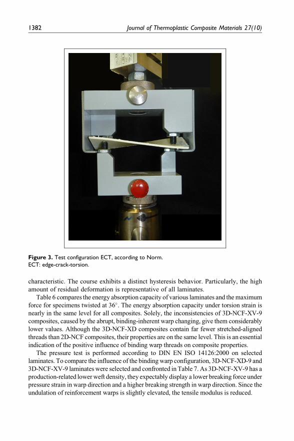
characteristic. The course exhibits a distinct hysteresis behavior. Particularly, the high
amount of residual deformation is representative of all laminates.
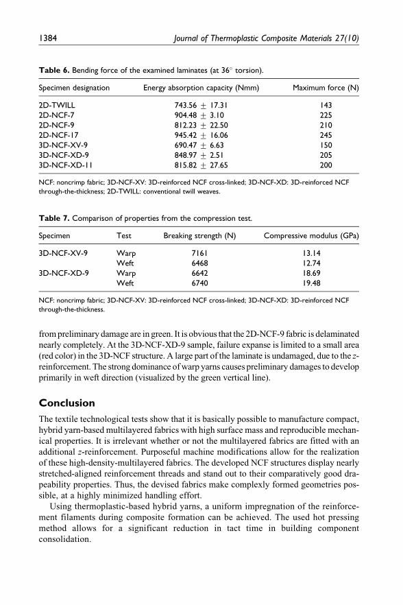
Table 6 compares the energy absorption capacity of various laminates and themaximum
force for specimens twisted at 36�. The energy absorption capacity under torsion strain is
nearly in the same level for all composites. Solely, the inconsistencies of 3D-NCF-XV-9
composites, caused by the abrupt, binding-inherent warp changing, give them considerably
lower values. Although the 3D-NCF-XD composites contain far fewer stretched-aligned
threads than 2D-NCF composites, their properties are on the same level. This is an essential
indication of the positive influence of binding warp threads on composite properties.
The pressure test is performed according to DIN EN ISO 14126:2000 on selected
laminates. To compare the influence of the bindingwarp configuration, 3D-NCF-XD-9 and
3D-NCF-XV-9 laminates were selected and confronted in Table 7. As 3D-NCF-XV-9 has a
production-related lowerweft density, they expectably display a lower breaking force under
pressure strain in warp direction and a higher breaking strength in warp direction. Since the
undulation of reinforcement warps is slightly elevated, the tensile modulus is reduced.
Figure 3. Test configuration ECT, according to Norm.
ECT: edge-crack-torsion.
1382 Journal of Thermoplastic Composite Materials 27(10)
1382
For a final assessment of delamination strength, two laminates are chosen according
to laboratory capacities. One 2D and one 3D composites with quite similar architecture
are taken into consideration, resulting from the static tests:
� 2D-NCF-9: which act more or less than a composite, made from stacked layers,
� 3D-NCF-XD-9: as a representative 3D composite with additional z-reinforcement.
Impacts are among the most frequent damages to FRP structure components, especially
within aeronautics. Although it usually does not leave visible superficial damage, it can
cause delamination of individual layers within the structure. During operation under
dynamically alternating loads, these delaminations can grown and lead to an increasing
structural degradation. This leads to component failure. Initially, the impact energy to
attain the desired impact depth of 1 mm was established at 54 J and used for further tests.
The samples (100 � 150 mm2) were clamped on three sides. Strain gauges (four each
side) were fixed on the specimen. The impactor with a diameter of 10 mm hit the speci-
men horizontal with 54 J. After the impact tests, the examined laminates were ultraso-
nically scanned in an immersion bath in order to establish the damage distribution.
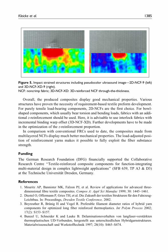
The pictures in Figure 5 show the externally visible damage areas as well as the damage
areas detected in the ultrasonic bath. The pseudocolor image shows the delaminated areas in
red, the heavily damaged ones in yellow and the undamaged areas in blue. Areas suffering
Figure 4. Exemplary hysteresis course of a 3D-NCF-XD-9 laminate.
NCF: noncrimp fabric; 3D-NCF-XD: 3D-reinforced NCF through-the-thickness.
Kleicke et al. 1383
1383
frompreliminary damage are in green. It is obvious that the 2D-NCF-9 fabric is delaminated
nearly completely. At the 3D-NCF-XD-9 sample, failure expanse is limited to a small area
(red color) in the 3D-NCF structure. A large part of the laminate is undamaged, due to the z-
reinforcement. The strong dominance ofwarp yarns causes preliminary damages to develop
primarily in weft direction (visualized by the green vertical line).
Conclusion
The textile technological tests show that it is basically possible to manufacture compact,
hybrid yarn-based multilayered fabrics with high surface mass and reproducible mechan-
ical properties. It is irrelevant whether or not the multilayered fabrics are fitted with an
additional z-reinforcement. Purposeful machine modifications allow for the realization
of these high-density-multilayered fabrics. The developed NCF structures display nearly
stretched-aligned reinforcement threads and stand out to their comparatively good dra-
peability properties. Thus, the devised fabrics make complexly formed geometries pos-
sible, at a highly minimized handling effort.
Using thermoplastic-based hybrid yarns, a uniform impregnation of the reinforce-
ment filaments during composite formation can be achieved. The used hot pressing
method allows for a significant reduction in tact time in building component
consolidation.
Table 7. Comparison of properties from the compression test.
Specimen Test Breaking strength (N) Compressive modulus (GPa)
3D-NCF-XV-9 Warp 7161 13.14
Weft 6468 12.74
3D-NCF-XD-9 Warp 6642 18.69
Weft 6740 19.48
NCF: noncrimp fabric; 3D-NCF-XV: 3D-reinforced NCF cross-linked; 3D-NCF-XD: 3D-reinforced NCF
through-the-thickness.
Table 6. Bending force of the examined laminates (at 36� torsion).
Specimen designation Energy absorption capacity (Nmm) Maximum force (N)
2D-TWILL 743.56 + 17.31 143
2D-NCF-7 904.48 + 3.10 225
2D-NCF-9 812.23 + 22.50 210
2D-NCF-17 945.42 + 16.06 245
3D-NCF-XV-9 690.47 + 6.63 150
3D-NCF-XD-9 848.97 + 2.51 205
3D-NCF-XD-11 815.82 + 27.65 200
NCF: noncrimp fabric; 3D-NCF-XV: 3D-reinforced NCF cross-linked; 3D-NCF-XD: 3D-reinforced NCF
through-the-thickness; 2D-TWILL: conventional twill weaves.
1384 Journal of Thermoplastic Composite Materials 27(10)
1384
Overall, the produced composites display good mechanical properties. Various
structures have proven the necessity of requirement-based textile preform development.
For purely tensile load-bearing components, 2D-NCFs are the first choice. For bowl-
shaped components, which usually bear torsion and bending loads, fabrics with an addi-
tional z-reinforcement should be used. Here, it is advisable to use interlock fabrics with
incremental binding warp offset (3D-NCF-XD). Further developments have to be made
in the optimization of the z-reinforcement proportion.
In comparison with conventional FRCs used to date, the composites made from
multilayered NCFs display much better mechanical properties. The load-adjusted posi-
tion of reinforcement yarns makes it possible to fully exploit the fiber substance
strength.
Funding
The German Research Foundation (DFG) financially supported the Collaborative
Research Centre ‘‘Textile-reinforced composite components for function-integrating
multi-material design in complex lightweight applications’’ (SFB 639, TP A3 & D3)
at the Technische Universitat Dresden, Germany.
References
1. Mouritz AP, Bannister MK, Falzon PJ, et al. Review of applications for advanced three-
dimensional fibre textile composites. Compos A: Appl Sci Manufac 1999; 30: 1445–1461.
2. Diestel O, Offermann P, Gries TH, et al. Die Zukunft der textilen Strukturen fur den Fahrzeug-
Leichtbau. In: Proceedings, Dresden Textile Conference, 2002.
3. Beyreuther R, Brunig H and Vogel R. Preferable filament diameter ratios of hybrid yarn
components for optimized long fiber reinforced thermoplastics. Int Polym Process 2002;
17(2): S153–S157.
4. Bunzel U, Schneider K and Lauke B. Delaminationsverhalten von langfaser-verstarkten
thermoplastischen UD-Verbunden, hergestellt aus unterschiedlichen Hybridgarnstrukturen.
Materialwissenschaft und Werkstofftechnik 1997; 28(10): S465–S474.
Figure 5. Impact strained structures including pseudocolor ultrasound image—2D-NCF-9 (left)
and 3D-NCF-XD-9 (right).
NCF: noncrimp fabric; 3D-NCF-XD: 3D-reinforced NCF through-the-thickness.
Kleicke et al. 1385
1385
5. Krucinska I, Klata E, Ankudowicz W, et al. Preliminary studies on the manufacturing of
hybrid yarns designed for thermoplastic composites. Fibres Text East Eur 2000; 8(2): 61–65.
6. Choi BD, Diestel O and Offermann P. CF-PEEK commingling hybrid yarns for textile rein-
forced light weight rotors situation and developmental perspective. Chem Fiber Int 2002;
52(4): 258–260.
7. Offermann P, Diestel O, Choi BD, et al. Advancement of comingling hybrid yarns for thermo-
plastic fiber reinforcement composites. Tech Textil 2002; 45(1): 16–18.
8. Rackers B. Textiles for advanced composites in commercial aircraft applications. In: Proceed-
ings 1st stade composite colloquium, 7–8 September 2000, pp. S1–S12.
9. Hamitouche L, Tarfaoui M and Vautrin A. 3D reinforcement and delamination resistance.
JEC Compos Mag 2006; 43: 42–45.
10. Birkel J and Rapp H. Festigkeit von Schale-Stringer-Verbindungen in Faserverbundbauweise.
Mater Mag 2007–2008; 11: S62–S64.
11. Ressler B and Sardemann G. Stoffstromanalysen zum Einsatz von carbonfaserverstarkten
Kunststoffen im Flugzeugbau. Technikfolgenabschatzung Theorie und Praxis 2002; 1(11):
41–50.
12. Lomov S, et al. A comparative study of tensile properties of non-crimp 3D orthogonal weave
and multi-layer plain weave E-glass composites. Compos A: Appl Sci Manuf 2009; 40:
1144–1157.
13. Choi BD. Entwicklung von Commingling-Hybridgarnen fur langfaserverstarkte thermoplas-
tische. Verbundwerkstoffe Thesis, Technische Universitat Dresden, Dresden, Germany, 2005.
14. Bohm R, Gude M and Hufenbach W. A phenomenologically based damage model for textile
composites with crimped reinforcements. Compos Sci Technol 2009; 70: 81–87.
15. De Moura, et al. Numerical analysis of the edge crack torsion test for mode III interlaminar
fracture of composite laminates. Eng Fract Mech 2009; 76: 469–478.
16. Orawattanasrikul S. Experimentelle analyse der scherdeformation biaxial verstarkter Mehrla-
gengestricke. Thesis, Technische Universitat Dresden, Dresden, Germany, 2006.
17. Ratcliffe JG. Characterization of the edge crack torsion (ECT): test for mode III fracture
toughness. Measurement of laminated composites. CiteSeer, 2004.
1386 Journal of Thermoplastic Composite Materials 27(10)
1386


