Embed Size (px)
Citation preview

Manual Part Number U01134Rev. 05/29/2015
Thermo ScientificLaboratory Temperature Control Products
STANDARD Series Heated Immersion Circulators SC100 SC150 SC150L
ARCTIC Series Refrigerated/Heated Bath CirculatorsA5B A28F A24B
A10B A40 A25
A25B A10 A28
SAHARA Series Heated Bath CirculatorsS3 S5T S6P
S7 S12T S14P
S13 S19T S21P
S15
S21
S30
S45
S49
Multilingual Quick Start Guides
Installation
Operation
Basic Maintenance
Thermo Fisher Scientific
25 Nimble Hill RoadNewington, NH 03801Tel : (800) 258-0830 or(603) 436-9444Fax : (603) 436-8411www.thermoscientific.com/tc
Sales, Service, and Customer Support
25 Nimble Hill RoadNewington, NH 03801Tel: (800) 258-0830 Sales: 8:00 am to 5:00 pmService and Support: 8:00 am to 6:00 pm Monday through Friday (Eastern Time)Fax: (603) [email protected]
Dieselstrasse 4 D-76227 Karlsruhe, Germany Tel : +49 (0) 721 4094 444 Fax : +49 (0) 721 4094 [email protected]
Building 6, No. 27Xin Jinqiao Rd., Shanghai 201206Tel : +86(21) 68654588Fax : +86(21) [email protected]
Statement of Copyright Copyright © 2015 Thermo Fisher Scientific. All rights reserved. This manual is copyrighted by Thermo Fisher Scientific. Users are forbidden to reproduce, republish, redistribute, or resell any materials from this manual in either machine-readable form or any other form.
Thermo Scientific
Table of Contents Quick Starts
Preface ...................................................................................................................... i Compliance ..............................................................................................................i After-Sale Support ..................................................................................................i Unpacking ...............................................................................................................ii Feedback ..................................................................................................................ii Section 1 Safety ..................................................................................1-1 Safety Warnings ..................................................................................................1-1
Section 2 General Information ................................................................2-1 Description .........................................................................................................2-1 ImmersionCirculatorSpecifications ...............................................................2-1 Bath/CirculatorSpecifications .........................................................................2-3 Wetted Materials .................................................................................................2-8
Section 3 Installation ...........................................................................3-1 Ambient Conditions ..........................................................................................3-1 Immersion Circulator Only ..............................................................................3-1 Bath Circulator ...................................................................................................3-2 Ventilation ...........................................................................................................3-3 Electrical Requirements ....................................................................................3-3 External Circulation ..........................................................................................3-7 USB Port .............................................................................................................3-8 Tubing ..................................................................................................................3-7 Approved Fluids...............................................................................................3-10 Additional Fluid Precautions .........................................................................3-12 Filling Requirements .......................................................................................3-15 Draining .............................................................................................................3-15
Section 4 Operation .............................................................................4-1 STANDARD Immersion Circulator ...............................................................4-1 Setup ....................................................................................................................4-2 Start Up ...............................................................................................................4-2 Status Display .....................................................................................................4-3 Stand By Mode ...................................................................................................4-3 Stopping the Circulator .....................................................................................4-3 Power Down .......................................................................................................4-4 Shut Down ..........................................................................................................4-4 Restarting ............................................................................................................4-4 Changing the Setpoint .......................................................................................4-5
Contents
Thermo Scientific
Menu Displays ....................................................................................................4-6 Menu ....................................................................................................................4-6 Menu Tree ...........................................................................................................4-7 Settings ................................................................................................................4-8 System ................................................................................................................4-13 High Temperature Cutout ..............................................................................4-17 Decommissioning/Disposal...........................................................................4-18 Storage................................................................................................................4-18
Section 5 Accessories ..........................................................................5-1 Lifting Platform Installation.............................................................................5-1 Immersion Cooler Bridge Installation ............................................................5-2 Rack Assembly Instructions .............................................................................5-3 Serial Communication Adapter........................................................................5-4 Tubing ..................................................................................................................5-5
Section 6 Preventive Maintenance ..........................................................6-1 Cleaning ...........................................................................................................6-1 Condenser Fins ..................................................................................................6-1 Grounding Strap and Nut ................................................................................6-2 Testing the Safety Features ...............................................................................6-2
Section 7 Troubleshooting ............................................................................................... 7-1 Error Displays ....................................................................................................7-1
Appendix Serial Communications ..................................................................................A-1 Declaration of Conformity
RoHS Directive
Warranty
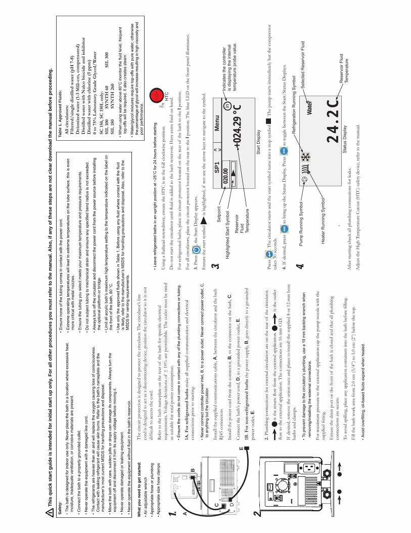
• Ensure the cords do not come in contact with any of the plumbing connections or tubing.
1A. F
or r
efri
gera
ted
bat
hs
mak
e all
supp
lied
com
mun
icatio
n an
d ele
ctric
al co
nnec
tions
prio
r to
star
ting.
• Never connect controller power inlet, B, to a power outlet. Never connect power outlet, C,
to anything but the circulator.
Inst
all th
e su
pplie
d co
mm
unica
tions
cab
le, A
, bet
wee
n th
e cir
culat
or a
nd th
e ba
th
RJ45
con
nect
ors.
Inst
all th
e po
wer
cor
d fr
om th
e co
nnec
tor,
B, t
o th
e co
nnec
tor o
n th
e ba
th, C
.
Conn
ect t
he b
ath’
s pow
er c
ord,
D, t
o a
grou
nded
pow
er o
utlet
, E.
1B. F
or n
on-r
efri
gera
ted
bat
hs
the
pow
er su
pply,
B, g
oes d
irect
ly to
a g
roun
ded
pow
er o
utlet
, E.
2. P
lum
bing
con
nect
ions
for e
xter
nal c
ircul
atio
n ar
e on
the
rear
of
the
circu
lator
.
is th
e ou
tlet
barb
s and
clam
ps.
• To prevent damage to the circulator’s plumbing, use a 19 mm backing wrench when
removing/installing the external connections.
For m
axim
um p
ress
ure
to th
e ex
tern
al ap
plica
tion
cap
the
pum
p no
zzle
with
the
Ens
ure
the
drain
por
t on
the
fron
t of
the
bath
is c
lose
d an
d th
at a
ll pl
umbi
ng
conn
ectio
ns a
re se
cure
.
• Avoid overfilling, oil-based fluids expand when heated.
cord
is d
esig
ned
to a
ct a
s a d
iscon
nect
ing
devi
ce, p
ositi
on th
e cir
culat
or so
it is
not
as su
itabl
e fo
r tot
al po
wer
con
sum
ptio
n.
Wha
t you
nee
d to
get
sta
rted
:An adjustable wrench
Appropriate hose or plumbing
Appropriate size hose clamps
A
B
C D
E
1. 2.
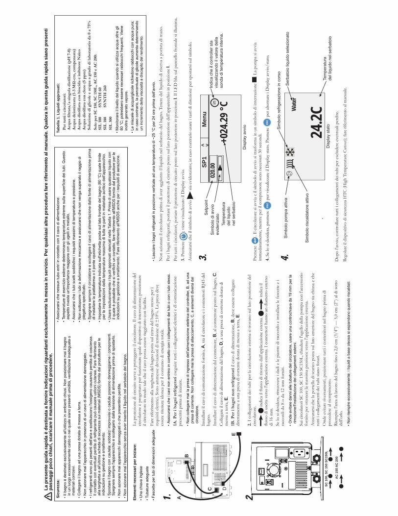
• Leave refrigerated baths in an upright position at ~25°C for 24 hours before starting.
For r
efrig
erat
ed b
aths
, plac
e its
circ
uit p
rote
ctor
loca
ted
on th
e re
ar o
f th
e ba
th to
the
I pos
ition
.
For a
ll cir
culat
ors,
plac
e th
e cir
cuit
prot
ecto
r loc
ated
on
the
rear
to th
e I
3. P
ress
Ens
ure
the
star
t sym
bol
is h
ighl
ight
ed, i
f no
t use
the
arro
w k
eys t
o na
viga
te to
the
sym
bol.
Pres
s
4. If
des
ired,
pre
ss
Pres
s
Afte
r sta
rting
che
ck a
ll pl
umbi
ng c
onne
ctio
ns fo
r lea
ks.
Highlighted Start Symbol
Setpoint
Reservoir
Fluid
Temperature
Indicates the controller
is displaying the internal
temperature probe value.
in
+024
.29 °C
SP1
M
enu
02
0.00
Start Display
< >
3.
Selected Reservoir Fluid
24.2
CW
ater
Heater Running Symbol
Pump Running Symbol
Refrigeration Running Symbol
Reservoir Fluid
Temperature
Status Display
4.
This
qui
ck s
tart
gui
de is
inte
nded
for i
nitia
l sta
rt u
p on
ly. F
or a
ll ot
her p
roce
dure
s yo
u m
ust r
efer
to th
e m
anua
l. A
lso,
if a
ny o
f the
se s
teps
are
not
cle
ar d
ownl
oad
the
man
ual b
efor
e pr
ocee
ding
.
Tabl
e 1.
App
rove
d Fl
uids
:
All
circ
ula
tors
: F
ilter
ed/
sin
gle
dis
tille
d w
ater
(p
H 7
-8)
Dis
tille
d w
ater
wit
h N
alco
bio
cid
e an
d in
hib
itor
0 to
75%
Lab
orat
ory
Gra
de
Gly
col/
Wat
er
SIL
100
SY
NT
H 6
0
SIL
300
SIL
180
SY
NT
H 2
60
• When using water above 80°C monitor the fluid level, frequent
top-offs will be required. It also creates steam.
• Water/glycol mixtures require top-offs with pure water, otherwise
the percentage of glycol will increase resulting in high viscosity and
poor performance.
• Ensure none of the tubing comes in contact with the power cord.
• Extreme operating temperatures will lead to extreme temperatures on the tube surface, this is even
more critical with metal nozzles.
• Ensure the tubing you select meets your maximum temperature and pressure requirements.
• Do not subject tubing to mechanical strain and ensure any specified bend radius is not exceeded.
• Always turn off the circulator and disconnect the power cord from the power source before installing
the optional platform or bridge.
• Limit all acrylic bath’s maximum high temperature setting to the temperature indicated on the label on
the front of the bath, 80 °C.
• Use only the approved fluids shown in Table 1. Before using any fluid where contact with the fluid
is likely, refer to the manufacturer’s MSDS for handling precautions and disposal. Also, refer to the
MSDS for venting requirements.
Safe
ty:
• The bath is designed for indoor use only. Never place the bath in a location where excessive heat,
moisture, inadequate ventilation, or corrosive materials are present.
• Connect the bath to a properly grounded outlet.
• Never operate the equipment with a damaged line cord.
• The refrigerants are heavier than air and will replace the oxygen causing loss of consciousness.
Contact with leaking refrigerant will cause skin burns. Refer to the bath’s nameplate and the
manufacturer’s most current MSDS for handling precautions and disposal.
• Move the bath with care, sudden jolts or drops can damage its components. Always turn the
equipment off and disconnect it from its supply voltage before moving it.
• Never operate damaged or leaking equipment.
• Never operate the equipment without fluid in the bath’s reservoir.
°C
HTC
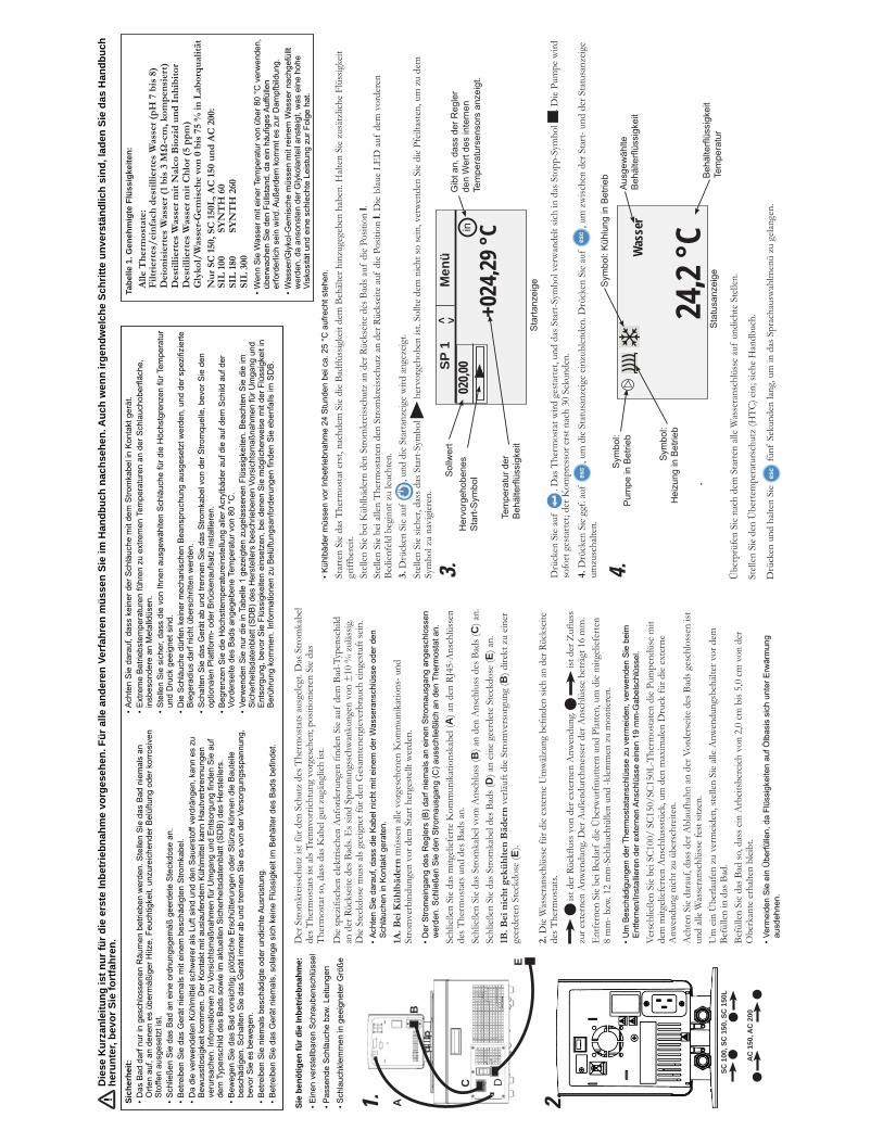
• Achten Sie darauf, dass die Kabel nicht mit einem der Wasseranschlüsse oder den
Schläuchen in Kontakt geraten.
1A. B
ei K
üh
lbäd
ern
müs
sen
alle
vorg
eseh
enen
Kom
mun
ikat
ions
- und
St
rom
verb
indu
ngen
vor
dem
Sta
rt he
rges
tellt
wer
den.
• Der Stromeingang des Reglers (B) darf niemals an einen Stromausgang angeschlossen
werden. Schließen Sie den Stromausgang (C) ausschließlich an den Thermostat an.
Schl
ießen
Sie
das m
itgel
iefer
te K
omm
unik
atio
nska
bel (
A) a
n de
n RJ
45-A
nsch
lüss
en
des T
herm
osta
ts u
nd d
es B
ads a
n.
Schl
ießen
Sie
das S
trom
kabe
l vom
Ans
chlu
ss (B
) an
den
Ans
chlu
ss d
es B
ads (
C) a
n.Sc
hließ
en S
ie da
s Stro
mka
bel d
es B
ads (
D) a
n ein
e ge
erde
te S
teck
dose
(E) a
n.
1B. B
ei n
ich
t ge
küh
lten
Bäd
ern
ver
läuft
die
Stro
mve
rsor
gung
(B) d
irekt
zu
einer
ge
erde
ten
Stec
kdos
e (E
).
2. des T
herm
osta
ts.
zur e
xter
nen
Anw
endu
ng. D
er A
ußen
durc
hmes
ser d
er A
nsch
lüss
e be
trägt
16
mm
. E
ntfe
rnen
Sie
bei B
edar
f di
e Ü
berw
urfm
utte
rn u
nd P
latte
n, u
m d
ie m
itgel
iefer
ten
8 m
m- b
zw. 1
2 m
m-S
chlau
chtü
llen
und
-klem
men
zu
mon
tiere
n.
• Um Beschädigungen der Thermostatanschlüsse zu vermeiden, verwenden Sie beim
Entfernen/Installieren der externen Anschlüsse einen 19 mm-Gabelschlüssel.
Vers
chlie
ßen
Sie
bei S
C100
/ SC
150/
SC15
0L-T
herm
osta
ten
die
Pum
pend
üse
mit
dem
mitg
elief
erte
n A
nsch
luss
stüc
k, u
m d
en m
axim
alen
Dru
ck fü
r die
exte
rne
Anw
endu
ng n
icht z
u üb
ersc
hreit
en.
Ach
ten
Sie
dara
uf, d
ass d
er A
blau
fhah
n an
der
Vor
ders
eite
des B
ads g
esch
loss
en is
t un
d all
e W
asse
rans
chlü
sse
fest
sitz
en.
Um
ein
Übe
rlauf
en z
u ve
rmeid
en, s
telle
n Si
e all
e A
nwen
dung
sbeh
älter
vor
dem
Be
fülle
n in
das
Bad
.Be
fülle
n Si
e da
s Bad
so, d
ass e
in A
rbeit
sber
eich
von
2,0
cm b
is 5,
0 cm
von
der
O
berk
ante
erh
alten
blei
bt.
• Vermeiden Sie ein Überfüllen, da Flüssigkeiten auf Ölbasis sich unter Erwärmung
ausdehnen.
Der
Stro
mkr
eissc
hutz
ist f
ür d
en S
chut
z de
s The
rmos
tats
aus
geleg
t. D
as S
trom
kabe
l de
s The
rmos
tats
ist a
ls Tr
ennv
orric
htun
g vo
rges
ehen
; pos
ition
ieren
Sie
das
Ther
mos
tat s
o, d
ass d
as K
abel
gut z
ugän
glich
ist.
an d
er R
ücks
eite
des B
ads.
Es s
ind
Span
nung
ssch
wan
kung
en v
on ±
10 %
zul
ässig
. D
ie St
eckd
ose
mus
s als
geeig
net f
ür d
en G
esam
tene
rgiev
erbr
auch
ein
gest
uft s
ein.
Sie
benö
tigen
für d
ie In
betr
iebn
ahm
e:Einen verstellbaren Schraubenschlüssel
Passende Schläuche bzw. Leitungen
Schlauchklemmen in geeigneter Größe
A
B
C D
E
1. 2.
• Kühlbäder müssen vor Inbetriebnahme 24 Stunden bei ca. 25 °C aufrecht stehen.
griff
bere
it.
Stell
en S
ie be
i Küh
lbäd
ern
den
Stro
mkr
eissc
hutz
an
der R
ücks
eite
des B
ads a
uf d
ie Po
sitio
n I.
Stell
en S
ie be
i alle
n Th
erm
osta
ten
den
Stro
mkr
eissc
hutz
an
der R
ücks
eite
auf
die
Posit
ion
I. D
ie bl
aue
LED
auf
dem
vor
dere
n Be
dien
feld
beg
innt
zu
leuch
ten.
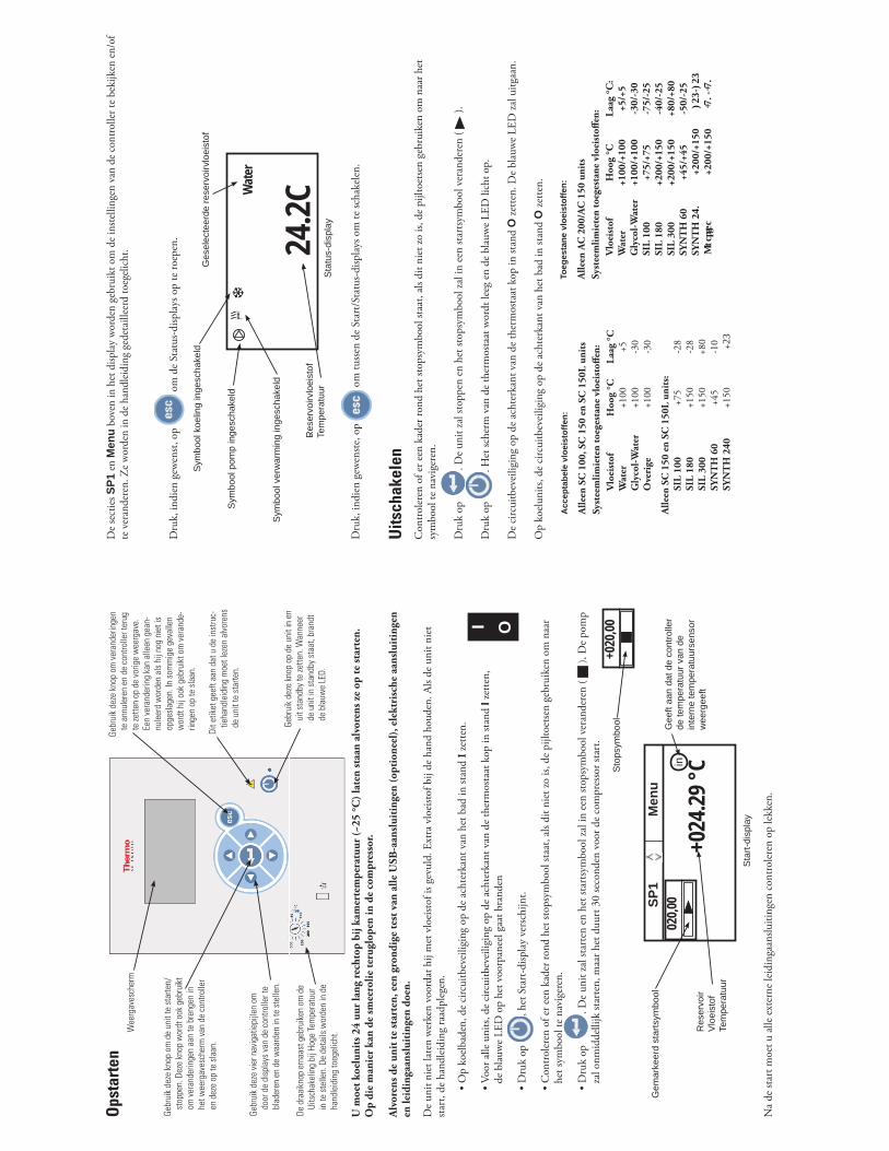
3. D
rück
en S
ie au
f , u
nd d
ie St
arta
nzeig
e w
ird a
ngez
eigt.
her
vorg
ehob
en is
t. So
llte
dem
nich
t so
sein
, ver
wen
den
Sie
die
Pfeil
tast
en, u
m z
u de
m
Drü
cken
Sie
auf
. Die
Pum
pe w
ird
sofo
rt ge
star
tet;
der K
ompr
esso
r ers
t nac
h 30
Sek
unde
n.
4. D
rück
en S
ie gg
f. au
f , u
m d
ie St
atus
anze
ige
einzu
blen
den.
Drü
cken
Sie
auf
, um
zw
ische
n de
r Sta
rt- u
nd d
er S
tatu
sanz
eige
umzu
scha
lten.
Übe
rprü
fen
Sie
nach
dem
Sta
rten
alle
Was
sera
nsch
lüss
e au
f un
dich
te S
telle
n.
Drü
cken
und
halt
en S
ie fü
nf S
ekun
den
lang,
um
in d
as S
prac
haus
wah
lmen
ü zu
gela
ngen
.
Hervorgehobenes
Start-SymbolSollwert
Temperatur der
Behälterflüssigkeit
Gibt an, dass der Regler
den Wert des internen
Temperatursensors anzeigt.
in
+024
,29 °C
SP 1
M
enü
020,0
0
Startanzeige
< >
3.
Ausgewählte
Behälterflüssigkeit
24,2
°CWas
ser
Symbol:
Heizung in Betrieb
Symbol:
Pumpe in Betrieb
Symbol: Kühlung in Betrieb Behälterflüssigkeit
Temperatur
Statusanzeige
4.
Die
se K
urza
nlei
tung
ist n
ur fü
r die
ers
te In
betr
iebn
ahm
e vo
rges
ehen
. Für
alle
and
eren
Ver
fahr
en m
üsse
n Si
e im
Han
dbuc
h na
chse
hen.
Auc
h w
enn
irgen
dwel
che
Schr
itte
unve
rstä
ndlic
h si
nd, l
aden
Sie
das
Han
dbuc
h he
runt
er, b
evor
Sie
fort
fahr
en.
Tabe
lle 1
. Gen
ehm
igte
Flü
ssig
keite
n:A
lle T
her
mos
tate
: F
iltri
erte
s/ei
nfa
ch d
esti
llier
tes
Was
ser
(pH
7 b
is 8
)
Des
tilli
erte
s W
asse
r m
it N
alco
Bio
zid
un
d I
nh
ibit
or
Des
tilli
erte
s W
asse
r m
it C
hlo
r (5
pp
m)
• Wenn Sie Wasser mit einer Temperatur von über 80 °C verwenden,
überwachen Sie den Füllstand, da ein häufiges Auffüllen
erforderlich sein wird. Außerdem kommt es zur Dampfbildung.
• Wasser/Glykol-Gemische müssen mit reinem Wasser nachgefüllt
werden, da ansonsten der Glykolanteil ansteigt, was eine hohe
Viskosität und eine schlechte Leistung zur Folge hat.
• Achten Sie darauf, dass keiner der Schläuche mit dem Stromkabel in Kontakt gerät.
• Extreme Betriebstemperaturen führen zu extremen Temperaturen an der Schlauchoberfläche,
insbesondere an Metalldüsen.
• Stellen Sie sicher, dass die von Ihnen ausgewählten Schläuche für die Höchstgrenzen für Temperatur
und Druck geeignet sind.
• Die Schläuche dürfen keiner mechanischen Beanspruchung ausgesetzt werden, und der spezifizierte
Biegeradius darf nicht überschritten werden.
• Schalten Sie das Gerät ab und trennen Sie das Stromkabel von der Stromquelle, bevor Sie den
optionalen Plattform- oder Brückenaufsatz installieren.
• Begrenzen Sie die Höchsttemperatureinstellung aller Acrylbäder auf die auf dem Schild auf der
Vorderseite des Bads angegebene Temperatur von 80 °C.
• Verwenden Sie nur die in Tabelle 1 gezeigten zugelassenen Flüssigkeiten. Beachten Sie die im
Sicherheitsdatenblatt (SDB) des Herstellers beschriebenen Vorsichtsmaßnahmen für Umgang und
Entsorgung, bevor Sie Flüssigkeiten einsetzen, bei denen Sie möglicherweise mit der Flüssigkeit in
Berührung kommen. Informationen zu Belüftungsanforderungen finden Sie ebenfalls im SDB.
Sich
erhe
it:• Das Bad darf nur in geschlossenen Räumen betrieben werden. Stellen Sie das Bad niemals an
Orten auf, an denen es übermäßiger Hitze, Feuchtigkeit, unzureichender Belüftung oder korrosiven
Stoffen ausgesetzt ist.
• Schließen Sie das Bad an eine ordnungsgemäß geerdete Steckdose an.
• Betreiben Sie das Gerät niemals mit einem beschädigten Stromkabel.
• Da die verwendeten Kühlmittel schwerer als Luft sind und den Sauerstoff verdrängen, kann es zu
Bewusstlosigkeit kommen. Der Kontakt mit auslaufendem Kühlmittel kann Hautverbrennungen
verursachen. Informationen zu Vorsichtsmaßnahmen für Umgang und Entsorgung finden Sie auf
dem Typenschild des Bads sowie im aktuellen Sicherheitsdatenblatt (SDB) des Herstellers.
• Bewegen Sie das Bad vorsichtig; plötzliche Erschütterungen oder Stürze können die Bauteile
beschädigen. Schalten Sie das Gerät immer ab und trennen Sie es von der Versorgungsspannung,
bevor Sie es bewegen.
• Betreiben Sie niemals beschädigte oder undichte Ausrüstung.
• Betreiben Sie das Gerät niemals, solange sich keine Flüssigkeit im Behälter des Bads befindet.
SC 1
00, S
C 1
50, S
C 1
50L
AC
150
, AC
200
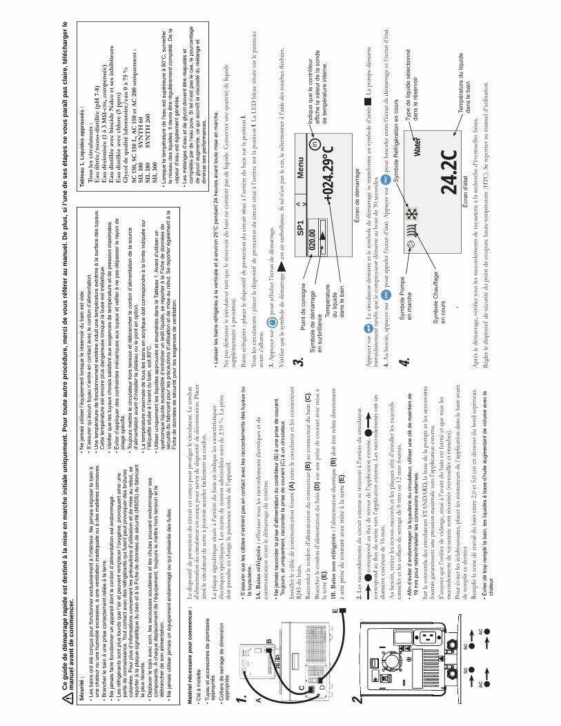
• S’assurer que les câbles n’entrent pas en contact avec les raccordements des tuyaux ou
la tuyauterie.
1A. B
ain
s ré
frig
érés
: ef
fect
uer t
ous l
es ra
ccor
dem
ents
élec
triqu
es e
t de
com
mun
icatio
n av
ant l
e dé
mar
rage
du
syst
ème.
• Ne jamais raccorder la prise d’alimentation du contrôleur (B) à une prise de courant.
Toujours, et uniquement, raccorder la prise de courant (C) à un circulateur.
Inst
aller
le c
âble
de c
omm
unica
tion
four
ni (A
) ent
re le
circ
ulat
eur e
t les
con
nect
eurs
RJ
45 d
u ba
in.
Racc
orde
r le
cord
on d
’alim
enta
tion
du c
onne
cteu
r (B
) au
conn
ecte
ur d
u ba
in (C
).Br
anch
er le
cor
don
d’ali
men
tatio
n du
bain
(D) s
ur u
ne p
rise
de c
oura
nt av
ec m
ise à
la
terr
e (E
). 1B
. Bai
ns
non
réf
rigé
rés
: l’al
imen
tatio
n éle
ctriq
ue (B
) doi
t être
relié
e di
rect
emen
t à
une
prise
de
cour
ant a
vec
mise
à la
terr
e (E)
.
2. L
es ra
ccor
dem
ents
du
circu
it ex
tern
e se
trou
vent
à l’
arriè
re d
u cir
culat
eur.
diam
ètre
ext
érieu
r de
16 m
m.
cann
elés e
t les
col
liers
de
serr
age
de 8
mm
ou
12 m
m fo
urni
s.
• Afin d’éviter d’endommager la tuyauterie du circulateur, utiliser une clé de maintien de
19 mm pour retirer/installer les connexions externes.
Sur l
e co
uver
cle d
es c
ircul
ateu
rs S
TAN
DA
RD, l
a bu
se d
e la
pom
pe e
t les
acc
esso
ires
four
nis g
aran
tisse
nt u
ne p
ress
ion
max
imale
ver
s l’ap
plica
tion
exte
rne.
racc
orde
men
ts d
e tu
yaut
erie
sont
sécu
risés
(ver
roui
llés e
t éta
nche
s).
Pour
évi
ter l
es é
clabo
ussu
res,
plac
er le
s con
tene
urs d
e l’a
pplic
atio
n da
ns le
bain
avan
t de
rem
plir
ce d
erni
er.
Rem
plir
la zo
ne d
e tra
vail
du b
ain e
ntre
2,0
et 5
,0 c
m e
n de
ssou
s du
bord
supé
rieur
.
• Éviter de trop remplir le bain, les liquides à base d’huile augmentant de volume avec la
chaleur.
Le d
ispos
itif
de p
rote
ctio
n du
circ
uit e
st co
nçu
pour
pro
tége
r le
circu
lateu
r. Le
cor
don
d’ali
men
tatio
n du
circ
ulat
eur e
st co
nçu
pour
serv
ir de
disp
ositi
f de
déc
onne
xion
. Plac
er
ainsi
le cir
culat
eur d
e so
rte à
pouv
oir a
ccéd
er fa
cilem
ent a
u co
rdon
.La
plaq
ue si
gnalé
tique
situ
ée à
l’ar
rière
du
bain
en
indi
que
les c
arac
téris
tique
s
doit
pren
dre
en c
harg
e la
puiss
ance
tota
le de
l’ap
pare
il.
Mat
érie
l néc
essa
ire p
our c
omm
ence
r :Clé à molette
Tuyau et accessoires de plomberie
appropriés
Colliers de serrage de dimension
appropriée
A
B
C D
E
1.
SC
AC
AC
SC
2.
• Laisser les bains réfrigérés à la verticale et à environ 25°C pendant 24 heures avant toute mise en marche.
Ne
pas d
émar
rer l
e cir
culat
eur t
ant q
ue le
rése
rvoi
r du
bain
ne
cont
ient p
as d
e liq
uide
. Con
serv
er u
ne q
uant
ité d
e liq
uide
su
pplém
enta
ire à
pro
xim
ité.
Bain
s réf
rigér
és :
plac
er le
disp
ositi
f de
pro
tect
ion
du c
ircui
t situ
é à
l’arr
ière
du b
ain su
r la
posit
ion
I.To
us le
s circ
ulat
eurs
: pl
acer
le d
ispos
itif
de p
rote
ctio
n du
circ
uit s
itué
à l’a
rrièr
e su
r la
posit
ion
I. La
LE
D b
leue
situé
e su
r le
pann
eau
avan
t s’al
lum
e.3.
App
uyer
sur
App
uyer
sur
. Le
circu
lateu
r dém
arre
et l
e sy
mbo
le de
dém
arra
ge se
tran
sfor
me
en sy
mbo
le d’
arrê
t . L
a po
mpe
dém
arre
im
méd
iatem
ent t
andi
s que
le c
ompr
esse
ur d
émar
re a
u bo
ut d
e 30
seco
ndes
. 4.
Au
beso
in, a
ppuy
er su
r p
our a
ppele
r l’éc
ran
d’ét
at. A
ppuy
er su
r p
our b
ascu
ler e
ntre
l’éc
ran
de d
émar
rage
et l
’écra
n d’
état
.
Régl
er le
disp
ositi
f de
sécu
rité
du p
oint
de
coup
ure
haut
e te
mpé
ratu
re (H
TC).
Se re
porte
r au
man
uel d
’util
isatio
n.
Symbole de démarrage
en surbrillance
Point de consigne
Température
du liquide
dans le bain
Indique que le contrôleur
affiche la valeur de la sonde
de température interne.
in
+024
.29°C
SP1
M
enu
02
0.00
Écran de démarrage
< >
3.
Type de liquide sélectionné
dans le réservoir
24.2C
Wat
er
Symbole Chauffage
en cours
Symbole Pompe
en marche
Symbole Réfrigération en cours
Température du liquide
dans le bain
Écran d’état
4.
Ce
guid
e de
dém
arra
ge ra
pide
est
des
tiné
à la
mis
e en
mar
che
initi
ale
uniq
uem
ent.
Pour
tout
e au
tre
proc
édur
e, m
erci
de
vous
réfé
rer a
u m
anue
l. D
e pl
us, s
i l’u
ne d
e se
s ét
apes
ne
vous
par
aît p
as c
laire
, tél
écha
rger
le
man
uel a
vant
de
com
men
cer.
Tabl
eau
1. L
iqui
des
appr
ouvé
s :
Tou
s le
s ci
rcu
late
urs
:
• Lorsque la température de l’eau est supérieure à 80°C, surveiller
le niveau des liquides. Il devra être régulièrement complété. De la
vapeur d’eau est également générée.
• Les mélanges d’eau et de glycol doivent être réajustés et
complétés par de l’eau pure. Si tel n’est pas le cas, le pourcentage
de glycol augmente, ce qui accroît la viscosité du mélange et
diminue ses performances.
• Ne jamais utiliser l’équipement lorsque le réservoir du bain est vide.
• S’assurer qu’aucun tuyau n’entre en contact avec le cordon d’alimentation.
• Une température de fonctionnement extrême induit une température extrême à la surface des tuyaux.
Cette température est encore plus dangereuse lorsque la buse est métallique.
• Vérifier que les tuyaux choisis satisfont aux exigences de température et de pression maximales.
• Éviter d’appliquer des contraintes mécaniques aux tuyaux et veiller à ne pas dépasser le rayon de
pliage spécifié.
• Toujours mettre le circulateur hors tension et débrancher le cordon d’alimentation de la source
d’alimentation avant d’installer le plateau ou le pont en option.
• La température maximale de tous les bains en acrylique doit correspondre à la limite indiquée sur
l’étiquette située à l’avant du bain, soit 80°C.
• Utiliser uniquement les liquides approuvés et énumérés dans le Tableau 1. Avant d’utiliser un
quelconque liquide susceptible d’entraîner un ledit liquide, se reporter à la Fiche de données de
sécurité du fabricant pour les précautions d’utilisation et de mise au rebut. Se reporter également à la
Fiche de données de sécurité pour les exigences de ventilation.
Sécu
rité
:
• Les bains ont été conçus pour fonctionner exclusivement à l’intérieur. Ne jamais exposer le bain à
une chaleur ou une humidité excessive, à une ventilation inadéquate ou à des matières corrosives.
• Brancher le bain à une prise correctement reliée à la terre.
• Ne jamais faire fonctionner un appareil dont le cordon d’alimentation est endommagé.
• Les réfrigérants sont plus lourds que l’air et peuvent remplacer l’oxygène, provoquant ainsi une
perte de connaissance. Tout contact avec des réfrigérants qui fuient peut provoquer des brûlures
cutanées. Pour plus d’informations concernant les précautions d’utilisation et de mise au rebut, se
reporter à la plaque signalétique du bain et à la Fiche de données de sécurité (MSDS) du fabricant
la plus récente.
• Déplacer le bain avec soin, les secousses soudaines et les chutes pouvant endommager ses
composants. À chaque déplacement de l’équipement, toujours le mettre hors tension et le
débrancher de son alimentation.
• Ne jamais utiliser jamais un équipement endommagé ou qui présente des fuites.
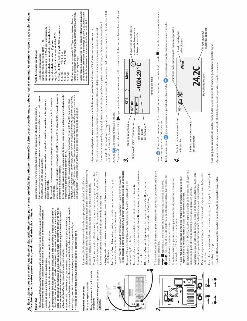
• Asegúrese de que los cables no entren en contacto con los tubos ni con las conexiones
de fontanería.
1A. P
ara
bañ
os r
efri
gera
dos
: est
ablez
ca to
das l
as c
onex
ione
s eléc
trica
s y d
e co
mun
icació
n su
min
istra
das a
ntes
de
com
enza
r.
• Nunca conecte la entrada de alimentación del controlador, B, a una toma de corriente.
Nunca conecte la toma de alimentación, C, a ningún otro aparato que no sea un circulador.
Inst
ale e
l cab
le de
com
unica
cione
s sum
inist
rado
, A, e
ntre
el c
ircul
ador
y lo
s co
nect
ores
RJ4
5 de
l bañ
o.
Inst
ale e
l cab
le de
alim
enta
ción
del c
onec
tor,
B, a
l con
ecto
r del
baño
, C.
Cone
cte
el ca
ble
de a
limen
tació
n de
l bañ
o, D
, a u
na to
ma
de c
orrie
nte
con
deriv
ació
n a
tierr
a, E.
1B
. Par
a b
años
no
refr
iger
ados
: la
fuen
te d
e ali
men
tació
n, B
, se
cone
cta
dire
ctam
ente
a u
na to
ma
de c
orrie
nte
con
deriv
ació
n a
tierr
a, E.
2. L
as c
onex
ione
s de
font
aner
ía pa
ra la
circ
ulac
ión
exte
rna
se e
ncue
ntra
n en
la p
arte
tra
sera
del
circu
lador
.
tiene
n un
diám
etro
ext
erno
de
16 m
m.
Si lo
des
ea, r
etire
las p
lacas
y tu
erca
s par
a in
stala
r las
abr
azad
eras
y c
onex
ione
s de
ntad
as d
e 8
o 12
mm
que
se su
min
istra
n.
• Para evitar que se produzcan daños en la fontanería del circulador, utilice una llave
inglesa fija de 19 mm para retirar o instalar las conexiones externas.
En
circu
lador
es S
C100
, SC1
50, S
C150
L ta
pe la
boq
uilla
de
la bo
mba
con
el a
cces
orio
su
min
istra
do p
ara
obte
ner l
a m
áxim
a pr
esió
n en
la a
plica
ción
exte
rna.
cerr
ado
y de
que
toda
s las
con
exio
nes d
e fo
ntan
ería
esté
n bi
en a
pret
adas
.Pa
ra e
vita
r salp
icadu
ras,
intro
duzc
a lo
s rec
ipien
tes d
e la
aplic
ació
n en
el b
año
ante
s de
llen
arlo
.
• No llene el baño en exceso; los líquidos a base de aceite se expanden con el calor.
La p
rote
cció
n de
l circ
uito
est
á di
seña
da p
ara
prot
eger
el c
ircul
ador
. El c
able
de
alim
enta
ción
del c
ircul
ador
está
dise
ñado
par
a act
uar c
omo
disp
ositi
vo d
e de
scon
exió
n;
colo
que
el cir
culad
or d
e fo
rma
que
perm
ita a
cced
er a
l cab
le co
n fa
cilid
ad.
Cons
ulte
los r
equi
sitos
eléc
trico
s con
cret
os q
ue a
pare
cen
en la
plac
a co
n el
nom
bre
del b
año,
situ
ada
en la
par
te tr
aser
a. Se
per
mite
una
des
viac
ión
de te
nsió
n de
± 1
0 %
. La
tom
a de
cor
rient
e de
be a
dmiti
r el c
onsu
mo
de e
nerg
ía to
tal.
Mat
eria
les
nece
sario
s:Una llave inglesa ajustable
Manguera o elementos de fontanería
apropiados
Abrazaderas de manguera de tamaño
adecuado
A
B
C D
E
1.
SC
AC
AC
SC
2.
• Los baños refrigerados deben mantenerse durante 24 horas en posición vertical y a unos 25 °C antes de su puesta en marcha.
En
los b
años
refr
iger
ados
, col
oque
el p
rote
ctor
del
circu
ito, s
ituad
o en
la p
arte
tras
era
del b
año,
en
la po
sició
n de
enc
endi
do, I
.Pa
ra to
dos l
os c
ircul
ador
es, c
oloq
ue e
l pro
tect
or d
e cir
cuito
, situ
ado
en la
par
te tr
aser
a, en
la p
osici
ón d
e en
cend
ido
I. E
l ind
icado
r LE
D
azul
del
pane
l fro
ntal
se il
umin
ará.
3. P
ulse
y
apa
rece
rá la
pan
talla
de
inici
o.A
segú
rese
de
que
el sím
bolo
de
inici
o
Pulse
. E
l circ
ulad
or a
rran
cará
y e
l sím
bolo
de
inici
o se
con
verti
rá e
n un
sím
bolo
de
para
da
. La
bom
ba se
inici
a au
tom
ática
men
te,
pero
el c
ompr
esor
tard
a 30
segu
ndos
. 4.
Si l
o de
sea,
pulse
p
ara
que
apar
ezca
la p
anta
lla d
e es
tado
. Pul
se
par
a alt
erna
r ent
re la
s pan
talla
s de
inici
o y
esta
do.
Símbolo de inicio resaltado
Valor de referencia
Temperatura
del líquido
del depósito
Indica que el controlador
muestra la temperatura
interna de la sonda.
in
+024
.29 °C
SP1
M
enu
02
0.00
Pantalla de inicio
< >
3.
Líquido del depósito
seleccionado
24.2C
Wat
er
Símbolo de funcionamiento
del calentador
Símbolo de funcionamiento
de la bomba
Símbolo de funcionamiento de la refrigeración
Temperatura del
líquido del depósito
Pantalla de estado
4.
Esta
guí
a de
pue
sta
en m
arch
a rá
pida
se
ha e
labo
rado
úni
cam
ente
par
a el
arr
anqu
e in
icia
l. Pa
ra o
bten
er in
form
ació
n so
bre
otro
s pr
oced
imie
ntos
, deb
e co
nsul
tar e
l man
ual.
Asi
mis
mo,
en
caso
de
que
tuvi
era
duda
s so
bre
algu
no d
e es
tos
paso
s, d
esca
rgue
el m
anua
l ant
es d
e co
ntin
uar.
Tabl
a 1.
Líq
uido
s ap
roba
dos:
Tod
os lo
s ci
rcu
lad
ores
:
• Al utilizar agua por encima de 80 °C para monitorizar el nivel de
líquido, será necesario rellenar el líquido con frecuencia. Además,
también se origina vapor.
• En las mezclas de agua/glicol, es necesario rellenar con agua pura;
de lo contrario, aumentará el porcentaje de glicol y se producirá un
aumento de la viscosidad y una disminución del rendimiento.
• Asegúrese de que ninguno de los tubos entra en contacto con el cable de alimentación.
• Las temperaturas de funcionamiento extremas se transmitirán a la superficie del tubo; esto origina
más daños con las boquillas metálicas.
• Asegúrese de que los tubos seleccionados cumplen los requisitos necesarios de temperatura y
presión máximas.
• No someta los tubos a presión mecánica y asegúrese de que no se supere el radio de curvatura
especificado.
• Apague siempre el circulador y desconecte el cable de la fuente de alimentación antes de instalar la
plataforma o el puente opcional.
• Limite el ajuste máximo de temperatura alta de todo el baño acrílico a la temperatura indicada en la
etiqueta de la parte delantera del baño, 80 °C.
• Utilice únicamente los líquidos aprobados que se muestran en la Tabla 1. Antes de utilizar otros
líquidos que puedan entrar en contacto con el líquido, consulte las hojas de datos de seguridad de
materiales (MSDS) del fabricante para obtener información sobre la eliminación y las precauciones
de manipulación. Consulte también la MSDS para conocer los requisitos de ventilación.
Segu
ridad
:
• El baño está destinado exclusivamente para uso en interiores. No lo coloque nunca en lugares con
calor o humedad excesivos o ventilación inadecuada, ni en presencia de materiales corrosivos.
• Conecte el baño a una toma de tierra adecuada.
• En caso de que el cable de alimentación esté dañado, no utilice el equipo.
• Los refrigerantes son más pesados que el aire, por lo que sustituirán al oxígeno y provocarán la
pérdida del conocimiento. En caso de que entre en contacto con el refrigerante procedente de
fugas, se producirán quemaduras en la piel. Consulte la placa identificativa del baño y la hoja de
datos de seguridad de materiales (MSDS) más actual del fabricante para obtener información
sobre la eliminación y las precauciones de manipulación.
• Mueva el baño con cuidado, ya que las caídas o los saltos repentinos pueden dañar los
componentes. Apague siempre el equipo y desconéctelo de la tensión eléctrica antes de moverlo.
• Nunca ponga en funcionamiento un equipo que esté dañado o que presente fugas.
• No utilice el equipo hasta que haya añadido el líquido al depósito de baño.
• Assicurarsi che i cavi non entrino in contatto con i collegamenti dei tubi o con i tubi stessi.
1A. P
er i
bag
ni r
efri
gera
ti e
segu
ire tu
tti i
colle
gam
enti
elettr
ici e
di c
omun
icazi
one
pres
critt
i prim
a di
iniz
iare.
• Non collegare mai la presa di ingresso dell'alimentazione elettrica del controller, B, ad una
presa di corrente. Non collegare mai la presa di allacciamento, C, a elementi diversi dal
circolatore.
Inst
allar
e il
cavo
di c
omun
icazi
one
forn
ito, A
, tra
il c
ircol
ator
e e
i con
netto
ri RJ
45 d
el ba
gno.
In
stall
are
il ca
vo d
i alim
enta
zion
e da
l con
netto
re, B
, al c
onne
ttore
pos
to su
l bag
no, C
.Co
llega
re il
cav
o di
alim
enta
zion
e de
l bag
no, D
, a u
na p
resa
di c
orre
nte
dota
ta d
i m
essa
a te
rra,
E.
1B. P
er i
bag
ni n
on r
efri
gera
ti il
cav
o di
alim
enta
zion
e, B
, dev
e es
sere
col
legat
o di
retta
men
te a
una
pre
sa d
i cor
rent
e do
tata
di m
essa
a te
rra,
E.
2. I
colle
gam
enti
dei t
ubi p
er la
circ
olaz
ione
est
erna
si tr
ovan
o su
l lat
o po
ster
iore
del
circo
lator
e. in
dica
il
di 1
6 m
m.
Se lo
si d
esid
era,
rimuo
vere
i da
di e
le p
iastre
di r
acco
rdo
e in
stall
are
le fa
scet
te e
i ra
ccor
di d
a 8
o da
12
mm
forn
iti.
• Onde evitare danni alle tubature del circolatore, usare una controchiave da 19 mm per la
rimozione/l'installazione dei collegamenti esterni.
Ond
e ev
itare
rive
rsam
enti,
pos
izio
nare
tutti
i co
nten
itori
nel b
agno
prim
a di
pr
oced
ere
al rie
mpi
men
to.
• Non riempire eccessivamente; i liquidi a base oleosa si espandono quando riscaldati.
La p
rote
zion
e di
circ
uito
serv
e a
prot
egge
re il
circ
olat
ore.
Il ca
vo d
i alim
enta
zion
e de
l cir
colat
ore
è pr
oget
tato
per
funz
iona
re q
uale
disp
ositi
vo d
i int
erru
zion
e; po
sizio
nare
requ
isiti
elettr
ici. S
ono
amm
esse
dev
iazio
ni d
i ten
sione
di ±
10%
. La
pres
a de
ve
esse
re ri
tenu
ta id
onea
per
il c
onsu
mo
di e
nerg
ia to
tale.
Elem
enti
nece
ssar
i per
iniz
iare
:Una chiave inglese
Tubature adeguate
Fascette per tubi di dimensioni adeguate
A
B
C D
E
1.
SC 1
00, S
C 1
50 S
C15
0L
AC
150
AC
200
2.
• Lasciare i bagni refrigerati in posizione verticale ad una temperatura di ~25 °C per 24 ore prima dell'avvio.
Non
azi
onar
e il
circo
lator
e pr
ima
di av
er a
ggiu
nto
il liq
uido
nel
serb
atoi
o de
l bag
no. T
ener
e de
l liq
uido
di r
iserv
a a
porta
ta d
i man
o.
I.Pe
r tut
ti i c
ircol
ator
i, po
rtare
il p
rote
ttore
di c
ircui
to p
osto
sul l
ato
post
erio
re in
pos
izio
ne I.
Il L
ED
blu
sul p
anne
llo fr
onta
le si
illum
ina.
3. P
rem
ere
; vien
e vi
suali
zzat
o il
Disp
lay av
vio.
sia
evid
enzi
ato;
in c
aso
cont
rario
usa
re i
tast
i di d
irezi
one
per s
post
arsi
sul s
imbo
lo.
Prem
ere
. Il c
ircol
ator
e si
avvi
a e
il sim
bolo
di a
vvio
si tr
asfo
rma
in u
n sim
bolo
di i
nter
ruzi
one
. La
pom
pa si
avvi
a
4. S
e lo
si d
esid
era,
prem
ere
per
visu
alizz
are
il D
isplay
stat
o. P
rem
ere
Simbolo di avvio
evidenziatoSetpoint
Temperatura
del liquido
nel serbatoio
Indica che il controller sta
visualizzando il valore della
sonda di temperatura interna.
in
+024
.29 °C
SP1
M
enu
02
0.00
Display avvio
< >
3.
Serbatoio liquido selezionato
24.2C
Wat
er
Simbolo riscaldatore attivo
Simbolo pompa attiva
Simbolo refrigerazione in corso
Temperatura
del liquido nel serbatoio
Display stato
4.
La p
rese
nte
guid
a ra
pida
è d
estin
ata
a fo
rnire
indi
cazi
oni r
igua
rdan
ti es
clus
ivam
ente
la m
essa
in s
ervi
zio.
Per
qua
lsia
si a
ltra
proc
edur
a fa
re ri
ferim
ento
al m
anua
le. Q
ualo
ra in
que
sta
guid
a ra
pida
sia
no p
rese
nti
pass
aggi
poc
o ch
iari,
sca
ricar
e il
man
uale
prim
a di
pro
cede
re.
Tabe
lla 1
. Liq
uidi
app
rova
ti:P
er t
utt
i i c
irco
lato
ri:
• Monitorare il livello del liquido quando si utilizza acqua oltre gli
80 °C; potrebbero essere necessari rabbocchi frequenti. Viene
inoltre generato vapore.
• Le miscele di acqua/glicole richiedono rabbocchi con acqua pura;
in caso contrario, la percentuale di glicole aumenta determinando
un incremento della viscosità a discapito del rendimento.
• Assicurarsi che nessun tubo entri in contatto con il cavo di alimentazione.
• Temperature di esercizio estreme determinano temperature estreme sulla superficie dei tubi. Questo
aspetto riveste un'importanza maggiore con gli ugelli in metallo.
• Assicurarsi che i tubi scelti soddisfino i requisiti massimi di temperatura e pressione.
• Non sottoporre i tubi a deformazione meccanica e assicurarsi che non venga superato il raggio di
piegatura specificato.
• Spegnere sempre il circolatore e scollegare il cavo di alimentazione dalla fonte di alimentazione prima
di installare la piattaforma o il ponte opzionali.
• Impostare la temperatura indicata sull'etichetta posta sul lato frontale del bagno (80 °C) quale limite
per le impostazioni della temperatura massima di tutte le parti in materiale acrilico dell'apparecchio.
• Usare esclusivamente i liquidi approvati elencati nella Tabella 1. Prima di usare qualsiasi liquido con
il quale è probabile che si verifichi un contatto, fare riferimento all'MSDS fornita dal produttore per le
indicazioni su gestione e smaltimento. Fare riferimento all'MSDS anche per i requisiti di aerazione.
Sicu
rezz
a:
• Il bagno è destinato esclusivamente all'utilizzo in ambienti chiusi. Non posizionare mai il bagno
in un luogo eccessivamente caldo o nel quale siano presenti umidità, ventilazione inadeguata o
materiali corrosivi.
• Collegare il bagno ad una presa dotata di messa a terra.
• Non azionare mai l'apparecchio in presenza di un cavo di alimentazione danneggiato.
• I refrigeranti sono più pesanti dell'aria e sostituiscono l'ossigeno causando perdita di coscienza.
Il contatto con eventuali perdite di refrigerante può causare ustioni cutanee. Fare riferimento
alla targhetta e all'ultima scheda di sicurezza sui materiali (MSDS) fornita dal produttore per le
indicazioni su gestione e smaltimento.
• Spostare il bagno con cautela: sobbalzi improvvisi o cadute possono danneggiarne i componenti.
Spegnere sempre l'apparecchio e scollegarlo dalla tensione di alimentazione prima di spostarlo.
• Non azionare mai apparecchi danneggiati o che presentino perdite.
• Non azionare mai l'apparecchio senza aver inserito il liquido nel serbatoio del bagno.
Ther
mo
Sci
entifi
c ar
tikel
num
mer
U01
064
Rev
. 01/
20/2
012
De
unit
is be
stem
d vo
or g
ebru
ik o
p ee
n sp
ecia
le u
itlaa
t. Al
le c
ircul
atie
pom
pen
zijn
uitg
erus
t met
aut
omat
ische
th
erm
isch
getr
igge
rde
20 A
mp
circ
uitb
evei
ligin
g.
De
circ
uitb
evei
ligin
g is
ontw
orpe
n om
de
circ
ulat
iepo
mp
te b
esch
erm
en, e
n is
niet
bed
oeld
ter v
erva
ngin
g va
n de
bev
eilig
ing
van
afta
kcirc
uits.
Het
is d
e ve
rant
woo
rdel
ijkhe
id v
an d
e ge
brui
ker o
m te
zorg
en v
oor e
en
stroo
mon
derb
reke
r. St
el d
e ci
rcul
atie
pom
p zo
op,
dat
het
nie
t moe
ilijk
is o
m d
e str
oom
onde
rbre
ker t
e be
dien
en.
Raa
dple
eg h
et n
aam
plaa
tje v
an h
et b
ad o
p de
ach
ters
te, b
oven
ste li
nker
hoek
van
het
bad
voo
r de
spec
ifiek
e el
ektri
sche
ve
reist
en. S
pann
ings
varia
ties v
an ±
10%
zijn
toeg
esta
an. H
et n
omin
ale
verm
ogen
van
het
stop
cont
act m
oet g
esch
ikt
zijn
voor
het
tota
le st
room
verb
ruik
van
de
unit.
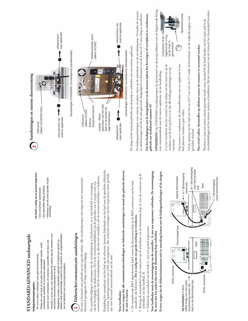
Elek
tris
che/
com
mun
icat
ie-a
ansl
uiti
ngen
STA
ND
AR
D/A
DVA
NC
ED sn
elst
artg
ids
1
Aan
slui
ting
en e
n ex
tern
e do
orst
rom
ing
2D
it he
eft u
nod
ig o
m te
kun
nen
begi
nnen
:• E
en v
erst
elba
re s
teek
sleu
tel
• Een
ges
chik
te s
lang
of l
eidi
ng• K
lem
men
van
de
juis
te g
root
te o
f typ
e aa
nslu
iting
Veili
ghei
dsm
aatr
egel
en:
De
unit
is a
lleen
ont
wor
pen
voor
geb
ruik
bin
nens
huis
.P
laat
s ee
n un
it no
oit o
p ee
n pl
ek m
et o
verm
atig
e w
arm
te, v
ocht
, on
vold
oend
e ve
ntila
tie o
f cor
rosi
eve
mat
eria
len.
Geb
ruik
noo
it on
tvla
mba
re o
f cor
rosi
eve
vloe
isto
ffen
met
dez
e un
it.Ve
rzek
er u
erv
an d
at u
een
sla
ng k
iest
die
vol
doet
aan
de
vere
iste
n vo
or
wat
bet
reft
max
imum
tem
pera
tuur
en
druk
. R
aadp
leeg
voo
rdat
u v
loei
stof
fen
gebr
uikt
of o
nder
houd
uitv
oert
op
plek
ken
waa
r waa
rsch
ijnlij
k co
ntac
t is
met
vlo
eist
of, d
e ve
iligh
eids
blad
en
van
de fa
brik
ant v
oor v
oorz
orgs
maa
trege
len.
De
slang
wor
dt n
orm
aal g
ebru
ikt o
m d
e po
mp
te v
erbi
nden
met
een
ext
erne
app
licat
ie.
De
leid
inga
anslu
iting
en v
oor e
xter
ne c
ircul
atie
zitte
n op
de
acht
erka
nt v
an d
e ci
rcul
atie
pom
p. V
erw
ijder
de
moe
ren
en a
fsche
rmin
gen
om b
ij de
uni
t gel
ever
de sl
anga
dapt
ers e
n kl
emm
en v
an d
e 8
mm
of 1
2 m
m sl
ang
te in
stalle
ren.
Om
bes
chad
igin
gen
aan
de sl
anga
dapt
ers e
n de
moe
ren
tijd
ens h
et b
eves
tige
n of
ver
wijd
eren
te v
oork
omen
, ge
brui
k ee
n st
eeks
leut
el n
umm
er 1
9.
OP
MER
KIN
G O
p ST
AND
ARD
circ
ulat
iepo
mpe
n de
spui
tmon
d va
n de
pom
p af
sluite
n m
et d
e bi
jgel
ever
de fi
tting
vo
or m
axim
umdr
uk n
aar d
e ex
tern
e ap
plic
atie
, zie
de
hand
leid
ing.
U e
rvan
ver
zeke
ren
dat h
et v
entie
l van
de
uitla
at v
an h
et re
serv
oir o
p de
vo
orka
nt v
an d
e un
it gesloten
is en
dat
alle
leid
inga
anslu
iting
en st
evig
va
stzitt
en.
Om
mor
sen
te v
oork
omen
, de
vloe
istof
houd
ers v
an u
w a
pplic
atie
in h
et
bad
plaa
tsen
voor
dat u
gaa
t vul
len.
Vul d
e op
enin
g va
n he
t bad
van
2,0
cm
(3/4
”) to
t 5,0
cm
(2”)
ond
er d
e bo
venk
ant,
zie d
e vo
lgen
de p
agin
a vo
or
gesc
hikt
e vl
oeist
of.
Nie
t tev
eel v
ulle
n, v
loei
stoff
en o
p ol
ieba
sis z
ette
n ui
t wan
neer
ze
verw
arm
d w
orde
n.
Wan
neer
er n
aar e
en ex
tern
syste
em g
epom
pt w
ordt
, ext
ra v
loei
stof b
ij de
han
d ho
uden
om
het
juist
e pei
l in
de
circ
ulat
ielei
ding
en en
het
exte
rne s
yste
em te
han
dhav
en. B
ij he
t ver
war
men
van
de v
loei
stof,
het v
loei
stofp
eil b
ewak
en.
Spu
itmon
d po
mp
Con
trole
ren
of d
e bi
jgel
ever
de o
-rin
g op
de
moe
r is
gem
onte
erd.
Aan
slui
tinge
n A
DVA
NC
ED
circ
ulat
iepo
mp
(kar
akte
ristie
k)
reto
urst
room
van
ex
tern
e ap
plic
atie
uitla
atst
room
na
ar a
pplic
atie
.
Aan
slui
tinge
n S
TAN
DA
RD
circ
ulat
iepo
mp
(kar
akte
ristie
k)
reto
urst
room
van
ex
tern
e ap
plic
atie
uitla
atst
room
na
ar a
pplic
atie
.
US
B-p
oort
(alle
en S
C15
0/S
C15
0L)
Mul
tifun
ctio
nele
poo
rt (a
lleen
AC
200)
Ext
erne
te
mpe
ratu
urse
nsor
Isol
atie
- A
lleen
ge
brui
ken
met
het
G50
ba
d en
bij
wer
ken
bij
lage
tem
pera
tuur
US
B-p
oort
(alle
en A
C20
0)
Voor
koe
lbad
en:
ervo
or z
orge
n da
t alle
com
mun
icat
ieve
rbin
ding
en e
n el
ektr
isch
e aa
nslu
itin
gen
tot s
tand
zijn
geb
rach
t alv
oren
s de
uni
t te
star
ten.
De
mee
gele
verd
e R
J45
afge
sche
rmde
kab
el tu
ssen
de
ther
mos
taat
kop
en
de R
J45
conn
ecto
rs v
an h
et b
ad
insta
llere
n (a
ls Et
hern
et).
Dit
is n
odig
om
een
goe
de w
erki
ng te
ver
zeke
ren.
Beve
stig
de st
room
kabe
l van
de
conn
ecto
r op
de a
chte
rkan
t van
de
ther
mos
taat
kop
, A, m
et d
e co
nnec
tor o
p de
ac
hter
kant
van
het
koe
lbad
, B.
Verb
ind
de st
room
kabe
l van
het
bad
, C, m
et e
en g
eaar
d sto
pcon
tact
. Vo
or k
oelb
aden
noo
it de
stro
omin
gang
van
de
cont
rolle
r , A
, met
een
stop
cont
act v
erbi
nden
. De
stro
omui
tgan
g,
B, n
ooit
met
iets
and
ers d
an m
et e
en th
erm
osta
at k
op v
erbi
nden
.
Ervo
or z
orge
n da
t de
elek
tric
itei
tssn
oere
n ni
et in
aan
raki
ng k
omen
met
de
leid
inga
ansl
uiti
ngen
of d
e sl
ange
n.
A =
Stro
omin
gang
va
naf b
ad
inga
ng th
erm
osta
atTh
erm
osta
at k
op
Bad
Bad
B =
Stro
omui
tgan
g na
ar th
erm
osta
at
kop
C =
Stro
omin
gang
va
naf s
troom
toev
oer
RJ4
5 co
nnec
tor
Op
koel
bade
n is
dez
e ka
bel n
odig
voo
r een
juis
te
func
tione
ring
tuss
en h
et
bad
en d
e th
erm
osta
at k
op.
RJ4
5 co
nnec
tor
Con
trole
ren
of e
r een
kad
er ro
nd h
et st
opsy
mbo
ol st
aat,
als d
it ni
et zo
is, d
e pi
jltoe
tsen
gebr
uike
n om
naa
r het
sy
mbo
ol te
nav
iger
en.
Dru
k op
. D
e un
it za
l sto
ppen
en
het s
tops
ymbo
ol za
l in
een
start
sym
bool
ver
ande
ren
( ).
Dru
k op
. H
et sc
herm
van
de
ther
mos
taat
wor
dt le
eg e
n de
bla
uwe
LED
lich
t op.
De
circ
uitb
evei
ligin
g op
de
acht
erka
nt v
an d
e th
erm
osta
at k
op in
stan
d O
zette
n. D
e bl
auw
e LE
D za
l uitg
aan.
Op
koel
units
, de
circ
uitb
evei
ligin
g op
de
acht
erka
nt v
an h
et b
ad in
stan
d O
zette
n.
I O
Dit
eti
ket
geef
t aa
n da
t u
de in
stru
c-
tieh
andl
eidi
ng m
oet
leze
n al
vore
ns
de u
nit
te s
tart
en.
Geb
ruik
dez
e kn
op o
p de
uni
t in
en
uit
stan
dby
te z
ette
n. W
anne
er
de u
nit
in s
tand
by s
taat
, bra
ndt
de b
lauw
e LE
D.
Geb
ruik
dez
e vi
er n
avig
atie
pijle
n om
door
de
disp
lays
van
de
cont
rolle
r te
blad
eren
en
de w
aard
en in
te
stel
len.
Geb
ruik
dez
e kn
op o
m d
e un
it t
e st
arte
n/
stop
pen.
Dez
e kn
op w
ordt
ook
geb
ruik
t
om v
eran
deri
ngen
aan
te
bren
gen
in
het
wee
rgav
esch
erm
van
de
cont
rolle
r
en d
eze
op t
e sl
aan.
Geb
ruik
dez
e kn
op o
m v
eran
deri
ngen
te a
nnul
eren
en
de c
ontr
olle
r te
rug
te z
ette
n op
de
vori
ge w
eerg
ave.
Een
vera
nder
ing
kan
alle
en g
ean-
nule
erd
wor
den
als
hij n
og n
iet
is
opge
slag
en. I
n so
mm
ige
geva
llen
wor
dt h
ij oo
k ge
brui
kt o
m v
eran
de-
ring
en o
p te
sla
an.
De
draa
ikno
p er
naas
t ge
brui
ken
om d
e
Uit
scha
kelin
g bi
j Hog
e Te
mpe
ratu
ur
in t
e st
elle
n. D
e de
tails
wor
den
in d
e
hand
leid
ing
toeg
elic
ht.W
eerg
aves
cher
m
Dru
k, in
dien
gew
enste
, op
om
tuss
en d
e St
art/S
tatu
s-di
spla
ys o
m te
scha
kele
n.
De s
ectie
s SP1
en M
enu
bove
n in
het
disp
lay
wor
den
gebr
uikt
om
de i
nste
lling
en v
an d
e con
trolle
r te b
ekijk
en en
/of
te v
eran
dere
n. Z
e wor
den
in d
e han
dlei
ding
ged
etai
lleer
d to
egeli
cht.
U m
oet k
oelu
nits
24
uur
lang
rech
top
bij k
amer
tem
pera
tuur
(~25
°C
) lat
en st
aan
alvo
rens
ze
op te
star
ten.
O
p di
e m
anie
r ka
n de
smee
rolie
teru
glop
en in
de
com
pres
sor.
Alvo
rens
de
unit
te st
arte
n, e
en g
rond
ige
test
van
alle
USB
-aan
slui
ting
en (o
ptio
neel
), el
ektr
isch
e aa
nslu
itin
gen
en le
idin
gaan
slui
ting
en d
oen.
De
unit
niet
late
n w
erke
n vo
orda
t hij
met
vlo
eisto
f is g
evul
d. E
xtra
vlo
eisto
f bij
de h
and
houd
en. A
ls de
uni
t nie
t sta
rt, d
e ha
ndle
idin
g ra
adpl
egen
.
I zet
ten.
I zet
ten,
de
bla
uwe
LED
op
het v
oorp
anee
l gaa
t bra
nden
, het
Sta
rt-d
ispla
y ve
rsch
ijnt.
het s
ymbo
ol te
nav
iger
en.
. De
unit
zal s
tart
en e
n he
t sta
rtsy
mbo
ol za
l in
een
stops
ymbo
ol v
eran
dere
n (
).. D
e po
mp
zal o
nmid
delli
jk st
arte
n, m
aar h
et d
uurt
30
seco
nden
voo
r de
com
pres
sor s
tart
.
Opstarten
Uits
chak
elen
Gem
arke
erd
star
tsym
bool
Res
ervo
ir
Vlo
eist
of
Tem
pera
tuur
Gee
ft aa
n da
t de
cont
rolle
r de
tem
pera
tuur
van
de
inte
rne
tem
pera
tuur
sens
or
wee
rgee
ft
in
+024
.29 °C
SP1
M
enu
Sto
psym
bool
+020
,00
Na
de st
art m
oet u
alle
ext
erne
leid
inga
anslu
iting
en c
ontro
lere
n op
lekk
en.
Dru
k, in
dien
gew
enst,
op
om
de
Stat
us-d
ispla
ys o
p te
roep
en.
020,0
0
24.2C
Wat
er
Sym
bool
ver
war
min
g in
gesc
hake
ld
Sym
bool
pom
p in
gesc
hake
ld
Sym
bool
koe
ling
inge
scha
keld
Res
ervo
irvlo
eist
of
Tem
pera
tuur
Ges
elec
teer
de re
serv
oirv
loei
stof
Sta
tus-
disp
lay
Sta
rt-di
spla
y
Acc
epta
bele
vlo
eist
offe
n:
Alle
en S
C 1
00, S
C 1
50 e
n SC
150
L un
its
Syst
eem
limie
ten
toeg
esta
ne v
loei
stoff
en:
V
loei
stof
H
oog
°C
Laag
°C
W
ater
+1
00
+5
G
lyco
l-W
ater
+1
00
-30
O
veri
ge
+100
-3
0
Alle
en S
C 1
50 e
n SC
150
L un
its:
SIL
100
+7
5
-28
SI
L 18
0
+150
-2
8
SIL
300
+1
50
+80
SY
NT
H 6
0
+45
-1
0
SYN
TH
20
+1
50
+
Toeg
esta
ne v
loei
stof
fen:
Alle
en A
C 2
00/A
C 1
50 u
nits
Syst
eem
limie
ten
toeg
esta
ne v
loei
stoff
en:
V
loei
stof
H
oog
°C
Laag
°C
:
Wat
er
+100
/+10
0
+5/+
5
Gly
col-
Wat
er
+100
/+10
0
-30/
-30
SI
L 10
0
+75/
+75
-7
5/-2
5
SIL
180
+2
00/+
150
-4
0/-2
5
SIL
300
+2
00/+
150
+8
0/+8
0
SYN
TH
60
+4
5/+4
5
-50/
-25
SY
NT
H 2
+2
00/+
150
+2
00/+
150
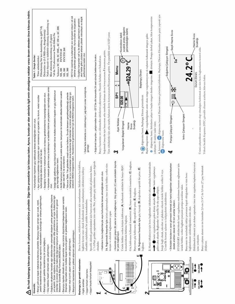
A
BC
DE
BE)
2.
)
)
C D
E
1.
STA
ND
AR
TST
AN
DA
RT
2.
I
I
3.
)
)
4.
)
+024
.29 °C
020.0
03.
24.2
°CSu4.
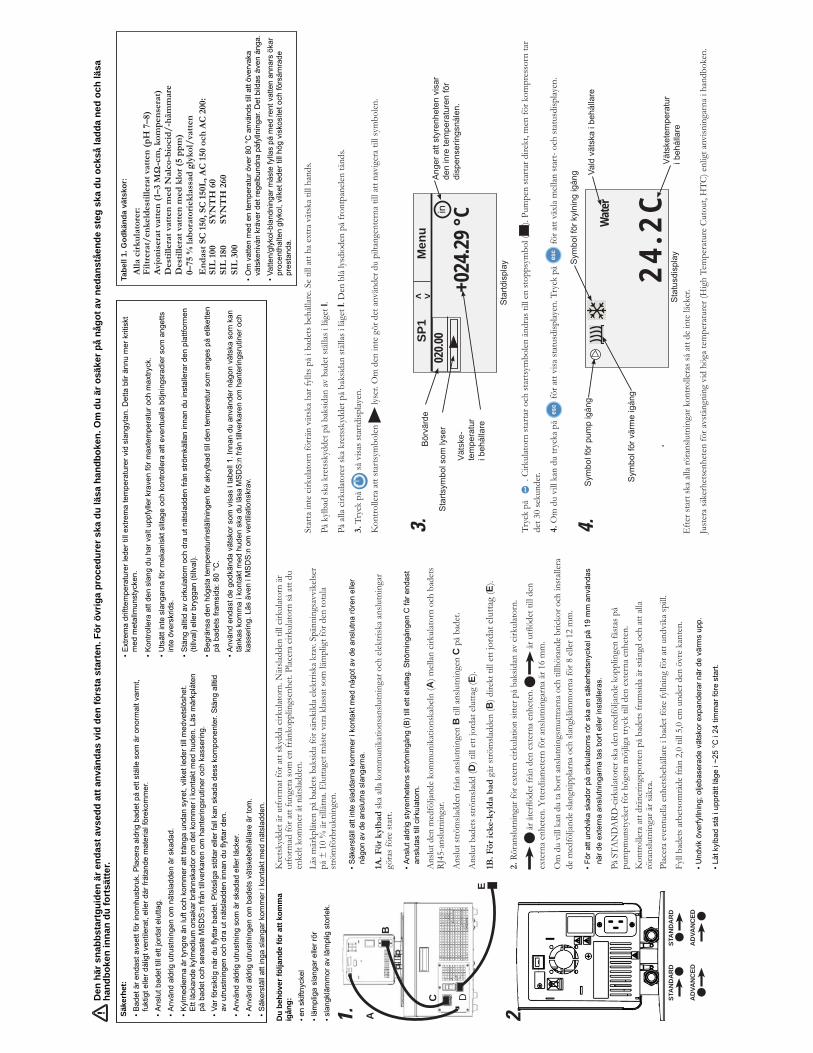
1A. F
ör k
ylb
ad sk
a all
a ko
mm
unik
atio
nsan
slutn
inga
r och
elek
trisk
a an
slutn
inga
r gö
ras f
öre
star
t.
Ans
lut d
en m
edfö
ljand
e ko
mm
unik
atio
nska
beln
(A) m
ellan
cirk
ulat
orn
och
bade
ts
RJ45
-ans
lutn
inga
r.
Ans
lut s
tröm
sladd
en fr
ån a
nslu
tnin
gen
B ti
ll an
slutn
inge
n C
på
bade
t.
Ans
lut b
adet
s strö
msla
dd (D
) till
ett
jord
at e
lutta
g (E
).
1B. F
ör ic
ke-k
yld
a b
ad g
år st
röm
sladd
en (B
) dire
kt ti
ll et
t jor
dat e
lutta
g (E
).
2. R
öran
slutn
inga
r för
ext
ern
cirku
latio
n sit
ter p
å ba
ksid
an av
cirk
ulat
orn.
exte
rna
enhe
ten.
Ytte
rdiam
eter
n fö
r ans
lutn
inga
rna
är 1
6 m
m.
Om
du
vill
kan
du ta
bor
t ans
lutn
ings
mut
trarn
a oc
h til
lhör
ande
bric
kor o
ch in
stall
era
de m
edfö
ljand
e sla
ngni
pplar
na o
ch sl
angk
lämm
orna
för 8
elle
r 12
mm
.
På S
TAN
DA
RD-c
irkul
ator
er sk
a de
n m
edfö
ljand
e ko
pplin
gen
fäst
as p
å pu
mpm
unst
ycke
t för
hög
sta
möj
liga
tryc
k til
l den
ext
erna
enh
eten
.K
ontro
llera
att
drän
erin
gspo
rten
på
bade
ts fr
amsid
a är
stän
gd o
ch a
tt all
a rö
rans
lutn
inga
r är s
äkra
.Pl
acer
a ev
entu
ella
enhe
tsbe
hålla
re i
bade
t för
e fy
llnin
g fö
r att
undv
ika
spill
.
Fyll
bade
ts a
rbet
som
råde
från
2,0
till
5,0
cm u
nder
den
övr
e ka
nten
.
Kre
tsky
ddet
är u
tform
at fö
r att
skyd
da c
irkul
ator
n. N
ätsla
dden
till
cirku
lator
n är
ut
form
ad fö
r att
fung
era
som
en
från
kopp
lings
enhe
t. Pl
acer
a cir
kulat
orn
så a
tt du
en
kelt
kom
mer
åt n
ätsla
dden
.Lä
s mär
kplåt
en p
å ba
dets
bak
sida
för s
ärsk
ilda
elekt
riska
kra
v. Sp
änni
ngsa
vvik
elser
på
± 1
0 %
är t
illåt
na. E
lutta
get m
åste
var
a kl
assa
t som
läm
plig
t för
den
tota
la st
röm
förb
rukn
inge
n.
Du
behö
ver f
ölja
nde
för a
tt ko
mm
a ig
ång:
A B
C D
E
1.
STA
ND
AR
D
AD
VAN
CED
AD
VAN
CED
STA
ND
AR
D
2.
Star
ta in
te c
irkul
ator
n fö
rrän
vät
ska
har f
yllts
på
i bad
ets b
ehåll
are.
Se ti
ll at
t ha
extra
vät
ska
till h
ands
.
På k
ylba
d sk
a kr
etss
kydd
et p
å ba
ksid
an av
bad
et st
ällas
i läg
et I.
På a
lla c
irkul
ator
er sk
a kr
etss
kydd
et p
å ba
ksid
an st
ällas
i läg
et I.
Den
blå
lysdi
oden
på
fron
tpan
elen
tänd
s.
3. T
ryck
på
så v
isas s
tartd
isplay
en.
Kon
trolle
ra a
tt st
arts
ymbo
len
lyse
r. O
m d
en in
te g
ör d
et a
nvän
der d
u pi
ltang
ente
rna
till a
tt na
vige
ra ti
ll sy
mbo
len.
Tryc
k på
. C
irkul
ator
n st
arta
r och
star
tsym
bolen
änd
ras t
ill e
n st
opps
ymbo
l ().
Pum
pen
star
tar d
irekt
, men
för k
ompr
esso
rn ta
r de
t 30
seku
nder
.
4. O
m d
u vi
ll ka
n du
tryc
ka p
å fö
r att
visa
stat
usdi
splay
en. T
ryck
på
för a
tt vä
xla
mell
an st
art-
och
stat
usdi
splay
en.
Efte
r sta
rt sk
a all
a rö
rans
lutn
inga
r kon
trolle
ras s
å at
t de
inte
läck
er.
Just
era
säke
rhet
senh
eten
för a
vstä
ngni
ng v
id h
öga
tem
pera
ture
r (H
igh
Tem
pera
ture
Cut
out,
HTC
) enl
igt a
nvisn
inga
rna
i han
dbok
en.
Vät
ske-
+024
.29 °C
SP1
M
enu
02
0.00
< >
3.
24.2
CW
ater
4.
Den
här
sna
bbst
artg
uide
n är
end
ast a
vsed
d at
t anv
ända
s vi
d de
n fö
rsta
sta
rten
. För
övr
iga
proc
edur
er s
ka d
u lä
sa h
andb
oken
. Om
du
är o
säke
r på
någo
t av
neda
nstå
ende
ste
g sk
a du
ock
så la
dda
ned
och
läsa
ha
ndbo
ken
inna
n du
fort
sätte
r.
Tabe
ll 1.
God
känd
a vä
tsko
r:A
lla c
irku
lato
rer:
F
iltre
rat/
enke
ldes
tille
rat
vatt
en (
pH
7–8
)
0
Säke
rhet
:

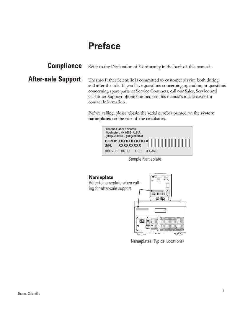
Thermo Scientifici
Preface
Compliance Refer to the Declaration of Conformity in the back of this manual.
After-sale Support Thermo Fisher Scientific is committed to customer service both during and after the sale. If you have questions concerning operation, or questions concerning spare parts or Service Contracts, call our Sales, Service and Customer Support phone number, see this manual's inside cover for contact information.
Before calling, please obtain the serial number printed on the system nameplates on the rear of the circulators.
Sample Nameplate
Thermo Fisher ScientificNewington, NH 03801 U.S.A.(800)258-0830 / (603)436-9444BOM#: XXXXXXXXXXXXS/N: XXXXXXXXXXXX VOLT XX HZ X PH X.X AMP
Nameplates (Typical Locations)
Nameplate Refer to nameplate when call-ing for after-sale support
ii
Preface
Thermo Scientific
Unpacking Retain all cartons and packing material until the circulators are operated and found to be in good condition. If the circulators shows external or internal damage contact the transportation company and file a damage claim. Under ICC regulations, this is your responsibility.
If a 150/150L immersion circulator was purchased without a bath, carefully remove the label and small piece of Styrofoam securing the float switch before using.
Leave refrigerated baths in an upright position for 24 hours before starting. This will ensure the lubrication oil has drained back into the compressor.
Feedback We appreciate any feedback you can give us on this manual. Please e-mail us at [email protected]. Be sure to include the manual part number and the revision date listed on the front cover.
CAUTION
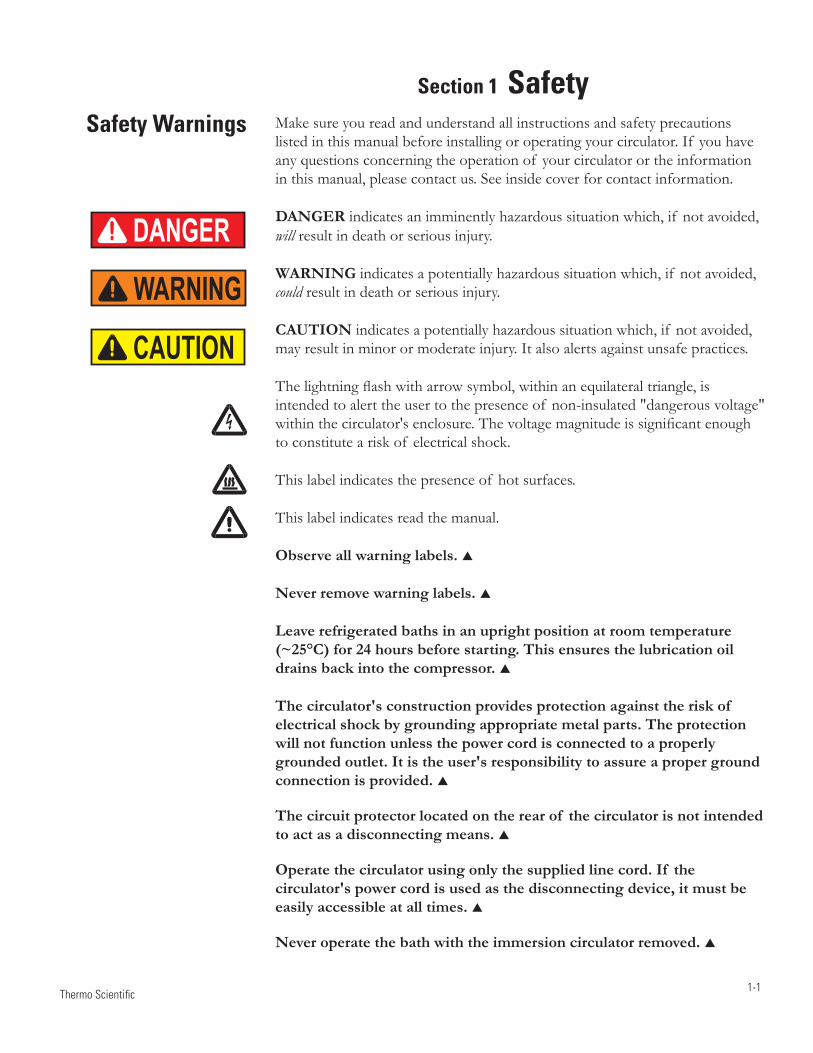
Thermo Scientific 1-1
Make sure you read and understand all instructions and safety precautions listed in this manual before installing or operating your circulator. If you have any questions concerning the operation of your circulator or the information in this manual, please contact us. See inside cover for contact information.
DANGER indicates an imminently hazardous situation which, if not avoided, will result in death or serious injury.
WARNING indicates a potentially hazardous situation which, if not avoided, could result in death or serious injury.
CAUTION indicates a potentially hazardous situation which, if not avoided, may result in minor or moderate injury. It also alerts against unsafe practices.
The lightning flash with arrow symbol, within an equilateral triangle, is intended to alert the user to the presence of non-insulated "dangerous voltage" within the circulator's enclosure. The voltage magnitude is significant enough to constitute a risk of electrical shock.
This label indicates the presence of hot surfaces.
This label indicates read the manual.
Observe all warning labels.
Never remove warning labels.
Leave refrigerated baths in an upright position at room temperature (~25°C) for 24 hours before starting. This ensures the lubrication oil drains back into the compressor.
The circulator's construction provides protection against the risk of electrical shock by grounding appropriate metal parts. The protection will not function unless the power cord is connected to a properly grounded outlet. It is the user's responsibility to assure a proper ground connection is provided.
The circuit protector located on the rear of the circulator is not intended to act as a disconnecting means.
Operate the circulator using only the supplied line cord. If the circulator's power cord is used as the disconnecting device, it must be easily accessible at all times.
Never operate the bath with the immersion circulator removed.
Safety Warnings
Section 1 Safety
DANGER
WARNING
CAUTION
1-2
Section 1 Safety
Thermo Scientific
Do not mount the immersion circulator backwards; the line cord could contact the reservoir fluid. Ensure the electrical cords do not contact any of the plumbing connections or tubing.
Never place the circulator in a location or atmosphere where excessive heat, moisture, or corrosive materials are present.
Ensure the tubing you select meets your maximum temperature and pressure requirements.
Ensure all communication and electrical connections are made prior to starting the circulator.
Many refrigerants which may be undetectable by human senses are heavier than air and replaces the oxygen in an enclosed area causing loss of consciousness. Refer to the circulator's nameplate and the manufacturer's most current MSDS for additional information.
Never operate the circulator without fluid in the reservoir.
Use only the approved fluids listed in this manual. Using other fluids voids the warranty.
Transparent Acrylic Bath and Polyphenylene oxide (PPO) Bath Circulators are used with water only.
Other than water, before using any approved fluid, or when performing maintenance where contact with the fluid is likely, refer to the manufacturer’s MSDS and EC Safety Data sheet for handling precautions.
Ensure, that no toxic gases can be generated by the fluid. Flammable gases can build up over the fluid during usage.
When using ethylene glycol and water, check the fluid concentration and pH on a regular basis. Changes in concentration and pH can impact system performance.
Ensure the fluid is at a safe temperature (~40°C) before handling or draining.
Never operate damaged or leaking equipment, or with any damaged cords.
Never operate the circulator or add fluid to the reservoir with panels removed.
Do not clean the circulator with solvents, only use a soft cloth and water.
Drain the reservoir before it is transported, and/or stored in, near or below freezing temperatures.
Always turn the circulator off and disconnect the supply voltage from its power source before moving or before performing any service or maintenance procedures.
Transport the circulator with care. Sudden jolts or drops can damage its components.
Refer service and repairs to a qualified technician.
The user is responsible for decontamination if hazardous materials are spilled. Consult the manufacturer regarding decontamination and or cleaning agents compatibility.
Performance of installation, operation, or maintenance procedures other than those described in this manual may result in a hazardous situation and voids the manufacturer's warranty.
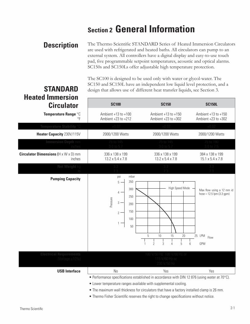
2-1 Thermo Scientific
Section 2 General InformationThe Thermo Scientific STANDARD Series of Heated Immersion Circulators are used with refrigerated and heated baths. All circulators can pump to an external system. All controllers have a digital display and easy-to-use touch pad, five programmable setpoint temperatures, acoustic and optical alarms. SC150s and SC150Ls offer adjustable high temperature protection.
The SC100 is designed to be used only with water or glycol-water. The SC150 and SC150L have an independent low liquid level protection, and a design that allows use of different heat transfer liquids, see Section 3.
Description
STANDARD Heated Immersion
Circulator
• Performance specifications established in accordance with DIN 12 876 (using water at 70°C).
• Lower temperature ranges available with supplemental cooling.
• The maximum wall thickness for circulators that have a factory installed clamp is 26 mm.
• Thermo Fisher Scientific reserves the right to change specifications without notice.
Pres
sure
psi mbar
Flow5 10 15 20 25 LPM
1 2 3 4 5 6 GPM
350
300
250
200
150
100
50
5
4
3
2
1
High Speed ModeMax flow using a 12 mm id hose = 12.5 lpm (3.3 gpm)
SC100 SC150 SC150L Temperature Range °C Ambient +13 to +100 Ambient +13 to +150 Ambient +13 to +150 °F Ambient +23 to +212 Ambient +23 to +302 Ambient +23 to +302
Temperature Stability °C ±0.02 ±0.02 ±0.02
Heater Capacity 230V/115V 2000/1200 Watts 2000/1200 Watts 2000/1200 Watts
Immersion Depth mm 75 to 145 75 to 145 75 to 190 inches 3.0 to 5.7 3.0 to 5.7 3.0 to 7.5
Circulator Dimensions (H x W x D) mm 336 x 138 x 199 336 x 138 x 199 384 x 138 x 199 inches 13.2 x 5.4 x 7.8 13.2 x 5.4 x 7.8 15.1 x 5.4 x 7.8
Net Weight kg 3.3 3.3 3.3 lb 7.3 7.3 7.3
Pumping Capacity
Electrical Requirements 100 V/50 Hz 100 V/60 Hz or (Voltage ±10%) 115 V/60 Hz or 230 V/50 Hz
USB Interface No Yes Yes
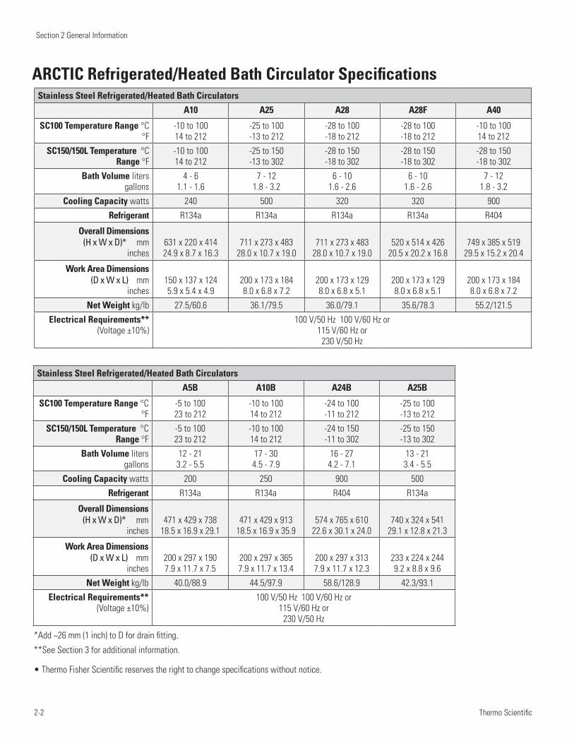
Section 2 General Information
2-2 Thermo Scientific
• Thermo Fisher Scientific reserves the right to change specifications without notice.
Stainless Steel Refrigerated/Heated Bath Circulators
A10 A25 A28 A28F A40
SC100 Temperature Range °C°F
-10 to 100 14 to 212
-25 to 100 -13 to 212
-28 to 100 -18 to 212
-28 to 100 -18 to 212
-10 to 100 14 to 212
SC150/150L Temperature °C Range °F
-10 to 100 14 to 212
-25 to 150 -13 to 302
-28 to 150 -18 to 302
-28 to 150 -18 to 302
-28 to 150 -18 to 302
Bath Volume liters gallons
4 - 6 1.1 - 1.6
7 - 12 1.8 - 3.2
6 - 10 1.6 - 2.6
6 - 10 1.6 - 2.6
7 - 12 1.8 - 3.2
Cooling Capacity watts 240 500 320 320 900
Refrigerant R134a R134a R134a R134a R404
Overall Dimensions (H x W x D)* mm
inches631 x 220 x 414 24.9 x 8.7 x 16.3
711 x 273 x 483 28.0 x 10.7 x 19.0
711 x 273 x 483 28.0 x 10.7 x 19.0
520 x 514 x 426 20.5 x 20.2 x 16.8
749 x 385 x 519 29.5 x 15.2 x 20.4
Work Area Dimensions (D x W x L) mm
inches150 x 137 x 124 5.9 x 5.4 x 4.9
200 x 173 x 184 8.0 x 6.8 x 7.2
200 x 173 x 129 8.0 x 6.8 x 5.1
200 x 173 x 129 8.0 x 6.8 x 5.1
200 x 173 x 184 8.0 x 6.8 x 7.2
Net Weight kg/lb 27.5/60.6 36.1/79.5 36.0/79.1 35.6/78.3 55.2/121.5
Electrical Requirements** (Voltage ±10%)
100 V/50 Hz 100 V/60 Hz or 115 V/60 Hz or
230 V/50 Hz
Stainless Steel Refrigerated/Heated Bath Circulators
A5B A10B A24B A25B
SC100 Temperature Range °C°F
-5 to 100 23 to 212
-10 to 100 14 to 212
-24 to 100 -11 to 212
-25 to 100 -13 to 212
SC150/150L Temperature °C Range °F
-5 to 100 23 to 212
-10 to 100 14 to 212
-24 to 150 -11 to 302
-25 to 150 -13 to 302
Bath Volume liters gallons
12 - 21 3.2 - 5.5
17 - 30 4.5 - 7.9
16 - 27 4.2 - 7.1
13 - 21 3.4 - 5.5
Cooling Capacity watts 200 250 900 500
Refrigerant R134a R134a R404 R134a
Overall Dimensions (H x W x D)* mm
inches471 x 429 x 738
18.5 x 16.9 x 29.1471 x 429 x 913
18.5 x 16.9 x 35.9574 x 765 x 610
22.6 x 30.1 x 24.0740 x 324 x 541
29.1 x 12.8 x 21.3
Work Area Dimensions (D x W x L) mm
inches200 x 297 x 190 7.9 x 11.7 x 7.5
200 x 297 x 365 7.9 x 11.7 x 13.4
200 x 297 x 313 7.9 x 11.7 x 12.3
233 x 224 x 244 9.2 x 8.8 x 9.6
Net Weight kg/lb 40.0/88.9 44.5/97.9 58.6/128.9 42.3/93.1
Electrical Requirements** (Voltage ±10%)
100 V/50 Hz 100 V/60 Hz or 115 V/60 Hz or
230 V/50 Hz
*Add ~26 mm (1 inch) to D for drain fitting.**See Section 3 for additional information.
ARCTIC Refrigerated/Heated Bath Circulator Specifications
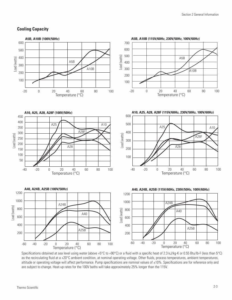
Section 2 General Information
2-3 Thermo Scientific
Cooling Capacity
-20 0 20 40 60 80 100 Temperature (°C)
-40 -20 0 20 40 60 80 100 Temperature (°C)
-60 -40 -20 0 20 40 60 80 100 Temperature (°C)
-60 -40 -20 0 20 40 60 80 100 Temperature (°C)
-40 -20 0 20 40 60 80 100 Temperature (°C)
-20 0 20 40 60 80 100 Temperature (°C)
600
500
400
300
200
100
450
400
350
300
250
200
150
100
50
1200
1000
800
600
400
200
1200
1000
800
600
400
200
700
600
500
400
300
200
100
600
500
400
300
200
100
A5B, A10B (100V/50Hz)
A10, A25, A28, A28F (100V/50Hz)
A40, A24B, A25B (100V/50Hz) A40, A24B, A25B (115V/60Hz, 230V/50Hz, 100V/60Hz)
A10, A25, A28, A28F (115V/60Hz, 230V/50Hz, 100V/60Hz)
A5B, A10B (115V/60Hz, 230V/50Hz, 100V/60Hz)
Load
(wat
ts)Lo
ad (w
atts)
Load
(wat
ts)
Load
(wat
ts)Lo
ad (w
atts)
Load
(wat
ts)
A5BA5B
A10B A10B
A10A10
A25
A24B A24B
A40A40
A25B A25B
A25
A28 A28
A28FA28F
Specifications obtained at sea level using water (above +5°C to +90°C) or a fluid with a specific heat of 2.3 kJ/kg-K or 0.55 Btu/lb-F (less than 5°C) as the recirculating fluid at a +20°C ambient condition, at nominal operating voltage. Other fluids, process temperatures, ambient temperatures, altitude or operating voltage will affect performance. Pump specifications are nominal values of ±10%. Specifications are for reference only and are subject to change. Heat-up rates for the 100V baths will take approximately 25% longer than the 115V.
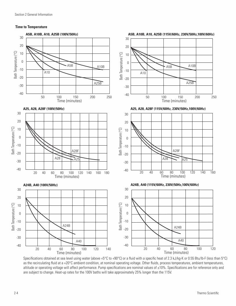
Section 2 General Information
2-4 Thermo Scientific
50 100 150 200 250 Time (minutes)
20 40 60 80 100 120 140 160 180 Time (minutes)
20 40 60 80 100 120 140 Time (minutes)
20 40 60 80 100 120 Time (minutes)
20 40 60 80 100 120 140 160 Time (minutes)
50 100 150 200 250 Time (minutes)
30
20
10
0
-10
-20
-30
-40
30
20
10
0
-10
-20
-30
-40
30
20
10
0
-10
-20
-30
-40
30
20
10
0
-10
-20
-30
-40
30
20
10
0
-10
-20
-30
-40
30
20
10
0
-10
-20
-30
-40
A5B, A10B, A10, A25B (100V/50Hz)
A25, A28, A28F (100V/50Hz)
A24B, A40 (100V/50Hz) A24B, A40 (115V/60Hz, 230V/50Hz,100V/60Hz)
A25, A28, A28F (115V/60Hz, 230V/50Hz,100V/60Hz)
A5B, A10B, A10, A25B (115V/60Hz, 230V/50Hz,100V/60Hz)
Bath
Temp
erat
ure (
°C)
Bath
Temp
erat
ure (
°C)
Bath
Temp
erat
ure (
°C)
Bath
Temp
erat
ure (
°C)
Bath
Temp
erat
ure (
°C)
Bath
Temp
erat
ure (
°C)
A5B
A28
A40 A40
A28
A5B
A10
A25 A25
A10
A25B A25B
A10B
A28F
A24B A24B
A28F
A10B
Time to Temperature
Specifications obtained at sea level using water (above +5°C to +90°C) or a fluid with a specific heat of 2.3 kJ/kg-K or 0.55 Btu/lb-F (less than 5°C) as the recirculating fluid at a +20°C ambient condition, at nominal operating voltage. Other fluids, process temperatures, ambient temperatures, altitude or operating voltage will affect performance. Pump specifications are nominal values of ±10%. Specifications are for reference only and are subject to change. Heat-up rates for the 100V baths will take approximately 25% longer than the 115V.
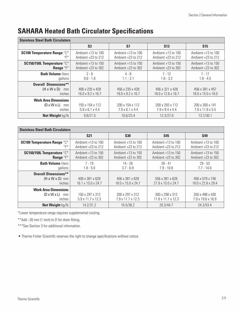
Section 2 General Information
2-5 Thermo Scientific
Stainless Steel Bath Circulators
S3 S7 S13 S15
SC100 Temperature Range °C*°F*
Ambient +13 to 100 Ambient +23 to 212
Ambient +13 to 100 Ambient +23 to 212
Ambient +13 to 100 Ambient +23 to 212
Ambient +13 to 100 Ambient +23 to 212
SC150/150L Temperature °C* Range °F*
Ambient +13 to 150 Ambient +23 to 302
Ambient +13 to 150 Ambient +23 to 302
Ambient +13 to 150 Ambient +23 to 302
Ambient +13 to 150 Ambient +23 to 302
Bath Volume liters gallons
2 - 6 0.6 - 1.6
4 - 8 1.1 - 2.1
7 - 12 1.8 - 3.2
7 - 17 1.8 - 4.5
Overall Dimensions** (H x W x D) mm
inches406 x 235 x 428 16.0 x 9.2 x 16.7
456 x 235 x 428 18.0 x 9.2 x 16.7
456 x 321 x 428 18.0 x 12.6 x 16.7
456 x 381 x 457 18.0 x 15.0 x 18.0
Work Area Dimensions (D x W x L) mm
inches150 x 154 x 112 5.9 x 6.1 x 4.4
200 x 154 x 112 7.9 x 6.1 x 4.4
200 x 293 x 112 7.9 x 9.4 x 4.4
200 x 300 x 141 7.9 x 11.8 x 5.5
Net Weight kg/lb 9.8/21.5 10.6/23.4 12.3/27.0 13.7/30.1
Stainless Steel Bath Circulators
S21 S30 S45 S49
SC100 Temperature Range °C*°F*
Ambient +13 to 100 Ambient +23 to 212
Ambient +13 to 100 Ambient +23 to 212
Ambient +13 to 100 Ambient +23 to 212
Ambient +13 to 100 Ambient +23 to 212
SC150/150L Temperature °C* Range °F*
Ambient +13 to 150 Ambient +23 to 302
Ambient +13 to 150 Ambient +23 to 302
Ambient +13 to 150 Ambient +23 to 302
Ambient +13 to 150 Ambient +23 to 302
Bath Volume liters gallons
7 - 19 1.8 - 5.0
14 - 26 3.7 - 6.9
30 - 41 7.9 - 10.8
29 - 53 7.7 - 14.0
Overall Dimensions** (H x W x D) mm
inches409 x 381 x 628
16.1 x 15.0 x 24.7456 x 381 x 628
18.0 x 15.0 x 24.7556 x 381 x 628
21.9 x 15.0 x 24.7456 x 579 x 746
18.0 x 22.8 x 29.4
Work Area Dimensions (D x W x L) mm
inches150 x 297 x 312 5.9 x 11.7 x 12.3
200 x 297 x 312 7.9 x 11.7 x 12.3
300 x 298 x 312 11.8 x 11.7 x 12.3
200 x 498 x 430 7.9 x 19.6 x 16.9
Net Weight kg/lb 14.2/31.2 16.5/36.2 20.3/44.7 24.3/53.4
*Lower temperature range requires supplemental cooling.
**Add ~26 mm (1 inch) to D for drain fitting.***See Section 3 for additional information.
• Thermo Fisher Scientific reserves the right to change specifications without notice.
SAHARA Heated Bath Circulator Specifications
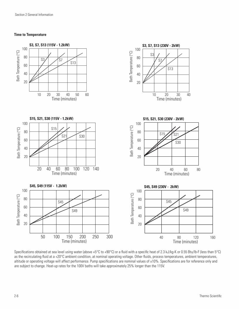
Section 2 General Information
2-6 Thermo Scientific
Time to Temperature
10 20 30 40 50 60 Time (minutes)
10 20 30 40 Time (minutes)
20 40 60 80 Time (minutes)
40 80 120 160 Time (minutes)
20 40 60 80 100 120 140 Time (minutes)
50 100 150 200 250 300 Time (minutes)
100
80
60
40
20
100
80
60
40
20
100
80
60
40
20
100
80
60
40
20
100
80
60
40
20
100
80
60
40
20
S3S3
S15S15
S45 S45
S7 S7
S21 S21
S49 S49
S13
S13
S30
S30
S3, S7, S13 (115V - 1.2kW) S3, S7, S13 (230V - 2kW)
S15, S21, S30 (230V - 2kW)S15, S21, S30 (115V - 1.2kW)
S45, S49 (230V - 2kW)S45, S49 (115V - 1.2kW)
Bath
Tem
pera
ture
(°C)
Bath
Tem
pera
ture
(°C)
Bath
Tem
pera
ture
(°C)
Bath
Tem
pera
ture
(°C)
Bath
Tem
pera
ture
(°C)
Bath
Tem
pera
ture
(°C)
Specifications obtained at sea level using water (above +5°C to +90°C) or a fluid with a specific heat of 2.3 kJ/kg-K or 0.55 Btu/lb-F (less than 5°C) as the recirculating fluid at a +20°C ambient condition, at nominal operating voltage. Other fluids, process temperatures, ambient temperatures, altitude or operating voltage will affect performance. Pump specifications are nominal values of ±10%. Specifications are for reference only and are subject to change. Heat-up rates for the 100V baths will take approximately 25% longer than the 115V.
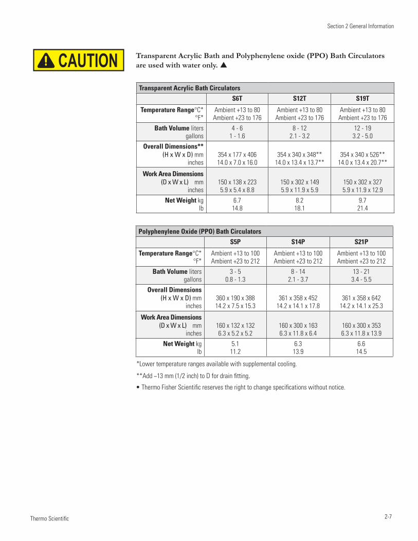
Section 2 General Information
2-7 Thermo Scientific
Transparent Acrylic Bath Circulators
S6T S12T S19T
Temperature Range°C*°F*
Ambient +13 to 80 Ambient +23 to 176
Ambient +13 to 80 Ambient +23 to 176
Ambient +13 to 80 Ambient +23 to 176
Bath Volume liters gallons
4 - 6 1 - 1.6
8 - 12 2.1 - 3.2
12 - 19 3.2 - 5.0
Overall Dimensions** (H x W x D) mm
inches354 x 177 x 406 14.0 x 7.0 x 16.0
354 x 340 x 348** 14.0 x 13.4 x 13.7**
354 x 340 x 526** 14.0 x 13.4 x 20.7**
Work Area Dimensions (D x W x L) mm
inches150 x 138 x 223 5.9 x 5.4 x 8.8
150 x 302 x 149 5.9 x 11.9 x 5.9
150 x 302 x 327 5.9 x 11.9 x 12.9
Net Weight kg lb
6.7 14.8
8.2 18.1
9.7 21.4
Polyphenylene Oxide (PPO) Bath Circulators
S5P S14P S21P
Temperature Range°C*°F*
Ambient +13 to 100 Ambient +23 to 212
Ambient +13 to 100 Ambient +23 to 212
Ambient +13 to 100 Ambient +23 to 212
Bath Volume liters gallons
3 - 5 0.8 - 1.3
8 - 14 2.1 - 3.7
13 - 21 3.4 - 5.5
Overall Dimensions (H x W x D) mm
inches360 x 190 x 388 14.2 x 7.5 x 15.3
361 x 358 x 452 14.2 x 14.1 x 17.8
361 x 358 x 642 14.2 x 14.1 x 25.3
Work Area Dimensions (D x W x L) mm
inches160 x 132 x 132 6.3 x 5.2 x 5.2
160 x 300 x 163 6.3 x 11.8 x 6.4
160 x 300 x 353 6.3 x 11.8 x 13.9
Net Weight kg lb
5.1 11.2
6.3 13.9
6.6 14.5
• Thermo Fisher Scientific reserves the right to change specifications without notice.
*Lower temperature ranges available with supplemental cooling.
**Add ~13 mm (1/2 inch) to D for drain fitting.
Transparent Acrylic Bath and Polyphenylene oxide (PPO) Bath Circulators are used with water only. CAUTION
Section 2 General Information
2-8 Thermo Scientific
Wetted Materials STANDARD Immersion CirculatorVitonEPDMRytonUltemVectraStainless Steel
Stainless Steel Baths/CirculatorsStainless Steel 316Stainless Steel 304 EPDM (drain fitting)RytonZotek-N (cover seal)
Transparent Acrylic Baths/CirculatorsPoly-acryl
Polyphenylene oxide (PPO) Baths/CirculatorsPolyphenylenoxid
3-1 Thermo Scientific
Section 3 Installation
Ambient Temperature Range 5°C to 40°C (41°F to 104°F)
Maximum Relative Humidity 80% at 31°C (88°F)
Operating Altitude Sea Level to 2000 meters (6560 feet)
Overvoltage Category II
Pollution Degree 2
Degree of Protection IP 20
The immersion circulator is designed for continuous operation and for indoor use.
Never place the immersion circulator in a location where excessive heat, moisture, inadequate ventilation, or corrosive materials are present.
Carefully install the immersion circulator to ensure it does not fall into the container or that its line cord does not make contact with the container contents.
For immersion circulators equipped with a clamp:
Attach and secure the clamp to your container.•
The maximum wall thickness is 25 mm (~1").•
The immersion depth is 75 to 145 mm (~3 to 5 • 3/4").
Your container must be sturdy enough to support the weight of the as-•sembly, approximately 3.8 kilograms (8.5 pounds).
Ambient Conditions
CAUTION
CAUTION
Immersion Circulator Only
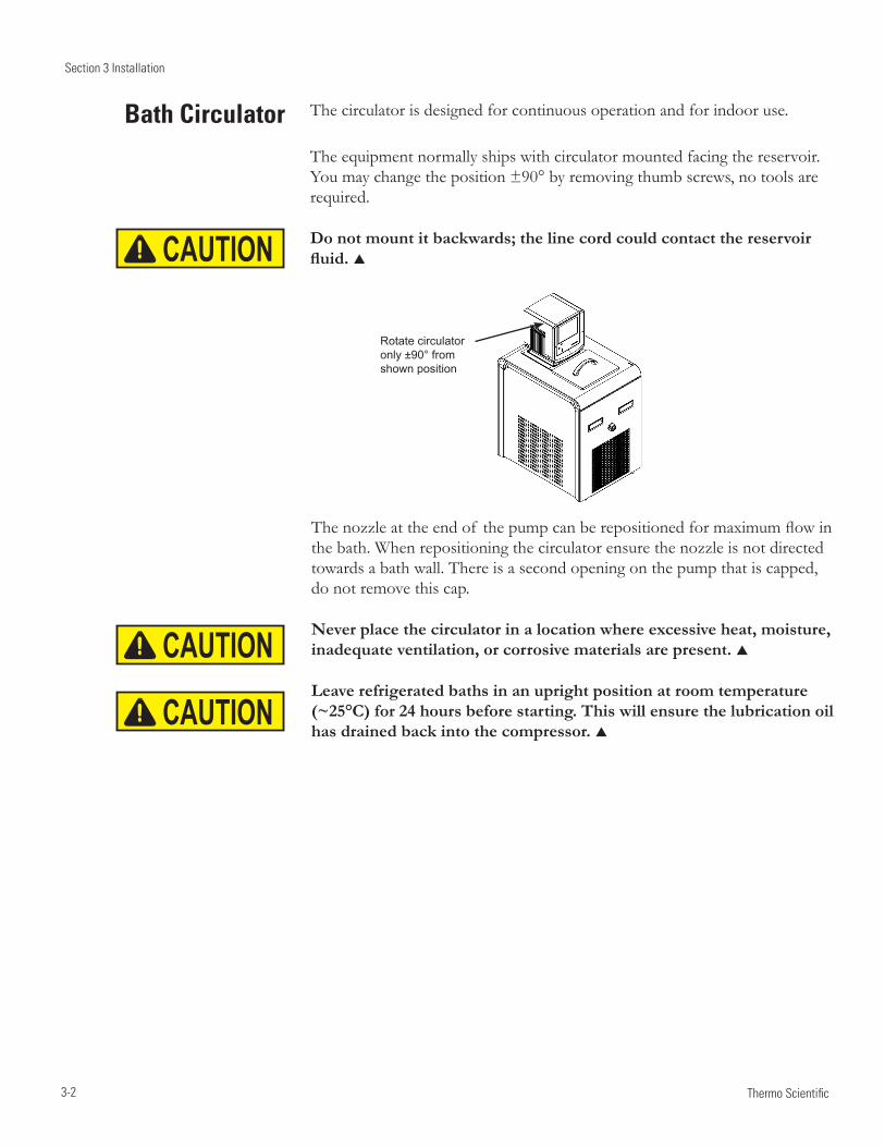
Section 3 Installation
3-2 Thermo Scientific
The circulator is designed for continuous operation and for indoor use.
The equipment normally ships with circulator mounted facing the reservoir. You may change the position ±90° by removing thumb screws, no tools are required.
Do not mount it backwards; the line cord could contact the reservoir fluid.
Thenozzleattheendof thepumpcanberepositionedformaximumflowinthe bath. When repositioning the circulator ensure the nozzle is not directed towards a bath wall. There is a second opening on the pump that is capped, do not remove this cap.
Never place the circulator in a location where excessive heat, moisture, inadequate ventilation, or corrosive materials are present.
Leave refrigerated baths in an upright position at room temperature (~25°C) for 24 hours before starting. This will ensure the lubrication oil has drained back into the compressor.
CAUTION
CAUTION
CAUTION
Rotate circulator only ±90° from shown position
Bath Circulator
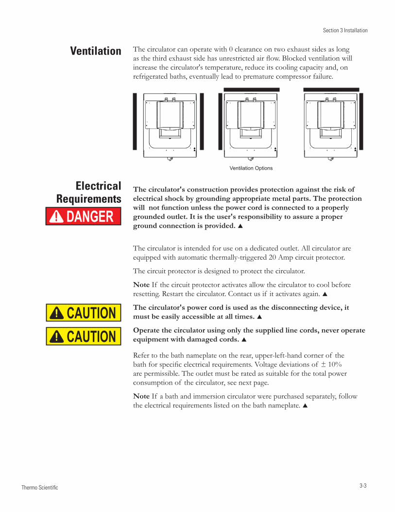
Section 3 Installation
3-3 Thermo Scientific
Electrical Requirements
The circulator's construction provides protection against the risk of electrical shock by grounding appropriate metal parts. The protection will not function unless the power cord is connected to a properly grounded outlet. It is the user's responsibility to assure a proper ground connection is provided.
The circulator is intended for use on a dedicated outlet. All circulator are equipped with automatic thermally-triggered 20 Amp circuit protector.
The circuit protector is designed to protect the circulator.
Note If the circuit protector activates allow the circulator to cool before resetting. Restart the circulator. Contact us if it activates again.
The circulator's power cord is used as the disconnecting device, it must be easily accessible at all times.
Operate the circulator using only the supplied line cords, never operate equipment with damaged cords.
Refer to the bath nameplate on the rear, upper-left-hand corner of the bathforspecificelectricalrequirements.Voltagedeviationsof ±10%are permissible. The outlet must be rated as suitable for the total power consumption of the circulator, see next page.
Note If a bath and immersion circulator were purchased separately, follow the electrical requirements listed on the bath nameplate.
DANGER
Ventilation
CAUTIONCAUTION
The circulator can operate with 0 clearance on two exhaust sides as long asthethirdexhaustsidehasunrestrictedairflow.Blockedventilationwillincrease the circulator's temperature, reduce its cooling capacity and, on refrigerated baths, eventually lead to premature compressor failure.
Ventilation Options
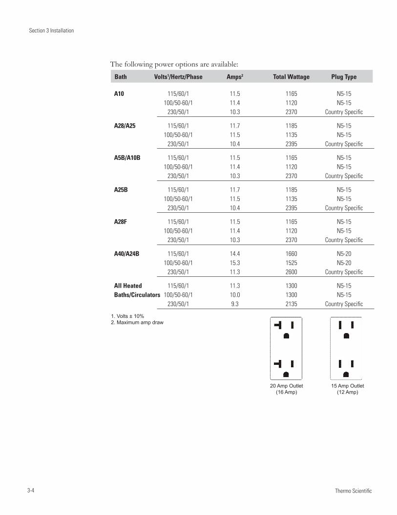
Section 3 Installation
3-4 Thermo Scientific
1. Volts ± 10% 2. Maximum amp draw
20 Amp Outlet 15 Amp Outlet (16 Amp) (12 Amp)
The following power options are available:
Bath Volts1/Hertz/Phase Amps2 Total Wattage Plug Type
A10 115/60/1 11.5 1165 N5-15 100/50-60/1 11.4 1120 N5-15 230/50/1 10.3 2370 Country Specific
A28/A25 115/60/1 11.7 1185 N5-15 100/50-60/1 11.5 1135 N5-15 230/50/1 10.4 2395 Country Specific
A5B/A10B 115/60/1 11.5 1165 N5-15 100/50-60/1 11.4 1120 N5-15 230/50/1 10.3 2370 Country Specific
A25B 115/60/1 11.7 1185 N5-15 100/50-60/1 11.5 1135 N5-15 230/50/1 10.4 2395 Country Specific
A28F 115/60/1 11.5 1165 N5-15 100/50-60/1 11.4 1120 N5-15 230/50/1 10.3 2370 Country Specific
A40/A24B 115/60/1 14.4 1660 N5-20 100/50-60/1 15.3 1525 N5-20 230/50/1 11.3 2600 Country Specific
All Heated 115/60/1 11.3 1300 N5-15 Baths/Circulators 100/50-60/1 10.0 1300 N5-15 230/50/1 9.3 2135 Country Specific
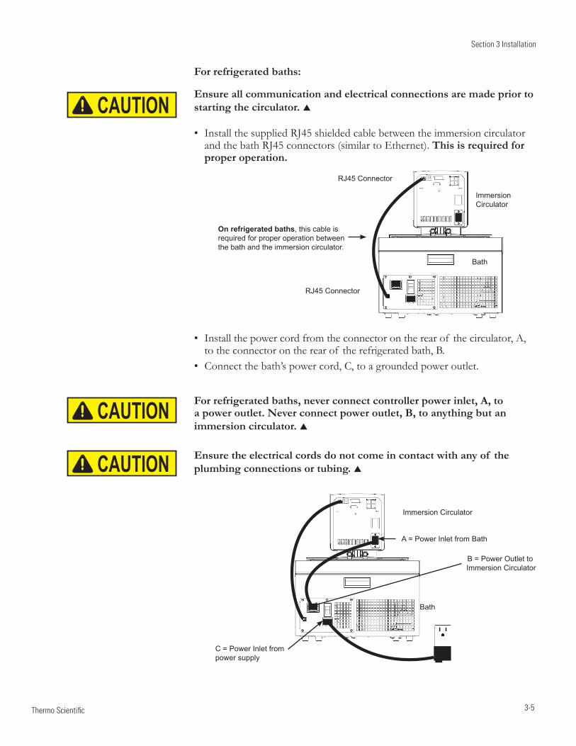
Section 3 Installation
3-5 Thermo Scientific
CAUTION
CAUTION
CAUTION
For refrigerated baths:
Ensure all communication and electrical connections are made prior to starting the circulator.
Install the supplied RJ45 shielded cable between the immersion circulator •and the bath RJ45 connectors (similar to Ethernet). This is required for proper operation.
Immersion Circulator
Bath
RJ45 Connector
On refrigerated baths, this cable is required for proper operation between the bath and the immersion circulator.
RJ45 Connector
A = Power Inlet from Bath
Immersion Circulator
Bath
B = Power Outlet to Immersion Circulator
C = Power Inlet from power supply
Install the power cord from the connector on the rear of the • circulator, A, totheconnectorontherearof therefrigeratedbath,B.Connect the bath’s power cord, C, to a grounded power outlet. •
For refrigerated baths, never connect controller power inlet, A, to a power outlet. Never connect power outlet, B, to anything but an immersion circulator.
Ensure the electrical cords do not come in contact with any of the plumbing connections or tubing.
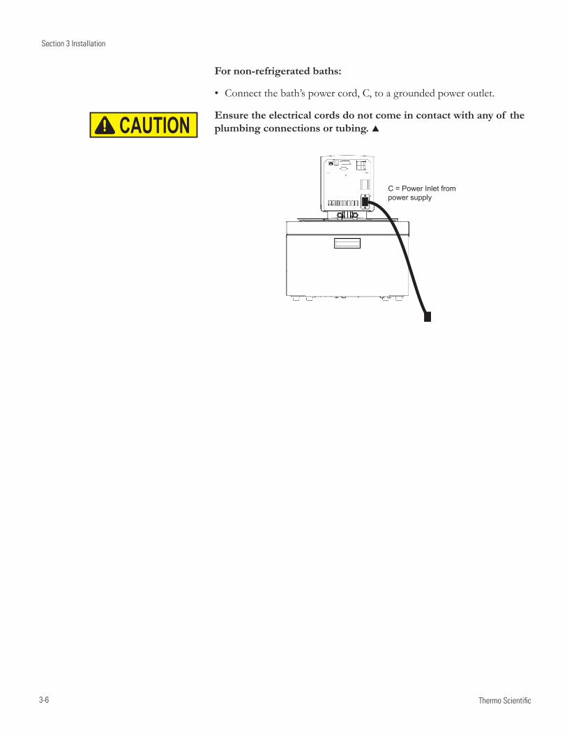
Section 3 Installation
3-6 Thermo Scientific
CAUTION
For non-refrigerated baths:
Connect the bath’s power cord, C, to a grounded power outlet. •
Ensure the electrical cords do not come in contact with any of the plumbing connections or tubing.
C = Power Inlet from power supply
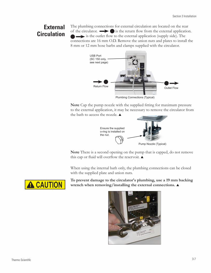
Section 3 Installation
3-7 Thermo Scientific
External Circulation
Pump Nozzle (Typical)
Ensure the supplied o-ring is installed on the nut.
The plumbing connections for external circulation are located on the rear of the circulator. isthereturnflowfromtheexternalapplication.
istheoutletflowtotheexternalapplication(supplyside).Theconnections are 16 mm O.D. Remove the union nuts and plates to install the 8 mm or 12 mm hose barbs and clamps supplied with the circulator.
Plumbing Connections (Typical)
Return Flow Outlet Flow
USB Port (SC 150 only, see next page)
NoteCapthepumpnozzlewiththesuppliedfittingformaximumpressureto the external application, it may be necessary to remove the circulator from the bath to access the nozzle.
CAUTION
Note There is a second opening on the pump that is capped, do not remove thiscaporfluidwilloverflowthereservoir.
When using the internal bath only, the plumbing connections can be closed with the supplied plate and union nuts.
To prevent damage to the circulator's plumbing, use a 19 mm backing wrench when removing/installing the external connections.
Section 3 Installation
3-8 Thermo Scientific
Tubing Requirements Tubing is normally used to connect the pump to an external application.
Ensure none of the tubing comes in contact with the power cord.
Note The maximum allowable length of tube depends largely on the size, form and material of the external reservoir. The length of tube and its diameter, combined with the circulating capacity, have a large affect on the temperature stability. Whenever possible, use a wider tube diameter and place the application as close as possible to the circulator.
Extreme operating temperatures will lead to extreme temperatures on the tube surface, this is even more critical with metal nozzles.
the required tube material depends on the heat transfer liquid used •
tubes must not be folded or bent•
after prolonged use, tubes may become brittle or they may get very soft, • check them on a regular basis and replace if necessary
secure all tube connections using clamps•
CAUTION
USB Port (SC 150 only)
If yourcomputerdoesnotautomaticallyrecognizetheUSBdriver,installa-tion instructions are provided in the Appendix.
Section 3 Installation
3-9 Thermo Scientific
Tubing TubingforThermoScientifictemperaturecontrolsystemsisoptional.Tubing is available in lengths of 0.5, 1.0 and 1.5 meters. Couplings for connecting tubes are also available. The smallest opening inside the metal tubes is 10 mm. The metal tubing is provided with coupling nuts (M16 x 1, DIN 12 879, part 2) at either end.
Please select the proper tubing from the table shown in Section 5.
Ensure the tubing you select will meet your maximum temperature and pressure requirements.
Plastic and rubber tubing If other plastic and rubber tubes are used, ensure that the tubes selected are fully suitable for the particular application, i.e., that they will not split, crack or become disengaged from their connections.
Connectthetubingusingthesuppliedtubefittingsfor8or12mmi.d.Theyare attached to the plumbing connections with a supplied coupling nut.
We highly recommend using foam rubber insulation on the tubing and the fittings.
Metal tubing ThermoScientificmetaltubing(stainlesssteelinsulated)offersaparticularlyhigh degree of safety and is suitable for both low and high temperatures/liquids.
The metal tubing is attached directly to the plumbing connections, gaskets are not required.
Do not subject tubing to mechanical strain and ensure any specified bend radius is not exceeded. CAUTION
CAUTION
Section 3 Installation
3-10 Thermo Scientific
Approved FluidsOnly use the approved fluids listed below.
All immersion circulators:
Water
Ethylene Glycol-Water
Propylene Glycol-Water
SC 150 and SC 150L immersion circulators only:
SIL 100
SIL 180
SIL 300
SYNTH 60
SYNTH 260
Thermo Fisher Scientific takes no responsibility for damages caused by the selection of an unapproved bath fluid.
Other than water, handle and dispose of approved liquids in accordance with the fluid manufacturer's specification and/or the fluid's MSDS.
To set the fluid temperature alarms, use the circulator's menu selection to identify the fluid, see Section 4.
When using water above 80°C closely monitor the fluid level, frequent top-offs will be required. It will also create steam.
Water/glycol mixtures require top-offs with pure water, otherwise the percentage of glycol will increase resulting in high viscosity and poor performance.
Transparent Acrylic Bath and Polyphenylene oxide (PPO) Bath Circulators are used with water only.
CAUTION
CAUTION
CAUTION
CAUTION
CAUTION
DANGER
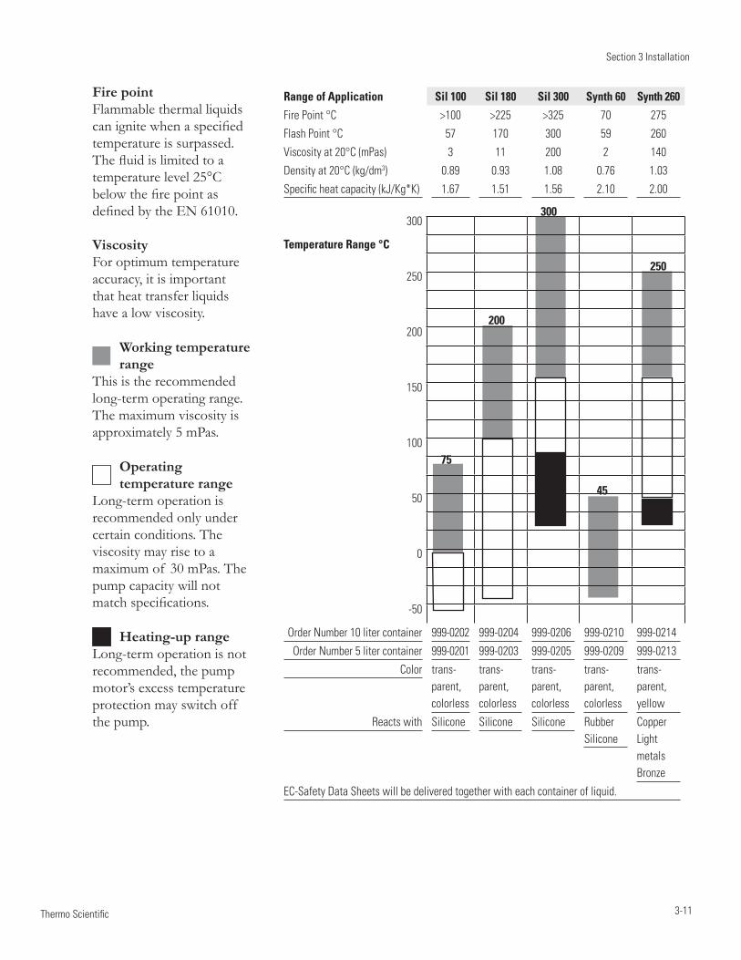
Section 3 Installation
3-11 Thermo Scientific
Range of Application Sil 100 Sil 180 Sil 300 Synth 60 Synth 260
Fire Point °C >100 >225 >325 70 275
Flash Point °C 57 170 300 59 260
Viscosity at 20°C (mPas) 3 11 200 2 140
Density at 20°C (kg/dm3) 0.89 0.93 1.08 0.76 1.03
Specific heat capacity (kJ/Kg*K) 1.67 1.51 1.56 2.10 2.00
300
Temperature Range °C
250
200
150
100
50
0
-50
Order Number 10 liter container 999-0202 999-0204 999-0206 999-0210 999-0214
Order Number 5 liter container 999-0201 999-0203 999-0205 999-0209 999-0213
Color trans-parent, colorless
trans-parent, colorless
trans-parent, colorless
trans-parent, colorless
trans-parent, yellow
Reacts with Silicone Silicone Silicone Rubber Silicone
Copper Light metals Bronze
EC-Safety Data Sheets will be delivered together with each container of liquid.
75
200
300
45
250
Fire point Flammable thermal liquids canignitewhenaspecifiedtemperature is surpassed. Thefluidislimitedtoatemperature level 25°C belowthefirepointasdefinedbytheEN61010.
ViscosityFor optimum temperature accuracy, it is important that heat transfer liquids have a low viscosity.
Working temperature range
This is the recommended long-term operating range. The maximum viscosity is approximately 5 mPas.
Operating temperature range
Long-term operation is recommended only under certain conditions. The viscosity may rise to a maximum of 30 mPas. The pump capacity will not matchspecifications.
Heating-up rangeLong-term operation is not recommended, the pump motor’s excess temperature protection may switch off the pump.
Section 3 Installation
3-12 Thermo Scientific
Chlorine Short term usage of tap water may not cause any adverse affects on the circulator or your application, but in the long term problems may arise. To helpalleviatetheseproblemsThermoFisherScientificrecommendstheuseof chlorine.
The duration of time that chlorine remains in solution depends on factors such as water temperature, pH and availability of direct sunlight. We recommend maintaining chlorine levels at proper levels using chlorine test strips, generally 1 to 5 ppm is adequate.
Forbestresults,thepHof thefluidshouldbemaintainedbetween6.5and7.5.Additionalchlorineshouldnotbeaddedwithoutfirstdeterminingtheconcentrationratiothatalreadyexistsinthefluidsupply.Corrosionanddegradation of the circulation components can result from concentration ratios that are too high. Contact our customer support for additional information.
5°C to 95°C — Distilled Water or Deionized Water(upto3MΩ-cm) Normal tap water leads to calcareous deposits necessitating frequent circulatordecalcification,seetableonpage3-14.
Calcium tends to deposit itself on the heating element. The heating capacity is reduced and service life shortened.
-30°C to 80°C — Water with Glycol Below5°Cwaterhastobemixedwithaglycol.Theamountof glycoladdedshould cover a temperature range 5°C lower than the operating temperature of the particular application. This will prevent the water/glycol from gelling (freezing) near the evaporating coil.
Excess glycol deteriorates the temperature accuracy due to its high viscosity.
-40°C to 200°C — SIL180 (SC 150 and SC 150L circulators only) SIL180 is suitable for covering nearly the entire range with just one liquid, especially when used with the cooling units.
Unfortunately SIL180 has a wetting tendency necessitating the occasional cleaning of the bath cover.
other temperatures (SC 150 and SC 150L circulators only) ThermoFisherScientificoffersarangeof heattransferfluidsforthesetemperature control applications.
SYNTH 60 and SYNTH 260: (SC 150 and SC 150L circulators only) Synthetic thermal liquid with a medium life span (several months) and little smell annoyance.
Section 3 Installation
3-13 Thermo Scientific
SIL 100, SIL 180, SIL 300: (SC 150 and SC 150L circulators only) Silicone oil with a very long life span ( over 1 year) and negligible smell.
ThermoFisherheattransferfluidsaresuppliedwithanECSafetyDataSheet.
Ensure, when selecting the heat transfer fluid, that no toxic gases can be generated. Inflammable gases can build up over the fluid during usage.
Ensure the over temperature cut-off point is set lower than the fire point for the heat transfer fluid selected.
The highest working temperature, as defined by the EN 61010 (IEC 1010), must be limited to 25°C below the fire point of the fluid.
Whenworkingwithfluidsotherthanwater:Donotuseanyapprovedfluiduntilyouhavereadandunderstood•the label and the Material Safety Data Sheet (MSDS).
Ensureanyfluidresidueoranyothermaterialisthoroughlyremoved•beforefillingthebathwithadifferentfluid.
Always wear protective clothing, especially a face shield and gloves. •
Avoid spattering on any of the circulator's components, always • slowly addfluid.Whenadding,pointtheopeningof acontainerawayfromyourself.
Use fume hoods. •
Do not allow any ignition sources in the vicinity. •
CAUTION
DANGER
CAUTIONAdditional Fluid
Precautions
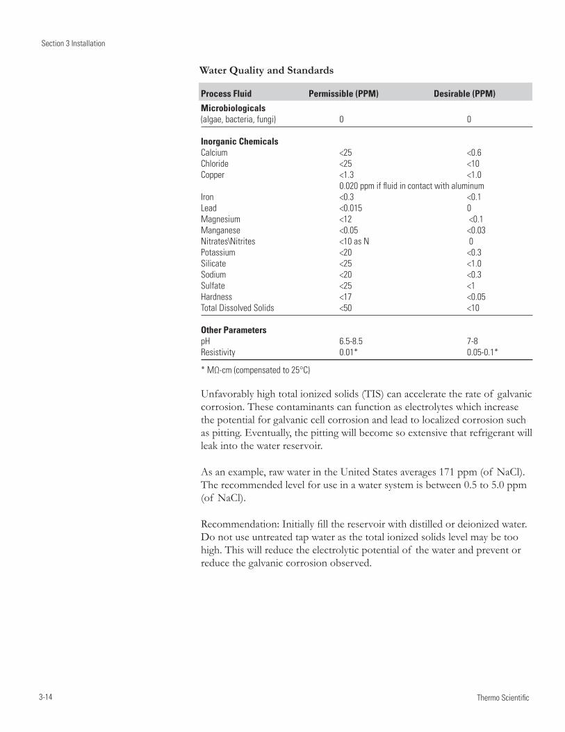
Section 3 Installation
3-14 Thermo Scientific
Process Fluid Permissible (PPM) Desirable (PPM)
Microbiologicals (algae, bacteria, fungi) 0 0
Inorganic ChemicalsCalcium <25 <0.6Chloride <25 <10 Copper <1.3 <1.0 0.020 ppm if fluid in contact with aluminumIron <0.3 <0.1Lead <0.015 0Magnesium <12 <0.1Manganese <0.05 <0.03Nitrates\Nitrites <10 as N 0Potassium <20 <0.3Silicate <25 <1.0Sodium <20 <0.3Sulfate <25 <1Hardness <17 <0.05Total Dissolved Solids <50 <10
Other ParameterspH 6.5-8.5 7-8Resistivity 0.01* 0.05-0.1*
* MΩ-cm (compensated to 25°C)
Unfavorably high total ionized solids (TIS) can accelerate the rate of galvanic corrosion. These contaminants can function as electrolytes which increase the potential for galvanic cell corrosion and lead to localized corrosion such as pitting. Eventually, the pitting will become so extensive that refrigerant will leak into the water reservoir.
As an example, raw water in the United States averages 171 ppm (of NaCl). The recommended level for use in a water system is between 0.5 to 5.0 ppm (of NaCl).
Recommendation:Initiallyfillthereservoirwithdistilledordeionizedwater.Do not use untreated tap water as the total ionized solids level may be too high. This will reduce the electrolytic potential of the water and prevent or reduce the galvanic corrosion observed.
Water Quality and Standards
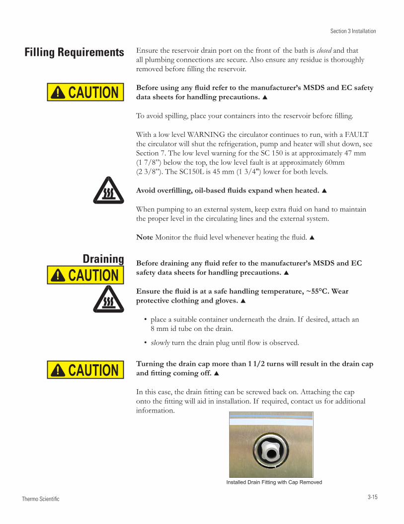
Section 3 Installation
3-15 Thermo Scientific
Filling Requirements
Draining
CAUTION
CAUTION
CAUTION
Installed Drain Fitting with Cap Removed
Ensure the reservoir drain port on the front of the bath is closed and that all plumbing connections are secure. Also ensure any residue is thoroughly removedbeforefillingthereservoir.
Before using any fluid refer to the manufacturer’s MSDS and EC safety data sheets for handling precautions.
Toavoidspilling,placeyourcontainersintothereservoirbeforefilling.
With a low level WARNING the circulator continues to run, with a FAULT the circulator will shut the refrigeration, pump and heater will shut down, see Section 7. The low level warning for the SC 150 is at approximately 47 mm (1 7/8”) below the top, the low level fault is at approximately 60mm (2 3/8”). The SC150L is 45 mm (1 3/4") lower for both levels.
Avoid overfilling, oil-based fluids expand when heated.
Whenpumpingtoanexternalsystem,keepextrafluidonhandtomaintainthe proper level in the circulating lines and the external system.
NoteMonitorthefluidlevelwheneverheatingthefluid.
Before draining any fluid refer to the manufacturer’s MSDS and EC safety data sheets for handling precautions.
Ensure the fluid is at a safe handling temperature, ~55°C. Wear protective clothing and gloves.
place a suitable container underneath the drain. If desired, attach an • 8 mm id tube on the drain.
slowly• turnthedrainpluguntilflowisobserved.
Turning the drain cap more than 1 1/2 turns will result in the drain cap and fitting coming off.
Inthiscase,thedrainfittingcanbescrewedbackon.Attachingthecapontothefittingwillaidininstallation.If required,contactusforadditionalinformation.

Section 3 Installation
3-16 Thermo Scientific
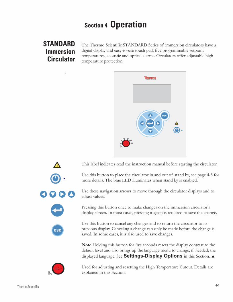
4-1 Thermo Scientific
Section 4 Operation
The Thermo Scientific STANDARD Series of immersion circulators have a digital display and easy-to-use touch pad, five programmable setpoint temperatures, acoustic and optical alarms. Circulators offer adjustable high temperature protection.
STANDARD Immersion Circulator
215
°C
18075
145
40
110
This label indicates read the instruction manual before starting the circulator.
Use this button to place the circulator in and out of stand by, see page 4-3 for more details. The blue LED illuminates when stand by is enabled.
Use these navigation arrows to move through the circulator displays and to adjust values.
Pressing this button once to make changes on the immersion circulator's display screen. In most cases, pressing it again is required to save the change.
Use this button to cancel any changes and to return the circulator to its previous display. Canceling a change can only be made before the change is saved. In some cases, it is also used to save changes.
Note Holding this button for five seconds resets the display contrast to the default level and also brings up the language menu to change, if needed, the displayed language. See Settings-Display Options in this Section.
Used for adjusting and resetting the High Temperature Cutout. Details are explained in this Section.
°C
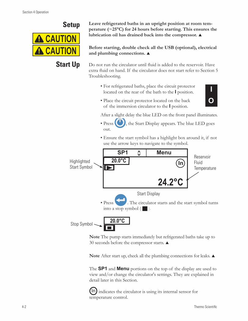
4-2 Thermo Scientific
Section 4 Operation
Setup
Start Up
CAUTIONCAUTION
I O
Stop Symbol 20.0°C
Start Display
Highlighted Start Symbol
Reservoir Fluid Temperature
20.0°C
24.2°C
SP1 Menu
In
Note The pump starts immediately but refrigerated baths take up to 30 seconds before the compressor starts.
Note After start up, check all the plumbing connections for leaks.
The SP1 and Menu portions on the top of the display are used to view and/or change the circulator's settings. They are explained in detail later in this Section.
In indicates the circulator is using its internal sensor for temperature control.
Leave refrigerated baths in an upright position at room tem-perature (~25°C) for 24 hours before starting. This ensures the lubrication oil has drained back into the compressor.
Before starting, double check all the USB (optional), electrical and plumbing connections.
Donotrunthecirculatoruntilfluidisaddedtothereservoir.Haveextrafluidonhand.If thecirculatordoesnotstartrefertoSection5Troubleshooting.
•Forrefrigeratedbaths,placethecircuitprotectorlocated on the rear of the bath to the I position.
•Placethecircuitprotectorlocatedontheback of the immersion circulator to the I position.
After a slight delay the blue LED on the front panel illuminates.
•Press , the Start Display appears. The blue LED goes out.
•Ensurethestartsymbolhasahighlightboxaroundit,if notuse the arrow keys to navigate to the symbol.
•Press . The circulator starts and the start symbol turns into a stop symbol ( ).
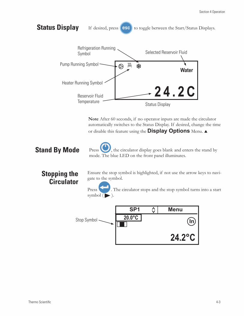
Thermo Scientific 4-3
Section 4 Operation
Press , the circulator display goes blank and enters the stand by mode. The blue LED on the front panel illuminates.
If desired, press to toggle between the Start/Status Displays. Status Display
Stand By Mode
2 4 . 2 CWater
Heater Running Symbol
Pump Running Symbol
Refrigeration Running Symbol
Reservoir Fluid Temperature
Selected Reservoir Fluid
Status Display
Note After 60 seconds, if no operator inputs are made the circulator automatically switches to the Status Display. If desired, change the time or disable this feature using the Display Options Menu.
Ensure the stop symbol is highlighted, if not use the arrow keys to navi-gate to the symbol.
Press . The circulator stops and the stop symbol turns into a start symbol ( ).
Stopping the Circulator
20.0°C
24.2°C
SP1 Menu
Stop Symbol In
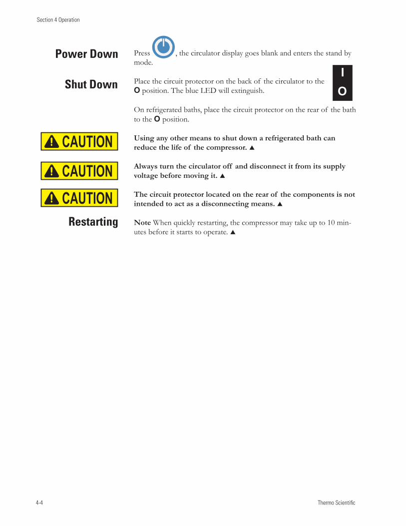
4-4 Thermo Scientific
Section 4 Operation
Press , the circulator display goes blank and enters the stand by mode.
Place the circuit protector on the back of the circulator to the O position. The blue LED will extinguish.
On refrigerated baths, place the circuit protector on the rear of the bath to the O position.
Using any other means to shut down a refrigerated bath can reduce the life of the compressor.
Always turn the circulator off and disconnect it from its supply voltage before moving it.
The circuit protector located on the rear of the components is not intended to act as a disconnecting means.
Note When quickly restarting, the compressor may take up to 10 min-utes before it starts to operate.
Power Down
Shut Down
Restarting
CAUTION
CAUTIONCAUTION
I O
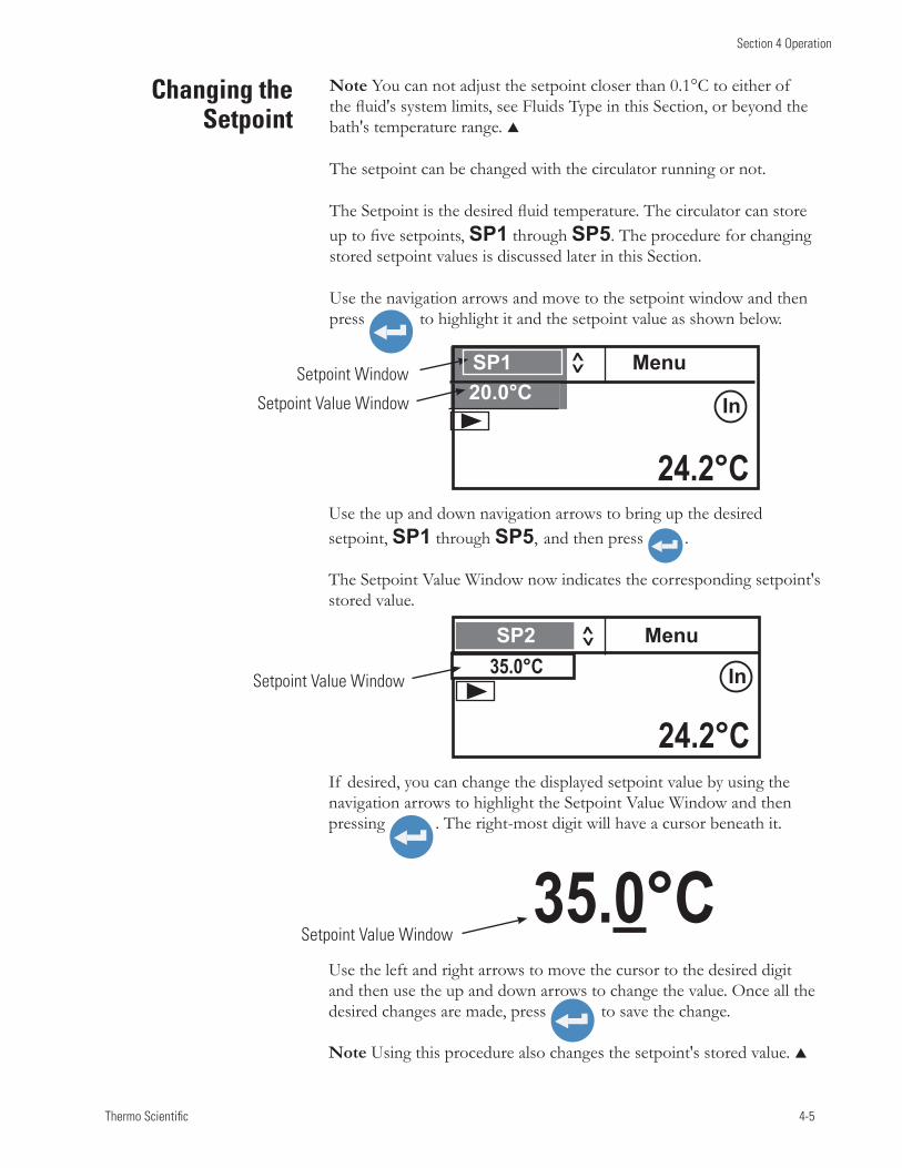
Thermo Scientific 4-5
Section 4 Operation
Note You can not adjust the setpoint closer than 0.1°C to either of the fluid's system limits, see Fluids Type in this Section, or beyond the bath's temperature range.
The setpoint can be changed with the circulator running or not.
The Setpoint is the desired fluid temperature. The circulator can store up to five setpoints, SP1 through SP5. The procedure for changing stored setpoint values is discussed later in this Section.
Use the navigation arrows and move to the setpoint window and then press to highlight it and the setpoint value as shown below.
Changing the Setpoint
Use the up and down navigation arrows to bring up the desired setpoint, SP1 through SP5, and then press .
The Setpoint Value Window now indicates the corresponding setpoint's stored value.
If desired, you can change the displayed setpoint value by using the navigation arrows to highlight the Setpoint Value Window and then pressing . The right-most digit will have a cursor beneath it.
Use the left and right arrows to move the cursor to the desired digit and then use the up and down arrows to change the value. Once all the desired changes are made, press to save the change.
Note Using this procedure also changes the setpoint's stored value.
Setpoint Value Window35.0°C
SP1 Menu20.0°CSetpoint Value Window
Setpoint Window
24.2°C
In
SP2 Menu 35.0°C
24.2°C
In Setpoint Value Window
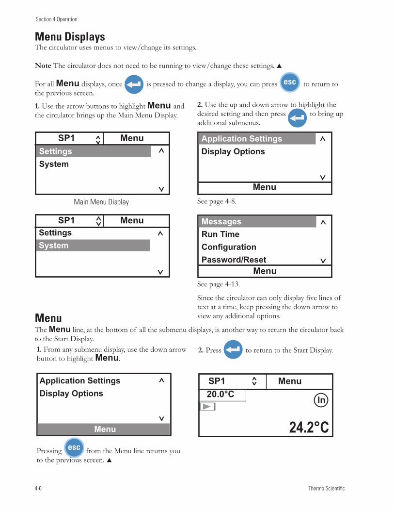
4-6 Thermo Scientific
Section 4 Operation
1. Use the arrow buttons to highlight Menu and the circulator brings up the Main Menu Display.
2. Use the up and down arrow to highlight the desired setting and then press to bring up additional submenus.
Menu Displays The circulator uses menus to view/change its settings.
Note The circulator does not need to be running to view/change these settings.
For all Menu displays, once is pressed to change a display, you can press to return to the previous screen.
See page 4-8.
See page 4-13.
MessagesRun TimeConfigurationPassword/Reset
Menu
SP1 Menu SettingsSystem
SP1 Menu SettingsSystem
Menu
Application SettingsDisplay Options
1. From any submenu display, use the down arrow button to highlight Menu.
2. Press to return to the Start Display.
Menu The Menu line, at the bottom of all the submenu displays, is another way to return the circulator back to the Start Display.
Pressing from the Menu line returns you to the previous screen.
Application SettingsDisplay Options
Menu
Since the circulator can only display five lines of text at a time, keep pressing the down arrow to view any additional options.
SP1 Menu20.0°C
24.2°C
In
Main Menu Display
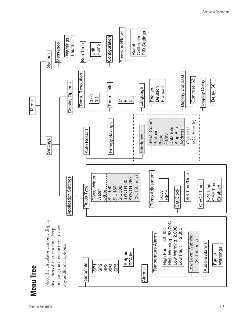
Thermo Scientific 4-7
Section 4 Operation
Men
u Tr
ee
Sinc
e th
e ci
rcul
ator
can
onl
y di
splay
fiv
e lin
es o
f te
xt a
t a ti
me,
keep
pr
essin
g th
e do
wn
arro
w to
vie
w
any
addi
tiona
l opt
ions
.
Men
u
Set
Clo
ck
On/
Off
Tim
er
ON
Tim
eO
FF T
ime
Ena
bled
Set
Tim
e/D
ate
Aut
o R
esta
rt
Ene
rgy
Sav
ings
Dis
play
Opt
ions
Lang
uage
Tem
p. U
nits
Tem
p. R
esol
utio
n
Dis
play
Con
trast
Dis
play
Del
ay
Eng
lish
Deu
tsch
Fran
cais
C F K0.01
0.1
Con
trast
32
Del
ay 6
0
Sys
tem W
arni
ngs
Faul
ts
Uni
tP
ump
Configuration
Run
Tim
e
Mes
sage
s
Pas
swor
d/R
eset
Res
etC
alib
ratio
nP
ID S
ettin
gs
Set
poin
ts
SP
1S
P2
SP
3S
P4
SP
5 Set
poin
tR
TA in
t
Pum
p A
djus
tmen
t
Gly
col-W
ater
W
ater
Oth
erS
IL 1
00S
IL 1
80S
IL 3
00S
YN
TH 6
0S
YN
TH 2
60
Flui
ds T
ype
Ala
rms
LOW
HIG
H
App
licat
ion
Set
tings
Set
tings O
ptio
nal
(SC
150
only
)
Inte
rface
s
Ser
ial C
omm
Pro
toco
lB
aud
Par
ityD
ata
Bits
Sto
p B
itsA
ddre
ss
(SC
150
only
)
(SC
150
only
)
Tem
pera
ture
Ala
rms
Aud
ible
Ala
rms
Low
Lev
el W
arni
ng
Hig
h Fa
ult
83.
00C
Hig
h W
arni
ng
83.0
0CLo
w W
arni
ng 2
.00C
Low
Fau
lt 2.
00C
Faul
tsW
arni
ngs
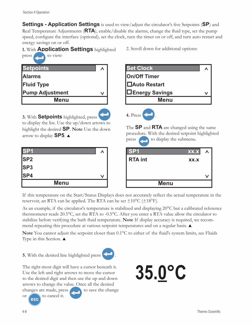
4-8 Thermo Scientific
Section 4 Operation
Settings - Application Settings is used to view/adjust the circulator's five Setpoints (SP) and Real Temperature Adjustments (RTA), enable/disable the alarms, change the fluid type, set the pump speed, configure the interface (optional), set the clock, turn the timer on or off, and turn auto restart and energy savings on or off.1. With Application Settings highlighted press to view:
Menu
Setpoints AlarmsFluidTypePumpAdjustment
2. Scroll down for additional options:
3. With Setpoints highlighted, press to display the list. Use the up/down arrows to highlight the desired SP. Note Use the down arrow to display SP5.
4. Press .
The SP and RTA are changed using the same procedure. With the desired setpoint highlighted press to display the submenu.
Menu
SP1 xx.xRTA int xx.x
Menu
SP1 SP2 SP3 SP4
If this temperature on the Start/Status Displays does not accurately reflect the actual temperature in the reservoir, an RTA can be applied. The RTA can be set ±10°C (±18°F). As an example, if the circulator's temperature is stabilized and displaying 20°C but a calibrated reference thermometer reads 20.5°C, set the RTA to -0.5°C. After you enter a RTA value allow the circulator to stabilize before verifying the bath fluid temperature. Note If display accuracy is required, we recom-mend repeating this procedure at various setpoint temperatures and on a regular basis. Note You cannot adjust the setpoint closer than 0.1°C to either of the fluid's system limits, see Fluids Type in this Section.
5. With the desired line highlighted press .
The right-most digit will have a cursor beneath it. Use the left and right arrows to move the cursor to the desired digit and then use the up and down arrows to change the value. Once all the desired changes are made, press to save the change or to cancel it.
35.0°C
Menu
Set ClockOn/OffTimerAutoRestartEnergySavings
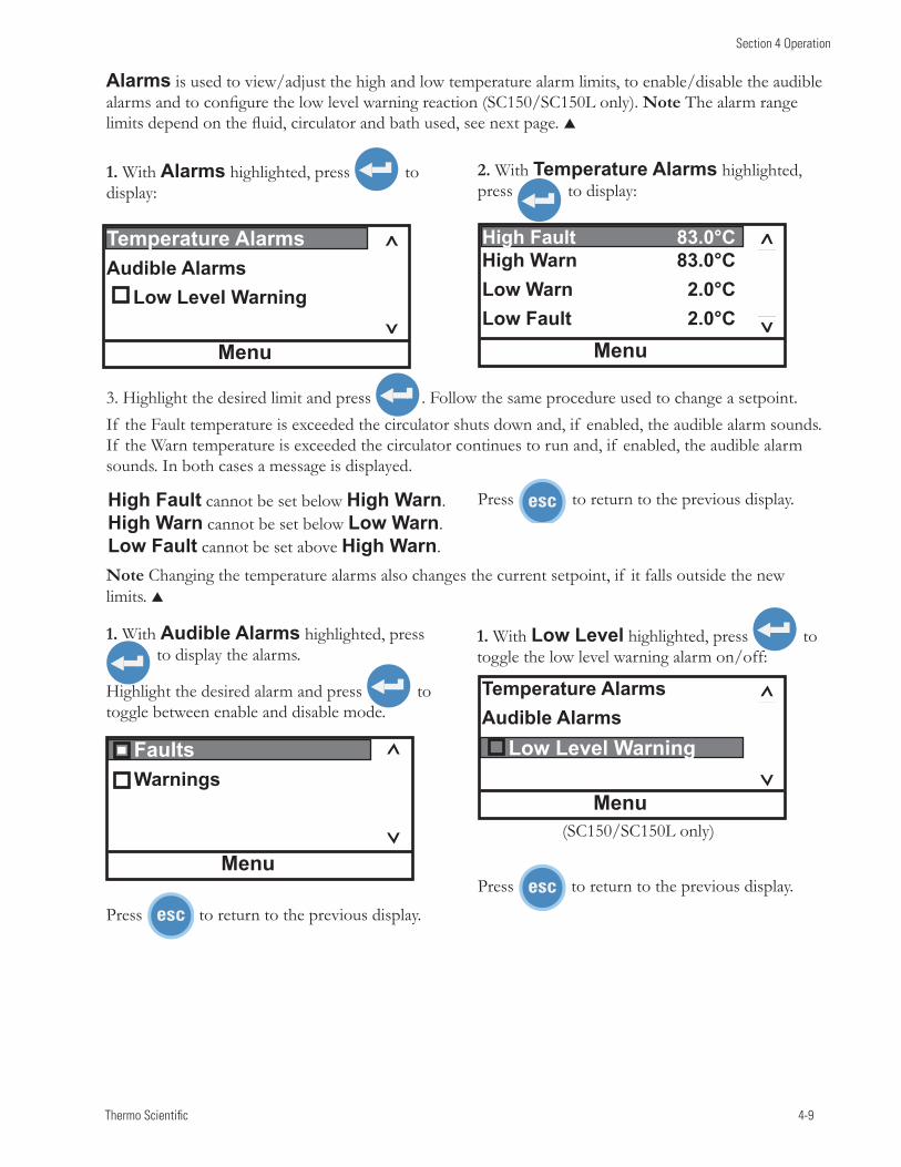
Thermo Scientific 4-9
Section 4 Operation
1. With Alarms highlighted, press to display:
2. With TemperatureAlarms highlighted, press to display:
1. With AudibleAlarms highlighted, press to display the alarms.
Highlight the desired alarm and press to toggle between enable and disable mode.
High Fault cannot be set below HighWarn. HighWarn cannot be set below LowWarn. Low Fault cannot be set above HighWarn.
Menu
High Fault 83.0°C HighWarn 83.0°CLowWarn 2.0°CLow Fault 2.0°C
3. Highlight the desired limit and press . Follow the same procedure used to change a setpoint. If the Fault temperature is exceeded the circulator shuts down and, if enabled, the audible alarm sounds. If the Warn temperature is exceeded the circulator continues to run and, if enabled, the audible alarm sounds. In both cases a message is displayed.
Menu
Faults Warnings
Menu
TemperatureAlarmsAudibleAlarmsLowLevelWarning
Press to return to the previous display.
Press to return to the previous display.
Note Changing the temperature alarms also changes the current setpoint, if it falls outside the new limits.
Press to return to the previous display.
1. With LowLevel highlighted, press to toggle the low level warning alarm on/off:
Alarms is used to view/adjust the high and low temperature alarm limits, to enable/disable the audible alarms and to configure the low level warning reaction (SC150/SC150L only). Note The alarm range limits depend on the fluid, circulator and bath used, see next page.
Menu
TemperatureAlarmsAudibleAlarms LowLevelWarning
(SC150/SC150L only)
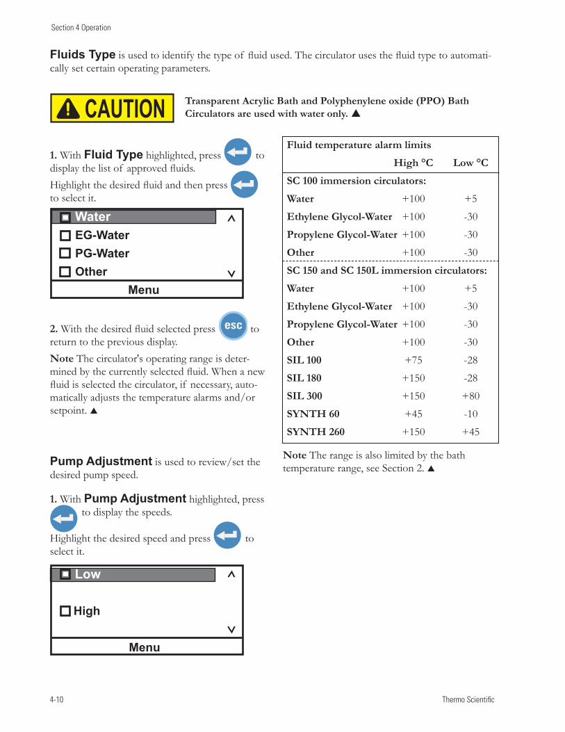
4-10 Thermo Scientific
Section 4 Operation
Fluids Type is used to identify the type of fluid used. The circulator uses the fluid type to automati-cally set certain operating parameters.
Pump Adjustment is used to review/set the desired pump speed.
2. With the desired fluid selected press to return to the previous display.Note The circulator's operating range is deter-mined by the currently selected fluid. When a new fluid is selected the circulator, if necessary, auto-matically adjusts the temperature alarms and/or setpoint.
1. With Fluid Type highlighted, press to display the list of approved fluids. Highlight the desired fluid and then press to select it.
1. With Pump Adjustment highlighted, press to display the speeds.
Highlight the desired speed and press to select it.
WaterEG-WaterPG-WaterOther
Menu
Low High
Menu
Note The range is also limited by the bath temperature range, see Section 2.
Fluid temperature alarm limits
High °C Low °C
SC 100 immersion circulators:
Water +100 +5
Ethylene Glycol-Water +100 -30
Propylene Glycol-Water +100 -30
Other +100 -30
SC 150 and SC 150L immersion circulators:
Water +100 +5
Ethylene Glycol-Water +100 -30
Propylene Glycol-Water +100 -30
Other +100 -30
SIL 100 +75 -28
SIL 180 +150 -28
SIL 300 +150 +80
SYNTH 60 +45 -10
SYNTH 260 +150 +45
Transparent Acrylic Bath and Polyphenylene oxide (PPO) Bath Circulators are used with water only. CAUTION
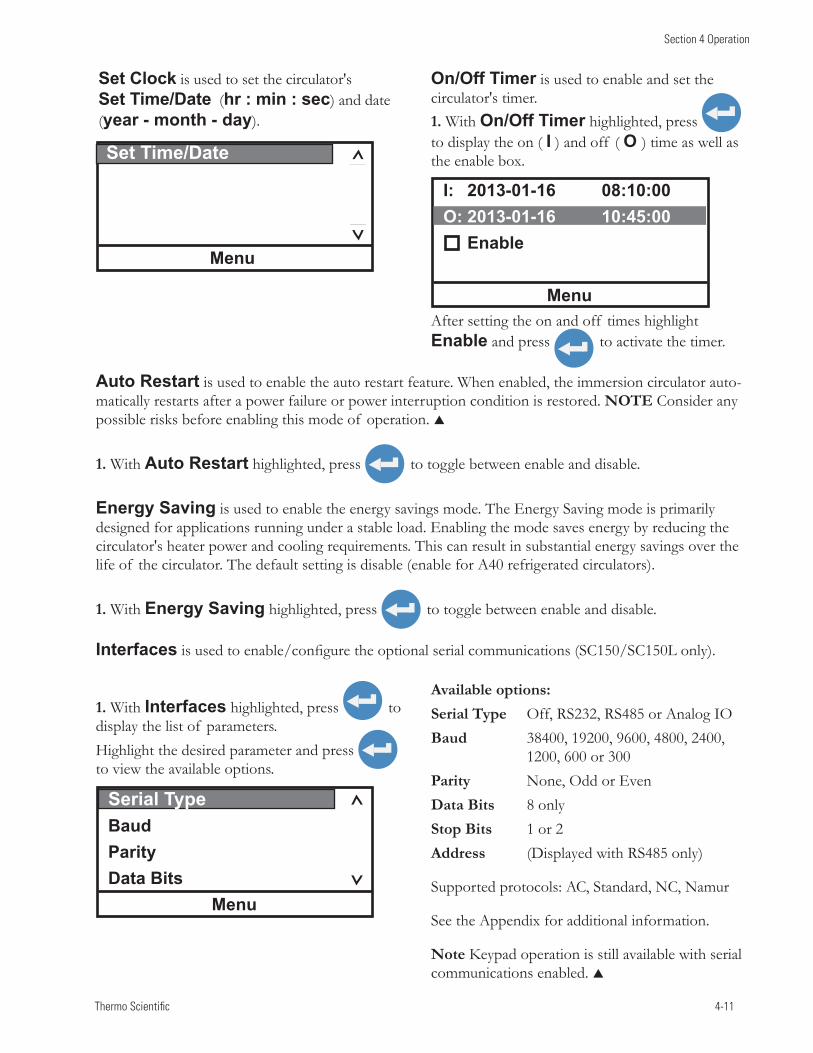
Thermo Scientific 4-11
Section 4 Operation
Set Clock is used to set the circulator's Set Time/Date (hr : min : sec) and date (year - month - day).
On/Off Timer is used to enable and set the circulator's timer.
Set Time/Date
Menu
1. With On/Off Timer highlighted, press to display the on ( I ) and off ( O ) time as well as the enable box.
I: 2013-01-16 08:10:00 O: 2013-01-16 10:45:00 Enable
MenuAfter setting the on and off times highlight Enable and press to activate the timer.
Auto Restart is used to enable the auto restart feature. When enabled, the immersion circulator auto-matically restarts after a power failure or power interruption condition is restored. NOTE Consider any possible risks before enabling this mode of operation.
1. With Auto Restart highlighted, press to toggle between enable and disable.
Energy Saving is used to enable the energy savings mode. The Energy Saving mode is primarily designed for applications running under a stable load. Enabling the mode saves energy by reducing the circulator's heater power and cooling requirements. This can result in substantial energy savings over the life of the circulator. The default setting is disable (enable for A40 refrigerated circulators).
1. With Energy Saving highlighted, press to toggle between enable and disable.
Interfaces is used to enable/configure the optional serial communications (SC150/SC150L only).
Serial TypeBaudParityData Bits
Menu
1. With Interfaces highlighted, press to display the list of parameters. Highlight the desired parameter and press to view the available options.
Available options:Serial Type Off, RS232, RS485 or Analog IOBaud 38400, 19200, 9600, 4800, 2400, 1200, 600 or 300Parity None, Odd or EvenData Bits 8 onlyStop Bits 1 or 2 Address (Displayed with RS485 only)
Supported protocols: AC, Standard, NC, Namur
See the Appendix for additional information.
Note Keypad operation is still available with serial communications enabled.
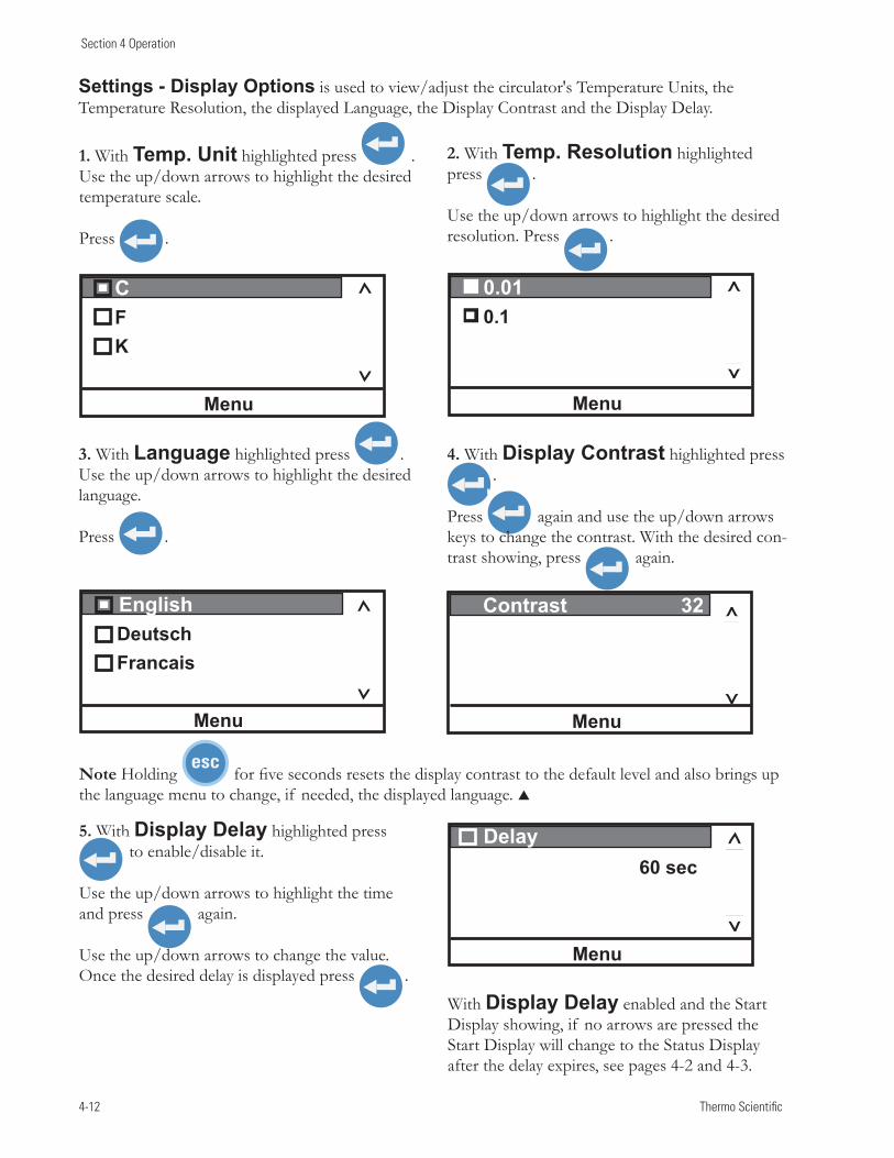
4-12 Thermo Scientific
Section 4 Operation
Settings - Display Options is used to view/adjust the circulator's Temperature Units, the Temperature Resolution, the displayed Language, the Display Contrast and the Display Delay.
3. With Language highlighted press . Use the up/down arrows to highlight the desired language.
Press .
1. With Temp. Unit highlighted press . Use the up/down arrows to highlight the desired temperature scale.
Press .
4. With DisplayContrast highlighted press .
Press again and use the up/down arrows keys to change the contrast. With the desired con-trast showing, press again.
2. With Temp. Resolution highlighted press .
Use the up/down arrows to highlight the desired resolution. Press .
Contrast32
Menu
Delay 60 sec
Menu
English DeutschFrancais
Menu
CFK
Menu
0.010.1
Menu
5. With Display Delay highlighted press to enable/disable it.
Use the up/down arrows to highlight the time and press again.
Use the up/down arrows to change the value. Once the desired delay is displayed press .
Note Holding for five seconds resets the display contrast to the default level and also brings up the language menu to change, if needed, the displayed language.
With Display Delay enabled and the Start Display showing, if no arrows are pressed the Start Display will change to the Status Display after the delay expires, see pages 4-2 and 4-3.
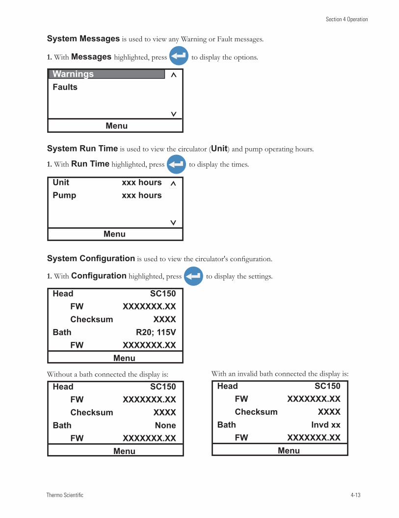
Thermo Scientific 4-13
Section 4 Operation
1. With Configuration highlighted, press to display the settings.
1. With Run Time highlighted, press to display the times.
1. With Messages highlighted, press to display the options.
Without a bath connected the display is: With an invalid bath connected the display is:
Head SC150 FW XXXXXXX.XX Checksum XXXXBath R20; 115V FW XXXXXXX.XX
Menu
Head SC150 FW XXXXXXX.XX Checksum XXXXBath None FW XXXXXXX.XX
Menu
Head SC150 FW XXXXXXX.XX Checksum XXXXBath Invdxx FW XXXXXXX.XX
Menu
System Run Time is used to view the circulator (Unit) and pump operating hours.
SystemConfiguration is used to view the circulator's configuration.
System Messages is used to view any Warning or Fault messages.
Unit xxxhoursPump xxxhours
Menu
WarningsFaults
Menu
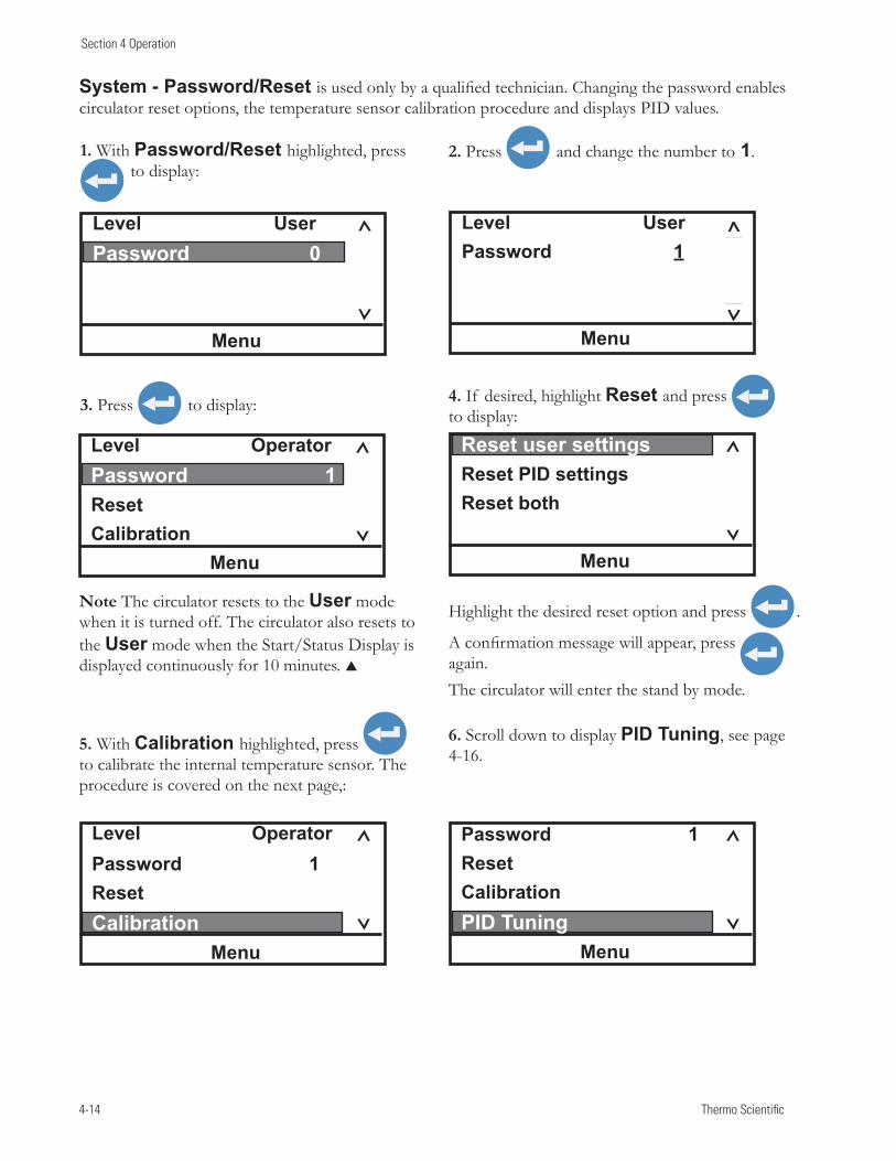
4-14 Thermo Scientific
Section 4 Operation
1. With Password/Reset highlighted, press to display:
5. With Calibration highlighted, press to calibrate the internal temperature sensor. The procedure is covered on the next page,:
Note The circulator resets to the User mode when it is turned off. The circulator also resets to the User mode when the Start/Status Display is displayed continuously for 10 minutes.
2. Press and change the number to 1.
Highlight the desired reset option and press .
A confirmation message will appear, press again. The circulator will enter the stand by mode.
4. If desired, highlight Reset and press to display:
Level UserPassword 0
Menu
Level UserPassword 1
Menu
Level OperatorPassword 1ResetCalibration
Menu
Level OperatorPassword 1ResetCalibration
Menu
Password 1ResetCalibrationPID Tuning
Menu
Reset user settingsReset PID settingsReset both
Menu
System - Password/Reset is used only by a qualified technician. Changing the password enables circulator reset options, the temperature sensor calibration procedure and displays PID values.
3. Press to display:
6. Scroll down to display PID Tuning, see page 4-16.
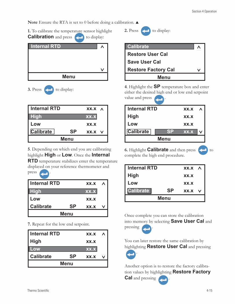
Thermo Scientific 4-15
Section 4 Operation
Note Ensure the RTA is set to 0 before doing a calibration.
Once complete you can store the calibration into memory by selecting Save User Cal and pressing .
You can later restore the same calibration by highlighting Restore User Cal and pressing
.
Another option is to restore the factory calibra-tion values by highlighting Restore Factory Cal and pressing .
5. Depending on which end you are calibrating highlight High or Low. Once the Internal RTD temperature stabilizes enter the temperature displayed on your reference thermometer and press .
6. Highlight Calibrate and then press to complete the high end procedure.
Internal RTD xx.xHigh xx.xLow xx.xCalibrate SP xx.x
Menu
Internal RTD xx.xHigh xx.xLow xx.xCalibrate SP xx.x
Menu
Internal RTD xx.xHigh xx.xLow xx.xCalibrate SP xx.x
Menu
1. To calibrate the temperature sensor highlight Calibration and press to display:
Internal RTD
Menu
2. Press to display:
3. Press to display: 4. Highlight the SP temperature box and enter either the desired high end or low end setpoint value and press .
Internal RTD xx.xHigh xx.xLow xx.xCalibrate SP xx.x
Menu
CalibrateRestore User Cal Save User CalRestore Factory Cal
Menu
Internal RTD xx.xHigh xx.xLow xx.xCalibrate SP xx.x
Menu
7. Repeat for the low end setpoint.
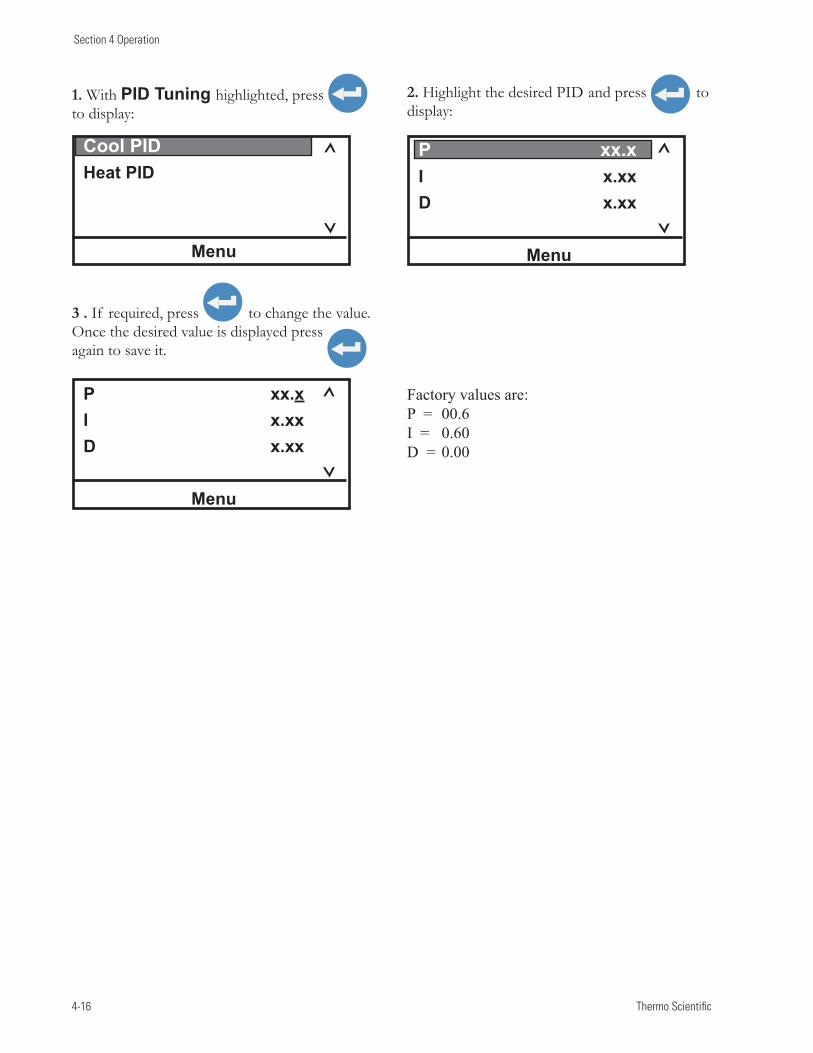
4-16 Thermo Scientific
Section 4 Operation
1. With PID Tuning highlighted, press to display:
2. Highlight the desired PID and press to display:
3 . If required, press to change the value. Once the desired value is displayed press again to save it.
Cool PIDHeat PID
Menu
P xx.xI x.xxD x.xx
Menu
P xx.xI x.xxD x.xx
Menu
Factory values are:P = 00.6 I = 0.60 D = 0.00
Thermo Scientific 4-17
Section 4 Operation
High Temperature Cutout
HTC (Temperature range varies with type of immersion circulator.)
°C
To protect your application, the adjustable High Temperature Cutout (HTC) ensures the heater does not exceed temperatures that can cause serious damage. A temperature sensor is located in the reservoir. A HTC fault occurs when the temperature of the sensor exceeds the set temperature limit.
In the event of a fault the circulator shuts down and displays a fault message, see Section 7. The cause of the fault must be identified and corrected before the circulator can be restarted. A low reservoir fluid level is a primary reason for the HTC to trip.
The HTC is factory preset fully clockwise to the highest possible setting. To set the cutout start the circulator and adjust the setpoint a few degrees higher than the highest desired fluid temperature. Allow the circulator to stabilize at the temperature setpoint. Then, using a flathead screwdriver, slowly turn the red dial counterclockwise until the circulator shuts down and the fault message appears. Press to clear the message.
Before you can restart the circulator it has to cool down a few degrees. To restart the circulator press the black reset ring surrounding the red dial - and then press again. If Auto Restart is enabled the circulator restarts, if disabled use the Start Up procedure.
Note: We recommend periodically rechecking operation or if the circulator is moved.
4-18 Thermo Scientific
Section 4 Operation
Storage
CAUTION
CAUTION
CAUTION
Decommissioning/Disposal Decommissioning prepares equipment for safe and secure transportation.
Laboratory Grade Ethylene glycol (EG) is poisonous and flam-mable. Before disposing refer to the manufacturer’s most current MSDS for handling precautions.
Decommissioning must be performed only by qualified dealer using certified equipment. All prevailing regulations must be followed.
Consider decommissioning the circulator when:
It fails to maintain desired specifications•
It no longer meets safety standards•
It is beyond repair for its age and worth •
Refrigerant (R134A) and oil (POE or Ester) must be recovered from equipment before disposal.
Note Keep in mind any impact your application may have had on the circulator.
Direct questions about chiller decommissioning or disposal to our Sales, Service and Customer Support.
Handling and disposal should be done in accordance with the manu-facturers specification and/or the MSDS for the material used.
If the circulator is to be transported and/or stored in cold temperatures it needs to be drained and then flushed with a 50/50 laboratory grade glycol/water mixture.
The circulator can be stored for up to 90 days inside the temperature range of -25°C to +60°C (-13°F to +140°F).
If necessary, when removing the circulator from storage allow it time to warm up and dry out in order to prevent any condensation issues.
WARNING
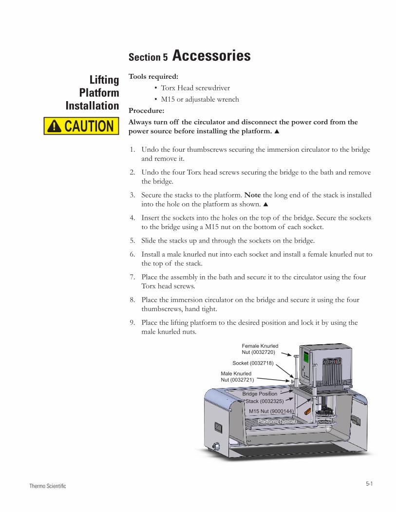
5-1 Thermo Scientific
Female Knurled Nut (0032720)
Male Knurled Nut (0032721)
M15 Nut (9000144)
Platform(Typical)
Stack (0032325)
Socket (0032718)
Bridge Position
Tools required: •TorxHeadscrewdriver •M15oradjustablewrenchProcedure:Always turn off the circulator and disconnect the power cord from the power source before installing the platform.
Undothefourthumbscrewssecuringtheimmersioncirculatortothebridge1.andremoveit.
UndothefourTorxheadscrewssecuringthebridgetothebathandremove2.thebridge.
Securethestackstotheplatform.3. Notethelongendof thestackisinstalledintotheholeontheplatformasshown.
Insertthesocketsintotheholesonthetopof thebridge.Securethesockets4.tothebridgeusingaM15nutonthebottomof eachsocket.
Slidethestacksupandthroughthesocketsonthebridge.5.
Installamaleknurlednutintoeachsocketandinstallafemaleknurlednutto6.thetopof thestack.
Placetheassemblyinthebathandsecureittothecirculatorusingthefour7.Torxheadscrews.
Placetheimmersioncirculatoronthebridgeandsecureitusingthefour8.thumbscrews,handtight.
Placetheliftingplatformtothedesiredpositionandlockitbyusingthe9.maleknurlednuts.
Section 5 AccessoriesLifting
Platform Installation
CAUTION
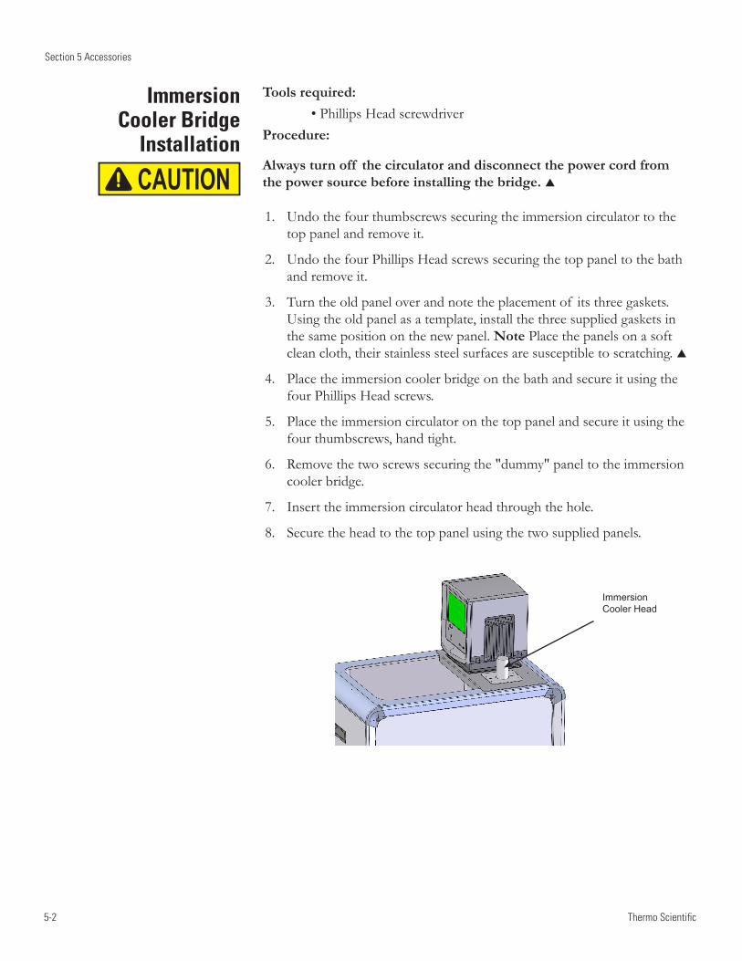
5-2
Section 5 Accessories
Thermo Scientific
Immersion Cooler Bridge
Installation
Tools required: •PhillipsHeadscrewdriverProcedure:
Always turn off the circulator and disconnect the power cord from the power source before installing the bridge.
Undothefourthumbscrewssecuringtheimmersioncirculatortothe1.toppanelandremoveit.
UndothefourPhillipsHeadscrewssecuringthetoppaneltothebath2.andremoveit.
Turntheoldpaneloverandnotetheplacementof itsthreegaskets.3.Usingtheoldpanelasatemplate,installthethreesuppliedgasketsinthesamepositiononthenewpanel.NotePlacethepanelsonasoftcleancloth,theirstainlesssteelsurfacesaresusceptibletoscratching.
Placetheimmersioncoolerbridgeonthebathandsecureitusingthe4.fourPhillipsHeadscrews.
Placetheimmersioncirculatoronthetoppanelandsecureitusingthe5.fourthumbscrews,handtight.
Removethetwoscrewssecuringthe"dummy"paneltotheimmersion6.coolerbridge.
Inserttheimmersioncirculatorheadthroughthehole.7.
Securetheheadtothetoppanelusingthetwosuppliedpanels.8.
CAUTION
Immersion Cooler Head
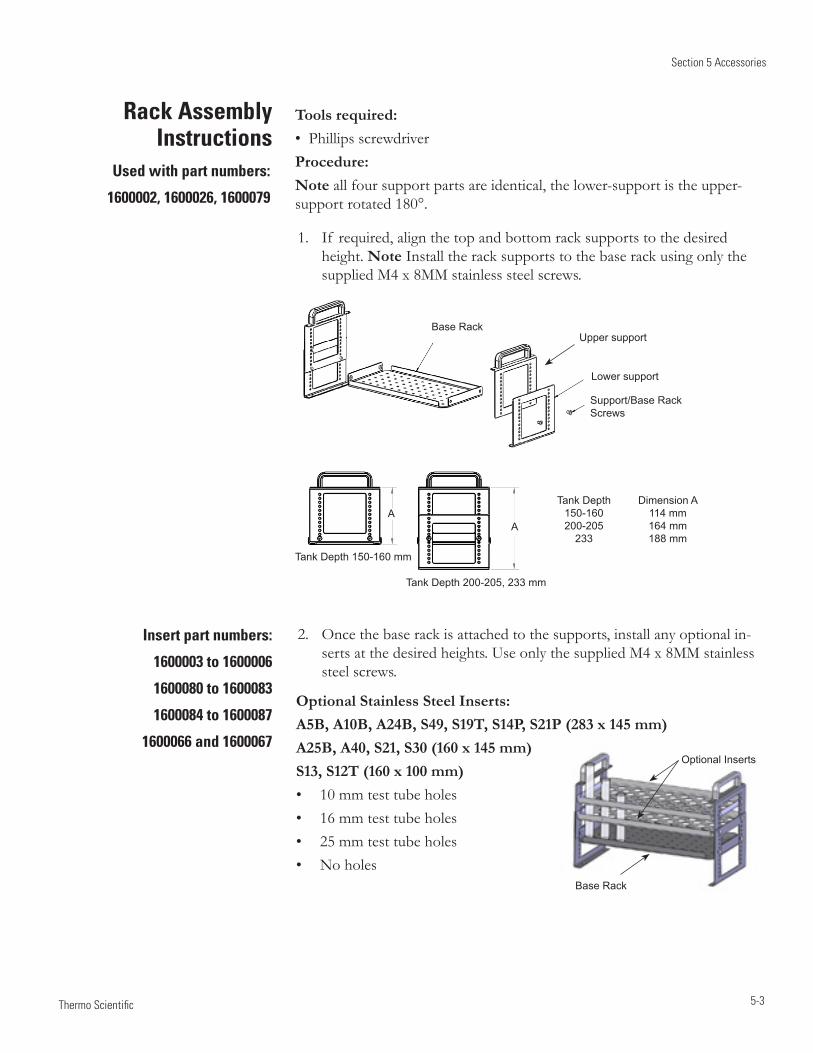
Section 5 Accessories
5-3 Thermo Scientific
Tank Depth Dimension A 150-160 114 mm 200-205 164 mm 233 188 mm
Tank Depth 200-205, 233 mm
AA
Tank Depth 150-160 mm
Base RackUpper support
Lower support
Support/Base Rack Screws
Tools required:• Phillips screwdriver Procedure:Note all four support parts are identical, the lower-support is the upper-support rotated 180°.
1. If required, align the top and bottom rack supports to the desired height. Note Install the rack supports to the base rack using only the supplied M4 x 8MM stainless steel screws.
Rack Assembly Instructions
Optional Stainless Steel Inserts:A5B, A10B, A24B, S49, S19T, S14P, S21P (283 x 145 mm)A25B, A40, S21, S30 (160 x 145 mm)S13, S12T (160 x 100 mm)• 10 mm test tube holes• 16 mm test tube holes• 25 mm test tube holes• No holes
Used with part numbers:
1600002, 1600026, 1600079
Insert part numbers:
1600003 to 1600006
1600080 to 1600083
1600084 to 1600087
1600066 and 1600067
2. Once the base rack is attached to the supports, install any optional in-serts at the desired heights. Use only the supplied M4 x 8MM stainless steel screws.
Base Rack
Optional Inserts
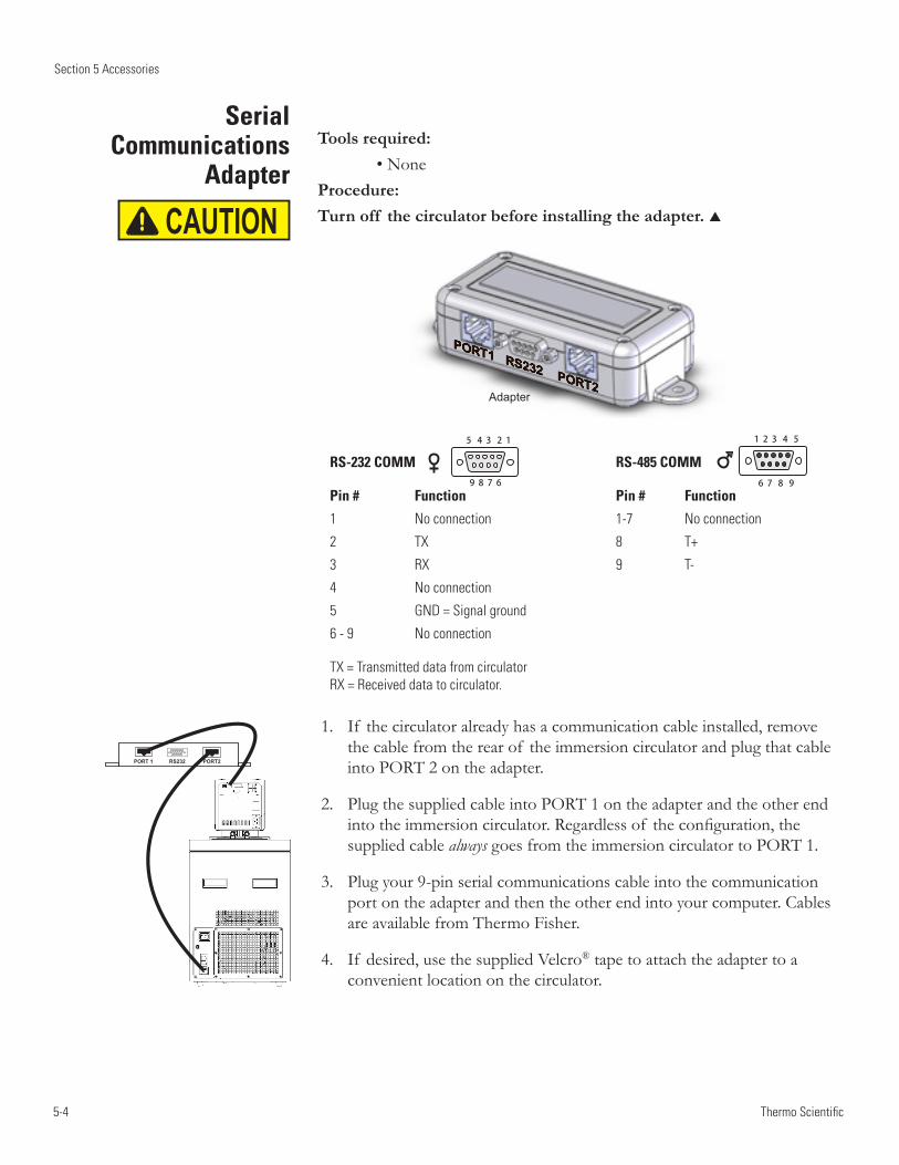
5-4
Section 5 Accessories
Thermo Scientific
Serial Communications
Adapter
CAUTION
Tools required: •NoneProcedure:Turn off the circulator before installing the adapter.
Adapter
If thecirculatoralreadyhasacommunicationcableinstalled,remove1.thecablefromtherearof theimmersioncirculatorandplugthatcableintoPORT2ontheadapter.
PlugthesuppliedcableintoPORT1ontheadapterandtheotherend2.intotheimmersioncirculator.Regardlessof theconfiguration,thesuppliedcablealwaysgoesfromtheimmersioncirculatortoPORT1.
Plugyour9-pinserialcommunicationscableintothecommunication3.portontheadapterandthentheotherendintoyourcomputer.CablesareavailablefromThermoFisher.
If desired,usethesuppliedVelcro4. ®tapetoattachtheadaptertoaconvenientlocationonthecirculator.
RS-232 COMM RS-485 COMM
Pin # Function Pin # Function
1 No connection 1-7 No connection
2 TX 8 T+
3 RX 9 T-
4 No connection
5 GND = Signal ground
6 - 9 No connection
TX = Transmitted data from circulator RX = Received data to circulator.
5 4 3 2 1
9 8 7 6
1 2 3 4 5
6 7 8 9
PORT 1 RS232 PORT2
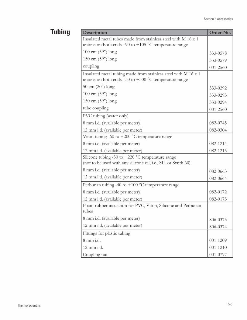
Section 5 Accessories
5-5 Thermo Scientific
Tubing Description Order-No.InsulatedmetaltubesmadefromstainlesssteelwithM16x1unionsonbothends.-90to+105°Ctemperaturerange100cm(39")long150cm(59")longcoupling
333-0578333-0579001-2560
InsulatedmetaltubingmadefromstainlesssteelwithM16x1 unionsonbothends.-50to+300°Ctemperaturerange50cm(20")long100cm(39")long150cm(59")longtubecoupling
333-0292333-0293333-0294001-2560
PVCtubing(wateronly)8mmi.d.(availablepermeter)12mmi.d.(availablepermeter)
082-0745082-0304
Vitontubing-60to+200°Ctemperaturerange8mmi.d.(availablepermeter)12mmi.d.(availablepermeter)
082-1214082-1215
Siliconetubing-30to+220°Ctemperaturerange (nottobeusedwithanysiliconeoil,i.e.,SILorSynth60)8mmi.d.(availablepermeter)12mmi.d.(availablepermeter)
082-0663082-0664
Perbunantubing-40to+100°Ctemperaturerange8mmi.d.(availablepermeter)12mmi.d.(availablepermeter)
082-0172082-0173
FoamrubberinsulationforPVC,Viton,SiliconeandPerbunantubes8mmi.d.(availablepermeter)12mmi.d.(availablepermeter)
806-0373806-0374
Fittingsforplastictubing8mmi.d.12mmi.d.Couplingnut
001-1209001-1210001-0797

5-6
Section 5 Accessories
Thermo Scientific
6-1 Thermo Scientific
Cleaning
Condenser Fins
Tubing
Section 6 Preventive Maintenance
CAUTION
CAUTION
CAUTION
Disconnect the power cord prior to performing any maintenance.
Handle the circulator with care. Sudden jolts or drops can damage its components.
After time, the circulator's stainless steel surfaces may show spots and become tarnished. Clean the reservoir and built-in components at least every time the reservoir fluid is changed. Only use water and a soft cloth.
Do not use scouring powder.
The inside of the bath must be kept clean in order to ensure a long service life. Quickly remove substances containing acidic or alkaline substances and metal shavings as they could harm the surfaces causing corrosion. If corrosion (e.g., small rust marks) occurs in spite of this, cleaning with stainless steel caustic agents has proved to be suitable. Apply these substances according to the manufacturer's recommendations.
Do not use any substances which contain solvents.
For refrigerated baths, in order to maintain the cooling capacity of the circulator, clean the fins two to four times per year, depending on the operating environment.
Switch off the circulator and unplug the power cord.
For ARCTIC A40 1 Remove the condenser panel.2 Clean fins with brush or similar tool.3 Replace the panel.
For all other refrigerated baths: Clean the fins with compressed air.
For extreme soiling a qualified technician will need to remove the cooling compressor casing.
Inspect and tighten the tubing and clamps daily.
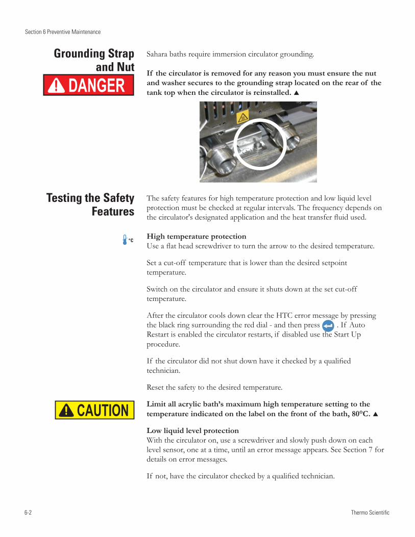
6-2
Section 6 Preventive Maintenance
Thermo Scientific
Sahara baths require immersion circulator grounding.
If the circulator is removed for any reason you must ensure the nut and washer secures to the grounding strap located on the rear of the tank top when the circulator is reinstalled.
Testing the Safety Features
Grounding Strap and Nut
DANGER
The safety features for high temperature protection and low liquid level protection must be checked at regular intervals. The frequency depends on the circulator's designated application and the heat transfer fluid used.
High temperature protection Use a flat head screwdriver to turn the arrow to the desired temperature.
Set a cut-off temperature that is lower than the desired setpoint temperature.
Switch on the circulator and ensure it shuts down at the set cut-off temperature.
After the circulator cools down clear the HTC error message by pressing the black ring surrounding the red dial - and then press . If Auto Restart is enabled the circulator restarts, if disabled use the Start Up procedure.
If the circulator did not shut down have it checked by a qualified technician.
Reset the safety to the desired temperature.
Limit all acrylic bath’s maximum high temperature setting to the temperature indicated on the label on the front of the bath, 80°C.
Low liquid level protection With the circulator on, use a screwdriver and slowly push down on each level sensor, one at a time, until an error message appears. See Section 7 for details on error messages.
If not, have the circulator checked by a qualified technician.
CAUTION
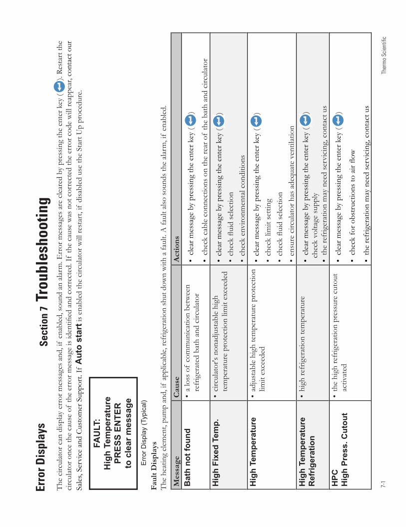
7-1
Ther
mo
Scie
ntifi
c
Erro
r Dis
play
sSe
ctio
n 7
Trou
bles
hoot
ing
Mes
sage
Cau
seA
ctio
nsB
ath
not f
ound
•alossofcommunicationbetween
refrigeratedbathandcirculator
•clearm
essagebypressingtheenterkey(
)
•checkcableconnectionsontherearofthebathandcirculator
Hig
h Fi
xed
Tem
p.•circulator'snonadjustablehigh
temperatureprotectionlimitexceeded
•clearm
essagebypressingtheenterkey(
)•checkfluidselection
•checkenvironmentalconditions
Hig
h Te
mpe
ratu
re•adjustablehightemperatureprotection
limitexceeded
•clearm
essagebypressingtheenterkey(
)•checklimitsetting
•checkfluidselection
•ensurecirculatorhasadequateventilation
Hig
h Te
mpe
ratu
re
Ref
riger
atio
n•highrefrigerationtemperature
•clearm
essagebypressingtheenterkey(
)checkvoltagesupply
•therefrigerationmayneedservicing,contactus
HPC
H
igh
Pres
s. C
utou
t•thehighrefrigerationpressurecutout
activated
•clearm
essagebypressingtheenterkey(
)
•checkforobstructionstoairflow
•therefrigerationmayneedservicing,contactus
Thecirculatorcandisplayerrormessagesand,ifenabled,soundanalarm.Errormessagesareclearedbypressingtheenterkey(
).Restartthe
circulatoroncethecauseoftheerrorm
essageisidentifiedandcorrected.Ifthecausewasnotcorrectedtheerrorcodewillreappear,contactour
Sales,ServiceandCustomerSupport.If
Aut
o st
artisenabledthecirculatorwillrestart,ifdisabledusetheStartUpprocedure.
FAU
LT:
Hig
h Te
mpe
ratu
rePR
ESS
ENTE
Rto
cle
ar m
essa
ge
Err
or D
ispl
ay (T
ypic
al)
Faul
t Dis
play
s Theheatingelement,pumpand,ifapplicable,refrigerationshutdownwithafault.Afaultalsosoundsthealarm,ifenabled.
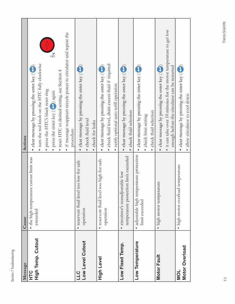
7-2
Sect
ion
7 Tr
oubl
esho
otin
g
Ther
mo
Scie
ntifi
c
Mes
sage
Cau
seA
ctio
nsH
TC
Hig
h Te
mp.
Cut
out
•thehightemperaturecutoutlimitwas
exceeded
•clearm
essagebypressingtheenterkey(
)•turntheredknobontheHTCfullyclockwise
•presstheHTC’sblackresetring
•presstheenterkey(
)again
•resetHTCtodesiredsetting,seeSection4
•ifmessagereappearsrecyclepowertocirculatorandrepeatthe
procedure
LLC
Low
Lev
el C
utou
t•reservoirfluidleveltoolowforsafe
operation
•clearm
essagebypressingtheenterkey(
)•checkfluidlevel
•checkforleaks
Hig
h Le
vel
•reservoirfluidleveltoohighforsafe
operation
•clearm
essagebypressingtheenterkey(
)•checkfluidlevel,drainexcessfluidifrequired
•verifyoptionalautorefilloperation
Low
Fix
ed T
emp.
•circulator'snonadjustablelow
temperatureprotectionlimitexceeded
•clearm
essagebypressingtheenterkey(
)•checkfluidselection
Low
Tem
pera
ture
•adjustablehightemperatureprotection
limitexceeded
•clearm
essagebypressingtheenterkey(
)•checklimitsetting
•checkfluidselection
Mot
or F
ault
•highmotortemperature
•clearm
essagebypressingtheenterkey(
)•itcantakeover10minutesforthemotortemperaturetogetlow
enoughbeforethecirculatorcanberestarted
MO
L M
otor
Ove
rload
•highmotoroverloadtemperature
•clearm
essagebypressingtheenterkey(
)•allowcirculatortocooldown
°C
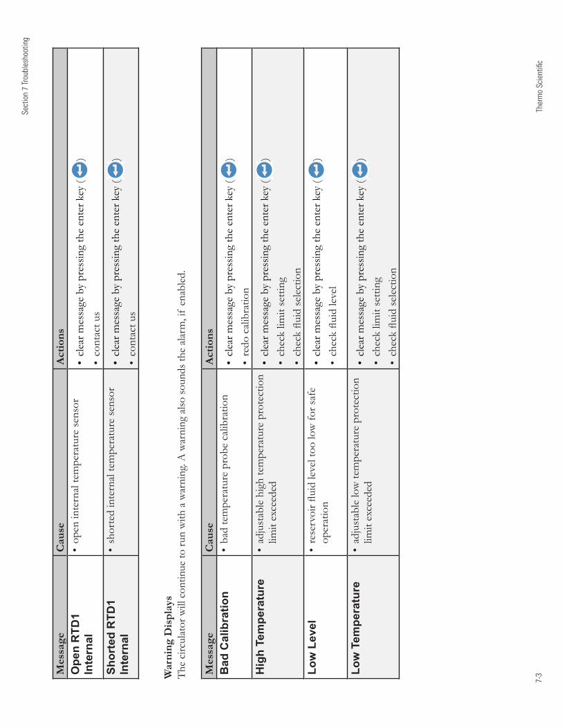
7-3
Sect
ion
7 Tr
oubl
esho
otin
g
Ther
mo
Scie
ntifi
c
Mes
sage
Cau
seA
ctio
nsO
pen
RTD
1 In
tern
al•openinternaltemperaturesensor
•clearm
essagebypressingtheenterkey(
)•contactus
Shor
ted
RTD
1 In
tern
al•shortedinternaltemperaturesensor
•clearm
essagebypressingtheenterkey(
)•contactus
Mes
sage
Cau
seA
ctio
nsB
ad C
alib
ratio
n•badtemperatureprobecalibration
•clearm
essagebypressingtheenterkey(
)•redocalibration
Hig
h Te
mpe
ratu
re•adjustablehightemperatureprotection
limitexceeded
•clearm
essagebypressingtheenterkey(
)•checklimitsetting
•checkfluidselection
Low
Lev
el•reservoirfluidleveltoolowforsafe
operation
•clearm
essagebypressingtheenterkey(
)•checkfluidlevel
Low
Tem
pera
ture
•adjustablelowtemperatureprotection
limitexceeded
•clearm
essagebypressingtheenterkey(
)•checklimitsetting
•checkfluidselection
War
ning
Dis
play
s Thecirculatorwillcontinuetorunwithawarning.Awarningalsosoundsthealarm,ifenabled.
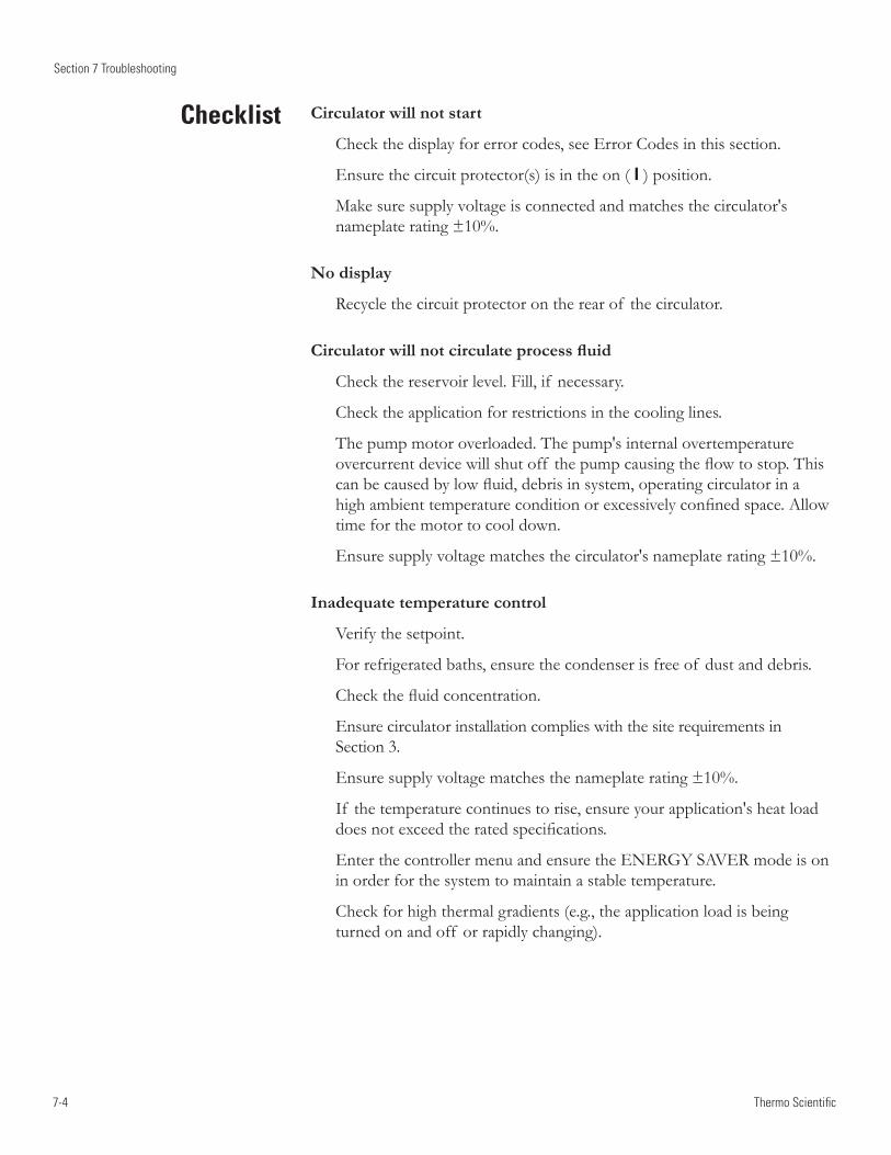
7-4
Section 7 Troubleshooting
Thermo Scientific
Checklist Circulator will not start
Check the display for error codes, see Error Codes in this section.
Ensure the circuit protector(s) is in the on ( I ) position.
Make sure supply voltage is connected and matches the circulator's nameplate rating ±10%.
No display
Recycle the circuit protector on the rear of the circulator.
Circulator will not circulate process fluid
Check the reservoir level. Fill, if necessary.
Check the application for restrictions in the cooling lines.
The pump motor overloaded. The pump's internal overtemperature overcurrent device will shut off the pump causing the flow to stop. This can be caused by low fluid, debris in system, operating circulator in a high ambient temperature condition or excessively confined space. Allow time for the motor to cool down.
Ensure supply voltage matches the circulator's nameplate rating ±10%.
Inadequate temperature control
Verify the setpoint.
For refrigerated baths, ensure the condenser is free of dust and debris.
Check the fluid concentration.
Ensure circulator installation complies with the site requirements in Section 3.
Ensure supply voltage matches the nameplate rating ±10%.
If the temperature continues to rise, ensure your application's heat load does not exceed the rated specifications.
Enter the controller menu and ensure the ENERGY SAVER mode is on in order for the system to maintain a stable temperature.
Check for high thermal gradients (e.g., the application load is being turned on and off or rapidly changing).
Section 7 Troubleshooting
7-5 Thermo Scientific
Circulator shuts down
Ensure button wasn't accidently pressed.
Ensure the circuit protector(s) is in the on ( I ) position.
Check the display for error codes.
Make sure supply voltage is connected and matches the nameplate rating ±10%.
Restart the circulator.
USB Driver Not Recognized
If your operating system does not automatically recognize the optional driver log on to:
http://www.ftdichip.com/FTDrivers.htm
for instructions.
Please contact Thermo Fisher Scientific Sales Service and Customer Support if you need any additional information, see inside cover for contact instructions.

7-6
Section 7 Troubleshooting
Thermo Scientific
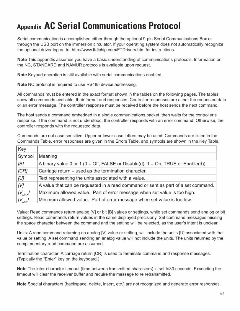
A-1
Appendix AC Serial Communications ProtocolSerial communication is accomplished either through the optional 9-pin Serial Communications Box or through the USB port on the immersion circulator. If your operating system does not automatically recognize the optional driver log on to: http://www.ftdichip.com/FTDrivers.htm for instructions.
Note This appendix assumes you have a basic understanding of communications protocols. Information on the NC, STANDARD and NAMUR protocols is available upon request.
Note Keypad operation is still available with serial communications enabled.
Note NC protocol is required to use RS485 device addressing.
All commands must be entered in the exact format shown in the tables on the following pages. The tables show all commands available, their format and responses. Controller responses are either the requested data or an error message. The controller response must be received before the host sends the next command.
The host sends a command embedded in a single communications packet, then waits for the controller’s response. If the command is not understood, the controller responds with an error command. Otherwise, the controller responds with the requested data.
Commands are not case sensitive. Upper or lower case letters may be used. Commands are listed in the Commands Table, error responses are given in the Errors Table, and symbols are shown in the Key Table.
KeySymbol Meaning[B] A binary value 0 or 1 (0 = Off, FALSE or Disable(d); 1 = On, TRUE or Enable(d)).[CR] Carriage return – used as the termination character.[U] Text representing the units associated with a value.[V] A value that can be requested in a read command or sent as part of a set command. [VMAX] Maximum allowed value. Part of error message when set value is too high.[VMIN] Minimum allowed value. Part of error message when set value is too low.
Value: Read commands return analog [V] or bit [B] values or settings, while set commands send analog or bit settings. Read commands return values in the same displayed precisiony. Set command messages missing the space character between the command and the setting will be rejected, as the user’s intent is unclear.
Units: A read command returning an analog [V] value or setting, will include the units [U] associated with that value or setting. A set command sending an analog value will not include the units. The units returned by the complementary read command are assumed.
Termination character: A carriage return [CR] is used to terminate command and response messages. (Typically the “Enter” key on the keyboard.)
Note The inter-character timeout (time between transmitted characters) is set to30 seconds. Exceeding the timeout will clear the receiver buffer and require the message to re retransmitted.
Note Special characters (backspace, delete, insert, etc.) are not recognized and generate error responses.
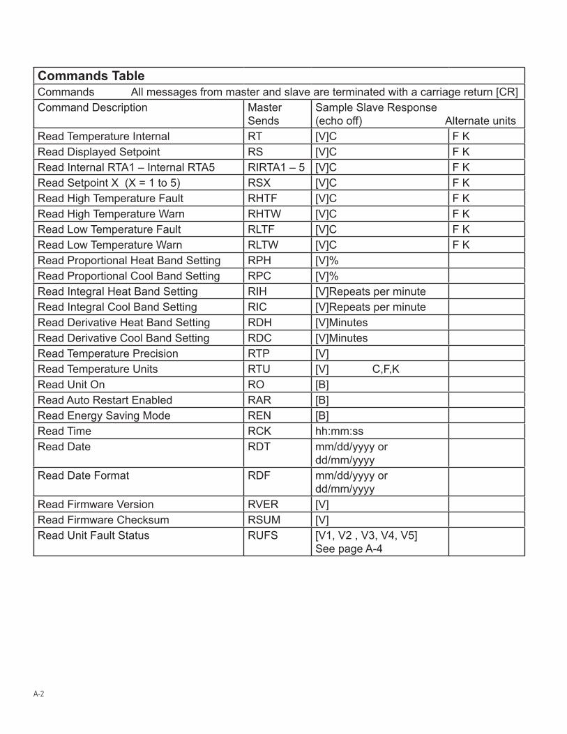
A-2
Commands TableCommands All messages from master and slave are terminated with a carriage return [CR]Command Description Master
SendsSample Slave Response(echo off) Alternate units
Read Temperature Internal RT [V]C F KRead Displayed Setpoint RS [V]C F KRead Internal RTA1 – Internal RTA5 RIRTA1 – 5 [V]C F KRead Setpoint X (X = 1 to 5) RSX [V]C F KRead High Temperature Fault RHTF [V]C F KRead High Temperature Warn RHTW [V]C F KRead Low Temperature Fault RLTF [V]C F KRead Low Temperature Warn RLTW [V]C F KRead Proportional Heat Band Setting RPH [V]%Read Proportional Cool Band Setting RPC [V]%Read Integral Heat Band Setting RIH [V]Repeats per minuteRead Integral Cool Band Setting RIC [V]Repeats per minuteRead Derivative Heat Band Setting RDH [V]MinutesRead Derivative Cool Band Setting RDC [V]MinutesRead Temperature Precision RTP [V]Read Temperature Units RTU [V] C,F,KRead Unit On RO [B]Read Auto Restart Enabled RAR [B]Read Energy Saving Mode REN [B]Read Time RCK hh:mm:ssRead Date RDT mm/dd/yyyy or
dd/mm/yyyyRead Date Format RDF mm/dd/yyyy or
dd/mm/yyyyRead Firmware Version RVER [V]Read Firmware Checksum RSUM [V]Read Unit Fault Status RUFS [V1, V2 , V3, V4, V5]
See page A-4
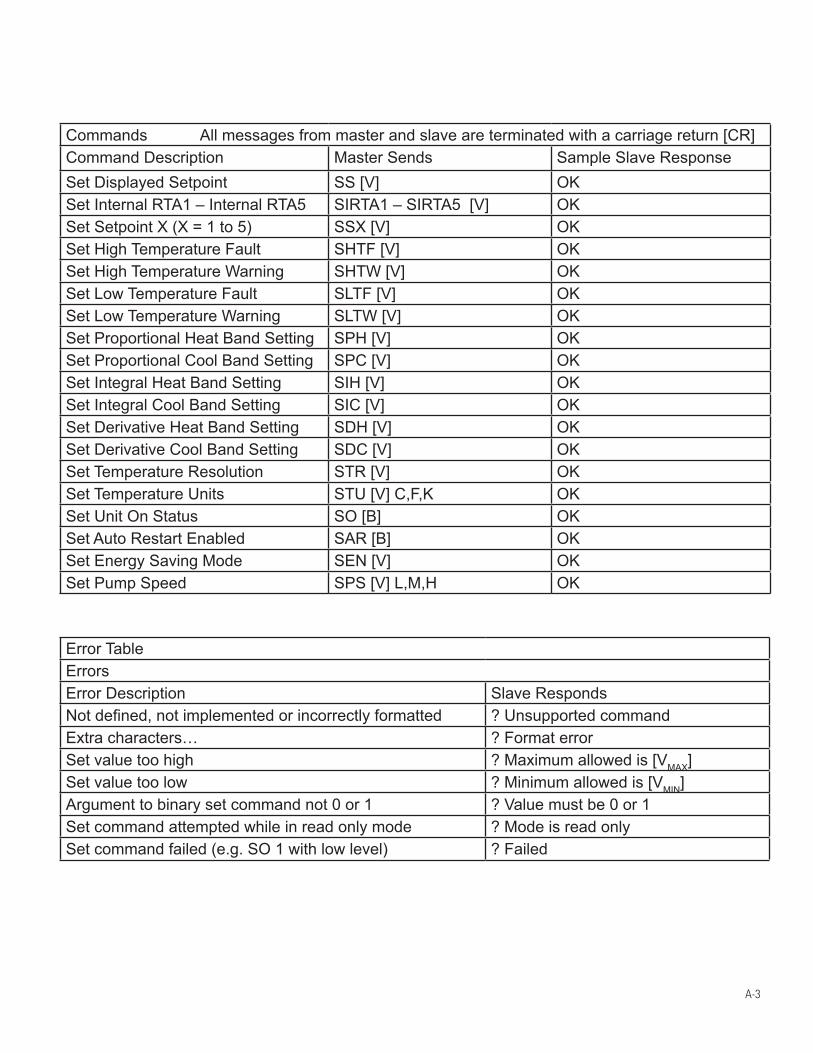
A-3
Commands All messages from master and slave are terminated with a carriage return [CR]Command Description Master Sends Sample Slave ResponseSet Displayed Setpoint SS [V] OKSet Internal RTA1 – Internal RTA5 SIRTA1 – SIRTA5 [V] OKSet Setpoint X (X = 1 to 5) SSX [V] OKSet High Temperature Fault SHTF [V] OKSet High Temperature Warning SHTW [V] OKSet Low Temperature Fault SLTF [V] OKSet Low Temperature Warning SLTW [V] OKSet Proportional Heat Band Setting SPH [V] OKSet Proportional Cool Band Setting SPC [V] OKSet Integral Heat Band Setting SIH [V] OKSet Integral Cool Band Setting SIC [V] OKSet Derivative Heat Band Setting SDH [V] OKSet Derivative Cool Band Setting SDC [V] OKSet Temperature Resolution STR [V] OKSet Temperature Units STU [V] C,F,K OKSet Unit On Status SO [B] OKSet Auto Restart Enabled SAR [B] OKSet Energy Saving Mode SEN [V] OKSet Pump Speed SPS [V] L,M,H OK
Error TableErrorsError Description Slave RespondsNot defined, not implemented or incorrectly formatted ? Unsupported commandExtra characters… ? Format errorSet value too high ? Maximum allowed is [VMAX]Set value too low ? Minimum allowed is [VMIN]Argument to binary set command not 0 or 1 ? Value must be 0 or 1Set command attempted while in read only mode ? Mode is read onlySet command failed (e.g. SO 1 with low level) ? Failed
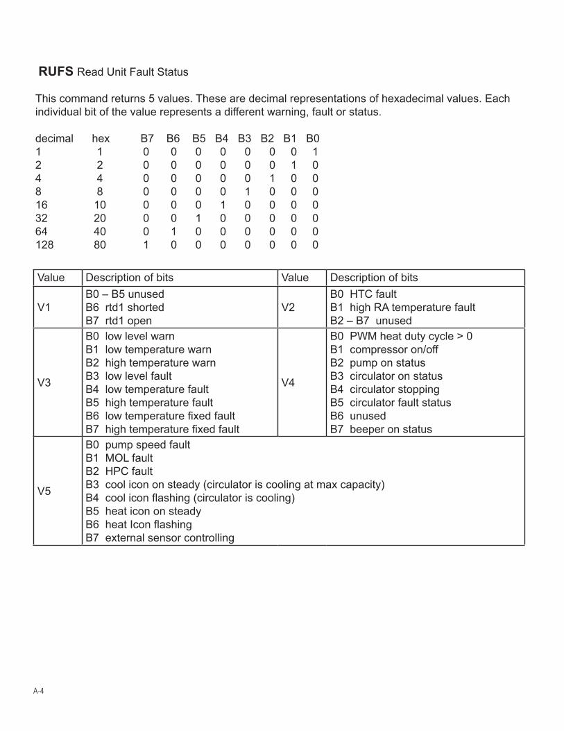
A-4
RUFS Read Unit Fault Status
This command returns 5 values. These are decimal representations of hexadecimal values. Each individual bit of the value represents a different warning, fault or status.
decimal hex B7 B6 B5 B4 B3 B2 B1 B01 1 0 0 0 0 0 0 0 12 2 0 0 0 0 0 0 1 04 4 0 0 0 0 0 1 0 08 8 0 0 0 0 1 0 0 016 10 0 0 0 1 0 0 0 032 20 0 0 1 0 0 0 0 064 40 0 1 0 0 0 0 0 0128 80 1 0 0 0 0 0 0 0
Value Description of bits Value Description of bits
V1B0 – B5 unusedB6 rtd1 shortedB7 rtd1 open
V2B0 HTC faultB1 high RA temperature faultB2 – B7 unused
V3
B0 low level warnB1 low temperature warnB2 high temperature warnB3 low level faultB4 low temperature faultB5 high temperature faultB6 low temperature fixed faultB7 high temperature fixed fault
V4
B0 PWM heat duty cycle > 0B1 compressor on/offB2 pump on statusB3 circulator on statusB4 circulator stoppingB5 circulator fault statusB6 unusedB7 beeper on status
V5
B0 pump speed faultB1 MOL faultB2 HPC faultB3 cool icon on steady (circulator is cooling at max capacity)B4 cool icon flashing (circulator is cooling)B5 heat icon on steadyB6 heat Icon flashingB7 external sensor controlling
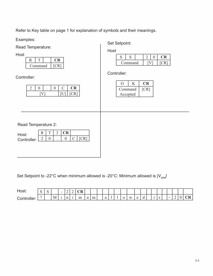
A-5
Refer to Key table on page 1 for explanation of symbols and their meanings.
Set Setpoint:
Host
Controller:
R T CRCommand [CR]
O K CRCommand Accepted
[CR]2 0 . 0 C CR[V] [U] [CR]
S S 2 0 CRCommand [V] [CR]
Read Temperature 2: Host: Controller:
Set Setpoint to -22°C when minimum allowed is -20°C: Minimum allowed is [VMIN]
Host:
Controller: S S - 2 2 CR? M i n i m u m a l l o w e d i s - 2 0 CR
R T 2 CR2 0 . 0 C [CR]
Examples:
Read Temperature:
Host
Controller:
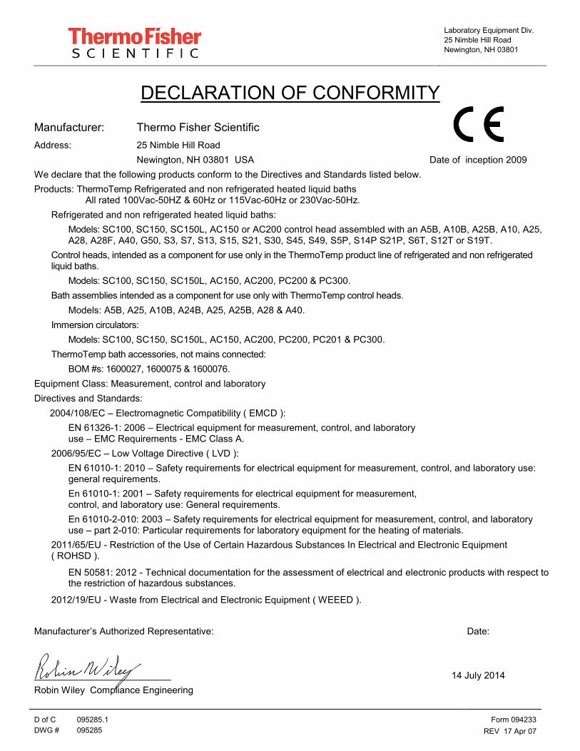
Laboratory Equipment Div.
25 Nimble Hill Road
Newington, NH 03801
D of C 095285.1 Form 094233
DWG # 095285 REV 17 Apr 07
DECLARATION OF CONFORMITY
Manufacturer: Thermo Fisher Scientific
Address: 25 Nimble Hill Road
Newington, NH 03801 USA Date of inception 2009
We declare that the following products conform to the Directives and Standards listed below.
Products: ThermoTemp Refrigerated and non refrigerated heated liquid baths All rated 100Vac-50HZ & 60Hz or 115Vac-60Hz or 230Vac-50Hz.
Refrigerated and non refrigerated heated liquid baths:
Models: SC100, SC150, SC150L, AC150 or AC200 control head assembled with an A5B, A10B, A25B, A10, A25, A28, A28F, A40, G50, S3, S7, S13, S15, S21, S30, S45, S49, S5P, S14P S21P, S6T, S12T or S19T.
Control heads, intended as a component for use only in the ThermoTemp product line of refrigerated and non refrigerated liquid baths.
Models: SC100, SC150, SC150L, AC150, AC200, PC200 & PC300.
Bath assemblies intended as a component for use only with ThermoTemp control heads.
Models: A5B, A25, A10B, A24B, A25, A25B, A28 & A40.
Immersion circulators:
Models: SC100, SC150, SC150L, AC150, AC200, PC200, PC201 & PC300.
ThermoTemp bath accessories, not mains connected:
BOM #s: 1600027, 1600075 & 1600076.
Equipment Class: Measurement, control and laboratory
Directives and Standards:
2004/108/EC – Electromagnetic Compatibility ( EMCD ):
EN 61326-1: 2006 – Electrical equipment for measurement, control, and laboratory use – EMC Requirements - EMC Class A.
2006/95/EC – Low Voltage Directive ( LVD ):
EN 61010-1: 2010 – Safety requirements for electrical equipment for measurement, control, and laboratory use: general requirements.
En 61010-1: 2001 – Safety requirements for electrical equipment for measurement, control, and laboratory use: General requirements.
En 61010-2-010: 2003 – Safety requirements for electrical equipment for measurement, control, and laboratory use – part 2-010: Particular requirements for laboratory equipment for the heating of materials.
2011/65/EU - Restriction of the Use of Certain Hazardous Substances In Electrical and Electronic Equipment ( ROHSD ).
EN 50581: 2012 - Technical documentation for the assessment of electrical and electronic products with respect to the restriction of hazardous substances.
2012/19/EU - Waste from Electrical and Electronic Equipment ( WEEED ).
Manufacturer’s Authorized Representative: Date:
__________________________ 14 July 2014
Robin Wiley Compliance Engineering
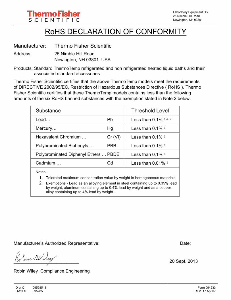
Laboratory Equipment Div. 25 Nimble Hill Road Newington, NH 03801
D of C 095285 .3 Form 094233 DWG # 095285 REV 17 Apr 07
RoHS DECLARATION OF CONFORMITY
Manufacturer: Thermo Fisher Scientific Address: 25 Nimble Hill Road Newington, NH 03801 USA
Products: Standard ThermoTemp refrigerated and non refrigerated heated liquid baths and their associated standard accessories.
Thermo Fisher Scientific certifies that the above ThermoTemp models meet the requirements of DIRECTIVE 2002/95/EC, Restriction of Hazardous Substances Directive ( RoHS ). Thermo Fisher Scientific certifies that these ThermoTemp models contains less than the following amounts of the six RoHS banned substances with the exemption stated in Note 2 below:
Substance Threshold Level Lead… Pb Less than 0.1% 1 & 2
Mercury… Hg Less than 0.1% 1
Hexavalent Chromium … Cr (VI) Less than 0.1% 1
Polybrominated Biphenyls … PBB Less than 0.1% 1
Polybrominated Diphenyl Ethers … PBDE Less than 0.1% 1
Cadmium … Cd Less than 0.01% 1
Notes: 1. Tolerated maximum concentration value by weight in homogeneous materials. 2. Exemptions - Lead as an alloying element in steel containing up to 0.35% lead
by weight, aluminum containing up to 0.4% lead by weight and as a copper alloy containing up to 4% lead by weight.
Manufacturer’s Authorized Representative: Date: __________________________ 20 Sept. 2013
Robin Wiley Compliance Engineering
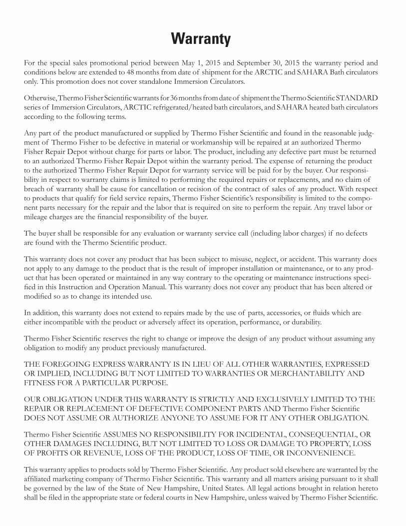
WarrantyFor the special sales promotional period between May 1, 2015 and September 30, 2015 the warranty period and conditions below are extended to 48 months from date of shipment for the ARCTIC and SAHARA Bath circulators only. This promotion does not cover standalone Immersion Circulators.
Otherwise, Thermo Fisher Scientific warrants for 36 months from date of shipment the Thermo Scientific STANDARD series of Immersion Circulators, ARCTIC refrigerated/heated bath circulators, and SAHARA heated bath circulators according to the following terms.
Any part of the product manufactured or supplied by Thermo Fisher Scientific and found in the reasonable judg-ment of Thermo Fisher to be defective in material or workmanship will be repaired at an authorized Thermo Fisher Repair Depot without charge for parts or labor. The product, including any defective part must be returned to an authorized Thermo Fisher Repair Depot within the warranty period. The expense of returning the product to the authorized Thermo Fisher Repair Depot for warranty service will be paid for by the buyer. Our responsi-bility in respect to warranty claims is limited to performing the required repairs or replacements, and no claim of breach of warranty shall be cause for cancellation or recision of the contract of sales of any product. With respect to products that qualify for field service repairs, Thermo Fisher Scientific’s responsibility is limited to the compo-nent parts necessary for the repair and the labor that is required on site to perform the repair. Any travel labor or mileage charges are the financial responsibility of the buyer.
The buyer shall be responsible for any evaluation or warranty service call (including labor charges) if no defects are found with the Thermo Scientific product.
This warranty does not cover any product that has been subject to misuse, neglect, or accident. This warranty does not apply to any damage to the product that is the result of improper installation or maintenance, or to any prod-uct that has been operated or maintained in any way contrary to the operating or maintenance instructions speci-fied in this Instruction and Operation Manual. This warranty does not cover any product that has been altered or modified so as to change its intended use.
In addition, this warranty does not extend to repairs made by the use of parts, accessories, or fluids which are either incompatible with the product or adversely affect its operation, performance, or durability.
Thermo Fisher Scientific reserves the right to change or improve the design of any product without assuming any obligation to modify any product previously manufactured.
THE FOREGOING EXPRESS WARRANTY IS IN LIEU OF ALL OTHER WARRANTIES, EXPRESSED OR IMPLIED, INCLUDING BUT NOT LIMITED TO WARRANTIES OR MERCHANTABILITY AND FITNESS FOR A PARTICULAR PURPOSE.
OUR OBLIGATION UNDER THIS WARRANTY IS STRICTLY AND EXCLUSIVELY LIMITED TO THE REPAIR OR REPLACEMENT OF DEFECTIVE COMPONENT PARTS AND Thermo Fisher Scientific DOES NOT ASSUME OR AUTHORIZE ANYONE TO ASSUME FOR IT ANY OTHER OBLIGATION.
Thermo Fisher Scientific ASSUMES NO RESPONSIBILITY FOR INCIDENTAL, CONSEQUENTIAL, OR OTHER DAMAGES INCLUDING, BUT NOT LIMITED TO LOSS OR DAMAGE TO PROPERTY, LOSS OF PROFITS OR REVENUE, LOSS OF THE PRODUCT, LOSS OF TIME, OR INCONVENIENCE.
This warranty applies to products sold by Thermo Fisher Scientific. Any product sold elsewhere are warranted by the affiliated marketing company of Thermo Fisher Scientific. This warranty and all matters arising pursuant to it shall be governed by the law of the State of New Hampshire, United States. All legal actions brought in relation hereto shall be filed in the appropriate state or federal courts in New Hampshire, unless waived by Thermo Fisher Scientific.


Thermo Fisher Scientific81 Wyman StreetP.O. Box 9046Waltham, Massachusetts 02454-9046United States
www.thermofisher.com


