Embed Size (px)
Citation preview
Thermal performance of a focusing type collector for paraffin wax meltingA. K. Kurchania, N. L. Panwar, Dinesh Mishra, and B. L. Salvi Citation: J. Renewable Sustainable Energy 4, 023114 (2012); doi: 10.1063/1.4705521 View online: http://dx.doi.org/10.1063/1.4705521 View Table of Contents: http://jrse.aip.org/resource/1/JRSEBH/v4/i2 Published by the American Institute of Physics. Additional information on J. Renewable Sustainable EnergyJournal Homepage: http://jrse.aip.org/ Journal Information: http://jrse.aip.org/about/about_the_journal Top downloads: http://jrse.aip.org/features/most_downloaded Information for Authors: http://jrse.aip.org/authors
Downloaded 21 May 2012 to 10.0.105.137. Redistribution subject to AIP license or copyright; see http://jrse.aip.org/about/rights_and_permissions
Thermal performance of a focusing type collectorfor paraffin wax melting
A. K. Kurchania,1,a) N. L. Panwar,1,b) Dinesh Mishra,2 and B. L. Salvi31Department of Renewable Energy Sources, College of Technology and Engineering,Maharana Pratap University of Agriculture and Technology, Udaipur (Rajasthan) 313001,India2Krishi Vigyan Kendra, RBS College Awagarh, Distt. Etah-207301, Uttar Pradesh, India3Department of Mechanical Engineering, College of Technology and Engineering,Maharana Pratap University of Agriculture and Technology, Udaipur (Rajasthan) 313001,India
(Received 15 March 2012; accepted 6 April 2012; published online 20 April 2012)
A solar paraboloid concentrator was designed and developed for paraffin wax
melting having 1.32 m2 aperture area and 0.25 m focal length. The performance of
the system was evaluated in terms of optical efficiency factor (F0no) and overall
heat loss factor (F0UL) by sensible water heating and cooling tests, respectively.
The values of the optical efficiency factor (F0no) and overall heat loss factor (F0UL)
were found to be 0.2125 and 39.46 W=m2 K, respectively. VC 2012 AmericanInstitute of Physics. [http://dx.doi.org/10.1063/1.4705521]
INTRODUCTION
Abundant availability, clean, and free of environment pollution are few important advan-
tages of solar energy.1–3 An analysis of major forms of energy used all over the world reveals
that the developed countries are accounting 24% of world’s population, consume 66% of the
world’s energy, whereas developing countries having 76% of population, consume only 34% of
total world’s energy. To meet the requirement, fossil fuels have satisfied most of our energy
needs. These fuels were much cheaper and more convenient compared to alternative energy
sources till the energy crises. However, considering the proved reserves of oil and gas and cur-
rent rate of fuel consumption, it would be adequate to meet the demand for another 40 to 60
years. The coal reserves are in better situation as they would be adequate for at least the next
250 years.4
A simple method of harnessing solar energy is the thermal conversion system that collects
and utilizes the sun’s energy in the form of heat. A solar concentrator can be used for medium
temperature process heat application. One of the applications of the solar energy is for melting
paraffin wax used by the small scale industries for different purposes, e.g., candle making, coat-
ing of medicines, etc. So, the attempt has been made to design and develop a paraboloid solar
concentrator for paraffin wax melting.
This paper deals with the testing of paraboloid concentrating collector for its performance
in terms of overall heat loss factor (F0UL) and optical efficiency factor (F0no) suggested by
Mullick et al.5
LITERATURE REVIEW
Chaurasia et al.6 fabricated two flat plate collectors for melting wax of different capacities
for manufacturing of candles. The absorbing area of flat plate collector was kept same as
0.25 m2 for 5 kg and 8 kg of solid wax, but the thickness of chamber was changed. They found
a)Email: [email protected])Email: [email protected]. Tel.: þ91 294 2471068. Fax: þ91 294 2471056.
1941-7012/2012/4(2)/023114/5/$30.00 VC 2012 American Institute of Physics4, 023114-1
JOURNAL OF RENEWABLE AND SUSTAINABLE ENERGY 4, 023114 (2012)
Downloaded 21 May 2012 to 10.0.105.137. Redistribution subject to AIP license or copyright; see http://jrse.aip.org/about/rights_and_permissions
that better result was obtained with lesser capacity during winter season. Jaffe7 measured per-
formance of various dishes, which included optical efficiencies ranging from 0.32 to 0.86 at a
geometric concentration ratio of 500 and 0.09 to 0.85 at a geometric concentration ratio of
3000. Thermal and optical performances of paraboloid concentrator were determined by carry-
ing out thermal test, i.e., by heating and cooling of water. Mullik et al.5 developed a model on
performance of paraboloid concentrator. They recommended two tests, sensible water heating
under clear sunshine and sensible cooling test, by shadowing the concentrator. From the analy-
sis of these two tests, they found out the overall heat loss factor (F0UL), 17.2 W=m2 K, from
sensible water cooling curve and the optical efficiency factor (F0no), 0.42, from sensible water
heating curve.
EXPERIMENTAL SETUP
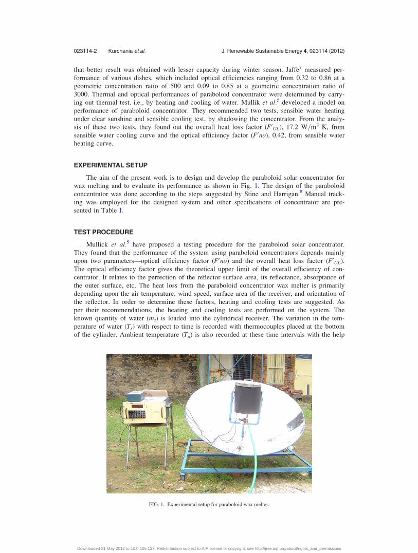
The aim of the present work is to design and develop the paraboloid solar concentrator for
wax melting and to evaluate its performance as shown in Fig. 1. The design of the paraboloid
concentrator was done according to the steps suggested by Stine and Harrigan.8 Manual track-
ing was employed for the designed system and other specifications of concentrator are pre-
sented in Table I.
TEST PROCEDURE
Mullick et al.5 have proposed a testing procedure for the paraboloid solar concentrator.
They found that the performance of the system using paraboloid concentrators depends mainly
upon two parameters—optical efficiency factor (F0no) and the overall heat loss factor (F0UL).
The optical efficiency factor gives the theoretical upper limit of the overall efficiency of con-
centrator. It relates to the perfection of the reflector surface area, its reflectance, absorptance of
the outer surface, etc. The heat loss from the paraboloid concentrator wax melter is primarily
depending upon the air temperature, wind speed, surface area of the receiver, and orientation of
the reflector. In order to determine these factors, heating and cooling tests are suggested. As
per their recommendations, the heating and cooling tests are performed on the system. The
known quantity of water (ms) is loaded into the cylindrical receiver. The variation in the tem-
perature of water (Ts) with respect to time is recorded with thermocouples placed at the bottom
of the cylinder. Ambient temperature (Ta) is also recorded at these time intervals with the help
FIG. 1. Experimental setup for paraboloid wax melter.
023114-2 Kurchania et al. J. Renewable Sustainable Energy 4, 023114 (2012)
Downloaded 21 May 2012 to 10.0.105.137. Redistribution subject to AIP license or copyright; see http://jrse.aip.org/about/rights_and_permissions
of digital temperature scanner (ADI, Baroda, India) and the solar intensity (Ib) was measured
using a METEON Irradiance Meter (Kipp & Zonen, The Netherlands).
The heating test is carried out until fairly steady state temperature is reached. For the cool-
ing test, the concentrator is defocused and shaded from the direct sunlight. Variation in temper-
ature of water with time is recorded. From the cooling test, the overall heat loss factor (F0UL) is
determined. The results of the heating test are then analyzed to obtain the optical efficiency fac-
tor (F0no). These trials were conducted during the month of May.
Following values of the collector system were used in the calculations:
1. Area of cylindrical receiver exposed to radiations Ar ¼ 0.070 m2.
2. Aperture area of dish, Ap ¼ 1.327 m2.
3. Geometrical concentration ratio, C ¼ (Ap=Ar) ¼ 20.
4. Specific heat of water, Cpw ¼ 1 kcal=kg �C.
RESULTS AND DISCUSSIONS
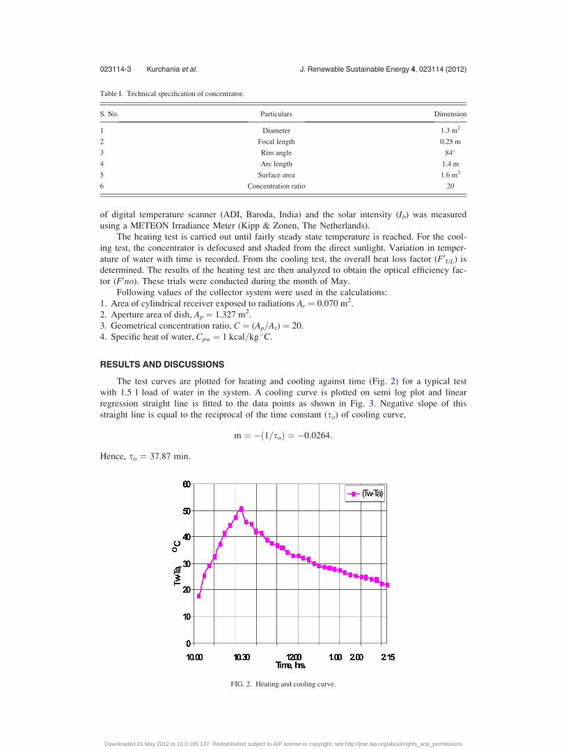
The test curves are plotted for heating and cooling against time (Fig. 2) for a typical test
with 1.5 l load of water in the system. A cooling curve is plotted on semi log plot and linear
regression straight line is fitted to the data points as shown in Fig. 3. Negative slope of this
straight line is equal to the reciprocal of the time constant (so) of cooling curve,
m ¼ �ð1=soÞ ¼ �0:0264:
Hence, so ¼ 37.87 min.
Table I. Technical specification of concentrator.
S. No. Particulars Dimension
1 Diameter 1.3 m2
2 Focal length 0.25 m
3 Rim angle 84�
4 Arc length 1.4 m
5 Surface area 1.6 m2
6 Concentration ratio 20
FIG. 2. Heating and cooling curve.
023114-3 Kurchania et al. J. Renewable Sustainable Energy 4, 023114 (2012)
Downloaded 21 May 2012 to 10.0.105.137. Redistribution subject to AIP license or copyright; see http://jrse.aip.org/about/rights_and_permissions
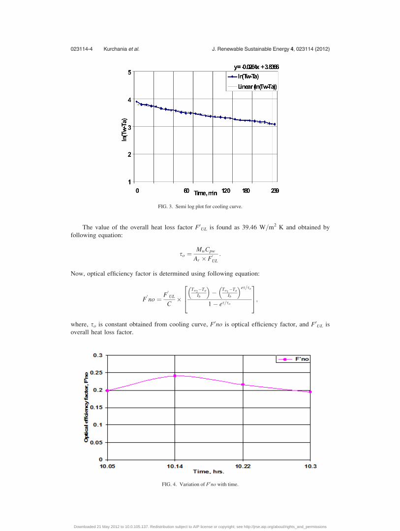
The value of the overall heat loss factor F0UL is found as 39.46 W=m2 K and obtained by
following equation:
so ¼MwCpw
Ar � F0UL
:
Now, optical efficiency factor is determined using following equation:
F0no ¼ F
0UL
C�
Tw2�Ta
Ib
� �� Tw1
�Ta
Ib
� �es=so
1� es=so
264
375;
where, so is constant obtained from cooling curve, F0no is optical efficiency factor, and F0UL is
overall heat loss factor.
FIG. 3. Semi log plot for cooling curve.
FIG. 4. Variation of F0no with time.
023114-4 Kurchania et al. J. Renewable Sustainable Energy 4, 023114 (2012)
Downloaded 21 May 2012 to 10.0.105.137. Redistribution subject to AIP license or copyright; see http://jrse.aip.org/about/rights_and_permissions
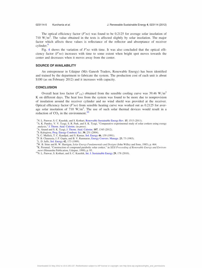
The optical efficiency factor (F0no) was found to be 0.2125 for average solar insolation of
710 W=m2. The value obtained in the tests is affected slightly by solar insolation. The major
factor which affects these values is reflectance of the reflector and absorptance of receiver
cylinder.9
Fig. 4 shows the variation of F0no with time. It was also concluded that the optical effi-
ciency factor (F0no) increases with time to some extent when bright spot moves towards the
center and decreases when it moves away from the center.
SOURCE OF AVAILABILITY
An entrepreneur in Udaipur (M/s Ganesh Traders, Renewable Energy) has been identified
and trained by the department to fabricate the system. The production cost of each unit is about
$100 (as on February 2012) and it increases with capacity.
CONCLUSION
Overall heat loss factor (F0UL) obtained from the sensible cooling curve was 39.46 W=m2
K on different days. The heat loss from the system was found to be more due to nonprovision
of insulation around the receiver cylinder and no wind shield was provided at the receiver.
Optical efficiency factor (F0no) from sensible heating curve was worked out as 0.2125 for aver-
age solar insolation of 710 W=m2. The use of such solar thermal devices would result in a
reduction of CO2 in the environment.10
1N. L. Panwar, S. C. Kaushik, and S. Kothari, Renewable Sustainable Energy Rev. 15, 1513 (2011).2A. K. Pandey, V. V. Tyagi, S. R. Park, and S. K. Tyagi, “Comparative experimental study of solar cookers using exergyanalysis,” J. Therm. Anal. Calorim. (in press).
3A. Anand and S. K. Tyagi, J. Therm. Anal. Calorim. 107, 1345 (2012).4S. Kalogirou, Prog. Energy Combust. Sci. 30, 231 (2004).5S. C. Mullick, T. C. Kandpal, and S. Kumar, Sol. Energy 46, 139 (1991).6P. B. Chaurasia, J. P. Gupta, and B. V. Ramnarao, Energy Convers. Manage. 23, 73 (1983).7L. D. Jaffe, Sol. Energy 42, 173 (1989).8W. B. Stine and R. W. Harrigan, Solar Energy Fundamentals and Designs (John Willey and Sons, 1985), p. 464.9K. Perumal, “Construction of compound parabolic solar cooker,” in SESI Proceeding of Renewable Energy and Environ-ment (Himanshu Publication, Udaipur, 1990), p. 95.
10N. L. Panwar, S. Kothari, and S. C. Kaushik, Int. J. Sustainable Energy 29, 178 (2010).
023114-5 Kurchania et al. J. Renewable Sustainable Energy 4, 023114 (2012)
Downloaded 21 May 2012 to 10.0.105.137. Redistribution subject to AIP license or copyright; see http://jrse.aip.org/about/rights_and_permissions


