Embed Size (px)
Citation preview
THE UNIFIED GOVERNMENT OF
ATHENS-CLARKE COUNTY, TRANSIT
DEPARTMENT
Request for Proposal (RFP # 00943)
Heavy Duty Transit Buses
Date of Advertising: March 4, 2019
Issue Date: March 4, 2019
Pre-Proposal Meeting: March 19, 2019
Due Date: April 4, 2019
DATE: March 4, 2019 TO: Equipment Vendors SUBJECT: Request for Proposal {RFP} # 00943 You are invited to submit a Proposal for “00943 RFP HEAVY DUTY TRANSIT BUS CONSORTIUM” for Transit Department of the Unified Government of Athens-Clarke County, Georgia. Inquiries regarding this request for proposal (RFP) should be made to Julie Ann Donahue, CPPB, Purchasing Administrator, or Toro Holt, Senior Buyer at (706) 613- 3068, fax: (706) 613- 1975 or e-mail: [email protected] The Request for Proposal (RFP) documents may be obtained at Georgia Procurement Registry or Athens Clarke County or via written request to e-mail: [email protected] or fax: (706) 613- 1975. Include your company name, address, the point of contact, fax number and phone number with your written request. Attached hereto are the general conditions, technical specifications, and submittal format. The written requirements contained in this Request for Proposal (RFP) shall not be changed or superseded except by written addendum from the Unified Government of Athens-Clarke County Purchasing Division of the Finance Department. Failure to comply with the written requirements for this RFP may result in rejection of the submittal by the Unified Government. Submittals are to be sealed, marked with the offeror's name and address and labeled: RFP #00943 “HEAVY DUTY TRANSIT BUS CONSORTIUM” and delivered to: The Unified Government of Athens-Clarke County Finance Department, Purchasing Division 375 Satula Avenue Athens, GA. 30601 Not later than 3:00 P.M. ET, THURSDAY, APRIL 4, 2019 A qualified interpreter for the hearing impaired is available upon request at least 10 (ten) days in advance of the proposal receipt date. Please call (706) 613-3088 for more information for the hearing impaired. This service is in compliance with the Americans with Disabilities Act (ADA). The Unified Government of Athens-Clarke County reserves the right to reject any and all submittals, to waive any technicalities or irregularities and to award contracts based on the highest and best interest of the Unified Government of Athens-Clarke County. Julie Ann Donahue, CPPB Purchasing Administrator
TABLE OF CONTENTS SECTION TITLE
I REQUEST FOR PROPOSAL (RFP) SUBMISSION INSTRUCTIONS
II REQUEST FOR PROPOSAL OVERVIEW AND PROCEDURES
III EVALUATION AND SELECTION PROCESS
IV MANDATORY PROPOSAL FORMS A: ADDENDA ACKNOWLEDGMENT
B: GEORGIA SECURITY & IMMIGRATION COMPLIANCE (GSIC) AFFIDAVIT CONTRACTOR AFFIDAVIT & AGREEMENT
C: BID LIST APPLICATION – should be submitted prior to the bid submission. If you have never registered to do business with ACCUG
D. Price Proposal Form Copy of Proposed Warranty Pricing of Optional Equipment and Accessories ATTACHMENT A – Proposer’s Offer and Guarantees ATTACHMENT B – Certification Regarding Debarment ATTACHMENT C – Lobbying ATTACHMENT D – Request for Equals ATTACHMENT E – Buy America Certificate of Compliance ATTACHMENT F – Certification of Compliance ATTACHMENT G – Bus Testing Program Certification ATTACHMENT H – Transit Vehicle Manufacturer Certification
ATTACHMENT I – Vehicle and Contractor Information Questionnaire ATTACHMENT J – Non-Collusion Certification
ATTACHMENT K – General Certifications
V CONTRACTUAL PROVISIONS
VI TECHNICAL SPECIFICATIONS
Section I - REQUEST FOR PROPOSAL (RFP) SUBMISSION INSTRUCTIONS
ALL DOCUMENTS RECEIVED WILL BECOME A PART OF THE OFFICIAL CONTRACT FILE AND MAY BE SUBJECT TO DISCLOSURE.
A complete signed price proposal must include the documents listed below:
PROPOSAL FORMAT: Offerors are expected to examine the proposal and all instructions. Failure to do so will be at the offeror’s risk. Each offeror shall furnish the information required by the solicitation. The proposal must be signed by an officer of the company, who is legally authorized to enter into a contractual relationship in the name of the offeror.
Cover Letter: A brief cover letter of introduction and interest.
Table of Contents
Acknowledgement of Addenda: Include completed Acknowledgement of Addenda form, from Section IV, part A of this RFP.
Georgia Security & Immigration Compliance (GSIC) Act Affidavit: Include a notarized copy of the GSIC Affidavit form for the contractor and all sub-contractors, from Section IV, part B of this RFP.
Technical Specifications: Please include from Section IV, part C
Brochures: in the number of copies specified, shall be enclosed as part of the Mandatory requirement for performance evaluation.
Warranty: The offeror shall provide warranty information which complies with requirements set forth in the technical specifications.
OPTIONAL DOCUMENTS CHECKLIST: Section V, part G
Bidder’s List Application – If you do not have a vendor number, please fill out a Bid List Application so one may be issued to your company
SUBMITTAL FORMAT: ALL bid copies must be submitted in a sealed envelope or container with the OUTERMOST Container stating the address, telephone number, the RFPP number, and title (RFP #00943 HEAVY DUTY TRANSIT BUS CONSORTIUM”). Also please include your Unified Government of Athens-Clarke County Vendor Number (ACCUG Vendor number). If you do not know your vendor number, please call 706-613-3088 or email: [email protected]. If you do not have a vendor number, please fill out a bid list application found at Bid List Application (https://www.accgov.com/DocumentCenter/View/45180/Bid-List-Application-Revised-2-28-2018?bidId=) so one may be issued to your company), the ACCUG Vendor is not required to submit a Bid but we encourage companies to apply.
1.1 Proposal Format/Content Requirements The following paragraphs detail the instructions and order to be followed in preparing a response to this RFP. Each part of the Proposal should be clearly labeled and tabbed for easy reference. The Proposal shall be submitted in 8 ½” by 11” format with foldouts utilized as necessary.
To aid in t h e timely, effective review of all Proposals, it is required that each respondent closely follow the format provided below. Additional information, such as company brochures and literature, may be included in the submittal but should be provided as attachments to the Proposal, not part of the Proposal text.
The Proposal must address the items listed herein. Failure by a Proposer to respond to a specific requirement may be a basis for elimination from consideration during the responsiveness evaluation.
Proposals shall be typed. Proposals should be prepared as simply and economically as possible while providing straightforward, concise information of the Proposer’s capabilities to satisfy the requirements of this Request for Proposals. Fancy binding, colored displays, and promotional material, etc. are neither necessary nor desired. Technical literature about the Proposer’s experience and qualifications may be included. The emphasis should be on completeness and clarity of content. In order to expedite the evaluations, it is essential that t h e specifications and instructions contained in this RFP be followed as closely as possible.
A cover letter transmitting the Proposal must be submitted, dated, and limited to one (1) page. The letter must indicate that the Proposer agrees to be bound by the Proposal without modifications unless mutually agreed to upon further negotiations between THE UNIFIED GOVERNMENT OF ATHENS-CLARKE COUNTY, TRANSIT DEPARTMENT and the Proposer. The cover letter shall contain a statement that the Proposal is valid for one hundred fifty (150) calendar days.
The cover letter shall also contain the company name, address, and telephone number(s) as well as the name, title, address, email, and telephone number(s) of an individual(s) with authority to bind the Proposer during the period in which the proposal is being evaluated. The cover letter shall also identify the legal status of the Proposer. If the Proposer is a corporation, the cover letter shall identify the state of incorporation. If a consortium, joint venture or team approach is being proposed, provide the above information for all participating entities.
Proposals shall include a "Table of Contents" identifying the page numbers of where to find the various sections included in the Proposal.
1.2 Conformity to Specifications / Approved Equals/ Deviations
Unless otherwise specifically provided in the specifications, a reference to any equipment, material, article or patented process by trade name, make or catalog number shall be regarded as establishing a standard of quality and shall not be construed as limiting competition. A Proposer may, at its option, request approval of any equipment, material,
article, or process as equal. All such requests shall be accompanied by supporting technical data and background information, test results as may be required. All requests for equals must be submitted on the supplied form (Attachment D) and shall be included with the proposal. These requests will be evaluated as part of the proposal.
1.3 Proposal Requirements
The proposal package shall consist of:
a) Cover Letter b) Table of Contents c) Your Proposal (including all elements required in for evaluation)
a. Product b. Performance c. Price Proposal Form
d) Copy of Proposed Warranty e) Pricing of Optional Equipment and Accessories f) ATTACHMENT A – Proposer’s Offer and Guarantees g) ATTACHMENT B – Certification Regarding Debarment h) ATTACHMENT C – Lobbying i) ATTACHMENT D – Request for Equals j) ATTACHMENT E – Buy America Certificate of Compliance k) ATTACHMENT F – Certification of Compliance l) ATTACHMENT G – Bus Testing Program Certification m) ATTACHMENT H – Transit Vehicle Manufacturer Certification n) ATTACHMENT I – Vehicle and Contractor Information Questionnaire o) ATTACHMENT J – Non-Collusion Certification p) ATTACHMENT K – General Certifications
1.4 Receipt of Proposals
The original proposal (clearly marked “ORIGINAL”) and a USB Flash Drive in a PDF file format shall be received until 3:00 P.M. ET, THURSDAY, APRIL 4, 2019. Proposals may be hand delivered, mailed or sent via a carrier such as UPS and Fed-Ex to the following address:
The Unified Government of Athens-Clarke County Finance Department, Purchasing Division 375 Satula Avenue Athens, GA 30601
The outside envelope or other package containing the proposal shall be clearly marked with the RFP number and title. Proposals delivered to any other address or received after the specified date and time may be considered late and may be returned unopened.
SECTION II - REQUEST FOR PROPOSAL OVERVIEW AND PROCEDURES
2.0 Proposal Postponement and Amendments THE UNIFIED GOVERNMENT OF ATHENS-CLARKE COUNTY, TRANSIT DEPARTMENT reserves the right to revise or amend the specifications up to the time set for receipt of the proposals. Such revisions and amendments, if any, shall be announced by written solicitation amendment(s). Copies of such amendment(s) shall be furnished only to all prospective Proposers. If the revision(s) and amendment(s) are likely to require proposal revision of prices proposed, the date set for opening proposals may be postponed by a such number of days as in the opinion of THE UNIFIED GOVERNMENT OF ATHENS-CLARKE COUNTY, TRANSIT DEPARTMENT shall enable Proposers to revise their proposals. All amendment(s) shall be acknowledged and returned with the proposal.
2.1 Proposal Withdrawal
Proposals must remain valid for not less than 150 days after the time/date set for proposal due date. Prior to the due date and time listed on the RFP cover, proposals may be modified or withdrawn by the Proposer's authorized representative in person or by written notices or by email with scanned withdraw letter signed by the authorized representative on company letterhead, with original to follow via certified mail. After that Proposal due time/date, proposals may not be withdrawn for 150 calendar days. In the event of a protest, in no case will the running of this 150 calendar day period be tolled for more than 150 calendar days.
2.2 Proposal Rejection
THE UNIFIED GOVERNMENT OF ATHENS-CLARKE COUNTY, TRANSIT DEPARTMENT reserves the right to either (1) waive any minor proposal informalities or irregularities which are not material to the proposal or which do not prejudice other Proposers; or (2) to reject any and all proposals submitted. Conditional proposals or those which take exception to the specifications may be considered non-responsive and may be rejected.
2.3 LATE SUBMITTAL, LATE MODIFICATIONS AND LATE WITHDRAWALS
Submittals received after the due date and time will not be considered. Modifications received after the due date will not be considered. The Unified Government of Athens-Clarke County assumes no responsibility for the premature opening of a proposal not properly addressed and identified, and/or delivered to the proper designation.
2.4 Background THE UNIFIED GOVERNMENT OF ATHENS-CLARKE COUNTY, TRANSIT DEPARTMENT is the Executive Agent on behalf of the agencies listed for the procurement of heavy-duty transit buses. Each participating agency has submitted its purchase forecast for the term of this contract.
2.5 Award THE UNIFIED GOVERNMENT OF ATHENS-CLARKE COUNTY, TRANSIT DEPARTMENT intends to make a single award as a result of this procurement. However, the Unified Government of Athens-Clarke County reserves the right to make multiple awards or to award a contract by individual line items or alternatives, by a group of line items or alternatives, or to make an aggregate award, whichever is deemed most advantageous to the Unified Government.
2.6 Executive Agent
THE UNIFIED GOVERNMENT OF ATHENS-CLARKE COUNTY, TRANSIT DEPARTMENT is the Executive Agent acting as the contracting agency authorized to award, modify, and terminate this contract. THE UNIFIED GOVERNMENT OF ATHENS-CLARKE COUNTY, TRANSIT DEPARTMENT is not responsible for any payments except when acting as a procuring agency.
2.7 Procuring Agency
Authorized to issue individual purchase orders in accordance with the terms and conditions of the contract and is responsible for inspection, acceptance, and payment.
2.8 Knowledge of Conditions
The Proposer is also required to examine the scope of work carefully and to be informed thoroughly regarding any and all conditions and requirements that may in any manner affect the work to be performed under the contract. No allowances will be made because of lack of knowledge of these specifications, conditions or requirements.
2.9 Communications
All inquiries pertaining to the proposal specifications, or any questions pertaining to the proposal documents, must be e-mailed to [email protected].
2.10 Pre-proposal Meeting A pre-proposal meeting will be held 10:00 A.M. ET, on MARCH 19, 2019 at Athens Transit Multimodal Transportat ion Center located at 775 E Broad St , Athens, GA 30601.
2.11 Questions All questions must be submitted via e-mail no later than COB, MARCH 15,
2019. All requests must be directed to [email protected] Questions must be clear, concise, and provide the pertinent solicitation page number for each question. Answers will be provided to all firms who have requested a copy of this RFP.
SECTION III - EVALUATION AND SELECTION PROCESS
3.0 Proposal Evaluation All requirements in this RFP must be satisfied in order to ensure that a proposal will qualify for consideration. The evaluation committee may be comprised of The Unified Government of Athens-Clarke County, Transit Department staff and other procurement members’ personnel as determined by The Unified Government of Athens-Clarke County, Transit Department.
3.1 Evaluation Criteria
Proposals will be evaluated on the following criteria in descending order of importance, with the first criteria being the most important:
I. Product (60 pts.)
1. Meets or Exceeds Performance Criteria. 2. Structural Integrity (passenger compartment protection) 3. Safety Features 4. Comfort Features 5. Fuel Efficiency 6. Corrosion Protection.
II. Performance (30 pts.) 1. Quality Control/Quality Assurance. 2. Qualifications and Experience. 3. Warranty Service. 4. Delivery History 5. Organization Structure.
III Price (10 pts.) 1. Bus 2. Options 3. Delivery 4. Training
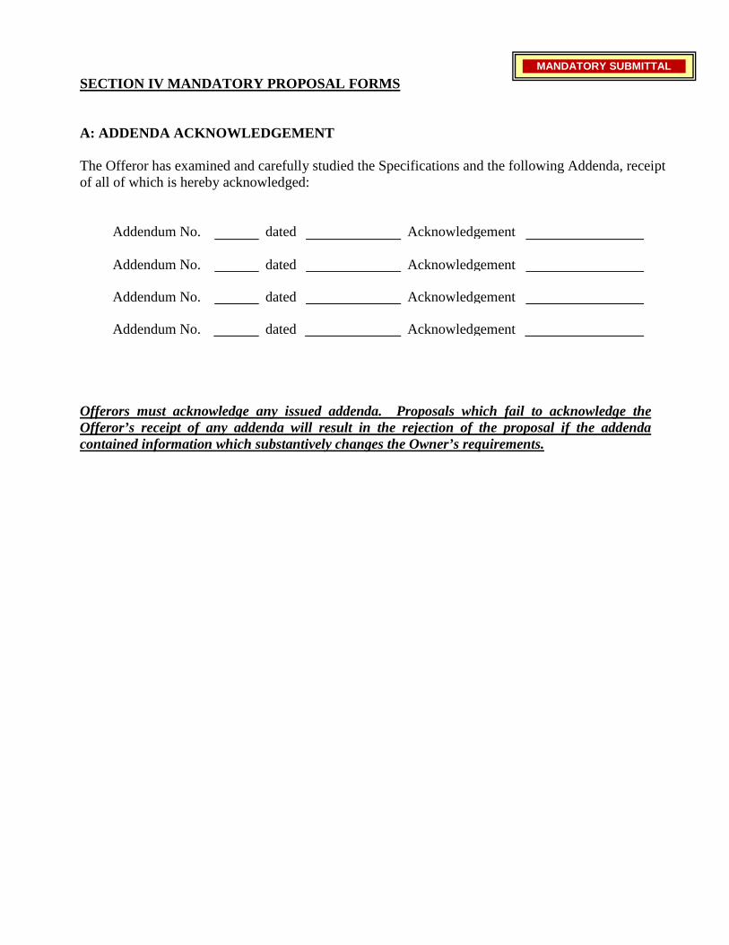
SECTION IV MANDATORY PROPOSAL FORMS
A: ADDENDA ACKNOWLEDGEMENT The Offeror has examined and carefully studied the Specifications and the following Addenda, receipt of all of which is hereby acknowledged:
Addendum No.
dated
Acknowledgement
Addendum No.
dated
Acknowledgement
Addendum No.
dated
Acknowledgement
Addendum No.
dated
Acknowledgement
Offerors must acknowledge any issued addenda. Proposals which fail to acknowledge the Offeror’s receipt of any addenda will result in the rejection of the proposal if the addenda contained information which substantively changes the Owner’s requirements.
MANDATORY SUBMITTAL
B: GEORGIA SECURITY & IMMIGRATION COMPLIANCE (GSIC) AFFIDAVIT The Unified Government of Athens-Clarke County and Contractor agree that compliance with the requirements of O.C.G.A. § 13-10-91, as amended, are conditions of this Agreement for the physical performance of services. If employing or contracting with any subcontractor(s) in connection with this Agreement, the Contractor further agrees:
(1) To secure from the subcontractor(s) an affidavit attesting to the subcontractor’s compliance with by O.C.G.A. § 13-10-91(b), as amended; such affidavit being in a form similar to and containing the same information as the form attached hereto; and
(2) To obtain such subcontractor affidavit(s) when the subcontractor(s) is retained.
Contractor shall have such forms available for inspection and submit to the Owner if so requested by the Owner.
The failure of the Contractor to supply the affidavit of compliance at the time of the bid will be cause for the bid being deemed non-responsive. Failure of Contractor to continue to satisfy the obligations of O.C.G.A. § 13-10-91, as amended throughout the entire contract period shall constitute a material breach of the contract. Upon notice of such breach, Contractor shall be entitled to cure the breach within ten days, upon providing satisfactory evidence of compliance with the terms of this Agreement and State law. Should the breach not be cured, Athens-Clarke County shall be entitled to all available remedies, including termination of the contract and damages.
SEE AFFIDAVITS ON FOLLOWING PAGES
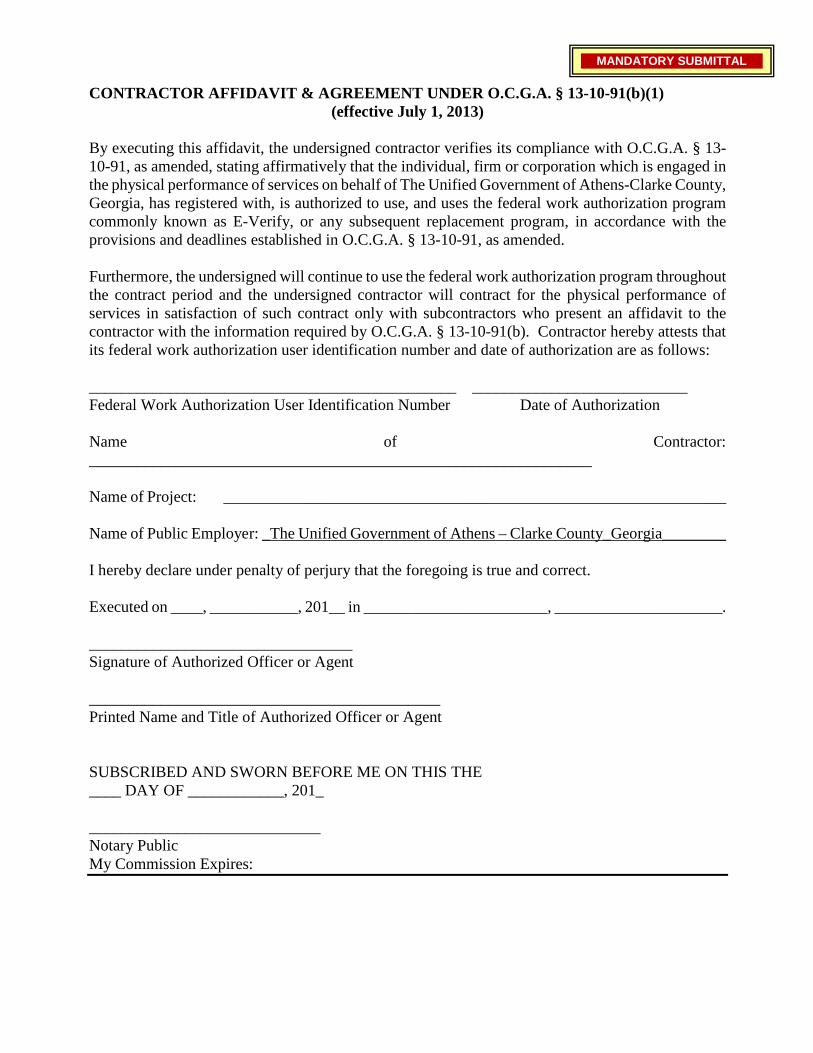
CONTRACTOR AFFIDAVIT & AGREEMENT UNDER O.C.G.A. § 13-10-91(b)(1) (effective July 1, 2013)
By executing this affidavit, the undersigned contractor verifies its compliance with O.C.G.A. § 13-10-91, as amended, stating affirmatively that the individual, firm or corporation which is engaged in the physical performance of services on behalf of The Unified Government of Athens-Clarke County, Georgia, has registered with, is authorized to use, and uses the federal work authorization program commonly known as E-Verify, or any subsequent replacement program, in accordance with the provisions and deadlines established in O.C.G.A. § 13-10-91, as amended.
Furthermore, the undersigned will continue to use the federal work authorization program throughout the contract period and the undersigned contractor will contract for the physical performance of services in satisfaction of such contract only with subcontractors who present an affidavit to the contractor with the information required by O.C.G.A. § 13-10-91(b). Contractor hereby attests that its federal work authorization user identification number and date of authorization are as follows: ______________________________________________ ___________________________ Federal Work Authorization User Identification Number Date of Authorization Name of Contractor: _______________________________________________________________ Name of Project: _______________________________________________________________ Name of Public Employer: _The Unified Government of Athens – Clarke County_Georgia________ I hereby declare under penalty of perjury that the foregoing is true and correct. Executed on ____, ___________, 201__ in _______________________, _____________________. _________________________________ Signature of Authorized Officer or Agent
____________________________________________ Printed Name and Title of Authorized Officer or Agent SUBSCRIBED AND SWORN BEFORE ME ON THIS THE ____ DAY OF ____________, 201_ _____________________________ Notary Public My Commission Expires:
MANDATORY SUBMITTAL
C. BID LIST APPLICATION We would like for this form to be turned in a minimum of four (4) days prior to bid
If you have an ACC Vendor Number please include it on the sealed envelope or container. If you do not know your ACC Vendor Number, please call 706-613-3088 or email: [email protected] If you DO NOT HAVE an ACC Vendor Number, please fill out the bidder’s list application attached below.
Base Order Price $1,000.00 Plus Percent Change (2.54% x $1,000) 25.40
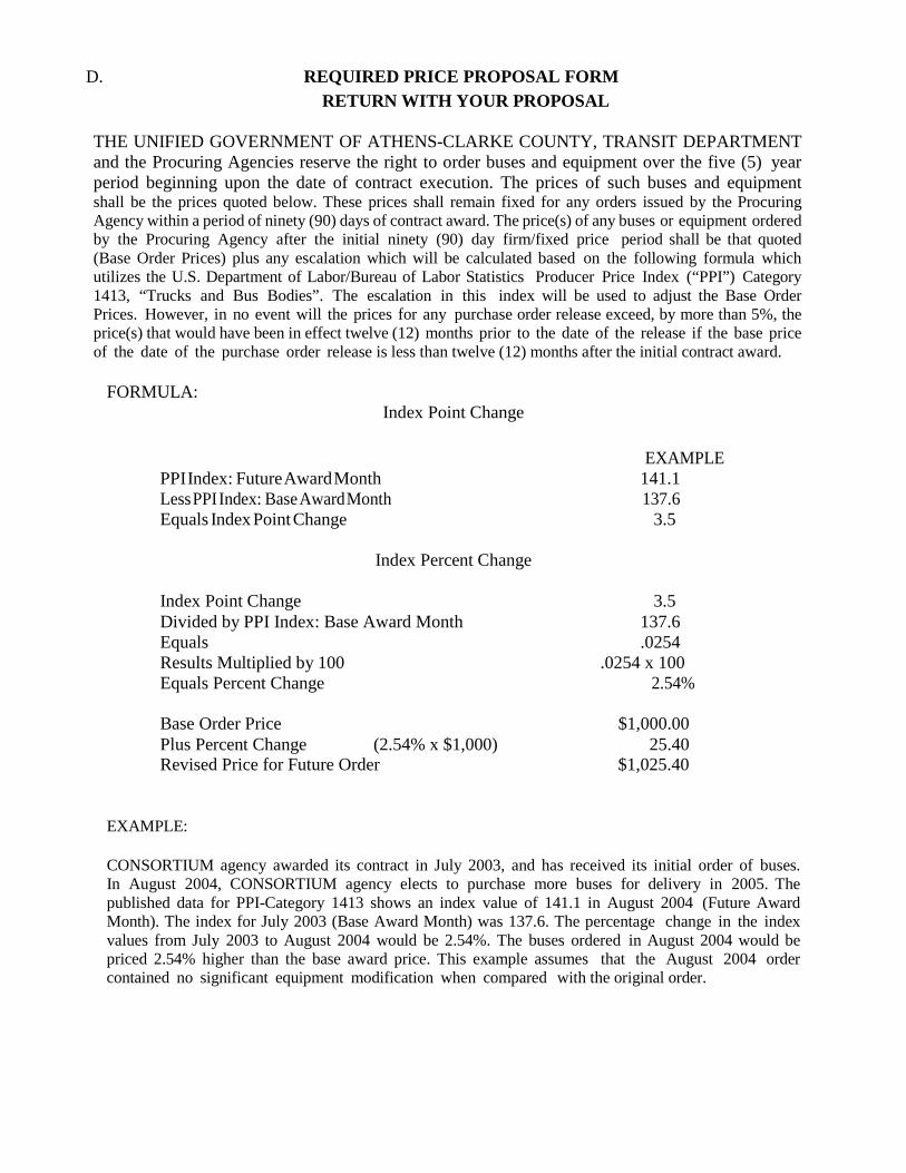
D. REQUIRED PRICE PROPOSAL FORM
RETURN WITH YOUR PROPOSAL THE UNIFIED GOVERNMENT OF ATHENS-CLARKE COUNTY, TRANSIT DEPARTMENT and the Procuring Agencies reserve the right to order buses and equipment over the five (5) year period beginning upon the date of contract execution. The prices of such buses and equipment shall be the prices quoted below. These prices shall remain fixed for any orders issued by the Procuring Agency within a period of ninety (90) days of contract award. The price(s) of any buses or equipment ordered by the Procuring Agency after the initial ninety (90) day firm/fixed price period shall be that quoted (Base Order Prices) plus any escalation which will be calculated based on the following formula which utilizes the U.S. Department of Labor/Bureau of Labor Statistics Producer Price Index (“PPI”) Category 1413, “Trucks and Bus Bodies”. The escalation in this index will be used to adjust the Base Order Prices. However, in no event will the prices for any purchase order release exceed, by more than 5%, the price(s) that would have been in effect twelve (12) months prior to the date of the release if the base price of the date of the purchase order release is less than twelve (12) months after the initial contract award.
FORMULA: Index Point Change
EXAMPLE PPI Index: Future Award Month 141.1 Less PPI Index: Base Award Month 137.6 Equals Index Point Change 3.5
Index Percent Change
Index Point Change 3.5 Divided by PPI Index: Base Award Month 137.6 Equals .0254 Results Multiplied by 100 .0254 x 100 Equals Percent Change 2.54%
Revised Price for Future Order $1,025.40
EXAMPLE:
CONSORTIUM agency awarded its contract in July 2003, and has received its initial order of buses. In August 2004, CONSORTIUM agency elects to purchase more buses for delivery in 2005. The published data for PPI-Category 1413 shows an index value of 141.1 in August 2004 (Future Award Month). The index for July 2003 (Base Award Month) was 137.6. The percentage change in the index values from July 2003 to August 2004 would be 2.54%. The buses ordered in August 2004 would be priced 2.54% higher than the base award price. This example assumes that the August 2004 order contained no significant equipment modification when compared with the original order.
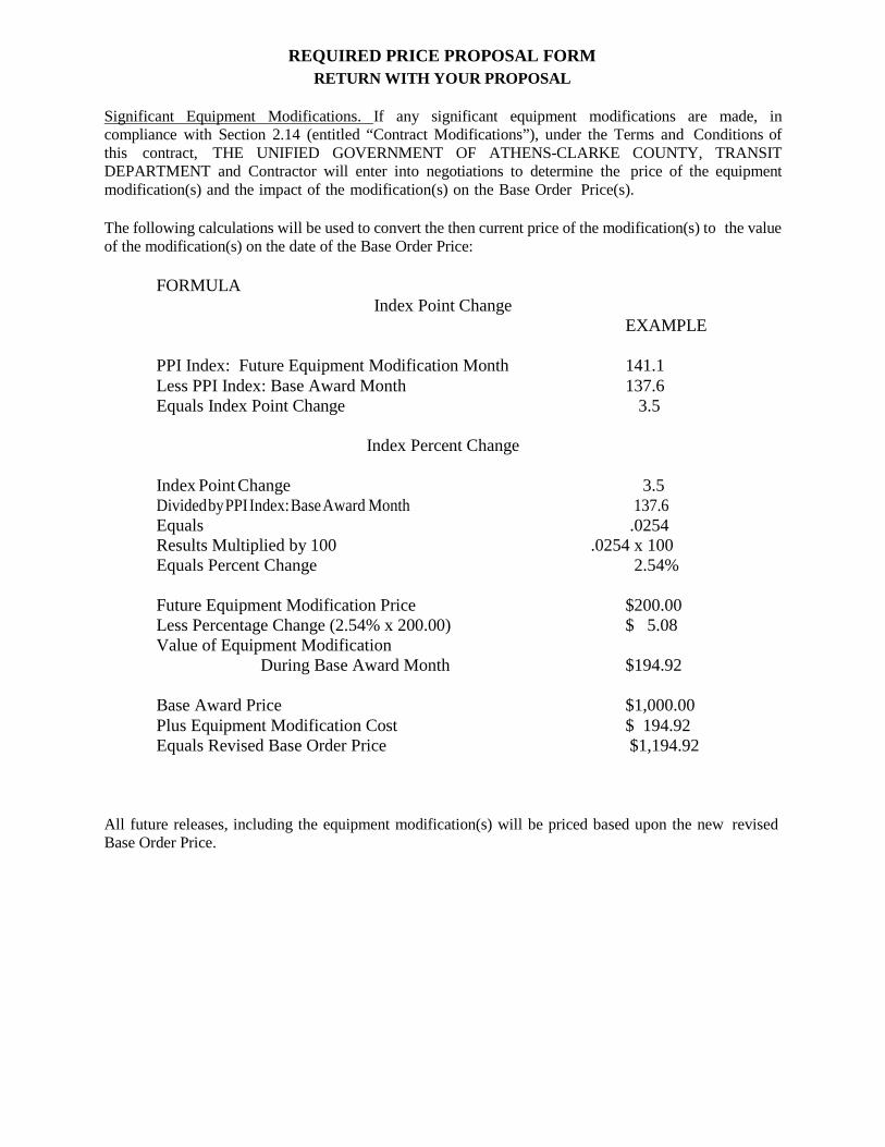
REQUIRED PRICE PROPOSAL FORM RETURN WITH YOUR PROPOSAL
Significant Equipment Modifications. If any significant equipment modifications are made, in compliance with Section 2.14 (entitled “Contract Modifications”), under the Terms and Conditions of this contract, THE UNIFIED GOVERNMENT OF ATHENS-CLARKE COUNTY, TRANSIT DEPARTMENT and Contractor will enter into negotiations to determine the price of the equipment modification(s) and the impact of the modification(s) on the Base Order Price(s).
The following calculations will be used to convert the then current price of the modification(s) to the value of the modification(s) on the date of the Base Order Price:
FORMULA Index Point Change
EXAMPLE
PPI Index: Future Equipment Modification Month 141.1 Less PPI Index: Base Award Month 137.6 Equals Index Point Change 3.5
Index Percent Change
Index Point Change 3.5 Divided by PPI Index: Base Award Month 137.6 Equals .0254 Results Multiplied by 100 .0254 x 100 Equals Percent Change 2.54%
Future Equipment Modification Price $200.00 Less Percentage Change (2.54% x 200.00) $ 5.08 Value of Equipment Modification
During Base Award Month $194.92
Base Award Price $1,000.00 Plus Equipment Modification Cost $ 194.92 Equals Revised Base Order Price $1,194.92
All future releases, including the equipment modification(s) will be priced based upon the new revised Base Order Price.
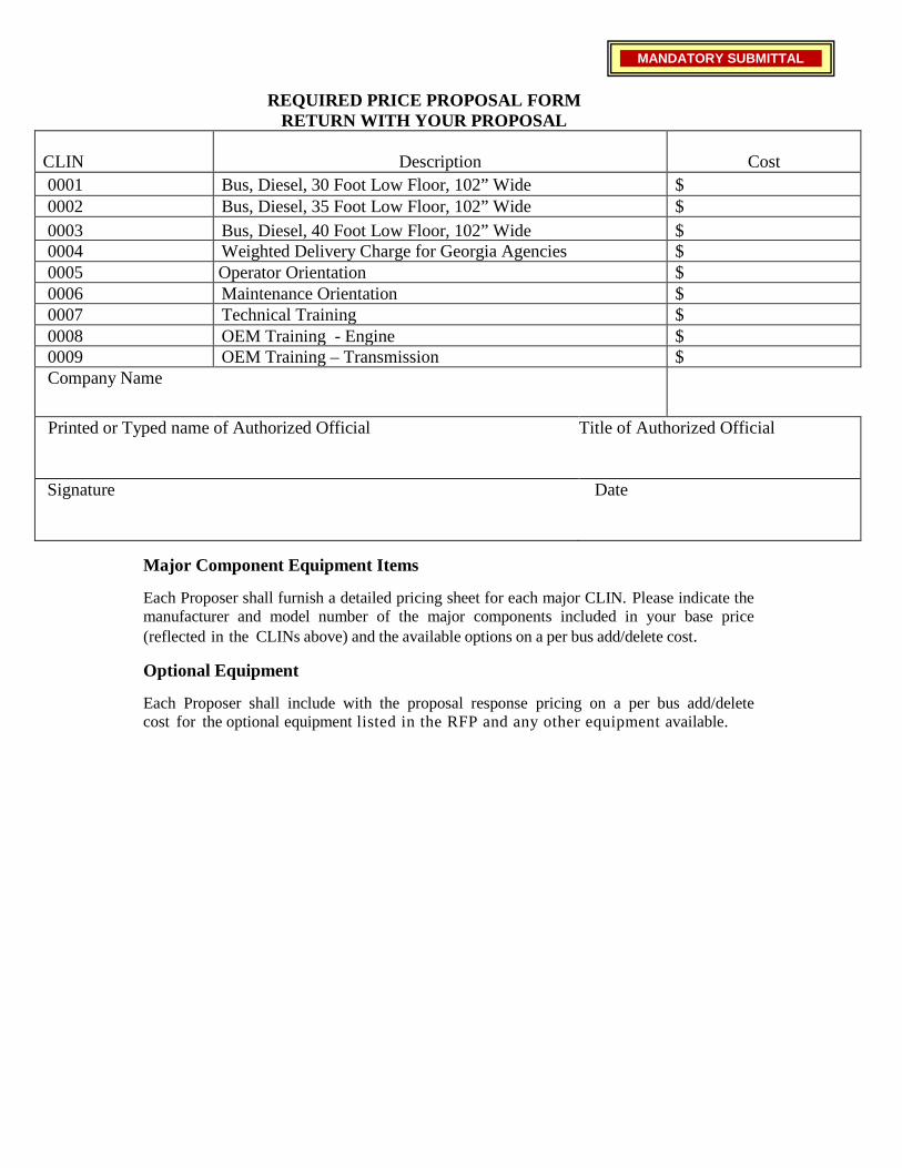
REQUIRED PRICE PROPOSAL FORM RETURN WITH YOUR PROPOSAL
CLIN
Description
Cost
0001 Bus, Diesel, 30 Foot Low Floor, 102” Wide $ 0002 Bus, Diesel, 35 Foot Low Floor, 102” Wide $ 0003 Bus, Diesel, 40 Foot Low Floor, 102” Wide $ 0004 Weighted Delivery Charge for Georgia Agencies $ 0005 Operator Orientation $ 0006 Maintenance Orientation $ 0007 Technical Training $ 0008 OEM Training - Engine $ 0009 OEM Training – Transmission $ Company Name
Printed or Typed name of Authorized Official Title of Authorized Official
Signature Date
Major Component Equipment Items
Each Proposer shall furnish a detailed pricing sheet for each major CLIN. Please indicate the manufacturer and model number of the major components included in your base price (reflected in the CLINs above) and the available options on a per bus add/delete cost.
Optional Equipment
Each Proposer shall include with the proposal response pricing on a per bus add/delete cost for the optional equipment listed in the RFP and any other equipment available.
MANDATORY SUBMITTAL
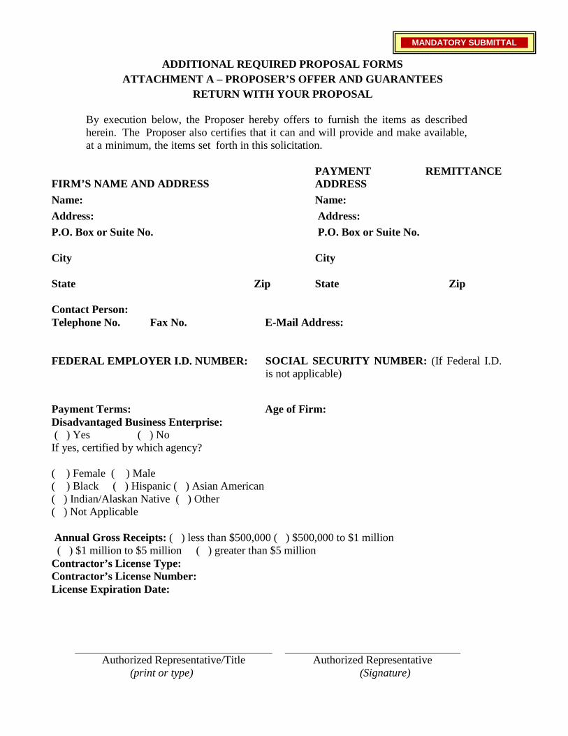
ADDITIONAL REQUIRED PROPOSAL FORMS ATTACHMENT A – PROPOSER’S OFFER AND GUARANTEES
RETURN WITH YOUR PROPOSAL
By execution below, the Proposer hereby offers to furnish the items as described herein. The Proposer also certifies that it can and will provide and make available, at a minimum, the items set forth in this solicitation.
FIRM’S NAME AND ADDRESS
PAYMENT REMITTANCE ADDRESS
Name: Name: Address: Address: P.O. Box or Suite No. P.O. Box or Suite No.
City
City
State
Zip
State
Zip
Contact Person: Telephone No. Fax No. E-Mail Address:
FEDERAL EMPLOYER I.D. NUMBER: SOCIAL SECURITY NUMBER: (If Federal I.D. is not applicable)
Payment Terms: Age of Firm: Disadvantaged Business Enterprise: ( ) Yes ( ) No
If yes, certified by which agency? ( ) Female ( ) Male ( ) Black ( ) Hispanic ( ) Asian American ( ) Indian/Alaskan Native ( ) Other ( ) Not Applicable
Annual Gross Receipts: ( ) less than $500,000 ( ) $500,000 to $1 million ( ) $1 million to $5 million ( ) greater than $5 million
Contractor’s License Type: Contractor’s License Number: License Expiration Date:
Authorized Representative/Title (print or type)
Authorized Representative (Signature)
MANDATORY SUBMITTAL
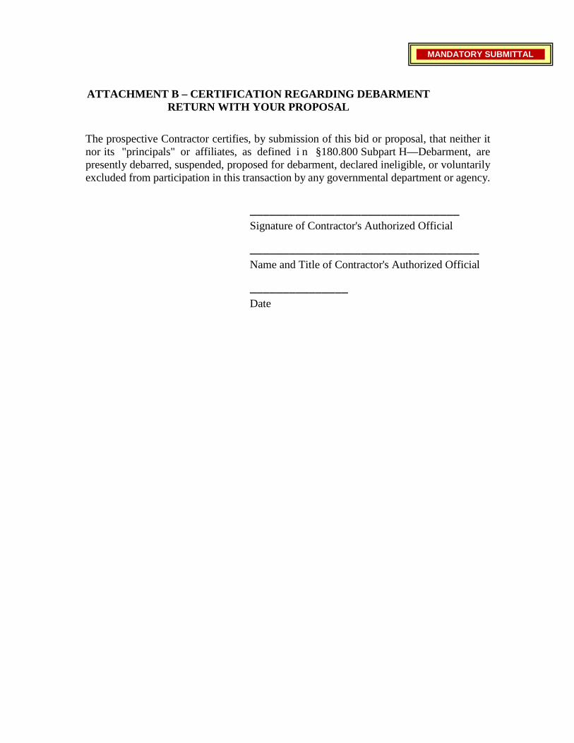
ATTACHMENT B – CERTIFICATION REGARDING DEBARMENT RETURN WITH YOUR PROPOSAL
The prospective Contractor certifies, by submission of this bid or proposal, that neither it nor its "principals" or affiliates, as defined i n §180.800 Subpart H—Debarment, are presently debarred, suspended, proposed for debarment, declared ineligible, or voluntarily excluded from participation in this transaction by any governmental department or agency.
________________________________ Signature of Contractor's Authorized Official
___________________________________ Name and Title of Contractor's Authorized Official
_______________ Date
MANDATORY SUBMITTAL

ATTACHMENT C – LOBBYING RETURN WITH YOUR PROPOSAL
Certification for Contracts, Grants, Loans, and Cooperative Agreements
(To be submitted with each bid or offer exceeding $100,000)
The undersigned [Contractor] certifies, to the best of his or her knowledge and belief, that:
(1) No Federal appropriated funds have been paid or will be paid, by or on behalf of the undersigned, to any person for influencing or attempting to influence an officer or employee of an agency, a Member of Congress, an officer or employee of Congress, or an employee of a Member of Congress in connection with the awarding of any Federal contract, the making of any Federal grant, the making of any Federal loan, the entering into of any cooperative agreement, and the extension, continuation, renewal, amendment, or modification of any Federal contract, grant, loan, or cooperative agreement.
(2) If any funds other than Federal appropriated funds have been paid or will be paid to any person for making lobbying contacts to an officer or employee of any agency, a Member of Congress, an officer or employee of Congress, or an employee of a Member of Congress in connection with this Federal contract, grant, loan, or cooperative agreement, the undersigned shall complete and submit Standard Form--LLL, "Disclosure Form to Report Lobbying," in accordance with its instructions [as amended by "Government wide Guidance for New Restrictions on Lobbying," 61 Fed. Reg. 1413 (1/19/96). Note: Language in paragraph (2) herein has been modified in accordance with Section 10 of the Lobbying Disclosure Act of 1995 (P.L. 104-65, to be codified at 2 U.S.C. 1601, et seq.)]
(3) The undersigned shall require that the language of this certification be included in the award documents for all subawards at all tiers (including subcontracts, subgrants, and contracts under grants, loans, and cooperative agreements) and that all subrecipients shall certify and disclose accordingly.
This certification is a material representation of fact upon which reliance was placed when this transaction was made or entered into. Submission of this certification is a prerequisite for making or entering into this transaction imposed by 31, U.S.C. § 1352 (as amended by the Lobbying Disclosure Act of 1995). Any person who fails to file the required certification shall be subject to a civil penalty of not less than $10,000 and not more than $100,000 for each such failure.
[Note: Pursuant to 31 U.S.C. § 1352(c)(1)-(2)(A), any person who makes a prohibited expenditure or fails to file or amend a required certification or disclosure form shall be subject to a civil penalty of not less than $10,000 and not more than $100,000 for each such expenditure or failure.]
The Contractor, , certifies or affirms the truthfulness and accuracy of each statement of its certification and disclosure, if any. In addition, the Contractor understands and agrees that the provisions of 31 U.S.C. A 3801, et seq., apply to this certification and disclosure, if any.
Signature of Contractor's Authorized Official:
Name and Title of Contractor's Authorized Official:
Date:
MANDATORY SUBMITTAL
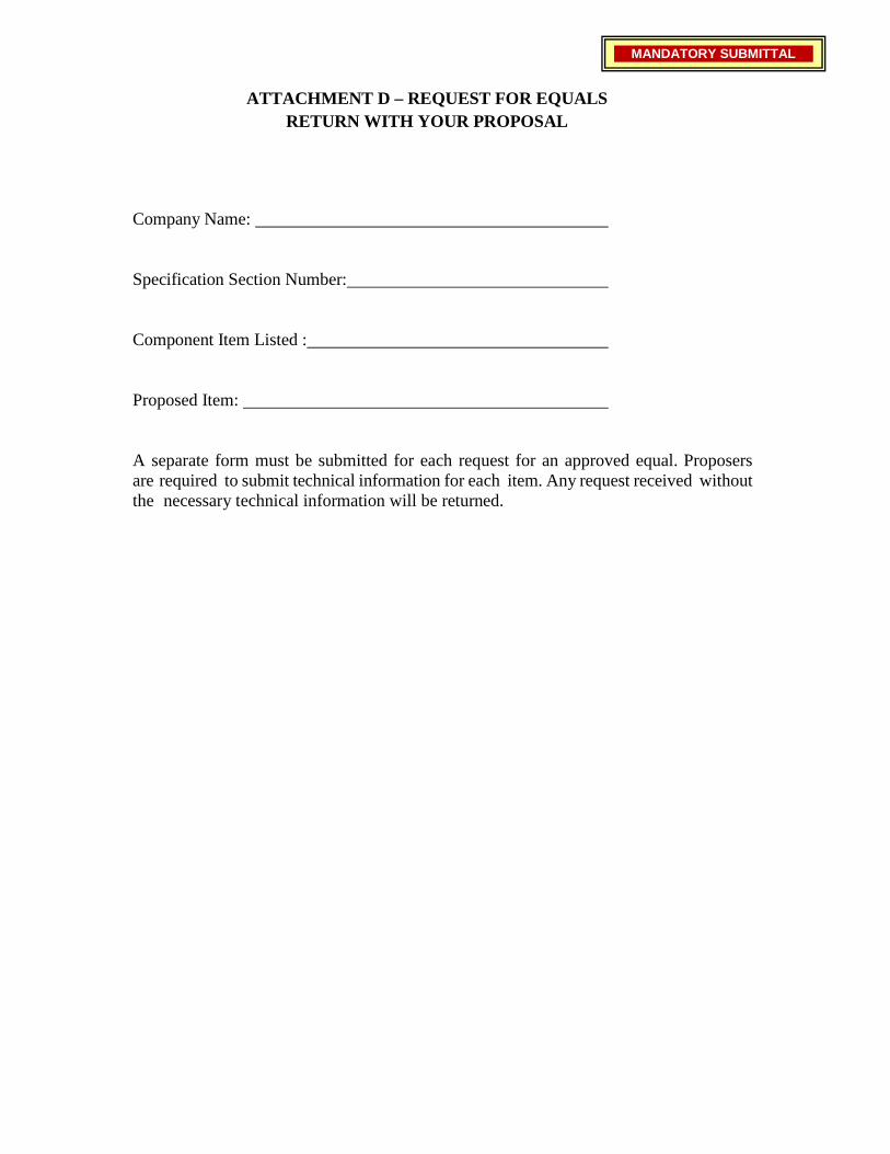
ATTACHMENT D – REQUEST FOR EQUALS RETURN WITH YOUR PROPOSAL
Company Name: Specification Section Number:
Component Item Listed :
Proposed Item:
A separate form must be submitted for each request for an approved equal. Proposers are required to submit technical information for each item. Any request received without the necessary technical information will be returned.
MANDATORY SUBMITTAL

ATTACHMENT E – BUY AMERICA CERTIFICATE OF COMPLIANCE
WITH FTA REQUIREMENTS FOR BUSES, OTHER ROLLING STOCK, OR ASSOCIATED EQUIPMENT
RETURN WITH YOUR PROPOSAL
Certificate of Compliance with 49 U.S.C. 5323(j)(2)(C). The bidder or offeror hereby certifies that it will comply with the requirements of 49 U.S.C. 5323(j)(2)(C) and the regulations at 49 CFR Part 661.
Date
Signature
Company Name
Title
Certificate of Non-Compliance with 49 U.S.C. 5323(j)(2)(C) The bidder or offeror hereby certifies that it cannot comply with the requirements of 49 U.S.C. 5323(j)(2)(C), but may qualify for an exception pursuant to 49 U.S.C. 5323(j)(2)(B) or (j)(2)(D) and the regulations in 49 CFR 661.7.
Date
Signature
Company Name
Title
MANDATORY SUBMITTAL
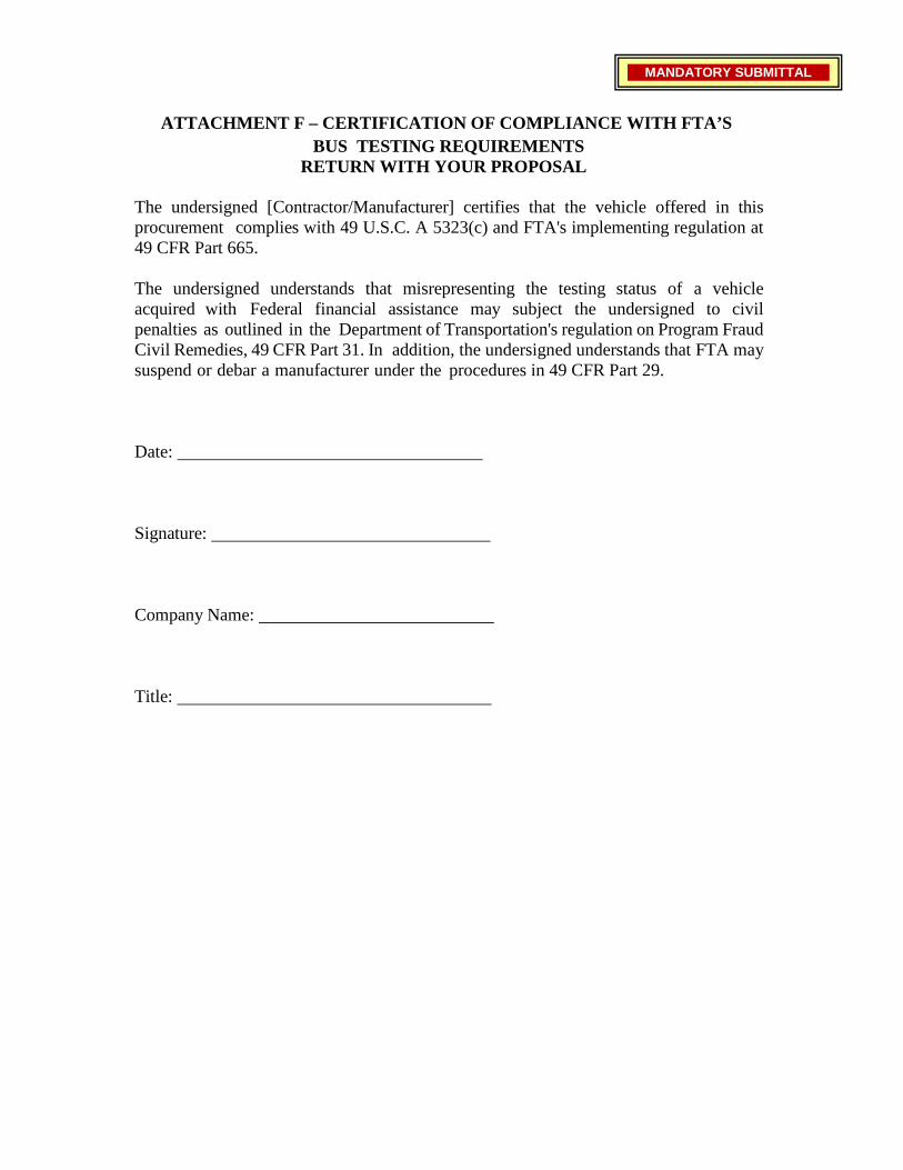
ATTACHMENT F – CERTIFICATION OF COMPLIANCE WITH FTA’S
BUS TESTING REQUIREMENTS RETURN WITH YOUR PROPOSAL
The undersigned [Contractor/Manufacturer] certifies that the vehicle offered in this procurement complies with 49 U.S.C. A 5323(c) and FTA's implementing regulation at 49 CFR Part 665.
The undersigned understands that misrepresenting the testing status of a vehicle acquired with Federal financial assistance may subject the undersigned to civil penalties as outlined in the Department of Transportation's regulation on Program Fraud Civil Remedies, 49 CFR Part 31. In addition, the undersigned understands that FTA may suspend or debar a manufacturer under the procedures in 49 CFR Part 29.
Date:
Signature:
Company Name:
Title:
MANDATORY SUBMITTAL
ATTACHMENT G – BUS TESTING PROGRAM
RETURN WITH YOUR PROPOSAL
ATTACHMENT G - BUS TESTING PROGRAM CERTIFICATION Here by certifies that the model of bus being offered in this bid has met the requirements imposed by 49 CFR Part 665, Bus Testing, including the following two (2) conditions:
1) A model of the bus has been tested at the bus testing
facility in Altoona, Pennsylvania; and 2) The bid includes a copy of the Test Report prepared on the bus model being
offered. Authorized Signee:
Title: Company:
MANDATORY SUBMITTAL
ATTACHMENT H – TRANSIT VEHICLE MANUFACTURER CERTIFICATION RETURN WITH YOUR PROPOSAL
(Bus or Rail Car Purchases Only)
CERTIFICATION OF DISADVANTAGED BUSINESS ENTERPRISES (DBE) COMPLIANCE
The responder, a Primary Transit Vehicle Manufacturer, hereby certifies that it has complied with the requirements of 49 CFR Section 26.49, as amended, by submitting an annual DBE goal, as amended, to the Federal Transit Administration (FTA). The goal has either been approved or not disapproved by the FTA.
SIGNATURE:
PRINT NAME:
TITLE:
COMPANY:
DATE:
MANDATORY SUBMITTAL

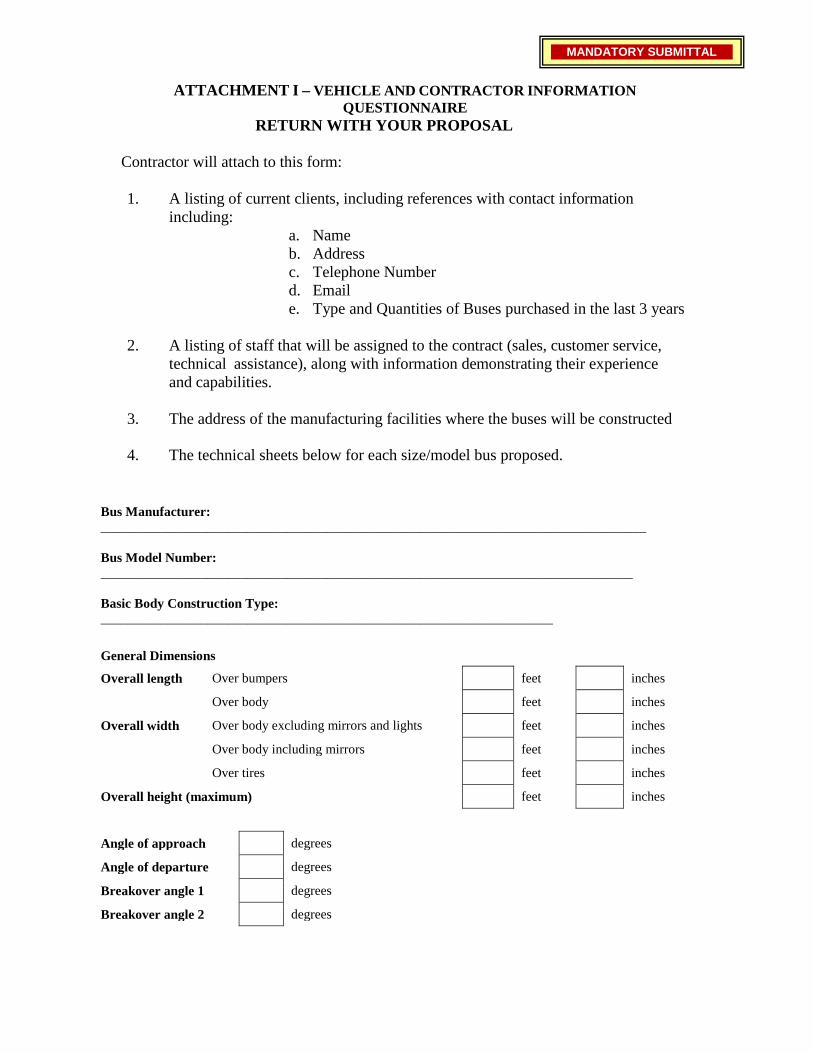
ATTACHMENT I – VEHICLE AND CONTRACTOR INFORMATION QUESTIONNAIRE
RETURN WITH YOUR PROPOSAL Contractor will attach to this form:
1. A listing of current clients, including references with contact information
including: a. Name b. Address c. Telephone Number d. Email e. Type and Quantities of Buses purchased in the last 3 years
2. A listing of staff that will be assigned to the contract (sales, customer service,
technical assistance), along with information demonstrating their experience and capabilities.
3. The address of the manufacturing facilities where the buses will be constructed
4. The technical sheets below for each size/model bus proposed.
Bus Manufacturer: __________________________________________________________________________________ Bus Model Number: ________________________________________________________________________________ Basic Body Construction Type: ____________________________________________________________________
General Dimensions
Overall length Over bumpers feet inches
Over body feet inches
Overall width Over body excluding mirrors and lights feet inches
Over body including mirrors feet inches
Over tires feet inches
Overall height (maximum) feet inches
Angle of approach degrees
Angle of departure degrees
Breakover angle 1 degrees
Breakover angle 2 degrees
MANDATORY SUBMITTAL
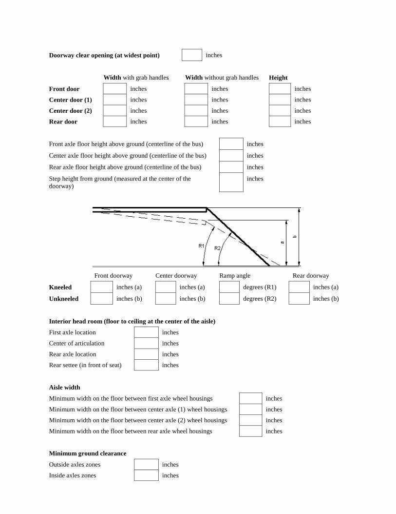
Doorway clear opening (at widest point) inches
Width with grab handles Width without grab handles Height
Front door inches inches inches
Center door (1) inches inches inches
Center door (2) inches inches inches
Rear door inches inches inches
Front axle floor height above ground (centerline of the bus) inches
Center axle floor height above ground (centerline of the bus) inches
Rear axle floor height above ground (centerline of the bus) inches
Step height from ground (measured at the center of the doorway)
inches
Front doorway Center doorway Ramp angle Rear doorway
Kneeled inches (a) inches (a) degrees (R1) inches (a)
Unkneeled inches (b) inches (b) degrees (R2) inches (b)
Interior head room (floor to ceiling at the center of the aisle)
First axle location inches
Center of articulation inches
Rear axle location inches
Rear settee (in front of seat) inches
Aisle width
Minimum width on the floor between first axle wheel housings inches
Minimum width on the floor between center axle (1) wheel housings inches
Minimum width on the floor between center axle (2) wheel housings inches
Minimum width on the floor between rear axle wheel housings inches
Minimum ground clearance
Outside axles zones inches
Inside axles zones inches
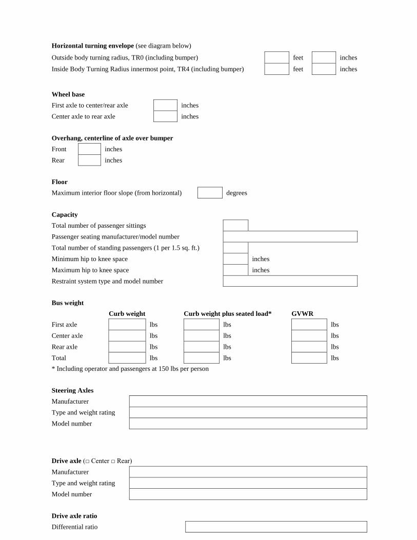
Horizontal turning envelope (see diagram below)
Outside body turning radius, TR0 (including bumper) feet inches
Inside Body Turning Radius innermost point, TR4 (including bumper) feet inches
Wheel base First axle to center/rear axle inches Center axle to rear axle inches Overhang, centerline of axle over bumper Front inches Rear inches Floor Maximum interior floor slope (from horizontal) degrees Capacity Total number of passenger sittings Passenger seating manufacturer/model number Total number of standing passengers (1 per 1.5 sq. ft.) Minimum hip to knee space inches Maximum hip to knee space inches Restraint system type and model number Bus weight
Curb weight Curb weight plus seated load* GVWR First axle lbs lbs lbs Center axle lbs lbs lbs Rear axle lbs lbs lbs Total lbs lbs lbs * Including operator and passengers at 150 lbs per person Steering Axles Manufacturer Type and weight rating Model number Drive axle (□ Center □ Rear) Manufacturer Type and weight rating Model number Drive axle ratio Differential ratio
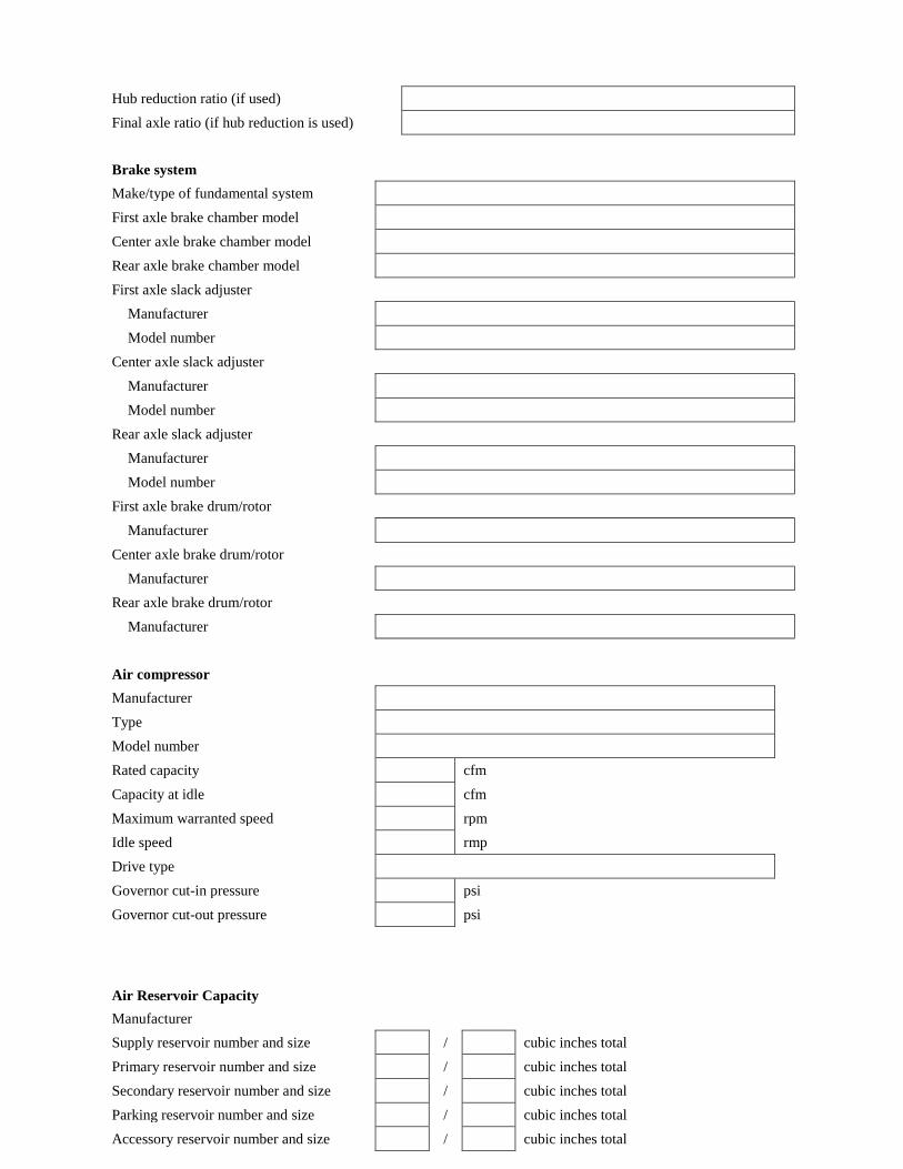
Hub reduction ratio (if used) Final axle ratio (if hub reduction is used) Brake system Make/type of fundamental system First axle brake chamber model Center axle brake chamber model Rear axle brake chamber model First axle slack adjuster
Manufacturer Model number
Center axle slack adjuster Manufacturer Model number
Rear axle slack adjuster Manufacturer Model number
First axle brake drum/rotor Manufacturer
Center axle brake drum/rotor Manufacturer
Rear axle brake drum/rotor Manufacturer
Air compressor Manufacturer Type Model number Rated capacity cfm Capacity at idle cfm Maximum warranted speed rpm Idle speed rmp Drive type Governor cut-in pressure psi Governor cut-out pressure psi Air Reservoir Capacity Manufacturer Supply reservoir number and size / cubic inches total Primary reservoir number and size / cubic inches total Secondary reservoir number and size / cubic inches total Parking reservoir number and size / cubic inches total Accessory reservoir number and size / cubic inches total
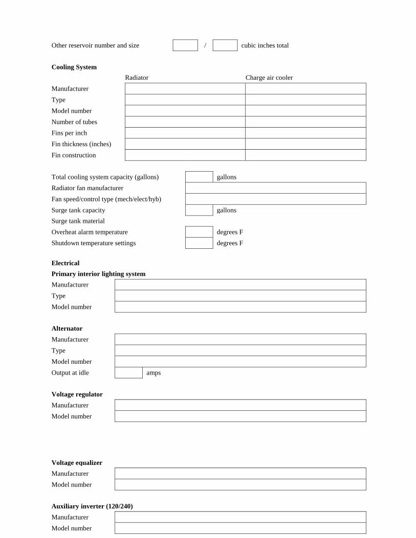
Other reservoir number and size / cubic inches total Cooling System
Radiator Charge air cooler Manufacturer Type Model number Number of tubes Fins per inch Fin thickness (inches) Fin construction Total cooling system capacity (gallons) gallons Radiator fan manufacturer Fan speed/control type (mech/elect/hyb) Surge tank capacity gallons Surge tank material Overheat alarm temperature degrees F Shutdown temperature settings degrees F
Electrical Primary interior lighting system Manufacturer Type Model number Alternator Manufacturer Type Model number Output at idle amps Voltage regulator Manufacturer Model number
Voltage equalizer Manufacturer Model number Auxiliary inverter (120/240) Manufacturer Model number
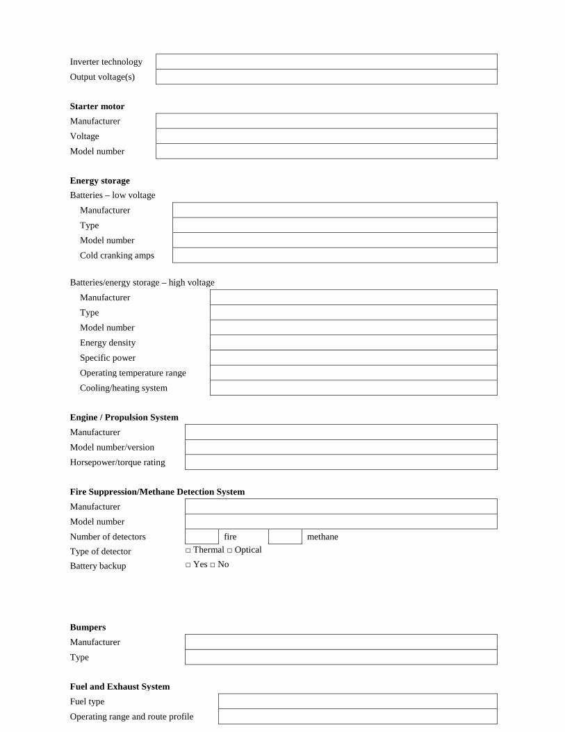
Inverter technology Output voltage(s) Starter motor Manufacturer Voltage Model number Energy storage Batteries – low voltage
Manufacturer Type Model number Cold cranking amps
Batteries/energy storage – high voltage
Manufacturer Type Model number Energy density Specific power Operating temperature range Cooling/heating system
Engine / Propulsion System Manufacturer Model number/version Horsepower/torque rating Fire Suppression/Methane Detection System Manufacturer Model number Number of detectors fire methane Type of detector □ Thermal □ Optical
Battery backup □ Yes □ No
Bumpers Manufacturer Type Fuel and Exhaust System Fuel type Operating range and route profile
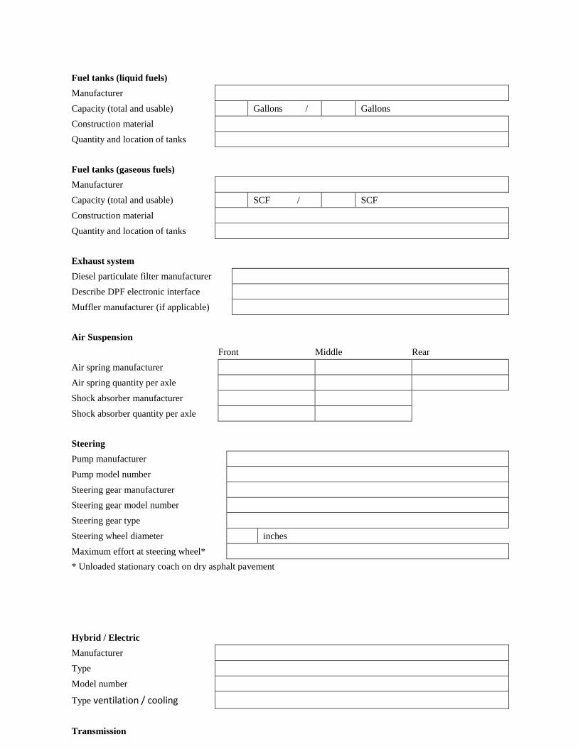
Fuel tanks (liquid fuels) Manufacturer Capacity (total and usable) Gallons / Gallons Construction material Quantity and location of tanks Fuel tanks (gaseous fuels) Manufacturer Capacity (total and usable) SCF / SCF Construction material Quantity and location of tanks Exhaust system Diesel particulate filter manufacturer Describe DPF electronic interface Muffler manufacturer (if applicable) Air Suspension
Front Middle Rear Air spring manufacturer Air spring quantity per axle Shock absorber manufacturer Shock absorber quantity per axle Steering Pump manufacturer Pump model number Steering gear manufacturer Steering gear model number Steering gear type Steering wheel diameter inches Maximum effort at steering wheel* * Unloaded stationary coach on dry asphalt pavement
Hybrid / Electric Manufacturer Type Model number
Type ventilation / cooling
Transmission
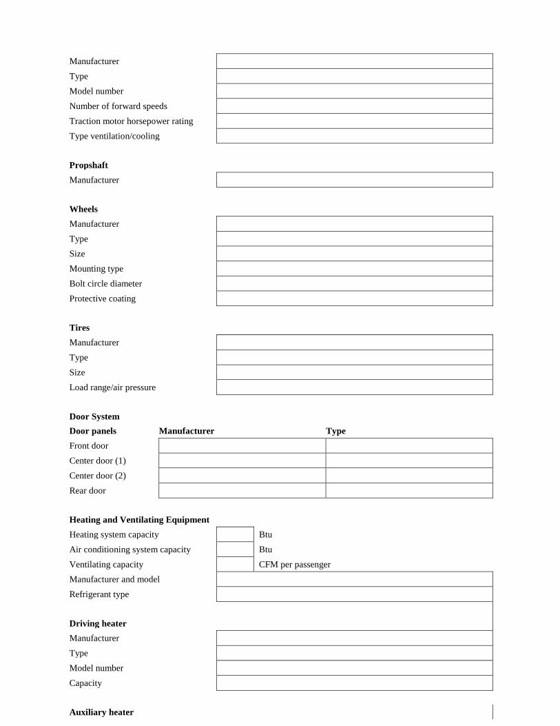
Manufacturer Type Model number Number of forward speeds Traction motor horsepower rating Type ventilation/cooling Propshaft Manufacturer Wheels Manufacturer Type Size Mounting type Bolt circle diameter Protective coating Tires Manufacturer Type Size Load range/air pressure Door System Door panels Manufacturer Type Front door Center door (1) Center door (2) Rear door Heating and Ventilating Equipment Heating system capacity Btu Air conditioning system capacity Btu Ventilating capacity CFM per passenger Manufacturer and model Refrigerant type Driving heater Manufacturer Type Model number Capacity Auxiliary heater
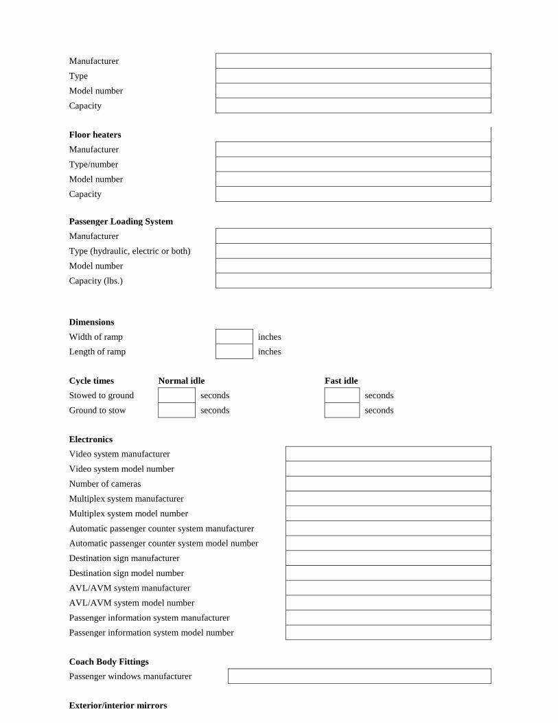
Manufacturer Type Model number Capacity Floor heaters Manufacturer Type/number Model number Capacity
Passenger Loading System Manufacturer Type (hydraulic, electric or both) Model number Capacity (lbs.)
Dimensions Width of ramp inches Length of ramp inches Cycle times Normal idle Fast idle Stowed to ground seconds seconds Ground to stow seconds seconds Electronics Video system manufacturer Video system model number Number of cameras Multiplex system manufacturer Multiplex system model number Automatic passenger counter system manufacturer Automatic passenger counter system model number Destination sign manufacturer Destination sign model number AVL/AVM system manufacturer AVL/AVM system model number Passenger information system manufacturer Passenger information system model number Coach Body Fittings Passenger windows manufacturer Exterior/interior mirrors
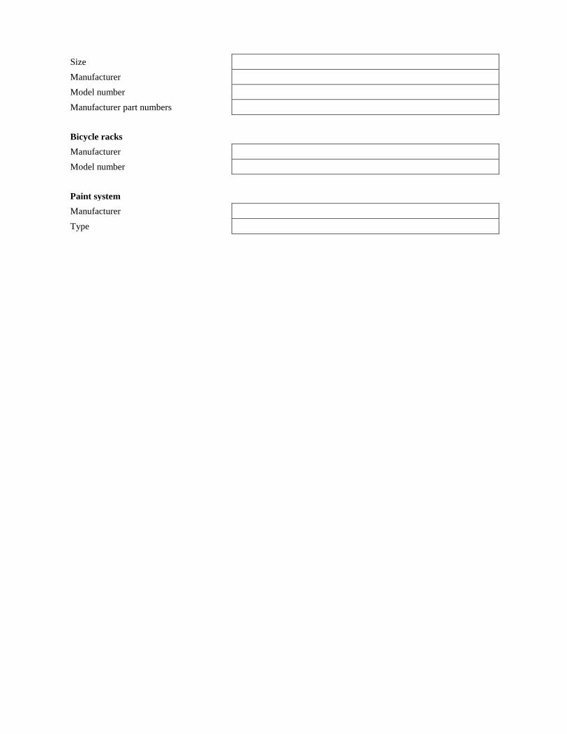
Size Manufacturer Model number Manufacturer part numbers Bicycle racks Manufacturer Model number Paint system Manufacturer Type
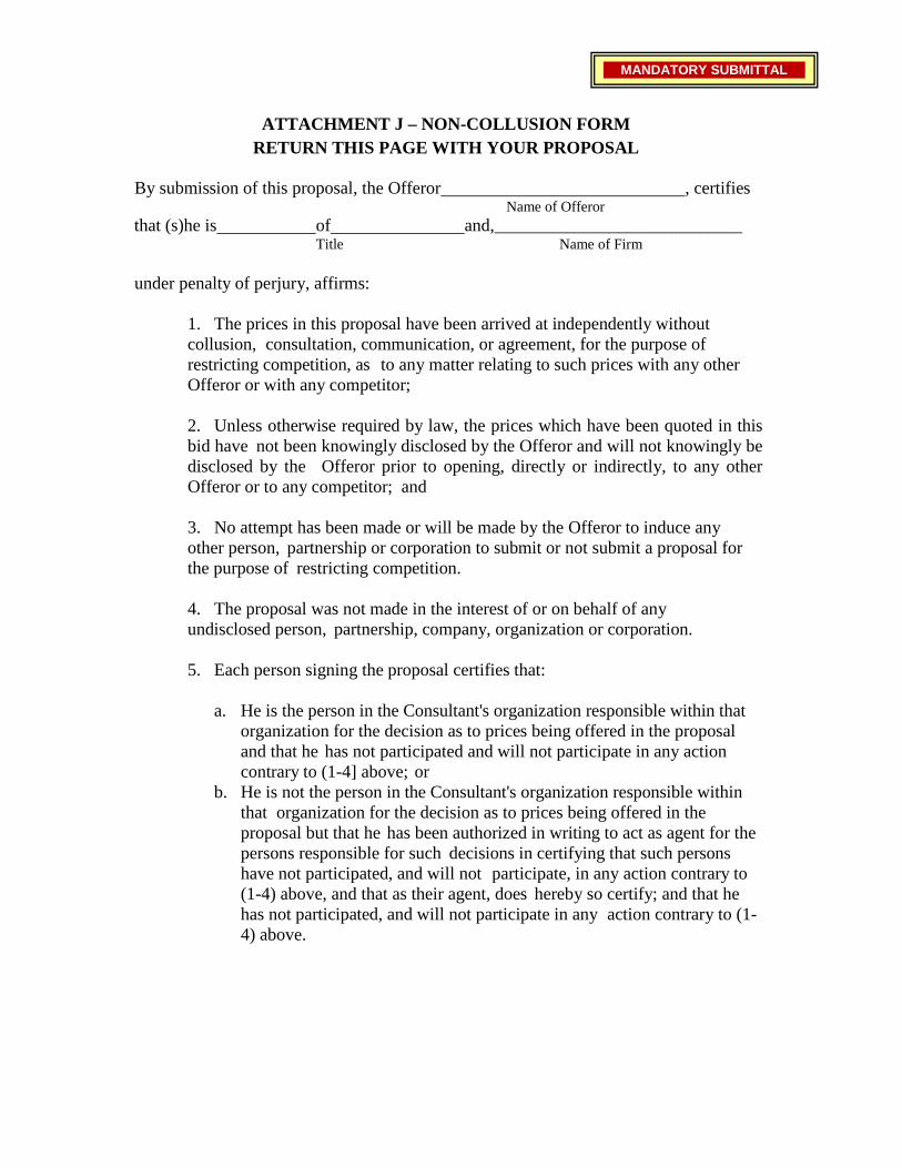
ATTACHMENT J – NON-COLLUSION FORM
RETURN THIS PAGE WITH YOUR PROPOSAL
By submission of this proposal, the Offeror , certifies Name of Offeror
that (s)he is of and,____________________________ Title Name of Firm
under penalty of perjury, affirms:
1. The prices in this proposal have been arrived at independently without collusion, consultation, communication, or agreement, for the purpose of restricting competition, as to any matter relating to such prices with any other Offeror or with any competitor;
2. Unless otherwise required by law, the prices which have been quoted in this bid have not been knowingly disclosed by the Offeror and will not knowingly be disclosed by the Offeror prior to opening, directly or indirectly, to any other Offeror or to any competitor; and
3. No attempt has been made or will be made by the Offeror to induce any other person, partnership or corporation to submit or not submit a proposal for the purpose of restricting competition.
4. The proposal was not made in the interest of or on behalf of any undisclosed person, partnership, company, organization or corporation.
5. Each person signing the proposal certifies that:
a. He is the person in the Consultant's organization responsible within that
organization for the decision as to prices being offered in the proposal and that he has not participated and will not participate in any action contrary to (1-4] above; or
b. He is not the person in the Consultant's organization responsible within that organization for the decision as to prices being offered in the proposal but that he has been authorized in writing to act as agent for the persons responsible for such decisions in certifying that such persons have not participated, and will not participate, in any action contrary to (1-4) above, and that as their agent, does hereby so certify; and that he has not participated, and will not participate in any action contrary to (1- 4) above.
MANDATORY SUBMITTAL
37
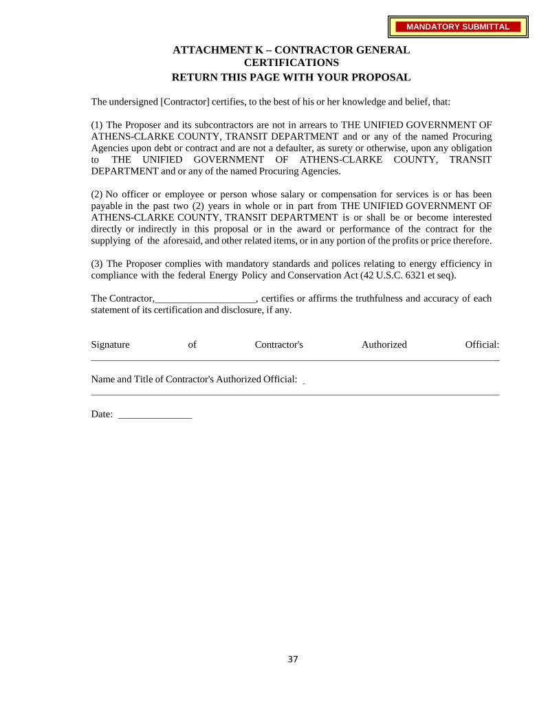
ATTACHMENT K – CONTRACTOR GENERAL
CERTIFICATIONS RETURN THIS PAGE WITH YOUR PROPOSAL
The undersigned [Contractor] certifies, to the best of his or her knowledge and belief, that:
(1) The Proposer and its subcontractors are not in arrears to THE UNIFIED GOVERNMENT OF ATHENS-CLARKE COUNTY, TRANSIT DEPARTMENT and or any of the named Procuring Agencies upon debt or contract and are not a defaulter, as surety or otherwise, upon any obligation to THE UNIFIED GOVERNMENT OF ATHENS-CLARKE COUNTY, TRANSIT DEPARTMENT and or any of the named Procuring Agencies.
(2) No officer or employee or person whose salary or compensation for services is or has been payable in the past two (2) years in whole or in part from THE UNIFIED GOVERNMENT OF ATHENS-CLARKE COUNTY, TRANSIT DEPARTMENT is or shall be or become interested directly or indirectly in this proposal or in the award or performance of the contract for the supplying of the aforesaid, and other related items, or in any portion of the profits or price therefore.
(3) The Proposer complies with mandatory standards and polices relating to energy efficiency in compliance with the federal Energy Policy and Conservation Act (42 U.S.C. 6321 et seq).
The Contractor, , certifies or affirms the truthfulness and accuracy of each statement of its certification and disclosure, if any.
Signature of Contractor's Authorized Official:
Name and Title of Contractor's Authorized Official:
Date:
MANDATORY SUBMITTAL
38
SECTION V - CONTRACTUAL PROVISIONS AND FEDERAL TRANSIT
ADMINISTRATION (FTA) REQUIREMENTS
5.0 Qualifications for Award Award of this contract shall be made on a best value basis to a responsive and responsible firm(s). THE UNIFIED GOVERNMENT OF ATHENS-CLARKE COUNTY, TRANSIT DEPARTMENT may conduct written/oral negotiations and request proposers to make presentations. THE UNIFIED GOVERNMENT OF ATHENS-CLARKE COUNTY, TRANSIT DEPARTMENT reserves the right to award based on the initial proposal. THE UNIFIED GOVERNMENT OF ATHENS-CLARKE COUNTY, TRANSIT DEPARTMENT reserves the right to request a best and final offer from any firm(s) in the competitive range.
The Proposer and its subcontractors must demonstrate the capability to assure performance of work within the time specified under this contract.
The Proposer and its subcontractors must have the capability of providing personnel to satisfy any technical or service problems that may arise during the term of the contract.
The Proposer must have the necessary facilities and financial resources to complete the contract in a satisfactory manner and within the required time.
The Proposer must certify that it has not divulged to, discussed or compared his proposal with other Proposers and has not colluded with any Proposer or parties to a proposal whatsoever.
5.1 Award Procedure Award of the Contract shall be made, if at all, to the Proposer or Proposers whose proposal(s) is/are determined to be most advantageous, price and other factors considered. However, THE UNIFIED GOVERNMENT OF ATHENS-CLARKE COUNTY, TRANSIT DEPARTMENT reserves the right to reject any or all Proposals if it is determined to be in the best interest of the Unified Government of Athens-Clarke County, Transit Department to do so. THE UNIFIED GOVERNMENT OF ATHENS-CLARKE COUNTY, TRANSIT DEPARTMENT reserves the right to delete, add to or alter provisions of the Contract prior to execution and any amendments thereafter shall be mutually agreed upon in writing.
5.2 Next Most Qualified Proposer
In the event that the most qualified Proposer fails or refuses to enter into a contract with THE UNIFIED GOVERNMENT OF ATHENS-CLARKE COUNTY, TRANSIT DEPARTMENT, then THE UNIFIED GOVERNMENT OF ATHENS-CLARKE COUNTY, TRANSIT DEPARTMENT may award the RFP to the next most qualified Proposer. The next most qualified Proposer shall enter into a contract with THE UNIFIED GOVERNMENT OF ATHENS-CLARKE COUNTY, TRANSIT DEPARTMENT in accordance with the terms of its proposal.
39
5.3 Protest of Award Procedures Protests will be processed in accordance with ATHENS / CLARK COUNTY PROCUREMENT RULES. All vendors have the right to protest or challenge the award of contract to another vendor. The protest procedure outlined below is designed to provide a remedy to this issue.
5.3.1 Policy [Purchasing Ordinance Section 1-7-28: Vendors’ appeal]
Any vendor or professional may appeal the award of a contract to the manager within five calendar days of the award of the contract. A vendor dissatisfied with the manager's decision shall have ten calendar days to appeal to the administrative hearing officer pursuant to section 1-5-1 of the Athens-Clarke County Code for final determination.
5.3.2 Grounds for Protest
Protests resulting from the award of contract from the competitive sealed bid procedure typically result when the vendor claims: a. His bid was erroneously determined to be non-responsive b. His firm was determined to be not responsible c. The lowest bidder’s bid was non-responsive
5.3.3 Legal & Contractual Remedies
For the competitive sealed proposal procedure, protest may result from vendor claims that: a. ACC failed to follow the proposal evaluation process or its evaluation criteria b. Misleading discussions occurred during the evaluation process c. ACC failed to include qualified vendors in the process d. ACC failed to conduct the process in a fair and impartial manner A bidder has no claim when protesting another vendor’s responsibility when it has been determined during the bid evaluation process that the selected vendor meets the minimum requirements for prior experience or bonding capacity. Likewise, a vendor may not protest the terms and conditions of the invitation to bid.
5.3.4 Steps to Determine the Validity of Protests
When a claim or challenge is received, the following steps will be performed to determine validity of a claim: a. Confirm the correctness of the claim that the low bidder was non-responsive and/or not responsible b. Confirm that the apparent low bidder is responsive c. Confirm that any deviations from the invitation to bid were minor informalities and not material deviations d. Confirm that the selection of a vendor for the competitive sealed proposal process was based only on the factors or criteria set forth in the solicitation e. Confirm that there were no verbal statements made during the process that may have misled vendors f. Confirm that the successful vendor satisfied all requirements of the solicitation g. Insure that all vendors participating in the negotiation process were notified in writing of any changes in requirements h. Confirm that the evaluation of proposals was accurate, documented and objectively performed.
40
5.3.5 Effect of Protest on the Award of Contract ACC may award a contract during the open protest period. However, if a protest is received within the timeframe allotted, ACC Purchasing should take no action to award the contract unless a written determination is made that proceeding without delay is necessary to protect the public interest. In the event that the bid or proposal would expire during the protest period, ACC Purchasing would request bidders or offerors to extend their bids or proposals for a longer period of time until the protest is resolved.
5.3.6 Protests and Access to Public Records
In the event the protest depends on open records that are not immediately available, the written protest must be received in the Purchasing Division within five (5) calendar days after the records are available for inspection.
5.3.7 Handling Protests
All protests received from vendors must be forwarded to Purchasing. A written determination must be made within the time frame required to respond to a protest. This determination will be that the claim is either valid or invalid. All protest determinations must be made in consultation with the Manager and the Attorney’s Office.
5.3.7.1 Denial of Protests
If a written determination is made that the protester’s claim is invalid, a written notice denying the claim will be prepared by the Purchasing Division and sent to the vendor via fax and certified mail, return receipt requested. This decision will be final unless the vendor invokes the judicial administrative appeals process. If the vendor does not invoke the administrative appeals process, ACC will proceed with the award of contract.
5.3.8 Valid Protests
If the claim has been deemed valid, Purchasing will investigate any violation of criminal law or the Purchasing Ordinance, and may proceed with one of the following: a. Prior to Award of Contract - The award will be cancelled or revised to comply with the law. b. After Contract Award – The vendor may be enjoined from performing the contract. c. After Performance Begins – The contract may be declared void if it is determined to be the best course of action and in the best interest of ACC.
5.3.9 Violation of Criminal Law
If it is determined during the investigation into a protest that there has been a violation of criminal law, corruption, or a violation of the government’s code of ethics, the Purchasing Administrator is required to forward this information to the Attorney’s Office for final disposition.
5.4 Definitions
The following are definitions of the special terms used in this solicitation. ADA - Americans with Disabilities Act AUTHORIZED SIGNEE - The person who is executing this contract on behalf of the Proposer/Contractor and who is authorized agent to bind the
41
Proposer/Contractor. CLIN – Contract Line Item Number. CONTRACTING OFFICER – THE UNIFIED GOVERNMENT OF ATHENS-CLARKE COUNTY, TRANSIT DEPARTMENT authorized person to award and modify the contract. DBE - Disadvantaged Business Enterprise DOJ - U.S. Department of Justice DOT - U.S. Department of Transportation EEOC - Equal Employment Opportunity Commission EXECUTIVE AGENT – Authorized to award, modify, and terminate this contract. FTA - Federal Transit Administration FMVSS – Federal Motor Vehicle Safety Standard “THE UNIFIED GOVERNMENT OF ATHENS-CLARKE COUNTY, TRANSIT DEPARTMENT”. Executive agent under this RFP. PROCURING AGENCY – An agency authorized to place orders pursuant to this contract.
5.5 Period of Performance
The term of this contract will be for a period of five (5) years from date of contract execution.
5.6 Minimum and Maximum Quantities
The minimum number to be purchased is (4) four buses. This minimum number will be satisfied by UNIFIED GOVERNMENT OF ATHENS-CLARKE COUNTY, TRANSIT DEPARTMENT. The maximum number of buses to be purchased is 1 4 5 ( on e hund r ed a nd f o r ty - f i ve ) . There is no minimum or maximum number of each different size of bus. The minimum and maximum are for the total number of buses to be purchased. Each procuring m e m b e r has a maximum number of buses they can purchase regardless of the size or type.
5.7 Procurement Members
The following named agencies are members of this procurement and are authorized to place orders against the contract. Athens-Clarke County Transit, Athens, GA (26) Chatham Area Transit, Savannah, GA (36) Cobb County Transit, Marietta, GA (20) METRA, Columbus, GA (15) Augusta Public Transit, Augusta, GA (10) Macon Bibb Transit Authority, Macon, GA (10)
City of Rome Transit, Rome, GA (8)
42
Gwinnett Transit, Lawrenceville, GA (20)
5.8 Assignability Any assignment of the rights and responsibilities of this contract is restricted to agencies specifically authorized by the Agencies assigned contract rights under this agreement must comply with the FTA piggyback requirements contained in the FTA circular 4220.1f or as amended.
5.9 Ordering Instructions
Each Procuring Agency will work directly with the contractor on their specific bus order and is responsible for the inspection, acceptance and payment.
5.10 Delivery Time
Delivery of each procuring agencies initial order shall be no later than 365 calendar days and the end of the calendar quarter after which the Procuring Agency’s purchase order is issued to the contractor. All subsequent orders shall be negotiated between the contractor and procuring agency at the time of order placement. Delivery shall be made on Monday through Friday; Federal and State holidays excluded, between the hours of 8:00 A.M. and 4:00 P.M. local time or as negotiated between the procuring agency and the contractor at time of delivery.
5.11 FOB Point
The FOB point shall be the delivery address indicated on the individual purchase order. 5.12 Acceptance
The Procuring Agency will provide the contractor written notice of acceptance or rejection of each bus upon completion of acceptance testing and within a reasonable period after delivery to facilitate that testing. If the equipment is rejected, the notice shall state the discrepancy noted. The Procuring Agency reserves the right to conditionally or provisionally accept one or more buses subject to correction of minor discrepancies.
5.13 Assumption of Risk of Loss
The Procuring Agency shall assume risk of loss of the vehicle(s) only upon delivery of the bus.
Repairs by Contractor If Procuring agency requires the Contractor to perform repairs after rejection or conditional acceptance of the equipment, the Contractor's representative will begin work within a mutually acceptable timeframe between the contractor and procuring agency after receiving notification of failure of acceptance tests. Procuring agency shall make the equipment available to complete repairs timely with the Contractor's repair schedule.
5.14 License and Taxes
THE UNIFIED GOVERNMENT OF ATHENS-CLARKE COUNTY, TRANSIT DEPARTMENT and the various Procuring Agencies are exempt from Federal and State taxation and will provide a tax exempt certificate as required. All applicable Federal taxes, State of Georgia sales taxes, and any other taxes are the
43
responsibility of the Contractor. The Contractor shall procure any and all licenses, permits, or certificates required by properly constituted authorities for the performance of the service
5.15 Title
Adequate documents for securing the bus title in the county of the individual Procuring Agency shall be provided to the Procuring Agency at least Five (5) working days before each bus is released to the common carrier driveway. Following acceptance of each bus, the Contractor warrants that the title shall pass to the Procuring Agency free and clear of all liens, mortgages and encumbrances, financing statements, claims, and demands of any character.
The Procuring Agency is responsible to provide the Contractor with the necessary information to title the vehicles and shall provide a point to contact for the delivery of the titles.
5.16 Payment Schedule
Except for purchases under the progress payment terms, payment will be made within 30 days of receipt of a proper invoice and acceptance (final or provisional) of the bus. The Procuring Agency may withhold up to five (5%) percent of the total cost of each delivered and accepted bus to assure correction of minor deficiencies. The withheld funds shall be paid in full to the Contractor within 30 days of bus acceptance, unless specific defects are found in the vehicle or it is subject to a fleet defect. The defect(s) found shall be described and submitted in writing, including the relevant specification requirement, to the Contractor when identified and within the 30-day withholding period. The withheld funds shall be paid in full to the Contractor upon repairs of the vehicle or receipt of a written commitment from the Contractor reflecting a mutual agreement to resolve the identified deficiency.
5.17 Invoice Terms
a. The Contractor may offer a cash discount for prompt payment. Invoices will be paid within 30 days from receipt of a valid and proper invoice. The Contractor shall prepare and submit invoices to the Finance Office address specified on individual orders. If the invoice does not comply with these requirements, the Finance Office will return it with the reasons why it is not a proper invoice. A proper invoice must include the items listed below.
(i) Name and address of the Contractor. (ii) Invoice date and invoice number. (The Contractor should date
invoices as close as possible to the date of the mailing or transmission.)
(iii) Purchase order number for supplies delivered or services performed.
(iv) Description, quantity, unit of measure, unit price, and extended price of supplies delivered or services performed.
(v) Shipping and payment terms (e.g., shipment number and date of shipment, discount for prompt payment terms).
44
(vi) Name and address to whom payment is to be sent. (vii) Name (where practicable), title, phone number, and mailing
address of person to notify in the event of a defective invoice. (viii) Any other information or documentation required by the
contract (e.g., evidence of shipment). b. In the event orders are made via monthly or period purchase orders, contractor
may provide a summary invoice for all deliveries made during a billing period, identifying the delivery tickets covered therein, stating their total dollar value. A summary invoice shall be supported by receipt copies of the delivery tickets. Delivery tickets or sales slips shall contain:
(i) Name of supplier (ii) Purchase Order number (iii) Ship to Department and Address (iv) Description, Quantity, unit price, and extension of each item. (v) Date of delivery or shipment.
5.18 Contract Modifications
No change in this contract shall be made unless THE UNIFIED GOVERNMENT OF ATHENS-CLARKE COUNTY, TRANSIT DEPARTMENT gives its prior written approval. Therefore, the Contractor shall be liable for all costs resulting from, and/or for satisfactorily correcting, any specification change not properly ordered by written modification to the contract and signed by the Contractor and the Contracting Officer.
THE UNIFIED GOVERNMENT OF ATHENS-CLARKE COUNTY, TRANSIT DEPARTMENT or the procuring agency may order changes within the general scope of work consisting of additions, deletions or other revisions and the fixed price shall be adjusted accordingly. Any such changes shall be in writing.
5.19 Vendor Site Inspection and Evaluation
THE UNIFIED GOVERNMENT OF ATHENS-CLARKE COUNTY, TRANSIT DEPARTMENT reserves the right to inspect the manufacturers facilities including sales, engineering, fabrication, manufacturing, parts, the resident inspector’s facilities and production change order (PCO) process prior to award of the contract.
5.20 Omission
Notwithstanding the provision of drawings, technical specifications or other data by THE UNIFIED GOVERNMENT OF ATHENS-CLARKE COUNTY, TRANSIT DEPARTMENT, the Contractor shall have the responsibility of supplying all details required to make an accurate proposal of services offered even though such details may not be specifically mentioned in the specifications.
5.21 Priority
In the event of any discrepancies or conflicts between the description of the item(s) and/or service(s) proposed on Part III, Technical Specifications, and other parts of this document, the Technical specifications shall govern.
5.22 Material Safety Data Sheets
In compliance with Georgia Law, the contractor must submit any required Material Safety Data Sheets on hazardous chemicals or substances supplied to THE
45
UNIFIED GOVERNMENT OF ATHENS-CLARKE COUNTY, TRANSIT DEPARTMENT and or Procuring Agency. These sheets shall be provided upon delivery.
5.23 Cost or Price Analysis:
The contractor will be required to cooperate with THE UNIFIED GOVERNMENT OF ATHENS-CLARKE COUNTY, TRANSIT DEPARTMENT or the procuring agency as necessary to conduct any required cost or price analysis, whether required by local policy, State law or regulation, or Federal law, regulation, or other requirements.
5.24 Fly America Requirements
The Contractor agrees to comply with 49 U.S.C. 40118 (the “Fly America” Act) in accordance with the General Services Administration’s regulations at 41 CFR Part 301- 10, which provide that recipients and sub recipients of Federal funds and their contractors are required to use U.S. Flag air carriers for U.S Government-financed international air travel and transportation of their personal effects or property, to the extent such service is available, unless travel by foreign air carrier is a matter of necessity, as defined by the Fly America Act. The Contractor shall submit, if a foreign air carrier was used, an appropriate certification or memorandum adequately explaining why service by a U.S. flag air carrier was not available or why it was necessary to use a foreign air carrier and shall, in any event, provide a certificate of compliance with the Fly America requirements. The Contractor agrees to include the requirements of this section in all subcontracts that may involve international air transportation. The Fly America requirements flow down from FTA recipients and subrecipients to first tier contractors, who are responsible for ensuring that lower tier contractors and subcontractors are in compliance.
5.25 Buy America
The contractor agrees to comply with 49 U.S.C. 5323(j) and 49 C.F.R. Part 661, which provide that Federal funds may not be obligated unless steel, iron, and manufactured products used in FTA-funded projects are produced in the United States, unless a waiver has been granted by FTA or the product is subject to a general waiver. General waivers are listed in 49 C.F.R. 661.7, and include final assembly in the United States for 15 passenger vans and 15 passenger wagons produced by Chrysler Corporation, and microcomputer equipment and software. Separate requirements for rolling stock are set out at 49 U.S.C. 5323(j)(2)(C) and 49 C.F.R. 661.11. Rolling stock must be assembled in the United States and have a 65 percent domestic content.
Proposer must submit the appropriate Buy America certification to THE UNIFIED GOVERNMENT OF ATHENS-CLARKE COUNTY, TRANSIT DEPARTMENT as formatted in Attachment E.
5.26 Cargo Preference Use of United States Flag Vessels
The contractor agrees: a. to use privately owned United States-Flag commercial vessels to ship at least 50 percent of the gross tonnage (computed separately for dry bulk carriers, dry cargo liners, and tankers) involved, whenever shipping any equipment, material, or commodities pursuant to the underlying contract to the
46
extent such vessels are available at fair and reasonable rates for United States-Flag commercial vessels; b. to furnish within 20 working days following the date of loading for shipments originating within the United States or within 30 working days following the date of leading for shipments originating outside the United States, a legible copy of a rated, "on-board" commercial ocean bill-of -lading in English for each shipment of cargo described in the preceding paragraph to the Division of National Cargo, Office of Market Development, Maritime Administration, Washington, DC 20590 and to the FTA recipient (through the contractor in the case of a subcontractor's bill-of-lading.) c. to include these requirements in all subcontracts issued pursuant to this contract when the subcontract may involve the transport of equipment, material, or commodities by ocean vessel.
5.27 Energy Conservation The contractor agrees to comply with mandatory standards and policies relating to energy efficiency which are contained in the state energy conservation plan issued in compliance with the Energy Policy and Conservation Act. The Energy Conservation requirements extend to all third party contractors and their contracts at every tier and subrecipients and their subagreements at every tier.
5.28 Clean Water
(1) The Contractor agrees to comply with all applicable standards, orders or regulations issued pursuant to the Federal Water Pollution Control Act, as amended, 33 U.S.C. 1251 et seq. The Contractor agrees to report each violation to the Purchaser and understands and agrees that the Purchaser will, in turn, report each violation as required to assure notification to FTA and the appropriate EPA Regional Office.
(2) The Contractor also agrees to include these requirements in each subcontract exceeding $100,000 financed in whole or in part with Federal assistance provided by FTA.
5.29 Bus Testing
The Contractor [Manufacturer] agrees to comply with 49 U.S.C. A 5323(c) and FTA's implementing regulation at 49 CFR Part 665 and shall perform the following:
5.29.1 A manufacturer of a new bus model or a bus produced with a major change in components or configuration shall provide a copy of the final test report to the recipient at a point in the procurement process specified by the recipient which will be prior to the recipient's final acceptance of the first vehicle.
5.29.2 A manufacturer who releases a report under paragraph 1 above shall provide notice to the operator of the testing facility that the report is available to the public.
5.29.3 If the manufacturer represents that the vehicle was previously tested, the vehicle being sold should have the identical configuration and major components as the vehicle in the test report, which must be provided to the recipient prior to recipient's final acceptance of the first vehicle. If the configuration or components
47
are not identical, the manufacturer shall provide a description of the change and the manufacturer's basis for concluding that it is not a major change requiring additional testing.
5.29.4 If the manufacturer represents that the vehicle is "grandfathered" (has been used in mass transit service in the United States before October 1, 1988, and is currently being produced without a major change in configuration or components), the manufacturer shall provide the name and address of the recipient of such a vehicle and the details of that vehicle's configuration and major components.
The Proposer must submit the appropriate certification to THE UNIFIED GOVERNMENT OF ATHENS-CLARKE COUNTY, TRANSIT DEPARTMENT as formatted in Attachment G.
5.30 Pre-Award and Post-Delivery Audit Requirements The Contractor agrees to comply with 49 U.S.C. § 5323(l) and FTA's implementing regulation at 49 C.F.R. Part 663 and to submit the following certifications:
(1) Buy America Requirements: The Contractor shall complete and submit a declaration certifying either compliance or noncompliance with Buy America. If the Bidder/Offeror certifies compliance with Buy America, it shall submit documentation which lists 1) component and subcomponent parts of the rolling stock to be purchased identified by manufacturer of the parts, their country of origin and costs; and 2) the location of the final assembly point for the rolling stock, including a description of the activities that will take place at the final assembly point and the cost of final assembly.
(2) Solicitation Specification Requirements: The Contractor shall submit evidence that it will be capable of meeting the bid specifications.
(3) Federal Motor Vehicle Safety Standards (FMVSS): The Contractor shall submit 1) manufacturer's FMVSS self-certification sticker information that the vehicle complies with relevant FMVSS or 2) manufacturer's certified statement that the contracted buses will not be subject to FMVSS regulations.
(4) If THE UNIFIED GOVERNMENT OF ATHENS-CLARKE COUNTY, TRANSIT DEPARTMENT cannot complete a post-delivery audit because THE UNIFIED GOVERNMENT OF ATHENS-CLARKE COUNTY, TRANSIT DEPARTMENT or the Procuring Agency cannot certify Buy America compliance or that the buses meets the purchaser's requirements specified in this contract, the buses may be rejected and final acceptance by the Procuring Agency will not be required. THE UNIFIED GOVERNMENT OF ATHENS-CLARKE COUNTY, TRANSIT DEPARTMENT may exercise any legal rights it has under the contract or at law. (5) Contract is subject to the pre-award and post award delivery requirements of 49 CFR Part 663.
48
5.31 Byrd Anti-Lobbying Amendment, 31 U.S.C. 1352, as amended by the Lobbying Disclosure Act of 1995, P.L. 104-65 [to be codified at 2 U.S.C. § 1601, et seq.] Contractors who apply or bid for an award of $100,000 or more shall file the certification required by 49 CFR part 20, "New Restrictions on Lobbying." Each tier certifies to the tier above that it will not and has not used Federal appropriated funds to pay any person or organization for influencing or attempting to influence an officer or employee of any agency, a member of Congress, officer or employee of Congress, or an employee of a member of Congress in connection with obtaining any Federal contract, grant or any other award covered by 31 U.S.C. 1352. Each tier shall also disclose the name of any registrant under the Lobbying Disclosure Act of 1995 who has made lobbying contacts on its behalf with non-Federal funds with respect to that Federal contract, grant or award covered by 31 U.S.C. 1352. Such disclosures are forwarded from tier to tier up to the recipient.
5.32 Pre-Award and Post-Delivery Audit Requirements:
The Contractor agrees to comply with 49 U.S.C. § 5323(l) and FTA's implementing regulation at 49 C.F.R. Part 663 and to submit the following certifications:
(1) Buy America Requirements: The Contractor shall complete and submit a declaration certifying either compliance or noncompliance with Buy America. If the Offeror certifies compliance with Buy America, it shall submit documentation which lists 1) component and subcomponent parts of the rolling stock to be purchased identified by manufacturer of the parts, their country of origin and costs; and 2) the location of the final assembly point for the rolling stock, including a description of the activities that will take place at the final assembly point and the cost of final assembly. (2) Solicitation Specification Requirements: The Contractor shall submit evidence that it will be capable of meeting the Proposal specifications.
(3) Federal Motor Vehicle Safety Standards (FMVSS): The Contractor shall submit 1) manufacturer's FMVSS self-certification sticker information that the vehicle complies with relevant FMVSS or 2) manufacturer's certified statement that the contracted buses will not be subject to FMVSS regulations.
(4) If THE UNIFIED GOVERNMENT OF ATHENS-CLARKE COUNTY, TRANSIT DEPARTMENT cannot complete a post-delivery audit because THE UNIFIED GOVERNMENT OF ATHENS-CLARKE COUNTY, TRANSIT DEPARTMENT or the Procuring Agency cannot certify Buy America compliance or that the buses meets the purchaser's requirements specified in this contract, the buses may be rejected and final acceptance by the Procuring Agency will not be required. THE UNIFIED GOVERNMENT OF ATHENS-CLARKE COUNTY, TRANSIT DEPARTMENT may exercise any legal rights it has under the contract or at law. (5) Contract is subject to the pre-award and post award delivery requirements of 49 CFR Part 663.
5.33 Access to Records The following access to records requirements apply to this Contract:
49
1. Where the Purchaser is not a State but a local government and is the FTA Recipient or a subgrantee of the FTA Recipient in accordance with 49 C.F.R. 18.36(i), the Contractor agrees to provide the Purchaser, the FTA Administrator, the Comptroller General of the United States or any of their authorized representatives access to any books, documents, papers and records of the Contractor which are directly pertinent to this contract for the purposes of making audits, examinations, excerpts and transcriptions. Contractor also agrees, pursuant to 49 C.F.R. 633.17 to provide the FTA Administrator or his authorized representatives including any PMO Contractor access to Contractor's records and construction sites pertaining to a major capital project, defined at 49 U.S.C. 5302(a)1, which is receiving federal financial assistance through the programs described at 49 U.S.C. 5307, 5309 or 5311.
2. Where the Purchaser is a State and is the FTA Recipient or a subgrantee of the FTA Recipient in accordance with 49 C.F.R. 633.17, Contractor agrees to provide the Purchaser, the FTA Administrator or his authorized representatives, including any PMO Contractor, access to the Contractor's records and construction sites pertaining to a major capital project, defined at 49 U.S.C. 5302(a)1, which is receiving federal financial assistance through the programs described at 49 U.S.C. 5307, 5309 or 5311. By definition, a major capital project excludes contracts of less than the simplified acquisition threshold currently set at $100,000.
3. Where the Purchaser enters into a negotiated contract for other than a small purchase or under the simplified acquisition threshold and is an institution of higher education, a hospital or other non-profit organization and is the FTA Recipient or a subgrantee of the FTA Recipient in accordance with 49 C.F.R. 19.48, Contractor agrees to provide the Purchaser, FTA Administrator, the Comptroller General of the United States or any of their duly authorized representatives with access to any books, documents, papers and record of the Contractor which are directly pertinent to this contract for the purposes of making audits, examinations, excerpts and transcriptions.
4. Where any Purchaser which is the FTA Recipient or a subgrantee of the FTA Recipient in accordance with 49 U.S.C. 5325(a) enters into a contract for a capital project or improvement (defined at 49 U.S.C. 5302(a)1) through other than competitive bidding, the Contractor shall make available records related to the contract to the Purchaser, the Secretary of Transportation and the Comptroller General or any authorized officer or employee of any of them for the purposes of conducting an audit and inspection.
5. The Contractor agrees to permit any of the foregoing parties to reproduce by any means whatsoever or to copy excerpts and transcriptions as reasonably needed.
6. The Contractor agrees to maintain all books, records, accounts and reports required under this contract for a period of not less than three years after the date of termination or expiration of this contract, except in the event of litigation or settlement of claims arising from the performance of this contract, in which case Contractor agrees to maintain same until the Purchaser, the FTA Administrator, the
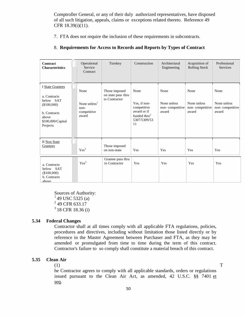
50
Comptroller General, or any of their duly authorized representatives, have disposed of all such litigation, appeals, claims or exceptions related thereto. Reference 49 CFR 18.39(i)(11).
7. FTA does not require the inclusion of these requirements in subcontracts.
8. Requirements for Access to Records and Reports by Types of Contract
Contract Characteristics
Operational Service Contract
Turnkey Construction Architectural Engineering
Acquisition of Rolling Stock
Professional Services
I State Grantees
a. Contracts below SAT ($100,000)
b. Contracts above $100,000/Capital Projects
None
None unless1
non- competitive award
Those imposed on state pass thru to Contractor
None
Yes, if non- competitive award or if funded thru2
5307/5309/53 11
None
None unless non- competitive award
None
None unless non- competitive award
None
None unless non- competitive award
II Non State Grantees
Yes3
Those imposed on non-state
Yes
Yes
Yes
Yes
a. Contracts below SAT ($100,000) b. Contracts above
Yes3
Grantee pass thru to Contractor
Yes
Yes
Yes
Yes
Sources of Authority: 1 49 USC 5325 (a) 2 49 CFR 633.17 3 18 CFR 18.36 (i)
5.34 Federal Changes
Contractor shall at all times comply with all applicable FTA regulations, policies, procedures and directives, including without limitation those listed directly or by reference in the Master Agreement between Purchaser and FTA, as they may be amended or promulgated from time to time during the term of this contract. Contractor's failure to so comply shall constitute a material breach of this contract.
5.35 Clean Air
(1) The Contractor agrees to comply with all applicable standards, orders or regulations issued pursuant to the Clean Air Act, as amended, 42 U.S.C. §§ 7401 et seq.
51
The Contractor agrees to report each violation to the Purchaser and understands and agrees that the Purchaser will, in turn, report each violation as required to assure notification to FTA and the appropriate EPA Regional Office.
(2) The Contractor also agrees to include these requirements in each subcontract exceeding $100,000 financed in whole or in part with Federal assistance provided by FTA.
5.36 Recycled Products
The contractor agrees to comply with all the requirements of Section 6002 of the Resource Conservation and Recovery Act (RCRA), as amended (42 U.S.C. 6962), including but not limited to the regulatory provisions of 40 CFR Part 247, and Executive Order 12873, as they apply to the procurement of the items designated in Subpart B of 40 CFR Part 247.
These requirements flow down to all contractor and subcontractor tiers.
5.37 No Obligation by the Federal Government.
(1) The Purchaser and Contractor acknowledge and agree that, notwithstanding any concurrence by the Federal Government in or approval of the solicitation or award of the underlying contract, absent the express written consent by the Federal Government, the Federal Government is not a party to this contract and shall not be subject to any obligations or liabilities to the Purchaser, Contractor, or any other party (whether or not a party to that contract) pertaining to any matter resulting from the underlying contract.
(2) The Contractor agrees to include the above clause in each subcontract financed in whole or in part with Federal assistance provided by FTA. It is further agreed that the clause shall not be modified, except to identify the subcontractor who will be subject to its provisions.
5.38 Program Fraud and False or Fraudulent Statements or Related Acts.
(1) The Contractor acknowledges that the provisions of the Program Fraud Civil Remedies Act of 1986, as amended, 31 U.S.C. § 3801 et seq. and U.S. DOT regulations, "Program Fraud Civil Remedies," 49 C.F.R. Part 31, apply to its actions pertaining to this Project. Upon execution of the underlying contract, the Contractor certifies or affirms the truthfulness and accuracy of any statement it has made, it makes, it may make, or causes to be made, pertaining to the underlying contract or the FTA assisted project for which this contract work is being performed. In addition to other penalties that may be applicable, the Contractor further acknowledges that if it makes, or causes to be made, a false, fictitious, or fraudulent claim, statement, submission, or certification, the Federal Government reserves the right to impose the penalties of the Program Fraud Civil Remedies Act of 1986 on the Contractor to the extent the Federal Government deems appropriate.
(2) The Contractor also acknowledges that if it makes, or causes to be made, a false, fictitious, or fraudulent claim, statement, submission, or certification to the
52
Federal Government under a contract connected with a project that is financed in whole or in part with Federal assistance originally awarded by FTA under the authority of 49 U.S.C. § 5307, the Government reserves the right to impose the penalties of 18 U.S.C. § 1001 and 49 U.S.C. § 5307(n)(1) on the Contractor, to the extent the Federal Government deems appropriate.
(3) The Contractor agrees to include the above two clauses in each subcontract financed in whole or in part with Federal assistance provided by FTA. It is further agreed that the clauses shall not be modified, except to identify the subcontractor who will be subject to the provisions.
5.39 Termination
Termination for Convenience: THE UNIFIED GOVERNMENT OF ATHENS-CLARKE COUNTY, TRANSIT DEPARTMENT may terminate this contract, in whole or in part, at any time by written notice to the Contractor when it is in the Government's best interest. The Contractor shall be paid its costs, including contract close-out costs, and profit on work performed up to the time of termination. The Contractor shall promptly submit its termination claim to THE UNIFIED GOVERNMENT OF ATHENS-CLARKE COUNTY, TRANSIT DEPARTMENT to be paid the Contractor. If the Contractor has any property in its possession belonging to the THE UNIFIED GOVERNMENT OF ATHENS-CLARKE COUNTY, TRANSIT DEPARTMENT, the Contractor will account for the same, and dispose of it in the manner the THE UNIFIED GOVERNMENT OF ATHENS-CLARKE COUNTY, TRANSIT DEPARTMENT directs.
Termination for Default: THE UNIFIED GOVERNMENT OF ATHENS-CLARKE COUNTY, TRANSIT DEPARTMENT may, by written notice of default to the Contractor, terminate the whole or any part of this contract if the Contractor fails to make delivery of the supplies or to perform the services within the time specified herein or any extension thereof, or if the Contractor fails to perform any provision of the contract, in reasonable accordance with its terms, and in either of these two circumstances does not cure such failure within a period of ten (10) days (or such longer period as the Contracting Officer may authorize in writing) after receipt of notice from the Contracting Officer specifying such failure.
If the contract is terminated in whole or in part for default, THE UNIFIED GOVERNMENT OF ATHENS-CLARKE COUNTY, TRANSIT DEPARTMENT and or the Procuring Agencies may procure, upon such terms and in such manner as the Contracting Officer may deem appropriate, supplies or services similar to those so terminated. The Contractor shall be liable to THE UNIFIED GOVERNMENT OF ATHENS-CLARKE COUNTY, TRANSIT DEPARTMENT and or the Procuring Agencies for any excess costs for such similar supplies or services, and shall continue the performance of this contract to the extent not terminated under the provisions of this clause.
(1) Upon termination of the contract, Procuring Agency shall pay only such costs that result from obligations which were properly incurred by Contractor or subcontractor before the effective date of termination; and
53
(2) such costs as would be allowable if the contract were not terminated or expired normally at the end of the contract.
Except with respect to defaults of subcontractors, the Contractor shall not be liable for any excess costs if the failure to perform the contract arises out of causes beyond the control and without the fault or negligence of the Contractor. If the failure to perform is caused by the default of a sub-contractor, and if such default arises out of causes beyond the control of both the Contractor and sub-contractor, and without the fault or negligence of either of them, the Contractor shall not be liable for any excess costs for failure to perform, unless the supplies or services to be furnished by the sub-contractor were obtainable from other sources in sufficient time to permit the Contractor to meet the required delivery schedule.
Payment for completed supplies delivered to and accepted by Procuring Agency shall be at the contract price. Procuring Agency may withhold cash payments from amounts otherwise due the Contractor to pay for goods and services deemed by the Contracting Officer to be necessary to protect Procuring Agency against loss due to default by Contractor of subcontractor or because of any lien or claim of lien. THE UNIFIED GOVERNMENT OF ATHENS-CLARKE COUNTY, TRANSIT DEPARTMENT shall be entitled to take other remedies that may be legally available.
If, after notice of termination of Contractor’s work pursuant to this contract, it is determined for any reason that Contractor was not in default, or that its default was excusable, or that Procuring Agency is not entitled to the remedies against Contractor provided herein, then Contractor’s remedies against PROCURING AGENCY shall be the same as and limited to those afforded Contractor set out in the section entitled “Disputes”. In the event a Procuring Agency elects to waive its remedies for any breach by the contractor of any covenant, term or condition of this contract, such waiver Procuring Agency shall not limit THE UNIFIED GOVERNMENT OF ATHENS-CLARKE COUNTY, TRANSIT DEPARTMENT and or the Procuring Agencies remedies for any succeeding breach of that or any other term, covenant, or condition of this contract.
Opportunity to Cure: THE UNIFIED GOVERNMENT OF ATHENS-CLARKE COUNTY, TRANSIT DEPARTMENT in its sole discretion may, in the case of a termination for breach or default, allow the Contractor 10 days in which to cure the defect. In such case, the notice of termination will state the time period in which cure is permitted and other appropriate conditions
If Contractor fails to remedy to THE UNIFIED GOVERNMENT OF ATHENS-CLARKE COUNTY, TRANSIT DEPARTMENT satisfaction the breach or default of any of the terms, covenants, or conditions of this Contract within ten (10) days after receipt by Contractor of written notice from THE UNIFIED GOVERNMENT OF ATHENS-CLARKE COUNTY, TRANSIT DEPARTMENT setting forth the nature of said breach or default, THE UNIFIED GOVERNMENT OF ATHENS-CLARKE COUNTY, TRANSIT DEPARTMENT shall have the right to terminate
54
the Contract without any further obligation to Contractor. Any such termination for default shall not in any way operate to preclude THE UNIFIED GOVERNMENT OF ATHENS-CLARKE COUNTY, TRANSIT DEPARTMENT from also pursuing all available remedies against Contractor and its sureties for said breach or default.
If it is later determined by the THE UNIFIED GOVERNMENT OF ATHENS-CLARKE COUNTY, TRANSIT DEPARTMENT that the Contractor had an excusable reason for not performing, such as a strike, fire, or flood, events which are not the fault of or are beyond the control of the THE UNIFIED GOVERNMENT OF ATHENS-CLARKE COUNTY, TRANSIT DEPARTMENT, after setting up a new delivery of performance schedule, may allow the Contractor to continue work, or treat the termination as a termination for convenience.
5.40 Excusable Delays
If the delivery of the item(s) under this contract should be unavoidably delayed, the Executive Agent shall extend the time for completion of the contract for the determined number of days of excusable delay. A delay is unavoidable only if the delay relates to a natural disaster, war, or strike, and was substantial and in fact caused the contractor to miss delivery dates.
The Contractor shall notify THE UNIFIED GOVERNMENT OF ATHENS-CLARKE COUNTY, TRANSIT DEPARTMENT as soon as the contractor has, or should have, knowledge that an event has occurred which will delay deliveries. Within five (5) days, the Contractor shall confirm such notice in writing furnishing as much detail as is available.
The Contractor agrees to supply, as soon as such data are available, any reasonable proofs that are required by the Contracting Officer to make a decision on any request for extension. THE UNIFIED GOVERNMENT OF ATHENS-CLARKE COUNTY, TRANSIT DEPARTMENT shall examine the request and any documents supplied by the Contractor and shall determine if the Contractor is entitled to an extension and the duration of the extension. The Contracting Officer shall notify the Contractor of his decision in writing. It is expressly understood and agreed that the Contractor shall not be entitled to damages or compensation, and shall not be reimbursed for losses on account of delays resulting from any cause under this provision.
5.41 Government-Wide Debarment and Suspension (Nonprocurement)
This contract is a covered transaction for purposes of 49 CFR Part 29. As such, the contractor is required to verify that none of the contractor, its principals, as defined at 49 CFR 29.995, or affiliates, as defined at 49 CFR 29.905, are excluded or disqualified as defined at 49 CFR 29.940 and 29.945.
The contractor is required to comply with 49 CFR 29, Subpart C and must include the requirement to comply with 49 CFR 29, Subpart C in any lower tier covered transaction it enters into. By signing and submitting its bid or proposal, the bidder or Proposer certifies as follows:
The certification in this clause is a material representation of fact relied upon by
55
THE UNIFIED GOVERNMENT OF ATHENS-CLARKE COUNTY, TRANSIT DEPARTMENT. If it is later determined that the bidder or Proposer knowingly rendered an erroneous certification, in addition to remedies available to THE UNIFIED GOVERNMENT OF ATHENS-CLARKE COUNTY, TRANSIT DEPARTMENT, the Federal Government may pursue available remedies, including but not limited to suspension and/or debarment. The bidder or Proposer agrees to comply with the requirements of 49 CFR 29, Subpart C while this offer is valid and throughout the period of any contract that may arise from this offer. The bidder or Proposer further agrees to include a provision requiring such compliance in its lower tier covered transactions.
5.42 Civil Rights
The following requirements apply to the underlying contract:
(1) Nondiscrimination - In accordance with Title VI of the Civil Rights Act, as amended, 42 U.S.C. § 2000d, section 303 of the Age Discrimination Act of 1975, as amended, 42 U.S.C. § 6102, section 202 of the Americans with Disabilities Act of 1990, 42 U.S.C. § 12132, and Federal transit law at 49 U.S.C. § 5332, the Contractor agrees that it will not discriminate against any employee or applicant for employment because of race, color, creed, national origin, sex, age, or disability. In addition, the Contractor agrees to comply with applicable Federal implementing regulations and other implementing requirements FTA may issue.
(2) Equal Employment Opportunity - The following equal employment opportunity requirements apply to the underlying contract:
(a) Race, Color, Creed, National Origin, Sex - In accordance with Title VII of the Civil Rights Act, as amended, 42 U.S.C. § 2000e, and Federal transit laws at 49 U.S.C. § 5332, the Contractor agrees to comply with all applicable equal employment opportunity requirements of U.S. Department of Labor (U.S. DOL) regulations, "Office of Federal Contract Compliance Programs, Equal Employment Opportunity, Department of Labor," 41 C.F.R. Parts 60 et seq., (which implement Executive Order No. 11246, "Equal Employment Opportunity," as amended by Executive Order No. 11375, "Amending Executive Order 11246 Relating to Equal Employment Opportunity," 42 U.S.C. § 2000e note), and with any applicable Federal statutes, executive orders, regulations, and Federal policies that may in the future affect construction activities undertaken in the course of the Project. The Contractor agrees to take affirmative action to ensure that applicants are employed, and that employees are treated during employment, without regard to their race, color, creed, national origin, sex, or age. Such action shall include, but not be limited to, the following: employment, upgrading, demotion or transfer, recruitment or recruitment advertising, layoff or termination; rates of pay or other forms of compensation; and selection for training, including apprenticeship. In addition, the Contractor agrees to comply with any implementing requirements FTA may issue.
(b) Age - In accordance with section 4 of the Age Discrimination in Employment
56
Act of 1967, as amended, 29 U.S.C. § § 623 and Federal transit law at 49 U.S.C. § 5332, the Contractor agrees to refrain from discrimination against present and prospective employees for reason of age. In addition, the Contractor agrees to comply with any implementing requirements FTA may issue.
(c) Disabilities - In accordance with section 102 of the Americans with Disabilities Act, as amended, 42 U.S.C. § 12112, the Contractor agrees that it will comply with the requirements of U.S. Equal Employment Opportunity Commission, "Regulations to Implement the Equal Employment Provisions of the Americans with Disabilities Act," 29 C.F.R. Part 1630, pertaining to employment of persons with disabilities. In addition, the Contractor agrees to comply with any implementing requirements FTA may issue.
(3) The Contractor also agrees to include these requirements in each subcontract financed in whole or in part with Federal assistance provided by FTA, modified only if necessary to identify the affected parties.
5.43 Disputes
Contract Disputes shall be resolved in accordance with ATHENS / CLARK COUNTY PROCUREMENT RULES. Transit Vehicle Manufacturer (TVM) Certification for DBE/WBE: Proposers must certify compliance with the requirements of 49 C.F.R Section 26.49. Failure to so certify will exclude a proposal from further consideration.
5.44 Incorporation of Federal Transit Administration (FTA) Terms
The preceding provisions include, in part, certain Standard Terms and Conditions required by DOT, whether or not expressly set forth in the preceding contract provisions. All contractual provisions required by DOT, as set forth in FTA Circular 4220.1F, are hereby incorporated by reference. Anything to the contrary herein notwithstanding, all FTA mandated terms shall be deemed to control in the event of a conflict with other provisions contained in this Agreement. The Contractor shall not perform any act, fail to perform any act, or refuse to comply with any THE UNIFIED GOVERNMENT OF ATHENS-CLARKE COUNTY, TRANSIT DEPARTMENT requests which would cause THE UNIFIED GOVERNMENT OF ATHENS-CLARKE COUNTY, TRANSIT DEPARTMENT or Procuring Agency to be in violation of the FTA terms and conditions.
5.45 Access Requirements for Individuals with Disabilities: The Contractor agrees to comply with and assure that any sub-recipient, or third party contractor under this Project complies with all applicable requirements of the Americans with Disabilities Act of 1990 (ADA), 42 U.S.C. § 12101 et seq,; section 504 of the Rehabilitation Act of 1973, as amended 29 U.S.C. § 794; the transit assistance laws codified at 49 U.S.C. § 5301, et seq,; and the following regulations and any amendments thereto:
(1) U.S. DOT regulations. "Nondiscrimination on the Basis of Handicap in Programs
57
and Activities Receiving or Benefiting from Federal Financial Assistance," 49 C.F.R. Part 27. (2) Department of Justice (DOJ) regulations. "Nondiscrimination on the Basis of Disability in State and Local Government Services." 28 C.F.R. Part 35;
(3) DOJ regulations. "Nondiscrimination on the Basis of Disability by Public accommodations and in Commercial Facilities." 28 C.F.R. Part 36;
(4) Equal Employment Opportunity Commission, (EEOC) regulations. "Regulations to Implement the Equal Employment Provisions of the Americans with Disabilities Act." 29 C.F.R. Part 1630;
(5) No grant may be used to support a procurement that uses an exclusionary or discriminatory specification. 49 USC 5323 (h).
5.46 Interest of Members of, or Delegates to, Congress
No member of, or delegate to, the Congress of the United States shall be admitted to any share or part of this contract or to any benefit arising there from.
5.47 HOLD HARMLESS AND INDEMNIFICATION
The Contractor shall indemnify and hold harmless THE UNIFIED GOVERNMENT OF ATHENS-CLARKE COUNTY, TRANSIT DEPARTMENT and the Procuring Agencies or any of them, from and against all claims of liability to third parties for injury to or death of persons, or loss of or damage to property arising out of or in connection with the performance of the work under this Contract, and the use of the premises incident thereto, except where such liability arises out of the sole negligence of THE UNIFIED GOVERNMENT OF ATHENS-CLARKE COUNTY, TRANSIT DEPARTMENT or the Procuring Agencies, or any of them, and shall defend all suits brought upon such claim and pay all costs and expenses incident thereto. THE UNIFIED GOVERNMENT OF ATHENS-CLARKE COUNTY, TRANSIT DEPARTMENT shall have the right to participate in the defense of any suit, without relieving the Contractor of any obligation hereunder.
5.48 Materials and Accessories Responsibility
The Contractor shall be responsible for all materials and workmanship in the construction of the equipment and all accessories used whether the same are manufactured by the Contractor or obtained from the Contractor or subcontractor.
5.49 Spare Parts
The Contractor shall guarantee the availability of replacement parts for this equipment for at least a 12 year period after the date of acceptance. Spare parts shall be interchangeable with the original equipment and shall be manufactured in accordance with the quality assurance provisions of this contract.
5.50 Maintenance and Parts Manuals
The Contractor shall provide 2 set of manuals for each 3 buses ordered. This set will include a service manual, parts manual, electrical schematic manual and the same for all subsystems and sub components incorporated in the equipment. Additionally, the contractor will provide all the aforementioned manuals on
58
compact disc (CD) formatted in a searchable portable document format (PDF). The Contractor shall keep maintenance information available for a period of 12 years after the date of acceptance of the equipment procured under this contract. The Contractor shall also keep all information up-to-date for a period of 12 years.
5.51 Maintenance Diagnostic Software
As an option provide maintenance diagnostic software. (1) Cummins Electronic Service Diagnostic Software Insite 8.0.0 (2) Allison Transmission Software 11.0.3 (3) Meritor Wabco Diagnostic Toolbox Software 11.2.0.0 (4) I/O Controls Diagnostic Software (5) Apollo Camera System Diagnostic Software
5.52 Liquidated Damages
THE UNIFIED GOVERNMENT OF ATHENS-CLARKE COUNTY, TRANSIT DEPARTMENT and the Procuring Agencies have determined that timely delivery of the goods and services to be obtained through this procurement is of the essence and that failure to obtain timely delivery will cause financial and non-financial damages that would be difficult to calculate. Liquidated damages in the amount of $50 per calendar day, per bus are deemed a reasonable approximation of these damages and will be assessed for any late delivery, not as a penalty but as a means of compensating the Procuring Agencies for these damages.
Liquidated damages are payable directly to the Procuring Agency purchasing the bus(es) involved and may, at the option of the Procuring Agency, be offset against any monies due, or which may thereafter become due, to the Contractor under this Contract. The Contractor shall provide, at its own expense, all spare parts, tools, and space required to complete repairs. If the equipment is removed from Procuring agency's property, repair procedures must be diligently pursued by the Contractor's representatives.
5.52.1 Warranty
Warranties in this document are in addition to any statutory remedies or warranties imposed on the Supplier. The Supplier is individually and totally responsible to the Procuring Agency for all warranty claims. Consistent with this requirement, the Supplier warrants and guarantees to the Procuring Agency each complete Bus, including sub-systems and components as follows:
Complete Bus One (1) year / 50, 0000 miles on parts and labor, whichever comes first. All warranties stated in this section apply, whichever comes first on coverage expiration.
Sub-Systems and Components Engine - Two (2) year / unlimited miles warranty coverage on parts and labor.
As an option, the cost for Five (5) year / 300,000 will be made available and priced separately.
59
Transmission - two (2) year / unlimited miles warranty coverage on parts and labor.
As an option, the cost for Five (5) year / 300,000 will be made available and priced separately.
Differential - two (2) years / unlimited miles warranty coverage on parts and labor.
HVAC - three (3) years / unlimited miles warranty on parts and labor.
Basic body structure - three (3) year / unlimited miles warranty on parts and labor, Structure/body integrity - seven (7) year unlimited miles warranty on parts and Labor. Exterior paint - three (3) year unlimited miles warranty on parts.
Sub-Flooring and rubber flooring twelve (12) year unlimited miles warranty on parts and labor. All other components, sub-systems or appurtenances are to carry the manufacturer’s basic warranty, but in no event will any warranty be less than one (1) year on parts and labor. All warranty dates will start from the in-service date of each Bus received.
Voiding of Warranty The warranty shall not apply to any part or component of the Bus that has been subject to misuse, negligence, accident, or that has been repaired or altered in any way so as to adversely affect its performance or reliability, except insofar as such repairs were made in accordance with the Supplier’s maintenance manuals and the workmanship was in accordance with recognized standards of the industry.
Exceptions to Warranty The warranty shall not apply to scheduled maintenance items such as filters. Consumable items are only fuel, oil and lubricants. Items with progressive wear characteristics such as belts, wiper blades, etc. are not excluded from warranty and should not be of poor quality that requires frequent change. The warranty shall not apply to tires, nor to any items furnished by the Procuring Agency such as radios, fare boxes, and other auxiliary equipment, except insofar as such equipment may be damaged by the failure of a part, component, or design for which the Supplier is responsible.
Fleet Defects A fleet defect is defined as the failure of identical items or sub-systems covered by the warranties of this contract, in proportion to the total number of buses delivered. Deliveries of one (1) to twenty (20) buses, the proportion shall be fifty (50%). Deliveries of twenty (20) buses or more the proportion shall be twenty- five (25%) percent.
Scope of Fleet Defect Provisions
60
The Supplier shall promptly, upon notification, correct all fleet defects as defined above and undertake a work program designed to prevent the occurrence and reoccurrence of the same defect in all Buses purchased under this contract. Detailed instructions for any work program must be submitted to the Procuring Agency, in writing, before any work commences. The warranty on repairs to items or sub-systems determined to be fleet defects shall be extended for one year or 50,000 miles to assure the corrections made are not a temporary fix, beginning on the repair/replacement date for the correction on the last Bus in the fleet covered by the warranty of this contract. If the fleet defect failure reoccurs during this period the fleet defect status will again be applied until there is no reoccurrence. If the Supplier does not start the work program within thirty (30) calendar days after being notified of the fleet defect, the Procuring Agency reserves the right to start the repairs unless the Supplier has an understanding with the Procuring Agency Warranty Department that thirty (30 calendar days is not sufficient and an agreement has been made on the time frame. Fleet defect work performed by the Procuring Agency will be charged back to the Supplier at the labor rate of $95.00 per hour.
The Supplier shall be totally responsible for the correction of all fleet defects. The Procuring Agency will make the bus available to the Supplier or Supplier’s representative upon timely notice.
61
SECTION VI TECHNICAL SPECIFICATIONS
6.0 TECHNICAL SPECIFICATIONS GENERAL
Scope THE UNIFIED GOVERNMENT OF ATHENS-CLARKE COUNTY, TRANSIT DEPARTMENT and participating procuring agencies seek to purchase the most modern heavy duty transit buses available that will provide maximum, reliability, dependability, economy of operation comfort, and safety. Heavy duty transit buses ordered under this bid will be low-floor diesel power or as an alternative to the base diesel, hybrid drive or CNG. Buses shall have a minimum expected life of twelve (12) years or 500,000 miles, whichever comes first, and are intended for the widest possible spectrum of passengers, including children, adults, the elderly and people with disabilities. Attached to this specification is a listing of optional equipment. All items listed shall be priced and included as part of the bid. Individual agencies that use this bid shall be able to select alternative equipment from this listing without incurring cost for additional engineering hours for any changes in optional equipment.
6.1 Conformity to Specifications / Approved Equals / Deviations
References to equipment, material, article or patented process by trade name, make or catalog number shall be regarded as establishing a standard of quality and components known to meet the intended requirement and shall not be construed as limiting competition. A Proposer may, at its option, provide a deviation of any equipment, material, article, or process they consider to be as equal. All such requests shall be accompanied by supporting technical data, background information and test results that substantiate the deviation is an equal to or better than the any equipment, material, article, or process requested in the specification. All deviations must be submitted on the supplied form (Attachment D) and shall be included with the proposal. Deviations will be evaluated and scored accordingly.
6.2 Definitions Alternative. An alternative specification condition to the default bus configuration. The Agency may define alternatives to the default configuration to satisfy local operating requirements. Alternatives for the default configuration will be clearly identified. Ambient Temperature. The temperature of the surrounding air. For testing purposes, ambient temperature must be between 16 °C (50 °F) and 38 °C (100 °F). Analog Signals. A continuously variable signal that is solely dependent upon magnitude to express information content. NOTE: Analog signals are used to represent the state of variable devices such as rheostats, potentiometers, temperature probes, etc. Audible Discrete Frequency: An audible discrete frequency is determined to exist if the sound power level in any 1/3-octave band exceeds the average of the sound
62
power levels of the two adjacent 1/3-octave bands by 4 decibels (dB) or more. Battery Compartment. Low-voltage energy storage, i.e. 12/24 VDC batteries. Battery Management System (BMS). Monitors energy, as well as temperature, cell or module voltages, and total pack voltage. The BMS adjusts the control strategy algorithms to maintain the batteries at uniform state of charge and optimal temperatures. Braking Resistor. Device that converts electrical energy into heat, typically used as a retarder to supplement or replace the regenerative braking. Burst Pressure. The highest pressure reached in a container during a burst test. Capacity (fuel container). The water volume of a container in gallons (liters). Cells. Individual components (i.e., battery or capacitor cells). Code. A legal requirement. Combination Gas Relief Device. A relief device that is activated by a combination of high pressures or high temperatures, acting either independently or together. Composite Container for CNG. A container fabricated of two or more materials that interact to facilitate the container design criteria. Compressed Natural Gas (CNG). Mixtures of hydrocarbon gases and vapors consisting principally of methane in gaseous form that has been compressed for use as a vehicular fuel. Container. A pressure vessel, cylinder, or cylinders permanently manifolded together used to store CNG. Container Appurtenances. Devices connected to container openings for safety, control or operating purposes. Container Valve. A valve connected directly to a container outlet. Curb Weight. Weight of vehicle, including maximum fuel, oil and coolant; and all equipment required for operation and required by this Specification, but without passengers or driver. dBA. Decibels with reference to 0.0002 microbar as measured on the “A” scale. DC to DC Converter. A module which converts a source of direct current (DC) from one voltage level to another. Default Configuration Bus. The bus described if no alternatives are selected. Signing, colors, the destination sign reading list and other information must be provided by the Agency.
63
Defueling. The process of removing fuel from a tank. Defueling Port. Device which allows for vehicle defueling, or the point at which this occurs. Destroyed. Physically made permanently unusable. Discrete Signal. A signal that can take only pre-defined values, usually of a binary 0 or 1 nature where 0 is battery ground potential and 1 is a defined battery positive potential. DPF. Diesel particulate filter. Driver's Eye Range. The 95th-percentile ellipse defined in SAE Recommended Practice J941, except that the height of the ellipse shall be determined from the seat at its reference height. Energy Density. The relationship between the weight of an energy storage device and its power output in units of watt-hours per kilogram (Wh/kg). Energy Storage System (ESS). A component or system of components that stores energy and for which its supply of energy is rechargeable by a PPU and/or an off-vehicle energy source. Fill Pressure for CNG. The pressure attained at the actual time of filling. Fill pressure varies according to the gas temperatures in the container, which are dependent on the charging parameters and the ambient conditions. The maximum dispensed pressure shall not exceed 125 percent of service pressure. Flow Capacity. For natural gas flow, this is the capacity in volume per unit time (normal cubic meters/minute or standard cubic feet per minute) discharged at the required flow rating pressure. Fuel Line. The pipe, tubing or hose on a vehicle, including all related fittings, through which natural gas passes. Fusible Material. A metal, alloy or other material capable of being melted by heat. Fire Resistant. Materials that have a flame spread index less than 150 as measured in a radiant panel flame test per ASTM-E 162-90. Fireproof. Materials that will not burn or melt at temperatures less than 2000 °F. Free Floor Space: Floor area available to standees, excluding the area under seats, area occupied by feet of seated passengers, the vestibule area forward of the standee line, and any floor space indicated by manufacturer as non-standee areas such as, the floor space “swept” by passenger doors during operation. Floor area of 1.5 sq ft shall be allocated for the feet of each seated passenger that protrudes into the standee area. Fuel Management System. Natural gas fuel system components that control or contribute to engine air fuel mixing and metering, and the ignition and combustion of
64
a given air-fuel mixture. The fuel management system would include, but is not limited to, reducer/regulator valves, fuel metering equipment (e.g. carburetor, injectors), sensors (e.g., main throttle, wastegate). GAWR (Gross Axle Weight Rated). The maximum total weight as determined by the axle manufacturer, at which the axle can be safely and reliably operated for its intended purpose. Gross Load. 150 lbs for every designed passenger seating position, for the driver, and for each 1.5 square feet of free floor space. GVW (Gross Vehicle Weight). Curb weight plus gross load. GVWR (Gross Vehicle Weight Rated): The maximum total weight as determined by the vehicle manufacturer, at which the vehicle can be safely and reliably operated for its intended purpose. High Pressure. Those portions of the CNG fuel system that see full container or cylinder pressure. High Voltage (HV). Greater than 50 volts (AC and DC). Hose: Flexible line. Hybrid. A vehicle that uses two or more distinct power sources to propel the vehicle. Hybrid System Controller (HSC). Regulates energy flow throughout hybrid system components in order to provide motive performance and accessory loads, as applicable, while maintaining critical system parameters (voltages, currents, temperatures, etc.) within specified operating ranges. Hybrid Drive System (HDS). The mechanical and/or electromechanical components, including the PPU and energy storage system, which comprise the traction drive portion of the hybrid propulsion system. Intermediate Pressure. The portion of a CNG system after the first pressure regulator, but before the engine pressure regulator. Intermediate pressure on a CNG vehicle is generally from 3.5 to 0.5 MPa (510 to 70 psi). Inverter. A module that converts DC to and from AC. Labeled. Equipment or materials to which has been attached a label, symbol or other identifying mark of an organization, which is acceptable to the authority having jurisdiction and concerned with product evaluation, which maintains periodic inspection of production labeled equipment or materials, and by whose labeling the manufacturer indicates compliance with appropriate standards or performance in a specified manner. Leakage. Release of contents through a Defect or crack. See Rupture. Line: All tubes, flexible and hard, that carry fluids.
65
Liner. Inner gas-tight container or gas container to which the overwrap is applied. Local Regulations. Regulations below the state level. Low-Floor Bus. A bus that, between at least the front (entrance) and rear (exit) doors, has a floor sufficiently low and level so as to remove the need for steps in the aisle between the doors and in the vicinity of these doors. Low Voltage (LV). 50 volts or less (AC and DC). Lower Explosive Limit. The lowest concentration of gas where, given an ignition source, combustion is possible. Maximum Service Temperature. The maximum temperature to which a container/cylinder will be subjected in normal service. Metallic Hose. A hose whose strength depends primarily on the strength of its metallic parts; it can have metallic liners or covers, or both. Metering Valve. A valve intended to control the rate of flow of natural gas. Module. Assembly of individual components Motor (Electric). A device that converts electrical energy into mechanical energy. Motor (Traction). An electric motor used to power the driving wheels of the bus. Operating Pressure. The varying pressure developed in a container during service. Physical Layer. The first layer of the seven-layer International Standards Organization (ISO) Open Systems Interconnect (OSI) reference model. This provides the mechanical, electrical, functional and procedural characteristics required to gain access to the transmission medium (e.g., cable) and is responsible for transporting binary information between computerized systems. Pipe: Nonflexible line. Pressure Relief Device (PRD). A pressure and/or temperature activated device used to vent the container/cylinder contents and thereby prevent rupture of a NGV fuel container/cylinder, when subjected to a standard fire test as required by fuel container/cylinder standards. NOTE: Since this is a pressure-activated device, it may not protect against rupture of the container when the application of heat weakens the container to the point where its rupture pressure is less than the rated burst pressure of the relief device, particularly if the container is partially full. Power. Work or energy divided by time Power Density. Power divided by mass, volume or area.
66
Propulsion System. System that provides propulsion for the vehicle proportional to operator commands. Includes, as applicable, the HDS, energy storage system and the hybrid system controller. Real-Time Clock (RTC). Computer clock that keeps track of the current time. Regenerative Braking. Deceleration of the bus by switching motors to act as generators, which return vehicle kinetic energy to the energy storage system. Rejectable Damage. In terms of NGV fuel containers/cylinders, this is damage as outlined in CGA C-6.4, “Methods for External Visual Inspection of Natural Gas Vehicle Fuel Containers and Their Installations,” and in agreement with the manufacturer’s recommendations. Retarder. Device used to augment or replace some of the functions of primary friction based braking systems of the bus. Rupture. Sudden and unstable damage propagation in the structural components of the container resulting in a loss of contents. See Leakage. Seated Load. 150 lbs for every designed passenger seating position and for the driver. SLW (Seated Load Weight). Curb weight plus seated load. Serial Data Signals. A current loop based representation of ASCII or alphanumeric data used for transferring information between devices by transmitting a sequence of individual bits in a prearranged order of significance. NOTE: An example is the communication that takes place between two or more electronic components with the ability to process and store information. Service Pressure. The settled pressure at a uniform gas temperature of 21 °C (70 °F) and full gas content. It is the pressure for which the equipment has been constructed, under normal conditions. Also referred to as the nominal service pressure or working pressure. Settled Pressure. The gas pressure when a given settled temperature, usually 21 °C (70 °F), is reached. Settled Temperature. The uniform gas temperature after any change in temperature caused by filling has dissipated. Solid State Alternator. A module that converts high-voltage DC to low-voltage DC (typically 12/24 volt systems). Sources of Ignition. Devices or equipment that because of their modes of use or operation, are capable of providing sufficient thermal energy to ignite flammable compressed natural gas-air mixtures when introduced into such a mixture, or when such a mixture comes into contact with them
67
Special Tools. Tools not normally stocked by the Agency. Specification. A particular or detailed statement, account, or listing of the various elements, materials, dimensions, etc. involved in the manufacturing and construction of a product. Standard. A firm guideline from a consensus group. Standards. Standards referenced in “Part 5: Technical Specifications” are the latest revisions unless otherwise stated. Standee Line. A line marked across the bus aisle to designate the forward area that passengers may not occupy when the bus is moving. State of Charge (SOC). Quantity of electric energy remaining in the battery relative to the maximum rated Amp hour (Ah) capacity of the battery expressed in percent. This is a dynamic measurement used for the energy storage system. A full SOC indicates that the energy storage system cannot accept further charging from the engine driven generator or the regenerative braking system. Stress Loops. The “pig-tails” commonly used to absorb flexing in piping. Structure. The structure shall be defined as the basic body, including floor deck material and installation, load bearing external panels, structural components, axle mounting provisions and suspension beams and attachment points. Thermally Activated Gas Relief Device. A relief device that is activated by high temperatures and generally contains a fusible material. NOTE: Since this is a thermally activated device, it does not protect against over-pressure from improper charging practices. Wheelchair. A mobility aid belonging to any class of three- or four-wheeled devices, usable indoors, designed for and used by individuals with mobility impairments, whether operated manually or powered. A “common wheelchair” is such a device that does not exceed 30 in. in width and 48 in. in length measured 2 in. above the ground, and does not weigh more than 600 lbs when occupied.
6.3 Referenced Publications The documents or portions thereof referenced within this specification shall be considered part of the requirements of the specification. The edition indicated for each referenced document is the current edition, as of the date of the APTA issuance of this specification.
6.4 Legal Requirements The Contractor shall comply with all applicable federal, state and local regulations. These shall include but not be limited to ADA, as well as state and local accessibility, safety and security requirements. Local regulations are defined as those below the state level.
68
Buses shall meet all applicable FMVSS and shall accommodate all applicable FMCSR regulations in effect at location of the Agency and the date of manufacture. In the event of any conflict between the requirements of these specifications and any applicable legal requirement, the legal requirement shall prevail. Technical requirements that exceed the legal requirements are not considered to conflict.
6.5 Overall Requirements The Contractor shall ensure that the application and installation of major bus subcomponents and systems are compliant with all such subcomponent vendors’ requirements and recommendations. Components used in the vehicle shall be of heavy- duty design and proven in transit service. The buses shall afford features essential for safe, efficient and comfortable operation by the operator. This implies the utmost in road and traffic visibility under all driving conditions and adequate means for safe passenger movement. The bus must be maneuvered easily in normal and heavy traffic. All Proposers must conform to these specifications and the product they furnish shall be of first-class quality, and workmanship, and shall be of the best obtainable in the various trades. The design of the body, chassis, and equipment, which the manufacturer proposes to furnish, shall be such as to produce a vehicle of substantial and durable construction in all respects. All systems, sub-systems, and components shall be individually and permanently labeled with Manufacturer, Part Number, and Serial Number. Label is to be located, in each instance, for easiest access for reading while installed for use in the bus. List of all systems, subsystems, and components shall accompany each bus either on paper or diskette. This shall include an OEM to vendor cross- reference listing. The manufacturer shall use FC300 and FC 195 hoses for all flexible lines except A/C and discharge from the air compressor to the wet tank. The manufacturer shall be responsible for providing all parts or details which make each bus complete and ready for service, even though such part(s) or details(s) are not mentioned in these specifications. All buses shall be in compliance with the Americans with Disabilities Act (ADA). These buses shall be new, unused, current model specifically designed for intra-city service and substantially manufactured in the United States (in accordance with "Buy America" requirements). These units must meet all Federal requirements applicable to this type of vehicle. Buses provided under this contract shall be 30 foot, 35 foot, and 40 foot in length, 102 inches wide, with a low floor standard transit design.
6.6 Worker and Protective Measures All bolts or rods passing through wood shall be sealed with zinc chromate or other
69
approved sealing compound. Where wood and wood are placed together, all outer edges of wood, as well as the edges of holes, cutouts and notches shall be coated with a linseed oil and titanium dioxide sealer or zinc chromate or other appropriate sealing compound. All exterior light fixtures shall be fitted to the contour of the bus body and adequately sealed to prevent entrance of water. All rubber seals on ventilator doors and compartment cabinet doors shall be placed in 'U' shaped channels to firmly hold the rubber in place. Equally, self-adhering closed cell neoprene seals may be used, without 'U' channels. All burrs and sharp edges shall be dressed so as to prevent injury to passengers and employees, or damage to their clothing. All buses shall be subjected to water tests simulating the severe rain conditions experienced in the Georgia environment. Windows, escape hatches, doors, etc. are subject to an approved water test to be conducted at the manufacturer’s facility by the manufacturer and shall be observed by the Resident Inspector(s). Water testing may be verified by further testing at the agency’s Maintenance Facility prior to the acceptance of each vehicle if test observation or verification of leak repair is missed on or not observed by the Resident Inspector on any bus built. Any bus that fails to pass the water test shall be corrected by the contractor. The retest/corrective repair cycle shall repeat until the leak(s) have been eliminated to the agency’s satisfaction.
6.7 Water Test Description The roof, roof hatches, front cap, rear cap, sidewalls, passenger windows, driver’s windows, destination sign windows, windshields, wheel wells and all doors of all buses shall be water tested prior to the delivery of each unit as follows: 1. The water test shall consist of a series of nozzles which are strategically located around the perimeter of the vehicle so as to spray water over the entire surface of the vehicle. 2. The nozzles shall eject a volume of water no less than 2.6 gallons per minute per nozzle under a pressure of no less than 22 lbs. per minute measured at the nozzle tip. 3. The contractor shall be required to water test each vehicle under the conditions described above for no less than 15 minutes to ensure there are no water leaks in the bus. 4. Bus road testing shall be conducted immediately after the water test. Contractor shall take the necessary steps of corrective action to repair any leaks found as a result of the described test and shall repeat the 15 minute water test to ensure that corrective steps have been successful. This process shall be repeated until no leaks are found. Documentation of each bus shall be kept by the manufacturer as to the location of the leak, what caused the leak to occur and shall describe the repair action taken to prevent the leak from reoccurring.
70
If the Contractor’s bus manufacturing process water test differs from the water test process and criteria described above, then any deviations shall be approved by the procuring agency.
6.8 Total Bus Operation Total bus operation shall be evaluated during road tests. The purpose of the road tests is to observe and verify the operation of the bus as a system and to verify the functional operation of the subsystems that can be operated only while the bus is in motion. Each bus shall be driven for a minimum of 25 miles during the road tests. The plan shall be submitted to the agency for approval. All zerk grease testing fittings shall be accessible from a pit location with a standard straight nose grease gun. All vehicles will be road-tested and dyno-tested.
6.9 Weight It shall be a design goal to construct each bus as light in weight as possible without degradation of safety, appearance, comfort, traction or performance. Buses at a capacity load shall not exceed the tire factor limits, brake test criteria or structural design criteria.
6.10 Capacity The vehicle shall be designed to carry the gross vehicle weight, which shall not exceed the bus GVWR.
6.11 Service Life The minimum useful design life of the bus in transit service shall be at least twelve (12) years or 500,000 miles. It shall be capable of operating at least 40,000 miles per year, including the 12th year.
6.12 Maintenance and Inspection Scheduled maintenance tasks shall be related and shall be, in accordance with the manufacturer’s recommended preventative maintenance schedule (along with routine daily service performed during the fueling operations). Test ports shall be provided for commonly checked functions on the bus, such as air intake, exhaust, hydraulic, pneumatic, charge-air and engine cooling systems, engine, transmission, etc. All Engine and Transmission components will have the fluid sampling valves (or equivalents) installed that are easy to access: device and location selection to be made at pre-production meeting. The manufacturer shall give prime consideration to the routine problems of maintaining the vehicle. All bus components and systems, both mechanical and electrical, which will require periodic physical Work or inspection processes shall be installed so that a minimum of time is consumed in gaining access to the critical repair areas. It shall not be necessary to disassemble portions of the bus structure
71
and/or equipment such as seats and flooring under seats in order to gain access to these areas. Each bus shall be designed to facilitate the disassembly, reassembly, servicing or maintenance, using tools and equipment that are normally available as standard commercial items. Requirements for the use of unique specialized tools will be minimized. The body and structure of the bus shall be designed for ease of maintenance and repair. Individual panels or other equipment which may be damaged in normal service shall be repairable or replaceable. Ease of repair shall be related to the vulnerability of the item to damage in service. Contractor shall provide a list of all special tools and pricing required for maintaining this equipment. Said list shall be submitted as a supplement to the Pricing Schedule. NOTE: Tools such as compartment door keys, bellows gauges and other tools that are required for daily maintenance and inspections shall not be included in the special tool list and shall be furnished for each bus.
6.13 Interchangeability Unless otherwise agreed, all units and components procured under this Contract, whether provided by Suppliers or manufactured by the Contractor, shall be duplicates in design, manufacture and installation to ensure interchangeability among buses in each separate order group in this procurement. This interchangeability shall extend to the individual components as well as to their locations in the buses. These components shall include, but are not limited to, passenger window hardware, interior trim, lamps, lamp lenses and seat assemblies. Components with non-identical functions shall not be, or appear to be, interchangeable. Any one component or unit used in the construction of these buses shall be an exact duplicate in design, manufacture and assembly for each bus in each order group in this Contract. Contractor shall identify and secure approval for any changes in components or unit construction provided within a Contract. In the event that the Contractor is unable to comply with the interchangeability requirement, the Contractor must notify the Agency and obtain the Agency’s prior written approval, including any changing in pricing. Agency shall review proposed product changes on a case-by-case basis and shall have the right to require extended warranties to ensure that product changes perform as least as well as the originally supplied products.
6.14 Training Along with the purchase of new buses, it is the Procuring Agency’s requirements to have the manufacturer provide an appropriate program of instruction targeted to the operator, servicing, and maintenance personnel. This will be accomplished through a combination of Agency on-site and contractor and/or supplier site training. All Training will be priced as an option and separately from the base bus price.
72
All training instructors shall be competent to teach the course area they are instructing. Further, all instructors shall speak English and have a complete understanding of the English language. If the instructor or vendor presenter lacks the skill or knowledge to provide instruction, or cannot communicate with the students, the procuring agency reserves the right to request that the instructor be replaced and the area of training be repeated.
6.15 Operator Orientation The Contractor shall provide an 8 hour course of instruction for procuring agency for Operations personnel. Class size is not to exceed 10 employees per session. The program shall include, but not be limited to the following: Operator Compartment; Controls and Switches; Warning Indicators and Gauges; Seat Adjustment; Door Control; Walk Around Inspection; Compartment-by-Compartment Explanation; Mirror Adjustments; Climate Control system; Wheelchair Ramp; Safety Equipment; Emergency Procedures Wheelchairs Securement;
6.16 Maintenance Orientation The Contractor shall provide an 8 hour course of instruction for procuring agency Maintenance personnel on Vehicle Servicing. Class size is not to exceed 10 employees per session. At minimum, the course shall cover the following areas: Chassis, Suspension, Steering, Axles, Brakes Air, Body, Doors, Electrical, Engine, Fuel, Transmission, HVAC, Fire Suppression, Towing/ Jacking. Technical Training The contractor shall provide a structured program of technical training which will consist of specific and identifiably separate curriculum for each subject area. Each subject area training session shall be between eight (8) and forty (40) classroom/hands-on hours based on subject area, with class size being no more than (10) participants. The training will be delivered at the Procuring Agency’s location on a schedule coordinated by the Procuring Agency’s training department and the contractor. The following subject areas will be offered: Body and Chassis, Suspension and Steering, Electrical and Electronics, Air and Brake system, HVAC/Climate Controls, Engine, Transmission, Wheelchair ramp system, Destination Signs, Doors, Axles and Tires, Hybrid Drive, CNG fuel system, and Fire Suppression. The technical training shall be delivered on a schedule coordinated between the Procuring Agency’s training department and the contractor. The subject area of sessions to be provided will be negotiated between the procuring agency's training personnel and the Contractor, with the base requirement being 96 hours. OEM
73
The contractor shall provide two (2) class slots at the manufacturer’s suppliers training facility for technical instruction course on the operation, diagnostics, troubleshooting, repair, and servicing of the below listed areas: 1. Engine 2. Transmission
6.17 Operating Environment The bus shall achieve normal operation in ambient temperature ranges of 10 ºF to 115 ºF, at relative humidity between 5 percent and 100 percent, and at altitudes up to 3000 feet above sea level. Degradation of performance due to atmospheric conditions shall be minimized at temperatures below 10 °F, above 115 °F or at altitudes above 3000 feet.
6.18 Noise a. Interior Noise The combination of inner and outer panels and any material used between them shall provide sufficient sound insulation so that a sound source with a level of 80 dBA measured at the outside skin of the bus shall have a sound level of 65 DBA or less at any point inside the bus. These conditions shall prevail with all openings, including doors and windows, closed and with the engine and accessories switched off. The bus-generated noise level experienced by a passenger at any seat location in the bus shall not exceed 80 dBA. The driver area shall not experience a noise level of more than 75.5 dBA. b. Exterior Noise Airborne noise generated by the bus and measured from either side shall not exceed 80 dBA under full power acceleration when operated 0 to 35 mph at curb weight. The maximum noise level generated by the bus pulling away from a stop at full power shall not exceed 83 dBA. The bus-generated noise at curb idle shall not exceed 65 dBA. If the noise contains an audible discrete frequency, a penalty of 5 dBA shall be added to the sound level measured. All noise readings shall be taken fifty (50) feet from, and perpendicular to, the centerline of the bus with all accessories operating. The Contractor shall comply with the exterior noise requirements defined in local laws and ordinances identified by the Agency and SAE J366.
6.19 Fire Safety The bus shall be designed and manufactured in accordance with all applicable fire safety and smoke emission regulations. These provisions shall include the use of fire-retardant/low-smoke materials, fire detection systems, bulkheads and facilitation of passenger evacuation. All materials used in the construction of the passenger compartment of the bus shall be in accordance with the Recommended Fire Safety Practices defined in FMVSS 302, dated October 20, 1993. Materials entirely enclosed from the passenger compartment, such as insulation within the sidewalls and sub-floor, need not comply. In addition, smaller components and items, such as seat grab rails, switch knobs, and small light lenses shall be exempt from this requirement.
74
6.20 Respect for the Environment In the design and manufacture of the bus, the Contractor shall make every effort to reduce the amount of potentially hazardous waste. In accordance with Section 6002 of the Resource Conservation and Recovery Act, the Contractor shall use, whenever possible and allowed by the specifications, recycled materials in the manufacture of the bus.
6.21 DIMENSIONS Physical Size With exceptions such as exterior mirrors, marker and signal lights, bumpers, fender skirts, washers, wipers, ad frames, cameras, object detection systems, bicycle racks, feelers and rub rails, the bus shall have the following overall dimensions. Bus Length: 30 Foot Bus (28’ TO 33’ 11”) 35 Foot Bus (34’ TO 39’) 40 Foot Bus (39’ 1” TO 44’ 11”) Bus Width Body width shall be 102 in. (+0, -1 in.) Bus Height Maximum overall height shall be 140 in., including all rigid, roof-mounted items. Step Height The step height shall not exceed 16.5 in. at either doorway without kneeling and shall not exceed 15.5 in. at the step. A maximum of two steps is allowed to accommodate a raised aisle floor in the rear of the bus. Underbody Clearance The bus shall maintain the minimum clearance dimensions as shown in Figure 2 and defined in SAE Standard J689, regardless of load up to the gross vehicle weight rating. Ramp Clearances The approach angle is the angle measured between a line tangent to the front tire static loaded radius arc and the initial point of structural interference forward of the front tire to the ground. The departure angle is the angle measured between a line tangent to the rear tire static loaded radius arc and the initial point of structural interference rearward of the rear tire to the ground. The breakover angle is the angle measured between two lines tangent to the front and rear tire static loaded radius and intersecting at a point on the underside of the vehicle that defines the largest ramp over which the vehicle can roll.
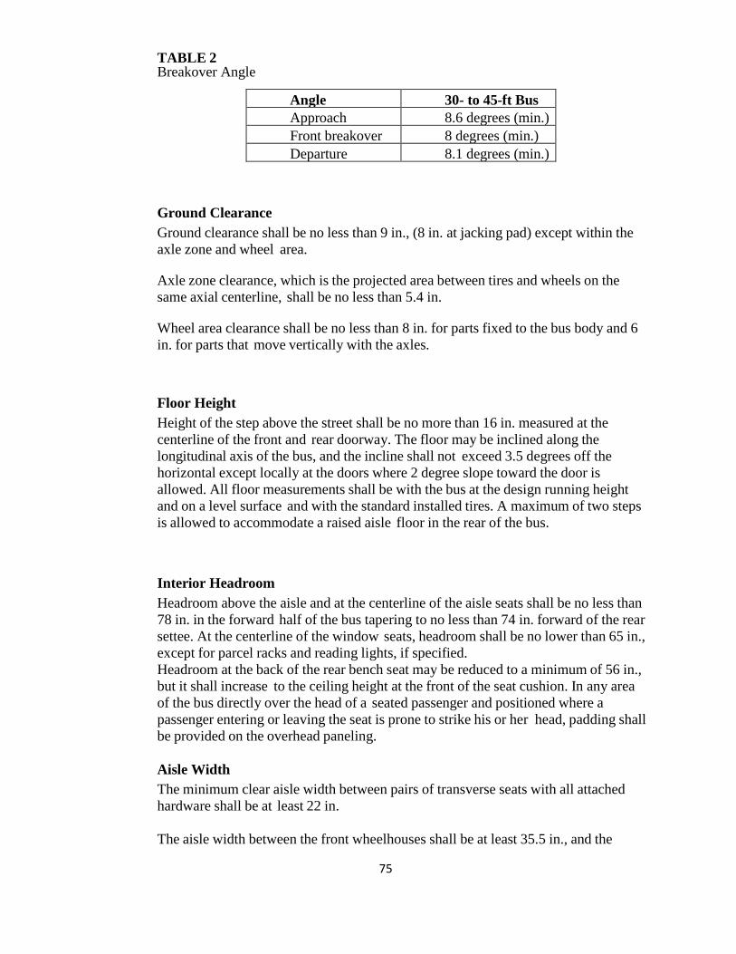
75
TABLE 2 Breakover Angle
Angle 30- to 45-ft Bus Approach 8.6 degrees (min.) Front breakover 8 degrees (min.) Departure 8.1 degrees (min.)
Ground Clearance Ground clearance shall be no less than 9 in., (8 in. at jacking pad) except within the axle zone and wheel area. Axle zone clearance, which is the projected area between tires and wheels on the same axial centerline, shall be no less than 5.4 in. Wheel area clearance shall be no less than 8 in. for parts fixed to the bus body and 6 in. for parts that move vertically with the axles. Floor Height Height of the step above the street shall be no more than 16 in. measured at the centerline of the front and rear doorway. The floor may be inclined along the longitudinal axis of the bus, and the incline shall not exceed 3.5 degrees off the horizontal except locally at the doors where 2 degree slope toward the door is allowed. All floor measurements shall be with the bus at the design running height and on a level surface and with the standard installed tires. A maximum of two steps is allowed to accommodate a raised aisle floor in the rear of the bus. Interior Headroom Headroom above the aisle and at the centerline of the aisle seats shall be no less than 78 in. in the forward half of the bus tapering to no less than 74 in. forward of the rear settee. At the centerline of the window seats, headroom shall be no lower than 65 in., except for parcel racks and reading lights, if specified. Headroom at the back of the rear bench seat may be reduced to a minimum of 56 in., but it shall increase to the ceiling height at the front of the seat cushion. In any area of the bus directly over the head of a seated passenger and positioned where a passenger entering or leaving the seat is prone to strike his or her head, padding shall be provided on the overhead paneling. Aisle Width The minimum clear aisle width between pairs of transverse seats with all attached hardware shall be at least 22 in. The aisle width between the front wheelhouses shall be at least 35.5 in., and the
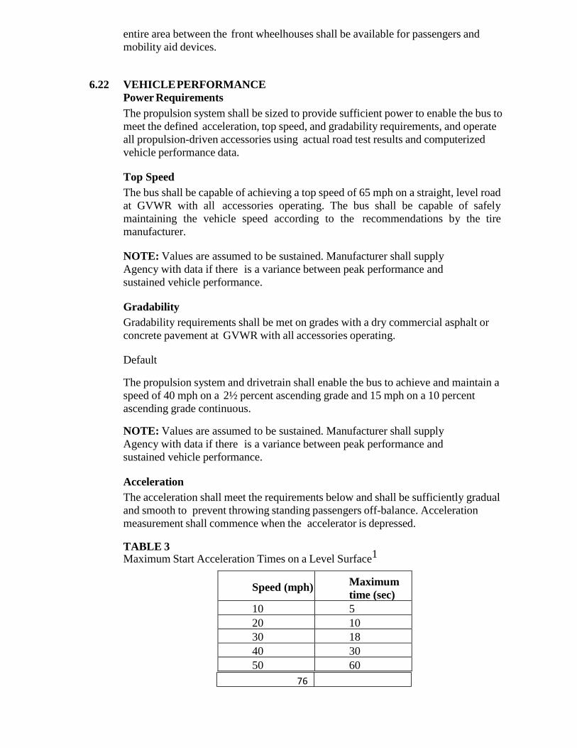
76
entire area between the front wheelhouses shall be available for passengers and mobility aid devices.
6.22 VEHICLE PERFORMANCE Power Requirements The propulsion system shall be sized to provide sufficient power to enable the bus to meet the defined acceleration, top speed, and gradability requirements, and operate all propulsion-driven accessories using actual road test results and computerized vehicle performance data. Top Speed The bus shall be capable of achieving a top speed of 65 mph on a straight, level road at GVWR with all accessories operating. The bus shall be capable of safely maintaining the vehicle speed according to the recommendations by the tire manufacturer. NOTE: Values are assumed to be sustained. Manufacturer shall supply Agency with data if there is a variance between peak performance and sustained vehicle performance. Gradability Gradability requirements shall be met on grades with a dry commercial asphalt or concrete pavement at GVWR with all accessories operating. Default The propulsion system and drivetrain shall enable the bus to achieve and maintain a speed of 40 mph on a 2½ percent ascending grade and 15 mph on a 10 percent ascending grade continuous. NOTE: Values are assumed to be sustained. Manufacturer shall supply Agency with data if there is a variance between peak performance and sustained vehicle performance. Acceleration The acceleration shall meet the requirements below and shall be sufficiently gradual and smooth to prevent throwing standing passengers off-balance. Acceleration measurement shall commence when the accelerator is depressed. TABLE 3 Maximum Start Acceleration Times on a Level Surface1
Speed (mph) Maximum
time (sec)
10 5 20 10 30 18 40 30 50 60
77
Top speed 1. Vehicle weight = GVWR Hybrid The propulsion and braking systems shall meet the performance requirements of the Duty Cycle. Braking application and performance shall remain consistent regardless of hybrid system State of Charge (SOC) or other variances related to regenerative braking. The system shall be programmable to allow optimization of acceleration and deceleration rate. Performance may be affected when reprogramming. The manufacturer shall supply the new performance data. Operating Range The operating range of the bus shall be designed to meet the operating profile as stated in the “Design Operating Profile” section. Diesel The operating range of the bus when run on the Altoona Test cycle shall be at least 350 miles with full fuel capacity. CNG The operating range of the bus when run on the Altoona Test cycle shall be at least 350 mi les with an initial gas settled pressure of 3600 psi at 70 °F. Electric Drive Propulsion As an option, Electric Vehicle Propulsion system may be selected. Hybrid The operating range of the bus when run on the Altoona Test cycle shall be at least 350 miles with full fuel capacity. Hybrid Energy storage system state of charge correction methods stated in SAE J2711 shall be utilized.
6.23 POWERPLANT Engine (Diesel) The bus shall be powered by a Cummins ISL 280 HP diesel engine capable of providing the performance to satisfy the operating conditions in geographical areas throughout the state of Georgia. The engine shall have a minimum design life of 12 years or 500,000 miles, whichever comes first, and it shall be designed to require no more than one (1) major overhaul to achieve this lifetime. The engine and the transmission shall be compatible with each other in that the electronic controls of the engine shall interface with the transmission and vice versa, if controls are used. Engine shall meet all current Federal EPA requirements. A copy of the engine certification shall be supplied with the proposal.
78
The engine shall comply with applicable local, state, and/or federal emissions and useful life requirements. Components of the fuel management and/or control system shall have a design life of not less than 150,000 miles without replacement or major service. The lifetime estimate is based on the design operating profile. The engine shall be equipped with an electronically controlled management system, compatible with either 12- or 24-volt power distribution. The engine control system shall be capable of transmitting and receiving electronic inputs and data from other drivetrain components and broadcasting that data to other vehicle systems. Communication between electronic drivetrain components and other vehicle systems shall be made using the communications networks. The engine’s electronic management system shall monitor operating conditions and provide instantaneous adjustments to optimize both engine and bus performance. The system shall be programmable to allow optimization of programmable features. The engine starting system shall be protected by an interlock that prevents its engagement when the engine is running. Special equipment or procedures may be employed to start the bus when exposed to temperatures less than 30 °F for a minimum of four hours without the engine in operation. All cold weather starting aids, engine heating devices and procedures shall be of the type recommended by the engine manufacturer and approved by the Agency. The integration of all systems on the vehicle relative to engine idle speed shall be the responsibility of the vehicle manufacturer to meet the requirements of the transit property. A 120 volt @ 1000 watt engine block heater will be located in the rear engine compartment. As an option, Delete Engine Block heater, provide a Credit on Option pricing sheet.
6.24 Automatic Engine Protection/Shutdown Override Feature The engine control system shall protect the engine against progressive damage. The system shall monitor conditions critical for safe operation and automatically de-rate power and/or speed and initiate engine shutdown as needed. The on-board diagnostic system shall trigger an audible alarm and warning light to signal the operator when the engine control unit detects a malfunction and the engine protection system is activated. Automatic shutdown shall occur when parameters established for the functions below are exceeded: • Coolant Level • Coolant Temperature • Oil Pressure • Oil Temperature • 5 minutes of idling • Exhaust Temperature • Fire Suppression Engine Automatic Shutdown Control shall occur after five minutes of idling, interior HVAC temperature is met, engine operating temperature reaches 195 degrees, transmission is in neutral position, and parking brake is applied.
79
The automatic shutdown for the Fire Suppression feature shall occur when the Fire Suppression system is discharged. A control shall be available to the operator/driver, to allow temporary override (30-45 seconds) of the engine protection/shutdown system if engine power is required to move the bus in emergency conditions. Override action shall be recorded. This data shall be retrievable by the Agency. The fast idle device shall be activated and controlled manual. This device will operate only when the transmission is in neutral, park brake applied, and switch in on position. The integration of all systems on the vehicle relative to engine idle speed shall be the responsibility of the vehicle manufacturer and shall meet the requirements of the transit property. The engine starting system shall be protected by an interlock that prevents its engagement when the engine is running. Engine throttle operation shall be inhibited, through interlocks, whenever: 1. Front or rear door open (front door optional: selection made by transit agency) 2. The vehicle is kneeled 3. Wheelchair ramp is in operation 4. Rear door emergency release 5. Fast Idle Operation
Failure of the engine throttle control shall not result in an unsafe condition. Loss of air or electrical throttle control shall inhibit throttle. A rear mounted engine speed control (hand throttle) will be provided. The engine shall have on-board diagnostic capabilities, able to monitor vital functions, store out-of- parameter conditions in memory, and communicate faults and vital conditions to service personnel. Diagnostic reader device connector ports, suitably protected against dirt and moisture, shall be provided in operator’s area and near or inside engine compartment. The on-board diagnostic system shall inform the operator via visual and/or audible alarms when out-of-parameter conditions exist for vital engine functions. All removable caps shall be tethered including the caps for the diagnostic connector ports in the operator’s area and in the engine compartment.
6.25 Engine (CNG) As an option a Cummins ISL-G engine meeting all regulatory requirements when operating on fuel equal to CARB Specifications for Compressed Natural Gas. #2292.5 will be provided. The four predominant characteristics that must be met are Methane, Ethane, Butane, and Propane.
6.26 Propulsion System (Hybrid) As an option the primary propulsion system of a hybrid will be a Cummins ISB 260 HP engine. The propulsion system shall comply with applicable federal, state and
80
local emissions regulations. The primary propulsion system coupled with the hybrid drive system shall be rated for the GVWR of the bus. Propulsion System Service The propulsion system shall be arranged so that accessibility for all routine maintenance is assured. No special tools, other than dollies and hoists, shall be required to remove the propulsion system or any subsystems. However, the Agency shall recognize that properly rated test equipment and safe electrical work practices are essential when servicing high voltage hybrid components. The exhaust system, air cleaner, air compressor, starter (if used), alternator, radiator, all engine accessories, and any other component requiring service or replacement shall be easily removable. Hybrid Drive (Transmission) Buses shall have a hybrid drive unit that coordinated with the engine and the rear axle drive ratio enables the vehicle to achieve the required top speed, acceleration and hill climbing capability while still maintaining passenger comfort and providing a smooth ride. The hybrid drive will use parallel or series architecture. The engine and hybrid drive combination shall automatically prevent lugging when climbing hills of any gradient on which the bus is designed to operate. The hybrid drive system design must provide a means to ensure that the operator has a consistent level of retardation based on pedal angle without being dependent on the level of charge of the batteries. The electronically controlled hybrid drive shall have on-board diagnostic capabilities, be able to monitor functions, store and time stamp out-of parameter conditions in memory, and communicate faults and vital conditions to service personnel. The hybrid drive shall have built in protection software to guard against severe damage. Hybrid Energy Storage System (ESS) The energy storage system shall be composed of batteries storage system along with associated power electronics interface and controls, diagnostic systems, and environmental controls. The system shall be designed to provide load leveling function in the hybrid propulsion system. The energy storage devices used and their arrangement shall be selected and sized to meet bus performance specifications and design goals, including reduced vehicle emissions, improved vehicle fuel economy, long cycle life, low life cycle cost, safety, maintainability, durability and simple , robust diagnostics. The minimum design life of the energy storage system shall be 6 years. Controller (DPIM) The hybrid system shall incorporate a management system to monitor and control the operating conditions within the energy storage system module, including voltage, current, and temperature. This system shall include over-current and over-temperature protection feature that will disconnect and/or isolate an adverse condition. Energy storage cooling unit shall not activate the passenger compartment evaporators and fans. Voltage equalization in the energy storage unit shall not require any intervention by the operator of the vehicle.
6.26.1 Electric Drive Propulsion As an option, Electric Vehicle Propulsion system may be selected. A minimum gradability of 14% must be achieved by electric propulsion system. Bus must be able
81
to achieve at least a minimum road speed of 46 MPH. Charging times and vehicle range shall be approved by independent agencies. A charging station shall be selected and provided for each for each bus ordered.
6.26.2 High Voltage Devices All devices that contain circuits or equipment energized or capable of being energized at high voltage shall be contained within protective enclosures or enclosed bus body compartments. All access covers for these compartments shall be permanently labeled with ‘DANGER HIGH VOLTAGE’ signs. All conductors carrying voltages of 50 VAC or greater, shall be considered High Voltage (HV). All HV wiring must be installed separately from low voltage wiring. Conductors, insulation, cable supports and terminating connections must be designed for the purpose, voltage and operating conditions. As an option, the Allison Hybrid Drive system and the BAE Hybrid Drive System will be made available and priced separately. As an option, Extended Coverage for each Hybrid system will be made available and priced separately.
6.27 Standard Requirements for a Fast Idle Device The fast idle device shall be activated and controlled automatically by the control system.
6.28 Cooling Systems The cooling systems shall be of sufficient size to maintain all engine and transmission fluids and engine intake air at safe, continuous operating temperatures during the most severe operations possible and in accordance with engine and transmission manufacturers’ cooling system requirements. The cooling system fan controls should sense the temperatures of the operating fluids and the intake air, and if either is above safe operating conditions the cooling fan should be engaged. The fan control system shall be designed with a fail-safe mode of “fan on.” The cooling system shall meet the requirements stated in the operating environment. The engine shall be cooled by a water-based, pressure type, cooling system that does not permit boiling or coolant loss during the operations described above. Engine thermostats shall be easily accessible for replacement. Shutoff valves shall allow filter replacement without coolant loss. Valves shall permit complete shutoff of lines for the heating and defroster units, and water booster pumps. The water boost pump shall be a long life brushless design. All low points in the water-based cooling system shall be equipped with a standard with a 1/4" MPT brass hex plug. Air vent valves shall be fitted at high points in the cooling system unless it can be demonstrated that the system is self-purging. Engine cooling system shall include fitting provisions to accommodate Cummins recommended bottom fill procedures to ensure that air pockets are purged in cooling system during system fill. A Modine E-Fan electric fan system will be provided. Electric fans shall be brushless, variable speed, reversible and have a corrosion resistant metal shroud with finger guards that meet SAE spec J1308 200808. The fans should provide
82
electronic feedback control and have diagnostics capability through the standard SAE J1939 diagnostics port. The cooling system shall consist of multiple electric DC brushless pusher type variable speed fans with electronic feedback controls. Electric fan motor speeds shall have a minimum operating range of 0-5500 rpm with capability of manual or automatic reverse operation in order to assist in debris removal. The cooling system shall be equipped with a master controller with the following capabilities; automatically reduce fan speed when the vehicle stops to minimize noise. As an option, A EMP electric fan system will be made available and priced separately. As an option, A hydraulic drive fan system will be made available and price separately. A means of determining satisfactory engine coolant level shall be provided. A spring-loaded, push-button type valve or lever shall be provided to safely release pressure or vacuum in the cooling system with both it and the water filler no more than +/- 60 in. above the ground. Radiator and charge air cooler fan(s) shall be electrically driven and capable of a manual reverse operations for periodic self-cleaning of the radiator and charge air cooler.
Charge Air Cooling The charge air cooling system also referred to as after-coolers or inter-coolers shall provide maximum air intake temperature reduction with minimal pressure loss. The charge air radiator shall be sized and positioned to meet engine manufacturer’s requirements. The charge air radiator shall not be stacked ahead of or behind the engine radiator and shall be positioned as close to the engine as possible unless integrated with the radiator. Air ducting and fittings shall be protected against heat sources and shall be configured to minimize restrictions and maintain sealing integrity. Transmission Cooling The transmission shall be cooled by a dedicated heat exchanger sized to maintain operating fluid within the transmission manufacturer’s recommended parameters of flow, pressure and temperature. The transmission cooling system shall be matched to retarder and engine cooling systems to ensure that all operating fluids remain within recommended temperature limits established by each component manufacturer. The engine cooling system should provide coolant bypass flow to the transmission cooling system with the engine thermostats closed. Hybrid Drive System Cooling Thermal management system shall maintain hybrid system components within design operating temperature limits.
6.29 Transmission (Conventional Powertrain) The transmission shall be an Allison B400R automatic shift with torque converter, retarder and electronic controls. Gross input power, gross input torque and rated
83
input speed shall be compatible with the engine. The transmission shall be designed to operate for not less than 300,000 miles on the design operating profile without replacement or major service. The transmission should be easily removable without disturbing the engine and accessible for service. Allison ECU fluid changes shall be disabled. As an option, the Voith 864.5 transmission will be made available and priced separately. As an option the ZF 6AP1400 will be made available and priced separately. The electronic controls shall be capable of transmitting and receiving electronic inputs and data from other drivetrain components and broadcasting that data to other vehicle systems. Communication between electronic drivetrain components and other vehicle systems shall be made using the communications networks. Electronic controls shall be compatible with either 12- or 24-volt power distribution, provide consistent shift quality and compensate for changing conditions such as variations in vehicle weight and engine power. A nominal brake pedal application of 6 to 10 psi shall be required by the driver to engage forward or reverse range from the neutral position to prevent sudden acceleration of the bus from a parked position. The electronically controlled transmission shall have on-board diagnostic capabilities, be able to monitor functions, store and time stamp out-of-parameter conditions in memory, and communicate faults and vital conditions to service personnel. The transmission shall contain built-in protection software to guard against severe damage. The on-board diagnostic system shall trigger a visual alarm to the driver when the electronic control unit detects a malfunction. As an option, an electronic transmission fluid level monitoring and protection system will be made available and priced separately. Models with remote mounted transmission vents shall have vents mounted to prevent plugging and/or the entry of foreign materials.
6.30 Retarder The powertrain shall be equipped with a retarder designed to extend brake lining service life. The application of the retarder shall cause a smooth blending of both retarder and service brake function and shall not activate the brake lights Actuation of ABS and/or automatic traction control (ATC) shall override the operation of the brake retarder.
6.31 Standard Requirement for Retarder Activation The retarder shall be adjustable within the limits of the powertrain and activated when the brake pedal is depressed. The Agency will work with the OEM/drive system manufacturer to determine retarder performance settings. A retarder disable switch shall be accessible to the seated driver. Disabling retarder shall be recorded for Agency data collection. Retarder shall apply as accelerator pedal is released to
84
engine idle position.
6.32 Mounting All powerplant mounting shall be mechanically isolated to minimize transfer of vibration to the body structure and provide a minimum clearance of 0.75 in. Mounts shall control the movement of the powerplant so as not to affect performance of belt-driven accessories or cause strain in piping and wiring connections to the powerplant.
6.33 Engine / Transmission Oil Fill / Filters Engine oil and the radiator filler caps shall be hinged to the filler neck and closed with spring pressure or positive locks to prevent leakage. All fluid fill locations shall be properly labeled to help ensure that correct fluid is added. All fillers shall be easily accessible with standard funnels, pour spouts and automatic dispensing equipment. All lubricant sumps shall be fitted with magnetic-type drain plugs. The engine and transmission shall be equipped with sufficient heavy-duty fuel and oil filters for efficient operation and to protect the engine and transmission between scheduled filter changes. All filters shall be easily accessible and the filter bases shall be plumbed to ensure correct reinstallation. As an option, the FEMCO oil drain will be made available and priced separately. As an option, the ESOC oil drain/fill system will be made available and priced separately As an option, the KP push button value will be made available on engine and transmission sampling ports and priced separately.
6.34 Engine Compartment Gauges Engine oil pressure, Transmission and coolant temperature gauges required in engine compartment.
6.35 Engine Air Cleaner An air cleaner with a dry filter element shall be provided. The location of the air intake system shall be designed to minimize the entry of dust and debris and to maximize the life of the air filter. The engine air duct shall be designed to minimize the entry of water into the air intake system. Drainage provisions shall be included to allow any water/moisture to drain prior to entry into air filter.
6.36 Hydraulic Systems Hydraulic system service tasks shall be minimized and scheduled no more frequently than those of other major bus systems. All elements of the hydraulic system shall be easily accessible for service or unit replacement. Critical points in the hydraulic system shall be fitted with service ports so that portable diagnostic equipment may be connected or sensors for an off-board diagnostic system permanently attached to monitor system operation when applicable. A tamper-proof priority system shall prevent the loss of power steering during operation of the bus if other devices are also powered by the hydraulic system. The hydraulic system shall operate within the allowable temperature range as specified by the lubricant manufacturer.
85
6.37 Fluid Lines All lines shall be rigidly supported to prevent chafing damage, Fatigue Failures, degradation and tension strain. Lines should be sufficiently flexible to minimize mechanical loads on the components. Lines passing through a panel, frame or bulkhead shall be protected by grommets (or similar devices) that fit snugly to both the line and the perimeter of the hole that the line passes through to prevent chafing and wear. Pipes and fluid hoses shall not be bundled with or used to support electrical wire harnesses. Lines shall be as short as practicable and shall be routed or shielded so that failure of a line shall not allow the contents to spray or drain onto any component operable above the auto-ignition temperature of the fluid. All hoses, pipes, lines and fittings shall be specified and installed per the manufacturer’s recommendations.
6.38 Fittings and Clamps All clamps shall maintain a constant tension at all times, expanding and contracting with the line in response to temperature changes and aging of the line material. The lines shall be designed for use in the environment where they are installed. For example, high-temperature resistant in the engine compartment, resistant to road salts near the road surface, and so on. Compression fittings shall be standardized to prevent the intermixing of components. Compression fitting components from more than one manufacturer shall not be mixed, even if the components are known to be interchangeable.
6.39 Charge Air Piping Charge air piping and fittings shall be designed to minimize air restrictions and leaks. Piping shall be as short as possible, and the number of bends shall be minimized. Bend radii shall be maximized to meet the pressure drop and temperature rise requirements of the engine manufacturer. The cross-section of all charge air piping shall not be less than the cross-section of the intake manifold inlet. Any changes in pipe diameter shall be gradual to ensure a smooth passage of air and to minimize restrictions. Piping shall be routed away from heat sources as practicable and shielded as required to meet the temperature rise requirements of the engine manufacturer. Charge air piping shall be constructed of stainless steel, aluminized steel or anodized aluminum, except between the air filter and turbocharger inlet, where piping may be constructed of fiberglass. Connections between all charge air piping sections shall be sealed with a short section of reinforced hose and secured with stainless steel constant tension clamps that provide a complete 360-degree seal.
6.40 Radiator Radiator piping shall be stainless steel or brass tubing, and if practicable, hoses shall be eliminated. Necessary hoses shall be impervious to all bus fluids. All hoses shall be secured with stainless steel clamps that provide a complete 360-degree seal. The clamps shall maintain a constant tension at all times, expanding and contracting
86
with the hose in response to temperature changes and aging of the hose material.
6.41 Oil and Hydraulic Lines Oil and hydraulic lines shall be compatible with the substances they carry. The lines shall be designed and intended for use in the environment where they are installed. For example, high–temperature resistant in the engine compartment, resistant to road salts near the road surface, and so on. Lines within the engine compartment shall be composed of steel tubing where practicable, except in locations where flexible lines are required.
6.42 Fuel Fuel Lines Fuel lines shall be securely mounted, braced and supported as designed by the bus manufacturer to minimize vibration and chafing and shall be protected against damage, corrosion or breakage due to strain or wear. Manifolds connecting fuel containers shall be designed and fabricated to minimize vibration and shall be installed in protected locations to prevent line or manifold damage from unsecured objects or road debris. Fuel hose and hose connections, where permitted, shall be made from materials resistant to corrosion and fuel and protected from fretting and high heat. Fuel hoses shall be accessible for ease of serviceability. Fuel Lines, Diesel Fuel lines shall be capable of carrying the type of fuel specified by the Agency (i.e., up to B20 type fuel). Fuel Lines, CNG Fuel lines shall comply with NFPA-52. All tubing shall be a minimum of seamless stainless steel (ASTM A269 or equivalent). Fuel lines and fittings shall not be fabricated from cast iron, galvanized pipe, aluminum, plastic, or copper alloy with content exceeding 70 percent copper. Pipe fittings and hoses shall be clear and free from cuttings, burrs or scale. Pipe thread joining material that is impervious to CNG shall be utilized as required. Fuel lines shall be identifiable as fuel lines only. High-pressure CNG lines shall be pressure tested to 3600 psi pressure prior to fueling. CNG, nitrogen or clean, dry air shall be used to pressure test the lines/assembly. The bus manufacturer shall have a documented procedure for testing the high pressure line assembly. Fuel lines shall be securely mounted, braced and supported using “split-block” type or stainless steel P clamps; all mounting clamps shall be mounted to a rigid structure to minimize vibration and shall be protected against damage, corrosion or breakage due to strain, rubbing, or wear. “Floating clamps” (not mounted to a rigid structure) shall not be permitted. Fuel lines shall not be used to secure other components (wires, air lines, etc). Manifolds connecting fuel containers shall be designed and fabricated to minimize vibration and shall be installed in protected location(s) to prevent line or manifold
87
damage from unsecured objects or road debris. Fuel hose connections, where possible, shall be less than 60 in. in length, made from materials resistant to corrosion and action of natural gas, and protected from fretting and high heat and shall be supported approximately every 12 in.
6.43 Design and Construction Design and Construction, Diesel Fuel Tank(s) The fuel tank(s) shall be made of corrosion resistant stainless steel. The fuel tank shall be made of 3CR12 structural stainless steel. The fuel tank(s) shall be securely mounted to the bus to prevent movement during bus maneuvers. The fuel tank(s) shall be equipped with an external, hex head, drain plug. It shall be at least a ⅜-inch size and shall be located at the lowest point of the tank(s). The fuel tank(s) shall have an inspection plate or easily removable filler neck to permit cleaning and inspection of the tank(s) without removal from the bus. The tank(s) shall be baffled internally to prevent fuel-sloshing noise regardless of fill level. The baffles or fuel pickup location shall assure continuous full power operation on a 6 percent upgrade for 15 minutes starting with no more than 25 gallons of fuel over the unusable amount in the tank(s). The bus shall operate at idle on a 6 percent downgrade for 30 minutes starting with no more than 10 gallons of fuel over the unusable amount in the tank(s). All systems/engines on all model buses will be compatible with all blends of Bio-Diesel fuel based on manufacturer’s recommendations. The materials used in mounting shall withstand the adverse effects of road salts, fuel oils, and accumulation of ice and snow for the life of the bus.
6.44 Labeling The capacity, date of manufacture, manufacturer name, location of manufacture, and certification of compliance to Federal Motor Carrier Safety Regulation shall be permanently marked on the fuel tank(s). The markings shall be readily visible and shall not be covered with an undercoating material.
6.45 Fuel Filler The fuel filler shall be located 7 to 32 feet behind the centerline of the front door on the curbside of the bus. The filler cap shall be retained to prevent loss and shall be recessed into the body so that spilled fuel will not run onto the outside surface of the bus. The fuel lines forward of the engine bulkhead shall be in conformance to SAE Standards.
6.46 Dry-break Fuel Filler Emco PosiLock 105 Fast Fill fuel system shall be provided. The fuel filler shall accommodate a nozzle that forms a locked and sealed connection during the refueling process to eliminate spills. Fuel shall not be allowed to flow into the tank unless the nozzle has been properly coupled, locked and sealed to the filler. With the nozzle open, fuel shall enter the tank at a fill rate of not less than 40 gallons per minute of foam-free fuel without causing the nozzle to shut off before the tank is
88
full. The nozzle shall automatically shut off when the tank is essentially full. Once disconnected, fuel shall not be allowed to flow through the nozzle at any time. Any pressure over 3 psi shall be relieved from the fuel tank automatically. An audible signal shall indicate when the tank is essentially full. The dry break system shall be compatible with the Agency’s system. The fuel filler cap shall be hinged. Equipment will be finalized at pre-production meeting. The Fuel Master AIM 2 System version 2.10 or higher shall be provided. As an option, a gravity fuel fill system will be made available and priced separately.
6.47 Design and Construction, CNG Fuel Containers/Cylinders CNG fuel containers/cylinders must be designed, constructed, manufactured, and tested in accordance with at least one of the following: NFPA 52-Standard for Compressed Natural Gas (CNG) Vehicular Fuel Systems FMVSS 304 Any local standard(s) specifically intended for CNG fuel containers The design and construction of the fuel system supplied by the OEM shall comply with federal and local regulations. Installation Fuel cylinders shall be installed in accordance with ANSI/IAS NGV2 - 1998, Basic Requirements for Compressed Natural Gas Vehicles (NGV) Fuel Containers and NFPA 52, Compressed Natural Gas (CNG) Vehicular Fuel Systems Code, 1998 edition Section 303. The placement of tanks shall be limited to the roof of the vehicle. Fuel cylinders, attached valves, pressure relief devices, and mounting brackets should be installed and protected so that their operation is not affected by bus washers and environmental agents such as rain, snow, ice or mud. These components should be protected from significant damage caused by debris or collision. For safety purposes, the roof mounted tanks must be accessible to maintenance personnel without the requirement to walk on top of the closed tank enclosure to open the enclosure doors. The enclosure doors shall be secured with non-keyed twist latches and shall incorporate hand holds to assist in opening the enclosure doors once unlatched. When opened, the enclosure doors shall be secured to prevent from over-extension. The open enclosure doors shall also provide a certain degree of fall prevention. Once the tanks are exposed, for safety purposes, access should be provided in the middle of the roof line without having to walk on top of or over the tanks in order to inspect or service the tanks, valves, regulators or Pressure Relief Devices (PRD). This access shall be constructed in a manner that avoids the need to walk on the actual roof covering. Access to the roof mounted tanks shall be through the rear roof hatch. CNG fueled buses shall be equipped with an active automatic gas detection system which shall annunciate unsafe levels of methane. The automatic gas
89
detection system shall be integrated with an onboard fire suppression system. Labeling CNG fuel systems shall be labeled in accordance with NFPA 52, “Compressed Natural Gas (CNG) Vehicular Fuel Systems Code,” 1998 edition. Pressure Relief Devices (PRDs) PRDs must be designed, constructed, manufactured and tested in accordance with ANIS/IAS PRD1 - 1998, “Pressure Relief Devices for Natural Gas Vehicle (NGV) Fuel Containers” and ANSI/IAS NGV2- 1998, “Basic Requirements for Compressed Natural Gas Vehicle (NGV) Fuel Containers.” All natural gas fuel system piping, including the PRD vent line, shall be stainless steel. All PRDs must be vented to outside. Valves Valves must be installed in accordance with ANIS/IAS NGV2 - 1998, “Basic Requirements for Compressed Natural Gas Vehicle (NGV) Fuel Containers” and NFPA 52, “Standard for Compressed Natural Gas (CNG) Vehicular Fuel Systems.”
6.48 Fuel Filler The fuel filler shall be located 7 to 38 feet (on a 30-, 35- and 40-foot bus) behind the centerline of the front door on the curbside of the bus. The filler cap shall be retained to prevent loss and shall be recessed into the body. The fill and vent receptacles shall be located within an enclosure on the right side of the bus. The access door shall be sized to allow full viewing of gauges, ease of hookups and maneuver of fuel nozzle. The fuel fill receptacle and vent receptacle attachment shall be robust and capable of routine fueling connects/disconnects without deflection or metal fatigue, and capable of withstanding mechanical loads induced by a fueling drive away incident without attachment failure.
6.49 Fueling System The CNG fueling port receptacle shall be an ANSI/AGA NGV1 or NGV2 certified receptacle as designated by the Agency. The bus shall be capable of being fueled by a nozzle determined by the Agency. The fueling port receptacle location shall be such that connection by fueling personnel can be performed without physical strain or interference. A dust cap shall be permanently “tethered” to the fueling port receptacle. The fueling port receptacle access door shall be equipped with an interlock sensor that disables the engine starting system when the access door is open, to prevent drive-aways. The interlock shall be of the type such that if the sensor fails, the bus will not start. Fueling site characteristics such as pressure, flow rate, and temperature shall be provided by the Agency. Defueling System The CNG defueling port shall be an NGV-3.1/CGA-12.3 certified receptacle. The CNG defueling port shall be located on the curbside of the bus, in a location that is
90
compatible with the Agency’s defueling station operation. The de-fueling system shall incorporate the following characteristics: Dust cap permanently “tethered” to the defueling port. Device(s) to prevent inadvertent defueling. Specifications to be provided by Agency. Components compatible with Agency’s defueling operation. The piping and fittings onboard the bus shall be sized to allow the fueling station to meet the following operating parameters:
6.50 Emissions and Exhaust Exhaust Emissions The engine and related systems shall meet all applicable emission and engine design guidelines and standards. Exhaust System Exhaust gases and waste heat shall be discharged from the roadside rear corner of the roof. The exhaust pipe shall be of sufficient height to prevent exhaust gases and waste heat from discoloring or causing heat deformation to the bus. The entire exhaust system shall be adequately shielded to prevent heat damage to any bus component, including the exhaust after-treatment compartment area. The exhaust outlet shall be designed to minimize rain, snow or water generated from high-pressure washing systems from entering into the exhaust pipe and causing damage to the after-treatment. An exhaust after treatment system will be provided to ensure compliance to all applicable EPA regulations in effect.
6.51 Diesel Exhaust Fluid Injection If required by the engine manufacturer to meet NOx level requirements specified by EPA, a DEF injection system will be provided. The DEF system will minimally include a tank, an injector, a pump, an ECM and a selective catalytic converter. The tanks shall be designed to store DEF in the operating environment described in the “Operating Environment” section. The DEF fluid lines shall be designed to prevent the DEF from freezing. The DEF injection system shall not be damaged from a cold soak at 10°F.
6.52 Particulate Aftertreatment If required by the engine manufacturer to meet particulate level requirements specified by EPA, a particulate trap will be provided. The particulate trap shall regenerate itself automatically if it senses clogging. Regeneration cycles and conditions will be defined by the engine manufacturer.
6.53 Fire Suppression System A Fogmaker automatic fire suppression system will be provided to ensure adequate coverage of in the engine compartment and main electrical box areas should a fire event happen. The system shall incorporate a telltale, dash mounted operator warning light, audible indicator and switch, automatically shutting off all fans and climate control systems in the event of discharge. The system installed shall be certified by the vehicle manufacturer that it is suitable for use in the proposed vehicle in case the unit fails to function during an on board
91
vehicle event or fire. Each vehicle shall be delivered with a certificate identifying the vehicle identification number (VIN) for which it applies. The system shall be U.L., U.C.L., and F.M. listed and meet all D.O.T. and be certified by the vehicle and equipment manufacturer. NOTE: Fire Suppression shall be mandatory on all Hybrid and CNG buses and shall be included in the price of each respective fuel alternative. As an option, a delete for the Fire Suppression for the diesel bus will be included. As an option, the AMEREX Fire Suppression system will be made available and priced separately. As an option, the KIDDE Fire Suppression System will be made available and priced separately.
6.54 STRUCTURE General & Design The structure of the bus shall be designed to withstand the transit service conditions typical of an urban duty cycle throughout its service life. The vehicle structural frame shall be designed to operate with minimal maintenance throughout the 12-year design operating profile. The design operating profile specified by the Agency shall be considered for this purpose.
6.55 Altoona Testing Prior to acceptance of first bus, the vehicle must have completed any FTA-required Altoona testing. Any items that required repeated repairs or replacement must undergo the corrective action with supporting test and analysis. A report clearly describing and explaining the failures and corrective actions taken to ensure any and all such failures will not occur shall be submitted to the Agency. Altoona Test Report Provided to Agency Prior to Start of Bus Production Prior to the start of any bus manufacturing or assembly processes, the structure of the proposed bus model shall have undergone appropriate structural testing and/or analysis, including the complete regimen of FTA required Altoona tests. Prior to assembly of the first bus, the OEM shall provide the Agency with a completed report of Altoona testing for the proposed bus model along with a plan of corrective action to address deficiencies, breakdowns and other issues identified during Altoona testing. The bus model tested shall match the bus model proposed for procurement, including structure, axles and drive-train. Base model and partial Altoona test reports are acceptable when the combination of these tests adequately represents the proposed bus model.
6.56 Structural Validation Baseline Structural Analysis The structure of the bus shall have undergone appropriate structural testing and/or analysis. At minimum, appropriate structural testing and analysis shall include Altoona testing or Finite Element Analysis (FEA).
6.57 Distortion The bus, loaded to GVWR and under static conditions, shall not exhibit deflection or
92
deformation that impairs the operation of the steering mechanism, doors, windows, passenger escape mechanisms or service doors. Static conditions shall include the vehicle at rest with any one wheel or dual set of wheels on a 6 in. curb or in a 6 in. deep hole.
6.58 Resonance and Vibration All structure, body and panel-bending mode frequencies, including vertical, lateral and torsional modes, shall be sufficiently removed from all primary excitation frequencies to minimize audible, visible or sensible resonant vibrations during normal service.
6.59 Engine Compartment Bulkheads The passenger and engine compartment shall be separated by fire-resistant bulkheads. The engine compartment shall include areas where the engine and exhaust system are housed. This bulkhead shall preclude or retard propagation of an engine compartment fire into the passenger compartment. Only necessary openings shall be allowed in the bulkhead, and these shall be fire-resistant. Any passageways for the climate control system air shall be separated from the engine compartment by fire- resistant material. Piping through the bulkhead shall have fire-resistant fittings sealed at the bulkhead. Wiring may pass through the bulkhead only if connectors or other means are provided to prevent or retard fire propagation through the bulkhead. Engine access panels in the bulkhead shall be fabricated of fire-resistant material and secured with fire-resistant fasteners. These panels, their fasteners, and the bulkhead shall be constructed and reinforced to minimize warping of the panels during a fire that will compromise the integrity of the bulkhead.
6.60 Crashworthiness The bus body and roof structure shall withstand a static load equal to 150 percent of the curb weight evenly distributed on the roof with no more than a 6 in. reduction in any interior dimension. Windows shall remain in place and shall not open under such a load. These requirements must be met without the roof-mounted equipment installed. The bus shall withstand a 25 mph impact by a 4000-pound automobile at any side, excluding doorways, along either side of the bus with no more than 3 in. of permanent structural deformation at seated passenger hip height. This impact shall not result in sharp edges or protrusions in the bus interior. Exterior panels below 35 in. from ground level shall withstand a static load of 2000 lbs. applied perpendicular to the bus by a pad no larger than 5 sq. in. This load shall not result in deformation that prevents installation of new exterior panels to restore the original appearance of the bus. The transit bus, at GVWR and under static conditions, shall not exhibit deformation or deflection that impairs operation of doors, windows, or other mechanical elements. Static conditions include the vehicle at rest with any one wheel or dual set of wheels on a 6 inch curb or in a 6 inch deep hole. The sidewall structure shall be capable of withstanding impacts of 200 foot pounds of
93
energy from a steel faced spherical missile no less than 9 inches in diameter and of a 500 pound load applied anywhere along their length by a rigid plate 1 foot in length with no visible damage to the supporting structure. A damaged portion of the supporting structure shall be replaceable without requiring removal or replacement of the entire structure. The bus chassis shall be stainless steel with an integrated side impact barrier to provide additional safety to the passengers in the low floor area.
6.61 Corrosion The bus flooring, sides, roof, understructure and axle suspension components shall be designed to resist corrosion or deterioration from atmospheric conditions and de-icing materials for a period of 12 years or 500,000 miles, whichever comes first. It shall maintain structural integrity and nearly maintain original appearance throughout its service life, with the Agency’s use of proper cleaning and neutralizing agents. All materials that are not inherently corrosion resistant shall be protected with corrosion-resistant coatings. All joints and connections of dissimilar metals shall be corrosion resistant and shall be protected from galvanic corrosion. Representative samples of all materials and connections shall withstand a two-week (336-hour) salt spray test in accordance with ASTM Procedure B-117 with no structural detrimental effects to normally visible surfaces and no weight loss of over 1 percent. Corrosion-Resistance Requirements for Exposed and Interior Surfaces of Tubing Below Lower Window Level All exposed surfaces and the interior surfaces of tubing and other enclosed members below lower window line shall be corrosion resistant through application of a corrosion protection system.
6.62 Towing Each towing device shall withstand, without permanent deformation, tension loads up to 1.2 times the curb weight of the bus within 20 degrees of the longitudinal axis of the bus. If applicable, the rear towing device(s) shall not provide a toehold for unauthorized riders. The method of attaching the towing device shall not require the removal, or disconnection, of front suspension or steering components. Removal of the bike rack is permitted for attachment of towing devices. A plug connector permanently mounted at the front of the bus shall provide for bus tail lamp, marker, stop and turn signal lamp operation as controlled from the towing vehicle. The connector shall include a spring-loaded dust- and water-resistant cap. Shop air connectors shall be provided at the front and rear of the bus and shall be capable of supplying all pneumatic systems of the bus with externally sourced compressed air. The location of these shop air connectors shall facilitate towing operations. Lifted (Supported) Front Axle and Flat Towing Capability The front towing devices shall allow attachment of adapters for a rigid tow bar and shall permit the lifting of the bus until the front wheels are clear off the ground in order to position the bus on the towing equipment by the front wheels. These devices shall also permit common flat towing.
94
Two rear recovery devices/tie downs shall permit lifting and towing of the bus for a short distance, such as in cases of an emergency, to allow access to provisions for front towing of bus. The method of attaching the tow bar or adapter shall require the specific approval of the Agency. Any tow bar or adapter exceeding 50 lbs should have means to maneuver or allow for ease of use and application. Each towing device shall accommodate a crane hook with a 1 in. throat.
6.63 Jacking It shall be possible to safely jack up the bus, at curb weight, with a common 10-ton floor jack with or without special adapter, when a tire or dual set is completely flat and the bus is on a level, hard surface, without crawling under any portion of the bus. Jacking from a single point shall permit raising the bus sufficiently high to remove and reinstall a wheel and tire assembly. Jacking pads located on the axle or suspension near the wheels shall permit easy and safe jacking with the flat tire or dual set on a 6 in. high run-up block not wider than a single tire. The bus shall withstand such jacking at any one or any combination of wheel locations without permanent deformation or damage.
6.64 Hoisting The bus axles or jacking plates shall accommodate the lifting pads of a two-post (or three-post if 60 ft. articulated bus) hoist system. Jacking plates, if used as hoisting pads, shall be designed to prevent the bus from falling off the hoist. Other pads or the bus structure shall support the bus on jack stands independent of the hoist.
6.65 Floor Design The floor shall be essentially a continuous plane, except at the wheel housings and platforms. Where the floor meets the walls of the bus, as well as other vertical surfaces such as platform risers, the surface edges shall be blended with a circular section of radius not less than ¼ in. or installed in a fully sealed butt joint. Similarly, a molding or cover shall prevent debris accumulation between the floor and wheel housings. The vehicle floor in the area of the entrance and exit doors shall have a lateral slope not exceeding 2 degrees to allow for drainage. Strength The floor deck may be integral with the basic structure or mounted on the structure securely to prevent chafing or horizontal movement and designed to last the life of the bus. Sheet metal screws shall not be used to retain the floor, and all floor fasteners shall be serviceable from one side only. Any adhesives, bolts or screws used to secure the floor to the structure shall last and remain effective throughout the life of the bus. Tapping plates, if used for the floor fasteners, shall be no less than the same thickness as a standard nut, and all floor fasteners shall be secured and protected from corrosion for the service life of the bus. The floor deck shall be reinforced as needed to support passenger loads. At GVWR, the floor shall have an elastic deflection of no more than 0.60 in. from the normal plane. The floor shall withstand the application of 2.5 times gross load weight without permanent detrimental deformation. The floor, with coverings applied, shall
95
withstand a static load of at least 150 lbs. applied through the flat end of a ½ in. diameter rod, with 1/32-inch radius, without permanent visible deformation. Construction The floor shall consist of the subfloor and the floor covering that will last the life of the bus. The floor as assembled, including the sealer, attachments and covering, shall be waterproof, non-hygroscopic and resistant to mold growth. The subfloor shall be resistant to the effects of moisture, including decay (dry rot). It shall be impervious to wood-destroying insects such as termites. Pressure-Preserved Plywood Panel Plywood shall be certified at the time of manufacturing by an industry-approved third-party inspection agency such as APA – The Engineered Wood Association (formerly the American Plywood Association). Plywood shall be of a thickness adequate to support design loads, manufactured with exterior glue, satisfy the requirements of a Group I Western panel as defined in PS 1-95 (Voluntary Product Standard PS 1-95, “Construction and Industrial Plywood”) and be of a grade that is manufactured with a solid face and back. Plywood shall be installed with the highest-grade, veneer side up. Plywood shall be pressure-treated with a preservative chemical and process such as alkaline copper quaternary (ACQ) that prevents decay and damage by insects. Preservative treatments shall utilize no EPA-listed hazardous chemicals. The concentration of preservative chemicals shall be equal to or greater than required for an above ground level application. Treated plywood will be certified for preservative penetration and retention by a third party inspection agency. Pressure-preservative treated plywood shall have a moisture content at or below 15 percent. As an option, a composite subfloor will be made available and priced separately.
6.66 Platforms Driver’s Area The covering of platform surfaces and risers, except where otherwise indicated, shall be the same material as specified for floor covering. Trim shall be provided along top edges of platforms unless integral nosing is provided. Driver’s Platform The driver’s platform shall be of a height such that, in a seated position, the driver can see an object located at an elevation of 42 in. above the road surface, 24 in. from the leading edge of the bumper. Notwithstanding this requirement, the platform height shall not position the driver such that the driver’s vertical upward view is less than 15 degrees. A warning decal or sign shall be provided to alert the driver to the change in floor level. Figure 3 illustrates a means by which the platform height can be determined, using the critical line of sight. FIGURE 3 Determining Platform Height
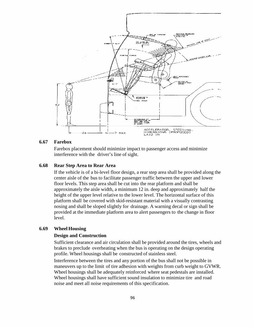
96
6.67 Farebox
Farebox placement should minimize impact to passenger access and minimize interference with the driver’s line of sight.
6.68 Rear Step Area to Rear Area If the vehicle is of a bi-level floor design, a rear step area shall be provided along the center aisle of the bus to facilitate passenger traffic between the upper and lower floor levels. This step area shall be cut into the rear platform and shall be approximately the aisle width, a minimum 12 in. deep and approximately half the height of the upper level relative to the lower level. The horizontal surface of this platform shall be covered with skid-resistant material with a visually contrasting nosing and shall be sloped slightly for drainage. A warning decal or sign shall be provided at the immediate platform area to alert passengers to the change in floor level.
6.69 Wheel Housing Design and Construction Sufficient clearance and air circulation shall be provided around the tires, wheels and brakes to preclude overheating when the bus is operating on the design operating profile. Wheel housings shall be constructed of stainless steel. Interference between the tires and any portion of the bus shall not be possible in maneuvers up to the limit of tire adhesion with weights from curb weight to GVWR. Wheel housings shall be adequately reinforced where seat pedestals are installed. Wheel housings shall have sufficient sound insulation to minimize tire and road noise and meet all noise requirements of this specification.
97
Design and construction of front wheel housings shall allow for the installation of a radio or electronic equipment storage compartment on the interior top surface, or its use as a luggage rack. The finish of the front wheel housings shall be scratch-resistant and complement interior finishes of the bus to minimize the visual impact of the wheel housing. If fiberglass wheel housings are provided, then they shall be color-impregnated to match interior finishes. The lower portion extending to approximately 10 to 12 in. above floor shall be equipped with scuff-resistant coating or stainless steel trim. Wheel housings, as installed and trimmed, shall withstand impacts of a 2 in. steel ball with at least 200 ft.-lbs. of energy without penetration. Wheel housings not equipped with seats or equipment enclosure shall have a horizontal assist mounted on the top portion of the housing no more than 4 in. higher than the wheel well housing.
6.70 CHASSIS Suspension General Requirements The front, rear suspensions shall be pneumatic type. The basic suspension system shall last the service life of the bus without major overhaul or replacement. Adjustment points shall be minimized and shall not be subject to a loss of adjustment in service. Routine adjustments shall be easily accomplished by limiting the removal or disconnecting the components. Alignment All axles should be properly aligned so the vehicle tracks accurately within the size and geometry of the vehicle.
6.71 Springs and Shock Absorbers Suspension Travel The suspension system shall permit a minimum wheel travel of 2.75 in. jounce-upward travel of a wheel when the bus hits a bump (higher than street surface), and 2.75 in. rebound-downward travel when the bus comes off a bump and the wheels fall relative to the body. Urethane bumpers shall be provided at the limit of jounce travel. Rebound travel may be limited by urethane bumpers or hydraulically within the shock absorbers. Suspensions shall incorporate appropriate devices for automatic height control so that regardless of load the bus height relative to the centerline of the wheels does not change more than ½ in. at any point from the height required. The safe operation of a bus cannot be impacted by ride height up to 1 in. from design normal ride height.
98
6.72 Damping Vertical damping of the suspension system shall be accomplished by hydraulic shock absorbers mounted to the suspension arms or axles and attached to an appropriate location on the chassis. Damping shall be sufficient to control bus motion to three cycles or less after hitting road perturbations. The shock absorber bushing shall be made of urethane material that will last the life of the shock absorber. The damper shall incorporate a secondary hydraulic rebound stop.
6.73 Lubrication Standard Grease Fittings All elements of steering, suspension and drive systems requiring scheduled lubrication shall be provided with grease fittings conforming to SAE Standard J534. These fittings shall be located for ease of inspection and shall be accessible with a standard grease gun from a pit or with the bus on a hoist. Each element requiring lubrication shall have its own grease fitting with a relief path. The lubricant specified shall be standard for all elements on the bus serviced by standard fittings and shall be required no less than every 6000 miles.
6.74 Kneeling A kneeling system shall lower the entrance(s) of the bus a minimum of 2.0 in. during loading or unloading operations regardless of load up to GVWR, measured at the longitudinal centerline of the entrance door(s) by the driver. The kneeling control shall provide the following functions: • Downward control must be held to allow downward kneeling movement. • Release of the control during downward movement must completely stop the lowering motion and hold the height of the bus at that position. • Upward control actuation must allow the bus to return to normal floor height without the driver having to hold the control. The brake and throttle interlock shall prevent movement when the bus is kneeled. The kneeling control shall be disabled when the bus is in motion. The bus shall kneel at a maximum rate of 1.25 in. per second at essentially a constant rate. After kneeling, the bus shall rise within 3 seconds to a height permitting the bus to resume service and shall rise to the correct operating height within 7 seconds regardless of load up to GVWR. During the lowering and raising operation, the maximum vertical acceleration shall not exceed 0.2g, and the jerk shall not exceed 0.3g/second. An indicator visible to the driver shall be illuminated until the bus is raised to a height adequate for safe street travel. An audible warning alarm will sound simultaneously with the operation of the kneeler to alert passengers and bystanders. A warning light mounted near the curbside of the front door, a minimum in. diameter amber lens, shall be provided that will blink when the kneel feature is activated. Kneeling shall not be operational while the wheelchair ramp is deployed or in operation.
6.75 Wheels and Tires All wheels shall be interchangeable and shall be removable without a puller. Wheels
99
shall be compatible with tires in size and load-carrying capacity. Front wheels and tires shall be balanced as an assembly per SAE J1986. Alcoa full polish aluminum wheels with Durabrite coating will be standard. As an option, Hub piloted white powder coated steel wheels (maximum 3.5 mil) will be made available and priced separately. As an option, the Stemco Data Track electronic and Veeder Root RT1000 Hubodometer will be made available and priced separately.
6.76 Tires Tires shall be suitable for the conditions of transit service and sustained operation at the maximum speed capability of the bus. Load on any tire at GVWR shall not exceed the tire Supplier’s rating. 35’ and 40’ buses will have 305/85/22.5 tires and 30’ buses will have 275/70/22.5 tires. If procuring agency has a tire supplier, either purchase or lease, arrangements will be made for the supplier to furnish tires. Tires will be approved for transit application with a load range appropriate to bus weight and size. As an option, Contractor supplied tires will be made available and priced separately.
6.77 Steering Hydraulically assisted steering shall be provided. The steering gear shall be an integral type with the number and length of flexible lines minimized or eliminated. Engine driven hydraulic pump shall be provided for power steering. As an option, electrically assisted steering will be made available and priced separately. Steering Axle Solid Beam Axle and Grease-Type Front Bearings and Seals The front axle shall be a Meritor solid beam, non-driving with a load rating sufficient for the bus loaded to GVWR and shall be equipped with grease type front wheel bearings and grease seals. All friction points on the front axle shall be equipped with replaceable bushings or inserts and lubrication fittings easily accessible from a pit or hoist. All friction points on the front axle shall be equipped with replaceable bushings or inserts and, if needed, lubrication fittings easily accessible from a pit or hoist. The steering geometry of the outside (frontlock) wheel shall be within 2 degrees of true Ackerman up to 50 percent lock measured at the inside (backlock) wheel. The steering geometry shall be within 3 degrees of true Ackerman for the remaining 100 percent lock measured at the inside (backlock) wheel.
100
As an option, oil seals will be made available and priced separately. Wheel Turning Effort Steering effort shall be measured with the bus at GVWR, stopped with the brakes released and the engine at normal idling speed on clean, dry, level, commercial asphalt pavement and the tires inflated to recommended pressure. Under these conditions, the torque required to turn the steering wheel 10 degrees shall be no less than 5 ft- lbs and no more than 10 ft-lbs. Steering torque may increase to 70 ft.-lbs. when the wheels are approaching the steering stops, as the relief valve activates. Power steering failure shall not result in loss of steering control. With the bus in operation, the steering effort shall not exceed 55 lbs. at the steering wheel rim, and perceived free play in the steering system shall not materially increase as a result of power assist failure. Gearing shall require no more than seven turns of the steering wheel lock-to-lock. Caster angle shall be selected to provide a tendency for the return of the front wheels to the straight position with minimal assistance from the driver.
6.78 Steering Wheel, General The steering wheel diameter shall be approximately 18-20 in.; the rim diameter shall be ⅞ in. to 1¼ in. and shaped for firm grip with comfort for long periods of time. Steering wheel spokes and wheel thickness shall ensure visibility of the dashboard so that vital instrumentation is clearly visible at center neutral position (within the range of a 95th-percentile male, as described in SAE 1050a, Sections 4.2.2 and 4.2.3). Placement of steering column must be as far forward as possible, but either in line with or behind the instrument cluster.
6.79 Steering Column Tilt The steering column shall have full tilt capability with an adjustment range of no less than 40 degrees from the vertical and easily adjustable by the driver.
6.80 Steering Wheel Telescopic Adjustment The steering wheel shall have full telescoping capability and have a minimum telescopic range of 1.8 in. and a minimum low-end adjustment of 28 in., measured from the top of the steering wheel rim in the horizontal position to the cab floor at the heel point.
6.81 Drive Axle The bus shall be driven by a heavy-duty Meritor single reduction axle with a load rating sufficient for the bus loaded to GVWR. The drive axle shall have a design life to operate for not less than 300,000 miles on the design operating profile without replacement or major repairs. The lubricant drain plug shall be magnetic type. If a planetary gear design is employed, the oil level in the planetary gears shall be easily checked through the plug or sight gauge. The axle and driveshaft components shall
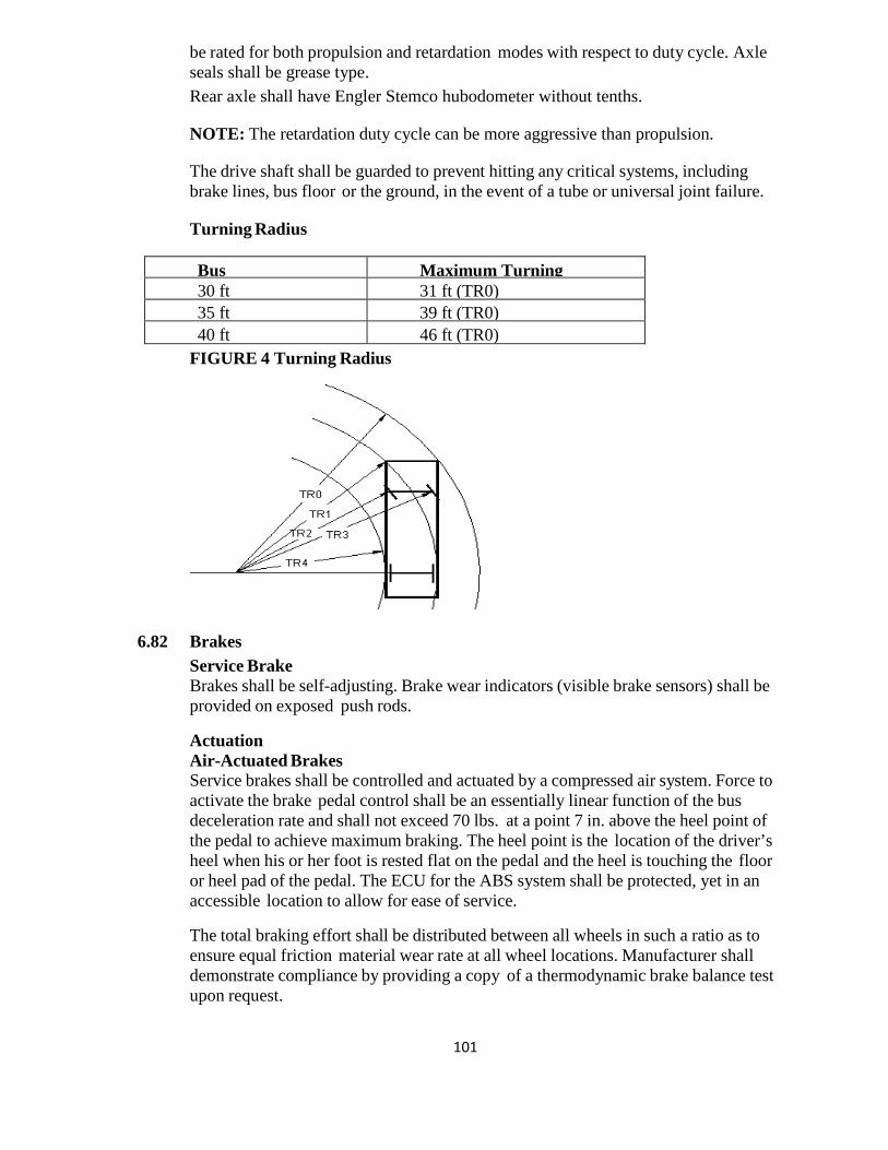
101
be rated for both propulsion and retardation modes with respect to duty cycle. Axle seals shall be grease type. Rear axle shall have Engler Stemco hubodometer without tenths. NOTE: The retardation duty cycle can be more aggressive than propulsion. The drive shaft shall be guarded to prevent hitting any critical systems, including brake lines, bus floor or the ground, in the event of a tube or universal joint failure.
Turning Radius Bus
Maximum Turning 30 ft 31 ft (TR0)
35 ft 39 ft (TR0) 40 ft 46 ft (TR0)
FIGURE 4 Turning Radius
6.82 Brakes Service Brake Brakes shall be self-adjusting. Brake wear indicators (visible brake sensors) shall be provided on exposed push rods. Actuation Air-Actuated Brakes Service brakes shall be controlled and actuated by a compressed air system. Force to activate the brake pedal control shall be an essentially linear function of the bus deceleration rate and shall not exceed 70 lbs. at a point 7 in. above the heel point of the pedal to achieve maximum braking. The heel point is the location of the driver’s heel when his or her foot is rested flat on the pedal and the heel is touching the floor or heel pad of the pedal. The ECU for the ABS system shall be protected, yet in an accessible location to allow for ease of service. The total braking effort shall be distributed between all wheels in such a ratio as to ensure equal friction material wear rate at all wheel locations. Manufacturer shall demonstrate compliance by providing a copy of a thermodynamic brake balance test upon request.
102
Automatic Traction Control Microprocessor controlled automatic traction control (ATC) shall be provided. Friction Material The brake linings shall be made of non-asbestos material. In order to aid maintenance personnel in determining extent of wear, a provision such as a scribe line or chamfer indicating the thickness at which replacement becomes necessary shall be provided on each brake lining. The complete brake lining wear indicator shall be clearly visible from the hoist or pit without removing backing plates.
6.83 Hubs Replaceable wheel bearing seals shall run on replaceable wear surfaces or be of an integral wear surface sealed design. Wheel bearing and hub seals and unitized hub assemblies shall not leak or weep lubricant when operating on the design operating profile for the duration of the initial manufacturer’s warranty. Hub shall be painted with black powder coat.
6.84 Drum Brakes The service brakes shall be two (2) shoe, internal-expanding, air operated S-cam type brakes at each wheel. The brakes must be capable of stopping the vehicle in accordance with the performance requirements of State and Federal regulations in effect at the time of manufacture. Parking brake shall be spring applied, air released chamber mounted on the rear axle assembly. All brake linings shall be of non-asbestos material three quarters (3/4) inch thick. Brake shoe return springs shall be the heaviest available. MGM Spring brake chambers shall be provided, and shall comply with requirements of State and Federal regulations FMVSS 121 in effect at time of manufacturer on the front and rear of these buses. At a minimum the front chamber shall be size 24 and the rear shall be size 36. The emergency air tank shall be piped to a service valve at the left front corner of the bus to fill the tank for towing the vehicle. Brake shoe effective area shall total a minimum of nine-hundred thirty-two (932) square inches. Brake shoes shall be operated by cams which in return are operated by automatic slack adjusters. Slack adjusters shall be Haldex and equipped with grease fittings and be capable of automatic adjustments throughout the life of the lining and drum assembly. Brake lines shall be installed so that the possibility of damage is minimized. Lines and hoses shall be clamped and supported in a manner which minimizes long, unsupported hose lengths and precludes rubbing against any part of the bus. The parking and emergency brakes shall be with a 40 PSI setting, controlled by a manual valve located convenient to the driver for safe, convenient access. Valve operation shall be "pull to set brakes" and "push to release" type brake system. This brake shall have stopping ability that is equal to or better than required by Federal and State regulations. It shall automatically apply if air system pressure falls below half the normal value or such other value as is recommended by the manufacturer. This parking/emergency brake shall be of spring brake design. The
103
manufacturer will provide in their proposal a statement of brake efficiency at empty and loaded capacity. As an option, a brake stroke and wear monitoring system shall be made available and priced separately. As an option, Four (4) wheel disc brakes will be made available and priced separately.
6.85 Parking/Emergency Brake Air Brakes The parking brake shall be a spring-operated system, actuated by a valve that exhausts compressed air to apply the brakes. The parking brake may be manually enabled when the air pressure is at the operating level per FMVSS 121.
6.86 Interlocks Passenger Door Interlocks To prevent opening mid and rear passenger doors while the bus is in motion, a speed sensor shall be integrated with the door controls to prevent the mid/rear doors from being enabled or opened unless the bus speed is less than 2 mph. To preclude movement of the bus, an accelerator interlock shall lock the accelerator in the closed position, and a brake interlock shall engage the service brake system to stop movement of the bus when the driver’s door control is moved to a mid/rear door enable or open position, or a mid or rear door panel is opened more than 3 in. from the fully closed position (as measured at the leading edge of the door panel). The interlock engagement shall bring the bus to a smooth stop and shall be capable of holding a fully loaded bus on a 6 percent grade, with the engine at idle and the transmission in gear, until the interlocks are released. These interlock functions shall be active whenever the vehicle Master Run Switch is in any run position. All door systems employing brake and accelerator interlocks shall be supplied with supporting failure mode effects analysis (FEMA) documentation, which demonstrates that failure modes are of a failsafe type, thereby never allowing the possibility of release of interlock while an interlocked door is in and unsecured condition, unless the door master switch has been actuated to intentionally release the interlocks. An accelerator interlock shall lock the accelerator in the closed position, and a brake interlock shall engage the service brake system to stop movement of the bus whenever front doors are open, selection to be made by procuring agency at pre-production meeting.
6.87 Pneumatic System General The bus air system shall operate the air-powered accessories and the braking system with reserve capacity. New buses shall not leak down more than 5 psi over a 15-minute period of time as indicated on the dash gauge.
104
Provision shall be made to apply shop air to the bus air systems. A quick disconnect fitting shall be easily accessible and located in the engine compartment and near the front bumper area for towing. Retained caps shall be installed to protect fitting against dirt and moisture when not in use. Air for the compressor shall be filtered. The air system shall be protected per FMVSS 121.
6.88 Air Compressor An engine-driven air compressor shall be sized to charge the air system from 40 psi to the governor cut-off pressure in less than 4 minutes while not exceeding the fast idle speed setting of the engine.
6.89 Air Lines and Fittings Air lines, except necessary flexible lines, shall conform to the installation and material requirements of SAE Standard J1149 for copper tubing with standard, brass, flared or ball sleeve fittings, or SAE Standard J844 for nylon tubing if not subject to temperatures over 200 oF. The air on the delivery side of the compressor where it enters nylon housing shall not be above the maximum limits as stated in SAE J844. Nylon tubing shall be installed in accordance with the following color-coding standards: Green: Indicates primary brakes and supply. Red: Indicates secondary brakes. Brown: Indicates parking brake Yellow: Indicates compressor governor signal. Black: Indicates accessories. Line supports shall prevent movement, flexing, tension, strain and vibration. Copper lines shall be supported to prevent the lines from touching one another or any component of the bus. To the extent practicable and before installation, the lines shall be pre-bent on a fixture that prevents tube flattening or excessive local strain. Copper lines shall be bent only once at any point, including pre-bending and installation. Rigid lines shall be supported at no less than 5-ft intervals. Nylon lines may be grouped and shall be supported at 30 in. intervals or less. The compressor discharge line between power plant and body-mounted equipment shall be flexible convoluted copper or stainless steel line, or may be flexible Teflon hose with a braided stainless steel jacket. Other lines necessary to maintain system reliability shall be flexible Teflon hose with a braided stainless steel jacket. End fittings shall be standard SAE or JIC brass or steel, flanged, swivel-type fittings. Flexible hoses shall be as short as practicable and individually supported. They shall not touch one another or any part of the bus except for the supporting grommets. Flexible lines shall be supported at 2-ft intervals or less. Air lines shall be clean before installation and shall be installed to minimize air leaks. All air lines shall be routed to prevent water traps to the extent possible. Grommets or insulated clamps shall protect the air lines at all points where they pass through understructure components.
6.90 Air Reservoirs All air reservoirs shall meet the requirements of FMVSS Standard 121 and SAE
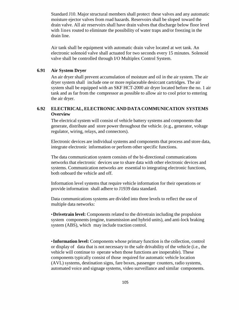
105
Standard J10. Major structural members shall protect these valves and any automatic moisture ejector valves from road hazards. Reservoirs shall be sloped toward the drain valve. All air reservoirs shall have drain valves that discharge below floor level with lines routed to eliminate the possibility of water traps and/or freezing in the drain line. Air tank shall be equipment with automatic drain valve located at wet tank. An electronic solenoid valve shall actuated for two seconds every 15 minutes. Solenoid valve shall be controlled through I/O Multiplex Control System.
6.91 Air System Dryer An air dryer shall prevent accumulation of moisture and oil in the air system. The air dryer system shall include one or more replaceable desiccant cartridges. The air system shall be equipped with an SKF HCT-2000 air dryer located before the no. 1 air tank and as far from the compressor as possible to allow air to cool prior to entering the air dryer.
6.92 ELECTRICAL, ELECTRONIC AND DATA COMMUNICATION SYSTEMS Overview The electrical system will consist of vehicle battery systems and components that generate, distribute and store power throughout the vehicle. (e.g., generator, voltage regulator, wiring, relays, and connectors). Electronic devices are individual systems and components that process and store data, integrate electronic information or perform other specific functions. The data communication system consists of the bi-directional communications networks that electronic devices use to share data with other electronic devices and systems. Communication networks are essential to integrating electronic functions, both onboard the vehicle and off. Information level systems that require vehicle information for their operations or provide information shall adhere to J1939 data standard. Data communications systems are divided into three levels to reflect the use of multiple data networks: • Drivetrain level: Components related to the drivetrain including the propulsion system components (engine, transmission and hybrid units), and anti-lock braking system (ABS), which may include traction control. • Information level: Components whose primary function is the collection, control or display of data that is not necessary to the safe drivability of the vehicle (i.e., the vehicle will continue to operate when those functions are inoperable). These components typically consist of those required for automatic vehicle location (AVL) systems, destination signs, fare boxes, passenger counters, radio systems, automated voice and signage systems, video surveillance and similar components.
106
• Multiplex level: Electrical or electronic devices controlled through input/output signals such as discrete, analog and serial data information (i.e., on/off switch inputs, relay or relay control outputs). Multiplexing is used to control components not typically found on the drivetrain or information levels, such as lights; wheelchair lifts; doors; heating, ventilation and air conditioning (HVAC) systems; and gateway devices. FIGURE 5 Data Communications Systems Levels Information level Multiplex level Drivetrain level
6.93 Modular Design Design of the electrical, electronic and data communication systems shall be modular so that each electronic device, apparatus panel, or wiring bundle is easily separable from its’ interconnect by means of connectors. Power plant wiring shall be an independent wiring harness. Replacement of the engine compartment wiring harness (es) shall not require pulling wires through any bulkhead or removing any terminals from the wires.
6.94 Environmental and Mounting Requirements The electrical system and its electronic components shall be capable of operating in the area of the vehicle in which they will be installed, as recommended in SAE J1455. Electrical and electronic equipment shall not be located in an environment that will reduce the performance or shorten the life of the component or electrical system when operating within the design operating profile. As a recommendation, no vehicle component shall generate, or be affected by, electromagnetic interference or radio frequency interference (EMI/RFI) that can disturb the performance of electrical/electronic equipment as defined in SAE J1113 and UNECE Council Directive 95/54 (R 10). The Agency shall follow recommendations from bus manufacturers and subsystem Suppliers regarding methods to prevent damage from voltage spikes generated from welding, jump starts, shorts, etc.
107
All electrical/electronic hardware mounted in the interior of the vehicle shall be inaccessible to passengers and hidden from view unless intended to be viewed. The hardware shall be mounted in such a manner as to protect it from splash or spray. All electrical/electronic hardware mounted on the exterior of the vehicle, that is not designed to be installed in an exposed environment, shall be mounted in a sealed enclosure. All electrical/electronic hardware and its mounting shall comply with the shock and vibration requirements of SAE J1455. Electrical cables and wiring shall be adequate for all anticipated loads. The main wiring harness shall, to the maximum extent practical, be installed inside the bus body passenger compartment and, where that is not practical, shall be secured in frame rail raceways. The Contractor shall route and secure all wiring so that it does not rub anywhere. Routing of step well light wiring shall be such as to avoid rubbing door posts, etc. When wires or looms pass through metal, the wires shall be protected by a rubber grommet. Each electrical panel i.e. front and exit door panels, battery compartment, and front electrical panel shall provide an explanation of the respective electrical circuits and components contained within and shall be furnished in a silk-screened or water/oil proof diagram on the inside of the door panel. All engine compartment wiring and light wiring shall be insulated from the heat and be resistant to oil and grease. Electrical equipment, junction boxes and connectors shall not be placed where they are subjected to excessive heat, oil, grease, or road spray. All multiple terminal connectors shall be military (cannon plug) type, fully sealed and protected with a potting compound to prevent outside dirt and corrosives from entering the wiring, connectors, or plugs. All main power supply terminals shall be covered with electric post rubber cover. All electrical end plugs shall be covered. The wiring harnesses shall incorporate 10% spare wires. Wiring located in the engine compartment shall be routed away from high-heat sources or shielded and/or insulated from temperatures exceeding the wiring and connector operating requirements. All cables and harnesses shall be secured to prevent chafing or shorting against each other or any part of the vehicle. Clamps shall be rubber or PVC clad aircraft type. Grommets or other protective material shall be installed at points where wiring penetrates metal structures. All wiring shall start and end at a junction block or component. All inline and bulkhead connectors are to be of the weather pack sealed type. Multi-pin connectors shall be protected internally from corrosion with silicone dielectric grease (Dow Corning #4). All circuits except the engine emergency shut-
108
off and speedometer circuits must be protected by reset circuit breakers that clearly indicate their position when tripped. Each breaker must be labeled. Circuit breakers must have plastic dust caps. Provide constant power for powering systems, such as but not limited to the fire suppression, radio, farebox, and DC-DC converter that require constant power when battery cutoff switch is off. The windshield wiper and headlamps electric circuit shall be protected by modified auto-reset circuit breakers sized to the requirement of the load. Rubber Covers shall be provided for all the Electric Posts. All junction boxes located in the engine compartment shall be designed to allow thorough steam cleaning of the engine compartment area without intrusion of water. Major junction panels shall be readily accessible for maintenance, not located behind or alongside seat or other fixed/semi-fixed obstructions. Access panels and junction box covers shall have seals which will preclude entry of rain, wash water, road debris, etc. All wiring and junction panel terminals shall be numbered and color coded for easy identification. A diagram showing the coding as the bus was built shall be furnished. The Contractor shall supply at least two spare circuits in the main harness between the front and rear of the bus. The main harness from the engine compartment shall be equipped with multiple circuit cannon type connectors.
6.95 Hardware Mounting The mounting of the hardware shall not be used to provide the sole source ground, and all hardware shall be isolated from potential EMI/RFI, as referenced in SAE J1113. All electrical/electronic hardware mounted in the interior of the vehicle shall be inaccessible to passengers and hidden from view unless intended to be viewed. The hardware shall be mounted in such a manner as to protect it from splash or spray. All electrical/electronic hardware mounted on the exterior of the vehicle that is not designed to be installed in an exposed environment shall be mounted in a sealed enclosure. All electrical/electronic hardware and its mounting shall comply with the shock and vibration requirements of SAE J1455.
6.96 General Electrical Requirements Batteries Low-Voltage Batteries (24V) Two twelve volt AGM thermal battery units, size 8D, with side post connectors with minimum 1300 cold cranking amps at zero degrees Fahrenheit with a reserve capacity of 425 minutes or greater will be required.
109
As an option, Four (4) Group 31 Batteries will be made available and priced separately.
6.97 Battery Cables The battery terminal ends and cables shall be color-coded with red for the primary positive, black for negative and another color for any intermediate voltage cables. Positive and negative battery cables shall not cross each other if at all possible, be flexible and sufficiently long to reach the batteries with the tray in the extended position without stretching or pulling on any connection and shall not lie directly on top of the batteries. Except as interrupted by the master battery switch, battery and starter wiring shall be continuous cables with connections secured by bolted terminals and shall conform to specification requirements of SAE Standard J1127 – Type SGT, SGX or GXL and SAE Recommended Practice J541.
6.98 Master Battery Switch A single master switch shall be provided near the battery compartment for the disconnecting of all battery positives (12V and 24V), except for safety devices such as the fire suppression system and other systems as specified. The location of the master battery switch shall be clearly identified on the exterior access panel, be accessible in less than 10 seconds for deactivation and prevent corrosion from fumes and battery acid when the batteries are washed off or are in normal service. The access door shall be labeled "Battery Emergency Shut-Off Switch." Turning the master switch off with the power plant operating shall shut off the engine and shall not damage any component of the electrical system. The master switch shall be capable of carrying and interrupting the total circuit load.
6.99 Jump-Start Connector Front and rear jump start Anderson 350, Gray, Mtd shall be provided on curbside of bus. A jump-start connector, red for 24V and blue for 12V, shall be provided at a location determined at the pre-production meeting and shall be equipped with dust cap and adequately protected from moisture, dirt and debris. As an option, the KBi KSM super-capacitor start aid will be made available and priced separately.
6.100 Battery Compartment The battery compartment must be well-ventilated to prevent hydrogen buildup while protecting the compartment from road spray, water intrusion and de-icing chemicals. Batteries shall be mounted in a stainless steel slide out tray on rollers, with less than 50 lbs. of effort. The battery tray shall have drain holes. The batteries shall not be located in the engine compartment. The vehicle shall be equipped with a 12VDC and 24VDC quick disconnect switch (es). The battery compartment door shall conveniently accommodate operation of the
110
12VDC and 24VDC quick disconnect switch (es).
6.101 Alternator / Regulator A Niehoff 803 alternator shall supply the entire nighttime operating electrical load of the coach while providing at least 20 percent of its current output for battery charging when the battery is fully discharged. If a hybrid propulsion system is used a Vanner HBA500 will be the standard alternator. As an option, the Niehoff 703 alternator will be made available and priced as an option. As an option, the Delco 450 DN will be made available and price separately. As an option, the Delco 50DN will be made available and price separately.
6.102 Circuit Protection All branch circuits, except battery-to-starting motor and battery-to-generator/alternator circuits, shall be protected by current-limiting devices such as circuit breakers, fuses or solid state devices sized to the requirements of the circuit. Electronic circuit protection for the cranking motor shall be provided to prevent engaging of the motor for more than 30 seconds at a time to prevent overheating. The circuit breakers or fuses shall be easily accessible for authorized personnel. Fuses shall be used only where it can be demonstrated that circuit breakers are not practicable. This requirement applies to in-line fuses supplied by either the Contractor or a Supplier. Fuse holders shall be constructed to be rugged and waterproof. All manual reset circuit breakers critical to the operation of the bus shall be mounted in a location convenient to the Agency mechanic with visible indication of open circuits. The Agency shall consider the application of automatic reset circuit breakers on a case-by-case basis. The Contractor shall show all in-line fuses in the final harness drawings. Any manually resettable circuit breakers shall provide a visible indication of open circuits. Any manually resettable circuit breakers shall provide a visible indication of open circuits. Circuit breakers or fuses shall be sized to a minimum of 15 percent larger than the total circuit load. The current rating for the wire used for each circuit must exceed the size of the circuit protection being used.
6.103 Grounds The battery shall be grounded to the vehicle chassis/frame at one location only, as close to the batteries as possible. When using a chassis ground system, the chassis shall be grounded to the frame in multiple locations, evenly distributed throughout the vehicle to eliminate ground loops. No more than four ground ring/spade terminal connections shall be made per ground stud. Electronic equipment requiring an isolated ground to the battery (i.e., electronic ground) shall not be grounded through the chassis.
6.104 Low Voltage/Low Current Wiring and Terminals All power and ground wiring shall conform to specification requirements of SAE
111
Recommended Practice J1127, J1128 and J1292. Double insulation shall be maintained as close to the junction box, electrical compartment or terminals as possible. The requirement for double insulation shall be met by wrapping the harness with plastic electrical tape or by sheathing all wires and harnesses with non-conductive, rigid or flexible conduit. Wiring shall be grouped, numbered and/or color-coded. Wiring harnesses shall not contain wires of different voltage classes unless all wires within the harness are insulated for the highest voltage present in the harness. Kinking, grounding at multiple points, stretching, and exceeding minimum bend radius shall be prevented. Strain-relief fittings shall be provided at all points where wiring enters electrical compartments. Grommets or other protective material shall be installed at points where wiring penetrates metal structures outside of electrical enclosures. Wiring supports shall be protective and non-conductive at areas of wire contact and shall not be damaged by heat, water, solvents or chafing. To the extent practicable, wiring shall not be located in environmentally exposed locations under the vehicle. Wiring and electrical equipment necessarily located under the vehicle shall be insulated from water, heat, corrosion and mechanical damage. Where feasible, front to rear electrical harnesses should be installed above the window line of the vehicle. All wiring harnesses over 5 ft long and containing at least five wires shall include 10 percent (minimum one wire) excess wires for spares. This requirement for spare wires does not apply to data links and communication cables. Wiring harness length shall allow end terminals to be replaced twice without pulling, stretching or replacing the wire. Terminals shall be crimped to the wiring according to the connector manufacturer’s recommendations for techniques and tools. All cable connectors shall be locking type, keyed and sealed, unless enclosed in watertight cabinets or vehicle interior. Pins shall be removable, crimp contact type, of the correct size and rating for the wire being terminated. Unused pin positions shall be sealed with sealing plugs. Adjacent connectors shall either use different inserts or different insert orientations to prevent incorrect connections. Terminals shall be crimped, corrosion-resistant and full ring type or interlocking lugs with insulating ferrules. When using pressure type screw terminal strips, only stranded wire shall be used. Insulation clearance shall ensure that wires have a minimum of “visible clearance” and a maximum of two times the conductor diameter or 1/16 in., whichever is less. When using shielded or coaxial cable, upon stripping of the insulation, the metallic braid shall be free from frayed strands that can penetrate the insulation of the inner wires. Ultra-sonic and T-splices may be used with 7 AWG or smaller wire. When a T-splice is used, it shall meet these additional requirements: • It shall include a mechanical clamp in addition to solder on the splice. • The wire shall support no mechanical load in the area of the splice. • The wire shall be supported to prevent flexing. All splicing shall be staggered in the harness so that no two splices are positioned in the same location within the harness.
112
Wiring located in the engine compartment shall be routed away from high-heat sources or shielded and/or insulated from temperatures exceeding the wiring and connector operating requirements. The instrument panel and wiring shall be easily accessible for service from the driver’s seat or top of the panel. The instrument panel shall be separately removable and replaceable without damaging the instrument panel or gauges. Wiring shall have sufficient length and be routed to permit service without stretching or chafing the wires.
6.105 Electrical Components All electrical components, including switches, relays, flashers and circuit breakers, shall be heavy-duty designs with either a successful history of application in heavy-duty vehicles or design specifications for an equivalent environment. All electric motors shall be heavy-duty brushless type where practical, and have a continuous duty rating of no less than 40,000 hours (except cranking motors, washer pumps and wiper motors). All electric motors shall be easily accessible for servicing.
6.106 Electrical Compartments All relays, controllers, flashers, circuit breakers and other electrical components shall be mounted in easily accessible electrical compartments. All compartments exposed to the outside environment shall be corrosion-resistant and sealed. The components and their functions in each electrical compartment shall be identified and their location permanently recorded on a drawing attached to the inside of the access panel or door. The drawing shall be protected from oil, grease, fuel and abrasion. The front compartment shall be completely serviceable from the driver’s seat, vestibule or from the outside. “Rear start and run” controls shall be mounted in an accessible location in the engine compartment and shall be protected from the environment.
6.107 General Electronic Requirements If an electronic component has an internal real-time clock, it shall provide its own battery backup to monitor time when battery power is disconnected, and/or it may be updated by a network component. If an electronic component has an hour meter, it shall record accumulated service time without relying on battery backup. All electronic component Suppliers shall ensure that their equipment is self-protecting in the event of shorts in the cabling, and also in over-voltage (over 32V DC on a 24V DC nominal voltage rating with a maximum of 50V DC) and reverse polarity conditions. If an electronic component is required to interface with other components, it shall not require external pull-up and/or pull-down resistors. Where this is not possible, the use of a pull-up or pull-down resistor shall be limited as much as possible and easily accessible and labeled.
113
6.108 Wiring and Terminals Kinking, grounding at multiple points, stretching and reducing the bend radius below the manufacturer’s recommended minimum shall not be permitted.
6.109 Discrete I/O (Inputs/Outputs) All wiring to I/O devices, either at the harness level or individual wires, shall be labeled, stamped or color coded in a fashion that allows unique identification at a spacing not exceeding 4 in. Wiring for each I/O device shall be bundled together. If the I/O terminals are the same voltages, then jumpers may be used to connect the common nodes of each I/O terminal.
6.110 Shielding All wiring that requires shielding shall meet the following minimum requirements. A shield shall be generated by connecting to a ground, which is sourced from a power distribution bus bar or chassis. A shield shall be connected at one location only, typically at one end of the cable. However certain standards or special requirements, such as SAE J1939 or RF applications, have separate shielding techniques that also shall be used as applicable. NOTE: A shield grounded at both end forms a ground loop, which can cause intermittent control or faults. When using shielded or coaxial cable, upon stripping of the insulation, the metallic braid shall be free from frayed strands, which can penetrate the insulation of the inner wires. To prevent the introduction of noise, the shield shall not be connected to the common side of a logic circuit.
6.111 Communications The data network cabling shall be selected and installed according to the selected protocol requirements. The physical layer of all network communication systems shall not be used for any purpose other than communication between the system components, unless provided for in the network specifications. Communications networks that use power line carriers (e.g., data modulated on a 24V-power line) shall meet the most stringent applicable wiring and terminal specifications.
6.112 Radio Frequency (RF) RF components, such as radios, video devices, cameras, global positioning systems (GPS), etc., shall use coaxial cable to carry the signal. All RF systems require special design consideration for losses along the cable. Connectors shall be minimized, since each connector and crimp has a loss that will attribute to attenuation of the signal. Cabling should allow for the removal of antennas or attached electronics without removing the installed cable between them. If this cannot be done, then a conduit of sufficient size shall be provided for ease of attachment of antenna and cable assembly. The corresponding component vendors shall be consulted for proper application of equipment, including installation of cables.
114
6.113 Audio
Cabling used for microphone level and line level signals shall be 22 AWG minimum with shielded twisted pair. Cabling used for amplifier level signals shall be 18 AWG minimum.
6.114 Multiplexing- General The multiplexing system shall be a Dinex system used to control of components necessary to operate the vehicle. This is accomplished by processing information from input devices and controlling output devices through the use of an internal logic program. Versatility and future expansion shall be provided for by expandable system architecture. The multiplex system shall be capable of accepting new inputs and outputs through the addition of new modules and/or the utilization of existing spare inputs and outputs. All like components in the multiplex system shall be modular and interchangeable with self-diagnostic capabilities. The modules shall be easily accessible for troubleshooting electrical failures and performing system maintenance. Multiplex input/output modules shall use solid-state devices to provide extended service life and individual circuit protection. Ten percent of the total number of inputs and outputs, or at least one each for each voltage type utilized (0V, 12V, 24V), at each module location shall be designated as spares.
6.115 Data Communications - General All data communication networks shall be either in accordance with a nationally recognized interface standard, such as those published by SAE, IEEE or ISO, or shall be published to the Agency with the following minimum information: • Protocol requirements for all timing issues (bit, byte, packet, inter-packet timing, idle line timing, etc.) packet sizes, error checking and transport (bulk transfer of data to/from the device). • Data definition requirements that ensure access to diagnostic information and performance characteristics. • The capability and procedures for uploading new application or configuration data. • Access to revision levels of data, application software and firmware. • The capability and procedures for uploading new firmware or application software. • Evidence that applicable data shall be broadcast to the network in an efficient manner such that the overall network integrity is not compromised. Any electronic vehicle components used on a network shall be conformance tested to the corresponding network standard.
6.116 Drivetrain Level Drivetrain components, consisting of the engine, transmission, retarder, anti-lock braking system and all other related components, shall be integrated and communicate fully with respect to vehicle operation with data using SAE Recommended Communications Protocols such as J1939 and/or J1708/J1587 with forward and backward compatibilities or other open protocols.
115
6.117 Diagnostics, Fault Detection and Data Access Drivetrain performance, maintenance and diagnostic data, and other electronic messages shall be formatted and transmitted on the communications networks. The drivetrain level shall have the ability to record abnormal events in memory and provide diagnostic codes and other information to service personnel. At a minimum, this network level shall provide live/fail status, current hardware serial number, software/data revisions and uninterrupted timing functions.
6.118 Programmability (Software) The drivetrain level components shall be programmable by the Agency with limitations as specified by the sub-system Supplier. Data Access At a minimum, information shall be made available via a communication port on the multiplex system. The location of the communication port shall be easily accessible. A hardware gateway and/or wireless communications system are options if requested by the Agency.
6.119 Diagnostics and Fault Detection
The multiplex system shall have a proven method of determining its status (system health and input/output status) and detecting either active (online) or inactive (offline) faults through the use of on-board visual/audible indicators. In addition to the indicators, the system shall employ an advanced diagnostic and fault detection system, which shall be accessible via either a personal computer or a handheld unit. Either unit shall have the ability to check logic function. The diagnostic data can be incorporated into the information level network or the central data access system.
6.120 Programmability (Software) The multiplex system shall have security provisions to protect its software from unwanted changes. This shall be achieved through any or all of the following procedures: • password protection • limited distribution of the configuration software • limited access to the programming tools required to change the software • hardware protection that prevents undesired changes to the software Provisions for programming the multiplex system shall be possible through a PC or laptop. The multiplex system shall have proper revision control to ensure that the hardware and software are identical on each vehicle equipped with the system. Revision control shall be provided by all of the following: • hardware component identification where labels are included on all multiplex hardware to identify components • hardware series identification where all multiplex hardware displays the current hardware serial number and firmware revision employed by the module
116
• software revision identification where all copies of the software in service displays the most recent revision number • a method of determining which version of the software is currently in use in the multiplex system
6.121 Electronic Noise Control Electrical and electronic sub-systems and components on all buses shall not emit electromagnetic radiation that will interfere with on-board systems, components or equipment, telephone service, radio or TV reception or violate regulations of the Federal Communications Commission. Electrical and electronic sub-systems on the buses shall not be affected by external sources of RFI/EMI. This includes, but is not limited to, radio and TV transmission, portable electronic devices including computers in the vicinity of or onboard the buses, ac or dc power lines and RFI/EMI emissions from other vehicles.
6.122 DRIVER PROVISIONS, CONTROLS AND INSTRUMENTATION Driver’s Area Controls General In general when designing the driver’s area, it is recommended that SAE J833, “Human Physical Dimensions,” be used. Switches and controls shall be divided into basic groups and assigned to specific areas, in conformance with SAE Recommended Practice J680, Revised 1988, “Location and Operation of Instruments and Controls in Motor Truck Cabs,” and be essentially within the hand reach envelope described in SAE Recommended Practice J287, “Driver Hand Control Reach.” Glare The driver’s work area shall be designed to minimize glare to the extent possible. Objects within and adjacent to this area shall be matte black or dark gray in color wherever possible to reduce the reflection of light onto the windshield. The use of polished metal and light-colored surfaces within and adjacent to the driver’s area shall be avoided. Visors/Sun Shades Front and Side Sun Shade/Visor An adjustable roller type sunscreen shall be provided over the driver’s windshield and/or the driver’s side window. The sunscreen shall be capable of being lowered to the midpoint of the driver’s window. When deployed, the screen shall be secure, stable and shall not rattle, sway or intrude into the driver’s field of view due to the motion of the bus or as a result of air movement. Once lowered, the screen shall remain in the lowered position until returned to the stowed position by the driver. Sunscreen shall be shaped to minimize light leakage between the visor and windshield pillars to the extent possible. Visors shall store out of the way and shall not obstruct airflow from the climate control system or interfere with other equipment, such as the radio handset or the
117
destination control. Deployment of the visors shall not restrict vision of the rearview mirrors. Visor adjustments shall be made easily by hand with positive locking and releasing devices and shall not be subject to damage by over-tightening. Sun visor construction and materials shall be strong enough to resist breakage during adjustments.
6.123 Driver’s Controls Frequently used controls must be in easily accessible locations. These include the door control, kneel control, windshield wiper/washer controls, ramp, and lift and run switch. Any switches and controls necessary for the safe operation of the bus shall be conveniently located and shall provide for ease of operation. They shall be identifiable by shape, touch and permanent markings. Controls also shall be located so that passengers may not easily tamper with control settings. All panel-mounted switches and controls shall be marked with easily read identifiers. Graphic symbols shall conform to SAE Recommended Practice J2402, “Road Vehicles – Symbols for Controls, Indicators, and Tell Tales,” where available and applicable. Color of switches and controls shall be dark with contrasting typography or symbols. Mechanical switches and controls shall be replaceable, and the wiring at these controls shall be serviceable from a convenient location. Switches, controls and instruments shall be dust- and water-resistant.
6.124 Normal Bus Operation Instrumentation and Controls The following list identifies bus controls used to operate the bus. These controls are either frequently used or critical to the operation of the bus. They shall be located within easy reach of the operator. The operator shall not be required to stand or turn to view or actuate these controls unless specified otherwise. Systems or components monitored by onboard diagnostics system shall be displayed in clear view of the operator and provide visual and/or audible indicators. The intensity of indicators shall permit easy determination of on/off status in bright sunlight but shall not cause a distraction or visibility problem at night. All indicators shall be illuminated using backlighting. The indicator panel shall be located in Area 1 or Area 5, within easy view of the operator instrument panel. All indicators shall have a method of momentarily testing their operation. The audible alarm shall be tamper-resistant and shall have an outlet level between 80 and 83 dBA when measured at the location of the operator’s ear. On-board displays visible to the operator shall be limited to indicating the status of those functions described herein that are necessary for the operation of the bus. All other indicators needed for diagnostics and their related interface hardware shall be concealed and protected from unauthorized access. Table 3 represents instruments and alarms. The intent of the overall physical layout of the indicators shall be in a logical grouping of systems and severity nature of the fault.
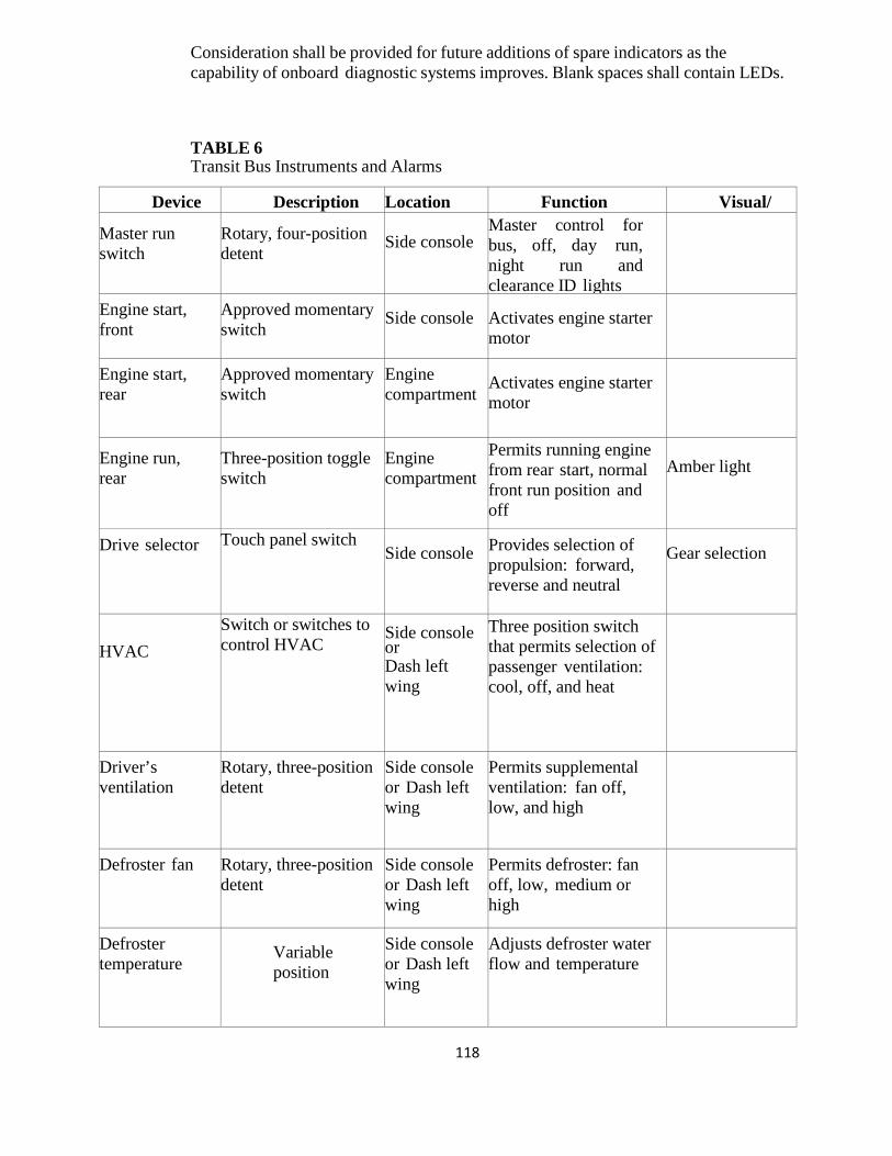
118
Consideration shall be provided for future additions of spare indicators as the capability of onboard diagnostic systems improves. Blank spaces shall contain LEDs. TABLE 6 Transit Bus Instruments and Alarms
Device Description Location Function Visual/ Master run
switch Rotary, four-position detent
Side console
Master control for bus, off, day run, night run and clearance ID lights
Engine start, front
Approved momentary switch
Side console
Activates engine starter motor
Engine start, rear
Approved momentary switch
Engine compartment
Activates engine starter motor
Engine run, rear
Three-position toggle switch
Engine compartment
Permits running engine from rear start, normal front run position and off
Amber light
Drive selector Touch panel switch Side console Provides selection of
propulsion: forward, reverse and neutral
Gear selection
HVAC
Switch or switches to control HVAC
Side console or Dash left wing
Three position switch that permits selection of passenger ventilation: cool, off, and heat
Driver’s ventilation
Rotary, three-position detent
Side console or Dash left wing
Permits supplemental ventilation: fan off, low, and high
Defroster fan Rotary, three-position detent
Side console or Dash left wing
Permits defroster: fan off, low, medium or high
Defroster temperature
Variable position
Side console or Dash left wing
Adjusts defroster water flow and temperature
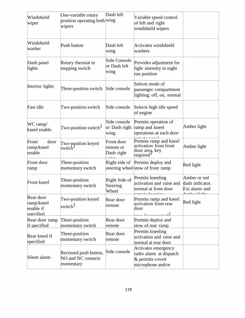
119
Windshield wiper
One-variable rotary position operating both wipers
Dash left wing Variable speed control
of left and right windshield wipers
Windshield washer
Push button
Dash left wing
Activates windshield washers
Dash panel lights
Rotary rheostat or stepping switch
Side Console or Dash left wing
Provides adjustment for light intensity in night run position
Interior lights Three-position switch
Side console
Selects mode of passenger compartment lighting: off, on, normal
Fast idle
Two-position switch
Side console
Selects high idle speed of engine
WC ramp/ kneel enable
Two-position switch1
Side console or Dash right wing
Permits operation of ramp and kneel operations at each door remote panel
Amber light
Front door ramp/kneel enable
Two-position keyed switch1
Front door remote or Dash right wing
Permits ramp and kneel activation from front door area, key required1
Amber light
Front door ramp
Three-position momentary switch
Right side of steering wheel
Permits deploy and stow of front ramp
Red light
Front kneel Three-position
momentary switch Right Side of Steering Wheel
Permits kneeling activation and raise and normal at front door remote location
Amber or red dash indicator. Ext alarm and Amber light Rear door
ramp/kneel enable if specified
Two-position keyed switch1
Rear door remote
Permits ramp and kneel activation from rear door area key required1
Red light
Rear door ramp if specified
Three-position momentary switch
Rear door remote
Permits deploy and stow of rear ramp
Rear kneel if specified
Three-position momentary switch
Rear door remote
Permits kneeling activation and raise and normal at rear door
Silent alarm
Recessed push button, NO and NC contacts momentary
Side console
Activates emergency radio alarm at dispatch & permits covert microphone and/or
bl d ti ti i
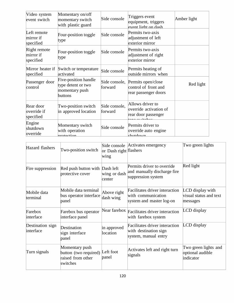
120
Video system event switch
Momentary on/off momentary switch with plastic guard
Side console Triggers event
equipment, triggers event light on dash
Amber light
Left remote mirror if specified
Four-position toggle type
Side console Permits two-axis
adjustment of left exterior mirror
Right remote mirror if specified
Four-position toggle type
Side console Permits two-axis
adjustment of right exterior mirror
Mirror heater if specified
Switch or temperature activated
Side console Permits heating of
outside mirrors when
Passenger door control
Five-position handle type detent or two momentary push buttons
Side console, forward
Permits open/close control of front and rear passenger doors
Red light
Rear door override if specified
Two-position switch in approved location
Side console, forward
Allows driver to override activation of rear door passenger tape switches
Engine shutdown override
Momentary switch with operation protection
Side console Permits driver to
override auto engine shutdown
Hazard flashers Two-position switch
Side console or Dash right wing
Activates emergency flashers
Two green lights
Fire suppression Red push button with protective cover
Dash left wing or dash center
Permits driver to override and manually discharge fire suppression system
Red light
Mobile data terminal
Mobile data terminal bus operator interface panel
Above right dash wing
Facilitates driver interaction with communication system and master log-on
LCD display with visual status and text messages
Farebox interface
Farebox bus operator interface panel
Near farebox Facilitates driver interaction with farebox system
LCD display
Destination sign interface
Destination sign interface panel
in approved location
Facilitates driver interaction with destination sign system, manual entry
LCD display
Turn signals
Momentary push button (two required) raised from other switches
Left foot panel
Activates left and right turn signals
Two green lights and optional audible indicator
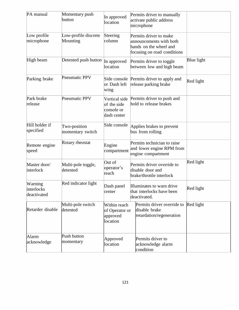
121
PA manual Momentary push button In approved
location Permits driver to manually activate public address microphone
Low profile microphone
Low-profile discrete Mounting
Steering column
Permits driver to make announcements with both hands on the wheel and focusing on road conditions
High beam Detented push button In approved location
Permits driver to toggle between low and high beam
Blue light
Parking brake Pneumatic PPV Side console or Dash left wing
Permits driver to apply and release parking brake
Red light
Park brake release
Pneumatic PPV Vertical side of the side console or dash center
Permits driver to push and hold to release brakes
Hill holder if specified
Two-position momentary switch
Side console Applies brakes to prevent bus from rolling
Remote engine speed
Rotary rheostat Engine compartment
Permits technician to raise and lower engine RPM from engine compartment
Master door/ interlock
Multi-pole toggle, detented
Out of operator’s reach
Permits driver override to disable door and brake/throttle interlock
Red light
Warning interlocks deactivated
Red indicator light Dash panel center
Illuminates to warn drive that interlocks have been deactivated.
Red light
Retarder disable
Multi-pole switch detented
Within reach of Operator or approved location
Permits driver override to disable brake retardation/regeneration
Red light
Alarm acknowledge
Push button momentary Approved
location Permits driver to acknowledge alarm condition
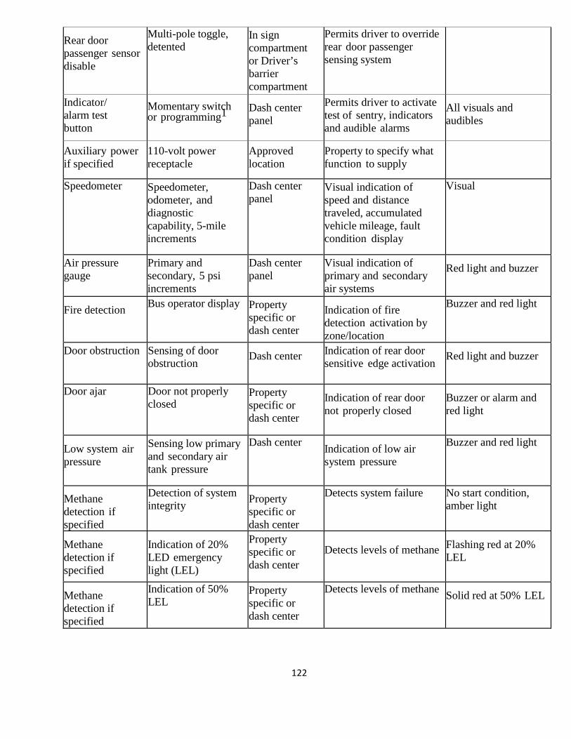
122
Rear door passenger sensor disable
Multi-pole toggle, detented
In sign compartment or Driver’s barrier compartment
Permits driver to override rear door passenger sensing system
Indicator/ alarm test button
Momentary switch or programming1
Dash center panel
Permits driver to activate test of sentry, indicators and audible alarms
All visuals and audibles
Auxiliary power if specified
110-volt power receptacle
Approved location
Property to specify what function to supply
Speedometer Speedometer, odometer, and diagnostic capability, 5-mile increments
Dash center panel
Visual indication of speed and distance traveled, accumulated vehicle mileage, fault condition display
Visual
Air pressure gauge
Primary and secondary, 5 psi increments
Dash center panel
Visual indication of primary and secondary air systems
Red light and buzzer
Fire detection Bus operator display Property specific or dash center
Indication of fire detection activation by zone/location
Buzzer and red light
Door obstruction Sensing of door obstruction Dash center Indication of rear door
sensitive edge activation Red light and buzzer
Door ajar Door not properly closed
Property specific or dash center
Indication of rear door not properly closed
Buzzer or alarm and red light
Low system air pressure
Sensing low primary and secondary air tank pressure
Dash center Indication of low air system pressure
Buzzer and red light
Methane detection if specified
Detection of system integrity Property
specific or dash center
Detects system failure No start condition, amber light
Methane detection if specified
Indication of 20% LED emergency light (LEL)
Property specific or dash center
Detects levels of methane Flashing red at 20%
LEL
Methane detection if specified
Indication of 50% LEL
Property specific or dash center
Detects levels of methane Solid red at 50% LEL
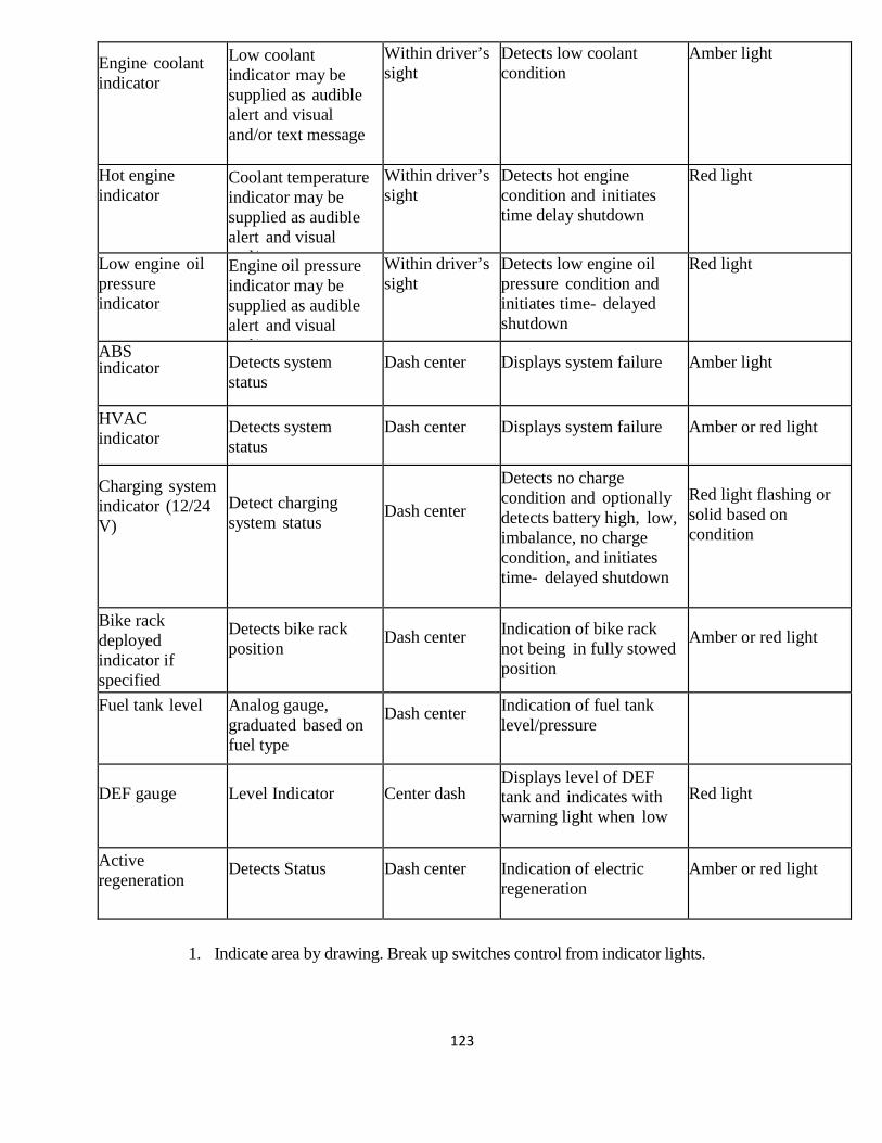
123
Engine coolant indicator
Low coolant indicator may be supplied as audible alert and visual and/or text message
Within driver’s sight
Detects low coolant condition
Amber light
Hot engine indicator
Coolant temperature indicator may be supplied as audible alert and visual
d/ t t
Within driver’s sight
Detects hot engine condition and initiates time delay shutdown
Red light
Low engine oil pressure indicator
Engine oil pressure indicator may be supplied as audible alert and visual
d/ t t
Within driver’s sight
Detects low engine oil pressure condition and initiates time- delayed shutdown
Red light
ABS indicator Detects system
status Dash center Displays system failure Amber light
HVAC indicator
Detects system status
Dash center Displays system failure Amber or red light
Charging system indicator (12/24 V)
Detect charging system status
Dash center
Detects no charge condition and optionally detects battery high, low, imbalance, no charge condition, and initiates time- delayed shutdown
Red light flashing or solid based on condition
Bike rack deployed indicator if specified
Detects bike rack position
Dash center Indication of bike rack
not being in fully stowed position
Amber or red light
Fuel tank level Analog gauge, graduated based on fuel type
Dash center Indication of fuel tank level/pressure
DEF gauge
Level Indicator
Center dash
Displays level of DEF tank and indicates with warning light when low
Red light
Active regeneration
Detects Status Dash center Indication of electric regeneration
Amber or red light
1. Indicate area by drawing. Break up switches control from indicator lights.
124
6.125 Driver Foot Controls Accelerator and brake pedals shall be designed for ankle motion. Foot surfaces of the pedals shall be faced with wear-resistant, nonskid, replaceable material.
6.126 Pedal Angle The vertical angle of the accelerator and brake pedals shall be determined from a horizontal plane regardless of the slope of the cab floor. The accelerator and brake pedals shall be positioned at an angle of 37 to 50 degrees at the point of initiation of contact and extend downward to an angle of 10 to 18 degrees at full throttle. The location of the brake and accelerator pedals shall be determined by the manufacturer, based on space needs, visibility, lower edge of windshield, and vertical H-point.
6.127 Pedal Dimensions and Position The floor-mounted accelerator pedal shall be 10 to 12 in. long and 3 to 4 in. wide. Clearance around the pedal must allow for no interference precluding operation. As an option, Adjustable Brake / Accelerator pedals will be made available and priced separately.
6.128 Driver Foot Switches Floor-Mounted Foot Control Platform The angle of the turn signal platform shall be determined from a horizontal plane, regardless of the slope of the cab floor. The turn signal platform shall be angled at a minimum of 10 degrees and a maximum of 37 degrees. It shall be located no closer to the seat front than the heel point of the accelerator pedal. Turn Signal Controls Turn signal controls shall be floor-mounted, foot-controlled, water-resistant, heavy-duty, momentary contact switches. Foot Switch Control The control switches for the turn signals shall be mounted on an inclined, floor-mounted stainless steel enclosure or metal plate mounted to an incline integrated into the driver’s platform, located to the left of the steering column. The location and design of this enclosure shall be such that foot room for the operator is not impeded. The inclined mounting surface shall be skid-resistant. All other signals, including high beam and public address system shall be in approved location. The foot switches shall be UL-listed, heavy-duty type, of a rugged, corrosion-resistant metal construction. The foot switches for the directionals shall be momentary type, while those for the PA system and the high beam shall be latching type. The spacing of the switches shall be such that inadvertent simultaneous deflection of switches is prevented. Other Floor-Mounted Controls The following may be floor mounted, momentary or latching, as identified by the Agency at the pre-production meeting. • hazard • silent alarm

125
• PA system
6.129 Driver’s Amenities Coat Hook A hook and tie-back loop shall be provided to secure the driver’s coat. It shall be mounted above and to the left rear of the driver's head level behind the driver’s seat. As an option, a dash mounted cup holder will made available and priced as separately. As an option, a trash bag holder will be made available and priced separately.
6.130 Windshield Wipers and Washers Windshield Wipers The bus shall be equipped with a windshield wiper for each half of the windshield. At 60 mph, no more than 10 percent of the wiped area shall be lost due to windshield wiper lift. For two- piece windshields, both wipers shall park along the center edges of the windshield glass. For single-piece windshields, wipers shall park along the bottom edge of the windshield. Windshield wiper motors and mechanisms shall be easily accessible for repairs or service. The fastener that secures the wiper arm to the drive mechanism shall be corrosion-resistant. Electric wipers will be used. Intermittent Wiper with Variable Control A variable-speed feature shall be provided to allow adjustment of wiper speed for each side of the windshield between approximately five (5) and twenty-five (25) cycles per minute. Non-Synchronized Wipers For non-synchronized wipers, separate controls for each side shall be supplied. Windshield Washers The windshield washer system, when used with the wipers, shall deposit washing fluid evenly and completely wet the entire wiped area. The windshield washer system shall have a minimum 3-gallon reservoir, located for easy refilling from outside of the bus. Reservoir pumps, lines and fittings shall be corrosion-resistant and must include a means to determine fluid level.
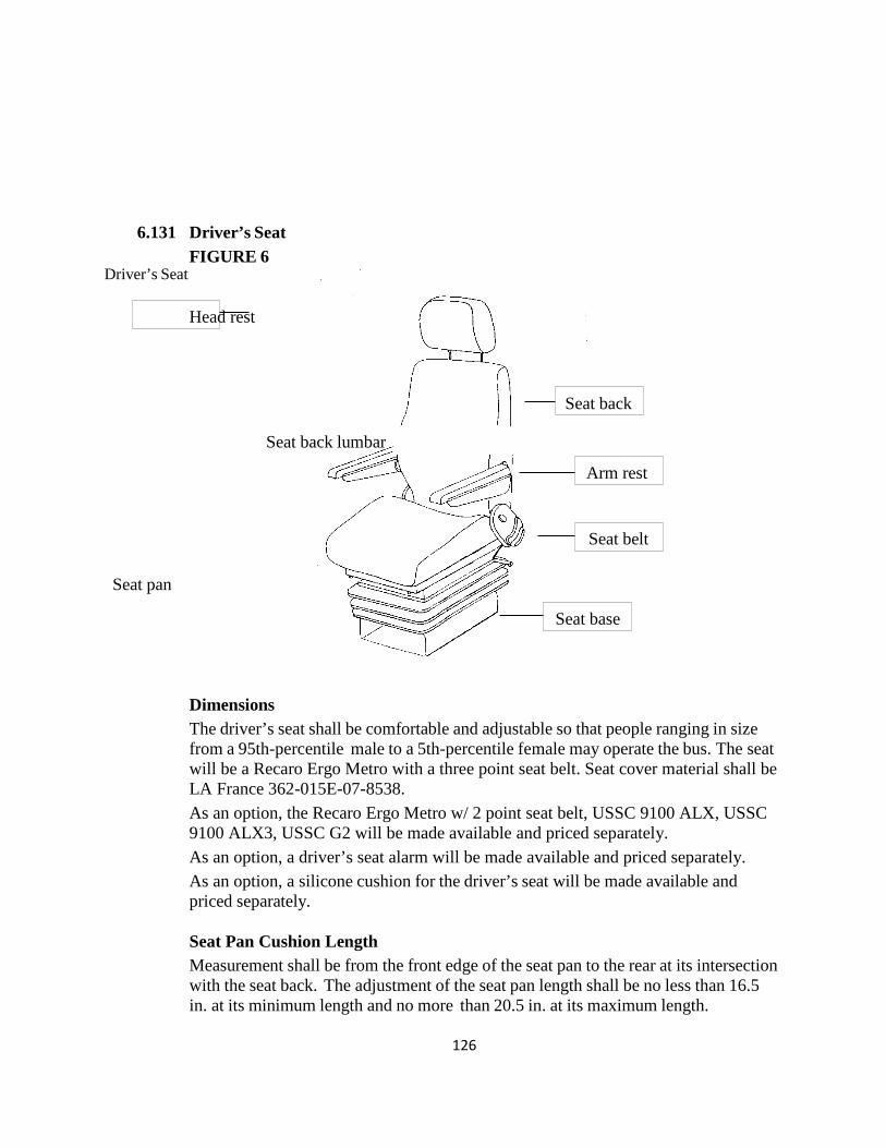
126
Driver’s Seat
Seat pan
6.131 Driver’s Seat FIGURE 6 Head rest
Seat back
Seat back lumbar
Arm rest
Seat belt
Seat base Dimensions The driver’s seat shall be comfortable and adjustable so that people ranging in size from a 95th-percentile male to a 5th-percentile female may operate the bus. The seat will be a Recaro Ergo Metro with a three point seat belt. Seat cover material shall be LA France 362-015E-07-8538. As an option, the Recaro Ergo Metro w/ 2 point seat belt, USSC 9100 ALX, USSC 9100 ALX3, USSC G2 will be made available and priced separately. As an option, a driver’s seat alarm will be made available and priced separately. As an option, a silicone cushion for the driver’s seat will be made available and priced separately. Seat Pan Cushion Length Measurement shall be from the front edge of the seat pan to the rear at its intersection with the seat back. The adjustment of the seat pan length shall be no less than 16.5 in. at its minimum length and no more than 20.5 in. at its maximum length.
127
Seat Pan Cushion Height Dimensions Measurement shall be from the cab floor to the top of the level seat at its center midpoint. The seat shall adjust in height from a minimum of 14 in., with a minimum 6 in. vertical range of adjustment. Seat Pan Cushion Slope Measurement is the slope of the plane created by connecting the two high points of the seat, one at the rear of the seat at its intersection with the seat back and the other at the front of the seat just before it waterfalls downward at the edge. The slope can be measured using an inclinometer and shall be stated in degrees of incline relative to the horizontal plane (0 degrees). The seat pan shall adjust in its slope from no less than plus 12 degrees (rearward “bucket seat” incline), to no less than minus 5 degrees (forward slope). Seat Base Fore/Aft Adjustment Measurement is the horizontal distance from the heel point to the front edge of the seat. The minimum and maximum distances shall be measured from the front edge of the seat when it is adjusted to its minimum seat pan depth (approximately 15 in.). On all low-floor buses, the seat-base shall travel horizontally a minimum of 9 in. It shall adjust no closer to the heel point than 6 in. Seat Pan Cushion Width Measurement is the horizontal distance across the seat cushion. The seat pan cushion shall be 17 to 21 in. across at the front edge of the seat cushion and 20 to 23 in. across at the side bolsters. Seat Suspension The driver’s seat shall be appropriately dampened to support a minimum weight of 380 lbs. The suspension shall be capable of dampening adjustment in both directions. Rubber snubbers shall be provided to prevent metal-to-metal contact. Seat Back Width Measurement is the distance between the outermost points of the front of the seat back, at or near its midpoint in height. The seat back width shall be no less than 19 in. Seat back will include dual recliner gears on both sides of the seat. Seat Back Lumbar Support Measurement is from the bottom of the seat back at its intersection with the seat pan to the top of the lumbar cushioning. The seat back shall provide adjustable depth lumbar back support with three individual operating lumbar cells within a minimum range of 7 to 11 in. Seat Back Angle Adjustment
128
The seat back angle shall be measured relative to a level seat pan, where 90 degrees is the upright position and 90 degrees-plus represents the amount of recline. The seat back shall adjust in angle from a minimum of no more than 90 degrees (upright) to at least 105 degrees (reclined), with infinite adjustment in between. Seat Belt The belt assembly should be an auto-locking retractor (ALR) seatbelt. All seat belts should be stored in automatic retractors. All seatbelts will be a combination of shoulder and lap belt configuration and shall be mounted to the seat frame so that the driver may adjust the seat without resetting the seat belt. No seatbelt shall be a configured as a lab belt only. Seat belt shall retract toward center of the bus. The seat and seat belt assemblies as installed in the bus shall withstand static horizontal forces as required in FMVSS 207 and 210. Seatbelt webbing shall be Orange in color. Seat Control Locations While seated, the driver shall be able to make seat adjustments by hand without complexity, excessive effort or being pinched. Adjustment mechanisms shall hold the adjustments and shall not be subject to inadvertent changes. Seat Structure and Materials Cushions Cushions shall be fully padded with at least 3 in. of materials in the seating areas at the bottom and back. Cushion Materials All materials used on the seat assembly, passenger and driver's seat shall meet the flammability requirements of the FMVSS #302. Proof of Compliance must be submitted with proposals. Pedestal Exposed portions of frame and hardware shall be stainless steel or chrome plated.
6.132 Mirrors Exterior Mirrors Exterior mirrors shall be Lucerix (Metagal) 8” x 15” 2-piece flat and convex. Mirrors shall be manually adjusted. Left mirror shall be mounted near the front or upper edge of the driver's window. Right mirror shall be viewed through the upper right corner of windshield and mounted so as to provide maximum practical clearance to the ground. Mirrors must fold out of way of automatic washer. Metal mirror parts to be black. Exterior mirrors shall utilize zerk fitting to lube adjustment points. As an option, the B&R 10” x 11” and 6” x 14” 2-piece flat and convex, heated and remote w/ stainless steel and cast aluminum arms will be made available and priced separately.
129
Interior Mirrors Mirrors shall be provided for the driver to observe passengers throughout the bus without leaving the seat and without shoulder movement. The driver shall be able to observe passengers in the front/entrance and rear/exit areas, anywhere in the aisle, and in the rear seats. A (min) 8 1/2” x 16” rear view mirror shall be provided on the front sign header. A 6" diameter adjustable convex mirror over and forward of the front door shall be provided. An adjustable convex mirror shall be provided over/above and to the rear of the rear exit door. (Convex mirrors described above are to be used in conjunction with each other.) The glass in this mirror shall be replaceable.
6.133 WINDOWS General Windshield The windshield shall permit an operator’s field of view as referenced in SAE Recommended Practice J1050. The vertically upward view shall be a minimum of 14 degrees, measured above the horizontal and excluding any shaded band. The vertically downward view shall permit detection of an object 3½ ft high no more than 2 ft in front of the bus. The horizontal view shall be a minimum of 90 degrees above the line of sight. Any binocular obscuration due to a center divider may be ignored when determining the 90- degree requirement, provided that the divider does not exceed a 3-degree angle in the operator’s field of view. Windshield pillars shall not exceed 10 degrees of binocular obscuration. The windshield shall be designed and installed to minimize external glare as well as reflections from inside the bus. The windshield shall be easily replaceable by removing zip-locks from the windshield retaining moldings. Bonded-in-place windshields shall not be used. Winglets may be bonded. Glazing The windshield glazing material shall have a ¼ in. nominal thickness laminated safety glass conforming to the requirements of ANSI Z26.1 Test Grouping 1A and the Recommended Practices defined in SAE J673.
6.134 Driver’s Side Window The driver’s side window shall be the sliding type, requiring only the rear half of sash to latch upon closing, and shall open sufficiently to permit the seated operator to easily adjust the street-side outside rearview mirror. When in an open position, the window shall not rattle or close during braking. This window section shall slide in tracks or channels designed to last the service life of the bus. The operator’s side window shall not be bonded in place and shall be easily replaceable. The glazing material shall have a single-density tint. The driver’s view, perpendicular through operator’s side window glazing, should
130
extend a minimum of 33 in. (840 mm) to the rear of the heel point on the accelerator, and in any case must accommodate a 95th percentile male operator. The view through the glazing at the front of the assembly should begin not more than 26 in. (560 mm) above the operator’s floor to ensure visibility of an under-mounted convex mirror. Driver’s window construction shall maximize ability for full opening of the window. The driver’s side window glazing material shall have a ¼ in. nominal thickness laminated safety glass conforming with the requirements of ANSI Z26.1-1996 Test Grouping 2 and the Recommended Practices defined in SAE J673. The design shall prevent sections from freezing closed in the winter. Light transmittance shall be 75 percent on the glass area below 53 in. from the operator platform floor. On the top fixed over bottom slider configuration, the top fixed area above 53 in. may have a maximum 5 percent light transmittance.
6.135 Passenger Side Windows The side windows shall be full sliders. With the exception of the upper portion of first right-hand and /or left hand window where the side destination sign shall be located, all other shall be tinted 7/32" 28% gray tinted safety glass and frame windows will have black (dark) polyester powder coat aluminum frames inside and out. Windows shall be flat panel, transit application with approved laminated safety glass (ANSI 25.1). Glazing in the sash shall be easily replaced without removing the sash from the bus. Side window sliders shall be equipped with metal latches. All windows shall be of Glass shall be mounted in removable rubber retaining strips/seals. As an option, Fixed Frame, Framed Transom, Frameless bonded fixed, Frameless bonded transom mounted windows will be made available and be priced separately. A positive lock type emergency latch meeting the FMVSS-217 shall be furnished on each window frame. Each window shall have a permanent decal describing emergency window operation procedures. Side windows shall be designed to prevent the entrance of air and water when windows are closed. The window seal rubber must be installed so that passengers cannot remove it and rubber shall be of such quality to resist adhering to other sash sill.
6.136 HEATING, VENTILATING AND AIR CONDITIONING Capacity and Performance The Heating, Ventilation and Air Conditioning (HVAC) climate control system shall be rear-mounted MCC RM 35 with 05G compressor capable of maintaining the interior of the bus at the temperature and humidity levels defined in the following paragraphs. Accessibility and serviceability of components preferably shall be provided without requiring maintenance personnel to climb up on the roof of the bus.
131
The following climatic factors shall be used as design guidelines and shall be considered as operational requirements. Temperature and Solar Load Ambient air temperature, external equipment: Minimum ............................................................................ -20° F Maximum............................................................................120° F Humidity: Minimum ................................................................................ 5% Maximum............................................................................ 100% Precipitation Maximum rainfall rate ................................................... 6 inches per hour Maximum snowfall rate ................................................. 5 inches per hour Maximum snow accumulation................................................... 18 inchs With the bus running at the design operating profile with corresponding door opening cycle, and carrying a number of passengers equal to 150 percent of the seated load, the HVAC system shall maintain an average passenger compartment temperature within a range between 65° and 80° F, while controlling the relative humidity to a value of 50 percent or less. The system shall maintain these conditions while subjected to any outside ambient temperatures within a range of 10° to 95° F and at any ambient relative humidity levels between 5 and 50 percent. Reheat system water control valve to be pulsing type to provide even heat distribution. When the bus is operated in outside ambient temperatures of 95° to 115° F, the interior temperature of the bus shall be permitted to rise one degree for each degree of exterior temperature in excess of 95° F. When bus is operated in outside ambient temperatures in the range of -10° to +10* F, the interior temperature of the bus shall not fall below 55° F while bus is running on the Design Operating Profile. System capacity testing, including pull down/warm-up, stabilization and profile, shall be conducted in accordance to the APTA "Recommended Instrumentation and Performance Testing for Transit Bus Air Conditioning System". Temperature measurements shall be made in accordance to this document with the following modifications: The temperatures measured from a height of 6 inches below the ceiling shall be
132
within plus or minus three degrees F. of the average temperature at the top surface of the seat cushions. Temperatures measured more than three inches above the floor shall be within plus or minus 5 degrees F. of the average temperature at the top surface of the seat cushions. The interior temperatures, from front to rear of the bus, shall not vary more than plus or minus 3 degrees F. from the average. The recommended locations of temperature probes are only guidelines and may require slight modifications to address actual bus design. Care must be taken to avoid placement of sensing devices in immediate path of air duct outlet. In general, the locations are intended to accurately represent the interior passenger area. The air conditioning portion of the HVAC system shall be capable of reducing the passenger compartment temperature from 110° to 90° F in less than 20 minutes after engine start-up. Engine temperature shall be within the normal operating range at the time of start-up of the cool-down tes t and the engine speed shall be limited to fast idle that may be activated by an operator-controlled device. During the cool-down period the refrigerant pressure shall not exceed safe high-side pressures and the condenser discharge air temperature, measured 6 inches from the surface of the coil, shall be less than 45° F above the condenser inlet air temperature. The appropriate solar load as recommended in the APTA "Recommended Instrumentation and Performance Testing for Transit Bus Air Conditioning System," representing 4 P.M. on August 21, shall be used. There shall be no passengers on board, and the doors and windows shall be closed. The air conditioning system shall meet these performance requirements using HFC R134a. The climate control blower motors and fan shall be designed such that their operation complies with the interior noise level requirements. There shall be manual shut off valves to isolate the drier, receiver, and compressor. Note: air conditioning requirements for hybrid drive batteries, if necessary, shall not activate or degrade the efficiency of the passenger HVAC system. As an option, the Thermo King TK 14 will be made available and priced separately. As an option, the Thermo King 616 Compressor will be made available and priced separately. As an option, the Thermo King S391 Compressor will be made available and priced separately. As an option, the Thermo King X430 Compressor will be made available and priced separately. As an option, the Thermo King all electric HVAC will be made available and priced separately. Controls and Temperature Uniformity The HVAC system excluding the driver’s heater/defroster shall be centrally controlled with an advanced electronic/diagnostic control system with provisions for
133
extracting/reading data. The system shall be compliant with J1939 Communication Protocol for receiving and broadcasting of data. Hot engine coolant water shall be delivered to the HVAC system driver’s defroster/heater and other heater cores by means of an auxiliary coolant pump, sized for the required flow, which is brushless and seamless having a minimum maintenance free service life for both the brushless motor and the pump of at least 40,000 hours at full power. Manual Mode Selection of Climate Control System After manual selection and/or activation of climate control system operation mode, all interior climate control system requirements for the selected mode shall be attained automatically to within ±2 °F of specified temperature control set-point. Manually Adjustable Temperature Control Set Point The climate control system temperature controls shall be located behind the rear return air grill in accessible location for maintenance personal to adjust with a tamper proof cover. A 3 position switch (Cool, Heat and off) shall be located on the driver’s dash. The driver shall have full control over the defroster and driver’s heater. The driver shall be able to adjust the temperature in the driver’s area through air distribution and fans. The interior climate control system shall switch automatically to the ventilating mode if the refrigerant compressor or condenser fan fails. Interior temperature distribution shall be uniform to the extent practicable to prevent hot and/or cold spots. After stabilization with doors closed, the temperatures between any two points in the passenger compartment in the same vertical plane, and 6 to 72 in. above the floor, shall not vary by more than 5 °F with doors closed. The interior temperatures, measured at the same height above the floor, shall not vary more than ± 5 °F from the front to the rear from the average temperature determined in accordance with APTA’s “Recommended Instrumentation and Performance Testing for Transit Bus Air Conditioning System.” Variations of greater than ± 5 °F will be allowed for limited, localized areas provided the majority of the measured temperatures fall within the specified requirement. Air Flow Passenger Area The cooling mode of the interior climate control system shall introduce air into the bus at or near the ceiling height at a minimum rate of 25 cubic ft per minute (cfm) per passenger based on the standard configuration bus carrying a number of passengers equal to 150 percent of the seated load. Airflow shall be evenly distributed throughout the bus, with air velocity not exceeding 100 ft. per minute on any passenger. The ventilating mode shall provide air at a minimum flow rate of 20 cfm per passenger. Airflow may be reduced to 15 cfm per passenger (150 percent of seated load) when operating in the heating mode. The fans shall not activate until the heating element
134
has warmed sufficiently to ensure at least 70 °F air outlet temperature. The heating air outlet temperature shall not exceed 120 °F under any normal operating conditions. The climate control blower motors and fan shall be designed such that their operation complies with the interior noise level requirements. Blower motors shall be brushless. The climate control blower motor fan speed shall operate in low speed in heat mode. In Air Conditioning mode climate control blower motor fan speed shall operate in high speed until temperature set point is met; after set point is reached fan speed shall operate in low speed. Driver’s Area The bus interior climate control system shall deliver at least 100 cfm of air to the driver’s area when operating in the ventilating and cooling modes. Adjustable nozzles shall permit variable distribution or shutdown of the airflow. Airflow in the heating mode shall be reduced proportionally to the reduction of airflow into the passenger area. The windshield defroster unit shall meet the requirements of SAE Recommended Practice J382, “Windshield Defrosting Systems Performance Requirements,” and shall have the capability of diverting heated air to the driver’s feet and legs. The defroster or interior climate control system shall maintain visibility through the driver’s side window. Controls for the Climate Control System (CCS) The controls for the driver’s compartment for heating, ventilation and cooling systems shall be integrated and shall meet the following requirements: • The heat/defrost system fan shall be controlled by a separate switch that has an “off” position and at least two positions for speed control. All switches and controls shall preclude the possibility of clothing becoming entangled, and shields shall be provided, if required. If the fans are approved by the Agency, an “on-off” switch shall be located to the right of or near the main defroster switch. • A manually operated control valve shall control the coolant flow through the heater core. • If a cable-operated manual control valve is used, the cable length shall be kept to a minimum to reduce cable seizing. Heater water control valves shall be “positive” type, closed or open. The method of operating remote valves shall require the concurrence of the Agency project manager. Driver’s Compartment Requirements The heating, ventilation and defroster system for the driver’s area shall be controlled by the driver. The system shall meet the following requirements: • The heater and defroster system shall provide heating for the driver and heated air to completely defrost and defog the windshield, driver’s side window, and the front
135
door glasses in all operating conditions. Fan(s) shall be able to draw air from the bus body interior and/or the exterior through a control device and pass it through the heater core to the defroster system and over the driver’s feet. A minimum capacity of 100 cfm shall be provided. The driver shall have complete control of the heat and fresh airflow for the driver’s area. • The defroster supply outlets shall be located at the lower edge of the windshield. These outlets shall be durable and shall be free of sharp edges that can catch clothes during normal daily cleaning. The system shall be such that foreign objects such as coins or tickets cannot fall into the defroster air outlets. Adjustable ball vents or louvers shall be provided at the left of the driver’s position to allow direction of air onto the side windows. The bus interior climate control system shall deliver at least 100 cubic feet per minute of air to the driver's area when operating in the ventilation, heating, and cooling modes without use of the driver's booster fan. The climate control system blower motors will operate at the set speed during all operating modes. All return air ducts will be protected by guards constructed of a sturdy mesh which will resist damage. Adjustable nozzles shall permit variable distribution or shut down of all air flow. The defroster and/or interior climate control system shall maintain visibility through the driver's side window. A booster fan with driver control shall be provided in the ductwork at the driver's area, forward of the operator’s position, for increased air flow to the operator. The windshield defroster unit shall meet or exceed all requirements of SAE Recommended Practice J382, Windshield Defrosting Systems Performance Requirements, and shall have the capability of diverting heated air to the driver's feet and legs. Air Filtration Air shall be filtered before discharge into the passenger compartment. The filter shall meet the ANSI/ASHRAE 52.2 Minimum Efficiency Reporting Value (MERV) “1” requirement for approximately 60 percent average arrestance. Air filters shall be easily removable for service. Filters Hog Hair filters shall be provided. Roof Ventilators Two roof ventilators shall be provided in the roof of the bus, one approximately over or just forward of the front axle and the other approximately over the rear axle. Each ventilator shall be easily opened and closed manually. When open with the bus in motion, this ventilator shall provide fresh air inside the bus. The ventilator shall cover an opening area no less than 425sq in. and shall be capable of being positioned as a scoop with either the leading or trailing edge open no less than 4 in., or with all four edges raised simultaneously to a height of no less than 3½ in. An escape hatch shall be incorporated into the roof ventilator. Roof ventilator(s) shall be sealed to prevent entry of water when closed.
136
6.137 EXTERIOR PANELS, FINISHES AND EXTERIOR LIGHTING
Design The bus shall have a clean, smooth, simple transit bus design, primarily derived from bus performance requirements and passenger service criteria. The exterior and body features, including grilles and louvers, shall be shaped to facilitate cleaning by automatic bus washers without snagging washer brushes. Water and dirt shall not be retained in or on any body feature to freeze or bleed out onto the bus after leaving the washer. The body and windows shall be sealed to prevent leaking of air, dust or water under normal operating conditions and during cleaning in automatic bus washers for the service life of the bus. Exterior panels shall be sufficiently stiff to minimize vibration, drumming or flexing while the bus is in service. When panels are lapped, the upper and forward panels shall act as a watershed. However, if entry of moisture into the interior of the vehicle is prevented by other means, then rear cap panels may be lapped otherwise. The windows, hatches and doors shall be able to be sealed. Accumulation of spray and splash generated by the bus’s wheels shall be minimized on windows and mirrors. As an option, alternative exterior styling designs will be made available and priced separately. Materials Body materials shall be selected and the body fabricated to reduce maintenance, extend durability and provide consistency of appearance throughout the service life of the bus. Detailing shall be kept simple, and add-on devices and trim shall be minimized and integrated into the basic design. Roof-Mounted Equipment A non-skid, walkway shall be incorporated on the roof to provide access to equipment without climbing or over any equipment. Pedestrian Safety Exterior protrusions along the side and front of the bus greater than ½ in. and within 80 in. of the ground shall have a radius no less than the amount of the protrusion. The exterior rearview mirrors, cameras and required lights and reflectors are exempt from the protrusion requirement. Advertising frames shall protrude no more than ⅞ in. from the body surface. Grilles, doors, bumpers and other features on the sides and rear of the bus shall be designed to minimize toeholds or handholds. Exterior protrusions shall not cause a line-of-sight blockage for the driver. Easily Replaceable Lower Side Body Panels The lower section of the side body panels (low-floor buses) shall be made of aluminum and they shall be quickly and easily and replaceable. As an option, provide pricing for lower skirt panels, rear tail light housing module, and rear bumper assembled.
137
Rain Gutters Rain gutters shall be provided to prevent water flowing from the roof onto the passenger doors and driver’s side window. When the bus is decelerated, the gutters shall not drain onto the windshield, driver’s side window or door boarding area. Cross-sections of the gutters shall be adequate for proper operation. License Plate Provisions Provisions shall be made to mount standard-size U.S. license plates per SAE J686 on the rear of the bus. These provisions shall direct-mount or recess the license plates so that they can be cleaned by automatic bus-washing equipment without being caught by the brushes. The rear license plate provision shall be illuminated per SAE J587. Fender Skirts Features to minimize water spray from the bus in wet conditions shall be included in wheel housing design. Any fender skirts shall be easily replaceable. They shall be flexible if they extend beyond the allowable body width. Wheels and tires shall be removable with the fender skirts in place. Standard Splash Aprons Splash aprons, composed of ¼ in. minimum composition or rubberized fabric, shall be installed behind and/or in front of wheels as needed to reduce road splash and protect under floor components. The splash aprons shall extend downward to within 6 in. off the road surface at static conditions. Apron widths shall be no less than tire widths. Splash aprons shall be bolted to the bus understructure. Splash aprons and their attachments shall be inherently weaker than the structure to which they are attached. The flexible portions of the splash aprons shall not be included in the road clearance measurements. Splash apron shall be installed as necessary to protect the wheelchair loading device from road splash. Other splash aprons shall be installed where necessary to protect bus equipment. An approved method of grounding static electricity shall be provided on each bus such as a conductive nylon grounding strap.
6.138 Service Compartments and Access Doors Access Doors Conventional or pantograph hinged doors shall be used for the engine compartment and for all auxiliary equipment compartments including doors for checking the quantity and adding to the engine coolant, engine lubricant and transmission fluid. Access openings shall be sized for easy performance of tasks within the compartment, including tool operating space. Access doors shall be of rugged construction and shall maintain mechanical integrity and function under normal operations throughout the service life of the bus. They shall close flush with the body surface. All doors shall be hinged at the top or on the forward edge and shall be prevented from coming loose or opening during transit service or in bus washing operations. All access doors shall be retained in the open position by props or counterbalancing with over-center or gas-filled springs with safety props and shall be easily operable by one person. Springs and hinges shall be corrosion resistant. Latch handles shall be flush with, or recessed behind, the body contour and shall be
138
sized to provide an adequate grip for opening. Access doors, when opened, shall not restrict access for servicing other components or systems. If precluded by design, the manufacturer shall provide door design information specifying how the requirements are met. Access Door Latch/Locks The engine compartment, including the exhaust duct plenum, shall be completely sealed to prevent smoke or fumes from entering the bus interior. The engine bulkhead and exhaust duct plenum shall be insulated adequately to prevent discomfort to passengers due to heat, to minimize hazard in case of fire in the engine compartment, and to aid in controlling noise to meet required levels. An engine air intake designed to minimize noise shall be provided. Insulation shall be provided as needed in the engine compartment area for sound suppression. An adequate number of fire detectors shall be furnished in the engine compartment, as determined by the bus manufacturer. The detectors shall activate an alarm (visual as well as audible) at the driver's station. Access panels to the left and right side of the engine compartment shall be provided with expanded metal inserts to provide heat dissipation in the engine compartment. Panels shall also be constructed so that maintenance personnel can easily reach all under the floor and engine compartment equipment requiring access from outside the bus body. Access panels will be hinged to swing up and out of the way, and be secured with a 5/16” square latch. Gas operated shocks with safety locks shall secure access doors in the open position during inspection and servicing. The engine compartment doors will be equipped with handles. Louvers shall be provided in the rear engine compartment door to optimize airflow. Access doors are not required in the engine door. Forward edge hinges with positive action hold open springs shall be provided on the fuel connector and lay flat against the adjacent panel when fully opened. The battery access door shall have top edge hinges with gas operated shocks with safety devises when the battery is being serviced. A small access door shall be provided to the battery disconnect switch. Battery disconnect switch, fuel and air tank drain valve doors will be equipped with a well type securing latch.
6.139 Bumpers Location Bumpers shall provide impact protection for the front and rear of the bus with the top of the bumper being 27 in., ± 2 in., above the ground. Bumper height shall be such that when one bus is parked behind another, a portion of the bumper faces will contact each other. Front Bumper No part of the bus, including the bumper, shall be damaged as a result of a 5 mph
139
impact of the bus at curb weight with a fixed, flat barrier perpendicular to the bus’s longitudinal centerline. The bumper shall return to its pre-impact shape within 10 minutes of the impact. The bumper shall protect the bus from damage as a result of 6.5 mph impacts at any point by the common carriage with contoured impact surface defined in Figure 2 of FMVSS 301 loaded to 4000 lbs. parallel to the longitudinal centerline of the bus. It shall protect the bus from damage as a result of 5.5 mph impacts into the corners at a 30-degree angle to the longitudinal centerline of the bus. The energy absorption system of the bumper shall be independent of every power system of the bus and shall not require service or maintenance in normal operation during the service life of the bus. The bumper may increase the overall bus length specified by no more than 7 in. Buses shall include a Sportworks Apex bike rack mounting bracket. As an option, a 2- position stainless steel and black powder coated bike rack will be made available and priced separately. As an option a dash mounted bike deployed indicator lamp will be made available and priced separately. As an option, bike rack advertising package will be made available Rear Bumper No part of the bus, including the bumper, shall be damaged as a result of a 2 mph impact with a fixed, flat barrier perpendicular to the longitudinal centerline of the bus. The bumper shall return to its pre-impact shape within 10 minutes of the impact. When using a yard tug with a smooth, flat plate bumper 2 ft wide contacting the horizontal centerline of the rear bumper, the bumper shall provide protection at speeds up to 5 mph, over pavement discontinuities up to 1 in. high, and at accelerations up to 2 mph/sec. The rear bumper shall protect the bus, when impacted anywhere along its width by the common carriage with contoured impact surface defined in Figure 2 of FMVSS 301 loaded to 4000 lbs, at 4 mph parallel to or up to a 30-degree angle to, the longitudinal centerline of the bus. The rear bumper shall be shaped to preclude unauthorized riders standing on the bumper. The bumper shall not require service or maintenance in normal operation during the service life of the bus. The bumper may increase the overall bus length specified by no more than 7 in. Additional support gussets located on right rear and left rear frame outriggers shall be provided to lower rear end collision damage in the event of accidents. Bumper Material Bumper material shall be corrosion-resistant and withstand repeated impacts of the specified loads without sustaining damage. Visible surfaces shall be black. These bumper qualities shall be sustained throughout the service life of the bus.
6.140 Finish and Color Appearance All exterior surfaces shall be smooth and free of wrinkles and dents. Exterior surfaces to be painted shall be properly prepared as required by the paint system Supplier prior to application of paint to assure a proper bond between the basic surface and
140
successive coats of original paint for the service life of the bus. Drilled holes and cutouts in exterior surfaces shall be made prior to cleaning, priming and painting, where possible, to prevent corrosion. Body filler materials may be used for surface dressing, but not for repair of damaged or improperly fitted panels. Paint shall be applied smoothly and evenly with the finished surface free of visible dirt and the following other imperfections: • blisters or bubbles appearing in the topcoat film • chips, scratches, or gouges of the surface finish • cracks in the paint film • craters where paint failed to cover due to surface contamination • overspray • peeling • runs or sags from excessive flow and failure to adhere uniformly to the surface • chemical stains and water spots • dry patch due to incorrect mixing of paint activators • buffing swirls All exterior finished surfaces shall be impervious to diesel fuel, gasoline and commercial cleaning agents. Finished surfaces shall resist damage by controlled applications of commonly used graffiti-removing chemicals. Proper adhesion between the basic surface and successive coats of the original paint shall be measured using an Elcometer adhesion tester as outlined in ASTM 4541-17Adhesion shall be a minimum 300 ft- lbs. The bus manufacturer shall supply test samples of the exterior surface for each step of the painting process that may be subject to adhesion testing per ASTM D4541-17and may be used for inspection testing during assembly of the vehicle. Within 30 days of execution of contract, the Contractor shall supply to procuring agency the detailed drawings of the front, rear, both sides, and roof of the bus that will be supplied. Within 60 days of execution of the contract, the procuring agency will return these drawings to the Contractor with details of the color schemes included. The bus exterior shall be primed as recommended by the manufacturer of the final finish, and shall be finished with the color scheme specified in the order. Paint shall be Axalta L0007-EW white, N0306-EX blue, 819136-EX green, N0001-EX Black Gloss. Current color schemes used by the various Procuring Agencies are publicly available. Rear of bus and corners shall have Safety White Avero#307 clear coat. There shall be no bare or exposed metal surfaces showing on the exterior of the bus, exclusive of ornamentation and accessories. The display of manufacturer's name or insignia on the exterior of the bus will be as specified in the individual order.
6.141 Decals, Numbering and Signing Monograms, numbers and other special signing shall be applied to the inside and outside of the bus as required. Signs shall be durable and fade-, chip- and peel-
141
resistant. They may be painted signs, decals or pressure-sensitive appliqués. All decals shall be installed per the decal Supplier recommendations. Signs shall be provided in compliance with the ADA requirements defined in 49 CFR, Part 38.27. Buses shall have fleet numbers applied both on the interior and exterior of the bus in sequence with factory serial numbers. Each individual order will include the correct starting number and the location, size and color of numbers. Rear Yield sign shall be applied on rear air conducting compartment door. As an option, Roof Number shall be priced separately. 6.156 Passenger Information ADA priority seating signs as required and defined by 49 CFR, Part 38.27 shall be provided to identify the seats designated for passengers with disabilities. Requirements for a public information system in accordance with 49 CFR, Part 38.35 shall be provided. Interior of bus shall have two public information displays. Displays shall be Transit Information Product mode OBIC T 15P 1 (17x11). Interior decals such as but not limited to the following, No Smoking, Exit door, Emergency Exit, Watch Your Step, Wheelchair instructions and "Reserved for Wheelchairs," etc. shall be provided . All decals shall be in English and Spanish. Optional Tri-Lingual decals will be made available, with the three languages being verified at the pre-production meeting. Decals containing identification of windows, hatches, etc., shall also be provided. All decals shall conform to Georgia state law.
6.142 Exterior Lighting Exterior lighting and reflectors shall comply, as applicable, with 49 CFR Part 393.11, 49 CFR Part 571.108 of the FMCSA, and FMVSS No. 108. All exterior lights shall be designed to prevent entry and accumulation of moisture or dust. Dialight LED-type lamps shall be utilized at all exterior lamp locations. Lamps, lenses and fixtures shall be interchangeable to the extent practicable. Two hazard lamps at the rear of the bus shall be visible from behind when the engine service doors are opened. Light lenses shall be designed and located to prevent damage when running the vehicle through an automatic bus washer. Front marker (clearance) lights along with lights located on the roof and sides of the bus shall have protective shields or be of the flush mount type to protect the lens against minor impacts. Exterior lighting shall comply with all applicable State and Federal regulations. Replacement lamps shall be readily available from commercial sources; they shall not be a bus manufacturer unique item. Those applications which will not accommodate an LED lamp shall have a replaceable bulb with access to the bulb by removing the lens from outside the bus. High and Low beam head lights shall be LED and controlled from a sealed, moisture-protected foot switch located on the floor in the driver's station. The LED
142
units shall be of the latest heavy-duty type and be ruggedly mounted to maintain adjustment under transit operating conditions. Headlights shall be wired to operate on reduced voltage in the run position. As an option, LED low beam headlamps only will be made available and priced separately. As an option, Halogen head lights shall be made available and priced separately. All other lights shall be LED as allowed by applicable State Laws. The stop lights and tail light shall be 4” diameter. Rear turn indicator lights shall be separate from the stop-tail lights. The LED marker lights at the front and rear upper corners of the bus shall be of flush mounted type to preclude breakage by tree limbs, bus washers, etc. Each doorway shall have an outside light(s) which, when the door is open, provides at least one foot candle of illumination of the street surface for a distance of three feet perpendicular to the bottom step tread outer edge. Light (s) shall be located below window level and shielded to protect the eyes of entering and exiting passengers.
6.143 Backup Light/Alarm Visible and audible warnings shall inform following vehicles or pedestrians of reverse operation. Visible reverse operation warning shall conform to SAE Standard J593. Audible reverse operation warning shall conform to SAE Recommended Practice J994 Type C or D.
6.144 Doorway Lighting Lamps at the front and rear passenger doorways shall comply with ADA requirements and shall activate only when the doors open. These lamps shall illuminate the street surface to a level of no less than 1 foot- candle for a distance of 3 ft. outward from the outboard edge of the door threshold. The lights may be positioned above or below the lower daylight opening of the windows and shall be shielded to protect passengers’ eyes from glare.
6.145 Service Area Lighting (Interior and Exterior) LED lamps shall be provided in the engine and all other compartments where service may be required to generally illuminate the area for night emergency repairs or adjustments. These service areas shall include, but not be limited to, the engine compartment, the communication box, junction/apparatus panels and passenger door operator compartments. Lighting shall be adequate to light the space of the service areas to levels needed to complete typical emergency repairs and adjustments. The service area lamps shall be suitable for the environment in which they are mounted. LED Yield lamp shall be provided on the rear air conditioning compartment door. As an option, seven (7”) inches tail lights will be made available and priced separately.
143
As an option, an all LED “STOP” light will be made available and priced separately.
6.146 INTERIOR PANELS AND FINISHES General Requirements Materials shall be selected on the basis of maintenance, durability, appearance, safety, flammability and tactile qualities. Materials shall be strong enough to resist everyday abuse and be vandalism and corrosion resistant. Trim and attachment details shall be kept simple and unobtrusive. Interior trim shall be secured to avoid resonant vibrations under normal operational conditions. Interior surfaces more than 10 in. below the lower edge of the side windows or windshield shall be shaped so that objects placed on them fall to the floor when the bus is parked on a level surface. Any components and other electrical components within close proximity to these surfaces shall also be resistant to this cleaning method.
6.147 Interior Panels Panels shall be easily replaceable and tamper-resistant. They shall be reinforced, as necessary, to resist vandalism and other rigors of transit bus service. Individual trim panels and parts shall be interchangeable to the extent practicable.
6.148 Driver Area Barrier A barrier or bulkhead between the driver and the street-side front passenger seat shall be provided. The barrier shall minimize glare and reflections in the windshield directly in front of the barrier from interior lighting during night operation. Location and shape must permit full seat travel and reclining possibilities that can accommodate the shoulders of a 95th-percentile male. The partition shall have a side return and stanchion to prevent passenger from reaching the driver by standing behind the driver’s seat. The lower area between the seat and panel must be accessible to the driver. The partition must be strong enough in conjunction with entire partition assembly for mounting of such equipment as flare kits, fire extinguishers (1.2 kg), microcomputer, public address amplifier, etc. Flares shall be maintained in stainless steel container. Dark or black panels are preferred behind the driver’s head. The panel should be isolated for noise control and attached with rubber grommets.
As an option, a driver’s security enclosure door will made available and price separately.
6.149 Modesty Panels Sturdy divider panels constructed of durable, unpainted, corrosion-resistant material complementing the interior shall be provided to act as both a physical and visual barrier for seated passengers. Design and installation of modesty panels located in front of forward-facing seats shall include a handhold or grab handle along its top edge. These dividers shall be mounted on the sidewall and shall project toward the aisle no farther than passenger
144
knee projection in longitudinal seats or the aisle side of the transverse seats. Modesty panels shall extend from at least the window opening of the side windows, and those forward of transverse seats shall extend downward to 1 and 1½ in. above the floor. Panels forward of longitudinal seats shall extend to below the level of the seat cushion. Dividers positioned at the doorways shall provide no less than a 2½ in. clearance between the modesty panel and a fully open, inward opening door, or the path of a deploying flip-out ramp to protect passengers from being pinched. Modesty panels installed at doorways shall be equipped with grab rails if passengers assist are not provided by other means. The modesty panel and its mounting shall withstand a static force of 250 lbs applied to a 4 × 4 in. area in the center of the panel without permanent visible deformation.
6.150 Front End The entire front end of the bus shall be sealed to prevent debris accumulation behind the dash and to prevent the driver’s feet from kicking or fouling wiring and other equipment. The front end shall be free of protrusions that are hazardous to passengers standing at the front of the standee line area of the bus during rapid decelerations. Paneling across the front of the bus and any trim around the driver’s compartment shall be formed metal or composite material. Composite dash panels shall be reinforced as necessary, vandal-resistant and replaceable. All colored, painted and plated parts forward of the driver’s barrier shall be finished with a surface that reduces glare. Any mounted equipment must have provision to support the weight of equipment.
6.151 Rear Bulkhead The rear bulkhead and rear interior surfaces shall be material suitable for exterior skin; painted and finished to exterior quality; or paneled with melamine-type material, composite, scratch-resistant plastic or carpeting and trimmed with stainless steel, aluminum or composite. The rear bulkhead paneling shall be contoured to fit the ceiling, side walls and seat backs so that any litter or trash will tend to fall to the floor or seating surface when the bus is on a level surface. Any air vents in this area shall be louvered to reduce airflow noise and to reduce the probability of trash or liter being thrown or drawn through the grille. If it is necessary to remove the panel to service components located on the rear bulkhead, the panel shall be hinged or shall be able to be easily removed and replaced. Grilles where access to or adjustment of equipment is required shall be heavy-duty and designed to minimize damage and limit unauthorized access.
6.152 Headlining Ceiling panels shall be made of durable, corrosion resistant, easily cleanable material. Headlining shall be supported to prevent buckling, drumming or flexing and shall be secured without loose edges. Headlining materials shall be treated or insulated to prevent marks due to condensation where panels are in contact with metal members. Moldings and trim strips, as required to make the edges tamperproof, shall be stainless steel, aluminum or plastic, colored to complement the
145
ceiling material. Headlining panels covering operational equipment that is mounted above the ceiling shall be on hinges for ease of service but retained to prevent inadvertent opening.
6.153 Fastening Interior panels shall be attached so that there are no exposed unfinished or rough edges or rough surfaces. Fasteners should be corrosion resistant. Panels and fasteners shall not be easily removable by passengers. Exposed interior fasteners should be minimized, and where required shall be tamper-resistant.
6.154 Insulation Any insulation material used between the inner and outer panels shall minimize the entry and/or retention of moisture. Insulation properties shall be unimpaired during the service life of the bus. Any insulation material used inside the engine compartment shall not absorb or retain oils or water and shall be designed to prevent casual damage that may occur during maintenance operations. The combination of inner and outer panels on the sides, roof, wheel wells and ends of the bus, and any material used between these panels, shall provide a thermal insulation sufficient to meet the interior temperature requirements. The bus body shall be thoroughly sealed so that the driver or passengers cannot feel drafts during normal operations with the passenger doors closed. Insulation shall meet the requirements of FMVSS 302.
6.155 Floor Covering The floor covering shall be RCA rubber TR766 Charcoal Gray floor material. The floor covering, as well as transitions of flooring material to the main floor and to the entrance and exi t area, shall be smooth and present no tripping hazards. Seams shall be sealed/welded per manufacturer’s specifications. The standee line shall be approximately 2 in. wide and shall extend across the bus aisle. This line and the edge of the steps shall be White. The color and pattern shall be consistent throughout the floor covering. As an option, Altro flooring will be made available and price separately. Any areas on the floor that are not intended for standees, such as areas “swept” during passenger door operation, shall be clearly and permanently marked. The floor shall be easily cleaned and shall be arranged to minimize debris accumulation. A one-piece center strip shall extend from the vertical wall of the rear settee between the aisle sides of transverse seats to the standee line. If the floor is of a bi-level construction, then the center strip shall be one piece at each level. The covering between the center strip and the wheel housings may be separate pieces. At the rear door, however, a separate strip as wide as the door shall extend from the center strip to the outboard edge of the rear/exit area. The floor under the seats shall be covered with smooth surface flooring material. The floor covering shall closely fit the sidewall in a fully sealed butt joint or extend to the top of the cove.
146
Stainless steel floor trim and edging shall be provided.
6.156 Interior Lighting Passenger The passenger interior lighting system shall be an I/O Controls LED lighting system. The interior lighting system shall provide a minimum 15 foot-candle illumination on a 1 square foot plane at an angle of 45 degree from horizontal, center 33 inches above the floor and 24 inches in front of the seat back at each seat position. Allowable average light level for the rear bench seats shall be 7 foot-candles. Floor surface in the aisles shall be a minimum of 10 foot-candles, vestibule area a minimum of 4 foot-candles with the front doors open and minimum of 2 foot-candles with the from doors closed. The front entrance area and curb lights shall illuminate when the front door is open and master run switch is in the "Lights" positions. Rear exit area and curb lights shall illuminate when rear door is unlocked. Step lighting for the intermediate platform between lower and upper floor levels shall be provided and shall illuminate in all engine run positions. The step lighting shall be low-profile to minimize tripping and snagging hazard for passengers and shall be shielded as necessary to protect passengers' eyes from glare. The light source shall be located to minimize windshield glare with distribution of the light focused primarily on the passengers' reading plane while casting sufficient light onto the advertising display. The bus shall be equipped with interior advertising card tracks on each side of the interior passenger compartment, running the length of the bus, to hold 11" high ad cards. Photo sensor detects and adjusts light level automatically relative to ambient light for passenger comfort. Lens material shall be clear polycarbonate. Lens shall be designed to effectively '`mask" all individual LED's to make them invisible and there shall be no "hot spot" or "dark spot". Lens shall be sealed to inhibit incursion of dust and insects yet are easily removable for service. If threaded fasteners are used they must be held captive in the lens. Access panels shall be provided to allow servicing of components located behind light panels. Individual driver module shall be provided for each light fixture. Driver module shall have built-in self- protection of thermal shut-down and restart, PWM (Pulse Width Modulation) output to regulate light level, reverse polarity protect and rebuild able. When the master switch is in the RUN or NITE/RUN mode, the first light module on each side of the bus shall slowly fades to darkness when the front door is in the closed position and light output shall gradually illuminate to reach maximum light level when the door is opened. Solid state LED lighting shall have unlimited on-off cycles. The light system may be designed to form part of the entire air distribution duct. Emergency backup system shall keep the light fixtures over the front and rear doors
147
illuminated at minimum light output under a separated battery power for 10 to 15 minutes allowing passengers visibility and timely evacuation from the vehicle during emergency conditions. Driver Area The driver’s area shall have a light to provide general illumination, and it shall illuminate the half of the steering wheel nearest the driver to a level of 5 to 10 foot-candles. This light shall be controlled by a toggle switch that is convenient to the driver. Light fixture shall be mounted in the ceiling above the farebox location. The fixture shall be capable of projecting a concentrated beam of light on the farebox. This light will automatically come on whenever the front doors are opened and the run switch is in the “night run” or “night park” position. As an option, a light that illuminates the farebox will be made available and priced separately. Vestibules/Doors Floor surface in the aisles shall be a minimum of 10 foot-candles, and the vestibule area a minimum of 4 foot-candles with the front doors open and a minimum of 2 foot-candles with the front doors closed. The front entrance area and curb lights shall illuminate when the front door is open and master run switch is in the “lights” positions. Rear exit area and curb lights shall illuminate when the rear door is unlocked. Step Lighting Step lighting for the intermediate steps between lower and upper floor levels shall be a minimum of 4 foot-candles and shall illuminate in all engine run positions. The step lighting shall be low-profile to minimize tripping and snagging hazards for passengers and shall be shielded as necessary to protect passengers’ eyes from glare. Ramp Lighting Exterior and interior ramp lighting shall comply with CFR Part 49, Sections 19.29 and 19.31.
6.157 Fare Collection If selected, a fare box shall be installed in a space as far forward as practicable, and/or structural provisions shall be made for installation of a fare box (if not installed by manufacturer). Location of this fare collection device shall not restrict traffic in the vestibule and shall allow the driver to easily reach the coin levers and view the change platform. The fare box shall not restrict access to the driver's area and shall not restrict operation of driver controls. Fare box location shall permit accessibility to the vault for easy manual removal or attachment of suction devices. Meters and counters on the fare box shall be readable on a daily basis. A 20 amp, 12-volt, DC, protected lead will be made available to power the farebox. A telescoping pedestal base for farebox OCU shall be provided. As an option, a GFI Odyssey and Cents-a-bill Farebox will be made available and priced separately.
148
6.158 Interior Access Panels and Doors
Access for maintenance and replacement of equipment shall be provided by panels and doors that appear to be an integral part of the interior. Access doors shall be hinged with gas or mechanical props or over-center springs, where practical, to hold the doors out of the mechanic’s way. Panels shall prevent entry of mechanism lubricant into the bus interior. All fasteners that retain access panels shall be captive in the cover. Access doors shall be secured with hand screws or latches. All fasteners that retain access panels shall be captive in the cover.
6.159 Floor Panels Access openings in the floor shall be sealed to prevent entry of fumes and water into the bus interior. Flooring material at or around access openings shall be flush with the floor and shall be edge-bound with stainless steel or another material that is acceptable to the Agency to prevent the edges from coming loose. Access openings shall be asymmetrical so that reinstalled flooring shall be properly aligned. Fasteners shall tighten flush with the floor. The number of special fastener tools required for panel and access door fasteners shall be minimized.
6.160 PASSENGER ACCOMMODATIONS Passenger Seating Arrangements and Seat Style American Seating Insight Composite Plastic passenger seats shall be arranged in the bus in such a way that seating capacity is maximized and shall accommodate as many forward facing seats as possible. Hip-to-knee room shall be a minimum of 26.50”. Proposers shall indicate standard seating layout for each size bus. As an option, the 4ONE - CitiSeat, Angel, Citi Pro, Mariella, Gemini, Aries, Patriot seats and the American Seating - N2005, Insight, Metropolitan, Reliant 3-Point System. Vision will be made available and priced separately. Any exposed metal of the frame will be powder coated, color coordinated to match the seat inserts, or brushed aluminum, or brushed stainless steel. NOTE: Proposers shall provide a proposed seating layout with their proposal. The handholds shall be colored the same as the back panels of the passenger seats. The top area of the seat back shell will wrap around the upper portion of the seat back (below the grab rail) in a "bubble" to form a crash pad on the rear of each seat. The crash pad will be of continuous construction with the back. Rear seat platform shall be hinged to gain access to engine compartment.
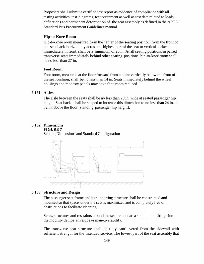
149
Proposers shall submit a certified test report as evidence of compliance with all testing activities, test diagrams, test equipment as well as test data related to loads, deflections and permanent deformation of the seat assembly as defined in the APTA Standard Bus Procurement Guidelines manual. Hip-to-Knee Room Hip-to-knee room measured from the center of the seating position, from the front of one seat back horizontally across the highest part of the seat to vertical surface immediately in front, shall be a minimum of 26 in. At all seating positions in paired transverse seats immediately behind other seating positions, hip-to-knee room shall be no less than 27 in. Foot Room Foot room, measured at the floor forward from a point vertically below the front of the seat cushion, shall be no less than 14 in. Seats immediately behind the wheel housings and modesty panels may have foot room reduced.
6.161 Aisles The aisle between the seats shall be no less than 20 in. wide at seated passenger hip height. Seat backs shall be shaped to increase this dimension to no less than 24 in. at 32 in. above the floor (standing passenger hip height).
6.162 Dimensions FIGURE 7 Seating Dimensions and Standard Configuration
6.163 Structure and Design
The passenger seat frame and its supporting structure shall be constructed and mounted so that space under the seat is maximized and is completely free of obstructions to facilitate cleaning. Seats, structures and restraints around the securement area should not infringe into the mobility device envelope or maneuverability. The transverse seat structure shall be fully cantilevered from the sidewall with sufficient strength for the intended service. The lowest part of the seat assembly that
150
is within 12 in. of the aisle shall be at least 10 in. above the floor. In locations at which cantilevered installation is precluded by design and/or structure, other seat mounting may be allowed. All transverse objects — including seat backs, modesty panels, and longitudinal seats — in front of forward-facing seats shall not impart a compressive load in excess of 1000 lbs onto the femur of passengers ranging in size from a 5th-percentile female to a 95th-percentile male during a 10g deceleration of the bus. This deceleration shall peak at 0.05 to 0.015 seconds from initiation. Permanent deformation of the seat resulting from two 95th-percentile males striking the seat back during this 10g deceleration shall not exceed 2 in., measured at the aisle side of the seat frame at height H. The seat back should not deflect more than 14 in., measured at the top of the seat back, in a controlled manner to minimize passenger injury. Structural failure of any part of the seat or sidewall shall not introduce a laceration hazard. The seat assembly shall withstand static vertical forces of 500 lbs. applied to the top of the seat cushion in each seating position with less than ¼-in. permanent deformation in the seat or its mountings. The seat assembly shall withstand static horizontal forces of 500 lbs evenly distributed along the top of the seat back with less than ¼-in. permanent deformation in the seat or its mountings. The seat backs at the aisle position and at the window position shall withstand repeated impacts of two 40-lb sandbags without visible deterioration. One sandbag shall strike the front 40,000 times and the other sandbag shall strike the rear 40,000 times. Each sandbag shall be suspended on a 36-in. pendulum and shall strike the seat back 10,000 times each from distances of 6, 8, 10 and 12 in. Seats at both seating positions shall withstand 4 0 0 0 vertical drops of a 40-lb sandbag without visible deterioration. The sandbag shall be dropped 1000 times each from heights of 6, 8, 10 and 12 in. Seat cushions shall withstand 100,000 randomly positioned 3½-in. drops of a squirming, 150-lb, smooth-surfaced, buttocks-shaped striker with only minimal wear on the seat covering and no failures to seat structure or cushion suspension components. The back of each transverse seat shall incorporate a handhold no less than ⅞ in. in diameter for standees and seat access/egress. The handhold shall not be a safety hazard during severe decelerations. The handhold shall extend above the seat back near the aisle so that standees shall have a convenient vertical assist, no less than 4 in. long that may be grasped with the full hand. This handhold shall not cause a standee using this assist to interfere with a seated 50th-percentile male passenger. The handhold shall also be usable by a 5th-percentile female, as well as by larger passengers, to assist with seat access/egress for either transverse seating position. The upper rear portion of the seat back and the seat back handhold immediately forward of transverse seats shall be padded and/or constructed of energy absorbing materials. During a 10g deceleration of the bus, the HIC number (as defined by SAE Standard J211a) shall not exceed 400 for passengers ranging in size from a 5th percentile female through a 95th percentile male. The seat back handhold may be deleted from seats that do not have another transverse seat directly behind and where a vertical assist is provided. Longitudinal seats shall be the same general design as transverse seats but without
151
seat back handholds. Longitudinal seats may be mounted on the wheelhouses. Armrests shall be included on the ends of each set of longitudinal seats except on the forward end of a seat set that is immediately to the rear of a transverse seat, the driver’s barrier, or a modesty panel, when these fixtures perform the function of restraining passengers from sliding forward off the seat. Armrests are not required on longitudinal seats located in the wheelchair parking area that fold up when the armrest on the adjacent fixed longitudinal seat is within 3½ in. of the end of the seat cushion. Armrests shall be located from 7 to 9 in. above the seat cushion surface. The area between the armrest and the seat cushion shall be closed by a barrier or panel. The top and sides of the armrests shall have a minimum width of 1 in. and shall be free from sharp protrusions that form a safety hazard. Seat back handhold and armrests shall withstand static horizontal and vertical forces of 250 lbs applied anywhere along their length with less than ¼-in. permanent deformation. Seat back handhold and armrests shall withstand 25,000 impacts in each direction of a horizontal force of 125 lbs with less than ¼-in. permanent deformation and without visible deterioration. Construction and Materials Selected materials shall minimize damage from vandalism and shall reduce cleaning time. The seats shall be attached to the frame with tamper-resistant fasteners. Coloring shall be consistent throughout the seat material, with no visually exposed portion painted. Any exposed metal touching the sides or the floor of the bus shall be stainless steel. The seat, pads and cushions shall be contoured for individuality, lateral support and maximum comfort and shall fit the framework to reduce exposed edges. The minimum radius of any part of the seat back, handhold or modesty panel in the head or chest impact zone shall be a nominal ¼-in. The seat back and seat back handhold immediately forward of transverse seats shall be constructed of energy-absorbing materials to provide passenger protection and, in a severe crash, allow the passenger to deform the seating materials in the impact areas. Complete seat assemblies shall be interchangeable to the extent practicable. Agency to select seat fabric.
6.164 Passenger Assists Passenger assists in the form of full grip, vertical stanchions or handholds shall be provided for the safety of standees and for ingress/egress. Passenger assists shall be convenient in location, shape, and size for both the 95th-percentile male and the 5th-percentile female standee. Starting from the entrance door and moving anywhere in the bus and out the exit door, a vertical assist shall be provided either as the vertical portion of seat back assist or as a separate item so that a 5th-percentile female passenger may easily move from one assist to another using one hand and the other without losing support. All stanchions shall be Stainless steel finish. As an option, yellow powder coated stanchions will be made available and priced separately. Assists Excluding those mounted on the seats and doors, the assists shall have a cross-sectional diameter between 1¼ and 1½ in. or shall provide an equivalent gripping
152
surface with no corner radii less than ¼ in. All passenger assists shall permit a full hand grip with no less than 1½ in. of knuckle clearance around the assist. Passenger assists shall be designed to minimize catching or snagging of clothes or personal items and shall be capable of passing the NHTSA Drawstring Test. Any joints in the assist structure shall be underneath supporting brackets and securely clamped to prevent passengers from moving or twisting the assists. Seat handholds may be of the same construction and finish as the seat frame. Door mounted passenger assists shall be of anodized aluminum, stainless steel or powder-coated metal. Connecting tees and angles may be powder-coated metal castings. Assists shall withstand a force of 300 lbs applied over a 12-in. lineal dimension in any direction normal to the assist without permanent visible deformation. All passenger assist components, including brackets, clamps, screw heads and other fasteners used on the passenger assists shall be designed to eliminate pinching, snagging and cutting hazards and shall be free from burrs or rough edges.
6.165 Front Doorway Front doors, or the entry area, shall be fitted with ADA-compliant assists. Assists shall be as far outward as practicable, but shall be located no farther inboard than 6 in. from the outside edge of the entrance step and shall be easily grasped by a 5th-percentile female boarding from street level. Door assists shall be functionally continuous with the horizontal front passenger assist and the vertical assist and the assists on the wheel housing or on the front modesty panel.
6.166 Vestibule The aisle side of the driver’s barrier, the wheel housings, and when applicable the modesty panels shall be fitted with vertical passenger assists that are functionally continuous with the overhead assist and that extend to within 36 in. of the floor. These assists shall have sufficient clearance from the barrier to prevent inadvertent wedging of a passenger’s arm. A horizontal passenger assist shall be located across the front of the bus and shall prevent passengers from sustaining injuries on the fare collection device or windshield in the event of a sudden deceleration. Without restricting the vestibule space, the assist shall provide support for a boarding passenger from the front door through the fare collection procedure. The assist shall be no less than 36 in. above the floor. The assists at the front of the bus shall be arranged to permit a 5th-percentile female passenger to easily reach from the door assist, to the front assist, to vertical assists on the driver’s barrier, wheel housings or front modesty panel.
6.167 Rear Doorway(s) Vertical assists that are functionally continuous with the overhead assist shall be provided at the aisle side of the transverse seat immediately forward of the rear door and on the aisle side of the rear door modesty panel(s). Passenger assists shall be provided on modesty panels that are functionally continuous with the rear door assists. Rear doors, or the exit area, shall be fitted with assists having a cross-sectional diameter between 1¼ and 1½ in. or providing an equivalent gripping surface with no corner radii less than ¼ in., and shall provide at least 1½ in. of
153
knuckle clearance between the assists and their mounting. The assists shall be designed to permit a 5th-percentile female to easily move from one assist to another during the entire exiting process. The assists shall be located no farther inboard than 6 in. from the outside edge of the rear doorway step.
6.168 Overhead Except forward of the standee line and at the rear door, a continuous, full grip, overhead assist shall be provided. This assist shall be located over the center of the aisle seating position of the transverse seats. The assist shall be no less than 70 in. above the floor. There shall be fourteen (14) vinyl coated nylon grab straps (35’and 40’ bus) and ten (10) on (30’ bus) positioned throughout the bus interior mounted to the horizontal stanchions. A deduct will be made available for those agencies not desiring grab straps. Overhead assists shall simultaneously support 150 lbs on any 12-in. length. No more than 5 percent of the full grip feature shall be lost due to assist supports.
6.169 Longitudinal Seat Assists Longitudinal seats shall have vertical assists located between every other designated seating position, except for seats that fold/flip up to accommodate wheelchair securement. Assists shall extend from near the leading edge of the seat and shall be functionally continuous with the overhead assist. Assists shall be staggered across the aisle from each other where practicable and shall be no more than 52 in. apart or functionally continuous for a 5th percentile female passenger. Wheel Housing Barriers/Assists Unless passenger seating is provided on top of wheel housing, passenger assists shall be mounted around the exposed sides of the wheel housings which shall also be designed to prevent passengers from sitting on wheel housings. Such passenger assists shall also effectively retain items, such as bags and luggage, placed on top of wheel housing.
6.170 Passenger Doors The front door shall be a "slide glide" type inward opening, driver controlled, of corrosion-resistant construction. Minimum clear opening shall be 31.75” inches. The front door shall have a minimum height of 78” inches. The overhead clearance between the top of the door opening and the highest point of the ramp shall be a minimum of 68 inches. The step height shall not exceed 16.5 in. at either doorway without kneeling and shall not exceed 15.5 in. at the step. A maximum of two steps is allowed to accommodate a raised aisle floor in the rear of the bus. Operation of, and power to, the front door shall be controlled by the driver. Door shall be opened completely in 1 to 3.5 seconds from the time of control actuation, and shall be subject to adjustment requirements of this specification. A control valve in the driver's compartment shall shut off the power to, and/or dump the power from, the front door mechanism to permit manual operation of the front door with the bus shut down.
154
The rear or exit door shall be a two panel swing out type designed to provide a minimum clear opening of 30” inches panel to panel and a minimum height of 78 inches. Rear doors shall be operator opened and spring closed. The closing of the door shall begin after the control has been moved to the closed position, and after the door has been fully opened. Door opening and closing speeds shall be adjustable. The rear door shall be equipped with a sensitive edge which will open the door automatically if an object is trapped between the doors. The doors shall have handrails (1.25 inches or equivalent surface area with a 1.50 inch knuckle clearance) mounted on the door panels and/or a modesty panel in the door well/step well. The clear opening dimension shall apply inside these handrails. Handrails whether on the door panel or in the body, shall be part of the systematic set of passenger assists. To preclude movement of the bus, an accelerator interlock shall lock the accelerator in the closed position and a brake interlock shall engage the rear axle service brake system when the front and rear door control is activated and the vehicle is moving below 3 mph. When vehicle is moving above 3 mph the rear door shall remain locked. The braking effort shall be to the maximum capability of the rear axle brakes. As an option, the Vapor V-Touch control system will be made available and priced separately. As an option, the Vapor CLASS control system will be made available and priced separately. Locked doors shall require a force of more than 300 lbs to open manually. When the locked doors are manually forced to open, damage shall be limited to the bending of minor door linkage with no resulting damage to the doors, actuators or complex mechanism.
6.171 Rear Door Interlocks See “Hardware Mounting” for door system interlock requirements.
6.172 Emergency Operation In the event of an emergency, it shall be possible to manually open doors designated as emergency exits from inside the bus using a force of no more than 25 lbs after actuating an unlocking device. The unlocking device shall be clearly marked as an emergency-only device and shall require two distinct actions to actuate. The respective door emergency unlocking device shall be accessible from the doorway area. The unlocking device shall be easily reset by the operator without special tools or opening the door mechanism enclosure. Doors that are required to be classified as “Emergency Exits” shall meet the requirements of FMVSS 217. As an option, an emergence that will open the doors located in the engine
155
compartment with spring loaded dust and water resistant cover will be provided and priced separately.
6.173 Door Control The door control shall be located in the operator’s area within the hand reach envelope described in SAE Recommended Practice J287, “Driver Hand Control Reach.” The driver’s door control shall provide tactile feedback to indicate commanded door position and resist inadvertent door actuation. Door Controller Five-Position Driver’s Door Controller The control device shall be protected from moisture. Mounting and location of the door control device handle shall be designed so that it is within comfortable, easy arm’s reach of the seated driver. The door control device handle shall be free from interference by other equipment and have adequate clearance so as not to create a pinching hazard. Position of the door control handle shall result in the following operation of the front and rear doors: • Center position: Front door closed, rear door(s) closed or set to lock. • First position forward: Front door open, rear door(s) closed or set to lock. • Second position forward: Front door open, rear door(s) open or set to open. • First position back: Front door closed, rear door(s) open or set to open. • Second position back: Front door open, rear door(s) open or set to open. Loading Systems The bus shall be equipped with a front door Lift –U LU 18 ramp mechanism that conforms to all requirements of the Americans with Disabilities Act (ADA). It is to be an all electrically operated system which will assume the normal entrance configuration when stowed. When stowed, the ramp should not exceed any of the normal bus undercarriage clearances. All ramp components and mechanisms shall be constructed of corrosion resistant materials and incorporate a design which affords maximum protection from the elements during normal bus operations. Ease of maintenance and servicing shall be a prime consideration in system design and construction. As an option, the Ricon 6:1 ramp will be made available and priced separately. The wheelchair ramp shall have a manual release, deploy, and stow mechanism. The components involved with manual operation shall be completely accessible. If ramp provides for a nylon strap, it must be located on the forward side of the ramp to preclude a trip hazard. The ramp shall be controlled by toggle switches, master on-off, up-down and stow-deploy. The control switches shall be of the spring loaded to a safe position type so that constant manual pressure is required by the operator during ramp operation. All
156
controls shall be clearly identified by function and present a reasonably foolproof and natural sequence of operation. Visual and audible warning devices shall be located immediately to the rear of the front door. The audible warning device shall be activated only when the ramp is functioning. Interlocking and fast idle provisions shall be incorporated so the ramp cannot be extended unless the entrance door is in the full open position, the transmission in neutral, and the parking brake engaged. The entrance door cannot be closed unless the ramp is in the fully stowed position. The bus service brakes shall be automatically applied when the ramp is in any position other than the stowed and locked position. All ramp components mounted under the bus shall be protected from dirt, debris, and road splash through the use of appropriate enclosures, mud flaps, or sealed compartments, subject to approval by each procuring agency. Weatherproof access panels/doors shall be provided to allow for servicing and troubleshooting both ramp and under-floor bus components. Lubing the ramp shall be accomplished without removing the belly pan. The electrical interfacing connections between the bus and the ramp shall be of the quick disconnect type to facilitate ramp removal and installation.
6.174 Two Forward-Facing Wheelchair Securement Locations Two forward-facing locations, as close to the wheelchair loading system as practical, shall provide parking space and securement system compliant with ADA requirements for a passenger in a wheelchair.
6.175 Wheelchair Securing System The wheelchair securement shall be QPODS, at a minimum, all restraint systems must meet CFR 49, FMVSS, FTA and ADA standards. As an option the American Seating Reliant system, the 4ONE Q-pod and 4ONE V-Pro, Q ‘Straint Belts and Retractors will be made available and priced separately.
6.176 SIGNAGE AND COMMUNICATION Destination Signs A Twin Vision all LED White (Sliver Series) automatic electronic destination sign system shall be furnished and installed in each bus by the manufacturer. The destination sign system shall consist of: •One (1) Front sign 16 rows x 160 columns; display height minimum 7.9 inches, display width 63”, or a 24 rows x 200 columns sign. •One (1) Side sign, on the curb side, 14 rows x 108 columns; display height minimum 4.2 inches, display width 42”. •One (1) Rear sign 16 rows x 48 columns; display height minimum 6.1 inches, display width 17”. •Operators Control Unit (OCU) •Front sign, side sign, and rear sign Sliver Series LED shall be provided. As an option, Amber LED light sign system will be made available and be priced separately.
157
As an option, color LED light sign system will be made available and be priced separately. As an option, Hanover signs will available and priced separately. Cables and Accessories The Front Sign shall be mounted on the front of the Bus, near the top edge of the body, behind windshield protection, and in an enclosed but accessible compartment. The Side Sign shall be located on the right side (curb side) of the bus near the front door, mounted near the top of an existing window. The Rear Sign (external) shall be mounted on the rear of the vehicle on an appropriate sized cutout. The entire display area of all signs shall be readable in direct sunlight, at night, and in all lighting conditions between those two lighting extremes, with evenly distributed illumination appearance to the un-aided eye. The system shall be microprocessor-based, utilizing approved bi-directional serial communications, such as S.A.E J1708 or IBIS, E.I.A. RS-485, between system components, and shall utilize error detection techniques within the communication protocol. Independent Controller Boards shall be mounted in the front & side destination Sign. The system shall be capable of communicating with additional information devices, such as interior information Signs, Voice Annunciation devices, fare box, etc. The system shall provide for destination and/or Public Relations (P/R) message entry. Flash memory integrated circuits shall be capable of storing and displaying up to 10,000 message lines. Message memory shall be changeable by the use of a USB flash drive of not less than one (1) megabyte memory capacity but sized according to the message listing noted herein. The System shall have the ability to sequentially display multi-line destination messages, with the route number portion remaining in a constant “on” mode at all times, if so programmed. It shall also be capable of accepting manual entry of Route Alpha/Numeric information on any/all signs. The various Signs shall be programmable to display independent messages or the same messages; up to two destination messages and one public relations message shall be pre-selectable. The operator shall be able to quickly change between the pre-selected messages without re-entering a message code. Public relations messages shall be capable of being displayed alternately with the regular text and route messages or displayed separately. An emergency message shall be activated by a push button or toggle switch. The emergency message shall be displayed on signs facing outside the vehicle while signs inside the vehicle, including the OCU display, remain unchanged. The emergency message shall be canceled by entering a new destination code, or power cycling (after removal of the emergency signal).
158
The programming software shall provide means of adjusting the length of time messages are displayed in 0.1 second increments up to twenty-five seconds. Power to the Sign system shall be controlled by the Master Bus Run Switch. The signs shall operate in all positions of this switch except off. The signs shall be internally protected against voltage transients and RFI interference to ensure proper operation in the local environment. Display and Display Illumination All Sign displays shall consist of pixels utilizing High Intensity Light Emitting Diodes (“LED”), for superior outdoor environmental performance, (of Amber illumination appearance of light wavelength of 590 NM). LED should be made of AllnGaP II, superior UV resistant Epoxy lens and superior resistance to the effects of moisture. Each pixel shall have a dedicated LED for illumination of that pixel in all lighting conditions. The sign system shall have multi-level intensity changes, which adjust automatically as a function of ambient lighting conditions. There shall be no requirement for any fan or any specialized cooling or air circulation. This LED shall be mounted such as to be visible directly to the observer positioned in the viewing cone, allowing for full readability 65 degrees either side of the destination sign centerline. The LEDs shall be the only means of illumination of the sign system. The LED illumination source shall have an operating life M.T.B.F. of not less than 100,000 hours. Each LED shall not consume more than 0.02 Watts. The characters formed by the System shall meet the requirements of the Americans with Disabilities Act (ADA) of 1990 Reference 49 CFR Section 38.39. Sign Enclosures All Signs shall be enclosed in a manner such as to inhibit entry of dirt, dust, water and other contaminants during normal operation or cleaning. Access shall be provided to clean the inside of the Bus window(s) associated with the Sign and to remove or replace the Sign components. Access panels and display boards shall be mounted for ease of maintenance/replacement. Any exterior Rear Sign enclosure used shall be made of Polycarbonate material containing fiberglass reinforcement. The vehicle manufacturer shall comply with the Sign manufacturer's recommended mounting, mounting configuration, and installation procedures to assure optimum visibility and service accessibility of the Sign System and System components. Electronic System Requirements All electronic circuit boards used in the Sign System shall be conformal coated to meet the requirements of military specification MIL-I-46058C. All Sign System components shall be certified to have been subjected to a "burn-in" test of a minimum of twelve (12) hours operation in a temperature of 150 degrees F. prior to final inspection. Operator Control Unit (OCU)
159
The OCU Unit shall be used to view and update display messages. It shall be recess mounted on the Bus vehicle front Sign compartment access cover or door. The OCU shall utilize a multi-key conductive rubber pad keyboard and be designed for transit operating conditions. Other mounting locations for the OCU shall be made available, with selection made at the pre-production meeting. Only one switch is required to activate the 3 systems (radio, surveillance and sign.) Integration is required if the Twin Vision Sign and the Digital Recorders Talking Bus system are selected with a single OCU to control both systems. The OCU Unit shall contain a display of at least two-lines of 20-character capability. The OCU Unit shall contain an audio annunciation that beeps indicating that a key is depressed. The OCU Unit shall continuously display the message associated with the selected destination readings (except the emergency message feature as noted above). If the IBIS interface is required in the Destination Sign System, an auxiliary RS232 (DB9) port shall be made optionally available on the OCU under frame for inputs from any wireless technology that might be envisioned in the future. This auxiliary RS232 port shall operate at 9600 baud and accept commands from a wireless source (such as Spread Spectrum receivers) and will set destination sign addresses as if manually operated by the OCU operator. If the J1708 interface is selected for the Destination Sign System, an auxiliary J1708 port shall be made available on the J1708 OCU so that auxiliary J1708 commands may be provided to the Destination Sign system from a wireless source that conforms to the J1708 command structure. Interconnecting Cabling Data Communication Single twisted pair (two conductors) cable. Power Cabling, three conductors connecting to the switched and unswitched (battery) power and a return (battery). OCU Unit cable single twisted pair cable between the OCU and front
6.177 Passenger Information and Advertising Interior Displays Advertising media 11 in. high and 0.09 in. thick shall be retained near the juncture of the bus ceiling and sidewall. The retainers may be concave and shall support the media without adhesives. The media shall be illuminated by the interior light system. As an option, plastic holders (Two 81/2 x 11 and four scheduled size pockets) will be made available and priced separately. As an option, plastic holders (Two 81/2 x 11 and four scheduled size pockets) will be made available and priced separately. Luminator, INFOtransit passenger information system integrated with Apollo CCTV for onboard security and digital advertising shall be priced as an option.
160
Exterior Displays As an option, provisions shall be made to integrate advertising into the exterior design of the bus. Advertising media, frames or supporting structures shall not detract from the readability of destination signs and signal lights, and shall not compromise passenger visibility. Advertising provisions shall not cause pedestrian hazards or foul automatic bus washing equipment, and shall not cover or interfere with doors, air passages, vehicle fittings, or in any other manner restrict the operation or serviceability of the bus.
6.178 Passenger Stop Request/Exit Signal The ambulatory passenger signal shall be clear pull cords conveniently located so standing and seated passengers can easily reach it, this includes down the mullions. The pull cords shall be accessible from the exit door area. There shall be a lighted display sign which indicates "STOP REQUESTED" when the signal is activated. The signal chime shall operate once, and the sign shall light and remain lit with the chime disabled until the next stop when the front doors or rear doors have been opened, resetting the system. There shall be a second passenger signal of a different tone that meets the ADA requirements mounted to the bottom of the flip seat for the mobility aid users to alert the operator when a mobility aid user wishes to disembark. One such system that meets these minimum requirements are the Tape Switch Corp. 3.5”x7” yellow push pad. There shall be two lights on the operator’s front dash that indicate when an ambulatory or non-ambulatory passenger wishes to disembark. As an option, the touch tape system will be made available and priced separately.
6.179 Communications - Video Surveillance System An Apollo Roadrunner video surveillance system shall be required. The system will require 5 internal and 3 external camera locations. Backup camera shall record and provide backup view. The DVR shall have GPS, a (2) terabyte hard drive. The GPS antenna shall be interior mounted. An event / status indicator switch shall be located on the left side of the driver’s dash. DVR configuration shall match current fleet configuration. A 17” LCD monitor mounted in a rugged, impact and vandal-resistant casing shall be mounted to outside of the DVR cabinet for onboard viewing. A backup camera system and shall be provided. The system shall include a 7” color LCD monitor mounted with in the drivers view. Monitor shall operate as transmission is placed in reverse only. Camera System shall have identification label located on interior camera cabinet door, hard drive, DVR, and wiring. System identification shall include video in port, audio in port, bus number, and camera location. Front center aisle camera and rear door exit camera shall be designated for audio cameras.
161
Camera event signals shall include brakes applied, right turn signal, left turn signal, etc. As an option, 12 channel/ DVR Apollo Roadrunner video surveillance system with up to 12 cameras will be priced separately.
As an option, an emergency wake-up switch that will be activate cameras and DVR located in the engine compartment with spring loaded dust and water resistant cover will be made available and priced separately. As an option a plug to permit hard wire connection to the camera system locate in the engine compartment with spring loaded dust and water resistant cover will be made available and priced separately. As an option, three convert cameras with appropriate mounting as required to hide the (location: 2 in front of door area and one in center line of bus) will be made available and priced separately. As an option, Vehicles shall be equipped with Apollo wireless device with Wi-Fi capability. As an option, a Seon 7 Camera system w/ GPS, and 2 TB HDD, and impact sensor will be priced separately.
6.180 Mobile Radio System A separate electrical circuit protected with the circuit breaker shall be provided to the radio transceiver location. The radio circuit shall be connected and placed to minimize electrical noise and transients. The power supply should be proposed with available variations to accommodate various systems in use by the several procuring Agencies. As an option, provide a Motorola P25 Radio. Radio Model Number is M25URS9PW1AN. Radio model ASTRO APX 6500 with 05 Control Head Mobile. The handset model number is HMN4097. The antenna model number is RAF4220ARB. As an option, the Motorola XLT 1500, XLT 2500, XLT 5000 and the APX 6500 LI with silent alarm switch will be made available and priced separately.
6.181 Electronics/Equipment Compartment Each bus shall be equipped a fully sealed compartment located on the left front wheelhouse to provide a mounting location for radio equipment, video recording equipment, APC equipment and other electronic equipment. The compartment shall be lockable, completely water resistant and of steel construction. It shall be accessible from inside the bus, shall have 3 slide trays that automatically lock into place for easy maintenance of the equipment. The compartment shall be water resistant when the service door is secured. The compartment shall be supplied with power and ground circuit requirements.
162
A location convenient to the driver shall be provided for the radio control head, speaker and handset. The antenna mounting and lead termination shall be accessible from the bus interior. Conduit shall lead to the radio compartment and shall have a minimum bend radius adequate for easy pulling of coaxial cable. An access plate shall be provided in the ceiling. The compartment door shall have a lock. A sealing provision (gasket) shall be incorporated in the door of this compartment. The radio compartment finish shall be powder coated Black, standard black, or agency designated color.
6.182 Radio Mounting A suitable area shall be provided for the mounting of communication Radio. This mounting could range from a simple plate to a box to contain the radio. A factor governing the mounting of the radio is what space is available. Another provision is that the cable that connects the radio and control head switch must be routed to an area immediately accessible to the driver.
6.183 Radio Transmitter A Radio control head and speaker mounting plate shall be installed in a location to provide easy access for driver operation. The hand set shall be hand held and be equipped with a cradle harness. The radio handset will be a telephone hand set with magnetic hang up cup. All switches and controls shall be permanently and clearly labeled.
6.184 Antenna A single antenna will be mounted on the roof of each bus that will accommodate RF/GPS/Cellular. This antenna shall be located as close to midpoint between the two sides as practical, but not on a seam, and as close to the area of the radio, as to preclude a long run of coaxial cable that connects the radio and the antenna, so as to provide access below, should the antenna ever need to be changed.
6.185 Voice Annunciation and ITS Avail automated voice announcement system shall be integrated into the ITS solution. Proposers will be required to contact Avail for detailed requirements of procuring agencies architecture and pricing. Avail stop announcement system shall be installed on each vehicle. The system shall meet or exceed all ADA requirements found in 49CFR Parts 37.167 and 38.35 and shall provide different, simultaneous audio announcements to riders on-board and waiting curbside. The system shall also provide a control capability for integrating present and future electronics on the bus. In order to maximize the system's useful life and to ensure ease of integration with third party electronics on transit vehicles, the system shall provide a robust, open software and hardware architecture. The system shall comply with SAE J1587/J1939 vehicle communications protocols. The system shall have the capability of hardware and software extension to include new or additional features. The system shall also incorporate ease of programming and
163
updates of all operating information. The system shall have internal passenger sign. GPS-Based Automatic Message Trigger (AMT) shall automatically determine adherence to the bus route and trigger the announcement of the next bus stop as it is approached. The AMT shall utilize signals received from GPS satellites, WAAS satellites, a heading sensor, and an odometer sensor to provide continuous location information and automatic correction. This four-pronged approach maximizes accuracy of location information, even in the event of multi-path interference or signal drop-outs (i.e. in dense urban areas with tall buildings, etc.) The LT2 Operator Control Unit (OCU), in conjunction with the VLU, shall provide a single operator log-on for electronic devices on the transit vehicles, at the Authority's discretion. As an option, OCU Type-Q or Net-960 for the capability of canned/text messages from dispatch to vehicle. As an option, Vehicles shall be equipped with integrated Wi-Fi capability or equivalent. The Wireless Data Transfer System shall include vehicle hardware, base station hardware, and software for wireless transfer of data between a centralized base station and individual fleet vehicles. With the exception of the antenna, the on-vehicle hardware shall be internal to the DR700. Data shall be transmitted using an industry-standard 802.11 a/b/g/n system with security enhancements. REI public announcement system configured independent from the bus radio system with (6) internal and (2) external speakers, (1) hand held microphone port, (1) Boom Microphone 13-0761-REI172904 without switch on boom microphone and volume control mounted on the dash will be made available.
6.186 Automatic Passenger Counting As a standard, a standalone UTA Automatic Passenger Counting (APC) will be made available and priced separately.


