Embed Size (px)
Citation preview
A R T A - A P P L I C A T I O N N O T E
No 1: The ARTA MeasuringBox version 2.0
1
The ARTA MeasuringBox offers accurate and repeatable measurements of loudspeaker impedance and frequency response.
This Application Note describes the ARTA MeasuringBox version 2.0, which is slightly
different from ARTA MeasuringBox version 1. Later in this Application Note, we will
describe the differences between the two versions.
This interface box is for soundcards that do not have a microphone preamplifier, or that may
have a low-quality mono microphone preamplifier but high quality line inputs and line
outputs.
Typical low-cost equipment for loudspeaker measurements with ARTA, STEPS and LIMP
should consist of:
1) High quality soundcard that has stereo line inputs and outputs.
2) Calibrated microphone (i.e. Behringer ECM 8000 or Audix TM1),
3) Microphone preamplifier with calibrated gain control (i.e. Monacor MPA-102).
4) Power amplifier with volume control and output power between 10-50 W,
5) A switch box and cables for easy connections of audio devices.
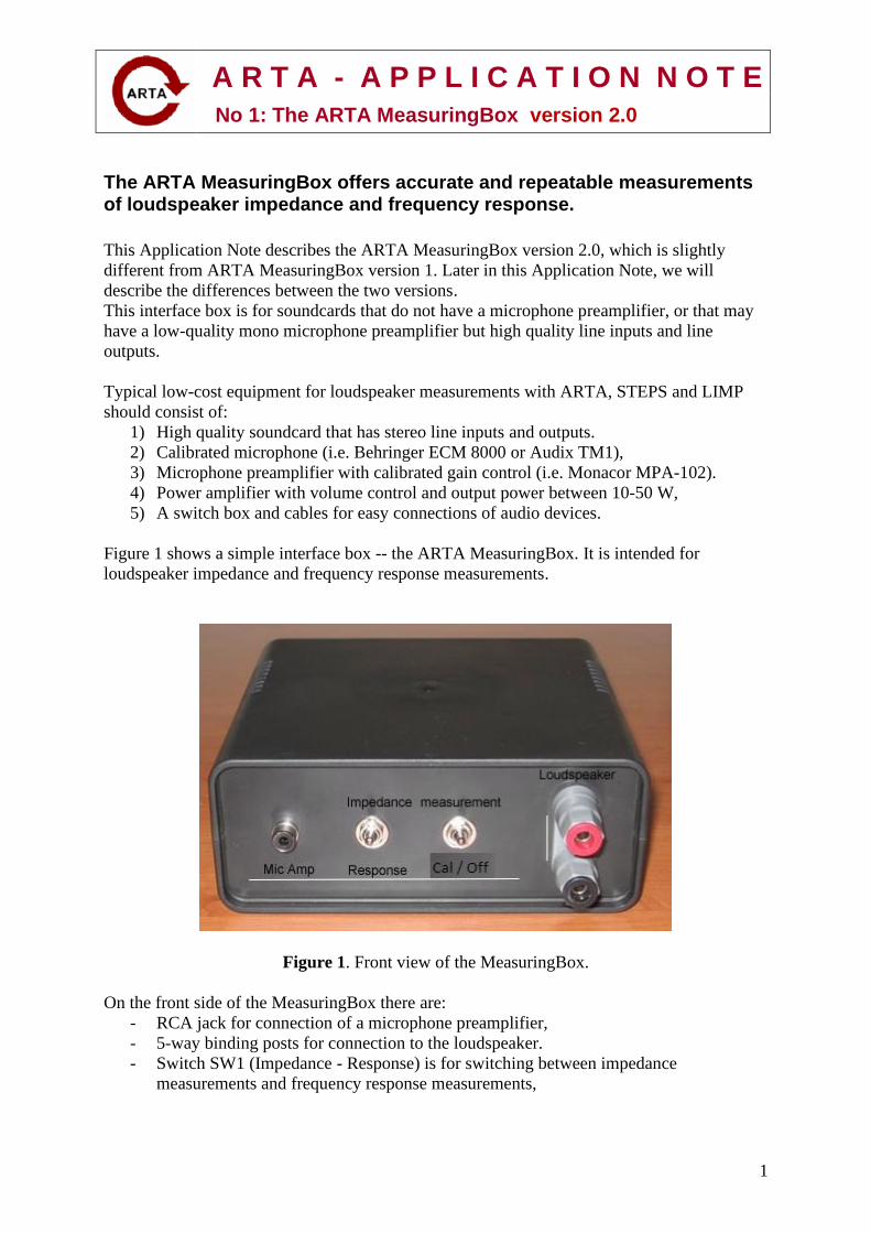
Figure 1 shows a simple interface box -- the ARTA MeasuringBox. It is intended for
loudspeaker impedance and frequency response measurements.
Figure 1. Front view of the MeasuringBox.
On the front side of the MeasuringBox there are:
- RCA jack for connection of a microphone preamplifier,
- 5-way binding posts for connection to the loudspeaker.
- Switch SW1 (Impedance - Response) is for switching between impedance
measurements and frequency response measurements,
A R T A - A P P L I C A T I O N N O T E
No 1: The ARTA MeasuringBox version 2.0
2
- Switch SW2 (Measurement – Cal / Off) is for switching between measurement or
impedance calibration. The SW2 position for calibration also disconnects the output to
the loudspeaker. After calibration, SW2 should be returned to the Measurement
position.
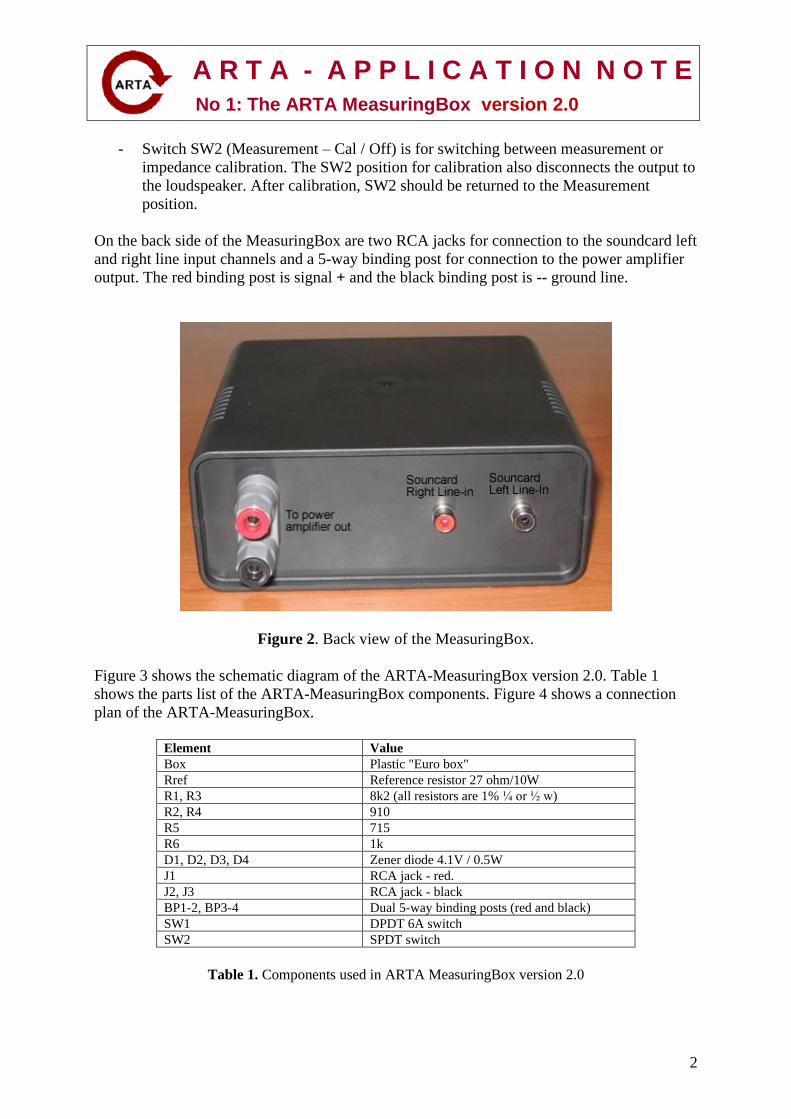
On the back side of the MeasuringBox are two RCA jacks for connection to the soundcard left
and right line input channels and a 5-way binding post for connection to the power amplifier
output. The red binding post is signal + and the black binding post is -- ground line.
Figure 2. Back view of the MeasuringBox.
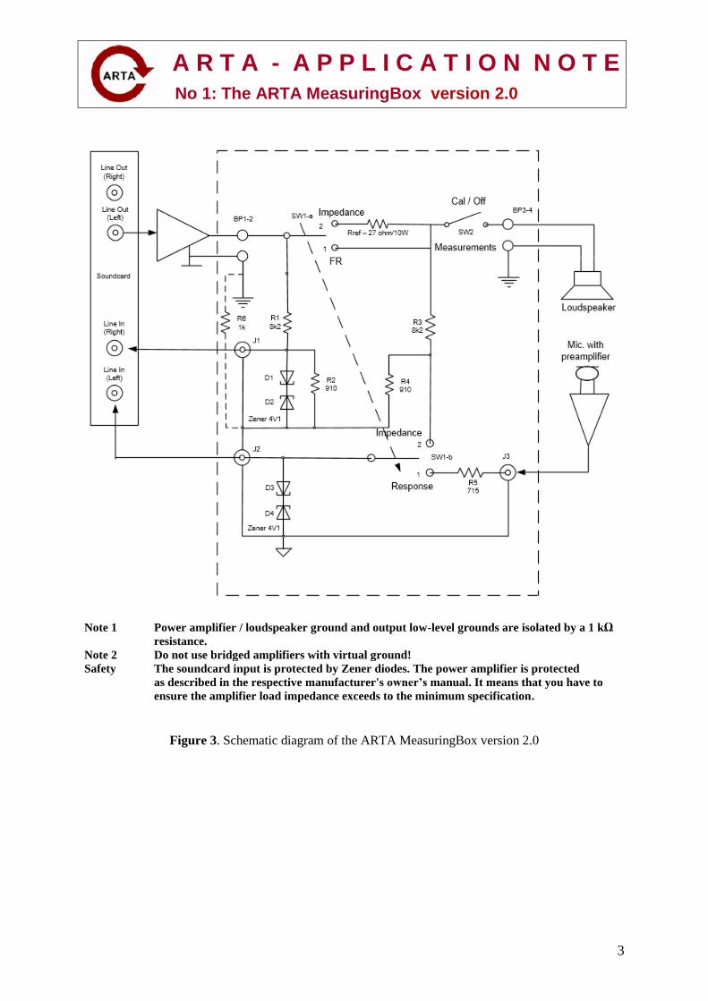
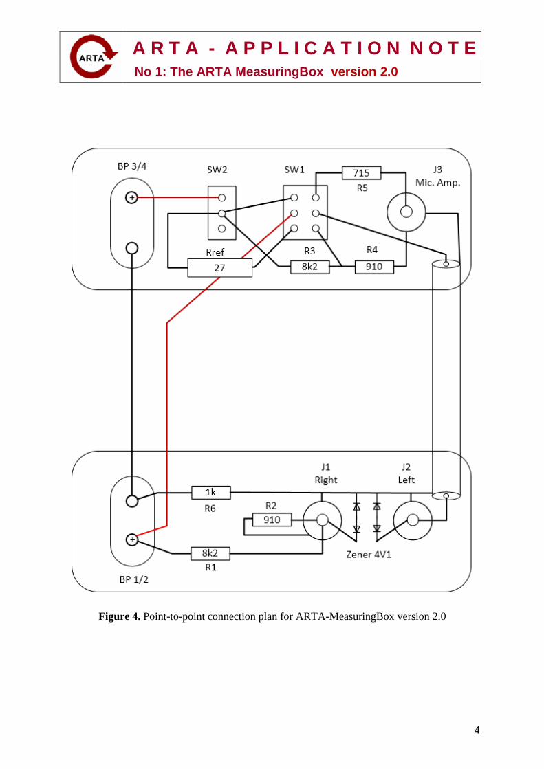
Figure 3 shows the schematic diagram of the ARTA-MeasuringBox version 2.0. Table 1
shows the parts list of the ARTA-MeasuringBox components. Figure 4 shows a connection
plan of the ARTA-MeasuringBox.
Element Value
Box Plastic "Euro box"
Rref Reference resistor 27 ohm/10W
R1, R3 8k2 (all resistors are 1% ¼ or ½ w)
R2, R4 910
R5 715
R6 1k
D1, D2, D3, D4 Zener diode 4.1V / 0.5W
J1 RCA jack - red.
J2, J3 RCA jack - black
BP1-2, BP3-4 Dual 5-way binding posts (red and black)
SW1 DPDT 6A switch
SW2 SPDT switch
Table 1. Components used in ARTA MeasuringBox version 2.0
A R T A - A P P L I C A T I O N N O T E
No 1: The ARTA MeasuringBox version 2.0
3
Note 1 Power amplifier / loudspeaker ground and output low-level grounds are isolated by a 1 kΩ
resistance.
Note 2 Do not use bridged amplifiers with virtual ground!
Safety The soundcard input is protected by Zener diodes. The power amplifier is protected
as described in the respective manufacturer's owner’s manual. It means that you have to
ensure the amplifier load impedance exceeds to the minimum specification.
Figure 3. Schematic diagram of the ARTA MeasuringBox version 2.0
A R T A - A P P L I C A T I O N N O T E
No 1: The ARTA MeasuringBox version 2.0
4
Figure 4. Point-to-point connection plan for ARTA-MeasuringBox version 2.0
A R T A - A P P L I C A T I O N N O T E
No 1: The ARTA MeasuringBox version 2.0
5
A little math for designers or how to adopt ARTA MeasuringBox component values for
special requirements.
In the default configuration, the ARTA MeasuringBox has the following characteristics:
Resistors R1 and R2 together with the soundcard input impedance Zin, form a voltage divider
r that is equal to: (R2 || Zin) / (R1 + (R2 || Zin)). Two lines || denotes parallel connection.
Refresher: To compute the total resistance of two different value resistors RA and RB in
parallel, use the following formula: RTOTAL= (RA RB)/ (RA + RB)
For two parallel resistors of equal value, the total resistance is simply 1/2 the value of either
resistor.
Solving for r: (R2 || Zin) / (R1 + (R2 || Zin)) = (910 || 10k) / (8k2+ (910 || 10k)) = 0.0923
To prevent overloading your soundcard or external audio device, it is important to know the
maximum voltage that can be applied (from the power amplifier) to its line input reference
channel (usually the right channel). This voltage is equal to the soundcard sensitivity / r.
The line input sensitivity is equal to the maximum peak voltage that the soundcard can record
– [See ARTA version 1.9.2 manual – chapter 1.5]. Therefore, the maximum power, Pmax
that can be used in measurement with MeasuringBox is equal to:
Pmax = (sensitivity (Vpk)/ r)2 / (2 * nominal loudspeaker impedance)
Example: Using the value of 0.0923 for r (from the solution above) and a Vpeak input
sensitivity of 1.0 volts; P max = (1.0/0.0923)² / (2 * 8) = 7.33 W.
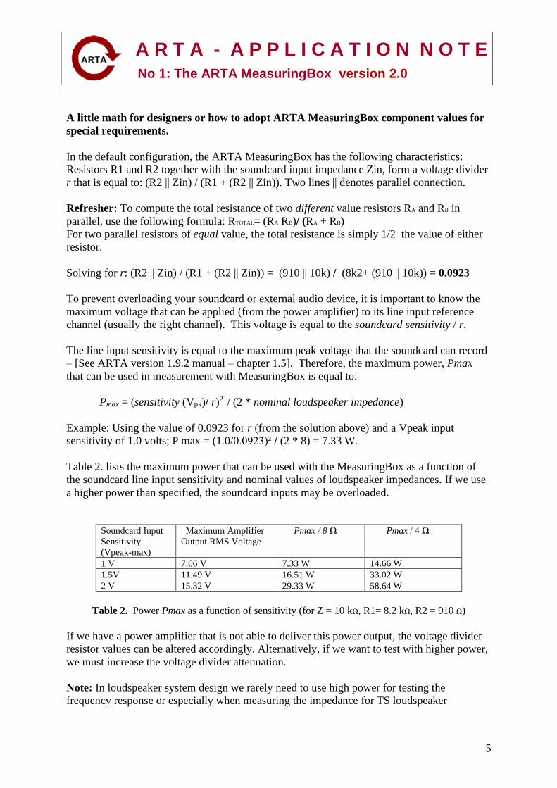
Table 2. lists the maximum power that can be used with the MeasuringBox as a function of
the soundcard line input sensitivity and nominal values of loudspeaker impedances. If we use
a higher power than specified, the soundcard inputs may be overloaded.
Soundcard Input
Sensitivity
(Vpeak-max)
Maximum Amplifier
Output RMS Voltage
Pmax / 8 Ω Pmax / 4 Ω
1 V 7.66 V 7.33 W 14.66 W
1.5V 11.49 V 16.51 W 33.02 W
2 V 15.32 V 29.33 W 58.64 W
Table 2. Power Pmax as a function of sensitivity (for Z = 10 kΩ, R1= 8.2 kΩ, R2 = 910 Ω)
If we have a power amplifier that is not able to deliver this power output, the voltage divider
resistor values can be altered accordingly. Alternatively, if we want to test with higher power,
we must increase the voltage divider attenuation.
Note: In loudspeaker system design we rarely need to use high power for testing the
frequency response or especially when measuring the impedance for TS loudspeaker
A R T A - A P P L I C A T I O N N O T E
No 1: The ARTA MeasuringBox version 2.0
6
parameters testing. In fact, the AES2-2012 Standard recommends the use of a sinewave
voltage of about 0.1V. If using multitone or pink PN, rms voltage should be about 0.2V.
Generally, the recommendation is to use a power amplifier of less than 20 watts. If your
power amplifier has a higher output power, drive it with the maximum soundcard output level
and set its input gain control so that the output power (or voltage) will be lower than the
values given in Table 2.
The value of series resistor R5 can be solved using the following expression:
R5 = (R1 || R2) Zout where Zout is the microphone preamplifier output impedance.
Example: Let Zout = 100 Ω; R1= 8k2 Ω; R2 = 910 Ω
R5 = (R1R2) 100 = 8200 * 910 100 = 7.462^6 100 = 819 Ω 100 Ω = 719 Ω
8200 + 910 9.11^3
This expression arose from the requirement that both soundcard input channels are to be
driven from generators that have the same source impedance. In this configuration we assume
Zout=100 ohm (i.e. a value for the MPA-102 preamplifier).
Using the ARTA MeasuringBox in Calibrated Measurements
For the measurement of impedance with LIMP, follow the calibration procedure in the LIMP
User Manual Section 4.7 Calibrated Measurements. With the ARTA MeasuringBox version
2.0, you must first put the calibration switch SW2 in the 'Cal / Off' position and follow the
calibration procedure that is necessary for each impedance measurement. After calibration is
completed, you must return the calibration switch SW2 to 'Measurement'.
Using the Dual channel frequency response measurement mode in ARTA and STEPS, we
must enter the proper values for left and right preamplifier or probe gain. In this mode, SW2
switch is not used. We assume that the right soundcard channel is used as the reference
channel and the left soundcard input channel is used as the response channel.
In ARTA or STEPS, click on Setup->Audio devices and using Figure 5., enter the
appropriate data.
For the Ext. right preamp gain, enter the voltage probe divider value. Using Zin of 10 kΩ as
an example; right = (R2 || Zin) / (R1 + (R2 || Zin)) = (910 || 10000) / (820 + (910 || 10000)) =
0.0923. In decibel notation, that’s 20 * log 0.0923= -20.696 dB.
To calculate the effective Ext. left preamp gain, use the formula: (Mic preamp gain) * Zin /
(Zout + R5 + Zin). e.g. for a mic preamp gain of 100 (40 dB), Zin = 10,000 Ω, Zout = 100 Ω,
R5 = 715 Ω, left = (100 * 10,000) / 10,815 = 92.46 or 39.32 dB

A R T A - A P P L I C A T I O N N O T E
No 1: The ARTA MeasuringBox version 2.0
7
Figure 5. Audio devices setup for ARTA and STEPS program
The MeasuringBox is constructed for a two-channel measurements of frequency response and
impedance, but if we want to measure frequency response in a single channel mode (FR1),
with calibrated results, we must enter the proper value in the edit box ‘Power amplifier
gain’.
The easiest way to measure the power amplifier gain is to switch in two-channel mode FR2,
with connected and calibrated MeasuringBox. Then follow the next seven steps:
1) Set switch SW1 to Response and switch SW2 to Off.
2) With additional cable connect soundcard Line Out (Right) to Mic Amp jack and in
the edit box ‘Ext. left preamp gain’ enter value 1.
3) In the edit box ‘Ext. right preamp gain’ enter the value of the voltage divider. This
way ARTA measures the proper value of the amplifier output voltage.
4) In ARTA open the FR2 Window and set Toolbar combo box Inp to Right/L. For
ARTA software versions older than 1.9.2 in the Measurement setup dialog box set
the combo box Preferred input channel to Right.
5) Set ARTA signal generator to periodic noise (PN pink or PN white) with generator
output volume slightly lowered to -10dB (just to protect soundcard).
6) Start measurement in the Fr2 mode, with smoothing set to 1/6 octave, and read the
value of the FR magnitude level at, or near, frequency 1000 Hz.
7) The measured level is equal to the power amplifier gain in dB. To get the absolute
value of the power amplifier gain use the following formula:
Power amplifier gain = 10(FR magnitude level at 1kHz) / 20
To conclude:
MeasuringBox version 2.0 enables the ARTA, STEPS & LIMP user simple control of
complex impedance and frequency response measurements while ensuring safety for the
soundcard and other connected devices.
Difference from previous version of MeasuringBox
The role and wiring of switch SW2 is different than in the original ARTA MeasuringBox.
Switch SW2 now serves to disconnect the unknown impedance, while in the old measuring
box it switched the connections of both input channels to a single point, to allow calibration
and compensation of different channel sensitivities. The current MeasuringBox allows for the
additional compensation of current that flow through the input channel impedance. As a
result, the impedance measurement range is multiplied at least ten times. Please read LIMP
User Manual (version 1.9.2 or higher) for a description of the latest calibration procedures.
A R T A - A P P L I C A T I O N N O T E
No 1: The ARTA MeasuringBox version 2.0
8
Users of the old MeasuringBox can use the new calibration process under two conditions:
1) Switch SW2 should always remain in the Measurement position (not Cal).
2) During calibration the measured impedance must be disconnected.
Solution for a measurement system that uses a high quality professional audio soundcard with built-in microphone preamplifier.
Professional audio soundcards from most manufacturers: RME, M-AUDIO, ROLAND,
TASCAM, FOCUSRITE, MOTU, Creative EMU, etc. have similar characteristics:
- dedicated balanced inputs with preamplifiers for phantom powered (24/48V) microphones,
- unbalanced line or high-impedance instrumentation inputs (usually using a combo
XLR/1/4” TRS stereo jack.
- balanced/unbalanced line outputs with analog or virtual volume control.
- headphone stereo outputs, with volume control, that can safely drive impedances with
magnitude larger than 40 ohms.
- these units have either a separate power supply or are powered by a PC via USB.
For these soundcards, high-quality measurements are possible with separate low loss cabling
for impedance measurements and separate cabling for frequency response measurements.
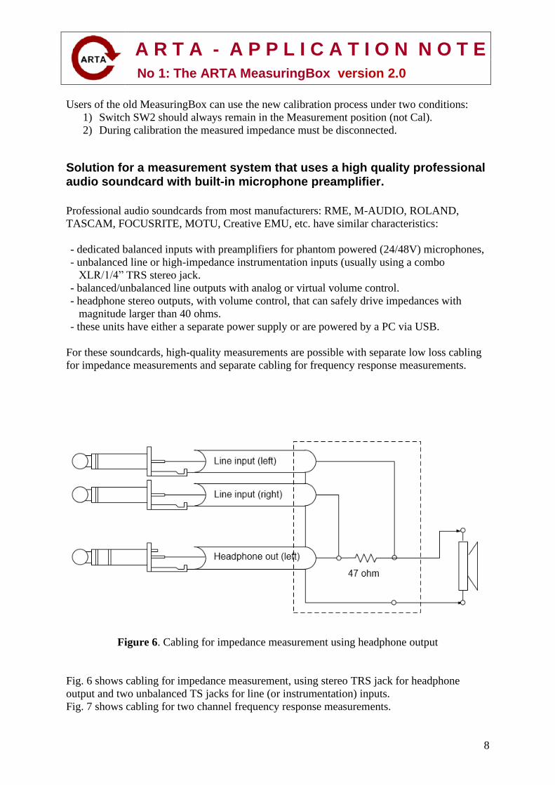
Figure 6. Cabling for impedance measurement using headphone output
Fig. 6 shows cabling for impedance measurement, using stereo TRS jack for headphone
output and two unbalanced TS jacks for line (or instrumentation) inputs.
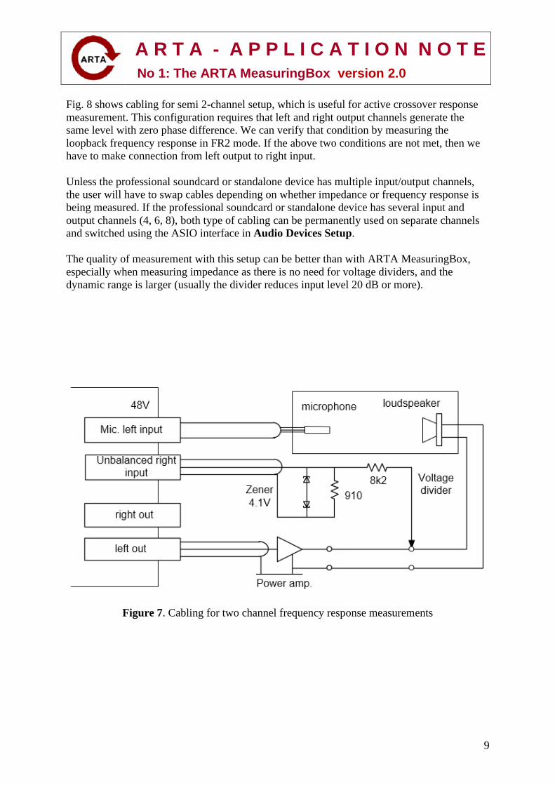
Fig. 7 shows cabling for two channel frequency response measurements.
A R T A - A P P L I C A T I O N N O T E
No 1: The ARTA MeasuringBox version 2.0
9
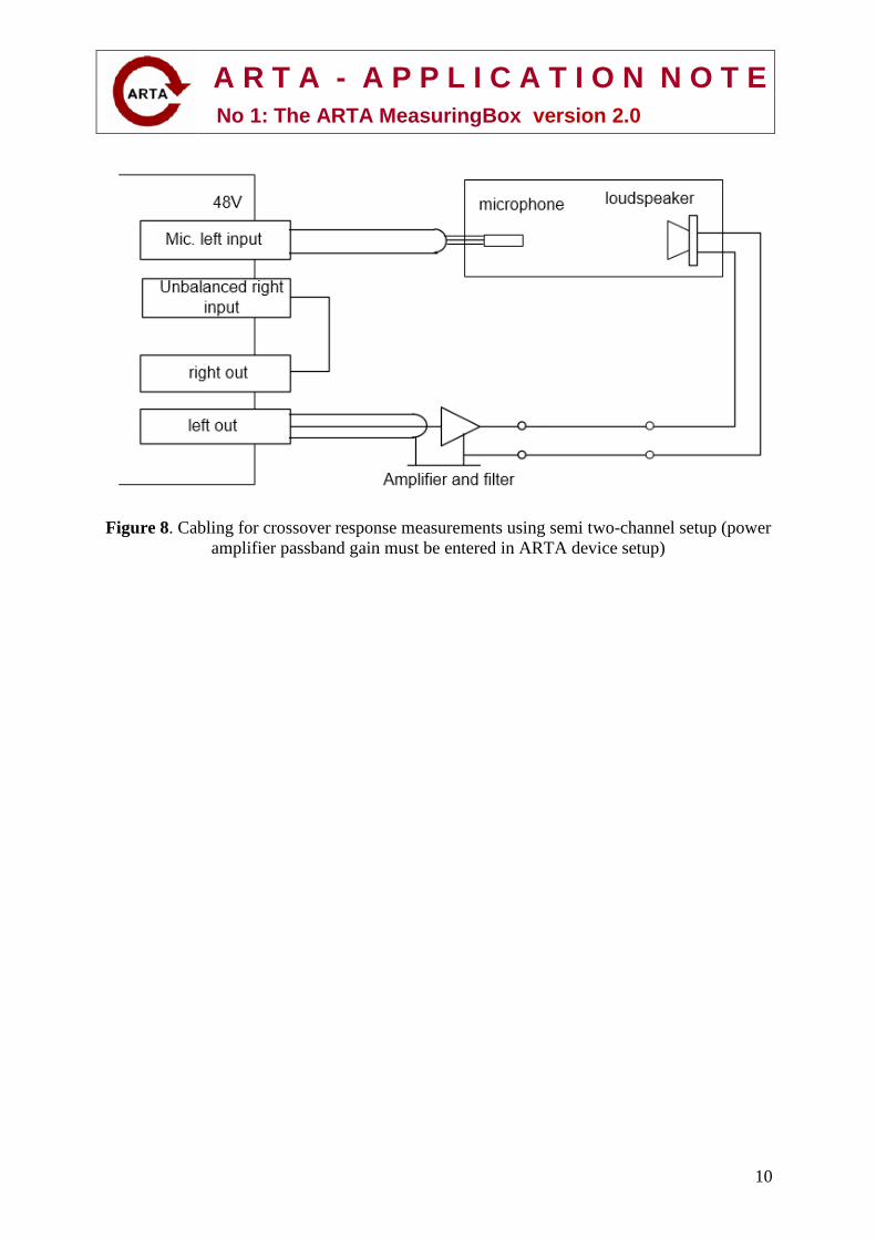
Fig. 8 shows cabling for semi 2-channel setup, which is useful for active crossover response
measurement. This configuration requires that left and right output channels generate the
same level with zero phase difference. We can verify that condition by measuring the
loopback frequency response in FR2 mode. If the above two conditions are not met, then we
have to make connection from left output to right input.
Unless the professional soundcard or standalone device has multiple input/output channels,
the user will have to swap cables depending on whether impedance or frequency response is
being measured. If the professional soundcard or standalone device has several input and
output channels (4, 6, 8), both type of cabling can be permanently used on separate channels
and switched using the ASIO interface in Audio Devices Setup.
The quality of measurement with this setup can be better than with ARTA MeasuringBox,
especially when measuring impedance as there is no need for voltage dividers, and the
dynamic range is larger (usually the divider reduces input level 20 dB or more).
Figure 7. Cabling for two channel frequency response measurements
A R T A - A P P L I C A T I O N N O T E
No 1: The ARTA MeasuringBox version 2.0
10
Figure 8. Cabling for crossover response measurements using semi two-channel setup (power
amplifier passband gain must be entered in ARTA device setup)
A R T A - A P P L I C A T I O N N O T E
No 1: The ARTA MeasuringBox version 2.0
11
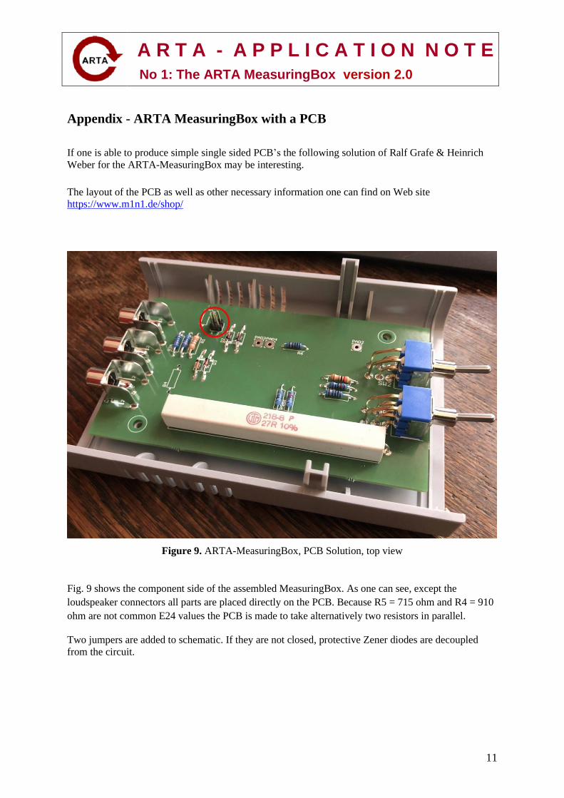
Appendix - ARTA MeasuringBox with a PCB
If one is able to produce simple single sided PCB’s the following solution of Ralf Grafe & Heinrich
Weber for the ARTA-MeasuringBox may be interesting.
The layout of the PCB as well as other necessary information one can find on Web site
https://www.m1n1.de/shop/
Figure 9. ARTA-MeasuringBox, PCB Solution, top view
Fig. 9 shows the component side of the assembled MeasuringBox. As one can see, except the
loudspeaker connectors all parts are placed directly on the PCB. Because R5 = 715 ohm and R4 = 910
ohm are not common E24 values the PCB is made to take alternatively two resistors in parallel.
Two jumpers are added to schematic. If they are not closed, protective Zener diodes are decoupled
from the circuit.
A R T A - A P P L I C A T I O N N O T E
No 1: The ARTA MeasuringBox version 2.0
12
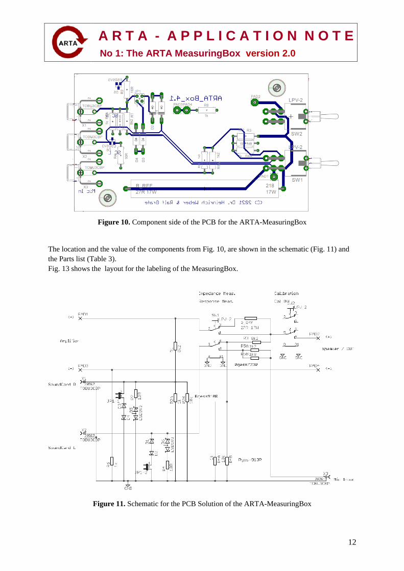
Figure 10. Component side of the PCB for the ARTA-MeasuringBox
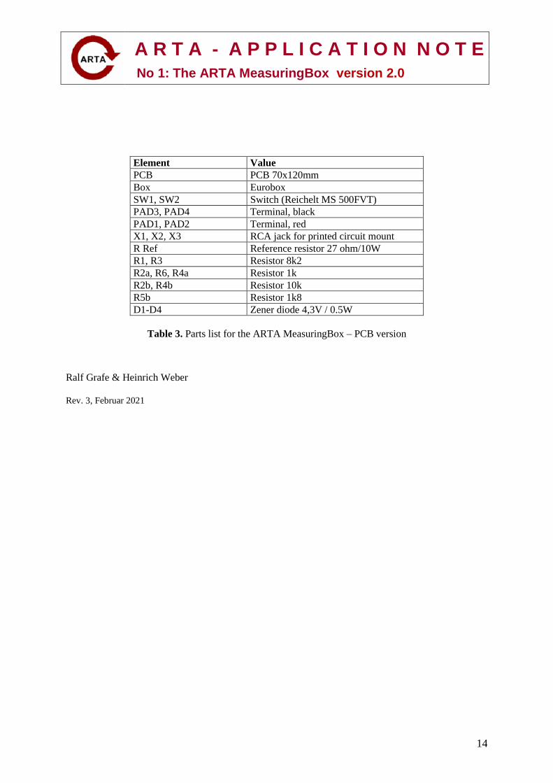
The location and the value of the components from Fig. 10, are shown in the schematic (Fig. 11) and
the Parts list (Table 3).
Fig. 13 shows the layout for the labeling of the MeasuringBox.
Figure 11. Schematic for the PCB Solution of the ARTA-MeasuringBox
A R T A - A P P L I C A T I O N N O T E
No 1: The ARTA MeasuringBox version 2.0
13
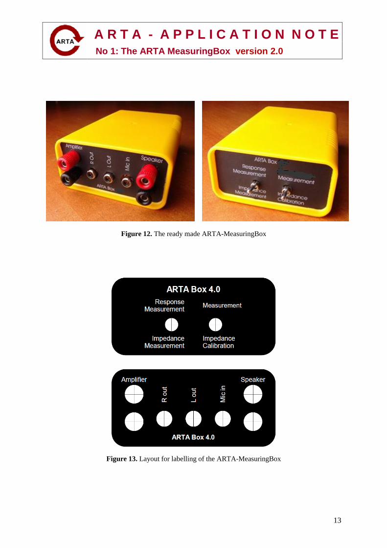
Figure 12. The ready made ARTA-MeasuringBox
Figure 13. Layout for labelling of the ARTA-MeasuringBox
A R T A - A P P L I C A T I O N N O T E
No 1: The ARTA MeasuringBox version 2.0
14
Element Value
PCB PCB 70x120mm
Box Eurobox
SW1, SW2 Switch (Reichelt MS 500FVT)
PAD3, PAD4 Terminal, black
PAD1, PAD2 Terminal, red
X1, X2, X3 RCA jack for printed circuit mount
R Ref Reference resistor 27 ohm/10W
R1, R3 Resistor 8k2
R2a, R6, R4a Resistor 1k
R2b, R4b Resistor 10k
R5b Resistor 1k8
D1-D4 Zener diode 4,3V / 0.5W
Table 3. Parts list for the ARTA MeasuringBox – PCB version
Ralf Grafe & Heinrich Weber
Rev. 3, Februar 2021


