Embed Size (px)
Citation preview
1
The Structure and Stability of the Laminar Counterflow Partially
Premixed Methane/Air “Triple-Flame”
R.D. Lockett, B. Boulanger+, S.C. Harding
#, D.A. Greenhalgh
School of Mechanical Engineering, Cranfield University, Cranfield Beds, MK43 0AL,
United Kingdom
ABSTRACT
The flame stability map defining the regime of existence of a counter-flowing laminar
partially premixed methane-air “triple flame” has been determined using OH Planar Laser
Induced Fluorescence (PLIF). The stability limits were determined through the
observation of flame merging and flame extinction, a function of rich and lean equivalence
ratios, and mean axial strain rate.
Relatively quantitative OH species profiles and Rayleigh scattering profiles have been
measured for three flame conditions. Axial flow velocity profiles, and nozzle exit
velocity profiles have been determined for two of the three conditions using 1-D Laser
Doppler Velocimetry (LDV). The diffusion flame extinction axial velocity profile has
been measured, and the local extinction axial strain rate has been determined to be 710s-1
.
+ Current address University of Liege.
# Current address Rolls-Royce Bristol.
2
1. INTRODUCTION
Flame development occurs in turbulent fuel-air mixtures exhibiting both mixture gradients
and fluid strain in many modern combustion systems (gas turbine, internal combustion
engine). Flame response to fluctuating mixture gradients and fluctuating strain will
deviate from the behaviour predicted from simple diffusion flame theory or premixed
flame theory. The description of the combustion in these systems in terms of either
diffusion flame models or premixed flame models is thus incomplete. The combustion
occurring in such systems is termed “partially premixed” [1,2]. Consequently, there have
been a growing number of studies recently in partially premixed combustion.
One of the early systematic studies of partially premixed counter-flow flames was
conducted by Yamaoka et al [1]. This paper reported an experimental investigation of the
structure of partially premixed counter-flow “double flames”, stabilised in the forward
stagnation region of a porous cylinder. The authors also investigated the lean and rich
flame stability limits of this flame system for a specific strain rate.
This work was followed by that of Seshadri et al [2], in which the authors report the results
of an experimental and theoretical study of extinction of partially premixed diffusion
flames. The study was conducted in a counter-flow burner; one stream methane diluted
with nitrogen, the other stream diluted air. Small quantities of methane were added to the
diluted air stream in the first case, and a small quantity of air was added to the fuel stream
in the second case. In both cases, a partially premixed diffusion flame with two reaction

3
zones was formed. The extinction strain rate was measured, and compared with modelled
results.
Lin et al followed this with an experimental study of the transition of diffusion flames to
premixed flames in partially premixed flame systems [3]. This paper identified “double
flame” structures and “triple flame” structures observable in counter-flowing partially
premixed butane-air streams, and examined some basic conditions necessary for the
existence of these flames. Tanoff et al have recently performed numerical calculations of
counter-flow “double flames”, and compared the results with experimentally obtained
species profiles for the same flame conditions [4]. The rich mixture stream had an
equivalence ratio = 1.4, and the flame was beginning to show “double flame” structure.
The other studies in “triple flame” structures have examined the properties of co-flowing
partially premixed “triple flames” [5, 6].
The axially symmetric laminar counter-flow flame geometry is convenient for the
examination of flame stretch (flame response to flow strain). The use of an appropriate
stream function in conjunction with the Navier-Stokes equations reduces the
multi-dimensional nature of the problem to a single space dimension. Knowledge of the
axial velocity profile, and the axial density profile (through experiment or modelling)
enables the calculation of the local flame stretch rate. Consequently, many studies have
examined axially symmetric back-to-back premixed flame structures [9-11], and
fresh-to-burnt geometries [11,12] for the determination of flame response to flow strain,
the determination of laminar flame velocities as a function of fuel type, and as a function of
pressure.
4
Therefore an axially symmetric counter-flowing geometry has been chosen to examine the
response of partially premixed flames to fluid strain and mixture gradient. This paper
reports on a laser diagnostic study (Laser Doppler Velocimetry (LDV), OH Planar Laser
Induced Fluorescence (PLIF) & Rayleigh Scattering) of the flame structure of
counter-flowing partially premixed methane-air flames, which exhibit themselves as
counter-flowing “triple flames” or as “thick double flames”. Full experimental details of
the laser diagnostics employed are provided in the following section.
2. EXPERIMENTAL METHOD
2.1: The Counter-flow Burner
The Counter-flow burner which was designed and constructed at Cranfield University is
shown in Figure 1. It consists of two opposed burner nozzles inside two opposed annular
sections. The opposed burner nozzles are 38 mm in diameter, and the inter nozzle spacing
is variable. The mixed gas flow through each nozzle passes through a bead cage, and a
scintered bronze disc, to produce plug flow at the nozzle exit. All individual gas flows are
metered using pressure transducers upstream of, and downstream of, calibrated sonic
nozzles. Gaseous fuels are mixed uniformly with air in user determinable proportions,
using a dense wire mesh upstream of two sets of baffle plates in the mixing zone. The
mixing of gases occurs downstream of the sonic nozzle metering system. For these
experiments, 99.9% CP grade methane was mixed with filtered air supplied by a standard

5
laboratory compressor (maximum line pressure 7.5 bar). The annular sections outside the
burner nozzles were used to provide a flame stabilising nitrogen curtain.
Fig. 1. Counter-flow burner.
The burner was designed to provide user determinable, stabilised, laminar, opposed plug
flows of premixed fuel-air mixtures of independently variable stoichiometry for each
nozzle. This defines an axially symmetric counterflow system with mixture gradients.
2.2: The Counter-flowing Laminar Methane-Air “Triple Flame”
The counter-flowing laminar methane-air “triple flame” consists of two premixed
counter-flowing laminar methane-air jets, one jet mixed rich, the other mixed lean.
Combustion produces two strained premixed flames, one rich, and the other lean.
Between these two strained premixed flames, excess oxygen passes from the lean flame

6
towards the stagnation plane, and excess CO, atomic and molecular hydrogen pass from
the rich flame towards the stagnation plane. These two hot flows react predominantly as a
pure wet CO-hydrogen-air diffusion flame. Therefore the laminar “triple flame” appears
as a laminar diffusion flame sandwiched between the strained laminar lean and rich
premixed flames.
Fig. 2. Laminar methane–air triple flame in counter-flow burner.
Figure 2 is a photograph showing a laminar counter-flowing “triple flame” produced in the
counter-flow burner. The strained rich premixed flame is the lower flame, the strained
lean premixed flame is the upper flame, and the CO/H2 diffusion flame is the centre flame.
2.3: The “Triple-Flame” Stability Map
Counter-flowing “triple flames” undergo strain as a consequence of the local flow velocity
gradients. The local axial strain affects the stability of the flame structure, and determines
the mixture strength at which flame merging or flame extinction occurs. Counterflowing
“triple flame” stability limits are determined in terms of merging of one of the premixed
7
flames with the diffusion flame, producing a “double flame”; or axial strain extinction of
the diffusion flame; or flashback. Thus a regime of “triple flame” stability exists, defined
by the dependence of rich and lean mixture strength merging limits on axial strain,
flashback, simultaneous rich and lean mixture strength support for the diffusion flame, and
axial strain extinction of the diffusion flame. For axial strain rates above the strain
extinction limit, partially premixed counter-flowing flames appear as thick “double
flames”, consisting of two premixed flames.
The hydroxyl radical is principally responsible for fuel oxidation in both premixed flames
and the diffusion flame. Elevated levels of OH radical concentration relative to equilibrium
indicate flame reaction zones. The presence of peaks in the OH radical concentration
profile along the symmetry axis is a good indicator of flame existence and position. The
counter-flowing “triple flame” produces three elevated regions of OH, indicating the three
reaction zones. Thus the presence or absence of OH is a good indicator of the presence or
absence of one of the flames in the “triple flame” system.
2.4: OH Planar Laser Induced Fluorescence (PLIF)
The regime of “triple flame” stability was determined using OH PLIF. The OH
fluorescence intensity is proportional to the local OH concentration, and was thus used to
determine the presence or absence of one of the flames in the “triple flame” system. A
Lambda Physik EMG-150 MSC excimer laser was employed in narrow-band tuneable
mode, operating at 308.24 nm, exciting the Q1(3) line in the 0 - 0 band of the A X
transition in OH. The EMG-150 laser produces pulses of approximately 20 ns duration,
8
and 145 mJ energy. The laser light was directed through a 2 m spherical lens and a
cylindrical telescope, producing a laser sheet of height 25 mm, and width 0.2 mm. The
fluorescence from the excited OH was on-resonance, and was imaged onto a gated,
intensified lens coupled Astromed CCD camera, using a Nikon Nikkor 105 mm f4.5 uv
lens.
The “triple flame” stability map was determined by mapping the merging limits of the lean
and rich premixed flames with the diffusion flame, determined by the critical mixture
strength at which flame merging occurs as a function of nozzle exit velocity, or mean axial
strain rate. The mean axial strain rate a is defined as
ad
lower upperv v
,
where |vlower| and |vupper| are the lower and upper nozzle exit speeds, and d is the inter-nozzle
spacing.
The merging limits were determined through a qualitative measurement of the position of
the three flames relative to each other along the centreline axis using OH PLIF. Various
consistency tests were applied to the flame stability data. The dependence of the “triple
flame” stability data on mean axial strain rate, and independence of inter-nozzle spacing
was checked by measuring the variation of flame merging limits for inter-nozzle distances
of 25 mm, 30 mm, and 37 mm, and correcting for the mean axial strain rate.
The dependence of the merging limits of the rich premixed flame on the lean flame
stoichiometry was tested by determining the rich merging limits for various lean flame
9
stoichiometries. The dependence of the merging limits of the lean premixed flame on the
rich flame stoichiometry was tested by determining the lean flame merging limits for
various rich flame stoichiometries. Buoyancy and heating effects in the unburned gas
flows were tested by reversing the mixtures between upper and lower burners.
Relative quantitative OH PLIF measurements have been performed for three partially
premixed flame conditions. These measurements employed the Lambda Physik EMG
150 MSC excimer laser operating in narrow band tunable mode, as described above. The
fluorescence was imaged onto a gated Princeton Instruments ICCD camera, using a Nikon
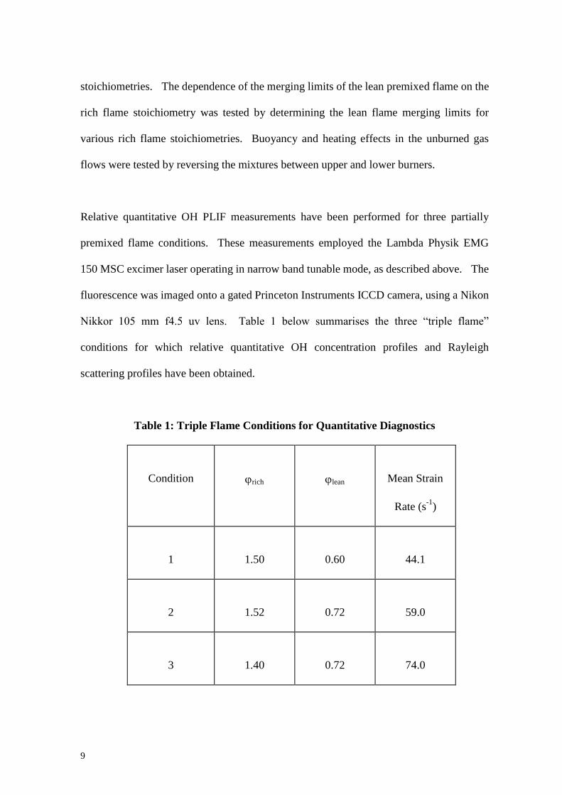
Nikkor 105 mm f4.5 uv lens. Table 1 below summarises the three “triple flame”
conditions for which relative quantitative OH concentration profiles and Rayleigh
scattering profiles have been obtained.
Table 1: Triple Flame Conditions for Quantitative Diagnostics
Condition
rich
lean
Mean Strain
Rate (s-1
)
1
1.50
0.60
44.1
2
1.52
0.72
59.0
3
1.40
0.72
74.0

10
It was determined that the OH PLIF produced using this laser was partially saturated. An
approximate correction was made for the partial saturation, by assuming that the functional
form of the laser profile at focus could be described by a top hat. This approximation
produces an error of about 5% in deduced OH concentration. On-resonance fluorescence
imaging is also subject to contamination from background scattering and Rayleigh
scattering. The background was subtracted from the images using standard techniques.
Rayleigh scattering intensity in the flame zone was estimated from the Rayleigh scattering
intensity in the unburnt gas region, and subtracted from the flame images.
The Q1(3) line of the 0 - 0 transition has a population fraction of about 0.084 at 1800 K,
with a temperature dependence of -0.004 per 100 K change in temperature. Therefore, if
the rich and lean premixed flames are about 100 K lower in temperature than the diffusion
flame, then the rich and lean OH peaks are over-predicted by about 5%. Radiation
trapping is a further source of systematic error, estimated at about 10 %. The resulting
imaged fluorescence intensity is proportional to OH concentration to an accuracy of about
13%.
2.5: Rayleigh Scattering
The determination of the local flame stretch rate requires the determination of the axial
density profile and the axial velocity profile [7,8]. The most accessible diagnostic for the
determination of mixed gas density is 2-d Rayleigh scattering. Rayleigh scattering from
the “triple-flame” combustion zone produces a Rayleigh cross-section weighted axial
density profile. Modelled species profiles and a temperature profile enables the
11
computation of a model Rayleigh cross-section weighted axial density profile for
comparison.
Rayleigh scattering measurements have been performed for three partially premixed flame
conditions, corresponding to those specified in Table 1. A Spectra Physics GCR-270
Nd:YAG laser was employed, operating at 532 nm. The GCR-270 laser is TEM00
injection seeded, and produces up to 900 mJ per pulse at 532 nm, of 7 ns to 9 ns pulse
duration. The laser was operated at approximately 400 mJ per pulse for the Rayleigh
scattering measurements reported here.
The laser light was directed through a 2 m lens and a 4x inverted cylindrical telescope, to
produce a sheet 32 mm high, and 0.2 mm wide. The outer edges of the sheet were
truncated using an iris, producing a sheet 22 mm high in the flame. The Rayleigh
scattering from the flame gases were imaged onto a gated Princeton Instruments ICCD
camera, using a Nikon 50 mm f1.2 lens.
Background images and flat-field images were required for processing of the Rayleigh
scattering data. Three sets of 40 images were obtained from the measurement zone,
saturating the region with helium, air and methane respectively. The background image
was obtained using the mean helium Rayleigh scattering image against the mean methane
Rayleigh scattering image, using the expression
background He
He
methane He
methane HeS S S S
( )( )
,
12
where SHe and Smethane are the mean helium and methane Rayleigh scattering images
respectively. He and methane are the helium and methane Rayleigh scattering
cross-sections respectively [13].
The background image derived above possessed two sources of image contamination
which had to be corrected. The first source of image contamination was caused by
intensifier defocussing. Intense Rayleigh scattering from surrounding air was focussed by
the intensifier onto the low background level. The point spread function was estimated by
modelling the effects of intensifier defocussing, and comparing the results with the
background data. The point spread function was found to be well described by a
Gaussian-Lorentzian product. A Wiener function was then used, together with the
derived point spread function to recover the true background image.
The resulting background image still possessed a low level of second order scattering
contamination on parts of the background, not present on the Rayleigh data images
(approximately 15% of the mean background scattering intensity, and approximately 10%
of the Rayleigh scattering intensity in the flames). This second order scattering
contamination was subtracted from the refocused background derived above to produce the
final background image.
The laser flat-field image was obtained by subtracting the mean background derived above
from the mean Rayleigh scattering image of methane. The Rayleigh scattering image data
was processed by subtracting the final derived background from the data images, and then
flat-fielding the data images with the above laser flat-field. The Rayleigh scattering data
13
for flame condition 1 was incomplete in that the laser sheet was not quite wide enough to
include the unburned rich mixture fully. However, the sheet did include the edge of the
unburned lean mixture, and the flame zone.
2.6: 1-D Laser Doppler Velocimetry (LDV)
1-D LDV measurements of the counterflow velocity profile were performed for “triple
flames” Condition 1 and Condition 2 specified in Table 1 above. A third partially
premixed flame condition was subjected to LDV measurement; and that condition
corresponded to axial strain extinction of the diffusion flame.
The scintered bronze discs were removed from the upper and lower burner nozzles for
these measurements, as they would have become clogged up with seed. This meant that
the flow was marginally less stable at low nozzle exit velocities (vrms/v < 0.01, v < 1.5
m.s-1
), but became progressively more unstable at higher nozzle exit velocities (v > 2.0
m.s-1
). The flow was found to be moderately turbulent (vrms/v ~ 0.1) at axial strain
extinction.
A Lexel Model 95 4W cw Argon Ion laser was employed, operating in single line (TEM00)
mode at 514.5 nm. The laser beam passed through a Dantec beam splitter/Bragg shifter
which split the beam into two, and then shifted the frequency of one of the beams by 30
Mhz. The two beams were then directed separately through a Dantec 3-D optical
distributor into an optical fibre cable to a 500 mm focal length Dantec LDV beam crossing

14
lens. The fundamental mode and the Bragg shifted mode were brought to a focus and
crossed along the symmetry axis between the two opposing burner nozzles.
The counter-flowing premixed gas flows were seeded with 0.25 m zirconium dioxide
particles, obtained using two identical cyclone seeders. Each of the premixed flows
entered a bypass tube by choking the main flow tubes with needle valves. The bypass
tubes led into the cyclone seeders. The seeding density in each flow was varied by
adjusting the needle valve in the main flow tube, regulating the flow into the seeders.
The light scattered back from the seed particles were imaged into an optical fibre, and
passed though to a photo-multiplier tube. The Doppler burst data captured by the
photo-multiplier tube were then analysed using a Dantec 3-D Burst Spectrum Analyzer
(BSA), using Dantec’s Burstware software.
Possible biasing in the measurement velocities of the opposed flows due to different
seeding densities was eliminated by ensuring that the data capture rate was the same for
both flows, for the same absolute displacement from the nozzles. A cold flow axial
velocity of zero was obtained at the midpoint between the nozzles.
LDV measurements of axial and radial velocities were obtained along the symmetry axis,
and 1.5 mm radial displacement from the symmetry axis. These measurements were
obtained at 1 mm intervals between the opposed nozzles for small velocity gradients, and
0.5 mm intervals for large velocity gradients. Radial LDV measurements of axial velocity
were also obtained 4 mm above the lower nozzle, and 5 mm below the upper nozzle at
1mm intervals across the nozzle diameters for all axial velocity measurements presented

15
here. The limits of the upper and lower heights of these radial measurements were
determined by the proximity of the crossing laser beams to the edge of the nozzle.
3. RESULTS AND DISCUSSION
3.1: The “Triple-Flame” Stability Map
Figure 3(a) shows a hydroxyl (OH) radical concentration profile obtained using OH PLIF
in the laminar methane-air counter-flowing “triple flame”. The “triple flame” structure
can be seen clearly in terms of local OH concentration peaks. The flow and mixture
conditions for this triple flame were rich = 1.20, lean = 0.80, mean axial strain rate a = 180
s-1
.
Increasing the rich mixture strength lowers the strained rich premixed flame speed, which
causes the strained rich premixed flame to move closer towards the stagnation plane. At
some point, the rich premixed flame begins to merge with the diffusion flame, and the two
flames cannot be distinguished from each other. Flame merging has taken place. An
example of this can be seen in figure 3(b), which shows an OH concentration profile in a
partially premixed counter-flow methane-air flame where the rich flame has completely
merged with the diffusion flame, and cannot be identified. The flow and mixture
conditions for this flame profile were rich = 1.34, lean = 0.80, mean axial strain rate a = 180
s-1
.

16
Fig. 3. OH Concentration as a function of distance along burner axis; (a)
standard triple flame, (b) rich flame merg- ing, (c) lean flame merging.
Obtaining the dependence of the strained rich premixed flame merging limits on axial flow
strain rate as described above defines the regime of existence of the strained rich premixed
flame. The regime of existence of the strained lean premixed flame and the diffusion
flame can be similarly determined. Leaning out the lean premixed flame causes the lean
flame speed to decrease, and the flame is observed to move towards the stagnation plane,
eventually merging with the diffusion flame. Lean flame merging has occurred. Figure
3(c) shows an OH concentration profile where lean flame extinction, or merging has
17
occurred. The flow and mixture conditions for this flame were rich = 1.20, lean = 0.68,
mean axial strain rate a = 180 s-1
.
The diffusion flame only exists if there is simultaneously enough oxygen passing from the
lean premixed flame to the stagnation plane, and CO, atomic and molecular hydrogen
passing from the rich premixed flame to the stagnation plane to react to form a diffusion
flame. If these conditions are not satisfied, the diffusion flame will extinguish.
Finally, there exists a critical flame stretch (or axial flow strain), above which the CO/H2
diffusion flame is extinguished. Flame stretch effects dominate the diffusion mass flux
across the stagnation plane when the axial flow strain rate is greater than the axial
extinction strain rate. This means that the rate of increase of flame surface area is larger
than the diffusion mass flux necessary to sustain the flame. The critical local axial strain
rate for extinction of the diffusion flame was measured to be 710 s-1
using 1-D LDV. This
can be seen from figure 9, which profiles the mean flow velocity for the axial strain
extinction condition. For axial strain rates larger than this critical strain rate, the
counter-flowing partially premixed flame structure is best described as a “thick double
flame”. Putting these datasets together defines the regime of existence of the laminar
“triple flame”, which is shown in figure 4.
Firstly the consistency tests mentioned in section 2.4 require some discussion. The “triple
flame” stability map was found to be independent of inter-nozzle distance over the range
25mm to 37mm within the 1% experimental error in mixture stoichiometry. The rich
flame merging limits were found to be independent of the lean flame stoichiometry within

18
the 1% experimental error. The lean flame merging limits were similarly found to be
independent of the rich flame stoichiometry.
Fig. 4. Triple flame stability map.
Secondly the flame stability map in figure 4 requires some explanation. The ordinate
describes the stoichiometry of both nozzle flows. In practice no “triple flame” will exist if
these stoichiometries are equal and by definition the lean flame stoichiometry cannot
exceed the rich flame stoichiometry. The map shows that to first order the diffusion flame
extinction is dominated by the rich flame stoichiometry; however there is a slight
sensitivity to the lean stoichiometry. Increasing the lean flame stoichiometry from the
lean merging limit to stoichiometric causes a slight increase in the stoichiometric
extinction limit for the difusion flame from rich ext. = 1.18 to rich ext. = 1.21. Therefore the
2-D map in figure 4 is strictly 3-D as far as the diffusion flame is concerned, however

19
because the variation is close to experimental error, plotting figure 4 in a 3-D form would
be confusing.
Thus to establish whether a triple-flame is predicted to exist the following is required.
Firstly select the lean stoichiometry to be less than 1.0 and more than the lean merging limit
for the mean axial strain rate, secondly choose the rich flame stoichiometry to fall
between the rich = 1.18 extinction limit (the diffusion flame is extinguished for rich <
1.18) and the rich flame merging limit for the same mean axial strain rate. The latter
criteria is clearly seen to be the most restrictive and therefore we can conclude that the
“triple flame” is strongly sensitive to both the rich flame stoichiometry and the axial strain
rate.
The temperature of the rich and lean mixture streams has a strong global effect on the
“triple flame” stability map. The upper burner nozzle reaches a steady state temperature
approximately 60 K to 100 K higher than the lower nozzle. This temperature difference
between the two nozzles produces a systematic variation in the lean merging limit of -0.001
K-1
, and a systematic variation in the rich merging limit of +0.0008 K-1
. For example, if
the temperature of the unburnt lean mixture was 300K, and it had a lean merging limit of
= 0.600: then if the temperature of the unburnt lean mixture was raised to 360K, the lean
merging limit would change to = 0.540.
20
3.2: Relative Quantitative OH PLIF
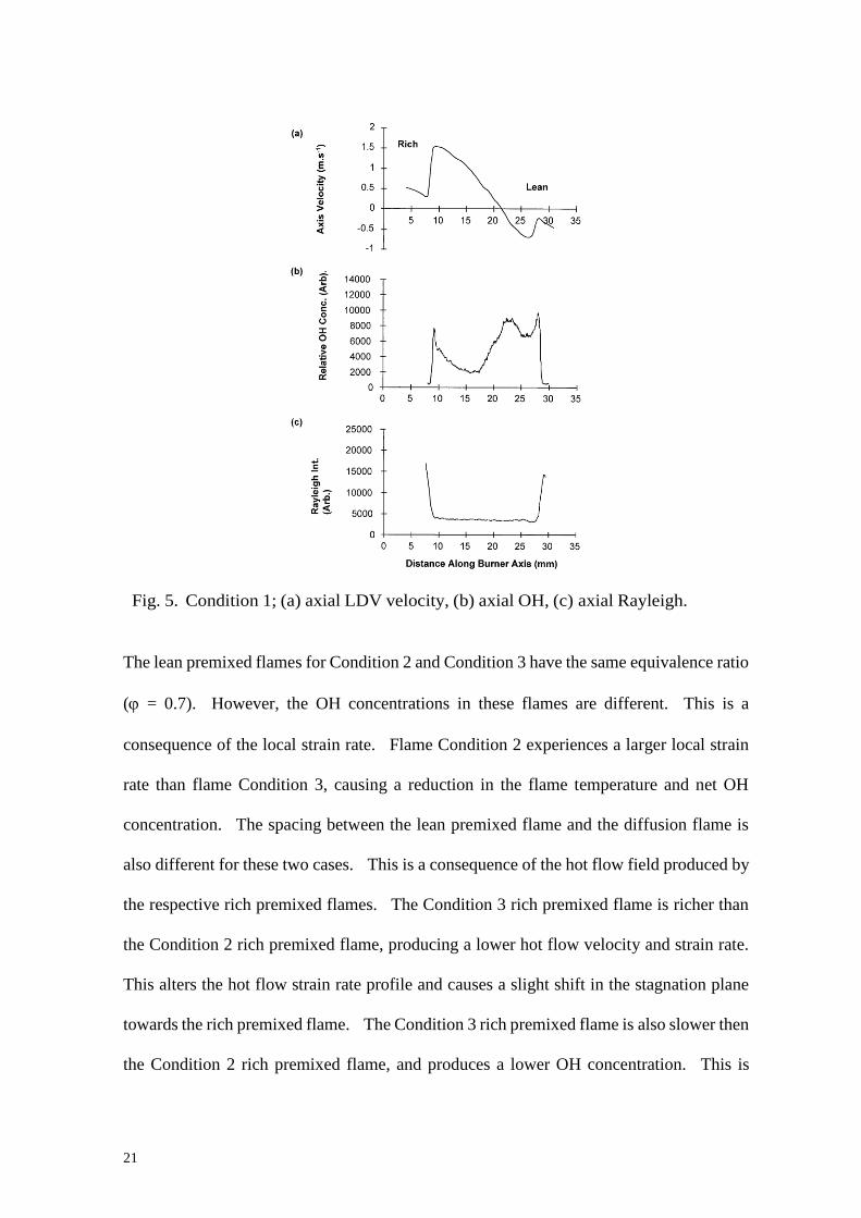
Figures 5 and 6 show the measured velocity profiles, the OH concentration profiles, and the
Rayleigh scattering profiles for “triple flame” Condition 1 and Condition 2 respectively.
Comparing the position of the OH concentration peaks in the diffusion flames for
Conditions 1 and 2 with the stagnation planes defined by the zero point velocity in the axial
velocity profiles suggests that the diffusion flames occur on the lean side of the stagnation
plane. This is to be expected for methane/air “triple flames” as molecular hydrogen and
CO have larger molecular diffusivities than air, and thus would diffuse through the
stagnation plane at a larger rate.
Flame Condition 1 has the lowest strain rate of the three conditions presented here (a1 = 50
s-1
). The premixed flames appear relatively unaffected by the flow strain rate. Figure 7
shows the measured OH concentration profile, and the Rayleigh scattering profile for
“triple flame” Condition 3. Using figures 6 and 7 to compare flame Condition 2 with
Condition 3 reveals that the “triple flame” thickness is approximately the same for these
two conditions, even though the axial strain rates and rich mixtures differ. The diffusion
flame in Condition 3 appears hotter than the diffusion flame in Condition 2 through the
larger relative OH concentration. This observation is supported by the fact that the
Rayleigh scattering intensity is lower for Condition 3 than for Condition 2 (see next
section).
21
Fig. 5. Condition 1; (a) axial LDV velocity, (b) axial OH, (c) axial Rayleigh.
The lean premixed flames for Condition 2 and Condition 3 have the same equivalence ratio
( = 0.7). However, the OH concentrations in these flames are different. This is a
consequence of the local strain rate. Flame Condition 2 experiences a larger local strain
rate than flame Condition 3, causing a reduction in the flame temperature and net OH
concentration. The spacing between the lean premixed flame and the diffusion flame is
also different for these two cases. This is a consequence of the hot flow field produced by
the respective rich premixed flames. The Condition 3 rich premixed flame is richer than
the Condition 2 rich premixed flame, producing a lower hot flow velocity and strain rate.
This alters the hot flow strain rate profile and causes a slight shift in the stagnation plane
towards the rich premixed flame. The Condition 3 rich premixed flame is also slower then
the Condition 2 rich premixed flame, and produces a lower OH concentration. This is
22
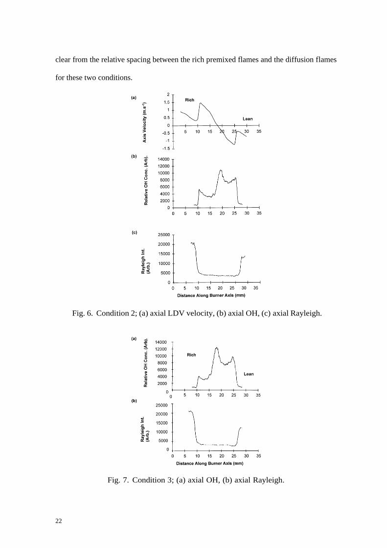
clear from the relative spacing between the rich premixed flames and the diffusion flames
for these two conditions.
Fig. 6. Condition 2; (a) axial LDV velocity, (b) axial OH, (c) axial Rayleigh.
Fig. 7. Condition 3; (a) axial OH, (b) axial Rayleigh.
23
3.3: Rayleigh Scattering
The flame Condition 3 Rayleigh scattering profile from the lower unburned rich mixture
was used to standardise the other profiles. The equivalence ratio of this mixture was =
1.51, and the mixture temperature was taken as 293K, the measured upstream air and
methane temperature.
The difference between the Rayleigh scattering intensity on the rich and lean sides is due to
two factors. The first, and most obvious, is the difference in the equivalence ratios for the
rich and lean mixtures, causing a larger weighted Rayleigh scattering cross section on the
rich side. The second factor, and most important, is the elevated temperature of the upper
flow. The upper burner is radiatively heated from a burner protection plate. Even though
the upper burner was water cooled, the gas mixture passing through the upper burner
nozzle was still heated to around 360 K.
Comparing the Rayleigh scattering intensities from flame Condition 1 (figure 5) and flame
Condition 2 (figure 6) suggests that the unburned lean mixture from Condition 1 is slightly
cooler than the unburned mixture from Condition 2. Assuming similar combustion
products for these two conditions, the flame temperatures appear to be very similar for
these two flames. The combustion enthalpy is clearly larger for lean flame Condition 2
than for lean flame Condition 1, as indicated by the velocity profiles in figures 5 and 6,
however this is balanced by a higher axial strain rate which will act to lower the flame
temperature.
24
Using figures 6 and 7 to compare the Rayleigh scattering intensities from flame Condition
2 with flame Condition 3 reveals that the Condition 3 flame has a significantly higher
temperature than the Condition 2 flame. This can be seen from the ratio of the Rayleigh
scattering intensities in the two flame zones. In this case, the lower Rayleigh scattering
intensity is indicative of a smaller number density, and thus a larger flame temperature.
As stated earlier, the Rayleigh scattering profile for flame Condition 1 is incomplete in that
the laser sheet was not quite wide enough to include the unburned rich mixture.
3.4: 1-D LDV
The counter-flow burner was designed to produce plug flow at the exit of the burner
nozzles, for a gas flow from the nozzles into a stationary gas medium. However, when
two such flows oppose each other, the plug flow from each nozzle is altered. Figures 8
and 9 show axial velocity measurements performed 4 mm above the lower nozzle and 5
mm below the upper nozzle for “triple flame” Conditions 1 and 2 respectively. The
nozzle exit velocities are a minimum in the centre of the nozzle, and slowly increase to a
maximum just inside the nozzle edge. The measurements performed in this study are
consistent with those performed by Rolon et al [14].
The deviation from plug flow is the consequence of the decrease in the axial velocity
gradient with radius from the centre of the burner nozzles. The axial velocity gradient
produces a small back pressure at the nozzle exit; and the greater the magnitude of the axial
velocity gradient, the greater the back pressure generated in the flow. Therefore, a

25
radially dependent back pressure gradient is generated across the nozzle. This back
pressure gradient causes the flow velocity profile at the nozzle exit to deviate from plug
flow to that shown in Rolon et al [14], as demonstrated by figures 8 and 9. Clearly any
numerical flame model attempting to reproduce this flame data should take account of this
effect.
Fig. 8. Axial nozzle exit velocity as a function of radial distance across burner
nozzles for flow condition 1. Upper curve is for the upper nozzle and lower curve
for the lower nozzle. Downward velocities are arbitrarily defined as positive for
both curves.
Fig. 9. Nozzle exit velocity as a function of radial distance across burner nozzle:
condition 2. Upper curve is for upper nozzle and lower curve for lower nozzle.
Downward veloc- ities are arbitrarily defined as positive for both curves.
26
The velocity measurements for flame Conditions 1 and 2 (velocity profiles in figures 6 and
7 respectively) show that the flow was laminar with a measured standard deviation of less
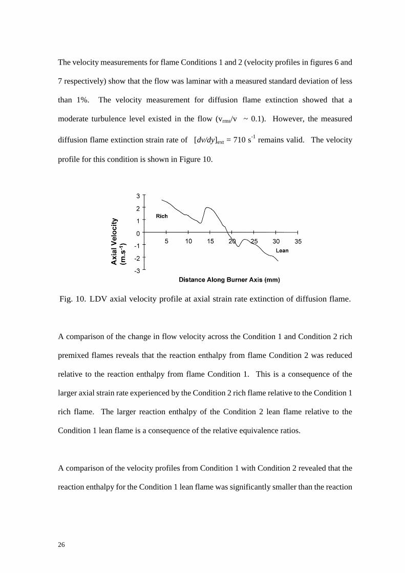
than 1%. The velocity measurement for diffusion flame extinction showed that a
moderate turbulence level existed in the flow (vrms/v ~ 0.1). However, the measured
diffusion flame extinction strain rate of [dv/dy]ext = 710 s-1
remains valid. The velocity
profile for this condition is shown in Figure 10.
Fig. 10. LDV axial velocity profile at axial strain rate extinction of diffusion flame.
A comparison of the change in flow velocity across the Condition 1 and Condition 2 rich
premixed flames reveals that the reaction enthalpy from flame Condition 2 was reduced
relative to the reaction enthalpy from flame Condition 1. This is a consequence of the
larger axial strain rate experienced by the Condition 2 rich flame relative to the Condition 1
rich flame. The larger reaction enthalpy of the Condition 2 lean flame relative to the
Condition 1 lean flame is a consequence of the relative equivalence ratios.
A comparison of the velocity profiles from Condition 1 with Condition 2 revealed that the
reaction enthalpy for the Condition 1 lean flame was significantly smaller than the reaction

27
enthalpy for the Condition 1 rich flame. The consequence of this was a shift of the
stagnation plane towards the lean flame.
4. The Turbulent Double/Triple Flame
Large nozzle exit velocities cause large strain rates in the flow field. Large local axial
strain rate flows (dv/dy > 710 s-1
) are sufficient to quench the CO/hydrogen diffusion
flame, and thus the partially premixed counter-flow flame exhibits a “double flame”
structure. The extinction of the diffusion flame occurs as a consequence of the effect of
rate of increase of flame surface area dominating the rate of molecular diffusion across the
stagnation plane. The cooling of reaction products due to flame stretch causes the reactive
gas temperature to drop below the critical temperature required to sustain the flame. If
there is turbulence present, and if the nozzle exit velocity is lowered, the critical local axial
strain rate is reached which will allow the existence of the diffusion flame, and a transition
occurs from a turbulent “thick double flame” to a turbulent “triple flame”.
5. Conclusion
1. Qualitative OH concentration profiles have been obtained along the symmetry axis of an
axially symmetric laminar counter-flowing methane-air partially premixed “triple flame”.
They show the three principal oxidation regions as local peaks in OH concentration.
2. Premixed and diffusion flame merging limits have been determined as a function of
mean axial flow strain rate, along with the conditions for the existence of the diffusion

28
flame. The conditions define the stability map for the laminar counter-flowing
methane-air “triple flame”.
3. It has proven possible to construct a two-dimensional triple flame stability map with
equivalence ratio ϕ, plotted against global strain rate a.
4. Relative quantitative OH concentration profiles and Rayleigh scattering profiles have
been obtained for three “triple flame” conditions. 1-D LDV measurements of the radial
and axial velocity profiles have been obtained for two of the three “triple flame”
conditions.
5. The counter-flow “triple flame” is significantly more sensitive to rich flame
stoichiometry than the lean flame stoichiometry, and it is also sensitive to axial strain.
6. The diffusion flame extinction axial strain rate has been measured to be [dv/dy]ext =
710s-1
, using 1-D LDV.
7. The transition from highly strained partially premixed turbulent “double flames” to
partially premixed “triple flames” at lower turbulence levels has been shown to be caused
by the local axial strain rate allowing the existence of the CO/hydrogen diffusion flame.

29
Acknowledgements
This work was undertaken with funding from the EPSRC (GR/G 57543). The authors
would also like to thank Dr R. Hicks of Leeds University for his assistance with the LDV
measurements and Prof. K.N.C. Bray with advice on the burner design and the seeding
system for the LDV measurements.
References
[1] I. Yamaoka, H. Tsuji, “An Experimental Study of Flammability Limits Using
Counter-flow Flames”, Nineteenth Symposium (International) on Combustion, pp. 843 –
855, The Combustion Institute, 1982
[2] K. Seshadri, I.Puri, N.Peters, “Experimental and Theoretical Investigation of Partially
Premixed Diffusion Flames at Extinction”, Combustion and Flame 61: pp. 237 – 249, 1985
[3] T.H. Lin, S.H. Sohrab, “On the Transition of Diffusion to Premixed Flames in
Conserved Systems”, Combustion and Flame 68: pp. 73 – 79, 1987
[4] M.A. Tanoff, M.D. Smooke, R.J. Osborne, T.M. Brown, R.W. Pitz, “The Sensitive
Structure of Partially Premixed Methane-Air vs. Air Counterflow Flames”, Twenty-Sixth
Symposium (International) on Combustion, pp. 1121 – 1128, The Combustion Institute,
1996

30
[5] P.N. Kioni, B. Rogg, K.N.C. Bray, A. Linan, “Flame Spread in Laminar Mixing
Layers: The Triple Flame”, Combustion and Flame 95: pp 276 - 290 (1993)
[6] D. Veynante, L. Vervisch, T. Poisot, A. Linan, “Triple Flame Structure in Diffusion
Flame Stabilisation”, CTR Proceedings of Summer Programme, pp.55 - 73 (1994)
[7] G. Dixon-Lewis, “Structure of Laminar Flames”, Twenty-Third Symposium
(International) on Combustion, pp. 305 – 324, The Combustion Institute, 1990
[8] R.J. Kee, J.A. Miller, G.H. Evans, G. Dixon-Lewis, “A Computational Model of the
Structure and Extinction of Strained, Opposed Flow, Premixed Methane-Air Flames”,
Twenty-Second Symposium (International) on Combustion, pp. 1479 – 1494, The
Combustion Institute, 1988
[9] C.K. Law, D.L. Zhu, G. Yu, “Propagation and Extinction of Stretched Premixed
Flames”, Twenty-First Symposium (International) on Combustion, pp. 1419 – 1426, The
Combustion Institute, 1986
[10] F.N. Egolfopoulos, P. Cho, C.K. Law, “Laminar Flame Speeds of Methane-Air
Mixtures Under Reduced and Elevated Pressures”, Combustion and Flame 76: pp. 375 –
391, 1989
31
[11] S. Ishizuka, C.K. Law, “An Experimental Study on Extinction and Stability of
Stretched Premixed Flames”, Nineteenth Symposium (International) on Combustion, pp.
327 – 335, The Combustion Institute, 1982
[12] M.D. Smooke, J. Crump, K. Seshadri, V. Giovangigli, “Comparison Between
Experimental Measurements and Numerical Calculations of the Structure of Counterflow,
Diluted, Methane-Air, Premixed Flames”, Twenty-Third Symposium (International) on
Combustion, pp. 463 – 470, The Combustion Institute, 1990
[13] A.C. Eckbreth, “Laser Diagnostics for Combustion Temperature and Species”,Abacus
Press, Cambridge, 1988
[14] J.C. Rolon, D. Veynante, J.P. Martin, “Counter jet stagnation flows”, Experiments in
Fluids, v11, pp. 1 – 12, Springer Verlag, 1991


