Embed Size (px)
Citation preview

The Robotic Endo-Laryngeal Flexible (Robo-ELF) Scope System

Table of Contents Executive Summary ....................................................................................................................................... 3
Risk Assessment ............................................................................................................................................ 4
Background ................................................................................................................................................... 5
System Description ....................................................................................................................................... 6
System Overview ...................................................................................................................................... 6
System Hardware Description .................................................................................................................. 7
Robot ..................................................................................................................................................... 7
Main Enclosure ..................................................................................................................................... 8
Elbow Joint ............................................................................................................................................ 8
Rotation Stage Enclosure ...................................................................................................................... 9
Scope Holder Enclosure ........................................................................................................................ 9
Passive Positioning Arm ...................................................................................................................... 10
Joystick System ................................................................................................................................... 11
Electronics Enclosure .......................................................................................................................... 12
System Software ..................................................................................................................................... 14
OR Compatibility ..................................................................................................................................... 15
Safety Systems and Procedures .............................................................................................................. 16
Testing and Evaluation ................................................................................................................................ 18
FMEA ....................................................................................................................................................... 18
Formal Testing ........................................................................................................................................ 18
Clinical Studies ........................................................................................................................................ 18
References .................................................................................................................................................. 19

Executive Summary
The Robotic Endo-Laryngeal Scope (Robo-ELF Scope) is a robotic system for the manipulation of unmodified clinical flexible endoscopes (Fig 1). It is designed to improve precision, coordination, ergonomics, and surgical capabilities when using flexible endoscopes in the operating room for visualization of the upper airway. The system includes a robot which is mounted to the rail of the operating table with a passive positioning arm, a joystick controller, a standard clinical flexible endoscope, an electronics enclosure, sanitary drapes, and a control PC. The robot is slow moving with limited range of motion, and incorporates several redundant layers of hardware, electronic, and software safety features (see Safety Systems and Procedures section). The tip and shaft of the endoscope, which is already approved for clinical use, are the only parts of the system that contact the patient. The highly flexible and compliant nature of the endoscope tip and shaft, and the insensitivity of upper airway tissues to the small forces involved, further reduce the risk to the patient. The Robo-ELF Scope has been tested in both phantoms and cadavers with positive results.
Figure 1: Left) The Robo-ELF Scope system. Right) The Robo-ELF Scope system in an artificial airway phantom.

Risk Assessment
When used for visualization tasks in the upper airway, the Robo-ELF Scope system poses minimal risk to patients. The endoscope, which is already used clinically, is the only part of the system that contacts the patient. Since the endoscope tip and shaft are flexible and highly compliant, it is unlikely that any plausible manipulation of the endoscope body could cause damage in the upper airway. Similar visualization procedures are frequently done using identical manually manipulated endoscopes in humans. In terms of cross contamination, the Robo-ELF Scope is functionally equivalent to an operating room microscope in that it does not contact the patient, is draped with sterile drapes for procedures, and it manipulated by surgeons through the drapes.
The Robo-ELF Scope has a very limited range of motion, and software limited to move at very slow speeds (Table 1). The system also includes numerous mechanical, electrical, and software safety systems to prevent any unintended scope movements from occurring. Careful grounding, fuses, an isolated power supply, careful sealing of the system, and the use of only +/-12V or less outside of the AC/DC converter ensure electrical safety. Adjustable locking joints with gravity compensation ensure that the system can be quickly removed in case of an emergency, while simultaneously preventing any unintentional movement. The entire system except for the endoscope itself is sealed with sterile drapes during operation, preventing cross contamination. The Robo-ELF Scope has been tested in human cadavers and in an airway phantom performing visualization tasks, with successful results and no apparent safety issues. A Failure Modes and Effects Analysis (FMEA) was conducted, and a testing and validation plan to verify the detection and control functionality claimed in the FMEA was carried out (see FMEA/Test Plan document).
Scope Handle Manipulation (Joint A)
Scope Rotation (Joint B) Scope Translation (Joint C)
Range of motion 60 degrees 270 degrees 100 mm
Maximum Speed 10 degrees per second 20 degrees per second 7 mm per second
Table 1: Joint speeds and ranges of motion for Robo-ELF Scope.

Background
There has recently been a significant movement in laryngeal surgery toward minimally invasive transoral techniques. A range of novel instrumentation including telescopes, microscopes, lasers, and microsurgical instruments has been developed to facilitate visualization and manipulation of the larynx through the mouth. However, while current techniques in transoral endoscopic surgery reduce the risk of complications encountered with classic open approaches such as scarring and infection, there remain significant challenges, particularly poor sensory feedback, reduced visibility, limited working area, and increased hand tremor due to long instruments [1]. Several robotic surgical systems, most notably the da Vinci robot (Intuitive Surgical, Inc.) have sought to remedy these problems in other surgical venues. The da Vinci was designed primarily for robotic laparoscopic surgery, in which instrument position and orientation simulate the normal hand position of a surgeon, with widely-spaced instruments. This configuration precludes parallel placement of closely spaced instrumentation, which is necessary in transoral laryngeal surgery. Although the daVinci has been reported for endolaryngeal surgery in select patents with favorable anatomy [2, 3], there is currently no robotic device available for general laryngeal procedures [4]. Therefore, the current state of the art in laryngeal surgery continues to utilize hand-held rigid endoscopes and microscopes to optimally view the endolarynx.
Flexible scopes are frequently used in the clinic for diagnostic purposes with an increasing breadth of therapeutic procedures being introduced. These endoscopes are very advanced, offering HD video, working ports, high range of motion tips, and full sterilizability. Although these endoscopes offer a wide array of functionality, the primary limitation is the requirement for bimanual control. In a typical procedure, one surgeon holds and actuates the endoscope, which requires both hands, while another uses instruments such as forceps and a laser to manipulate and ablate tissue. This may lead to a crowded working environment with cumbersome endoscopic control. Coordination between the two surgeons can be difficult and supporting and actuating the endoscope for long periods of time can result in fatigue and inaccuracy [5]. For these reasons flexible endoscopes have remained primarily for use in awake patients in clinic and have found limited roles for laryngeal procedures in the operating room.
Several groups have reported development of robotic actuation for the tip of flexible endoscopes. For example, Reilink et al. [6] combine computer vision techniques with robotic tip actuation for a hand-manipulated colonoscope. Although this assists the colonoscopist in controlling the view and advancing the endoscope, it still requires manual manipulation of the scope itself. Similarly, Eckl et al. [5] partially actuate a flexible endoscope for diagnostic use in the nasal cavity. This approach uses a two degree-of-freedom hand-held manipulator which controls scope rotation and tip angle, but not translation, which is left for the surgeon to control manually. This system is small and simple, but since the scope is not completely robotically controlled, its benefits during surgery are reduced. At the other extreme, a number of groups (e.g., [7-11]) have reported development of very sophisticated robotic systems for natural orifice surgery, providing bimanual telemanipulation of robotic arms and cameras at the end of flexible endoscopes. These systems, which are in various stages of development, tend to be complex and expensive. In the current project, we have sought to develop a low-cost, easily deployed robot to drive a flexible scope for use in the operating room in order to overcome some of the current limitations of transoral laryngeal surgery.

System Description
System Overview
The Robotic Endo-Laryngeal Flexible Scope (Robo-ELF Scope) is a small, inexpensive robot that takes full advantage of existing clinical equipment with the goal of using this technology in the operating room on anesthetized patients. It was designed to hold and actuate a clinical endoscope, allowing the surgeon to control the scope with one hand using a custom joystick console thereby freeing the other hand to operate, or to position the scope using the robot and operate bimanually. The Pentax VNL-1570STK (Pentax Corporation, Golden, CO) flexible laryngoscope has been used with the system.
Surgeons typically use three degrees of freedom when manipulating flexible endoscopes: bending of the scope’s tip using the scope handle, rotation of the scope about its axis, and translation of the scope along the axis of the airway. These are the degrees of freedom that the Robo-ELF Scope was designed to actively control. To aid in positioning and removal of the scope, two passive lockable degrees of freedom were added to the robot, as well as a five-degree-of-freedom passive positioning arm (Fig 2). The power system and motor controllers are housed in an electronics enclosure separate from the robot itself, connected by a watertight cable and connectors. The system is controlled using a custom joystick interface which mounts to the rail of the operating table. A PC is used to interface to the motor controller through Ethernet. Numerous redundant hardware and software safety features have been incorporated to ensure that no single fault in the system can result in patient injury (see Safety Systems and Procedures section).
Figure 2: A) Passive positioning arm. B) Robotic scope manipulator with three active degrees of freedom. C) Joystick controller. D) Control PC. E) Electronics enclosure. F) Endoscope Video Processor.

System Hardware Description
Robot
The center of the Robo-ELF Scope system is its robotic scope manipulator (Fig 3). The robot has three active degrees of freedom: manipulation of the scope tip (joint A), rotation of the scope about its axis (joint B), and translation of the scope in and out of the patient (joint C). The robot also has two locking passive degrees of freedom, acting as an elbow and a wrist, which are controlled via shaft collars with large knobs. The scope is held by an adjustable plastic scope holder which, along with the rest of the robot, is completely covered by a sterile drape. The scope is attached by taping it onto the scope holder outside the drape with surgical cloth tape.
Figure 3: Robotic Scope Manipulator Degrees of Freedom. A) Scope tip manipulation joint. B) Scope rotation joint. C) Insertion/extraction joint.
To minimize weight over the patient the system was designed so that the largest motors for the scope translation and rotation degrees of freedom are located in the main enclosure. To transmit power from the main enclosure to the scope rotation joint a cable-pulley mechanism was used. Twelve volt DC servo motors with planetary gearheads and integrated magnetic encoders controlled all active degrees of freedom. Potentiometers were installed on each active degree of freedom for added safety. Motor control is achieved using a Galil DMC-4030 (Galil Motion Control Inc., Rocklin, CA) with built-in 1A linear amplifiers. Potentiometer signals are buffered and lowpass filtered before digitalization using the Galil controller’s built-in analog/digital conversion.
Both active and passive robot joints are sealed with corrosion resistant sealed bearings, O-rings, or bellows, allowing the robot to remain fully watertight even when in motion. The electrical connection to the robot is achieved using a Soriau corrosion resistant waterproof electrical connector. All compartment covers are sealed with O-rings.

Main Enclosure
The main enclosure consists of a wash-down rated NEMA fiberglass enclosure with an O-ring sealed bolt-on cover and re-enforced mounting holes (Fig 4). The main enclosure houses the entire mechanism for joint C, as well as the motor for joint B. The joint B motor, which is the largest of the system’s three motors, was placed in the main box in order to avoid enlarging (and thus increasing the weight) other enclosures that are nearer to the patient. The motion from the joint B motor is transmitted to the rotation stage enclosure using two aircraft grade Bowden cables actuated by a pulley. Joint C is implemented as a DC servo motor with a planetary gearhead and integrated magnetic encoder driving a lead screw via a timing belt. The lead screw acts on a lead nut attached to a linear motion slide. Forward and reverse limit switches are mounted on the slide, and triggered by the enclosure walls when the slide nears the end of its approximately 100mm range of motion. A linear potentiometer is also actuated by the slide, which in addition to the motor’s integrated magnetic encoder provides redundant sensing for additional safety. The robot arm’s hollow shaft enters the main box through an O-ring sealed mounting flange, and attaches to the linear motion slide. The exterior of the flange mates with an FDA grade rubber bellows, forming a water-tight seal around the arm while still allowing it to translate in and out.
All electrical connections to the main box pass through a single Souriau 35 pin watertight connector, which ensures a water-tight seal. Electrical connections either pass directly to components in the main box, or pass through a circuit board on the main box mounting plate. The remaining electrical connections which connect to components in subsequent enclosures pass through the robot arm’s hollow shaft along with the Bowden cables.
Figure 4: Main Enclosure Interior
Elbow Joint
The robot arm’s shaft emerges from the main enclosure and threads into the elbow joint (Fig 5). This joint allows the robot arm to swing away from the patient in case of emergency. The arm is held stationary by a shaft collar, which is tightened by a large knob. In order to prevent the arm from falling under the force of gravity when the collar is loosened, a high strength nylon two piece collar also grips
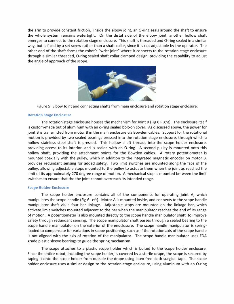
the arm to provide constant friction. Inside the elbow joint, an O-ring seals around the shaft to ensure the whole system remains watertight. On the distal side of the elbow joint, another hollow shaft emerges to connect to the rotation stage enclosure. This shaft is threaded and O-ring sealed in a similar way, but is fixed by a set screw rather than a shaft collar, since it is not adjustable by the operator. The other end of the shaft forms the robot’s “wrist joint” where it connects to the rotation stage enclosure through a similar threaded, O-ring sealed shaft collar clamped design, providing the capability to adjust the angle of approach of the scope.
Figure 5: Elbow Joint and connecting shafts from main enclosure and rotation stage enclosure.
Rotation Stage Enclosure
The rotation stage enclosure houses the mechanism for Joint B (Fig 6 Right). The enclosure itself is custom-made out of aluminum with an o-ring sealed bolt-on cover. As discussed above, the power for joint B is transmitted from motor B in the main enclosure via Bowden cables. Support for the rotational motion is provided by two sealed bearings pressed into the rotation stage enclosure, through which a hollow stainless steel shaft is pressed. This hollow shaft threads into the scope holder enclosure, providing access to its interior, and is sealed with an O-ring. A second pulley is mounted onto this hollow shaft, providing the attachment points for the Bowden cables. A rotary potentiometer is mounted coaxially with the pulley, which in addition to the integrated magnetic encoder on motor B, provides redundant sensing for added safety. Two limit switches are mounted along the face of the pulley, allowing adjustable stops mounted to the pulley to actuate them when the joint as reached the limit of its approximately 270 degree range of motion. A mechanical stop is mounted between the limit switches to ensure that the the joint cannot overreach its intended range.
Scope Holder Enclosure
The scope holder enclosure contains all of the components for operating joint A, which manipulates the scope handle (Fig 6 Left). Motor A is mounted inside, and connects to the scope handle manipulator shaft via a four bar linkage. Adjustable stops are mounted on the linkage bar, which activate limit switches mounted adjacent to the bar when the manipulator reaches the end of its range of motion. A potentiometer is also mounted directly to the scope handle manipulator shaft to improve safety through redundant sensing. The scope manipulator shaft passes through a sealed bearing to the scope handle manipulator on the exterior of the endclosure. The scope handle manipulator is spring-loaded to compensate for variations in scope positioning, such as if the rotation axis of the scope handle is not aligned with the axis of rotation of the manipulator. The scope handle manipulator uses FDA grade plastic sleeve bearings to guide the spring mechanism.
The scope attaches to a plastic scope holder which is bolted to the scope holder enclosure. Since the entire robot, including the scope holder, is covered by a sterile drape, the scope is secured by taping it onto the scope holder from outside the drape using latex free cloth surgical tape. The scope holder enclosure uses a similar design to the rotation stage enclosure, using aluminum with an O-ring

sealed bolt-on cover. The scope holder is made of soft plastic which will prevent marring the scope handle.
Figure 6: Left) Scope holder enclosure. Right) Rotation stage enclosure.
Passive Positioning Arm
The robot is fixed to the operating table rail using a five degree of freedom passive positioning arm (Fig 7). The five degrees of freedom provided are X, Y, and Z translation of the robot, as well as rotation of the robot about horizontal and vertical axes. The main components of the passive positioning arm are: a support arm gripper which fixes the whole system to the operating table rail, a threaded height adjustment shaft with a hand nut for setting the robot’s height, a support arm joint which clamps onto the height adjustment shaft, a horizontal slider joint which mounts on the support block and supports a square shaft with plastic plane bearings, a robot attachment block with allows the robot to be separated from the support arm, an L beam which mounts onto the square shaft with a shaft collar mechanism allowing a yaw rotation, and a robot mounting plate which attaches the robot main enclosure to the L beam with a shaft collar mechanism, allowing a tilt rotation. The robot itself also has two passive degrees of freedom, an elbow joint which allows the arm to be swung up, and a wrist joint which allows adjustment of the scope angle.
The arm attaches to the operating table rail using a screw-driven clamp which is operated via a large knob. The clamp jaw motion is guided by two shoulder bolts passing through food grade bushings. The height adjustment shaft is threaded into the top of the clamp and locked with two set screws. The height of the robot is determined by a large knurled hand nut which can be positioned anywhere along the threaded height adjustment shaft. The nut supports a mounting block which clamps the shaft using a screw-driven shaft-collar mechanism actuated by a large knob. An FDA grade PTFE thrust bearing prevents the hand nut from rubbing on the mounting block. The mounting block supports a square plane bearing assembly, which houses a square shaft, allowing the robot to translate toward and away from the patient. The square shaft can be clamped in place by a screw-driven clamp mounted in the support block and manipulated with a large knob.

The square shaft supports a screw-driven attachment joint which supports an L beam via a vertical shaft, which is clamped by a shaft collar assembly on the L beam. The joint parts are prevented from rubbing by two PTFE thrust bearings, and can be locked by turning a large knob which drives the shaft collar. The other end of the L beam supports the robot mounting plate through another shaft collar assembly. Without support, this joint would move due to gravity when the shaft collar is loosened, so a high strength nylon friction collar maintains constant friction to counteract gravity. This joint is similarly supported by two PTFE thrust bearings, and can be locked using a large knob which drives the shaft collar. The mounting plate is bolted to the robot’s main enclosure using the enclosure’s built-in mounting holes.
Figure 7: Passive Positioning Arm. A) Wrist joint. B) Elbow joint. C) Tilt joint. D) Yaw joint. E) Slider joint. F) Support arm joint. G) Heigh adtjustmetn joint. H) Robot attachment knob. I) Robot support
arm gripper.
Joystick System
The joystick system provides the surgeon with two joysticks, which together provide control over the Robo-ELF’s three active degrees of freedom (Fig 8). The joystick enclosure also houses the system’s emergency shutoff button, and PC controlled safety shutoff relay, both of which can directly cut power to the motors in the event of an emergency. The enclosure mounts to the operating table rail using an adjustable arm, which prevents it from sliding and eliminates the possibility of it being dropped, which could potentially send false commands to the robot.
The enclosure itself is a NEMA polycarbonate enclosure with an O-ring sealed bolt-on cover. All electrical connections to the enclosure are made either through water-tight cable glands, or a water-tight USB connector. The enclosure bolts onto an aluminum mounting plate through its built-in mounting holes. The mounting plate is supported by an anodized aluminum support arm, which in turn mounts to an operating table rail clamp. The support arm can be locked using a single plastic knob.
The joysticks themselves are watertight sealed industrial control joysticks which pass through the top of the enclosure. One of the joysticks is four-position, and the other is two-position, providing a total of three forward and reverse degrees of freedom. Each joystick position controls two independent SPST switches, switching between 3.3V and ground, resulting in twelve independent signals. The 3.3V, ground, and joystick signals pass through a sealed cable gland and terminate at the Galil controller extended IO port (See Electrical Schematic). The Galil controller reads these signals and passes the
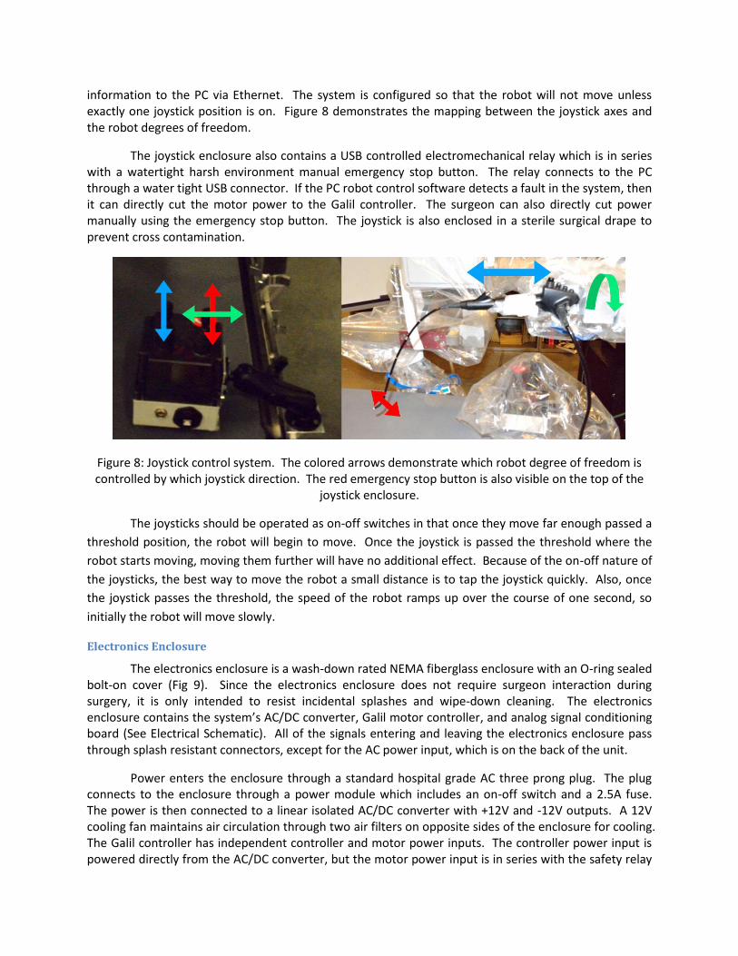
information to the PC via Ethernet. The system is configured so that the robot will not move unless exactly one joystick position is on. Figure 8 demonstrates the mapping between the joystick axes and the robot degrees of freedom.
The joystick enclosure also contains a USB controlled electromechanical relay which is in series with a watertight harsh environment manual emergency stop button. The relay connects to the PC through a water tight USB connector. If the PC robot control software detects a fault in the system, then it can directly cut the motor power to the Galil controller. The surgeon can also directly cut power manually using the emergency stop button. The joystick is also enclosed in a sterile surgical drape to prevent cross contamination.
Figure 8: Joystick control system. The colored arrows demonstrate which robot degree of freedom is controlled by which joystick direction. The red emergency stop button is also visible on the top of the
joystick enclosure.
The joysticks should be operated as on-off switches in that once they move far enough passed a
threshold position, the robot will begin to move. Once the joystick is passed the threshold where the
robot starts moving, moving them further will have no additional effect. Because of the on-off nature of
the joysticks, the best way to move the robot a small distance is to tap the joystick quickly. Also, once
the joystick passes the threshold, the speed of the robot ramps up over the course of one second, so
initially the robot will move slowly.
Electronics Enclosure
The electronics enclosure is a wash-down rated NEMA fiberglass enclosure with an O-ring sealed bolt-on cover (Fig 9). Since the electronics enclosure does not require surgeon interaction during surgery, it is only intended to resist incidental splashes and wipe-down cleaning. The electronics enclosure contains the system’s AC/DC converter, Galil motor controller, and analog signal conditioning board (See Electrical Schematic). All of the signals entering and leaving the electronics enclosure pass through splash resistant connectors, except for the AC power input, which is on the back of the unit.
Power enters the enclosure through a standard hospital grade AC three prong plug. The plug connects to the enclosure through a power module which includes an on-off switch and a 2.5A fuse. The power is then connected to a linear isolated AC/DC converter with +12V and -12V outputs. A 12V cooling fan maintains air circulation through two air filters on opposite sides of the enclosure for cooling. The Galil controller has independent controller and motor power inputs. The controller power input is powered directly from the AC/DC converter, but the motor power input is in series with the safety relay

and manual emergency stop button in the joystick enclosure. This ensures that both the surgeon and the PC can cut the power to the motors even if the Galil is not functioning properly. Earth ground is connected to the chassis of the AC/DC converter and Galil controller. Earth ground also passes through the Souriau connector into the robot’s main enclosure, where it connects to the robot chassis.
The Galil supports both A/D conversion and digital I/O, in addition to motor and encoder channels, so it is used to interface all signals between the PC and the rest of the robot. The analog potentiometer signals from the robot’s joints are buffered and low pass filtered on an analog signal conditioning board before entering the Galil’s A/D ports. Power for all of the peripheral electronics (potentiometers, signal conditioning board, limit switches) is provided by the Galil’s 5V and 3.3V outputs.
Figure 9: Electronics enclosure interior. Note: High voltage (120V) warning is for maintenance safety. System is fully grounded and enclosure is closed during normal use.

System Software
The software system for the RoboELF software provides functionality to control the RoboELF and
implement safety mechanisms.
The software interacts with the hardware of the system in several places. The PC interacts with the Galil
motor controller to gather sensor data and issue motion commands. The Galil receives information from
encoders, potentiometers, input switches and other electronic sensors. All of the data is accessible to
the PC program. The PC also interacts with the USB relay that controls the Emergency Stop switch. To
perform control of the robot, the PC program sends commands to the Galil, which implements them
using a PID control process.
Further description can be found in the software documentation.

OR Compatibility
The system is designed to be fully covered by sterile drapes. The robot is covered by an Intuitive Surgical Camera Arm Drape Ref: 420022 Ver: -02, and the joystick by a Preferred Surgical Produces Band Bag with Tape 30”x30” Ref: BB-05. These drapes have been tested with the robot (see Testing and Evaluation section). The entire system is also designed to be wash-down resistant and cleanable using Metrex Cavicide and Metrex Caviwipes. All ingress points to the robot are sealed with O-rings, bellows, sealed bearings, or watertight connectors. Only corrosion resistant non-toxic materials are used on the exterior of the system, including: aluminum, stainless steel, USDA grade PTFE based food grade grease, FDA grade rubber bellows, silicone rubber, urethane rubber, fiberglass, nylon, polyethylene, nitrite rubber, polycarbonate, and Rulon.

Safety Systems and Procedures
The Robo-ELF system incorporates several redundant layers of safety systems in hardware, electronics, and software. On start-up, the robot runs a calibration routine where it stores corresponding encoder and potentiometer values for each joint. This allows the system to check if the potentiometer and encoder values remain synchronized while the robot is running. If the values fall out of sync by greater than a pre-set threshold, then the system cuts the power to the motors and reports the error to the operator. The calibration routine also allows the robot to detect any limit switch faults, since the Galil can detect when a joint hits a mechanical stop without tripping a limit switch. Motor and encoder faults can also be detected directly by the Galil if the actual position of the motors deviates too far from the commanded position. See the Software Documentation document for more details.
The Robo-ELF also has several mechanisms to ensure electrical safety. An isolated AC/DC converter with 2.5A fuse was used to prevent power surges from endangering the patient. The AC/DC converter output is +/-12V, which powers everything else in the system, ensuring that no voltages beyond +/-12V exist outside of the AC/DC converter. The AC/DC converter, Galil controller, and robot chassis are connected to Earth ground, preventing any electrical fault from reaching an operator or patient (See Electrical Schematic).
There are several ways that both the system and the operator can respond to faults. If the operator detects a fault that the system has not caught, the system can be stopped using the manual emergency stop button on the joystick enclosures, which directly cuts the power to the motors. If the PC detects a fault, it can cut the power to the motors via the normally open USB controlled relay in the joystick enclosure. The Galil and PC also have a heartbeat function running in the background which intermittently sends messages and replies back and forth between the Galil and PC. If the PC detects that the Galil is not responding, then it can cut the motor power and alert the user. If the Galil detects that the PC is not responding, it will stop all motor movements and turn on its error LED. For additional safety, the Galil uses a position control method where small incremental position commands are sent from the PC to the Galil. If the PC drops out and stops sending position commands, and the Galil somehow does not detect it, then it will only move to the last commanded position and stop.
The joystick also includes several fault tolerance features. The robot will only move if exactly one of the joystick positions is on, which prevents inadvertent movement. The software is configured so that a joystick position is “on” when its signal is at ground, and “off” when it is at 3.3V. The Galil inputs for the joystick signals use pull-up resistors, so if any of the joystick signals is disconnected, it will automatically turn off. The joystick hardware uses two independent SPST switches for each position, adding redundancy to the joystick hardware.
There are also several ways to remove the robot and scope from the patient in case of emergency. The simplest is to remove the tape and take the scope out of the holder. This will remove the scope from the patient, but the robot arm will still be in position. To quickly get the robot arm and the scope away from the patient, the operator can unlock the elbow joint and rotate the entire arm up and away from the patient (Fig 10). If the surgeon prefers to remove the scope from the patient by sliding it out as they normally would without the robot, then the passive positioning arm’s slider assembly allows the surgeon to quickly slide the robot away from the patient, removing the scope from the patient’s mouth.

Figure 10: A) Elbow joint in normal position. B) Elbow joint with arm raised. The arm is raised by loosening the handle and flipping the arm up.
All of the procedures for using the Robo-ELF Scope, including setup, operation, takedown, and cleaning, have been documented in the User Manual. The procedures in this manual have been tested and validated (See FMEA/Test Plan document). The procedures for maintaining the system have also been formalized in a Maintenance Manual, which is to be used after every operation.
In order to prevent cross contamination, both the robot and the joystick are covered with sterile plastic drapes. In order to validate the draping procedure, the system was set up, draped, operated, then spray painted with red latex spray paint. While the paint was still wet, the drapes were removed according to the instructions in the User Manual and the system was checked for paint. No paint was found on any part of the robot or joystick. The system can also be cleaned using Metrex Cavicide and Metrex Caviwipes, which have been verified through repeated cleanings to do no damage to any part of the robot, joystick, or cables.

Testing and Evaluation
FMEA
In order to quantify the risks involved with using the Robo-ELF Scope, a Failure Mode and Effects
Analysis (FMEA) was performed, evaluating potential failures including electrical, mechanical, software,
and user error (See FMEA/Test Plan document). The FMEA was used to determine tests for failure
detection and control mechanisms to validate that the system will behave as intended.
Formal Testing
In order to validate the detection and control mechanisms in the FMEA, a formal test plan was
developed (see FMEA/Test Plan document). These tests evaluate safety systems such as encoder-
potentiometer cross checking, PC-motor controller heartbeat, friction collars, electrical safety, and
integrity of surgical drapes. All tests were passed and the system functioned as expected.
Clinical Studies
Several papers have been published detailing the results of cadaver and phantom tests of the Robo-ELF Scope [12-15]. [12] and [14] discuss the technical design of an earlier version of the Robo-ELF Scope. [13] presents a human cadaver study in which the field of view, ease of visualizing anatomical targets, and ability to perform two handed procedures were evaluated using the Robo-ELF Scope and compared to results obtained using standard rigid endoscopes. Performance was evaluated through surgeon subjective assessment. The setup for this experiment is shown in Figure 11. [15] presents a second study in human cadavers in which the Robo-ELF Scope was used by seven laryngology residents naïve to the system to visualize anatomical targets. The participants filled out an ease of use survey, and their performance was timed. All residents completed the visualization tasks in under 5 minutes, and rated the difficulty of the visualization tasks with the Robo-ELF Scope as very easy, easy, or neutral.
Figure 11: Setup for cadaver experiments.
References
[1] P. Plinkert and H. Lowenheim, "Trends and perspectives in minimally invasive surgery in
otorhinolaryngology-head and neck surgery", Laryngoscope vol. 107- 1483-1489, 1997.
[2] R. Gervacio, F. Blanco, P. Ha, J. Califano, and J. Saunders, "Transoral Robotic Surgery of the Vocal Cord", J
Laparoendosc Adv Surg Tech vol. 21- 2, pp. 157-159, Mar, 2011.
[3] P. Céruse, B. Lallemant, S. Morinière, S. Vergez, A. Benlyazid, A. Ramade, G. Buiret, and Y. Mallet
"Transoral minimally invasive robotic surgery for carcinoma of the pharynx and the larynx: a new approach",
Anticancer Drugs, vol. 22- 7, pp. 591-5, Aug, 2011.
[4] A. T. Hillel, A. Kapoor, N. Simaan, R. H. Taylor, and P. Flint, " Applications of Robotics for Laryngeal
Surgery", Otolaryngologic Clinics of North America, vol. 41- 4, pp. 781-791, August, 2008.
[5] R. Eckl, J. Gumprecht, G. Strauss, M. Hofer, A. Dietz, and T. Lueth, "Comparison of manual Steering and
Steering via Joystick of a flexible Rhino Endoscope", in 32nd Annual International Conference of the IEEE EMBS,
2010. pp. 1234-7.
[6] R. Reilink, S. Stramigioli, and S. Misra, "Image-Based Flexible Endoscope Steering", in IEEE/RSJ
International Conference on Intellitgent Robots and Systems, Taipei, Taiwan, October 18-22, 2010. pp. 2339-2344.
[7] T. Kobayashi, S. Lemoine, A. Sugawara, T. Tsuchida, T. Gotoda, I. Oda, H. Ueda, and T. Kakizoe, "A Flexible
Endoscopic Surgical System: First Report on a Conceptual Design of the System Validated by Experiments", Jpn J
Clin Oncol, vol. 35- 11, pp. 667-671, 2005.
[8] ----, "Development Of Flexible Endoscopic Surgery Robot For NOTES",
http://robot.kaist.ac.kr/?page_id=241.
[9] S. J. Phee, S. C. Low, V. A. Huynh, A. P. Kencana, Z. L. Sun, and K. Yang, "Master And Slave Transluminal
Endoscopic Robot (MASTER) for Natural Orifice Transluminal Endoscopic Surgery (NOTES)", in 31st Ann31st Annual
International Conference of the IEEE EMBS, Minneapolis, 2009. pp. 1192-1195.
[10] D. J. Abbott, C. Becke, R. I. Rothstein, and W. J. Peine, "Design of an Endoluminal NOTES Robotic System",
in IEEE/RSJ International Conference on Intelligent Robots and Systems, San Diego, Oct 29-Nov 2, 2007. pp. 410-
416.
[11] N. Suzuki, M. Hayashibe, and A. Hattori, "Development of a downsized master-slave surgical robot system
for intragastic surgery", in ICRA Surgical Robotics Workshop, Barcelona, Spain, 2005.
[12] K. Olds, A. Hilel, E. Cha, M. Curry, L. Akst, R. Taylor, and J. Richmon, "A Robotic Assistant for Trans-Oral Surgery: The Robotic Endo-Laryngeal Flexible (Robo-ELF) Scope", The Hamlyn Symposium on Medical Robotics 19-20 June, 2011.
[13] K. Olds, A. Hilel, E. Cha, M. Curry, L. Akst, R. Taylor, and J. Richmon, "Robotic Endo-Laryngeal Flexible
(Robo-ELF) Scope: A Preclinical Feasibility Study", The Laryngoscope, p. 2731-4, 2011.

[14] K. Olds, A. Hilel, J. Kriss, A. Nair, H. Kim, E. Cha, M. Curry, L. Akst, R. Yung, J. Richmon, R. Taylor. "Design of
a Robotic Assistant for Trans-Oral Surgery: The Robotic Endo-Laryngeal Flexible (Robo-ELF) Scope", Journal of
Robotic Surgery, vol. 6 issue 1 March 2012. p. 13 - 18, 2011.
[15] K. Olds, L. Akst, R. H. Taylor, J. Richmon, “Assessment of the Robotic Endolaryngeal Flexible (Robo-ELF) Scope by Novice Users” 8th International Conference on Head and Neck Cancer. July 2012.


