Embed Size (px)
Citation preview
01-02 July 2013
Low Temperature CombustionThe future of Internal Combustion Engines
Prof. Giovanni Ferrara
Con la collaborazione del Dott. Marco Ciampolini
1S&I MCI LTC – Prof. G. Ferrara
EU regulations on exhaust emissions
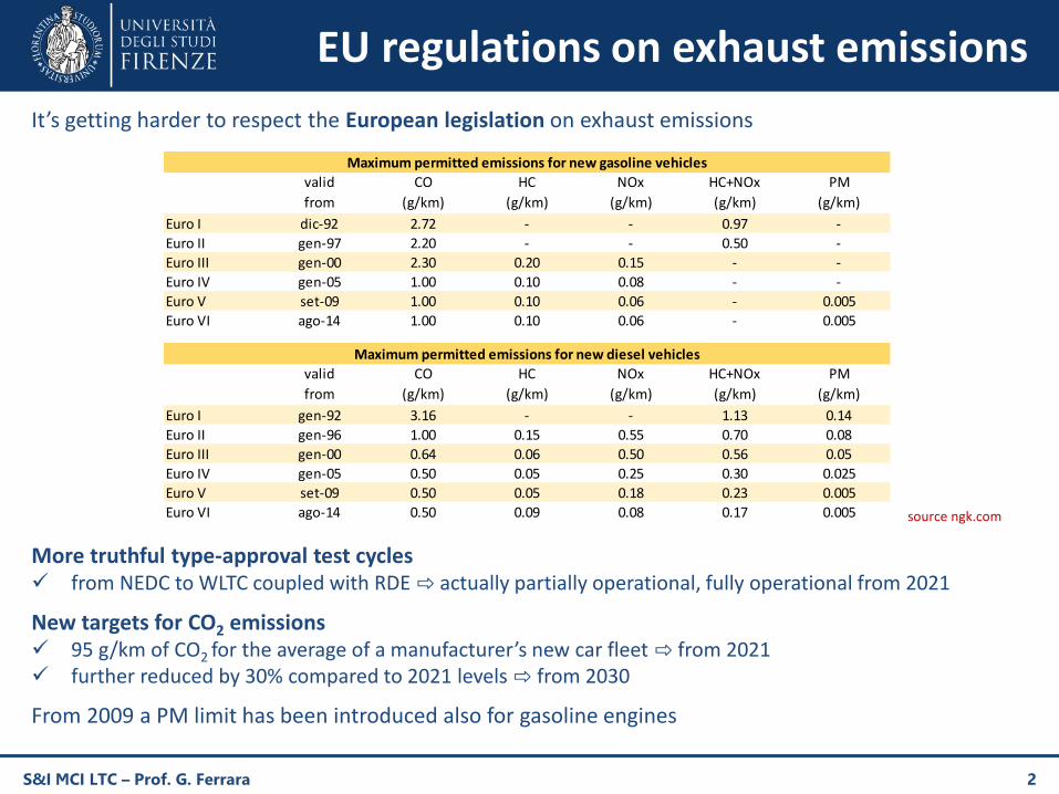
It’s getting harder to respect the European legislation on exhaust emissions
More truthful type-approval test cycles from NEDC to WLTC coupled with RDE ⇨ actually partially operational, fully operational from 2021
New targets for CO2 emissions 95 g/km of CO2 for the average of a manufacturer’s new car fleet ⇨ from 2021 further reduced by 30% compared to 2021 levels ⇨ from 2030
From 2009 a PM limit has been introduced also for gasoline engines
S&I MCI LTC – Prof. G. Ferrara 2
valid CO HC NOx HC+NOx PM
from (g/km) (g/km) (g/km) (g/km) (g/km)
Euro I dic-92 2.72 - - 0.97 -
Euro II gen-97 2.20 - - 0.50 -
Euro III gen-00 2.30 0.20 0.15 - -
Euro IV gen-05 1.00 0.10 0.08 - -
Euro V set-09 1.00 0.10 0.06 - 0.005
Euro VI ago-14 1.00 0.10 0.06 - 0.005
valid CO HC NOx HC+NOx PM
from (g/km) (g/km) (g/km) (g/km) (g/km)
Euro I gen-92 3.16 - - 1.13 0.14
Euro II gen-96 1.00 0.15 0.55 0.70 0.08
Euro III gen-00 0.64 0.06 0.50 0.56 0.05
Euro IV gen-05 0.50 0.05 0.25 0.30 0.025
Euro V set-09 0.50 0.05 0.18 0.23 0.005
Euro VI ago-14 0.50 0.09 0.08 0.17 0.005
Maximum permitted emissions for new gasoline vehicles
Maximum permitted emissions for new diesel vehicles
source ngk.com
Combustion proven technologies (1)
Conventional diesel still represents the most fuel-efficient propulsion system forpowertrain. On the other hand gasoline engines are more environmentally friendly.
Critical issues for gasoline PFI (Port Fuel Injection) engines
regulation by quantity ⇨ high pumping losses at partial loads
stoichiometric premixed combustion ⇨ high peak temperature, thus NOx emissions
slow combustion (flame front propagation)
– lower indicated positive efficiency
– CO emissions (mainly uncomplete combustion)
– HC emissions (crevices, fuel wall film, oil absorption)
fuel short-circuit
– crucial in two-stroke engines, where exhaust port closes after transfer port
detonation ⇨ it limits the compression ratio, thus lower ideal efficiency
Critical issues for diesel DI (Direct Injection) engines
heterogeneous nature of diffusive combustion
– fuel spray distribution ⇨ unavoidable PM emissions
– excess oxygen and peak pressure higher than gasoline engines ⇨ higher NOx emissions
S&I MCI LTC – Prof. G. Ferrara 3
Combustion proven technologies (2)
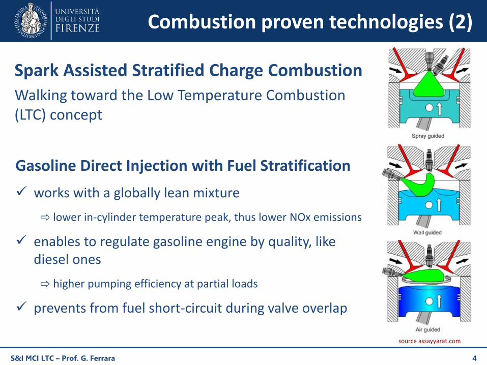
Spark Assisted Stratified Charge Combustion
Walking toward the Low Temperature Combustion (LTC) concept
S&I MCI LTC – Prof. G. Ferrara 4
Gasoline Direct Injection with Fuel Stratification
works with a globally lean mixture
⇨ lower in-cylinder temperature peak, thus lower NOx emissions
enables to regulate gasoline engine by quality, like diesel ones
⇨ higher pumping efficiency at partial loads
prevents from fuel short-circuit during valve overlap
source assayyarat.com
Combustion proven technologies (3)
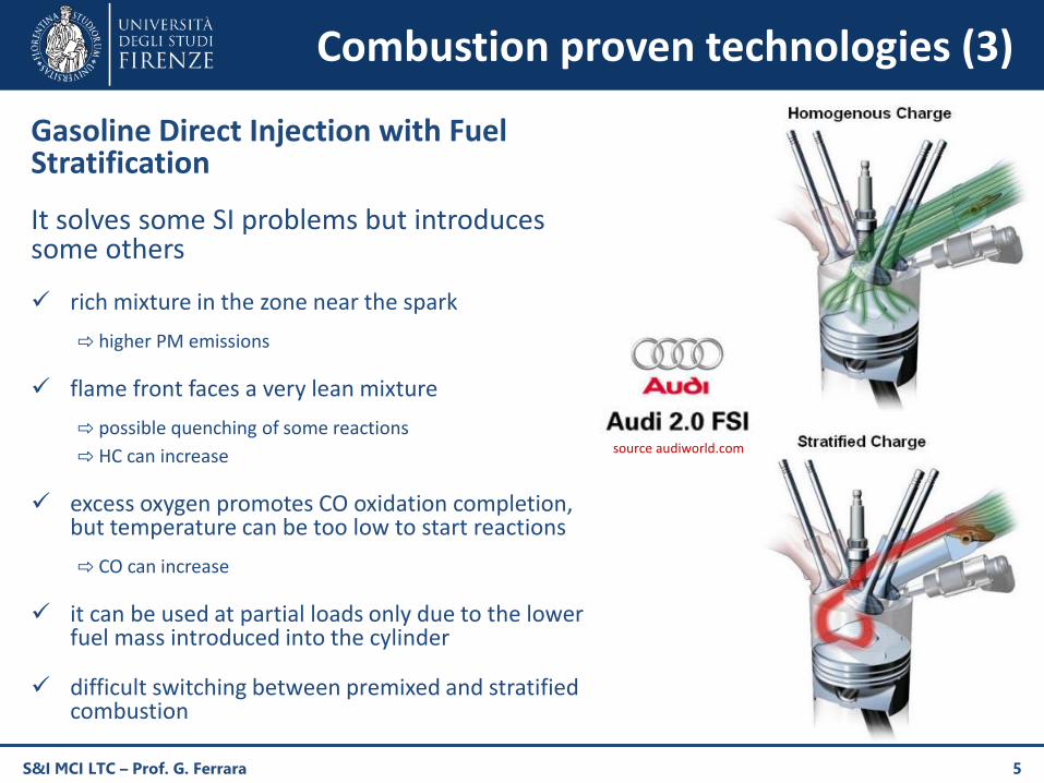
Gasoline Direct Injection with Fuel Stratification
It solves some SI problems but introduces some others
rich mixture in the zone near the spark
⇨ higher PM emissions
flame front faces a very lean mixture
⇨ possible quenching of some reactions
⇨ HC can increase
excess oxygen promotes CO oxidation completion, but temperature can be too low to start reactions
⇨ CO can increase
it can be used at partial loads only due to the lower fuel mass introduced into the cylinder
difficult switching between premixed and stratified combustion
S&I MCI LTC – Prof. G. Ferrara 5
source audiworld.com
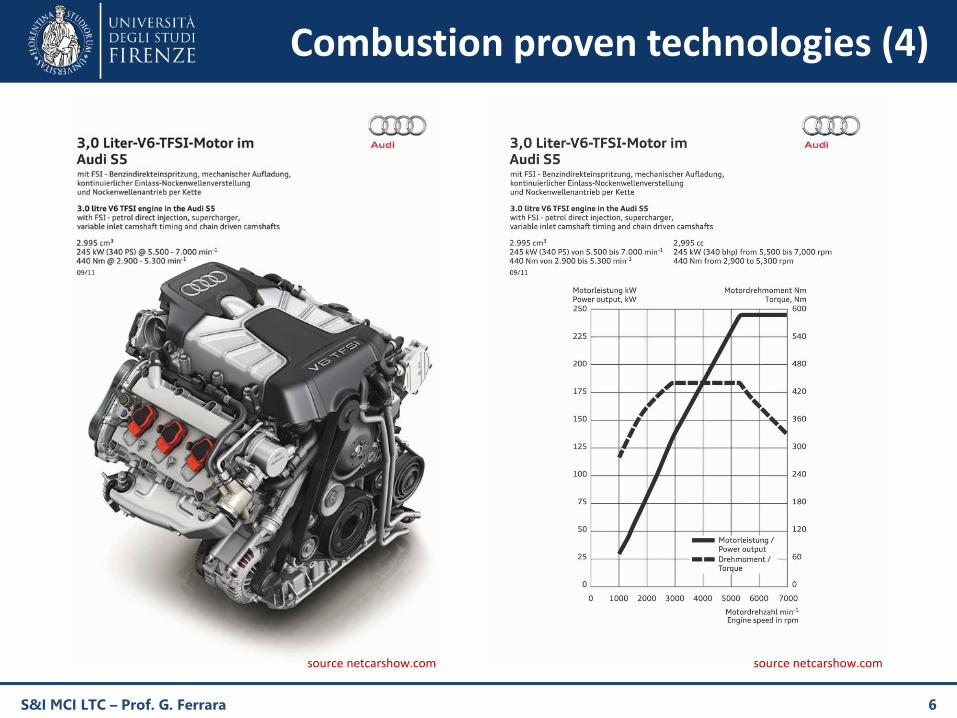
Combustion proven technologies (4)
S&I MCI LTC – Prof. G. Ferrara 6
source netcarshow.com source netcarshow.com
LTC fundamentals (1)
S&I MCI LTC – Prof. G. Ferrara 7
Diesel Combustion
SIIncomplete Combustion
Low Temperature Combustion
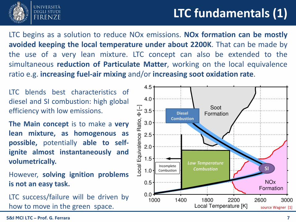
LTC begins as a solution to reduce NOx emissions. NOx formation can be mostlyavoided keeping the local temperature under about 2200K. That can be made bythe use of a very lean mixture. LTC concept can also be extended to thesimultaneous reduction of Particulate Matter, working on the local equivalenceratio e.g. increasing fuel-air mixing and/or increasing soot oxidation rate.
LTC blends best characteristics ofdiesel and SI combustion: high globalefficiency with low emissions.
The Main concept is to make a verylean mixture, as homogenous aspossible, potentially able to self-ignite almost instantaneously andvolumetrically.
However, solving ignition problemsis not an easy task.
LTC success/failure will be driven byhow to move in the green space. source Wagner [1]
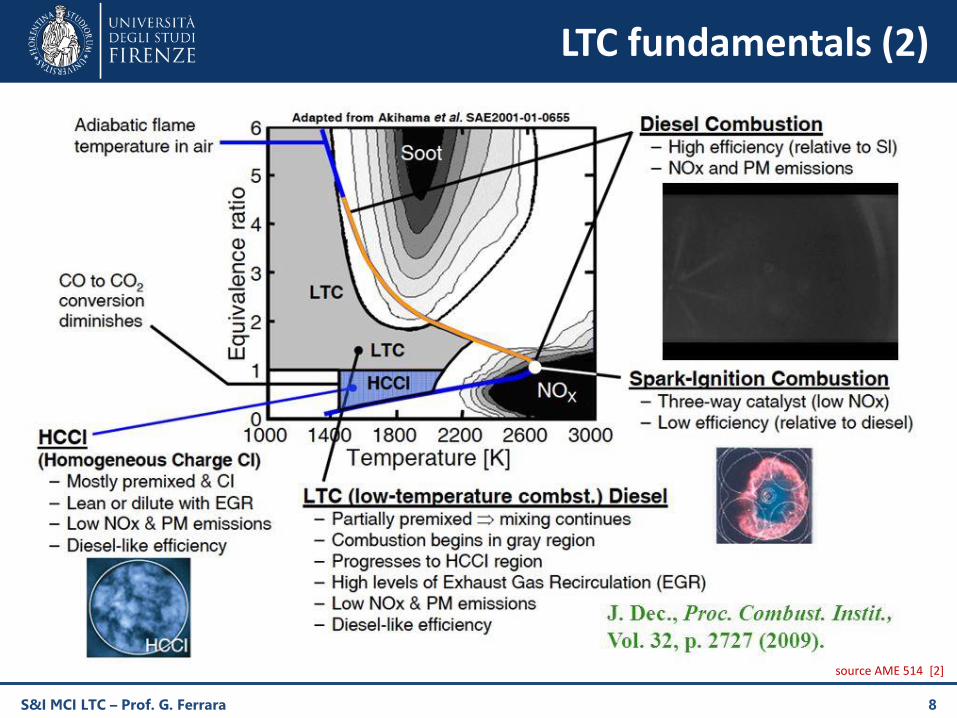
LTC fundamentals (2)
S&I MCI LTC – Prof. G. Ferrara 8
source AME 514 [2]
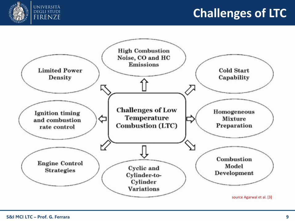
Challenges of LTC
S&I MCI LTC – Prof. G. Ferrara 9
source Agarwal et al. [3]
How to perform LTC
Most relevant LTC technologies
HCCI «Homogeneous Charge Compression Ignition»
PCCI «Premixed Charge Compression Ignition»
SCCI «Stratified Charge Compression Ignition»
RCCI «Reactivity Controlled Compression Ignition»
SACI «Spark Assisted Compression Ignition»
LACI «Laser Assisted Compression Ignition»
TJI «Turbulent Jet Ignition» and TI «Torch Ignition»
S&I MCI LTC – Prof. G. Ferrara 10
LTC identifies not one only but a group of combustion technologies
There are several techniques which move toward the LTC concept trying at the same time tosolve LTC challenges
they differ mainly in charge preparation procedure and ignition strategy
As much as the mixture is lean and homogeneous, the lower NOx and PM emissions, but itmakes ignition harder
generating fuel-rich zones inside the chamber, e.g. partial stratification, can assistmixture ignition but on the other hand increase pollutant emissions
HCCI fundamentals (1)
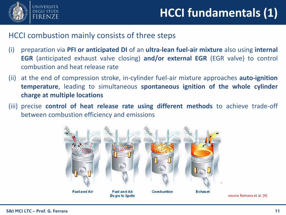
HCCI combustion mainly consists of three steps
(i) preparation via PFI or anticipated DI of an ultra-lean fuel-air mixture also using internalEGR (anticipated exhaust valve closing) and/or external EGR (EGR valve) to controlcombustion and heat release rate
(ii) at the end of compression stroke, in-cylinder fuel-air mixture approaches auto-ignitiontemperature, leading to simultaneous spontaneous ignition of the whole cylindercharge at multiple locations
(iii) precise control of heat release rate using different methods to achieve trade-offbetween combustion efficiency and emissions
S&I MCI LTC – Prof. G. Ferrara 11
source Ramana et al. [4]
HCCI fundamentals (2)
S&I MCI LTC – Prof. G. Ferrara 12
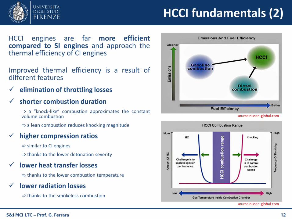
HCCI engines are far more efficientcompared to SI engines and approach thethermal efficiency of CI engines
Improved thermal efficiency is a result ofdifferent features
elimination of throttling losses
shorter combustion duration
⇨ a “knock-like” combustion approximates the constantvolume combustion
⇨ a lean combustion reduces knocking magnitude
higher compression ratios
⇨ similar to CI engines
⇨ thanks to the lower detonation severity
lower heat transfer losses
⇨ thanks to the lower combustion temperature
lower radiation losses
⇨ thanks to the smokeless combustion
source nissan-global.com
source nissan-global.com
HCCI operating range (1)
S&I MCI LTC – Prof. G. Ferrara 13
source Yang [5]
HCCI operating range (2)
Upper boundaries [5]
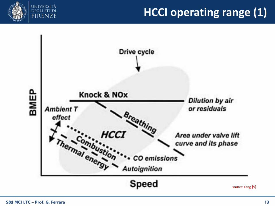
engine knockWhen fueling rate is increased, combustion rate increases, and gradually causes unacceptable noise due to detonation,which may potentially lead to engine damage, and eventually unacceptable levels of NOx emissions.
insufficient breathingSome HCCI engines employ negative valve overlap to trap larger quantities of hot residual gas to increase the mixturetemperature in order to achieve auto-ignition. NVO requires smaller valve lift therefore upon increasing engine speed, thetrapped mass is reduced, leading to movement of HCCI operating region boundary further downwards.
Lower boundaries [5]
sharp increase in CO emissionsWhen engine load decreases, the mixture eventually becomes too lean and the gas temperature during combustionbecomes too low for CO oxidation reactions to be completed. The resulting high CO emissions significantly reducecombustion efficiency.
highly delayed combustion timing and increased cyclic variationThis happens due to lack of thermal energy available for auto-ignition of the fuel-air mixture. The demand for thermalenergy for mixture's auto-ignition increases at lower loads; however, the available thermal energy remains low in theseconditions.
misfiringLack of adequate thermal energy for mixture's auto-ignition eventually leads to engine misfire.
variations in ambient temperatureWhich affect both the required thermal energy for auto-ignition of the mixture and the heat transfer losses. When theambient temperature decreases, lower operating boundary moves up, and HCCI operating regime shrinks.
S&I MCI LTC – Prof. G. Ferrara 14
HCCI shortcomings (1)
ignition timing and combustion rate control
The most challenging task for HCCI implementation is to ensure that auto-ignition occurs close to top deadcenter, under various operating conditions for optimal thermal efficiency. Combustion phasing of HCCIengines is affected by several factors such as fuel auto-ignition properties, local fuel-air ratio, flow rateand reactivity of residual gases, fuel-air mixture homogeneity, fuel latent heat of vaporization,compression ratio, intake air temperature and pressure, engine temperature, heat transfer.
limited power density
HCCI engines operate satisfactorily from low-to-medium loads only. At high loads the engine needshigher equivalence ratios, thus combustion rate increase, resulting in very high rate of pressure rise, thusinto pressure oscillations. This leads to unacceptable noise, potential engine damage, and higher NOxemissions. This also limits the power output density and puts high structural demand on the LTC engines.
high combustion noise, HC and CO emissions
HCCI engines emit significantly lower NOx and PM emissions but they emit relatively higher HC and COemissions. In homogeneous combustion, significant portion of charge enters the crevices duringcompression stroke and escapes during expansion stroke without combustion. The problem of HCCIengines is that burnt gas temperature is too low to consume much of this unburned charge when it re-enters the cylinder during expansion stroke. In addition, peak burnt gas temperatures are too low tocomplete CO to CO2 oxidation reactions at low loads, thus combustion efficiency also deteriorates.
cold start capability
In HCCI engines, ignition is extremely sensitive to the intake charge temperature. During cold start, lowertemperature of the compressed charge prevents the engine from firing.
S&I MCI LTC – Prof. G. Ferrara 15
HCCI shortcomings (2)
homogeneous mixture preparation
Homogeneous mixture preparation and avoiding fuel-wall interactions are crucial for achieving highthermal efficiency, reducing HC and PM emissions. This is particularly important when using relatively lowvolatility fuels such as diesel. Mixture homogeneity significantly affects the auto-ignition reactions, whichdirectly controls combustion phasing.
cyclic variations
Cyclic variations in HCCI engines are typically lower compared to conventional SI engines, however theycan become much relevant under certain operating conditions (e.g. very lean engine operations, lowintake temperatures). Studies indicate that temperature inhomogeneity has larger influence on HCCIcyclic variations in comparison to composition inhomogeneity. Temperature inhomogeneity and thermalstratification in the chamber are due to: (i) inadequate mixing of residual gas with fresh charge, (ii) heattransfer from cylinder liner, head, piston and valves, (iii) cyclic variations in residual gas temperatureand wall temperature.
cylinder-to-cylinder variations
When HCCI is applied to multi-cylinder engines, the engine exhibits cylinder-to-cylinder variations as welldue to its structure and different lengths of individual manifolds. These small differences cause ignitiontimings and combustion rates to vary greatly.
exhaust gas treatment
The low temperature at the engine outlet combined with a very lean mixture make standard after-treatment systems less effective.
closed-loop control system and expensive sensors
S&I MCI LTC – Prof. G. Ferrara 16
HCCI control parameters (1)
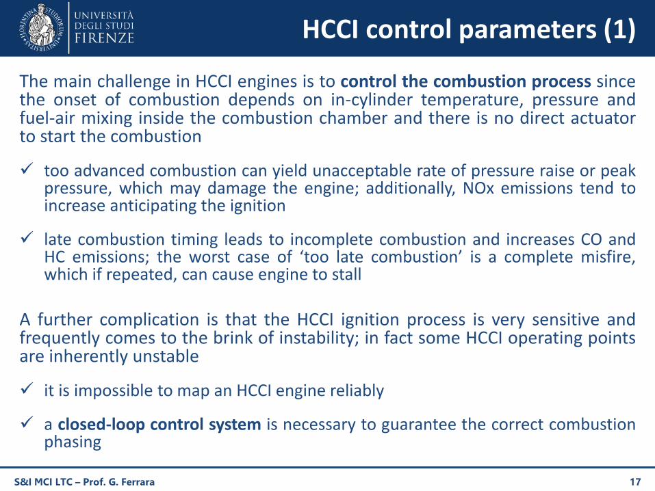
The main challenge in HCCI engines is to control the combustion process sincethe onset of combustion depends on in-cylinder temperature, pressure andfuel-air mixing inside the combustion chamber and there is no direct actuatorto start the combustion
too advanced combustion can yield unacceptable rate of pressure raise or peakpressure, which may damage the engine; additionally, NOx emissions tend toincrease anticipating the ignition
late combustion timing leads to incomplete combustion and increases CO andHC emissions; the worst case of ‘too late combustion’ is a complete misfire,which if repeated, can cause engine to stall
A further complication is that the HCCI ignition process is very sensitive andfrequently comes to the brink of instability; in fact some HCCI operating pointsare inherently unstable
it is impossible to map an HCCI engine reliably
a closed-loop control system is necessary to guarantee the correct combustionphasing
S&I MCI LTC – Prof. G. Ferrara 17
HCCI control parameters (2)
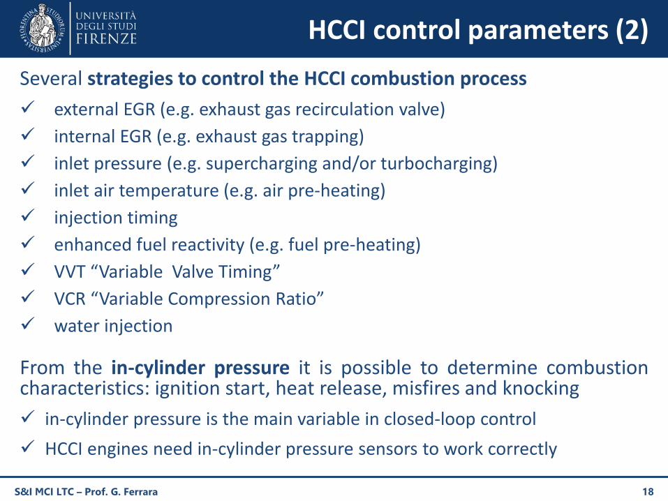
Several strategies to control the HCCI combustion process
external EGR (e.g. exhaust gas recirculation valve)
internal EGR (e.g. exhaust gas trapping)
inlet pressure (e.g. supercharging and/or turbocharging)
inlet air temperature (e.g. air pre-heating)
injection timing
enhanced fuel reactivity (e.g. fuel pre-heating)
VVT “Variable Valve Timing”
VCR “Variable Compression Ratio”
water injection
From the in-cylinder pressure it is possible to determine combustioncharacteristics: ignition start, heat release, misfires and knocking
in-cylinder pressure is the main variable in closed-loop control
HCCI engines need in-cylinder pressure sensors to work correctly
S&I MCI LTC – Prof. G. Ferrara 18
HCCI control parameters - EGR (1)
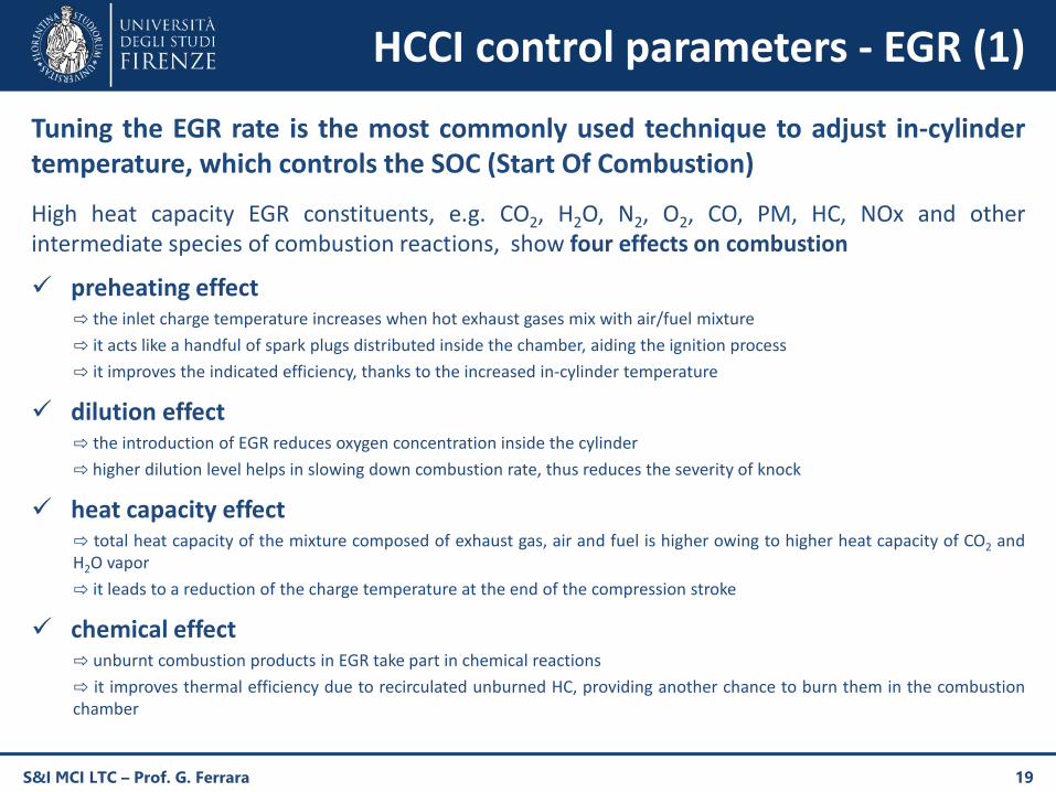
Tuning the EGR rate is the most commonly used technique to adjust in-cylindertemperature, which controls the SOC (Start Of Combustion)
High heat capacity EGR constituents, e.g. CO2, H2O, N2, O2, CO, PM, HC, NOx and otherintermediate species of combustion reactions, show four effects on combustion
preheating effect⇨ the inlet charge temperature increases when hot exhaust gases mix with air/fuel mixture
⇨ it acts like a handful of spark plugs distributed inside the chamber, aiding the ignition process
⇨ it improves the indicated efficiency, thanks to the increased in-cylinder temperature
dilution effect⇨ the introduction of EGR reduces oxygen concentration inside the cylinder
⇨ higher dilution level helps in slowing down combustion rate, thus reduces the severity of knock
heat capacity effect⇨ total heat capacity of the mixture composed of exhaust gas, air and fuel is higher owing to higher heat capacity of CO2 andH2O vapor
⇨ it leads to a reduction of the charge temperature at the end of the compression stroke
chemical effect⇨ unburnt combustion products in EGR take part in chemical reactions
⇨ it improves thermal efficiency due to recirculated unburned HC, providing another chance to burn them in the combustionchamber
S&I MCI LTC – Prof. G. Ferrara 19
HCCI control parameters - EGR (2)
S&I MCI LTC – Prof. G. Ferrara 20
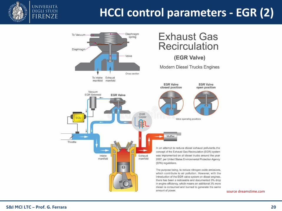
source dreamstime.com
HCCI control parameters - EGR (3)
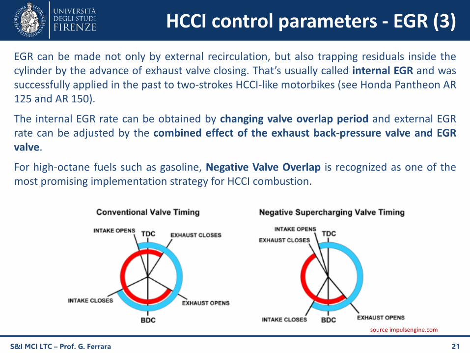
EGR can be made not only by external recirculation, but also trapping residuals inside thecylinder by the advance of exhaust valve closing. That’s usually called internal EGR and wassuccessfully applied in the past to two-strokes HCCI-like motorbikes (see Honda Pantheon AR125 and AR 150).
The internal EGR rate can be obtained by changing valve overlap period and external EGRrate can be adjusted by the combined effect of the exhaust back-pressure valve and EGRvalve.
For high-octane fuels such as gasoline, Negative Valve Overlap is recognized as one of themost promising implementation strategy for HCCI combustion.
S&I MCI LTC – Prof. G. Ferrara 21
source impulsengine.com
S&I MCI LTC – Prof. G. Ferrara 22
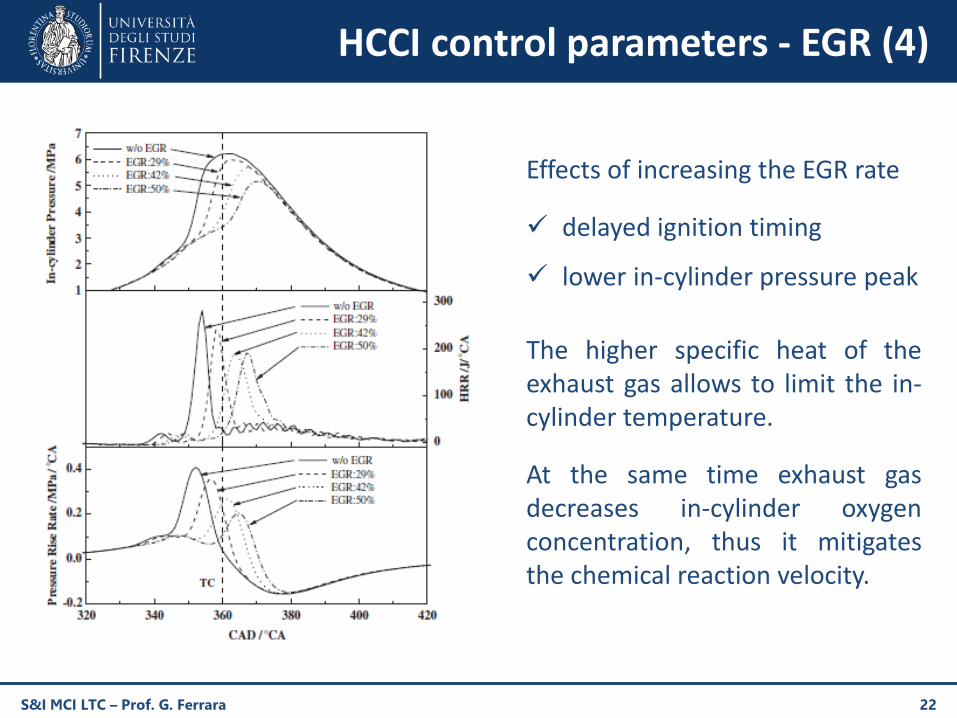
Effects of increasing the EGR rate
delayed ignition timing
lower in-cylinder pressure peak
The higher specific heat of theexhaust gas allows to limit the in-cylinder temperature.
At the same time exhaust gasdecreases in-cylinder oxygenconcentration, thus it mitigatesthe chemical reaction velocity.
HCCI control parameters - EGR (4)
S&I MCI LTC – Prof. G. Ferrara 23
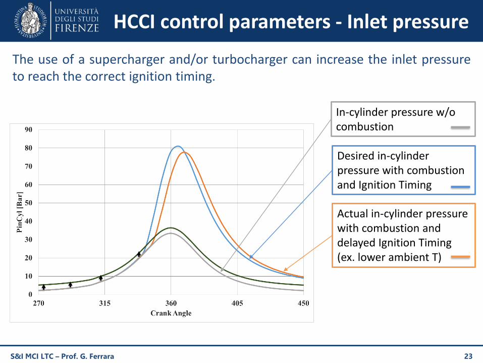
In-cylinder pressure w/o combustion
Desired in-cylinder pressure with combustion and Ignition Timing
Actual in-cylinder pressure with combustion and delayed Ignition Timing (ex. lower ambient T)
The use of a supercharger and/or turbocharger can increase the inlet pressureto reach the correct ignition timing.
HCCI control parameters - Inlet pressure
S&I MCI LTC – Prof. G. Ferrara 24
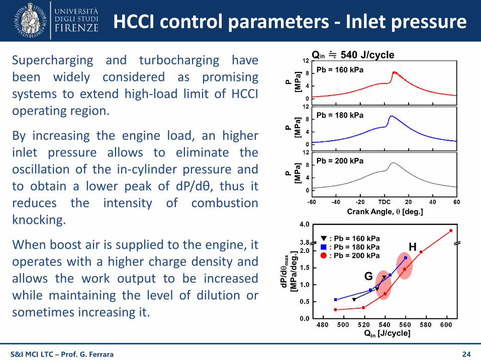
Supercharging and turbocharging havebeen widely considered as promisingsystems to extend high-load limit of HCCIoperating region.
By increasing the engine load, an higherinlet pressure allows to eliminate theoscillation of the in-cylinder pressure andto obtain a lower peak of dP/dθ, thus itreduces the intensity of combustionknocking.
When boost air is supplied to the engine, itoperates with a higher charge density andallows the work output to be increasedwhile maintaining the level of dilution orsometimes increasing it.
HCCI control parameters - Inlet pressure
S&I MCI LTC – Prof. G. Ferrara 25
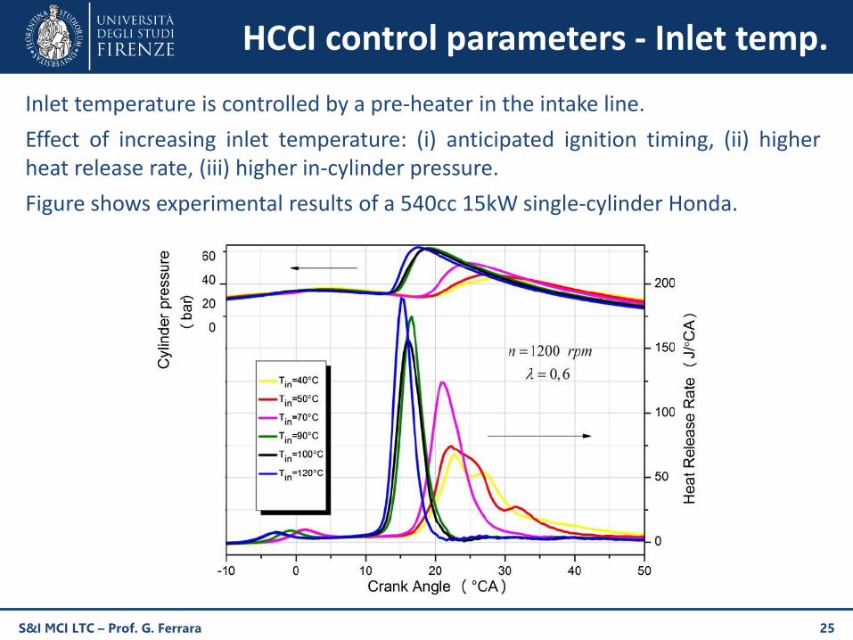
Inlet temperature is controlled by a pre-heater in the intake line.
Effect of increasing inlet temperature: (i) anticipated ignition timing, (ii) higherheat release rate, (iii) higher in-cylinder pressure.
Figure shows experimental results of a 540cc 15kW single-cylinder Honda.
HCCI control parameters - Inlet temp.
S&I MCI LTC – Prof. G. Ferrara 26
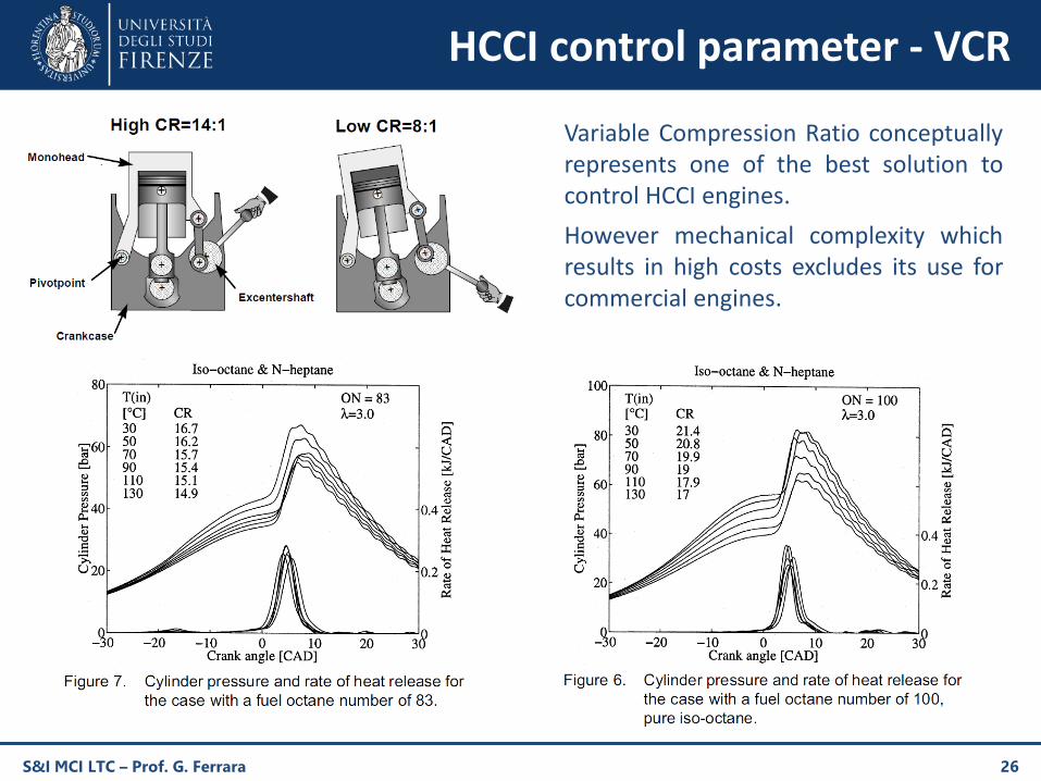
Variable Compression Ratio conceptuallyrepresents one of the best solution tocontrol HCCI engines.
However mechanical complexity whichresults in high costs excludes its use forcommercial engines.
HCCI control parameter - VCR
PCCI fundamentals (1)
To achieve LTC goals, light-duty diesel engines can be operated in Premixed ChargeCompression Ignition (PCCI) mode without increasing overly engine complexity
PCCI can be achieved by the use of a single injection (like conventional diesel) but
increasing EGR rate
advancing SOI timings
increasing fuel injection pressure
emphasizing charge motions
These characteristics lead to a more homogeneous combustion flame, in opposition to thestratified flame that occurs along the fuel spray during diffusive diesel combustion
PCCI combustion is a single-stage combustion process, similar to the premixed phase ofconventional diesel combustion
Fuel-rich pockets which form due to imperfect homogenization are useful for triggeringauto-ignition and advancing the combustion phasing
S&I MCI LTC – Prof. G. Ferrara 27
PCCI fundamentals (2)
Compared to HCCI combustion, PCCI combustion results in relatively higher NOx and sootemissions; however PCCI combustion offers significantly lower HC and CO emissions. Dualinjection strategy (e.g. moving toward SCCI) was found to be very effective for NOx emissionreduction, while combustion efficiency reduced. This strategy consisted of an advanced firstinjection for PCCI combustion and a retarded second injection.
Compared to diffusive combustion, PCCI shows lower NOx and PM emissions but relativelyhigher CO and HC emissions. Emissions problem can be solved by the use specific after treatmentdevices e.g. lean NOx trap (LNT), diesel oxidation catalyst (DOC), and diesel particulate filter (DPF).
Like HCCI, PCCI shows detonation at high loads and cyclic variation at low loads. The operatingrange of PCCI engine could be extended from low loads to high loads by reducing thecompression ratio. However, reduction in compression ratio resulted in relatively higher COemissions due to relatively inferior combustion efficiency.
Late IVC “Inlet Valve Closing” allows to reduce the temperature inside the combustion chamberand to increase the ignition delay, thus it provides more time for pre-mixing of fuel and air.Combined effect of pre-mixing and lower in-cylinder temperature resulted in lower soot and NOxemissions.
An increase in fuel injection pressure results in lower HC, PM and NOx emissions.
S&I MCI LTC – Prof. G. Ferrara 28
S&I MCI LTC – Prof. G. Ferrara 29
PCCI application - Nissan MK
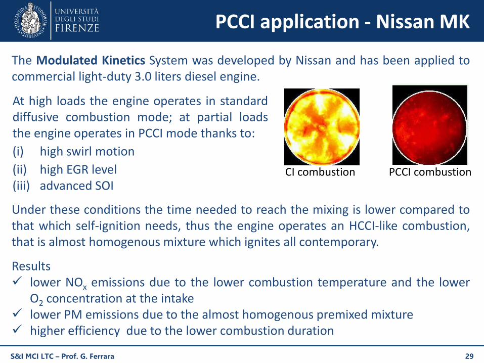
The Modulated Kinetics System was developed by Nissan and has been applied tocommercial light-duty 3.0 liters diesel engine.
Under these conditions the time needed to reach the mixing is lower compared tothat which self-ignition needs, thus the engine operates an HCCI-like combustion,that is almost homogenous mixture which ignites all contemporary.
Results lower NOx emissions due to the lower combustion temperature and the lower
O2 concentration at the intake lower PM emissions due to the almost homogenous premixed mixture higher efficiency due to the lower combustion duration
CI combustion PCCI combustion
At high loads the engine operates in standarddiffusive combustion mode; at partial loadsthe engine operates in PCCI mode thanks to:
(i) high swirl motion
(ii) high EGR level(iii) advanced SOI
SCCI fundamentals (1)
S&I MCI LTC – Prof. G. Ferrara 30
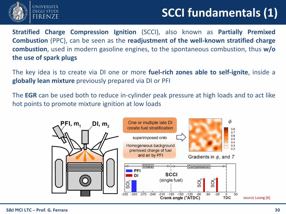
Stratified Charge Compression Ignition (SCCI), also known as Partially PremixedCombustion (PPC), can be seen as the readjustment of the well-known stratified chargecombustion, used in modern gasoline engines, to the spontaneous combustion, thus w/othe use of spark plugs
The key idea is to create via DI one or more fuel-rich zones able to self-ignite, inside aglobally lean mixture previously prepared via DI or PFI
The EGR can be used both to reduce in-cylinder peak pressure at high loads and to act likehot points to promote mixture ignition at low loads
source Luong [6]
SCCI fundamentals (2)
S&I MCI LTC – Prof. G. Ferrara 31
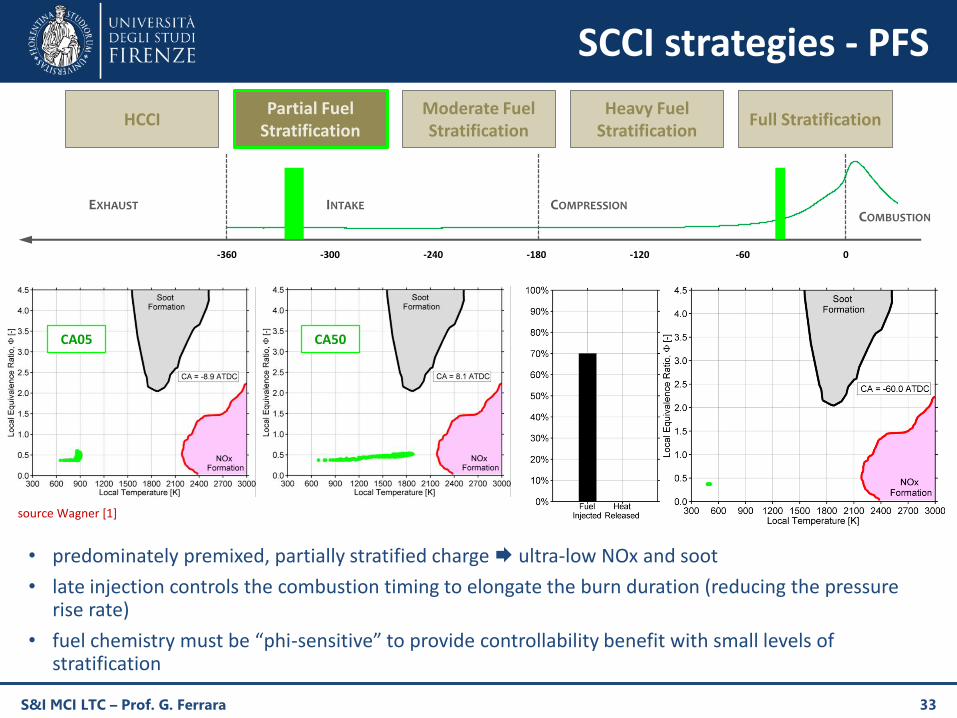
There are different ways to perform stratification, which differ in the advance of the pilotinjection/s and the duration of pilot/s and main injection
(i) PFS “Partial Fuel Stratification”
(ii) MFS “Moderate Fuel Stratification”
(iii) HFS “Heavy Fuel Stratification”
PFS goes in the direction of PCCI, while HFS moves toward diffusive combustion
The higher the in-cylinder stratification, the higher the combustion stability, but also
higher NOx emissions⇨ fuel-rich zones reach a higher temperature during combustion
higher PM emissions⇨ fuel-rich zones promote nucleation phase of carbon particles
Advantages of SCCI combustion
the same engine can perform all these combustion strategies
it necessitates of only one injector (if the main injection is made via DI) and only one fuel
high-range operability
Studies showed better performance in conventional diffusive combustion mode, however SCCImode was found to be superior in terms of emissions
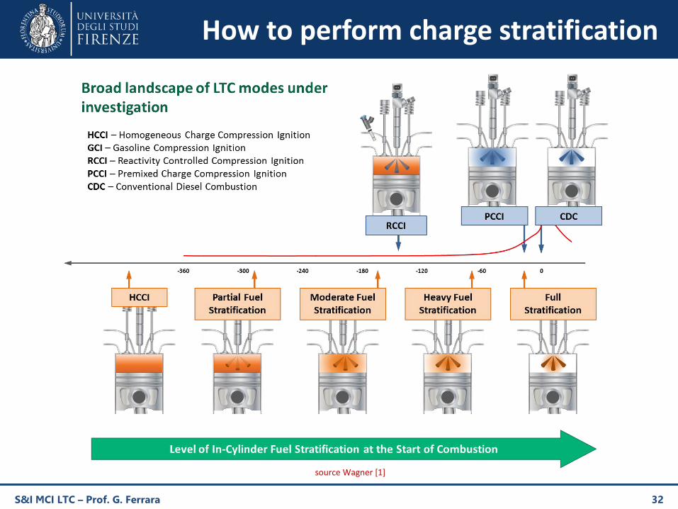
How to perform charge stratification
S&I MCI LTC – Prof. G. Ferrara 32
source Wagner [1]
S&I MCI LTC – Prof. G. Ferrara 33
-360 -300 -240 -180 -120 -60 0
HCCIPartial Fuel
StratificationModerate Fuel Stratification
Heavy Fuel Stratification
Full Stratification
CA05 CA50
• predominately premixed, partially stratified charge ultra-low NOx and soot
• late injection controls the combustion timing to elongate the burn duration (reducing the pressure rise rate)
• fuel chemistry must be “phi-sensitive” to provide controllability benefit with small levels of stratification
INTAKE COMPRESSIONEXHAUSTCOMBUSTION
SCCI strategies - PFS
source Wagner [1]
S&I MCI LTC – Prof. G. Ferrara 34
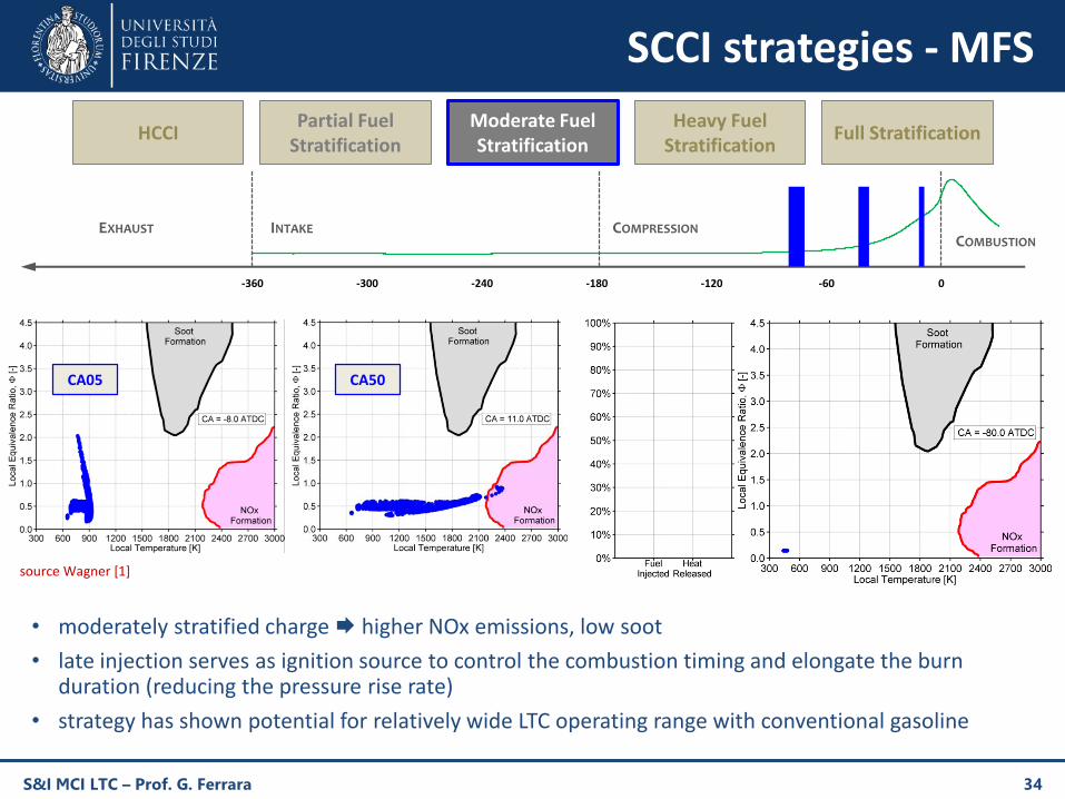
-360 -300 -240 -180 -120 -60 0
HCCIPartial Fuel
StratificationModerate Fuel Stratification
Heavy Fuel Stratification
Full Stratification
• moderately stratified charge higher NOx emissions, low soot
• late injection serves as ignition source to control the combustion timing and elongate the burn duration (reducing the pressure rise rate)
• strategy has shown potential for relatively wide LTC operating range with conventional gasoline
CA05 CA50
INTAKE COMPRESSIONEXHAUSTCOMBUSTION
SCCI strategies - MFS
source Wagner [1]
S&I MCI LTC – Prof. G. Ferrara 35
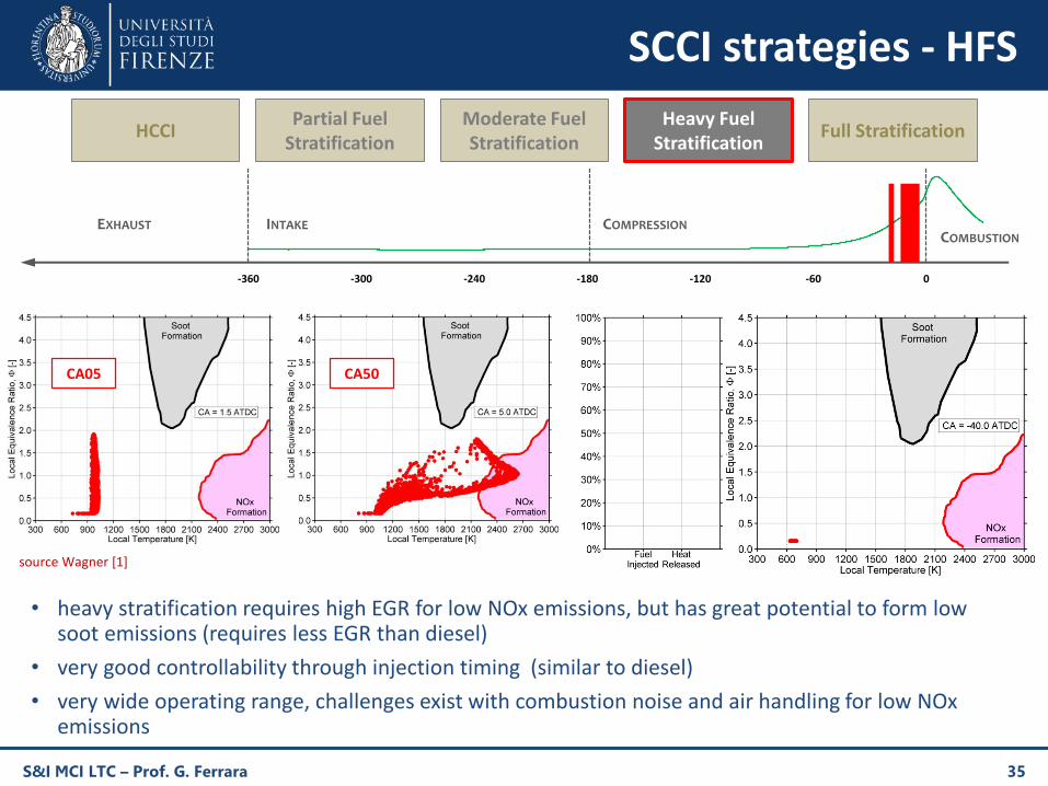
-360 -300 -240 -180 -120 -60 0
HCCIPartial Fuel
StratificationModerate Fuel Stratification
Heavy Fuel Stratification
Full Stratification
• heavy stratification requires high EGR for low NOx emissions, but has great potential to form low soot emissions (requires less EGR than diesel)
• very good controllability through injection timing (similar to diesel)
• very wide operating range, challenges exist with combustion noise and air handling for low NOx emissions
CA05 CA50
INTAKE COMPRESSIONEXHAUSTCOMBUSTION
SCCI strategies - HFS
source Wagner [1]
S&I MCI LTC – Prof. G. Ferrara 36
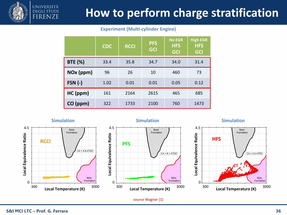
CDC RCCIPFSGCI
No EGR
HFSGCI
High EGR
HFSGCI
BTE (%) 33.4 35.8 34.7 34.0 31.4
NOx (ppm) 96 26 10 460 73
FSN (-) 1.02 0.01 0.01 0.05 0.12
HC (ppm) 161 2164 2615 465 685
CO (ppm) 322 1733 2100 760 1473
Experiment (Multi-cylinder Engine)Lo
cal E
qu
ival
en
ce R
atio
Local Temperature (K)
0
4.5
300 3000
Loca
l Eq
uiv
alen
ce R
atio
Local Temperature (K)
0
4.5
300 3000
Loca
l Eq
uiv
ale
nce
Rat
io
Local Temperature (K)
0
4.5
300 3000
RCCI PFSHFS
Simulation Simulation Simulation
How to perform charge stratification
source Wagner [1]
S&I MCI LTC – Prof. G. Ferrara 37
SCCI application - Toyota UNIBUS
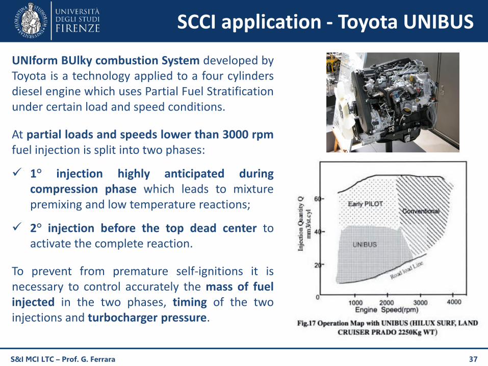
UNIform BUlky combustion System developed byToyota is a technology applied to a four cylindersdiesel engine which uses Partial Fuel Stratificationunder certain load and speed conditions.
At partial loads and speeds lower than 3000 rpmfuel injection is split into two phases:
1° injection highly anticipated duringcompression phase which leads to mixturepremixing and low temperature reactions;
2° injection before the top dead center toactivate the complete reaction.
To prevent from premature self-ignitions it isnecessary to control accurately the mass of fuelinjected in the two phases, timing of the twoinjections and turbocharger pressure.
RCCI fundamentals (1)
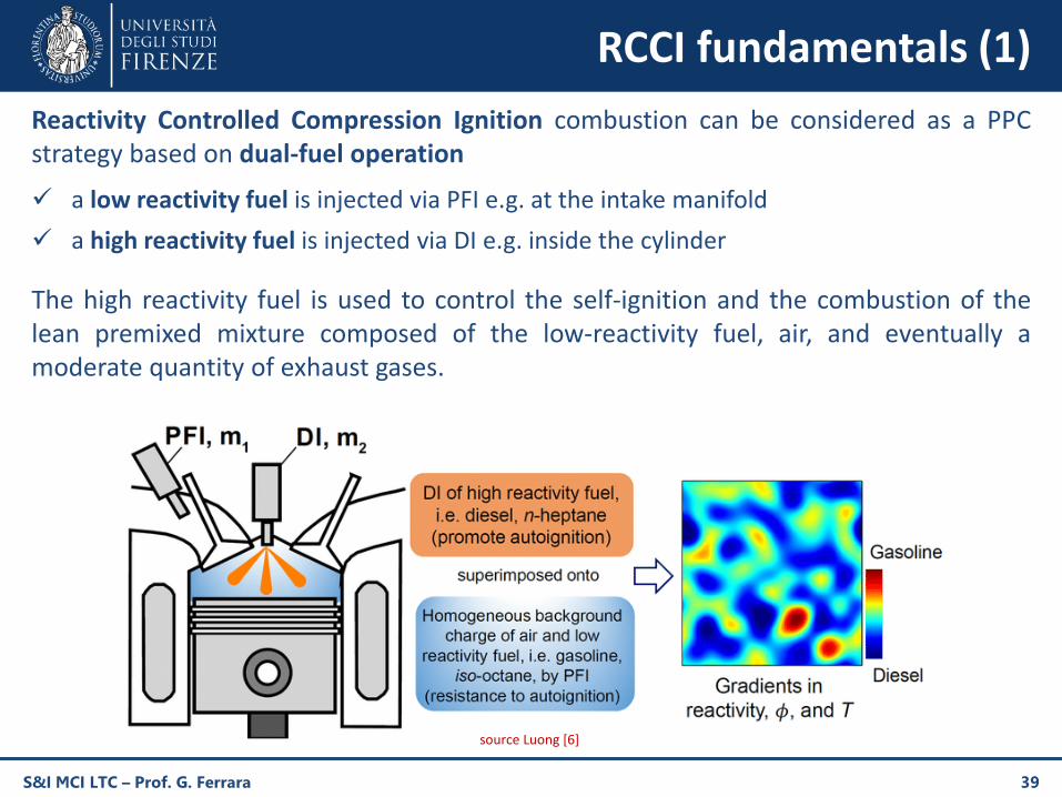
Reactivity Controlled Compression Ignition combustion can be considered as a PPCstrategy based on dual-fuel operation
a low reactivity fuel is injected via PFI e.g. at the intake manifold
a high reactivity fuel is injected via DI e.g. inside the cylinder
The high reactivity fuel is used to control the self-ignition and the combustion of thelean premixed mixture composed of the low-reactivity fuel, air, and eventually amoderate quantity of exhaust gases.
S&I MCI LTC – Prof. G. Ferrara 39
source Luong [6]
RCCI fundamentals (2)
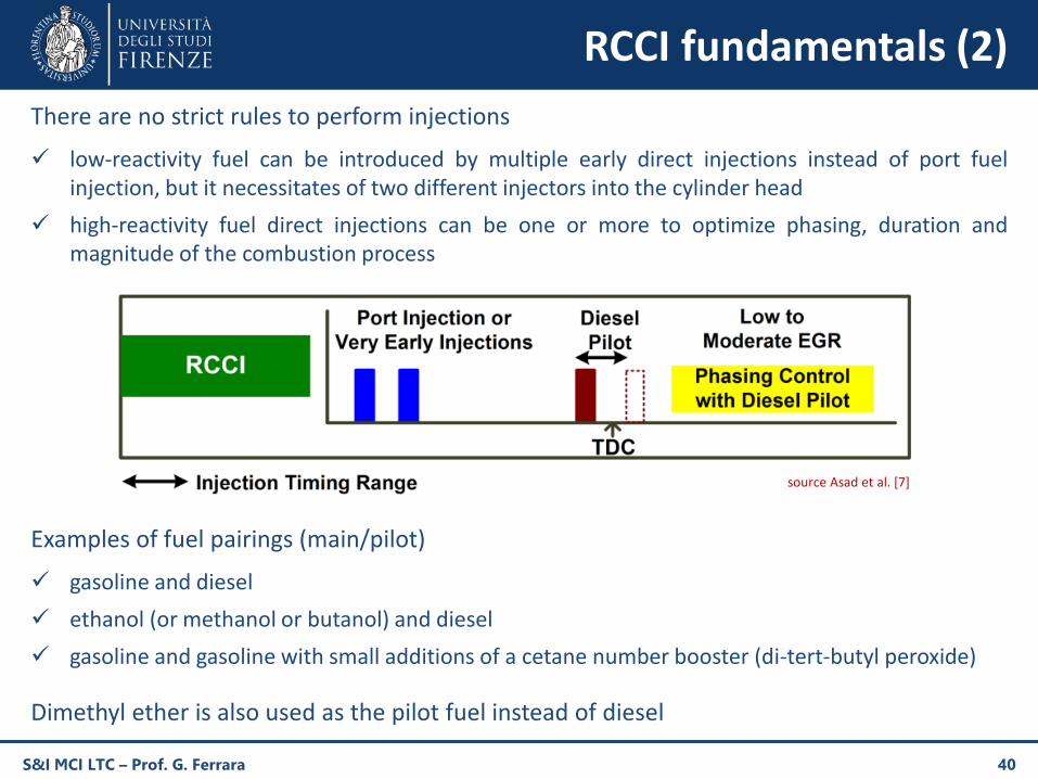
There are no strict rules to perform injections
low-reactivity fuel can be introduced by multiple early direct injections instead of port fuelinjection, but it necessitates of two different injectors into the cylinder head
high-reactivity fuel direct injections can be one or more to optimize phasing, duration andmagnitude of the combustion process
Examples of fuel pairings (main/pilot)
gasoline and diesel
ethanol (or methanol or butanol) and diesel
gasoline and gasoline with small additions of a cetane number booster (di-tert-butyl peroxide)
Dimethyl ether is also used as the pilot fuel instead of diesel
S&I MCI LTC – Prof. G. Ferrara 40
source Asad et al. [7]
RCCI fundamentals (3)
RCCI combustion results in relatively higher brake thermal efficiency compared to HCCIcombustion and other derivatives of LTC, while maintaining lower NOx and PMemissions than diesel diffusive combustion (up to 90% lower when usinggasoline/diesel combination) without the need for after-treatment methods, thus it isconsidered one of the most promising LTC technologies. In fact, studies demonstratethat up to medium engine loads, RCCI combustion can be achieved without EGR, whichresults in higher thermal efficiency without increasing significantly exhaust emissions.
Main shortcoming of RCCI technology is the high-load range restriction. At high loads,the engine needs less pilot fuel to ignite the low-reactivity mixture, thus there is lowerin-cylinder stratification, resulting in an excessive rate of pressure raise and higher NOxemissions due to the HCCI-like combustion. That problem can be solved increasing theEGR rate: in that case, the mixture necessitates of a bigger quantity of pilot fuel toreach self-ignition, leading to an higher in-cylinder stratification. However it leads tohigher soot emissions.
Another non-negligible problem, which translates in high manufacturing costs, is thatRCCI engines necessitate of two different injection systems, running with differentpressures, and two different fuel reservoirs.
S&I MCI LTC – Prof. G. Ferrara 41
SACI Fundamentals (1)
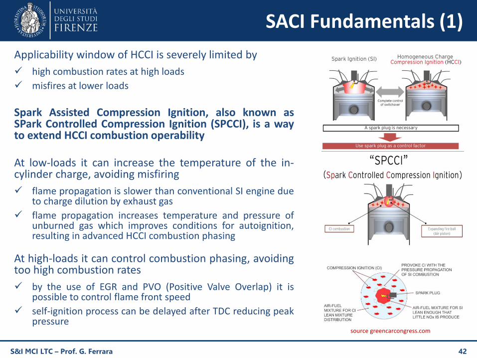
Applicability window of HCCI is severely limited by
high combustion rates at high loads
misfires at lower loads
Spark Assisted Compression Ignition, also known asSPark Controlled Compression Ignition (SPCCI), is a wayto extend HCCI combustion operability
At low-loads it can increase the temperature of the in-cylinder charge, avoiding misfiring
flame propagation is slower than conventional SI engine dueto charge dilution by exhaust gas
flame propagation increases temperature and pressure ofunburned gas which improves conditions for autoignition,resulting in advanced HCCI combustion phasing
At high-loads it can control combustion phasing, avoidingtoo high combustion rates
by the use of EGR and PVO (Positive Valve Overlap) it ispossible to control flame front speed
self-ignition process can be delayed after TDC reducing peakpressure
S&I MCI LTC – Prof. G. Ferrara 42
source greencarcongress.com
SACI Fundamentals (2)
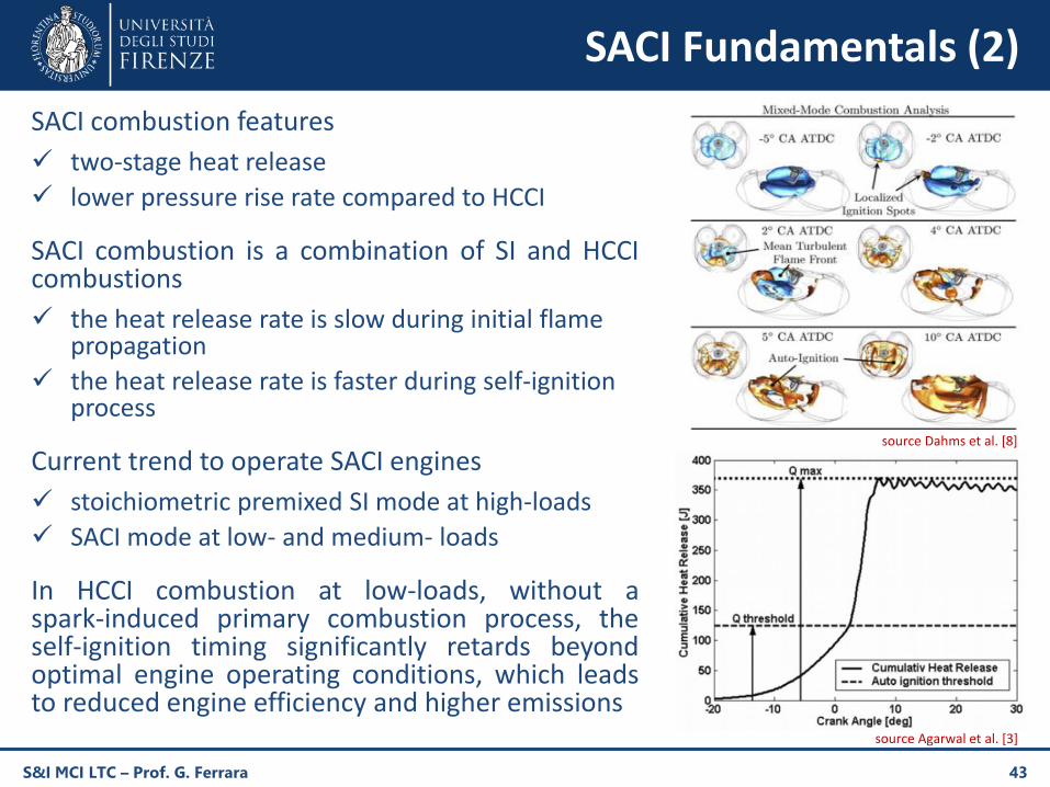
SACI combustion features
two-stage heat release
lower pressure rise rate compared to HCCI
SACI combustion is a combination of SI and HCCIcombustions
the heat release rate is slow during initial flame propagation
the heat release rate is faster during self-ignition process
Current trend to operate SACI engines
stoichiometric premixed SI mode at high-loads
SACI mode at low- and medium- loads
In HCCI combustion at low-loads, without aspark-induced primary combustion process, theself-ignition timing significantly retards beyondoptimal engine operating conditions, which leadsto reduced engine efficiency and higher emissions
S&I MCI LTC – Prof. G. Ferrara 43
source Dahms et al. [8]
source Agarwal et al. [3]
SACI application - Mazda Skyactiv-X
S&I MCI LTC – Prof. G. Ferrara 44
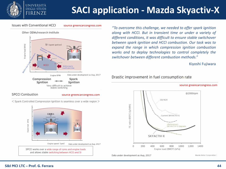
“To overcome this challenge, we needed to offer spark ignitionalong with HCCI. But in transient time or under a variety ofdifferent conditions, it was difficult to ensure stable switchoverbetween spark ignition and HCCI combustion. Our task was toexpand the range in which compression ignition combustionworks and to deploy technologies to control completely theswitchover between different combustion methods.”
Kiyoshi Fujiwara
source greencarcongress.com
source greencarcongress.com
source greencarcongress.com
LACI Fundamentals
Laser ignition (LI) is an alternative to SI both for LTC and standard Otto engines
a short laser pulse is focused in a small volume of fuel-air mixture, which results in a non-resonantbreakdown of the gas, similar to the one resulting from an electrical spark discharge, in the focal region,followed by formation of hot and dense plasma
LI advantages
charge ignitability is less sensitive to the local equivalence ratio
⇨ plasma is located well inside the charge, thus no heat losses occur in the ignition region
ignition process is far more effective than SI, resulting in shorter ignition delay
multiple ignition points can be used and focused in arbitrary locations inside the combustion chamber
can ignite leaner fuel-air mixtures than SI leading to lower peak in-cylinder temperature and NOx
When LI is applied to HCCI-like combustion, it is called Laser Assisted Compression Ignition
compared to standard HCCI, laser plasma can sustain HCCI combustion at lower inlet air temperature
compared to standard HCCI, lower EGR is sufficient in order to control NOx emissions (leaner mixture)
LACI shortcoming
laser components are expensive
optical access into the engine is difficult
S&I MCI LTC – Prof. G. Ferrara 45
TJI and TI fundamentals (1)
S&I MCI LTC – Prof. G. Ferrara 46
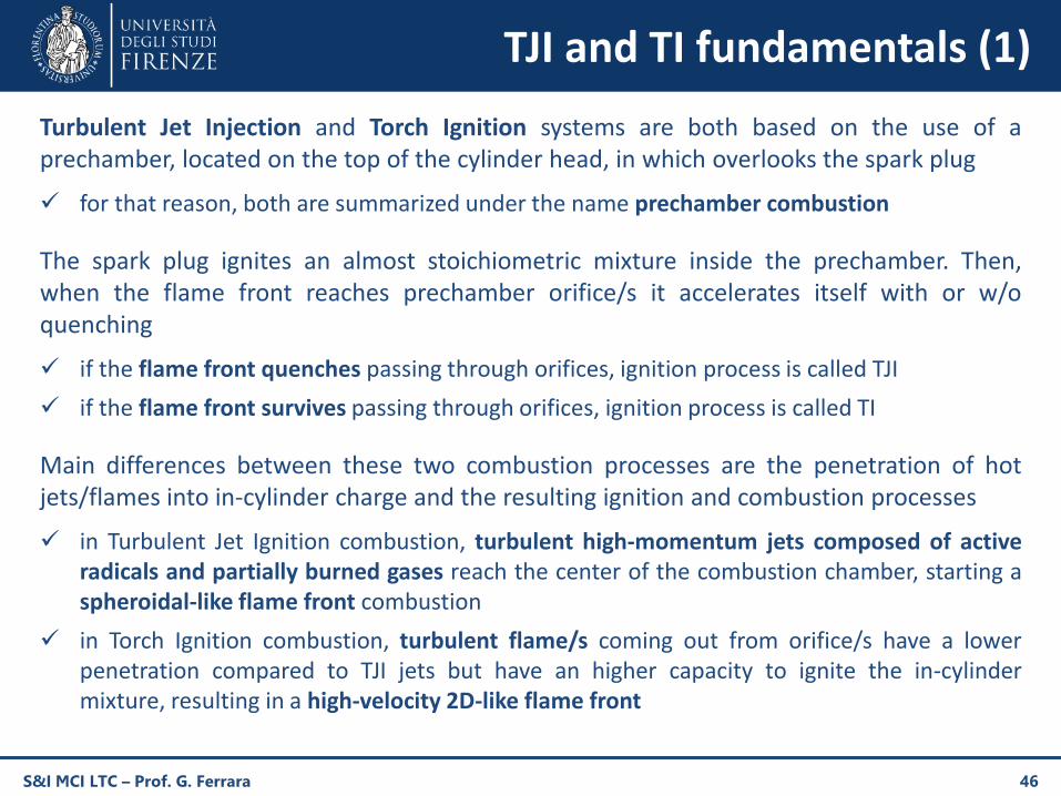
Turbulent Jet Injection and Torch Ignition systems are both based on the use of aprechamber, located on the top of the cylinder head, in which overlooks the spark plug
for that reason, both are summarized under the name prechamber combustion
The spark plug ignites an almost stoichiometric mixture inside the prechamber. Then,when the flame front reaches prechamber orifice/s it accelerates itself with or w/oquenching
if the flame front quenches passing through orifices, ignition process is called TJI
if the flame front survives passing through orifices, ignition process is called TI
Main differences between these two combustion processes are the penetration of hotjets/flames into in-cylinder charge and the resulting ignition and combustion processes
in Turbulent Jet Ignition combustion, turbulent high-momentum jets composed of activeradicals and partially burned gases reach the center of the combustion chamber, starting aspheroidal-like flame front combustion
in Torch Ignition combustion, turbulent flame/s coming out from orifice/s have a lowerpenetration compared to TJI jets but have an higher capacity to ignite the in-cylindermixture, resulting in a high-velocity 2D-like flame front
TJI and TI fundamentals (2)
S&I MCI LTC – Prof. G. Ferrara 47
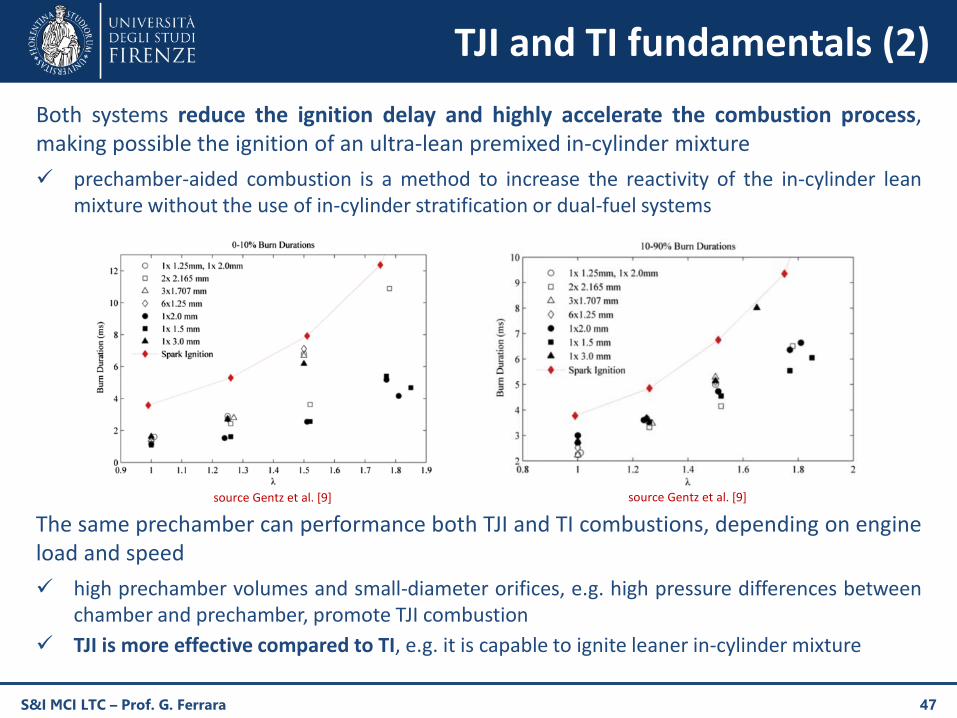
Both systems reduce the ignition delay and highly accelerate the combustion process,making possible the ignition of an ultra-lean premixed in-cylinder mixture
prechamber-aided combustion is a method to increase the reactivity of the in-cylinder leanmixture without the use of in-cylinder stratification or dual-fuel systems
The same prechamber can performance both TJI and TI combustions, depending on engineload and speed
high prechamber volumes and small-diameter orifices, e.g. high pressure differences betweenchamber and prechamber, promote TJI combustion
TJI is more effective compared to TI, e.g. it is capable to ignite leaner in-cylinder mixture
source Gentz et al. [9]source Gentz et al. [9]
TJI and TI fundamentals (3)
S&I MCI LTC – Prof. G. Ferrara 48
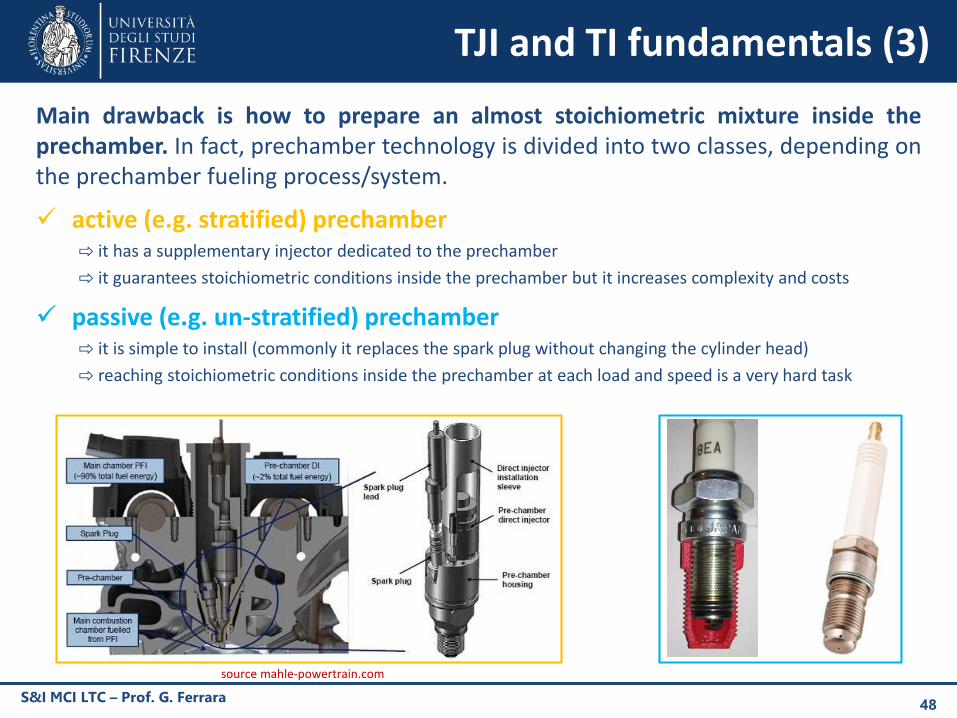
Main drawback is how to prepare an almost stoichiometric mixture inside theprechamber. In fact, prechamber technology is divided into two classes, depending onthe prechamber fueling process/system.
active (e.g. stratified) prechamber⇨ it has a supplementary injector dedicated to the prechamber
⇨ it guarantees stoichiometric conditions inside the prechamber but it increases complexity and costs
passive (e.g. un-stratified) prechamber⇨ it is simple to install (commonly it replaces the spark plug without changing the cylinder head)
⇨ reaching stoichiometric conditions inside the prechamber at each load and speed is a very hard task
source mahle-powertrain.com
TJI chemiluminescence analysis
S&I MCI LTC – Prof. G. Ferrara 49
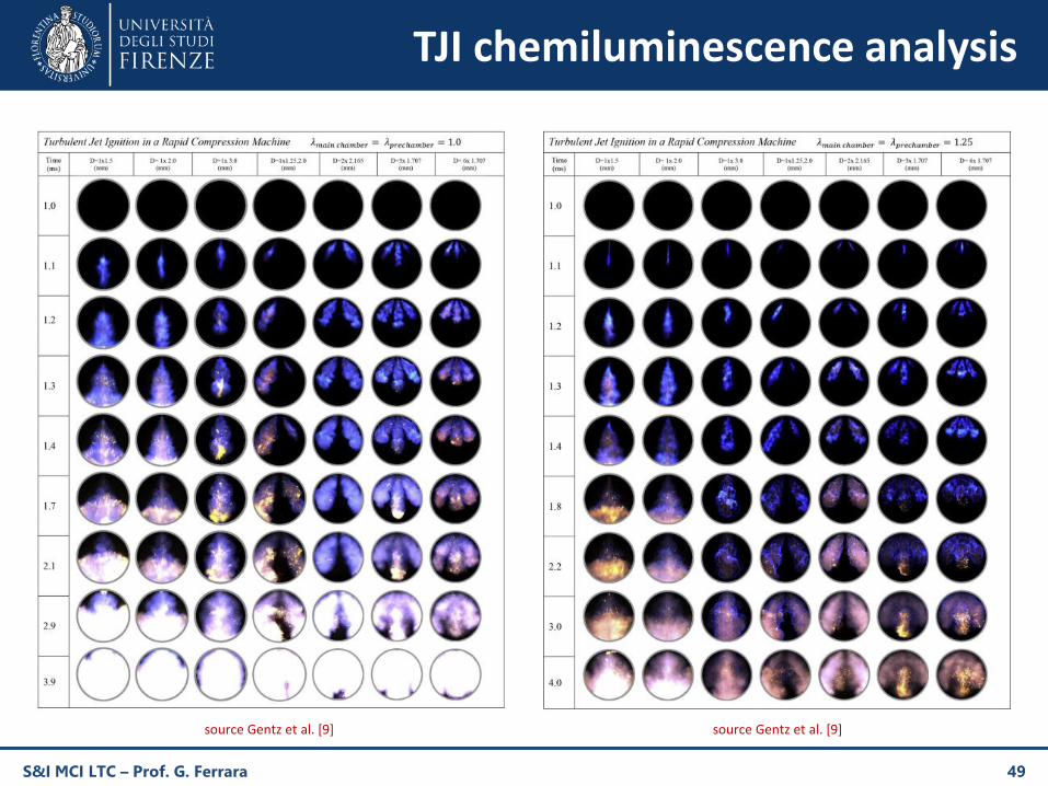
source Gentz et al. [9]source Gentz et al. [9]
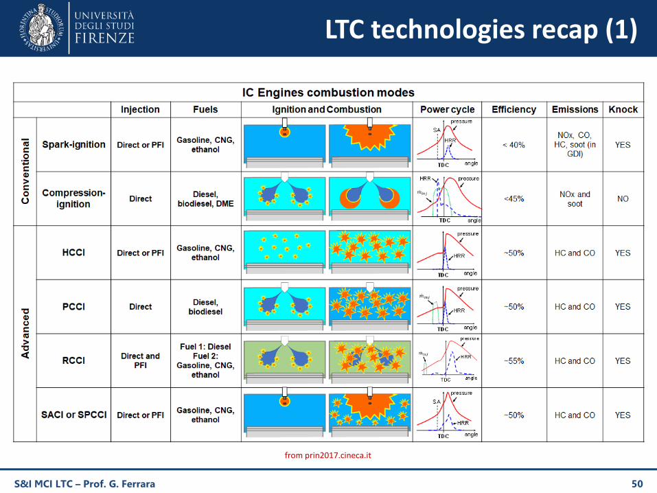
LTC technologies recap (1)
S&I MCI LTC – Prof. G. Ferrara 50
from prin2017.cineca.it
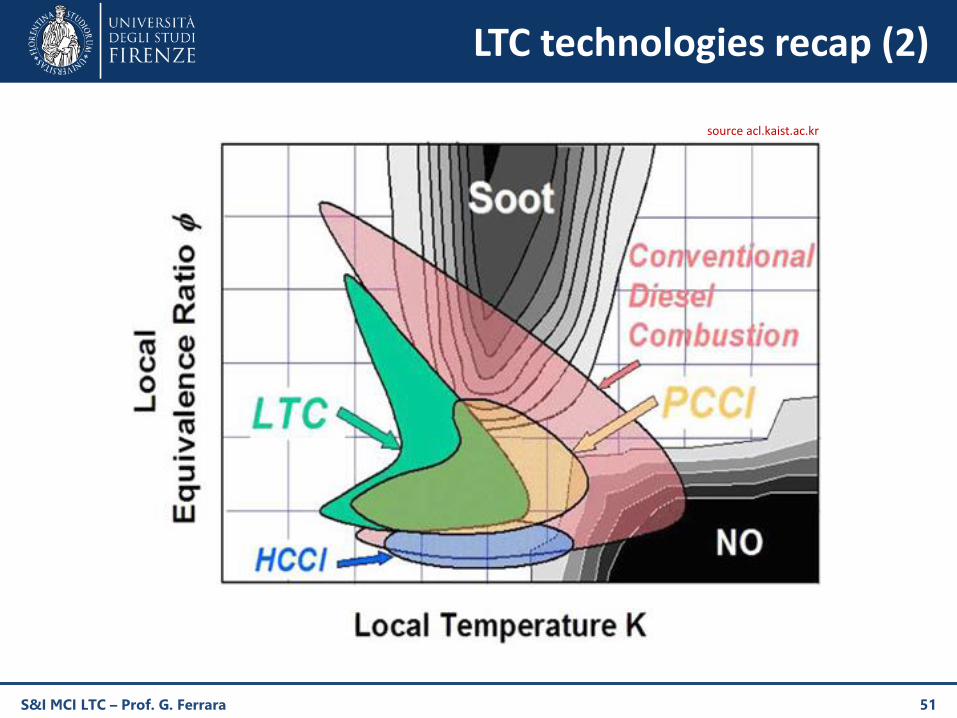
LTC technologies recap (2)
S&I MCI LTC – Prof. G. Ferrara 51
source acl.kaist.ac.kr
Bibliography
1. R.M. Wagner, “Disruptive Opportunities for small engine combustion systems”, The 21st Small Engine Technology Conference, 2015
2. AME 514, Application of combustion, Lecture 14: New technologies (2017)
3. A.K. Agarwal, A.P. Singh, R.K. Maurya, “Evolution, challenges and path forward for low temperature combustion engines”, Progress inEnergy and Combustion Science 61 (2017) 156
4. P.V. Ramana, D. Maheswar, B. Umamaheswa Gowd, “An approach of experimental study of HCCI engine”, International Journal ofAdvanced Research in Engineering and Applied Sciences, 2015
5. J. Yang, “Expanding the operating range of homogeneous charge compression ignition–spark ignition dual-mode engines in thehomogeneous charge compression ignition mode”, Int. J. Engine Res. Vol. 6 (2005)
6. M.B. Luong, R. Sankaran, G.H. Yu, S.H. Chung, C.S. Yoo, “On the effect of injection timing on the ignition of lean PRF/air/EGR mixturesunder direct dual fuel stratification conditions”, Combustion and Flame 183 (2017)
7. U. Asad, M. Zheng, D. Ting, J. Tjong, “Implementation challenges and solutions for homogenous charge compression ignitioncombustion in diesel engines”, Proceedings of the ASME 2014 Internal Combustion Engine Division Fall Technical Conference
8. R. Dahms, C. Felsch, O. Rohl, N. Peters, “Detailed chemistry flamelet modeling of mixed-mode combustion in spark-assisted HCCIengines”, Proceedings of the Combustion Institute 33 (2011)
9. G. Gentz, B. Thelen, M. Gholamisheeri, P. Litke, A. Brown, J. Hoke, E. Toulson, “A study of the influence of orifice diameter on aturbulent jet ignition system through combustion visualization and performance characterization in a rapid compression machine”,Applied Thermal Engineering 81 (2015)
S&I MCI LTC – Prof. G. Ferrara 52