Embed Size (px)
Citation preview
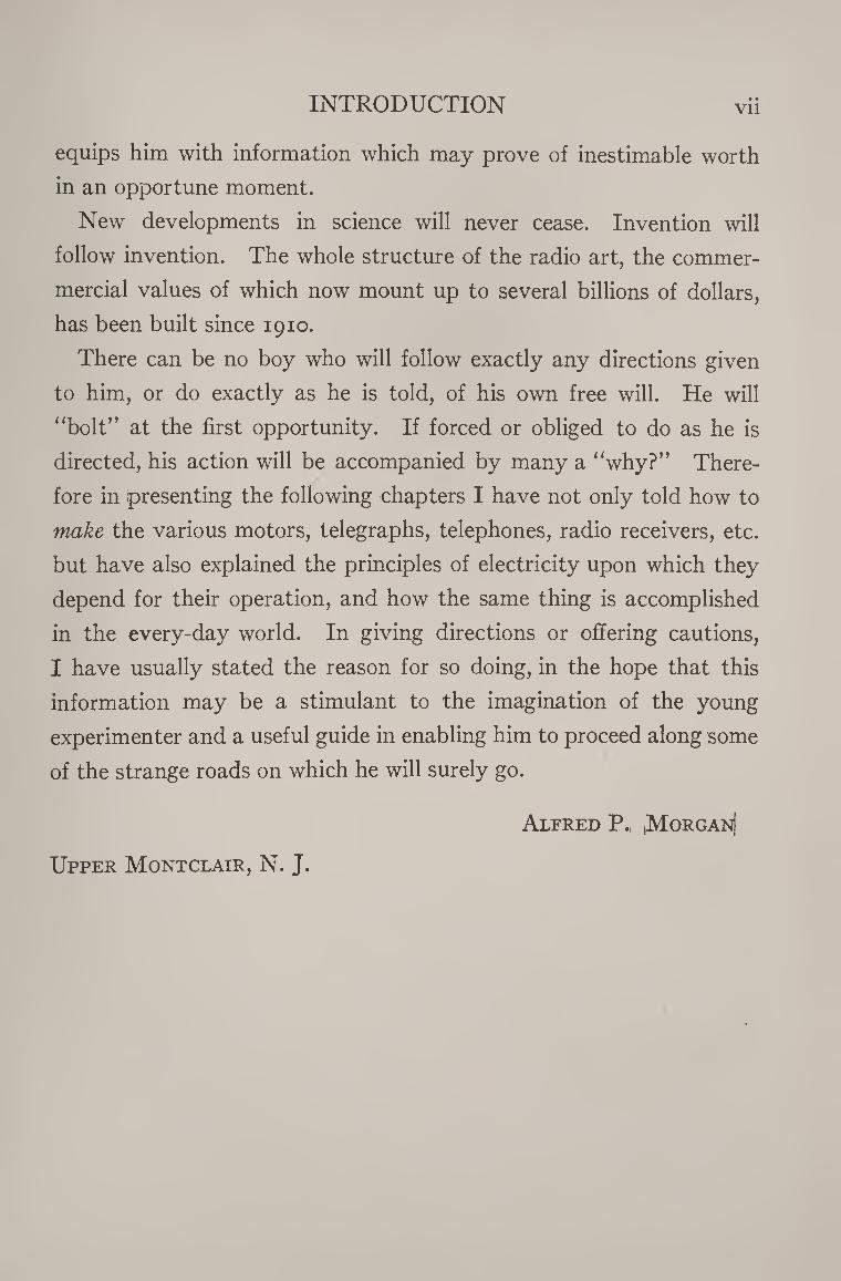
Hrir .fjl
Copyright^?. _ma COPYRIGHT DEPOSIT.


N

:s
A B
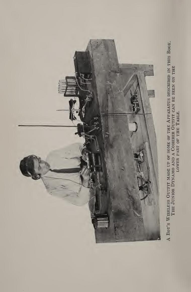
oy’s W
irele
ss O
utf
it m
ade
up o
f so
me
of
the A
ppara
tus
des
crib
ed i
n t
his
Bo
ok
. T
he J
un
ior
Dynam
o a
nd a
Cohere
r O
utf
it c
an b
e se
en o
n t
he
LO
WER
PA
RT
OF
TH
E T
AB
LE.
Practical Plans for Electrical Apparatus for work and play, with an explanation Of the principles of every-day electricity.
By yf
JfLFEED PMoUGMN With illustrations hy the; author'-
Revised Edition
I l^^OI
• K|7 1°!^
Copyright, 1913, by Lothrop, Lee & Shepard Co.
Copyright, 1929, by Lothrop, Lee & Shepard Co.
Entered at Stationers’ Hall, London
All rights reserved
The Boy Electrician
Printed in U. S. A.
APR 25 jg?g ©Clfc 678S* VHM'JO
TO THE SELF-RELIANT
of Bmedca, OUR FUTURE ENGINEERS AND SCIENTISTS, THAN WHOM
NONE IN THE WHOLE WORLD ARE BETTER ABLE
TO WORK OUT AND SOLVE THE PROBLEMS
THAT EVER CONFRONT YOUNG
MANHOOD, THIS BOOK
IS CORDIALLY
DEDICATED.

INTRODUCTION
Once upon a time, and this is a true tale, a boy had a whole rail¬
road system for a toy. The train ran automatically, propelled by
tiny electric motors, the signals went up and down, the station was
reached, a bell rang, the train moved on again and was off on its
journey around many feet of track to come back over the old route.
The boy viewed his gift with raptured eyes, and then his face
changed and he cried out in the bitterness of his disappointment:
“But what do I do? ” The toy was so elaborate that the boy was
left entirely out of the play. Of course he did not like it. His cry
tells a long story.
The prime instinct of almost any boy at play is to make and to
create. He will make things of such materials as he has at hand, and
use the whole force of dream and fancy to create something out of
nothing. The five-year-old will lay half a dozen wooden blocks to¬
gether with a spool on one end and tell you it is a steam train. And it
is. He has both made and created an engine, which he sees but which
you don’t, for the blocks and spool are only a symbol of his creation.
Give his older brother a telephone receiver, some wire and bits of
brass, and he will make a wireless telegraph outfit and listen to a
steamship hundreds of miles away spell out its message to the shore.
The wireless outfit is not a symbol, but something that you can
both hear and see in operation even though you may not understand
the whispering of the dots and dashes. And as soon as the mystery
of this modem wonder more firmly grips your imagination, you per-
VI INTRODUCTION
haps may come to realize that we are living more and more in the
age of electricity and mechanism. Electricity propels our trains, lights
our houses and streets, makes our clothes, cures our ills, warms us,
cooks for us and performs an innumerable number of other tasks at
the turning of a little switch. A mere list is impossible.
Almost every boy experiments at one time or another with elec¬
tricity and electrical apparatus. It is my purpose in writing this
book to open this wonderland of science and present it in a manner
which can be readily understood, and wherein a boy may “ do some¬
thing.” Of course there are other books with the same purport, but
they do not accomplish their end. They are not practical. I can
say this because as a boy I have read and studied them and they
have fallen far short of teaching me or my companions the things
that we were seeking to learn. If they have failed in this respect,
they have done so perhaps not through any inability of the author,
but from the fact that they have not been written from the boy’s
standpoint. They tell what the author thought a boy ought to know
but not what he really does want to know. The apparatus described
therein is for the most part imaginary. The author thought it might
be possible for a boy to build motors, telegraph instruments, etc.,
out of old bolts and tin cans, but he never tried to do so himself.
The apparatus and experiments that I have described have been
constructed and carried out by boys. Their problems and their
questions have been studied and remedied. I have tried to present
practical matter considered wholly from a boy’s standpoint, and to
show the young experimenter just what he can do with the tools
and materials in his possession or not hard to obtain.
To the boy interested in science, a wide field is open. There is no
better education for any boy than to begin at the bottom of the lad¬
der and climb the rungs of scientific knowledge, step by step. It
INTRODUCTION Vll
equips him with information which may prove of inestimable worth
in an opportune moment.
New developments in science will never cease. Invention will
follow invention. The whole structure of the radio art, the commer-
mercial values of which now mount up to several billions of dollars,
has been built since 1910.
There can be no boy who will follow exactly any directions given
to him, or do exactly as he is told, of his own free will. He will
“bolt” at the first opportunity. If forced or obliged to do as he is
directed, his action will be accompanied by many a “why?” There¬
fore in presenting the following chapters I have not only told how to
make the various motors, telegraphs, telephones, radio receivers, etc.
but have also explained the principles of electricity upon which they
depend for their operation, and how the same thing is accomplished
in the every-day world. In giving directions or offering cautions,
I have usually stated the reason for so doing, in the hope that this
information may be a stimulant to the imagination of the young
experimenter and a useful guide in enabling him to proceed along some
of the strange roads on which he will surely go.
Alfred P., ,Morgan)
Upper Montclair, N. J.

CHAPTER I PAGE
Magnets and Magnetism..
The Discovery of the Magnet — The Origin of the Compass — Ex¬ periments with Magnetism — Artificial Magnets — Making a Magnet — Magnetic Poles — Magnetic Force — Compasses — Magnetic Sub¬ stances — Attraction through Bodies — Magnetic Induction — The Laws of Magnetic Attraction — Lines of Magnetic Force — The Mag¬ netic Circuit — The Earth a Great Magnet — Magnetic Dip — A
Dipping Needle — The Uses of Magnets — Preserving a Magnet.
CHAPTER II
Static Electricity.16
The Wonderful Amber — The First Observation of Electricity — Benjamin Franklin’s Famous Kite — Lightning and Electricity — Electrical Induction — Two Kinds of Electricity — Conductors and Insulators — Electrified Writing-Paper — A Surprise for the Cat — Frictional Electricity — Electroscopes — The Pith-Ball Electroscope — The Gold-Leaf Electroscope — Positive and Negative Electricity — The Electrophorus — An Electrical Frog-Pond.
CHAPTER III
Static Electric Machines.30
A Cylinder Electric Machine — Selecting the Bottle — Mounting the Bottle — The Base — The “ Rubber ” — The Prime Conductor — Using the Machine — The Wimshurst Machine — The Glass Plates — The Sectors — The Bosses — The Frame — The Uprights — The
IX
X CONTENTS
Driving-Wheels — The Collectors — The Neutralizers — Experiments
with an Electric Machine — The Leyden Jar — Igniting Gunpowder
— The Electric Umbrella — A Lightning Board — The Electric Dance
— The Electric Whirl — Lichtenberg’s Figures.
CHAPTER IV
Cells and Batteries.
Build your own Batteries first — The Voltaic Cell — How Electricity
is made with Chemicals — A Simple Cell — Leclanche Cell — Polari¬
zation — Dry Cells — How to make a Dry Cell — Recharging Dry
Cells — Wet Batteries — Carbon Plates — Battery Elements — Bi¬
chromate Batteries — Handling Acid — A Plunge Battery — The
Edison - Lalande Cell — A Tomato-Can Battery — Secondary or
Storage Batteries — Connecting Cells — Making a Storage Battery —
The Plates — Forming the Plates — Charging a Storage Battery —
Ampere Hours.
CHAPTER V
Electro - Magnetism and Magnetic Induction.
Oersted’s Experiment — The Magnetic Field about a Wire Carrying
Current — Field of Force — The Iron Core — The Principle of an
Electro - Magnet — Electro - Magnets — Handling Steel Rails with
Electro-Magnets — Magnetic Induction.
CHAPTER VI
Electrical Units.
The Units of Electrical Measure — Measuring the Current — The
Ampere — The Volt — Electro-motive Force — The Ohm — Ohm’s
Law — The Watt — The Electrical Horse-power — The Kilowatt —
The Coulomb — The Difference between Alternating and Direct Cur¬
rents — The Cycle — The Alternation — Frequency.
CHAPTER VII
Electrical Appurtenances.
Wires — Wire Sizes — Insulators — Binding-Posts — Switches and
Cut-Outs — Home-made Switches — Fuses — Lightning-Arresters.
PAGE
53
8s
92
10o
CONTENTS xi
CHAPTER VIII PAGE
Electrical Measuring Instruments.116
Meters — A Simple Voltmeter and Ammeter — A Portable Volt¬
meter and Ammeter — Calibrating the Meters — Connecting the
Meters — Galvanoscopes and Galvanometers — Simple Galvanoscopes
— Astatic Galvanoscope — Astatic Galvanometer — How to Make a
Wheatstone Bridge — Resistance-Coils — How to Use a Wheatstone
Bridge for Measuring Resistance.
CHAPTER IX
Bells, Alarms, and Annunciators.140
How to Build an Electric Bell — An Electric Alarm — An Annun¬
ciator — Push-Buttons — Bell Systems — A Burglar Alarm.
CHAPTER X
Electric Telegraphs.150
The First Telegraph — The Principle of the Telegraph — The Key
— The Sounder — How to Make a Simple Key and Sounder — Con¬
necting the Instruments — A Complete Telegraph Set — How to
Build a Telegraph Relay — Connecting a Relay — How to Learn to
Telegraph — The Alphabet — Operating.
CHAPTER XI
Microphones and Telephones.170
Microphones — How to Hear a Fly’s Footstep — Telephones —
The Principle of the Telephone — The Telephone Transmitter — The
Telephone Receiver — How to Build a Telephone — Telephone Re¬
ceivers — A Home-made Telephone Receiver — A Home-made Tele¬
phone Transmitter — A Complete Telephone Instrument — A Desk-
Stand Type of Telephone — A Telephone Induction Coil — Connect¬
ing the Telephones.
CHAPTER XII
Induction Coils.194
A Medical Coil or Shocking Coil — Spark Coils — The Principle of
the Spark Coil — Building a Spark Coil — The Core — The Primary
CONTENTS Xll
PAGE
— The Secondary —• Winding the Secondary — The Interrupter —
The Condenser — Finishing the Coil —• Experiments with a Spark Coil
— Electrical Hands — Geissler Tubes — Ghost Light — Puncturing
Paper — A Practical Joke — An Electrified Garbage-Can — Photo¬
graphing an Electric Discharge — Jacob’s Ladder — X-Rays — The
Tube — The Fluoroscope — Using the Outfit.
CHAPTER XIII
Transformers.221
How Alternating Current is Transmitted — An Alternating Current
System — The Transformer — Step-Up Transformers — Step-Down
Transformers — An Experimental Transformer —• The Core — The
Windings —• Arranging the Switches — Connecting and Mounting the
Transformer.
CHAPTER XIV
Wireless Telegraphy.237
The Principle of Wireless Telegraphy — Wireless Waves — A Simple
Transmitter — Waves in the Ether — The Action of the Receiving
Station — How to Build Wireless Instruments — The Aerial — Erecting
the Aerial —• The Ground Connection — The Receiving Apparatus — A
Tuning Coil — Detectors — A Crystal Detector — “Cat-Whiskers”
Detectors — The Fixed Condenser — Telephone Receivers — Connect¬
ing the Receiving Apparatus —■ The Continental Code — A Coherer
Outfit — The Coherer — The Decoherer — Building a Relay—’Con¬
necting and Adjusting the Apparatus — The Transmitting Apparatus
— The Spark Coil — Small Spark-Gaps.
CHAPTER XV
Radio Receiving Sets.266
Principles of Radio Reception and Transmission — The “Edison
Effect” —• The DeForest Audion — A Simple Audion Receiving Circuit
— The Audion Amplifier Circuit — How to Build a Single Tube Single
Control Regenerative Receiver — Parts and Materials — Variable Con¬
denser —Filament Rheostat —• The Vacuum Tube—The Batteries—The
Coil — Assembling and Connecting — A One Stage Amplifier — How to
Build a Four Tube Regenerative Receiver — Parts and Materials —• The
Circuit Diagram—The Radio-Frequency Transformer — The Volume
Control—The Jacks — The Loud Speaker—’Assembling the Receiver
— Tuning the Receiver.
CONTENTS Xlll
CHAPTER XVI PAGE
An Experimental Wireless Telephone.297
The Principle of the Wireless Telephone — Experiments illustrating
the Principle of the Wireless Telephone —• Building a Wireless Tele¬
phone — Making the Coils — The Strap-Key — Connecting and
Operating the Apparatus.
CHAPTER XVII
Electric Motors.305
Thomas Davenport —• The First Electric Motor — A Simple Electric
Motor — The Simplex Motor —• The Armature ■—• Making the Field
Magnet—’The Bearings—'The Commutator Core — The Base —
Assembling the Motor—• Connections — How to Build a Larger Motor
— Cutting out the Laminations — Winding the Motor.
CHAPTER XVIII
Dynamos.317
The Difficulties of Building a Dynamo — The Principle of the Alter¬
nator and the Direct-Current Dynamo — Making a Magneto into a
Dynamo — A 10-Watt Dynamo —• The Field —• The Armature —
The Commutator—'The Windings — The Base — The Bearings —
The Brushes ■—• Assembling and Completing the Dynamo.
CHAPTER XIX
An Electric Railway.334
A Toy Railway Car — How to Make the Running Gear — Installing
the Motor—-Testing the Car—-Making the Body — How to Make
the Track —• Track Patterns — A Cross-over — A Rail Connector —
Making the Car Reversible — A Track Bumper — A Design for a Rail¬
way Bridge —• A Design for a Railway Station.
CHAPTER XX
Miniature Lighting.35°
What it may be used for — Carbon Battery Lamps — Tungsten
Battery Lamps—-Lamp Bases — Sockets and Receptacles—-The
Wires used for Miniature Lighting — Switches — Batteries—Mul¬
tiple Wiring — Series Wiring — Three-way Wiring — Lamp Brackets
— A Hanging Lamp — Small Dry Cells — An Electric Hand-Lantern
— A Ruby Lantern — A Night Lamp — A Watch-Light — An Electric
Scarf-Pin.
XIV CONTENTS
CHAPTER XXI
Miscellaneous Electrical Apparatus.
How Electricity may be Generated by Heat — The Energy of the
Sun—’Sun-Power Apparatus — How to Build a Thermopile — How
to Make a Reflectoscope — How to Reduce the 110-v. Current so that
it may be used for Experimenting — The Induction Motor — A Motor
without Brushes — Alternating-Current Power Motors — Electrolysis
—• Electro-Plating — Copper-Plating — Nickel-Plating — How to Make
a Rheostat — How to Make a Pole-Changing Switch — Reversing a Small Motor — The Tesla Coil —High-Frequency Currents — How
to Make a Tesla Coil — Experiments with High-Frequency Currents
— Conclusion.
PAGE
369
LIST OF HALF-TONE ILLUSTRATIONS
(In addition to three hundred and twenty-seven text illustrations)
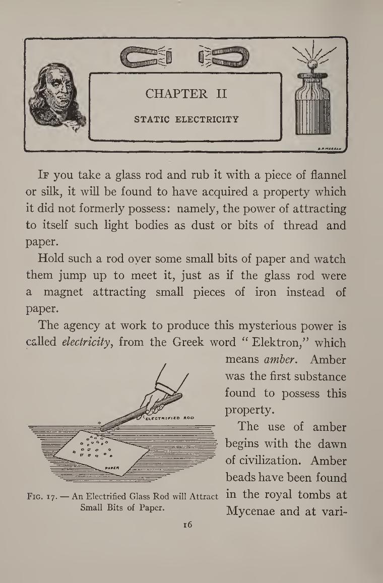
A Boy’s Wireless Outfit Made up of some of the Apparatus described in this
Book. Frontispiece
FACING PAGE
A Double Lightning Discharge from a Cloud to the Earth .... 20
Lifting-Magnets of the Type known as Plate, Billet, and Ingot Magnets . 88
An X-Ray Photograph of the Hand.220
Electro-Magnetic Waves Compared.240
A Double-Slider Tuning Coil.250
Complete Wireless Receiving Set, consisting of Double-Slider Tuning Coil,
Detector, and Fixed Condenser.250
Crystal Detectors.250
The Junior Dynamo, Mounted.332
A Complete Coherer Outfit, as described on page 258 386
The Tesla High-Frequency Coil.386
xv

THE BOY ELECTRICIAN

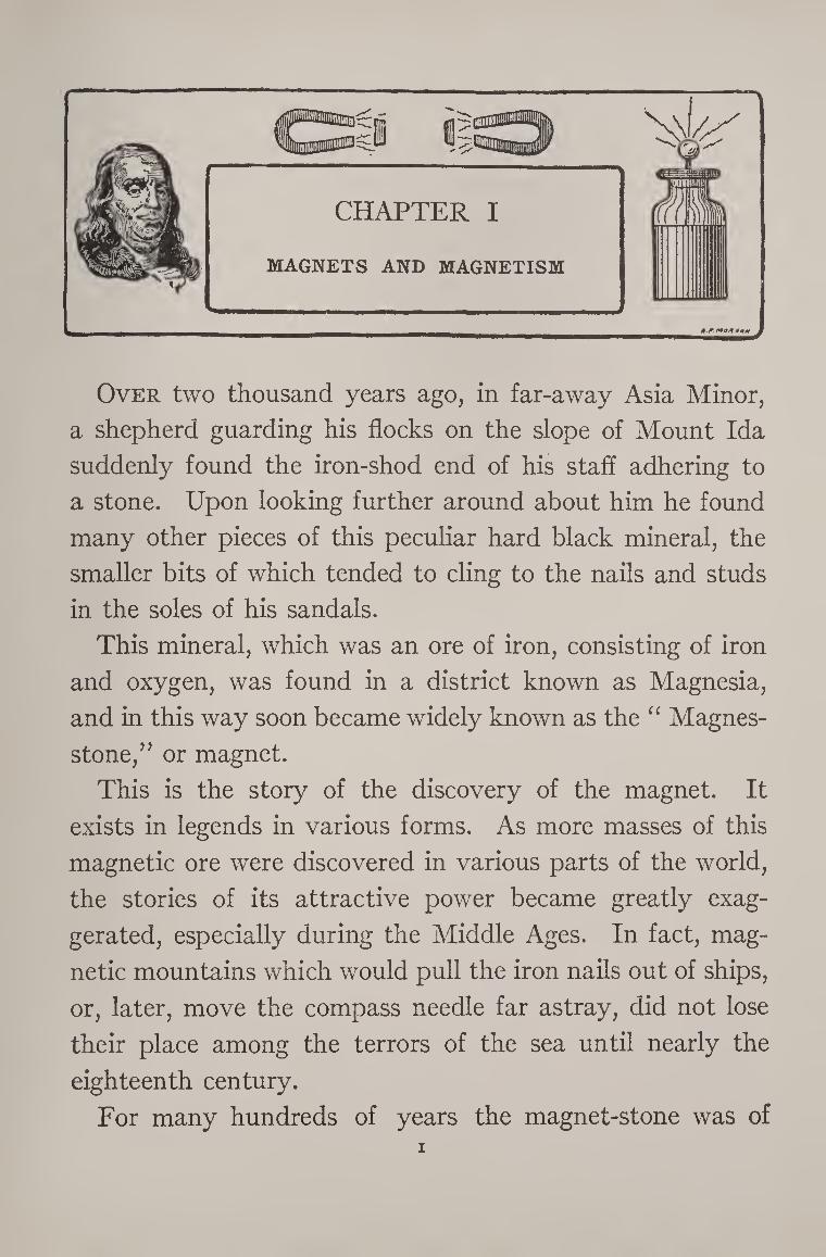
Over two thousand years ago, in far-away Asia Minor,
a shepherd guarding his flocks on the slope of Mount Ida
suddenly found the iron-shod end of his staff adhering to
a stone. Upon looking further around about him he found
many other pieces of this peculiar hard black mineral, the
smaller bits of which tended to cling to the nails and studs
in the soles of his sandals.
This mineral, which was an ore of iron, consisting of iron
and oxygen, was found in a district known as Magnesia,
and in this way soon became widely known as the “ Magnes-
stone,” or magnet.
This is the story of the discovery of the magnet. It
exists in legends in various forms. As more masses of this
magnetic ore were discovered in various parts of the world,
the stories of its attractive power became greatly exag¬
gerated, especially during the Middle Ages. In fact, mag¬
netic mountains which would pull the iron nails out of ships,
or, later, move the compass needle far astray, did not lose
their place among the terrors of the sea until nearly the
eighteenth century.
For many hundreds of years the magnet-stone was of
2 THE BOY ELECTRICIAN
little use to mankind save as a curiosity which possessed
the power of attracting small pieces of iron and steel and
other magnets like itself. Then some one, no one knows
who, discovered that if a magnet-stone were hung by a
thread in a suitable manner it would always tend to point
North and South; and so the “ Magnes-stone ” became
also called the “ lodestone,” or “ leading-stone.”
These simple bits of lodestone suspended by a thread
were the forerunners of the modern compass and were of
great value to the ancient navigators, for they enabled
them to steer ships in cloudy weather when the sun was
obscured and on nights when the pole-star could not be
seen.
The first real compasses were called gnomons, and con¬
sisted of a steel needle which had been rubbed upon a
lodestone until it acquired its magnetic properties. Then it
was thrust through a reed or short piece of wood which
supported it on the surface of a vessel of water. If the
needle was left in this receptacle, naturally it would move
against the side and not point a true position. Therefore
it was given a circular movement in the water, and as soon
as it came to rest, the point on the horizon which the north
end designated was carefully noted and the ship’s course
laid accordingly.
The modern mariners’ compass is quite a different ar¬
rangement. It consists of three parts, the bowl, the card,
and the needle. The bowl, which contains the card and
needle, is usually a hemispherical brass receptacle, sus-
MAGNETS AND MAGNETISM 3
pended in a pair of brass rings, called gimbals, in such a
manner that the bowl will remain horizontal no matter
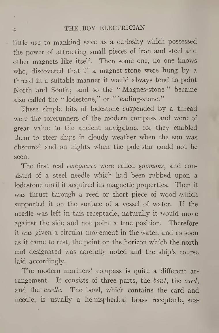
how violently the ship may pitch and roll. The card, which
is circular, is divided into 32
equal parts called the points
of the compass. The needles,
of which there are generally
from two to four, are fastened
to the bottom of the card.
In the center of the card is
a conical socket poised on an
upright pin fixed in the bot¬
tom of the bowl, so that the
card hanging on the pin turns
freely around its center. On
shipboard, the compass is so placed that a black mark,
called the lubber’s line, is fixed in a position parallel to the
keel. The point on the compass-card which is directly
against this line indicates the direction of the ship’s head.
Experiments with Magnetism
The phenomena of magnetism and its laws form a very
important branch of the study of electricity, for they play
an important part in the construction of almost all elec¬
trical apparatus.
Dynamos, motors, telegraphs, telephones, wireless appa¬
ratus, voltmeters, ammeters, and so on through a practically
endless list, depend upon magnetism for their operation.
4 THE BOY ELECTRICIAN
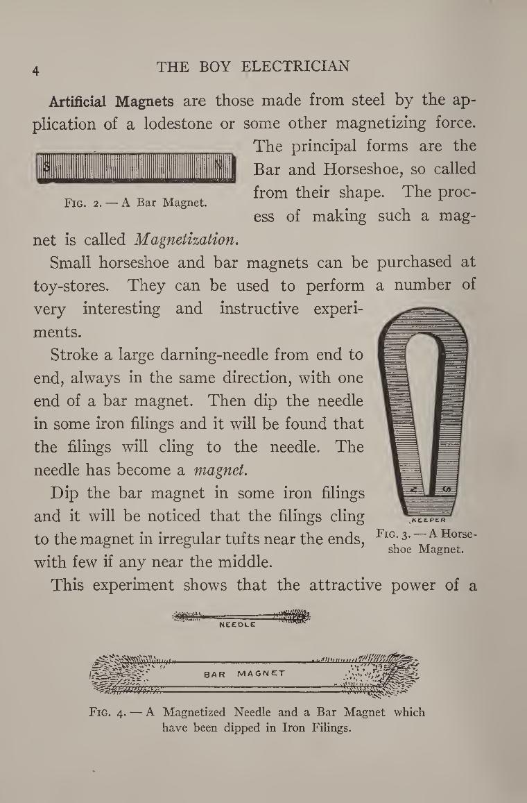
Artificial Magnets are those made from steel by the ap¬
plication of a lodestone or some other magnetizing force.
The principal forms are the
Bar and Horseshoe, so called
from their shape. The proc¬
ess of making such a mag¬
net is called Magnetization.
Small horseshoe and bar magnets can be purchased at
toy-stores. They can be used to perform
very interesting and instructive experi¬
ments.
Stroke a large darning-needle from end to
end, always in the same direction, with one
end of a bar magnet. Then dip the needle
in some iron filings and it will be found that
the filings will cling to the needle. The
needle has become a magnet.
Dip the bar magnet in some iron filings
and it will be noticed that the filings cling
to the magnet in irregular tufts near the ends,
with few if any near the middle.
This experiment shows that the attractive power of a
a number of
vKEEP£R
Fig. 3. — A Horse¬ shoe Magnet.
Fig. 2. — A Bar Magnet.
needle
> w * /* ■s+a
bar magnet
Fig. 4. — A Magnetized Needle and a Bar Magnet which
have been dipped in Iron Filings.
MAGNETS AND MAGNETISM
magnet exists in two opposite places. These are called the
poles.
There exists between magnets and bits of iron and steel
a peculiar unseen force which can exert itself across
space.
The power with which a magnet attracts or repels an¬
other magnet or attracts bits of iron and steel is called
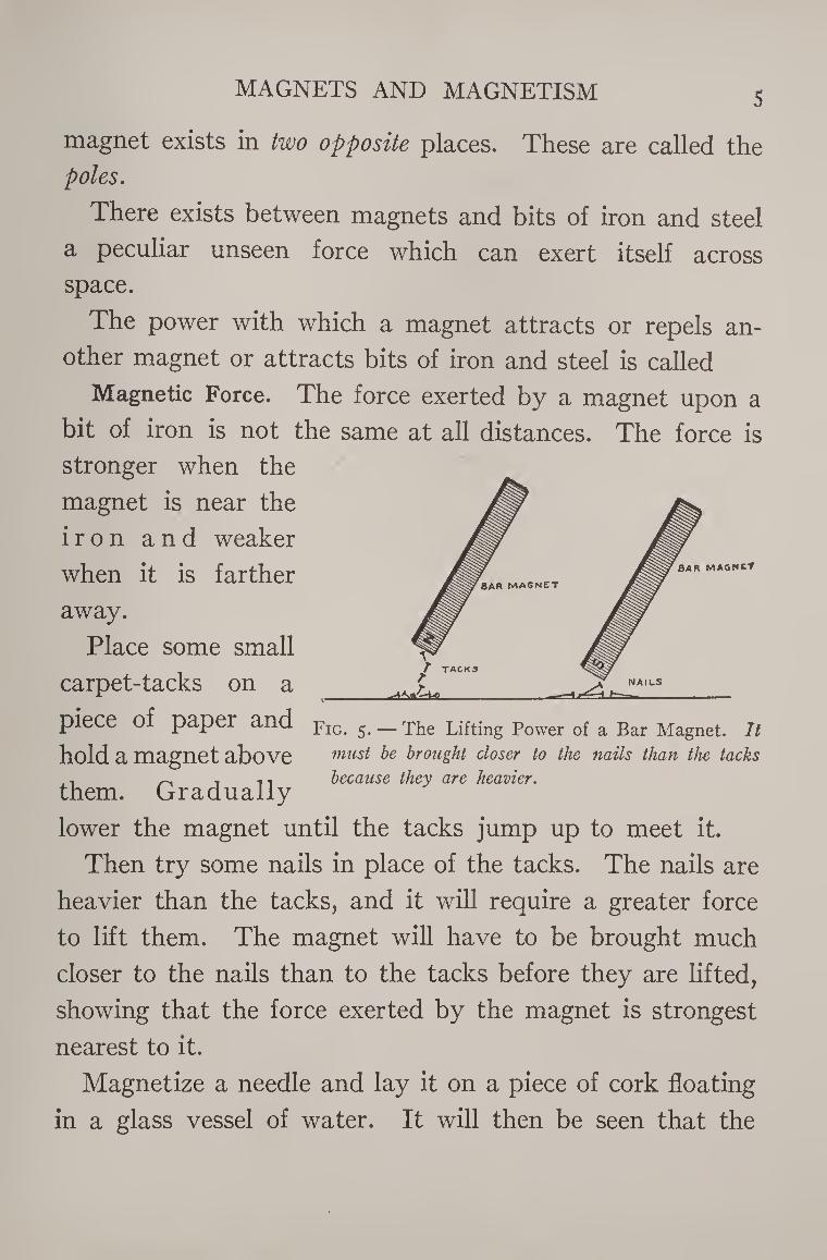
Magnetic Force. The force exerted by a magnet upon a
bit of iron is not the same at all distances. The force is
stronger when the
magnet is near the
iron and weaker
when it is farther
away.
Place some small
carpet-tacks on a
BAR MAGNET
T TACK3
BAR MAGNCT
NAILS
piece O paper and jrIG> ^ — The Lifting Power of a Bar Magnet. It hold a magnet above must be brought closer to the nails than the tacks
~ in because they are heavier. them. Gradually
lower the magnet until the tacks jump up to meet it.
Then try some nails in place of the tacks. The nails are
heavier than the tacks, and it will require a greater force
to lift them. The magnet will have to be brought much
closer to the nails than to the tacks before they are lifted,
showing that the force exerted by the magnet is strongest
nearest to it.
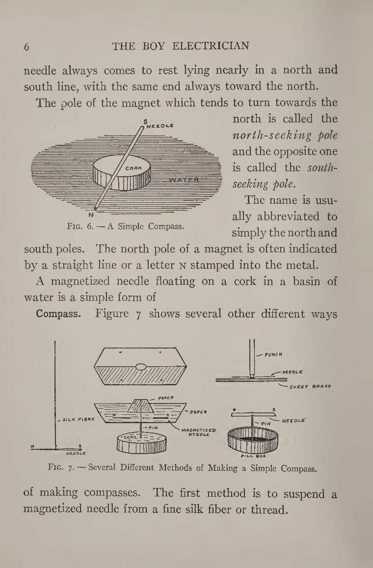
Magnetize a needle and lay it on a piece of cork floating
in a glass vessel of water. It will then be seen that the
6 THE BOY ELECTRICIAN
needle always comes to rest lying nearly in a north and
south line, with the same end always toward the north.
The pole of the magnet which tends to turn towards the
north is called the
north-seeking pole
and the opposite one
is called the south¬
seeking pole.
The name is usu¬
ally abbreviated to
simply the north and
south poles. The north pole of a magnet is often indicated
by a straight line or a letter n stamped into the metal.
A magnetized needle floating on a cork in a basin of
water is a simple form of
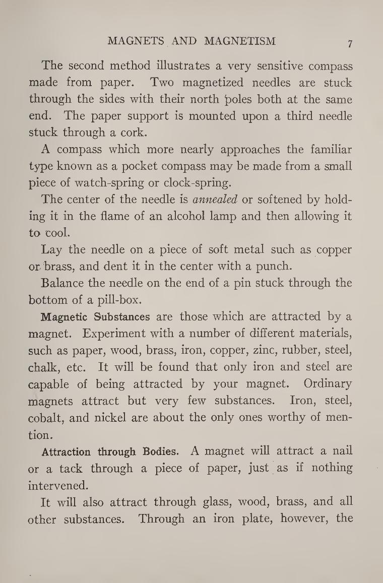
Compass. Figure 7 shows several other different ways
Fig. 6. — A Simple Compass.
Fig. 7. — Several Different Methods of Making a Simple Compass.
of making compasses. The first method is to suspend a
magnetized needle from a fine silk fiber or thread.
MAGNETS AND MAGNETISM 7
The second method illustrates a very sensitive compass
made from paper. Two magnetized needles are stuck
through the sides with their north jDoles both at the same
end. The paper support is mounted upon a third needle
stuck through a cork.
A compass which more nearly approaches the familiar
type known as a pocket compass may be made from a small
piece of watch-spring or clock-spring.
The center of the needle is annealed or softened by hold¬
ing it in the flame of an alcohol lamp and then allowing it
to cool.
Lay the needle on a piece of soft metal such as copper
or brass, and dent it in the center with a punch.
Balance the needle on the end of a pin stuck through the
bottom of a pill-box.
Magnetic Substances are those which are attracted by a
magnet. Experiment with a number of different materials,
such as paper, wood, brass, iron, copper, zinc, rubber, steel,
chalk, etc. It will be found that only iron and steel are
capable of being attracted by your magnet. Ordinary
magnets attract but very few substances. Iron, steel,
cobalt, and nickel are about the only ones worthy of men¬
tion.
Attraction through Bodies. A magnet will attract a nail
or a tack through a piece of paper, just as if nothing
intervened.
It will also attract through glass, wood, brass, and all
other substances. Through an iron plate, however, the
8 THE BOY ELECTRICIAN
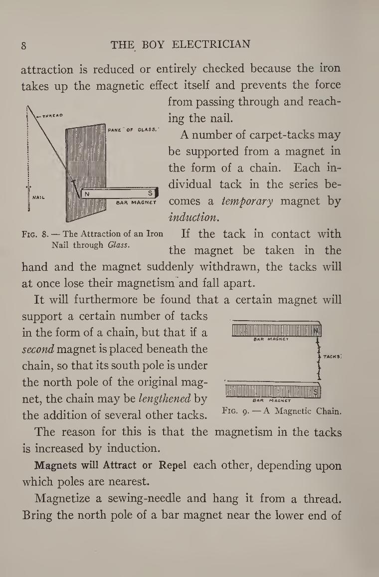
Fig. 8. — The Attraction of an Iron Nail through Glass.
attraction is reduced or entirely checked because the iron
takes up the magnetic effect itself and prevents the force
from passing through and reach¬
ing the nail.
A number of carpet-tacks may
be supported from a magnet in
the form of a chain. Each in¬
dividual tack in the series be¬
comes a temporary magnet by
induction.
If the tack in contact with
the magnet be taken in the
hand and the magnet suddenly withdrawn, the tacks will
at once lose their magnetism and fall apart.
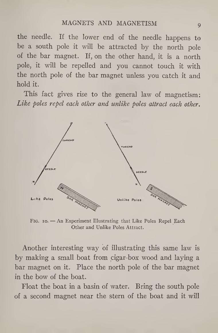
It will furthermore be found that a certain magnet will
support a certain number of tacks
in the form of a chain, but that if a
second magnet is placed beneath the
chain, so that its south pole is under
the north pole of the original mag¬
net, the chain may be lengthened by
the addition of several other tacks. FlG' 9'~ A Masnetlc Cham.
The reason for this is that the magnetism in the tacks
is increased by induction.
Magnets will Attract or Repel each other, depending upon
which poles are nearest.
Magnetize a sewing-needle and hang it from a thread.
Bring the north pole of a bar magnet near the lower end of
BAR MAGNET
MAGNETS AND MAGNETISM 9
the needle. If the lower end of the needle happens to
be a south pole it will be attracted by the north pole
of the bar magnet. If, on the other hand, it is a north
pole, it will be repelled and you cannot touch it with
the north pole of the bar magnet unless you catch it and
hold it.
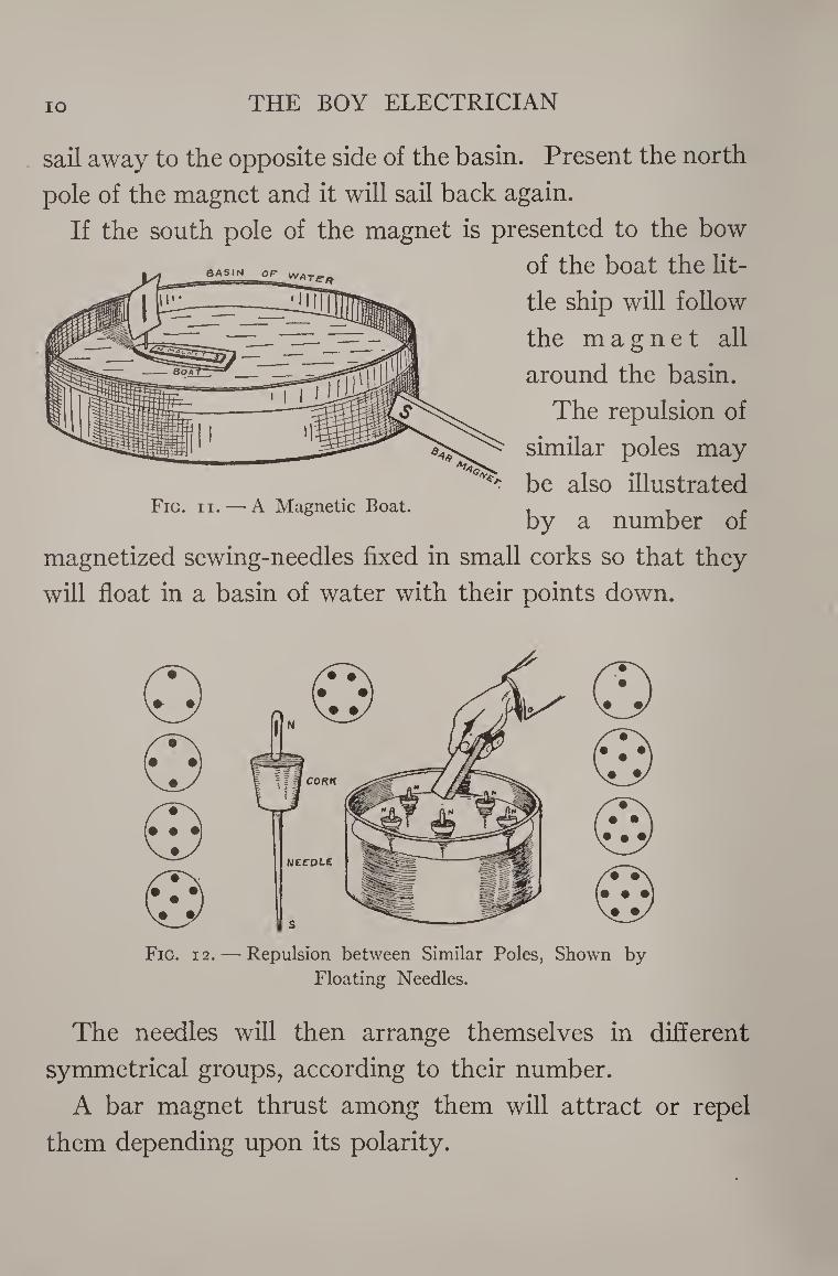
This fact gives rise to the general law of magnetism:
Like poles repel each other and unlike poles attract each other.
Fig. 10. — An Experiment Illustrating that Like Poles Repel Each
Other and Unlike Poles Attract.
Another interesting way of illustrating this same law is
by making a small boat from cigar-box wood and laying a
bar magnet on it. Place the north pole of the bar magnet
in the bow of the boat.
Float the boat in a basin of water. Bring the south pole
of a second magnet near the stern of the boat and it will
10 THE BOY ELECTRICIAN
BASIN OF ”*Te-R
sail away to the opposite side of the basin. Present the north
pole of the magnet and it will sail back again.
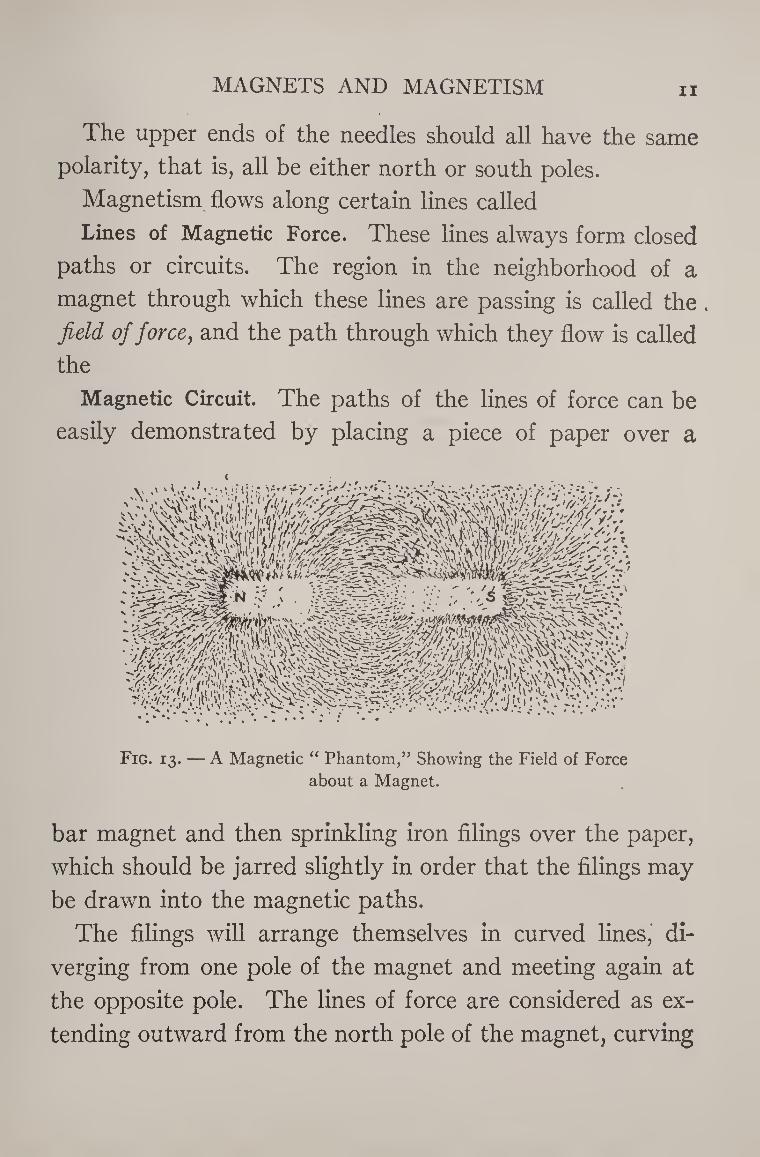
If the south pole of the magnet is presented to the bow
of the boat the lit¬
tle ship will follow
the magnet all
around the basin.
The repulsion of
similar poles may
be also illustrated
by a number of
magnetized sewing-needles fixed in small corks so that they
will float in a basin of water with their points down.
Fig. ii. — A Magnetic Boat.
Fig. 12. — Repulsion between Similar Poles, Shown by
Floating Needles.
The needles will then arrange themselves in different
symmetrical groups, according to their number.
A bar magnet thrust among them will attract or repel
them depending upon its polarity.
MAGNETS AND MAGNETISM ii
The upper ends of the needles should all have the same
polarity, that is, all be either north or south poles.
Magnetism flows along certain lines called
Lines of Magnetic Force. These lines always form closed
paths or circuits. The region in the neighborhood of a
magnet through which these lines are passing is called the .
field of force, and the path through which they flow is called
the
Magnetic Circuit. The paths of the lines of force can be
easily demonstrated by placing a piece of paper over a
Fig. 13. — A Magnetic “ Phantom,” Showing the Field of Force
about a Magnet.
bar magnet and then sprinkling iron filings over the paper,
which should be jarred slightly in order that the filings may
be drawn into the magnetic paths.
The filings will arrange themselves in curved lines, di¬
verging from one pole of the magnet and meeting again at
the opposite pole. The lines of force are considered as ex¬
tending outward from the north pole of the magnet, curving
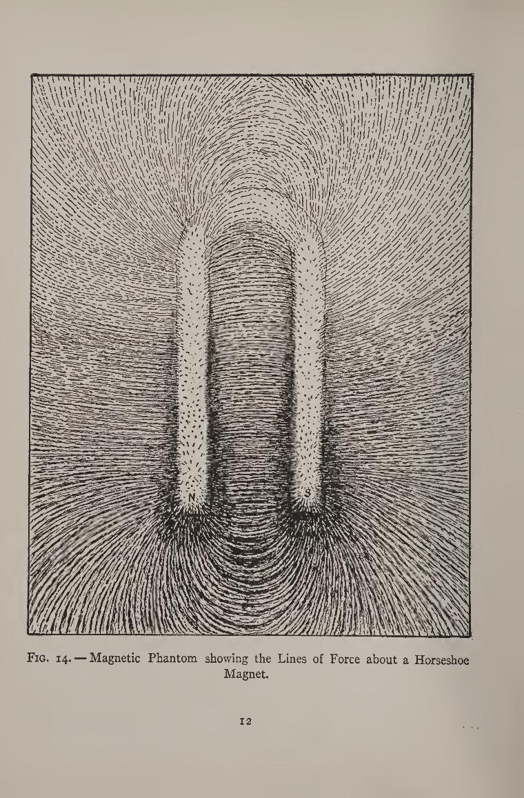
Fig. 14. — Magnetic Phantom showing the Lines of Force about a Horseshoe
Magnet.
MAGNETS AND MAGNETISM 13
around through the air to the south pole and completing
the circuit back through the magnet.
Figure 14 shows the lines of force about a horseshoe
magnet. It will be noticed that the lines cross directly
between the north and south poles.
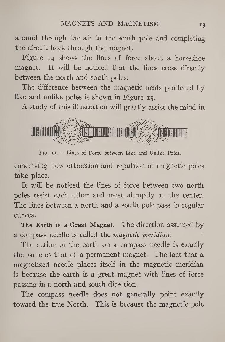
The difference between the magnetic fields produced by
like and unlike poles is shown in Figure 15.
A study of this illustration will greatly assist the mind in
Fig. 15. — Lines of Force between Like and Unlike Poles.
conceiving how attraction and repulsion of magnetic poles
take place.
It will be noticed the lines of force between two north
poles resist each other and meet abruptly at the center.
The lines between a north and a south pole pass in regular
curves.
The Earth is a Great Magnet. The direction assumed by
a compass needle is called the magnetic meridian.
The action of the earth on a compass needle is exactly
the same as that of a permanent magnet. The fact that a
magnetized needle places itself in the magnetic meridian
is because the earth is a great magnet with lines of force
passing in a north and south direction.
The compass needle does not generally point exactly
toward the true North. This is because the magnetic pole
14 THE BOY ELECTRICIAN
of the earth toward which the needle points is not situated
at the same place as the geographical pole.
Magnetic Dip. If a sewing-needle is balanced so as to be
perfectly horizontal when suspended from a silk thread
and is then magnetized, it will be found that it has lost its
balance and that the north end points slightly downward.
This is due to the fact that the earth is round and that
the magnetic pole which is situated in the far North is
therefore not on a horizontal line
with the compass, but below such
a line.
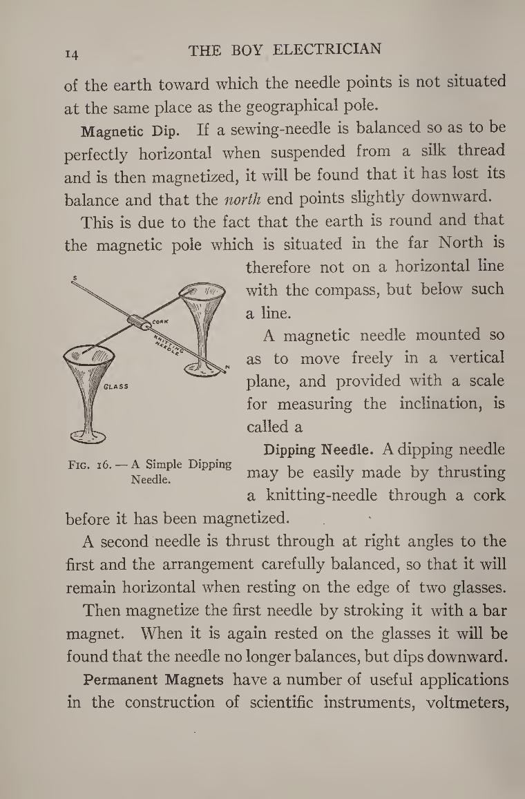
A magnetic needle mounted so
as to move freely in a vertical
plane, and provided with a scale
for measuring the inclination, is
called a
Dipping Needle. A dipping needle
may be easily made by thrusting
a knitting-needle through a cork
before it has been magnetized.
A second needle is thrust through at right angles to the
first and the arrangement carefully balanced, so that it will
remain horizontal when resting on the edge of two glasses.
Then magnetize the first needle by stroking it with a bar
magnet. When it is again rested on the glasses it will be
found that the needle no longer balances, but dips downward.
Permanent Magnets have a number of useful applications
in the construction of scientific instruments, voltmeters,
Fig. i6. — A Simple Dipping
Needle.
MAGNETS AND MAGNETISM *■ - 15
ammeters, telephone receivers, magnetos and a number of
other devices.
In order to secure a very powerful magnet for some pur¬
poses a number of steel bars are magnetized separately, and
then riveted together. A magnet made in this way is called
a compound magnet, and may have either a bar or a horse¬
shoe shape.
Magnets are usually provided with a soft piece of iron
called an armature or “ keeper.” The “ keeper ” is laid
across the poles of the magnet when the latter is not in use
and preserves its magnetism.
A blow or a fall will disturb the magnetic arrangement of
the molecules of a magnet and greatly weaken it. The most
powerful magnet becomes absolutely demagnetized at a
red heat, and remains so after cooling.
Therefore if you wish to preserve the strength of a mag¬
netic appliance or the efficiency of any electrical instrument
provided with a magnet, do not allow it to receive rough
usage.
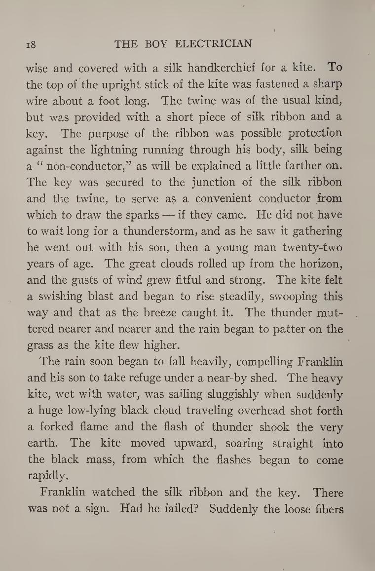
If you take a glass rod and rub it with a piece of flannel
or silk, it will be found to have acquired a property which
it did not formerly possess: namely, the power of attracting
to itself such light bodies as dust or bits of thread and
paper.
Hold such a rod oyer some small bits of paper and watch
them jump up to meet it, just as if the glass rod were
a magnet attracting small pieces of iron instead of
paper.
The agency at work to produce this mysterious power is
called electricity, from the Greek word “ Elektron,” which
means amber. Amber
was the first substance
found to possess this
property.
The use of amber
begins with the dawn
of civilization. Amber
beads have been found
Fig. 17. — An Electrified Glass Rod will Attract in the royal tombs at Small Bits of Paper. Mycenae and at vari-
16
STATIC ELECTRICITY i7
ous places throughout Sardinia, dating from at least two
thousand years before our era.
Amber was used by the ancient world as a jewel and for
decoration.
The ancient Syrian woman used distaffs made of amber
for spinning. As the spindle whirled around it often rubbed
against the spinner’s garments and thus became electrified,
as amber always does when it is rubbed. Then on nearing
the ground it drew to itself the dust or bits of chaff or leaves
lying there, or sometimes perhaps attracted the fringe of
the clothing.
The spinner easily saw this, because the bits of chaff
which were thus attracted would become entangled in her
thread unless she were careful. The amber spindle was,
therefore, called the “ harpaga ” or “ clutcher,” for it
seemed to seize such light bodies as if it had invisible talons,
which not only grasped but held on.
This was probably the first intelligent observation of an
electrical effect.
In the eighteenth century, when Benjamin Franklin
performed his famous kite experiment, electricity was be¬
lieved to be a sort of fiery atmospheric discharge which
could be captured in small quantities and stored in recep¬
tacles such as Leyden jars.
Franklin was the first to prove that the lightning dis¬
charges taking place in the heavens are electrical.
The story of his experiment is very interesting.
He secured two light strips) of cedar wood, placed cross-
i8 THE BOY ELECTRICIAN
wise and covered with a silk handkerchief for a kite. To
the top of the upright stick of the kite was fastened a sharp
wire about a foot long. The twine was of the usual kind,
but was provided with a short piece of silk ribbon and a
key. The purpose of the ribbon was possible protection
against the lightning running through his body, silk being
a “ non-conductor,’5 as will be explained a little farther on.
The key was secured to the junction of the silk ribbon
and the twine, to serve as a convenient conductor from
which to draw the sparks — if they came. He did not have
to wait long for a thunderstorm, and as he saw it gathering
he went out with his son, then a young man twenty-two
years of age. The great clouds rolled up from the horizon,
and the gusts of wind grew fitful and strong. The kite felt
a swishing blast and began to rise steadily, swooping this
way and that as the breeze caught it. The thunder mut¬
tered nearer and nearer and the rain began to patter on the
grass as the kite flew higher.
The rain soon began to fall heavily, compelling Franklin
and his son to take refuge under a near-by shed. The heavy
kite, wet with water, was sailing sluggishly when suddenly
a huge low-lying black cloud traveling overhead shot forth
a forked flame and the flash of thunder shook the very
earth. The kite moved upward, soaring straight into
the black mass, from which the flashes began to come
rapidly.
Franklin watched the silk ribbon and the key. There
was not a sign. Had he failed? Suddenly the loose fibers

STATIC ELECTRICITY i9
of the twine erected themselves. The moment had come.
Without a tremor he advanced his knuckle to the key.
And between his knuckle and the key passed a spark! then
another and another. They were the same kind of little
sparks that he had made hundreds of times with a glass
tube.
And then as the storm abated and the clouds swept off
towards the mountains and the kite flew lazily in the blue,
the face of Franklin gleamed in the glad sunshine. The
great discovery was complete, his name immortal.
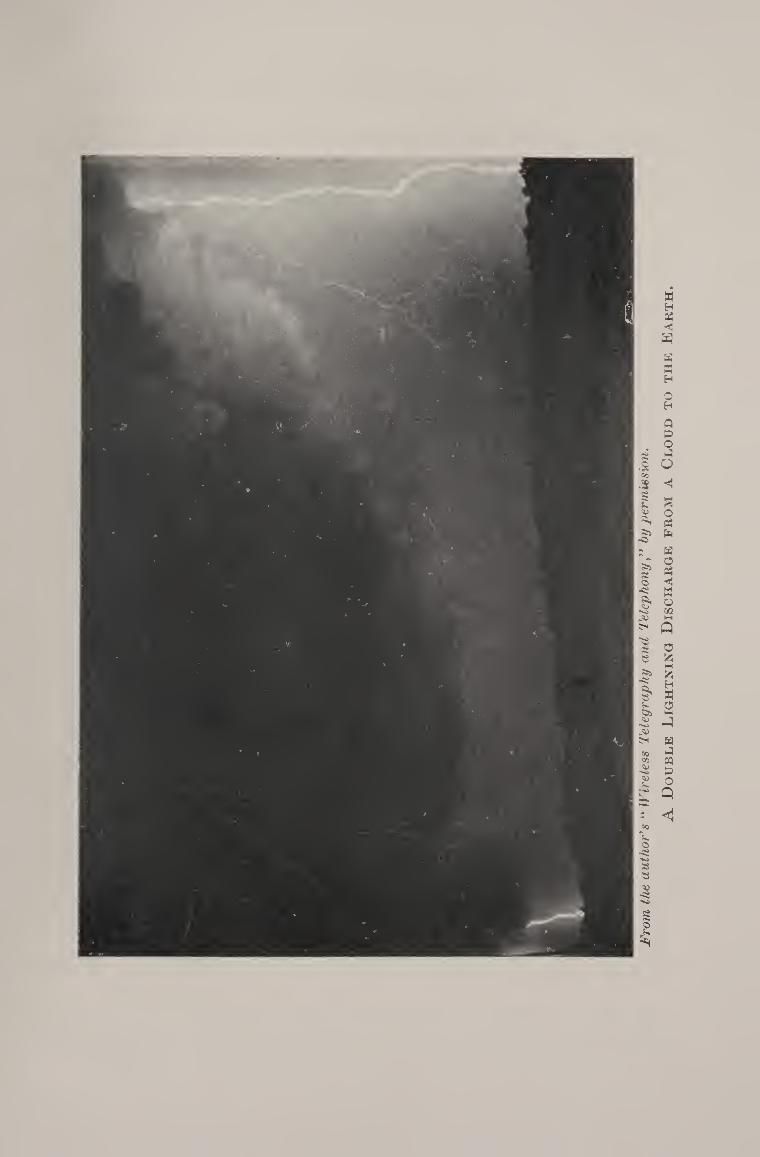
The cause of lightning is the accumulation of the electric
charges in the clouds, the electricity residing on the surface
of the particles of water in the cloud. These charges grow
stronger as the particles of water join together and become
larger. As the countless multitude of drops grows larger and
larger the “ potential ” is increased, and the cloud soon be¬
comes heavily charged.
Through the effects of a phenomenon called induction,
and which we have already stumbled against in the experi¬
ment with the tacks and the magnetic chain, the force
exerted by the charge grows stronger because of a charge
of the opposite kind on a neighboring cloud or some object
on the earth beneath. These charges continually strive
to burst across the intervening air.
As soon as the charge grows strong enough a vivid flash
of lightning, which may be from one to ten miles long, takes
place. The heated air in the path of the lightning expands
with great force; but immediately other air rushes in to
20 THE BOY ELECTRICIAN
fill the partial vacuum, thus producing the terrifying sounds
called thunder.
In the eighteenth century, electricity was believed to be
a sort of fiery atmospheric discharge, as has been said.
Later it was discovered that it seemed to flow like water
through certain mediums, and so was thought to be a fluid.
Modern scientists believe it to be simply a vibratory mo¬
tion, either between adjacent particles or in the ether sur¬
rounding those particles.
It was early discovered that electricity would travel
through some mediums but not through others. These
were termed respectively “ conductors ” and “ non-con¬
ductors ” or insulators. Metals such as silver, copper, gold,
and other substances like charcoal, water, etc., are good
conductors. Glass, silk, wool, oils, wax, etc., are non¬
conductors or insulators, while many other substances,
like wood, marble, paper, cotton, etc., are partial con¬
ductors.
There seems to be two kinds of electricity, one called
“ static ” and the other “ current ” electricity. The former
is usually produced by friction while the latter is generated
by batteries or dynamos.
A very simple and well-known method of generating
static electricity is by shuffling or sliding the feet over
the carpet. The body will then become charged, and if the
knuckles are presented to some metallic object, such as a
gas-jet or radiator, a stinging little spark will jump out to
meet it.
Fro
m t
he a
uth
or'
s “ W
irel
ess
Tel
egra
ph
y a
nd T
ele
ph
on
yb
y p
erm
issi
on
.
A D
ouble L
igh
tnin
g D
isch
arg
e fr
om a C
loud to
th
e E
arth
.
STATIC ELECTRICITY 21
The electricity is produced by the friction of the feet
sliding over the carpet and causes the body to become
electrified.
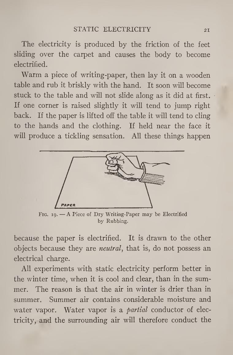
Warm a piece of writing-paper, then lay it on a wooden
table and rub it briskly with the hand. It soon will become
stuck to the table and will not slide along as it did at first.
If one corner is raised slightly it will tend to jump right
back. If the paper is lifted off the table it will tend to cling
to the hands and the clothing. If held near the face it
will produce a tickling sensation. All these things happen
Fig. 19. — A Piece of Dry Writing-Paper may be Electrified
by Rubbing.
because the paper is electrified. It is drawn to the other
objects because they are neutral, that is, do not possess an
electrical charge.
All experiments with static electricity perform better in
the winter time, when it is cool and clear, than in the sum¬
mer. The reason is that the air in winter is drier than in
summer. Summer air contains considerable moisture and
water vapor. Water vapor is a partial conductor of elec¬
tricity, and the surrounding air will therefore conduct the
22 THE BOY ELECTRICIAN
static electricity away from your apparatus almost as fast
as it can be produced in the summer time.
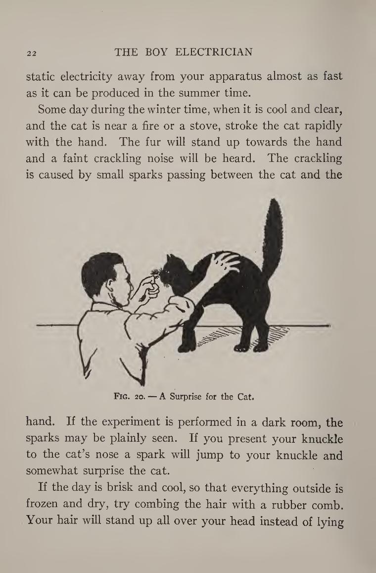
Some day during the winter time, when it is cool and clear,
and the cat is near a fire or a stove, stroke the cat rapidly
with the hand. The fur will stand up towards the hand
and a faint crackling noise will be heard. The crackling
is caused by small sparks passing between the cat and the
Fig. 20. — A Surprise for the Cat.
hand. If the experiment is performed in a dark room, the
sparks may be plainly seen. If you present your knuckle
to the cat's nose a spark will jump to your knuckle and
somewhat surprise the cat.
If the day is brisk and cool, so that everything outside is
frozen and dry, try combing the hair with a rubber comb.
Your hair will stand up all over your head instead of lying
STATIC ELECTRICITY 23
down flat, and the faint crackling noise, showing that
sparking is taking place as the comb passes through the
hair, will be plainly heard. The electricity is produced by
the friction between the hair and the comb.
Electricity may be produced by friction between a num¬
ber of substances. A hard rubber rod, a glass rod, a rubber
comb or a stick of sealing-wax may be very easily electri¬
fied by rubbing them briskly with a piece of dry, warm
flannel.
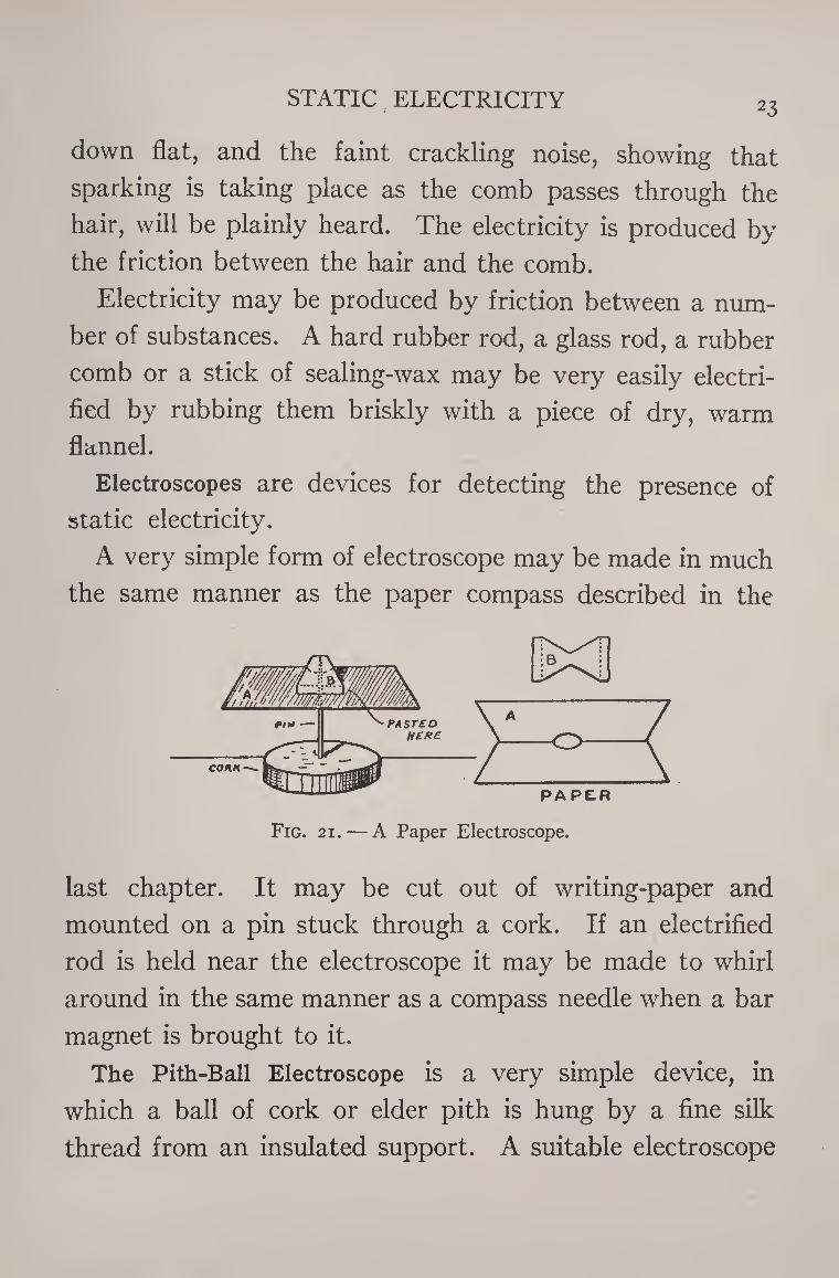
Electroscopes are devices for detecting the presence of
static electricity.
A very simple form of electroscope may be made in much
the same manner as the paper compass described in the
Fig. 21. — A Paper Electroscope.
last chapter. It may be cut out of writing-paper and
mounted on a pin stuck through a cork. If an electrified
rod is held near the electroscope it may be made to whirl
around in the same manner as a compass needle when a bar
magnet is brought to it.
The Pith-Ball Electroscope is a very simple device, in
which a ball of cork or elder pith is hung by a fine silk
thread from an insulated support. A suitable electroscope
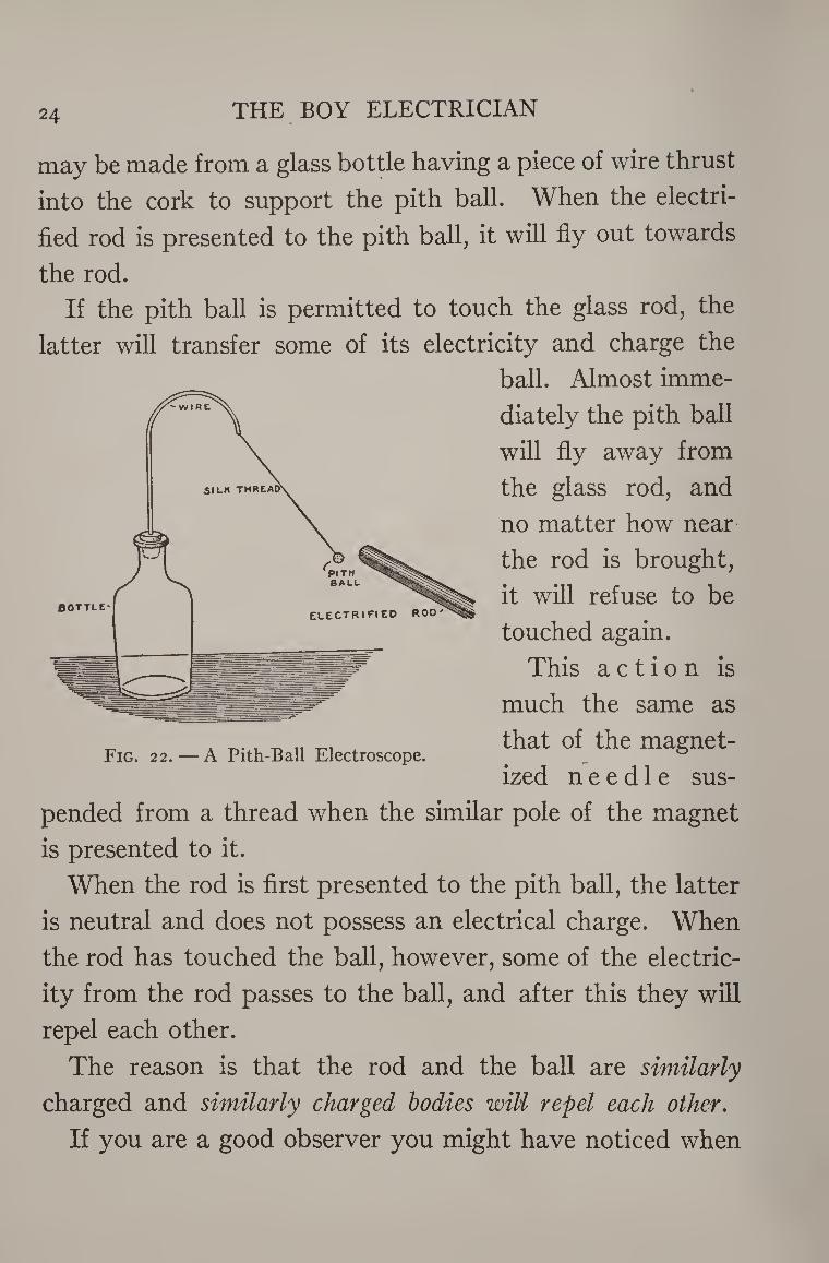
24 THE BOY ELECTRICIAN
may be made from a glass bottle having a piece of wire thrust
into the cork to support the pith ball. When the electri¬
fied rod is presented to the pith ball, it will fly out towards
the rod.
If the pith ball is permitted to touch the glass rod, the
latter will transfer some of its electricity and charge the
ball. Almost imme¬
diately the pith ball
will fly away from
the glass rod, and
no matter how near
the rod is brought,
it will refuse to be
touched again.
This action is
much the same as
that of the magnet¬
ized needle sus¬
pended from a thread when the similar pole of the magnet
is presented to it.
When the rod is first presented to the pith ball, the latter
is neutral and does not possess an electrical charge. When
the rod has touched the ball, however, some of the electric¬
ity from the rod passes to the ball, and after this they will
repel each other.
The reason is that the rod and the ball are similarly
charged and similarly charged bodies will repel each other.
If you are a good observer you might have noticed when
STATIC ELECTRICITY
Fig. 23. — A Double Pith-Ball Electroscope.
25
experimenting with an electrified rod and the small bits of
paper, that some of the little papers were first attracted and flew upwards to the
rod, but having once
touched it, were
quickly repelled.
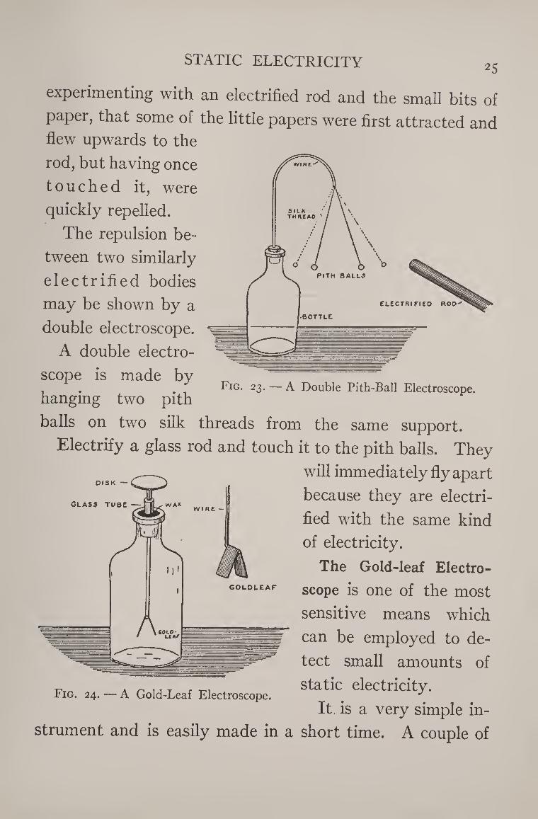
The repulsion be¬
tween two similarly
electrified bodies
may be shown by a
double electroscope.
A double electro¬
scope is made by
hanging two pith
balls on two silk threads from the same support.
Electrify a glass rod and touch it to the pith balls. They
will immediately fly apart
because they are electri¬
fied with the same kind
of electricity.
The Gold-leaf Electro¬
scope is one of the most
sensitive means which
can be employed to de¬
tect small amounts of
Fig. 24. — A Gold-Leaf Electroscope. sta(y electricity. It is a very simple in¬
strument and is easily made in a short time. A couple of
GLASS TUBE -
26 THE BOY ELECTRICIAN
narrow strips of the thinnest tissue paper, or, better still,
two strips of gold leaf, are hung from a support in a wide¬
mouthed glass bottle which serves at once to insulate and
protect the strips from draughts of air.
The mouth of the jar is closed by a plug of paraffin wax,
through the center of which passes a small glass tube. A
stiff copper wire passes through the tube. The lower end of
the wire is bent at right angles to furnish support for the
strips of gold leaf. A round sheet metal disk about the size
of a quarter is soldered to the upper end of the rod.
If an electrified stick of sealing-wax or a glass rod is pre¬
sented to the disk of the electroscope, the strips will repel
each other very strongly. If the instrument is sensitive,
the strips should begin to diverge some time before the rod
reaches the disk. It is possible to make an electroscope so
sensitive that chips formed by sharpening a pencil will
cause the strips to diverge.
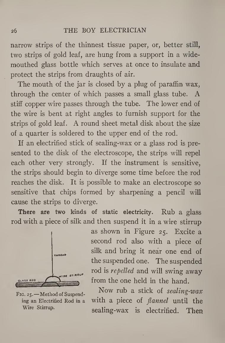
There are two kinds of static electricity. Rub a glass
rod with a piece of silk and then suspend it in a wire stirrup
as shown in Figure 25. Excite a
second rod also with a piece of
silk and bring it near one end of
the suspended one. The suspended
rod is repelled and will swing away
from the one held in the hand.
Now rub a stick of sealing-wax
with a piece of flannel until the
sealing-wax is electrified. Then
TNMCA9
Fig. 25.—Method of Suspend¬
ing an Electrified Rod in a
Wire Stirrup.
STATIC ELECTRICITY 27
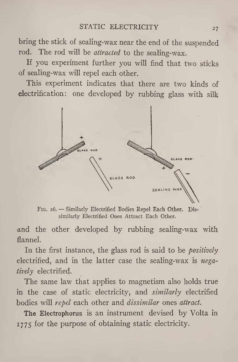
bring the stick of sealing-wax near the end of the suspended
rod. The rod will be attracted to the sealing-wax.
If you experiment further you will find that two sticks
of sealing-wax will repel each other.
This experiment indicates that there are two kinds of
electrification: one developed by rubbing glass with silk
Fig. 26. — Similarly Electrified Bodies Repel Each Other. Dis¬ similarly Electrified Ones Attract Each Other.
and the other developed by rubbing sealing-wax with
flannel.
In the first instance, the glass rod is said to be positively
electrified, and in the latter case the sealing-wax is nega¬
tively electrified.
The same law that applies to magnetism also holds true
in the case of static electricity, and similarly electrified
bodies will repel each other and dissimilar ones attract.
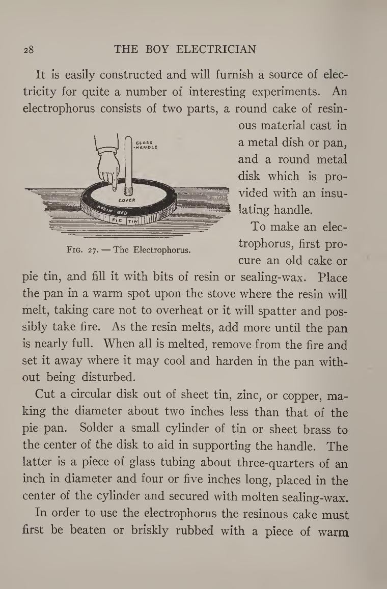
The Electrophorus is an instrument devised by Volta in
1775 for the purpose of obtaining static electricity.
28 THE BOY ELECTRICIAN
It is easily constructed and will furnish a source of elec¬
tricity for quite a number of interesting experiments. An
electrophorus consists of two parts, a round cake of resin¬
ous material cast in
a metal dish or pan,
and a round metal
disk which is pro¬
vided with an insu¬
lating handle.
To make an elec¬
trophorus, first pro¬
cure an old cake or
pie tin, and fill it with bits of resin or sealing-wax. Place
the pan in a warm spot upon the stove where the resin will
melt, taking care not to overheat or it will spatter and pos¬
sibly take fire. As the resin melts, add more until the pan
is nearly full. When all is melted, remove from the fire and
set it away where it may cool and harden in the pan with¬
out being disturbed.
Cut a circular disk out of sheet tin, zinc, or copper, ma¬
king the diameter about two inches less than that of the
pie pan. Solder a small cylinder of tin or sheet brass to
the center of the disk to aid in supporting the handle. The
latter is a piece of glass tubing about three-quarters of an
inch in diameter and four or five inches long, placed in the
center of the cylinder and secured with molten sealing-wax.
In order to use the electrophorus the resinous cake must
first be beaten or briskly rubbed with a piece of warm
Fig. 27. — The Electrophorus.
STATIC ELECTRICITY 29
woolen cloth or flannel. Then place the disk on the cake
holding the insulating handle with the right hand. Touch
the cover or the disk momentarily with the forefinger of
the left hand. After the finger is removed, raise the disk
from the cake by picking it up with the glass insulating
handle. The disk will now be found heavily charged with
positive electricity, and if the knuckles are presented to
the edge, a spark will jump out to meet them.
The cover may then be replaced, touched, and once more
removed. It will yield any number of sparks, the resinous
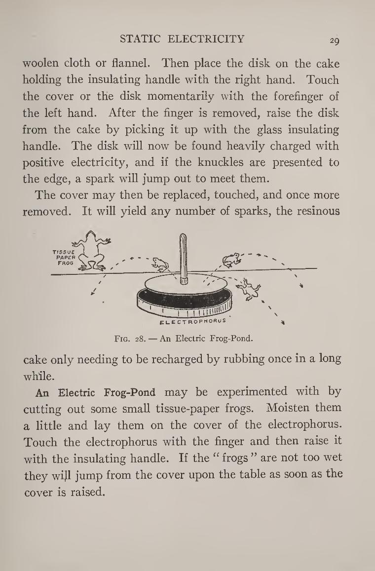
Fig. 28. — An Electric Frog-Pond.
cake only needing to be recharged by rubbing once in a long
while.
An Electric Frog-Pond may be experimented with by
cutting out some small tissue-paper frogs. Moisten them
a little and lay them on the cover of the electrophorus.
Touch the electrophorus with the finger and then raise it
with the insulating handle. If the “ frogs ” are not too wet
they wi}l jump from the cover upon the table as soon as the
cover is raised.
____ _*.**4QX**m u
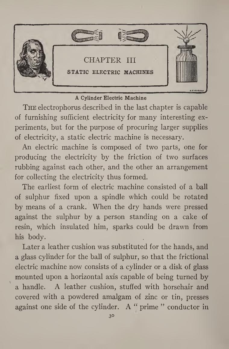
A Cylinder Electric Machine
The electrophorus described in the last chapter is capable of furnishing sufficient electricity for many interesting ex¬ periments, but for the purpose of procuring larger supplies of electricity, a static electric machine is necessary.
An electric machine is composed of two parts, one for
producing the electricity by the friction of two surfaces
rubbing against each other, and the other an arrangement
for collecting the electricity thus formed.
The earliest form of electric machine consisted of a ball
of sulphur fixed upon a spindle which could be rotated
by means of a crank. When the dry hands were pressed
against the sulphur by a person standing on a cake of
resin, which insulated him, sparks could be drawn from
his body.
Later a leather cushion was substituted for the hands, and
a glass cylinder for the ball of sulphur, so that the frictional
electric machine now consists of a cylinder or a disk of glass
mounted upon a horizontal axis capable of being turned by
a handle. A leather cushion, stuffed with horsehair and
covered with a powdered amalgam of zinc or tin, presses
against one side of the cylinder. A “ prime ” conductor in 30
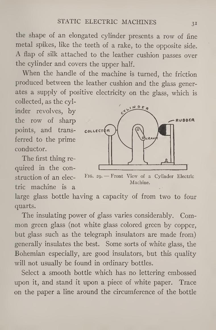
STATIC ELECTRIC MACHINES 3i
the shape of an elongated cylinder presents a row of fine
metal spikes, like the teeth of a rake, to the opposite side.
A flap of silk attached to the leather cushion passes over
the cylinder and covers the upper half.
When the handle of the machine is turned, the friction
produced between the leather cushion and the glass gener¬
ates a supply of positive electricity on the glass, which is
collected, as the cyl¬
inder revolves, by
the row of sharp
points, and trans¬
ferred to the prime
conductor.
The first thing re¬
quired in the con¬
struction of an elec¬
tric machine is a
large glass bottle having a capacity of from two to four
quarts.
The insulating power of glass varies considerably. Com¬
mon green glass (not white glass colored green by copper,
but glass such as the telegraph insulators are made from)
generally insulates the best. Some sorts of white glass, the
Bohemian especially, are good insulators, but this quality
will not usually be found in ordinary bottles.
Select a smooth bottle which has no lettering embossed
upon it, and stand it upon a piece of white paper. Trace
on the paper a line around the circumference of the bottle
Fig. 29. — Front View of a Cylinder Electric
Machine.
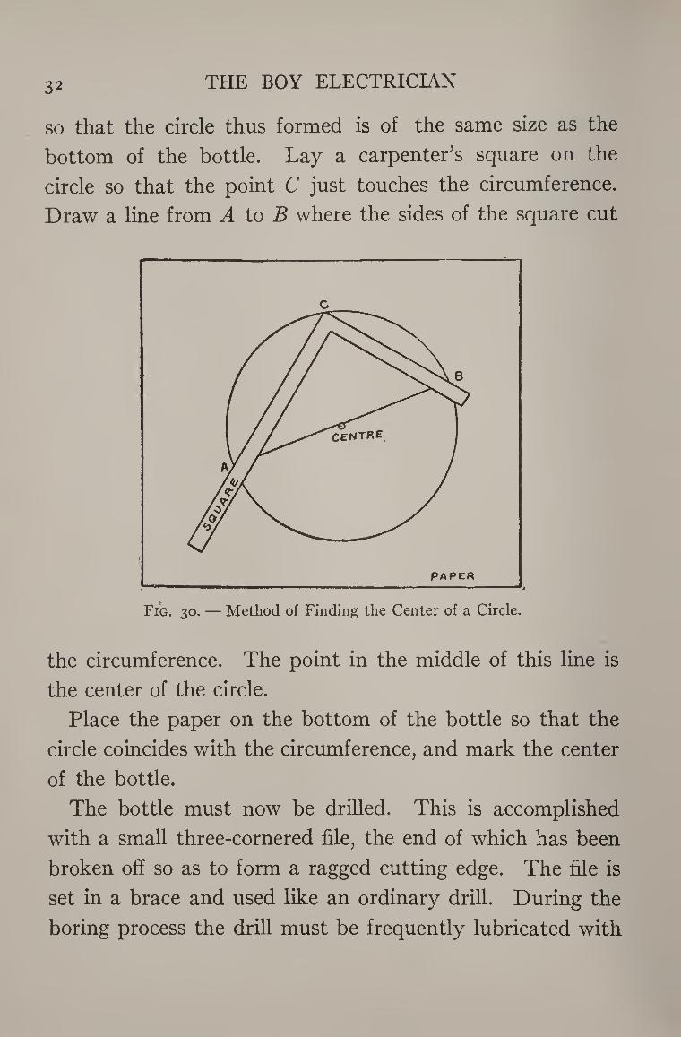
32 THE BOY ELECTRICIAN
so that the circle thus formed is of the same size as the
bottom of the bottle. Lay a carpenter’s square on the
circle so that the point C just touches the circumference.
Draw a line from A to B where the sides of the square cut
Fig. 30. — Method of Finding the Center of a Circle.
the circumference. The point in the middle of this line is
the center of the circle.
Place the paper on the bottom of the bottle so that the
circle coincides with the circumference, and mark the center
of the bottle.
The bottle must now be drilled. This is accomplished
with a small three-cornered file, the end of which has been
broken off so as to form a ragged cutting edge. The file is
set in a brace and used like an ordinary drill. During the
boring process the drill must be frequently lubricated with
STATIC ELECTRIC MACHINES 33
a mixture of gum camphor and turpentine. The drilling,
which will require almost an hour before the glass is pierced,
if the bottle is a thick one, should be performed slowly and
carefully, so as to avoid all danger of cracking the glass.
The hole, when finished, should be from one-quarter to
three-eighths of an inch in diameter.
After the hole has been bored, fit a wooden plug into the
neck of the bottle and cement it there with a mixture com¬
posed of one-half a pound of resin, five ounces of beeswax,
one-quarter of an ounce of plaster of Paris, and three-
quarters of an ounce of red ocher, melted together over a
moderately warm stove. Dip the plug in the molten cement
and force it into the neck of the bottle. When the cement
dries it will be impossible to remove it.
The sizes of bottles vary, so that it is quite impossible to
give dimensions which must be closely followed in construct¬
ing the machine. Those in the text are approximate. The
drawings have been made to scale so as to show the propor¬
tions the parts bear to each other.
A heavy wooden base will be required to mount the
machine on. Two uprights are mounted on the base to
support the axis of the bottle. Through one of these bore
a hole of the same diameter as the wooden plug fitted in
the neck of the bottle. The end of the wooden plug pro¬
jecting through the upright is notched and fitted with a
crank so that the bottle may be revolved. The handle of
the crank is an ordinary spool having one flange cut off and
mounted with a screw and a washer.
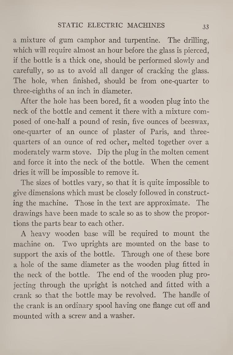
34 THE BOY ELECTRICIAN
The machine is now ready for the “ rubber ” and “ prime
conductor.” The rubber is a piece of wood one inch square
and from six to eight inches long. A piece of undressed
leather is tacked on as shown in the illustration and stuffed
with horsehair. The wood is
shellacked and covered with tin-
foil previous to tacking on the
leather. A strip of wood, two
inches wide and one-half an inch
thick, is fastened to the back
of the rubber. The strip should
be just long enough so that when
the lower end rests on the base
the rubber is level with the axis
of the bottle. The lower end
may be fastened to the base by
means of a small brass hinge.
Two rubber bands stretch from
hooks between the rubber and the base so as to pull the
former tightly against the bottle. The illustration shows
a method of mounting the rubber on a foot-piece held to
the base with a thumb-nut so that it may be slid back and
forth and the pressure varied at will.
The prime conductor is formed from a piece of curtain-
pole two inches in diameter and eight inches long. The
ends are rounded with a rasp and then smoothed with sand¬
paper. The whole surface is then shellacked and covered with
a layer of tinfoil. The heads of a number of dressmaker’s
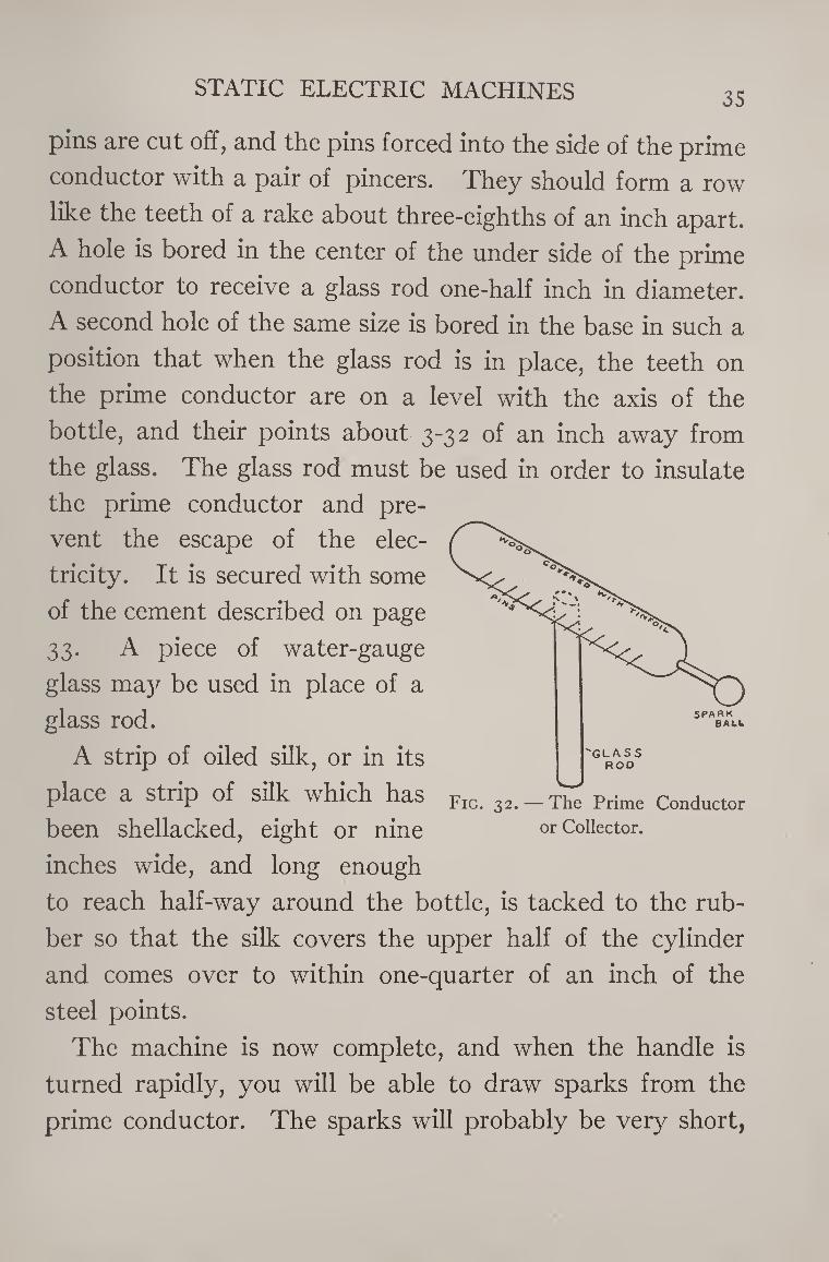
STATIC ELECTRIC MACHINES 35
pins are cut off, and the pins forced into the side of the prime
conductor with a pair of pincers. They should form a row
like the teeth of a rake about three-eighths of an inch apart.
A hole is bored in the center of the under side of the prime
conductor to receive a glass rod one-half inch in diameter.
A second hole of the same size is bored in the base in such a
position that when the glass rod is in place, the teeth on
the prime conductor are on a level with the axis of the
bottle, and their points about 3-32 of an inch away from
the glass. The glass rod must be used in order to insulate
the prime conductor and pre¬
vent the escape of the elec¬
tricity. It is secured with some
of the cement described on page
33. A piece of water-gauge
glass ma)r be used in place of a
glass rod.
A strip of oiled silk, or in its
place a strip of silk which has
been shellacked, eight or nine
inches wide, and long enough
to reach half-way around the bottle, is tacked to the rub¬
ber so that the silk covers the upper half of the cylinder
and comes over to within one-quarter of an inch of the
steel points.
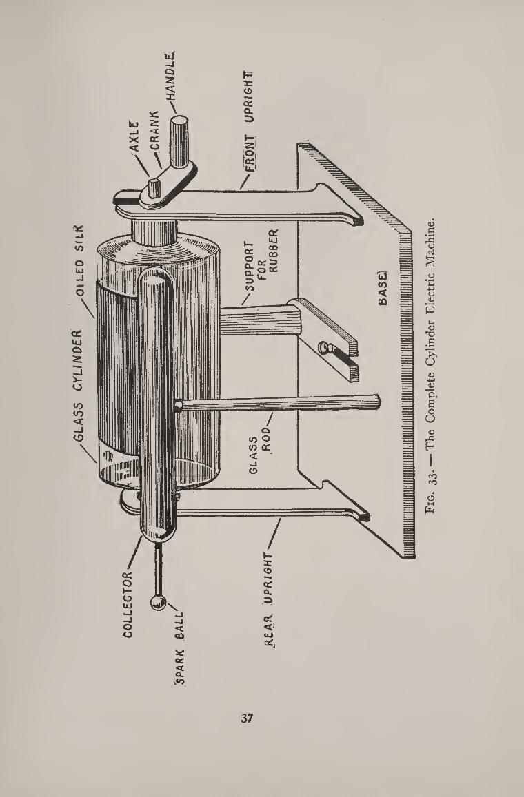
The machine is now complete, and when the handle is
turned rapidly, you will be able to draw sparks from the
prime conductor. The sparks will probably be very short,
Fig. 32. — The Prime Conductor or Collector.
36 THE BOY ELECTRICIAN
about one-half of an inch long. These can be increased,
however, to three inches, if the glass is of the right quality,
by treating the rubber with amalgam.
The amalgam is formed by melting one ounce of tin and
adding to it one ounce of zinc in small bits. As soon as
the zinc has also melted add to the mixture two ounces of
mercury which has been previously warmed. Be careful
not to inhale any of the vapor during this operation. Pour
the mixture into a vessel of cold water, which will reduce
the metal to small grains. Pour off the water and grind
the amalgam to a powder by pounding the grains with a
hammer.
The leather rubber should be thinly smeared with lard
and the powdered amalgam rubbed on it.
In order to obtain the greatest effect from an electric
machine, it must be carefully freed from dust and particles
of amalgam adhering to the glass, and the insulating column
rubbed with a warm woolen cloth. The best results are
obtained by placing the machine near a stove or radiator
where it is warm.
A Wimshurst Machine
The Wimshurst Machine consists of two varnished glass
plates revolving in opposite directions. On the outside of
each of these plates are cemented a number of tinfoil
“ sectors,” arranged radially. Two conductors at right
angles to each other extend obliquely across the plates, one
at the back and the other at the front. These conductors
GL
AS
S
CY
LIN
DE
R
37
Fig
. 33
. —
Th
e C
om
ple
te
Cy
lin
der E
lect
ric
Mac
hin
e.
3§ THE BOY ELECTRICIAN
each terminate in brushes of tinsel which electrically excite
the “ sectors ” as the plates revolve. The electricity is
collected by a set of “ collectors ” arranged in a somewhat
similar manner to the collector on the cylinder electric
machine.
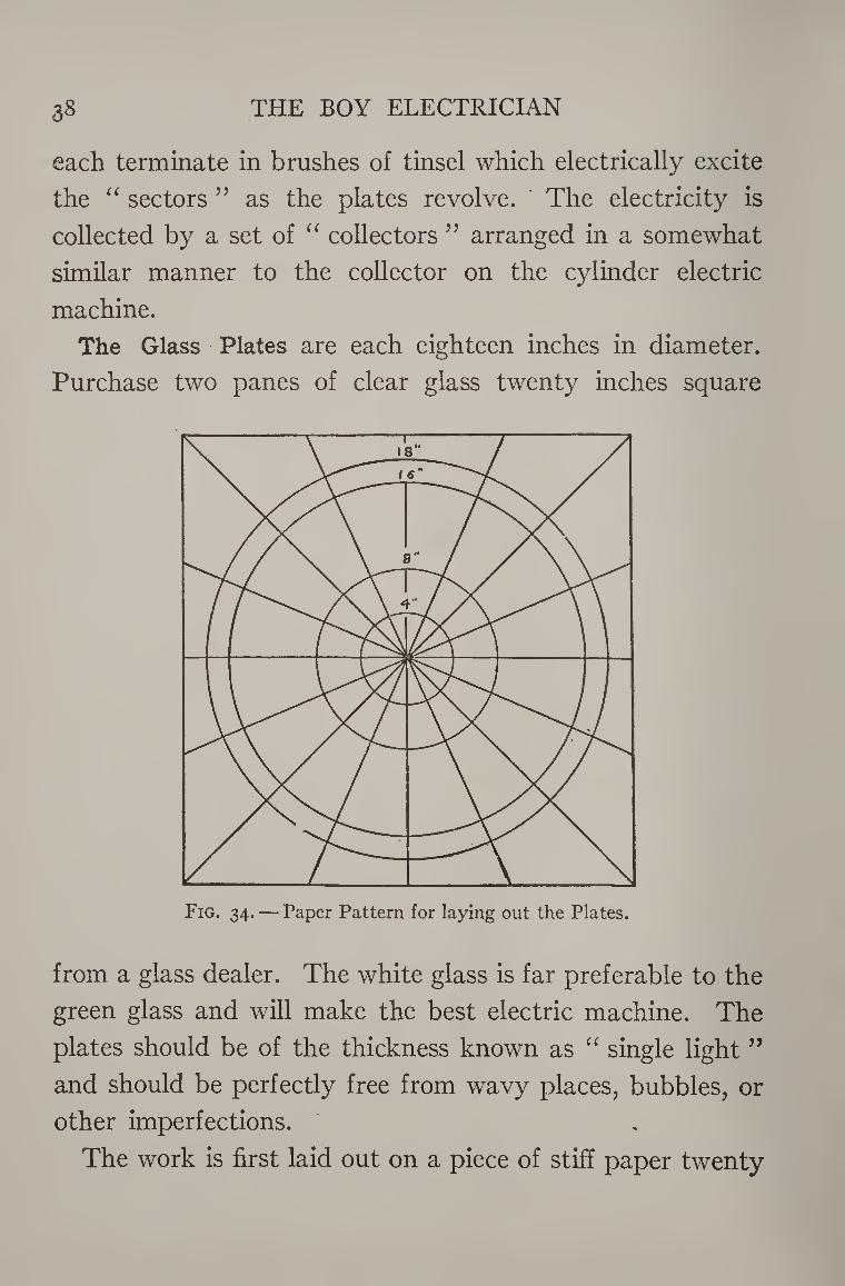
The Glass Plates are each eighteen inches in diameter.
Purchase two panes of clear glass twenty inches square
Fig. 34. — Paper Pattern for laying out the Plates.
from a glass dealer. The white glass is far preferable to the
green glass and will make the best electric machine. The
plates should be of the thickness known as “ single light ”
and should be perfectly free from wavy places, bubbles, or
other imperfections.
The work is first laid out on a piece of stiff paper twenty
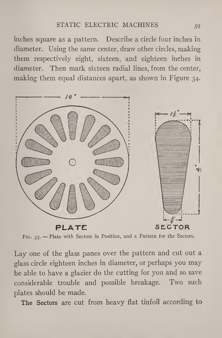
STATIC ELECTRIC MACHINES 39
inches square as a pattern. Describe a circle four inches in
diameter. Using the same center, draw other circles, making
them respectively eight, sixteen, and eighteen inches in
diameter. Then mark sixteen radial lines, from the center,
making them equal distances apart, as shown in Figure 34.
IQ m
Fig. 35. — Plate with Sectors in Position, and a Pattern for the Sectors.
Lay one of the glass panes over the pattern and cut out a
glass circle eighteen inches in diameter, or perhaps you may
be able to have a glazier do the cutting for you and so save
considerable trouble and possible breakage. Two such
plates should be made.
The Sectors are cut from heavy flat tinfoil according to
40 THE BOY ELECTRICIAN
the pattern shown in Figure 35. They should be made one
inch and one-half wide at the wide end and three-quarters
of an inch at the other end. They are each four inches
long. Thirty-two such sectors are required. The easiest
way to make them is to cut out a pattern from heavy card¬
board to serve as a guide.
Clean and dry both of the glass plates very carefully and
then give them each two thin coats of white shellac. After
they have been dried, lay one of the plates on the paper
pattern so that the outside of the plate will coincide with
the largest circle on the paper.
Then place a weight in the center of the plate so that it
will not move, and stick sixteen of the tinfoil sectors on the
plate with thick shellac. The sectors are arranged symmet¬
rically on the plate, using the eight-inch and sixteen-inch
circles and the radial lines as guides. Both plates should
be treated in this manner. Each sector should be care¬
fully pressed down on the glass, so that it will stick
smoothly without air-bubbles or creases. When all the
sectors are in place the plates will appear like that shown
in Figure 35.
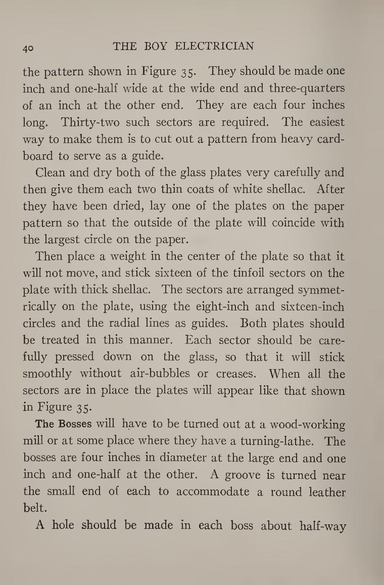
The Bosses will have to be turned out at a wood-working
mill or at some place where they have a turning-lathe. The
bosses are four inches in diameter at the large end and one
inch and one-half at the other. A groove is turned near
the small end of each to accommodate a round leather
belt.
A hole should be made in each boss about half-way
STATIC ELECTRIC MACHINES 41
SECTION
through from the small end. These holes should be bushed
with a piece of brass tubing having an inside diameter of
one-half inch. The tubing should go into the hole very
snugly and be a “ driven fit.”
The bosses should both be given a coat of shellac, and
after this is dry, fastened to the glass plates on the same side
to which the tinfoil sectors
are attached. The best plan
is to lay the disks on the
paper pattern and adjust
them until the outer edge
coincides with the largest
circle.
Then apply some bichro¬
mate glue to the flat surface
of one of the bosses and place the latter in the center of the
plate in line with the smallest circle.
Place a weight on the boss to hold it down firmly against
the plate and leave it over night, or for ten or twelve hours,
until thoroughly dry.
The glue is prepared by placing some high-grade glue in
a tin cup and covering it with cold water. Allow it to stand
until the glue absorbs all the water it will and becomes
soft. Then pour the water off and add enough glacial acetic
acid to cover the glue.
Heat the mixture until it is reduced to a liquid, stirring it
until it is perfectly smooth. Add a teaspoonful of powdered
bichromate of potash to the glue.
Fig. 36. — A Side View of one of the
Bosses, showing the Brass Bushing
used.
42 THE BOY ELECTRICIAN
The glue must now be kept in the dark, for sunlight will
“ set ” the glue so that it becomes insoluble.
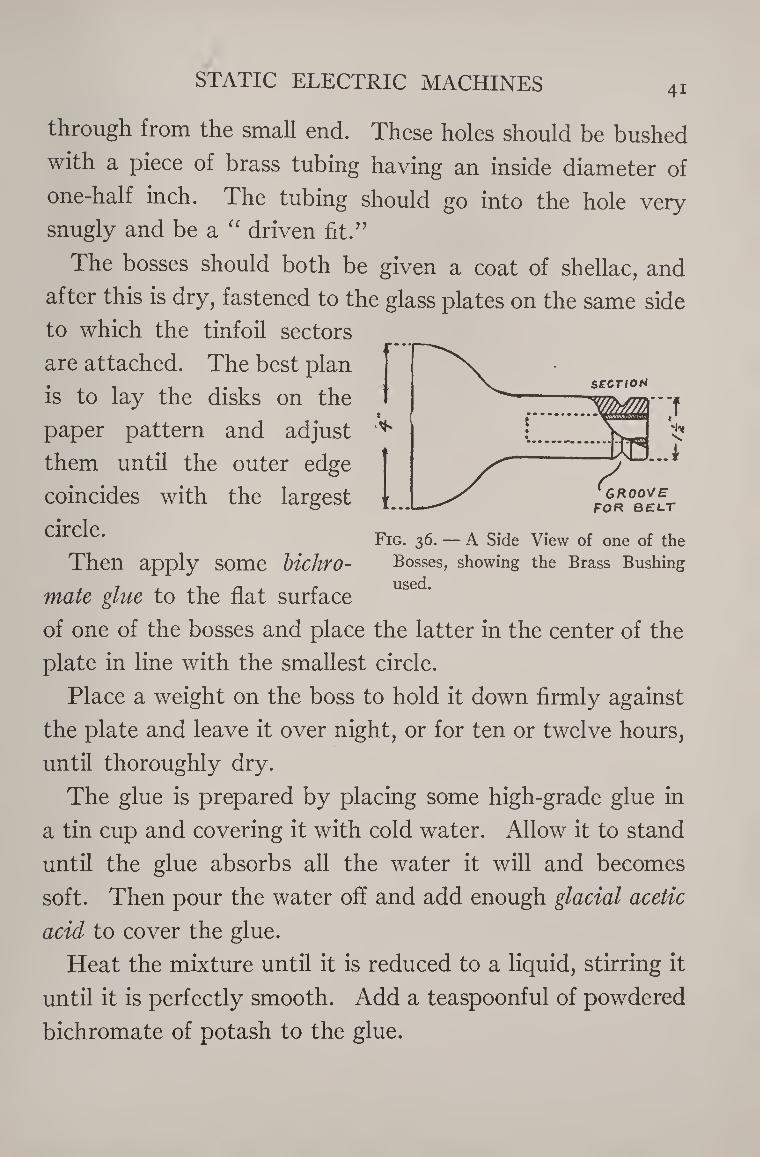
The Frame of the machine is composed of two strips
twenty-five inches long, three inches wide, and an inch and
Fig. 37.— The Frame.
one-half in thickness, and two cross-pieces of the same
thickness and width fifteen inches long.
Notches are cut at both sides of the base to admit the
feet of the uprights.
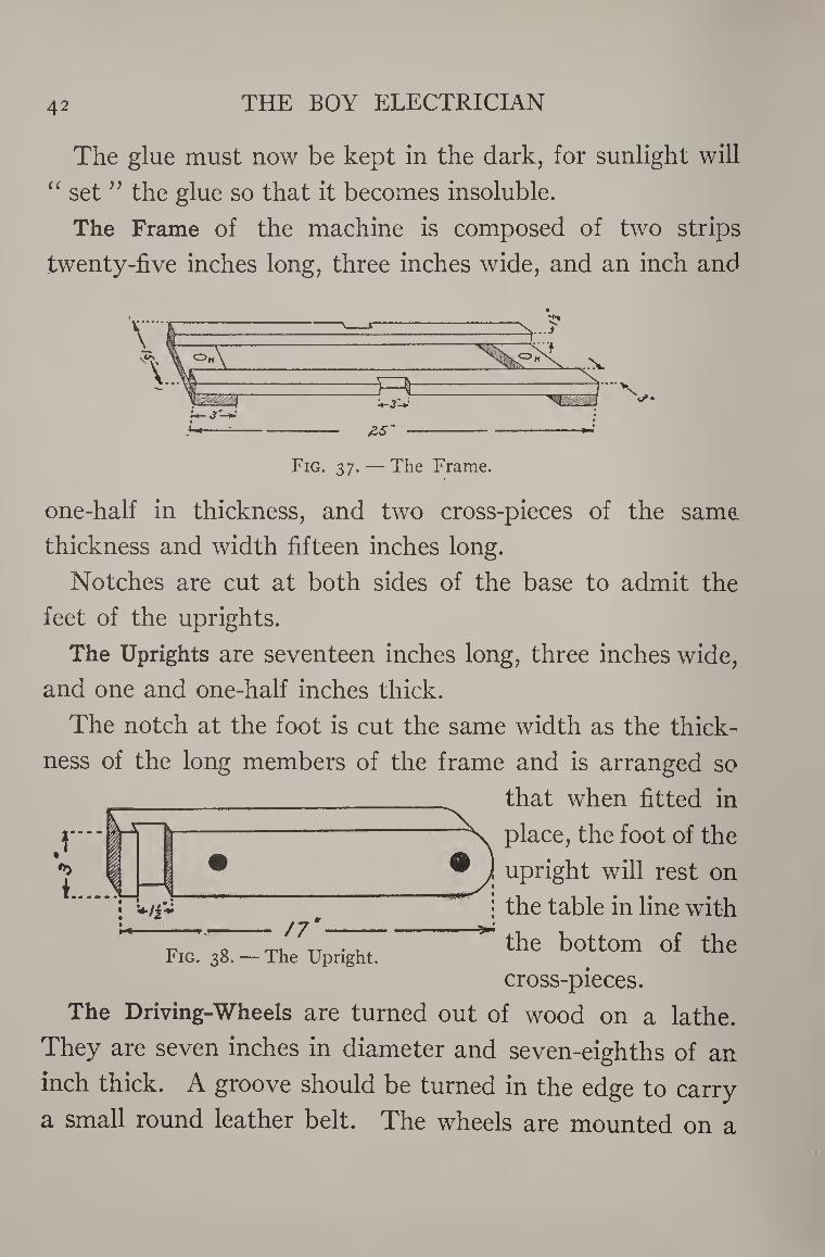
The Uprights are seventeen inches long, three inches wide,
and one and one-half inches thick.
The notch at the foot is cut the same width as the thick¬
ness of the long members of the frame and is arranged so
that when fitted in
place, the foot of the
upright will rest on
the table in line with
Fig. 38. — The Upright. ^ bottom of the cross-pieces.
The Driving-Wheels are turned out of wood on a lathe.
They are seven inches in diameter and seven-eighths of an
inch thick. A groove should be turned in the edge to carry
a small round leather belt. The wheels are mounted on a
f"t —
--——
• —. —
/7
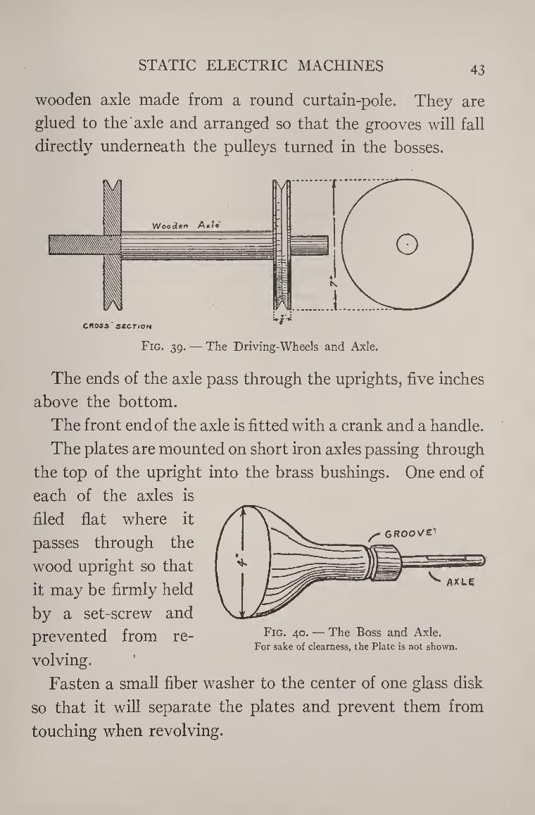
STATIC ELECTRIC MACHINES 43
wooden axle made from a round curtain-pole. They are
glued to the axle and arranged so that the grooves will fall
directly underneath the pulleys turned in the bosses.
Fig. 39. — The Driving-Wheels and Axle.
The ends of the axle pass through the uprights, five inches
above the bottom.
The front end of the axle is fitted with a crank and a handle.
The plates are mounted on short iron axles passing through
the top of the upright into the brass bushings. One end of
each of the axles is
filed flat where it
passes through the
wood upright so that
it may be firmly held
by a set-screw and
prevented from re- FlG* 4°-— The Boss and Axle- For sake of clearness, the Plate is not shown.
volving.
Fasten a small fiber washer to the center of one glass disk
so that it will separate the plates and prevent them from
touching when revolving.
44 THE BOY ELECTRICIAN
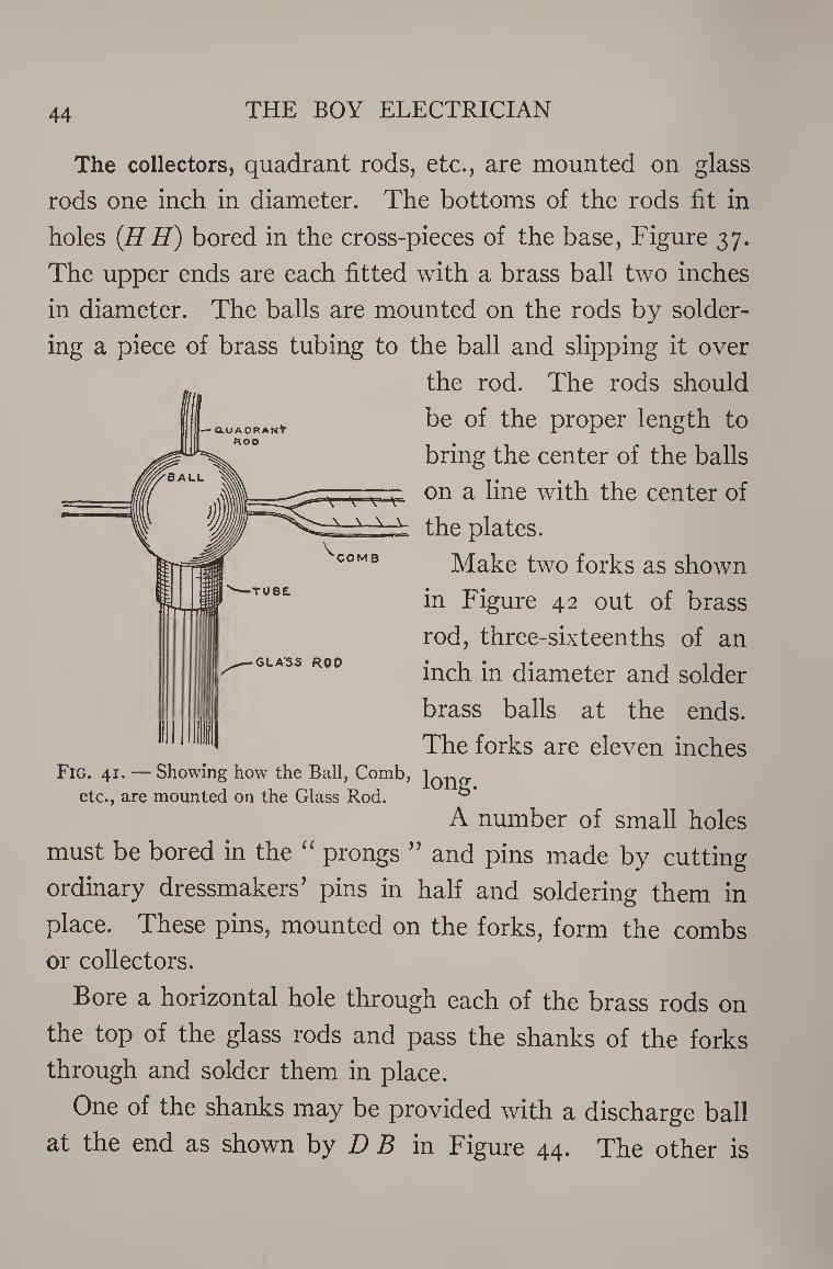
The collectors, quadrant rods, etc., are mounted on glass
rods one inch in diameter. The bottoms of the rods fit in
holes (H H) bored in the cross-pieces of the base, Figure 37.
The upper ends are each fitted with a brass ball two inches
in diameter. The balls are mounted on the rods by solder¬
ing a piece of brass tubing to the ball and slipping it over
the rod. The rods should
be of the proper length to
bring the center of the balls
on a line with the center of
the plates.
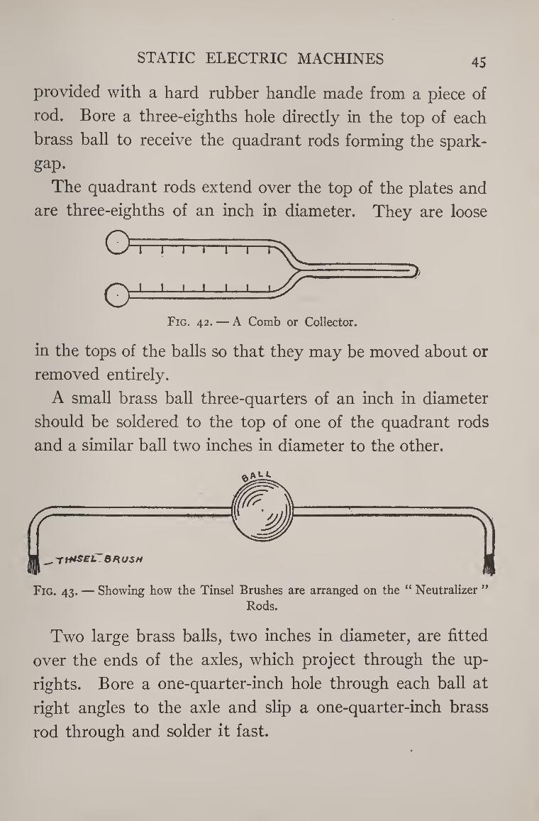
Make two forks as shown
in Figure 42 out of brass
rod, three-sixteenths of an
inch in diameter and solder
brass balls at the ends.
The forks are eleven inches
long.
A number of small holes
must be bored in the “ prongs ” and pins made by cutting
ordinary dressmakers’ pins in half and soldering them in
place. These pins, mounted on the forks, form the combs
or collectors.
Bore a horizontal hole through each of the brass rods on
the top of the glass rods and pass the shanks of the forks
through and solder them in place.
One of the shanks may be provided with a discharge ball
at the end as shown by D B in Figure 44. The other is
STATIC ELECTRIC MACHINES 45
provided with a hard rubber handle made from a piece of
rod. Bore a three-eighths hole directly in the top of each
brass ball to receive the quadrant rods forming the spark-
gap.
The quadrant rods extend over the top of the plates and
are three-eighths of an inch in diameter. They are loose
Fig. 42. — A Comb or Collector.
in the tops of the balls so that they may be moved about or
removed entirely.
A small brass ball three-quarters of an inch in diameter
should be soldered to the top of one of the quadrant rods
and a similar ball two inches in diameter to the other.
Two large brass balls, two inches in diameter, are fitted
over the ends of the axles, which project through the up¬
rights. Bore a one-quarter-inch hole through each ball at
right angles to the axle and slip a one-quarter-inch brass
rod through and solder it fast.
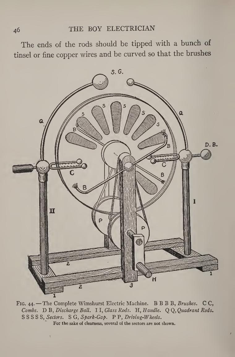
46 THE BOY ELECTRICIAN
The ends of the rods should be tipped with a bunch of
tinsel or fine copper wires and be curved so that the brushes
Fig. 44.— The Complete Wimshurst Electric Machine. B B B B, Brushes. C C, Combs. D B, Discharge Ball. 11, Glass Rods. H, Handle. Q Q, Quadrant Rods.
S S S S S, Sectors. S G, Spark-Gap. P P, Driving-Wheels. For the sake of clearness, several of the sectors are not shown.
/
STATIC ELECTRIC MACHINES 47
so formed will just touch the sectors on the disks when the
latter are revolved.
These are the neutralizers and are arranged in the ap¬
proximate positions shown in Figure 44.
The driving-wheels are connected to the bosses by means
of small round leather belts. The belt at the rear of the
machine is crossed in order to make the plates revolve in
opposite directions.
If the machine has been properly built it is now ready for
operation. It may be necessary to charge the machine the
first time that it is used by touching several of the sectors
with the charged cover of an electrophorus. Then if the
handle is turned the accumulated electricity should dis¬
charge across the spark-gap at the top of the machine in
the form of bright blue sparks.
Experiments with an Electric Machine
Many interesting experiments can be performed with an
electric machine. The number is almost unlimited. A few
of the most instructive ones are described below. Others
can be found in almost any text book on physics.
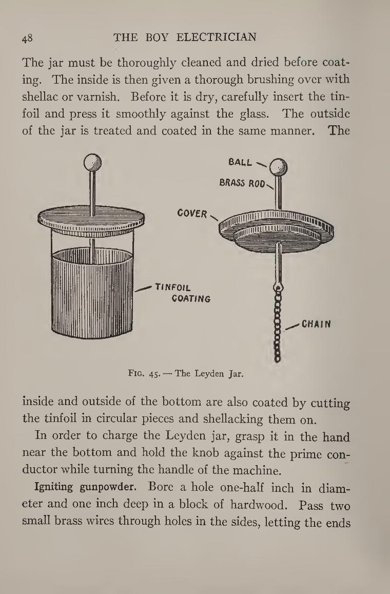
The Leyden jar consists of a glass jar coated with tinfoil
part way up on both the outside and inside. Through the
wooden stopper passes a brass rod or a heavy copper wire
which connects with the inner coating of tinfoil by means
of a small brass chain. The upper and outside end of the
rod usually terminates in a brass ball or knob.
It is a very simple matter to make a good Leyden jar.
48 THE BOY ELECTRICIAN
The jar must be thoroughly cleaned and dried before coat¬
ing. The inside is then given a thorough brushing over with
shellac or varnish. Before it is dry, carefully insert the tin-
foil and press it smoothly against the glass. The outside
of the jar is treated and coated in the same manner. The
!
Fig. 45. — The Leyden Jar.
inside and outside of the bottom are also coated by cutting
the tinfoil in circular pieces and shellacking them on.
In order to charge the Leyden jar, grasp it in the hand
near the bottom and hold the knob against the prime con¬
ductor while turning the handle of the machine.
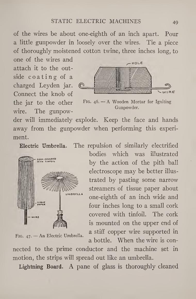
Igniting gunpowder. Bore a hole one-half inch in diam¬
eter and one inch deep in a block of hardwood. Pass two
small brass wires through holes in the sides, letting the ends
STATIC ELECTRIC MACHINES 49
HOLE
^ WIRE
Fig. 46. — A Wooden Mortar for Igniting
Gunpowder.
of the wires be about one-eighth of an inch apart. Pour
a little gunpowder in loosely over the wires. Tie a piece
of thoroughly moistened cotton twine, three inches long, to
one of the wires and
attach it to the out¬
side coating of a
charged Leyden jar.
Connect the knob of
the jar to the other
wire. The gunpow¬
der will immediately explode. Keep the face and hands
away from the gunpowder when performing this experi¬
ment.
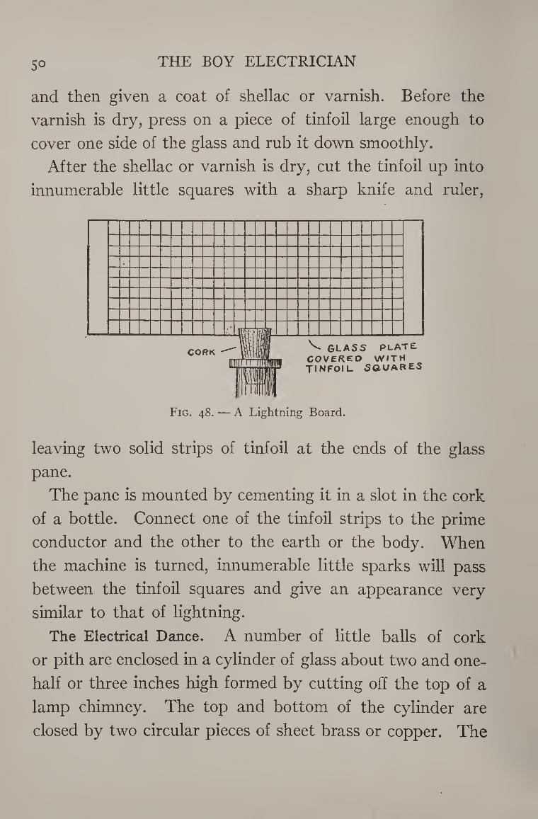
Electric Umbrella. The repulsion of similarly electrified
bodies which was illustrated
by the action of the pith ball
electroscope may be better illus¬
trated by pasting some narrow
streamers of tissue paper about
one-eighth of an inch wide and
four inches long to a small cork
covered with tinfoil. The cork
is mounted on the upper end of
a stiff copper wire supported in
a bottle. When the wire is con-
— COR* COVCRCO WITH TINFOIU
UMBRELLA
Fig. 47. — An Electric Umbrella.
nected to the prime conductor and the machine set in
motion, the strips will spread out like an umbrella.
Lightning Board. A pane of glass is thoroughly cleaned
5° THE BOY ELECTRICIAN
and then given a coat of shellac or varnish. Before the
varnish is dry, press on a piece of tinfoil large enough to
cover one side of the glass and rub it down smoothly.
After the shellac or varnish is dry, cut the tinfoil up into
innumerable little squares with a sharp knife and ruler,
.
m CORK '
in; N. glass plate
COVERED WITH TINFOIL SOUARES
1 1 Fig. 48. — A Lightning Board.
leaving two solid strips of tinfoil at the ends of the glass
pane.
The pane is mounted by cementing it in a slot in the cork
of a bottle. Connect one of the tinfoil strips to the prime
conductor and the other to the earth or the body. When
the machine is turned, innumerable little sparks will pass
between the tinfoil squares and give an appearance very
similar to that of lightning.
The Electrical Dance. A number of little balls of cork
or pith are enclosed in a cylinder of glass about two and one-
half or three inches high formed by cutting off the top of a
lamp chimney. The top and bottom of the cylinder are
closed by two circular pieces of sheet brass or copper. The
STATIC ELECTRIC MACHINES 5i
iCHAirJ CONNECTED TO
coNoucrryp.
,-UPPEA DISK .
-GLASS CUINOEA
r.nNHECT Ep IS THE RU&QER
Fig. 49. — An Electric Dance.
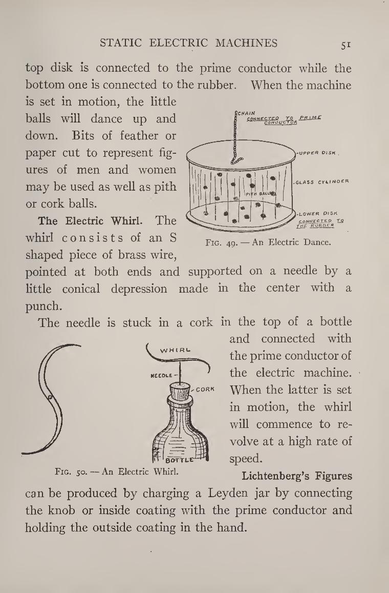
top disk is connected to the prime conductor while the
bottom one is connected to the rubber. When the machine
is set in motion, the little
balls will dance up and
down. Bits of feather or
paper cut to represent fig¬
ures of men and women
may be used as well as pith
or cork balls.
The Electric Whirl. The
whirl consists of an S
shaped piece of brass wire,
pointed at both ends and supported on a needle by a
little conical depression made in the center with a
punch.
The needle is stuck in a cork in the top of a bottle
and connected with
the prime conductor of
the electric machine.
When the latter is set
in motion, the whirl
will commence to re¬
volve at a high rate of
speed. Fig. so. - An Electric Whirl. Lichtenberg’s Figures
can be produced by charging a Leyden jar by connecting
the knob or inside coating with the prime conductor and
holding the outside coating in the hand.
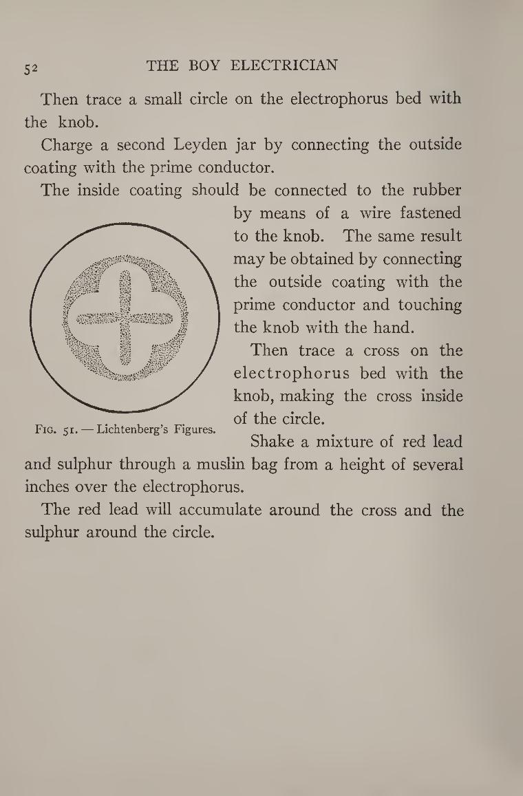
52 THE BOY ELECTRICIAN
Then trace a small circle on the electrophorus bed with
the knob.
Charge a second Leyden jar by connecting the outside
coating with the prime conductor.
The inside coating should be connected to the rubber
by means of a wire fastened
to the knob. The same result
may be obtained by connecting
the outside coating with the
prime conductor and touching
the knob with the hand.
Then trace a cross on the
electrophorus bed with the
knob, making the cross inside
T., , _ of the circle. Fig. 51. — Lichtenberg s Figures.
Shake a mixture of red lead
and sulphur through a muslin bag from a height of several
inches over the electrophorus.
The red lead will accumulate around the cross and the
sulphur around the circle.
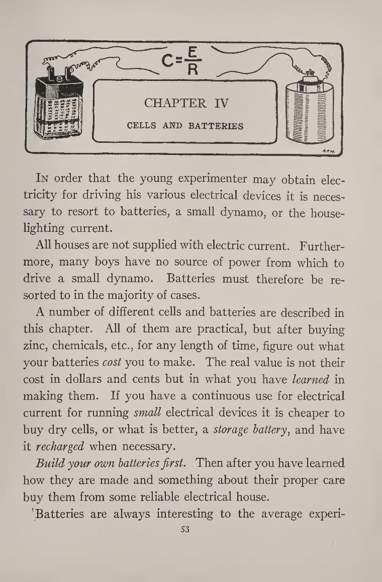
In order that the young experimenter may obtain elec¬
tricity for driving his various electrical devices it is neces¬
sary to resort to batteries, a small dynamo, or the house¬
lighting current.
All houses are not supplied with electric current. Further¬
more, many boys have no source of power from which to
drive a small dynamo. Batteries must therefore be re¬
sorted to in the majority of cases.
A number of different cells and batteries are described in
this chapter. All of them are practical, but after buying
zinc, chemicals, etc., for any length of time, figure out what
your batteries cost you to make. The real value is not their
cost in dollars and cents but in what you have learned in
making them. If you have a continuous use for electrical
current for running small electrical devices it is cheaper to
buy dry cells, or what is better, a storage battery, and have
it recharged when necessary.
Build your own batteries first. Then after you have learned
how they are made and something about their proper care
buy them from some reliable electrical house.
Batteries are always interesting to the average experi- 53
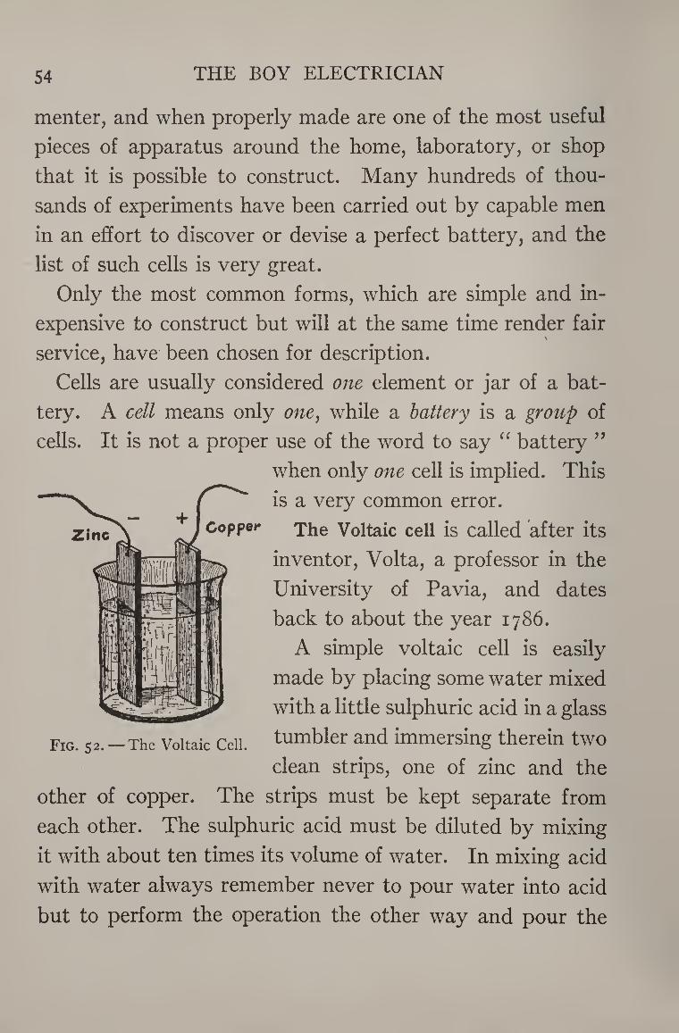
54 THE BOY ELECTRICIAN
menter, and when properly made are one of the most useful
pieces of apparatus around the home, laboratory, or shop
that it is possible to construct. Many hundreds of thou¬
sands of experiments have been carried out by capable men
in an effort to discover or devise a perfect battery, and the
list of such cells is very great.
Only the most common forms, which are simple and in¬
expensive to construct but will at the same time render fair
service, have been chosen for description.
Cells are usually considered one element or jar of a bat¬
tery. A cell means only one, while a battery is a group of
cells. It is not a proper use of the word to say “ battery ”
when only one cell is implied. This
is a very common error.
The Voltaic cell is called after its
inventor, Volta, a professor in the
University of Pavia, and dates
back to about the year 1786.
A simple voltaic cell is easily
made by placing some water mixed
with a little sulphuric acid in a glass
tumbler and immersing therein two
clean strips, one of zinc and the
other of copper. The strips must be kept separate from
each other. The sulphuric acid must be diluted by mixing
it with about ten times its volume of water. In mixing acid
with water always remember never to pour water into acid
but to perform the operation the other way and pour the
Fig. 52.—The Voltaic Cell.
CELLS AND BATTERIES 55
acid into the water. A copper wire is fastened with a screw
or by soldering to the top of each of the strips, and care
must be exercised to keep the wires apart.
As has been said, the zinc and copper must never be al¬
lowed to touch each other in the solution, but must be kept
at opposite sides of the jar.
The sulphuric acid solution attacks the zinc, causing it
slowly to waste away and disappear. This action is called
oxidation, and in reality is a very slow process of burn¬
ing. The consumption of the zinc furnishes the electric
energy, which in the case of this cell will be found to be
sufficient to ring a bell or buzzer, or run a very small toy
motor.
As soon as the plates are immersed in the acid solution,
bubbles will begin to rise from the zinc. These bubbles
contain a gas called hydrogen and they indicate that a
chemical action is taking place. The zinc is being dissolved
and the hydrogen gas is being set free from the acid. It will
be noticed that no bubbles arise from the copper plate and
that there is little if any chemical action there. In other
words, it seems that the chemical action at one plate is
stronger than that at the other.
A cell might be likened to a furnace in which the zinc is
the fuel which is burned to furnish the energy. We know
that if the zinc is burned or oxidized in the open air it will
give out energy in the form of heat. When it is burned or
oxidized slowly in acid in the presence of another metal it
gives out its energy in the form of electricity. The acid
THE BOY ELECTRICIAN 56
might be likened to the fire, and the copper to a hand which
dips into the cell to pick up the current and takes no part
chemically.
If a wire is connected to each of the plates and the free
ends of the wires touched to the tip of the tongue it will
produce a peculiar salty taste in the mouth indicating the
presence of a current of electricity.
If the wires are connected to an electric bell, the bell will
ring, or, instead, the current may be used to run a small
motor. If the cell is made of two zinc plates or two copper
plates, the bell will not ring, because no electricity will be
produced. In order to produce a current, the electrodes
must be made of two different materials upon which the
acid acts differently. Current may be obtained from a cell
made with a zinc and carbon plate or from one with zinc and
iron.
Therefore, in order to make a battery it is necessary to
have a metal which may be consumed, a chemical to con¬
sume or oxidize it, and an inactive element which is merely
present to collect the electricity.
When the wires connected to the two plates are joined
together, a current of electricity will flow from the copper
plate through the wire to the zinc. The copper is known as
the positive pole and the zinc as the negative.
A simple voltaic cell may be easily made by cutting out a
strip of zinc and a strip of copper, each 3^ inches long, and
one inch wide. A small hole bored through the upper end
of the strips will permit them to be mounted on a wooden
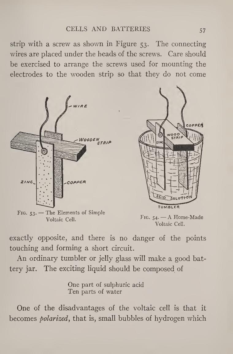
CELLS AND BATTERIES 57
strip with a screw as shown in Figure 53. The connecting
wires are placed under the heads of the screws. Care should
be exercised to arrange the screws used for mounting the
electrodes to the wooden strip so that they do not come
Voltaic Cell.
exactly opposite, and there is no danger of the points
touching and forming a short circuit.
An ordinary tumbler or jelly glass will make a good bat¬
tery jar. The exciting liquid should be composed of
One part of sulphuric acid Ten parts of water
One of the disadvantages of the voltaic cell is that it
becomes polarized, that is, small bubbles of hydrogen which
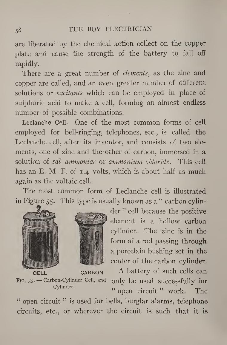
THE BOY ELECTRICIAN 58
are liberated by the chemical action collect on the copper
plate and cause the strength of the battery to fall off
rapidly.
There are a great number of elements, as the zinc and
copper are called, and an even greater number of different
solutions or excitants which can be employed in place of
sulphuric acid to make a cell, forming an almost endless
number of possible combinations.
Leclanche Cell. One of the most common forms of cell
employed for bell-ringing, telephones, etc., is called the
Leclanche cell, after its inventor, and consists of two ele¬
ments, one of zinc and the other of carbon, immersed in a
solution of sal ammoniac or ammonium chloride. This cell
has an E. M. F. of 1.4 volts, which is about half as much
again as the voltaic cell.
The most common form of Leclanche cell is illustrated
in Figure 55. This type is usually known as a “ carbon cylin¬
der ” cell because the positive
element is a hollow carbon
cylinder. The zinc is in the
form of a rod passing through
a porcelain bushing set in the
center of the carbon cylinder.
A battery of such cells can CELL CARBON
Fig. 55. — Carbon-Cylinder Cell, and only be used Successfully for Cylinder. . . . ,,
open circuit work. The
“ open circuit ” is used for bells, burglar alarms, telephone
circuits, etc., or wherever the circuit is such that it is
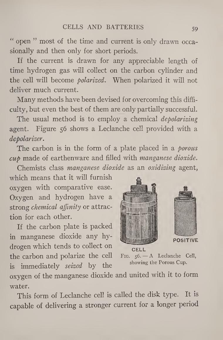
CELLS AND BATTERIES 59
“ open ” most of the time and current is only drawn occa¬
sionally and then only for short periods.
If the current is drawn for any appreciable length of
time hydrogen gas will collect on the carbon cylinder and
the cell will become polarized. When polarized it will not
deliver much current.
Many methods have been devised for overcoming this diffi¬
culty, but even the best of them are only partially successful.
The usual method is to employ a chemical depolarizing
agent. Figure 56 shows a Leclanche cell provided with a
depolarizer.
The carbon is in the form of a plate placed in a porous
cup made of earthenware and filled with manganese dioxide.
Chemists class manganese dioxide as an oxidizing agent,
which means that it will furnish
oxygen with comparative ease.
Oxygen and hydrogen have a
strong chemical affinity or attrac¬
tion for each other.
If the carbon plate is packed
in manganese dioxide any hy¬
drogen which tends to collect on
the carbon and polarize the cell Fig. 56. — A Leclanche Cell,
. . -i. . , . 7 i , i _ showing the Porous Cup. is immediately seized by the
oxygen of the manganese dioxide and united with it to form
water.
This form of Leclanche cell is called the disk type. It is
capable of delivering a stronger current for a longer period
CELL
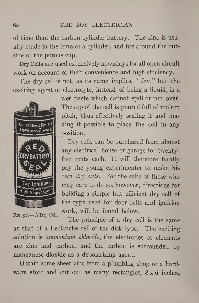
6o THE BOY ELECTRICIAN
of time than the carbon cylinder battery. The zinc is usu¬
ally made in the form of a cylinder, and fits around the out¬
side of the porous cup.
Dry Cells are used extensively nowadays for all open circuit
work on account of their convenience and high efficiency.
The dry cell is not, as its name implies, “ dry,” but the
exciting agent or electrolyte, instead of being a liquid, is a
wet paste which cannot spill or run over.
The top of the cell is poured full of molten
pitch, thus effectively sealing it and ma¬
king it possible to place the cell in any
position.
Dry cells can be purchased from almost
any electrical house or garage for twenty-
five cents each. It will therefore hardly
pay the young experimenter to make his
own dry cells. For the sake of those who
may care to do so, however, directions for
building a simple but efficient dry cell of
the type used for door-bells and ignition
„ work, will be found below. Fig. 5 7.—A Dry Cell.
The principle of a dry cell is the same
as that of a Leclanche cell of the disk type. The exciting
solution is ammonium chloride, the electrodes or elements
are zinc and carbon, and the carbon is surrounded by
manganese dioxide as a depolarizing agent.
Obtain some sheet zinc from a plumbing shop or a hard¬
ware store and cut out as many rectangles, 8x6 inches,
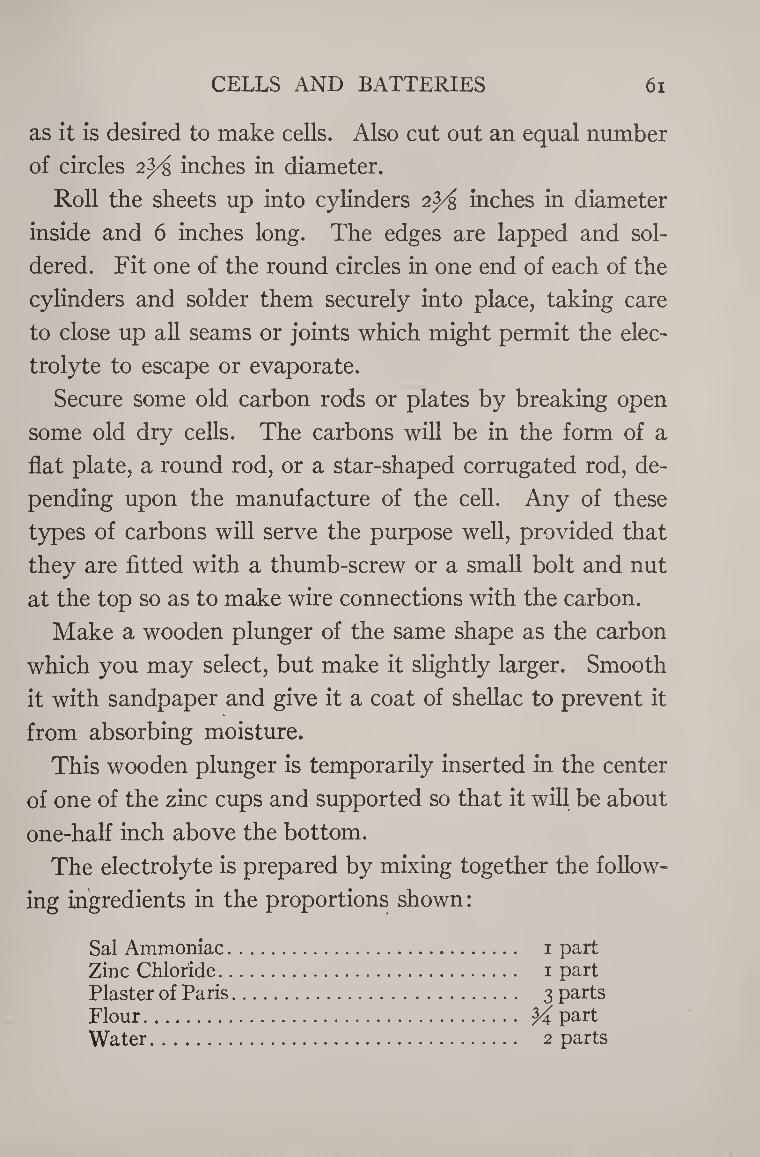
CELLS AND BATTERIES 61
as it is desired to make cells. Also cut out an equal number
of circles 2^ inches in diameter.
Roll the sheets up into cylinders 2^ inches in diameter
inside and 6 inches long. The edges are lapped and sol¬
dered. Fit one of the round circles in one end of each of the
cylinders and solder them securely into place, taking care
to close up all seams or joints which might permit the elec¬
trolyte to escape or evaporate.
Secure some old carbon rods or plates by breaking open
some old dry cells. The carbons will be in the form of a
flat plate, a round rod, or a star-shaped corrugated rod, de¬
pending upon the manufacture of the cell. Any of these
types of carbons will serve the purpose well, provided that
they are fitted with a thumb-screw or a small bolt and nut
at the top so as to make wire connections with the carbon.
Make a wooden plunger of the same shape as the carbon
which you may select, but make it slightly larger. Smooth
it with sandpaper and give it a coat of shellac to prevent it
from absorbing moisture.
This wooden plunger is temporarily inserted in the center
of one of the zinc cups and supported so that it will be about
one-half inch above the bottom.
The electrolyte is prepared by mixing together the follow¬
ing ingredients in the proportions shown:
Sal Ammoniac. 1 part Zinc Chloride. 1 part Plaster of Paris. 3 parts Flour. y part Water. 2 parts
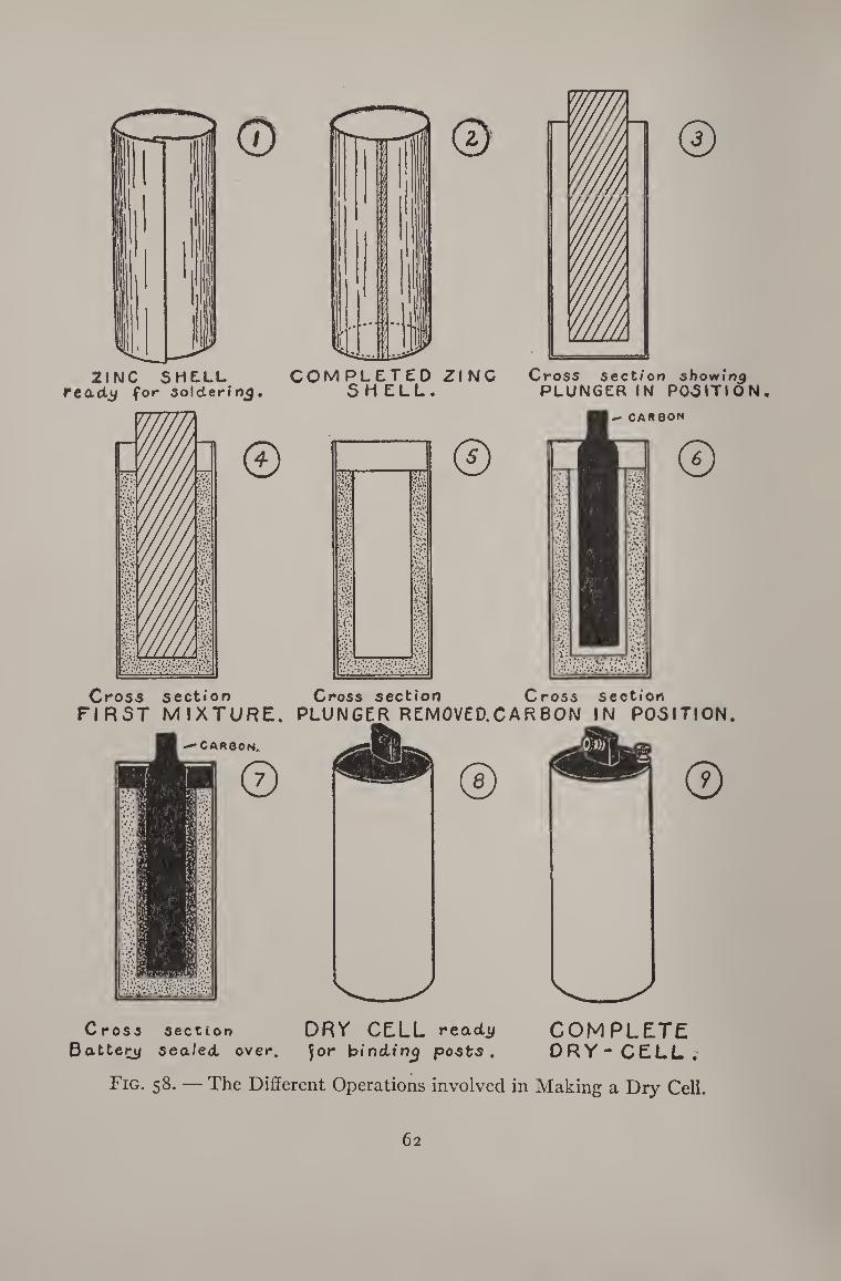
Cross section sbowfn^ PLUNGER IN POSITION,
Cross section Battery sealed, over.
DRY CELL ready for binding posts.
COMPLETE DRY-CELL.
Fig. 58. — The Different Operations involved in Making a Dry Cell.
62
CELLS AND BATTERIES 63
The above paste is then firmly packed into the zinc shell
around the wooden plunger, leaving a space of about Y of
an inch at the top. The paste can be poured in very readily
when first mixed but sets and hardens after standing a short
while.
After it has set, withdraw the wooden plunger, thus
leaving a space inside of the dry cell a little larger than the
carbon. The carbon is now inserted in this hole and the
surrounding space is filled with a mixture composed of:
Sal Ammoniac. 1 part Zinc Chloride. 1 part Manganese Dioxide. 1 part Granulated Carbon. 1 part Flour. 1 part Plaster of Paris. 3 parts Water. 2 parts
The granular carbon may be had by crushing up some old
battery carbons. The parts given in both of the above
formulas are proportioned so that they may be measured
by bulk and not by weight. An old teaspoon or a small cup
will make a good measure.
Each one of the zinc shells should be filled in this man¬
ner. After they have all been filled, clean off the top edge
of the zinc and pour the remaining space in the cell full of
molten tar or pitch so as to seal it over.
Solder a small binding-post to the top edge of the zinc to
facilitate connection. Then wrap the cells in several thick¬
nesses of heavy paper to prevent them from short circuit¬
ing, and they are ready for use.
64 THE BOY ELECTRICIAN
A small hole bored through the sealing material
after it is dry will provide a vent for the escape of
gases.
Recharging dry cells is a subject that interests most ex¬
perimenters.
Dry cells very often become useless before the zinc shell
is used up or the chemicals are exhausted, due to the fact
that the water inside of the cell dries up and the resistance
therefore becomes so great that it is practically impossible
for the current to pass.
The life of such cells may be partially renewed by drilling
several holes in the cell and permitting it to soak in a strong
solution of sal ammoniac until some of the liquid is absorbed.
The holes should then be plugged up with some sealing wax
in order to prevent evaporation.
An old dry cell may be easily turned into a “ wet ” cell by
drilling the zinc full of holes and then setting it in a jar con¬
taining a sal ammoniac solution. The battery should be
allowed to remain in the solution.
Wet batteries are very much easier to make than dry bat¬
teries and are capable of delivering more current.
They have the disadvantage, however, of wasting away
more rapidly, when not in service, than dry cells.
The Leclanche cell is the type generally first attempted
by most experimenters.
Carbon plates for making such a battery are most easily
and cheaply obtained from old dry cells. About the only
way that a dry cell can be broken open is with a cold-chisel
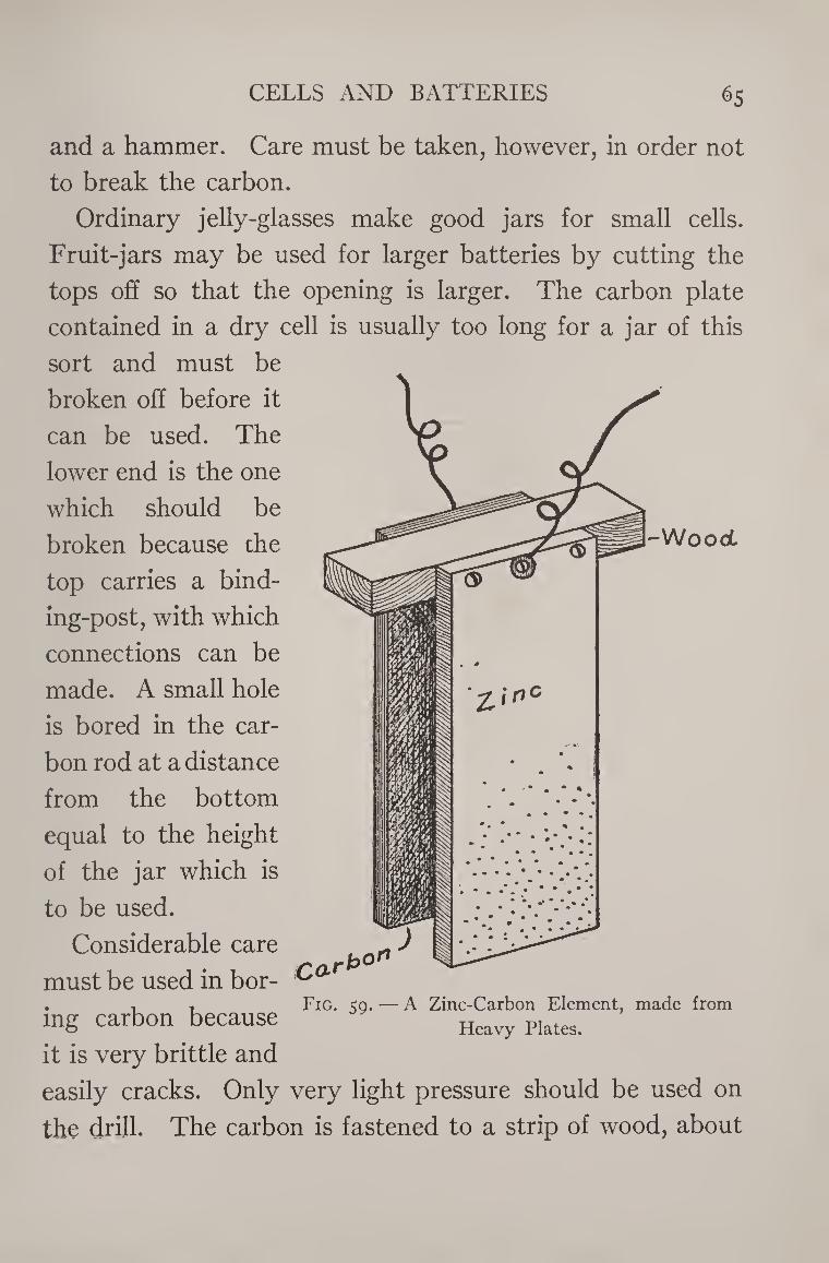
CELLS AND BATTERIES 65
and a hammer. Care must be taken, however, in order not
to break the carbon.
Ordinary jelly-glasses make good jars for small cells.
Fruit-jars may be used for larger batteries by cutting the
tops off so that the opening is larger. The carbon plate
contained in a dry cell is usually too long for a jar of this
sort and must be
broken off before it
can be used. The
lower end is the one
which should be
broken because the
top carries a bind¬
ing-post, with which
connections can be
made. A small hole
is bored in the car¬
bon rod at a distance
from the bottom
equal to the height
of the jar which is
to be used.
Considerable care
must be used in bor- . ■, Fig. ^0. — A Zinc-Carbon Element, made from ing carbon because Heavy plates
it is very brittle and
easily cracks. Only very light pressure should be used on
the drill. The carbon is fastened to a strip of wood, about
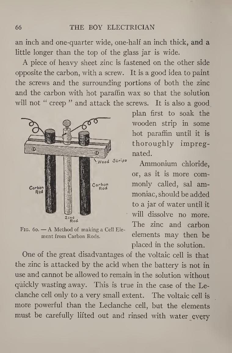
66 THE BOY ELECTRICIAN
Vw/ooct 'Strip3
an inch and one-quarter wide, one-half an inch thick, and a
little longer than the top of the glass jar is wide.
A piece of heavy sheet zinc is fastened on the other side
opposite the carbon, with a screw. It is a good idea to paint
the screws and the surrounding portions of both the zinc
and the carbon with hot paraffin wax so that the solution
will not “ creep ” and attack the screws. It is also a good
plan first to soak the
wooden strip in some
hot paraffin until it is
thoroughly impreg¬
nated.
Ammonium chloride,
or, as it is more com¬
monly called, sal am¬
moniac, should be added
to a jar of water until it
will dissolve no more.
The zinc and carbon
elements may then be
placed in the solution.
One of the great disadvantages of the voltaic cell is that
the zinc is attacked by the acid when the battery is not in
use and cannot be allowed to remain in the solution without
quickly wasting away. This is true in the case of the Le-
clanche cell only to a very small extent. The voltaic cell is
more powerful than the Leclanche cell, but the elements
must be carefully lifted out and rinsed with water every
Carbon Carbon
Root
Fig. 6o. — A Method of making a Cell Ele¬
ment from Carbon Rods.
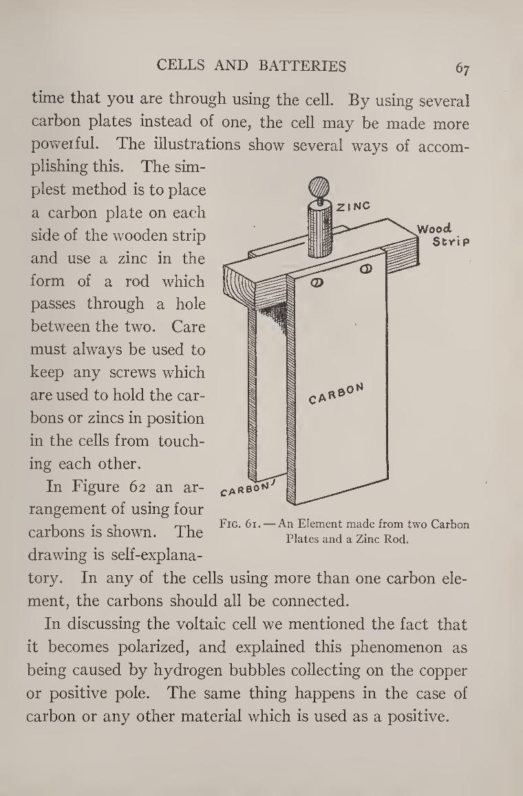
CELLS AND BATTERIES 67
Wood Strip
C A*' tf
time that you are through using the cell. By using several
carbon plates instead of one, the cell may be made more
powerful. The illustrations show several ways of accom¬
plishing this. The sim¬
plest method is to place
a carbon plate on each
side of the wooden strip
and use a zinc in the
form of a rod which
passes through a hole
between the two. Care
must always be used to
keep any screws which
are used to hold the car¬
bons or zincs in position
in the cells from touch¬
ing each other.
In Figure 62 an ar¬
rangement of using four
carbons is shown. The
drawing is self-explana¬
tory. In any of the cells using more than one carbon ele¬
ment, the carbons should all be connected.
In discussing the voltaic cell we mentioned the fact that
it becomes polarized, and explained this phenomenon as
being caused by hydrogen bubbles collecting on the copper
or positive pole. The same thing happens in the case of
carbon or any other material which is used as a positive.
ca RBO^
Fig. 61. An Element made from two Carbon
Plates and a Zinc Rod.
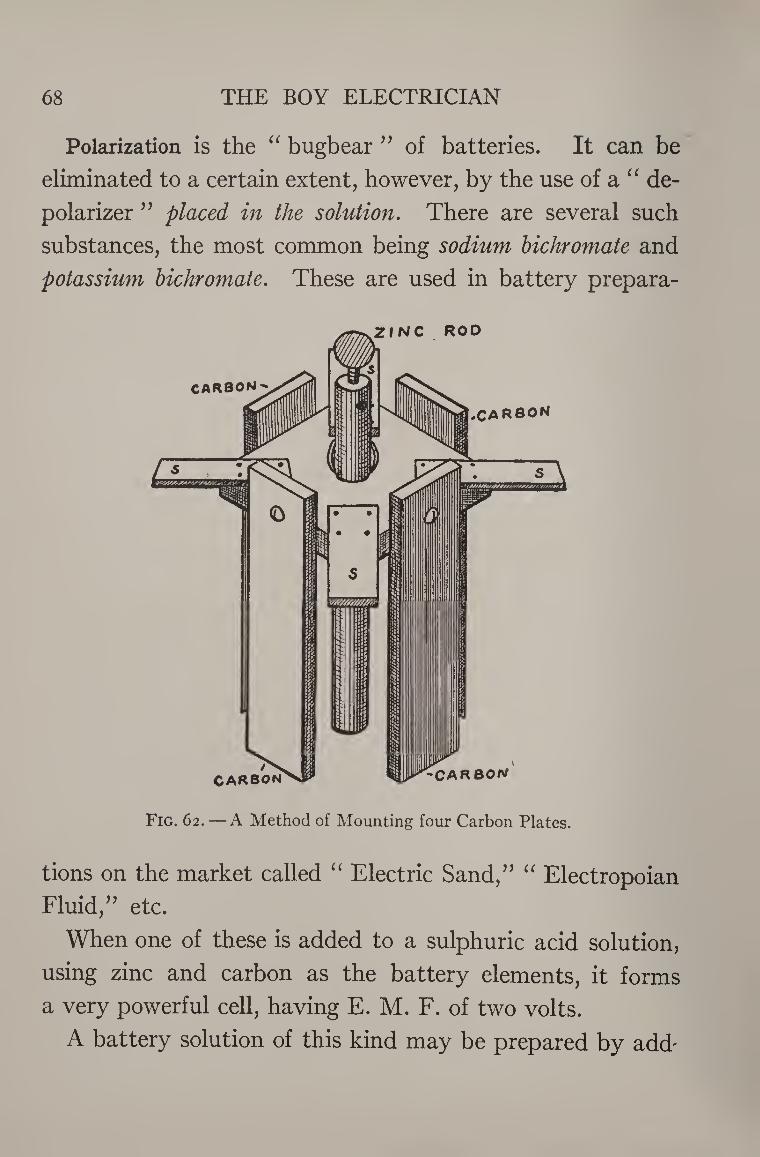
68 THE BOY ELECTRICIAN
Polarization is the “ bugbear ” of batteries. It can be
eliminated to a certain extent, however, by the use of a “ de¬
polarizer ” placed in the solution. There are several such
substances, the most common being sodium bichromate and
potassium bichromate. These are used in battery prepara¬
tions on the market called “ Electric Sand,” “ Electropoian
Fluid,” etc.
When one of these is added to a sulphuric acid solution,
using zinc and carbon as the battery elements, it forms
a very powerful cell, having E. M. F. of two volts.
A battery solution of this kind may be prepared by add-
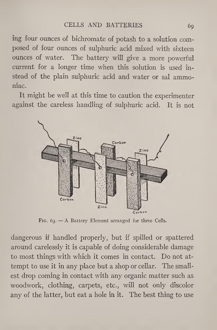
CELLS AND BATTERIES 69
ing four ounces of bichromate of potash to a solution com¬
posed of four ounces of sulphuric acid mixed with sixteen
ounces of water. The battery will give a more powerful
current for a longer time when this solution is used in¬
stead of the plain sulphuric acid and water or sal ammo¬
niac.
It might be well at this time to caution the experimenter
against the careless handling of sulphuric acid. It is not
C ar b ori
Fig. 63. — A Battery Element arranged for three Cells.
dangerous if handled properly, but if spilled or spattered
around carelessly it is capable of doing considerable damage
to most things with which it comes in contact. Do not at¬
tempt to use it in any place but a shop or cellar. The small¬
est drop coming in contact with any organic matter such as
woodwork, clothing, carpets, etc., will not only discolor
any of the latter, but eat a hole in it. The best thing to use
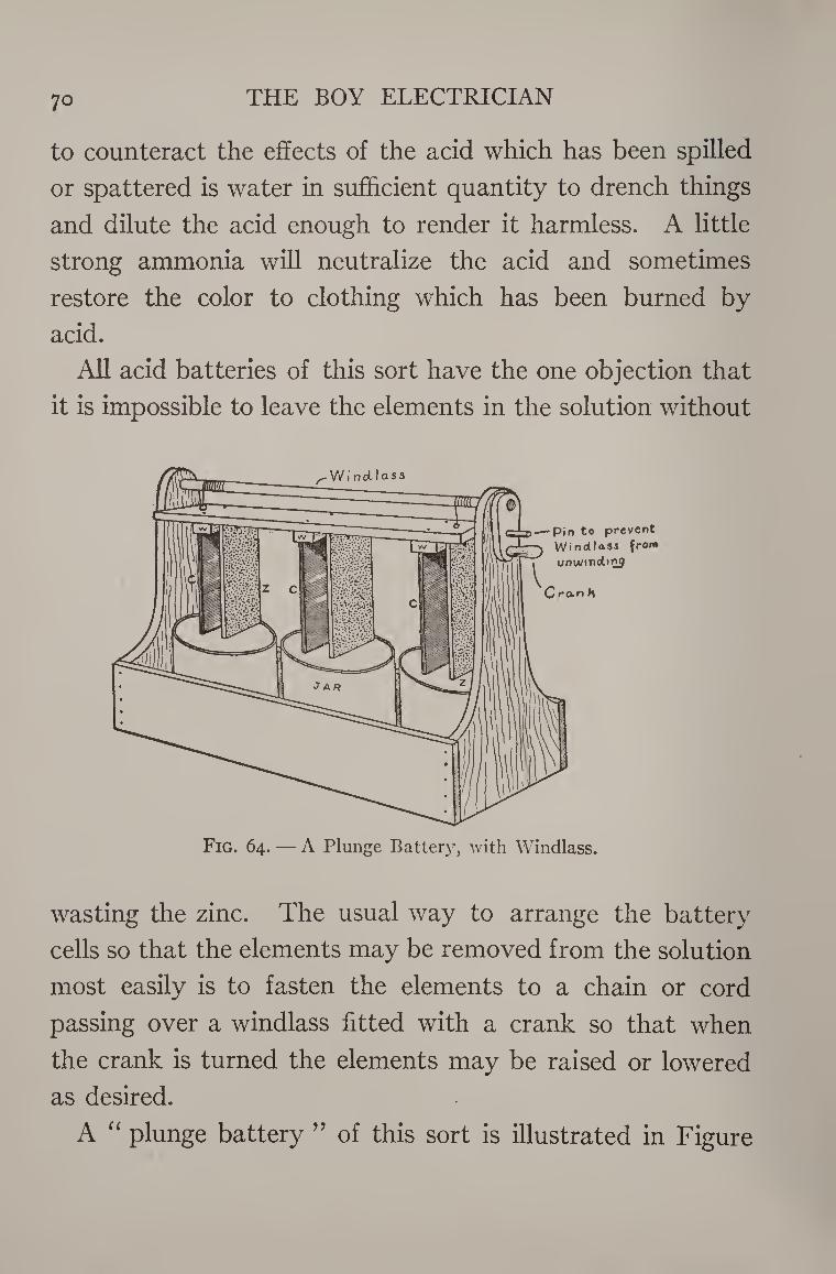
7o THE BOY ELECTRICIAN
to counteract the effects of the acid which has been spilled
or spattered is water in sufficient quantity to drench things
and dilute the acid enough to render it harmless. A little
strong ammonia will neutralize the acid and sometimes
restore the color to clothing which has been burned by
acid.
All acid batteries of this sort have the one objection that
it is impossible to leave the elements in the solution without
Windlass
-pin to prevent Windlass from
unw/rndinj
Cran H
Fig. 64. — A Plunge Battery, with Windlass.
wasting the zinc. The usual way to arrange the battery
cells so that the elements may be removed from the solution
most easily is to fasten the elements to a chain or cord
passing over a windlass fitted with a crank so that when
the crank is turned the elements may be raised or lowered
as desired.
A “ plunge battery ” of this sort is illustrated in Figure
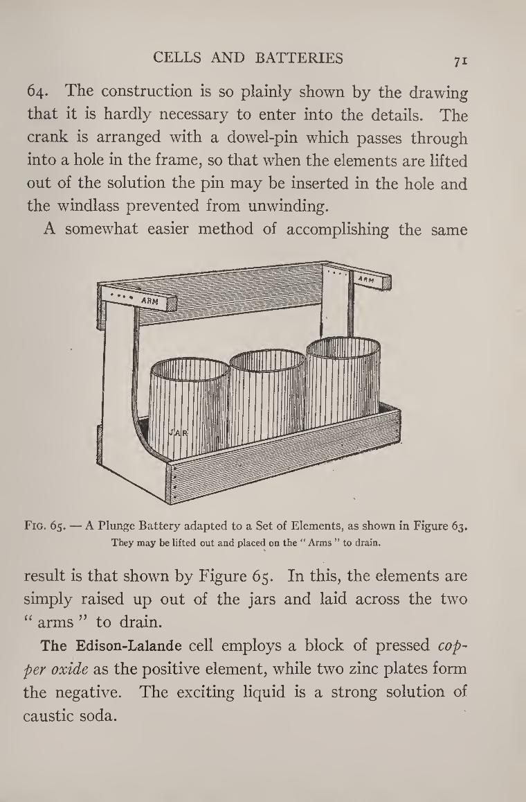
CELLS AND BATTERIES 7i
64. The construction is so plainly shown by the drawing
that it is hardly necessary to enter into the details. The
crank is arranged with a dowel-pin which passes through
into a hole in the frame, so that when the elements are lifted
out of the solution the pin may be inserted in the hole and
the windlass prevented from unwinding.
A somewhat easier method of accomplishing the same
Fig. 65. — A Plunge Battery adapted to a Set of Elements, as shown in Figure 63.
They may be lifted out and placed on the “ Arms ” to drain.
result is that shown by Figure 65. In this, the elements are
simply raised up out of the jars and laid across the two
“ arms 99 to drain.
The Edison-Lalande cell employs a block of pressed cop¬
per oxide as the positive element, while two zinc plates form
the negative. The exciting liquid is a strong solution of
caustic soda.
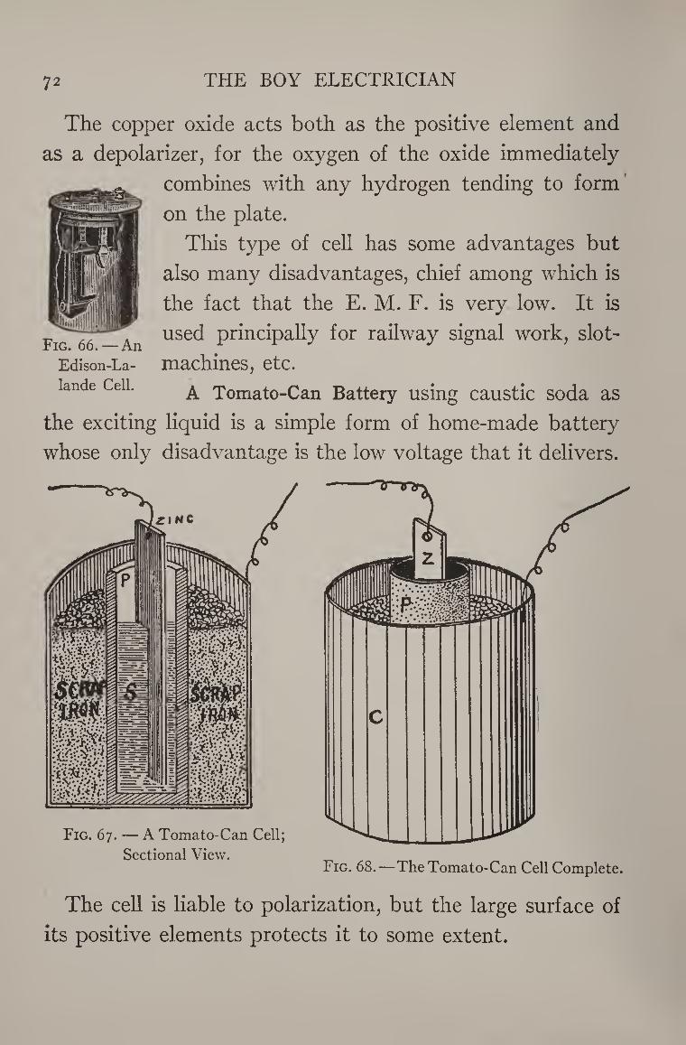
72 THE BOY ELECTRICIAN
The copper oxide acts both as the positive element and
as a depolarizer, for the oxygen of the oxide immediately
combines with any hydrogen tending to form
on the plate.
This type of cell has some advantages but
also many disadvantages, chief among which is
the fact that the E. M. F. is very low. It is
used principally for railway signal work, slot-
machines, etc.
A Tomato-Can Battery using caustic soda as
the exciting liquid is a simple form of home-made battery
whose only disadvantage is the low voltage that it delivers.
Fig. 66. — An
Edison-La-
lande Cell.
Fig. 67. — A Tomato-Can Cell;
Sectional View. Fig. 68.—The Tomato-Can Cell Complete.
The cell is liable to polarization, but the large surface of
its positive elements protects it to some extent.
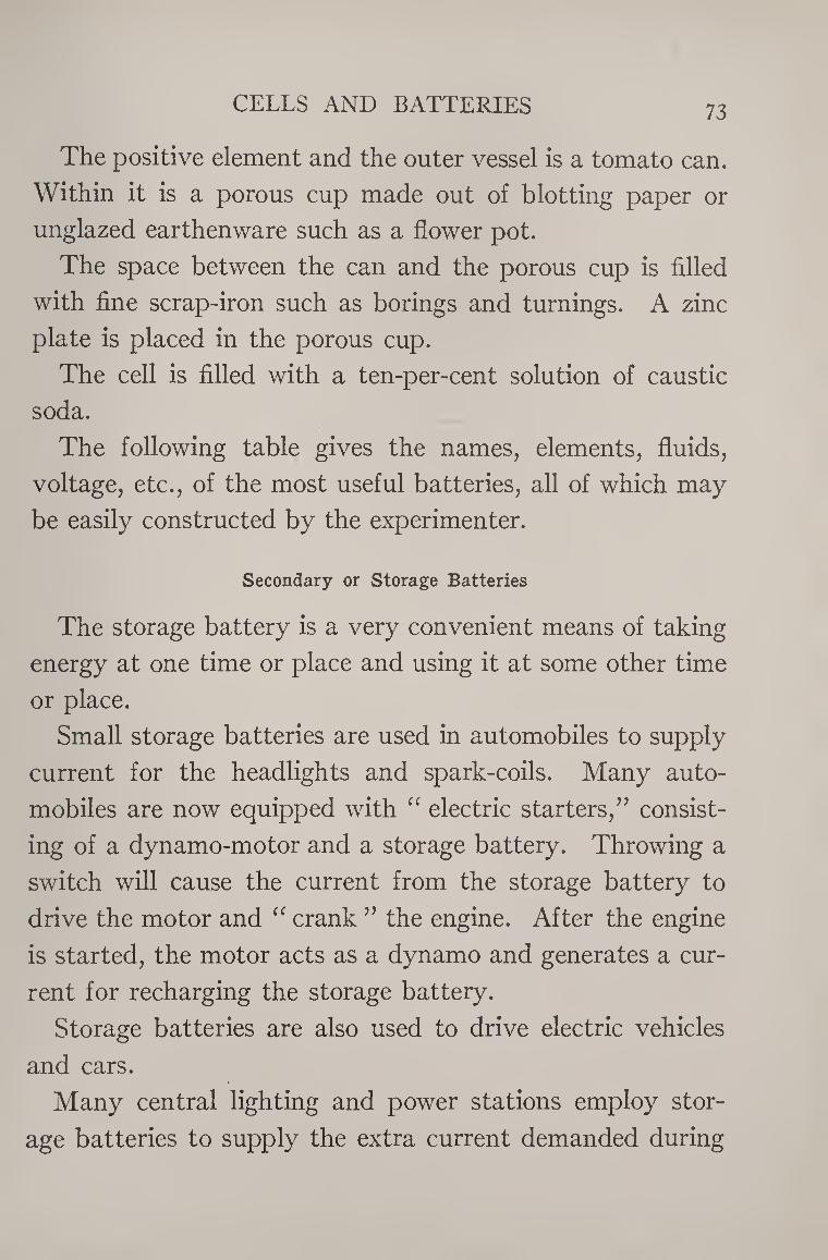
CELLS AND BATTERIES 73
The positive element and the outer vessel is a tomato can.
Within it is a porous cup made out of blotting paper or
unglazed earthenware such as a flower pot.
The space between the can and the porous cup is filled
with fine scrap-iron such as borings and turnings. A zinc
plate is placed in the porous cup.
The cell is filled with a ten-per-cent solution of caustic
soda.
The following table gives the names, elements, fluids,
voltage, etc., of the most useful batteries, all of which may
be easily constructed by the experimenter.
Secondary or Storage Batteries
The storage battery is a very convenient means of taking
energy at one time or place and using it at some other time
or place.
Small storage batteries are used in automobiles to supply
current for the headlights and spark-coils. Many auto¬
mobiles are now equipped with “ electric starters,” consist¬
ing of a dynamo-motor and a storage battery. Throwing a
switch will cause the current from the storage battery to
drive the motor and “ crank ” the engine. After the engine
is started, the motor acts as a dynamo and generates a cur¬
rent for recharging the storage battery.
Storage batteries are also used to drive electric vehicles
and cars.
Many central lighting and power stations employ stor¬
age batteries to supply the extra current demanded during
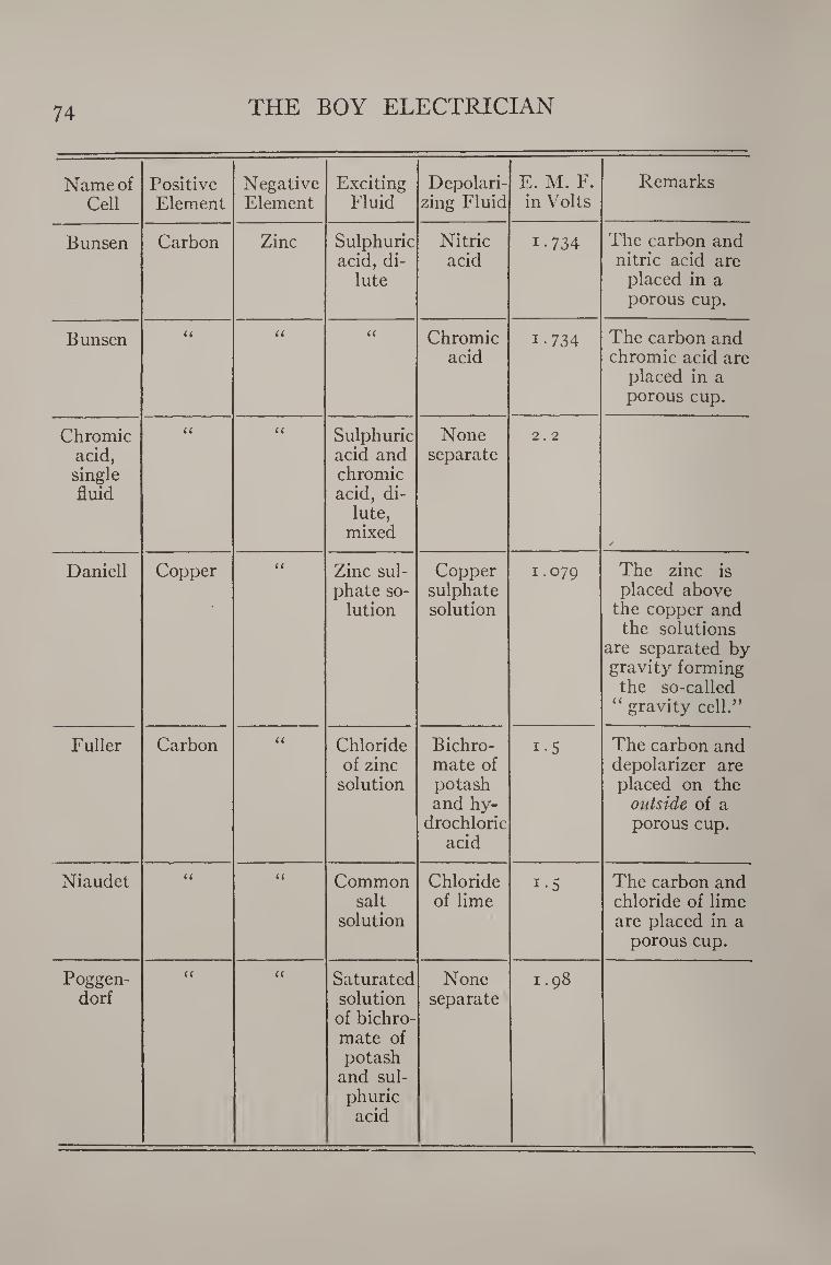
74 THE BOY ELECTRICIAN
Name of Cell
Positive Element
Negative Element
Exciting Fluid
Depolari¬ zing Fluid
E. M. F. in Volts
Remarks
Bunsen Carbon Zinc Sulphuric acid, di¬
lute
Nitric acid
1-734 The carbon and nitric acid are
placed in a porous cup.
Bunsen <( U (( Chromic acid
i-734 The carbon and chromic acid are
placed in a porous cup.
Chromic acid, single fluid
U a Sulphuric acid and chromic acid, di¬
lute, mixed
None separate
2.2
/
Daniell Copper u Zinc sul¬ phate so¬
lution
Copper sulphate solution
1.079 The zinc is placed above
the copper and the solutions
are separated by gravity forming the so-called
“ gravity cell.”
Fuller Carbon u Chloride of zinc
solution
Bichro¬ mate of potash and hy¬
drochloric acid
i-5 The carbon and depolarizer are placed on the
outside of a porous cup.
Niaudet U u Common salt
solution
Chloride of lime
i-5 The carbon and chloride of lime are placed in a
porous cup.
Poggen- dorf
u u Saturated solution of bichro¬ mate of potash
and sul¬ phuric acid
None separate
i .98
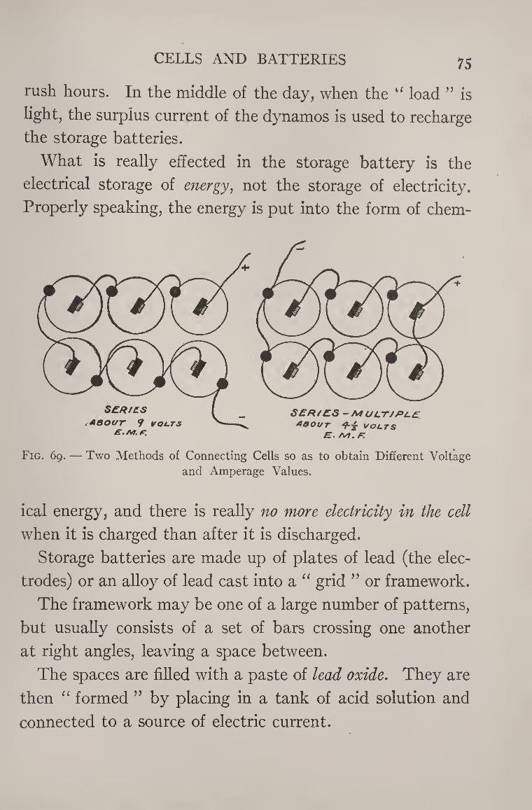
CELLS AND BATTERIES 75
rush hours. In the middle of the day, when the u load ” is
light, the surplus current of the dynamos is used to recharge
the storage batteries.
What is really effected in the storage battery is the
electrical storage of energy, not the storage of electricity.
Properly speaking, the energy is put into the form of chem-
Fig. 69. — Two Methods of Connecting Cells so as to obtain Different Voltage
and Amperage Values.
ical energy, and there is really no more electricity in the cell
when it is charged than after it is discharged.
Storage batteries are made up of plates of lead (the elec¬
trodes) or an alloy of lead cast into a “ grid ” or framework.
The framework may be one of a large number of patterns,
but usually consists of a set of bars crossing one another
at right angles, leaving a space between.
The spaces are filled with a paste of lead oxide. They are
then “ formed ” by placing in a tank of acid solution and
connected to a source of electric current.
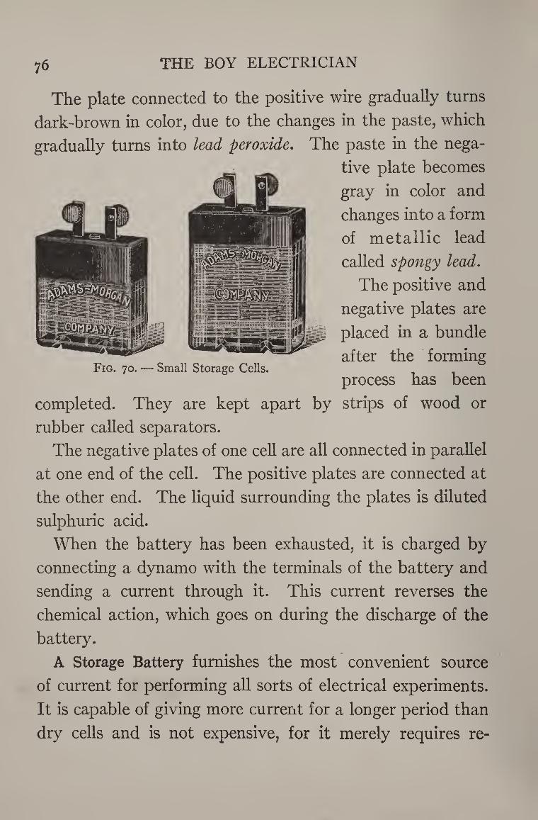
76 THE BOY ELECTRICIAN
Fig. 70. — Small Storage Cells.
The plate connected to the positive wire gradually turns
dark-brown in color, due to the changes in the paste, which
gradually turns into lead peroxide. The paste in the nega¬
tive plate becomes
gray in color and
changes into a form
of metallic lead
called spongy lead.
The positive and
negative plates are
placed in a bundle
after the forming
process has been
completed. They are kept apart by strips of wood or
rubber called separators.
The negative plates of one cell are all connected in parallel
at one end of the cell. The positive plates are connected at
the other end. The liquid surrounding the plates is diluted
sulphuric acid.
When the battery has been exhausted, it is charged by
connecting a dynamo with the terminals of the battery and
sending a current through it. This current reverses the
chemical action, which goes on during the discharge of the
battery.
A Storage Battery furnishes the most convenient source
of current for performing all sorts of electrical experiments.
It is capable of giving more current for a longer period than
dry cells and is not expensive, for it merely requires re-
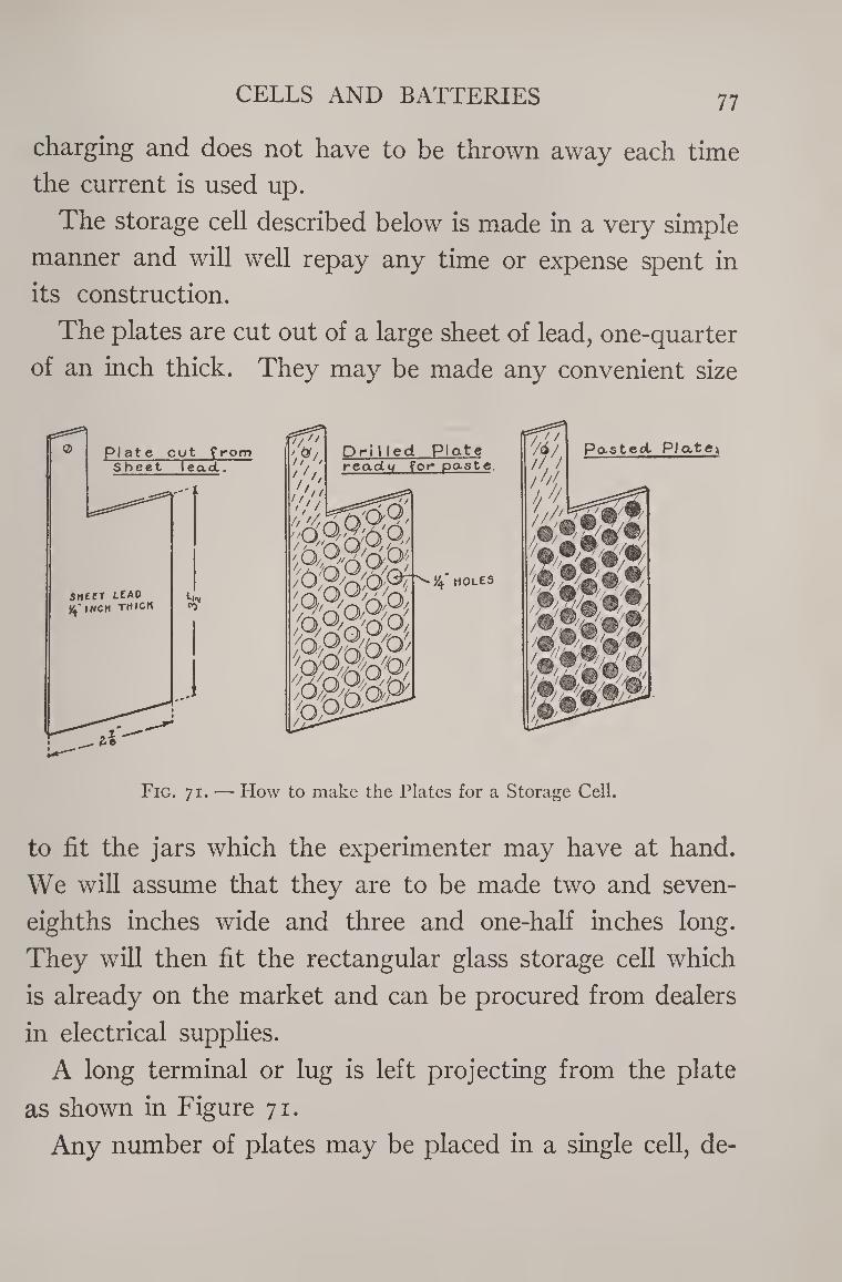
CELLS AND BATTERIES 77
charging and does not have to be thrown away each time
the current is used up.
The storage cell described below is made in a very simple
manner and will well repay any time or expense spent in
its construction.
The plates are cut out of a large sheet of lead, one-quarter
of an inch thick. They may be made any convenient size
Fig. 71. — How to make the Plates for a Storage Cell.
to fit the jars which the experimenter may have at hand.
We will assume that they are to be made two and seven-
eighths inches wide and three and one-half inches long.
They will then fit the rectangular glass storage cell which
is already on the market and can be procured from dealers
in electrical supplies.
A long terminal or lug is left projecting from the plate
as shown in Figure 71.
Any number of plates may be placed in a single cell, de-
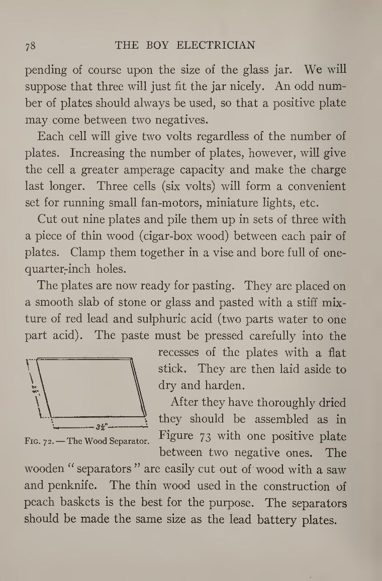
78 THE BOY ELECTRICIAN
pending of course upon the size of the glass jar. We will
suppose that three will just fit the jar nicely. An odd num¬
ber of plates should always be used, so that a positive plate
may come between two negatives.
Each cell will give two volts regardless of the number of
plates. Increasing the number of plates, however, will give
the cell a greater amperage capacity and make the charge
last longer. Three cells (six volts) will form a convenient
set for running small fan-motors, miniature lights, etc.
Cut out nine plates and pile them up in sets of three with
a piece of thin wood (cigar-box wood) between each pair of
plates. Clamp them together in a vise and bore full of one-
quarter-inch holes.
The plates are now ready for pasting. They are placed on
a smooth slab of stone or glass and pasted with a stiff mix¬
ture of red lead and sulphuric acid (two parts water to one
part acid). The paste must be pressed carefully into the
recesses of the plates with a flat
stick. They are then laid aside to
dry and harden.
After they have thoroughly dried
^ they should be assembled as in
Fig. 72. —The Wood Separator. FiSUI'C 73 with one positive plate between two negative ones. The
wooden “ separators ” are easily cut out of wood with a saw
and penknife. The thin wood used in the construction of
peach baskets is the best for the purpose. The separators
should be made the same size as the lead battery plates.
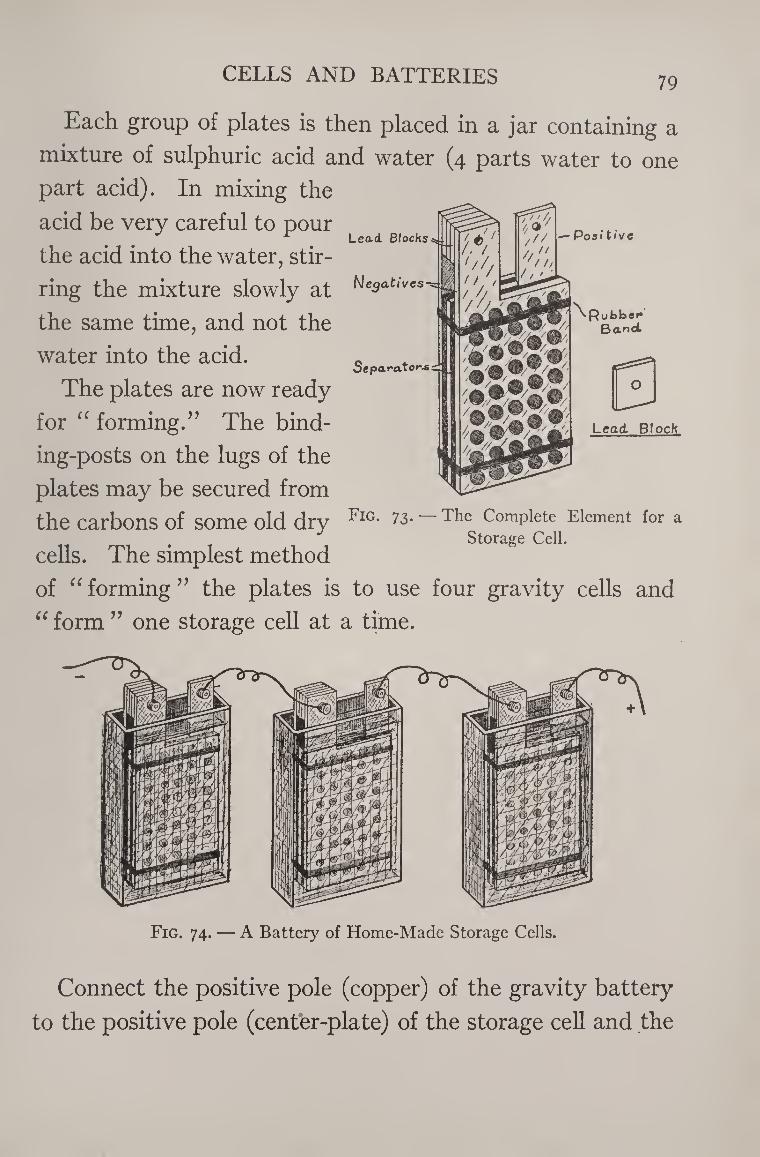
CELLS AND BATTERIES 79
Each group of plates is then placed in a jar containing a
mixture of sulphuric acid and water (4 parts water to one
part acid). In mixing the
acid be very careful to pour
the acid into the water, stir¬
ring the mixture slowly at
the same time, and not the
water into the acid.
The plates are now ready
for “ forming.” The bind¬
ing-posts on the lugs of the
plates may be secured from
the carbons of some old dry
cells. The simplest method
of “forming” the plates is
“ form ” one storage cell at
Storage Cell.
to use four gravity cells and
a time.
Fig. 74. — A Battery of Home-Made Storage Cells.
Connect the positive pole (copper) of the gravity battery
to the positive pole (center-plate) of the storage cell and the
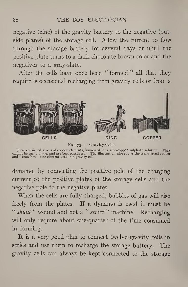
8o THE BOY ELECTRICIAN
negative (zinc) of the gravity battery to the negative (out¬
side plates) of the storage cell. Allow the current to flow
through the storage battery for several days or until the
positive plate turns to a dark chocolate-brown color and the
negatives to a gray-slate.
After the cells have once been “ formed ” all that they
require is occasional recharging from gravity cells or from a
CELLS ZINC COPPER
Fig. 75. — Gravity Cells.
These consist of zinc and copper elements, immersed in a zinc-copper sulphate solution. They cannot be easily made, and are best purchased. The illustration also shows the star-shaped copper and “ crowfoot ” zinc element used in a gravity cell.
dynamo, by connecting the positive pole of the charging
current to the positive plates of the storage cells and the
negative pole to the negative plates.
When the cells are fully charged, bubbles of gas will rise
freely from the plates. If a dynamo is used it must be
“ shunt ” wound and not a “ series ” machine. Recharging
will only require about one-quarter of the time consumed
in forming.
It is a very good plan to connect twelve gravity cells in
series and use them to recharge the storage battery. The
gravity cells can always be kept connected to the storage
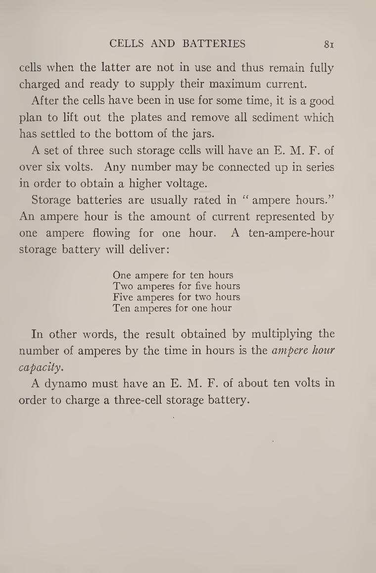
CELLS AND BATTERIES 81
cells when the latter are not in use and thus remain fully
charged and ready to supply their maximum current.
After the cells have been in use for some time, it is a good
plan to lift out the plates and remove all sediment which
has settled to the bottom of the jars.
A set of three such storage cells will have an E. M. F. of
over six volts. Any number may be connected up in series
in order to obtain a higher voltage.
Storage batteries are usually rated in “ ampere hours.”
An ampere hour is the amount of current represented by
one ampere flowing for one hour. A ten-ampere-hour
storage battery will deliver:
One ampere for ten hours Two amperes for five hours Five amperes for two hours Ten amperes for one hour
In other words, the result obtained by multiplying the
number of amperes by the time in hours is the ampere hour
capacity.
A dynamo must have an E. M. F. of about ten volts in
order to charge a three-cell storage battery.
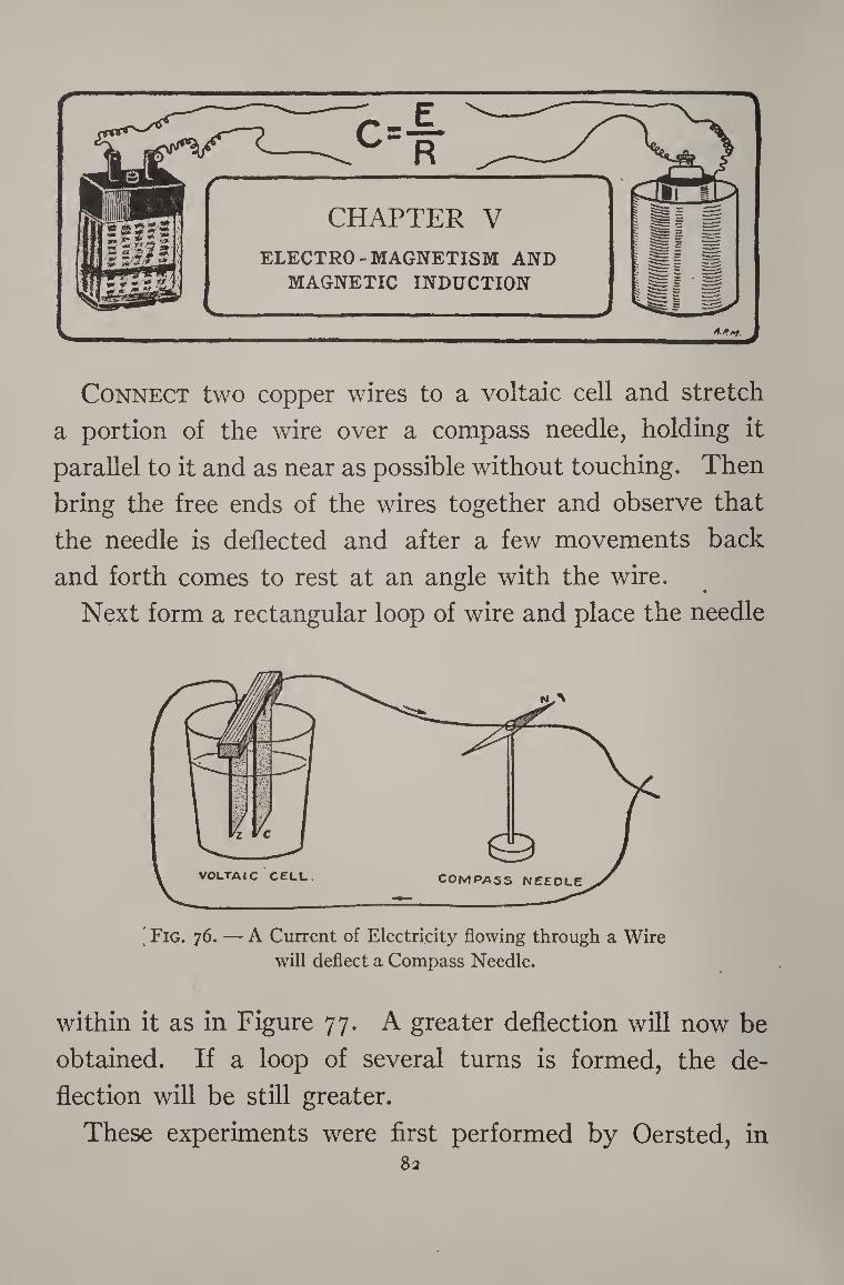
R /—
CHAPTER V
ELECTRO-MAGNETISM AND
MAGNETIC INDUCTION
s._ _> 4-* A?.
Connect two copper wires to a voltaic cell and stretch
a portion of the wire over a compass needle, holding it
parallel to it and as near as possible without touching. Then
bring the free ends of the wires together and observe that
the needle is deflected and after a few movements back
and forth comes to rest at an angle with the wire.
Next form a rectangular loop of wire and place the needle
Fig. 76. — A Current of Electricity flowing through a Wire
will deflect a Compass Needle.
within it as in Figure 77. A greater deflection will now be
obtained. If a loop of several turns is formed, the de¬
flection will be still greater.
These experiments were first performed by Oersted, in 82
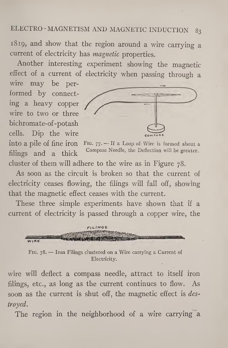
ELECTRO - MAGNETISM AND MAGNETIC INDUCTION 83
1819, and show that the region around a wire carrying a
current of electricity has magnetic properties.
Another interesting experiment showing the magnetic
effect of a current of electricity when passing through a
wire may be per¬
formed by connect¬
ing a heavy copper
wire to two or three
bichromate-of-potash
cells. Dip the wire
into a pile of fine iron Fig. 77. — If a Loop of Wire is formed about a
filings and a thick Compass Needle, the Deflection will be greater.
cluster of them will adhere to the wire as in Figure 78.
As soon as the circuit is broken so that the current of
electricity ceases flowing, the filings will fall off, showing
that the magnetic effect ceases with the current.
These three simple experiments have shown that if a
current of electricity is passed through a copper wire, the
a
©
FI LINGS
Fig. 78. — Iron Filings clustered on a Wire carrying a Current of
Electricity.
wire will deflect a compass needle, attract to itself iron
filings, etc., as long as the current continues to flow. As
soon as the current is shut off, the magnetic effect is des¬
troyed.
The region in the neighborhood of a wire carrying a
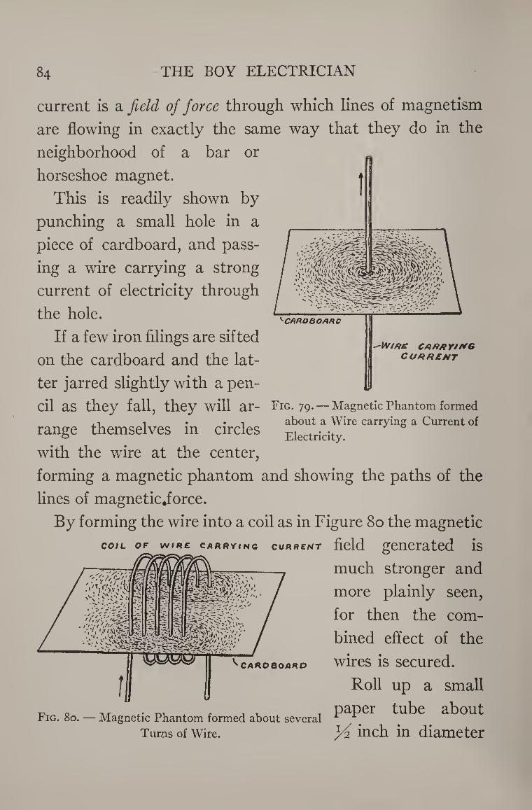
84 THE BOY ELECTRICIAN
^CAAOBOARG
-\M ME carrying
CURRENT
current is a field of force through which lines of magnetism
are flowing in exactly the same way that they do in the
neighborhood of a bar or
horseshoe magnet. ♦ This is readily shown by
punching a small hole in a
piece of cardboard, and pass¬
ing a wire carrying a strong
current of electricity through
the hole.
If a few iron filings are sifted
on the cardboard and the lat¬
ter jarred slightly with a pen¬
cil as they fall, they will ar- Fig. 79. — Magnetic Phantom formed
,1 t ... about a Wire carrying a Current of range themselves in circles Electricity.
with the wire at the center,
forming a magnetic phantom and showing the paths of the
lines of magnetic.force.
By forming the wire into a coil as in Figure 80 the magnetic
field generated is
much stronger and
more plainly seen,
for then the com¬
bined effect of the
wires is secured.
Roll up a small
•p 0 ,, t,. , j , , paper tube about riG. 80. — Magnetic Phantom formed about several
Turns of wire. M inch in diameter
COIL OF WIRE CARRYING CURRENT
CARDBOARD
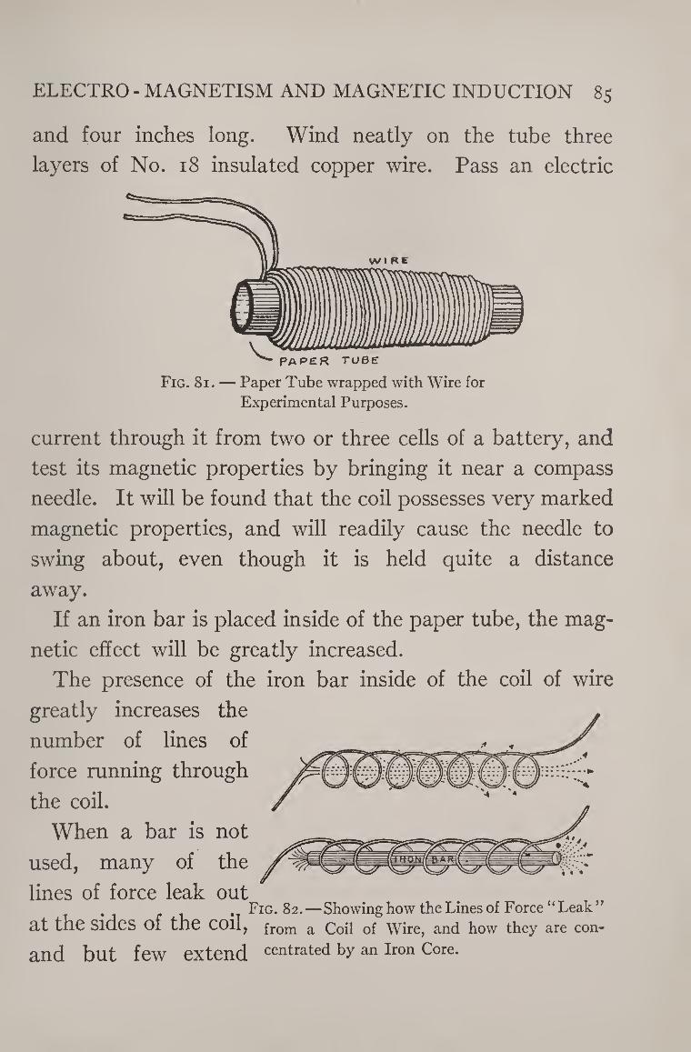
ELECTRO - MAGNETISM AND MAGNETIC INDUCTION 85
and four inches long. Wind neatly on the tube three
layers of No. 18 insulated copper wire. Pass an electric
Fig. 81. — Paper Tube wrapped with Wire for
Experimental Purposes.
current through it from two or three cells of a battery, and
test its magnetic properties by bringing it near a compass
needle. It will be found that the coil possesses very marked
magnetic properties, and will readily cause the needle to
swing about, even though it is held quite a distance
away.
If an iron bar is placed inside of the paper tube, the mag¬
netic effect will be greatly increased.
The presence of the iron bar inside of the coil of wire
greatly increases the
number of lines of
force running through
the coil.
When a bar is not
used, many of the
lines of force leak out Fig. 82.—Showing how the Lines of Force “Leak”
at the sides of the coil, from a Coil of Wire, and how they are con-
and but few extend centrated by an Iron Core.
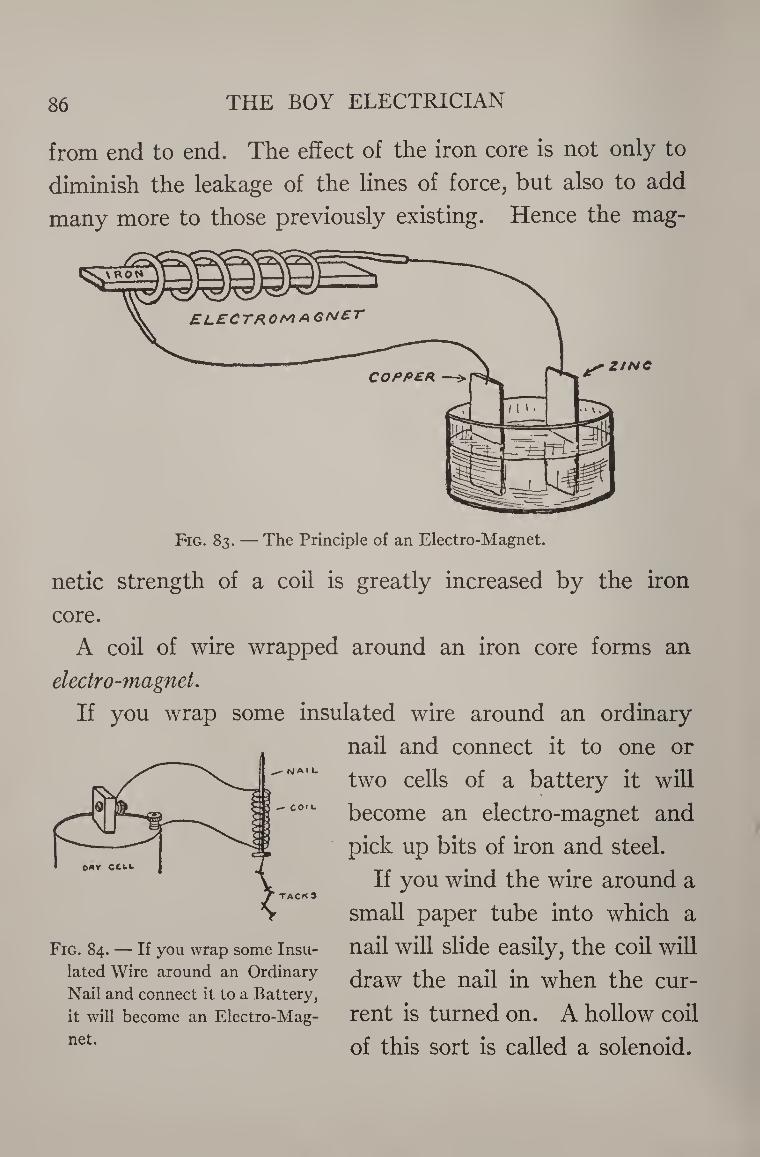
86 THE BOY ELECTRICIAN
from end to end. The effect of the iron core is not only to
diminish the leakage of the lines of force, but also to add
many more to those previously existing. Hence the mag¬
netic strength of a coil is greatly increased by the iron
core.
A coil of wire wrapped around an iron core forms an
electro-magnet.
If you wrap some insulated wire around an ordinary
nail and connect it to one or
two cells of a battery it will
co,l‘ become an electro-magnet and
pick up bits of iron and steel.
If you wind the wire around a ACK 9
small paper tube into which a
Fig. 84. — if you wrap some insu- nail will slide easily, the coil will lated Wire around an Ordinary Jraw the nail in when the cur- Nail and connect it to a Battery,
it will become an Electro-Mag- rent is turned On. A hollow Coil
net* of this sort is called a solenoid.
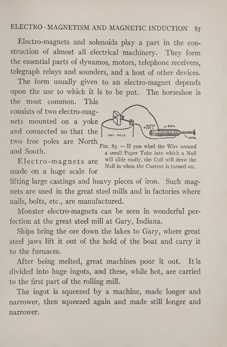
ELECTRO - MAGNETISM AND MAGNETIC INDUCTION 87
Electro-magnets and solenoids play a part in the con¬
struction of almost all electrical machinery. They form
the essential parts of dynamos, motors, telephone receivers,
telegraph relays and sounders, and a host of other devices.
The form usually given to an electro-magnet depends
upon the use to which it is to be put. The horseshoe is
the most common. This
consists of two electro-mag¬
nets mounted on a yoke
and connected so that the NAIfc
two free poles are North Fig. 85. — If you wind the Wire around
and South. a small Paper Tube into which a Nail
Electro-magnets are sjic*e easily»the c°d wiI1 draw tlie Nail in when the Current is turned on.
made on a huge scale for
lifting large castings and heavy pieces of iron. Such mag¬
nets are used in the great steel mills and in factories where
nails, bolts, etc., are manufactured.
Monster electro-magnets can be seen in wonderful per¬
fection at the great steel mill at Gary, Indiana.
Ships bring the ore down the lakes to Gary, where great
steel jaws lift it out of the hold of the boat and carry it
to the furnaces.
After being melted, great machines pour it out. It is
divided into huge ingots, and these, while hot, are carried
to the first part of the rolling mill.
The ingot is squeezed by a machine, made longer and
narrower, then squeezed again and made still longer and
narrower.
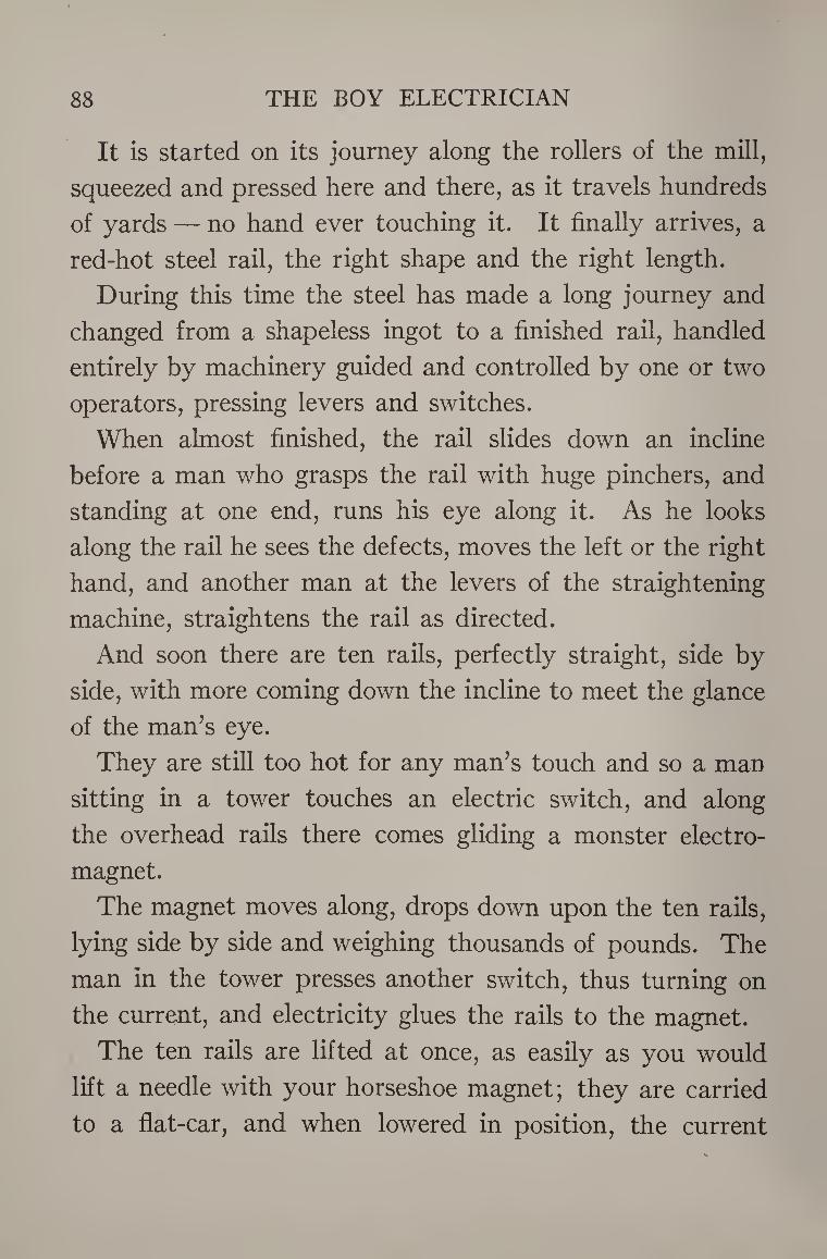
88 THE BOY ELECTRICIAN
It is started on its journey along the rollers of the mill,
squeezed and pressed here and there, as it travels hundreds
of yards — no hand ever touching it. It finally arrives, a
red-hot steel rail, the right shape and the right length.
During this time the steel has made a long journey and
changed from a shapeless ingot to a finished rail, handled
entirely by machinery guided and controlled by one or two
operators, pressing levers and switches.
When almost finished, the rail slides down an incline
before a man who grasps the rail wdth huge pinchers, and
standing at one end, runs his eye along it. As he looks
along the rail he sees the defects, moves the left or the right
hand, and another man at the levers of the straightening
machine, straightens the rail as directed.
And soon there are ten rails, perfectly straight, side by
side, with more coming down the incline to meet the glance
of the man’s eye.
They are still too hot for any man’s touch and so a man
sitting in a tower touches an electric switch, and along
the overhead rails there comes gliding a monster electro¬
magnet.
The magnet moves along, drops down upon the ten rails,
lying side by side and weighing thousands of pounds. The
man in the tower presses another switch, thus turning on
the current, and electricity glues the rails to the magnet.
The ten rails are lifted at once, as easily as you would
lift a needle with your horseshoe magnet; they are carried
to a flat-car, and when lowered in position, the current
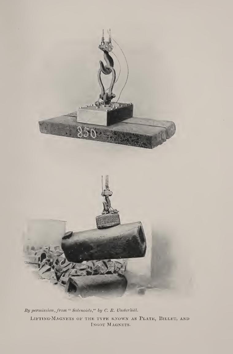
By permission, from “ Solenoidslyy (7. 22. Underhill.
Luting-Magnets of the type known as Plate, Billet, and
Tngot Magnets.

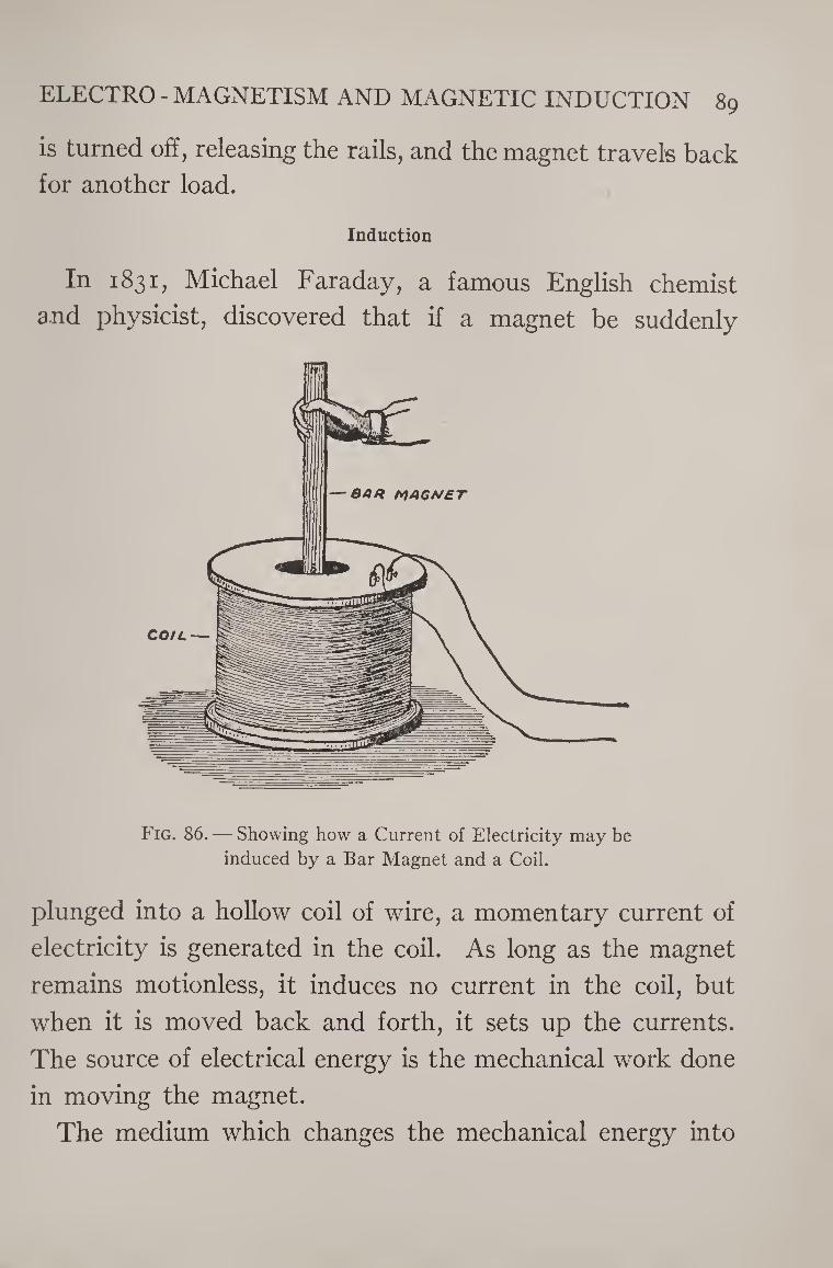
ELECTRO - MAGNETISM AND MAGNETIC INDUCTION 89
is turned off, releasing the rails, and the magnet travels back
for another load.
Induction
In 1831, Michael Faraday, a famous English chemist
and physicist, discovered that if a magnet be suddenly
Fig. 86. — Showing how a Current of Electricity may be
induced by a Bar Magnet and a Coil.
plunged into a hollow coil of wire, a momentary current of
electricity is generated in the coil. As long as the magnet
remains motionless, it induces no current in the coil, but
when it is moved back and forth, it sets up the currents.
The source of electrical energy is the mechanical work done
in moving the magnet.
The medium which changes the mechanical energy into
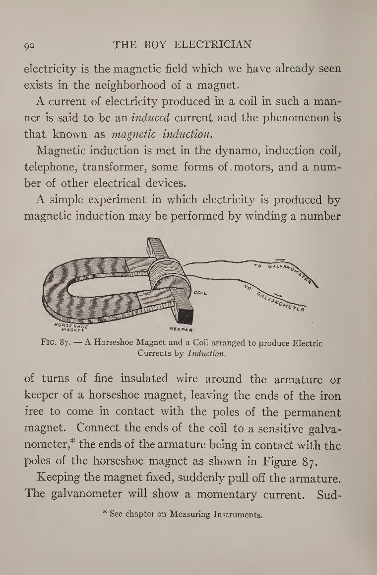
go THE BOY ELECTRICIAN
electricity is the magnetic field which we have already seen
exists in the neighborhood of a magnet.
A current of electricity produced in a coil in such a man¬
ner is said to be an induced current and the phenomenon is
that known as magnetic induction.
Magnetic induction is met in the dynamo, induction coil,
telephone, transformer, some forms of.motors, and a num¬
ber of other electrical devices.
A simple experiment in which electricity is produced by
magnetic induction may be performed by winding a number
Fig. 87. — A Horseshoe Magnet and a Coil arranged to produce Electric
Currents by Induction.
of turns of fine insulated wire around the armature or
keeper of a horseshoe magnet, leaving the ends of the iron
free to come in contact with the poles of the permanent
magnet. Connect the ends of the coil to a sensitive galva¬
nometer,* the ends of the armature being in contact with the
poles of the horseshoe magnet as shown in Figure 87.
Keeping the magnet fixed, suddenly pull off the armature.
The galvanometer will show a momentary current. Sud-
* See chapter on Measuring Instruments.
ELECTRO - MAGNETISM AND MAGNETIC INDUCTION 91
denly bring the armature up to the poles of the magnet;
another momentary current in the reverse direction will
flow through the circuit.
The fact that it is a reverse current is shown by the ac¬
tions of the galvanometer for it will be noticed that the
needle swings in the opposite direction this time.
It will also be noticed that no current is produced when
the coil and magnet are stationary. Current is only gen¬
erated when the coil and magnet are approaching one an¬
other or moving apart suddenly.
This is because it is only then that the magnetic field is
changing. The field is strongest nearest the magnet, and
therefore if either the magnet or the coil of wire is moved,
the strength of that part of the field which intersects the
coil is changed. Induced currents can only be generated
by a changing magnetic field.
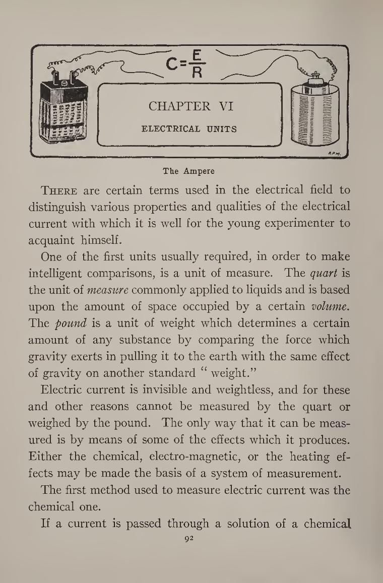
The Ampere
There are certain terms used in the electrical field to
distinguish various properties and qualities of the electrical
current with which it is well for the young experimenter to
acquaint himself.
One of the first units usually required, in order to make
intelligent comparisons, is a unit of measure. The quart is
the unit of measure commonly applied to liquids and is based
upon the amount of space occupied by a certain volume.
The pound is a unit of weight which determines a certain
amount of any substance by comparing the force which
gravity exerts in pulling it to the earth with the same effect
of gravity on another standard “ weight.”
Electric current is invisible and weightless, and for these
and other reasons cannot be measured by the quart or
weighed by the pound. The only way that it can be meas¬
ured is by means of some of the effects which it produces.
Either the chemical, electro-magnetic, or the heating ef¬
fects may be made the basis of a system of measurement.
The first method used to measure electric current was the
chemical one.
If a current is passed through a solution of a chemical 92
ELECTRICAL UNITS 93
called copper sulphate (blue vitriol) by means of two copper
plates, copper will be deposited on one plate and dissolved
from the other. If the current is furnished by a battery the »
copper will be deposited on the plate connected with the
zinc of the battery. If the current is allowed to flow for a
short time and the two copper plates are then taken out and
weighed it will be found that one plate is considerably
heavier than the other.
The copper has been taken from one plate and deposited
on the other by the electric currents. The amount of elec¬
tric current which will deposit 1.177 grammes of copper in
an hour is called an ampere. The ampere is the unit of
electrical current measurement, and implies quantity or
amount.
The chemical method of measuring current was at one
time put to practical service in the distribution of electric
current for lighting and power. Many years ago the house
meters, used to measure the current, consisted of a jar con¬
taining two copper plates. The current used in the house
would cause copper to deposit on one plate, and by weighing
the plate the power company could determine the amount
of current used, and thereby the amount of the bill. The
meters nowadays make use of the magnetic effects of the
current instead of the chemical, as described later on.
The Volt
For purposes of explanation the electric current may be
likened to a stream of water flowing through a pipe.
94 THE BOY ELECTRICIAN
If you hold your thumb over the end of a water-pipe
through which water is flowing it will push your thumb
away because of the pressure which the water exerts.
Electric currents also exert a pressure, only it is not called
pressure in electrical parlance, but, spoken of as electro¬
motive force or potential.
The pressure of the water enables it to pass through
small openings and to overcome the resistance offered by
the pipe.
Wires and other electrical conductors do not offer a per¬
fectly free path to an electric current, but also possess a re¬
sistance. It is the potential of the electro-motive force
which overcomes the resistance and pushes the current
through the wire.
Advantage has been taken of the fact to fix a unit of elec¬
trical pressure called the volt. The pressure of the water
in a water-pipe is measured in pounds, but the pressure of
an electric current in a wire is measured by volts. The volt
is the unit of electrical force which will cause a current of
one ampere to flow through a resistance of one ohm.
The Ohm
The ohm is the unit of electrical resistance. The standard
ohm is the resistance offered by a column of pure mercury
having a section of one square millimeter and a length of
106.28 centimeters at a temperature of o.° centigrade.
The pressure which will force sufficient current through
such a column of mercury to deposit 1.177 grammes of cop-
ELECTRICAL UNITS 95
per in one hour is a volt, and in doing so has passed a cur¬
rent of one ampere through a resistance of one ohm.
The units ohm, ampere, and volt, were named in honor
of the three great electricians: Ohm, Ampere, and Volta.
These three units bear a very close relation to each other
which is explained by Ohm’s Law.
Ohm’s Law is a simple statement of facts which it is well
for the young electrician thoroughly to understand, for it
might almost be said to be the basis of design of almost all
electrical instruments.
It is simply this: The strength of a current equals the
voltage divided by the resistance. It may be expressed in
symbols by: c = f. Where C is the current in amperes,
E is the potential in volts, and R the resistance in ohms.
By way of a simple example, we will suppose that a small
telegraph sounder is connected to a battery and that the
voltage of the battery is ten volts. We will further suppose
that the resistance of the sounder connecting wires and the
battery itself is jive ohms. Knowing these two facts, it is
very easy to find out how many amperes are flowing
through the sounder by substituting these values in the
equation as follows:
E = io volts and R = 5 ohms
therefore c = ^ or 2 amperes
In order to indicate fractions or very large values of the am¬
pere, volt, and ohm, it is customary to use the following terms:
96 THE BOY ELECTRICIAN
Milli-volt = I7fo o' °f a vo^
Mill-ampere = roVo of an ampere
Kilo-volt = 1000 volts
Meg-ohm = 1,000,000 ohms
The Watt
It is no doubt perfectly plain that the water in a certain
size of pipe at a pressure of ioo lbs. is more powerful than a
stream of water in the same size of pipe at 25 lbs. pressure.
Likewise a current of electricity represents more power
at 100 volts potential than the same current would at 25
volts. The unit of electrical power is called the watt. A
watt is represented by a current of one ampere flowing
through a wire at a potential of one volt.
The number of watts is found by multiplying the voltage
by the amperage. In the case of the sounder and battery
used as an example to explain Ohm’s Law, and where the
voltage was 10 and the amperage found to be 2, the number
of watts is 10 x 2, or 20 watts.
Seven hundred and forty-six watts represent one elec¬
trical horse-power. One thousand watts are called a kilo¬
watt. The Coulomb
So far, none of the units have taken into consideration the
element of time.
If water should be permitted to run out of a pipe into a
tank until ten gallons had passed it would not be possible
to tell at what rate the water was flowing by knowing that
ELECTRICAL UNITS 97
ten gallons had passed unless it were also known how long
the water had been flowing. Ten gallons per minute or ten
gallons per hour would indicate the rate of flow.
One ampere flowing for one second is the electrical unit
of flow. This unit is called the coulomb.
One ampere flowing for one hour is called an ampere hour.
The number of ampere hours is found by multiplying the
current in amperes by the time in hours.
A battery may be said to have a capacity of io ampere
hours. This means that it will deliver one ampere for io
hours (i ampere x io hours = io ampere hours) or 2 am¬
peres for 5 hours (2 amperes x 5 hours = 10 ampere hours).
The same element of time enters into consideration in
connection with the watt. One watt flowing for one hour is
a watt hour and one kilowatt flowing for one hour is a kilo¬
watt hour.
The Difference between Alternating and Direct Currents
There are two distinct kinds of electric current supplied
for lighting and power, one known as direct current and the
other as alternating.
A direct current is one which passes in one direction only.
It may be represented by a straight line, as A in Figure 88.
An alternating current is one which reverses its direction
and passes first^one way and then the other. It may be
represented by a curved line, shown in Figure 88. It starts
at zero, and gradually grows stronger and stronger. Then it
commences to die away until no current is flowing. At this
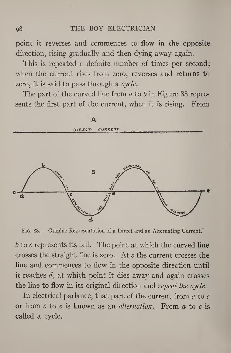
98 THE BOY ELECTRICIAN
point it reverses and commences to flow in the opposite
direction, rising gradually and then dying away again.
This is repeated a definite number of times per second;
when the current rises from zero, reverses and returns to
zero, it is said to pass through a cycle.
The part of the curved line from a to b in Figure 88 repre¬
sents the first part of the current, when it is rising. From
A
OlR£CT- CURftE*T ,
Fig. 88. — Graphic Representation of a Direct and an Alternating Current.
b to c represents its fall. The point at which the curved line
crosses the straight line is zero. At c the current crosses the
line and commences to flow in the opposite direction until
it reaches d, at which point it dies away and again crosses
the line to flow in its original direction and repeat the cycle.
In electrical parlance, that part of the current from a to c
or from c to e is known as an alternation. From a to e is
called a cycle.
ELECTRICAL UNITS 99
The reason why alternating current is often used in place
of direct current is that it can be sent over the wires for
long distances more economically than direct current. This
is more fully explained farther on in the chapter dealing
with a step-down transformer.
The number of cycles taking place in one second is known
as the frequency of the current. The usual frequency of
commercial alternating currents is 60 cycles per second or
7200 alternations per minute.
Wires
Electric currents are usually led from place to place,
at will, by means of conductors called wires. There are a
great many kinds of wires, each adapted to some special
purpose.
Wires are usually covered with a material called an
insulator, in order to prevent the loss of electric current
due to the wires coming into contact with other bodies or
circuits. Insulators are substances which do not conduct
electricity.
Wires which are insulated by heavy braids of cotton
fiber and then impregnated with some compound, such as
creosote, are called weather-proof wires, and are best adapted
to outside service, where they must be exposed to the action
of the elements.
The wires used for interior wiring in buildings, etc., are
usually insulated with rubber, over which is placed a
cotton braid to protect the rubber.
Rubber cannot well be used as an insulator for all wires,
although its insulating value is very great, owing to the
fact that it deteriorates under many conditions. IOO
ELECTRICAL APPURTENANCES IOI
Rubber-covered and weather-proof wires are made in a
variety of insulations. Some may have only one insulating
layer, while others have a great many. Different sub¬
stances are used as insulators to adapt the wire to some
special purpose. Copper is usually the only metal used
to form the wire or conductor itself. The reason for this
is that copper is a better conductor than any other metal
except those known as precious metals, such as gold and
silver, the cost of which prohibits their use for such pur¬
poses. The wire may be solid, or made up of a number of
small conductors so that it is flexible.
The various combinations of insulating layers, together
with either a solid or a stranded conductor, have made
possible a variety of current-carriers, known as:
Theater or Stage Cable
Elevator Cable
Fixture Wire
Telephone Wire
Mining Cable
Feeder Cable
Brewery Cord
Heater Cord, etc.
depending upon the special use for which they were de¬
signed.
The wires which the young experimenter is likely to use
in his work the most are known as magnet wires, and are
used for making electro-magnets, coils, and various wind-
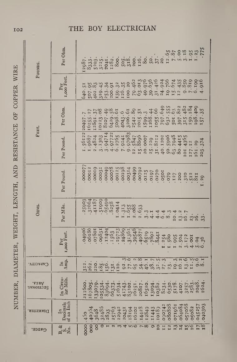
NU
MB
ER
, D
IAM
ET
ER
, W
EIG
HT
, L
EN
GT
H,
AN
D
RE
SIS
TA
NC
E
OF
CO
PP
ER
WIR
E
102 THE BOY ELECTRICIAN
•
B to
to O' O 00 to CO O'
O < VO 00 O h O' CM O'
O' CO CO to H IN 0 toco O *0 O O O' O CN O' to CO H W 00 CO O IN ifOO O O CM O 01 00 to CO CM HM O' CO CM CM O IN OO to CO CM HM CM 00 to CO CM HM
& M 0
Pm 0 <N coo O O it'd -4- to O' O' 0"0
Per
DO
O F
l M 10 CO IO 't H CM to O O M O' CO CM CMO N d) IO H O' H to 000 't CO 0 CO CO CM Tf O 0"0 it O' C'O itCO 00 m O'
O C' <N O' CO 0 0"0 O O' co O' O' h rf O' to cm O' C"0 if- • it O O 1 to O to ci O C^VO ct CO CO CM HM M HM
'OlO'tfOCMCMHHH
O' to CM CM Tf O' a N NOO OiCO M M O' M 0-0 it to CO CM 00 OO O lO -a N CM CO 0 Ct too O O 00 to CO cto O too CO cf h tJ* CO
O t' l-O H CO f' ChOO COO CM to (000 to N CM HM C' to 0 00 O'
0) O' lo O' CM 0 CM O' Mf 0 it hm 0"0 to O' co O O' hm to O' to Cm it CM 00 CM H it O O CM to O to CM O f'O tO CO CO CM HM HM
OO N OOOO lOltCON CM H H H
w <N M M M
w CM it CM CO til
T3 <N N rO H <N to w 00 I^VO <N M \0 CO tO lO H CO ^ O N t^*VO 't O O' O O H O O H \C Tt*
c OOOO CO -t N N H r^OO VO 0 CM CM CM O' O' ■cj- CO CM O'f^ 3 0
to O' ct H O' O' CM O' O' to OO 0 CM CO HM to t"t tj- HM CM CO
Pm HM HM CM co CO •^•'O t' O' CM to 0 to HM O O CO O HM C' HM CO HM H CM CM CO Nf to VO 00 O CM O O
Pm HM HM HM CM
(N Q\ w OnOO tooo On M 0 HM HM CO it C"- CM O' HM O' O' to N 0 HM OOOOOOhmhm co r)- n cm 0»n O o> N O O ci h
3 0
OOOOQQQQQQOHMHMCMtor^'CMOCMWHMOs
OOOOOOOOOOOOOOOOhmcmco toco cm (X, Ut 0
M
Pm
CO it C" O' O O VO 00 O O\00 it
c/5 a3 0"0 HM O' it to hm CO toco CO a • r-H lOCIHHIOCM'tH tOOO CO w O
s N CO Tj- too co O co VO 0 to COM Tt- CO 't CM
1-4 a> H H H CM Cl co if if-VO CO O COVO COO CO
Pm HM HM HM CM CM co
OO H H If CO O' H O H O 00 O CO 0 CO CM 0 'O it C-i O' CM HM
<L> <u
»-< U4 <L> **
O' HM CO CO ltV0 C' 00 CO tOCO CM Q"t if O to it CM HM 'O r2- O' CM to O' it hm O' O' toco it to 00 O' 0 0 if-to
OOOOhmwhmcm co co if” vO t--- OO CM to O' to h O O co
Pm §
M
H H H CM co if too
a £ COO CM 00 H N 10 CO CO CM O too H
•AXI0VdV3 ® E CM CM 0 too HM 0 CM N to if- O 00 CM C— CO (OO CO HM O'00 < HM O CM co to CO HM O' C^O to if- CO CO CM CM H H HM HM
CO CM CM HM HM HM HM
s JS •vaav O to O' if- if- CO if- CO CM HM if- CM if 0 00 t-~ COCO if-
iVNOixoag O O N ro On N ro rf O 10 w m OnOO fO N O to 00 ^ ^ 'O 00 o too roo <N 00 toO CS to M m <N to O O
flJs m c- co to COVO cm hm CO'S OND (0000*0 to if- co CM CM hm CM O CO 0 00 O to lf-00 CM CM HM HM HM rs) M M t-4
tn -fl -1 O 2 a
c SH if- VO CO CM HM if- CM CO O' CO <^N
CM OO HM itOO it O VO OO VO CM
co to O
■H3X3WVTQ VO 00 OO CO VO if- CO O' O CM it It 00 l"~0O o o o co tt co HM-n a O 'Os if- if- O' O' if- hm CM it 00 Tf- M O O H If N O to O
<u a to o VO cm 00 to CM o 00 VO it CM HM O OOO VO to to ”ct-
^ o rt CO CO <N CN M W H M HM HM O O OOOO o o
•aonvo
B.
&
S.
No.
o OO
ooo O
OO
O
H CM co if- to VO t^OO o o w 1
1
12
co Tf to VO M M H M
t^oo HM HM
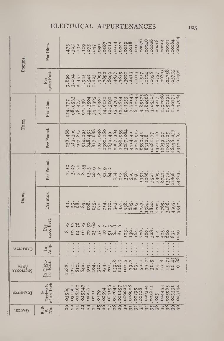
ELECTRICAL APPURTENANCES 103
a ja O
u u
(X,
'O 'O 00 00 NN O'OO M rf N
to N CMO N O OO M rf N M M O ~ r-'OO'Mf^TfrOMtHOOOOOO rfcOMMOOOOOOOOOOO
toco VO N O' N O' VO N ft) to N rtO NO VOlOOl
O' rt N von ft) O' O' O' fO ft) O m m m O vo vo 00 O' O'O'iOrtrtN'O'O O 00 00 O '"t O' vo N O' t'-'O rj- co n
00 0 't O' t) ft O' t'-'O Ti-coco<NMMMOOOOOO
CO CO N M M H
H « «
B M O
M 4>
(L,
•X3 a 3 o
P.1 u w
Oh
CO CO vovO vo >0 N N tf CO rf-VOM M M CO rt VO rt rt t^-'O o C^CO O' t>» 00
t~- co comO O O 00 coOOvovoM n vo O' <0 m O N O' Nlt)NfO>OCOtOH M t'-OO CON N VO VO N N N O O-
O' rt N COM 00 VO rt N N N H 00 00 O tj- CMO ft O'
rt00 00 N O'O'M rt O' VO N N O' t^vo 't to to N M H M
O' tJ-coconmmmO
00 O' 10 CO N 0O co O tf 0"t vo t-~ VO O' M O' VOCO COCO 0"0 VO00 O' M M N 10 tO CO rt coco m •^•'O 0 m tt co O' O rt O' rt CO ^ m O' N N -O
vO co rtCO m O O' f^MO I-~ rtvO O N m rt O' COO O votNOM-fMCOO fOO 000 m N O' M 00 m VO m O' N N CO 'ft 100 00 O coo 0 O N rt N vo co 't N O O rt rt
M M M N N co 'ft vovo 00 O COVO HO CO M M M N N co
tn a w O
•3 3 3 O
Oh Ih SJ
Oh
« Ph
I-h fr, <D ^
0* O vo N co CO O' N O' N
N CO VO CO co O 00 N rt rt COCO 0"0 M O' N N vO CO M N CO 1000 CO M CO co vo VOO NO t N a N
m n co 1000 coh v)tj-N r^oo 00 M N co 1000 CO W rt M N CO
CO COOO VO00 rt 100 00 o
vo O rt O co N 00 vo 10 co O' O 0 voO vo N co N h r-» rt co CO00 O CO00 N O O 00 O' 'ft H M N N CO rt VOVO 00 O COOO N N vt to 10
MMMNNCO'ftVO
vo N o VO O O N M N CO'O N CO00 VO
OOON'OO'ONOMTtMCOO rtO O 00 rt CO 0 N O' m M m N N CO rt voO 00 0 CO'O O'ONMN'Ocorj-
M M M N N co rt voO 00 0
„ d •AXI3VdV3 £ a
<
00 N O0
3 m to M VO 00 V'' rt CO
•V3HV 00 M O o*
S'
rt O M 0"0 0 O' co 0 O' M vo O' VO N O' 00 <N M O N 10 0 vo <N 0 vo co co CN M M M iVNOixoas (N O 00 0 to Tf CO <N W M M
C rt HH —•
M M
v/) ^2 0 W <N M vo M N- VO 00 Tf* co vo M rt 2 c Os VO vO O' rt vo N N VO00 0 M VOVO CO rt
•aaxareviQ c CO O' rt co vo M O' O' w 0 <N 0 O' O' 0 CO'O rt O' vo M Ho d M 00 vo CN O N IO <N M O CO N lO vo rt co CO CO
ou c3 O >*H W O
CO O
CO <N 0 0
<N O 0
<N w O O
M O
M O
M O
M O
W O 88
O O 8888888
B.&
S.
No. O' O M M co rt VOO r^oo O' 0 W <N co rt ICO r^oo O' O
•aonvo W N N N o* CN <N N (N <N co co co CO CO CO CO CO CO CO rt
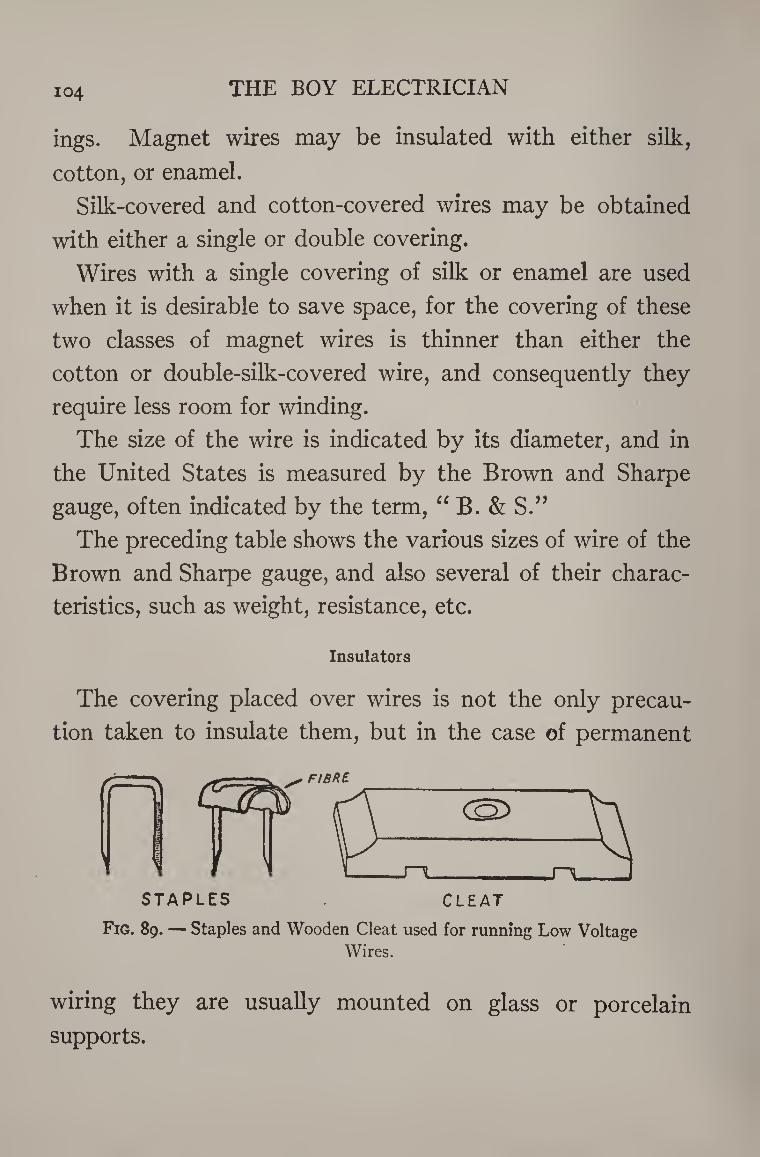
104 THE BOY ELECTRICIAN
ings. Magnet wires may be insulated with either silk,
cotton, or enamel.
Silk-covered and cotton-covered wires may be obtained
with either a single or double covering.
Wires with a single covering of silk or enamel are used
when it is desirable to save space, for the covering of these
two classes of magnet wires is thinner than either the
cotton or double-silk-covered wire, and consequently they
require less room for winding.
The size of the wire is indicated by its diameter, and in
the United States is measured by the Brown and Sharpe
gauge, often indicated by the term, “B. & S.”
The preceding table shows the various sizes of wire of the
Brown and Sharpe gauge, and also several of their charac¬
teristics, such as weight, resistance, etc.
Insulators
The covering placed over wires is not the only precau¬
tion taken to insulate them, but in the case of permanent
Fig. 89. — Staples and Wooden Cleat used for running Low Voltage Wires.
wiring they are usually mounted on glass or porcelain
supports.
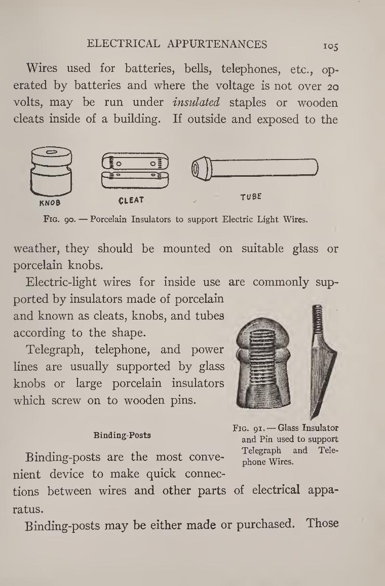
ELECTRICAL APPURTENANCES 105
Wires used for batteries, bells, telephones, etc., op¬
erated by batteries and where the voltage is not over 20
volts, may be run under insulated staples or wooden
cleats inside of a building. If outside and exposed to the
Fig. 90. — Porcelain Insulators to support Electric Light Wires.
weather, they should be mounted on suitable glass or
porcelain knobs.
Electric-light wires for inside use are commonly sup¬
ported by insulators made of porcelain
and known as cleats, knobs, and tubes
according to the shape.
Telegraph, telephone, and power
lines are usually supported by glass
knobs or large porcelain insulators
which screw on to wooden pins.
Fig. 91. — Glass Insulator Binding-Posts and pjn uge(j to SUpp0rt
, Telegraph and Tele- Bindmg-posts are the most conve- phone wires,
nient device to make quick connec¬
tions between wires and other parts of electrical appa¬
ratus.
Binding-posts may be either made or purchased. Those
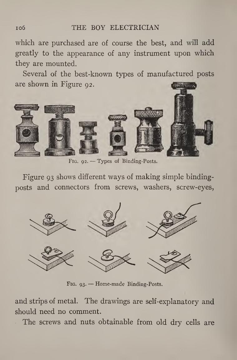
io6 THE BOY ELECTRICIAN
which are purchased are of course the best, and will add
greatly to the appearance of any instrument upon which
they are mounted.
Several of the best-known types of manufactured posts
are shown in Figure 92.
Fig. 92. — Types of Binding-Posts.
Figure 93 shows different ways of making simple binding-
posts and connectors from screws, washers, screw-eyes,
and strips of metal. The drawings are self-explanatory and
should need no comment.
The screws and nuts obtainable from old dry cells are
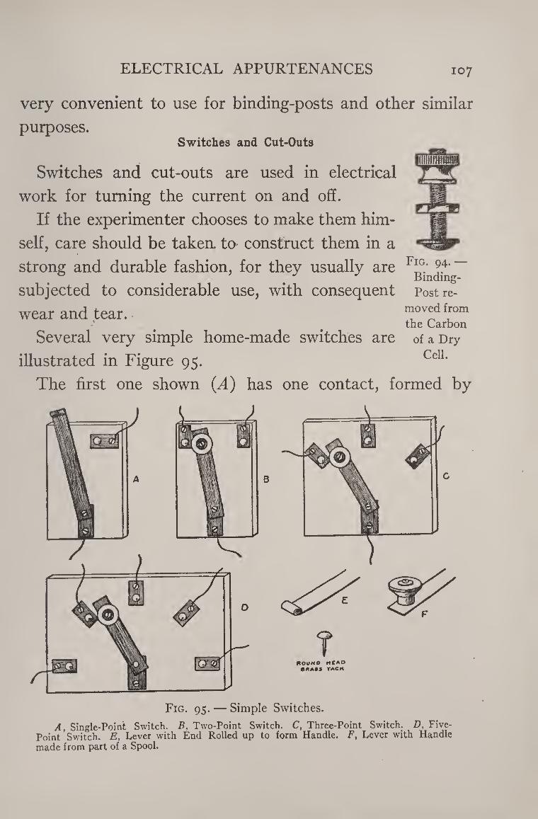
ELECTRICAL APPURTENANCES 107
very convenient to use for binding-posts and other similar
purposes. Switches and Cut-Outs
Switches and cut-outs are used in electrical
work for turning the current on and off.
If the experimenter chooses to make them him¬
self, care should be taken, to construct them in a
strong and durable fashion, for they usually are
subjected to considerable use, with consequent
wear and tear. *
Fig. 94. —
Binding- Post re¬
moved from the Carbon
Several very simple home-made switches are of a Dry
illustrated in Figure 95. CelL
The first one shown (A) has one contact, formed by
Fig. 95. — Simple Switches. A, Single-Point Switch. B, Two-Point Switch. C, Three-Point Switch. D, Five-
Point Switch. E, Lever with End Rolled up to form Handle. F, Lever with Handle made from part of a Spool.
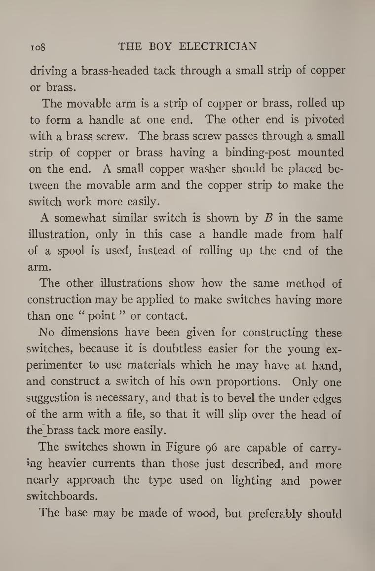
io8 THE BOY ELECTRICIAN
driving a brass-headed tack through a small strip of copper
or brass.
The movable arm is a strip of copper or brass, rolled up
to form a handle at one end. The other end is pivoted
with a brass screw. The brass screw passes through a small
strip of copper or brass having a binding-post mounted
on the end. A small copper washer should be placed be¬
tween the movable arm and the copper strip to make the
switch work more easily.
A somewhat similar switch is shown by B in the same
illustration, only in this case a handle made from half
of a spool is used, instead of rolling up the end of the
arm.
The other illustrations show how the same method of
construction may be applied to make switches having more
than one “ point ” or contact.
No dimensions have been given for constructing these
switches, because it is doubtless easier for the young ex¬
perimenter to use materials which he may have at hand,
and construct a switch of his own proportions. Only one
suggestion is necessary, and that is to bevel the under edges
of the arm with a file, so that it will slip over the head of
the brass tack more easily.
The switches shown in Figure 96 are capable of carry¬
ing heavier currents than those just described, and more
nearly approach the type used on lighting and power
switchboards.
The base may be made of wood, but preferably should
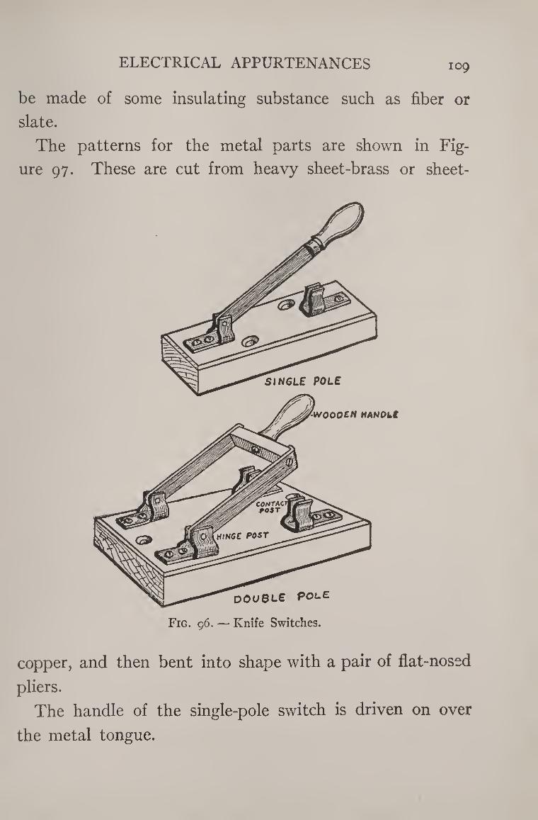
ELECTRICAL APPURTENANCES 109
be made of some insulating substance such as fiber or
slate.
The patterns for the metal parts are shown in Fig¬
ure 97. These are cut from heavy sheet-brass or sheet-
copper, and then bent into shape with a pair of flat-nosed
pliers.
The handle of the single-pole switch is driven on over
the metal tongue.
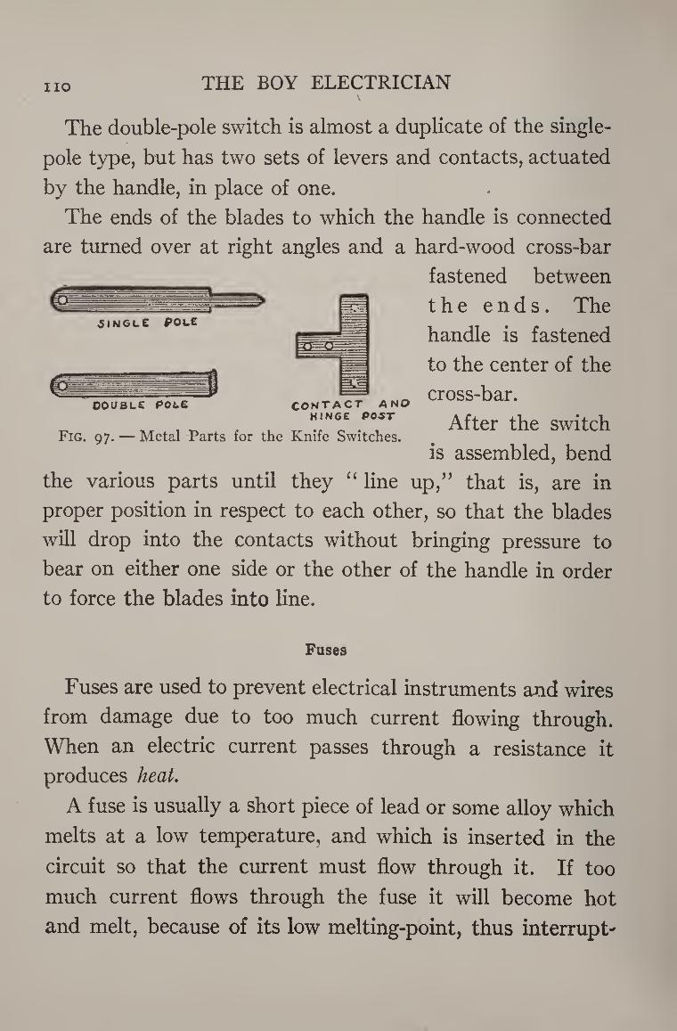
HO THE BOY ELECTRICIAN
JINGLE P OLE
The double-pole switch is almost a duplicate of the single¬
pole type, but has two sets of levers and contacts, actuated
by the handle, in place of one.
The ends of the blades to which the handle is connected
are turned over at right angles and a hard-wood cross-bar
fastened between
the ends. The
handle is fastened
to the center of the
cross-bar.
After the switch
is assembled, bend
the various parts until they “ line up/’ that is, are in
proper position in respect to each other, so that the blades
will drop into the contacts without bringing pressure to
bear on either one side or the other of the handle in order
to force the blades into line.
DOUBLE POLE A NO contact HINGE POST
Fig. 97. — Metal Parts for the Knife Switches.
Fuses
Fuses are used to prevent electrical instruments and wires
from damage due to too much current flowing through.
When an electric current passes through a resistance it
produces heat.
A fuse is usually a short piece of lead or some alloy which
melts at a low temperature, and which is inserted in the
circuit so that the current must flow through it. If too
much current flows through the fuse it will become hot
and melt, because of its low melting-point, thus interrupt-
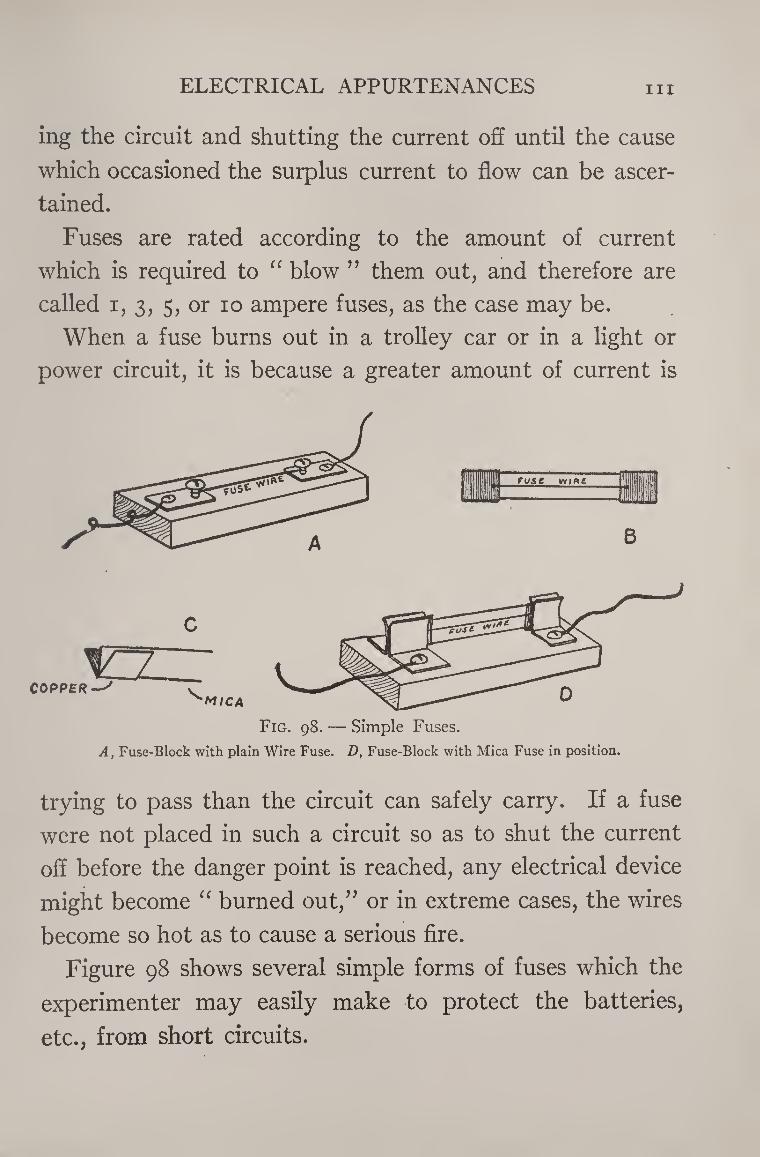
ELECTRICAL APPURTENANCES hi
ing the circuit and shutting the current off until the cause
which occasioned the surplus current to flow can be ascer¬
tained.
Fuses are rated according to the amount of current
which is required to “ blow ” them out, and therefore are
called i, 3, 5, or 10 ampere fuses, as the case may be.
When a fuse burns out in a trolley car or in a light or
power circuit, it is because a greater amount of current is
COPPER ^m/ca
A, Fuse-Block with plain Wire Fuse. D, Fuse-Block with Mica Fuse in position.
trying to pass than the circuit can safely carry. If a fuse
were not placed in such a circuit so as to shut the current
off before the danger point is reached, any electrical device
might become “ burned out,” or in extreme cases, the wires
become so hot as to cause a serious fire.
Figure 98 shows several simple forms of fuses which the
experimenter may easily make to protect the batteries,
etc., from short circuits.
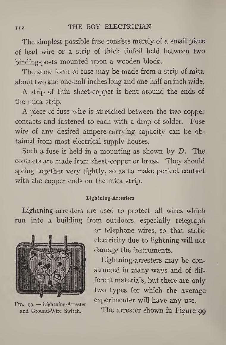
112 THE BOY ELECTRICIAN
The simplest possible fuse consists merely of a small piece
of lead wire or a strip of thick tinfoil held between two
binding-posts mounted upon a wooden block.
The same form of fuse may be made from a strip of mica
about two and one-half inches long and one-half an inch wide.
A strip of thin sheet-copper is bent around the ends of
the mica strip.
A piece of fuse wire is stretched between the two copper
contacts and fastened to each with a drop of solder. Fuse
wire of any desired ampere-carrying capacity can be ob¬
tained from most electrical supply houses.
Such a fuse is held in a mounting as shown by D. The
contacts are made from sheet-copper or brass. They should
spring together very tightly, so as to make perfect contact
with the copper ends on the mica strip.
Lightning-Arresters
Lightning-arresters are used to protect all wires which
run into a building from outdoors, especially telegraph
or telephone wires, so that static
electricity due to lightning will not
damage the instruments.
Lightning-arresters may be con¬
structed in many ways and of dif¬
ferent materials, but there are only
two types for which the average
experimenter will have any use.
The arrester shown in Figure 99 Fig. 99. — Lightning-Arrester
and Ground-Wire Switch.
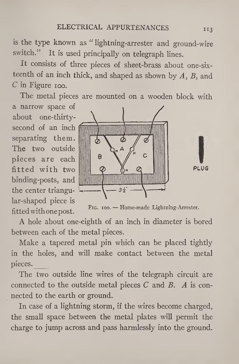
ELECTRICAL APPURTENANCES 113
is the type known as “ lightning-arrester and ground-wire
switch.” It is used principally on telegraph lines.
It consists of three pieces of sheet-brass about one-six¬
teenth of an inch thick, and shaped as shown by A, B, and
C in Figure 100.
The metal pieces are mounted on a wooden block with
a narrow space of
about one-thirty-
second of an inch
separating them.
The two outside
pieces are each
fitted with two
binding-posts, and
the center triangu¬
lar-shaped piece is
fitted with one post.
A hole about one-eighth of an inch in diameter is bored
between each of the metal pieces.
Make a tapered metal pin which can be placed tightly
in the holes, and will make contact between the metal
PLUS
Fig. 100. — Home-made Lightning-Arrester.
pieces. _
The two outside line wires of the telegraph circuit are
connected to the outside metal pieces C and B. A is con¬
nected to the earth or ground.
In case of a lightning storm, if the wires become charged,
the small space between the metal plates will permit the
charge to jump across and pass harmlessly into the ground.
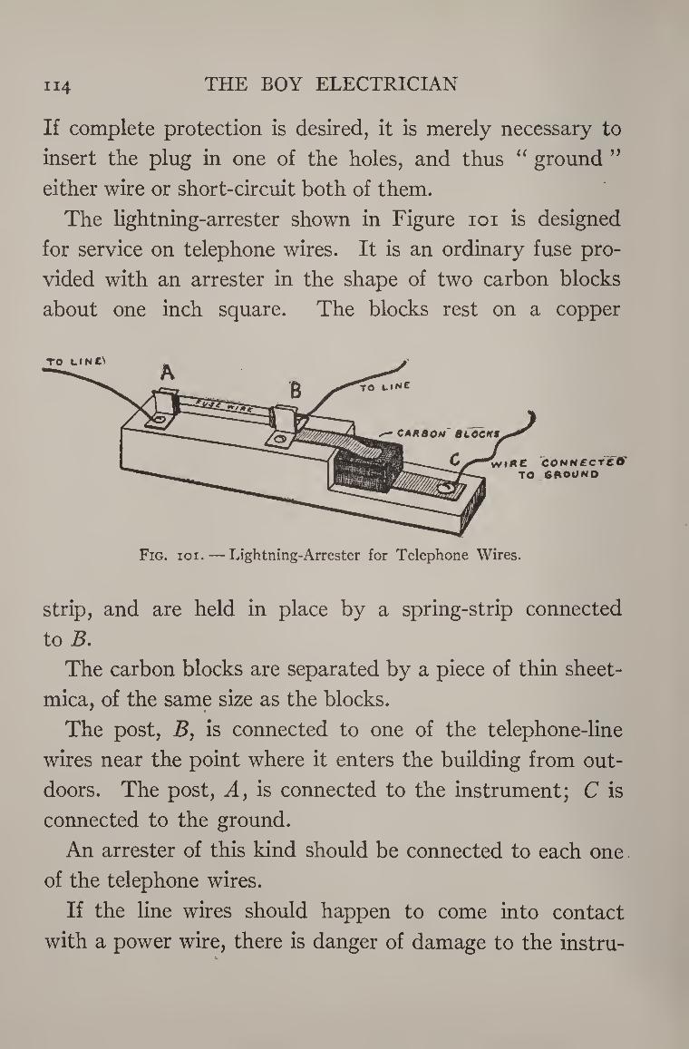
THE BOY ELECTRICIAN 114
If complete protection is desired, it is merely necessary to
insert the plug in one of the holes, and thus “ ground ”
either wire or short-circuit both of them.
The lightning-arrester shown in Figure 101 is designed
for service on telephone wires. It is an ordinary fuse pro¬
vided with an arrester in the shape of two carbon blocks
about one inch square. The blocks rest on a copper
Fig. ioi. — Lightning-Arrester for Telephone Wires.
strip, and are held in place by a spring-strip connected
to B.
The carbon blocks are separated by a piece of thin sheet-
mica, of the same size as the blocks.
The post, B, is connected to one of the telephone-line
wires near the point where it enters the building from out¬
doors. The post, A, is connected to the instrument; C is
connected to the ground.
An arrester of this kind should be connected to each one
of the telephone wires.
If the line wires should happen to come into contact
with a power wire, there is danger of damage to the instru-

ELECTRICAL APPURTENANCES 115
merits, but if an arrester is connected in the circuit such an
occurrence would be prevented by the blowing out of the
fuse. If the lines become charged by lightning, the charge
can easily pass over the edge of the mica between the two
blocks and into the ground.
An instrument designed to measure electromotive force
(electrical pressure) is called a voltmeter. An instru¬
ment designed to measure volume of current is called an
ammeter.
There are many forms of reliable meters for measuring
current and voltage, but all are more or less expensive and
out of the reach of an ordinary boy.
Some meters are more carefully made than a watch, and
are provided with fine hair-springs and jeweled bearings,
but all depend upon the same principle for their action,
namely, the mutual effects produced between a magnetic
needle and a coil of insulated wire carrying a current of
electricity.
The little meters described in this chapter are simple
and inexpensive but quite sensitive. Unlike a meter ma¬
king use of a hair-spring, they will stand considerable rough
handling, but of course should not be subjected to such
treatment unnecessarily.
Two types of meters are described. Both operate on
exactly the same principle, but one is more elaborate than
the other.
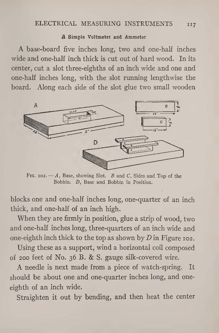
ELECTRICAL MEASURING INSTRUMENTS 117
A Simple Voltmeter and Ammeter
A base-board five inches long, two and one-half inches
wide and one-half inch thick is cut out of hard wood. In its
center, cut a slot three-eighths of an inch wide and one and
one-half inches long, with the slot running lengthwise the
board. Along each side of the slot glue two small wooden
Fig. 102. — A, Base, showing Slot. B and C, Sides and Top of the Bobbin. D, Base and Bobbin in Position.
blocks one and one-half inches long, one-quarter of an inch
thick, and one-half of an inch high.
When they are firmly in position, glue a strip of wood, two
and one-half inches long, three-quarters of an inch wide and
one-eighth inch thick to the top as shown by D in Figure 102.
Using these as a support, wind a horizontal coil composed
of 200 feet of No. 36 B. & S. gauge silk-covered wire.
A needle is next made from a piece of watch-spring. It
should be about one and one-quarter inches long, and one-
eighth of an inch wide.
Straighten it out by bending, and then heat the center
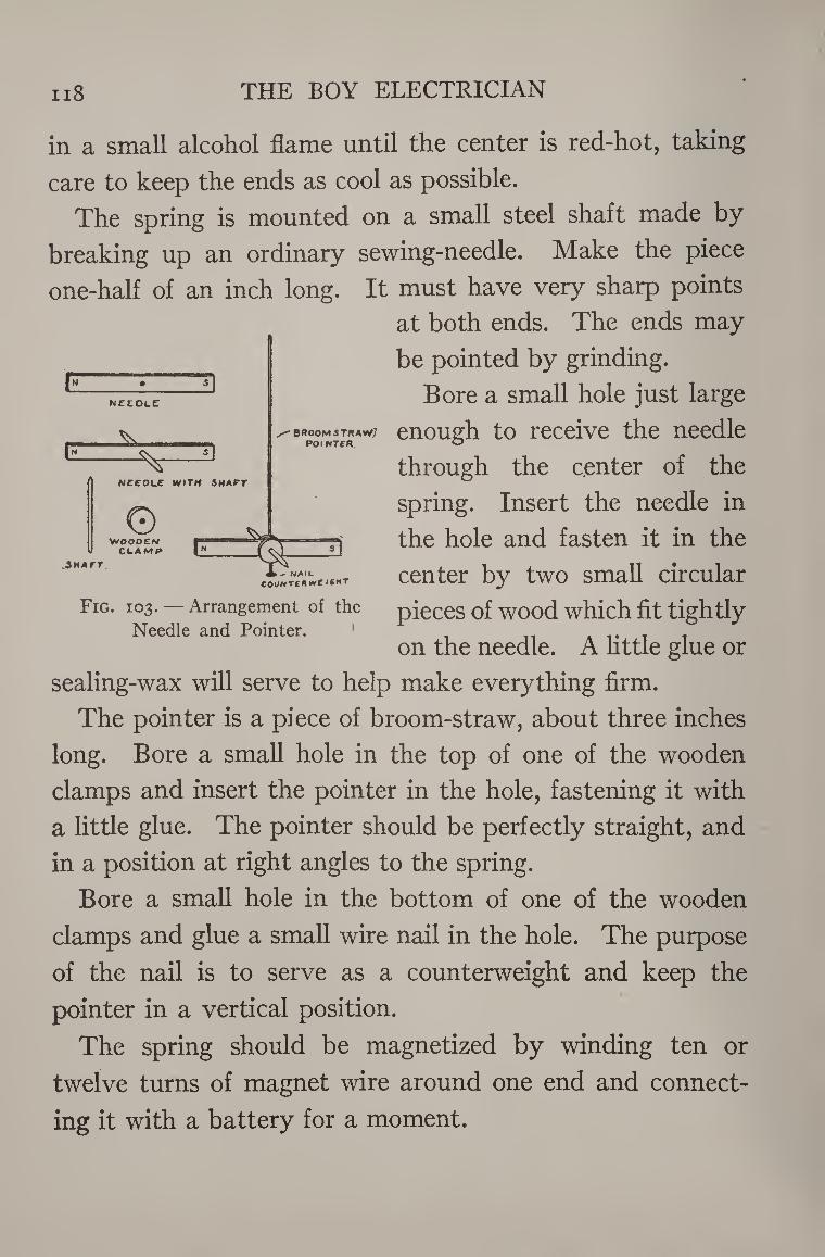
n8 THE BOY ELECTRICIAN
F“ • 5I needle
s]
NEEDLE WITH SHAFT
© WOOOEM
CLAMP G:
• BPOOMSTKA**/ POINTCH
.Shatt » - NAIL
COUNT£«»vC I6HT
in a small alcohol flame until the center is red-hot, taking
care to keep the ends as cool as possible.
The spring is mounted on a small steel shaft made by
breaking up an ordinary sewing-needle. Make the piece
one-half of an inch long. It must have very sharp points
at both ends. The ends may
be pointed by grinding.
Bore a small hole just large
enough to receive the needle
through the center of the
spring. Insert the needle in
the hole and fasten it in the
center by two small circular
pieces of wood which fit tightly
on the needle. A little glue or
sealing-wax will serve to help make everything firm.
The pointer is a piece of broom-straw, about three inches
long. Bore a small hole in the top of one of the wooden
clamps and insert the pointer in the hole, fastening it with
a little glue. The pointer should be perfectly straight, and
in a position at right angles to the spring.
Bore a small hole in the bottom of one of the wooden
clamps and glue a small wire nail in the hole. The purpose
of the nail is to serve as a counterweight and keep the
pointer in a vertical position.
The spring should be magnetized by winding ten or
twelve turns of magnet wire around one end and connect¬
ing it with a battery for a moment.
Fig. 103. — Arrangement of the
Needle and Pointer.
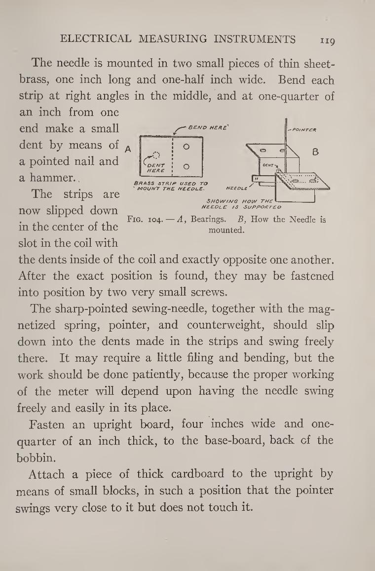
ELECTRICAL MEASURING INSTRUMENTS 119
BEND MERE'
O
^DENT HERE
O \
Brass strip used to ' MOUNT THE NEE DUE.
F
Ofwr-*
^vlL
needle
Showing how the
■ POINTER
B
,'<0...
needle is supported
Fig. 104.—A, Bearings. B, How the Needle is
mounted.
The needle is mounted in two small pieces of thin sheet-
brass, one inch long and one-half inch wide. Bend each
strip at right angles in the middle, and at one-quarter of
an inch from one
end make a small
dent by means of
a pointed nail and
a hammer.
The strips are
now slipped down
in the center of the
slot in the coil with
the dents inside of the coil and exactly opposite one another.
After the exact position is found, they may be fastened
into position by two very small screws.
The sharp-pointed sewing-needle, together with the mag¬
netized spring, pointer, and counterweight, should slip
down into the dents made in the strips and swing freely
there. It may require a little filing and bending, but the
work should be done patiently, because the proper working
of the meter will depend upon having the needle swing
freely and easily in its place.
Fasten an upright board, four inches wide and one-
quarter of an inch thick, to the base-board, back of the
bobbin.
Attach a piece of thick cardboard to the upright by
means of small blocks, in such a position that the pointer
swings very close to it but does not touch it.
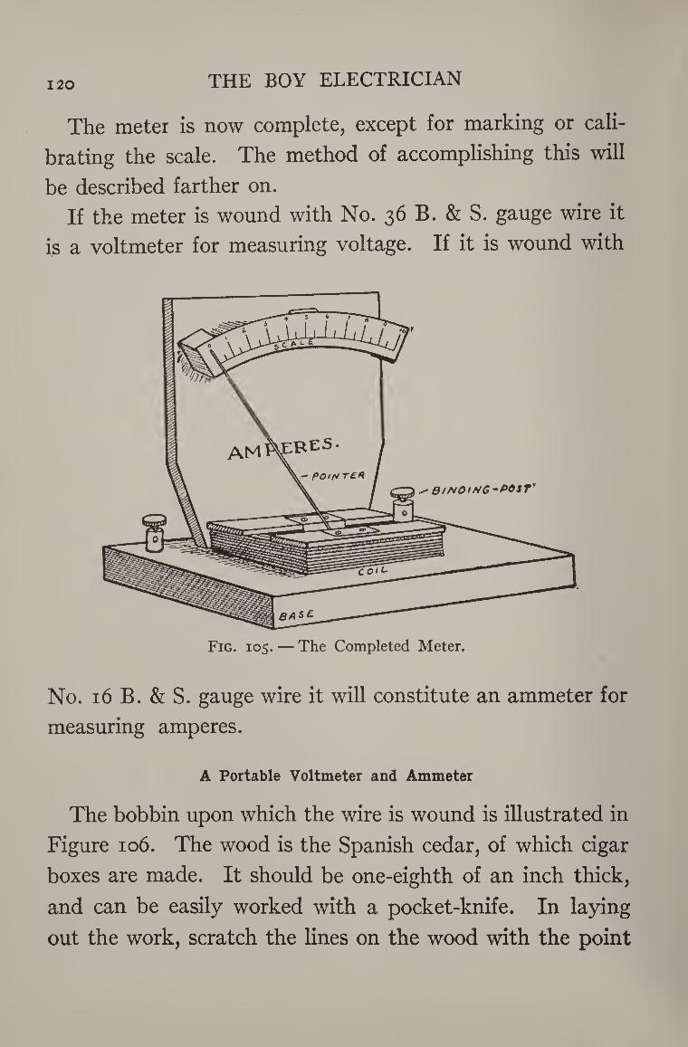
120 THE BOY ELECTRICIAN
The meter is now complete, except for marking or cali¬
brating the scale. The method of accomplishing this will
be described farther on.
If the meter is wound with No. 36 B. & S. gauge wire it
is a voltmeter for measuring voltage. If it is wound with
No. 16 B. & S. gauge wire it will constitute an ammeter for
measuring amperes.
A Portable Voltmeter and Ammeter
The bobbin upon which the wire is wound is illustrated in
Figure 106. The wood is the Spanish cedar, of which cigar
boxes are made. It should be one-eighth of an inch thick,
and can be easily worked with a pocket-knife. In laying
out the work, scratch the lines on the wood with the point
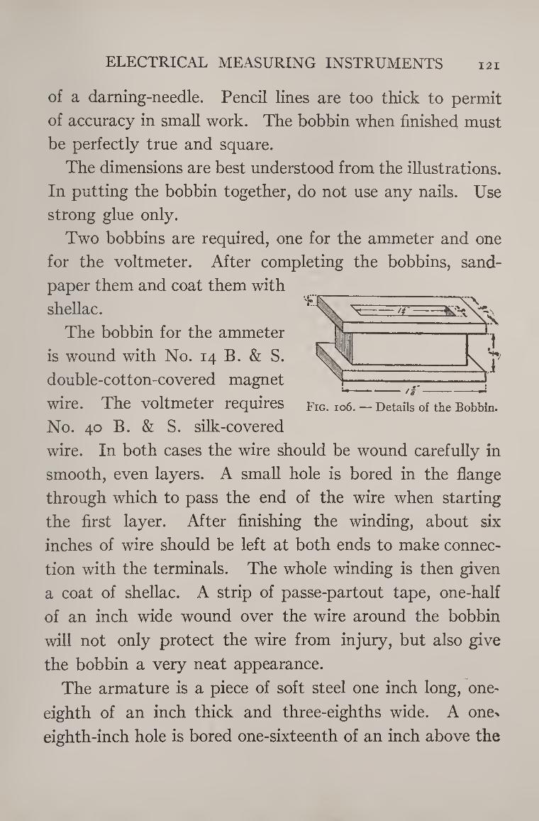
ELECTRICAL MEASURING INSTRUMENTS 121
of a darning-needle. Pencil lines are too thick to permit
of accuracy in small work. The bobbin when finished must
be perfectly true and square.
The dimensions are best understood from the illustrations.
In putting the bobbin together, do not use any nails. Use
strong glue only.
Two bobbins are required, one for the ammeter and one
for the voltmeter. After completing the bobbins, sand¬
paper them and coat them with
shellac.
The bobbin for the ammeter
is wound with No. 14 B. & S.
double-cotton-covered magnet
wire. The voltmeter requires
No. 40 B. & S. silk-covered
wire. In both cases the wire should be wound carefully in
smooth, even layers. A small hole is bored in the flange
through which to pass the end of the wire when starting
the first layer. After finishing the winding, about six
inches of wire should be left at both ends to make connec¬
tion with the terminals. The whole winding is then given
a coat of shellac. A strip of passe-partout tape, one-half
of an inch wide wound over the wire around the bobbin
will not only protect the wire from injury, but also give
the bobbin a very neat appearance.
The armature is a piece of soft steel one inch long, one-
eighth of an inch thick and three-eighths wide. A one>
eighth-inch hole is bored one-sixteenth of an inch above the
Fig. 106. — Details of the Bobbin.
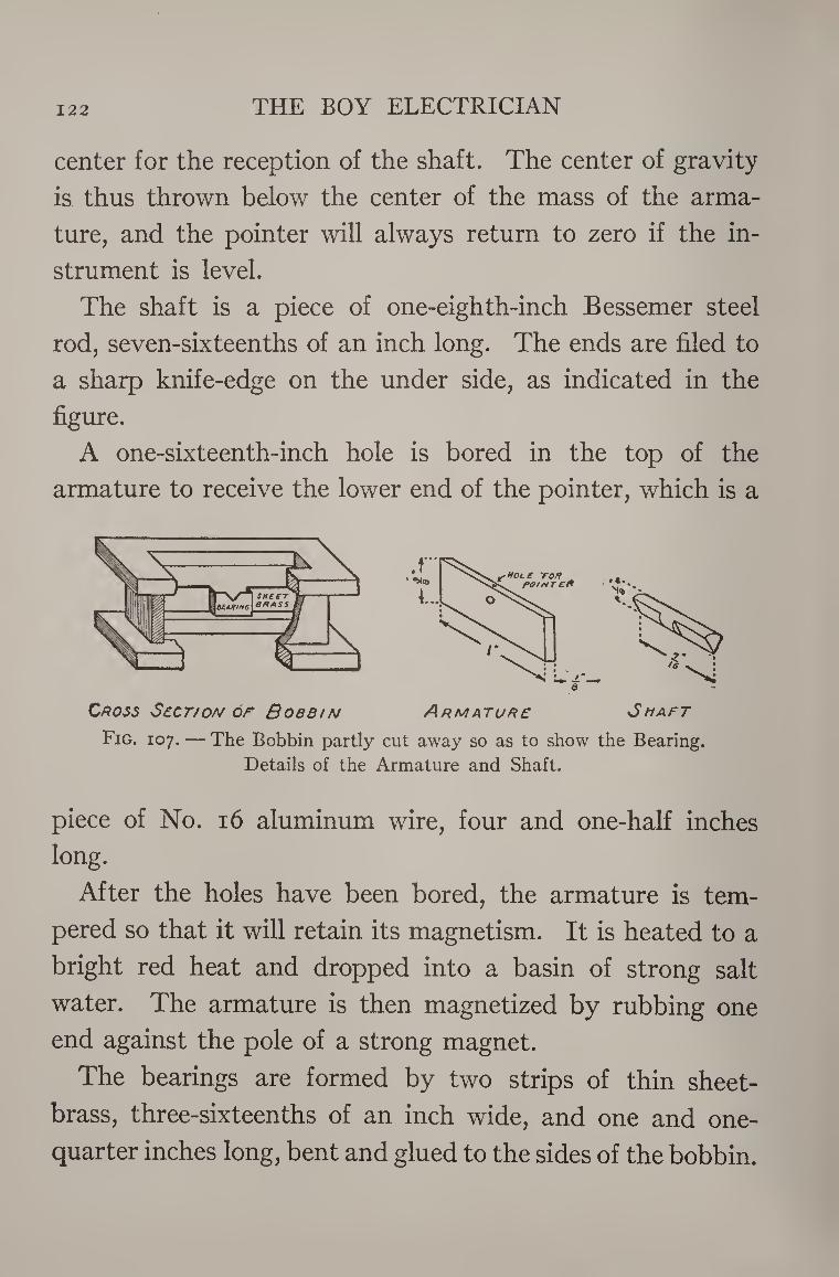
122 THE BOY ELECTRICIAN
center for the reception of the shaft. The center of gravity
is thus thrown below the center of the mass of the arma¬
ture, and the pointer will always return to zero if the in¬
strument is level.
The shaft is a piece of one-eighth-inch Bessemer steel
rod, seven-sixteenths of an inch long. The ends are filed to
a sharp knife-edge on the under side, as indicated in the
figure.
A one-sixteenth-inch hole is bored in the top of the
armature to receive the lower end of the pointer, which is a
Cross Sbct/on or Bobbin Armature 3haft
Fig. 107. — The Bobbin partly cut away so as to show the Bearing.
Details of the Armature and Shaft.
piece of No. 16 aluminum wire, four and one-half inches long.
After the holes have been bored, the armature is tem¬
pered so that it will retain its magnetism. It is heated to a
bright red heat and dropped into a basin of strong salt
water. The armature is then magnetized by rubbing one
end against the pole of a strong magnet.
The bearings are formed by two strips of thin sheet-
brass, three-sixteenths of an inch wide, and one and one-
quarter inches long, bent and glued to the sides of the bobbin.
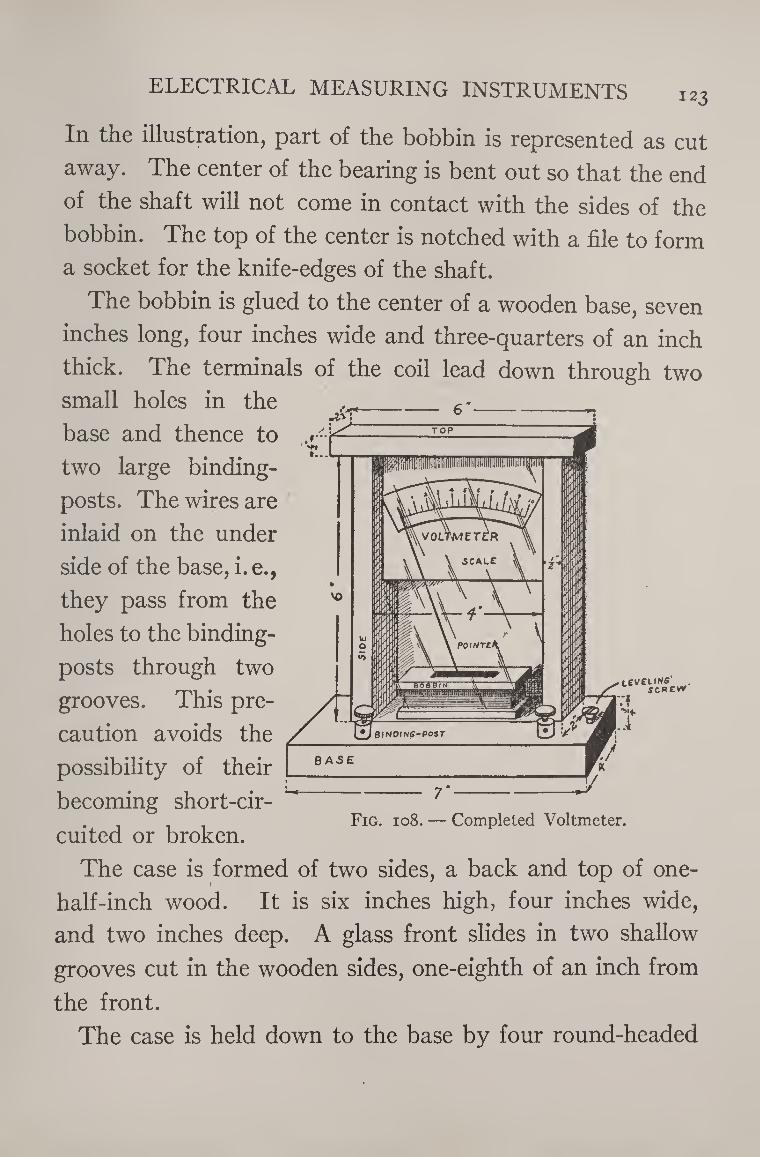
ELECTRICAL MEASURING INSTRUMENTS 123
In the illustration, part of the bobbin is represented as cut
away. The center of the bearing is bent out so that the end
of the shaft will not come in contact with the sides of the
bobbin. The top of the center is notched with a file to form
a socket for the knife-edges of the shaft.
The bobbin is glued to the center of a wooden base, seven
inches long, four inches wide and three-quarters of an inch
thick. The terminals of the coil lead down through two
small holes in the
base and thence to
two large binding-
posts. The wires are
inlaid on the under
side of the base, i. e.,
they pass from the
holes to the binding-
posts through two
grooves. This pre¬
caution avoids the
possibility of their
becoming short-cir¬
cuited or broken.
teveuws SCREV*
/ UJaiNPINC-POST EJV & BASE r *
--r- _Jj
Fig. 108. — Completed Voltmeter.
The case is formed of two sides, a back and top of one-
half-inch wood. It is six inches high, four inches wide,
and two inches deep. A glass front slides in two shallow
grooves cut in the wooden sides, one-eighth of an inch from
the front.
The case is held down to the base by four round-headed
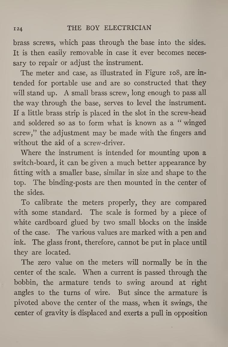
124 THE BOY ELECTRICIAN
brass screws, which pass through the base into the sides.
It is then easily removable in case it ever becomes neces¬
sary to repair or adjust the instrument.
The meter and case, as illustrated in Figure 108, are in¬
tended for portable use and are so constructed that they
will stand up. A small brass screw, long enough to pass all
the way through the base, serves to level the instrument.
If a little brass strip is placed in the slot in the screw-head
and soldered so as to form what is known as a “ winged
screw,” the adjustment may be made with the fingers and
without the aid of a screw-driver.
Where the instrument is intended for mounting upon a
switch-board, it can be given a much better appearance by
fitting with a smaller base, similar in size and shape to the
top. The binding-posts are then mounted in the center of
the sides.
To calibrate the meters properly, they are compared
with some standard. The scale is formed by a piece of
white cardboard glued by two small blocks on the inside
of the case. The various values are marked with a pen and
ink. The glass front, therefore, cannot be put in place until
they are located.
The zero value on the meters will normally be in the
center of the scale. When a current is passed through the
bobbin, the armature tends to swing around at right
angles to the turns of wire. But since the armature is
pivoted above the center of the mass, when it swings, the
center of gravity is displaced and exerts a pull in opposition
ELECTRICAL MEASURING INSTRUMENTS 125
to that of the bobbin, and the amount of swing indicated
by the pointer will be greater as the current is stronger.
The pointer will swing either to the right or the left, de¬
pending upon the direction in which the current passes
through the bobbin. The pointer of the instrument illus¬
trated in Figure 108 is at zero when at the extreme left of
the scale. The pointer is bent to the left, so that the current
AMMETER VOLTMETER*
Fig. 109. — Circuits for Calibrating the Ammeter and Volftneter.
will be registered when passing through the meter only in
one direction, but the scale will have a greater range of
values. It will also be necessary to cut a small groove in
the base of the instrument in this case so that the arma¬
ture will have plenty of room in which to swing.
When calibrating the ammeter, it is placed in series with
the standard meter, a set of strong batteries, and a rheo¬
stat. The rheostat is adjusted so that various current read¬
ings are obtained. The corresponding positions of the
126 THE BOY ELECTRICIAN
pointer on the meter being calibrated are then located for
each value.
The voltmeters must be placed in parallel, or shunt with
each other, and in series with several battery cells. A
switch is arranged so that the voltage of a varying number
of cells may be passed through the meters. To secure
fractional values of a volt, the rheostat is placed in shunt
with the first cell of the battery. Then, by adjusting both
the switch and the rheostat, any voltage within the maxi¬
mum range of the battery may be secured.
This means of regulating voltage is a common one, and
of much use in wireless telegraph circuits, as will be ex¬
plained later.
When using the meters, it is always necessary that the
ammeter shall be in series and the voltmeter in parallel or
in shunt with the circuit.
Galvanoscopes and Galvanometers
In the first part of Chapter V it was explained that several
turns of wire surrounding a compass-needle would cause
the needle to move and show a deflection if a current of
electricity were sent through the coil.
Such an instrument is called a galvanoscope and may be
used for detecting very feeble currents. A galvanoscope
becomes a galvanometer by providing it with a scale so that
the deflection may be measured.
A galvanometer is really, in principle, an ammeter the
scale of which has not been calibrated to read in amperes.
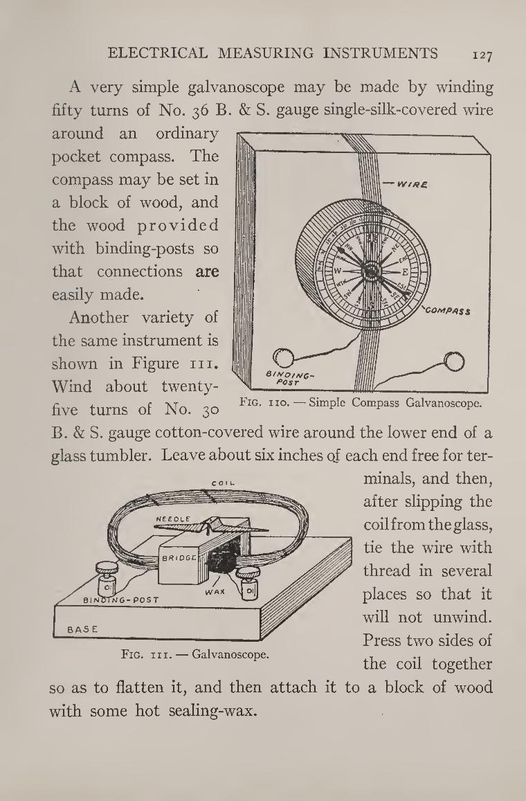
ELECTRICAL MEASURING INSTRUMENTS 127
A very simple galvanoscope may be made by winding
fifty turns of No. 36 B. & S. gauge single-silk-covered wire
around an ordinary
pocket compass. The
compass may be set in
a block of wood, and
the wood provided
with binding-posts so
that connections are
easily made.
Another variety of
the same instrument is
shown in Figure hi.
Wind about twenty- five turns of No. 30 Fig- no. —Simple Compass Galvanoscope.
B. & S. gauge cotton-covered wire around the lower end of a
glass tumbler. Leave about six inches oj each end free for ter¬
minals, and then,
after slipping the
coil from the glass,
tie the wire with
thread in several
places so that it
will not unwind.
Press two sides of Fig. hi. — Galvanoscope. , ... .
the coil together
so as to flatten it, and then attach it to a block of wood
with some hot sealing-wax.
COIL
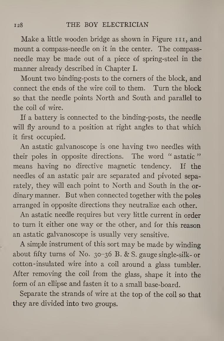
128 THE BOY ELECTRICIAN
Make a little wooden bridge as shown in Figure in, and
mount a compass-needle on it in the center. The compass-
needle may be made out of a piece of spring-steel in the
manner already described in Chapter I.
Mount two binding-posts to the corners of the block, and
connect the ends of the wire coil to them. Turn the block
so that the needle points North and South and parallel to
the coil of wire.
If a battery is connected to the binding-posts, the needle
will fly around to a position at right angles to that which
it first occupied.
An astatic galvanoscope is one having two needles with
their poles in opposite directions. The word “ astatic ”
means having no directive magnetic tendency. If the
needles of an astatic pair are separated and pivoted sepa¬
rately, they will each point to North and South in the or¬
dinary manner. But when connected together with the poles
arranged in opposite directions they neutralize each other.
An astatic needle requires but very little current in order
to turn it either one way or the other, and for this reason
an astatic galvanoscope is usually very sensitive.
A simple instrument of this sort may be made by winding
about fifty turns of No. 30-36 B. & S. gauge single-silk-or
cotton-insulated wire into a coil around a glass tumbler.
After removing the coil from the glass, shape it into the
form of an ellipse and fasten it to a small base-board.
Separate the strands of wire at the top of the coil so that
they are divided into two groups.
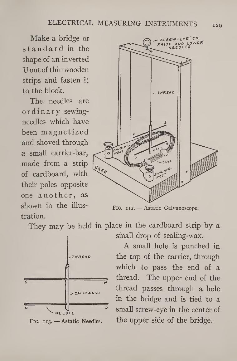
ELECTRICAL MEASURING INSTRUMENTS 129
Make a bridge or
standard in the
shape of an inverted
U out of thin wooden
strips and fasten it
to the block.
The needles are
ordinary sewing-
needles which have
been magnetized
and shoved through
a small carrier-bar,
made from a strip
of cardboard, with
their poles opposite
one another, as
shown in the illus¬
tration.
They may be held in
- JCREW-ei'f TO RAISE and lower,
neeolES
i
N K til ^ N E £0L
✓ THREAD
cardboard
Fig. 113.—Astatic Needles.
Fig. i 12. — Astatic Galvanoscope.
place in the cardboard strip by a
small drop of sealing-wax.
A small hole is punched in
the top of the carrier, through
which to pass the end of a
=> thread. The upper end of the
thread passes through a hole
in the bridge and is tied to a
small screw-eye in the center of
the upper side of the bridge.
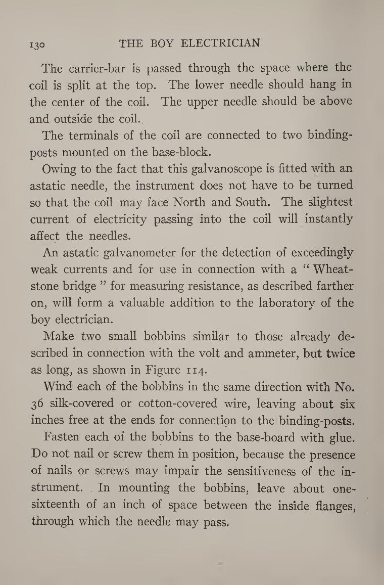
130 THE BOY ELECTRICIAN
The carrier-bar is passed through the space where the
coil is split at the top. The lower needle should hang in
the center of the coil. The upper needle should be above
and outside the coil.
The terminals of the coil are connected to two binding-
posts mounted on the base-block.
Owing to the fact that this galvanoscope is fitted with an
astatic needle, the instrument does not have to be turned
so that the coil may face North and South. The slightest
current of electricity passing into the coil will instantly
affect the needles.
An astatic galvanometer for the detection of exceedingly
weak currents and for use in connection with a “ Wheat¬
stone bridge ” for measuring resistance, as described farther
on, will form a valuable addition to the laboratory of the
boy electrician.
Make two small bobbins similar to those already de¬
scribed in connection with the volt and ammeter, but twice
as long, as shown in Figure 114.
Wind each of the bobbins in the same direction with No.
36 silk-covered or cotton-covered wire, leaving about six
inches free at the ends for connectipn to the binding-posts.
Fasten each of the bobbins to the base-board with glue.
Do not nail or screw them in position, because the presence
of nails or screws may impair the sensitiveness of the in¬
strument. In mounting the bobbins, leave about one-
sixteenth of an inch of space between the inside flanges,
through which the needle may pass.
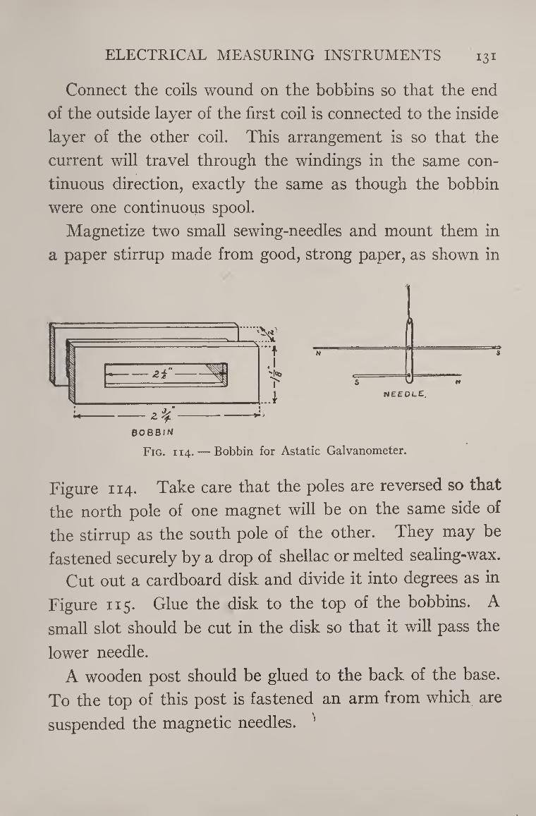
ELECTRICAL MEASURING INSTRUMENTS I3I
Connect the coils wound on the bobbins so that the end
of the outside layer of the first coil is connected to the inside
layer of the other coil. This arrangement is so that the
current will travel through the windings in the same con¬
tinuous direction, exactly the same as though the bobbin
were one continuous spool.
Magnetize two small sewing-needles and mount them in
a paper stirrup made from good, strong paper, as shown in
BOBBIN
Fig. i 14. — Bobbin for Astatic Galvanometer.
Figure 114. Take care that the poles are reversed so that
the north pole of one magnet will be on the same side of
the stirrup as the south pole of the other. They may be
fastened securely by a drop of shellac or melted sealing-wax.
Cut out a cardboard disk and divide it into degrees as in
Figure 115. Glue the disk to the top of the bobbins. A
small slot should be cut in the disk so that it will pass the
lower needle.
A wooden post should be glued to the back of the base.
To the top of this post is fastened an arm from which are
suspended the magnetic needles. ’
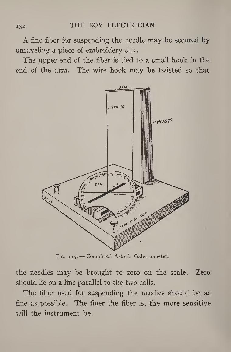
132 THE BOY ELECTRICIAN
A fine fiber for suspending the needle may be secured by
unraveling a piece of embroidery silk.
The upper end of the fiber is tied to a small hook in the
end of the arm. The wire hook may be twisted so that
Fig. i 15. — Completed Astatic Galvanometer.
the needles may be brought to zero on the scale. Zero
should He on a line parallel to the two coils.
The fiber used for suspending the needles should be as
fine as possible. The finer the fiber is, the more sensitive
will the instrument be.
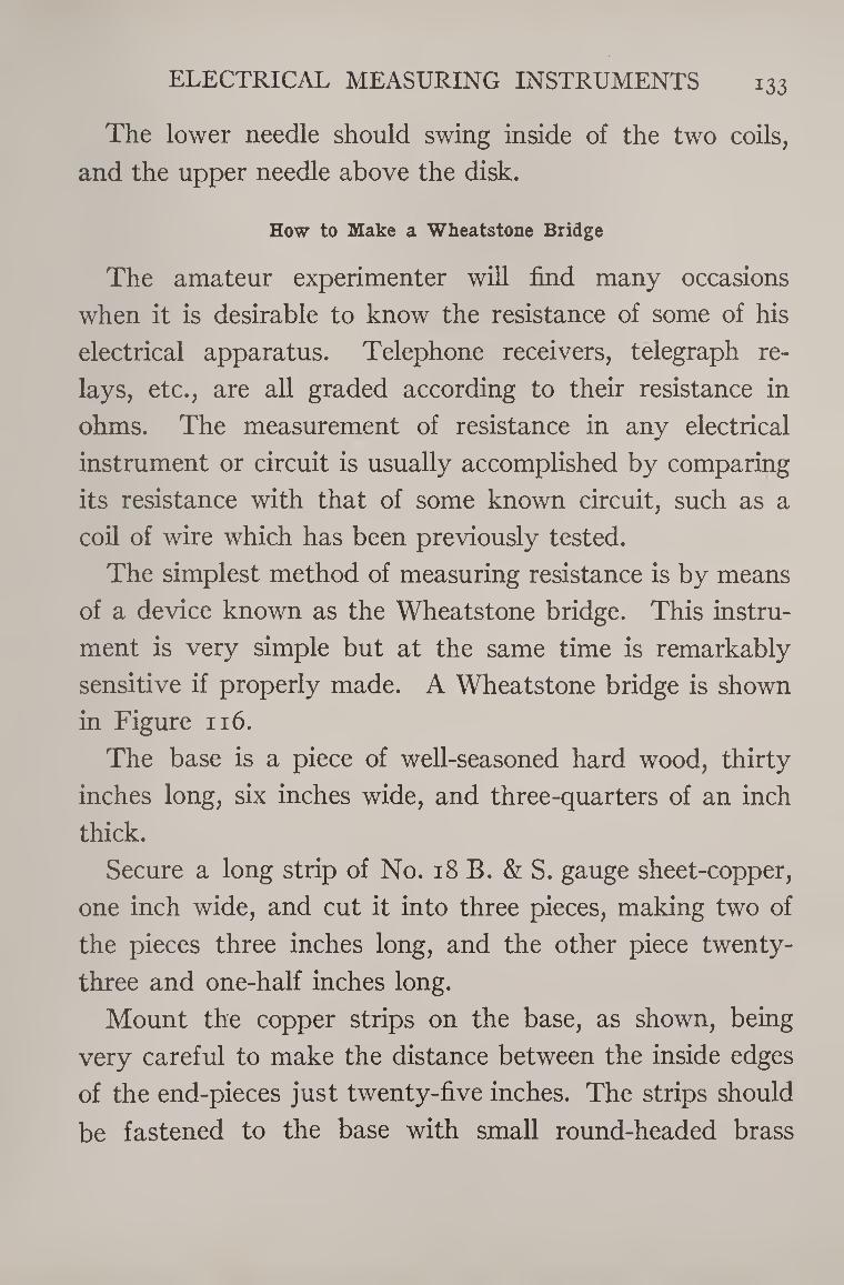
ELECTRICAL MEASURING INSTRUMENTS i33
The lower needle should swing inside of the two coils,
and the upper needle above the disk.
How to Make a Wheatstone Bridge
The amateur experimenter will find many occasions
when it is desirable to know the resistance of some of his
electrical apparatus. Telephone receivers, telegraph re¬
lays, etc., are all graded according to their resistance in
ohms. The measurement of resistance in any electrical
instrument or circuit is usually accomplished by comparing
its resistance with that of some known circuit, such as a
coil of wire which has been previously tested.
The simplest method of measuring resistance is by means
of a device known as the Wheatstone bridge. This instru¬
ment is very simple but at the same time is remarkably
sensitive if properly made. A Wheatstone bridge is shown
in Figure 116.
The base is a piece of well-seasoned hard wood, thirty
inches long, six inches wide, and three-quarters of an inch
thick.
Secure a long strip of No. 18 B. & S. gauge sheet-copper,
one inch wide, and cut it into three pieces, making two of
the pieces three inches long, and the other piece twenty-
three and one-half inches long.
Mount the copper strips on the base, as shown, being
very careful to make the distance between the inside edges
of the end-pieces just twenty-five inches. The strips should
be fastened to the base with small round-headed brass
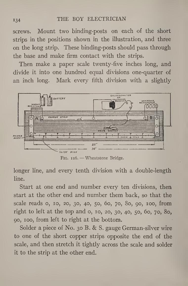
134 THE BOY ELECTRICIAN
screws. Mount two binding-posts on each of the short
strips in the positions shown in the illustration, and three
on the long strip. These binding-posts should pass through
the base and make firm contact with the strips.
Then make a paper scale twenty-five inches long, and
divide it into one hundred equal divisions one-quarter of
an inch long. Mark every fifth division with a slightly
longer line, and every tenth division with a double-length
line.
Start at one end and number every ten divisions, then
start at the other end and number them back, so that the
scale reads o, io, 20, 30, 40, 50, 60, 70, 80, 90, 100, from
right to left at the top and o, 10, 20, 30, 40, 50, 60, 70, 80,
90, 100, from left to right at the bottom.
Solder a piece of No. 30 B. & S. gauge German-silver wire
to one of the short copper strips opposite the end of the
scale, and then stretch it tightly across the scale and solder
it to the strip at the other end.
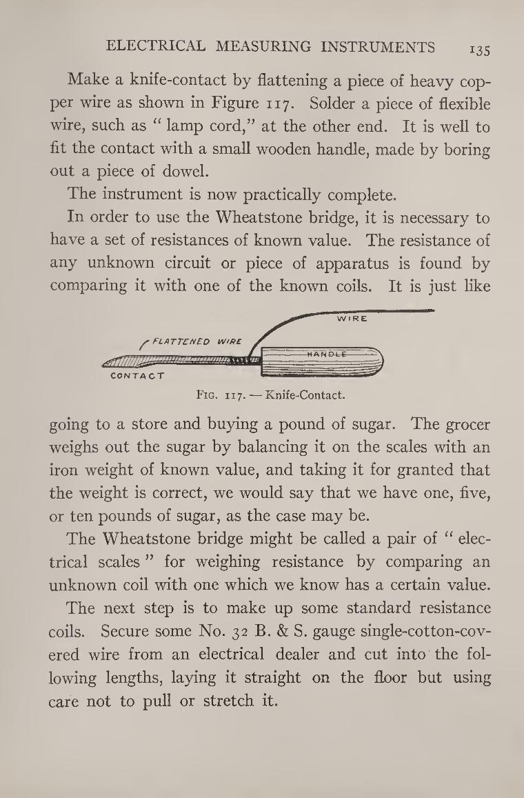
ELECTRICAL MEASURING INSTRUMENTS i3S
Make a knife-contact by flattening a piece of heavy cop¬
per wire as shown in Figure 117. Solder a piece of flexible
wire, such as “ lamp cord,” at the other end. It is well to
fit the contact with a small wooden handle, made by boring
out a piece of dowel.
The instrument is now practically complete.
In order to use the Wheatstone bridge, it is necessary to
have a set of resistances of known value. The resistance of
any unknown circuit or piece of apparatus is found by
comparing it with one of the known coils. It is just like
going to a store and buying a pound of sugar. The grocer
weighs out the sugar by balancing it on the scales with an
iron weight of known value, and taking it for granted that
the weight is correct, we would say that we have one, five,
or ten pounds of sugar, as the case may be.
The Wheatstone bridge might be called a pair of “ elec¬
trical scales ” for weighing resistance by comparing an
unknown coil with one which we know has a certain value.
The next step is to make up some standard resistance
coils. Secure some No. 32 B. & S. gauge single-cotton-cov¬
ered wire from an electrical dealer and cut into the fol¬
lowing lengths, laying it straight on the floor but using
care not to pull or stretch it.
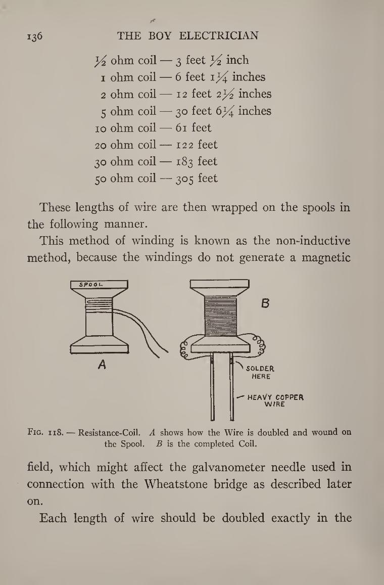
136 THE BOY ELECTRICIAN
ohm coil — 3 feet ]/2 inch
1 ohm coil — 6 feet i}i inches
2 ohm coil — 12 feet 2^ inches
5 ohm coil — 30 feet 6X inches
10 ohm coil — 61 feet
20 ohm coil — 122 feet
30 ohm coil — 183 feet
50 ohm coil — 305 feet
These lengths of wire are then wrapped on the spools in
the following manner.
This method of winding is known as the non-inductive
method, because the windings do not generate a magnetic
A HERE
HEAVY COPPER W/RE
Fig. 118. — Resistance-Coil. A shows how the Wire is doubled and wound on
the Spool. B is the completed Coil.
field, which might affect the galvanometer needle used in
connection with the Wheatstone bridge as described later
on.
Each length of wire should be doubled exactly in the
ELECTRICAL MEASURING INSTRUMENTS 137
middle, then wrapped on the spools like a single wire, the
two ends being left free for soldering to the terminals as
shown in Figure 118, B.
The spools may be the ordinary reels upon which cotton
and sewing-silk are wrapped.
The terminals of the spools are pieces of stout copper
wire, No. 12 or No. 14 B. & S. gauge. Two pieces of wire
about three inches long are driven into holes bored in the
ends of each spool. A small drop of solder is used perma¬
nently to secure the ends of the coil to each of the heavy
wire terminals.
The spools are then dipped into a pan of molten paraffin
and boiled until the air bubbles cease to rise.
The spools should be marked 1, 2, 10, 20, 30, and 50,
according to the amount of wire each one contains as in¬
dicated in the table above.
How to Use a Wheatstone Bridge for Measuring Resistance
The instrument is connected as in Figure 116.
The unknown resistance or device to be measured is
connected across the gap at B. One of the standard known
coils is connected across the gap at A. A sensitive galva¬
nometer or a telephone receiver and two cells of battery
are also connected as shown.
If a telephone receiver is used, place it to the ear. If a
galvanometer is used instead, watch the needle carefully.
Then move the sharp edge of the knife-contact over the
scale along the German-silver “ slide wire ” until a point is
138 THE BOY ELECTRICIAN
reached when there is no deflection of the needle or no sound
in the telephone receiver.
If this point lies very far on one side or the other of the
center division on the scale, substitute the next higher or
lower known resistance spool until the point falls as near
as possible to the center of the scale.
When this point is found, note the reading on the scale
carefully. Now comes the hardest part. Almost all my
readers have no doubt progressed far enough in arithmetic
to be able to carry on the following simple calculation in
proportion which must be made in order to find out the
resistance of the unknown coil.
The unknown resistance, connected to B, bears the same
ratio to the known coil, at A, that the number of divisions
between the knife-contact and the right-hand end of the
scale (lower row of figures) bears to the number of divisions
between the knife-edge and the left-hand end of the scale
(upper row of figures).
We will suppose that a 5-ohm coil was used at A in a test,
and the needle of the galvanometer stopped swinging when
the knife-contact rested on the 60th division from the left-
hand end, or on the 40th from the right. Then, in order to
find the value of the unknown resistance at B, it is simply
necessary to multiply the standard resistance at A by the
number of left-hand divisions and divide the product by
the number of right-hand divisions. The answer will be
the resistance of B in ohms.
The calculation in this case would be as follows:
ELECTRICAL MEASURING INSTRUMENTS 139
5 X 40 = 200
200 -T- 60 = 3.33 ohms
3.33 ohms is the resistance of B.
This explanation may seem very long and complex, but
if you will study it carefully you will find it to be very
simple. When once you master it, you will be enabled to
make many measurements of resistance which will add
greatly to the interest and value of your experiments.
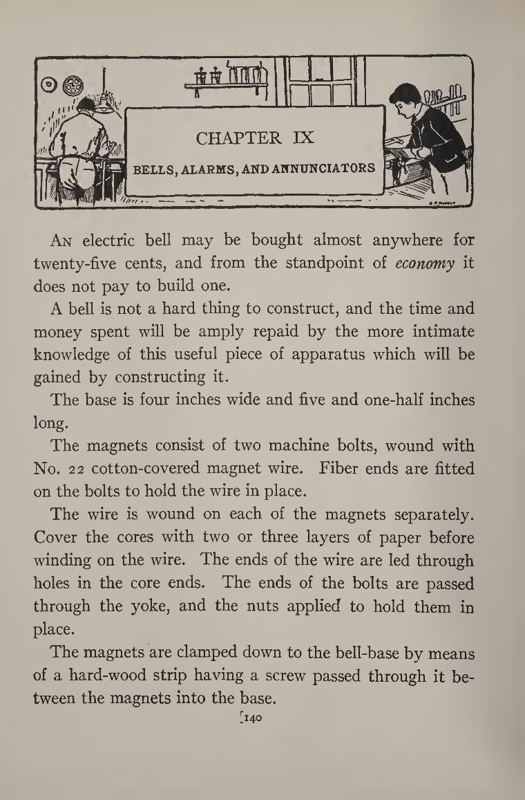
An electric bell may be bought almost anywhere for
twenty-five cents, and from the standpoint of economy it
does not pay to build one.
A bell is not a hard thing to construct, and the time and
money spent will be amply repaid by the more intimate
knowledge of this useful piece of apparatus which will be
gained by constructing it.
The base is four inches wide and five and one-half inches
long.
The magnets consist of two machine bolts, wound with
No. 22 cotton-covered magnet wire. Fiber ends are fitted
on the bolts to hold the wire in place.
The wire is wound on each of the magnets separately.
Cover the cores with two or three layers of paper before
winding on the wire. The ends of the wire are led through
holes in the core ends. The ends of the bolts are passed
through the yoke, and the nuts applied to hold them in
place.
The magnets are clamped down to the bell-base by means
of a hard-wood strip having a screw passed through it be¬
tween the magnets into the base. [140
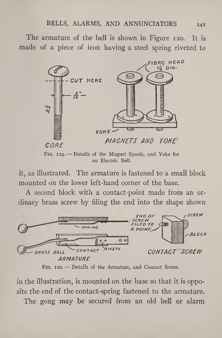
BELLS, ALARMS, AND ANNUNCIATORS 141
The armature of the bell is shown in Figure 120. It is
made of a piece of iron having a steel spring riveted to
Fig. 119. — Details of the Magnet Spools, and Yoke for
an Electric Bell.
it, as illustrated. The armature is fastened to a small block
mounted on the lower left-hand corner of the base.
A second block with a contact-point made from an or¬
dinary brass screw by filing the end into the shape shown
Fig. i 20. — Details of the Armature, and Contact Screw.
in the illustration, is mounted on the base so that it is oppo¬
site the end of the contact-spring fastened to the armature.
The gong may be secured from an old bell or alarm
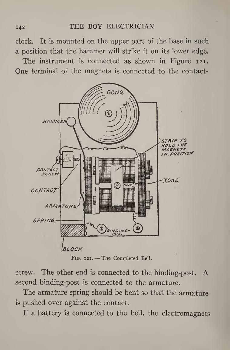
142 THE BOY ELECTRICIAN
clock. It is mounted on the upper part of the base in such
a position that the hammer will strike it on its lower edge.
The instrument is connected as shown in Figure 121.
One terminal of the magnets is connected to the contact-
screw. The other end is connected to the binding-post. A
second binding-post is connected to the armature.
The armature spring should be bent so that the armature
is pushed over against the contact.
If a battery is connected to the bell, the electromagnets
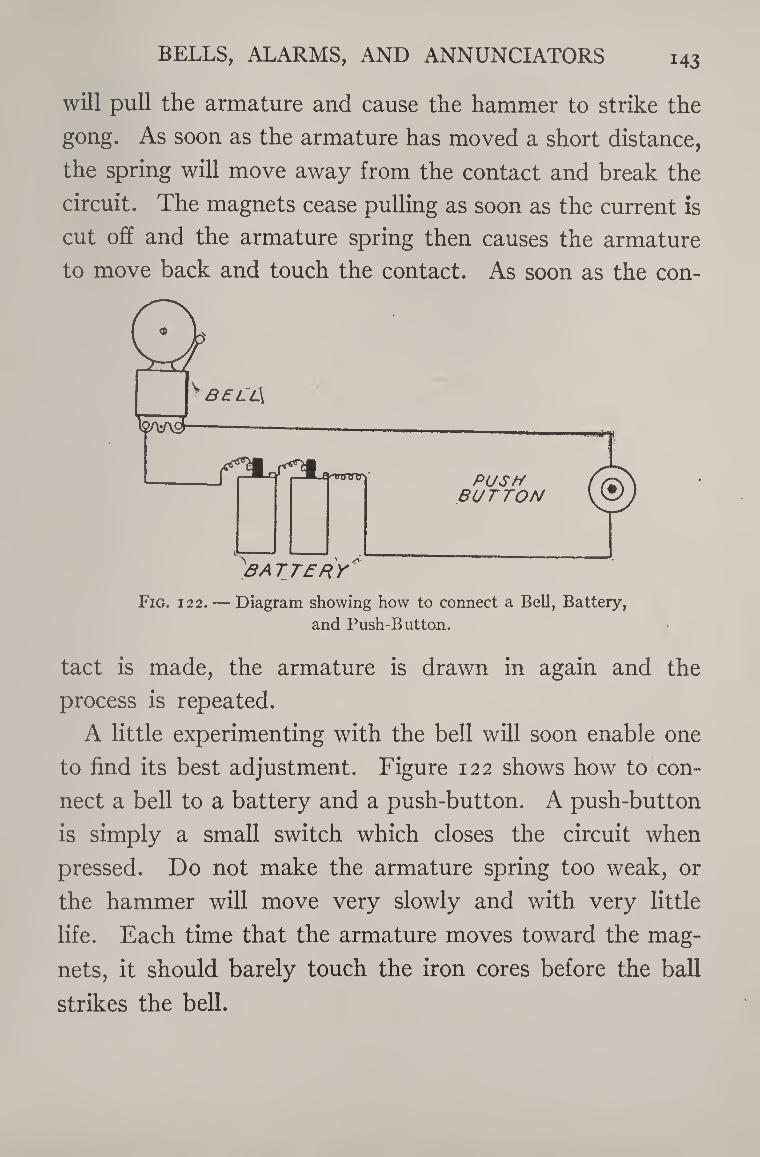
BELLS, ALARMS, AND ANNUNCIATORS i43
will pull the armature and cause the hammer to strike the
gong. As soon as the armature has moved a short distance,
the spring will move away from the contact and break the
circuit. The magnets cease pulling as soon as the current is
cut off and the armature spring then causes the armature
to move back and touch the contact. As soon as the con-
Fig. 122. — Diagram showing how to connect a Bell, Battery,
and Push-Button.
tact is made, the armature is drawn in again and the
process is repeated.
A little experimenting with the bell will soon enable one
to find its best adjustment. Figure 122 shows how to con¬
nect a bell to a battery and a push-button. A push-button
is simply a small switch which closes the circuit when
pressed. Do not make the armature spring too weak, or
the hammer will move very slowly and with very little
life. Each time that the armature moves toward the mag¬
nets, it should barely touch the iron cores before the ball
strikes the bell.
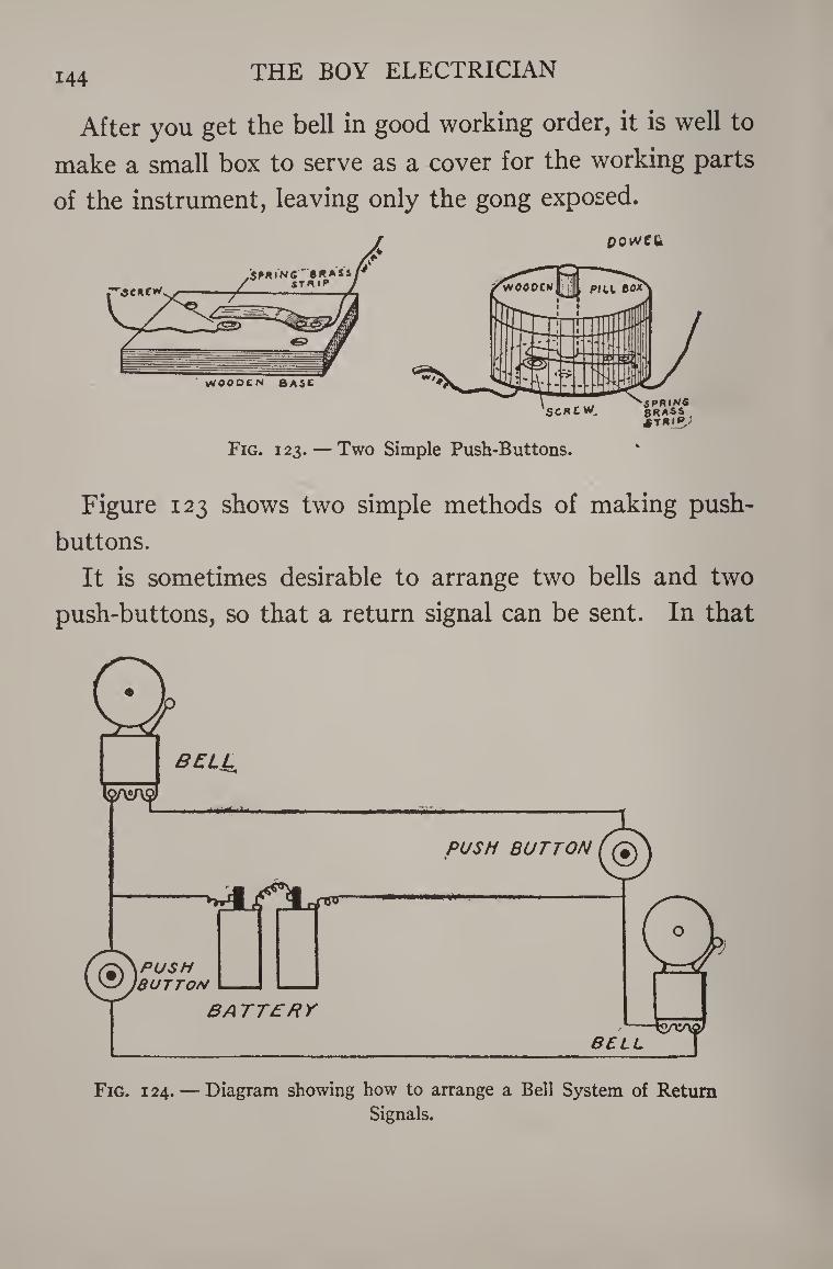
144 THE BOY ELECTRICIAN
After you get the bell in good working order, it is well to
make a small box to serve as a cover for the working parts
of the instrument, leaving only the gong exposed.
Fig. 123. — Two Simple Push-Buttons.
Figure 123 shows two simple methods of making push¬
buttons.
It is sometimes desirable to arrange two bells and two
push-buttons, so that a return signal can be sent. In that
Fig. 124. — Diagram showing how to arrange a Bell System of Return Signals.
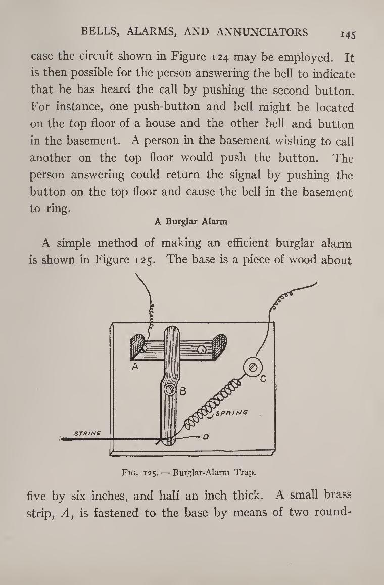
BELLS, ALARMS, AND ANNUNCIATORS i4S
case the circuit shown in Figure 124 may be employed. It
is then possible for the person answering the bell to indicate
that he has heard the call by pushing the second button.
For instance, one push-button and bell might be located
on the top floor of a house and the other bell and button
in the basement. A person in the basement wishing to call
another on the top floor would push the button. The
person answering could return the signal by pushing the
button on the top floor and cause the bell in the basement
to ring. A Burglar Alarm
A simple method of making an efficient burglar alarm
is shown in Figure 125. The base is a piece of wood about
five by six inches, and half an inch thick. A small brass
strip, Ay is fastened to the base by means of two round-
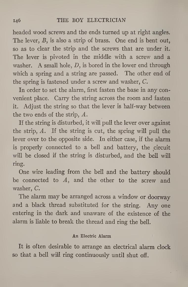
146 THE BOY ELECTRICIAN
headed wood screws and the ends turned up at right angles.
The lever, B, is also a strip of brass. One end is bent out,
so as to clear the strip and the screws that are under it.
The lever is pivoted in the middle with a screw and a
washer. A small hole, D, is bored in the lower end through
which a spring and a string are passed. The other end of
the spring is fastened under a screw and washer, C.
In order to set the alarm, first fasten the base in any con¬
venient place. Carry the string across the room and fasten
it. Adjust the string so that the lever is half-way between
the two ends of the strip, A.
If the string is disturbed, it will pull the lever over against
the strip, A. If the string is cut, the spring will pull the
lever over to the opposite side. In either case, if the alarm
is properly connected to a bell and battery, the circuit
will be closed if the string is disturbed, and the bell will
ring.
One wire leading from the bell and the battery should
be connected to A, and the other to the screw and
washer, C.
The alarm may be arranged across a window or doorway
and a black thread substituted for the string. Any one
entering in the dark and unaware of the existence of the
alarm is liable to break the thread and ring the bell.
An Electric Alarm
It is often desirable to arrange an electrical alarm clock
so that a bell will ring continuously until shut off.
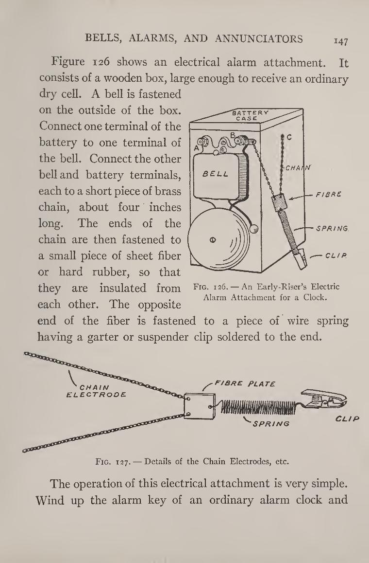
BELLS, ALARMS, AND ANNUNCIATORS i47
Figure 126 shows an electrical alarm attachment. It
consists of a wooden box, large enough to receive an ordinary-
dry cell. A bell is fastened
on the outside of the box.
Connect one terminal of the
battery to one terminal of
the bell. Connect the other
bell and battery terminals,
each to a short piece of brass
chain, about four inches
long. The ends of the
chain are then fastened to
a small piece of sheet fiber
or hard rubber, so that they are insulated from Fig. 126. — An Early-Riser’s Electric
. - . . Alarm Attachment for a Clock. each other. Ihe opposite
end of the fiber is fastened to a piece of wire spring
having a garter or suspender clip soldered to the end.
SPP/mg CLIP
Fig. 127. — Details of the Chain Electrodes, etc.
The operation of this electrical attachment is very simple.
Wind up the alarm key of an ordinary alarm clock and
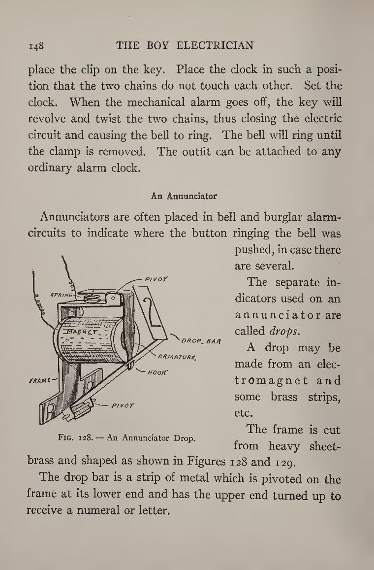
148 THE BOY ELECTRICIAN
place the clip on the key. Place the clock in such a posi¬
tion that the two chains do not touch each other. Set the
clock. When the mechanical alarm goes off, the key will
revolve and twist the two chains, thus closing the electric
circuit and causing the bell to ring. The bell will ring until
the clamp is removed. The outfit can be attached to any
ordinary alarm clock.
An Annunciator
PIVOT
Annunciators are often placed in bell and burglar alarm-
circuits to indicate where the button ringing the bell was
pushed, in case there
are several.
The separate in¬
dicators used on an
annunciator are
called drops.
A drop may be
made from an elec-
tromagnet and
some brass strips,
etc.
The frame is cut
from heavy sheet-
brass and shaped as shown in Figures 128 and 129.
The drop bar is a strip of metal which is pivoted on the
frame at its lower end and has the upper end turned up to
receive a numeral or letter.
fRAtAt-
PIVOT
Fig. 128. — An Annunciator Drop.
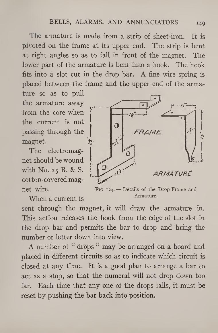
BELLS, ALARMS, AND ANNUNCIATORS 149
The armature is made from a strip of sheet-iron. It is
pivoted on the frame at its upper end. The strip is bent
at right angles so as to fall in front of the magnet. The
lower part of the armature is bent into a hook. The hook
fits into a slot cut in the drop bar. A fine wire spring is
placed between the frame and the upper end of the arma¬
ture so as to pull
the armature away
from the core when
the current is not
passing through the
magnet.
The electromag¬
net should be wound
with No. 25 B. & S.
cotton-covered mag¬
net wire.
When a current is
sent through the magnet, it will draw the armature in.
This action releases the hook from the edge of the slot in
the drop bar and permits the bar to drop and bring the
number or letter down into view.
A number of “ drops ” may be arranged on a board and
placed in different circuits so as to indicate which circuit is
closed at any time. It is a good plan to arrange a bar to
act as a stop, so that the numeral will not drop down too
far. Each time that any one of the drops falls, it must be
reset by pushing the bar back into position.
Fig 129. — Details of the Drop-Frame and
Armature.
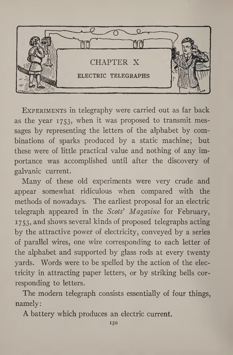
Experiments in telegraphy were carried out as far back
as the year 1753, when it was proposed to transmit mes¬
sages by representing the letters of the alphabet by com¬
binations of sparks produced by a static machine; but
these were of little practical value and nothing of any im¬
portance was accomplished until after the discovery of
galvanic current.
Many of these old experiments were very crude and
appear somewhat ridiculous when compared with the
methods of nowadays. The earliest proposal for an electric
telegraph appeared in the Scots’ Magazine for February,
1753, and shows several kinds of proposed telegraphs acting
by the attractive power of electricity, conveyed by a series
of parallel wires, one wire corresponding to each letter of
the alphabet and supported by glass rods at every twenty
yards. Words were to be spelled by the action of the elec¬
tricity in attracting paper letters, or by striking bells cor¬
responding to letters.
The modern telegraph consists essentially of four things,
namely:
A battery which produces an electric current. 150
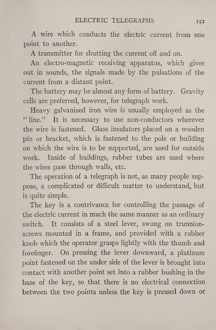
ELECTRIC TELEGRAPHS 151
A wire which conducts the electric current from one
point to another.
A transmitter for shutting the current off and on.
An electro-magnetic receiving apparatus, which gives
out in sounds, the signals made by the pulsations of the
current from a distant point.
The battery may be almost any form of battery. Gravity
cells are preferred, however, for telegraph work.
Heavy galvanized iron wire is usually employed as the
“ line.” It is necessary to use non-conductors wherever
the wire is fastened. Glass insulators placed on a wooden
pin or bracket, which is fastened to the pole or building
on which the wire is to be supported, are used for outside
work. Inside of buildings, rubber tubes are used where
the wires pass through walls, etc.
The operation of a telegraph is not, as many people sup¬
pose, a complicated or difficult matter to understand, but
is quite simple.
The key is a contrivance for controlling the passage of
the electric current in much the same manner as an ordinary
switch. It consists of a steel lever, swung on trunnion-
screws mounted in a frame, and provided with a rubber
knob which the operator grasps lightly with the thumb and
forefinger. On pressing the lever downward, a platinum
point fastened on the under side of the lever is brought into
contact with another point set into a rubber bushing in the
base of the key, so that there is no electrical connection
between the two points unless the key is pressed down or
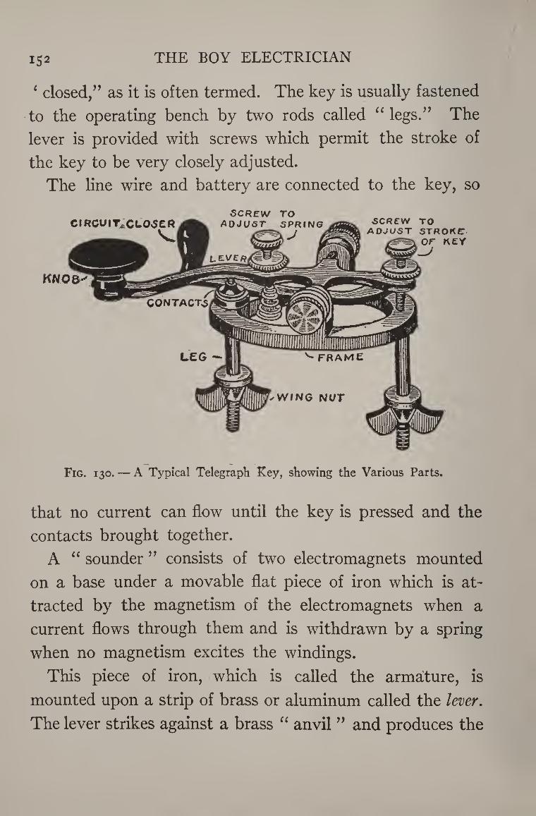
152 THE BOY ELECTRICIAN
‘ closed/’ as it is often termed. The key is usually fastened
to the operating bench by two rods called “ legs.” The
lever is provided with screws which permit the stroke of
the key to be very closely adjusted.
The line wire and battery are connected to the key, so
SCREW TO
Fig. 130. — A Typical Telegraph Key, showing the Various Parts.
that no current can flow until the key is pressed and the
contacts brought together.
A “ sounder ” consists of two electromagnets mounted
on a base under a movable flat piece of iron which is at¬
tracted by the magnetism of the electromagnets when a
current flows through them and is withdrawn by a spring
when no magnetism excites the windings.
This piece of iron, which is called the armature, is
mounted upon a strip of brass or aluminum called the lever.
The lever strikes against a brass “ anvil ” and produces the
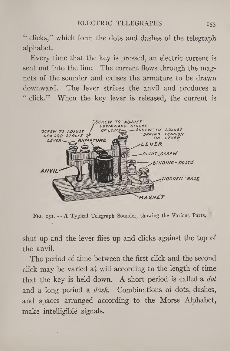
ELECTRIC TELEGRAPHS 153
“ clicks,” which form the dots and dashes of the telegraph
alphabet.
Every time that the key is pressed, an electric current is
sent out into the line. The current flows through the mag¬
nets of the sounder and causes the armature to be drawn
downward. The lever strikes the anvil and produces a
“ click.” When the key lever is released, the current is
/rSCREW TO ADJUST\ DOWNWARD STROKE OF LEVEf^—-^-SCREW TO ADJUST
T,£FNySJ%N LEVER'_ARMRTUnC fi&Fl °N
\ IK ’ EVER
PIVOT SCREW
ANVIL
BINDING-POSTS
WOODEN .'BASE
MAGNET
Fig. 131. — A Typical Telegraph Sounder, showing the Various Parts.
shut up and the lever flies up and clicks against the top of
the anvil.
The period of time between the first click and the second
click may be varied at will according to the length of time
that the key is held down. A short period is called a dot
and a long period a dash. Combinations of dots, dashes,
and spaces arranged according to the Morse Alphabet,
make intelligible signals.
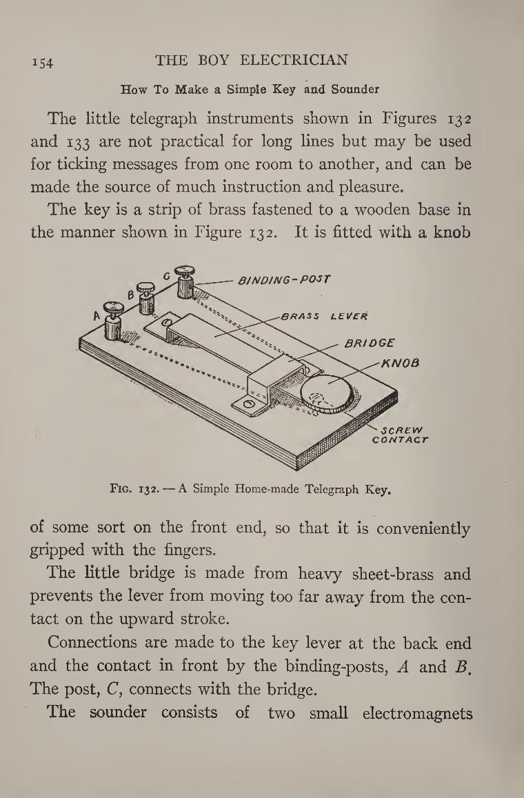
iS4 THE BOY ELECTRICIAN
How To Make a Simple Key and Sounder
The little telegraph instruments shown in Figures 132
and 133 are not practical for long lines but may be used
for ticking messages from one room to another, and can be
made the source of much instruction and pleasure.
The key is a strip of brass fastened to a wooden base in
the manner shown in Figure 132. It is fitted with a knob
Fig. 132. — A Simple Home-made Telegraph Key.
of some sort on the front end, so that it is conveniently
gripped with the fingers.
The little bridge is made from heavy sheet-brass and
prevents the lever from moving too far away from the con¬
tact on the upward stroke.
Connections are made to the key lever at the back end
and the contact in front by the binding-posts, A and Bm
The post, C, connects with the bridge.
The sounder consists of two small electromagnets
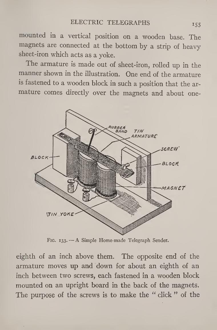
ELECTRIC TELEGRAPHS iS5
mounted in a vertical position on a wooden base. The
magnets are connected at the bottom by a strip of heavy
sheet-iron which acts as a yoke.
The armature is made out of sheet-iron, rolled up in the
manner shown in the illustration. One end of the armature
is fastened to a wooden block in such a position that the ar¬
mature comes directly over the magnets and about one-
Fig. 133. — A Simple Home-made Telegraph Sender.
eighth of an inch above them. The opposite end of the
armature moves up and down for about an eighth of an
inch between two screws, each fastened in a wooden block
mounted on an upright board in the back of the magnets.
The purpose of the screws is to make the “ click ” of the
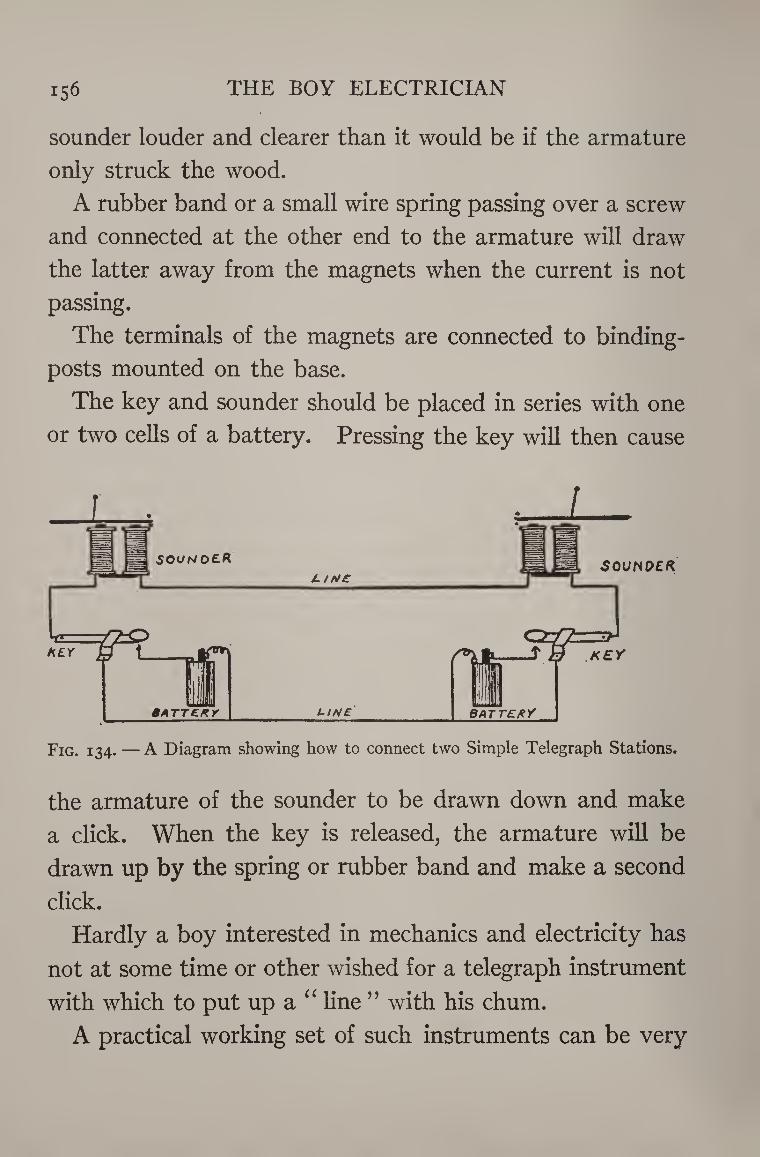
156 THE BOY ELECTRICIAN
sounder louder and clearer than it would be if the armature
only struck the wood.
A rubber band or a small wire spring passing over a screw
and connected at the other end to the armature will draw
the latter away from the magnets when the current is not
passing.
The terminals of the magnets are connected to binding-
posts mounted on the base.
The key and sounder should be placed in series with one
or two cells of a battery. Pressing the key will then cause
Fig. 134. — A Diagram showing how to connect two Simple Telegraph Stations.
the armature of the sounder to be drawn down and make
a click. When the key is released, the armature will be
drawn up by the spring or rubber band and make a second
click.
Hardly a boy interested in mechanics and electricity has
not at some time or other wished for a telegraph instrument
with which to put up a “ line ” with his chum.
A practical working set of such instruments can be very
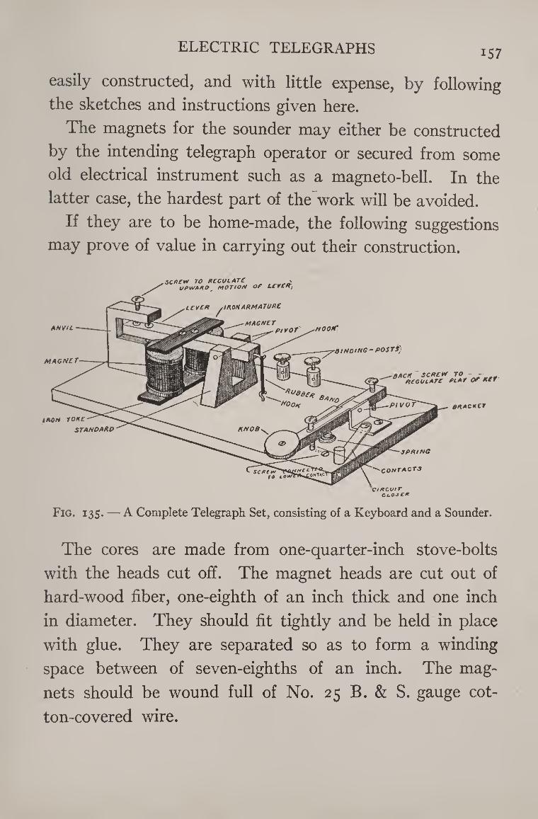
ELECTRIC TELEGRAPHS iS7
easily constructed, and with little expense, by following
the sketches and instructions given here.
The magnets for the sounder may either be constructed
by the intending telegraph operator or secured from some
old electrical instrument such as a magneto-bell. In the
latter case, the hardest part of the work will be avoided.
If they are to be home-made, the following suggestions
may prove of value in carrying out their construction.
MAGNCT
KNOB
SPAING
CONTACTS onIXC
C/xcutr
ANVIL
iaon rone standard
,SCA£W TO ACGULATC , UPNAAO MOTION OF LCVCA,
,LCVCR ^moHABMATUAt
HOO/f
■BINDING-POST?)
MAGNCT PIVOT
BACK SCPCVV TO - ACGULATC PLAT OF KCt
BAACKC1
Fig. 135. — A Complete Telegraph Set, consisting of a Keyboard and a Sounder.
The cores are made from one-quarter-inch stove-bolts
with the heads cut off. The magnet heads are cut out of
hard-wood fiber, one-eighth of an inch thick and one inch
in diameter. They should fit tightly and be held in place
with glue. They are separated so as to form a winding
space between of seven-eighths of an inch. The mag¬
nets should be wound full of No. 25 B. & S. gauge cot¬
ton-covered wire.
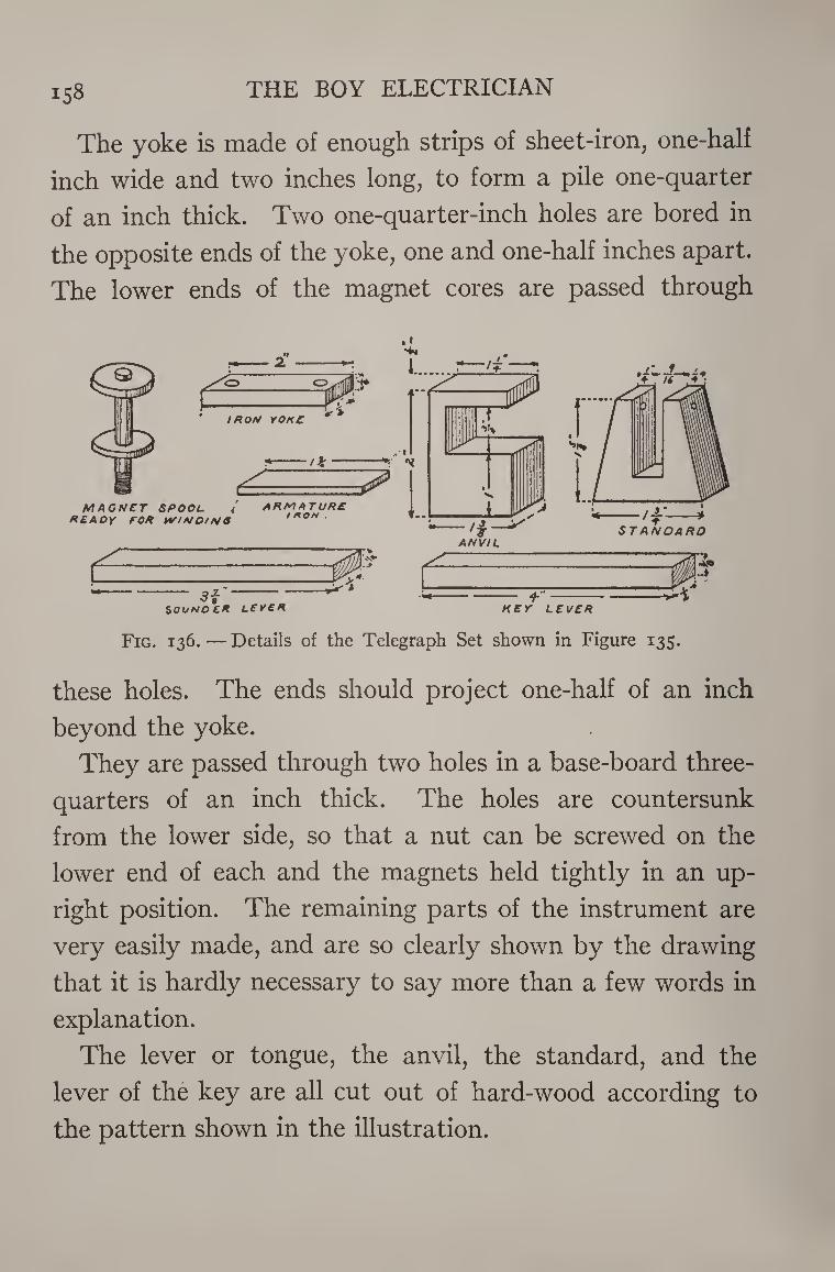
158 THE BOY ELECTRICIAN
The yoke is made of enough strips of sheet-iron, one-half
inch wide and two inches long, to form a pile one-quarter
of an inch thick. Two one-quarter-inch holes are bored in
the opposite ends of the yoke, one and one-half inches apart.
The lower ends of the magnet cores are passed through
. i
Fig. 136. — Details of the Telegraph Set shown in Figure 135.
these holes. The ends should project one-half of an inch
beyond the yoke.
They are passed through two holes in a base-board three-
quarters of an inch thick. The holes are countersunk
from the lower side, so that a nut can be screwed on the
lower end of each and the magnets held tightly in an up¬
right position. The remaining parts of the instrument are
very easily made, and are so clearly shown by the drawing
that it is hardly necessary to say more than a few words in
explanation.
The lever or tongue, the anvil, the standard, and the
lever of the key are all cut out of hard-wood according to
the pattern shown in the illustration.
ELECTRIC TELEGRAPHS 159
The armature is a piece of soft iron fastened to the lever
with a small brass screw.
Tacks are placed under the heads of the adjusting screws
on the sounder so that it will click more loudly.
The rubber band acts as a spring to counteract the weight
of the armature and lever and draw it up as soon as the
current is cut off. The movement of the lever should be
so adjusted that it is only sufficient to make an audible
click.
Use care to avoid friction between the lever and the
standard, so that the former will move with perfect free¬
dom.
All the screws used in the work should be round-headed
brass wood screws with the points filed flat. Bore a small
hole before screwing them into place so as to avoid splitting
the wood.
The construction of the key is even more simple than that
of the sounder. It should move up and down without any
side motion. \
The circuit-closer should be kept closed when the instru¬
ments are not in use, and when you are receiving a message.
As soon as you are through receiving and wish to transmit,
you should open your circuit-closer and your friend close
his.
The tension of the spring under the lever of the key must
be adjusted to suit the needs of each individual operator.
The diagram for connecting the instruments is self-ex¬
planatory. In cities or towns where a “ ground ” is avail-
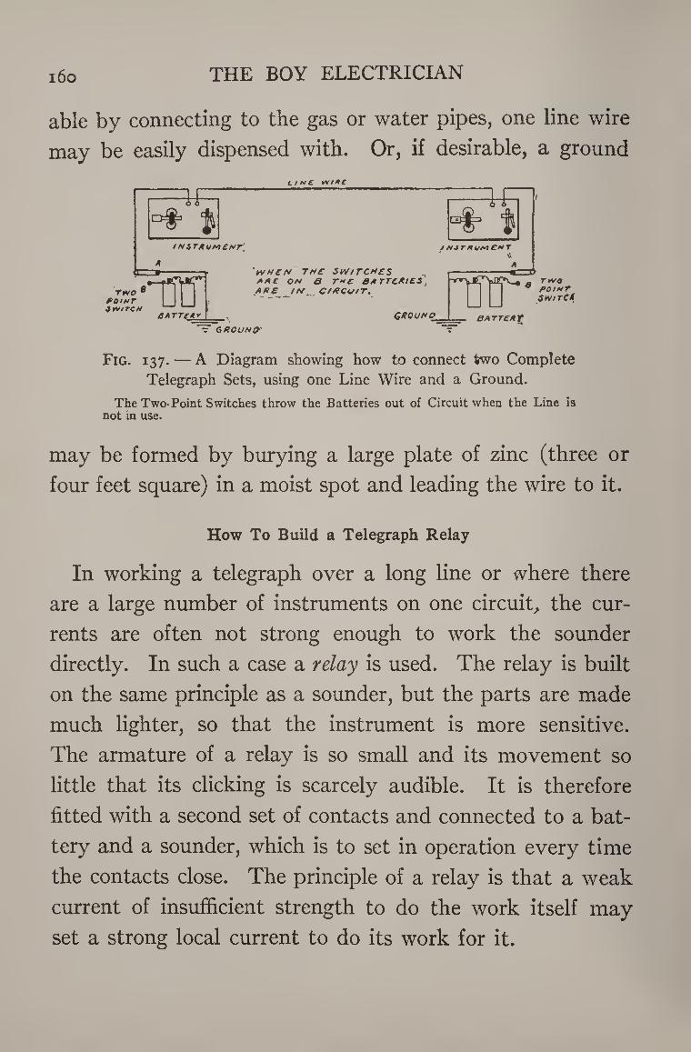
160 THE BOY ELECTRICIAN
able by connecting to the gas or water pipes, one line wire
may be easily dispensed with. Or, if desirable, a ground
Line *n*c
Fig. 137. — A Diagram showing how to connect two Complete Telegraph Sets, using one Line Wire and a Ground.
The Two-Point Switches throw the Batteries out of Circuit when the Line is not in use.
may be formed by burying a large plate of zinc (three or
four feet square) in a moist spot and leading the wire to it.
How To Build a Telegraph Relay
In working a telegraph over a long line or where there
are a large number of instruments on one circuit, the cur¬
rents are often not strong enough to work the sounder
directly. In such a case a relay is used. The relay is built
on the same principle as a sounder, but the parts are made
much lighter, so that the instrument is more sensitive.
The armature of a relay is so small and its movement so
little that its clicking is scarcely audible. It is therefore
fitted with a second set of contacts and connected to a bat¬
tery and a sounder, which is to set in operation every time
the contacts close. The principle of a relay is that a weak
current of insufficient strength to do the work itself may
set a strong local current to do its work for it.
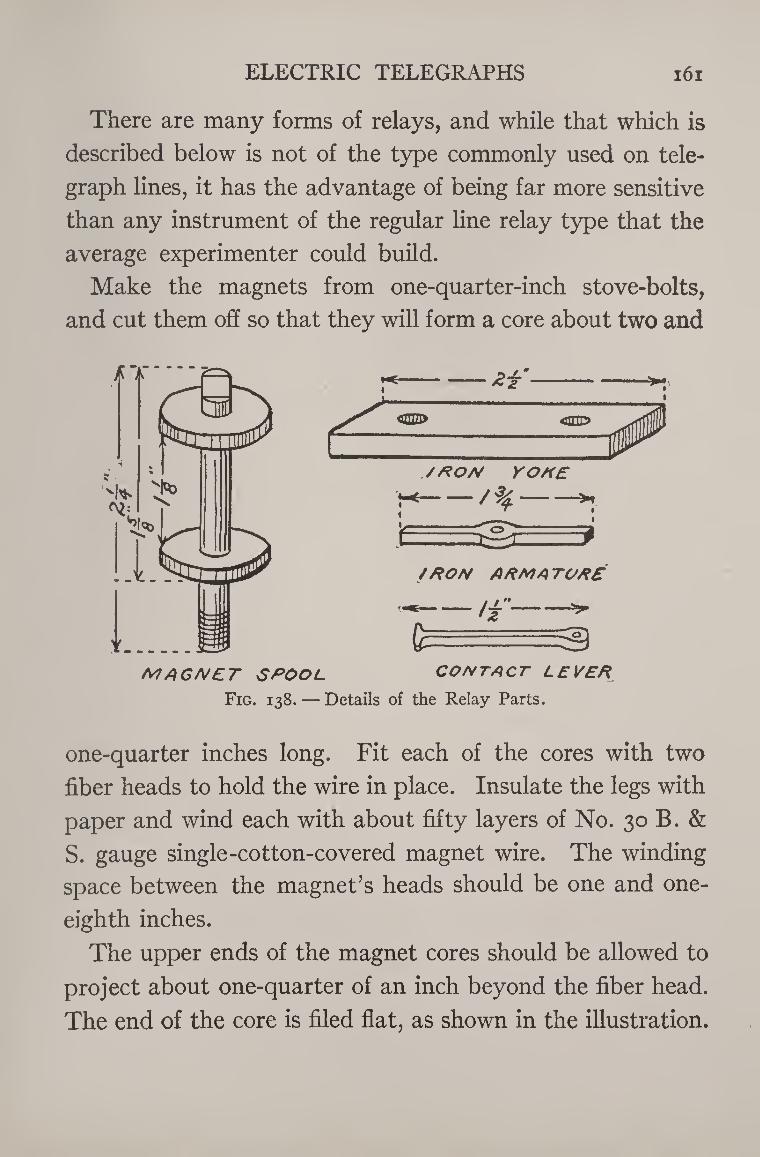
ELECTRIC TELEGRAPHS 161
There are many forms of relays, and while that which is
described below is not of the type commonly used on tele¬
graph lines, it has the advantage of being far more sensitive
than any instrument of the regular line relay type that the
average experimenter could build.
Make the magnets from one-quarter-inch stove-bolts,
and cut them off so that they will form a core about two and
MAGNET SPOOL CONTACT LEVER
Fig. 138. — Details of the Relay Parts.
one-quarter inches long. Fit each of the cores with two
fiber heads to hold the wire in place. Insulate the legs with
paper and wind each with about fifty layers of No. 30 B. &
S. gauge single-cotton-covered magnet wire. The winding
space between the magnet’s heads should be one and one-
eighth inches.
The upper ends of the magnet cores should be allowed to
project about one-quarter of an inch beyond the fiber head.
The end of the core is filed flat, as shown in the illustration.
162 THE BOY ELECTRICIAN
The magnets are mounted upon an iron yoke, three-
sixteenths of an inch thick. The holes in the yoke should
be spaced so that there is a distance of one and one-half
inches between the centers of the magnet cores.
The armature of the relay is mounted on a small steel
shaft with sharp points at each end. The exact shape of
the armature may be best understood from the illustrations.
The lower end of the shaft rests in a small cone-shaped
depression made by driving a center punch into the yoke
half-way between the two magnets.
The top bearing is a strip of brass projecting from a
wooden support. The end of the shaft rests in a depression
similar to that in the yoke.
The contact lever is made of brass and forced on the
shaft below the armature. It swings between a small brass
clip fastened to one side of the support and a little screw
held in a similar clip on the opposite side.
The contact clip is made of spring brass about No. 22
gauge in thickness. It may be adjusted by a screw passing
through the support.
The armature may be controlled in its movement so
that the latter will be very slight by adjusting the screws.
There should not be any friction in the bearings and the
armature should move with perfect freedom. The arma¬
ture should approach the ends of the magnet cores until a
space about the thickness of heavy paper separates them
and should not touch them.
The spring is made of fine brass wire. It is fastened to
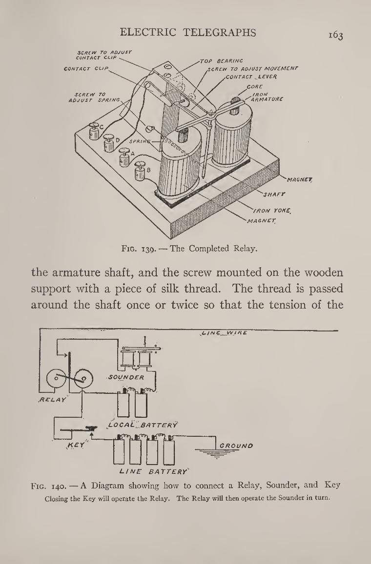
ELECTRIC TELEGRAPHS 163
SCREW TO ADJUST
CONTACT CUP
CONTACT CUP
SCREW TO ADJUST SPRING
TOP BEARING
,$CREW TO ADJUST MOVEMENT
.CONTACT .. LEVER
CORE
/ IRON ARMATURE
MAGNET
SHAFT
/HON YOK£t
MAGNET
Fig. 139. — The Completed Relay.
the armature shaft, and the screw mounted on the wooden
support with a piece of silk thread. The thread is passed
around the shaft once or twice so that the tension of the
Fig. 140. — A Diagram showing how to connect a Relay, Sounder, and Key
Closing the Key will operate the Relay. The Relay will then operate the Sounder in turn.
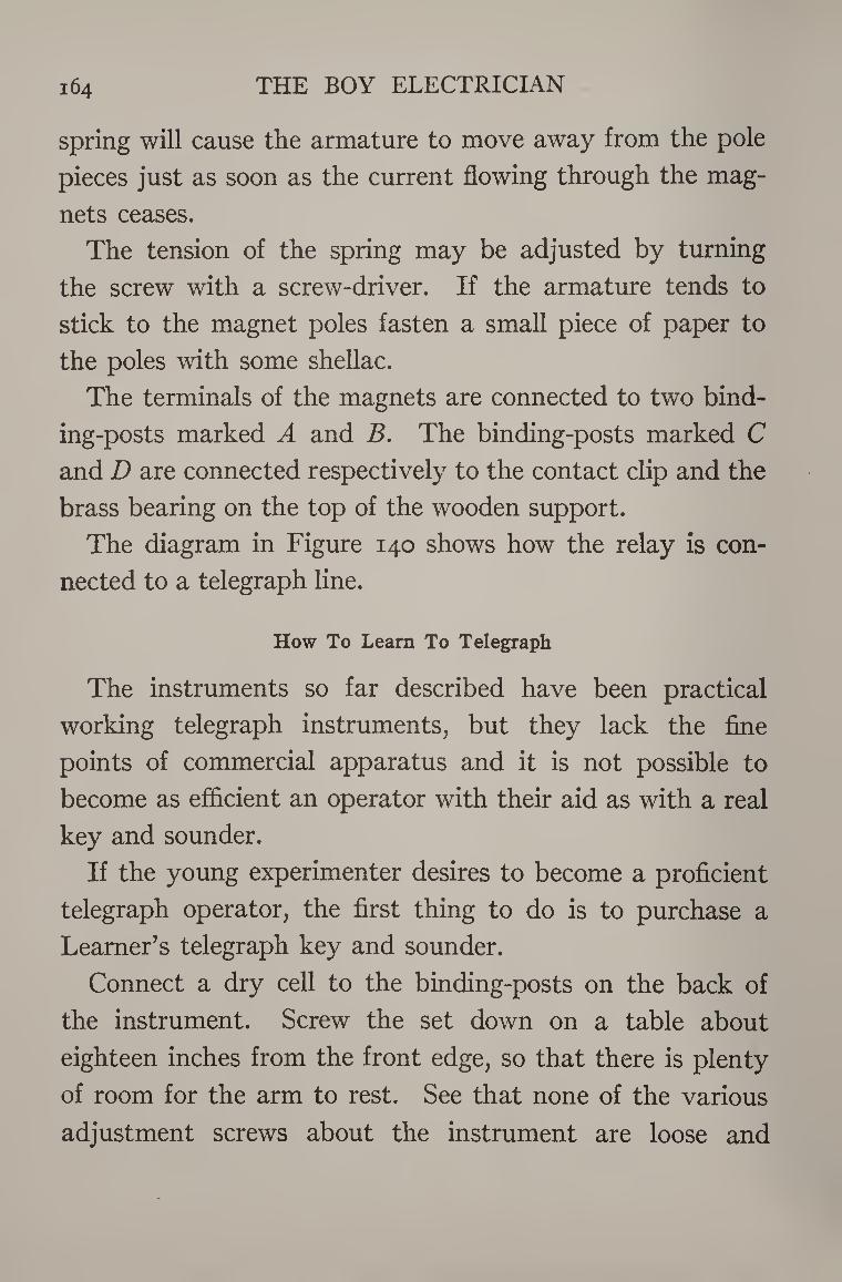
164 THE BOY ELECTRICIAN
spring will cause the armature to move away from the pole
pieces just as soon as the current flowing through the mag¬
nets ceases.
The tension of the spring may be adjusted by turning
the screw with a screw-driver. If the armature tends to
stick to the magnet poles fasten a small piece of paper to
the poles with some shellac.
The terminals of the magnets are connected to two bind¬
ing-posts marked A and B. The binding-posts marked C
and D are connected respectively to the contact clip and the
brass bearing on the top of the wooden support.
The diagram in Figure 140 shows how the relay is con¬
nected to a telegraph line.
How To Learn To Telegraph
The instruments so far described have been practical
working telegraph instruments, but they lack the fine
points of commercial apparatus and it is not possible to
become as efficient an operator with their aid as with a real
key and sounder.
If the young experimenter desires to become a proficient
telegraph operator, the first thing to do is to purchase a
Learner’s telegraph key and sounder.
Connect a dry cell to the binding-posts on the back of
the instrument. Screw the set down on a table about
eighteen inches from the front edge, so that there is plenty
of room for the arm to rest. See that none of the various
adjustment screws about the instrument are loose and
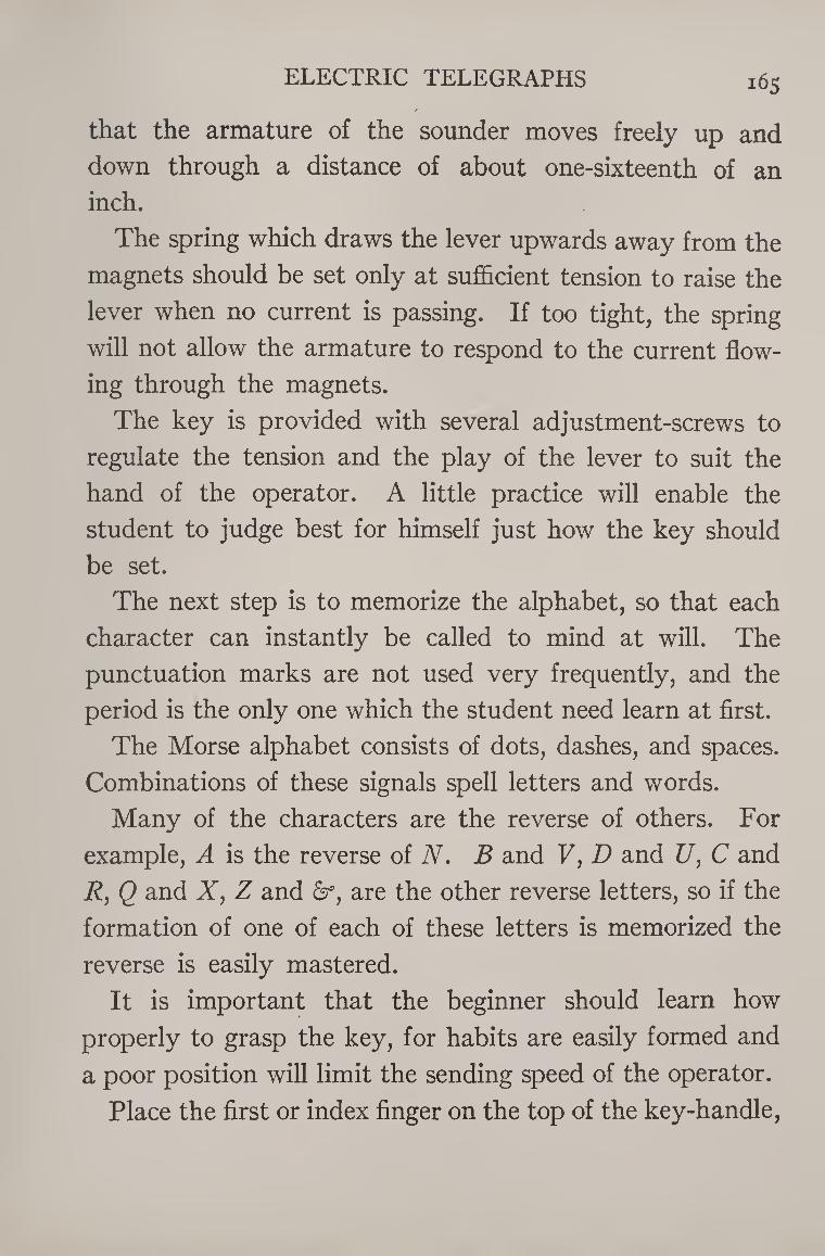
ELECTRIC TELEGRAPHS 165
that the armature of the sounder moves freely up and
down through a distance of about one-sixteenth of an
inch.
The spring which draws the lever upwards away from the
magnets should be set only at sufficient tension to raise the
lever when no current is passing. If too tight, the spring
will not allow the armature to respond to the current flow¬
ing through the magnets.
The key is provided with several adjustment-screws to
regulate the tension and the play of the lever to suit the
hand of the operator. A little practice will enable the
student to judge best for himself just how the key should
be set.
The next step is to memorize the alphabet, so that each
character can instantly be called to mind at will. The
punctuation marks are not used very frequently, and the
period is the only one which the student need learn at first.
The Morse alphabet consists of dots, dashes, and spaces.
Combinations of these signals spell letters and words.
Many of the characters are the reverse of others. For
example, A is the reverse of A. B and F, D and U, C and
R, Q and X, Z and &, are the other reverse letters, so if the
formation of one of each of these letters is memorized the
reverse is easily mastered.
It is important that the beginner should learn how
properly to grasp the key, for habits are easily formed and
a poor position will limit the sending speed of the operator.
Place the first or index finger on the top of the key-handle,
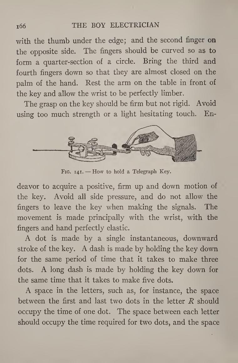
i66 THE BOY ELECTRICIAN
with the thumb under the edge; and the second finger on
the opposite side. The fingers should be curved so as to
form a quarter-section of a circle. Bring the third and
fourth fingers down so that they are almost closed on the
palm of the hand. Rest the arm on the table in front of
the key and allow the wrist to be perfectly limber.
The grasp on the key should be firm but not rigid. Avoid
using too much strength or a light hesitating touch. En¬
deavor to acquire a positive, firm up and down motion of
the key. Avoid all side pressure, and do not allow the
fingers to leave the key when making the signals. The
movement is made principally with the wrist, with the
fingers and hand perfectly elastic.
A dot is made by a single instantaneous, downward
stroke of the key. A dash is made by holding the key down
for the same period of time that it takes to make three
dots. A long dash is made by holding the key down for
the same time that it takes to make five dots.
A space in the letters, such as, for instance, the space
between the first and last two dots in the letter R should
occupy the time of one dot. The space between each letter
should occupy the time required for two dots, and the space
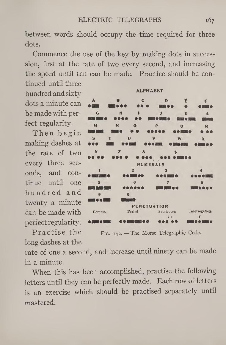
ELECTRIC TELEGRAPHS 167
between words should occupy the time required for three
dots.
Commence the use of the key by making dots in succes¬
sion, first at the rate of two every second, and increasing
the speed until ten can be made. Practice should be con¬
tinued until three
hundred and sixty
dots a minute can
be made with per¬
fect regularity.
Then begin
making dashes at
the rate of two
every three sec¬
onds, and con¬
tinue until one
hundred and
twenty a minute
can be made with
perfect regularity.
Practise the
long dashes at the
rate of one a second, and increase until ninety can be made
in a minute.
When this has been accomplished, practise the following
letters until they can be perfectly made. Each row of letters
is an exercise which should be practised separately until
mastered.
ALPHABET
A B C D E F •m • • • • 9M9
G H 1 J K L m • ••• • • H9D19 flHHI
M N 0 P Q R 1 1 HSH# • • ••••• 99H9 • ••
S • ••
U • •I
V
• ••I w X
Y Z & $ • • •• ••• • • ••• ••• tB NUMERALS
1 2 3 ■ • 99RHM 999IH9
5 6 7
4 9999H
8 ■I9999
9 ■ 991
Comma
PUNCTUATION Period Semicolon
• •I 1*0 999 ••
Interrogatioi
7
Fig. 142. — The Morse Telegraphic Code.
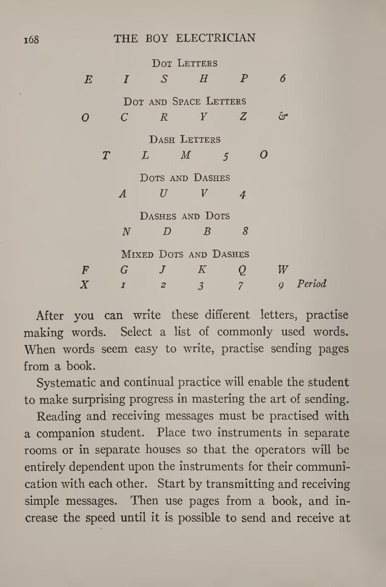
i68 THE BOY ELECTRICIAN
Dot Letters
E I S H P 6
Dot and Space Letters
O C R Y Z &
Dash Letters
T L M 5 O
Dots and Dashes
A U V 4
Dashes and Dots
N D B 8
Mixed Dots and Dashes
F G J K Q W X i 2 3 7 Q Period
After you can write these different letters, practise
making words. Select a list of commonly used words.
When words seem easy to write, practise sending pages
from a book.
Systematic and continual practice will enable the student
to make surprising progress in mastering the art of sending.
Reading and receiving messages must be practised with
a companion student. Place two instruments in separate
rooms or in separate houses so that the operators will be
entirely dependent upon the instruments for their communi¬
cation with each other. Start by transmitting and receiving
simple messages. Then use pages from a book, and in¬
crease the speed until it is possible to send and receive at
ELECTRIC TELEGRAPHS 169
least 15 words a minute without watching the sounder but
merely depending upon the clicks to determine the duration
of the dots and dashes.
Figure 140 shows how to arrange a regular telegraph line
for two stations. Gravity batteries should be used for
regular telegraph work. It is necessary that the key should
be kept closed by having its circuit-closer shut when mes¬
sages are not being sent. If one of the keys is left open the
circuit is broken, and it is not possible for a person at the
other end of the line to send a message.
Every telegraph office has a name or call usually consist¬
ing of two letters; thus for New York the call might be
N. Y. and for Chicago, C. H.
If New York should desire to call Chicago, he would
repeat the call letters, C H., until answered. Chicago
would answer by sending I, several times and signing,
C H. When so answered, New York would proceed with
the message.
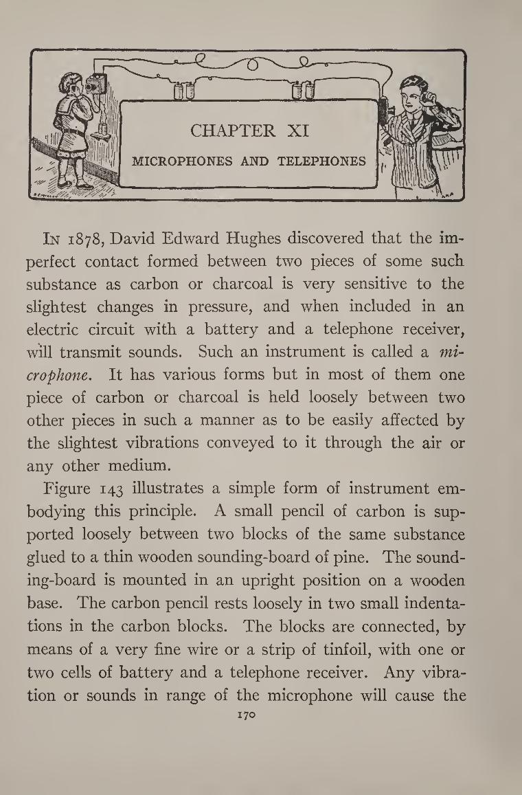
In 1878, David Edward Hughes discovered that the im¬
perfect contact formed between two pieces of some such
substance as carbon or charcoal is very sensitive to the
slightest changes in pressure, and when included in an
electric circuit with a battery and a telephone receiver,
will transmit sounds. Such an instrument is called a mi¬
crophone. It has various forms but in most of them one
piece of carbon or charcoal is held loosely between two
other pieces in such a manner as to be easily affected by
the slightest vibrations conveyed to it through the air or
any other medium.
Figure 143 illustrates a simple form of instrument em¬
bodying this principle. A small pencil of carbon is sup¬
ported loosely between two blocks of the same substance
glued to a thin wooden sounding-board of pine. The sound¬
ing-board is mounted in an upright position on a wooden
base. The carbon pencil rests loosely in two small indenta¬
tions in the carbon blocks. The blocks are connected, by
means of a very fine wire or a strip of tinfoil, with one or
two cells of battery and a telephone receiver. Any vibra¬
tion or sounds in range of the microphone will cause the 170
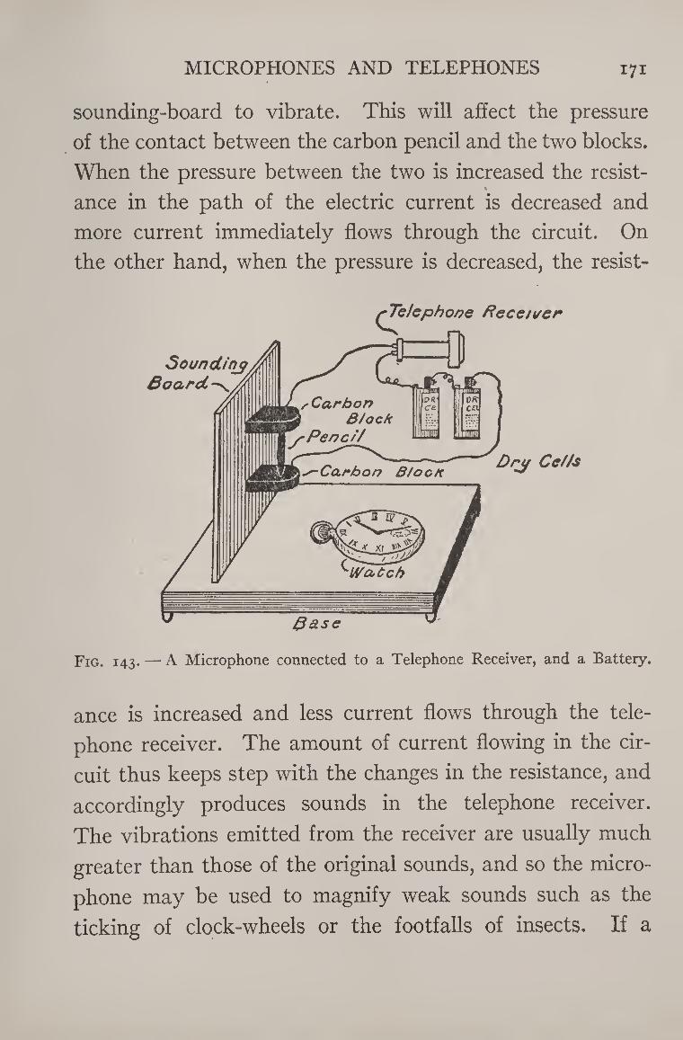
MICROPHONES AND TELEPHONES 171
sounding-board to vibrate. This will affect the pressure
of the contact between the carbon pencil and the two blocks.
When the pressure between the two is increased the resist-
ance in the path of the electric current is decreased and
more current immediately flows through the circuit. On
the other hand, when the pressure is decreased, the resist-
Fig. 143. — A Microphone connected to a Telephone Receiver, and a Battery.
ance is increased and less current flows through the tele¬
phone receiver. The amount of current flowing in the cir¬
cuit thus keeps step with the changes in the resistance, and
accordingly produces sounds in the telephone receiver.
The vibrations emitted from the receiver are usually much
greater than those of the original sounds, and so the micro¬
phone may be used to magnify weak sounds such as the
ticking of clock-wheels or the footfalls of insects. If a
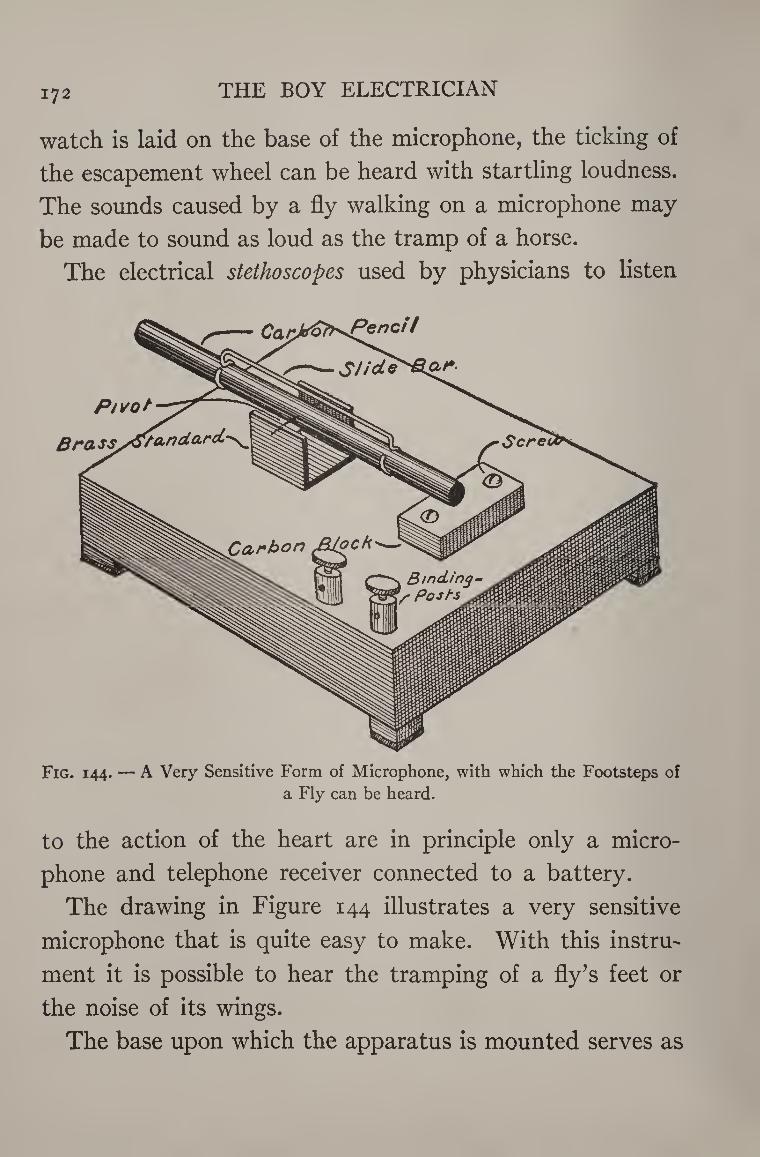
172 THE BOY ELECTRICIAN
watch is laid on the base of the microphone, the ticking of
the escapement wheel can be heard with startling loudness.
The sounds caused by a fly walking on a microphone may
be made to sound as loud as the tramp of a horse.
The electrical stethoscopes used by physicians to listen
Fig. 144. — A Very Sensitive Form of Microphone, with which the Footsteps of a Fly can be heard.
to the action of the heart are in principle only a micro¬
phone and telephone receiver connected to a battery.
The drawing in Figure 144 illustrates a very sensitive
microphone that is quite easy to make. With this instru¬
ment it is possible to hear the tramping of a fly’s feet or
the noise of its wings.
The base upon which the apparatus is mounted serves as
MICROPHONES AND TELEPHONES i73
the sounding-board and is made in the form of a hollow
wooden box. It can be made from an ordinary cigar-box
by removing the paper and taking the box apart. The
piece forming the top of the box must be planed down until
it is only three thirty-seconds of an inch thick. The box
should measure about five inches square and three-quarters
of an inch thick when finished. Do not use any nails or
small brads whatsoever in its construction, but fasten it
together with glue. If you use any nails you will decrease
the sensitiveness of the instrument quite appreciably.
The bottom of the box should be left open. The result
is a sounding-board of the same principles as that of the
banjo head. Small feet, one-quarter of an inch square, are
glued to the four under corners so as to raise the bottom
clear of the table, or whatever the microphone may be
placed upon. The bottom of each one of the small feet is
cushioned with a layer of felt so that no jars will be trans¬
mitted to the instrument by any object upon which it is
resting.
The carbon pencil used on this type of instrument is
pivoted in the center and rests at one end upon a carbon
block.
The carbon block is made about one inch long, one-
quarter of an inch thick, and one-half of an inch wide. A
small hole is drilled near each end to receive a screw which
fastens the block to the sounding-board. A fine wire is
led from one of these screws to a binding-post mounted at
the side of the box. Another wire leads from a second
174 THE BOY ELECTRICIAN
binding-post to a standard which is also fastened to the
sounding-board with a small screw.
The standard is made from a sheet of thin brass and is
bent into the shape shown in the illustration.
The pencil is a piece of one-quarter-inch carbon rod,
two and three-quarter inches long. A small hole is drilled
one and five-eighths of an inch from one end with a sewing-
needle, and a piece of fine brass wire, pointed at both ends,
pushed in. The wire should be a tight fit in the hole. It
should be about one-half of an inch long, and may bejnade
from an ordinary pin.
The slide-bar is used to regulate the pressure of "the
pencil upon the carbon block and is simply a piece of soft
copper wire about one-eighth of an inch in diameter. It is
bent into the shape shown in the illustration so that it
will slide over the carbon pencil. The sides of the standard
should press just tightly enough against the ends of the
pivot which passes through the carbon pencil to hold it in
position without slipping, and at the same time allow it to
swing freely up and down.
The two binding-posts should be connected in series with
two dry cells and a pair of good telephone receivers. Place
the receivers against the ears. Move the slide-bar gently
back and forth until the voice of any one talking in another
part of the room can be heard distinctly in the telephone
receivers. In order to hear faint whispers, move the slide-
bar away from the carbon block.
In order to hear a fly walk it is necessary to have the
MICROPHONES AND TELEPHONES 175
carbons very dry and clean. The instrument must be very
carefully adjusted. Cover the microphone with a large
glass globe and place a fly inside of the globe. Whenever
the fly walks on any part of the microphone you will be
able to hear each footstep in the telephone receivers. When
he flies about inside of the globe, his wings will cause a
loud roaring and buzzing noise to be heard in the receivers.
Telephones
Not many years ago, when the telephone made its first
appearance, it was the wonder of the times just as wireless
telegraphy is to-day. Starting as an exceedingly simple
and inexpensive apparatus, it has gradually developed
into a wonderful and complex system, so that at the pres¬
ent time, instead of experiencing difficulty in telephoning
over distances of fifty or one hundred miles, as at first, it
is possible to carry on a conversation over a line two thou¬
sand nples long as easily as it is face to face.
Like the telegraph, the principle of the telephone is that
of a current of electricity flowing over a line wire into a
pair of electro-magnets, but with many important differ¬
ences.
When compared with telegraph apparatus, the telephone
is found to be exceedingly sensitive. A telegraph relay
requires perhaps about one-hundredth, of an ampere to
work it properly. A telegraph sounder will require about
one-tenth of an ampere, but a telephone receiver will
render speech audible with less than a millionth of an
176 THE BOY ELECTRICIAN
ampere, and therefore may almost be said to be a hundred
thousand times more sensitive than a sounder.
Another difference between the telephone and the tele¬
graph lies in the fact that the currents flowing over a
telegraph line do not usually vary at a rate greater than
twenty or thirty times a second, whereas telephone cur¬
rents change their intensity hundreds of times a second.
The telephone is an instrument for the transmission of
speech to a distance by means of electricity, wherein the
speaker talks to an elastic plate of thin sheet-iron which
vibrates and sends out a pulsating current of electricity.
The transmission of the vibrations depends upon well-
known principles of electricity, and does not consist of the
actual transmission of sounds, but of electrical impulses
which keep perfect accord or step with the sound waves
produced by the voice in the transmitter. These electrical
currents pass through a pair of small electro-magnets acting
upon a plate or diaphragm, which in turn agitates the air
in a manner similar to the original voice speaking into the
transmitter and thus emits sounds.
That part of the apparatus which takes up the sounds
and changes them into electric currents composes the
transmitter. When words are spoken into the mouthpiece
they strike a diaphragm, on the back of which is fastened
a small cup-shaped piece of carbon. A second cup is
mounted in a rigid position directly back of the first. The
space between them is filled with small polished granules
of carbon. When these granules are in a perfectly loose
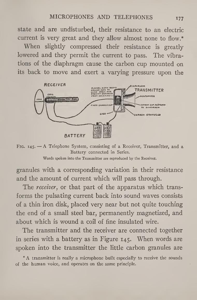
MICROPHONES AND TELEPHONES 177
state and are undisturbed, their resistance to an electric
current is very great and they allow almost none to flow.*
When slightly compressed their resistance is greatly
lowered and they permit the current to pass. The vibra¬
tions of the diaphragm cause the carbon cup mounted on
its back to move and exert a varying pressure upon the
Fig. 145. — A Telephone System, consisting of a Receiver, Transmitter, and a Battery connected in Series.
Words spoken into the Transmitter are reproduced by the Receiver.
granules with a corresponding variation in their resistance
and the amount of current which will pass through.
The receiver, or that part of the apparatus which trans¬
forms the pulsating current back into sound waves consists
of a thin iron disk, placed very near but not quite touching
the end of a small steel bar, permanently magnetized, and
about which is wound a coil of fine insulated wire.
The transmitter and the receiver are connected together
in series with a battery as in Figure 145. When words are
spoken into the transmitter the little carbon granules are
* A transmitter is really a microphone built especially to receive the sounds
of the human voice, and operates on the same principle.
i78 THE BOY ELECTRICIAN
immediately thrown into motion, and being alternately
compressed and released cause corresponding changes in
the current flowing through the receiver from the battery.
The magnetism of the receiver changes with each change
in the electric current, and thus by alternately attracting
and repelling the diaphragm causes it to vibrate and emit
sounds. Such is the principle of the telephone. The tele¬
phones in actual service to-day are complicated with bells,
magnetos, induction coils, condensers, relays, and various
other apparatus, which fact renders them more efficient.
The bells and magnetos are for the purpose of calling
the central operator or the person at the other end of the
line and drawing attention to the fact that some one wishes
to get into communication with him. The older styles of
telephones used what is known as a polarized bell and a
hand magneto for this purpose. A polarized bell is a very
sensitive piece of apparatus which will operate with very
little current. A magneto is a small hand dynamo which
when turned with a crank will generate a current causing
the bell at the other end of the line to ring. When the
telephone receiver is raised off its hook in order to place it
to the ear the bell and magneto are automatically dis¬
connected from the line and the receiver and the trans¬
mitter are connected in their place. The current necessary
to supply the telephone and receiver is supplied by two or
three dry cells placed inside of each telephone.
The latest types of instruments employ what is known as
the central energy system, wherein the current is supplied
MICROPHONES AND TELEPHONES 179
by a large storage battery located at the central office and
serving as a current supply to all the telephones connected
to that system.
It would be impossible to enter into the history of the
telephone far enough to explain the details of some of the
various systems in every-day use in such a book as this
because of the immense amount of material it would be
necessary to present. Such a work would occupy a volume
of its own. Additional information may be readily found
in any reference library. However, the “ boy electrician ”
who wishes to make a telephone for communicating be¬
tween the house and barn, or with his chum down the
street, will find the necessary information in the following
pages. If this work is carried out carefully and a home¬
made telephone system built and installed it will not only
prove a very interesting undertaking but will also serve to
dispel all mystery which may surround this device in the
mind of the young experimenter.
✓
How to Build a Telephone
Telephone receivers are useful for many purposes in
electrical work other than to receive speech. They are
used in connection with wireless instruments, in place of
a galvanometer in measuring electrical circuits, and for
testing in various ways.
Telephone receivers are of two types. One of them is
long and cumbersome, and is very similar to the original
Bell telephone receiver. The other is small and flat, and
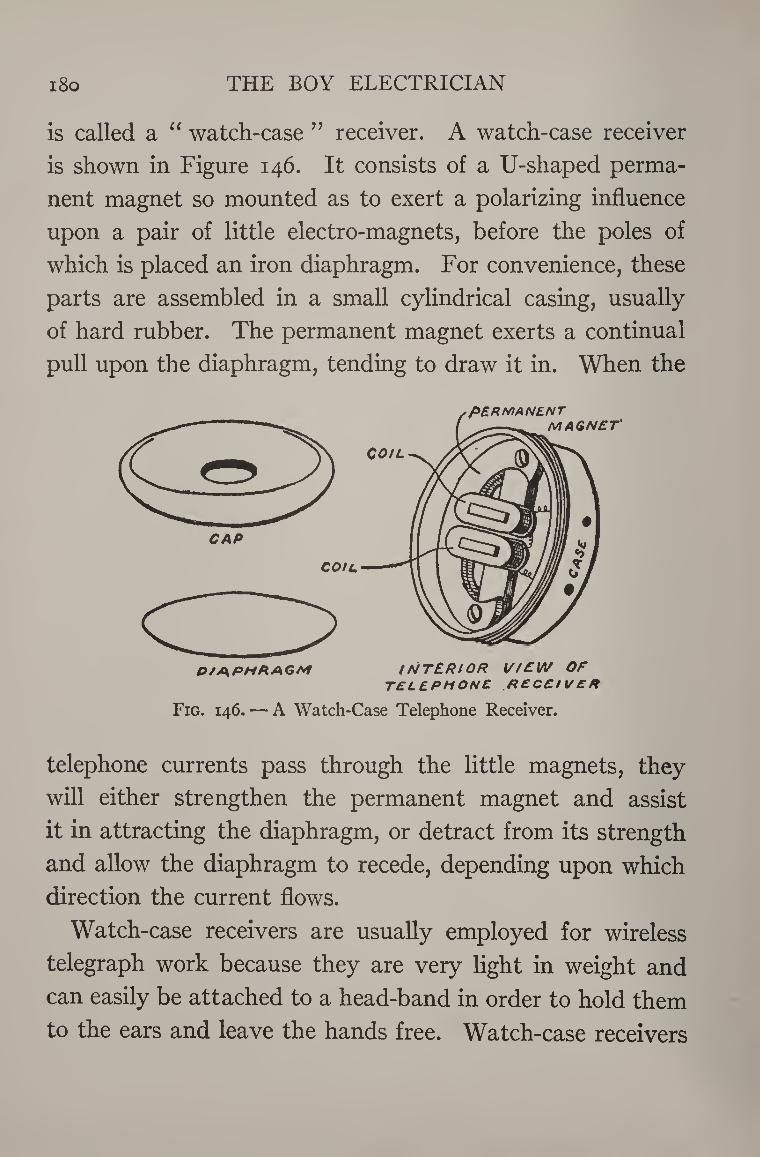
i8o THE BOY ELECTRICIAN
is called a “ watch-case ” receiver. A watch-case receiver
is shown in Figure 146. It consists of a U-shaped perma¬
nent magnet so mounted as to exert a polarizing influence
upon a pair of little electro-magnets, before the poles of
which is placed an iron diaphragm. For convenience, these
parts are assembled in a small cylindrical casing, usually
of hard rubber. The permanent magnet exerts a continual
pull upon the diaphragm, tending to draw it in. When the
CAP
COIL
D/A.PMAAGM INTERIOR VIEW OF TELEPHONE RECEIV ER
Fig. 146. — A Watch-Case Telephone Receiver.
telephone currents pass through the little magnets, they
will either strengthen the permanent magnet and assist
it in attracting the diaphragm, or detract from its strength
and allow the diaphragm to recede, depending upon which
direction the current flows.
Watch-case receivers are usually employed for wireless
telegraph work because they are very light in weight and
can easily be attached to a head-band in order to hold them
to the ears and leave the hands free. Watch-case receivers
MICROPHONES AND TELEPHONES 181
can be purchased for forty-five to seventy-five cents at
almost any electrical supply house. They are very useful
to the amateur experimenter in many ways.
A telephone receiver capable of giving fair results on a
short telephone line can be very easily made, but of course
will not prove as efficient as one which is purchased ready¬
made from a reliable electrical manufacturer.
The first practical telephone receiver was invented by
Alexander Graham Bell and was made somewhat along the
same lines as that shown in Figure 147.
Such a receiver may be made from a piece of curtain-
pole, three and three-quarter inches long and about one
and one-eighth inches in diameter. A hole, three-eighths
of an inch in diameter, is bored along the axis throughout
its entire length, to receive the permanent magnet.
The shell of the receiver is a cup-shaped piece of hard
wood, two and one-half inches in diameter and one inch
deep. It will have to be turned on a lathe. Its exact shape
and dimensions are best understood from the dimensions
shown in the cross section in Figure 147. The shell is firmly
attached to one end of the piece of curtain-pole by gluing.
The permanent magnet is a piece of hard steel, three-
eighths of an inch in diameter and four and five-eighths of
an inch in length. The steel will have to be tempered or
hardened before it will make a suitable magnet, and the
best way to accomplish this is to have a blacksmith do it
for you by heating the rod and then plunging it into water
when just at the right temperature.
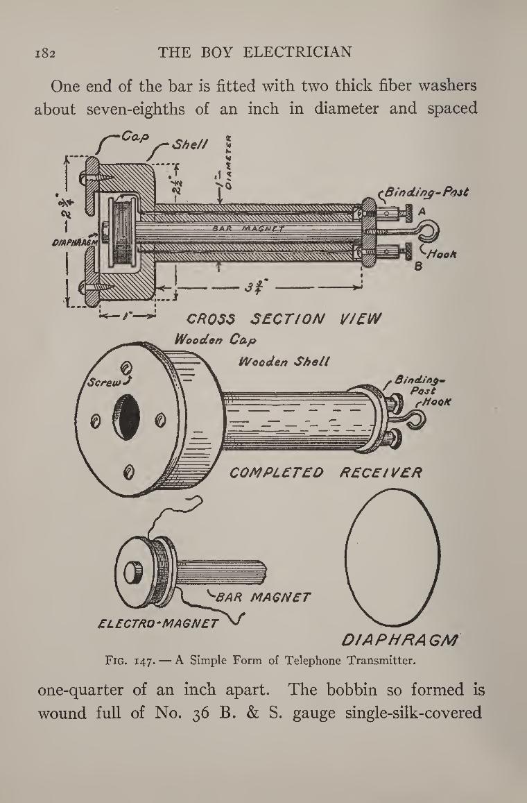
i82 THE BOY ELECTRICIAN
One end of the bar is fitted with two thick fiber washers
about seven-eighths of an inch in diameter and spaced
Coup
r She// X W K *4
CROSS SECTION VIEW
DIAPHRAGM Fig. 147. — A Simple Form of Telephone Transmitter.
one-quarter of an inch apart. The bobbin so formed is
wound full of No. 36 B. & S. gauge single-silk-covered
MICROPHONES AND TELEPHONES 183
magnet wire. The ends of the wire are passed through two
small holes in the fiber washers and then connected to a
pair of heavier wires. The wires are run through two holes
in the curtain-pole, passing lengthwise from end to end,
parallel to the hole bored to receive the bar magnet.
This bar magnet is then pushed through the hole until
the end of the rod on which the spool is fixed is just below
the level of the edges of the shell.
The two wires are connected to binding-posts, A and B,
mounted on the end of the receiver. A hook is also pro¬
vided so that the receiver may be hung up.
The diaphragm is a circular piece of thin sheet-iron, two
and one-half inches in diameter. It is placed over the
shell, and the bar magnet adjusted until the end almost
touches the diaphragm. The magnet should fit into the
hole very tightly, so that it will have to be driven in order
to be moved back and forth.
The diaphragm is held in place by a hard-wood cap, two
and three-quarter inches in diameter and having a hole
three-quarters of an inch in diameter in the center. The
cap is held to the shell by means of four small brass screws.
The receiver is now completed and should give a loud
click each time that a battery is connected or disconnected
from the two posts, A and B.
The original Bell telephone apparatus was made up
simply of two receivers without any battery or transmitter.
In such a case the current is generated by “ induction.’7
The receiver is used to speak through as well as to hear
THE BOY ELECTRICIAN 184
through. This method of telephoning is unsatisfactory
over any appreciable distances. The time utilized in making
a transmitter will be well spent.
A simple form of transmitter is shown in Figure 148.
The wooden back, B, is three and one-half inches square
and three-quarters of an inch thick. The front face of the
block is hollowed out in the center as shown in the cross-
section view.
The face-plate, A, is two and one-half inches square and
one-half an inch thick. A hole, seven-eighths of an inch
in diameter, is bored through the center. One side is then
hollowed out to a diameter of one and three-quarter inches,
so as to give space for the diaphragm to vibrate as shown
in the cross-sectional drawing.
The carbon buttons are one inch in diameter and three-
sixteenths of an inch thick. A small hole is bored in the
center of each to receive a brass machine screw. The
hole is countersunk, so as to bring the head of the screw
down as close to the surface of the carbon as is possible.
Then, using a sharp knife or a three-cornered file, score
the surface of the carbon until it is covered with criss-cross
lines.
The diaphragm is a piece of thin sheet-iron cut in the
form of a circle two and one-half inches in diameter. A
small hole is bored through the center of this. One of the
carbon buttons is fastened to the center of the diaphragm
with a small screw and a nut.
Cut out a strip of flannel or thin felt, nine-sixteenths of
MICROPHONES AND TELEPHONES 185
an inch wide and three and one-half inches long. Around
the edge of the carbon button mounted on the diaphragm,
bind this strip with silk thread in such a manner that the
strip forms a cylinder closed at one end with the button.
Fill the cylinder with polished carbon telephone trans¬
mitter granules to a depth of about one-eighth of an inch.
These granules will have to be purchased from an electrical
supply house. They are finely polished small carbon balls,
much like birdshot in appearance.
Slip a long machine-screw through the hole in the second
carbon button and clamp it in place with a nut. Then place
the carbon button in the cylinder so that it closes up the
end. The space between the two buttons should be about
three-sixteenths of an inch. Bind the flannel or felt around
the button with a piece of silk thread so that it cannot
slip out of place. The arrangement of the parts should now
be the same as that shown by the cross-sectional drawing
in the upper right-hand corner of Figure 148.
The complete transmitter is assembled as shown in the
lower part of Figure 148.
A small tin funnel is fitted into the hole in the face¬
plate, A, to act as a mouthpiece. A screw passes through the back, B, and connects to the
diaphragm. The screw is marked “ E ” in the illustration.
A binding-post is threaded on the screw so that a wire may
be easily connected. The screw passing through the back
carbon button also passes through a hole in the wooden
back, and is clamped firmly in position with a brass nut
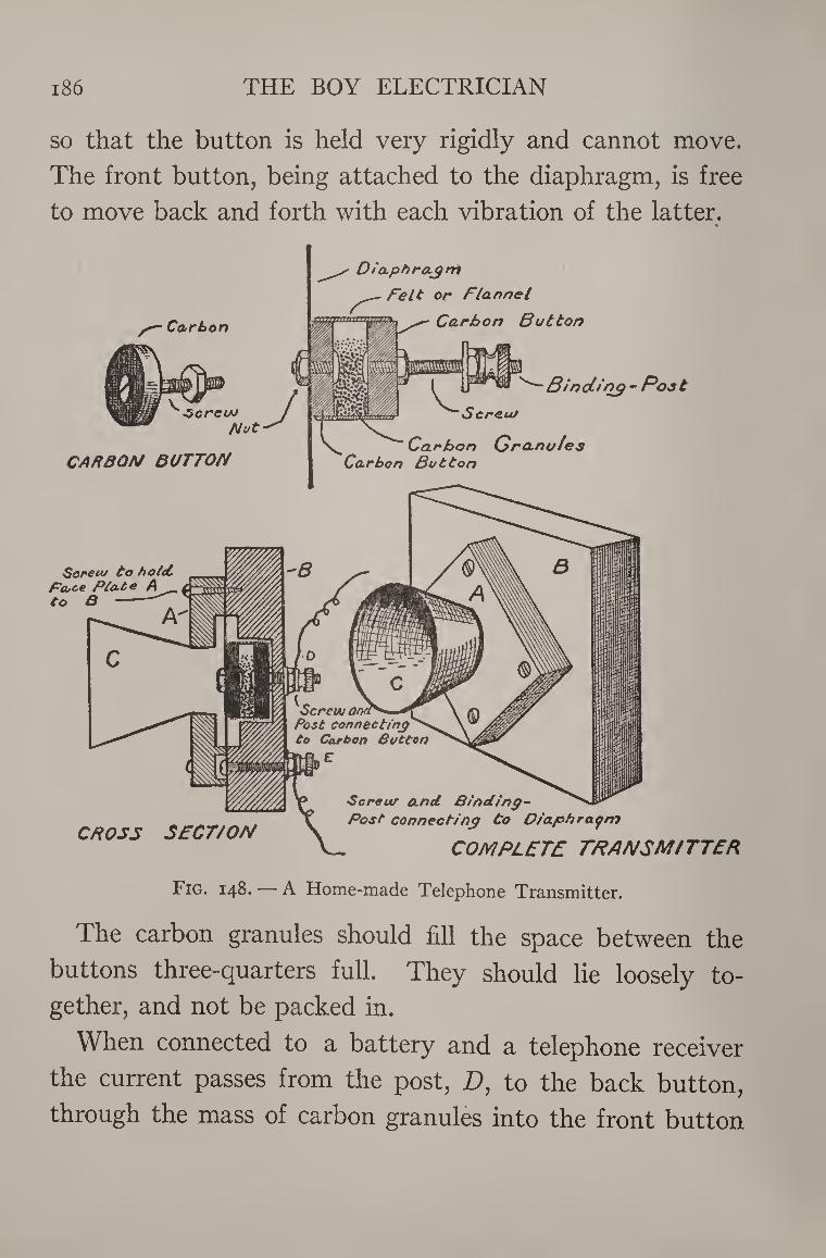
i86 THE BOY ELECTRICIAN
so that the button is held very rigidly and cannot move.
The front button, being attached to the diaphragm, is free
to move back and forth with each vibration of the latter.
Carbon
Dia.phro.jni
Felt or Flannel
Carbon Button
herein Nut
CARBON BUTTON
• Binding - Poo t Screw
Carbon Gra.no/es Carbon Button
Soretu to hotel Face Plato A to 8
A
Screw a, Post connecting to Carton Button
€
Screw and Binding-
_ _ . v Post connecting to D/aphraom CROSS SECT/ON \ *
COMPLETE TRANSMITTER
Fig. 148. — A Home-made Telephone Transmitter.
The carbon granules should fill the space between the
buttons three-quarters full. They should lie loosely to¬
gether, and not be packed in.
When connected to a battery and a telephone receiver
the current passes from the post, D, to the back button,
through the mass of carbon granules into the front button
MICROPHONES AND TELEPHONES 187
and out at the post, E. When the voice is directed into the
mouthpiece, the sound waves strike the diaphragm and
cause it to vibrate. The front button attached to it then
also vibrates and constantly changes the pressure on the
carbon granules. Each change in pressure is accompanied
by an immediate change in resistance and consequently
the amount of current flowing.
Figure 149 shows a complete telephone ready for mount¬
ing on the wall. It consists of a receiver, telephone trans¬
mitter, bell, hook, and push-button. The bell is mounted
on a flat base-board. The transmitter is similar to that just
described, but is built into the front of a box-like cabinet.
The box is fitted with a push-button at the lower right-
hand corner. A simple method of making a suitable push¬
button is shown in the upper left-hand part of the illustra¬
tion. It consists of two small brass strips arranged so that
pushing a small wooden plug projecting through the side
of the cabinet will bring the two strips together and make
an electrical connection.
The “ hook ” consists of a strip of brass, pivoted at one
end with a round-headed brass wood screw and provided
with a small spring, so that when the receiver is taken off
of the hook it will fly up and make contact with a screw,
marked C in the illustration. When the receiver is on the
hook, its weight will draw the latter down against the
screw, D. The hook is mounted on the base-board of the
telephone, and projects through a slot cut in the side of
the cabinet.
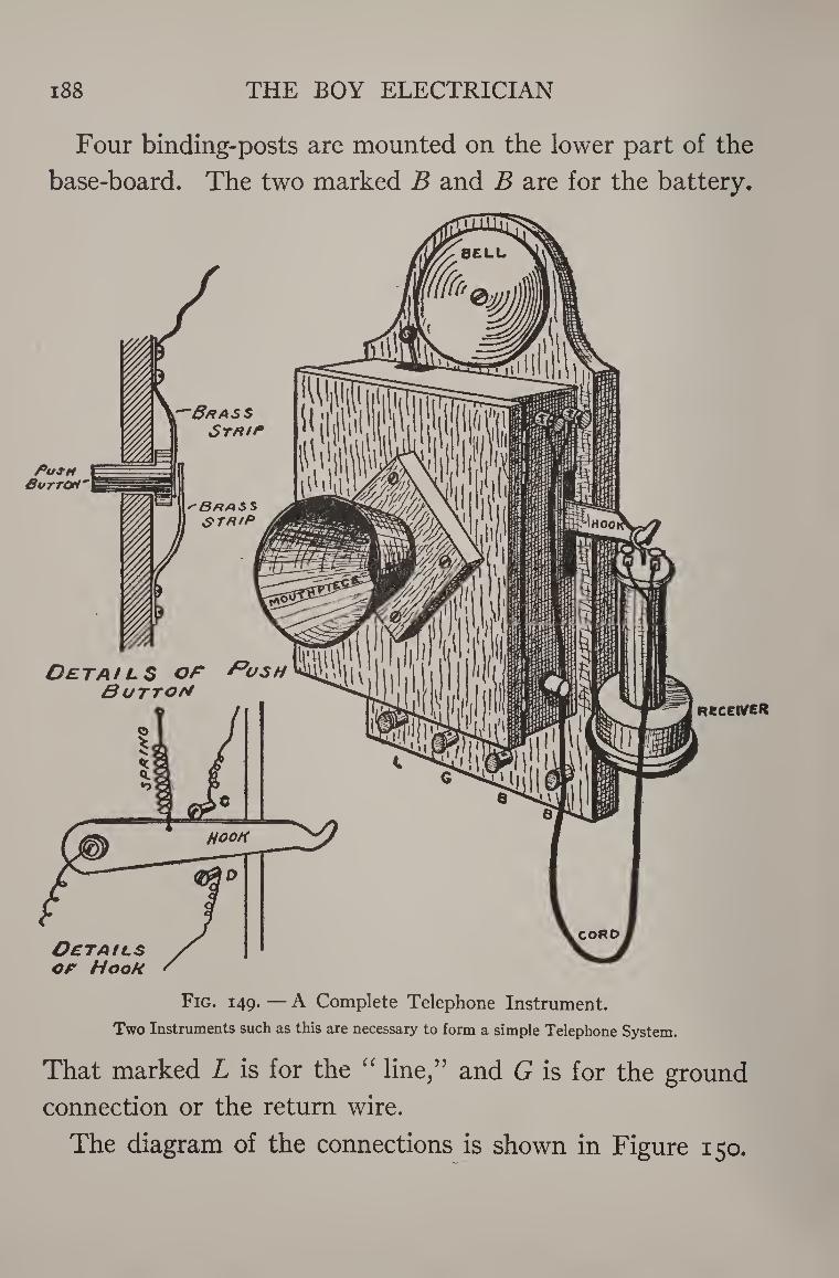
188 THE BOY ELECTRICIAN
Four binding-posts are mounted on the lower part of the
base-board. The two marked B and B are for the battery.
PufM GuttOH'
'-&/9ASS
B HASS STA/P
Deta/l$ or Push Button
OCTAtLS or Hook
Receive*
Fig. 149. — A Complete Telephone Instrument.
Two Instruments such as this are necessary to form a simple Telephone System.
That marked L is for the “ line,” and G is for the ground
connection or the return wire.
The diagram of the connections is shown in Figure 150.
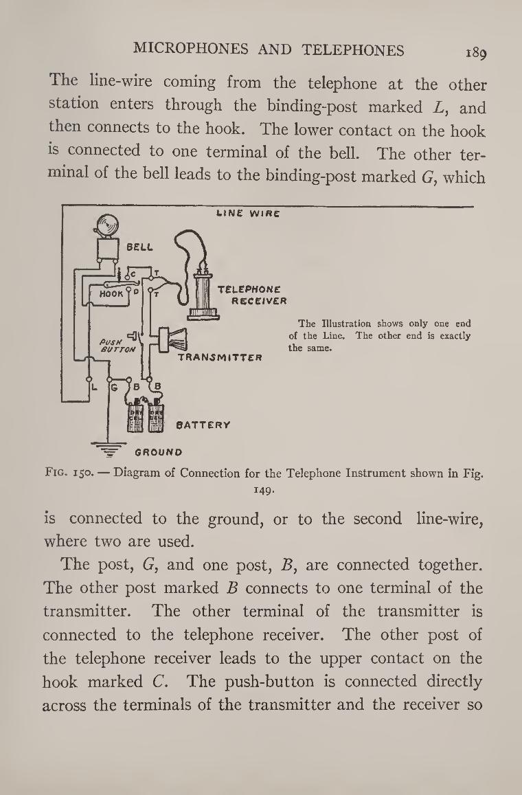
MICROPHONES AND TELEPHONES 189
The line-wire coming from the telephone at the other
station enters through the binding-post marked L, and
then connects to the hook. The lower contact on the hook
is connected to one terminal of the bell. The other ter¬
minal of the bell leads to the binding-post marked G, which
GROUND
Fig. 150. — Diagram of Connection for the Telephone Instrument shown in Fig.
149.
is connected to the ground, or to the second line-wire,
where two are used.
The post, G, and one post, B, are connected together.
The other post marked B connects to one terminal of the
transmitter. The other terminal of the transmitter is
connected to the telephone receiver. The other post of
the telephone receiver leads to the upper contact on the
hook marked C. The push-button is connected directly
across the terminals of the transmitter and the receiver so
190 THE BOY ELECTRICIAN
that when the button is pushed it short-circuits the trans¬
mitter and the receiver. When the receiver is on the hook
and the latter is down so that it makes contact with D any
current coming over the line-wire will pass through the
bell and down through the ground or the return-wire to the
other station, thus completing the circuit. If the current
is strong enough it will ring the bed. When the receiver is
lifted off the hook, the spring will cause the hook to rise
and make contact with the screw marked C. This will
connect the receiver, transmitter, and the battery to the
line so that it is possible to talk. If, however, it is desired
to ring the bell on the instrument at the other end of the
line, all that it is necessary to do is to press the push-button.
This will short-circuit the receiver and the transmitter
and ring the bell. The battery current is flowing over the
line all the time when the receiver is up, but the trans¬
mitter and the receiver offer so much resistance to its flow
that not enough current can pass to ring the bell until the
resistance is cut out by short-circuiting them with the
push-button.
The instruments at both ends of the line should be simi¬
lar. In connecting them together care should be taken to
see that the batteries at each end of the line are arranged
so that they are in series and do not oppose each other.
One side of the line may be a wire, but the return may be
the ground, as already explained in the chapter on tele¬
graph apparatus.
A transmitter of the “ desk-stand ” type may be made
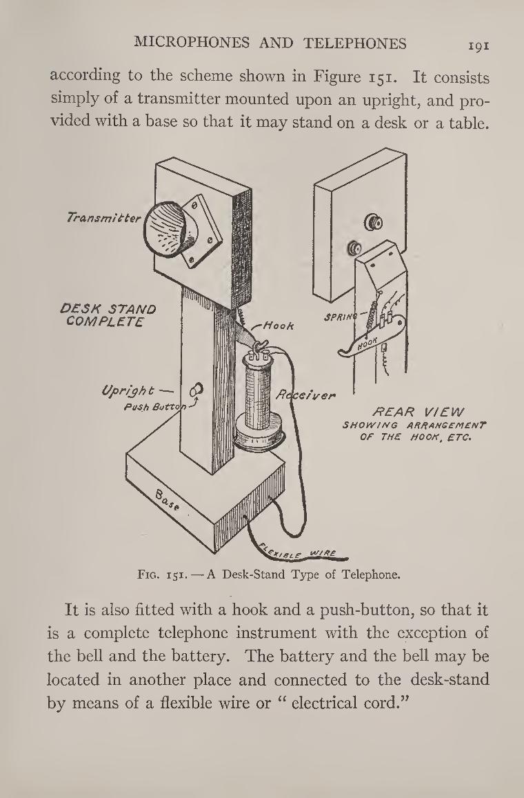
MICROPHONES AND TELEPHONES I9I
according to the scheme shown in Figure 151. It consists
simply of a transmitter mounted upon an upright, and pro¬
vided with a base so that it may stand on a desk or a table.
It is also fitted with a hook and a push-button, so that it
is a complete telephone instrument with the exception of
the bell and the battery. The battery and the bell may be
located in another place and connected to the desk-stand
by means of a flexible wire or “ electrical cord.”
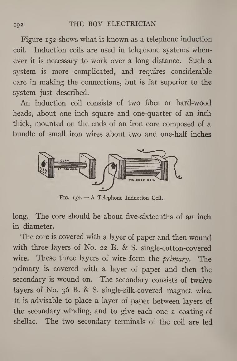
192 THE BOY ELECTRICIAN
Figure 152 shows what is known as a telephone induction
coil. Induction coils are used in telephone systems when¬
ever it is necessary to work over a long distance. Such a
system is more complicated, and requires considerable
care in making the connections, but is far superior to the
system just described.
An induction coil consists of two fiber or hard-wood
heads, about one inch square and one-quarter of an inch
thick, mounted on the ends of an iron core composed of a
bundle of small iron wires about two and one-half inches
long. The core should be about five-sixteenths of an inch
in diameter.
The core is covered with a layer of paper and then wound
with three layers of No. 22 B. & S. single-cotton-covered
wire. These three layers of wire form the primary. The
primary is covered with a layer of paper and then the
secondary is wound on. The secondary consists of twelve
layers of No. 36 B. & S. single-silk-covered magnet wire.
It is advisable to place a layer of paper between layers of
the secondary winding, and to give each one a coating of
shellac. The two secondary terminals of the coil are led
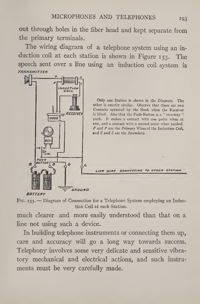
MICROPHONES AND TELEPHONES 193
out through holes in the fiber head and kept separate from
the primary terminals.
The wiring diagram of a telephone system using an in¬
duction coil at each station is shown in Figure 153. The
speech sent over a line using an induction coil system is TRANSMITTER
•=■ GROUND
CATTERY
Only one Station is shown in the Diagram. The
other is exactly similar. Observe that there are two
Contacts operated by the Hook when the Receiver
is lifted. Also that the Push-Button is a “ two-way ”
push. It makes a contact with one point when at
rest, and a contact with a second point when pushed.
P and P are the Primary Wires of the Induction Coil,
and 5 and S are the Secondary.
line wire connecting to or hen station
Fig. 153. — Diagram of Connection for a Telephone System employing an Induc¬
tion Coil at each Station.
much clearer and more easily understood than that on a
line not using such a device.
In building telephone instruments or connecting them up,
care and accuracy will go a long way towards success.
Telephony involves some very delicate and sensitive vibra¬
tory mechanical and electrical actions, and such instru¬
ments must be very carefully made.
A Medical Coil or shocking coil, as it is properly termed,
is nothing more or less than a small induction coil, and
consists of a core, a primary winding, a secondary wind¬
ing, and an interrupter. The principle of an induction coil
and that of magnetic induction have already been explained
in Chapter V. It might be well for the readers to turn back
to pages 89-91 and reread them.
The human body possesses considerable resistance, and
the voltage of one or two ordinary cells of battery is not
sufficient to overcome that resistance and pass enough
current through the body to be felt, unless under excep¬
tional conditions.
The simplest means employable for raising the voltage
of a battery high enough to produce a shock is the medical
coil.
The first step in making such a coil is to roll up a paper
tube, five-sixteenths of an inch in diameter inside, and
two and one-half inches long. The outer end of the paper
is carefully glued, so that it will not unroll. The tube is
filled with pieces of iron wire two and one-half inches long
which have been straightened by rolling between two 194
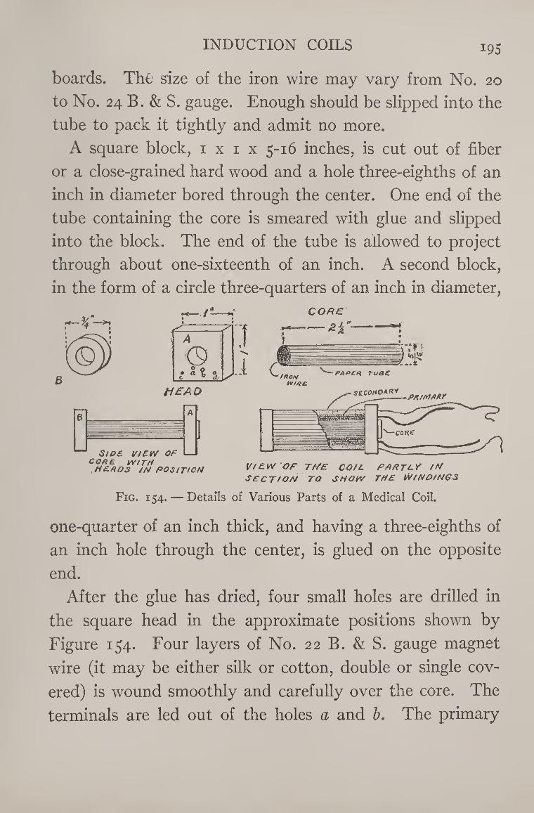
INDUCTION COILS 195
boards. The size of the iron wire may vary from No. 20
to No. 24 B. & S. gauge. Enough should be slipped into the
tube to pack it tightly and admit no more.
A square block, 1 x 1 x 5-16 inches, is cut out of fiber
or a close-grained hard wood and a hole three-eighths of an
inch in diameter bored through the center. One end of the
tube containing the core is smeared with glue and slipped
into the block. The end of the tube is allowed to project
through about one-sixteenth of an inch. A second block,
in the form of a circle three-quarters of an inch in diameter,
3 HEAD
B A 1
1
S/OE VIEW OF
J
CORE WITH HER OS IN POSITION VIEW OF T//£ CO/L PHPTC? IN
SECTION TO SNOW THE WINDINGS
Fig. 154. — Details of Various Parts of a Medical Coil.
one-quarter of an inch thick, and having a three-eighths of
an inch hole through the center, is glued on the opposite
end.
After the glue has dried, four small holes are drilled in
the square head in the approximate positions shown by
Figure 154. Four layers of No. 22 B. & S. gauge magnet
wire (it may be either silk or cotton, double or single cov¬
ered) is wound smoothly and carefully over the core. The
terminals are led out of the holes a and b. The primary
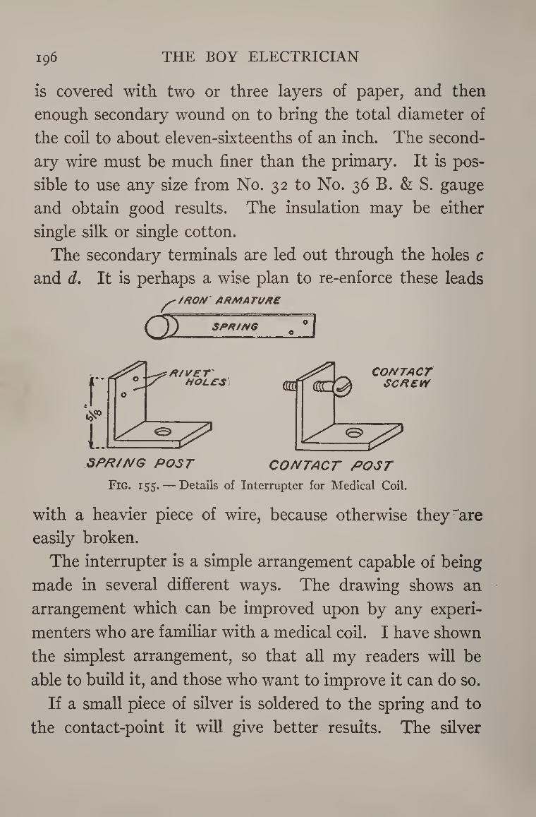
196 THE BOY ELECTRICIAN
is covered with two or three layers of paper, and then
enough secondary wound on to bring the total diameter of
the coil to about eleven-sixteenths of an inch. The second¬
ary wire must be much finer than the primary. It is pos¬
sible to use any size from No. 32 to No. 36 B. & S. gauge
and obtain good results. The insulation may be either
single silk or single cotton.
The secondary terminals are led out through the holes c
and d. It is perhaps a wise plan to re-enforce these leads ^ //ROM ARM A Tl/RE
O) SRR/MG c °|
SPR/A/G POST CONTACT POST
Fig. 155. — Details of Interrupter for Medical Coil.
with a heavier piece of wire, because otherwise they'are
easily broken.
The interrupter is a simple arrangement capable of being
made in several different ways. The drawing shows an
arrangement which can be improved upon by any experi¬
menters who are familiar with a medical coil. I have shown
the simplest arrangement, so that all my readers will be
able to build it, and those who want to improve it can do so.
If a small piece of silver is soldered to the spring and to
the contact-point it will give better results. The silver
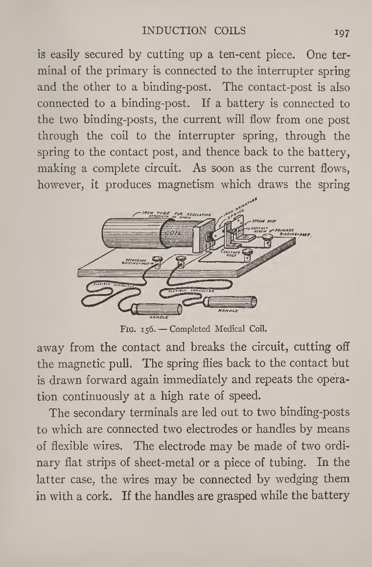
INDUCTION COILS 197
is easily secured by cutting up a ten-cent piece. One ter¬
minal of the primary is connected to the interrupter spring
and the other to a binding-post. The contact-post is also
connected to a binding-post. If a battery is connected to
the two binding-posts, the current will flow from one post
through the coil to the interrupter spring, through the
spring to the contact post, and thence back to the battery,
making a complete circuit. As soon as the current flows,
however, it produces magnetism which draws the spring
Fig. 156. — Completed Medical Coil.
away from the contact and breaks the circuit, cutting off
the magnetic pull. The spring flies back to the contact but
is drawn forward again immediately and repeats the opera¬
tion continuously at a high rate of speed.
The secondary terminals are led out to two binding-posts
to which are connected two electrodes or handles by means
of flexible wires. The electrode may be made of two ordi¬
nary flat strips of sheet-metal or a piece of tubing. In the
latter case, the wires may be connected by wedging them
in with a cork. If the handles are grasped while the battery
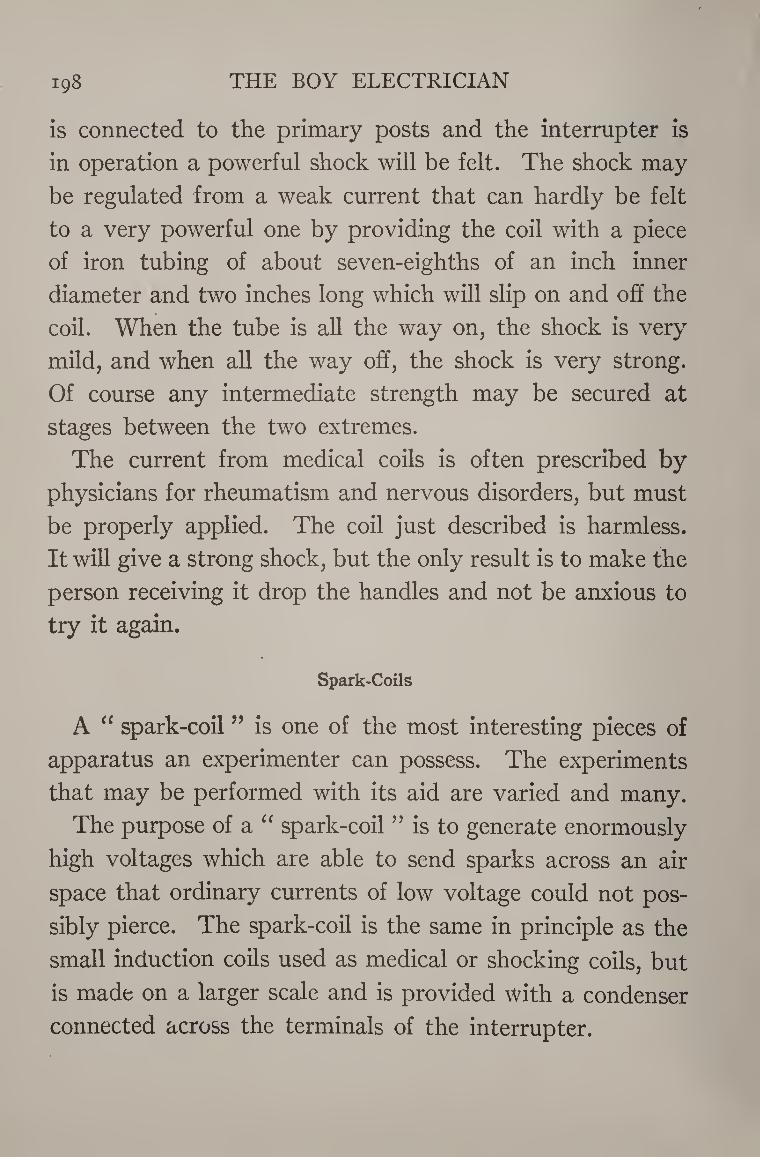
THE BOY ELECTRICIAN 198
is connected to the primary posts and the interrupter is
in operation a powerful shock will be felt. The shock may
be regulated from a weak current that can hardly be felt
to a very powerful one by providing the coil with a piece
of iron tubing of about seven-eighths of an inch inner
diameter and two inches long which will slip on and oh the
coil. When the tube is all the way on, the shock is very
mild, and when all the way off, the shock is very strong.
Of course any intermediate strength may be secured at
stages between the two extremes.
The current from medical coils is often prescribed by
physicians for rheumatism and nervous disorders, but must
be properly applied. The coil just described is harmless.
It will give a strong shock, but the only result is to make the
person receiving it drop the handles and not be anxious to
try it again.
Spark-Coils
A “ spark-coil ” is one of the most interesting pieces of
apparatus an experimenter can possess. The experiments
that may be performed with its aid are varied and many.
The purpose of a “ spark-coil ” is to generate enormously
high voltages which are able to send sparks across an air
space that ordinary currents of low voltage could not pos¬
sibly pierce. The spark-coil is the same in principle as the
small induction coils used as medical or shocking coils, but
is made on a larger scale and is provided with a condenser
connected across the terminals of the interrupter.
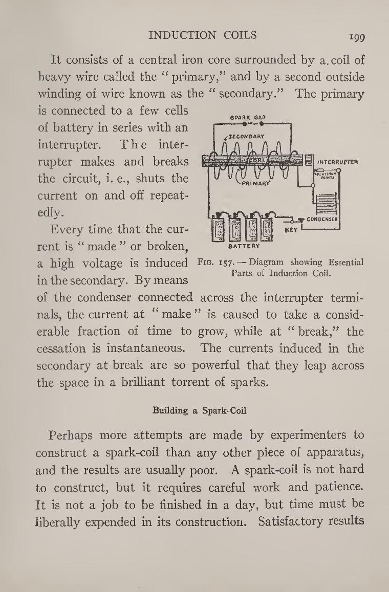
INDUCTION COILS 199
SPARK CAP
It consists of a central iron core surrounded by a. coil of
heavy wire called the “ primary,” and by a second outside
winding of wire known as the “ secondary.” The primary
is connected to a few cells
of battery in series with an
interrupter. The inter¬
rupter makes and breaks
the circuit, i. e., shuts the
current on and off repeat¬
edly.
Every time that the cur¬
rent is “ made ” or broken,
INTCARuprc*
BATTERY
a high voltage is induced Fig- 157.— Diagram showing Essential . . . -r. Parts of Induction Coil. m the secondary. By means
of the condenser connected across the interrupter termi¬
nals, the current at “ make ” is caused to take a consid¬
erable fraction of time to grow, while at “ break,” the
cessation is instantaneous. The currents induced in the
secondary at break are so powerful that they leap across
the space in a brilliant torrent of sparks.
Building a Spark-Coil
Perhaps more attempts are made by experimenters to
construct a spark-coil than any other piece of apparatus,
and the results are usually poor. A spark-coil is not hard
to construct, but it requires careful work and patience.
It is not a job to be finished in a day, but time must be
liberally expended in its construction. Satisfactory results
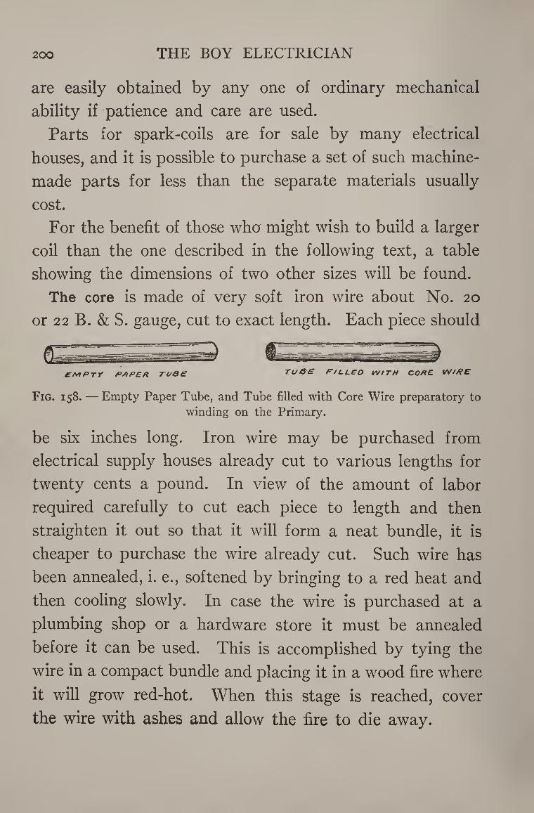
200 THE BOY ELECTRICIAN
are easily obtained by any one of ordinary mechanical
ability if patience and care are used.
Parts for spark-coils are for sale by many electrical
houses, and it is possible to purchase a set of such machine-
made parts for less than the separate materials usually
cost.
For the benefit of those who might wish to build a larger
coil than the one described in the following text, a table
showing the dimensions of two other sizes will be found.
The core is made of very soft iron wire about No. 20
or 22 B. & S. gauge, cut to exact length. Each piece should
EMPTY PAPER TO0E TuO'E P/LLEO WITH CORE WIRE
Fig. 158. — Empty Paper Tube, and Tube filled with Core Wire preparatory to
winding on the Primary.
be six inches long. Iron wire may be purchased from
electrical supply houses already cut to various lengths for
twenty cents a pound. In view of the amount of labor
required carefully to cut each piece to length and then
straighten it out so that it will form a neat bundle, it is
cheaper to purchase the wire already cut. Such wire has
been annealed, i. e., softened by bringing to a red heat and
then cooling slowly. In case the wire is purchased at a
plumbing shop or a hardware store it must be annealed
before it can be used. This is accomplished by tying the
wire in a compact bundle and placing it in a wood fire where
it will grow red-hot. When this stage is reached, cover
the wire with ashes and allow the fire to die away.
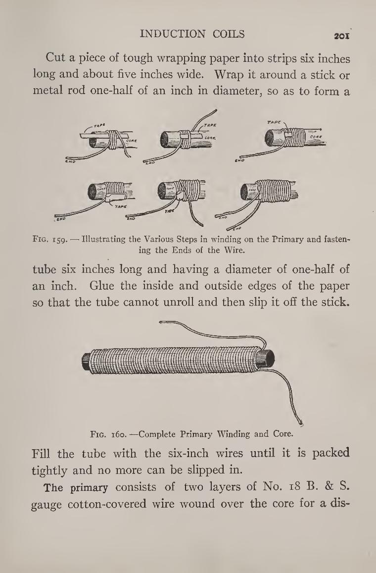
INDUCTION COILS 201
Cut a piece of tough wrapping paper into strips six inches
long and about five inches wide. Wrap it around a stick or
metal rod one-half of an inch in diameter, so as to form a
Fig. 159. — Illustrating the Various Steps in winding on the Primary and fasten¬
ing the Ends of the Wire.
tube six inches long and having a diameter of one-half of
an inch. Glue the inside and outside edges of the paper
so that the tube cannot unroll and then slip it off the stick.
Fill the tube with the six-inch wires until it is packed
tightly and no more can be slipped in.
The primary consists of two layers of No. 18 B. & S.
gauge cotton-covered wire wound over the core for a dis-
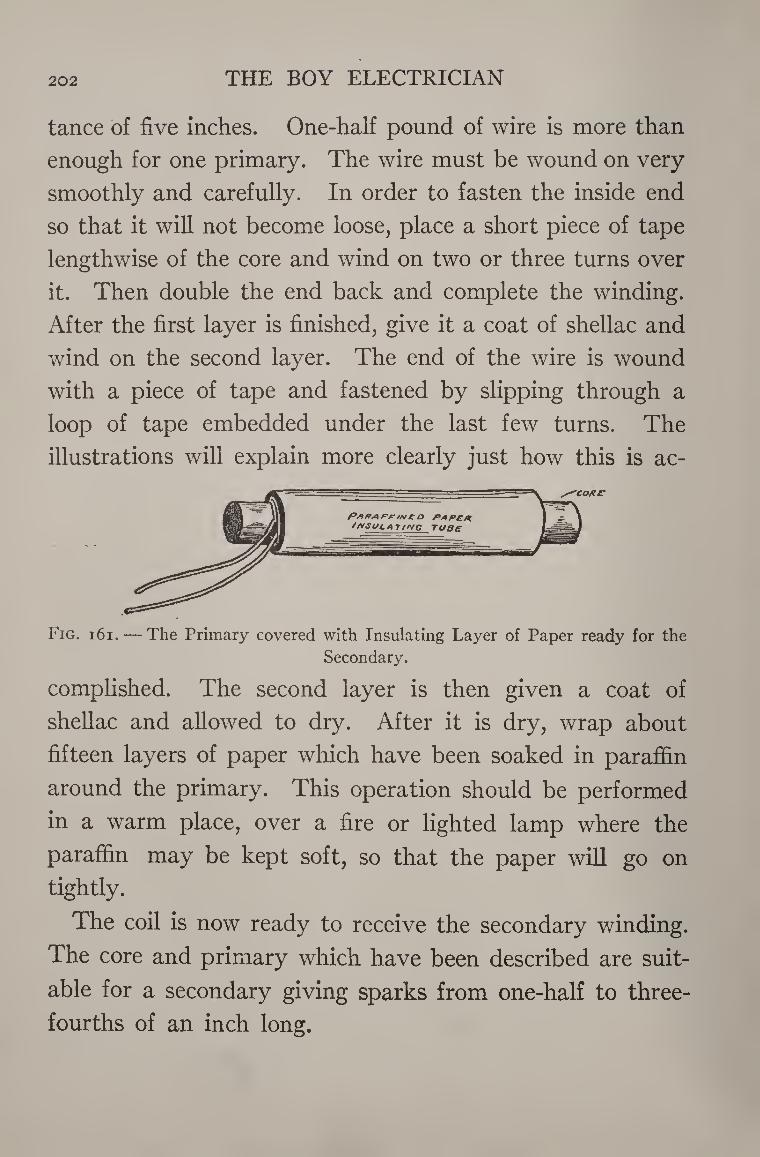
202 THE BOY ELECTRICIAN
tance of five inches. One-half pound of wire is more than
enough for one primary. The wire must be wound on very
smoothly and carefully. In order to fasten the inside end
so that it will not become loose, place a short piece of tape
lengthwise of the core and wind on two or three turns over
it. Then double the end back and complete the winding.
After the first layer is finished, give it a coat of shellac and
wind on the second layer. The end of the wire is wound
with a piece of tape and fastened by slipping through a
loop of tape embedded under the last few turns. The
illustrations will explain more clearly just how this is ac-
Fig. 161. — The Primary covered with Insulating Layer of Paper ready for the Secondary.
complished. The second layer is then given a coat of
shellac and allowed to dry. After it is dry, wrap about
fifteen layers of paper which have been soaked in paraffin
around the primary. This operation should be performed
in a warm place, over a fire or lighted lamp where the
paraffin may be kept soft, so that the paper will go on
tightly.
The coil is now ready to receive the secondary winding.
The core and primary which have been described are suit¬
able for a secondary giving sparks from one-half to three-
fourths of an inch long.
INDUCTION COILS 203
The secondary winding consists of several thousand
turns of very fine wire wound on in smooth even layers
with paper between each two layers.
The following table shows the size and amount of wire
required. In addition, about two pounds of paraffin and
a pad of linen paper or typewriter paper will be required.
The wire may be either enamel, cotton, or silk insulated.
Single silk-covered wire is preferred.
SIZE OF COIL SIZE OF WIRE AMOUNT
yi inch i inch
\]/2 inch
36 B. & S. 34 B. & S. 34 B. & S.
10 ounces 1 lb. 2 lbs.
The means for supporting and turning the coil in order
to wind on the secondary may be left somewhat to the
ingenuity of the young experimenter. The following sug¬
gestion, however, is one which experience has proved to
be well worth following out, and may be applied to other
things than the construction of an induction coil. It seems
to be the nature of most boys, for some reason or other, to
be unwilling to spend time and labor on anything which
will aid them in their work. They are always in such a
hurry and so anxious to see something completed that they
direct all their energy to that end rather than spend part
of their time in constructing some little device which
would really lighten the other work and go a long way
towards insuring its successful completion.
I have frequently given instructions for building an
induction coil and placed particular stress upon winding
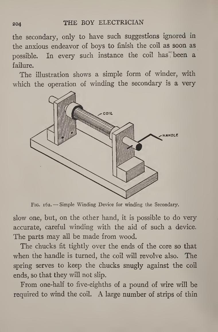
204 THE BOY ELECTRICIAN
the secondary, only to have such suggestions ignored in
the anxious endeavor of boys to finish the coil as soon as
possible. In every such instance the coil has^ been a
failure.
The illustration shows a simple form of winder, with
which the operation of winding the secondary is a very
Fig. 162. — Simple Winding Device for winding the Secondary.
slow one, but, on the other hand, it is possible to do very
accurate, careful winding with the aid of such a device.
The parts may all be made from wood.
The chucks fit tightly over the ends of the core so that
when the handle is turned, the coil will revolve also. The
spring serves to keep the chucks snugly against the coil
ends, so that they will not slip.
From one-half to five-eighths of a pound of wire will be
required to wind the coil. A large number of strips of thin
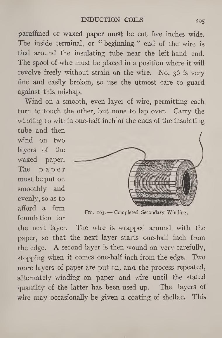
INDUCTION COILS 205
paraffined or waxed paper must be cut five inches wide.
The inside terminal, or “ beginning ” end of the wire is
tied around the insulating tube near the left-hand end.
The spool of wire must be placed in a position where it will
revolve freely without strain on the wire. No. 36 is very
fine and easily broken, so use the utmost care to guard
against this mishap.
Wind on a smooth, even layei of wire, permitting each
turn to touch the other, but none to lap over. Carry the
winding to within one-half inch of the ends of the insulating
tube and then
wind on two
layers of the
waxed paper.
The paper
must be put on
smoothly and
evenly, so as to
afford a firm
foundation for
the next layer. The wire is wrapped around with the
paper, so that the next layer starts one-half inch from
the edge. A second layer is then wound on very carefully,
stopping when it comes one-half inch from the edge. Two
more layers of paper are put on, and the process repeated,
alternately winding on paper and wire until the stated
quantity of the latter has been used up. The layers of
wire may occasionally be given a coating of shellac. This
Fig. 163. — Completed Secondary Winding.
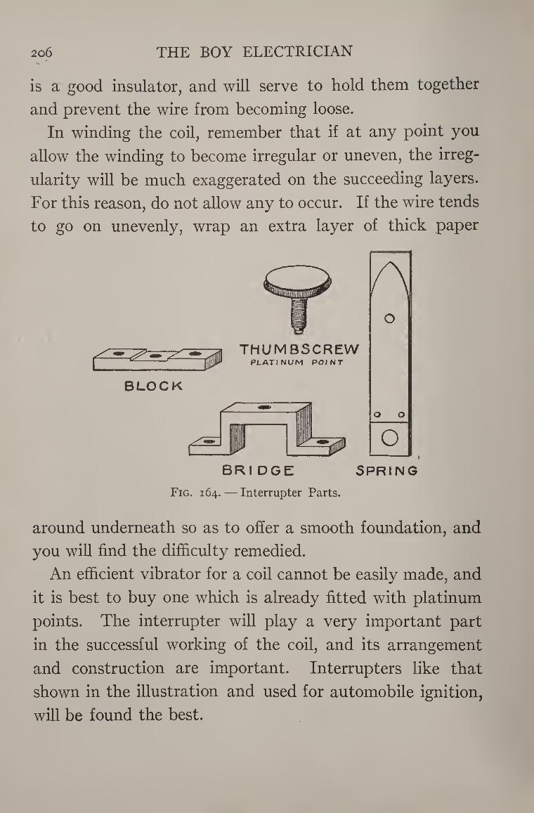
THE BOY ELECTRICIAN 206 V. • S*
is a good insulator, and will serve to hold them together
and prevent the wire from becoming loose.
In winding the coil, remember that if at any point you
allow the winding to become irregular or uneven, the irreg¬
ularity will be much exaggerated on the succeeding layers.
For this reason, do not allow any to occur. If the wire tends
to go on unevenly, wrap an extra layer of thick paper
Fig. 164. — Interrupter Parts.
around underneath so as to offer a smooth foundation, and
you will find the difficulty remedied.
An efficient vibrator for a coil cannot be easily made, and
it is best to buy one which is already fitted with platinum
points. The interrupter will play a very important part
in the successful working of the coil, and its arrangement
and construction are important. Interrupters like that
shown in the illustration and used for automobile ignition,
will be found the best.
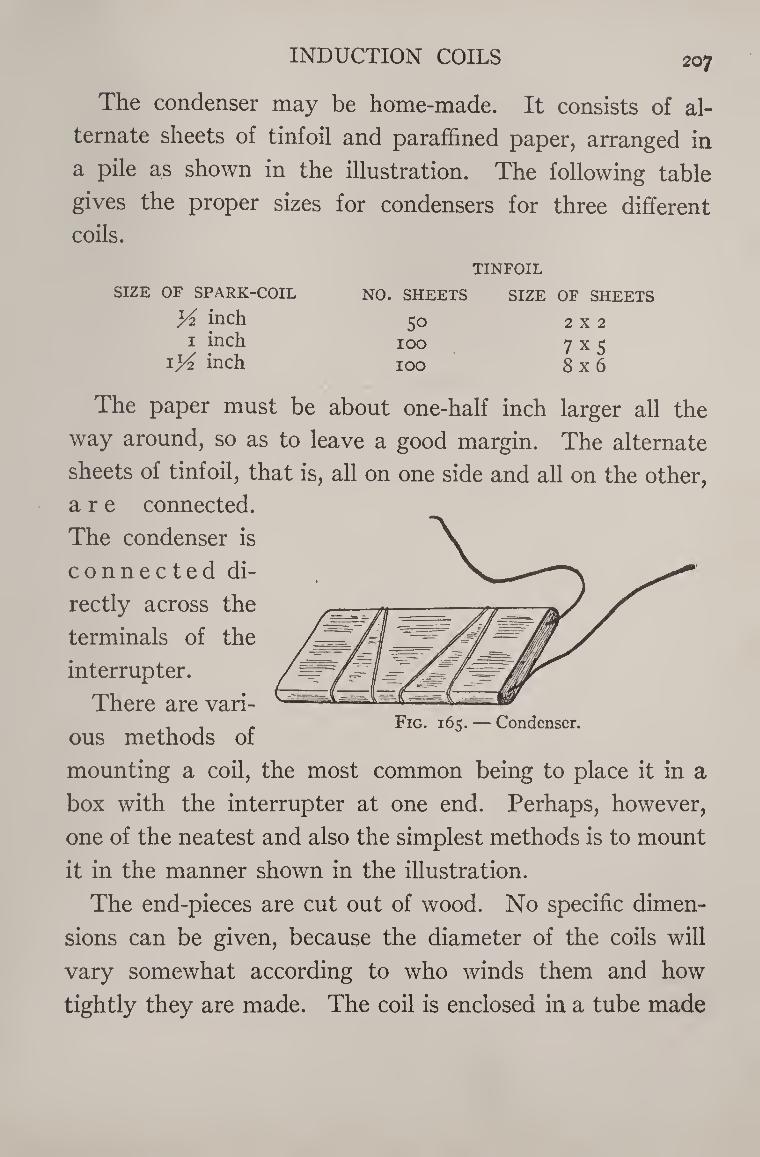
INDUCTION COILS 207
The condenser may be home-made. It consists of al¬
ternate sheets of tinfoil and paraffined paper, arranged in
a pile as shown in the illustration. The following table
gives the proper sizes for condensers for three different
coils.
SIZE OF SPARK-COIL
K inch i inch
1 yi inch
NO. SHEETS
50 IOO
IOO
TINFOIL
SIZE OF SHEETS
2X2
7X5
8x6
The paper must be about one-half inch larger all the
way around, so as to leave a good margin. The alternate
sheets of tinfoil, that is, all on one side and all on the other,
are connected.
The condenser is
connected di¬
rectly across the
terminals of the
interrupter.
There are vari- , . . Fig. 165. — Condenser.
ous methods of
mounting a coil, the most common being to place it in a
box with the interrupter at one end. Perhaps, however,
one of the neatest and also the simplest methods is to mount
it in the manner shown in the illustration.
The end-pieces are cut out of wood. No specific dimen¬
sions can be given, because the diameter of the coils will
vary somewhat according to who winds them and how
tightly they are made. The coil is enclosed in a tube made
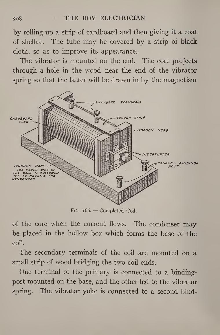
20 8 THE BOY ELECTRICIAN
by rolling up a strip of cardboard and then giving it a coat
of shellac. The tube may be covered by a strip of black
cloth, so as to improve its appearance.
The vibrator is mounted on the end. The core projects
through a hole in the wood near the end of the vibrator
spring so that the latter will be drawn in by the magnetism
of the core when the current flows. The condenser may
be placed in the hollow box which forms the base of the
coil.
The secondary terminals of the coil are mounted on a
small strip of wood bridging the two coil ends.
One terminal of the primary is connected to a binding-
post mounted on the base, and the other led to the vibrator
spring. The vibrator yoke is connected to a second bind-
INDUCTION COILS 209
ing-post on the base. One terminal of the condenser is
connected to the spring, and the other to the yoke.
Four cells of dry battery should be sufficient to run the
coil and cause it to give a good one-half-inch spark if built
according to the directions here given. The vibrator or
interrupter will require adjusting and a position of the
adjusting screw will soon be found where the coil works
best.
Experiments with a Spark-Coil
Electrical Hands. Many extraordinary and interesting
experiments may be performed with the aid of a spark-
coil.
The following experiment never fails to amuse a party
of friends, and is mystifying and weird to the ordinary
person, unacquainted with the secret of its operation. Figure 167 shows the arrangement of the apparatus.
The primary of an ordinary one-inch spark induction coil
is connected in series with a twelve-volt battery and tele¬
phone transmitter. A small switch is included in the cir¬
cuit to break the current and prevent needless waste of the
battery when the apparatus is not in immediate use. The
secondary terminals of the induction coil are led by means
of an insulated wire to the adjoining room where they
terminate in a pair of scissors, or some other small metallic
object which may be clasped in the hand.
Each of two persons, wearing dry shoes or rubber-soled
slippers, grasps the terminal of one wire in one hand. The
other hand is placed flat against the ear of a third person,
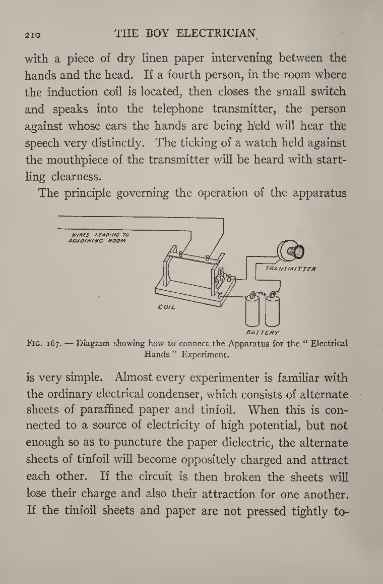
210 THE BOY ELECTRICIAN
with a piece of dry linen paper intervening between the
hands and the head. If a fourth person, in the room where
the induction coil is located, then closes the small switch
and speaks into the telephone transmitter, the person
against whose ears the hands are being held will hear the
speech very distinctly. The ticking of a watch held against
the mouthpiece of the transmitter will be heard with start¬
ling clearness.
The principle governing the operation of the apparatus
Hands ” Experiment.
is very simple. Almost every experimenter is familiar with
the ordinary electrical condenser, which consists of alternate
sheets of paraffined paper and tinfoil. When this is con¬
nected to a source of electricity of high potential, but not
enough so as to puncture the paper dielectric, the alternate
sheets of tinfoil will become oppositely charged and attract
each other. If the circuit is then broken the sheets will
lose their charge and also their attraction for one another.
If the tinfoil sheets and paper are not pressed tightly to-

INDUCTION COILS 211
gether, there will be a slight movement of the tinfoil and
paper which will correspond in frequency to any fluctua¬
tions of the charging current which may take place.
The head of the third person and the hands held against
his head act like three tinfoil sheets of a condenser, sepa¬
rated by two sheets of paper. The words spoken in the
transmitter cause the current to fluctuate and the induction
coil raises the potential of the current sufficiently to charge
the condenser and cause a slight vibration of the paper
dielectric. The vibrations correspond in strength and
speed to those of the voice, and so the words spoken in the
transmitter are audible to the person over whose ears the
paper is pressed.
Everything about the apparatus must be as dry as pos¬
sible, to insure its successful operation. The people holding
the wires in their hands should stand on a carpeted floor.
Always be very careful to tighten the adjusting screw" and
block the interrupter on the coil, so that by no means can
it possibly commence to operate, or the person listening,
instead of “ hearing things/’ will become the victim of a
rather painful, practical joke.
Geissler Tubes
The most beautiful and surprising effects may be ob¬
tained by lighting Geissler tubes with a coil. The tubes
are made in intricate and varied patterns of special glass,
containing fluorescent minerals and salts, and are filled with
different rarefied gases. When the tubes are connected
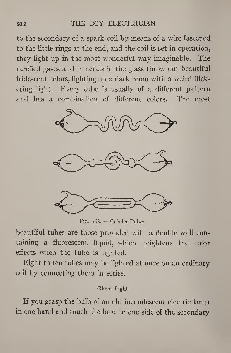
212 THE BOY ELECTRICIAN
to the secondary of a spark-coil by means of a wire fastened
to the little rings at the end, and the coil is set in operation,
they light up in the most wonderful way imaginable. The
rarefied gases and minerals in the glass throw out beautiful
iridescent colors, lighting up a dark room with a weird flick¬
ering light. Every tube is usually of a different pattern
and has a combination of different colors. The most
beautiful tubes are those provided with a double wall con¬
taining a fluorescent liquid, which heightens the color
effects when the tube is lighted.
Eight to ten tubes may be lighted at once on an ordinary
coil by connecting them in series.
Ghost Light
If you grasp the bulb of an old incandescent electric lamp
in one hand and touch the base to one side of the secondary
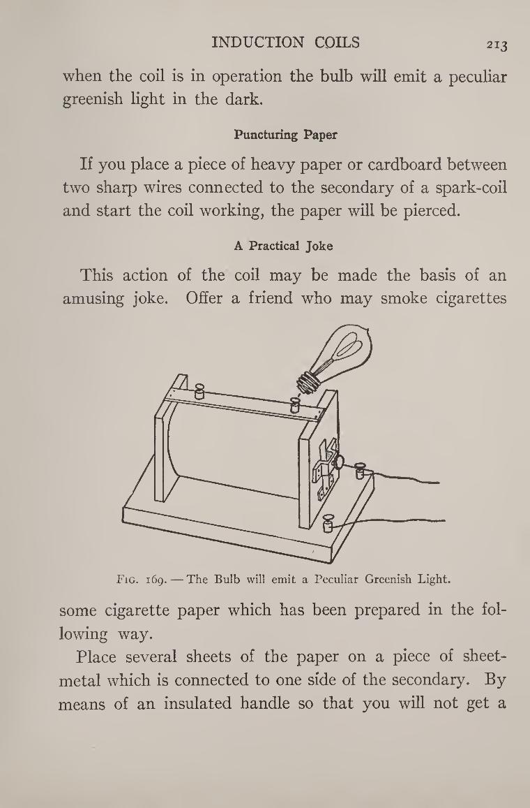
INDUCTION COILS 213
when the coil is in operation the bulb will emit a peculiar
greenish light in the dark.
Puncturing Paper
If you place a piece of heavy paper or cardboard between
two sharp wires connected to the secondary of a spark-coil
and start the coil working, the paper will be pierced.
A Practical Joke
This action of the coil may be made the basis of an
amusing joke. Offer a friend who may smoke cigarettes
Fig. 169. — The Bulb will emit a Peculiar Greenish Light.
some cigarette paper which has been prepared in the fol¬
lowing way.
Place several sheets of the paper on a piece of sheet-
metal which is connected to one side of the secondary. By
means of an insulated handle so that you will not get a
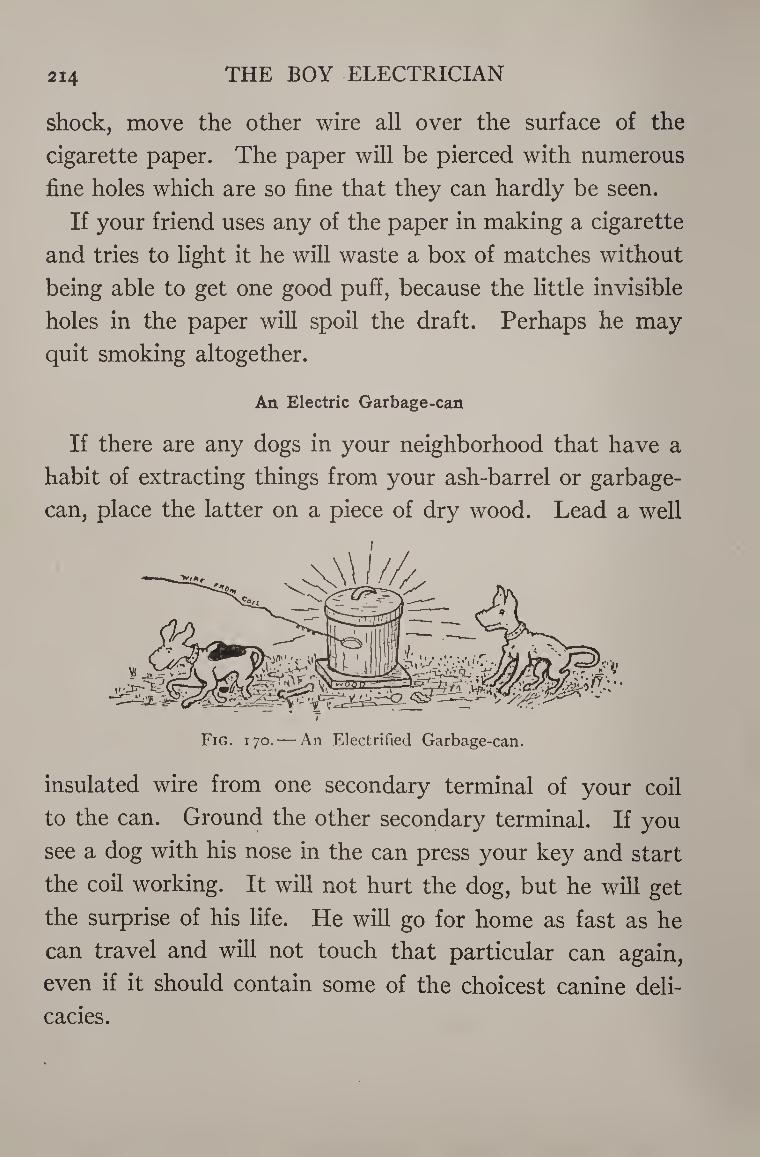
214 THE BOY ELECTRICIAN
shock, move the other wire all over the surface of the
cigarette paper. The paper will be pierced with numerous
fine holes which are so fine that they can hardly be seen.
If your friend uses any of the paper in making a cigarette
and tries to light it he will waste a box of matches without
being able to get one good pufi, because the little invisible
holes in the paper will spoil the draft. Perhaps he may
quit smoking altogether.
An Electric Garbage-can
If there are any dogs in your neighborhood that have a
habit of extracting things from your ash-barrel or garbage-
can, place the latter on a piece of dry wood. Lead a well
Fig. 170. — An Electrified Garbage-can.
insulated wire from one secondary terminal of your coil
to the can. Ground the other secondary terminal. If you
see a dog with his nose in the can press your key and start
the coil working. It will not hurt the dog, but he will get
the surprise of his life. He will go for home as fast as he
can travel and will not touch that particular can again,
even if it should contain some of the choicest canine deli¬
cacies.
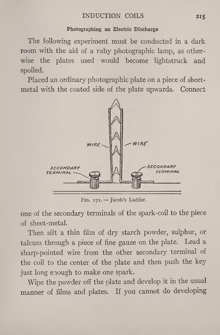
INDUCTION COILS 215
Photographing an Electric Discharge
The following experiment must be conducted in a dark
room with the aid of a ruby photographic lamp, as other¬
wise the plates used would become lightstruck and
spoiled.
Placed an ordinary photographic plate on a piece of sheet-
metal with the coated side of the plate upwards. Connect
one of the secondary terminals of the spark-coil to the piece
of sheet-metal.
Then sift a thin film of dry starch powder, sulphur, or
talcum through a piece of fine gauze on the plate. Lead a
sharp-pointed wire from the other secondary terminal of
the coil to the center of the plate and then push the key
just long enough to make one spark.
Wipe the powder off the plate and develop it in the usual
manner of films and plates. If you cannot do developing
216 THE BOY ELECTRICIAN
yourself, place the plate back in its box and send it to some
friend, or to a photographer.
The result will be a negative showing a peculiar electric
discharge, somewhat like sea-moss in appearance. No two
such photographs will be alike and the greatest variety
of new designs, etc., imaginable may be produced in this
manner.
Jacob’s Ladder
Take two pieces of bare copper wire about eight inches
long and bend them at right angles. Place them in the
secondary terminals of a spark-coil as in Figure 171. Bend
them so that the vertical portions are about one-half of an
inch apart at the bottom and one inch apart at the top.
Start the coil working, and the sparks will run up the wires
from the bottom to the top and appear very much like the
rungs in a ladder.
X-Rays
Most young experimenters are unaware what a wonder¬
ful and interesting field is open to the possessor of a small
X-ray tube.
Small X-ray tubes which will operate satisfactorily on
an inch and one-half spark-coil may be obtained from sev¬
eral electrical supply houses. They usually cost about
four dollars and a half. With such a tube and a fluoroscope
it is possible to see the bones in the human hand, the con¬
tents of a closed purse, etc.
The tube is made of glass and contains a very high
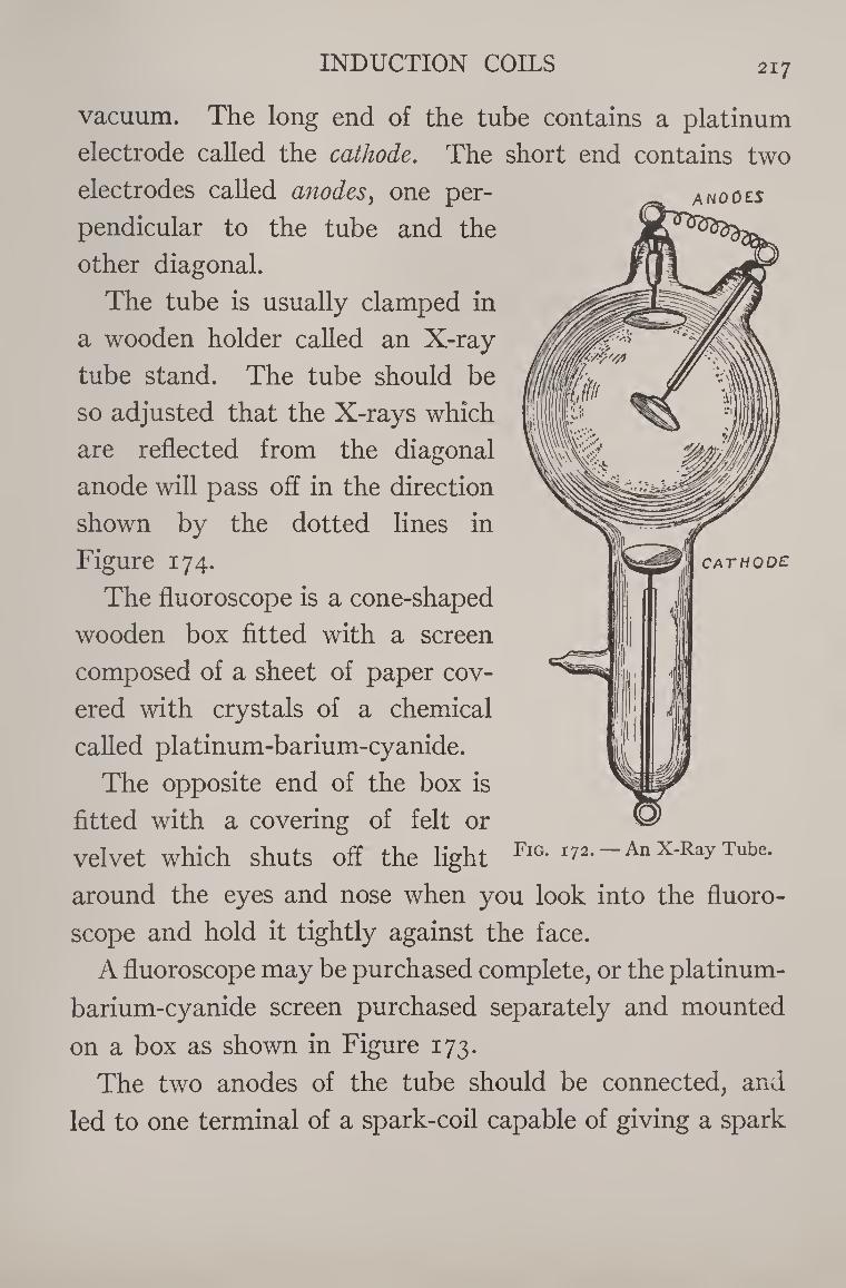
INDUCTION COILS 217
ANODES
CATHODE
vacuum. The long end of the tube contains a platinum
electrode called the cathode. The short end contains two
electrodes called anodes, one per¬
pendicular to the tube and the
other diagonal.
The tube is usually clamped in
a wooden holder called an X-ray
tube stand. The tube should be
so adjusted that the X-rays which
are reflected from the diagonal
anode will pass off in the direction
shown by the dotted lines in
Figure 174.
The fluoroscope is a cone-shaped
wooden box fitted with a screen
composed of a sheet of paper cov¬
ered with crystals of a chemical
called platinum-barium-cyanide.
The opposite end of the box is
fitted with a covering of felt or
velvet which shuts off the light FlG* x72'“ An X-Ray Tube.
around the eyes and nose when you look into the fluoro¬
scope and hold it tightly against the face.
A fluoroscope may be purchased complete, or the platinum-
barium-cyanide screen purchased separately and mounted
on a box as shown in Figure 173.
The two anodes of the tube should be connected, and
led to one terminal of a spark-coil capable of giving a spark
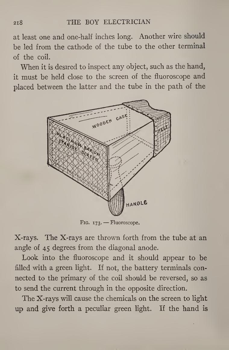
2l8 THE BOY ELECTRICIAN
at least one and one-half inches long. Another wire should
be led from the cathode of the tube to the other terminal
of the coil.
When it is desired to inspect any object, such as the hand,
it must be held close to the screen of the fluoroscope and
placed between the latter and the tube in the path of the
Fig. 173. — Fluoroscope.
X-rays. The X-rays are thrown forth from the tube at an
angle of 45 degrees from the diagonal anode.
Look into the fluoroscope and it should appear to be
filled with a green light. If not, the battery terminals con¬
nected to the primary of the coil should be reversed, so as
to send the current through in the opposite direction.
The X-rays will cause the chemicals on the screen to light
up and give forth a peculiar green light. If the hand is
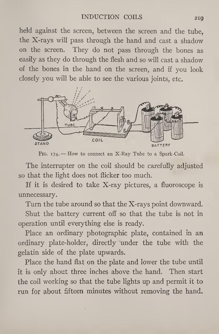
INDUCTION COILS 219
held against the screen, between the screen and the tube,
the X-rays will pass through the hand and cast a shadow
on the screen. They do not pass through the bones as
easily as they do through the flesh and so will cast a shadow
of the bones in the hand on the screen, and if you look
closely you will be able to see the various joints, etc.
Fig. 174. — How to connect an X-Ray Tube to a Spark-Coil.
The interrupter on the coil should be carefully adjusted
so that the light does not flicker too much.
If it is desired to take X-ray pictures, a fluoroscope is
unnecessary.
Turn the tube around so that the X-rays point downward.
Shut the battery current off so that the tube is not in
operation until everything else is ready.
Place an ordinary photographic plate, contained in an
ordinary plate-holder, directly under the tube with the
gelatin side of the plate upwards.
Place the hand flat on the plate and lower the tube until
it is only about three inches above the hand. Then start
the coil working so that the tube lights up and permit it to
run for about fifteen minutes without removing the hand.
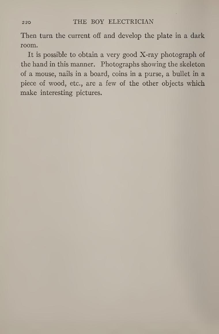
220 THE BOY ELECTRICIAN
Then turn the current off and develop the plate in a dark
room.
It is possible to obtain a very good X-ray photograph of
the hand in this manner. Photographs showing the skeleton
of a mouse, nails in a board, coins in a purse, a bullet in a
piece of wood, etc., are a few of the other objects which
make interesting pictures.
An X-Ray Photograph of the ±1and taken with the Outfit shown in Figure 174. The arrows point to injuries to
the bone of the third finger near the middle JOINT RESULTING IN A STIFF JOINT.

In most towns and cities where electricity for light and
power is carried over long distances, it will be noticed that
small iron boxes are fastened to the poles at frequent
intervals, usually wherever there is a group of houses or
buildings supplied with the current. Many boys know that
the boxes contain “ transformers,” but do not quite under¬
stand exactly what their purpose is, and how they are
constructed.
When it is desired to convey electrical energy to a distance,
for the purpose of producing either light or power, one of
the chief problems to be faced is, how to reduce to a mini¬
mum any possible waste or loss of energy during its trans¬
mission. Furthermore, since wires and cables of large size
are very costly, it is desirable that they be as small as
possible and yet still be able to carry the current without
undue losses.
It has already been explained that wires offer resistance
to an electrical current, and that some of the energy is lost
in passing through a wire because of this resistance. Small
wires possess more resistance than large ones, and if small
wires are to be used, in order to save on the cost of the 221
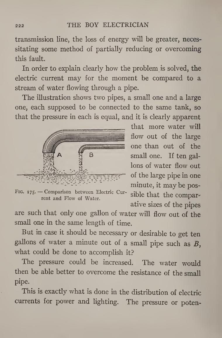
222 THE BOY ELECTRICIAN
transmission line, the loss of energy will be greater, neces¬
sitating some method of partially reducing or overcoming
this fault.
In order to explain clearly how the problem is solved, the
electric current may for the moment be compared to a
stream of water flowing through a pipe.
The illustration shows two pipes, a small one and a large
one, each supposed to be connected to the same tank, so
that the pressure in each is equal, and it is clearly apparent
that more water will
flow out of the large
one than out of the
small one. If ten gal¬
lons of water flow out
of the large pipe in one
minute, it may be pos- Fig. 175. — Comparison between Electric Cur- .1 . ,-1
rent and Flow of Water. SlHe that the COmPar'
ative sizes of the pipes
are such that only one gallon of water will flow out of the
small one in the same length of time.
But in case it should be necessary or desirable to get ten
gallons of water a minute out of a small pipe such as B, what could be done to accomplish it?
The pressure could be increased. The water would
then be able better to overcome the resistance of the small
pipe.
This is exactly what is done in the distribution of electric
currents for power and lighting. The pressure or poten-
' :j • • III iV'V • • N X*» , I | * Z < ✓
” * r ? 5 ?• -J. lit r -y
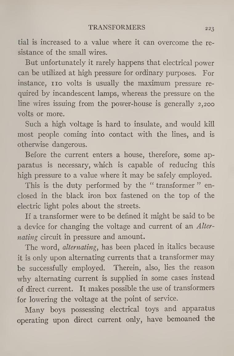
TRANSFORMERS 223
tial is increased to a value where it can overcome the re¬
sistance of the small wires.
But unfortunately it rarely happens that electrical power
can be utilized at high pressure for ordinary purposes. For
instance, no volts is usually the maximum pressure re¬
quired by incandescent lamps, whereas the pressure on the
line wires issuing from the power-house is generally 2,200
volts or more.
Such a high voltage is hard to insulate, and would kill
most people coming into contact with the lines, and is
otherwise dangerous.
Before the current enters a house, therefore, some ap¬
paratus is necessary, which is capable of reducing this
high pressure to a value where it may be safely employed.
This is the duty performed by the “ transformer ” en¬
closed in the black iron box fastened on the top of the
electric light poles about the streets.
If a transformer were to be defined it might be said to be
a device for changing the voltage and current of an Alter¬
nating circuit in pressure and amount.
The word, alternating, has been placed in italics because
it is only upon alternating currents that a transformer may
be successfully employed. Therein, also, lies the reason
why alternating current is supplied in some cases instead
of direct current. It makes possible the use of transformers
for lowering the voltage at the point of service.
Many boys possessing electrical toys and apparatus
operating upon direct current only, have bemoaned the
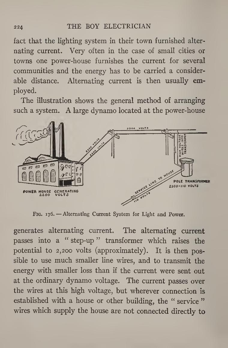
224 THE BOY ELECTRICIAN
fact that the lighting system in their town furnished alter¬
nating current. Very often in the case of small cities or
towns one power-house furnishes the current for several
communities and the energy has to be carried a consider¬
able distance. Alternating current is then usually em¬
ployed.
The illustration shows the general method of arranging
such a system. A large dynamo located at the power-house
Fig. 176. — Alternating Current System for Light and Power.
generates alternating current. The alternating current
passes into a “ step-up ” transformer which raises the
potential to 2,200 volts (approximately). It is then pos¬
sible to use much smaller line wires, and to transmit the
energy with smaller loss than if the current were sent out
at the ordinary dynamo voltage. The current passes over
the wires at this high voltage, but wherever connection is
established with a house or other building, the “ service ”
wires which supply the house are not connected directly to
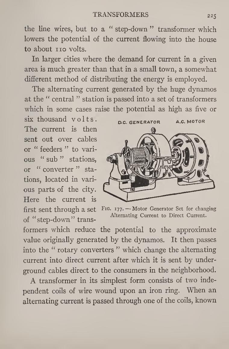
TRANSFORMERS 225
the line wires, but to a a step-down ” transformer which
lowers the potential of the current flowing into the house
to about no volts.
In larger cities where the demand for current in a given
area is much greater than that in a small town, a somewhat
different method of distributing the energy is employed.
The alternating current generated by the huge dynamos
at the “ central ” station is passed into a set of transformers
which in some cases raise the potential as high as five or
six thousand volts. o.c. generator a.c.motor
The current is then
sent out over cables
or “ feeders ” to vari¬
ous “ sub ” stations,
or “ converter ” sta¬
tions, located in vari¬
ous parts of the city.
Here the current is
first sent through a set Fig- 177. — Motor Generator Set for changing . ,, . ,, , Alternating Current to Direct Current.
of step-down trans¬
formers which reduce the potential to the approximate
value originally generated by the dynamos. It then passes
into the “ rotary converters ” which change the alternating
current into direct current after which it is sent by under¬
ground cables direct to the consumers in the neighborhood.
A transformer in its simplest form consists of two inde¬
pendent coils of wire wound upon an iron ring. When an
alternating current is passed through one of the coils, known
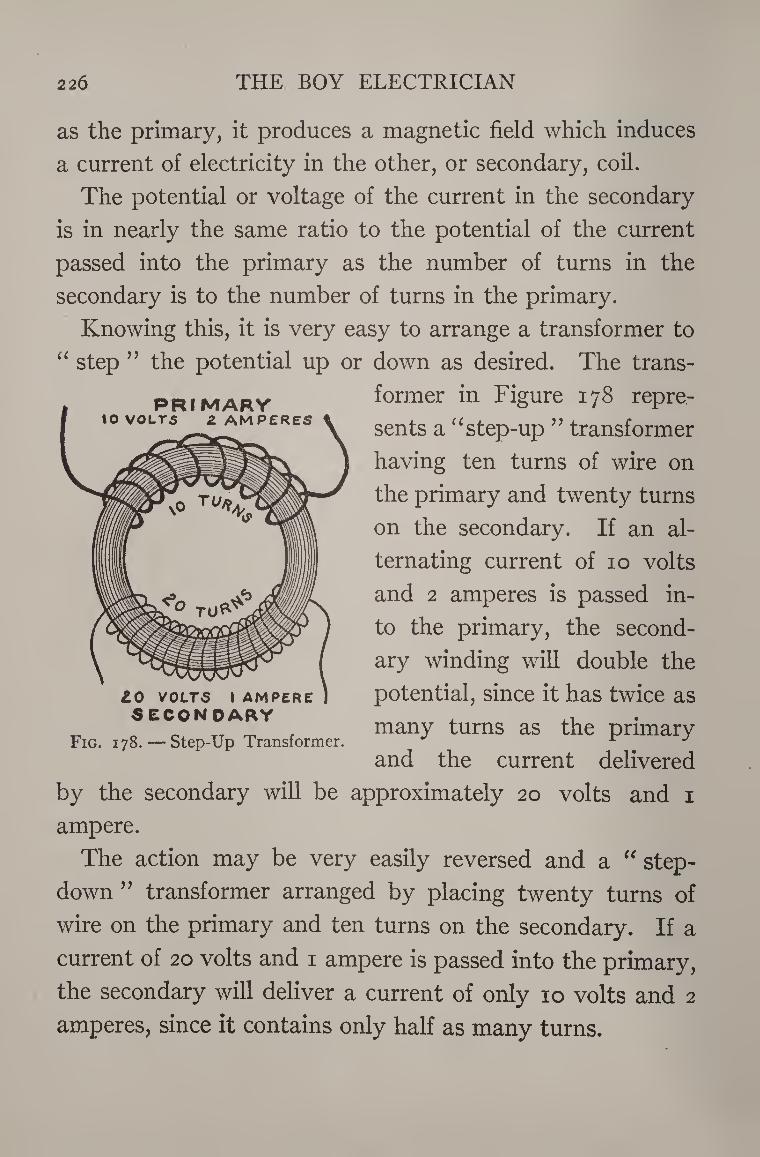
226 THE BOY ELECTRICIAN
PRIMARY VOLTS 2 AM PE
as the primary, it produces a magnetic field which induces
a current of electricity in the other, or secondary, coil.
The potential or voltage of the current in the secondary
is in nearly the same ratio to the potential of the current
passed into the primary as the number of turns in the
secondary is to the number of turns in the primary.
Knowing this, it is very easy to arrange a transformer to
“ step ” the potential up or down as desired. The trans¬
former in Figure 178 repre¬
sents a “ step-up ” transformer
having ten turns of wire on
the primary and twenty turns
on the secondary. If an al¬
ternating current of 10 volts
and 2 amperes is passed in¬
to the primary, the second¬
ary winding will double the
potential, since it has twice as
many turns as the primary
and the current delivered
by the secondary will be approximately 20 volts and 1
ampere.
The action may be very easily reversed and a “ step-
down ” transformer arranged by placing twenty turns of
wire on the primary and ten turns on the secondary. If a
current of 20 volts and 1 ampere is passed into the primary,
the secondary will deliver a current of only 10 volts and 2
amperes, since it contains only half as many turns.
LO VOLTS I AMPERE SECONDARY
Fig. 178. — Step-Up Transformer.
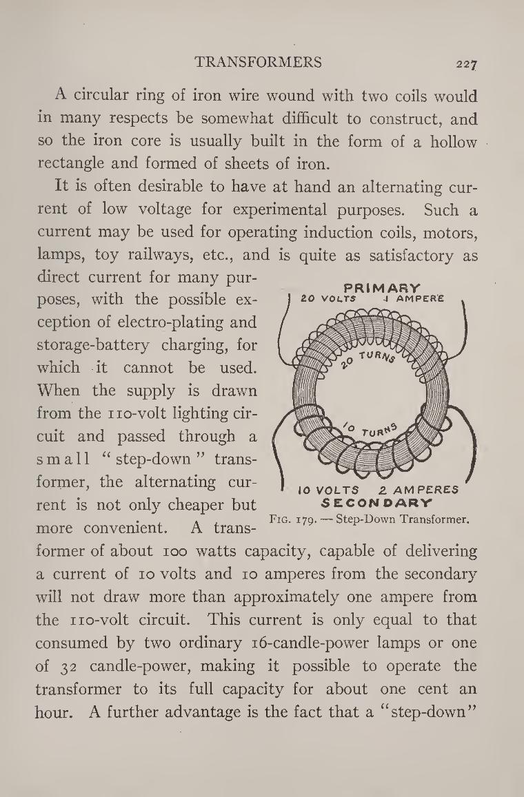
TRANSFORMERS 227
A circular ring of iron wire wound with two coils would
in many respects be somewhat difficult to construct, and
so the iron core is usually built in the form of a hollow
rectangle and formed of sheets of iron.
It is often desirable to have at hand an alternating cur¬
rent of low voltage for experimental purposes. Such a
current may be used for operating induction coils, motors,
lamps, toy railways, etc., and is quite as satisfactory as
direct current for many pur¬
poses, with the possible ex¬
ception of electro-plating and
storage-battery charging, for
which it cannot be used.
When the supply is drawn
from the no-volt lighting cir¬
cuit and passed through a
small “ step-down ” trans¬
former, the alternating cur¬
rent is not only cheaper but secondary . . . . Fig. 179. — Step-Down Transformer.
more convenient. A trans¬
former of about 100 watts capacity, capable of delivering
a current of 10 volts and 10 amperes from the secondary
will not draw more than approximately one ampere from
the no-volt circuit. This current is only equal to that
consumed by two ordinary 16-candle-power lamps or one
of 32 candle-power, making it possible to operate the
transformer to its full capacity for about one cent an
hour. A further advantage is the fact that a “step-down”
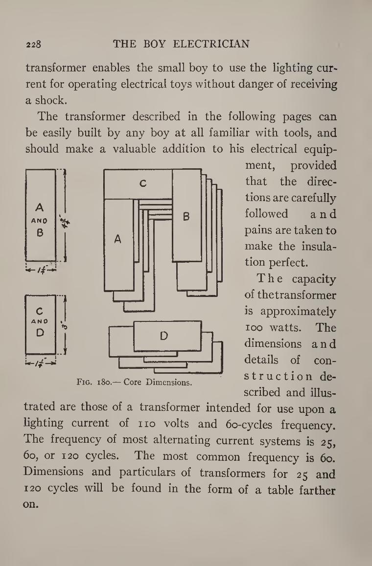
228 THE BOY ELECTRICIAN
c A N 0 «'
D
.1 .
B
transformer enables the small boy to use the lighting cur*
rent for operating electrical toys without danger of receiving
a shock.
The transformer described in the following pages can
be easily built by any boy at all familiar with tools, and
should make a valuable addition to his electrical equip¬
ment, provided
that the direc¬
tions are carefully
followed and
pains are taken to
make the insula¬
tion perfect.
The capacity
of the transformer
is approximately
ioo watts. The
dimensions and
details of con-
struction de¬
scribed and illus¬
trated are those of a transformer intended for use upon a
lighting current of no volts and 6o-cycles frequency.
The frequency of most alternating current systems is 25,
60, or 120 cycles. The most common frequency is 60.
Dimensions and particulars of transformers for 25 and
120 cycles will be found in the form of a table farther
Fig. 180.— Core Dimensions.
on.
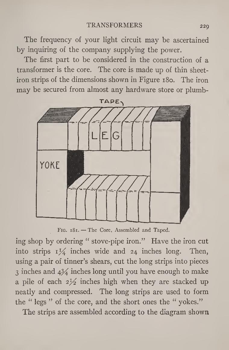
TRANSFORMERS 229
The frequency of your light circuit may be ascertained
by inquiring of the company supplying the power.
The first part to be considered in the construction of a
transformer is the core. The core is made up of thin sheet-
iron strips of the dimensions shown in Figure 180. The iron
may be secured from almost any hardware store or plumb-
Fig. 181. — The Core, Assembled and Taped.
ing shop by ordering “ stove-pipe iron.” Have the iron cut
into strips i1/^ inches wide and 24 inches long. Then,
using a pair of tinner’s shears, cut the long strips into pieces
3 inches and 4^4 inches long until you have enough to make
a pile of each 2^ inches high when they are stacked up
neatly and compressed. The long strips are used to form
the “ legs ” of the core, and the short ones the “ yokes.”
The strips are assembled according to the diagram shown
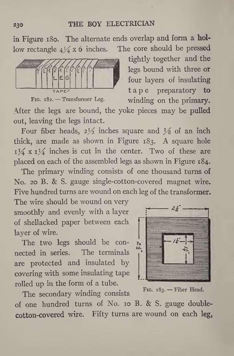
230 THE BOY ELECTRICIAN
in Figure 180. The alternate ends overlap and form a hol¬
low rectangle 4^ x 6 inches. The core should be pressed
tightly together and the
TAPE''
Fig. 182. — Transformer Leg.
legs bound with three or
four layers of insulating
tape preparatory to
winding on the primary.
After the legs are bound, the yoke pieces may be pulled
out, leaving the legs intact.
Four fiber heads, 2}4 inches square and y& of an inch
thick, are made as shown in Figure 183. A square hole
inches is cut in the center. Two of these are
placed on each of the assembled legs as shown in Figure 184.
The primary winding consists of one thousand turns of
No. 20 B. & S. gauge single-cotton-covered magnet wire.
Five hundred turns are wound on each leg of the transformer.
The wire should be wound on very
smoothly and evenly with a layer
of shellacked paper between each
layer of wire.
The two legs should be con¬
nected in series. The terminals
are protected and insulated by
covering with some insulating tape
rolled up in the form of a tube.
The secondary winding consists
of one hundred turns of No. 10 B. & S. gauge double-
cotton-covered wire. Fifty turns are wound on each leg,
bs
Fig. 183. — Fiber Head.
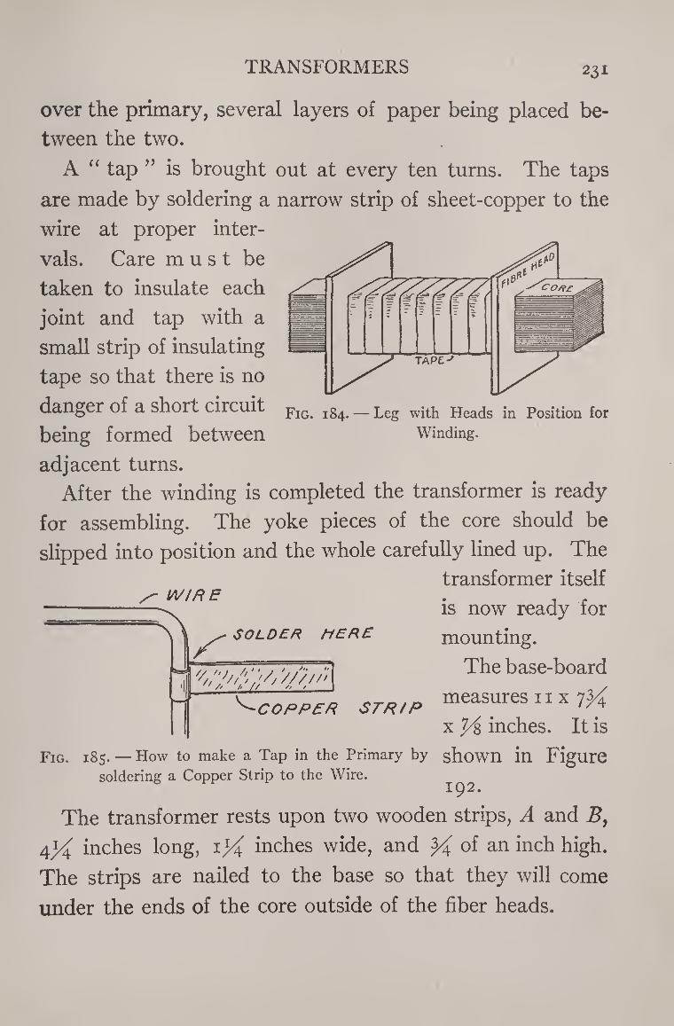
TRANSFORMERS 231
over the primary, several layers of paper being placed be¬
tween the two.
A “ tap ” is brought out at every ten turns. The taps
are made by soldering a narrow strip of sheet-copper to the
wire at proper inter¬
vals. Care must be
taken to insulate each
joint and tap with a
small strip of insulating
tape so that there is no
danger of a short circuit
being formed between
adjacent turns.
After the winding is completed the transformer is ready
for assembling. The yoke pieces of the core should be
slipped into position and the whole carefully lined up. The
transformer itself
is now ready for
mounting.
The base-board
measures n x 7^
x 7/& inches. It is
WIRE
s' SOLDER MERE
^COPPER STR/P
Fig. 185. — How to make a Tap in the Primary by shown in Figure soldering a Copper Strip to the Wire. ^
The transformer rests upon two wooden strips, A and B,
4^ inches long, inches wide, and of an inch high.
The strips are nailed to the base so that they will come
under the ends of the core outside of the fiber heads.
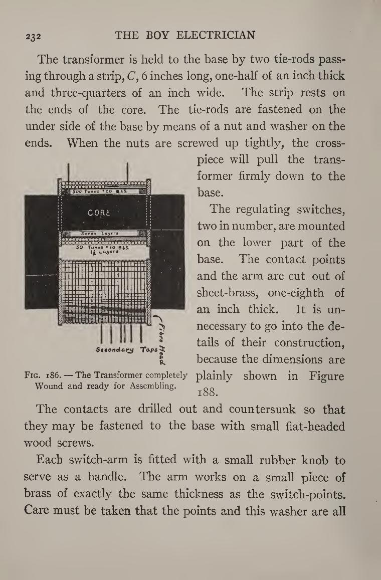
232 THE BOY ELECTRICIAN
The transformer is held to the base by two tie-rods pass¬
ing through a strip, C, 6 inches long, one-half of an inch thick
and three-quarters of an inch wide. The strip rests on
the ends of the core. The tie-rods are fastened on the
under side of the base by means of a nut and washer on the
ends. When the nuts are screwed up tightly, the cross¬
piece will pull the trans¬
former firmly down to the
base.
The regulating switches,
two in number, are mounted
on the lower part of the
base. The contact points
and the arm are cut out of
sheet-brass, one-eighth of
an inch thick. It is un¬
necessary to go into the de¬
tails of their construction,
because the dimensions are
Fig. 186. — The Transformer completely plainly shown in Figure Wound and ready for Assembling. QO
loo.
The contacts are drilled out and countersunk so that
they may be fastened to the base with small flat-headed
wood screws.
Each switch-arm is fitted with a small rubber knob to
serve as a handle. The arm works on a small piece of
brass of exactly the same thickness as the switch-points.
Care must be taken that the points and this washer are all
Secondary Tapsjjt s
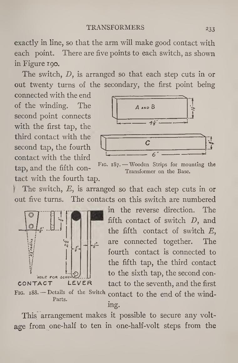
TRANSFORMERS 233
•H* J
exactly in line, so that the arm will make good contact with
each point. There are five points to each switch, as shown
in Figure 190.
The switch, E, is arranged so that each step cuts in or
out twenty turns of the secondary, the first point being
connected with the end
of the winding. The
second point connects
with the first tap, the
third contact with the
second tap, the fourth : __ s - ____
contact with the third i rr.i Fig. 187. — Wooden Strips for mounting the
tap, and the fifth con- Transformer on the Base.
tact with the fourth tap.
) The switch, E, is arranged so that each step cuts in or
out five turns. The contacts on this switch are numbered
in the reverse direction. The
fifth contact of switch D, and
the fifth contact of switch E,
are connected together. The
fourth contact is connected to
the fifth tap, the third contact
to the sixth tap, the second con¬
tact to the seventh, and the first
Fig. 188. — Details of the Switch COntact to the end of the wind- Parts.
mg.
This arrangement makes it possible to secure any volt¬
age from one-half to ten in one-half-volt steps from the
...J
>
-l«'J
j*
jO HOLE FOR ^CREwSi^/ . ,.L
CONTACT LEVER
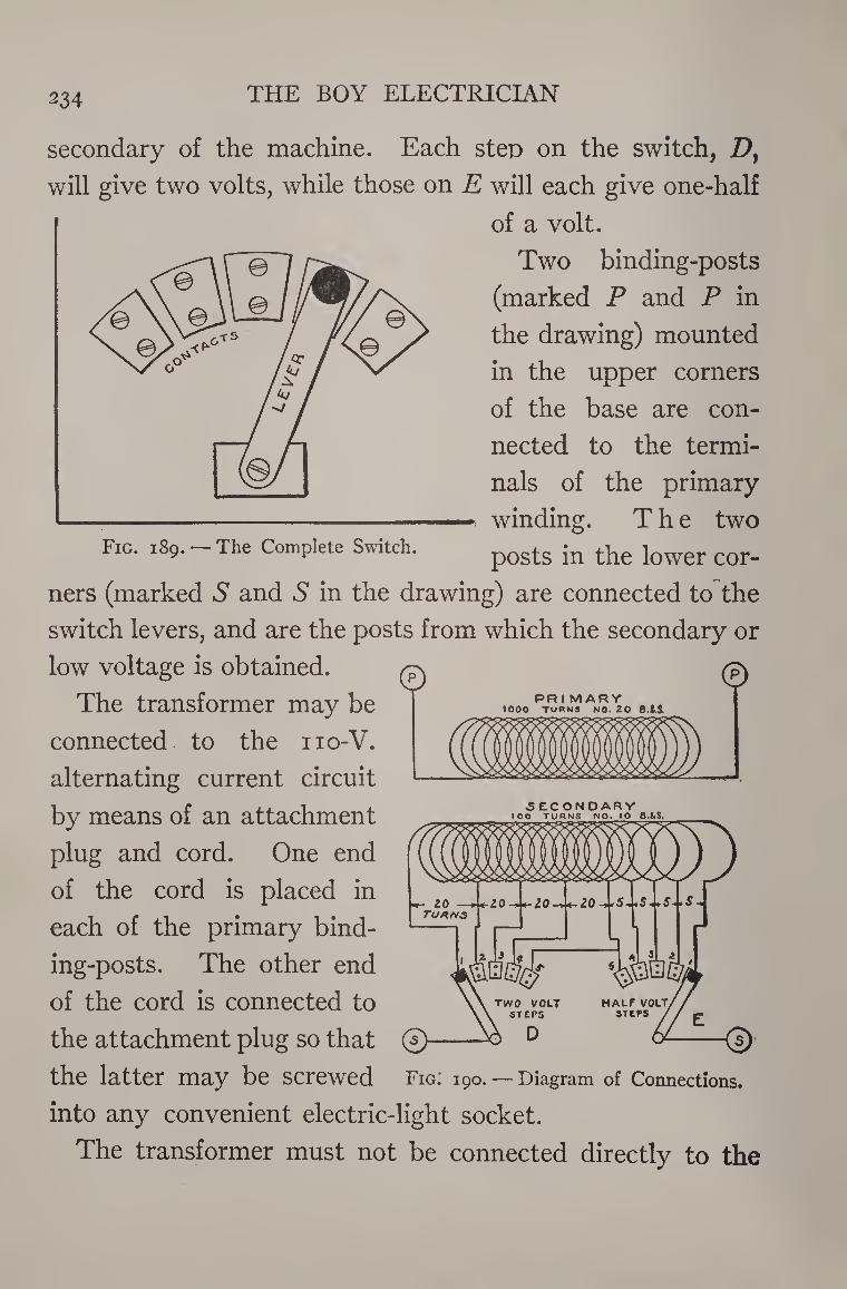
234 THE BOY ELECTRICIAN
secondary of the machine. Each step on the switch, Dy
will give two volts, while those on E will each give one-half
of a volt.
Two binding-posts
(marked P and P in
the drawing) mounted
in the upper corners
of the base are con¬
nected to the termi¬
nals of the primary
winding. The two Fig. 189. - The Complete Switch. posts jn the Jower cor_
ners (marked S and 5 in the drawing) are connected to the
switch levers, and are the posts from which the secondary or
low voltage is obtained.
The transformer may be
connected to the iio-V.
alternating current circuit
by means of an attachment
plug and cord. One end
of the cord is placed in
each of the primary bind¬
ing-posts. The other end
of the cord is connected to
the attachment plug so that
the latter may be screwed
into any convenient electric-light socket.
The transformer must not be connected directly to the
PRI MARY • 000 TURNS NO. 20 B.tS.
©
3 EC ONDARY IOO TURNS NO. IO B.&S.
Fig. 190. — Diagram of Connections.
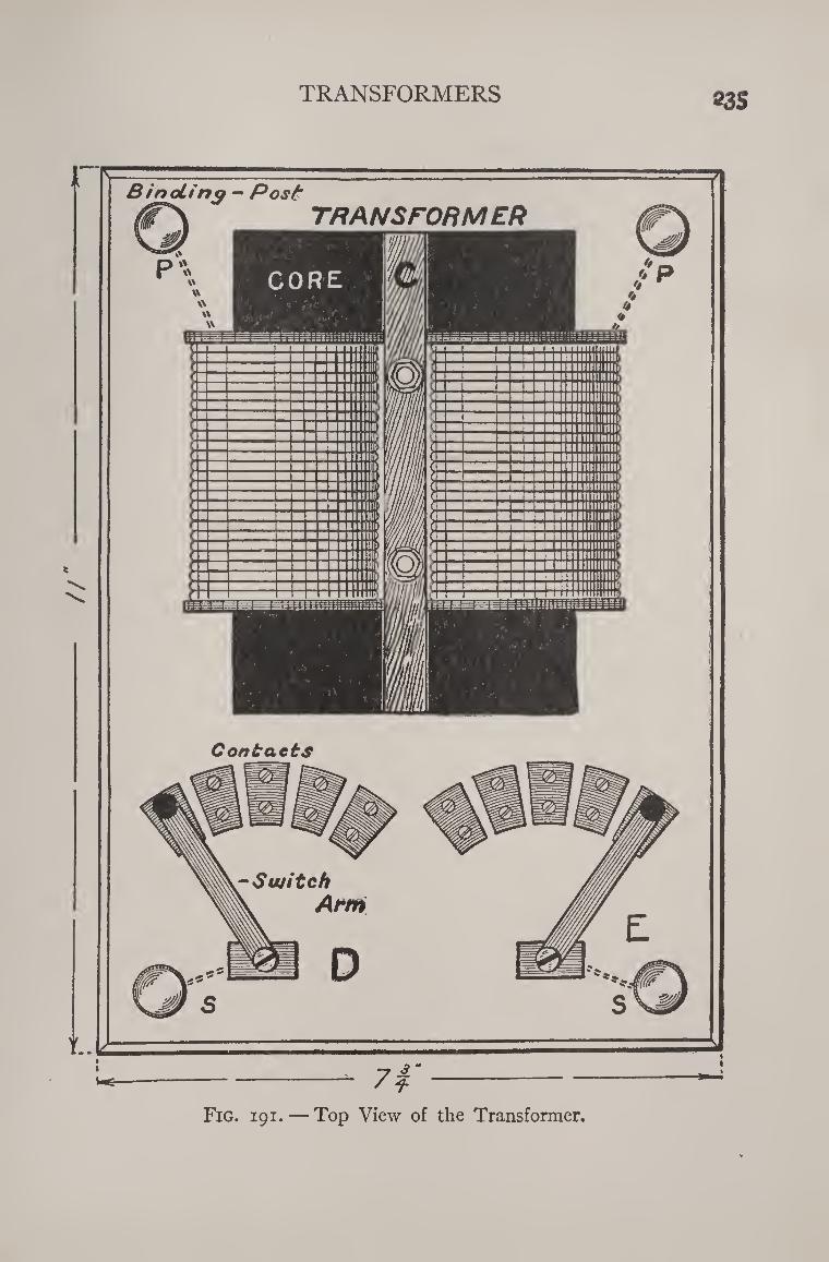
TRANSFORMERS «3S
Fig. 191. — Top View of the Transformer.
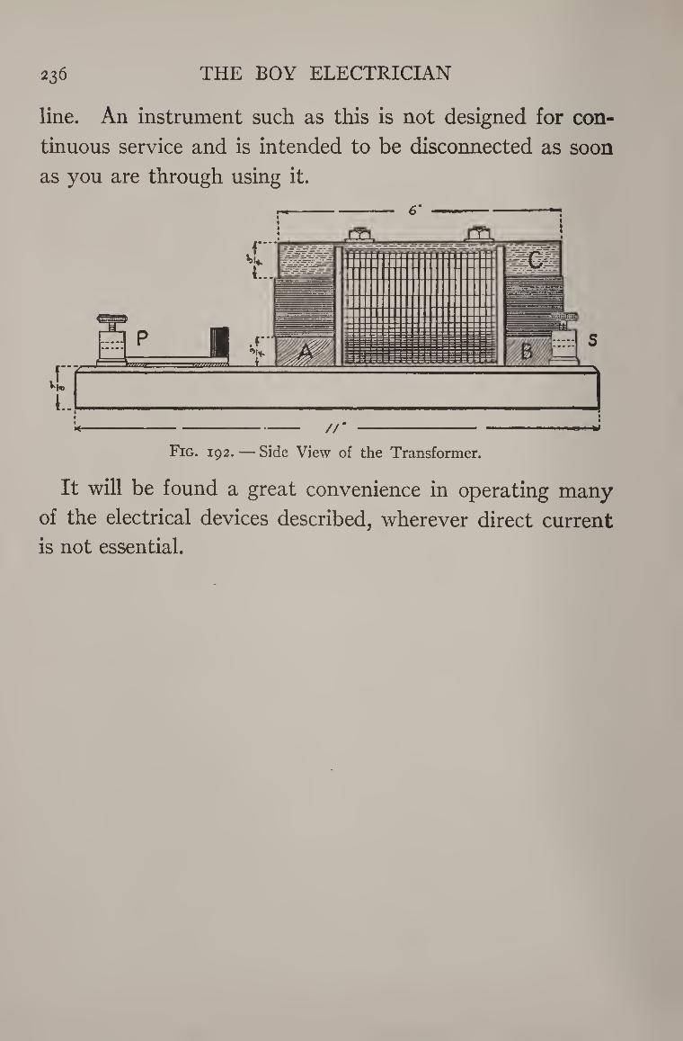
236 THE BOY ELECTRICIAN
line. An instrument such as this is not designed for con¬
tinuous service and is intended to be disconnected as soon
as you are through using it.
m jTl
Fig. 192. — Side View of the Transformer.
It will be found a great convenience in operating many
of the electrical devices described, wherever direct current
is not essential.
Probably no branch of electrical science ever appealed
more to the imagination of the experimenter than that com¬
ing under the heading of wireless telegraphy. A few years
ago when the first edition of this book was published, almost
anywhere one might go in this country, there were to be seen
the ear-marks of amateur wireless telegraph stations in the
aerials and masts set up in trees and on house-tops. It is es¬
timated that there were nearly a quarter of a million such
stations in the United States. They were not for the pur¬
pose of listening to the entertainment furnished by radio
broadcast programs, for at that time radio telephony was not
entirely practical, and broadcasting of regular programs had
not been thought of, but were “wireless” stations for sending
and receiving wireless telegraph signals.
These amateur stations could listen to the telegraph mes¬
sages passing between ships at sea and the shore or co lmuni-
cate with one another over distances varying from two or
three miles to halfway across the continent. Those amateur
stations which were equipped for transmitting were licensed
by the United States Department of Co imerce. No other
nation had the liberal laws which encouraged the operation
of private stations. Consequently during the World War, 237
THE BOY ELECTRICIAN 238
the wireless telegraph equipment and operators of the Ameri¬
can Army and Navy were vastly superior to those of the other
warring nations solely because of the stimulus and experience
of the large number of amateur operators that had been
developed in this country.
The amateur radio operator was also undoubtedly directly
responsible for modern broadcasting, because amateurs were
the first to send out phonograph music more or less regularly
over their experimental wireless telephone sets, thus creating
the idea of broadcasting. They constituted a vast army of
listeners already equipped with sets to receive the first broad¬
cast programs when they were finally started on a commer¬
cial basis.
Most experimenters to-day are content to build instru¬
ments solely for the purpose of receiving broadcast programs.
Although that fact is undoubtedly considered in the light of a
blessing by the owner of a broadcast receiver because the
telegraph signals of an amateur radio telegraph transmitter
are apt to interfere with the reception of musical programs,
I believe that no electrical book of this sort would be com¬
plete if it did not explain something of the principles involved
in the old art of wireless telegraphy.
In the days before broadcasting, the term radio was not
universally used. The word “wireless” was usually applied
instead. I am still going to use the older word when refer¬
ring to wireless or radio-telegraphy, and radio only when the
more modern transmission and reception of speech or music
by means of the three-element vacuum tube with which we
are familiar in the broadcast receiver, is involved.
The really valuable and most practical use for wireless
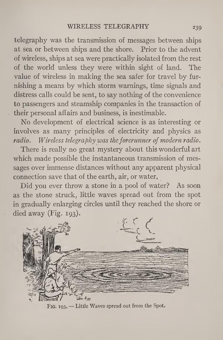
WIRELESS TELEGRAPHY 239
telegraphy was the transmission of messages between ships
at sea or between ships and the shore. Prior to the advent
of wireless, ships at sea were practically isolated from the rest
of the world unless they were within sight of land. The
value of wireless in making the sea safer for travel by fur¬
nishing a means by which storm warnings, time signals and
distress calls could be sent, to say nothing of the convenience
to passengers and steamship companies in the transaction of
their personal affairs and business, is inestimable.
No development of electrical science is as interesting or
involves as many principles of electricity and physics as
radio. Wireless telegraphy was the forerunner of modern radio.
There is really no great mystery about this wonderful art
which made possible the instantaneous transmission of mes¬
sages over immense distances without any apparent physical
connection save that of the earth, air, or water.
Did you ever throw a stone in a pool of water? As soon
as the stone struck, little waves spread out from the spot
in gradually enlarging circles until they reached the shore or
died away (Fig. 193).
Fig. 193. — Little Waves spread out from the Spot.
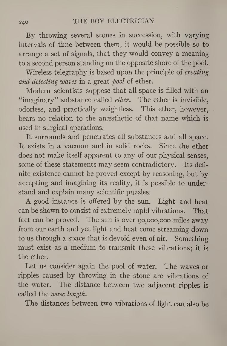
240 THE BOY ELECTRICIAN
By throwing several stones in succession, with varying
intervals of time between them, it would be possible so to
arrange a set of signals, that they would convey a meaning
to a second person standing on the opposite shore of the pool.
Wireless telegraphy is based upon the principle of creating
and detecting waves in a great pool of ether.
Modern scientists suppose that all space is filled with an
“imaginary” substance called ether. The ether is invisible,
odorless, and practically weightless. This ether, however, .
bears no relation to the anaesthetic of that name which is
used in surgical operations.
It surrounds and penetrates all substances and all space.
It exists in a vacuum and in solid rocks. Since the ether
does not make itself apparent to any of our physical senses,
some of these statements may seem contradictory. Its defi¬
nite existence cannot be proved except by reasoning, but by
accepting and imagining its reality, it is possible to under¬
stand and explain many scientific puzzles.
A good instance is offered by the sun. Light and heat
can be shown to consist of extremely rapid vibrations. That
fact can be proved. The sun is over 90,000,000 miles away
from our earth and yet light and heat come streaming down
to us through a space that is devoid even of air. Something
must exist as a medium to transmit these vibrations; it is
the ether.
Let us consider again the pool of water. The waves or
ripples caused by throwing in the stone are vibrations of
the water. The distance between two adjacent ripples is
called the wave length.
The distances between two vibrations of light can also be
' ■■
p®;® S® * ■ . ■ ,
The illustration is already magnified more than 10,000 times. The distance from A to B represents the thickness of a piece of newspaper. The
waves shown are those of ultra violet light. Scientists have measured X-rays which are a million times smaller,
and radio-active rays which are smaller still.
Courtesy of lladio Neivs.
A radio wave of moderate wave-length, in daily use at Bordeaux, France. As all radio-waves travel at 188,100 miles per second (300,000,000 meters)
thiswrave has a frequency of 12,840, in other words over 12,000 such waves pass a given point in a second.
Electro-Magnetic Waves Compared: Ultra-Violet Light
and Radio.
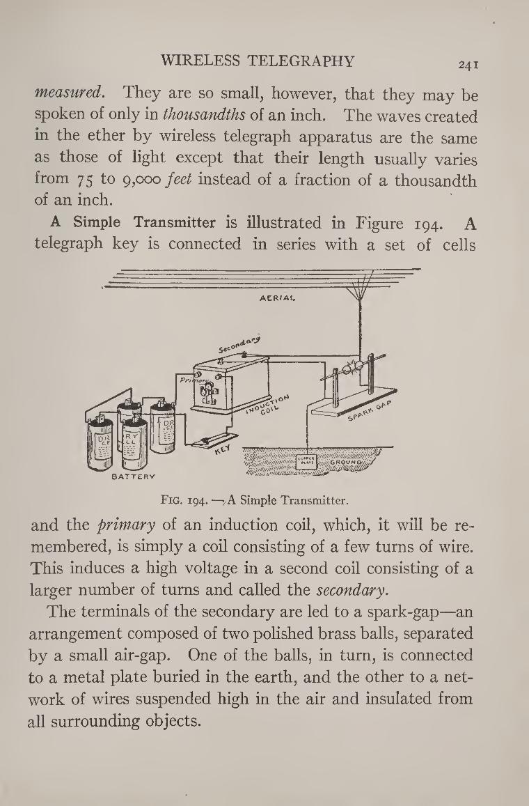
WIRELESS TELEGRAPHY 241
measured. They are so small, however, that they may be
spoken of only in thousandths of an inch. The waves created
in the ether by wireless telegraph apparatus are the same
as those of light except that their length usually varies
from 75 to 9,000 feet instead of a fraction of a thousandth of an inch.
A Simple Transmitter is illustrated in Figure 194. A
telegraph key is connected in series with a set of cells
Fig. 194. —y A Simple Transmitter.
and the primary of an induction coil, which, it will be re¬
membered, is simply a coil consisting of a few turns of wire.
This induces a high voltage in a second coil consisting of a
larger number of turns and called the secondary.
The terminals of the secondary are led to a spark-gap—an
arrangement composed of two polished brass balls, separated
by a small air-gap. One of the balls, in turn, is connected
to a metal plate buried in the earth, and the other to a net¬
work of wires suspended high in the air and insulated from
all surrounding objects.
242 THE BOY ELECTRICIAN
When the key at the transmitter is pressed, the battery
current flows through the primary of the induction coil and
generates in the secondary a current of very high voltage,
20,000 volts or more, which is able to jump an air-gap in
the shape of a spark at the secondary terminals. The latter
are connected to the earth and aerial, as explained above.
The high potential currents are therefore enabled to charge
the aerial. The charge in the aerial exerts a great tendency
to pass into the ground, but is prevented from doing so by
the small air-gap between the spark-balls until the charge
becomes so great that the air-gap is punctured and the charge
passes across and flows down into the ground. The passage
of the charge is made evident by the spark between the two
spark-balls.
The electrical charges flowing up and down the aerial
disturb the ether, strike it a blow, as it were. The effect of
the blow is to cause the ether to vibrate and to send out
waves in all directions. It may be likened to the pond of
water which is suddenly struck a blow by throwing a stone
into it, so that ripples are immediately sent out in widening
circles.
These Waves in the Ether are called electro-magnetic or
Hertzian waves, after their discoverer, Hertz. The distance «
over which they pass is dependent upon the power of the
transmitting station. The waves can be made to corre¬
spond to the dots and dashes of the telegraphic code by so
pressing the key. If some means of detecting the waves is
employed we may readily see how it is possible to send wire¬
less messages.
The Action of the Receiving Station is just the opposite
WIRELESS TELEGRAPHY 243
of that of the transmitter. When the waves pass out through the ether, some of them strike the aerial of the receiving station and generate a charge of electricity in it which tends to pass down into the earth. If the transmitting and receiving stations are very close together and the former is very powerful, it is possible to make a very small gap in the receiving aerial across which the charge will jump in the shape of sparks. Thus the action of the receptor simply takes place in a reversed order from that of the transmitter.
If the stations are any considerable distance apart, it is impossible for the currents induced in the receiving aerial to produce sparks, and so some more sensitive means of de¬ tecting the waves from the transmitter is necessary, prefer¬ ably one which makes itself evident to the sense of hearing.
The telephone receiver is an extremely sensitive instru¬ ment, and it only requires a very weak current to operate it and produce a sound. The currents or oscillations gen¬ erated in the aerial, however, are alternating currents (see
pages 97-99) of high frequency, that is, they flow in one direc¬ tion and then reverse and flow in the other several thousand times a second. Such a current cannot be made to pass through a telephone receiver, and in order to do so the nature of the current must be changed by converting it into
direct current flowing in one direction only. Certain crystalline minerals possess the remarkable ability
to change or rectify an alternating current into a direct cur¬ rent. They act as sort of “an electrical valve”, allowing the current to flow in one direction but not in the other. One
half of the alternating current cycle only can therefore pass
through one of these mineral rectifiers or detectors.
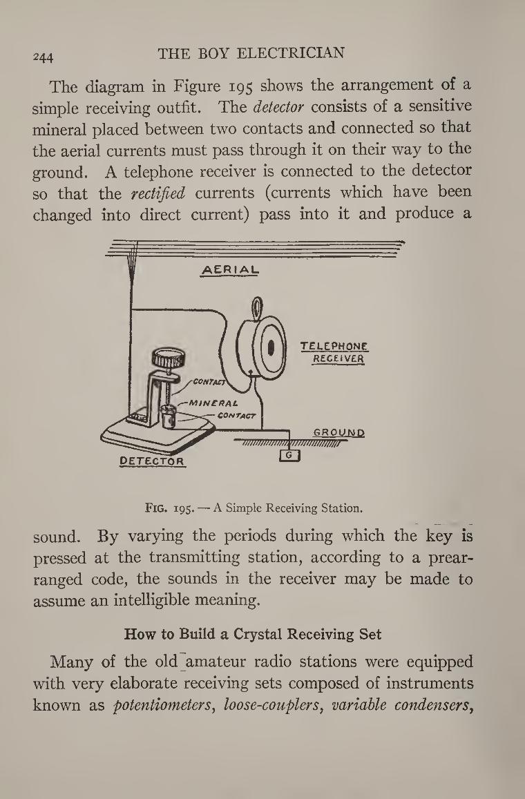
244 THE BOY ELECTRICIAN
The diagram in Figure 195 shows the arrangement of a
simple receiving outfit. The detector consists of a sensitive
mineral placed between two contacts and connected so that
the aerial currents must pass through it on their way to the
ground. A telephone receiver is connected to the detector
so that the rectified currents (currents which have been
changed into direct current) pass into it and produce a
Fig. 195. — A Simple Receiving Station.
sound. By varying the periods during which the key is
pressed at the transmitting station, according to a prear¬
ranged code, the sounds in the receiver may be made to
assume an intelligible meaning.
How to Build a Crystal Receiving Set
Many of the old amateur radio stations were equipped
with very elaborate receiving sets composed of instruments
known as potentiometers, loose-couplers, variable condensers,
WIRELESS TELEGRAPHY 245
couplers, etc. These made possible the very accurate and
close adjustment of the circuits so that the maximum of
selectivity and distance was obtained. Selectivity is the term
applied to the ability of the station to “tune out” undesired
messages and to bring in the one wanted with the greatest
volume. But in order simply to “listen in” and receive the
messages of other near-by amateurs and ships or commercial
stations it was only necessary to employ
A Detector,
A Tuning Coil,
A Fixed Condenser,
And a Telephone Receiver,
connected to a suitable aerial and ground.
Such an outfit is described in the following pages. It
may be used to pick up radio programs from broadcasting
stations not over twenty-five miles away.
One of the first things to receive attention when thinking
of building a wireless or radio outfit should be
The Aerial
Every wireless station is provided with a system of wires
elevated high in the air, above all surrounding objects, the
purpose of which is to radiate or intercept the electro¬
magnetic waves, accordingly as the station is transmitting
or receiving. This system of wires is, as already has been
stated, called the aerial or antenna.
The arrangement of the aerial will greatly determine the
efficiency and range of the apparatus.
The aerial should be as long as it is reasonably possible to
make it, that is from 50 to 100 feet.
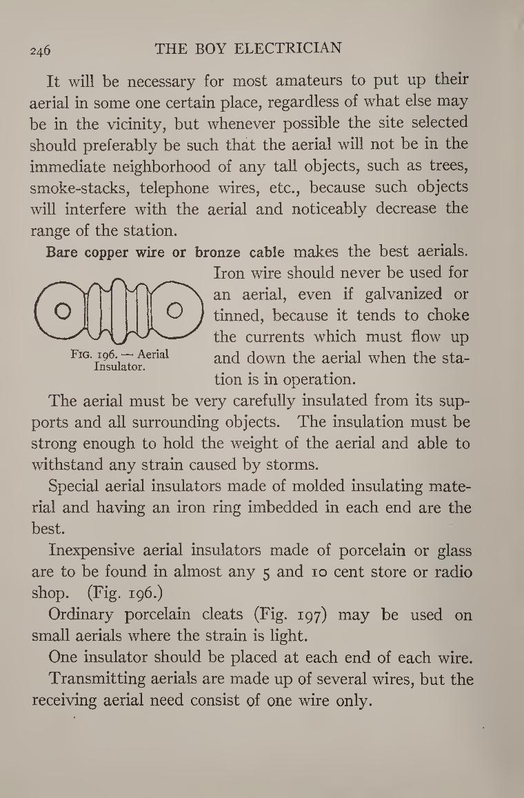
246 THE BOY ELECTRICIAN
It will be necessary for most amateurs to put up their
aerial in some one certain place, regardless of what else may
be in the vicinity, but whenever possible the site selected
should preferably be such that the aerial will not be in the
immediate neighborhood of any tall objects, such as trees,
smoke-stacks, telephone wires, etc., because such objects
will interfere with the aerial and noticeably decrease the
range of the station.
Bare copper wire or bronze cable makes the best aerials.
Iron wire should never be used for
an aerial, even if galvanized or s—N/>TVrv^ x / \ dll deadly cvtu 11 gai v vii
( 0 O ) tinned, because it tends to choke X—✓Ah, /■"UX—y fhe currents which must flow ur> \J
Fig. 196. — Aerial Insulator.
the currents which must flow up
and down the aerial when the sta¬
tion is in operation.
The aerial must be very carefully insulated from its sup¬
ports and all surrounding objects. The insulation must be
strong enough to hold the weight of the aerial and able to
withstand any strain caused by storms.
Special aerial insulators made of molded insulating mate¬
rial and having an iron ring imbedded in each end are the
best.
Inexpensive aerial insulators made of porcelain or glass
are to be found in almost any 5 and 10 cent store or radio
shop. (Fig. 196.)
Ordinary porcelain cleats (Fig. 197) may be used on
small aerials where the strain is light.
One insulator should be placed at each end of each wire.
Transmitting aerials are made up of several wires, but the
receiving aerial need consist of one wire only.
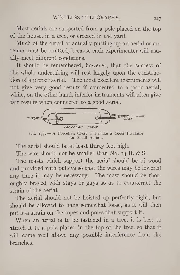
WIRELESS TELEGRAPHY, 247
Most aerials are supported from a pole placed on the top
of the house, in a tree, or erected in the yard.
Much of the detail of actually putting up an aerial or an¬
tenna must be omitted, because each experimenter will usu¬
ally meet different conditions.
It should be remembered, however, that the success of
the whole undertaking will rest largely upon the construc¬
tion of a proper aerial. The most excellent instruments will
not give , very good results if connected to a poor aerial,
while, on the other hand, inferior instruments will often give
fair results when connected to a good aerial.
PonceuAir* ci-cat
Fig. 197. — A Porcelian Cleat will make a Good Insulator for Small Aerials.
The aerial should be at least thirty feet high.
The wire should not be smaller than No. 14 B. & S.
The masts which support the aerial should be of wood
and provided with pulleys so that the wires may be lowered
any time it may be necessary. The mast should be thor¬
oughly braced with stays or guys so as to counteract the
strain of the aerial.
The aerial should not be hoisted up perfectly tight, but
should be allowed to hang somewhat loose, as it will then
put less strain on the ropes and poles that support it.
When an aerial is to be fastened in a tree, it is best to
attach it to a pole placed in the top of the tree, so that it
will come well above any possible interference from the
branches.
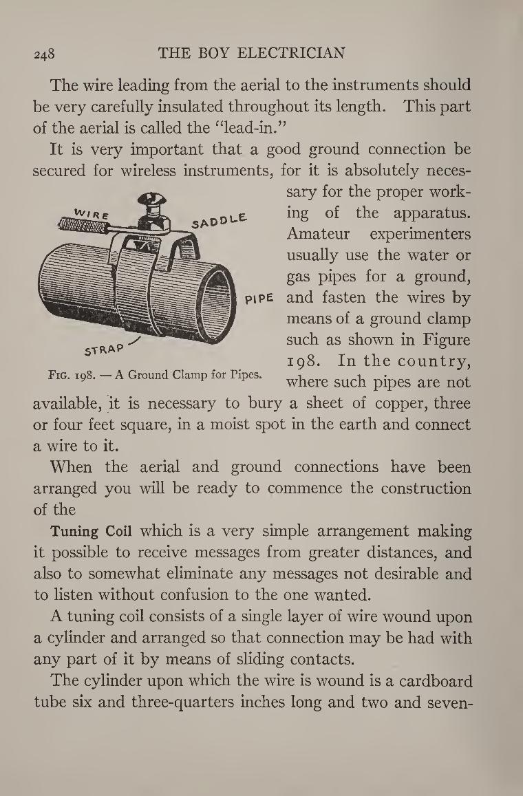
248 THE BOY ELECTRICIAN
The wire leading from the aerial to the instruments should
be very carefully insulated throughout its length. This part
of the aerial is called the “lead-in.”
It is very important that a good ground connection be
secured for wireless instruments, for it is absolutely neces¬
sary for the proper work¬
ing of the apparatus.
Amateur experimenters
usually use the water or
gas pipes for a ground,
and fasten the wires by
means of a ground clamp
such as shown in Figure
198. In the country,
where such pipes are not
available, it is necessary to bury a sheet of copper, three
or four feet square, in a moist spot in the earth and connect
a wire to it.
When the aerial and ground connections have been
arranged you will be ready to commence the construction
of the
Tuning Coil which is a very simple arrangement making
it possible to receive messages from greater distances, and
also to somewhat eliminate any messages not desirable and
to listen without confusion to the one wanted.
A tuning coil consists of a single layer of wire wound upon
a cylinder and arranged so that connection may be had with
any part of it by means of sliding contacts.
The cylinder upon which the wire is wound is a cardboard
tube six and three-quarters inches long and two and seven-
Fig. 198. — A Ground Clamp for Pipes.
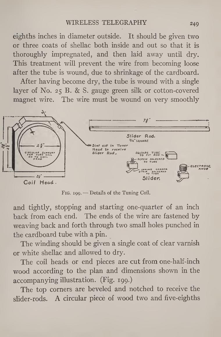
WIRELESS TELEGRAPHY 249
eighths inches in diameter outside. It should be given two
or three coats of shellac both inside and out so that it is
thoroughly impregnated, and then laid away until dry.
This treatment will prevent the wire from becoming loose
after the tube is wound, due to shrinkage of the cardboard.
After having become dry, the tube is wound with a single
layer of No. 25 B. & S. gauge green silk or cotton-covered
magnet wire. The wire must be wound on very smoothly
and tightly, stopping and starting one-quarter of an inch
back from each end. The ends of the wire are fastened by
weaving back and forth through two small holes punched in
the cardboard tube with a pin.
The winding should be given a single coat of clear varnish
or white shellac and allowed to dry.
The coil heads or end pieces are cut from one-half-inch
wood according to the plan and dimensions shown in the
accompanying illustration. (Fig. 199.)
The top corners are beveled and notched to receive the
slider-rods. A circular piece of wood two and five-eighths
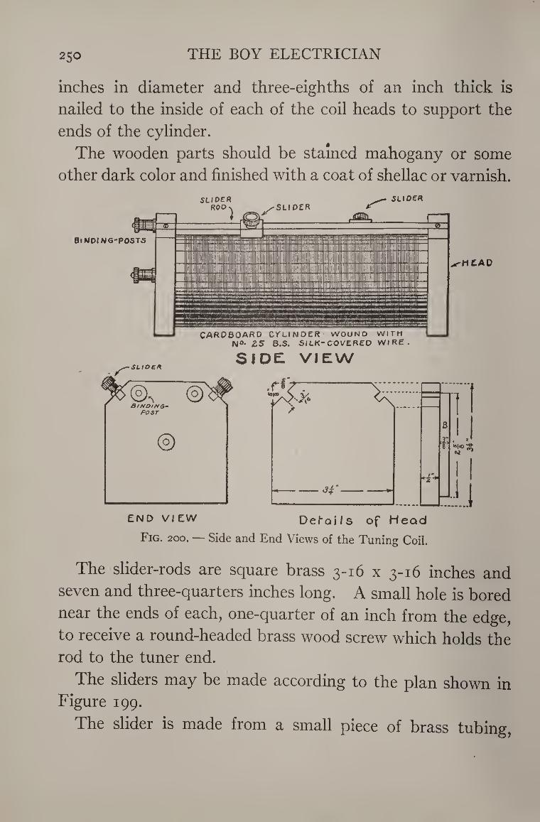
250 THE BOY ELECTRICIAN
inches in diameter and three-eighths of an inch thick is
nailed to the inside of each of the coil heads to support the
ends of the cylinder.
The wooden parts should be stained mahogany or some
other dark color and finished with a coat of shellac or varnish.
S I DEL VIEW
END VIEW Def-Qils of Head
Fig. 200. — Side and End Views of the Tuning Coil.
The slider-rods are square brass 3-16 x 3-16 inches and
seven and three-quarters inches long. A small hole is bored
near the ends of each, one-quarter of an inch from the edge,
to receive a round-headed brass wood screw which holds the rod to the tuner end.
The sliders may be made according to the plan shown in Figure 199.
The slider is made from a small piece of brass tubing,
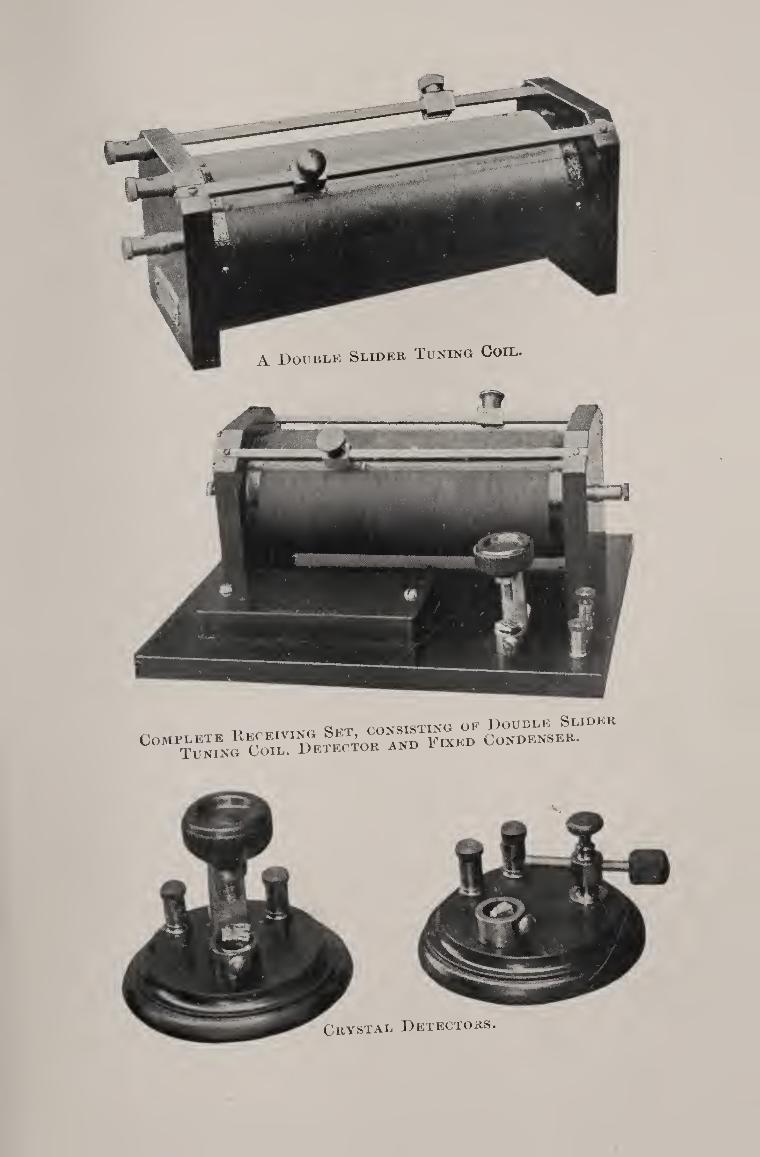
^ oT^rn rnv<?TSTING OF DOUBLE SLIDER
COMP^f»?rCoTLT,DFlECTOE AND FIXED CORDEKSER.

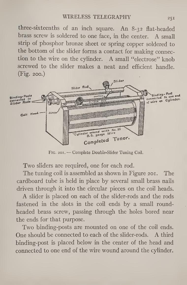
WIRELESS TELEGRAPHY 251
three-sixteenths of an inch square. An 8-32 flat-headed
brass screw is soldered to one face, in the center. A small
strip of phosphor bronze sheet or spring copper soldered to
the bottom of the slider forms a contact for making connec¬
tion to the wire on the cylinder. A small “electrose” knob
screwed to the slider makes a neat and efhcient handle. (Fig. 200.)
Binding'?0*1/ connecte
5|id«r
Co ',1
dor oiot
Complete Tuner.
eon".*1* 'culioJC- 0f wire at»
Fig. 201. — Complete Double-Slider Tuning Coil.
Two sliders are required, one for each rod.
The tuning coil is assembled as shown in Figure 201. The
cardboard tube is held in place by several small brass nails
driven through it into the circular pieces on the coil heads.
A slider is placed on each of the slider-rods and the rods
fastened in the slots in the coil ends by a small round-
headed brass screw, passing through the holes bored near
the ends for that purpose.
Two binding-posts are mounted on one of the coil ends.
One should be connected to each of the slider-rods. A third
binding-post is placed below in the center of the head and
connected to one end of the wire wound around the cylinder.
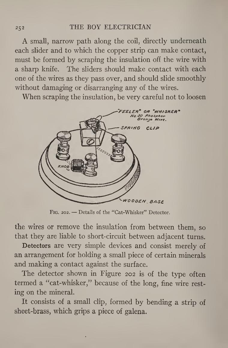
252 THE BOY ELECTRICIAN
A small, narrow path along the coil, directly underneath
each slider and to which the copper strip can make contact,
must be formed by scraping the insulation off the wire with
a sharp knife. The sliders should make contact with each
one of the wires as they pass over, and should slide smoothly
without damaging or disarranging any of the wires.
When scraping the insulation, be very careful not to loosen
'•WOOOZ/V 6AS£
*F£ELER* OR VHIGHER' A/o. SO PAoJpAor
S^onjo M/tre.
SPR'rfG CLIP
Fig. 202. — Details of the “Cat-Whisker” Detector.
the wires or remove the insulation from between them, so
that they are liable to short-circuit between adjacent turns.
Detectors are very simple devices and consist merely of
an arrangement for holding a small piece of certain minerals
and making a contact against the surface.
The detector shown in Figure 202 is of the type often
termed a “cat-whisker,” because of the long, fine wire rest¬
ing on the mineral.
It consists of a small clip, formed by bending a strip of
sheet-brass, which grips a piece of galena.
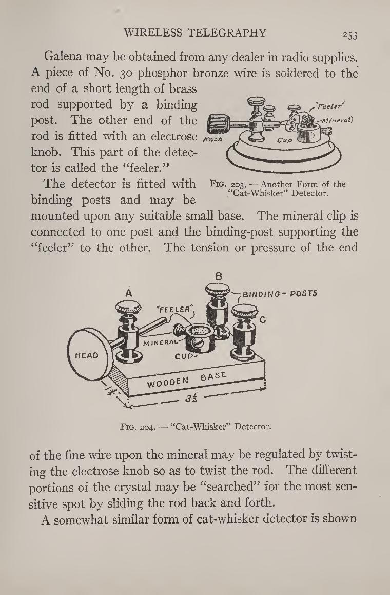
WIRELESS TELEGRAPHY 253
—Mineral)
/fnob
Galena may be obtained from any dealer in radio supplies.
A piece of No. 30 phosphor bronze wire is soldered to the
end of a short length of brass
rod supported by a binding
post. The other end of the
rod is fitted with an electrose
knob. This part of the detec¬
tor is called the “feeler.”
The detector is fitted with
binding posts and may be
mounted upon any suitable small base. The mineral clip is
connected to one post and the binding-post supporting the
“feeler” to the other. The tension or pressure of the end
Fig. 203. — Another Form of the “Cat-Whisker” Detector.
Fig. 204. — “Cat-Whisker” Detector.
of the fine wire upon the mineral may be regulated by twist¬
ing the electrose knob so as to twist the rod. The different
portions of the crystal may be “searched” for the most sen¬
sitive spot by sliding the rod back and forth.
A somewhat similar form of cat-whisker detector is shown
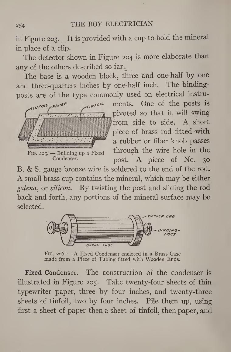
254 THE BOY ELECTRICIAN
in Figure 203. It is provided with a cup to hold the mineral
in place of a clip. The detector shown in Figure 204 is more elaborate than
any of the others described so far.^
The base is a wooden block, three and one-half by one
and three-quarters inches by one-half inch. The binding-
posts are of the type commonly used on electrical instru-
ffjFO,u p1kpl* ments. One of the posts is
. C . ., - ^ pivoted so that it will swing
drom side to side. A short
piece of brass rod fitted with
a rubber or fiber knob passes
through the wire hole in the
post. A piece of No. 30
B. & S. gauge bronze wire is soldered to the end of the rod.
A small brass cup contains the mineral, which may be either
galena, or silicon. By twisting the post and sliding the rod
back and forth, any portions of the mineral surface may be
selected.
Fig. 205. — Building up a Fixed Condenser.
Fig. 206. — A Fixed Condenser enclosed in a Brass Case made from a Piece of Tubing fitted with Wooden Ends.
Fixed Condenser. The construction of the condenser is
illustrated in Figure 205. Take twenty-four sheets of thin
typewriter paper, three by four inches, and twenty-three
sheets of tinfoil, two by four inches. Pile them up, using
first a sheet of paper then a sheet of tinfoil, then paper, and
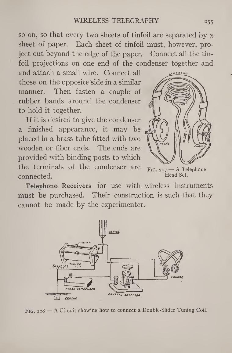
WIRELESS TELEGRAPHY 255
uCAP flA HQ
so on, so that every two sheets of tinfoil are separated by a
sheet of paper. Each sheet of tinfoil must, however, pro¬
ject out beyond the edge of the paper. Connect all the tin-
foil projections on one end of the condenser together and
and attach a small wire. Connect all
those on the opposite side in a similar
manner. Then fasten a couple of
rubber bands around the condenser
to hold it together.
If it is desired to give the condenser
a finished appearance, it may be
placed in a brass tube fitted with two
wooden or fiber ends. The ends are
provided with binding-posts to which
the terminals of the condenser are
connected.
Telephone Receivers for use with wireless instruments
must be purchased. Their construction is such that they
cannot be made by the experimenter.
Fig. 207.— A Telephone Head Set.
ACRtAL
• suoca
_ „ Tuning \ \ Pft'ten c°“-
%-
nxco QONDtNSCR
~vTm>fA
CD CAOUNO CRYSTAL OCTCCTOf)
Fig. 208.— A Circuit showing how to connect a Double-Slider Tuning Coil.
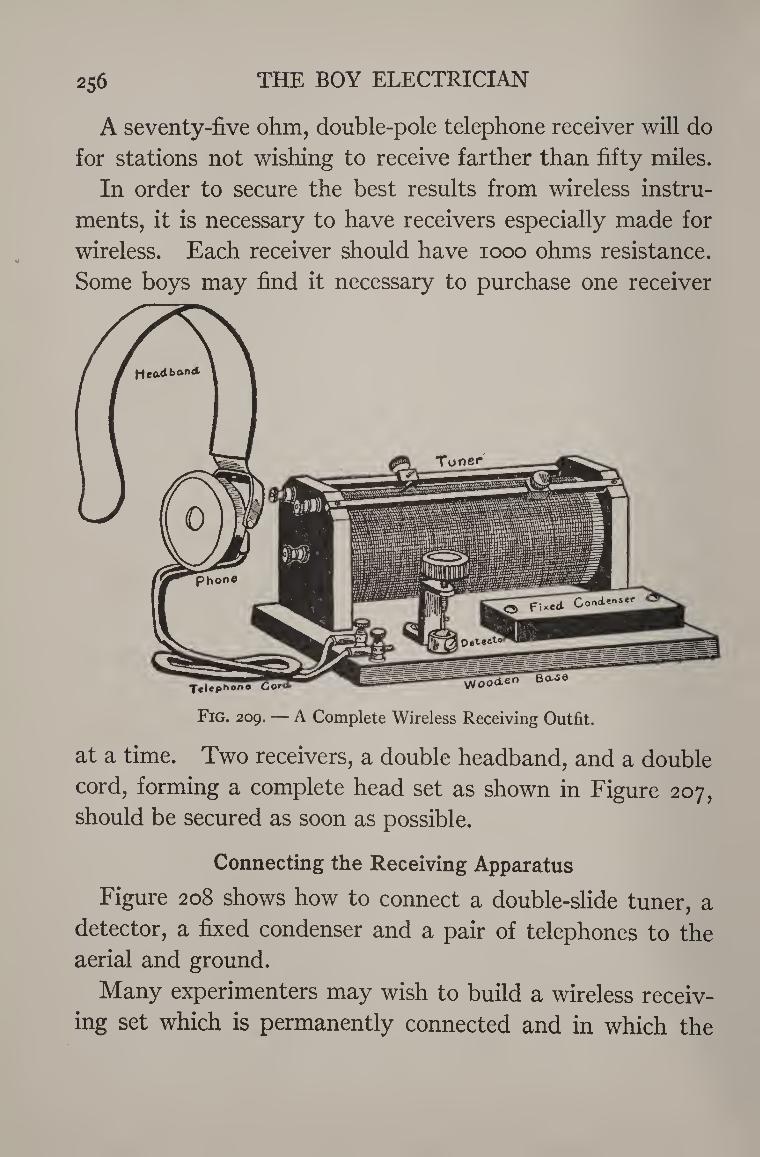
THE BOY ELECTRICIAN 256
A seventy-five ohm, double-pole telephone receiver will do
for stations not wishing to receive farther than fifty miles.
In order to secure the best results from wireless instru¬
ments, it is necessary to have receivers especially made for
wireless. Each receiver should have 1000 ohms resistance.
Some boys may find it necessary to purchase one receiver
at a time. Two receivers, a double headband, and a double
cord, forming a complete head set as shown in Figure 207,
should be secured as soon as possible.
Connecting the Receiving Apparatus
Figure 208 shows how to connect a double-slide tuner, a
detector, a fixed condenser and a pair of telephones to the
aerial and ground.
Many experimenters may wish to build a wireless receiv¬
ing set which is permanently connected and in which the
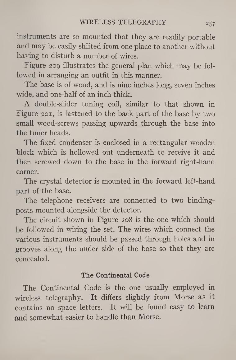
WIRELESS TELEGRAPHY 257
instruments are so mounted that they are readily portable
and may be easily shifted from one place to another without
having to disturb a number of wires.
Figure 209 illustrates the general plan which may be fol¬
lowed in arranging an outfit in this manner.
The base is of wood, and is nine inches long, seven inches
wide, and one-half of an inch thick.
A double-slider tuning coil, similar to that shown in
Figure 201, is fastened to the back part of the base by two
small wood-screws passing upwards through the base into
the tuner heads.
The fixed condenser is enclosed in a rectangular wooden
block which is hollowed out underneath to receive it and
then screwed down to the base in the forward right-hand
corner.
The crystal detector is mounted in the forward left-hand
part of the base.
The telephone receivers are connected to two binding-
posts mounted alongside the detector.
The circuit shown in Figure 208 is the one which should
be followed in wiring the set. The wires which connect the
various instruments should be passed through holes and in
grooves along the under side of the base so that they are
concealed.
The Continental Code
The Continental Code is the one usually employed in
wireless telegraphy. It differs slightly from Morse as it
contains no space letters. It will be found easy to learn
and somewhat easier to handle than Morse.
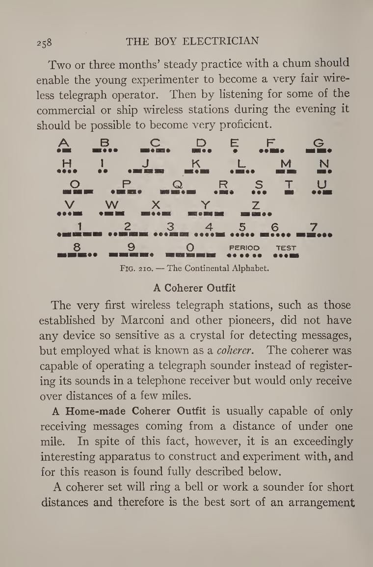
THE BOY ELECTRICIAN 258
Two or three months’ steady practice with a chum should
enable the young experimenter to become a very fair wire¬
less telegraph operator. Then by listening for some of the
commercial or ship wireless stations during the evening it
should be possible to become very proficient.
/K B JS.' D E •
F G
H 1 J K L M N •••• w w # m M&w 1 • 1 • 1 • • 1 1 HH 1
O p Q R S T U «aa bh ■Of 0 BH HI
1 • 1 • •• ■* • 0 ■ V
•••■ #W X
BH • • 1 1
H i
z
1 2 3 4 5 6 7 HH ##BHM ■* ••••■ ••••• ■•••• ■ 8 9 0 PERIOD TEST
Fig. 210. — The Continental Alphabet.
A Coherer Outfit
The very first wireless telegraph stations, such as those
established by Marconi and other pioneers, did not have
any device so sensitive as a crystal for detecting messages,
but employed what is known as a coherer. The coherer was
capable of operating a telegraph sounder instead of register¬
ing its sounds in a telephone receiver but would only receive
over distances of a few miles.
A Home-made Coherer Outfit is usually capable of only
receiving messages coming from a distance of under one
mile. In spite of this fact, however, it is an exceedingly
interesting apparatus to construct and experiment with, and
for this reason is found fully described below.
A coherer set will ring a bell or work a sounder for short
distances and therefore is the best sort of an arrangement
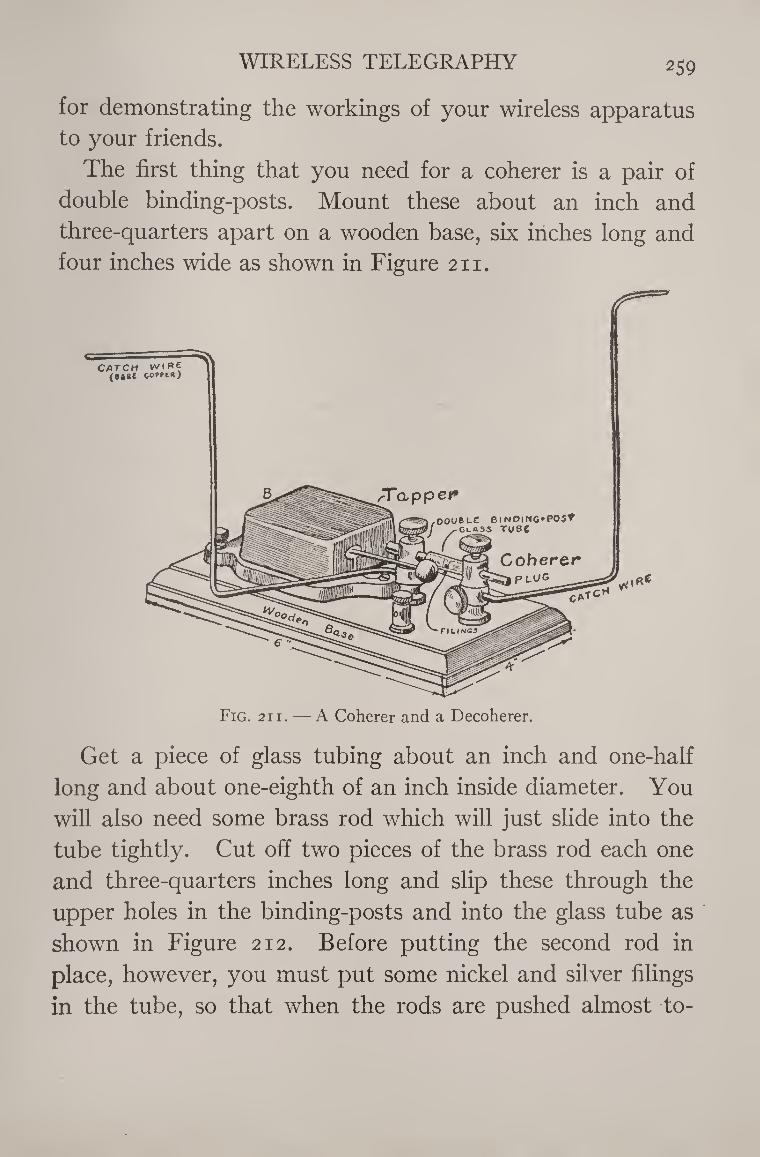
WIRELESS TELEGRAPHY 259
for demonstrating the workings of your wireless apparatus
to your friends.
The first thing that you need for a coherer is a pair of
double binding-posts. Mount these about an inch and
three-quarters apart on a wooden base, six inches long and
four inches wide as shown in Figure 211.
Get a piece of glass tubing about an inch and one-half
long and about one-eighth of an inch inside diameter. You
will also need some brass rod which will just slide into the
tube tightly. Cut off two pieces of the brass rod each one
and three-quarters inches long and slip these through the
upper holes in the binding-posts and into the glass tube as
shown in Figure 212. Before putting the second rod in
place, however, you must put some nickel and silver filings
in the tube, so that when the rods are pushed almost to-
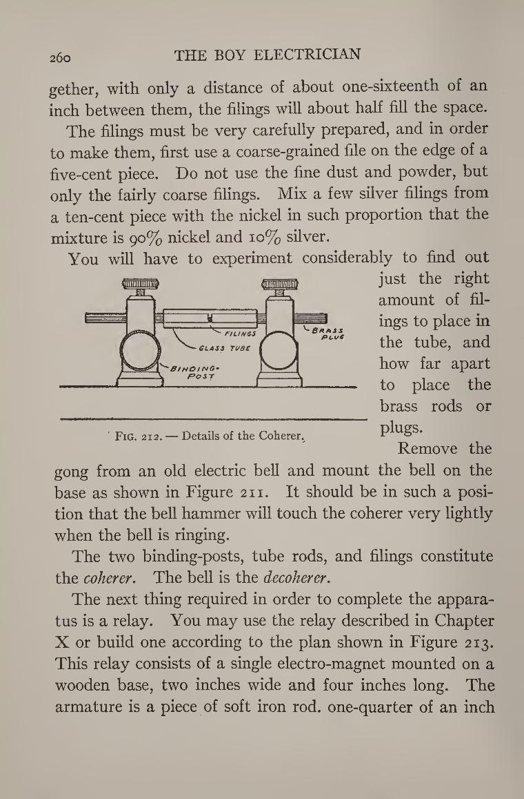
26o THE BOY ELECTRICIAN
gether, with only a distance of about one-sixteenth of an
inch between them, the filings will about half fill the space.
The filings must be very carefully prepared, and in order
to make them, first use a coarse-grained file on the edge of a
five-cent piece. Do not use the fine dust and powder, but
only the fairly coarse filings. Mix a few silver filings from
a ten-cent piece with the nickel in such proportion that the
mixture is 90% nickel and 10% silver.
You will have to experiment considerably to find out
just the right
amount of fil¬
ings to place in
the tube, and
how far apart
to place the
brass rods or
plugs.
Remove the
gong from an old electric bell and mount the bell on the
base as shown in Figure 211. It should be in such a posi¬
tion that the bell hammer will touch the coherer very lightly
when the bell is ringing.
The two binding-posts, tube rods, and filings constitute
the coherer. The bell is the decoherer.
The next thing required in order to complete the appara¬
tus is a relay. You may use the relay described in Chapter
X or build one according to the plan shown in Figure 213.
This relay consists of a single electro-magnet mounted on a
wooden base, two inches wide and four inches long. The
armature is a piece of soft iron rod. one-quarter of an inch
Fig. 212. — Details of the Coherer.
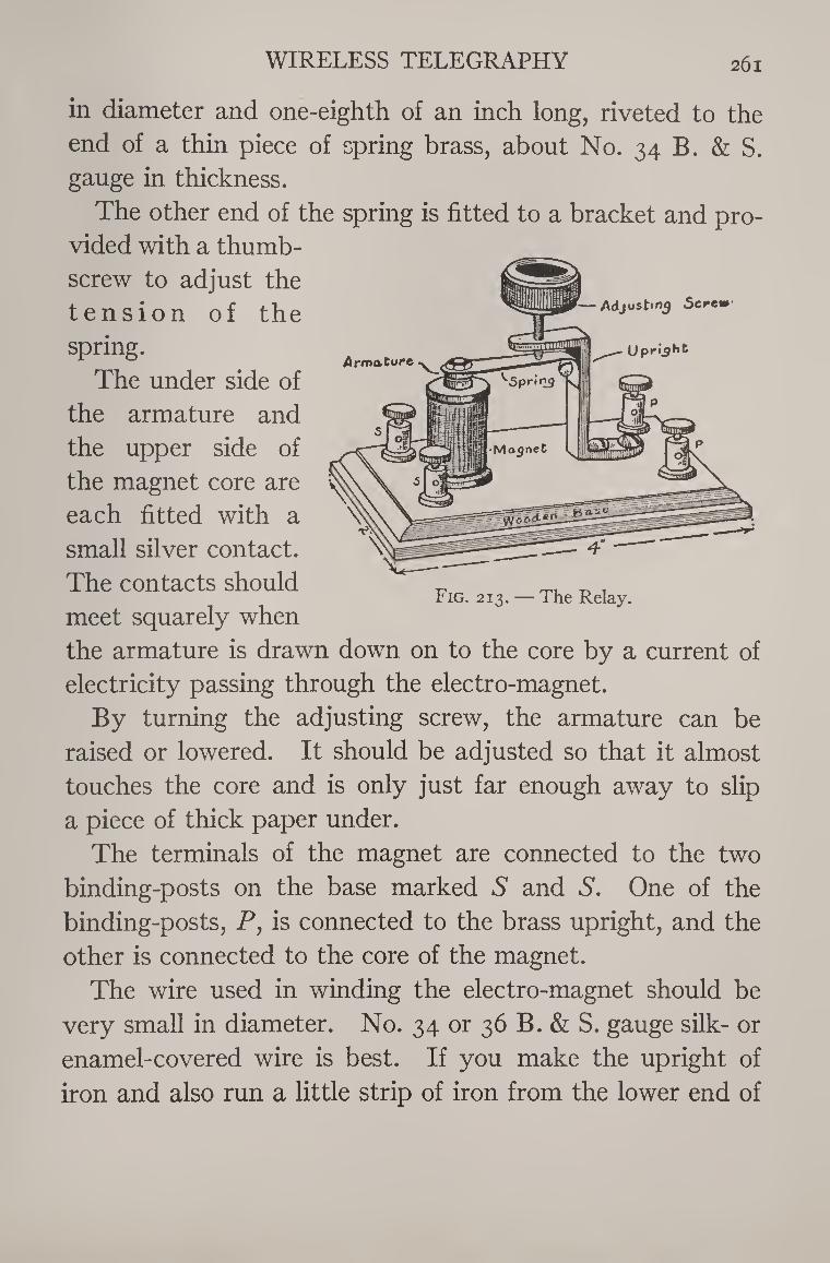
WIRELESS TELEGRAPHY 261
in diameter and one-eighth of an inch long, riveted to the
end of a thin piece of spring brass, about No. 34 B. & S.
gauge in thickness.
The other end of the spring is fitted to a bracket and pro¬
vided with a thumb¬
screw to adjust the
tension of the
spring.
The under side of
the armature and
the upper side of
the magnet core are
each fitted with a
small silver contact.
The contacts should
meet squarely when
the armature is drawn down on to the core by a current of
electricity passing through the electro-magnet.
By turning the adjusting screw, the armature can be
raised or lowered. It should be adjusted so that it almost
touches the core and is only just far enough away to slip
a piece of thick paper under.
The terminals of the magnet are connected to the two
binding-posts on the base marked S and S. One of the
binding-posts, P, is connected to the brass upright, and the
other is connected to the core of the magnet.
The wire used in winding the electro-magnet should be
very small in diameter. No. 34 or 36 B. & S. gauge silk- or
enamel-covered wire is best. If you make the upright of
iron and also run a little strip of iron from the lower end of
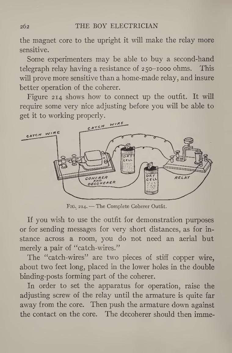
262 THE BOY ELECTRICIAN
the magnet core to the upright it will make the relay more
sensitive.
Some experimenters may be able to buy a second-hand
telegraph relay having a resistance of 250-1000 ohms. This
will prove more sensitive than a home-made relay, and insure
better operation of the coherer.
Figure 214 shows how to connect up the outfit. It will
require some very nice adjusting before you will be able to
get it to working properly.
Fig. 214. — The Complete Coherer Outfit.
If you wish to use the outfit for demonstration purposes
or for sending messages for very short distances, as for in¬
stance across a room, you do not need an aerial but
merely a pair of “catch-wires.”
The “catch-wires” are two pieces of stiff copper wire,
about two feet long, placed in the lower holes in the double
binding-posts forming part of the coherer.
In order to set the apparatus for operation, raise the
adjusting screw of the relay until the armature is quite far
away from the core. Then push the armature down against
the contact on the core. The decoherer should then imme-
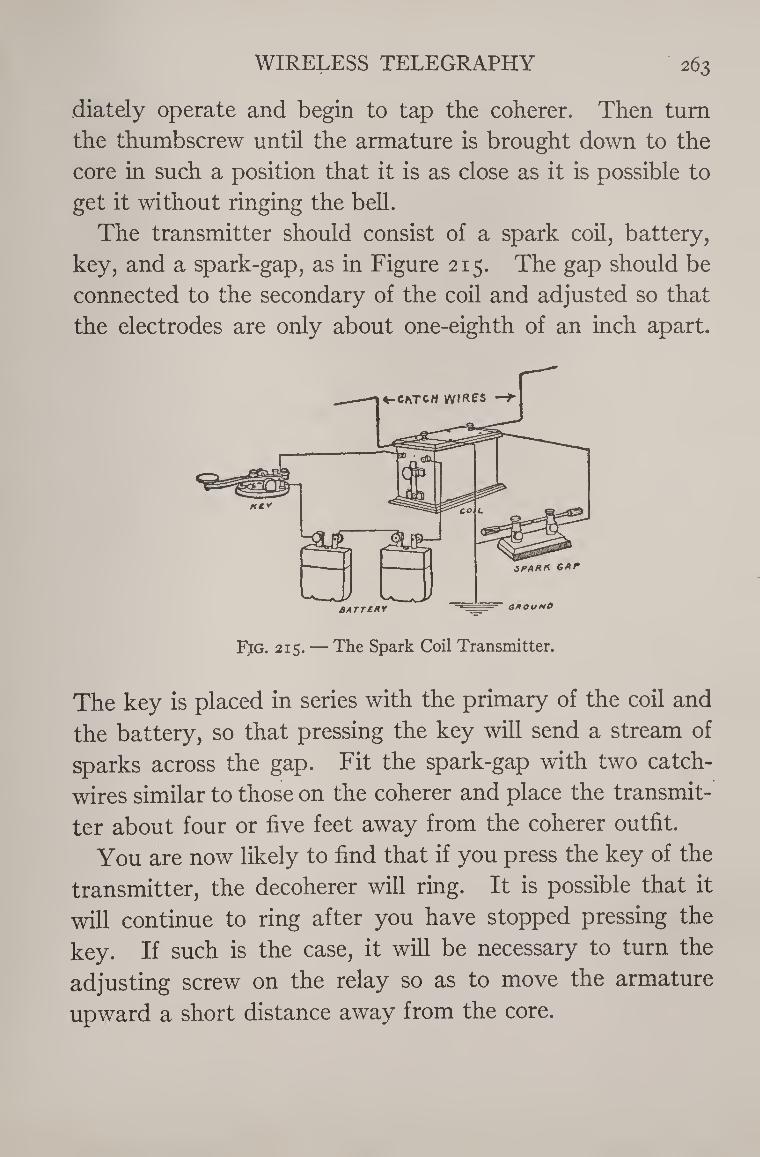
WIRELESS TELEGRAPHY 263
diately operate and begin to tap the coherer. Then turn
the thumbscrew until the armature is brought down to the
core in such a position that it is as close as it is possible to
get it without ringing the bell.
The transmitter should consist of a spark coil, battery,
key, and a spark-gap, as in Figure 215. The gap should be
connected to the secondary of the coil and adjusted so that
the electrodes are only about one-eighth of an inch apart.
Fjg. 215. — The Spark Coil Transmitter.
The key is placed in series with the primary of the coil and
the battery, so that pressing the key will send a stream of
sparks across the gap. Fit the spark-gap with two catch-
wires similar to those on the coherer and place the transmit¬
ter about four or five feet away from the coherer outfit.
You are now likely to find that if you press the key of the
transmitter, the decoherer will ring. It is possible that it
will continue to ring after you have stopped pressing the
key. If such is the case, it will be necessary to turn the
adjusting screw on the relay so as to move the armature
upward a short distance away from the core.
264 THE BOY ELECTRICIAN
If the decoherer will not operate each time when you press
the key, the brass plugs in the coherer need adjusting. You
must not be discouraged if you have some difficulty in mak¬
ing the apparatus work at first. After you learn how to
adjust it properly, you will find that you can move the
transmitter quite a distance away from the coherer and it
will still operate very nicely.
After you manage that, you can place the apparatus in
separate rooms and find it possible to work it just the same,
because ordinary walls will not make any difference to wire¬
less waves. Bear in mind that the nearer the coherer plugs are to each
other, the more sensitive the coherer will be, but that if too
close, the decoherer will not be able to shake the filings
properly and will not stop when you stop pressing the key.
The operation of the apparatus depends upon the fact
that when properly adjusted the resistance of the filings
between the two brass plugs is too great to allow sufficient
battery current to flow to attract the armature of the relay.
As soon as any wireless waves from the transmitter strike
the catch-wires of the coherer, they cause the filings to cling
together or cohere. When in this state, they have a low
resistance and permit the current to flow in the relay circuit
and draw down the armature. The armature closes the
second circuit and sets the decoherer into operation. The
decoherer shakes the filings and causes them to decohere or
fall apart and so makes them ready again for the next signal.
Spark coils have already been described in Chapter XII
under the heading of “Induction Coils”.
A Ford spark coil will perform any of the experiments
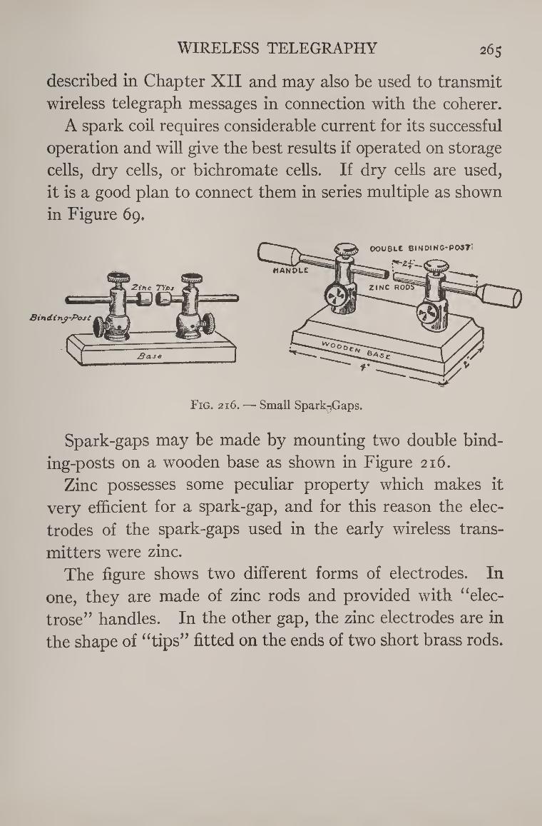
WIRELESS TELEGRAPHY 265
described in Chapter XII and may also be used to transmit
wireless telegraph messages in connection with the coherer.
A spark coil requires considerable current for its successful
operation and will give the best results if operated on storage
cells, dry cells, or bichromate cells. If dry cells are used,
it is a good plan to connect them in series multiple as shown
in Figure 69.
Fig. 216. — Small Spark-iGaps.
Spark-gaps may be made by mounting two double bind¬
ing-posts on a wooden base as shown in Figure 216.
Zinc possesses some peculiar property which makes it
very efficient for a spark-gap, and for this reason the elec¬
trodes of the spark-gaps used in the early wireless trans¬
mitters were zinc.
The figure shows two different forms of electrodes. In
one, they are made of zinc rods and provided with “elec-
trose” handles. In the other gap, the zinc electrodes are in
the shape of “tips’’ fitted on the ends of two short brass rods.
The building and adjustment of radio equipment for receiving broadcast programs is a subject large enough to require more than a whole volume. There are a great many different basic circuits and combinations of circuits. You have all probably heard of neutro-dynes, super-heterodynes, radio-frequency amplification, regenerative circuits, etc. Each one of these might even be worthy of a volume of its own. Therefore, I hope that when you turn to this chapter, you will not be disappointed if you do not find a detailed ex¬ planation of many of the radio terms and devices which you have seen advertised or heard about. If you wish to build an elaborate radio receiver which you may consider to be the latest in design, I would advise that you follow the instructions given in some of the radio magazines or pur¬ chase one of the booklets devoted to the details of building a certain type of receiver. There are styles and fads in radio just as in other things. These are to a large extent created by the manufacturers of parts and the publishers of radio magazines and columns in order to increase business. There are improvements, of course, from time to time in radio, but ninety-nine times out of a hundred the so-called
266
RADIO RECEIVING SETS 267
new circuits are basically not new, just disguised and modi¬
fied forms of old ideas. Only a book which is reprinted
several times a year could keep up with the “latest im¬
provements.”
However, the three-electrode vacuum tube or auction, as it
was named by its inventor, Lee DeForest, is universally
used in modern radio and is the basis of the present-day art
of transmitting and receiving sounds. Incidentally, long¬
distance wire telephony also depends upon the audion.
If you wish to understand radio, you must first under¬
stand the audion or three-electrode vacuum tube. The
elementary principles of its action and operation are ignored
in most articles dealing with radio and the limited space
which can be given to radio in this book can therefore per¬
haps be made of inestimable value to you by devoting it
largely to an explanation of the interesting “happenings in¬
side of the electric lamp” which sends and receives sounds
over long distances, transmits pictures through the air, and
will undoubtedly some day be the basis of television or seeing
by wire and radio.
It is hardly possible to explain the action of the audion in
really simple language. You will have to study this portion
of “The Boy Electrician” a little more carefully than the
rest. But if you do, and thereby gain an understanding of
this wonderful little device, you will be able to build and
operate a radio set far better and more intelligently than
heretofore.
A receiving set in the early days of this still young art of
radio was and still is (as I have explained in the last chapter)
a complicated arrangement of the following essential parts:
268 THE BOY ELECTRICIAN
1. An aerial, 2. A tuning device, 3. A detector, 4. Head-telephones or receivers, 5. A ground connection.
Sounds, as of the voice, or a musical instrument, are trans¬
mitted by radio for great distances by the medium of electro¬
magnetic waves created by electrical vibrations. How this
is accomplished in wireless telegraphy has already been
explained.
Originating at a sending or broadcasting station, these
waves carrying the music or speech also radiate in every
direction at a rate of vibration or at a frequency measured
by the number of waves which pass a given point in a second,
amounting sometimes to several million and travelling with
the speed of light, or 186,000 miles a second.
When these waves occur more rapidly than 20,000 per
second, they are arbitrarily said to be of radio frequency,
and cannot be heard by the human ear. When waves of
radio frequency (above 20,000 per second) strike the aerial
of a distant receiving set, they impose upon that aerial,
waves of the same high frequency, and it is the function of
the receiving apparatus to convert them into waves of lower
frequency, or below 20,000 per second so that they may be
heard by the human ear, or, in other words, become audible.
When thus converted, they are called amfoh-frequency waves.
Waves of radio-frequency are sent out by an alternating
current, and in turn produce alternating currents. Before
they will transmit sound, their frequency or rate of alterna¬
tion must not only be reduced to the audible state, below
RADIO RECEIVING SETS 269
20,000 per second, but the current must be transformed
from an alternating current to a pulsating direct current
through which alone sound may be carried to the ear.
This is the function of the detector, or as it might also be
called, the rectifier. It rectifies, converts, or filters, tech¬
nically speaking, or more plainly, changes the radio-fre¬
quency vibrations coming through the receiving aerial into
vibrations of audio-frequency.
For many years it had been known that a piece of red hot
metal will give off millions of minute particles or negative
charges of electricity, called electrons, in much the same
manner that a piece of iron heated white in a blacksmith’s
forge throws off sparks. When the red-hot metal is en¬
closed in a vacuum, the quantity of electrons given off is
greatly increased. Several years before radio was an ac¬
complishment or perhaps even thought of, Thomas A. Edi¬
son performed an interesting experiment and made a very
valuable discovery. He placed a metallic plate inside an
electric-light bulb and discovered that when the filament of
the bulb was lighted or heated, an electric current would
flow across the space between the filament and the plate.
When the filament was cold, no current would pass. The
diagram in Figure 217 shows the arrangement of the appa¬
ratus in this famous experiment which was known as the
discovery of the “Edison effect”. No practical use of the
Edison “effect” was made in radio until the English scientist,
Fleming, took a vacuum tube with a heated filament like that
of an electric light and placed a metallic plate in the zone of
the myriads of electrons emitted by the filament and so dis¬
covered that by a sort of valve action, it would pass elec-
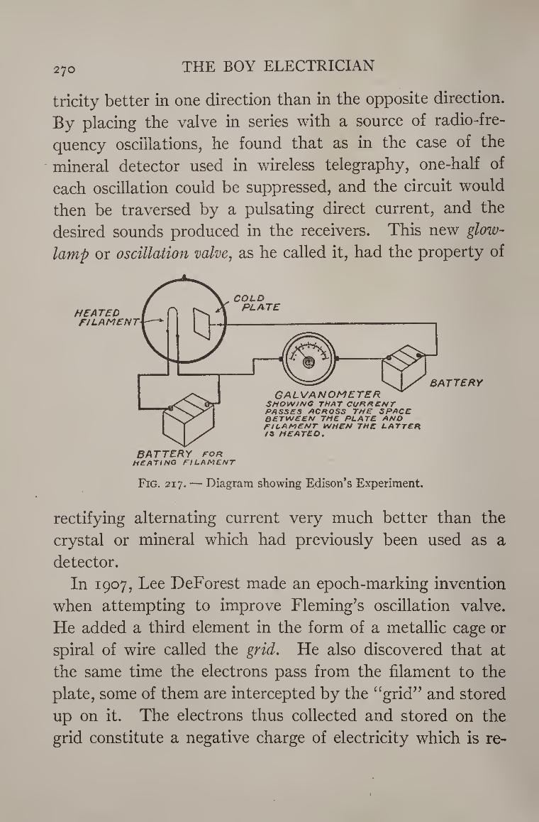
270 THE BOY ELECTRICIAN
tricity better in one direction than in the opposite direction.
By placing the valve in series with a source of radio-fre¬
quency oscillations, he found that as in the case of the
- mineral detector used in wireless telegraphy, one-half of
each oscillation could be suppressed, and the circuit would
then be traversed by a pulsating direct current, and the
desired sounds produced in the receivers. This new glow-
lamp or oscillation valve, as he called it, had the property of
BATTERY for HEATING FILAMENT
Fig. 217. — Diagram showing Edison’s Experiment.
rectifying alternating current very much better than the
crystal or mineral which had previously been used as a
detector.
In 1907, Lee DeForest made an epoch-marking invention
when attempting to improve Fleming’s oscillation valve.
He added a third element in the form of a metallic cage or
spiral of wire called the grid. He also discovered that at
the same time the electrons pass from the filament to the
plate, some of them are intercepted by the “grid” and stored
up on it. The electrons thus collected and stored on the
grid constitute a negative charge of electricity which is re-
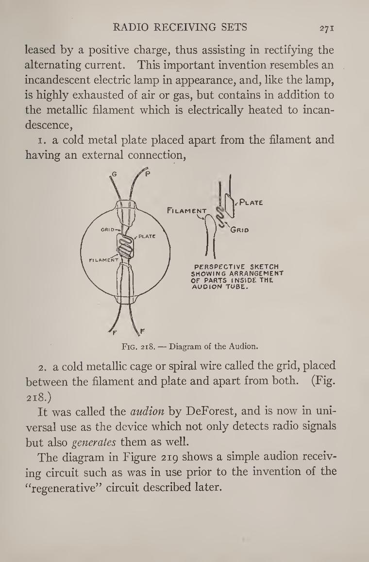
RADIO RECEIVING SETS 271
leased by a positive charge, thus assisting in rectifying the
alternating current. This important invention resembles an
incandescent electric lamp in appearance, and, like the lamp,
is highly exhausted of air or gas, but contains in addition to
the metallic filament which is electrically heated to incan¬
descence,
1. a cold metal plate placed apart from the filament and
having an external connection,
2. a cold metallic cage or spiral wire called the grid, placed
between the filament and plate and apart from both. (Fig.
218.) It was called the audion by DeForest, and is now in uni¬
versal use as the device which not only detects radio signals
but also generates them as well.
The diagram in Figure 219 shows a simple audion receiv¬
ing circuit such as was in use prior to the invention of the
“regenerative” circuit described later.
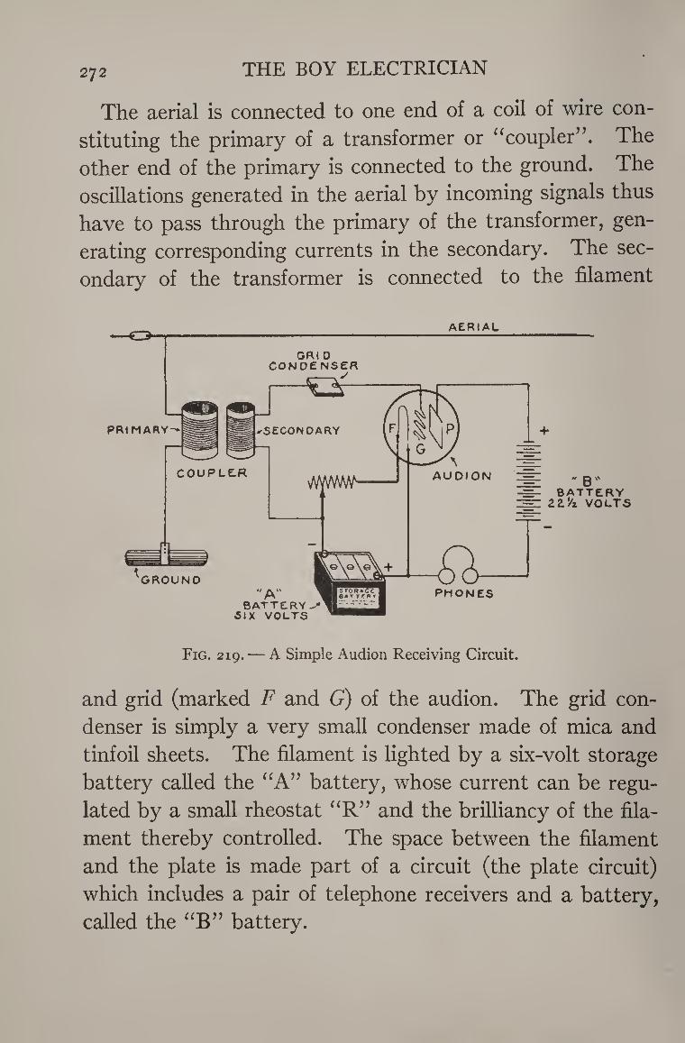
272 THE BOY ELECTRICIAN
The aerial is connected to one end of a coil of wire con¬
stituting the primary of a transformer or “coupler”. The
other end of the primary is connected to the ground. The
oscillations generated in the aerial by incoming signals thus
have to pass through the primary of the transformer, gen¬
erating corresponding currents in the secondary. The sec¬
ondary of the transformer is connected to the filament
AERIAL
GRt 0 CONOENSER
PRIMARY'-
COUPLE.R
GROUND
=- " B" ■=- BATTERY =Z ZZ'/z VOLTS
'A BATTERY
SIX VOLTS
PHONES
Fig. 219. — A Simple Audion Receiving Circuit.
and grid (marked F and G) of the audion. The grid con¬
denser is simply a very small condenser made of mica and
tinfoil sheets. The filament is lighted by a six-volt storage
battery called the “A” battery, whose current can be regu¬
lated by a small rheostat “R” and the brilliancy of the fila¬
ment thereby controlled. The space between the filament
and the plate is made part of a circuit (the plate circuit)
which includes a pair of telephone receivers and a battery,
called the “B” battery.
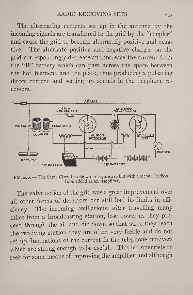
RADIO RECEIVING SETS 273
The alternating currents set up in the antenna by the
incoming signals are transferred to the grid by the “coupler”
and cause the grid to become alternately positive and nega¬
tive. The alternate positive and negative charges on the
grid correspondingly decrease and increase the current from
the “B” battery which can pass across the space between
the hot filament and the plate, thus producing a pulsating
direct current and setting up sounds in the telephone re¬
ceivers.
AfRfAL
GRID CONDENSER
AMPLIFIER Transformer
Fig. 220. — The Same Circuit as shown in Figure 219 but with a second Audion Tube added as an Amplifier.
The valve action of the grid was a great improvement over
all other forms of detectors but still had its limits in effi¬
ciency. The incoming oscillations, after travelling many
miles from a broadcasting station, lose power as they pro¬
ceed through the air and die down so that when they reach
the receiving station they are often very feeble and do not
set up fluctuations of the current in the telephone receivers
which are strong enough to be useful. This led scientists to
seek for some means of improving the amplifier, and although
274 THE BOY ELECTRICIAN
many men in different parts of the world made the same
discoveries at about the same time, the courts, after much
litigation of the patents in question, have decided that
DeForest was also the inventor of two ingenious circuits
known as the audion amplifier and the regenerative circuit.
The audion amplifier circuit is shown in Figure 220. It
consists of two audions connected so that the fluctuating
currents in the plate circuit of the first audion pass through
a transformer and are thereby transferred to the grid circuit
of the second audion. The fluctuations of current produced
in the plate circuit are always much greater in energy than
the charges on the grid. The signals in the first audion are
therefore greatly amplified by the second audion.
Audion amplifiers are arranged to consist of one, two or
three stages, accordingly as one, two, or three tubes are
employed. More than three stages usually distort the sig¬
nals very badly.
The amplifier is now commonly used in the modern radio
set to increase the signal strength to the point where it will
operate a loud speaker. A special form of audion amplifier
tube, known as a telephone repeater, is used to strengthen
the speech currents over long distance telephone lines.
The next step in the development of radio was the logical
one of finding out how to couple up the output plate circuit
with the input grid circuit so that the energy of each circuit
would react upon the other, thus building up the weak in¬
coming radio oscillations. Or stated differently, to feed
back the energy of the output circuit to the input circuit so
that the latter would be regenerated. This accomplishment
was called the regenerative or feed-back circuit and coinci-
RADIO RECEIVING SETS 275
dentally involved a great discovery. This is that the audion
when hooked up with the feed-back circuit and supplied with
sufficient energy will develop a sustained alternating current
or sustained local oscillations of its own. Thus within itself
it becomes a source of electrical power. When arranged in
this form it is called the oscillating audion, and is used as the
generator of the oscillatory currents which produce the out¬
going waves from the modern broadcasting station. The
waves are controlled or modulated, that is, made to con¬
form to the vibrations of the voice and music at the trans¬
mitting station by an audion amplifier circuit.
How to Build a Single Tube, Single Control Regenerative Receiver
Figure 221 is the circuit diagram of a little receiving set
which for ease of operation, strength of signals and recep¬
tion of far distant stations is hard to beat. It is easy to
construct, the coils being the only part which it is necessary
to make. The circuit is not complicated and since it is only
a one tube receiver, the parts to be purchased are not as
many or as expensive as they would be if three or four tubes
were required. All of the parts may be used again later in
the construction of a more elaborate receiver. For these
reasons it is ideal for the novice to build as his first attempt
in making a radio set. The various units which enter into the construction of a
radio receiver are manufactured in large quantities and sold
at very reasonable prices by radio dealers and in most of the
5-10-25 cent and #1.00 stores. A complete set of materials
and parts, less the telephone receivers and batteries, as
276 THE BOY ELECTRICIAN
listed below can be purchased for as little as $3.50. It
would be very difficult for the amateur not equipped with
proper tools and experience to make these parts. The
trouble and expense involved in procuring the various mate¬
rials would alone make it uneconomical.
In order to build the one tube set it will be necessary to
purchase the following
Parts and Materials
1 21-23 Plate Variable Condenser
1 Three-inch Knob and Dial
1 Grid Condenser
1 Grid Leak
1 Fixed Condenser
1 Filament Rheostat
1 Vacuum Tube
1 Vacuum Tube Socket
1 Telephone Headset
1 Six Volt Storage Battery
1 “B” Battery
1 Three inch dia. Cardboard Tube
6 Binding Posts
60 feet No. 22 B. & S. gauge Single-Cotton-Cov¬
ered Wire
The Variable Condenser is for tuning and adjusting the
circuit of the receiver to respond to the wave length of the
station which it is desired to intercept. Variable condensers
consist of two sets of semi-circular plates, mounted in a sup¬
porting frame. All of the plates of one set are connected
together but insulated from those of the other set. One
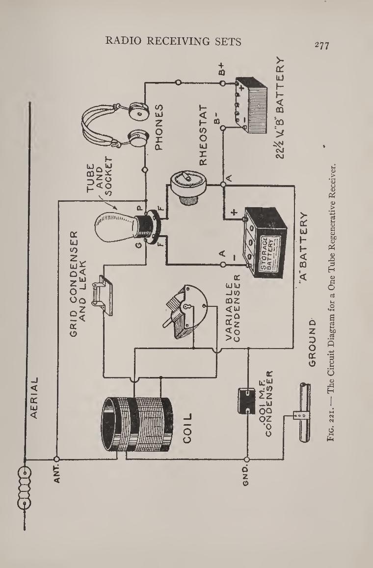
GR
ID
CO
N D
EN
SE
R
AN
D
LE
AK
RADIO RECEIVING SETS 277
Fig
. 2
21
. —
The C
ircuit D
iag
ram
fo
r a O
ne
Tu
be R
eg
en
era
tiv
e R
ecei
ver
.
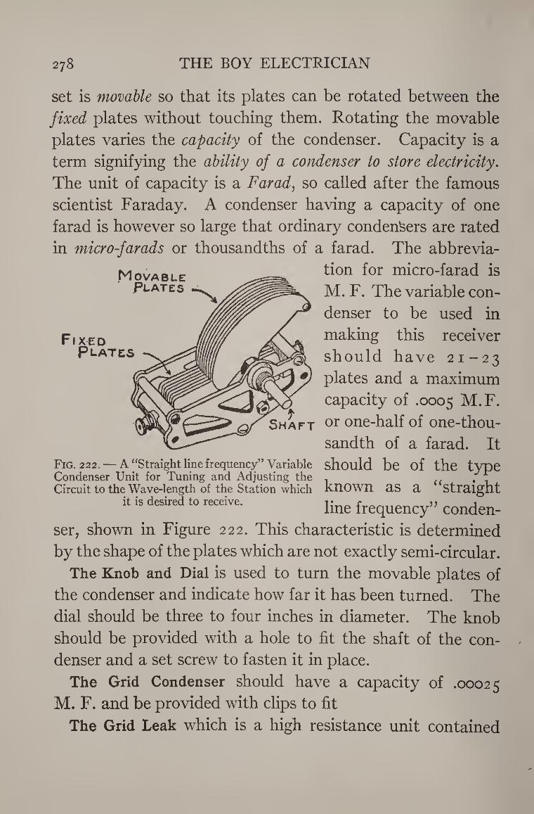
278 THE BOY ELECTRICIAN
Movable Plates
Fixed Plates
set is movable so that its plates can be rotated between the
fixed plates without touching them. Rotating the movable
plates varies the capacity of the condenser. Capacity is a
term signifying the ability of a condenser to store electricity.
The unit of capacity is a Farad, so called after the famous
scientist Faraday. A condenser having a capacity of one
farad is however so large that ordinary condensers are rated
in micro-farads or thousandths of a farad. The abbrevia¬
tion for micro-farad is
M. F. The variable con¬
denser to be used in
making this receiver
should have 21-23
plates and a maximum
capacity of .0005 M.F.
Shaft or one-half of one-thou- sandth of a farad. It
Fig. 222. — A “Straight line frequency” Variable should be of the type Condenser Unit for Tuning and Adjusting the . ; "f Circuit to the Wave-length of the Station which known as a Straight
it is desired to receive. line frequency” conden-
ser, shown in Figure 222. This characteristic is determined
by the shape of the plates which are not exactly semi-circular.
The Knob and Dial is used to turn the movable plates of
the condenser and indicate how far it has been turned. The
dial should be three to four inches in diameter. The knob
should be provided with a hole to fit the shaft of the con¬
denser and a set screw to fasten it in place.
The Grid Condenser should have a capacity of .00025
M. F. and be provided with clips to fit
The Grid Leak which is a high resistance unit contained
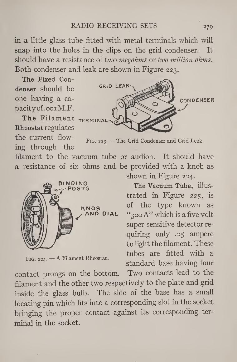
RADIO RECEIVING SETS 279
in a little glass tube fitted with metal terminals which will
snap into the holes in the clips on the grid condenser. It
should have a resistance of two megohms or two million ohms.
Both condenser and leak are shown in Figure 223.
The Fixed Con- GRID LEAK^
CONDENSER
Fig. 223. — The Grid Condenser and Grid Leak.
Bl NDfNG POSTS
denser should be
one having a ca¬
pacity of .001M. F.
The Filament TERMINAL^
Rheostat regulates
the current flow¬
ing through the
filament to the vacuum tube or audion. It should have
a resistance of six ohms and be provided with a knob as
shown in Figure 224.
The Vacuum Tube, illus¬
trated in Figure 225, is
of the type known as
“300 A” which is a five volt
super-sensitive detector re¬
quiring only .25 ampere
to light the filament. These
tubes are fitted with a
standard base having four
contact prongs on the bottom. Two contacts lead to the
filament and the other two respectively to the plate and grid
inside the glass bulb. The side of the base has a small
locating pin which fits into a corresponding slot in the socket
bringing the proper contact against its corresponding ter¬
minal in the socket.
knob AND DIAL
Fig. 224. — A Filament Rheostat.
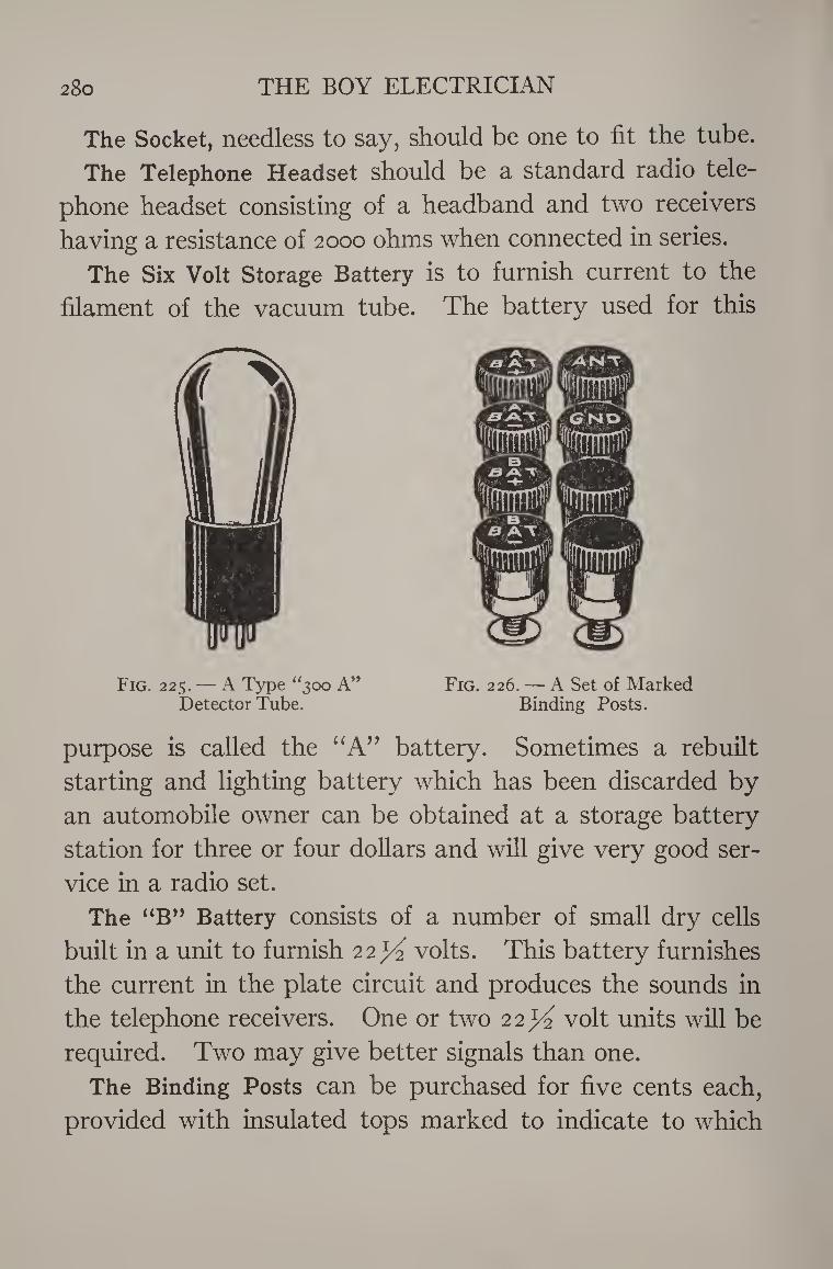
280 THE BOY ELECTRICIAN
The Socket, needless to say, should be one to fit the tube.
The Telephone Headset should be a standard radio tele¬
phone headset consisting of a headband and two receivers
having a resistance of 2000 ohms when connected in series.
The Six Volt Storage Battery is to furnish current to the
filament of the vacuum tube. The battery used for this
Fig. 225. — A Type “300 A” Fig. 226. — A Set of Marked Detector Tube. Binding Posts.
purpose is called the “A” battery. Sometimes a rebuilt
starting and lighting battery which has been discarded by
an automobile owner can be obtained at a storage battery
station for three or four dollars and will give very good ser¬
vice in a radio set.
The “B” Battery consists of a number of small dry cells
built in a unit to furnish 22^ volts. This battery furnishes
the current in the plate circuit and produces the sounds in
the telephone receivers. One or two 22^ volt units will be
required. Two may give better signals than one.
The Binding Posts can be purchased for five cents each,
provided with insulated tops marked to indicate to which
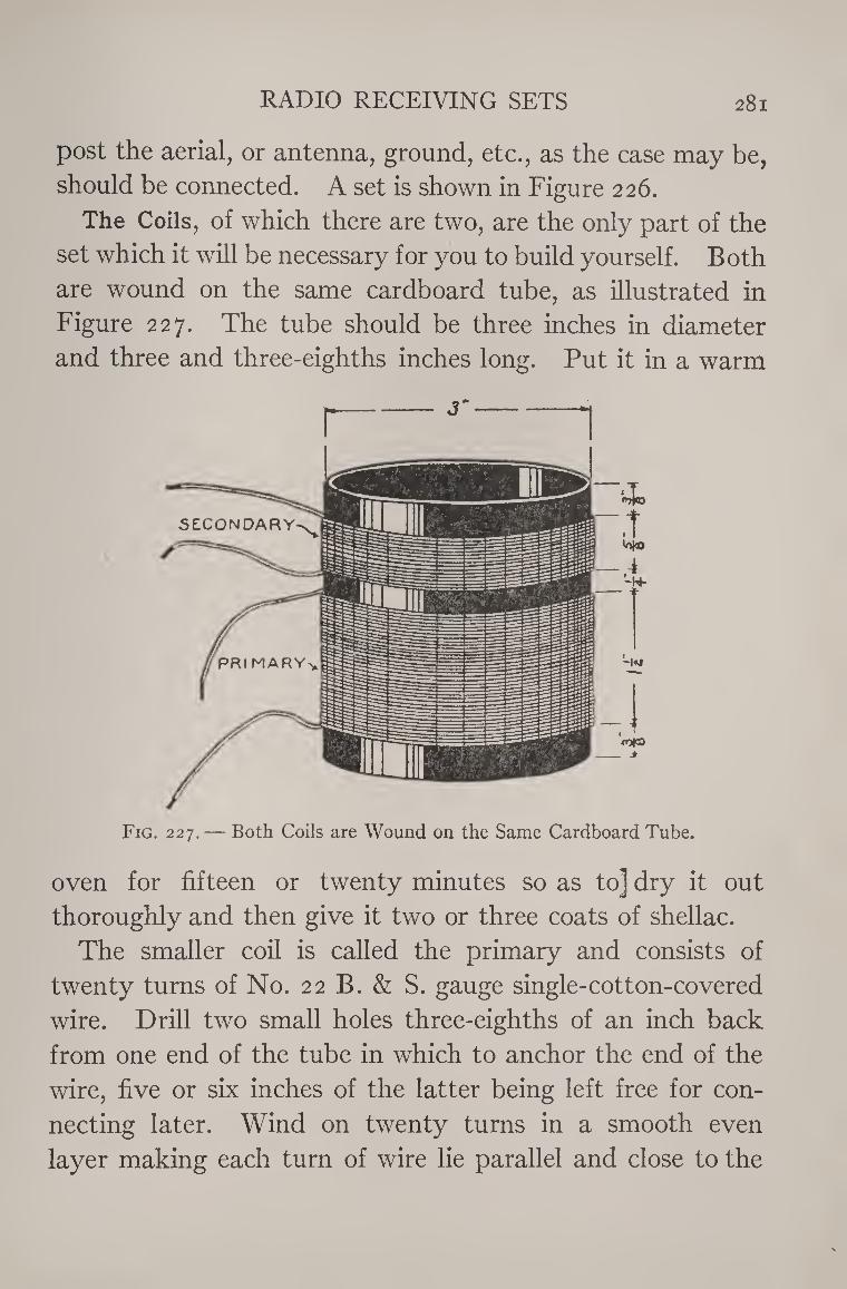
RADIO RECEIVING SETS 281
post the aerial, or antenna, ground, etc., as the case may be,
should be connected. A set is shown in Figure 226.
The Coils, of which there are two, are the only part of the
set which it will be necessary for you to build yourself. Both
are wound on the same cardboard tube, as illustrated in
Figure 227. The tube should be three inches in diameter
and three and three-eighths inches long. Put it in a warm
oven for fifteen or twenty minutes so as to] dry it out
thoroughly and then give it two or three coats of shellac.
The smaller coil is called the primary and consists of
twenty turns of No. 22 B. & S. gauge single-cotton-covered
wire. Drill two small holes three-eighths of an inch back
from one end of the tube in which to anchor the end of the
wire, five or six inches of the latter being left free for con¬
necting later. Wind on twenty turns in a smooth even
layer making each turn of wire lie parallel and close to the
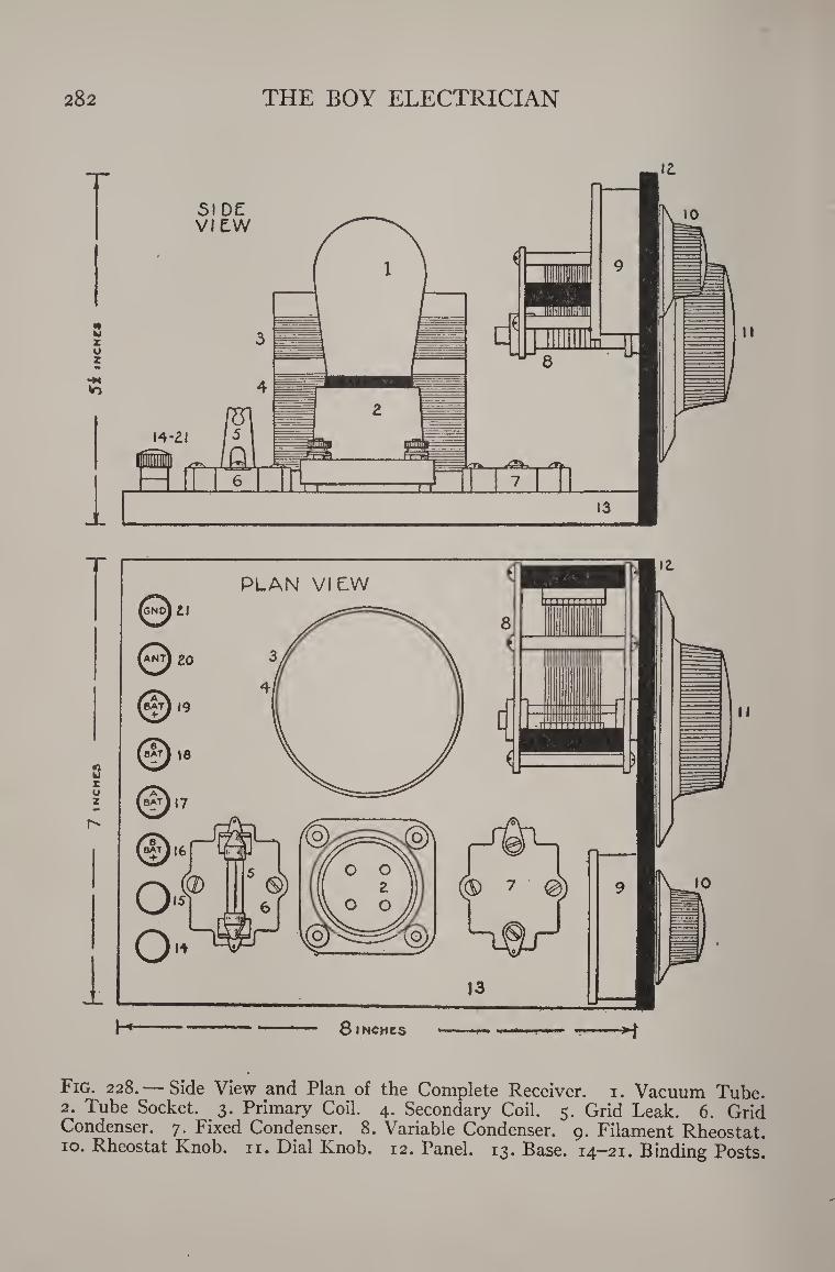
<n u £ o z
i Fig. 228. — Side View and Plan of the Complete Receiver. 1. Vacuum Tube. 2. Tube Socket. 3. Primary Coil. 4. Secondary Coil. 5. Grid Leak. 6. Grid Condenser. 7. Fixed Condenser. 8. Variable Condenser. 9. Filament Rheostat. 10. Rheostat Knob. 11. Dial Knob. 12. Panel. 13. Base. 14-21. Binding Posts.
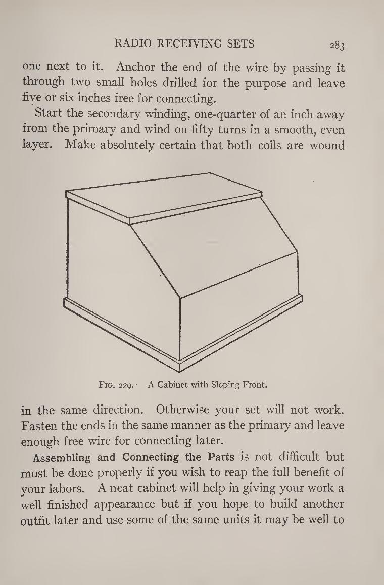
RADIO RECEIVING SETS 283
one next to it. Anchor the end of the wire by passing it
through two small holes drilled for the purpose and leave
five or six inches free for connecting.
Start the secondary winding, one-quarter of an inch away
from the primary and wind on fifty turns in a smooth, even
layer. Make absolutely certain that both coils are wound
Fig. 229. — A Cabinet with Sloping Front.
in the same direction. Otherwise your set will not work.
Fasten the ends in the same manner as the primary and leave
enough free wire for connecting later.
Assembling and Connecting the Parts is not difficult but
must be done properly if you wish to reap the full benefit of
your labors. A neat cabinet will help in giving your work a
well finished appearance but if you hope to build another
outfit later and use some of the same units it may be well to
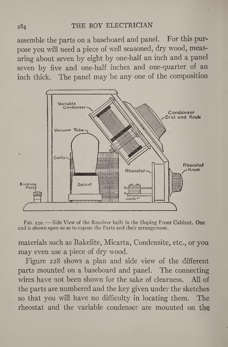
284 THE BOY ELECTRICIAN
assemble the parts on a baseboard and panel. For this pur¬
pose you will need a piece of well seasoned, dry wood, meas¬
uring about seven by eight by one-half an inch and a panel
seven by five and one-half inches and one-quarter of an
inch thick. The panel may be any one of the composition
Fig. 230. — Side View of the Receiver built in the Sloping Front Cabinet. One end is shown open so as to expose the Parts and their arrangement.
materials such as Bakelite, Micarta, Condensite, etc., or you
may even use a piece of dry wood.
Figure 228 shows a plan and side view of the different
parts mounted on a baseboard and panel. The connecting
wires have not been shown for the sake of clearness. All of
the parts are numbered and the key given under the sketches
so that you will have no difficulty in locating them. The
rheostat and the variable condenser are mounted on the
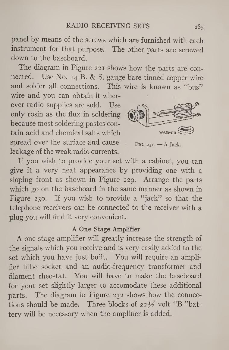
RADIO RECEIVING SETS 285
panel by means of the screws which are furnished with each
instrument for that purpose. The other parts are screwed down to the baseboard.
The diagram in Figure 221 shows how the parts are con¬
nected. Use No. 14 B. & S. gauge bare tinned copper wire
and solder all connections. This wire is known as “bus”
wire and you can obtain it wher¬
ever radio supplies are sold. Use
only rosin as the flux in soldering
because most soldering pastes con¬
tain acid and chemical salts which
spread over the surface and cause
leakage of the weak radio currents.
If you wish to provide your set with a cabinet, you can
give it a very neat appearance by providing one with a
sloping front as shown in Figure 229. Arrange the parts
which go on the baseboard in the same manner as shown in
Figure 230. If you wish to provide a “jack” so that the
telephone receivers can be connected to the receiver with a
plug you will find it very convenient.
A One Stage Amplifier
A one stage amplifier will greatly increase the strength of
the signals which you receive and is very easily added to the
set which you have just built. You will require an ampli¬
fier tube socket and an audio-frequency transformer and
filament rheostat. You will have to make the baseboard
for your set slightly larger to accomodate these additional
parts. The diagram in Figure 232 shows how the connec¬
tions should be made. Three blocks of 22^ volt “B ”bat-
tery will be necessary when the amplifier is added.
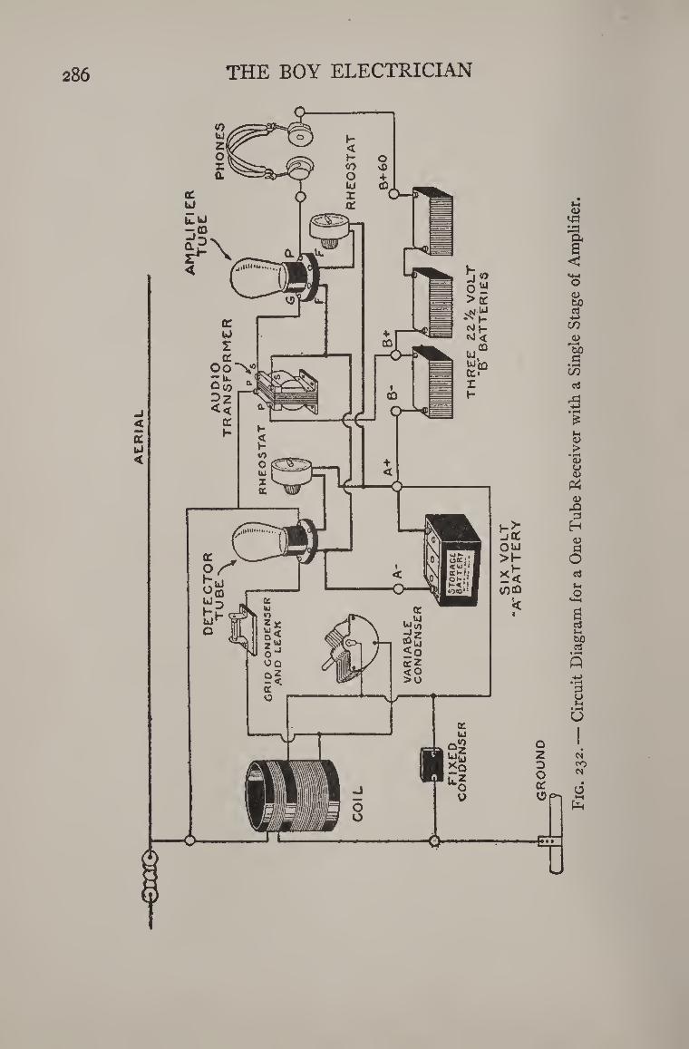
AtR
IAL
286 THE BOY ELECTRICIAN
Fig
. 232. —
Cir
cu
it D
iagra
m f
or
a O
ne
Tube R
eceiv
er
wit
h a
Sin
gle S
tage o
f A
mpli
fier
.
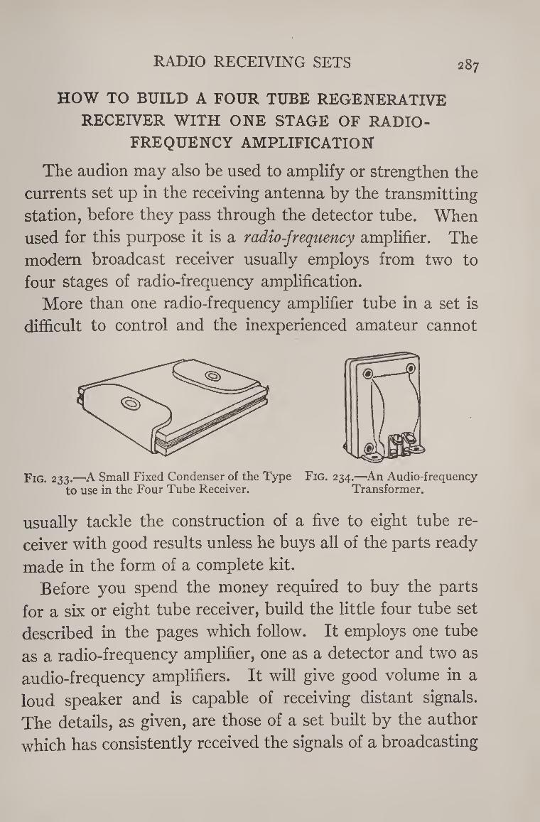
RADIO RECEIVING SETS 287
HOW TO BUILD A FOUR TUBE REGENERATIVE
RECEIVER WITH ONE STAGE OF RADIO-
FREQUENCY AMPLIFICATION
The audion may also be used to amplify or strengthen the
currents set up in the receiving antenna by the transmitting
station, before they pass through the detector tube. When
used for this purpose it is a radio-frequency amplifier. The
modem broadcast receiver usually employs from two to
four stages of radio-frequency amplification.
More than one radio-frequency amplifier tube in a set is
difficult to control and the inexperienced amateur cannot
Fig. 233.—A Small Fixed Condenser of the Type Fig. 234.—An Audio-frequency to use in the Four Tube Receiver. Transformer.
usually tackle the construction of a five to eight tube re¬
ceiver with good results unless he buys all of the parts ready
made in the form of a complete kit.
Before you spend the money required to buy the parts
for a six or eight tube receiver, build the little four tube set
described in the pages which follow. It employs one tube
as a radio-frequency amplifier, one as a detector and two as
audio-frequency amplifiers. It will give good volume in a
loud speaker and is capable of receiving distant signals.
The details, as given, are those of a set built by the author
which has consistently received the signals of a broadcasting
288 THE BOY ELECTRICIAN
station located in California, during the winter months
night after night. The receiver was located in New Jersey,
i In order to build this four tube set, it will be necessary to
purchase the following
Parts and Materials
i .0005 M.F. Straight Line Frequency Variable Con¬
denser.
1 Four-inch Knob and Dial.
1 .00025 M.F. Grid Condenser.
1 Three Megohm Grid Leak.
1 .002 M.F. Fixed Condenser.
1 .00025 M.F. Fixed Condenser.
1 Filament Rheostat.
1 Filament Resistance.
4 Type 201-A Vacuum Tubes.
4 Vacuum Tube Sockets.
2 Audio-Frequency Transformers.
2 Single Circuit Jacks.
1 Single Pole Battery Switch.
1 Single Pole Double-throw Battery Switch.
1 Six-volt Storage Battery.
2 45-volt “B” Batteries.
8 Binding Posts.
Miscellaneous Magnet Wire, etc., as described below.
1 Loud Speaker.
The Circuit Diagram of the receiver is shown in Figure 235.
The round black circles indicate the position of the various
binding posts.
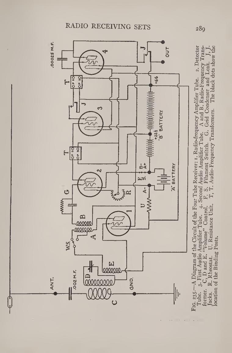
AN
T.
.0O
OZ
S M
.F.
RADIO RECEIVING SETS 289
- 1
U oj G <u
Jjhl o
^ E u 3-1 o ^3 -=< <u ^ O 1/3 <u
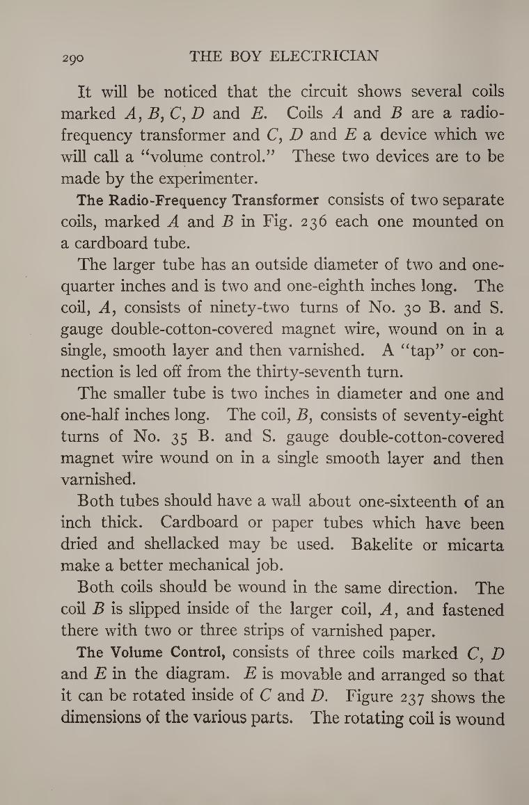
290 THE BOY ELECTRICIAN
It will be noticed that the circuit shows several coils
marked Ay B, C, D and E. Coils A and B are a radio¬
frequency transformer and C, D and E a device which we
will call a “volume control.” These two devices are to be
made by the experimenter.
The Radio-Frequency Transformer consists of two separate
coils, marked A and B in Fig. 236 each one mounted on
a cardboard tube.
The larger tube has an outside diameter of two and one-
quarter inches and is two and one-eighth inches long. The
coil, Ay consists of ninety-two turns of No. 30 B. and S.
gauge double-cotton-covered magnet wire, wound on in a
single, smooth layer and then varnished. A “tap” or con¬
nection is led off from the thirty-seventh turn.
The smaller tube is two inches in diameter and one and
one-half inches long. The coil, B, consists of seventy-eight
turns of No. 35 B. and S. gauge double-cotton-covered
magnet wire wound on in a single smooth layer and then
varnished.
Both tubes should have a wall about one-sixteenth of an
inch thick. Cardboard or paper tubes which have been
dried and shellacked may be used. Bakelite or micarta
make a better mechanical job.
Both coils should be wound in the same direction. The
coil B is slipped inside of the larger coil, A, and fastened
there with two or three strips of varnished paper.
The Volume Control, consists of three coils marked C, D
and E in the diagram. E is movable and arranged so that
it can be rotated inside of C and D. Figure 237 shows the
dimensions of the various parts. The rotating coil is wound
RADIO RECEIVING SET 291
on a tube one and five-eighths of an inch in diameter and one
inch long. This tube is mounted on a shaft which passes
through the tube supporting the windings C and D, at right
angles to the axis.
The coil E consists of fourteen turns of No. 25 B. and S.
gauge double-cotton-covered magent wire. Seven turns
are wound on each side of the shaft.
The coil D consists of sixty-five turns of No. 34 B. and S.
Fig. 236.—Details of the Coils which form the Radio Frequency Transformer.
gauge double-cotton-covered wire wound on a tube two and
one-quarter inches in diameter and two and one-eighth
inches long. Thirty-seven turns are wound on that portion
above where the shaft of the rotating coil passes through
and twenty-eight turns below. \ Coil C consists of five turns of No. 14 B. and S. gauge
double-cotton-covered magnet wire wound directly over the
lower portion of D. The Jacks shown in the circuit diagram and included
in the list of materials make it possible to use either one or
two stages of audio-frequency amplification at will. The
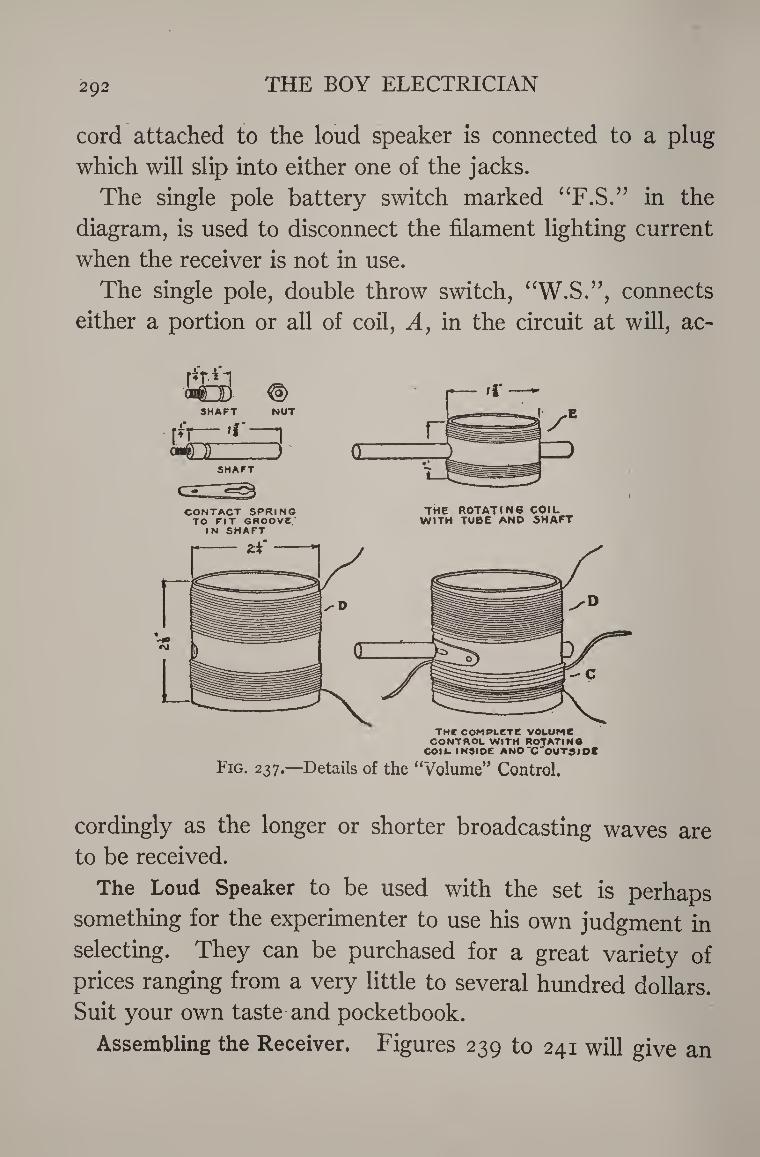
292 THE BOY ELECTRICIAN
cord attached to the loud speaker is connected to a plug
which will slip into either one of the jacks.
The single pole battery switch marked “F.S.” in the
diagram, is used to disconnect the filament lighting current
when the receiver is not in use.
The single pole, double throw switch, “W.S.”, connects
either a portion or all of coil, A, in the circuit at will, ac-
CONTACT SPRING TO PIT GROOVE'
IN SHAFT
THE ROTATING COIL WITH TUBE AND SHAFT
tmc complete volume CONTROL WITH ROTATINO
COIL INSIDE ANO'C'OUTSIOC
Fig. 237.—Details of the “Volume” Control.
cordingly as the longer or shorter broadcasting waves are
to be received.
The Loud Speaker to be used with the set is perhaps
something for the experimenter to use his own judgment in
selecting. They can be purchased for a great variety of
prices ranging from a very little to several hundred dollars. Suit your own taste and pocketbook.
Assembling the Receiver. Figures 239 to 241 will give an
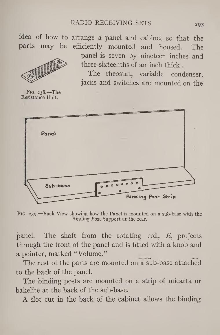
RADIO RECEIVING SETS 293
idea of how to arrange a panel and cabinet so that the
parts may be efficiently mounted and housed. The
panel is seven by nineteen inches and
three-sixteenths of an inch thick .
The rheostat, variable condenser,
jacks and switches are mounted on the
Fig. 238—The Resistance Unit.
Fig. 239.—Back View showing how the Panel is mounted on a sub-base with the Binding Post Support at the rear.
panel. The shaft from the rotating coil, E, projects
through the front of the panel and is fitted with a knob and
a pointer, marked “Volume.”
The rest of the parts are mounted on a sub-base attached
to the back of the panel.
The binding posts are mounted on a strip of micarta or
bakelite at the back of the sub-base.
A slot cut in the back of the cabinet allows the binding
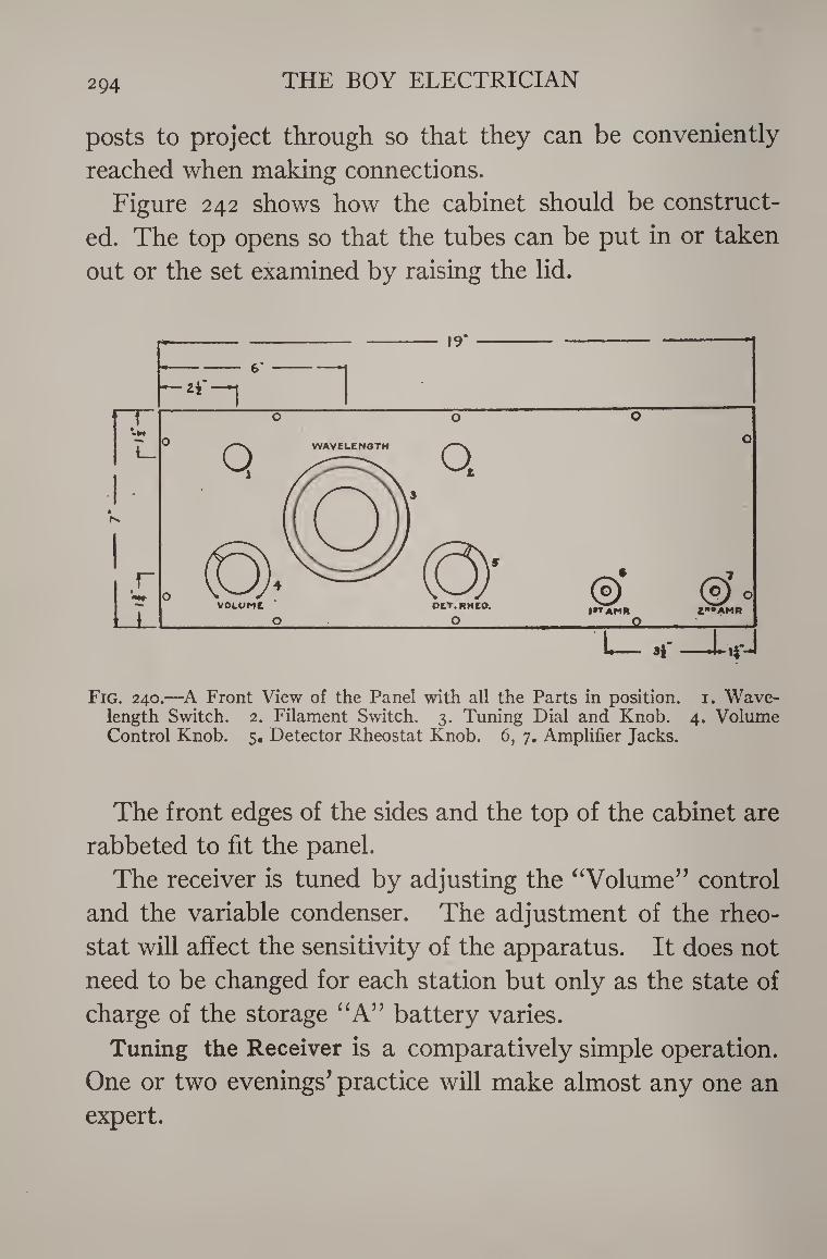
2Q4 THE BOY ELECTRICIAN
posts to project through so that they can be conveniently
reached when making connections.
Figure 242 shows how the cabinet should be construct¬
ed. The top opens so that the tubes can be put in or taken
out or the set examined by raising the lid.
Fig. 240.—A Front View of the Panel with all the Parts in position, i. Wave¬ length Switch. 2. Filament Switch. 3. Tuning Dial and Knob. 4. Volume Control Knob. 5. Detector Rheostat Knob. 6, 7. Amplifier Jacks.
The front edges of the sides and the top of the cabinet are
rabbeted to fit the panel.
The receiver is tuned by adjusting the “Volume” control
and the variable condenser. The adjustment of the rheo¬
stat will affect the sensitivity of the apparatus. It does not
need to be changed for each station but only as the state of
charge of the storage “A” battery varies.
Tuning the Receiver is a comparatively simple operation.
One or two evenings’ practice will make almost any one an
expert.
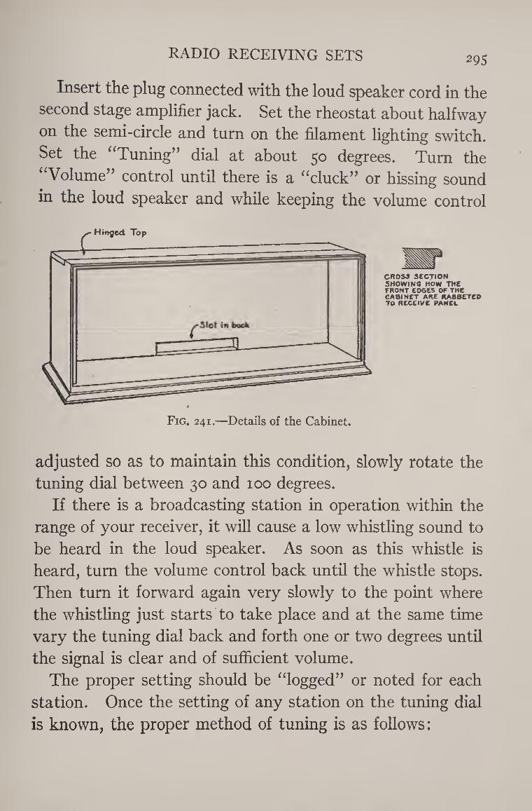
RADIO RECEIVING SETS 295
Insert the plug connected with the loud speaker cord in the
second stage amplifier jack. Set the rheostat about halfway
on the semi-circle and turn on the filament lighting switch.
Set the “Tuning” dial at about 50 degrees. Turn the
“Volume” control until there is a “cluck” or hissing sound
in the loud speaker and while keeping the volume control
CROSS SECTION SHOWING HOW THE FRONT EDGES OF The CABINET ARE RABBETED TO RECEIVE PANEL
adjusted so as to maintain this condition, slowly rotate the
tuning dial between 30 and 100 degrees.
If there is a broadcasting station in operation within the
range of your receiver, it will cause a low whistling sound to
be heard in the loud speaker. As soon as this whistle is
heard, turn the volume control back until the whistle stops.
Then turn it forward again very slowly to the point where
the whistling just starts to take place and at the same time
vary the tuning dial back and forth one or two degrees until
the signal is clear and of sufficient volume.
The proper setting should be “logged” or noted for each
station. Once the setting of any station on the tuning dial
is known, the proper method of tuning is as follows:
296 THE BOY ELECTRICIAN
Set the tuning dial at the exact point where the station
was previously received and slowly turn the volume control
until the signal is strong and clear.
The proper position of the “wavelength switch” will vary
accordingly as the station desired tunes in on the upper or _m.-.
the lower part of the tuning dial. When through using the
receiver be certain to turn the filament switch so as to
extinguish the tubes,
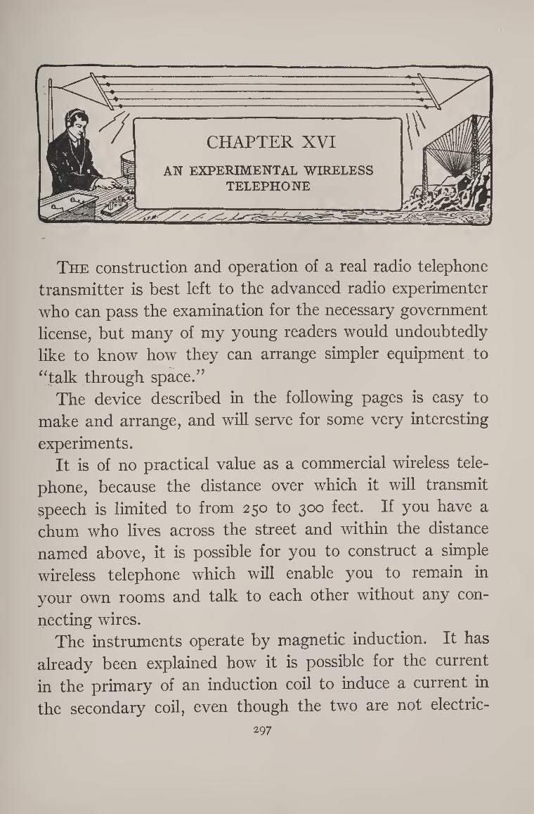
CHAPTER XVI
AN EXPERIMENTAL WIRELESS TELEPHONE
The construction and operation of a real radio telephone
transmitter is best left to the advanced radio experimenter
who can pass the examination for the necessary government
license, but many of my young readers would undoubtedly
like to know how they can arrange simpler equipment to
“talk through space.”
The device described in the following pages is easy to
make and arrange, and will serve for some very interesting
experiments. It is of no practical value as a commercial wireless tele¬
phone, because the distance over which it will transmit
speech is limited to from 250 to 300 feet. If you have a
chum who lives across the street and within the distance
named above, it is possible for you to construct a simple
wireless telephone which will enable you to remain in
your own rooms and talk to each other without any con¬
necting wires. The instruments operate by magnetic induction. It has
already been explained how it is possible for the current
in the primary of an induction coil to induce a current in
the secondary coil, even though the two are not electric-
297
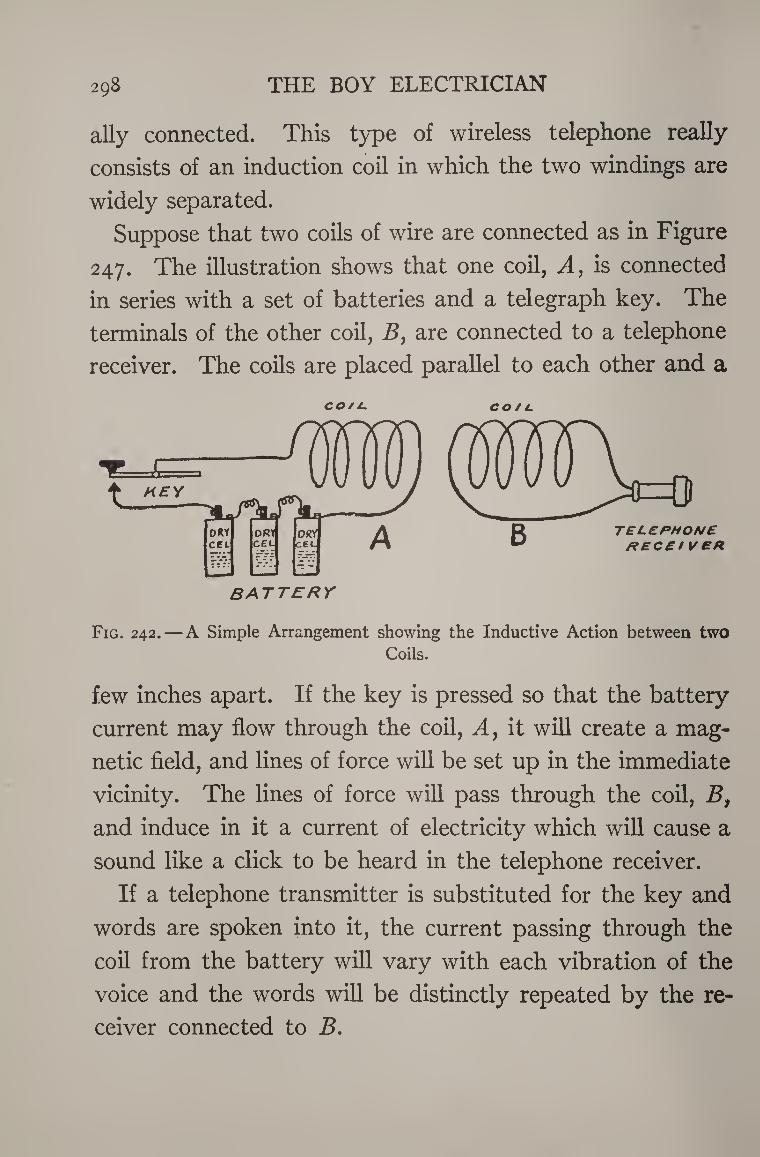
298 THE BOY ELECTRICIAN
ally connected. This type of wireless telephone really
consists of an induction coil in which the two windings are
widely separated.
Suppose that two coils of wire are connected as in Figure
247. The illustration shows that one coil, A, is connected
in series with a set of batteries and a telegraph key. The
terminals of the other coil, B, are connected to a telephone
receiver. The coils are placed parallel to each other and a
co/i- co/c.
Fig. 242. — A Simple Arrangement showing the Inductive Action between two Coils.
few inches apart. If the key is pressed so that the battery
current may flow through the coil, A, it will create a mag¬
netic field, and lines of force will be set up in the immediate
vicinity. The lines of force will pass through the coil, Bf and induce in it a current of electricity which will cause a
sound like a click to be heard in the telephone receiver.
If a telephone transmitter is substituted for the key and
words are spoken into it, the current passing through the
coil from the battery will vary with each vibration of the
voice and the words will be distinctly repeated by the re¬
ceiver connected to B.
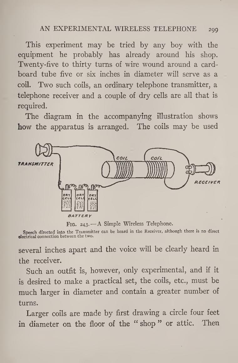
AN EXPERIMENTAL WIRELESS TELEPHONE 299
This experiment may be tried by any boy with the
equipment he probably has already around his shop.
Twenty-five to thirty turns of wire wound around a card¬
board tube five or six inches in diameter will serve as a
coil. Two such coils, an ordinary telephone transmitter, a
telephone receiver and a couple of dry cells are all that is
required.
The diagram in the accompanying illustration shows
how the apparatus is arranged. The coils may be used
Fig. 243. — A Simple Wireless Telephone.
Speech directed into the Transmitter can be heard in the Receiver, although there is no direct electrical connection between the two.
several inches apart and the voice will be clearly heard in
the receiver.
Such an outfit is, however, only experimental, and if it
is desired to make a practical set, the coils, etc., must be
much larger in diameter and contain a greater number of
turns.
Larger coils are made by first drawing a circle four feet
in diameter on the floor of the “ shop ” or attic. Then
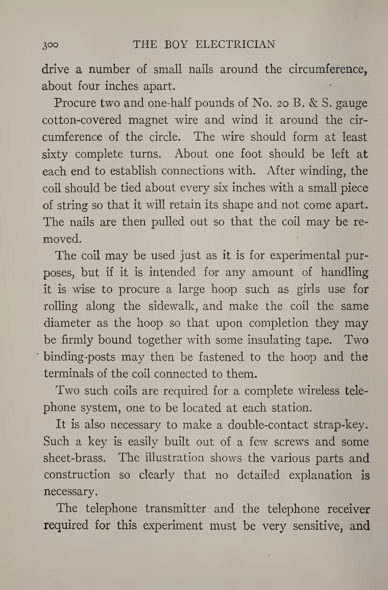
3°° THE BOY ELECTRICIAN
drive a number of small nails around the circumference,
about four inches apart.
Procure two and one-half pounds of No. 20 B. & S. gauge
cotton-covered magnet wire and wind it around the cir¬
cumference of the circle. The wire should form at least
sixty complete turns. About one foot should be left at
each end to establish connections with. After winding, the
coil should be tied about every six inches with a small piece
of string so that it will retain its shape and not come apart.
The nails are then pulled out so that the coil may be re¬
moved.
The coil may be used just as it is for experimental pur¬
poses, but if it is intended for any amount of handling
it is wise to procure a large hoop such as girls use for
rolling along the sidewalk, and make the coil the same
diameter as the hoop so that upon completion they may
be firmly bound together with some insulating tape. Two
binding-posts may then be fastened to the hoop and the
terminals of the coil connected to them.
Two such coils are required for a complete wireless tele¬
phone system, one to be located at each station.
It is also necessary to make a double-contact strap-key.
Such a key is easily built out of a few screws and some
sheet-brass. The illustration shows the various parts and
construction so clearly that no detailed explanation is
necessary.
The telephone transmitter and the telephone receiver
required for this experiment must be very sensitive, and
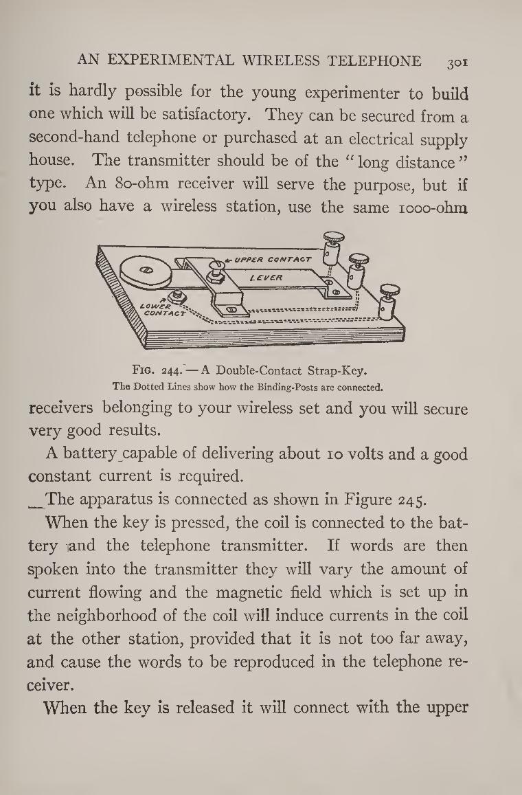
AN EXPERIMENTAL WIRELESS TELEPHONE 301
it is hardly possible for the young experimenter to build
one which will be satisfactory. They can be secured from a
second-hand telephone or purchased at an electrical supply
house. The transmitter should be of the “ long distance ” type. An 8o-ohm receiver will serve the purpose, but if
you also have a wireless station, use the same iooo-ohm
Fig. 244. — A Double-Contact Strap-Key.
The Dotted Lines show how the Binding-Posts are connected.
receivers belonging to your wireless set and you will secure
very good results.
A battery capable of delivering about 10 volts and a good
constant current is required.
_The apparatus is connected as shown in Figure 245.
When the key is pressed, the coil is connected to the bat¬
tery and the telephone transmitter. If words are then
spoken into the transmitter they will vary the amount of
current flowing and the magnetic field which is set up in
the neighborhood of the coil will induce currents in the coil
at the other station, provided that it is not too far away,
and cause the words to be reproduced in the telephone re¬
ceiver.
When the key is released it will connect with the upper
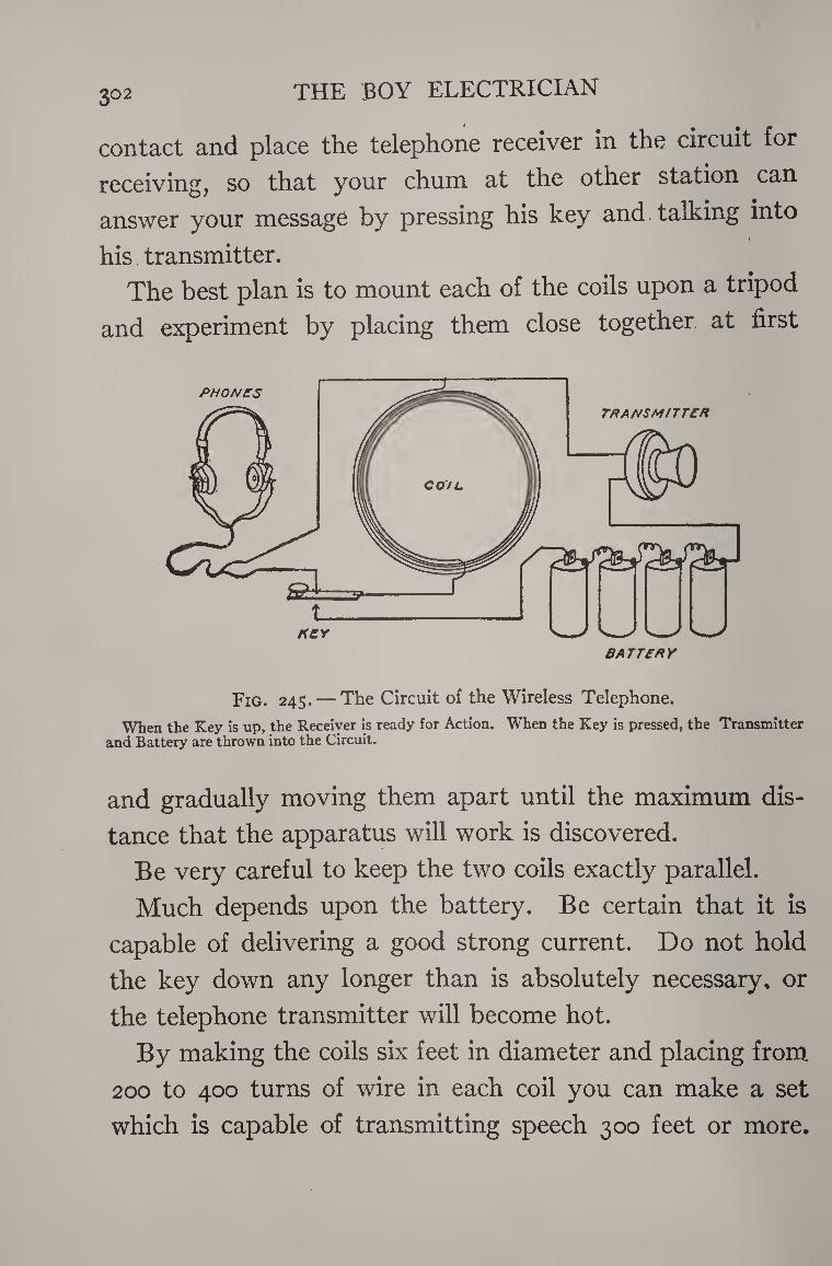
THE BOY ELECTRICIAN 3° 2
contact and place the telephone receiver in the circuit for
receiving, so that your chum at the other station can
answer your message by pressing his key and talking into
his transmitter.
The best plan is to mount each of the coils upon a tripod
and experiment by placing them close together at first
PHONES TRANSMITTER
BATTERY
Fig. 245. — The Circuit of the Wireless Telephone.
When the Key is up, the Receiver is ready for Action. When the Key is pressed, the Transmitter and Battery are thrown into the Circuit.
and gradually moving them apart until the maximum dis¬
tance that the apparatus will work is discovered.
Be very careful to keep the two coils exactly parallel.
Much depends upon the battery. Be certain that it is
capable of delivering a good strong current. Do not hold
the key down any longer than is absolutely necessary, or
the telephone transmitter will become hot.
By making the coils six feet in diameter and placing from
200 to 400 turns of wire in each coil you can make a set
which is capable of transmitting speech 300 feet or more.
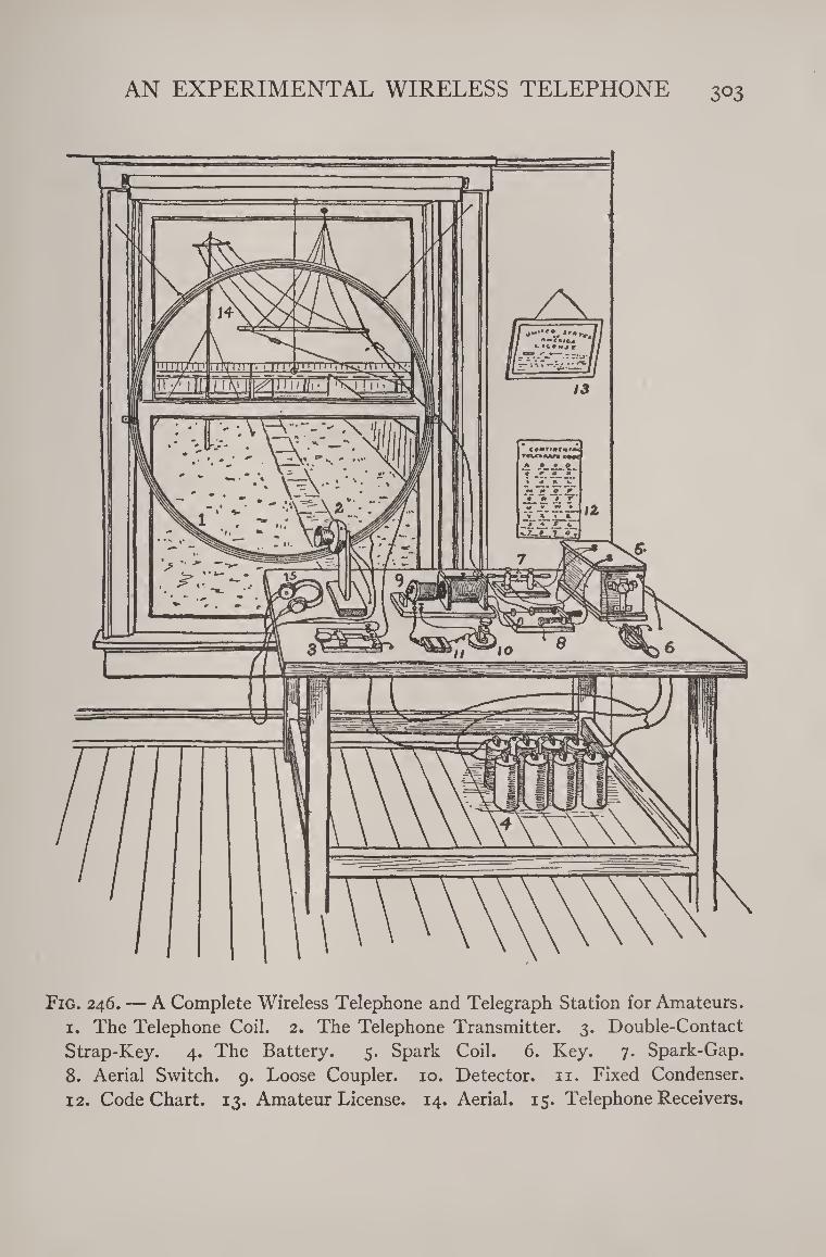
AN EXPERIMENTAL WIRELESS TELEPHONE 303
Fig. 246. — A Complete Wireless Telephone and Telegraph Station for Amateurs. 1. The Telephone Coil. 2. The Telephone Transmitter. 3. Double-Contact
Strap-Key. 4. The Battery. 5. Spark Coil. 6. Key. 7. Spark-Gap.
8. Aerial Switch. 9. Loose Coupler. 10. Detector, n. Fixed Condenser. 12. Code Chart. 13. Amateur License. 14. Aerial. 15. Telephone Receivers.
304 THE BOY ELECTRICIAN
The coil may be mounted on the wall of your shop in a
position where it will be parallel to one located in your
chum’s house.
The success of a wireless telephone system of this sort
lies in making the coils of large diameter and many turns,
in keeping the coils parallel, using a sensitive transmitter
and receiver, and in employing a good strong battery.
Storage cells are the best for the purpose.
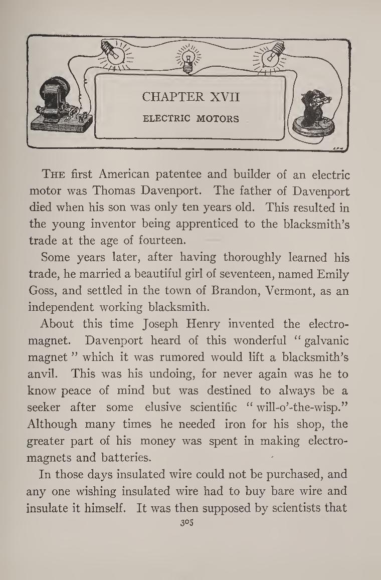
The first American patentee and builder of an electric
motor was Thomas Davenport. The father of Davenport
died when his son was only ten years old. This resulted in
the young inventor being apprenticed to the blacksmith’s
trade at the age of fourteen.
Some years later, after having thoroughly learned his
trade, he married a beautiful girl of seventeen, named Emily
Goss, and settled in the town of Brandon, Vermont, as an
independent working blacksmith.
About this time Joseph Henry invented the electro¬
magnet. Davenport heard of this wonderful “ galvanic
magnet ” which it was rumored would lift a blacksmith’s
anvil. This was his undoing, for never again was he to
know peace of mind but was destined to always be a
seeker after some elusive scientific “ will-o’-the-wisp.”
Although many times he needed iron for his shop, the
greater part of his money was spent in making electro¬
magnets and batteries.
In those days insulated wire could not be purchased, and
any one wishing insulated wire had to buy bare wire and
insulate it himself. It was then supposed by scientists that 3°5
3°6 THE BOY ELECTRICIAN
silk was the only suitable material for insulating wire and
so Davenport’s brave young wife cut her silk wedding gown
into narrow strips and with them wound the coils of the
first electric motor.
Continuing his experiments in spite of almost insur¬
mountable difficulties and making many sacrifices which
were equally shared by his family, he was enabled to make
a trip to Washington in 1835 f°r the purpose of taking out
a patent. His errand was fruitless, however, and he was
obliged to return home penniless.
Nothing daunted, he made the second and third trip and
finally secured his memorable patent, the first of the long
line of electric-motor patents that have made possible both
the electric locomotive that hauls its long train so swiftly
and silently, and the whirring little fan which stirs up a
breeze during the hot and sultry days.
These are a few of the reasons why a modest country
blacksmith, in turn an inventor and an editor, through per¬
severance in struggling against adversity and poverty
succeeded in placing his name on the list which will be
deservedly immortal among the scientists and engineers
of the world.
A Simple Electric Motor can be made in fifteen minutes
by following the plan shown in Figure 247.
The armature is made by sticking a pin in each end of a
long cork. The pins should be as nearly central as it is
possible to make them, so that when the cork is revolved
upon them it will not wabble. The pins form the shaft or
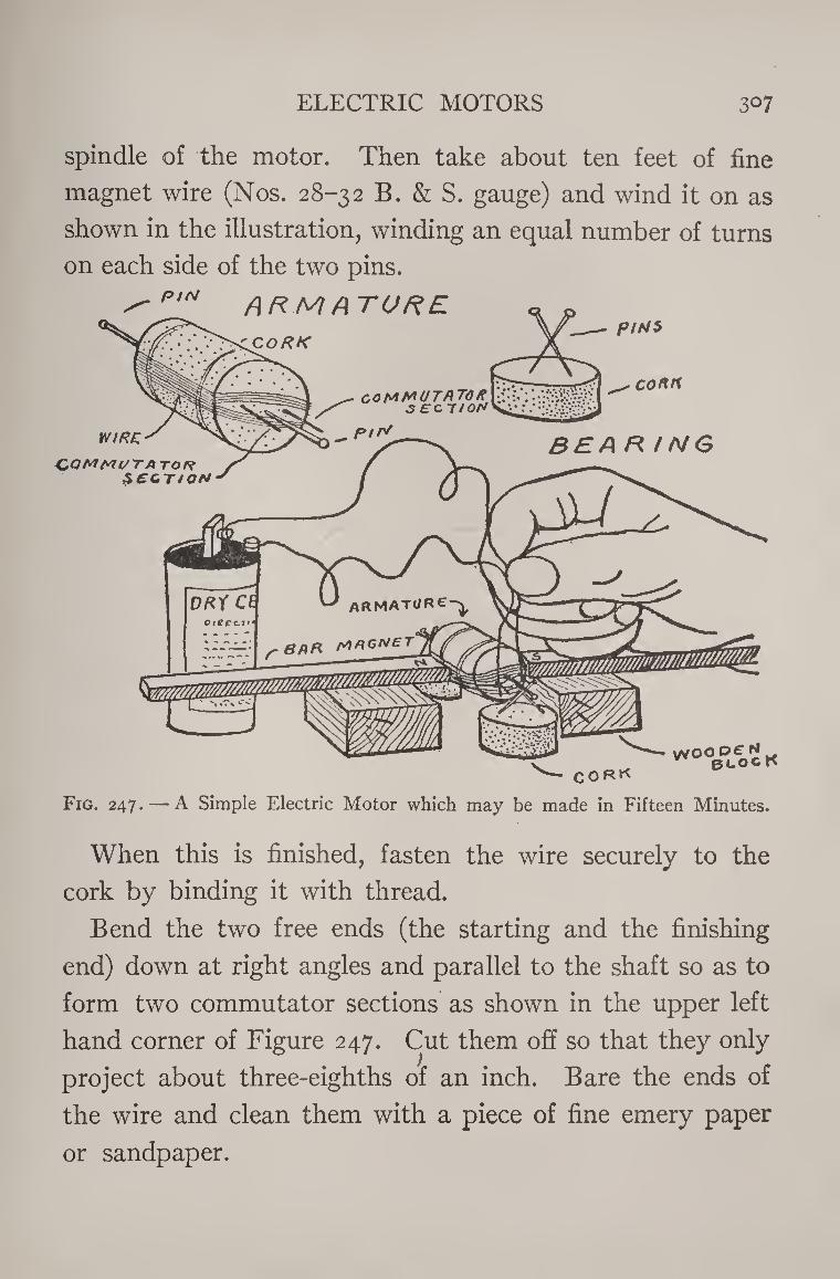
ELECTRIC MOTORS 3° 7
spindle of the motor. Then take about ten feet of fine
magnet wire (Nos. 28-32 B. & S. gauge) and wind it on as
shown in the illustration, winding an equal number of turns
on each side of the two pins.
Fig. 247. — A Simple Electric Motor which may be made in Fifteen Minutes.
When this is finished, fasten the wire securely to the
cork by binding it with thread.
Bend the two free ends (the starting and the finishing
end) down at right angles and parallel to the shaft so as to
form two commutator sections as shown in the upper left
hand corner of Figure 247. Cut them off so that they only
project about three-eighths of an inch. Bare the ends of
the wire and clean them with a piece of fine emery paper
or sandpaper.
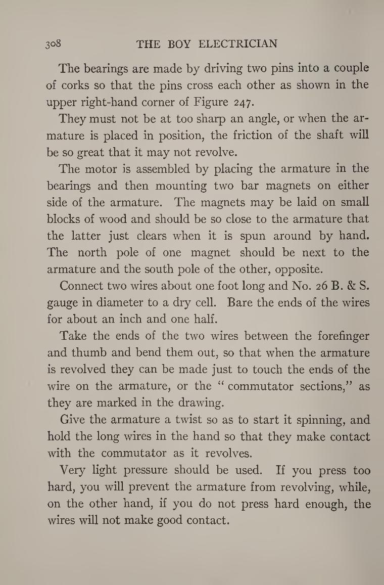
3°8 THE BOY ELECTRICIAN
The bearings are made by driving two pins into a couple
of corks so that the pins cross each other as shown in the
upper right-hand corner of Figure 247.
They must not be at too sharp an angle, or when the ar¬
mature is placed in position, the friction of the shaft will
be so great that it may not revolve.
The motor is assembled by placing the armature in the
bearings and then mounting two bar magnets on either
side of the armature. The magnets may be laid on small
blocks of wood and should be so close to the armature that
the latter just clears when it is spun around by hand.
The north pole of one magnet should be next to the
armature and the south pole of the other, opposite.
Connect two wires about one foot long and No. 26 B. & S.
gauge in diameter to a dry cell. Bare the ends of the wires
for about an inch and one half.
Take the ends of the two wires between the forefinger
and thumb and bend them out, so that when the armature
is revolved they can be made just to touch the ends of the
wire on the armature, or the “ commutator sections,” as
they are marked in the drawing.
Give the armature a twist so as to start it spinning, and
hold the long wires in the hand so that they make contact
with the commutator as it revolves.
Very light pressure should be used. If you press too
hard, you will prevent the armature from revolving, while,
on the other hand, if you do not press hard enough, the
wires will not make good contact.
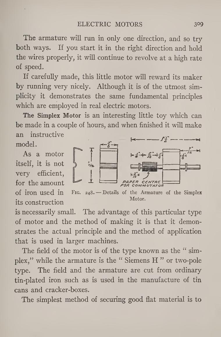
ELECTRIC MOTORS 309
J ^1*
i
sm ‘S'
J z
The armature will run in only one direction, and so try
both ways. If you start it in the right direction and hold
the wires properly, it will continue to revolve at a high rate
of speed.
If carefully made, this little motor will reward its maker
by running very nicely. Although it is of the utmost sim¬
plicity it demonstrates the same fundamental principles
which are employed in real electric motors.
The Simplex Motor is an interesting little toy which can
be made in a couple of hours, and when finished it will make
an instructive
model.
As a motor
itself, it is not
very efficient,
for the amount
of iron used in
its construction
is necessarily small. The advantage of this particular type
of motor and the method of making it is that it demon¬
strates the actual principle and the method of application
that is used in larger machines.
The field of the motor is of the type known as the “ sim¬
plex/ ’ while the armature is the “ Siemens H ” or two-pole
type. The field and the armature are cut from ordinary
tin-plated iron such as is used in the manufacture of tin
cans and cracker-boxes.
The simplest method of securing good flat material is to
t PAPER CENTRE POH COMM OTATOR
Fig. 248. — Details of the Armature of the Simplex Motor.
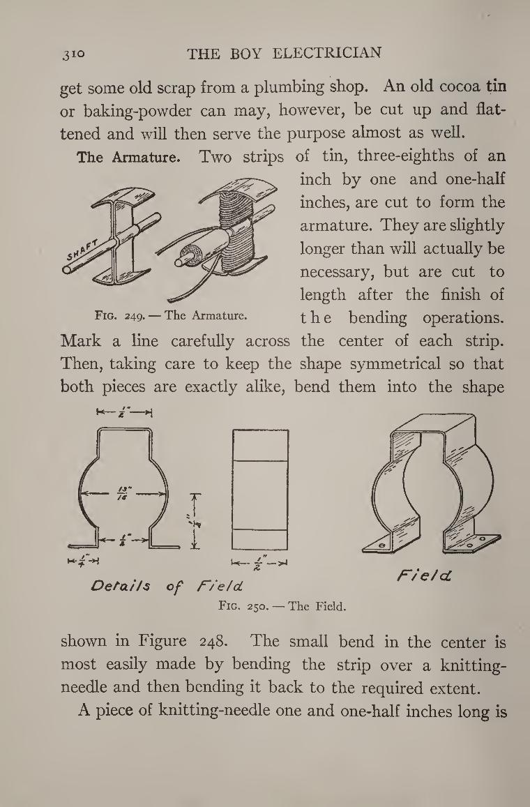
3io THE BOY ELECTRICIAN
get some old scrap from a plumbing shop. An old cocoa tin
or baking-powder can may, however, be cut up and flat¬
tened and will then serve the purpose almost as well.
The Armature. Two strips of tin, three-eighths of an
inch by one and one-half
inches, are cut to form the
armature. They are slightly
longer than will actually be
necessary, but are cut to
length after the finish of
the bending operations.
Mark a line carefully across the center of each strip.
Then, taking care to keep the shape symmetrical so that
both pieces are exactly alike, bend them into the shape
K—z'-H
Details of F/e/d
Fig. 250. — The Field.
F/e/cC
shown in Figure 248. The small bend in the center is
most easily made by bending the strip over a knitting-
needle and then bending it back to the required extent.
A piece of knitting-needle one and one-half inches long is
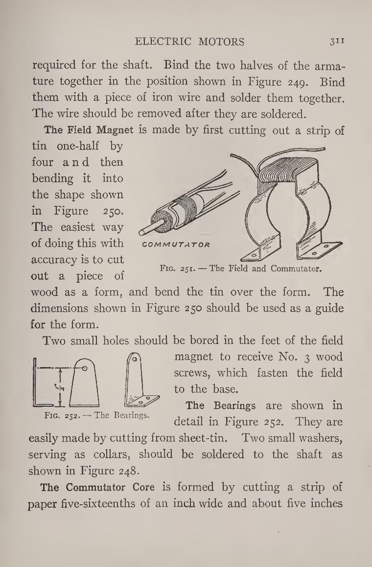
ELECTRIC MOTORS 3ii
required for the shaft. Bind the two halves of the arma¬
ture together in the position shown in Figure 249. Bind
them with a piece of iron wire and solder them together.
The wire should be removed after they are soldered.
The Field Magnet is made by first cutting out a strip of
tin one-half by
four and then
bending it into
the shape shown
in Figure 250.
The easiest way
of doing this with
accuracy is to cut
out a piece of
wood as a form, and bend the tin over the form. The
dimensions shown in Figure 250 should be used as a guide
for the form.
Two small holes should be bored in the feet of the field
COMMUTATOR
Fig. 251. — The Field and Commutator.
(fo'
Fig. 252. — The Bearings.
magnet to receive No. 3 wood
screws, which fasten the field
to the base.
The Bearings are shown in
detail in Figure 252. They are
easily made by cutting from sheet-tin. Two small washers,
serving as collars, should be soldered to the shaft as
shown in Figure 248.
The Commutator Core is formed by cutting a strip of
paper five-sixteenths of an inch wide and about five inches
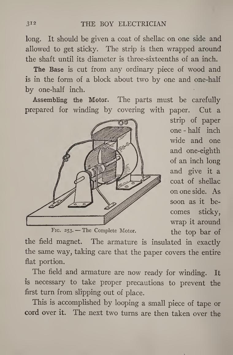
,312 THE BOY ELECTRICIAN
long. It should be given a coat of shellac on one side and
allowed to get sticky. The strip is then wrapped around
the shaft until its diameter is three-sixteenths of an inch.
The Base is cut from any ordinary piece of wood and
is in the form of a block about two by one and one-half
by one-half inch.
Assembling the Motor. The parts must be carefully
prepared for winding by covering with paper. Cut a
strip of paper
one - half inch
wide and one
and one-eighth
of an inch long
and give it a
coat of shellac
on one side. As
soon as it be¬
comes sticky,
wrap it around Fig. 253* The Complete Motor. the top bar of
the field magnet. The armature is insulated in exactly
the same way, taking care that the paper covers the entire
flat portion.
The field and armature are now ready for winding. It
is necessary to take proper precautions to prevent the
first turn from slipping out of place.
This is accomplished by looping a small piece of tape or
cord over it. The next two turns are then taken over the
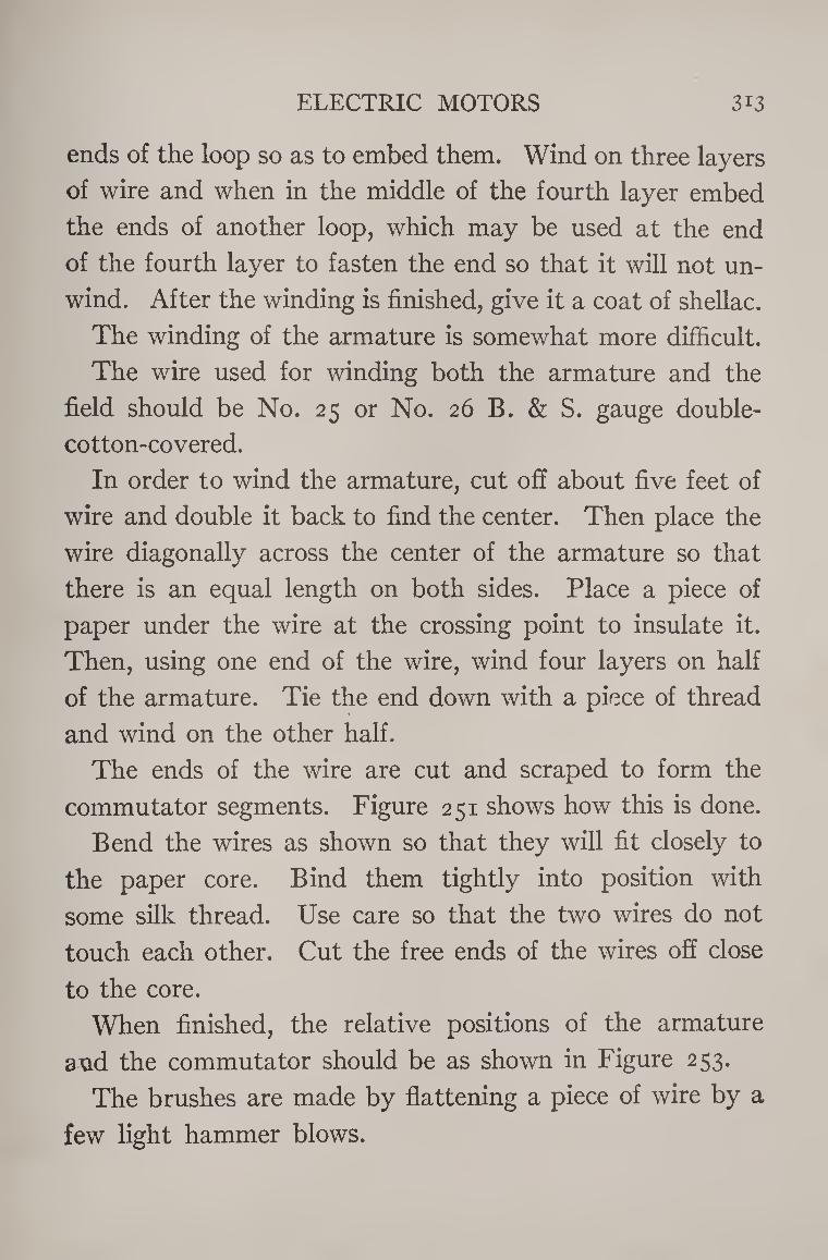
ELECTRIC MOTORS 3i3
ends of the loop so as to embed them. Wind on three layers
of wire and when in the middle of the fourth layer embed
the ends of another loop, which may be used at the end
of the fourth layer to fasten the end so that it will not un¬
wind. After the winding is finished, give it a coat of shellac.
The winding of the armature is somewhat more difficult.
The wire used for winding both the armature and the
field should be No. 25 or No. 26 B. & S. gauge double¬
cotton-covered.
In order to wind the armature, cut off about five feet of
wire and double it back to find the center. Then place the
wire diagonally across the center of the armature so that
there is an equal length on both sides. Place a piece of
paper under the wire at the crossing point to insulate it.
Then, using one end of the wire, wind four layers on half
of the armature. Tie the end down with a piece of thread
and wind on the other half.
The ends of the wire are cut and scraped to form the
commutator segments. Figure 251 shows how this is done.
Bend the wires as shown so that they will fit closely to
the paper core. Bind them tightly into position with
some silk thread. Use care so that the two wires do not
touch each other. Cut the free ends of the wires off close
to the core.
When finished, the relative positions of the armature
and the commutator should be as shown in Figure 253.
The brushes are made by flattening a piece of wire by a
few light hammer blows.
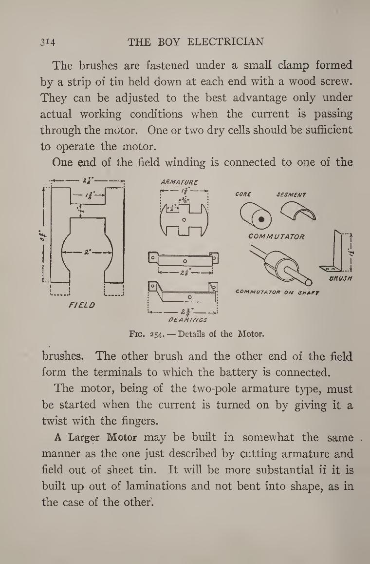
3H THE BOY ELECTRICIAN
The brushes are fastened under a small clamp formed
by a strip of tin held down at each end with a wood screw.
They can be adjusted to the best advantage only under
actual working conditions when the current is passing
through the motor. One or two dry cells should be sufficient
to operate the motor.
One end of the field winding is connected to one of the
2 s’-*: ARMATURE
BEAR/MGS
CO HE SEGMENT
COMMUTATOR on smart
Fig. 254. — Details of the Motor.
brushes. The other brush and the other end of the field
form the terminals to which the battery is connected.
The motor, being of the two-pole armature type, must
be started when the current is turned on by giving it a
twist with the fingers.
A Larger Motor may be built in somewhat the same .
manner as the one just described by cutting armature and
field out of sheet tin. It will be more substantial if it is
built up out of laminations and not bent into shape, as in
the case of the other.
ELECTRIC MOTORS 315
Lay out an armature disk and a field lamination on a
sheet of tin in accordance with the dimensions and pattern
shown in Figure 254. These pieces are used as patterns
for laying out the rest of the laminations.
Place them on some thin sheet-iron and trace the outline
with a sharp-pointed needle. Then cut a sufficient number
Fig. 255. — Complete Motor.
of pieces of each pattern to form a pile three-quarters of an
inch thick.
Four laminations for the field should be cut with ex¬
tensions shown by the dotted lines. They are bent out at
right angles for mounting the motor and holding it up¬
right.
Assemble the armature and field by piling the pieces on
top of each other and truing them up. Enough laminations
should be used to form a pile three-quarters of an inch
thick when piled up and clamped tightly.
3l6 THE BOY ELECTRICIAN
File off any burrs and rough edges and then bind the
laminations together with some string to hold them until
wound. Wrap a couple of layers of paper around those portions
of the armature and field which are liable to come into
contact with the iron. Five or six layers of No. 18 B. & S.
gauge double-cotton-covered magnet wire are sufficient to
form the field coil.
The armature is wound with three or four layers of wire
of the same size.
The commutator is made out of a circular piece of hard
wood or fiber, fitted with segments cut out of thin sheet-
copper. The segments may be fastened to the core with
thick shellac or some melted sealing-wax. The ends may
be bound down tightly by wrapping with silk thread.
The brushes are cut out of thin sheet-copper similar
to that used for the commutator segments.
The bearings are strips of heavy sheet-brass bent into the
shape shown. They are mounted by passing a nail through
the holes in the ends and through the holes, A and B, in
the field and then riveting the ends over.
Assemble the motor as shown in Figure 255. If desirable,
a small pulley may be fitted to the shaft and the motor used
to run small mechanical toys. If it is properly constructed,
two or three dry cells will furnish sufficient current to run
the motor at high speed.
i
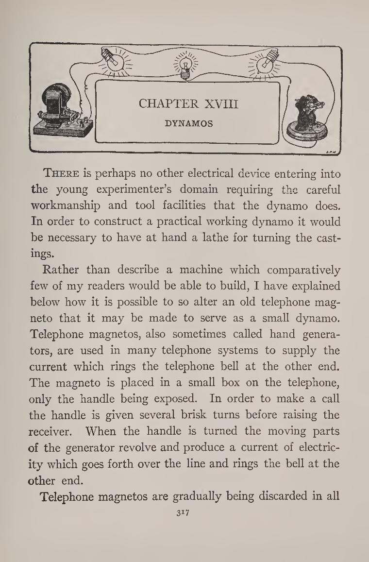
There is perhaps no other electrical device entering into
the young experimenter’s domain requiring the careful
workmanship and tool facilities that the dynamo does.
In order to construct a practical working dynamo it would
be necessary to have at hand a lathe for turning the cast¬
ings.
Rather than describe a machine which comparatively
few of my readers would be able to build, I have explained
below how it is possible to so alter an old telephone mag¬
neto that it may be made to serve as a small dynamo.
Telephone magnetos, also sometimes called hand genera¬
tors, are used in many telephone systems to supply the
current which rings the telephone bell at the other end.
The magneto is placed in a small box on the telephone,
only the handle being exposed. In order to make a call
the handle is given several brisk turns before raising the
receiver. When the handle is turned the moving parts
of the generator revolve and produce a current of electric¬
ity which goes forth over the line and rings the bell at the
other end.
Telephone magnetos are gradually being discarded in all
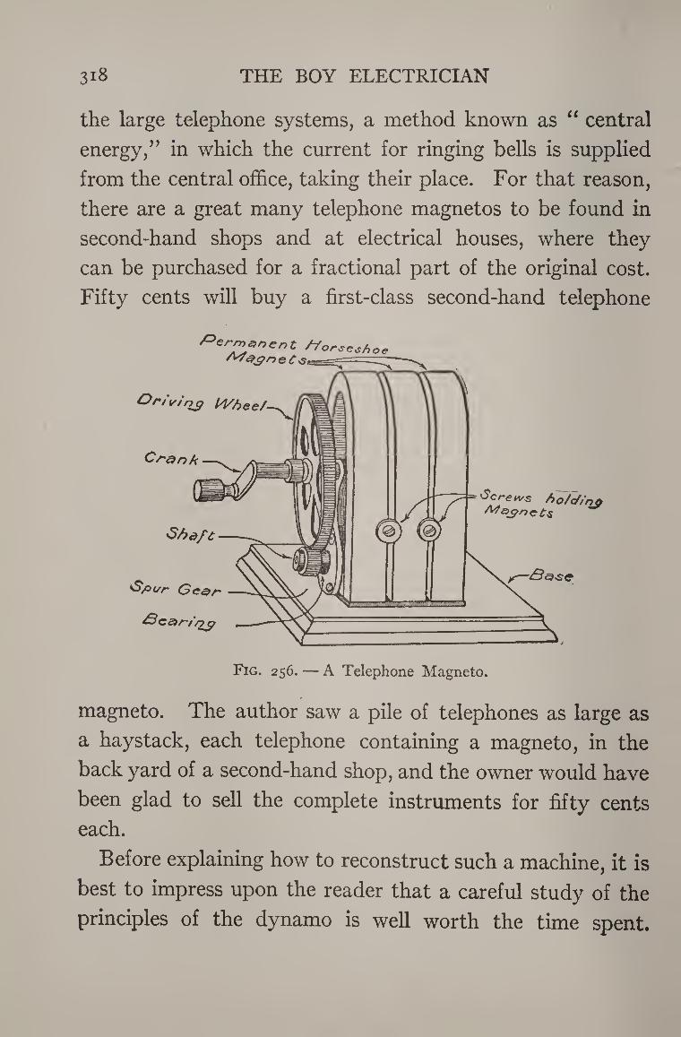
3i8 THE BOY ELECTRICIAN
the large telephone systems, a method known as “ central
energy,” in which the current for ringing bells is supplied
from the central office, taking their place. For that reason,
there are a great many telephone magnetos to be found in
second-hand shops and at electrical houses, where they
can be purchased for a fractional part of the original cost.
Fifty cents will buy a first-class second-hand telephone
magneto. The author saw a pile of telephones as large as
a haystack, each telephone containing a magneto, in the
back yard of a second-hand shop, and the owner would have
been glad to sell the complete instruments for fifty cents
each.
Before explaining how to reconstruct such a machine, it is
best to impress upon the reader that a careful study of the
principles of the dynamo is well worth the time spent.
DYNAMOS 3I9
Almost any book on physics or electricity, or even the en¬
cyclopedia, will be found to contain a description of this
wonderful machine that supplies the power for running the
trolley cars, electric lights, etc., in fact all of the electricity
in use to-day with the exception of that generated by
batteries for telegraph and telephone lines.
It will be remembered that if a bar magnet is suddenly
plunged into a hollow coil of wire, a momentary electric
current will be generated in the coil. The current is easily
detected by means of an instrument called a galvanometer.
The space in the vicinity of a magnet is filled with a pecul¬
iar invisible force called magnetism. The magnetism flows
along a certain path, passing through the magnet itself and
then spreading out in curved lines. If a sheet of paper is laid
over a magnet and a few iron filings are sprinkled on the
paper, they will follow the magnetic lines of force.
When the magnet is plunged into the hollow coil, the
lines of force flow through the turns of wire, or are said to
cut them. Whenever lines of force cut a coil of wire and
they are in motion, electricity is produced. It does not
matter whether the coil is slipped over the magnet or the
magnet is plunged into the coil, a current will be produced
as long as they are in motion. As soon as the magnet or
the coil stops moving the current stops.
By arranging a coil of wire between the poles of a horse¬
shoe magnet so that it can be made to revolve, the motion
can be made continuous and the current of electricity
maintained.
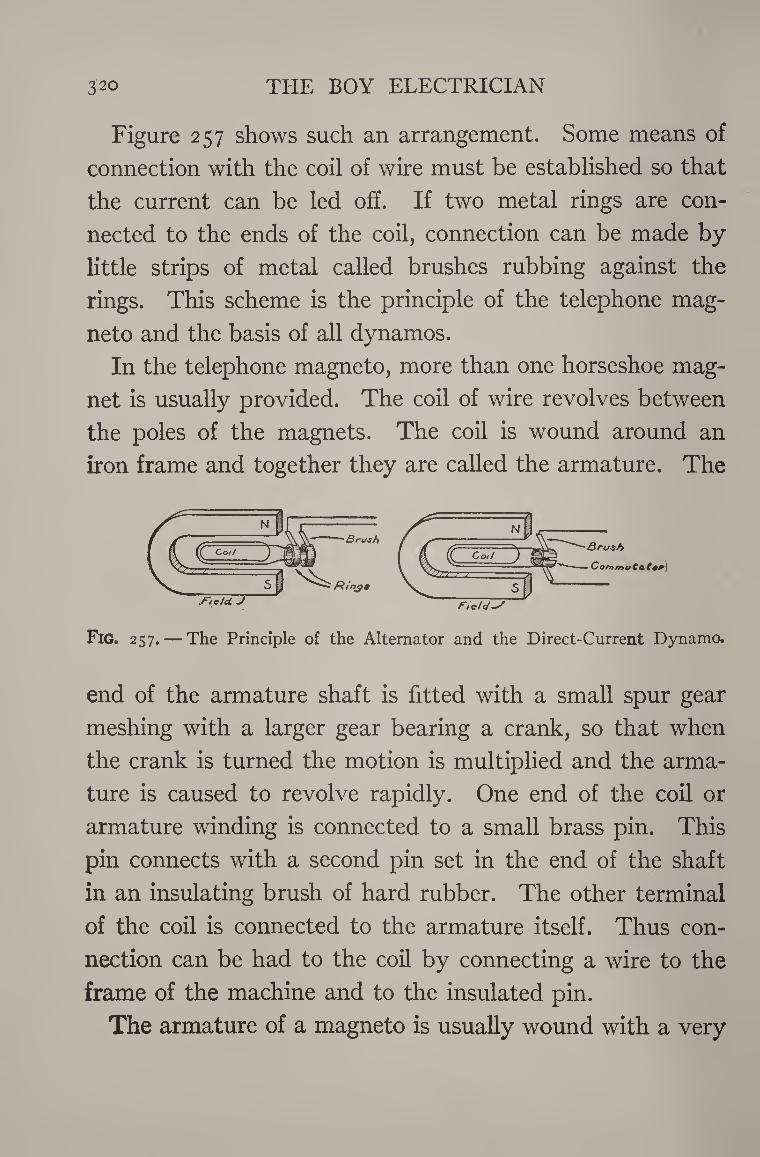
320 THE BOY ELECTRICIAN
Figure 257 shows such an arrangement. Some means of
connection with the coil of wire must be established so that
the current can be led off. If two metal rings are con¬
nected to the ends of the coil, connection can be made by
little strips of metal called brushes rubbing against the
rings. This scheme is the principle of the telephone mag¬
neto and the basis of all dynamos.
In the telephone magneto, more than one horseshoe mag¬
net is usually provided. The coil of wire revolves between
the poles of the magnets. The coil is wound around an
iron frame and together they are called the armature. The
Fig. 257. — The Principle of the Alternator and the Direct-Current Dynamo.
end of the armature shaft is fitted with a small spur gear
meshing with a larger gear bearing a crank, so that when
the crank is turned the motion is multiplied and the arma¬
ture is caused to revolve rapidly. One end of the coil or
armature winding is connected to a small brass pin. This
pin connects with a second pin set in the end of the shaft
in an insulating brush of hard rubber. The other terminal
of the coil is connected to the armature itself. Thus con¬
nection can be had to the coil by connecting a wire to the
frame of the machine and to the insulated pin.
The armature of a magneto is usually wound with a very
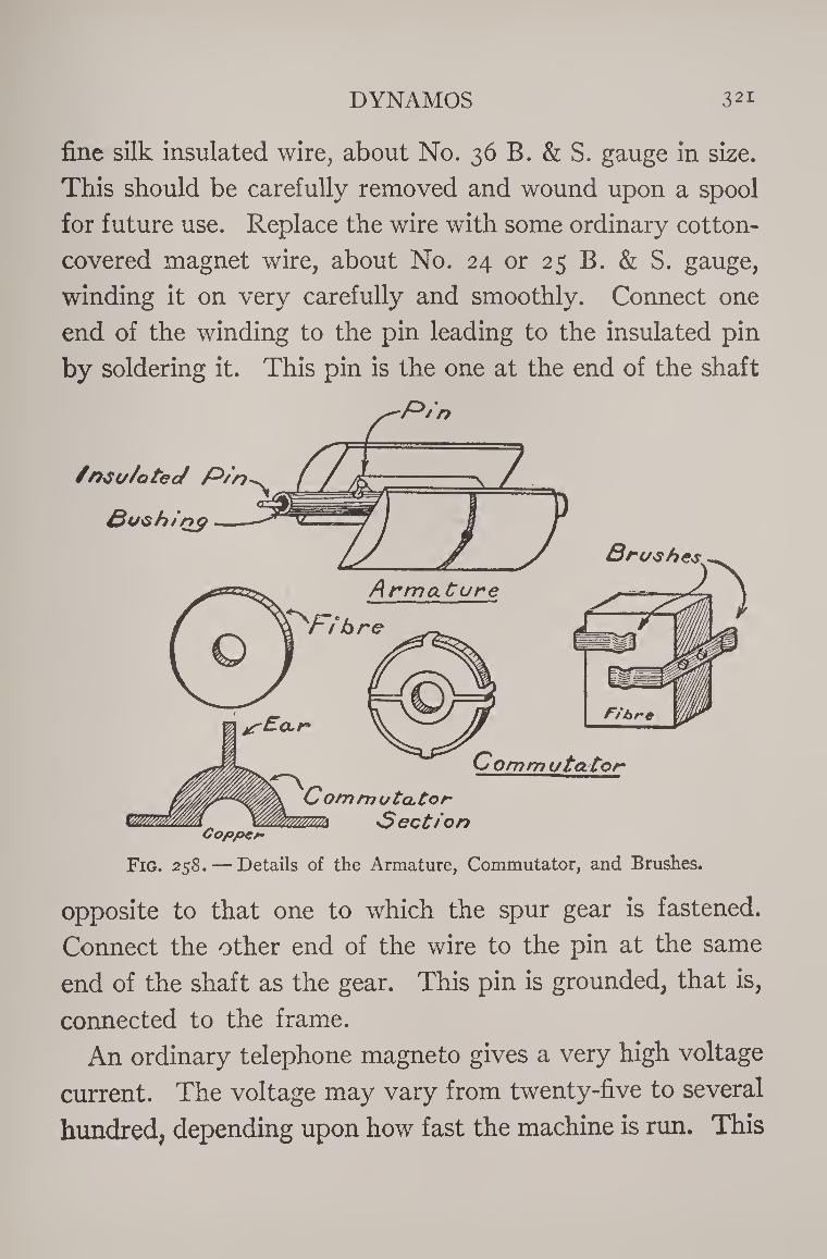
DYNAMOS 321
fine silk insulated wire, about No. 36 B. & S. gauge in size.
This should be carefully removed and wound upon a spool
for future use. Replace the wire with some ordinary cotton-
covered magnet wire, about No. 24 or 25 B. & S. gauge,
winding it on very carefully and smoothly. Connect one
end of the winding to the pin leading to the insulated pin
by soldering it. This pin is the one at the end of the shaft
Copper
Fig. 258. — Details of the Armature, Commutator, and Brushes.
opposite to that one to which the spur gear is fastened.
Connect the other end of the wire to the pin at the same
end of the shaft as the gear. This pin is grounded, that is,
connected to the frame.
An ordinary telephone magneto gives a very high voltage
current. The voltage may vary from twenty-five to several
hundred, depending upon how fast the machine is run. This
322 THE BOY ELECTRICIAN
is due to the fact that the armature winding is composed
of a very large number of turns of wire. The more turns
that are placed on the armature, the higher its voltage will
be. The current or amperage of a large telephone magneto
wound with a large number of turns of fine wire is very low.
Too low in fact to be used for anything except ringing a
bell or testing. Winding the armature with fewer turns
of large wire reduces the voltage and increases the am¬
perage so that the current will light a small lamp or may
be used for other purposes. The winding does not change
the principle of the magneto, it merely changes its am¬
perage and voltage.
The magneto may be mounted on a wooden base-board
and screwed to a table, so that the handle may be turned
without inconvenience. A small strip of copper, called a
brush, should be fastened to the base with a screw and
brought to bear against the end of the insulated pin. The
brush should be connected to a binding-post with a piece
of wire. A second wire leading to a binding-post should
be connected to the frame of the magneto. When the
handle is turned rapidly, currents may be drawn from the
two binding-posts.
The current is of the kind known as alternating, that is
to say, it flows first in one direction, then reverses and flows
in the other.
In order to make the machine give direct current, it must
be fitted with a commutator. This is somewhat difficult
with some magnetos but the following plan may be carried
DYNAMOS 323
out in most cases. Cut a small fiber circle or disk about
one inch in diameter from sheet fiber three-sixteenths of
an inch thick. Cut a small hole in the center, just large
enough so that the fiber will slip very lightly over the end
of the shaft from which the insulated pin projects. Two
small commutator sections similar to that shown in Figure
258 must be cut from sheet-brass or sheet-copper. The
three long ears shown in the drawing are bent back around
the fiber and squeezed down flat with a pair of pincers so
that they grip the fiber very tightly and will not slip. One
ear on one section should be bent over the back down to
the hole, where it will connect with the shaft. The other
section of the commutator is connected to the insulated
pin by a drop of solder. In this manner, one end of the
winding is connected to one section of the commutator and
the other end to the other section. The commutator should
fit tightly on the end of the shaft so that it will not twist.
The dividing line between the section should be parallel
to a line drawn to the axis of the actual armature coil.
When the iron parts of the armature are nearest the poles
of the horseshoe magnets in their revolution, the slot in
the commutator should be horizontal.
When the magnet is provided with a commutator, it
may also be run as a motor by connecting it to a battery.
In order to operate it either as a dynamo or a motor, how¬
ever, it must first be fitted with a pair of brushes. They
are shown in detail in Figure 258. They are made from
two small strips of sheet-copper bent as shown and mounted
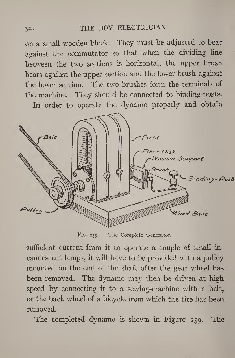
324 THE BOY ELECTRICIAN
on a small wooden block. They must be adjusted to bear
against the commutator so that when the dividing line
between the two sections is horizontal, the upper brush
bears against the upper section and the lower brush against
the lower section. The two brushes form the terminals of
the machine. They should be connected to binding-posts.
In order to operate the dynamo properly and obtain
Fig. 259. — The Complete Generator.
sufficient current from it to operate a couple of small in¬
candescent lamps, it will have to be provided with a pulley
mounted on the end of the shaft after the gear wheel has
been removed. The dynamo may then be driven at high
speed by connecting it to a sewing-machine with a belt,
or the back wheel of a bicycle from which the tire has been
removed.
The completed dynamo is shown in Figure 259. The
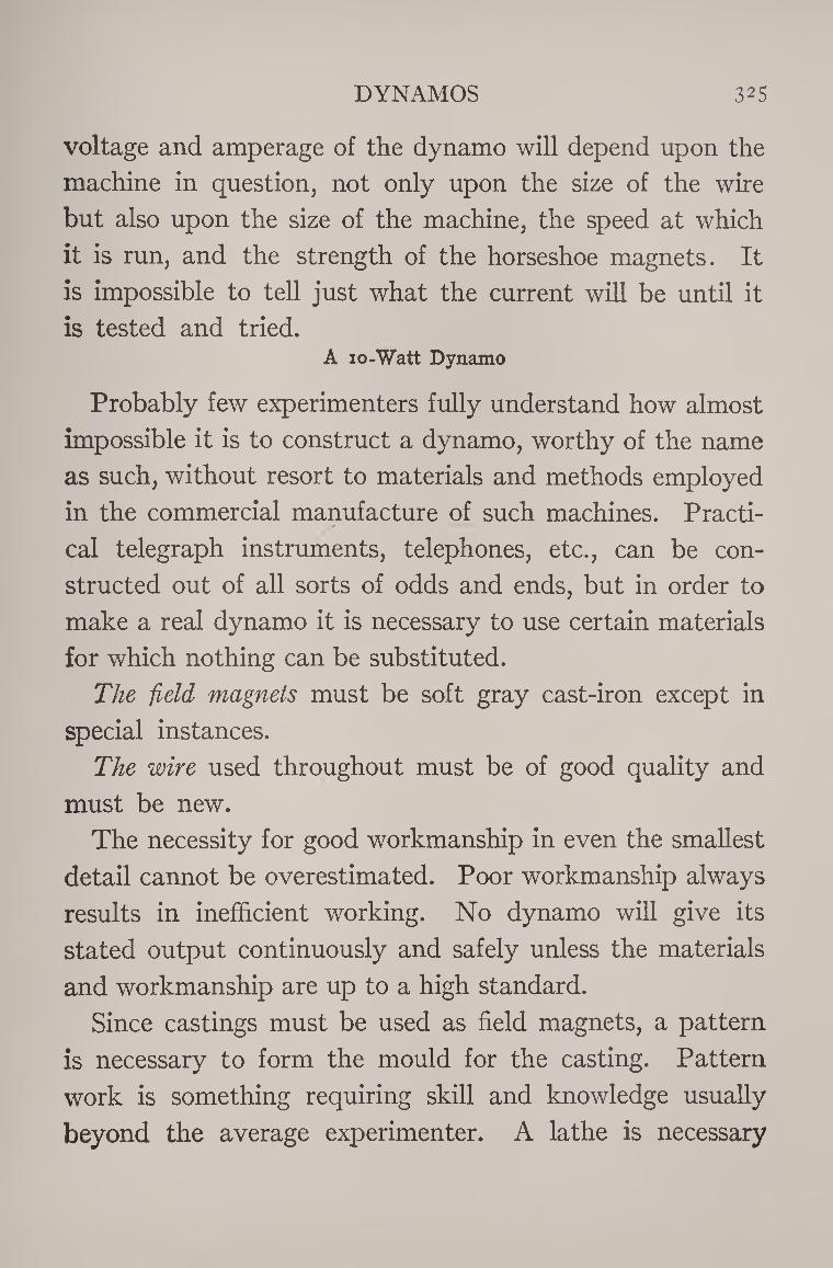
DYNAMOS 325
voltage and amperage of the dynamo will depend upon the
machine in question, not only upon the size of the wire
but also upon the size of the machine, the speed at which
it is run, and the strength of the horseshoe magnets. It
is impossible to tell just what the current will be until it
is tested and tried. A io-Watt Dynamo
Probably few experimenters fully understand how almost
impossible it is to construct a dynamo, worthy of the name
as such, without resort to materials and methods employed
in the commercial manufacture of such machines. Practi¬
cal telegraph instruments, telephones, etc., can be con¬
structed out of all sorts of odds and ends, but in order to
make a real dynamo it is necessary to use certain materials
for which nothing can be substituted.
The field magnets must be soft gray cast-iron except in
special instances.
The wire used throughout must be of good quality and
must be new.
The necessity for good workmanship in even the smallest
detail cannot be overestimated. Poor workmanship always
results in inefficient working. No dynamo will give its
stated output continuously and safely unless the materials
and workmanship are up to a high standard.
Since castings must be used as field magnets, a pattern
is necessary to form the mould for the casting. Pattern
work is something requiring skill and knowledge usually
beyond the average experimenter. A lathe is necessary
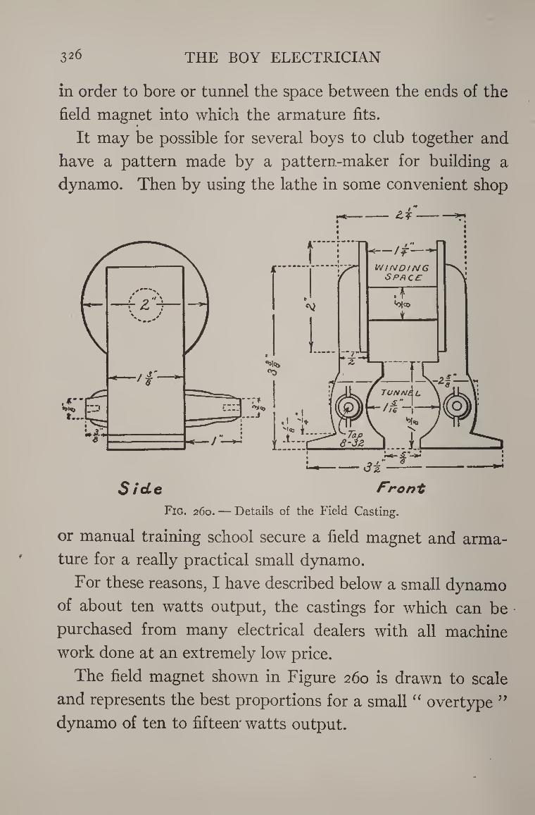
326 THE BOY ELECTRICIAN
in order to bore or tunnel the space between the ends of the
field magnet into which the armature fits. »
It may be possible for several boys to club together and
have a pattern made by a pattern-maker for building a
dynamo. Then by using the lathe in some convenient shop
or manual training school secure a field magnet and arma¬
ture for a really practical small dynamo.
For these reasons, I have described below a small dynamo
of about ten watts output, the castings for which can be
purchased from many electrical dealers with all machine
work done at an extremely low price.
The field magnet shown in Figure 260 is drawn to scale
and represents the best proportions for a small “ overtype ”
dynamo of ten to fifteen' watts output.
DYNAMOS 327
The dimensions are so clearly shown by the drawings
that further comment in that respect is unnecessary.
The armature is of the type known as the “ Siemen’s H.”
It is the simplest type of armature it is possible to make,
which is a feature of prime importance to the beginner at
dynamo construction, although it is not the most efficient
form from the electrical standpoint. The armature in
this case is also a casting and therefore a pattern is
required.
The patterns for both
the field and the arma¬
ture are of the same
size and shape as shown
in Figures 260 and 261.
They are made of wood,
and are finished by rub¬
bing with fine sandpaper
until perfectly smooth
and then given a coat of
shellac. The parts are Fig. 261. — Details of the Armature Casting.
also given a slight “ draft,” that is, a taper toward one
side, so that the pattern may be withdrawn from the
mould.
The patterns are turned over to a foundry, where they
are carefully packed in a box, called a “ flask,” full of
moulder’s sand. When the patterns are properly with¬
drawn, they will leave a perfect impression of themselves
behind in the sand. The mould is then closed up and poured
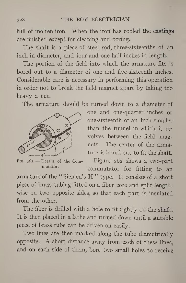
328 THE BOY ELECTRICIAN
full of molten iron. When the iron has cooled the castings
are finished except for cleaning and boring.
The shaft is a piece of steel rod, three-sixteenths of an
inch in diameter, and four and one-half inches in length.
The portion of the field into which the armature fits is
bored out to a diameter of one and five-sixteenth inches.
Considerable care is necessary in performing this operation
in order not to break the field magnet apart by taking too
heavy a cut.
The armature should be turned down to a diameter of
one and one-quarter inches or
one-sixteenth of an inch smaller
than the tunnel in which it re¬
volves between the field mag¬
nets. The center of the arma¬
ture is bored out to fit the shaft.
Figure 262 shows a two-part
commutator for fitting to an
armature of the “ Siemen’s H ” type. It consists of a short
piece of brass tubing fitted on a fiber core and split length¬
wise on two opposite sides, so that each part is insulated
from the other.
The fiber is drilled with a hole to fit tightly on the shaft.
It is then placed in a lathe and turned down until a suitable
piece of brass tube can be driven on easily.
Two lines are then marked along the tube diametrically
opposite. A short distance away from each of these lines,
and on each side of them, bore two small holes to receive
Fig. 262. — Details of the Com¬
mutator.
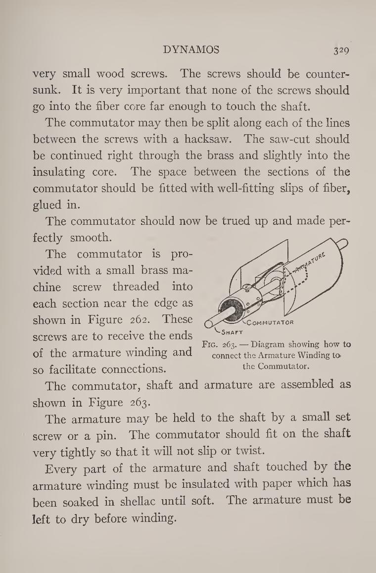
DYNAMOS 329
very small wood screws. The screws should be counter¬
sunk. It is very important that none of the screws should
go into the fiber core far enough to touch the shaft.
The commutator may then be split along each of the lines
between the screws with a hacksaw. The saw-cut should
be continued right through the brass and slightly into the
insulating core. The space between the sections of the
commutator should be fitted with well-fitting slips of fiber,
glued in.
The commutator should now be trued up and made per¬
fectly smooth.
The commutator is pro¬
vided with a small brass ma¬
chine screw threaded into
each section near the edge as
shown in Figure 262. These
screws are to receive the ends
of the armature winding and
so facilitate connections.
The commutator, shaft and armature are assembled as
shown in Figure 263.
The armature may be held to the shaft by a small set
screw or a pin. The commutator should fit on the shaft
very tightly so that it will not slip or twist.
Every part of the armature and shaft touched by the
armature winding must be insulated with paper which has
been soaked in shellac until soft. The armature must be
left to dry before winding.
^Commutator
^Shaft
Fig. 263. — Diagram showing how to
connect the Armature Winding to»
the Commutator.
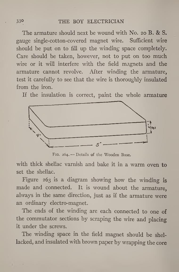
330 THE BOY ELECTRICIAN
The armature should next be wound with No. 20 B. & S.
gauge single-cotton-covered magnet wire. Sufficient wire
should be put on to fill up the winding space completely.
Care should be taken, however, not to put on too much
wire or it will interfere with the field magnets and the
armature cannot revolve. After winding the armature,
test it carefully to see that the wire is thoroughly insulated
from the iron.
If the insulation is correct, paint the whole armature
with thick shellac varnish and bake it in a warm oven to
set the shellac.
Figure 263 is a diagram showing how the winding is
made and connected. It is wound about the armature,
always in the same direction, just as if the armature were
an ordinary electro-magnet.
The ends of the winding are each connected to one of
the commutator sections by scraping the wire and placing
it under the screws.
The winding space in the field magnet should be shel¬
lacked, and insulated with brown paper by wrapping the core
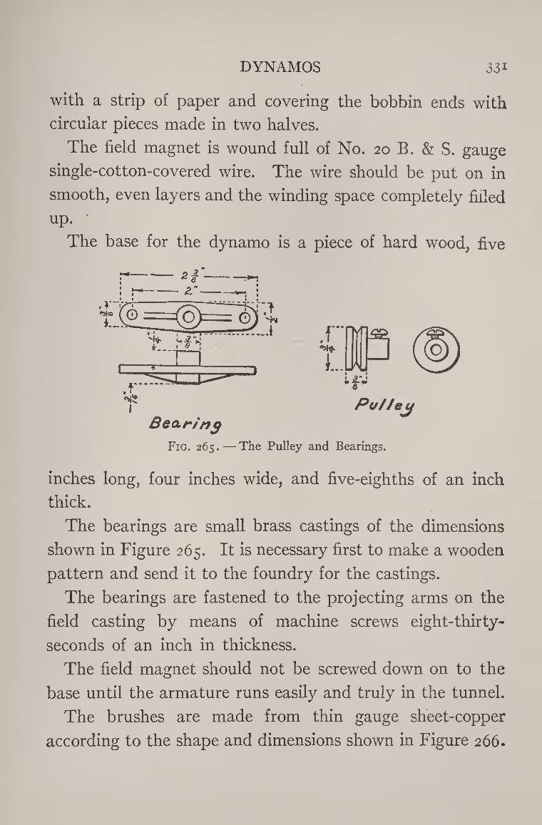
DYNAMOS 33i
with a strip of paper and covering the bobbin ends with
circular pieces made in two halves.
The field magnet is wound full of No. 20 B. & S. gauge
single-cotton-covered wire. The wire should be put on in
smooth, even layers and the winding space completely filled
up.
The base for the dynamo is a piece of hard wood, five
Bearing Put/ey
Fig. 265. — The Pulley and Bearings.
inches long, four inches wide, and five-eighths of an inch
thick.
The bearings are small brass castings of the dimensions
shown in Figure 265. It is necessary first to make a wooden
pattern and send it to the foundry for the castings.
The bearings are fastened to the projecting arms on the
field casting by means of machine screws eight-thirty-
seconds of an inch in thickness.
The field magnet should not be screwed down on to the
base until the armature runs easily and truly in the tunnel.
The brushes are made from thin gauge sheet-copper
according to the shape and dimensions shown in Figure 266.
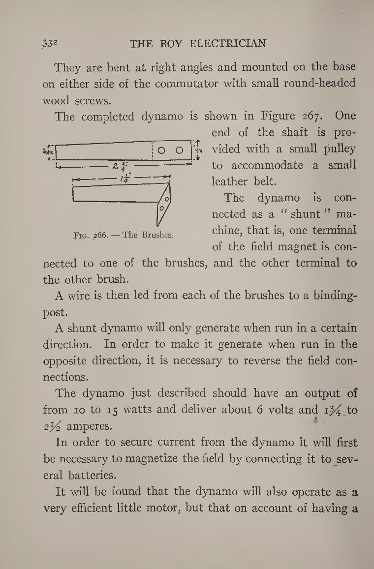
332 THE BOY ELECTRICIAN
They are bent at right angles and mounted on the base
on either side of the commutator with small round-headed
wood screws.
The completed dynamo is shown in Figure 267. One
end of the shaft is pro¬
vided with a small pulley
to accommodate a small
leather belt.
The dynamo is con-
-r *_
o o l:f H"
- >T
Fig. 266. — The Brushes.
nected as a “ shunt" ma¬
chine, that is, one terminal
of the field magnet is con¬
nected to one of the brushes, and the other terminal to
the other brush.
A wire is then led from each of the brushes to a binding-
post.
A shunt dynamo will only generate when run in a certain
direction. In order to make it generate when run in the
opposite direction, it is necessary to reverse the field con¬
nections.
The dynamo just described should have an output of
from 10 to 15 watts and deliver about 6 volts and 1^ to
2y2 amperes.
In order to secure current from the dynamo it will first
be necessary to magnetize the field by connecting it to sev¬
eral batteries.
It will be found that the dynamo will also operate as a
very efficient little motor, but that on account of having a
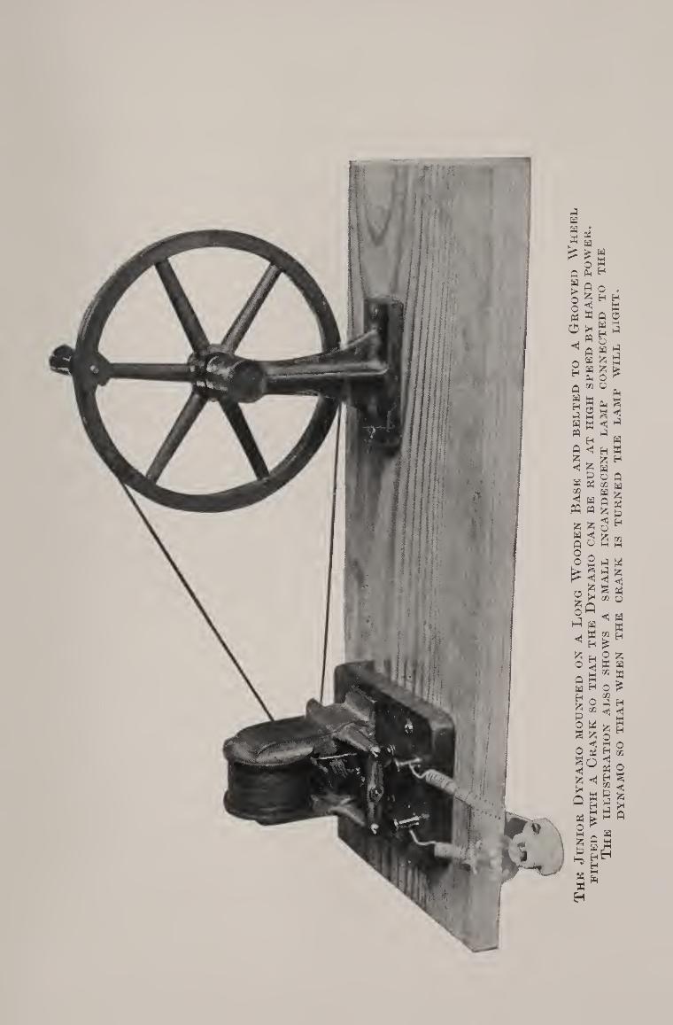
a a H ft
>>
ft a > O o ft o
\ $
0 ° ft ft bH ^
pC ^ ft W 0 a 2 a £ H a o ft ^ u a a a ® M M
ft ?
a m
a
«j PQ
a a **s
«! J J a H ft ft H o ft M w a 55 s ft g a & 5
j, < H 5 « o 55 a m tn
£ a ft o n o 2 a ft
t*- ^ a 'z,
rh ft g ns a w a ft a
®'.;<!h ft
% H ^ a 2 ^ o S « a h^W a a o ^ h o S a
° « >? a £ 5 o _ ^ g o O pj a oa
3^g 5>q <i H S S £ <1 □ a R a "Sag a > M ^ o ^ m _ a Z H M c arm -, M
M ^ ft H
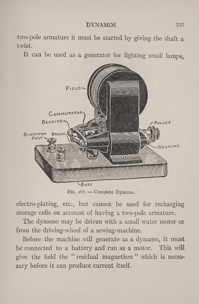
DYNAMOS 333
two-pole armature it must be started by giving the shaft a
twist.
It can be used as a generator for lighting small lamps,
^Base
Fig. 267. — Complete Dynamo.
electro-plating, etc., but cannot be used for recharging
storage cells on account of having a two-pole armature.
The dynamo may be driven with a small water motor or
from the driving-wheel of a sewing-machine.
Before the machine will generate as a dynamo, it must
be connected to a battery and run as a motor. This will
give the field the “ residual magnetism ” which is neces¬
sary before it can produce current itself.
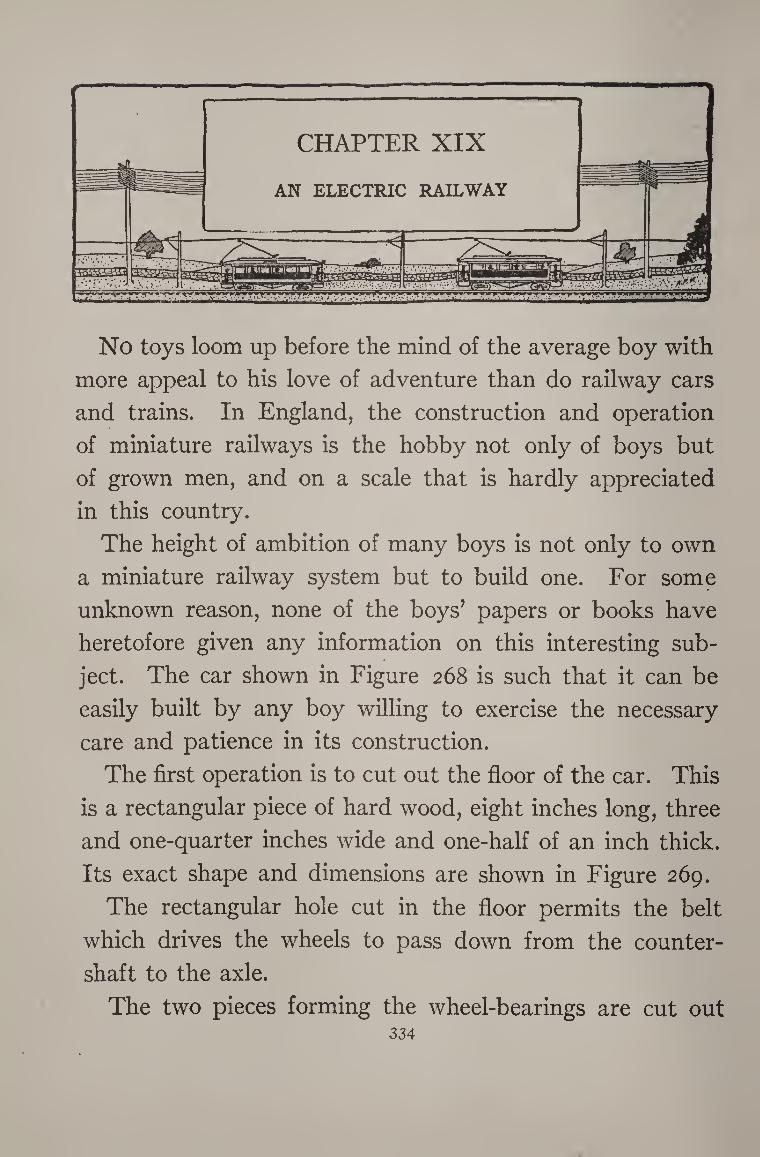
No toys loom up before the mind of the average boy with
more appeal to his love of adventure than do railway cars
and trains. In England, the construction and operation
of miniature railways is the hobby not only of boys but
of grown men, and on a scale that is hardly appreciated
in this country.
The height of ambition of many boys is not only to own
a miniature railway system but to build one. For some
unknown reason, none of the boys’ papers or books have
heretofore given any information on this interesting sub¬
ject. The car shown in Figure 268 is such that it can be
easily built by any boy willing to exercise the necessary
care and patience in its construction.
The first operation is to cut out the floor of the car. This
is a rectangular piece of hard wood, eight inches long, three
and one-quarter inches wide and one-half of an inch thick.
Its exact shape and dimensions are shown in Figure 269.
The rectangular hole cut in the floor permits the belt
which drives the wheels to pass down from the counter¬
shaft to the axle.
The two pieces forming the wheel-bearings are cut out 334
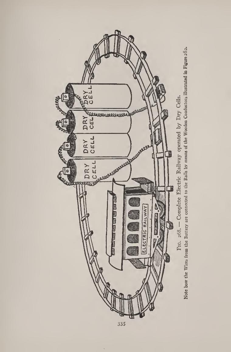
335
Fig
. 268. —
Co
mp
lete E
lectr
ic R
ail
way o
pera
ted by D
ry
Cel
ls.
No
te h
ow t
he
Wir
es f
rom
the
Bat
tery
are
connec
ted t
o t
he
Rai
ls b
y m
ean
s o
f th
e W
ooden
Conduct
ors
ill
ust
rate
d i
n F
igure
282.
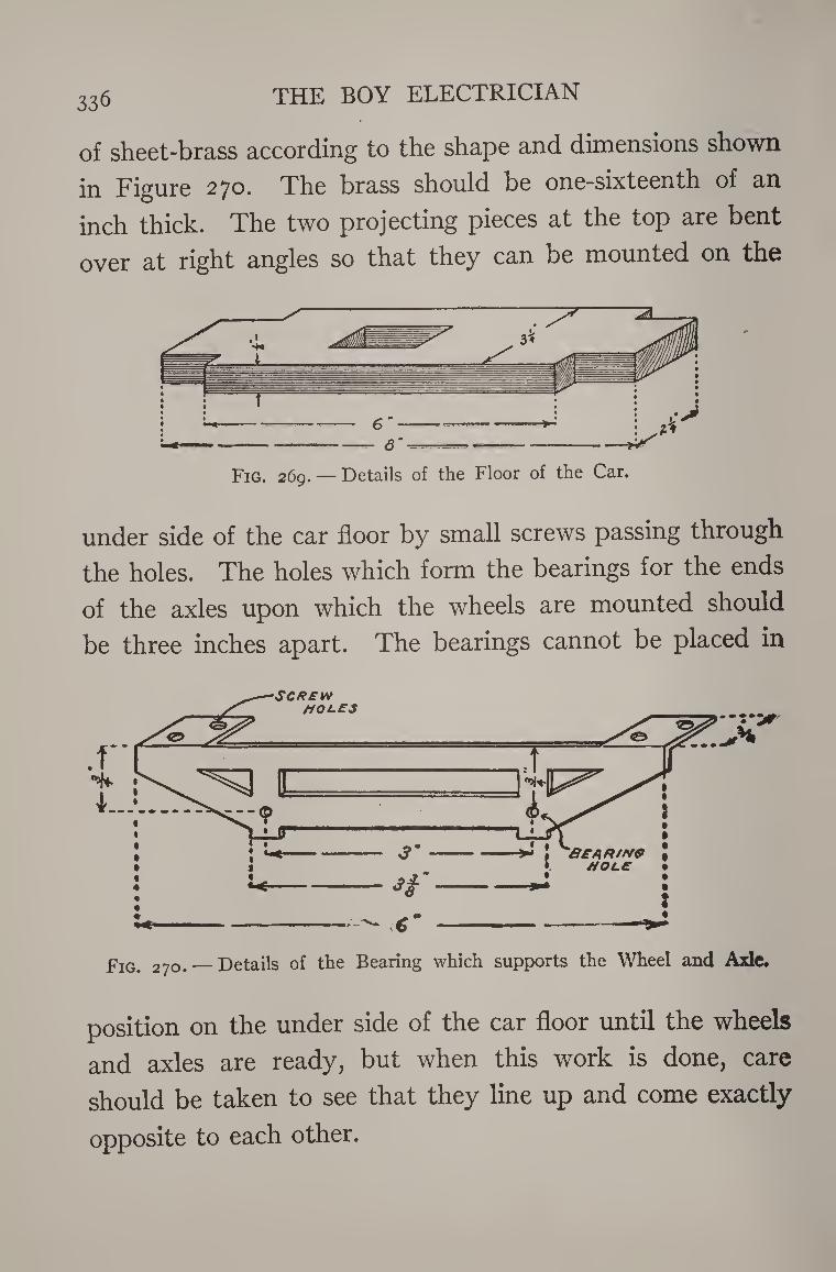
THE BOY ELECTRICIAN 336
of sheet-brass according to the shape and dimensions shown
in Figure 270. The brass should be one-sixteenth of an
inch thick. The two projecting pieces at the top are bent
over at right angles so that they can be mounted on the
under side of the car floor by small screws passing through
the holes. The holes which form the bearings for the ends
of the axles upon which the wheels are mounted should
be three inches apart. The bearings cannot be placed in
position on the under side of the car floor until the wheels
and axles are ready, but when this work is done, care
should be taken to see that they line up and come exactly
opposite to each other.
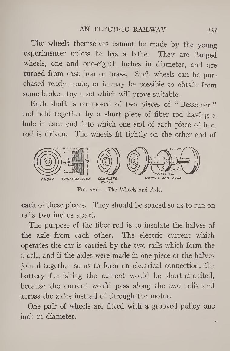
AN ELECTRIC RAILWAY 337
The wheels themselves cannot be made by the young
experimenter unless he has a lathe. They are flanged
wheels, one and one-eighth inches in diameter, and are
turned from cast iron or brass. Such wheels can be pur¬
chased ready made, or it may be possible to obtain from
some broken toy a set which will prove suitable.
Each shaft is composed of two pieces of “ Bessemer ”
rod held together by a short piece of fiber rod having a
hole in each end into which one end of each piece of iron
rod is driven. The wheels fit tightly on the other end of
W H ECL__
Fig. 271. — The Wheels and Axle.
each of these pieces. They should be spaced so as to run on
rails two inches apart.
The purpose of the fiber rod is to insulate the halves of
the axle from each other. The electric current which
operates the car is carried by the two rails which form the
track, and if the axles were made in one piece or the halves
joined together so as to form an electrical connection, the
battery furnishing the current would be short-circuited,
because the current would pass along the two rails and
across the axles instead of through the motor.
One pair of wheels are fitted with a grooved pulley one
inch in diameter.
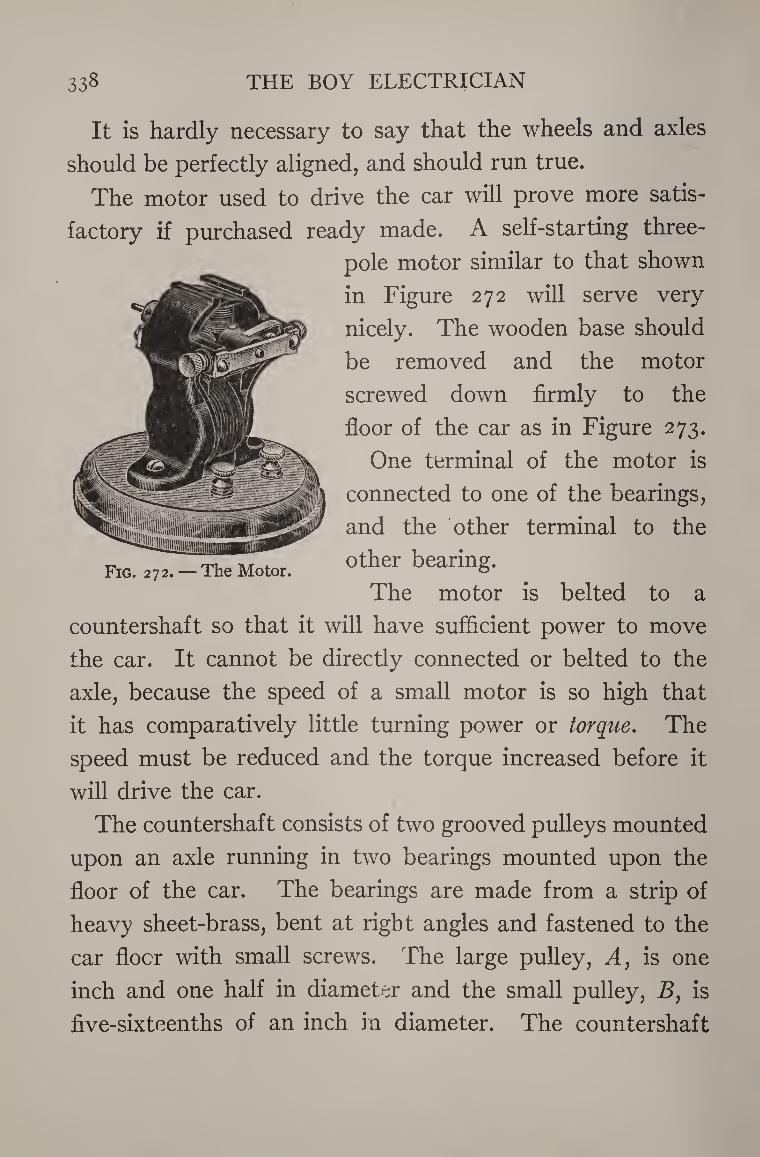
338 THE BOY ELECTRICIAN
It is hardly necessary to say that the wheels and axles
should be perfectly aligned, and should run true.
The motor used to drive the car will prove more satis¬
factory if purchased ready made. A self-starting three-
pole motor similar to that shown
in Figure 272 will serve very
nicely. The wooden base should
be removed and the motor
screwed down firmly to the
floor of the car as in Figure 273.
One terminal of the motor is
connected to one of the bearings,
and the other terminal to the
other bearing.
The motor is belted to a
countershaft so that it will have sufficient power to move
the car. It cannot be directly connected or belted to the
axle, because the speed of a small motor is so high that
it has comparatively little turning power or torque. The
speed must be reduced and the torque increased before it
will drive the car.
The countershaft consists of two grooved pulleys mounted
upon an axle running in two bearings mounted upon the
floor of the car. The bearings are made from a strip of
heavy sheet-brass, bent at right angles and fastened to the
car floor with small screws. The large pulley, A, is one
inch and one half in diameter and the small pulley, B, is
five-sixteenths of an inch in diameter. The countershaft
AN ELECTRIC RAILWAY 339
is mounted in such a position that a belt may be run from
the small pulley, B, to the pulley mounted on the axle of
one pair of wheels. A belt is also run from the small pulley
on the motor to the large pulley, A, on the countershaft.
The pulleys must all be carefully lined up so that the belts
will run in their grooves without danger of slipping out.
The shield on the platform at each end of the car is made
of sheet-iron or tin. Two small projections on the bottom
are bent over at right angles and used to secure the shields
Fig. 273. — The Complete Truck of the Car without the Body.
in position by driving a small tack through them into the
floor of the car.
The steps on either side of each platform are also made
by bending strips of sheet-iron or tin and fastening them to
the car with small nails or tacks.
The coupler consists of a strip of tin having a small hook
soldered to the end so that a trail car may be attached if
desirable.
The car is now ready for testing, and when held in the
hand so that the wheels are free to run, two cells of dry
340 THE BOY ELECTRICIAN
battery should be found all that
is necessary to drive them at a
fair rate of speed. The two
wires leading from the battery
should be connected to the
bearings, one wire leading to
each bearing. It will require
& more than two cells, however, u « to drive the wheels properly
•3 when the car is on the track,
•jj All moving parts should run
^ freely and smoothly. The car
* may be used just as it is, but if <D
§ fitted with a body and a top it
r§ will present a much more realis¬
es tic appearance.
§ The sides and ends of the car 4->
£ body are made of sheet-iron or
J. tin. Figure 274 shows the pat-
w tern and dimensions for these
£ parts. They may be made from
one piece of metal eighteen and
one-half inches long and three
and three-quarters inches wide.
The doors and windows are cut
out with a pair of tin-snips.
The small projections along the
top are bent down at right
AN ELECTRIC RAILWAY 34i
angles and the roof is fastened to them. The dotted lines
indicate the places for bending these projections and also
the sides and ends of the car.
The roof is made in two pieces. It also is sheet-iron or
tin. The roof proper is eight inches long and four inches
wide. It has a hole five and one-half inches long and one
and three-quarters inches wide cut in the center. A num¬
ber of small projections are left and bent upward to sup-
(l/mn I 1 H '•
Ey e e a FLFCTRIC RAILWAY | t
] 0 0
u=&
Fig. 276. — The Completed Car.
port the deck and to form imitation ventilators. The deck
is six inches long and two and one-quarter inches in width.
It is placed in position on the roof and fastened by solder¬
ing. The roof is fastened to the sides and ends of the
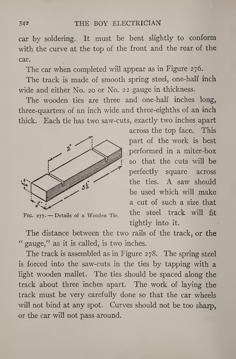
342 THE BOY ELECTRICIAN
car by soldering. It must be bent slightly to conform
with the curve at the top of the front and the rear of the
car. r
The car when completed will appear as in Figure 276.
The track is made of smooth spring steel, one-half inch
wide and either No. 20 or No. 22 gauge in thickness.
The wooden ties are three and one-half inches long,
three-quarters of an inch wide and three-eighths of an inch
thick. Each tie has two saw-cuts, exactly two inches apart
across the top face. This
part of the work is best
performed in a miter-box
so that the cuts will be
perfectly square across
the ties. A saw should
be used which will make
a cut of such a size that
the steel track will fit
tightly into it.
The distance between the two rails of the track, or the
“ gauge,’’ as it is called, is two inches.
The track is assembled as in Figure 278. The spring steel
is forced into the saw-cuts in the ties by tapping with a
light wooden mallet. The ties should be spaced along the
track about three inches apart. The work of laying the
track must be very carefully done so that the car wheels
will not bind at any spot. Curves should not be too sharp,
or the car will not pass around.
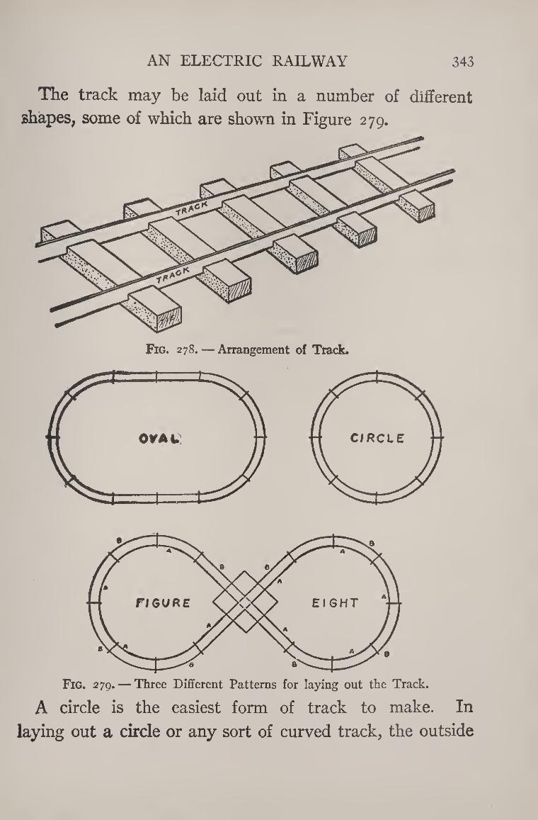
AN ELECTRIC RAILWAY 343
The track may be laid out in a number of different
shapes, some of which are shown in Figure 279.
Fig. 278. — Arrangement of Track.
Fig. 279. — Three Different Patterns for laying out the Track.
A circle is the easiest form of track to make. In
laying out a circle or any sort of curved track, the outside
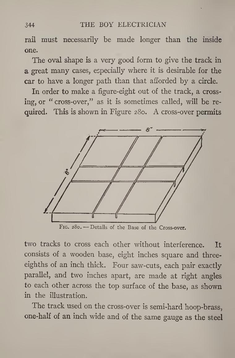
344 THE BOY ELECTRICIAN
rail must necessarily be made longer than the inside
one.
The oval shape is a very good form to give the track in
a great many cases, especially where it is desirable for the
car to have a longer path than that afforded by a circle.
In order to make a figure-eight out of the track, a cross¬
ing, or “ cross-over,” as it is sometimes called, will be re¬
quired. This is shown in Figure 280. A cross-over permits
two tracks to cross each other without interference. It
consists of a wooden base, eight inches square and three-
eighths of an inch thick. Four saw-cuts, each pair exactly
parallel, and two inches apart, are made at right angles
to each other across the top surface of the base, as shown
in the illustration.
The track used on the cross-over is semi-hard hoop-brass,
one-half of an inch wide and of the same gauge as the steel
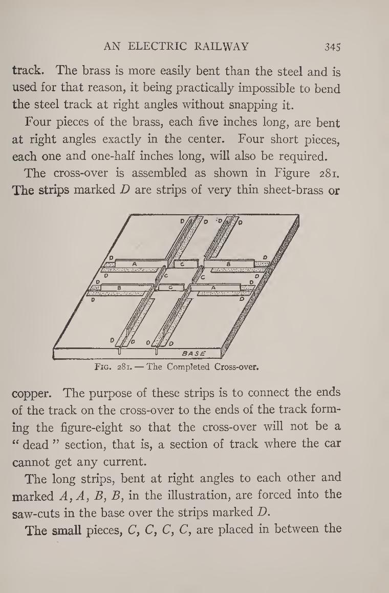
AN ELECTRIC RAILWAY 345
track. The brass is more easily bent than the steel and is
used for that reason, it being practically impossible to bend
the steel track at right angles without snapping it.
Four pieces of the brass, each five inches long, are bent
at right angles exactly in the center. Four short pieces,
each one and one-half inches long, will also be required.
The cross-over is assembled as shown in Figure 281.
The strips marked D are strips of very thin sheet-brass or
Fig. 281. — The Completed Cross-over.
copper. The purpose of these strips is to connect the ends
of the track on the cross-over to the ends of the track form¬
ing the figure-eight so that the cross-over will not be a
“ dead ” section, that is, a section of track where the car
cannot get any current.
The long strips, bent at right angles to each other and
marked A, A, B, B, in the illustration, are forced into the
saw-cuts in the base over the strips marked D. The small pieces, C, C, C, C, are placed in between the
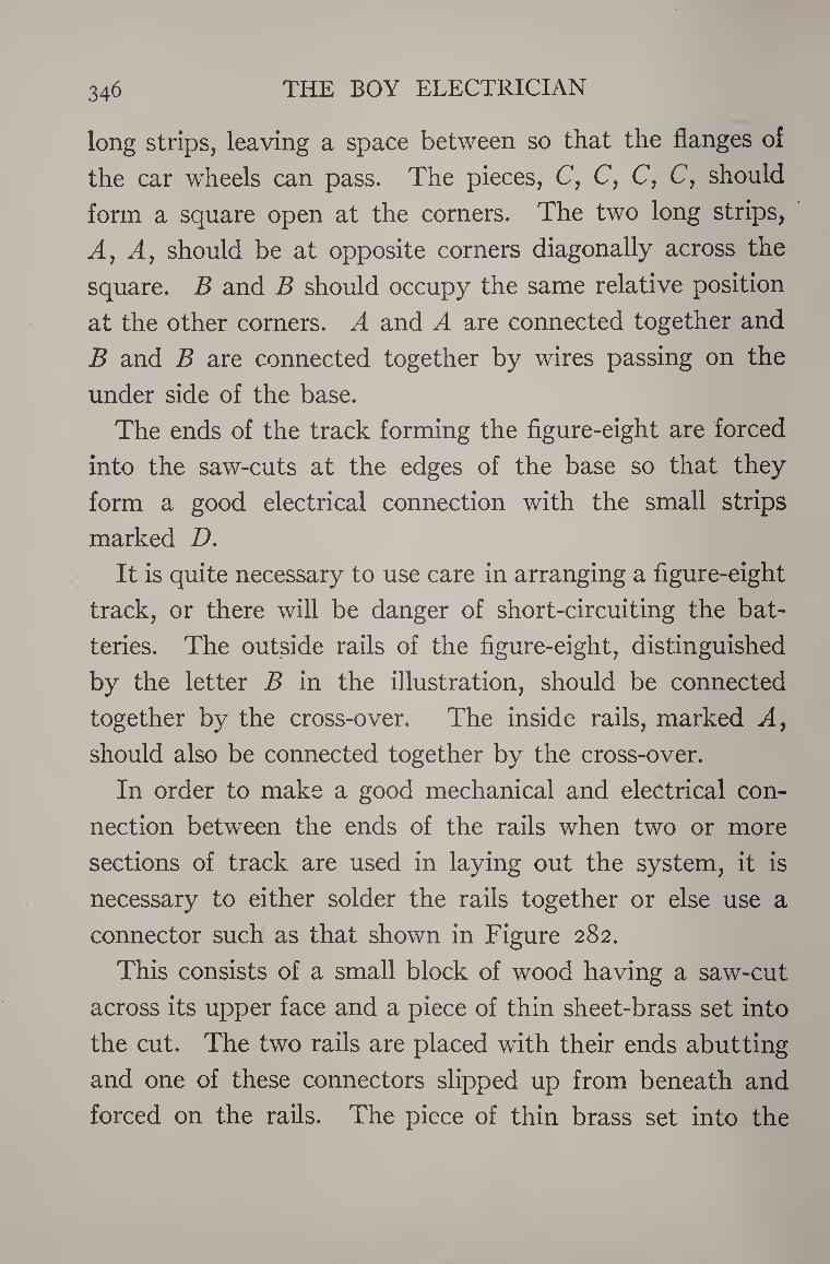
346 THE BOY ELECTRICIAN
long strips, leaving a space between so that the flanges of
the car wheels can pass. The pieces, C, C, C, C, should
form a square open at the corners. The two long strips,
A, A, should be at opposite corners diagonally across the
square. B and B should occupy the same relative position
at the other corners. A and A are connected together and
B and B are connected together by wires passing on the
under side of the base.
The ends of the track forming the figure-eight are forced
into the saw-cuts at the edges of the base so that they
form a good electrical connection with the small strips
marked D. It is quite necessary to use care in arranging a figure-eight
track, or there will be danger of short-circuiting the bat¬
teries. The outside rails of the figure-eight, distinguished
by the letter B in the illustration, should be connected
together by the cross-over. The inside rails, marked A, should also be connected together by the cross-over.
In order to make a good mechanical and electrical con¬
nection between the ends of the rails when two or more
sections of track are used in laying out the system, it is
necessary to either solder the rails together or else use a
connector such as that shown in Figure 282.
This consists of a small block of wood having a saw-cut
across its upper face and a piece of thin sheet-brass set into
the cut. The two rails are placed with their ends abutting
and one of these connectors slipped up from beneath and
forced on the rails. The piece of thin brass set into the
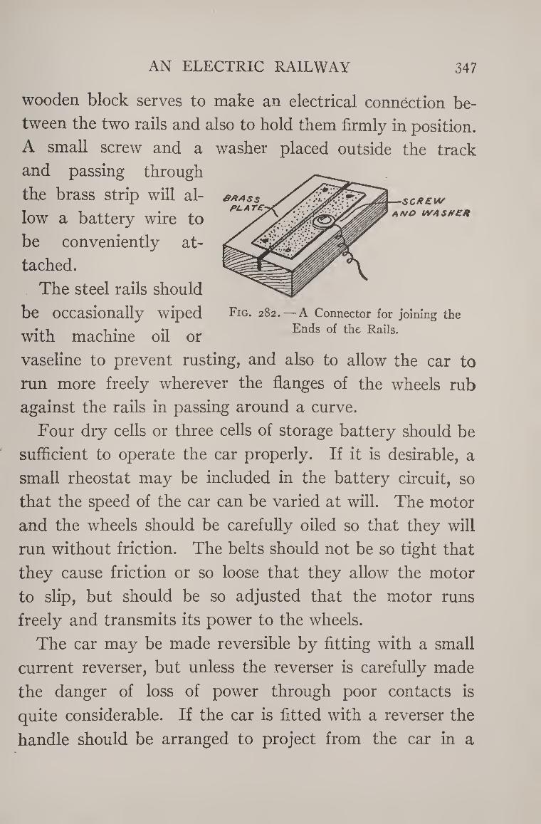
AN ELECTRIC RAILWAY 347
&X4SS PL A TE
wooden block serves to make an electrical connection be¬
tween the two rails and also to hold them firmly in position.
A small screw and a washer placed outside the track
and passing through
the brass strip will al¬
low a battery wire to
be conveniently at¬
tached.
The steel rails should
be occasionally wiped
with machine oil or
SCREW
A NO WASHER
Fig. 282.—A Connector for joining the Ends of the Rails.
vaseline to prevent rusting, and also to allow the car to
run more freely wherever the flanges of the wheels rub
against the rails in passing around a curve.
Four dry cells or three cells of storage battery should be
sufficient to operate the car properly. If it is desirable, a
small rheostat may be included in the battery circuit, so
that the speed of the car can be varied at will. The motor
and the wheels should be carefully oiled so that they will
run without friction. The belts should not be so tight that
they cause friction or so loose that they allow the motor
to slip, but should be so adjusted that the motor runs
freely and transmits its power to the wheels.
The car may be made reversible by fitting with a small
current reverser, but unless the reverser is carefully made
the danger of loss of power through poor contacts is
quite considerable. If the car is fitted with a reverser the
handle should be arranged to project from the car in a
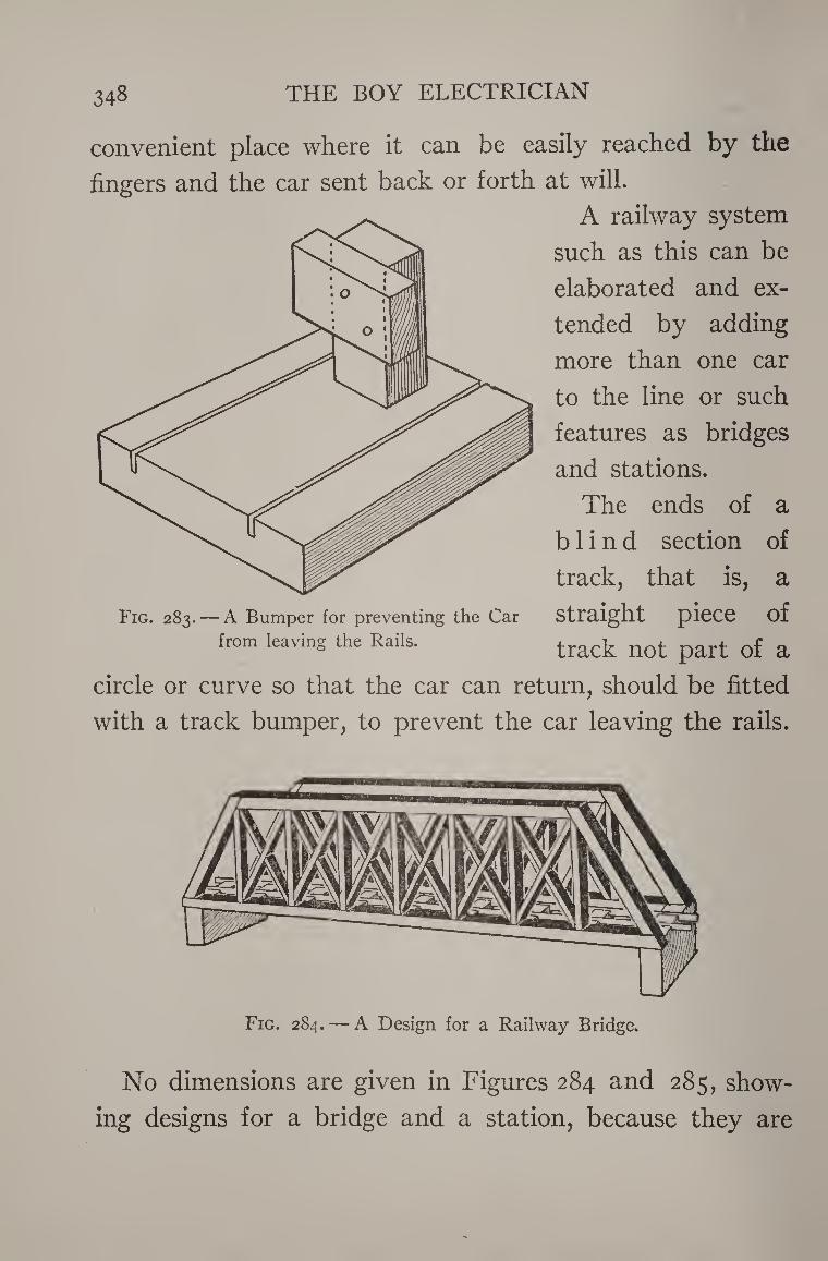
348 THE BOY ELECTRICIAN
convenient place where it can be easily reached by the
fingers and the car sent back or forth at will.
A railway system
such as this can be
elaborated and ex¬
tended by adding
more than one car
to the line or such
features as bridges
and stations.
The ends of a
blind section of
track, that is, a
Fig. 283. — A Bumper for preventing the Car Straight piece of from leaving the Rails. track nQt part Qf &
circle or curve so that the car can return, should be fitted
with a track bumper, to prevent the car leaving the rails.
Fig. 284. — A Design for a Railway Bridge.
No dimensions are given in Figures 284 and 285, show¬
ing designs for a bridge and a station, because they are
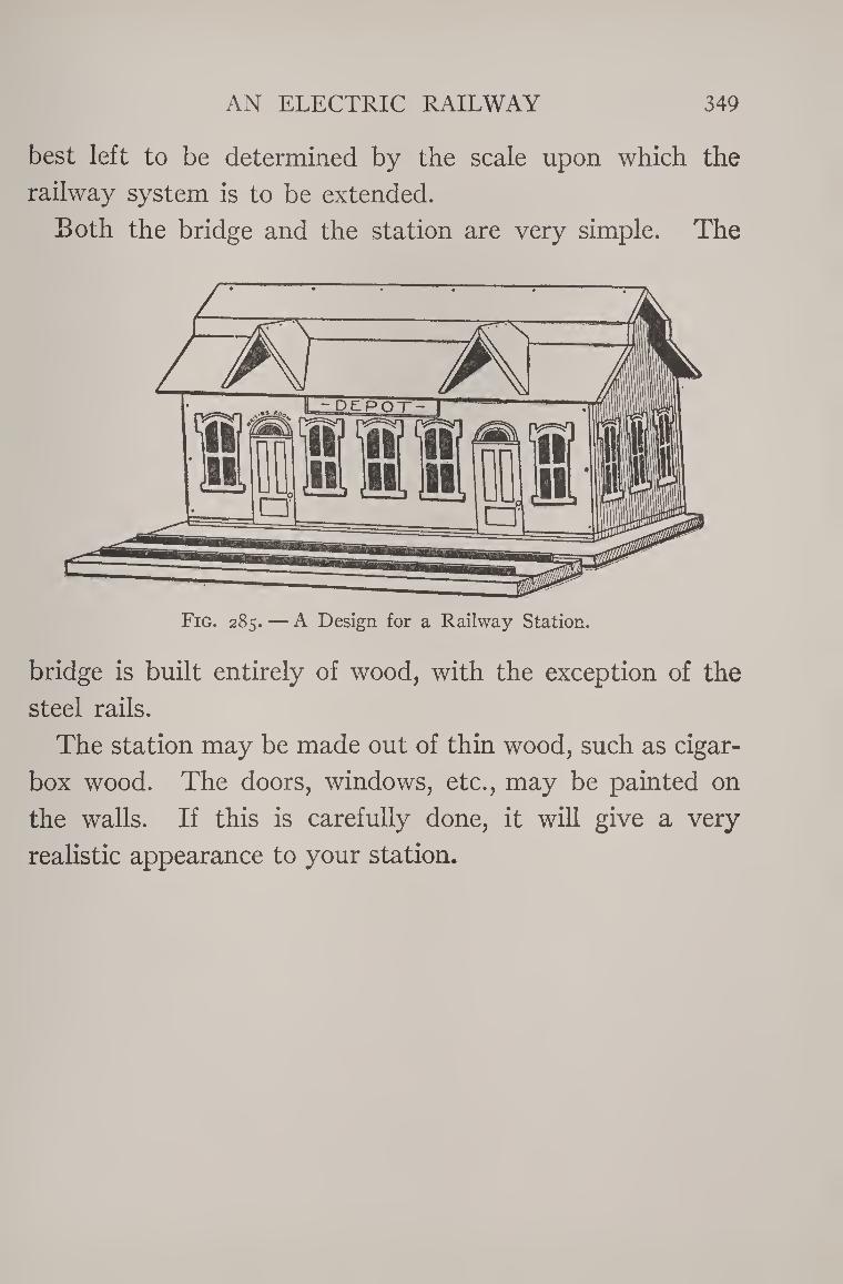
AN ELECTRIC RAILWAY 349
best left to be determined by the scale upon which the
railway system is to be extended.
Both the bridge and the station are very simple. The
Fig. 285. — A Design for a Railway Station.
bridge is built entirely of wood, with the exception of the
steel rails.
The station may be made out of thin wood, such as cigar-
box wood. The doors, windows, etc., may be painted on
the walls. If this is carefully done, it will give a very
realistic appearance to your station.
±1
CHAPTER XX
MINIATURE LIGHTING
Miniature lighting is a field of many interesting pos¬
sibilities for the young experimenter. Any labor expended
along this line will result in something far more useful from
a practical standpoint than almost any of the other
things described in this book.
Miniature lights, operated from batteries, may be used
in various ways; to light dark corners, hallways, or other
places where a light is often temporarily wanted without
the accompanying danger and nuisance of matches or kero¬
sene lamps.
Miniature lighting has only been made practical by the
tungsten filament lamp. The filament, or wire inside
the globe, which becomes hot and emits the light when
the current is turned on, is made of tungsten in a tungsten
lamp. In the earlier lamps, it was made of carbon. The
carbon lamp is now seldom used and is highly inefficient
when compared to the tungsten.
A Carbon Lamp consumes about three and one-half
watts of current for each candle-power of light, whereas
a small tungsten lamp uses only about one watt per candle-
power and is therefore three times as efficient. 350
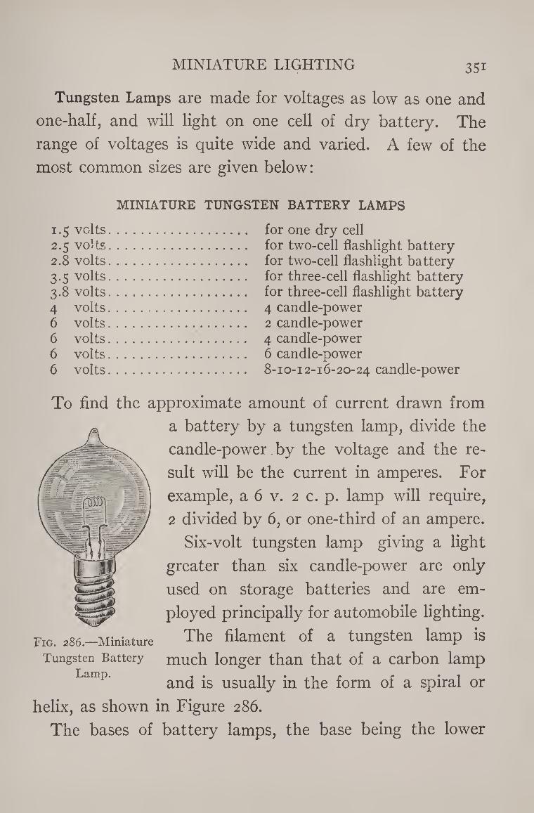
MINIATURE LIGHTING 35i
Tungsten Lamps are made for voltages as low as one and
one-half, and will light on one cell of dry battery. The
range of voltages is quite wide and varied. A few of the
most common sizes are given below:
MINIATURE TUNGSTEN BATTERY LAMPS
1.5 volts. for one dry cell 2.5 volts. for two-cell flashlight battery 2.8 volts. for two-cell flashlight battery 3.5 volts. for three-cell flashlight battery 3.8 volts. for three-cell flashlight battery 4 volts. 4 candle-power 6 volts. 2 candle-power 6 volts. 4 candle-power 6 volts. 6 candle-power 6 volts. 8-10-12-16-20-24 candle-power
To find the approximate amount of current drawn from
a battery by a tungsten lamp, divide the
candle-power by the voltage and the re¬
sult will be the current in amperes. For
example, a 6 v. 2 c. p. lamp will require,
2 divided by 6, or one-third of an ampere.
Six-volt tungsten lamp giving a light
greater than six candle-power are only
used on storage batteries and are em¬
ployed principally for automobile lighting.
The filament of a tungsten lamp is
much longer than that of a carbon lamp
and is usually in the form of a spiral or
helix, as shown in Figure 286.
The bases of battery lamps, the base being the lower
Fig. 286.—Miniature
Tungsten Battery
Lamp.
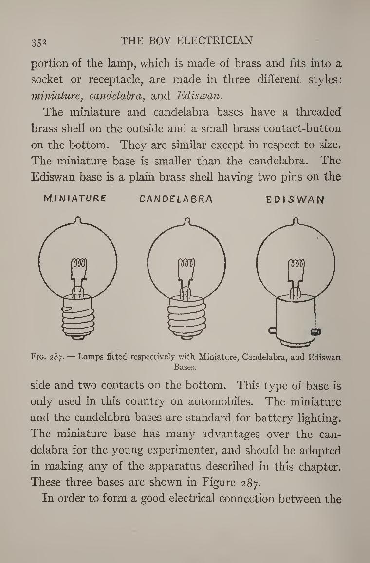
352 THE BOY ELECTRICIAN
portion of the lamp, which is made of brass and fits into a
socket or receptacle, are made in three different styles:
immature, candelabra, and Ediswan.
The miniature and candelabra bases have a threaded
brass shell on the outside and a small brass contact-button
on the bottom. They are similar except in respect to size.
The miniature base is smaller than the candelabra. The
Ediswan base is a plain brass shell having two pins on the
MINIATURE CANDELABRA EDISWAN
Fig. 287. — Lamps fitted respectively with Miniature, Candelabra, and Ediswan Bases.
side and two contacts on the bottom. This type of base is
only used in this country on automobiles. The miniature
and the candelabra bases are standard for battery lighting.
The miniature base has many advantages over the can¬
delabra for the young experimenter, and should be adopted
in making any of the apparatus described in this chapter.
These three bases are shown in Figure 287.
In order to form a good electrical connection between the
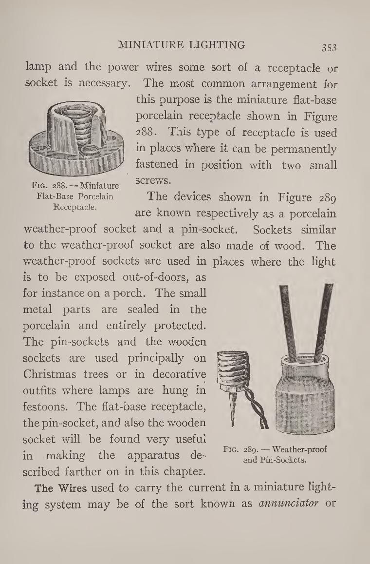
MINIATURE LIGHTING 353
lamp and the power wires some sort of a receptacle or
socket is necessary. The most common arrangement for
this purpose is the miniature flat-base
porcelain receptacle shown in Figure
288. This type of receptacle is used
in places where it can be permanently
fastened in position with two small
Fig. 288. —Miniature screws*
Flat-Base Porcelain The devices shown in Figure 289 Receptacle. 1 ,. , , .
are known respectively as a porcelain
weather-proof socket and a pin-socket. Sockets similar
to the weather-proof socket are also made of wood. The
weather-proof sockets are used in places where the light
is to be exposed out-of-doors, as
for instance on a porch. The small
metal parts are sealed in the
porcelain and entirely protected.
The pin-sockets and the wooden
sockets are used principally on
Christmas trees or in decorative 1
outfits where lamps are hung in
festoons. The flat-base receptacle,
the pin-socket, and also the wooden
socket will be found very useful
in making the apparatus de¬
scribed farther on in this chapter.
The Wires used to carry the current in a miniature light¬
ing system may be of the sort known as annunciator or
Fig. 289. — Weather-proof and Pin-Sockets.
354 THE BOY ELECTRICIAN
office wire if the wires are to be run entirely indoors. The
wire should not be smaller than No. 16 B. & S. gauge.
When the wires are run outdoors, on a porch, or in some
other place exposed to the weather, the wire used should
be rubber-covered. Hanging lights or lights intended to
be adjustable should be connected with “ flexible con¬
ductor.’’ This is made of a number of very fine wires
braided together and insulated with silk. The v/ires used
in a lighting system should not in any case be longer than
it is necessary to have them. When a battery is connected
to a system of wires it is found that the voltage at the end
of the wires is much lower than at a point near the battery.
This is called voltage “ drop,” and is much greater as the
wires grow longer. A light placed at the end of two very
long wires will not burn as brightly as it would if connected
to the same battery by means of short wires.
Switches can be made by following the suggestions given
in Chapter VII. Suitable switches can be purchased for a
few cents at a most any electrical house and will prove very
much neater and efficient. They should preferably be of
any of the types shown in Figure 290.
The Batteries used for miniature lighting may be made
up of storage cells, dry cells or carbon cylinder cells. Stor¬
age cells will prove the most satisfactory, provided that
the experimenter has some convenient means of recharg¬
ing them or of having them recharged. Storage cells will
be found of especial value wherever it is desirable to operate
several lights from one battery.
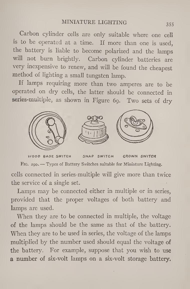
MINIATURE LIGHTING 355
Carbon cylinder cells are only suitable where one cell
is to be operated at a time. If more than one is used,
the battery is liable to become polarized and the lamps
will not burn brightly. Carbon cylinder batteries are
very inexpensive to renew, and will be found the cheapest
method of lighting a small tungsten lamp.
If lamps requiring more than two amperes are to be
operated on dry cells, the latter should be connected in
series-multiple, as shown in Figure 69. Two sets of dry
WOOD BASE SWITCH SNAP SWITCH CROWN SWITCH
Fig. 290. — Types of Battery Switches suitable for Miniature Lighting.
cells connected in series-multiple will give more than twice
the service of a single set.
Lamps may be connected either in multiple or in series,
provided that the proper voltages of both battery and
lamps are used.
When they are to be connected in multiple, the voltage
of the lamps should be the same as that of the battery.
When they are to be used in series, the voltage of the lamps
multiplied by the number used should equal the voltage of
the battery. For example, suppose that you wish to use
a number of six-volt lamps on a six-volt storage battery.
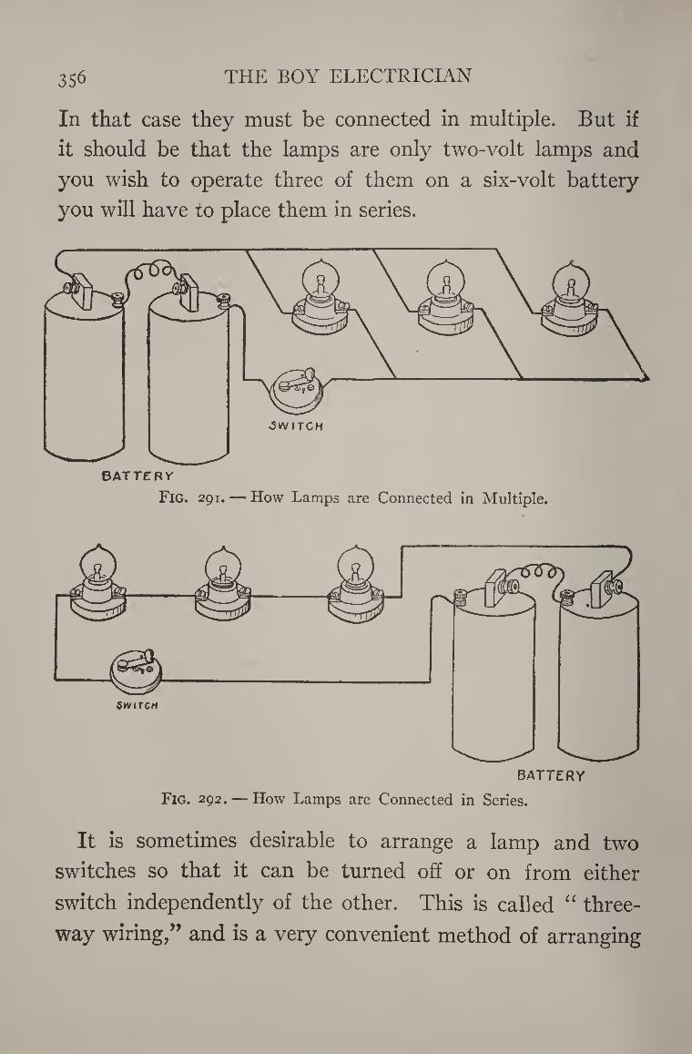
356 THE BOY ELECTRICIAN
In that case they must be connected in multiple. But if
it should be that the lamps are only two-volt lamps and
you wish to operate three of them on a six-volt battery
you will have to place them in series.
Fig. 291. — How Lamps are Connected in Multiple.
SWITCH
BATTERY
Fig. 292. — How Lamps are Connected in Series.
It is sometimes desirable to arrange a lamp and two
switches so that it can be turned off or on from either
switch independently of the other. This is called “ three-
way wiring,” and is a very convenient method of arranging
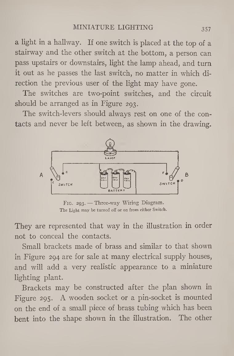
MINIATURE LIGHTING 357
a light in a hallway. If one switch is placed at the top of a
stairway and the other switch at the bottom, a person can
pass upstairs or downstairs, light the lamp ahead, and turn
it out as he passes the last switch, no matter in which di¬
rection the previous user of the light may have gone.
The switches are two-point swatches, and the circuit
should be arranged as in Figure 293.
The switch-levers should always rest on one of the con¬
tacts and never be left between, as shown in the drawing.
B
Fig. 293. — Three-way Wiring Diagram. The Light may be turned off or on from either Switch.
They are represented that way in the illustration in order
not to conceal the contacts.
Small brackets made of brass and similar to that shown
in Figure 294 are for sale at many electrical supply houses,
and will add a very realistic appearance to a miniature
lighting plant.
Brackets may be constructed after the plan shown in
Figure 295. A wooden socket or a pin-socket is mounted
on the end of a small piece of brass tubing which has been
bent into the shape shown in the illustration. The other
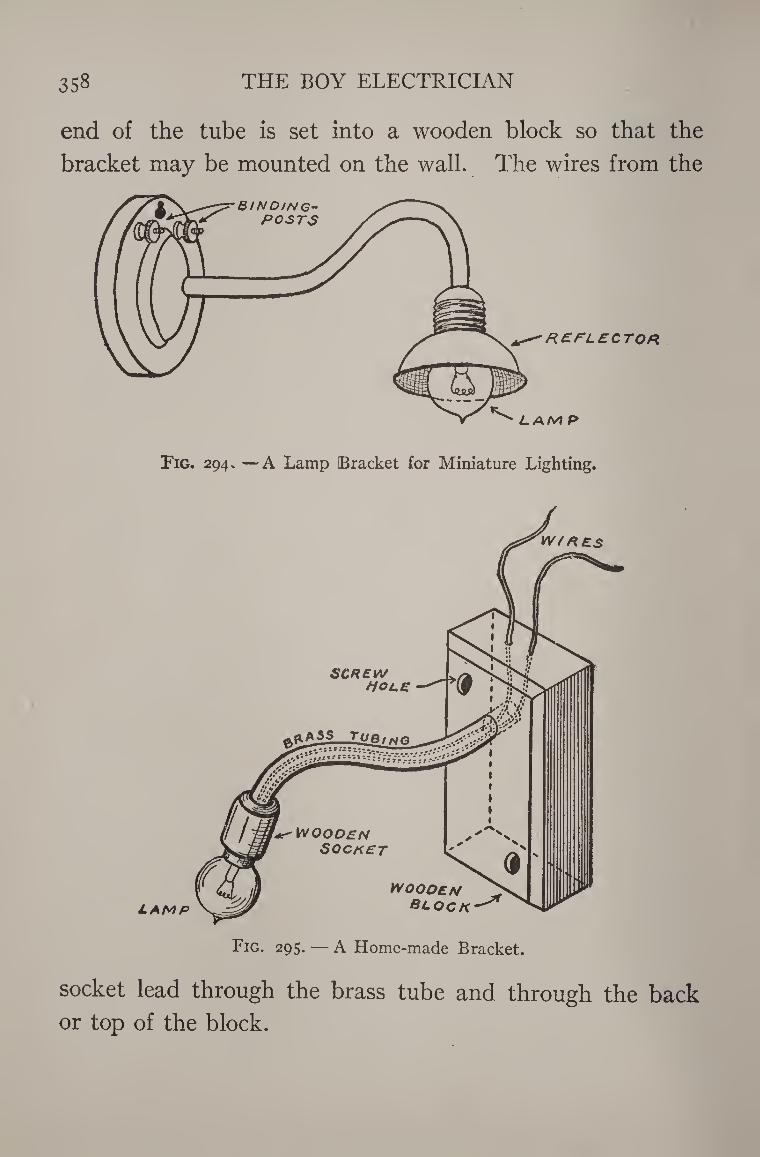
358 THE BOY ELECTRICIAN
end of the tube is set into a wooden block so that the
bracket may be mounted on the wall. The wires from the
!Fig. 294. —A Lamp [Bracket for Miniature Lighting.
socket lead through the brass tube and through the back
or top of the block.
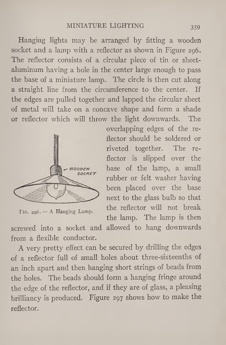
MINIATURE LIGHTING 359
Hanging lights may be arranged by fitting a wooden
socket and a lamp with a reflector as shown in Figure 296.
The reflector consists of a circular piece of tin or sheet-
aluminum having a hole in the center large enough to pass
the base of a miniature lamp. The circle is then cut along
a straight line from the circumference to the center. If
the edges are pulled together and lapped the circular sheet
of metal will take on a concave shape and form a shade
or reflector which will throw the light downwards. The
overlapping edges of the re¬
flector should be soldered or
riveted together. The re¬
flector is slipped over the
base of the lamp, a small
rubber or felt washer having
been placed over the base
next to the glass bulb so that
the reflector will not break
the lamp. The lamp is then
screwed into a socket and allowed to hang downwards
from a flexible conductor.
A very pretty effect can be secured by drilling the edges
of a reflector full of small holes about three-sixteenths of
an inch apart and then hanging short strings of beads from
the holes. The beads should form a hanging fringe around
the edge of the reflector, and if they are of glass, a pleasing
brilliancy is produced. Figure 297 shows how to make the
reflector.
Tig. 296. — A Hanging Lamp.
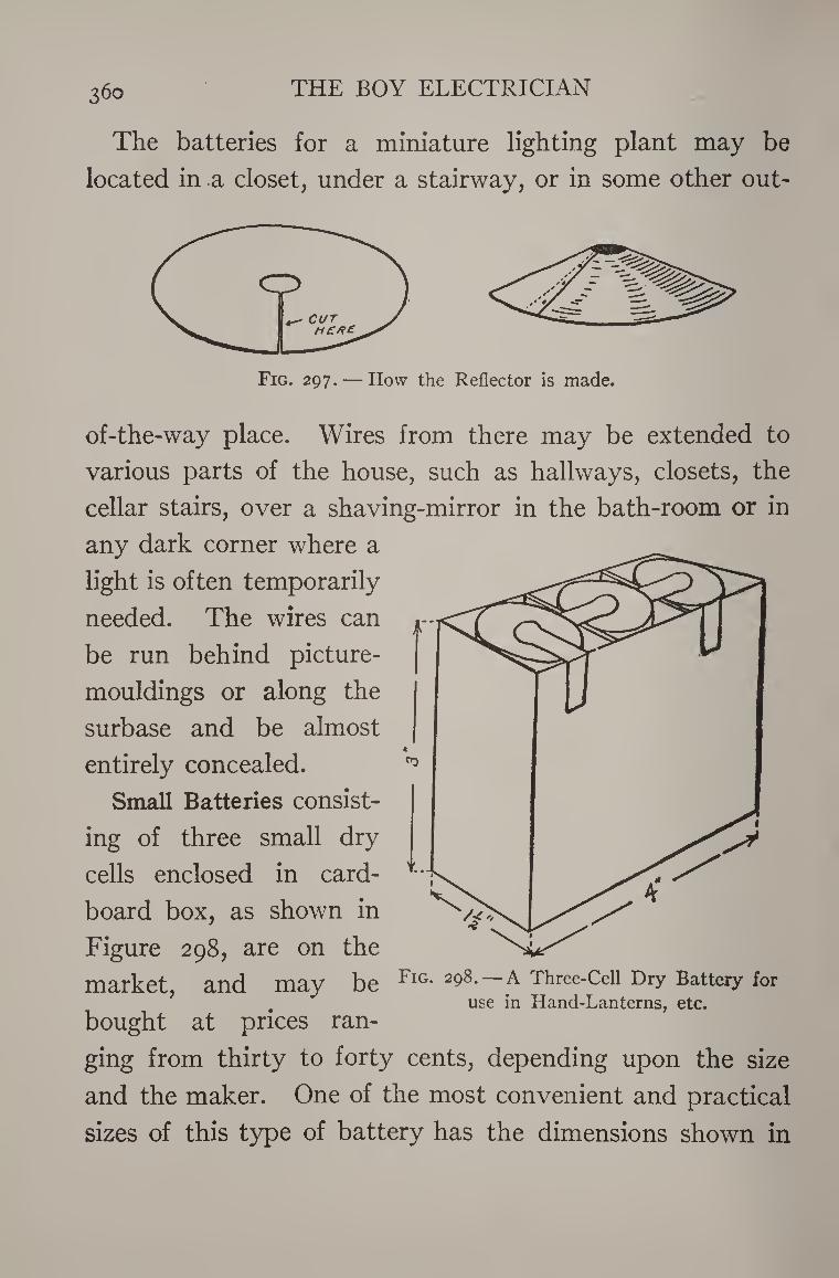
360 the boy electrician
The batteries for a miniature lighting plant may be
located in a closet, under a stairway, or in some other out-
Fig. 297.— How the Reflector is made.
of-the-way place. Wires from there may be extended to
various parts of the house, such as hallways, closets, the
cellar stairs, over a shaving-mirror in the bath-room or in
any dark corner where a
light is often temporarily
needed. The wires can
be run behind picture-
mouldings or along the
surbase and be almost
entirely concealed.
Small Batteries consist¬
ing of three small dry
cells enclosed in card¬
board box, as shown in
Figure 298, are on the
market, and may be
bought at prices ran¬
ging from thirty to forty cents, depending upon the size
and the maker. One of the most convenient and practical
sizes of this type of battery has the dimensions shown in
Fig. 298. — A Three-Cell Dry Battery for use in Hand-Lanterns, etc.
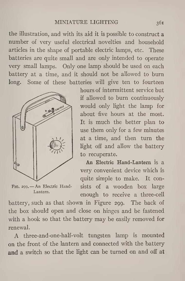
MINIATURE LIGHTING 361
the illustration, and with its aid it is possible to construct a
number of very useful electrical novelties and household
articles in the shape of portable electric lamps, etc. These
batteries are quite small and are only intended to operate
very small lamps. Only one lamp should be used on each
battery at a time, and it should not be allowed to burn
long. Some of these batteries will give ten to fourteen
hours of intermittent service but
if allowed to burn continuously
would only light the lamp for
about five hours at the most.
It is much the better plan to
use them only for a few minutes
at a time, and then turn the
light off and allow the battery
to recuperate.
An Electric Hand-Lantern is a
very convenient device which is
quite simple to make. It con¬
sists of a wooden box large
enough to receive a three-cell
battery, such as that shown in Figure 299. The back of
the box should open and close on hinges and be fastened
with a hook so that the battery may be easily removed for
renewal.
A three-and-one-half-volt tungsten lamp is mounted
on the front of the lantern and connected with the battery
and a switch so that the light can be turned on and off at
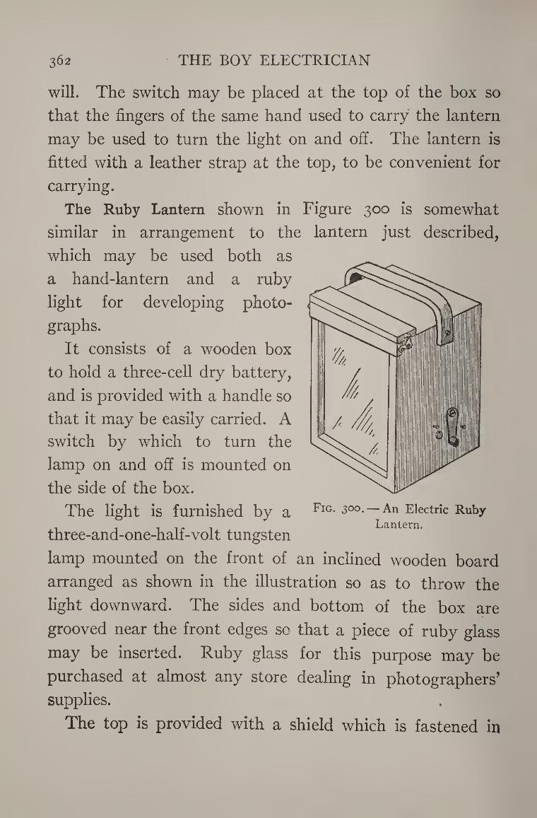
3 62 THE BOY ELECTRICIAN
will. The switch may be placed at the top of the box so
that the fingers of the same hand used to carry the lantern
may be used to turn the light on and off. The lantern is
fitted with a leather strap at the top, to be convenient for
carrying.
The Ruby Lantern shown in Figure 300 is somewhat
similar in arrangement to the lantern just described,
which may be used both as
a hand-lantern and a ruby
light for developing photo¬
graphs.
It consists of a wooden box
to hold a three-cell dry battery,
and is provided with a handle so
that it may be easily carried. A
switch by which to turn the
lamp on and off is mounted on
the side of the box.
The light is furnished by a Fig* 300. — An Electric Ruby . . i i i Lantern.
three-and-one-half-volt tungsten
lamp mounted on the front of an inclined wooden board
arranged as shown in the illustration so as to throw the
light downward. The sides and bottom of the box are
grooved near the front edges so that a piece of ruby glass
may be inserted. Ruby glass for this purpose may be
purchased at almost any store dealing in photographers’
supplies.
The top is provided with a shield which is fastened in
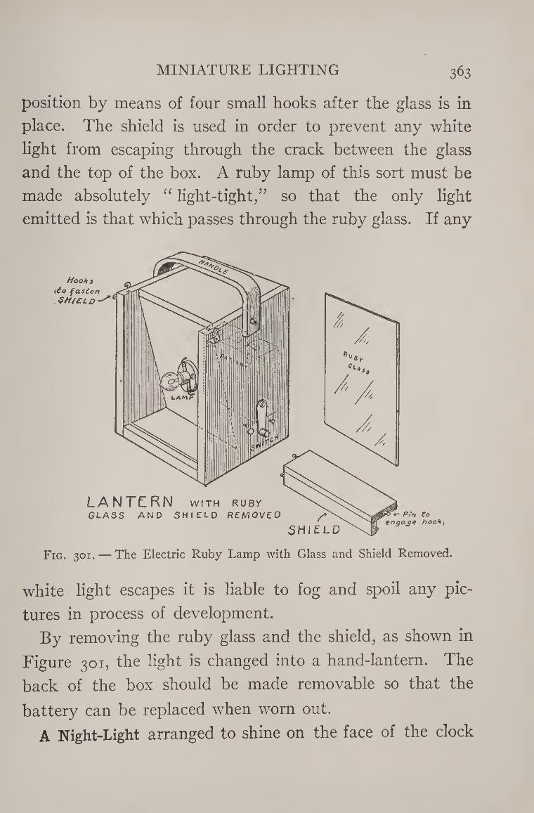
MINIATURE LIGHTING 363
position by means of four small hooks after the glass is in
place. The shield is used in order to prevent any white
light from escaping through the crack between the glass
and the top of the box. A ruby lamp of this sort must be
made absolutely “ light-tight/’ so that the only light
emitted is that which passes through the ruby glass. If any
white light escapes it is liable to fog and spoil any pic¬
tures in process of development.
By removing the ruby glass and the shield, as shown in
Figure 301, the light is changed into a hand-lantern. The
back of the box should be made removable so that the
battery can be replaced when worn out.
A Night-Light arranged to shine on the face of the clock
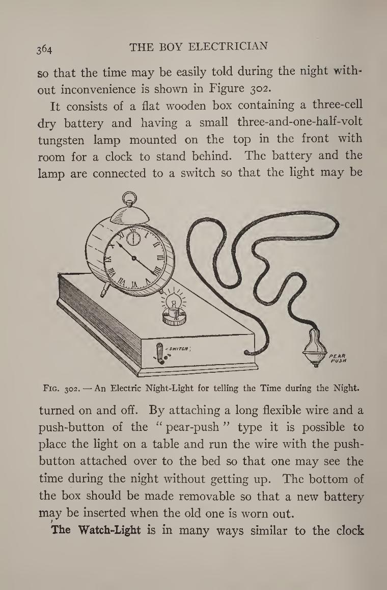
364 THE BOY ELECTRICIAN
so that the time may be easily told during the night with¬
out inconvenience is shown in Figure 302.
It consists of a flat wooden box containing a three-cell
dry battery and having a small three-and-one-half-volt
tungsten lamp mounted on the top in the front with
room for a clock to stand behind. The battery and the
lamp are connected to a switch so that the light may be
Fig. 302. — An Electric Night-Light for telling the Time during the Night.
turned on and off. By attaching a long flexible wire and a
push-button of the “ pear-push ” type it is possible to
place the light on a table and run the wire with the push¬
button attached over to the bed so that one may see the
time during the night without getting up. The bottom of
the box should be made removable so that a new battery
may be inserted when the old one is worn out. 1
The Watch-Light is in many ways similar to the clock
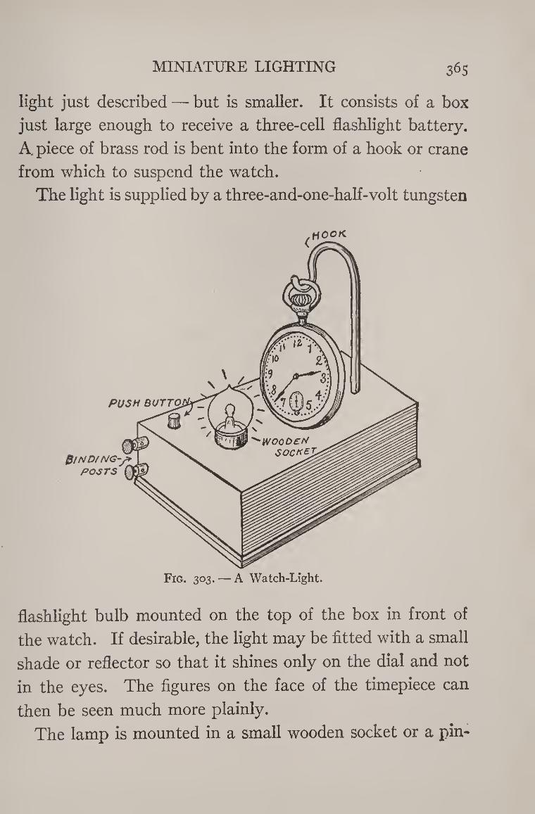
MINIATURE LIGHTING 365
light just described — but is smaller. It consists of a box
just large enough to receive a three-cell flashlight battery.
A. piece of brass rod is bent into the form of a hook or crane
from which to suspend the watch.
The light is supplied by a three-and-one-half-volt tungsten
flashlight bulb mounted on the top of the box in front of
the watch. If desirable, the light may be fitted with a small
shade or reflector so that it shines only on the dial and not
in the eyes. The figures on the face of the timepiece can
then be seen much more plainly.
The lamp is mounted in a small wooden socket or a pin-
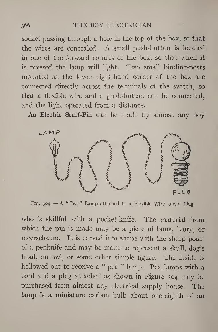
366 THE BOY ELECTRICIAN
socket passing through a hole in the top of the box, so that
the wires are concealed. A small push-button is located
in one of the forward corners of the box, so that when it
is pressed the lamp will light. Two small binding-posts
mounted at the lower right-hand corner of the box are
connected directly across the terminals of the switch, so
that a flexible wire and a push-button can be connected,
and the light operated from a distance.
An Electric Scarf-Pin can be made by almost any boy
Fig. 304. — A u Pea ” Lamp attached to a Flexible Wire and a Plug.
who is skillful with a pocket-knife. The material from
which the pin is made may be a piece of bone, ivory, or
meerschaum. It is carved into shape with the sharp point
of a penknife and may be made to represent a skull, dog’s
head, an owl, or some other simple figure. The inside is
hollowed out to receive a “ pea ” lamp. Pea lamps with a
cord and a plug attached as shown in Figure 304 may be
purchased from almost any electrical supply house. The
lamp is a miniature carbon bulb about one-eighth of an
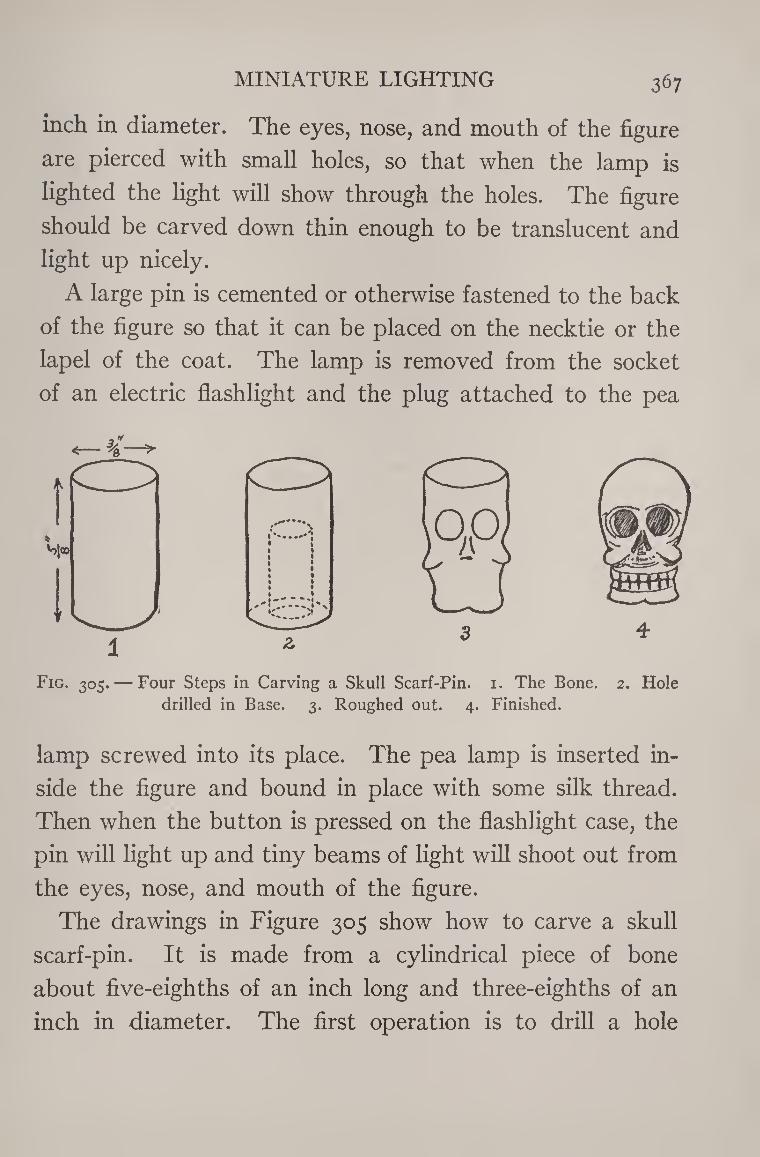
MINIATURE LIGHTING 367
inch in diameter. The eyes, nose, and mouth of the figure
are pierced with small holes, so that when the lamp is
lighted the light will show through the holes. The figure
should be carved down thin enough to be translucent and
light up nicely.
A large pin is cemented or otherwise fastened to the back
of the figure so that it can be placed on the necktie or the
lapel of the coat. The lamp is removed from the socket
of an electric flashlight and the plug attached to the pea
Fig. 305. — Four Steps in Carving a Skull Scarf-Pin. 1. The Bone. 2. Hole
drilled in Base. 3. Roughed out. 4. Finished.
lamp screwed into its place. The pea lamp is inserted in¬
side the figure and bound in place with some silk thread.
Then when the button is pressed on the flashlight case, the
pin will light up and tiny beams of light will shoot out from
the eyes, nose, and mouth of the figure.
The drawings in Figure 305 show how to carve a skull
scarf-pin. It is made from a cylindrical piece of bone
about five-eighths of an inch long and three-eighths of an
inch in diameter. The first operation is to drill a hole
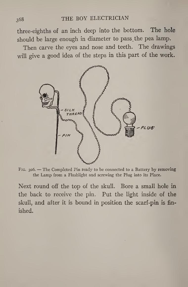
368 THE BOY ELECTRICIAN
three-eighths of an inch deep into the bottom. The hole
should be large enough in diameter to pass^the pea lamp.
Then carve the eyes and nose and teeth. The drawings
will give a good idea of the steps in this part of the work.
Fig. 306. — The Completed Pin ready to be connected to a Battery by removing
the Lamp from a Flashlight and screwing the Plug into its Place.
Next round off the top of the skull. Bore a small hole in
the back to receive the pin. Put the light inside of the
skull, and after it is bound in position the scarf-pin is fin¬
ished.
For the past century there has been on the part of ’many
scientists and inventors a constant endeavor to “ harness
the sunlight.” The power which streams down every day
to our planet is incalculable. The energy consumed in the
sun and thrown off in the form of heat is so great that it
makes any earthly thing seem infinitesimal. We can only
feel the heat from a large fire a few feet away, yet the
scorching summer heat travels 90,000,000 miles before it
reaches us, and even then our planet is receiving only the
smallest fractional part of the total amount radiated.
Dr. Langley of the Smithsonian Institute estimated that
all the coal in the State of Pennsylvania would be used
by the sun in a fraction of a second if it were sent up there
to supply energy.
Perhaps, some day in the future, electric locomotives
will haul their steel cars swiftly from city to city by means
of electricity, generated with “ sun power.” Perhaps
energy from the same source will heat our dwellings and
furnish us light and power.
This is not an idle dream, but may some day be an
369
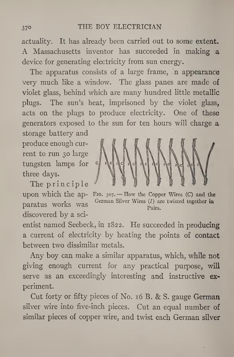
370 THE BOY ELECTRICIAN
actuality. It has already been carried out to some extent.
A Massachusetts inventor has succeeded in making a
device for generating electricity from sun energy.
The apparatus consists of a large frame, n appearance
very much like a window. The glass panes are made of
violet glass, behind which are many hundred little metallic
plugs. The sun’s heat, imprisoned by the violet glass,
acts on the plugs to produce electricity. One of these
generators exposed to the sun for ten hours will charge a
storage battery and
produce enough cur¬
rent to run 30 large
tungsten lamps for
three days.
The principle
upon which the ap- Fig. 307.— How the Copper Wires (C) and the
paratus works was Silver Wires (/^are twisted together in
discovered by a sci¬
entist named Seebeck, in 1822. He succeeded in producing
a current of electricity by heating the points of contact
between two dissimilar metals.
Any boy can make a similar apparatus, which, while not
giving enough current for any practical purpose, will
serve as an exceedingly interesting and instructive ex¬
periment.
Cut forty or fifty pieces of No. 16 B. & S. gauge German
silver wire into five-inch pieces. Cut an equal number of
similar pieces of copper wire, and twist each German silver
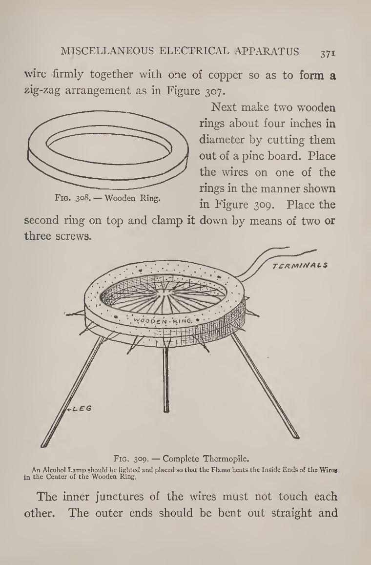
MISCELLANEOUS ELECTRICAL APPARATUS 371
wire firmly together with one of copper so as to form a
zig-zag arrangement as in Figure 307.
Next make two wooden
rings about four inches in
diameter by cutting them
out of a pine board. Place
the wires on one of the
rings in the manner shown
in Figure 309. Place the
second ring on top and clamp it down by means of two or
three screws.
Fig. 309. — Complete Thermopile.
An Alcohol Lamp should be lighted and placed so that the Flame heats the Inside Ends of the Wires in the Center of the Wooden Ring.
The inner junctures of the wires must not touch each
other. The outer ends should be bent out straight and
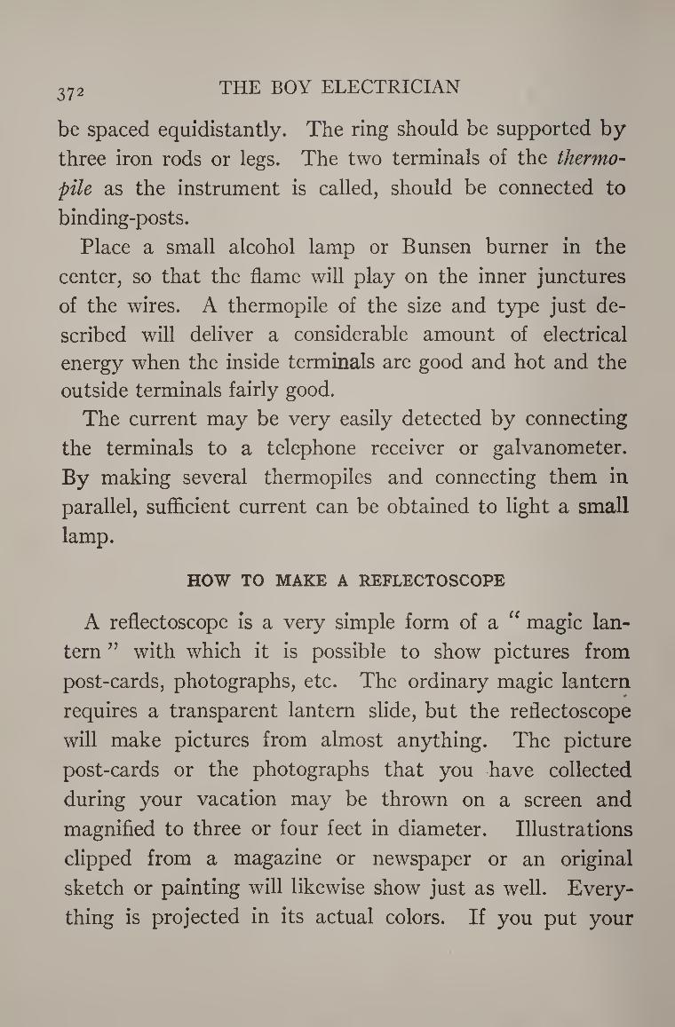
372 THE BOY ELECTRICIAN
be spaced equidistantly. The ring should be supported by
three iron rods or legs. The two terminals of the thermo¬
pile as the instrument is called, should be connected to
binding-posts.
Place a small alcohol lamp or Bunsen burner in the
center, so that the flame will play on the inner junctures
of the wires. A thermopile of the size and type just de¬
scribed will deliver a considerable amount of electrical
energy when the inside terminals are good and hot and the
outside terminals fairly good.
The current may be very easily detected by connecting
the terminals to a telephone receiver or galvanometer.
By making several thermopiles and connecting them in
parallel, sufficient current can be obtained to light a small
lamp.
HOW TO MAKE A REFLECTOSCOPE
A reflectoscope is a very simple form of a “ magic lan¬
tern ” with which it is possible to show pictures from
post-cards, photographs, etc. The ordinary magic lantern #
requires a transparent lantern slide, but the reflectoscope
will make pictures from almost anything. The picture
post-cards or the photographs that you have collected
during your vacation may be thrown on a screen and
magnified to three or four feet in diameter. Illustrations
clipped from a magazine or newspaper or an original
sketch or painting will likewise show just as well. Every¬
thing is projected in its actual colors. If you put your
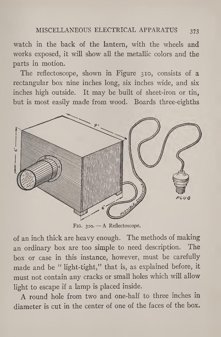
MISCELLANEOUS ELECTRICAL APPARATUS 373
watch in the back of the lantern, with the wheels and
works exposed, it will show all the metallic colors and the
parts in motion.
The reflectoscope, shown in Figure 310, consists of a
rectangular box nine inches long, six inches wide, and six
inches high outside. It may be built of sheet-iron or tin,
but is most easily made from wood. Boards three-eighths
of an inch thick are heavy enough. The methods of making
an ordinary box are too simple to need description. The
box or case in this instance, however, must be carefully
made and be “ light-tight,” that is, as explained before, it
must not contain any cracks or small holes which will allow
light to escape if a lamp is placed inside.
A round hole from two and one-half to three inches in
diameter is cut in the center of one of the faces of the box.
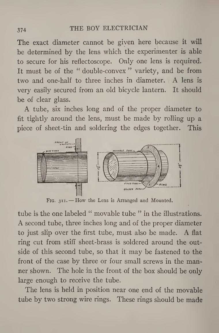
374 THE BOY ELECTRICIAN
The exact diameter cannot be given here because it will
be determined by the lens which the experimenter is able
to secure for his reflectoscope. Only one lens is required.
It must be of the “ double-convex ” variety, and be from
two and one-half to three inches in diameter. A lens is
very easily secured from an old bicycle lantern. It should
be of clear glass.
A tube, six inches long and of the proper diameter to
fit tightly around the lens, must be made by rolling up a
piece of sheet-tin and soldering the edges together. This
Fig. 31 i. — How the Lens is Arranged and Mounted.
tube is the one labeled “ movable tube ” in the illustrations.
A second tube, three inches long and of the proper diameter
to just slip over the first tube, must also be made. A flat
ring cut from stiff sheet-brass is soldered around the out¬
side of this second tube, so that it may be fastened to the
front of the case by three or four small screws in the man¬
ner shown. The hole in the front of the box should be only
large enough to receive the tube.
The lens is held in position near one end of the movable
tube by two strong wire rings. These rings should be made
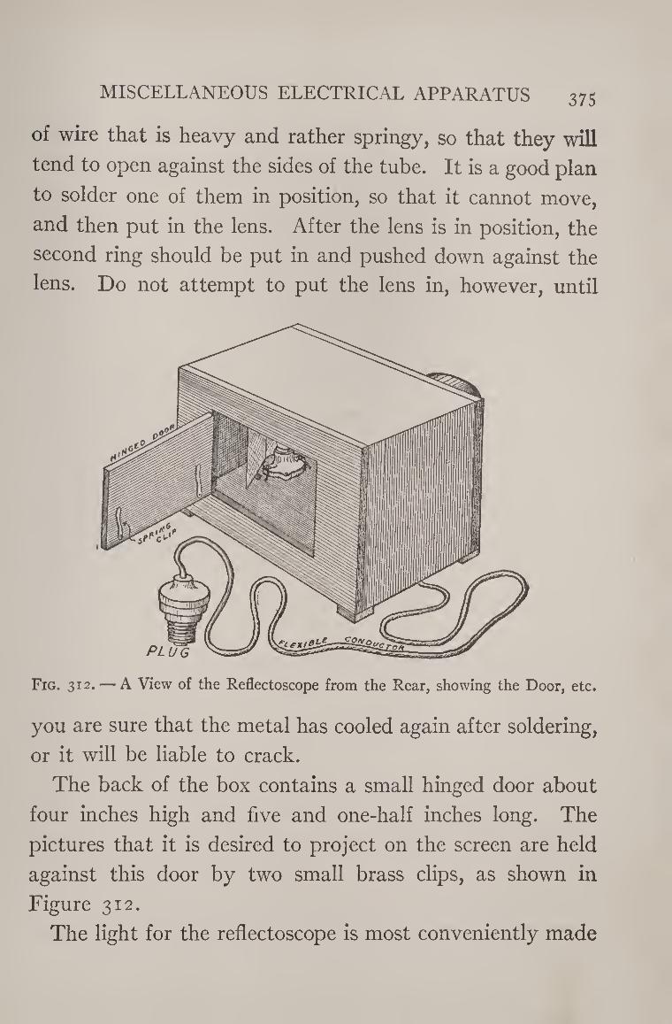
MISCELLANEOUS ELECTRICAL APPARATUS 375
of wire that is heavy and rather springy, so that they will
tend to open against the sides of the tube. It is a good plan
to solder one of them in position, so that it cannot move,
and then put in the lens. After the lens is in position, the
second ring should be put in and pushed down against the
lens. Do not attempt to put the lens in, however, until
Fig. 312. — A View of the Reflectoscope from the Rear, showing the Door, etc.
you are sure that the metal has cooled again after soldering,
or it will be liable to crack.
The back of the box contains a small hinged door about
four inches high and five and one-half inches long. The
pictures that it is desired to project on the screen are held
against this door by two small brass clips, as shown in
Figure 312.
The light for the reflectoscope is most conveniently made
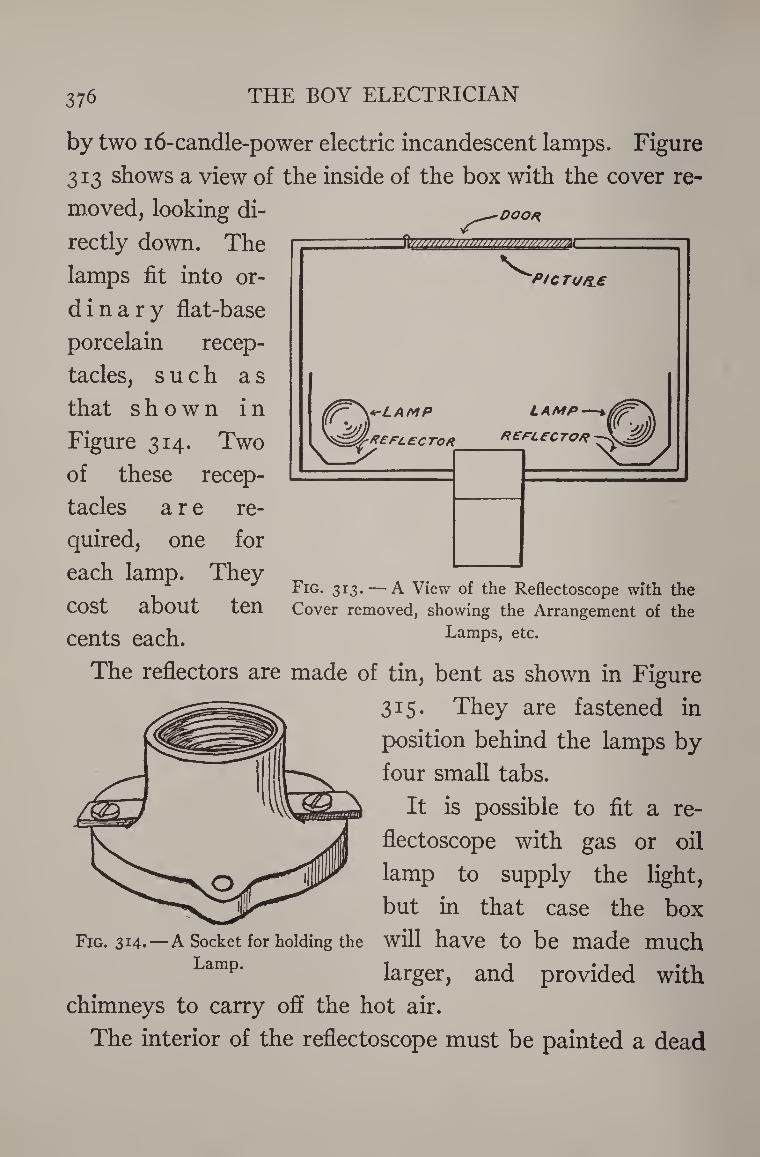
376 THE BOY ELECTRICIAN
by two 16-candle-power electric incandescent lamps. Figure
313 shows a view of the inside of the box with the cover re¬
moved, looking di¬
rectly down. The
lamps fit into or-
d inary flat-base
porcelain recep¬
tacles, such as
that shown in
Figure 314. Two
of these recep¬
tacles are re¬
quired, one for
each lamp. They
cost about ten
cents each.
Fig. 313. — A View of the Reflectoscope with the Cover removed, showing the Arrangement of the
Lamps, etc.
The reflectors are made of tin, bent as shown in Figure
315. They are fastened in
position behind the lamps by
four small tabs.
It is possible to fit a re¬
flectoscope with gas or oil
lamp to supply the light,
but in that case the box
Fig. 314.—A Socket for holding the will have to be made much
Lamp’ larger, and provided with
chimneys to carry off the hot air.
The interior of the reflectoscope must be painted a dead
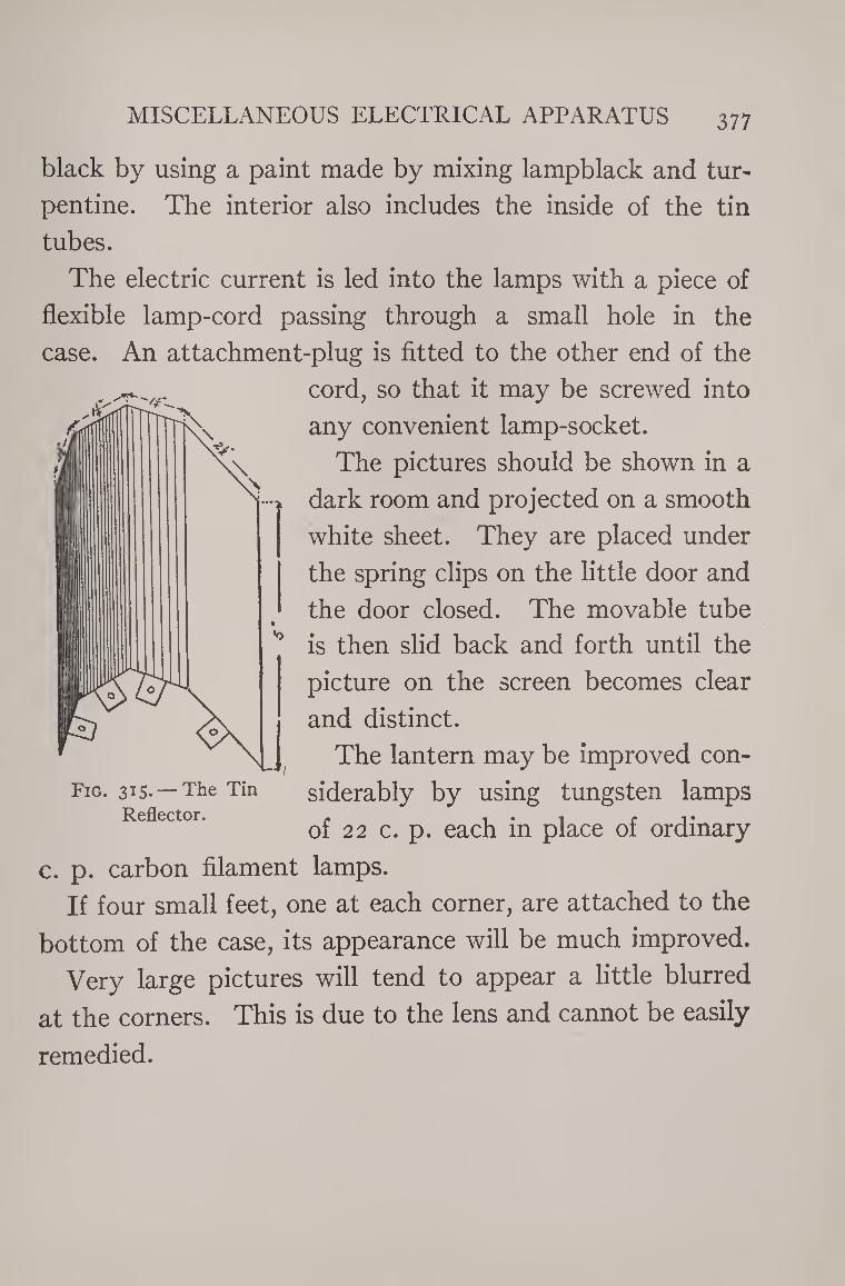
MISCELLANEOUS ELECTRICAL APPARATUS 377
black by using a paint made by mixing lampblack and tur¬
pentine. The interior also includes the inside of the tin
tubes.
The electric current is led into the lamps with a piece of
flexible lamp-cord passing through a small hole in the
case. An attachment-plug is fitted to the other end of the
cord, so that it may be screwed into
any convenient lamp-socket.
The pictures should be shown in a
dark room and projected on a smooth
white sheet. They are placed under
the spring clips on the little door and
the door closed. The movable tube
is then slid back and forth until the
picture on the screen becomes clear
and distinct.
The lantern may be improved con¬
siderably by using tungsten lamps
of 22 c. p. each in place of ordinary
c. p. carbon filament lamps.
If four small feet, one at each corner, are attached to the
bottom of the case, its appearance will be much improved.
Very large pictures will tend to appear a little blurred
at the corners. This is due to the lens and cannot be easily
remedied.
Fig. 315. — The Tin Reflector.
378 ' THE BOY ELECTRICIAN
HOW TO REDUCE THE no-v. CURRENT SO THAT IT MAY BE USED FOR EXPERIMENTING
Oftentimes it is desirable to operate small electrical
devices from the iio-v. lighting or power circuits. Alter¬
nating current can be reduced to the proper voltage by
means of a small step-down transformer, such as that de¬
scribed in Chapter XIII. Direct current may be reduced
by means of a resistance. The most suitable form of re¬
sistance for the young experimenter to use is a “ lamp
bank.”
A lamp bank consists of a number of lamps connected
in parallel, and arranged so that any device may be con¬
nected in series with it.
The lamps are set in sockets of the type known as “ flat-
base porcelain receptacles,” such as that shown in Figure
314, mounted in a row upon a board and connected as
shown in Fig. 316.
The current from the power line enters through a switch
and a fuse and then passes through the lamps before it
reaches the device it is desired to operate. The switch
is for the purpose of shutting the current on and off, while
the fuse will “ blow ” in case too much current flows in
the circuit.
The amount of current that passes through the circuit
may be accurately controlled by the size and number of
lamps used in the bank. The lamps may be screwed in or
out and the current altered by one-quarter of an ampere
at a time if desirable.
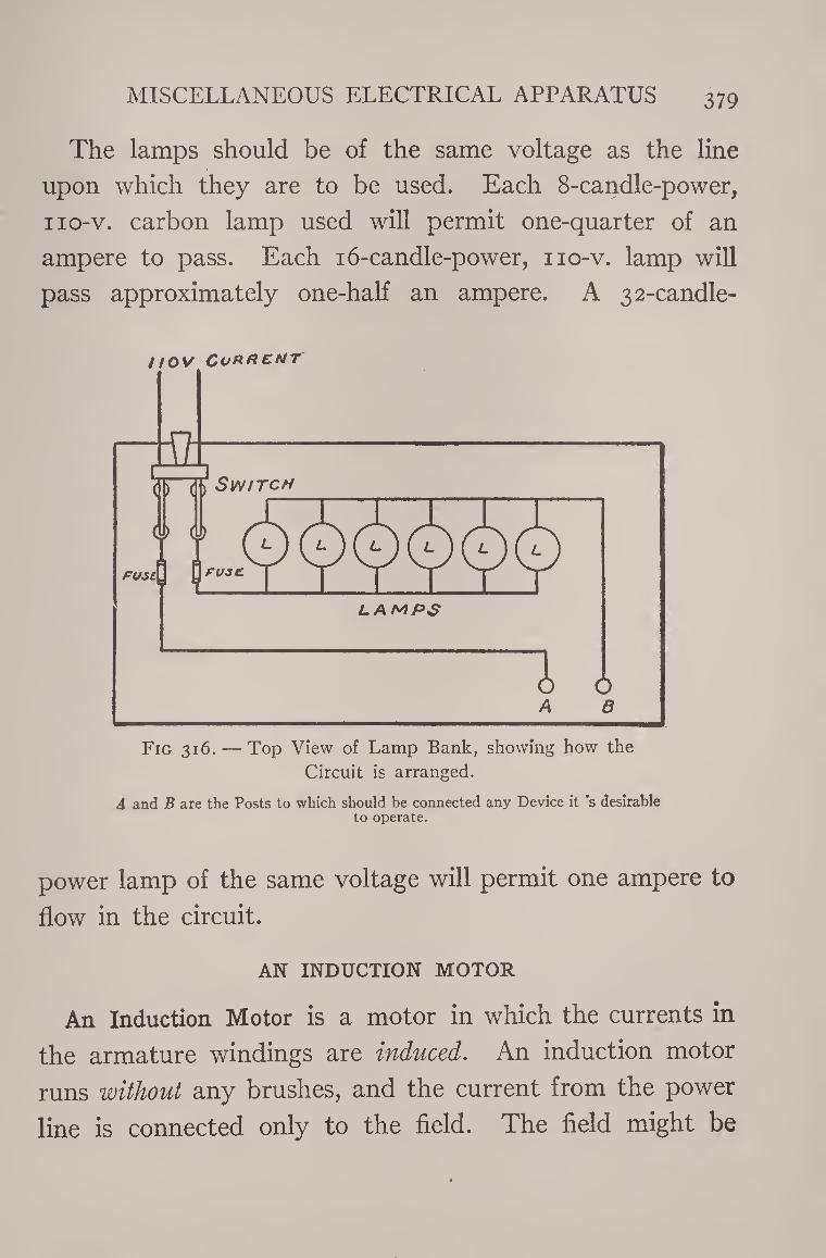
MISCELLANEOUS ELECTRICAL APPARATUS 379
The lamps should be of the same voltage as the line
upon which they are to be used. Each 8-candle-power,
iio-v. carbon lamp used will permit one-quarter of an
ampere to pass. Each 16-candle-power, 110-v. lamp will
pass approximately one-half an ampere. A 32-candle-
nov ConfiCNT
Fig 316. — Top View of Lamp Bank, showing how the
Circuit is arranged.
A and B are the Posts to which should be connected any Device it ‘s desirable to operate.
power lamp of the same voltage will permit one ampere to
flow in the circuit.
AN INDUCTION MOTOR
An Induction Motor is a motor in which the currents in
the armature windings are induced. An induction motor
runs without any brushes, and the current from the power
line is connected only to the field. The field might be
38° THE BOY ELECTRICIAN
likened to the primary of a transformer. The currents in
the armature then constitute a secondary winding in which
currents are induced in the same manner as in a trans¬
former.
An induction motor will operate only on alternating cur¬
rent.
A small motor such as that shown in Figure 272, and
having a three-pole armature, is the best type to use in
making an experimental induction motor.
Remove the brushes from the motor and bind a piece of
bare copper wire around the commutator so that it short-
circuits the segments.
A source of alternating current should then be connected
to the terminals of the field coil. If you have a step-down
transformer, use it for this purpose, but otherwise connect
it in series with a lamp bank such as that just described.
Place a switch in the circuit so that the current may be
turned on and off. Wind a string around the end of the
armature shaft so that it may be revolved at high speed
by pulling the string in somewhat the same manner that
you would spin a top. When all is ready, give the string
a sharp pull and immediately close the switch so that the
alternating current flows into the field.
If this is done properly, the motor will continue to run
at high speed, and furnish power if desirable.
Most of the alternating-current motors in every-day use
for furnishing power for various purposes are induction
motors. They are, however, self-starting, and provided
MISCELLANEOUS ELECTRICAL APPARATUS 381
with a hollow armature, which contains a centrifugal gov¬
ernor. When the motor is at rest or just starting, four
brushes press against the commutator and divide the ar¬
mature coils into four groups. After the motor has attained
the proper speed, the governor is thrown out by centrif¬
ugal force and pushes the brushes away from the com¬
mutator, short-circuiting all the sections and making each
coil a complete circuit of itself.
ELECTRO-PLATING
Water containing chemicals such as sulphate of copper,
sulphuric acid, nitrate of nickel, nitrate of silver, or other
metallic salts is a good conductor of electricity. Such a
liquid is known as an electrolyte.
It has been explained in Chapter IV that chemical action
may be used to produce electricity and that in the case of
a cell such as that invented by Volta, the zinc electrode
gradually wastes away and finally enters into solution in
the sulphuric acid.
It is possible exactly to reverse this action and to pro¬
duce what is known as electrolysis. If an electrolyte in
which a metal has been “ dissolved ” is properly arranged
so that a current of electricity may be passed through the
solution, the metal will “ plate out,” or appear again upon
one of the electrodes.
Electrolysis makes possible electro-plating and thousands
of other exceedingly valuable and interesting chemical
processes.
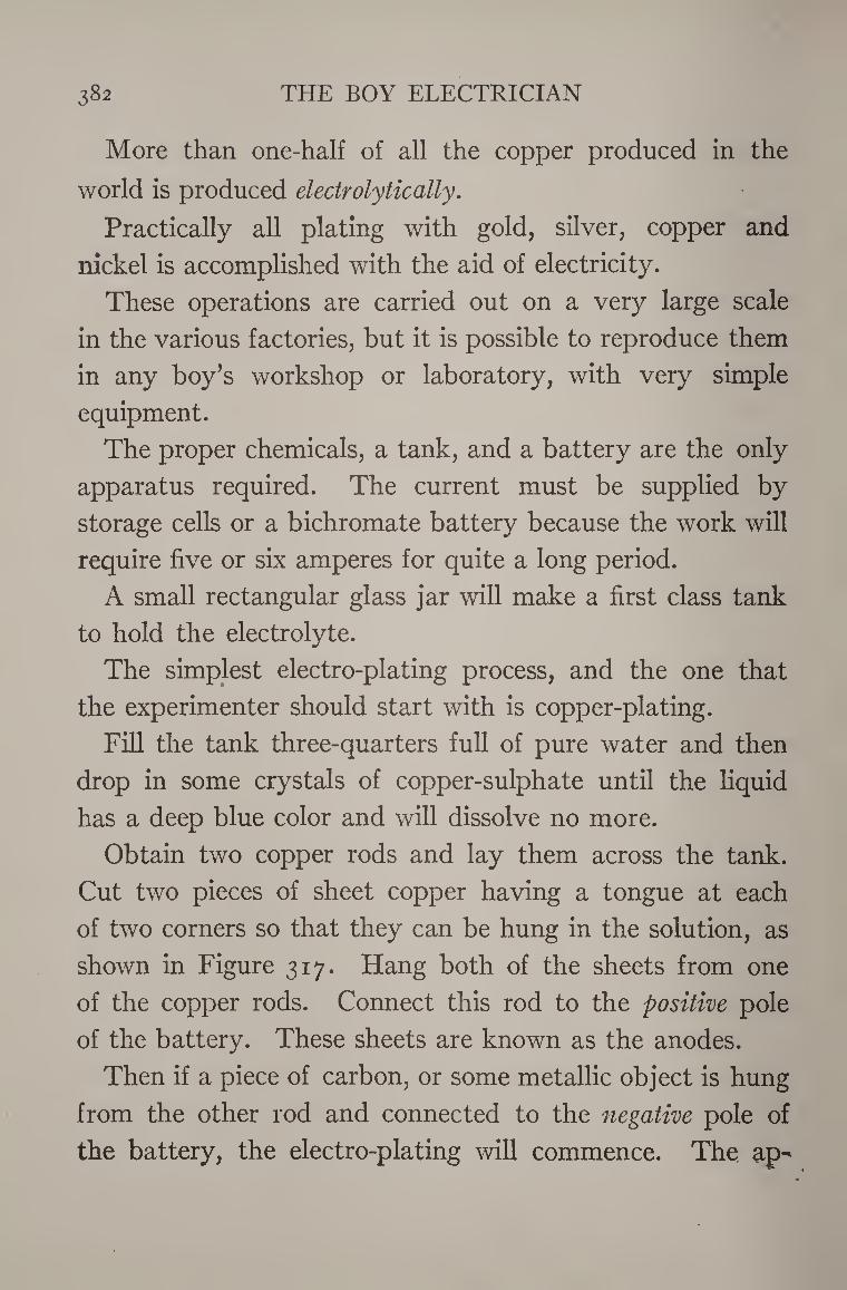
382 THE BOY ELECTRICIAN
More than one-half of all the copper produced in the
world is produced electrolytically.
Practically all plating with gold, silver, copper and
nickel is accomplished with the aid of electricity.
These operations are carried out on a very large scale
in the various factories, but it is possible to reproduce them
in any boy’s workshop or laboratory, with very simple
equipment.
The proper chemicals, a tank, and a battery are the only
apparatus required. The current must be supplied by
storage cells or a bichromate battery because the work will
require five or six amperes for quite a long period.
A small rectangular glass jar will make a first class tank
to hold the electrolyte.
The simplest electro-plating process, and the one that
the experimenter should start with is copper-plating.
Fill the tank three-quarters full of pure water and then
drop in some crystals of copper-sulphate until the liquid
has a deep blue color and will dissolve no more.
Obtain two copper rods and lay them across the tank.
Cut two pieces of sheet copper having a tongue at each
of two corners so that they can be hung in the solution, as
shown in Figure 317. Hang both of the sheets from one
of the copper rods. Connect this rod to the positive pole
of the battery. These sheets are known as the anodes.
Then if a piece of carbon, or some metallic object is hung
from the other rod and connected to the negative pole of
the battery, the electro-plating will commence. The ap-
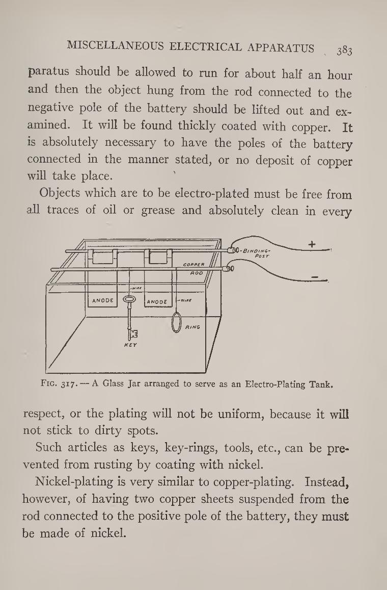
MISCELLANEOUS ELECTRICAL APPARATUS 383
paratus should be allowed to run for about half an hour
and then the object hung from the rod connected to the
negative pole of the battery should be lifted out and ex¬
amined. It will be found thickly coated with copper. It
is absolutely necessary to have the poles of the battery
connected in the manner stated, or no deposit of copper
will take place.
Objects which are to be electro-plated must be free from
all traces of oil or grease and absolutely clean in every
Fig. 317. — A Glass Jar arranged to serve as an Electro-Plating Tank.
respect, or the plating will not be uniform, because it will
not stick to dirty spots.
Such articles as keys, key-rings, tools, etc., can be pre¬
vented from rusting by coating with nickel.
Nickel-plating is very similar to copper-plating. Instead,
however, of having two copper sheets suspended from the
rod connected to the positive pole of the battery, they must
be made of nickel.
38 4 THE BOY ELECTRICIAN
The electrolyte is composed of one part of nickel-sul¬
phate dissolved in twenty parts of water to which one part
of sodium-bisulphate is added.
This mixture is placed in the tank instead of the copper-
sulphate. The objects to be plated are hung from the
copper rod connected to the negative pole of the battery.
When the nickel-plated articles are removed from the
bath they will have a dull, white color known as “ white
nickel.” When white nickel is polished with a cloth wheel
revolving at high speed, and known as a buffing-wheel, it
will assume a high luster.
HOW TO MAKE A RHEOSTAT
It is often desirable to regulate the amount of current
passing through a small lamp, motor, or other electrical
device operated by a battery.
This is accomplished by inserting resistance into the
circuit. A rheostat is an arrangement for quickly altering
the amount of resistance at will.
A simple rheostat is easily made by fitting a five-point
switch such as that shown in Figure 95 with several coils
of German-silver resistance wire. German silver has much
more resistance than copper wire, and is used, therefore,
because less will be required, and it will occupy a smaller
space.
A five-point switch will serve satisfactorily in making a
rheostat, but if a finer graduation of the resistance is de¬
sired it will be necessary to use one having more points.
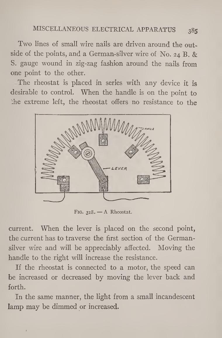
MISCELLANEOUS ELECTRICAL APPARATUS 385
Two lines of small wire nails are driven around the out¬
side of the points, and a German-silver wire of No. 24 B. &
S. gauge wound in zig-zag fashion around the nails from
one point to the other.
The rheostat is placed in series with any device it is
desirable to control. When the handle is on the point to
:he extreme left, the rheostat offers no resistance to the
current. When the lever is placed on the second point,
the current has to traverse the first section of the German-
silver wire and will be appreciably affected. Moving the
handle to the right will increase the resistance.
If the rheostat is connected to a motor, the speed can
be increased or decreased by moving the lever back and
forth.
In the same manner, the light from a small incandescent
lamp may be dimmed or increased.
1
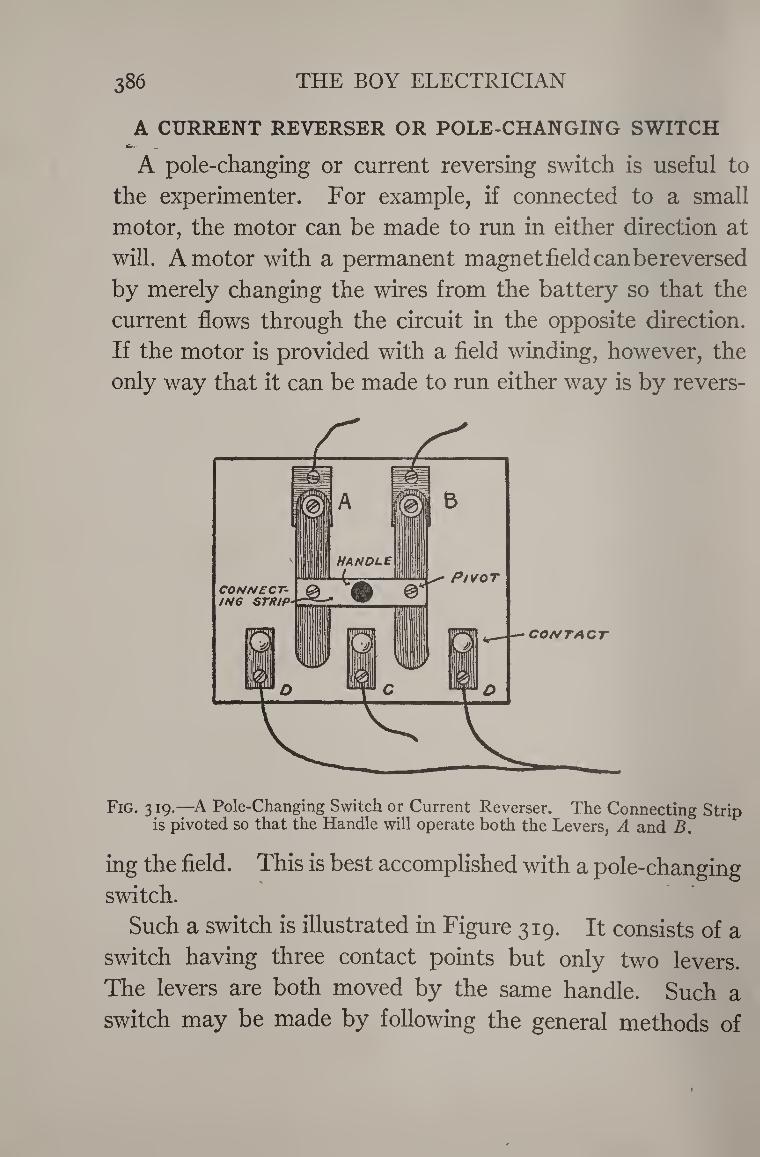
386 THE BOY ELECTRICIAN
A CURRENT REVERSER OR POLE-CHANGING SWITCH _ —
A pole-changing or current reversing switch is useful to
the experimenter. For example, if connected to a small
motor, the motor can be made to run in either direction at
will. A motor with a permanent magnet field can bereversed
by merely changing the wires from the battery so that the
current flows through the circuit in the opposite direction.
If the motor is provided with a field winding, however, the
only way that it can be made to run either way is by revers-
Fig. 319.—A Pole-Changing Switch or Current Reverser. The Connecting Strip is pivoted so that the Handle will operate both the Levers, A and B.
ing the field. This is best accomplished with a pole-changing switch.
Such a switch is illustrated in Figure 319. It consists of a
switch having three contact points but only two levers.
The levers are both moved by the same handle. Such a
switch may be made by following the general methods of
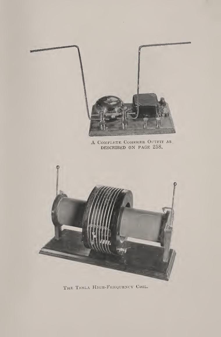
A Complete Coherer Outfit as
DESCRIBED ON PAGE 258.
The Tesla High-Frequency Coil.

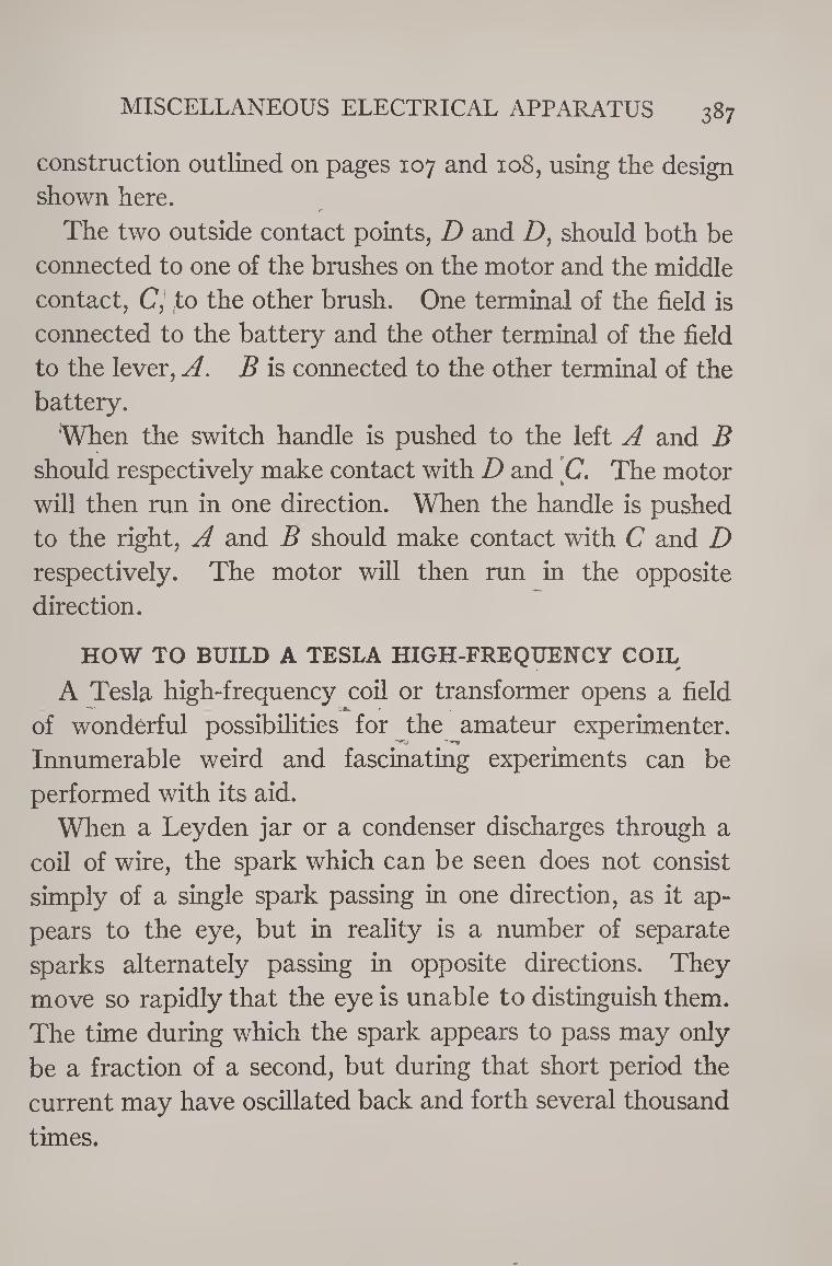
MISCELLANEOUS ELECTRICAL APPARATUS 387
construction outlined on pages 107 and 108, using the design shown here.
S’
The two outside contact points, D and Z), should both be connected to one of the brushes on the motor and the middle contact, C, (to the other brush. One terminal of the field is connected to the battery and the other terminal of the field to the lever, A. B is connected to the other terminal of the battery.
'When the switch handle is pushed to the left A and B should respectively make contact with D and C. The motor will then run in one direction. When the handle is pushed to the right, A and B should make contact with C and D respectively. The motor will then run in the opposite direction.
HOW TO BUILD A TESLA HIGH-FREQUENCY COIL
A Tesla high-frequency coil or transformer opens a field of wonderful possibilities for the amateur experimenter. Innumerable weird and fascinating experiments can be performed with its aid.
When a Leyden jar or a condenser discharges through a coil of wire, the spark which can be seen does not consist simply of a single spark passing in one direction, as it ap¬ pears to the eye, but in reality is a number of separate sparks alternately passing in opposite directions. They move so rapidly that the eye is unable to distinguish them. The time during which the spark appears to pass may only
be a fraction of a second, but during that short period the
current may have oscillated back and forth several thousand
times.
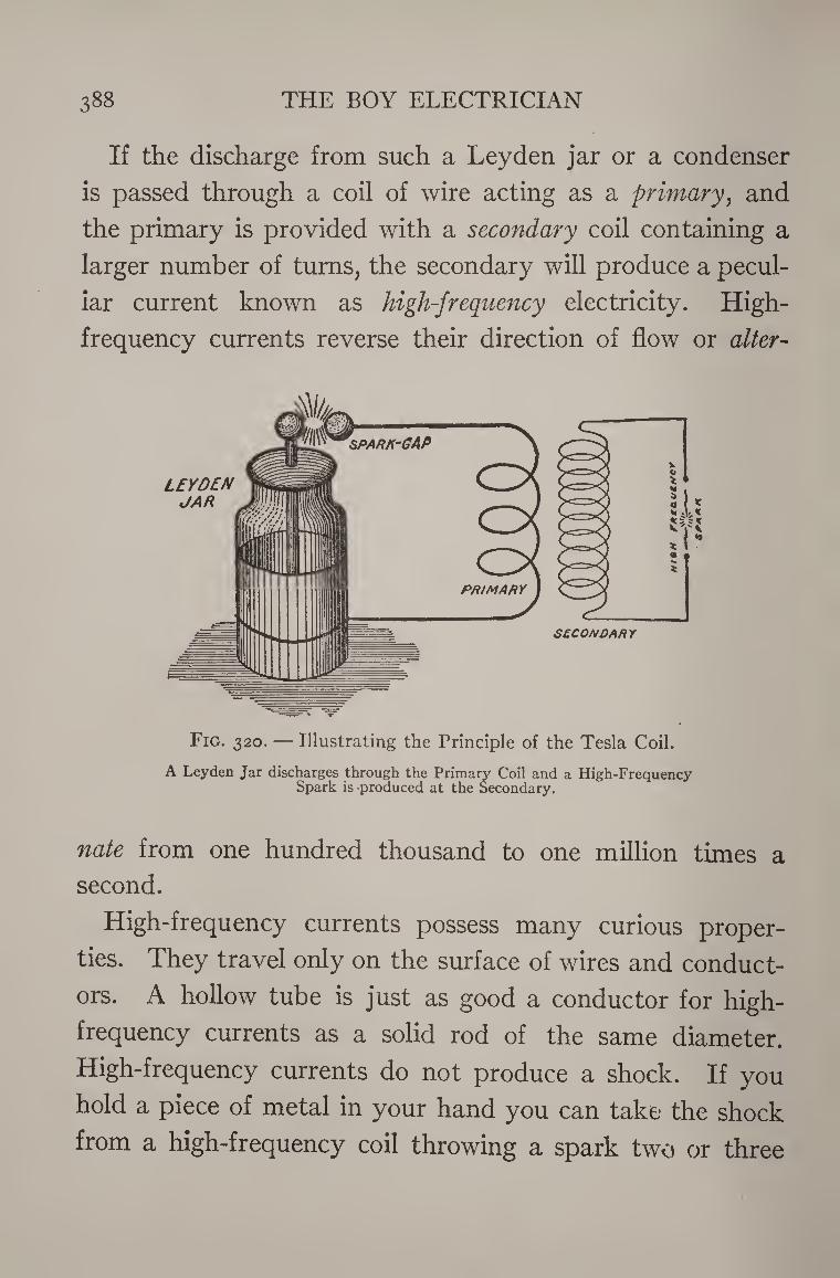
388 THE BOY ELECTRICIAN
If the discharge from such a Leyden jar or a condenser
is passed through a coil of wire acting as a primary, and
the primary is provided with a secondary coil containing a
larger number of turns, the secondary will produce a pecul¬
iar current known as high-frequency electricity. High-
frequency currents reverse their direction of flow or alter-
Fig. 320. — Illustrating the Principle of the Tesla Coil.
A Leyden Jar discharges through the Primary Coil and a High-Frequency Spark is produced at the Secondary.
nate from one hundred thousand to one million times a
second.
High-frequency currents possess many curious proper¬
ties. They travel only on the surface of wires and conduct¬
ors. A hollow tube is just as good a conductor for high-
frequency currents as a solid rod of the same diameter.
High-frequency currents do not produce a shock. If you
hold a piece of metal in your hand you can take the shock
from a high-frequency coil throwing a spark two or three
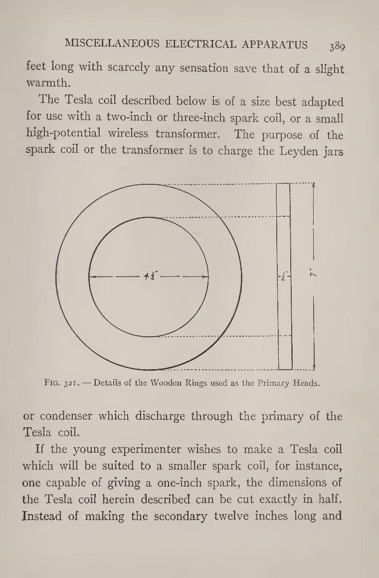
MISCELLANEOUS ELECTRICAL APPARATUS 389
feet long with scarcely any sensation save that of a slight
warmth.
The Tesla coil described below is of a size best adapted
for use with a two-inch or three-inch spark coil, or a small
high-potential wireless transformer. The purpose of the
spark coil or the transformer is to charge the Leyden jars
Fig. 321. — Details of the Wooden Rings used as the Primary Heads.
or condenser which discharge through the primary of the
Tesla coil.
If the young experimenter wishes to make a Tesla coil
which will be suited to a smaller spark coil, for instance,
one capable of giving a one-inch spark, the dimensions of
the Tesla coil herein described can be cut exactly in half.
Instead of making the secondary twelve inches long and
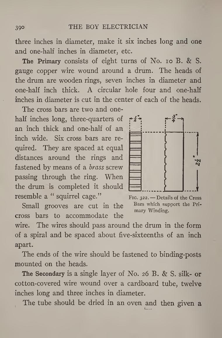
390 THE BOY ELECTRICIAN
3 >
three inches in diameter, make it six inches long and one
and one-half inches in diameter, etc.
The Primary consists of eight turns of No. io B. & S.
gauge copper wire wound around a drum. The heads of
the drum are wooden rings, seven inches in diameter and
one-half inch thick. A circular hole four and one-half
inches in diameter is cut in the center of each of the heads.
The cross bars are two and one-
half inches long, three-quarters of
an inch thick and one-half of an
inch wide. Six cross bars are re¬
quired. They are spaced at equal
distances around the rings and
fastened by means of a brass screw
passing through the ring. When
the drum is completed it should
resemble a “ squirrel cage.”
Small grooves are cut in the
cross bars to accommodate the
Fig. 322.— Details of the Cross
Bars which support the Pri¬
mary Winding.
wire. The wires should pass around the drum in the form
of a spiral and be spaced about five-sixteenths of an inch
apart.
The ends of the wire should be fastened to binding-posts
mounted on the heads.
The Secondary is a single layer of No. 26 B. & S. silk- or
cotton-covered wire wound over a cardboard tube, twelve
inches long and three inches in diameter.
The tube should be dried in an oven and then given a
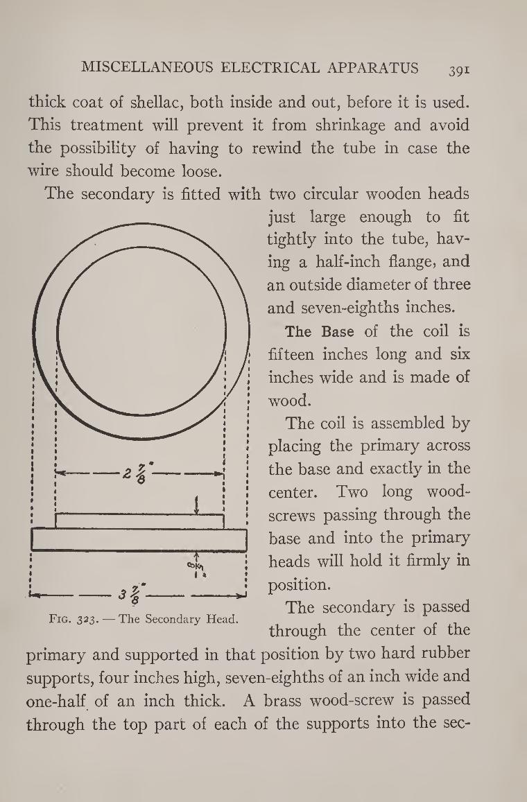
MISCELLANEOUS ELECTRICAL APPARATUS 39i
thick coat of shellac, both inside and out, before it is used.
This treatment will prevent it from shrinkage and avoid
the possibility of having to rewind the tube in case the
wire should become loose.
The secondary is fitted with two circular wooden heads
just large enough to fit
tightly into the tube, hav¬
ing a half-inch flange, and
an outside diameter of three
and seven-eighths inches.
The Base of the coil is
fifteen inches long and six
inches wide and is made of
wood.
The coil is assembled by
placing the primary across
the base and exactly in the
center. Two long wood-
screws passing through the
base and into the primary
heads will hold it firmly in
position.
The secondary is passed
through the center of the Fig. 323. — The Secondary Head.
primary and supported in that position by two hard rubber
supports, four inches high, seven-eighths of an inch wide and
one-half of an inch thick. A brass wood-screw is passed
through the top part of each of the supports into the sec-
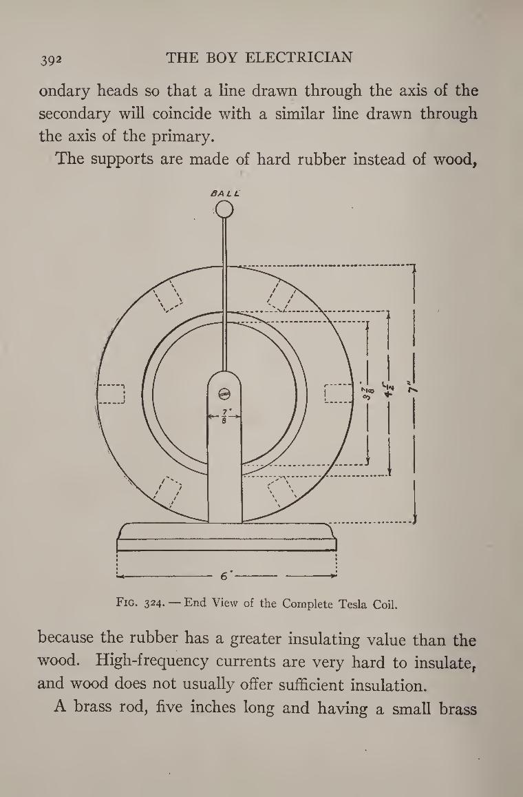
392 THE BOY ELECTRICIAN
ondary heads so that a line drawn through the axis of the
secondary will coincide with a similar line drawn through
the axis of the primary.
The supports are made of hard rubber instead of wood,
BA L L
because the rubber has a greater insulating value than the
wood. High-frequency currents are very hard to insulate,
and wood does not usually offer sufficient insulation.
A brass rod, five inches long and having a small brass
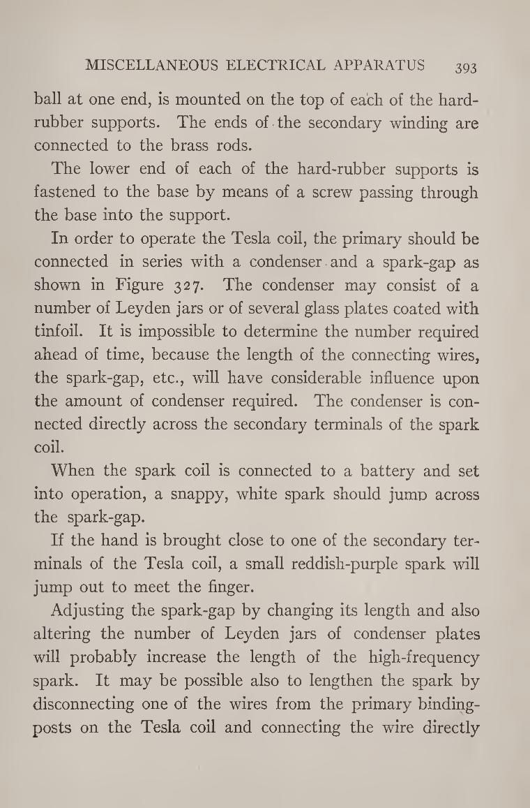
MISCELLANEOUS ELECTRICAL APPARATUS 393
ball at one end, is mounted on the top of each of the hard-
rubber supports. The ends of the secondary winding are
connected to the brass rods.
The lower end of each of the hard-rubber supports is
fastened to the base by means of a screw passing through
the base into the support.
In order to operate the Tesla coil, the primary should be
connected in series with a condenser and a spark-gap as
shown in Figure 327. The condenser may consist of a
number of Leyden jars or of several glass plates coated with
tinfoil. It is impossible to determine the number required
ahead of time, because the length of the connecting wires,
the spark-gap, etc., will have considerable influence upon
the amount of condenser required. The condenser is con¬
nected directly across the secondary terminals of the spark
coil.
When the spark coil is connected to a battery and set
into operation, a snappy, white spark should jump across
the spark-gap.
If the hand is brought close to one of the secondary ter¬
minals of the Tesla coil, a small reddish-purple spark will
jump out to meet the finger.
Adjusting the spark-gap by changing its length and also
altering the number of Leyden jars of condenser plates
will probably increase the length of the high-frequency
spark. It may be possible also to lengthen the spark by
disconnecting one of the wires from the primary binding-
posts on the Tesla coil and connecting the wire directly
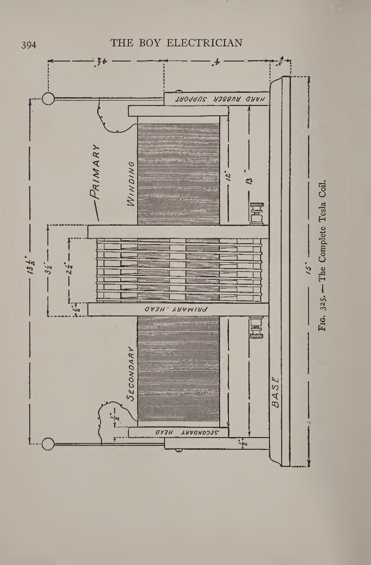
394 THE BOY ELECTRICIAN
- /j--
Fig
. 3
25
. —
The
Co
mp
lete T
esl
a
Coil
.
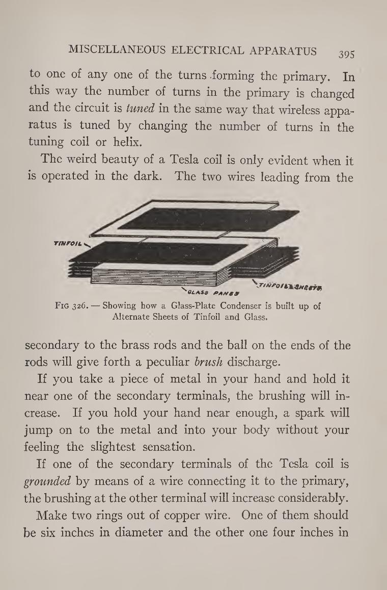
MISCELLANEOUS ELECTRICAL APPARATUS 395
to one of any one of the turns .forming the primary. In
this way the number of turns in the primary is changed
and the circuit is tuned in the same way that wireless appa¬
ratus is tuned by changing the number of turns in the
tuning coil or helix.
The weird beauty of a Tesla coil is only evident when it
is operated in the dark. The two wires leading from the
Fig 326. — Showing how a Glass-Plate Condenser is built up of Alternate Sheets of Tinfoil and Glass.
secondary to the brass rods and the ball on the ends of the
rods will give forth a peculiar brush discharge.
If you take a piece of metal in your hand and hold it
near one of the secondary terminals, the brushing will in¬
crease. If you hold your hand near enough, a spark will
jump on to the metal and into your body without your
feeling the slightest sensation.
If one of the secondary terminals of the Tesla coil is
grounded by means of a wire connecting it to the primary,
the brushing at the other terminal will increase considerably.
Make two rings out of copper wire. One of them should
be six inches in diameter and the other one four inches in
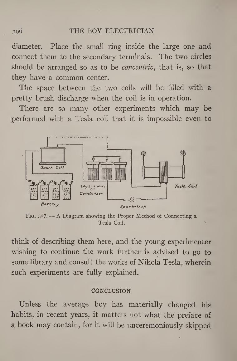
396 THE BOY ELECTRICIAN
diameter. Place the small ring inside the large one and
connect them to the secondary terminals. The two circles
should be arranged so as to be concentric, that is, so that
they have a common center.
The space between the two coils will be filled with a
pretty brush discharge when the coil is in operation.
There are so many other experiments which may be
performed with a Tesla coil that it is impossible even to
think of describing them here, and the young experimenter
wishing to continue the work further is advised to go to
some library and consult the works of Nikola Tesla, wherein
such experiments are fully explained.
CONCLUSION
Unless the average boy has materially changed his
habits, in recent years, it matters not what the preface of
a book may contain, for it will be unceremoniously skipped
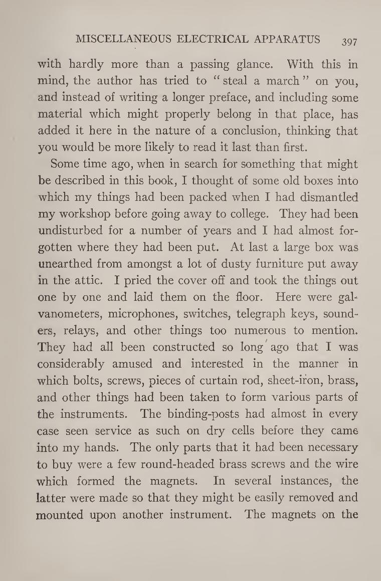
MISCELLANEOUS ELECTRICAL APPARATUS 397
with hardly more than a passing glance. With this in
mind, the author has tried to “ steal a march ” on you,
and instead of writing a longer preface, and including some
material which might properly belong in that place, has
added it here in the nature of a conclusion, thinking that
you would be more likely to read it last than first.
Some time ago, when in search for something that might
be described in this book, I thought of some old boxes into
which my things had been packed when I had dismantled
my workshop before going away to college. They had been
undisturbed for a number of years and I had almost for¬
gotten where they had been put. At last a large box was
unearthed from amongst a lot of dusty furniture put away
in the attic. I pried the cover off and took the things out
one by one and laid them on the floor. Here were gal¬
vanometers, microphones, switches, telegraph keys, sound¬
ers, relays, and other things too numerous to mention.
They had all been constructed so long ago that I was
considerably amused and interested in the manner in
which bolts, screws, pieces of curtain rod, sheet-iron, brass,
and other things had been taken to form various parts of
the instruments. The binding-posts had almost in every
case seen service as such on dry cells before they came
into my hands. The only parts that it had been necessary
to buy were a few round-headed brass screws and the wire
which formed the magnets. In several instances, the
latter were made so that they might be easily removed and
mounted upon another instrument. The magnets on the
39§ THE BOY ELECTRICIAN
telegraph sounder could be removed and fitted to form part
of an electric engine or motor.
One particular thing which struck me very forcibly was
the lack of finish and the crudeness which most of the
instruments showed.
Of course it was impossible to avoid the clumsy appear¬
ance which the metal parts possessed, since they were not
originally made for the part that they were playing, but I
wished that I had taken a little more care to true up things
properly or to smooth and varnish the wood, or that I had
removed the tool-marks and dents from the metal work
by a little filing.
If I had done so, I should now be distinctly proud of my
work. That is not to say that I am in the least ashamed
of it, for my old traps certainly served their purpose well,
even if they were not ornamental and were better back
in their box. Perhaps I might be excused for failing in this
part of the work through lack of proper tools, and also
because at that time there were no magazines or books
published which explained how to do such things, and
when I built my first tuning coils and detectors nothing on
that subject had ever been published. I had to work out
such problems for myself, and gave more thought to the
principles upon which the instruments operated than to
their actual construction.
The boys who read this book have the advantage of
instructions showing how to build apparatus that has
actually been built and tested. You know what size of
MISCELLANEOUS ELECTRICAL APPARATUS 399
wire to use and will not have to find it out for yourself.
For that reason you ought to be able to give more time
to the construction of such things. The purpose of this
conclusion is simply a plea for better work. The Ameri¬
can boy is usually careless in this regard. He often com¬
mences to build something and then, growing tired before
it is finished, lays it aside only to forget it and undertake
something else. Finish whatever yon undertake. The
principle is a good one. Remember also that care with the
little details is what insures success in the whole.
If in carrying out your work, you get an idea, do not
hesitate to try it. A good idea never refused to be devel¬
oped. It is not necessary to stick absolutely to the direc¬
tions that I have given. They will insure success if fol¬
lowed, but if you think you can make an improvement, do
so.
Of course, such a book as this cannot, in the nature of
things, be exhaustive, nor is it desirable, in one sense, that
it should be.
I have tried to write a book which, considered as a
whole, would prove to be exhaustive only in that it
treats of almost every phase of practical electricity.
The principle in mind has been to produce a work which
would stimulate the inventive faculties in boys, and to
guide them until face to face with those practical emer¬
gencies in which no book can be of any assistance but
which must be overcome by common sense and the exercise
of personal ingenuity.
400 THE BOY ELECTRICIAN
The book is not as free from technical terms or phrases,
as it lay in my power to make it, because certain of those
terms have a value and an every-day use which are a
benefit to the young experimenter who understands them.
Any one subject treated in the various chapters of the
“ Boy Electrician ” may be developed far beyond that
point to which I have taken it. The railroad system could
be fitted with electric signals, drawbridges, and a num¬
ber of other devices.
Many new ideas suggest themselves to the ready-witted
American boy. I shall always be pleased to hear from any
boy who builds any of the apparatus I have described,
and, if possible, to receive photographs of the work. I
should be glad to be of any assistance to such a lad, but
remember that some of the drawings and text in this book
required many hours even to complete a small portion,
and therefore please do not write to ask how to build other
apparatus not described herein. And, as the future years
bring new inventions and discoveries, no one now knows
but that, some day, perhaps I will write another “ Boy
Electrician.”
THE END.
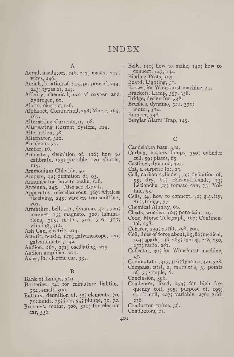
INDEX
A
Aerial, insulators, 246, 247; masts, 247; wires, 246.
Aerials, location of, 245; purpose of, 243, 245; types of, 247.
Affinity, chemical, 60; of oxygen and hydrogen, 60.
Alarm, electric, 146. Alphabet, Continental, 258; Morse, 165,
167. Alternating Currents, 97, 98. Alternating Current System, 224. Alternation, 98. Alternator, 320. Amalgam, 37. Amber, 16. Ammeter, definition of, 116; how to
calibrate, 125; portable, 120; simple,
JI7‘ Ammonium Chloride, 59. Ampere, 92; definition of, 93. Annunciator, how to make, 148. Antenna, 245. Also see Aerials. Apparatus, miscellaneous, 369; wireless
receiving, 245; wireless transmitting, 263.
Armature, bell, 141; dynamo, 321, 329; magnet, 15; magneto, 320; lamina¬ tions, 315; motor, 306, 310, 315; winding, 312.
Ash Can, electric, 214. Astatic, needle, 129; galvanoscope, 129;
galvanometer, 132. Audion, 267, 271; oscillating, 275. Audion amplifier, 274. Axles, for electric car, 337.
B
Bank of Lamps, 379. Batteries, 54; for miniature lighting,
354; small, 360. Battery, definition of, 55; elements, 70,
75; fluids, 75; jars, 55; plunge, 71, 72. Bearings, motor, 308, 311; for electric
car, 336.
Bells, 140; how to make, 140; how to connect, 143, 144.
Binding Posts, 105. Board, Lighting, 51. Bosses, for Wimshurst machine, 41. Brackets, Lamp, 357, 358. Bridge, design for, 348. Brushes, dynamo, 321, 332;
motor, 314. Bumper, 348. Burglar Alarm Trap, 143.
C
Candelabra base, 352. Carbon, battery lamps, 350; cylinder
cell, 59; plates, 65. Castings, dynamo, 325. Cat, a surprise for, 23. Cell, carbon cylinder, 59; definition of,
55; dry, 61; Edison-Lalande, 73; Leclanche, 59; tomato can, 73; Vol¬ taic, 55.
Cells, 54; how to connect, 76; gravity, 81; storage, 77.
Chemical Affinity, 60. Cleats, wooden, 104; porcelain, 105. Code, Morse Telegraph, 167; Continen¬
tal, 258. Coherer, 259; outfit, 258, 260. Coil, lines of force about, 85,86; medical,
194;spark, 198,263;tuning, 248, 250, 251; radio, 281.
Collector, 36; for Wimshurst machine,
45- Commutator, 313,316; dynamo, 3 21,3 28. Compass, first, 2; mariner’s, 3; points
of, 3; simple, 6. Conclusion, 396. Condenser, fixed, 254; for high fre¬
quency coil, 395; purpose of, 199; spark coil, 207; variable, 276; grid, 278.
Conductor, prime, 36. Conductors, 21.
401
402 INDEX
Connections for, alternating current system, 224; ammeter, 125, 126; bells, 122, 124; burglar alarm, 146; cells, 76; coherer, 262; current reverser, 387; electro-plating, 382; induction coil, 210; induction motor, 380; lamp bank, 379; lights, 356, 357; micro¬ phone, 170; motors, 315; railway car, 340; relay, 163; rheostat, 385; storage cells, 80; telegraphs, 134; telephones, 189; Tesla coil, 396; transformer, 234; voltmeter, 125, 126; Wheatstone Bridge, 134; wireless telegraph, 255, 256, 257, 263; wireless telephone, 302; X-Ray outfit, 219.
Connector, for joining rails, 347. Continental Alpahbet, 258. Copper-plating, 382. Copper Wire, 246. Core, effects of, 86; spark coil, 200;
transformer, 229. Coulomb, 97. Coupler, for electric cars, 339. Cross-over, 344. Crystal Receiving Set, how to build,
244, 245. Current, alternating, 97; direct, 97;
electricity, 21; how to reduce from iiov. for experimenting, 21; reverser, 386.
Currents, high-frequency, 388; oscilla¬ tory, 243; rectified, 244.
Cut-outs, 107. Cycle, 98. Cylinder Electric Machine, 31.
D Dance, electrical, 51. Dashes, 153, 165, 166, 167. Decoherer, 259. Depolarizer, 60. Depolarizing Agent, 60. Desk-Stand Telephone, 191. Detector, action of, 244, 252, 253, 254;
radio, 269. Detectors, 252, 253; crystal, 253; “Cat-
Whisker,” 252, 253. Dimensions, spark coil, 207. Dipping Needle, 14. Direct Current, 97. Discharge, photograph of, 215.
Discovery of the Magnet, 1. Dots, 153, 165, 166, 167. Dry Cells, 61; recharging, 65. Dynamo, armature, 321, 329; bearings,
331; brushes, 321, 332; commutator, 321, 328; principle of, 320; winding,
315- Dynamos, 315.
E “Edison Effect,” 269, 270. Edison-Lalande Cell, 73. Ediswan base, 352. Electric Alarm, 146. Electric Ash Can, 214. Electric Current, comparison with
water, 222. Electric Cylinder machine, 31. Electric Frog Pond, 30. Electric Discharge, 215. Electric Hand-Lantern, 361. Electric Machines, 31; experiments
with, 48. Electric Motors, 305. Electric Railway, 334; how to reverse,
347- Electric Ruby Lamp, 362. Electric Scarf-Pin, 366. Electric Umbrella, 50. Electric Whirl, 52. Electrical Apparatus, miscellaneous,
369- Electrical Dance, 51. , Electrical Hands, 209. Electrical Horsepower, 96. Electrical Pressure, 222. Electrical Units, 92. Electricity, 16; current, 21; frictional,
21; generated by heat, 369; gener¬ ated by chemical action, 56; static, 21.
Electro-magnetic Induction, 89. Electro-magnetism, 83. Electro-magnetic waves, 242. Electro-magnets, principle of, 87; lift¬
ing, 88. Electrolysis, 381. Electromotive Force, 75, 82, 94. Electrons, 269. Electrophorus, 29. Electroscope, double pith ball, 26;
gold-leaf, 26; paper, 24; pith-ball, 24. Electro-plating, 381. Elektron, 16.
INDEX 403
Element, cell, 59, 66, 67, 68. Ether, 240; waves in, 242, 243. Experiments, with an electric machine,
48; with spark coils, 209.
F
Faraday, Michael, 89, 278. Field of Force, 85. Field, castings, 326; dynamo, 325;
laminations, 315; motor, 309, 311, 315.
Figures, Lichtenberg’s, 52. Fixed Condenser, 254. Floor, for electric car, 336. Fluoroscope, 217. Force, field of, 85; magnetic, n. Forming Plates, 80. Frame for Wimshurst Machine, 43. Franklin, Benjamin, 17; kite experi¬
ment, 17, 18, 19, 20. Frequency, 99; radio, 268. Frog Pond, electric, 30. Fuses, no, hi.
G
Galena, 252, 253, 254. Galvanometer, astatic, 132. Galvanometer, 126. Galvanoscope, simple, 127; compass,
127; astatic, 129. Galvanoscopes, 126. Gaps, spark, 241, 265; coils, 264, 265. Geissler Tubes, 211. Generator, complete, 324. Ghost Light, 212. Gnomon, 2. Gravity Cells, 81. Grid, storage ceil, 76; 270. Ground, for wireless, 248; clamp, 248. Gunpowder, igniting, 49-
H
Hanging Lamp, 359- Head, fiber, 230. Heat, generated into electricity, 369. Hertzian Waves, 242. High-frequency, coil, 388; currents, 388. Horse-power, electrical, 96. Hydrogen, 56.
I
Igniting Gunpowder, 49. Induction, 19; electro-magnetic, 89;
magnetic, 8, 82, 90. Induction Motor, 379. Instruments, wireless, 245. Insulating Pin, 105. Insulator, glass, 105. Insulators, 104, 247. Interrupter, for medical coil, 196;
spark coil, 206.
J
Jacob’s Ladder, 215. Jar, Leyden, 48. Joke, practical, 213.
K
Keeper, magnet, 15. Key, strap, 300. Kilowatt, 96. Kilowatt hour, 97. Knife Contact, 135. Knobs, porcelain, 105.
L Ladder, Jacob’s, 215. Lamp, Bracket, for miniature fighting,
357; home-made, 358. Lamp, carbon battery, 350) tungsten
battery, 351. Lamp Bank, 379. Lamp, for telling time at night, 365;
hanging, 359; ruby, 362. Lantern, electric, 361, 362. “Lead-in”, 248. Leading-stone, 3. Leak, grid, 278. Leclanche cell, 59. Leg, transformer, 230. Lens, for reflectoscope, 374. Lichtenberg’s Figures, 52. Light, night, 363; watch, 364. Light, Ghost, 212. Lightning, 19; arresters, 112, 113;
board, 50; telephone arrester, 114. Lines of force, 86. Lodestone, 2. Loose Coupler, 244; simple, 272, 273.
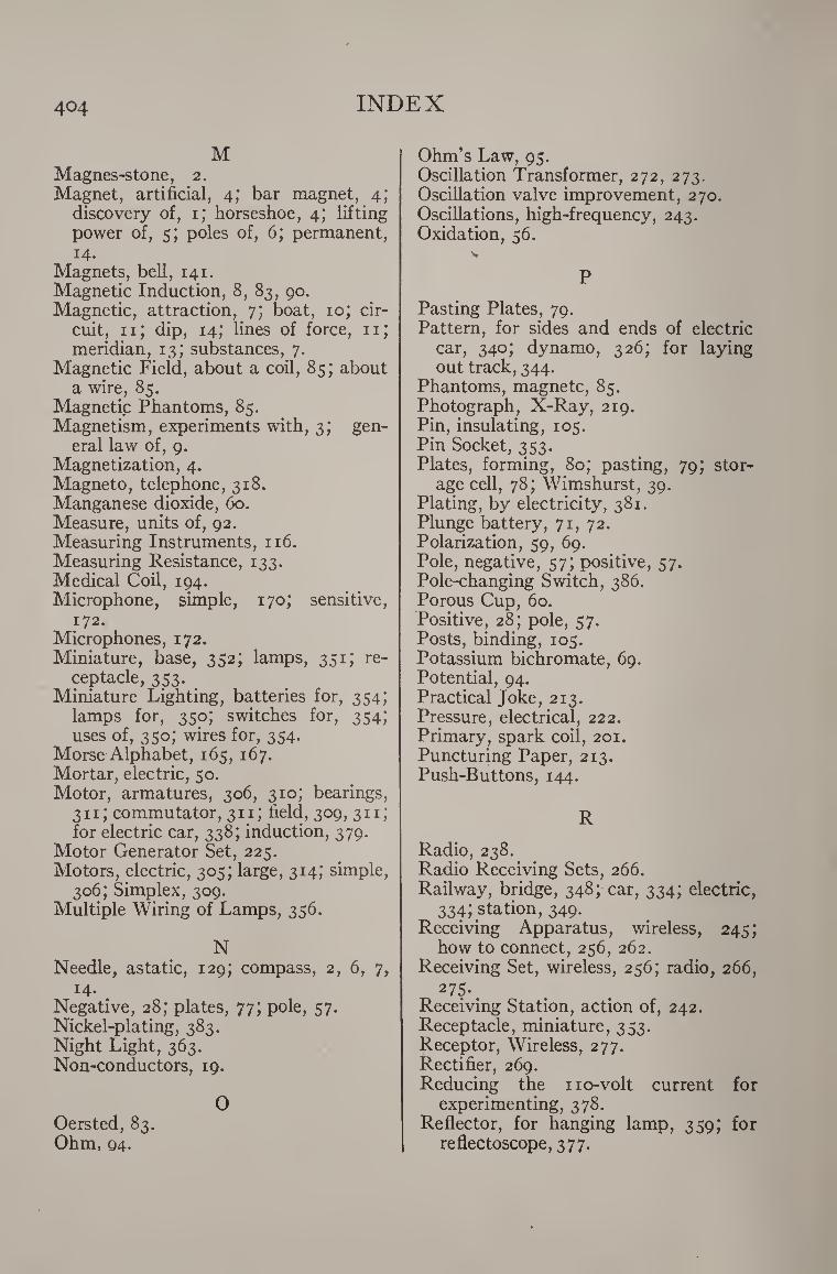
404 INDEX
M Magnes-stone, 2. Magnet, artificial, 4; bar magnet, 4;
discovery of, 1; horseshoe, 4; lifting power of, 5; poles of, 6; permanent, 14.
Magnets, bell, 141. Magnetic Induction, 8, 83, 90. Magnetic, attraction, 7; boat, 10; cir¬
cuit, 11; dip, 14; lines of force, 11; meridian, 13; substances, 7.
Magnetic Field, about a coil, 85; about a wire, 85.
Magnetic Phantoms, 85. Magnetism, experiments with, 3; gen¬
eral law of, 9. Magnetization, 4. Magneto, telephone, 318. Manganese dioxide, 60. Measure, units of, 92. Measuring Instruments, 116. Measuring Resistance, 133. Medical Coil, 194. Microphone, simple, 170; sensitive,
172. Microphones, 172. Miniature, base, 352; lamps, 351; re¬
ceptacle, 353. Miniature Lighting, batteries for, 354;
lamps for, 350; switches for, 354; uses of, 350; wires for, 354.
Morse Alphabet, 165, 167. Mortar, electric, 50. Motor, armatures, 306, 310; bearings,
311; commutator, 311; field, 309, 311; for electric car, 338; induction, 379.
Motor Generator Set, 225. Motors, electric, 305; large, 314; simple,
306; Simplex, 309. Multiple Wiring of Lamps, 356.
N Needle, astatic, 129; compass, 2, 6, 7,
14. Negative, 28; plates, 77; pole, 57. Nickel-plating, 383. Night Light, 363. Non-conductors, 19.
O Oersted, 83. Ohm, Q4.
Ohm’s Law, 95. Oscillation Transformer, 272, 273. Oscillation valve improvement, 270. Oscillations, high-frequency, 243. Oxidation, 56.
P
Pasting Plates, 79. Pattern, for sides and ends of electric
car, 340; dynamo, 326; for laying out track, 344.
Phantoms, magnetc, 85. Photograph, X-Ray, 219. Pin, insulating, 105. Pin Socket, 353. Plates, forming, 80; pasting, 79; stor¬
age cell, 78; Wimshurst, 39. Plating, by electricity, 381. Plunge battery, 71, 72. Polarization, 59, 69. Pole, negative, 57; positive, 57. Pole-changing Switch, 386. Porous Cup, 60. Positive, 28; pole, 57. Posts, binding, 105. Potassium bichromate, 69. Potential, 94. Practical Joke, 213. Pressure, electrical, 222. Primary, spark coil, 201. Puncturing Paper, 213. Push-Buttons, 144.
R
Radio, 238. Radio Receiving Sets, 266. Railway, bridge, 348; car, 334; electric,
334; station, 349. Receiving Apparatus, wireless, 245;
how to connect, 256, 262. Receiving Set, wireless, 256; radio, 266,
275- Receiving Station, action of, 242. Receptacle, miniature, 353. Receptor, Wireless, 277. Rectifier, 269. Reducing the no-volt current for
experimenting, 378. Reflector, for hanging lamp, 359; for
reflectoscope, 377.
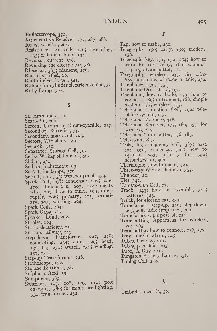
INDEX 405
Reflectoscope, 372. Regenerative Receiver, 277, 287, 288. Relay, wireless, 261. Resistance, 221; coils, 136; measuring,
133; of human body, 194. Reverser, current, 386. Reversing the electric car, 386. Rheostat, 385; filament, 279. Rod, electrified, 16. Roof of electric car, 341. Rubber for cylinder electric machine, 35. Ruby Lamp, 362.
S
Sal-Ammoniac, 59. Scarf-Pin, 366. Screen, barium-platinum-cyanide, 217. Secondary Batteries, 74. Secondary, spark coil, 203. Sectors, Wimshurst, 40. Seebeck, 370. Separator, Storage Cell, 79. Series Wiring of Lamps, 356. Sliders, 250. Sodium bichromate, 69. Socket, for lamps, 376. Socket, pin, 353; weather proof, 353. Spark Coil, 198; condenser, 207; core,
200; dimensions, 207; experiments with, 209; how to build, 199) inter- rupter, 206; primary, 201; second¬ ary, 203; winding, 204.
Spark Coils, 264. Spark Gaps, 265. Speaker, Loud, 292. Staples, 104. Static electricity, 21. Station, railway, 349- Step-down Transformer, 227, 228,
connecting, 234; core, 229; head, 230; leg, 230; switch, 232; winding,
23°, 231.
Step-up Transformer, 220. Stethoscope, 172. Storage Batteries, 74. Sulphuric Acid, 55. Sun-power, 369. Switches, 107, 108, 109, no; pole
changing, 386; for miniature lighting, 354; transformer, 232.
T
Tap, how to make, 231. Telegraphs, 150; early, 150; modern,
150. Telegraph, key, 151, 132, 154; how to
learn to, 164; relay, 160; sounder, 153, i5S; transmitter, 151.
Telegraphy, wireless, 237. See wire¬ less’, forerunner of modern radio, 239.
Telephones, 170, 175. Telephone Desk-stand, 191. Telephone, how to build, 179; how to
connect, 189; instrument, 188; simple system, 177; wireless, 297.
Telephone Induction Coil, 192; tele¬ phone system, 193.
Telephone Magneto, 318. Telephone Receiver, 177, 180, 255; for
wireless, 255. Telephone Transmitter, 176, 183. Television, 267. Tesla, high-frequency coil, 387; base
for, 391; condenser, 395; how to operate, 393; primary for, 390; secondary for, 390.
Thermopile, how to make, 370. Three-way Wiring Diagram, 357. Thunder, 21. Ties, 342. Tomato-Can Cell, 73. Track, 343; how to assemble, 342;
patterns, 343. Truck, for electric car, 339. Transformer, step-up, 226; step-down,
227, 228; radio frequency, 290. Transformers, purpose of, 221. Transmitting Apparatus for wireless,
264, 265. Transmitter, how to connect, 276, 277. Trap, burglar alarm, 145. Tubes, Geissler, 211. Tubes, porcelain, 105. Tube, X-Ray, 216. Tungsten Battery Lamps, 351. Tuning Coil, 248.
U
Umbrella, electric, 50.
406 INDEX
V
Vacuum Tube, three-electrode, 267, 279. Volt, 93. Volta, 55. Voltaic Cell, 55. Voltmeter, defined, 116; calibrating,
125; portable, 120; simple, 117.
W Watt, 96. Watt hour, 97. Watch Light, 365. Waves, ether, 240, 242; Hertzian, 242;
radio-frequency, 268. Weatherproof Socket, 353. Wet Batteries, 65. Wheatstone Bridge, 133. Wheels, for electric car, 337. Whirl, electric, 52. Wimshurst Machine, 37; bosses, 41;
collectors, 45; frame, 43; plates, 39; quadrant rods, 45; sector, 40; up¬ rights, 43-
Winding, spark coils, 204; transformer, 230, 231.
Wireless Telegraph, instruments, 245; outfit, 277; receiving set, 256; re¬ ceptor, 244; simple transmitter, 241; station, 303.
Wireless Telegraphy, 237; principles of, 237.
Wireless Telephone, 297; complete station, 303; principle of, 297; simple, 299.
Wireless Transmitter, 263. Wires, 100; aerial, 245, 246; magnet,
101; miniature lighting, 354; sizes of, 102, 103.
Writing-Paper, electrified, 23.
X
X-Ray, tube, 216; fluoroscope, 217; screen, 217; outfit, 219; holder, 217.
X-Rays, 216.